XVII International Conference on Chemical Reactors ...
759
XVII International Conference on Chemical Reactors C CHEMREACTOR-17 May 15-19, 2006 Athens-Crete, Greece ABSTRACTS
Transcript of XVII International Conference on Chemical Reactors ...

XVII International Conferenceon Chemical Reactors
CCHEMREACTOR-17
May 15-19, 2006 Athens-Crete, Greece
ABSTRACTS

Boreskov Institute of Catalysis of the Siberian Branch of Russian Academy of Sciences, Novosibirsk, Russia
Russian Scientific and Cultural Center in Athens
Russian Center of International Scientific and Cultural Cooperation under RF Government
Ministry of Education and Science of the Russian Federation
European Federation on Chemical Engineering
Scientific Council on Theoretical Bases of Chemical Technology RAS
Scientific Council on Catalysis RAS
With assistance of the General Secretariat for Research and Technology of the Ministry of Development, Greece
XVII International Conferenceon Chemical Reactors
CHEMREACTOR-17 Post-Symposium “Catalytic Processing of
Renewable Sources: Fuel, Energy, Chemicals”
Athens-Crete, Greece May 15-19, 2006
ABSTRACTS
Novosibirsk, 2006

© Boreskov Institute of Catalysis, 2006

INTERNATIONAL SCIENTIFIC COMMITTEE Mikhail G. Slinko, Honour Chairman
State Research Center "Karpov NIPCI", Moscow, Russia
Valentin N. Parmon, Chairman
Boreskov Institute of Catalysis SB RAS, Novosibirsk, Russia
David Agar University of Dortmund, Germany Alex Bell University of California, Berkeley, CA, USA Anthony Bridgwater Bio-Energy Research Group, Aston University, Birmingham, UK Ji�í Hanika Institute of Chemical Process Fundamentals, Prague, Czech Republic Raghunath Chaudhari National Chemical Laboratory, Pune, India Mike P. Dudukovi� Washington University, St. Louis, USA Gerhardt Eigenberger Stuttgart University, Germany Pio Forzatti Technical University of Milan, Italy Sergei S. Ivanchev St. Petersburg Department of the Boreskov Institute of Catalysis SB RAS,
Russia Boris V. Gidaspov RSC “Applied Chemistry”, St. Petersburg, Russia John Gleaves Washington University, USA Guiliano Grassi European Biomass Industry Association – EUBIA, Brussels, Belgium Valerii A. Kirillov Boreskov Institute of Catalysis SB RAS, Novosibirsk, Russia Guy Marin Ghent University, Belgium Dmitrii Yu. Murzin �bo Akademi University, Turku, Finland Stylianos Neophytides Institute of Chemical Engineering and High Temperature Chemical
Processes, Patras, Greece Alexander V. Putilov Federal Agency for Atomic Energy of the Russian Federation, Moscow, RussiaPavel D. Sarkisov Mendeleyev University of Chemical Technology of Russia, Moscow, RussiaVladimir G. Sister Moscow Government, Russia Vladimir A. Sobyanin Boreskov Institute of Catalysis SB RAS, Novosibirsk, Russia Gennadii F. Tereschenko Russian Academy of Science, St. Petersburg, Russia Constantinos G. Vayenas University of Patras, Greece
ORGANIZING COMMITTEE Alexander S. Noskov, Chairman
Boreskov Institute of Catalysis SB RAS, Novosibirsk, Russia
Victor A. Chumachenko JSC «Katalizator», Novosibirsk, Russia Sergei M. Foshkin Russian Scientific and Cultural Center, Athens, Greece Arthur Iordanidis ABB Switzerland Ltd, Baden-Dattwil, Switzerland Vitalii N. Kashkin Boreskov Institute of Catalysis SB RAS, Novosibirsk, Russia Tatiana B. Khlebnikova Boreskov Institute of Catalysis SB RAS, Novosibirsk, Russia Sergei I. Reshetnikov Boreskov Institute of Catalysis SB RAS, Novosibirsk, Russia Norbert Vasen ETA Renewable Energies, Florence, Italy Vadim A. Yakovlev Boreskov Institute of Catalysis SB RAS, Novosibirsk, Russia Ilya A. Zolotarskii Boreskov Institute of Catalysis SB RAS, Novosibirsk, Russia Tatiana V. Zamulina, Secretary
Boreskov Institute of Catalysis SB RAS, Novosibirsk, Russia

The organizers express their gratitude to
Ministry of Education and Science of the Russian Federation, Moscow, Russia
for the financial support

PLENARY LECTURES
XVII International Conference on Chemical Reactors


PL-1
FUNDAMENTAL KINETIC MODELING FOR REACTOR DESIGN
AND SIMULATION
G.F. Froment
Artie Mc Ferrin Department of Chemical Engineering
Texas A & M University, Texas, USA
The necessity and the potential of a more fundamental approach to the kinetic modeling
of catalytic processes is illustrated by means of a few examples in which special attention is
given to the role of the catalyst.
The first example deals with phthalic anhydride synthesis in which the catalyst itself
provides the oxygen inserted into the reacting species.
A second example deals with solid-acid alkylation and with the conversion of methanol
into olefins on zeolites. In these processes the catalyst is progressively deactivated through
irreversible site coverage or channel blockage by heavy reaction products, but the latter are
not inert towards the reacting species and also contribute to the evolution of conversion and
selectivities.
Finally, the transformation of heavy oil fractions into more valuable and clean
transportation fuels is considered. A realistic representation of the overwhelming product
distribution of these processes requires the decomposition of the reaction scheme in terms of
elementary steps of carbocation chemistry. The fundamental modeling based upon the single
event concept, in combination with the Evans-Polanyi relationship, permits a drastic reduction
of the number of independent rate parameters, accessible through judicious experimentation.
The potential of such an approach in the simulation of the commercial hydrocracking of
vacuum gas oil is illustrated.
References: 1. Papageorgiou, J.N. and G.F. Froment. “Phthalic Anhydride Synthesis-Reactor Optimization Aspects.”
Chem. Eng. Sci. Vol. 51, 10, 2091-2098 (1996). 2. Park T.Y. and Froment G.F., “Reaction Rates in the Methanol-to-Olefins Process and their Role in Reactor
Design and Operation” Ind. Eng. Chem. Res. (2004), 43(3)682-689 3. Saeed M. Alwahabi and Gilbert F. Froment, “Single Event Kinetic Modeling of the Methanol-to-Olefins
Process on SAPO-34” Ind. Eng. Chem. Res, (2004), 43, 5098-5111 Saeed M. Alwahabi and Gilbert F. Froment, “Conceptual Reactor Design for the Methanol-to-Olefins Process on SAPO-34” Ind. Eng. Chem. Res, (2004), 43, 5112-5122. Jorge.M.Martinis and Gilbert F Froment, “Solid Acid Alkylation. Part I. Experimental Investigation of Catalyst Deactivation“ Ind.Eng.Chem.Res,(2006),45, 940-953.
4. Jorge.M. Martinis and Gilbert F Froment, ”Solid Acid Alkylation. Part II Single-Event Kinetic Modeling”, Ind. Eng. Chem. Res ,(2006), 45,954-967.
5. Gilbert F. Froment; “Single Event Kinetic Modeling of Complex Catalytic Processes”, Catalysis Reviews (2005)1, 83-124.
7

PL-2
WOVEN FIBER GLASS MATERIALS AS A
NEW GENERATION OF STRUCTURED CATALYSTS
Bair S. Bal’zhinimaev
Boreskov Institute of Catalysis SB RAS,
Prospect Akademika Lavrentieva, 5, 630090, Novosibirsk, Russia
fax: 7 383 330 80 56 e-mail: [email protected]
Abstract
The potentiality of silicate glass fiber materials modified with Zr and REM (Rare Earth Metal) oxides as a new catalysts for application in reactions of oxidative and environmental catalysis is evaluated. The questions related to study of molecular structure of glass, formation and stabilization of highly dispersed metal (mostly, Pt and Pd) species in the bulk of glassmatrix are elucidated. The glass fiber based catalysts showed high performance in number reactions (deNOx, VOC removal, selective hydrogenation of acetylene/ethylene feedstock, CH4 conversion to C2H4 via intermediate selective halogenation of methane to methylchloride, etc). The effect of heat/mass transfer on catalyst performance, the results of pilot testings, as well as the main advantages of these catalysts in comparison with traditional ones are also considered.
The silicate glass fiber materials are produced in the industry and widely used as
perfect heat and electric insulators. At the same time these materials are practically unknown to people from catalysis despite of obvious advantages such as high thermostability (up to 1200�C), mechanical strength, improved hydrodynamic properties, as well as possibility to make catalytic reactors with new flexible design and to move from traditional packed catalysts beds to structural ones.
The lecture is devoted to study of glass fiber materials modified with Zr and REM (Rare Earth Metals) oxides in order to reveal their potential properties in catalysis. These materials
comprise of elemental fibers of 7 - 9 �m in diameter, twisted into separate yarns of 0,2 - 1 mm in size which are used for manufacturing of different shape textiles. The glass fibers are nonporous and surface area is equal to geometrical one (ca. 1 m2/g). The average chemical composition of leached materials is a following (% wt.): 80-90 SiO2, 10% ZrO2 or REM + 0,5-3 Al2O3. By means of IRS and NMR the layered model of glass structure, when 2-3 rows of SiO4 tetrahedra are altered by hydroxyl groups, was proposed. The presence of OH-groups is important because the introduction of active metal cations via ion exchange mechanism with
8

PL-2
protons takes place. The effective procedure for introduction of metal (mostly, Pt, Pd) complexes into the bulk of glassmatrix, their further reduction into highly dispersed metal species (clusters) or unusual low-valent states at elevated temperatures was developed and characterized by UV-Vis DRS in combination with TPO and TPR. The size of metal clusters was too small to be observed by high resolution electron microscopy. These species (up to 10 Å in size) appeared under heating by electron beam only, possibly due to partial sintering of smaller metal particles. Pt or Pd clusters are located in the bulk of glass matrix up to hundred angstroms of depth which is confirmed by XPS data combining with ion etching.
Despite of very low noble metal content (~0,01% wt.) the glass fiber catalysts exhibited high performance in many reactions (deNOx, VOC removal, SO2 oxidation, destruction of chlorinated wastes etc.). The main reason is a capability of the materials to stabilize highly dispersed metal clusters in upper layers of glass fibers. It was found that REM cations can significantly modify the charge of Pd clusters resulting in substantial improvement of catalyst performance. Another feature of glass materials is a capability to absorb predominantly the polar or polarizable molecules from gas or liquid. Because of active sites are located in the bulk of fibers it allows to involve into reaction the polar substances with extremely low concentration. It was demonstrated clearly by the example of selective hydrogenation of acetylene (polarizable molecule) in ethylene feedstock when very high selectivity and purification level (less than 0,1 ppm of acetylene) were achieved.
Due to specific geometry and structure of glass fiber textiles, as well as high reaction rate the heat- and mass transfer limitations related to mostly, external and intra-yarn diffusion were revealed. It was shown these phenomena lead to decreasing of activity in oxidation of methane and CO, catalytic reduction of NO with CH4 and may cause some operation unstability like overheating, oscillations of thermokinetic origin. In case of selective hydrogenation of acetylene/ethylene feedstock the intra-yarn diffusion limitation leads to deacreasing not only activity, but selectivity as well. Special isotopic studies showed that diffusion of reacting molecules inside of glassmatrix doesn’t control the reaction rate and limiting step is mass transfer on the gas (liquid) – glass interface.
In conclusion, the results of glass fiber based catalysts testing in various reactions, including 2-step conversion of methane to ethylene via intermediate halogenation of methane to methylchloride, the results of pilot testing in SO2 oxidation, treatment of diesel exhausts, as well as the main advantages of these catalysts in comparison with traditional ones are listed. Acknowledgements: The financial support by Russian Foundation for Basic Research (Grants No 00-03-22004, 02-03-32480) is highly appreciated.
9

PL-3
IS IT WORTH DOING KINETIC MODELLING IN ASSYMETRIC
HETEROGENEOUS CATALYSIS OF FINE CHEMICALS?
Dmitry Yu. Murzin
Åbo Akademi University, Biskopsgatan 8, 20500, Åbo/ Turku, Finland, [email protected]
Proper reactor modeling requires physico-chemical understanding of catalytic processes.
Catalysis is a kinetic process according to its definition, therefore reliable kinetic models are
needed for design and intensification of catalytic processes. Kinetic and engineering studies of
heterogeneous catalytic reactions are widespread, especially in connection with oil refining or
production of bulk and specialty chemicals. However, in the filed of fine chemicals and
pharmaceuticals, kinetic studies are rather sparse, although application of heterogeneous
catalysis is growing. Interestingly a great number of various mechanisms are advanced in the
literature for many organic catalytic reactions on rather rare being supported by kinetic studies.
Analysis of experimental data in complex reaction networks typical for synthesis of fine
chemicals is not trivial, requiring laborious experimentation. Moreover, often only data for the
major products and some by-products are available; while other components are lumped into
pseudo- components.
Therefore many researchers neglect kinetic studies, presuming that kinetic analysis of
complex catalytic reactions has no scientific value at all being “just a mathematical exercise
and not really chemistry at all” *
In the presentation modeling of kinetics, stereo-, regio- and enantioselectivity of reactions
representing different typical cases of multiphase organic catalysis will be discussed.
Challenges in establishing kinetic regularities and subsequent modeling will be illustrated by
experimental data on liquid-phase hydrogenation of ��� unsaturated aldehydes (citral,
cinnamaldehyde, crotonaldehyde), alkylaromatics and alkylphenols, sitosterol, various sugars,
asymmetric hydrogenation of diketones, one-pot synthesis of menthol, hydrogenolysis of
hydroxymatairesinol, oxidation of lactose, �-pinene isomerization and synthesis of
conjugated linoleic acid, performed with participation of the author [1-19]. Among others the
following items will be addressed: the rate determining steps, the adsorption mode of organic
* One of the reviewers comment on the manuscript of H. Lineweaver and D. Burk, [J. Am. Chem. Soc., 56, 658, 1934 ] on enzymatic kinetics, which eventually became the most cited JACS paper in XXth century [C&EN, 81(24), 27, 2003]
10

PL-3
compounds, type of gas (hydrogen or oxygen) adsorption, the competitiveness between small
molecules and large organic molecules, changes of adsorption mode with coverage, catalyst
deactivation to name a few. Special emphasis will be put on selectivity, analysis of which
(Figure 1) allows for instance discrimination of rival models.
Despite the obvious difficulties in doing kinetic modeling of heterogeneous catalytic
reactions in fine chemicals, kinetic analysis of selectivity, which in broad sense is understood
as chemo-, regio- and enantioselectivity, is a very powerful tool in establishing reaction
mechanisms as well as in process development.
O
OH
OH
OCinnamaldehyde(A)
3-Phenypropanal(C)
3-Phenylpropanol(D)
Cinnamylalcohol(B)
r1 r3
r4r2
0
0.1
0.2
0.3
0.4
0.5
0 0.25 0.5 0.75 1
Conversion [%]
Sele
ctiv
ity
Model I.
433 K0
0.1
0.2
0.3
0.4
0.5
0 0.25 0.5 0.75
Conversion [%]
Sele
ctiv
ity [%
]
Model II.
433 K
1
Figure 1. Selectivity to 3-phenylpropanal in cinnamaldehyde hydrogenation as a function of conversion: experimental vs. estimated (� - 59, � - 37, � - 14 bar) [6]
11

PL-3
References
1. A. Allahverdiev, S. Irandoust, B.Andersson, D.Yu.Murzin, Kinetics of �-pinene enantiomeric isomerization over clinoptilolite, Applied Catal. A.Gen. 2000, 198, 197.
2. J. Aumo, J. Wärnå, T. Salmi, D.Yu. Murzin, Interaction of kinetics and internal diffusion in complex catalytic three-phase reactions: activity and selectivity in citral hydrogenation, Chemical Engineering Science, 2006, 61, 814.
3. H. Backman, A.Kalantar Neyestanaki, D.Yu. Murzin, Mathematical modeling of o-xylene hydrogenation kinetics over Pd/Al2O3, Journal of Catalysis, 2005, 233, 109.
4. A. Bernas, D.Yu. Murzin, Linoleic acid isomerization on Ru/Al2O3 catalyst. 1. Conjugation and hydrogenation, Chemical Engineering Journal, 2005, 115, 13.
5. A. Bernas, D.Yu. Murzin, Linoleic acid isomerization on Ru/Al2O3 catalyst. 2. Elementary step mechanism and data fitting, Chemical Engineering Journal, 2005, 115, 23.
6. J. Hájek, J. Wärnå, D.Yu. Murzin, Liquid-phase hydrogenation of cinnamaldehyde over Ru-Sn sol-gel catalyst. Part II Kinetic modeling, Industrial & Engineering Chemistry Research, 2004, 43, 2039.
7. A. Kalantar, H. Backman, J.H. Carucci, T. Salmi, D.Yu. Murzin, Gas-phase hydrogenation of 4-tert-butylphenol over Pt/SiO2, J. Catalysis, 2004, 227, 60.
8. K. Liberkova, R. Touroude, D. Yu. Murzin, Analysis of deactivation and selectivity pattern in catalytic reduction of a molecule with different functional groups: Crotonaldehyde hydrogenation on Pt/SnO2, Chem. Eng. Sci., 2002, 57, 2519.
9. M.Lindroos, P. Mäki-Arvela, N. Kumar, T. Salmi, D.Yu. Murzin, Catalyst deactivation in selective hydrogenation of �-sitosterol to �-sitostanol over palladium, Catalysis in Organic Reactions, 2002, 587.
10. H. Markus, P.Mäki-Arvela, N.Kumar, N.V. Kul’kova, P. Eklund, R. Sjöholm, B. Holmbom, T. Salmi, D.Yu. Murzin, Hydrogenolysis of hydroxymatairesionol over carbon supported palladium catalysts, Catalysis Letters, 2005, 103, 125.
11. D. Yu. Murzin, P. Mäki-Arvela, E. Toukoniitty, T. Salmi, Asymmetric heterogeneous catalysis: science and engineering, Catalysis Reviews, Science and Engineering, 2005, 47, 175.
12. P.Mäki-Arvela, N.Kumar, A.Nasir, T.Salmi, D.Yu.Murzin, Selectivity enhancement by catalyst deactivation in three phase hydrogenation of nerol, Industrial & Engineering Chemistry Research 2005, 44, 9376.
13. P.Mäki-Arvela, N.Kumar, D. Kubicka, A.Nasir, T.Heikkilä, V.-P.Lehto, R. Sjöholm, T.Salmi, D.Yu.Murzin, One-pot citral transformation to menthol over bifunctional micro- and mesoporous metal modified catalysts: effect of catalyst support and metal, Journal of Molecular Catalysis A. Chemical, 2005, 240, 72.
14. P.Mäki-Arvela, J. Hajek, T.Salmi, D.Yu.Murzin, Chemoselective hydrogenation of carbonyl compounds over heterogeneous catalysts, Applied Catalysis A. General, 2005, 292, 1.
15. P. Mäki-Arvela, N.Kumar, V. Nieminen, R. Sjöholm, T.Salmi, D.Yu.Murzin, Cyclization of citronellal over zeolites and mesoporous materials for production of isopulegol, J. Catal. 2004, 225, 155.
16. V. Nieminen, A. Taskinen, E. Toukoniitty, M. Hotokka, D.Yu.Murzin, One-to-one reactant-modifier interactions in enantio- and diastereoselective hydrogenation of chiral a -hydroxyketones on Pt(111), Journal of Catalysis, 2006, 237, 131.
17. M.L. Toebes, T. A. Nijhuis, J. Hajek, J.H. Bitter, A.J. van Dilen, D.Yu.Murzin, K.P. de Jong, Support effects in hydrogenation of cinnamaldehyde over carbon nanofiber-supported platinum catalysts: kinetic modeling, Chemical Engineering Science, 2005, 60, 5682.
18. B. Toukoniitty, J. Kuusisto, J.-P.Mikkola, T. Salmi, D.Yu. Murzin, Effect of ultrasound on catalytic hydrogenation of D-fructose to D-mannitol, Industrial & Engineering Chemistry Research, 2005, 44, 9370.
19. E.Toukoniitty, B. Sevcikova, P. Mäki-Arvela, J. Wärnå, T.Salmi, D.Yu. Murzin, Kinetics and modeling of 1-phenyl-1,2-propanedione hydrogenation, Journal of Catalysis, 2003, 213, 7
12

PL-4
TRICKLE BED REACTOR OPERATION UNDER FORCED LIQUID
FEED RATE MODULATION
J. Hanikaa,b, V. Jiricnya, J. Kolenac, J. Ledererc, V. Staneka, V. Tukacb
aInstitute of Chemical Process Fundamentals, Czech Academy of Sciences, Rozvojová 135,
165 02 Prague 6, Czech Republic, fax +420 220 390 286, [email protected] bInstitute of Chemical Technology, Technická 5, 166 28, Prague 6, Czech Republic,
[email protected] cUnipetrol, a.s., div. VUANCH, 436 70, Litvinov, Czech Republic, [email protected]
Trickle bed operations are well spread, especially in the base chemical industry1,
biochemical industry and also in toxic gas purification and waste water treatment. Trickle bed
reactors are used in the chemical and biochemical industry for heterogeneously catalysed
reactions, e.g. for hydrogenation, oxidation and hydrotreating processes. In the trickle beds
gas and liquid percolate continuously through a fixed bed of solid particles and they are
flowing in the downward direction. The particles contain at their surface solid catalyst on
which components from the gas- and liquid phase react. The reaction product is then
transported out of the bed by the flowing liquid.
Two phase flow of reaction mixture through catalyst bed is complicated by mal-
distribution of both phases in a void space between individual neighbouring catalyst pellets on
cross section and along the bed2. Mal-distribution of volatile reaction mixture in catalyst bed
can also initiate hot spot formation in imperfect or partially wetted zones in the bed3 where
both reaction rate and rate of heat production (in case of exothermal reaction) are higher. The
diffusion resistance of gaseous component in flowing liquid film is lower there and
simultaneously there is lower thermal conductivity.
Out of nature this type of reactor is very non-linear in performance. This fact is very
important from the point of view of its safe operation4. There are several reasons: high
concentration of reactants (high adiabatic temperature rise and low heat capacity of the
system), high activation energy of reaction (its value strongly depends on catalyst nature),
change of reaction system selectivity with temperature (substrate decomposition by
undesirable reaction like methanization on nickel catalysts at temperature above 200 °C)
decrease of mass transfer resistance (partial evaporation of liquid phase, exceeding of critical
13
PL-4
point of reaction mixture). As an extreme, in exothermic reactions (most of those mentioned)
temperature excursions can and do sometimes lead to severe runaways and accidents3.
Trickle bed reactors can operate in a number of flow regimes. Hydrodynamic regime
of reaction mixture flow in reactor can be characterised by so called "flow map". For
industrial design the flow regime with a gas continuous phase and a liquid trickle regime is
usually chosen. Nevertheless, high interaction pulsing regime for waste water treatment is
conveniently applied. Therefore, at certain gas and liquid rates during reactor control or after
some parameter disturbance, pulses develop in the bed, whereby dense slugs of liquid form.
These pulses are in fact waves of liquid that move downward, take up the liquid at their front
and leave liquid at the back. The pulses can be promoted also by forced feed rate modulation.
The influence of pulses is very beneficial for the following reasons5-8:
� Pulses drown any temperature deviation, suppress hot spot formation in the bed and
improve the safety operation of the reactor.
� Mass transfer of reaction components between gas, liquid and solid phases is enhanced in
pulsing flow regime and thus process intensification can be reached.
� During pulsed flow regime the radial concentration gradients are mixed out and better
plug flow performance of the reactor is expected.
� Forced feed oscillations can produced pulses with frequencies reached in order several
hundredths Hertz and because of the non-linearity of the process better reaction
conversion can be made.
The paper reports results of the project "New operation methods of industrial trickle
bed reactors - intensification and safe control" granted by the Ministry of Industry and Trade
of the Czech Republic, project No. FT-TA/039. Scope and motivation for the research was a
need for improvement of selective hydrogenation of dienes in light pyrolysis gasoline. This
process is installed e.g. in CHEMOPETROL Co. Litvínov.
Using model reactions - unsaturated hydrocarbons hydrogenation on palladium
supported catalyst - an effect of periodic feed rate modulation on trickle bed reactor
performance has been investigated. It was confirmed that under specific conditions the feed
rate modulation enables enhancement of the mean reaction rate in catalyst bed as a result of
lower mean thickness of liquid film covering external surface of catalyst pellets. Moreover,
higher gas-liquid mass transfer interaction during the liquid rich part of period is possible. An
14

PL-4
enhancement of reactor throughput depends at feed rate modulation conditions on both the
hydrodynamics in the catalyst bed and the feed rate modulation parameters, i.e. period length
and its split value.
The research was aimed to investigate possible improvement of safe operation and
throughput of trickle bed reactor by periodic modulation of reaction mixture feed rate which
brings total wetting of catalyst and improves interaction and mass transfer rate between gas
and liquid in liquid rich part of the period. The application of periodically modulated liquid
feed rate brings smaller mean thickness of the liquid film flowing down along the external
surface of catalyst pellets (lower diffusion resistance to gas component transfer to catalyst
surface) and tubulisation of potential stagnant zones in the reactor. Period length, split to
liquid rich and poor parts, and/or feed rate amplitude are important parameters of the feed rate
modulation mode. It is evident that modulated feed rate of liquid reaction mixture affected
liquid hold-up, concentration and temperature fields in the reactor.
Pilot plant unit built by Institute of Inorganic Chemistry Usti n.L. in Research Centre
of CHEMOPETROL Co. Litvinov was used for feasibility tests of dynamic operation and
control of trickle bed reactor. Adiabatic trickle bed reactor of diameter 0.1 m, length 2 m was
made for operation till temperature 200 °C and pressure 2.5 MPa. The unit was equipped by
two pumps (maximum feed rate 120 and 600 lt/h resp.), two tanks of 1.1 m3 volume, phase
separator of 40 lt volume and data logger and control system ControlWeb 2000 SP9
(Moravské p�ístroje Zlín).
The model reactions used in this study represent many of similar transformations of
dienes and other unsaturated hydrocarbons during selective hydrogenation of pyrolysis
gasoline. The reactor performance at continuous feed rate was compared with that one
observed during feed rate modulation at the same operation conditions, i.e. at the same mean
throughput of catalyst, identical temperature, pressure and feed composition.
Experiments confirmed the possible way for increase of throughput of trickle bed
reactor by periodic modulation of reaction mixture feed rate9. Under optimal conditions
transfer improvement of gaseous component across flowing liquid film represents approx. 6%
relatively. The similar effect in case of exothermal reaction like unsaturated hydrocarbons
hydrogenation is based on the higher mean temperature of the catalyst bed which was
confirmed by reactor dynamic model solution. The gain in reactor throughput by the higher
interaction between gaseous and liquid phases in the vicinity of change of the system
hydrodynamics between film and pulsing flows (which is periodically overcame at feed rate
modulation) represents additional intensification of the trickle bed reactor (approx. 12%rel).
15

PL-4
Conclusion
Induced pulsing flow of the reaction mixture in the trickle bed reactor is a promised
way for the improvement the time-average reaction conversion with respect to that observed
under the steady-state trickle bed reactor operation. The better catalyst wetting, improved
mixing of reaction mixture in the stagnant pockets in the catalyst bed, uniformity in radial
temperature profile were reached during the induced pulse operation regime.
Periodic operation of trickle bed reactor by application of the feed rate modulation can
reasonably improve reaction conversion in comparison to the steady state operation mode. It
was confirmed that temperature effects of exothermic reaction can contribute to the
enhancement factor of the system in the order of several percents. There are of course the
other effects such as periodic renewal of external catalyst surface accelerating gas component
transfer to the poorly wetted catalyst pellets, stronger interaction of gas and liquid flowing co-
currently through bed of catalyst close to the frontier between trickle and pulsing flow
regimes, etc. The simulation results were compared with experimental data.
References
1. Hanika J., Lederer J.: Simultaneous hydrogenation of dienes and olefines using palladium catalyst in plant trickle bed reactor, Congress EUROPACAT-1, Montpellier, September 1993.
2. Stan�k V.: Fixed bed operations – flow distribution and efficiency, Ellis Horwood Ltd. Chichester & Academia Prague, 1994.
3. Gossens E., Donker R., van den Brink F.: Reactor runaway in pyrolysis gasoline hydrogenation, 1st Internat Symp. on Proc. Safety, Oostende, Feb. 17-19, 1997.
4. Hanika J.: Safe operation and control of trickle bed reactor, Chem. Eng. Sci. 54, 4653-4659 (1999).
5. Boelhouver J.G., Piepers H.W., Drinkenburg A.A.H.: Liquid induced pulsing flow in trickle bed reactors, Chem. Eng. Sci. 57, 3387-3399 (2002).
6. Silveston P.L., Hanika J.: Challenges for the periodic operation of trickle bed catalytic reactors, Chem. Eng. Sci. 57, 3373-3385 (2002).
7. Silveston P.L., Hanika J.: Periodic operation of three-phase catalytic Reactors, Canad. J. Chem. Eng. 82, 1105-1142 (2004).
8. Giakoumakis D., Kostoglou M., Karabelas A.J.: Induced pulsing in trickle beds - characteristics and attenuation of pulses, Chem. Eng. Sci. 60, 5183-5197 (2005).
9. Tuka� V., Šimícková M., Chyba V., Lederer J., Kolena J., Hanika J.: Dynamic behaviour of trickle bed reactor, CAMURE-05 & ISMR-4 Symposium, Portorož 15.-18.6.2005, Book of Extended Abstracts 87-88 (2005).
16

PL-5
MONOLITHIC ELECTROPROMOTED REACTORS:
FROM FUNDAMENTALS TO PRACTICAL DEVICES
Costas G. Vayenas
Department of Chemical Engineering, University of Patras, Patras, Greece
A Monolithic electropromoted reactor (MEPR) is a new type of high-throughput reactor which permits the in situ use of the phenomenon of electrochemical promotion of Catalysis (EPOC or NEMCA effect) to enhance the rate and selectivity of catalytic reactions. The concept, design and construction of the first MEPR units is discussed, together with the first performance results in high space velocity laboratory and car exhaust environments. 1. Electrochemical promotion of catalytic reactions
The phenomenon of Electrochemical Promotion of Catalysis (EPOC) or Non-Faradaic electrochemical promotion of catalytic activity (NEMCA effect) and its close relationship with classical promotion and with metal-support interaction has been discussed and analyzed in numerous publications [1-15]. Work in this area has been reviewed recently [14,16]. The metal or conductive metal oxide catalyst is deposited on a solid electrolyte component and electrical current or potential is applied between the catalyst and a second electrode (termed counter electrode) also deposited on the solid electrolyte component (Figure 1). This electrical current or potential applications causes pronounced and usually reversible changes in the catalytic activity and selectivity of the catalyst electrode. The induced change in catalytic rate is up to 6 orders of magnitude larger than the rate, I/nF, of electrochemical supply or removal of ions (of charge n) to or from the catalyst-electrode through the solid electrolyte, where I is the applied current and F is the Faraday constant. The induced change in catalytic rate can be up to 300 times larger than the catalytic rate before current or potential application. The counter electrode may be exposed to a separate gas compartment (fuel cell-type design) or may by exposed to the same reactive gas mixture as the catalyst-electrode (single chamber design). The solid electrolyte component (e.g. plate or tube) may be either gas impervious, but can also be porous (Vayenas et al, European Patent 0480116 (1996)). The phenomenon of electrochemical promotion has been studied already for more than seventy catalytic reactions (Vayenas et al, “Electrochemical Activation of Catalysis: Promotion, Electrochemical Promotion and Metal-Support Interactions” Kluwer/ Academic Publishers (2001)) but so far there has been no practical reactor configuration designed, constructed and tested in order to utilize it in industrial practice or in automotive exhaust catalysis.
We discuss here a new reactor and method for utilizing the effect of electrochemical promotion of catalysis to enhance the rate and selectivity of catalytic reactions. The new reactor has all the geometric characteristics of a monolithic honeycomb reactor but, due to its special design, can be dismantled and assembled at will and can be used to electrochemically promote
17

PL-5
the catalyst-electrodes deposited on its plate components with only two external electrical connections. Therefore both electrical manifolding and also gas manifolding is extremely simplified in the new monolithic electrochemically promoted reactor (MEPR) [16-19]. 2. Description and operation of the MEPR
Figure 2 shows the monolithic electrochemical promoted reactor (MEPR) concept. Theplate and reactor dimensions are quite flexible and those shown in Figure 2 are indicative and corresponding to those of the prototype units tested [16-19].
The ceramic reactor walls (casing) must be insulating and can be made, for example, by Machinable Ceramic (MACOR) material. It is enclosed in a suitably designed metal (or ceramic) gas manifolding casing with insulating material (e.g. vermiculite) placed, if desirable, between the ceramic reactor walls and the metal (or ceramic) gas manifolding casing in order to reduce mechanical stresses when the unit is used in an automotive exhaust (Figure 3).
The internal side of the two opposing reactor walls has appropriately machined parallel grooves (typically 1-5 mm deep, thickness a few �m larger than the plate thickness (typically 500 �m).
The distance between the parallel grooves dictates the reactor channel height and is typically 0.5 to 2 mm, depending on the desired reactor surface to volume ratio.
The grooves can be made to terminate before the reactor exit in order to ensure that the plates cannot be entrained by the flowing gas stream.
The solid electrolyte plates can be flat, in which case the resulting reactor channels are rectangular, or can be ribbed in which case the resulting reactor channels are rectangular or square. The rib height can be adjusted to either make contact with the next plate or to leave a small (e.g. 5 �m) margin between the rib top and the next plate. The plates can be gas-impervious or porous.
Two different catalysts, based on the rate vs potential behaviour of the catalytic reaction of interest (electrophobic, electrophilic, volcano or inverted volcano type [14-16,20,21].
The first catalyst is coated (e.g. via metal evaporation or sputtering) or using organometallic metal pastes followed by sintering on one side of the plates in such a way as to ensure electrical contact on one side of the plate with the electronic current collector deposited on one side of the inner reactor wall [16-19].
The second catalyst is coated on the other side of the plate in such a way as (a) to avoid short-circuiting with current collector 1 (e.g. by leaving 4-6 mm of the plate surface uncoated, Fig. 2) and (b) to ensure electrical contact with the current collector 2 deposited on the opposite inner reactor wall (Fig. 2).
The thickness of the catalysts 1 and 2 can be as low as 10 nm or as high as 10 �m. Thecatalysts can be porous. The current collectors 1 and 2 are connected via insulated metal sheets or wires to the external power supply or galvanostat or potentiostat.
Figure 3 shows a prototype MEPR reactor with 24 8%Y2O3-stabilized-ZrO2 (YSZ) plates and Rh (catalyst 1) and Pt (catalyst 2) catalyst-electrodes.
Experimental details and performance data have been discussed elsewhere [16-19]. Here we discuss some results obtained with a MEPR loaded with 22 Rh/YSZ/Pt plates.
18

PL-5
The reaction studied was the reduction of NO by ethylene in presence of gaseous O2.Under mildly reducing conditions at 320°C (Fig. 4) electropromotion with an anodic current (+30mA) increases the conversion of C2H4 from 49% to 59%, the conversion of O2 from 68% to 81% and the conversion of NO from 72% to 93%.The shape (flat leveling) of the rate transients suggests that under these conditions the conversions of C2H4, O2 and NO reach a saturation level which is limited by gas bypass.
The reactor was operated at much higher flowrates (1.8 l/min), (more recent studies have utilized flowrates up to 20 l/min), hourly space velocities (1200 h-1) and conversions (~90%) than all previous electropromoted units and shows significant promise for practical applications. More important is the successful electropromotion of its thin (40 nm) Rh and Pt elements, with metal dispersions of at least 10%, i.e. comparable with metal dispersions of supported commercial catalysts. This appears to eliminate the major economic obstacle for the practical utilization of electrochemical promotion. It will be necessary to develop suitable reactor-electrochemical reactor models and scale-up or scale-down strategies for potential practical applications.
References [1] C.G. Vayenas, S. Bebelis, S. Ladas, Nature 343 (1990) 625. [2] J. Pritchard, Nature 343 (1990) 592. [3] R.M. Lambert, F. Williams, A. Palermo, M.S. Tikhov, Top. Catal. 13 (2000) 91. [4] G. Foti, S. Wodiunig, C. Comninellis, Cur. Top. Electrochem. 7 (2001) 1. [5] C.A. Cavalca, G.L. Haller, J. Catal. 177 (1998) 389. [6] L. Ploense, M. Salazar, B. Gurau, E.S. Smotkin, JACS 119 (1997) 11550. [7] P. Vernoux, F. Gaillard, L. Bultel, E. Siebert, M. Primet, J. Catal. 208 (2002) 412. [8] I. Metcalfe, J. Catal. 199 (2001) 247; J. Catal. 199 (2001) 259. [9] C. Sanchez, E. Leiva, in Handbook of Fuel Cells: Fundamentals, Technology and Applications, Vol. 2 (W.
Vielstich,H. Gasteiger and A. Lamm, eds.), John Wiley & Sons Ltd., England, 2003. [10] G.-Q. Lu, A. Wieckowski, Current opinion in Colloid and Interface Science 5 (2000) 95. [11] B. Grzybowska-Swierkosz, J. Haber, Annual Reports on the Progress of Chemistry, The Royal Society of
Chemistry, Cambridge, 1994. [12] J.O.M. Bockris, Z.S. Minevski, Electrochim. Acta 39 (1994) 1471. [13] C.G. Vayenas, M.M. Jaksic, S. Bebelis, S.G. Neophytides, in Modern Aspects of Electrochemistry, Vol.
29 (J.O.M. Bockris,B.E. Conway and R.E. White, eds.), Kluwer Academic/Plenum Publishers, New York, 1996, p. 57.
[14] C.G. Vayenas, S. Bebelis, C. Pliangos, S. Brosda, D. Tsiplakides, Electrochemical Activation of Catalysis: Promotion, Electrochemical Promotion and Metal-Support Interactions, Kluwer Academic/Plenum Publishers, New York, 2001; references therein.
[15] A. Wieckowski, E. Savinova, C.G. Vayenas, eds., Catalysis and Electrocatalysis at Nanoparticles, Marcel Dekker, Inc, New York, 2003.
[16] D. Tsiplakides, S. Balomenou, A. Katsaounis, D. Archonta, C. Koutsodontis and C.G. Vayenas, Catal. Tod. 100 (2005) 133-144.
[17] S. Balomenou, D. Tsiplakides, A. Katsaounis, S. Thiemann-Handler, B. Cramer, G. Foti, Ch. Comninellis and C.G. Vayenas, Appl. Cat. B-Envir. 52 (2004) 181-196.
[18] S.P. Balomenou, D. Tsiplakides, A. Katsaounis, S. Brosda, G. Fóti, Ch. Comninellis, S. Thiemann-Handler, B. Cramer and C.G. Vayenas, Solid State Ionics, in press (2006).
[19] PCT/GR2004/000006 “Method and Apparatus for carrying out electrochemically promoted reactions” C.G. Vayenas, S. Balomenou, D. Tsiplakides, A. Katsaounis, S. Brosda, G. Foti, C. Comninellis, S. Thieman-Handler, B. Cramer (2004).
[20] C.G. Vayenas, S. Brosda and C. Pliangos, J. Catal. 203 (2001) 329-350. [21] S. Brosda and C.G. Vayenas, J. Catal. 208 (2002) 38-53.
19

PL-5
U
I
Solid electrolyte
Catalyst-electrode
Counter electrode
�
e12OH2CO2
O6HC
22
242
OH2CO2
O3HC
22
242
�
)g(O2
��� 222 OOO
Electrochemical(Electrocatalytic)OxidationRate r =I/nFe
Catalytic OxidationRate rCurrent induced rate change
r>>I/nF�
e-
e-
Fig. 1. Principle and basic experimental setup used in electrochemical promotion (NEMCA) experiments.
Fig. 2. Schematic of the monolithic electropromoted reactor (MEPR) with ribbed plates.
0 10 20 30 40 50 60 90 100t / min
4.6
5
5.4
5.8
r CO
2 / 10
-6 m
ol/s
1
2
3
U /
V
0.9
1
1.1
1.2
-r NO
/ 10
-6 m
ol/s
70
80
90
x NO
/ %
48
52
56
60
x C2H
4 / %
65
70
75
80
x O2 /
%
+30 mA 320oC0.5% C2H41% O21300ppm NOFV=1300cc/min�CO2
=1.2�CO2
=18
�NO=1.3�NO=1.7
Fig. 3. Photographs of the MEP reactor-sensor tested showing: (a) the machinable ceramic reactor walls, one of the Ag current collectors on the wall, the plate location for two-plate operation (top plate was used as sensor element) and part of the metal casing. (b) the twenty-two plate unit (c) the assembled reactor with metal casing in the furnace. Also shown are the two thermocouple housings and the four shielded electrical connections for sensing and electropromotion.
Fig. 4. Transient effect of a constant applied current (+30mA) on the catalytic rates of CO2 production ( ) and NO reduction (r
2COr NO), on the NO conversion
(xNO) and on the Rh-Pt potential difference (U). T=320oC.
20

PL-6
HYDROGEN PRODUCTION FOR FUEL CELLS
V.A. Kirillov and V.A. Sobyanin
Boreskov Institute of Catalysis SB RAS, Novosibirsk, Russia
pr. Akademika Lavrentieva, 5, 630090 Novosibirsk, Russia,
E-mail: [email protected]
Hydrogen production from hydrocarbon fuels is a key problem of hydrogen energy.
Technologies relying on utilization of catalysts at all stages of fuel conversion are wide spread
for this purpose: (i) conversion of hydrocarbon feedstock into synthesis gas; (ii) steam
reforming of ��; (iii) preferential �� oxidation. Conversion of fuel into hydrogen is
performed in fuel processors (FP) designed as compact heat-and-function integrated devices
comprising of catalytic reactors, heat exchangers, feed systems and operation regime
controllers. Because of specific requirements for FP, the existing commercial catalysts cannot
be used in fuel processors for a number of reasons. This necessitates the development of novel
catalysts oriented for utilization in FP. These catalysts should meet the following
requirements: high thermal stability and scale resistance of the support and catalyst; catalyst
heat conductivity at a level about 1-5 W/m·K; catalyst life not less than 6000 hours; possible
application of catalysts as structural units for the reactor construction; low cost; equal
coefficients of thermal expansion of catalyst layer and support; good adhesion between the
catalyst layer and the metal wall. The structured metal porous catalysts supported on metal
nets are most completely met the above requirements. In given work there are analyzed
variants of possible application of these catalysts at the synthesis gas production by means of
partial oxidation and steam reforming of natural gas, steam reforming of methanol and bio-
ethanol, auto-thermal reforming of diesel fuel. These catalysts were tested during short-term
and life-timing tests in the abovementioned reactions. There was developed a number of
catalytic reactors on a base of coupling by heat of endothermic and exothermal reactions for
natural gas steam conversion.
Experimental data on the specific productivity and temperature and concentration profiles
within the exo- and endothermic channels are presented. Numerical analysis of the developed
mathematic model proved good agreement between the calculated data and experiment. A
radial-type reactor for partial oxidation of natural gas has been developed and studied. The
reactor includes a perforated gas-distributing tube with a structured net-supported catalyst
21

PL-6
sintered on the outer surface of the tube. Mathematical model for the reactor has been
developed. The results of mathematical modeling agreed well with the experiment. The
reactor modifications for water-gas shift and preferential CO oxidation in hydrogen-rich gas
have been designed and tested successfully. Current state of hydrogen generation by fuel
processors has been analyzed that proved high promises of a heat-integrated fuel processor, in
which heat losses are minimized due to efficient arrangement of reactors, heat exchangers and
other constituent parts. Particular example of that type processor has been considered and
results of experimental studies of its heat regimes and specific productivity presented.
22

PL-7
ALTERNATIVE CATALYTIC PROCESSES FOR LIGHT OLEFINS
PRODUCTION: FROM LAB TO PRACTICE
Angeliki A. Lemonidou
Department of Chemical Engineering, Aristotle University of Thessaloniki,
P.O.Box 1517, University Campus, GR-54006, Thessaloniki, Greece
Light olefins, ethylene and propylene, are the major building blocks of the petrochemical
industry with annual production exceeding 75.000 kt and 45.000 kt respectively for 2004.
Ethylene and propylene are used in the production of diverse products, ranging from solvents
to plastics. The established process for their production is steam cracking of various
hydrocarbon feedstocks (ethane, LPG, naphtha, gas oils), a process that operates under severe
conditions. Steam cracking is the most energy-consuming route in the petrochemical industry
with energy requirements exceeding 26 GJ/ton of ethylene. Ethylene is exclusively produced
via steam cracking while a significant part of propylene (around 30%) is additionally
produced as by-product of fluid catalytic cracking process. With lower olefins market
growing at 3-4% per year and fuel costs constantly rising, research efforts have been focussed
on the development of less-energy intensive, environmental processes for their production.
The availability and the low cost of lower paraffins have spurred the industrial interest for
paraffin transformation to high value products, namely olefins. Successful development of
this approach is the catalytic dehydrogenation of propane to propene. Indeed, nowadays about
2 % of propene is produced via this route. The thermodynamic limitations combined with the
high endothermicity of the reaction and the coke tendency are the major drawbacks limiting
the large exploitation of the process.
The catalytic oxidative dehydrogenation of light alkanes is an appealing alternative route,
which due to the mild exothermicity may allow developing an energetically well-balanced
process. A highly active and selective catalytic system, able to efficiently transform the
alkanes to alkenes and not to oxidation products in the presence of an oxidant, is the key for
the successful realization of the new method. Oxidative dehydrogenation of ethane and
propane has been studied over a wide range of catalytic materials. Supported early transition
23

PL-7
metal oxides (V, Mo, Cr) operate at low temperature (<550°C) and exhibit high initial olefin
selectivity. However, high activity can only be achieved at the expense of olefin production,
since these catalysts are as a rule more reactive towards olefins. High olefins yields have been
reported over chlorine-promoted non-reducible oxides (e.g. LiCl/MgO), where the reaction
proceeds at high temperature (>600°C) via a homogeneous-heterogeneous reaction scheme.
Still, serious problems, such as the low catalyst stability and the release of chlorine, are
associated with the use of these catalysts.
Multicomponent mixed oxides seem to be the most promising class of materials, especially
for the ethane oxidative dehydrogenation reaction. Research on multicomponent catalysts has
been mainly focused on Mo/V/Nb formulations, promoted with various metal combinations.
A recent breakthrough has been achieved with the development of hydrothermally prepared
Mo/V/Nb/Te multi-oxides, where the key component has been related to the crystalline
structures formed in the materials. These materials appear active in both oxidative
dehydrogenation of ethane and propane to olefins and oxygenates, respectively. Another
recent appealing alternative to the traditional early transition metal-based oxides, with all the
associated disadvantages, is nickel oxide-based catalysts. Although NiO exhibits well-known
total hydrocarbon oxidation properties, it was surprisingly observed that when the oxide is
supported on a suitable oxidic carrier it demonstrates significant ethane selective oxidation
abilities. The same effect can be also realized by promoting the unsupported NiO phase with a
suitable transition metal. Recently developed Nb-promoted NiO mixed oxide exhibit very
good potential as catalysts for ethylene production. The Ni-Nb mixed oxides combine both
high activity at low temperature and high ethene selectivity at high conversion level resulting
in an overall ethene yield of 46% at 400°C. Variation of the Nb/Ni ratio indicates that the key
component for this excellent catalytic behavior is the Ni-Nb solid solution formed upon
doping of NiO with Nb, since small amounts of niobium effectively convert NiO from a total
oxidation catalyst to an effective ODH catalytic material. Optimum incorporation of Nb ions
in the NiO lattice is achieved for intermediate Nb/Ni ratios (Ni0.85Nb0.15 catalyst), since higher
Nb concentrations lead to the saturation of the bulk sites and segregation of the nickel and
niobium phases. Correlation of the surface properties of the materials with their catalytic
behavior shows that nickel sites are the active sites responsible for the activation of the
parafinic substrate, with niobium affecting mainly the selectivity to the olefin by modifying
the oxygen species on the catalytic surface.
24

PL-7
Significant information on the functionality of the materials is deduced via isotopic-labelling
studies. Transient and SSITKA experiments with isotopic 18O2 show that on both NiO, a
typical total oxidation catalyst, and the Ni-Nb-O mixed oxide catalysts, the reaction proceeds
via a Mars and van Krevelen type mechanism, with participation of lattice oxygen anions. The
prevalent formation of cross-labelled oxygen species on NiO indicates that dissociation of
oxygen is the fast step of the exchange process, leading to large concentration of intermediate
electrophilic oxygen species on the surface, active for the total oxidation of ethane. Larger
amounts of doubly-exchanged species observed on the Ni-Nb-O catalyst indicate that doping
with Nb renders diffusion the fast step of the process and suppresses the formation of the
oxidizing species. The performance of the Ni0.85Nb0.15 catalyst is kinetically described by a
model based on a redox parallel-consecutive reaction network with the participation of two
types of active sites, sites I responsible for the ethane ODH and ethene overoxidation reaction
and sites II active for the direct oxidation of ethane to CO2.
The perspectives for industrial application of the Ni-Nb-O mixed oxide catalysts are very
good given that the catalyst is stable under reaction conditions for extended TOS. A further
advantage of these catalysts is that the only byproduct detected is CO2 making these materials
attractive from engineering point of view because of the greatly reduced separation cost
downstream from the reactor. Reactor designs, which allow high alkene selectivity with
effective heat management of the exothermic oxidative dehydrogenation is a real challenge.
Multitubular fixed bed or fluidised bed with staged oxidant feed or decoupled operation in
alkane and oxidant feeding, are possible reactor configurations and mode of operations.
25

PL-8
26

PL-8
27

PL-8
28

PL-8
29

ORAL PRESENTATIONS
Section 1. Kinetics of catalytic reactions


OP-1-1
KINETIC MODELLING OF ETHANE OXIDATIVE
DEHYDROGENATION OVER Ni-Nb-O MIXED OXIDE CATALYSTS
E. Heracleous, A.A. Lemonidou, I.A. Vasalos
Department of Chemical Engineering, Aristotle University of Thessaloniki and Chemical
Process Engineering Research Institute (CERTH/CPERI), POBox 1517,
University Campus, GR-54006 Thessaloniki, Greece
Tel. +30-2310-996199, Fax. +30-2310-996184, e-mail: [email protected]
1. Introduction The oxidative dehydrogenation (ODH) of ethane to ethylene has been studied over a wide
range of materials [1-4], however most catalysts suffer from low yields at high conversion
levels due to the thermodynamically favored oxidation of both reactant and product to carbon
oxides. We have recently reported [5] the high potential of a new class of catalytic materials
based on nickel for the oxidative dehydrogenation of ethane to ethylene. The developed bulk
Ni-Nb-O mixed nano-oxides exhibit high activity in ethane ODH at low reaction temperature
and very high selectivity (~90% ethene selectivity), resulting in an overall ethene yield of
46% at 400°C. Varying the Nb/Ni atomic ratio led to an optimum catalytic performance for
the catalyst with a Nb/Ni ratio equal to 0.176. Detailed characterization of the as-synthesized
materials with several techniques [5] showed that the key component for the excellent
catalytic behavior is the Ni-Nb solid solution formed upon the introduction of niobium in
NiO. The incorporation of Nb in the NiO lattice, by either substitution of nickel atoms and/or
filling of the cationic vacancies in the defective non-stoichiometric NiO surface structure, led
to a reduction of the electrophilic oxygen species (O-), abundant on NiO and responsible for
the total oxidation of ethane to carbon dioxide. Mechanistic studies, performed by employing
various isotopic 18O2 exchange techniques on Nb-doped NiO [6], showed that the reaction
proceeds via a Mars and van Krevelen type mechanism, with participation of lattice oxygen
anions. Based on the obtained mechanistic information, we performed and present in this
work kinetic studies which led to the development of a macroscopic kinetic model, describing
the catalytic behavior of the Ni0.85Nb0.15 catalyst in the ethane ODH reaction.
2. Experimental partThe kinetic studies were conducted at atmospheric pressure in a continuous fixed bed flow
reactor. The reaction products were analyzed on line by a Perkin Elmer gas chromatograph in
a series-bypass configuration equipped with a thermal conductivity detector (TCD). The main
32
OP-1-1
reaction products were C2H4, CO2 and H2O. The kinetic experiments were conducted at four
different temperatures (240, 260, 280 and 300°C) with varying inlet partial pressures of
ethane (1.01-9.12 kPa), oxygen (1.01-20.26 kPa) and balance helium. In order to assess the
secondary reactions of ethene oxidation, the same experiments were repeated using ethene as
feed instead of ethane. Catalyst weight was adjusted accordingly in each set of conditions in
order to keep the reactants conversion lower than 6% and maintain differential conditions in
the reactor. The total flow rate was 150cm3/min in all cases. The absence of heat and mass
transfer limitations were confirmed theoretically and experimentally.
3. General considerations for kinetic modelling
The kinetic parameters were determined by modelling the quartz tubular reactor as an
isothermal axial plug flow reactor. Assuming steady-state operation, the material balance for
each gas phase component was expressed by the PFR equation, resulting in a first-order
differential equation system. Surface coverage values were calculated by numerically solving
a system of algebraic equations describing the mass balance of each species and the global
balance of the normalized surface coverages for each centre. The system of differential
equations was numerically integrated over the catalyst mass for each set of initial
experimental conditions, using an explicit Runge-Kutta (2,3) pair method. In the parameter
search procedure, the minimization was performed by first obtaining initial estimates of the
kinetic constants by employing a genetic algorithm, which were then used as starting values
for non-linear regression analysis, using a Gauss-Newton algorithm with Levenberg-
Marquardt modifications. All computational calculations were performed with MATLAB
software.
4. Results and Discussion
The product distribution in ethane ODH over the Ni0.85Nb0.15 catalyst [5] allowed the
construction of a very simple reaction network consisting of the oxydehydrogenation of
ethane to ethylene (C2H6 + 0.5O2 � C2H4 + H2O), the primary oxidation of ethane to carbon
dioxide (C2H6 + 3.5O2 � 2CO2 + 3H2O) and the secondary oxidation of produced ethene to
CO2 (C2H4 + 3O2 � 2CO2 + 2H2O. The influence of the reactants partial pressure on the
ethane oxidative dehydrogenation reaction was studied by maintaining the partial pressure of
the one reactant constant and varying that of the other, while keeping the total inlet flow
constant by balancing with He. Increasing the ethane concentration in the feed stream proved
beneficial for the ODH reaction, increasing similarly the consumption rate of ethane and
oxygen and formation rate of ethylene and carbon dioxide. Concerning the oxygen
concentration, at low oxygen pressures all rates increased almost linearly up to a C2H6/O2
ratio of 1. Further increase reduced the influence of O2 on the ethane consumption and ethene
33

OP-1-1
formation rate, while that of O2 and CO2 kept increasing, showing that high oxygen
concentrations promote total oxidation in expense to the oxydehydrogenation reaction.
The kinetic data obtained from the experiments described above were then used in order to
develop the kinetic model and estimate the corresponding parameters. Based on the
mechanistic indications derived from isotopic and transient experiments presented elsewhere
[6], which confirmed the participation of catalyst oxygen in both the selective and unselective
steps of the reaction sequence, we formulated four basic models of the Mars-van Krevelen
(MVK) mechanism assuming the presence of one or two types of active sites with several
variants. The kinetic parameters for ethylene oxidation were obtained separately by fitting
data with ethylene/oxygen as feed and were then considered constant for the estimation of the
rest of the model parameters. For brevity reasons, we present here the reactions, rate equations
and estimated kinetic parameters, with the 95% confidence intervals for the dominant kinetic
model (R-square value 0.99978) in Table 1. The dominant kinetic model considers the
presence of two types of active sites, sites [M-O] responsible for the ethane ODH and ethene
overoxidation reaction and sites [T-O] active for the direct oxidation of ethane to CO2. Based
on the indications derived from the 18O2 isotopic experiments [6], sites [M-O] correspond to
strongly bonded lattice O2- species, whereas sites [T-O] to the limited amount of non-
stoichiometric O- species which remain on the surface after incorporation of Nb.
Table 1. Reactions, rate equations and estimated kinetic parameters for the proposed model
KINETIC PARAMETERS REACTION RATE EQUATION
ko or KoE or ��(kJ/mol)
C2H6 + [M-O] � C2H4 + H2O + [M] r1= k1pC2H6�[�-�]
2 12.523 � 0.295 98.43 � 2.40 C2H6 + [T-O] + 3O2 � 2CO2 + 3H2O + [T] r2= k2pC2H6
�[T-�]2 2.040 � 0.089 88.82 � 4.25
C2H4 + [M-O] + 2.5O2 � 2CO2 + 2H2O + [M] r3= k3pC2H4�[�-�]
2 3.868 � 0.389 105.66 � 7.60
H2O + [M] + [M-O] � 2[M-OH] r4= k4pH2O�[�-�]�[�] – (k4/K4)�[M-OH]
2 383.53 � 71.60 -206.88 � 9.36
0.5O2 + [M] � [M-O] r5= k5pO21/2�[�] 4.284 � 0.171 52.49 � 2.06
0.5O2 + [T] � [T-O] r6= k6pO21�[T] 0.981 � 0.031 90.84 � 2.86
A comparison between experimental and simulated data is shown in Figure 1 for all data
points included in the parameter estimation. The parity plots do not show any systematic
deviations, with all points equally spread around the diagonal line, indicating that the
deviations are due to experimental and not model-based error.
In a further step, the developed kinetic model was employed in order to predict the
catalytic performance data of the Ni0.85Nb0.15 catalyst reported in [5], which were realized in
considerably different conditions than the kinetic experiments. The results of the model
simulation (represented by full lines) and the experimental data (represented by symbols) for
34

OP-1-1
ethane and oxygen
conversion and ethylene and
CO2 selectivity versus
temperature are illustrated in
Fig. 2. The excellent ability
of the model to predict the
catalytic data is apparent.
The successful application
of the kinetic model proves
the physicochemical sense
of the kinetic parameters
and ensures that the
underlying mechanistic
assumptions are correct.
0
1
2
3
4
5
6
7
0 1 2 3 4 5 6 7Exp C2H6 conversion, %
Cal
c C
2 H6 c
onve
rsio
n, %
A
5. Conclusions
A mechanistic kinetic model, able to successfully
predict the catalytic performance of the
Ni0.85Nb0.15 catalyst in ethane ODH over a wide
range of experimental conditions, was developed.
The kinetic modelling showed that the ethane
oxidative dehydrogenation reaction on Ni-Nb-O
occurs via a redox parallel-consecutive reaction network, with the participation of two types
of active sites, strongly bonded lattice O2- species responsible for the ethane ODH and ethene
overoxidation reaction and non-stoichiometric O- species, active for the direct oxidation of
ethane to CO2.
References 1. G. Centi, F. Cavani, F. Trifiro, Selective Oxidation by Heterogeneous Catalysis, Kluwer Academic
Publishers/Plenum Press, New York, 2001.
2. M.A. Banares, Catal. Today 51 (1999) 319.
3. T. Blasco and J.M. Lopez-Nieto, Appl. Catal. A 157 (1997) 117.
4. H.X. Dai, C.T. Au, Current Topics in Catal. 3 (2002) 33.
5. E. Heracleous, A.A. Lemonidou, J. Catal. 237 (2006) 162.
6. E. Heracleous, A.A. Lemonidou, J. Catal. 237 (2006) 175.
7575 80 85 90 95 100
Exp C2H4 selectivity, %
80
85
90
95
100
Cal
c C
2H4 s
elec
tivity
, %
C
00 5 10 15 20 25
Exp CO2 selectivity, %
5
10
15
20
25
Cal
c C
O2 s
elec
tivity
, %
D
0
1
2
3
4
5
6
0 1 2 3 4 5 6Exp O2 conversion, %
Calc
O2 c
onve
rsio
n, %
B
Figure 1. Parity plots of measured and calculated values for dominant kinetic model including all data used in parameter estimation. (a) C2H6 conversion; (b) O2 conversion; (c) C2H4selectivity; (d) CO2 selectivity.
0
20
40
60
80
100
275 300 325 350 375 400 425Temperature, °C
Con
vers
ion
- Sel
ectiv
ity, %
C2H6O2C2H4CO2
C2H6
O2
C2H4
CO2
Figure 2. Comparison of experimental and simulated results
35

OP-1-2
KINETICS OF ENZYMATIC TRANS-ESTERIFICATION OF LOW
QUALITY OLIVE OIL FOR THE PRODUCTION OF BIODIESEL
V. Calabrò, M. G. De Paola, S. Curcio, G. Iorio
Dipartimento di Ingegneria Chimica a dei Materiali, Università della Calabria
Via P. Bucci Cubo 45/A, Arcavacata di Rende (CS) – ITALY
Tel. +39 0984 496703 -+39 0984 496672 Fax: +39 0984 496655
E-mail: [email protected], [email protected], [email protected]
Summary
In this paper the enzyme trans-esterification of low purity (60%) triolein or low quality
olive oil with ethanol has been studied in a reaction medium containing hexane as solvent at
temperature of 37 °C finalised to the production of biodiesel from vegetable oil.
As enzyme the Lipase from Mucor Miehei has been used, immobilized on ionic exchange
resin, with the aim to achieve high catalytic specific surface and to recovery, regenerate and
reuse the biocatalyst to improve the performance of enzyme trans-esterification in the
biodiesel production. A kinetic analysis has been carried out to define the reaction path and
the rate equation whose kinetic parameters have been also calculated. The kinetic model has
been validated with experimental data. The yield of the reaction with different reactor
configurations has been also predicted.
Introduction
Biodiesel is a mixture of alkyl esters of fatty acids from biological source. It that can be
obtained by means of trans-esterfication (catalytic or bio-catalytic) of glycerides of fatty
acids of vegetal oils with short chain alchools. Compared with other vegetable oils, biodiesel
shows a lower viscosity and it’s less polluting with respect to the production of CO2, (saving
2.4 – 3.2 kg of CO2 per kg of fuel). Furthermore, it is biodegradable and, during the
combustion, a reduced level of particulate, carbon monoxide and nitrogen oxides is produced.
The research of an alternative fuel for diesel motor has acquired great importance because
of both the reduction of oil stocks and of the environmental pollution due to the emissions of
greenhouse gases from the combustion of oil products.
36

OP-1-2
It seems very interesting to use low quality olive oil as substrate for the trans-
esterification to produce biodiesel, since it not usable for food industry, should be in this way
revalued and recovered.
Enzyme trans-esterification is the most expensive technique but it offers some advantages
such as:
– the presence of free fatty acids in the reaction mixture doesn’t imply the production of
saponification products;
– a higher yield and a better glycerol recovery can be obtained
Materials and methods
Triolein pure at 60% (same composition of olive oil) and olive oil from husk have been
tested as reactants, with Ethanol as alcohol and Hexane as solvent.
Lipase from Mucor Miehei, immobilyzed on ionic exchange resin (Lypozyme) has been
used as biocatalyst, after a preliminary screening based on the optimization of costs and
performances of lipases from different sources.
The concentrations of reactants and products have been measured by HPLC (JASCO)
under the following conditions: RI detector, eluent phase acetone/acetonitrile 70/30 vol., flux
1 ml/min, internal normalization as integration method. Before the analysis the lipase has
been removed with centrifugation and the hexane with evaporation.
Experiments have been carried out using a batch reactor. The operating parameters that
have been investigated are the feed Enzyme/Substrate ratio, the reaction medium (anhydrous
or not), the reactants molar ratio (in particular the feed Ethanol/Substrate ratio).
All the experimental reactions have been carried out at Temperature T = 37 °C and pH = 7.
Experimental Results
Experimental results permit to estimate the effect of reaction medium on instantenous
yield of reaction, the effect of feed Enzyme/Substrate mass ratio, and Ethanol/Substrate as on
the reaction behaviour and on the kinetic rate.
To verify the possibility to recovery and reuse the enzyme, after the reaction, the Lipase
has been recovered by filtration, washed three times with acetone, then dried at room
temperature and reused for the new reaction. More reaction cycles have been carried out with
good yield with both triolein and olive oil the reaction yield was higher then 75%.
37

OP-1-2
Kinetic Analysis
Experimental data have been elaborated to evaluate the kinetic rate behaviour as function
of triolein concentration and as function of triglycerides concentration when using olive oil.
The reaction pattern can be predicted as a sequence of three reactios in series, with the
production of one mole of esther for step and the production of glycerol only at the third step,
when also the monoglycerides are converted. But the lipase that has been used shows a 1-3
regio-specificity, consequently, the glycerol production is strongly limited
A ping-pong mechanism with inhibition of ethanol has been preliminarly hyphotesized to
describe the kinetics of the reaction with triolein, and the kinetic rate v has been formulated as
function of concentration of triolein (A), ethanol (B), mixture of glycerides (P) and Ethyl
Oleate (Q), as following:
� � � � � � ��
���
�����
AAQPBA
Ev
2
where � and � are functions of initial ethanol concentration B0:
000 ��� �� BB 00020
20 ���� ��� BB BB
All the parameters �0, ��0 and �0, ��0 have been estimated.
When using olive oil, all triglycerides have been calculated and time evolution of total
tryglicerides during all the experiments seems to show a pseudo first order kinetic behaviour.
In the literature it is reported that the reactions catalysed from free or immobilised lipase
follow a ping-pong bi-bi mechanism in which either acylation or deacylation of the enzyme,
first order reaction, is the rate-controlling step. Consequently a simplified kinetic equation
rate has been hypothized and integrated to give the instantaneous concentration of total
triglycerides Y according to the following equation:
� � tktltl ecccY ���� 0
where Ctl and (Co-Ctl) are the coefficients that depend on the operating conditions, Ctl being
the concentration of triglycerdes at long time (t > 24 hr) and Co the initial concentration of
triglycerides; k is a kinetic parameter also depending from operating conditions.
All these parameters have been estimated with their functionality with operating
conditions.
Both kinetic models showed a good agreement with experimental data.
It was possible to estimate the operating optimal conditions, as reported in the figure 1.
38

OP-1-2
Conclusions
The trans-esterification carried out with low purity triolein (60%) and low quality olive
oil gave the same results. The immobilized enzyme can be successfully used for the trans-
estheryfication, confirming the possibility to be recovered and reused. Furthermore, a good
stability of the enzyme when reused for further reaction cycles has been observed.
The kinetic mechanism and the kinetic models with the evaluation of kinetic parameters
have been defined and the optimal operating conditions have been calculated too, both with
triolein and with olive oil from husk.
Figure 1 Optimal Operative Conditions for enzymatic trans-estherification of oil; comparison from theoretical predictions (t) and experimental data (s).
References 1. H.Fukuda, A.Kondo, H.Noda, (2001), REVIEW Biodiesel Fuel Production by Transesterification of Oils,
Journal of Bioscience and Bioengineering, Vol 92, No 5, 405-416 2. F.Ma, M.A.Hanna, (1999), Biodiesel production: a review, Bioresource Technology, 70, 1-15. 3. G. Knothe, (2005), Dependence of biodiesel fuel properties on the structure of fatty acid alkyl esters, Fuel
Processing Technology, 86, 1059-1070. 4. M.Iso, B.Chen, Masashi Eguchi, T.Kudo, S.Shrestha, (2001), Production of Biodiesel fuel from triglycerides
and alcohol using immobilized lipase, J.of Molecular Catalysis B:Enzymatic, 16,53-58. 5. A.V.L.Pizarro, E.Y.Park, (2003), Lipasi-catalyzed production of biodiesel fuel from vegetable oils container
in waste activated bleaching earth, Process Biochemistry, 38, 1077-1082. 6. C.J.Shieh, H.F.Liao, C.C.Lee, (2003), Optimization of lipasi-catalyzed biodiesel by response surface
methodology, Bioresource Technology , 88, 103-106 7. M. M. Soumanou, U.T.Bornscheuer, (2003), Improvement in lipase-catalyzed synthesis of fatty acid methyl
esters from sunflower oil, Enzyme and microbial technology, 33, 97-103.
39

OP-1-3
REACTION RATE EQUATION OF COMPLEX CATALYTIC
REACTION IN TERMS OF HYPERGEOMETRIC SERIES
Mark Lazman
Aspen Technology Inc. 900 – 125 - 9th Avenue SE, Calgary, Alberta CANADA T2G OP6
e-mail: [email protected], tel: (403) 303-1000, fax: (403) 303-0927
Introduction The Quasi Steady State Approximation is a common method for generation of
kinetic models of complex catalytic reactions. This is a zero-order approximation of original
(singularly perturbed) system of differential equations corresponding to the reaction
mechanism. We are simply replacing differential equations corresponding to the “fast”
intermediates with algebraic equations. This algebraic system defines the chemical source
function (i.e. rate of generation or consumption of reagents) for the rest of our model (for
instance, the model of catalytic reactor). An explicit reaction rate equation is most effective
for the applications form of source function.
Steady state reaction rate Assuming Mass Action Law (MAL), our algebraic system
consists of polynomial equations. Models, corresponding to the linear reaction mechanisms,
allow the explicit formula for reaction rate. These expressions were interpreted in terms of
reaction graph in enzyme kinetics and, later, in heterogeneous catalysis. Additional
assumptions make possible in some cases the explicit reaction rate expressions for models
corresponding to the non-linear reaction mechanisms. There are two classic approximations,
hypothesis of rate-limiting step (i), and vicinity of thermodynamic equilibrium (ii).
Hypothesis of the single rate-limiting step was a key assumption in the theory of reaction rate
of heterogeneous catalysis founded independently by J. Horiuti and by G.K. Boreskov in
1940s. Approximations (i) and (ii), as well as theory of linear mechanisms produce the
following reaction rate equation for single-route reaction mechanism
}])(fK
)(f[{1rr M
eq cc
� , (1)
where is the steady-state reactiond rate, is the reaction rate in forward direction, is
the equilibrium constant of the overall reaction, and are the products of
concentrations written according to the MAL for the net stoichiometric equation (forward and
r r eqK
)(cf )(cf
40

OP-1-3
reverse), and is the vector of concentrations of reactants and products of the net reaction. The
degree
c
M is 1 for linear mechanism as well as for approximation (ii) and in the case
of single rate-limiting step ( is the stoichiometric number of the rate-limiting step). While
this equation and its particular forms like the Hougen-Watson kinetic equation play a
fundamental role in the kinetics of heterogeneous catalytic reactions, there are open problems.
For instance, what is the form of kinetic equation corresponding to the expression (1) in the
general case? What is the domain of applicability of equation (1)? What is the general
expression for ?
1� LM �
L�
r
Kinetic polynomial To some extent these questions were answered in the theory of non-
linear MAL kinetic models [1]. We have proved that the system of polynomial equations
corresponding to the single-route mechanism of heterogeneous catalytic reaction has the
resultant with respect to reaction rate, i.e. the polynomial
01...)( BrBrBrR LL , (2) �
vanishing iff r corresponds to the zero of this system. This resultant, named kinetic
polynomial, is the general form of kinetic equation corresponding to the single-route reaction
mechanism. Coefficients are polynomials in terms of reaction weights of elementary
steps. The fundamental property of polynomial (2) is
LBB ,...,0
)()(~0 cc � fkfkCB , (3)
where is the net reaction constant, are the kinetic constants (forward and
reverse) of ith reaction stage,
��
�� �n
iiikk
1
�ik�
i� is the stoichiometric number, and n is the number of reaction
stages. Property (3) provides the thermodynamic correctness of kinetic polynomial; it
guarantees that there is a zero of polynomial (2) vanishing at the thermodynamic equilibrium.
This zero belongs to the branch of multivalued algebraic function . The latter (i.e.
the thermodynamic branch) is defined in the vicinity of thermodynamic equilibrium by the
lower order terms of polynomial (2). Expression
),...,(Br 0 LB
(4)10 / BBr �
gives in many cases a reasonable approximation of the exact reaction rate dependence in the
vicinity of thermodynamic equilibrium [1]. Expression (4) corresponds to the expression (1)
for 1�M . Thus, kinetic polynomial theory predicts expression (1) in the vicinity of
thermodynamic equilibrium. As a byproduct of this theory, we found the explicit
expression for the case of single rate-limiting step [1].
r
41

OP-1-3
Reaction rate in terms of hypergeometric series General algebraic equation cannot be
solved in terms of radicals if 4�L (Galois). It is possible, however, to find the analytic (not
necessarily algebraic) expression for zero of general polynomial. For instance, F.Klein (late
XIX century) showed that zero of quintic ( 5�L ) can be found from solution of some
differential equation in terms of hypergeometric functions. In modern times, Sturmfels [2]
expressed zeros of algebraic equation in terms of A-hypergeometric series. Applying this
result to the thermodynamic branch, we can write the following reaction rate equation in
terms of multidimensional hypergeometric series
,1
0 DBB
r ��1
0
2
1
1
20
0,...,0 2
1
0
),...,
(1
)1(i
n
k
ik
i
ii n
i
B
BB
iii
iD
k
n
�� ��
��
�
� , . (5) ��
��
��n
kk
n
kk ikikii
20
21 )1(,
It follows from property (3) and other properties of kinetic polynomial that we can represent
the equation (5) as a four-term reaction rate equation
)1())()((
1'
1
1id
ii
eq CtB
cfKcfkr �
�
�
� , (6)
where is either coefficient or its multiplier (see [1]) , '1B 1B ,...2,1�iti are rational functions
in , c , and integer degree is non-negative. ik� id
The latter property guarantees vanishing of reaction rate at the thermodynamic equilibrium.
Equation (6) corresponds to the equation (1) with 1�M . Also, similar to the Hougen-Watson
equation, we have the kinetic term , the potential term as well as the
term which can be interpreted as the adsorption resistance term.
k )()( 1 cfKcf eq
'1B
However, unlike the known approximations, our exact expression has the fourth term
that represents the infinite series. It is important to know the convergence
domain of this series. It is intuitively clear that reaction rate series (6) may converge near
equilibrium. We have found that series (6) could provide an excellent fit to the exact reaction
rate not only in the vicinity of thermodynamic equilibrium but also far from thermodynamic
equilibrium. For the model, corresponding to the non-linear Eley-Rideal mechanism, series
(6) converges for any set of feasible values of kinetic parameters. For the case of Langmuir-
Hinshelwood mechanism, we found a certain convergence domain. The region of non-
)1(1
id
iiCt�
�
�
42

OP-1-3
convergence for the LH model looks similar to the domain of steady state multiplicity (see
Fig. 1).
Fig.1 Convergence and steady-state multiplicity domains for Langmuir-Hinshelwood mechanism on the plane f1, f2 at r1 = 0; f1,f2,f3 and r1,r2,r3 are reaction weights of forward and reverse reactions of
corresponding stage
Our case study shows that even the first term (4) provides satisfactory approximation of exact
reaction rate value. Unlike classical approximations, the approximation with truncated series
(6) has non-local features. We may think of the domain of convergence of series (6) as a
domain where reaction rate is relatively small.
Conclusions We have presented a new form of quasi-steady-state model of complex catalytic
reaction corresponding to the single-route reaction mechanism in terms of multidimensional
hypergeometric series in coefficients of kinetic polynomial. This form generalizes known
explicit reaction rate equations and provides the exact solution of kinetic model for non-linear
reaction mechanism.
References
[1] M.Z. LAZMAN, G.S YABLONSKII. Kinetic Polynomial: A New Concept of Chemical Kinetics // In: The IMA Volumes In Mathematics And Its Applications, V. 37: Patterns and Dynamics in Reactive Media. R. Aris, D.G. Aronson, H.L. Swinney Eds. Springer-Verlag, New York, (1991), P. 117-150.
[2] B. STURMFELS Solving algebraic equations in terms of A-hypergeometric series, Discrete mathematics, v, 210,1-3, (2000), P.171-181.
43

OP-1-4
KINETICS FOR THERMAL OXIDATION OF LEAN METHANE –
AIR MIXTURES IN REVERSE FLOW REACTORS
K. Gosiewski1, K. Warmuzinski2, M. Jaschik2, M. Tanczyk2
1Institute of Chemistry and Environmental Protection, Jan Dlugosz University in
Czestochowa, ul. Armii Krajowej 13/15, 42-201 Czestochowa, Poland,
E-mail: [email protected]; 2Institute of Chemical Engineering, Polish Academy of Sciences, ul. Baltycka 5,
44-100 Gliwice, Poland.
Large amounts of methane are discharged into the atmosphere with mine ventilation air.
A single ventilation shaft can emit over 500 000 m3(STP)/h of ventilation air in which
methane content can be as high as 1 vol.% The abatement of this emission is therefore
important from both economic and environmental point of view, as the gaseous fuel is
inadvertently lost, simultaneously contributing to greenhouse effect. A number of studies
have been carried out to utilize this methane via combustion and to recover the energy thus
produced. Due to very low CH4 concentrations the most promising solution seems to be
autothermal combustion in reverse flow reactors. So far, most of the studies have focused on
catalytic combustion in CFRRs (catalytic flow reversal reactors) - cf., among others, the work
done by CANMET in Canada [1]. Simulations and experimental studies performed within a
European project [2] show that CFRRs are characterized by high operating temperatures (up
to 800 oC for the 0.5 % Pd / �-Al2O3 catalyst), leading to the deactivation or even destruction
of the relatively expensive catalyst. Therefore, non-catalytic oxidation in TFRRs (thermal
flow-reversal reactors) is now frequently regarded as an attractive alternative. Such reactors
have long been used, e.g. for the homogeneous (thermal) combustion of volatile organic
compounds (VOCs). However, obvious differences exist between the combustion of VOCs
and the oxidation of mine ventilation methane in flow-reversal reactors. In the former case no
heat is withdrawn from the system (sometimes the reactor has even to be heated in order to
sustain autothermicity), whereas during the combustion of lean methane-air mixtures it is
estimated that some 7 MWt can be produced per 100 000 m3(STP)/h of the gaseous feed.
Thus, an installation connected to an average ventilation shaft can produce several dozen
MWts. The thermal combustion in a TFRR should be carried out under conditions that do not
promote excessive formation of NOx, i.e. at maximum temperatures in the reactor below
44

OP-1-4
1 300 oC. With the combustion of methane such temperatures are quite possible. The use of a
TFRR for the combustion of lean methane mixtures requires therefore detailed studies to
determine the reasonable operating conditions. While for the CFRR thermal combustion
occurs in parallel to catalytic oxidation, for the TFRR overall conversion and other parameters
are much more dependent on kinetic parameters that describe thermal combustion. Therefore
if simulation is to be used in process analysis, then the reliability of kinetic equations used
becomes by far more important than for the CFRR. Unfortunately, kinetic data for such
combustion, taken from various sources, differ significantly. Moreover, the combustion in the
TFRR takes place in voids of the reactor bed. Therefore, the first order kinetic equations of
the type 4hom 0 exp CH
Er k CRT
� �� � !" #
exhibit dependence of the experimentally obtained kinetic parameters (k0 and E) on the
geometry of the bed used in the experiments (e.g. diameter of the combustor or the particle
size for pelletized beds). This, obviously, is difficult to explain theoretically. Such
dependence was included in the kinetic equation developed by the Boreskov Institute of
Catalysis SB RAS (BIC) for [2].
This paper presents results for the TFRR computer simulations based on various kinetic
equations of the foregoing type taken from [3], [4], on the kinetics developed in the Institute
of Chemical Kinetics and Combustion SB RAS (ICKC) in [] and, additionally, on our own
kinetic data measured in the Institute of Chemical Engineering, Polish Academy of Sciences
(ICE) [5]. Simulations were carried out for a 30 000 m3(STP)/h pilot plant (similar to the
CFRR analyzed in [2]). The computations reveal that the results differ significantly for the
different kinetic equations used in the simulations. The maximum temperature varied from
827 to 1190 oC, while the reactor starting temperature (i.e. the initial preheating), necessary
to heat up the reactor to an autothermal cyclic steady state had to be assumed case by case
within a range of 660 to 950 oC.
These simulations are summarized in the Table: Kinetic Equation ko
[1/sec] E
[J/mol] Effective
conversionStarting temperature Maximum
temperature ICKC [2] 1.2x10¹⁰ 209 340 0.937 1063 K (790 oC) 1310 K (1037 oC)
Coekelbergs & Mathieu [3] *)
1.1x10¹¹ 263 768 0.9999 1223 K ( 950 oC) 1256 K (983 oC)
Boshoff-Mosert & Viljoen [4]
1.8x10⁸ 130 000 0.9999 933 K ( 660 oC) 1100 K (827 oC)
ICE [5] 1.15x10⁷ 138 650 0.997 1223 K ( 950 oC) 1463 (1190 oC) *) For this case kinetic equation of the form: � � 4 2
0.5 0.5hom 0 exp CH O
Er k C CRT� � � was used.
45

OP-1-4
On the other hand, for all the kinetic equations employed in the simulations (except for
that given by the ICKC in []) a very high methane conversion (close to 100%) is easily
achieved in the cyclic steady state. Only in case [2] conversion is lower, but still exceeds
90%.
Conclusion
Large differences in simulation results are due to the fact that experimental conditions of
homogeneous combustion in a packed bed or in an empty space can produce substantial
differences in the parameters of the estimated kinetic equations. It was assumed by BIC in [2]
that combustion in such an environment follows a two-step consecutive scheme CH4 � CO
and CO � CO2. It cannot be expected that a universal kinetic equation for the TFRR can
readily be obtained. On the other hand, simulations for various kinetic equations reveal that
either temperature range or conversion in such a reactor is acceptable from the practical
standpoint. Since the operating temperature range of the TFRR is very important in the
process design, one should rely upon experiments on a reasonable scale rather than on purely
numerical simulations.
1. Sapoundjiev H., Trottier R., Aube F. (1999). Greenhouse Gas Control Technologies, Elsevier Science 805
– 810.
2 . European Union Grant (Contract No. ICA2-CT-2000-10035) – Final Report (2003).
3 . Coekelbergs & Mathieu: Genie Chemique June 1963 p. 183
4 . Boshoff-Mosert & Viljoen: Chem. Eng. Sci. 1996 p. 1107
5 . Gosiewski K., Matros Yu., Warmuzinski K., Jaschik M., Tanczyk M. (2006) – to be presented at USPC-5, Osaka, Japan
46

OP-1-5
CHOICE OF A REACTOR TO STUDY KINETICS OF HYDROGEN
RELEASE FROM METHYLCYCLOHEXANE
G.V. Santa Cruz B.a, Ph. Kerleaua, I. Pitaulta, V. Meillea, F. Heurtauxb
aLaboratoire de Génie des Procédés Catalytiques – CNRS/CPE – BP 2077 –
69616 Villeurbanne Cedex – France –
00 33 (0) 4 72 43 17 55 – Fax : 00 33 (0) 4 72 43 16 73 – [email protected] bRenault – Direction of research – 1 Avenue du golf – 78288 Guyancourt – France –
00 33 (0)1 30 02 89 05 - Fax : 00 33 (0)1 30 02 83 05 - [email protected]
Introduction To feed an on-board fuel cell, hydrogen can either be produced in situ by a chemical
reaction or chemically or physically stored. The process we are studying can be either seen as
a production or a storage one. It consists in releasing hydrogen from naphthenic molecules.
The by-products of the dehydrogenation reaction, aromatic compounds, can be recycled ex
situ in a hydrogenation plant to restore the hydrogen-rich reactants.
The hydrogen-rich reactant chosen was methylcyclohexane (MCH) because of its high
capacity in hydrogen (6 wt-%) and the lower toxicity of the produced toluene compared to
benzene. Its dehydrogenation is very endothermic (204kJ/mol) and thus requires a particular
attention with regard to the reactor. A previous published study on the same reaction by
Touzani et al. [1] showed that a 6cm-diameter reactor filled with 1.6mm-diameter catalyst
induces thermal gradient between the core and the reactor wall of about 160K [Tw = 610K –
Tc = 450K]. To increase the efficiency of an on-board engine, and thus avoid heat transfer
limitations, a solution consists in washcoating the wall of a plate-reactor with the catalyst.
However, to design car engine, published kinetics [2, 3] can not be used, firstly, due to
the different catalyst natures and, secondly, due to the omission of thermodynamics of this
reversible reaction. To determine the kinetics of the reaction, two solutions can be envisaged:
either a laboratory reactor implementing a thin catalyst layer coated on tube wall or the same
scrapped catalyst in a classical micro packed bed.
In this work, the first alternative has been chosen. Firstly, we have determined the kinetics
using the washcoated catalyst and we have shown the pertinence of our choice comparing its
performance with that of a classical reactor (packed bed).
47

OP-1-5
Kinetics An annular reactor composed of one catalytic wall has been used. The catalyst was
obtained by coating the external surface of a 6mm stainless steel tube with $-Al2O3 (around
50�m thick) and impregnating the alumina layer with Pt(acac)2. This tube was placed in
another tube (8mm I.D.). The reactor was heated by 5 independent copper shells. The
isothermicity of the reactor was checked by comparing the temperatures of both sides of the
annular space. Methylcyclohexane flow rate (0.05 to 2mL/min liquid flow rate), the
temperature (598 to 658K), the total pressure (2 to 5.5 bar), the hydrogen flow rate (0 to
40NmL/min) and the inlet molar MCH/toluene ratio (100/0 to 30/70) were varied. The MCH
conversion was calculated from the GC analysis of the condensed phase and confirmed from
the produced hydrogen flow rate.
Under kinetic control, the conversion was found to be independent on the MCH pressure
and on the hydrogen pressure. Nevertheless, the presence of hydrogen stabilises the catalyst
activity and avoids deactivation.
Considering an ideal and isothermal plug flow model of reactor (Pe > 100) and a
Langmuir-type kinetic law, the kinetic parameters have been estimated using a Levenberg-
Marquardt routine in Matlab.
!!
#
�
"
�
!#�
"�
�MCH
TOL3H
TOLTOLMCHMCH
MCHMCHa
0
PPP
1PKPK1
PKRT
Eexpk
r 2 [mol.s-1.gPt-1]
with k0 = 13.34 ± 6.54 mol.s-1.gPt-1
KMCH, 0 = 1.34 ·10-2± 0.32·10-2 bar-1
KTOL, 0 = 2.09·10-5 ± 0.74·10-5 bar-1
Ea = 28.46 ± 2.56 kJ.mol-1
HMCH = 31.2kJ.mol-1 [4]
HTOL = 60.3kJ.mol-1 [4]
Comparison of reactor performance - simulation A series of simulations was carried out to justify the choice of our reactor instead of more
traditional fixed bed reactors. Our annular reactor was compared to packed beds containing
the same amount of catalyst (0.82g of 0.1wt-% Pt/Al2O3). The reactor diameters vary between
5.29mm and 15mm with particle diameters varying between 10�m and 200�m.
48

OP-1-5
The simulation was performed using a pseudo-homogeneous bidimensional plug flow
model taking into account variations of physical properties of gas and heat transfer
coefficients with composition and temperature.
(a) (b)
Figure: Simulated temperature profiles in a) a fixed bed of 5.3mm I.D. filled with particles of 10µm diameter b) a fixed bed of 1.5cm I.D filled with particles of 200µm diameter. Conditions: 648K, 2 bar, 0.4mL/min liquid MCH.
As the figure shows, the temperature can drop from 648 to 530 K in the reactor
corresponding to the scrapped catalyst and even to 480 K in the centre of the bigger packed
bed. At the centre of the reactors, the temperatures are so low that they lead to the reverse
reaction, and thus to decrease the conversion. In this case, assuming the isothermicity of the
reactor leads to overestimate the apparent reaction rate.
ConclusionThe wall-coated reactor was shown to be optimal to estimate methylcyclohexane
dehydrogenation kinetics. Moreover the low temperature gradients make this kind of reactor
attractive in terms of hydrogen productivity.
This encouraging result has made us hope that the configuration could also be suitable to
study the combustion kinetics since we have planed to replace the electric furnace by a
combustion reaction (for example, the combustion of a few part of the produced toluene)
providing the calories required by the dehydrogenation reaction. However, the combustion
experiments have shown important temperature gap between the wall and the gas (150K) and
large temperature gradients all along the reactor that can not reasonably be compensated by
heating shells.
49

OP-1-5
This kind of reactor can thus find some limitations due to too large local power
production or supply. The nature of the material should be studied to demonstrate the effect of
heat conductivity.
Another limitation concerns the catalyst. Its preparation at the reactor wall is not easy to
make reproducible and moreover, its characterisation requires the scrapping of the wall and
can thus be only achieved at the end of all experiments.
PerspectivesThis process could provide an intermediate efficiency between pure hydrogen supply and
reforming. Less than 40 grams CO2 per km should be produced. Nevertheless, more
knowledge of the combustion reaction is still required to design a heat-exchange reactor
coupling dehydrogenation and combustion reactions.
References [1] : A. Touzani et al., Int. J. of Hyd. Energy 9 (1984) 929-936.
[2]: A. Touzani et al., Studies in Surface Science and Catalysis 19 (1984) 357-364.
[3]: J. H. Sinfelt, J. Mol. Catal. 163 (2000) 123-128.
[4]: Z.S. Gonenc et al., Recent advances in Chem. Eng. (1990) 266-271.
50

OP-1-6
KINETICS OF AMMONIA OXIDATION OVER PLATINUM FOIL
STUDIED IN A NOVEL MICRO-STRUCTURED QUARTZ REACTOR
R. Kraehnert
Leibniz-Institut für Katalyse e. V. an der Universität Rostock, Außenstelle Berlin
Richard-Willstaetter-Str. 12, D-12489 Berlin, Germany
fax: +49 30 6392 4454 e-mail: [email protected]
Introduction
The selective oxidation of ammonia to NO over Pt-containing alloy gauzes is widely
applied in the industrial production of nitric acid. The reaction has been studied repeatedly,
but a common understanding of the reaction mechanism and kinetics has not been reached
yet, due to high exothermicity and reaction rate, reaction-induced changes of Pt morphology,
and structure sensitivity of ammonia oxidation on Pt. Since the exothermicity results in
ignition, i.e. loss of temperature control in the reactor, the ammonia oxidation on Pt has so far
been investigated either at low pressures (reduced heat generation: [1, 2]) or on wall-coated
supported catalyst (improved heat removal: [3]), but not on the unsupported polycrystalline Pt
that is relevant for the industrial application.
The aim of the present work was to overcome the experimental difficulties related to
temperature control during catalytic tests on polycrystalline Pt in the kPa pressure range, and
to elucidate the kinetics of Pt-catalyzed ammonia oxidation under such conditions. For this
purpose, kinetic data were measured applying a novel micro-structured quartz-reactor. The
obtained kinetic data were used to develop the first micro-kinetic model of ammonia
oxidation on polycrystalline Pt for reactant partial pressures as high as 6 kPa. Extrapolation of
the kinetic model beyond the conditions of the actual experiments shows that the trends
observed in low-pressure experiments and also at nearly industrial conditions are reasonably
well described.
Methodology
The kinetics of ammonia oxidation over a Pt-foil catalyst was investigated in steady-state
experiments applying the novel micro-structured quartz reactor described before [4]. The
influence of temperature (286-385°C), feed composition (pNH3=1-6 kPa, pO2=1-6 kPa,
pNO=0-0.4 kPa, pN2O=0-0.4 kPa) and time-on-stream on the rate of product formation (N2,
51
OP-1-6
N2O, NO) was assessed following an experimental design with 108 different experimental
conditions and 16 replicate runs. Additional tests concerned the proof of differential reactor
operation and the absence of mass transfer limitations. The surface morphology of selected
catalyst samples was studied by electron microscopy prior and after catalytic tests.
Different kinetic models were developed based on available mechanistic information for
single-crystal Pt systems and already published models [1, 3]. The kinetic models were fitted
to experimental data applying an optimization strategy that employs genetic and Nelder-Mead
algorithm. The best-fitting model was identified via model discrimination based on statistic
criteria.
Results
Catalysts were equilibrated to reaction conditions prior to kinetic measurements. During
this equilibration period the catalysts became more active with time on stream, accompanied
by a temperature-dependent faceting of the Pt surface as observed by SEM. Ongoing catalyst
activation and mass-transfer limitation imposed the upper temperature limit of the kinetic
study.
Nitrogen was the major product at all temperatures, NO was only formed above 374°C.
N2 formation increased with partial pressure of ammonia as well as oxygen, but without
marked inhibition in excess of either NH3 or O2. In contrast, NO and N2O formation occurred
preferably in oxygen excess. Adding NO to a mixture of NH3 and O2 increased the rate of
N2O formation, but decreased N2 production at low temperatures. In contrast, adding N2O had
no influence on the product distribution.
Three kinetic models were used to describe the measured rate data, two of them being
based on published kinetic models (models A, Pt(533) [1] and B, Pt/Al2O3 [3]). All models
including C were derived from mechanistic and kinetic information of possible elementary
reaction steps, and simplified to reduce the number of parameters. Surface species were
assigned to either one type of adsorption site (“model A”), or to two energetically different
types of sites assuming either a Pt(100) (“B”) or a Pt(111) (“C”) model surface. Reactions and
adsorption sites included in model C are shown schematically in Fig. 1.
For all models only moderate agreement was obtained between experimental and
simulated temperature dependences. The inadequate description of the temperature influence
could be overcome by including a term for temperature-dependent roughening of the catalyst
surface, derived from SEM images of the catalyst surface taken after reaction.
52

OP-1-6
Models B and C described the influence of ammonia and oxygen partial pressures on
rates of product formation well. Model C achieved a smaller lack-of-fit than model B,
although the difference in model quality is significant only for the rates of formation of NO
and N2O (F-test: (1-) = 99 %). Moreover, only model C describes the experimentally
observed increase in N2O formation when NO was added to a feed mixture containing
ammonia and oxygen. The kinetic model C containing one lumped reaction (NH3-s + O-s �
…..) and 9 elementary reaction steps, and an assignment of two energetically different
adsorption sites assuming a Pt(111) model surface is concluded to provide the best description
of the experimental data.
NH3 NON2O2
NH3O O
N2O
N NO+ O-a+ O-a
- H2O+ N-a
+ N-a
a a b a aplatinum
NH3 NON2O2
NH3O O
N2O
N NO+ O-a+ O-a
- H2O+ N-a
+ N-a
a a b a aplatinum
a: hollow site b: on-top site
Fig. 1 Reactions on which the kinetic model C for ammonia oxidation on Pt is based solid lines: elementary reaction steps dashed line: lumped reaction
To test its predictive qualities, the best kinetic model was extrapolated beyond the range
of experimental conditions towards lower and higher temperatures (50 - 900 °C) as well as
pressures (pNH3 = 10 Pa … 40 kPa), and compared to available experimental data. For
previously published pulse experiments at lower pressures (TAP reactor, pNH3,max~10 Pa ) [4]
the model describes the observed trends in product formation as a function of temperature and
NH3/O2 ratio reasonably well. At higher pressures, the typical condition for a mid-pressure
ammonia oxidation plant (ptotal = 4 bar, 10.5 % NH3 in air, 900 °C) computed selectivity’s are
SNO = 50 % and SN2O = 0.5 %. The values are reasonable, considering the simplifications of
the simulation that assumed a differential reactor and a catalyst different from the industrially
applied PtRh.
Conclusions
The applied novel micro-structured reactor allows to study ammonia oxidation over
polycrystalline Pt foil with partial pressures of reactants up to 6 kPa in a temperature-
controlled way and in kinetic regime. The experimental data is described well by a micro
53

OP-1-6
kinetic model (Fig. 1) containing 9 elementary steps, as well as one lumped reaction for
oxidative activation of adsorbed ammonia, assuming two energetically different adsorption
sites consistent with known adsorption site preferences on Pt(111). Finally, the model
reproduces reasonably well the trends observed in low-pressure experiments and also near
industrial conditions.
References [1] A. Scheibe, M. Hinz, and R. Imbihl, Surface Science, 576 (2005) 131.
[2] V. Kondratenko, doctoral thesis, Mechanistic aspects of the platinum-catalysed ammonia oxidation,
Humboldt Universitaet Berlin, Berlin, 2005.
[3] E.V. Rebrov, M.H.J.M.d. Croon, and J.C.Schouten, Chemical Engineering Research and Design, 81
(2003) 744.
[4] M. Baerns, R. Imbihl, V.A. Kondratenko, R. Kraehnert, W.K. Offermans, R.A. van Santen, and A.
Scheibe, Journal of Catalysis, 232 (2005) 226.
Acknowledgement:
This work was supported by DFG’s priority program SPP 1019
“Bridging the gap between real and ideal systems in heterogeneous catalysis”
54

OP-1-7
VAPOUR PHASE EPOXIDATION OF PROPENE USING N2O
AS AN OXIDANT: REACTION NETWORK, KINETICS
AND CATALYST DEACTIVATION
T. Thömmes, A. Reitzmann, B. Kraushaar-Czarnetzki
Institute of Chemical Process Engineering (CVT), University of Karlsruhe (TH),
Kaiserstr. 12, 76131 Karlsruhe, Germany
fax: +49 - 721 - 608 61 18; e-mail: [email protected]
The present study focuses on the kinetics of the direct epoxidation of propene to propylene
oxide (PO) in the vapour phase using nitrous oxide (N2O) as an oxidant. Addition of
intermediates to the feed provided information to derive a detailed reaction network. A
mathematic model was developed which describes the kinetics satisfactorily. Carbonaceous
deposits (coke) were identified as major by-products. The formation of coke leads to a rapid
deactivation of the catalyst.
Background and objective
Several approaches to the vapour phase epoxidation of propene are under investigation today.
The objective is to replace current processes for the production of PO, which are featured by
multiple reaction steps in liquid phase. A promising route comprises the use of N2O as an
oxidant – firstly applied in propene epoxidation by Duma and Hönicke [1] – and a
CsOx/FeOy/SiO2 catalyst that provides selectivities to PO of up to 70 % among the vapour
phase products at propene conversions of about 10 % [2]. However, a rapid deactivation of
the catalyst was observed, which was supposed to be caused by coking [3].
Experimental
Experiments were carried out in a fixed bed reactor with plugflow characteristics. Reactants
and products were analysed by on line gas-chromatography. Unit and catalyst preparation are
described in [2]. The unit allows for measurements both in reactor and by-pass mode. A total
oxidation reactor downflow, equipped with NDIR for CO2-detection, was used for on-line
monitoring of the carbon balance. Coke on the spent catalysts was measured by
thermogravimetry. Varied parameters in the kinetic measurements were reaction temperature
(350-400 °C), residence time, and feed composition. Not only propene and N2O were fed into
the reactor in varying concentrations, but also the products PO and propion aldehyde (PA).
55

OP-1-7
Results
In all experiments, a deficiency in the carbon balance of the vapour phase was revealed. After
determining the amount of coke deposited on the catalysts, the carbon balance could be
completely closed. The selectivity to coke was between approx. 40 % and approx. 60 % at
propene conversions between 10 % and 30 %, respectively. Thus, the formation of coke is an
important side reaction of the epoxidation of propene and should not be neglected. As a result,
the over-all selectivity to PO was limited to 40 % at the conditions under investigation.
Besides propene, the C2 – C4 olefins formed through PA conversion were identified as coke
precursors. The addition of PO and PA to the reactor feed gave a deep insight into the reaction
network which is presented in the figure.
O
coke
coke
OH
O
OH
OH
+N O2 +N O2+N O2
+N O2
CO2
CO2
+N O2
+N O2
C H , C H ,C H , C H
2 6 2 4
3 6 4 x+ CO
+N O2
Figure: Reaction network of propene epoxidation
To model the kinetics, a simplified reaction network was used, containing only propene, PO,
PA, acetone and coke lumped together with other by-products. All reaction rates had to be
described via rate laws in the form of rational functions containing inhibition terms in
concordance with experimental findings [3]:
�
��
k kk
jii cb1
ckr
Herein k and bk are the model parameters and c is the respective concentration. The rate laws
for propene conversion to PO, PA and coke contain inhibition terms for propene; the laws for
PO conversion to PA, acetone and coke contain inhibition terms for propene, PO, PA and
N2O. The PA consumption was only inhibited by PA itself. A set of 11 parameters in the
model was fitted to 160 experimental data points. The resulting average error was below
10 %.
56

OP-1-7
0 500 1000 1500 20000.0
0.5
1.0
1.5
prop
ene
conc
entr
atio
n c C
3= /
mol
/m�
residence time tmod / kg s m-3 0 500 1000 1500 2000
0
5
10
15
20
PO c
once
ntra
tion
c PO /
mm
ol/m
�
residence time tmod / kg s m-3
Figure: Selected measured (symbols) and calculated (lines) concentration profiles of propene (left) and propylene oxide (right) along the modified residence time (tmod = ) at different inlet concentrations of propene (cV/mcat.
� 0,N2O = 3.6 mol/m³, T=375°C)
Conclusions
The kinetic analysis showed that the values of the rate coefficients in PO-consuming reactions
are about one magnitude larger than those in the formation of PO. Furthermore, the formation
of carbonaceous deposits on the catalyst is the most important side reaction. Our current
investigations focus on this deactivation phenomenon and its kinetics. As coke deposition also
consumes valuable propene and limits the selectivity to PO, it is our aim to identify suitable
measures to suppress those reactions yielding coke.
[1] V. Duma, D. Hönicke, J. Catal. 191 (2000) 93.
[2] E. Ananieva, A. Reitzmann, Chem. Eng. Sci. 59 (2004) 5509.
[3] A. Reitzmann, T. Thömmes, A.Wix, B. Kraushaar-Czarnetzki, Proceedings of the DGMK/SCI-Conference
Milan, Italy, DGMK-Tagungsbericht 2005-2 (2005) 231.
57

OP-1-8
KINETIC MODELLING OF AN INDUSTRIAL FLUIDIZED
CATALYTIC CRACKING (FCC) PROCESS
Joana L. Fernandesa, Carla I.C. Pinheiroa, Nuno Oliveirab, F. Ramôa Ribeiroa,
José Invernoc, Maria A. Santosc
aCEBQ, Department of Chemical Engineering, Instituto Superior Técnico, Av. Rovisco Pais,
1, 1049 – 001 Lisboa, Portugal bGEPSI-PSE Group, Department of Chemical Engineering, University of Coimbra, Pinhal de
Marrocos, 3030-290 Coimbra, Portugal c Galpenergia, Tecnologia e Controlo Processual, Refinaria de Sines, Portugal
AbstractThis work describes an improved 6-lumped kinetic model for a fluidized catalytic cracking industrial process. The model represents a progress in the simulation of the kinetic behavior of an industrial FCC unit because the kinetic constants are correlated to the industrial routinely available feedstock API gravity parameter. The results presented show good agreement with industrial data.
Introduction
Fluidized Catalytic Cracking (FCC) is one of the most important processes in a refinery, and
is therefore sometimes referred to as the heart of the refinery.
The development of efficient and reliable kinetic models for FCC processes is normally a
difficult task because it involves a variety of components and also a high number of possible
reactions. In a general way there are two types of kinetic models: the fundamental models and
the lumped models. In the particular case of cracking kinetics for an industrial feed what is
found in the literature are lumped models since the fundamental models are more demanding
at the analytical and computational level.
The initial attempts to model FCC units where primarily oriented towards the kinetics of
cracking. The first and most widely used kinetic models are the three lump model proposed
by Weekman et al. (1970), which mainly focused on feedstock conversion and gasoline
selectivity, and a ten lump model that introduced a more chemical description of the heavier
fractions, also proposed by Weekman and coworkers a few years later (Jacob et al., 1976). In
more recent studies, detailed kinetic models for the catalytic cracking of industrial Vacuum
Gas Oil (VGO) feeds have been developed based on the single events approach (Moustafa
and Froment, 2003). This modeling technique aims at retaining the full detail of the reaction
pathways of all individual feed components and reaction intermediates by describing the
58

OP-1-8
reaction network in terms of elementary steps. It therefore requires a very detailed
characterization of feeds and products, which is generally not available in industry, and is
computationally more demanding than lumped models. Semi-lumped models that consider the
different types of elementary reactions occurring in catalytic cracking have also been
proposed, in which the reaction scheme is detailed to the level of the carbon atom number
(Carabineiro et al., 2004). Unfortunately, studies concerning this type of models have been
made mainly for model molecules and like the single events models they require good
characterization of the reactants and products.
The choice of the kinetic model to be used should be supported by the desired level of detail,
which normally depends on the type of usage that the FCC model will have.
Kinetic Model
The proposed kinetic model will be subsequently used in studies of real time optimization in
an industrial FCC unit, so the major classes of economical valuable cracking products were
considered. The cracking kinetics will then be described by a modified 6-lumped model,
based on the model presented by Takatsuka et al. (1987). The lumps considered are: VGO/DO
– Vacuum Gas Oil+Decanted Oil (>360°C); LCO – Light Cycle Oil (220 – 360°C); GLN –
Gasoline (C5 – 220°C); LPG – Light Petroleum Gas (C3 and C4); FG – Fuel Gas (H2, C1, C2
and H2S) and Coke (Figure 1).
VGO/DO
LCO
LPG CO
GLN
FG KE Figure 1. Kinetic scheme of the cracking reactions.
It is well known that cracking products distribution is strongly affected by feedstock
properties and composition. Usually, in simplified lumped models found in literature, this
dependence is usually disregarded, since a detailed feedstock characterization would lead to a
more complicated model with an increasing number of estimated parameters. On the other
hand, if the model is being developed for the purpose of being used in real time optimization,
it is important that all the information required by the kinetic model can be available every
time the optimizer runs. In our modified 6-lumps kinetic model the kinetic constants were
then correlated to the API gravity parameter, which is an important feedstock property
routinely available in the refineries.
According to this kinetic model the rate of the reaction of lump i towards lump j is given by:
59

OP-1-8
ijni
RS
ijijij C
RTE
Ar €exp !!#
� "
�%�
(1)
In the rate expression above, % accounts for the catalyst deactivation along the riser due to
coke deposition on the catalyst:
� �catckY��% exp (2)
The pre-exponential factors, Aij, for VGO�Products are correlated with the feedstock
property API gravity parameter:
jibjiji APIaA ��� �� (3)
Results and Discussion
Figure 2 shows some validation results for products distribution of catalytic cracking of
industrial feedstocks. The model of the riser used for simulating the industrial cases has been
presented in previous works (Fernandes et al. 2005a and 2005b) and assumes that both gas
and catalyst are in plug flow along the riser.
In this modified model new orders of reaction, nij, were estimated for each lump i� lump j
reaction, as also the parameters and in equation 3. jia � jib �
Predicted results showed that the feed VGO reacts to give products (FG, LPG, GLN, LCO
and Coke) with orders higher than 1 and lower than 3.
2.0
2.5
3.0
3.5
4.0
4.5
5.0
2.0 2.5 3.0 3.5 4.0 4.5 5.0
Industrial Flow (kg/s)
Sim
ulat
ed F
low
(kg/
s)
COKE
0
7
14
21
28
35
42
0 7 14 21 28 35 42Industrial Flow (kg/s)
Sim
ulat
ed F
low
(kg/
s)
FGLPGGLNLCO
Figure 2. Products and coke flows predicted by the model vs. industrial data from Galpenergia for a 5
year period (May 2000 until May 2005).
Considering the large period of time used for parameters estimation, the model shows a very
good agreement with industrial data.
60
OP-1-8
Conclusions
This work shows that the simplified 6-lumped kinetic model is capable of predicting the
major classes of cracking products in a large period of operation of an industrial FCC unit.
The influence of a characteristic property of the feedstock in products distribution was
included in the model by taking into account the refinery routinely available API gravity
parameter in the kinetic constants calculation.
Nomenclature
Aij: Pre-exponential factor of the reaction i�j (s-1 or m3s-1kg-1); aij and bij: kinetic parameters for Aij
calculation; Eij: Activation energy (J/mol); �i: Mass concentration of lump i (kg/m3); nij: Order of
reaction; R: Universal gas constant (Jmol-1K-1) rij : Rate of reaction i�j (kgm-3s-1); TRS: Riser
Temperature (K); Yckcat: catalytic coke content on catalyst (kg/kg); �: deactivation constant; %:
Deactivation function
References 1. Fernandes, J.L., Verstraete, J., Pinheiro, C.I.C., Oliveira, N., & Ribeiro, F.R. (2005a). Mechanistic
Dynamic Modelling of an Industrial FCC Unit, in: Book and CD of Proceedings of the 15th European Symposium on Computer-Aided Process Engineering – ESCAPE 15, 589-594, Barcelona.
2. Fernandes, J.L., Pinheiro, C.I.C., Oliveira, N., & Ribeiro, F.R. (2005b). Modelling and Simulation of an Operating Industrial Fluidized Catalytic Cracking (FCC) Riser, in: Full Papers CD of the 4th Mercosur Congress on Process Systems Engineering – ENPROMER 2005, 38, Rio de Janeiro.
3. Jacob, S., Gross, B., Voltz, S. E., & Weekman, V. W. Jr. (1976). A Lumping and Reaction Scheme for Catalytic Cracking. AIChE Journal, 22(4), 701-713.
4. Moustafa, T. M., Froment, G. F.(2003). Kinetic Modelling of Coke Formation and Deactivation in the Catalytic Cracking of Vacuum Gas Oil. Industrial Engineering & Chemical Research, 42, 14-25.
5. Carabineiro, H., Pinheiro, C.I.C., Lemos, F., & Ramôa Ribeiro, F. (2004). Transient microkinetic modelling of n-heptane catalytic cracking over H-USY zeolite. Chemical Engineering Science, 59, 1221-1232.
6. Takatsuka, T., Sato, S., Morimoto, Y., & Hashimoto, H. (1987). A Reaction Model for Fluidized-Bed Catalytic Cracking of Residual Oil. International Chemical Engineering, 27, 107-115.
7. Weekman, V. W. Jr., Nace, D. M. (1970). Kinetics of Catalytic Cracking Selectivity in Fixed, Moving, and Fluid Bed Reactors. AIChE Journal, 16(3), 397-404.
Acknowledgments
The author Joana Fernandes thanks the financial support granted by the program POCTI –
Formar e Qualificar from Fundação para a Ciência e Tecnologia through the grant number
SFRH/BD/12853/2003.
61

OP-1-9
EMULSION POLYMERIZATION SYSTEMS
AS INTERCONNECTED CONTROLLABLE MICROREACTORS
S.S. Ivanchev, V.N. Pavlyuchenko, V.P. Tyulmankov, S.V. Myakin
St-Petersburg Department of the Boreskov Institute of Catalysis SB RAS14, prospect Dobrolubova, 197198, St-Petersburg, Russia fax: +7 812 2330002, e-mail: [email protected]
Emulsion polymerization as a method for the preparation of polymer systems is attractive for researchers within a long time since the capabilities of the relating versatile approaches are far from exhaustion. Important advantages of emulsion polymerization technologies include their safety, environment friendly nature and possibilities for obtaining products in industrially applicable forms of latexes or water dispersed polymeric materials. For the recent two decades processes for obtaining such promising systems as latexes with a radial gradient of the chemical composition in the polymer particle, hollow particle latexes and latexes for the production of coatings with special properties have been developed and commercially implemented.
This report presents a consideration of the emulsion polymerization peculiarities in respect of the formation and functioning of the system of microreactors where the processes of polymerization initiation, proceeding and yielding of the resulting product take place. These microreactors are represented by growing polymer-monomer particles arising on the basis of micellar structures or microdroplets.
The main approaches to the selection of emulsion polymerization system recipes providing the change or control of the size and size distribution of the particles acting as microreactors during the process are discussed. Different variants of the distribution of the polymerization system components responsible for the possibility of the polymerization elementary reactions (initiation, propagation, termination) localization in microreactor areas are considered. These factors afford the control over the emulsion polymerization kinetic behavior and processes taking place in the system of microreactors.
The possibilities and conditions for obtaining monodispersed latexes or polymer dispersions are also discussed. The process providing core-shell latex systems with adjustable radial gradient of the copolymer composition inside the particle and conditions for the preparation of hollow particle latexes are analyzed.
The suggested microreactor concept is considered in comparison with the theoretic notions conventionally used in the study of emulsion polymerization.
62
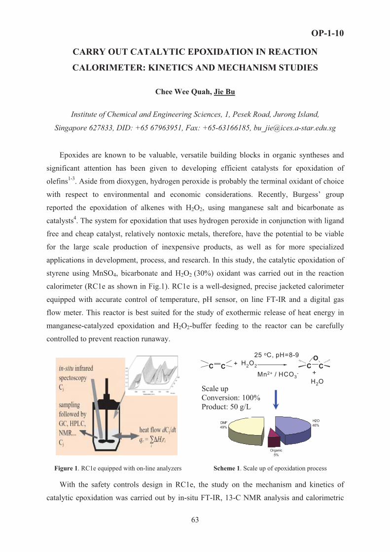
OP-1-10
CARRY OUT CATALYTIC EPOXIDATION IN REACTION
CALORIMETER: KINETICS AND MECHANISM STUDIES
Chee Wee Quah, Jie Bu
Institute of Chemical and Engineering Sciences, 1, Pesek Road, Jurong Island,
Singapore 627833, DID: +65 67963951, Fax: +65-63166185, [email protected]
Epoxides are known to be valuable, versatile building blocks in organic syntheses and
significant attention has been given to developing efficient catalysts for epoxidation of
olefins1-3. Aside from dioxygen, hydrogen peroxide is probably the terminal oxidant of choice
with respect to environmental and economic considerations. Recently, Burgess’ group
reported the epoxidation of alkenes with H2O2, using manganese salt and bicarbonate as
catalysts4. The system for epoxidation that uses hydrogen peroxide in conjunction with ligand
free and cheap catalyst, relatively nontoxic metals, therefore, have the potential to be viable
for the large scale production of inexpensive products, as well as for more specialized
applications in development, process, and research. In this study, the catalytic epoxidation of
styrene using MnSO4, bicarbonate and H2O2 (30%) oxidant was carried out in the reaction
calorimeter (RC1e as shown in Fig.1). RC1e is a well-designed, precise jacketed calorimeter
equipped with accurate control of temperature, pH sensor, on line FT-IR and a digital gas
flow meter. This reactor is best suited for the study of exothermic release of heat energy in
manganese-catalyzed epoxidation and H2O2-buffer feeding to the reactor can be carefully
controlled to prevent reaction runaway.
H2O2 C CO
C C
25 oC, pH=8-9+
Mn2+ / HCO3- +
H2O
H2O46%
Organic5%
DMF49%
Scale up Conversion: 100% Product: 50 g/L
Figure 1. RC1e equipped with on-line analyzers Scheme 1. Scale up of epoxidation process
With the safety controls design in RC1e, the study on the mechanism and kinetics of
catalytic epoxidation was carried out by in-situ FT-IR, 13-C NMR analysis and calorimetric
63

OP-1-10
data. Epoxidation in RC1 shows that scale-up can be potentially achievable up to 50 g/litres
and 100% conversion with optimization of the DMF: H2O ratio as shown in Scheme 1. For
mechanistic studies aided by on-line analyses, experiments indicate that the catalytic reactions
consist of 2 steps – (1) Formation of catalyst phase and (2) Epoxidation reaction. A possible
oxomanganese complex (Phase A, Mn-Cpx) is formed. By feeding styrene and H2O2 into the
mixture, containing phase A, a high conversion of epoxide (up to 90%) was observed, which
implies that phase A plays the role as catalyst for epoxidation. Figure 2 shows the changes of
heat flow and the conversion of epoxide during the reaction. Three distinctive peaks were
observed. The first peak indicates the formation of catalyst agent (phase A) and the second
peak shows the heat generation for the formation of epoxide.
0
0.5
1
1.5
2
2.5
3
3.5
4
0 20 40 60 80 100
Time (min)
Heat
flow
(au)
0
20
40
60
80
100Co
nver
sion
%
Formation of Phase A
Epoxidation
Yield %
HCO3
H2O2
HCO4
MnO O
O O
Mn2+
H
O
-
-
+
H2O
A
Figure 2. Reaction carried out in RC1e Scheme 2. Proposed mechanism
Calorimetric experiments confirmed that bicarbonate (HCO3-) plays an important role in
transferring an oxygen atom (from H2O2) to C=C, i.e., bicarbonate reacting with H2O2
generates peroxymonocarbonate (HCO4-)4-5, which then reacts with Mn2+ to form manganese-
peroxycarbonate complex (phase A), acting as catalyst agent to donate the oxygen to the
olefin. The proposed reaction mechanism is fully shown in scheme 2. Evidence for the
presence of this HCO4- species and the Mn-complex was shown in the NMR spectrum in
Figure 3.
H13CO3-
(aq) in DMF H13CO3-
(aq) + H2O2� H13CO4 H13CO4-
(aq) + Mn2+(aq)� Mn-Cpx
200 150 100 50 00.0
5.0x10⁷
1.0x10⁸
1.5x10⁸
2.0x10⁸
Inte
nsi
ty
ppm200 1 50 10 0 5 0 0
0
1x10 8
2x10 8
3x10 8
4x10 8
5x10 8
Inte
nsi
ty
p p m
200 150 100 50 00.0
2.0x10⁸
4.0x10⁸
6.0x10⁸
8.0x10⁸
1.0x10⁹
Inte
nsity
ppm
160 ppm
158.6 ppm
160 ppm
160 ppm
124 ppm
Figure 3. 13-C NMR spectrum
64

OP-1-10
Based on this proposed reaction mechanism in Scheme 2, the reaction kinetics was
studied and monitored using FT-IR spectroscopy as shown in Figure 4.
HCO3H2O2 HCO4
OH2
k1
k-1
HCO4 Mn2+ MnCO4 H
+k2
k-2
MnCO4 H+ k3 O
Mn2+ HCO3
H2O2
OOH2
- + - +
- + +
+ + + +-
+ +Overall Rate
Rate Expressions
k
0
20
40
60
80
100
0 30 60 90 120Time (min)
Perc
ent (
%)
0
0.1
0.2
0.3
0.4
Styr
ene
(mol
e/L)
Styrene EpoxideBy-Product Simulation
Figure 4. FTIR Spectrum ( 3-D) Figure 5. Reaction concentration profile
Chemometrics method was applied to convert the FT-IR spectrum (Fig.4) to the
concentration profile of styrene, epoxide and by-product (Fig.5). Subsequently, the overall
reaction rate constant, k, could be calculated as 1.4 L/mole.hr. The simulated curve of styrene
concentration matches well with the experimental data as illustrated in Figure 5. The kinetic
study of this cheap and efficient catalytic epoxidation enables reactor design and sizing for
future potential scale-up operations.
References 1. B. S. Lane and K. Burgess, Chem. Rev., 2003, 103, 2458. 2. E.N. Jacobsen, in: Catalytic Asymmetric Synthesis, ed. I. Ojima, ch. 4.2, VCH, New York, 1993. 3. J. Bu and H.-K. Rhee, Catal. Lett., 2000, 65, 141. 4. B. S. Lane, M. Vogt, V. J. DeRose, and K. Burgess, J. Am. Chem. Soc, 2002124 ,11946 (2002). 5. D. E. Richardson, H. Yao, K. M. Frank, and D. A. Bennett, J. Am. Chem. Soc. 2000, 122, 1729.
65

OP-1-11
CATALYST DEACTIVATION WITH RESIDUAL ACTIVITY
History, models, mechanisms and examples
N.M. Ostrovskii
AD Chemical Industry – HIPOL, Odžaci, Serbia & Montenegro
Fax: 381-25-743-452, E-mail: ostrovski @ hipol.com
The nature of catalyst deactivation with residual activity is analyzed, several models and
mechanisms are proposed, and examples of industrial processes are presented Scope of problem
It is observed in many processes that the catalyst is not completely deactivated, but
reaches a “stationary” or “residual” activity (fig. 1,2).
0.5
0.6
0.7
0.8
0.9
1
0 100 200 300q, kg/kg
&a '
� - Pt-Sn/Al2O3
� - Pt-Re/Al2O3
� - Pt/Al2O3
80
90
100
110
120
130
140
150
0 1 2 3 4 5Time on stream, h
Oxi
datio
n ra
te,
�mol
/g s
� - PdO/Al2O3
��- La-PdO/Al2O3
Fig. 1. Relative activity in heptane reforming
vs. feed loading. From [1]. Fig. 2. Oxidation rate of CH4 over Pd catalysts at
1123 K vs. time. From [2].
The existence of a residual activity was mentioned as yet in the fifties, but the suitable
models and explanations were published only in eighties [3-6].
There are two explanations of residual activity: 1 – the presence of active centers that
are not deactivated, which is wrong in most cases; 2 – the presence of reversible deactivation.
This reversibility of deactivation is not the catalyst ability to be regenerated. It means that
along with catalyst deactivation a certain process of recovery of active centers takes place
during the reaction. That is the process of “self-regeneration” [1,6] because it is provided by
the catalyst itself and with the assistance of some reagents taking part in the main reaction.
For example, in almost all hydrogenation processes the catalyst deactivation by surface
oligomers is accompanied by self-regeneration due to the saturation of oligomeric precursors
by hydrogen that is activated on the catalyst.
66

OP-1-11
The same mechanism of self-regeneration takes place in processes of naphtha
reforming, hydrotreating of distillates, paraffins isomerization and others, where the hydrogen
exceeds in circulating gas. Here the hydrogenation of coke precursors causes the self-
regeneration [8].
Another agent is water steam that provides the catalyst self-regeneration in methane
steam reforming and in some dehydrogenation processes due to the coke gasification. Finally,
in many deep and partial oxidation processes, the oxygen is not only the main reagent, but
also the agent of catalyst self-regeneration.
In all these processes the “stationary” or “residual” activity (aS) is achieved when the
rate of deactivation (rD) becomes equal to the rate of self-regeneration (rR):
t
aa(t)
1
0 0 tS
Fig. 3.
The illustration of stationary (residual) activity.
a(t) = r(t)/ro – relative activity; a aS � a(t � tS); t � tS : rD � rR . S
Several problems of catalyst deactivation kinetics can be solved easily using term of
residual activity: (i) the treating of experiments become convenient and more descriptive; (ii)
deactivation models become simpler for interpretation and for estimation of parameters; (iii)
the border between catalyst deactivation and ageing gains in physical meaning.
Mathematical model
A general equation applicable to any linear mechanisms has been derived in [5,6]:
S
SD
j
o
aaaw
wr
dtda
�1
, 1
1
!!#
� "
��
R
D
j
o
S ww
wra . (1)
In the case of any linear mechanism of main reaction and nonlinear binary deactivation
step rD = wD (i (j the equation has the following form [1]:
!!#
� "
�
�S
SDji
o
aaaaw
wwr
dtda
11)( 22
2. (2)
There is no general equation if the mechanism of main reaction is nonlinear. However,
if adsorption steps are in equilibrium, the same binary deactivation step rD = wD (i (j yields:
67

OP-1-11
!!#
� "
�
�S
SDji
o
aaaaaw
wwr
dtda
11)( 2
. (3)
It is more convenient for practice to express the relative activity (a) in terms of some
measured parameter, for example conversion at the reactor exit (X). The relation a = f (X)
depends on reaction kinetics and the type of reactor [1,7]. In the case of single first order
reaction r = k CAo (1-X) a :
in gradientless reactor k ) = Xo / (1 – Xo), and
XX
XXao
o
�1
1 , S
S
o
oS X
XX
Xa
�
11 ; (4)
in plug flow reactor k ) = – ln (1 – Xo), and
� �� �oX
Xa
�'&1ln1ln , � �
� �o
SS X
Xa
�'&1ln1ln . (5)
Then the deactivation equation in term of conversion takes the following form:
in gradientless reactor: � � � �So
SDo XX
XXXrXXdtdX
� 1 , (6)
where rD(X) = kD CAo – independent deactivation; rD(X) = kD CA
o X – deactivation by product;
rD(X) = kD CAo (1-X) – deactivation by reagent.
in plug flow reactor: � � � �� �X
XXX
XXX
dtdX o
S
o
SD
!!#
� "
�
�1ln1ln
11ln
11ln* , (7)
where *D(X) = kD CAo (1-X) ln(1-X) – independent deactivation; *D(X) = –kD CA
o X (1-X) –
deactivation by reagent; *D(X) = kD CAo (1-X) [X + ln(1-X)] – deactivation by product.
Note that in (7)
'&'&'&
�!!#
� "
�
S
S
S
o
S aaa
XX
XX
111ln
11ln , and � �
� � '&�
aXX o 1
1ln1ln .
Residual activity
According to (1) the residual activity depends on the ratio of deactivation and self-
regeneration rates wD /wR , and also on the reaction rate ro/wj. In most cases the j-th step
coincides with the rate-limiting step, then ro/wj = 1.
For example, in the case of heptane reforming (fig. 1) [1,6]:
2511
HRNDS YkYk
a
� , (8)
where YN5 , YH2 are mole fractions of N5-naphthenes and of hydrogen. Hydrogasification of
coke in heptane reforming has been studied in [8], and the effect of YH2 was examined.
68

OP-1-11
Similar approach was proposed in [9,10] for the deactivation of supported metals by
sintering, using the term of residual metal dispersion (DSS):
� �SSG DDdtdD
� * , RS
TSS DD** /1
1
� ; (9)
where *S , *R are functions of sintering and redispersion rates.
When the activity falls due to reversible deactivation and irreversible ageing, the
residual activity will also change slowly (like in fig. 2). It is possible (using term aS) to split
the complex model of such a phenomenon in two independent equations [1]:
deactivation period ( t < tS ): � �S
SAD
j
o
aaaww
wr
dtda
�1
; (10)
ageing period ( t > tS ): aa
awwr
dtda
S
SA
j
o
�
1. (11)
It means that the reaction is quasi-steady state with respect to deactivation (rD � rR << r)
and similarly deactivation is quasi-steady state with respect to ageing (rA << rD � rR).
Models like (10,11) are applicable to many industrial processes in which “quick”
deactivation is caused by poisoning, coking, surface or subsurface phase transitions, and
“slow” ageing is caused by sintering, bulk phase transitions, pores plugging, etc.
Several examples of application will be presented in the report.
Nomenclature
a = r/ro – relative activity of the catalyst; r, ro – current and initial reaction rate; wj = r/(j – weight
of key step in reaction mechanism; rD , rR – rates of deactivation and self-regeneration; (j –
intermediate (coverage) taking part in deactivation; wD = rD /(j, wR = rR /(D+– corresponding
weights; k , kD – constants of reaction rate and deactivation; ) – contact time; X, Xo, XS – current,
initial and residual conversion at the reactor exit; &a' – mean integral activity of catalyst bed; wA –
weight of ageing step.
References 1. N.M Ostrovskii, Catalyst Deactivation Kinetics, Nauka, Moscow, 2001 (in Russian). 2. Y. Ozawa, Y. Tochihara, M. Nagai, S. Omi – Chem. Eng. Sci., 2003, 58, 671- 677. 3. G.A. Fuentes – Appl. Catal., 1985, 15, 33-40. 4. J.M. Arandes, M.J. Azkoiti, J. Bilbao – Chem. Eng. Journ., 1985, 31, 137-143. 5. N.M. Ostrovskii, In “Chemical Kinetics and Catalysis. Theoretical Problems”, Chernogolovka, 1985, p.
143-150 (in Russian). 6. N.M. Ostrovskii, G.S. Yablonskii – React. Kinet. Catal. Lett., 1989 39, 287-292. 7. N.M. Ostrovskii – Kinetics and Catalysis, 2005, 46, No. 5, 693-704. 8. K. Liu, S.C. Fung, T.C. Ho, D.S. Rumschitzki – Ind. Eng. Chem. Res. 2003, 42, 1543-1550. 9. G.A. Fuentes, F.A. Ruiz-Trevino – Proc. AIChE Meeting, New York, Nov. 1987. 10. A. Monzón, T.F. Garetto, A. Borgna – Applied Catalysis A: General, 2003, 248, 279-289.
69

Section 2.Physico-chemical and mathematical bases
of the processes in chemical reactors

OP-2-1
OSCILLATIONS IN CATALYST PORES:
FROM THEORY TO PRACTICE
B. Blümich1, L.B. Datsevich2, A. Jess2,
T. Oehmichen2, X. Ren1, S. Stapf1
1 Technical University of Aachen (RWTH-Aachen), Worringer Weg 1,
D-52056 Aachen, Germany 2 University of Bayreuth, Universitaetsstr. 30, D-95447, Bayreuth, Germany
Fax: ++49 921 55 74 35. Email: [email protected], [email protected]
The oscillation theory predicts that in multiphase reactions on a porous catalyst with gas
and/or heat evolution, the alternating motion of liquid with velocities of 10-100 m/s at
frequencies more than 1 Hz can occur in pores, caused by periodical formation of gas/gas-
vapor bubbles. Such behaviour differs very much from the conventional models and
fundamentals used for description of chemical processes inside and outside the catalyst
particles (e.g. the Thiele/Zeldovich model (TZM) and the approaches to external and internal
mass transfer correlations).
In opposition to TZM where the delivery of reacting species to active centres is carried
out by comparatively slow molecular diffusion, the oscillatory motion of liquid in the parts of
pores alongside the particle shell (in the distance of oscillation penetration) leads to a
significant acceleration of internal mass transfer. That results in a change of the macrokinetic
mechanism and increases the overall reaction rate. The theoretical predictions concerning
internal mass transfer have been confirmed by the in-situ NMR observations and by the
experiments with the deuterium oxide exchange.
Fig. 1 shows an extremely chaotic pattern inside the catalyst particle in the reaction of
hydrogen peroxide decomposition; the distance of oscillation penetration can also be
distinguished (during the presentation, the movie will be demonstrated). The experimental results
of the deuterium oxide exchange are presented in Fig. 2. As can be seen, the more the reaction
rate (more intensive oscillations), the higher the values of the effective diffusivity are observed.
Oscillations in pores not only affect the mechanism of internal mass transfer, but also
have a strong impact on external mass transfer. Because of liquid motion in pore mouths, the
flow around the particle is severely disturbed. That causes a vigorous turbulence in the
71

OP-2-1
boundary layer, which, in turn, leads to a tremendous increase in mass transfer coefficients.
The dispersion coefficient (effective diffusivity) outside the catalyst pellet alongside its shell
is measured by the NMR technique. Depending on the reaction rate, the oscillations can
produce up to a 500-fold increase in external mass transfer (Fig. 3). It is noteworthy that the
influence of hydrodynamic properties in a reactor on external mass transfer can completely be
overwhelmed by the impact of oscillations (Fig. 4).
From a scientific point of view, the importance of the oscillation theory is not only that it
explains the phenomena related to mass transfer, but also that this theory explicates some
other physicochemical features observed in practice (e.g. catalyst destruction due to
cavitations, macrokinetic dependences, etc.).
The most important issue for practice is that the oscillation theory indicates the distinct
ways for process intensification by a special pore design (Table 1) or by induction of
oscillations (even if a reaction runs without them) with the help of some physical methods.
Table 1. Reaction rates of original and modified particles.
Reaction: hydrogenation of 1-octene to n-octane.
Catalyst: NISAT (Süd-Chemie) 6 mm×6 mm
Experiment Roriginal(mol/s)
Rmodified(mol/s)
Intensification factorRmodified /Roriginal
P1 2.93×10⁻⁶ 4.35×10⁻⁶ 1.48
P2 2.5×10⁻⁶ 7.75×10⁻⁶ 3.1
P3 4.53×10⁻⁶ 7.49×10⁻⁶ 1.65
P4 6.82×10⁻⁶ 8.39×10⁻⁶ 1.23
P5 5.11×10⁻⁶ 10.57×10⁻⁶ 2.07
P6 6.06×10⁻⁶ 10.23×10⁻⁶ 1.69
72

OP-2-1
Fig. 1. Spatial distribution of liquid in the catalyst pellet (Fe/Al2O3, 4 mm×4 mm) in the course of hydrogen peroxide decomposition.
0.51.01.52.02.53.03.5
0 10 20H2O2 concentration (mass %)
Def
f, os
c/D
eff,
0
30
Reaction rate
Fig. 2. Dependence of the effective diffusion coefficient of deuterium oxide Deff, osc on the reaction rate (Deff,0 -diffusivity without oscillations). Reaktion: hydrogen peroxide decomposition. Catalyst: NISAT (Süd-Chemie) 6mm×6 mm.
Fig. 3. Dispersion coefficient (effective diffusivity) outside the catalyst pellet (Fe/Al2O3, 4 mm×4 mm) alongside its shell. Initial concentration of H2O2 is (a) 22.5 % mass, (b) 7.5 % mass. (For comparison: the diffusion coefficient of H2O2 is 1.92×10⁻⁵
cm²/s.).
0.0
0.5
1.0
1.5
2.0
0 5 10 15 20 25 30
H2O2 (mass %)
Nor
mal
ized
ove
rall
reac
tion
rate
n=60 1/minn=450 1/minn=850 1/min
Stirring intensity does notinfluence on external mass transfer
Stirring intensity has some impact on external mass transfer
Fig. 4. Overall reaction rate normalized to the reaction rate at the stirring of n=60 min-1. Reaction: hydrogen peroxide decomposition. Catalyst: NISAT (Süd-Chemie) 6mm×6 mm.
73

OP-2-2
MATHEMATICAL MODELING OF SPATIO-TEMPORAL PATTERN
FORMATION IN THE NO+CO/Pt(100) REACTION
Kurkina E.S.
Lomonosov Moscow State University, Moscow, Russia
The present work is aimed at modeling of spatiotemporal concentrations patterns arising
on the Pt(100) single crystal surface in the NO+CO reaction. Recent investigations with the
photo-emission electron microscope (PEEM) have revealed a rich variety of wave trains,
spiral waves, fronts, chemical turbulence and others structures during this reaction [1]. A
four-variable mathematical model of the reaction-diffusion type was studied to describe the
self-organization phenomena [2]. This model is based on the previously developed space-
independent model, which provides very good agreement between simulation results and
various experimental facts measured on a macroscopic level. The point model successfully
reproduces temperature programmed desorption (TPD) spectra, hysteresis phenomena,
oscillatory behavior, the dependence of period of oscillations upon temperature and reactant
partial pressures, the explosive development of the reaction etc. The nonlinearities of the
mathematical model associated with lateral interactions play a crucial role in an adequate
description of complex dynamical behavior of the system.
To study the spatial behavior of the system, the diffusion terms which take into account
the influence of site-blocking on the diffusion rates, were included in the model. Under
certain condition the distributed model demonstrates an excitable dynamics. Solitary pulses,
fronts, wave trains, spatiotemporal chaos (STC) and other spatiotemporal patterns were
detected. Travelling pulses, their domain of existence, instabilities and bifurcations were
investigated in the present work. Pulses are considered as solutions of the system of four
second order differential equations with the Neiman boundary conditions in large domains in
a moving frame. The evolution of the traveling pulse solution with the changing of a
parameter was investigated by means of path-following algorithm for the travelling wave
ODEs and direct simulations in the full partial differential equations (PDE) frame with
periodic boundary condition on the large domains. Several bifurcations of pulse solutions
were revealed and examined: a saddle-node bifurcation leading to the coalescence of stable
and unstable pulses, a bifurcation in which a traveling-pulse solution ceases to exist as it
74

OP-2-2
merges with an unstable spatially uniform steady-state solution, a bifurcation through
transformation of a traveling pulse into a traveling front, etc. In particular two scenarios of
transition to spatiotemporal chaos were examined. In the first case chaos observed in the
domain of multiple spatially uniform steady states. At the bifurcation point, a branch of stable
solitary pulses collides with a branch of unstable fixed points, and a double heteroclinic
connection appears in the phase space. After the critical value of the parameter is passed,
pulse solution disappear and chaos develops in the system.
In the second scenario of transition to spatiotemporal chaos stable solitary pulses
transforms to modulated traveling pulses (MTP), due to a supercritical Hopf bifurcation. The
further changing of parameter leads to a cascade of period-doubling bifurcations of the MTP
and chaotic MTP is appeared. Finally, at some value of parameter the chaotic MTP begins to
split and as a result the complicated dynamics corresponding to spatiotemporal chaos is
observed. The spatio-temporal evolution of the system in the chaotic regime was examined.
The bifurcation analysis revealed all participants of this process such as stable and unstable
homogeneous states and pulses which are the driving forces of STC dynamics. It was revealed
self-replicated processes (SRP) and front emitting waves (FEW). Also an annihilation of two
pulses and so called ‘backfiring’ phenomenon there were detected in the model. The
considered model usually demonstrates STC dynamics of traveling type with annihilation.
2D computations revealed a variety of spatiotemporal patterns in the considered model.
They are the one-hand and two-hand spiral waves in a self-oscillating medium connected with
the self-oscillation region in the point model of the reaction, and spiral and spot chaos in an
excitable medium.
It was shown that the new reaction-diffusion model actually describes the some main
features of the experimental PEEM observations. In addition the simulation predicts various
interesting phenomena such as formation of localized pulses (stationary, oscillating and
chaotic) which probably can be discovered during experimental studies in future.
References 1. Veser G., Imbihl R. // J. Chem. Phys. V. 100. 11. �. 8483-8491. 1994.
2. E.S. Kurkina, A.V. Malykh. //Computational Mathematics and Mathematical Physics, Vol.41, No.10, 2001, pp. 1519-1531.
75

OP-2-3
TRANSIENT AND PROFILE MEASUREMENTS IN SYNGAS
FORMATION BY AUTOTHERMAL CATALYTIC PARTIAL
OXIDATION OF CH4 ON Rh FOAMS
R. Horn, N.J. Degenstein, K.A.Williams, L.D. Schmidt
Department of Chemical Engineering and Materials Science, University of Minnesota
432 Amundson Hall, 421 Washington Ave. SE, Minneapolis MN 55455, USA
e-mail: [email protected]
1. Introduction
The production of synthesis gas from methane by Catalytic Partial Oxidation (CPO) is a
process of growing importance because of the role of natural gas as an energy carrier and
chemical feedstock. In contrast to steam reforming (CH4 + H2O � CO + 3H2 (�rH, = +206
kJ/mol)), the CPO reaction is exothermic (CH4 + ½ O2 � CO + 2H2 (�rH, = -36 kJ/mol)).
Steam reforming on Ni requires contact times in the range of 1s to achieve sufficient
conversions. For the CPO reaction on Rh, CH4 conversion close to 100 % and selectivities to
H2 and CO, both > 90 %, can be achieved in a few ms [1] so that CPO reactors can operate
autothermally and are much smaller than steam reformers.
There is still a debate about the mechanism of the CPO reaction. A direct (partial oxidation)
mechanism and an indirect (combustion-reforming) mechanism are discussed in the literature
[2]. The direct mechanism assumes that H2 and CO are primary reaction products formed in
the hot oxidation zone at the catalyst entrance. The combustion-reforming mechanism
postulates total oxidation of CH4 at the catalyst entrance to CO2 and H2O, followed by steam
and CO2 reforming to H2 and CO. Here, H2 and CO are secondary reaction products. This
paper presents spatial profile and transient measurements on autothermally operated Rh
coated foam catalysts. The goal of these measurements is to obtain insight into the reaction
mechanism under conditions as close to a practical application as possible.
2. Experiments
To verify the presence of different reaction zones in the catalyst, temperature and species
profiles have been measured. These profiles are, to our knowledge, the first measured on foam
catalysts. A fine quartz capillary (o.d.=0.8mm) enclosing a type K thermocouple is moved
with sub - mm resolution through a slightly larger channel drilled through the monolith.
76

OP-2-3
The quartz capillary is connected to a capillary sampling quadrupole mass spectrometer.
Figure 1 shows the experimental setup. The
transient measurements shown here have been
done in an integral mode, i.e. the composition at
the reactor outlet was measured. Figure 2 shows
the reactor configuration. Transient
measurements at different positions in the
catalyst by combination of both experiments are
currently being performed. The C/O ratio has
been changed stepwise by switching the CH4
mass flow controller, keeping the other flows
constant. The transient data shown in Figures 4
and 5 were measured with a response time of
~1s. For the newly developed capillary system
(Fig. 1) MS response times of 50 to 100 ms
were measured. Thus transient experiments with
capillary sampling will give one order of
magnitude better time resolution. Rh coated �-
alumina foams of 16 mm diameter with 80
pores per linear inch (pore diameter ~ 0.3 mm)
have been used for all experiments. The metal
loading was typically 5 wt-%. The foams were 5
mm long for transient experiments and 10 mm
long for profile measurements.
Fig. 1 setup for profile measurements
Fig. 2 setup for transient measurements
3. Results & Discussion
a. Temperature and Species Profiles
Figure 3 shows a typical profile along the catalyst axis, measured for a total flow of 5 l/min
and a C/O ratio of 1.0 . Argon is used as internal standard. The Ar to O2 ratio of 3.76
simulates air. The profiles reveal interesting details. Oxygen is fully converted within 0.5 mm
of the catalyst entrance. CO2 is formed in the oxidation zone and remains constant afterwards.
Thus there is no indication of CO2 reforming and water gas shift. CO and H2 are formed in the
oxidation zone and also after total O2 conversion by steam reforming. The H2O profile
77

OP-2-3
(calculated from the O balance)
shows a net formation of H2O in
the oxidation zone followed by
its consumption in the reforming
zone. Approximately 1/3 of H2
and ½ of CO are formed in the
oxidation zone. At the point of
total O2 conversion (0.5 mm) the
CO profile shows a pronounced
change in slope whereas H2 does
not. The CO slope decrease
indicates that CO is partly a
direct oxidation product and
partly formed by steam reforming. When direct formation ceases due to absence of O2, the
CO formation rate is reduced to the reforming contribution. The H2 formation pathway can
not be concluded directly from the data. H2 may be formed as a direct product by immediate
recombination of two H atoms or indirect by steam reforming after a kinetically faster
intermediate H2O formation.
Fig. 3 species and temperature profiles, C/O=1, 5 l/min
The conclusion from the profiles is that the methane CPO proceeds via a mixed mechanism of
direct oxidation and steam reforming at these temperatures. An oxidation zone ~0.5 mm thick
and a steam reforming zone ~4 mm thick can be identified. H2 and CO are formed in both
zones, but in different molar ratios. The H2/CO ratio in the oxidation zone is about 1 but
increases in the reforming zone up to a final value of about 2. A clear separation between a
total oxidation zone with H2O and CO2 formation followed by a reforming zone with H2 and
CO formation as suggested by the combustion-reforming mechanism is not observed.
b. Transient Experiments
The transient data support the result of the profile measurements, that steam reforming has a
contribution to synthesis gas formation, but also reveals new aspects of the reaction. Figure 4
shows a transient experiment with a C/O switch from 0.6 – 1.0. Fig. 5 shows the H2 signal for
switches up to 1.4. O2 consumption is 100 % for all experiments. Diffusion, adsorption
reaction and desorption processes proceed on a ms time scale or faster and are not resolved by
the measurements shown here.
78

OP-2-3
What is resolved are
thermal processes ()~10 s)
and probably the buildup
and removal of multilayer
surface species (e.g. CxHy).
Also physical and
chemical changes of the
catalyst may proceed in a
time scale that is reflected
in these experiments. As
shown in Fig. 4, methane
and water increase
exponentially after the
switch from C/O 0.6 – 1.0.
H2O shows a sharp undershoot and then
increases, CH4 rises from zero. H2 and CO fall in
the same manner after a pronounced overshoot.
The curves are parallel (H2, CO) or anti-parallel
(CH4, H2O) to the measured back-face
temperature. These transients reflect the
contribution of the highly endothermic steam
reforming to the syngas production, because the
temperature dependence of this reaction is
strongest. New and surprising are the H2 (Fig. 5) and CO overshoots (not shown) after
switching back from high C/O ratios (-1.2) to 0.6. One possible explanation is that CxHy
species build up at the high C/O ratio which are removed as CO and H2 after switching back
to excess oxygen at C/O = 0.6.
Fig. 4 transient experiment C/O switch 0.6 – 1.0
Fig. 5 H2 signal for high C/O switches
The spatial and transient experiments reveal each on its own interesting details about the
reaction. Coupled spatially resolved transient experiments will supply even more information.
1 D. A. Hickman, L. D. Schmidt, Science, 1993, 259, 343. 2 A. P. E. Yorck, T. Xiao, M. L. H. Green Top. Catal., 2003, 22(3-4), 345.
79

OP-2-4
MATHEMATICAL MODELLING OF THE NONLINEAR BEHAVIOUR
DURING METHANE OXIDATION OVER Ni CATALYSTS
N.V. Peskov, M.M. Slinko*, V.N. Korchak*
Department of Computational Mathematics & Cybernetics, Moscow State University,119899, Moscow, Russian Federation
*Institute of Chemical Physics, Russian Academy of Science, Kosygina Str. 4, 119334, Moscow, Russian Federation
In the last years the oscillatory behaviour during methane oxidation was discovered by
different groups of experimentalists over variety of Ni catalysts including wires, foils, foams
and the review of experimental results can be found in the paper of Zhang et. al [1]. Although
the properties of oscillations described by various groups were different in all studies it was
generally suggested that oscillatory behaviour over Ni catalysts originates due to the repetitive
cycles of oxidation and reduction of the metal surface. However no any mathematical model
of this process producing the oscillatory behaviour has been developed and the detailed
mechanism of oscillations has not been understood. The goal of this study is to develop the
mathematical model, which can produce the oscillatory behaviour during methane oxidation
over Ni catalysts at realistic values of parameters and to explain the possible origin and the
mechanism of the observed reaction rate oscillations.
Recently Bychkov et al. [2] have studied the oscillatory behaviour during methane
oxidation over Ni foam using thermogravimetric analysis combined with on-line mass-
spectrometry analysis of the gas phase. It was shown that oscillatory behaviour of the weight
was defined mainly by the amount of oxygen associated with the nickel oxide in the catalyst.
It was also discovered that the maxima in temperature oscillations corresponded to the
maxima in weight oscillations, i.e. to the oxidised state of the Ni catalyst. Mass-spectrometric
analysis of the obtained products revealed that maxima in the rates of CO2 and H2O coincides
with the maxima of weight and temperature (oxidised state), while maxima in CO and H2
production rates correspond to the minimum weight and temperature oscillations (reduced
state). Basing on these experimental and literature data it was suggested that nickel catalyst
contains both oxidised and reduced surfaces (Ni0/NiO surface). On the reduced surface steps
1-6 proceed including CH4 and O2 adsorption, step 7 describes the transformation of the
adsorbed oxygen into the nickel oxide and finally steps 8-10 correspond to the reduction of
the nickel oxide.
80

OP-2-4
1. CH4 + 5[Ni0] � [Ni0-C] + 4[Ni0-H]2. O2 + 2[Ni0] � 2[Ni0-O]2r. 2[Ni0-O] � O2 + 2[Ni0]3. [Ni0-C] + [Ni0-O] � [Ni0-CO] + [Ni0]4. [Ni0-CO] � [Ni0] + CO5. 2[Ni0-H] � H2 + 2[Ni0] (1) 6. [Ni0-O] + 2[Ni0-H] � 3[Ni0] + H2O7. [Ni0-O] � NiO 8. 4[NiO] + CH4� CO2 + 2H2O + 4[Ni0]9. 2[NiO] + [Ni0-C] � CO2 + 3[Ni0]10. [NiO] + 2[Ni0-H] � 3[Ni0] + H2O
To simulate the surface phase transitions the variable s, 0 . s . 1, indicating the
fraction of the reduced surface was introduced. Correspondingly, so = 1s denotes the fraction
of the oxidized surface. The variables x1, x2, x3, x4, indicate the average coverages of C, O,
CO, and H on the reduced surface. The relation with respecting coverage on the whole surface
Xi is the following: Xi = xis. The equations for the evolution of xi consider the fact that xi can
change not only due to the surface reactions, but also due to the variation of the area of the
reduced surface. In this case the mathematical model, corresponding to the mechanism (1) and
describing the dynamic behaviour of the surface coverages, catalyst temperature, partial
pressures of reactants can be formulated as follows:
� �� �
� �� �
).()(
,)(
.)(
;2224,
,22,
,24
22221
2
81141
1
107
610
4106514
3433
2763222
19311
10987
�
�/
�/
�/
�/�/
�/�/
0�/
��
RRspPp
RsRpPp
RqRqsTTT
sfxsRRRRxsfxRRx
sfxsRRRRRxsfxsRRRx
fRRRRs
O
CH
iii ii
s
s
s
s
s
$)
$$)
���
(2)
Here PCH4, PO2, and T0, indicate the partial pressures of CH4 and O2 in the inlet gas mixture
and initial gas phase temperature. p1 and p2 denote the partial pressures of CH4 and O2 in
reactor, and T – the catalyst surface temperature. � = (hS)/(WCp); � = (SN)/(WCp); $ =
(SNRT0)/V; ) = V/F, where: h is the heat transfer coefficient, S – the catalyst surface area, W –
the catalyst weight, Cp – the catalyst heat capacity; N – the adsorption capacity of Ni; R – the
universal gas constant, V – the reactor volume; F – the flow rate of the reactant mixture, qi –
the heat effects of the corresponding studies of the reaction mechanism.
The results of mathematic modelling are demonstrated in Figures 1a, 1b. The model
produces oscillatory behaviour at realistic experimental conditions and values of parameters.
81

OP-2-4
a) b)
1020
1040
1060
1080
1100
1120
Tem
pera
ture
[K]
0 1 2 3 4 50
100
200
300
400
500
6001
43
21
O2
CH4
Pre
ssur
e [T
orr]
Time [min]
0.7
0.8
0.9
1.0
1
43
21
Reduced surface
s
0.0
0.3
0.6C coverage
x 1s
0.0
0.5
1.0O coverage
x 2s
0.0000
0.0003
0.0006
0.0009 CO coverage
x 3s
0 1 2 3 4 50.000
0.002
0.004 H coverage
x 4s
Time [min]
Figure 1. a) Calculated variations of temperature and partial pressures of reactants at PCH4 = 570 Torr, PO2 = 190 Torr, T0 = 1023 K. b) Simulated oscillations of reduced surface s and surface species coverages xis.
The mechanism of oscillations may be presented as follows: during the period of time
1-2, the system is in the so-called “oxidised state”. Here the temperature increases due to the
exothermic reactions, proceeding on the NiO and the oxygen concentration in the gas phase
decreases. At some temperature the rate of the catalyst reduction becomes larger than the rate
of the catalyst oxidation and the system moves to the so-called “reduced state” indicated as 3-
4. At this point the temperature decreases, because less exothermic reactions producing CO
and H2 occur on the reduced Ni surface. Although CH4 is in the excess in the gas phase, the
concentration of O surface atoms increases, while the concentration of C atoms decreases.
This is the result of the competition of CH4 and O2 for the free sites. As O2 adsorption needs
less free active sites, at some temperature the surface is covered by oxygen and the system
moves to the oxidised state.
The results of mathematical modelling showed that the thermokinetic oscillations
during methane oxidation originate on the “reactor level”. This means that the pressure
variation in the reactor is the essential condition for the appearance of the oscillatory
behaviour and parameters of the reactor play the important role in the generating of the
oscillatory behaviour.
Acknowledgment This work was supported by the Russian Foundation for Basic Researches (grant N
05-03-33128).
References [1] X.L. Zhang, C.S-M. Lee, D.M.P. Mingos, and D.O. Hayward, Catal.Today, 105 (2005) 283-294.
[2]. V.Yu. Bychkov, Yu.P. Tulenin, V.N. Korchak, and E.L. Aptekar, Appl. Catal. A, to be published
82

OP-2-5
MODELLING OF PARTICLE GROWTH: APPLICATION TO WATER
TREATMENT IN A FLUIDIZED BED REACTOR
R. Aldaco, A. Garea, A. Irabien
Deportamento Ingeniería Química y Química Inorgánica, Universidad de Cantabria
ETSIIyT. Avda. de los Castros s/n. 39005 Santander, SPAIN
Tel: +34942201597, Fax: +34942201591, Email: [email protected]
Introduction
Crystallization in a fluidized bed reactor (FBR) has been used in different water and
wastewater treatment plants, including water softening of drinking water, phosphate and
fluoride removal, and heavy metal recovery from wastewaters. When it is compared with the
chemical precipitation process, the major advantage of this technology is the decrease of
sludge formation, the simplification of the materials recovery procedures and the reduction of
solid wastes.
In the modeling, design and control of a FBR for water treatment it is necessary to study the
particle growth kinetics. The properties of the particles in a crystallization process depend
mainly on the crystal growth rate and nucleation kinetics, which control the final properties of
the solid product. The crystal growth is a complex mechanism that includes many factors
depending on different variables: dispersion, supersaturation, crystal size, solution velocity,
admixtures, magnetic field, temperature, and pH. The model allowing the mathematical
description of the variables is still very complex and a general expression of crystal growth is
difficult to establish, especially for sparingly soluble systems.
This work summarizes the experimental study of crystal growth of calcium fluoride on
granular calcite as seed material in a FBR. It has been studied the influence of the main
variables on the crystal growth and a mechanism of crystal growth has been suggested.
Materials and methods
The Fluidized Bed Reactor (FBR) is based on the crystallization of CaF2 upon seed material
instead of mass precipitation in the liquid phase [1,2].
The laboratory FBR consists of a methyl methacrylate cylindrical vessel partially filled with
granular calcite as the seed material. The fluoride water and calcium reagent solution are
pumped upward through the reactor at a velocity that ensures the fluidization of the pellets so
that cementing of grains is prevented [2].
83

OP-2-5
84
A typical run consists of adding about 70g of sieved granular calcite as seed material and
controlling the solution velocity so that the solids are uniformly suspended in the FBR. In
order to determine the influence of the variables on the calcium fluoride growth, the
superficial velocity (SV) in the reactor was changed in the range 21-45 m·h-1, the initial
particle size (L0) of granular calcite was between 260-580 �m, and the supersaturation (S)
was between 6.4 and 38.5.
During the operation, the grains increase in diameter and fluoride-coated calcite grains
(pellets) were removed from the bottom of the reactor at different times. The pellets were air
dried and the particle size was determined by Laser-Ray Diffraction (Mastersizer S, Malvern
Instruments).
Results and discussion
1
1,1
1,2
1,3
1,4
1,5
1,6
1,7
0 10 20 30 40
time (h)
L/L 0
(-)
1
1,1
1,2
1,3
1,4
1,5
1,6
0 10 20 30 40
time (h)
L/L 0
(-)
1
1,05
1,1
1,15
1,2
1,25
1,3
1,35
1,4
1,45
0 10 20 30 40
time (h)
L/L 0
(-)
Figure 1 shows the dimensionless particle size of
the pellets as a function of time when the
supersaturation, the particle size of the seed
material and the superficial velocity change. The
superficial velocity in the reactor, the
supersaturation and the initial particle size of the
seed material show an influence in the growth
rate of the calcium fluoride pellets in a FBR.
S=19,2
S=6,4
S=38,5
L0=580 �m
L0=260 �m
L0=470 �m
SV=45 m·h-1
SV=33 m·h-1
SV=21 m·h-1
(i)
(ii)
A general model from the growth has been fitted
according to the following equation:
jnm0g S SV L K
dtdLG �� (1)
where G is the overall linear growth rate (m·s-1),
L is the size of the particle (m), Kg is an overall
crystal growth coefficient , and m, n and j are the
crystal growth orders referred to the initial
particle size, superficial velocity and
supersaturation respectively.
(iii)
The experimental results have been fitted to the
model by the following equation: Figure 1. Influence of the (i) supersaturation, particle size (ii) and superficial velocity (iii) on the crystal growth of CaF2 as a function of time.
1.010.491.370
5 S SV L 2.96·10G � R2=0.969 (2)

OP-2-5
0,0
5,0
10,0
15,0
20,0
25,0
0 10 20 30 40
S (-)
G (
10-1
0 m
·s-1
)
Figure 2. Influence of the supersaturation (S) on the overall linear growth rate.
Experimental results Predicted values
From Figure 2 it is possible to deduce that the growth
rate increases linearly with the supersaturation. The
reason of this influence can be explained in terms of the
concentration driving force for crystallization [3].
Figure 3 shows that at a given supersaturation and
particle size of seed material, the growth rate increases
with the superficial velocity in terms of the particle
Reynolds number. Mass transfer between fluidized
solid particles and liquid has been studied extensively
over a wide range of Reynolds numbers [4].y = 0,496x - 21,29
R2 = 0,959
-21,00
-20,95
-20,90
-20,85
-20,80
-20,75
-20,70
-20,65
-20,60
-20,55
0,0 0,5 1,0 1,5 2,0
Ln (Re)
Ln (
G)
Figure 3. Linear fitting of the overall linear growth rate and the particle Reynolds number (Re).
It appears that most of the reported experimental data
can be adequately described by the following
correlation:
Sc Re BSh 1/31/21� (3)
where Sh is the Sherwood number, B1 is a constant, Re
is the particle Reynolds number and Sc is the Schmidt
number.
The experimental results agree well with the
correlations proposed in the literature. Therefore, the
influence of the superficial velocity on the growth rate
is related to the convective mass transfer.
0,0
5,0
10,0
15,0
20,0
25,0
0 100 200 300 400 500 600
L0 (10-6 m)
G (
10-1
0 m
·s-1
)
Figure 4. Influence of the particle size of the seed material (L0) on the overall linear growth rate.
Experimental results Predicted values
Results of linear growth rate for different sizes of
granular calcite are depicted in figure 4. The particles
with larger size have higher growth rate than, those
with smaller sizes. The overall linear growth rate may
be the addition of two mechanisms: 20
0.52
5.01 L S SV K S SV KG � (4)
where the first term on the right hand side of the equation arises from aggregation of fines
formed by homogenous nucleation in the liquid phase, and the second from molecular growth
upon the surface of the seed material. Thus, the crystal growth by aggregation is a function of
the superficial velocity and the supersaturation, and the crystal growth by molecular growth is
a function of the superficial velocity, the supersaturation and the particle size of the seed
material. Therefore, the overall linear growth calcium fluoride pellets in a FBR may be
85

OP-2-5
described according to the flowing equation:
0
5
10
15
20
25
0 5 10 15 20 25
Gpredicted (10-10 m·s-1)
Gex
peri
men
tal (1
0-10 m
·s-1)
Figure 5. Parity graph for predicted values of overall linear growth rate by the proposed model of crystal growth of calcium fluoride in a FBR.
S SV )L KK(G 0.52021 � (5)
where K1, the crystal growth rate coefficient by
aggregation, and K2, the crystal growth rate
coefficient by molecular growth, are 2.26·10-10
and 2.82·10-3 respectively.
The correlation between the experimental and
predicted values of G is shown in Figure 5. The
correlation coefficient of the fitting was 0.980,
which agrees well with the experimental data.
Conclusions
Based on the results of this work, it can be concluded:
(i) The increase of the superficial velocity in the reactor, the supersaturation and the
particle size of the seed material leads to an increase of the linear growth rate of the
calcium fluoride in a FBR. The pellets growth in a FBR takes place by aggregation of
fines and molecular growth onto seed material.
(ii) It has been applied a crystallization model based on the aggregation and molecular
growth mechanisms, which allows the introduction in the mass balances of the
industrial process after calculation of the parameters K1 and K2. The model is useful
in the design, operation and control of Fluidized Bed Reactors for water treatment.
Acknowledgements
The authors gratefully acknowledge the financial support of the Ministry of Science and
Technology of Spain through the project No. PPQ2003-00546.
References [1] Aldaco, R., Irabien, A., Luis, P. 2005.Fluidized bed reactor for fluoride removal. Chem.Eng.J., 107,113-117.
[2] Aldaco, R., Garea, A. Irabien, A. 2006. Fluoride Recovery in a Fluidized Bed: Crystallization of Calcium Fluoride on Silica Sand. Ind. Eng. Chem. Res. 45(2), 796-802.
[3] Tai, C.Y., Chien, W.C., Chen, C.Y. 1999. Crystal growth kinetics of calcite in a dense fluidized-bed crystallizer. AIChE J., 45(8), 1605-1614.
[4] Yang, J., Renken, A. 1998. Intensification of mass transfer in liquid fluidized beds with inert particles.Chem. Eng. Process, 37(6), 537-544.
86

OP-2-6
ANALYSIS, MODELING AND SIMULATION OF CATALYTIC
PROCESS OF HIGH PURITY ETHYLENE PRODUCTION
E.V. Pisarenko1, V.N. Pisarenko1 and A.Sh. Ziyatdinov2
1D. Mendeleyev University of Chemical Technology of Russia, Moscow, Russia 2JSC “Nizhnekamskneftehim”, Nizhnekamsk, Russia
In present century, there is a tendency of stable growth of low olefins production
capacities, in particular, ethylene in the Russian Federation. Prices for these products go up as
well. The main industrial process of ethylene production is thermal pyrolysis of hydrocarbons
of gasoline fraction of crude oil. Gaseous pyrolysis products are separated in ethane-ethylene
fraction, propane-propylene fraction and butane-butylene fraction.
Ethane-ethylene fraction usually contains up to 1 % mass. of acetylene. The purification
of ethane-ethylene fraction from acetylene is performed by catalytic hydrogenation reactions.
However, the technology of catalytic hydrogenation of acetylene in ethane-ethylene fraction
needs some improvements due to significant loses of ethylene.
The aim of given research was to develop new catalytic system and improved technology
of the process of ethylene purification from acetylene in ethane-ethylene fraction of pyrolysis
gases without any ethylene loses and even slight increase in ethylene in the reaction products.
First, efficient catalyst composition has been selected. The composition of active centers
among classes of palladium-oxide catalysts, active centers distribution over inner and outer
surface of the catalyst grain, pore distribution, grain size and geometry have been selected.
As a result of this research work, new catalyst sample with 0.04 % mass. of Pd was
synthesized. Micro quantities of metals of I and II group of the Periodic Table served as
promoters in this reaction. � - Alumina oxide was used as a catalyst support. For new catalyst
“CPNM-45” technological production documentation was developed. According to this
documentation 4 tons of new catalyst was manufactured at JSC “Niznekamskneftekhim”.
Second, the detailed mechanism of ethylene and acetylene hydrogenation reactions over
“CPNM-45” catalyst was determined. Kinetic model was derived for the mechanism
proposed. Kinetic parameters were estimated by the results of 48 experiments carried out in
flow circulating reactor operating under pressure. Bartlett and Hagao criteria were used to
prove the adequacy of the model to experimental data.
87

OP-2-6
Third, efficiency factors of the catalyst grain operation with respect to all reactants and
reaction routes corresponding to final reaction equations were estimated. The pilot plant
reactor with catalyst volume of 4 liters was designed and built. Based on the results of pilot
plant experiments, reactor model macrokinetic parameters were estimated and the model
adequacy to experimental results was demonstrated.
While carrying out pilot plant experiments, the appearance of some periodic oscillation
regimes of the reactor performance was noticed. The reactor model allowed one to determine
physical - chemical nature of the appearance of periodic oscillations in certain reaction zones.
Industrial two sectional reactor of ethylene purification from acetylene with ethylene
productivity of 70000 tons per year was loaded with new catalyst. Reactor start and optimal
regimes of its operation were carried out according to the results calculated due to the model.
Within first 8000 hours of the reactor operation, ethylene increase reached 0.2 % mass,
then for next 8000 hours – ethylene increase was 0.1 % mass. Volumetric flow rate was kept
at 2700 inverse hours. The results of industrial run of CPNM-45 catalyst showed its high
selectivity, activity and the possibility of long and stable service life without deactivation.
Overall run of pilot plant was 35000 hours.
88

OP-2-7
DIMENSIONAL ANALYSIS AS A TOOL FOR SCALING UP AND
DOWN STEAM CRACKING COILS
K.M. Van Geem, R. Žajdlík, M.-F. Reyniers, G.B. Marin
Laboratorium voor Petrochemische Techniek, Ghent University, Gent, Belgium
Abstract
Steam cracking is an endothermic process and is operated at high temperatures. Next
to the intrinsic chemical kinetics, heat and mass transport processes, which are scale
dependent, affect the product yields. Product yields obtained in small and large scale reactors
will only be identical provided that mass and heat transfer processes are similar and the
"chemistry" remains the same. Two different approaches are commonly applied in scale-up
and scale-down: direct experimental scale-up and mathematical modeling. Mathematical
modeling is the most attractive solution because it has the advantage that once the model is
developed, results can be gathered easily and computer simulations take only a limited time.1
One of the major challenges in this method consists of developing a fundamental reaction
network. Moreover fundamental kinetic models work with a detailed feedstock composition
and obtaining this information for naphtha’s, gas oils and VGO’s is not straightforward.
Therefore, direct experimental scale-up remains an interesting option and developing a pilot
plant set-up, although expensive, is still done quite often.2
Table 1: Typical dimensions and operating conditions used in steam cracking reactors of different scale
Laboratory scale reactor Pilot Plant reactor Industrial
reactorReactor length (m) 1 - 2 10 - 25 10 - 100 Tube diameter (m) 5.10-3 – 1.10-2 5.10-3 – 2.5 10-2 3.10-2 – 1.5 10-1
Flow rate (kg s-1) 5.10-5 – 5.10-4 5.10-4 – 1.10-2 10-2 - 1 Pressure drop (MPa) < 0.01 0.02 – 0.06 0.07 – 0.15 COT (K) 850 – 1100 900 – 1200 1000 – 1200 Residence time (s) 0.1 – 8 0.1 – 1 0.1 – 1 Re 102 4.103 - 1.104 1.105 - 5.105
Direct experimental scale-up requires little or no mathematical treatment and is based upon a
large experimental data set. A problem is that the differences in dimensions and in typical
operating conditions between industrial reactors, pilot plant reactors and laboratory scale
reactors are significant, see Table 1, and evidently this will result in differences between
89

OP-2-7
conversions and product yields obtained at different reactor scales. Basically, the direct
experimental scale-up consists in the construction of a small scale unit similar to an industrial
one and operating it under conditions of complete or partial similarity. According to the
theory of similarity, two processes can be defined as similar if they take place in a similar
geometrical space, and if all the dimensionless numbers necessary to describe the process,
have the same numerical value.3 The dimensionless numbers can be determined based on a
detailed mathematical description of the steam cracking process.4 If a 2-dimensional reactor
model is used and back mixing is neglected, then the dimensionless energy and continuity
equation for a component j are given by:
���!!#
� "
�12
21
122
1
22
iiVj,iI
jja 'rDa
'C'D1
Pe1)'C'v(
'z
[1]
� ��!#
� "
�1232
41122
13
22
iiVirIIa 'r)'H(Da'1Fo)'v(
'z
[2]
with: Lv
D4dPe
0a
0e
2t� ;
0
0V
0a
I Cr
vLDa � ; 2
tgp
0
0a dc
4vLFo
54
� and 0
gP
r
0a
0V
II TcH
vrL
Da5
��
If only friction with the wall is taken into account and radial pressure gradients are neglected,
the momentum equation can be transformed into the following dimensionless form:
� �2
at 'v
Eu1
'dz'dp
�
[3]
with: � � Lvf2pdEu 20
ag
0tt
5�
Analysis of these dimensionless model equations reveals that complete similarity of 2
different tubular reactors is impossible.3,5 All the dimensionless numbers defined in equations
[1-3] correspond with criteria of process-related similarity. Complete similarity requires
geometrical, material, and process-related similarity.3 However the criteria corresponding to
process-related similarity, geometrical similarity [equal L/dt-ratio] and hydrodynamic
similarity [equal Re-number] cannot be met simultaneously3,5 and therefore both geometrical
similarity and hydrodynamic similarity are usually abandoned. Scale-up is thus only possible
under partial similarity and inevitably this leads to differences. However, careful relaxation of
90

OP-2-7
the similarity criteria limits differences between units of different scale. Further analysis of
the dimensionless model equations shows that, even when allowing for hydrodynamic and
geometrical dissimilarities, problems with realizing a similar temperature and pressure profile
remain. Similarity of the radial temperature profile, i.e. equal Pe and Fo numbers, and of the
pressure profile, i.e. equal Eu number, in two tubular reactors for steam cracking implies that
these reactors need to be identical. Hence, two different relaxation strategies are available: the
first one aims at realizing similarity of the pressure profile and neglecting radial non-
uniformities [equal Eu; different Pe and Fo]; the second focuses on similarity of the radial
temperature profile [equal Pe and Fo; different Eu]. Neglecting the similarity of the radial
temperature profile leads to more important differences compared to the differences resulting
from neglecting the similarity of the axial pressure profile. The radial temperature drop in an
industrial reactor differs significantly from the one observed in a pilot plant reactor under
similar operation conditions.6 In the case of ethane cracking, differences between units of
different scale resulting from relaxation of the similarity of the radial temperature profile can
be up to 4.0 % (rel.) for the conversion and up to 1.2 % (rel.) for the ethylene yield. Similar
conclusions are found for n-butane cracking. The preceding insights can be applied to design
a so-called ideal pilot plant reactor for a given industrial reactor, i.e. a pilot reactor with a
similar radial temperature profile as the reference industrial scale reactor. Creating a unit with
a similar radial temperature profile requires that the different reactors have identical
diameters. The length of the reactor can be chosen freely, as long as the pilot plant reactor is
operated under an average pressure identical to that of the industrial unit. However, practical
considerations also affect the design of the pilot plant reactor. The minimum diameter of the
pilot reactor tube is limited by the need to measure process variables, such as gas phase
temperature. As the dimensions of the furnace are limited, the reactor length should not be
more than 20 m long. The recommended range of dimensions and operating conditions of the
ideal pilot reactor are specified in Table 1. Taking into account these practical limitations
result in a recommended length of 20 m and a diameter of 2.5 10-2 m for the ideal pilot plant
reactor for scale-down of a Lummus SRT-I reactor or a Millisecond reactor. The total flow
rate (hydrocarbons + steam) should be higher than 2.0 10-3 kg s-1 to guarantee turbulent flow
in the pilot reactor (Re>4000). Note that, although "ideal", imperfections remain and some
differences between product yields obtained in the pilot plant reactor and the industrial reactor
will always remain as the radial temperature drop is still significantly lower in the ideal pilot
reactor under similar conditions. This pilot plant reactor is also ideal for studying coke
formation but is not perfectly suited to study intrinsic kinetics because in practice it is not
91

OP-2-7
possible to accurately measure the radial temperature profile at a given axial position. To
study intrinsic kinetics, the radial temperature drop should be kept as small as possible, and
hence, the diameter of the reactor should be as small as possible.
Acknowledgments
Kevin M. Van Geem holds a Ph.D. grant of IWT-Vlaanderen.
References
1. Dente, M., Ranzi, E., Goossens, A.G., (1979). Detailed prediction of olefin yields from hydrocarbon pyrolysis through a fundamental simulation model (SPYRO). Comp. & Chem. Eng., 3, 61-75.
2. Pinter, A., Tungler, A., Nagy, L., Vida, L., Kovacs, I., Kerezsi, J., (2004). A laboratory steam cracking reactor to characterize raw materials. International Journal of Chemical Reactor Engineering, 2, A15.
3. Zlokarnik, M., (2002). Scale-up in chemical engineering. Wiley-VCH, Weinheim.
4. Himmelblau, D.M., Bishoff, K.B., (1968). Process analysis and simulation. J. Wiley, New York.
5. Van Geem, K.M., Heynderickx, G.J., Marin, G.B., 2004. A comparison of one and two-dimensional reactor models for steam cracking: effect on yields and coking rate. AIChE Journal, 50, 173–183.
6. Damköhler, G.Z., (1936). Einflüsse der Strömung, Dffusion und des Wärmeübergenges auf die Leistung von Reactionsöfen. Electrochemie, 42, 846-862.
List of Symbols
C concentration kmol m-3 cp heat capacity kJ kmol-1 K-1
D Diffusion coefficient m² s-1 Da Damköhler number -
dt internal tube diameter m Eu Euler number -
f Fanning friction factor - �rHk standard reaction enthalpy kJ kmol-1
L reactor length m pt total pressure MPa
Pe Peclet number - rV reaction rate kmol m-3 s-1
Re Reynolds number - T process gas temperature K
v velocity m s-1 z axial coordinate m
Greek symbols
� dimensionless temperature - � thermal conduction coeff. kJ m-1 s-1
�g density kg m-3 � normalized radial position -
� stoechiometric coefficient - � dynamic viscosity MPa s
Sub- and superscripts
0 initial a axial
r radial ‘ dimensionless
92

OP-2-8
SPATIOTEMPORAL PHENOMENA IN CATALYTIC CO
OXIDATION: SIMULATION RESULTS
V.V. Volkovskii, N.L. Semendyaeva, E.S. Kurkina
Moscow Lomonosov State University, Faculty of Computational Mathematics & Cybernetics
Leninskie Gory, Moscow, 119992, GSP-2, Russia, E-mail: [email protected]
The catalytic CO oxidation is an important reaction of ecological catalysis demonstrating complex behavior. Real time observations of supported catalysts, metal tips, nanostructured composite surfaces, single crystals of Pt-group metals by means of different microscopic techniques have detected propagating fronts, target patterns, rotating spirals, standing waves, solitary pulses, chemical turbulence [1]. In order to understand the origin and driving forces of these non-linear phenomena a new strategy for research of heterogeneous reactions has been applied [2]. Namely, a system of consistent mathematical models of various space scales has been constructed and investigated, and a comparative analysis of the reaction dynamics produced by different mathematical models has been performed. The system includes Monte Carlo (MC) simulations of a lattice gas (LG) reaction model, mean-field (MF) ordinary differential equations (ODEs) and reaction-diffusion equations (RDEs).
Fig. 1.
Our investigations revealed three types of oscillatory-like behaviour of the CO+O2
reaction on an atomic scale. In the first case oscillations are caused by chemical kinetics. They exist both in small scale LG and MF models in the oscillation region of the latter. RDEs and large scale LG model under the same conditions can reproduce experimentally observed spatio-temporal structures formation on the micrometer and millimetre scales – travelling pulses (fig.1, MC data) and spiral waves (fig. 2, MC data).
93

OP-2-8
Fig. 2.
Two other types of oscillatory-like behaviour on microscopic level are conditioned by internal fluctuations. Fluctuation-driven transitions from high-reactive stable steady state to low-reactive one (the second type) occur in the region of bistability of the MF model. Transitions take place in an immobile adsorption layer and are induced by internal fluctuations. In the numerical experiments based on RDEs or large scale LG models one can obtain propagating reaction fronts under the same conditions (fig. 3, MC data).
Fluctuation-induced oscillations of the third type take place in the monostable region of the MF model in consequence of the excitable nature of the stable steady state. Atomic scale stochastic models demonstrate excitable dynamics due to internal noise. Excitable dynamics of deterministic systems must be maintained by external conditions. In reaction-diffusion systems and large scale LG models the excitation region can expand forming a travelling pulse (in 1D) or a spiral wave (in 2D).
The presented results allow one to predict, understand and explain the complex nonlinear dynamic behavior of the CO+O2 reaction system over Pt-group catalysts.
Fig. 3.
References [1] R. Imbihl, G. Ertl // Chem. Rev. 95(1995) 697.
[2] E.S. Kurkina, N.L. Semendyaeva // Surf. Sci. 558 (2004) 122.
94

INVESTIGATION OF N2O DECOMPOSITION AND SURFACE
OXYGEN FORMATION ON Fe-MFI WITH TRANSIENT RESPONSE
METHODS
Ayten Atesa and Andreas Reitzmannb
aDepartment of Chemical Engineering, Engineering Faculty, Cumhuriyet University,
58140 Sivas, Turkey. Email: [email protected], Fax:+9003462191179 bInstitut für Chemische Verfahrenstechnik, Universität Karlsruhe, Kaiserstraße 12
76128 Karlsruhe, Germany, [email protected], Fax: +497216086118
The general aim of this work is to study the elementary steps of the N2O decomposition
on iron containing MFI zeolites with transient response methods, namely multi-pulse and step
techniques combined with temperature programmed desorption. Both methods should be
compared due to their applicability to determine the formation and amount of an surface
bound oxygen species. In addition, the global kinetics was determined from steady state
experiments at different residence times and temperatures. The formation of an atomic surface
oxygen should be linked to the global rate of N2O decomposition.
Introduction
In general, investigations under steady-state conditions give information on global
kinetics of reactions, but are not very informative about the reaction mechanisms and the
surface species involved. Therefore, regarding these aspects transient studies are believed to
give an further insight in the proceeding of a reaction. The decomposition of nitrous oxide is a
well known and important example where these techniques have been applied. The following
mechanism is generally accepted when different catalysts are applied:
Z + N2O � N2 + Z–O (1)
2 Z–O � O2 + 2 Z (2)
Z–O + N2O � N2 +O2 + Z (3)
Iron containing zeolites of MFI type are particularly interesting, because they have been
successfully applied in the abatement of N2O in waste gases as well as in partial oxidations of
aromatic hydrocarbons with N2O. Since for both applications the first step of the mechanism
(Eq. 1) is important where an atomic surface bound oxygen species is formed, many
investigations in the literature focus on it. Besides of experiments in a static vacuum set-up
OP-2-9
95
combined with 18O isotope exchange reactions and step-experiments, we proposed recently a
multi-pulse method which allows a quantitative tracing of the surface bound oxygen
formation [1,2]. Temperature programmed desorption and the CO reduction with the oxygen
loaded zeolites revealed that several oxygen species with different stability and reactivity
exist. Particularly, the role of molecularly adsorbed N2O cannot be neglected, on MFI zeolites
with high iron content.
Experimental
Iron containing MFI samples were prepared by a solid - state ion exchange with
FeCl2 · 4 H2O as described in [1,2 ]. The standard sample (Fe-MFI-A) has a Si/Al ratio of 11.5
and an Fe/Al ratio of 0.75 (5.66 % (wt./wt.) Fe). Prior to all experiments, catalysts were
pretreated with Helium at 500 °C. Temperature-programmed and transient studies of N2O
decomposition were performed in a set-up for catalyst characterisation (Autochem 2910,
Micromeritics) containing a quartz glass reactor (i.d. 9 mm). The reaction products were
monitored in an on-line mode using a quadruple mass spectrometer (QMS 422; Pfeiffer
Vacuum). Multi-pulse experiments were performed as described in [1,2] in a temperature range
of 150- 500 oC by injecting 0.31 μmol N2O via a sample loop into a helium flow and over the
catalyst, respectively. Step experiments were carried out according to the procedure proposed
by Kiwi-Minsker et al [3] and Wood et al. [4] at 150 – 300 °C (1 % (v/v) N2O / 1 % (v/v) Ar /
98 (v/v) % He). Steady-state kinetics were studied in the temperature range 150 to 500 oC and
under different residence times with N2O inlet concentrations of 1000 ppm (v/v) and 1 % (v/v)
in a quartz fixed bed reactor (i.d= 11.5 mm; L= and 250 mm). N2O concentrations were
determined by the non-dispersive infrared spectroscopy (Binos, Leybold Heraeus).
Results and Discussion
Multipulse technique
Figure 1 shows an exemplary result of the multi pulse studies at 250 °C for different
amounts of Fe-MFI-A. No molecular oxygen was detected during the pulse sequence. The
amount of surface oxygen calculated by summarizing the formed N2 was in each case 40 -
41 μmol/g. The shape of the curves is determined by the residence time of the pulses in the
catalyst bed, which was also found for different flow rates. Therefore this technique provides
a suitable method to determine the surface oxygen content. It has been successfully applied to
other zeolites with different Si/Al ratio and Fe content (not shown).
Subsequent temperature programmed desorption experiments revealed that oxygen
desorbed in two steps up to 900 °C, but only about 1/3 up to 500 °C. Moreover, N2O also
OP-2-9
96
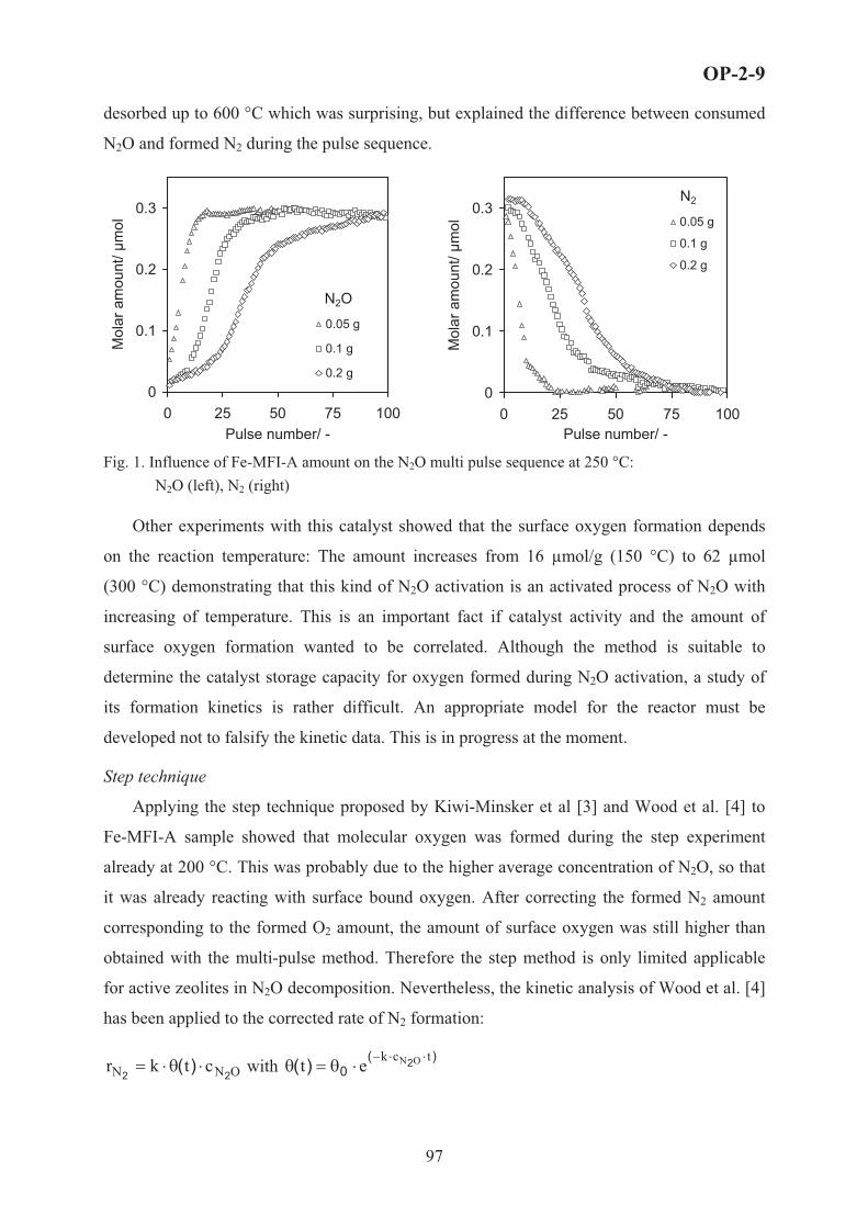
desorbed up to 600 °C which was surprising, but explained the difference between consumed
N2O and formed N2 during the pulse sequence.
0
0.1
0.2
0.3
0 25 50 75 100Pulse number/ -
Mol
ar a
mou
nt/ µ
mol
0.05 g
0.1 g
0.2 g
N2O
0
0.1
0.2
0.3
0 25 50 75 10Pulse number/ -
Mol
ar a
mou
nt/ µ
mol
0
0.05 g
0.1 g
0.2 g
N2
Fig. 1. Influence of Fe-MFI-A amount on the N2O multi pulse sequence at 250 °C: N2O (left), N2 (right)
Other experiments with this catalyst showed that the surface oxygen formation depends
on the reaction temperature: The amount increases from 16 μmol/g (150 °C) to 62 μmol
(300 °C) demonstrating that this kind of N2O activation is an activated process of N2O with
increasing of temperature. This is an important fact if catalyst activity and the amount of
surface oxygen formation wanted to be correlated. Although the method is suitable to
determine the catalyst storage capacity for oxygen formed during N2O activation, a study of
its formation kinetics is rather difficult. An appropriate model for the reactor must be
developed not to falsify the kinetic data. This is in progress at the moment.
Step technique
Applying the step technique proposed by Kiwi-Minsker et al [3] and Wood et al. [4] to
Fe-MFI-A sample showed that molecular oxygen was formed during the step experiment
already at 200 °C. This was probably due to the higher average concentration of N2O, so that
it was already reacting with surface bound oxygen. After correcting the formed N2 amount
corresponding to the formed O2 amount, the amount of surface oxygen was still higher than
obtained with the multi-pulse method. Therefore the step method is only limited applicable
for active zeolites in N2O decomposition. Nevertheless, the kinetic analysis of Wood et al. [4]
has been applied to the corrected rate of N2 formation:
ONN ctkr22
)( �3�� with )(0
2)( tck ONet ���3�3
OP-2-9
97
An activation energy of ~ 24 kJ/ mol and a pre-exponential factor of 3.6 · 107 ml/(gcat·s)
was found. Activation energy is lower than in literature reported for zeolites with low iron
content (0.38 % (wt) Fe) and can therefore be explained with the high iron content of the
sample. However, it is still an open question up to which extent this result is falsified by the
O2 formation during the step. It is investigated at the moment and the method should be
applied to zeolites with lower iron contents.
Temperature programmed desorption after the step experiments revealed the same results
than after the multi-pulse sequence: Oxygen desorbed in two temperature ranges up to 900 °C
and the N2O desorption took place up to stable up to 600 °C
Steady state measurements
The steady state measurements with 1000 ppm (v/v) and 1 % (v/v) N2O can each be fitted
with a first order rate law commonly proposed in literature. However, activation energy and
pre-exponential factor were significantly different in both cases, for 1000 ppm (v/v)
2.41 · 1013 ml/(gcat·s) and 162 kJ/ mol, for 1 % (v/v) inlet concentrations 9.2 · 1014 ml/(gcat·s)
and 185 kJ/ mol. In order to fit all results, the following model with an inhibition factor for
N2O was developed: ON
ONON Cb
Ckr
2
22 1 �
�� . The rate constant k can be calculated via an
Arrhenius equation with an pre-exponential factor of 4.5 · 1012 ml/(gcat·s) and an activation
energy 152 kJ/ mol. Results for the parameter b obtained from the best fit lead to the
assumption that it has the nature of an sorption constant for N2O at each temperature. Its
temperature dependency can be described with exponential law containing a positive
exponent. If this is consistent with the sorption constant must be proven by further
investigations.
Nevertheless, if the global rate determined under steady state conditions is compared to
the rate of the surface oxygen formation, it becomes clear that the latter one is much faster
and therefore not the rate limiting step for N2O decomposition.
This study shows that transient studies are suitable to get further insight to the elementary
steps and reaction mechanism of the N2O decomposition. However, kinetics of elementary
steps can only be obtained under the prerequisite of an appropriate model for the reactor
operating under unsteady state conditions.
References [1] A. Ates, A. Reitzmann, J. Catal., 235(1)(2005)164. [2] A. Ates, A.Reitzmann, Chem. Kinet. Catal. Lett. 86 (1) (2005) 11. [3] L. Kiwi-Minsker, D.A. Bulushev and A. Renken, J Catal., 219(2003) 273.[4] B.J. Wood, J.A Reimer, A. T.Bell, M.T. Janicke and K.C.Ott, J.Catal., 224 (2004)148.
OP-2-9
98

OP-2-10
SIMULATION OF THE REACTOR’S UNIT FOR CATALYTIC
ETHYLENE OXIDE HYDRATION
V.F. Shvets, R.A. Kozlovskiy, I.A. Kozlovskiy, M.G. Makarov, J.P. Suchkov,
A.V. Koustov, D.E. Zavelev
D.I.Mendeleev University of Chemical Technology of Russia, Chair of Basic Organic and
Petrochemical Synthesis, 9 Miusskaya Square, Moscow, 125047, Russia
e-mail: [email protected]
Abstract
The model of a tube fixed bed catalytic reactor for ethylene glycol production was used
for simulation of the various reactor’s units. The model includes equations describing
catalyst’s deactivation. The catalyst is a cross-linked styrene-divinylbenzene anion-exchange
resin in carbonate/bicarbonate form. Various process conditions (temperature, substance’s
concentrations), heating regimes (isothermal, adiabatic) and reactor combinations were
simulated. The optimal conditions for minimum of catalyst consumption were determined.
Introduction
Hydration of ethylene oxide is an industrial approach to glycols in general, and ethylene
glycol in particular. Ethylene glycol is one of the major large-scale products of industrial
organic synthesis, with the world annual production of about 15,3 million ton/y. Today
ethylene glycol is produced in industry only by a noncatalyzed reaction. As it follows from
numerous investigations [1-3] hydration of ethylene oxide catalyzed by anion-exchange resin
is one of the most promising methods for ethylene glycol production as alternative for
conventional industrial noncatalytic process. Catalytic method provides significant energy
saving in comparison with noncatalytic one due to much higher selectivity. But the main
disadvantage of such a catalyst is it’s deactivation that consists of two undesirable processes:
loss of catalytically active sites and catalyst’s swelling. In our previous works the models of
the tube fixed bed catalytic reactor [4] and of catalyst deactivation [5] were elaborated.
In the present work above mentioned models were used for analysis how process conditions
influence on catalyst life time.
99

OP-2-10
Results
The main parameters influencing on of the catalyst and its activity are temperature and
concentrations of ethylene oxide and glycol. The first series of calculations were made for
two types of reactor – isothermal and adiabatic. Process conditions were varied in the
following ranges: temperature 80-100oC; initial concentration of ethylene oxide 3-10 %
mass.; initial concentration of glycol 0-29 % mass. In each case selectivity, catalyst’s
capacity, catalyst’s volume, catalyst productivity (kmole of glycol per m3 of catalyst per h)
and catalyst consumption (m3 of catalyst per kmole of glycol) were calculated. Results of
simulation showed that adiabatic reactor is more favorable than isothermal. It was found that
most profitable conditions for production of outlet stream containing 35% mass of glycol are
follows: installation consisting of several (up to 5) consecutive adiabatic tube reactor with
distributed ethylene oxide input in each reactor and intermediate heat exchangers; initial
concentration of ethylene oxide in each reactor is 6 % mass. These conditions provide
selectivity about 95 %, catalyst productivity about 2,4 (kmole of glycol per m3 of catalyst per
h) and catalyst consumption about 7�10-5 (m3 of catalyst per kmole of glycol) and catalyst life
time up to 6000 h.
The final simulation was made in order to optimize the installation for glycol production
by means of variation of combinations of catalytic and noncatalytic consecutive adiabatic
reactors. The optimal scheme allowing minimum of catalyst consumption was found.
References 1. Shvets V.F., Makarov M.G., Koustov A.V., et al. Method for obtaining alkylene glycols. RU Patent
2149864, 2000.
2. Van Kruchten E. M. G. Process for the preparation of alkylene glycols. US Patent 5874653, 1999.
3. Iwakura T., Miyagi H. Production of alkylene glycol. JP Patent 11012206, 1999.
4. Shvets V.F., Kozlovskiy R.A., Makarov M.G., Koustov A.V., Selective catalytic hydration of ethylene and propylene oxides. XV International Conference on Chemical Reactors Chemreactor-15, Helsinki, Finland, June 5-8, 2001, c 102.
5. Shvets V.F., Kozlovskiy R.A., Kozlovskiy I.A., Makarov M.G., Suchkov Y.P., Koustov A.V., The Model of Catalytic Reactor of Ethylene Glycol Production. Organic Process Research & Development (2005), 9(6), 768-773.
100

OP-2-11
REACTION MECHANISM OF TAME SYNTHESIS FROM
DIFFUSE-REFLECTANCE FTIR ANALYSIS
Nezahat Boz1 and Timur Dogu2
1Department of Chemical Engineering, Kocaeli University, 41040, Kocaeli, Turkey 2Department of Chemical Engineering, Middle East Technical University,
06531, Ankara, Turkey
E-mail: [email protected], Tel: +90-262-3351148, Fax: +90-262-3355241
Inroduction
Oxygenated additives, such as MTBE (methyl tert-butyl ether), ETBE (Ethyl tert-butyl
ether), TAEE (tert-amyl-ethyl-ether), and TAME (tert-amyl-methyl-ether), are found to be
good substitutes for the aromatics, both in accomplishing the desired octane levels and in
reducing the hydrocarbon and carbon monoxide emissions. Due to their high octane numbers
and low volatilities, tert-amyl-ethyl-ether (TAEE) and tert-amyl-metyhl-ether (TAME) are
considered as attractive alternatives to MTBE as gasoline blending oxygenates. The recent
problems related to MTBE detection in groundwater, even at very low concentrations in the
drinking water, interest in heavier ethers (e.g. TAME and TAEE) has grown steadily. Our
earlier adsorption and diffuse reflectance FTIR spectrum (DRIFTS) results obtained for
MTBE and ETBE synthesis supported a Langmuir-Hinshelwood type reaction mechanism [1].
Significance of diffusional resistances on the production rate of these ethers using Amberlyst-
15 was also reported in our earlier work [2-4]. DRIFTS results obtained with methanol, 2-
methyl 1-butene (2M1B) and tert-amyl-methyl-ether (TAME) in adsorption and reaction
experiments, supported a Langmuir-Hinshelwood type reaction mechanism involving
adsorbed 2M1B molecules, which form a bridged structure between the adsorbed alcohols and
the –SO3H sites of Amberlyst-15. The reaction rate model, which was proposed basing on the
DRIFTS results, was shown to give good agreement with the published initial rate data for
TAEE synthesis [5].
In the present presentation, DRIFTS results obtained for isoamylenes, isoamylenes-
methanol mixtures and the reaction rate model, which was proposed basing on the DRIFTS
results in our recent publication [5], for the published initial rate data for TAME synthesis will
be presented.
101

OP-2-11
Experimental
DRIFTS experiments were carried out batchwise by injecting a pulse of tracer into the
reaction chamber of DRIFTS cell of FTIR instrument (MIDAC) which was filled with
nitrogen gas.
Results and Discussions
DRIFT spectra of 2M1B and an equimolar mixture of 2M1B-methanol obtained at 353 K
are shown once again here (Figure 1). The IR absorbtion band observed between 930 cm-1 and
1170 cm-1 with the 2M1B-methanol mixture (reaction experiments) is due to the contributions
of CO stretching of methanol (which was expected at 1030 cm-1) and C-O-C IR absorbtion
band of reaction product TAME (at around 1085 cm-1).
Figure 1. DRIFTS results of 2M1B, methanol and equimolar 2M1B-methanol mixture obtained at 353 K on Amberlyst-15.
Basing on these observations a reaction mechanism was proposed, which involved
adsorbed isoamylenes forming bridges structures between adsorbed alcohols and –SO3H sites
of the catalyst. The rate expression derived basing on the proposed reaction mechanism was
reported in our previous publications [5]. 2
EEBABA
AA
21
EBA
EBA
2AA
EBA )aKaaKK(
)aK1(aKK
Kaa"k)aK(1
Ka
aak r
666666
7
8
999999
:
;
667
8
99:
;!!#
� "
�
!!#
� "
�� (Eq.1)
102

OP-2-11
Considering the non-idealities of the alcoholisoamylenetert-ether mixtures, activities are
used in Eq.1.
For the synthesis of TAME, initial rate data were reported in our previous publications [2-
4] and also in other published work was used. In the analysis of the initial rate data, the terms
containing activity of ether ( ) become negligible in Eq.1 and the rate expression reduces to Ea2
AA
2/1
A
B2
AAB
A Ka1
aa
"kKa1
aa
k' r <=
<>?
<@
<AB
!!#
� "
�
667
8
99:
;!!#
� "
�!!
#
� "
�!!
#
� "
�� (initial rate) Eq.2
Here, the combined rate constants ' and arek "k
))SK(K16/()kS('k oBAo� ; AoB K)SK(8"k � ,
where So is the total number of sites per unit mass of catalyst (mol/g).
The initial rate data obtained in our studies and also published in the literature at different
temperatures were analyzed using Eq.2 and the rate parameters ( ) were determined
using a Quasi-Newton regression procedure. The adsorption equilibrium constants of
methanol (K
"k,'k
A) obtained from independent adsorption experiments were reported in our earlier
publication [1]. The agreement of the proposed rate expression with the data published in the
literature was found to be quite good.
Typical experimental results and model predictions of the initial rate of TAME formation
from 2M1B and 2M2B at 353 K are illustrated in Figures 2 and 3. As it is seen in these
figures the rate values pass through a sharp maximum. The predicted rate values are plotted as
a function of activity of methanol ( ) (activity of i-amylene ( ) being the parameter). In
the presence of alcohols, most of the surface is expected to be covered by alcohol molecules.
As a result of this, number of available sites involved in the adsorption of i-olefins is
drastically decreased with an increase in alcohol concentration. At sufficiently high alcohol
activities, reaction rate becomes almost zero order with respect to alcohol activity. However,
reaction order with respect to i-olefins is close to one. These observations are also in good
agreement with our earlier study of TAEE synthesis [5].
Aa Ba
103

OP-2-11
2M1B+Methanol353 K
0,0E+00
5,0E-05
1,0E-04
1,5E-04
2,0E-04
2,5E-04
0,0 0,1 0,2 0,3 0,4 0,5 0,6 0,7 0,8 0,9 1,0 1,1 1,2aA
-RA (m
ol/g
.s)
aB= 0.05aB= 0.1aB= 0.5aB= 1
2M2B+Methanol353 K
0,0E+00
5,0E-05
1,0E-04
1,5E-04
2,0E-04
2,5E-04
0,0 0,1 0,2 0,3 0,4 0,5 0,6 0,7 0,8 0,9 1,0 1,1 1,2aA
-RA (m
ol/g
.s)
aB= 0.05aB= 0.1aB= 0.5aB= 1
Figure 2. Dependence of initial rate of TAME formation on activities of methanol (aA) and
isoamylenes (2M1B) (aB) at 353 K. B
Figure 3. Dependence of initial rate of TAME formation on activities of methanol (aA) and
isoamylenes (2M2B) (aB) at 353 K. B
Acknowledgements
Turkish State Planning Organization Research Grants BAP-03-04-DPT-2002K120540-
19, DPT97K121110 through METU and Gazi Univ. Res. Funds are gratefully acknowledged.
Also, the contribution of Ebru Aydin on some of the DRIFTS results is acknowledged.
References1. Dogu, T., Boz, N., Aydin, E., Oktar, N., Murtezaoglu, K., Dogu, G., 2001, “DRIFT Studies for the
Reaction and Adsorption of Alcohols and Isobutylene on Acidic Resin Catalysts and the Mechanism of ETBE and MTBE Synthesis”, Ind. Eng. Chem. Res., 40, 5044-5051.
2. Dogu, T., Boz, N., Aydin, E., Murtezaoglu, K., Dogu, G., 2003, “Diffusion Studies for Ethanol, Methanol and Isoamylene in a Macroreticular Resin Catalyst by Batch adsorption Moment Analysis ”, Int. J. Chem. Reac. Eng., 1, Article A6. (Available online at http://www.bepress.com/ijcre/vol1/A6).
3. Oktar, N., Murtezaoglu, K.,Dogu, T., Dogu, G., 1999a, “Dynamic Analysis of Adsorption Equilibrium and Rate Parameters of Reactants and Products in MTBE, ETBE, and TAME Production", Can. J. Chem. Eng., Vol. 77, 406-412.
4. Oktar N., Murtezaoglu K., Dogu G., Gonderten I., Dogu T., 1999b, “Etherification rates of 2M2B and 2M1B with ethanol for environmentally clean gasoline production”, J. Chem. Technol. Biotechnol., 74, 155.
5. Boz, N., Dogu, T., Murtezaoglu, K., Dogu, G., 2005, “Mechanism of TAME and TAEE Synthesis From Diffuse Reflectance FTIR Analysis”, Cataly. Today., 100, 419-424.
104

OP-2-12
SYNGAS FORMATION FROM GASOLINE IN ADIABATIC REACTOR:
THERMODYNAMIC APROACH AND EXPERIMENTAL
OBSERVATIONS
L. Bobrova, I. Zolotarsky, V. Sobyanin, V. Parmon
Boreskov Institute of Catalysis SB RAS
5, Pr. Ak. Lavrentieva, Novosibirsk, 630090, Russia, [email protected]
Hydrogen is considered as an important energy carrier for sustained power consumption
with reduced impact on the environment. To avoid a hydrogen-supply infrastructure,
reforming conventional fuels (natural gas, gasoline, diesel, and jet) to the hydrogen-rich gas in
a small scale, near the point of usage may be a good solution [1]. The objective of the present
work is centered on the hydrogen-rich gas production from reformulated gasoline. The
process performance was studied theoretically by means of calculation of thermodynamic
equilibria, as well as experimentally by carrying out of the gasoline partial oxidation reaction
with formation of H2 and CO as main products (syngas) in a nearly adiabatic reactor with the
monolith catalyst under short residence times, in the order of milliseconds.
Thermodynamic approach is used to enable describing the process in terms of its input
qualities. A correlation between the product composition, temperature, overall energy
conversion efficiency, maximum hydrogen yield, adiabatic temperature rise available for the
different operating conditions such as the oxygen-to-carbon ratio, the steam-to-carbon ratio
and input temperature are established on the base of thermodynamic consideration. For this
purpose gasoline containing 191 types of hydrocarbons is represented as a surrogate mixture
of 29 organic compounds with well defined properties that can be calculated and compared
with the existing thermodynamic database. The model mixture is being formed as a set of the
equilibrium distribution of the close-cut fractions C3-C10 (see Table 1). Comparable
characteristics of the fuels, base gasoline and their surrogate model used in thermodynamic
calculations are summarized in Table 2. The main criteria of the conformity, as to sum of C
and H atoms, fractional distillation diagrams, and low heating values, are observed to have
very close values for the both fuels. A generic formula for the averaged composition
corresponds to �7.2�13.36.
Thermodynamic calculations of the gasoline reforming process have been performed with
a HYSYS software package (HyproTech. HYSYS.Process.v2.2 AEA.Technology).
105

OP-2-12
Table 1. The model composition of gasoline. N Component C H Mass fraction,
w/w % 1 Isobutane 4 10 0.4342 n-Butane 4 10 0.9663 Isopentane 5 12 1.5404 n-pentane 5 12 1.2605 2.2Dimethylbutane 6 14 0.3226 2.3Dimethylbutane 6 14 0.3227 2Methylpentane 6 14 1.1278 3Methylpentane 6 14 4.8289 Hexane 6 14 3.70210 Methylcyclopentane 6 12 0.82011 cyclogexane 6 12 1.18012 2.2Methylpentane 7 16 6.32213 2.3Methylpentane 7 16 4.14214 2.3 Metylhexane 7 16 7.19415 Heptane 7 16 4.14216 Isooctahe 8 18 0.26317 2,3+2,2 Dimethylhexane 8 18 1.57818 2,3,4 Trimethylpentane 8 18 0.26319 2,3,3 Trimethylpentane 8 18 0.26320 2Methylheptane 8 18 22.092 21 Octane 8 18 1.84122 Benzene 6 6 10.266 23 Toluene 7 8 14.514 24 m-Xylene 8 10 4.24825 p- Xylene 8 10 1.77026 o- Xylene 8 10 1.77027 Ethylbenzene 8 10 0.70828 p+o+m-Diethylbenzene 10 14 1.06229 1,2,4 Trimethylbenzene - 9 12 1.062
Table 2. Characteristics of gasoline and its model mixture
Fuel characteristic Base gasoline Model gasoline C/H ratio 0.539 0.539 Low heating value, MJ/kg 44.5 43.1 Data of fractional distillation, oC : Beginning 42 38
10 w/w % 73 71 50 w/w % 112 110 90 w/w % 165 170
End 185 182 Density, g/ml(20��) 0.78 0.8
Some results of thermodynamic calculations of equilibrium in processing the surrogate
model of gasoline with air and water are shown in Fig.1. At the fixed values of the input
temperature and O2/C ratio in the feed, there is an equilibrium limit for the relative content of
hydrogen in syngas. Water addition increases the hydrogen percentage in the product stream
up to the value of H2O/C ~1. This value corresponds to the maximum reformer efficiency,
because further increasing in the hydrogen yield would require an additional energy input to
dry the reformate gas.
106

OP-2-12
0.0 0.2 0.4 0.6 0.8 1.0 1.2 1.4 1.6
24
26
28
30
32
34
Wet stream
Dry stream
Tin=2000C
O2/C=0.5
Hyd
roge
n co
ncen
tratio
n, %
mol
.
Ratio H2O/C
0.0
0.1
0.2
0.3
0.4
Yie
ld, k
gH2 /k
g ga
solin
e
Figure 1. Thermodynamic predictions of equilibrium in adiabatic reactor for the surrogate gasoline: hydrogen concentration in the product gas (left axis) and hydrogen yield (right axis) versus H2O/C molar ratio in the feed with the temperature of 200oC (air/gasoline ratio is expressed as �2/� molar ratio).
Experimental observations. Experimental study of the process has been carried out in
the reactor specially designed to operate with a maximum of 90 % adiabaticity.
Temperature diagram
0
200
400
600
800
1000
1200
0:00
:01
0:12
:40
0:25
:19
0:37
:58
0:50
:37
1:03
:16
1:15
:55
1:28
:34
1:41
:13
1:53
:52
2:06
:31
2:19
:10
2:31
:49
2:44
:28
2:57
:07
3:09
:46
3:22
:25
3:35
:04
3:47
:43
4:00
:22
4:13
:01
4:25
:40
Run time
Tem
pera
ture
, C
T1T2T3T4T5T7T6
Figure 2. Schematic representation of the experimental short contact time reactor (left) and an experimental temperature diagram (right).
Catalytic monoliths with the metallic supports [2, 3] were loaded into the reactor. A pilot-
plant-scale set up was comprised of a feed supply system, vaporization system, the reactor,
and GC analysis system. Main electrical equipment (the balances, pumps, flow-mass
controller, pressure transducers, GC analysis unit, and the temperature measurement system)
was connected to the Pentium-III 700 MHz PC running under Windows XP Professional OS.
Special software was created to control the setup operation regimes according to the required
12 �
�1�1
�2
�3
�5
�6
�7
Feed 1
2
3
4
�4
107

OP-2-12
experimental program. Schematic representation of the experimental short contact time
reactor (left) and an experimental temperature diagram (right) are shown in Fig.2
0.45 0.46 0.47 0.48 0.49 0.50 0.51 0.52 0.53 0.54
16
18
20
22
24
26
28
30
Con
cent
ratio
n, v
ol.%
O2/C
0.00.20.40.60.81.01.21.41.61.82.0
CO
H2
CO2CH
4
Con
cent
ratio
n, v
ol.%
0.47 0.48 0.49 0.50 0.51 0.52 0.53 0.54
740
760
780
800
820
840
860
880
900
Del
ta T
, gra
d
O2/C
Figure 3. Experimentally measured values (symbols) and thermodynamic predictions (curves) for the process parameters versus O2/C ratio in the feed stream.
Experimental data obtained in the study of gasoline partial oxidation over metallic
monoliths in the short contact time reactor (Figure 3) are compared with thermodynamically
predicted one. The operational temperature in the adiabatic reactor is defined by the adiabatic
temperature rise at the given inlet conditions. It can be seen that both the product gas
composition and the adiabatic temperature rise in the experiments are very close to the
calculated values for the surrogate mixture proposed as a model for reformulated gasoline.
Acknowledgements. This work is in part supported by ISTC 2529 Project
References 1. C. Song, Fuel processing for low-temperature and high-temperature fuel cells. Challenges and opportunities
for sustainable development in the 21 st century. Catal. Today, 77 (2002) 17-49. 2. L. Bobrova, I. Zolotarskii, V. Sadykov, S. Pavlova, O. Snegurenko, S. Tikhov, V. Korotkich, T.
Kuznetsova, V. Sobyanin, V. Parmon, Syngas formation by selective catalytic oxidation of liquid hydrocarbons in a short contact time adiabatic reactor. Chem. Eng. Journal. (2005) 171-179.
3. V. A. Sadykov et al., Selective Oxidation of Hydrocarbons into Synthesis gas at Short Contact Times: Design of Monolith Catalysts and Main Process Parameters, Kinetics and Catalysis, 46, (2005), 227–250.
108

OP-2-13
SYNTHETIC FUEL FROM CATALYTIC DEGRADATION
OF WASTE POLYMERS OVER SOLID ACID ZEOLITES
M. Elgarni, S. Debbah, J. Saidan, S. I. Mustafa
Petroleum Research Center, Tripoli, Libya
E-mail: [email protected]
The catalytic degradation of polyethylene (PE) into synthetic fuel over H-ZSM-5 catalysts
was studied using a SS-tubular batch reactor. The effect of reaction temperature, reaction time
and catalyst weight were investigated. Processing under these conditions allowed for a higher
conversion into condensable liquid reaction product. Different analytical tools such as
GC-FID, IR and NMR have been used to analyze the reaction products. The products were of
a narrow range of carbon distribution (C5 to C15). The result showed that the average liquid
fraction obtained in the reaction product was 75 by weight. It has been found that the reaction
product contains mainly alkane, alkene and aromatics.
109

OP-2-14
SELF-SUSTAINED OSCILLATIONS FOR LANGMUIR-
HINSHELWOOD MECHANISM),ba Alexander V. Myshlyavtsev, Marta D. Myshlyavtseva )a
)a Omsk State Technical University, Omsk, Russia, e-mail: [email protected] )b Institute of Hydrocarbons Processing SB RAS, Omsk, Russia
1. Introduction.
The simplest model for CO oxidation on platinum surface is the well known three
steps Langmuir-Hinshelwood mechanism
2Z,ABBZAZBZ;ZB; 2AZ2ZA2 �CC (1)
where AZ and BZ are the adsorbed species on the catalyst Z, and A2, B and AB the gas phase
substances. The conventional mean-field (MF) kinetic equations can be written as [1]
� �� �<@
<AB
�
�
xykykyxPkdtdy
xykxkyxPkdtdx
32B2
32
12
A1
1/
212/2 , (2)
where x and y are the adsorbate concentrations, and the reactant pressures, and ,
, the rate constants for adsorption, desorption and reaction, respectively; t is time.
For some parameter sets there exist the domain of a multiplicity of steady states in the plane
2AP BP 21,kk
21, kk 3k
� �BA lg,lg2
PP . This domain contains only two internal steady states. The effect of
monomolecular adsorption reversibility � �0,0 21 D� kk on the domain of the multiplicity of
the steady states is very strong. At rather large values of parameter for all other
parameter values there are the one internal steady state and the one boundary steady state.
32 / kk
The simplest MF equations (2) ignore the non-ideality of surface rate processes. We
consider the MF equations incorporating the adsorbate-adsorbate lateral interactions via the
coverage dependence of the rate constants. Usually, the coverage dependence of the rate
constants is introduced “by hands” [2,3]. However, in the frameworks of the lattice gas model
and transition state theory there are exact expressions for the rate constants [4].
The goal of the present work is the study of lateral interactions and monomolecular
adsorption reversibility effect on the possibility of self-sustained oscillations appearance for
Langmuir-Hinshelwood mechanism.
2. Model and method.
We will consider a lattice gas model as a model of adsorbed overlayer. Two kind of
adsorbed species can occupy lattice sites of a square lattice. We take into account only
110

OP-2-14
nearest-neighbor lateral interactions. The thermodynamic Hamiltonian for this lattice gas
model can be written as
����� �i
ii
inn
jinn
jinn
jieff nnnnnnnnH ,BB,AA,B,BBB,B,AAB,A,AAA ����� , (3)
where BBABAA ,, ��� are the nearest-neighbor interactions energies, and the
occupation numbers, and
in ,A in ,B
A� and B� the chemical potentials for AZ and BZ adsorbed
species, respectively. nn means summation over all pairs of nearest lattice sites.
As it was emphasized the exact expressions for the adsorption, desorption and reaction
rate constants were obtained within the frameworks of the lattice gas model and transition
state theory [4]. Let us assume that activated complexes for adsorption, desorption and
reaction do not interact with its environment.
Let us introduce the following notations 3A1 /22
kPku � , 3B2 / kPkv � , , 32 / kks �
RT/AA �� � , RT/BB �� � and tk3�) , where R is the universal gas constant, T absolute
temperature in K. Then kinetic equations corresponding to mechanism (1) are as follows:
� �� �� �� �� � �<@
<AB
�
�
,exp1exp/
exp/
BA00B
BA00
���)
��)
pyxsvddy
upddx
�
�
(4)
where is the probability to find an empty couple of the nearest lattice sites. 00p
Within the framework of our model the exact analytical expressions for are
absent [5] and hence we should use an approximate technique. It is well known, that the one
of the most effective approach is the transfer matrix method [6-8]. Using the latter approach
one can solve the problem of deriving expressions for the rate constants as functions of
concentration. Experience shows that the transfer matrix technique yields very good results
already for small M, such as M = 4 [8,9], where M is the number of the sites belonging to the
ring. This ring is used for transfer matrix numerical algorithm.
yxp ,,00
Taking into account the features of the transfer matrix method we should to move
from the variables to the � yx, ),( BA �� ones. Then the system (4) can be rewritten as
� �� � � �� �
� �� � � �� �<<
@
<<
A
B
�67
89:
;
22
22
�
�67
89:
;
22
22
�
,exp)1(exp
exp)1(exp
BA00A
00BAA
B
BA00B
00BAB
A
���
���)
�
���
���)
�
pyxvxpuyd
d
pyxvxpuyd
d
(5)
where is the Jacobian.�
111

OP-2-14
It was shown that the number of the internal steady states can be equal to arbitrary
integer number. We have studied numerically twenty seven models with lateral interaction
energies BBABAA ,, ��� which possess the values 10; -10; 0 kJ/mol. All calculations were
carried out at T = 500 K and M = 4. For these interaction energies sets the total number of the
steady states was found to come up to twelve.
We have done the systematical analysis of the lateral interactions effect on the
possibility of self-sustained oscillations appearance for Langmuir-Hinshelwood mechanism.
3. Results and discussion.
Self-sustained oscillations for the reaction rate were found only for the lateral
interaction sets with A-B attraction. It seems the reason of this phenomenon under
observation is the increase of the reaction activation energy with surface coverage increasing.
This increasing results in nonmonotonous dependence of the reaction rate on the surface
coverages and in self-sustained oscillations
appearance. From mathematical point of view
the self-sustained oscillations for the studied
model are the result of Hopf’s bifurcation.
Let us consider some results obtained
for the model with the lateral interaction
energies 0,10,10 BBABAA ��� ��� kJ/mol.
For irreversible adsorption the multiplicity
diagram has domain with eight internal steady
states. We chose the point (-3,93;-4,342) in the parameter plane � �vu lg;lg . It belongs to the
domain with two internal steady states. The
phase portrait at given parameter values is
shown in Fig. 1. The reaction rate for the
phase trajectory beginning from the unstable
focus located into the limit cycle is shown in
Fig. 2. The reaction rate varies by a factor of
during the oscillations.210
When the parameter s increases the
multiplicity diagram becomes simpler and
after that the multiplicity domain disappears.
Self-sustained oscillations disappear as well.
112

OP-2-14
We have found that for two sets of the
lateral interactions energies (0;-10;-10) and
(10;-10;-10) self-sustained oscillations were
absent at s = 0, but at these ones
appeared. We chose the point (-4,065;-4,3825)
in the parameter plane for the
former set. It belongs to the domain with three
internal steady states. The phase portrait at
given parameter values is shown in Fig. 3.
There is the unstable focus into the stable limit
cycle. The filled circle exhibits the second unstable steady state. The third internal steady
state is a stable focus.
2
�v
10�s
� u lg;lg
4. Conclusion.
In the framework of the microscopic model of a non-ideal adsorbed overlayer the
kinetic behavior of the Langmuir-Hinshelwood mechanism was shown to become essentially
more complex than for an ideal overlayer. The self-sustained oscillations of the reaction rate
have been found for some sets of lateral interactions. From mathematical point of view the
self-sustained oscillations for the studied models are the result of Hopf’s bifurcation. It was
also shown when the parameter s increases self-sustained oscillations disappear. However, the
adsorption reversibility at moderate values of parameter s can be the reason of self-sustained
oscillations.
References 1. V.I. Bykov, V.I. Elokhin, A.N. Gorban, G.S. Yablonskii: Comprehensive chemical kinetics, Vol. 32.
Kinetic models of catalytic reactions (Ed. R.G. Compton). Elsevier, Amsterdam 1991.
2. M.M. Slinko, N.I. Jaeger: Oscillatory Heterogeneous Catalytic Systems, Elsevier, Amsterdam, 1994.
3. V.P. Zhdanov: Surf. Sci. Rep., 45, 231 (2002).
4. V.P. Zhdanov: Physicochemical Processes on Solid Surfaces, Plenum Press, New York, 1991.
5. R.J. Baxter: Exactly Solved Models in Statistical Mechanics, Academic Press, London, 1982.
6. A.V. Myshlyavtsev, V.P. Zhdanov: Chem. Phys. Lett., 162, 43 (1989).
7. A.V. Myshlyavtsev, M.D. Dongak: J. Stat. Phys., 87, 593 (1997)
8. V.I. Bykov, A.V. Myshlyavtsev, M.G. Slin’ko: Doklady Chemistry, 384, 170 (2002)
9. A.V. Myshlyavtsev, J.L. Sales, G. Zgrablich, V.P. Zhdanov: J. Stat. Phys., 58, 1029 (1990)
113

Section 3. Catalytic processes and reactors development:
modeling, optimization and catalyst design

OP-3-1
STRUCTURED REACTORS PACKED WITH CERAMIC FOAMS FOR
THE PARTIAL OXIDATION OF o-XYLENE
TO PHTHALIC ANHYDRIDE
A. Bareiss, A. Reitzmann, B. Kraushaar-Czarnetzki, B. Schimmöller*, H. Schulz*,
S.E. Pratsinis*
Institut für Chemische Verfahrenstechnik, Universität Karlsruhe (TH), Karlsruhe, Germany
*Particle Technology Laboratory, Swiss Federal Institute of Technology Zürich, Switzerland
e-mail: [email protected]
The objective of this study is to evaluate the applicability of ceramic foams as structured
catalyst supports in the partial oxidation of o-xylene to phthalic anhydride (PA). In
simulations, the performance of fixed bed reactors packed with foams or filled with catalyst
particles have been compared. A new technique to deposit nano-sized V2O5/TiO2 catalysts on
foams has been developed (Fig. 1). These foam catalysts have shown a considerably higher
catalytic activity than conventionally prepared catalysts.
FSP-Deposition
Fig. 1: Structure of foams and FSP-Deposition of foams
Background and motivation
The partial oxidation of o-xylene to PA is a fast and highly exothermic reaction. Although
cooled multi-tubular reactors are commonly applied to remove the heat efficiently out of the
reactor bed, pronounced radial and axial temperature gradients across the catalyst bed are
observed. The risk of catalyst deactivation due to overheating and of thermal reactor
runaways is given. Commercial catalysts are usually eggshell type containing an inert, shaped
115
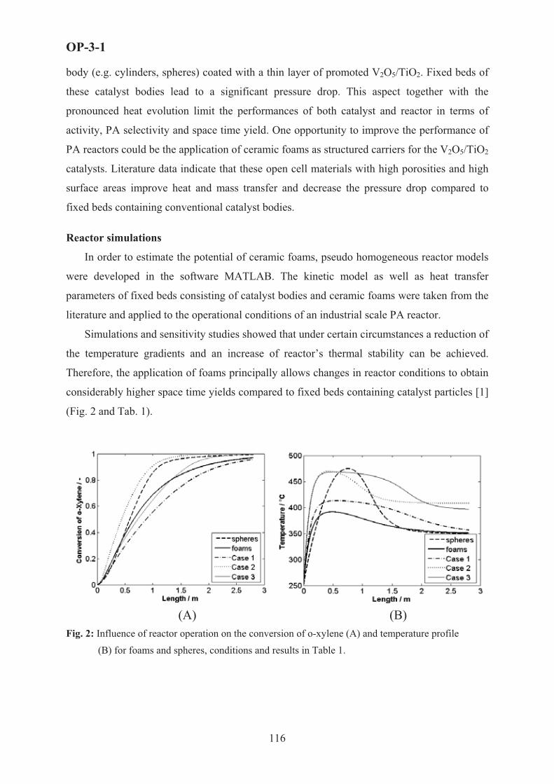
OP-3-1
body (e.g. cylinders, spheres) coated with a thin layer of promoted V2O5/TiO2. Fixed beds of
these catalyst bodies lead to a significant pressure drop. This aspect together with the
pronounced heat evolution limit the performances of both catalyst and reactor in terms of
activity, PA selectivity and space time yield. One opportunity to improve the performance of
PA reactors could be the application of ceramic foams as structured carriers for the V2O5/TiO2
catalysts. Literature data indicate that these open cell materials with high porosities and high
surface areas improve heat and mass transfer and decrease the pressure drop compared to
fixed beds containing conventional catalyst bodies.
Reactor simulations
In order to estimate the potential of ceramic foams, pseudo homogeneous reactor models
were developed in the software MATLAB. The kinetic model as well as heat transfer
parameters of fixed beds consisting of catalyst bodies and ceramic foams were taken from the
literature and applied to the operational conditions of an industrial scale PA reactor.
Simulations and sensitivity studies showed that under certain circumstances a reduction of
the temperature gradients and an increase of reactor’s thermal stability can be achieved.
Therefore, the application of foams principally allows changes in reactor conditions to obtain
considerably higher space time yields compared to fixed beds containing catalyst particles [1]
(Fig. 2 and Tab. 1).
(A) (B)Fig. 2: Influence of reactor operation on the conversion of o-xylene (A) and temperature profile
(B) for foams and spheres, conditions and results in Table 1.
116

OP-3-1
Tab. 1: Quantitative results comparing spheres and foams under different operational conditions.
Case Twall/(°C)
THotSpot/(°C)
C0, o-xylene/(g/Nm3)
STY/(kgPA/(m3·h))
SPA/(mol/mol)
YPA/(mol/mol)
Spheres 348 475 80 245 0.73 0.730 Foams 348 392 80 229 0.70 0.682 Case 1 348 413 175 496 0.71 0.679Case 2 408 469 80 249 0.74 0.740Case 3 395 468 175 542 0.75 0.740
Experimental investigations
In the first step, two types of V2O5/TiO2 catalysts were synthesized, one via impregnating
titania (anatase) with vanadia in the wet phase (WP), another one via flame spray pyrolysis
(FSP) [2]. Isothermal kinetic measurements were performed in a plug flow reactor to show
the impact of mass transfer limitations on activity and product selectivities. Different size
fractions of pelletised catalyst particles were used. An significant effect of mass transfer
limitation was observed for the pellets from FSP made nano-particles due to their higher
intrinsic activity as compared to the wet phase made catalyst.
The next step focused on the coating of catalyst carriers. A method for the direct foam
deposition of V2O5/TiO2 nano-particles made by flame spray pyrolysis was developed. The
influence of several operational parameters in this technique (duration, particle size, pressure
drop) on the quality of the coating was investigated [3]. Foams coated with FSP made
particles were twice as active as the smallest fraction of FSP pellets and even 25-30 times
more active than WP pellets (Fig. 3+4).
0
0,2
0,4
0,6
0,8
1
0,001 0,01 0,1 1lg+)mod / gKat*s/cm3
X o-X
ylen
e /-
FSP pelletsWP pelletsFSP foam
Fig. 3: Activity of FSP pellets, WP pellets and FSP foam.
117

OP-3-1
0
0,2
0,4
0,6
0,8
1
0 0,2 0,4 0,6 0,8Xo-Xylene /-
S PA
,o-X
ylen
e /-
1
FSP pelletsWP pelletsFSP foam
Fig. 4: Selectivity of phthalic anhydride of FSP pellets, WP pellets and FSP foam
FSP nano-particles, in general, exhibit higher surface areas than WP particles. When
deposited on a foam rather than compressed to a pellet, the active layer additionally exhibits a
very high porosity, enabling a maximum suppression of mass transfer restrictions. Among the
materials under investigation, the PA productivity of coated foams was found to be by far the
highest.
Conclusions
The simulations of a cooled PA reactor have shown that ceramic foams as catalyst
packings allow for much better heat removal as compared to fixed beds of particles and
enable a strong increase in PA space time yields under certain circumstances. The
experimental data obtained so far at isothermal conditions cannot be compared with the
simulation results. They show, however, that the novel coating technique of foams using
flame made nano-particles of V2O5/TiO2, produces catalysts with an extraordinary activity
and high PA selectivity.
References
[1] A. Reitzmann et al., Proc. of the DGMK/SCI-Conf., Milan, 2005-2 (2005) 107.
[2] L. Maedler et al., Aerosol Science 33 (2002) 369.
[3] B. Schimmöller et al., J. Catal. (2005) submitted for publication.
118

OP-3-2
DESORPTIVE COOLING OF FIXED- BED CHEMICAL REACTORS:
A PRACTICAL ALTERNATIVE TO MICROREACTORS
M. Nau, M. Richrath, M. Gruenewald, D.W. Agar
Chair of Reaction Engineering, Departament of Biochemical and Chemical Engineering,
University of Dortmund, Germany
Strongly exothermic heterogeneously catalysed gas phase reactions are commonly carried
out in multitubular reactors. The inherent limitations of recuperative heat removal lead to hot-
spot formation and can even cause reactor runaway. Apart from recuperative cooling via the
reactor walls, convective, reactive or regenerative cooling principles may be exploited. The
last, somewhat neglected, concept entails heat removal through the regenerative heating of the
fixed-bed followed by a subsequent cooling phase.
Desorptive cooling represents a new hybrid reactive-regenerative process, with desorption
of an inert providing the ‘reactive’ contribution. Initial studies on a test reactor using CO-
Oxidation as a strongly exothermic test system demonstrated the principle feasibility of
integrating the desorption process into the catalytic fixed-bed. The heat of reaction liberated
from the catalyst pellet is locally
dissipated by the desorption of an inert
component from adjacent adsorbent
particles (see fig. 1), thus leading to
quasi-isothermal conditions within the
bed. This concept permits operation in
a simple adiabatic reactor without
internal cooling surfaces. As a result,
cycle times in a technically relevant
range and much longer than those for
simple regenerative processes were
attained. Further work has identified
considerable potential for extending cycle times up to an hour or more: bed structuring and
adsorptive profiling in the inlet to achieve more uniform utilisation of cooling capacity. In
particular the latter proved to be an effective and feasible strategy for exploiting the concept
to its full. While thermal desorption alone provides inadequate cooling capacity, ramping
Figure 1: Concept of Desorptive Cooling Process
119

OP-3-2
adsorptive partial pressure avoids initial subcooling and leads to an isothermal temperature
profile (see fig.2). Furthermore, the regeneration procedure was modelled in order to establish
overall process parameters for a full cycle and the importance of the reaction kinetics for the
breakthrough behaviour and the self-regulating character of the process were identified.
Present work is focussing on scale-up to pilot plant dimensions and the application of
desorptive cooling to the industrial relevant selective hydrogenation of acetylene to ethylene.
The presentation focuses on the most recent results from a research programme supported by
introduction to the desorptive cooling
process with all the relevant design
parameters, a flexible dynamic
mathematical model, which is able to
simulate various reactor
configurations will be described.
Two-dimensional simulations were
found to be necessary to achieve
reasonable agreement with bench-
scale experimental results. The
degrees of freedom available in the
design of desorptive cooling systems
will be discussed. In addition, the
optimisation of key process parameters, such as the distribution of catalyst and adsorbent
along the bed, the regulation of operating parameters, such as the inert level in the feed and
the partial pressure ramping for effective cooling with maximum cycle times and acceptable
conversion rates and selectivities will be addressed.
the German Research Foundation (DFG). Following an
] M. Richrath, M. Grünewald, D. W. Agar Gezielte Temperaturregelung auf partikulärer Ebene durch Kopplung von Reaktion und Desorption - Teil I
[2] rer Ebene durch Kopplung von Reaktion und Desorption - Teil II
[3] Intensification of regenerative heat exchange in chemical reactors using desorptive cooling
Figure 2: Manipulation of Cycle Time by Desorption Driving Force
[1
Chem.-Ing.-Tech 77 (1-2): 94-101, 2005
M. Richrath, M. Grünewald, D. W. Agar Gezielte Temperaturregelung auf partikuläChem.-Ing.-Tech 77 (3): 252-256, 2005
M. Grünewald, D. W. Agar
Ind. Eng. Chem. Res. 43 (2004), S. 4773-4779
120

OP-3-3
BENZENE HYDROGENATION IN THE THIOPHENE PRESENCE
OVER THE SULFIDE Ni-Mo/$-Al2O3 CATALYST UNDER PERIODIC
OPERATION: KINETICS AND PROCESS MODELING
Reshetnikov S.I., Ivanov E.A. and Startsev A.N.
Boreskov Institute of Catalysis SB RAS, Pr. Lavrentieva, 5, 630090, Novosibirsk, Russia
E-mail: [email protected]
Introduction
One of an important subject of environmental catalysis is clean fuels research [1, 2]. In
the past decade clean fuels research including hydrodearomatization (HDA) and
hydrodesulfurization (HDS) processes. This processes are realizing on the sulfide (Ni, Mo)
and (Ni, W) catalysts. The difficult problem of the HAD-HDS processes on sulfide catalysts
is the mutual inhibition of hydrogenation reactions by sulfur-organic compounds and
hydroginolysis reactions by aromatics. In our paper [3] we have considered the unsteady-state
kinetic scheme of a simultaneous performance of the benzene hydrogenation and thiophene
hydrogenolysis on the sulfide (Ni, Mo) and (Ni,W) catalysts. However, the scheme did not
take into account the HDA activity decreasing when thiophene is absent in the reaction
mixture for a long period of time.
The goal of this work is to develop a kinetic model for simulating the transient regime
of catalyst taking into account influence of thiophene in feed gas and process modeling under
periodic of reactor operation.
Experimental
The benzene hydrogenation reaction was studied in an isothermal reactor with a fixed
catalyst bed [4]. Hydrogen was passed through a saturator filled either with pure benzene or a
mixture with benzene and thiophene molar ratio 9:1. After being loaded into the reactor, the
catalyst was treated with a benzene + thiophene mixture until the benzene conversion
becomes permanent. Then the hydrogen+benzene+thiophene flow was changed by a flow of
hydrogen+benzene or hydrogen+benzene+thiophene where molar ratio of benzene/thiophene
was varied from 20:1 up to 140:1. Conversion of benzene into cyclohexane at the reactor
outlet were monitored by chromatography. The experimental conditions were as follows: T =
300oC, P = 2 MPa, ) = 0.1-0.5 s. The (Ni, Mo)/Al2O3 catalyst contained 2.7% of Ni and
13.9% of Mo.
121

OP-3-3
Kinetic model and results discussion
The proposed kinetic model is based on the following standpoints, which were
revealed on studying the benzene hydrogenation reaction on the sulfide catalysts under
unsteady state conditions [5-7]:
1. The active sites of the both reactions of benzene hydrogenation and thiophene
hydrogenolysis are the nickel atoms, entering the composition of the sulfide bimetallic
species, which is an active component of the sulfide hydrotreating catalysts.
2. The every Ni atom is an active site for adsorption and activation of both thiophene and
benzene molecules and participates in catalysis.
3. The active sites are covered with the adsorbed molecule of either reagents or reaction
products at the catalysis conditions.
4. The adsorption heat of molecules on the active site decreases in a row: thiophene >
hydrogen sulfide > benzene > hydrogen > cyclohexane.
5. The both reaction of benzene hydrogenation and thiophene hydrogenolysis occur via the
concerted mechanism and involves the interaction of bezene (thiophene) molecule with
three (or four) molecules of hydrogen without the possible intermediates being desorbed
into the gas phase.
6. When hydrogen sulfide is absent in the both gas phase and adsorbed state, the structure-
forming sulfur atoms interact with hydrogen resulted in the destruction of the active
component structure and the catalyst deactivation.
In accordance with this standpoints, the kinetic of both benzene hydrogenation and thiophene
hydrogenolysis on sulfide Ni-Mo/Al2O3 catalyst is developed, which includes 7 following
steps:
1) C6H6 + [ZH2S] C [ZC6H6] + H2S,
2) C6H6 + 3H2 + [ZC6H6] � [ZC6H6] + C6H12,
3) nH2 + [ZC6H6] � [ZX] + nH2S + C6H6,
4) nH2 + [ZH2S] C [ZX] + (n+1)H2S.
5) (n+1)C4H4S + (3n+4)H2 + [ZX] � [ZH2S] + (n+1)C4H10 ,
6) C4H4S + 4H2 + [ZC6H6] � [ZH2S] + C4H10 + C6H6,
7) C4H4S + 4H2 + [ZH2S] � [ZH2S] + C4H10 + H2S.
The first step involves an interaction of benzene with adsorbed hydrogen sulfide with
the site [ZC6H6] formation, which active in benzene hydrogenation. The benzene interacts with
the activated hydrogen to yield cyclohexane (step 2). In the absence of hydrogen sulfide in the
122

OP-3-3
gas phase and on the catalyst surface, the hydrogen from the gas phase can interact with sulfur
atoms from the active component structure. This process involves the desorption of hydrogen
sulfide into the gas phase and destruction of the active component structure, i.e. deactivation
of the catalyst (steps 3, 4). There [ZX] is the active site structures depleted of n sulfur atoms.
Since the tiophene has most high the adsorption heat of molecule, it will displace of benzene
and hydrogen sulfide molecules on a catalyst surface. Then, steps (1)-(4) one can add by (5)-
(7) steps.
0 60 120 180 240 300Time (min)
0
5
10
15
Benz
ene
conv
ersi
on (%
)
1
2
3
4
Fig. 1. Benzene conversion versus time at the different benzene/thiophene molar ratio in feed mixture: 1 – 140; 2 – 50; 3 – 35; 4 – 20. )=0.18 s (points – experiments, lines – modeling).
Fig.1 shows benzene conversion versus time at different benzene/thiophene molar
ratio in feed mixture. The catalyst in the reactor was preliminary treated with a mixture of
hydrogen+benzene+thiophene until the steady-state conversion was achieved. It can see that
maximum value of the benzene conversion increase with thiophene concentration decreasing.
So, the rate of benzene hydrogenation is strongly inhibited by thiophene, which present in the
feed mixture. For the modeling of the CSTR model was used.
Experimental and theoretical studies in heterogeneous catalysis during the last
decades have given enough evidence that reactor performance under unsteady state
conditions can lead to improvement in process efficiency if compared to optimal steady state
operation. Using surface dynamics it is possible maintain the catalyst surface in an optimal
state in order to increase the mean reaction rate and the selectivity towards a specific product
formation. This can result in an increased yield of the desired product. On of the way of the
catalyst unsteady state regulation is forced oscillations of reagents concentrations (periodic
operations) [8,9].
The influence of various parameters like concentrations of thiophene, cycle split,
period of forced oscillations and so on was investigated. It was shown that under periodic
operations the mean reaction rate can exceed more the twice the steady state value.
123

OP-3-3
Conclusion
The kinetic model of both HDA and HDS on the (Ni, Mo)/Al2O3 catalyst has been
developed assuming that the catalyst surface contains only one type of active sites - nickel
atoms found in the sulfide bimetallic complex - on which the reactions of hydrogenolysis of
bond C-S and benzene hydrogenation occur. The number of active sites reduces due to both
interaction between the network-forming sulfur atoms and hydrogen and destruction of the
active site structure.
The model describes adequately the experimental data obtained at the preassure 2
MPa, temperature 573 K and variation of the contact time and ratio of benzene/thiophene in
feed mixture.
The optimization of various parameters like concentrations of thiophene, cycle split,
period of forced oscillations and so on was performed. It was shown that under periodic
operations the mean reaction rate can exceed more the twice the steady state value.
References 1. B.H. Cooper, B.B.L. Donnis: Appl. Catal. A: General, 137, 203 (1996).
2. C.Song, X.Ma. Applied Catalysis B: 41, 207 (2003)
3. N. M. Ostrovskii, K. S. Gulyaev, A. N. Startsev and O. A. Reutova: Can. Jr. Chem. Eng., 74, 935 (1996).
4. M.V. Sidyakin, A.N. Cholodovich, E.A. Ivanov, S.I. Reshetnikov, A.N. Startsev: React. Kinet. Catal. Lett, 77, 287 (2002).
5. A.N. Startsev, V.N. Rodin, G.I. Aleshina, D.G. Aksenov: Kinet. Katal., 39, 238 (1998) (in Russian).
6. A.N. Startsev, G.I. Aleshina, D.G. Aksenov, V.N. Rodin: Kinet. Katal., 39, 391 (1998) (in Russian).
7. A.N. Startsev, I.I. Zakharov, V.N. Rodin, G.I. Aleshina, D.G. Aksenov,: Kinet. Katal., 39, 549 (1998) (in Russian).
8. Renken, A. Int. Chem . Eng., 24, (1984). 202-213.
9. Silveston, P.L. Periodic operation of chemical reactors - a review of the experimental literature. Sadhana 10, (1987) 217-246.
124

OP-3-4
NEW CATALYTIC SYSTEM FOR CONJUGATED OXIDATION
OF CARBON MONOXIDE, SOLVENT,
AND HYDROCARBOXYLATION OF CYCLOHEXENE
Lev G. Bruk, Elena A. Timashova, Sergey N. Gorodsky,
Irina V. Oshanina, Oleg N. Temkin
M.V. Lomonosov State Academy of Fine Chemical Technology, Pr. Vernadskogo 86,
119571 Moscow, Russia, Fax: (495)434-87-11; E-mail: [email protected]
Introduction
Conjugated reactions are subject of theoretical and practical interest for creation of the
new catalytic systems [1-3]. The oxidation of carbon monoxide by molecular oxygen is one of
the simple available model reactions suitable for studying of fundamental regularities of the
conjugated processes [2-4].
This report deals with the mechanistic study results of the conjugated reactions of carbon
monoxide, water, and organic solvent oxidation, and cyclohexene hydrocarboxylation to
cyclohexane carboxylic acid in catalytic systems: PdBr2-1,4-dioxane-H2O, PdBr2–
tetrahydrofuran-H2O, PdI2–LiI-1,4-dioxane-H2O under very mild conditions (1 atm, 30o)(1-6).
CO + H2O + O2 � CO2 + H2O2 (1)
2CO + H2O2 � CO2 + HCOOH (2)
CO + 1,4-dioxane + O2 � CO2 + 1,4-dioxene + H2O (3)
CO + 1,4-dioxane + O2 � CO2 + 1,4-dioxan-2-ol (4)
CO + tetrahydrofuran + 1,5 O2 � CO2 + $-lactone of butyric acid + H2O (5)
CO + tetrahydrofuran + O2 � CO2 + 1,4-dioxane (6)
The effects of the nature of solvent, of anion, as well as the effects of inhibitors, and
kinetics were studied. The hypothetical mechanisms of conjugated reactions in the above-
mentioned systems were selected (discriminated). The best mechanism includes formation
and transformations of hydride palladium complex (scheme 1). This hydride palladium
complex is responsible for conjugation of the reactions of carbon monoxide, water, and
125

OP-3-4
solvent oxidation. Experimental kinetic equation (1) does not contradict to proposed
mechanism (scheme 1).
PdX2 + H2O XPdOH + HX
XPdOH + CO XPdCOOH
XPdCOOH XPdH + CO2
XPdH + O2 XPdOOH
XPdOOH + HX PdX2 + H2O2
scheme 1
rCO2= k1[Pd]E[H2O] PCO/([H+](1 + k2 PCO)) (1)
The correctness of this hypothesis was tested by experiments with addition of
cyclohexene in the system PdBr2 – tetrahydrofuran – H2O. The synthesis of cyclohexane
carboxylic acid is carried out in this system under mild conditions ( 30o, atmospheric pressure
of CO and O2 mixture) with rate up to 0.3 mol/l�h (fig 1). It is well known, that hydride
complexes of palladium are truthful catalysts of alkene carbonylation reactions in the
solutions of palladium complexes, for example [5].
0
0.2
0.4
0.6
0.8
1
0 0.5 1 1.5
[C6H1 0] mol/l
R, mol/l*h
2
cy clohexane carboxy lic acid gamma-buty rolacton CO2
The overall mechanistic scheme of kinetic conjugation of the reactions under
consideration includes three catalytic cycles (scheme 2).
126

OP-3-4
HX
PdX2 XPdOH XPdCOOH
XPdOOH XPdH
H2O CO
H2O2
HX
O2
-CO2
CO,H2O
COOH
HX
H
XPd
SOS
scheme 2
S-solvent
SO-product of solvent oxidation.
A number of alkenes were tested as substrates of hydrocarboxylation in these systems:
oktene-1, hexene-1, styrene, 4-vinyl-cyclohexene, norbornadiene, norbornene. In the case of
majority alkenes the products of hydrocarboxylation were identified.
Conclusion
It is possible to design catalytic systems for reactions with thermodynamic or kinetic
limitations using information about probable mechanism of these reactions. It is necessary to
find other reaction without thermodynamic or kinetic limitations (basic reaction), which
would be capable to produce key intermediate for desirable reaction. If reagents of desirable
reaction to introduce in the catalytic system of basic reaction under suitable conditions it
would be possible to obtain desirable product under mild conditions. We term this approach
“principle of kinetic conjugation of reactions”.
Acknowledge
Financial support of RFBR (Grants NN 05-03-08134, 04-03-33014).
1. Nagiev N.A. Chemical conjugation. Moscow: “Nauka”, 1989, p.35.(In Russian) 2. Zudin V.N., Likholobov V.A., Ermakov Y.I. Kinet. i Kataliz 1979, 20, 1559. 3. Bianchi D., Bortolo R., D’Aloisio R., Rici M. J. Mol. Catal. 1999, 150, 87.
4. Bruk L.G., Abdulaeva A.S., Vyrodov A.V., Temkin O.N. In: Abstracts 14-th Int. Symp. Homog. Catal. Munich, 2004, P0124.
5. Noskov Y. G., Simonov A.I., Petrov E.S. Kinet. i Kataliz 2000, 41, 564.
127

OP-3-5
CATALYTIC ACTIVITY OF HETEROPOLYTUNGSTIC ACID
ENCAPSULATED INTO MESOPOROUS MATERIAL STRUCTURE
G. Gündüz1, R. Dimitrova2, S. Yılmaz3
1Department of Chemical Engineering, Ege University, 35100 Bornova, Izmir, Turkey
Fax: 00-90-232-3887776, e-mail: [email protected] of Organic Chemistry, Bulgarian Academy of Sciences, 1113 Sofia, Bulgaria
Fax: 00-359-2-8700225, e-mail: [email protected] of Chemical Engineering, Izmir Institute of Technology, Izmir, Turkey
Fax: 00-90-232-750 6645, e-mail: [email protected]
1. Introduction
Tightening environmental legislation on the emission of hazardous pollutants is driving
the industries to consider alternative processes such as heterogeneously catalyzed processes.
Zeolites are widely used in chemicals industry in acid catalyzed processes. Unfortunately, the
use of zeolites is restricted by their small pore sizes of around < 8 A0, which makes them
unsuitable for reactions involving bulky substrates. The discovery of the M41S family of
mesoporous molecular sieves (MCM-41, MCM-48, MCM-50) offers pore sizes in the range
of 20-100 A0 which opens up new possibilities for liquid-phase acid catalyzed reactions of
large molecules. Pure silica MCM-41 shows a one-dimensional, hexagonally arranged
mesopore system (1.5-10 nm) with amorphous walls of the channels. It exhibits high thermal
stability, a large surface area, a large adsorption capacity and it comprises silanol OH groups
which are practically non acidic. Heteropoly acids (HPAs) are extremely strong acids. As
molecules of Keggin type, the HPAs are spherical and with diameters around 1 nm. Thus,
within the pore volume of MCM-41 molecular sieve, which is comparable to the HPAs size,
can be effectively encaged and mobilized the Keggin type HPAs [1-4].
In this work, 12-tungstophosphoric acid (HPW), which is a Keggin type heteropoly acid,
was immobilized in the pore volume of silicas MCM-41 molecular sieve and its catalytic
activity was tested in the isomerization of the bulky -pinene molecule, in methanol
conversion and as a green chemistry example, in oxidation of ethyl acetate.
128

OP-3-5
2. Experimental
2.1 Materials and Characterization
MCM-41 was synthesized in hydrothermal conditions by the method given in [3]. HPW
was introduced into MCM-41 pores using the method described in [5] with some modification
from the methanol solution containing 30 wt% of HPW. The concentration of HPW in the
MCM-41 sample was estimated as 76 wt%. The SEM microphotographs of MCM-41 and
HPW/MCM-41 samples were taken on Philips XL 30S Model Scanning electron microscope.
XRD patterns of the samples were determined by Philips x’Pert diffractometer with CuK
radiation. Nitrogen physisorption studies of the samples were performed at 77 K using
micromeritics ASAP 2010 model static volumetric adsorption instrument. FTIR spectra of the
samples were taken on a Brucker Spectrometer (Vector 22).
2.2 Catalytic Activity
The -pinene isomerization was carried out at atmospheric pressure with 0.5 g of catalyst
and 25 ml of -pinene at 100 °C under a nitrogen atmosphere. Samples, taken from the
reaction mixture, were analyzed with a gas chromatograph on a HP-Carbowax 20M capillary
column.
Methanol conversion and ethyl acetate oxidation were performed in a fixed bed reactor
(0.5 g of catalyst) at atmospheric pressure. On-line gas chromatographic analysis was made
on a Porapak Q and a molecular sieve column using an absolute calibration method.
3. Results and Discussion
The introduction of HPW into MCM-41 channels reduced the pore volume and decreased
the surface area of MCM-41 from 1030 m2/g to 169 m2/g. In the SEM images, the presence of
HPW in MCM-41 structure were observed. Characteristic peaks of HPW appeared in the
XRD reflections and the FTIR spectra of the HPW/MCN-41 sample, as the XRD signals of
the initial MCM-41 sample almost disappeared. Similar results were reported in the literature
[4, 6].
The overall conversion of -pinene and the composition of reaction mixture after a
reaction time of 3 h were presented in Table 1 for MCM-41 and HPW/MCM-41 samples. The
corresponding data for HPW dried at 100 °C in vacuum for 7.5 h and for HPW calcined at
300 °C at atmospheric pressure for 2 h were given for comparison too.
As it was seen from the data in Table 1, the introduction of HPW into MCM-41 channels
influenced significantly the catalyst activity in -pinene isomerization, which was an acid
catalyzed reaction. The results supported the knowledge that at high conversion levels of -
129

OP-3-5
pinene, limonene isomerized to terpinolenes and terpinenes and they were further transformed
into HRTPs [2, 4].
Table 1. -pinene conversion (x) and weight percentages of compounds after 3h reaction.
Catalyst x 1 2 3 4 5 6 LRTPa UPb HRTPc
MCM-41 2.9 85.88 2.14 - 1.76 0.62 0.38 - 3.2 6.02
HPW/MCM-41 98.3 1.70 15.30 5.79 0.25 19.73 - 4.98 1.85 50.39
HPW(at 100 °C) 6.2 93.58 3.09 0.44 0.87 0.28 - - 1.38 0.36
HPW(at 300 °C) 5.6 92.15 3.72 1.81 1.57 0.47 - - 1.19 0.18
1, -pinene; 2, camphene; 3, terpinenes; 4, limonene; 5, p-cymene; 6, terpinolenes a Products with a retention time lower than -pinene (low retention time products) b Products with a retention time in the range between -pinene and terpinolene (unidentified products) c Products with a retention time higher than terpinolene (high retention time products)
The conversion of methanol at low reaction temperatures was dominated by the formation
of dimethylether (DME). DME was registered at values greater than 80 % at temperatures
above 450 K on HPW/MCM-41, Figure 1.
4 0 0 4 5 0 5 0 0 5 5 0 6 0 0 6 5 0 7 0 0 7 5 0 8 0 00
1 0
2 0
3 0
4 0
5 0
6 0
7 0
8 0
9 0
1 0 0
2
1
Co
nve
rsio
n,
mo
l%
T e m p e r a t u r e , K
Figure 1 Methanol dehydration to dimethylether (DME) at different temperatures
on HPW/MCM-line 1 and MCM-41-line 2.
The conversion of methanol to DME began at temperatures above 550 K on MCM-41
sample.The obtained data for methanol conversion and products distribution were in a good
correlation with samples acidity. It was found that HPW/MCM-41 sample possessed higher
130

OP-3-5
activity than MCM-41 in ethyl acetate conversion. Significant ethyl acetate conversion was
found above 600 K, as ethanol, acetic acid and CO2 were the main registered products.
The combined physicochemical and catalytic investigations clearly showed that the
introduction of HPW on silica mesoporous MCM-41 sample influenced in a great extent the
properties of the so obtained sample. The experimental data showed that HPW/MCM-41 was
a very active catalyst in -pinene isomerization, methanol conversion and in the oxidation of
ethyl acetate.
References [1] Wilson, K., Clark, J.H.; Solid acids and their use as environmentally friendly catalysts in organic synthesis,
Pure Appl. Chem., 72 (7), (2000) 1313-1319.
[2] Dimitrova, R., Gündüz, G., Spassova, M.; A comparative study on the structural and catalytic properties of zeolites type ZSM-5, mordenite, Beta and MCM-41, J. Mol. Catal. A: Chemical 243 (2006) 17-23.
[3] Nowinska, K., Kaleta, W.; Synthesis of Bisphenol-A over heteropoly compounds encapsulated into mesoporous molecular sieves, Appl. Catal. A: Gen., 203 (2000) 91-100.
[4] Dimitrova, R., Gündüz, G., Dimitrov, L., Tsoncheva, T., Y�lmaz, S., Urquieta-Gonzalez, E.A.; Acidic sites in beta zeolites in dependence of the preparation methods, J. Mol. Catal. A: Chem., 214 (2004) 265-268.
[5] Lin, H-P., Mou, C-Y.; Salt effect in post-synthesis hydrothermal treatment of MCM-41, Microporous and Mesoporous Materials, 55 (2002), 69-80.
[6] Kozhevnikov, I.V., Kloestra, K.R., Sirinema, A., Zandbergen, H.W., van Bekkum, H.; Study of catalysts comprising heteropoly acid H3PW12O40 supported on MCM-41 molecular sieve and amorphous silica, J. Mol. Catal. A: Chemical, 114 (1996) 287-298.
131

OP-3-6
HYDROGEN PURIFICATION FOR LOW TEMPERATURE FUEL
CELLS BASED ON AN IRON REDOX CYCLE IN A PERIODICALLY
OPERATED CATALYTIC REACTOR
V. Galvita1, K. Sundmacher1,2
1 Max-Planck-Institute for Dynamics of Complex Technical Systems, Sandtorstraße 1,
39106 Magdeburg, Germany,
Tel.: +49-391-6110-391, E-mail: [email protected]
2 Otto-von-Guericke University, Process Systems Engineering, Universitätsplatz 2,
39106 Magdeburg, Germany
Fuel cell technology allows the highly efficient conversion of chemical energy into
electrical energy without emissions of environmental pollutants, thereby making fuel cells one
of the most promising sources for future power generation.
For the operation of the polymer electrolyte membrane fuel cell (PEMFC) the
production of high-purity hydrogen is required. This hydrogen can be produced from
hydrocarbon fuels or alcohols by reforming processes. These processes typically yield
mixtures of hydrogen, carbon monoxide, carbon dioxide and steam. The carbon monoxide
level in the gas has to be reduced below 20 ppm to avoid poisoning of the fuel cell electrodes
[1, 2]. This is generally accomplished in a multi-step purification train including high and low
temperature water-gas shift reactors (WGS) and a preferential oxidation reactor for CO
removal (PROX) [1]. The WGS convert CO into CO2 by the reaction with water over a
suitable catalyst and yields additional hydrogen. The reaction nearly attains thermodynamic
equilibrium. Two types of catalysts are commonly used in industry: a FeCr-based catalyst for
high temperature WGS and a Cu-Zn catalyst for low temperature WGS. The volume of the
WGS reactors steps takes a considerable part of the overall fuel processing due to the
thermodynamic constraint to operate at the lowest possible temperatures to achieve high
conversions. At these low temperatures most catalysts are not very active. In view of new
applications such as on board hydrogen generation for PEM fuel cells, more active catalyst
formulations are required for down-scaling the reformer, together with fast response
behaviour, long catalyst lifetime and without use of pyrophoric materials.
132

OP-3-6
As a novel alternative to this conventional technology, hydrogen purification from CO
can be achieved by a novel process which is based on an iron redox cycle [4]. This process
can be performed in a single reactor without any additional post-processing steps for the gas.
The technology is based on a periodic reduction/re-oxidation cycle of iron oxides. During the
first period (iron oxide reduction), CO reduces the iron oxide to iron, according to Eq.(1).
During the second period (iron re-oxidation), steam is used as oxidizing agent for iron from
which simultaneously hydrogen is being produced according to Eq.(2). This product gas also
consists steam and could be supplied directly to a PEMFC. The overall reaction process is the
water gas shift reaction according to Eq.(3).
4 CO + Fe3O4 � 4 CO2 + 3 Fe (1)
4 H2O + 3 Fe � 4 H2 + Fe3O4 (2)
CO + H2O � CO2 + H2 (3)
PEMFC CO + H2
Fe3O4-CeZrO2
Fe3O4-CeZrO2
FeOx-CeZrO2
FeOx-CeZrO2
H2O(Steam)
Electric power
H2
CO<10ppm
Fig. 1. Schematic diagram of novel concept of CO-free hydrogen production by a redox iron process in a periodically operated catalytic reactor for feeding a PEM fuel cell.
Fig.1 illustrates the novel concept of COx-free hydrogen production for polymer
electrolyte fuel cells. The concept is based on a multi-tubular reactor system which is based
on a bundle of simultaneously operating fixed bed reactors, some of them being in the
reduction period of iron oxide (tubes filled with Fe3O4-CeZrO2) and some of them being in
the oxidation period (tubes filled with FeOx-CeZrO2). They are operated at temperatures from
700 to 800 °C. While the first tubes are fed with CO/H2 gas which reduces the iron oxide, the
latter are fed with steam for hydrogen production whereby taking up oxygen into the lattice of
the solid material. When the reduction of the solid material in the reducing reactor tubes is
completed, they are switched to the oxidation mode, i.e. they are fed with water vapour for
133

OP-3-6
hydrogen production. Simultaneously, the other two reactor tubes are switched from steam
feeding to CO/H2 feeding. In this manner, a periodic redox cycle is established which requires
the switching of the feed valve at discrete times.
As mentioned above, for use in PEM fuel cells the CO content has to be below 20 ppm.
In our experiments, it was observed that directly after switching from reduction to oxidation
the CO concentration was lower than 10 ppm. Some coke was produced on the catalyst
surface by the Boudouard reaction. Subsequently, COx was detected during the oxidation step
due to the reaction of coke with water vapour. But the formation of carbon oxides could be
minimized by keeping the catalyst oxygen conversion below a certain degree [3, 4]. The
stability of iron oxides was observed during 1500 redox cycles (= 720 h time on stream) at a
temperature of 750 °C.
The proposed process can be used as a downstream process for CO removal no matter
by which process and from which primary hydrocarbon feed the hydrogen gas is being
produced. I.e. methane, higher hydrocarbons, gasoline, alcohols (e.g. bioethanol) can be used
for syngas production by steam, partial or autothermal reforming.
Acknowledgment
Funding for this research work by the German federal state of Saxony-Anhalt within the
project “Dezentrales Brennstoffzellen-basiertes Energieerzeugungssystem für den stationären
Betrieb in der Leistungsklasse 20 kW” is gratefully acknowledged.
References1. C. Song, Catal. Today, 77 (2002) 17.
2. J.N. Armor, Appl. Catal. A: General, 176 (1999) 159.
3. V. Galvita and K. Sundmacher, Hydrogen production from methane by steam reforming in a periodically operated two-layer catalytic reactor, Appl. Catalysis A: General, 289 (2005) 121.
4. V. Galvita, T. Schröder, B. Munder, K. Sundmacher, Production of COx-free hydrogen from methane by the iron-redox cycle for power stations on the basis of polymer electrolyte fuel cells. Int. J. Hydrogen Energy, submitted.
134

OP-3-7
VARIOUS MODELS OF GAS-SOLID REACTION IN ESTIMATION
OF SULFUR REMOVAL CATALYST BED SERVICE TIME
V.L. Hartmann
JSC “Novomoskovsk Institute of Nitrogen Industry”, 301650 Novomoskovsk, Russia,
Tula region, Kirova str., 11, [email protected]
It has been shown [1], that the adjoint problem of modelling the reaction between
minor impurity in a gas flow and the bed of porous granules of some absorbent (accepting
irreversibility of the absorption and first order of reaction rate with respect to gaseous
impurity content) can be reduced to two successive quadratures and one explicit relationship.
This fact simplifies computing considerably and makes results more reliable; moreover it
makes effects of some parameters more clear. For some cases even closed form solutions can
be found.
Assuming shrinking core model for the reaction of gas admixture with spherical
porous granule allows formulas for local reaction rate in the absorbent bed to be derived. We
treat three cases of increasing complexity. First two of them are widely known [2].
Introducing below specific exposure Esp allows results to be presented in a uniform
manner.
Model 1
Only diffusion of impurity via fully reacted outer granule shell is rate-limiting. The
absorbent in the bed is described by two parameters: adsorptive capacity P0 per unit volume,
kg/m3, and diffusion time scale )D, s.
The well-known expression for local reaction rate wb, kg/(m3�s), is
01( )b
D
cw � F G)
� � , � � 11/31( ) 0.5 1F G G
� , 2
6(1 )DS
RD
)� H�
, � =
0
cc
, � = 0
PP
,
where c – gas impurity content, kg/m3; c0 – inlet gas impurity content, kg/m3; � – bed
porosity; – gas impurity effective diffusivity in the outer shell, mSDH 2/s; R – granule radius,
m; P – local adsorptive capacity per unit bed volume, kg/m3.
Using results of [1] gives us the following pattern of bed behaviour. When frontal bed
layer is still reacting ( 0 0G � ),
1 0( )) G�sp DE T , , � � � �0) ) G G� ; 8: 7ac D I I �01 (1 )G � G� ,
135

OP-3-7
� � 2/31 1 3 2� T x x x , � � � �
1/31/3 2/3 1 23ln 1 2 3 arctan
63I� �
� !" #
xI x x x .
Time of full exhausting the frontal bed layer is finite and corresponds to Esp=)D. After this
moment
�1 (1 )) ) �� sp ac DE I ,
where 0 0spE c t P� – specific exposure, s; t – running time, s; 0G – value of � in the frontal
bed layer; – average contact time, s; V – space velocity, s1ac V) � -1.
At first at the bed outlet �=0 for some time. After the moment corresponding to Esp=)D+)ac
(time of full bed exhausting) �=1.
Model 2
Both diffusion and reaction on the core surface are limiting. The latter is first-order
with respect to gas impurity content. One more absorbent parameter is needed there, namely
kinetic scale )K, s.
The expression for local reaction rate is also well-known:
02 ( )b
D
cw � F G)
� � , 1
1/3 2 /32
1( ) 0.5 13
K
D
)F G G G)
� �!�
" #,
(1 )KR
K)
��
,
where K is a coefficient in an expression for the absorption rate ws per unit surface of
unreacted core, ws = Kc, m/s.
As in the previous case the results of [1] allow pattern of bed behaviour to be found.
When frontal bed layer is still reacting ( 0 0G � ),
1 0 2 0( ) ( )sp D KE T T) G ) G� , � � � � � � � �0 0ac D KI I F F) ) G G ) G G� ; 8 ; 87: 7 : , �01 (1 )G � G� ,
� � 1/32 1T x x� , � � � �1/3 1/ 3
1/ 3
11 1 1 2ln arctan2 1 63 3
x xF xx
I � �� ! " #
.
Time of full exhausting of the frontal bed layer is also finite and corresponds to Esp=)D+)K.
After this moment � �1 (1 ) 1 (1 )sp ac D KE I F) ) � )� � .
� never reaches 0 except for Esp=0. �=1 after the moment corresponding to Esp=)D+)ac+)K ,
i.e. time of full bed exhausting. Frequently used for rough estimations the so-called
“stoichiometric time of exhausting” corresponds to Esp=)ac.
Model 3
Absorption is considered as occurring in the bulk of the unreacted core, its rate being
proportional to the gaseous admixture content and the admixture being transported across the
136

OP-3-7
core pores by diffusion. Such complication of model results in an extra parameter of
absorbent such as characteristic depth � of admixture penetration into the core.
In this case for local reaction rate we get [1]:
03 ( )b
D
cw � F G)
� � , 1
1/3 03 1/3 1/3 1/3
0 0
( ) 0.5 13 [ ( ) 1]
K
D coth5)F G G
) G 5 G 5 G
B ?� A >@ =
, 0R54
� ,
where OD k4 H� , m; – gas impurity effective diffusivity in the unreacted core, mODH 2/s; k –
coefficient in an expression for the absorption rate wg inside the core, wg = kc, s-1.
For this model the description of bed behaviour is more complicated:
1/31 0 0 0 0
0
( ) ( ) ( )Ksp DE T L L)) G 5 5 G
5; 8� : 7 ,
� �
1
3 01 1acdx
x x�
)F G
� ; 8: 7
J ,
� � � �ln cosh sinhL x x x x� .
Neither time of full exhausting is finite. As well as in the previous case � never reaches 0
except for Esp=0.
In order to evaluate the
applicability of models mentioned
above for estimation of sulfur removal
catalyst bed service time they were
used in calculations of “breakthrough
curve”, i.e. �(Esp) relationship for the
typical sulfur absorber of an ammonia
plant using natural gas as a feedstock
and charged with the commercial zinc-
based absorbent.
Operating conditions in the
absorber were as follows: pressure – 40
atm, temperature – 370,C, space
velocity (at NTP) – 1300 hr-1.
Feedstock sulfur content varied from 59 to 144 mg/m3, which is a fairly severe condition, so
the charge has run only 81 day, but for our purpose such data are most convenient.
Fig.1. Sulphur removal catalyst bed output with gas analysis data of commercial absorber run.
- gas analysis data.
Values of the given absorbent parameters were obtained by fitting the results of
laboratory test using expressions for model 3 listed above. They were recalculated to absorber
operating conditions by means of commonly used relationships for diffusivities [3]. The
137

OP-3-7
coefficient k was assumed to depend on temperature and pressure like Knudsen diffusivity.
Thus values used are: )D= 1.94 s, )K= 0.07 s (both at NTP), �0= 62.4, P0= 400 kg/m3.
“Breakthrough curves” thus obtained are shown in the Fig. 1 along with some gas analysis
data. As x-coordinate it is more convenient to use exposure E= EspP0.
Model 3 is obviously the most adequate here.
Model 1 predicts prompt rise of � value from 0 up to 0.1.
Model 2 is more realistic, but nevertheless output rise is
too rapid and protective effect is too lasting.
In order to realize that the result obtained here can
hardly be expected let us compare expressions for local
reaction rate �1(x), �2(x) and �3(x). Fig.2 shows their
values in the vicinity of x=1, where �1(x) differs
appreciably and �2(x) and �3(x) merge. In the rest of the interval (0;1) all of them merge.
Fig.2. Local reaction rate behaviour in the vicinity of x=1.
To find anyway more regions where they behave differently, the following functions
can be plotted:
� � � �0
iKi
D
xx
xF)*
) 5� , i=1,2,3.
From Fig.3 it can be seen that even in such special form
curves do not merge only for x<0.0001.
One can hardly expect such differences to be
observed in the course of conventional laboratory study
of the reaction kinetics. So data received in such a way
are by no means reliable for use in estimation of commercial absorber service time. On the
contrary, in the case of absorbent bed differences mentioned above can be observed definitely.
Fig.3. Local reaction rate behaviour in the vicinity of x=0.
Therefore the laboratory tests of sulphur absorbents should be set up and interpreted as
absorbent bed tests.
References
1. Hartmann V.L. Chem. Eng. J., v. 107, issues 1 – 3, 2005, p. 39
2. Beskov V.S., Safronov V.S. General Chemical Engineering and Principles of Industrial Ecology// Khimiya – Moscow, 1999.
3. Floarea O., Smigelschi O. Calculations of Processes and Apparatuses of Chemical Engineering// Khimiya – Moscow, 1971.
138

OP-3-8
MAGNETIC FLUID MATERIALS FOR HOMOGENEOUS CATALYSIS
U. Laska*, C.G. Frost#, P.K. Plucinski*, G.J. Price#
University of Bath, *Department of Chemical Engineering, #Department of Chemistry,
Claverton Down, Bath, BA2 7AY, UK
Introduction
The separation of dissolved catalysts from reaction product(s) has been a major obstacle to the
broader application of homogeneous catalysis in the production of bulk as well as speciality
chemicals [1]. The sensitivity of many homogeneous catalysts to high temperatures often
prevents the use of common techniques such as distillation. A number of separation
technologies are available [2, 3]; filtration for separating supported catalysts (traditional
filtration for insoluble support, ultrafiltration for soluble support), ultrafiltration or
nanofiltration for unsupported catalysts. The main disadvantage of membrane separation is
the necessity of passing the majority of the reacting phase through the membrane and the
energy required to separate smaller molecules using moderate pressure nanofiltration. Another
approach is to use biphasic systems using e.g. fluorous solvent, scCO2, and ionic liquids.
However, the necessary exclusive solubility of either the product or catalyst in one phase
cannot always be realised and constraints are placed on the ligands that can be used to
coordinate the catalyst. Not all reactions are amenable to the supercritical fluids approach.
The aim of this work reported here is to prepare a series of catalysts supported on nanosized
magnetic particles. Their size means that they will operate in the same manner as homogeneous
catalysts but they may be easily recovered by applying a magnetic field. For this proof of
principle project, two reactions have been used: C-C bond coupling and hydrogenation, both
using rhodium compounds as the catalyst.
Experiments
Magnetite nanoparticles (NP’s) used for this work were prepared by two methods: (i)
Nanoparticles coated with a surfactant were produced by chemical co-precipitation from an
aqueous solution of ferrous and ferric salts in the presence of dispersed surfactant or in the
aqueous cores of reverse micellar droplets. (ii) Bare magnetite nanoparticles were prepared by co-
precipitation and stabilised by adsorption of an appropriate amphiphile by introduction of NO3- or
OH- ions onto the iron oxide crystallite surface. All the NP’s have been easily separated via
magnetic decantation using a permanent magnet.
139

OP-3-8
A number of methods have been used to immobilize catalytically active functional groups onto
the NP’s: (i) co-precipitation of NPs in the presence of unsaturated amphiphilic compounds
followed by reaction with [Rh(COD)Cl]2 or [Rh(COD)2]+BF4- (COD=1,5-cyclooctadiene) or (ii)
treatment of the bare NPs with separately prepared Rh-organic ligand (L1–L7, see Figure 1)
complexes (ultra-sonication a mixture of Rh-complex and NP’s in anhydrous methanol or THF at
room temperature for 1 h under N2).
Ligand functionalised nanoparticles were characterised by means of transmission electron
microscopy (TEM – JEOL JEM-1200EX microscope) and X-ray diffraction (XRD – Phillips
PW1740/00 diffractometer using CuK� radiation source).
COOH( )3
L4
SO3H
L5
CCH3
CH3
H3C O(CH2CH2O)nCOOH
)(
Figure 1. Organic ligands used for preparation of NP-supported catalysts.
P
SO3-Na+
L1
P
SO3-Na+
SO3-Na+
Na+O3S-
L2
O O
O
L6
COOH
COOHO O
OL3
L7
Results and Discussion
Rh functionalised NP’s were tested using the carbon-carbon coupling and hydrogenation
reactions, initially using substrates shown in the Table.
Carbon-carbon coupling Hydrogenation
H3COOCH3
O CH2
O
B(OH)2
NP-Rh (cat.)H3CO
OCH3
O
O
According to Chapman and Frost [4] (H2O, 100°C, air, ~5 mol% of Rh)
H3COOCH3
O CH2
OH3CO
OCH3
O
O
CH3
NP-Rh (cat.)
H2
( )n
H2NP-Rh (cat.) n
)(n=1, 4
NP-Rh cat.
OB(OH)2
OAccording to Hayashi et al.[5] (1,4-dioxane:H2O = 10:1, 100°C, air, ~5 mol% of Rh)
Both syntheses were carried out using a slight modification of the procedure reported by Merckle and Blümel [6] (CH2Cl2, 25°C, 1 atm H2).
11
3
2
Dimethyl itaconate 1 or 2-cyclohexen-1-one 2 treatments with phenylboronic acid were chosen
as model reactions for carbon-carbon coupling. The use of [Rh(L1)(COD)Cl]-functionalised
NP’s resulted in excellent 100 and 97% conversion for 1 and 2, respectively. The optimisation
of the synthetic procedures as well as kinetic studies is presently underway and will be
described in the report.
The search for an efficient hydrogenation NP-supported catalyst led us to use TPPTS (L2) as
the ligand. We have shown that 1 underwent hydrogenation in the presence of [Rh(L2)3Cl]-
140

OP-3-8
modified NP’s. The conversion after 4 h was < 60% [7], showing that further work to
optimise the reaction conditions is necessary. However, the work establishes the principle of
using Rh functionalised NP’s as hydrogenation catalysts. More recent developments in this
area will be included in the report.
After each reaction, the NP-supported catalyst was easily recovered by attraction with an
external permanent magnet, making recovery extremely simple.
0
100
200
300
400
500
600
700
10 20 30 40 50 60 70
2*Theta
Inte
nsity
Figure 2:
TEM image for NP-
[Rh(L1)(COD)Cl]
in toluene at magnification 200k.
Figure 3:
XRD pattern for NP-L3.
(311)
Ligand functionalised NP’s have been examined by transmission electron microscopy and X-
ray diffraction (Figures 2 and 3). Both methods show that we are producing NP’s with sizes in
the range of 7 – 17 nm depending on the system so that we have truly nanoparticulate
catalysts. We are currently undertaking a full characterisation of their catalytic behaviour.
However, significantly, initial work has showed that catalytic activity is retained on
subsequent use after the NP’s have been magnetically separated from the first reaction. While
the activity is somewhat reduced, this is encouraging and demonstrates that metal is bound to
the NP’s. Optimisation and further study is underway.
Conclusions
A series of novel rhodium based catalysts supported on magnetite nanoparticles have been
designed and studied. Nanosized magnetite particles (average diameter of 7-17 nm) were
prepared using co-precipitation methods and were characterized using TEM and XRD. The
nanoparticle cores comprise superparamagnetic iron oxide and thus can be simply and
141

OP-3-8
efficiently separated from the reaction mixture. Among the various ligands immobilized on
the particles surface, [Rh(L1)(COD)Cl] has been found to catalyze the carbon-carbon
coupling reactions with 100% conversion. [Rh(TPPTS)3Cl] (L2) appears to be most effective
so far for hydrogenations, although efforts are currently being made to improve the reaction
yields. Current work is aimed at fully characterising our systems as well as considering the
engineering aspects of their use in realistic situations.
Acknowledgements
This work was supported by UK Engineering and Physical Sciences Research Council.
References
1) Cornils, B., Herrmann, W.A., Applied Homogeneous Catalysis with Organometallic Compounds, Willey-VCH, Weinheim, 2002.
2) Cole-Hamilton, D.J., Science, 2003, 299, 1702-1706.
3) Tzschucke, C.C., Markert, C., Bannwarth, W., Roller, S., Hebel, A., Haag, R., Angew. Chem. Int. Ed., 2002,41, 3964-4000.
4) Chapman, C.J., Frost, C.G., Adv. Synth. Catal., 2003, 345, 35-355.
5) Hayashi, T., Takahashi, M., Takaya, Y., Ogasawara, M., J. Am. Chem. Soc., 2002, 124, 5052-5058.
6) Merckle, C., Blümel, J., Topics Catal., 2003, 34, 5-15.
7) Evaluated from the 1H NMR spectra of the reaction mixtures by the ratio of the integral intensity of =CH2
group of the initial substrate (� 6.31 ppm) and –CH3 group in the hydrogenated product (� 1.21 ppm).
142

OP-3-9
DEVELOPMENT OF NOVEL CATALYTIC SYSTEM FOR
SELECTIVE HYDROGENATION OF "IMINE" TO SERTRALINE
IN TRICKLE BED REACTOR
M.L. Kaliya, A. Erenburg, M. Herskowitz
Blechner Center for Industrial Catalysis and Process Development and Department of
Chemical Engineering, Ben-Gurion University of the Negev, Beer-Sheva, Israel
[email protected], Fax 972-8-6479427
Sertraline (1S-cis)-4-(3,4 dichlorophenyl)-1,2,3,4-tetrahydro-N-methyl-1 naphthalene- amine
is a valuable pharmaceutically active substance. An important stage in sertraline production
is the selective hydrogenation of imine to sertraline as shown in Fig. 1
N
Cl
Cl
N
Cl
Cl
H2
Imine Sertraline
Fig. 1
The challenge in this hydrogenation process is achieving high selectivity to the cis isomer that
is only active in antidepressant therapy. Furthermore, complete conversion of imine and
elimination of by-products. High performance of sertraline production is achieved by
combining the development of a highly selective and active catalyst along with a suitable
reactor design.
143

OP-3-9
Patent literature includes Raney Ni and supported Pd catalysts yielding 75-78% and 0.8-
1.3% of cis sertraline and dechlorinated (DCS) products respectively [1,2 ].
A novel catalyst containing 12wt% cobalt deposited on low surface area, 1.6 mm pellets
alumina-silica was developed. Tests carried out at 1200C and 15 atm both in the batch and
trickle-bed reactor [3] yielded 90% cis sertraline at DCS (dechlorinated sertraline) products
were less than 0.6%. Catalyst was prepared by deposition of cobalt nitrate the support,
calcinations at 5000C for 4 h and reduction in hydrogen at 4500C for 5h. Tetrahydrofuran
(THF) was selected as the most efficient solvent. Feed content of imine in THF was 30g/L
SEM, ESCA, XRD and TPR methods were used for characterization of the fresh and spent
catalysts. It was found that metallic Co species (crystals 20-25nm in cubic form) provide
selective hydrogenation. Increasing the reduction temperature to >5000C and decreasing of
Co3O4 crystal size enhanced formation of hexagonal Co phase. This cobalt phase was less
active and lowered selectivity to the cis isomer. Conversion of the cubic into hexagonal phase
during imine hydrogenation and deposition of heavy organic products gradually deactivated
the catalyst over 250 h on stream
Combustion of organic material on the catalyst by a air-nitrogen mixture containing 0.5-5% of
O2 at 300-3500C following by catalyst reduction at 4500C yielded complete regeneration of
catalyst.
References
1. V. Kumar, G. Park, Patent WO 01/16089 A1, 1999.
2. G. Quallich U.S. Pat. No. 6,593,496, 2000
3. M. Herskowitz, M. Kaliya, Patent WO 2004/092110, 2004.
144

OP-3-10
A NEW BASE APPROACH TO DEVELOPING POROUS BURNERS
V.S. Babkin*, I.G. Namyatov*, Yu.M. Maksimov**, A.I. Kirdyashkin**
* Institute of Chemical Kinetics and Combustion SB RAS, Novosibirsk, 3, Institutskaya str.,
Russia, fax: +7(383)3307350, e-mail: [email protected].
** Department of Structural Macrokinetics TRC SB RAS, Tomsk, 10/3,
Akademicheskii pr., Russia, fax: +7(3822)492838, e-mail: [email protected].
The term “porous burners” implies gas burners that employ a porous body to form a high-
temperature chemical transformation zone in which the thermal energy of fuel is released.
Usually, a porous body is produced from heat-resistant ceramics. Some burners include
porous bodies in the form of a set of metallic meshes, the fillings of disperse material and
perforated plates. At times, porous monoblocks are employed. A porous body can represent a
set of complementary elements. There is a great variety of porous burners [1]. Those with the
highest yield of a radiation component of a heat flux are called radiation burners. The porous
burners are used not only as heat generators but also as chemical reactors e.g., to produce
hydrogen [2], synthesis gas [3] and HCl [4].
Commonly, one-section burners are used with a layer of porous material which performs
a series of various functions to provide the combustion of a combustible mixture, the
stabilization and steadiness of combustion zone, the yield of effective IR-radiation, the
completeness of burning-out, explosion safety, etc. over a wide range of operating parameters,
i.e., the equivalence ratio, mixture flow rate, initial pressure.
A porous burner is a complex device which not only transforms chemical energy into the
thermal one but satisfies also a great number of other requirements, i.e., the effective burning
of a combustible mixture, process stability, power modulation over a wide range, the
maximum yield of IR-radiation, etc. These requirements are, as a rule, contradictory and
difficult to satisfy in the case of a one-section burner. On the other hand, the porous burner
refers to a flowing system. Its functional problems are of different physicochemical origin and
the various physicochemical processes run in the various zones of the burner and are
separated in time. Therefore, it is reasonable to produce a multi-section, multi-zone burner
each section (or zone) of which performs a certain function.
145

OP-3-10
Some modifications of porous burners contain the elements of the section division of
functions. These modifications are, however, of a sporadic character. In this respect, the two-
section burners of the group of D.Trimis and F.Durst are most up-to-date [5].
In one-section porous burners, the conditions for flame front stabilization either over the
surface of a porous body or inside this body, near the surface are realized most often. The
former case is of no practical interest. Flame stabilization in a porous body is promising in
many respects but displays its own disadvantages. First, front location depends on the
parameters of a combustible gas. Second, minor variations of flow parameters can cause
either flame blow-off or flashback.
The focus of attention in the present work is the novel methods of stabilization
determined by boundary conditions. This term means conditions at the interface between two
media with various physicochemical and structural properties: two inert porous media
(PM)1/(PM)2; two porous media one of which is inert and the second one is active, e.g.,
catalytically active – (PM)i/(PM)a; two media one of which is a porous medium and the other
is a structure, e.g., a set of meshes, perforated plates, (PM)/structure, etc.
A particular feature of this type of stabilization is its flexibility and great potentials
because it is in agreement with the principle of porous burner structuring and the principle of
a free choice of combustion regime. In this work, a flame front was stabilized using a
(PM)/structure scheme with LVR in a fine-pore inert medium and HVR in a “structure”
(coarse-porous medium).
The principles of gas burning are based on the steady-state regimes of gas combustion in
inert porous media. At present, the following steady-state regimes are identified: low velocity
regime (LVR, u�10–4 m/s), high velocity regime (HVR, S�10 m/s), sound velocity regime
(SVR, S�102 m/s), low-velocity detonation (LVD, D�800-1500 m/s), and normal detonation
with heat and pulse losses (ND, D>1500 m/s)[6]. These regimes have different parametric
dependences of the propagation velocity of thermal wave, the nature of limits, the domains of
existence, and the mechanisms of reaction transfer. The various properties of combustion
waves offer a wide means of both organizing combustion process in porous burners of
different applications and regulating thermal loading, the yield of a radiation component of
heat transfer, and specific thermal capacity over a wide range of these characteristics.
The present work is concerned only with low and high velocity regimes realized
experimentally in a two-section model setup: in a fine-porous layer (LVR) and in a coarse-
porous medium (HVR) under combustion of methane-air mixtures.
146

OP-3-10
When in the laminar flame the burning velocity is Su0, in the LVR a corresponding
combustion rate is SuLVR = (3-6)Su0. An increase in combustion rate in LVR with regard to the
burning velocity of the laminar flame is determined by thermal interaction between a gas flow
and a porous medium which depends on the properties of a porous medium and gas as well as
on flow rate and interface heat exchange. As a result, in the reaction zone of a stabilized wave
the temperatures and combustion rates are higher than those observed in the laminar flame. It
is this regime that dominates in one-section burners.
In the case of HVR, the SuHVR/Su0 ratio can amount to 30 which is due to the aerodynamic
interaction between a gas flow and a porous medium which is also determined by the
characteristics of a porous medium and a combustible mixture. However, the parameters that
determine an increase in the combustion rate in LVR and HVR are different. The expected
increase in the range of power modulation up to 1:30 can be one of the merits of section
burners.
As far the unstable work of porous burners, note only one aspect, i.e., the burning-through
upstream. It has been demonstrated that in addition to the common phenomenon of flashback
observed at d>dcr there is the phenomenon of burning-through of flame-arresters and as a
result, the passage of flame upstream even if d<dcr, where dcr is the critical diameter of flame
quenching [7].
Potentialities of porous section burners have been studied in a series of experiments. A
metallic flat burners with a cross-section of 48x48 had three sections, i.e., those of mixing,
fire-extinguishing, and combustion. A flame-arrester was represented by a heat resistant
monoblock of 48×48×20 mm with a porosity of 0.4 and a characteristic pore size of 0.5 mm
produced by the SVS method. A combustion section is composed of ceramic cylinders of 48
mm in length that were aligned in a row with a certain step. The cylinders of three diameters
were employed: 3, 5, and 7 mm. A three-row porous structure was assembled in experiments
which allows various combinations of structural elements, a simple change of element
geometry and material, hydravlic resistance, radiation and other characteristics of a system.
Experiments indicate a stable work of the burner with the flow rate of stoichiometric
methane-air mixture over the range of 0.5-5.5 l/s at a power of 1.7-18.7 kW. A corresponding
range of power modulation is 1:11. The heating of ceramic elements in the combustion zone
was 700-900 K. The radiation flux along the burner axis at a distance of 90 cm was
6-16 W/(cm2s).
147

OP-3-10
Conclusions
Thus, a new concept of porous burners is that the principles of their functioning, design,
solutions of the problems of combustion organization and efficiency and solutions of
ecological problems should be based on the present data on combustion processes and, in
particular, the processes of filtration combustion of gases. At such base approach, it appears
that the widely adopted burners can be produced on the basis of a multi-section structure of a
porous burner with a spatial distribution of inner functions, i.e., flame front stabilization,
combustion efficiency, the yield of maximum radiation flux, and process stability.
Acknowledgement
This work is partially supported by the RFBR (grant #05-03-9800-r-Ob).
References 1. V.P.Mikheev, Yu.P.Mednikov. Combustion of natural gas.//Leningrad,”Nedra”, Leningrad Department,
1975.
2. J.P.Bingue, A.V.Saveliev, L.A.Kennedy. Optimization of hydrogen production by filtration combustion
of methane by oxygen enrichment and depletion. //Int. J. of Hydrogen Energy 29 (2004) pp. 1365-1370.
3. M.K.Drayton, A.V.Saveliev, L.A.Kennedy,A.A.Fridman, Y-E Li. Syngas production using
superadiabatic combustion of ultra-rich methane-air mixtures. //27-th Symp.(Int.)on Comb. Pittsburgh,
1998, pp. 1361-1367.
4. K.Wawrzinek, A.Kesting, J. Kunzel and et al. Experimental and numerical study of applicability of
porous combustors for HCl synthesis. Catalysis Today, 69, 2001, pp 393-397.
5. D.Trimis, F.Durst. Combustion in a porous medium-advances and applications. //Combust. Sci. and
Tech, 1996, v. 121, pp. 153-168.
6. V.S. Babkin. "Filtrational Combustion of Gases. //Present State of Affairs and Prospects". Pure and
Applied Chemistry, 1993, Vol. 65, No 2, pp. 335-344
7. V.S. Babkin. The problems of porous flame – arresters.//V.E. Zarko et al. (eds.), Prevention of
Hazardous Fires and Explosions, 1999, Kluver Academic Publishers, Netherlands, pp. 199-213.
148
OP-3-11
ENHANCING CONSECUTIVE REACTIONS DURING THREE PHASE
HYDROGENATION WITH A SEMIBATCH LIQUID PHASE
P. Mäki-Arvela, A. Denecheau, K. Alho, J. Wärnå, K. Eränen, T. Salmi, D. Yu. Murzin
Process Chemistry Centre, Åbo Akademi University, FIN-20500 Turku/Åbo, Finland,
+358-2-2154479, [email protected]
1. Introduction
In complex heterogeneously catalyzed liquid phase reactions the desired products can be
formed in consecutive reactions. This is the case e.g. in the formation of citronellol as a
second product from citronellal in citral hydrogenation [1]. There are several methods to
enhance the reaction rates and to produce higher yields of the desired products, i.e. utilization
of higher temperatures and pressures or application of higher amounts of catalysts. Another
method to enhance the reaction rates is the use of temperature programmed experiments,
which have, however, a potential drawback, since it can lead to increased amounts of side
products. From the engineering point of view it might be beneficial to enhance the rates of
secondary reactions giving the desired products, not by temperature increase, but by
increasing the catalyst bulk density during the reaction. In this work the aim was to compare
the effect of liquid phase pumping from the reactor during hydrogenation with a conventional
case of constant liquid phase. Another aim was to develop a kinetic model, which could
describe quantitatively the increasing catalyst bulk density.
2. Experimental
Citral hydrogenation kinetics (Figure 1) was investigated in an autoclave (VL= 325 ml) in
2-pentanol as a solvent in the temperature and pressure range of 50 – 90°C and 5 – 21 bar,
respectively. The Ni/Al2O3 (20.2 wt.% Ni) catalyst with a mean particle size of 13.5 �m
(sieved below 100 �m) was reduced prior to the experiment in situ at 270°C for 90 min with
flowing hydrogen.
149

OP-3-11
OOH
H2H2
OHOH2
citral citronellal citronellol 3,7-dimethyloctanol
Figure 1. Scheme for citral hydrogenation.
Typically the initial citral concentration and the initial liquid phase volume were 0.1 mol/l and
325 ml, respectively. The catalyst mass was kept constant in all experiments (500 mg) and the
stirring rate was 1500 rpm. In the experiments with increasing catalyst bulk density about 1
g/min liquid was continuously pumped out. Additionally in some experiments the temperature
was increased during the hydrogenation by 0.8°C/min from 60°C to 90°C. The products were
analyzed with a gas chromatograph equipped with a FI-detector.
3. Results and discussion
The effect of the pumping of the liquid phase from the reactor on the initial citral
hydrogenation rates was the highest at 50°C, when the initial hydrogenation rate was
12.4 times higher than the rate observed in the absence of liquid phase pumping (Table 1,
Figure 2). At higher temperatures (70°C and 90°C) the rate enhancement was 2.6 times higher
in case of pumping.
Table 1. Comparison of the initial hydrogenation rates in citral hydrogenation under 10 bar hydrogen with and without liquid phase pumping at three different temperatures. The initial
citral concentration was 0.10 mol/l and the solvent was 2-pentanol.
Working mode Temperature (°C) Initial hydrogenation rate (mmol/min/g Ni)
Conversion after 60 min (%)
Pumping 50 10.5 98.0
No pumping 50 0.85 67.9
Pumping 70 15.6 99.8
No pumping 70 6.11 70.6
Pumping 90 25.1 99.8
No pumping 90 9.8 99.8
150

OP-3-11
The increased catalyst bulk density increased the concentrations of the desired products,
citronellal and citronellol. The largest increase in citronellal concentration was observed at
70°C, when the liquid phase was pumped out from the reactor (Table 2).
The effect of liquid phase pumping together with a temperature programmed reaction was
investigated in citral hydrogenation (Table 3).
a)
0
0.04
0.08
0.12
0 50 100 150 200
5bulk * time (g/l*min)
conc
entr
atio
n (m
ol/l)
0
0.04
0.08
0.12
0 40 80 120
5bulk * time (g/l*min)
conc
entr
atio
n (m
ol/l)
160
b)
0
0.04
0.08
0.12
0 50 100 150 200
5bulk * time (g/l*min)
conc
entr
atio
n (m
ol/l)
0
0.04
0.08
0.12
0 20 40 60 80 100 120 140 160 180 200 220
5bulk * time (g/l*min)
conc
entr
atio
n (m
ol/l)
c)
0.00
0.04
0.08
0.12
0 40 80 120 160 200
5bulk*time (g/l*min)
conc
entr
atio
n (m
ol/l)
0.00
0.04
0.08
0.12
0 40 80 120 160 200
5bulk*time (g/l*min)
conc
entr
atio
n (m
ol/l)
Figure 2. Kinetics for citral (�) hydrogenation, formation of citronellal (�) and citronellol (�) with (solid symbol, solid line) and without liquid phase pumping (open symbol, dashed line) in the hydrogenation of citral in 2-pentanol under 10 bar hydrogen at a) 50°C, b) 70°C and c) 90°C.
It turned out that the initial hydrogenation rate increased by 11% when the liquid phase was
pumped out from the reactor compared to the constant liquid phase volume experiment.
151

OP-3-11
Table 2. The effect of liquid phase pumping on the ratio of the concentrations of citronellal (CAL) and citronellol (COL) with pumping (wp) and without pumping (wop) at a defined
5bulk*time = 20 g/l*min.
Temperature (°C) wopCALwpCAL cc ,, / wopCOLwpCOL cc ,, /
50 2.5 No effect
70 3.5 2.8
90 1.3 1.6
Table 3. Comparison of the initial hydrogenation rates in citral hydrogenation under10 bar hydrogen with and without liquid phase pumping with a temperature programmed
reaction from 60°C to 90°C. The initial citral concentration was 0.10 mol/l and the solvent was 2-pentanol.
Working mode Initial hydrogenation rate (mmol/min/g Ni) Conversion after 30 min (%)
Pumping 6.47 90.5
No pumping 5.75 73.8
4. Conclusions
The results for three-phase hydrogenation of citral indicated that the initial reaction rates can
be enhanced by increasing catalyst bulk density, which is achieved by pumping out the liquid
phase during a batch-wise experiment. In the studied temperature range the concentrations of
the desired products at a normalized catalyst bulk density-time scale increased maximally at
70°C. A developed kinetic model containing the increase of catalyst bulk density can be used
for quantitative description of the reactor operation.
References 1. P. Mäki-Arvela, L.-P. Tiainen, A. Kalantar Neyestanaki, R. Sjöholm, T.-K. Rantakylä, E. Laine, T. Salmi,
D. Yu. Murzin, Appl. Catal. A: Gen. 237 (2002) 181.
152

OP-3-12
WET AIR OXIDATION OF PHENOL AND ACETIC ACID IN THE
TRICKLE BED REACTOR
N. Dobrynkin1, M. Batygina1, A. Noskov1, V. Parmon1, P. Tsyrulnikov2,
D. Shlyapin2, M. Besson3 and P. Gallezot3
1Boreskov Institute of Catalysis SB RAS, 5, Pr. Ak. Lavrentieva, 630090, Novosibirsk, Russia
Fax: (7)-383 -330 68 78, E-mail: [email protected] 2 Institute of Hydrocarbons Processing, SB RAS,
54, Neftezavodskaya str., 644040, Omsk, Russia 3Institut de Recherches sur la Catalyse, Centre National De La Recherche Scientifique, 2,
avenue Albert Einstein, 69626 Villeurbanne Cedex, France
AbstractThe high-active catalysts PZ-65 (0.6%Ru+5%CeO2/Sibunit), PZ-68 (0.6%Ru+8%CeO2/Sibunit) were
prepared by successive supporting CeO2 and Ru on Sibunit-4 carbon and tested in catalytic wet air oxidation (CWAO) of phenol and acetic acid. Experiments were performed with catalysts PZ-65, PZ-68 and Sibunit-4 at 180 oC for phenol oxidation and at 200 oC for acetic acid oxidation at 50 bar air total pressure.
CWAO reactions runs were carried out in a continuous micropilot trickle-bed reactor for about 300 h. The initial concentrations of phenol and acetic acid were 1 g/L, catalyst loading was 1 g, and glass balls were used as an inert material. The treated solution was periodically analyzed, collected and submitted to a recycling run. Total organic carbon content (TOC), inorganic carbon content (IC) and concentrations of separate organic substances Ci were analyzed by means of a TOC-meter and an HPLC.
All catalysts were rather active in oxidation of phenol and the activity was found very stable in all cases. No deactivation was observed. After several sets of recycling of treated solutions on catalyst PZ68, the oxidation activity measured on a fresh phenol solution was found similar to the initial activity. These experiments indicate directly that the catalyst is stable in phenol oxidation.
Wet air oxidation experiments were also carried out with acetic acid which is very resistant to degradation by WAO. The Sibunit catalyst did not exhibit catalytic activity up to temperature of 225 oC, whereas the promoted Ru-CeO2/Sibunit catalysts exhibited high activity at 200 oC; however, their activity decreased significantly as a function of time on stream after 100 h.
TEM investigations of (Ru+CeO2)/Sibunit catalysts have shown that 1nm-large Ru-particles are associated with 5 nm-large CeO2 particles supported on the carbon surface. This association is probably very beneficial to the activity of the catalyst.
Introduction
The development of new Ru-CeO2/carbon catalysts for deep oxidation of organic
pollutants is carried out with the purpose of the creation of catalytic reactors of neutralization
and processing of industrial waste water of high level of toxicity. The preliminary studies
conducted with use of the perfect-mixing metal batch reactor have allowed us to evaluate the
efficiency of catalysts, and to determine the initial levels of activity and selectivity of
catalysts in WAO of variety substances during short-term experiments (some cycles of tests -
totally within 3-12 hours) [1-2]. Nevertheless, owing to technical features of the reactor, the
153

OP-3-12
catalyst in tests of this kind is subjected force to mechanical effects and crushed. Therefore,
the additional long tests of the catalyst are necessary for objective further valuations of
developed catalysts. Besides, the results of tests in a continuous micropilot trickle-bed reactor are
very useful for the scaling of the process. Among the possible methods of long-term tests of a
reactionary medium effect on the catalyst the continuous methods of a measurement of
catalytic activity are most simple and convenient [3]. The experimental technique is well-
described for differ cases of heterogeneous catalytic reactions in three-phase systems. In view
of the aforesaid the trickle-bed reactors (TBR) are most suitable for laboratory and pilot tests of
solid catalysts. The various aspects of TBR applications have been reviewed by Gianetto and
Specchia [4]. Phenol and acetic acid were selected for oxidation as model systems of WAO
reactions.
Experimental and Procedures
The catalysts (Ru+CeO2)/� were prepared by successive supporting CeO2 and Ru on
Sibunit-4 as has been described in [1]. The detailed description of the reactor (Hastelloy C22,
length of 0.15 m, ID of 10 mm) and the test procedure used in this study has been given by
Pintar et al. [5]. Reactions runs carried out for about 300 h, periodically the treated solution
was collected, analyzed, and submitted to another WAO run for recycling it. Catalysts ( 1.0 g)
: PZ-65 (0.6%Ru+5%CeO2/Sibunit), PZ-68 (0.6%Ru+8%CeO2/Sibunit), Sibunit-4); solutions:
PhOH/H2O, CH3COOH/H2O (C0SOLUTION of 1.00 g/L); experiments were performed at 180 oC
for phenol oxidation and at 200 oC for acetic acid oxidation , 5.0 L/h of Vair , 0.06 L/h of Vliq,
50 bar of air total pressure. The layer of catalyst was located in isothermal zone of the reactor,
and the glass balls (D = 2.0 mm) were used as a top and bottom inert beds.
Analytically measured values were: content of total organic carbon - TOC, inorganic
carbon - IC, (mg/L), concentrations of separate organic substances Ci (mg/L). Selectivity and
conversion were used as calculated values: SCO2 = (TOC0-TOCi)/TOC0 = � TOC/TOC0,
X= (Co-Ci)/C0= �C/C0.
Results and Discussion
Figures 1-5 shows the experimental data for phenol and acidic acid oxidation in the
presence of catalysts Sibunit-4, PZ65 and PZ68. Data of the chromatographic analysis of the
reaction mixture show the identical complicated composition of the components for phenol
oxidation in all cases. Intermediate compounds identified are maleic, acetic and fumaric acids,
hydroquinone + catechol at the beginning of the reaction.
154

OP-3-12
0 5 0 10 0 1 50 20 0 2 50 30 00 ,0
0 ,1
0 ,2
0 ,3
0 ,4
0 - 0
CBA
S IB UN ITS C
O2
t,h
S c o nt.
S c u rr .
Fig. 1. Selectivity (“continuous” and “current” - for recycling) of CO2 formation in long term test of Sibunit-4. Recycling (A, B, C) after 93, 174, 242 hours. Line 0-0 – is the initial level of the activity.
0 5 10 15 20 25
0,2
0,4
0,6
0,8
X PhO
H
t,h
SIBUNIT PZ-65 PZ-68
0 5 10 15 20 25 30
0,1
0,2
0,3
0,4
0,5
0,6
0,7
S CO
2
t,h
SIBUNIT PZ-65 PZ-68
Fig. 2, 3. The comparison of initial levels of activity and selectivity of catalysts in phenol oxidation.
Fig. 4. Selectivity of CO2 formation in long term test of Ru-CeO2/C (PZ-68) catalyst in phenol oxidation. Recycling after 92 (A), 165 (B), 216 (C), 257 (D) hours; fresh solution after 276 h (E). Line 0-0 - initial level of activity.
As it was determined, all catalysts are rather active and are stable in oxidation of phenol.
For each of them the observable regularities of activity and selectivity in deep oxidation, and
also the composition of products are identical. The Sibunit catalyst did not exhibit catalytic
activity in acetic acid oxidation up to temperature of 225 oC, whereas the promoted Ru-
CeO2/Sibunit catalysts exhibited high activity at 200 oC; however, their activity decreased
significantly as a function of time on stream after 100 h. Atomic absorptive analysis showed
the absence of Ru leaching, moreover the content of the supported metal (Ru) and promoter
155

OP-3-12
(CeO2) have exceeded the initial values for the catalyst samples used in acetic acid oxidation,
that indicates considerable modification of the surface of carbon as a result of interaction of
Sibunit with CH3COOH and oxygen. TEM investigations of (Ru+CeO2)/Sibunit catalysts
have shown that 1 nm-large Ru-particles are associated with 5 nm-large CeO2 particles
supported on the carbon surface. This association is probably very beneficial to the activity of
the catalyst.
10 20 30 40 50 60 70 800,1
0,2
0,3
0,4
0,5
Acetic acid
S CO
2
t,h
PZ-65 PZ-68
Fig. 5. The comparison of initial activity of (0.6%Ru+5%CeO2) /Sibunit and (0.6%Ru+8%CeO2) /Sibunit catalysts in acetic acid oxidation.
The results obtained have demonstrated the high efficiency and stability of all Ru-
CeO2/Sibunit catalysts in purification of phenol-containing wastewaters. Pure Sibunit is also
very interesting for process economy because without precious metal it can degrade toxic
effluents such as phenol into intermediate oxidation products that can be treated by
conventional biological process. The research performed in this study presents a high
potential impact for development of the reactors for the treatment of toxic industrial waste
waters.
References
1. Dobrynkin N.M., Batygina M.V., Noskov A.S., Tsyrulnikov P.G., Shlyapin D.A., Schegolev V.V., Astrova, D.A., Laskin B.M., Topics in catalysis, 2005, Vol. 32, Nos. 1-4, p.69-76.
2. Batygina M., Dobrynkin N., Noskov A., Studies in Surface Science and Catalysis, 2003, Vol. 145, p.359-362.
3. Boreskov G. K. Heterogeneous catalysis. Moscow, Nauka, 1986, 304 p. 4. Gianetto A., Specchia V. Chem. Eng. Sc.,Vol. 47, Issues 13-14 , 1992, P. 3197-3213. 5. Pintar A., Besson M., Gallezot P., Applied Catalysis B: Environmental, 2001, Vol. 31, Issue 4, p. 275-290.
The financial support of this study by INTAS grants Nrs. 00-129 and 05-1000007-420 is gratefully acknowledged.
156

OP-3-13
ISOPROPYLATION OF NAPHTHALENE OVER SEVERAL
ZEOLITIC CATALYSTS: HY AND BIPOM’S
C. Bouvier and W. Buijs
Gebouw voor Scheikunde, Technische Universiteit Delft,
Julianalaan 136, 2628 BL Delft, The Netherlands.
Fax: +31 15 278 5006, [email protected]
BIPOM is the acronym for BImodal POrous Material. These zeolitic materials with a MFI
type framework exhibit unique structural features as a result of their very sophisticated
synthesis [1]. BIPOM’s can be obtained as so called zeogrids and zeotiles.
zeogrid zeotile-2 zeotile-4
Their potential as sustainable catalyst is currently being investigated in our group. Their
large mesopores should allow mass-transfer limitation free access of substrates to, and
products from the catalytic sites. It might be expected that they exceed the performance of
classical zeolite catalysts. As a model reaction isopropylation of naphthalene to 2,6-di-
isopropyl naphthalene was chosen. A series of zeolitic systems has been tried on this reaction,
and their performance will be compared with the first generation of BIPOM’s.
Specific attention will be paid to the performance of HY and BIPOM-2, an Al zeogrid,
because these catalysts showed a very good activity and selectivity depending on specific
process conditions.
[1] Kirschhock, C.EA., Kremer, S.P.B., Vermant, J., Van Tendeloo, G., Jacobs, P.A. and Martens, J.A., Chem. Eur. J. 11 (2005) 4306.
157

OP-3-14
THE AUTOTHERMAL SYNGAS PRODUCTION IN SOLID OXIDE
FUEL CELLS UNDER FLOW REVERSAL CONDITIONS
F. Paloukis and S.G. Neophytides
FORTH/ICE-HT, Stadiou str., Platani P.O. Box 1414, Patras GR-26504, Greece.
Fax:+30-2610-965223, e-mail: [email protected]
1. Introduction
One of the inherent problems in processing methane selective oxidation to syngas in a fuel
cell, is the low heating value of the reaction and the significantly larger in absolute values of
the reaction free Gibbs energy change (�HR=-5.127 kcal/mol and �GR= -60.53 kcal/mol at
1173 K). In that respect the thermodynamic efficiency of the SOFC may far exceed unity,
which is in a certain extend quite attractive. However the large positive entropy change of the
reaction (�SR=47.23 cal/mol·K at 1173 K) may cause a severe cooling effect in the SOFC as
the reaction mixture will absorb heat from the SOFC. This may render the autothermal
operation of the SOFC considerably difficult.
A proposed solution is to feed the cathode compartment with CH4 lean CH4/O2 mixture
where the complete oxidation of CH4 will be catalyzed by the perovskite cathode electrode
[1]. In that manner the direct and controlled supply of heat to the SOFC will be possible, so as
to maintain the reactor ignited. This can be also combined with the SOFC operation under
forced periodic reversal of the flow which was shown to be very successful for the
autothermal processing of reaction mixtures with very low heating values [2]. Such a
transient mode of operation may exploit the dynamic characteristics of the whole reactor,
leading to the formation and propagation of temperature and concentration profiles along the
reactor, which cannot be obtained in any steady state regime.
The reactions taking place at the anode and cathode compartments can be summarized as
follows:
Anode: (8) � eHCOOCH 222
4
Cathode: � 22 22
21 OeO , OHCOOCH 2224 22 � (9)
Since we are mostly interested in the proof of concept of the reversed flow operation of a
partial oxidation SOFC, it is assumed that at the anode methane is selectively oxidised into
CO and H2 (eq. 8) while at the cathode compartment beyond the electrochemical reduction of
158

OP-3-14
O2 into O2- the catalytic combustion of methane is considered to take place on the LSM
perovskite surface (eq. 9), thus producing heat which will compensate the freezing effect of
the positive entropy change of the partial oxidation reaction.
2. Mathematical model
The simulation is mathematically described by the following system of integro-diferential
equations [3,4] which consists of the continuity equations, the energy balances of the gas
streams and the solid electrolyte as well as the electron balance along the electrical and the
electrochemical circuit:
(i) Continuity equation in the gas streams
Fuel stream
)( ,,,,
4244
4fCHCOHffCHfCHf
fCHf nnnyn
dzdy
v ((� 11
Oxidant stream
oxoxOOOoxO
ox rnyndz
dyv ((�
222
2 )1(1 , 442
4CHoxoxCHOox
CHox nryn
dzdy
v ((� 1 ,
4)exp(
1 00
CHoxox
ox yRT
ENcLk
r �
(ii) Energy equation of the gas streams
Fuel stream
)( fsfff
f ghdz
dv (((�
( ,
11)11(2
0 cbCpNcbLh
ghtff
ff
�
oxidant stream
)( oxsoxoxox
ox ghdz
dv (((�
( ,
11)11(2
0 cbCpNcbLh
ghtoxox
oxox
� ,
(iii) Evolution of the dimensionless gas velocity
Fuel stream
)()( ,42 fCHCOHffsff nnngh
dzdv
(((� 1
Oxidant stream
2)( Ooxfsox
ox nghdz
dv1(((�
(iv) Energy balance of the solid electrolyte
159

OP-3-14
)1()1()1()()(1 ''2
2
(((((((
�(
soxcpoxrrscpsoxoxsffs
ha
s rHrHHHshshdz
dPed
dG11
)
0
0
fs
fssha Ctk
LNCvPe
5� ,
sss
fRcp ACv
CtcbCpnH
5
011�� ,
sss
fRcp ACv
CtcbCpnH
5
0' 11'�
� , sssf
Rfr ACvT
nHCtcbH
50
00' )(11 '�� ,
sssf
Rfr ACvT
nHCtcbH
50
00 )(11 �� ,
sssf
foxox ACvN
CtcbLhsh
50
0)11(2 � ,
sssf
fff ACvN
CtcbLhsh
50
0)11(2 �
(v)Electron balance
)7exp(]61ln5ln43)1(21[sp
sssssNN
kNNNNN
((((((� )11
where the total dimensionless current density is defined as
J
J
(
<=
<>?
<@
<AB
((((((
� 1
0
1
0
)7exp(61
)7exp(]1ln5ln43)1(21[
dzNN
dzNk
NNNNN
s
spsssss
)1
The dimensionless parameters N1 through N7 are defined
11)4()(1
002
0
cdNFHnLN
f
R
5�
� , 11)4(
)(2
002
0
cdNFTCpnL
Nf
fR
5�
� , 11)4(
)(3
002
00
cdNFTSnL
Nf
fR
5�
� , 07f
act
RTE
N �
11)4(4
002
0
cdNFTCpnL
Nf
fR
5�
� , 11)4(
50
02
0
cdNFLRT
Nf
f
5� ,
11Re])1([Re6
0dZbZxLN
5
�
The dimensionless cell potential or thermodynamic cell efficiency � is given by:
texr 1G �
where rex is the dimensionless external resistance and is defined by:
)(]ReRe)1[()4(11
0
20
R
fex HnZ
xZFNcbr
�
�
3. Simulation results
0.0 0.2 0.4 0.6 0.8 1.0
0.0
0.1
0.2
0.3
0.4
0.5
0.6
Dimensionless Reactor Length, z
X CH 4 a
t cat
hode
0.0 0.2 0.4 0.6 0.8 1.0-0.02
0.00
0.02
0.04
0.06
0.08
0.10
0.12
0.14
Dimensionless Reactor Length, z
X CH 4 a
t ano
de
0.0 0.2 0.4 0.6 0.8 1.0
500
600
700
800
900
T s , K
Dimensionless Reactor Length, z
t=0 t=20 t=40 t=60 t=80 end of semicycle
Figure 1: The temperature and concentration profiles are plotted for successive times thus depicting their
movement along the reactor. 20 mol/m�0fN 2K, Rex=1 ohm, �p=100, yCH4=0.024, 500 K �0
fT
158 160

OP-3-14
Fig. 1 shows typical simulation results of the reversed flow operation of the SOFC. The
temperature and concentration profiles are plotted for successive times thus depicting their
movement along the reactor. The direction towards which the profiles move is defined by the
direction of the flow. The features of these creeping profiles are quite similar with the
behavior of the creeping heat fronts that are developed in an infinite catalytic bed [2].
However in the present case since the length of the reactor is not infinite by keeping the flow
direction unchanged the creeping profiles will move out of the reactor thus resulting in the
extinguish of the SOFC’s operation. If prior to this the flow direction through the reactor is
reversed the temperature and concentration profiles will start moving towards the opposite
direction and the high temperature reaction zone will be confined inside, wondering back and
forth along the reactor.
The beneficial operation of this transient mode of operation is depicted in Fig.2 where the
reversed flow and steady state operation is compared in terms of fuel utilization,
thermodynamic efficiency and power output plotted against inlet temperature. The steady
state operation of the SOFC without the catalytic combustion of methane at the cathode
compartment is presented too. It is clearly observed that both steady state operations result in
an extinguished reactor at lower inlet temperatures while the reversed flow operation runs
autothermally even at inlet temperatures as low as 300 K. In this way a more compact reactor
system can be constructed since the use of heat exchangers for the preheating of the inlet gas
streams at the SOFC is avoided.
300 400 500 600 700 800 900
0
1
2
3
4
5
6
n
Tin , (K)300 400 500 600 700 800 900
0,00
0,06
0,12
0,18
0,24
0,30
p
Tin , (K)
reversed flow with CH4 at cathode steady state with CH
4 at cathode
steady state no CH4 at cathode
300 400 500 600 700 800 900-0.02
0.00
0.02
0.04
0.06
0.08
0.10
0.12
0.14
0.16
X CH
4 at a
node
Tin , (K) Figure 2: The reversed flow and steady state operation is compared in terms of fuel utilization, thermodynamic efficiency and power output plotted against inlet temperature. Inlet conditions as in Figure 1. References[1] R.F. Blanks, T.S. Wittrig, D.A. Petersen, Chem. Eng. Sci. 45 (1990) 2407-2413
[2] Y.S. Matros, in “Studies in Surface Science and Catalysis”, Elsiever, Amsterdam (1989)
[3] S.G. Neophytides, A. Tripakis, Canadian journal of Chem. Eng. 74 (1996) 719-728
[4] S.G. Neophytides, Chem. Eng. Science 54 (1999) 4603-4613
159 161

OP-3-15
DESIGN OF A CATALYST FOR THE DENITRIFICATION OF
NATURAL WATER. THE IMPORTANCE OF THE REACTOR DESIGN
A.E. Palomaresa, J.G. Prato
Instituto de Tecnología Química, (UPV-CSIC), Valencia, Spain; a Departamento de Ingeniería Química y Nuclear, Universidad Politécnica Valencia, Avda.
de Naranjos s/n, 46022 Valencia, Spain, fax: +34 963877639, e-mail: [email protected] Introduction
Nitrate concentration in water supplies has experienced an important increase in the last years,
mainly caused by the use of fertilizers necessary for an intensive agricultural production. The
increasing rigorousity of the drinking water quality standards, generates the urgent need to
develop a new technology for the nitrate removal from aqueous solutions. Conventional
techniques for ground water denitrification are relatively costly and they need in some cases a
secondary post-treatment of the effluent and the sludge generated. Recently, it has been
shown that the most adequate way to remove nitrates, from the environmental point of view,
is to convert them into N2 by liquid phase nitrate hydrogenation on noble metal catalysts [1-
5]. However the catalyst has to be selective to avoid the production of NO2- and NH4
+.
Typically, metal-oxide supported bimetallic catalysts, combining a noble metal, usually Pd or
Pt, and another metal, such as Cu, Sn or In, supported on alumina have been applied for this
reaction [4-6], but it has been suggested that the kinetics and the selectivity of the process are
severely limited by mass transfer limitations [2, 7]. The diffusion of the reactants towards the
active centers is very influenced by the nature of the support and by the reactor, for this
reason it is necessary an adequate selection of them to design an active catalyst.
In the present work, we have studied the influence of different supports on the activity of the
catalysts to show that it is possible to diminish the problems associated with diffusion
limitations by choosing an adequate support. After optimizing the catalyst design, the activity
of this catalyst have been tested in different reactor types.
Experimental
Beta (Si/Al=12.5) and ZSM5 (Si/Al=15) zeolites were supplied by PQ Zeolites, ITQ2 zeolite
(Si/Al=12) and hydrotalcites were synthesized in our laboratory and �-Al2O3 was supplied by
Merck. Palladium and copper were added to the support by standard impregnation methods in
order to have a metal concentration of 5 % and 1.5 % respectively. The sample was calcined
162

OP-3-15
in air at 500ºC for 1 hour and reduced in hydrogen flow at the same temperature. Powder
catalyst was tested in a 1 liter glass reactor and the gas flow was introduced into the vessel
below the impeller. In a typical run, 0.8 g of the catalyst was charged into the reactor
containing 0.6 liters of distilled water with KNO3, in order to have a nitrate concentration of
90 mg/l. The content of the reactor was purged with nitrogen and brought to reaction
conditions, then a H2/N2 mixture was sparged continuously through the suspension at a
metered rate. The concentrations of NO3-, NO2
- and NH4+ in the aqueous-phase samples were
determined by UV/VIS spectroscopy.
The optimized catalyst have been tested in different types of continuous reactors.
Results and discussion
The liquid phase nitrate hydrogenation has been studied on various catalysts based in a
combination of Pd and Cu supported on various materials (Table 1). As it can be observed in
Figure 1 the activity of the catalyst is very dependent on the support used. Catalysts supported
on alumina or hydrotalcite show a fast reduction of the nitrates. On the other hand, those
supported on zeolites exhibit a lower reaction velocity and only with the catalyst supported on
a laminar zeolite, as ITQ2, the complete removal of nitrates is observed. The nature of the
support is also influencing the selectivity of the catalyst and it is shown that with hydrotalcites
the formation of intermediate products as nitrite or final subproducts as ammonia is much
lower than with alumina.(Table 1).
It seems that hydrotalcites diminish the problems associated with diffusion limitations, since
when calcined hydrotalcites are contacted with water, they recover its layered structure by
capturing the anions present in the media (nitrates). The nitrates are located in the interlayer
space next to the metallic active sites, overcoming in this way the problems related with mass
transfer limitation. This does not occur when the support is alumina or zeolites.
Hydrotalcites can be prepared with different metals in its structure (Li-Al, Ca-Al, Zn-Al, Mg-
Al), then the next step was to test these supports in order to optimize the design of the
catalyst. The best results in activity and selectivity were obtained with Mg-Cu/Al
hydrotalcites were copper is in the hydrotalcite structure substituting Mg atoms. Other noble
metal as Pt was impregnated in the hydrotalcites substituting Pd, but the best results were
obtained with the last one.
This clearly indicates that for an adequate behavior of the catalyst in the liquid phase nitrogen
hydrogenation, it is necessary to look for a catalyst with the adequate metal active sites but in
addition, all the factors that contribute to increase diffusion limitations has to be overcome. In
order to do this, the first step has to be to choose an adequate support, as Mg-Al hydrotalcite,
163

OP-3-15
but the next steps have to be related with an adequate reaction system where all the mass
transfer problems, as the particle size, the stirring or the previous removal of particles and
colloids, have been minimized.
In order to do this, different continuous reactor configurations were tested. It was observed
that a good contact of the three phases present (the optimized solid catalyst, the liquid media
containing the nitrates and the gaseous hydrogen) it is basic in order to obtain good results no
only in the catalyst activity but also in its selectivity. In this way to obtain a very small
diameter of the bubble gas when contacting with the solid catalyst it is the controlling step in
order to obtain good results, similar to those obtained with the batch reactor.
Figure 1. NO3- concentration profile as a function
of time for Cu/Pd catalysts.
Time, min
0
10
20
30
40
50
60
70
80
90
0 30 60 90 120 150 180 210
Con
cent
ratio
n,m
g/l
ZSM5ITQ2Beta$-Al2O3
HT-Mg/AlHT-Ca/Al
Time, min
0
10
20
30
40
50
60
70
80
90
0 30 60 90 120 150 180 210
Con
cent
ratio
n,m
g/l
ZSM5ITQ2Beta$-Al2O3
HT-Mg/AlHT-Ca/Al
0
10
20
30
40
50
60
70
80
90
0 30 60 90 120 150 180 210
Con
cent
ratio
n,m
g/l
ZSM5ITQ2Beta$-Al2O3
HT-Mg/AlHT-Ca/Al
ZSM5ITQ2Beta$-Al2O3
HT-Mg/AlHT-Ca/Al
Table 1. Nitrite and ammonium concentrations after 200 min. of reaction.
Catalyst NO2-
(mg/l)NH4
+
(mg/l)ZSM5 zeolite 13.6 2.3 Beta zeolite 23.7 1.6 ITQ2 zeolite 5.0 12.4
$-Al2O3 2.0 18.7 Mg/Al hydrotalcite 0.05 7.4
ibliography
] S. Hörold, K. D. Vorlop, T. Tracke and M. Sell, Catal. Today, 17 (1993) 21.
a, Appl. Catal. B, 41 (2003) 3. , Cat. Today, 75 (2002) 49.
.
, S.N: Trukhan, E.N. Gribov, S.V. Bogdanov,
B [1[2] A. Pintar, J. Batista, Catal. Today 53 (1999) 35. [3] A.E. Palomares, J.G. Prato, F. Márquez, A. Corm[4] M.J. Chollier-Brym, R. Gavagnin, G. Strukul, M. Marella, M. Tomaselli, P. Ruiz[5] U. Prüsse, M. Hälhein, J. Daum, K. D. Vorlop, Catal. Today, 55 (2000) 79. [6] F. Epron, F. Gauthard, C. Pineda, J. Barbier, Appl. Catal. A., 237 (2002) 253[7] R. Gavagnin, L. Biasetto, F. Pinna, G. Strukul, Appl. Catal. B, 38 (2002) 91. [8] U. Prüsse, K.D. Vorlop, J. Mol. Catalyst A, 173 (2001) 313 [9] O.M. Ilnitch, L. V. Nosova, V.V. Gorodetskii, V.P. Ivanov
F.P. Cuperus, J. Mol. Chem. 158 (2000) 237
164

OP-3-16
PARTIAL OXIDATION OF METHANE TO SYNTHESIS GAS AT
SHORT CONTACT TIMES IN AN AUTOTHERMAL REACTOR WITH
MONOLITH CATALYSTS
S. Pavlova, V. Sadykov, Z. Vostrikov, O. Snegurenko, A. Shigarov, V. Skomorokhov,
V. Kuzmin, V. Kirillov, S. Pokrovskaya
Boreskov Institute of Catalysis, Siberian Branch of the Russian Academy of Sciences,
pr. Lavrentieva, 5, 630090, Novosibirsk, Russia, e-mail: [email protected]
Catalytic partial oxidation of methane (POM) at short contact times is now considered
as an attractive technology for the small-scale and distributed production of syngas in the
stationary and mobile fuel processing [1]. It is also of great practical interest to integrate POM
into stage combustors of methane for gas turbines wherein, primarily, methane is partially
oxidized to syngas in the fuel-rich combustor. Subsequent addition of syngas to ultra-lean
feeds allows to stabilize combustion and reduce the nitrogen oxide content of exhaust to 1-5
ppm. Syngas may also be added to the conventional vehicle internal combustion engine in
order to decrease pollutant emissions especially during the start -up period. In view of such
applications, realization of POM at contact times < 0.1 sec to miniaturize the reactors is the most
promising route, which determines the use of monolithic catalysts having a low pressure drop
[2]. Furthermore, due to mild exothermicity, the process can be realized in an authothermal
regime ensures a high yield of syngas.
Previous studies of POM using monoliths have been carried out mainly over small
fragments of ceramic monolithic catalysts containing Pt or Rh [2]. Several problems associated
with performance of such monolith catalysts exist. They are high contents of expensive Rh(Pt),
their evaporation due to high temperatures developed in the inlet part of monolith, deactivation
due to carbon build up in the outlet zone. Another problems associate with the insufficient
thermal stability and conductivity of monolith ceramic supports. To solve these problems, new
types of monolith support and more stable active components were developed earlier by the
authors [3].
In this work, performance of developed catalysts comprised of CeO2-ZrO2 and LaNiOx
promoted by Pt supported on different types of full-sized monolith substrates was studied in a
POM autothermal reactor at transient and stationary conditions with its subsequent modeling.
165
OP-3-16
The effect of the linear velocity, feed composition and inlet temperature on the catalysts
performance was elucidated.
Experimental. To prepare catalysts, two types of full-sized monolithic substrates were used:
thin-wall corundum monoliths and honeycomb monoliths based on fechraloy foil. The
corundum monoliths are a hexagon prism with a side of 40 mm and triangular channels with
wall thickness of 0.2– 0.3 mm. The metallic support of 50 mm diameter is made of foils 20 to
50 �m in thickness and has the density of cells 200 - 400 per square inch. The foil surface is
additionally protected by coating it with a protective nonporous film of thermally stable
oxides, a few microns in thickness, using the unique technology of blast dusting [3]. Active
components including both mixed oxides and platinum are supported by successive
impregnation with appropriate suspensions or solutions followed by drying and calcination.
For POM experiments, the monolith catalysts along with front and back-end thermal
shields were placed into a tubular stainless-steel reactor with required housing and thermal
insulation. The axial temperature at selected points along the monolith was scanned by
thermocouples located in the central channel plugged with alumina-silica fibers. The linear
velocity of the feed was varied in the range of 0.5-6 m/s. The feed composition was CH4
(natural gas) - 22-29 vol.%, air – balance. Gas composition was analyzed by GC method.
Modelling. For description of the monolith catalyst behavior, one-dimensional model was
used. Reactor was assumed to be adiabatic. The kinetic model of partial methane oxidation
includes the stages of complete methane oxidation shift and reforming reaction. All reaction
stages occur independently and simultaneously [4]. Internal mass transfer control of reaction
rates is negligible. External mass transfer control is significant and taken into account. The
plug flow mode is assumed with respect to the gas phase, heat is dispersed along the monolith
length due to thermal conductivity of substrate.
Results and discussion. To study the performance of the monolith catalyst during start-up,
the air-natural gas mixture heated up to 200-450,C was continuously fed through the cold
monolith catalyst until ignition occurred. At the ignition point, the rapid increase of the
catalyst temperature, methane and oxygen conversion and syngas concentration is observed.
For both catalysts based on corundum and metallic supports, the scan of the axial monolith
temperature in the different points during start-up shows that at all linear velocities in the
range of 0.25-6 m/s, ignition starts in the rear zone of a monolith. After ignition, the thermal
front (maximal catalyst temperature) moves towards the monolith entrance until the stationary
state is attained (Fig.1). At increasing the linear velocity, the time required to attain the steady
166
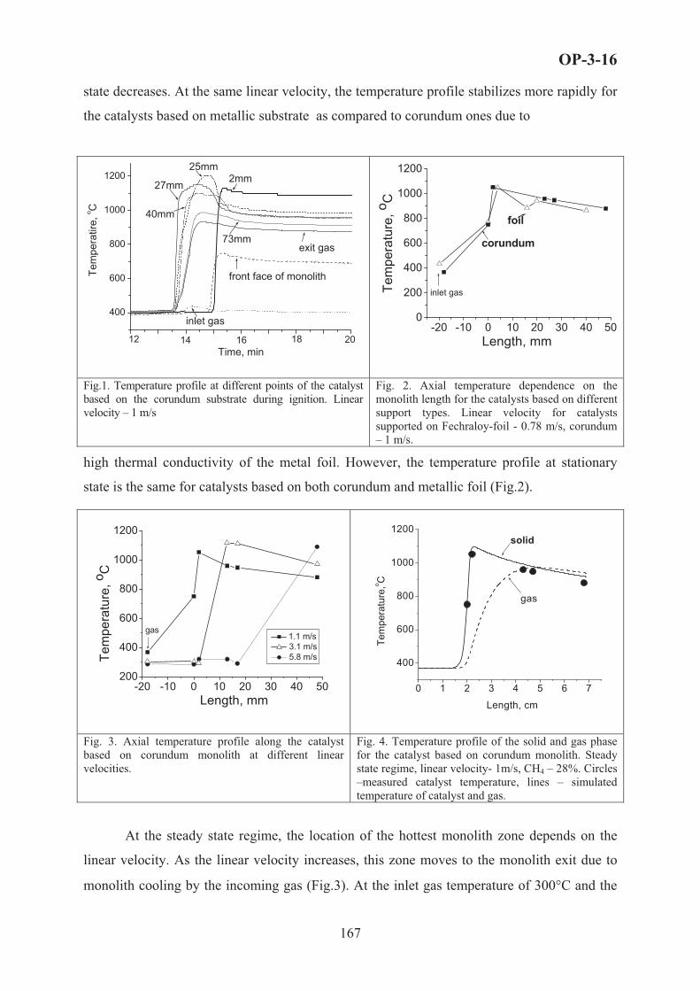
OP-3-16
state decreases. At the same linear velocity, the temperature profile stabilizes more rapidly for
the catalysts based on metallic substrate as compared to corundum ones due to
0:11:59 0:12:59 0:13:59 0:14:59 0:15:59 0:16:59 0:17:59 0:18:59 0:19:59
400
600
800
1000
1200
2018161412
2mm
73mm
40mm
25mm
27mm
front face of monolith
exit gas
inlet gas
Tem
pera
tire,
o C
Time, min
-20 -10 0 10 20 30 40 500
200
400
600
800
1000
1200
inlet gasTem
pera
ture
, o C
Length, mm
foil
corundum
Fig.1. Temperature profile at different points of the catalyst based on the corundum substrate during ignition. Linear velocity – 1 m/s
Fig. 2. Axial temperature dependence on the monolith length for the catalysts based on different support types. Linear velocity for catalysts supported on Fechraloy-foil - 0.78 m/s, corundum – 1 m/s.
high thermal conductivity of the metal foil. However, the temperature profile at stationary
state is the same for catalysts based on both corundum and metallic foil (Fig.2).
-20 -10 0 10 20 30 40 50200
400
600
800
1000
1200
gas
Tem
pera
ture
, o C
Length, mm
1.1 m/s 3.1 m/s 5.8 m/s
0 1 2 3 4 5 6 7
400
600
800
1000
1200
Tem
pera
ture
,o C
gas
solid
Length, cm
Fig. 3. Axial temperature profile along the catalyst based on corundum monolith at different linear velocities.
Fig. 4. Temperature profile of the solid and gas phase for the catalyst based on corundum monolith. Steady state regime, linear velocity- 1m/s, CH4 – 28%. Circles –measured catalyst temperature, lines – simulated temperature of catalyst and gas.
At the steady state regime, the location of the hottest monolith zone depends on the
linear velocity. As the linear velocity increases, this zone moves to the monolith exit due to
monolith cooling by the incoming gas (Fig.3). At the inlet gas temperature of 300,C and the
167

OP-3-16
linear velocity in the range of 0.5-2 m/s, methane conversion and syngas concentration are
nearly constant being equal to 77-72% and 45-41%, correspondingly. They decrease with
decreasing the inlet gas temperature.
It is known that partial methane oxidation can occur through an indirect route
including total oxidation of CH4 to CO2 and H2O followed by steam and dry reforming of
remaining CH4 [1]. Hence, in the narrow hottest zone of the monolith, highly exothermic total
oxidation occurs producing heat, which leads to the steep increase of the temperature. While
oxygen is consumed in this zone producing mainly CO2 and H2O, syngas is formed further
downstream via steam and, apparently, dry reforming of methane. The endothermic reforming
reactions lead to the temperature decrease along the catalytic monolith.
The simulation of the temperature profile along the catalyst based on corundum
monolith is in a good agreement with the experimental results (Fig. 4). In the exit zone of the
monolith, the simulated temperature of the gas phase is shown to be lower than the catalyst
temperature.
Acknowledgements. This work is in part supported by ISTC 2529 Project
1. C. Song, Catal.Today 77 (2002) 17.
2. D. A. Hickman and L. D. Schmidt, J. Catal., 138 (1992) 267.
3. V.A. Sadykov, S.N. Pavlova et al. , Kinetics and Catalysis, Vol. 46, No. 2 ( 2005) 227.
4. A.M. De Groote and G.F.Froment, Appl. Catal. A 138 (1996) 245.
168

OP-3-17
SIMULATION OF SELECTIVE REACTIONS PERFORMANCE IN
TRANSIENT REGIMES WITH PERIODICAL SEPARATE FEEDING
OF REAGENTS. CASE STUDY: PROPANE OXIDATIVE
DEHYDROGENATION IN ADIABATIC V-Ti CATALYST BED
A.N. Zagoruiko
Boreskov Institute of Catalysis SB RAS, pr. Akad. Lavrentieva, 5, Novosibirsk, 630090, Russia
e-mail: [email protected], fax: +7-383-3306878
Introduction
Improvement of selectivity and desired product yield in complex reaction systems is
one of the major problems in catalytic reaction engineering and also one of the main
challenges in the catalytic reaction engineering area. Usually such problems are solved by
development of new highly selective catalysts and by optimization of process operation
parameters, though it cannot guarantee the desired results in all cases.
One of the most prospective approaches for solution of the problem is application of
transient nonstationary regimes [1,2] and, in particular, periodical separate feeding of oxidant
and reductant. Studies [3,4] on propane oxidative dehydrogenation at vanadia catalysts
demonstrated that FFCC under isothermal conditions provided by periodical oscillations of
propane/oxygen concentration ratio in feed leads to increase of propylene yield compared to
steady-state conditions, with maximum C3H6 production at separate feeding of reagents.
Simulation of transient temperature and composition phenomena in an adiabatic
packed catalyst bed arising under periodical separate feeding of reagents was earlier
investigated by author for a complex consecutive system of model reactions [5]. The current
research is devoted to the case study of selective oxidative dehydrogenation of propane to
propylene.
Model formulation
As it was demonstrated in [4], the propane conversion at vanadia-titania catalyst may be
described by Eley-Rideal mechanism, proposing that oxygen is involved into reaction via step
of chemisorption, while hydrocarbon species react with chemisorbed lattice oxygen only (and
not the gas phase one). In this case the reaction scheme may be formulated as follows [4]:
C3H8 + [V2O5] K C3H6 + H2O + [V2O4] (1)
169

OP-3-17
C3H6 + 9 [V2O5] K 3 CO2 + 3H2O + 9 [V2O4] (2)
C3H8 + 10 [V2O5] K 3 CO2 + 4H2O + 10 [V2O4] (3)
[V2O4] + ½ O2 K [V2O5] (4)
At formulation of the process mathematical model two important factors were taken
into account: possibility of significant changing both the reaction mixture volume and heat
capacity in course of reaction performance. To simplify the model at this stage of research,
the dispersion factors (heat conductivity of the catalyst bed, mass transfer by gas diffusion), as
well as inter-phase heat/mass exchange were excluded from the description. The bed was
accounted as adiabatic and one-dimensional.
With account of these factors, the mass balance for species in the gas phase was
expressed as:
��2
2jij
i wl
uc�
)(
(5)
with boundary conditions: iniiin ccuul ��K� ;0 (6)
where u – superficial gas velocity, ci – molar concentrations of gas species (i = C3H8, C3H6,
CO2, H2O, O2, N2), �ij – stoichiometric coefficients of i-th species in j-th reactions, wj –
reaction rates (j = 1L4 correspond to reactions (1-4)), index in specifies values at the bed inlet.
Mass balance for lattice oxygen at the catalyst surface was given by equation:
��22
jjij wt
a �3max (7)
��! amax – maximum chemisorption capacity of catalyst surface in respect to lattice oxygen,
3 - surface fraction of oxidized active sites [V2O5] at the catalyst surface.
Kinetic equations (as well as values of their parameters) for wj were taken in
accordance with [4]:
)1(244
28333
26322
8311
33
3
3
��
�
�
O
HC
HC
HC
ckwckwckwckw
(8)
Due to significant changing of gas heat capacity in course of reaction it was
impossible to use conventional technique of adiabatic heat rise application, therefore, energy
balance was formulated in enthalpy terms:
170

OP-3-17
�2
2�
22
)),((),(
)1(cTuH
tTH gcat 3
� (9)
�2
2�
22
�22
�
iii Thcu
tHa
tT
))(()1( max
3$� 3 (10)
with boundary conditions:
);()();()(0;0
����
�
initinit
inin
TTtTTuu
33 ��K���K�
(11)
where � – temperature, cat and g – enthalpies of catalyst and gas, respectively, $ - heat
capacity of catalyst support material, �3 = �V2O5 - �V2O4, hi – enthalpies of individual
(i-th) components of reaction mixture.
Analysis of thermodynamic data showed that it is possible to neglect temperature
dependence for $ and �3, and to simplify polynomial functions hi (�) by linear
dependencies. Thermodynamic properties of surface species (V2O4 and V2O5) were assumed
to be equal to ones for the bulk state of these compounds.
Preliminary estimation of heat effects for reactions (1-4) showed, that stage of surface
selective oxidation (1) has slightly negative heat effect (app. -1.1 kcal per mole of propane),
while total exothermal character bulk selective oxidation (27.9 kcal/mole) is caused by high
enough heat effect of catalyst reoxidation stage (4) – ~ 29 kcal per mole of [V2O4]. At the
same time both deep oxidation stages (2,3) has fairly expressed positive heat effect (equal to
~ 200 kcal/mole for both stages).
Simulation results
Fig.1 represents the movement of heat front during feeding of pure propane with
elevated inlet temperature in the cold bed of preliminary oxidized catalyst. It is seen that (due
to practically zero heat effect of target reaction (1)) the maximum temperature of the catalyst
does not significantly exceeds the inlet gas temperature. In such conditions the observed
average-per-cycle selectivity of propane conversion into propylene is significantly higher than
in steady-state processes. In turn, reoxidation of the reduced catalyst by air also occurs at
moderate maximum temperatures (not exceeding 400°C), therefore, the process may be
realized without catalyst overheating even in case of using undiluted propane as feed.
Evidently, application of undiluted propane feed together with higher selectivity
provide higher unit propylene (per catalyst unit volume) output, compared to steady-state
processes, despite lower observed average conversion.
171

OP-3-17
Among other process advantages (compared to steady-state processes) the following
may be stated:
� higher propylene concentration in outlet gases and absence of diluents will simplify
separation of product propylene;
� absence of direct contact between hydrocarbon flammable species and oxygen,
impossibility of catalyst overheating will improve process safety;
� air may be used as oxidative agent instead of pure oxygen without decrease of process
efficiency;
� low coke formation (due to moderate process temperatures) as well as efficient
incineration of deposited coke during each reoxidation cycle may lead to higher
lifetime of the catalyst.
0
50
100
150
200
250
300
0 0,2 0,4 0,6 0,8 1l/L
T, �
0125250375500
Fig. 1. Temperature profiles vs catalyst bed length in different time points (time from cycle beginning is given at the right in seconds) under feeding
of pure propane into oxidized catalyst bed. Conditions: , T0,1 283 �� in
Oin
HC cc in=300°C, Tinit=20°C, 3init=1, L=1 m, u = 1 m/sec, �� = 20.8. Gas filtration direction is shown by arrow.
References 1. Matros Yu.Sh. Catalytic Processes Under Unsteady-State Conditions, Elsevier Science Publishers,
Amsterdam-New York, 1988.
2. P.L.Silveston. Composition modulation of catalytic reactors. Gordon and Breach Science Publishers, 1998.
3. D.Creaser et al. App.Catal.A: General, 187(1999), 147-160.
4. R.Grabowski, S.Pietrzyk et. al. Appl.Catal.A: General, 2002, 232, 277-288.
5. A.N.Zagoruiko. Chemical Engineering Journal, 2005, 107, 133-139.
172

OP-3-18
NOVEL CATALYTIC PLASMA REACTOR FOR THE ABATEMENT
OF DILUTED VOLATILE ORGANIC COMPOUNDS
Ch. Subrahmanyam, A. Renken and L. Kiwi-Minsker
Ecole Polytechnique Fédéral de Lausanne (LGRC-EPFL), CH-1015 Lausanne, Switzerland
Fax: +41-21- 693 31 90, [email protected], [email protected]
Abstract
The emission of industrial exhaust gases containing diluted Volatile Organic
Compounds (VOCs) into the atmosphere is an important source of air pollution and an
environmental concern. Abatement of VOCs needs highly efficient low cost processes.
Conventional techniques for the abatement of VOCs mainly include thermal and thermo-
catalytic oxidation. However, at low VOC concentrations (< 1000 ppm), these techniques are
limited by the energy supply. Among the alternatives, non-thermal plasma (NTP) generated at
atmospheric pressure is advantageous. The NTP selectively produces high energy electrons at
ambient temperature without heating the flue gas. The NTP has been tested for the destruction
of various VOCs, but the low selectivity (0.3 to 0.5) to total oxidation products (CO2 and
H2O) limits the application. In order to improve the efficiency of NTP technique, plasma is
often combined with a heterogeneous catalyst. In practice, the catalyst can be placed either in
the discharge zone (in-plasma catalytic reactor) or after the discharge zone (post-plasma
catalytic reactor). However, both reactors suffer due to the deactivation of the catalyst caused
by carbonaceous deposits on the catalyst surface. Hence, novel reactors combining plasma
with the catalytic action are needed. Present study deals with the design and performance of a
novel dielectric barrier discharge (DBD) reactor for the destruction of VOCs. Influence the
catalyst, voltage, frequency and energy input are studied for VOCs of different nature.
A novel DBD reactor with catalytic electrode is shown in Fig.1. The novelty is that the
metallic catalyst made of sintered metal fibers (SMF) also serves as the inner electrode. The
dielectric discharge was generated in a cylindrical quartz tube with a modified stainless steel
filter (SMF) as the inner electrode. The SMF was doped by Mn and Co oxides. Typical
discharge length was 10 cm and discharge gap was varied between 1.0 to 3.5 mm. The
specific input energy (SIE) in the range 165-1650 J/l was applied by varying the AC high
voltage (12.5-22.5 kV) and frequency (200-350 Hz). The V-Q Lissajous method was used to
determine the discharge power (W) from which SIE was calculated. Destruction of model
173

OP-3-18
VOCs (toluene, isopropanol (IPA) and trichloroethylene (TCE)) was carried out in the DBD
reactor designed.
SMF
VOC
Microdischarge Copper rod
CO2 + H2O
SMF
VOC
Microdischarge Copper rod
CO2 + H2O
Fig. 1. Schematic representation of the novel DBD reactor
Typical results obtained show that under the same experimental conditions (discharge
gap of 3.5 mm) MnOx and CoOx supported SMF electrodes shifted the product distribution
towards total oxidation. At a fixed initial concentration of the VOCs, it has been observed that
total oxidation of an alcohol (IPA) can be achieved at low SIE compared to an aromatic
hydrocarbon (toluene) followed by chlorinated hydrocarbon (TCE). The optimized results
with MnOx/ SMF electrode indicate that for 250 ppm of VOC, a SIE of 760 and 1650 J/l was
required for the complete oxidation of IPA and toluene, respectively, whereas for TCE the
selectivity to CO2 was ~ 50 % even at 1650 J/l. The better performance of MnOx/ SMF might
be due to the formation of active oxygen species by the in-situ decomposition of ozone on the
catalyst surface. The selectivity to CO2 during TCE destruction was further improved up to ~
85 % at 650 J/l by modifying MnOx/SMF with TiO2. The catalysts were characterized by
different methods and the results will be presented in detail.
References[1]. F. Holzer, U. Roland, F.D. Kopinke, Appl. Catal. B: Environmental 38 (2002)163.
[2]. B. Penetratnte, M.C. Hsiao, J.N. Bardsley, B.T. Merrit, G.E. Vogtlin, A. Kuthi, C.P. Burkhart, J.R. Bayless, Plasma Sources Sci. Technol. 6 (1997) 251.
[3]. S. Futamura, H. Einaga, H. Kabashima, L.Y. Jwan, Catal. Today 89 (2004) 89.
[4]. Ch. Subrahmanyam, M. Magureanu, A. Renken and L. Kiwi-Minsker, Appl. Catal. B: Environmental (in press).
174
OP-3-19
SELECTIVITY OF OXIDATION PROCESSES IN FLUIDIZED BED
REACTOR UNDER CATALYST UNSTEADY STATE
S.A. Pokrovskaya, M.G. Slinko*
Boreskov Institute of Catalysis SB RAS, Novosibirsk, pr. Akademika Lavrentieva, 5, Russia
*SPC “Karpov NIPCI”, Voronzovo pole, 10, Moscow, Russia
Phone: 007-3833-306278; fax: 007-3833-306878, E-mail: [email protected]
One of the specific features of heterogeneous catalytic processes in the reactors with
fluidized bed is that catalyst particles move continuously in non-uniform field of gas
concentrations. The concentrations of active species on the catalyst surface depend on the
surrounding gas composition due to reaction stages and various physical processes on the
surface and in the bulk of the crystalline lattice. The time scale required for attainment of
steady state of the catalyst surface could be close or exceed the time scale of particles moving
along the bed height. In this case, in spite of stationary operation conditions of fluidized bed
reactor as a whole, the process is realized at unsteady coverage of the catalyst surface by
reactive species with respect to reagent and product concentrations [1].
Under unsteady state of the catalyst the main process characteristics such as reagent
conversion, selectivity to desired product, process productivity etc., could differ considerably
from the ones for steady conditions. The studies illustrated the similar effects were fulfilled
for the processes in the fixed catalyst bed with forced feed composition cycling. It was shown
that such approach may provide enhancement of selectivity for a number of reaction systems
[2,3,4]. But effects of unsteady state of the catalyst surface in fluidized bed reactors were
studied only in a few works [1, 5, 6].
This work considers such effect on products selectivity in fluidized bed reactor (without
inlet and outlet of catalyst particles) for the partial oxidation processes. At first the numerical
simulation of the system behaviour is carried out for model kinetic scheme. Examples of the
comparison of modeling and experimental results are discussed also for some processes of
selective oxidation of hydrocarbons.
Mathematical model. The review of equation systems of material balance based on the
kinetics with steady coverage of catalyst surface and used nowadays for process modeling in
the reactor with fluidization regime is given in the publication of J. R. Grace with co-workers
175

OP-3-19
[7]. To simulate the system behavior with catalyst unsteady state this mathematical
description includes in addition the differential equation of the Focker-Plank type [1]. In
studies presented below the simple two-phase model is applied to describe gas concentration
profiles.
Model kinetic scheme. The simplified reaction scheme used for simulation contains two
consecutive pathways of partial and deep oxidation: A + �1 B � C, C + �2 B � D, where
is A – the reagent, B – the oxidant (oxygen), C – the desired product, D – the undesired
product. These reactions were supposed to occur according the following steps:
a) B + [ ] � [B] b) A + �1 [B] � C + �1 [ ] c) C + �2 [B] � D + �2 [ ]
Catalytic step rates were in accordance with mass-action law assuming that activation
energies may depend on the surface coverage [8].
Account runs were fulfilled using complete model, reflecting unsteady coverage of the
catalyst surface, with variation of stoichiometric coefficients and step rate constants as
functions of the fraction of surface oxidized sites. To reveal the effect of unsteady catalyst
state, the results were compared with the data simulated for the steady coverage of the catalyst
surface. For the second stage, as usually, the surface oxidant concentration was taken to be
stationary with respect to gas concentrations and excluded from kinetics, all other parameters
were the same. Summarizing results it is possible to choose three types of effects for studied
system:
– Catalytic step rates are linearly dependent on surface oxidant concentration. Unsteady and
steady catalyst state in fluidized bed lead to the same output yield of desired product C.
– The dependence is not linear, selectivity rises with the increase of the fraction of oxidized
active sites. Process selectivity in the reactor declines because of more reduced unsteady
state of the catalyst surface.
– Selectivity increases with the growth of the fraction of reduced surface sites. Unsteady
surface coverage results in the rise of process selectivity and output yield of purposeful
product C.
Thus, due to integral unsteady state of the catalyst the selectivity to purposeful product in
the fluidized bed reactor might be considerably lower or higher as compared to that for
corresponding stationary state. The state of the catalyst in the fluidized bed could be one of
the main factors governing the product selectivity. The examples of such effects are given
below.
176

OP-3-19
Effect of unsteady state for the selective oxidation processes. Numerical simulation of
three processes of selective oxidation of hydrocarbons was carried out comparing with the
experimental results of laboratory and pilot setups with fluidized bed reactor.
Propylene oxidation to acrolein and acrylic acid
The process was realized on Co/Mo/Te/P catalyst in the pilot fluidized bed reactor. 11-
12% decrease of the yield of acrolein and acrylic acid was obtained in comparison with the
data simulated on the basis of stationary kinetic model.
Modeling has shown that the product selectivity decrease takes place as a result of mass
transfer between a dense and bubble phase, by about 1-2%, and as a result of unsteady state of
the catalyst, by about 10%. The special comparison experiments in laboratory reactors with a
fixed and fluidized bed have confirmed these results. At studied operation conditions the
catalyst surface was found to be more reduced in the fluidized bed reactor than one of the
reactor with the fixed bed.
Propylene ammoxidation to acrylonitrile
The transient experiments obtained on 8-component catalyst (C-41 type) showed that the
reduction of catalyst surface results in an increase of the selectivity to acrylonitrile. In the
fluidized bed reactor, the state of the catalyst surface depends on the ratio of inlet
concentration of ammonia to oxygen one. The optimal conditions were found by simulation to
exclude unsteady state of the catalyst with a high degree of oxygen coverage and to provide
maximum selectivity to acrylonitrile. The experiments in the pilot reactor confirmed the
modeling results to demonstrate the 3-4% increase of the acrylonitrile selectivity.
O-xylene oxidation to phthalic anhydride
The simulation has been carried out based on the dynamic kinetic model. Quantitative
estimations of surface species on V-Ti-O catalyst were received for the process in the
fluidized bed reactor. Reactor modeling was performed for isothermal and nonisothermal
fluidization regimes and for such regimes to assume steady catalyst state. Simulation results
were in an agreement with experiments carried out in the lab fluidized bed reactor by A.A.
Ivanov with co-workers [5].
At studied operation conditions the process occurs with unsteady state of the catalyst.
This state generated for isothermal conditions results in significant decrease of phthalic
anhydride selectivity in the reactor. The selectivity loweres by 6-8 % in comparison with one
simulated with stationary kinetics. Conditions to form the unsteady selective state of the
catalyst with the high yield of phthalic anhydride have been specified. In nonisothermal
177
OP-3-19
regime the alteration of catalyst state takes place in comparison with isothermal conditions
and phthalic anhydride yield increases by about 20%.
Acknowledgments
The authors are grateful:
– to colleagues from Boreskov Institute of Catalysis T.V.Andrushkevich and A.A. Ivanov
with co-workers for a large number of precise experiments and fruitful discussion;
– to V.P.Gaevoi (Sobolev Institute of Mathematics ) and E.M. Sadovskaya (Boreskov
Institute of Catalysis) for assistance in software development.
References 1. Slinko M.G., Pokrovskaya S.A., Sheplev V.S., Dokl.AN SSSR., 221 (1975) 157-161; 244 (1979) 669-673.
2. Yu.Sh. Matros, Catalytic Processes Under Unsteady-State Conditions, Elsevier Science Publishers,Amsterdam,1988.
3. P.L. Silveston, Composition Modulation of Catalytic Reactors, Gordon and Breach Science Publishers, 1998.
4. A.N. Zagoruiko, Chemical Engineering Journal, 107 (2005) 133-139.
5. A.A. Ivanov and B.S. Balzhinimaev, In Proceedings of the International Conference “Unsteady State Processes in Catalysis” (1990) 91-113, Utrecht, The Netherlands, Tokyo, Japan: VSP.
6. Reshetnikov S.I., Balzhinimaev B.S., Gaevoi V.P., Ivanov A.A., Chemical Engineering Journal, 60 (1995) 131-139.
7. H.T.Bi, N.Ellis, I.A.Abba, J.R.Grace, CES, 55 (2000) 4789-4825.
8. A. Renken, In Proceedings of the International Conference “Unsteady State Processes in Catalysis” (1990) 183-203, Utrecht, The Netherlands, Tokyo, Japan: VSP.
178

OP-3-20
MATHEMATICAL MODELING AND EXPERIMENTAL STUDY
OF HIGH PRESSURE ETHYLENE POLYMERIZATION REACTORS
A.M. Saveljev*, Ju.N. Kondratjev*, A.E. Sofiev*, S.S. Ivanchev**
*Central R&D Institute for Complex Automation
8, Mozhaisky Val, Moscow, Russia
fax: +7 (495) 2404206, e-mail: [email protected]
**St-Petersburg Department of the Boreskov Institute of Catalysis SB RAS
14, prospect Dobrolubova, 197198, St-Petersburg, Russia
fax: +7 812 2330002, e-mail: [email protected]
Mathematical models and experimental data are discussed for high pressure ethylene
polymerizations in stirred tank and tubular reactors. The model is based on free radical
mechanism of ethylene polymerization using material and energy balance equations as well as
impact balance (for tubular reactors).
A stirred tank reactor is modeled taking into account mixing modes in the reactor on
the basis of the segregation approach. Models for single- and double-zone stirred tank reactors
are considered upon the comparison of the relating calculations with experimental data
obtained using commercial polymerization reactors. The developed mathematical model was
used to study the stability of stirred tank reactors and determine the range of the process
parameters corresponding to their sustainable functioning. The possibility and conditions
responsible for arising of bifurcation modes in the reactor at certain process parameters as
well as the effect of the initiation and mixing modes upon the stable functioning ranges are
theoretically revealed and experimentally confirmed.
The experimental data show that at the temperature increase in the top cross-section of
the reactor (S1) due to the control of the initiator amount supplied in this zone the temperature
growth profile in the next cross-section (S2) gradually drops and the polymerization zone
continuously shifts towards S1. This phenomenon is accompanied by the decrease of the
polymer molecular weight and initiator efficiency (Fig. 1, 2).
179

OP-3-20
Figure 1. Temperature profiles in S1 and S2 cross-sections at temperature increase in S1
Figure 2. Temperature gradient in two cross-sections at temperature increase in S1
Industrial stirred tank reactors operate in a nearly adiabatic mode with the ratio
G*Cp /KF > 5 and the temperature difference between the cross-sections S2 and S1 (�s2 - �s1)
being always positive. #$!��? @�\�^_`!\{|?. (G*, Cp are the reaction medium mass flow
and heat capacity accordingly and K, F are the heat transfer constant and surface area in the
stirred tank reactor). However, for a pilot stirred tank installation at G*Cp /KF~0.5 the
temperature growth in the cross-section S1 leads to negative values of the temperature
gradient between these cross-sections confirming the process shift towards S1.
At reduced temperatures in S1 zone for a certain initiator the process temperature
should be controlled on the basis of the temperatures in this cross-section while at higher S1
temperatures the control can be based on the levels for either S1 or S2. The further increase of
S1 temperature with S2-S1 temperature gradient approaching zero is undesirable in view of a
high risk of the process thermal stability loss.
The considered changes in the polymerization behavior are qualitatively intrinsic to all
the applied initiators, however a certain initiator type affects the temperature gradient value in
S1 cross-section. For Trigonox-36 the low temperature level is 170-175,C whereas for
Trigonox-42 this value is about 215,C.
For a multi-zone tubular reactor the mathematical model is based on the plug-flow
admission and the following aspects are presented and discussed:
- calculation results and experimental data for a series of commercial ethylene
polymerization reactors;
- recommendations for the selection of optimum technological conditions and modes
for the exploration of such reactors as well as for their geometric (length, number of zones
and their diameters) and heat exchange system design.
180

OP-3-20
The adequacy of the developed mathematical models was tested using experimental
data obtained for various commercial tubular polyethylene production reactors. First the
sensitivity towards the main process parameters was analyzed followed by the determination
of criteria to the experimental data. The studies were carried out relating to industrial high
pressure reactors with a merely peroxide (stirred tank and tubular reactors), oxygen and
complex (tubular reactors) initiation.
The results of mathematical modeling for a double-zone tubular reactor with different
initiating systems are shown in Fig. 3 and fitting of the calculated and experimental
temperature profiles are illustrated in Fig. 4. The theoretically expected and measured data for
the initiator consumption, temperature profiles and process control parameters are found to be
in a good agreement.
150160170180190200210220230240250260270280290300310320
0 100 200 300 400 500 600 700 800 900 1000 1100 1200 1300 1400
length,m
Tem
pera
ture
, C
12
3 1 and 2
3
Water
3
Figure 3. Temperature profiles in a double-zone tubular reactor with different initiating
systems
1 – oxygen initiation in both zones;
2 – first zone: oxygem + Trigonox-36 (1.9 kg/h), second zone: oxygen;
3 – first zone: oxygen + Trigonox-36 (1.3 kg/h)+Trigonox-� (0.52 kg/h), second zone:
oxygen + Trigonox-C (1.9 kg/h). Conversion growth up to 23 %.
- initiator solution input points; - control points.
181

OP-3-20
150160170180190200210220230240250260270280290300310
0 150 300 450 600 750 900 1050 1200 1350
length, m
Tem
pera
ture
, C
�g }�w MTg ETw E
Figure 4. Comparison of experimental and modelling data.
Experiment: PE=10.9tons/h; first zone - Tr-36+Tr-C+O2 (26+15.4+54.6) ppm;
second zone - Tr-C+O2 (28+14.1) ppm
Modeling: PE=11.045 tons/h; first zone – Tr-36+Tr-C+O2 (26+15.4+10.7) ppm;
second zone – Tr-C+O2 (30.2+4.33) ppm
182

OP-3-21
MODELING AND SIMULATION OF THE DIMETHYL CARBONATE
(DMC) SYNTHESIS PROCESS IN REACTIVE DISTILLATION
REACTOR WITH A NONEQUILIBRIUM MODEL
Feng Wang1, 2, Ning Zhao1, Junping Li1, Wei Wei1, Yuhan Sun1,*
1 State Key Laboratory of Coal Conversion, Institute of Coal Chemistry, Chinese Academy of
Sciences, Taiyuan, 030001, P R China; 2 Graduate School of the Chinese Academy of Sciences, Beijing, 100039, China
* Corresponding author, e-mail [email protected], fax +86 351 4041153
Dimethyl carbonate (DMC) has drawn considerable attentions as it is considered as an
environmentally benign building block and has wide usage in chemical industry. It may be
used as methylation reagent to substitute extremely toxic dimethyl sulfate or as carbonylation
reagent for replacing phosgene [1-3]. However, the current routes of the DMC synthesis suffer
from some drawbacks, such as using of poisonous and/or corrosive gases of chlorine, nitrogen
oxides and carbomonoxide and bearing the possibility of explosion. Recently, a novel process
for the synthesis of DMC from urea and methanol over heterogeneous solid bases catalyst has
been presented and successfully carried out in packed reactive distillation at bench and pilot
scale[1].
The packed reactive distillation (RD), a kind of reactive distillation, which combine a
chemical reaction and distillation in a single unit, has become more important in the chemical
processing industry for it can provide many advantages, such as high product conversion and
selectivity, energy saving, simpler operation, overcoming of the azeotropic limitations and
prolonging the catalyst lifetime[4]. Its application in chemical industry has increased rapidly in
recent year. Up to now, a quite number of publications on nonequilibrium models have been
presented on investigation of the performance of the RD.
In this work, a nonequilibrium model has been developed for the packed RD process of the
DMC synthesis by urea methanolysis method over heterogeneous solid bases catalyst, which
has been operated in the pilot scale. The mass and heat transfer between the vapor and liquid
183

OP-3-21
surface is taken into account based on the Maxwell-Stefan theory. The heterogeneous reaction
in the DMC synthesis process is considered as a pseudo-homogeneous description, so the total
amount of the catalyst presented in the RD is the necessary parameter to meet the need of the
chemical reactions [5]. The mathematical model has been solved by discretizing the
differential equations along the spatial dimension using a high order finite-differential
approach [6].
The synthesis of DMC from urea and methanol was considered to be a two-step reaction
(shown as following). The intermediate methyl carbomate (MC) was produced with high yield
in the first step and further converted to DMC by reaction with methanol in the second step. It
was also found that the first step is much easier than the second step which might take place
even without catalyst[1]. As a result, the first reaction of the DMC synthesis has been omitted
in the kinetics model.
H2N NH 2
O
+H 3CO NH 2
O
+ NH 3CH 3OH
+H3CO OCH3
O
H3CO NH2
O
+ NH 3CH 3OH
(1)
(2)
As can be seen from Eqs. (1) and Eqs. (2), the reaction system includes a light component
ammonia and a binary azeotrope methanol-DMC. Considering the system nonideality, the
Wilson model for the liquid activity and the Virial function for the gas fugacity are used to
calculate the vapor-liquid equilibrium.
As a result, the following assumptions are made for the NEQ model:
(1) The process reaches steady state;
(2) The first reaction is omitted as the first step may be take place in the preheater without
catalyst.
(3) The reactions take place entirely in the liquid bulk.
(4) The heat effect of the reaction is omitted in the model.
(5) Total mixing for liquid bulk.
(6) Vapor-liquid equilibrium occurs at the vapor-liquid interface and in the condenser and the
reboiler.
(7) The reactions are considered to be pseudo-homogeneous.
184

OP-3-21
(8) The pressure drop per meter along the RD column is considered as constant.
The nonequilibrium differential model equations are described below:
Material balance is defined as:
0� Lii
Li
i NRfdzdl (3)
0� Vi
Vi
i Nfdzdv (4)
The energy balance is defined as:
0)(� QeHF
dzLHd LLL
L
(5)
0)(� QeHF
dzVHd VVV
V
(6)
where the vapor and liquid energy transfer rate is considered as equal. The vapor heat
transfer rate is defined as:
��
22
�C
i
VVi
VVV HNTahe
1G(7)
Vapor-liquid equilibrium occurs at the vapor-liquid interface: (8)
0� Ii
Ii
Ii xKy
The equilibrium constant is computed by
i
iiiIi Pf
fPK00$
� (9)
The mathematical model is discretized along the spatial dimension of the packed reactive
distillation using a high order finite-differential approach to generate the differential-algebraic
equations [6].
The simulated column is configured with two feeding inlets and a side outlet, two preheaters
for each feeding inltet, in which the first step reaction of the DMC synthesis occur. The catalyst
pellets are randomly packed in the reaction section. As for releasing the noncondensing gas of
ammonia, the distillation has configured a partial condenser.
The process for the DMC synthesis has been operated at the pressure of 10-16 atm. and the
185

OP-3-21
reactions took place at the temperature of 420-450 K. The mixture of urea and methanol and
the pure methanol were fed to the RD respectively and the product was sampled from the side
outlet. Based on the nonequilibrium model, the catalytic feasibility, effects of the feed
locations of the reactants, the strong interaction of the components and the mass transfer in the
packed RD column has been investigated. The predicted result was in accordance with the
experiment data.
Conclusion: In this work, a nonequilibrium model of the packed reactive distillation has
been carried out to investigate the process for the synthesis of DMC from urea and methanol
by using solid base as catalyst. As the process includes a binary azeotrope, the reactive
distillation has shown its advantages on the synthesis of the DMC and the product separation.
Notation efficient interface area, m2/m3
liquid and vapor heat transfer rate, J/s a
liquid and vapor feed of component , mol/s Vi
Li ff , i
vl ee ,
liquid and vapor feed, mol/s VL FF ,
heat transfer coefficient, J m-2s-1K-1h liquid enthalpy, J/mol L
vapor enthalpy, J/mol HH V
equilibrium ratio liquid flux of component , mol/s i
IKi
vapor and vapor mass transfer rate of component , mol/s iil
L NN , Vii
pressure, kPa vapor pressure of component , kPa iP
heat duty, J/s absolute temperature, K vapor flux of component , mol/s i liquid composition, molar fraction vapor composition, molar fraction
References [1] W. Mouhua, W. Hui, Z. Ning, Catal. Comm. 7 (2005) 6. [2] A.G. Shaikh, S. Sivaram, Chem. Rev. 96 (1996) 951. [3] P. Tundo, M. Selva, Chemtech. 25 (5) (1995) 31. [4] L. Huping, X. Wende, Chem. Eng. Sci. 56 (2001) 406. [5] Higler, A, Taylor, R., & Krishna, R. Comput. Chem. Eng. 22 (1998) 113. [6] Sebastien Lextrait, R. Bruce Eldridge, Ind. Eng. Chem. Res. 43(2004) 3860.
QT
xy
0iP
vi
186

OP-3-22
CITRAL HYDROGENATION OVER DIFFERENT ZEOLITES AND
MCM-41 SUPPORTED Ni AND Ni-Sn CATALYSTS
Hilal Gülec1, Selahatttin Yilmaz1, Levent Artok2
1) Department of Chemical Engineering,2)Department of Chemistry,
zmir Insitute of Technology, Gülbahçe Köyü, Urla, zmir, Fax:00-90-232-7506645,
e-mail:[email protected]
1. INTRODUCTION
The selective hydrogenation of -� unsaturated aldehydes is a difficult challenge since the
C=C bond is much easily attacked then the C=O bond when a conventional heterogeneous
catalysts used. Therefore, many efforts have been made to develop a suitable industrial
catalyst that would be able to lead to the hydrogenation of C=O bond to get unsaturated
alcohols. Citral hydrogenation was performed over noble metals (Pt, Rh, Ru, Pd and Ni) on
different supports [1-5] over bimetallic catalysts such as Ni-Cu [5], Ru-Fe [3] and Ru-Sn [7,8]
and over basic catalysts [9]. These studies showed that modification of the metal properties by
promoter increased selectivity to unsaturated alcohols (nerol, geraniol, citronellol) and the
support also affected the product distribution. Electronic effects and geometric effects have
been suggested as explantaion for the improvement in the selectivity to unsaturated alcohols.
Zeolite supports induce the possibility of metal support interactions: active metals can be
polarized by nearby cations or by metal support interaction [10]. Zeolite supported
monometallic catalysts were tested in citral hydrogenation recently [4,5]. Maki-Arwela et
al[2003] reported that the Ni supported on H or NH4 forms of Y zeolite catalysts gave lower
selectivities (<5%) and this was attributed to the presence of acid sites in the zeolite.
However, in our study [5] Pd supported on clinoptiolite rich natural zeolite, the major product
was citronellal (90 % selectivity). Further research is needed to determine the role of zeolite
supports in citral hydrogenation reaction.
In the present study, monometalic (Ni) and bimetallic (Ni-Sn) catalysts supported on
Na-Y, Na-Beta, Na-Mordenite (Na-MOR) and MCM-41 and clinoptilolite rich natural zeolite
(CLINO) were prepared, characterized and tested in citral hydrogenation.
187

OP-3-22
2. EXPERIMENTAL STUDY
2.1. Preparation of Catalysts
Clinoptilolite rich natural zeolites (Gördes-Manisa, Turkey) [4], Na-MOR (Süd-Chemie,
MOR powder), Na-Y (Zeolyst, CBV100), and Na-� (Süd-Chemie, BEA powder) were
calcined at 500 oC under N2 flow (100 ml/min) for 5 h in a tubular reactor. MCM-41 was
synthesised according to a method given literature[11] It was calcined at 560 oC with
1.5 oC/min heating rate for 6 h in order to remove the template.
Monometallic Ni catalysts were prepared by impregnation method from a ethanolic
solution of 0.01 M Ni(NO3)2.6H2O. Bimetallic catalysts were prepared by coimpregnation
method. The Ni loading of the catalysts were kept constant (10 wt %) while the Sn/(Sn+Ni)
mole ratio was 0.2. For this catalyst, the ethanolic solution of Ni(NO3)2.6H2O and
SnCl2.2H2O was used. The impregnated samples were dried at 120 oC overnight and then they
were calcined at 500 oC under dry air (100 ml/min) for 5 h.
2.3 Catalyst Testing
Hydrogenation experiments were performed in a stirred, semibatch reactor (500 ml, 4574
model, Parr Instrument Co.). The catalysts (0.25 g for each test) were activated in situ. Citral
(200 ml of 0.1 M citral in ethanol) was hydrogenated at 80 oC under 6 bar H2 with a stirring
rate of 600 rpm.The products formed were analyzed by a GC and were identified by GC-MS
technique. The compositions of components in the reaction mixture were determined by
internal standardization method.
3. RESULTS AND DISCUSSION
3.1. Catalyst Characterisation
Elemental and textural properties of supports, monometallic and bimetallic catalysts are
given in Table 3.1. The Sn/Sn+Ni mol ratio of bimetallic catalysts are shown in brackets. The
catalyst surface areas were found to decrease with the metal loading. This could be due to
blockage and/or narrowing of some of the pores due to the loading.
SEM micrographs of zeolites showed that the morphologies of the samples were different.
The crystallite sizes of Na-Y, Na-�, Na-MOR, MCM-41 and CLINO supports were around as
400 nm, 100 nm, 150 nm, 500 nm and 7 μm respectively. XRD diagrams showed that the
structures of the support materials were preserved. The peak of Nickel Sin Alloy (Ni4Sn) was
also observed at 23 = 44.8 , for Na-Y and Na-MOR supported bimetallic catalysts.
188

OP-3-22
Table 3.1. Properties maximum selectivities of UOL observed with the corresponding
conversion and for the different catalysts tested.
Catalysts Ni
(wt %)
Sn
(wt%)
Si/Al
BET Area
(m2/g)
Vp
(cm3/g)
X1
(%)
SUOL2
(%)
Na-Y - - 2.6 886.1 0.463 - -
Ni/Na-Y 8.2 - 2.6 785.7 0.404 57.6 1.5
Ni-Sn/Na-Y (0.2) 8.1 4.1 2.6 703.0 0.324 10.3 27.4
Na-� - - 12.4 558.8 0.413 - -
Ni/Na-� 8.2 - 12.4 549.2 0.350 - 0.0
Ni-Sn/Na-� (0.2) 8.1 4.2 12.4 515.8 0.297 18.1 29.7
Na-MOR - - 9.0 390.2 0.233 - -
Ni/Na-MOR 8.8 - 9.0 394.7 0.182 - 0
Ni-Sn/Na-MOR(0.2) 8.1 3.87 9.0 348.2 0.138 26.6 35.5
MCM-41 - - - 1449.0 0.866 - -
Ni/MCM-41 8.5 - - 1074.2 0.596 29.8 24.8
Ni-Sn/ MCM-41(0.042) 9.2 0.83 - 970.7 0.564 37.4 16.9
CLINO - - 5.3 43.3 0.065 - -
Ni/CLINO 9.0 - 5.3 38.6 0.055 37.6 13.4
Ni-Sn/CLINO(0.2) 8.5 4.6 5.3 34.1 0.050 26.7 17.1
1) conversion at maximum selectivity to UOL, 2) maximum UOL selectivity observed
3.2 Activity and Selectivity of the Catalysts
Citral hydrogenation reaction over monometallic and bimetallic catalysts gave variety of
products, which were citronellal, citronellol, nerol, geraniol, isopulegol, 3,7-Dimethyl-1-
octanol, menthols and acetals. Unsaturated alcohols nerol and geraniol were reffered to as
UOL in the text. The maximum selectivities to UOL observed for different catalysts with
corresponding conversions are given in Table 2.
The major product over all monometallic catalysts and bimetallic catalysts was citronellal
except for Ni/Na-� catalyst, which gave acetal as the main product. The product distribution
was affected by the different supports. The acetal formation is related to presence of acid sites
[5]. The high silica to alumina ratio of Na-� (compared to other supports) together with its
smallest crystallite and irreqular morphology might be the reason for the acetal formation.
Among the monometalic catalysts, geraniol and nerol formed only Ni/Na-Y, Ni-MCM-41
and Ni/CLINO. Their amounts were initially high and dropped with reaction time. The
maximum selectivity to UOL was observed with Ni-MCM-41 (24.8%).
189

OP-3-22
Monometallic catalysts showed high activity (conversions> 90 %) over the whole reaction
time (300 min). Ni/Na-Y catalyst gave the highest conversion among the catalyst giving
desired products. This could be related to its high surface area and its Al content compared to
other catalysts.
The addition of Sn affected monometallic catalyst product distributions and activities
differently. Selectivity to UOL significantly increased over Ni-Sn/Na-MOR (from 0 to
35.5 %), Ni-Sn/Na-Y (from 1.5 to 27.4 %) and Ni-Sn/Na-Beta (from 0 to 29.7)%. SUOL was a
little improved over Ni-Sn/CLINO. However, an unexpected trend was observed with
Ni-Sn/MCM-41 for which SUOL decreased by 1/3. The significant increase in the SUOL was
observed over the catlayst having Ni-Sn alloy formation. Probably these sites were
responsible for enhance UOL formation [7,8]. Amount of acetal formation was also lowered
with bimetallic catalysts. This implied that some of the active acid sites and metal sites were
covered by the promoter. As a result asetal formation decreased
The activity of catalysts dropped with promoter addition except Ni-Sn/MCM-41, this was
the catalyst for which Sn addition decreased SUOL. This was the only catalyst that did not
contain Al. The reason for the increase in activity was not clear. This awaits further
invetigation.
5. REFERENCES 1. Armendia M. A., Borau, V., Jimenez, C., Marinas, J.M., Porras, A., Urbano F.J., J.Catal, 172 (1997) 46.
2. Singh U.K.and Vannice M.A., J. Catal. 189(2001)
3. Baeza, B.B., Guerrero-Ruiz, A., Wang, P. and Rodríguez-Ramos, I. Guerrero-Ruiz, A., App. Catal. A:Gen, 205(2001)227.
4. Y�lmaz, S., Ucar, �., Artok, L., Güleç, H., App. Catal. A:Gen., 2005.
5. Mäki-Arvela, P., Tiainen, L.-P., Lindblad, M., Demirkan, K., Kumar, N., Sjöholm, R., Ollonqvist, T., Väyrynen, J., Salmi, T. and Murzin, D.Yu. , App. Catal. A:Gen., 241(2003)271.
6. Baeza, B.B., Guerrero-Ruiz, A., Wang, P. and Rodríguez, I. J. Catal., 204(2001)450.
7. Silva, A.M., Santos, O.A.A., Mendes, M.J., Jordão, E. and Fraga, M.A. App. Catal. A:Gen.,.241 (2003.)155.
8. Coupé, J.N., Jordão, E., Fraga, M.A. and Mendes, M.J. , App. Catal. A:Gen 199(2000)45.
9. Armendia M. A., Borau, V., Jimenez, C., Marinas, J.M., Ruiz J.R, A., Urbano F.J., J. Mol. Catal. A.171 (12001)153.
10. A.P. Jansen, R.A. van Santen, J. Phys. Chem 94 (1990)67.
11. Lin, H.P., Cheng, S. and Mou, C.Y. 2002. Microporous Matter. p. 10-11.
190
OP-3-23
A TWO DIMENSIONAL STEADY-STATE MODEL OF THE
GAS-SOLID-SOLID REACTOR. EXAMPLE OF THE PARTIAL
OXIDATION OF METHANE TO METHANOL
Dallos C.G., Kafarov V., Maciel R.*
Universidad Industrial de Santander, Bucaramanga, Colombia
*Estadual de Campinas, Campinas-sp, Brazil
Partial oxidation of methane
The partial oxidation of methane to methanol has considerable potential for the utilization
of vast natural gas fields in remote areas of the world. This process would not only be easier
to of transport, but also increases the range of subsequent applications for further processing.
The number of recent publications in this area reflects renewed interest in this reaction as an
alternative to the two-stage steam reforming route to methanol [1-4]. The partial oxidation
reaction is, potentially, a simpler and more energy-efficient process than the steam-reforming
route, but in spite of the effort of investigators, no catalyst has been obtained to achieve
desired levels of selectivity and conversion to take this process at industrial practice.
The gas-solid-solid reactor
Bearing this in mind, this work focuses in the way to increase the conversion of reversible
reactions in a special kind of multifunctional reactors [5-7]: the gas-solid-solid reactors. In
this reactor, a mixture of gaseous reactants is fed at the bottom of the packed column. The
solid packing contains catalyst pellets. Another solid material, a selective product adsorbent,
is fed at the top of the column and trickles down over the packing. The solids stream adsorbs
the product immediately after it has been released from the catalyst surface. The reaction
product therefore leaves the reactor in the adsorbed state at the lower end of the reactor. The
unconverted reactants leave the reactor at the top, together with the non-adsorbed fraction of
the product formed. With such design the reaction rates are not hampered by a reversed
reaction and remain high. In this way, higher conversions and reaction rates can be expected.
It may be possible even to find out operation conditions so that almost complete conversion
can be achieved, so that the recycling is no longer necessary. This necessarily will result in
considerable investment and operating costs savings.
191

OP-3-23
Model of the reactor
In this work this concept of reactor design is explored. A two dimensional steady-state
model for the reactor is developed based on the mass and energy balance. The model was
solved numerically through the finite difference method with software written in FORTRAN
90 with the NAG routines. The influence of the process parameters on the behavior of the
reactor is discussed. The model was applied to the case of methanol synthesis directly from
methane over ferric molybdate [8-9], with an amorphous silica-alumina powder as the
methanol adsorbent [10]. The concentration of the adsorbed methanol was optimized at the
exit of the reactor using as decision variables the feed relationship CH4/O2 and the supply rate
of adsorbent. The results show that this reactor, in principle, must be cable to lead to high
conversions of the feed gas to product in spite of unfavorable equilibrium.
On the basis of the results of this study, we conclude that a gas-solid-solid reactor offers a
very attractive alternative to today's processes based on catalytic equilibrium reactions and
deserves further evaluation in a pilot plant.
References 1. K. Otsuka, Y. Wang, Applied Catalysis A: General 222 (2001) 145
2. Q. Zhang et al, Fuel 81 (2002) 1599
3. T. Takemoto et al., Journal of Molecular Catalysis A: Chemical 179 (2002) 279
4. X. Wang et al., Journal of Catalysis 217 (2003) 457
5. K.R. Westerterp, Chemical Engineering Science 47 (1992) 2195
6. L.V. Barysheva et al., Chemical Engineering Journal 91 (2003) 219
7. N. Nikacevic and A. Dudukovic, Ind. Eng. Chem. Res. 44 (2005) 6509
8. A. Chellappa and D. Viswanath, Ind. Eng. Chem. Res. 34 (1995) 1933
9. A. Chellappa University of Missouri-Columbia, Doctoral Thesis (1997)
10. M. Kuczynski, A. van Ooteghem and K. R. Westerterp, Colloid Polymer Sci. 264 (1986) 362
192

OP-3-24
SYNERGETIC USE OF HETEROGENEOUS PHOTOCATALYSIS AND
CONSTRUCTED WETLANDS IN WASTEWATER TREATMENT:
PRELIMINARY RESULTS OF COMPATIBILITY AND
EFFECTIVENESS
A. Antoniadis1, V. Takavakoglou2, G. Zalidis2, I. Poulios1
1 Laboratory of Physical Chemistry, Department of Chemistry,
Aristotle University of Thessaloniki, 54124 Thessaloniki, Greece 2 Laboratory of Applied Soil Science, School of Agriculture,
Aristotle University of Thessaloniki, 54124 Thessaloniki, Greece
Tel. +30 2310 997785, Fax. +30 2310 997709, e-mail: [email protected]
Introduction
Wastewater has been recognized as one of the most important environmental pressures in
Mediterranean region. The last decades centralized conventional wastewater treatment
systems were typically provided to large cities and secondary towns. However, the
establishment and operation of theses systems in the Mediterranean region have been costly
and problematic (Ansola et al. 2003). As a result, the last decades several efforts have been
made towards the development of alternative methods of wastewater treatment systems well
established in the environmental and socioeconomic status of Mediterranean region. In order
to fullfill the above mentioned expectations a low cost treatment system that is based on solar
photocatalytic oxidation and natural processes has been developed. The system combines the
synergetic action of the heterogeneous photocatalytic oxidation with the surface flow
constructed wetlands in order to utilize the high solar irradiation (Malato et al. 2002) and the
ability of the constructed wetlands to improve water quality through natural processes (Kadlec
and Knight 1996). Comparing to conventional systems of wastewater treatment, the main
advantages of the combined system are:
� Low cost of establishment and operation
� Ability to treat wastewater with great variability of hydraulic and pollutants load.
� Low requirements in chemicals and energy and utilization of solar energy and natural
processes
� No need for additional disinfection method.
193

OP-3-24
� Wastewater reuse opportunities
Aim of this work is to present the preliminary results regarding the compatibility of the
two methods (heterogeneous photocatalysis/constructed wetlands) and the effectiveness of the
combined system.
Materials and Methods
Experiments were conducted at laboratory scale using of both synthetic (OECD 1999)
and cesspool wastewater. Each experiment consisted of two phases. In the first phase the
wastewater was treated by using heterogeneous photocatalytic method, and the final effluent
was channeled into surface flow constructed wetlands for the final purification. The
photocatalytic treatment was tested using both artificial and natural irradiation in a lab-scale
reactor able to treat 12 liters wastewater. For the needs of the experiment 9 surface flow
wetlands were constructed. The dimensions of each wetland were 60 cm × 30 cm × 50 cm,
the hydraulic residence time was 6 days, and the hydraulic loading rate was 1,5 lit/day. As
wetland substrate a mixture of sandyloam soil and zeolite (5:1) was used and all wetlands
were planted with Typha spp. Dissolved Organic Carbon analysis was performed using a TOC
analyser (Shimadzu, model 5000A).Chemical Oxygen Demand (COD) and phosphates were
measured according to APHA-AWWA-WEF (1992). COD was determined by the COD
micromethod, while phosphates by the use of a spectrophotometer Perkin-Elmer Lambda 3.
Nitrates and ammonium were measured using a Merck RQ Plus Reflectometer.
Results and Discussion
Preliminary experiments using synthetic wastewater under artificial irradiation revealed
that the heterogeneous photocatalytic oxidation led to a 77 % reduction of the organic load,
while the constructed wetlands led to a 17 % reduction (Figure 1). The concentrations of
ammonium and nitrate ions were increased in the treatment process but the final outflow was
below the disposal limits (Figure 2). The concentration of phosphate ions was reduced by
71,56 % in total. Experiments using real cesspool wastewater under solar irradiation revealed
a 98,46 % decrease of the organic load in total (Figure 3). The concentrations of ammonium
and phoshate ions were decreased by 95,6 % and 84,1 % respectively. Nitrates were increased
in the treatment process but the final concentration in the outflow of the combined system was
below the disposal limits (Figure 4).
194

OP-3-24
inflow photocatalysis output wetlands output limit0
100
200
300
400
500
Disposal
limits*
wetlandoutflow
photocatalysisoutflow
inflow
DO
C (m
g L-1
)Synthetic wastewater
DOC ( mg L-1)
inflow photoc. outflowwetlands outflow limit
0
10
20
30
40
50
60
70
DisposalLimits*
wetlandsoutflow
photocatalysisoutflow
inflow
mg
L-1
Synthetic wastewater
NH4+
NO3-
P-PO43-
Figure 1. Organic load reduction of synthetic wastewater during the treatment phases of the combined system. (*limits set by Greek legislation PD/22374/91/94 for the disposal of the treated wastewater at Thermaikos Gulf)
Figure 2. Nutrients concentration of synthetic wastewater during the treatment phases of the combined system.
inflow photocatalysis output wetlands output limit0
200
400
600
800
1000 Cesspool wastewater
COD ( mg L-1)
DisposalLimits*
wetlandsoutflow
photocatalysisoutflow
inflow
CO
D (m
g L-1
)
-- phot wet limit
0
20
40
60
80
100
DisposalLimits*
wetlandsoutflow
photocatalysisoutflow
inflow
mg
L-1
Cesspool wastewater
NH4+
NO3-
P-PO43-
Figure 3. Organic load reduction of cesspool wastewater during the treatment phases of the combined system.
Figure 4. Nutrients concentration of cesspool wastewater during the treatment phases of the combined system.
Conclusions
The combined system effectively reduces the organic load and nutrients of both synthetic
and cesspool wastewater. In all cases the quality of the outflows fulfilled the environmental
legislative requirements in the region of Thessaloniki (Greece), where the system was tested.
The combination of homogeneous photocatalysis and constructed wetlands provides
several advantages to each other, resulting in a flexible and operational system of wastewater
treatment. The positive effects of Constructed Wetlands on Photocatalysis include:
a) Reduction of treatment time, b) Reduction of the required amounts of chemical additives,
195

OP-3-24
c) Lower cost of operation, d) Seasonal operation in touristic areas may effectively cope with
peaks of hydraulic and pollutants load, and e) Reduction of nitrogen and phosphorous
concentrations.
On the other hand the main positive effects of Photocatalysis on Constructed Wetlands
include: a) Reduction of the required area, b) Lower cost of establishment, c) Elimination of
clogging problems, d) Extension of operational lifetime, and e) Elimination of problems
related to hard degradable substances (e.g. dyes, pesticides)
The preliminary results revealed that heterogeneous photocatalysis and constructed
wetlands are compatible methods and their combination results in an effective treatment
system for synthetic and cesspool wastewater. However further research is needed for the
optimization of the system’s performance and the operational evaluation at large scale.
References1. Ansola G., J. M. González, R. Cortijo, and Estanislao de Luis. 2003. Experimental and full–scale pilot plant
constructed wetlands for municipal wastewaters treatment. Ecological Engineering 21(1): 43-52
2. APHA-AWWA-WEF. 1992. Standard Methods for the Examination of Water and Wastewater. American
Public Health Association, 18th edition, Washington D.C.
3. Kadlec, R.H. and R.L. Knight. 1996. Treatment wetlands. Lewis Publishers, CRC
4. Malato S., J. Blanco, A. Vidal, C. Richter. 2002. Photocatalysis with solar energy at a pilot-plant scale: an
overview. Appl Catal B: Environ 37(1):1–15.
5. OECD. 1999. Guidelines for Testing of Chemicals,Simulation Test-Aerobic Sewage Treatment 303A.
196

Section 4.Catalytic technologies in fuel and energy production
� hydrogen production � production of environmentally safe fuel� environmentally friendly energetics
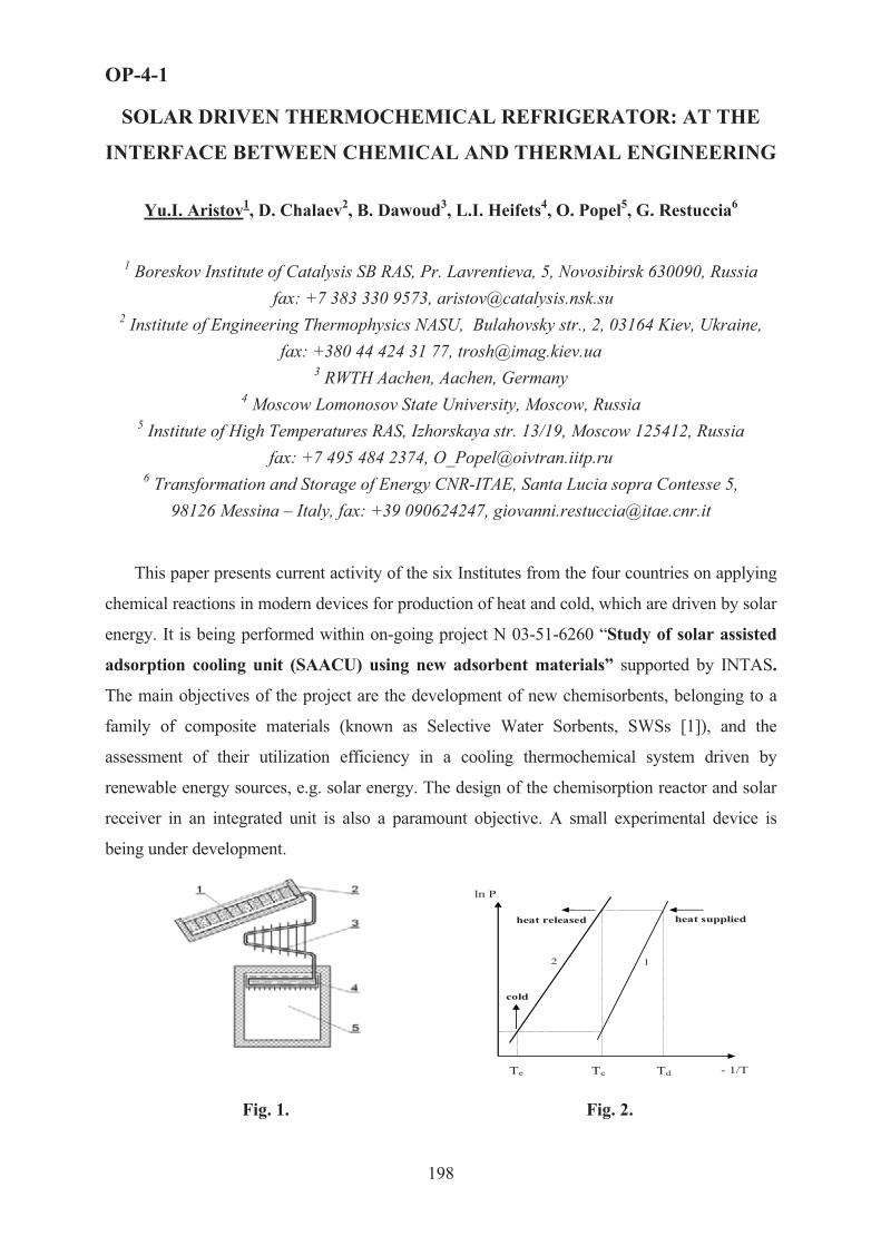
OP-4-1
SOLAR DRIVEN THERMOCHEMICAL REFRIGERATOR: AT THE
INTERFACE BETWEEN CHEMICAL AND THERMAL ENGINEERING
Yu.I. Aristov1, D. Chalaev2, B. Dawoud3, L.I. Heifets4, O. Popel5, G. Restuccia6
1 Boreskov Institute of Catalysis SB RAS, Pr. Lavrentieva, 5, Novosibirsk 630090, Russia fax: +7 383 330 9573, [email protected]
2 Institute of Engineering Thermophysics NASU, Bulahovsky str., 2, 03164 Kiev, Ukraine, fax: +380 44 424 31 77, [email protected]
3 RWTH Aachen, Aachen, Germany 4 Moscow Lomonosov State University, Moscow, Russia
5 Institute of High Temperatures RAS, Izhorskaya str. 13/19, Moscow 125412, Russia fax: +7 495 484 2374, [email protected]
6 Transformation and Storage of Energy CNR-ITAE, Santa Lucia sopra Contesse 5,98126 Messina – Italy, fax: +39 090624247, [email protected]
This paper presents current activity of the six Institutes from the four countries on applying
chemical reactions in modern devices for production of heat and cold, which are driven by solar
energy. It is being performed within on-going project N 03-51-6260 “Study of solar assisted
adsorption cooling unit (SAACU) using new adsorbent materials” supported by INTAS.
The main objectives of the project are the development of new chemisorbents, belonging to a
family of composite materials (known as Selective Water Sorbents, SWSs [1]), and the
assessment of their utilization efficiency in a cooling thermochemical system driven by
renewable energy sources, e.g. solar energy. The design of the chemisorption reactor and solar
receiver in an integrated unit is also a paramount objective. A small experimental device is
being under development.
ln P
- 1/T
heat supplied heat released
cold
1 2
Te Tc Td
Fig. 1. Fig. 2.
198

OP-4-1
Solar cooling is one of one of the promising ways to transform solar heat for preservation
of food and medicine, production of cold water and ice in arid areas, where other sources of
energy are not available. A solar refrigerator consists of an adsorber 1 (Fig. 1), filled with
solid sorbent and integrated with a flat solar receiver 2, a condenser 3 and an evaporator 4
integrated with an insulated cooling chamber 5 for food preservation.
An ideal cycle of thermochemical refrigerator includes two processes, namely, a
monovariant vapour-solid chemical reaction S + G = G*S with the formation of non-volatile
complex G*S (line 1 on Fig. 2) and, in simple version, an evaporation/condensation of pure
vapour (line 2). The first process can be considered as a sorption of the vapour by the salt.
Heat is consumed in the evaporator at Te and released in the condenser at Tc, so that both cold
and heat are produced. The cycle is driven by an external heat source, which causes the
decomposition of complex G*S in chemical reactor (adsorber) at pressure Pc and temperature
Td. First demonstration unit was realised by Michel Faraday in 1824 with a reaction between
AgCl and NH3 [2].
Sorption systems for heating and cooling based on chemical reactions are considered to
be an alternative to vapour compression cycles using CFC’s that are unacceptable any more
according to the Montreal Protocol of 1988. One more reason concerns the effect of global
warming (the Kyoto Protocol of 1997). Having zero Ozone Depletion and Global Warming
Potentials, thermochemical systems are completely friendly for the environment, and their
large scale dissemination requires searching new advanced chemical reactions, intensification
of heat and mass transfer and improvement of interplay between chemical and thermal
processes.
Fig. 3. Minimal decomposition temperature �2
vs. Tc at various evaporator temperatures: deep
freezing (�! = –30 °�), ice making (�! = –5 °�)
and air conditioning (�! = 10 °�).
The new composites of SWS type (chemisorbents) have been described elsewhere [1, 3,
4], and here we focus on various aspects of chemical and thermal engineering of this
advanced systems:
199

OP-4-1
� thermodynamic criteria for choosing a chemical reaction proper for particular cooling
cycle;
� thermodynamic, kinetic and thermal properties of new chemosorbents,
� model of the integrated system taking into account variable climatic conditions;
� detailed mathematical model of chemical reactor/solar receiver unit and exergy analysis;
� design of the thermochemical refrigerator driven by solar energy.
First, we analyzed a basic thermochemical cycle for choosing a proper vapour-solid
reaction (or proper solid sorbent) [5]. The minimal temperature �2 necessary to drive this
cycle was found, to depend only on the condenser and evaporator temperatures, Tc and Te,
which are dictated by ambient climatic conditions. T2 was calculated using the Trouton's rule
(Fig. 3). The requirements to the optimal reaction are: a) complete decomposition should
occur immediately at temperature T2; b) amount of vapor desorbed at T2 should be maximal.
The optimal adsorbent for the cycle considered in this project is to be searched among the
class of hydrated compounds, first of all, the dehydration of CaCl2·2H2O, Ca(NO3)2·2H2O,
Ca(NO3)2·3H2O and Na2HPO4·2H2O.
These substances were confined to pores of various host materials (silica, alumina) to
improve dynamics of mass transfer and avoid a hysteresis between the formation and
decomposition reactions. Sorption equilibrium with water vapor was measured at T = 35-
150 °C and P(H2O) = 6-70 mbar [7, 8]. Sorption kinetics is controlled by the intraparticle
Knudsen diffusion of water. Appropriate diffusivities have been measured as function of
temperature, water uptake and salt content [9, 10]. For CaCl2/alumina a crossover to chemical
reaction limitation was found at large salt contents. The equilibrium and dynamic data served
as input parameters for further mathematical modeling.
One of the main peculiarities of a solar refrigerator is the variation of its working
conditions (the ambient temperature and solar radiation). To put this factor in evidence we
collected, systemized and processed climatic information for different sites (South of Russia,
Italy, Germany, South-Eastern Asia, Africa, etc.) in formats necessary for the dynamic
simulation of solar chiller. Typical Meteorological Years were generated for these selected
sites for further utilization under the TRNSYS software [11]. Fig. 4 presents the averaged
daily solar radiation for Messina.
Developed mathematical model of the thermochemical refrigerator allowed the simulation
of the unit operation in real climatic conditions as well as the study on how different
parameters affect the system thermal ratio STR and specific cooling power SCP at different
200

OP-4-1
rated evaporator temperatures, varied in our calculations from 5 to 10 oC. If use the composite
CaCl2/silica, the model for different sites predicted the SCP = 35 – 60 W/m2 and STR � 0.2,
that is better than for common adsorbents. To reach these values the optimal mass of solid
sorbent should be 12–16 kg/m2 and the typical time for setting sorption equilibrium in the
granulated sorbent layer should be less than 1 h. The latter value takes into account both heat
and mass transfer in the layer as well as the rate of chemical reaction. Detailed analysis of
these processes, which will carefully consider the effect of the vapor re-adsorption along the
layer (the heat pipe effect), is on the way.
0 30 60 90 120 150 180 210 240 270 300 330 3600
2
4
6
8
10
Messina
Dai
ly ra
diat
ion
on h
oriz
onta
l sur
face
, kW
h/m
2
Days
Fig. 4. Fig. 5.
As a result of this comprehensive study a prototype of the thermochemical refrigerator
driven by solar energy has been designed and built (Fig. 5). It will be tested in Crimea during
summer 2006.
The authors thank INTAS (grant 03-51-6260) for financial support of this work.
Literature
1. Yu.I.Aristov, G.Restuccia, G.Cacciola, V.N.Parmon, Appl.Therm.Engn., 2002, v.22, N 2, pp.191-204. 2. W.M.Raldow, W.E.Wentworth, Solar Energy, 1979, v.23, p.75-79. 3. L.G. Gordeeva, A.V. Gubar, L.M. Plyasova, V.V. Malakhov, Yu.I. Aristov, Kinetika i Kataliz (Russ. J.
Kinetics and Catalysis), 2005, v. 46, N 5, pp. 736-742. 4. G.Restuccia, A.Freni, S.Vasta, Yu.Aristov, 2004, v. 27, N 3, pp. 284-293. 5. Yu.I. Aristov, Proc. VI Int. Seminar “Heat pipes, heat pumps, refrigerators”, 12-15 Sept. 2005, Minsk,
Belorus, pp. 342-353. 6. D.M. Chalaev, Yu.I. Aristov, Teploenergetika (Rus. J. Power Engineering), 2006, N 3, pp. 73-77. 7. I.A. Simonova, Yu.I. Aristov, Rus. J. Physical Chemistry, 2005, v. 79, N 8, pp. 1307-1311. 8. M.M.Tokarev, B.N.Okunev, M.S.Safonov, L.I.Heifets, Yu.I.Aristov, Rus. J. Physical Chemistry, 2005, v.
79, N 9, pp. 1490-1494. 9. Yu.I. Aristov, I.S. Glaznev, A. Freni, G. Restuccia, Chem. Engn. Sci., 2006, v.61, N 5, pp.1453-1458. 10. B.Dawoud, Yu.I.Aristov, Int.J.Heat& Mass Transfer, 2003, v.46, N 2, pp. 273-281. 11. TRNSYS – The Transient System Simulation Program // http://sel.me. wisc.edu/TRNSYS/.
201
OP-4-2
FUEL PROCESSING IN MICROSTRUCTURED HEAT-EXCHANGER
REACTORS - A PRACTICAL COMPARISON OF DIFFERENT FUELS
FROM METHANOL TO DIESEL
G. Kolb, Y. Men, J. Schürer, D. Tiemann, M. Wichert, R. Zapf, V. Hessel, H. Löwe
Institut für Mikrotechnik Mainz GmbH (IMM), Carl-Zeiss-Str.18-20 D-55129 Mainz;
Germany; Tel.: ++49-6131-990-341; Fax.:-305; email: [email protected]
Introduction Size reduction is a critical issue for the applicability of mobile fuel cell and fuel
processing systems, which is currently addressed by widespread international research. The benefits gained by microstructured heat-exchanger / reactor technology [1] are thus under investigation in numerous research projects related to fuel processing [2, 3].
Based upon experience with processing of methanol [4], ethanol, propane [5], gasoline [6] and diesel, a comprehensive study of advantages and drawbacks of different fuels is provided. It covers not only catalyst activity and durability issues [7, 8] and reactor design, but also the aspects of heat- and water management, start-up procedures, choice of reactor material, joining techniques and the aspects of future mass production of these devices, which are dedicated for the future distributed and clean energy production. Another issue, which needs to be taken into consideration, are the gas purification system requirements. This clean-up system needs to be installed downstream the reformer itself and deals mostly with the removal of carbon monoxide out of the reformate, at least as long as conventional PEM fuel cell systems are applied. In case catalytic CO-clean-up is chosen as strategy, it usually comprises water-gas shift and preferential oxidation of carbon monoxide, which both bear significant potential for improvement by the application of microstructured heat-exchangers [9, 10, 11, 12]. The efforts required for this purification system depend, once again, strongly on the fuel applied. Alcohol Fuels
Alcohol fuels such as methanol and ethanol have significant advantages concerning the operating temperature of the reformer itself, which is significantly lower compared to hydrocarbon reforming. Methanol reforming, especially in case steam reforming, may well be operated at temperatures below 300°C. However, recent catalyst development work will be presented, which deals with new formulations allowing for a lower operating temperature for ethanol as well. Due to its lower toxicity and its potential production from organic waste, ethanol appears even more attractive than methanol on the longer term. The low operating temperature makes alcohol fuels attractive especially for portable energy generation systems. The smaller the size of the fuel processor the more drastic are the effects of heat losses on
202

OP-4-2
system efficiency and consequently system size. Examples of the effects of heat losses on fuel processor efficiency will be presented.
However, the lower the operating temperature of the reforming reaction, the lower the activity of the catalytic systems is. A comparison of the activity of commercial and self-developed catalyst systems for different fuels will be provided. However, lower catalyst activity relates to higher reactor size, regardless if microstructured plate heat-exchanger technology, metallic or ceramic monoliths or even fixed beds are applied.
Finally, low operating temperatures allow for alternative choice of the reactor material different to stainless steel, such as aluminium, which helps to reduce the system weight. However, the laser welding procedure usually applied for joining microstructured plate stacks at IMM (see Fig.1) is not applicable for this novel material. Consequently, new joining techniques such as brazing (see Fig.2) and electron beam welding, which were so far only applied for stainless steel, need to be adopted for aluminium.
Fig.1: Integrated Methanol steam reformer / catalytic afterburner developed at IMM
Fig.2: Micro-structured heat-exchangers joined by brazing
Propane / Butane Propane, butane and mixtures thereof are attractive fuels for small scale applications due
to the existing distribution grid. Due to the higher operating temperature normally exceeding 700°C, catalyst activity is less an issue but rather rather catalyst stability, which is affected by sintering procedures. In fact, very high catalytic activity may be achieved even for steam reforming owing to the improved heat and mass transfer in microstructured reactors. WHSV values as high as 750 Ndm³/(h gcat) have been realised at IMM for a duration of 1,000 hours over PGM catalyst formulations.
As soon as oxygen is added to the feed, the activity even increases. WHSV values up to 2400 Ndm³/(h gcat) were achieved at IMM for the partial oxidation of propane. Gasoline
Gasoline, even more than propane, has advantages owing to the existing distribution grid and is evidently most attractive to the automotive industry. Operating temperatures of a gasoline reformer are similar to the propane system, and thus catalyst stability issues are
203

OP-4-2
similar as far as structural deactivation mechanisms such as sintering are concerned. However, deactivation by coking gets more an issue compared to light hydrocarbons. The addition of air to the reformer feed is one viable option to cope with coking problems. However, running a fuel processor in the autothermal mode (see Fig.3) has the drawback of a significantly lower hydrogen content compared to steam reforming owing to the dilution of the reformate by nitrogen.
Fig. 3 Autothermal microstructured reformer / gasoline developed at IMM
Fig. 4: Integrated catalytic steam reformer afterburner for diesel fuel developed at IMM
DieselSteam reforming of higher hydrocarbon fuels such as diesel requires advanced technology
concerning catalyst coatings and reactor material due to the very high reaction temperature exceeding 800°C. At IMM, a microstructured heat-exchanger / reactor was developed and operated for more than 40 hours already, which completely converts diesel fuel (see Fig.4). The application standing behind this work is, once again, power generation for automotive applications.
References [1] Kolb G., Hessel V, „Review: Micro-structured reactors for gas phase reactions” Chem. Eng. J. 98, 1-38
(2004). [2] Hessel V., Löwe H., Müller, A., Kolb G., 2005, ’Chemical Micro Process Engineering- Processing,
Applications and Plants’, Wiley, Weinheim, ISBN-13 978-3-527-30998-6, p.281 ff. [3] Reuse P., Renken A., Haas-Santo K., Görke O., Schubert K., Chem. Eng. J. 101, 133-141 (2004). [4] Cominos V., Hardt S., Hessel V., Kolb G., Löwe H., Wichert M., Zapf R., Chem. Eng. Comm. 192 (2005)
685. [5] Kolb G., Zapf R., Hessel V., Löwe H., Appl. Catal. A: General 277 (2004) 155. [6] Kolb G., Cominos, V., Zapf R., Hessel V., Löwe H., Proc. Of the 7th World Congress of Chem. Eng.,
Glasgow (2005), Paper O112-002, published on CD [7] Zapf R., Becker-Willinger C., Berresheim K., Bolz H., Gnaser H., Hessel V., Kolb G., Löb P., Pannwitt A.-
K., Ziogas A., Trans I Chem E Part A, 81 (2003) 721. [8] Zapf R. and Kolb G., Chem Eng. Techn., in prep. [9] TeGrotenhuis, W.E. King, D.L., Brooks, K.P., Holladay B.J., Wegeng, R.S. 6th International Conference on
Microreaction Technology, 2002, AIChE, NY, 2002, p. 18 [10] Kolb G., Pennemann H., Zapf R., Catal. Today 110 (2005) 121 [11] Baier T. and Kolb G., Chem Eng. Sci., submitted for publ. [12] Cominos V., Hessel V., Hofmann C., Kolb G., Zapf R., Ziogas A., Delsman E.R., Schouten J.C., Catal.
Today 110 (2005) 140
204

OP-4-3
CATALYTIC DECOMPOSITION OF NATURAL GAS FOR COX-FREE
HYDROGEN PRODUCTION IN A STRUCTURED MULTILAYER
REACTOR
G. Italiano1, C. Espro1, F. Arena1, F. Frusteri2, A. Parmaliana1
1Dipartimento di Chimica Industriale e Ingegneria dei Materiali,
Università degli Studi di Messina, Salita Sperone , 31, I-98166, Messina, Italy 2 Istituto CNR-ITAE “Nicola Giordano”, Salita S. Lucia 39, I-98126 Messina, Italy
Introduction
The catalytic decomposition of natural gas (CDNG) into hydrogen and carbon is
currently attracting a great research interest since it appears a direct, mildly endothermic
attractive route for producing high purity hydrogen avoiding any concern due to CO2
emissions. The CDNG is the candidate process for fueling fuel cell systems as well a potential
alternative to the conventional H2 production processes owing to the higher energy efficiency
and lower environmental duty [1-4].
Among transition metals and their alloys, Ni based catalysts feature high activity and
the capability of producing carbon filaments or carbon nanotubes at moderate temperatures
(500-700°C) [5]. The unavoidable carbon lay down on the catalyst surface leading to the
reactor plugging is a serious issue which could limit the practical feasibility of the CDNG
process. However, such hurdle can be overcome by using adequate catalyst configurations
and reactor devices [6-7]. In this context, this contribution is aimed to highlight the suitability
and potential of a novel class of Ni thin layer silica cloth catalysts in the decomposition of
natural gas for producing COx-free hydrogen in a structured multilayer reactor (MLR).
Experimental
Ni Thin Layer Catalysts (Ni-TLC). A commercial silica fabric (OS 120, Thermal
Material Systems (TMS) product; thickness, 0.15 mm; specific weight, 120 g/m2) was
washcoated with a colloidal SiO2 (Ludox LS, Aldrich product; S.A., 215 m2/g) solution in
order to confer an adequate surface area for the dispersion of the active species. The weight
ratio between SiO2 layer and silica cloth was 34/100. Ni-TLC samples were prepared by
stepwise incipient method impregnating the SiO2/silica cloth support with a 0.1 M solution of
Ni(NO3)2*6H2O. After impregnation the samples were dried at 120°C for 12h and calcined at
550°C for 3h.
205

OP-4-3
A series of Ni-TLC samples with Ni loading ranging from 0.5 to 50 wt%, referred to
the weight of the SiO2 layer, has been prepared.
Fresh and used Ni-TLC catalysts have been characterized by H2 chemisorption,
Temperature Programmed Reduction, SEM, TEM and Thermal Analysis.
Structured Multilayer Reactor (MLR), schematically shown in Fig.1, consists of a
package of six Ni-TLC discs (�, 37 mm; W, 0.22 g) sandwiched between quartz rings (�ext,
37 mm; thickness, 4 mm) set in a quartz tube (�int, 39 mm; length, 600 mm). A heating wire
was wrapped around the quartz tube providing the thermal conditioning of the reactor system.
The influence of space velocity (GHSV, h-1), reaction temperature and Ni loading on specific
activity, catalyst performance and nature of the carbon nanostructures deposited on the
catalyst surface has been evaluated.
Ni-TLC Testing was carried out at 500-600°C and atmospheric pressure using a 10%
CH4/5% N2/85%Ar (vol/vol) reaction mixture. The activity of the catalysts was monitored
until complete deactivation evaluating the trend of activity decay, the average H2 Yield
(STYH2, kgH2/kgNi*h) and the Carbon Capacity (C/Ni, number of CH4 molecules decomposed
for Ni atom along the catalyst lifetime).
T1 T2
T3
Thin Layer Catalyst
Heating Wire
INOUT
Quartz Ring Quartz Disc Thin Layer Catalyst
Fig. 1 - Schematic of Structured Multilayer Reactor (MLR) (T1, inlet Temperature; T2, outlet Temperature; T3, reaction Temperature)
Results and Discussion
The low magnification SEM micrographs, shown in Fig.2, accounts for the textural properties
of the Ni-TLC systems. Silica cloth is constituted by fibres, 0.5 mm in diameter, interlaced each
other (Fig. 2a). After the washcoating the fibres were randomly covered with SiO2 aggregates
(Fig. 2b). The subsequent impregnation with the aqueous solution of the Ni precursor (Fig. 2c)
causes a redistribution of silica on fibres resulting in a more homogeneous catalyst surface. The
physico-chemical characteristics of Ni-TLC samples are listed in Table 1.
206

OP-4-3
a) b) c)
Fig. 2 SEM micrographs (magnification, 103x) of (a) bare silica cloth, (b) SiO2/silica cloth and (c)
Ni-TLC sample
Table 1 – Characteristics of Ni-TLC samples
Catalyst Ni Loading (%)
SABET(m2/gcat)
MSA(m2
Ni/gcat)aDNi(%)
bds, Chem(nm)
TLC - 71 - - - N1-TLC 4.6 50 1.2 10.9 9.3 N2- TLC 11.4 51 2.3 8.1 12.5 N3- TLC 19.5 51 3.6 7.1 14.3 N4- TLC 41.1 48 2.3 1.8 56.6 N5- TLC 50.4 52 2.4 1.4 71.5
a) DNi, Ni dispersion; b) ds, mean diameter of Ni crystallites
A general overview of the performance of the Ni-TLC samples, in terms of Carbon
Capacity (C/Ni) and initial and average STYH2 (STYH2,i and STYH2,a, respectively) at 500°C,
is presented in Table 2. The inevitable decay of the activity with the reaction time, at various
reaction temperatures, for the N3-TLC sample is displayed in Fig. 3. The extent as well the
trend of catalyst deactivation is controlled by reaction temperature, space velocity, Ni loading
and nature/amount of coke laid down during the reaction time.
Table 2 – Activity data of Ni –TLC samples in the CDNG reaction at 500°C
CatalystCode
Ni Loading (%) C/Ni STYH2,i (a)
(kgH2/kgNi*h)STYH2,a (b)
(kgH2/kgNi*h)Lifetime
(h)N1-TLC 4.6 1.3 4.8*10-1 1.8*10-1 0.5 N2-TLC 11.4 3.4 5.6*10-1 2.3*10-1 1.0 N3-TLC 19.5 61.3 3.7*10-1 3.1*10-1 13.6 N4-TLC 41.1 20.4 1.6*10-1 1.1*10-1 12.5 N5-TLC 50.4 16.0 1.2*10-1 8.2*10-2 13.3
a) STYH2,i refers the STYH2 calculated on the basis of the activity at reaction time of 0.5 min b) STYH2,a refers the average STYH2 calculated on the basis of the activity along the entire reaction time
207

OP-4-3
0 1 2 3 4 5 6 7 8 9 10 11 120
10
20
30
40
50
60
70
80
90
100
Time on stream (h)
CH
4 C
onve
rsio
n (m
ol %
)
Fig. 3 Catalytic Decomposition of Natural Gas on N3-TLC sample. Methane conversion vs time on stream at (�) 500; (�) 550 and (�) 600°C (GHSV, 1908 h-1).
A detailed analysis of the coking of Ni-TLC systems, accomplished by SEM and TEM
techniques, evidences the deposition of filamentous (whisker-like) carbon deposits at 500°C
and encapsulating coke at 600°C with a mixed filamentous-encapsulating residues at 550°C.
References [1] N. Z. Muradov, Energy & Fuels 12 (1998) 41
[2] R. Aiello, J. E. Ficus, H. Loye, M.D. Amiridis, App. Catal. A: General 192 (2000) 227.
[3] T.V. Choudhary, D. W. Goodmanm, J. Catal .192 (2000) 316
[4] N. Z. Muradov, T.N. Veziro�lu, Int. J. Hydrogen Energy 30 (2005) 225
[5] K. Otsuka, A. Mito, S. Takenaka, I. Yamanaka, Stud. Surf. Sci. Catal. 136 (2001) 215.
[6] A.Beretta, G. Groppi, L. Malocchi, P. Forzatti, Appl. Catal., A: General 187 (1999) 49 [7] L. Kiwi-Minsker, A. Renken, Catal. Today 110 (2005) 2
208

OP-4-4
209
HYDROGEN PRODUCTION BY METHANOL STEAM REFORMING
AND ETHANOL STEAM REFORMING IN MEMBRANE REACTORS:
AN EXPERIMENTAL STUDY
A.Basile1, A. Iulianelli2, F. Gallucci1, S. Tosti3, E. Drioli1,2
1 Institute on Membrane Technology, ITM-CNR, c/o University of Calabria, via P. Bucci, Cubo 17/C, 87030 Rende (CS), Italy, Phone: (+39) 0984 492013 – Fax: (+39) 0984 402103 –
[email protected] Department of Chemical Engineering and Materials, University of Calabria, via P. Bucci Cubo 42/A, 87030 Rende (CS), Italy, Phone: (+39) 0984 492039 – Fax: (+39) 0984 402103 3 ENEA, Unità Tecnico Scientifica Fusione, C.R. ENEA Frascati, Via E. Fermi 45, Frascati,
Roma 00044, Italy, Phone: +39 06 94005160 – Fax: +39 06 94005374
Abstract
In this work a comparison between methanol steam reforming reaction (MSR) and ethanol steam reforming reaction (ESR) to produce hydrogen in membrane reactors (MRs) is discussed from an experimental point of view .
Both reaction systems have been investigated by considering the influence of the membrane characteristics as well as the influence of the operating temperature. In the case of the dense membrane, the sweep gas flow rate and the different fluxes configurations have also been analysed.
Experimental results, in terms of reactants conversion as well as hydrogen production and gases selectivity in MRs and in a traditional reactor (TR), are presented. The catalyst stability in both reaction systems was also tested.
1. Description of the process
The TR consists of a stainless steel tube, length 250 mm, i.d. 6.7 mm with the reaction zone 150 mm. The MR consists of a tubular stainless steel module, length 280 mm, i.d. 20 mm, containing different membranes, the first one (MR1) is a TiO2-Al2O3 asymmetric porous commercial membrane (Inoceramic) with a Pd-Ag deposit. The second membrane (MR2) is a commercial asymmetric porous ceramic membrane with a Pd-Ag deposit. The third membrane (MR3) is a pine-hole free Pd-Ag thin wall membrane tube permeable only to hydrogen, having thickness 50 �m, o.d. 10 mm, length 150 mm.

OP-4-4
210
2. Results and discussion
2.1 The membrane reactor MR1
Figure 1 reports the results, in terms of ethanol and methanol conversion, for both traditional reactor and membrane reactor MR1. Considering the conversion values for both reactions in the TR, it should be said that the catalyst shows higher activity for methanol steam reforming (MSR) than ethanol steam reforming (ESR). In fact, for the whole temperature range investigated the methanol conversion is higher than the ethanol conversion.
Temperature, °C
350 400 450 500 550 600
Con
vers
ion,
%
0
10
20
30
40
50
60
70
80
90
100
TR EthanolMR1 EthanolTR MethanolMR1 Methanol
Temperature, °C
350 400 450 500 550 600
Con
vers
ion,
%
0
10
20
30
40
50
60
70
80
90
100
TR EthanolMR2 EthanolTR MethanolMR2 Methanol
Fig 1 Methanol and Ethanol conversion versus temperature in MR1 and TR, H2O/Alcool = 4.5/1, plumen=1.3 bar, pshell = 1 bar (for MR)
Fig 2 Methanol and Ethanol conversion versus temperature in MR2 and TR, H2O/Alcool = 4.5/1, plumen=1.3 bar, pshell = 1 bar (for MR)
2.2 The membrane reactor MR2 In Figure 2 the results, in terms of ethanol and methanol conversion, for both traditional
reactor and membrane reactor MR2, are reported. For both MSR and ESR reactions, the results obtained in the MR2 are lower that the results obtained in the TR. In particular, the best conversion achieved by MSR in MR2 is 65% while it is 90% in TR (at T = 550°C); at this temperature, the conversion achieved by ESR it is 37% in MR2 and 47% in TR.
2.3 The membrane reactor MR3 The membrane reactor MR3 uses a dense Pd-Ag membrane with a perm-selectivity
H2/(other gases) infinite. For this membrane reactor there are at least two advantages: the first one is that the shell stream is CO-free and so it can be directly fed to a PEMFC. The second advantage is that, in order to improve the hydrogen recovery in this reactor, a sweep gas can be used in the shell side. The sweep gas can be used either in co-current and in counter-current mode and at different flow rates. The hydrogen production (Figure 3) is higher for the MSR reaction than the ESR reaction. In the best conditions, the MSR reaction is able to give an increase in the hydrogen production of around 80% with respect to the ESR reaction.
The same results are obtained by using the counter-current mode. In Figures 4, the comparison between ESR reaction and MSR reaction in terms of hydrogen production, are

OP-4-4
211
reported, for the counter current mode. Also in this case the counter-current mode is able to give higher hydrogen production than the co-current mode. For the counter-current mode the best reaction system to be considered for producing hydrogen seams to be the MSR reaction system.
Fig 3 Hydrogen production versus temperature and versus sweep gas flow rate during ESR and MSR in MR3. Co-current mode
Fig 4 Hydrogen production versus temperature and versus sweep gas flow rate during ESR and MSR in MR3. Counter-current mode
3 Conclusions The methanol and ethanol steam reforming reactions have been studied from an
experimental point of view in TR and in three different MRs packed with commercial Ru-based catalyst. Two Pd/Ag supported membranes (MR1 and MR2) and a dense Pd-Ag membrane (MR3) were used in order to increase the reactant conversion and the hydrogen production. The experiments show that in both traditional and membrane reactors MSR conversions are higher than ESR. The ESR needs a higher reaction temperature than MSR in order to increase the ethanol conversion. With our membranes it is not possible to reach such high temperature. For MSR, the highest conversion is achieved in MR3 where, already at T = 400°C, in counter-current mode and sweep gas flow rate equal to 11.8 mL/s, 100% conversion is reached. For ESR, the highest conversion is achieved in MR3 at T = 450°C, in counter-current mode and sweep gas flow rate 11.8 mL/s, and it is equal to 50%. Also the total molar hydrogen flow rates, in both traditional and membrane reactors, for MSR are higher than ESR and the best results are obtained in MR3. By using Ru-Al2O3 5% as a catalyst, ESR shows coke deposition with consequent deactivation of the catalyst. Finally, we can conclude that, in the conditions investigated in this work, the MSR reaction is much suitable than the ESR for producing hydrogen. However, a more in deep investigation, aided by a theoretical and an economical analysis, is necessary in order to find the best operative conditions for producing hydrogen.

OP-4-5
FISCHER-TROPSCH SYNTHESIS FIXED-BED REACTOR: A NEW CHANCE FOR OLD TECHNOLOGY
�uz’min �.�.
A.V. Topchiev Institute of Petrochemical Synthesis RAS, 119991, Moscow,Leninsky Av., 29, Russia, (495)954-47-98, [email protected]
In come XXI century the hydrocarbon synthesis from �� and �2 for fuel and
petrochemical purposes (Fischer-Tropsch synthesis, FTS), evidently, is one of the most dynamically developing processes of chemical industry; if at the end of XX century sum world capacity of FTS plants was about 7 million t/year (and its main part was concentrated in Southern Africa) then in the beginning of the present decade it will become worldwide and increase approximately in 10 times. Representing wide variety of the obtained products, applied catalysts and technological methods, FTS, in spite of the fact that it is known about one hundred years remains extremely interesting field both for fundamental researches and for applied developments.
FTS is an exothermal process (�170 kJ/mol CO), and one of the major problems of its industral realization is removal of generating heat from the reactor; insufficient heat removing followed by catalyst overheating quickly results to increased methane formation or catalyst coking (or to both phenomena together). Historically the first FTS reactor technology was fixed-bed one using granulated catalyst (at first with sheet-packed, then in a tubular reactor) and cooling condensate, but in this case temperature situation in a reactor becomes essentially non-isothermal both in axial and radial directions. This circumstance, obviously, imposes restrictions on a achievable CO conversion value per one reactor pass and on application of possible FTS catalysts with very high activity. Besides fixed-bed reactor has complex design (it is required to make several thousands of reaction tubes) and inconvenient for catalyst loading/unloading.
The most popular commercial SFT technology presented first in large-scale by Sasol (1993) and accepted in most of builded and commissioned plants is a reactor with three-phase suspended catalyst bed (slurry). Its basic advantages are near-isothermal reaction mode, an opportunity of use of fine catalyst powders, simplicity of its introduction into reaction and relative simplicity of reactor design (a bubble column). It appeared enough that FTS fixed-bed technology has considered now as a minor commercial opportunity.
Attempts to modify this type of process, however, were undertaken repeatedly. So, one variant of this technology is a reactor with adiabatic catalyst sections and intercoolers where one probably can more effective adjust a temperature profile of a reaction feed (the most
212

OP-4-5
known development – the Lurgi reactor [1]). Other approach was recently presented in [2], where it is offered to use for FTS tubular reactor the syngas produced by air (instead of pure oxygen) conversion of methane and containing about 50 % of N2 that is an inert at typical FTS conditions; application of such gas, besides its relatively low cost, allows to optimize non-isothermal reaction pattern a little. However, these both approaches are characterized by the specific problems: in the first case - inconvenience of reactor design in a whole (necessity of several intercoolers, tubular as a rule) and increase of section number at use of more active catalysts, in the second – expencive recirculation of syngas with ballast N2 followed by necessity of achievement of 90-95 % CO conversion per pass and necessity of N2 remove from gaseous FTS products.
Nevertheless, the fixed-bed technology, as it is represented, has more opportunites of upgrade. First, one can use two-section intertubular space of reactor and two vapor condensate feeds with different temperatures: lower one near reaction stream inlet, higher one near its outlet. Second, for this purpose it is possible to use as a coolant not the steam condensate evaporating at strictly determined temperature but heated cocurrent water with appropriate values of inlet temperature and velocity. In both cases at other parameters being equal one can calculate that CO conversion become higher and axial temperature profile become smoother in comparison with cooling by one-feed condensate; it is possible to tell that non-isothermicity of the coolant compensates non-isothermicity of reaction stream, eliminating both a characteristic temperature maximum within initial tube section and excessive cooling of tube "tail" where more effective conversion of the reactant-poor gas needs the raised temperature.
FTS technological features described above also cause lower average radial temperature difference in comparison with common fixed-bed reactor. It, in turn, can permit to increase diameter of a tube without excess of allowable temperature of catalyst at tube axis and, hence, to reduce number of tubes in an commercial reactor and to simplify its design.
Thus, for FTS tubular fixed-bed reactor one can sufficiently improve its temperature mode that can shift towards to one for slurry reactor and also to simplify reactor design. If to take into account that slurry reactor, besides obvious advantages, has also the specific lacks (the insufficient flexibility of working temperature that is caused by thickening or boiling away of a liquid phase; difficulty of application of catalysts with cracking function causing liquid phase destruction; certain difficulties concern separation and mechanical deterioration of the catalyst) which do not exist for fixed bed then one most to conclude that SFT fixed-bed technology still can remain efficient commercial alternative to three-phase one. 1. Chemierohstoffe aus Kohle (her. von J. Falbe), Stuttgart, 1977
2. A. Jess, R. Popp, K. Hedden/ Appl. Catal., A, 1999, v.186, p. 321
213

OP-4-6
UPGRADING OF FLASH PYROLYSIS LIQUID BY REACTIVE
DISTILLATION USING A HIGH-BOILING ALCOHOL IN THE
PRESENCE OF SOLID CATALYSTS
F.H. Mahfud, I.V. Melian de Cabrera, H.J. Heeres*
Department of Chemical Engineering, Faculty of Mathematics and Natural Sciences
Rijksuniversiteit Groningen, Nijenborgh 4, 9747 AG, Groningen, The Netherlands
Fax: +31-50-363 4479, Telephone: +31-50-363 4497, *E-mail: [email protected]
Introduction
Anticipated future energy shortages and environmental concerns have boosted research on
alternatives for fossil energy carriers [1]. This has encouraged the exploration of renewable
resources like biomass for energy generation. Flash pyrolysis liquid, also known as bio-oil
(BO), is a biomass-derived liquid energy carrier. It is produced via flash pyrolysis in yields up
to 70%-wt [2-7]. A large variety of applications for BO have been proposed [8]. One of the
challenging applications is the use as a liquid transportation fuel for internal combustion
engines. For this application, the BO has to be upgraded to fulfill the stringent transportation-
fuel product requirements. A number of BO upgrading technologies have been proposed and
explored. For example, it is possible to treat bio-oil with hydrogen in the presence of solid
catalysts to produce a diesel like transportation fuel (HDO process, see [[9-12]]). However, up
till now, hydrogen consumption is excessive which negatively affects the economics of this
process.
A number of studies have been reported dealing with chemical upgrading of crude bio-oil by
reacting it with an alcohol (e.g. ethanol) at mild conditions using a liquid mineral acid catalyst
like sulphuric acid [13-15]. From a chemical point of view, it is anticipated that reactive
molecules like organic acids and aldehydes are converted to esters and acetals, respectively
(Figure 1). Removal of water is essential to shift the equilibria to the right side. Radlein [15]
has proposed the use of molecular sieves to capture the water and to drive the equilibria to the
right side. Product studies indeed have shown that the product properties of bio-oil are
significantly improved by this alcohol treatment.
214

OP-4-6
C
O
HR1C
OR
OR
R1
H2
C
O
OHR1
R OH OH2C
O
ORR1
H+
H+
BIO-OIL + R-OH Upgraded BO + H2O (general) H+
2 (1)
(2)
OH2R OH
Figure 1. Reactions involve in bio-oil alcoholysis. (1) Acetalization, (2) Esterification.
However, the alcohol treatment concept also has some major drawbacks. The process applies
a liquid mineral acid which has to be neutralised after reaction. This leads to an extra
processing step and generates a large amount of waste salts. In addition, to be cost effective,
the molecular sieves for water removal need to be regenerated, also leading to additional
investments and processing costs. We here report our studies on the upgrading of bio-oil
using an improved alcohol treatment concept.
Results and discussion
We have explored an improved upgrading technology using a solid catalysts and a high
boiling alcohol (n-butanol). A schematic representation of the (batch)-concept is provided in
Figure 2. The solid catalyst is retained in the reactor and thus the use of a post neutralisation
step, necessary when using a liquid mineral acid, is avoided. The water formed during the
reactions and the water present in the bio-oil feed is removed by distillation at reduced
pressure. To avoid excessive alcohol vaporisation, a high boiling alcohol in the form of n-
butanol is applied. This particular alcohol was selected as it can be produced from renewable
resources.
Initially, a number of solid acid catalysts were screened (T= 60oC, P= 50 mbar, treaction= 1 hr).
Among these, Nafion® SAC13 was found to be the preferred catalyst. The amount of water
produced by the reactions as given in Figure 1 was highest, implying that this catalysts results
in the highest reaction rates. To study the influence of operating conditions on product
properties, an experimental design using a half fraction factorial method was applied. The
investigations indicate that the optimum conditions are a 50%-v alcohol content, 1%-wt
catalyst concentration, a reaction temperature of 70oC, a pressure of 50 mbar and a reaction
time of 120 minutes.
215

OP-4-6
Figure 2. Batch reactive distillation set-up for high boiling alcoholysis.
AA ++ BB �� EE ++ WW
L, xi,…,xj
V, yi,…,yj
Reactor
Settler
Condenser
HotWater
ColdWater
P,T
Heating Mediu
CClloosseedd SSyysstteemm
AAllccoohhooll RRiicchhPPhhaassee
WWaatteerr RRiicchhPPhhaassee
VVaaccuuuumm PPuummpp
A= Acid/Aldehyde, B = HB Alcohol, E=Esters, W=Water
The product properties for these optimised conditions are given in Table 1.
Table 1. Properties comparison for crude bio-oil, upgraded Bio-oil, diesel and biodiesel
Physical property Bio-oil Upgraded Bio-Oil Diesel Bio diesel
Viscosity40 ‘C, cSt 17 6.96 1.2 – 4.1 1.9 – 6.0
Water content 31.5 %wt 8.69 %wt 161 ppm <0.05 %vol
Flash Point, oC 52.5 45 60 – 80 100 – 170
Density, kg/L 1.17 0.95 0.85 0.88
PH 3 3.22 7 7
It may be concluded that the alcohol upgrading procedure has led to a significant increase in
the product properties. In particular, beneficial effects were observed on the viscosity and
water content. Moreover, due to the presence of butyl esters, the pungent odor of the BO is
absent and the product has a banana like odor.
Conclusions
A novel method of chemical upgrading of bio-oil by using reactive distillation with a high
boiling alcohol and a solid catalysts has been explored in a batch set-up. The product
properties of the upgraded bio-oil are significantly improved compared to the crude bio-oil.
Engine tests are in progress and will also be provided.
216

OP-4-6
References
1. Ssen, Z., Solar energy in progress and future research trends. Progress in Energy and Combustion Science, 2004. 30(4): p. 367-416.
2. Agblevor, F.A., S. Besler, and A.E. Wiselogel, Fast Pyrolysis of Stored Biomass Feedstocks. Energy & Fuels, 1995. 9(4): p. 635-640.
3. Bridgwater, A.V., Czernik, S., Diebold, J., Meier, D., Oasma, A., Peackocke, C., Pizkorz, J., Radlein, D., Fast Pyrolysis of Biomass: A Handbook. 1st ed. Vol. 1. 1999: CPL Press, Newbury Berkshire, UK.
4. Bridgwater, A.V. and G. Grassi, Biomass pyrolysis liquids : upgrading and utilisation. 1991, London ; New York, NY, USA: Elsevier Applied Science ; Elsevier Science Pub. ix, 377 p.
5. Czernik, S., J. Scahill, and J. Diebold, The Production of Liquid Fuel by Fast Pyrolysis of Biomass.Journal of Solar Energy Engineering-Transactions of the Asme, 1995. 117(1): p. 2-6.
6. Onay, O. and O.M. Kockar, Slow, fast and flash pyrolysis of rapeseed. Renewable Energy, 2003. 28(15): p. 2417-2433.
7. Oasmaa, A., et al., Fast pyrolysis of forestry residue. 1. Effect of extractives on phase separation of pyrolysis liquids. Energy & Fuels, 2003. 17(1): p. 1-12.
8. Czernik, S. and A.V. Bridgwater, Overview of applications of biomass fast pyrolysis oil. Energy & Fuels, 2004. 18(2): p. 590-598.
9. Adjaye, J.D. and N.N. Bakhshi, Production of Hydrocarbons by Catalytic Upgrading of a Fast Pyrolysis Bio-Oil .1. Conversion over Various Catalysts. Fuel Processing Technology, 1995. 45(3): p. 161-183.
10. Bridgwater, A.V., Production of high grade fuels and chemicals from catalytic pyrolysis of biomass.Catalysis Today, 1996. 29(1-4): p. 285-295.
11. Elliott, D.C. and E.G. Baker, Upgrading Biomass Liquefaction Products through Hydrodeoxygenation.Biotechnology and Bioengineering, 1984: p. 159-174.
12. Maggi, R. and B. Delmon, A review of catalytic hydrotreating processes for the upgrading of liquids produced by flash pyrolysis. Hydrotreatment and Hydrocracking of Oil Fractions, 1997. 106: p. 99-113.
13. Oasmaa, A., et al., Fast pyrolysis of forestry residue and pine. 4. Improvement of the product quality by solvent addition. Energy & Fuels, 2004. 18(5): p. 1578-1583.
14. Boucher, M.E., A. Chaala, and C. Roy, Bio-oils obtained by vacuum pyrolysis of softwood bark as a liquid fuel for gas turbines. Part I: Properties of bio-oil and its blends with methanol and a pyrolytic aqueous phase. Biomass & Bioenergy, 2000. 19(5): p. 337-350.
15. Radlein, D.J., Piskorz, J. Majerski, P., Methode of Upgrading Biomass Pyrolysis Liquids for use as Fuels and as Sources of Chemicals Reaction with Alcohol, E. Patent, Editor. 1996.
217

OP-4-7
1, 2, 4-TRIMETHYLBENZENE TRANSFORMATION OVER
Y-ZEOLITE BASED CATALYST: EFFECT OF ACIDITY
S. Al-Khattaf
Chemical Engineering Department King Fahd University of Petroleum & Minerals
Dhahran 31261, Saudi Arabia
In this study, the transformation of 1,2,4-Trimethylbenzene (TMB) over Y-based zeolite
catalysts will be investigated in a novel riser simulator that resembles closely the operating
conditions of large scale FCC units. The focus of the study will be on the effect of Catalyst
acidity and reaction conditions on the variation of conversion and the ratios of isomerization
to disproportionation products (I/D). Also, distribution of the trimethylbenzene (TMB)
isomers and the variation of the different xylene ratios with changes in the reaction conditions
will be reported.
All the experimental runs will be carried out in the riser simulator. This reactor is novel
bench scale equipment with internal recycle unit [1] to overcome the technical problems of
the standard micro-activity test (MAT). The products will be analyzed in an Agilent 6890N
gas chromatograph with a flame ionization detector and a capillary column INNOWAX, 60-m
cross-linked methyl silicone with an internal diameter of 0.32 mm. The Y zeolite to be used in
this work is spray-dried using kaolin as the filler and silica sol as the binder. The resulting 60-
�m catalyst particles have the following composition: 30 wt% zeolite, 50 wt% kaolin, and 20
wt% silica sol. The process of sodium removal was repeated for the pelletized catalyst. The
catalyst was calcined for 2 hr at 600oC (CAT-C). Some part of CAT-C was then treated with
100% steam at 800oC for 6 hr producing CAT-S. Table 1 shows the physical and chemical
properties of both catalysts.
1,2,4TMB conversion over CAT-C catalyst was found to be slightly higher than that over
CAT-S due to the higher acidity of CAT-C. The initial experimental results show that both
disproportionation and isomerization reactions are taking place over both catalysts. The
disproportionation reaction involves the formation of xylenes and tetramethylbenzenes from 2
moles of 1,2,4-TMB. Subsequently, the xylenes (one of the disproportionation product) react
with the TMB to form a transalkylation product Toluene. Isomerization reaction forms both
1,3,5 TMB and 1,2,3 TMB. Fig 1 shows the total xylene yields and total isomerization yields
218

OP-4-7
over both catalysts. Dealkylation reaction was found to be inconsequential over CAT-S due to
the very small amount of gases observed. However, dealkylation reaction was found
appreciable over CAT-C. At 500C and 15 sec contact time, CAT-S forms a negligible amount
of gases compared to 11.4 wt % over CAT-C. Moreover, coke yield over CAT-C and at the
same reaction condition was found to be 14 times more than that formed over CAT-S. And as
expected, these products increase with increasing conversion. Conversion was also observed
to increase with increasing contact time and reaction temperature.
Table 1. Catalyst properties
. Fig. 1. Xylene and isomerization yield over both catalysts. � and are xylene yields over CAT-C and CAT-S respectively. � and � isomerization yields over CAT-C and CAT-S respectively.
While benzene yield was found low in both catalysts, toluene was produced in an
appreciable amount over both catalysts. However, both catalysts have shown different toluene
yeild. For example, at 500C and 15 sec reaction time, toluene yield was found 8.5 wt% over
CAT-C compared to 1.5 wt% over CAT-S. This difference in toluene yield could be
explained as follows; for CAT-S toluene is produced from only one reaction path
(disproportionation). However, over CAT-C, toluene is produced via both the primary
disproportination path and as well as the secondary dealkylation path. The initial experiments
also suggest that toluene and ethylene are the main products for the dealkylation reaction
which explains the low benzene selectivity over both catalysts.
References [1] H.I. de Lasa, U.S. Pat. 5 102 (1992) 628.
219
OP-4-8
WATER GAS SHIFT CATALYSTS FOR FUEL PROCESSOR:
FROM FIXED BED TO MICROCHANNEL REACTORS
S. Fiorot, C. Galletti, S. Specchia, G. Saracco, V. Specchia
Dipartimento di Scienza dei Materiali e Ingegneria Chimica,
Politecnico di Torino – Corso Duca degli Abruzzi, 24 – 10129 Torino, Italy.
Due to the increasing attention towards the emissions from the internal combustion
engine, fuel cell technology is now standing out as a “clean” alternative for automotive
pollution. The polymer electrolyte membrane fuel cell (PEMFC) is currently considered as
the most suitable technology for vehicles application by the majority of the automotive
companies due to its high power density, mechanical robustness, fast start-up, dynamic
response characteristics.
Pure hydrogen is the ideal fuel as it offers some advantages for PEMFC: low operating
temperature, high current density, low weight, compactness, long stack life, fast start-ups,
satisfactory efficiency and truly “zero emissions” [1]. At the moment its utilization presents
some problems due to lack of production plants and distribution nets and safety issues.
Therefore, the current way to feed vehicle FC transforms hydrocarbon feedstocks with a
complex system based on reformate production and clean-up. The process considers a
sequence of catalytic stages which reduces the reformate CO concentration to 10 ppm, limit
value necessary to avoid poisoning of fuel cell Pt electrocatalyst.
The H2 flow from reformer contains about 10% CO. Water gas shift (WGS) reaction (Eq.
(1)) is the preferred one for CO removal; it reduces CO concentration to about 0.5–1% [2] and
simultaneously increases the hydrogen one.
;222 HCOOHCO C (1) 11.41 �� kJmolH
Since at high temperatures CO conversion is equilibrium limited and at low temperatures
is kinetically controlled, two types of WGS catalysts are commercially used. One for high
temperature shift (HTWGS), based on Fe and Cr oxides, reduces at 400–500°C the CO
concentration to about 2–5%. The second one for low temperature shift (LTWGS), with Cu
and ZnO on alumina, is used at 200-400°C for reducing the CO concentration to about 1%.
A last preferential oxidation process (PROX) is yet necessary to reach 10 ppm CO.
Commercially a combination of the two catalysts is used with in between a cooling stage.
However, they pose some disadvantages (low activity and some thermodynamic limitations at
220
OP-4-8
high temperatures for the HT catalyst; pyrophoricity for the LT one) that render the catalysts
unsuitable for residential or automotive applications, where fast start-ups dictate the use of
reactors with low catalyst volume and therefore very active and non-pyrophoric catalysts [1].
If more active low temperature shift catalysts are developed, the CO conversion can then
approach more favourable equilibrium limit.
Several other literature studies on catalysts for the WGS reaction considered noble (Pd,
Au, Rh, Pt). In this work, some catalysts were prepared according to literature [3] as concerns
the active elements and their catalytic activity was tested as powders in a fixed bed
microreactor; the most active catalysts were then deposed and tested in a structured
microchannel reactor.
Three preparation procedures were used: SCS (Solution Combustion Synthesis), IWI
(Incipient Wetness Impregnation) and Deposition-Precipitation (DP). In all cases, the final
powder obtained was calcined in oxygen flow and reduced in H2 flow for 2 hours.
The feed mixture was prepared via mass flow controllers (MFC), for the gaseous
components; water (dosed through a liquid-MFC) was added feeding it to an evaporator kept
at a suitable temperature. The feedstock was delivered through a heated tube (above 110°C) to
avoid water condensation. For powder catalysts, a pressure transducer measuring the inlet and
outlet pressure checked any possible undesired clogging of the catalytic fixed bed.
The outlet gas stream was analyzed through a gas chromatograph (Varian CP-3800)
equipped with a thermal conductivity detector (TCD). The feed mixture composition was
varied depending on the temperature condition of the shift reaction: 10% CO, 6% CO2, 40%
H2, 30% H2O and He (balance) for HTWGS; 5% CO, 11% CO2, 40% H2 , 25% H2O and He
(balance) for LTWGS. The total gas flow rate for the fixed bed microreactor was in any case
equal to 200 Nml/min with a weight gas hourly space velocity WHSV = 78 Nl/h/g.
For LTWGS, the catalytic activity of Pt, Au, Rh on CeO2 and TiO2 on powder was
investigated. Fig. 1 shows the CO residual concentration vs. temperature; the equilibrium
conditions are also drawn to facilitate a quick glance estimation of the catalysts performance.
The lowest activity was shown by 2%Au-CeO2 catalyst prepared by DP: 18% maximum
conversion at 340°C. This result is in disagreement with the good activity data for literature
Au-catalysts, prepared with synthesis procedures that allowed reaching a good dispersion of
Au clusters on the support [4, 5]. HRTEM analysis of our Au catalyst showed the presence of
large metal clusters size (about 20 nm), probably responsible for the not good performance.
A comparison between the catalytic activity of 2% Pt/CeO2 catalysts prepared by IWI and
SCS methods showed a better performance for the first one. Therefore, IWI was chosen as the
synthesis method for the further catalysts preparation.
221

OP-4-8
0
5
10
15
20
25
30
35
40
45
50
180 200 220 240 260 280 300 320 340 360 380 400 420 440
Temperature (°C)
ppm
CO
out
let (
x 10
-3)
Fig. 1: CO outlet concentration vs. temperature for LTWGS on powder. (�) thermodynamic equilibrium;
(+) 2%Pt/CeO2(SCS); (�) 2%Pt/CeO2(IWI); (�) 2%Rh/CeO2; (�) Cu/ZnO/Al2O3 commercial catalyst; (×) 2%Au/CeO2; (�) 2%Pt/La2O3; (M) 2%Pt/TiO2.
For comparison, the activity of the LTWGS commercial catalyst Cu/ZnO/Al2O3 is also
drawn in Fig. 1; its interesting performance was developed at rather high temperature.
Moreover, the CO residual concentration in low temperature range, also if lower than that
measured with the noble metal catalysts, proved to be not compatible with that required for
PROX feeding. Some catalysts we prepared demonstrate to possess good activity. The
2%Rh/CeO2 catalyst was particularly active at high temperature: the CO outlet concentration
was about 2.3% at 390°C. The 2% Pt/TiO2 reached, at 380°C, a residual CO concentration of
about 2.5%, near to the thermodynamic equilibrium. These data proved the two above
catalysts could be used for HTWGS reaction; therefore, they were tested for HTWGS and the
obtained results (Fig.2) confirmed their satisfactory performance.
0
5
10
15
20
25
30
35
40
45
50
55
60
65
70
75
80
85
90
260 280 300 320 340 360 380 400 420 440 460 480 500 520
Temperature (°C)
ppm
CO
out
let (
x 10
-3)
Fig. 2: ppm CO outlet vs. temperature for HTWGS on powder. (�) thermodynamic equilibrium;
(�) 2%Pt/CeO2(IWI); (�) 2%Rh/CeO2; (M) 2%Pt/TiO2.
222

OP-4-8
In order to develop a structured system, preliminary catalytic activity tests on a microchannel
laboratory reactor, equipped with six plates 50x50x1 mm with microchannels 0.26 mm width,
were also carried out for HTWGS with 1%Pt catalyst on both CeO2 and a modified mixed support
(50%CeO2+50%TiO2) for a stronger and better adhesion on the metallic surface of the
microchannel plates (Fig.3). Each catalyst reached practically the equilibrium conditions, but at
different temperature: 450°C with Pt-MIX and 530°C with Pt-CeO2.
0
0,1
0,2
0,3
0,4
0,5
0,6
0,7
0,8
0,9
1
300 320 340 360 380 400 420 440 460 480 500 520 540 560 580 600
Temperature(°C)
CO
con
vers
ion
Fig. 3: CO conversion vs. temperature for HTWGS microchannel reactor with WHSV=50Nl/h/g.
(�) thermodynamic equilibrium; (�) 2%Pt/CeO2(IWI); (�) 1%Pt-(50%CeO2+50%TiO2).
Since the catalysed plates used in the microchannel reactor showed good activity and a
satisfactory potentiality for approaching the WGS equilibrium condition.
[1] A. F. Ghenciu, Current Opinion in Solid State and Materials Science, 6, (2002), 389-399;
[2] A. Luengnaruemitchai, S. Osuwan, E. Gulari, Catalysis Communications, 4, (2003), 215-221;
[3] G. Jacobs, L. Williams, U. Graham, G. A. Thomas, D. E. Sparks, B. H. Davis, Applied Catalysis A: General, 252, (2003), 107-118;
[4] A. Wolf, F. Schuth, Applied Catalysis A: General, 226, (2002), 1-13;
[5] T. Tabakova, F. Boccuzzi, M. Manzoli, J.W. Sobczak, V. Idakiev, D. Andreeva, Applied Catalysis B. Environmental, 149, (2004), 73-81.
223

OP-4-9
PARALLIZED REACTOR SYSTEM FOR HIGH-THROUGHPUT-
TESTING OF HYDROGEN STORAGE MATERIALS
A. Lange de Oliveira, P. Kolb
hte Aktiengesellschaft; Kurpfalzring 104; D-69123 Heidelberg; Germany
Fax. +49 (0)6221 7497-177; [email protected]
A 2-fold-reactor was developed for simultaneous testing of hydrogen storage materials with
respect to storage capacity and kinetics. The underlying base unit can be easily parallized to a
manifold-reactor-system. Maximum temperatures and pressures are 300°C and respectively
200bar. Validation of the system was performed with a hydrogen-storage material (AB5-type)
that is highly sensitive towards water.
Working principle
In Figure 1 the base unit of the 2-fold-reactor system is depicted. The unit mainly consists of
two loops for absorption and desorption which are connected via automated 2-way-valves to
the actual reactor. Pressure transducers in conjunction with thermocouples in both loops and
the reactor allow calculation of the absorbed or
desorbed amount of hydrogen by means of van-der-
Waals-equation. Transfer tubes especially within the
zone of thermal gradient into and out of the oven
have low cross-section so that temperatures
recorded are representative for the gas-phase in the
reactor. The difference in mass-balance between
amount of hydrogen introduced into the reactor
respectively discharged from the reactor and the
amount determined in the reactor´s gas-phase is
accounted as absorbed respectively desorbed
hydrogen.
Figure 1: scheme of base unit
Powder samples can be easily introduced into the reactor within glass vials. Thermocouple
TI 2 is in contact with the sample thus exothermicity or endothermicity of the processes can
be directly assessed.
224

OP-4-9
The measurement itself consists of repeated cycles that involve following steps:
1. filling of V1 with hydrogen up to p0 by acting Valve 1, equilibration and subsequently
acting Valve 1 again
2. filling of V2 (reactor) with hydrogen from V2 by acting Valve 2, equilibration and
acting Valve 2 again
Desorption is measured accordingly by acting Valves 3 and 4.
Validation
In Figure 2 a) the typical course of pressure and temperature during absorption cycles is
displayed. Initially high exothermicities are noticed upon charging cycles. From the pressure
decrease within the cycles kinetics can be deduced. Figure 2 b) shows the high accuracy
within six repetition experiments. In the first absorption cycle the full capacity of the storage
material is not accessible. This phenomenon of activation upon the first charging and
discharging processes is well known for AB5-type materials.
0
5
10
15
20
25
00:00 00:30 01:00time [hh:mm]
pres
sure
[bar
]
40
60
80
100
120
140
tem
pera
ture
[°C
]
PI 1PI 2TI 2
a)
0
0.2
0.4
0.6
0.8
1
1.2
1 5 9 13 17 21 2No. of cycles
amou
nt H
2 abs
orbe
d [w
t.%]
5
1. absorption
2. absorption
3. absorption
4. absorption
5. absorption
6. absorption
reference value: 1.17 wt.%
b)
Figure 2: pressure and temperature course during absorption experiment (a) and calculated hydrogen-absorption in repetition experiments (b)
Summary
A 2-fold-reactor-system for testing of hydrogen-storing materials was successfully validated.
The generic low-cost-approach allows for higher degree of parallelization and may be
employed for other gas-absorptions-tests as well. Especially for hydrogen-storage materials
the long-term cycling stability is an important issue. HTE supplies the necessary high testing
capacities.
225

OP-4-10
AROMATIZATION OF ISO-OCTANE ON Mo2C CATALYSTS
Frigyes Solymosi*, Aleksander Széchenyi
Institute of Solid State and Radiochemistry, University of Szeged,
Szeged, H-6701, P.O.Box 168, Hungary
*Corresponding author. Tel/Fax :+36-62-420-678, [email protected]
Introduction
Recently, we undertook the study of the aromatization of C2-C7 hydrocarbons on
Mo2C-containing catalyst [1]. This research program was initiated by the finding that Mo2C
on ZSM-5 exhibits a unique catalytic behaviour; it can convert methane with 80% selectivity
into benzene at 10-15 % conversion [2-5]. In the present paper we give an account on the
reaction pathways of iso-octane on various Mo2C-containing catalysts.
Experimental
Mo2C was prepared by the carburization of MoO3 (products of ALFA AESAR) by
C2H6/H2. The oxide was heated under 10% v/v C2H6/H2 gas mixture from room temperature
to 900 K at a heating rate of 0.8 K/min. Afterwards the sample was cooled down to room
temperature under argon. The carbide was passivated in flowing 1% O2/He at 300 K. The
surface area of Mo2C is 20 m2/g. In certain cases Mo2C was prepared in situ, in the catalytic
reactor, when the last step was missing. Supported Mo2C catalysts have been made in the
similar ways by the carburization of MoO3-containing supports with C2H6/H2 gas mixture. All
the catalysts used in the study have been characterized by XPS measurements. The acidic
properties of catalysts were evaluated by NH3-TPD and FTIR methods using the adsorption of
pyridine and CO. Catalytic reaction was carried out at 1 atm of pressure in a fixed-bed,
continuous flow reactor consisting of a quartz tube connected to a capillary tube. The flow
rate was 12 ml/min. The carrier gas was Ar. The hydrocarbon content was 2.0%. Generally
0.3 g of loosely compressed catalyst sample was used. Reaction products were analysed gas
chromatographically using a Hewlett-Packard 6890 gas chromatograph with a 60 m long
GS-GASPRO column.
226

OP-4-10
Results
Pure Mo2C prepared by C2H6/H2 gas mixture exhibited relatively low activity. The
decomposition of iso-octane started at ~623 K, and the conversion reached value of ~18-20 %
at 873 K. At lower temperature, 623-723 K, the main process is the dehydrogenation with
some cracking. At 723-873 K, however, aromatics, mainly p-xylene and toluene are also
formed with 6-10 % selectivity. On Mo2C/Al2O3 the product distribution was somewhat
different. Although still the dehydrogenation of iso-octane was the dominant process as
indicated the formation of octenes, aromatics were produced with higher selectivity. At 773-
823 K the main aromatics were ethylbenzene and p-xylene, they formed with ~23-25 %
selectivity. In contrast, on Mo2C/ ZSM-5(80), which was the most effective catalyst, toluene
and benzene were the dominant aromatics indicating the occurrence of the hydrogenolysis of
C8 aromatics on the acidic sites of ZSM-5. The selectivity of these compounds reached a
value of 45-55 % at 773 K at a conversion level of ~20%. This catalyst exhibited a very stable
activity: the conversion decayed only with few percent even after 10 hours, and the
aromatizing capability also remained high. Interestingly, octenes were detected only in traces.
This suggests that octenes formed in the dehydrogenation process have been rapidly
converted into other compounds. This was confirmed by the study of the reaction of 1-octene
on the Mo2C/ZSM-5 catalysts. Applying ZSM-5 of different acidity showed that highest
conversion and aromatics selectivity were attained using ZSM-5 of high Brønstead acid sites.
The results are interpreted by the monofunctional (pure Mo2C) and bifunctional mechanism
(supported Mo2C) of the aromatization of iso-octane. From the comparison of these results
with those obtained on the aromatization of n-octane we can infer some interesting conclusion
as concerns the influence of the structure of hydrocarbons on their reaction pathways.
References[1] R. Barthos, F. Solymosi, J. Catal. 235 (2005) 60-68. and references therein
[2] L. Wang, L. Tao, M. Xie, G. Xu, J. Huang, Y. Xu, Catal. Lett. 21 (1993) 35.
[3] F. Solymosi, A. Erd�helyi, A. Sz�ke, Catal. Lett. 32 (1995) 43.
[4] F. Solymosi, J. Cserényi, A. Sz�ke, T. Bánsági, A. Oszkó, J. Catal. 165 (1997) 150.
[5] D.W. Wang, J.H. Lunsford, M.P. Rosynek, J. Catal. 169 (1997) 347.
[6] F. Solymosi, A. Széchenyi, J.Catal. 223 (2004) 221.
227

OP-4-11
A COMPARATIVE STUDY OF THE PRODUCTION OF ETHYL
ESTERS FROM VEGETABLE OILS AS A BIODIESEL FUEL
A. Bouaid, M. Martinez and J. Aracil
Chemical Engineering Department, Faculty of Chemistry,
University of Complutense 28040 Madrid, Spain
E-mail: jam1@ quim.ucm.es.
In recent years, the development of alternative fuels from renewable resources, like
biomass, has received considerable attention. Fatty acid methyl or ethyl esters, known as
biodiesel, show large potential applications as diesel substitutes.
Ethyl esters are the product of transesterification of fats and vegetable oils with ethanol
(obtained from fermentation in our case) in the presence of an acid or an alkaline catalyst. In
addition, the process yields glycerol, which has large applications in the pharmaceutical, food
and plastics industries.
In the present work, the process of synthesis of ethyl esters from High Oleic Sunflower
Oil (HOSO), High and Low Erucic Brassica Carinata Oils (HEBO and LEBO), as alternative
vegetable oils, using KOH as catalyst, has been developed and optimized by application of the
Factorial Design and Response Surface Methodology. The effect of temperature, ethanol/oil
molar ratio and catalyst concentration were studied. Catalyst concentration was found to have
the most significant influence on conversion. A second order model was obtained to predict
conversions as a function of temperature and catalyst concentration for LEBO process. The
model has been found to describe the experimental range studied adequately.
228
OP-4-12
PRODUCTION OF SYNTHESIS GAS BY REFORMING OF METHANE
IN PRESENCE OF WATER OVER BIMETALLIC SUPPORTED
CATALYSTS
Sh.S. Itkulova, G.D. Zakumbaeva, I.S. Chanysheva, L.V.Komashko
D.V. Sokolsky Institute of Organic Catalysis and Electrochemistry; 142, Kunaev str.,
Almaty, 050010, Republic of Kazakhstan, fax: +7-3272-915722, e-mail: [email protected]
Reforming of methane by carbon dioxide in presence of steam (steam-dry reforming or bi-
reforming of methane) has been studied over the 5% bimetallic ��-containing catalysts
promoted by a noble metal and supported on alumina with additives of NaZSM. It has been
established that the introduction of steam into an initial gaseous mix (��2/��4) leads to
decreasing the temperature of complete methane conversion (<700oC), suppressing the coke
deposition, and increasing the content of hydrogen in synthesis-gas formed (H2/CO > 1). It
has been shown that the introduction of 10% zeolite (NaZSM) into the ��-}/Al2O3 catalyst
causes growing its activity.
Introduction
Synthesis-gas (��+�2) is a source being alternative to oil for the production of
hydrocarbons and oxygenates by the well-known Fischer-Tropsch Synthesis (eqn. 1).
CO + 2H2 � CnH2m (eqn.1)
Synthesis-gas can be produced from available and abundant source - natural gas by 3
ways widely described in literature: 1) steam reforming (eqn.2); 2) partial oxidation (eqn.3);
and 3) dry reforming (eqn.4).
CH4 + H2O � CO + 3H2 � H = 206.3 kJ/mol (eqn.2)
CH4+1/2O2 � CO + 2H2 � H = - 35.6 kJ/mol (eqn.3)
CH4 + CO2 � 2CO + 2H2 � H = 247.3 kJ/mol (eqn.4)
Carbon deposition occurring due to methane decomposition and/or disproportionation
of carbon monoxide formed is a major problem of all abovementioned processes.
We have made an attempt to carry out the process combining both dry and steam
reforming of C�4 - steam-dry reforming, which can be called as the bi-reforming of methane.
It was expected that the combining both processes can lead to a necessary ratio of �2/���2.
229

OP-4-12
Besides, the suppression of carbon deposition by water was also supposed. The Co-containing
catalysts promoted by Pt-Group metal and supported on alumina modified by NaZSM zeolite
have been used.
Experimental procedures
The Co-containing bimetallic catalysts supported on alumina promoted by zeolite
(NaZSM) have been used in both dry reforming and bi-reforming of methane. The content of
metals (Co and Pt-Group metal) is 5 wt. % from total catalyst amount. Co/M weight ratio is
8/2. The content of NaZSM in the support was varying from 10 to 20 wt. % from total mass
of support (�-Al2O3 + NaZSM). The catalysts were prepared by an impregnation method.
The processes were carried out at a flow quartz reactor supplied with the programmed
heating and controlled feeding velocity under conditions: atmospheric pressure, space
velocity - 1000 hr-1 and varying temperature from 200 to 800��. The volume ratio of gases
��2/��4/Ar/�2� was 10/10/80/2 for bi-reforming and ��2/��4/Ar = 10/10/80 for dry
reforming of methane.
The initial and final gaseous reaction products have been on-line analysed by the
gaseous chromatographs. Liquid products were collected in a special cooling trap and
analysed after reaction by using the GC.
The physico-chemical properties of catalysts were studied by an electron microscopy,
BET and IR-spectroscopy.
Results and Discussion
Dry reforming occurs with a slight activity at 300oC over all the catalysts studied. The
complete conversion of methane is observed at temperature higher than 700oC. CO2
conversion does not reach 100% and varied within 94.0-96.6%. The complete CO2 conversion
was not observed even at increasing temperature to 850-900oC.
Synthesis-gas is only one product of dry reforming over the 5%��-}/Al2O3 catalyst.
Over the zeolite containing catalysts, synthesis-gas, water, acetic acid, and non-significant
amount of other oxygenates such as ethers, alcohols, and higher molecular carboxylic acids
are formed. Selectivity to acetic acid is about 2% over both zeolite containing catalysts.
It has been observed that adding steam into the feeding mix promotes the CH4
conversion. Temperature of the complete CH4 conversion is decreased by 30 and 55�� with
increasing the content of zeolite from 10 to 20 wt.% respectively. For the catalyst containing
no zeolite, a decrease by 20oC is observed (Table 1). The comparison of both processes at the
same temperatures demonstrates that CH4 conversion in bi-reforming is higher than in dry
reforming.
230

OP-4-12
Table 1. Comparative characteristics of 5%Co-M2/Al2O3+zeolites catalysts at the
processes of dry reforming and bi-reforming of CH4 (�O2:CH4=1:1; �O2:CH4:H2O=1:1:0.2;
V=1000 hr-1; � = 1 atm)
Catalysts Process T,o� KCH4,% KCO2,% H2/CO
500 34.5 39.5 1.5
600 77.3 70.9 0.7
Dry reforming
725 ~100 94.0 0.8
500 36.6 26.7 2.1
600 86.9 71.3 1.0
5%Co-M/90%Al2O3-
10%NaZSM
Bi-reforming
695 ~100 87.3 1.1
500 16.9 46.7 1.5
600 87.8 86.5 1.1
Dry reforming
755 ~100 94.9 0.9
500 41.9 32.5 0.9
600 89.7 74.4 0.7
5%Co-M/80%Al2O3-
20%NaZSM
Bi-reforming
700 ~100 81.2 0.9
500 23.8 17.4 2
600 79.9 60.6 1.1
Dry reforming
740 ~100 96.6 1.1
500 40.6 31.3 2.3
600 90.7 60 1.5
5%Co-M/Al2O3
Bi-reforming
720 ~100 78 1.2
The conversion of CO2, when KCH4= 100%, is lower in bi-reforming as compared with
dry reforming. It can indicate that the steam reforming begins to be prevalent at higher
temperatures over all catalysts.
The main products of bi-reforming are carbon monoxide and hydrogen; also,
oxygenates are formed over all the catalysts including containing no zeolite unlike the dry
reforming. The yield of acetic acid is increased to 5-6% in bi-reforming. The yield of other
oxygenates: methanol, ethanol, ethers, and carboxylic acids is not significant (less than 0.1%).
At adding steam (20 vol.%) to the CO2-CH4 feeding mix, yield of hydrogen is
increased over the catalysts except the catalyst with 20% NaZSM. At temperature
231

OP-4-12
corresponding to 100% CH4 conversion, a ratio of �2/�� is 1.1 and 1.2 over 5%Co-
M/90%Al2O3-10%NaZSM and 5%Co-M/Al2O3 respectively that is higher than in dry
reforming (0.8 and 1.1 respectively).
The effect of a reaction medium on the catalyst surface has been observed by TEM. In
a fresh sample, the metal particles have a larger size than in the catalysts used in the dry
reforming of methane. Adding water to the reacting mix leads to the following increase in
dispersion. This effect has been observed over all catalysts.
Amorphous carbon has been observed in the catalysts after dry reforming of methane.
No coke and no carbon have been determined after the bi-reforming of methane over all
catalysts. It is possible to suppose that carbon formed reacts with water with the formation of
an additional amount of carbon oxide and hydrogen. This reaction may be one of reasons of
the positive effect of water.
IR-study of the catalysts showed the dissociative character of adsorption of CH4 and
CO2 over the catalysts. The bands attributed to COads (1920, 2000 cm-1) and to CHxads groups
(~3000 cm-1) are presented in IR-spectra. Also, OHads groups have been observed in the
catalysts after both reactions. In case of dry reforming, OHads can be appeared due to the
secondary surface reactions. During bi-reforming, also the dissociation of H2O can take place.
Conclusions
The results of study show, that bi-reforming is more effective than dry reforming of
CH4 over the Co-containing supported catalysts. The presence of up to 20 vol.% water
positively effects on the process. Temperature of complete methane conversion decreases by
20-55o depending on the zeolite content. Also, water prevents the coke formation. It gives a
possibility to use the real natural and technological gases containing some amount of water
for production of synthesis gas and oxygenates such as acetic acids by one step. Adding the
10% zeolite (NaZSM) into the Co-M/Al2O3 improves its performance in both processes.
Temperature of complete methane conversion decreases to 695oC in bi-reforming of CH4 over
this catalyst.
232
OP-4-13
STUDY OF OXIDATION OF ORGANIC COMPOUNDS
IN A MICROSTRUCTURED CATALYTIC REACTOR
Z.R. Ismagilov, E.M. Michurin, I.Z. Ismagilov, M.A. Kerzhentsev, A.N. Zagoruiko,
E.V. Rebrov*, M.H.J.M. de Croon*, J.C. Schouten*
Boreskov Institute of Catalysis SB RAS, pr. Akad. Lavrentieva 5, 630090, Novosibirsk,
Russia; fax +7-383-339-73-52; e-mail: [email protected]
*Eindhoven University of Technology, Den Dolech 2, P.O.Box 513, 5600 MB Eindhoven,
The Netherlands; fax: +31-40-244-6653, e-mail: [email protected]
Development of microstructured reactors is a prospective field in chemical technology, in
particular for hydrogen production for fuel cells, fine chemical synthesis, high energetic
materials synthesis and processes with participation of hazardous compounds.
This presentation refers mostly to the field of hydrogen energy, namely to one of the main
stages – the catalytic conversion of fuels to produce hydrogen. The reaction of total oxidation
is the first step in processes of fuel autothermal conversion and partial oxidation. On the other
hand, the total fuel oxidation (catalytic combustion) is a important step in the fuel
microprocessor network to provide heat for endothermic reaction of fuel conversion with
steam and for utilization of anode gases. Therefore, we undertook systematic research for
development of a catalytic microreactor for total oxidation of organic compounds, including:
� Fabrication of microstructured plates from the Al51st alloy;
� Preparation of a uniform anodic alumina coating on the plates;
� Impregnation of alumina coating with a catalyst precursor;
� Assembling of the microreactor;
� Microreactor testing in the reactions of total oxidation of organic compounds;
� Computer simulation of reaction kinetics.
Microstructured plates. Aluminum or its alloys were selected for the microreactor due to
their high heat conductivity and possibility of preparation of a strong porous alumina layer by
anodization. For the microreactor fabrication, plates with a length of 40 mm and a width of 28
mm made from AlMgSiCu1 alloy (6082 series, Al51 st) were taken. This alloy, being electro
discharge machined (EDM) by the method of “2 incisions”, provided a surface roughness of
microchannel walls (Ra) below 2.0 �m. In each plate of 416 �m thickness, 45 semi-
233

OP-4-13
cylindrical microchannels of 208 �m in radius with the distance in between of 150 �m were
machined.
Coating Development. A porous alumina layer was produced by anodic oxidation of the
AlMgSiCu1 alloy in 3.5 wt.% oxalic acid solution at 274�0.1 K for 23 hrs under current
controlled conditions. The produced alumina layer has cylindrical pores with an average
diameter of ca. 40 nm and very narrow pore size distribution. The layer has a uniform
thickness of 29�1 �m.
Catalyst Development. The resulting coatings were impregnated with an aqueous solution
of copper dichromate followed by drying and calcination at 450oC to produce active catalysts.
The coatings were characterized by XPS, ESDR, chemical analysis, X-ray microprobe
analysis and SEM. The effect of a copper dichromate concentration, number of impregnation
cycles (1 or 2), and different after-treatments on catalytic activity and stability in complete
oxidation of butane was studied. The catalytic activity of the obtained coatings is comparable
or superior to that of alumina supported pelletized catalysts even at much lower loadings of
active metals. For the fabrication of the microreactor, microstructured catalysts containing 5
wt.% of Cu(II) and Cr(III) oxides (related to the mass of alumina layer) were prepared.
Microreactor fabrication The microreactor catalyst section is assembled from 63
microstructured plates with the catalytic coating. It has a size of ca. 28 x 34 x 40 mm3 and
contains 2835 semi-cylindrical microchannels. The microreactor has an inlet section with a
diffuser and an outlet section with a cooler to cool gases leaving the catalyst section,
preventing homogeneous gas phase reactions. The microreactor is connected to an automatic
experimental setup equipped with mass flow controllers for preparation of reaction mixtures,
temperature controllers and a GC.
Study of the kinetics of oxidation of organic compounds in a microreactor. Oxidation of
n-butane, ethanol and isopropanol was studied at initial concentrations 0.5 -1.2 vol. %; GHSV
in the range of 1600-10700 h-1, temperature 150-360°C.
The oxidation of butane proceeds with the formation of the products of deep oxidation
CO2 and H2O in the whole temperature range. No products of partial oxidation were detected.
The dependencies of butane conversion on space velocities and temperatures (Fig. 1) were
found to be in the best agreement with the reaction rate of first order with respect to butane.
The kinetic parameters of the reaction: the rate constants and the apparent activation energy
Ea (103 kJ/mol) were calculated.
234

OP-4-13
Ethanol oxidation in the temperature range 200-325°C was shown to proceed with an
intermediate formation of the products of partial oxidation: acetaldehyde and CO (Fig.2). In
addition trace concentrations of acetone were detected. At higher temperatures, only products
of deep oxidation: CO2 and H2O were formed.
150 200 250 300 350
0102030405060708090
100
3
2
1
Temperature, oC
C4H
10 c
onve
rsio
n, %
200 225 250 275 300 325
0,0
0,10,2
0,3
0,40,5
0,60,70,8
0,91,0
5
4
3
2
1
Con
cent
ratio
n, �
mol
/ml
Temperature, oC
C2H5OH (1) CO (2) CO2(3) CH
3CHO (4)
C3H6O (5)
Fig. 1. Butane conversion at oxidation with air versus temperature at different GHSV: (1) 1600 h-1,(2) 5360 h-1, (3) 10700 h-1, GHSV calculated with respect to the volume of catalyst coating
Fig.2. Composition of reaction products at the outlet of the reactor versus temperature during oxidation of ethanol with air at 5360 h-1
The oxidation of isopropanol at T<325°C proceeded similarly with the formation of
intermediate products of partial oxidation: acetone and CO. In addition, a parallel reaction of
isopropanol dehydration on alumina support with propylene formation took place. At
T>325°C mainly products of deep oxidation: CO2 and H2O were formed.
The kinetics of the reactions of alcohols oxidation was studied and tentative mechanisms
of the reactions were proposed.
The oxidation reaction stimulation was done using the Mathcad 12 software, with the one-
dimensional plug flow model including the Langmuir-Hinshelwood (L-H) kinetics and
accounting for the variation of average temperature of catalyst, based on the pre-determined
geometry of microchannels.
Acknowledgments: to NWO and RFBR for support of the project 047.15.007
The authors thank Dr. L.T.Tsikoza and Mrs. E.V.Matus for the preparation of catalytic
coatings on alumina-coated microstructured plates.
235
POST-SYMPOSIUM“Catalytic Processing of Renewable Sources: Fuel, Energy, Chemicals”
PLENARY LECTURES

PLS-1
PRECENT TRENDS IN CATALYTIC PROCESSING OF RENEWABLE
PLANT BIOMASS INTO VALUABLE PRODUCTS
B.N. Kuznetsov
Institute of Chemistry and Chemical Technology SB RAS, Krasnoyarsk, Russia
Some features of catalyst application in the conversions of plant biomass The main drawback of the conventional technologies of renewable plant biomass
processing into chemicals, liquid hydrocarbons and carbon materials is their low productivity and selectivity as compared to catalytic petrochemical processes. The common approaches developed for liquid and gaseous reagents are not always suitable in catalytic conversions of solid plant polymers.
The processes of direct and indirect catalysis are used in catalytic conversions of plant biomass. For the direct action of catalyst on the transformation of chemical bonds in plant polymers the effective interaction between catalyst and polymer surface is demanded. The degree of catalyst and polymer interaction is increased in a sequence: solid catalyst < suspended catalyst < supported particles of catalyst < dissolved or molten and volatile catalysts < catalyst chemically bonded with polymer.
The other group of catalytic transformations proceeds via a route of indirect catalysis by means of the transfer of the catalyst action through the reaction medium:
catalyst � generation of active intermediates in the reaction medium � plant polymer � products.
The realization of indirect catalysis route simplifies the technology of the catalytic process, owing to the use a fixed or fluidized bed of heterogeneous catalysts for processing of powdery plant biomass.
Some examples of the successful use of catalysts in the novel processes of lignin oxidative depolymerization, polysaccharide acidic transformations, plant polymers thermocatalytic conversions are presented below.
Catalytic conversions of plant biomass to chemical products Lignin oxidative destruction. The use of catalysts makes it possible to increase the
efficiency of wood delignification processes. Two catalysts: antraquinone and 1,4-dihydro-9,10-dihydroxyanthracene disodium salt are used for the cellulose production in industry. But the many other different catalysts were successfully tested on a laboratory scale at the
237

PLS-1
conditions of alkaline pulping and oxidative delignification in the presence of metal salts, polyoxometalates, manganese complexes, etc.
The ecologically friendly process of wood delignification in the medium “acetic acids – hydrogen peroxide – water – catalyst” was developed. It was found that the delignification activity of oxidative –reductive catalysts is higher as compared to acidic catalysts. The conditions of one-step producing of pure cellulose and microcrystalline cellulose by wood delignification with powdery TiO2 catalyst through the route of indirect catalysis were selected.
Low molecular-mass lignin of wood delignification process was used as raw material for producing aromatic hydrocarbons on zeolite catalyst HZSM. The maximal yield of liquid products (43 % mas.), containing toluene, xylenes, benzol was observed at 550 °C. Catalytic processes of lignin conversion were adapted to production of high-octane components of motor fuels: alkyl (C7-C10) benzoles and arylmethyl ethers.
Novel catalytic methods of aromatic aldehydes producing from wood lignin are under the development. The significant increase of vanillin and syringaldehyde yields was observed in the process of wood lignin and lignosulphonates oxidation by molecular oxygen in alkaline medium in the presence of copper catalysts. At selected conditions the yield of vanillin is by 2 times higher and the total duration of the process is about 10 times shorter in the comparision with the industrial non-catalytic process of vanillin production from lignosulphonates.
Wood polysaccharides acidic conversions. Catalytic reactions of hydrolytic splitting of
wood polysaccharides in the presence of mineral acids are used in hydrolysis industry, mainly for ethanol and furfural producing. The important directions of the research at this area are connected with the products diversification and catalytic process simplification.
It was found the yield and the composition of wood steam-cracking products (furfural, acidic acid, alcohols, sugars, hydroxymethylfurfural e.a.) are changed in high extend under the action of metal sulfate catalysts at 150-350 °C. The degree of wood conversion at 200 °C is increased by 2-3 times in the presence of Fe2(SO4)3, by 4 and 9 times in the presence of CoSO4 and Al2(SO4)3 accordingly. In a flow reactor the levoglucosenone is formed from wood with the yield up to 4.6 % mas. under the action of Al2(SO4)3. In the autoclave reactor mainly furfural and levulinic acid are produced with yields 15-16 % and 30-35 %, accordingly. Sulfuric acid catalyzes the transformation of levoglucosenone to levulinic acid.
The scheme of levulinic acid formation from wood cellulose was established: cellulose �
� glucose � levoglucosenone � hydroxymethylfurfural � levulinic acid. Sulfuric acid catalyst can be effectively used under the moderate temperature (98 °C) to
synthesize levulinic acid with yields exceeding 35 % mol. for glucose and 50 % mol. for
238

PLS-1
sucrose. In the two-phases system “catalyst water solution – butanol” the continuous removal of carbohydrate conversion products from water phase by means of alkylation and extraction processes increases significantly (by 8-9 times) the yields of ethers of levulinic acid and hydroxymethylfurfural at high concentration of carbohydrates in the water solution.
Thermocatalytic conversions of plant biomass Co-hydropyrolysis of biomass/plastic mixtures. The utilization of plant biomass residues
and the waste plastics to liquid products was studied. The main task of the accomplished work was to establish the influence of co-liquefaction process conditions on the yield and composition of liquid products, in particularly: process operating parameters (temperature, gaseous medium, time of treatment, biomass/plastic ratio); nature of plant biomass (cellulose, lignin, beech-wood, pine-wood); nature of plastic (polyethylene, isotactic-polypropylene, atactic-polypropylene).
Hydropyrolysis of biomass/plastic mixture results in the higher degree of conversion and in the increased yield of light liquids with b.p. < 180 °C (by 1.6-1.8 times) as compared to co-pyrolysis in an inert atmosphere. The addition of activated iron ore catalysts also increases the degree of mixture conversion and the yield of light hydrocarbon fraction. Pyrhotite catalyst yields the highest amount of the light fraction (40 % wt. for beech-wood/PE mixture with ratio 1:1 at 400 °C). The highest degree of conversion (91% wt.) was observed for activated haematite catalyst. The formation of light liquids is promoted by H2 pressure, which suppresses the char formation and facilitates the thermal cracking of heavy liquid products.
According GC-MS data the light liquids of biomass/plastic hydropyrolysis contain mainly normal paraffines C7-C13 (about 75 % for pine-wood/i-PP mixture), alkylbenzenes and alkylfuranes compounds (about 10%) and non-identified compounds (about 15 %). The composition of heavy liquids of co-pyrolysis process significantly depends on biomass/plastic ratio. Wood pyrolysis liquids mainly contain polars (eluted with DCM) and polyaromatics (eluted with dichlormethane-THF mixture). The addition of plastic to wood biomass increases the concentration of saturates and light aromatics with synchronous decreasing by a few times the content of polar compounds.
The liquids of biomass/plastic pyrolysis and hydropyrolysis can be used as chemical feedstock and their light hydrocarbon fraction as motor fuel component.
Catalytic carbonization and grafitization. Different approaches are applied for the
preparation of metal-containing porous carbons from cellulosic materials. Some methods are based on introducing of metal compound into cellulosic material with following pyrolysis at
239

PLS-1
elevated temperature. In this case the simultaneous carbonization of cellulosic material and chemical transformations of introduced metal take place.
In order to select an optimal parameters of pyrolysis process resulting in the formation of metal-containing porous carbons with high yield and high surface area the influence of carbonization temperature, rate and time of heating, type of pretreatment and methods of metal introducing into cellulosic material on the characteristics of obtained carbon products was investigated.
The most evident changes were detected at pyrolysis temperature 500-700 °C. They are connected with the destruction of �-�-� bonds and generation of polycondensed aromatic systems resulting in the formation of carbonaceous structure. Thermogravimetric analysis indicates the decreasing of the start of thermal decomposition process for metal-containing cellulose in the comparison with non-modified cellulose. SEM-data have shown that the carbonaceous products keep a fiber structure of the origin cellulose and their surface area can reach to 600 m2/g.
The decrease of carbon material graphitization temperature was also detected at the presence of nickel and all resulting carbons have a turbostatic structure.
The thermocatalytic conversion of wood biomass in catalytic fluidized bed gives new possibilities for process intensification and for regulation an yield and composition of products. Oxide catalysts accelerate the oxidation of volatile compounds derived at the initial steps of biomass thermal transformation. Owing to intensive heat evolution the thermocatalytic process proceeds at autothermal conditions. Carbon products with the high porosity and surface area can be obtained. The formation of pyrolysis tars and polyaromatic
compounds like benz-�-pyren was suppressed in the presence of catalysts. The integrated process of gaseous fuel and carbon porous material producing from wood biomass in catalytic fluidized bed was suggested.
The integration in an united technological cycle two processes: the oxidative carbonization of powder biomass in a fluidized bed of catalytically active slag and the steam gasification of produced char makes it possible to increase the effectiveness of plant biomass processing to fuel-gas and syn-gas. The continuous recirculation of hot char between carbonization and gasification reactors provides the gasification process by the additional heat. The advantages of integrated process of plant biomass gasification are the reduced consumption of oxygen and the higher quality of produced gas.
240

PLS-2
LOW COST PRODUCTION OF BIO-HYDROGEN FROM AGRI-PELLETS
Grassi G., Vasen N.N.*, Conti L.**, S. Mascia**
European Biomass Association (EUBIA), Brussels, Belgium *ETA – Renewable Energies, Piazza Savonarola 10, 50132 Florence, Italy
**University of Sassari, Via Vienna 2, 07100 Sassari, Italy
Introduction
The scope of this thesis is the technical-economical feasibility and the optimization of a prototype, four-steps process for the production of bio-hydrogen from low quality biomass.
The production of bio-hydrogen is very promising for sustainable development, and economically viable. Possible markets for hydrogen today are: petrochemical, steel, glass, etc. This market is supplied by conversion of fossil fuels. The large market of the future are not only vehicles but also many other applications where hydrogen can function as an energy vector (as electricity is, but this is not storable).
This short document has been elaborated to provide some elements of reflection on a promising and today viable integration of large-scale Biohydrogen production into the conventional hydrogen production capacity. The Russian Federation has huge renewable biomass resources that enable this extension.
Bio-hydrogen (or H2 derived from biomass) can be produced at competitive cost, with the commercially available technologies, in comparison of that derived from natural gas and at even very attractive conditions with the benefits of “CO2 –trading”.
It is of strategic importance to use the available time (~ 15/20 years), before the high demand of H2 will take place, for the development of a sustainable mass production capacity of bio-hydrogen.
In the framework of an international Renewable Energy Technology transfer network (see www.renewtransnet.com), supported financially by the European Commission, coordinated by Renew-Transnet (UK) and with Italian partner Tecnocentro Eng Srl in Terni, in Italy the market promotion of this process is undertaken. It is a method to bring innovations of SMEs from laboratory to commercial exploitation in the market.
Scheme of the 4-steps process
In the following sections, the four steps are explained singularly.
241

PLS-2
Step 1: biomass characterisation and pelletisation
In the Department of Chemistry of the University of Sassari some carbonisation and gasification tests of vegetal biomass were performed.
The pelletisation process is performed on inhomogeneous or small size biomass (chips, sawdust, agro-industrial wastes, etc.). The biomass is shattered and homogenised in an apparatus constituted of a riddled cylinder, where the biomass is compressed and transformed in little hard cylinders (See fig. 1). The bulk density is over 650 kg/Nm3.
Fig. 1. Pelleting process
In the process there are losses of moisture, the pellets have an humidity content under 10%. The product is then easily transportable, storable and doesn’t degrade. Before the carbonisation and gasification tests a characterisation of the pellets utilised was carried out. The results are reported in tab. 1.
Tab. 1. Analysis of the biomass
AshMoisture
%wt%wt
5,499,95
CHNO
%wt%wt%wt%wt
42,11 5,200,5136,74
H.H.V. MJ/kg 18,534
Step 2: Pellet carbonization
Some carbonisation tests and following steam gasification of the obtained charcoal were carried on at laboratory scale. The employed equipment for these tests is shows in the figure below. The apparatus consists of four units:
1. Reactor with heating unit 2. Pneumatic device and gas flow controller 3. Gasification steam feeder 4. Effluents collection traps
Experimental carbonisation and gasification device
During the tests gas samples were collected for the analysis. Produced gas was measured by a gas meter and vented. Liquid products were collected by cold traps, recovered and quantified.
The charcoal characteristics are showed in the table below.
242

PLS-2
Tab. 2. Analysis of charcoal pellets
Ash %wt 19.38C % wt 72,15H % wt 1,49N % wt 0,36O % wt 6,62
H.H.V (mf) kJ/g 25.5
Step 3: Charcoal gasification
Gasificationi,ii is a thermal conversion process of biomass in gaseous products carried out with oxidant agents and steam at a temperature around 1000°C. As oxidant agents, air or oxygen are used. Produced gas is mainly made of carbon monoxide, hydrogen, carbon dioxide and a little percentage of methane. Little amounts of ethane, ethylene, water and several particles as char, ash, tars and oil drops are also produced.
Water gas is a mixture of carbon monoxide and hydrogen produced by passing steam through deep beds of incandescent coal (water gas reaction). The H.H.V.ranges around 11 MJ/Nm3
C + H2O CO + H2 �H0 +118.0 kJ/mol
The water gas process is carried out in two alternate steps. In the first, air or oxygen are blew for 1-2 minutes; the charcoal burns and the temperature rises until 1000°C. in the second step steam was blown for 2-4 minutes until the temperature goes down under 900°C.
Steam reacts with charcoal at a temperature around 600°C producing a mixture of carbon dioxide and hydrogen
C + H2O CO2 + H2 �H0 +76.2 kJ/mol
At higher temperature CO2 is reduced into CO by hydrogen
CO2 + H2 CO +H2O �H0 +41.8 kJ/mol
Also the following reaction occurs and a little percentage of carbon dioxide is found the in water gas.
C + CO2 CO �H0 +159.8 kJ/mol
Reversible reactions producing water gases in dependence of the temperature bring to an equilibrium according to the mass reaction law:
22
2
HCO
OHCOp pp
ppK
�
��
The figure below shows the calculated composition of pure water gas from charcoal at various reaction temperatures. The reactor on the right shows the new approach to integrate steps 2 and 3 in order to avoid cooling of the carbonised pellets, so that much energy is saved.
600 700 800 900 1000 °C0
10
20
30
40
50
60
70
% vol
CO2
CO
H2
243

PLS-2
Step 4: Steam shifting syn-gas
A steam shift was carried out on the syn-gas, resulting in about 98 % pure hydrogen, so that the final amount of hydrogen was 5.4 gr, departing from 100 gr of pellets. The completefour step process in terms of mass balance is given in the flow diagramme below.
References
L. Conti, G. Grassi, S. Mascia, G. Scano, E. Maggioni, P.Pedani, R. Ostan, Commercial Process for Low Cost Production of Charcoal, Activated Carbon, Bio-Hydrogen, from Low Value Biomass. 12th European Conference and Technology Exhibition on Biomass foe Energy, Industry and Climate Protection, Amsterdam, The Nederlands, 17-21 June 2002.
i A. Kaupp / J. R. Goss "Small scale gas producer engine systems" Vieweg 1984 (ISBN 3-02001-6), pag. 25-96 ii T. B. Reed / A. Das "Handbook of biomass downdraft gasifier engine systems" The Biomass Energy
Foundation Press, pag. 1-50
244

POST-SYMPOSIUM“Catalytic Processing of Renewable Sources: Fuel, Energy, Chemicals”
ORAL PRESENTATIONS

PS-1
CATALYTIC PYROLYSIS OF BIOMASS BY MESOPOROUS
MATERIALS: EFFECT OF STEAM STABILITY AND ACIDITY
OF Al-MCM-41 CATALYSTS
E.F. Iliopoulou1,2, E.V. Antonakou2, S.A. Karakoulia3, A.A. Lappas2
I.A. Vasalos2, K.S. Triantafyllidis1,*
1 Department of Chemistry, Aristotle University of Thessaloniki, 541 24 Thessaloniki, Greece 2 Chemical Process Engineering Research Institute, CERTH, 570 01 Thessaloniki, Greece
3 Department of Chemical Engineering, Aristotle University of Thessaloniki,
Thessaloniki, Greece
Introduction
Biomass is a renewable source, expected to play a substantial role in the future global
energy balance. It can provide energy either by combustion or by transformation to more
valuable gaseous or liquid products (by gasification or pyrolysis). Among thermo chemical
conversion processes biomass pyrolysis is the most emerging for the production of liquid oil
(up to 75%wt on biomass). Bio-liquids can be used for energy production or as a source of
high value chemicals. Fast pyrolysis of biomass is carried out in various types of reactors
using an inert solid heat carrier for the fast heating of biomass particles [1]. However recently,
various catalysts have been used both as heat carriers and for selectivity enhancement for the
in-situ upgrading of biomass pyrolysis vapours. The use of catalysts usually leads to
additional water and coke formation, at the expense of organic products but on the other hand
it improves the quality of bio-oil [1,2]. Thus, tailoring of catalyst properties for simultaneous
enhancement of the production and quality of biofuels would be a major accomplishment.
Aluminum substituted MCM-41 materials [3] seem to have promising properties (highly
ordered mesoporosity, large surface area, and mild-to-moderate acidity). In recent studies [2]
of our group, such materials were tested as catalysts in the biomass fast catalytic pyrolysis
process, altering significantly the quality of pyrolysis products. The acid sites present in an
Al-MCM-41 catalytic material can be of both Brönsted and Lewis type, each of them
participating in the biomass pyrolysis via different mechanisms. However, water produced
during biomass pyrolysis in combination with the relatively low hydrothermal stability of Al-
MCM-41materials, could tentatively cause problems in their potential commercial use. In the
present paper, various MCM-41 mesoporous aluminosilicate materials with different Si/Al
246

PS-1
ratios were evaluated as catalysts for the fast pyrolysis of biomass. Furthermore, the effect of
steaming of MCM-41 materials on their catalytic performance was also investigated.
Experimental
All MCM-type mesoporous materials were synthesized in the laboratory based on a
modified procedure of the method that has been initially presented by Beck et al. [3]. In a
typical synthesis of an aluminosilicate MCM-41 material (Al-MCM-41), a mixture of
tetraethylorthosilicate (TEOS) and aluminum isopropoxide (AIP) was slowly added under
stirring at room temperature to an aqueous solution of cetyltrimethylammonium bromide
(CTAB) which has been previously become alkaline (pH=10-11) by the addition of ammonia
solution. The formed gel was further stirred for 1 hour and was then transferred to a
polypropylene bottle and was hydrothermally aged at 100oC for five days. The white product
was filtered, washed with double distilled water and dried at room temperature. The silicate
MCM-41 sample (MCM-41) was synthesized following the above procedure with the absence
of the Al source. All dried samples were further calcined at 540oC for 7 hrs in air in order to
combust the organic template (CTAB) and produce the H+-form of the samples. The calcined
samples were further steamed at 550 and 750oC for 3 h at 20% steam partial pressures, in
order to test the gradual effect of steaming on their acidic, porous and catalytic properties.
The biomass pyrolysis tests were performed on a bench-scale fixed bed reactor at 500°C,
using a wood-based feed (LIGNOCEL). For comparison, tests with a non-catalytic solid
(glass beads) were also performed. All experiments are ex-situ, using a piston to transfer the
biomass into the pyrolysis zone [2], followed by direct contact of the produced pyrolysis
vapours with the inert solid or the catalyst. The reactor was filled with 0.7 g glass beads or
catalyst, for the non-catalytic or catalytic tests respectively, while the piston was filled with
biomass (1.5 g). The gaseous products are directly measured by water displacement and sent
to a GC for analysis. The liquid products are collected in a receiver immersed in a liquid bath
(-17 °C) and then the two phases of the liquid product (organic and aqueous) are separated
using an organic solvent (dichloromethane). Finally the amount of coke deposited on the
catalyst is determined by weight difference method. Both gaseous and liquid products are
analyzed using advanced GC and GC-MS techniques.
Results and Discussion
The porosity and acidic characteristics of the calcined MCM-41 –type materials are given
in Table 1. As expected, all MCM-41 samples, both silicate and aluminosilicate, exhibit very
247

PS-1
high surface areas and mean pore diameters of N 28 Å. In addition, the number of acid sites
increases with Al content of the samples, being negligible in the siliceous MCM-41 sample.
Preliminary characterization results of the steamed MCM-41 materials have shown that even
after steaming at 750oC their structural and porosity properties, which greatly affect the
catalytic performance, are not significantly altered (decrease of surface area less than 20 %).
This is due to the relatively low steam partial pressure, which however, could simulate the
hydrothermal conditions during biomass pyrolysis. On the other hand, a more than 50%
decrease of the number of acid sites was noticed after steaming. In catalytic processes, such as
the biomass pyrolysis, the acidic properties of the catalytic materials play an important role
since the acid sites catalyze the cracking, isomerization, oligomerization-aromatization,
decarboxylation and dehydration reactions.
Table 1. Properties of caclined MCM-41 – type catalytic materials
Samples Surfacearea (m2/g)
Pore size (Å)
Total acid sites (mmoles NH3/g)
MCM-41 (siliceous) 946 27 0.02
Al-MCM-41 (Si/Al=50) 875 27 0.20
Al-MCM-41 (Si/Al=30) 869 28 0.28
The catalytic biomass pyrolysis tests with the inert solid (glass beads) and the MCM-41
materials showed that the use of the mesoporous catalysts induces a small increase in total
liquid products, mainly due to higher water formation, leaving the organic phase almost
unaffected. The total gases production is also similar between non-catalytic and catalytic
pyrolysis tests. With regard, to the composition of the organic liquid phase, certain trends are
observed in relation to the porosity and acidity characteristics of the MCM-41 samples. The
yields of important compounds in the organic phase, which affect greatly the quality of the
produced bio-oil, are shown in Table 2. As can be seen, the concentration of the high-added-
value phenols in the organic phase increases with both Al-MCM-41 samples, compared to the
non-catalytic runs, showing higher yields for the sample with Si/Al = 50. This indicates that a
tuning of the Al content and consequently of the number of acid sites of Al-MCM-41
materials is necessary for higher phenol production. The above beneficial effect of Al-MCM-
41 was eliminated after steaming of the samples which lowered their acidity.
248

PS-1
Table 2. Product yields (wt. % on organic phase) in catalytic biomass pyrolysis tests
Catalysts Phenols Acids Alcohols PAH Heavy
Glass beads 20.97 5.6 11.45 2.68 13.87
Al-MCM-41 (Si/Al=50) 30.09 1.48 9.16 0.98 9.03
Al-MCM-41 (Si/Al=30) 22.95 0.46 5.48 0.73 7.63
Al-MCM-41 (Si/Al=50), 20% steam 750°C/3h 19.96 0.34 8.96 - 15.09
Al-MCM-41 (Si/Al=30), 20% steam 550°C/3h 19.96 0.34 8.96 0.98 15.09
Al-MCM-41 (Si/Al=30), 20% steam 750°C/3h 19.57 0.42 9.53 - -
In the case of the undesirable acids, alcohols and polyaromatic hydrocarbons (PAH) of
the organic phase of the bio-oil, the use of both calcined and steamed Al-MCM-41 catalytic
materials induces a significant reduction in their yields, which in most cases is enhanced with
higher number of acid sites of the catalysts. As far as the heavy compounds are concerned,
only the calcined samples reduce their yields, with the steamed samples having a minor effect.
Conclusions
The use of Al-MCM-41 materials as catalysts in biomass pyrolysis appears to be
promising, with respect to improving the quality of bio-oil and the production of phenols.
However, fine tuning of their acidic properties is required for optimization of the results. The
relatively moderate steaming pretreatment of the catalytic materials before testing had a
limited effect on products selectivity, which however was varied depending on the type of
organic phase component.
References 1. S. Yaman, Energy Conv. Manage. 45 (2004) 651.
2. E. Antonakou, A.A. Lappas, M.H. Nilsen, A. Bouzga, M. Stöcker, submitted to Micropor. Mesopor. Mater., June 2005.
3. J.S. Beck, J.C. Vartuli, W.J. Roth, M.E. Leonowicz, C.T. Kresge, K.D. Schmitt, C.T.W. Chu, D.H. Olson, E.W. Sheppard, S.B. McCullen, J.B. Higgins, J.L. Schlenker, J. Am. Chem. Soc. 114 (1992) 10834.
249

PS-2
OXYGENATED ADDITIVES PRODUCTION FOR DIESEL FUELS
L. Spadaro1, F. Arena2,1, G. Bonura1, O. Di Blasi1, and F. Frusteri1
1 Istituto di Tecnologie Avanzate per l'Energia (CNR-ITAE) “Nicola Giordano”,
Messina, Italy;2 Dipartimento di Chimica Industriale e Ingegneria dei Materiali,
Università degli Studi di Messina, Italy
Introduction
Since a higher thermal efficiency and fuel economy, diesel engines are to date considered
as the main power supply for heavy transportation and power-generation plants. Nevertheless
the emission of pollutant compounds, such as NOx, SOx, HC, CO and mostly micro-
particulate (PM10), highly noxious for both human health and environment, represent a
major drawback for an intensive employment [1].
It is generally recognised that the addition of oxygenated compounds, like ethers or
acetals, to diesel fuels allows improving engines combustion, ensuring much less pollutant
emissions and a superior energetic efficiency [2]. Indeed, oxygenated additives imply a rise
of the cetane number (CN) reflecting in better ignition quality and flammability of diesel
fuels [3, 4]. In this respect, the 1,1-di-ethoxyethane (acetal) is considered as one of the most
suitable “CN improvers” [3].
Actually, acetal is industrially produced via uneconomic homogeneous catalytic process,
involving the reaction of two moles of ethanol with one of acetaldehyde to produce one mole
of acetal. Like many other high-value chemicals industrial syntheses, this process still lies on
the use of strong mineral acids, such as H2SO4 or HF, as catalysts [5]. Clearly, environmental
and economic reasons [6,7] impose the adoption of cleaner and more selective process
technologies deserving the replacement of homogeneous processes with safer heterogeneous
catalytic technologies based on the employment of strong solid-acid catalysts [8]. Though
zeolites and functionalized silicas catalyze several organic reactions [9-15], yet, in the case of
acetal manufacture, the actual targets are still inadequate for industrial purposes [16,17].
Amongst various classes of potential solid-acid catalysts, in recent years a great interest
has been focused on acid ion-exchanged polymers, such as Nafion®, characterized by
terminal sulfonic groups, whose acidic strength is comparable with that of “concentrated”
sulphuric acid [18,19]. However, the use of “pure” perfluorosulfonic-like solid acids is
250

PS-2
generally limited by an intrinsic low surface exposure reflecting in poor process yields [20].
Therefore, this paper is aimed at assessing synthesis route and catalytic performance of
silica-heterogenized perfluorosulfonic (PFS) acids in the synthesis of acetal.
Experimental
The PFS-SiO2 catalysts were prepared by the incipient wetness impregnation of a
commercial silica sample (Cab-O-Sil) with an isopropanolic solution of the PFS-polymer.
Catalysts were characterized by BET, XRD and SEM measurements, while loading,
composition and Brönsted’s acidity, were valued by TGA, CHNS and ZPC (via NaOH
titration) techniques, respectively.
Testing in the acetal synthesis was performed at 4°C and a pressure of 3 atm using a 100
cm3 batch reactor containing 0.05g of catalyst and 60 cm3 of a reactant mixture of
acetaldehyde/ethanol in the molar ratio 1:2, stirred at 2000 rpm. Reagents and products were
analysed using a HP 5890 gas chromatograph.
The list of the studied catalyst is reported in Table 1.
Table 1. List of the studied catalysts.
Code a Polymer (wt %) b(meq H+·g-1) S.A. BET (m2g-1) Mean pore diameter (Å) 6A-LM50 6 0.069 120 16013A-LM50 13 0.150 111 15518A-LM50 18 0.210 101 14224A-LM50 24 0.282 97 13530A-LM50 30 0.371 95 129a Polymer loading evaluated by TGA analysis; b Brönsted’s acidity evaluated by ZPC analysis.
Results and discussion
Rising the polymer loading from 6 to 30% (wt/wt) implies a progressive, though slight,
decrease in surface area (120-95 m2g-1) and mean pore diameter (160-130Å), likely due to
“filling” of larger pores by polymer molecules.
However, Brönsted’s acidity data, as probed by electrochemical Zero Point Charge
(ZPC) measurements, signal a straight-line increase in the concentration of acidic groups
with the polymer loading (Fig. 1), diagnostic of a distribution of the active phase on the silica
surface (e.g., dispersion) slightly, if any, affected by the loading.
The catalytic synthesis of acetal in the presence of PFS-SiO2 systems leads to the
exclusive formation of acetal while no trace of PFS in the reacting solution, due to leaching
phenomena, was detected.
251

PS-2
0 6 12 18 24 30 360.0
0.1
0.2
0.3
0.4A
cid
capa
bilit
y (m
eq H
+ ·gca
taly
st-1
)
Polymer loading (wt %)5 10 15 20 25 30 35
0
5
10
15
20
25
30
0
10
20
30
40
50
60
Polymer loading (wt %)
Xet
hano
l(%
)
Acetal Productivity (mol·h
-1·gcat -1·L
slurry -1)
Fig. 1 Brönsted’s acidity vs polymer loading. Fig. 2 Activity data carried out at 30’of reaction time.
Catalytic data in the synthesis of acetal at 30 minutes of reaction time, using a
catalyst/reagents ratio of 1/900 (wt/wt), are shown in Figure 2 in terms of ethanol conversion
(Xethanol %) and Acetal productivity (mol·h-1·gcat-1·Lslurry
-1). Experimental data indicate that, at
low reaction time, the catalytic activity depends linearly upon the Brönsted acidity, matching
with a full availability of sulphonic acidic groups at the catalyst surface. Although the ethanol
conversion is limited by thermodynamic constraints due to water formation:
OHCHCHOHCCHOCHOHHC H23252352 )(2 OO�P
however, the maximum acetal productivity value (ca. 36 mol·h-1·gcat-1·Lslurry
-1) is remarkable,
resulting higher by ca. two orders of magnitude than those recently reported in the literature
using diverse solid acid catalysts for acetal systems [17].
Conclusions
The heterogeneization of PFS acid polymers on pre-formed SiO2 carriers by a simple
impregnation technique doesn’t affect the acidic properties of the bare PFS polymer, leading
to very significant improvement in the surface area which allows for a full availability of the
sulphonic acidic groups in acid-catalysed liquid-phase reactions.
The suitability of PFS-SiO2 catalysts for the synthesis of acetal has been ascertained.
PFS-SiO2 systems result very active and selective towards the production of acetal, denoting
also a good mechanical and chemical stability under the typical process conditions.
252

PS-2
References [1] Pischinger FF. Compression-ignition engines. In: Sher E, editor. Handbook of air pollution from internal
combustion engines. London, UK: Academic Press; 1998. p. 261–3.
[2] Peckham J. Diesel likeliest option for high-mileage car, says NRC. Fuels and Lubricants, Hart’s Fuels and Lubes SAE Show Special, Potomac, MD: Hart Publication, May 1997.
[3] Owen K, Coley T. Diesel fuel additives, 2nd ed. Automotive fuels reference book; 1995. p. 503–10.
[4] L.N. Allard, N.J. Hole, G.D. Webster, T.W. Ryan, D. Otto III, A. Beregszazy, C.W. Fairbridge, J. Cooley, K. Mitchell, E.K. Richardson, N.G. Elliot, D.J. Rickeard, SAE Tech. Pap. Ser. 971636 (1997) 45.
[5] M. Kaufhold, M. El-Chahawi. Pat. DE 44 04 515 A1 (1995), to Huls AG, Germany.
[6] R.A. Sheldon, Chem. Ind. (1997) 12.
[7] R.A. Sheldon, H. Van Bekkum, Fine Chemicals through Heterogeneous Catalysis, Wiley VCH, Weinheim, 2000.
[8] A. Corma, H. Garcia, Chem. Rev. 103 (2003) 4307–4365.
[9] A. Corma, M.J. Climent, H. García, J. Primo, Appl. Catal. 49 (1989) 109–123.
[10] R. Fang, G. Harvey, H.W. Kouwenhoven, R. Prins, Appl. Catal. A 130 (1995) 67–77.
[11] K. Garre, D. Akporiaye, J. Mol. Catal. A 109 (1996) 177.
[12] K. Smith, Z. Zhenhua, P.K.G. Hodgson, J. Mol. Catal. A 134 (1998) 121.
[13] Y. Ma, W. Wang, W. Jiang, B. Zuo, Appl. Catal. A 165 (1997) 199.
[14] D. Das, S. Cheng, Appl. Catal. A 201 (2000) 159.
[15] Q.L. Wang, Y. Ma, X. Ji, Y. Yan, Q. Qiu, Chem. Commun. (1995)
[16] J. Andrade, D. Arntz, M. Kraft, G. Prescher. Pat. DE 34 03 426 A1 (1985), to Degussa AG, Germany.
[17] M. R. Capeletti, L. Balzano, G. de la Puente, M. Laborde, U. Sedran Applied Catalysis A: General 198 (2000) L1–L4
[18] G.A. Olah, NATO ASI Ser. C 444 (1994) 305.
[19] M.A. Harmer, W.E. Farneth, Q. Sun, Adv. Mater. 10 (1998) 1255.
[20] M. Alvaro, A. Corma, D. Das, V. Fornés, H. García, Journal of Catalysis 231 (2005) 48–55
253

PS-3
BIOETHANOL AS AN ADVANCED FUEL FOR FUEL
CELL POWER PLANTS
V.A. Kirillov, V.D. Meshcheryakov and V.A. Sobyanin
Boreskov Institute of Catalysis SB RAS, Prosp. Akad. Lavrentieva, 5
Novosibirsk 630090, Russia
Bioethanol is a 12-14% aqueous solution of ethyl alcohol resulting from biochemical
conversion of industrial wood residue and agriculture waste. In contrast to natural gas and oil
refinery products, bioethanol is renewable fuel and practically has unrestricted resource.
Therefore, bioethanol can be considered as one of the most promising fuels for generation of
synthesis gas or hydrogen for fuel cell (FC) power plants. The role and significance of
bioethanol have markedly increased in recent times in view of the development of high-
temperature polymer fuel cells providing stable operation at �� concentrations up to 5 % in
the hydrogen-containing gas.
Thermodynamics of the reaction. As follows from the available literature data, steam
ethanol catalytic conversion is the most efficient method of synthesis gas generation applying
to bioethanol. The complexity of the process performance is associated with its high
endothermicity and possibility of carbon deposition caused by side reactions. The reaction of
steam ethanol reforming can be carried out in a reactor with supported cobalt, rhodium, nickel
or copper-nickel catalysts to yield ��4, �2, ��, ��2, acetaldehyde and ethylene via the
following equations:
C2H5OH = CH4 + H2 + CO
C2H5OH = CH3CHO + H2
CH4 + 2H2O = CO2 + 4H2
CH3CHO + H2O = 3H2 + 2CO
C2H5OH = C2H4+H2O
Choosing the catalysts and reaction conditions, it is possible to reduce of acetaldehyde
and ethylene content in the reaction products.
At atmospheric pressure, temperature and molar ratio H2O:C2H5OH are factors governing
the equilibrium mixture composition in the ethanol steam reforming.
As follows from refs. [1-3], at molar ratios H2O:C2H5OH = 4:1-10:1 and a temperature
range of 300-950°�, the degree of ethanol conversion is higher than 99.9% and H2O, CO,
254

PS-3
CO2, CH4, H2 are the main reaction products. Concentrations of the other reaction products
are not exceed 10-3 vol.%. Since the reaction of ethanol steam reforming is an endothermal
one, its equilibrium at moderate temperatures is shifted to the left and methane is the main
hydrogen containing product. With rising of temperature the concentration of hydrogen
increases, however, its concentration becomes noticeable at temperatures exceeding 300°�.
Thus, the thermodynamic calculations suggest that at H2O/C2H5OH = 2–4 and 700-800°�, the
ethanol conversion is approached to100%, carbon does not formed, and H2, CO, CO2 are the
main products of the steam ethanol reforming. In this case, the reaction products will contain
(in terms of dry gas) about 65-69% of hydrogen, 8-9% of ��, 10-15% of carbonic acid gas,
the methane residue being 0.5%.
0,0
10,0
20,0
30,0
40,0
50,0
60,0
300 350 400 450 500 550 600 650 700 750 800
Temperature, C
Co
ncen
tratio
n, v
ol.%
CH4 CO CO2 H2 H2O
Fig. 1. Equilibrium composition of ethanol reforming products under 1 at and H2O:C2H5OH=4.
Fig. 1 shows an equilibrium composition of the ethanol reforming products versus
temperature under pressure of 1 at and molar feed ratio H2O:C2H5OH=4 (according to data of
ref. [2]).
The as-generated synthesis gas can be utilized as a fuel providing low NOx emission in
gas-turbine generators, internal combustion engines, and high-temperature polymer fuel cell
(FC) power plants. However, because the CO concentration in the reaction products of the
bioethanol reforming exceeds 10%, it complicates the direct utilization of this synthesis gas in
high-temperature polymer fuel cells. To reduce CO concentration to 1%, it is necessary to
apply additional step of the synthesis gas clean up, steam �� reforming. A two-step process
involving (1) steam bioethanol reforming and (2) steam carbon monoxide reforming permits
255

PS-3
one to produce hydrogen rich gas with �� content is not higher than 1%. Such synthesis gas
can be used as feed for the high-temperature polymer fuel cells.
Catalysts of steam bioethanol reforming. Literature data suggest that reaction of steam
ethanol reforming is usually performed in the presence of supported cobalt, rhodium, nickel,
nickel-copper and palladium catalysts. Activity of the above catalysts supported on Al2O3,
MgO, and TiO2 is compared in refs. [4-7]. It emerged that the rhodium catalysts are most
active and selective with respect to hydrogen. At ~800°�, the catalysts provide 100%
conversion of ethanol, whereas and ethylene and acetaldehyde are not practically observed in
the reaction products. Long-term testing of Rh catalysts at 700°� showed that the main
process parameters such as degree of ethanol conversion and selectivity towards products do
not substantially change during 100 h operation even after several process shutdowns without
catalyst reload. Thus, rhodium holds the greatest promise as an active component to be used
in the steam bioethanol reforming.
Version of the technology concept. Difficulties of the process performance are
associated with high endothermicity of the reaction and necessity of evaporation of large
volumes of water contained in the bioethanol. This requires the development of new types of
heat conducting catalysts for bioethanol conversion and heat-coupled reactors. A heat-coupled
reactor can be designed as an apparatus formed by two types of flat channels inside of which
catalysts for steam ethanol conversion and ethanol deep oxidation are placed, accordingly.
The reaction of deep ethanol oxidation will supply by heat the endothermal steam ethanol
reforming process. Applying a high heat-conducting catalyst will improve the reactor
performance. For that both catalysts are sintered with the metal walls of the channels. An
example of the process flow sheet is given in Fig. 2. The operation principle is as follows:
bioethanol (concentration is 14-15%) is fed from a reservoir to a converter of the first step of
reforming. In heat exchangers TO1 and TO2, the mixture is evaporated and directed to a heat-
coupled converter at 360,�. Combustion of ethanol rectificate provides heat for the
endothermal ethanol conversion. A synthesis gas flow, containing �2 (8%), �� (0.02%), ��2
(5.4%), �2� (78%) and ��4 (8.30%), is directed to a high-temperature steam methane
converter (the second step). Here, conversion is performed at 800,�. Needed heat for the
endothermic steam methane reforming reaction is covered for expense combustion of the
ethanol rectificate. The composition of the resulting synthesis gas is: �2 (31.2%), �� (4.07%),
��2 (7.72%), �2� (57.01%), and ��4 (0.004%). In heat exchanger TO1, synthesis gas is
cooled to 350,� and directed to a reactor of steam carbon monoxide reforming. At the outlet
256

PS-3
of this reactor, the gas flow has the following composition: �2 (34.76%), �� (0.52%), ��2
(11.28%), �2� (53.45%, and ��4 (0.004%) (dry gas is: �2 74.66%, �� 1.11%, ��2 24.22%,
and ��4 0.01%). The resulting hydrogen-enriched synthesis gas can be used for feeding of
high-temperature polymer membrane fuel cells.
Air Exhaust
Battery
Water
6TO
Water
Bioethanol
4TO5 TO TO3
Ethanol Combustion
Reforming T=360 C
Reforming
2TO 1TO
Reforming T=800 C
of FuelCells
��
Ethanol Combust-n
Fig. 2. Flow sheet of a fuel processor relaying on the two-step bioethanol reforming
References 1. E.Y. Garcia and M.A. Laborde // Int. J. Hydrogen Energy, 16 (1991) 307-312.
2. K. Vasudeva, N. Mitra, P. Umasankar, S. Dhingra // Int. J Hydr. Energy, 21(1996) 13-18.
3. I. Fishtik, A. Alexander, R. Datta, D. Geana // Int. J. of Hydr. Energy, 25 (2000) 31-45.
4. F. Frusteri, S. Freni, L. Spadaro, V. Chiodo, G. Bonura, S. Donato, S. Cavallaro // Catalysis Communications, 5 (2004) 611-615 .
5. M.A. Goula, S.K. Kontou, P.E. Tsiakaras // Applied Catalysis B: Environmental, 49 (2004) 135-144.
6. J. P. Breen, R. Burch, H.M. Coleman //Applied Catalysis B: Environmental, 39 (2002) 65-74.
7. D.K.Liguras, D.I. Kondarides, X.E.Verykios //Applied Catalysis B: Environmental, 43 (2003) 345-354.
257

PS-4
CATALYTIC PROCESSING OF BIOETHANOL COMBINED WITH
FUEL CELL SYSTEM FOR ENVIRONMENTALLY FRIENDLY
ENERGY PRODUCTION
L. Hernández, V. Kafarov
Center for Simulation and Control of Process, Industrial University of Santander
Cra 27 Cl 9. Fax: +57-7-6459647. A.A. 678, Bucaramanga, Colombia
Abstract
In this work, an environmentally friendly alternative for energy production from renewable
sources is proposed. For this aim, an integration of catalytic bioethanol steam reforming and a
fuel cell system (SOFC) was developed. For process integration, was taking into account that
steam reforming of bioethanol is an endothermic and SOFC electrochemical reaction is
exothermic. An integrated flowsheet was developed using heat integration of process streams
improving the energetic efficiency.
1. Introduction
Electricity production from bioethanol and its steam reforming to hydrogen for fuel cells is a
clean technology which offers high energy efficiency and zero emissions pollutants like SOx,
NOx and CO2 which is consumed for the biomass growth. This process has high energy
efficiency, because the fuel cells are energy conversion devices which produce electricity
from chemical energy of fuels. Among them the solid oxide fuel cells (SOFCs) has high
efficiency (near to 60%), high rate in reaction kinetics and high quality heat.
The SOFC – based power plants fuelled by bioethanol have been studied for recent 3 years.
The most of these researches are focused on SOFC direct ethanol fed (Gupta, et. al., 2005,
Douvatzides, et. al., 2004, Assabumrungrat, et. al., 2004), but some operational problems
must be solved. Other kind of these power plants is which the bioethanol reforming take place
on external reformer at SOFC. The state of the art about this process is on developing and we
can make mention of one work only of Douvartzides, et. al. (2003), although at the present on
EU are going ahead several research projects as BioH2.
2. Catalytic processing of bioethanol
The most of research made about bioethanol steam reforming is addressed to develop catalyst
for this process and to study its behaviour, but only few works have been reported about the
258

PS-4
development of reaction mechanisms and kinetics models. For catalyst development, different
metals with several supports of metallic oxides have been probed among them: Rh/CeO2,
Rh/ZrO2 and Rh/CeO2-ZrO2 (Diagne, et. al., 2004)(Diagne, et. al., 2002); Pt/CeO2 (Freni, et.
al., 2003); Ni/Al2O3 (Laborde, et. al., 2004 a), Ni/Y2O3 and Ni/La2O3 (Sun, et. al., 2005),
(Sun, et. al., 2004), Ni/YSZ and Ni/MgO (Athanasios, et. al., 2002) (Athanasios, et. al., 2003)
(Freni, et. al., 2003); Co/Al2O3, Co/SiO2 and Co/MgO (Batista, et. al., 2004), Co/ZnO (Llorca,
et. al., 2002), Co/Al2O3, Co/CeO2, Co/SiO2, Co/ZnO, Co/TiO2, Co/V2O5, Co/La2O3, and
Co/Sm2O3 (Llorca, et. al., 2003 b); Au/CeO2 (Freni, et. al., 2003); Pd/Al2O3 (Goula, 2004),
Pd/CeO2 (Freni, et. al., 2003) and Ru/Al2O3 (Dimitris, 2003). Also, have been studied metallic
oxides on metallic oxides as CuO/CeO2 (Nishiguchi, et. al., 2005) and bimetallic catalyst as
Cu-Ni/Al2O3 (Laborde, et. al., 2004 b) and Cu-Ni/SiO2 (Fierro, et. al., 2002).
For feed ratio of ethanol/water have been probed experimentally ratios from 1:6 (Laborde, et.
al., 2004 a) to 1:13 (Llorca, et. al., 2003 a), but for ratios superior at 1:8 was not registred an
improving of conversion and selectivity for bioethanol steam reforming (Diagne, et. al.,
2004). In relation to the discernment of reaction mechanisms for steam reforming of
bioethanol, have been found only few such as for Nickel catalyst supported on La2O3
(Athanasios, et. al., 2004), Rhodiun on TiO2 (Raskó, 2004), Nickel on Al2O3 (Laborde, et. al.,
2004 b) and Cobalt on ZrO2 (Benito, et. al., 2005). About kinetic models only have been
found one complete work for Ni/Al2O3 catalyst (Therdthianwong, 2001) and this model was
correlated for only one temperature of 400°C. On the other hand, for creation of kinetic model
the following reaction scheme was used (equations 1 to 4).
2323 HCHOCHOHCHCH Q (1)
43 CHCOCHOCH Q (2)
224 3HCOOHCH Q (3)
222 HCOOHCO Q (4)
3. Solid oxide fuel cells (SOFC) system and co-generation
Solid oxide fuel cells with operating temperature of >800°C promotes rapid kinetics by no
precious materials, and produces high quality by-product heat for cogeneration. For process
integration was using SOFC with typical operational conditions: T=1000°C, fuel utilization:
85% and oxidant utilization: 25%.
259

PS-4
4. Results: process description, design and integration
4.1. Process design
The process was designed to produce 1MW by SOFC on steady state conditions join with an
additional cogeneration by gas turbine. As row materials were used liquid bioethanol, and
water to feed the reformer and to produce hydrogen as fuel, and air to feed the SOFC as
oxidant. This design was computer aided for HYSYS® software. The process flowsheet is
showed on Figure 2.
Nam e Ethanol Water Air 100 103 200 203 300 303Tem perature(°C) 25 25 25 25 400 25 400 45,939 485Pressure (kPa) 101,325 101,32 101,3 131 120,7 131 120,7 121,36 117,2M olar flow (kgmole/h) 58,068 348,34 3198 58,068 58,07 348,3 348,3 3198,2 3198M ass flow (kg/h) 2675,187 6275,3 92268 2675,2 2675 6275 6275 92268 92268Nam e 304 400 401 404 500 603 703 803 901Tem perature(°C) 1000,012 400 485 985,58 903,3 82,75 64,73 108,14 895Pressure (kPa) 110,3312 118,6 117,2 108,95 105,5 101,4 101,4 101,37 101,3M olar flow (kgmole/h) 3055,737 629,83 629,8 3685,6 3686 165,9 1548 751,85 1220M ass flow (kg/h) 87710,21 8950,5 8951 101218 1E+05 4555 42512 20649 33503
Figure 2. Electricity from bioethanol by steam reforming and fuel cell (SOFC) flowsheet
4.2. Integration of catalytic processing of bioethanol with fuel cell system
As SOFC operation temperature is 1000°C the fuel cell product streams have a high thermal
potential. For this reason, two SOFC product streams were mixed and used to heat the steam
reformer up to reaction temperature 400°C. The hot stream leaves the reformer at 903°C then;
it is split on four streams to vaporize and preheat bioethanol, water, to preheat air and to feed
a gas turbine. The process designed is a net energy exporter, which produce net 556.32 kW.
5. Conclusions
The environmentally friendly alternative for energy production proposed is a base to develop
clean technologies to produce electricity by using renewable sources such as bioethanol. A
new proposal of a clean technology to produce electricity from bioethanol by steam reforming
260

PS-4
and SOFC using are designed. This alternative can produce net 556.32 kW and a burner to
heat the steam reformer no is required.
6. References 1. Allied-Signal Aerospace Company, data (1992). In: Fuel Cells Handbook. EG&G Services Parsons, Inc.
Science Applications International Corporation. U.S. Department of Energy. Office of Fossil Energy. National Energy Technology Laboratory. Fifth edition. Morgantown. 2000.
2. Assabumrungrat, S. et. al. (2004). Thermodynamic analysis for a solid oxide fuel cell with direct internal reforming fueled by ethanol. Chemical Engineering Science. 59 (24) 6015-6020.
3. Athanasios, N. et. al. (2002). Production of hydrogen for fuel cells by reformation of biomass-derived ethanol. Catalysis Today. 75.145–155.
4. Athanasios, N. et. al. (2003). Steam reforming of biomass-derived ethanol for the production of hydrogen for fuel cell applications. chemcomm communication.
5. Athanasios, N. et. al. (2004). Reaction network of steam reforming of ethanol over Ni-based catalysts. Journal of Catalysis. 225. 439–452.
6. Batista, M. et. al. (2004). High efficiency steam reforming of ethanol by cobalt-based catalysts. Journal of Power Sources. 134. 27–32.
7. Benito, M. et al. Bio-ethanol steam reforming: Insights on the mechanism for hydrogen production. Journal of Power Sources. Article in press.
8. Diagne, C., et. al. (2002). Hydrogen production by ethanol reforming over Rh/CeO2–ZrO2 catalysts. Catalysis Communications. 3. 565–571.
9. Diagne, C. et. al. (2004). Efficient hydrogen production by ethanol reforming over Rh catalysts. Effect of addition of Zr on CeO2 for the oxidation of CO to CO2. C. R. Chimie. 7. 61–622
10. Dimitris, K. (2003). Production of hydrogen for fuel cells by steam reforming of ethanol over supported noble metal catalysts. Applied Catalysis B: Environmental. 43. 345–354.
11. Douvartzides, S. et. al. (2004). Electricity from ethanol fed SOFCs: the expectations for sustainable development and technological benefits. International Journal of Hydrogen Energy. 29 (4) 375-379.
12. Douvartzides, S., Coutelieris, F. and Tsiakaras P. (2003). On the systhematic optimization of ethanol fed SOFC-based electricity generating systems in terms of energy and exergy. Journal of Power Sources. 114. 203-212.
13. Fierro, V. et. al. (2002). Oxidative reforming of biomass derived ethanol for hydrogen production in fuel cell applications. Catalysis Today. 75. 141–144.
14. Freni, S. et. al. (2003). Production of hydrogen for MC fuel cell by steam reforming of ethanol over MgO supported Ni and Co catalysts. Catalysis Communications. 4. 259–268.
15. Gaurav, G. Comparison of conversion and deposit formation of ethanol and butane under SOFC conditions. Journal of Power Sources, Article In Press.
16. Goula, M. (2004). Hydrogen production by ethanol steam reforming over a commercial Pd/ -Al2O3 catalyst. Applied Catalysis B: Environmental. 49.135–144.
17. Laborde, M. et. al. (2004 a). Bio-ethanol steam reforming on Ni/Al2O3 catalyst. Chemical Engineering Journal. 98. 61–68.
18. Laborde, M. et. al. (2004 b). Hydrogen production via catalytic gasifcation of ethanol. A mechanism proposal over copper–nickel catalysts. International Journal of Hydrogen Energy. 29. 67 – 71.
19. Llorca, J., et. al. (2002). Efficient Production of Hydrogen over Supported Cobalt Catalysts from Ethanol Steam Reforming. Journal of Catalysis. 209. 306–317.
20. Llorca, J., et. al. (2003 a). CO-free hydrogen from steam-reforming of bioethanol over ZnO-supported cobalt catalysts Effect of the metallic precursor. Applied Catalysis B: Environmental. 43. 355–369.
21. Llorca, J., et. al. (2003 b). In situ magnetic characterisation of supported cobalt catalysts under steam-reforming of ethanol. Applied Catalysis A: General. 243. 261–269.
22. Nishiguchi, T., et. al. (2005). Catalytic steam reforming of ethanol to produce hydrogen and acetone. Applied Catalysis A: General. 279. 273–27.
23. Raskó, J. (2004). Surface species and gas phase products in steam reforming of ethanol on TiO2 and Rh/TiO2. Applied Catalysis A: General. 269. 13–25.
24. Sun, J. et. al. (2004). Hydrogen from steam reforming of ethanol in low and middle temperature range for fuel cell application. International Journal of Hydrogen Energy. 29. 1075 – 1081.
25. Sun, J. et. al. (2005). H2 from steam reforming of ethanol at low temperature over Ni/Y2O3, Ni/La2O3 and Ni/Al2O3 catalysts for fuel-cell application. International Journal of Hydrogen Energy. 30. 437 – 445.
26. Therdthianwong, A., Sakulkoakiet, T. and Therdthianwong, S. (2001). Hydrogen production by catalytic ethanol steam reforming. Science Asia. 27. 193-198.
261

PS-5
BIODIESEL PRODUCTION FROM WASTE OILS BY USING LIPASE
IMMOBILIZED ON HYDROTALCITE AND ZEOLITES
Yagiz F., Kazan D., Akin A.N.
Kocaeli University Engineering Faculty Chemical Engineering Department, Kocaeli, Turkey
Marmara University Engineering Faculty Chemical Engineering Department, Istanbul, Turkey
TUBITAK-Research Institute for Genetic Engineering and Biotechnology, Kocaeli, Turkey
Introduction
There is an increasing worldwide concern for environmental protection and for the
conservation of non-renewable natural resources. Day by day fossil fuel resources deplete due
to rapidly increasing population and industrialization all around the world. For this reason the
possibility of developing alternative energy sources to replace traditional fossil fuels has been
receiving a large interest in the last few decades. Fatty acid methyl esters (FAME), which are
collectively named biodiesel and produced by methanolysis of triglycerides such as animal
fats and plant oils, are shown as promising renewable sources of fuel [1]. Biodiesel can be
used directly or mixed with conventional fuel for diesel engines, and as a heating fuel.
The main advantage of using biodiesel as fuel is that the amounts of SO2, halogens, soot
and CO contained in the exhaust gas, which are major contributors to environmental
pollution, are much lower than those in petroleum diesel [2]. Furthermore, the recycling of
waste oil will also contribute to alleviation of environmental problems.
Biodiesel is synthesized from direct transesterification of vegetable oils and animal fat,
where the corresponding triglycerides react with a short-chain alcohol, usually methanol in
the presence of a catalyst. Although conventional chemical technology using alkaline
catalysts has been applied to biodiesel fuel production, there are several drawbacks to this
approach, including difficulties in the recovery of glycerol and potassium and/or sodium salt,
the need for catalyst exclusion, and the energy-intensive nature of the process. Utilization of
lipase as a catalyst for biodiesel fuel production has great potential compared with chemical
methods using alkaline catalyst, since no complex operations are needed either to recover the
glycerol or to eliminate the catalyst and salt. In literature, the lipase enzyme has been used in
biodiesel production in free form or immobilized on some different materials such as
ceramics, kaolinites, silica, etc. [3]
262

PS-5
In this work, immobilized lipase enzyme (Lipozyme IM) was used to produce diesel fuel
from waste cooking oils. Lipase enzyme was immobilized on hydrotalcite prepared by
coprecipitation method and four different types of commercial zeolites. Immobilization
conditions such as temperature, pH, time and particle sizes on enzyme activity were
investigated. Beside the immobilization conditions, the effect of reaction temperature and
type of support for immobilization were also investigated.
Experimental
Lipozyme IM purchased from Novozyme was used without further purification for the
experiments. Zeolite types 13-x, 5A, FM-8 and AW-300 kindly supplied by Altek Metal
Ticaret A.� of Turkiye, Zeochem EU and Aldrich, respectively were used as different types of
support for lipase immobilization. On the other hand, hydrotalcite was prepared by
coprecipitation method from solutions of precursors by using precipitation reagents [4]. The
coprecipitation was performed in a semi-batch system composed of an insulated cold water
bath, a mechanical stirrer, a glass reaction beaker, a peristaltic pump and a pH-meter. The
precipitation reagent was added to the precursor solutions using peristaltic pump while the
solution mixed vigorously. After drying and calcination steps, hydrotalcite were ready to use
for immobilization of enzyme.
Before immobilization all supports were grinded to different particle sizes. Enzyme
solution was prepared by solving Lipozyme IM in potassium phosphate buffer pH 7.0 (for
zeolite types) and Tris buffer pH 8.5 (for hydrotalcite). The hydrotalcite and zeolite particles
were suspended in lipase solution for 5 h at different temperatures. The immobilized lipase
was filtered and the supernatant was kept for protein and enzyme activity assays. The
immobilized enzyme was stored at 4 °C until use.
The amount of protein content before and after immobilization was determined by
Bradford method using BSA as a standard [5]. Lipase activity was estimated by the
colorimetric method of Winkler and Stuckmann [6] by measuring the micromoles of 4-
nitrophenol released from 4-nitrophenyl palmitate. The activities were expressed in IU
(international unit) where 1 IU is defined as the amount of enzyme required to produce 1
μmol of 4-Nitro palmitate min-1 under assay conditions.
For the transesterification experiments, two types of waste cooking oil, kindly supplied by
Saray Catering of Kocaeli, Turkey, and methanol (Merck) were used as reactants.
Transesterification experiments were carried out in a stirred tank reactor provided with a
reflux condenser to avoid methanol losses. Effects of immobilization materials and
temperature on transesterification reaction were investigated.
263

PS-5
Feed and product analysis was performed on a Agilent 6890N Series Gas Chromatograph
with Agilent 5973 Network Mass Selective Detector using a fused silica capillary column.
Helium was used as carrier gas with a flowrate of 1.2 ml/min, oven temperature was raised
from 190 to 300 °C with a heating rate of 4 °C min-1.
Results
The results were discussed in terms of immobilization conditions, reaction temperatures
and support type. The results obtained show that types of support affect the immobilization
activity and reaction activity of lipase enzyme. Hydrotalcite was found to be the best support
material for lipase than the other four types of zeolites. The maximum amount of protein
bounded to the supporting material was 8.8 mg/g for zeolite FM-8 and 10.1 mg/g for
hydrotalcite at 4 oC. It was found that the immobilized lipase on hydrotalcite yielded a
lipolytic activity equivalent to 36% of initial activity of lipase that was measured after the
seventh using as shown in Table.1.
Table 1. Stabilitiy of immobilized lipase on hydrotalcite in repeated use at 45 °C and pH:8.5
Number of cycle 1 2 3 4 5 6 7
Relative activity % 100 90 72 66 55 49 36
References 1. Taichi Samukawa, Masaru Kaieda, Takeshi Matsumoto, Kazuhiro Ban, Akihiko Kondo, Yuji Shimada,
Hideo Noda, and Hideki Fukuda, Pretreatment of Immobilized Candida antarctica Lipase for Biodiesel Fuel Production from Plant Oil, Journal of Bioscience And Bioengineering Vol. 90, No.2, 180-183, 2000.
2. Cetinkaya M., Karaosmanoglu F., Today’s position of biodiesel in Turkiye and EU, AOCS-94th Annual Meeting & Expo, Kansas City, USA, May 4-7, 2003.
3. Knezevic Z., Mojovic L., ve Adnadjevic B., Palm oil hydrolysis by lipase from Candida cylindracea immobilized on zeolite type Y, Enzyme Microb. Techol., 1998, 22, 275-280.
4. Tsyganok A.I., Inaba M., Tsunoda T., Suzuki K., Takehira K., and Hayakawa T., Combined partial oxidation and dry reforming of methane to synthesis gas over noble metals supported on Mg-Al mixed oxide, Applied Catalysis, 2004, 275, 149-155.
5. Bradford M.M., A rapid and sensitive method fort he quantitation of microgram quantities of protein utilizing the principle of protein-dye binding, Anal. Biochem., 1976, 72, 248-254.
6. Kumar S., Kikon K., Upadhyay A., Kanwar S.S., Gupta R., Production purification, and characterization of lipase from thermophilic and alkaliphilic Bacillus coagulans BTS-3, Protein Expression and Purification, 2005, 41, 38-44.
264

PS-6
SYNTHESIS OF BIODIESEL WITH HETEROGENEOUS CATALYSTS:
NaOH SUPPORTED ON ALUMINA AND SILICA
G. Arzamendi a, I. Campo a, E. Arguiñarena a, M. Montes b, L.M. Gandía a
a Departamento de Química Aplicada. Universidad Pública de Navarra. Edificio de los
Acebos. Campus de Arrosadía s/n. E-31006, Pamplona, Spain. E-mail: [email protected] b Departamento de Química Aplicada. Facultad de Ciencias Químicas de San Sebastián.
Universidad del País Vasco. Pº Manuel de Lardizábal 3. E-20018, San Sebastián, Spain.
Introduction
Biodiesel could be an alternative renewable fuel for diesel engines. It consists of mono-alkyl
esters usually produced by transesterification with an alcohol (most commonly methanol) of
the triglycerides found in vegetable oils or animal fats. The European Union is the leading
region of the world in terms of development of a biodiesel sector; 2.42 million tons were
produced in 2004, representing a 25.7% increase compared to the 2003 figures [1]. Most of
the commercial biodiesel is produced from plant oils (mainly colza, soybean and sunflower)
using homogeneous base catalysts (NaOH or KOH), that is, catalysts soluble in methanol.
However, production costs are still high and currently biodiesel is not cost-competitive with
petrol diesel. This is largely due to the high vegetable oil prices, but there are also other
drawbacks: the homogeneous catalyst cannot be recovered and must be neutralized giving rise
to alkaline wastewaters and the formation of stable emulsions making separation of the
methyl esters difficult, there is limited use of continuous processing technologies, and the
synthesis is very sensitive to the presence of water and free fatty acids. Therefore, there is an
increasing interest in the possibility to replace the homogeneous alkaline hydroxides,
carbonates or metal alkoxides by heterogeneous solid catalysts that could potentially lead to
lower production costs [2-5].
In this work, we report on the activity for the transesterification of sunflower oil with
methanol of a series of basic solids consisting of NaOH supported on conventional alumina
and silica catalytic carriers. Their performance will be compared with that of homogeneous
NaOH under standard transesterification reaction conditions. We have also investigated the
possible effect of the sampling procedure on the experimental results due to the
heterogeneous character of the reaction (both methanol and vegetable oil are mutually
immiscible).
265

PS-6
Experimental procedures
The catalysts were prepared by incipient wetness impregnation with aqueous NaOH solutions
of the 212-300 �m size fraction of commercial alumina (Spheralite 505, Procatalyse) and
silica (Aerolyst 350, Degussa) supports previously calcined in a muffle for 12 h at 500ºC.
After impregnation the catalysts were dried at 120ºC under reduced pressure (10 kPa) and
then, calcined at 400ºC for 12h in air. The nominal NaOH contents of the final solids were in
the range from 10 to 26 wt.%.
The experiments were carried out at 50°C in two different experimental set-ups. When using
the homogeneous NaOH catalyst, a 1 litre jacketed glass reactor fitted with a reflux
condenser, a nitrogen inlet, a stainless steel agitator comprising a turbine (370 rpm), a
thermocouple probe and a heated circulating water bath was employed. Edible-grade
sunflower oil (ca. 300 g) and some methanol (ca. 40 g) were initially charged into the reactor
to reach the reaction temperature. The catalyst (0.3g NaOH) was rapidly added into the
reactor dissolved in the amount of methanol necessary to give overall alcohol/oil molar ratios
of 3:1, 6:1 and 12:1. Samples were withdrawn during the experiment at various intervals. The
sampling device consisted of a polyamide tube connected to a stainless steel one-way
compression-nut stopcock and a 10 ml polypropylene syringe. A recirculation loop
comprising a PTFE tube, a diaphragm-type metering pump working at 80 ml/min and a
stainless steel three-way ball valve was also used for sampling purposes.
In the case of the heterogeneous catalysts a screening of the reaction conditions was carried
out by performing series of 5 parallel reactions in closed glass flasks (60 ml) immersed in
thermostatic water baths at 50ºC with magnetic stirring. 20 g of sunflower oil, 0.413g of
supported catalysts (19.3 wt.% NaOH) and the volume of methanol required to reach
alcohol/oil molar ratios of 6:1, 12:1, 24:1 and 48:1 were added into the flasks. The amount of
NaOH in the 0.413g of solid catalyst is four times the NaOH relative to the oil mass used in
the homogenously-catalyzed reaction (0.1%).
The reaction was short-stopped by addition of some drops of an acetic acid solution in
tetrahydrofuran (THF). Once filtered and diluted with additional THF, the samples were
analyzed at room temperature by size exclusion chromatography (SEC).
Results and discussion
Figure 1 illustrates the evolution of the SEC chromatograms with time for a typical
transesterification reaction. This technique has allowed to determine simultaneously the total
amounts of triglycerides (TG), diglycerides (DG), monoglycerides (MG), fatty acid methyl
esters (ME), free glycerol (GLY) in samples of the transesterification reaction. Only one
266

PS-6
chromatographic peak was obtained for each kind of compounds which resulted in an easy
and accurate quantitation of these substances. D
iffer
entia
l ref
ract
ive
inde
x de
tect
or si
gnal
Elution volume
ME
TG
Reactiontime
DGMG
GLY
0
0.2
0.4
0.6
0.8
1
0 20 40 60 80 100
3:1 (loop)6:1 (loop)12:1 (loop)12: 1 (syringe)
Oil
conv
ersi
onTime (min)
Figure 1. Evolution with reaction time of the SEC chromatograms of a typical transesterification reaction of sunflower oil using NaOH as homogeneous catalyst (50 ºC, methanol/oil molar ratio of 6:1).
Figure 2. Effect of the methanol/oil ratio and sampling procedure in the transesterification of edible-grade sunflower oil using NaOH as homogeneous catalyst (50 ºC).
As regards the sampling procedure, some differences have been found between using a
syringe or the recirculation loop only in the first instants, as shown in Figure 2. That is, when
the viscosity of the reaction mixture is high. This allows some phase separation to take place
in the tube used to extract the samples with the syringe. As the reaction progresses, the
viscosity remarkably decreases and the results obtained with both sampling procedures are
almost coincident. Also shown in Figure 2 is the effect of the methanol/oil molar ratio for
transesterification reactions carried out with the same amount of homogeneous NaOH
catalysts. As judged from the slope of the curves, the initial reaction rate decreases as the
methanol/oil ratio increases which can be due to a lower concentration of active methoxide
species. On the contrary, the final conversion increases with the methanol/oil ratio, as
expected from the effect of the alcohol excess on the equilibrium conversion. Figure 3 shows
the results obtained with the heterogeneous catalysts. A significantly better performance of
the alumina supported catalysts compared to the silica supported ones has been found. In both
cases, the performance improves when the catalyst is not calcined. The behaviour of the silica
supported catalysts is very sensitive to the methanol/oil ratio. Although homogeneous NaOH
267
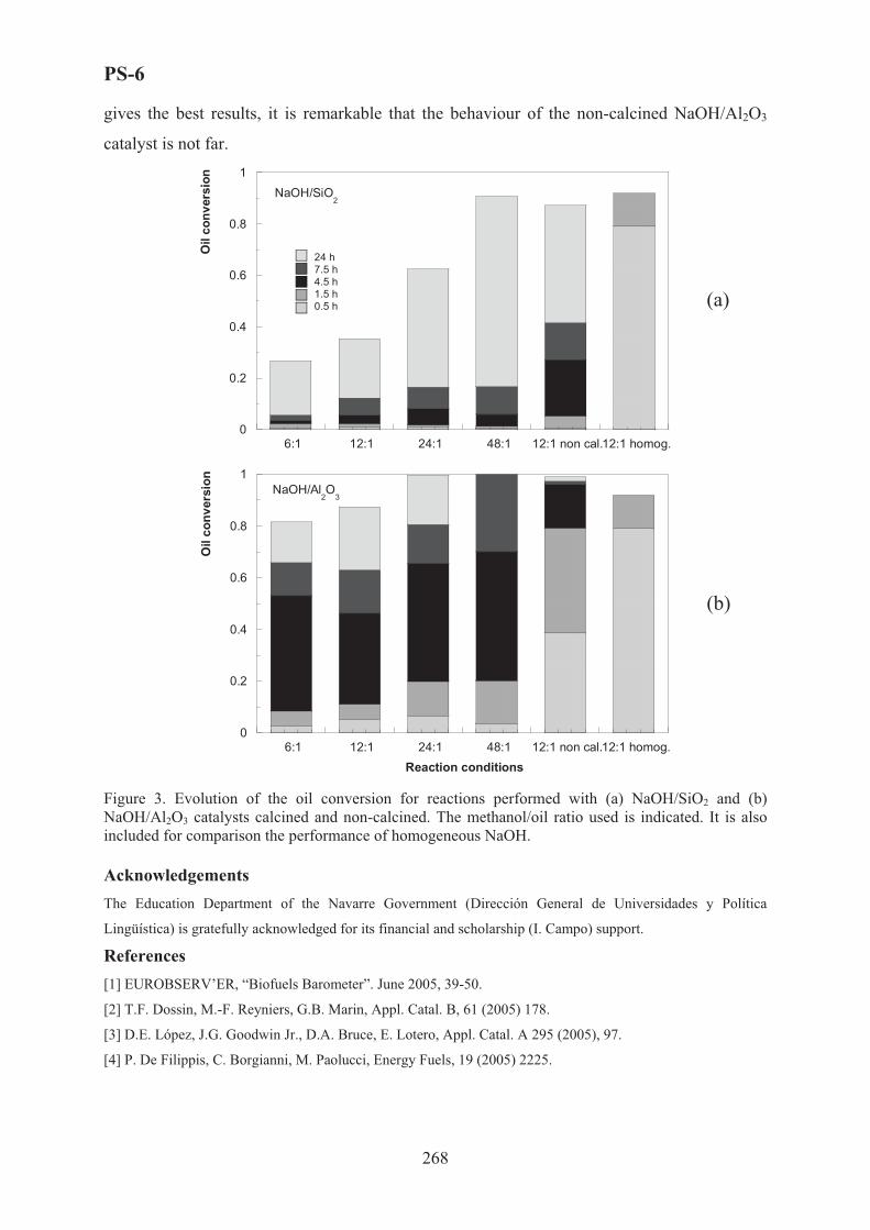
PS-6
gives the best results, it is remarkable that the behaviour of the non-calcined NaOH/Al2O3
catalyst is not far.
0
0.2
0.4
0.6
0.8
1
6:1 12:1 24:1 48:1 12:1 non cal.12:1 homog.
Oil
conv
ersi
on
24 h7.5 h4.5 h1.5 h0.5 h
NaOH/SiO2
(a)
0
0.2
0.4
0.6
0.8
1
6:1 12:1 24:1 48:1 12:1 non cal.12:1 homog.
Oil
conv
ersi
on
Reaction conditions
NaOH/Al2O
3
(b)
Figure 3. Evolution of the oil conversion for reactions performed with (a) NaOH/SiO2 and (b) NaOH/Al2O3 catalysts calcined and non-calcined. The methanol/oil ratio used is indicated. It is also included for comparison the performance of homogeneous NaOH.
Acknowledgements The Education Department of the Navarre Government (Dirección General de Universidades y Política
Lingüística) is gratefully acknowledged for its financial and scholarship (I. Campo) support.
References [1] EUROBSERV’ER, “Biofuels Barometer”. June 2005, 39-50.
[2] T.F. Dossin, M.-F. Reyniers, G.B. Marin, Appl. Catal. B, 61 (2005) 178.
[3] D.E. López, J.G. Goodwin Jr., D.A. Bruce, E. Lotero, Appl. Catal. A 295 (2005), 97.
[4] P. De Filippis, C. Borgianni, M. Paolucci, Energy Fuels, 19 (2005) 2225.
268

PS-7
STEAM REFORMING OF BIO-OIL IN A FIXED BED REACTOR FOR
THE PRODUCTION OF HYDROGEN
P.N. Kechagiopoulos(1), S.S. Voutetakis(2), A.A. Lemonidou(3), A.A. Iordanidis(4)
and I.A. Vasalos(5)
(1,3,5)Department of Chemical Engineering, Aristotle University of Thessaloniki, P.O. Box
1517, University City, Thessaloniki 54124, Greece (2,4,5)Process Engineering Research Institute, Centre for Research and Technology Hellas,
P.O. Box 361, GR 57001, Thermi, Thessaloniki, Greece (1) [email protected], (2) [email protected], (3) [email protected],
(4) [email protected], (5) [email protected]
Introduction
The continuously increasing pressure on the pollution of the environment from the use of
conventional fuels, in conjunction with the concern for the depletion of oil reserves, has led to
a necessity to intensify the search for alternative energy sources. Hydrogen is emerging as the
energy carrier of the future since it can be used as a clean transport fuel as well as a means for
the production of electricity via fuel cells. Nowadays, hydrogen is mainly produced from non-
renewable sources leading to high CO2-emissions. Hydrogen can present environmental
benefits only when derived from renewable energy sources. Steam reforming of biomass
pyrolysis oil (bio-oil) is a promising sustainable hydrogen production route. The main
objective of this work was to study the reforming of bio-oil model compounds and the
aqueous fraction of a bio-oil derived from beech wood in a pilot plant unit.
Experimental
The experiments for this study were conducted at the SYNGAS pilot plant unit of CPERI
using a fixed-bed reactor. Gas chromatographs were used for the analysis of gas and liquid
products. The reactor was heated electrically by a three-zone furnace. An industrial naphtha
reforming catalyst supplied by Sud-Chemie (C11-NK) was used for the experiments Runs
were conducted with ethylene glycol, acetone and acetic acid. The aqueous fraction of a bio-
oil derived from catalytic pyrolysis of beech wood was also tested.
Results and discussion
Ethylene Glycol reforming: Complete conversion of ethylene glycol was attained for all the
conditions studied. Hydrogen yield is presented as a function of H2O/C ratio and temperature
269

PS-7
in Fig.1a and b respectively. The approach to equilibrium for all of the conditions studied is
very good with hydrogen yield always well above 80% reaching 93% at 700oC and a H2O/C
ratio of 6. Experiments terminated due to reactor blockage for H2O/C ratios less than 3 after
approximately 7 hours. Temperature variation experiments proceeded more smoothly. Coke
formation was noticeably smaller due to the high H2O/Carbon ratio (equal to 6) that was used.
We managed to sustain a continuous run even at temperature 600oC for more than 12 hours.
0.00
20.0
40.0
60.0
80.0
100
0.0
0.20
0.40
0.60
0.80
1.0
1.2
1.4
1 2 3 4 5 6 7
H2
Yie
ld, H
2/CO
CO
/CO
2
H2O/C
H2 Yield
H2/CO
CO/CO2
(a)
0.00
20.0
40.0
60.0
80.0
100
0.0
0.10
0.20
0.30
0.40
0.50
550 600 650 700 750
H2Y
ield
, H2/C
O
CO
/CO
2
Temperature (oC)
H2 Yield
H2/CO
CO/CO2
(b)
Figure 1. Ethylene glycol reforming at: (a) T=700oC and (b) H2O/C=6. GC1HSV = 1500 hr-1
Model compounds mixture reforming: An equimolar mixture of acetic acid, acetone and
ethylene glycol was prepared. The results for variable H2O/C ratio and temperature are
depicted in Fig.2a and b respectively. Equilibrium product composition was attained under all
the conditions used. Hydrogen yield as high as 90% is attained with the catalyst being able to
convert completely the organic compounds. Steady runs in every experimental condition
lasted for more than 4 hours. However, it was observed that coke formation was higher
compared to ethylene glycol for the same conditions.
0.00
20.0
40.0
60.0
80.0
100
0
0.2
0.4
0.6
0.8
1
1.2
1.4
2 3 4 5 6 7
H2
Yie
ld, H
2/CO
CO
/CO
2
H2O/C
H2 Yield
H2/CO
CO/CO2
(a)
0.00
20.0
40.0
60.0
80.0
100
-0.2
0.0
0.2
0.4
0.6
0.8
1.0
1.2
600 650 700 750 800
H2
Yie
ld, H
2/CO
CO
/CO
2
Temperature ( oC)
H2 Yield
H2/CO
CO/CO2
(b)
Figure 2. Mixture reforming at: (a) T=750oC and (b) H2O/C=6. GC1HSV = 1500 hr-1
Acetone reforming: Acetone is known to undergo aldol condensation reactions forming
products such as mesityl oxide or produce ketene via decomposition. Both compounds can
270

PS-7
undergo oligomerization forming carbonaceous deposits. Acetone being more susceptible for
coke formation could be the reason for the higher carbon formation observed in the 3-
component mixture experiments compared to ethylene glycol. This was validated in a separate
set of experiments with acetone as the oxygenated feed stock (Fig.3a and b). At the same
experimental conditions acetone showed increased formation of coke deposits. The approach
to equilibrium is good for temperatures higher than 650�C and H2O/C ratios higher than 4.
Coke formation restricted the TOS to 2h under which steady conditions could be attained.
Nonetheless, conversion of acetone was complete in the entire spectrum of conditions covered
under steady operation.
0.00
20.0
40.0
60.0
80.0
100
0
0.2
0.4
0.6
0.8
1
2 3 4 5 6 7
H2Y
ield
, H2/C
O
CO
/CO
2
H2O/C
H2 Yield
H2/CO
CO/CO2
(a)
0.00
20.0
40.0
60.0
80.0
100
-0.50
0.0
0.50
1.0
550 600 650 700 750 800
H2Y
ield
, H2/C
O
CO
/CO
2
Temperature ( oC)(b)
H2 Yield
H2/CO
CO/CO2
Figure 3. Acetone reforming at: (a) T=650oC and (b) H2O/C=6. GC1HSV = 1500 hr-1
Bio-oil aqueous phase reforming: Bio-oil produced from the catalytic pyrolysis of beech
wood was separated by adding water at a mass ratio equal to 2:1 in order to extract the
aqueous fraction. The final aqueous mixture contained 16% wt organics (CH2.48O0.94), the rest
being water, corresponding to a H2O/C equal to 8.2. To avoid high extent of thermal
decomposition an injection system was installed in the fixed bed reactor in order to feed the
bio-oil at environmental temperature.
The first series of experiments with bio-oil as a feedstock were conducted in the absence of
catalyst in order to investigate the extent of decomposition in the gaseous phase. The
conversion of bio-oil to gaseous products was as low as 12% for 650oC and increased up to
60% for temperatures higher than 850oC. More than 20% of the incoming carbon was
deposited in the catalytic bed as coke at 650oC, with this number lowering to 12% above
800oC. Thus the total conversion of the bio-oil spanned from 35% to 80% with increasing
temperature.
The catalytic tests with bio-oil were performed without any further addition of external water.
The yield of hydrogen did not surpass 60% (Fig.4a) in all of the conditions studied with the
271

PS-7
conversion of bio-oil being complete. The highest values were observed at the higher
temperatures, while the flow of the organics did not seem to influence notably. According to
thermodynamic calculations, hydrogen yield for these conditions is almost 90%. This
deviation can be ascribed to the increased coke formation in the catalytic bed that amounted to
around 30% wt of the incoming carbon. The majority of the experiments terminated after 4
hours in order to regenerate the catalytic bed.
0
10
20
30
40
50
60
70
80
90
100
575 625 675 725 775 825 875Temperature (oC)
H2 Y
ield
, H2/C
O
0.0
0.2
0.4
0.6
0.8
1.0
1.2
1.4
1.6
1.8
2.0
CO
/CO
2H2/CO
CO/CO2
H2 Yield
H2 Selectivity
50.0
60.0
70.0
80.0
90.0
100
110
550 600 650 700 750 800 850 900
H2 Y
ield
Temperature (oC) Figure 4. Catalytic reforming of bio-oil: (a) Effect of reaction temperature, (b) �2 yield based on carbon moles
at the outlet. GC1HSV = 300 hr-1 (solid), 600 hr-1 (blank). Lines: equilibrium
(a) (b)
Worthy to note that the composition of the gaseous products follows very well the
thermodynamically predicted, implying that the reactions of steam reforming and water-gas
shift are at equilibrium. This can be proved by calculating the yield of hydrogen assuming that
the incoming carbon moles are equal to the sum of those contained in the gaseous products
(Fig.4b). It is clear from this diagram that hydrogen yield is equal to or greater than that
theoretically predicted from equilibrium.
Conclusions
Biomass can be efficiently used for hydrogen production. Representative model compounds
of bio-oil are effectively reformed in a fixed bed in the presence of commercial nickel-based
catalysts. Hydrogen yields up to 90% can be achieved at reaction temperatures higher than
600°C and steam to carbon ratios higher than 3. Reforming of real bio-oil resulted in a much
lower hydrogen yield around 60% due to the high extent of coking. The severe coking caused
mainly from thermal decomposition of the unstable oxygenates, imposes the use of fluid bed
reactors in processing the aqueous fraction of the bio-oil. By combining a proper reactor
design with catalytic materials that minimize the catalytically produced coke, bio-oil has the
potential to become an important and environmentally friendly hydrogen production method.
272

PS-8
RENEWABLE HYDROGEN AND CHEMICALS BY AUTOTHERMAL
REFORMING OF ALCOHOLS, ETHYLENE GLYCOL,
AND GLYCEROL
P.J. Dauenhauer, J. Salge, E. Wanat and L.D. Schmidt
Department of Chemical Engineering & Materials Science
University of Minnesota – Twin Cities
151 Amundson Hall, 421 Washington Avenue SE
Minneapolis MN 55455, USA
Fax: 612-626-7246, [email protected]
Autothermal reforming is a very promising method to convert biofuels into hydrogen and
chemicals. [1-4] High conversion with residence times less than 10 milliseconds allow for
very small reactors that operate without external heat sources. Flexible operation allows for
start-up in a few seconds as well as in transient modes. [1]
We describe the reforming of alcohols (methanol, ethanol, n-propanol, and iso-propanol)
as well as ethylene glycol and glycerol and consider the catalysts and reactor conditions that
maximize either hydrogen or chemicals. All experiments exhibited greater than 90%
conversion of fuel and oxygen and adiabatic temperatures greater than 700 °C. These fuels
can be made to produce H2, H2O, CO, and CO2 and less than 1% of any other species
including olefins, alkanes, or aldehydes by tuning the carbon to oxygen ratio (C/O) to 1 for
maximum H2. By using larger pore diameters and operating at a C/O > 1, larger yields of
chemicals can be obtained.
All alcohols can be converted into H2 and CO with selectivities of at least 60% using
rhodium (Rh) on a ceramic foam monolith support at C/O ~1. [2-4] The addition of a +
$-alumina wash coat improves the hydrogen selectivity by up to 15% as observed with ethanol
by increasing catalyst dispersion. The addition of cerium (Ce) to Rh has also been shown to
dramatically improve hydrogen selectivity of ethanol and 1-propanol to 80% and 90%
respectively. Alcohols can also produce chemicals such as ethylene in selectivities as high as
25% on Pd or Pt by increasing the C/O ratio beyond ~1. Furthermore, acetone can be
produced from 2-propanol with selectivities up to 60%. [4] Few aldehydes have been
observed from any of the alcohols under the range of reactor conditions.
273

PS-8
Addition of water improves H2 selectivity from ethanol as high as 140%, based on the H
atoms in the fuel. [2] The presence of water on a RhCe catalyst promotes water-gas shift,
producing hydrogen molecules from all six H atoms of ethanol as well as H atoms from
additional water molecules. The promoted shift reaction has the additional benefit of reducing
the carbon monoxide selectivity from 80% to 40%, thereby reducing a fuel cell poison from
the hydrogen rich product stream.
Ethylene glycol and glycerol have one carbon atom for every oxygen atom present as a
hydroxyl group similar to larger biologically derived molecules. This class of molecules is
restricted thermodynamically to H2 selectivities of ~60%, achieved on RhCe catalysts with
$-alumina wash coat. Autothermal reforming with steam to carbon ratios as high as 4.5 have
resulted in H2 selectivities as high 90% and CO selectivities as low as 25% at 700 °C.
The high yield of H2 without significant formation of any other chemicals appears to
occur primarily by surface chemistry through the alkoxy bond with the Rh surface which is
known to be the primary mechanism of alcohol bonding to noble metals. [4] � scission of the
adsorbed alkoxy leads to complete dissociation and resultant formation of primarily H2 and
CO or to CO2 in the presence of H2O. Acetone is probably formed primarily by
homogeneous chemistry within the pores of the catalyst, with the weak secondary C-H bond
dissociation to form a radical species which eliminates H to form the ketone.
* This research partially supported by grants from the University of Minnesota Initiative for
Renewable Energy and the Environment and the Minnesota Corn Growers Association.
[1] K. Williams, C. Leclerc, and L. D. Schmidt, "Rapid lightoff of syngas production from methane: A transient product analysis," AIChE Journal 51, 1, (2005).
[2] G. A. Deluga, J. R. Salge, and L. D. Schmidt, "Renewable hydrogen from ethanol by autothermal reforming," Science 303, 993-997, (2004).
[3] J.R. Salge, G.A. Deluga, L.D. Schmidt, “Catalytic partial oxidation of ethanol over noble metal catalysts,” Journal of Catalysis, 235, 69-78, (2005).
[4] E.C. Wanat, B. Suman, L.D. Schmidt, “Partial oxidation of alcohols to produce hydrogen and chemicals in millisecond-contact time reactors,” Journal of Catalysis 235, 18-27, (2005).
274

PS-9
OXIDATION OF �-PINENE WITH O2 AND AQUEOUS H2O2
OVER SINGLE SITE CATALYSTS
N.V. Maksimchuk1, M.S. Melgunov1, J. Mrowiec-Bia�o�2, A.B. Jarzbski2,
V.N. Parmon1,V.A. Semikolenov,† and O.A. Kholdeeva1
1Boreskov Institute of Catalysis SB RAS,
Prospekt Akademika Lavrentieva 5, Novosibirsk, 630090, Russia
E-mail: [email protected]; Fax : +7 383 330 80 56 2Polish Academy of Sciences, Institute of Chemical Engineering,
44-100 Gliwice, Ba�tycka 5, Poland
Introduction
�-Pinene is the main component of gum turpentine and is thus an inexpensive, readily
available, and renewable starting material for producing a wide variety of valuable products,
such as flavors, fragrances, medicines, and agrochemicals [1-2]. Specifically, its oxidation
products, verbenol, verbenone, �-pinene epoxide, and campholenic aldehyde, are of high
practical importance as flavor chemicals and key intermediates for manufacture of various
fine chemicals, including citral, menthol, taxol, vitamins A and E [3-5].
verbenol�-pineneOH O
verbenone
+
campholenicaldehyde
+CHO[O]
O
�-pineneepoxide
+
The development of methods for the selective oxidation of �-pinene using environmentally
benign and cheap oxidants, such as O2 and H2O2, over solid, easily recyclable catalysts is a
challenging goal of fine chemistry.
Here we first report a comparative study of �-pinene autoxidation and oxidation by
molecular oxygen (as well as its co-oxidation with isobutyraldehyde) over heterogeneous
catalysts based on Co-containing polyoxometalate (Co-POM), TBA4HPW11CoO39, and NH2-
modified mesoporous silicate matrixes (MMM, SBA-15, etc.). The catalytic properties of the
single site catalysts, such as mesostructured metal-silicates Ti-MMM-2 and Fe-MMM-2,
TiO2-SiO2 mixed oxides, Ti- and Zr-grafted on mesoporous silica cellular foams (Ti- and Zr-
MCF), and the new composite material H5PW11TiO40/silica prepared by a sol-gel method, in
allylic oxidation of �-pinene with aqueous H2O2 are also reported. The effects of the reaction
275

PS-9
conditions (temperature, concentration of reagents, solvent nature, etc.) on the product
distribution and yield have been studied. The question on the catalyst stability and its
reusability was addressed.
Experimental
The catalysts were prepared according to the literature procedures [6-8] and were
characterized by elemental analysis, N2 adsorption, XRD, IR and DRS-UV spectroscopy.
Catalytic experiments were carried out in thermostated glass vessels under vigorous stirring.
Aliquots of the reaction mixture were withdrawn periodically during the reaction course, and
the reaction products were identified by GC-MS and 1� NMR, and quantified by GC using
internal standard. The leaching and stability tests were performed as described previously [9].
Results and Discussion
The kinetic peculiarities of �-pinene liquid-phase autoxidation by molecular oxygen have
been studied (in the temperature range of 70-120°C and at oxygen pressure within 0.5-6 bar
range). At a low �-pinene conversion (5.5%), the process of �-pinene oxidation by molecular
oxygen proceeds selectively and gives two main products: �-pinene epoxide (39% selectivity)
and verbenyl-hydroperoxide (55% selectivity), which can be catalytically hydrogenated to
verbenol to increase its yield. The reaction conditions for selective reduction of verbenyl-
hydroperoxide to verbenol by molecular hydrogen over the Pd/C catalyst without affecting the
�-pinene C=C bond were found. The products ratio depends slightly on the temperature,
oxygen pressure and �-pinene conversion. A kinetic equation for the reaction rate was
inferred.
The catalytic �-pinene oxidation by molecular oxygen over Co-POM/silica catalysts
leads to allylic oxidation products (50% selectivity at 56% conversion) while co-oxidation
with isobutyraldehyde gives selectively �-pinene epoxide (90% selectivity at 100%
conversion). The �-pinene oxidation by O2 (both with and without isobutyraldehyde) without
catalyst is slower and less selective than the
catalytic process. The catalyst activity related to one
Co center (TOFav) in the �-pinene oxidation
decreased in the order Co-POM/MCF N
Co-POM/silica composite material > Co-
POM/SBA-15 > Co-POM/silica (both with and
without isobutyraldehyde). The catalysts can be
used repeatedly without a significant loss in activity
1 2 30
20
40
60
80
100
�-Pi
nen
conv
ersi
on a
nd
�-p
inen
e ep
oxid
e se
lect
ivity
, %
Catalytic cycles (Co-POM/SBA-15)
�pinene conversion, %�pinene epoxide selectivity, %
276

PS-9
although minor leaching of the active component is observed.
The catalyst activity related to one active metal center (TOFav) in the H2O2-based
�-pinene oxidation decreased in the order H5PW11TiO40/silica >> Ti-MCF > Ti-MMM-2 >
Zr-MCF > Ti,Si-xerogel > Fe-MMM-2. The reaction selectivity strongly depends on the
solvent, substrate/oxidant molar ratio, reaction temperature, and �-pinene conversion. In
optimized reaction conditions (MeCN, 30,C), with H5PW11TiO40/silica as catalyst, the
selectivity toward verbenol/verbenone attains 82 and 68% at 8-15 and 28% conversion of the
substrate, respectively. Interestingly, Co-POM/silica and Co-POM/SBA-15 yield the
selectivity toward verbenol/verbenone as high as 67% at 16-21% of substrate conversion
(MeCN, 50,C), so a higher selectivity level can be reached with H2O2. Meanwhile, in all the
systems, the selectivity decreases with the substrate conversion indicating overoxidation
processes.
The Ti-catalysts can be used repeatedly without a significant loss in activity, no
leaching of the active component is observed.
1 2 3 41 2 3 4 5 6 7 80
10
20
30
40
50
�-P
inen
e co
nver
sion
and
prod
ucts
yield
s, %
�-pinene conversion, % verbenol yield, % verbenone yield, %
The experiments with a fast catalyst filtration at the reaction temperature showed that the
oxidation is a true heterogeneous process. The reaction atmosphere (air, O2 or Ar) and small
amounts of the radical chain inhibitor, 2,6-di-tert-butyl-4-methylphenol, had no significant
affect on the product distribution and the reaction rate indicating most likely radical non-chain
mechanism of the oxidation or short chains.
Conclusion
In all the systems studied, the selectivity of allylic oxidation of �-pinene strongly depends on
the substrate conversion. The highest selectivity to verbenol/verbenone (82% at 15%
conversion) was obtained using heterogeneous composite catalyst H5PW11TiO40/silica and
aqueous H2O2 as oxidant. The catalyst behaves as a true heterogeneous one and can be used
repeatedly without suffering its activity. Another advantage of this system is its non-chain
277

PS-9
radical mechanism (or mechanism with short chains). That ensures a good reproducibility of
the catalytic results obtained with H2O2, which is in contrast to O2-based processes
proceeding via chain radical mechanisms.
Acknowledgement
The research was partially supported by RFBR-CNRS (grant 05-03-34760). N.V.M.
acknowledges Award No. NO-008-X1 from CRDF.
References
[1] W.F. Erman, Chemistry of the Monoterpenes: An Encyclopedic Handbook, Marcel Dekker, New York, 1985.
[2] Bauer K., Garbe D., Surburg H., Common Fragrance and Flavor Materials, Wiley-VCH, New York, 1997.
[3] C. Mercier, P.Chabardes, Pure and Appl. Chem. 66 (1994) 1509.
[4] P.Z. Bedoukian, Am. Perf. and Cosm. 86 (1971) 25.
[5] P.A. Wender, T.P. Mucciaro, J. Am. Chem. Soc. 114 (1992) 5878.
[6] O.A. Kholdeeva, M.S. Melgunov, A.N. Shmakov, N.N. Trukhan, V.V. Kriventsov, V.I. Zaikovskii, V.N. Romannikov, Catal. Today, 91-92 (2004) 205.
[7] M.S.Morey, S.O'Brien, S.Schwarz, G.D.Stucky, Chem. Mater., 12 (2000) 898.
[8] O. A. Kholdeeva, M. P. Vanina, M. N. Timofeeva, R. I. Maksimovskaya, T. A. Trubitsina, M. S. Melgunov, E. B. Burgina, J. Mrowiec-Bia�o�, A.B. Jarz�bski, C. L. Hill, J. Catal., 226 (2004) 363.
[9] N.N. Trukhan, V.N. Romannikov, E.A. Paukshtis, A.N. Shmakov, O.A. Kholdeeva, J. Catal. 202 (2001) 110.
278

PS-10
REACTION OF THE NATURAL LIGNAN HYDROXYMATAIRESINOL
OVER PALLADIUM ON CARBON NANOFIBRES
Heidi Markus1, Arjan Plomp2, Päivi Mäki-Arvela1, Narendra Kumar1,
Krijn P. de Jong2, Johannes H. Bitter2, Dmitry Yu. Murzin1
1Laboratory of Industrial Chemistry, Process Chemistry Centre, Åbo Akademi University,
Biskopsgatan 8, FIN-20500 Turku, Finland 2Department of Inorganic Chemistry and Catalysis, Debye Institute, Utrecht University,
P.O. Box 80083, Utrecht 3508 TB, The Netherlands
Introduction
Lignans can be found in many different parts of plants, such as the wooden parts, roots,
leaves, flowers, fruits, and seeds. Most plants contain small amounts of lignans as glycosidic
conjugates associated with fibre components, which complicates the isolation process [1].
Coniferous trees, on the other hand, contain large amounts of lignans in unconjugated forms,
which can be more easily isolated. Knots of Norway spruce (Picea abies), i.e., the part of the
branch that is embedded in the stem, contain large quantities of lignans, 6–24 wt-%, out of
which hydroxymatairesinol (HMR) is the most abundant (65–85 wt-% of the lignans) [2].
Studies have suggested that lignans have a preventive effect against hormone-dependent
cancers such as breast, prostate and colon cancers [3]. In addition to the anticarcinogenic
effects, they also have antioxidative effects [4].
Matairesinol (MAT) can be found in small amounts in different plants, for example, in
flaxseed and rye [5]. MAT can be produced through hydrogenolysis of HMR, which as
indicated above, can be extracted in larger amounts from Norway spruce knots. Markus et al.
[6] hydrogenolysed hydroxymatairesinol over palladium on active carbon, and it was
concluded that the acidity of the carbon had a profound effect on the activity; the reaction rate
increased with the acidity increase. However, carbon supported metal catalysts can exhibit
large batch-to-batch variations due to, for example, natural variations in the starting material
[7], and moreover the reproducibility of the catalyst preparation with respect to the surface
groups might become difficult. To avoid this, synthetic carbons can be used. Examples on
synthetic carbons are carbon nanofibres (CNF) and carbon nanotubes (CNT). Carbon
nanofibres are graphite-like fibres grown from decomposition of carbon-containing gases on
small metal particles and they contain neither micropores nor impurities [8]. The acidity of
279

PS-10
this material can be modified by oxidation (creating acid sites) or reduction (removing acid
sites). In this work, HMR was hydrogenolysed over palladium containing CNF, comprising
different amount of acid sites.
Experimental
The carbon nanofibres were grown on a Ni/SiO2 catalyst as described by Toebes et al. [9].
The deposition of palladium on the CNF was performed according to Winter et al. [10]. Three
portions of the Pd/CNF were heat-treated in a N2-flow at 300°C, 400°C, and 500°C during 2
hours (ramp 5°C/min). These catalysts and the non-treated Pd/CNF were having different
concentration of acid sites; the most acidic was the non-treated catalyst, and the least acidic
was the catalyst treated in N2-flow at 500°C. The catalysts were tested in the hydrogenolysis
of HMR under hydrogen atmosphere in stirred glass reactor at 70°C and using 2-propanol as
solvent. The reaction scheme is presented in Fig. 1.
cat./2-propanol
cat./H2
cat./H2
cat./H2
cat./H2
cat./H2
7-i-propoxyMAT
HMR MAT
byproduct D
byproduct C
byproduct B
byproduct A
O
OCH3
H3CO
HO
OH
O
O
OH
H3CO
OCH3
O
O
OCH3
H3CO
HO
OH
O
HO
O
OCH3
H3CO
HO
OH
O
H7C3O
O
OCH3
H3CO
HO
O
O
OH
HO
H3CO
O
O
OCH3
HO
OH
O
Fig. 1. Reaction scheme.
Results and discussion
As illustrated by Fig. 2, the least acidic Pd/CNF (treated in N2-flow at 500°C) had the
lowest activity and selectivity. The non-treated Pd/CNF had approximately the same activity
as the catalyst treated at 300°C, but the non-treated catalyst was much more selective. It can
280

PS-10
be concluded that a more acidic CNF support is preferred, and this is in agreement with the
results obtained with Pd/C [6].
a)
0
0.2
0.4
0.6
0.8
1
0 40 80 120 160 200 240
time (min)
conv
ersio
n Pd/CNF, 500C N2Pd/CNF, 400C N2Pd/CNF, 300C N2Pd/CNF, no treatment
b)
0.7
0.8
0.9
1
0 0.2 0.4 0.6 0.8 1
conversion
sele
ctiv
ity
Pd/CNF, 500C N2Pd/CNF, 400C N2Pd/CNF, 300C N2Pd/CNF, no treatment
Fig. 2. Hydrogenolysis of hydroxymatairesinol to matairesinol: a) conversion versus time, b) selectivity to matairesinol versus conversion.
References [1] N.M. Saarinen, A. Wärri, S.I. Mäkelä, C. Eckerman, M. Reunanen, M. Ahotupa, S.M. Salmi, A.A.
Franke, L. Kangas, R. Santti, Nutr. Cancer 36 (2000) 207. [2] S. Willför, J. Hemming, M. Reunanen, C. Eckerman, B. Holmbom, Holzforschung 57 (2003) 27. [3] H. Adlercreutz, Lancet 3 (2002) 364. [4] S.M. Willför, M.O. Ahotupa, J.E. Hemming, M.H.T. Reunanen, P.C. Eklund, R.E. Sjöholm, C.S.E.
Eckerman, S.P. Pohjamo, B.R. Holmbom, J. Agric. Food Chem. 51 (2003) 7600. [5] S. Heinonen, T. Nurmi, K. Liukkonen, K. Poutanen, K. Wähälä, T. Deyama, S. Nishibe, H. Adlercreutz, J.
Agric. Food Chem. 49 (2001) 3178. [6] H. Markus, P. Mäki-Arvela, N. Kumar, N.V. Kul’kova, P. Eklund, R. Sjöholm, B. Holmbom, T. Salmi,
D.Yu. Murzin, Catal. Lett. 103 (2005) 125. [7] N. Krishnankutty, M.A. Vannice, J. Catal. 155 (1995) 312. [8] M.L. Toebes, J.M.P. van Heeswik, J.H. Bitter, A.J. van Dillen, K.P. de Jong, Carbon 42 (2004) 307. [9] M.L. Toebes, J.H. Bitter, A.J. van Dillen, K.P. de Jong, Catal. Today 76 (2002) 33. [10] F. Winter, A.J. van Dillen, K.P. de Jong, J. Mol. Catal. A 219 (2004) 273.
281

PS-11
ENVIRONMENTALLY FRIENDLY NOVEL HYBRIDIZED CHIRAL
ORGANO-INORGANIC CATALYSTS FOR EPOXIDATION AND
ALKYLATION REACTIONS
Oriana Lanitou1,2, Dimitra Dimotikali1, Elina Yiannakopoulou2,
Kyriakos Papadopoulos2
1Chemical Engineering Department, N.T.U. Athens, 15780 Athens, Greece,
e-mail: [email protected], tel.: 210-6503634; fax.: 210-6511766. 2Institute of Physical Chemistry, NCSR "Demokritos", 15310 Athens, Greece,
e-mail: [email protected] , tel.: 210-6503647; fax.: 210-6511766
Introduction
In recent years, methods for the stereoselective synthesis of epoxides as well as of -amino
acids have attracted widespread attention due to their importance as potential intermediates
for the synthesis of natural or pharmaceutical products. Especially, numerous studies for the
synthesis of -amino acids, the “building blocks of life”, have been made over the past quarter
century [1-4].
In most cases the stereoselective formation of the aforementioned compounds has been
extensively studied using chiral liquid-liquid phase-transfer catalysts on the basis of cinchona
alkaloids [5,6]. However, these catalysts often cause problems related to their recovery and
recycle. In the last years, the above mentioned catalysts are replaced by hybridized organo-
inorganic ones which are insoluble in aqueous or organic solvents and thus easily removable
from the reaction mixtures. Soai [7] and Lasperas [8,9] were of the first who described the use
of such functionalized chiral organo-inorganic catalysts for enantioselective reduction
reactions with very promising results. Encouraged by these results, we decided to prepare
similar silica-functionalized chiral quaternary ammonium salts and test them on the
asymmetric epoxidation of enones and asymmetric alkylations of glycine derivatives.
In this study, we present for the first time the synthesis of two novel chiral functionalized
organo-inorganic catalysts 1 and 2 using the chiral auxiliaries (S)-(+)-cinchonine and (S)-(-)-
nicotine, respectively, and their application in the asymmetric epoxidation reactions of
chalcone 3 and asymmetric benzylation of ethyl N-(diphenylmethylene)-glycinate 5
(O’Donnell’s-reagent).
282

PS-11
Results and Discussion
The novel chiral hybridized organo-inorganic catalysts 1 and 2 have been synthesized in two
steps. In the first step, 3-chloropropyl-triethoxysilane was bonded on activated silica gel (pore
diameter 6.0 nm) by simple reflux in toluene. In the second step the isolated hybridized silica
containing the chloropropylsilane-spacer was refluxed in toluene with the chiral auxiliaries,
(S)-(+)-cinchonine or (S)-(-)-nicotine, filtered, washed and dried. Elemental analysis
measurements showed that up to 1.5 mmol organic material was bound per gram silica. The
existence of organic material on silica verified, also by infrared spectroscopy.
OOO
Si
N
NOH
H
+Cl-
OOO
Si N
NH3CH
Cl-
+
1 2 Scheme 1. Novel organo-inorganic chiral catalysts produced from activated silica gel and chiral
auxiliaries, such as (S)-(+)-cinchonine 1 or (S)-(-)-nicotine 2.
The novel hybridized organo-inorganic catalysts were tested on the asymmetric epoxidation
of trans-chalcone 3 (Scheme 1) and on the asymmetric benzylation of ethyl N-
(diphenylmethylene)-glycinate 5 (Scheme 2). These reagents have been chosen due to their
often use in liquid-liquid phase-transfer reactions as well as for comparison reasons due to the
known stereochemistry of their products.
In epoxidation reactions of chalcone, both catalysts lead to moderate chemical yields (50-
60%), very high diastereoselectivities (de>96 %) but very low enantioselectivities (ee < 2 %).
The extent of the diastereoselectivities (de) was determined by 13C NMR spectroscopy, while
the enantiomeric excess (ee) and absolute configuration after comparison of the measured
optical rotation value of product 4 with that of authentic one given in the literature. The
epoxide 4 showed the (-)-sign in optical rotation measurements which corresponds to the (2R,
3S)-configuration [10].
O 30% H2O2 / NaOH solvent, rt
chiral catalyst O
C
H
HO
3 4 Scheme 1. Catalytic asymmetric synthesis of (2R, 3S)-2.3-epoxy-3-phenyl-propiophenone
4 using hybridized catalysts 1 and 2.
283
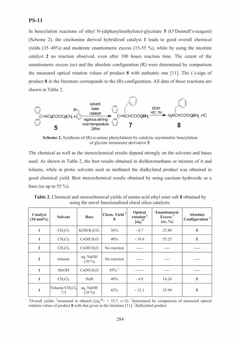
PS-11
In benzylation reactions of ethyl N-(diphenylmethylene)-glycinate 5 (O’Donnell’s-reagent)
(Scheme 2), the cinchonine derived hybridized catalyst 1 leads to good overall chemical
yields (35–48%) and moderate enantiomeric excess (15-55 %), while by using the nicotine
catalyst 2 no reaction observed, even after 100 hours reaction time. The extent of the
enantiomeric excess (ee) and the absolute configuration (R) were determined by comparison
the measured optical rotation values of product 8 with authentic one [11]. The (-)-sign of
product 8 in the literature corresponds to the (R)-configuration. All data of these reactions are
shown in Table 2.
C=NCH2COOCH2CH3 + C=NCHCOOCH2CH3 H2NCHCOOCH2CH3 .HCBr
solventbase
catalystvigorous stirring
room temperature24hrs
EtOHHCl 1N
5 7 8
Scheme 2. Synthesis of (R)--amino phenylalanin by catalytic asymmetric benzylation of glycine iminoester derivative 5.
The chemical as well as the stereochemical results depend strongly on the solvents and bases
used. As shown in Table 2, the best results obtained in dichloromethane or mixture of it and
toluene, while in protic solvents such as methanol the dialkylated product was obtained in
good chemical yield. Best stereochemical results obtained by using caesium hydroxide as a
base (ee up to 55 %).
Table 2. Chemical and stereochemical yields of amino acid ethyl ester salt 8 obtained by using the novel functionalised chiral silica catalysts.
Catalyst (10 mol%) Solvent Base Chem. Yield 1
8
Optical rotation 2
[a]D25
Enantiomeric Excess 3
(ee, %)
Absolute Configuration 3
1 CH2Cl2 KOH/K2CO3 36% - 8.7 25.80 R
1 CH2Cl2 CsOH.H2O 40% - 18.6 55.25 R
2 CH2Cl2 CsOH.H2O No reaction ----- ---- -----
2 toluene aq. NaOH (10 %) No reaction ----- ---- -----
1 MeOH CsOH.H2O 85% 5 ------ ---- -----
1 CH2Cl2 NaH 48% - 4.8 14.24 R
1 Toluene/CH2Cl2 7:3
aq. NaOH (10 %) 42% - 12.1 35.94 R
1Overall yields; 2measured in ethanol ([a]D25= + 33.7, c=2); 3determined by comparison of measured optical
rotation values of product 8 with that given in the literature [11]; 5dialkylated product.
284

PS-11
Conclusions
Although the first stereochemical results of the novel hybridized chiral organo-inorganic
catalysts tested on the asymmetric epoxidation of chalcone and on the benzylation of ethyl N-
(diphenylmethylene)-glycinate are not very impressive, nevertheless, the high chemical yields
of these reactions and the advantage of the easy removal of the catalyst from the reaction
mixture by simple filtration make such catalysts very attractive. The novel functionalized
organo-inorganic catalysts can play an important role in the new greener industry by replacing
hazardous and environmentally threatening chemicals. Further studies of these novel phase-
transfer catalysts are now under investigation.
References [1] R. O. Duthaler, Tetrahedron, 1994, 50, 1539.
[2] A. Studer, Synthesis, 1996, 793.
[3] D. Seebach, A.R. Sting, M. Hoffman, Angew. Chem., Int. Ed. Engl. 1996, 35, 2708.
[4] M. J. O’ Donnell, I.A. Esikova, A. Mi, D.F. Shullenberger, S. Wu, in Phase-Transfer Catalysis; M.E. Halpern, (Ed), ACS Symposium Series 659, American Chemical Society: Washington, DC, 1997, Chap. 10, pp. 124-135.
[5] B. Lygo, D. To, Tetrahedron Lett., 2001, 42, 1343-1346.
[6] E. J. Corey, F. Zhang, Org. Lett., 1999, 1, 1287-1290.
[7] K. Soai, M. Watanabe, A. Yamamoto, J. Org. Chem. 1990, 55, 4832-4835.
[8] N. Bellocq, S. Abramson, M. Lasperas, D. Brunel, P. Moreau, Tetrahedron: Asymmetry 1999, 10, 3229-3241.
[9] M. Lasperas, N. Bellocq, D. Brunel, P. Moreau, Tetrahedron: Asymmetry, 1998, 9, 3053-3064
[10] B. Lygo, P.G. Wainwright, Tetrahedron, 1999, 55, 6289-6300
[11] http://www.chemexper.com/chemicals/supplier/cas/3182-93-2.html
285

PS-12
SYNTHESIS OF SATURATED FATTY ACIDS FROM NATURAL
OIL RESOURCES OVER Pd/C CATALYST IN FIXED-BED FLOW
CHEMICAL REACTOR
Simakova I.L., Deliy I.V., Romanenko A.V., Voropaev I.N.
Boreskov Institute of Catalysis SB RAS, Pr. Ak. Lavrentieva, 5, Novosibirsk 630090, Russia.
E-mail: [email protected]
Hardening of liquid vegetable oils and free fatty acids is one of the key operations in the
fats and oils industry. The main objective is the partial or total saturation of the C=C double
bonds of polyunsaturated oils:
CH2-O-CO-(CH2)6-CH=CH-(CH2)8-CH3
The physical-chemical properties of the final product depend on the unsaturations of the oil
hydrogenated, type of catalyst and oil feedstock, residence time, hydrogen/substrate ratio,
temperature and pressure. Hydrogenated oils of soft consistency are required for the
manufacture of edible products: margarines, shortenings, light butters and fats. In recent years
a monounsaturated and saturated fatty acids for tire and candle production, cosmetic and
pharmaceutical industries are of great interest [1, 2]. At present, the process is carried out at
high temperatures (180 – 250oC) over toxic nickel or nickel-copper catalysts and has serious
disadvantages: low catalyst activity, contamination of products by carcinogenic Ni and
inevitability of catalyst waste utilization. Earlier a batch method to produce edible
hydrogenated oils in the presence of Pd/C catalyst was developed [3, 4]. Vegetable oils were
hydrogenated periodically in autoclave in the presence of powdered Pd/C, after that hardening
products were separated from the catalyst under filter presses. To solve this problem the
method of continuous non-filtration hydrogenation over fix-bed palladium catalyst was
suggested. Coming to practical industrial operational requirements we have made an attempt
to work out an effective universal catalyst for hydrogenation of vegetable oil feedstock both
in triglyceride form and in free fatty acid (FFA) form. However FFA are of less reactivity
than triglycerides [5] and FFA saturation requires higher temperature and elevated hydrogen
pressure to give carbon monoxide that can affect palladium sites activity [6].
CH2-O-CO-(CH2)6-(CH=CH)2-(CH2)6-CH3
CH2-O-CO-(CH2)6-(CH=CH)3-(CH2)4-CH3
H2, Pd/C CH2-O-CO-(CH2)16-CH3
CH2-O-CO-(CH2)6-CH=CH-(CH2)8-CH3
CH2-O-CO-(CH2)6-CH=CH-(CH2)8-CH3
286

PS-12
The aim of this work is to develop a synthesis of saturated fatty acids based on industrial
vegetable oil feedstock in form free fatty acids and triglycerides in fix-bed flow chemical
reactor over Pd/C catalyst.
Industrial rapeseed oil and FFA were not distilled before catalytic runs. Samples of Pd/C
catalyst with palladium content from 0.5 to 1.0% (wt) were prepared by an incipient wetness
impregnation method which includes spraying the solutions H2PdCl4 and Na2CO3 onto the
carbon granules (spheres by diameter of 2÷3 and 4÷6 mm) agitated in a rotating cylinder. The
activated carbon “Sibunit” has been chosen as a carbonaceous support because of its high
surface area and chemical inertness in acidic and basic media [7]. Preferable carbon granule’s
size was determined to be less than 4 mm according to previous simulator studying of carbon
support grain size effect on hydrodynamic properties of triglyceride’s feed.
To perform catalytic runs a
catalytic set-up was working out
and constructed (Fig. 1). The
experiments were performed using
stainless-steel up-flow reactor at
temperature range from 146 to
180oC and hydrogen pressure up to
8 bars. Reagents passed through a
pre-heat reservoir and then flowed
over the fixed catalyst bed.
Hydrogen was metered into the
system using a mass flow controller.
Condensable products were
collected in a water-cooled collector
and analyzed by GLC method. To
estimate C=C double bond
saturation degree the melting point
of fatty acid hydrogenated products
(MPFA) was determined. This
characteristic reflects the completeness of fatty acid hydrogenation (full C=C double bond
saturation of FFA and rapeseed oil correspond to 61o and 65o of MPFA respectively).
Fig. 1. General view of experimental set-up with fix-bed flow catalytic reactor for vegetable oil feed stock hydrogenation.
It was found that the higher reaction temperature the more MPFA of hydrogenated
product. Operation temperature was tuned to maintain a value of MPFA upper than 58o in
287

PS-12
hydrogenation run. It was shown that the behavior of FFA and their triglycerides in
hydrogenation reaction essentially depends on palladium metal content. A comparison of
catalytic activity of 0.5 and 1.0% (wt) Pd/C shows that the latter is most effective and stable
in FFA saturation under mild reaction conditions (Fig. 2). Fatty acids triglycerides are more
chemical stable and can be hydrogenated at high temperature over the catalyst with 0.5% (wt)
palladium content (Fig. 3). According to X-ray fluorescence spectroscopic data the content of
palladium in fresh and spent catalyst samples practically didn’t differ. It indicates no notable
palladium leaching occurs during hydrogenation.
0 20 40 60 80 100 120
40
50
60
150
200
250
MPF
A, o
Time, h
0.5% Pd/Sibunit 1.0% Pd/Sibunit T
empe
ratu
re, o C
Fig. 2. FFA hydrogenation over Pd/C
catalysts, fr. 2÷3 mm.
0 20 40 60 80 10050
55
60
65
70
140
160
180
200
fr. 4-6 mm
MPF
A, o
Time, h
0.5%Pd/Sibunit
fr. 2-3 mm
Tem
pera
ture
, o C
Fig. 3. Rapeseed oil hydrogenation over Pd/C
catalysts, fr. 2÷3and 4÷6 mm.
The samples of fresh and spent catalysts were analyzed by HREM and XRD methods to
study palladium catalyst sintering during catalytic runs. The results obtained indicate that Pd
dispersion was not changed: average palladium particle size of fresh samples, after long-term
hydrogenation of triglycerides and FFA are 4.4, 4.3 and 4.8 nm respectively (Fig. 4).
288

PS-12
Fig. 4. HREM images of the fresh (left) and spent (right) 0.5% (wt) Pd/C samples in FFA hydrogenation reaction.
Notable amount of carbon monoxide was detected by GC analysis during FFA
hydrogenation at temperature above 160oC. It indicates that decarbonylation reaction
accompanies FFA hydrogenation to cause 0.5% (wt) Pd/C catalyst deactivation (Fig. 2). It is
important to note that FFA saturation over 1.0% (wt) Pd/C shows quite stable value of MPFA
during about 100 hours of catalyst performance at temperature below 160oC (Fig. 2).
Obviously the effect of decarbonylation reaction is rather insignificant over 1.0% (wt) Pd/C at
these reaction conditions. This can be explained by different carbon monoxide interaction
with palladium particles depending on metal particle size and temperature. According to
authors [8] carbon monoxide adsorbed on sufficiently small palladium particles
disproportionates to surface carbon and carbon dioxide but this does not occur on large
particles. Thus we can suggest plausibly that palladium particles of 1.0% (wt) Pd/C are large
enough to be more resistant to carbon monoxide poisoning effect.
To conclude the method for synthesis of saturated fatty acids by hydrogenation of
vegetable oil feedstock in form both free fatty acids and triglycerides in a fix-bed flow
chemical reactor over the same 1.0% (wt) Pd/C catalyst was developed.
1. H.J. Dutton. Chem. Ind. 2 (1982) 9-172. H. Wagner, R. Luther, T. Mang. Appl. Catal. A: General. 221 (2001) 429-442 3. Russian Pat. No. 2105050, 1996 4. V.A. Semikolenov, I.L. Simakova and G.V. Sadovnichii. Chimicheskaia promyshlennost`(“Russian
chemical industry”). 3 (1996) 184. 5. F. Joo, L. Vigh, A.R. Cosins, J.A. Logue. Biochimica et Biophysica Acta (BBA)/Biomembranes. 1368
(1998) 41-51 6. J.B. Giorgi, T. Schroeder, M. Baumer, H.-J. Freund. Surface Science. 498 (2002) 171-177 7. A.F. Pérez-Cadenas, M.P. Zieverink, F. Kapteijn, J.A. Moulijn. Carbon. 44 (2006) 173-176 8. S. Ichikawa, H. Poppa, M. Boudart. Catalytic Materials: Relationship between Structure and Reactivity,
ACS Symp. Ser. Vol.248, eds. E.T.Whyte, R.A. Dalla Betta, E.G. Derouane, R.T.K. Baker (ACS, Washington, DC, 1984) 439-451
289
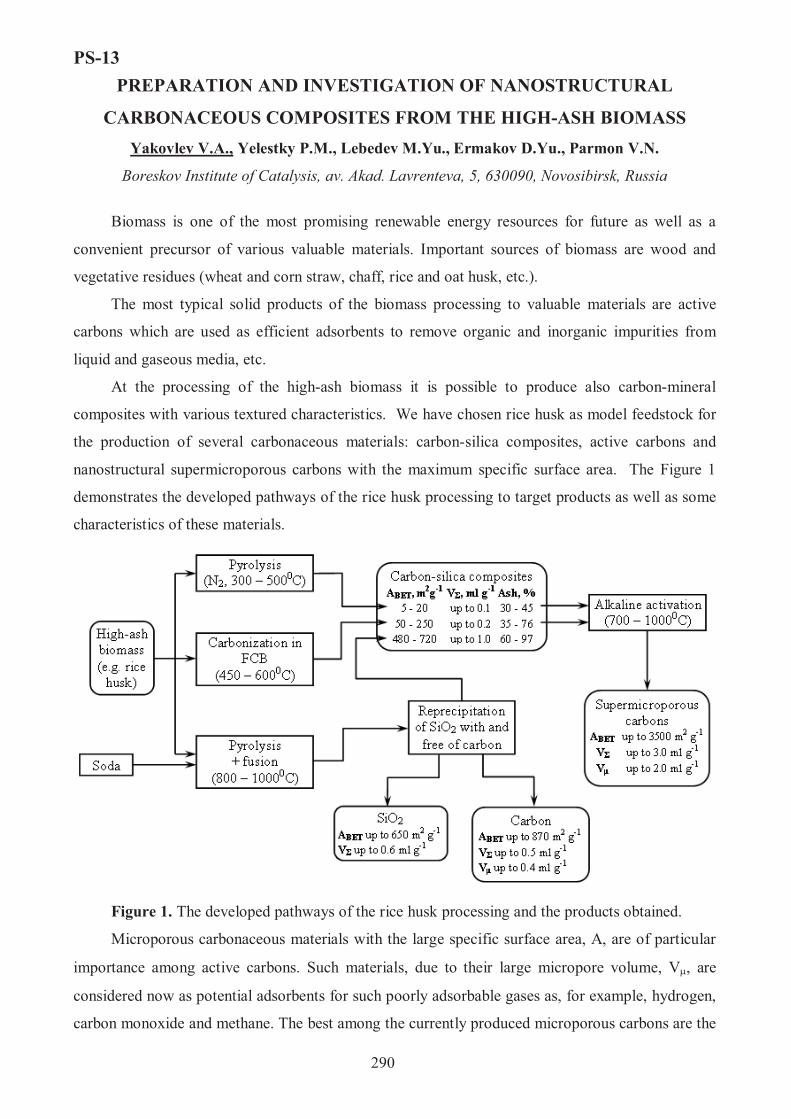
PS-13
290
PREPARATION AND INVESTIGATION OF NANOSTRUCTURAL
CARBONACEOUS COMPOSITES FROM THE HIGH-ASH BIOMASS Yakovlev V.A., Yelestky P.M., Lebedev M.Yu., Ermakov D.Yu., Parmon V.N.
Boreskov Institute of Catalysis, av. Akad. Lavrenteva, 5, 630090, Novosibirsk, Russia
Biomass is one of the most promising renewable energy resources for future as well as a
convenient precursor of various valuable materials. Important sources of biomass are wood and
vegetative residues (wheat and corn straw, chaff, rice and oat husk, etc.).
The most typical solid products of the biomass processing to valuable materials are active
carbons which are used as efficient adsorbents to remove organic and inorganic impurities from
liquid and gaseous media, etc.
At the processing of the high-ash biomass it is possible to produce also carbon-mineral
composites with various textured characteristics. We have chosen rice husk as model feedstock for
the production of several carbonaceous materials: carbon-silica composites, active carbons and
nanostructural supermicroporous carbons with the maximum specific surface area. The Figure 1
demonstrates the developed pathways of the rice husk processing to target products as well as some
characteristics of these materials.
Figure 1. The developed pathways of the rice husk processing and the products obtained.
Microporous carbonaceous materials with the large specific surface area, A, are of particular
importance among active carbons. Such materials, due to their large micropore volume, V�, are
considered now as potential adsorbents for such poorly adsorbable gases as, for example, hydrogen,
carbon monoxide and methane. The best among the currently produced microporous carbons are the

PS-13
291
so called Maxsorb materials (Kansai Coke and Chemical Co Ltd., Japan), also known as AX-21
(Anderson Develop Co., USA). These carbons have ABET = 2670�600 m2/g, V� N 1.20 cm3/g [1,2].
The Boreskov Institute of Catalysis proposes a new method for the synthesis of
supermicroporous carbons (SMPC’s) with even higher adsorbability via treatment of agricultural
high-ash lignocellulose wastes (like rice and oats husk, as well as wheat straw). In the new SMPC’s,
the specific surface area ABET reaches 3460 m2/g while micropore volume V� is up to 1.9 cm3/g at
the total of pore volume (not larger than 100 nm), V�, as large as 3.0 cm3/g.
The preliminary carbonization of mentioned wastes in inert atmosphere at 300–500 °C
(pyrolysis) or in a fluidized catalyst bed (FCB) at 450–600 °C allows carbon-mineral composites to
be synthesized with the different textural parameters [3]. In these composites, the ash residue
contains mainly as nanospheres of amorphous silica which may behave as a mineral structure-
forming agent – template – during the further treatment to synthesize microporous carbons, the
carbon nanostructure with 1 to 1.5 nm graphenes being arranged around the template.
The obtained carbon-mineral composites are activated in melted KOH and/or NaOH at 700–
900 °C to produce potassium silicates through the interaction between amorphous silica and KOH.
After this activation, the materials are cooled and the silicate templates are removed by dissolving in
water.
The similar interaction of silica template and carbon phase (template carbonization) can be
observed at the fusion of rice husk and soda at 900oC. After that the obtained silicates are dissolved
and silica is precipitated by CO2. The TEM studies of these samples revealed that the carbonaceous
phase consists of leaf-like, coral-like and hollow spheres of carbon, while silica is presented as
microspheres with the average size up to 5 nm (Figure 2, 3).
One of the principal parameters affecting the textural characteristics of thus obtained
SMPC’s is the activation temperature [4]. Table 1 summarizes the data on the properties of SMPC’s
synthesized at different temperatures. �BET, Vpore and V� are determined from the nitrogen
adsorption isotherms at 77 K.
Table 1: Characteristics of carbonaceous nanostructural SMPC’s materials synthesized at different temperatures
Activation temperature, oC ABET, m2/g Vpore /V�, cm3/g Micropore proportion % 700 3170 1.77/1.45 81.9 750 3450 2.01/1.68 83.6 800 3360 2.18/1.87 92.3 850 3170 2.26/1.74 77.0 900 3210 2.97/1.48 49.8
The total pore volume increases with the activation temperature. At the temperatures below
800°C, the increase is due to the micropore formation. At the further temperature elevation, the
micropore volume decreases but the mesopore volume increases due to burning processes.

PS-13
292
In the synthesized microporous carbons, not only the specific surface areas and micropore
volumes are superior to those of AX-21. The characteristic features of SMPC’s are the much
narrower pore size distribution as well as a higher contribution of micropores to the total pore
volume (see Fig. 4). The differential surface area vs pore size is determined by the Ustinov method
[5]; the authors [5] assert that this is the most appropriate method for large surface area carbons.
Figure 2: The TEM image of the carbonaceous phase after the rice husk fusion with Na2CO3 at 900oC.
Figure 3: The TEM image of the silica phase after rice husk fusion and Na2CO3 at 900oC following by the reprecipitation of SiO2.
Figure 4: The differential surface area vs pore size of SMPC’s prepared at different activation temperatures (calculated according to ref. [5]).
Now, we focus our studies on the preparation conditions of the new developed kind of
microporous carbons to adopt it for particular applications such as membranes and sorbents for the
gas separation as well as accumulators of power gases (hydrogen, methane etc.)
Indeed, the search for alternative energy sources for motor vehicles is an urgent problem of
our days. A most thriving area is the substitution of hydrogen and natural gas for the traditional
hydrocarbon fuels for motor vehicles. Therefore, much attention is paid to the development of safe
and efficient on-board storage facilities. The adsorptive storage of hydrogen and methane seems to

PS-13
293
be one of such methods with a good safety. Few systems based on the SMPC nanomaterials with
high sorbability are developed at the Boreskov Institute of Catalysis for the accumulation and
storage of hydrogen and methane.
Indeed, experimental studies on the adsorption of hydrogen and methane demonstrated a
considerable sorption capacity of the SMPC materials. These carbons were shown to absorb up to
65 wt % of methane at room temperature and 60 atm and more than 6 wt % of hydrogen under mild
cryogenic conditions (at 77 K).
0 10 20 30 40 50 600
1
2
3
4
5
6800, max. 6,3 %900, max. 6,2 %850, max. 5,8 %750, max. 5,7 %
% (w
eigh
t)
P (atm)
700, max. 4,7 %
0 10 20 30 40 50 60 700
10
20
30
40
50
60
70
800, max. 46 %
900, max. 65 %
850, max. 50 %
750, max. 38 %
% (w
eigh
t)
P (atm)
700, max. 41 %
Figure 5: Isotherms of the hydrogen adsorption at 77 K for SMPC’s synthesized at 700–900 °�.
Figure 6: Isotherms of the methane adsorption at 293 K for SMPC’s synthesized at 700 – 900 °�.
The above data demonstrate the possibility of the synthesis of highly microporous carbons
with the very large specific surface area from the high-ash biomass. The samples obtained are
superior in their textural characteristics to the known best analogues synthesized by treating
petroleum pitch with nitric acid. The expected practical application of the obtained carbon-silica
composites may be first of all reinforcing rubber extenders and bifunctional sorbents for the gas and
liquid purification.
The work was supported by grant “Leading scientific schools 6526.2006.3”.
References 1. March H., Van Davis S., O’Grandy T. M., Wennerberg A., Carbon, 22 (1984) 603
2. USA Patent 3,624,004 (1971) and 4,088,694 (1978)
3. Yakovlev V.A., Simonov A.D., Startsev A.N., Yeletsky P.M., Parmon V.N., Catalytic processing of biomass to heat, carbon materials and high-quality fuels, Proc. of 14th European Biomass Conference & Exhibition, October 17-21, Paris, France, (2005), 105-109.
4. Yakovlev V.A., Yelestky P.M., Parmon V.N., Nanostructural microporous carbonaceous material; RU patent application 2006105038, priority 09.02.2006.
5. E.A. Ustinov, D.D. Do, V.B. Fenelonov, Carbon 44 (2006) 653.

PS-14
THE DEVELOPMENT OF THE METHOD OF LOW–TEMPERATURE
PEAT PYROLYSIS ON THE BASIS OF ALUMOSILICATE
CATALYTIC SYSTEM
E. Sulman, V. Alfyorov, O. Misnikov, A. Afanasjev, N. Kumar1, D. Murzin1
Tver State Technical University; A. Nikitin Str., 22, 170026, Tver, Russia,
phone/fax: +7 0822 449317, e-mail: [email protected] 1Abo Akademi University; Biskopsgatan 8, 20500, Turku, Finland,
phone: + 358 2 215 4985, fax: 358 2 215 4479, e-mail: [email protected]
Nowadays in many developed countries the programs on power systems transfer on new more available biogen fuel that can help to solve some ecological and technological problems have been developed. Peat – mineral compositions can become such fuel.
Physical – chemical study of composite granulated fuel on the basis of peat has been carried out. The granulation of organic mineral mixture by the method of palletizing allows to proportion exactly the initial components and to obtain solid bio-fuel with good technological characteristics (heat of combustion, humidity, strength, loosens and others).
The aim of the investigations is to study peat low – temperature pyrolysis in the presence of catalytic systems on the basis of natural alumosilicate materials and synthetic zeolites. In the present paper the following problems have been solved: to study the influence of temperature, nature and the catalyst amount on composition and calorific value of combustible gas mixture obtained and to choose optimal conditions of this process.
The study of peat low-temperature pyrolysis has been carried out in the presence of the catalysts – natural and synthetic materials with concentration 1, 2, 3, 4, 5 and 10 mass % at a temperature range of 350-480°C.
The best results have been observed at 2% alumosilicate minerals content of peat mass at a temperature of 480°C. Under such conditions of the experiment hydrocarbon yield as well as the heat of combustion of the pyrolysis gas obtained has been much higher than those of non-catalytic process. The value of activation energy for the catalytic process of peat pyrolysis has been approximately 2 times less than for the non-catalytic one.
As the result of the experiments carried out the application of natural and synthetic zeolite catalysts in peat catalytic pyrolysis was revealed to increase gaseous hydrocarbons yield by 2,1 – 2,5 times in case of natural catalysts and approximately by 4 times incase of synthetic ones. The heat of combustion has increased by 1,5 – 4 times on different catalysts.
294

PS-15
NOVEL CHIRAL LIGANDS FOR CATALYSTS OF ASYMMETRIC
REACTIONS DERIVED FROM NATURAL TERPENES
T.B. Khlebnikova, Yu.V. Sapegina, V.N. Konev, Z.P. Pai, A.G. Tolstikov
Boreskov Institute of Catalysis SB RAS, Akad. Lavrentiev Pr. 5, Novosibirsk, 630090, Russia,
fax:(383) 330 80 56, E-mail: [email protected]
Efficient use of renewable hydrocarbon raw materials is of topic importance at present
time. Availability of numerous constituents of complex structure in vegetal feedstock opens
the possibility to obtain compounds, synthesis of which starting from oil and gas processing
products is impossible or economically unfeasible. Thus, the products of the integrated wood
processing are the convenient starting material for the directional functionalization aimed at
production of a whole series of substances with predetermined physicochemical properties
and bioactivity.
Phytogenic diterpenes have been under intensive investigation for many years. Owing to
their availability and unique structures, these compounds have been widely used as starting
materials for the production of highly effective drugs and chiral reagents. The use of natural
terpenoids as convenient chiral pools for the synthesis of optically active elementorganic
compounds is the prospective approach to the creation of wide spectrum of available chiral
ligands for the catalysts of asymmetric reactions.
Asymmetric catalysis is an attractive strategy of the synthesis of optically pure organic
compounds and the dominant role in enantioselectivity of catalyst plays the structure of chiral
ligand. Thus, design of the ligands of various structural types allows extending the field of
application of asymmetric catalysis over the wide range of substrate and reactions. When
preparing the ligands most attention was concentrated on the transformations of hydroxy- and
amino acids, carbohydrates as well as binaphtyl, biphenyl, ferrocene derivatives. The
synthesis of ligands based on steroids and terpenoids received lesser acceptance [1].
As a result of our investigations the synthetic procedure of preparing metallocomplex
catalysts with the P-, N-containing ligands derived from terpenoids was developed [2].
Starting from tricyclic diterpenes, levopimaric and dehydroabietic acid, which are constituents
of the composition of the galipot and colophony of the conifers of the Pinus genus, a number
of chiral diphosphine, diphosphinite, amine, azomethine and urea ligands was prepared and
used in complexes with Rh(I), Ru(II) and V(IV) as catalysts of asymmetric reactions.
295

PS-15
BF4-Rh
CH2NHBn
P
PH
H
R2
R3
R4
H2, Cat
+
PhPh
PhPh
R1
R2HR3
R4
R1
Cat
HH
conversion 80-100%ee 10-40%
CO2H
Levopimaric acid
Scheme 1.
The additional functional group in diphosphine ligands presented on the Scheme 1 makes
possible the immobilization of the complex catalysts by the covalent tethering onto the
support surface (for example, mesoporous silica), which can be used as a coating of the
interior surface of microreactors for the catalytic asymmetric reactions.
NHCXNH
H
Ph
CH2N=CHN
NN=CH
2X= O, S L
L
L
iPrOH*
O OH[RhL(COD)Cl]2 or [RuL(COD)Cl2]2
CO2H
HO
CH2N=CH
Dehydroabieticacid
N=CH
HOL L
conversion 10-90%ee 10-60%
Scheme 2.
296

PS-15
High molecular weight of the catalysts depicted on schemas 1 and 2 permits to carry out
the asymmetric reduction reactions in membrane reactors with the use of catalyst during
several cycles.
The study was financially supported by SB RAS integration project N 32.
References 1. A.G. Tolstikov, T.B. Khlebnikova, O.V. Tolstikova, G.A.Tolstikov. Natural compounds in the
synthesis of chiral organophosphorous ligands. // Russian Chemical Reviews.- 2003.- V. 72.- P. 803-822.
2. T.B. Khlebnikova, N.N. Karpyshev, O.V. Tolstikova, A.G. Tolstikov. Synthesis of New Chiral Phosphorous- and Nitrogen-containing Ligands from Resin Acids. // Chirality. Proceedings from the fifteenth International Symposium on Chirality (ISCD-15), Shizuoka, Japan, 2003.- 2004.- V. 16.- P. S40-S50.
297

PS-16
XANTHAN GUM PRODUCTION USING FED-BATCH CONTINUOUS
RECYCLED PACKED BED BIOREACTOR
Awang Bono1, Ng Lee Fong1, Rosalam Hj. Sarbatly2, Duduku Krishnaiah1
1Chemical Engineering Programme, School of Engineering and Information Technology,
University Malaysia Sabah, 88999 Kota Kinabalu, Sabah, Malaysia 2Department of Chemical Engineering, Bath University, Bath, United Kingdom
FAX: +60-88-320348, E-mail: [email protected]
Abstract
Xanthan gum is widely used as a thickening agent in food, pharmaceutical industries and
chemicals (Becker et al.1998). It is a high molecular weight polysaccharides gum produced by
a pure culture fermentation of carbohydrate with natural strains of exopolysaccharide derived
from Xanthomonas campestris NRRL B-1459 (Leela and Sharma, 2000; Flores and Deckwer,
1999). The xanthan gum polymer consists of repeated units of five sugars, namely, two D-
glucose, two D-mannose and one D-glucoronate and varying amounts of acetate and pyruvate
(Flores and Deckwer, 1999). Xanthan also contains monovalent cations, which can be Na, K
or ½ Ca (Flores and Deckwer, 1999; Nancy et al 1995). This polysaccharide produces
Xanthomonas campestris high viscosity aqueous solutions which are also highly
pseudoplastic.
Most studies on microbial exopolysaccharide production have been performed so far
using batch incubation conditions (Lo et al. 1997; Lo et al 2001, Pollock et al 1997), the
polymer macromolecules being recovered from fermentation broths by simple chemical and
physical techniques, e.g. precipitation and centrifugation (Leela and Sharma, 2000). Some
attempts have been made to apply immobilized-cell cultures for the production of xanthan
gum (Yang et al. 1996 and Yang et al. 1998) and other bacterial polysaccharides (Saude et al.
2002; Stavros et al. 2003). Immobilization ensures the physical separation between
microorganisms and the liquid phase containing nutrients and products, and facilitates
continuous processes. In addition, high cell densities can be reached inside immobilized-cell
particles, which may enhance productivities as compared with free-cell cultures. In the last
few years, however, membrane processes have been increasingly used to separate microbial
cells from the production medium.
298

PS-16
Continuous experiments in membrane cell recycle bioreactors have been essentially
devoted to the production of low-or moderate-molecular-weight molecules such as L-
methionime (Yuan et al. 2002), lactic acid (Krishnan et al. 2001) and pediocin (Lebrun et al
1994;Cho et al. 1996).There are few studies of xanthan fermentation using immobilized cells.
A large portion of the xanthan gum product was trapped in the bed and could not be easily
separated from the cells(Yang et al. 1998). It is clear that cell entrapment is not an appropriate
cell immobilization method for xanthan gum fermentation because of the high viscosity of
xanthan solution.
In this work, a novel, continuous packed-bed bioreactor was developed for xanthan gum
fermentation. Difficulties in agitation and aeration in the conventional stirred-tank bioreactor
were overcome by continuous medium recirculation through a fibrous matrix, which
contained immobilized cells. In this bioreactor, liquid media and air were passed through the
porous fibrous matrix to ensure intimate contact with the immobilized cells, thus achieving
high oxygen transfer and reaction rates.
Adsorption of Cell
Packing density of 0.026g/ml and 0.039g/l was used to determine the effectiveness of cell
adsorption and its effect on the xanthan gum production. There are four lines denoted with
different packing density and the inoculum’s age. From the results, it is evident that, packing
with 0.039g/ml gave better adsorption of cells where it decreases to zero at the fourth day of
fermentation. From the literature, the xanthan gum production was not effected by the types
of fibrous material used in the adsorption and fastest adsorption rate ( Yang et al. 1998).
Effect of Inoculumn Age
A set of two different ages 24 and 48 hours immobilized inoculums was used in this
study. The gum production was optimum with 36-48 hours old inoculum ( Leela and Sharma,
2000.). The adsorption of cells to the fibers is more effective for 48 hours inoculumn which
reduced from 1.75g/l to zero in five days. There is still 0.25g/l remaining cells on the broth for
24 hours age inoculum. This result also proves the statement that the cell still growing
actively before reach 48 hour of inoculation( Leela and Sharma, 2000). The inoculum of 24
hours and 48 hours was immobilized on the cotton, yielded more production with higher
packing density (0.039g/ml) on the 24 hours (20.63g/l) than 48 hours inoculum (18.75g/l).
This is because of after 48 hours of incubation, the cells enter stationary phase and activity of
cells growing decreases due to decaying. Production at lower packing density for 24hour and
48hour inoculum gives lower production because of low cell density on packing .
299

PS-16
Comparison Between Free Cell And Immobilized Cell Fermentation
For comparison batch fermentation with free cells repeated in conventional 200 ml
Erlenmeyer flask( reactor) by shaking in incubator at 200 rpm, 30ºC and pH 7. Inoculum age
of 24 hours and packing density of 0.039 g/ml was used. Figure 4 shows the typical time
course of batch fermentation of Xanthomonas campestris. As fpund from the results, the
xanthan gum was the product of fermentation with yield of 18.1g/ml. Exponential growth of
production is observed with the free cell fermentation. Cell immobilized fermentation was
conducted in packed bed and without packed bed. The concentration of cell and xanthan
production in fermentation where cell is adsorbed on cotton but without packed bed. Figure 6
shows the concentration of cells and xanthan gum production where cell is adsorbed on cotton
in packed bed.
Comparison with immobilized cells shows that, the immobilized cells fermentation
production is higher than the conventional batch fermentation, mainly because of higher cell
density in the reactor. The maximum xanthan obtained with free cells was only 18.1g/l,
whereas 20.58g/l xanthan was obtained with immobilized cells. The adsorption rate from
cotton that is packed into tube or bed gives results of higher rate than cotton without packing
into bed. The productivity is highest (20.58g/l) in the fermentation using cotton that is packed
into bed with a tube which supports the matrix .
Conclusions
Xanthan gum production by Xanthomonas campestris DSMZ using glucose as carbon
source was studied in packed bed bioreactor.The cells were immobilized in order to improve
xanthan gum quality. The results showed that the concentration of xanthan gum achieved by
the immobilized cells in batch fermentation was 19.4 to 20.6g/l which is higher than the
conventional batch fermentation without immobilized cells at 18.1g/l. However, the
production of xanthan gum from fed-batch fermentation was comparable to batch
fermentation and the highest concentration was obtained as 18.7g/l at the dilution rate equal to
1.44d-1.
References 1. Becker A, Katzan, F and Ielpi,L(1998): Xanthan Gum biosynthesis and application: a biochemical/ genetic
prespective. Applied Microbial Biotechnology 50: 145-152.
2. Chia-Hua and Martin Lo, Y : (2003): Characterization of xanthan gum biosynthesis in a centrifugal flux analysis: Process Biochemistry : 38: 1617-1625.
3. Cho, H. Y., Yousef, A. E. & Yang, S. T., (1996): “Continuous production of pediocin by immobilized Pediococcus acidilactici in a packed bed bioreactor”. Applied Microbiology and Biotechnology 45 : 589 – 594.
300

PS-16
4. Cooney, C.L 1986, Continuous culture. Dlm. Perspective in Biotechnology and Applied Microbiology: 271-285, Elsevier Applied science publisher, London.
5. Flores Candia, J.L. & Deckwer, W.D., (1999): Dlm. Flickinger, M.C. & Drew, S.W.: Encyclopedia of Bioprocess Technology Fermentation, Biocatalysis and Bioseparation. Volume 5,John Willey & Sons Inc. USA
6. Harding, N.E., Clearly, J.M. & Luis, L., (1995): Genetics and Biochemistry of Xanthan Gum Production by Xanthomonas campetris. Dlm. Hui, Y.H. & Khachatourians, G. Food Technology Microorganisms: 495-514. John Wiley-VCH Inc. USA
7. Krishnan, S., Gowthaman, M.K., Misra, M.C. & Karanth, N.G., (2001): “Chitosan-treated polypropylene matrix as immobilization support for lactic acid production using Lactobacillus plantarum NCIM 2084”, Chemical Technology and Biotechnology 76 :461-468.
8. Lebrun,L., Junter,G.A., Jouenne, T., Mignot,L (1994), Exopolysaccharide production by free and immobilized microbial cultures. Enzyme and Microbial Technology: 16 : 1048-1058.
9. Leela, J.K. & Sharma, G., (2000): “Studies on xanthan production from Xanthomonas campetris”. Bioprocess Engineering 23: 687-689.
10. Lo, Y.M., Hsu, C.H., Yang, S.T. & Min, D.B., (2001): “Oxygen transfer characteristics of a centrifugal, packed-bed reactor during viscous xanthan fermentation”, Bioprocess and Biosystems Engineering 24: 187-193.
11. Lo, Y.M., Yang, S.T. and Min, D.B., (1997): “Effect of yeast extract and glucose on xanthan xanthan and cell growth in batch culture of Xanthomonas campetris”. Application Microbial Biotechnology 47: 689-694.
12. Nancy E. Harding., Joseph M. Cleary and Luis Ielpi(1995): Genetics and Biochemistry of Xanthan gum production by Xanthomonas Comprestris: Food Technology Microorganisms, John Wiley- VCH Inc., USA
13. Pollock., T.J ., Yamazaki, M and Armentrout R.W (1997). Production of Xanthan gum by Sphingomonas bacteria carrying genes from Xanthomonas campestris: J. Industrial Microbiology and Biotechnology 19: 92-97.
14. Saude, N., Chèze-Lange, H., Beunard, D., (2002): Alginate production by Azotobacter Vinelandii in a membrane bioreactor. Process Biotechnology 38: 273-278.
15. Stavros Kalogiannis, Gesthimani ,I, Maria L.K, Dimitrios A.K and George, N.S: (2003): Optimization of xanthan gum production by Xanthomonas campestris grown in molasses: 39: 249-256.
16. Yang, S. T., Lo, M. Y. & Chattopadhyay, D., (1998): “Production of Cell-Free Xanthan Fermentation Broth by Cell Adsorption on Fibers”. Biotechnology Progress 14: 259 – 264.
17. Yang, S. T., Lo, M. Y. & David B. Min., (1996): “Xanthan Gum Fermentation by Xanthomonas campestris Immobilized in a Novel Centrifugal Fibrous-Bed Bioreactor”. Biotechnology Progress 12: 630 – 637.
18. Yuan, J.Y., Wang, S.H., Song, Z.X. & Gao, R.C., (2002): “Production of L-methionine by immobilized pellets of Aspergillus oryzae in packed bed reactor”, Chemical Technology and Bi.
301

PS-17
PRODUCTION OF DIESEL FUEL FROM RENEWABLE FEEDS:
KINETICS OF ETHYL STEARATE DECARBOXYLATION
M. Snåre, I. Kubiková, P. Mäki-Arvela, K. Eränen, H. Backman and D.Yu. Murzin
Laboratory of Industrial Chemistry, Process Chemistry Centre, Åbo Akademi University,
Biskopsgatan 8 FIN-20500 Åbo/Turku, Finland, Tel.:+358 2 215 4985, Fax: +358 2 215
4479, E-mail: [email protected]
Introduction
The extreme increase in energy consumption in the past decade and the growing
environmental concerns have made renewable fuels an exceptionally attractive alternative as a
fuel for the future. Several methods of producing fuels from renewable resources are
nowadays well established, however, new innovative solutions are needed to satisfy the
increasing energy demand and the well-being of our ecological system.
A novel method for production of diesel-like fuel from renewable resources, like vegetable
oils and animal fats, is being investigated at our laboratory. It has recently been demonstrated
that renewable feeds over heterogeneous catalysts in liquid-phase tend to decarboxylate [1].
The production of a deoxygenated biodiesel fuel involves removal of the carboxyl group in
the fatty acid structure via carbon dioxide release, thus producing a linear hydrocarbon
originating from the fatty acid alkyl group (typically C6-C22) [2]. The catalytic
decarboxylation of fatty acids, fatty acid esters and triglycerides (comprising of three fatty
acids and a glycerol group) is schematically illustrated below.
Fatty acid ester
O
3CO2 + R�-H + R��-H + R���-H + (light HC)
het. cat.
Triglyceride
CnH2n+1�� O �� C �� R�
O
Fatty acid het. cat.
het. cat.
CO2 + R�-H
CO2 + CnH2n + R�-H
H�� O �� C �� R�
O
O
O
CH�� O�� C�� R��
CH2�� O �� C �� R���
CH2�� O �� C �� R�
In the present work the kinetic behavior of ethyl stearate decarboxylation over a
heterogeneous catalyst was investigated with the aim to verify the reaction mechanism and
further optimize the chemical process.
302

PS-17
Experimental
The kinetic study was carried out in a semi-batch reactor (300 ml Parr autoclave) over a fine
powder catalyst (catalyst mass 1 g, particle size < 50 �m) which was reduced with hydrogen
prior to reaction. The experiments were conducted at a stirring speed of 1100 rpm, which is
proven to be efficient enough to avoid mass transfer limitations. The reaction temperature and
pressure were kept constant during the reaction, in the range of 270-360 °C and 17-40 bar (the
reaction pressure was adjusted according to the vapor pressure of the reaction mixture),
respectively. The reaction was performed in a solvent (n-dodecane) under helium, nitrogen,
hydrogen or argon- (5 vol%) hydrogen atmosphere, the total liquid volume in the reactor was
100 ml. The carrier gas was added with the volumetric flow of 25 ml/min.
Results and discussion
The decarboxylation of the fatty acid ester, ethyl stearate (A), proceeds via its corresponding
fatty acid, stearic acid (B), which is subsequently decarboxylated to n-heptadecane (P1). The
produced paraffin is, however, simultaneously dehydrogenated to unsaturated olefins (P2) and
aromatics (P3) (Figure 1).
A B P1
P2
P3
50
60
70
80
90
100
0 10 20 30 40 50 60Reaction time (min)
Mol
ar fr
actio
n of
eth
yl st
erat
e (m
ol%
)
0
2
4
6
8
10
Mol
ar fr
actio
n of
pro
duct
s(m
ol%
ethyle stearate
n-heptadecane
other C17-products
stearic acid
1-heptadecene C17-aromatics
Figure 1. Concentration profile of ethyle stearate and products in the decarboxylation reaction.
The reaction conditions: T = 300 �C, p= 17 bar (Ar-(5 vol%) H2), cethyl stearate = 1.6 mol/l, mcatalyst = 1 g.
303

PS-17
As expected, the reaction rate increased with temperature when ethyl stearate was
decarboxylated in a temperature range of 300-360 �C with apparent activation energy equal to
57.3 kJ/mol (Figure 2).
0
20
40
60
80
100
0 60 120 180 240 300 360
Reaction time (min)
Con
vers
ion
of e
thyl
stea
rate
(%)
360 °C330 °C300 °C
Arrhenius plot
-18
-17.6
-17.2
-16.8
-16.4
-160.0015 0.0016 0.0017 0.0018
1/T (/K)
ln(k
)
Figure 2. Effect of reaction temperature in the decarboxylation of ethyle stearate. The reaction conditions:
T = 300-360 �C, p= 17 bar (Ar-(5 vol%) H2), cethyl stearate = 1.6 mol/l, mcatalyst = 1 g.
In addition kinetic decarboxylation experiments with the intermediate product, stearic acid,
were performed. The study showed that the reaction order of steraic acid is close to zero and
the apparent reaction constant is approximately 0.0065 mol/l/min. However, with high initial
concentrations (1.54 mol/l) of stearic acid, catalyst deactivation is observed (Figure 3), which
is reflected in lower value of the corresponding rate constant. An earlier study of
decarboxylation in a tubular reactor showed that the catalyst is indeed deactivated with a fatty
acid feedstock [3].
0.0
0.2
0.4
0.6
0.8
1.0
1.2
1.4
1.6
0 15 30 45 60 75 9
Reaction time (min)
Con
cent
ratio
n of
Ste
aric
aci
d (m
ol/l)
0
Apparent reaction constants k1 � k2 � k3 � 0.0065 mol/l/min
Apparent reaction constant k4 � 0.0034 mol/l/min
1.
2.
3.
4.
Figure 3. Effect of reactant concentration in the decarboxylation of stearic acid.
T = 300�C, p= 17 bar (inert atmosphere), cstearic acid = 0.154 – 1.54 mol/l, mcat = 1 g
304
PS-17
Conclusion
The kinetics of ethyl stearate decarboxylation was studied in a broad range of temperatures
and pressures. Additionally decarboxylation of intermediate product, stearic acid, was
investigated. The main kinetic regularities were established. The apparent activation energy in
ethyl stearate decarboxylation was 57.3 kJ/mol.
[1] I. Kubi�ková, M. Snåre, P. Mäki-Arvela, K. Eränen and D. Yu. Murzin, Catalysis Today 106 (2005) 197-200. [2] A. Demirbas, Fuel 77 (1998) 1117-1120
[3] M. Snåre, I. Kubi�ková, P. Mäki-Arvela, K. Eränen and D. Yu. Murzin, Proceedings of the14th European Biomass Conference and Exhibition on Biomass for Energy, Industry and Climate Protection, Paris (2005), in press
305

PS-18
ISOMERIZATION OF n-BUTANE OVER Pd-H-MCM-22 AND
H-MCM-22 ZEOLITE CATALYSTS: INFLUENCE OF ACIDITY AND
CATALYST SYNTHESIS METHODS
*1Narendra Kumar, 1Prem K. Seelam, 2Teemu Heikkilä, 2Vesa-Pekka Lehto,1Tapio Salmi, 1Dmitry Yu. Murzin
1Laboratory of Industrial Chemistry, Process Chemistry Centre, Åbo Akademi University,
FIN-20500 Åbo/Turku, Finland,2Department of Physics, Laboratory of Industrial Physics, Turku University, FIN-20014
Åbo/Turku, Finland,
* Corresponding author, e-mail: [email protected], Fax: +358 2 2154555
Isomerization of n-butane to iso-butane was investigated over H-MCM-22 zeolite catalyst
with varying acidities and Pd modified MCM-22 prepared by ion-exchange, impregnation and
in-situ synthesis methods. The reaction was carried out in a fixed bed micro-reactor with
hydrogen as a carrier gas. The influence of acidity, methods of Pd- modifications and
pretreatment of Pd-H-MCM-22 and H-MCM-22 catalysts in n-butane isomerization were
investigated. The conversion of n-butane and yield to iso-butane was observed to be
influenced by the acidity of H-MCM-22 zeolite catalysts. The Pd- modified MCM-22 zeolite
catalysts exhibited higher conversion of n-butane and yield to iso-butane than H-MCM-22.
Pretreatment of the Pd-MCM-22 catalyst i.e. directly reduced or calcined and then reduced
were observed to influence the conversion of n-butane and yield to iso-butane.
Na-MCM-22 zeolites with SiO2/Al2O3 ratios 30, 50 and 100 were synthesized and
transformed to H-MCM-22-30, H-MCM-22-50 and H-MCM-22-100 catalysts by ion-
exchange with aqueous solution ammonium chloride, drying and deammoniation at elevated
temperature. The Pd modified MCM-22 zeolite catalysts were prepared by ion-exchange,
impregnation and in-situ synthesis methods. The catalysts were characterized using X-ray
powder diffractometer, scanning electron microscope, nitrogen adsorption, X-ray
fluorescency, direct current plasma spectrometer, TPD of ammonia and FTIR of adsorbed
pyridine.
306

PS-18
Introduction
Metal modified and proton forms of zeolite catalysts due to its unique properties of
uniform pores, shape selectivity, thermal stability and coke resistant are used in several
processes in oil refinery and has potential applications in synthesis of fine chemicals and
environmental catalysis. The methods of metal introduction in zeolite and catalyst
pretreatment have been reported to influence their state, dispersion, metal-zeolite interaction
and consequently the catalytic properties.
Isomerization of n-butane to iso-butane is an important reaction from academic and
industrial point of view. The direct conversion of n-butane to iso-butane can produce large
amount of iso-butane which is a valuable raw material for the production of isooctane. There
are several publications in open literature on Pt modified zeolite catalysts for n-butane
isomerization [1]. However, there are only two publications regarding the Pd- modified
zeolite catalysts in isomerization of n-butane [2]. In this work we report the synthesis and
characterization of H-MCM-22 with varying acidities and Pd- modified MCM-22 zeolite
catalysts prepared by ion-exchange, impregnation and in-situ synthesis methods. Further more
isomerization of n-butane to iso-butane was investigated over H-MCM-22 and Pd- modified
MCM-22 zeolite catalysts.
Experimental
Na-MCM-22 zeolite was synthesized with SiO2/Al2O3 ratios such as 30, 50 and 100 in
300 ml autoclaves as mentioned in references [3-5] with some modifications. The Na-MCM-
22 zeolites synthesized with varying acidities were transformed to H- forms by ion-exchange
with ammonium chloride, followed by drying and calcination. Pd modified MCM-22 zeolite
catalysts were prepared by impregnation, ion-exchange and in-situ synthesis methods using
aqueous solution of palladium nitrate, followed by drying and calcinations. The catalysts were
characterized using X-ray powder diffractometer, scanning electron microscope, nitrogen
adsorption, TPD of ammonia and FTIR of adsorbed pyridine for acidity measurement. The
state of Pd was investigated by XPS and crystallite size was determined by X-ray powder
diffractometer. The isomerization of n-butane to iso-butane was carried out in a fixed bed
micro reactors. Hydrogen was used as a carrier gas and Pd- modified MCM-22 molecular
sieve catalysts were pretreated with hydrogen prior to the catalyst testings. The on-line
analyses of the reaction products were carried out using a gas chromatograph equipped with a
capillary column and FID.
307

PS-18
Results and discussion
The X-ray powder diffraction patterns of Na-MCM-22 micro-porous molecular sieves
with SiO2/Al2O3 ratios 30, 50 and 100 were similar to those reported in the literature. It was
confirmed from the XRD patterns that modification of MCM-22 with Pd- using ion-exchange,
impregnation and in-situ synthesis methods did not influence parent structure of MCM-22. Pd
was highly dispersed in Pd-H-MCM-22-30-IE catalyst prepared by ion-exchange. The
scanning electron micrograph of MCM-22 showed platelet like crystals. The acidity
measurement by temperature programmed desorption of ammonia exhibited highest acidity
for MCM-22 with SiO2/Al2O3 ratio of 30 and lowest acidity for MCM-22 with SiO2/Al2O3 of
100. The H-MCM-22 catalyst synthesized with SiO2/Al2O3 ratio of 30 showed highest
conversion of n-butane and yield to iso-butane among the three proton form catalysts. The
lowest conversion of n-butane and yield to iso-butane was observed for H-MCM-22 with
SiO2/Al2O3 ratio of 100. It was observed that the Pd-H-MCM-22-30-IE ion-echanged zeolite
catalyst exhibited higher conversion of n-butane and yield to iso-butane than the H-MCM-22-
30 indicating the positive influence of Pd- modification of MCM-22 in isomerization of n-
butane. The method of Pd introduction in MCM-22 was found to influence the conversion of
n-butane and yield to iso-butane. The H- and Pd- modified MCM-22 catalysts showed
deactivation in n-butane isomerization with time on stream. However, catalysts regained the
activity after regeneration with synthetic air. The physico-chemical and catalytic properties of
H-MCM-22 and Pd- modified MCM-22 catalysts in n-butane isomerization will be discussed
in detail during the presentation.
Conclusions
Na-MCM-22 molecular sieve was synthesized with varying SiO2/Al2O3 ratios of 30, 50
and 100. The H-MCM-22 catalyst synthesized with silica to alumina ratio 30 exhibited the
highest conversion of n-butane and yield to iso-butane among the three H- forms. It was
concluded that conversion of n-butane and yield to iso-butane was highly influenced by the
acidic property of H-MCM-22 catalysts. The Pd- modified MCM-22 catalyst exhibited higher
conversion of n-butane and yield to iso-butane than the proton forms of MCM-22 catalysts
indicating the positive role of Pd in n-butane isomerization.
Reference1. R. A. Asuquo, E. M. Gabriele, J. A. Lercher, Journal of Catalysis 155 (1997) 376. 2. P. Canizares, A. de Lucas, F. Dorado, J. Aguirre 42 (2001) 245. 3. Juttu G. G., Lobo R. F., Microporous and Mesoporous Material 40 (2000) 9. 4. Corma A., Corell C., Perez-Pariente J., Zeolites 15 (1995) 2. 5. Corma A., Fornes V., Martinez-Triguero J, Pergher S. B., Journal of Catalysis 186 (1999) 58.
308

PS-19
LACTOSE OXIDATION ON GOLD CATALYSTS
A.V. Tokareva,b, E.V. Murzinab , J.-P. Mikkolaa, J. Kuusistoa, L.M. Kustovb,
D.Yu. Murzina
aProcess Chemistry Centre, Åbo Akademi University, Biskopsgatan 8, FIN-20500, Turku/Åbo,
Finland, fax: +358 2 215 4479, E-mail:[email protected] of Chemistry, Moscow Lomonosov State University, 119992, Moscow, Russia
Inroduction
Lactose oxidation is a consecutive reaction, resulting first in lactobionic acid, and then to 2-
keto-lactobionic acid. From industrial viewpoint this reaction is interesting because
lactobionic acid possesses useful properties and can, thus, be used as acidulant, complexing
agent or antioxidant in food, pharmacy and medicine. Lactose, an abundant disaccharide, is a
by-product of dairy industry available in big amounts.
Oxidation of sugars is very sensitive to several factors such as pH of reaction media, since the
formation of corresponding carbohydrate acids results into big pH change. Another important
parameter is the oxygen feed rate, since the reaction rate can be retarded either due to the lack
or due to “oversupply of oxygen (i.e. oxygen poisoning) at high oxygen feed rate. For such
cases “in situ” catalyst potential measurements, applied in the present work, give important
information about red-ox state of the catalyst surface. Among different supported metals used
as catalysts in oxidation of sugars gold nanoparticles recently emerged as very effective and
selective catalysts [1]. The present study is mostly concentrated on gold nanoparticles
supported on different materials.
309

PS-19
Experimental
A shaker reactor for in situ catalyst potential measurements was used for lactose oxidation
(Fig. 1). This reactor is an attractive alternative to other slurry systems. First of all, shaking
helps to avoid appearance of stagnant zones of solution and improves gas to liquid mass
transfer limitations. Moreover liquid to solid mass transfer limitations could be also
eliminated. Second, the shaker is convenient for “in situ” catalyst potential measurements
which provide information on the red/ox state of
the catalyst surface during reaction. A
continuous gas flow is used to ensure constant
composition of a gas mixture over reaction
media. Constant ratio between nitrogen and
oxygen in gas mixture is maintained by mass
flow controllers (Brooks 5850E). The stainless
steel cup of reactor is used as an electrode
collector for measurements of the catalyst
potential. For this purpose all parts of the
reactor are electrically isolated from shaking
device (mechanical part of “3916
Hydrogenating Apparatus” Parr®). Potential
measurements were performed versus Ag/AgCl electrode. Constant pH of reaction media was
maintained by automatic titration device (Metrohm Titrino 751) at pH-stat mode.
so
Figure 1. Shaker reactor: 1 - pH electrode, 2 - reference electrode, 3 - thermocouple, 4 - cooling coil, 5 - grid, 6 - alkaline inlet, 7 - electronics
cket, 8 - gas outlet, 9 - inlets for cooling water, 10 - gas inlet.
For comparative catalysts testing, lactose oxidation was performed at 60°C in aqueous media.
Gas flow was 20 cm3/min, with an oxygen content 12.5 % (O2/N2 = 2.5/17.5). pH was
maintained at a level higher than 8. For this purpose a 2.5 M NaOH solution was applied. In
each experiment, the catalyst amount was 0.5 g, lactose concentration – 9.4 mM and the
overall weight of the reaction mixture was 100 g.
310

PS-19
Results and discussion
In the present study a number of gold catalysts prepared by different methods on a variety of
support materials (active charcoal, alumina, ceria, zirconia, iron oxide) were tested. Catalytic
activity, selectivity and time dependences of catalyst potential were obtained and compared.
Additionally, the influence of catalyst deactivation on catalytic activity was evaluated for Au
on alumina and ceria support and a reference Pd on alumina catalyst. In Fig. 2, the activities
of gold catalysts is compared to a 5% Pd/Al2O3
catalyst. Taking into account higher metal
loading of palladium catalyst, it can be
concluded that gold is more active, selective and
more resistant to deactivation.
0 50 100 150 2000.00
0.02
0.04
0.06
0.08
Con
c. L
BA
, mol
time, min
2% Au /Al2O32% Au /CeO2
5% Pd /Al2O3
Figure 2. Kinetic curves of lactobionic acid formation over Pd and Au catalysts.
Qualitative difference in reaction products
caused by different metal nature is visible from
dependence of selectivity on conversion (Fig.3).
The main feature of lactose oxidation on gold is
that there is almost no formation of the product
of the consecutive oxidation (2-keto-lactobionic
acid).
“In situ” measured catalyst potential correlate well with catalysts activity (Fig.4).
0.0 0.2 0.4 0.6 0.8 1.0-300
-200
-100
0
100
200
E, m
V
Lactose Conv.
2% Au/Al2O3
2% Au/CeO2
5% Pd/Al2O3
Figure 4. Potential on conversion dependences for Au and Pd catalysts.
0.0 0.2 0.4 0.6 0.8 1.00.0
0.2
0.4
0.6
0.8
1.0
Sele
ctiv
ity
Conversion
2% Au/Al2O32% Au/CeO2 5% Pd/Al2O3
LBA
2-keto-LBA
Figure 3. Selectivity as a function of conversion for Au and Pd catalysts.
311

PS-19
Dependences of electrochemical catalyst potential on time shown in Fig. 5 have linear parts
with different slopes. These slopes characterize rate of accumulation of non-reacted oxygen
on the surface. From curves of LBA formation (Fig. 6) it is visible that in the beginning of
experiment reaction rate is proportional to oxygen feed rate. However, decrease of lactose
concentration makes reaction slower and non-reacted oxygen accumulates on the catalyst
surface. Deactivation state is reached faster in case of higher oxygen feed rates.
0 50 100 150 200-300
-200
-100
0
100
200
0 50 100 150 2000.00
0.02
0.04
0.06
0.08
conc
. LB
A, m
ol
time, min
O2 content in gas phase: 12.5 % 17.5 % 25.0 % 37.5 %
Figure 6. Concentration of lactobionic acid in experiments with different oxygen feed rate.
E, m
V
time, min
O2 content in gas phase: 12.5 % 17.5 % 25.0 % 37.5 %
Figure 5. Catalyst potential transients for experiments with different oxygen feed rate.
Conclusions
Gold catalysts were successfully applied in lactose oxidation. The results of performed
research show that on gold catalysts lactobionic acid can be obtained with high yields and
selectivity.
References
[1] H. Berndt, A. Martin, I. Pitsch, U. Prüsse, K.-D. Vorlop, Catalysis Today 91-92 (2004) 191.
312

PS-20
BIOETHANOL FROM HAZELNUT HUSK
Selim Ceylan, Dilek Kazan, Sevil Ünal and A. Alp Sayar
Marmara University, Faculty of Engineering, Chemical Engineering Department
Göztepe 34722 Istanbul, TURKEY
In order to obtain a better exploitation of raw material for bioethanol production, the
most favorable conditions were explored for saccharification of the residues of hazelnut, an
abundant agricultural product in Turkiye. Hazelnut husk was pulverized and treated with
sulphuric acid. Different times of treatment (30 min – 90 min), different concentrations of
sulphuric acid (1% to 5%, by wt) and different concentrations of sample (1/5, 1/10, 1/15, 1/20
solid/liquid ratio) were tested.
The maximum yield of sugar (g reducing sugar/g dry mass %) was obtained as 18.63
±0.51% for 1.5 hour incubation at an acid concentration of 4% and a sample concentration of
1/20 for hazelnut husk. The sugar composition of hydrolysed hazelnut husk was analysed
using Thin Layer Chromatography (TLC). Four mono-sugars, arabinose, glucose, mannose
and xylose were determined in acid hydrolyzed hazelnut husk.
Hydrolyzates obtained after saccharification were used in ethanol production by
S.cerevisiae. The highest ethanol yield as 7.65 g/L was obtained using acid hydrolyzate of
hazelnut husk.
313

PS-21
ENVIRONMENTALLY FRIENDLY FUEL FROM RENEWABLERAW MATERIALS
Yandieva F.A., Tsodikov M.V., Kugel V.Ya., *Gekhman A.E., *Moiseev I.I.
A.V. Topchiev Institute of Petrochemical Synthesis, RAS, Moscow, Russia *N.S. Kurnakov Institute of General and Inorganic Chemistry, RAS, Moscow, Russia
E-mail: [email protected]
Investigation results of recently discovered [1,2] aliphatic alcohol (C2-C5) reductive dehydration reaction proceeding at 300-400°C and 0,3-0,5 MPa in the presence polymetallic hydride-forming systems leading to formation of hydrocarbons are reported.
In the case of ethanol this new reaction proceeds via the following scheme: n �2�5OH + �2�5OH �2n�4n+2 + ��3CHO + n H2O, where n �1 The target reaction products represent the main components of gasoline fraction. The
yield of hydrocarbon fraction, comprising more than 90% isoalkanes, most valuable high-octane fuel components, attained 50% mass.
The initial alcohol nature exerts the considerable influence on the reaction product composition. Thus, 2-methylpropan�l-1 or 3-methylbutanol with high selectivity has been transformed to isooctane or isodecane, respectively, representing doubling products of alcohol carbonic skeleton:
2[H]
2 2H2O +O H
where hydrogen source could be an alcohol molecule, generating H2 in the course of dehydrogenation reaction.
New one-stage cross-condensation reaction between aliphatic and cyclic alcohols with formation of alkylcycloalkanes, representing gasoline valuable components, was developed:
+EtOHOH Et +n H2On
The main source of aliphatic alcohols represents biomass being renewable raw material. Submitted data demonstrate actual possibility for future utilization of new approach for
production of ecologically clean and high-quality motor fuels from raw-materials of non-oil origin. References: 1. M.V. Tsodikov, V.Ya. Kugel, F.A. Yandieva, G.A.Kliger, L.S. Glebov, A.I. Mikaya, V.G. Zaikin, E.V.
Slivinskii, N.A. Plate, A.E. Gekhman I.I. Moiseev // Kinetics and Catalysis, 2004, vol. 45, 6, p.854-866.
2. I.I. Moiseev, A.E. Gekhman, M.V. Tsodikov, V.Ya. Kugel, F.A. Yandieva et all. In “Multimetallic Catalysts in Organic Synthesis” (Eds: M.Shibasaki, Y.Yamamoto), WILEY-VCH, 2004, 249-290.
314

POSTER PRESENTATIONS
XVII International Conference on Chemical Reactors

PP-1
316
THE PROCESS OF SYNTHESIS OF PREMIUM MOTOR FUELS FROM
HIGH-SULFUR STRAIGHT-RUN DISTILLATES OVER
COMBINATION OF ZEOLITE CATALYST WITH HYDROTREATING
CATALYST – THE BIMF-2 PROCESS
Dmitry G. Aksenov, Oleg V. Klimov and Gennadii V. Echevsky
Boreskov Institute of Catalysis SB RAS, pr. Lavrentieva, 5, Novosibirsk 630090 Russia
E-mail: [email protected]
Manufacture of non-polluting high-quality motor fuels is one of actual and priority tasks
of oil refining. Boreskov Institute of Catalysis has developed a new catalytic process for the
one-stage conversion of gas condensates or of oil distillates with boiling points up to 360 °C
to high-octane gasoline, diesel fuel (winter grade) and liquefied gases �3-�4 [1]. This
technology, named as BIMF (Boreskov Institute Motor Fuels) process, allows one to reduce
essentially the power consumption for the manufacturing of motor fuels. The process is
carried out over a zeolite catalyst (IC-30-BIMF) not containing a noble metal in a temperature
range of 350–450 °C and pressure of 50 – 250 MPa. The gasoline produced at these
conditions contains as a rule less than 35 wt.% of aromatic compounds, up to 10 wt.% n-
alkanes, with the rest being i-alkanes and naphthenes. The produced diesel fuel consists
mainly of i-alkanes and naphthenes, with the content of n-alkanes lower than 5 wt.%, and the
content of aromatic compounds lower than 10 wt.% [2].
Recently we have showed that gasoline produced from wide-fractional gasoline
feedstocks with different sulfur content always fall into allowed sulfur content range
prescribed by the Russian standards on gasoline quality [3]. The obtained results agree very
well with those of other researchers [4] who found the upper limit of 150 mg/kg for sulfur
content in gasoline produced on zeolite catalysts. However, the similar situation with diesel
fuel is more complicated. In the case of application of the basic IC-30-BIMF catalyst sulfur
content in diesel fuel may be reduced as much as in two times compared with fed
hydrocarbon raw material. That sulfur reduction efficiency doesn’t always allow to meet the
required on the Russia territory parameter – less than 0.2 %wt. This observation may be
explained by the presence in hydrocarbon feedstocks of sulfur-containing compounds which
may be divided to two groups:

PP-1
317
1. Chemically inert compounds of thiophene derivatives group.
2. Rather reactive S-containing compounds of aliphatic derivatives group – thiols,
mercaptanes, sulfides.
The main problem in production of high-quality diesel fuel is to convert the sulfur-
containing compounds of the first group. While compounds of the second group rather easily
react on zeolite catalysts to give hydrogen sulfide and respective hydrocarbons at moderate
temperatures and pressures without necessity in hydrogen, compounds of the first group to be
removed from fuels require not only rather high temperatures and pressures but presence of
hydrotreating catalyst and some hydrogen pressure also.
For the basic variant of the BIMF process it was shown that conversion of thiophene and
dibenzothiophene, the typical representitatives of the first class compounds, was rather low
[5]. As a consequence, in Boreskov Institute of Catalysis the new variant of the BIMF
process of premium motor fuels synthesis from high-sulfur hydrocarbon feedstocks has been
developed – the BIMF-2 process. This process is based on application of the two essentially
different components of the complex catalyst:
A) zeolite component responsible for the conversion of n-paraffins with low octane
number (ON) and high melting temperature to hydrocarbons with high ON:
B) hydrotreating component responsible for sulfur reduction in motor fuels.
Under the reaction conditions of the BIMF process (350 – 450 °�, 0,5 – 2,5 MPa) in
presence of zeolite catalyst normal paraffins �5+ are converted mainly to aromatic
hydrocarbons �7-�10 with formation of some hydrogen. Conversion of other feedstock’s
components is rather low [6]. As a result, there are suitable conditions in the BIMF reactor for
hydrotreating catalyst functioning.
The BIMF-2 process may be realized in two main practical variants.
First variant. Two different catalyst are charged into BIMF-2 reactor, for example,
zeolite catalyst IC-30-BIMF and any hydrotreating or hydrocracking catalyst according to [7].
Charging of the reactor is possible in several ways as depicted in Fig. 1.
In accordance with variant 1(a), the upstream part of reactor is filled with zeolite catalyst
and the bottom part is filled with hydrotreating catalyst. In the upper part n-paraffins are
converted to aromatic hydrocarbons and hydrogen. Thiophenes are converted in the bottom
part of the reactor under the action of hydrotreating catalyst and hydrogen giving hydrogen
sulfide and hydrocarbons.

PP-1
318
S
S
R
RH2S
Z Z Z Z
ZZZZZ Z Z
HC HC HC HCHC HC HC
HCHCHCHC
H2
Feedstock
Products
Z
S
R
H2S
Z Z
Z
Z
Z
ZZ
Z
ZZ
HC
HC HC
HCHC
HC HC
HCHC
HC
HC
H2
Z
Feedstock
Liquid products
H2,
C1-
C4 g
ases
a bZ - zeolite catalyst, HC - hydrotreating catalyst
Figure 1.
In accordance with variant 1(b), reactor is loaded with a mechanical mixture of both
catalysts, and conversion of n-paraffins and thiophenes proceeds simultaneously. For this
case circulation of part of the reacted gases, containing hydrogen, through the reactor is
necessary.
Second variant. The BIMF-2 reactor is loaded with bifunctional catalyst which contains
zeolite and hydrotreating component and binder (Fig.2). The method of preparation of such
catalyst is described in [8]. It has been shown [9] that the hydrotreating component is
localized on the binder particles only and has no influence on zeolite component’s
performance. In the process by variant 2 the circulation of the reacted gas, containing formed
hydrogen, through the reactor is necessary as well.

PP-1
319
In conclusion, synthesis of premium motor fuels
from high-sulfur straight-run distillates, the BIMF-2
process, may be realized in several variants, differing
in applied catalysts and charging schemes of the
reactor. For all variants of the BIMF-2 process
realization in our experiments the sulfur content in
gasoline products didn’t exceed 150 mg/kg, and that in
diesel fuels was less than 0.1 %wt. Synthesis of motor
fuels with more lower sulfur content is also possible,
but other than described in [7 – 9] hydrotreating
components or catalysts are required.
Figure 2.
References [1] Echevsky G.V.// Science and Technologies in Industry .2 (2002) 62 (In Russian).
[2] Echevsky G.V., Klimov O.V., Kikhtyanin O.V. et al.// Catalysis in Industry, 2 (2003) p.60.
[3] Klimov O.V., Kikhtyanin O.V., Aksenov D.G. et al.// Chemistry and technology of fuels and oils, 5
(2005) p.20.
[4] Stepanov V.G., Ione K.G.// Catalysis in Industry, 2 (2003) p.55.
[5] Aksenov D.G., Klimov O.V., Echevsky G.V.//Petroleum and Coal, v. 45, 3-4 (2003) 200.
[6] Aksenov D.G., Klimov O.V., Kikhtyanin O.V., Echevsky G.V.// Scientific base and technology of BIMF.
In “New challenges in catalysis”, IV, P.Putanov ed., Belgrade, 2006, p.123.
[7] Aksenov D.G., Klimov O.V., Kikhtyanin O.V. et al.// Russian Patent 2219219.
[8] Klimov O.V., Aksenov D.G., Dudarev S.V. et al.// Russian Patent 2235591.
[9] Klimov O.V., Aksenov D.G., Prosvirin I.P. et al.// Studies in Surface Science and Catalysis, v.158 (2005)
1779.
BFC - bifunctional catalyst
Feedstock
Liquid products
H2,
C1-
C4 g
ases
S
R
H2SH2
BFC BFCBFC
BFC BFCBFC
BFCBFC
BFCBFC
BFCBFC
BFC

PP-2
320
EFFECT OF GOLD LOADING ON THE PHYSICOCHEMICAL AND
CATALYTIC PROPERTIES OF Au/�-Fe2O3 CATALYSTS FOR THE
PREFERENTIAL CO OXIDATION REACTION
G. Avgouropoulos1, J. Papavasiliou1, Ch. Papadopoulou2, T. Ioannides1, H. Matralis1,2
(1) FORTH/ICE-HT, Stadiou str., Platani P.O. Box 1414, Patras GR-26504, Greece
Fax: +30-2610-965223, e-mail: [email protected] (2) Department of Chemistry, University of Patras, GR-26504 Patras, Greece
Fax: +30-2610-996322, e-mail: [email protected]
1. Introduction
Contamination of H2, produced from fuels such as methanol, with 1-2 % CO results in anode poisoning of H2-fuelled solid polymer fuel cells. The acceptable concentration of CO at CO-tolerant alloy anodes is < 100 ppm [1, 2]. Preferential CO oxidation reaction (PROX) is the simplest and most cost effective method for removing CO from H2-rich fuels. An efficient PROX catalyst must fulfill three requirements: (i) high oxidation rate, (ii) high selectivity with respect to the undesired H2 oxidation side reaction and (iii) stability with reaction time.
Most of the reports in the literature for the PROX reaction are related with Pt group catalysts [1, 3]. However, these systems can’t avoid significant losses of H2 due to oxidation. CuO-CeO2 catalysts have been also proposed as one of the best candidates for the PROX reaction [1, 2]. These catalysts are able to operate at 100-200 °C with almost ideal selectivity and stability. They can also tolerate high concentrations of CO2 and H2O. On the other hand, highly dispersed Au nanoparticles (<3-5 nm) supported on reducible metal oxides [4, 5], such as Fe2O3, CeO2, TiO2 and MnOx, were found to be superior than Pt group catalysts, since they are able to remove CO from reformed fuels with extraordinarily high oxidation rate and better selectivity at much lower temperatures (<100 °C). Precipitation techniques are able to bring a strong interaction of gold particles with the support. The strong interaction leads to the stabilization of small gold particles through a wider contact area and often gives the longest perimeter interface around gold particles [4, 5]. The support provides additional O2 adsorption sites at the perimeter interface around gold particles and supplies it to the gold surface, in order to facilitate the oxidation of CO in the presence of H2. In this work, a series of Au/α-Fe2O3 catalysts were prepared by the coprecipitation method, and their physicochemical and catalytic properties were investigated for the PROX reaction. The main parameter of this study was the Au content of Au/-Fe2O3 catalysts. 2. Experimental

PP-2
321
A series of Au/-Fe2O3 catalysts were prepared via the coprecipitation method [1]. The obtained solids were calcined in flowing air at 400 °C and sieved in the desired fraction (90<d<160 �m). The catalysts were characterized by atomic adsorption spectroscopy (AAS), N2 adsorption, X-ray powder diffraction (XRD) and X-ray photoelectron spectroscopy (XPS).
The catalytic performance for the PROX reaction was studied in a fixed-bed reactor system [1] at 1 atm and in the temperature range of 30-270 °C. The contact time was 0.03-0.144 g s cm–3 and the reaction mixture consisted of 1 % CO, 1.25 % O2 and 50 % H2 in He. The effects of CO2 and H2O were also investigated, at separate runs, by adding 15 % CO2 and 10 % H2O in the reaction mixture. Gas analysis was carried out by a gas chromatograph. Details on the experimental techniques employed can be found elsewhere [2]. Table 1. Physicochemical properties of �u/-Fe2O3 catalysts.
Catalyst Au loadinga (wt. %)
SBET (m2 g–1)
VP (cm3 g–1)
DP (nm) 103·[Au/(Au+Fe)]XPS 103·[Au/(Au+Fe)]AAS
Au1 0.7 44.2 0.2 7-30 1.2 3.0 Au2 2.1 49.4 0.2 6-30 3.9 (2.9b) 9.1 Au3 2.9 49.8 0.2 6-30 7.3 (3.5b) 12.2 Au4 4.0 44.9 0.2 7-30 2.8 17.0 -Fe2O3 0.0 2.0 - - - - a measured by AAS, b measured after exposure in realistic reaction conditions for 7 days
3. Results and discussion
Various physicochemical properties of Au/-Fe2O3 catalysts are reported in Table 1. For all catalyst samples, the isotherms of nitrogen adsorption/desorption were of type II and had type B hysteresis loops, which closed at P/Po = 0.65-0.70. Significant enhancement of surface area is observed in supported catalysts (SBET = 44-50 m2 g–1) compared to pure -Fe2O3 (SBET = 2 m2 g–1). Strong interaction between gold and iron oxide hinders the tendency of each other towards agglomeration and formation of large crystalline particles. The pore size distribution, DP, as estimated using the BJH method, was in the range 7-30 nm and the total pore volume, VP, was equal to 0.2 cm3 g–1. XRD measurements of supported catalysts showed no gold peaks implying that the metal particle size is less than 3 nm. XPS analysis of Au 4f, Fe 2p and O 1s spectra of all the fresh samples indicated the presence of metallic gold and Fe2O3. More specifically, the Au 4f7/2, Fe 2p3/2 and O 1s binding energies were equal to 83.9, 711 and 530 eV, respectively. Neither gold loading nor exposure in reaction conditions affected these values. A broad shoulder at a higher BE region of O 1s spectra was evident in all the samples. This shoulder is attributed to oxygen in hydroxyl groups. Table 1 compares the atomic ratio Au/(Au+Fe), as determined by XPS, with the corresponding bulk concentration, as determined by AAS. The surface concentration of gold is significantly lower than the bulk concentration. The linear increase in the loading region of 0-3 wt.% implies constant

PP-2
322
dispersion of gold on the catalyst surface of Au1, Au2 and Au3 samples. Further increase of gold loading (Au4 sample) resulted in lower metal dispersion, probably due to the formation of bigger gold crystallites.
0 50 100 150 200 250 3000
25
50
75
100
0 50 100 150 200 250 3000
25
50
75
100
T, oC
Au1 Au2 Au3 Au4
open symbols: with 15% CO2
W/F = 0.03 g s cm-3
Sele
ctiv
ity, %
CO
con
vers
ion,
%
25 50 75 100 1250
25
50
75
100 25 50 75 100 1250
25
50
75
100
CO
con
vers
ion,
%T, oC
Catalyst: Au3
W/F = 0.144 g s cm-3
1% CO, 1.25 O2, 50% H2, He addition of 15% CO2
addition of 15% CO2 and 10% H2O
Sele
ctiv
ity, %
Figure 1. Activity-selectivity of Au/�-Fe2O3 catalysts for the PROX reaction.
Figure 2. Effect of CO2 and H2O on the activity-selectivity of Au3 catalyst for the PROX reaction.
Fig. 1 shows the activity and selectivity of four Au/-Fe2O3 catalysts, namely Au1, Au2, Au3 and Au4 under PROX conditions, while the CO oxidation rates and T50 values are presented in Table 2. The Au3 catalyst appeared to be the most active. The activity decreases in the order Au3> Au2> Au4> Au1, regardless of the presence of 15% CO2 in the feed (open symbols in Fig. 1). The presence of CO2 had a negative effect on the performance of all the samples and it lowered their catalytic activity by 1-2 orders of magnitude. The observed trends in activity with variation of Au loading correlate well with surface measurements by XPS. The reaction rate increases monotonically and almost linearly with the gold surface concentration. Therefore, the high activity of �u/-Fe2O3 is due to the presence of highly dispersed gold nanoparticles. In what concerns the selectivity towards CO2 production, the increase of the reaction temperature from 30 to 270 °C is accompanied by a continuous decrease of the selectivity from 100 to 15 %, indicating a higher apparent activation energy for H2 oxidation than for the CO oxidation. Maximum CO conversion, i.e. 99%, was achieved over the Au3 catalyst at 110 °C with 40 % selectivity (W/F = 0.03 g s cm–3). Using a W/F ratio of 0.144 g s cm–3, complete CO conversion was obtained over the Au3 catalyst at 45 °C with 82 % selectivity (Fig. 2). By adding 15 % CO2 in the feed, complete CO removal can be achieved at higher temperature, i.e. at 77 °C (45 % selectivity). Addition of both 15 % CO2 and 10 % H2O provoked further decrease in the Au3 activity, probably due to competitive adsorption of CO, CO2 and H2O on the catalyst surface [1, 2]. The presence of H2O also

PP-2
323
diminishes H2 oxidation activity. Thus, 99.5 % CO conversion is obtained at 100 °C with 55 % selectivity. Table 2. CO oxidation rates, rCO, in the absence (at 50 °C) and presence (at 100 °C) of 15 %
CO2 in the feed.
Catalyst rCO at 50 °C T50 a rCO at 100 °C T50 a
(�molCO s−1 gcat−1) (°C) (�molCO s−1 gcat
−1) (°C)
In the absence of CO2 In the presence of 15% CO2
Au1 0.9 143 0.8 b
Au2 2.2 92 3.6 127 Au3 >10.0 36 9.0 77 Au4 1.9 104 1.8 149 a W/F = 0.03 g s cm–3, b maximum CO conversion = 39 %
A 7-days catalytic run was performed with the Au2 and Au3 catalysts, in order to examine their stability under realistic reaction conditions. Both samples lost a significant part (15 and 30 % for Au2 and Au3 catalysts, respectively) of their initial activity during the first 75 h. The deactivation with reaction time for Au can be explained by taking into account the surface gold concentration values after exposure in PROX conditions (Table 1), which are significantly lower than those of fresh samples. This effect is much more pronounced in the case of Au2 catalyst, implying a higher degree of gold agglomeration during reaction.
4. Conclusions
The effect of Au loading on the catalytic performance of Au/-Fe2O3 catalysts in PROX reaction correlates well with the characterization results. The reaction rate increases almost linearly with the Au surface concentration (in the region of 0-3 wt.% Au). Further increase of Au loading causes agglomeration phenomena, which are also responsible for the deactivation behaviour. The catalyst with 2.9 wt.% Au showed the best catalytic performance, remaining very active at low temperatures and with good selectivity and tolerance towards deactivation.
References [1] G. Avgouropoulos, T. Ioannides, Ch. Papadopoulou, J. Batista, S. Hocevar, H. Matralis, Catal. Today 75
(2002) 157.
[2] G. Avgouropoulos, T. Ioannides, Appl. Catal. A 244 (2003) 155.
[3] P. Snytnikov, V. Sobyanin, V. Belyaev, P. Tsyrulnikov, N. Shitova, D. Shlyapin, Appl. Catal. A: Gen. 239 (2003) 149.
[4] M. Haruta, Cat. Tech. 6 (2002) 102.
[5] G.C. Bond, D.T. Thompson, Gold Bull. 33 (2000) 41.

PP-3
324
ON THE THEORY OF SPATIAL-TEMPORAL INSTABILITY IN
CATALYTIC TRANSFORMATIONS ON ELECTRODES OF
HYDROGEN-HYDROCARBONS FUEL CELLS
V.Barelko, A.Ivanova, K.Pribitkova, Z.Andrianova
Institute for Problems of Chemical Physics RAS, Chernogolovka, Russia
The presented work is developing the earlier created theoretical notions about non-linear
phenomena (travelling waves, domain structures, oscillations, “ignition” effects) in catalytic
combustion reactions (oxidation of hydrogen, hydrocarbons, ammonia etc.) on platinum
containing catalysts (see [1,2] and the cited references). This instability problem is a most
important subject for theory of chemical reactors. Now, it is obviously, the question about
appearing of spatial-temporal structures on catalytic electrodes of fuel cells is a very essential
aspect of this devices engineering and exploitation. Nevertheless, this non-linear feature of
fuel cells systems was long time out attention of scientists and engineers acting in this field.
A theoretical analysis of critical conditions of “ignition” of exothermic heterogeneous
catalytic reaction by thermal action on a local part of catalytic surface was carried out in this
work on base of numerical experiments. One- and two-dimensional catalytic elements
(catalytic filament-wire and flat surface of catalyst) were used as physical models of the
process. The studied equations systems for thermal and substances balances uses two types of
nonlinear kinetic schemes of the process which are typical ones for the practical important
class of catalytic combustion reactions with Pt-containing catalysts for fuel cell systems
(hydrogen & hydrocarbons oxidation reactions): i – reactions with hysteresis kinetics; ii –
reactions with braking by initial reagent. We investigated the named models in relation of
bifurcation features of them, autowave transitions between steady state regimes, phenomena
of domain instability and spatial-temporal patterns. The present report describes threshold
conditions of “ignition” and dynamics of the transient process depending on energy value of
local thermal perturbation. There was shown that in a definite parametric region “ignition”
process does not be finished by a homogeneous steady state regime. The “ignition” results by
a single domain of reaction that is not accepted for fuel cell process. This domain regime may
be a stationary and stable or unstable oscillating one. The results explain the existing
phenomena “hot spots” in catalytic transformations. Such phenomena are rather probable for

PP-3
325
catalytic process on cathode of fuel cell. These results may be used as a tool for search of
technological ways for suppressing of the nonlinear effects.
The work form an initial theoretical base for describing of macrokinetic features of “two-
dimensional catalysis” on fuel sells electrodes. Full model will demand to include additional
stages description in the equations system: ions emission, diffusion of them through layer of
solid electrolyte, charges recombination.
1. K.V.Pribitkova, V.V.Barelko // Himicheskaya fizika 2002, v.21, No 3, p.68.
2. A.N.Ivanova, Z.S.Andrianova, V.V.Barelko // Himicheskaya fizika, 2004, v.23, No 1 p.73

PP-4
326
NEW TYPE OF PLATINOID CATALYTIC GAUZES FOR OXIDIZING
CONVERSION OF AMMONIA (nitric acid industry)
V.V. Barelko*, L.A. Bykov*, V.Ya. Onischenko*,
A.G. Ivanyuk**, V.N. Chepelenko**, M.G. Kurbatov**,
N.V. Gorshkova***, V.A. Shults***, R.Yu. Bogidaev***, L.V. Spakhova***
*Institute for Problems of Chemical Physics RAS,
JSC “Chemphyst-Splav”, Chernogolovka, Russia
**“Moscow Special Alloys Processing Plant”, Moscow, Russia
***JSC “Acron”, V.Novgorod, Russia
We proposed a new geometric structure for platinoid woven gauze catalysts of oxidizing
ammonia conversion in nitric acid production technology. A main difference of the proposed
catalytic gauze in comparison with traditional one is using of a rectangular woven cell instead
of the conventional square one. Realized up to now pilot tests confirmed the theoretical
predicted advantages of the new catalytic gauze type. The catalytic materials have a highest
competitive market potential because:
• decreasing of platinum mass in catalytic reactor packet by 20-50 %;
• decreasing of ammonia losses in conversion process by 1,5-2 times;
• decreasing of platinum losses by 15-20 %.
We have started industrial production of the catalysts.
The developed platinoid catalytic gauze is protected by patent:
Russian patent No 2212272, 20.09.2003, Bull. No 6;
International application No PCT/RU03/00527, 08.12.03

PP-5
327
MEASUREMENT OF TIME CONSTANT FOR OXYGEN ELECTRODE
S. Bashir, E. Edreder
Petroleum Research Centre, Tripoli, Libya
Mass transfer coefficient has been estimated by many different methods, the physical
method is one of them. The principle of this method is to measure the change of the yield of
gas solved in liquid with respect to time in the oxygen electrode, the gas was transferred into
the membrane which is inside of the electrode, therefore the error for measuring device has
been formed, this error explained by the diffusion of gas into the liquid more rapid than to the
membrane. Most of the research which has been reported in the literature weren’t carried out
this state, and also were not advert it. Therefore the objective of this work is to find the
mechanism how to evaluate the time constant and the relationship between the measured
value CE for the oxygen electrode and the real value CL has been derived. Experimental setup
has been constructed to perform this work and the numerical results were fitted with the
measuring values to estimate the time constant. From the experimental data we can be seen
that the difference between the measured values CE and the real values CL until the 30 sec
after that the measured and real values are the same.

PP-6
328
PREPARATION AND STABILITY OF COATED CERAMIC
MONOLITHS FOR HYDROGEN PRODUCTION BY STEAM
REFORMING OF ETHANOL
Albert Casanovas, Jordi Llorca
Institut de Tècniques Energètiques, Universitat Politècnica de Catalunya
Av. Diagonal 647, Ed. ETSEIB, 08028 Barcelona, SPAIN
Fax : (0034)934017149 E-mail : [email protected]
Introduction
Our current energy model, based mainly on fossil fuels and combustion processes, will
be no longer sustainable. Hydrogen has been proposed as a possible energy carrier between
renewable energy sources and applications[1]. However, apart from the development of
technologies that transform the chemical energy of hydrogen, like fuel cells, it is necessary to
produce hydrogen in an efficient, clean, cheap and safe way.
Bio-fuels appear as an alternative to fossil fuels for hydrogen production. Among
them, bio-ethanol offer several advantages. When obtained from biomass sources, ethanol can
be considered as a renewable fuel; it is liquid, safe, easy to manipulate and has a high H/C
ratio, yielding up to 6 mol of hydrogen per mol of ethanol consumed in steam reforming
processes (1).
CH3CH2OH + 3 H2O � 6 H2 + 2 CO2 ΔH = 173 kJ·mol-1 (1)
Different materials have been proposed as catalysts for the ethanol steam reforming
reaction. Commonly these materials are metals supported on high surface area inorganic
oxides (M/oxide). Several studies demonstrate the influence of both the metal and oxide
phases, depending on their nature and properties. It is known that a redox exchange between
M0 and Mδ+ species are required for the metallic phase to be active, and that strong redox
properties of the oxide are also advantageous. This is the case, for example, for ZnO-
supported cobalt catalysts which exhibit good catalytic performance for ethanol steam
reforming reaction at moderate temperature[2-4]. These systems have been tested in powder
form, like different supported catalysts based on Ni, Cu, Rh, Pd, etc.[5-8]. However, for
practical applications, these catalysts must be deposited or anchored on structured supports,
like pellets or monoliths[9-10], in order to obtain good structural and thermal stability. In this
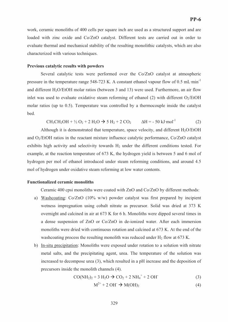
PP-6
329
work, ceramic monoliths of 400 cells per square inch are used as a structured support and are
loaded with zinc oxide and Co/ZnO catalyst. Different tests are carried out in order to
evaluate thermal and mechanical stability of the resulting monolithic catalysts, which are also
characterized with various techniques.
Previous catalytic results with powders
Several catalytic tests were performed over the Co/ZnO catalyst at atmospheric
pressure in the temperature range 548-723 K. A constant ethanol vapour flow of 0.5 mL·min-1
and different H2O/EtOH molar ratios (between 3 and 13) were used. Furthermore, an air flow
inlet was used to evaluate oxidative steam reforming of ethanol (2) with different O2/EtOH
molar ratios (up to 0.5). Temperature was controlled by a thermocouple inside the catalyst
bed.
CH3CH2OH + ½ O2 + 2 H2O � 5 H2 + 2 CO2 ΔH = - 50 kJ·mol-1 (2)
Although it is demonstrated that temperature, space velocity, and different H2O/EtOH
and O2/EtOH ratios in the reactant mixture influence catalytic performance, Co/ZnO catalyst
exhibits high activity and selectivity towards H2 under the different conditions tested. For
example, at the reaction temperature of 673 K, the hydrogen yield is between 5 and 6 mol of
hydrogen per mol of ethanol introduced under steam reforming conditions, and around 4.5
mol of hydrogen under oxidative steam reforming at low water contents.
Functionalized ceramic monoliths
Ceramic 400 cpsi monoliths were coated with ZnO and Co/ZnO by different methods:
a) Washcoating: Co/ZnO (10% w/w) powder catalyst was first prepared by incipient
wetness impregnation using cobalt nitrate as precursor. Solid was dried at 373 K
overnight and calcined in air at 673 K for 6 h. Monoliths were dipped several times in
a dense suspension of ZnO or Co/ZnO in de-ionized water. After each immersion
monoliths were dried with continuous rotation and calcined at 673 K. At the end of the
washcoating process the resulting monolith was reduced under H2 flow at 673 K.
b) In-situ precipitation: Monoliths were exposed under rotation to a solution with nitrate
metal salts, and the precipitating agent, urea. The temperature of the solution was
increased to decompose urea (3), which resulted in a pH increase and the deposition of
precursors inside the monolith channels (4).
CO(NH2)2 + 3 H2O � CO2 + 2 NH4+ + 2 OH- (3)
M2+ + 2 OH- � M(OH)2 (4)

PP-6
330
After that, monoliths were dried, calcined in air at 673 K and reduced under H2 flow at
673 K.
Stability of monolithic catalysts
Stability tests over the monolithic catalysts are currently being developed under the
experimental conditions tested for the powder Co/ZnO sample in order to examine possible
technological applications of these catalysts for the production of hydrogen from ethanol
steam reforming processes. To evaluate thermal stability, the functionalized monoliths are
exposed to different vapour treatments with H2O, EtOH+H2O (ethanol steam reforming) and
EtOH+H2O+O2 (ethanol oxidative steam reforming) at various temperatures between 573 and
873 K. Functionalized monoliths have also been subjected to thermal cycles to simulate
continuous switch on and shut down of the reformer.
In order to evaluate mechanical stability, vibration tests are conducted by ultrasound
exposure with monoliths immersed in ethanol or water.
In all cases, weight loss is monitored. In addition, scanning electron microscopy
(SEM) is used to study in detail the morphology of the monolithic catalysts, both as prepared
and after the stability tests. Electron probe for microanalysis (EPMA) is used to analyze
catalyst composition inside the monolith channels.
Acknowledgments
Financial support from DURSI (Generalitat de Catalunya) is acknowledged. We are
grateful to Corning for providing us with ceramic monolith samples.
References[1] J.N. Armor, Applied Catalysis A: General, 176 (1999) 159.
[2] J. Llorca, N. Homs, J. Sales and P. Ramírez de la Piscina, Journal of Catalysis, 209 (2002) 306.
[3] J. Llorca, P. Ramírez de la Piscina, J.A. Dalmon, J. Sales and N. Homs, Applied Catalysis B: Environmental, 43 (2003) 355.
[4] J. Llorca, N. Homs, J. Sales, J.L.G. Fierro and P. Ramírez de la Piscina, Journal of Catalysis, 222 (2004)470.
[5] V. Klouz, V. Fierro, P. Denton, H. Katz, J.P. Lisse, S. Bouvot-Mauduit and C. Mirodatos, Journal of Power Sources, 105 (2002) 26.
[6] G.A. Deluga, J.R. Salge, L.D. Schmidt and X.E. Verykios, Science, 303 (2004) 993.
[7] C. Diagne, H. Idriss and A. Kienemann, Catalysis Communications, 3 (2002) 565.
[8] M.A. Goula, S.K. Kontou and P.E. Tsiakaras, Applied Catalysis B: Environmental, 49 (2004) 135.
[9] D.K. Liguras, K. Goundani, X.E. Verykios, International Journal of Hydrogen Energy, 29 (2004) 419.
[10] D.K. Liguras, K. Goundani, X.E. Verykios, Journal of Power Sources, 130 (2004) 30.

PP-7
331
EXPERIMENTAL STUDY OF TURBULENT REGIMES
IN FLUIDIZED BED OF MICROSPHERICAL CATALYST V.A. Chumachenko, V.N. Kashkin, A.S. Samarina*
Boreskov Institute of Catalysis SB RAS, address: pr. Akademika Lavrentieva, 5, Novosibirsk,
630090, Russia; e-mail: [email protected], fax: +7 383 3306878*JSC Katalizator, Tikhaya St. 1, 630058 Novosibirsk, Russia
Introduction
Dehydrogenation of low alcanes C4-C5 in fluidized beds of catalyst is the main stage
of production of many synthetic rubbers monomers and MTBE. Large capacity industrial
facility comprise reactor-regenerator unit with some hundred tons of microspherical catalyst
which is circulating between reactor and regenerator. For better quality of fluidization, both
vessels are equipped with several rows of horizontal grids. Hydrodynamic regimes of
fluidization play a key role in reactor performance, being strongly depended on physical
properties and particle size distribution. In some cases, gas-particle interaction [1] may
seriously affect gas-solid contacting and transport processes.
The comparative study of fluidization regimes of 2 commercial dehydrogenation
catalysts was performed at the lab-scale setup.
Experimental procedure
A sketch of experimental
setup is shown in Fig.1. It consists
of 6-m long vertical column, 0.15 m
ID equipped with 1.8-m long
transparent glass lower section,
followed by stainless steel upper
section and a particle wide separator
at the top. At the outlet of column
gas enters into the battery of
cyclones that was installed to ensure
separating of entrained fine solids
from the gas. Particles captured by
the cyclones were returned back
through the discharging tube to the
bottom of column.
Particles separator
Pressure probes
Air feed
Moistening column
Distributing plate
Discharging tube
Cyclones
Fig. 1

PP-7
332
Ports with pressure probes were mounted every 50 mm along the column height.
Differential pressure fluctuations were measured between ports located at various distances.
Absolute pressure fluctuations were measured at heights of 0.16, 0.41, 0.715 and 0.915 m
above distribution plate. Low-inertial differential pressure sensors Motorola MPX 2010DP
and 2050DP were used for both absolute and differential measurements. In each run pressure
fluctuations were detected at a frequency 100 Hz during 40 sec. Electric signals from the
pressure probes were transformed and recorded by computer controlled device. To ensure
more statistical validity of information, experiments at a given gas velocity were repeated up
to 20 times. Then the average values of the pressure drop in the bed at given conditions, and
its standard (mean square) deviations were fixed.
Experiments were made at ambient temperature and pressure. To reduce static charge,
air supplied to the setup was humidified to 70-80% in a separate moistening column. The
following parameters of fluidization of various catalysts were determined in the course of
experimental studies:
• gas velocity demarcating the transition from bubbling to turbulent fluidization;
• apparent bulk density along the bed height;
• relative expansion of the bed;
• effect of horizontal grids on the quality of fluidization.
Specifications of commercial C4-C5 dehydrogenation catalysts are shown in the Table 1.
Table 1
Size, % wt. CatalystIM
CatalystAOK
CatalystAOK 80/20
CatalystAOK 70/30
1 2 3 4 5 < 63 mcm 8.3 -63-71 mcm 4.2 1.4 12.6 (< 63) 17.9 (< 63) 71-90 mcm 7.5 5.6 9.0 10.790-160 mcm 37.7 77.1 78.4 (>90) 71.4 (>90) > 160 mcm 42.3 16.0 Bulk density, kg/m3
1400 1312 1328 1332
Results and discussion
At the first stage of experimental runs hydrodynamic properties of catalysts IM-2201
and AOK-73-21 were compared under the following conditions:

PP-7
333
Table 2
Nomenclature Catalyst IM Catalyst AOK
CatalystsAOK modif.
1 2 3 4Packed bed height, m 0.94 0.73 0.66-0.76 Range of gas velocities, m/s (S.T.P.) 0.2-1.4 0.2-1.4 0.2-1/2 Relative humidity of air, % 60 65 65Pressure in the column, kg/cm2 1-1.2 1-1.2 1-1/2 Minimum fluidization velocity, m/s 0.013 0.02 Bulk density at minimum fluidization velocity, kg/m3
897 1084 1103
Points of measuring the pressure fluctuations above distributor, m
0.16-0.9150.41-0.915
0.16-0.7150.41-0.715
0.36-0.715
Relative expansion of the bed depending on superstitial gas velocity is rather similar
for both catalysts, in spite of different size distribution and bulk density, see Fig.2.
The transition from bubbling to turbulent regime in the terms of gas velocity can be
identified when a maximum value of the standard deviation (SD) of pressure fluctuation is
reached. Standard deviation can be regarded as a qualitative measure of fluidization
uniformity of various particles: the less SD, the smoother fluidization occurs.
As shown in Fig.3, for both catalysts SD reaches its maximum within 0.8-1.0 m/s,
although its value is larger for catalyst AOK, as a consequence of larger average particles
sizes, narrow size distribution, and larger bubbles in the bed. Catalyst efficiency in fluidized
bed strongly depends on mass exchange between bubbles and dense phase, so that it seems
reasonable to increase it by adding a definite fraction of fine particles to existing catalyst.
0,0 0,2 0,4 0,6 0,8 1,0 1,2 1,4 1,6
1,05
1,10
1,15
1,20
1,25
1,30
1,35
Bed
exp
ansi
on,[-
]
Gas velocity, m/s
��-73-21 (0.41-0.715 m above distributor) IM -2201 (0.41-0.915 m above distributor)
0,0 0,2 0,4 0,6 0,8 1,0 1,2 1,4 1,60
500
1000
1500
2000
2500
3000
Sta
ndar
d de
viat
ion,
Pa
Gas velosity, m/s
��-73-21 (0.41-0.715 m above distributor) IM -2201 (0.41-0.915 m above distributor)
Fig. 2 Fig. 3

PP-7
334
At the second stage of experiments three modifications of catalyst AOK distinguished
by various size distribution were tested: initial catalyst AOK, mixture of AOK with 20 % wt.
of small fines <60 mcm (AOK 80/20), and mixture of AOK with 30 % wt. of small fines <60
mcm (AOK 70/30), see Table 1. Experimental conditions are shown in Table 2.
Standard deviation of pressure fluctuations (see Fig.4) is rather close for all 3 catalysts
at gas velocities <0.5 m/s. At higher velocities SD for catalysts AOK 80/20 and AOK 70/30 is
15-20% less than that for initial AOK. This may be explained by smaller size bubble
formation, due to a greater fraction of small particles in these mixtures. In the total range of
velocities there was found no significant difference in SD between catalysts AOK 80/20 and
AOK 70/30, while they approach to catalyst IM.
In the third series of experiments the effect of multi-sectioned grid on apparent bed
density (see Fig.5) and bed expansion of 3 catalysts AOK was studied. At gas velocities
>0.5 m/s relative expansion of a sectioned bed is 2-3 times higher, standard deviation of
pressure fluctuations is 5-10 times less compared to a freely bubbling bed. Transition to the
turbulent regime in sectioned bed occurs at lower velocity, maximum SD shifts from 1.0 to
0.3 m/s. Fluidization regimes of catalysts AOK 80/20 and 70/30 are just without distinctions,
while they remarkably differ from initial AOK.
References
1. Jie Li, J.A.M.Kuipers. Chemical Engineering Science, 58 (2003), 711-718.
0,0 0,2 0,4 0,6 0,8 1,0 1,20
500
1000
1500
2000
2500
3000
�� -73-21 (initial) �� 80/20 �� 70/30 IM-2201
Sta
ndar
d de
viat
ion,
Pa
Gas velocity, m/s0,0 0,2 0,4 0,6 0,8 1,0 1,2
300
400
500
600
700
800
900
1000
1100
�� -73 -21 initial �� 80/20 �� 70/30
B
ed d
ensi
ty, k
g/m
3
Gas velocity, m/s
Fig.4 Fig. 5

PP-8
335
KINETICS OF PHENOL OXIDATION OVER HYPERCROSSLINKED
POLYSTERENE IMPREGNATED WITH Pt NANOPARTICALS
Doluda V., Sulman E., Matveeva V., Sulman M., Lakina N., Sidorov A.,
Valetskiy P., Bronstein L.
Biotechnology and Chemistry Department, Tver State Technical University, A. Nikitina str.,
22, Tver, 170026, Russia. Tel./ Fax: 7 0822 449317. E-mail [email protected].
Nowadays there is a large amount of phenols in the noosphere, hence, novel technologies
based on the conversion of phenols to non-hazardous or useful substances should be
developed and implemented at industrial scale. Catalytic wet air oxidation (CWAO) of
phenols compounds are the most significant methods for wastewater treatment. A great
challenge for solving problem of phenol compounds waste water treatment is to design a
highly selective catalyst comprising of an active site with the correct ensemble of metal atoms
and other active components[1-3]. The advantages of a nanocatalyst prepared in organic
functional polymers are not only the “nanoscale” size control of metal crystallites, but also the
easy tailoring via variation of the polymer nature[4-5]. Nanostructures in a polymeric
composite are defined as regular nanosized heterogeneous domains (i.e., certain regions of the
polymeric material that are separated by some interface)[6,7]. Due to the presence of
nanostructures one can control the growth of nanoparticles, the particle size distribution and
interfacial interactions and control phenol wastewater treatment rate. The main goal of our
research work was investigation of efficient catalyst and study of it's kinetics for waste waters
treatment.
Synthesis of the catalyst for CWAO
Platinum nanoparticle formation in cavities (pores) of a polymer matrix was carried out
with hypercrosslinked polystyrene (HPS). The controlled growth of metal nanoparticles in a
polymer matrix is possible if it occurs in cavities or pores. In this case, the size of the growing
particles can be limited to the cavity size. HPS is the representative of cross-linked polymers
that gives the possibility for nanoparticle growth control. In this study we investigate HPS
purchased from Purolite inc. (MN-270) as organic support. Synthesis of Pt catalysts was
performed the following way. First step is dissolving of platonic acid H2[PtCl6] in complex
solvent (H2O/THF/CH3OH = 1/4/1), then follows solubilization of salt solution by HPS

PP-8
336
matrix and stirring of HPS suspension for two hours. Then follows drying of the catalyst
(t=600C, 0,5 atm) and reduction of the catalyst with different types of reducing agents (N2H4,
NaBH4, H2). And the last step is catalyst drying (T=600C)
Oxidation of the phenol
Phenol oxidation is carried out in laboratory set up shown in fig. 1.
1 - reactor, 2 - reverse refrigerator, 3 - burette hydrogen peoxide, 4 - oxygen cylinder, 5 - magnetic stirrer, 6 - laboratorial transformer, 7 - rotameter, 8 - pH-meter, 9 - electrodes, 10- automatical titration block, 11 - electromagnetic valve Fig. 1. Laboratory equipment for catalytical and biocatalytical oxidation of phenol compounds.
Kinetics of phenol oxidation
For investigation of CWAO kinetics we used phenol as a main pollutant from the phenol
compounds. Reaction that is proposed for CWAO is shown in fig. 2.
OH
[O] Cat [O] Cat
O O
O
[O] Cat
CH3 2CH COOH
+COOHCH
3
COOHCH2
2CH COOH
+CO2 H O2+
[O] Cat
Fig. 2. Wet air oxidation of the phenol
For finding optimal conditions of phenol CWAO we varied following parameters:
temperature, catalyst concentration, oxygen flow rate and phenol concentration. On fig. 3 it is
possible to see increasing of phenol conversion with increasing of temperature. CWAO
oxidation of phenol is characterized with low activation energy level compare to non-catalytic
oxidation Fig. 4.

PP-8
337
0
10
20
30
40
50
60
70
80
90
100
0 50 100 150 200 250 300 350
t, min
Con
vert
ion,
%
t=95 0C
t=80 0C
t=70 0C
t=60 0C
t=50 0C
t=40 0C
Fig. 3. Kinetics curves of phenol oxidation with temperature variation 40-950C. Catalyst -HPS-5,9%-Pt, m(Cat)=0,1g, �(Phenol)=20 g/l, V(Phenol)=25 ml, P(O2)=1 bar, W=400 1/c, W (O2)=8 ml/sec
-7
-6
-5
-4
-3
-2
-1
00,0026 0,0027 0,0028 0,0029 0,003 0,0031 0,0032 0,0033
1/T
ln(1
/t0,2
)
Ea=48,6 kDj/mol
��=162754,79 Activation energy equation. Catalyst -HPS-5,9%-Pt, m(Cat)=0,1g, �(Phenol)=20 g/l, V(Phenol)=25 ml, P(O2)=1 bar, W=400 1/c, W (O2)=8 ml/sec
CWAO treatment of phenol compounds leads to full (concentration of left phenol
compound is less then 5 ppb) conversion in non-hazardous substances. Implementation of the
results can present a new attractive possibility to decrease the phenol content of industrial
wastewaters. The successful development of novel, inexpensive should lead to their use by
phenol producing plants.
We sincerely thank to NATO science for peace programme Sfp 981438 for financial support.
References 1] Bronstein, L.M.; Goerigk, G.; Kostylev, M. Pink, M.; Khotina, I.A.; Valetsky, P.M.; Matveeva, V.G.; Sulman, at. AlJ. Phys. Chem. B (2004), 108(47), 18234-18242. 2] Okhapkin I.M., Bronstein L.M., Makhaeva E.E., Matveeva V.G., Sulman M.G., Sulman E.M., Khokhlov A.R. Macromolecules (2004), 37, 7879-7883 4] Sulman, E., Matveeva, V., Bronstein, L., Sidorov, A., Lakina, N., Sidorov, S., Valetsky, P. Green Chemistry 2003, 5(2), 205-208. 5] Matveeva V.G., Sulman E.M., Sulman M.G. Catalytic oxidation of Catalysis in Industry 2002, 5, 50-60. – In Russian. 6] Sulman E.M., Semagina N.V., Matveeva V.G. Bulletin of the Tver State Technical University, 2002, 1, 28-31. – In Russian. 7] Sulman E.M., Valetsky P.M., Bronstein L.M., Lakina N.V., Matveeva V.G., Sidorov S.N., Chernyshov D.M., Ankudinova T.V., Kirsanov A.T., Sidorov A.I., Sulman M.G. Patent � 2185369 Priority at 02.04.2001. (Russia)

PP-9
338
THE EFFECT OF GROWTH REGULATORS AND CHEMICAL
MODIFICATION ON CHLOROPLAST FERREDOXIN-NADP
REDUCTASE OF CHENOPODIUM ALBUM
El-Shora H.M.
Botany Department, Faculty of Science, Mansoura University, Mansoura, Egypt
Chloroplast ferredoxine-NADP reductase from Chenopodium album was investigated
under the effect of four growth regulators namely kinetin, gibberellic acid (GA3),
6-benzyladenine and 2,4-D. These regulators were investigated at 5 x 10⁻⁴ M, 2 x 10⁻⁴ M and
10-3 M. The four compounds induced the enzyme activity in leaves particularly at 5 x10⁻⁴ M.
Gibberellic acid was the strongest stimulator. This stimulation was corroborated in the leaves
by inhibition of the enzyme activity with 10 mM b-chloroethyltrimethylammonium (CETA),
and the reconstitution of the enzyme activity when GA3 was added with CETA. The enzyme
activity was inhibited by cycloheximide, actinomycin D, and methylpurine and this suggests
that protein synthesis is involved in the enzyme induction. Chemical modifications of the
enzyme with N,N-dicyclohexylcarbodi-imide (DCCD), citraconic anhydride (CAN) and
N-bromosuccinimide (NBS), which are respective chemical modifiers of carboxylic, lysine
and tryptophan residues, were examined. Incubation of the enzyme with increasing
concentration of each tested modifier resulted in a progressive decrease in enzyme activity.
Kinetics data for the inactivation demonstrated that each of carboxyl, lysine and tryptophan
residues is essential for catalytic activity of the enzyme. The protective effect of NADP
against the inactivation by the three compounds suggests that functional carboxyl, lysine and
tryptophan residues are located in the active site.

PP-10
339
DEVELOPMENT OF AN ACTIVE Pt BASED CATALYST FOR H2
PRODUCTION BY HYDROLYSIS OF NaBH4
Ersoz Y., Yildirim R., Akin A.N.
Kocaeli University, Department of Chemical Engineering, Kocaeli, Turkey
Bogazici University, Department of Chemical Engineering, Istanbul, Turkey
Introduction
In the future, hydrogen is to become a major source of energy. In the search for efficient,
clean and safe energy resource, hydrogen draws attention with its advantages such as high
energy density (142 kj/g) and electronegative properties. Recently, the use of hydrogen is
applied to various industries and will be used more and more if the research and development
of it is continued. Hydrogen production and storage technologies are developed parallel to the
developments in fuel cell technologies. Especially, PEM fuel cells are attractive and
alternative options for producing clean energy by using hydrogen as fuel. Hydrogen needed
for PEM fuel cell can be stored somewhere or produced from a source on demand. However,
the currently used hydrogen is mostly produced from natural gas via catalytic reforming,
which produces a mixture of H2, H2O, N2, CO2, and CO [1,2]. The performances of PEM fuel
cell are sensitive to the concentration of carbon monoxide in hydrogen. Even a few parts per
million CO can cause the catalyst poisoning in PEM fuel cell [2]. Therefore, a fast and clean
hydrogen supply method is required, especially for a mobile PEM fuel cell. At this point a
chemical hydrate sodium borohydrate is seen as a safe and portable alternative route because
it is stable under ordinary conditions and liberates pure H2 in a safe and controllable way [3].
NaBH4 contains 10.8%wt hydrogen. In the presence of a selected catalyst, hydrolysis reaction
of NaBH4 solution gives 4 moles of H2 and the half of the produced hydrogen comes from
water. The by-product NaBO2 does no harm to the environment, and can be recycled as the
raw material for producing NaBH4 [2,3]. Thus, the hydrolysis reaction of NaBH4 is an
environmentally friendly and renewable process. It is a zero order reaction and without a
catalyst the reaction is very slow (half life is about 430 days in pH=14 and 25 °C) [4].
Therefore, development of an effective catalyst is the focal point of the researches in the
literature.
Various type of catalysts are being used by different researchers such as metal halides
(NiCl2, CoCl2), colloidal platinum, Co and Ni boride, active carbon, Raney nickel, Ru

PP-10
340
supported on ion exchange resin beads, and uorinated particles of Mg-based material [3-8].
Pt-LiCoO2 (among the others) was found to work as an excellent catalyst for releasing
hydrogen by hydrolysis of NaBH4 solution [5]. In all these studies, Pt-LiCoO2 catalysts were
prepared by impregnation of Pt precursor on commercial LiCoO2 support material.
The aim of this study is to develop of an effective Pt/LiCoO2 catalyst by investigating the
preparation conditions of support material. LiCoO2 as catalyst support material was prepared
by solid state reaction of lithium and cobalt precursors and effects of preparation parameters
on catalyst activity and hydrogen production rate in the hydrolysis reaction were determined.
Effects of hydrolysis reaction parameters on hydrogen production rate were also investigated.
Experimental
In this study 1.5% Pt/LiCoO2 catalysts were prepared and their activities were tested in
hydrolysis reaction of NaBH4. LiCoO2 was prepared as support material by solid state
reaction of Li2O and Co(NO3)2.6H2O. Commercial LiCoO2 was also used for comparison. Pt
impregnation on LiCoO2 was done by incipient to wetness impregnation method. In solid
state reaction method, Li2O, Co(NO3)2.6H2O precursors and heat generating material were
mixed in appropriate amounts and heated in a muffle furnace [6]. Amount of reactants,
existence and type of the heat generating material and calcination temperature were chosen as
preparation parameters. Prepared catalysts characterized by different methods. The total
surface areas and the total pore volumes were determined by N2 adsorption from N2-He
mixtures using a multipoint technique together with the BET equation and by the N2
adsorption-desorption method, respectively. XRD analysis were performed to determine the
catalyst structure. The activities of catalysts in hydrolysis of NaBH4 were measured in a semi-
batch jacketed reactor at atmospheric pressure and room temperature.
Results
LiCoO2 as catalyst support material was prepared by solid state reaction of lithium and
cobalt precursors and effects of preparation parameters on catalyst activity and hydrogen
production rate in the hydrolysis reaction were determined. The results were discussed in
terms of preparation conditions. Amount of reactants, existence and type of the heat
generating material and calcination temperature were preparation parameters. The amount and
type of heat generating material was found as an important parameter. Equal amount of heat
generating material to the reactants was determined as optimum amount and using 1 ml of
water in the mixture of solid materials improves the mixing quality, however does not affect
hydrogen production rate so much. Catalysts prepared by using NH4NO3 as heat generating
material, compare to urea, gives higher hydrogen production rates. Calcination procedures

PP-10
341
with wide temperature ranges were investigated and 500-600 °C were found as ideal
calcination temperatures. Type of Pt precursor was also investigated. Pt(NH3)4.(NO3)2 gave
better results. Effect of addition of Pt precursor in the preparation of solid mixing rather than
impregnation was also investigated. Hydrogen production rate measured by using the catalyst
prepared by solid state reaction showed a different profile. It was slow at the beginning and
accelerated by time. However, all the other catalysts prepared by impregnation gave similar
H2 production profiles which have high acceleration rate at the beginning and then remain
constant. According to the results of the catalyst development studies catalysts prepared by
impregnation Pt on LiCoO2 prepared by solid state reaction gave the highest H2 production
rate comparing to the catalyst prepared by commercial LiCoO2 studied both in our work and
literature [2,5,7]. In this study, effects of hydrolysis reaction parameters on hydrogen
production rate were also investigated. The parameters studied were concentrations NaBH4
and NaOH solutions, reaction temperature and catalyst amount. Results showed that:
Decreasing concentrations of NaBH4 and NaOH solutions increased H2 production rate.
Increasing reaction temperature and catalyst amount was also increased the rate as expected.
References (1) Amor J.N., Applied Catalysis 176, p.169. 1999
(2) Chuan Wu ., Huaming Zhang, Baolian Yi, Catalysis Today 93–95 p. 477–483, 2004
(3) Amendola S.C., Sharp-Goldman S.L., Janjua M.S., Spencer N.C., Kelly M.T., Petillo P.Jbinder. M., Int. J. Hydrogen Energy 25, p. 969, 2000
(4) Amendola S.C., Sharp-Goldman S.L., Janjua M.S., Kelly M.T., Petillo P.J. and Binder M. J. Power Sources 85, p. 186, 2000
(5) Kojima Y., Suzuki K., Fukumoto K., Sasaki M., Yamamoto T., Kawai Y. and HAYASHI H., Int. J. Hydrogen Energy 27, p. 1029, 2002
(6) S. Suda, Y.M. Sun, B.H. Liu, Y. Zhou, S. Morimitsu, K. Aral, N. Tskamoto, M. Uchida, Y. Caudra, Z.P. Li, Appl. Phys. A 72, 209. 2001
(7) Kojima Y., Kawai Y., Nakanishi H., Matsumoto S., J. Power Sources 135, p.36, 2004.
(8) Kaufman C.M., Sen B., J. Chem. Soc., Dalton Trans. p.307 1985 .

PP-11
342
CATALYTIC PERFORMANCE OF Au-TiO2 CATALYSTS PREPARED
BY DEPOSITION-PRECIPITATION FOR CO PREFERENTIAL
OXIDATION IN H2-RICH GASES
C. Galletti, S. Fiorot, S. Specchia, G. Saracco and V. Specchia
Dipartimento di Scienza dei Materiali e Ingegneria Chimica, Politecnico di Torino – Corso
Duca degli Abruzzi 24, 10129 Torino, Italy – fax. +390115644699 –
The use of PEM fuel cells as a power source for electrically operated vehicles is currently
of major interest due to their ability to produce virtually no pollutants. The H2 fuel gas for the
PEM fuel cell is required to be “nearly CO free” as the platinum fuel cell anodes are poisoned
by traces of CO. H2 rich gas produced by catalytic steam reforming of fossil fuels, followed
by water gas shift reaction, requires the final catalytic selective CO oxidation to remove CO
content. Selective oxidation of CO to CO2 (CO-PROX) is carried out to reduce the CO
content of the reformate gas to a concentration not higher of 10 ppm [1, 2].
The main goal is the study of suitable catalysts for the CO-PROX reaction.
Until the end of the 1980s, only very limited attention has been paid to catalysis with gold
metal because of its electronic configuration of noble metal, which is usually accompanied by
very low activities [3]. This situation changed in recent years with the discovery of the
catalytic activity of gold nanoparticles [4]. Remarkable catalytic properties of supported gold
were first obtained for the reaction of CO preferential oxidation at sub-ambient temperature
by Haruta et al. [5]. The most studied catalyst for preferential CO oxidation is gold supported
on TiO2 because it is one of the most active catalysts for this reaction at low temperature, and
it may allow to operate at temperatures compatible with those of PEM fuel cell (80-100°C).
The optimum gold particle size in these catalysts was found to be 2–3 nm [6-8]. Such particle
sizes can be achieved owing to suitable preparation methods and a careful control of the
running conditions during preparation.
Up to now, for the preparation of Au-TiO2 catalysts, the best method was the deposition-
precipitation with NaOH [9], particularly because it allowed the size of the gold particles to
be adjusted towards very small values by controlling the pH during the preparation.
In this work, Au-TiO2 catalysts were prepared by means of deposition-precipitation
method, with NaOH, varying pH and some other parameters in the preparation procedure.

PP-11
343
Titania prepared in our laboratory by gel combustion method was used as support and solid
HAuCl4*3H2O (Sigma-Aldrich) as Au precursor. The gold load on TiO2 was 2 wt%.
Two different methods were used. In the first one, an aqueous solution of HAuCl4
(4.2*10�3 M) was adjusted to pH = 10.4 by drop wise addition of NaOH, then a suitable
amount of TiO2 particles was dispersed in the solution which was then heated to 70°C and in
the same time the pH lowered till 8.6. Then the solution was filtered and the separated
particles washed with H2O.
With the second method an aqueous solution of HAuCl4 (4.2*10�3 M) was firstly heated up to
80°C, then its pH was adjusted to 7 by drop wise addition of NaOH (1 M). A suitable amount of
TiO2 was dispersed in the solution and the pH was readjusted to 7 with NaOH. The suspension
thermostated at 80°C was vigorously stirred for 2 h, then filtered and the separated particles
washed with H2O. After preparation, all the Au-TiO2 catalysts were calcined in air at 200 and
300°C for 2 hours and therefore characterized by means of XRD, SEM and TEM analyses.
Catalytic activity tests were carried out on catalysts in powder: a suitable amount of catalyst
was placed in a fixed bed tubular micro-reactor, heated up by a PID regulated oven, and the
feed gas was set at a composition similar to that of a reformate gas: 37%vol H2, 5%vol H2O,
18%vol CO2, 1%vol CO, 2%vol O2 and He as balance. The λ value (λ = 2O2/CO) was fixed
equal to 4. The outlet gas stream was analyzed through a gas chromatograph equipped with a
thermal conductivity detector (TCD); CO and O2 conversions and O2 selectivity toward CO
oxidation were determined in the 40°C-180°C temperature range.
A first comparison was performed on catalysts prepared through the first method and
calcined at 200 and 300°C (2% Au-TiO2-1-200, 2% Au-TiO2-1-300) feeding 100 ml/min of
synthetic reformate gas; the obtained results are shown in Fig. 1.
Fig. 1: CO conversion for 2% Au-TiO2-1 calcined at different temperatures.

PP-11
344
The complete CO conversion was reached in the range 40-45°C with sample calcined at
300°C, whereas the minimum CO residual amount for the catalyst calcined at 200°C was 150
ppm at about 60°C. However, the complete conversion with 2% Au-TiO2-1-300 was obtained
at too low temperature, as the operating temperature of PEMFC is in the range 80-100°C.
Therefore, the second preparation method, as indicated above, was used and catalytic
activity tests were carried out on the catalyst calcined at 300°C, identified as 2% Au-TiO2-2-
300. The obtained results are shown in Fig. 2: a complete CO conversion was achieved in the
temperature range 60-80°C.
Fig. 2: CO and O2 conversion and O2 selectivity vs. temperature for 2% Au-TiO2-2-300.
Then, on this promising catalyst, the research activity was deepened varying some
parameters, as λ, weight space velocity and inlet CO concentration.
Test performed at λ = 3 showed still complete CO conversion, but only at 60°C, again a
little bit low temperature for PEM applications.
In sight of industrial applications, weight space velocity was increased. Unfortunately,
catalytic test did not show complete conversion: the CO residual concentration was about 600
ppm with a doubled weight space velocity.
As outlet CO concentration from WGS step could be lower than 1%, following tests were
carried out with an inlet CO concentration of about 0.5%, feeding 100 ml/min of synthetic
reformate gas at two different λ values (Fig. 3).

PP-11
345
Fig. 3: Performance of 2% Au-TiO2-2-300 at two different λ values; CO inlet concentration 0.5%.
As shown in Fig. 3, by decreasing the inlet CO concentration complete CO conversion
was not reached: with λ = 4 residual CO was about 450 ppm, and it increased to 1000 ppm
with λ = 3.
The above results could probably be explained by the lower CO concentration: in this
case the parasite RWGS reaction (CO2 + H2 � CO + H2O) could be favoured, then
decreasing the CO conversion.
Therefore, the 2% Au-TiO2-2 catalyst calcined at 300°C and operating at λ = 4 could
potentially be used for CO-PROX applications at low temperature: the catalyst was able to
reduce the CO concentration to below 10 ppm in the 60°C-80°C temperature range.
[1] Oetjen H.F., Schmidt V.M., Stimming U., Trila F., J. Electrochem. Soc. 143 (1996) 3838.
[2] Dudfield C.D., Chen R., Adcock P.L., J. Power Sources 86 (2000) 214.
[3] B. Hammer, J.K. Norskov, Nature 376 (1995) 238.
[4] M. Haruta, Catal. Today 36 (1997) 153.
[5] M. Haruta, T. Kobayashi, H. Sano, N. Yamada, Chem. Lett. 2 (1987) 405.
[6] G.R. Bamwenda, S. Tsubota, T. Nakamura, M. Haruta, Catal. Lett. 44 (1997) 83.
[7] M. Valden, X. Lai, D.W. Goodman, Science 281 (1998) 1647.
[8] T. Tabakova, F. Boccuzzi, M. Manzoli, J.W. Sobczak, V. Idakiev, D. Andreeva, Appl. Cat. B: Environmental, 149, (2004), 73-81.
[9] S. Tsubota, D.A.H. Cunningham, Y. Bando, M. Haruta, Stud. Surf. Sci. Catal. 91 (1995) 227.

PP-12
346
SIMULATION STUDY OF A MEMBRANE METHANOL REFORMER
FOR HYDROGEN PRODUCTION: HIGH RECOVERY
IN COUNTER-CURRENT MODE
Fausto Gallucci1, Angelo Basile1, A. Iulianelli1,2, Enrico Drioli1,2
1 Institute on Membrane Technology, ITM-CNR, c/o University of Calabria, Via P. Bucci,
cubo 17/C, I-87030 Rende (CS) Italy. Phone: (+39) 0984 492011 – Fax: (+39) 0984 402103,
E-mail: [email protected] [email protected] 2 Department of Chemical Engineering and Materials, University of Calabria, via P. Bucci
Cubo 42/A, 87030 Rende, (CS), Italy, Phone: (+39) 0984 492039 – Fax: (+39) 0984 402103
Abstract
In this simulation study, methanol steam reforming reaction to produce synthesis gas has
been studied in a membrane reactor when shell side and lumen side streams are in co-current
mode and in counter-current mode. The simulation results for both co-current and counter-
current modes are presented in terms of methanol conversion and molar fraction versus
temperature, pressure, H2O/CH3OH molar feed flow rate ratio and axial co-ordinate.
Although the methanol conversion is sometimes higher in the membrane reactor operated
in co-current mode than in the counter-current one, in the last case it is possible to extract
more hydrogen from the reaction zone. With this theoretical analysis we present a set of
parameters which permit to have a CO-free hydrogen stream and a complete recovery of the
hydrogen from the lumen side of the reactor.
Theoretical Model of Methanol Steam Reforming
The model was developed using all the thermodynamic values for the reaction species and
the kinetic expressions; hydrogen removal was calculated using experimental permeabilities [1].
The rate equations are taken from Peppley et al. [2], as well as kinetic and adsorption
parameters. A mass balance for a differential reactor volume along the z axis of MR for both
co-current and counter-current mode has been written for the reaction zone (lumen) and for
the permeating zone (the last mass balance changes for the two modes). The set of differential
equations has been solved using a IV order Runge-Kutta method with variable step. The
counter-current mode has been solved using the shooting method. The code was written in
Fortran 95 by using the Salford Plato3 platform.

PP-12
347
Results and discussion
Fig. 1 Methanol conversion versus lumen pressure. pshell = 1 bar, H2O/CH3OH feed ratio = 3, T = 270°C
Fig. 2 Hydrogen recovery versus lumen pressure. pshell = 1 bar, H2O/CH3OH feed ratio = 3, T = 270°C
Fig. 1 reports the methanol conversion versus the reaction pressure at 270°C. It shows that
at pressures higher than 4 bar the methanol conversion in the counter-current mode is higher
than the one in the co-current mode, vice versa, for pressures lower than 4 bar the co-current
mode gives a higher conversion than the counter-current mode. Although the conversion is an
important parameter in the reactor’s performances evaluation, the key parameter in the CO-free
hydrogen production is the hydrogen recovery, calculated as the percentage of hydrogen
recovered in the shell side of the reactor with respect to the total hydrogen produced. Fig 2
shows the hydrogen recovery versus reaction pressure for the same operative conditions of the
previous figure. For both co-current and counter-current mode the hydrogen recovered in the
shell side increases by increasing the reaction pressure. This is because, by increasing the
reaction pressure the hydrogen permeation is promoted. In this case, one can see that hydrogen
recovery in counter-current mode is always higher than the hydrogen recovery in co-current
mode. In particular, at pressure of 2 bar the hydrogen recovery in co-current mode is about 51%
while in the counter-current mode it is more than 80%.
Fig. 3 Methanol conversion versus H2O/CH3OH feed ratio. plumen = 6 bar, pshell = 1 bar, T = 270°C
Fig. 4 Hydrogen recovery versus H2O/CH3OH feed ratio. plumen = 6 bar, pshell = 1 bar, T = 270°C

PP-12
348
Figg. 3 and 4 report the methanol conversion and the hydrogen recovery versus the
H2O/CH3OH feed flow rate ratio, respectively, for a temperature of 270°C, reaction pressure 6
bar and shell-side pressure 1 bar. Methanol conversion decreases with increasing the feed
flow rate ratio for both co-current and counter-current modes. The counter-current mode gives
methanol conversions always higher than the co-current mode. Although the difference in the
methanol conversion between the counter-current mode and the co-current one is practically
not so high, the hydrogen recovery in the counter-current mode is almost 100% in all the
H2O/CH3OH range considered, while the hydrogen recovery for co-current mode quickly
decreases with increasing H2O/CH3OH.
Conclusions
Hydrogen production by methanol steam reforming reaction and its recovery have been
studied in a membrane reactor when shell side and lumen side streams are in co-current mode
or in counter-current mode. The theoretical results show that the counter-current mode gives a
methanol conversion often comparable with the co-current mode one. The difference in the
hydrogen production depends on parameters such as reaction temperature and pressure and
molar feed flow rate ratio. In general, counter-current mode can give hydrogen production
higher than co-current mode. The most interesting result is the hydrogen recovery. In fact, in
the case of counter-current mode it is possible to have 100% of hydrogen recovered in the
permeate stream. This results are very interesting because, if steam is used as sweep gas in the
membrane reactor, it is possible to recover all the hydrogen produced in the reactor as a pure
stream and to use it directly in a fuel cell. It should be noted that the theoretical results
suggest that it is possible to improve the MR performance also by changing the feeding mode
between lumen and shell side of the membrane reactor.
References [1] Gallucci, A.; Paturzo, L.; Basile A. Hydrogen Recovery from Methanol Steam Reforming in a Dense Membrane Reactor: Simulation Study. Ind & Eng Chem Res., 2004, 43(10), 2420-2432.
[2] Peppley, B.A.; Amphlett, J.C.; Kearns, L.M.; Mann, R.F. Methanol steam reforming on Cu/ZnO/Al2O3catalysts. Part 2. A comprehensive kinetic model. Appl. Catal. A: Gen. 1999, 179, 31-49.

PP-13
349
KINETIC ANALYSIS OF TOTAL OXIDATION OF BENZENE
USING MIXED OXIDES TYPE CATALYSTS Cu-Cr SUPPORTED
ON Al2O3 + SiO2
V. Georgescu, G. Dobrescu, F. Papa and V.T. Popa
Institute of Physical Chemistry “I.G.Murgulescu”, Romanian Academy,
Spl. Independentei 2o2, Bucharest, Romania
E-mail: [email protected]; [email protected]
Total oxidation of basic organic compounds for the depopluation of industrial
environments is an acute problem. Using rare metals catalysts for oxidation through
heterogeneous catalysis turned out to be successful.
However, the higher prices of these catalysts stimulated the searching other alternatives,
one of them being the mixed oxides type catalysts with spinel structure, deposited on support.
In this work a mixed oxide type catalyst of Cu-Cr supported on Al2O3 + 20% SiO2 from
the complex precursor with tartaric acid [CrCu4Ta6].5H2O was prepared [1]. After
calcinations at 650 °C, a catalyst with spinel structure and specific surface of 175 m2/g was
obtained. The catalyst was characterized by Infrared Spectroscopy (IR), X-Ray diffraction
(XRD), UV-VIS Spectroscopy (UV-VIS), thermoprogrammed reduction (TPR) and
thermoprogrammed desorption (TPD) studies; the thermogravimetric analysis (TGA)
evidenced the spinel phase CuCr2O4 that is the active phase of the catalyst [2,3].
The catalyst has been used in the oxidation reaction of benzene in a laboratory installation
with continuum flux; the reaction products were chromatographic analysed.
A good activity and stability of the catalysts has been evidenced by testing different
benzene concentrations in the reaction mixture and different spatial velocities [4].
The chemical reactor was designed to simulate the industrial total oxidation reactors with
pre-heating of the reaction mixture.
The chemical reaction was initiated in the catalyst thin layer and it is continuated in the
gaseous-phase, in the inner part of the reactor. The contribution of the homogeneous process
to the total conversion X, is more important as the reaction temperature increases.
Taking into account the space where the heterogeneous catalytic initiated reaction can be
continued in gaseous-phase (homogeneous), the spatial velocities: heterogeneous s1 and

PP-13
350
homogeneous s2, respectively, and the contact times: τ1 and τ2 are related by the following
equation: s1/s2 =τ2 /τ1 = 20.
The chemical reactor can be modeled as a two series-bounded tubular reactors system: the
first reactor is working as a differential reactor (at X�0.1) or as a integral reactor (at X>0.1);
the second one, the un-catalytically reactor, is a integral reactor. These contributions have
been evidenced by kinetic analysis using some simplifying assumptions.
Also, the preliminary analysis of the oxidation results is based on the selection of the
experimental domains where the assumption of the higher importance of the heterogeneous
reaction versus the global process is valid.
Differential analysis
The experimental results for lower conversions (X�0.1) were used to compute the
apparent kinetic constants. The Arrhenius curves lead to computing of the activation energies.
Integral analysis
The apparent kinetic constants corresponding to the integral reactor were computed using
an Excel-based computer code from the F(n,X) – τ1 curves.
The conversion integral function F(n,X) was computed using the trapezium-method with
a step of ΔV=0.001.
Conclusion
The values of the activation energies of the total oxidation of benzene, within the kinetic
temperature domain, {where a weak variation of activation energy on reaction rate is
observed} are in agreement with our results obtained from work function data.
Bibliografie1. V.Pocol, L.Patron and P.Spacu, Rev. Roumaine de Chim., 39 {1994} 1113.
2. M.I.Vass, V.Georgescu, Catal. Today 29 {1996} 463-470.
3. M.Teodorescu, I.Sitaru, V.Georgescu, M.I. Vass, E.Segal, Thermochimica Acta 282/283 {1996} 61-68.
4. D.Mehandjiev, K.Cheskova, A.Naydenov and V.Georgescu, React. Kinet. Catal. Lett. 76(2) {2002) 287-293.
PP-14
351
HETEROPOLY ACID H3PW12O40/SiO2 CATALYZED SYNTHESIS
OF BENZOCAINE UNDER SOLVENT-FREE CONDITION
A. Gharib, F.F. Bamoharram, M. Roshania, M. Jahangir
Department of Chemistry Science, School of Science, Islamic Azad University,
Mashhad - Iran, [email protected]
Microwave heating and its application in organic chemistry for reaction is currently being
developed successfully and in recent years, there has been a tremendous interest in this area.
Remarkable decrease in reaction times and in some cases cleaner reaction have been reported
with microwave irradiation. The use of heteropoly acid (HPA) as catalysis for fine organic
synthesis process in developing synthesis of antioxidant and biologically active substance for
instance have been reported [1]. Heteropoly acids are more active catalyst for various reaction
in solution than conventional inorganic and organic acids [2]. Herein we report the
esterifacation P-amino benzoic acid with Ethanol to corresponding Ethyl-4-amino benzoate
which has local anesthetic commonly used as topical pain reliever. It is active ingredient in
many over –the-counter analgesic ointments and sprays[3]. This work describe the application
of silica support H3PW12O40(PW). The strongest HPA in the Keggin series against silica
supported sulfuric acid and other heterogeneous catalyst like zeolite, HZSM-5 for
esterificiation of 4-amino benzoic acid with ethanol under microwave irradiation and
traditional thermal condition.
References1 .Onous Y., MizutanY.,S.Akiyam,Y. Izumi, Chem.Ttechnol, 8, (1978) 432.
2. I. V. Kozhevnikov, K. I. Matveev Appl.Catal, 5, (1983) 135.
3. F.Y, W.O.principles of Medicinal chemistry, Philadelphia. Leaond febiger.1974, chap14 (local Anesthatica)

PP-15
352
PREYSSLER HETEROPOLYACID AS GREEN, ECO-FRIENDLY
AND REUSABLE CATALYST FOR HIGHLY SELECTIVE SYNTHESIS
OF PHENYLSALICYLATES
F.F. Bamoharram, M. Roshani, A. Gharib, M. Jahangir
Department of Chemistry, School of Science, Islamic Azad University of Mashhad - Iran.
Generally phenylsalicylates are prepared under liquid phase, refluxing the reactants in the
presence of small amount of conc. H2SO4, HCl, POCl3 or sulfonic acid as the catalyst [1].
Solid acids such as zeolites, oxides, aluminophosphates and their modified forms have been
extensively studied as possible alternatives to conventional Lewis/ Bronsted acid catalysts [2-
4]. Although many effective and reliable methods for the preparation of aromatic esters exist,
there is still a good scope for research towards finding eco-friendly and economically viable
processes.
Polyoxometalates, and particularly the heteropolyanions, can function as effective
catalysts whose redox properties can be controlled by alteration of their compositions. They
are remarkably stable both in the solid state and in solution, making them useable as
heterogeneous or homogeneous catalysts. All reports show that heteropolyacids, like Keggin
and Dawson structures, are efficient "Supper acid" catalysts which can be used both in the
homogeneous or heterogeneous phase [5] and the catalytic applicability of Preyssler's anion
with exclusive properties has been very limited, with only a few demonstrations of catalytic
activity. This heteropolyanion with fourteen acidic protons, is an efficient "supper acid" solid
catalyst which can be used both in the homogeneous and heterogeneous phases [6].
In continuation of our research on exploring the application of this catalyst and
application of heteropolyacids in organic syntheses [7], in the present work we have studied
performance of sodium-30 tungsto pentaphosphate, the so-called Preyssler's anion as catalyst
for highly selective preparation of phenyl esters of salicylic acid from aromatic alcohols. The
performance of the Preyssler catalyst as pure, mixed addenda and silica supported was
compared against known classical catalyst: sulfuric acid. We have found that this green solid
and recyclable catalyst in an organic solvent, render effective reaction better than sulfuric acid
under different temperatures. Both homogeneous and heterogeneous catalysts are discussed

PP-15
353
and compared and the results show that the catalytic performance of this catalyst is excellent.
The effects of various parameters such as catalyst type, reaction time, temperature, molar ratio
and solvent type have studied and the optimum conditions have been obtained. All different
forms of this green solid catalyst can be easily recovered and recycled with retention of their
initial structure and activity.
References 1. A. Rodriguez, M. Nomen, B. W. Spur Tetrahedron Lett, 39 (1998) 8563.
2. P. B Venuto Micropor Mater, 2(1998) 297.
2. M. E. Davis, Micropor Mesopor Mater, 21(1998) 12657.
4. S. E. Sen, S. M. Smith, K. A. Salivan, Tetrahedron. 55, (1998) 12657.
5. N. Mizuno, M. Misono J. Mol. Catal, 86, (1994) 319.
6. M. H. Alizadeh, H. Razavi, F. F. Bamoharram, M. K. Hassanzadeh Kinet. Catal, 44, (2003) 524.
7. a) M. M. Heravi, F. Derikvand, F. F. Bamoharram J. Mol. Catal. 242, (2005) 173. b) Alizadeh, H. Razavi, F. F. Bamoharram, K. Daneshvar J. Mol. Catal, 206, ( 2003) 89.

PP-16
354
SPECIFIC CATALYST INFLUENCE TO PROCESSES FOR AEROSOL
NANOCATALYSIS TECHNOLOGY
Glikina I., Glikin M.
Vladimir Dal Eastern-Ukrainian National University, Severodonetsk Technological Institute,
av. Sovetskiy, 59A, Severodonetsk, Ukraine
e-mail: [email protected], [email protected]
The successful development chemical industry for processing various raw material is
connected to application heterogeneous catalysis on carriers [1]. During 150 years the main
attention of a science and practice in catalysis is concentrated on improvement of technology
of carriers reception with given structure and ways of fixing on catalytic active components
on their surface. On this period the engineering of definition of properties stability, activity
and selectivity of the received samples in researched reactions was constantly improved.
Simultaneously there was the complication of reception desired result and a growth of
catalysts cost. In the scientific literature, at domestic and international conferences and
symposiums the problems of activity, aging, poisoning and regeneration of catalysts [2, 3]
were regularly examined. As a result of experimental and practical data for traditional
catalysis on carriers have revealed a lot of complex and difficultly soluble problems. In
general view they subdivide to three blocks: reduction of potential possibilities of catalysis;
fast catalyst deactivation; the reactions, which not speeding up catalysis on carriers.
From the end of XX centuries our specialists developed new ideology of heterogeneous
and catalytic manufactures creation, which free from these problems, is named aerosol
nanocatalysis (AnC) [3, 4]. The chemical reaction will be carried out with catalytic system
application. It consists the moving inert material and catalytic active substance. The particles
sizes in reaction zone are 8-100 nm. Were used the reactors with mode of a fluidized and
vibrating bed. One of the first reactions which systematic investigating was the deep oxidation
of acetic acid reaction by use of the catalyst on carriers and in aerosol catalyst [3].
The major industrial synthesis are detailed investigated and is studied them kinetics for
the reactions of aerosol nanocatalysis technology. Thus are revealed new phenomenon for
catalysis. The results of oxidation reagents, taking place in gaseous, liquid and solid condition
are given on Fig. 1. For all reagents irrespective of aggregate state are fixed new properties

PP-16
355
for heterogeneous catalysis, such as dependence of reaction rate on catalyst concentration,
insignificant catalyst concentration, presence of a maximum rate for each reaction at catalyst
concentration up to 5 g/m3. It notes a successful reaction realization with active silt containing
solid oxidizing components. The left part direction of lines is natural. It was not represented
possible to predict the subsequent rate decrease in the right part of dependence. The results
Table 1. The process of acetic acid deep oxidation at temperature 6000�
Maximal loading mode, kg/(kgcat*h) Fluidized catalyst bed
on γ-Al2O3 Aerosol of catalyst and moving inert material
Acid concentration, %vol.
Pt CuCrO4 Fe2O3 1 98 1,5 0,8 - 2 60 - 0,65 3,6*104 3 30 - 0,37 2,6*104
0
50
100
150
200
250
300
350
0,5 1 1,5 2 2,5 3 3,5 4 4,5 5 5,5 6 Ccat, g/m3
Rea
ctio
n ra
te o
f CH
3CO
OH
, NH
3, m
mol
e/(g
cat*
sec)
0
0,5
1
1,5
2
2,5
Rea
ctio
n ra
te o
f A
ctiv
silt,
m
mol
e/(g
cat*
sec)
Acetic acid
Ammonia
Activ silt
Fig. 1. Dependence of reaction rate of ammonia, acetic acid and active silt oxidation processes on aerosol
catalyst concentration in reactor with fluidised bed.
were unexpected. Probably, it is connected to some reasons, such as energy change to catalyst
surface and reagents from moving inert materials, braking of diffusion, increase of the
influence of convective carry to rate of the process. Probably, displacement of process balance
is influenced during destruction and agglomeration of catalyst particles in fluidized bed.
Thereof the active catalyst surface decreases. The further study of this phenomenon is
necessary.
The similar dependence of chemical processes studying by aerosol nanocatalysis
technology with vibrating bed (Fig. 2) was received. In this case it was show an opportunity

PP-16
356
of chemical reaction stopped. It is necessary to note, the reaction rate does not decrease even
at concentration 0,3 g/m3r.vol..
At the results the �n� technology has shown a new opportunity to manage activity and
selectivity of catalysis of chemical processes. The reaction rate is constant at catalysis on
carrier, as the amount of active component is constant. It can be changed even during
chemical reactions for �n� technology.
Fig. 2. Dependence of reaction rate of acetic acid oxidation on catalyst concentration in reactor with
vibrating bed by frequency 6 sec-1 and amplitude 7 mm.
There is a maximum catalyst quantity (3-4 g/m3 for fluidised bed and 0,3-2 g/m3 for
vibrating bed at realization of acetic acid oxidation process. The vibrating bed allows
receiving the more active catalyst than fluidized bed. Previously, it is necessary to define a
dependence of reaction rate on catalyst concentration up to kinetic studying of chemical
reactions. It is possible to ensure a constant catalyst activity for the practically unlimited time
for �n� technology.
The vibrating bed has allowed increasing reaction rate in 106 times and probably more.
It has resulted in new features of aerosol nanocatalysis technology:
– minimization of catalyst concentration (0,3-2 g/m3);
– management of mechanical and chemical activation in situ (frequency, amplitude, size
of inert material, efforts of influence to catalyst particles);
– decrease of hydraulic resistance of reactor practically up to zero;
– decrease of reactor volume in 3-10 times.
The reaction rate and selectivity depends on concentration of active oxygen on contact
surface by viewing of the mechanism of oxidation process. The degree of surface filling by
active oxygen depends on catalyst concentration, active centers of surface and diffusion
conditions in a reaction zone at a constant ratio of reagents in mixture. Nanoparticles have a

PP-16
357
plenty of the active centers at the moment of formation, so it explains catalyst activity in
aerosol nanocatalysis technology [5].
The studying of catalyst influence to reaction rate on aerosol nanocatalysis technology
opens a new sight on kinetic of gas-phase processes.
Also it influences to the basic theoretical and practical parameters for technology and
equipment development. By analyzing experimental results, it came to a conclusion about
introduction catalyst concentration in the mathematical description of chemical process.
The modern evolutionary development of a scientific idea in chemistry and chemical
technology is created by enterprises satisfaction by an actual level of engineering. It’s not
stimulated essentially new energy- and cost-saving scientific development. It reminds you,
that ££I century, is called as nanotechnology century. The nanochemistry reviews [5] are
rather pessimistic. Probably, the given work will change this opinion and will expand
numbers scientific engaged aerosol nanocatalysis technology.
References 1. �¤¥\�# �.�. }_¤�#�¦ §¤_¨_$ ¤!$©¤$�#, ¨?�¤ª¨|!|_! �§¤©^?«¬!¦ $¤!�¥ _ @¤�\!®¥ §?`?\_¨? //
��$$_¦$§_¦ ¯_®_±!$§_¦ ^©¤|?\. – 1997. - 3 – �. 124 – 136.
2. �$`¤�#$§_¦ �.}. �_|!`_§? �!¨?§`_#?³__ §?`?\_¨?`�¤�#. }., �?©§?, 2001.334 $.
3. }.�. ´\_§_|. �¶¤�¨�\{|¥¦ §?`?\_¨ // �!�¤!`_±!$§_! �$|�#¥ ¯_®_±!$§�¦ `!¯|�\��__. – `. 30, 4, 1996. – �. 430-434
4. Glikin M., Kutakova D., Prin E. Unsteady-process and aerosol catalysis // Chemical Engineering Science, 1999, P. 4337-4342
5. ¸©¯`_ª¤�# �.¹., �\_|{§� �.´. }!`?\\_±!$§_! |?|�$_$`!®¥ # §?`?\_¨! // »$@!¯_ ¯_®__. - 2001, �. 70. - 2. - � 167–181.

PP-17
358
HYDROGEN PRODUCTION TECHNOLOGY BY NATURAL GAS
PYROLYSIS WITH ENERGY SAVING
Tarasov V., Glikin M., Glikina I.
Vladimir Dal Eastern-Ukrainian National University, Severodonetsk Technological Institute,
av. Sovetskiy, 59A, Severodonetsk, Russia
e-mail: [email protected], [email protected], [email protected]
Hydrogen is a widely used reagent. The yearly increase of its consumption in Europe
is above 8% [1]. Large-scale hydrogen producing enterprises are necessary for the
hydrogenation of chemical compounds in chemical, petrochemical, metallurgy and a number
of other industries. The prospects of hydrogen use in internal combustion engines is
extensively discussed. The efficient solution of these problems would require the reduction of
capital invested in the hydrogen production and the decrease of its prime costs. At present, the
basic hydrogen producing technology worldwide is the natural gas conversion. Of alternative
methods, the steam conversion is mainly preferred. The small-scale hydrogen consumers,
previously relied upon the water electrolysis and ammonia or methanol decomposition
processes become more inclined to the natural gas conversion.
The schemes of steam-based natural gas conversion were gradually improved during
past 70 years. Their most efficient versions were implemented in several generations of the
ammonia-producing technology. However, the underlying chemical process remains
essentially the same, and consists of four chemical stages and one mass-transfer stage. During
this time, the energy consumption in commercial conditions was decreased from 170 to 6,5
GJ per one ton of ammonia, and more than 70% of this energy is spent at the conversion
stage. One can hardly expect any significant improvements of technological and economical
parameters at natural gas conversion stage in the ammonia production process.
The alternative to known multistage technologies of the hydrogen production for its
use in industry and transportation should be the pyrolysis of the same natural gas and,
possibly, other hydrocarbons [2-4]:
��4 = �↓ + 2�2 (1)
The temperature dependence of the monomolecular rate constant of the methane
pyrolysis was studied in a number of works; the Ea values obtained therein are varied in the
PP-17
359
range of 263 to 435 kJ/mol. The pre-exponential factor value is (3.0±1.0)·1012, which agrees
with the activated complex theory for the monomolecular reaction. The expression derived for
the monomolecular constant of reaction rate in steady state conditions (closed system) fits the
experimental data obtained for the temperature range 1100-1600 K quite well. However, all
the carbon formed as the result of chemical reaction was accumulated at the reactor walls.
This would certainly affect the experimental results [2].
One of the methods of pyrolysis is the contact pyrolysis (CP) of natural gas in liquid-
high temperature heat carrier (LHC). The pyrolysis is performed in the “gas-melt” system.
The contact heat exchange based on mixing is implemented, which determines a number of
parameters and processes of the pyrolysis. For these conditions there is a lack of reliable
experimental and calculation methods to determine the time and area of the contact between
the phases, and the heat transfer regime [3]. However, these parameters determine the rate and
the extent of chemical transformations. Therefore, the development of technology would
require the experimental studies, on which reliable kinetic models could be based.
The studies were performed on the continuous flow unit in the bubbling-type reactor
made of quartz [4]. The main parameters of the reaction zone are: diameter 40 mm, the melt
bed height (h0) up to 70 mm. The gas-off is performed from the melt surface. Gaseous
products of the reaction were analyzed using the gas chromatograph. The composition of
natural gas used in the study was: methane (95.6% vol.), ethane (3.3% vol.) and other gases
(less than 1.1% vol.). The influence of oxygen on pyrolysis rate was explored in number of
experiments by temperature is 1233 K. The experiments shown, the rates of methane and
hydrogen formation is not depended from oxygen concentration, if it changed from 0,1 to
5%vol. Relative oxygen rate spending approximately complies with relative methane rate
spending. Under enough high additive of the oxygen ([O2] =5 %) was fixed CO formation.
The experiments with mixtures of the composition ��4 : N2 = 1:1 (1:2 and 1:3) were
organized by changing of velocities of gas flow in free reactor volume from 0,003 to 0,051
m/s and the height of fixed melting bed from 10 to 70 mm (fig.). The change of �2 contents in
products of reactions did not exceed 1% when the heights of heat carrier layer change in 7
times. This fact explaining that when entering raw material in melt is instant heating (the heat
explosion) from temperature into reactor. Herewith the chemical reactions is run, and certain
chemical balance reached in "gas - melt" system (the gas bubble). The further bubble moving
under the Arhimed power influence do not bring to offset of the balance (fig.). The change of
methane partial pressures has allowed defining the order of NG in LHC pyrolysis reactions.
The importance of reactions order fits to the literary dates and is 1. The results obtained in the

PP-17
360
experiments are summarized in Table 1. These data were used to derive an expression for the
rate constant of the natural gas decomposition reaction which takes place during the CP in the
sodium chloride melt:
r = k*CCH4 (2)
k ¾= (2,8±1,0) 107 e -134000±5000/RT, $-1 (3)
The value of energy Ea = (134±5) kJ/mol, and remains constant for various gas
dynamic modes. The significant changes in the values of activation energy and pre-
exponential factor imply that the mechanism of the pyrolysis process in the “gas-surface”
system is different from that in the “gas-melt” system
3
2
1
40
5
10
15
20
25
30
10 30 50 70 90 110 130h 0 , mm
WH
2 , %
Fig. The Dependency of the contents �2 in product of the reactions from height layer heat carrier at the temperature 1233� and its concentrations: 1 - 95,6 %vol.; 2 - 50 %vol.; 3 - 33 %vol.; 4 - 25 %vol.
Table 1 Composition (%vol.) of gaseous products of natural gas pyrolyses process at height an
bubbling bed of LHC 40 mm
Consumption of natural gas , l/h 4,7 10,7 21,5 34,9
Diameter of natural gas output, mm
Tem
pera
ture
, �
Com
pone
nt
1 2,5 5 1 2,5 5 1 2,5 5 1 2,5 5 �2 19,5 28,7 35,7 13,8 23,0 30,0 9,0 18,6 25,2 6,1 18,4 22,0
1113 ��4 79,4 70,3 63,2 85,1 75,9 69,0 89,9 80,4 73,7 92,9 80,6 77,0 �2 25,2 32,5 42,3 18,9 29,6 35,2 14,9 25,1 32,1 12,3 23,3 31,2
1153 ��4 73,7 66,5 56,6 80,0 69,2 63,8 84,0 73,9 66,8 86,7 75,7 67,8 �2 36,2 51,2 66,5 27,2 36,2 43,3 25,2 34,2 41,2 21,2 32,3 40,2
1213 ��4 62,7 47,8 32,5 71,8 62,7 55,7 73,8 64,8 57,7 77,8 66,6 58,7 �2 48,0 59,4 75,4 44,6 56,6 61,2 32,2 39,2 46,2 29,8 36,3 44,2
1263 ��4 50,9 39,6 23,5 54,3 42,2 37,8 65,7 59,8 52,7 69,2 62,7 54,8 �2 79,4 85,0 92,0 74,8 79,6 85,2 65,0 74,6 81,2 58,0 68,0 76,2
1353 ��4 19,5 14,0 7,0 24,1 19,2 13,8 33,9 24,4 17,7 40,9 30,9 22,8
.

PP-17
361
And the sequence of the stages of methane transformation in the pyrolysis process in static
conditions proposed in [2]:
��4¿ �2�6¿ �2�4¿ �2�2 ¿ �
seems to be inapplicable to CP in LHC. However, to verify this supposition, more accurate
experimental data should be obtained.
Conclusions: The comparison of the results obtained in this study with the data for various
schemes of the hydrogen production by natural gas conversion shows that:
• the two-stage process of hydrogen production by natural gas pyrolysis can be used in
industry instead of the five-stage conversion process, which will decrease the capital
investments more than twice;
• it is possible to reduce the prime costs of hydrogen by 60% due to the decrease of the
expenses for capital investments, power resources and maintenance.
References 1. G. Lipkin. Shortly about Various Things: Energy Utilities as the PCO’s ‘Stepsons’, Neftegazowyje
technologii, No.2(2001)119.
2. V.S. Arutyunov, V.I. Vedeneev, R.I. Moshkina, V.A. Ushakov, Kinetics and catalysis, 32(1991)267.
3. United States Patent 5,435,814. Molten metal decomposition apparatus.
4. Tarasov V.Yu., Glikin }.�., Glikina I.M. The synthesis of hydrogen by methane pyrolysis process using the liquid heat-carrier technology / Book of abstracts of the VII Ukrainian-Polish Symposium "Theoretical and experimental studies of interfacial phenomena and their technological application", September 2004, P.350-352.

PP-18
362
THE CRITICAL PHENOMENA IN THE DYNAMICS
OF THE HOMOGENEOUS CATALYTIC PROCESSES
Gorodsky S.N., Bruk L.G., Temkin O.N.
Lomonosov State Academy of Fine Chemical Technology
Vernadsky av. 86, 119571, Moscow, Russia; +7(495)434-87-11; [email protected]
Introduction
By the study of homogeneous and heterogeneous catalytic reaction kinetics in increasing
frequency nontrivial dynamic behaviour of reacting systems (the critical phenomena) is
observed - occurrence of intermediates, products and reactions rates self-oscillations, multiple
steady states, hysteresis, chaotic behaviour [1, 2]. Reactions, in which the critical phenomena
are found out (mostly oscillations of concentrations) in homogeneous isothermal conditions,
in general concern to organic substrates oxidation processes by strong oxidants (KBrO3, KIO3, H2O2, O2), catalyzed by metals ions of variable valency (Ce (IV)/Ce (III), Mn (III)/Mn (II), Fe
(III)/Fe (II), Co (III)/Co (II) and others), and to inorganic reactions with participation of H2O2
[1]. Self-oscillations are discovered also in typical reaction of benzaldehyde liquid-phase
oxidation by oxygen at the presence of Co (II) complexes [3].
Experimental
Participants of our team discovered the critical phenomena in typical reactions of the
organometallic catalysis by metals complexes in which no substrates destruction, but
synthesis of complex molecules occurs. So, in acetylene carbalkoxylation reaction in the
system PdBr2 – KBr – HBr – butanol-1 – dimethylsulphoxide proceed the reactions:
CO + (CH3)2SO ⎯→ CO2 + (CH3)2S (1)
2CO + C2H2 + 2ROH ⎯→ ROCOCH=CHCOOR (E, Z) + (CH3)S + H2O (2)
with periodic change of carbon monoxide and acetylene absorption rate, values of platinum
electrode electric potential (EPt), pH and color of a reaction solution [4]. By the study of
various alkynes oxidative carbonylation reaction in the system PdI2 - KI - MeOH on
reaction (3)
RC≡CH + 2CO + 2MeOH + ½ O2 ⎯→ MeOCOC(R)=CHCOOMe + H2O (E, Z) (3)
oscillations of EPt and pH have been found out [5-7]. The multiple steady states phenomenon
in reaction of maleic anhydride synthesis from acetylene and CO was discovered [8].

PP-18
363
Discussions
The analysis of the information concerning reaction mechanism with the critical
phenomena and experience of such processes studying [5-7] allow us to formulate the features
of homogeneous catalytic reactions mechanisms which can become the reason of nontrivial
dynamic behaviour:
1) Presence of nonlinear stages in the process mechanism (reaction between
intermediates, presence of one or more catalysts);
2) Participation of active particles formation and destruction stages, i.e. chain
mechanisms of the catalytic process;
3) Presence in the mechanism schema the positive (autocatalysis) and negative
(autoinhibition) feedbacks.
The study of reaction (3) in solutions of Pd (II) iodide complexes allow us to suppose an
autocatalysis by hydride particles HPdI, the presence of active particles formation and
destruction stages, and features of the chain multiroute process display.
Conclusions
We are thinking, that mechanisms of many processes in organometallic catalysis allow to
expect occurrence of self-oscillations and other critical phenomena. The searching of such
phenomena is important for development of the catalytic reactions mechanisms theory, and
their presence is the powerful tool of hypotheses discrimination [7].
Acknowledges
Work is executed at financial support of the Russian Foundation for Basic Research (Projects 00-03-32037 and 05-03-33151)
References [1] R. J. Field, M. Burger, Oscillations and Travelling Waves in Chemical Systems, Wiley, New York, 1985. [2] M. M Slin’ko, N. Jaeger, Oscillating Heterogeneous Catalytic Systems, Elsevier, Studies in Surface
Science and Catalysis, 1994, 86, 1 – 408. [3] M. G. Roelofs, E. Wasserman, J. H. Jensen, A. E. Nader, J. Am. Chem. Soc., 1987, 109, 4207 – 4217. [4] G. M. Shul’akovsky, O. N. Temkin, N. V. Bykanova, A. N. Nyrkova, in book: Chemical kinetics in
catalysis: Kinetic models of liquid-phase reactions, Chernogolovka: IPC, 1985, 112. [5] A. V. Malashkevich , L. G. Bruk, O. N. Temkin, J. Phys. Chem., A, 1997, 101, 51, 9825 - 9827. [6] S. N. Gorodskii, A. N. Zakharov. A. V. Kulik, Bruk, O. N. Temkin, Kinetics and Catalysis, 2001, 42, 2,
280 – 291. [7] S. N. Gorodskii, E. S. Kalenova, L. G. Bruk, O. N. Temkin, Russ. Chem. Bull., 2003, 52, 7, 1534 - 1543. [8] L. G. Bruk, I. V. Oshanina, A. S. Zakieva, A. P. Kozlova, O. N. Temkin, Kinetics and Catalysis, 1998,
39, 2, 183 – 186.

PP-19
364
NEW OSCILLATING REACTION - OXIDATIVE
CARBONYLATION OF PHENYLACETYLENE TO
ANHYDRIDE OF PHENYLMALEIC ACID
Gorodsky S.N., Kasatkina O.V., Bruk L.G., Temkin O.N.
M.V. Lomonosov State Academy of Fine Chemical Technology
Vernadsky av., 86, Moscow, Russia; +7(495)434-87-11; [email protected]
Introduction
In solutions of palladium complexes a reaction oxidative carbonylation of phenylacetylene
to anhydride of phenylmaleic acid proceeds in soft conditions: at 40 °� and 1 atm. CO and O2
[1]. Using methylacetylene in the same conditions results in formation of citraconic acid
anhydride. Both products are valuable reagents in organic chemistry. Recently by study this
reaction we been a success to find out a mode in which periodic changes of intermediate
concentration are observed. It allows to speak that one more oscillatory system among typical
catalytic processes with metal complexes is found [2, 3]. Thus, it is possible to assert, that the
oscillatory mode for reactions with participation of complexes of transitive metals is not the
exclusive phenomenon and advise to peer into other processes which were earlier described
with the help of linear mechanisms [4] more steadfastly.
Experimental
Experiments were carry out in glass thermostating at 40 °� closed reactor with 180 ml
volume. The stirring of a gas and liquid phases was made by magnetic mixer. During the
experiments potential differences glass (pH) and platinum electrodes (E¤t), immersed into
catalytic solution, in relation to standard chlorine-silver electrode in saturated solution of KCl
are measured. Gases volume absorbed during the reaction is measured by calibrated burette.
Structures of initial and reactionary gas by method gas chromatography are determined.
Experiments with phenylacetylene are carried out; as solvent the acetone containing 0,55 M
of water was used (1).
C CH + 2CO + 1/2O2PdBr2-LiBr-(CH3)2CO-H2O C
HCC
C
O (1)
O
O

PP-19
365
The products of phenylacetylene oxidative carbonylation are identified by chrom-mass-
spectrometry. It was used Agilent Technologies (USA) gas chromatograph, equipped by
Agilent 5973N mass - detector. As a basic product of phenylacetylene oxidative carbonylation
phenylmaleic anhydride was found.
Discussions
Oxidative carbonylation of phenylacetylene (PhA) in system PdBr2-LiBr-H2O-acetone, as
it has been shown, can proceed in an oscillatory mode. In researched system oscillations of
values EPt and pH, and also the characteristic periodic absorption of a gases (CO, �2) mixture
have been found out (fig. 1).
EPt,mV
150
200
250
300
350
400
0 20 40 60 80 100 120 T,min
pH
-2,5
-2
-1,5
-1
0 20 40 60 80 100 120 T,min
V CO,O2, mL
0
10
20
30
40
50
60
0 20 40 60 80 100 120 �,min
Fig. 1. Oxidative carbonylation of phenylacetylene in system LiBr-PdBr2-H2O- acetoneLiBr=0,2}; PdBr2=0,01}; ��=0,1}; �2� = 0,75}; V (CH3)2�O=10®\; [CO]0: [O2]0 = 1:1

PP-19
366
Oscillations in researched process have an unusual form and quickly fade. Thus the
solution remains homogeneous; the palladium in a course of experiments is not reduced, that
can speak about the reason of oscillations attenuation may be other. Oscillations EPt occur at
values 150 - 400 mV; and ¤� - in an interval of values -2,5 – 0. Values ¤� decrease from 4 –
5 to -2,5 – 0 directly after an expulsion of system with gases mixture (CO, �2) for the first
5 - 7 minutes of experiments.
By studying of gases mixture composition influence on an oscillatory mode of the reaction
we find oscillations in experiments with the percentage of CO in gas mixture no more than
50 %. In these xperiments used mixtures ��:�2 which composition changed from 1,5 : 1 up
to 1 : 1,3.
Conclusions
The new oscillatory system - reaction of oxidative carbonylation of phenylacetylene to
anhydride phenylmaleic acid is found out. Independence of a mode of oscillations of a gases
mixture composition is shown at the percentage of CO no more than 50 %. Ranges of EPt and
pH in which the oscillations have fading character are revealed. An immediate task are
researches of oscillating reaction kinetic, and also research of behavior in this system of
methylacetylene and others alkynes.
Acknowledges
Work is executed at financial support of the Russian Foundation for Basic Research
(Project 05-03-33151).
References [1] Zargarian D., Alper H., Organometallics, 1991, v. 10, pp. 2914-2921.
[2] S.N. Gorodsky, A.N. Zaharov, A.V. Kulik, L.G. Bruk, O.N. Temkin, Concentration limits of the oscillations occurrence in process phenylacethylene carbonylation and possible mechanisms of process,Kinetic and Catalysis, 2001, v. 42, 2, pp. 285-293.
[3] S.N. Gorodsky, E.N. Kalenova, L.G. Bruk, O.N. Temkin, Oxidative carbonylation of alkynes in an oscillating mode. The substrate nature influence on the dynamic behavior of reaction system. Russ. Chem.Bull. 2003, v.52, 7, pp. 1534-1542.
[4] O.N. Temkin, L.G. Bruk, Complexes Pd (II, I, 0) in catalytic reactions of the Oxidative carbonylation.Kinetic and Catalysis, 2003, v. 44, 5, pp. 661-676.

PP-20
367
CATALYTIC WET OXIDATION OF ETHANOL BY H2O2 ON
NANOSIZED Mn2O3/SBA-15 - PREPARATION,
CHARACTERIZAION AND KINETICS
Yi-Fan Han*, Fengxi Chen, Zi-Yi Zhong, Effendi Widjaja, Lu-Wei Chen,
Wong Wan Ling and Dou Jian
Institute of Chemical and Engineering Sciences, 1, Pesek Road, Jurong Island, Singapore,
627833; E-mail: [email protected]
Removal of organic compounds from wastewater is of importance, because organic
substances, i.e., benzene, alcohols etc., may lead to serious intimidate to human and animal health
by drinking the contaminated water. Currently, a Fenton reagent, consisting of homogenous iron
ions and hydrogen peroxide, is used as an effective oxidant in the purification of industrial
effluents containing organic compounds [1]. However, several problems raised by the
homogenous Fenton system, i.e., disposing the iron-containing waste sludge, limiting the pH
value of the aqueous solutions, and irreversible losing reactivity of the regent, are of great
challenge. Recently, a heterogeneous Fenton reagent using metal ions exchanged zeolites, i.e.,
Fe/ZSM-5 catalysts, has been proved to be a promising alternative in the remediation treatment of
wastewater, since it has showed a comparable reactivity with the homogenous Fenton system [2]
without encountering the above problems. Inspired by those studies, we will explore an
alternative heterogeneous catalytic system using manganese oxides as catalysts, which has rarely
been addressed.
In this study, nano-crystalline Mn2O3 was prepared inside the mesopores of SBA-15. The
catalyst as prepared has been examined for wet oxidation of ethanol in aqueous solution. For
comparison, the reactivity of several standard bulk manganese oxides was also examined under
the same reaction conditions. The structure of nano-crystalline Mn2O3 has been characterized
with a series of techniques.
The synthesis of SBA-15 is adopted from literature method [3] that employs Pluronic P123
(BASF) surfactant as template and tetraethyl orthosilicate (TEOS, 98%) as silica source. First,
manganese (III) acetylacetonate ([CH3COCH=C(O)CH3]3Mn, Aldrich, denoted as MnAc) was
PP-20
368
dissolved in acetone (C.P.) at room temperature, then SBA-15 powder was put into the solution.
The ratio of MnAc/SBA-15 is 2.5 mmol/g. The mixture was vigorously stirred until the solvent
was evaporated completely. Finally, the precursor was heated in an oven at 773 K for 5 h with a
ramping rate of 1 K/min. Through calcination the organic compound was decomposed into
Mn2O3 crystalline. Note that by the similar process for heating MnAc, only a mixture of
oxidation state of MnxOy (mainly MnO2, dark color) was formed. Characterizing the catalysts
was performed through several techniques, including powder X-ray diffraction (PXRD, Bruker
D8 diffractometer), N2 adsorption-desorption isothermals, transmission electron microscopy
(TEM, Tecnai TF 20 S-twin with Lorentz Lens), laser Raman spectroscopy (LRS, JY Horiba
LabRAM HR) and X-ray photoelectron spectroscopy (XPS, VG ESCALAB 250 spectrometer).
The activity measurements were carried out in a glass batch reactor equipped with a magnetic
stirrer and thermostat. The analysis of the reactant was done with a GC (Agilent 6890N)
equipped with a HP-5 column.
The existence of sole Mn2O3 phase is confirmed by the Raman and XPS spectra. Raman
spectra obtained for the bulk Mn2O3 (99.99% Aldrich) and the Mn2O3/SBA-15 catalyst are
presented in Fig. 1. The bands at 309, 502, and 641cm-1 correspond to the bending modes of
Mn2O3, asymmetric stretch of Mn-O-Mn, symmetric stretch of Mn2O3 groups, respectively [4]. It
is worthy to note that the band at 974 cm-1 (Fig. 1b), which is ascribed to stretch of terminal
Mn=O, is an indicative of the isolated Mn2O3 [4]. Furthermore, the strong intensity for the peak at
974 cm-1 indicates that nano-crystalline Mn2O3 is highly dispersed inside the channels; therefore,
it is understandable that almost no diffraction peak is visualized in XRD patterns. It is well
known that the minimum size of crystalline determined by XRD is ca. 3 nm [5]. So, most of
single Mn2O3 crystalline inside the SBA-15 is estimated to be consisted of about three unit cells
(the lattice parameter for Mn2O3 (cubic), a=0.941 nm). On the other hand, XPS analysis of the
Mn 2p core level and split of Mn 3s proved the predominant species is Mn(3+) in the
Mn2O3/SBA-15 [6].
The high dispersion of Mn2O3 and the location of these nano-crystallines are also verified by
PXRD, TEM and N2-adsorption experiments. PXRD patterns at low angles suggest that the SBA-
15 still has a high degree of hexagonal mesoscopic organization even after forming Mn2O3 nano-
crystallines [3]. N2 adsorption measurements confirmed that the Mn oxide particles indeed were
inserted in the pores of SBA-15, because the pore volume of the SBA-15deceased from

PP-20
369
1.27 cm3/g to 0.49 cm3/g after the deposition of Mn2O3; meanwhile, the average pore size of the
bare SBA-15 is 7.7 nm, deceasing to 6.3 nm after the insertion of Mn2O3. The morphology and
structure were further characterized by TEM. The SBA-15 employed has typical p6mm
hexagonal morphology with the well-ordered 1D array (Figs. 2a and 2b). The estimated average
pore size of the SBA-15 is ca. 8.0 nm from the TEM measurement, very close to the value (ca.
7.7 nm) determined by N2 adsorption. Furthermore, along [001] and [100] orientation, we can see
the pores are filled with Mn2O3 nano-crystallines (Figs. 2c and 2d), while the features for the
SBA-15 nanostructure are little affected in the process of preparation.
1 2 0 0 8 0 0 4 0 0
b
a
97
4
68
8
30
9
50
2
64
1
Fig 1. Raman spectroscopy of Mn2O3/SBA-15 (a) and single crystalline Mn2O3 (b).
Fig 2. TEM images recorded along the [001] and [100] of SBA-15 (a and b), Mn2O3/SBA-15 (c and d)
Fig 3. Reactivity of bulk manganese oxides and Mn2O3/SBA-15 for the wet oxidation of ethanol in aqueous solution. Reaction conditions: 100 ppm of ethanol, 8000 ppm of H2O2, 0.25 g/L of catalyst, at 363 K for 1 h, pH of 7
Fig. 3 shows that the reactivity of the standard manganese oxides, such as MnO (aldrich,
99.99%, 1.1 m2/g), Mn2O3 (aldrich, 99.999%, 4.0 m2/g) and MnO2 (aldrich, 99.999%, 0.9 m2/g),
20 nm
b
50 nm
a
20 nm
c
20 nm
d
0
2
4
6
8
10
12
14
16
nano-Mn2O3/SBA-15MnO2Mn2O3
Rate
*10-5
[mol
/gca
t.h]
MnO

PP-20
370
exhibit an order of Mn2O3>MnO>MnO2. Interestingly, the reactivity of the Mn2O3 nano-
crystalline is about three times higher than the bulk Mn2O3.
In summary, a method has been developed to prepare highly dispersed Mn2O3/SBA-15
catalysts. Preliminary results indicate that most of the Mn2O3 particles are located in the channels
of SBA-15. The prepared catalyst exhibits high catalytic activity in the wet oxidation of ethanol,
and is a promising Fenton-type catalyst material.
Notes and references
[1] Centi, G.; Perathoner, S.; Torre, T.; Verduna, M. T. Catal. Today 2000, 55, 61.
[2] Kuznetsova, E. V.; Savinov, E. N.; Vostrikova, L. A.; Parmon, V. N. Appl. Catal. B 2004, 51, 165
[3] (a) Zhao, D. Y.; Huo, Q. S.; Feng, J. L.; Chmelka, B. E.; Stucky, G. D. J. Am. Soc. Chem. 1998, 120, 6024. (b) Zhao, D. Y.; Feng, J. L.; Huo, Q. S.; Melosh, N.; Fredrickson, G. H.; Chmelka, B. F.; Stucky, G. D. Science,1998, 279, 548.
[4] (a) Chua, Y. T.; Stair, P. C.; Wachs, I. E. J. Phys. Chem. B 2001, 105, 8600. (b) Bernard, M.-C.; Goff, A. H.; Thi, B. V.; De Torresi, S. C. J. Electrochem. Soc. 1993, 140, 3065. (c) Handbook of Viberational Spectroscopy;Chalmers, J. M.; Riffiths, P. R.; Eds.; Jim Wilkie, J & R Press, UK, 2002.
[5] (a) Handbook of Heterogeneous Catalysis; Ertl, G.; Knözinger, H.; Weitkamp, J.; Eds.; VCH, Weinheim, Germany, 1997. (b) Handbook of Chemistry and Physics; Lide, D. R.; Eds.; 2000, CRC Press LLC.
[6] (a) Zhao, L. Z.; Young, V. J. Electron Spectrosc. Relat. Phenom. 1984, 34, 45. (b) Elp, J. van; Potze R. H.; Eskes, H.; Berger, R.; Sawatzky, G. A. Phys. Rev. B 1991, 44, 1530.
PP-21
371
GAS TO LIQUIDS (GTL) AS AN OPTION IN MONETIZING
STRANDED GAS FIELD. FEASIBILITY ANALYSES USING
INTEGRATED PROCESS ROUTES
A. Hanifa, A. Thaiba, A.D. Yagusa, W.W. Purwantob, K. Muliab, A.H. Saputrab
aPERTAMINA EP, 14th Kwarnas Build. Jl.Merdeka Timur no. 6 Jakarta, 10110, Indonesia
Email : [email protected] bChemical Engineering Department, University of Indonesia, Depok 16424, Indonesia
Indonesia has wealth of natural gas resources; part of these resources are stranded and located in remote regions outside Java Island that is still untapped, with excellent prospective for further utilization of natural gas. The main obstacle of this kind of natural gas reserves development is high cost of transportation. Gas to Liquids (GTL) technology offers some superb opportunities to bring Indonesia’s remote natural gas reserves to markets by converting the gas into high quality liquid fuels, sulfur free, ultra low aromatics and high centane number that can be transported using conventional petroleum infrastructures.
This paper, first reviews emerging gas technologies and its economic considerations. Second analyses technical and economical aspects of integrated GTL application on Indonesia’s gas reserves with the case study of Matindok block gas fields. In the technical aspect, five integrated GTL process routes are proposed, producing simultaneously ultra clean liquid fuels (diesel and naphtha), electricity and valuable chemicals. This analysis is conducted using mainly CHEMCAD process simulator in evaluating technical performances of each integrated process routes such as their synthesis gas characteristic, carbon efficiency and energy efficiencies. Profitability analyses are conducted by evaluating economical parameters such as NPV and IRR for some process routes. In addition, sensitivity analyses are also carried out to find the most sensible parameters such as gas price, product prices or crude oil price, and plant capacity, affecting the profitability of integrated GTL plant.
The analyses results revealed that some integrated GTL process routes producing synthetic fuels, electricity and chemicals (urea) are feasible for certain natural gas reserves with modest gas price (~ 1.2 – 1.8 US$/MMbtu) with 30.000 bpd capacity corresponding to ~ 3 tcf of gas reserves. And for natural gas reserve with high content of carbon dioxide up to 40%, integrated GTL process with co-product acetic acid is very promising due to high price of co-product for even at higher gas prices and smaller gas fields. Finally, the energy policy needed to capitalize Indonesia’s stranded gas is also discussed.

PP-22
372
MATHEMATICAL MODELLING OF PHENOL PHOTOOXIDATION.
KINETICS OF THE PROCESS TOXICITY
Oscar Primo, María J. Rivero, Inmaculada Ortiz*, Angel Irabien
Departamento de Ingeniería Química y Química Inorgánica, E.T.S.I.I. y T.,
Universidad de Cantabria, Avenida de los Castros s/n, 39005 Santander, Spain.
Phone: 34 942201585 Fax: 34 942201591 E-mail: [email protected]
ABSTRACT
This work reports the kinetic analysis of the photochemical degradation of phenol
considering the evolution of parameters such as the total organic carbon, TOC, toxicity of the
treated water, TU, and oxidant concentration H2O2. The experimental study was carried out
working with an initial concentration of phenol of 1000 mg L-1, with a constant flux of
radiation of 8.8 × 10⁻⁵ einstein s-1 and a variable initial concentration of the oxidant in the
range between 17000 mg L-1 and 51000 mg L-1. The obtained results of TOC fitted to a first
order kinetic law whereas zero order kinetics was found to describe H2O2 evolution. The
decrease of the toxicity followed a constant trend related to TOC, being the ratio TU/TOC
dependant on the initial H2O2 concentration.
1. INTRODUCTION
Phenol is usually taken as a model compound in research studies dealing with advanced
wastewater treatments due to its toxicity, the frequency of its presence in industrial
wastewaters and the fact that it is an intermediate in the oxidation route of higher molecular
weight aromatics. The combination of ultraviolet light and H2O2 has great potential and could
be applicable for the conversion of many types of organic contaminants into mainly CO2 and
H2O. Degradation of phenol by different advanced oxidation processes, including UV-based
processes, has been reported in literature [1-4]. When studying oxidation reactions, attention
has to be paid not only to the removal of the main compound but also to the reduction of the
toxicity of the final products because it is well known that phenol oxidation treatments lead to
the generation of highly toxic intermediate products. Besides, generally there is excess of
H2O2 over the stoichiometric ratio in the reaction, and it also contributes considerably to the
toxicity of the final product. In this sense, bioassays can complete the chemical
characterization of the reaction products.

PP-22
373
In this work, the degradation process of phenol in polluted water by UV/H2O2 has been
studied. An experimental design was carried out to investigate the influence of operation
variables. Finally, a generalized kinetic model is developed in order to determine the kinetic
behaviour of the main operation variables.
2. EXPERIMENTAL SECTION
Phenol (99%, Panreac) and H2O2 (35 % w/w, Solvay Interox) were used as reagents.
Deionized water supplied by a Milli-Q water purification unit (Millipore Waters) was used.
The experiments were performed in a batch cylindrical glass photoreactor of 0.8 L. It
included a medium-pressure Hg lamp TQ 150 (150 w) with a wavelength emission at 200 –
450 nm (Heraeus Nobelight) immersed in a quartz sleeve placed in the middle of the reactor.
The photon flux entering the reactor was 8.8 × 10⁻⁵ einstein s-1 estimated from hydrogen
peroxide actinometry. A magnetic stirrer (Selecta Agimatic-S) was used to provide proper
mixing.
For a standard run, 0.75 L of aqueous solution were used. The initial phenol concentration
was 1000 mg L-1. The H2O2 concentration varied in the range of 0 – 1.5 M. The initial pH
value was in a range of 3.5 – 4. The reaction was carried out at no buffered pH and constant
temperature (293 K).
Total organic carbon (TOC) analyses were carried out using an analyzer Euroglas model
TOC 1200. Phenol and identified reaction intermediates (catechol, hydroquinone and p-
benzoquinone) were measured by a Waters high-pressure liquid chromatograph (HPLC). A
Dionex 120 ion chromatograph (IC) equipped with a column IonPac AS9-HC and a
conductivity detector was used for organic acids analyses. H2O2 concentration was analyzed
by iodometric titration. The toxicity of the samples was determined by means of a bioassay
following the standard ISO 11348-3 (1998) [21] based on the decrease of light emission by
photobacterium phosphoreum with a Microtox M500 analyzer (Azur Environmental).
3. RESULTS AND DISCUSSION
H2O2 concentration had two opposing effects on the reaction rate. Increasing the initial
hydrogen peroxide concentration enhanced the oxidation process up to a certain
concentration, when hydrogen peroxide started to react with hydroxyl radicals. At higher
hydrogen peroxide concentrations, hydrogen peroxide acted as a free-radical scavenger itself
decreasing the hydroxyl radicals concentration so, there was an optimum H2O2 concentration.
For all the experiments more than 88 % of phenol removal was achieved after 60 minutes of
irradiation and total degradation was achieved after 120 minutes. An optimum H2O2
concentration of 1.0 M (initial H2O2/phenol molar ratio = 100) was found.

PP-22
374
The reaction rate constants kph were calculated based on the pseudo-first-order kinetics
assumption (equation 1) by linear regression of the experimental data obtaining values from
3.7x10⁻² min-1 to 6.7x10⁻² min-1.
- dCph/dt = kph Cph (1)
where Cph is the phenol concentration at time t. Figure 1 illustrates the photodegradation of
phenol and Figure 2 shows formation and degradation of reaction intermediates.
Fig. 1. Pseudo-first-order kinetic for phenol oxidation for several H2O2 initial concentrations
Fig. 2. Organic acids concentration (Initial H2O2 = 1.0 M )
But due to the intermediate species formation, the total degradation of the target
compound does not always correspond to the total mineralization of the organics to CO2 and
H2O. So, TOC is a global parameter that is frequently analyzed. The decrease of TOC was
slower than phenol decrease. The pseudo-first-order kinetic constants kTOC were determined
for TOC removal obtaining values between 3.2x10⁻³ min-1 and 4.8x10⁻³ min-1.
Related to a kinetic model for H2O2 evolution, a zero-order kinetic expression was found
(equation 2). The values of the kinetic parameter kH2O2 ranged between 1.1x10⁻³ Mmin-1 and
2.1x10⁻³ Mmin-1.
[H2O2] = [H2O2]o - kH2O2 t (2)
The kH2O2 dependence on the initial H2O2 concentration could be understood considering
that phenol and its degradation intermediates could compete with hydrogen peroxide for the
available radiation and the value of the H2O2/TOC ratio was different in each experiment.
Moreover, an empirical relationship between H2O2 and TOC was found (equation 3a).
The value of the H2O2/TOC ratio was dependent on the initial H2O2 concentration (equation
3b) in the range of operation variables (H2O2 concentration between 0.5 M and 1.5 M)
(Figure 3).
(a) H2O2 = R1 x TOC; (b) R1 = 17.68 [H2O2]o (r2=0.99) (3)

PP-22
375
Fig.3. Empirical H2O2/TOC relationship. Fig. 4. Empirical TU/TOC relationship.
During the experiments a linear relationship between the values of TU and TOC was also
found (equation 4a), as it is shown in Figure 4. The TU/TOC ratio (R2) (M-1) depends on the
initial H2O2 concentration in the range of operation variables (equation 4b)
(a) TU = R2 x TOC; (b) R2 = 2.99x10⁴ [H2O2]o (r2=0.99) (4)
4. CONCLUSIONS
Thus, a simple predictive model based on the description of the kinetics of the main
operation variables of the photochemical oxidation process, i.e., TOC, TU and oxidant
concentration has been proposed.
REFERENCES [1] R. Andreozzi, V. Caprio, A. Insola, R. Marotta, Advanced oxidation processes (AOP) for water purification
and recovery, Catal. Today 53 (1999) 51 – 59.
[2] P. R. Gogate, A. B. Pandit, A review of imperative technologies for wastewater treatment I: oxidation technologies at ambient conditions, Adv. Environ. Res. 8 (2004) 501 – 551.
[3] O. Legrini, E. Oliveros, A. M. Braun, Photochemical processes for water treatment, Chem. Rev. 93 (1993) 671 – 698.
[4] R. Alnaizy, A. Akgerman, Advanced oxidation of phenolic compounds, Adv. Environ. Res. 4 (2000) 233 - 244.

PP-23
376
SYNTHESIS OF CATALYSTS ON THE BASE OF CERIA-ZIRCONIA
OXIDES IN MOLTEN AMMONIUM NITRATE BY USING
MICROWAVE IRRADIATION
Ishmaev N.M.1, Morozov I.V.1, Lermontov A.S.2,
Fedorova A.A.1, Burdeynaya T.N.2, Tretyakov V.F.2
1Moscow Lomonosov State University, Chemistry Department, Moscow, Russia, fax: 939-
09-982 A.V. Topchiev Institute of Petrochemical Synthesis RAS, Moscow, Russia
[email protected]; [email protected]
Now special attention is paid to searching of three-way catalysts for neutralization of
dangerous wastes of motor transport (mixture of ��, light hydrocarbons and NOx). One of the
most perspective catalytic systems is system on the base of solid solutions of zirconium and
cerium dioxides. This system possesses high thermal and mechanical stability. Besides one of
the most important property of cerium dioxide is its ability to regulate the partial oxygen
pressure by oxidation – reduction transformation: �!�2 À �!�2-¯ + ¯/2 �2 (0 � ¯ � 0.5) [1].
Intercalation of ZrO2 in crystal lattice of cerium dioxide leads to increase sintering
temperature of cerium dioxide [2, 3]. Besides that, solid solutions on the base of cubic or
tetragonal modification of ZrO2 possess high ionic oxygen conductivity and have higher
oxygen capacity as compared with pure �!�2 [4].
The catalysts on the base of ceria-zirconia oxides were synthesized by decomposition of
nitrate mixtures in molten NH4NO3 using microwave radiation for the first time in this work.
One of the advantages of this method is that excess of ammonium nitrate can be easily
eliminated from the reaction mixture during heating that leads to formation pure samples
without any admixtures. Besides that, mixtures containing NH4NO3 absorb microwave
radiation that permit to carry out decomposition in microwave furnace. Microwave treatment
provides uniform heating of reaction mixture all over the volume that leads to formation high
homogeneous products and decreases time of the synthesis.
In all cases, reaction mixture was heated at 130 ºC to prepare homogeneous solution
before decomposition in microwave furnace.
PP-23
377
Support A with average composition Ce0.5Zr0.5O2 was obtained by decomposition of
mixture Ce(NO3)3·5.7H2O, ZrO(NO3)2·2H2O and NH4NO3 (molar ratio 1:1:6). Support B with
the same average composition was prepared from reaction mixture that contained
ZrOCl2·8H2O instead of ZrO(NO3)2·2H2O and monohydrate of citric acid �6�8�7·�2� (CA)
was added in it in molar ratio Ce:Zr:CA:NH4 = 1:1:5:20. Both supports were annealed in
furnace at 500 °� (2 h). A specific surface area of support A was 51.1 m2/g and of support B -
12.1 m2/g.
Supports A and B were used for preparation supported samples I-VII. Samples I-IV with
composition CuO/CexZr1-xO2 contained 1 mol. % CuO. Samples I and II were synthesized by
impregnation of support A with aqueous solution of Cu(NO3)2·3H2O or Cu(CH3COO)2·H2O
accordingly. Sample III was prepared by impregnation of support A with solution
Cu(NO3)2·3H2O in molten NH4NO3 (molar ratio Cu:NH4 = 1:4). Sample IV was synthesized
by impregnation of support B with aqueous solution of Cu(NO3)2·3H2O. Sample V
CuO/CexZr1-xO2 was prepared by the same way with sample IV but copper oxide content in
sample V was 5 mol. %. Sample VI was obtained by simultaneous decomposition of cerium
nitrate, zirconium oxonitrate, copper (II) nitrate and ammonium nitrate mixing in molar ratio
1:1:0.8:12 accordingly. Sample VII was synthesized from cerium nitrate, zirconium
oxonitrate, iron (III) nitrate and ammonium nitrate taking in molar ratio 1:1:0.8:12
accordingly. Both samples VI and VII were washed in concentrated HNO3 to remove copper
(II) oxide and iron (III) oxide accordingly.
Samples were annealed at 500 °� (1 h) and at 600 °� (2 h).
Investigation of decomposition process was carried out by thermo-gravimetric (TGA) and
differential-thermal (DTA) analyses. Samples obtained were investigated by X-ray powder
diffraction (XRD). Samples were tested in carbon monoxide oxidation reaction (gas volume
rate was 10000 sm3·h-1, gas mixture composition was 4 vol. % �� and 2 vol. % �2 in He).
According to XRD support A consists of two phases: t-ZrO2 and solid solution on the
base of �!�2 (t-Ce0,81(3)Zr0,19(3)O2). At the same time support B is monophase and its
composition is the same with average composition Ce0.5Zr0.5O2.
According to the results of TGA and DTA temperatures of the formation of ZrO2 and
�!�2 are close but �!�2 forms at lower temperature. So decomposition of solution of cerium
and zirconium nitrates in molten NH4NO3 does not lead to formation of monophase sample
�!0.5Zr0.5�2 and formation of two different phases takes place (support A). Monophase
sample �!0.5Zr0.5�2 was obtained when citric acid was added in reaction mixture (support B).
Perhaps it connects with the formation of stable chelate citrate complexes including
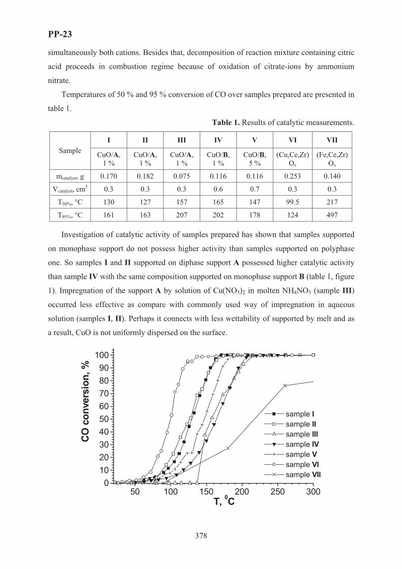
PP-23
378
simultaneously both cations. Besides that, decomposition of reaction mixture containing citric
acid proceeds in combustion regime because of oxidation of citrate-ions by ammonium
nitrate.
Temperatures of 50 % and 95 % conversion of �� over samples prepared are presented in
table 1.
Table 1. Results of catalytic measurements.
I II III IV V VI VII Sample �uO/A,
1 % �uO/A,
1 % �uO/A,
1 % �uO/B,
1 % �uO/B,
5 % (�u,�!,Zr)
Ox (Fe,Ce,Zr)
Ox
mcatalyst, g 0.170 0.182 0.075 0.116 0.116 0.253 0.140
Vcatalyst, cm3 0.3 0.3 0.3 0.6 0.7 0.3 0.3
�50%, °� 130 127 157 165 147 99.5 217
�95%, °� 161 163 207 202 178 124 497
Investigation of catalytic activity of samples prepared has shown that samples supported
on monophase support do not possess higher activity than samples supported on polyphase
one. So samples I and II supported on diphase support A possessed higher catalytic activity
than sample IV with the same composition supported on monophase support B (table 1, figure
1). Impregnation of the support A by solution of Cu(NO3)2 in molten NH4NO3 (sample III)
occurred less effective as compare with commonly used way of impregnation in aqueous
solution (samples I, II). Perhaps it connects with less wettability of supported by melt and as
a result, CuO is not uniformly dispersed on the surface.
50 100 150 200 250 3000
102030405060708090
100
sample I sample II sample III sample IV sample V sample VI sample VII
CO c
onve
rsio
n, %
T, 0C

PP-23
379
Fig. 1. Carbon monoxide oxidation over samples synthesized.
Sample VI demonstrated the highest catalytic activity (�50% = 99.5 °�). Perhaps it
connects with high catalytic activity of copper oxide clusters (distance Cu - Cu < 5 Å) that are
formed in CuO-ZrO2 system [5]. At the same time sample VII synthesized by the analogous
way demonstrated less catalytic activity (�50% = 217 °�). It can be explain by that
decomposition of Fe(NO3)3·9H2O to Fe2O3 proceeds near 100 °�. Therefore, zirconium and
cerium dioxides, which decompose at much higher temperature, precipitate on the surface of
Fe2O3 particles. This scheme is confirmed by that Fe2O3 from sample VII does not dissolve in
concentrated HNO3. So different distribution character of oxides CuO and Fe2O3 in samples
VI and VII accordingly is in good agreement with catalytic activity data.
Thus, oxide samples, which possess good catalytic activity in carbon monoxide oxidation
reaction, can be obtained by synthesis in molten NH4NO3 using microwave radiation. It was
shown that this new way of oxide synthesis permits to obtain pure products in short time.
The work was supported by the RFBR (grant 04-03-32734a).
1. Fukui K., Namai Y., Iwasawa Y. // Applied Surface Science. 2002. V. 188. P. 252-256.
2. Masui T., Ozaki T., Machida K., Adachi G. // Journal of Alloys and Compounds. 2000. V. 303-304. P. 49-55.
3. Pichinger S. // Topics in Catalysis. 2004. V. 30-31. P. 5-15.
4. Bernal S., Blanco G., Calvino J.J., Gatica J.M., Perez Omil J.A., Pintado J.M. // Topics in Catalysis. 2004. V. 28. P. 31-45.
5. Vasenin N.T., Fedorova A.A., Anufrienko V.F., Larina T.V., Morozov I.V., Paukshtis E.A., Ismagilov Z.R. // Russian Journal of Physical Chemistry. 2005. V. 79. 8. P. 1417-1423.

PP-24
380
FORMATION OF THE Pt(O)/Si(Ca)O2 NANOFIBERS UPON THE REACTION OF PLATINUM AEROSOL PARTICLES WITH A
CALCIUM- AND SILICON-CONTAINING MATERIAL
A.S. Ivanova, E.M. Slavinskaya, V.I. Zaikovskii, I.N. Polukhina, O.V. Chub, and A.S. Noskov
Boreskov Institute of Catalysis, Novosibirsk, Russia E-mail: [email protected]
1. Introduction
The high-temperature oxidation of ammonia carried out on platinum gauzes under
pressure [1] is accompanied by platinum evaporation and mechanical entrainment as aerosol
particles. To reduce the irretrievable loss of platinum, its particles are trapped, in particular,
by mounting a granular layer of refractory calcium oxide. The reaction of platinum and
platinum oxide vapors with CaO yields compounds like CaO PtO2, 3CaO PtO2, etc. A
macroscopic study of the surface of calcium oxide grains after trapping has shown that Pt
particles are located on the surface of the oxide grains and almost do not penetrate inside the
grains. To increase the efficiency of using CaO by increasing its surface area, it was proposed
[2] to apply CaO on a high-temperature silicon-containing material (glass fabric).
In this work, we studied the interaction between platinum aerosol particles formed
upon the oxidation of ammonia on a platinum catalyst and calcium oxide supported on a high-
temperature silicon-containing material (glass fabric) at about 900oC.
2. Experimental
The high-temperature oxidation of ammonia was carried out on model Pt-containing
catalysts (16--45% Pt/SiO2) with simultaneous capture of platinum aerosol particles by a
material (filter) containing 12--14 wt % CaO applied onto a glass fabric. Ammonia oxidation
proceeded in a flow-type reactor as follows: a reaction mixture containing 10 vol % ammonia,
14.6 vol % oxygen, and balance helium was passed through a Pt catalyst bed at a temperature of
900oC and a pressure of 2 atm for 1 to 5 h. The hot reaction gases formed traveled through a
filter layer. After the experiment, the reactor was cooled to room temperature in a helium flow.
The unloaded Pt-containing catalyst and the filter were analyzed by X-ray
fluorescence on VRA-30 analyzers using a Karl-Zeiss-Jena X-ray tube with a Cr anode; by
scanning electron microscopy on an REM-100U instrument (Selmi, Ukraine); and by high-

PP-24
381
resolution (0.14 nm) transmission electron microscopy (TEM) on a JEM-2010 instrument
(Jeol, Japan) coupled with energy dispersive X-ray microanalysis (EDX).
3. Results and discussion
According to scanning electron microscopy, the initial glass fabric is composed of
interlaced threads consisting of fibers 6.5 - 7 μm in diameter (Fig. 1a). In the thread structure,
the fibers are evenly arranged at distances of 3 - 4 μm from each other (Fig. 1a). After
application of CaO, the general pattern changes (Fig. 1b): the distance between the fibers
increases to 6 - 18 μm. This is due to the fact that calcium oxide penetrates both into the
thread fibers and between them (Fig. 1b). The CaO particles between the thread fibers are
distributed nonuniformly. In the sites with greater CaO concentration, aggregation of its
particles takes place to form larger agglomerates (Fig. 1b). The average diameter of the
smallest particle is 2 - 4 μm, that of the agglomerate is 9 - 17 μm.
a) b)
Fig.1. Images of (a) the initial glass fabric sample and (b) glass fabric with applied CaO.
In chemical reactor new material is
formed in process of ammonia oxidation at
900oC as a result of platinum evaporation from
model Pt- containing catalyst. To elucidate the
state of platinum on the filter, the filter was
examined under an electron microscope after the
reaction. High-resolution images show (Fig. 2a)
that CaO occurs on the glass fiber surface as
porous particles with a size of 20 - 70 nm;
simultaneously, crystalline rods (nanofibers)
about 50 nm in diameter and up to 1000 nm
high with different orientations of the growth axes can b e detected. The EDX spectrum of
Fig.2. TEM image of the filter: (a) silica nanofibers grown on the CaO/glass fabric surface; (b) EDX spectrum of nanofibers (the sites for the spectra were taken inside the circles).
�
Energy, keV
¸
�
Energy, keVEnergy, keV
¸
a
b
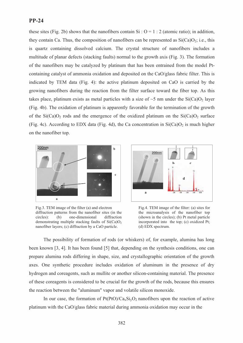
PP-24
382
these sites (Fig. 2b) shows that the nanofibers contain Si : O = 1 : 2 (atomic ratio); in addition,
they contain Ca. Thus, the composition of nanofibers can be represented as Si(Ca)O2; i.e., this
is quartz containing dissolved calcium. The crystal structure of nanofibers includes a
multitude of planar defects (stacking faults) normal to the growth axis (Fig. 3). The formation
of the nanofibers may be catalyzed by platinum that has been entrained from the model Pt-
containing catalyst of ammonia oxidation and deposited on the CaO/glass fabric filter. This is
indicated by TEM data (Fig. 4): the active platinum deposited on CaO is carried by the
growing nanofibers during the reaction from the filter surface toward the fiber top. As this
takes place, platinum exists as metal particles with a size of ~5 nm under the Si(Ca)O2 layer
(Fig. 4b). The oxidation of platinum is apparently favorable for the termination of the growth
of the Si(Ca)O2 rods and the emergence of the oxidized platinum on the Si(Ca)O2 surface
(Fig. 4c). According to EDX data (Fig. 4d), the Ca concentration in Si(Ca)O2 is much higher
on the nanofiber top.
The possibility of formation of rods (or whiskers) of, for example, alumina has long
been known [3, 4]. It has been found [5] that, depending on the synthesis conditions, one can
prepare alumina rods differing in shape, size, and crystallographic orientation of the growth
axes. One synthetic procedure includes oxidation of aluminum in the presence of dry
hydrogen and coreagents, such as mullite or another silicon-containing material. The presence
of these coreagents is considered to be crucial for the growth of the rods, because this ensures
the reaction between the "aluminum" vapor and volatile silicon monoxide.
In our case, the formation of Pt(PtO)/CaxSiyO2 nanofibers upon the reaction of active
platinum with the CaO/glass fabric material during ammonia oxidation may occur in the
�
¸
�
�
¸
�
a
b
c
¸ �
�
´
¸̧ ��
��
´
a
b c
d
Fig.4. TEM image of the filter: (a) sites for the microanalysis of the nanofiber top (shown in the circles); (b) Pt metal particle incorporated into the top; (c) oxidized Pt; (d) EDX spectrum.
Fig.3. TEM image of the filter (a) and electron diffraction patterns from the nanofiber sites (in the circles): (b) one-dimensional diffraction demonstrating multiple stacking faults of Si(Ca)O2 nanofiber layers; (c) diffraction by a CaO particle.
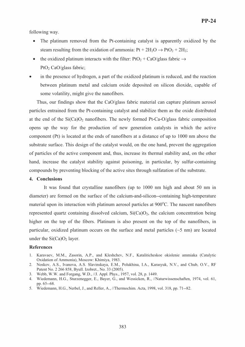
PP-24
383
following way.
• The platinum removed from the Pt-containing catalyst is apparently oxidized by the
steam resulting from the oxidation of ammonia: Pt + 2H2O → PtO2 + 2H2;
• the oxidized platinum interacts with the filter: PtO2 + CaO/glass fabric →
PtO2 CaO/glass fabric;
• in the presence of hydrogen, a part of the oxidized platinum is reduced, and the reaction
between platinum metal and calcium oxide deposited on silicon dioxide, capable of
some volatility, might give the nanofibers.
Thus, our findings show that the CaO/glass fabric material can capture platinum aerosol
particles entrained from the Pt-containing catalyst and stabilize them as the oxide distributed
at the end of the Si(Ca)O2 nanofibers. The newly formed Pt-Ca-O/glass fabric composition
opens up the way for the production of new generation catalysts in which the active
component (Pt) is located at the ends of nanofibers at a distance of up to 1000 nm above the
substrate surface. This design of the catalyst would, on the one hand, prevent the aggregation
of particles of the active component and, thus, increase its thermal stability and, on the other
hand, increase the catalyst stability against poisoning, in particular, by sulfur-containing
compounds by preventing blocking of the active sites through sulfatation of the substrate.
4. Conclusions
It was found that crystalline nanofibers (up to 1000 nm high and about 50 nm in
diameter) are formed on the surface of the calcium-and-silicon--containing high-temperature
material upon its interaction with platinum aerosol particles at 900oC. The nascent nanofibers
represented quartz containing dissolved calcium, Si(Ca)O2, the calcium concentration being
higher on the top of the fibers. Platinum is also present on the top of the nanofibers, in
particular, oxidized platinum occurs on the surface and metal particles (~5 nm) are located
under the Si(Ca)O2 layer.
References 1. Karavaev, M.M., Zasorin, A.P., and Kleshchev, N.F., Kataliticheskoe okislenie ammiaka (Catalytic
Oxidation of Ammonia), Moscow: Khimiya, 1983. 2. Noskov, A.S., Ivanova, A.S. Slavinskaya, E.M., Polukhina, I.A., Karasyuk, N.V., and Chub, O.V., RF
Patent No. 2 266 858, Byull. Izobret., No. 33 (2005). 3. Webb, W.W. and Forgang, W.D., //J. Appl. Phys., 1957, vol. 28, p. 1449. 4. Wiedemann, H.G., Sturzenegger, E., Bayer, G., and Wessicken, R., //Naturwissenschaften, 1974, vol. 61,
pp. 65--68. 5. Wiedemann, H.G., Nerbel, J., and Reller, A., //Thermochim. Acta, 1998, vol. 318, pp. 71--82.

PP-25
384
DESIGN OF THE TWO-STAGE AMMONIA OXIDATION CATALYTIC
SYSTEM FOR MEDIUM PRESSURE NITRIC ACID PLANTS
L.A. Isupova, I.A. Zolotarskii, N.A. Kulikovskaya, A.A. Marchuk,
E.F. Sutormina, V.A. Sadykov, A.S. Noskov
Boreskov Institute of Catalysis SB RAS, pr. Lavrentieva, 5, Novosibirsk, Russia, 630090
Ammonia oxidation process in nitric acid production (4NH3 + 5O2 �4NO + 6H2O) is
realized on Pt gauzes. There are three types of ammonia oxidation reactors working under
atmospheric, medium and high pressure, their operation conditions are presented in the Table 1.
Table 1. Industrial operation conditions for ammonia oxidation process
Pressure Temperature of Gauses, oC
NH3 content, vol.%
NO yield, % Pt loss, g/t HNO3 Operating time, month
Atmospheric 810-850 11-12 97-98 0.04-0.05 10-12 Medium, 3-5Bar 850-890 10-11 95.0-96.5 0.10-0.11 5-6 High, 7-11 Bar 900-940 10-11 92-95 0.15-0.30 3-4
Due to high temperature operation conditions, Pt losses occur (Table 1). At that, the last
gauzes in the catalyst layer polish ammonia conversion while still lose a sound portion of
noble metals. Therefore, an idea to replace them by less expensive oxide catalyst is evident.
In 1960th the two stage catalytic system (1 gauze + layer of palletized oxide catalyst) was
developed by GIAP for normal pressure plants [1]. For medium and high pressure plants
honeycomb catalysts seem to be more attractive providing uniformity of gas flow, low
pressure drop and low dust formation. Boreskov Institute of Catalysis has developed the iron
oxide based honeycomb catalyst BIC-42-1 in 1990th [2,3]. This catalyst has found wide
application in high pressure UKL-7 plants. It is shaped as a 70x70x50 mm monolith with
square cannels (5x5 mm) and wall thickness 1.8-2.2 mm. Its application results in 25-30%
saving in gauzes loading and 15-20% reduction of Pt losses at near the same product yield and
longer gauzes life time [4]. However, as it will be shown below, its application for medium
pressure plants is questionable due to its geometry.
Mathematical modelling of a two-stage catalytic system consisting of different numbers of
Pt gauzes and honeycomb catalyst layers of different geometry was performed at conditions
corresponding to the ammonia oxidation reactor of the typical Russian medium pressure plant
AK-72 (operation pressure – 3.5 Bar). This reactor is loaded by 7 woven Pt gauzes with an
PP-25
385
initial fibre diameter of 0.092 mm traditionally. The mathematical model applied presumes
mass transfer limitation of the reaction both on Pt gauzes and a honeycomb catalyst.
Calculations show that ammonia conversion reaches 98.8% when a standard catalytic
system with 7 sheets is used. The aim of calculations was to find out a configuration of a
honeycomb catalyst bed when 3 sheets of Pt gauzes are removed. Table 2 shows calculation
results for 3 types of a honeycomb catalyst.
Table 2. Ammonia conversion for different configuration of a honeycomb catalyst bed.
Number of channels per square inch: I – 15, II – 30, III – 200. Height of one layer – 50 mm.
Number of honeycomb catalyst layers Type of catalyst
1 2 3
I 96.9 98.1 98.8
II 97.7 99.0 99.6
III 98.6 99.6 99.9
One can see that a two-stage catalytic system comprising 4 Pt gauzes and 2 layers of the
catalyst III or 3 layers of the catalyst II provides ammonia conversion higher than a standard
Pt system. Such system can be applied in industry if the oxide honeycomb catalyst meets the
following requirements:
– high activity;
– high selectivity;
– robustness in operation conditions (strength and resistance to thermoshocks);
– manufacturability.
It is hardly possible to fulfill these requirements, especially thermoshock resistance, for a
bulk iron oxide based honeycomb monolith catalyst with cell density corresponding to
catalyst II and III because of its rather high thermal expansion coefficient (TEC). Therefore, a
comprehensive study of different catalytic materials was carried out. The frame structured
cordierite (2MgOx2Al2O3x5SiO2) honeycombs are characterized by the low TEC (2*10-6
1/K) and often used as a refractory carrier for high temperature catalyst applications [5].
Results of this study for impregnated on cordierite catalyst including results of a life test in
real operation conditions were published in [6].
This paper presents results of ammonia oxidation process study for another kind of
catalytic materials – cordierite-like frame structured ones.
A frame structure allows to obtain modified materials with 3d active cations (Fe, Co, Mn)
instead of Mg, that may be active in ammonia oxidation. Meanwhile frame structured
materials can be directly shaped as monoliths.

PP-25
386
Therefore, this paper deals with investigation of ammonia oxidation process with
modified frame structured honeycomb monoliths. A draw plate used for monoliths
preparation had a triangle channel side of 2.5 mm and wall thickness of 0.4 mm that gives
approximately 200 channels per square inch. Monolith height was 50 mm. Three types of
honeycomb catalysts with Co, Fe and Mn cations (2CoOx2Al2O3x5SiO2,
2FeOx2Al2O3x5SiO2, MnOx2Al2O3x5SiO2) were prepared.
Ammonia oxidation process was carried out in a bench scale quartz tubular reactor with
inner diameter of 26 mm at temperature 700-900 oC and atmospheric pressure. Samples of
honeycomb catalysts in the form of fragments with diameter of 21-22 mm and length of 50
mm were tested with and without one Pt sheet. Before the reaction starts up, catalysts were
preheated at 700 oC in air for 30 minutes. Then reaction gazes (5% ammonia in the air
preheated at 450oC in a quartz mixer) were flowed through the catalyst with 7.6 l/min flow
rate (standard gas velocity 0.33 m/s). The ignition of the catalyst was determined by
temperature increase. Ammonia, NO and NO2 concentrations were analyzed by the on-line
spectrophotometer analysis [6, 7].
All such prepared catalysts provide 100 % ammonia conversion degree even without Pt
gauzes at temperature higher 850 oC. The two-stage system (with one Pt gauze) provides NO
yield higher than 94%. 2FeOx2Al2O3x5SiO2 and MnOx2Al2O3x5SiO2 frame structured
catalysts (BIC-42-4) was shown not to be deactivated after living tests in UKL-7 plant as
compared with supported catalysts.
References 1. M.M. Karavaev, A.P. Zasorin, N.F. Klesev. Catalytic oxidation of ammonia. Moskow, Khimiya, 1983.232
c.(In Russian)
2. V.A. Sadykov, E.A. Brushtein, L.A. Isupova, et al. Khimicheskaya promyshlennost’, No 12 (1997) 33 (In Russian).
3. V.A. Sadykov, L.A. Isupova, I.A. Zolotarskii et al. Applied Catalysis A: General 204 (2000) 59.
4. V.I. Chernyshev, E.A. Brushtein, Cataliz v Promyshlennosti (Catalysis in Industry), 3 (2001) 30 (in Russian).
5. E.G. Avakumov, A.A. Gusev. Kordierite- advanced ceramic material. Novosibirsk, SB RAS, 1999 166c
6. L. A. Isupova, E.F. Sutormina, N.A. Kulikovskaya, L.M. Plyasova, N.A.Rudina, I.A. Ovsyannikova, I.A. Zolotarskii, V.A. Sadykov Catalysis.Today105(2005) 436.
7. Á. F. Sutormina, Zurnal Analiticheskoi Khimii (J. Analytic Chem.) 59/4 (2004) 1 (In Russian).
PP-26
387
PtNi CATALYSTS FOR DRY REFORMING OF METHANE
S. Damyanova1, K. Arishtirova1, B. Pawelec2, J.L.G. Fierro2, L. Petrov1
1 Institute of Catalysis, Bulgarian Academy of Sciences, 1113 Sofia, Bulgaria 2 Instituto de Catalis y Petroleoquimica, CSIS, Cantoblanco, 28049 Madrid, Spain
Fax: 359 2 9712967, E-mail: [email protected]
Introduction
Hydrogen offers a potentially non-polluting, inexhaustible, efficient, and cost attractive
fuel for energy demands. Hydrogen is the “fuel of the future”. However, the use of hydrogen
as a fuel depends on how it is produced. Of all the potential sources of hydrogen, natural gas
offers many advantages. The main processes used to transform natural gas to hydrogen are:
steam reforming, dry reforming, partial oxidation and autothermal reforming of methane.
The catalytic reforming of methane with carbon dioxide (CH4 + CO2 → 2CO + 2H2) has
several advantages compared to other methane reforming reactions, such as: (i) production of
low H2/CO ratio, suitable for synthesis gas; (ii) providing a practical method for consumption
of the both greenhouse gases (CH4 and CO2); (iii) opportunity for combination with steam
reforming and/or partial oxidation of methane, etc. [1, 2].
Unfortunately, no industrial technology for CO2 reforming of methane has yet been
developed, because no effective, economic catalysts have been discovered. One of the main
problems for the preparation of effective reforming catalysts is the prevention of coke
formation. The parameters responsible to enhance the catalytic performances of the catalysts
include the kind of the components and their concentration, type of the support, temperature
of reaction.
The subject of this work is to develop new effective Ni-containing catalysts supported on
a suitable support and modified with a small amount of noble metal that can result in a non-
expensive bimetallic supported system assuring both high activity of catalyst for hydrogen
production and low carbon deposition. The effect of the method of preparation and of the ratio
Ni/noble metal on the surface and catalytic properties of the nickel-based catalysts in the
process of dry reforming was investigated.
Experimental
Zeolite-supported Ni-containing catalysts modified with Pt were prepared by sequential
impregnation and co-impregnation techniques using aqueous precursor solutions of

PP-26
388
Ni(NO3)2.6H2O and solution of H2PtCl6.6H2O in ethanol. Zeolite ZMS-5 was used as carrier.
After impregnation the samples were dried at 384 K and calcined at 823 K. The amount of Pt
was 0.5 or 0.3 wt%. The amount of Ni was in the range of 1-12 wt%.
The samples were characterized X-ray diffraction (XRD), temperature-programmed
reduction (TPR), infrared spectroscopy (IR) and by SBET method. The catalytic properties of
the catalysts were evaluated in the reaction of reforming of methane with CO2 at 773 K.
Results and discussion
The textural properties of bimetallic PtNi samples presented in Table 1 show that the SBET
surface area and pore volume decrease with increase of Ni content, which is caused by the
plugging of the pores with nickel oxide particles. There was no influence of the presence of Pt
on the textural properties of the samples. However, the method of preparation influences the
change of SBET and pore volume; the PtNi sample prepared by co-impregnation shows higher
SBET and pore volume compared to those of the sample prepared by consecutive impregnation
method.
Table 1. Textural properties of zeolite-supported PtNi samples
Samples SBETm2/g
Pore Volume cm3/g
DXRD, NiO nm
H2/CO
ZSM-5 401 0.66 - - Pt1Ni 389 0.61 - 0.4 Pt3Ni 374 0.61 - 0.4 Pt6Ni 345 0.49 8.7 0.9 Pt12Ni 335 0.50 11.1 0.6 0.3Pt6Ni 367 0.55 9.7 0.7 Pt6Ni-co 367 0.55 10.3 0.6 6Ni 341 0.53 11.1 0.2 Pt 399 0.62 - 0.4
The IR spectra showed no change in the structure of zeolite framework of the supported
samples.
XRD patterns of bimetallic zeolite-supported PtNi samples with Ni loading ≤ 3 wt% did
not show any diffraction peak of NiO phase that means that NiO is in amorphous state.
Diffraction peaks of NiO at 2θ=43.8° were detected in the spectra of the samples with higher
Ni content of 6 and 12 wt% Ni. The latter is confirmed by the change of the values of the
calculated particle size of NiO phase based on the diffraction peak broadening (Table 1); the
size of NiO increases from 8.7 to 11.1 nm for samples with 6 and 12 wt%, respectively. No
diffraction peaks due to formation of platinum oxide species were observed for all calcined
samples, that means well dispersed Pt on the surface of PtNi catalysts.

PP-26
389
The TPR results demonstrated that the reducibility of supported Ni species depends on the
amount of nickel, method of preparation and the presence of Pt. The hydrogen consumption
for supported samples increased with increasing the agglomeration of NiO. The PtNi sample
prepared by co-impregnation showed TPR peak at temperature of 689 K, which is higher
compared to that for samples prepared by consecutive impregnation. The effect of the
presence of Pt in Ni catalysts was revealed by easy reduction of NiO.
It was clear that the addition of small amount of Pt in Ni catalysts led to increasing of the
catalytic activity in the reaction of reforming of CH4 with CO2 at 773 K and CH4:CO2=1.
With exception of the Ni/zeolite catalyst all catalysts showed high stability. The ratio H2/CO
was lower than one for all catalysts. The values of CO2 conversion were higher than those of
CH4 conversion as a consequence of the participation of the reverse of water-gas shift
reaction. The reason for the lowest activity of the low-loaded Ni samples was related to less
accessible metal surface area. The highest activity for zeolite-supported Pt6Ni catalyst was
connected with the existence of interaction between Pt and Ni revealed by XPS data.
Conclusions
The presence of small amount of noble metal (Pt) in zeolite-supported Ni catalysts leads to: (i)
formation of nano-sized NiO particles; (ii) better dispersion of NiO particles and (iii) easy
reduction of nickel species. The obtained bimetallic PtNi catalysts are good catalysts for
hydrogen production by the process of methane reforming with CO2.
Acknowledgments. The financial support of the project between the National Council of
Scientific Research (CSIC), Spain and Bulgarian Academy of Sciences is gratefully
acknowledged. The authors acknowledge financial support by project No X-1515/05 from
National Science Fund at the Bulgarian Ministry of Education and Science.
References 1. S.M. Gheno, S. Damyanova, B.A. Riguetto, C.M.P.Marques, C.A.P. Leite, J.M.C. Bueno, Mol. Catal.A: Gen. 198 (2003) 263.
2. S. Damyanova, J.M.C. Bueno, Appl. Catal. A: Gen. 253 (2003) 135.

PP-27
390
EFFECT OF H2O ON ABSORPTION OF FLUE GAS SO2
OVER A CuO/γ-Al2O3 CATALYST – A MICRO-KINETICS STUDY
Zhehua Jia, Zhenyu Liu, Youhua Zhao, Jianli Yang
State Key Laboratory of Coal Conversion, Institute of Coal Chemistry
Chinese Academy of Sciences, Taiyuan, Shanxi 030001, P.R. China
[email protected] Fax: +86-351-4048571
Introduction
CuO/γ-Al2O3 has been studied for simultaneous removal of SO2 and NOx from flue gases
emitted from stationary sources [1-4]. The adsorption characteristics of SO2 over CuO/
γ-Al2O3 are of importance to the overall performance and have been studied mostly in water-
free conditions[3,4], However, flue gases always contain some amount of H2O, 2-18%, and
the presence of H2O may affect the behavior of SO2 adsorption on this catalyst-sorbent.
Therefore, understanding of SO2 adsorption behavior of CuO/γ-Al2O3 in the presence of H2O
is fundamental and important.
In this work, effect of H2O on SO2 adsorption behavior of CuO/γ-Al2O3 is studied. Before
the study being made, the catalyst-sorbent are subjected to SO2 removal and NH3-
regeneration to simulate a continued SO2 removal process where the adsorbed SO2 is
converted to ammonium-sulfur salts by regeneration in NH3. The micro-kinetics study
performed include a surface-coverage model and a non-ideal adsorption model.
Experimental
The SO2 removal experiments are performed in a thermogravimetric analyzer (Setaram
TGA92). The CuO/γ-Al2O3 (containing 8wt% CuO and termed R-CuO/γ-Al2O3) is prepared
by heating up a SO2-adsorbed CuO/γ-Al2O3 to 400oC in 5 vol% NH3/Ar in a fixed bed reactor.
The TGA tests use 3~5 mg of R-CuO/γ-Al2O3 and are carried out at a total flue gas flow of
400 ml/min. The flue gas contains 3000ppm SO2, 5% O2, various amounts of H2O and
balance Ar. H2O vapor is fed to the TGA by passing an Ar stream through a temperature-
controlled gas-wash bottle containing de-ionized water.

PP-27
391
Results and discussion
Effect of H2O concentration on SO2 adsorption over the R-CuO/γ-Al2O3
The SO2 removal from the gas phase is accomplished by reacting the gaseous SO2 with
CuO in the presence of O2 to form CuSO4, during which the weight of R-CuO/γ-Al2O3
increases. Figure 1 shows the weight increase in R-CuO/γ-Al2O3 during SO2 removal at
various H2O concentrations. The SO2 adsorption rate and the maximum SO2 adsorption
capacity increase with increasing H2O concentration in the H2O concentration range of 0-10%,
at a H2O concentration of 20%, however, the SO2 adsorption rate and the maximum SO2
adsorption capacity are significantly lower. These behaviors seem to suggest that the effect of
H2O on the SO2 adsorption at high H2O contents follows a different mechanism compared to
that at low H2O contents. It is likely that the promoting effect of H2O at the low H2O contents
results from increased oxidation activity of R-CuO/γ-Al2O3, and the reduced SO2 adsorption
at H2O content of 20% results from high coverage of H2O over R-CuO/γ-Al2O3 surface,
which reduces the rates of SO2 and O2 adsorption, but these suggestions need to be verified.
0 10 20 30 40 50 600.00
0.02
0.04
0.06
0.08
0.10
Wei
ght C
hang
e
Time(min)
H2O 0%2.5% 5% 10% 15% 20%
Figure 1. Weight increase in R-CuO/γ-Al2O3 during SO2 adsorption at 400oCat various flue gas H2O concentrations
Kinetics analysis using the surface coverage model
For water-free conditions the surface coverage model has been used to study the kinetics,
which assumes that the SO2 adsorption rate is controlled by surface chemical reaction and the
reaction takes place only on the active sites which are not covered by product. This model is
used here as the first step to correlate the data. Equation (1) is the form of the model:
( )tkktkX 211 5.01+= (1)
where, X is defined as 0max
0
WWWW
X t
−−
= , 0W , maxW and tW are weight of R-CuO/γ-Al2O3 before
the SO2 adsorption, at the maximum SO2 adsorption and at reaction time t , respectively. The
rate constant 1k represents SO2 oxidation and adsorption activities, and is a function of the

PP-27
392
reactants (gas and solid) concentration and temperature; 2k is a function of solid reactants
concentration and temperature. In the presence of H2O, 1k may be expended to include the
H2O concentration.
The fitting of the experimental data to Equation (1), shown in Figure 2, indicates that the
experimental data at H2O concentrations of 0%, 2.5%and 5% are well represented by the
model, and the value of 1k increases with increasing H2O concentration. But the fitting
increasingly deviates from the data when the H2O concentration is increased further to 10%
and 20%. This seems to suggest that the SO2 adsorption is no longer controlled by the surface
reaction, and changes in surface texture may have occurred at the high H2O concentrations.
0 10 20 30 40 50 60
0.0
0.2
0.4
0.6
0.8
1.0
Con
vers
ion(
X)
Time(min)
H2O 0% 2.5% 5% 10% 20%
Figure 2. Fitting of the surface coverage model to the experimental data
Kinetics analysis using a non-ideal adsorption model
To account for the inability of the surface coverage model, a non-ideal adsorption model
is used to fit the experimental data, and the fitting results are shown in Figure 3. The non-
ideal adsorption model assumes that the adsorption of SO2 on the surface is the rate-
controlling step, and the active sites on the surface are different and interacts to each other.
0 10 20 30 40 50 60
0.0
0.2
0.4
0.6
0.8
1.0
Con
vers
ion(
X)
Time(min)
H2O 0% 2.5% 5%10% 20%
Figure 3. Fitting of the non-ideal adsorption model to the experimental data

PP-27
393
In the nonideal adsorption model, the adsorption rate of SO2 is expressed as[5]:
( ) ( )tst XgXkyr −−= exp1 (2)
where, Xt can be expressed by the the solid-phase balance:
MSrdt
dXes
t υ= (3)
Introduction of Equation (2) into Equation (3) yields:
( ) ( )� −−=
tX
tst
t
e XgXkydX
MSt
0 exp11
υ (4)
Figure 3 show the fitting results of Equation (4) to the experimental data. Apparently, this
model is suitable to the data of high H2O concentrations. Dependence of the parameters in the
model to the H2O concentration and the chemical nature of the kinetics are to be discussed in
the conference.
Conclusion
Micro-kinetics of SO2 adsorption over a NH3-regenerated CuO/γ-Al2O3 in the presence of
H2O is firstly studied. H2O promotes SO2 adsorption at H2O concentrations of 15% or below,
but inhibits SO2 adsorption at H2O concentrations of 20%. The surface-coverage model used
for H2O-free conditions fits the data well for H2O content of less than 10%. A non-ideal
adsorption model however is suitable for the data of high H2O concentrations. The study
suggests that the effect of H2O on the SO2 adsorption over CuO/γ-Al2O3 follows different
mechanisms at low and high H2O concentrations.
Acknowledgments
The authors express thanks for financial support to the Natural Science Foundation of
China (90210034).
References [1] Yeh, J.T.; Drummond,C.J.; Joabert, J.I. Process Simulation of the Fluidized-Bed Copper-Oxide Process
Sulfation Reaction. Envi-ron.Prog. 1987, 6, 44.
[2] Waqif, M.; Saur, D.; Lavalley,J.C.; Perathoner, S.; Centi, G. Nature and Mechanism of Formation of Sulfate Species on Copper/Alumina Sorbent-Catalyst for SO2 Removal. J.Phy.Chem. 1991, 95, 4051.
[3] Centi,G.; Passarini, N.; Perathoner,S.; Riva,A. Combined DeSOx/DeSOx Reactions on a copper on Alumina Sorbent-Catalyst. 1. Mechanism of SO2 Oxidation-Adsorption. Ind. Eng. Chem. Res.1992, 31, 1947.
[4] Centi,G.; Passarini, N.; Perathoner,S.; Riva,A. Combined DeSOx/DeSOx Reactions on a copper on Alumina Sorbent-Catalyst. 2. Kinetics of the DeSOx reaction.Ind. Eng. Chem. Res.1992, 31, 1956.
[5] Murzin,D.Y.; Modeling of adsorption and kinetics in catalysis over induced nonuniform surfaces. Ind. Eng. Chem. Res. 34, 1208-1218.

PP-28
394
SCR OF NO OVER A HONEYCOMB CuO/Al2O3/CORDIERITE –
EFFECT OF AMMONIA PRETREATMENT ON Al2O3 COATING AND
SCR ACTIVITY
Junhua Su, Zhenyu Liu, Xiaohang Zhang, Qingya Liu
State Key Laboratory of Coal Conversion, Institute of Coal Chemistry
Chinese Academy of Sciences, Taiyuan, 030001 P.R. China
[email protected] , Fax: +86-351-4048571
Introduction
Selective catalytic reduction (SCR) of NO with ammonia is an effective approach to solve
stationary NOX emission problems. Vanadium oxide supported on honeycomb TiO2 is the
current state of art for such a purpose [1, 2]. However, this catalyst is of high cost, which
hampers its broader application. Low cost catalysts are therefore widely studied. CuO/Al2O3
has been reported to be an alternative, which is active for the SCR at 400°C [3]. Since packing
of the pellet type CuO/Al2O3 catalyst in a fixed-bed reactor causes high flow resistance and
plugging problems due to trapping of particulates in flue gas, honeycomb type CuO/Al2O3 is
also preferred. One of the methods that have been used in preparing honeycomb CuO/Al2O3 is
to support CuO over an Al2O3 coated cordierite honeycomb. The literature shows that the SCR
activity and stability of this type of catalyst are strongly affected by the amount and type of
Al2O3 coatings [4]. In this works, we report a new method for coating of Al2O3, which involves
pre-treatment of a cordierite with ammonia. This new approach significantly increases the
amount of Al2O3 loaded over the cordierite but results in lower SCR activity.
Experimental
Preparation of the catalysts
The honeycomb cordierite used in this work is a commercial product with a cell density of
200 cells per square inch (cpsi) and a BET surface area of 0.7 m2/g. It is treated with oxalic
acid [5] (marked CHC) to increase its surface area to 164 m2/g before been used. The alumina

PP-28
395
sols used for coating are prepared by pseudo-boehmite (known as SB powder commercially)
and nitric acid.
Two preparation methods are used. In one case CHC is directly dipped into the alumina sol
for a certain period of time and then subjected to drying and/or calcinations (marked SB). In
another case CHC is treated in ammonia (pH=11.6) for 5s before being dipped into the alumina
sol (marked SB-NH3). These two samples obtained are then impregnated with a cupric nitrite
solution and then dried and calcined to yield catalysts with a Cu loading of about 1wt%. The
catalysts prepared are named Cu1/SB and Cu1/SB-NH3, respectively. Catalyst activity measurement
The SCR activity measurements are carried out in a fixed-bed reactor (0.02m i.d.) system.
When the system reaches steady state at a desired temperature, a feed containing 1600 ppm
SO2, 600ppm NO, 600 ppm NH3, 5.0% O2, 2.5% H2O and balance N2 are introduced into the
reactor. In all the runs, the total flow rate is maintained at 450 ml/min, corresponding to a
superficial space velocity of 7800 h-1. The concentrations of NO, SO2 and O2 in the reactor
outlet are measured online with a flue gas analyzer (KM96006, Germany).
Results and discussion
Figure 1 shows the amounts of Al2O3 loaded onto CHC by the two methods. Clearly the
ammonia pretreatment significantly increases the Al2O3 loading. This phenomenon may be
attributed to changes in surface acidity/basicity of CHC. Since CHC is obtained by oxalic acid
treatment of the cordierite, its surface is acidic; the ammonia treatment however makes the
surface basic. This surface basicity certainly would result in strong interaction with the weakly
acidic alumina sol SB, and increase the Al2O3 loading.
The SCR activity of the catalysts prepared, Cu1/SB and Cu1/SB-NH3, are shown in Figure 2.
It is rather surprise to see that Cu1/SB, with a smaller amount of Al2O3, shows higher SCR
activities than Cu1/SB-NH3, with a larger amount of Al2O3, does.
Further studies using TPR indicate that Cu1/SB-NH3 is more difficult to be reduced in H2
than Cu1/SB, and this difference is not resulted from difference in Al2O3 loading. NH3
oxidation experiments show that Cu1/SB-NH3 produces significantly more NO and less N2
than Cu1/SB does at the SCR temperatures.

PP-28
396
SB SB-NH30
1
2
3
4
5
6
7Th
e Al
2O3 l
oadi
ng(%
)
The Samples
Figure1. The Al2O3 loading of SB and SB-NH3
0 2 4 6 850
60
70
80
90
100
NO
con
vers
ion(
%)
Time on stream(h)
Cu1/SB Cu1/SB-NH3
Figure2. The SCR activity of Cu1/SB and Cu1/SB-NH3
Conclusion
NH3-pretreatment to a cordierite honeycomb significantly increases the amounts of Al2O3
coated from an acidic SB alumina sol. The catalyst prepared, however, shows low SCR activity
towards NO reduction, which is due mainly to the over oxidation of NH3 to NO.
Acknowledgments
The work is financial support by the Natural Science Foundation of China (90210034).
References 1 C. J. Pereira, K. W. Phumlee, Grace Camet® metal monolith catalytic emission control technologies, Catal.
Today, 13(1992): 23-32. 2 J. Svachula, N. Ferlazzo, P. Forzatti, E. Tronconi, F. Bregani, Selective reduction of nitrogen oxides (NOx) by
ammonia over honeycomb selective catalytic reduction catalysts, Ind. Eng. Chem. Res., 32(1993): 1053-1060. 3 G. Xie, Z. Liu, Z. Zhu, Q. Liu, Simultaneous removal of SO2 and NOx from flue gas using a CuO/Al2O3
catalyst sorbent II. Promotion of SCR activity by SO2 at high temperature, J. Catal., .224(2004): 36-41. 4 Q. Liu, Z. Liu, Preparation and performance of cordierite honeycomb based CuO/Al2O3 for SO2 and NO
removal from flue gas, Doctor Paper 62 (2004) 5 Q. Liu, Z. Liu, Z. Huang, Catal. Today, 93-95(2004): 833-837.

PP-29
397
PRODUCTION OF ELEMENTAL SULFUR BY H2-REGENERATION
OF SO2-ADSORBED CuO/Al2O3
Youhua Zhao, Zhenyu Liu, Zhehua Jia, Jianli Yang
State Key Laboratory of Coal Conversion, Institute of Coal Chemistry
Chinese Academy of Sciences, Taiyuan, 030001, P.R. China
[email protected], Fax: +86-351-4048571
Introduction
As an effective catalyst-sorbent for SO2 removal or simultaneously SO2 and NOx removal
from flue gas, CuO/Al2O3 has been studied since 1970s [1-3]. The process consists of three
stages, SO2 adsorption from flue gas or sulfation, regeneration of the SO2-saturated
CuO/Al2O3 and sulfur recovery into marketable products. In the Shell process, both sulfation
and regeneration are carried out at 400oC [1]. The regeneration yields concentrated SO2 gas,
which is further treated in another unit. Reduction of SO2 to elemental sulfur by hydrogen is
regarded to be a better choice compared to other options for sulfur recovery [4-6]. However,
the requirement of additional catalyst and reactor for such a purpose results in increased cost.
Carrying out the three operation stages in one unit certainly will result in significant cost
reduction. To achieve such a goal, new catalyst-sorbent and reactor strategy need to be
developed which are capable of removing (adsorb) SO2 in flue gas in one operation mode and
reducing the SO2 released during H2-regeneration to form elemental sulfur in another
operation mode. Here, we report recent work on such a process which uses CuO/Al2O3 as the
catalyst-sorbent. Effects of regeneration temperature and H2 feed strategy on elemental sulfur
yield and SO2 removal capacity are mainly discussed.
1. Experimental
A commercial �-Al2O3, 30-60 mesh with a BET surface area of 200 m2/g, is impregnated
with an aqueous Cu(NO3)2⋅3H2O solution and subjected to drying at 110oC for 8 h and
calcination at 500oC for 8 h to yield a CuO loading of 8.0 wt.%.
The reactor configuration is shown in Figure 1. A flue gas containing 2200 ppm SO2, 6%
O2 and balance N2 is introduced into the fixed-bed reactor for sulfation of CuO/Al2O3 at
400oC. Upon SO2 saturation of the catalyst-sorbent the reactor is purged with N2 and then

PP-29
398
switched to H2 to initiate the H2-regenration and elemental sulfur production processes. The
effluent gas is cooled in a cold trap to collect elemental sulfur formed, and the rest of the gas
is recycled back to the reactor. This process is carried out in two modes, a continuous H2 feed
mode (C) and an intermittent H2 feed mode (I). Changes in the gas composition in the system
are monitored on-line by mass-quadrupole detector (OmmiStar 200, Blazers).
Figure 1. Experimental apparatus
Elemental sulfur yield Y is defined as MmY 100= , where m is the mass of elemental
sulfur collected and M the total amount of sulfur generated from the regeneration.
2. Results and discussion
Effect of regeneration temperature
Figure 2 shows elemental sulfur formation at various regeneration temperatures on
operation mode C. It can be seen that no elemental sulfur is collected at regeneration
temperatures of lower than 350oC, but in the regeneration temperature range of 350-440oC the
elemental sulfur collected increases with increasing temperature, corresponding to elemental
sulfur yields of 55-90%. These data indicate that the process works well, which is capable to
desorb SO2 from the catalyst-sorbent and then reduce the released SO2 to elemental sulfur.
The optimum regeneration temperature is 420oC or higher.
Another purpose of the H2-regeneration is to restore the catalyst-sorbent’s activity for SO2
adsorption in the subsequent cycles. Figure 3 shows the effect of H2-regeneration temperature
on the SO2 adsorption capacity at 400oC. Apparently, H2-regeneration of the SO2-adsorbed
catalyst-sorbents is not very effective at temperatures of 420oC or lower, which results in SO2
adsorption capacities less than that obtained at higher temperatures. These observations
correlate well with the elemental sulfur yield data shown in Figure 2.

PP-29
399
320 340 360 380 400 420 440 46002468
1012141618 320 340 360 380 400 420 440 4600
102030405060708090
Regeneration Temperature (oC)
Sulfu
r Mas
s (m
g/gc
at.)
Sulfu
r Yie
ld (%
)
Figure 2. Effect of regeneration temperature on sulfur yield
320 340 360 380 400 420 440 4600
5
10
15
20
25
30
35
40
SO2 R
emov
al C
apac
ity (m
gSO
2/gca
t.)
Regeneration Temperature (oC)
Figure 3. Effect of regeneration temperature on SO2 removal capacity
Effect of H2 feed strategy
Since the whole H2-regeneration process may involve desorption of sulfur species from the
catalyst-sorbent to form gaseous SO2, reduction of some amounts of SO2 by H2 to form H2S,
and reaction of the H2S with the rest of SO2 to form elemental sulfur, the amounts of H2 fed
into the reactor is a very important operation parameter, which affects the H2S/SO2 ratio and
the yield of elemental sulfur. Figure 4 shows the elemental sulfur yields obtained from
operation modes C and I at a H2-regeneration temperature of 400oC. It can be seen that the
intermittent H2 feed mode (filled symbol) yields better results than the continuous H2 feed
mode (open symbol) does and the catalyst-sorbent has a good stability for elemental sulfur
formation.

PP-29
400
1 2 3 4 570
80
90
100
Contineous mode CIntermittent mode I
Sulfu
r Yie
ld (%
)
Cycles
Figure 4. Effect of H2 feed strategy on elemental sulfur yield, 400oC
3. Conclusions
CuO/Al2O3 catalyst-sorbent can be used for flue gas SO2 removal and elemental sulfur
production if H2-regeneration is used and the effluent gas from the regeneration operation is
recycled back to the reactor. Temperatures greater than 420oC are necessary for high
elemental sulfur yield and high SO2 removal capacity. Elemental sulfur yield of greater than
90% can be obtained if the H2-regeneration temperature and H2 feed strategy are properly
selected. Intermittent H2 feed mode shows better results than continuous H2 feed mode.
Acknowledgements
The authors express their grateful appreciation to financial support from the Natural Science
Foundation of China (90210034).
References [1] F.M. Dautzanberg J.E. Nader and A.J. van Ginneken, Chem. Eng. Prog. 67 (1971) 86. [2] P.S. Lowell, K. Schwitzgebel, T.B. Parsons and K.J. Sladek, Ind. Eng. Chem. Process Des. Dev. 10 (1971) 384. [3] D.H. McCrea, A.J. Forney and J.G. Myers, J. Air Pollut. Control Assoc. 20 (1970) 819. [4] T.F. Doumani, R.F. Deery and W.E. Bradley, Ind. Eng. Chem. 36 (1944) 329. [5] S.C. Paik and J.S. Chung, Appl. Catal. B 5 (1995) 233. [6] S.C. Paik and J.S. Chung, Appl. Catal. B 8 (1996) 267.

PP-30
401
EXPERIMENTATION IN INDUSTRIAL HYDROTREATMENT
REACTOR WITH APPLICATION OF ARTIFICIAL INTELLIGENCE
FOR SELECTION OF CATALYSTS WITH DESIRED
PHYSICO-CHEMICAL PROPERTIES
F. Jiménez1, V. Kafarov1, M. Nuñez2
1Industrial University of Santander, Kra. 27 Calle 9, Bucaramanga, Colombia
Tel. +57 +76344746, Fax +57 +76344684, E-mail: [email protected] Petroleum Institute –ICP, Piedecuesta, Colombia
Abstract
The complexity of heterogeneous catalytic systems doesn’t allow, nowadays, forecasting the
catalytic activity for the hydrotreatment processes based on rigorous laws of heterogeneous
catalysis, expressed in quantitative form. In this paper is presented a strategy for prediction of
the catalytic activity based on a combination of computational tools such as Artificial Neural
Networks (ANN), Fuzzy Logic, traditional and non traditional statistic regression methods
with an industrial experimental methodology developed by the Colombian Petroleum
Institute, based on aging of catalysts with different textural and chemical properties, inside
industrial reactor during the normal length of the run. The methodology was validated for
twenty four different hydrotreatment catalysts.
Introduction and Proposed Methodology
The strategic methodology developed to selection catalysts with desired physic-chemical
properties is presented in Figure 1. Twenty four fresh hydrodemetallation catalysts samples
were tested during the investigation. Six physic-chemical properties were measures: Porosity
(%), superficial area (mc/g), pore diameter (A), equivalent size (mm), initial content of
Molybdenum (%) and initial content of Nickel (%). The samples were submitted inside the
industrial reactor to the real conditions during approximately eight months. Then the aged
samples were recovered and repetitively was measured their capacity to retain metals like Ni,
Mo, and V (catalytic activity). The reliability of the obtained database is made through the
application of statistics filter, like Hotelling T2 Multidimensional Method. Next, is proposed
the training of a suitable Neural Network to obtain the rank of influence of each one of
physic-chemical properties on the metals removal. The tools to predict the catalytic activity
based on the reliable experimental information acquired are:

PP-30
402
Figure 1. Strategic Methodology of Research
Statistic Filter: is proposed the Hotelling Method (Johnson, 1998) to evaluate if the
differences among the repeated measurements taken for metals removal (Ni, V, Mo) in a
catalyst sample, are statistically less than the differences among averages values from
others samples. Then, is possible to compare simultaneously all the activities
measurements (Ni, V, Mo) and to determine if there are irregular data, that must be
reviewed or not considered.
Neural Network: Is proposed the application of a neural network to predict the catalytic
activity. Also, when the final model be obtained, the sequential importance of physic-
chemical variables in activity will be determined from the sequential elimination of each
variable, the error in final prediction will be useful to attribute a place in importance order.
Statistic Methods: Is proposed the Brandon Method (Johnson, 1998) to define the catalytic
activity as a product of six expressions. Each expression is function of each selected
parameter, and the order depends on the sequential importance on the activity (obtained
by ANN). Likewise, forty one (41) traditional statistical models to establish dependence
between catalytic activity and physic-chemical properties (multiple lineal regressions with
1-6 parameters, regression by steps, polynomial regression with two interactions, etc.) are
proposed to compare the results with results from others proposed methods.

PP-30
403
Fuzzy Logic Method: Large part of qualitative data about catalysts selection, presents
some uncertainty, and hampers often a strict mathematical statement. The application of
Fuzzy Logic in combination with other mathematical methods can promote the efficiency
of catalyst activity prediction due to formalization of such knowledge (Qian et al, 1995).
The combination of this methods are introduced like hypothesis to take decisions about
selection of catalysts with desired physic-chemical properties for very complexes processes,
in this case the hydrodemetallation of heavy petroleum fractions.
Experimental part
The fresh catalysts samples are introduced during the load and are recovered during unload of
industrial reactor (Nuñez et al, 2000). The samples were aged inside the fixed-bed industrial
catalytic reactor with a catalyst load of approximately 40 tonnes. The process was operated at
LHSV of 1.0h-1, total pressure of 1500 psia and maximum temperature of 400°C. The
recovered baskets were identified and were determined in repetitive way (with the purpose of
obtain replicas for statistical analysis) by Atomic Sorption (Perkin Elmer 5-100), the contents
of Nickel, Vanadium and Molybdenum. Finally, the measures for activity, and the physic-
chemical properties conform the main database of this investigation.
Results
Based on the Hotelling-T2 Method, was developed specific software, and was achieved the
comparison of twenty four hydrotreatment catalysts. Was deduced that the database from
compared catalyst, have sufficient reliability to assure the utilization in the research.
Artificial Neural Network Method (ANN): Eight different tables with aleatory data were
organized. Eighteen data sets were useful for network training and six data sets were
useful like test or validation. Three different architectures were selected for network
training, and a hidden layer with 3-5 nodes was defined (Quick-Propagation rulers, and
Dot-Product input functions were used; Hilera et al, 1995). The normalized data sets were
applied with the best table and more efficient network architecture. After more than 2000
iterations and a low forecast error, was defined the final model. With this model, and the
proposed methodology, the level influence on activity for input variables was: porosity,
surface area, pore diameter, equivalent size, and initials Ni and Mo contents.
Statistics Methods: Specific software for application of Brandon Method and Multiple
Lineal Regression was developed. Comparative results (sum of quadratic errors) of some
methods are showed in Table 1. Is observed that statistical methods are not viable in this
forecast. The Brandon method demonstrated be good, since were obtained results that
present a real physical sense. The equations confirm that the retention of metals is

PP-30
404
associated with an optimum porosity, high superficial area and pore diameter, and a small
equivalent size. On the other hand, the ability of ANN provides a more exact prediction
than other traditional prediction methods, and is possible to establish isolated effects and
dependences of the chosen variables. However, the effective learning depends on the
supplied information, quality and quantity.
Table 1. Sum of quadratic errors for some regression methods (Training and test data)
Multiple Regression
Regressionby steps
BackElimination
BrandonModified
ANN
Σε21. Training data (16) 20669,05 20844,28 19387,29 632,97 359,11
Σε22. Test data (8) 5633.27 6377.46 6121,94 440.96 276.22
Fuzzy Logic Method: Quantitative ranks, fuzzy vocabulary and trapezoidal type belonging
functions were defined for all the parameters. To formalize correlation between
parameters, nineteen rules from literature were obtained (Absi-Halabi et al., 1995;
Bogdanor, 1986; Do, 1984; Furimsky et al., 1999; Nunez et al., 2000; Pazos et al., 1983;
Pereira et al., 1987). Numerical values were referent to compare with experimental data.
The fuzzy model was created by dialogue of expert with computer. The developed model,
predict qualitatively the experimental activity for 22 from 24 data set.
Acknowledgement
We thank to COLCIENCIAS (Instituto Col. para el Desarrollo de la Ciencia y Tecnología),
and Colombian Petroleum Institute, ECOPETROL-ICP for support of this research.
References 1. Absi-Halabi M., Stanislauss A., Qamra A., 1995. Fuel, 74 (8) 1211-1216. 2. Bogdanor J. 1986, Eng. Chem. Prod. Res. Dev., 25, 220-226.
3. Do D., 1984. AIChe J. 30: 849-854.
4. Furimsky E., Massoth F., 1999. Catalysis Today, 52 (4): 381-386
5. Hilera J., Martínez J., 1995. “Redes Neuronales Artificiales”, Addison Wesley Ib., Madrid, 1995, 388p.
6. Johnson D., 1998. “Métodos Multivariados Aplicados al Análisis de Datos”, Thompson ed., México, 566p.
7. Núñez, M., Pachón, Z., Kafarov V., Resasco D. 2000, Appl. Catal. A, 5057: 1-10.
8. Pazos, J. M., Gonzalez J.C., Salazar-Guillen A.J., 1983, Ind. Eng. Chem. Process Des. Dev., 22: 653-661.
9. Pereira C., Donelly R., Hegedus L., 1987. Catalyst Deactivation. Edit. Marcell Dekker. 315 p.
10. Qian Y., Tessier P., 1995. Chem. Eng. Technol., 18: 1-7.

PP-31
405
MODELING OF INDUSTRIAL REACTOR FOR HYDROTREATMENT
OF VACUUM GAS OILS.
JOINT HYDRODESULFURIZATION, HYDRODENITROGENATION
AND HYDRODEAROMATIZATION REACTIONS
F. Jiménez1, V. Kafarov1, M. Nuñez2
1Industrial University of Santander, Kra 27 Calle 9, Bucaramanga, Colombia
Tel. +57 +76344746, Fax +57 +76344684, E-mail: [email protected] Petroleum Institute -ICP, Piedecuesta, Colombia
Abstract
Simultaneous reactions for hydrodesulfurization (HDS), hydrodenitrogenation (HDN) and
hydrodearomatization (HDA) were investigated during hydrotreating of vacuum gas oil. The
results include the modeling of Trickle Bed Reactor based on experiments carried out under
typical industrial conditions at pilot plant, and the inhibition effects among different
molecules such as decahydro-naphtalene, naphthalene, anthracene, (mono, di, tri-aromatic),
carbazole (non basic nitrogen), acridine (basic nitrogen), dibenzotiophene (sulfur), and water,
mixed in a vacuum gas oil severely hydrotreated (matrix feed), according to the elaborated
factorial experimental design. The analytical techniques selected for this research were
Nuclear Magnetic Resonance-NMR (for aromatic content and other analysis), Gas
chromatography coupled with high performance mass spectrometry-GC-MS (for aromatic
families distribution-including sulfur families), Ultra violet-visible spectrometry-UV/VIS (for
aromatic families), Simulated distillation (SimDis), analysis of Saturates-Aromatic-Resin
(SAR), and Standard Tests (ASTM) to determinate basic nitrogen, total nitrogen, total sulfur,
and other physic-chemical properties in vacuum gas oils (VGO).
Introduction
Hydrotreatment (HDT) is used in refining industry to remove contaminants such as sulfur,
nitrogen, metals, etc., by technical and environmental reasons. Better understanding about
HDS has been acquired during the process development over the last decades; however, the
most of available information has been obtained from study of light fractions, or synthetic
solvents and model molecules. Thus, mathematical models for heaviest fractions, like vacuum

PP-31
406
gas oil, and for joint HDS, HDN and HDA are limited in literature, probably because of the
necessity of specific data for heaviest fractions, and to the incomplete or less precise
information about mutual inhibitions. For these reasons, and based on the inevitability to
process heavy oils in refining industry, the purpose of this work reside in confront some of
challenges concerning with modeling taking into account the inhibitions or promotion effects,
during HDT of vacuum gas oils.
Experimental part
A gas oil from an intermediate crude oil (Naphtenic/Paraffinic, 27°API, 0.8%S) was selected
like main feed for kinetic and inhibition analysis. Six pure reactive (based on technical
evaluation): decahydro-naphtalene, naphthalene, anthracene, carbazole, acridine and
dibenzotiophene, were purchased. Also, one part of selected gas oil was split in six fractions
(in liquid-liquid extraction pilot plant) and each one was separated in aromatic and saturate
fraction with the purpose of use like additional reactive. Likewise, water emulsify was used in
high concentrations (5-10% vol.). To detect inhibition or promotion effects, the selected
reactive were mixed (in comparables concentrations with real feedstock) with the severely
hydrotreated vacuum gas oil, under the elaborated factorial design of experiments. All the
hydrotreatment test were made in Pilot Plant (ICP) using the catalyst in their original size (Ni-
Mo/Al2O3, trilobe shape, equivalent size of 1,8mm, length 4,1mm). The reactor has an inside
diameter of 1,9cm and a length of 73,5 cm. The normal operating conditions selected for
inhibition test were: T:350°C, P:10MPa, LSHV:1.1h-1, gas/oil ratio:6.24, whereas the severe
operating conditions consider 370°C of temperature. Finally, 46 tests, involving different
operational conditions, were made for kinetic analysis, and other 32 tests were made to detect
inhibition effects (25 factorial design).
Reactor modeling
As well known the Trickle Bed Reactor (TBR) for HDT process has a lot of advantages in
comparison with other types of reactors. A set of several three-phase reactor models were
evaluated (Cheng et al, 2004; Lange et al, 2004, Avraam and Vasalos, 2003; Chowdhury et al,
2002, Korsten and Hoffman, 1996; Medjell et al, 2001; Chen et al, 2001; Cotta et al, 2000;
Froment et al, 1994; Tsamatsoulis and Papayannakos, 1998; Van Hasselt et al, 1999). In this
work, for liquid and gas phase, was selected the model proposed by Korsten and Hoffman,
and was combined with model reported by Froment et al., for solid phase. Specific numerical
package was developed for the evaluation of thermodynamic and physic-chemical properties

PP-31
407
of hydrocarbon compounds and mixtures, and for calculation of interfacial mass transfer rates,
using information reported in literature (Rodriguez & Ancheyta, 2004; Avraam and Vasalos,
2003; Korsten and Hoffman, 1996). Specific software also was developed for integration of
equation of model based on Orthogonal Collocation Method for solid phase, and Runge-
Kutta-Gill for gas and liquid phase. Similarly, to apply Sequential Design of Experiments for
kinetic analysis, a user-friendly computational program was developed, which, supplemented
with a statistical analysis, discriminated among nine models from literature (Broderick and
Gates, 1981; Cheng et al, 2001; Medjell et al, 2001; Cotta et al, 2000; Girgis and Gates, 1991;
Froment et al, 1994; Avraam and Vasalos, 2003; Tsamatsoulis and Papayannakos, 1998; Van
Hasselt et al, 1999) and minimized the volumes of the confidences intervals. The developed
kinetic model for simultaneous hydrodesulfurization, hydrodenitrogenation and
hydrodearomatization reactions was based on unification of the kinetic models for HDS
hydrogenation and hydrogenolysis proposed by Broderick and Gates (1981) joint with HDN
and HDA kinetic expressions of Avraam and Vasalos, 2003.
Results
Simulation Performance
The software showed excellent agreement between theoretical and experimental data, and it
was observed a behavior similar to showed in literature. The increase in temperature or
pressure, or the decrease in space-velocity, improves the conversion of sulfur and nitrogen
compounds. The concentrations profiles for selected compounds along the reactor show an
increment in mono-aromatic, whereas the H2S concentration increases rapidly, and sulfur,
nitrogen, and di plus tri-aromatics decrease.
Inhibition Effects
The proposed methodology of use a VGO severely hydrotreated (less than 120 ppm sulfur, 20
ppm basic nitrogen, 1% total nitrogen) like matrix to carry the pure molecules led to
interesting results. The matrix re-hydrotreatment doesn’t produce significant changes in
concentrations. Initially, the solubility of pure molecules in matrix wasn’t complete, then was
necessary make test at high pressures and agitation velocities, and make some emulsions with
the reactive, until good solubility was observed. Based on this methodology, were detected
inhibitions for HDS reactions by low and high concentrations of different aromatic molecules
such as anthracene, naphthalene, and decahydro-naphthalene, likewise inhibition by basic
nitrogen (acridine) and non-basic nitrogen (carbazole), in different extensions. In similar way

PP-31
408
were detected inhibitions for HDN by sulfur and aromatics molecules. Also, it was observed
that water markedly enhanced the capacity to remove sulfur and nitrogen compounds during
HDT of VGO’s.
Conclusions
A heterogeneous model for industrial reactor was developed to carry out the simulation of
hydrotreatment of vacuum gas oils, where simultaneous HDS, HDN and HDA reactions have
been included. A sequential design of experiments was used for kinetic model discrimination
and estimates their parameters from pilot plant tests. Likewise, was investigated the mutual
influence of different model molecules (mono, di, tri-aromatic, basic nitrogen, non basic
nitrogen, sulfur, water) mixed properly, under a factorial design of experiments, in a severely
hydrotreated vacuum gas oil. The simulation shows good agreement with experimental data
and with information available in literature. Were detected mutual inhibitions for HDS and
HDN by pure molecules used, and a promoter effect of water for all the HDT reaction.
Acknowledgement
We thank to COLCIENCIAS (Instituto Colombiano para el Desarrollo de la Ciencia y
Tecnología) and Colombian Petroleum Institute, ECOPETROL-ICP for support of this
research.
References 1. Avraam D., Vasalos I., 2003. Catalysis Today, 79–80: 275–283.
2. Broderick D., Gates B., 1981. AIChE Journal, Vol 27, No 4. 663 -672.
3. Chen J., Ring Z., 2001. Ind. Eng. Chem. Res, 40: 3294-3300.
4. Cheng Z., Fanga X., Zeng R., Han B., Huang L., Yuan W, 2004. Chem. Eng. Sci, 59: 5465–5472
5. Chowdhury R., Pedernera E., and Reimert R., 2002, AICHE Journal, 48 (1) 126-135.
6. Cotta R., Wolf-Maciel M., Maciel Filho R., 2000. Computers and Chemical Engineering, 24: 1731 – 1735.
7. Froment G., Depauw G., Vanrysselberghe V., 1994. Ind. Eng. Chem. Res., 33 (12): 2975 – 2988.
8. Girgis M., Gates B., 1991. Ind. Eng. Chem. Res., 30 (9) 2021-2058
9. Khadilkar M., Mills P., Dudukovic M., 1999. Chemical Engineering Science, 54: 2421 – 2431
10. Korsten H., Hoffman U., 1996. AICHE Journal, 42 (5) 1350-1360
11. Matos E., Guirardello R., 2000. Brazilian Journal of Chem Eng, 17 (2) 1-14
12. Medjell T., Myrstad R., Steiner P.,2001. Studies in surface science and catalysis 133. Elsevier Sc. 189-194.
13. Rodriguez M., Ancheyta J., 2004. Energy & Fuels, Vol 18, No. 3, 789 – 794
14. Tsamatsoulis D., Papayannakos N., 1998. Chem. Eng. Sci, 53 (19): 3449–3458.
15. Van Hasselt B., Lebens P., Calis H., Van Den Bleek C., 1999. Chem. Eng. Sci, 54: 4791- 4799

PP-32
409
CATALYSIS OF THE HYDROCARBON AND OIL OXIDATION BY
TETRAALKYAMMONIUM SALTS
Kasaikina O.T., Maximova T.V., Kartasheva Z.S., Pisarenko L.M.
Institute of Chemical Physics RAS, Moscow, Russia
The recent studies showed that additives of surfactants can affect substantially the rate and mechanism of hydrocarbon oxidation. Surfactant molecules form microaggregates of a reverse micelle type in a nonpolar hydrocarbon medium in which polar oxidation products, viz., water, alcohols, hydroperoxides, and others, are concentrated. Quaternary ammonium salts (quats) accelerate the oxidation of hydrocarbons and oils and possess a bactericidal effect.
The catalytic effects of cetyltrimethylammonium halides (CTABr, CTACl), CTAHSO4,dicetyldimethyl ammonium bromide (DDABr), as well as acethylcholine chloride (AcC) on the oxidation of various hydrocarbons (dodecane, cumene, limonene, RH) and sunflower (TGSO) and olive (TGOO) oil triacylglycerols have been studied thoroughly. The hydroperoxide (ROOH) decomposition was found to be a key stage affected by surfactants. We found that the catalytic effect of quats on the oxidation is caused by the accelerated decomposition of ROOH in mixed ROOH-quats micelle microreactors with escape of RO2•radicals to a hydrocarbon bulk followed by the chain-radical oxidation of the hydrocarbon.
The inhibitor method equipped with proprietary radical acceptors was used to study the kinetics of free radical formation during the hydroperoxide decomposition catalyzed by quats combined with NMR, GC-MS and TLC methods to analyze the oxidation products obtained. The rate of free radical formation was found to depend strongly on the counterion of quats.
CTACl exceeds considerably CTABr and especially CTAHSO4 in catalytic activity in free radical initiation. It contradicts the published assumptions on a special role of bromide ions in the decomposition of hydroperoxides. A lower rate of radical formation in the case of CTABr can be related to the influence of bromine as a heavy atom facilitating the intracellular (microreactor) recombination of radicals, which decreases the apparent initiation rate.
The increase of free radical escape has been found for the systems CTABr+ cumene hydroperoxide and CTABr+limonene hydroperoxide in magnetic field. An unusual magnetic-field effect points out the spin selectivity of a radical producing reaction and the generation of ion-radical couple via electron transport. It is established that free radical escape in these systems 2.5-fold decreases under oxygen atmosphere. This fact can be caused by oxygen spin-catalysis for the decay reactions (recombination/disproportionation) of free radicals generated inside micelle microreactors.

PP-33
410
INVESTIGATION OF REACTION KINETICS AND INTRAPARTICLE
DIFFUSION LIMITATION OF �-PICOLINE OXIDATION TO
NICOTINIC ACID
V.N. Kashkin, E.V. Ovchinnikova, A.P. Kagyrmanova, V.N. Bibin, G.Ya. Popova,
I.A. Zolotarsky, G.A. Zenkovetz, T.V. Andrushkevich
Boreskov Institute of Catalysis of Siberian Branch of Russian Academy of Sciences,
Pr. Ak. Lavrentieva, 5, Novosibirsk, 630090, Russia, e-mail: [email protected]
1. Introduction
Nicotinic acid (NA) is used as a vitamin in medicine, in the food-processing industry and as an intermediate in synthesis of some pharmaceuticals. NA is produced by a hazardous technology of liquid-phase oxidation mainly. The Boreskov Institute of Catalysis (BIC) has developed the one-stage gas-phase process of NA production by oxidation of �-picoline (�P) over the V2O5/TiO2 catalyst. [1]. The main goal of this work was to investigate kinetics of �-picoline oxidation over this ring – shaped vanadia-titania catalyst and to clarify the effect of intraparticle diffusion limitation on catalyst performance. 2. Experimental2.1. Catalyst
The catalyst was prepared by spray drying of an aqueous suspension of vanadyl oxalate and TiO2 (anatase) followed by extrusion into rings 2 mm ID, 4 mm OD and 5 mm length and calcination at 450 °C. The resulted catalyst contained V2O5 and TiO2 in a weight ratio 1:4. The original TiO2 was prepared by a sulfate-based technology and contained 3.3 % wt. of (SO4)–. The BET specific surface area of the catalyst was 25 m2/g. Average pore radius, measured by N2 adsorption was 34 nm. 2.2. Kinetic measurements
Kinetics of P oxidation to NA was investigated in a differential reactor with external circulation loop providing ideal mixing regime. Kinetics was studied at ambient pressure and temperature 270 °C, �P conversion was 20-85%. Initial concentrations of the components were varied as follows: 0.09 - 1.82 % vol. of �P, 9 - 28 % vol. of oxygen, 5 - 25 % vol. steam, and nitrogen – balance. 3. Reaction network and kinetics data processing
The main products of �P oxidation over V2O5/TiO2 catalyst are nicotinic acid, 3-pyridine aldehyde (PA), 3-pyridine nitrile (PN) and CO2. The high catalyst surface acidity due to high content of (SO4)– of the catalyst under investigation was assumed to be responsible for the

PP-33
411
significant amount of PN formed. Previously studied catalyst samples containing 0.04 % wt. (SO4)– were shown to form PN at a trace level.
Using FTIR in situ technique it was shown that formation of NA from �P and PA proceeds through the sequence of a similar surface compounds (SC2, SC3, SC4) [2]:
2-
SC3SC2SC1
2-
SC4
NHHH
C
n+V
n+V O2-O2-O
N O
HC
2-O2-O2-O n+V
m+Vn+V
H
NH
OC
n+V n+V2-O2-O2-O
NOH
OC
N
HC
HH
2-On+
Vn+
V2-
O2-O 2-On+V
n+V
2-O
N OO
C
n+V
m+Vn+V
HH
2-O ON
OC
O
H
n+V
2-O2-On+V
2-O
O2
According to the previous work [3] the overall reaction network could be represented as
follows:
Reaction mechanism data and experimental kinetics data obtained resulted in the following kinetics equations for the reaction rates according to reaction network scheme showed above (eq. 1-6). Equations 1-6 were obtained applying the graph theory and using the following assumptions:
1. Reactions (1), (2) occur on the different active centers and reactions (3,4,5,6) occur on the same active centers.
2. Surface compounds (SC2, SC3) are formed with a participation of surface oxygen. 3. Decomposition of the carboxylic compound (SC3) proceeds according to the
associative mechanism with participation of gas phase oxygen of combined stage of catalyst reoxidation and NA desorption.
1
2 2
1
2 3 41
P
P PP
O H O
k PP P
k k P kP P
β
β ββ
ω =+ + +
(1);
2 2
52
6 7 81PA
PA PAPA
O H O
k PP Pk P k kP P
ω =+ + +
(2) ; 93
Pk PDEN
βω = (3);
104
NAk PDEN
ω = (4); 135
Pk PDEN
βω = (5); 146
NAk PDEN
ω = (6);2 2
11 121 P NA
O O
k P k PDENP P
β= + +
where iω – reaction rates [mole/(m3s)]; ki – kinetic parameters; P�P, PO2, PPA, PH2O, PNA –
partial pressure of components [atm].
PP-33
412
Intraparticle diffusion limitation was accounted by a general dusty gas model: 6
* *
1( ) ( )i
ri i i ij jj
C RTD V CP
γ ωρ ρ ρ =
∂∂ ∂− =∂ ∂ ∂ � ,
2 2, , , , ,P O PA H O NA PNi C C C C C Cβ≡ (7)
with boundary conditions: 0=ρ : 0=∂∂
ρiC
; grainρρ = : surfaceii CC = , Ci – component
concentration [mole/m3].
In equation (7),
�=
+= 6
1**
*
11
kkniik
kri
DDC
PRT
D is a diffusivity of a component i in a mixture,
�
�
=
=
+= 6
1**
6
1*
*
1k
kniik
k
k ik
k
i
DDC
PRT
DJ
PRT
V is a hydrodynamic velocity of a component i. Effective binary and
Knudsen diffusivity are defined as: Dik*=�Dik; *kn
iD =� kniD , where � is permeability. The
kinetic parameters ki as well as permeability � were evaluated by minimizing the function F (eq.8) which represents the difference between the experimental and the calculated apparent
rates iW of main components transformations: 2exp4
exp1 1
14
calcNi i
j i i
W WFN W= =
� �−= � �⋅ � �� 2, , ,i P PA PN COβ≡ (8)
Calculated apparent rate of component i transformation was defined as:
6
10
1 ( )grain
calci ij j
jgrain
W dρ
γ ω ρ ρρ =
= �� (9)
4. Results
Kinetic parameters calculated by described above procedure are given at the Table. The kinetic parameters provide mean average deviation of 14.2 % between calculated and experimental reaction rates.
Table Values of kinetic parameters constant dimension values constant dimension values
k1 mole m-3 s-1atm-1 0.0572 k8 dimensionless 330.5 k2 dimensionless 0.0012 k9 mole m-3 s-1atm-1 0.0023 k3 atm-1 0.0069 k10 mole m-3 s-1atm-1 0.0003 k4 dimensionless 0.0014 k11 dimensionless 0.00001 k5 mole m-3 s-1atm-1 0.5922 k12 dimensionless 1.449 k6 atm-1 0.5454 k13 mole m-3 s-1atm-1 8×10⁻⁷ k7 dimensionless 0.0005
k14 mole m-3 s-1atm-1 0.0002 � dimensionless 0.03
Effect of intraparticle diffusion limitation was studied for an isothermal plug flow reactor numerically. Product selectivities for two different catalyst sizes are shown at the Figs. 1-3.
PP-33
413
The following operation conditions were used for the modeling: T=270 °C, inlet
concentrations: βP-1%, O2-18%, H2O-20% (vol.).
0 20 40 60 80 100
0
20
40
60
80
100
NA, cat aly st - rings 4x 2x5 mm (O DxIDxLength) NA, cat aly st - f rac tion 0.2 -0.4 mm 3-P A, cata lys t - rings 4x2 x5 mm (O Dx IDxLength) 3- PA, cata lys t - frac tion 0 .2 -0.4 m m
S ,
%
X (β-picol ine), %0 20 40 60 80 100
0
2
4
6
8
10
12
14
16
18
Catalyst - rings 4x2x5 mm (ODxIDxLength) Catalyst - fraction 0.2-0.4mm
S (C
O2),
%
X (β-picoline), % Fig. 1. Simulated selectivity of NA and PA vs. βP conversion in isothermal plug flow reactor
Fig. 2. Simulated selectivity of CO2 vs. βP conversion in isothermal plug flow reactor The increase of catalyst pellet size evidently
results in enhancement of intraparticle diffusion limitations, which causes dramatic changing in product selectivities. The only kinetic route of NA formation is through the intermediate PA. For a catalyst fraction 0.2-0.4 mm, modelled PA selectivity is 85% and NA selectivity is only 11 % at XP = 3 % (Fig. 1). Low mass transfer resistance is observed. For a ring-shaped catalyst
a new pseudo route of direct βP-oxidation into NA appears due to significant intraparticle mass-
transfer limitation. At βP conversion close to zero, modelled NA selectivity consists of 62 % (Fig.1). An apparent share of consecutive transformation PA into NA is less than 40 %. The corresponding changes take place with the selectivities of deep oxidation products – CO2 and PN. Increase of catalyst pellet size results in significant rise of their selectivities (Fig.2, 3).
Thus, intraparticle diffusion limitation decreases the yield of desired product (NA). For increasing the yield of NA the change of catalyst porous structure and optimization of catalyst pellet shape and size are required.
[1] E.M. Alkaeva, T.V. Andrushkevich, G.A. Zenkovetz, M.G. Makarenko, Russian Patent 2049089,1995;
Euro Patent 0747359 A1 WO 95/20577; US Patent 5,728,837,1998. [2] G.Ya. Popova, Yu. A. Chesalov, T.V. Andrushkevich, E.V. Ovchinnikova, React. Kinet. Catal. Lett., V.87,
2, 287-386, 2006 [3] E.V. Ovchinikova, T.V. Andrushkevich, L.A. Shadrina, React. Kinet. Catal.Lett.,V.82, 1, 2004,191-197.
0 20 40 60 80 1000
2
4
6
8
10
12
14
16
S (P
N),
%
X (β-picoline)
, %
Catalyst - rings 4x2x5 mm (ODxIDxLength) Catalyst - fraction 0.2-0.4mm
Fig. 3. Modeling of catalyst size effect on PN selectivity in isothermal plug flow reactor

PP-34
414
THEORETICAL BASIS FOR STEAM REFORMING CATALYST
SIZING
A.P. Kagyrmanova, I.A. Zolotarsky, E.I. Smirnov, N.V. Vernikovskaya
Boreskov Institute of Catalysis SB RAS,
Pr. Ak. Lavrentieva, 5, Novosibirsk, 630090, Russia, e-mail: [email protected]
1. Introduction
Catalyst shape and dimensions have an extremely high importance in performance of
steam reformers. Catalysts of different sophisticated shape are widely used in industry for
steam reforming of natural gas and higher hydrocarbons [1]. But theoretical optimization of
catalyst dimensions is strictly restricted by lack of correlations for heat transfer parameters of
beds packed by shaped particles. This gap was closed by recently derived correlations based
on a hydrodynamic model of gas flow through holed particles [2,3]. That made possible to
carry out theoretical optimization of dimensions for different catalyst shapes.
This paper presents optimization of shaped catalyst dimensions with technologically
imposed restrictions for industrial operation conditions of a typical methanol plant reformer.
A three-hole cylinder was taken as an example (height H, the outer diameter D and the hole
diameter d of the particle), general conclusions on steam reforming catalysts sizing being
made.
2. Optimization criteria and restrictions
From economical point of view the following criteria are most important:
� the maximum methane conversion;
� the low pressure drop along the catalyst bed.
But requirements of process reliability and safety place additional restrictions on catalyst
mechanical strength and uniform packing. Nonuniform catalyst packing results in
maldistribution of gas flow through reformer tubes and a risk of tubes overheating. According
to [4], for cylindrical particle the ratio of tube diameter to height HDtube / and the ratio
of height to diameter DH / should be kept within 5/ ≥HDtube and 5.1/75.0 ≤≤ DH for
providing uniform catalyst packing.
Poor catalyst strength results in catalyst damage and dust formation worsening reformer
performance and shortening catalyst life time. Thus, catalyst strength should be kept constant
during an optimization procedure. It is known from the resistance of materials, that generatrix

PP-34
415
crushing strength of a holed cylindrical particle depends on the hole diameter to outer
diameter ratio d/D only and does not depend on the outer dimension characteristics of the
pellet (D and H). It means that varying a height H and an outer diameter D of the particle
and keeping the ratio d/D the same for all calculations, the mechanical strength is not
changed.
Steam reformer operation strongly depends on furnace chamber conditions. Enhanced
catalyst heat transfer and activity properties ensure effective heat sink from reformer tubes
and high conversion. Wall temperature was assumed to be constant for purposes of this work.
In this case the optimization criteria is methane conversion at some fixed tube length.
3. Simulation procedure
Optimization of three-hole cylinder dimensions was performed by using the previously
elaborated comprehensive mathematical model of a single reformer tube [5]. The two-
dimensional pseudo homogeneous model accounts for a heat transfer between the tube wall
and catalyst bed, conductivity and diffusivity in the radial direction in the packed bed and
intraparticle diffusion.
Process parameters correspond to a typical methanol reformer, operation pressure being
25 Bars and tube diameter being 100 mm. Therefore, dimensions of three-hole cylinders were
varied as D = 5 ÷ 15 mm and H=10 ÷ 20 mm.
Numerous simulations with different sizes of three-hole cylinder were performed at
constant tube temperature for industrial conditions of a typical methanol plant reformer. Since
the diameter of the reformer tube in our simulations was 100 mm, the varying range of three-
hole dimensions was of D = 5 ÷ 15 mm and H=10 ÷ 20 mm. The holes were placed to have the
same wall thickness between holes and between a hole and outer surface. Their diameter is
defined from the ratio d/D = 0.30. This ratio provides the same mechanical strength of three-
hole particles as that for Rahig rings with d/D = (corresponding to commercial catalysts).
4. Results and discussions
Figures 1 and 2 present the effect of three-hole cylinder dimensions on the optimization
criteria. The methane conversion is characterised by a ratio of methane concentration at a
fixed bed tube length (L=2.4 m) to an equilibrium one at tube wall temperature (X).
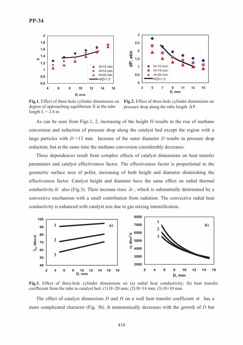
PP-34
416
0,6
0,8
1
1,2
1,4
1,6
1,8
2
4 6 8 10 12 14 16
D, mm
X
H=10 mmH=14 mmH=20 mmH/D=1.5
0
0,5
1
1,5
2
2,5
3
3 5 7 9 11 13 15D, mm
dP, a
tm
H=10 mmH=14 mmH=20 mmH/D=1.5
Fig.1. Effect of three-hole cylinder dimensions on degree of approaching equilibrium X at the tube length L = 2.4 m
Fig.2. Effect of three-hole cylinder dimensions on pressure drop along the tube length Δ P.
As can be seen from Figs.1, 2, increasing of the height H results in the rise of methane
conversion and reduction of pressure drop along the catalyst bed except the region with a
large particles with D >13 mm. Increase of the outer diameter D results in pressure drop
reduction, but at the same time the methane conversion considerably decreases.
These dependences result from complex effects of catalyst dimensions on heat transfer
parameters and catalyst effectiveness factor. The effectiveness factor is proportional to the
geometric surface area of pellet, increasing of both height and diameter diminishing the
effectiveness factor. Catalyst height and diameter have the same effect on radial thermal
conductivity rλ also (Fig.3). Their increase rises rλ , which is substantially determined by a
convective mechanism with a small contribution from radiation. The convective radial heat
conductivity is enhanced with catalyst size due to gas mixing intensification.
40
50
60
70
80
90
100
2 4 6 8 10 12 14 16 18D, mm
λ r, W
/m K
2000
3000
4000
5000
6000
7000
8000
2 4 6 8 10 12 14 16D, mm
α, W
/m2K
Fig.3. Effect of three-hole cylinder dimensions on (a) radial heat conductivity; (b) heat transfer coefficient from the tube to catalyst bed. (1) H=20 mm; (2) H=14 mm; (3) H=10 mm.
The effect of catalyst dimensions D and H on a wall heat transfer coefficient α has a
more complicated character (Fig. 3b). It monotonically decreases with the growth of D but
1
2
3
a)123
b)

PP-34
417
has an opposite trend from the height H in the range of practical interest with D < 13 mm. At
D >13 mm dependence of α from H is divergent. This effect is caused by redistribution of
gas flow through holes and around particles according to the mathematical model applied.
Since process performance is more sensitive to α than to rλ , this effect strongly determines
methane conversion curves shown at Fig. 1. Namely, height rise does not decrease the
conversion at D >14 mm in spite of effectiveness factor drop.
Therefore, the height to outer diameter ratio H/D in the optimized catalyst should be
maximal. Solid lines on Figs 1 and 2 correspond to isolines with maximum allowed H/D =
1.5. Since methane conversion changes slightly along the isoline in comparison with the
pressure drop, optimal catalyst dimensions are determined by pressure drop dependence
mainly and restricted by maximum catalyst height. Therefore, optimal dimensions of the
three-hole cylindrical catalyst are: H=20 mm; D = 13.3 mm, d = 3.9.
The similar results were obtained for different holed cylindrical catalysts – for optimal
catalyst sizing one can choose a maximum catalyst height and minimum diameter with
restrictions determined by requirements of uniform catalyst packing. Numerical results
obtained for Rashig rings and trilobed catalyst will be presented in the paper.
[1] J.R. Rostrup-Nielsen, Catalytic Steam Reforming, Berlin: Springer, 1984.
[2] E.I. Smirnov, A.V. Muzykantov, V.A. Kuzmin, A.E. Kronberg, I.A. Zolotarskii, Chem. Eng. J., 11,2003,
243-248.
[3] E.I. Smirnov, V.A. Kuzmin, I.A. Zolotarskii, Chem. Eng. Research Des., 82,2004, 293-296.
[4] S. Afandizadeh, E.A. Foumey, Applied Thermal Eng., 21, 2001, 669-682.
[5] A.P. Kagyrmanova, I.A. Zolotarskii, N.V. Vernikovskaya, E.I. Smirnov, V.A. Kuzmin, N.A. Chumakova,
Theoret. Found. Chem. Eng., 2, 2006, 1-14.

PP-35
418
METHOD OF DEFINITION OF MOISTURE CONTENT IN OIL
PRODUCTS
R.M. Kasimov, E.M. Mamedov
Institute of Chemical Problems, Azerbaijan National Academy of Sciences,
Baku, AZ0143, 29 Husein Javid Prospect, Azerbaijan Republic
Phone: 994 12 439 41 59, E-mail: [email protected]
Oil products used during processing require the preliminary control of the water in them
in allowable limits. Existing laboratorial chemical and physicochemical methods of definition
of moisture content in oil products are difficult enough and demand much time for processing
the received information. In this connection, because of simplicity of technical realization
there was preferable an application of physical methods of the analysis which are based on
measurements of dielectric coefficients of oil products in capacitor cells or under
characteristics of reflection from them microwave radiation. Sensitivity of these methods is
connected to essential distinction in dielectric coefficients of water and dehydrated oil
product. However, the complex and not always simple dependence between required and
measured sizes, and also necessity of application of the products purified from water at
carrying out of calibration of a scale of the device complicates carrying out of settlement
operations by these methods.
With the purpose of elimination of these lacks of a physical quality method of control the
new variant of a microwave method of definition of moisture content in oil products which is
based on the analysis of peak characteristics of the wave reflected from a layer adjustable on
thickness of researched substance is offered. By preliminarily carried out researches of
modeling binary solutions of polar liquids in non polar solvents, and in particular solutions of
water in non polar dioxan, it has been established, that at the set temperature and frequency of
radiation in these solutions at certain, selective values of thickness of a layer of a solution and
concentration in it of a polar component the effect of full or unreflecting absorption of falling
radiation takes place. Thus their product appears in invariant size for the given solution.
Existence of such selective values of structure and thickness of a layer in similar binary
solutions and invariance of their product allows to carry out a quantitative estimation of a

PP-35
419
polar component without carrying out preliminary procedure of measurement of dielectric
coefficients of pure components.
The method of definition developed on the basis of carried out researches small (0,01–
10 % weight.) content of water in oil product is reduced to the removal of dependence on
thickness of a layer of a product of amplitude of the microwave radiation reflected from it and
definitions of such thickness of a layer at which it is feasible or the condition of full
absorption of radiation in a layer of this substance. Thus for finding out the percentage
content of water in oil product the measured values of amplitude of the reflected signal in two
points of a minimum of the removed dependence located on both sides from found boundary
area of thickness of a layer of substance are used. Approbation of the developed method is
carried out in a range of microwaves at lengths of waves 1,5 and 0,8 sm. Reliability of the
carried out analyses on moisture of some samples of oil product is confirmed with the data
control distillation method of the analysis of the same products.

PP-36
420
REDUCING OF AN ENERGY CONSUMPTION IN THE PROCESS
OF THE VAPOR-PHASE DEHYDRATION
OF METHYLPHENYLCARBINOL BY THE USE
OF A COMPOSITE HEAT CARRIERS
Kharlampidi Kh., Karalin E., Abramov A., Ksenofontov Dm.
Kazan State Technological University, Russia, Kazan, 420015, K. Marks st. 68;
fax (843)2314162; e-mail: [email protected]; [email protected])
Up to the present are known 3 industrial methods for receiving of propylene oxide and the
best one among them is the method of simultaneous receiving of propylene oxide and styrene monomer (POSM) on account at relatively low costs of production [1]. A similar production in Russia was introduced in the mid 1980s in “Nizhnekamskneftechim” (Nizhnekamsk, Tatarstan), where today about 60000 tons of propylene oxide pro year are produced [2]. Home technology of this process (POSM), worked up under heading of M.A. Dalin and B.R. Serebryakov, doesn’t differ from foreign analog processes in principle and includes the stage of vapor-phase catalytic dehydration of methylphenylcarbinol (MPC). Dehydration of MPC is realized in the presence of alumina (gamma-oxide) catalyst under adiabatic conditions by temperature at the entry of the reaction vessel 280 ÷ 320°C. For lowering of partial pressure of hydrocarbons and compensation of endothermic effect of the basic reaction there is used a water excess of 10 mol for 1 mol of MPC.
For reducing of power capacity at the dehydration stage there is proposed a partial replacement of water steam with a methane -hydrogen fraction by mass correlation MPC : water : hydrogen = 1 : 1 : 4⋅10-4 ÷ 4⋅10-2 [3,4]. It should be note that there is an alternate reducing method of water consumption by its partial replacement not with a gasiform but with a hydrocarbon diluter as this there can be used, for example, ethylbenzene which is an intermediate product by the POSM process.
Taking in account the proper thermal and hydrodynamic parameters, which ensure the maximally permissible fall in temperature by the work with water steam in an industrial installation, it must be one of the urgent task by replacement of heat carrier to hold the adiabatic fall in temperature in optimal limits appointed for water steam.
The object of this paper is to value the realization possibility of both methods of partial water replacement taking in account the adiabatic fall in temperature.
The maximal temperature of reaction mixture, which is possible in adiabatic conditions, when the reaction proceeds to the end (�Tad), is determined from equation:

PP-36
421
mixpad mCM
mHT⋅⋅⋅Δ=Δ (1),
where m is reagent mass, kg /hour; M – mol mass of the reagent, kg /kmol; mmix – mass of base mix, which comes into the reaction vessel, kg /hour; Cp – thermal capacity of the mixture, kJ /(kg·K); �H – thermal effect of reaction, kJ /mol.
When taking as row material a binary mix, which consists of 82% - mass MPC and 18% - mass acetophenone (ACP) [5, 6] with MPC=1, for a system with only water as heat carrier, we convert the product Cp ·mmix for base and final mix composition as:
( ) PwaterwaterPACPACPPMPCMPCbaseiPi Cm�mCmmC ⋅+⋅+⋅=⋅� 00
( ) PwaterwaterPwaterwaterPACPACPPSTSTendiPi CmCm�mCmmC ⋅+⋅+⋅+⋅=⋅� 10 ,
where Cpi is medium thermal capacity of i-th component at interval 500 ÷ 600 K (227 ÷ 327°C), kJ/ (kg·K); m0water – water mass at the reaction vessel entrance, kg; m1water – water mass separated during the reaction, kg; mACP and mST are masses of ACP and styrene, kg.
Since reagent MPC and reaction products – styrene and water – have practically the same thermal capacity and accordingly the products (ÂCpi·mi) at entrance and outlet of the reaction vessel don’t differ, then we have:
( ) ( ) PwaterwaterendiPibaseiPi CmconstmCmC ⋅+=⋅=⋅ �� 0
It is evident, that by the fixed value of �Tad and replacing a part of water with an inert heat carrier the next condition must be carried out:
PhchcPwaterwaterPwaterwater CmCmCm ⋅+⋅=⋅ 20 (2),
where m2water is water mass by its partial replacement with a heat carrier, kg; mhc – mass of an inert heat carrier, kg; CPhc – medium thermal capacity of an inert heat carrier at interval 500 ÷ 600 K (227 ÷ 327°C), kJ/ (kg·K).
By calculation for 1 kg MPC-fraction of above mentioned composition m0water for an industrial process is 1,210 kg (10 mol of water on 1 mol MPC), m2water – by partial replacement of water with hydrogen [3, 4] – 0,820 kg (6,8 mol of water on 1 mol MPC). Under these conditions, we see from equation (3) that it is necessary to put into the system 0,373 kg of ethylbenzene or 0,054 kg of hydrogen (what considerably exceeds the maximum quantity of hydrogen in accordance with patents [3, 4]) to compensate the 0,34 kg lowering of water quantity.
Heat quantity QÂ used for warming of a heat carrier up to work temperature of the dehydration process by utilizing of a liquid heat carrier includes heat for warming the heat carrier up to the boiling temperature Q1, heat for evaporation of heat carrier vapor up to the work temperature Q3. When a gasiform heat carrier is used two former components aren’t necessary and heat is consumed only for worming gas up to the work temperature.

PP-36
422
A calculation example to water:
( )initialboilPlwaterwater tt�mQ −⋅⋅= 01 (3)
vbwater HmQ Δ⋅= 02 (4)
( )boilworkPwaterwater ttCmQ −⋅⋅= 03 (5),
where tinitial is initial temperature of the up heat carrier (about 40°C); tboil – normal boiling temperature of the heat carrier; twork – work process temperature (at the entrance of the reaction vessel); CPlwater – medium thermal capacity of liquid water at interval tinitial ÷ tboil,
kJ/(kg·grad); CPwater – medium thermal capacity of water steam at interval tboil ÷ twork, kJ/(kg·grad); �Hvb – evaporation enthalpy by normal boiling temperature, kJ/kg.
Calculation results from the equations (1-5) for different combinations of heat carriers by the work temperature 300°C are given in the table 1. It is seen that the total heat consumption for warming of a heat carrier by a partial replacement of water is practically the same (regardless of replacing water with hydrogen or ethylbenzene) and makes about 75% of heat consumption in an active process.
At the same time, 54 g of hydrogen for 1 kg of row material are equivalent to 600 dm3 (normal conditions) of gasiform hydrogen, it means that cooling and separation of such gas quantity will require a considerable complication of technological equipment. Increase of explosion danger is another negative side of hydrogen application.
The alternate version with the partial replacement of water with hydrocarbon doesn’t require principal changing in the technological scheme, but by using of ethylbenzene there will be higher requirements to equipment for separation of dehydration products on account of close boiling temperatures of styrene and ethylbenzene.
In our option, it is preferable to utilize aliphatic hydrocarbon with boiling temperature lower than styrene has (for example n-hexane or n-octane).
Table 1. Heat consumption for warming of a heat carrier
Quantity of a heat carrier on a basis of 1 kg MPC-fraction, kg Q, kJ
Water �2 Ethylbenzene Q1 Q2 Q3 Q�
1 1,210 0 0 304 2730 482 3516 2 0,820 0,054 0 206 1850 531 2587 3 0,820 0 0,373 280 1977 454 2711
References [1] Lyondell Chemical Company (http://www.lyondell.com) [2] "Nizhnekamskneftekhim" INC (http://www.nknk.ru/about_company_en.asp) [3] RU Patent 2,083,543 (1997) [4] RU Patent 2 104 991 (1998) [5] USA Patent 4 521 635 (1985) [6] Lange, Jean-Paul. Mass transport limitations in zeolite catalysts: the dehydration of 1-phenyl-ethanol to
styrene / J.P. Lange, Carl M.A.M. Mesters // Appl. Catal. A: General. – 2001.– 210. – P. 247–255.

PP-37
423
AN EFFECTIVE CoOx-CuOx-CeO2 CATALYST FOR PREFERENTIAL
OXIDATION OF CO
Kibar M.E., Ozdemir E., Yildlrim R.*, Akin A.N.
Kocaeli University, Department of Chemical Engineering, Kocaeli, Turkey
*Bogazici University, Department of Chemical Engineering, Istanbul, Turkey
Introduction
There is a worldwide interest in the development and commercialization of polymer electrolyte membrane fuel cells (PEMFC) [1]. The PEMFCs require hydrogen as its fuel source in order to avoid storing high pressure hydrogen be generated on board [2]. The hydrogen produced by steam reforming or partial oxidation of hydrocarbons or renewable fuels contains 0,5-2,0 vol.% CO. Hydrogen mixtures for fuel cell should be free of CO because it adsorbs on anode catalysts and decrease the performance [3].
As a fact, CO should be removed to ppm level (<10 ppm) and preferential oxidation of CO (PROX) has been recognized as one of the most strong and cost effective method for removing of CO in hydrogen in feed gas [4]. Different types of catalysts have shown their efficiency for the preferential oxidation of CO. This can be classified into four general groups: noble metal-based catalysts, perovskites, spinels, solid dispersions/solutions of transition metal oxides and lanthanide oxides [5]. Among these catalysts, CuO/CeO2 have shown to be very active for CO oxidation and therefore, they are superior to Pt-based catalysts [6]. CeO2 is used as promoter or support based on its high oxygen capacity. The activity and selectivity of CeO2-based catalysts are greatly enhanced by base metals, especially copper [7]. Also, cobalt oxide shows very high CO oxidation activity in CO/O2 mixtures even at ambient temperature [8].
The catalyst properties which influenced the activity/selectivity of catalyst, vary by the preparation methods and conditions. Most commonly used methods are impregnation and precipitation. For product homogenity, high metal loading, small crystalline form of metals and the reproducibility of the process, co-precipitation can also be used as catalyst preparation method [9]. Experimental
In this study a co-precipitation method has been developed and modified for the preparation of CuOx – CoOx – CeO2 catalysts developed for CO oxidation in H2 rich environment in the presence of CO2 and water. Catalysts were prepared by coprecipitation of metal nitrates in a semi-batch reactor by using NaOH as precipitation reagent. Two important

PP-37
424
precipitation parameters pH and temperature are optimized for the activity and the selectivity of mixed oxide catalyst. Experimental design is performed to two factors and three levels (pH : 8,5-10,0-11,5 and T = 5,0-37,5-70,0 °C) by using central composite design for the preparation of 20%CuO-20%CoO-60%CeO2 catalysts.
To determine the effect of metal interactions in the prepared catalysts to catalyst activity, new catalysts were prepared at optimum pH and temperature by using statistical experimental design techniques. For this purpose, 14 catalysts were prepared at six metal levels of 0,17, 33, 50, 67, 100 % for all Co, Cu and Ce metals to perform mixture design.
Prepared catalysts characterized by different physical and chemical methods. Metal contents of the catalysts were measured by atomic absorption spectrometer. The total surface areas were determined by N2 adsorption using multipoint technique with BET equation. SEM and XRD analysis were performed to determine the catalyst structure.
Catalytic activity tests were conducted in a microreactor flow system, including an online gas chromatograph for feed and product analysis. The effect of reaction conditions such as temperature, CO, O2, CO2, and H2O concentrations in the feed mixture, time-on-stream, space velocity were also investigated. Results
Optimum catalyst preparation conditions (pH and temperature) and metal contents are determined according to catalytic activity and selectivity at PROX. The activity and selectivity results for prepared catalysts were correlated with their physical and chemical properties measured to understand the effects of metal loadings and preparation conditions. The catalyst preparation conditions were also optimized using activity as the response considering that achieving full conversion of CO is the primary goal for this catalyst. The results show that the addition of Co as a second metal leads to bimetallic interaction which gives way to enhanced activities at very low temperatures. Optimum conditions for catalyst preparation are found as 37.5 °C and pH 10. 100 % conversion in PROX of CO at 150 °C was obtained. H2O and CO2 in the feed cause a decrease in activity and selectivity. However, water vapor dramatically decreases the activity of the catalyst compared to CO2.References 1. J. D. Kim, Y. I. Park, K. Kobayashi, M. Nagai, M. Kunimatsu, Solid state Ionics, 140 (2001) 313 2. P. K. Cheekatamarla, W. S. Epling, A. M. Lane, J. Power Sources, 147 (2005) 178 3. F. Marino, C. Descorme, D. Duprez, App.Catal B: Environ., 58 (2005) 175 4. A. Martinez-Arias, A. B. Hungaria, M. Fernandez-Garcia, J. C. Conesa, G. Munuera, J. Power Sources, 151
(2005) 32 5. G. Marban, A. B. Fuertes, App. Catal. B: Environ. 57 (2005) 43 6. G. Avgouropoulos, T. Ioannides, H. K. Matralis, J. Batista, S. Hocevar, Cat. Lett., 73 (2001) 33 7. X. Tang, B. Zhang, Y. Li, Y. Xu, Q. Xin, W. Shen, App. Catal. A: Gen, 288 (2005) 116 8. J. Jansson, A. E. C. Palmqvist, E. Fridell, M. Skoglundh, L. Osterlund, P. Thormahlen, V. Langer, J. Catal,
211 (2002) 387 9. M.Campanati, G. Fornasari, A. Vaccari, Catal. Today, 77 (2003) 299

PP-38
425
IMPROVEMENT OF TEMPERATURE CHARACTERISTICS OF
DIESEL FRACTIONS AND LUBE CUTS BY THEIR
HYDROISOMERIZATION ON Pt-SAPO-31 CATALYST
O.V. Kikhtyanin, A.V. Toktarev, G.A. Urzuntsev, L.A. Vostrikova and G.V. Echevsky
Boreskov Institute of Catalysis, SB RAS, Lavrentyev Ave., 5, Novosibirsk, 630090, Russia
Low temperature properties of diesel fuels and base oils are one of their main working
characteristics which allow fuel and oil systems of engines to operate at extreme temperature
conditions. There are a number of processes oriented on production of diesel fuels and base
oils with improved temperature characteristics. The main task of these methods, named
deparaffinization, is a decrease of n-paraffins content in final product. Long-chain n-paraffins
as a substantial part of a raw material possess undesirable temperature properties and, hence,
should be removed to get high-quality goal product with low pour point.
Several processes concerning conversion of n-paraffins using zeolite catalysts are
known. These catalysts usually contain noble metals, Pt or Pd, and the reaction is carried out
in the presence of hydrogen. In the course of the reaction over zeolites n-paraffins meet two
pathways of their transformation, hydrocracking and hydroisomerization.
When n-paraffins content in initial hydrocarbon mixture is not very high it is possible
to carry out deparaffinization by means of catalysts on the base of pentasil zeolites, ZSM-5,
ZSM-11, etc. Removing of n-paraffins occurs via their hydrocracking producing light
hydrocarbons, and in this case an yield of the aim low-freezing product depends on the
percentage of linear compounds in the starting material.
However, when content of n-paraffins is high, direct deparaffinization via cracking is
not suitable due to the significant yield loss of the goal product. In this case
hydroisomerization is more convenient as soon as long-chain linear hydrocarbons are not
transformed to shorter molecules but are converted to branched isomers making unchanged
fractional composition of the product comparatively with the feed.
Zeolitic unidimentional substituted aluminophosphates attract a lot of attention for this
case due to their unique pore structures and acidic properties of moderate strength.

PP-38
426
Hydroisomerization catalyst on the base of Pt-SAPO-11 is known as one of the examples of
successful industrial application [1].
Boreskov Institute of Catalysis during several years has been working out its own
hydroisomerization catalyst on the base of SAPO-31 silicoaluminophosphate. This catalyst
possesses high activity in conversion of long-chain paraffins to corresponding isomers with
very low content of cracked products. The present work presents some results on
hydroconversion of diesel fraction and gatch (wax concentrate) on Pt-SAPO-31 catalyst in
dependence on reaction conditions and properties of initial feed.
Synthesis of SAPO-31 sample was carried out according to [2]. Calcined
silicoaluminophosphate powder was impregnated with Pt(NH3)4Cl2 solution to get 1 wt.% of
Pt loading followed by granulation with 20% of pseudoboehmite and calcining of the resulted
extrudates at 550°. Catalytic tests were carried out using a flow installation with a fixed
catalyst bed (catalysts volume - 10 cm3). Prior to experiments catalyst was pretreated in a
hydrogen flow at 400°C. Reaction products were analyzed using HP-5890 unit equipped with
DB-1 capillary column.
Prepared Pt-SAPO-31 catalyst was tested in hydroconversion of diesel fraction (b.p.
170-350°C) used as an initial feed. Reaction conditions and results of the experiments are
presented in Table 1.
Table 1. Hydroconversion of diesel fraction on Pt-SAPO-31 in dependence on reaction
temperature. Preac. – 3.0 MPa, WHSV – 1.2 h-1, volume ratio H2 : feed = 2000.
Reaction
temperature, °�
Yield of diesel
fraction, wt%.
n-Paraffins
content, wt%.
Pour point of diesel
fraction, °�
Calculated Cetane
Number [3]
Feed
290
300
310
320
330
340
350
100
98,8
98,3
97,6
96,8
96,2
95,1
93,6
22,5
15.5
12,7
10,1
8,1
6,2
3,9
not determ’d
-10
-28
-35
-46
-55
-58
-61
-65
54,0
53,2
52,7
52,4
51,7
51,1
50,5
50,1

PP-38
427
Table 1 shows high hydroconversion activity of Pt-SAPO-31 sample. Transformation
of initial diesel fraction is observed at reaction temperatures even below 300°C what is seen
from the lowering of pour point of the obtained diesel products. It is seen that decrease of n-
paraffins content in the products is greater than loss of the yield of the aim fraction. This
proves that during hydrotreatment of the feed n-paraffins undergo isomerization rather than
cracking. This is due to moderate acidity and unique pore structure of SAPO-31 material what
substantially minimizes secondary hydrocracking.
Hydrotreating of sulfur containing hydrocarbon fractions is seems to be another
problem in production of high-quality products. Sulfur presented in nearly all refinery feeds
affects the properties of hydroisomerization catalyst, so it would be desirable that Pt-
containing catalyst stays active when initial feed contains increased amounts of sulfur.
Runs were carried out with diesel fractions with 0-500 ppm of sulfur
(dibenzothiophene specially added to initial sulfur-free feed). Figure 1 shows the effect of S
content in the feed on activity of Pt-SAPO-31 which is represented in the terms of pour points
of resulted products.
-70
-65
-60
-55
-50
-45
-40
-35
-30
0 100 200 300 400 500Sulfur Content, ppm
Pour
Poi
nt,0 � T=330C
T=340CT=350CT=360C
Figure 1. Influence of sulfur content in initial feed on pour point of resulted diesel fractions. Catalyst - Pt-SAPO-31, � = 3.0 MPa, WHSV = 1.2 h-1,
volume ratio H2 : feed = 2000.

PP-38
428
Obviously, in the case of S-containing feed to produce diesel fuel with improved
temperature properties it is necessary to increase reaction temperature. On the other hand, this
is a reason of decreasing yield of the desired fraction due to secondary cracking of isomerized
product. In the case of high sulfur feed such decrease may amount as much as 15%.
Pt-SAPO-31 was also used to isomerize wax concentrate – gatch (b.p. 360-480°C)
which is considered as a feed to produce high quality high viscosity base oil. Content of n-
paraffins in this feed attains 72.5 %wt. From data presented in Table 2 it is seen that lowering
of the pour point from 56°C in the feed to below zero results in a lube yield of more than 75
%wt. The main by-product in this case is low-freezing diesel fraction >150°C. Decrease in
reaction temperature improves yield of the desired product but simultaneously pour point
increases up to 12-16°C.
Table 2. Hydroconversion of wax concentrate (gatch) on Pt-SAPO-31 in dependence on
reaction temperature. Preac. – 3.0 MPa, WHSV – 1.2 h-1, volume ratio H2 : feed = 2000.
Reaction
temperature, °� Yield of lube, wt%. Pour point of lube, °�
Feed
310
320
340
350
100
89.7
82.3
76.1
62.4
56
15
6
-1
-8
The presented data prove that Pt-SAPO-31 catalyst is highly effective for improving
temperature characteristics of fuels and lubes by hydroisomerization of n-paraffins in the feed.
Isomerization properties of the catalyst are decreased by sulfur presenting in the starting
material, but increasing the reaction temperature it is possible to produce products with the
desired pour point characteristics starting from feed with S content up to 500 ppm.
References 1. S.J. Miller, et al, NPRA Natl. Fuels and Lubr. Mtg. (1992), Paper No. FL-92-109.
2. Patent of Russian Federation, No. 2,264,859 (2005).
3. S.V. Cherepitsa, et al, Khimiya i Technologiya Topliv i Masel (Rus.), No. 6 (2003), p. 45.

PP-39
429
MODELING OF A HEAT-COUPLED CATALYTIC REACTOR WITH
CONCURRENT OXIDATION AND CONVERSION FLOWS
Kirillov V.A.*, Fadeev S.I.**, Kuzin N.A.*, Shigarov A.B.*
*Boreskov Institute of Catalysis SB RAS, Prosp. Akad. Lavrentieva, 5, Novosibirsk, [email protected]
**Sobolev Institute of Mathematics SB RAS, Prosp. Akad. Koptyuga 4, Novosibirsk 630090, Russia
Development of a compact catalytic reactor for conversion of hydrocarbon fuels into
synthesis gas with following production of hydrogen for fuel cells has become a highly topical problem in recent years. Steam conversion provides the maximal hydrogen yield, but it requires heat supply to the endothermal reaction zone. One promising solution of the problem is that heat coupling of the endothermal reaction of steam natural gas conversion, for instance, and catalytic afterburning of the hydrogen-containing anode gas unspent in the fuel-cell stack in one reactor. In this case, the reactor is designed as a combination of flat catalytic channels. A number of the channels are ment for endothermal steam conversion of natural gas (endothermal channels). Oxidation of the anode gas to evolve heat proceeds in the neighboring exothermal channels. The evolved heat is transferred to the neighboring endothermal channels due to heat conductivity. This type of reactors was considered in several publications [1-3] and a number of mathematical models were suggested to describe steady state regimes. However, the amount of available experimental data confirming the validity mathematical models is insufficient. In this work we present a more detailed model as compared to the earlier reported in ref. [3] and a comparison of the experimental and simulation data. Fig. 1 schematically shows the reactor of synthesis gas generation. The experimental conditions were: natural gas flow rate 60 cm3/s, steam flow rate 0.32 g/s, flow rates of hydrogen and air at the reactor inlet 310 and 2250 cm3/s, respectively. The experiment was described in detail in [3].
Fig. 1. Heat coupled reactor.

PP-39
430
Mathematical model
The following equation set was used to describe the processes occurred in the endothermic
channels: 0≤z≤�, 0≤ � ≤L,
( )engcen
eng
enenp TTS
TGc −=
∂∂
α�
, ( )engcenshshconcon
cz TTSWHWH
zT −=Δ+Δ+
∂∂ αλ 2
2
,
( ) ishshicon
coni
ien mWWyG νν +=
∂∂�
, { }2224 ,,,, COHCOOHCHi = , (1)
The processes in the exothermal channels were described by: z = H, 0≤ � ≤L,
( )exgWex
exgex
p TTd
dTgc −= α
�, j
exH
hydj
j mwddx
g2
ν=�
, { }OHHNOj 2222 ,,,= , (2)
The heat-balance equation for the wall between the channels is: z=H, 0≤ � ≤L,
( ) 2
2
22 �dTdHwTT
zT W
WWHexH
exgWex
cz δλαλ +Δ=−+
∂∂ . (3)
�¤?!#¥! ©$\�#_ª: yi=yi0, xj=xj0, ,0en
gen
g TT = exg
exg TT 0= at 0=� ;
0=∂∂
zTc at z = 0; �� = Tw at z = 1; 0=
�ddTW at 0=� and L=� . (4)
Coefficients of heat-mass transfer, heat conductivity, kinetics of the reaction were determined
from the dependences described elsewhere [3]. Definition of the boundary problem does not
belong to a standard type. Therefore, the problem solution called for the development of an
ingenious numerical method.
Results
Figure 2 shows temperature profiles along the reactor length. Note that at the reactor inlet,
one can observe rather high temperature differences between the gas and the catalyst and
through the endothermic unit thickness between its wall (z=1) and center (z=0). Fig. 3 shows
changes in calculated «dry» mole fractions of ��4, �2, ��, and ��2 in the gas flow along the
endothermal channel length and the experimental values at the outlet. Fig. 4 shows a
hysteresis dependence of the reactor temperature regime versus oxidation catalyst activity
k0ox. The wall temperature profiles were obtained for eight solutions in the range 6<k0
ox<
30 m/s. Calculations were performed as parameter k0ox gradually changed from its maximal
value of 30 m/s to 6 m/s, and then in reverse sequence. The upper solution branch (normal
operation mode of reactor) exists if activity of the oxidation catalyst is rather high (k0ox>
6 m/s). However, if activity is very high (k0ox>15 m/s), the catalyst undergoes dangerous
overheating >1000��. If the catalyst activity decays to a critical value (k0ox~6 m/s), the reactor
operation changes from the high-temperature mode to the low-temperature one, that is the
reactor stops its operation. The reverse process is possible if k0ox~13 m/s. Interestingly, the
actual values of parameter k0ox are just in the range between the points of ignition and

PP-39
431
extinction, i.e. in the domain of regime multiplicity. This indicates that in order to start up
such a catalytic reactor, it should be initially heated.
Thus, our mathematical model adequately describes the experimental data and permits
one to predict regimes of the process performance in the thermally-coupled catalytic reactors,
which undoubtedly hold much promise as generators of synthesis gas for fuel cells.
0,00 0,05 0,10 0,15 0,200
100
200
300
400
500
600
700
800
Catalyst (endochannel, z=0)
Gas (endochannel, z=0)
Catalyst (exochannel, z=1)
Gas (exochannel)
T ,�
C
Length, m Fig. 2. Temperature profiles along the reactor length. Experimental data are denoted by the following symbols:
Δ - exothermic channels, Ο - endothermic channels, solid lines denote calculations made at k0o x= 7 m/s.
0,00 0,05 0,10 0,15 0,200,0
0,2
0,4
0,6
0,8
1,0
�2
CH4
"Dry
" mol
ar fr
actio
ns (e
ndoc
hann
el, z
=0)
Length, m0,00 0,05 0,10 0,15 0,20
0,00
0,03
0,06
0,09
0,12
0,15
CO2
CO
Length, m
"Dry
" mol
ar fr
actio
ns (e
ndob
lock
, z=0
)
Fig. 3. Profiles of dry gas concentrations calculated for endothermic unit (at the symmetry plane z=0) and
experimental data obtained at the outlet at k0ox=7 m/s.

PP-39
432
0,00 0,05 0,10 0,15 0,20 0,250
200
400
600
800
1000
The lower steady state branch
The upper steady state branch
8
1 - k0ox=30 m/s,
2 - k0ox=15 m/s,
3 - k0ox=13.5 m/s,
4 - k0ox=10 m/s,
5 - k0ox=7 m/s,
6 - k0ox=6.5 m/s,
7 - k0ox=6 m/s,
8 - k0ox=12 m/s.
7
6
5
43
21
T W (z
=1),
��
Length, m Fig. 4. Calculated profiles of wall temperature TW under variation of oxidation catalyst activity k0
ox.
Reference1. Frauhammer J., Eigenberger G., Van Hippel L., Arntz D. A new reactor concept for endothermic high-
temperature reactions //Chem.Eng.Sci. 1999. V. 54. P.3661-3670.
2. Zanfir M., Gavriilidis A. Modelling of a catalytic plate reactor for dehydrogenation-combustion coupling //Chem. Engng. Sci. 2001. V. 56. P 2671-2683.
3. Kirillov V.A., Kuzin N.A., Kulikov A.V., Fadeev S.I., Shigarov A.B., Sobyanin V.A. Thermally coupled catalytic reactor for steam reforming of methane and liquid hydrocarbons: experiment and mathematical modeling. // Theor. Found. Chem. Eng., 2003, V. 37, P. 276-284.

PP-40
433
A SIMULATION OF THE STEADY-STATE FLOW AND CHEMISTRY
IN THE PACKED BED REACTOR
O.P. Klenov, A.S. Noskov
Boreskov Institute of Catalysis SB RAS, Novosibirsk, 630090, Russia
Fax: +7(383) 330 68 78, e-mail: [email protected]
The objective of this paper is to simulate the steady-state flow and chemistry in the
packed bed reactor. An influence of inlet nonuniformity and heat transfer through the reactor
wall was examined. The complete Navier-Stokes model, considering 3D mass, momentum
and energy transport and 1-step heterogeneous catalyst reaction was used.
Fig. 1 shows the sketch of a typical single bed catalytic reactor, using for a gas pollutant
emissions purification. The inner diameter of reactor is equal 1.3 m. The reactor has both side
inlet and outlet. The height of packed bed of catalyst particles is equal 0.8 m. The distinctive
size of catalyst particles and the bed void fraction are equal 15·10-3 m and 0.4 accordingly.
The inlet flow consists of 0.007
mass fraction C2H2, 0.23 – O2, 0.0015
H2O and N2 – remaining. The inlet
temperature and static pressure are equal
673 K and 101325 Pa accordingly. A
Reynolds number based on inlet
conditions is Re=2.2·105, that
corresponding to a turbulent mode.
The reaction mechanism for
acetylene combustion based on 1-step
catalytic reaction was used.
C2H2 + 2.5O2 → 2CO2 + H2O
The reaction rate r was described by first-order equation r=k•CC2H2, where the rate
constant k was computed using the Arrhenius expression. The Arrhenius parameters for
the rate constants are a pre-exponential factor k0=6.38·106 s-1 and an activation energy
Á0=7.45·107 J/(kgmol).
The radial void fraction distribution inside a packed bed was used in a reactor model [1].
Inlet
Outlet
Packed Bed of Catalyst
Heat Insulation
Fig.1. The sketch of the packed bed reactor

PP-40
434
A model was used perfect-gas behavior, the turbulent, multi-component, chemically reacting
Navier-Stokes equations. A model solver is based on the FLUENT software using a finite-volume
approach [2]. The distinctive size of mesh of 3D reactor model is equal 2.5·10-3 m.
A flow distribution
The case of heat insulated reactor with outside temperature 273K is discussed. Fig. 2
shows the flow distribution inside reactor by path lines of stream. The jet from a side inlet
tube spreads through a over bed space, runs up to opposite reactor wall and divides on two
parts, generating a two symmetrical eddy flows and nonuniform pressure distribution above
packed bed. There is a reason of flow nonuniformity in a bed inlet.
Fig. 2. Flow distribution inside reactor shown by path lines of stream.
The temperature distribution in vertical cross section z=0 and level cross sections of
packed bed is shown on Fig. 3.
The Influence of Heat Transfer through the Reactor Wall
The three cases of heat transfer through the reactor wall are discussed. There are two limit
cases, firstly is an adiabatic reactor, secondly – a no insulated reactor with wall temperature
Twall=273K-const, and in the third place a heat insulated reactor with outside temperature
Tout=273K-const.
Fig. 4 shows the radial distributions of temperature on different heights of packed bed for
three cases discussed here.
The total conversion N of C2H2 was determined as N=(Cinlet – Coutlet)/Cinlet·100%, where C
is a mass-weighted average of acetylene mass fraction. The conversions of acetylene for
discussed cases shows on Fig. 5.
Plane Z=0 View from above

PP-40
435
Fig. 3. Temperature distribution maps in packed bed reactor. Values of temperature are
in compliance with the colour scale on left.
Conclusions
A main behavior of catalytic reactor depends on a heat exchange between reactor and
surroundings. A conversion of pollutant emissions can reach to critical value over poor heat
insulation.
A hydrodynamic nonuniformity based on inlet condition does not sufficient effect on
behavior of reactor as a heat leakage.
200
300
400
500
600
700
800
-0.65 -0.45 -0.25 -0.05 0.15 0.35 0.55r/R0
T, K
Adiabat. reactor
Tout=273K
Treact=273K
Fig. 4. Radial distributions of temperature on 0.5 height of packed bed.
Plane Z=0

PP-40
436
6.2
40.5
63.3
0
10
20
30
40
50
60
70
Non InsulatedReactor
Heat InsulatedReactor
Adiabat. Reactor
Con
vers
ion
of C
2H2,
%
Fig. 5. Influence of heat transfer through the reactor wall
on the C2H2 conversion
References 1. R.F.Benenati, C.B.Brosilow. Void Fraction Distribution in Beds of Spheres. AIChEJournal, Vol 8, No3,
p. 359-361, 1962.
2. Fluent Version 6.1. Fluent Inc., Lebanon, New Hampshire, 2003.

PP-41
437
MULTI-VARIANT PRODUCTION OF HIGH-OCTANE GASOLINE
AND LOW-FREEZING DIESEL FUEL BY “BIMF” TECHNOLOGY
O.V. Klimov, D.G. Aksenov, E.G. Kodenev, G.V. Echevski, A.A. Meged*,
S.N. Korsakov*, G.N. Tlekhurai*, A.Yu. Adzhiyev*
Boreskov Institute of Catalysis SB RAS, Novosibirsk, Russia
*NIPIgaspererabotka, Krasnodar, Russia
E-mail: [email protected]
Recently in the Boreskov Institute of Catalysis it has been developed the new catalytic
process of one-stage refining of wide-cut oil hydrocarbons to high quality motor fuels – the
“BIMF” process (Boreskov Institute Motor Fuels) [1]. In this process hydrocarbon feedstocks
with end boiling point (EBP) of 360 °C (in some cases EBP of 400 °C), distillated from crude
oil or gas condensate, are converted in a fixed-bed catalyst reactor to gasoline with desired
octane number, winter diesel fuel and some amount of gas product consisting mainly from �3-
�4 hydrocarbons [2]. The process was successfully tested largely up to pilot plant scale with
production capacity of 4000 tons of feedstock per year [3].
The process utilizes IC-30-BIMF catalyst based on ZSM-5 zeolite with molar silica-to-
alumina ratio of 80 and is carried out at following parameters in the reactor: start temperature
350 °C, pressure up to 2.5 MPa, WHSV = 1.5 – 4 h-1. With decrease of catalyst’s activity,
realizing in decrease of gasoline octane number and resulted from blocking of active surface
by coke deposits, temperature in reactor is periodically increased by 5 or 10 °C steps up to
450 °C. After that, under the condition of progressive decrease of gasoline octane number,
feeding is stopped and catalyst regeneration is carried out by the known methods. Production
of gasoline with desired octane number is achieved by appropriate combination of feed
velocity, temperature and time intervals between temperature ramps. The background
chemistry data and typical product yields for different types of hydrocarbon feedstocks are
given in [3–8]. It is important to mention that in all experiments the produced diesel fuel
fraction has freezing point below -50 °C.
In present work we describe variants of BIMF process, characterizing by increased
motor fuel yields and differing from the base variant of the process given in [9]. Schematic
diagram of the base variant of the BIMF process is presented in Fig. 1. According to this

PP-41
438
variant the products from reactor come to separator with following rectification of liquid
product for gasoline and diesel fuel. In the base variant of the process under production of
gasoline with MON (Motor octane number) = 83 – 85, the overall production of gas products
may reach the value of 18 wt% and more [8, 9]. Furthermore, the produced gasoline contains
appreciable amount of C5 hydrocarbons whose MONs don’t exceed 77. To compensate the
negative influence of those low-octane number components one should increase the content of
high-octane number aromatic hydrocarbons in gasoline by hardening of the process regime
what, in turn, leads to increased gas production. Usually gas product after separator S-1
contains an appreciable amount of C5+ hydrocarbons and needs in additional purifying in
accordance with standards on liquefied gas.
Fig. 1. Based variant
From the other hand, it is possible to organize the processing regime in separator in such way
when most of C5 hydrocarbons will be in gas phase, similar to that described in [3] where
outlet gas from separator operating at 35– 40 °C and <0.3 MPa contained 12.3 wt% of C5+
hydrocarbons. There are different variants for processing of such gas. In all variants the outlet
gas from separator is heated in furnace �-2 and comes to reactor R-2 charged with a catalyst
for aromatization, for example with IC-17-M catalyst based on modified high-alumina ZSM-5
zeolite. Operating parameters for reactor R-2 are those to produce either aromatics or liquid
products with maximal yield. Generally, process in reactor R-2 is carried out at <0.5 MPa,
475–550 °C and volume feed velocity of <2000 h-1. In such regime the yield of liquid
hydrocarbons may reach 60 % and more based on the converted gas. The produced in reactor
R-2 liquid product has MON as high as 104, and gas product mainly consists of �1-�2
hydrocarbons and may be utilized as a fuel for furnaces.
There are three main variants of the BIMF process aimed on processing of gas product
produced in the first reactor. The are illustrated in Figs. 2 -4. In accordance with the first
variant reactor R-2 operates in most hard regime to produce the maximal yield of concentrate

PP-41
439
of aromatics, which contains at least 88 wt% of benzene, toluene and xylenes in sum and is a
marketable product itself.
Fig. 2. Variant 1
In second and third variants the maximal yield of liquid products (not only aromatic ones) in
reactor R-2 is provided. In accordance with the second variant (Fig. 3) those liquid products
are compounded with gasoline fraction after rectification column K to get commercial
gasoline. The operating parameters for reactors are those to produce gasoline with desired
MON.
Fig. 3. Variant 2
In accordance with the third variant (Fig. 4) only part (about 20 wt%) of fed on column K-1
hydrocarbons is initially separated, which represents mainly light hydrocarbons of C5 – C6
composition with MON of 70 – 75. The rest 80 % of hydrocarbons comes to reactor R-1, gas
product, including C5+ hydrocarbons, after separator S-1 is converted in reactor R-2 and the
produced liquid products are compounded with above obtained on column K-1 light
hydrocarbons fraction to get commercial gasoline, specified as Gasoline-1. Two commercial
products, diesel fuel and gasoline-2, comes out from column K-2. Necessary to mention that it
is most rational to organize operation of BIMF unit in such way when MON of gasoline-2 is

PP-41
440
higher than that of gasoline-1, for example, gasoline-1 corresponds to AI-92 (Russian index)
and gasoline-2 – to AI-95.
Fig. 4. Variant 3
All three variants of processing of �1-�5 hydrocarbons formed in BIMF reactor provide the
overall yield of liquid products in the process exceeding 90 wt%, what is higher for
5 – 10 wt% than typical yield for the base BIMF process. For all that, quality of motor fuels
remains high.
References 1. Echevsky G.V., Klimov O.V., Kikhtyanin O.V. et al.// Russian Patent 2181750.
2. Echevsky G.V., Klimov O.V., Kikhtyanin O.V. et al.// Catalysis in Industry, 2 (2003) p.60.
3. Klimov O.V., Aksenov D.G., Kodenev E.G. et al.// Catalysis in Industry, 1 (2005) p.18.
4. Klimov O.V., Kikhtyanin O.V., Aksenov D.G. et al.// Chemistry and technology of fuels and oils, 5 (2005) p.20.
5. Klimov O.V., Aksenov D.G., Echevsky G.V. et al.// XVI Russian Conference on Chemical Reactors “Chemreactor-16”, 17-20.06.2003 Kazan, Russia, Thesis, p. 299.
6. Klimov O.V., Pimonova M.N. and Echevsky G.V.// 13th international congress on catalysis, Paris 11-16 July 2004, P4-015.
7. Klimov O.V., Kikhtyanin O.V., Aksenov D.G. and Echevsky G.V.// ”EUROPACAT-VI” (Innsbruck, 31.08-4.09.2003). A3, 044.
8. Klimov O.V., Aksenov D.G., Kikhtyanin O.V., Echevsky G.V.// Aktualnye problemy neftekhimii, Second Russian Conference,11-13.10.2005. Ufa, Russia, Thesis p.186.
9. Klimov O.V., Aksenov D.G., Kodenev E.G. et al. // Russian Patent 2265042.

PP-42
441
KINETICS OF BENZENE HYDROGENATION ON Rh/C
S.R. Konuspayev1, M. Schaimardan1, H. Backman2, D.Yu. Murzin2
1A.B. Bekturov Institute of Chemical Sciences, Almaty, 480100, Sh.Ualikhanov st. 106,
Kazakhstan, [email protected] 2Åbo Akademi University, Turku, Biskopsgatan 8, 20500, Finland, [email protected]
Introduction
Hydrogenation of aromatic hydrocarbons has become a key process for the production
of environmentally acceptable transportation fuels in the recent years. As soon as the
connection between aromatics and formation of harmful emissions was recognized, tighter
environmental regulations were imposed on gasoline and diesel fuel compositions [1– 3]. The
reduction of aromatics content in diesel results in an improved quality of the fuel since
aromatics, owing to their stability, are not suitable for combustion in ignition engines. In
addition, the saturation of aromatic hydrocarbons brings further benefits: the cetane number is
increased and the fuel density decreased [2, 3]. The improvement of these properties has been
shown to suppress formation of particulate matter and NOx emissions, which are connected
with serious health risks. Hydrogenation of aromatics has been studied by many researchers
both in the liquid and gas phase [4–7], with benzene being the most frequently studied system.
Experimental
The kinetic experiments were performed in a well-mixed 170 ml autoclave assuring that the
reaction took place in the external diffusion free region. All experiments were carried out
under isothermal and isobaric dead-end conditions. The hydrogen pressure and temperature
were varied between 2.0 and 10.0 MPa and 15-100oC respectively. Ethanol was used as
diluent. Some experiments were done with water and octane as solvents as well as in neat
solvent. The reactor was equipped with special hydrogen containing vessel (10 l) allowing
monitoring hydrogen consumption during the reaction (the values of hydrogen consumption
in what follows refer to standard temperature and pressure conditions). In a typical run 2 ml of
benzene and 0.3 g of 3%Rh/sibunit in 50 ml of the solvent were put into the reactor. The use
of activated carbon "sibunit" in the recent years has been due to its high surface area,
chemical inertness both in acidic and basic media, and by the absence of very strong acidic
centers on its surface which in principle could promote undesirable side reactions. The
catalysts particles were less then 50 μm. A fresh portion of catalyst was taken for each

PP-42
442
experiment. For selected runs during the course of the reaction samples of the solution were
taken for analysis by gas chromatography.
Results and Discussion
A typical profile of hydrogen consumption in benzene hydrogenation is shown in Fig. 1.
0 50 1000
500
1000
1500
2000
Benzene hydrogenation at 40 bar, mcat= 0.3 g, Vbenzene= 2 ml
100oC 80oC 60oC 40oC 20oC 13oC
Hyd
roge
n vo
lum
e, m
l
Time
Figure 1. Temperature dependence in benzene hydrogenation in ethanol.
It can be observed that the hydrogen consumption goes through maximum as a function of
temperature. Similar dependences were previously reported for gas-phase hydrogenation of
aromatics being a result of an interplay between kinetics and adsorption [7] and for the liquid
phase citral hydrogenation due to catalyst deactivation [8].
Hydrogen pressure dependence (Figure 2) is less pronounced, than temperature dependence.
0 500
500
1000
1500
2000Benzene hydrogenation at T = 80°C, mcat= 0.3 g, Vbenzene= 2 ml
100 80 40
Hyd
roge
n vo
lum
e, m
l
time
Figure 2. Pressure dependence in benzene hydrogenation in ethanol.
Concentration of benzene in a mixture with cyclohexane exhibits a linear dependency on
reaction time up to high conversions levels (Figure. 3).

PP-42
443
0 20 40 60 80 100 120 1400.0
0.2
0.4
0.6
0.8
1.0
Ben
zene
mol
e fra
ctio
n
time, min
80oC, 4 MPa
Figure 3. Hydrogenation of benzene in solvent-free conditions.
This means that the reaction order with respect to benzene is equal to zero, i.e., the reaction
rate is independent of the aromatics concentration. Similar behavior was reported previously
for liquid-phase hydrogenation of other aromatic hydrocarbons on several VIII group metal
catalysts [9], where the zeroth order dependence on the concentration of aromatics was
ascribed to a very high surface concentration of these compounds due to their strong
adsorption on the active sites .
Conclusions
Hydrogenation of benzene was performed over a wide range of temperatures and pressures
with a rhodium catalyst supported on a special carbon sibunit. Kinetic regularities were
established. Several previously advanced kinetic models were tested and compared to
experimental data.
References[1] Quality of European Gasoline and Diesel Fuels. EU Fuels Directive 2003/17/EC.
[2] A. Stanislaus, B.H. Cooper, Catal. Rev.- Sci. Eng. 36 (1994) 75.
[3] B.H. Cooper, B.B.L. Donnis, Appl. Catal. A: Gen. 137 (1996) 203.
[4] U.K. Singh, M.A. Vannice, AIChE J., 45 (1999) 1059.
[5] S. Toppinen, T.-K. Rantakylå, T. Salmi, J. Aittamaa, Ind. Eng. Chem. Res. 35 (1996) 1824.
[6] H. Backman, A.Kalantar, D.Yu. Murzin, J.Catal. 233 (2005) 109.
[7] A. Kalantar, P. Mäki-Arvela, H. Backman, H. Karhu, T. Salmi, J. Väyrynen, D.Yu. Murzin, J.Catal., 218 (2003) 267
[8] P. Mäki-Arvela, N. Kumar, K. Eränen, T. Salmi, D.Yu. Murzin (in preparation).
[9] D.Yu.Murzin, N.V.Kul’kova, Catalysis Today, 24 (1995) 35.

PP-43
444
VORTEX REACTORS FOR HETEROGENEOUS
DIFFUSION-CONTROLLED PROCESSES. ENZYMATIC LIQUID-SOLID PROCESS OF STARCH SACCHARIFICATION
Kovalenko G.A., Sukhinin S.V., Perminova L.V., Tanashev Yu.Yu.
Boreskov Institute of Catalysis SB RAS, 630090 Novosibirsk, Russia
E-mail: [email protected]
R&D of novel types of reactors are at the heart of modern heterogeneous biotech
processes performed by immobilized enzymes. The main directions of the reactor design are
the enhancement the productivity of the processes due to the overcoming diffusion limitation
by significant intensification of mass transfer of substrate to biocatalyst and elimination of
stagnant zones in bioreactor.
The exploitation of renewable feedstock such as starch to produce the sweeteners for
food industry is still of great importance. Now the all stages of starch–feedstock processing
relies at homogeneous conditions. The heterogeneous regimes of the starch saccharification to
treacle performing with the immobilized enzyme glucoamylase are more attractive and
feasible for economy.
The two types of vortex reactors – rotor-inertial bioreactor (RIB) and vortex-immersed
reactor (VIR), were designed for heterogeneous diffusion-controlled processes. These types
of reactor were investigated in the enzymatic liquid-solid process of starch saccharification.
Rotor-inertial bioreactor (RIB) was designed for the heterogeneous biocatalysts
prepared on the base of macrostructured inorganic supports, in particular foam-like ceramics.
Rotor-inertial bioreactor
was consisted of rotated
container fitted by foam-
like heterogeneous
biocatalyst. The rate of
starch saccharification was
maximal at the rotation rate

PP-43
445
of container of ca. 80 rpm (Fig. attached to Paragraph). At continuous mode of RIB operation
full conversion of 10w/w% starch dextrin to glucose syrup was observed at the slow flow rate
(< 0,2 l/h) of substrate solution through the bioreactor (Fig. attached to Paragraph).
Vortex-immersed reactor (VIR) was designed for the biocatalysts prepared on the
base of granulated inorganic supports. Vortex-immersed reactor was consisted of rotated body
filled by granules of heterogeneous biocatalyst. Rate of starch saccharification was constant at
rotation rate of the
body more than 300
rpm (Fig. attached to
Paragraph), e.g. at
these conditions the
external diffusion
limitation was
overcome. The internal
diffusion restriction
was eliminated when size of the support granules did not exceed 1 mm. Thus, the observed
rate of starch saccharification increased in order of magnitude when the carbon support was
grinded from 3 mm-granules to 0,6 mm-granules (Fig. attached to Paragraph). In periodic
mode of VIR operation full conversion of 32w/w% dextrin to glucose syrup was observed for
ca.4 hours.
As a result, the activities of heterogeneous biocatalysts observed in the vortex reactors
and productivity of the heterogeneous diffusion-controlled processes, in particular enzymatic
liquid-solid process of starch saccharification have been found to be of 1,2-1,5-fold higher if
to compare with the actively engaged fixed-bed reactor.

PP-44
446
SIMULATION OF THE CATALYST DEACTIVATION IN
SELECTIVE ETHYLENE GLYCOL PRODUCTION
V.F. Shvets1, R.A. Kozlovskiy1, I.A. Kozlovskiy1, M.G. Makarov1, J.P. Suchkov1,
A.E. Kapustin2, D.E. Zavelev1
1D.I.Mendeleev University of Chemical Technology of Russia, Chair of Basic Organic and
Petrochemical Synthesis, 9 Miusskaya Square, Moscow, 125047, Russia, [email protected] 2Azov State University, Mariupol, 87500, Ukraine, [email protected]
Abstract
The model of the tube fixed bed catalytic reactor for ethylene glycol production was used
for analysis how process conditions influence on catalyst life time. The model includes
equations describing catalyst’s deactivation. The catalyst is a cross-linked styrene-
divinylbenzene anion-exchange resin in carbonate/bicarbonate form. Various process
conditions (temperature, substance’s concentrations), heating regimes (isothermal, adiabatic)
and a stream direction were simulated. The optimal conditions concerning minimum of the
catalyst consumption were determined.
Introduction
Hydration of ethylene oxide is an industrial approach to glycols in general, and ethylene
glycol in particular. Ethylene glycol is one of the major large-scale products of industrial
organic synthesis, with the world annual production of about 15,3 million ton/y. Today
ethylene glycol is produced in industry only by a noncatalyzed reaction. As it follows from
numerous investigations [1-3] hydration of ethylene oxide catalyzed by anion-exchange resin
is one of the most promising methods for ethylene glycol production as alternative for
traditional industrial noncatalytic process. Catalytic method provides significant energy
saving in comparison with noncatalytic one due to much higher selectivity. But the main
disadvantage of such a catalyst is it’s deactivation that consists of two undesirable processes:
loss of catalytically active sites and catalyst’s swelling. In our previous works the models of
the tube fixed bed catalytic reactor [4] and of catalyst deactivation [5] were elaborated.
In the present work above mentioned models were used for analysis how process conditions
influence on catalyst life time.

PP-44
447
Results
The main parameters influencing on of the catalyst and its activity are temperature and
concentrations of ethylene oxide and glycol. Series of calculations were made for two types of
reactors – isothermal and adiabatic. Process conditions were varied in the following ranges:
temperature 80-100oC; initial concentration of ethylene oxide 3-10 % mass.; initial
concentration of glycol 0-29 % mass. In each case selectivity, catalyst’s capacity, catalyst’s
volume, catalyst productivity (kmole of glycol per m3 of catalyst per h) and catalyst
consumption (m3 of catalyst per kmole of glycol) were calculated. Results of simulation
showed that adiabatic reactor is more favorable than isothermal. It was found that most
profitable conditions for production of outlet stream containing 35% mass of glycol are
follows: installation consisting of several (up to 5) consecutive adiabatic tube reactor with
distributed ethylene oxide input in each reactor and intermediate heat exchangers; initial
concentration of ethylene oxide in each reactor is not exceed 6 % mass. These conditions
provide selectivity about 95 %, catalyst productivity about 2,4 (kmole of glycol per m3 of
catalyst per h) and catalyst consumption about 7×10⁻⁵ (m3 of catalyst per kmole of glycol) and
catalyst life time up to 6000 h.
Simulation was also used in order to investigate how stream direction influence on
catalyst deactivation. Result of simulation have showed that periodically changing of
direction of feed stream allows to decrease catalyst consumption per ton of glycol up to 10 %.
References 1. Shvets V.F., Makarov M.G., Koustov A.V., et al. Method for obtaining alkylene glycols. RU Patent
2149864, 2000.
2. Van Kruchten E. M. G. Process for the preparation of alkylene glycols. US Patent 5874653, 1999.
3. Iwakura T., Miyagi H. Production of alkylene glycol. JP Patent 11012206, 1999.
4. Shvets V.F., Kozlovskiy R.A., Makarov M.G., Koustov A.V., Selective catalytic hydration of ethylene and propylene oxides. XV International Conference on Chemical Reactors Chemreactor-15, Helsinki, Finland, June 5-8, 2001, c 102.
5. Shvets V.F., Kozlovskiy R.A., Kozlovskiy I.A., Makarov M.G., Suchkov Y.P., Koustov A.V., The Model of Catalytic Reactor of Ethylene Glycol Production. Organic Process Research & Development (2005), 9(6), 768-773.

PP-45
448
CATALYTIC EPOXIDATION OF CYCLOOCTENE BY
IMMOBILIZED SALEN COMPLEXES
T. Luts, W. Suprun, H. Papp
Institute of Technical Chemistry, University of Leipzig
Linnéstraße 3, 04103 Leipzig, Germany
Fax: +49(0341)9736349; e-mail: [email protected]
Introduction
The oxidation of alkenes to epoxides and their products is both of academic and industrial
interest. Consequently, several groups work in this field using different catalysts such as
supported metal oxides [1,2] as well as homogeneous transition metal complexes [3]. The
metal Salen complexes have been reported as very efficient catalysts in asymmetric catalytic
reactions and they are also widely used for the epoxidation of olefins [4.5]. Due to the
problems to separate the homogeneous catalysts from the products, significant efforts were
undertaken to immobilize them. The catalyst immobilization helps to overcome the problems
of catalyst separation, recovery and recycling. In the present study covalent bonding
techniques were chosen as a very efficient approach to design stable immobilized catalysts on
an amorphous mesoporous silica gel. The results about synthesis, characterization and
application of homogeneous and immobilized metal (Mn and Mo) Salen complexes in
epoxidation are presented.
Experimental
(3-aminopropyl)trimethoxysilane and (3-iodopropyl)trimethoxysilane were preliminary used
in a post-synthesis grafting method to prepare organosilane-modified porous materials.
Peptide (1) and ester (2) bonding were employed to anchor the Salen complex to the silica
framework using amino- and iodo-functionalized groups, respectively (Fig. 1).
To characterize and to prove the presence of immobilized Salen complexes on the surface FTIR,
atomic absorption spectroscopy (AAS), electrospray ionization mass spectroscopy (ESI MS),
CNHO elemental analysis and termogravimetry analysis (TGA) were used. The amount of
manganese and molybdenum content on the silica surface was determined by elemental analysis
of metal using AAS. The presence of only covalently coupled molecules of Salen complex
excluding non-bound ones in porous material was proven by ESI MS approach. FTIR
spectroscopy allows to observe the presence of specific bonds of immobilization process.

PP-45
449
To test the catalytic activity of the immobilized Mn and Mo-Salen complexes the catalytic
epoxidation of cyclooctene (CycO) with tert-butylhydroperoxide (TBHP) as well as cumene
hydroperoxide as an oxidant was studied. Gas chromatography was used for the identification
and the quantification of the reaction products. The influence of different reaction conditions
on the epoxide yield was studied.
MN
OO
N
SiOOO
NH
O
X
tButBu
tBu tBu
1. M - X: Mn(III) - Cl2. M - X: Mo(IV) = O
MN
OO
N
X
SiOOO
O
O
tBu
tBu tBu
tBu
1 2
Fig. 1. The structures of Salen complexes immobilized via peptide (1) and ester (2) bonding.
Results and discussions
Manganese and molybdenum Salen complexes were successfully immobilized in amorphous
mesoporous silica support with high yield of heterogeneous catalyst. The obtained
immobilized Salen complexes were found to be stable at the temperature up till 100oC,
towards different solvents (polar, nonpolar) as well as oxidative agents (TBHP, cumene
hydroperoxide).
Using AAS, FTIR, ESI MS as well as TGA and elemental analysis the definitive structure of
catalyst with its characteristic groups were proven. The presence of metal and its content in
immobilized complexes were determined by AAS. The characteristic bonds, typical only for
the immobilized complex were observed by FTIR. ESI MS experiments were carried by
treatment of immobilized metal Salen complexes with formic acid, triethylamine and also in
neutral condition in different solvent systems (chloroform/acetonitrile,
chloroform/acetonitrile+Na, tetrahydrofuran/acetonitrile and methanol) to explicitly prove the
catalyst structure.
In the current study the effects of reaction temperature, solvent, adduct proportions on the
catalytic activity were investigated. Epoxidation of cyclooctene was performed at 25, 45, 60
and 75oC in following solvents: toluene, chlorobenzene and tetrachloroethane (Tab. 1).

PP-45
450
Experiments in which the immobilized catalyst was used for three consecutive runs in the
epoxidation of cyclooctene were also carried out (Fig. 2). The results demonstrate constant
stability and activity of spent catalyst after several uses.
Tab. 1. Influence of reaction parameters on the epoxidation of cyclooctene (reaction conditions: CycO (2.7 mmol), TBHP (6.0 mmol), catalyst (0.045 mmol of active centers) and 1 ml of solvent).
Catalyst T (oC) Reaction time (h) Solvent Yield* (%) 75 35 Toluene 26
Homogeneous 60 35 Toluene 34 Mn-Salen 45 35 Toluene 45
45 35 Chlorobenzene 35 45 35 Tetrachlotoethane 48
Immobilized Mn-Salen 45 35 Toluene 39 Immobilized Mo-Salen 45 3 Tetrachlotoethane 89
* Yield of epoxide was calculated according to initial amount of olefin.
Conclusions
Manganese and molybdenum Salen
complexes were immobilized on the
silica support. The defined structure
of the resulting heterogeneous
system was proven by spectroscopic
analysis (FTIR, ESI MS, AAS and
TGA). The immobilized catalysts
were tested for the epoxidation of
cyclooctene and found to be active.
A comparison of the results obtained
with the homogeneous and the immobilized catalyst showed that there was no significant loss
of cyclooctene conversion in epoxidation by immobilization (Tab. 1). The influence of the
immobilized catalyst, solvent, temperature and adduct proportion was studied. Although the
systems were not completely optimized, the catalyst based on the silica surface could be used
in at least three consecutive runs. The mechanism of the epoxidation in presence of
homogeneous and heterogeneous Salen complexes was discussed.
References 1. F. Chiker, et al., Appl. Catal. A: Gen., 2003, 243 (309). 2. R. Ghosh, et al., J. Catal., 2004, 224 (288). 3. L. Canali, et al., Chem. Soc. Rev., 1999, 28 (85). 4. J. F. Larrow, et al., J. Org. Chem., 1994, 59 (1939). 5. T. Katsuki, Chem. Soc. Rev., 2004, 33 (437).
0 5 10 15 20 250
5
10
15
20
25
30
35
40
45
Yie
ld o
f epo
xide
(%)
Time (h)
first run second run third run
Fig. 2. Epoxidation of CycO by immobilized Mn-Salen complex in3 consecutive runs at 45oC. Reaction conditions: see legend of Tab.1.

PP-46
451
OVERALL PERFORMANCE OF THE CATALYST IN A
MICROREACTOR FOR THE METHANE PARTIAL OXIDATION
L.L. Makarshin, D.V. Andreev, S.N. Pavlova, V.A. Sadykov, O.I. Snegurenko,
V.V. Privezentsev*, A.V.Gulevich*, V.Yu. Ulianitsky**, V.A. Sobyanin, V.N. Parmon
Boreskov Institute of Catalysis, Prosp. akad. Lavrentieva 5, 630090 Novosibirsk, Russia
* SSCRF – Institute for Physics and Power Engineering named after acad. A.I. Leypunsky Sq.
Bondarenko 1, Obninsk, Kaluga Region, 249020, Russia
** Lavrentyev Institute of Hydrodynamics, Prosp. akad. Lavrentieva 15, 630090 Novosibirsk,
Russian
Introduction
Use of natural gas as a source of syngas is a perspective direction in the hydrogen
energy development and gas-to-liquid (GTL) processes. Generally, methane is converted to
syngas by steam reforming, but this endothermic process requires a large heat input, while the
H2/CO ratio obtained (about 3) is too high for fuels synthesis via Fischer–Tropsch reaction or
methanol route [1]. Due to its exothermic nature, the methane partial oxidation is an
advantageous route for syngas production, since it is less energy intensive and more cost-
efficient [2]. Moreover, H2/CO ratio (about 2) in syngas is favorable for GTL processes.
Microfabricated chemical reactors with at least one typical dimension in the sub-millimeter
range are of a great promise for the partial oxidation reactions and processes of chemicals
production. Their distinct advantages over conventional reactors are associated with their high
surface-to-volume ratio, which increases the heat transfer and thus, reduces thermal gradients
in the reactor. Due to small channel dimensions, their heat-exchanging efficiency is rather
high allowing fast heating and cooling of reaction mixtures, so that development of hotspots
or reaction heat accumulation within microstructures is prevented [3]. Development of
methods of the microchannel plate (MCP) manufacturing and procedures for the catalyst
supporting is a paramount problem in manufacturing the microreactor. Though a variety of
methods for MCP design and catalyst layers supporting are described in literature, their
majority could not be applied for design of a microreactor for syngas generation due to high
(>7000C) operation temperatures. High operation temperatures impose also restrictions on
selection of construction materials. The methane partial oxidation is catalyzed by transition

PP-46
452
group (Ni, Co) [5] and noble (Ru, Rh, Pd, Pt and Ir) metals [6]. However, they are rapidly
deactivated by carbon deposition.
The combined structures and various metal additives to basic Ni-Al2O3 composition
allowed to improve essentially performance of this catalyst ensuring a high activity and
selectivity in methane partial oxidation at high (105 – 106 ml/(g·h) space velocities and
temperatures (> 700 oC) [7,8]
The purpose of the present work was to elucidate main features of methane partial
oxidation into syngas at ms contact times in a microchannel reactor as dependent upon the
design of catalytic microchannel plate.
Experimental
The performance of the catalyst supported onto a microchannel plate was estimated
in a microreactor manufactured from stainless steel (Fig. 1) equipped with one }CP of 21×21
mm size. The goffered microchannel plate was made of fechraloy foil with 50 microns
thickness (Fig. 2). Corrugation produces a plate slab of 0.6 mm thickness with nearly
triangular (sides 0.3×0.6 mm) channels. The foil surface was precovered by continuous non-
porous buffer corundum layer via blast dusting deposition. The catalyst was supported in two
steps: first, the complex oxide support was deposited, and second, an active component was
supported by the incipient wetness impregnation. One }CP contained 80 mg of the active
metals. The MCP was finally calcined at 9000C for 2 h [9]. Microreactor was thermally
insulated by siliceous plates with thickness of 20 mm. The reactor temperature was controlled
between 200 and 900 ÈC by placing it within a furnace. The temperature was measured by a
thermocouple fixed at the microreactor external wall. Air - methane mixture with O2/CH4
ratio 0.55 was fed into the microreactor. The methane partial oxidation ignites at heating a
Fig 1
Fig. 2

PP-46
453
microreactor up to 6000� (Fig. 3). After achieving the microreactor temperature 820-8300C,
the furnace was cooled to a room temperature. However, the temperature of a microreactor
practically did not change due to heat generation by exothermic reactions of deep and partial
oxidation. Feed rate of the mixture varied within 2-35 ml/s being controlled with a flow-mass
controller. The GHSV (gas hourly space velocities) were calculated with respect to the
volume of reactants in the gas phase at 250 C. The time of contact of reagents with a layer of
the catalyst varied in the range of 175-10 ms corresponding to GHSV ~ 20000-360000 h-1.
The reaction feed components were analyzed by GC.
Using material balance equations the conversions of oxygen and methane as well as CO
selectivity were calculated:
04
42
020
4
4 %100CH
CHNNCH
XCH
⋅−⋅= (1)
02
22
020
2
2 %100O
ONNO
XO
⋅−⋅= (2)
4040
2
2 CHCHNN
COSCO
−⋅= (3)
where 02N , 0
2O and 04CH - initial concentrations of the feed gases, 2N , 2O , CO and 4CH -
outlet concentrations of the products.
Results and discussion
The plots of methane conversion and
CO selectivity versus space velocity are shown in
Fig. 4. It should be noted that at sufficiently high
values GHSV = 360000 h-1, methane conversion
£��4 remains at 86 %. This fact indicates a high
efficiency of the microreactor. In this case the
amount of hydrogen produced by one MCP is
equal to 48 L/h. At }CP volume equal to 0.35
cm3, this corresponds to hydrogen capacity 139
L/(h·cm3). This value allows estimating the size
of the microreactor with required hydrogen
production capacity. Specific hydrogen productivity of a microreactor related to the weight of
0 200 400 600 800 1000
0
20
40
60
80
100
XCH4
SCO
XO2
%
Temperature, 0C Fig 3 Temperature dependence of the methane and oxygen conversion and CO selectivity at feed rate 35 mL/s
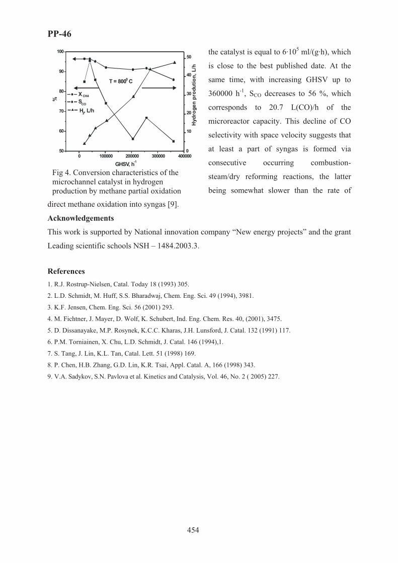
PP-46
454
the catalyst is equal to 6·105 ml/(g·h), which
is close to the best published date. At the
same time, with increasing GHSV up to
360000 h-1, SCO decreases to 56 %, which
corresponds to 20.7 L(CO)/h of the
microreactor capacity. This decline of CO
selectivity with space velocity suggests that
at least a part of syngas is formed via
consecutive occurring combustion-
steam/dry reforming reactions, the latter
being somewhat slower than the rate of
direct methane oxidation into syngas [9].
Acknowledgements
This work is supported by National innovation company “New energy projects” and the grant
Leading scientific schools NSH – 1484.2003.3.
References 1. R.J. Rostrup-Nielsen, Catal. Today 18 (1993) 305.
2. L.D. Schmidt, M. Huff, S.S. Bharadwaj, Chem. Eng. Sci. 49 (1994), 3981.
3. K.F. Jensen, Chem. Eng. Sci. 56 (2001) 293.
4. M. Fichtner, J. Mayer, D. Wolf, K. Schubert, Ind. Eng. Chem. Res. 40, (2001), 3475.
5. D. Dissanayake, M.P. Rosynek, K.C.C. Kharas, J.H. Lunsford, J. Catal. 132 (1991) 117.
6. P.M. Torniainen, X. Chu, L.D. Schmidt, J. Catal. 146 (1994),1.
7. S. Tang, J. Lin, K.L. Tan, Catal. Lett. 51 (1998) 169.
8. P. Chen, H.B. Zhang, G.D. Lin, K.R. Tsai, Appl. Catal. A, 166 (1998) 343.
9. V.A. Sadykov, S.N. Pavlova et al. Kinetics and Catalysis, Vol. 46, No. 2 ( 2005) 227.
0 100000 200000 300000 40000050
60
70
80
90
100
0
10
20
30
40
50
X CH4
SCO
GHSV, h-1
H2, L/h
%
T = 800 C0
Hyd
roge
n pr
odut
ion,
L/h
Fig 4. Conversion characteristics of the microchannel catalyst in hydrogen production by methane partial oxidation

PP-47
455
EQUATION-FREE BIFURCATION ANALYSIS OF THE LATTICE-GAS
MODELS OF CATALYTIC REACTIONS
Alexei G. Makeev and Ioannis G. Kevrekidis*
Faculty of Computational Mathematics and Cybernetics, Moscow Lomonosov State
University, Moscow, 119992, Russia; Tel. +7 495 9394079; e-mail: [email protected]
*Department of Chemical Engineering, Princeton University, Princeton, NJ 08544, USA;
Tel.: +1 609 2582818; e-mail: [email protected]
Kinetic Monte Carlo (kMC) simulations may provide an atomically detailed description
of catalytic chemical reactions. With the increasing power of computers, kMC simulations
become more and more prominent in modeling of catalytic systems, which may exhibit
complex reaction dynamics. However, traditional nonlinear dynamics tools, such as
bifurcation analyses and parameter continuation, are not directly applicable to the stochastic
models represented on a microscopic level by means of kMC algorithms. This feature is
considered as one the main disadvantages of kMC simulations as compared to the traditional
mean-field type deterministic equations.
Over the last several years we have worked on developing a novel computational
framework [1, 2] that allows one to bypass the derivation of explicitly closed macroscopic
equations in order to address problems for which macroscopic equations conceptually exist
but are not explicitly available. The inner component of this methodology is the best available
microscopic simulator of the process, such as a kMC simulator. This framework bridges
traditional, continuum numerical analysis with atomistic simulation codes, allowing tasks like
stability and bifurcation analysis, control and optimization to be performed using the fine
scale code directly. Our approach trades functions evaluation (these functions are explicitly
unavailable!) with estimation based on short, appropriately initialized kMC simulations. The
proposed computational framework consists of the following basic elements:
a) translation (lifting) of a macroscopic initial condition to an ensemble of consistent
microscopic configurations;
b) evolution of each initial microscopic configuration in the ensemble according to a
microscopic simulator for the same short time period;

PP-47
456
c) averaging over the ensemble of the evolved microscopic configurations to provide a
macroscopic evolved system state;
d) execution of the previous three steps over a finite set of macroscopic initial conditions
corresponding to nearby values of the operating parameter set (in this way, numerical
evaluation of a Jacobian matrix is performed).
These steps are supplemented by the Newton-Raphson iterations, which, in turn, may
converge to the stable or unstable steady states.
We illustrate an equation-free framework for the study of the complex models of
heterogeneous catalytic reactions; our illustrative examples are the stochastic kMC lattice-gas
models of the CO+O2 and NO+CO catalytic surface reactions. Beyond the practical
importance, these reactions have enjoyed long-standing academic interest, because they
exhibit complex reaction dynamics, such as bistability and kinetic oscillations. In the presence
of adsorbate-adsorbate interactions the mean-field closures for these models are not accurate
over relevant ranges of operating conditions. The numerical bifurcation analysis of the coarse-
grained microscopic dynamics was performed using the “coarse time-stepper” approach in
order to link kMC simulations with deterministic, continuum computational tools such as
Newton-Raphson iterations, parameter continuation and eigenanalysis.
The continuation algorithm was able to produce the complete one-parameter bifurcation
diagrams during a single simulation run. The calculated diagrams exhibit saddle-node and
Hopf bifurcations and demonstrate that our algorithm succeeds in finding both the coarse
stable and unstable stationary states. The coarse unstable states as well as the complex shape
of the bifurcation diagrams would be practically impossible to reproduce using only the direct
kMC simulations. In addition, we discuss the relevance of the studied lattice-gas models for
the description of the experimental data obtained under UHV conditions over single-crystal Pt
surfaces.
[1] A.G. Makeev, D. Maroudas, I.G. Kevrekidis. "Coarse" stability and bifurcation analysis using stochastic simulators: Kinetic Monte Carlo examples. Journal of Chemical Physics 116 (2002) 10083-10091.
[2] A.G. Makeev, D. Maroudas, A.Z. Panagiotopoulos, I.G. Kevrekidis. Coarse bifurcation analysis of kinetic Monte Carlo simulations: A lattice-gas model with lateral interactions. Journal of Chemical Physics 117 (2002) 8229-8240.

PP-48
457
DYNAMICS OF THE METHANE PARTIAL OXIDATION INTO
SYNGAS AT SHORT CONTACT TIMES ON MONOLITHIC
CATALYSTS: EFFECT OF THE LATTICE OXYGEN MOBILITY
AND ITS MODELING
N. Mezentseva, S. Reshetnikov, V. Sadykov, Yu. Frolova-Borchert, V. Muzykantov,
E. Paukshtis, G. Alikina, A. Lukashevich, T. Kuznetsova, S. Pavlova, O. Snegurenko,
Z. Vostrikov, S. Tikhov and V. Parmon
Boreskov Institute of Catalysis SB RAS, Pr. Lavrentieva, 5, 630090, Novosibirsk, Russia.
E-mail: [email protected]
At present, selective oxidation and autothermal (steam–oxygen or steam–air) reforming of
hydrocarbons into synthesis gas are considered to be promising alternatives to conventional
steam reforming [1]. Advantages of this process are mild exothermicity, superiority to steam
reforming in terms of efficiency (productivity), and, hence, smaller reactor sizes (lower
capital investments).
Catalysts comprised of doped ceria-zirconia oxides with supported Pt were recently
shown to be very efficient and stable in these reactions [2]. A high activity of these systems is
explained in the frame of a bi-functional scheme [4]. It includes methane activation on Pt
clusters into CHx fragments followed by their subsequent interaction with the lattice oxygen
of the oxide support at the Pt– support interface. Hence, ability of oxide systems to provide
fast oxygen diffusion from the bulk to the surface could be important for these catalysts
performance especially in dynamic conditions. Incorporation of low-valence cations (La, Gd,
Pr) into the lattice of ceria-zirconia solutions is expected to create anion vacancies, thus
improving catalytic properties of these systems [3].
On the other hand, start-up of syngas generators where selective oxidation of the natural
gas occurs, is known to be accompanied by the temperature excursions often exceeding
stationary values, which could cause break-up or even melting of monolithic catalysts. To
avoid it, relation between such an overheat (caused by domination of deep oxidation during
start-up period) and mobility of the lattice oxygen is to be elucidated, and factors controlling
this mobility in complex oxide supports are to be clarified.
In this respect, it is of interest to make a quantitative estimation of the scope of the lattice
oxygen diffusion coefficients at which the greatest deviation of the transient regimes from the

PP-48
458
stationary one is observed. These results will be of primary importance for the tailor-made
design of nanostructured catalysts based upon Ce-Zr complex oxide supports via controllable
tuning the lattice oxygen mobility by variation of their chemical composition and real/defect
structure parameters.
This work present results of studies of the relaxation characteristics for the process of
methane selective oxidation into syngas at short contact times and their mathematical
modeling aimed at elucidating their interrelation with the lattice oxygen mobility in doped
CeO2 –ZrO2 complex oxides as well as effects of the Pt –complex oxide supports interaction.
Experimental
Samples of complex oxides Ce0.5-x/2Zr0.5-x/2 MexO2-y (Me = La, Gd or Pr, x=0÷0.3) were
prepared via the polymerized precursor route with modifications of procedures described
earlier [5, 6] and calcined at 500-700 oC. Pt (1.4 wt. %) was supported by the incipient
wetness impregnation with H2PtCl6 solution followed by drying and calcination at 500 oC.
Dynamic isotope oxygen exchange was carried out in a static installation with MS control
in the temperature-programmed mode as described elsewhere [5].
The surface features of sample were characterized by Fourier Transform Infra-red
Spectroscopy (FTIRS) of CO adsorbed and earlier described procedures [6].
Experimental procedures of catalytic activity characterization in the reaction of CH4
partial oxidation for both dispersed active components and real-size monolithic catalysts on
different substrates were described earlier [5]. The catalysts were pretreated in O2 at 500 C for
1 h and tested in the isothermal (or autothermal) mode (steady-state and transient
experiments) as well as temperature -programmed mode using feeds with CH4/O2 ratio 2 either
diluted by He (CH4 concentration 1-5%) for dispersed samples or stoichiometric methane-air
mixture for monolithic catalysts.
Results and discussion
Catalytic transients. In all experiments, after contact of reaction mixture with oxidized
catalysts studied here, deep oxidation products are formed simultaneously with syngas, its
selectivity increasing with the temperature. Among studied systems, the active component based
on Pt-supported Ce-Zr-La-O sample with an optimum (20 at.%) content of La was shown to be
the most active and selective in the partial oxidation of methane into syngas. In diluted feeds,
prolonged (up to 60 min) relaxations are observed at temperatures ~ 650 oC, while decreasing up
to 10 min at temperatures exceeding 800 oC in concentrated feeds. Shorter relaxations were
observed for deep oxidation products suggesting mainly participation of highly mobile

PP-48
459
surface/near surface oxygen forms in methane combustion, while syngas relaxations seem to be
controlled by the lattice diffusion.
Theoretical analysis of effect of the lattice oxygen mobility in oxide supports on the
transient dynamics of fast catalytic reactions. Red-ox scheme of the reaction mechanism [8]
was used as a basis for this analysis. Parameters of kinetic and mathematical models were
derived from the experimental data on steady-state and transient methane selective oxidation
in diluted feed on powdered 1.4%Pt/Gd0.2Ce0.4Zr0.4Ox catalyst.
Key parameter defining dynamics of change of the catalyst surface due to diffusion,
parameter Tiele is ϕ2=L2ks/D (D - effective coefficient of the lattice oxygen diffusion, L -
characteristic size of the oxide crystallite/domain, ks-reaction rate constant for reoxidation of
the surface site by oxygen from the bulk). For efficient operation of a catalyst in the
bifunctional mode of syngas generation (vide supra), diffusion of oxygen in the bulk should
not limit the transient dynamics, so Tiele parameter should be small. Nevertheless, our task is
to define area in which effect of the oxygen diffusion is the most pronounced.
At the initial contact of the reaction feed with the catalyst, only oxygen of the near-
surface layers takes part in oxidation. At small ϕ values (a fast bulk diffusion), the catalyst
reduction proceeds uniformly within all depth of crystallites. At a large ϕ (a slow bulk
diffusion), the oxygen mobility is insufficient for reoxidation of the reduced surface. For this
reason, at bigger ϕ values, the surface coverage by oxygen and reagent (CH4) conversion
declines faster (Fig. 2).
Modeling revealed that there is a range of the Tiele parameter variation (ϕ∈[0.3÷7]) in
which the greatest effect of the oxygen diffusion on the process dynamics is observed. This
range corresponds to the values of the oxygen diffusion coefficient D~ 10-18÷10-13 cm2/s close
to the typical values for the oxygen diffusion in oxides [9].
Oxygen mobility and Pt-support interaction. Fig. 2 presents dynamic degree of the oxygen
exchange [7] for nanocrystalline ceria-zirconia system doped with La, Gd, or Pr. As amount of
the easily exchanged oxygen is mainly below a monolayer, this oxygen appears to be mainly
located in the surface layer or in the vicinity of disordered domain boundaries of these
nanocrystalline systems. The most mobile near-surface oxygen is revealed for Ce-Zr-La-O
system, which correlates with the biggest size of La cation and, hence, the biggest lattice
parameter, which decreases the energy barrier for the oxygen diffusion.
For Pr-doped ceria-zirconia, after decline of the lattice mobility at a low doping level (up
to xPr = 0.1), it increases again at a higher Pr content (Fig. 2). This phenomenon can be

PP-48
460
0.0 1.0 2.0
τ
0.4
0.6
0.8 C
onve
rsio
n
ϕ=0.52
10
5
0 5 10 15 20 25 300,0
0,5
1,0
1,5
X s (m
onol
ayer
s) @
T =
650o
C
Dopant content, at.%
123
4
Fig. 1. Dependence of conversion CH4 versus time at various values of module Tiele (ϕ = 0.5, 2, 5,10).
Fig. 2. The dynamic degree of exchange (Xs) at 650 oC versus the dopant content (mole fraction, x) for ceria –zirconia (1:1) oxide systems doped with Gd (1), Pr (2) or La (3). 4-Pt/Ce-Zr-La-O system.
assigned to the effect of red-ox Pr3+/Pr4+ couple ensuring a mixed ionic-electronic
conductivity in the mixed oxide when a high doping level is achieved.
Pt supporting strongly affects the oxygen mobility, apparently via facilitating the bulk
oxygen transfer to the surface. This suggests a strong Pt interaction with support. Indeed, IR
Spectroscopy of CO adsorbed at 77K as a test molecule revealed bands at 2175-2180 cm-1
(Pt2+- CO complexes), 2125-2132 cm-1 (Pt+- CO complexes) and 2041-2046 cm-1 (Pto –CO
complexes) [6]. The highest concentration of cationic Pt species is observed for Ce-Zr-O
system doped by La, which correlates with the highest oxygen mobility and shortest
relaxations of catalytic activity as well as the highest specific activity and syngas selectivity.
Cationic Pt2+ species dominate for studied systems, which are associated with their
nanocrystallinity, namely, ability to stabilize these cations at surface defects, probably, in
vicinity of domain boundaries.
Acknowledgements. This work is in part supported by ISTC 2529 and RFBR-CNRS Project
0503-34-761.
References 1. V. A. Sadykov, S. N. Pavlova, R et al. Kinetics and Catalysis 46 (2005) 227
2. M. Krumpelt, S. Ahmed, R. Kumar and R. Doshi, US Patent 6,110,861 (2000).
3. J. Kašpar, P. Fornasiero, In Catalysis by Ceria and Related Materials.
4. Pantu P., Kim K., Gavals G.R. App. Catal. A 193(2000)203.
5. V. A. Sadykov, Yu. V. Frolova, et al, Mater. Res. Soc. Symp. Proc. 835, (2005) 199.
6. V. A. Sadykov, S. N. Pavlova, R et al. Kinetics and Catalysis 46 (2005) 227.
7. V. A. Sadykov, Y.V. Frolova et al, React. Kinet. Catal. Lett., 85, 375 (2005).
8. N.M. Ostrovskii, Kinetic of catalyst desactivation. }.: Nauka, 2001.
9. P.Kofstad. “Nonstoichiometry, diffusion and electrical conductivity in binary metal oxides”. Willey-Interscience, New-York, 1972.

PP-49
461
RECENT DEVELOPMENT OF CONVENIENT METHODS OF
SYNTHESIS OF CHLORO CARBOXYLIC ACIDS ON THE BASIS OF
LIQUID PHASE OXIDATION OF SUBSTITUTED VINYL CHLORIDES
A.R. Mikaelyan, N.L. Asatryan, S.S. Akarmazyan, G.H. Torosyan
State Engineering University of Armenia (SEUA), Department of Chemical Technologies and
Environmental Engineering, 105 Terian St., B. 1, Yerevan, 375009, Republic of Armenia.
Introduction: Application of selective oxidation of alkenes by molecular oxygen is one of
the current challenges in the manufacture of organic building blocks and industrial
intermediates [1,2]. According to literature [3], the data relating to auto-oxidation of series of
activated alkenes without halogen substitutes by oxygen is known. The involvement of
styrene, α- methylstyrene, methyl acrylate, methyl methacrylate, butyl acrylate, etc. results
usually in their polymerization into the oxidation process at 70-120 °C.
Liquid phase non-catalytic direct oxidations by molecular oxygen or by air of chlorovinylic
compounds, have been presented in our recent reports [4,5]. Present work has established that
for a great number of compounds studied, the chloroanhydrides of α-chloroacids are the main
products of the reaction:
O2 RCXClCOClRCX=CCl2 R= CH2Cl, CH2OAc, CH2C6H5, (CH2)3Cl, (CH2)3OAc; X=H
The high yield (≈ 80 %) and the selectivity of formation of chloroanhydrides brings to the
forefront the direct oxidation reaction of halogenvinylic compounds from a practical point of
view. A possible problem might be the formation of peroxides; however, explosion of
peroxide intermediate was not noticed because of they are mainly converted into the
chloroanhydrides of corresponding carboxylic acids above 100-110 °C. From the presented
data, one can see that liquid phase direct oxidation of halogenvinylic compounds by air is a
simple and convenient method for synthesis of α-halogen- and α,α-dihalogencarboxylic acids
and their derivatives. It should be noticed that in recent years many halogenvinyl compounds
have already become available and cheap raw materials due to introduction of new and
effective methods of chlorination of alkenes, alkynes, alkadienes, and other petrochemicals.

PP-49
462
We hope, that this way vinylhalogen organic molecules oxidation can be use also in various
field, which are extended to drinking water treatment, advance treatment of sewage water,
treatment of waste water.
Thus the problem of development of new effective methods of their selective oxidation is
becoming more actual.
Results and Discussion: The kinetics of oxidation of 1,1,3-trichloropropene (I); 1,1-dichloro-
3-phenyl-1-propene (II); 1,1,5-trichloro-1-pentene (III) and 1,1-dichloro-5-acetoxy-1-pentene
(IV) by oxygen has been studied [6,7,8]. Kinetic studies of liquid phase oxidation reaction of
halogenolefines are based on measurements of oxygen absorption rate (manometric method)
and speed of consumption of halogenvinyl compounds, and formation of the products by GLC
method. The correlation of products, dynamics of their formation and changes in quantities of
intermediary products are determined by the following methods: peroxides- by iodometric
method, halogenanhydride of halogencarboxylic acids, halogenoxiranes and the starting
halogenvinyl compounds - by GLC method in isothermal and programming regimes.
The obtained experimental data shows that the increase of oxygen flow speed does not affect
the process itself furthermore substitution of oxygen with air causes increase of
chloroanhydrides yield. The most reactive was trichlorpropene, which over the 20-70 °C
temperature range oxidizes with average rate of 0,5-1,5∗10-4 mol/(l.∗sec). The calculations
show that the oxidation process proceeds selectively below 70 °C and when conversion of
the compounds reaches 100% yield of chloroanhydrides of α-chlororganic acids exceeds
90%. It has been established that in early stages of oxidation the peroxides are formed,
amount of which reaches maximum values (40-42 %, iodometric method) at 65-70% of the
reaction conversion.
The quantitative analysis of thermal treatment products of peroxides by GLC method shows
that hem-dichlorolefine oxide and chloranhydride of the corresponding acid are the products
of following rearrangement reaction.
R=CH2Cl, (CH2)3Cl
OOO
+ +
RCHCl COCl
RCH=CCl2 O2 RCH CCl2 RCH CCl2 RCHCl COCl
distillation

PP-49
463
We carry out also the hydrolysis, alcoholysis and aminolysis of the oxidate into the acids,
esters and amides of α-chlorocarboxylic acids, respectively.
It is obviously, that the increasing of oxidation speed and prevention of long time thermal
influence on intermediates leads to increasing of the yield an selectivity aimed products.
In this goal the non-catalytic liquid phase oxidation of 1,1-dichloro-5-acetoxy-1-pentene by
molecular oxygen in reactor with oxygen-spray has been investigated [8]. It has been shown
that the main products of the reaction are ω-acetoxyvalerianic acid chloride and the olygomer,
which is obtained as a result of poly-condensation of the chloride with abstraction of acetyl
chloride. It has been determinate, that in case of application of oxygen-spray reactor with
glass-ring packed, the yield of ω-acetoxyvalerianic acid chlorid is approximately two-time
higher.
In addition, the catalytic (TiO2) liquid phase oxidations of 1,1,5-trichloro-1-pentene (as a
model compound) by molecular oxygen in glass-ring packed reactor with oxygen-spray have
been investigated.
The investigations of kinetics of oxidation processes (consumption of 1,1,5-trichloro-1-
pentene and formation of α,ω-dichlorovaleric acid chlorides by GLC method) have been
performed.
Cl
ClCl O
OO2
TiO2, 60-70 oC Cl
Cl Cl O
O
Cl ClCl
Cl
ClCl
Oxidate
Cl(CH2)nCHClCOOH
Cl(CH2)nCHClCONH2
HOH
ROH
NH3
O2Cl(CH2)nCH=CCl2 Cl(CH2)nCHClCOOR

PP-49
464
It has been shown, that titanium dioxide (10mg TiO2 to 1mmol substrate) have catalytic
activity in this oxidation reactions, so by 60 °C after 5.5 hour the yield of acid chloride 6
arrived at 61% (by non-catalytic oxidation this rate have been attained more then 9 hour
reaction time).
It has been proposed that this oxidation process will offer synthetic utility since reaction
proceeds readily, does not require any solvent (which would usually introduce problems for
purifying of products) and provide selective formation of chlorides of α-halogenalkenoic
acids. On the basis of the obtained results on direct liquid phase oxidation of halogenolefines
by oxygen in air it is supposed to find the opportunities for application of these reactions for
solution of environmental problems related particularly to the problems of utilization,
mineralization and metabolism in the biosphere of halogenorganic compounds wastes.
Acknowledgements: This work was supported by the Armenian National Science and
Education Fund (ANSEF, Grant 05–PS– chemorg–814–116, 2005 year).
References [1] R.A. Sheldon, J.K. Kochi.//Metal-Catalyzed Oxidation of Organic Compounds, Academic: New York, 1981.
[2] G.W. Parshall, S.D. Ittel. // Homogeneous Catalysis, Wiley: NewYork,1992.
[3] E.M.Pliss, V.M.Troshin. // Neftekhimiya 1982, v.22, N 4, pp. 539-542.
[4] B. Bayatyan, A. Mikaelyan, N. Asatryan et al. // Book of abstracts of annual scientific conference of SEUA, 25-29 October 1999, Yerevan, p. 40, 41.
[5] B.E. Bayatyan, A.R. Mikaelyan, E.S. Voskanyan, Sh.O. Badanyan. // "Chemistry in Armenia on the Threshold of the XXI Century", Book of Abstracts (NAN of RA), 18-20 May 2000, Yerevan, p. 121.
[6] B. Bayatyan, A. Mikaelyan et al. // Book of abstracts of annual scientific conference of SEUA, Vol. 1, 29 October -2 November 2001, Yerevan, pp. 66-68, 68-70.
[7] A.G. Ayvazyan, A.R. Mikaelyan, N.L. Asatryan, B.E. Bayatyan, R.M. Mirzakhanyan, Sh.O. Badanyan. // Information Technologies and Management, (Series chemical technologies and ecological engineering), Yerevan, 2002, N1, pp.191-196.
[8] A. Sarksyan, A. Mikaelyan. // Book of abstracts of annual scientific conference of SEUA, 28-30 April 2003, Yerevan, pp. 3-5.

PP-50
465
PERMEABLE CATALYTIC MEMBRANE FOR COMPACT
APPARATUS FOR HYDROGEN-RICH GASES DEEP CLEANING
FROM CO
Minyukova T.P., Itenberg I.Sh., Khasin A.A., Sipatrov A.G., Dokuchits E.V.,
Terent’ev V.Ya.*, Khristolyubov A.P.*, Brizitskii O.F.*, Yurieva T.M.
Boreskov Institute of Catalysis SB RAS, 5, Pr. Lavrentieva, Novosibirsk, 630090, Russia,
fax. +7-383-3308056, [email protected]
*Russian Institute for Experimental Physics (VNIIEF), 37, Mira ave, Sarov, 607190,
Nizhegorodskoi obl., fax +7-831-3040032, [email protected]
In order to provide a wide application of the PEMFC technology, reduce cost and
improve characteristics of PEMFC-based power plants, it is necessary to create a compact and
economic apparatus for deep cleaning (to 20 ppm) of converted fuel from carbon monoxide.
In the existent technologies of hydrogen conditioning for fuel cells WGSR and deep
purification by CO selective oxidation follow the stage of hydrocarbon steam reforming.
Method of selective CO hydrogenation for deep purification is the alternative one to the
selective CO oxidation. It doesn’t demand the addition of the air (therefore, the dilution by
nitrogen is excluded) and provides more high-calorie hydrogen fuel, that leads to the higher
overall efficiency of electric power plant.
Method of selective CO hydrogenation is not so developed, but some publications and
patents are known [1-5]. The hydrogenation is carrying out in one or two stages on the
catalysts based on Ru, Rh, Pt, Fe. In these studies the necessary depth of purification is not
reached and so a problem is solved by the subsequent selective oxidation. In [6] the required
purity is achieved on Ni/Al2O3 catalyst at GHSV 300 h-1. A compact apparatus for hydrogen
deep purification can’t be designed on the base of such a low active catalyst.
The present study is devoted to:
(1) the search of the catalyst, providing the CO hydrogenation to the content below
20 ppm and having the selectivity not less than 0.3 at GHSV above 6000 h-1;
(2) the development of the permeable catalytic membrane on the base of this
catalyst. CO hydrogenation occurs by the reactions (1) and (2) forming methane (and some
amounts of higher hydrocarbons) and is complicated by reaction (3):

PP-50
466
CO + 3H2 = CH4 + H2O (1) CO2 + 4H2 = CH4 + 2H2O (2) ��2 + �2 = �� + �2� (3)
The obstacle of the selective CO hydrogenation consists in the presence along with 1
vol.% CO about 20 vol.% of CO2 and the same amount of water vapours. The following
criteria were adopted for estimation of the effectiveness of the catalysts for selective CO
hydrogenation for the compact apparatus of hydrogen-rich gas conditioning for fuel cells:
(1) depth of purification: CO outlet gas content not higher than 20 ppm;
(2) selectivity 0,3; i.e. not more than 70% of methane may be formed from CO2;
(3) activity: GHSV not less than 6000 h-1.
Experimental part. The catalysts were obtained by the thermal decomposition of
appropriate hydroxocompounds. For the comparison commercial Ru-containing catalyst RC-3
(0.5% Ru/Al2O3) known as effective methanation catalyst was tested in the same conditions.
The catalytic tests were carried out in the unit with flow reactor at 0.1 MPa. Gas
Chromatograph Cristall-2000 was used for fuel gas analysis. The threshold of sensitivity by
CO was 10 ppm. Inlet gas composition was: CO:CO2:H2O:H2 = 1:21:18:60.
Results. The series of nickel- and cobalt-containing catalysts with different
composition, thermal treating and activation parameters have been prepared and tested. in
selective CO hydrogenation [7]. On the base of results of catalytic tests in the kinetic field
(catalyst granules 0.25-0. 5 mm) the composition of optimal catalyst has been revealed. This
catalyst was denoted as NM-1.
It was shown that in the kinetic field at 190-2100C and GHSV from 2000 to 17000 h-1
CO hydrogenation on NM-1 catalyst occurs up to 10-20 ppm with selectivity about 0.7.
However, while using larger granules of 2-3 mm, especially pellets of 5¯5 mm, it was
ascertained that abrupt decrease of selectivity takes place, i.e. the methane amount produced
by ��2 hydrogenation increases by several times. This is a result of the influence of diffusion
resistance on the catalyst surface state, in particular, reduction of the catalyst surface coating
with adsorbed carbon monoxide.
To solve the problem we used the developed in BIC approach to improving mass
exchange by application of a permeable catalytic membrane (PCM) [8]. The contact of
reaction gas with the catalyst’s particles of 70-150 �m occurs in the (PCM), i.e. the
conversion takes place in the kinetic field. Such membranes can be prepared from a
composite, containing a catalytic active component (NM-1 catalyst in our study); metal,
providing the strength and high thermal conductivity of membrane; and porophore

PP-50
467
component. PCM may be prepared in the form of the plates or hollow cylinder. In the last
case the gas flow is radially directed.
The procedure of PCM preparation includes a sequence of operations commonly used in
powder metallurgy: 1) preparation of a mixture of powders of a catalytic active oxide
component, a metal and a porophore component; 2) mixture densification; and 3) sintering at
elevated temperatures. In present research
the powder of NM-1 catalyst was mixed
with electrolytic metallic Cu powder of 20 -
50 �m in size having dendrite structure and
malachite (as porophore), then pressurized
at ~200 MPa to the hollow cylinder of 13
mm in height and 18 mm in diameter. After
all it was sintered at 450�C in flowing
argon. Figure 1 shows the appearance of
PCM-NM-1 based.
Figure 1. Permeable catalytic membrane based on the NM-1 catalyst
Figure 2 shows the dependence of CO outlet content and the selectivity of CO
hydrogenation from GHSV for permeable catalytic membrane PCM-NM-1. It can be seen that
in the wide range of GHSV from 15 000 to 30 000 h-1, PCM-NM-1 has the selectivity above
0.3 and the CO content in the outlet gas below 20 ppm. Therefore, PCM-NM-1 meets the
criteria of the effective catalyst for selective CO hydrogenation in a compact apparatus.
Furthermore, it should be
noted that PCM has high thermal
conductivity, comparable with the
thermal conductivity of metals. It
provides the isothermal catalytic
bed. The application of PCM in the
form of rings allows constructing a
tubular reactor with low
hydrodynamic resistance.
Figure 2. Dependence of CO outlet content and selectivity (WCO/WCH4) from GHSV for permeable catalytic membrane based o NM-1 catalyst (PCM-NM-1) at 2000C. Inlet fuel gas composition: CO: CO 2:H2: H2O = 1:21:60:18
0
20
40
60
80
100
120
0 10000 20000 30000 40000GHSV, h-1
ppm
CO
, out
let
0
0,1
0,2
0,3
0,4
0,5
0,6
0,7
sele
ctiv
ity, W
CO
/WC
H4

PP-50
468
The tests of RC-3 catalyst as commercial granules (3-5 mm) were performed varying
GHSV and temperature. The results have shown that the lowest CO outlet content for this catalyst
is 60 ppm and the best selectivity 0.6-0.8 at 270-2800C in a very narrow GHSV 2000-5000 h-1. It
implies subsequent selective CO oxidation for achievement the required 20 ppm CO.
Figure 3 shows the advantage of PCM-NM-1 catalyst in comparison with commercial
RC-3. Note, that our results on Ru-based catalyst RC-3 are in good agreement with the results
of [3,4] while developed permeable catalytic membrane based on NM-1 catalyst (PCM-NM-
1) is characterised by the wider effective range of GHSV in comparison with nickel-
containing catalyst in [6].
50
100
150
200
250
300
350
5000 10000 15000 20000 25000 30000GHSV, h-1
ppm
��
out
let
RC-3 (0.5% Ru/Al2O3)280oC
PCM-NM-1200oC
Figure 3. Comparative studies of RC-3 catalyst as commercial granules at 2800C (Ê) and PCM-NM-1 at 200�� (�). Inlet fuel gas composition: CO: CO 2:H2: H2O = 1:21:60:18
So, the developed NM-1 catalyst in the form of permeable catalytic membrane (PCM)
provides the fine fuel gas purification to CO concentration 20 ppm and below in the wide
range of GHSV from 6000 to 30000 h-1 and has selectivity above 0.5.
Acknowledgements. This research is financed by the ISTC Project # 2327.
References: 1. R. Wangerow, C. Sishtla, A.H.Hill, M. Onischak. US Patent 2003/0086866, 2003. 2. K. Heikrodt, S. Wieland, P.Britz, F. Baumann. EP 1246286, 2002. 3. V. Keulen. US Patent 6,207,307, 2001. 4. M.Echido, O.Yamazaki, H.Sasaki, T. Tabata. Fuel Cell Seminar 2003. Extended Abstracts, p.98-101. 5. J.Wagner, H.Takeda. Fuel Cell Seminar 2003. Extended Abstracts, p.245-248. 6. H. Ashiro, K. Nagaya K. Mitani. Fuel Cell Seminar 1996. Extended Abstracts, p.319-322. 7. T.P.Minyukova, I.Sh.Itenberg, M.P.Demeshkina, N.V.Shtertser, T.M. Yurieva. Chem. Sust. Dev. 13(6)
(2005) 793-796. 8. A.A. Khassin, A.G. Sipatrov, T.M. Yurieva, G.K. Chermashentseva, N.A. Rudina, V.N. Parmon. Catal.
Today, 105(3-4) (2005) 362-366.

PP-51
469
NOVEL ZnBiGaO4 PHOTOCATALYST FOR VISIBLE LIGHT
PHOTOCATALYTIC HYDROGEN PRODUCTION
Jin-Ook Baeg, Sang-Jin Moon* and Hyunju Chang
Korea Research Institute of Chemical Technology (KRICT)
100 Jang-dong, Yuseong-gu, Daejeon 305-343, Republic of Korea
*e-mail; [email protected], fax; 82-42-860-7590
Introduction
The hydrogen generation by photocatalytic decomposition of hydrogen sulfide (H2S) is
one of the considerable interest due to environmental hazardness of H2S. Photocatalytic
decomposition of H2S using oxide photocatalysts provides a good method for the removal of
the pollutant, H2S and leads to the production of hydrogen, which is a clean fuel and a starting
material for many industries. H2S is considered to be a potential source of hydrogen in the
future hydrogen economy. An ubiquitous Claus process is currently used for the
decomposition of hydrogen sulfide.1 This conventional Claus process comprises the
proportionation reaction between H2S and SO2 yielding elemental sulfur and water vapor. If
hydrogen can be recovered from H2S instead of oxidizing it into H2O (Claus process),
immense amount of hydrogen can be produced.2 Photocatalytic splitting of H2S to H2 using
solar energy is a challenging, interesting and an eminent topic of research with the potential to
provide clean and renewable alternate energy to the mankind. This process requires less
photoelectrochemical energy compared to the photocatalytic decomposition of water.3-6
In this paper, we are reporting first time the photocatalytic decomposition of H2S by using
a novel spinel oxide photocatalyst, ZnBiGaO4. We have synthesized this photocatalyst by
solid-state and hydrothermal methods and characterized its crystalline property and surface
morphology by using XRD and FE-SEM. The characteristics of crystal and band structure
were studied using computational analysis. This paper also describes the novelty in synthesis
of new product, its characterization and evaluation for the photocatalytic decomposition of
H2S to generate hydrogen under visible light irradiations.

PP-51
470
Experimental Section
Materials
In our studies, ZnBiGaO4 was prepared by two methods. One is the solid-state reactions
between stoichiometric amounts of ZnO, Bi2O3 and Ga2O3 (all are Aldrich grade). Another
compound was prepared by hydrothermal method using a stoichiometric amounts of
Zn(NO3) 2 .5H2O, Bi (NO3) 3. 6H2O, Ga(NO3)3. xH2O.
Photocatalytic Studies under UV and Visible Irradiations
In all experiments, 500 mg of the photocatalyst was dispersed in 250ml of 0.50M KOH
aqueous solution with the H2S flow (2.5ml/min.) in a Pyrex glass photoreactor with a water-
cooled quartz immersion well and thermostated water jacket. The excess hydrogen sulfide
was trapped in NaOH solution. The solution mixture was thermostated at 25°C and
vigorously stirred and the dispersion was purged with argon gas for 1h and then hydrogen
sulfide (H2S) was bubbled through the dispersion solution mixture for about 1h. The
dispersion solution mixture was irradiated with 450 W xenon-arc lamp (Oriel) in the case of
visible light irradiation which produces a line-free continuum from 350 to 2500 nm. The IR
radiation and UV radiation were filtered by a water jacket IR filter and 420nm cut-off light
filter(Oriel), respectively. The amount of evolved hydrogen was measured using graduated
gas burette and the collected gas was detected as hydrogen by GC (Model Shimadzu GC-14B,
MS-5Å column, TCD) by using argon as the carrier gas.
Results
Characterization
Powder XRD patterns for ZnBiGaO4 (s-s) and ZnBiGaO4 (h-t) are shown in fig. 1(a) and
fig.1(b). The XRD patterns of ZnBiGaO4 (s-s) and ZnBiGaO4 (h-t) contain peaks at 24.7°,
27.7° and 32° and these peaks matches with the theoretical values.7 The major peak at 27.7°
shows the formation of ZnBiGaO4. XRD results of ZnBiGaO4 shows that it is cubic spinel
structure.
Fig.1c and fig.1d depict the FESEM micrographs of ZnBiGaO4 (s-s) and ZnBiGaO4 (h-t).
SEM micrograph of ZnBiGaO4 (s-s) shows the unique layered structure. The aggregation of
particles was observed, which suggests the homogeneity of the solid solution with fairly good
crystallinity. The very hard nature of the products suggests that there may be formation of
highly crystalline glass ceramics having the particle size in the range of 0.2-1.0μ.
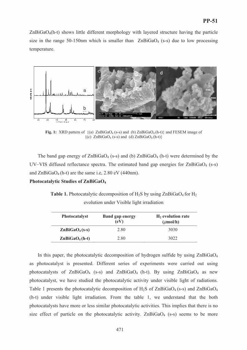
PP-51
471
ZnBiGaO4(h-t) shows little different morphology with layered structure having the particle
size in the range 50-150nm which is smaller than ZnBiGaO4 (s-s) due to low processing
temperature.
Fig. 1: XRD pattern of {(a) ZnBiGaO4 (s-s) and (b) ZnBiGaO4 (h-t)} and FESEM image of {(c) ZnBiGaO4 (s-s) and (d) ZnBiGaO4 (h-t)}
The band gap energy of ZnBiGaO4 (s-s) and (b) ZnBiGaO4 (h-t) were determined by the
UV–VIS diffused reflectance spectra. The estimated band gap energies for ZnBiGaO4 (s-s)
and ZnBiGaO4 (h-t) are the same i.e, 2.80 eV (440nm).
Photocatalytic Studies of ZnBiGaO4
Table 1. Photocatalytic decomposition of H2S by using ZnBiGaO4 for H2
evolution under Visible light irradiation
Photocatalyst Band gap energy (eV)
H2 evolution rate (μmol/h)
ZnBiGaO4 (s-s) 2.80 3030
ZnBiGaO4 (h-t) 2.80 3022
In this paper, the photocatalytic decomposition of hydrogen sulfide by using ZnBiGaO4
as photocatalyst is presented. Different series of experiments were carried out using
photocatalysts of ZnBiGaO4 (s-s) and ZnBiGaO4 (h-t). By using ZnBiGaO4 as new
photocatalyst, we have studied the photocatalytic activity under visible light of radiations.
Table 1 presents the photocatalytic decomposition of H2S of ZnBiGaO4 (s-s) and ZnBiGaO4
(h-t) under visible light irradiation. From the table 1, we understand that the both
photocatalysts have more or less similar photocatalytic activities. This implies that there is no
size effect of particle on the photocatalytic activity. ZnBiGaO4 (s-s) seems to be more

PP-51
472
crystalline than the ZnBiGaO4 (h-t) as observed in XRD and SEM. From the above studies,
we concluded that the photocatalytic activity is more dependent on crystallinity and good
microstructure than the smaller particle size and high surface area.8 Low light absorption and
unsatisfactory stability in time are, unfortunately, typical for smaller particle sized
(nanoparticles) photocatalysts.
Acknowledgements
This research (paper) was performed for the Hydrogen Energy R&D Center, one of the
21st Century Frontier R&D Program, funded by the Ministry of Science and Technology of
Korea.
References
(1) Elsner, M. P.; Menge, M.; Muller, C.; Agar, D. W. Cata. Today 2003, 79, 487.
(2) Linkous, C. A.; Muradov, N. Z.; Ramser, S. N. Int. J. Hydrogen Ener. 1995, 20, 701.
(3) Kudo, A.; Kato, H.; Tsuji, I. Chem Lett. 2004, 33, 1534.
(4) Kato, H.; Kudo, A. J. Phys Chem. B. 2002, 106, 5029.
(5) Kim, J.; Hwang, D.W.; Kim, H.; Bae, S.W.; Ji, S. M.; Lee, J. S. Chem. Commun. 2002, 2488.
(6) Ishii, T.; Kudo, H.; Kudo, A. J. Photochem. Photobiol. A. 2004, 163, 181.
(7) JCPDS file, 38-1240.
(8) Beydoun, D.; Amal, R.; Low G.; McEvoy, S. J. Nanoparticle Res., 1999, 1, 439.
PP-52
473
PHOTOCATALYTIC HYDROGEN PRODUCTION
OF CdS COMPOSITE FILMS BASED ON TITANIA-NANOTUBE
Sang-Jin Moon*, Hyun-Mi Lee, Won-Wook So, Jin-Ook Baeg, and Hyunju Chang
Korea Research Institute of Chemical Technology (KRICT)
100 Jang-dong, Yuseong-gu, Daejeon 305-343, Republic of Korea
*e-mail; [email protected], fax; 82-42-860-7590
1. Introduction
Recently, TiO2 nanotubes have been prepared by a rather simple hydrothermal processing
using NaOH aqueous solution [1]. Since this TiO2 form has a larger surface area, it is of
particular interest in the respect of catalytic or photocatalytic application. In the present study,
we prepared TiO2 nanotubes following the previous hydrothermal process under the basic
condition [1] but using KOH solution instead of NaOH solution, resulting in longer TiO2
nanotubes with a very strong thermal resistance at higher temperatures. Thus, their
applicability as a catalyst scaffold for photo-production of hydrogen from aqueous H2S
solution was studied and the activities were tested after preparing CdS-TiO2 nanotube
composite films as visible-light sensible photocatalysts.
2. Experimental
Nano-crystalline CdS sol was prepared by a precipitation reaction of 0.5 M Cd(NO3)2 and
0.5 M Na2S aqueous solutions at room temperature and a subsequent hydrothermal treatment
at 240°C for 12 hr [2]. TiO2 nanotubes were prepared by the hydrothermal reaction under
strongly basic condition. A commercial TiO2 powder (P-25, Degussa) was used as a starting
material. For alkali-treatment of the TiO2 raw material, concentrated (10~15 M) KOH or
NaOH aqueous solution was used. Hydrothermal treatment was conducted for 12 hr at 120°C
in a sealed Teflon-lined S.S. vessel containing about 50 cc of KOH or NaOH aqueous solution.

PP-52
474
The resulting TiO2 slurry was washed with deionized water and further treated with an
inorganic acid like HCl (~0.1 M), and then washed again repeatedly with deionized water to
obtain the final TiO2 nanotube slurry. These CdS sol and TiO2 nanotube slurries were mixed
together mechanically using ultrasonification with variation of the mole ratio, r = TiO2
nanotube/(CdS + TiO2 nanotube). Using these CdS-TiO2 nanotube composite sols, CdS-TiO2
nanotube composite films were prepared by casting the final sol onto fluorine doped SnO2
conducting glass (F:SnO2), and a subsequent heat-treatment at 450°C for 30 min under air.
The physico-chemical properties of the composite films were measured by using SEM, TEM,
XRD, and the BET method (Micromeritics, ASAP 2400). The photocurrent was measured in a
water-jacketed cell of three-electrodes system consisting of the composite film electrode
(photo-anode), a saturated calomel electrode (SCE), and Pt gauze. The light was illuminated
on the photo-anode with the intensity of 100 mW/cm2 (A.M. 1.5) using a Xe lamp (ILC
Technology, U.S.A). Hydrogen production experiments were carried out in a closed
circulation system [3] using an aqueous solution of 0.1 M Na2S and 0.02 M Na2SO3 as a
reference feedstock for comparison of water photo-splitting activity of these composite films
which was coated with Pt particles as co-catalyst by plasma sputtering (80 watt, 30 sec.,
3x10⁻³ torr of Ar).
3. Results and Discussion
Figure 1 shows typical TEM images for the microstructure of TiO2 nanotubes prepared.
Depending on the kind of the basic solution used, the nanotubes (Figure 1b) prepared with
KOH solution revealed a different morphology with smaller outer diameter (~5 nm) and
longer length (~500 nm) compared to the nanotubes (Figure 1a) prepared with NaOH solution.
After calcination of the nanotubes under air at 450°C, the surface areas of nanotubes prepared
with NaOH solution reduced to about 30 % of the initial surface area (376 � 134 m2/g),
while that of the nanotubes prepared with KOH solution was not so much variant (352 �
296 m2/g). The nanotubes prepared under KOH solution were apparently more resistant to

PP-52
475
heat treatment at a higher temperature.
Figure 2 shows SEM photographs of CdS-TiO2 nanotube composite films, whose nanotube
was prepared in KOH solution. The pure TiO2 nanotube film (r = 1) showed a rather dense
shape consisting of thin and long nanotubes, which were aligned uniformly. The CdS-TiO2
nanotube composite films (Figure 2b and 2c) revealed that CdS particles and TiO2 nanotubes
were well mixed homogeneously without any severe agglomeration among TiO2 nanotubes.
Their photocatalytic performances such as the photocurrents and the hydrogen photo-
production rates were measured. The values measured under the present experimental
conditions varied in the range of 0.05 ~ 4.95 mA/cm2 and 0.03 ~ 0.23 cc/cm2·hr with r,
respectively, and showed the maximum hydrogen production rate at r = 0.2 (Figure 3). As a
result of higher resistance of the present TiO2 nanotubes to the acid etching and thermal
treatment at higher temperatures, the CdS-TiO2 nanotube films showed stable and strong film
properties, although their photocatalytic performances were not so remarkable compared to
the previous CdS-TiO2 particulate films [4].
Acknowledgements This research was performed for the Hydrogen Energy R&D Center, one of the 21st Century Frontier R&D Program, funded by the Ministry of Science and Technology of Korea.
References
[1] T. Kasuga, M. Hiramatsu , A. Hoson , T. Sekino, K. Niihara, Adv. Mater.,11(15),1307 (1999).
[2] W.W. So, J.S. Jang, Y.W. Rhee, K.J. Kim, S.J. Moon, J. Colloid Interface Sci., 237, 136 (2001).
[3] S.J. Moon, W.W So, H.Y. Chang, J. Electrochem. Soc., 148(9), E378 (2001).
[4] W.W. So, K.J. Kim, S.J. Moon, Int. J. Hydrogen Energy, 29, 229 (2004).

PP-52
476
(a (b
Figure 1. TEM images of TiO2 nanotubes
prepared by the hydrothermal treatment
with (a) NaOH aqueous solution and (b)
KOH aqueous solution.
(a (b
(c (d
Figure 2. SEM photo-graphs of
composite films with variation of
the mole ratio, r = TiO2
nanotube/(CdS + TiO2 nanotube):
(a) r = 0, (b) 0.2, (c) 0.4, (d) 1.
0 5 10 15 20 25 30 35
0.00
0.03
0.06
0.09
0.12
0.15
H2 p
rodu
ctio
n ra
te (m
L/c
m2 )
Time (min)
(a)
(b)
(c)(d)
(e)(f)
Figure 3. The amount of hydrogen produced from
CdS-TiO2 nanotube composite films:
(a) r = 0, (b) 0.2, (c) 0.4, (d) 0.6, (e) 0.8, (f) 1.

PP-53
477
EFFECT OF PREPARATION PARAMETERS ON ACTIVITY OF
La1-xCexCoO3 PEROVSKITES FOR ENERGY PRODUCTION BY
THE CATALYTIC FLAMELESS COMBUSTION OF METHANE
C. Olivaa, G.L. Chiarelloa, S. Cappellia, I. Rossettia, A. Kryukovb, L. Fornia
aDipartimento di Chimica Fisica ed Elettrochimica, Università degli Studi di Milano,
and CNR Institute, via C.Golgi, 19 20133 Milano, Italy. Fax:+39-02-70638129 bD.I. Mendeleev University of Chemical Technology of Russia, Moscow, Russia.
Introduction and aim of the investigation
Perovskite-like La1-xCexCoO3 samples are well-known catalysts for several
applications [1, 2] and particularly for the catalytic flameless combustion (CFC) of methane
[3,4]. However, samples with the same nominal composition, but prepared by different
procedures, can show very different catalytic performance. In a few cases the XRD patterns of
catalysts prepared by the traditional sol-gel (SG) method show traces of La2O3, CeO2, and/or
Co3O4 [3]. This does not occur with samples with the same composition, but obtained by
innovative methods based on flame-hydrolysis (FH) [4] or flame pyrolysis (FP) [5]. However,
these impurities are present in a very low concentration, so to be hardly detectable by XRD.
Furthermore, to the best of our knowledge, no clear connection has been ever established
between the presence of those low-concentration phases and catalytic performance. In
addition, some SG-prepared La1-xCexCoO3 catalysts showed an Electron Paramagnetic
Resonance (EPR) line at g ≅ 2, Lorentzian-shaped at low temperature and broadening with
increasing it (L line, Fig.1(a)). This feature was observed with some low-performance
catalysts both when fresh and after use for the CFC of methane [3] but it was noticed only
after the catalytic reduction of NO by CO with other nominally identical SG-prepared
samples [2]. Furthermore, L was never observed with FH- or with FP-prepared La1-xCexCoO3
catalysts [4, 5]. In any case, no connection between L and catalytic performance has been
proposed up to date with La1-xCexCoO3 catalysts. Lines like L have been reported in literature
also with SG-prepared La1-xMxMnO3 samples (M = Ce, Eu, Sr) [6]. In that case the EPR line
broadening was attributed to polaron propagation involving Mn3+(3d4; S = 2) and the nearest
neighbour Mn4+(3d3; S = 3/2), among which a conduction electron hops (Double Exchange
mechanism) and a connection between this line, activity and durability of those catalysts has
been proposed [7]. However, in the here examined case of La1-xCexCoO3, the 3d6 Co3+ ions

PP-53
478
are stable in the low spin (S = 0, t62g, e0
g) state when octahedrally coordinated to 6 oxygen
atoms in an ideal LaCoO3 structure. Therefore, no EPR line at all would be expected with
ideal samples of this kind and the considerations above reported for La1-xMxMnO3 cannot be
simply applied to La1-xCexCoO3 catalysts. The aim of this investigation was then to better
understand this complicate situation and to find a connection between these phenomena and
catalytic activity of La1-xCexCoO3 in the CFC of methane.
Experimental
The La1-xCexCoO3 samples (x = 0; 0.1) have been prepared both by the traditional SG
route, followed by calcination at 800°C for 8 h (SG0 and SG1 samples) and by the mentioned
FP method [5], recently proposed by us (FP0 and FP1 samples). The last were prepared by
employing n-octanol or ethanol as fuel, obtaining identical results. All the prepared samples
have been then activated at 600 °C for 1 h in flowing air and tested as catalysts for the CFC of
methane. After reaction, the samples underwent three deactivation cycles under reaction
conditions, but at 800 °C for 1 h (samples SG0U, SG1U, FP0U and FP1U) and then re-
examined by XRD and by EPR spectroscopy.
Results and discussion
Catalytic activity was always lower with the SG samples than with the FP ones
(Fig.2). The XRD patterns revealed a pure perovskite-like structure for SG0 and FP0 samples,
as well as for FP1, (see for example Fig.3(a)). On the contrary, traces of CeO2 and Co3O4
phases were noticed in the SG1 (Fig.3(c)).
In our opinion, these can form through the decomposition reaction:
120 La0.9 Ce0.1CoO3+δ → 12 CeO2 +54 La2O3 + 40 Co3O4 + 7 O2 (1)
in which δ = 0.05 to obtain charge neutrality. Usually, not all the right-hand solid phases of
Eq.(1) can be detected by XRD, due to their low amount and dilution in the main perovskite-
like phase. Furthermore, CeO2 and Co3O4 impurities appear also in the FP1U samples
(Fig.3(b)).
No EPR L signal has been observed with SG0, nor with FP0, SG0U and FP0U. By
contrast, both SG1 (Fig.1(a)) and SG1U (Fig.1(b)) showed a L feature, though the latter
showed a g value higher than the former. FP samples behaved in a different way. In fact, the
EPR signal was noticed with FP1U (Fig.1(c)), but not with FP1. The former was characterised
by a g value comparable to that measured with SG1U and higher than that of SG1.
Therefore, L does not appear with pure mono-phasic perovskite-like La1-xCexCoO3
samples. It appears only when La2O3, CeO2 and Co3O4 or similar species form in them, due to
catalytic use (as with FP1U) and/or to the preparation method (as with SG1U and SG1).

PP-53
479
Indeed, a g ≅ 2 Lorentzian-shaped L line has been noticed since long time with Co3O4 [8, 9]
and its origin has been described satisfactorily [10]. The formation of units like:
- O2- - Co3+ - O2- - Co2+ - O2- - Co3+ - O2- - Co2+ - O2- - (Scheme 1)
has been hypothesised, in which two Co2+ (3d7, S = 3/2) ions, localised in tetrahedral sites,
would interact with each other through O2- - Co3+ - O2- bridges, Co3+ (3d6, S = 0) being
localised in an octahedral field. Two sets of units like that underlined in Scheme 1 would
form, characterised by antiferromagnetic and ferromagnetic coupling, respectively. The
former would possess multiplicity 12, the latter multiplicity 24. Furthermore, polarons would
propagate also in Co3O4 [9], accounting for broadening of L with increasing temperature.
Therefore, the presence of the L line in fresh catalysts marks the presence of Co3O4 or, in any
case, that of Co2+ magnetic ions mixed with diamagnetic Co3+ ones. The former, when
clustered, could constitute ferromagnetic (FM) domains. These would cause an internal
magnetic field in the sample, leading to the increased apparent g value of the used catalysts.
Therefore, the L line in fresh samples (as here with SG1) indicates that the reaction (1) has
occurred and, therefore, that the sample has lost a part of its oxygen, becoming a worse
catalyst. Analogously, the appearance of L after reaction (as here with both SG1U and FP1U)
indicates that the catalyst loosed its oxygen through Eq.(1) and that it did not re-oxidize
completely. Furthermore, in the latter cases the increased apparent g value suggests also the
formation of disordered FM clusters of Co2+ and/or other magnetic impurities.
EPR spectroscopy shows then an useful tool to probe the influence of preparation
method on performance of these perovskite-like catalysts, as well as to monitor their re-
oxidation state after the present catalytic reaction.
Acknowledgements
We are indebted with Professor A.V.Vishniakov for helpful discussion. References
[1] L.Forni, C.Oliva, F.P.Vatti, M.A.Kandala, A.M.Ezerets, A.V.Vishniakov, Applied Catalysis B: Environm., 7 (1996) 269. [2] L.Forni, C.Oliva, T.Barzetti, E.Selli, A.M.Ezerets, A.V.Vishniakov, Catalysis B: Environm., 13 (1997) 35. [3] C.Oliva, L.Forni, A.D’Ambrosio, F.Navarrini, A.D.Stepanov, Z.D.Kagramanov, A.I.Mikhailichenko, Applied Catal.A: General, 205 (2001) 245. [4] R.Leanza, I.Rossetti, L.Fabbrini, C.Oliva, L.Forni, Applied Catal.B: Environm., 28 (2000) 55. [5] C.Oliva, S.Cappelli, A.Kryukov, G.L.Chiarello, A.V.Vishniakov, L.Forni, J.Molecular Catal.A: Chemical, 2005, in press. [6] C.Oliva, L.Forni, P.Pasqualin, A.D’Ambrosio, A.V.Vishniakov, Phys.Chem.Chem.Phys., 1 (1999) 355. [7] C.Oliva, L.Forni, Catalysis Commun., 1 (2000) 5. [8] S.Angelov, E.Zhecheva, S.Stoyanova, M Atanasov, J.Phys.Chem. Solids, 51 (1990, 1157. [9] C.Oliva, L.Forni, L.Formaro, Applied Spectroscopy, 50 (1996) 1395. [10 ] W.L.Roth, J.Phys.Chem.Solids, 25 (1964) 1.

PP-53
480
0 1000 2000 3000 4000 5000 6000G
(a)
(b)
(c)k
Fig.1 R.T. EPR spectra of some La0.9Ce0.1CoO3. Samples (a) SG1, (b) SG1U, (c) FP1U. (a) and (b): Intensity x 3; k is a bump due to the instrument cavity, and not to the sample.
0
20
40
60
80
100
200 300 400 500 600 700T [°C]
CH
4 mol
% c
onv. (a)
((
(b) (c)
Fig.2 Activity of La0.9Ce0.1CoO3 for CFC of methane: (a) fresh FP1; b) FP1 after three deactivation cycles (activity decreases significantly only after the first cycle); (c) SG1: activity curves are identical for fresh sample and after three deactivation cycles.
20 30 40 50 60 70 80
2θ
coun
ts
(c)
(b)
(a)
∗
∗
+
+
Fig.3 XRD of La 0.9Ce 0.1CoO3 : (a) FP1, (b) FP1U, (c) SG1. (*) Co3O4; (+) CeO2 phases.

PP-54
481
FUNGICIDE (FUNAC-S) TECHNOLOGY USING
THE PHASE-TRANSFER CATALYSIS METHOD
Z.P. Pai and B.M. Khlebnikov
Boreskov Institute of Catalysis SB RAS, Prosp. Akad. Lavrentieva, 5, Novosibirsk 630090
Russia, Fax: +7(383) 330 8056 E-mail: zpai@ catalysis.nsk.su
The prospects for the sulfur production speed-up in Russia (2006) are estimated at 6.5
million tons, which is associated with the development of gas-processing, oil-refining and
metallurgy industries. Besides, more rigid ecological standards on sulfur emissions into the
atmosphere [1] can become a cofactor of the sulfur output increase.
However, taking into account the fact that sulfur is not highly profitable commodity, as
compared to oil products, it is reasonable and commercially viable to develop and
commercialize new sulfur-processing technologies providing an increase in the production of
agrichemicals.
In this work we report on the development of a new agrochemical micro-structured
composite FUNAK-S. To develop a pesticides composite, one should prepare a water-soluble
emulsion containing elemental sulfur (by product of the gas-production, oil-refining, by-
product-coking and metallurgy industries) as the main initial component. In order to improve
functional properties of the product, we added to the mixture a number of ammonium salts of
lignin sulfonic acids (wood residue) and ameliorant (a special additive), acting as a phase-
transfer catalyst. Adding the phase-transfer catalyst, it is possible to prepare
sulfanmonosulfonic acids, which provide both stabilization of the resulting colloidal system
and improve its acaricide activity.
On the development of a reactor, we used a number of unique technical solutions, which
permit one to reduce the process time by integrating several technological steps; to improve
the quality of the resulting product due to formation of particles <1 micron in size, the yield
being 80%. Note that the best analogue-prototypes contain 70-80% of granules 6 micron in
size and 20-30%, 12 micron in size [2].
«FUNAK-S» is a multipurpose chemical because of its fungicidal, acaricidal and
insecticide properties. Using the “FUNAK-S”, it is possible to
?) increase activity due to formation of sulfur-containing acids, which improve stability of
the suspension with time;

PP-54
482
b) improve LD50 indexe (the corresponding dose or concentration of the solution that
provide demise of 50% of organisms) with respect to analogues by not less that two times;
c) increase selectivity and persistence (ability to preserve in the surrounding for some time
and to keep biological activity).
In contrast to the known pesticides, «FUNAK-S» does not enter plant fruits!
The product can be manufactured as powder or paste with the moisture up to 15-20%. For
treatment of plants, one should prepare a solution: 10-20 g of FUNAK-S per 10 L of water.
References1. www/rcc/ru/Rus/Chemicals/
2. kagol.chat.ru/garden/prilov.htm

PP-55
483
SYNTHESIS OF EPOXIDE COMPLEXES FROM RENEWABLE
RAW MATERIALS
Z.P. Pai, Yu.V. Sapegina, N.V. Selivanova, T.B. Khlebnikova, A.G. Tolstikov
Boreskov Institute of Catalysis SB RAS, Pr. Ak. Lavrentieva, 5, Novosibirsk 630090 Russia
Fax: (383) 330-80-56, E-mail: [email protected]
Utilization of renewable raw materials, such as industrial wood residue, offers
possibilities of manufacturing of epoxy compounds of commercial value. The field of
application of epoxides is rather wide. Epoxides are efficient plasticizers (modifiers,
stabilizing agents and diluents) of plastics and epoxy resins as well as precursors in the
synthesis of different pharmaceutical products. One of the most promising processes for
preparing of epoxides from raw materials is the method of phase-transfer catalysis, providing
direct oxidation of different organic substrates in the presence of peroxopolyoxotungstate
based catalysts [1].
The present work reports screening of substrates of different nature (unsaturated aliphatic
compounds, terpenoids and coumarins) in the reaction of oxidation in a two-phase solution in
the presence of methyltri-n-octylammonium tetrakis(oxodiperoxotungsto)phosphate.
It was established that epoxidation of oleic (1), ricinoleic (2) acids and their ethers (3, 4)
(scheme 1) provides 90 % selectivity with respect to epoxide.
Scheme 1.
R1O2CR2
H2O2
[Cat] R1O2C O R2
1, 5 - R1, R2 = H
2, 6 - R1 = H, R2 = OH
3, 7 - R1 = CH3, R2 = H
4, 8 - R1 = CH3, R2 = OH
1, 2, 3, 4 5, 6, 7, 8
Epoxidation of coumarins was performed using peucedanin (9) as an example. It was
oxidized to yield unstable epoxide (10), which transforms into ketol hydroxyoreozelon (11)
under reaction conditions (Scheme 2).

PP-55
484
Scheme 2
OO O
MeO
Pri
OO O OO O
OHOPri
OPri
OMeH2O2
[Cat]
9 10 11
The process of oxidation of natural terpenoids (such as betulin isolated from birch bark)
results in the formation of a number of products, including epoxide, the yield of which is not
higher than 30 %. By contrast, the oxidation of betulin diacetate (12) provides 90% selectivity
with respect to epoxide (13).
Scheme 3
AcO
OAc
AcO
OAc
O
H2O2
[Cat]
12 13Since the above betulin derivatives exhibit antiphlogistic, antiviral and antineoplastic
activity, they are of profound interest for medicinal chemistry [2].
The work was supported by Russian Found of Fundamental Investigations, Grant No 04-
03-32425, RAS Integration Project No 5.6.3, and State Contract No 02.434.11.2026 (theme
IN-12.6/004).
References 1. Z.P.Pai, A.G. Tolstikov, P.V. Berdnikova, G. N. Kustova, T.B. Khlebnikova, N.V. Selivanova, A.B. Shangina, and V.G. Kostrovskii// Russian Chemical Bulletin, International Edition, 2005, 54, 8, P. 1847-1854.
2. Achrem-Achremowicz J., Janeczko Z. Betulin – a pentacyclic triterpene // Wiadomosci Chemiczne, 2003, 57,3-4. P. 223-246.

PP-56
485
WATER-GAS SHIFT ACTIVITY OF DOPED Pt/CeO2 CATALYSTS
P. Panagiotopoulou1, J. Papavasiliou1,2, G. Avgouropoulos2, T. Ioannides2,
D.I. Kondarides1
(1) Department of Chemical Engineering, University of Patras, GR-26504 Patras, Greece (2) FORTH/ICE-HT, GR-26504 Patras, Greece
Fax:+30-2610-965223, e-mail: [email protected]
1. Introduction
Conventional low-temperature (Cu/ZnO/Al2O3) and high-temperature (Fe3O4/Cr2O3)
water-gas shift (WGS) catalysts cannot be used in power generation systems for
transportation and residential fuel cell applications due to restrictions related to their volume
and weight and also due to the requirements for reduced start-up times, durability under
steady state and transient conditions and stability to condensation and poisons [1,2]. Catalyst
formulations based on cerium oxide seem to be promising alternatives [3-5], exhibiting
activity comparable to that of Cu/ZnO/Al2O3 catalysts [5]. However, most ceria-supported
noble metals are not sufficiently stable under conditions typical of a reformer outlet [6] and
progressively deactivate, possibly due to irreversible reduction of the support [6] and/or
sintering of the dispersed metallic phase [7]. As a result, efforts are made to further increase
catalytic activity and to improve structural stability of ceria-supported noble metal catalysts.
In our previous studies [8,9] it was shown that the WGS activity of supported noble
metals depends strongly on the nature and physicochemical characteristics of the support. In
particular, it was found that activity is significantly improved when the noble metal is
supported on “reducible” rather than on “irreducible” metal oxides [9]. In the present study,
we report on the WGS activity of Pt catalysts supported on metal (Me)-doped cerium oxide
prepared by the urea-nitrate combustion method [10]. The catalytic performance of these
Pt/Ce-Me-O catalysts is investigated with respect to the physicochemical characteristics of
the support, in particular reducibility and primary crystallite size of ceria.
2. Experimental
Metal-promoted cerium oxide supports were synthesized by the urea-nitrates
combustion method [10] by mixing the nitrate salt of the promoter [Me(NO3)z·XH2O] (Me:
Yb, Gd, Zr, Mg, La, Ca, Y, Zn) with cerium nitrate [Ce(NO3)3·6H2O] and urea (CH4N2O) in
appropriate molar ratios (Me/(Me+Ce) = 0.10, 75% excess of urea). In order to obtain pure,

PP-56
486
well-crystallized supports, the resulting powders were calcined in air at 550oC for 1 h.
Catalysts were prepared employing the wet impregnation method with the use of the above
promoted cerium oxide powders and (NH3)2Pt(NO2)2 (Alfa) as a platinum precursor salt.
Materials were characterized with respect to their specific surface area, primary
crystallite size of the support and platinum dispersion, employing nitrogen physisorption at the
temperature of liquid nitrogen (BET method), X-ray diffraction (XRD) and selective
chemisorption of CO, respectively. Temperature-programmed reduction (TPR) experiments
were performed under a flow of a 3% H2/He mixture (50 cm3 min-1) over 200 mg of
preoxidized catalyst using a heating rate of 10oC/min. The catalytic performance for the WGS
reaction was investigated in the temperature range of 100-550oC using a feed stream
consisting of 3%CO and 10%H2O (balance: He, total flow: 150 cm3/min, mcat= 75 mg).
Measurements of intrinsic rates were obtained under differential reaction conditions. Details
on the techniques and methods employed can be found elsewhere [8].
3. Results and discussion
Results of catalyst characterization are summarized in Table 1. It is observed that
doping results in a substantial increase of the BET surface area, compared to that of undoped
Pt/CeO2, which is accompanied by a parallel decrease of the primary crystallite size of ceria.
Table 1. Results of catalyst characterization and of kinetic measurements obtained from the 0.5%Pt/(Ce-Me-O) catalysts investigated.
Promoter (Me)
SBET (m2.g-1)
dCeO2(*)
(nm) Pt dispersion
(%) Rate at 250oC (�mol.s-1.g-1)
TOF at 250oC (s-1)
Activation Energy
(kcal.mol-1) Yb 41 7.9 40 13.1 1.28 18.8 Gd 42 9.4 52 11.1 0.83 20.5 Zr 27 11.0 100 10.7 0.42 19.9 Mg 33 10.2 58 10.1 0.68 20.4 La 50 8.9 73 9.65 0.52 19.2 Ca 43 8.0 45 6.22 0.54 20.9 Y 28 11.2 48 5.21 0.42 20.5 Zn 20 15.5 37 1.33 0.14 20.0
Undoped 8 18.5 46 6.53 0.55 18.2 (*) Primary particle size of CeO2 determined by XRD line broadening.
XRD patterns obtained from the Pt/Ce-Me-O catalysts are shown in Fig. 1. It is
observed that the diffraction peaks of ceria in the doped samples are shifted towards higher or
lower diffraction angles, compared to that of the undoped catalyst. This depends on the ionic
radius of the dopant cation and implies that the dopant cation is incorporated in the ceria
lattice.

PP-56
487
25 30 35
CeO2
Pt-CeO2
Ce-Ca-O
Ce-Yb-O
Ce-Gd-O
Ce-La-O
Ce-Zn-O
Ce-Zr-O
Ce-Mg-O
Ce-Y-O
Inte
nsity
(a.u
)
2� (degree)
100 200 300 400 500 600 700 800
Pt/Ce-Y-O
Pt/Ce-Yb-O
Pt/Ce-La-O
Pt/Ce-Gd-O
Pt/Ce-Zr-O
Pt/Ce-Zn-O
Pt/Ce-Mg-O
Pt/CeO2
H2 c
onsu
mpt
ion,
a.u
.
T, oC
Figure 1. XRD profiles of Pt/Ce-Me-O catalysts. Figure 2. TPR profiles of Pt/Ce-Me-O catalysts.
The TPR profiles (Fig. 2) of Pt/Ce-Me-O catalysts are characterized by features at high
(>600oC) and low (<150oC) temperatures, assigned to reduction of bulk ceria and platinum
oxide, respectively, and by broad peaks at intermediate temperatures (200-600oC), attributed
to the Pt-catalyzed reduction of the surface cell of ceria. The amount of H2 consumed during
TPR is larger for doped catalysts, indicating that doping enhances the reducibility of ceria.
Results of catalytic performance tests are presented in Fig. 3. It is observed that doping
of Pt/ceria with Ca (line 3), Gd, Mg, La (line 2) and, especially, Yb (line 1) results in a shift
of the conversion curves toward lower reaction temperatures, compared to the one of the
unpromoted catalyst (line 4). Similar was the effect of addition of Zr, which gave a
conversion curve located between lines 1 and 3 (not shown for clarity). In contrast, doping
with Y (line 5) and Zn (line 6) results in a decrease of catalytic activity, which is much more
pronounced for the latter sample.
Results of kinetic experiments (Table 1) show that the apparent activation energy (Ea)
of the WGS reaction does not vary significantly, taking values between 18 and 21 kcal.mol-1
for all samples investigated. In contrast, the specific reaction rate (per gram of catalyst)
depends strongly on the nature of the promoter, following the order of Yb> Gd> Zr> Mg>
La> Ca> CeO2(undoped)> Y> Zn, with the Yb-promoted catalyst being about one order of

PP-56
488
magnitude more active than the Zn-promoted one, at 250oC. Comparison with the TPR results
of Fig. 2 shows that a general correlation between catalyst activity and ceria reducibility does
not exist.
200 250 300 350 4000
20
40
60
80
100
6
5
43
2
1
Con
vers
ion
of C
O (%
)
Temperature (oC)
Dopant (Me)(1) Yb(2) Gd, Mg, La(3) Ca(4) CeO2 (undoped)(5) Y(6) Zn
Figure 3. Catalytic performance of the indicated 0.5%Pt/(Ce-Me-O) catalysts for the WGS reaction.
4. Conclusions
The WGS activity of Pt/Ce-Me-O catalysts depends strongly on the nature of the dopant
employed, following the order of Yb> Gd> Zr> Mg> La> Ca> CeO2(undoped)> Y> Zn, with
the Yb-promoted catalyst being about one order of magnitude more active than the Zn-
promoted one at 250oC. Although ceria becomes more reducible upon doping, the enhanced
reducibility does not seem to be the only factor influencing activity in doped catalysts.
References1. A.F. Ghenciu, Curr. Opin. Solid State Mater. Sci. 6 (2002) 389.
2. J.M. Zalc and D.G. Löffler, J. Power Sources 111 (2002) 58.
3. T. Bunluesin, R.J. Gorte, Appl. Catal. B 15 (1998) 107.
4. Y. Li, Q. Fu, M. Flytzani-Stephanopoulos, Appl. Catal. B 27 (2000) 179.
5. Q. Fu, H. Saltsburg and M. Flytzani-Stephanopoulos, Science 301 (2003) 935.
6. J.M. Zalc, V. Sokolovskii, D.G. Löffler, J. Catal. 206 (2002) 169.
7. T. Bunluesin, R.J. Gorte, G.W. Graham, Appl. Catal. B 15 (1998) 107.
8. P. Panagiotopoulou, D.I. Kondarides, J. Catal. 225 (2004) 327.
9. P. Panagiotopoulou, D.I. Kondarides, Catal. Today, in press.
10. G. Avgouropoulos, T. Ioannides, Appl. Catal. A 244 (2003) 155.

PP-57
489
MESOPOROUS ZrO2-TiO2-Y2O3 FOR FUEL CELLS APPLICATIONS
V. Parvulescua, N. Cioateraa, S. Somacescua, G. Telipanb, M. Ignatb,
B.G. Albuc and B.L. Sud
aInstitute of Physical Chemistry, Spl. Independentei 202, Bucharest, Romania
e-mail:[email protected] bRcesearch Institute for Electrical Engineering-Advanced Research, Bucharest, Romania
cResearch Center for Macromolecular Materials and Membranes, Bucharest, Romania dLaboratoire de Chimie des Matériaux Inorganiques, The University of Namur (FUNDP),
61 rue de Bruxelles, B-5000 Namur, Belgium
ABSTRACT: Y2O3-ZrO2, Y2O3-TiO2 and Y2O3-TiO2-ZrO2 oxides with various composition,
structure and morphology were prepared using a surfactant templating strategy. The obtained
binary and ternary oxides were characterized by XRD, TEM and SEM microscopies,
adsorption and N2 desorption of. Characterization revealed that the mesoporous powder,
calcined at 873 K was weakly agglomerated and had a high surface area.
INTRODUCTION
Zirconia based ceramics have been widely used for several advanced and structured
applications such as solid-oxide fuel cells (SOFC), gas sensors and automotive [1-3]. One of
the most successful semiconducting oxygen sensors in automotive application is the TiO2. For
these applications it is desirable to control the porosity of the materials to obtain a
homogeneous structure and a good packing of powders. Colloidal processing is accepted as an
ideal route [4, 5]. These materials must be able to operate in harsh conditions, such as high
temperature and the presence of aggressive gases. One of the possibilities to operate at lower
temperatures is the introduction of the porosity by the preparation of nanoscaled materials.
Here we describe and discuss the synthesis and characterization of mesostrucured yttria-
zirconia and yttria-titania-zirconia with 8 wt. % yttria. The mesoporous oxides are obtained as
materials for anode in SOFC applications.
MATERIALS AND METHODS
Y2O3-ZrO2, Y2O3-TiO2 and Y2O3-TiO2-ZrO2 were synthesized by two methods using
sol-gel procedure. The surfactant used in the first method was cetyltrimethhylamonium
bromide-CTAB and in the second poly(alkylene oxide) block copolymer-Pluronic. The
reagents used as precursors were zirconium propoxide or ZrCl4, titanium isopropoxide or

PP-57
490
TiCl4 and Y (NO3)3 6H2O. In the first method the oxides were obtained by partial hydrolysis
of alkoxides in the presence of water resulting from an esterification reaction between
propylic alcohol and acetic acid. The sols with various ZrO2/TiO2/Y2O3 molar ratios were
mixed with CTAB solution in alcohol. In the second method the solutions of inorganic
precursors were added with vigorous stirring in to block copolymer alcoholic solution. The
resulting sol solution was gelled at 313 K in air for hydrolysis and polymerization of the
inorganic precursors. The gels were supported by dip coating method on CeO2-Ta2O5 support
(Í=1.0 mm, h=10 mm), dried at 373 K and calcined at 873 K. The obtained powders and
films were characterized by XRD, TEM and SEM microscopy and N2 adsorption-desorption.
RESULTS AND DISCUSSION
XRD patterns of Y2O3-ZrO2,
Y2O3-TiO2 and Y2O3-TiO2-ZrO2
materials reveal the presence of
amorphous phase with a mesoporous
structure (Fig.1). The low-angle
diffraction indicates that mesoscopic
order is preserved in the calcined oxides.
This is confirmed by nitrogen adsorption-
desorption isotherms (Fig.2) and
transition electron microscopy (TEM)
images (Fig.3). The isotherms of the
calcined samples obtained by the first method (Fig.2) are typical for the mesoporous materials
with narrow pore distribution. The isotherms of the samples obtained by the second method
exhibit distinct hysteresis loop in the P/Po ranging from 0.4 to 0.9, typical for the mesoporous
materials with larger pore distribution. This binary and ternary mesoporous materials display
a high surface area (134-182 m2/g). The mesoporous structure is stable up to 873 K for the
oxides obtained by the first method. The samples obtained by the second method are more
stable. The evolution of the mesoporous structure was examined by TEM and SEM for the
samples calcined at 873 K and 973 K. In Fig. 3 are clearly observed the ordered array. For the
formation of low-densified Y2O3-TiO2-ZrO2 oxides from mesoporous powder, at higher
temperature, it may consider that the mesopores grew into larger connected channel during
calcination and sintering process.
10 20 30 40 50 60
4 8 12 16 20
Z8Ys
Inten
sitate
, u.a.
2θ
T8Ys
TZ8Ys
Inte
nsita
te, u
.a.
2θ Fig. 1. XRD patterns of binary and ternary oxides

PP-57
491
0.0 0.2 0.4 0.6 0.8 1.0
ZTY1ZTY22
ZTY 2
Pore
vol
ume,
cm
3 /g
P/Po
Fig. 2. N2 adsorption-desorption isotherms of the powders obtained by the method 1
Fig. 3. TEM images of ZTY22 sample
A B
Fig. 4. SEM images of ZTY22 oxide film (A) and powder (B)
The morphology of binary and ternary powders and films are typically for the
mesoporous materials. Figures 4 presents SEM images of Y2O3-TiO2-ZrO2 film (A) and
powder (B) obtained by the first method.
The mesoporous powders obtained by the second method are weakly agglomerated
and all the films obtained are very homogeneous. Such materials with open structure may be
used as the skeleton of SOFC electrodes in order to reduce the concentration polarization.
Further coming, mesoporous Cu-CeO2-YTZ and Ni-YTZ anodes will be prepared by this
method and its effect on the concentration polarization will be investigated.
CONCLUSIONS
The nanocrystalline mesoporous oxides with Y2O3, TiO2, ZrO2 oxides were prepared
using CTMA or block copolymer as surfactants. The obtained oxides are mesoporous
materials with high surface area and highly stable structure.
REFERENCES 1. R.J. Gorte, J.M. Vohs, S. McIntosh, Solid State Ionics, 175 (2004) 1. 2. S.D. Kim, S.H.H. Yun, J. Moon, J-H. Kim, R.H. Song, J. Power Sources 139 (2005) 67. 3. C-W. You, Y-H. Lee, K-Z. Fung, M-C. Wng, J. Non-Crystal. Solids, 351 (2005) 304. 4. N. McN. Alford, J.D. Birchall, K. Kandall, Nature, 330 (1987) 51. 5. J. Zhang, F. Ye, J. Sun, D. Jiang, M. Iwasa, Colloid Surf. A Physicochem Eng. Aspects, 254 (2005) 199.

PP-58
492
BENZENE TO PHENOL OXIDATION ON TRANSITION METALS
INCORPORATING MESOPOROUS SILICAS
V. Pârvulescua, S. Todorovab, G. Kadinovb, K. Tenchevb, Cr. Tableta and B.L. Suc
aInstitute of Physical Chemistry, Spl. Independen�ei 202, FAX: 402131
[email protected], R-060021 Bucharest, Romania bInstitute of Catalysis, Bulgarian Academy, Acad. G. Bonchev St., Block 11, Sofia, Bulgaria
cLaboratoire de Chimie des Matériaux Inorganiques, ISIS, The University of Namur
(FUNDP), 61 rue de Bruxelles, B-5000 Namur, Belgium
ABSTRAC: Mono- (Ti, V, Cr, Mn, Fe, Ni, Cu) and bimetallic (V-Ti, V-Co, V-Cu, Cr-Ni, Cr-
Ru, Ni-Ru, Cu-Ru)- MCM-41 molecular sieves, obtained by hydrothermal synthesis, are
active in selective oxidation of benzene to phenol. Benzene hydroxylation temperature and
time were varied from 293 to 343K and from 12 to 48 h, respectively. The incorporation of
the second metal increases the activity of the Me-MCM-41 catalysts. The effects are
significantly for V on Ti and Co and Ru on Cu containing molecular sieves. The main
reaction product is phenol. Leaching for the ruthenium and chromium was only evidenced.
INTRODUCTION
The oxidative hydroxylation of aromatic compounds is a very attractive way to
produce phenol by one-step oxidation of benzene [1, 2]. A new process to produce phenol
without by-product and with high selectivity has therefore been explored, under mild
conditions, by catalytic hydroxylation of benzene over transition metal or transition metal
complex containing micro/mesoporous materials [3, 4]. The common feature of these
biomimetics reactions is activated species with oxygen. Of the environmentally benign
materials, hydrogen peroxide is the most attractive for hydroxylation reactions realized at
small-scale procedures [5].
In this paper, direct hydroxylation of benzene with hydrogen peroxide on mono- and
bimetallic MCM-41 mesoporous molecular sieves was investigated. Especially, improvement
of the catalytic activity was explored by incorporation of the second metal (another 3d
transition metal or ruthenium) into MCM-41 network.
EXPERIMENTAL
The mono- and bimetallic MCM-41 molecular sieves were prepared by hydrothermal
treatment [4,6] on the basis of molar gel composition of 1.0 SiO2: x M: 0.48 CTMAB: 0.28

PP-58
493
Na2O: 3.7 TMAOH: 222.0 H2O (where x= 0.02-0.1 for M= Co, x= 0.02 for M=Ti, V, Cr, Mn,
Fe, Ni, Cu, and x= 0.04 for M=V-Ti, V-Co, V-Cu, Cr-Ni, Cr-Ru, Ni-Ru, Cu-Ru with M1/M2
molar ratio=1). The solid products were recovered by filtration, washed, dried in air at 373 K
and calcined in a flow of N2 followed by air at 823 K. The obtained materials and the metal
states were characterized by XRD, N2 adsorption/desorption, SEM and TEM microscopy,
TPR, XPS and DRS methods.
Phenol hydroxylation experiments were run in a glass reactor equipped with a reflux
condenser and a magnetic stirrer. The reaction temperature and time varied from 293 to 343
K and from 12 to 48 h, respectively. The molar ratio of phenol /hydrogen peroxide was 1/3.
After reaction, the catalyst was separated by centrifugation and the oxidation products were
analyzed on gas chromatography. The catalysts were reutilized in the oxidation reactions and
characterized after each utilization. Hydrogen peroxide consummation was determined by
iodometric titration and metal ions leaching were also verified.
RESULTS AND DISCUSSION
The activity, at 323 K, of monometallic redox molecular sieves and the effect of ionic
ratio on the conversion of benzene are presented in Figure 1. A higher conversion was
obtained for the cation with lower RM(n+)/RO(2-) ratio. A comparation of the XRD patterns and
the cell parameter a0 (calculated from a0 =2d100(3)-1/2), for the obtained monometallic samples,
show a highly ordered and stable hexagonal phases when the oxidation state of the cation,
introduced during synthesis, is favorable for a tetrahedral coordination and the RM(n+)/RO(2-)
ratio varies between 0.3 and 0.5. Conversion of benzene to phenol increases with the quantity
of the incorporation of the metals in the silica framework (see Fig. 1) for different values of
RM(n+)/RO(2-) ratio). The highly ordered array of MCM-41 molecular sieves and metal state are
modified with metal loading and activity increase. The maximum activity was obtained al 7.4
% Co. In the low loaded Me-MCM-41 catalysts the metal is in one oxidation state in
tetrahedral position. The increase in the metal content results in the appearance of the oxide
extra-framework phase. Increasing of the metal loading changes the ratio between two kinds
of the metal: extra-framework and in the framework (Fig.2). The high can be favorable to the
homolyticaly decomposition of H2O2 and the reaction of the hydroxyl radicals with benzene.

PP-58
494
Fig. 1. Effect of transition metal modification and ionic ratio on the conversion of benzene
Fig. 2. Variation of TPR profiles with loading of cobalt
Fig. 3. Effect of the second metal on the conversion of benzene to phenol
In the reaction of benzene oxidation the conversion on the monometallic cobalt
catalysts increased with the cobalt content. As is mentioned above, several oxide phases and
Co3O4 are formed in the samples with high cobalt content. It is possible that the key factor in
the benzene oxidation with hydrogen peroxide on the cobalt modified catalyst to be the
formation of cobalt oxide interacting weakly with the siliceous framework.
The longer induction period of the catalysts was modified by changing the addition
method for H2O2. The second metal increases the activity of the Me-MCM-41 catalysts. The
effects are significantly for V on Ti and Co and Ru on Cu containing molecular sieves (Fig.3).
The main reaction product is phenol and selectivity to phenol is high for all the catalysts.
PP-58
495
The effect of reaction temperature was also evidenced. The selectivity to phenol is
lower for all the catalysts with Cr. Leaching for the ruthenium and chromium was only
evidenced.
CONCLUSIONS
XRD patterns of the monometallic samples show a highly ordered and stable
hexagonal phase. The monometallic samples form several oxide phases, which differ in their
interaction with the support and are placed outside the molecular sieve framework. A higher
conversion was obtained for the cation with lower RM(n+)/RO(2-) ratio. Conversion of benzene
to phenol increases with the quantity of the incorporation of the metals in the silica
framework. The activity increase with metal content and the maximum value was obtained for
Co-MCM-41 catalysts with 7.4 % wt. Co. An increase in cobalt content leads to a decrease in
the interaction of CoO phase(s) with MCM-41 and to the appearance of Co3+ in Oh symmetry.
The second metal increases the activity of redox molecular sieves.
REFERENCES 1. V.Parvulescu, C. Anastasescu, B.L. Su, J. Mol. Catal A Chem ., 211 (2004) 143.
2. J. He, W-P Xu, D.G. Evans, X. Duan and C-Y. Li, Microporous Mesoporous Mat., 44-45 (2001) 581.
3. T. Miyake, M. Hamada, Y. Sasaki and M. Oguri, Appl. Catal. A: Gen. 131 (1995) 33.
4. V. Parvulescu, C. Anastasescu, C. Constantin and B. L. Su, Stud. Surf. Sci. Catal, 142 (2002) 1213.
5. V.van de Velde, I.W.C.E. Arends and R.A. Sheldon, J. Inorg. Biochem., 80 (2000) 81.
6. V. Pârvulescu and B. L. Su, Stud. Surf. Sci. Catal., 143 (2002) 575.

PP-59
496
HYDROGEN PRODUCTION BY STEAM REFORMING OF
METHANOL OVER GRANULATED AND PLATE-TYPE
Cu-BASED CATALYSTS
S. Pavlova, P. Yaseneva, V. Sadykov, V. Sobyanin, Sukhe, L. Makarshin,
A. Gribovskii, D. Andreev, E. Moroz, E. Burgina
Boreskov Institute of Catalysis SB RAS, Pr. Lavrentieva, 5, 630090, Novosibirsk, Russia
E-mail: [email protected]
Steam reforming of methanol is a promising route to produce hydrogen for small solid
polymer fuel cells which can be an attractive power source for on-board or portable devices
[1]. To develop an effective compact fuel processor, an integrated approach combining the
endothermic SRM with the exothermic combustion of methanol or H2 in the fuel cell anode
off-gases is the most promising. Such a system requires the metal-supported catalysts
ensuring high thermal conductivity and yet ensuring high yield of hydrogen containing low
amounts of CO (not exceeding a few ppm). To miniaturize a fuel processor, microreactors
with microchannels are more applicable. Micro-structured reactors ensure high performance
especially for periodic operation due to the short residence time, which also allows a quick
response to dynamic changes in the inlet conditions [2]. Recently, a number of works
concerning this field were published, however, development of effective microchannel
catalysts for SRM and the methods of their preparation are still a problem to discuss.
Commercial Cu-Zn-based catalysts supported on plate-type metallic substrates are
commonly used for SRM. However, these catalysts have the low thermal and long-term
stability especially at temperatures up to 300°C. The catalysts based on mixed oxides of Cu,
Ce, Y and Zr were found to be more active and selective for SRM than CuO-ZnO catalysts [3].
In this study, to prepare the mixed oxide catalysts with high activity, selectivity and stability,
alumina and Cr were added. Their effect on the SRM performance of the granular mixed
oxides and these systems supported on the porous steel plates with microchannels was
studied.
Experimental
The urea-nitrate combustion method [4] was used to synthesize pure
Cu0.2Ce0.5Y0.2Zr0.1Oy (CCYZ) sample and that with Al2O3 and Cr additives. Urea CO(NH2)2

PP-59
497
(doubled quantity as compared with a stoichiometric value) was added to a mixed solution of
Cu(NO3)2 Ce(NO3)3, ZrO(NO3)2, Y(NO3)3 and Cr(NO3)3 in the appropriate molar ratios.
Al2O3 powder (10-40 w.%) was added to the mixed solution with urea and then it was
steamed until a gel formation followed by calcination in air at 400°C for 3 h. Granular
catalysts were prepared by crushing the pressed pellets obtained from a catalyst powder. To
obtain plate-type catalysts, steel porous plates (~0.7 mm thickness, 30 mm width and 40 mm
length) with microchannels were dipped into alcohol suspension containing a catalyst powder
and glycol and treated in the ultrasonic bath followed by drying. The phase composition of
the catalysts was characterized using XRD and IR spectroscopy. Granular catalysts were
tested in a fixed-bed flow reactor at 250-350°C and GHSV 10000 h-1 in
N2:CH3OH:�2�=20:40:40%vol. reaction mixture. Plate type catalysts were tested in a brass
square microreactor in the feed of CH3OH:�2�=1:1 at a liquid rate ~0.1-2 μmol/min. The
reaction products were analyzed by GC.
Results and discussion
Phase composition of the catalysts. According to XRD data, in all catalysts, the solid
solutions of fluorite structure are present. Though reflections of γ-Al2O3 are absent in all
XRD patterns, the IR data reveal the presence of γ-Al2O3 with a poor crystallinity. Highly
dispersed CuO is also present in samples that is verified by XRD, IR and UV–vis spectra. In
the Cr-containing catalysts, the chromate also is revealed by IR. The specific surface area
(SSA) increases from 30 to 140 m2/g at increasing alumina content in the range of 10-40%.
The addition of Cr favours the increase of SSA up to 170 m2/g.
SRM activity of the granular catalysts. The methanol conversion and selectivity depend on the
catalyst composition and temperature. At all temperatures, addition of Al2O3 increases methanol
conversion which reaches 86% at 300°C for samples containing 40% Al2O3. The incorporation of
Cr in the solid solution as well as the increase of Cu-content up to 12% leads to higher methanol
conversion. The most effective catalysts comprised of Al2O3 and Cr ensure at 300°C the
hydrogen production rate ~10 l/h⋅gcat. For catalysts without additives, CO2 selectivity is 100% at
250-300°C and decreases to 98-98.7% (CO concentration ~0.25-0.3%) at 350°C. For samples
containing Al2O3 and Cr, CO2 selectivity decreases at temperatures above 250°C depending
on the catalysts composition. Note that formation of CO starts only above 250°C even though
this is permitted thermodynamically at much lower temperatures. These results indicate that
the reaction sequence is such that CO2 and H2 are the primary products of the reaction and

PP-59
498
that CO is formed at higher temperatures by the reverse water-gas shift reaction. Addition of
Al2O3 and Cr ensures a stable performance of the catalysts in SRM (Fig.1).
0 10 20 30 40 50 60 70 8060
70
80
90
100CCYZ+Al2O3+Cr
CCYZ+Al2O3
CCYZwithout additives
CH
3OH
con
vers
ion,
%
Time, min
Plate-type catalysts. The performance of the powder catalysts supported on plate-substrates
differs from that of the pellets. The catalysts with only Al2O3 additive show poor hydrogen
production, selectivity and stability. The catalysts comprised of both Al2O3 and Cr ensure
high stability, higher methanol conversion and lower CO concentration as compared with
CuO-ZnO-Al2O3 especially at short contact times (Fig.2).
0.0 0.5 1.0 1.5 2.0
40
60
80
100A
CH
3OH
con
vers
ion,
%
W/F g*min/mmol CH3OH
CCCYZ+Al2O3+Cr
CuO-ZnO-Al2O3
0.0 0.5 1.0 1.5
1.0
1.5
2.0
2.5B
CCCYZ+Al2O3+Cr
CuO-ZnO-Al2O3
CO
con
cent
ratio
n, %
W/F g*min/mmol CH3OH
Fig. 2. Contact time dependence of methanol conversion (A) and CO concentration (B) for CuO-ZnO-Al2O3 (280°C) and Cu-CeZrYOx promoted by Cr and Al2O3 (275°C ) in plate-type microreactor.
Fig.1. Time dependence of methanol conversion over granular catalysts with different composition. 10000h-1, 300°C.

PP-59
499
For all catalysts, the hydrogen production (per gram of the active component) over plate-
supported catalysts is less than that for pellet catalysts. Such a difference could be due to
various testing conditions for granular and plate-type catalysts. In the latter case, higher
methanol and water concentration in the feed could be one reason of the methanol conversion
decreasing. Another cause of the catalysts activity decline could be the internal diffusion
limitation.
References.
1. D. L. Trimm and Z. I. Onsan, Cat. Rev., 43 (2001) 31.
2. P. Reuse, A. Renken, K. Haas-Santo, O.Gorke, K. Schubert, Chem. Eng. Jour. 101 (2004) 133
3. Y. Liu, T. Hayakawa, K. Suzuki, S. Hamakawa, et.al, Appl. Cat. A 223 (2002) 137.
4. J. Papavasiliou, G. Avgouropoulos, T. Ionnides, Cat. Commun. 5(2004) 231.

PP-60
500
KINETIC EVALUATION OF CARBON FORMATION IN A
MEMBRANE REACTOR FOR METHANE REFORMING
Marisa N. Pedernera, Juliana Piña, Daniel O. Borio
Planta Piloto de Ingeniería Química (UNS - CONICET), Camino La Carrindanga Km. 7,
(8000) Bahía Blanca, ARGENTINA. Fax: 0054-291-4861700 Ext: 210/265
E-mail: [email protected]
Introduction
Methane steam reforming is one of the most important processes for the production of
hydrogen and synthesis gas. It may be represented by the reversible reactions (1) to (3).
Deactivation of Ni catalysts by carbon formation is a significant problem in CH4
reforming, caused by fouling of the Ni surface, blockage of the pores of the catalytic particle
and disintegration of the support material [1]. Thermodynamically, the more probable
reversible reactions for carbon formation are equations (4) to (6).
224 3HCOOHCH +↔+ (1) CH4 Cracking 24 2 HCCH +↔ (4)
222 HCOOHCO +↔+ (2) Boudouard 22 COCCO +↔ (5)
2224 42 HCOOHCH +↔+ (3) CO Reduction OHCHCO 22 +↔+ (6)
When CO2 is available at large quantities and low costs, it can be used to replace the
steam partially (mixed reforming) or totally (dry reforming). However, the presence of CO2
augments the risk of carbon formation [1].
An alternative to increase the CH4 conversion is the membrane reactor (MR), in which the
chemical equilibrium is shifted through selective permeation of reaction products. For the
CH4 reforming, the composed membranes constitute an adequate choice due to their high
permeation flows and selectivity [2]. However, it has been demonstrated by means of a
thermodynamic criterion that the removal of H2 from the products stream tends to augment
the risk of carbon formation [3].
In this work, the risk of carbon formation for a MR is kinetically analyzed and compared
with that corresponding to a conventional fixed bed reactor (CR).

PP-60
501
Mathematical Model
Figure 1 shows a scheme of the MR under study. It consists in two concentric tubes, an
external shell installed in an electric furnace and an internal supported Pd membrane tube.
The Ni catalyst is packed in the annular space and a parallel flow configuration is supposed
on both sides of the membrane. The reactor geometry is detailed in Table 1.
CH4,H2OCO2
Sweep gas CH4,H2OCO2
ProductsProducts
H2 H2
Catalyst
Membrane
HeatHeat
Figure 1: Scheme of the membrane reforming reactor.
To represent the MR, a 1D heterogeneous
model is adopted subject to the following
assumptions: a) non-isothermal conditions on
the reaction side, b) plug-flow, c) isothermal
and isobaric conditions for the permeate side,
d) ideal membrane (infinite selectivity to H2)[2, 4]. The intrinsic kinetics reported by Xu and
Froment [5] is selected for reactions (1)
to (3). The effectiveness factors are calculated after solving the mass balances inside the
catalyst particle [6]. The hydrogen permeance is evaluated using the Sievert Law [2, 4].
Table 1: Geometric parameters and operating conditions used to simulate the CR and MR.
Parameter Value Parameter Value Reactor length 20 cm [2] Overall heat transfer coefficient 227 W/m2 K [2]
Shell internal diameter 32.6 mm [2] Furnace temperature 500 ºC [2]
Tube internal diameter 21 mm [2] Feed flow rate 200 SSCM [2]
Tube external diameter 25 mm [2] Feed temperature 500 ºC [2]
Catalyst 30% Ni/Al2O3[4] Pressure 100 kPa [2]
Diameter/height of pellet 1 / 3 mm [4] Sweep flow rate 2000 SSCM [2]
Thickness of Pd film, δ 7.5 μm [2] Sweep gas temperature 500 ºC [2]
The performance of the MR is compared with that of a conventional reactor (CR), which
is modeled by assuming the parameters of Table 1 and null H2 permeation. The trends of the
main variables of the MR model were validated against experimental and numerical results
from the literature [4]. The net rate of carbon deposition (reactions 4 to 6) is evaluated by
means of the kinetic expression reported by Snoeck et al. [7].
2654
DEN
rrr cc
netc)(,,
,++
= (7)
The first term of the right-hand side of equation (7) represents the carbon formation by
CH4 cracking and its gasification by H2 (reaction 4). The second term rc,(5+6) groups the
carbon formation by reactions (5) and (6), and its gasification by CO2 and H2O. According
with this kinetic criterion, if rc,net ≥ 0 at any axial position along the reactor, carbon deposition
occurs.

PP-60
502
Results and Discussion
The influence of the CO2 content in the feed stream is shown in Table 2, where the
equilibrium conversion, the outlet conversion for MR and CR and the carbon formation
prediction through the kinetic criterion are included. For all the studied operating conditions,
the conversion for the MR is higher than that of the CR and even higher than the equilibrium
value. For conditions 1 and 2 (high H2O/CH4 ratios) carbon formation does not occur in any
of the reactors. Conversely, for condition 4 (high CO2/CH4 ratio) carbon deposition appears in
MR and CR. For condition 3, carbon formation is only predicted in the MR.
Table 2: Influence of the H2O/CH4 and CO2/CH4 ratios on XCH4 and the carbon formation in the CR y MR.
Operatingcondition H2O/CH4 CO2/CH4 XCH4
eq XCH4CR XCH4
MR (Carbon formation) CR
(Carbon formation)MR
1 2.9 0.1 0.441 0.405 0.477 NO NO 2 2 1 0.322 0.305 0.389 NO NO 3 0.9 2.1 0.264 0.247 0.326 NO YES 4 0.2 2.8 0.283 0.250 0.320 YES YES
To compare the carbon deposition phenomenon in both reactors, Fig. 2 shows the rc,net
curves along the reactor length. As it can be seen, no carbon formation takes place in the CR
(rc,net <0 for r = 0 and r = 1) while in the MR carbon appears from the critical axial position
zc = 0.117m towards the reactor outlet. This behavior can be explained by inspection of Fig. 3.
The diminution in pH2 caused by the H2 permeation through the membrane, increases the rate
of carbon deposition by CH4 cracking. Besides, pH2O is lower for the MR as a consequence of
the higher CH4 conversion and the shift to the right of the WGS reaction (2). The lower pH2O
values promote carbon formation by CO reduction (reaction 6). As the axial temperature
profiles for both reactors are very similar, it is not possible to attribute the differences
observed in rc,net to a thermal effect.
0.00 0.04 0.08 0.12 0.16 0.20-5
-4
-3
-2
-1
0
1
2
3
CR(r=0)
CR(r=1)
MR(r=0)
z*
r c,ne
t X 1
03 (mol
C/g
cat h
)
z(m)
zc
MR(r=1)
Figure 2: Axial profiles of the net carbon deposition rate in CR and MR (Condition 3 of Table 2). r = 0: catalyst surface; r =1: catalyst
center.0.00 0.04 0.08 0.12 0.16 0.20
0.15
0.18
0.21
0.24
0.00
0.04
0.08
0.12
0.160.40
0.42
0.44
0.46
0.48
0.50
0.52
0.00
0.03
0.06
0.09
H2
pH
2 (atm)
MR CR
p H2O
,p CH
4 (atm
)
z(m)
CH4
H2O
CO2
pC
O (atm)
p CO
2 (atm
)
CO
Figure 3: Axial variation of composition for CR and MR (Condition 3 of Table 2).

PP-60
503
As it can be seen in Fig. 2, the rc,net values at the particle center (r = 1) are higher than
those corresponding to the catalyst surface (r = 0) for both reactors. For the MR, Fig. 4 shows
the rates of carbon formation within the catalyst particle at z* = 0.128m. From the catalyst
surface and up to r = 0.005m, the rate of carbon deposition by reaction (4) is lower than the
rate of carbon gasification by reactions (5) and (6), thus rc,net is negative. From this radial
position to the particle center, the model predicts carbon formation. This result is a
consequence of the composition profiles within the catalyst (see Fig. 5). The decrease in pCH4
and the increase in pH2 cause the diminution in rc,4 towards the catalyst center shown in Fig. 4.
However, the increase in pCO and the decrease in pH2O with the radial coordinate are
responsible for the continuous augment in the rc,(5+6) and rc,net curves. The results shown in
Figs. 4 and 5 demonstrate the importance of taking into account the intraparticle diffusional
limitations to evaluate the risk of carbon formation in MRs.
0.00 0.02 0.04 0.06 0.08 0.10
-1.6
-1.2
-0.8
-0.4
0.0
0.4
0.8
1.2
rC,(5+6)
rC,4
r C x
103 (m
olC/g
cat h
)
r
rC,net
Figure 4: Profiles of rc,net, rc,4 and rc,(5+6) within the catalyst at z*=0.128 m for MR (Condition 3).
0.00 0.02 0.04 0.06 0.08 0.100.96
0.98
1.00
1.02
1.04
1.06
CO2
H2O
CH4
CO
p j/pj (
r=0)
r
H2
Figure 5: Partial pressures (dimensionless values)within the catalyst particle at z*=0.128 m for MR
(Condition 3). The influence of the tube wall temperature and the inlet temperature on the carbon
formation phenomenon was also analyzed (results not shown in this abstract).
Conclusions
The kinetic analysis has demonstrated that the hydrogen permeation through the
membrane increases the risk of carbon formation with respect to the conventional fixed bed
reactor. This risk should be carefully evaluated along the reactor, not only at the catalyst
surface but also within the particle and considering simultaneously the three possible sources
of carbon formation (reactions 4 to 6).
References [1] J.R. Rostrup Nielsen, Catalysis Science and Technology, 1, (1984), 1. [2] G. Marigliano, G. Barbieri, E. Drioli, Catalysis Today, 67 (2001) 85. [3] K. Hou, M. Fowles, R. Hughes, Chem. Eng. Sci., 54 (1999) 3783. [4] G. Madia, G. Barbieri, E. Drioli, The Can.J.Chem.Eng, 77 (1999) 698. [5] J. Xu, G.F. Froment, AIChE J., 35 (1989) 88.[6] J.Piña, V. Bucalá, D.O. Borio, Int. J. Chem. Reactor Eng., A25, (2003), 1. [7] J.-W. Snoeck, G.F. Froment, M. Fowles, Int. J. Chem. Reactor Eng., A7, (2003), 1.

PP-61
504
MONTE CARLO SIMULATION OF METALLIC NANOPARTICLE
OXIDATION
N.V. Peskov, A.P. Chernavsky*, P.A. Chernavsky*
Department of Computational Mathematics and Cybernetics, Moscow Lomonosov State
University, Moscow, Russia
*Department of Chemistry, Moscow Lomonosov State University, Moscow, Russia
Metallic particles of nanometer size are often used in modern catalysts. The process of the
metallic nanoparticles oxidation is now a matter of great interest both in practical and
theoretical points of view. In practice, it is important to know the optimal conditions for the
passivation of catalysts after their preparation. Also in the course of catalyst exploitation there
can occur the oxidation of metal used as the active part of the catalyst. These and some other
aspects require deeper understanding of the process of metallic nanoparticles oxidation. From
a theoretical point of view, the oxidation process of metallic nanoparticles could be
considered as a suitable object for investigations of the size effects in topochemical reactions.
There are a lot of studies devoted to the investigation of thermo-oxidation of massive
metals as well as thin metallic films (see, for example, the review [1]), while the number of
works devoted to the oxidation of tiny metallic particles is rather small [2,3,4]. Most of these
works are related with the comparatively high temperatures (upper 573 K) where the
oxidation proceeds in the "Wagner region" and is controlled by the diffusion in the oxide
layer. Besides, the investigators have to do, as a rule, with sufficiently coarse particles of
micrometer size.
Applicability of the general theory of metal oxidation to the particles of nanometer size is
questionable due to many reasons. For example, one could mention high complexity of the
particle surface and the interface between metal and oxide layer as well as more importance of
the initial stage of oxidation in the case of nanoparticle in comparison with massive metals
oxidation. It should be noticed that the detailed theory of the initial stage of metal oxidation is
under construction now and one of the first models was presented in [5]. In addition, a finite
and relatively not large number of atoms (μ 103) are involved in the process of oxidation of
nanoparticle that is why the process cannot be correctly described by the mean field
approximation used in the theory. The goal of our presentation is to present the new model of

PP-61
505
metal nanoparticle oxidation based on the Monte Carlo simulation of main elementary stages
involved into the process.
The presented model is based on the atomistic concepts of the Cabrera-Mott [6] theory of
metal oxidation applied to the case of nanoparticle. Our main goals are to reproduce the
experimentally observed dependencies of Co nanoparticles oxidation kinetics on the
temperature of oxidation and on the size of particles [7].
We consider a metal crystalline particle with fcc crystal structure. Many metals with high
catalytic activity have crystal lattice of such type. Moreover, crystal lattice of some metals
(e.g. Co), which ordinary have the hex crystal structure, reconstruct to fcc structure in
nanometer size particles. It is known that the equilibrium form of fcc crystal (at zero
temperature) is cubo-octahedron form. In real catalyst the metal particles sit on a passive
substrate. Therefore, neglecting the interaction metal-substrate, one can consider only half of
cobo-octahedron particle. The particle surface consists of four hexagonal (111) faces, and one
quadratic (top) and four triangle (100) faces separated by sixteen edges.
According to the Cabrera-Mott theory the kinetic scheme of metal oxidation consists of
the following elementary stages.
Dissociative adsorption of O2 molecule on the metal surface.
Surface oxidation and formation of oxide film.
Ionization of adsorbed O atoms on the oxide-gas interface.
Formation of metal ions on the metal-oxide interface.
Migration of metal ion in oxide layer under influence of electric field.
Reaction of metal and oxygen ions on the oxide-gas interface and grows of oxide film.
These elementary stages are simulated with the help of the 3D lattice gas model.
The rate of O2 adsorption on metal and oxide surface is extracted from the kinetic gas
theory. Two neighboring empty adsorption centers are needed for O2 adsorption. The
adsorbed atom O is supposed to be immobile.
Surface oxidation is treated as the reaction O + M → MO between neighboring atoms O
and M (metal). The oxide molecule MO is placed in the site of atom M and the crystal lattice
parameters are supposed unchanged. The activation energy of this reaction is supposed to be
dependent on the population of the first neighbor of metal atoms. This supposition allows one
to simulate the dependence of oxidation rate on the atom position on surface, and reproduce
the island mechanism of oxide film growth.
According to Cabrera-Mott the ionization of adsorbed oxygen proceeds owing to electron
tunneling from metal to surface through the oxide film: O + 2e- → O2-. The ionization creates

PP-61
506
surface charges on the interfaces gas-oxide and metal-oxide. The rate of ionization is assumed
to depend on average diameter of metallic core of particle, width of oxide film, and local
electric field. These dependences allow one to simulate the size effects in nanoparticles
oxidation observed experimentally.
The process of metal ions creation on the interface metal-oxide is simulated for simplicity
via the position interchange of neighboring metal atom M and oxide molecule MO: M + MO
→ MO + M2+. The rate of this process is supposed to depend on local population of M and
MO.
The migration of metal ions in the oxide layer is also simulated via lattice position
interchange: M2+ + MO → MO + M2+. The activation energy of metal ion hop depends on the
hop direction via dependence of hop's activation energy on local electric field.
When the migrating metal ion occurs in the first neighboring position with oxygen ion the
reaction M2+ + O2- → MO can happen. The new MO molecule occupies the site of M2+
increasing the mass of the oxide layer.
The process of metal oxidation is simulated be the dynamic Monte Carlo algorithm with
continuous time. Local electric field is computed as the sum of electric field from point
charges corresponding to oxygen and metal ions and surface charge of metallic core of the
particle.
Thus the simplified electro-chemical model of metallic nanoparticle oxidation based of
contemporary concept of metal low temperature oxidation mechanism is constructed. The
model is devoted, in the first turn, to the description of particle size effects on the oxidation
kinetics. The simulation results demonstrate a qualitatively agreement of model oxidation
kinetics with available experimental data. Future development of the model will be connected
with the problem of determination of size distribution of particles in real catalyst from the
oxidation kinetics data.
References
1. A. Atkinson, Rev. Mod. Phys. 57, (1985), 437. 2. R. van Wijk, et al., Appl. Surf. Sci. 90, (1995), 261. 3. S. Ohno, H. Okuyama, Y. Sakka, J. Jap. Inst. Met. 60, (1996), 318. 4. R. Karmhag, G.A. Niklasson, M. Nygren, J. Appl. Phys. 89, (2001), 3012. 5. R. Chakarova, D.E. Oner, I. Zoric, B. Kasemo, Surf. Sci. 472, (2001), 63. 6. N. Cabrera, N. F. Mott, Rep. Prog. Phys. 12, (1948), 163. 7. P.A. Chernavsky, Russian J. Phys. Chem. 77, (2003), 636.

PP-62
507
ISOMERIZATION OF XYLENES OVER DIFFERENT ZEOLITES:
TEMPORAL ANALYSIS OF PRODUCTS STUDY
P. Poladli, H. Papp
Institut für Technische Chemie, Universität Leipzig, Linnestrasse 3, 04103 Leipzig, Germany
Introduction Xylene isomerization allows one to meet the high demand for p-xylene (which is eg. a precursor of polyesters) by converting the much less needed m- and o- xylenes [1]. The selective production of p-xylene by isomerization of o- and m-xylene over modified zeolites has been a subject of many investigations. The product distribution of isomerization depends on the prevailing mechanism and on the diffusion rate of intermediates and products. The temporal analysis of products (TAP) reactor system is tool for investigating “gas-solid” reactions, particularly reactions on catalysts. TAP experiments are one method to determine the diffusion coefficients [3]. In this work the isomerization of xylenes on zeolites with different pore sizes was investigated and correlated with the diffusion coefficients of educts and products determined by the TAP experiments. ExperimentalThe zeolites were characterized by DTA/TG, BET-N2, elementary analysis, and XRD. The xylene isomerization (m-xylene, o-xylene, p-xylene) was investigated on different zeolites (HZSM-5, HFER, HFAY, H-beta) in the temperature range from 200 to 350°C, at atmospheric pressure and at various space velocities (4-7 g/h*gcat). The test of the activity of zeolites was carried out in a flow apparatus with a glass tube reactor connected on-line to a gas chromatograph. Before the reaction the catalysts were activated in situ by N2 (50 ml/min) for 2 h at 450°C. The principle of the TAP II reactor system has been described in detail elsewhere [3]. Single pulse experiments were performed with SiMCM-41 and the zeolite under vacuum conditions at 10-9 mbar in a temperature range from 200 to 300°C. The outlet pulses were detected by QMS. A fraction of granulated sample of about 0.2-0.315 mm of equivalent diameter was used. The sample grains were placed between two layers of inert, nonporous corundum of the same grain size. ResultsThe isomerization was performed over different zeolites to study the influence of the pore structure on the product distribution. Results of the isomerization of pure xylene isomers over HZSM-5 (26) at 250°C are given in Table 1. The conversion of p-xylene and selectivity to p-xylene in m-xylene isomerization is higher than that of the other isomers. From literature it is known that the minimum van der Waals diameter of p-xylene is smaller than that of the other

PP-62
508
isomers that seems to be the determining factor for higher conversion of p-xylene and higher yield of p-xylene than for the other isomers in the isomerization reactions. Table 1. Isomerization of different xylene isomers over HZSM-5 (26)
Reaction conditions: He/m-xylene =11.5, T=250 °C, WHSV 4,4 h-1
The small size of p-xylene allows it to diffuse easier into the pores and also easier out from the pores of the zeolite than the other isomers. The conversions of all three isomers increased with increasing temperature. HZSM-5 showed the highest activity and selectivity for the isomerization reaction. At 250°C isomerization is the favoured reaction over HZSM-5. With increasing temperature the rate of disproportionation of xylenes increased over HZSM-5. Mainly disproportionation is found over H-beta and HFAU zeolites. The activity of HFER is low at the investigated temperatures. The difference of the diffusion rates of reactants and products is the main reason for the observed differences in reactivity. The diffusion coefficients of educts and products in the different zeolites were determined by pulse experiments in the TAP II reactor system. Figure 1 shows a comparison of area normalized responses for pulsing m-xylene and p-xylene over SiMCM-41 at 573 K. It can be seen that the m-xylene response is broader than that of p-xylene, indicating that m-xylene diffuses slower than p-xylene. Over corundum the m-xylene and p-xylene responses are approximately the same. Acknowledgment
This work is supported by DFG (Germany) and NWO (The Netherlands) within the International Research
Training Group “Diffusion in Porous Materials”.
References
1. M.Guisnet et al. J. Micropor. Mesopor. Mater. 35-36 (2000) p.50 2. A.S.Araujo et al. J. React. Kinet. Catal. Lett. 73, ( 2001) p.283 3. G.S.Yablonsky et al. J. Catal. 216 (2003) p.121
reaction o-xylene isomerization m-xylene isomerization p-xylene isomerization Yield (%):
toluene ~1 ~1 ~1 p-xylene 13 23 - m-xylene 27 - 55 o-xylene - 17 14
trimethylbenzene isomers ~1 ~1 ~1 conversion 42 42 71
p-xylene selectivity 31 55 - m-xylene selectivity 64 - 77 o-xylene selectivity - 40 20
0.0 0.5 1.0 1.5 2.0
0
1
2
3
4
5
6
time (sec)
corundum/SiMCM-41
corundumar
ea n
orm
aliz
ed re
spon
se m
/e 9
1m-xylenep-xylene
Figure 1. Comparison of area normalized responses for pulsing m-xylene and p-xylene over SiMCM-41 (40 mg)

PP-63
509
DEVELOPMENT OF OXYGEN PERMEABLE MEMBRANE REACTOR
O.Yu. Podyacheva, A.P. Nemudry*, N.V. Shikina, V.V. Kuznetsov, E.A. Schevchenko,
N.Z. Lyakhov* and Z.R. Ismagilov
Boreskov Institute of Catalysis SB RAS, prosp. Akad. Lavrentieva, 5, 630090 Novosibirsk,
Russia, Fax: +7-383-339-73-52, e-mail: [email protected] *Institute of Solid State Chemistry and Mechanochemistry SB RAS, Kutateladze st. 18,
630128, Novosibirsk, Russia
Presently the main source of pure oxygen production is purification of air in cryogenic
plants. This technology is rather costly and requires specific storage and transportation
equipment to the main processes where the pure oxygen is utilized. One of the promising
large scale oxygen consumption technologies is partial oxidation of methane to syngas as
downstream processing requirements cannot tolerate nitrogen. The use of oxygen permeable
membrane for the separation and its combination with catalytic conversion in one catalytic
membrane reactor is a new approach worked out intensively now [1]. This approach can
decrease the cost of the syngas produced via partial methane oxidation by 45% [2]. It was
found that mixed electronic-ionic conducting perovskites exhibit high oxygen permeability
and can be successfully used as oxygen permeable membranes. As estimated, the industrial
reactors for methane partial oxidation comprising 1000 perovskite membrane tubes of 1 m
length with oxygen fluxes not less than 10 cm3/cm2 min will demonstrate methane capacity
about 500 kg/hour. It is foreseen that increase of reactor capacity by several times is possible
if thickness of the membrane layer is reduced to the
level of 20-50 μm, and the application of reactor
with supported membrane layers is favorable. The
successful industrial application of tube membrane
reactors requires preliminary detailed study and
optimization of oxygen fluxes in a simple plate
perovskite reactor.
The subject of this paper is testing of a
membrane reactor with oxygen permeable plates
based on bulk and supported perovskite membranes.
The scheme of the reactor for the study of
oxygen fluxes through membranes is shown in
Air, N2
O2
Air, N2
Air
Perovskitemembrane
Fig.1. Oxygen permeable perovskite membrane reactor

PP-63
510
Fig.1. For this reactor, the samples in the shape of plates having diameter of 13-18 mm were
fabricated. The plates were composed of Sr1-xCo0.8-yFe0.2O3-z perovskite as a parent material.
The parent perovskite was doped by Nb, Al, La metals, and stability of the materials was
studied. It was found that partial substitution of Co by Nb or Al and Sr by La in the parent
perovskite stabilizes the perovskite phase in a wide oxygen nonstoichiometry window (z=0-
0.4). Partial substitution of parent perovskite was also accompanied by a substantial increase
of material stability in the reducing atmospheres (5%H2/95%Ar and 10%CH4/90%Ar), the
temperature of perovskite degradation shifted to the high temperature region by 50-250oC
depending on the perovskite composition. The formation of specific microdomain texture was
registered in the chosen perovskites.
The oxygen mobility in perovskite materials was tested. A technique of measuring kinetic
parameters of oxygen mobility along microdomain boundaries and inside defect-free domains
by the use of electrochemical relaxation methods was developed. Using the kinetic model
developed to describe the diffusion of oxygen in perovskites, the potentiostatic relaxation
curves of the oxidation of SrCo0.5Fe0.3Nb0.2O3-z have been analyzed. It was demonstrated that
the current transients are described in the frame of interdiffusion regime and the limiting stage
is the supply of oxygen along the domain boundaries. On the basis of studies of
electrochemical oxidation at different temperatures, it was shown that the oxygen diffusion
along domain boundaries is described by the following Arrhenius equation: D= 2·10-4 exp[-
(74± 3 kJ/mole)/RT] cm2/s.
Oxygen permeable membrane reactor based on perovskite membrane deposited on the
surface of appropriate support, i.e. zirconia, hexaaluminate or perovskite plates, is being
developed, Fig.2. Plasma spraying and sol-gel techniques [3] were used for the fabrication of
supported perovskite membranes with membrane layer thickness of 10-50 μm. The formation
of gas-tight membrane perovskite layers on zirconia and hexaaluminate supports was
observed if sol-gel technique was used, but partial interaction of membrane layer with both
zirconia and hexaaluminates was found to occur. The influence of membrane composition and
thickness of membrane layer on oxygen flux in plate reactor based on bulk or supported
membranes was studied.
The process of the methane partial oxidation on Sr1-xCo0.8-yFe0.2O3-z catalysts was
investigated in a flow reactor with fixed catalyst bed and reaction mixture
20%CH4/10%O2/Ar at GHSV=50000 h-1. The highest reaction rate was achieved when Sr1-
xLaxCo0.8-yFe0.2AlyO3-z was used: considerable syngas formation with 20% yield, was
observed starting from 600oC, the maximum methane conversion amounted to 50% at 900oC

PP-63
511
with CO and H2 selectivity 90 and 80% respectively, Fig.3. It was found that in this case the
main process of syngas production is not impeded by the reaction of coke formation.
Air
CH4
CO, H , CH2 4
Membrane layer
Support
CO, H , CH2 4
Fig. 2. Design of oxygen permeable reactor and supported membrane for methane partial oxidation.
500 600 700 800 900 10000
20
40
60
80
100
Temperature, oC
Con
vers
ion,
%
CH4 O2
0
20
40
60
80
100 H2 CO CO2 C*
Sel
ectiv
ity, %
Fig. 3. Methane partial oxidation parameters on perovskite Sr1-xLaxCo0.8-yFe0.2AlyO3-z.
Summarizing, the operation of plate membrane reactor based on perovskites Sr1-xCo0.8-
yFe0.2O3-z where x= La and y= Nb, Al has been studied. The effective membrane layer
thickness to optimize oxygen flux has been proposed and reactor with supported perovskite
membrane of 10-50 μm thickness has been developed. The highest reaction rate of syngas
production has been observed over Sr1-xLaxCo0.8-yFe0.2AlyO3-z catalyst caused by the
suppression of the reaction of coke formation.
Acknowledgements
This work is supported by the Russian Foundation for Basic Research, grants 05-03-
32640, 05-03-08109 and RFBR-NWO 03-03-89005.
Literature 1. J.E.ten Elshof, H.J.M.Bouwmeester, H.Verweij, Appl.Cat. A 130 (1995) 195. 2. P.V.Hendriksen, P.H.Larsen, M.Mogensen, F.W.Poulsen, K.Wiik, Catalysis Today 56 (2000) 283. 3. Z.R.Ismagilov, O.Yu.Podyacheva, O.P.Solonenko, V.V.Pushkarev, V.I.Kuzmin, V.A.Ushakov,
N.A.Rudina, Catalysis Today, 51 (1999) 411.

PP-64
512
DYNAMIC SIMULATION OF SOLAR DRIVEN THERMOCHEMICAL
REFRIGERATOR IN DIFFERENT CLIMATIC CONDITIONS
O.S. Popel, S.E. Frid, S.S. Sharonov
Institute of High Temperatures RAS, Izhorskaya str. 13/19, Moscow 125412, Russia
fax: +7 495 484 2374, [email protected]
This paper concerns the on-going INTAS project No. 03-51-6260 “Study of solar assisted
adsorption cooling unit (SAACU) using new adsorbent materials” [1] and represents some
results of mathematical simulation of an adsorption solar cooler operation in real climatic
conditions.
The solar cooler under consideration (Fig. 1) consists of an adsorber integrated with a flat
solar receiver, a condenser and an evaporator of cooling chamber. Principle and ideal cycle of
solar adsorption cooler operation have been described [2] and its preliminary thermodynamic
analysis which demonstrates advantages of selective water sorbents (SWSs [3]) application
has been carried out [4].
Fig. 1. Fig. 2.
At the same time influence of variable climatic conditions (daily and seasonal variations of
solar irradiation and ambient temperature) on solar cooler performance has not been studied.
The target of this work was development of simplified mathematical model of the solar
adsorption cooler to predict its thermal efficiency in different climates and to define critical
parameters affecting on its performance. The following 2 indicators are most important to
characterize thermal efficiency of solar cooler: achievable average for the considered period
of time (month, season, whole year) cooling capacity counting on 1 m2 of solar receiver (SCP)
�������������:����������
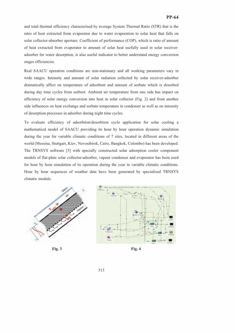
PP-64
513
and total thermal efficiency characterised by average System Thermal Ratio (STR) that is the
ratio of heat extracted from evaporator due to water evaporation to solar heat that falls on
solar collector-absorber aperture. Coefficient of performance (COP), which is ratio of amount
of heat extracted from evaporator to amount of solar heat usefully used in solar receiver-
adsorber for water desorption, is also useful indicator to better understand energy conversion
stages efficiencies.
Real SAACU operation conditions are non-stationary and all working parameters vary in
wide ranges. Intensity and amount of solar radiation collected by solar receiver-adsorber
dramatically affect on temperature of adsorbent and amount of sorbate which is desorbed
during day time cycles from sorbent. Ambient air temperature from one side has impact on
efficiency of solar energy conversion into heat in solar collector (Fig. 2) and from another
side influences on heat exchange and sorbate temperature in condenser as well as on intensity
of desorption processes in adsorber during night time cycles.
To evaluate efficiency of adsorbtion/desorbtion cycle application for solar cooling a
mathematical model of SAACU providing its hour by hour operation dynamic simulation
during the year for variable climatic conditions of 7 sites, located in different areas of the
world (Messina, Stuttgart, Kiev, Novosibirsk, Cairo, Bangkok, Colombo) has been developed.
The TRNSYS software [5] with specially constructed solar adsorption cooler component
models of flat-plate solar collector-adsorber, vapour condenser and evaporator has been used
for hour by hour simulation of its operation during the year in variable climatic conditions.
Hour by hour sequences of weather data have been generated by specialized TRNSYS
climatic module.
Fig. 3 Fig. 4

PP-64
514
One node solar collector-adsorber model (Fig. 3) was used describing the adsorber heat
balance by equation:
( )[ ]twH
AMTTUSFTwcc
tAM
desc
adsaadsLadswads
c
ads
∂∂+−−=+
∂∂ )(])[( ταλ ,
where cads, cw – specific heat of adsorbent and adsorbed water, Mads – mass of adsorbent, w –
mean water content of adsorbent, (�) – optical efficiency of solar adsorber-collector, Ac – its
area, S – solar radiation flux, UL – adsorber heat loss coefficient, Tads – mean adsorbent
temperature, Ta – ambient air temperature, Hdes – the heat of desorption. The factor F� was
introduced to use the mean adsorbent temperature instead of solar flux adsorbing plate
temperature.
The Linear Driving Force model [6] was used for description of the kinetics of vapor
sorption/desorption:
)( 0 wwktw −=
∂∂ ,
where equilibrium water content (w0) is determined by sorption curves for given sorbent and
Polani equation.
The condenser model assumes vapour condensation at the temperature of ambient air. The
evaporator was considered to stay at constant temperature varied as parameter in range of 5–
10°C. In both cases the vapour pressure is equal to saturation pressure for corresponding
temperatures.
Only SWS-1L selective water sorbent [7] was considered at this stage of study. It is clear
from the model description that at the chosen evaporator rated temperature there are 2 main
parameters defining the SAACU operation efficiency at the given climatic conditions of
considered sites: the specific sorbent mass counting on 1 m2 of solar receiver aperture and the
effective mass transfer coefficient k, which were correspondingly varied in our calculations in
ranges of 4–20 kg/m2 and 0,1–2,5 h-1.
Typical curves illustrating the received summarized results of SAACU mathematical
simulation during whole year of its operation are presented at Fig. 5 (Messina, evaporator
temperature 5°C, k=0.8 h-1,) and Fig. 6 (Messina, absorbent mass 10 kg/m2, evaporator
temperature 5°C). The following 2 most important conclusions could be made: (1) – an
optimal specific adsorbent mass exists providing maximal average specific cooling capacity
of solar cooler; (2) – there is a critical minimal value of effective mass transfer coefficient
below which heat and mass transfer processes of sorption/desorption are too slow to provide

PP-64
515
effective production of cold. It has been also shown that for considered sites and different
periods of solar cooler operation optimal specific mass of SWS-1L adsorbent has to be 12–16
kg/m2 and design and construction of adsorber has to provide effective mass transfer
coefficient not less than 0,5–1,0 h-1. If these requirements are satisfied the specific average
cooling capacity SCP of considered solar cooler 35–60 W/m2, total system thermal ratio STR
up to 0,2 and COP up to 0,5–0,8 could be achieved in different climatic conditions.
4 8 12 16 2030
40
50
60
70
0.2
0.4
0.6
0.8 Pyear, W/m2
Papr-sep, W/m2
Psummer
, W/m2
Pjuly, W/m2
Mads/Ac, kg/m2
Messina
STRyear
STRap-sep
STRsummer
STRjuly
COPyear
COPap-sep
COPsummer
COPjuly
Ave
rage
coo
ling
pow
er, W
/m2
CO
P, S
TR
0,0 0,5 1,0 1,5 2,0 2,520
30
40
50
60
0,2
0,4
0,6
0,8
1,0
Ave
rage
coo
ling
pow
er, W
/m2
Pyear, W/m2
Papr-sep, W/m2
Psummer, W/m2
Pjuly, W/m2
k, h-1
Messina
CO
P
COPyear
COPap-sep
COPsummer
COPjuly
Fig. 5. Fig. 6. Next stages of the study will be devoted to comparison analysis of different sorbents
influence on solar cooler performance to justify their optimal choice and SAACU
mathematical model improvement to provide more detailed simulation of heat and mass
transfer processes in adsorber as well as in cooling chamber.
The authors thank INTAS for financial support of this work. We also very grateful to our
colleagues from CNR-ITAE (Italy), RWTH-Aachen (Germany), BIC SB RAS, MSU (Russia)
and ITTF (Ukraine) participating in this joint project for effective and pleasant collaboration.
Literature 1. Yu. I. Aristov, D. Chalaev, B. Dawoud, L. I. Heifets, O. Popel, G. Restuccia, Proc. CHEMREACTOR-17
2. Yu.I.Aristov, G.Restuccia, G.Cacciola, V.N.Parmon, Appl.Therm.Engn., 2002, v.22, N 2, pp.191-204.
3. W.M.Raldow, W.E.Wentworth, Solar Energy, 1979, v.23, p.75-79.
4. Yu.I. Aristov, Proc. VI Int. Seminar “Heat pipes, heat pumps, refrigerators”, 12-15 Sept. 2005, Minsk, Belorus, pp. 342-353.
5. TRNSYS – The Transient System Simulation Program // http://sel.me. wisc.edu/TRNSYS/.
6. E. Glueckauf, Part 10. Formulae for diffusion into spheres and their application to chromatography, Trans. Faraday Soc. 1955. V.51. part 11, pp. 1540-1551.
7. M.M.Tokarev, B.N.Okunev, M.S.Safonov, L.I.Heifets, Yu.I.Aristov, Rus. J. Physical Chemistry, 2005, v. 79, N 9, pp. 1490-1494.
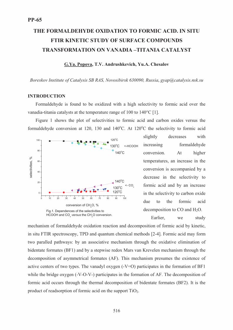
PP-65
516
THE FORMALDEHYDE OXIDATION TO FORMIC ACID. IN SITU
FTIR KINETIC STUDY OF SURFACE COMPOUNDS
TRANSFORMATION ON VANADIA –TITANIA CATALYST
G.Ya. Popova, T.V. Andrushkevich, Yu.A. Chesalov
Boreskov Institute of Catalysis SB RAS, Novosibirsk 630090, Russia, [email protected]
INTRODUCTION
Formaldehyde is found to be oxidized with a high selectivity to formic acid over the
vanadia-titania catalysts at the temperature range of 100 to 140°C [1].
Figure 1 shows the plot of selectivities to formic acid and carbon oxides versus the
formaldehyde conversion at 120, 130 and 140oC. At 120oC the selectivity to formic acid
slightly decreases with
increasing formaldehyde
conversion. At higher
temperatures, an increase in the
conversion is accompanied by a
decrease in the selectivity to
formic acid and by an increase
in the selectivity to carbon oxide
due to the formic acid
decomposition to CO and H2O.
Earlier, we study
mechanism of formaldehyde oxidation reaction and decomposition of formic acid by kinetic,
in situ FTIR spectroscopy, TPD and quantum chemical methods [2-4]. Formic acid may form
two paralled pathways: by an associative mechanism through the oxidative elimination of
bidentate formates (BF1) and by a stepwise redox Mars van Krevelen mechanism through the
decomposition of asymmetrical formates (AF). This mechanism presumes the existence of
active centers of two types. The vanadyl oxygen (-V=O) participates in the formation of BF1
while the bridge oxygen (-V-O-V-) participates in the formation of AF. The decomposition of
formic acid occurs through the thermal decomposition of bidentate formates (BF2). It is the
product of readsorption of formic acid on the support TiO2.
0 10 20 30 40 50 60 70 80 90 100
0
20
40
60
80
100
130oC120oC
140oC
140oC
130oC
sele
ctiv
ities
, %
conversion of CH2O, %
120oC
<-HCOOH
<- COx
Fig.1. Dependences of the selectivities to HCOOH and COx versus the CH2O conversion.

PP-65
517
In this work we studied the kinetics of formation and decomposition of surface formates
BF1 and AF in formaldehyde oxidation to formic acid and surface formate BF2 during formic
acid decomposition.
RESULTS AND DISCUSSION
FTIR spectra of surface species recoding at passing the reaction mixture of 2% CH2O in
air and 1% HCOOH in air through the IR cell-reactor are shown in Fig. 2.
The kinetic curves of formation and
decomposition surface formates BF1, AF and
BF2 determined by optical density D changes
of adsorption bands νas(COO-) =1568 cm-1
(BF1), νas(COO-)=1640 cm-1 (AF) and
νas(COO-)=1557 cm-1 (BF2).
Time dependencies of relative intensities
of adsorption bands νas(COO-) =1568 cm-1
(BF1), νas(COO-)=1640 cm-1 (AF) and that of
ln(1-D/Do) during BF1 and AF formation in
the reaction mixture of CH2O in air are shown
in Fig. 3,4. The data are satisfactorily
processed in the coordinates of first order
reaction.
0 200 400 600 800 1000 12000,0
0,2
0,4
0,6
0,8
1,0
0 200 400 600 800 1000 1200
54 3 2
1
D/D
o
ln(1
-D/D
o )
0
-1
-3
-2
Fig.3 The kinetic curves of BF1 formates formation1 - 70, 2 - 100, 3 - 120, 4 - 150, 5 - 190oC
5 4 32
1
t, s
0,0
0,2
0,4
0,6
0,8
1,0
0 200 400 600 800 1000 1200 1400
D/Do
2
3
4
Fig.4 The kinetic curves of AF formates formation1 - 100, 2 - 120, 3 - 150, 4 - 170oC
t, s
ln(1
-D/D
o)
1
-2
-1
0
1800 1700 1600 1500 1400
H-CO
O Vm+
H-CO
OVn+
AF1 νas(COO-)=1640 cm-1
νs(COO-)=1366 cm-1
νas(COO-)=1557 cm-1
1366
1568
1640
2
1
Wavenumber, cm-1
BF1
BF2H-COO
Tin+νs(COO-)=1366 cm-1νas(COO-)=1557 cm-1
137015
57
1665
Fig.2 In situ FTIR spectra of V-Ti-O catalystduring CH2O oxidation (1,2) and HCOOH decomposition (3)
3

PP-65
518
Time dependencies of relative intensities (D/Do) of adsorption bands νas(COO-) =
1568 cm-1 (BF1) and νas(COO-)=1640 cm-1 (AF) in the air flow at different temperature are
shown in Fig. 5,6 (a). The kinetic dependences of surface species decomposition are
processed in the coordinates of first order rate reaction (Fig. 5,6 b).
0 50 100 150 200 250 3000,0
0,2
0,4
0,6
0,8
1,0
0 50 100 150 200 250 300-4,0
-3,5
-3,0
-2,5
-2,0
-1,5
-1,0
-0,5
0,0
Fig. 5. Kinetic curves of the decomposition of surface formats BF1.1-70, 2-100, 3-120, 4-150, 5-190oC.
?
65
4
3
2
1
D/D
o
t, s
6
5
4
32
1
ln(D
/Do)
t, s0 500 1000 1500 2000
-3
-2
-1
0
0 500 1000 1500 20000,0
0,5
1,0
5
4
3
ln(D
/Do)
t, s
b
5
4
3
2
1
D/D
o
t, s
a
Fig. 6. Kinetic curves of the decomposition of surface formats AF.1-100, 2-120, 3-150, 4-170, 5-190oC.
Figure 7,a shows kinetic curves of
surface species HCOOH (BF2)
decomposition in air flow at 50-150oC.
The BF2 decomposition rate is
described by the first order equation of
reaction rate (Fig. 7 b).
The rates of the BF1 and AF
decomposition (Ws) and the rates of the
formic acid and CO formation (Wk) at
the formaldehyde oxidation (sample
1,2) and the rate of BF2 decomposition
and the rate of the CO formation at the formic acid decomposition (sample 3) are listed in
Table. The rate of the formic acid formation in the gas phase is close to the rate of the BF1
decomposition in flowing air at 100 oC (sample 1). and to the sum of the rates BF1 and AF
decomposition at 120 oC (sample 2). The rate of the CO formation in the gas phase is close to
the rate of the BF2 decomposition at 150 oC (sample 3).
0 50 100 150 200 250 3000,0
0,2
0,4
0,6
0,8
1,0
0 50 100 150 200 250 300-4,0
-3,5
-3,0
-2,5
-2,0
-1,5
-1,0
-0,5
0,0
?
65
4
3
2
1
D/D
o
t, $!§
6
5
4
3
2
1
ln(D
/Do)
t, $!§
Fig. 7. Time dependence of relative intensity (D/Do) of band BF2 (a) and that of ln(D/Do) (b) during the decomposition of HCOOH in the air flow:1-50, 2-75, 3-100, 4-125, 5-130, 6-150oC.

PP-65
519
Table. The rate of the surface compounds decomposition (Ws) and the rate of the reaction
products formation (Wk) on the V-Ti-O catalyst.
Sample T,oC N*·10-18*, molecules·m-2
Ws·10-15, molecules·m-2·s-1
Wk·10-15, molecules·m-2·s-1
BF1 AF BF2* BF1 AF BF2 HCOOH COx 1 100 3.0 3.1 2.9 0.03 2 120 3.3 2.4 5.0 0.4 5.1 0.10 3 150** 2.5 14.3 11.8
*N is the surface formate concentration, **decomposition of �����.
Schema describes the formation of formic acid by formaldehyde oxidation and
decomposition of formic acid to COx on V-Ti-O catalyst. The temperature dependences of the
rate constants in Scheme take the following values:
r1 r3
r2 r4
CH2O[BF1]
HCOOH[AF]
r5[BF2] COxHCOOH
RTeK 9,434,31−×= s-1
K e RT2 8 16 6 9= × −, , s-1,
RTeK 8.921028,13−×= s-1,
K e RT4 3 67 151= × −, , s-1
RTeK 4,2610104,25−×= s-1.
Acknowledgements
This work was supported by Russian Foundation for Basic Research, Grant 06-03-32473-?.
References 1. G.Ya. Popova, T.V. Andrushkevich and G.A. Zenkovets, Kinet. Catal., 1997, 38, 285.
2. G.Ya. Popova, Yu.A. Chesalov, T.V. Andrushkevich and E.S. Stoyanov, Kinet. Catal., 2000, 41, 601.
3. G.Ya. Popova, Yu.A. Chesalov, T.V. Andrushkevich, I.I. Zakharov and E.S. Stoyanov J. Mol. Catal. A: Chemical, 2000, 158, 345.
4. G.Ya. Popova, T.V. Andrushkevich, I.I. Zakharov and Yu. A. Chesalov, Kinet. Catal., 2005, 46, 217.
r3
r2

PP-66
520
EVALUATION OF CO AND CO2 BASED METHANOL SYNTHESES
USING ASPEN PLUS SIMULATION SOFTWARE
Riitta Raudaskoski, Esa Turpeinen & Riitta L. Keiski
Department of Process and Environmental Engineering, Mass and Heat Transfer Process
Laboratory, P.O.Box. 4300, FIN-90014 University of Oulu, Finland. Fax. +358 8 553 2369.
E-mail address: [email protected]
Introduction
Kyoto protocol and emissions trading closely related to it entered into force during the year
2005, which has increased the interest to CO2 utilization. Among those bulk chemical
processes in which CO2 can be used as a feedstock, methanol synthesis is one of the most
potential methods to utilize CO2 separated from flue gases. Methanol is an important product
and feedstock in chemical industry. It is used for example as a refrigerant, as a synthetic fuel,
as a solvent and in the manufacturing of formaldehyde as well as dimethyl terephthalate
(DMT) [1]. Currently methanol is commercially produced from synthesis gas (CO + H2) over
Cu-Zn oxide based catalysts using gas phase fixed bed reactors [1]. In this process CO2 is
commonly used only to adjust the feed composition. Although commercial methanol
synthesis is well known and several companies offer commercial technologies (e.g. ICP,
Lurgi and Mitsubishi processes [1]), methanol synthesis from CO2 and H2 has also gained a
wide attention during the last decade mainly because of the possibility to utilize CO2 as a
feedstock in this process. Several articles have already been published around this area [e.g. 2-
6], but more research work is needed. The objective of the present study is to evaluate, using
Aspen Plus (version 2004.1) simulation software [7], two different ways to produce methanol.
These two Cases are following: a typical natural gas based production route (a commercial
process) and methanol synthesis directly from CO2 and H2.
Simulations
Thermodynamic calculation is a useful and practical tool for designing new or alternative
processes, particularly in determining favourable reaction conditions and in evaluating
required material and energy flows. In this study material and energy balances are calculated
using Aspen Plus simulation software for two different methanol processes, which are a
typical natural gas based production route (Case A) and methanol synthesis directly from CO2
and H2 (Case B). Economic efficiencies of these Cases are evaluated based on the material

PP-66
521
and energy balances as well as average list prices of raw materials and electricity. Flow sheets
of the simulated Cases and the used reaction conditions are shown in Figures 1 and 2.
H2O
H2O,IN INPUT
SYNGAS
OUTPUT
CH4,IN
920 C
105 C
CH3OH REACTOR250 C
COMPRESSOR
75 bar
STEAM GENERATOR
PREHEATER400 C
REFORMER
CO2, IN
Figure 1. Natural gas based production route, Case A.
OUTPUT
INPUT
CH3OH REACTOR250 C75 bar
COMPRESSOR
CO2, H2
Figure 2. Methanol synthesis from CO2 and H2, Case B.
The used reaction conditions for the reformer and the methanol reactor have been selected
based on thermodynamic calculations and typical commercial processes [1], respectively.
Results from thermodynamic calculations reveal that suitable reaction conditions are high
temperature and low pressure in the reformer and low temperature and high pressure in the
methanol reactor. Although high temperature is favourable in the reformer, e.g. increase in
energy consumption sets limits to the temperature level. For many years numerous hydrogen
plants have operated with reformer outlet temperatures of about 920°C [8]. This temperature
is also used in this study. The rate of reaction at low temperature in the methanol reactor is
very slow over most catalysts and high operation temperature becomes almost mandatory [1].
Because of that, the reaction conditions used in typical commercial methanol processes have
been selected for the methanol reactor. Primary reactions involved in the two Cases are:
Reformer CH4 + H2O ↔ CO + 3H2 (1)
Methanol reactors CO + 2H2 ↔ CH3OH (2)
CO2 + 3H2 ↔ CH3OH + H2O (3)

PP-66
522
The stoichiometry of the reformed gas can be conveniently characterized by the ratio M (M=
(H2-CO2/(CO+CO2). Stoichiometry of the methanol synthesis (reactions 2 and 3) requires
that M ≈ 2 [9]. To reach the stoichiometry necessary for the methanol reactor, CO2 is mixed
with the exit gas from the steam reformer (Case A). In the Case B, the stoichiometric ratio of
the feed gas has been used. In both Cases, it is assumed that the only carbon containing
product in the methanol reactor is CH3OH which means that reactions are selective to
methanol. In order to compare these two Cases to each other, the yield of methanol is set to
1.0 kmol/h.
Simulation results and discussion
Calculated material and energy balances are summarized in Table 1 and 2, respectively.
Operation costs are shown in Table 3. Energy losses are excluded in calculations and heat
transfer efficiency is assumed to be 100%.
Table 1. Material balances.Case A Case B
Input (kmol/h) CH4 1.36 - CO2* 0.41 3.54 H2O 1.36 - H2 - 10.63 CO - - Output (kmol/h) CO2 0.42 2.54 H2O 0.030 1.01 H2 1.96 7.61 CO 0.31 - CH3OH 1.00 1.01
* It is assumed that CO2 (pure enough) is available without extra expenses, e.g. the methanol synthesis plant is near the CO2 emission source.
Table 2. Energy balances.Case A Case B
Energy balance (MJ/h) Reformer* 475 - Methanol converter* -221 43.8 Feed ** 1088 (CH4) 2570 (H2)Total net energy (MJ/h) 1342 2614
* Heat duty ** Lower heating value
Table 3. Operation costs. Case A Case B
Operation costs (€/h) Feed* 4.90 (CH4) 12.86 (H2 ) Electricity ** 4.94 0.85 Total operation costs 9.84 13.71
* CH4 0.45 snt/MJ [10], H2 0.5 snt/MJ [11] ** 1.94 snt/MJ [12], heat duty required in reactors is produced by hydrogen
PP-66
523
Calculations indicate that energy needed to produce 1 kmol/h methanol is in the Case B
almost twice as high as in the Case A. If recycling is taken into account Case B becomes more
energy efficient than without recycling, because un-reacted hydrogen can be reused and thus
the competitiveness increases compared to the Case A. Operation costs are also higher in the
Case B than in the Case A. Operation costs in the Case B will decrease, if cheaper hydrogen is
available since this Case consumes quite a lot H2. Merchant hydrogen prices vary
considerably depending on the volume and form of the feedstock. Hydrocarbon based steam
reforming is the cheapest way to produce hydrogen [13] and hydrogen produced by this
technology can cost as little as 0.5 €/kg [11], which value is used in this study. CO2 emissions
trading can also affect the cost-effectiveness of the Case B, because this Case can exploit
theoretically more CO2 than Case A. In addition, emissions trading favour the Case B,
because of larger net CO2 consumption.
To concluse the presented results: Nowadays, with the selected assumptions, Case A
(commercial natural gas based methanol synthesis) is economically more attractive, but
decisions in energy politics can change the situation in the future.
Acknowledgements
This work has been carried out with the financial contribution from the National Technology
Agency of Finland (Tekes) and the Graduate School in Chemical Engineering (GSCE).
References[1] Lee, S. Methanol synthesis technology. United States 1990, CRC Press, Inc. 236 p.
[2] Chen, G. & Yuan, Q. Separation and Purification Technology, 34 (2004) 227-237.
[3] Liu, J., Shi, J., He, D., Zhang, Q., Wu, X., Liang, Y., Zhu, Q. Applied Catalysis A: General, 218 (2001) 113-119.
[4] Ma, Y., Sun, Q., Wu, D., Fan, W.-H., Zhang, Y.-L., Deng, J.-F. Applied Catalysis A: General, 171 (1998) 45-55.
[5] Ma, L., Tran, T., Wainwright, M.S. Topics in Catalysis, 22 (2003) 287-293.
[6] Mignard, D., Sahibzada, M., Duthie, J.M. & Whittington, H.W. International Journal of Hydrogen Energy, 28 (2003) 455-464.
[7] http://www.aspentech.com/
[8] Rostrup-Nielsen, T. Catalysis Today, 106 (2005) 293-296.
[9] Kroschwitz, J.I.(edit.) Kirk-Othmer Encyclopedia of Chemical Technology. Volume 16. 4. edition. United States 1995, John Wiley & Sons. 1117 p.
[10] http://www.energiamarkkinavirasto.fi/data.asp?articleid=1104&pgid=188 (in Finnish)
[11] Dincer, I. International Journal of Hydrogen Energy, 27 (2002) 265-285.
[12] http://www.energia.fi/page.asp?Section=2772 (in Finnsh)
[13] Rostrup-Nielsen, J.R. & Rostrup-Nielsen, T. Cattech, 6 (2002) 150.

PP-67
524
MATHEMATICAL MODELING OF TOLUENE
OXYDATION ON VANADIA/TITANIA CATALYST
UNDER UNSTEADY STATE CONDITIONS
Reshetnikov S.I. and Ivanov E.A.
Boreskov Institute of Catalysis, Pr. Lavrentieva, 5, 630090, Novosibirsk, Russia.
E-mail: [email protected]
Experemental and theoretical studies performed in a last decades have proved that
unsteady state operation of heterogeneous catalytic reactors can be an effective tool to
improve reactor performance [1, 2]. The physical basis for such improvement lies in the
ability to regulate the concentration of adsorbed species by reaction conditions.
One of the ways to perform the process of hydrocarbon catalytic oxidation is to divide
the reaction space in a few separate zones, for instance, a zone of the catalyst reduction by
hydrocarbon and a zone of its oxidation by oxygen and catalyst circulation between zones
(see, for example [3, 4]). This operation was industrially used in the DuPont process of butane
oxidation to maleic anhydride over vanadium-phosphorous catalysts [3].
Second way is regulation (or periodic operations) when the reagents concentrations,
gas flow rates are changed periodically in the fixed bed catalytic reactor input - cyclic
reduction and re-oxidation of a catalyst [1,5]. The possible objectives of the use of periodic
operation of catalytic reactors are to provide an increased conversion, improved selectivity,
and reduced deactivation. Aditionally, an important information could be extracted from the
transient behavior of the reaction after the fast change of the composition of reaction mixture
over the catalyst. Modeling of the transient phenomena allows obtaining valuable kinetic
constants, which often could not be determined from the steady state experiments.
For the toluene oxidation by the same researchers it was shown that benzaldehyde
(BA) and some CO2 are formed in the flow of toluene, while after consecutive oxygen
introduction only maleic anhydride and carbon dioxide are observed. These data were
explained by a conjugated oxidation of the catalyst and desorption/formation of the products.
In [6] during the toluene interaction with a V/Ti-oxide catalyst found that BA is formed for a
long time with a very high selectivity (around 100%) while CO2 is evolved only during the
first moments of the reaction. This was assigned to different surface oxygen species.

PP-67
525
The aim of this work is modeling of toluene interaction with a pre-oxidized
vanadia/titania catalyst under periodic operation.
The catalyst was prepared via a well-known grafting technique by the vapor
deposition of VOCl3 on the surface of TiO2 (Aldrich). The BET specific surface area was
equal to 9 m2/g, the amount of vanadium was found to be 0.57 wt. % that corresponds to 0.75
of a monolayer (ML) [7] . It is important that this catalyst contained only about a monolayer
of the surface vanadia species and did not contain any bulk crystalline V2O5.
An experimental set-up used for the transient response study has been described in [8].
The catalyst (1 g) was loaded into a fixed bed reactor of i.d. 6 mm. Before each experiment,
the catalyst was pretreated in an oxidative atmosphere (20 vol. % �2 in Ar) at 673 K for 30
min. Then the flow was switched to Ar and the catalyst was cooled to the reaction
temperature. The reaction was carried out with a 2 vol. % toluene/Ar mixture (1 ml/s). The
products were analyzed with a quadrupole mass spectrometer and a gas chromatograph.
Fig.1. Toluene interaction with the pre-oxidised 0.75 ML catalyst at Symbols – experiments, lines – modelling .
A typical transient behavior of the toluene, benzaldehyde and CO2 concentrations as a
result of interaction of toluene with the 0.75 ML V/Ti-oxide catalyst is demonstrated in Fig. 1
[8]. The main products of the interaction of toluene with the pre-oxidized vanadia/titania
catalyst in the temperature range 523-633 � are benzaldehyde (BA), CO2, CO and �2�. The
transient behavior of CO is similar to CO2, but the CO concentration is 5–6 times lower.
Hence, it was not taken into account. It is seen that the dynamics of the CO2 and
benzaldehyde formation are different. CO2 is formed during the initial time of the reaction,
declining quickly with time, while BA is formed for a prolonged time.
For mathematical modeling of periodic operation the kinetic model of the interaction
of toluene with a pre-oxidized vanadia/titania catalyst was used. The model is based on the
0 60 120 180 2400.00
0.02
0.04
0.06
0.08
0.10
0.12
1.6
1.8
2.0
Con
cent
ratio
n (v
ol%
)
Time (s)
CO2
BA
Toluene
T=603K

PP-67
526
following main assumptions [8]: (i) Benzaldehyde and ��2 are formed mainly on different
active sites; (ii) the ratio of these active sites is independent of the temperature; (iii) adsorbed
benzoates and other coke-like species are formed on the surface of vanadia/titania during the
interaction; (iv) diffusion of oxygen from the bulk of the catalyst is not important in the
studied temperature range.
A kinetic scheme with the minimal amount of steps that appropriately describes the
response curves of toluene and reaction products was chosen. It includes 5 steps [8]: 1) C6H5CH3 + 2 [YO] → 2 [Y] + C6H5CHO + H2O,
2) 2 C6H5CHO + 3 [YO] → 2 [YC6H5COO] + [Y] + H2O,
3) C6H5CH3 + 18 [ZO] → 18 [Z] + 7 CO2 + 4 H2O,
4) C6H5CH3 + [ZO] → [ZOC7H8],
5) [ZOC7H8] + 17 [ZO] → 18 [Z] + 7 CO2+ 4 H2O.
Toluene from the gas phase interacts with nucleophilic oxygen sites [YO] of the
catalyst with the formation of benzaldehyde (step 1). Then, benzaldehyde interacts with the
same oxygen sites forming benzoate on the catalyst surface (step 2). Toluene can be adsorbed
with its aromatic ring parallel to the surface on a group of electrophilic sites [ZO].
Electrophilic oxygen may provide a fast formation of ��2 by fission of the aromatic ring (step
3). Toluene may also be adsorbed on [ZO] sites (step 4). Adsorbed toluene interacts slowly
with [ZO] sites forming the total oxidation products (step 5).
The kinetic equations corresponding to steps 1–5 are as follows: mYOTCkr θ11 = , YOBACkr θ22 = , n
ZOTCkr θ33 = , ZOTCkr θ44 = , ZOTkr θθ55 = ,
where CT and CBA are the concentrations of toluene and benzaldehyde in the gas phase (mole
fractions); �YO, �ZO, �YB, �ZT are the fractions of adsorbed species, benzoate and toluene on the
catalyst surface, correspondingly; �Y, �Z are the fractions of not occupied sites of the
monolayer; kj are the rate constants of the corresponding steps (s-1); m, n are the reaction
orders in the kinetic equations r1 and r3.
To describe the transient behavior of interaction of toluene with pre-oxidized catalyst,
the mathematical model of the continuous stirred tank reactor was used.
The response curves presented in Fig. 1 indicate that the dynamics of the CO2 and BA
formation are different. The CO2 formation declines quickly, while BA is formed over
extended period of time. Except for gaseous products, the coke-like species are formed on the
catalyst surface. This follows from the balance calculations as well as from the oxygen

PP-67
527
introduction experiments after the toluene interaction. After the oxygen introduction, ��2,
�� _ �2� were found in the products, while benzaldehyde was never observed.
On the base kinetic model the modeling of the interaction of toluene with the pre-
oxidized vanadia/titania catalyst has been performed. It was shown, that under periodic
operation it is possible to increase selectivity towards to BA essentially with comparison
steady state ones. This was due to presence a different surface oxygen species: nucleophilic
lattice species and electrophilic surface species participating in the parallel routes of the
toluene oxidation. The latter species could be formed easier in the presence of gaseous
oxygen providing the decrease of BA selectivity.
Acknowledgment. The authors acknowledge to RFBR (Grant 06-03-32473-?) for the
financial support.
References 1. G.K. Boreskov, Yu.Sh. Matros: Catal. Rev.-Sci. Eng., 25, 551 (1983).
2. P. Silveston, R.R. Ross, A. Renken: Catal. Today, 25, 91 (1995).
3. R. M. Contractor, A.E. Sleight. Catal. Today. 1, 587 (1987).
4. S.I. Reshetnikov, N.M. Ostrovsky: React. Kinet. Catal. Lett., 71, 129 (2000).
5. Silveston, P.; Hudgins, R. R.; Renken, A. Catal. Today, 25, 91 (1995).
6. Bulushev, D. A.; Kiwi-Minsker, L.; Renken, A. Catal.Today, 61, 271 (2000).
7. Bulushev, D. A.; Kiwi-Minsker, L.; Zaikovskii, V. I.; Lapina, O. B.; Ivanov, A. A.; Reshetnikov, S. I.; Renken, A. Appl. Catal. A: General, 202, 243 (2000).
8. Bulushev, D. A., Ivanov E.A., Reshetnikov S.I., Kiwi-Minsker, L., Renken, A. Chem. Eng.J., 107, 147 (2005).

PP-68
528
KINETICS OF THE N-HEXANE SKELETAL ISOMERIZATION OVER
NEW SULFATED ZIRCONIA CATALYSTS IN FIXED-BED REACTOR
G.G. Volkova, L.N. Shkuratova, A.A. Budneva, E.A. Paukshtis, S.I. Reshetnikov
Boreskov Institute of Catalysis SB RAS, Pr. Akademika Lavrentieva 5,
Novosibirsk, 630090, Russia
Naphtha isomerization is a simple and cost effective technology for increasing octane
number of gasoline. Isomerization of naphtha is composed mainly of conversion of n-pentane and n-hexane into iso-pentane, mono-methyl and di-methyl hexane. Di-methyl hexane has higher octane number than mono-methyl hexane, and is preferentially produced at low temperature subject to chemical equilibrium. Recently new acid catalyst based on sulfated zirconia have been developed and successfully commercialized by UOP LLC [1-2]. This catalyst revealed higher activity for light naphtha isomerization at lower temperature and is less sensitive to the amount of water in feed oil than conventional catalysts. By the large demand of desired isomerization products development of new more active catalysts has been continued [3]. Group of researchers from Boreskov Institute of Catalysis and Institute of Hydrocarbons Processing has developed new sulfated zirconia catalysts with high density of Lewis acid sites [4].
The aim of this work was to investigate the kinetics of n-hexane skeletal isomerisation over Pt/SO4
2-/Al2O3/ZrO2 catalysts with different density of Lewis acid sites. Catalysts were evaluated in fixed-bed flow reactor. Study of the kinetics of isomerization
of the n-hexane on solid superacids [5] has shown that it is the possible to divide process into three stages. The first, most fast stage, is formation of 3-methyl pentane (3MP) from 2-methyl pentane (2MP), and then, 2,3-methyl butane (2,3DMB) formation up to thermodynamic equilibrium. The reactions of the isomerization of n-hexane and the formation of 2,2- methyl butane (2,2DMB) has the comparable rates. Third stage is the side products formation. For the kinetic analysis the following reaction network was used:
n-�6 ↔ 2}P + 3}P + 2,3 DMB ↔ 2,2 DMB
�1-�5
)1(11
211
1
eKCCCk
ddC −−=
τ ,
k2
k-2
k1
k-1

PP-68
529
3322
322
11
211
2 )1()1( CkKC
CCkKC
CCkddC
ee
−−−−=τ ,
)1(22
322
3
eKCCCk
ddC −=
τ ,
234 Ck
ddC =
τ ,
Where �1 – mole fraction of n-hexane; �2 - 2}P + 3}P + 2,3 DMB; �3 - 2,2 DMB;
�4 – cracking products; τ - contact time; ki,k-i – rate constants of direct and reverse reactions of n-hexane isomerisation and 2,2 DMB formation; Kei – equilibrium constants.
The calculation of the rate constants, characterizing the catalyst activity and selectivity was performed on the base of mathematical model of plug flow reactor. It is assumed that the reactions are pseudo-first order in reagents. The kinetic constants and activation energies were determined. The results of mathematical modeling are in good agreement with experimental data.
Table 1. Kinetic data for catalysts Pt/SO42-/Al203/ZrO2 in n-hexane skeletal isomerization
at the pressure 3 atm and temperature 200oC.
Sample Lewis acid sites N μmol g-1 Rate constant k1 ,$-1 Rate constant
k2,$-1 1 220 0.810 0.066 2 240 0.850 0.065 3 250 0.909 0.073 4 150 0.224 0.033 5 50 0.103 0.011
The data presented in Table 1 show that rate constant of n-hexane isomerization (k1) for Catalyst 1-3 is fourfold as those for Catalyst 4-5, and k2 which characterized the rate of
desired product (2,2DMB) formation for Catalyst 1-3 (Lewis acidity 220-250 μmol g-1) is also
higher than for Catalyst 4-5 (Lewis acid sites 50-150 μmol g-1). From these data it may be concluded that the rate of n-hexane isomerization is mainly determined by the density of Lewis acid sites on the surface of Pt/SO4/ZrO2 catalysts.
References
1. T. Kimura, Catal.Today, 81 (2003) 57. 2. S.A. Gembicki, Stud. Sur. Sci. Catal., 130 (2000) 147.3. Patents:US 5,036,035, US 6,495,733, US 6,448,198, US 5,629,257, US 67066594. G.G. Volkova, L.N. Shkuratova, L.S. Egorova, E.A. Paukshtis, A.A. Budneva, G.N. Kustova,
S.I. Reshetnikov, V.K. Duplyakin, V.A. Likholobov, Russian Patent 28.09.2005, application 2004132964.5. D.M. Brouwer, J.M. Olderik, Reac. Trav. Chim. 1968, 87, 721.

PP-69
530
KINETIC STUDY OF AMMONIA SYNTHESIS OVER Ru/C CATALYST
Ilenia Rossetti1, Francesco Ferrero2, Nicola Pernicone3 and Lucio Forni1*
1Dipartimento di Chimica Fisica ed Elettrochimica, Università degli Studi di Milano,
v. C. Golgi 19 I-20133 Milano, Italy 2v. Turbigo, 2 I-28100 Pernate (NO), Italy
3 v. Pansa, 7 I-28100 Novara, Italy
Introduction
Ru-based catalysts for ammonia synthesis are gaining growing attention, due to a
significant increase of productivity with respect to the traditional Fe-based catalyst [1-3]. This
is mainly due to the kinetic inhibition of the Fe catalyst by ammonia [4,5]. Though the
availability of reliable kinetic equations is of utmost importance for both design and operation
of catalytic reactors, only some fundamental papers on the main reaction steps have been
published [6,7] and, to the best of our knowledge, no kinetic model has been reported so far
for the industrially employed Ru/C catalyst. To fill this gap we undertook a kinetic test
program aiming at evaluating the performance of a Ru/C catalyst under widely different
reaction conditions of industrial relevance. Modelling of the results allowed us to propose a
possible kinetic model for the present reaction, suitable for reactor design.
Experimental
A 3.8 wt% Ru on C catalyst, promoted with K, Cs and Ba [8], diluted with quartz
powder, was employed for the collection of kinetic data. Catalytic activity was measured in a
microreactor [2,8], by varying GHSV between 50,000 and 400,000 h-1. The test program
included 20 runs, during which we varied temperature (370, 400, 430, 460°C), pressure (50,
70, 85, 100 bar) and H2/N2 feeding ratio (1.5 or 3 vol/vol). Data elaboration was
accomplished by non linear regression and subsequent Runge-Kutta numerical integration of
the model rate equations, with the usual objective function based on the minimization of the
mean square sum of the differences between calculated and experimental data.
Results and Discussion
Different kinetic models have been tested. As expected, fitting of experimental data of
our Ru-based catalyst by the classical Temkin equation was not satisfactory, the Fe-based

PP-69
531
catalyst being inhibited by ammonia and Ru by H2. Further attempts were carried out by
varying the value of α in the Temkin equation, in order to obtain at least a better data fitting,
but the model did not show satisfactory results even with α as low as 0.15 and therefore it was
abandoned.
A LHHW approach was then tried, in order to better highlight the role of single
reaction steps on the overall kinetics [5,9], but it did not allow a physically meaningful
representation of every adsorption parameters.
Therefore, we tried to introduce terms accounting for the competitive adsorption
properties of the Ru-based catalyst, by modifying the classical Temkin equation. The general
form of the proposed model is the following:
3233
232223
2
323
322
1
32
23
223
32
2
)()()()(
)(11
)()(
)(1
)()()(
)(wn
NHNHwn
HHwnH
wnNH
wnN
nH
nNH
nnNH
nHn
N
f
aKaKaa
KaK
aa
Kaaaa
qkdd
⋅⋅⋅
⋅
⋅
−
⋅+⋅+⋅+
�
� �
�⋅−
�
� �
�⋅
⋅=
αα
λτη
The best fit of our experimental data was obtained with n = 0.5, α = 0.25 and w2 = w3 = 0.2.
This resulted in the following three-parameters equation:
2.033
3.022
125.12
75.03
25.03
375.025.0
2
)()(1)()(1
)()()(
)(NHNHHH
H
NH
NH
HN
f aKaKaa
Kaaaa
qkdd
⋅+⋅+
�
� �
�⋅−
�
� �
�⋅
⋅= λτη
It should be remarked that no significant effect of N2 adsorption was observed, while, as
expected, H2 competition with N2 was important. The best values of the various constants for
our Ru/C catalyst have been determined, obtaining an average agreement around 5% between
calculated and experimental data. Some typical examples are shown in Fig. 1. The
consistency of the optimised parameters was checked through the Arrhenius or Van’t Hoff
equations, which allowed to obtain reliable kinetic and thermodynamic parameters, with
excellent correlation coefficients. The values of ΔHads derived from this model confirm H2
inhibition, although the NH3 adsorption term cannot be neglected. The value of the activation
energy obtained with the present analysis for our Ru-based catalyst was Ea = 23 kcal/mol.
The present data were compared with those of a commercial Fe-based catalyst, tested
under its usual reaction conditions, i.e. 100 bar, 430°C and H2/N2=3 (vol/vol). Our Ru-based
catalyst outperformed both the traditional and the innovative Fe-based samples, mainly by
noticeably decreasing the activation energy required for N2 dissociation (35 kcal/mol for the
magnetite-based catalyst and 32.5 kcal/mol for the wustite-based one). This allows to strongly
improve catalyst productivity. Indeed, when fixing, e.g., operating conditions such as¾

PP-69
532
τ = 0.0010 h L mol-1, H2/N2 = 3 (vol/vol) and T = 460°C, the same ammonia content in the
exit gas obtainable with the Fe-magnetite catalyst at 100 bar (6.6%) can be obtained at 57 bar
with the Ru/C catalyst (Fig.2). Hence our Ru-based catalyst allows to decrease by 40-50% the
working pressure with respect to a commercial magnetite-derived catalyst. Similar
considerations can be extended to calculate the increase of NH3 concentration in the reactor
outlet gas at the fixed pressure of 100 bar. Such an increase is +28% and +42% at 430 and
460°C, respectively. If preferred, it is also possible to decrease the bed volume of Ru-based
catalyst. In this case the same conversion of the magnetite-based catalyst is attained, under
identical operating conditions, with bed volumes –34% and –54% at 430 and 460°C,
respectively.
Conclusions
The present results show that with our Ru/C catalyst the equilibrium conversion can be
attained at 460°C by feeding under-stoichiometric H2/N2 mixture. The simple addition of
adsorption terms for H2 and NH3 in the Temkin equation allowed to obtain a reliable kinetic
model, useful for both design and operation of industrial reactors. An activation energy value
as low as 23 kcal/mol for the ammonia synthesis reaction was obtained, showing that the
activation barrier for N2 dissociation on Ru is by far lower than for the traditional Fe-based
catalyst, prepared from either magnetite or wustite precursor. When comparing our Ru/C
catalyst with the best commercial Fe catalysts, it must be concluded that a substantial
reduction of the reaction pressure can be obtained with the same plant productivity.
References 1. Z. Kowalczyk, J. Sentek, S. Jodzis, E. Mizera, J. Goralski, T. Paryjczak, R. Diduszko, Catal. Lett. 45, 65
(1997)
2. L. Forni, D. Molinari, I. Rossetti, N. Pernicone, Appl. Catal. A: Gen. 185, 269 (1999).
3. C.Liang, Z.Wei, Q.Xin, C.Li, Appl. Catal. A: General 208, 193 (2001).
4. S.R. Tennison, in: “Catalytic Ammonia Synthesis” (J.R. Jennings, Ed.), Plenum Press, New York, 1991, p. 303.
5. G. Gramatica, N. Pernicone, in: “Catalytic Ammonia Synthesis” (J.R. Jennings, Ed.), Plenum Press, New York, 1991, p.211.
6. O. Hinrichsen, F. Rosowski, A. Hornung, M. Muhler, G. Ertl, J. Catal. 165, 33 (1997).
7. O. Hinrichsen, Catal. Today, 53, 177 (1999).
8. I. Rossetti, N. Pernicone, L. Forni, Appl. Catal. A: Gen. 208, 271 (2001).
9. G. Buzzi Ferraris, G. Donati, F. Rejna, S. Carrà, Chem. Eng. Sci., 29 (1974) 1621.

PP-69
533
Figure 1: Calculated kinetic curves (Modified Temkin Equation) and experimental points under the following working conditions: a) P=100 bar, T=460°C, H2/N2=1.5 (vol/vol); b) P=85 bar, T=430°C, H2/N2=3 (vol/vol)
c
b
a
0.00
0.10
0.20
0.30
0.0 0.5 1.0 1.5τ*1000
Frac
tiona
l Con
vers
ion
Figure 2: Performance of Fe-based catalysts and of Ru/C catalysts at 460°C, H2/N2 = 3: a) Fe at 100 atm; b) Ru/C at 57 atm; c) Ru/C at 100 atm.
0
0.08
0.16
0.24
0.32
0 0.5 1 1.5 2 2.5105 / GHSV (h)
Frac
tiona
l Con
vers
ion
b
a

PP-70
534
EXPERIMENTAL STUDY OF FEATURES OF THE ETHYLENE
GLYCOL OXIDATION PROCESS
M.A. Salaev, V.S. Shmotin, A.S. Knyazev, O.V. Vodyankina, L.N. Kurina
Tomsk State University, pr. Lenina, 36, Tomsk, Russia
Fax: (3822) 52-95-85, e-mail: [email protected]
Partial oxidation of organic compounds is one of the most important methods of synthesis
of such available compounds as formaldehyde, ethylene oxide, acetic acid, etc. Recently the
interest to the process of ethylene glycol oxidation into glyoxal on silver catalysts has also
increased.
Glyoxal is a highly active bifunctional organic compound widely used for production of
pharmaceuticals and pesticides; it proved to be a valuable intermediate especially in the
preparation of heterocyclic compounds. It is most widely used as a cross-linker in the
production of permanent press resins for textiles. It has also found application in the production
of moisture resistant glues and adhesives as well as moisture resistant foundry binders. It is also
used to improve the wet strength of paper and the moisture resistance of leather [1].
The world production of glyoxal is approximately 170000 tones per year. At present the
production of glyoxal in Russia is absent while the requirement in it is over 10000 tones per
year. Main producers of glyoxal are Germany, China and USA. Detailed information about
glyoxal technology is not published in literature. There are sparse patent data describing the
preparation of catalytic systems and the realization of the process of glyoxal synthesis in a
laboratory reactor. The experimental study of the ethylene glycol oxidation process in flow
reactor with a fixed catalyst bed is necessary to elaborate the macrokinetic model.
The aim of the present work is the detailed investigation of the regime of ethylene glycol
oxidation process into glyoxal on the polycrystalline silver catalyst.
In the present work the experimental study of the influence of contact time, partial
pressures of components in the reaction mixture and temperature on the main factors of the
process such as ethylene glycol conversion and glyoxal selectivity has been performed. The
investigations in a flow fixed bed reactor with i.d. of 16 mm. (height of catalyst bed was 20
mm, reactor length was 100 mm) [2] have been carried out, the temperature interval was 500-
650 ��. In each experiment the peak of the temperature gradient along the reactor under
steady operating conditions has been measured and recorded as the reaction temperature.

PP-70
535
0,02 0,03 0,04 0,05 0,06 0,07 0,0840
50
60
70
80
Contact time, s.
Glyoxal selectivity, %mol.
530 oC
550 oC
580 oC
Fig. 1. Effect of the contact time on the glyoxal selectivity.
The influence of the weight hour space velocity of the reaction mixture on the behavior of
the temperature gradient along the reactor has been studied. The decrease of the contact time
up to values lower than 0.01 sec leads to the shift of the “hot” zone to the bottom part of
reactor. The approaching of the “hot” zone to the heat-treatment cooler, which is immediately
located under the catalyst bed, increases instability of the temperature regime in reactor and,
finally, leads to the “dying-away” of reaction.
In this work the boundaries of stable realization of the ethylene glycol oxidation process
into glyoxal on the polycrystalline silver catalyst have been characterized. The manners of
temperature regime realization management in the laboratory level by changing of reaction
mixture composition have been developed. The control is provided:
firstly, due to the increase and decrease of partial pressure of components at the
constant ratio between them;
secondly, due to changing of oxygen/alcohol (O2/EG) molar ratio under inert gas
constant dilution of reaction mixture that allows to vary the ratio between the reactions
of partial and deep oxidation of ethylene glycol. The variation of O2/EG molar ratio, in
its turn, changes the amount of emitting heat and decreases/increases the silver
catalyst heating-up temperature.
The contact time variation
exerts its influence on the
selectivity of the process of
ethylene glycol partial oxidation
into glyoxal (Fig. 1). At all
investigated temperatures the
extreme dependences with the
maximum glyoxal selectivity in
the range of 0.04-0.05 s. have
been obtained. Under contact
times higher than
aforementioned the glyoxal
selectivity is decreased due to
the deep oxidation reaction of
the desired product up to ��2 or because of the participation of glyoxal in processes which lead
to the occurrence of carbon-content deposits on the silver catalyst surface as it was shown

PP-70
536
earlier [3]. The decrease of the contact time leads to the incomplete interaction of the reaction
mixture with the catalyst surface that is accompanied by the reduction of the glyoxal selectivity.
It is interesting to note that the increase of the contact time of the reaction mixture with
the catalyst leads to the insignificant
reduction of the ethylene glycol
conversion (Fig. 2). Possibly the
obtained result is associated with the
formation of carbon deposits on the
silver surface. These deposits
particularly poison the active centers of
the catalyst surface under investigated
conditions (O2/EG/N2 =1.1/1.0/20.0).
Lack of oxygen-content in the reaction
mixture does not allow removing the
carbon deposits from the catalyst
surface completely. And under long-
continued contact times the rate of the
carbon deposit formation dominates over their burning-out rate. As a result a part of the active
silver surface is inaccessible to the selective ethylene glycol transformation.
In the present work the thermodynamic analysis of routes of the ethylene glycol
transformation such as dehydrogenation, partial oxidation, and oxidative dehydrogenation has
been carried out at 550��. Both partial oxidation and oxidative dehydrogenation of ethylene
glycol routes have been mainly realized. Kinetic equations describing the glyoxal formation
routes have been derived. Physical-chemical properties of individual components and its
mixtures have been calculated. The hydrodynamic modes of steams of reaction mixtures and
products in the reactor branch pipe and in the catalyst bed have been estimated.
This work was supported by the Grant of the President of the Russian Federation YK-
1571.2005.3.
Literature 1. Mattioda G., Metivier B., Guette J.P. What can you do with glyoxal // Chemtech. 1983 V.13(8) 478 – 481.
2. Vodyankina, O. V.; Kurina, L. N.; Izatulina, G. A.; Arkatova, L. A. Vapor-phase catalytic oxidation of ethylene glycol to glyoxal. // Zhurnal Prikladnoi Khimii (Sankt-Peterburg) 1997. 70(12) 2007-2010.
3. Vodyankina, O.V.; Koscheev, S.V.; Yakushko, V.T.; Salanov, A.N.; Boronin, A.I.; Kurina, L.N. // Journal of Molecular Catalysis A: Chemical 2000 158(1) 381-387.
0,02 0,03 0,04 0,05 0,06 0,07 0,0850
60
70
80
90
100Ethylene glycol conversion, %mol.
Contact time, s.
530 550 580
Fig. 2. Effect of the contact time on the ethylene glycol conversion.

PP-71
537
MODEL OF THE REACTOR FOR BUTYL LACTATE PRODUCTION
S.V. Schactlivaya, D.N. Kondratiev, V.F. Shvets, R.A. Kozlovskiy
D.I. Mendeleev University of Chemical Technology of Russia, Chair of Basic Organic and
Petrochemical Synthesis, 9 Miusskaya Square, Moscow, 125047, Russia, [email protected]
Abstract
Esterification of lactic acid with butanol-1 (eq. (1)) in presence of strong-acid cation-
exchange resin “Levatit” as a catalyst was investigated. Kinetic equations in batch reactor (in
kinetic region) and in a tube fixed-bed reactor were found. Mathematical model of circulating
semibatch installation for butyl lactate production was elaborated. The model describes
experimental data adequately.
Introduction
Butyl lactate is one of the promising “green” chemical which successfully replaces toxic and
environmentally harmful solvents (for example chloro-organic solvents). Butyl lactate is
biodegradable substance and is synthesized from lactic acid which is produced from
renewable resources. That’s why there is great interest for highly efficient technology for
butyl lactate production. In other hand strong-acid cation-exchange resins are expected to be
very suitable heterogeneous catalysts for esterification reactions. The aim of present work was
obtaining of kinetic description and, on this basic, elaboration of mathematical model of a
reactor for butyl lactate production. H3C
COOH
HO
+ C4H9OH
H3C
HO
+
O
OC4H9
H2O
(1)
Results
At the beginning kinetics of esterification was investigated in a batch reactor in kinetic region.
Strong-acid cation-exchange resin “Levatit” was used as a heterogeneous catalyst. The
Lengmuir-Hinshelwood like kinetic equation, well describing all experimental data, was
obtained:
( )WW
WBLLBcatBL
CbCCkCCkC
ddC
+−
=1
21
τ (2)
Where Ccat – catalyst concentration, g/L; CB , CBL , CL , CW - concentrations of butanol-1,
butyl lactate, lactic acid and water respectively, mol/L; k1 , k2 - constants of direct and back
reactions respectively; bW - water adsorption constant.

PP-71
538
At the next stage the kinetics of reaction was investigated in a fixed-bed tubular reactor. It
was found that experimental data were described adequately by equation (3), which differed
from kinetic equation for batch reactor (1) by presence coefficient β = 0.14. All the rest
kinetic parameters (k1 , k2 , bW ) remained the same. The coefficient β evaluates diffusion
resistance for mass transfer between liquid flow and catalyst’s grains.
( )WW
WBLLBcatBL
CbCCkCCkC
ddC
+−
=1
21βτ
(3)
The kinetic equation (3) was used for making of mathematical model of laboratory circulating
semibatch installation for butyl lactate producing (Fig. 1). Operating mode of the installation
was following: Reaction mixture (at the start of experiment: butanol and lactic acid) was
circulated continuously by peristaltic pump (point 9) through thermostated fixed-bed tubular
reactor and boiling still (point 10). In the reactor catalytic esterification took place. The
reaction mixture continuously boiled in the still and butanol-water azeotropic vapor moved up
into the backflow condenser (point 2) where it condensed and flowed down into phase
separator (point 4). In the separator heteroazeotropic liquid divided into organic and water
layers. Water layer was
continuously removed
through outlet cock and
organic one flowed back to
the still. Water removing
shifted equilibrium of
esterification (eq. 1) to the
right and made possible to
achieve high conversion of
lactic acid up to 99.5 %.
Mathematical model
including equations of
reaction kinetics (3), liquid-
vapor equilibriums (in the
boiling still) and mutual
solubility (in the phase
separator) was made. This
model describes
experimental data obtained on laboratory installation sufficiently adequate.

PP-72
539
THE DEVELOPMENT OF PORTABLE HYDROGEN GENERATORS
Simagina V.I., Storozhenko P.A.1, Komova O.A., Netzkina O.V.
Boreskov Institute of Catalysis SB RAS, Novosibirsk, Russia 1State Scientific Research Institute of Chemistry & Technology of Organoelement
Compounds, Moscow, Russia
Growing market of the mobile devices calls for safety effective sources of energy
providing prolonged working period. Maximum gravimetric energy density of nickel-hydride
and lithium-ion batteries used now does not exceed 0.2 Wh/g. Application of portable fuel
cells allows to increase the energy density, but the problem of creation of hydrogen compact
sources appears. At present several types of portable hydrogen generators are offered,
including the generators based on hydrolysis of hydrides. Among the hydrides sodium
borohydride (NaBH4) is desirable due to its high hydrogen density – about 0.112 g/cm3,
whereas the density of liquid hydrogen is only 0.07 g/cm3. The hydrolysis of NaBH4 provides
the amount of hydrogen twice more than in case of thermal decomposition of the hydride.
Furthermore, alkaline solutions of sodium borohydride are stable during storage. The
hydrolysis of NaBH4 is observed even at room temperature, but for the complete hydrolysis
the using of catalysts is necessary.
The works on creation of portable hydrogen generators were begun at the end of 90s.
Millennium Cell company (USA) [1, 2] and Central Research & Development Laboratories
(Toyota) [3, 4] achieved the most results in this area. However, essential disadvantages of
proposed constructions are unsatisfactory mass and size properties. Overcoming of this
problem is possible by development of active and stable catalysts, optimization of the
catalytic bed and application of new engineering solutions.
Joint efforts of specialists of Boreskov Institute of Catalysis and State Scientific Research
Institute of Chemistry & Technology of Organoelement Compounds allow to develop
portable systems for hydrogen generation on the basis of sodium borohydride hydrolysis with
optimized mass and size properties.
It was found that Pt and Rh catalysts supported on untraditional LiCoO2 carrier show the
highest activity in NaBH4 hydrolysis in comparison with catalysts prepared using traditional
supports – �-Al2O3, TiO2 and carbonaceous material. It should be mentioned that using of

PP-72
540
LiCoO2 provides stable hydrogen generation by request both in uninterrupted and in periodic
modes of operation. As a result of performed investigations the preparation conditions of
catalysts providing stable working of 100 Watt portable fuel cell were found.
The optimization of initial support geometry and the catalysts packing method allows to
form the catalytic bed, providing uniform hydrogen generation both in uninterrupted and in
periodic modes of operation.
It was showed that fixed-bed reactors can be used to provide a continuous, controllable
reactions for generation of hydrogen from sodium borohydride. The reactor consists of a
hollow tube with a top and bottom end caps, and screens to contain a catalyst material. The
feed solution is pumped through the reactor. Upon contact with the catalyst, the hydrolysis
reaction is initiated resulting in the generation of both the hydrogen and reaction by-products.
The type and quantity of catalyst, the feed rate and the feed solution concentration are all key
parameters in the reactor operation.
Carried out studies have permitted to develop the optimized design of hydrogen
generators with automatic control system. During the testing it was shown that generator with
mass of 300 g can provide work of 100 Watt portable fuel cell during 1 hour under one-time
refueling by 150 ml of sodium borohydride solution.
The authors thank the MMK Norilsk Nickel Group for financial support of this work.
References [1] Amendola S.C., Sharp-Goldman S.L., Janjua M.S., Kelly M.T., Petillo P.J. Binder M., J. Power Sources
2000, 85, 186-189.
[2] Richardson B.S., Birdwell F.J., Pin F.G., Jansen J.F., Lind R.F., J. Power Sources 2005, (in press).
[3] Kojima Y., Suzuki K., Fukomoto K., Sasaki M., Yamatomo T., Kawai Y., Hayashi H., Int. J. Hydrogen Energy 2002, 27, 1029-1034.
[4] Kojima Y., Suzuki K., Fukumoto K., Kawai Y., Kimbara M., Nakanishi H., Matsumoto S., J. Power Sources 2004, 125, 22-26.

PP-73
541
DEVELOPMENT OF BIOBASED CATALYTIC PROCESS: PECULIARITIES OF LACTIC ACID TO 1,2-PROPANDIOL
HYDROGENATION OVER VARIOUS COPPER-CONTAINING CATALYSTS
Simakova I.L., Simonov M.N., Minyukova T.P., Khassin A.A.
Boreskov Institute of Catalysis SB RAS, Pr. Ak. Lavrentieva, 5, Novosibirsk 630090, Russia
E-mail: [email protected] 1,2-Propanediol has uses in a wide variety of applications including as monomers in
polyester resins; in antifreeze and deicing fluids; in the manufacture of food, drug and
cosmetic products; and in liquid detergents. The demand for 1,2-propanediol has recently
increased as it could replace toxic ethylene glycol in these applications. Commercial
production of propylene glycol is currently petroleum-based and involves the high pressure
and high temperature hydrolysis of propylene oxide that is manufactured by either
chlorohydrin’s process or the per-oxidation process [1]. Successful attempts to replace
petrochemicals are recently undertaken to produce 1,3-propanediol. DuPont, the creator of
nylon products and the famous Lycra®, has successfully manufactured a “smart” ingredient
1,3-propanediol for its newest polymer Sorona™ using a fermentation process based on corn
sugar. Fabrics made with Sorona™ fiber are soft to the touch, exhibit excellent stretch and
recovery characteristics, can be dyed readily and feature the easy care attributes of polyester
and stain resistance for a wide variety of uses in the apparel and carpet industry. Because the
corn is a renewable resource and can be produced anywhere in the world 1,3-propanediol
becomes 40% less expensive to manufacture. At the same time a catalytic method of 1,2-
propanediol synthesis has been in progress where promising starting material is a refined
lactic acid obtained by fermentation of crude biomass. However high pressure up to 350 bar
and temperature till 350oC is necessary for reasonable lactic acid conversion over Re, Ni
Reney and Ru catalysts [2-4]. Silica-supported copper is a high selective catalyst to convert
lactic acid carboxylic group to 1,2-propanediol hydroxyl one at less hydrogen pressure [5].
The goal of the present work is to study catalytic behaviour of various copper-containing
catalysts in hydrogenation of a crude lactic acid in order to develop high selective catalytic
process of 1,2-propanediol synthesis in mild reaction conditions.
Four samples of copper-containing oxides were chosen as copper catalyst precursors
(Table 1): copper chromite with a tetragonally distorted spinel structure (Cu-Cr), copper-zinc

PP-73
542
oxide (Cu-Zn), copper hydroxysilicate with Chrysocolla mineral structure (Cu-Si), copper-
zinc hydroxysilicate with Zincsilite mineral structure (Cu-Zn-Si) [6]. Besides a sample of
porous copper was tested to compare catalytic properties of unsupported copper catalyst.
Table 1. Copper-containing catalysts tested in lactic acid hydrogenation
Code Catalyst precursor Copper loading, at. % Cu-Cr CuCr2O4 33,3 Cu-Zn Cu0.08Zn0.92O* 8
Cu-Zn-Si (Cu0.3Zn0.7)3[Si4O10](OH)2*nH2O 12,9 Cu-Si Cu8(OH)12[Si4O10]*nH2O 50
The catalytic properties of the samples were studied in the fix-bed flow chemical reactor
at atmospheric hydrogen pressure in a temperature range from 130 to 220��. Catalyst grains
of size 0.25-1.00 mm mixed with the quartz spheres of the size 0.63-1.6 mm were loaded in
the glass reactor for the vapor phase hydrogenation of lactic acid. Before the catalytic run
every sample of copper-containing oxide was reduced in pure hydrogen flow (1000-2000 h-1)
under a programmed temperature regime (2 K/min). An aqueous solution of lactic acid was
supplied to the reactor by a syringe pump, vaporized in a heated line and brought to catalyst
bed with hydrogen flow. Hydrogen was deoxygenated by passage through a deoxo unit.
Condensable products were collected in a glass trap and analyzed by a GLC method (FID).
Direct method of quantitative GLC analysis for carboxylic acids and glycols mixture was
worked out.
According to GLC analysis 1,2-propandiol (PG) and propionic acid (PA) are the main
products of lactic acid hydrogenation. Catalytic activity and selectivity obtained for different
catalyst samples are presented on Fig. 1. Sample Cu-Cr with copper loading 33 % exhibited
very low conversion of lactic acid and deactivated rapidly. Despite the fact that copper
content in Cu-Zn-Si and Cu-Si catalyst samples is quite the same (13 and 14%), lactic acid
conversion of the latter is essentially higher. It was not observed any catalytic activity of Cu-
Zn catalyst sample.
0
1020304050607080
Cu-Cr Cu-Zn Cu-Zn-Si Cu-Si
ConversionPG
PA
ConversionPGPA
33,3% 8% 13% 14%
Fig. 1. Comparison of catalytic activity and selectivity of catalyst samples in lactic acid hydrogenation. Reaction conditions : T=200o�, PH2= 1 bar, WHSV=0,08 h-1

PP-73
543
It was found that the maximum conversion of lactic acid was achieved over Cu-Si catalyst
sample. Since all the catalyst samples exhibit catalytic activity in lactic acid hydrogenation
only after reductive activation by hydrogen, it seemed to be reasonable to relate their catalytic
activity difference with that in copper content and surface area of copper. Metallic copper
content is the same in Cu-Si and Cu-Cr, but the latter shows very low catalytic activity.
Difference between metallic copper surface area in Cu-Zn-Si and Cu-Si does not match the
difference in their catalytic activity also (Table 2 and Fig. 1).
Table 2. The copper metal content and copper surface area in reduced samples
Catalyst sample Cu-Zn-Si Cu-Si Cu-Cr Cu-Zn Cuo content (at.%) 8.4 14.0 14.0 8.0 Cuo surface area (m2/g catalyst)* ~13 ~27 ~8 ~2.6
Cuo surface area (m2/g catalyst)** 7.0 31.0 6.0 2.0
*Copper surface area was calculated from structural data
**Surface area was determined by N2O titration
Lactic acid conversion was found to correlate with Cuo surface area of copper-containing
samples reduced. Similar catalytic behaviours were observed for these catalysts in
dehydrogenation reaction of cyclohexanol to cyclohexenone as well as in dehydrogenation
reaction of methanol [9]. It seems that similar active sites are responsible for the
hydrogenation-dehydrogenation reaction performance.
With respect to Cu-Zn-Si sample, copper cations are known to occupy two structural
positions in the “interlayer” and “layer” that differ by reduction temperatures. Copper cations
from the “interlayer” and that from the “layer” are known to reduce at 270�� and 380��
respectively. According to the literature data copper atoms formed by the reduction of copper
cations from the Zincsilite “layer” are crystallized mainly at the copper particles formed in the
course of reduction of copper cations from the “interlayer”. It was assumed that low Cu-Zn-Si
specific catalytic activity may be explained by a partial decoration of copper particles,
probably Si-Ox clusters. The decoration indicates a strong metal-support interaction (SMSI),
which may change the electronic and catalytic properties of copper [9]. Thus, we are inclined
to assume that SMSI is responsible for low catalytic activity of Cu-Zn-Si catalyst.
Copper loading effect on PG and PA selectivity as well as lactic acid conversion was
studied in the presence of the most active Cu-Si catalyst sample. PG selectivity slightly
increases with the copper loading growth up to 50% (Fig. 2). Further increasing of copper
content causes sharp decreasing of PG selectivity. Note that lactic acid conversion does not
depend on copper loading at value more than 20%. Sample of porous unsupported copper was

PP-73
544
found to be not active in 1,2-propandiol
synthesis. Thus the highest conversion of lactic
acid and PG selectivity is observed over copper-
silica if ratio Cu/Si is equal to 1:1 as that is in
nature Chrysocolla mineral.
During Cu-Si catalytic performance it was
shown selectivity to PG and PA practically does
not change during several hours that indicates
promising catalytic activity (Fig. 3).
Effect of temperature and residence time on
reaction rate and PG selectivity were studied. It
is noteworthy that catalytic activity was very low
at 160oC and the formation of pyrolysis products
was not observed up to 220oC. Temperature
growth causes lactic acid conversion increase but
PG selectivity decrease.
To conclude catalytic behaviour of copper-
containing catalysts to develop far-reaching
process of biomass-derived crude lactic acid hydrogenation has been studied. Catalyst
samples prepared via reductive activation of various copper oxides strongly differed in
catalytic activity. The most active catalyst precursor was found to be chrysocolla-like copper
hydroxosilicate with copper loading 50% at. provided 95% lactic acid conversion and 65%
PG selectivity in mild reaction conditions [10]. To compare the known copper-silica catalyst
provides 7% lactic acid conversion and 75% PG selectivity in these reaction conditions [5].
The authors thank Demeshkina M.P. for catalysts preparation and Zheivot V.I., who
worked out the method of quantitative GLC analysis of carboxylic acids and glycols mixture.
The authors wish to express their gratitude to Prof. Yurieva T.M. for helpful discussions of
the results obtained.
1. A.I. Rakhimov. Chemistry and technology of organic peroxide compounds. M.: Khimia. 1979. 2. WO 2000030744 3. US 6455742 4. US 6479713 5. R.D. Cortright et al. Applied Catalysis B 39 (2002) 353-359 6. T.M. Yurieva. Mat. Res. Innovat. 5 (2001) 74-80 7. T.P. Minyukova et al. Appl. Cat.A: G 237 (2002) 171-180 8. RF Appl. N 2005 141791
10 20 30 40 50 60
0
20
40
60
80
100
Selectivity to PA
Selectivity to PG
Lactic acid conversion%
Copper loading, at. %
Fig. 2. Effect of copper loading on lactic acid conversion and selectivity of PG and PA. Reaction conditions: T=180o�, PH2= 1 bar, WHSV=0,08 h-1
0 100 200 3000
20
40
60
80
10050% Cu-Si PA
PG Lactic acid
Mol
e fra
ctio
n, %
Reaction time, min
Fig. 3. Hydrogenation of lactic acid over Cu-Si sample. Reaction conditions : T=200o�, PH2= 1 bar, WHSV=0,08 h-1

PP-74
545
AUTOTHERMAL REFORMING OF GASOLINE FOR VEHICLES
APPLICATION
E.I. Smirnov1, V.V. Kireenkov, Yu.P. Ermakov, V.A. Kuzmin, N.A. Kuzin, V.A. Kirillov
Boreskov Institute of Catalysis, SB RAS, pr. Lavrentieva, 5, 630090, Novosibirsk, Russia 1E-mail: [email protected]
Introduction
While stoichiometrically operated gasoline spark ignition engines (SI-engines)
equipped with three-way catalysts (TWC) are capable to fulfill the most stringent emission
standards, the fuel consumption of SI-engines has to be lowered considerably for successful
competition with diesel engines and fuel cell systems in vehicle application [1]. In order to
reach fuel economy and to reduce CO2 emissions the gasoline engines will need to switch
from stoichiometrically to lean (with oxygen excess) operation. Unfortunately, TWC does not
work in lean mixtures and for this reason emission standards for NOx could not be achieved in
the engine by operating lean, using only gasoline. This will require development of lean NOx
aftertreatment systems that complicates design of the engine, increases its cost and reduces its
operating efficiency. On the other hand, mixtures of hydrogen and gasoline can burn lean
enough to meet this requirement without any exhaust aftertreatment [2]. Combining the
increase in heating value, lean operation and higher compression ratios provides a potentially
high increase in thermal efficiency (as high as 56% according to [3], for example) for the
hydrogen-enriched fuels. Thus hydrogen has good potential and great environmental
advantages not only for vehicle fuel cell systems in the future but also as a supplemental fuel
for SI-engines today.
Synthesis gas (syngas) with a high H2 content can be on-board generated via
autothermal steam reforming of the preliminary evaporated gasoline. Thus, there appears a
chance to develop vehicle system with partial substitution of gasoline by syngas that improves
thermal efficiency and ecological characteristics of SI-engines operation.
The aim of this work was to develop catalysts of autothermal reforming of gasoline into
syngas, which will be stable to coke formation and provide a high productivity of hydrogen
with his high content in the reforming products.

PP-74
546
Results
The lab-scale axial-type syngas reactor for autothermal steam reforming of gasoline was
made of a stainless steel tube with heat insulation, which encloses monolith reinforced metal
porous catalyst. The outer tube diameter is 84 mm, and the reactor length is 160 mm. The
reactor design permits one to test catalysts of the standard size: 53 mm diameter and 57 mm
length.
The technology of preparation of monolith reinforced metal porous catalysts has been
recently developed at the Boreskov Institute of Catalysis for synthesis gas generation from
natural gas [4]. This technology was used to prepare a catalyst sample for the autothermal
reforming of gasoline also. To prepare the catalyst, one used a stainless steel net formed as a
strip covered with Al2O3 and SiO2. Then the support was impregnated with active
components. The as-prepared catalytic strips were used to manufacture a multi-channel
monolith by sintering a couple of spiraled flat and corrugated strips. The general view of
catalytic strips and monolith reinforced metal porous catalysts presented on Fig. 1.
Fig. 1. General view of catalytic strips and monolith reinforced metal porous catalysts.
The setup for the catalysts testing (see testing scheme on Fig. 2) provides feed of the
inlet air-gasoline-water mixtures with different concentration of the initial reagent amounts.
The system of conditioning and preparation of the air-gasoline-water mixture includes both

PP-74
547
gas and liquid flow mass controllers and an evaporator. The initial reagents are fed through a
nozzle into the evaporator, heated with waste gases released by the catalytic burner, then into
the catalytic reformer.
Wate rDecane
Air / A rgon
Air Hydrogen / Syngas
Syngas
Exit gas
F urnace gas
F uelmixture
Syngas reactor
Eva
pora
tor
Mix
ing
unit
Cat
alyt
icbu
rner
to composit io nalanalysis
Wate rDecane
Air / A rgon
Air Hydrogen / Syngas
Syngas
Exit gas
F urnace gas
F uelmixture
Syngas reactor
Eva
pora
tor
Mix
ing
unit
Cat
alyt
icbu
rner
to composit io nalanalysis
GasolineWate rDecane
Air / A rgon
Air Hydrogen / Syngas
Syngas
Exit gas
F urnace gas
F uelmixture
Syngas reactor
Eva
pora
tor
Mix
ing
unit
Cat
alyt
icbu
rner
to composit io nalanalysis
Wate rDecane
Air / A rgon
Air Hydrogen / Syngas
Syngas
Exit gas
F urnace gas
F uelmixture
Syngas reactor
Eva
pora
tor
Mix
ing
unit
Cat
alyt
icbu
rner
to composit io nalanalysis
Gasoline
Fig. 2. Scheme of the developed catalysts testing.
After the catalysts testing it was accepted that the promising are the samples of
monolith reinforced metal porous catalysts containing Pt, Co and Mn as an active component.
The process of autothermal reforming of gasoline into syngas is not accompanied by coke
formation for these catalysts. The most promising catalysts provide hydrogen productivity at
least 2.5 Nm3/lcat/h with more than 30 vol.% H2 in the dry reforming products.
The obtained solutions will be used in future developments of vehicle versions of the
on-board syngas generator in order to provide high SI-engines efficiency and low pollutants
emission in exhaust gas.
References[1] S. Pischinger. The future of vehicle propulsion – combustion engines and alternatives. Topics in Catalysis,
30, p. 5-16 (2004)[2] Y. Jamal and M.L. Wyszynski. On-board generation of hydrogen-rich gaseous fuels – a review. Int. J.
Hydrogen Energy, 19, p. 557-572 (1994) [3] H.B. Mathur and L.M. Das. Performance characteristics of a hydrogen fueled SI engine using timed
manifold injection. Int. J. Hydrogen Energy, 16, p. 115-127 (1991) [4] V.A. Kirillov, A.S. Bobrin, N.A. Kuzin, V.A. Kuzmin, A.B. Shigarov, V.B. Skomorokhov, E.I. Smirnov,
V.A. Sobyanin. Compact radial reactor with a structured metal porous catalyst for conversion of natural gas to synthesis gas: experiment and modeling. Industrial & Engineering Chemical Research, 43, p. 4721-4731 (2004)

PP-75
548
DEHYDROGENATION OF ETHANE TO ETHYLENE
IN A WALL-LESS REACTOR
V.N. Snytnikov, Vl.N. Snytnikov, T.I. Mischenko, O.P. Sklyar, V.N. Parmon
Boreskov Institute of Catalysis SB RAS, Novosibirsk, Russia
The mechanism of the endothermic dehydrogenation of ethane to ethylene is usually associated with generation of radicals. In the thermal cracking of ethane, the radicals are most probably generated and perish on the reactor inner walls through which the energy is supplied. While considering pyrolysis in reactors, it is of great interest to distinguish between homogeneous reactions of hydrocarbons in the reactor volume and heterogeneous processes on the reactor walls, as well as to study the gas-phase thermal reactions in order to improve further the industrially important methods for synthesis of C2–C3 and other olefins.
Dehydrogenation of ethane was studied under conditions of a wall-less reactor when heterogeneous processes are excluded. We designed a reactor of 6.5 cm3 in volume where the heat energy was supplied directly to the gas at atmospheric pressure using a continuous CO2
laser with the radiation power up to 120 W at the power density up to 104 W/cm2. Since ethane does not absorb radiation of the CO2 laser, it was mixed with ethylene or propylene which are characterized by a strong absorption band at 10.6 μm. In our experiments, the vibration energy of radiation-excited olefin molecules was transferred to ethane molecules due to fast relaxation through collisions. The reactor design ensured the gas bifunctionality, i.e. a part of the high-dense mixture behave as a heat insulator between the quartz walls at the temperature not higher than 125 °C and the reaction zone at the temperature not higher than 1000 °C.
The product analysis using chromatographic technique revealed that the absorption of the laser radiation by the ethane-ethylene mixture containing more than 5 vol % of ethylene gave rise to the chemical reaction of dehydrogenation of ethane into ethylene to generate hydrogen. The ethane conversion depended on the radiation energy and reached 90%. The selectivity for ethylene decreased from 90% to 70% as the energy supply increased. The decrease in the selectivity was accounted for by synthesis of methane. Propylene was formed in amount of 1–1.5 vol % under any conditions of the ethane pyrolysis. At a low laser energy supply, butane was detected in trace amount among the products nearby the point of initiating the chemical reactions; it disappeared as the ethane conversion increased. Acetylene was detected at high conversions of ethane. No other product was detected.
The possibility of the autocatalytic effect to occur in the system is discussed along with the radical chain mechanisms of the ethane pyrolysis to be used in technological applications. The obtained experimental data on ethane dehydrogenation in the wall-less reactor demonstrate applicability of the selective CO2-laser radiation to control endothermic chemical reactions.

PP-76
549
MATHEMATICAL MODELING OF A MULTIPHASE REACTOR
OF AN AQUEOUS ALKALI OXIDATION OF PRIMARY ALCOHOLS
Staroverov D.V., Varlamova E.V., Suchkov Yu.P., Shvets V.F.
D.I. Mendeleyev University of Chemical Technology of Russia,
Miusskaya Sq. 9, 125047 Moscow, Russia;
phone/fax +7 495 978 95 54; E-mail: [email protected]
Introduction
Oxidation of primary alcohols with oxygen in aqueous alkali solutions on noble metals is
attractive method for preparation of valuable acids [1–5]:
RCH2OH + O2 + NaOH ⎯⎯→ RCOONa + 2 H2O.
These processes are environmentally friendly, especially in comparison with stoichiometric
oxidation, and can be performed with high selectivity under mild operating conditions.
Studies of oxidation of the alcohols on Pd/C–catalysts was carried out.
Results
Alcohols examined are differred by chemical structure and physico-chemical properties:
– the water-soluble 2-methoxyethanol (methyl cellosolve) and ethylene glycol;
– boundedly water-soluble n-butyl, i-butyl and isoamyl alcohols;
– micellar ethylene oxide adducts of fatty alcohols (Syntanols ALM) and alkyl
phenols (Neonols AF9)
are greatly differred by chemical structure and physico-chemical properties. It was
established, that in all cases the main reaction, and also mutually inverse over-oxidation and
reactivation of the catalyst, occur on a water-wetted catalyst surface. The rates of reaction
(rOx), over-oxidation (rOx) and reactivation (rRe) is described by equations:
rOx = kOx·(1 – XOv)·CS·COx/(1+b·CS), (1)
rOv = dXOv/dt = kOv·(1 – XOv)·(COx)½/(1+b·CS), (2)
rRe = –dXOv/dt = kRe·XOv·CS·�B/[(1+b·CS)(1+K·CB)], (3)
where CS, COx, �B are substrate, oxygen and base concentrations; XOv is catalyst over-
oxidation degree; kOx, kOv, kRe, b, K are coefficients.
As is known in a kinetic mode the catalyst rapidly lose activity because of over-oxidation,
especially when micellar adducts is oxidized [1, 2, 5]. In many cases the current catalyst
activity is essentially increased if oxidation process was carried out under limited oxygen

PP-76
550
mass transfer conditions [6]. For oxygen mass transfer limitation we used remote trickle-bed
reactor in semi-periodical circulation scheme (Fig. 1).
t C°
t°Cwater
O2
1
2
4
3
0 50 100 150 200 250 3000,0
0,2
0,4
0,6
0,8
1,0
CG,
mol
/lt, min
Fig. 1. Circulation apparatus for alcohols oxidation:
1 — condenser; 2 — mixer; 3 — pump; 4 — trickle-bed reactor.
Fig 2. Kinetic curves of glycol oxidation:
T = 35°�; usG = 1,54·10–2 m/s; usL = 6,99·10–
3 m/s; �S,0 = �NaOH,0 = 1 mol/l.
In the course of process a volume portion of reaction solution in flow circuit wasn’t more
10% and current passage conversion wasn’t more of 10%. In this case we accepted the
catalyst is in state of dynamic balance over-oxidation–reactivation (2)–(3), that is
dXOv/dt � 0, (4)
and concentration change at mixer 2 is described as for batch reactor.
Kinetic equations (1)–(3) with corresponding simplification and assumption (4) was used
for modeling of circulation oxidation process.
For glycol and 2-methoxyethanol oxidation was established: b·CS � 1, K·CB � 1.
Correspondigly, the oxidation rate equation is
dCG/dt = (m/V)·k'1·CS/(1 + k'2·CS), (5)
where m is the catalyst amount at trickle-bed; V is the reaction solution volume.
Accordance of equation (5) with experimental data is presented on Fig. 2. One can see up to
glycol conversion 70–90% the kinetic curves is linear, that is 1 � k'2·CS.
At the same time the oxidation rate is depended on hydrodynamic parameters of gas–liquid
flow at trickle–bed, first of all on superficial liquid velocity usL (Fig. 3). The form of this
dependence indicate the oxidation rate is limited by oxygen transfer from gas to catalyst

PP-76
551
particle surface through flow film of reaction solution. Keeping in mind the form of catalyst
(Pd/Sibunite) particles is near spherical, we used the Otake & Okada correlation [7].
Correspondingly, observed reaction rate coefficient k′1 we calculated on basis of kinetic rate
coefficient:
k�� = kOx/(1+(kOx/�) usL0.676, (6)
where � is oxygen transfer coefficient ‘gas–particle’.
0,0004 0,0008 0,0012 0,0016
0,003
0,004
0,005
r, m
ol/(l
•min
)
usL, m/s
0 50 100 150 200 250 300 3500,0
0,1
0,2
0,3
t, min
C E, m
ol/l
-2
-1
0
ln(1
– X
)
Fig. 3. Glycol oxidation rate vs superficial
liquid velocity:
T = 35°�; usG = 1,54·10–2 m/s; �S,0 = �NaOH,0 = 1 mol/l.
Fig. 4. Kinetic curves of Neonol AF–12 oxidation:
T = 90°�; usG = 3.76·10–3 m/s; usL = 2.48·10–3 m/s;
�S,0 = �NaOH,0 = 0.28 mol/l.
For boundedly water-soluble alcohols oxidation in a kinetic mode was observed partial
‘capsulating’ of catalyst particles into drops of organic phase. This ‘capsulating’ resulted in
rate rapid decrising with incrising of alcohol content in reaction mixture over solubility. But
this effect wasn’t appeared when boundedly water-soluble alcohols was oxidated in trickle-
bed reactor. The modeling principles for this case are similar to water-soluble alcohols
oxidation.
For Syntanols and Neonols oxidation was established: b·CS � 1, K·CB � 1.
Correspondigly,
dCE/dt = (m/V)·k��1·(CS)2/(1 + k′′2·CS) (7)
True solubility of micellar surfactants is the critical micelle-formation concentration
(CMC). For mixtures of compatible surfactants it may accept that components solubilities are
proportional to respect concentrations in micellar phase. The CMC values for adducts and
ether carboxylates are very small, namely 10Ñ5–10Ñ2 mol/l. So Neonol concentration in
aqueous phase is CS ~ (1 – X), where X is conversion of Neonol.
‘Micellar’ part of kinetic curve is linearized as semi-logarithmic anamorphosis (Fig. 4), i. e.

PP-76
552
dCE/dt = (m/V)·(k��1/k��2)·(1 – X). (8)
Correspondigly, 1 � k''2·CS.
Neonol oxidation rate isn’t depended from hydrodynamic prameters, and the ratio (k''1/k''2)
for makeup catalyst is well agreed with value calculated from kinetic data.
Conclusions
1. Aqueous alkali oxidation of different primary alcohols with oxygen on Pd/C-catalyst at
kinetic mode is described by unified model including oxidation rate equation as well as
equations of catalyst over-oxidation and reactivation rates.
2. Oxidation rate in circulation reactor with remote trickle-bed reactor for different substrates
may be modelled on base of kinetic data taking into account a dynamic balance between
over-oxidation and reactivation of catalyst.
3. In case of low-reactive alcohol oxidation a process rate is near kinetic, and in case of high-
reactive substrate one is limited by oxygen transfer ‘gas–particle’.
Acknowledgement
This work was financially supported by Federal Agency of Education of Russian Federation
in terms of Program “The Development of Scientific Potential of the Higher”, Subprogram 1,
# 1.12.05.
References 1. T. Mallat and A. Baiker, Catal. Today, 19 (1994) 247.
2. M. Besson and P. Gallezot, Catal. Today, 57 (2000) 127.
3. J.H.J. Kluytmans et al., Catal. Today, 57 (2000) 143.
4. Nonionic Surfactants (Surf. Sci. Ser.,V. 72), N.M. Van Os ed. New York – Basel – Hong-Kong: M. Dekker,
1998. 291.
5. D.V. Staroverov et al., Chim. Prom., 1 (2000) 58.
6. H.E. van Dam, H. van Bekkum, React. Kinet. and Catal. Lett., 40 (1989) 13.
7. G.F. Froment, K.B. Bischoff. Chemical Reactor Analysis & Design. J. Wiley & Sons. 1990.

PP-77
553
SYNTHESIS OF 1,5-NAPHTHALENE DICARBAMATE BY
METHOXYCARBONYLATION OF 1,5-NAPHTHALENE DIAMINE
WITH DIMETHYL CARBONATE IN THE PRESENCE OF ZINC
CYCLOHEXANEBUTYRATE DIHYDRATE
Fukui Xiaoa, b, c, Desheng Zhangc, Zhenshun Piaoc, Ning Zhaoa, Wei We a, Yuhan Suna *
a State Key Laboratory of Coal Conversion, Institute of Coal Chemistry, Chinese Academy of
Sciences, Taiyuan 030001, China; b Graduate School of Chinese Academy of Sciences, Beijing 100039, China;
c Research Institute of Jilin Petrochemical Company of Petrochina , Jilin 132021,China;
*Corresponding author, Tel: +86-351-4053801, Fax: +86-351-4041153, E-mail:
[email protected]; [email protected]
Abstract
The catalytic performances of zinc compounds for the methoxycarbonylation of
1,5-naphthalene diamine (NDA) with dimethyl carbonatec (DMC) to 1,5-naphthalen
dicarbamate (NDC) were examined. The results showed that zinc carboxylates dihydrate,
especially zinc cyclohexanebutyrate dihydrate, had high catalytic activities toward the
methoxycarbonylation. But the oxides, hydroxides, carbonatebasic and inorganic acid salts of
zinc hardly were active towards the methoxycarbonylation. When the methoxycarbonylation
was catalyzed by zinc cyclohexanebutyrate, the conversion of 1,5-naphthalene diamine and the
selectivity of 1,5-naphthalene dicarbamate could reach 100% and 99%, respectively.
1. Introduction
1,5-naphthalene diisocyanate (NDI)/ester elastomers are known for high performance and
long service life in particularly demanding dynamic applications, and have a wide usage
prospect.1, 2 But the material NDI are industrially produced from 1,5-naphthalen diamine
(NDA) and phosgene,3 which is a very poisonous gas, 4 the use in bulk quantities will bring
about enormous menace to the entironment and life. Fortunately, the non-phosgene route for
the NDI through the pyrogenation of 1, 5-naphthalene dicarbamate (NDC) has been opened out,
which represents an attractive synthetic route.5-7 Thus, it is very important to synthesize NDC
in green chemistry pattern. NDC can be prepared in non-phosgene method by the
methoxycarbonylation of NDA with dimethyl carbonate (DMC) in the presence of organic or

PP-77
554
inorganic zinc salts (see Scheme 1).8 However, relative research in the open literature was few
and less systemic. Here, the catalytic performances of zinc compounds, especially the catalytic
performances of zinc cyclohexanebutyrate dihydrate in the methoxycarbonylation were
explored in detail for the synthesis of NDC with higher yield than that reported. NH2
NH2
+
NHC(O)OCH3
NH2
NHC(O)OCH3
NHC(O)OCH3(NDA) (ANC) (NDC)(DMC)
C
O
O OCH3H3C
- CH3OHCatalyst
- CH3OH+ DMC, Catalyst
Scheme 1 The methoxycarbonylation of NDA with DMC to NDC
2. Experimental
The reaction was carried out in a 75 ml stainless steel autoclave with a magnetic stirrer
under a nitrogen atmosphere. An excess quantity of DMC with respect to NDA was preferably
used in the reactions as it also acted as a solvent. The conversions of NDA and the selectivity
of ANC and NDC were determined by high-performance liquid chromatography (HPLC) with
external standard method, which was performed on Waters 510 LC connected with a
photodiode array detector under the condition of Zorbax Bonus-RP C18 column (4.6×250 mm,
5�m), methanol/water=45:55 (v/v) mobile phase and 0.8 ml min-1 flow. The selectivity of ANC
and NDC are expressed based on the amount of NDA charged.
3. Results and discussion
3.1 Catalytic performances of zinc compounds for the methoxycarbonylation
As shown in Table 1, zinc carboxylates dihydrate showed high catalytic activities.
However, though the oxides, hydroxides, carbonate, and inorganic acid salts of zinc could
promote the conversion of NDA more or less, they could not promote the
methoxycarbonylation of NDA with DMC.
Table 1 Catalytic performance of zinc compounds for the methoxycarbonylation
Catalyst Conversion of NDA (%) Selectivity of ANC (%) Selectivity of NDC (%) Zn(NO3)2·6H2O 17.34 0 0 Zn3(PO4)2·4H2O 11.51 0 0
ZnSO4·7H2O 12.84 0 0 ZnO 23.19 0 0
ZnCO3 20.28 0 0 3ZnCO3·2 Zn(OH)2 21.15 0 0
Zn(OH)2 15.84 0.07 0 Zn(OOCH)2 15.79 0 0
Zn(OOCCH3)2·2H2O 100 0.85 92.94 Zn(OOC(CH2)3C6H11)2·2H2O 100 1.17 95.44 Zn(OOC(CH2)16CH3)2·2H2O 74.63 18.17 50.46
Reaction conditions: 6.33 mmol NDA, 0.46 mmol catalyst, 356.67 mmol DMC, at 170�C for 3 h.

PP-77
555
3.2 The Catalytic performance of zinc cyclohexanebutyrate dihydrate
As shown in Fig. 1, the reaction of NDA with DMC proceeded slowly when the reaction
temperature below 130�C, but with the rise of temperature, NDA conversion increased and
reached at 100% at 170�C. When the temperature below 150 �C, the dominant carbamate
product was ANC, and the selectivity of ANC reached a maximum of 56% at 150 �C. The
formation of NDC was observed at reaction temperatures higher than 130 �C, and reached a
maximum at 170�C. At 190�C, the selectivity of NDC became lower due to its decomposition.
Therefore, the suitable temperature range was 150�C to 170�C.
When the reaction was carried out at 150�C, the conversion of NDA was fast and ANC was
the dominant product in the initial 3 h. When the reaction time over 3 h, the conversion of
NDA became slow and the selectivity of ANC decreased, but the selectivity of NDC sharply
increased and reached maximum (98%) at 5 h, and then decreased slightly (see Fig. 2). Thus,
5 h was a suitable reaction time for the formation of NDC.
100 120 140 160 180 2000
20
40
60
80
100
0
20
40
60
80
100
Sel
ectiv
ity o
f AN
C a
nd D
ND
C (%
)
Con
vers
ion
of N
DA
(%)
Reaction temperature (oC)
NDA ANC NDC
0 1 2 3 4 5 6 7 8
0
10
20
30
40
50
60
70
80
90
100
0
10
20
30
40
50
60
70
80
90
100
Sel
ectiv
ity o
f AN
C a
nd N
DC
(%)
Con
vers
ion
of N
DA
(%)
Reaction time (h)
NDA ANC NDC
Fig. 1 Effect of reaction temperature on NDA conversion and selectivity of ANC and NDC. Conditions: 6.33 mmol NDA, 356.67 mmol DMC, 0.23 mmol Zinc cyclohexanebutyrate dihydrate, 3 h.
Fig. 2 Effect of reaction time on NDA conversion and the selectivity of ANC and NDC. Conditions: 6.33 mmol NDA, 356.67 mmol DMC, 0.23 mmol Zinc cyclohexanebutyrate dihydrate, 150�C.
The amount of the catalyst showed a great effect on the reaction when it was carried out at
150 �C and reacting for 5 h (see Fig. 3). The conversion of NDA and the selectivity of NDC
were both low at the zinc cyclohexanebutyrate dihydrate/NDA molar ratio of 0.01. With
increasing the catalyst amount, the conversion of NDA and the selectivity of NDC both
increased sharply, and reached 100% and 99%, respectively at the zinc cyclohexanebutyrate
dihydrate/NDA molar ratio of 0.03. With further increasing the catalyst amount, the selectivity
of NDC decreased gradually. Therefore, the optimum molar ratio was around 0.03.
The conversion of NDA and the selectivity of ANC and NDC were also strongly dependant
on the amount of DMC (see Fig. 4). The conversion of NDA and the selectivity of NDC were

PP-77
556
both low at the DMC/NDA molar ratio of 10, and the selectivity of ANC was relatively high
(16%). With increasing the mount of DMC, the conversion of NDA and the selectivity of NDC
increased and reach at 100% and 99%, respectively at the DMC/NDA molar ratio of 37, and
the selectivity of ANC decreased to a minimum of 0.4%. With further increasing the amount of
DMC, the selectivity of NDC decreased and the selectivity of ANC increased slightly again.
Therefore, the optimum molar ratio of DMC/NDA was around 37.
0.00 0.01 0.02 0.03 0.04 0.05 0.06 0.07 0.080
10
20
30
40
50
60
70
80
90
100
0
10
20
30
40
50
60
70
80
90
100
Sele
ctiv
ity o
f AN
C a
nd N
DC
(%)
Con
vers
ion
of N
DA
(%)
The molar ratio of zinc cyclohexanebutyrate dihydrate to NDA
NDA ANC NDC
0 10 20 30 40 50 60 70 80 90 100
0
10
20
30
40
50
60
70
80
90
100
0
10
20
30
40
50
60
70
80
90
100
Sel
ectiv
ity o
f AN
C a
nd N
DC
(%)
Con
vers
ion
of N
DA
(%)
The molar ratio of DMC to NDA
NDA ANC NDC
Fig. 3 Effect of zinc cyclohexanebutyrate dihydrate amount on NDA conversion and the selectivity of ANC and NDC. Conditions: 6.33 mmol NDA, 356.67 mmol DMC, 150�C, 5 h.
Fig. 4 Effect of DMC amount on NDA conversion and the selectivity of ANC and NDC. Conditions: 6.33 mmol NDA, 0.03 of Zinc cyclohexanebutyrate dihydrate/NDA molar ratio, 150�C, 5 h.
Conclusion
NDC could be synthesized with high yield by the methoxycarbonylation of NDA with
DMC using zinc cyclohexanebutyrate dihydrate as catalyst.
References (1) Kultys, A.; Podkoscielny, W.; Pikus, S. Polyesters containing sulfur. VI. Synthesis and characterization of
polyesters from naphthalene-1,4- or naphthalene-1,5-bis(methylthioacetic acid) and aliphatic diols. J. Polym. Sci. Part A 1998, 36 (13), 2359.
(2) Kozlova, T.V.; Letunovskii, M.P.; Zharkov, V.V. Effect of isocyanate structure on the mechanical and orientational characteristics of polyurethane elastomers. Polym. Sci. USSR 1989, 31 (12), 2766.
(3) Li, F.; Chong, J. S.; Xue, W.; Zhao B. The synthesis state of 1,5-naphthalene diisocyanate. china chem. Comm. 2002, 65, 83
(4) Babad, H.; Zeiler, A. G. The chemistry of phosgene. Chem. Rev. 1973, 73 (1), 75
(5) Franz, M.; Friedrich, T. Thermal decomposition of aryl urethanes Thermal decomposition of aryl urethanes. U.S. Patent 4,330,479, 1982.
(6) Hamnen, F. W. D. Process for the preparation of polyisocyanates. EP Patent 0396976, 1990.
(7) Butler, D. C. D.; Alper, H. Synthesis of isocyanates from carbamate esters employing boron trichloride. Chem. Commun., 1998, 23, 2575.
(8) Cong, J. S.; L, F.; Zhao, B.; Xue, W.; Zhao, X.; Zhao, X. Q.; Wang, Y. J. The synthesis method of 1,5-naphthalene dicarbamate. CN Patent 1176065C, 2004.

PP-78
557
MECHANIZM OF PHOTO-DRIVEN NO SCR WITH AMMONIA OVER
TITANIA PHOTOCATALYST
TsunehiroTanaka, Seiji Yamazoe, Kentaro Teramura
Department of Molecular Engineering, Kyoto University, Kyoto 615-8510, Japan
E-mail: [email protected], Fax: +81-75-383-2561
Introduction
Recently, it is desirable to develop
the low temperature SCR systems. We
have reported that photoassisted
selective catalytic reduction of NO
with NH3 in the presence of O2
proceeds at room temperature over
Rb2O-V2O5/SiO21), TiO2/SiO2
2) and
TiO23, 4). Above all in the case of TiO2,
photo-SCR took place efficiently in a
conventional fixed bed flow system
(83% NO conversion and 96% N2
selectivity were 83 % and 96 %). We
have reported that the reasonable
reaction mechanism of the photo-SCR with NH3 over TiO2 by means of various spectroscopic
methods and kinetics4, 5). Scheme 1 shows the photo-SCR reaction mechanism over TiO2.
NH2 radical formed by the photo-activation of NH3 adsorbed on TiO2 (step 2) is an
intermediate and this NH2 radical plays an important role in photo-SCR. In this study, we
attempted to unveil the role of thes paramagnetic NH2 radical by ESR and analysis of
effective wavelength to formation of NH2 radical.
Experimental
TiO2 samples used in this study were supplied from the Japan Catalysis Society (JRC-TIO-
4 and 11). The measurement of the life times of NH2 radical at each temperature (113-143 K)
was carried out by analysis of decay curve of ESR signal. Before ESR measurements, TiO2
sample was heated in air and evacuated for 30 min at 673 K, followed by treatment with 90
Ti4+
O Ti
NH3
O TiTi4+
NH2
H2N H
O TiTi3+
H
NH2NO
O TiTi3+
H
O TiTi3+
H
Ti4+
O Ti
NO
N2 OH2
O2
OH2
N2 OH2NO NH3 O2
NH3
νh
+
1/4
1/2
1/4+ + 3/2+
Step 1
Step 2
Step 3
Step 4
Step 5
Scheme 1 Reaction scheme of photoassisted selective catalytic reduction of NO with NH3 in the presence of O2 under irradiation

PP-78
558
Fig. 1 ESR spectrum of TiO2 adsorbed NH3 under irradiation at 123 K.
5mT
g=1.972
g=1.990
g=2.004
g=2.009g=2.019
g=2.007g=2.014
g=2.021 g=1.980
torr O2 for 60 min and evacuation for 30 min at 673 K. ESR spectra of NH2 radical were
obtained by illumination of NH3 adsorbed TiO2. As a light source, 500 W ultrahigh-pressure
mercury lamp equipped UV-33 cut filter was used.
Catalysts were filled up in quartz reactor, which had flat facet (50 x 15 x 1 mm3), and were
fixed with quartz wool. Before photocatalytic reaction, catalysts were pretreated at 673 K by
flowing 10% O2 diluted with Ar at flow rate of 50 ml/min. The composition of the reaction
gas was NO: 1000ppm, NH3: 1000ppm and O2: 2% (Ar balance). As a light source in the
reaction, PERKIN-ELMER PE300BF 300 W Xe lamp was used and samples were
illuminated from the flat face side of the reactor with this lamp at room temperature.
The measurement of action spectrum of the
photo-SCR was measured by measuring the
product yield in a conventional fixed bed flow
reactor irradiated through the monochromator
from Xe lamp.
Results and discussion
Fig. 1 shows the ESR spectrum obtained by
illumination to TiO2 adsorbed NH3 at 123 K.
The signals in the range of g = 1.980-2.021 are
assigned to NH2 radical formed by photo-
activation of NH3 adsorbed on TiO2. At 15 min
irradiation, the lamp was turned and the decay
curve of the NH2 radical signal was measured.
The life time of NH2 radical at 123 K was
evaluated to be 4.3 min from the decay curve
analysis. In the same way, the life times of NH2
radical at 113, 133 and 143 K were 5.0, 3.8 and
3.2 min respectively. We evaluated the life time
of NH3 at reaction temperature by extrapolation
of Arrhenius plot of half-lives. Consequently,
the life time of NH2 radical was estimated to be
1.4 min in the reaction condition. This shows
the time span for the recombination of photoformed holes and electrons is 1.4 min since NH2
radical is formed by capturing a hole generated by photo-excitation of TiO2. In comparison
10
8
6
4
2
0
App
aren
t qua
ntum
yie
ld /
%
500450400350300Wavelength / nm
3.0
2.5
2.0
1.5
1.0
0.5
0.0
KM
Fig. 2 Action spectrum of photo-SCR over TiO2 (�) and UV-Vis spectrum of TiO2 (curve).

PP-78
559
with the life time (< 100 psec) of charge separation of TiO26), the adsorption of NH3
elongates the charge separation of TiO2 extremely.
Fig. 2 shows the action spectrum of photo-SCR together with the UV-Vis spectrum of
TiO2. In region of the wavelength less than 385 nm, the both plots are consistent with each
other. However, the action spectrum exhibits the shoulder peak at around 425 nm while UV-
Vis spectrum shows the typical band gap absorption edge of TiO2. The feature of the action
spectrum is very similar to that of UV-Vis spectrum of nitrogen-doped titanium oxides7). We
guess analogously that electron donor level of N 2p is formed in the forbidden band by the
adsorption of NH3 and electron transition occurs from N 2p of NH3 adsorbed on TiO2 to Ti
3d directly. This process promotes the oxidation of NH3 resulting in the formation of NH2
radical. Actually, the formation of NH2 radical by visible light (> 400 nm) was confirmed by
ESR. Therefore, photo-SCR can be operated by irradiation of both UV and visible light.
4. Conclusions
The photo-activation of NH3 exhibits two characteristic features. One is that the elongation
of life time of charge separation in TiO2 by capturing holes resulting in the formation of NH2
radicals. This is the direct cause of the high activity. The other is that the effective wavelength
for driving photo-SCR is longer than that corresponding to band gap energy (3.2 eV) of TiO2
photoctalyst. This is concluded to be caused by electron transfer from N 2p by NH3 adsorbed
on TiO2 to Ti 3d.
References 1) T. Tanaka,K. Teramura,T. Funabiki, Phys. Chem. Chem. Phys., 2 (2000) 2681. 2) T. Tanaka,K. Teramura,T. Yamamoto,S. Takenaka,S. Yoshida,T. Funabiki, J. Photoch. photobio. A, 148
(2002) 277. 3) T. Tanaka,K. Teramura,K. Arakaki,T. Funabiki, Chem. Commun, (2002) 2742. 4) K. Teramura,T. Tanaka,T. Funabiki, Langmuir, 19 (2003) 1209. 5) K. Teramura,T. Tanaka,T. Funabiki, Chem. Lett, 32 (2003) 1184. 6) S. Ikeda,N. Sugiyama,B. Pal,G. Marci,L. Palmisano,H. Noguchi,K. Uosaki,B. Ohtani, Phys. Chem. Chem.
Phys., 3 (2001) 267. 7) R. Asahi,T. Morikawa,T. Ohwaki,K. Aoki,Y. Taga, Science, 293 (2001) 269.
PP-79
560
THE CENTRIFUGAL FLASH REACTORS OF NEW DESIGN AND
LOW-WASTE PREPARATION OF ALUMINA FROM THE CTA
PRODUCT
Yu.Yu. Tanashev, V.S. Lakhmostov, V.V. Danilevich, V.A. Balashov, V.I. Pinakov*,
A.S. Ivanova, L.A. Isupova, V.Yu. Kruglyakov, I.A. Zolotarsky, V.N. Parmon
Boreskov Institute of Catalysis SB RAS, Novosibirsk, Russia, E-mail: [email protected]
*Lavrentiev Institute of Hydrodynamics SB RAS, Novosibirsk, Russia
Very rapid heating of powdered materials (hydroxides, salts, clays, etc.) with consequent thermal quenching is known as an efficient way of their reactivity rising [1] and can be used as an initial stage of the multi-step catalysts preparation. The high heating rate, the short time of treatment at the temperature of a phase transition and the high rate of the following cooling are essential for the formation of a substance that is characterised by a high stored energy, considerable chemical activity and amorphous structure.
The fast thermal treatment of powders is usually provided by the contact with hot gas. To improve the conditions of the heating, the special type of Centrifugal Flash Reactor (CEFLARTM) has been recently proposed [2,3] and used in the BIC for the rapid thermal treatment of the aluminium hydroxide (gibbsite) powder at temperature T = 300-700oC. The heating is provided by a hot rotating solid heat carrier with the rate more than 1000 degrees
per second, the contact time τ is about 0.5-1.5 s and can be varied by centrifugal forces. The solid products of thermal treatment are quenched in contact with cooled surface, the gaseous products (steam) are separated and move away.
At the present day, the design of CEFLAR has been considerably improved, so that two modifications of the reactor are now under operation in the BIC. In the first one, the reagent moves over the hot rotating plate with special profile (“tulip”), in the second one it moves along the inner surface of the hot rotating cylinder barrel, as it is shown on Fig.1. In previous presentation [2] we reported only about reactor with conic plate. According to the change of plate’ shape the increase in product output as well as the decrease in energy consumption are achieved.
It has been found that treated in CEFLAR gibbsite Al(OH)3 is partially dehydrated and transformed to the so called “centrifugally thermally activated” (CTA) product. The CTA products have been investigated by a lot of methods including X-ray and thermal analysis, BET, electron microscopy, IRS, NMR. It has been shown that the crystal structure of gibbsite
is completely destroyed at T > 400-500oC, τ > 1.0 s and the initial powder particle size

PP-79
561
< 0.12 mm. The CTA product is mainly amorphous, it can include pseudoboehmite-like or boehmite-like constituents, its phase composition essentially depends on thermal treatment conditions and its specific surface area can achieve 250-300 m2/g.
The CTA products are shown to be promising starting materials for the preparation of various alumina-based compounds including catalysts and catalyst supports. Active alumina can be prepared by ordinary calcination of CTA product; spherical alumina can be obtained by using plate granulator. Also, CTA products possess essential reactivity in the rehydration process. The conditions of pseudoboehmite or bayerite synthesis have been established. These
hydroxides are used for preparation of γ-Al2O3 or η-Al2O3 with regulated porous structure and low impurities content.
The main merits of the CEFLARTM are the following: compactness and simple design; the provision of no environment pollution; the short contact of the reagent with the rotating heat carrier will not lead to the appearance of additional impurities in the activated products; the product output (tens kg per hour) and the energy consumption (about 5 kJ/g) of the tested reactors are suitable for an industrial coping of the devices.
HEATING
POWDER
CO
OL
ING
CO
OL
ING
Fig.1. Principle of operation of CEFLAR with different heat carriers: hot rotating plate (left) and hot rotating barrel (right).
References 1. Rhone Poulenc, US patent 2,915,365 (1959).
2. V.I. Pinakov, O.I. Stoyanovsky, Yu.Yu. Tanashev et al // XVI International Conference on Chemical Reactors CHEMREACTOR-16, December 1-5, 2003, Berlin, Germany. P.364-367
3. V.I. Pinakov, O.I. Stoyanovsky, Yu.Yu. Tanashev et al // Chemical Engineering Journal, 2005, v. 107, issue 1-3, pp. 157-161.

PP-80
562
PROPANE OXIDATION BY CHEMICALLY BOUND OXYGEN OVER
Pt/TiO2/Al2O3 AND Pt/CeO2/Al2O3
V.V. Sinelnikov, A. Yu. Stakheev, N. N. Tolkachev
N.D. Zelinsky Institute of Organic Chemistry RAS, Moscow, 119991, Leninsky pr. 47, Russia
fax: +7(095)135-5328, e-mail: [email protected]
Experiments
Oxidative transformation of light alkanes (C1-C3) to valuable products is one of the most
important problems in heterogeneous catalysis nowadays. One of the promising approaches to
improve oxidation selectivity is to carry the reaction under conditions of alternative supply of
an oxidant (e.g. oxygen) and a hydrocarbon containing feed to a catalyst. The overall catalytic
process passes through two stages. At the first stage the catalyst accumulates oxygen and at
the second stage the interaction of hydrocarbon with catalyst active sites and accumulated
oxidant occurs. This makes it possible to increase selectivity of the partial oxidation due to a
suppression undesirable gas phase total oxidation process. However, two main problems
arise: 1) low efficiency due to small oxygen storage capacity of the catalyst and 2) low
activity in hydrocarbon oxidation of catalytic systems studied so far. Former problem can
be solved by introduction of oxygen storage component (OSC) into a catalyst composition.
The second restriction can be avoided using noble metal for hydrocarbon activation (Pt) [1].
In this research we study propane oxidation under conditions of continuous flow
(simultaneous supply of C3H8 and O2) and alternative supply of propane and oxygen (air) on
the catalyst. The performances of two catalysts were compared: conventional three-way
catalyst Pt/CeO2/Al2O3 and Pt/TiO2/Al2O3 containing TiO2 as OSC component [2]. In
addition to that we estimate an impact of oxygen desorption from OSC on the propane
oxidation under conditions of alternative supply of reagents.
Catalytic data demonstrate a principal difference in propane oxidation under conditions of
continuous flow and alternative supply of reagents. Propane oxidation under continuous flow
results in a deep C3H8 oxidation and formation of CO2 and H2O as a reaction products. On the
other hand, under conditions of alternative supply of C3H8 and O2 a significant amount of CO
and the products of propane oxidative dehydrogenation were detected (Fig. 1). Noteworthy,
that Pt/TiO2/Al2O3 was found to be more selective toward propane oxidative dehydrogenation
as compared to Pt/CeO2/Al2O3.

PP-80
563
Pt/TiO2/Al2O3
0
50
100
150
200
250
300
350
400
450
500
550
600
650μm
olC
1/g. c
at.
Pt/Al2O3+ TiO2/Al2O3
�ads
��2
��
��4
�2�4
�2�6
�3�6
Fig.1 Cumulative product distribution of 10 pulses of propane reacting with TiO2containing catalysts.
Pt/TiO2/Al2O3
0
50
100
150
200
250
300
350
400
450
500
550
600
650
0
50
100
150
200
250
300
350
400
450
500
550
600
650μm
olC
1/g. c
at.
Pt/Al2O3+ TiO2/Al2O3
�ads
��2
��
��4
�2�4
�2�6
�3�6
�ads
��2
��
��4
�2�4
�2�6
�3�6
Fig.1 Cumulative product distribution of 10 pulses of propane reacting with TiO2containing catalysts.
Experiments with O2-TPD indicate
that an influence of oxygen desorption
on the overall reaction mechanism is
negligible under conditions of
alternative supply of C3H8 and O2.
Evidently, propane is oxidized by
oxygen tightly bound by OSC
component of the catalyst.
Additionally, we compare the
catalytic data obtained for
Pt/CeO2/Al2O3 and Pt/TiO2/Al2O3;
mechanically mixed Pt/Al2O3 +
CeO2/Al2O3 and Pt/Al2O3 + TiO2/Al2O3
(Fig. 1); CeO2/Al2O3 and TiO2/Al2O3. The comparative study indicates that a hypothetical
reaction scheme includes propane activation over Pt followed by a transfer of intermediates
through gas phase toward oxygen storage component where intermediates undergo oxidation
by chemically bound oxygen (Fig. 2).
Data analysis
Chemical process running under conditions of alternative reagent supplying has several
peculiarities. Main of them is interaction of the reagent supplied into the reactor with the
reagent preadsorbed on the catalyst surface. Hence, analysis of the performance and
Al2O3
Pt
CxHy*
TiO2�Ti2O3
C3H8
CO, CO2, H2O…
Fig.2 Reaction pathway

PP-80
564
selectivity of the catalytic process becomes more complicated in comparison with conditions
of continuous reagent supplying.
It was found that during propane oxidation stage several processes can run sequentially.
Interaction of propane with the catalyst is started by oxidation (partial oxidation) of the
hydrocarbon followed by cracking when stored oxygen was consumed. Simple approach was
developed to estimate impact of these two different reaction on target process efficiency. In
framework of this approach unselective consumption of preadsorbed oxygen (XO) and
unselective non-oxidative consumption of hydrocarbon (XHC) were taken into account. It was
shown that overall unselective consumption of the preadsorbed oxygen differs significantly
for the catalyst containing different oxygen storage components (Fig. 3).
0%
5%
10%
15%
20%
25%
30%
0% 10% 20% 30% 40% 50%Propane Conversion, %
Prop
elyn
e Yi
eld,
%
Pt/CeO/Al2O3Pt/TiO2/Al2O3
XHC=5% XHC=15% XHC=25%
XO=20%
XO=50%
XO=80%
Fig. 3. Performance of different catalyst under conditions of periodic supply
in the propane oxidation process.
References1. P. Pantu, K. Kim, G.R. Gavalas, Appl.Catal A: General, 193 (2000) 203-214.
2. Sinelnikov V.V., TolkachevN.N, Stakheev A.Yu., Kinetics and Catalysis, 2005.v. 46, #4, p. 585
3. Sinelnikov V.V., TolkachevN.N, Telegina N.S., Goryashenko S.S., Stakheev A.Yu., Kinetics and Catalysis,
2006.v. 46, #1, p. 104

PP-81
565
METHANOL CONVERSION TO HYDROGEN ON INDUSTRIAL
CATALYSTS: SURFACE REACTIONS AND MECHANISM
Tretyakov V.F., Berezina L.A., Lermontov A.S., Burdeynaya T.N., Matyshak V.A.*
A.V. Topchiev Institute of Petrochemical Synthesis, RAS, Leninsky pr., 29, 119991, Moscow,
Russia; fax 7 (495) 230-2224; [email protected] * N.N. Semenov Institute of Chemical Physics, RAS, Russia
At present, proton exchange membrane fuel cells (PEMFC) are considered for the purpose
of replacing the engines of internal combustion in cars as promising energy sources for
automobiles. The most preferable fuel for such elements is pure hydrogen. However, its
unrestricted use is inhibited by a number of difficulties. Therefore, it was proposed to
generate hydrogen on-board by methanol reforming. Gas flow exiting the reformer typically
contains 40–75 vol.% H2, 20–25 vol.% CO2, up to 10 vol.% H2O and 0.5–2 vol.% CO.
However, even such low content of CO in gas has negative effect on PEMFC performance.
Traditionally, copper containing catalysts are the most promising for methanol to hydrogen
conversion process. However, there are a few copper containing industrial catalyst which can
be used in methanol conversion. We have shown that SNM-1 (CuO/ZnO/Al2O3) it is most
active and selective one among the others. But its activity and selectivity in methanol
conversion to hydrogen and CO2 still need to be enhanced; therefore we try to make a direct
investigation of mechanism of this process on SNM-1 surface using in situ IR-spectroscopy
techniques. The main task of investigation is identifying the surface species (intermediates) in
reactions of methanol catalytic decomposition over Al2O3, Cu/Al2O3 and industrially made
SNM-1 (CuO/ZnO/Al2O3) systems with the help of spectrokinetic method. This method
includes the simultaneous measurement of the rate of surface species transformation and of
the rate of products formation in the reaction. IR-Fourier spectroscopy (transmission, diffuse
reflectance) in situ is used for these tasks.
Adsorption of methanol on these catalytic systems, the influence of temperature and
reaction mixture composition on activity and properties of surface species, and reactivity of
surface complexes of adsorbed methanol were investigated. It was found on the first stage
methanol or adsorbed methoxy species are decomposed on catalysts surface forming at least

PP-81
566
three first intermediate species – formate, aldehyde and carbonate complexes. Then these
initial intermediates on the surface of the catalysts are converted by different reaction routes.
Fig. 1. Mechanism of methanol conversion reactions on industrial SNM-1
(CuO/ZnO/Al2O3) catalyst revealed by IR-spectroscopy in situ.
The main product of methanol conversion on γ-Al2O3 is dimethyl ether forming via two
bridged methoxy species interaction or via interaction of gas phase methanol molecule with
bridged surface methoxy specie. Linear methoxy species are transformed to formiate and
aldehyde surface complexes, which are the main source of CO2 in a gas phase. On 10%
Cu/γ-Al2O3 the very same complexes were found, but the products composition is different –
beside dimethyl ether, there are large quantity of CO2, �2 and some ��. CO2 is formed from
formate surface complexes, but CO is formed from surface aldehyde species. Hydrogen is
produced via H-atoms recombination on surface of copper clusters. On SNM-1 catalyst some
new reaction pathways was observed (Fig.1). Most of aldehyde surface species are
transformed to methylformate, which then is decomposed forming small quantities of gaseous
��. Carbonate species are transformed to CO2, and formate species generate H-atoms, the
last recombine to molecular hydrogen on copper surface.
As a main result of this investigation is a proposed mechanism of H2 formation via
methanol transformation on industrial SNM-1 catalyst. Knowledge of detail mechanism is a
great advantage for industrial technology design and reactors construction and optimization.
The work is made with the financial support of A/S “Haldor Topsoe”.
CH3OH
Formate complex HCOO-
(1600 ��-1)
�2
Surface carbonate
-CO3-
(1440 c�-1)
Aldehyde complex CH2O-
Methylformate complex
(HCOOCH3)ads. (1750 ��-1)
Cu+1-CO (2180 ��-1),
H2
+ CH2O-
CO, H2
�2, �2

PP-82
567
THE INFLUENCE OF METAL OXIDE ADDITION TO INDUSTRIAL
H-ZSM-5 CATALYST ON ETHANOL CONVERSION TO MOTOR
FUELS AND AROMATIC HYDROCARBONS
Tretjakov V.F., Burdeynaya T.N., Lermontov A.S., Mastyunina T.N.
A.V. Topchiev Institute of Petrochemical Synthesis, RAS, Leninsky pr., 29, 119991, Moscow,
Russia; fax 7 (495) 230-2224; [email protected]
Last fifty years the main source of aromatic compounds for industry was petroleum
processing. Nowadays with the continuous growth of the world market petroleum prices and
ecology friendly orientation of the industrial countries the bio-resources have a great
preference on petroleum based technologies. Plant derived ethanol is the good alternative to
the petroleum from ecological, industrial and agricultural viewpoints. The first is CO2
consumption by plants which can be transformed to ethanol, so this is only one route to bring
CO2 from atmosphere to the industrial use. The second is a prices, despite of years of ethanol
production from ethylene, today’s situation on the market is a 700-900$ for the metric ton of
ethylene comparing to 200-400$ for the metric ton of ethanol. The third is agriculture; years
of optimization bring us to a great overload of its products so the conversion of the part of
them to ethanol gives a new interest in this economy sector.
However, ethylene is not only one product [1], which can be derived by ethanol
conversion. A significant amount of ethanol can be converted to various aromatic products
over H-ZSM-5 zeolite based catalysts. In recent work [2] we have show that using pure H-
ZSM-5 zeolite up to the 20% of ethanol can be converted to the aromatics mixture mainly
consisted of toluene and
xylenes.
In this work we have
tried to investigate the
influence of various
oxides addition to H-
ZSM-5 on the ethanol
conversion. Experiments
were performed in the
continuous flow fixed-

PP-82
568
bed reactor at 420°C and 3 atm with ethanol flow 10 h-1. Industrial catalyst - 65%H-ZSM +
4%B2O3 /Al2O3, doped by 4% of Cr2O3, CoO, CuO, MoO3, NiO and 0,5%Pd (maked by
Irkutsk SU via impregnation of corresponding metal salts) were used in this study. Compound
analysis of liquid and gaseous products was carried out by GC-MS. The activation of the
catalysts carried out in air stream at 550 C for 1 hour, the same procedure was applied for
catalysts reactivation.
The conversion to
hydrocarbons in all cases
was nearly complete because
of relatively high
temperature of the reaction.
However most of the
catalysts, except undoped,
copper and Pd containing
ones completely lost their
selectivity to liquid
hydrocarbons after 2 hours
of reaction due to high amount of carbon deposits on their surface. However, selectivity can
be nearly completely recovered by reactivation in air, except Co and Ni doped catalysts. In all
cases addition of the oxides to the industrial zeolite catalyst have negative influence on
selectivity to liquid hydrocarbons (Fig.1).
As it can be seen from Fig. 2 the composition of liquid hydrocarbons fraction does not
change significantly with nature of added component. Only in the case of chromia and copper
significant amount of
long aliphatic
products was greater
than on unpromoted
catalyst. The addition
of metals – Pd, Co, Ni
leads to increase in
aromatics yield,
however only Pd can
be a promoter due to
irreversible lost of selectivity in the case of Co and Ni. Very similar behavior of gaseous

PP-82
569
products concentration changes was observed for all of the catalysts. Looking onto gas phase
changes during the time of experiment, we can observe only a few types of species mainly
gaseous hydrocarbons and CO and CO2 (Fig 3). At the first moments of reaction hydrogen
was also observed. The lost of selectivity increase an ethylene yield, so the final gas
composition is 100% ethylene. It is an important observation, that C3 products are the main
reaction products in gaseous phase when any of the catalysts have maximum selectivity to
liquid hydrocarbons. Propane, hydrogen and CO observations are in contradiction to the
previously proposed reaction mechanisms [3,4], so this can be the object for further study.
As the result of this work we have found that aromatics yield in ethanol conversion on
HZSM-5 containing catalyst can be increased by addition of palladium. Also it is possible to
increase the yield of aliphatic hydrocarbons adding copper or chromia to the catalyst.
References 1. T.M. Nguen, R. Le Van Mao, Appl. Catal., 1990, V.58, pp.119-129
2. V.F. Tretyakov et al., Catalysis in Industry 2006, .5 (in press).
3. C. Tsakiris et al, Revista de Chimie, 1995, V.46 (3) pp. 214-218
4. S. Bun et al, Appl. Catal. 1990, V.59, pp.13-29

PP-83
570
OXIDATIVE CONVERSION OF METHANE TO SYNTHESIS-GAS AND
HYDROGEN OVER POLYCOMPONENT OXIDE CATALYSTS
Tungatarova S.A., Dossumov K., Salakhova R.Kh., Masalimova B.K. and
Turlygazhaeva D.Zh.
D.V.Sokolsky Institute of Organic Catalysis and Electrochemistry, 142 D.Kunaev str., Almaty,
050010, Republic of Kazakhstan. Fax: 7(3272)915722. E-mail: [email protected]
Powerful raising of economy in XX century is the result of availability of oil, the main
power resource of hydrocarbons and other chemicals. However the reserve of oil is not
unlimited. Processing of the natural gas, containing C1-C3 alkanes, is actual at the present
moment.
Production of synthesis-gas from methane. Ni-Cu- and Ni-Cu-Cr-catalysts on Al2O3
and other carriers are widely used in red-ox processes: deep oxidation of CO and organic
compounds, combustion of methane, reduction and decomposition of nitrogen oxides,
hydrogenation of fats, and decomposition of methane up to carbon /1-3/. According to
physical-chemical data, the initial Ni-Cu-Cr-catalyst after reduction at temperature higher
than 673 K forms the alloy of Ni with Cu with face-centered cubic lattice, in internodes of
which the chromium is introduced. /4,5/.
In our report the results of investigation of the partial oxidation of ��4 to synthesis - gas
in micro-reactor at atmospheric pressure on micro-dispersed (20-25 microns) 9 % Ni-Cu-
Cr/2%�!/(θ+α)Al2O3, received by method of capillary impregnation of the carrier by water
solutions of metal nitrates with the subsequent heating on air and reduction in a current of a
�2+Ar mixture at a ratio �2:Ar=40:60 at 1173 K within 1 hour are presented /6/. The amount
of the catalyst was 0,01 g, which was diluted by SiO2 in the ratio 1:43. The investigations
were carried out at 1173 K at ratio ��4:�2:Ar = (1,4÷2,2):(0,6÷0,8):(97÷98) (vol. %),
variation of ratio ��4:�2 from 2 up to 3,75, contact time (τ) from 2 up to 8 ms and space
velocity (W) from 1,8 106 up to 4,5 105 h-1.
In figure 1 the results of investigation of reduced Ni-Cu-Cr catalyst within 180 minutes at
a ratio ��4:�2=2,79 in a reaction mixture and contact time 2 ms (W=1,8 106 h-1) are
presented. From figure it is visible, that on the catalyst there is a stable conversion of methane
to mixture of CO and hydrogen with high selectivity by products (SCO=96,26-99,13%,

PP-83
571
SH2=89,0-95,65%), which slightly varied within 3 hours. The ratio �2/CO in a received
mixture made 1,85÷1,93.
The investigation of increase of a ratio ��4:�2 in a mixture from 2,07 up to 3,75 has
shown that the oxygen completely reacts with methane at contact time 2,0-2,6 ms (W=
1,8 106-1,38 106 h-1). The conversion degree of oxygen is close to 100 %, and the conversion
0 20 40 60 80 100 120 140 160 180 2000
10
20
30
40
50
60
70
80
90
100
3
2
1
%
Time, min Fig. 1 Change of methane conversion, selectivity by CO and hydrogen on reduced
9 % Ni-Cu-Cr/2%�!/(θ+α)Al2O3 during experiment. τ=2 ms, ��4:�2=2,79, �=1173 K. 1 – methane conversion, 2 – selectivity by CO, 3 – selectivity by hydrogen.
degree of CH4 to synthesis - gas falls from 80,6 up to 48,5 % at high selectivity by CO and �2
(S��=90,9-99,9% and S�2=87,7-99,6 %). A ratio �2/CO made 1,9-2,1 in a received mixture.
The conversion degree of methane is increased up to 97-100 % at preservation of high
selectivity by CO and hydrogen (S��=96,6-100%, S�2=79,3-99,7%) and at a ratio �2/CO in a
received mixture ~ 2,0 during reduction of space velocity from 1,44 106 h-1 up to 1,02 106 h-1
(τ from 2,49 up to 3,5 ms). Further reduction of space velocity up to 4,5 105 h-1 (τ=8 ms)
results in appearance in composition of a received mixture of CO and hydrogen the 0,03 %
��2 (S��2=2,0%) too and reduction of selectivity by �2 up to 75,9%.
The received data testify that reduced Ni-Cu-Cr catalyst supported on promoted by
cerium the alumina, is capable to carry out the selective oxidation of methane to synthesis -
gas at very short contact times.
Production of hydrogen from methane and propane-butane mixture. The hydrogen
formed in composition of products of oxidative conversion of alkanes, represents independent
interest as a marketable product. The rapt attention is given to synthesis of hydrogen and
hydrogen-containing mixtures for producing of hydrogen fuels. Hydrogen is practically
inexhaustible renewed source of energy. The hydrogen exceeds on power consumption all
compounds, which can serve as fuel: 2,6 times - natural gas, 3,3 times - liquid hydrocarbons

PP-83
572
of oil, 5 times - coal, 6,6 times - methanol etc. The hydrogen is unique ecologically clean fuel
and reagent, product of which oxidation is water vapor or liquid water /7,8/. Using the
hydrogen addition into different types of fuel points to perspective of such direction for
intensification of combustion processes. Delphi (USA) and Toliyati Technical University
(Russia) have developed a method for reduction of harmful gas emissions via addition of
hydrogen to gasoline. The partial oxidation of fuel without essential modifying of engines and
more effective catalytic work is provided at optimum temperature /9-11/.
Catalytic action of supported catalysts on the base of the Mo and W polyoxometallates
and mixed oxides of Mo, Ni, Fe, Cr for the processes of partial oxidative conversion of CH4
to H2-cotaining mixtures was carried out. It is known that using of the gas fuel with H2 as
addition to gasoline and diesel fuel increases combustion efficiency of fuel and decreases
exhaust of CO, NO and other waste gases. It improves ecological situation of regions. Tests
were realized in reaction mixture, containing methane, oxygen and inert gas (Ar) with water
vapor or without it. Granulated and block ceramic carriers are used for preparation of
catalysts. The concentration of active component is varied from 1 to 20 vol.%. The size of
catalytic granules, contact time and relation of components are varied widely.
Increase of temperature up to 850°C sharply raises conversion of CH4 (to 67,1%), yield
and selectivity by H2. It was established that the activity of investigated compositions of
catalysts in synthesis of H2 are increases in series: [BiSiMo12] (Y=2,5%, S=44%) <
[ZnSiMo12] (Y=12,8%, S=43,6%) < [MgSiMo12] (Y=19,4%, S=61%) < [NH4NiMo6]
(Y=56,9%, S=84,8%), Fig.2.
1 2 3 4 5 60
10
20
30
40
50
60
70
80
90
100
Yiel
d, s
elec
tivity
, %
Catalyst
- yield - selectivity
Fig.2. Influence of the composition of 10% Mo containing catalysts, supported over aluminosilicate on oxidative
conversion of methane. W = 4000h-1, τ = 0,9c, CH4:O2:Ar = 70:30:100, vol. 1 – Fe2Mo6Ox, 2 – MgSiMo12Ox, 3 – NH4NiMo6O24, 4 – ZnSiMo12O40, 5 – Na6PV3Mo9O40, 6 – BiSiMo12Ox.

PP-83
573
W-containing polyoxometallates of different composition was investigated in the process
of oxidative conversion of CH4 to H2-containing mixtures too. Yield of H2 on the catalyst
Bax[PW11Ni] attains 80,8% (850°C). Aluminosilicate as carrier was more active and selective
from the series of carries (silica gel, aluminosilicate, alumina, fluorinated alumina, cordierite,
zeolite with clinoptilolite structure).
Block carrier from cordierite was investigated in the process of oxidative conversion of
methane. As a result of investigation it was shown that supporting method of active
component over block porous carrier by variation of secondary carrier, binding agent,
protective layer play an important part in the process of selective production of hydrogen. The
yield of H2 on 5%(NH4)4NiMo6O24 over carrier attains 53,0%. W-containing samples
supported over block porous carriers are more perspective. It was carried out the investigation
of the physical-chemical properties of catalysts by complex methods (IRS, XRD, ESDR,
TPR) and determined the correlation between catalytic and physical-chemical properties.
The prospecting investigations of catalytic oxidative conversion of methane to hydrogen-
containing mixtures have allowed to show an opportunity for application of low percentage
catalysts supported on granulated carriers on a base of polyoxometallates and production
sufficiently high yields of hydrogen from methane.
References 1. G.R.Kosmambetova, N.M.Popova, E.A.Marchenko, K.Dosumov, Z.T.Zheksenbaeva. Int. Symp.
”Combustion and Plasmochemistry”. Almaty. (2001) 217.
2. T.V.Reshetenko, L.B.Avdeev, Z.R.Ismagilov. EUROPACAT-V. Book 4. Limerick, Ireland. Symposium 5. (2001) 5-P-01.
3. N.M.Popova. Influence of the carrier and structure of metals on adsorption of gases. Nauka. Almaty. (1980) 15.
4. E.Z.Golosman, V.N.Efremov, V.I.Jakerson. Khimicheskaja promyshlennost. 1 (1996) 25.
5. N.M.Popova, Z.T.Zheksenbaeva, A.S.Sass, K.Dosumov, R.Kh.Salakhova. Izvestija MON RK, NAN RK. Ser. Khimicheskaja. 5 (2003) 50.
6. S.N.Pavlova, N.N.Sazonova, V.�.Sadykov et.al. �inetika i kataliz. 45 (2004) 1.
7. L.F.Kozin, S.V.Volkov. Hydrogen energy and ecology. Naukova Dumka. Kiev. 2002, P.336.
8. J.N.Armor. The multiple roles for catalysis in the production of H2 // Applied Catalysis A: General 176 (1999) 159-176.
9. Bortnikov L.N., Rusakov }.}., Shaikin �.P., Pelipenko V.N. Chemical Physics of combustion and explosion, 12-Symp. on combustion and explosion, Chernogolovka, Russia, Sept. 11-15, 2000, Part. 3, 170.
10. Weniger Emissionen durch Wasserstoffzusatz zum Benzin, Erdol-Erdgas-Kohle, 118 (2002) 386.
11. B.Ibrahimogli, A.O.Mekhrabov, I.M.Akhmedov, R.Alibekli et.al. ICHMS’2003. Sudak, Kiev. Sept.14-20, 2003, 982.

PP-84
574
ISOMERIZATION OF LIGHT PARAFFINES OVER ANION-DOPPED
MIXED OXIDES
G.A. Urzhuntsev, O.V. Kikhtyanin, A.V. Toktarev and G.V. Echevsky
Boreskov Institute of Catalysis SB RAS, Novosibirsk, Russia
Nowadays the requirements to modern refinery products are becoming more and more
ecologically complex. Latest world-wide regulation even call for low concentration level of
sulfur, benzene and MTBE in gasolines and therefore refiners have to find improved
pathways to develop processes of production of clean high-octane gasoline.
In this context, acid-catalysed alkane isomerization has become an increasingly important
in producing high-octane blending fraction because of low investments, possibly using idle
reactors from either catalytic reforming or hydroprocessing.
Traditionally, process of light paraffins isomerization is based on a choice between
Pt-zeolite catalysts and Pt-chlorinated alumina oxide which is much more active than zeolite
catalyst. Chlorinated alumina is more preferable to use for low-temperature isomerization in
favorable equilibrium condition producing high-octane gasoline.
Zeolite catalysts are characterized by outstanding tolerance to feedstock impurities such
as sulfur and water, chlorinated alumina catalyst suffering from extreme sensitivity to all feed
contaminants.
At the present, several companies such as UOP, Exxon-Mobil, Sud-Chemie develop
metal oxide catalysts for paraffin isomerization based on anion-dopped zirconia. These
catalysts possess outstanding activity and high sulfur and water resistance at low-temperature
isomerization.
Some isomerization catalysts and process features are presented in Table 1.
Table 1. Isomerization catalysts and process features [1].
Process features Platinum on Chlorinated Alumina
Metal oxide (Platinum on sulphate – dopped zirconia ) Pt-zeolite
Temperature, oC 130-150 180-210 250-280 Pressure, atm 15-35 15-35 15-35
LHSV, h-1 1-3 1-3 1-3 H2/hydrocarbons molar ratio 1-2 1-2 1-1.5 Sulfur contaminants ppmw <1 30 200 Water contaminants ppmw <1 30 200
Isomerizate yield, % >96 >96 >96 Isomerizate octane number 82 80 78

PP-84
575
During several years Boreskov Institute of Catalysis has been working out its own
isomerization catalyst on the base of sulfate-dopped zirconia, dispersed in porous alumina
matrix. This catalyst possesses high activity in conversion of different paraffins to highly
branched isomers at low reaction temperatures. The present work contains some results on
isomerization of light paraffins and paraffin fraction over Pd promoted SO4-ZrO2/Al2O3
catalyst in dependence on reaction conditions and properties of initial feed.
Synthesis of Pd promoted SO4-ZrO2/Al2O3 catalyst was carried out according to [2].
Catalytic tests were carried out on a flow installation with a fixed catalyst bed (catalysts
volume - 5 cm3). Prior to experiments a catalyst was pretreated in a hydrogen flow at 150°C.
Reaction products were analyzed using HP-6850 unit equipped with DB-1 capillary column.
Pd promoted SO4-ZrO2/Al2O3 catalyst was tested in isomerization of n-butane, n-pentane,
n-hexane at different temperatures. Results of the reaction are presented in Picture 1.
20
30
40
50
60
70
80
90
100
80 100 120 140 160
Temperature,oC
Con
vers
ion,
%
n-Butanen-Pentanen-Hexane
Picture 1. Isomerization of light paraffins over Pd promoted SO4-ZrO2/Al2O3 catalyst at different temperatures.
Isomerization condition: reaction pressure – 1,5 MPa, WHSV – 3 h-1, H2//hydrocarbon molar ratio – 0.5
Picture 1 shows high isomerization activity of Pd promoted SO4-ZrO2/Al2O3 catalyst.
Significant conversion of light paraffins C4-C6 is observed at reaction temperatures even
below 100°C. Equilibrium conversion of light paraffins is observed at 130-140oC at more
favorable temperature conditions than isomerization over typical non-dispersed sulfated
zirconia.

PP-84
576
Pd promoted SO4-ZrO2/Al2O3 catalyst was also used to isomerize model paraffin fraction
C5-C6 in the presence of some impurities such as naphthenes, aromatics, water and sulfur.
Characteristics of a feed composition are presented in Table 2.
Table 2. Typical feed composition
Component Wt%iC5 0,24 nC5 40,60 2Methylpentane 0,27 3Methylpentane 0,53 nC6 48,34 Cyclohexane 5,72 Benzene 1,94 �7+ 2,36 Water, ppmw 80 Sulfur (as thiophene), % wt
0.15
Results on isomerization of model hydrocarbon mixture are presented in Table 3.
Table 3. Reaction product composition (130oC, WHSV = 3 hr -1, P=1,5 MPa, TOS=50 hours)
Component Wt% iC5 32,2 nC5 7,3 2.2Dimetilbutane 18,9 2.3Dimethylbutane 4,8 2Methylpentane 15,5 3Methylpentane 6,3 nC6 3,9 MethylCyclopentane 3,6 Cyclohexane 4,0 Benzene 0 �7+ 3,4
Results presented in Table3 shows that activity of the prepared catalyst at chosen reaction
conditions is close to theoretical calculations and ensures a thermodynamic attainment of
content of multi-branched paraffin hydrocarbons during isomerization process.
Fig. 2 contain data on catalyst stability when converting a model C5-C6 feed with added
80 ppmw of water and 0.15% wt. of sulfur (thiophene). An activity decrease is observed when
water concentration in the catalyst reaches 3-3.3% wt. Regeneration in a flow of a dry
hydrogen at 160°C resulted to an initial activity of the catalyst.

PP-84
577
Figure 2. Stability of prepared catalyst in a process of n-paraffins isomerization when using a model feed with 80 ppmw of water and 0.15% wt. of sulfur (thiophene). PIN= {(i-�5/n-�5)+ (2,2 DMB+2,3 DMB)/(n-�6)}*100, where: i-C5 – weight content of isopentane in C5 reaction products; n-C5 – weight content of n-pentane in feed;
2,2 DMB- weight content of 2.2-dimethylbutane in C6 reaction products; 2.3 DMB- weight content of 2.3 dimethylbutane in C6 reaction products, n-�6 - weight content of n-hexane in feed
The presented data prove that Pd promoted SO4-ZrO2/Al2O3 catalyst is highly effective
for isomerization of light paraffins at low reaction temperatures and it is stable to poisoning
action by feed contaminants.
References 1. Jeff Beck “ EMICT, a Regenerable Paraffin Isomerization Catalyst”, MCCJ 15th Anniversary Symposium, 2000. 2. Patent of Russian Federation, No. 2,264,256 (2005).
0
20
40
60
80
100
120
140
0 20 40 60 80 100
Time on stream, hours
PIN

PP-85
578
TRANSIENT BEHAVIOR OF THE METHANE PARTIAL OXIDATION
IN A SHORT CONTACT TIME REACTOR: MODELING ON THE
BASE OF CATALYST DETAILED CHEMISTRY
N.V. Vernikovskaya, L.N. Bobrova, I.A. Zolotarskii
Boreskov Institute of Catalysis SB RAS, Pr. Akademika Lavrentieva, 5,
630090,Novosibirsk, Russia, Fax: 007 3833 308056, [email protected]
In particular at short contact times, a complex interaction of transport and reaction kinetics
can occur at partial oxidation of methane (POM) in a monolith reactor. The implications of
the reliable detail kinetic model for reactor design and scale up are significant. Detailed
elementary-step kinetic models should be coupled with appropriate reactor models and the
simulation results should then be tested against available experimental data such as
conversions and selectivities for the specific reactor configurations [1].
The goal of this paper is the study of the transient behavior of POM by mathematical
modeling of the reaction on the base of catalyst detailed chemistry to assist a sound
understanding of the interaction between chemical and physical processes inside a short
contact time monolith reactor. The 1D reactor model is developed on the base of differential
equations of mass and energy changes. The reactor model contains one-dimensional detailed
species mass and energy balances for both gas and solid phases. The model implements
molecular, nonsteady-state kinetics. Accumulation terms were considered in all equations.
The following assumptions are considered in the model: a fixed bed adiabatic reactor; non
steady-state heat– and mass transfer; heterogeneously of the system; both the axial and
thermo diffusions in the gas phase; thermal conduction of solid phase by means of effective
axial thermal conductivity; heat loss due to radiation.
Model equations, boundary and initial conditions are listed below:
The mass balance equations
gas phase:
( ) ( ) ( )( )1 1
g gNr Ng i g i i
sp i g i i ij j sp i g i i ij i
J S z r S zt z z
ρ ω ρ υ ωε ε ε β ρ ω ω ε ν ω ρ β ω ω
= =
∂ ∂ ∂= − − − − + + −∂ ∂ ∂ � �� � ,
1 , 1,Ti ii g im i g
mix
M x TJ D D i NM z T z
ρ ∂ ∂= − − =∂ ∂
(1)

PP-85
579
solid phase:
( ) ( ) ( )( )1 1
1 1, 1,
gs
g s
NNri
g sp i g i i c pt i ij j sp i g i i ij i
N Nr
i c pt i ij j gi j
S z S f � r S zt
S f � r i N
ωερ β ρ ω ω μ ω ρ β ω ω
ω μ
= =
= =
∂ = − + − − −∂
=
� �
� �
��� � � ��
� � (2)
The energy balance equations
gas phase:
( )( )1 1
g g
g g i
Nr Ng g g
g p g p sp s g j j p ij j
T T Tc c S z T T H r c J
t z zερ ευρ α ε ε
= =
∂ ∂ ∂+ = − − Δ −
∂ ∂ ∂� � (3)
solid phase:
( ) ( ) ( )( )1
1 1s
s
Nrs s
s p eff sp s g c pt j jj
T Tc S z T T S f H rt z z
ε ρ ε λ α=
∂ ∂∂− = − − − − Δ∂ ∂ ∂ � � (4)
Species mass balance equations
1
, 1,sNr
kkj j s
jr k N
tθ ν
=
∂ = =∂ � � (5)
Boundary conditions:
0=z : g inT T= ; ini iω ω= ; ( )4 4s
eff s wT T Tz
λ σε∂ ′= −∂
;
Lz = : 0i
zω∂ =∂
; ( )4 4seff s w
T T Tz
λ σε∂ ′− = −∂
. (6)
Initial conditions:
0=t : 0ii ωω = ; 0
i iω ω=� � ; 0s sT �= ; 0
g g� �= ; 0ii θθ = . (7)
A surface reaction mechanism of POM on a platinum catalyst described in [2], which contains
10 intermediates, 13 gaseous compounds and 31 reactions, was taken for the unsteady-state
kinetic model. The gas phase reactions can be neglected for the atmospheric pressure. The
monolith transport properties were accounted for by specific heat and mass transfer
correlations published in literature. The balance equations represent a system of differential
equations in partial derivatives, which solved numerically by the method of lines. Numerical
experiments have been carried out on the base of the dynamic 1D heterogeneous diffusive
mathematical model with complex chemistry and heat conduction along the reactor. Figure 1
illustrates the time dependencies of main components in the product gas. It can be seen that at
first total oxidation of CH4 to CO2 and H2O occurs during the first 5 seconds, which may
enhance significantly the process exothermicity in this period.

PP-85
580
Figure 1. Time dependencies of main components in the product gas at using a honeycomb monolith with triangular channels. Tin=400oC, P=1atm,
4
inCHx =0.25 mole fr.,
2
inOx =0.15 mole fr.,
deq=0.67 mm, ε=0.59, v =0.5 m/s.
Fig. 2 reveals the numerically predicted both
temperature and species distribution in the
monolithic structure as function of time.
There is no H2 and CO produced in the first
few second after ignition. At 5 s the temperature is high enough for hydrogen formation, CO
is appeared in 2 s later. The model includes the calculation of the surface coverage with
adsorbed species as function of time as well. Complex dynamic behavior of the surface
species is revealed. Figure 2f shows that the vacancies coverage is settled rather slowly due to
the multi-step heterogeneous reaction mechanism. The adsorption–desorption equilibrium of
the species shifts with increasing the temperature leading to changing the rate-limiting steps
and prevailing reaction rout in the surface reaction kinetics.
In this work the influence of such parameters as linear velocity, equivalent channel
diameter and effective thermal conductivity of the monolith on the POM dynamics has been
studied. The mathematical model developed is essential to capture the underlying physics of
the process and explain the transient behavior of the POM in a monolith reactor.
Nomenclature: �� – heat capacity, J/g�; imD – mixture-averaged diffusion coeff. between species i and the
remaining mixture; m2/s; TiD – thermal diffusion coefficients of i-th compound, g/m s; deq – equivalent channel
diameter, mm; ptf – the molar site density for Pt, mol/m2; jHΔ – heat of reaction j, J/mol; iJ – mass flux of i-
th compound, g/m2s; iM – molecular weight of i-th compound, g/mol; P – pressure, atm; ,j jr r� – j-th reaction
rate in gas and solid phase, g/m3s, mol/molpts; spS – specific surface area, m2/m3; cS – specific surface area
occupied with Pt, m2/m3; � – temperature, �; t – time, s; ix –mole fraction in gas phase; z – reactor axial
coordinate, m; Greek letters: α – heat transfer coefficient, J/m2sK; β – mass transfer coefficient, m/s; ε, ε� –
void fraction in monolith and in coverage pores; 'ε – emission coefficient; λeff – effective heat dispersion coefficient, J/msK; μij, νij – stoichiometric coefficients; θj– surface coverage; ,g gρ ρ� – density in gas phase and
in coverage pores, g/m3 ; υ – velocity, m/s; σ– Stefan-Boltzmann constant, J/m2sK4; ,i iω ω� – weight fraction in gas phase and in coverage pores.
Subscripts: g –gas phase; s – solid phase; w – surrounding; in – inlet; mix – mixture; o – initial; out – outlet.
Acknowledgements. This work is in part supported by ISTC 2529 Project
0 10 20 30 40 50 600.00
0.06
0.12
0.18
0.24
0.30
0.36
CO2
COH2O
H2
CH4
x iout, m
ole
fract
ion
T ime, s

PP-85
581
0
10
20
30
01020304050
0.0
0.1
0.2
0.3
0.4
~ 360~
Length, mm
xCO2
Time, s
a 0
10
20
30
01020304050
0.0
0.1
0.2
0.3
0.4
360~~
Length, mm
xH2O
Time, s
b
0
10
20
30
01020304050
0.0
0.1
0.2
0.3
0.4
360~~
Length, mm
xCO
Time, s
c
0
10
20
30
01020304050
0.0
0.1
0.2
0.3
0.4
360~~
Length, mm
xH2
Time, s
d
0
10
20
30
01020304050
400
600
800
1000
1200
360~~
Length, mm
Tg,oC
Time, s
e
010
2030
010
2030
4050
0.0
0.2
0.4
0.6
0.8
1.0
~360
~ Time, s
freeθ
Length, mm
f Figure 2. Axial gas-phase species mole fractions, surface temperature and free surface species distributions with time in the monolith with triangular channels. Tin=400oC, P=1atm,
4
inCHx =0.25 mole fr.,
2
inOx =0.15 mole fr.,
deq=0.67 mm, ε=0.59, v =0.5 m/s.
References
1. I.A. Dumesic, D.F. Rud, L.M. Aparicio, J.E. Rekoske, A.A. Revino, The Microkinetics of Heterogeneous Catalysis, American Chemical Society, Washington, DC, 1993.
2. P. Aghalayam, Y.K. Park, N. Fernandes, V. Papavassiliou, A.B. Mhadeshwar, D.G. Vlachos. A C1 mechanism for methane oxidation on platinum//Journal of Catalysis 213, 2003.

PP-86
582
CATALYTIC CONVERSION OF LIGHT HYDROCARBONS
INTO VALUABLE LIQUID PRODUCTS
A.V. Vosmerikov1, A.M. Masenkis2, A.I. Vagin1, L.N. Vosmerikova1, G.V. Echevskii3,
S.P. Milostnov2, Ya.Ye. Barbashin1, A.P. Popov2, V.V. Kozlov1, Y.G. Kodenev3
1Institute of Petroleum Chemistry SB RAS,
634021, 3, Akademichesky Avenue, Tomsk, Russia
fax: (3822)491-457; e-mail: [email protected] 2Soyuzprominvest Ltd, 109544, 17A, Bolshaya Andronievskaya Street, Moscow, Russia
3Boreskov Institute of Catalysis SB RAS, 630090, 5, Pr. Ak. Lavrentiev, Novosibirsk, Russia
The problem of the synthesis of petrochemical products from natural and associate
gases of petroleum and gas-producing industries is very urgent. Today Russia possesses great
resources of gaseous hydrocarbons whose conversion is non-efficient when using the
conventional technologies, and the simplest recycling causes serious environmental problems.
Most of these hydrocarbons are used at best as a fuel or are burnt in the flares. The search for
the ways of conversion of low-value and cheap raw material into practically important
products is one of the primary goals of Russian petroleum and gas companies. The processes
developed for the conversion of gaseous hydrocarbons must meet some obligatory conditions:
be non-expensive and quick-payable (in 2-3 years), give the products that may be used in-situ
(high-octane gasoline and low cold-test diesel fuel) or those whose transportation to long
distances is profitable. The latter include the valuable petrochemical raw materials: benzene,
ethylbenzene and other aromatic products.
The conventional technologies of the conversion of associate gas and wide fractions of
light hydrocarbons (WFLH) are based on the processes of separation of hydrocarbon
mixtures, though the obtained commercial products (propane, butane or their mixtures) do not
find a wide application in the regions of gas and oil production, which results in serious
problems of their marketing. In addition, the liquid phase isolated using the gas-liquid
fractionation plants, is not a commercial product and requires further conversion. Almost all
the known developments on the conversion of light hydrocarbons into higher compounds
have some limitations for raw composition, their technical solutions are incomplete and the
requirements to the catalysts are too strong rising the catalyst cost.

PP-86
583
One of the promising directions for conversion of the components of natural gas and
C2-C5 end gases of petroleum production and refining is their transformation into liquid C6-
C12 hydrocarbons over the zeolite-containing catalysts. The main advantages of zeolite-
containing catalysts and processes on their base are non-sensitivity of the catalytic systems to
different poisons contained in the initial feedstock; application of a fixed-bed catalyst that
significantly simplifies the design of the reactor and regeneration blocks; high yield of the
desired product obtained in one step; a versatile technology allowing both natural and
associate gases to be used as the feedstock. The liquid products obtained as a result of the
chemical transformation of gaseous products may be used as a high-octane additive to
gasolines or a valuable feedstock for petrochemical industry.
The present paper gives the results of the study into the process of the production of
aromatic hydrocarbons from a mixture of light C1-C6 hydrocarbons using the zeolite-
containing catalysts. The composition of these hydrocarbons maximally approaches that of
the stabilization gas obtained at the stabilization of the gas condensate. Discussed are the
problems of the influence of the process parameters (temperature, pressure, raw material
consumption), component ratio in the initial raw, service period of catalysts, and oxidative
regeneration on the composition and yield of the end products obtained.
The tests of the zeolite-containing catalysts (ZCC) R-1, R-2 and their mixture (1:1)
were carried out in a flow-circulation installation OL-120 with the reactor volume of 100 cm3
equipped with the system of water coolers and separator with a coil submerged in the
thermostat bath filled with a liquid cooled to –15 oC. The reaction products were analysed
using the gas chromatography. The products were sampled as a gas-vapor mixture using a
heated 6-way valve at the output of the catalytic reactor that allowed excluding the loss of the
high-boiling aromatic hydrocarbons caused by their rapid condensation on the connecting
pipes of the installation. During the study three process parameters were changed:
temperature (300-650 oC), pressure (0.1-2.0 MPa), and gas hourly space velocity (50-500 h-1).
Figure 1 shows the comparative data on the ZCC catalytic activity in the process of the
conversion of C1-C6 hydrocarbon mixture. It is seen that the greatest values of yield and
selectivity of aromatic hydrocarbon formation are observed over the catalyst R-2 and are,
respectively, 55.6 and 84.2% at the 66% conversion. Figure 2 shows the conversion, yield and
selectivity of arene formation over R-2 catalysts vs. time. During 96 h this catalyst
demonstrated a high operation stability: conversion and arene yield reduced by no more than
6%.

PP-86
584
0
10
20
30
40
50
60
70
80
90
R-1 R-1:R-2 R-2
X, Y
, S, %
1
2
1
1
2
2
3
3
3
10
20
30
40
50
60
70
80
90
0 12 24 36 48 60 72 84 96t ,
X, Y
, S, %
1
2
3
Fig. 1. Conversion (X) of the mixture of C1-C6 hydrocarbons (1), yield (Y) of C6+ arene (2) and selectivity (S) of C6+ arene formation (3) over different catalysts.
Fig. 2. Changes in the conversion (X) of the mixture of C1-C6 hydrocarbons (1), yield (Y)of C6+ arene (2) and selectivity (S) of C6+arene formation (3) vs. the period (t) of R-2 catalysts operation at a gradual temperature rise of reaction.
The Table gives the data on the thermal analysis of catalysts operated for different
periods of time in the process of conversion of gaseous hydrocarbon mixture. Endothermal
effects at 100-110 oC and corresponding maximums on DTG curves are caused by water
removal. Intensive exothermal effects and peaks on the DTG curves observed above 410-420oC correspond to the coke burnout. The results obtained evidence that a significant amount of
carbon deposits was formed over the R-1 catalyst operated for 56 h (37.2%). Although the
period of its operation is almost 2 times less than for other catalysts, there is significantly
more coke on it. The coke formed on the catalysts for different operation periods is very
similar, which is proved by a close position of DTA peak maximums corresponding to the
coke burnout (635-645 oC). Higher coke content on the R-1 catalysts as compared with
another samples and the shift of the temperature of the coke burnout end into the high-
temperature region evidence that the process of coke formation is very intensive on this
catalyst, and the coke formed is characterized by a high polycondensation degree. The
smallest coke amount is formed on the R-2 catalyst and it completely burns out at a lower
temperature that for other samples.

PP-86
585
Table – Temperature and weight data on the catalysts treated by a mixture of gaseous
C1-C6 hydrocarbons for different period of times*
Weight changes, % Catalyst
(period of operation, h) Water removal Coke removal
R-1 (56 h) – 4.9 (110 oC) – 37.2 (625 oC and a shoulder to 960 oC)
R-1: R-2 (100 h) – 2.3 (105 oC) – 21.4 (645 oC and a shoulder to 920 oC)
R-2 (100 h) – 1.8 (100 oC) – 20.3 (632 oC and a shoulder to 835 oC)
* In parentheses given are the corresponding temperatures of maximums on the DTG curves. The Table gives the weight changes as compared to the weight of ‘clean’ catalysts (after coke burnout to 1000 oC).
The study performed established that the conversion of gaseous hydrocarbons and the
yield of aromatic hydrocarbons greatly depend on the process temperature and gas hourly
space velocity of the feedstock, the pressure influencing less the process indices. Under
optimal process conditions one reaches a high conversion of gaseous hydrocarbons into the
mixture of aromatic compounds consisting mainly of benzene, toluene, xylene and
naphthalene as well as of small amounts of C9+, methyl- and dimethylnaphthalenes. It was
established that the introduction of 5-30 wt% of pentane-hexane fraction into the initial
gaseous mixture results in the rise in conversion and yield of aromatic hydrocarbons. The
service cycle of catalysts is no less than 96 h and, despite of the formation of a significant
coke amount on their surface, the oxidative regeneration allows the activity of ZCC to be
restored almost completely.
Thus, the direct catalytic conversion of associate gases and WFLC over zeolite-
containing systems into a mixture of aromatic hydrocarbons is the most promising method for
their processing. The application of the proposed method will allow building up of a new
structure of the gas-processing plant to manufacture the marketable products.

PP-87
586
PHYSICO-CHEMICAL CHARACTERISTICS OF Mg-Al-Fe
LAYERED DOUBLE HYDROXIDE BASED CATALYSTS
IN CORRELATION TO N2O ABATEMENT
T. Vulic1, A. Reitzmann2, M. Hadnadjev1, Y. Suchorski3,
R. Marinkovic-Neducin1, H. Weiss3
1University of Novi Sad, Faculty of Technology, Bul. Cara Lazara 1, 21000 Novi Sad,
Serbia & Montenegro, fax: +381 21 450413, E-mail: [email protected] 2University of Karlsruhe (TH), Institute for Chemical Process Engineering,
Karlsruhe, Germany 3Otto-von-Guericke Universität, Chemisches Institut, Magdeburg, Germany
Introduction and motivation
Layered double hydroxides (LDH), also known as hydrotalcite-like-materials belong to a
group of anionic clays. They consist of stacked hydroxide layers with charge-balancing anions
in the interlayer, presented by general formula: [M(II)1-x M(III) x(OH)2](An−)x/n ⋅ m H2O,
where M(II), M(III) represent divalent and trivalent cations; An− interlayer anion (usually
carbonate) and x = M(III) / [(M(II)+M(III)]. [1,2,3].
Tailoring possibilities of flexible properties enable design and synthesis of LDH based
catalysts for environmental friendly processes. Derived mixed oxides, after thermal treatment
of LDHs, have homogeneous interdispersion of constituting elements, developed surface area
and enhanced resistance to sintering compared to supported catalysts. [3,4,5,6,]. The
flexibility of layer composition accomplished by different M(II) and M(III) ions isomorphic
substitution, variation of M(II)/M(III) ratio and interlayer anion explains wide field of
application, as acid-base and redox reaction catalysts, catalyst supports, anion exchangers,
adsorbents, fillers (stabilisers for polymers) to medical-pharmaceutical employment [3,4,5].
LDH phase synthesis is considered to be possible in the range 0.1 < x < 0.5; the single phase
LDH synthesis is limited to 0.2 ≤ x ≤ 0.33 [3,5,7]. The structure and surface properties of
LDHs and derived mixed oxides, depend strongly on the extent of M(III) substitution,
chemical composition and synthesis procedures [5]. Exceeding the mentioned range for single
phase LDH synthesis the formation of additional single hydroxide phase (e.g. Al(OH)3 and
Mg(OH)2) proceeds [5]. The stability of the LDH matrix is reduced, especially concerning
metal to oxygen bonds, leading to metastable state of interest in catalytic act.

PP-87
587
Mg-Al-Fe-LDH based materials were investigated as potential catalysts for nitrous oxide
abetment, as one of the important sources of the greenhouse effect. Two catalytic reactions
are considered: decomposition to N2 and O2 and reduction with ammonia to N2 and H2O.
Introduction of iron (5 mol%) into LDH matrix enabled the redox properties necessary for
both mentioned processes. The influence of Mg/Al ratio on properties of Mg-Al-Fe-LDHs
was investigated in order to find a correlation between physico-chemical properties of Mg-Al-
Fe-LDH based materials and N2O catalytic abatement process.
Experimental
Among many different preparation methods presented in the literature [5,8,9], low
supersaturation coprecipitation with constant pH was selected for the synthesis of LDHs [10]
(denotation LS). The samples with different Mg:Al:Fe compositions, with x ranging from
0.15−0.7 were prepared. Magnesium, Aluminum and Iron nitrate salts solution (1M regarding
to metal content) was added continuously (4 cm3 min-1), and the constant pH (ca. 9.6−9.9)
was maintained by simultaneous addition of Na2CO3 and NaOH (CO32−/(M(III)+Mg) = 0.67
and OH−/(M(III)+Mg) = 2.25). The precipitates were calcined 5h, at 500°C in air.
The physico-chemical characterization of untreated and calcined samples was performed by
structural (XRD) and morphological analysis (SEM), X-ray photoelectron spectroscopy
(XPS) of iron species and temperature programmed reduction with H2 (TPR).
Catalytic tests, N2O decomposition (1000 ppm N2O) and N2O reduction with NH3
(1000 ppm N2O, 1000 ppm NH3), were followed in a fixed bed micro reactor with 0.8 g
catalysts loading in temperature range from 300 to 500°C, at atmospheric pressure and
modified space velocity, GHSVmod from 2.17 to 6.25 cm3g(cat)−1s−1 (NTP). The concentrations
of the gas mixture were analyzed with non dispersive IR.
Results
XRD patterns of all untreated samples are typical for LDH compounds; only in x = 0.7
sample an additional aluminum hydroxide phase, Al(OH)3, was observed. Well defined
structure with the most intensive and sharpest peaks is observed in the sample x = 0.3
(25 mol% Al; 5 mol% Fe) of LS-0.3-Fe5.
Figure 1. SEM from samples: LS-0.15-Fe5 (left); LS-0.3-Fe5 (middle left), LS-0.5-Fe5 (middle right) and LS-0.7-Fe5 (right); magnification 25000x

PP-87
588
The morphology of all samples is characterized by agglomerates of plate-like particles
whose dimensions vary with M(III) content (Figure 1). The largest particles are observed in
the previously mentioned x = 0.3 sample. Exceeding the optimal range for single LDH phase
synthesis, the size of particles diminishes.
Oxidation state of iron species in LDH derived catalysts was evaluated with XPS analysis in
accordance to the calibration curve of the reference iron oxide which determined the positions
of Fe3+ oxidation state peaks and Fe2+ oxidation state peaks. In all catalyst samples the
positions of iron peaks and corresponding binding energies suggest the presence of iron in the
3+ oxidation state, as presented in Figure 2 for the LS-0.3-Fe5 sample (Fe2p1/2 at binding
energy of 724.5eV and Fe2p3/2 at 710.8 eV).
Figure 2. XPS spectra of LS-0.3-Fe5 measured using Mg-anode.
Equations 1-3 describe the sequence for catalytic decomposition of N2O adsorbed on active
center giving N2 and surface oxygen O* (eq. 1). Surface oxygen then desorbs reacting with
another oxygen atom or in direct reaction with another N2O (eq. 2 and 3) [11]:
N2O + * → N2 + O* adsorption on active center *, giving surface oxygen O* (1)
N2O + O* → N2 + O2 + * desorption and reaction (2)
2O* ↔ O2 + 2* desorption and reaction (3)
The decomposition of N2O at Mg-Al-Fe-LDH derived catalysts is based on iron redox cycle
Fe3+ ↔ Fe2+ [11]. The results of catalytic tests are presented in Figure 3. Low iron containing
samples (5 mol%), independent on Mg/Al-ratio, have very low N2O conversion. The increase
of iron content (sample LS-0.3Fe; 30 mol% of iron) improves conversion. The higher

PP-87
589
conversion of catalyst with increased iron content confirms the crucial role of iron in the
catalytic act.
300 350 400 450 5000.0
0.2
0.4
0.6
0.8
1.0
400 450 5000.0
0.2
0.4
0.6
0.8
1.0
N2O
con
vers
ion,
-
Temperature, oC
LS-0.15-Fe5 LS-0.3-Fe5 LS-0.5-Fe5 LS-0.7-Fe5 LS-0.3Fe
N2O
con
vers
ion,
-
Temperature, oC
Figure 3. N2O decomposition (left) and N2O reduction with NH3 (right) at GHSVmod=2.17 cm3NTP gcat
-1 s-1
The other reaction path with reducing agent has overall higher activity, since the presence
of reducing agent e.g. ammonia, boosts the removal of surface oxygen (eq. 4) [12]:
2NH3 + 3O* ↔ N2 +3H2O + 3* (4)
In this reaction path, the crucial role of iron is also confirmed, but the activity of samples
with lower iron content is generally increased being dependent on the Mg/Al-ratio among the
series. Differentiation of lower iron content samples could be made depending on the stability
of LDH matrix structure and x value, since the N2O conversion in these series decreases with
the exceeding from the optimal range for single LDH phase synthesis. Conversion was the
highest in case of x = 0.5 sample (LS-0.5-Fe5) with x value nearest to the limit for the
incorporation of M(III) into LDH matrix. The presence of the additional single hydroxide
phase, Al(OH)3, in x = 0.7 sample (LS-0.7-Fe5), does not improve catalytic act.
References 1. Reichle, W.T. Solid States Ionics 1986, 22, 135-141 2. Newman, S. P.; Jones, W. In Supramolecular Organisation and Material Design; Jones, W.; Rao, C.N.R.; Eds.;
ISBN: 0-521-66240-0; Cambridge University Press: Cambridge, UK, 2002, pp 295-331 3. Vaccari, A. Catal. Today 1998, 41, 53-71 4. Serwicka, E.M., Bahranowski, K. Catal. Today 2004, 90, 85-92 5. Cavani, F.; Trifiro, F.; Vaccari, A. Catal. Today 1991, 11, 173-301 6. Carrado, K.A.; Kostapapas, A. Solid State Ionics 1988, 26, 77-86 7. Miyata, S. Clays Clay Min. 1980, 28, 50-56 8. Olsbye, U., Akporiaye, D., Rytter, E., Ronnekleiv, M., Tangsatd, E. Appl. Catal. 2002, 224 , 39-49 9. Prineto, F.; Ghiotti, G.; Durand, R.; Tichit, D. J. Phys. Chem. 2000, 104, 11117-11126 10. Chen. Y.Z.; Hwang, C.M.; Liaw, C.W. Appi .Catal. 1998, 69, 207-214 11. Kapteijn, F.; Rodriguez-Mirasol, J.; Moulijn, J.A. Appl. Catal. 1996, 9, 25-64 12. Coq, B.; Mauvezin, M.; Dalay, G. ; Kieger, S. J. Catal. 2000, 195, 298-303

PP-88
590
INVESTIGATION OF REACTION CONDITIONS ON BIODIESEL
PRODUCTION WITH HYDROTALCI�E, ZEOLITE
AND SULPHATED OXIDES
Yildiz M., Boz N., Canakci M., Akin A.N.
Kocaeli University Engineering Faculty Chemical Engineering Department, Kocaeli, Turkey
Kocaeli University Technical Education Faculty Mechanical Education Department, Kocaeli,
Turkey
Introduction
The suggested shortage of fuels encouraged the researches for substitutes for petroleum
derivatives. These researches resulted in “biodiesel” as an alternative fuel [1]. Biodiesel is an
alternative fuel that is made from renewable biological sources such as vegetable oils and
animal fats by chemically reacting with an alcohol. The reaction, named as transesterification,
requires a catalyst that is usually a strong base. The final product is called as methyl esters that
have come to be known as biodiesel [2, 3]. Because of higher oxygen content than petroleum
diesel, biodiesel has shown great reduction in emission of particulate matter, carbon monoxide,
sulphur, poly aromatics, hydrocarbons, smoke and noise in diesel engines [4].
Transesterification reactions can be alkali-catalyzed, acid-catalyzed or enzyme-catalyzed.
The first two types have received the greatest attention. Most current biodiesel research
concentrates on the alkali-catalyzed technology carried out on a bench scale. Apart from the
transesterification reaction, the actual process of biodiesel production includes many process
steps from raw material refining to product separation and purification [5].
In this study, the effect of reaction temperature on transesterification of canola oil and
waste cooking oil was investigated at four different temperatures in the presence of zeolite,
hydrotalcide and sulphated oxide catalysts. Beside the temperature effect, oil/methanol ratio
and catalyst amount were also investigated as reaction parameters.
Experimental
In this study, solid acid and base catalysts were prepared and their activities were tested in
transesterification reaction of canola oil. Hydrotalcide was used as solid base catalyst, while
sulphated zeolites and oxide catalysts were used as solid acid catalysts. Hydrotalcite and oxides
were prepared by coprecipitation method from solutions of precursors by using precipitation
reagents. The coprecipitation was performed in a semi-batch system composed of an insulated

PP-88
591
cold water bath, a mechanical stirrer, a glass reaction beaker, a peristaltic pump and a pH-meter.
The precipitation reagent was added to the precursor solutions using peristaltic pump while the
solution mixed vigorously. After drying and calcination steps catalysts were ready to use in
transesterification reaction. Sulphated zeolites and oxides were prepared by kneading of a
mixture of known amounts of zeolite and oxides with sulphuric acid.
Prepared catalysts characterized by different physical and chemical methods. The total
surface areas were determined by N2 adsorption using multipoint technique with BET
equation. XRD analysis were performed to determine the catalyst structure.
The transesterification reactions were performed in batch reactor system including a gas
chromatograph for feed and product analysis. The effect of reaction conditions such as
temperature, oil/methanol ratio and catalyst amount were also investigated. Freezing point,
flash point, free glycerine, kinematical viscosity and density determination methods were also
used to investigate the fuel properties of product.
Results
The results were discussed in terms of catalyst types, reaction temperatures, oil/alcohol
ratio and catalyst amount. The results obtained show that types of catalyst affect the reaction
conditions and yield. Results were also compared with the results obtained by using
homogeneous catalysts in literature and in our laboratories.
Acknowledgement
Ahmet Duran Çelik and Ôsmail Dinçer are acknowledged for their help in catalyst
preparation.
References [1] A.C. Pinto, L.L.N. Guarieiro, J.C. Rezende, N.M. Riberio, E.A. Torres, W.A. Lopes, P.A. Pereira, J.B.
Andrade, J. Braz. Chem. Soc., 16 (2005) 1313.
[2] J.V.Gerpen, Fuel Processing Technology, 86 (2005) 1097.
[3] F. Ma, M.A. Hanna, Bioresource Technology, 70 (1999) 1.
[4] S. Zullaikah, C. Lai, S.R. Vali, Y. Ju, Bioresource Technology, 96 (2005) 1889.
[5] Y. Zhang, M.A. Dube, D.D. McLean, M. Kates, Bioresource Technology, 89 (2003) 1.

PP-89
592
THE SKELATAL ISOMERISATION OF 1-BUTENE OVER
H-ZSM-5 MODIFIED BY ION EXCHANGE AND IMPREGNATION
Öniz Birsoy1, Selahatttin Yilmaz1, Levent Artok2, O�uz Bayraktar2
1) Department of Chemical Engineering, 2)Department of Chemistry,
zmir Insitute of Technology, Gülbahçe Köyü, Urla, zmir,
Fax:00-90-232-7506645, e-mail:[email protected]
1. Introduction
Isobutene is an important raw material for the production of polyisobutane-additive for
lubricating oils, butyl rubber and polybutene. It is the primary component for the production
of methyl tert-butyl ether (MTBE). The supplies of isobutene are not sufficient to meet the
increasing demand of for isobutene [1,2]. Therefore, considerable interest has been devoted to
finding a new isobutene source via skeletal isomerization of n-butene [3,4] and in the
development of new skeletal isomerization catalyst and processes to give optimum results of
various industrial requirements.
Zeolites having suitable acidity and pore size are active and selective for this reaction
[2,5]. The most suitable zeolites for skeletal isomerization of n-butenes are in the group of 10-
membered ring (MR) molecular sieves include ZSM-22, SAPO-11, ferrierite, and ZSM-5.
Their pore sizes are suitable to achieve high activity and selectivity [3-7]. ZSM-5 has straight
channels (5.3x5.5 Å) which are interconnected by zig-zag channels (5.1x5.5 Å). They are
very stable. Ferrierite is a two dimensional zeolite with main channels (4.2x5.4 Å) which are
interconnected via smaller 8 MR side channels (3.5x4.8 Å). H-FER is also very stable. The
pore structure of zeolites may hinder or restrict the access of reactant to some of the
potentially active sites.
An other important parameter that effects the activity and selectivity of a catalyst is its
acidity. The catalytic activity of acid solids is not only related to the surface concentration of
acid sites, but also depends on their nature (i.e. Brønsted or Lewis type) and strength. The
skeletal isomerization of 1-butene is mainly catalyzed by acid sites of Brønsted type [2],
whereas Lewis surface acid sites seem to be less important in this reaction [8]. Product
selectivity and activity depend strongly on the strength distribution of Brønsted acid sites. The
production of isobutene from this reaction is selectively achieved by a monomolecular

PP-89
593
mechanism, [8,9] and the byproducts (e.g., C3-C5 or C2-C6) are produced by a bimolecular
mechanism that involves dimerization of butenes and isobutene, followed by breakdown of
the octenes formed. Therefore, modification of the acid strength is a potential way to increase
the selectivity.
In this study, the effect of zeolite acidity on n-butene isomerization was investigated.
Catalysts were prepared by ion exchange (Co, Ni, Zn or Cu) and impregnation (Co) of H-
ZSM-5. For comparision, H-FER was also tested. The catalysts were characterized by XRD,
N2 adsorption, FTIR (pyridine adsorption) and ICP-AES, Scanning Electron Microscopy
(SEM).
2. Experimental
2.1. Catalyst preparation and characterization
The parent H-ZSM-5 materials were supplied by Süd-Chemie (MFI-50). Ion exchange
was performed from 0.01 M aques solution of metal salts (Co(NO3)2.6H2O, Ni(NO3)2.6H2O,
Zn(NO3)2.6H2O or Cu(NO3)2.2H2O) at 80°C for 4 hours in a water bath equipped with a
shaker. Only Co was loaded by incipient wetness. Appropriate amount of Co was taken so
that it gave about 1.5 % metal loading. The amount of solution was calculated by using the
pore volume of the catalyst. The samples were then dried at 110°C over night and calcined at
500°C (temperature increment 5°C/min) for 4 hours. Ferrierite was supplied from Zeolyst in
NH4 form (CP 914C, Si/Al=20). It was calcined at 540 oC for 4 h with a temperature ramp of
3 ºC/min. The acidity of the catalysts were determined by pyridine adsorption/desorption
using FTIR spectroscopy.
2.2. Catalyst testing
1-butene (98%, 8 ml/min) was sent together with N2 (99.99%) in to a packed bed reactor
(WHSV of 22 h-1). The catalyst amount (125-250 �m) was 0.050 g and n-buten isomerization
was carried out at 375 ºC. The products were online analyzed by a Gas Chromatogragphy.
Conversions and selectivities were calculated on a carbon basis.
3. Results and Discussion
3.1 Characterization Results
The ion exchanged sampled were labeled as M-H-ZSM-5 where M indicates the metal ion
used. The impregnated sample was labeled as Co-Imp/ZSM-5. The similar XRD patterns of
ion exchanged samples with the parent ZSM-5 zeolite indicated that the crsysrtal structure
was preserved. However, when the zeolite was impregnated with Co, the intensities of the
peaks at 2� = 7.9° and 8.5° decreased in comparison to those for H-ZSM-5. The catayst
surface area and pore volume changed with the ion metal loading, Table 1. The reason for the

PP-89
594
decrease in the surface area may be due to partial blockage of the channels and pores by the
metals loaded. Ferrierite catalyst had lower surface area than ZSM-5 catalysts.
The relative amounts of Lewis and Brönsted acid sites of the catalysyts measured are
given in Figure 1. The band at 1548 cm-1 is assigned to Brønsted acid sites. The intense band
at 1490 cm-1 assigned to Brønsted and Lewis acid sites. It was observed from each spectrum
that the zeolite in its metal loaded and H form had Brønsted and Lewis acid sites. None of the
H-ZSM-5 catalysts presented the band at 1455 cm-1 which is related to Lewis acidity.
Acidities of the catalysts varied with the type of the metal loaded. H-ZSM-5 and H-FER
showed the highest acidity when compared to other modified samples of ZSM-5. Co-
Imp/ZSM-5 showed the lowest acidity. The catalyst relative acidities was found decrease in
the following order;
H-FER > H-ZSM-5 > Co-ZSM-5 > Ni-ZSM-5 > Zn-ZSM-5 > Cu-ZSM-5 > Co-Imp/ZSM-5.
Table 1. Physico-chemical properties , activities and selectivities to isobutene at 3 h over
different catalysts. Sample Code Metal Loading
(wt%)
BET Surface
Area (m2/g)
H.K. Pore
volume (cm3/g)
Conversion
(%)
Selectivity
(%)
H-ZSM-5 - 455.7 0.210 82.5 25.0
Co-ZSM-5 1.12 460.49 0.209 82.7 22.4
Ni-ZSM-5 1.33 414.49 0.196 79.0 24.6
Zn-ZSM-5 1.42 394.78 0.185 79.0 23.4
Cu-ZSM-5 1.35 447.62 0.189 76.5 30.5
Co-Imp/ZSM-5* 1.78 429.57 0.172 66.0 28.4
H-FER - 339.25 0.172 57.0 68.9
3.2. Activity and Selectivity Results
The activity of ion exchanged zeolite did not change significantly with the metal type
loaded, see Table 1. Apart from Co-H-ZSM-5 which gave similar conversion to H-ZSM-5,
conversion dropped with the other metal loaded. The lowest conversion over the catalyst
prepared by ion exchange was observed with Cu-H-ZSM-5. Co-Imp/HZSM-5 gave a lower
activity. H-FER showed some deactivation at the beginning of the reaction: conversion
dropped from 70.5 to 57 % in 40 min and then stabilized. The selectivity to isobutene changed
little with the metal loading, Table 1. Only the Cu loading by ion exchange and Co loading by
impregnation improved H-ZSM-5 selectivity while it decreased for the others. Cu-H-ZSM-5
and

PP-89
595
1400145015001550160016501700
H-ZSM-5
Co-Imp/H-ZSM-5
Cu-H-ZSM-5
Zn-H-ZSM-5
Ni-H-ZSM-5
Co-H-ZSM-5
H-FER
Wavenumbers, cm-1
Figure 1. IR spectra of pyridine adsorbed the catalysts.
Co-Imp/H-ZSM-5 did not posses as much Bronsted and Lewis sites as others. On the other
hand, H-FER which relatively had higher amount of Bronsted and Lewis sides gave higher
selectivity to isobutene (68.9 %). It was suggested that strong acid sites of this catalyst were
deactivated by coke formation at the beginning of the reaction, as a result high selectivities
were observed.
The product distribution obtained changed with the catalyst used. Propylene was the
major by-product with parent (20.6 %), M-H-ZSM-5 (from 21.8 to 25.5 %) and with Co-
Imp/HZSM-5 (28.1%) catalysts. Then followed propane, n-butane and ethylene which were
about 5 % each. More propylene and ethylene formed over the modified catalysts. Since there
was no pentane formation, one could suggest that dimerazation reaction were not taking place.
This indicated that the reaction took place following a monomolecular mechanism which
takes place on weak and medium acid sites.
References [1] Seddon, D. “Reformulated Gasoline, Catalysis Today 1992, 15, 1.
[2] Houzvicka, J.; Ponec, V. Catal. ReV.sSci. Eng. 1997, 39, 319.
[3] Szabo J., Perrotey J., Szabo G., Duchet J.C., Cornet D., J. Mol. Catal. 67 (1991) 79.
[4] Houzvicka, J.; Hansildaar, S.; Ponec, V., J.Catal, 167(1997)273.
[5] Xu, W.-Q.; Yin, Y.-G.; Suib, S. L.; Edwards, J. C.; O’Young, C.-L. J. Phys. Chem. 99(1995)9443.
[6] Seo, G., Park, S.-H., Kim, J.-H Catal. Today 44 (1998) 215-222
[7] Byggningsbacka R.; Kumar, N.; Lindfors, L.E., J. Catal. 178(1998)611-620.
[8] Cheng, Z. X.; Ponec, V. J. Catal. 1994, 148, 607.
[9] Houzvicka, J.; Ponec, V. Ind. Eng. Chem. Res. 1998, 37, 303.

PP-90
596
COMPACT REACTOR FOR WATER GAS SHIFT REACTION
OVER THERMAL-CONDUCTING CATALYSTS
T.M. Yurievaa, N.A. Baronskayaa, T.P. Minyukovaa, M.P. Demeshkinaa, A.A. Khassina,
S.V. Dimovb, V.V. Kuznetsovb, V.Ya Terentiev c, A.P. Khristolyubov c, O.F. Brizitskiy c
a Boreskov Institute of Catalysis, Pr. Ac. Lavrentieva, 5, 630090, Novosibirsk, Russia,
fax: +7-383-3308056, e-mail: [email protected] b Kutateladze Institute of Thermophysics, Pr. Ac. Lavrentieva, 1, 630090, Novosibirsk, Russia
c Russian Institute for Experimental Physics (VNIIEF), Sarov, Russia
Decreasing the size of the reactors for the synthesis gas conditioning (water gas shift
reaction, WGSR, and fine CO removal) makes an appeal to the researches due to the need in
compact generators of pure hydrogen for fuel cell applications. For this purpose, a rather
small scale reactor with optimal productivity related to a reactor volume is needed. In this
case, the tubular bed reactors having the optimal temperature profile along the catalyst bed
may be fruitful. Such an approach to optimizing the WGSR reactor was reported in [1] and
[2]. For effective reactor heat abstraction tubular reactors with the tube diameter 50-60 mm
are used. Since the effective heat conductivity coefficient of a catalyst bed in the direction
perpendicular to the gas flow does not exceed 0.5-1 W(m.K)-1, the radial temperature
difference in the tubular catalyst bed for WGSR reaches 20-30°C [3, 4].
In our present contribution we report on the possibility of efficient solution of the
problem of intensive heat abstraction in the catalyst bed in the radial direction by: (1) using of
a catalyst with high thermal conductivity of the catalyst body and (2) effective organization of
the catalyst by using the catalyst body with perpendicular dimensions comparable with the
reactor size. The effective catalytic activity of such thermal-conductive catalyst bodies is even
higher than that of the commercial size catalyst grains.
The reported catalyst for water-gas shift reaction is a composite with high catalytic
activity and thermal conductivity no less than 1 W(m.K)-1, which consists of particles of a
catalytically active oxide component and heat conducting metal particles acting
simultaneously also as reinforcing component. Such composites were prepared by a sequence
of operations commonly used in powder metallurgy that includes: 1) preparation of a mixture
of powders of a catalytically active oxide component, a metal and a porophore component; 2)
mixture densification; and 3) sintering at elevated temperatures. In present research the

PP-90
597
powder of Cu-Zn-Zr WGSR catalyst containing 40 at. % of Cu was mixed with electrolytic
metallic Cu powder of 20 - 50 �m in size having dendrite structure and malachite (as
porophore), then pressurized at 170-220 MPa to the 2.4-2.6 mm plate, which after all was
sintered at 450�C in flowing argon. Fig. 1 shows the optical and scanning electron microscope
images of a typical thermal-conducting catalyst plate (TCP).
1 mm
Fig. 1. Optical (left) and scanning electron (right) micrographs of a typical heat conducting catalyst
plates. Scale bar at the right graph is 10 micrometers.
The thermal conductivity of the TCP
catalyst obviously correlates to the metallic
copper content. Fig. 2 shows that an
improvement in the composite thermal
conductivity can be obtained by introducing
above 10-12 % vol. of metallic copper. It is
noteworthy, however, that higher metallic
copper loading is needed to prepare strong
plates. The plates discussed below contain
20-25 % vol. (50-55 % wt.) of metallic
copper. The density of the WGSR catalyst
loading is approx. 1.1 g cm-3.
Fig. 2. The correlation between the metallic copper loading and thermal conductivity of the TCP catalyst. The plates were pressed at 170 MPa and sintered at 410oC.

PP-90
598
The prepared TCP catalysts have rather high porosity (> 55 % vol.), which makes the
diffusion constrains rather mild. Their WGSR catalytic performance was studied in the
circulating-flow gradientless reactor and the first order kinetic constants were calculated from
the experimental data. The ratios of the observed kinetic constants to those observed on the
fine catalyst powder (0.25-0.5 mm), i.e. effectiveness factors of the catalyst usage are
compared in Table 1 to the corresponding values for a traditional cylindrical catalyst pellet (5
mm x 5 mm). The performance of TCP catalysts is good when they were sintered at
temperatures of 410oC and below.
Table 1. Comparison of the catalytic performance of the TCP catalyst to that of the traditional catalyst pellet. CO content in dry gas 12 % vol., steam : gas ratio 0.6, atmospheric pressure. The figures in the TCP notation mean the conditions of its preparation: pressure (MPa) and temperature (oC).
Reaction temperature, oC 270 300 330 350
First order kinetic constant, s-1
Cu-Zn-Zr catalyst 24.2 36.1 45.1 62.2
Effectiveness factor of catalyst usage
Traditional pellet, 5mm x 5mm 0.41 0.37 0.36 0.34
TCP-220-380 0.47 0.44 0.35 0.29
TCP-170-380 0.53 0.46 0.36 0.39
TCP-170-410 0.60 0.48 0.40 0.40
TCP-220-440 0.39 0.38 0.28 0.24
TCP-170-440 0.51 0.40 0.33 0.33
The shape of the TCP catalyst and the way of its arrangement in the reactor may play
significant role for the TCP reactor performance. Figure 3 shows the calculated gas velocity
fields for two different TCP shapes, firmly arranged in a reactor tube. In Fig. 3.1 disks with
one hole are interchanged with those having four holes, in Fig. 3.2, all plates are disk
segments interchanging symmetrically (Fig. 3.2). The velocity of gas mixture is considered as
1 m3/h. At these conditions, the reactor with 66 TCP plates is expected to convert CO from 12
% to 1 % vol. One can see that in Fig 3.1 only forefront of the plate is washed by the gas
flow, while at the backside gas is stagnant. It forces one to expect twice worse performance of
the arranged TCP catalyst comparing to that of an “unarranged” one. This expectation agrees
with the experimental data on the TCP reactor arranged with square TCP catalyst (Table 2).
On the other hand, the both sides of a TCP plate are well washed in Fig. 3.2. It presents
modelling of the TCP reactor with the catalyst of a disk segment shape. This calculation
allows us to hope for better performance. The experimental catalytic study of the reactor with
TCP of disk segment shape is now under preparation.

PP-90
599
Fig. 3. Gas velocity fields for two different schemes for heat conducting plates arrangement in the tubular reactor: 1 – interchange of disks with one and four holes; 2 – interchange of disk segments. Gas flow 1 m3/h. Disks are of 25 mm in diameter, the gap between disks is 1 mm.
Table 2. Comparison of the catalytic performance of the reactor with square TCP catalyst. CO content in dry gas 12 % vol., steam:gas ratio 0.6, atmospheric pressure, gas velocity 0.4 m3/h.
Reaction temperature, oC 270 300 330 350
Effectiveness factor of catalyst usage
TCP-170-440-square “unarranged” 0.45 0.41 0.33 0.25
Arranged in the TCP reactor 0.30 0.25 0.24 0.20
Conclusions. Thermal conductive catalyst plates (TCP) for compact WGSR reactors were
prepared and studied. High thermal conductivity of 2.5–5 W (m K)-1 can be achieved, while
the effective catalytic activity of TCP catalysts is even higher than that of the commercial size
catalyst grains. The TCP shape is important for the overall reactor performance and should be
in the focus of our future studies.
Acknowledgements. This research is partially financed by the ISTC project 2327 and by the
Program 7 of Presidium of RAS. We are grateful Dr.N.A. Rudina for SEM studies and A.G.
Sipatrov for disscussitons.
References: [1] D. Myers, T. Krause, J.-M. Bae, and C. Pereira. D. Myers, T. Krause, J.-M. Bae and C. Pereira.
Extending Abstracts. 2000 Fuel Cell Seminar. p. 280-283, 2000. [2] X.D. Hu, J.P. Wagner, US Pat. 5’990’040, 1999, to United Catalysts Inc.
[3] S.D. Beskov, Technological Calculations. Vysshaya Shkola, Moscow, 1968 (in Russian);
[4] G.K. Boreskov, Heterogeneous Catalysis. Nauka, Moscow, 1988 (in Russian)

PP-91
600
SELECTIVE CATALYTIC OXIDATION OF HYDROGEN SULFIDE
FOR CLEANUP OF CLAUS TAIL GASES: STARTUP OF INDUSTRIAL
INSTALLATION AT OMSK REFINERY
A.N. Zagoruiko, V.V. Mokrinskii, N.A. Chumakova, G.A. Bukhtiarova, S.V. Vanag,
T.V. Borisova*, G.G. Isaeva*, P.G. Tsyrulnikov**, M.D. Smolikov**, B.G. Kozorog***
Boreskov Institute of Catalysis SB RAS, pr. Akad. Lavrentieva, 5, Novosibirsk, 630090,
Russia; e-mail: [email protected], fax: +7-383-3306878;
*JCS «Katalizator», Novosibirsk, Russia;
** Institute for Problems of Hydrocarbon Processing, Omsk, Russia;
*** JSC “Omsk Refinery”, Omsk, Russia
Introduction
Decrease of atmospheric emissions of volatile sulfur-containing compounds remains an actual
environmental problem worldwide. One of the most important challenges in this area is cleanup
of tail gases of Claus units which are widely applied in oil refinery and gas processing industry.
Though during last decades numerous tail gas cleanup processes were developed and put into
operation [1], there still exists the demand for the technology, combining low capital and
operating cost with appropriate cleanup efficiency. The most promising way in this area is
application of catalytic selective oxidation of H2S into sulfur by oxygen.
Catalyst selection and testing
The typical industrial processes of selective hydrogen sulfide oxidation are based on
application of iron oxide (SuperClaus process [2]), vanadia (Selectox process [1]) or titania
(MODOP process [1]) catalyst. In the scope of preliminary catalyst selection in our study
there were taken 9 own catalyst samples, including those based on oxides of iron, cobalt and
vanadium, with one reference iron oxide commercial catalyst.
Catalyst selection experiments were performed at laboratory installation in isothermal
microreactor with loading of each catalyst sample, equal to 2.5 cm3. »$\�#_ª @¤�#!�!|_ª
¶§$@!¤_®!|`�#: inlet reaction mixture composition: H2S – 1.2% (vol.), O2 – 5%, H2O – 30%,
SO2 – 0.1%, balance – helium; catalyst pellets size – 3-4 mm; residence time – 2 sec;
temperature range – 200-3000C; duration of each experiment – not less than 8-10 hours.
Outlet gas composition was controlled by GC (with measurement of H2S, SO2, O2, H2O
concentrations). Achievement of steady-state catalyst performance was checked by periodical

PP-91
601
control of reaction mass balance. The significant excess of oxygen in reaction mixture (almost
an order of magnitude over stoichiometry) was made to provide selection of the most
selective and stable to deactivation catalyst.
The criteria for comparison of tested catalysts were observed H2S conversion and
oxidation selectivity.
The selection experiment showed that all cobalt oxide based catalysts demonstrated
significant discrepancy of mass balance even after 10 hours of testing, which may be
attributed to their intensive sulfation. Vanadia catalyst showed much higher stability, but
failed to provide high oxidation selectivity – practically all H2S at temperatures higher than
250°C was converted into SO2.
The best results, both in sulfur yield and stability were demonstrated by iron-oxide based
catalysts. One of such samples, optionally called M-1, showed practically similar performance
as commercial reference sample. This sample was chosen for further testings.
Resource testings of M-1 and reference sample (optionally marked as RP) were
performed in two experimental cycles with duration of each cycle not less than 200-300
hours. The comparative results are shown at Fig.1.
0 50 100 150 200 250 300Time in operation, hours
30
40
50
60
70
80
90
100
H2S
con
vers
ion,
%
M-1 - 1st experiment
M-1 - 2nd experiment
RP - 1st experiment
RP - 2nd experiment
Fig. 1. Hydrogen sulfide conversion during comparative resourse testing.
It is seen that M-1 visibly shows higher operation stability than the reference sample. It
should be also stated that M-1, dislike reference sample, contains no chromium oxide and
other toxic additives. Therefore, we may state that proposed sample provides better
performance than known commercial catalyst and its industrial application is worthy.
The industrial technology of production of chosen catalyst was afterwards developed by
JSC “Katalizator” and the developed catalyst has received commercial trademark ICT-27-42.

PP-91
602
Process simulation and development
The proposed process flow-sheet was traditional and quite simple – it included device for
mixing of Claus tail gases with air, reaction mixture preheater, H2S oxidation reactor with a
packed bed of ICT-27-42 catalyst and sulfur condenser. Process simulation was performed on
the base of kinetic model, applying nonstationary kinetic equations to description of steady-
state experiments [3].
Separate modelling studies showed that selectivity of H2S oxidation into sulfur under
observed kinetic regularities may rise with the increase of the catalyst pellet size.
Substantially, deep oxidation reaction (with formation of SO2) requires stoichiometrically
three times more oxygen than selective oxidation reaction. Therefore, diffusion resistances
(both intra/extraparticle) rising with a catalyst pellet size, will limit oxygen access to catalyst
surface and favor selective oxidation. Of course, it will also cause decrease of total H2S
conversion rate, so there exists the optimal pellet size, providing maximum process operation
efficiency and maximum sulfur yield. Under studied process conditions such optimal pellet
equivalent diameter lies within the range 5-10 mm [4].
Industrial installation creation and startup
The developed installation was created and put into operation at the JSC “Omsk
Refinery” site to provide cleanup of combined flow of tail gases from two Claus units.
The oxidation reactor was charged with 5 tonnes of ICT-27-42 catalyst (cylinders 10x10
mm), produced by JSC “Katalizator”.
The startup of the installation was performed in
November 2004. The tail gases from Claus units
contatined upto 1-2% (vol.) H2S, 0-0.5% SO2, ~30%
H2O.
Temperature regime of reactor operation was quite
stable. Pressure control showed reasonably low pressure
drop both in the reactor and in the installation in total.
Moreover, the pressure regime was also quite stable,
showing no evidence of catalyst destruction or soiling.
Sulfur condenser showed good operation efficiency
and reliability. Direct measurements of the condensed
sulfur volume (upto 70-90 kg/hour) was in good
coincidence with design data. Information on observed
process operation parameters is given in the table below.

PP-91
603
Process operation parameters
No. Parameter Units Value
1. Total acid gas (90-95% H2S) processing capacity at two Claus units
st.m3/hour 1800-3200
2. Total volume of tail gases from two Claus units st.m3/hour 5000-9000
3. Flow rate of air, fed to H2S oxidation reactor st.m3/hour 105-250
4. Gas temperatures:
inlet of gas heater (outlet from last Claus condenser)
H2S oxidation reactor inlet
H2S oxidation reactor outlet
sulfur condenser outlet
°�
~ 130
170-180
200-240
125-135
5. Pressure drop at maximum gas loading:
H2S oxidation reactor
cleanup installation in total
mm WC 40-80
200-250
Gas composition analysis showed that observed sulfur recovery level (in general, with
Claus units) after introduction of the cleanup unit was increased from 90-92% to 95-99%. It
should be noted that minimum sulfur recovery efficiency (95-97%) was observed during
significant deviation of tail gas composition from optimal one, being a result of unsatisfactory
control of flow rate of air fed to the Claus furnaces, i.e. non-optimal operation of Claus units.
In the regimes meeting the tail gas composition requirements sulfur recovery level was
observed at predicted level (98.5-99.2%).
In general, startup of tail gas cleanup installation provided decrease of sulfur emissions
into atmosphere from refinery site by a factor of 4-5 or by almost 2000 tonnes SO2 per
annum.
References 1. J.Wieckowska. Catalytic and adsorptive desulphurization of gases. Catalysis Today, 1995, 24(4), 405-465.
2. P.F.M.T. van Nisselrooy, J.A.Lagas. Superclaus reduces SO2 emission by the use of a new selective oxidation catalyst. Catalysis Today, 1993, 16(2), 263-271.
3. A.N.Zagoruiko, V.V.Mokrinskii. Non-steady-state approach to steady-state kinetics: case study of H2S oxidation by oxygen. // XVI International Conference on Chemical Reactors (CHEMREACTOR-16), Berlin, Germany, December 1-5, 2003, pp.399-402.
4. A.N.Zagoruiko, V.V.Mokrinskii, N.A.Chumakova. Method of selective catalytic oxidation of hydrogen sulfide into sulfur. Russian Patent Application No.2003122581, 2003.

PP-92
604
KINETIC INSTABILITIES AND INTRA-THREAD DIFFUSION
LIMITATIONS IN CO OXIDATION REACTION
AT Pt/FIBER-GLASS CATALYSTS
A.N. Zagoruiko, S.A. Veniaminov, I.N. Veniaminova, B.S. Balzhinimaev
Boreskov Institute of Catalysis SB RAS, pr. Akad. Lavrentieva, 5, Novosibirsk, 630090,
Russia; e-mail: [email protected], fax: +7-383-3306878
Introduction
Novel catalysts comprising noble metals (Pt and Pd), supported on fiber-glass woven
support [1] has attained a lot of attention recently both from theoretical and applied points of
view. Though the research of their catalytic properties is developing very fast, still there is a
lack of understanding of heat/mass transfer processes in various packing of fibrous catalysts.
Earlier non-trivial influence of external mass transfer limitations in woven catalyst packing
was reported for SO2 oxidation reaction [2]. Though these results were obtained at pilot plant
tests with low accuracy level, nevertheless, it may be stated that diffusion limitations may
influence significantly the efficiency of processes in fiber-glass beds.
The situation becomes especially complicated for reactions with strongly non-linear
kinetics, such as CO oxidation by oxygen at noble-metal catalysts. Earlier studies of these
reaction at Pt/FG[3] and Pd/FG [4] catalysts showed that reaction kinetics may expressed by
an equation with second-order inhibition term, being a source of kinetic instabilities (reaction
rate hysteresis, oscillations etc.). Such instabilities are generally typical for CSTR reactor,
though they may be also observed in plug flow reactor under influence of external diffusion
limitation factors [5].
Experiments
The Pt/FG catalysts (~0.01% mass Pt
at high-silica glass fibers) were tested at
experimental installation, using three
types of reactor and catalyst arrangement
(see Fig.1). Fig. 1. Types of reactor and catalysts arrangement. A – loop reactor with separate catalyst threads, B – direct flow reactor with separate catalyst threads, C – direct flow reactor with a single layer (disc) of woven catalyst fabric.
(A) (B) (C)

PP-92
605
0,0
0,1
0,2
0,3
0,4
0,5
0,6
0,7
0,8
0,9
1,0
120 140 160 180 200Temperature, C
CO
con
vers
ion
Type A, 900 ppmType B, 900 ppmType C, 900 ppmType C, 500 ppm
Type A arrangement may be identified as CSTR, while B was expected to behave like
plug-flow reactor and probable behavior of C was not predominantly clear (at the same time it
was interesting to study this type as a prototype of commercial thin-bed reactors). The tests
were performed with mixture of 900/500 ppm CO, 10% vol. oxygen and balance helium.
The experimental results obtained are given in Fig.2.
Fig.2. CO conversion vs temperature in different types of reactor arrangement.
It is seen that kinetic instabilities typical for noble-metal catalysts (such as reaction “light-
off”, reaction rate hysteresis both with changing of temperature and residence time) are
clearly observed for CSTR (Type A reactor). The well-known reason of these instabilities is
strong non-linearity of kinetic equation with second-order inhibition term in combination with
CSTR type equation for reactor. The Type B reactor shows plug-flow behavior with lower
conversions and without conversion instability, what also is in good correspondence with
theory. The best description of experimental data for Types A and B was provided by
conventional kinetic equation )1( 221 COCO CkCkw += .
The operation of disc (Type C) reactor is less predictable. For mixtures with higher CO
content (900 ppm) that some experimental points are close to Type A performance, though some
definitely belong to Type B curve. Therefore, it may be stated that kinetic instabilities in this case
may be complicated by oscillations between CSTR/plug-flow reactor operation modes.
Type C operation is even more unstable in case of lower CO inlet concentration
(500 ppm). In this case the “light-off” is observed at lower temperature, but further increase of
temperature does not lead to achievement of complete conversion and results in chaotic
conversion oscillations in the range of ~80-90%, most probably, being a result of the same
oscillations between CSTR/plug-flow modes with influence of external mass-transfer
limitations.

PP-92
606
0
0,2
0,4
0,6
0,8
1
0 20 40 60 80 100
r, %
�/�
surf
highlow
Simulation of diffusion limitations inside the catalyst thread
The important question of prediction of fiber-glass catalysts behavior is influence of heat
and mass transfer inside the knitted thread of the catalyst.
As soon as it seems impossible to measure these effects experimentally, this problem was
studied by means of numerical simulation. Earlier it was shown that important difference of
fibrous catalyst from conventional granular ones is possibility of existence of the convective
flow inside the thread except the usual conductive diffusion [2]. Nevertheless, under studied
experimental conditions influence of such flows may be neglected as soon as they may play
significant role only at high gas linear velocities, as it was demonstrated in [6].
In our model formulation we proposed the single catalyst thread with internal diffusion of
reagents and internal heat conductive transfer.
The results of simulation are given in Figs.3-5. In general it was found that diffusion
limitations maybe significant even at low CO concentrations and moderate temperatures,
leading to existence of two reaction modes with “high” and “low” reaction rates and
temperature nonuniformity of the thread.
Fig. 3. Calculated relative local CO concentrations (related to concentration at the surface) vs catalyst thread radius. 0% - thread axis, 100% - thread surface. Surface conditions: temperature 150°C, CO concentration – 500 ppm, thread diameter – 3 mm.
In low conversion mode the thread is practically uniform and influence of diffusion
limitations is negligible. To the contrary, high conversion mode is characterized with strong
concentration nonuniformity, when the major part of conversion occurs in the thin zone
between thread surface and thread axis. The well expressed temperature gradient is also
observed, being quite significant, if compared with low adiabatic heat rise of diluted mixture
(~ 5°C).
Integral reaction rate in case of “high” conversion mode is higher than reaction rate at
thread surface conditions and formal observed effectiveness factor may reach the values as
high as 7-8. The value of temperature difference inside the thread may rise up to 50-80% of
adiabatic heat rise. Taking into account that, according to experimental data, the reaction
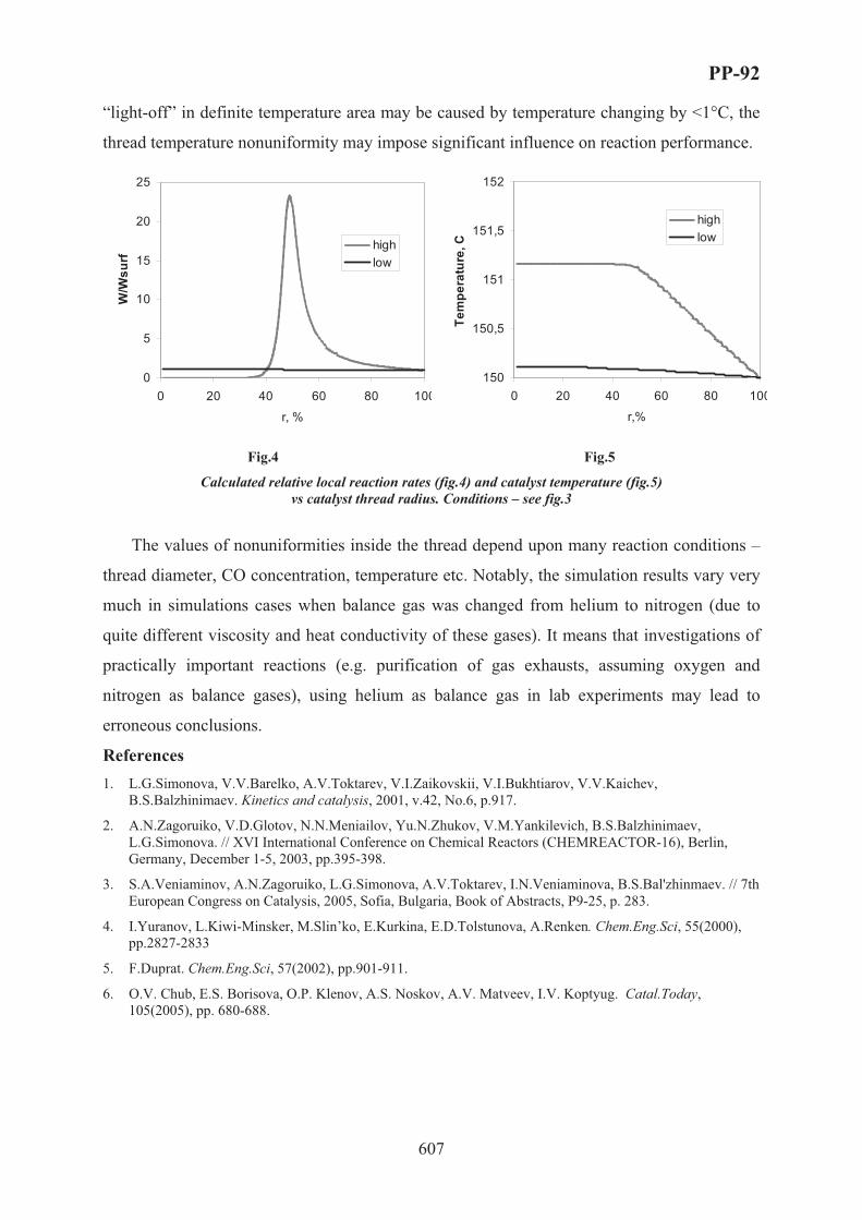
PP-92
607
“light-off” in definite temperature area may be caused by temperature changing by <1°C, the
thread temperature nonuniformity may impose significant influence on reaction performance.
0
5
10
15
20
25
0 20 40 60 80 100
r, %
W/W
surf
highlow
150
150,5
151
151,5
152
0 20 40 60 80 100
r,%
Tem
pera
ture
, C
highlow
Fig.4 Fig.5
Calculated relative local reaction rates (fig.4) and catalyst temperature (fig.5) vs catalyst thread radius. Conditions – see fig.3
The values of nonuniformities inside the thread depend upon many reaction conditions –
thread diameter, CO concentration, temperature etc. Notably, the simulation results vary very
much in simulations cases when balance gas was changed from helium to nitrogen (due to
quite different viscosity and heat conductivity of these gases). It means that investigations of
practically important reactions (e.g. purification of gas exhausts, assuming oxygen and
nitrogen as balance gases), using helium as balance gas in lab experiments may lead to
erroneous conclusions.
References1. L.G.Simonova, V.V.Barelko, A.V.Toktarev, V.I.Zaikovskii, V.I.Bukhtiarov, V.V.Kaichev,
B.S.Balzhinimaev. Kinetics and catalysis, 2001, v.42, No.6, p.917.
2. A.N.Zagoruiko, V.D.Glotov, N.N.Meniailov, Yu.N.Zhukov, V.M.Yankilevich, B.S.Balzhinimaev, L.G.Simonova. // XVI International Conference on Chemical Reactors (CHEMREACTOR-16), Berlin, Germany, December 1-5, 2003, pp.395-398.
3. S.A.Veniaminov, A.N.Zagoruiko, L.G.Simonova, A.V.Toktarev, I.N.Veniaminova, B.S.Bal'zhinmaev. // 7th European Congress on Catalysis, 2005, Sofia, Bulgaria, Book of Abstracts, P9-25, p. 283.
4. I.Yuranov, L.Kiwi-Minsker, M.Slin’ko, E.Kurkina, E.D.Tolstunova, A.Renken. Chem.Eng.Sci, 55(2000), pp.2827-2833
5. F.Duprat. Chem.Eng.Sci, 57(2002), pp.901-911.
6. O.V. Chub, E.S. Borisova, O.P. Klenov, A.S. Noskov, A.V. Matveev, I.V. Koptyug. Catal.Today,105(2005), pp. 680-688.

PP-93
608
ACTIVITY AND REGENERABILTY OF SULFATED ZIRCONIA AS A
FUNCTION OF CATALYST PRECURSOR AND PRETREATMENT
CONDITIONS
A. Zarubica1*, M. Kovacevic1, P. Putanov2, G. Boskovic1
1Faculty of Technology, University of Novi Sad, 21000 Novi Sad, Serbia & Montenegro;
[email protected] Academy of Sciences and Arts, 11000 Belgrade, Serbia & Montenegro
* on leave from Faculty of Natural Sciences and Mathematics, University of Nis,
18000 Nis, Serbia & Montenegro; [email protected]
Introduction
Supply of high octane number (ON) fuel is a challenging task for refineries due to strong
environmental restrictions initiated by EU. Mainly, elimination from gasoline harmful but at
the same time high-ON substances forces ON-issue to be solved by alternative processes.
Hydroisomerization of straight C5-C7 paraffins producing high-ON components for gasoline
blending is one possibility [1]. The reaction requires a byfunctional catalyst: a noble metal on
an acidic support, preferentially on zeolites due to their resistance to impurities [2]. M/zeolites
catalysts, however, demonstrate lower activity than corresponding chlorided-alumina-based
catalysts. Therefore, for the near future an important challenge is to develop a new
environmental friendly and active catalyst. Solid acids as sulfated zirconia (SZ) are potential
candidates for isomerization of light alkanes [3]. The problem with zirconia, however, is rapid
deactivation due to accumulation of coke [4], loss of acidity [5], and removal of active sulfur
entities [6]. The aim of this work is to correlate catalytic and physicochemical properties of
series of SZ samples as a function of catalyst precursor and pretreatment temperature.
Experimental
Three types of SZ catalysts were prepared from different commercial precursors
following the identical procedures for the equivalent sequences required to obtain the
particular sample: the catalyst (1) from SO4-Zr(OH)4 (97%, Aldrich) by its calcination; the
catalyst (2) from Zr(OH)4 (Aldrich) by first its sulfation and further calcination; and the
catalyst (3) from ZrO(NO3)2⋅xH2O (Aldrich) by its precipitation, followed by sulfation of the
obtained hydroxide and its further calcination. The hydroxide for the catalyst starting from
nitrate salt (catalyst 3) was obtained by its precipitation with 25% NH4OH. The sulfation of

PP-93
609
both hydroxides (one synthesized from nitrate - catalyst 3, and the commercial one - catalyst
2) was done by wet-impregnation of 0.5M H2SO4 for intended S content of 3%. All three
sulfated Zr(OH)4 catalyst precursors were finally calcined, for 3h in air flow. Consequently,
total of 9 samples of SZ catalysts were obtained, denoted as (1), (2) and (3) depending on
precursor, followed by A, B and C depending on applied calcination temperature, 500, 600
and 700 ºC, respectively.
Catalysts activity in n-hexane isomerization was measured in a fixed-bed micro reactor.
The reaction was performed at 200-350 oC, p=1bar, with 60.5 mbar n-C6 partial pressure,
molar ratio He(H2)/n-C6=15, and space velocity 6·10-2 – 8·10-2 mmol n-C6/g·min. The feed
was premixed by bubbling He (alternatively H2) through a saturator with n-C6. Reaction
products were separated using 30m long PONA column and identified by FID (Hewlett
Packard 5890). As a rule 0.5 g of a catalyst sample was loaded into the reactor and was in situ
activated in 20 ml/min flow of air at 500 ºC for 1h.
Surface area and average pore diameter were determined by BET (Micromeritics ASAP
2010). Thermogravimetric (TG) studies were performed on a Baehr STA 503, in temperature
range 30-1000 ºC, by using temperature ramp of 10 ºC/min.
Results and discussions
In Table I initial catalyst activities and corresponding textural characteristics are given,
together with weight loss attributed to SO4 release during TG analysis. Corresponding initial
temperatures for SO4 take-off are given as well. All samples follow surface area decrease and
average pore diameter increase with rise of calcination temperature. On another hand,
elevated calcination temperature is beneficial for the initial activity of all catalysts: it is
600 oC for both catalyst 1 and catalyst 2 (samples 1B and 2B), and in the case of catalyst 3
preferences are even to the highest calcination temperature of 700 oC (sample 3C).
A typical steady-state composition of isomers for the case of catalyst 1 is shown in Figure
1. The composition hardly change in the region of calcination temperatures preferred for
activity (500-600 oC), showing mostly mono-branched isomers (CH3x1). A minor fraction of
highly desirable dimethyl-butanes (CH3x2) might be understood in terms of low acidity of this
catalyst. Consequently reaction probably doesn’t occur via byfunctional isomerization
mechanism, but rather by transfer of methyl group on the hydrogenation catalyst function.
The similar isomer composition for samples 1A and 1B indicates the active sites of
comparable quality and quantity (Figure 1). Indeed, SO4 take-of temperatures for both
samples are very close each other (Table I).

PP-93
610
Table I. Catalysts performances and weight loss of SO4 during TG analysis
Conversion, % (SV=6.45⋅10-2 mmol n-C6/g⋅min)
Surfacearea,m2/g
Average pore diameter, nm
200 oC 300 oC 350 oC
SO4loss,%
Initial T for SO4
release, oC
1A 130 2.3 14 50 18 5.0 620 1B 103 3.3 15 22 58 3.8 652 1C 69 5.7 0 - 0 2.1 730 2A 82 2.6 0 1 - 2.3 675 2B 68 3.9 4 11 17 2.3 675 2C 67 5.0 2 3 - 1.9 675 3A 144 3.2 1* - 0 2.6 750 3B 117 4.4 1 10 14 2.6 750 3C 89 6.0 1* 25 25 2.4 750
*SV=0.13 mmol n-C6/gcat⋅min
Superacidic features of zirconia modified with ions, e.g. SO42-, depend on preparation
methods and activation procedure [7]. Temperature treatment above 500 oC brings
decomposition of some of the sulfates by forming SO2 [8], but increases the acidic strength of
SZ [9]. The effect of calcination temperature on sulfates can be followed by rest of sulfates
decomposition by means of TG; difference in SO4 take-of temperatures indicates various
types of sulfur created due to diversity in pretreatment temperatures for different samples
(Table I). The superior activity of sample 1A might be connected to higher amount of total S
(5% towards 2.3 and 2.6 for catalysts 2 and 3, respectively), but also to the different structure
of incorporated S into the ZrO2 matrice of different samples [10].
0
10
20
30
40
180 230 280 330 380
Reaction temperature, C
Com
posi
tion
of
isom
ers,
%
1A-(CH3)x1 1B-(CH3)x1
1B-(CH3)x2 1A-(CH3)x2
0
20
40
60
0 50 100 150
Time-on-stream, min
Con
vers
ion,
%
point of regeneration
Fig. 1. Isomers composition as a function of Fig. 2. Activity of catalyst 1A at 300 oC calcination temperature for catalyst (1) before and after regeneration

PP-93
611
All samples showed no even traces of activity when H2 was used as a carrier gas for
saturation with n-C6, confirming some previous findings [11]. This can be explained by H2
affinity towards S, and extraction of the former from the catalyst in form of H2S. By using He
premixed with n-C6 substantial activities were obtained (Table I), followed, however, with
fast deactivation (Figure 2). On Figure 2 activity of the best catalyst in the whole series (1A)
at its optimal reaction temperature of 300 oC is shown. After 100 min of time-on-stream
activity fools nearly to zero; the black color of the sample indicates coking as the cause for the
deactivation. Obviously, lack of hydrogenation function due to H2 deficiency takes away
auto-regeneration ability of the catalyst. Regeneration of the same catalyst was performed in
air flow at 500 oC for 2 h, restoring, however, only about 50% of the initial activity (Figure 2).
The similar regeneration procedure with catalyst 2B following its participation to the reaction
at 350 oC failed, implicating deactivation mechanism other then coking. Namely, with the
presence of He isomerization reaction can start with production of water, forcing S from +6 to
+4 oxidation state, the last being known of lower activity [11].
Acknowledgments
Financial support of Serbian Ministry of Science and Environmental Protection (Project
No. 142024), and Serbian Academy of Sciences and Arts is highly appreciated.
References [1] I.E.Maxwell, J.E.Naber, K.P.de Jong, Appl.Catal. A: General, 113(1994)153
[2] G.Boskovic, R.Micic, P.Pavlovic, P.Putanov, Catal.Today 65(2001)123
[3] T.Yamaguchi, Appl.Catal.A: General, 222(2001)237-246
[4] R.A.Keogh, D.E.Sparks, B.H.Davis, in: B.Delmon, G.F.Froment (Eds.), Catalyst Deactivation, Stud.Surf.Sci.Catal., vol. 88, Elsevier, Amsterdam, 1994, p. 647.
[5] C.Li, P.C.Stair, Catal.Lett,. 36 (1997) 119.
[6] V.Adeeva, J.W. de Haan, J.Janchen, G.D. Lei, G.Schunemann, L.J.M. van de Ven, W.M.H.Sachtler, R.A. van Santen, J. Catal. 151 (1995) 364.
[7] A.Corma, J.M.Serra, A.Chica, Catal.Today 81 (2003) 495.
[8] F.R.Chen, G.Coudurier, J.F.Joly, J.C.Vedrine, J.Catal. 143 (1993) 616.
[9] V.Bolis, G.Magnacca, G.Cerrato, C.Morterra, Tops.Catal. 19 (2002) 259.
[10] P.Nascimento, C.Akratopoulou, M.Oszagyan, G.Coudurier, C.Travers, J.F.Joly, J.C.Vedrine, in: L.Guczi (Ed.), Proceedings of Tenth International Congress on Catalysis, New Frontiers in Catalysis (1993) 2585.
[11] K.Fottinger, G.Kinger, H.Vinek, Appl.Catal. A: General 226 (2004) 195.

PP-94
612
PREPARATION OF Au/γ-Al2O3-NANOFIBERS CATALYST FOR
OXIDATION OF CO AT LOW TEMPERATURES
Ziyi Zhong*, Shoucang Shen, Yi-Fan Han
Institute of Chemical and Engineering Sciences, 1 Pesek Road, Jurong Island, Singapore
627833. Fax: +65- 6316 6182, e-mail: [email protected]
In last decade there has been a dramatic increase in the number of publications related to
the study of Au-based catalysts, though traditionally supported Au catalysts were almost
marginal value. However, this view is only partially true when the Au particles size is larger
than about 10 nm, in which the intrinsic size effects and the interactions between Au and
oxide supports are only weakly expressed [1, 2]. The quantum size-effects for supported Au
catalysts has been verified by Goodman et al. [3], and the remarkable reactivity at low
temperatures, e.g., oxidation of CO below 100°C, is only observed when the size of Au
particles is below 5 nm. CO oxidation at low temperatures is of great importance for
producing pure H2 on-board supplying to fuel cells derived vehicles, because the maximum
concentration of CO that the electrodes in the fuel cells can tolerate is ca. 10 ppm in the feed
gas [3]. Up to now, for this purpose TiO2 and other supported Au catalysts have been studied
widely [4]. Among them, Au/Al2O3 catalyst shows advantageous performance [5]. In
particular, Al2O3, as one of widely applied supports, is superior to TiO2 and other supports in
several aspects, such as strong mechanical strength, high thermal conductivity, etc. Obviously,
its properties in the preparation of supported Au catalyst have not been addressed enough. In
the study, we aim to develop an active Au/Al2O3 catalyst for CO oxidation.
Al2O3 nano-fibers were synthesized by a modified literature method [6]. Typically, 15g
of Al(NO3)3·9H2O (Merck, >98.5%) was dissolved in 100 mL of de-ionized water, then
mixed with 20% TEAOH (tetraethylammonium hydroxide, Merck-Schuchardt, Germany)
solution under rigorous stirring till the pH value reached 5.0. The mixture was continuously
stirred for 30 min before transferred into an autoclave equipped with a Teflon-liner. The
hydrothermal treatment was conducted at 170°C for 72 h. The as-prepared sample was
calcined at 750°C for 5 h with a heating rate of 5°C/min. While, a commercial γ-Al2O3 (Acros
Organic, surface area of 104m2/g) was used for comparison.
The immobilization of Au colloids onto the catalyst substrate was conducted employing
own invented method [6]. The loading amount of Au in the Au/Al2O3 catalyst was ca. 1.0wt%.

PP-94
613
The measurement of catalytic oxidation of CO was carried out in a fixed-bed microreactor.
Prior to the testing, the catalyst was treated in air at 200°C for 1 h. Reactant gas containing
CO was passed through the catalyst bed at a GHSV of 15000h-1. The outlet gases were
analyzed with an on-line GC (Shimadzu) equipped with one TCD and one FID detector. For
kinetic study, the catalyst was diluted with 90% of α-Al2O3.
The morphology and size of the Al2O3 samples and the Au/ Al2O3 catalyst were observed by
a transmission electron microscope (TEM, Tecai TF20 Super Twin, 200kV) and Scanning
electron microscope (SEM, JEOL-6700F). The powder XRD analysis was conducted on a Bruker
D8 Advance X-ray diffractometer with CuKα1 radiation. The surface area was measured at 77K
(liquid nitrogen) on a Quantachrome Autosorb-6B Surface Area & Pore SizeAnalyzer.
TEM in Fig. 1 shows that the Al2O3 nanofibers as prepared have 1-dimensional
morphology, with a diameter of 8-15 nm, and their length in the range up to 1μm. XRD result
(Fig.2) demonstrates that the calcined sample 750°C is γ-Al2O3(JCPDS 04-0858), and its BET
surface area is ca. 210 m2/g. The TEM images of the Au/Al2O3 catalysts in Fig. 3 reveal that
the Au particles (black dots) are highly distributed over the two types of the catalyst support,
and most of the Au particles size are successfully controlled in the range of 2-5 nm.
The catalytic activity of the Au/Al2O3-nanofibers catalyst is much higher than that of the
Au/Al2O3-commercial catalyst. The temperatures for 50% and 100% conversion of CO
(denoted as T50 and T100, respectively) for Au/γ-Al2O3-nanofibers catalyst were measured at
26 and 40°C, respectively, while the corresponding temperatures were 65 and 140°C
respectively for the Au/Al2O3-commercial catalyst. XPS spectra revealed that before and after
the reaction gold existed as metallic state. However, the apparent active energies, Ea, are
different for the two Au catalysts.
Fig.1. SEM image of the as-prepared γ-Al2O3.Nanofibers.
Fig.2. XRD pattern of the as-prepared γ- Al2O3nanofibers.
10 20 30 40 50 60 70 80
100
200
300
400
500
Inte
nsity
2Θ

PP-94
614
Fig.3. TEM images of the Au/γ-Al2O3-nanofibers (A) and Au/γ-Al2O3 commercial powder.
In conclusion, Au nanoparticles are successfully deposited on the γ-Al2O3 supports with
controlled particle size in the range of 2-5 nm. The Au/Al2O3-nanofibers catalyst exhibited
much higher catalytic activity for CO oxidation than the Au/γ-Al2O3 commercial powder as
prepared in the same way. XPS results show that in the Au/Al2O3 catalysts the chemical states
of Au(0) is quite stable in the reaction, and kinetic data hint that the active sites for CO
oxidation may be different for the two catalysts. Oxidation of CO in the presence of H2 is
underway.
Fig.4. Comparison of CO oxidation activity for the two Au/γ-Al2O3 catalysts. The feed gas is 1% CO in air and
the GHSV is 15000h-1.
References 1. G. Ertl et al, Handbook of Heterogeneous Catalysis,
Weinheim: VCH, 1997, vol 4, 1159-1693. (b) D. Ciuparu, et al, Catalytic Combustion of Methane over Pd-based Catalysts, Catal. Rev., 2002, 44 , 593.
2. V. Raman, Chem. Ind. 1997, 771.3. (a) Y.-F. Han, M. Kahlich, M. Kinne, and R. J.
Behm, Appl. Catal. B 50 (2004) 209. (b) Y.-F. Han, M. Kahlich, M. Kinne, and R. J. Behm, Appl. Catal. B 52 (2004) 123.
4. (a) M. Valden, X. Lai, D. W. Goodman, Science, 1998, 281, 1647. (b) M. Haruta, Catal. Today, 1997, 36,153.
5. (a) Q. Xu, K. C. C. Kharas, A. K. Datye, Catal. Lett., 2003, 85, 229. (b) C. K. Costello, J. H. Yang, H. Y. Law, Y. Wang, J.-N. Lin, L. D. Marks, M. C. Kung, H. H. Kung, Appl. Catal. A 2003, 243, 15. (c) J. T. Calla, R. J. Davies, Ind. Eng. Chem. Res. 2005, 44, 5403.
6. B. S. Gevert, Z.S. Ying, J. Porous Mater. 1999, 6, 63. 7. Ziyi Zhong*, Jizhong Luo, James Highfield, Ang Thiampeng, Jianyi Lin, Preparation of HighlyDispersed
Gold Catalysts for CO Oxidation, 13rd International Catalysis Conference(ICC) in Paris, July, 2004.
BA
20 30 40 50 60 70 80 90 100 110 120 130 1400
10
20
30
40
50
60
70
80
90
100
1.0% Au/γ-Al2O
3
Con
vers
ion
of C
O (%
)
Temperature(oC)
1.0 %Au/Al2O3-fibers

PP-95
615
PRODUCTION OF HYDROGEN BY CATALYTIC DECOMPOSITION
OF WATERMETHANOL MIXTURES
A.L. Lapidus, S.N. Antonyuk*, E.V. Egorova*, E.Z. Golosman**
N.D. Zelinsky Institute of Organic Chemistry RAS, 119991, Moscow, Leninsky avenue, 47,
Russia, fax +7(495)-135-53-03, E-mail:[email protected]
*M.V. Lomonosov State Academy of Fine Chemical Technology, 119571, Moscow,
Vernadsky avenue, 86, Russia, fax: +7 (495)-246-48-23 E-mail: [email protected]
**Novomoskovsk JSC “Institute of Nitrogen Industry”, 301650, Novomoskovsk,
Kirova avenue, 11, Russia, fax: +7(08762)-7-16-61, E-mail:[email protected]
Further expansion of methanol manufacturing is connected now not only with providing
of raw material for a number of chemical enterprises (formaldehyde, dimethylterephthalate,
methylamines, methyl methacrylate), but solution of some current problems in power
engineering, transport, and ecology as well [1].
In the long term, methyl alcohol may become the universal energy carrier as well as a
kind of raw material for manufacturing of hydrocarbon fuel, a wide spectrum of oxygen-
containing compounds and derivatives on their basis [2,3].
Alongside with it, development of highly effective catalysts for methanol decomposition
into H2 is of great importance to create the closed cycles of chemithermal power transfer (with
utilization of nuclear power plant heat) as well as increase the efficiency of methanol internal
combustion engines [3,4].
Besides, methanol decomposition holds much promise for preparative manufacturing of
gas synthesis to be applied in technologies of limited tonnage and research practice.
Our research is devoted to investigation of water-methanol mixtures decomposition over
catalysts on the basis of Cu, Zn,- Cu-cement catalysts as well.
Catalytic decomposition of water-methanol mixtures was carried out in flow-type fixed-
bed reactor at atmospheric pressure and temperature of 200-400 °C. Space velocity of the
stock (WHSV) was varied from 0.6 to 7 h–1.
Catalyst samples prepared by chemical mixing of basic carbonates of copper and zinc
with Cement Fondu-Talum, consisting of calcium mono- and dialuminates (NTK-10), were

PP-95
616
used in experiments. Samples were preliminary calcined in flowing air at 400 °C for 5 h.
Before the tests, catalysts were treated with methanol vapors at 200 °C for 3 h.
In investigation of methanol steam conversion on catalyst NTK-10, a series of
experiments overall temperature range of 200-300 °� and initial feedstock volumetric rate of
0.6-7 h–1 was carried out (Table 1) Equimolar water-methanol mixture was used as initial
feedstock. Formation of hydrogen-containing gas proceeds according to Reaction 1, in turn,
can be considered as a sum of Reactions 2 and 3.
��3�� + �2� ⇔ 3�2 + ��2 ( 1 )
��3�� ⇔ �� + 2�2 ( 2 )
�� + �2� ⇔ ��2 + �2 ( 3 )
Investigation of the process shows that as temperature rises from 200 to 250 °C, methanol
conversion increases up to 100 % at feedstock flow rate of 0.6 h–1. As water-methanol mixture
rate increases from 0.6 to 7 h–1 at 225 °C, degree of methanol conversion is reduced from 99.8
down to 93.7 %. At the same time, hydrogen-containing gas yield increases from 778.8 up to
9889.2 l/lcath and carbon monoxide content simultaneously decreases from 1.8 down to
1.1 vol. %
Table 1 Products of methanol-water mixture transformation at 225 �� at different flow rate
(Feedstock is methanol-water mixture: 64 wt.% of methanol and 36 wt.% of water).
Gas composition, vol. % OHCH3C , wt. %
OHCH3W ,
h–1 �2 �� ��2
Gas yield, l/lcath
99.8 0.6 73.4 1.8 24.8 778.8 99.6 1.5 73.9 1.5 24.6 1972.3 98.6 3.0 74.5 1.2 24.3 4222.5 95.4 5.0 74.6 1.2 24.2 5889.3 93.7 7.0 73.9 1.1 25.0 9556.2
Because carbon monoxide steam conversion is reversible and proceeds with heat
evolution, of interest was to shift it towards formation of hydrogen and carbon dioxide by
introduction of water excess. Experiments were carried out at 225 °C, initial mixture
volumetric rate was 3.0 h–1, and water content in feedstock was 15, 30, 36, 42, 50, 70 and
90 wt. %.
As followed from Table 2, methanol conversion at 225 °C is increased with water content
in initial mixture and attains 98.6 % at 36 wt. %. At the same time, residual carbon monoxide
in products is reduced down to 1.2 vol. %. Further enrichment of initial feedstock with water
results in complete carbon monoxide conversion with formation of practically stoichiometric
hydrogen-containing mixture.

PP-95
617
Table 2 Products of methanol-water mixture transformation at different water content
(� = 225 ��, OHCH3W = 3.0 h–1)
Gas content, vol. % Liquid products, wt. % �|2�, wt. %
OHCH3C ,
% �2 �� ��2 ������3 ��3�� �2�
Gas yield, l/lcath
15 53.3 73.7 5.9 20.4 3.4 96.2 0.4 2554.6 30 85.9 73.8 2.9 23.7 0.1 91.2 8.7 3720.9 36 98.6 74.5 1.2 24.3 0 14.6 85.4 4225.5 42 99.8 74.7 1.0 24.3 0 0.3 99.7 3665.4 50 99.8 74.9 0.8 24.3 0 0.3 99.7 2996.9 70 99.8 75.0 0.3 24.7 0 0.2 99.8 2415.8 90 99.8 75.0 0.1 24.9 0 0.1 99.9 888.5 Thus, dehydrogenation (Reaction 2) is completely suppressed at water-methanol mixture
decomposition.
2 ��3�� ⇔ ������3 + 2�2 ( 4 )
As water grows up to 90 %, methanol in liquid products decreases down to 0.1 % and gas
yield passes through a maximum of 4225,5 l/lcat⋅h, which corresponds to the equimolar
content in initial mixture.
Flow chart of water-methanol mixture transformation into hydrogen
Based on the results above a flow chart of methanol processing has been developed
(Fig. 1).The flow chart consists of several standard components – a tank farm for initial
feedstock and intermediate products (1-2), feedstock heating and evaporation section (heat
exchangers 3-5), reaction section (reactor of methanol decomposition 6) and separators 8.
Methanol from tank 1 and water from tank 2 with the mass ratio of 1.8:1 are pumped into
heat exchanging section and then into reactor 6 with NTK-10 catalyst (225 °C). After cooling
and separation, hydrogen-containing gas enters gas separation unit (not displayed at the
scheme). The gas containing 98-99 vol. % hydrogen goes to consumer.
Literature1. L. P. Strahova and T. G. Bitkova. Market research at grounds of investments in methanol manufacturing.
Proceedings of the 4th International Conference “Current problems of management – 96,” Moscow, 139,
(1996).
2. Asinger F. Methanol-Chemie und Energierohstoff: Die Mobilisation der Kohle. Berlin, (1987).
3. G. �. Terent’ev, V. }. Tyukov, and F. V. Smal'. Motor Fuel from Alternative Feedstock. Moscow,
Chemistry, 186, (1989).
4. N. S. Pechuro, V. D. Kapkin, and O. Yu. Pesin. Chemistry and Engineering of Synthetic Liquid Fuel and
Gas. Moscow, Chemistry, 323, (1986).

PP-95
618
Fig. 1 Flow chart of water-methanol processing (See position and flow designations in the text)

PP-96
619
LIMONENE EPOXIDATION OVER PW-AMBERLITE IN A
TRIPHASIC SYSTEM
Rolando Barrera Z., Aída L. Villa de P., Consuelo Montes de C.
Departamento de Ingeniería Química, Universidad de Antioquia, Medellín-Colombia
Calle 67 Nº 53-108. Tel: + 574 2106606, Fax: + 574 2106609, e-mail: [email protected]
Abstract
The effect of several reaction parameters on limonene epoxidation and hydrogen peroxide
decomposition over PW-Amberlite in a triphasic system was studied. Parameters evaluated
were average particle diameter and concentration of limonene and hydrogen peroxide.
Empirical reaction rates for limonene epoxidation and hydrogen peroxide decomposition were
estimated in terms of concentration and activities.
Introduction
Limonene is an abundant monoterpene extracted from citrus oil. It is usually epoxidized
as an intermediate step for obtaining fragrances, perfumes, and food additives.1 High
limonene conversion (> 80 %) and limonene epoxide selectivity (> 90 %) have been obtained
over PW-amberlite using aqueous H2O2 as oxidizing agent and acetonitrile as solvent.2 Upon
addition of 81 wt %, acetonitrile, in a biphasic system, the reaction rate is first order with
respect to limonene, oxidant and catalyst concentration3. Notwithstanding, due to
environmental and economic reasons it is desirable to minimize the amount of solvent and a
triphasic reaction system which consists of two liquid phases and a solid catalyst is formed.
Here, we report on the influence of several reaction parameters on limonene epoxidation and
hydrogen peroxide decomposition in a triphasic system. Studied parameters were: limonene
and hydrogen peroxide concentration, temperature and catalyst recycling. Internal mass
transfer limitations were avoided following the Weisz-Prater criterion.
Experimental
PW-Amberlite catalyst was synthesized as reported elsewhere.2 All catalytic experiments
were carried out in magnetically stirred glass flasks (8 mL) immersed in a thermally
controlled oil bath. Flasks were sampled at different times, between 0 and 120 minutes.
Catalytic tests were carried out with different catalyst particle sizes and hydrogen peroxide
concentration was varied between 0.73 – 1.92 mol/L. Acetonitrile concentration was 4.05

PP-96
620
mol/L, (71 wt %) which gives a maximum in the initial limonene epoxidation4. After reaction,
samples of the two liquid phases were analyzed by gas chromatography (Varian Star, 3400)
equipped with a flame ionization detector (FID) and a 50 m DB-1 capillary column. H2O2
concentration at different times was determined by cerimetric titration using a 0.1 N CeSO4
aqueous solution.
Results and discussion
First, internal and external diffusion limitations on initial reaction rate were investigated.
Stirring speed was varied for determining external mass transfer resistances. Above 800 rpm
no effects on limonene epoxidation in a triphasic system were observed. Thus, stirring speed
was set at 1000 rpm for all further experiments in order to avoid external mass transfer
resistances. The effect of internal diffusion on initial reaction rates was determined by
measuring reaction rates for different catalyst particle sizes (Table 1). It was observed that
initial reaction rates did not significantly vary when catalyst particle size was lower than
425 μm (fractions III to VI). Besides the estimated Weiz-Prater criterion is lower than 1. So,
particle sizes corresponding to fraction III was used in all further experiments.
Table 1. The effect of catalyst particle size on the initial reaction rates.
Initial reaction rate of limonene epoxidation, mmol/h.g dry cat aFraction Particle size
range (μm) Average diameter, (μm) Aqueous phase Organic phase Bulk
I 600 – 830 715 3.77 3.8 7.57II 425 – 600 512 3.78 3.54 7.32III 250 – 425 337 4.13 3.77 7.90IV 180 – 250 215 4.15 3.78 7.93V 125 – 180 152 4.11 3.80 7.91VI 90 – 125 107 3.98 3.85 7.83
a Reaction conditions: [C10H16]0 = 0.66 mol/L, [H2O2]0 = 1.33 mol/L, [H2O] = 5.84 mol/L, [cat] = 18 g/L, [CH3CN] = 14.05 mol/L, 306 K.
The initial reaction rate of limonene epoxidation increased with temperature; however,
above 306 K the higher the temperature, the higher the hydrogen peroxide decomposition
(table 2). Figures 1a and 1b show that initial reaction rate of limonene epoxidation increased,
and H2O2 decomposition decreased as limonene concentration increased. However, limonene
epoxidation decreased when hydrogen peroxide concentration increased, figure 1c. As
illustrated in figure 1d, hydrogen peroxide decomposition was proportional to concentration.
Results from figures 1c and 1d may be explained from LLE of water + limonene + acetonitrile
system,5 indicating limonene dilution in the aqueous phase because of hydrogen peroxide.

PP-96
621
Table 2. Effect of temperature on the initial reaction rate.
Initial limonene epoxidation rate (mmol/g.h) Temperature (K) Aqueous phase Organic phase Bulk reaction mixture
Initial H2O2 decomposition rate (mmol/g.h)
296 3.40 3.00 6.40 1.47 306 4.40 3.62 8.02 2.81 316 6.36 5.06 11.4 17.1 323 8.00 7.00 15.0 38.4
Reaction conditions: [C10H16]0 = 0.66 mol/L, [H2O2]0 = 1.33 mol/L, [H2O] = 5.84 mol/L, [cat] = 18 g/L, catalyst particle size:250 – 425 μm, [CH3CN] = 14.05 mol/L.
a) b)
0
5
10
15
20
0 0.5 1 1.5
[Limonene] (mol/L)
Initi
al r
eact
ion
rate
d[
limon
ene]
/dt (
mm
ol/h
.g)
0
2
4
6
0 0.2 0.4 0.6 0.8 1
[Limonene] (mol/L)
[H2O
2] d
ecom
posi
tion
rat
(mm
ol/h
.g)
c) d)
0
4
8
12
16
0 0.5 1 1.5 2 2.5
[H2O2] (mol/L)
Initi
al r
eact
ion
rate
d[li
mon
ene]
/dt (
mm
ol/
0
2
4
6
8
10
0 .5 1 1 .5 2
[H 2 O 2 ] (mol/L)
[H2O
2] d
ecom
pos
itio
n r
(mm
ol/h
.g)
Figure 1. The effect of limonene concentration (a and b) and H2O2 concentration (c and d) on the initial reaction rate of limonene epoxidation (a and c) and H2O2 decomposition rate (b and d). x, Organic phase; o, aqueous phase; Δ, bulk reaction mixture. [C10H16]0 = 0.27 - 1.04 mol/L (a and b) or [C10H16]0 = 0.66 mol/L (c and d), [H2O2]0 = 1.33 mol/L (a and b) or [H2O2]0 = 0.73 - 1.92 mol/L (c and d), [H2O] = 5.84 mol/L, [cat] = 18 g/L, catalyst particle size:250 – 425 μm, [CH3CN] = 14.05 mol/L, 306 K.
PW-Amberlite was recycled up to three times under the same reaction conditions.
Catalytic activity was recovered after catalyst washing with acetone; no significant change in
the initial limonene reaction rates was observed. The initial reaction rate for limonene
epoxidation was 8 × 10⁻³ mol/h.g with fresh catalyst and after three reactions it decreased to
7 × 10⁻³ mol/h.g.
Empirical reaction rate expressions for limonene epoxidation and hydrogen peroxide
decomposition are estimated in terms of concentrations and activities, to account for the
nonideal character of liquid mixtures using the optimization toolbox slqnonlin from Matlab 6.
Empirical kinetic parameters for limonene epoxidation and hydrogen peroxide decomposition
are listed in Table 3.

PP-96
622
Table 3. Empirical kinetic parameters for limonene epoxidation and hydrogen peroxide decomposition
Parameter with 95 % confidence interval Equation SSR × 105 SE × 103
k α ββα ][][ BAkrL =− 3.7 1.4 0.021± 0.007 a 1.934 ± 0.006 –1.410 ± 0.005
βα ][][ BAkrdes =− 4.8 0.7 1.581 ± 0.006 b –0.436 ± 0.007 2.475 ± 0.006
BAL akar βα=− 6.2 1.2 (9.479 ± 0.001) × 10–7 c 2.869 ± 0.017 –2.407 ± 0.043
BAdes akar βα=− 5.5 0.6 1.57 ± 0.005 c –0.371 ± 0.011 2.399 ± 0.016 a In mol0.476L0.524 (g.h)–1. b In mol-1.039L2.039 (g.h)–1. c In mol (g.h)–1. SSR = square sum of residuals, SE: standard error. –rL: limonene epoxidation rate, –rdes: H2O2 decomposition rate. [A] is limonene concentration and [B] is H2O2 concentration; ai is the activity of component i.
Interestingly, empirical reaction rate constant and order for hydrogen peroxide
decomposition are little affected when non-ideal reaction mixture is considered, in contrast to
those corresponding to limonene epoxidation.
Conclusions
Limonene epoxidation with aqueous H2O2 in the presence of acetonitrile in a triphasic
system was studied over PW-amberlite. External mass transfer problems were avoided using a
stirring speed of 1000 rpm. According to Weiz-Prater criterion, mass transfer limitations were
insignificant for catalyst particle sizes lower than 425 μm. Empirical kinetic parameters for
limonene epoxidation are different when concentration or activity data was fitted, while those
of hydrogen peroxide decomposition are almost the same independent of whether
concentration or activity data were used. The apparent activation energy of limonene
epoxidation was 25.16 KJ/mol, three times lower than that found previously in biphasic
system; for hydrogen peroxide decomposition the estimated apparent activation energy was
100.6 KJ/mol. PW-amberlite was recycled three times and no significant decrease on catalytic
activity was detected.
Acknowledgments
This work was sponsored by Colciencias/UdeA through CENIVAM RC No.432 and Colciencias/ SENA/ UdeA,
project 1115-05-12426.
References
(1) Derfer, J. M.; Derfer, M. M. Encyclopedia of Chemical Technology Kirk-Othmer, Vol 22, 3rd edition;Wiley: New York, 1978.
(2) Sels, B. F.; Villa, A. L.; Hoegaerts, D.; De Vos, D. E.; Jacobs, P. Top. in Catal. 2000, 13, 223.
(3) Villa, A. L.; Taborda, F.; Montes de C., C. J. Mol. Catal. A. 2002, 185, 269.
(4) Barrera R.; Villa A. L.; Montes de C., C. The effect of the amount of solvent in the epoxidation of limonene over PW-amberlite, 19th North American Meeting, Philadelphia, Pennsylvania, may 22-27 2005, poster 306.
(5) Barrera, R.; Villa A. L.; Montes de C., C. J. Chem. Eng. Data. 2005, 50, 1353.

PP-97
623
THE CRITICAL PHEMOMENA AND THE CATALYST SURFACE
TOPOLOGY
V.I. Bykov, N.V. Kisilev*, S.B. Tsybenova**
Bauman Moscow State Technical University, Moscow, 105005, Russia
E-mail: [email protected] *Krasnoyarsk State Technical University, Krasnoyarsk, 660074, Russia
** Russian State Social University, Moscow, 107150, Russia
The two-dimentional model of diffusion and reaction of intermediates on a surface of the
solid-state catalyst is offered. This model takes into account an opportunity of a jump of
adsorbed molecules with occupied on the next free active place. The coefficients of two-
dimentional diffusion depend from degrees of a covering. Nonlinearity of model is
determined generally nonlinear kinetics of reactions between substances adsorbed on a
surface of the catalyst. For a case autocatalytic oscillator are carried out illustrating the
calculations showing an opportunity of existence of structures and autowaves on a surface of
the catalyst. We considered four basic surface topology: plane, sphere, cylinder, torus.
In the elementary case the mathematical description of diffusion and reaction on surfaces
of the catalyst is under construction on a basis of lattice model [1]. As a surface of the catalyst
the square lattice of active places is considered [2−5]. Each place has 4 neighbours of the
nearest environment. We yet do not consider neighbours of more distant levels of an
environment. Except for that we assume, that everyone intermediate takes one active place.
Process of diffusion is considered as jump of a molecule with occupied on any free place. The
probability of this process depends on a degree of a covering of an active surface adsorbed
molecules.
The model of reaction and diffusion of intermediates on a surface of the catalyst has the
form:
),,()( zxfzxxzDtx
iiiii +Δ−Δ=
∂∂ ni ,,1�= , (1)
where z = 1 − x1 −…− xn is a share of free place, a vector ),,( 1 nxxx �= , ix are degrees of
intermediates covering, Δ is Laplas’s operator for a plane.

PP-97
624
As an example of general model (1) the model of reaction and diffusion for the scheme of
transformations [3]:
,)3,32)2,)1 YZBAZZXXZA ⇔++→+⇔+ (2)
where A, B are substances in a gas phase (A, B = const), X, Y are intermediates, Z is the
catalyst, is considered. Model (1) for scheme (2) in the assumption of diffusion X has the
form:
,1,
),(
33
2211
yxzykxkty
zxxzDxzkxkzktx
−−=−=∂∂
Δ−Δ+−−=∂∂
−
−
(3)
., 22
2
21
2
22
2
21
2
ξξξξ ∂∂+
∂∂=Δ
∂∂+
∂∂=Δ zzzxxx
Autocatalytic character of the kinetics for reaction (2) results to that the steady
homogeneous condition in the system at presence of diffusion in the distributed system can
lose stability that is characterized by presence in (3) steady non-homogeneous solutions
(dissipative structures) [6,7]. These structures can be stable in time or periodically vary, that
answers autowaves on the catalyst surface. In the latter case adsorbed substances form in
claster which periodically arise, grow, decrease and disappear. Such "blinking" of
intermediates on catalyst surfaces results in complex dynamics of total catalytic reaction rate.
It macro-characteristic essentially depends from a ratio of parameters of nonlinear interaction
of intermediates and their diffusions at a microlevel.
We have for the spherical surface the Laplas’s operator
��
����
�∂∂−
∂∂+
∂∂=Δ
ϕϕ
ψϕϕtg2
2
22
2
2 cos11
R, (4)
where ϕ, ψ are spherical coordinates. The dissipative structures and traveling waves on the
spherical catalyst surface are investigated. We considered also the cylinder and torus.
References 1. Zhdanov V. P. // Surf. Sci. Rep., 2002, vol.45, p. 231-326. 2. Gorban A.N., Bykov V.I., Yablonskii G. S. Sketches about a chemical relaxation. Novosibirsk: Nauka,
1986. 320 p. 3. Bykov V.I. Modelling of the critical phenomena in chemical kinetics. M.:Nauka, 1988. 264 p. 4. Yablonskii G.S., Bykov V.I., Gorban A.N., Elokhin V.I. Kinetic models of catalytic reactions. Amsterdam:
Elsevier.1991. 400 p. 5. Gorban A.N., Bykov V.I., Yablonski G.S. // Chem. Eng. Sci. 1980, vol. 35, 11, p. 2351. 6. Bykov V.I., Tsybenova S.B., Slinko M.G.// DAN. 2003, vol. 388, 6, p. 769. 7. Bykov V.I., Tatarenko A.A., Slinko M.G.// DAN. 2003, vol. 392, 5, p. 645.

PP-98
625
THE THERMOCATALYTIC OSCILLATORS
V.I. Bykov, S.B. Tsybenova*
Bauman Moscow State Technical University, Moscow, 105005, Russia
E-mail: [email protected]
* Russian State Social University, Moscow, 107150, Russia
E-mail: [email protected]
We considered the thermokinetic models of the catalytic reactions:
),(),()(
),,(
TTTxwHdtdTC
Txwdtdx
ossp
ss
−+Δ=
=
�
�
αρ
γ (1)
where x = (x1,…, xn) is the concentration vector; T is the temperature of catalytic surface; w is
the reaction rate. The dynamic system (1) for T=const have one or more steady states [1-3]:
.0),( =� Txwssγ (2)
The equations (2) determine a function x=x(T). So for steady state temperature we have
equation:
).()),(()( 0TTTTxwH ss −=Δ� α (3)
The temperature balance (3) gives a possibility to determine the steady states and
sometimes their stability [4-8]. In this paper we consider a set of thermokinetic models (1) for
the basic catalytic reactions. The mathematical model (1) consists of two subsystems − the
kinetic and thermal subsystems [9-12]. For the steady state it is (2) or (3).
1. Linear mechanism: 1) A+Z → AZ, 2) AZ → Z+B. (4)
The dimensionless model for (1), (4) has the form:
),1()()1)((
,)()1)((
2211
21
ysxyfxyfddy
xyfxyfddx
−++−=
−−=
ββτ
τ (5)
where x, y, τ are the dimensionless concentration, temperature and time;
)),11(exp()(y
Dayf iii −= γ i = 1,2;

PP-98
626
βi, γi, Dai, s are the dimensionless parameters. The parametrical analysis method gives a
possibility for thermokinetic model (5) to build the bifurcation curves, parametric and phase
portraits, oscillation regimes. We study the nonlinear dynamic system (5) like the famous
classic models CSTR − Aris-Amundson model [6] and Semenov-Zeldovich model [5].
2. Autocatalytic trigger: 1) Z ↔ X, 2) X+2Z → 3Z, (6)
where Z is a catalyst, X is an intermediate. The dimensionless thermokinetic model
corresponds to (6):
).1()1()()()1)((
,)1()()()1)((
2221111
2211
ysxxyfxyfxyfddy
xxyfxyfxyfddx
−+−++−=
−−−−=
−−
−
βββτ
τ (7)
We consider more detail two separated cases for system (7):
),1()(
,)1()()1( 221
ysxyfddy
xxkxyfxkddx
−+=
−−−−=
βτ
τ (8)
and
),1()1()(
,)1()()1(
2
211
ysxxyfddy
xxyfxkxkddx
−+−=
−−−−= −
βτ
τ (9)
where ki are the dimensionless reaction rate constants. The dynamic system (8) has a limit
cycle for example for parameters: β = 0.4, γ = 75, s = 4, Da = 0.1, k1 = 0.6, k2 = 1. The system
(9) has the oscillations for example for parameters: β = 0.395, γ = 65, s = 4.5, Da = 0.5, k1 =
0.6, k-1 = 1.
3. Autocatalytic oscillator: 1) Z ↔ X1, 2) X1 + 2Z → 3Z, 3) Z ↔ X2, (10)
where X1, X2 are the intermediates on the catalyst surface Z. The thermokinetic model
corresponds to scheme (10):
),1()(
,
,)(
21
2332
21111
1
yszxyfddy
xkzkddx
zxyfxkzkddx
−+=
−=
−−=
−
−
βτ
τ
τ
(11)
PP-98
627
where z = 1 − x1 − x2 , x1, x2, y are the dimensionless concentrations and temperature. The
dynamic system (11) has the oscillations for example for parameters: β = 0.4, γ = 65, s = 4.5,
Da = 0.56, k1 = 0.6, k-1 = 1, k3 = 0.001, k-3 = 0.03.
4. Catalytic trigger: 1) 2Z ↔ 2X1 , 2) Z ↔ X2 , 3) X1 + X2 → 2Z . (12)
For (12) the thermokinetic models has for example the form:
).1()(
,)(
,)(22
21
212222
21211
21
1
ysxxyfddy
xxyfxkzkddx
xxyfxkzkddx
−+=
−−=
−−=
−
−
βτ
τ
τ
(13)
5. Catalytic oscillator: the scheme (12)+ buffer step
4) Z ↔ X3 . (14)
is a catalytic oscillator [1,3]. The thermokinetic models for (12) and (12)+(14) may have a
complex dynamic behavior.
References 1. Bykov V.I. Modelling of the critical phenomena in chemical kinetics. M.:Nauka, 1988. 264 p.
2. Yablonskii G.S., Bykov V.I., Gorban A.N., Elokhin V.I. Kinetic models of catalytic reactions. Amsterdam: Elsevier.1991. 400 p.
3. Bykov V.I.//Zh.Phys.Chem. 1985, vol.54, 11, p. 2712.
4. Bykov V.I., Pushkareva T.P.//React.Kinet.Catal.Lett. 1994, vol. 52, 1, p. 87.
5. Bykov V.I., Pushkareva T.P.//React.Kinet.Catal.Lett. 1995, vol. 54, 1, p. 145.
6. Bykov V.I., Tsybenova S.B.//Phys.Gor.Vzryv. 2001, vol. 37, 5, p. 36.
7. Bykov V.I., Tsybenova S.B.//Teor.Osn.Chem.Techn. 2003, vol.37, 1, p. 64.
8. Bykov V.I. Tsybenova S.B.// DAN. 2000, vol. 374, 5, p. 640.
9. Bykov V.I., Tsybenova S.B., Slinko M.G.// DAN. 2001, vol. 378, 2, p. 214.
10. Bykov V.I., Tsybenova S.B., Slinko M.G.// DAN. 2001, vol. 378, 3, p. 355.
11. Bykov V.I., Tsybenova S.B.//Zh.Phys.Chem. 2003, vol. 77, 9, p. 1566.
12. Bykov V.I., Trotsenko L.S.//Zh.Phys.Chem. 2005, vol. 79, 5, p. 792.

PP-99
628
STUDY OF THE COMBINED ZEOLITE-CONTAINING ADSORBENT
LAYER FOR SWEETENING OF NATURAL GAS UTILIZED
AT THE «ORENBURGGAZPROM Ltd»
S.N. Filimonov1, S.R. Khairulin2, Z.R. Ismagilov2
1Orenburggazprom Ltd., Orenburg, Russia 2Boreskov Institute of Catalysis, SB RAS, Novosibirsk, Russia
Introduction
Sweetening of sour natural gases is a key problem of production of pollution free fuels.
One of the most promising technologies/processes is that removal of sulfur containing
complexes (hydrogen sulfide and mercaptans) by synthetic zeolite-based adsorbents which
successfully runs at the Orenburg Gas Processing Plant (OGPP). Prior to entering the natural
gas-sweetening and drying plant of the (OGPP), natural gas was passed through amine
treatment plants and glycol dehydration units of the gas processing/refining plant. Cleaning
was performed over the NaX zeolite containing adsorbent in vertical cylindrical adsorbers.
The zeolite loading is 70 tons, the gas flow rate through the adsorber was 250–360 thousand
m3/h. A stage of adsorption lasts for 20 h, regeneration and cooling last for 10 h each taken
separately. The process of regeneration is performed by preheated purified natural gas at
temperatures ranging from +270 to +320� �.
Upon the operation period of 18–24 months, adsorption capacity of the layer to all
components, including the main component such as sour sulfur, reduced from 3.2 to 1.6 wt.%
because of accumulation of coke deposits.
Deactivation of the layer is primarily caused by decomposition of mercaptans, however,
DEA and glycol also significantly contribute to this process (15 to 20% of the total coke
deposition), even if both amine and glycol plants operate stable and the concentration of DEA
and glycol does not exceed the limit 16 mg/m3 (in total).
Carbon deposit is non-uniformly throughout the zeolite height. The main portion of carbon is
deposited on the front layer part (7–10% of the loading height) where sorption of almost all
DEA and glycol, supplied to the adsorber, proceeds.
PP-99
629
Experimental
In order to optimize the process conditions, we proposed the following order of the
adsorber loading: 10% of the layer (along the gas movement) length at the inlet is formed by
zeolite adsorbent NaY, the rest being NaX.
To test the suggested load using the actual raw gas to be cleaned from sulfur compaunds
and dried, the pilot plant was designed and constructed (Fig. 1). The main units are two
parallel adsorbers designed for the zeolite load of 10-12 g. The size of zeolite fractions in both
adsorbers was 0.5-1.0 mm.
Both adsorbers are designed as a tube, the inner diameter is 10 mm, the zeolite bed
height is 200-250 mm.
A feed gas flow was directed to the both adsorber inlets at the pressure 50 kilogram-
force/cm2. The gas flow rate through the adsorber was 50 l/h, monitoring of the gas supply
was performed by gas meters, the variation in gas supply to the adsorbers was maintained at
± 0.2 l/h.
Adsorber 1 was loaded with two zeolite layers: the first layer (along the gas flow)
contains zeolite adsorbent NaY (1.18 g), the second layer contains commercial zeolite
adsorbent NaX (10.57 g).
Adsorber 2 (reference) was loaded with the NaX adsorbent (11.7 g). The size of zeolite
fractions in both adsorbers was 0.5-1.0 mm.
We were forced to use paralleling of the adsorbers in order to equalize differences in the
natural gas composition at the reactor inlet, because components of the gas flow and
concentrations of sulfur complexes in the gas vary within a rather wide range, thus the hourly
variations attain to 20%. The inlet and outlet flows were analyzed to determine:
– gas composition by a chromatography method (State Standard # 23781-87) using a
“TSVET 2000M” chromatograph. We registered hydrocarbons �1+6, ��2 and non-
hydrocarbon components;
– concentration of the sour sulfur and hydrogen sulfide by an iodimetric method (State
Standard # 22387.2 – 97);
– concentrations of amine and glycol in the feed flow by the standard technique for
mass concentrations of glycol and amines in gases (M 005 – 123 – 00).

PP-99
630
Fig. 1. Pilot setup for studying the process of adsorptive natural gas cleaning
Results and discussion
Processing of experimental data suggests that dynamic capacity of the composite layer
to sour sulfur exceeds that of the reference layer by 2 % and reaches 3.27% under
experimental conditions. Dynamic capacity to hydrogen sulfide and carbonic acid gas of both
loads was practically equal.
To study stability of the load characteristics, we performed a number of runs with varied
adsorption-regeneration cycles using the natural gas. The total number of cycles was 50. After
each ten cycles, the amount of coke deposits on the layer was determined by the weight
method. After 50 cycles, dynamic capacity of loads 1 and 2 was determined from the sour
sulfur.
The content of coke deposits vs cycle number is shown in Table 1
Content of coke deposits Number of
cycles NaY layer NaX layer (loading 1) NaX layer (loading 2)
10 0.023 g - 1.91 % 0.164 g - 1.53 % 0.191 g - 1.60 %
20 0.046 g - 3.75 % 0.271 g - 2.50 % 0.312 g - 2.60 %
30 0.058 g - 5,45 % 0.361 g - 3.30 % 0.425 g - 3.50 %
40 0.091 g - 7.16 % 0.418 g - 3.80 % 0.513 g - 4.20 %
50 0.110 g - 8.52 % 0.446 g - 4.05 % 62 g - 4.58 %

PP-99
631
As follows from the table data, the total concentration of coke on both loads is almost
equal. For load 1, coke deposits more intensively on the NaY zeolite layer than on the NaX
layer due to decomposition of DEA and glycol. The underlying NaX layer is fed by a gas flow
cleaned from both DEA and glycol. After 50 adsorption-regeneration cycles, the dynamic
capacity of the partially carbonized loads to sour sulfur was: 2.07 and 1.93 wt.% for loads 1
and 2, respectively.
Conclusion
As follows from the pilot tests, the combined zeolite load permits one to increase the
adsorbent life serving in the natural gas sweetening plant. An application of zeolite NaY as a
protective layer made it possible to preserve the value of dynamic capacity of the load that
exceeds that on the industrial load by 7.3%.

PP-100
632
EXPERIMENTAL-COMMERCIAL STUDIES OF CATALYTIC
SYSTEMS FOR AMMONIA OXIDATION PROCESS
Brushtein E.A., Golovnya E.V., Vanchurin V.I.
«ALVIGO-M» Ltd; 38, Shosse Entuziastov, 111123 Moscow, Russia
Tel./Fax: (+7 495) 232-1465, 232-9906
E-mail: [email protected]; Web: http://www.alvigo.ee
For decades, ammonia oxidation process in Russian domestic nitric acid plants was
performed with two variants of catalytic system - either over conventional stack of platinoid
catalyst gauzes, or over two-stage system comprising platinoid gauzes and non-precious oxide
catalyst. In the early 90s, the non-precious oxide catalyst for 2nd stage of ammonia oxidation
in the form of honeycomb-structured blocks have been developed for the first time in Russia.
Implementation of regular honeycomb catalyst instead of bulk beds of pelleted catalyst types
has allowed then to take the full advantage of using two-stage systems for ammonia
oxidation, namely to reduce the noble metal catalyst costs and losses of platinoids, as well as
to lower converter’s hydraulic resistance. On the other hand, the industrial tests have shown
that there is a room for performance improvement of ammonia oxidation units lying in
replacement of a part of conventional stack of platinoid catalyst gauzes by less expensive
palladium catchment gauzes, which are capable of absorbing noble metals aerosols.
Nevertheless, the costs of platinoid catalyst required for nitric acid production remain
high, and therefore a research aimed at reduction of both catalytic system initial cost and
losses of platinoids during operation is still of great importance today.
The possible new direction in development of ammonia oxidation process is the using of
new advanced catalytic system which have been designed taking into account the operating
experience of nitric acid plants with conventional catalyst options. Obviously, the new system
can not be marketed without carrying out very detailed and reliable operation tests under
conditions similar to those at commercial operation. The results of such tests can be of both
theoretical and practical value as they allow to discover and examine the new properties of
multi-stage catalytic system and significantly contribute to saving of precious metals.
Some results are given in this paper of such experimental-commercial studies of various
catalytic systems for ammonia oxidation process which have been carried out at the

PP-100
633
installation mounted at JSC ACRON industrial site in Novgorod, Russia with the participation
of ALVIGO-M Ltd.
The main device of the installation was an ammonia converter reactor with effective inner
diameter of 0.15 m, operating under process conditions equal to those in UKL-7 type
commercial nitric acid plant. Platinoid catalyst and catchment gauzes were fixed by special
flange in the converter, and oxide catalyst in the form blocks’ fragments was loaded in the
separate basket under the gauzes inside the converter. The stack of gauzes was separated from
a layer of the oxide catalyst by a Megapure gauze. The distance between the gauzes and
thermocouple was approx. 10 mm. The installation was also equipped by all the necessary
instrumentation and devices for process control, maintaining the preset technological
parameters, measurement and sampling.
The following types of catalytic system were studied:
Conventional types:
1. Platinoid system of 7-12 catalyst gauzes.
2. Platinoid system of 7 catalyst gauzes and 3-5 catchment gauzes (Pd/W-5 alloy).
3. Two-stage system, comprising 6-9 platinoid catalyst gauzes and a layer of the IK-42-1
honeycomb block oxide catalyst.
New advanced type:
4. Two-stage system comprising 9 platinoid catalyst gauzes, 3 catchment gauzes (Pd/W-5
alloy), and a layer of the honeycomb block oxide catalyst.
The graph is shown below (See Fig. 1) for the obtained values of ammonia conversion
rate over conventional catalytic systems against catalyst gauzes number, under the process
conditions of 500 nm3/hr flow rate of Ammonia-Air Mixture (AAM), temperature 880-890 º�
and ammonia concentration in AAM 10.53 – 10.69 vol.%.
It is evident from the diagram that for the conventional platinoid gauze catalyst system
(curve 1) there is a linear dependence between the ammonia conversion rate and the number
of gauzes for the system containing 7 to 10 gauzes, and for the number of gauzes 10 to 12 the
conversion rate changes insignificantly, which is in accordance with earlier studies results.
With the two-stage system of 9 platinoid catalyst gauzes and a layer of block oxide catalyst
(curve 2), the conversion rate is comparable to that with conventional stack of gauze catalyst,
or even slightly higher. It is obvious that the improvement of ammonia oxidation in this case
is due to effect of hydrodynamic conditions stabilization of AAM flow through the converter
by the layer of regular blocks of oxide catalyst.

PP-100
634
Fig. 1 Ammonia conversion rate (α, %) dependence on catalyst gauzes number (n): 1. – platinoid catalytic system of 7-12 catalyst gauzes; 2. – two-stage catalytic system of 6-9 catalyst gauzes and a layer of blocks of IK-42-1 oxide catalyst; 3. – platinoid catalytic system in combination with 3-5 catchment gauzes (Pd/W-5 alloy): p.7 – 7
platinoid gauzes, p.10 – 7 platinoid + 3 catchment gauzes, p.12 – 7 platinoid + 5 catchment gauzes;
4. – two-stage catalytic system of 9 platinoid gauzes in combination with 3 catchment gauzes (Pd/W-5 alloy) and a layer of the block oxide catalyst.
Also, it can be concluded from curves 1 and 3 comparison that in terms of selectivity the
combined systems of 10 gauzes (7+3) and 12 gauzes (7+5) generally slightly concede to the
systems of 10 and 12 platinoid catalyst gauzes. As an example, the obtained ammonia
conversion with the system of 12 platinoid gauzes amounts to 95.0 %, while the combined
system of 7 platinoid and 5 catchment gauzes has achieved 94.2 %. It is evident however that
no considerable decrease of system catalytic properties is observed at replacement of catalyst
gauzes by catchment ones, even of considerable part of stack. It testifies that catchment
gauzes possess the certain catalytic activity in desired reaction of ammonia conversion into
nitrogen oxide, i.e. their operation is bifunctional.
The interesting data have been obtained concerning ammonia slip. It have been found that
ammonia concentration in catalytic system effluent gas equaled to 0.016 vol. % with 12
platinoid gauzes system and 0.011 vol.% with the system of 7 platinoid catalyst and 5
catchment gauzes. The decrease in ammonia conversion rate and in ammonia concentration in
system effluent gas (ammonia slip) at using the catchment gauzes can point at the possible
occurrence of undesirable reaction:
4NH3 + 6NO ¿ 5N2 + 6H2O

PP-100
635
The point 4 on Fig. 1 illustrates the efficiency of two-stage system of 9 platinoid catalyst
and 3 catchment gauzes and a layer of the block catalyst. The ammonia conversion rate in this
case have reached 95.4 %, which is by 0.4 % than the calculated value for the system of 12
platinoid catalyst gauzes and by 1.2 % higher than for system of 7 platinoid catalyst and 5
catchment gauzes. It is assumed that this effect is conditioned by the favourable influence of
block oxide catalyst layer placed under gauzes stack on the gas flow hydrodynamics inside
the converter which results in excluding the selectivity decrease observed in the systems not
containing such layer.
The further research of the two-stage catalytic systems containing platinoid catalyst and
catchment gauzes along with the layer of block oxide catalyst will surely be very promising
for further improvements in ammonia oxidation process in nitric acid production.

PP-101
636
RELATIONAL DATABASE SYSTEM MANAGER OF COMPLEX REACTIONS IN THE PRESENCE OF ZIRCONIUM CATALYST
(C2H5)2ZrCl2
Irek M. Gubaydullin1, Il'dar I. Gubaydullin2
1Institute of Petrochemistry and Catalysis, Laboratory «Mathematical chemistry», Ufa Scientific Centre of RAS, address: Prosp. Oktyabrya, 141, 450075, Ufa, Russia,
phone/fax: 7-3472-312750, e-mail: [email protected]. 2Ufa State Aviation Technical University, address: K.Marx str, 12, 450000, Ufa, Russia,
phone/fax: 7-3472-730672, e-mail: [email protected].
Any mathematical model comprise a structure and algorithms of the investigated
process. In the heart of current technology of database underlie use of the relational model of
data (RMD), based on the strict apparatus of the relational algebra and the mathematical logic.
Such approach is the most effective at the decision of problems of modelling of complex
systems [4].
Under the direction of a member correspondent of Dzhemilev U.M. in the Instutute of
Petrochemistry and Catalysis (INK) of the Russian Academy of Science are studied complex
mechanisms of catalytic cycloaluminizing [1] and hydroaluminizing [2] of olefines in the
present of zirconium catalyst Cp2ZrCl2. The developed kinetic models for above specified
mechanisms, and also for reaction of oligomerization of alpha-methylstyrene [3], formed a
relational database system manager (RDBSM).
Ascertainment of the general mechanism of actionof Zirconium Catalyst
2004: Zr
Rhydrometallation
cyclometallationcarbometallation
isomerization
polymerizationoligomerization
R
H
Zr
Zr
RR
R
R
R'
Zr
*
R R
*nR R
PURPOSE:
[Djemilev U.M. and others2000]
Laboratory of catalytic fusion, member of corr. RAS Djemilev U.M.Laboratory of structural chemistry, prof. Halilov L.M.Laboratory of mathematical chemistry, prof. Spivak S.I.
2006:
THE MECHANISM OF ZIRCONIUM CATALYSIS
2003:
2010 (plan)
2008 (plan)
CARBO_AL.dat
OLIG_ALM.dat
OLIG_ALS.dat
GIDRO_AL.dat
ZIKLO_AL.dat
ZICLO_MG.dat
- developed DB;[name DB].dat - DB is developing;[name DB].dat
Notation:
Fig. 1 – The mechanism of zirconium catalysis

PP-101
637
In figure 1 strategy of studying of the general mechanism of action of zirconium
catalysts is presented. In process of modelling separate reactions of all complex mechanism
with participation of zirconium catalysts [1, 2, 3], there was a necessity not only to keep
numerous experimental data, but also to analyze and synthesize connections both between
data in one reaction, and between data of several reactions. The data taken from a database on
the basis of established connections, are the information. Outside of connections data are the
information only in the event that they are typified, or classified, and the applied classification
scheme is known. In figure 2 it is presented static part of a DB of the new considered complex
mechanism of cyclomagnezing of olefines.
Fig. 2 – The elementary input informational flow for to computing experiment by definition of the kinetic constants of mechanism cyclomagnezing of olefines and alens RMgR, catalyzed by complexes Ti and Zr
The natural language reflecting stoichiometry of chemical reactions, language of linear
algebra is. An atomically-molecular matrix mirror chemistry of agent, and stages of chemical
reaction - a stoichiometric matrix. Change in time of concentration of substances participating
in reaction too is set by matrix tables. During search of a minimum of functional conformity
of experimental and calculated concentration it is used Volpert's A. bipartite graphs which are
set by matrixes of an adjacency and incidence.

PP-101
638
In view of above specified, the relational approach is justified at designing a DB in an
opportunity of their future integration in the integrated distributed databases (IDDB).
First of all the RDBSM orientate for convenience of work of the chemical
experimenter (the technologist at a factory).
In figure 3 the superficial scheme of working user from RDBSM is presented. Deeper
and full description of structures of RDBSM will be presented in the subsequent works.
Fig. 3 – Schema of working user from RDBSM
The structure and the maintenance of each experiment is presented in figure 2.
Information input
Reactions and experiments review
Atomically-molecular and stoichiometric
matrices
Graph of reactions
Expirement 1 Experiment 2
… Experiment N
… …
Database query by AOS, by olefines, by
temperature, by activation energy
Correct query
No
Input information flows processing and output informational
flows forming
Yes
Verification of law of
conservation of mass
Ill-posed informational
input
Correction of schema
of chemical reaction
Yes
Relational system of database (RSDB)
CARBO_AL.dat No
Output of results of processing of
the entered informational
Forming of the derived constants and the activation energy on different medium
Output of query results
SCHEMA OF WORKING USER

PP-101
639
At present the first group of total of methods and means of definition of the connected
data is developed. The group contains the formal description of structures of data, and also
administration of a DB.
Following DB are developed:
1) OLIG_ALM.dat – alpha-methylstyrene oligomerization in the presence of NaHY
Zeolite;
2) ZIKLO_AL.dat – cycloaluminizing of alkylalanes by AlEt3 in alumocyclopentane
in the presence of Cp2ZrCl2;
3) GIDRO_AL.dat – olefin hydroalumination by alkylalanes in the presence of
Cp2ZrCl2.
In a stage of development are:
1) OLIG_ALS.dat – styrene oligomerization in the presence of NaHY Zeolite;
2) KARBO_AL.dat – carboaluminizing;
3) ZIKLO_MG.dat – of olefines and alens RMgR, which catalysting at complexes Ti
and Zr.
References
1. �.�.¸?\?!#, Õ.�.Ö?¤Ø!|�#?, ¹.}.´©?¦�©\\_| _ �¤. }!¯?|_¨® ¤!?§³__ ³_§\�?\«®_|_¤�#?|_ª ?\§!|�# `¤_¶`_\?\«®_|_!® # ?\«®?³_§\�@!|`?|¥, §?§`?\_¨_¤©®!�¦ Cp2ZrCl2 // Ù��, 2001, `�® 381. 3, $.364-367.
2. Ö?¤Ø!|�#? Õ.�., ´©?¦�©\\_| ¹.}., Ö!±?`§_|? �.�. _ �¤. }!¯?|_¨® �_�¤�?\«®_|_¤�#?|_ª @�� �!¦$`#_!® Cp2ZrCl2 // �!¨_$¥ ��§\?��# XVI �$!¤�$$_¦$§�¦ §�|Ø!¤!|³__ @� ¯_®_±!$§_® ¤!?§`�¤?® "£_®¤!?§`�¤-16", �?¨?|{, 2005, $`¤. 17-20.
3. Kutepov B.I., Balaev A.B., Grigor'eva N.G., Gubaydullin I.M. Kinetic model of a-Methylstyrene oligomerization in the presence of NaHy zeilite // XVI International Conference on Chemical Reactors "CHEMREACTOR-16", Berlin, Germany December 1-5, 2003, p.305-307.
4. Ù!¦` �.Ù^. �#!�!|_! # $_$`!®¥ ?¨ �?||¥¯: Ö!¤. $ ?|�\. - 7-! _¨�. - �_!#: Ù_?\!§`_§?, 2001. - 784 $.

PP-102
640
APPLIED SOFTWARE PACKAGE OF CHEMICAL HETEROGENIC-CATALYTIC PROCESSES’ COMPUTER MODELLING
I.U. Ibadzadeh, V.V. Bogatov
Institute of Chemical Problems of NAS of Azerbaijan, Department of Automation of Chemical Experiment, Baku, 370143, Husein-Javid ave, 29, Azerbaijan Republic
phone. +994 439-41-59
For behaviour prediction of complex chemical heterogenic-catalytic processes with non-stationary catalytic activity, scientific studies use methods of kinetic research computer modeling after all reduced to numeric techniques including automatic data collection for processing and display output.
The task arising therein is complex and multi-parametric, for which solution we develop the package of applied software providing parametric identification of the kinetic models and estimation of their reliability, finding model target parameters and estimation of disturbing influences.
The package of applied software is written and developed by us in Visual Basic 6.0 and functions in Windows XP environment, in dialogue mode allowing to:
• solve mathematical models describing complex chemical processes, consisting of over 100 simple differential equations, and equations in partial derivatives down to the fourth order unit with variable factors according to Runge Kutt method with automatic step change providing an approximated error estimation at each integration step;
• build graphic dependencies of target parameters and process disturbing influences, directly in dialogue mode;
• carry out model adequacy confirmation by means of data processing for finding optimum conditions of researched process course.
• investigate process kinetic laws.The given package of applied software has been approved using the mathematical model
of acetoxillation process of ethylene into vinyl-acetate and propylene into allylacetate on PdCuZn catalyst. Thus the found target parameters under the reactor process working pressure change (conversion of acetic acid, selectivity of target product from acetic acid, output of acetone from acetic acid), and changes of reagent partial pressure values differed only by 5% from the experimental values obtained using pilot installation, that is quite acceptable in engineering calculations.
On the basis of the data received, researched process optimization has been achieved where the output of vinyl-acetate and allylacetate was selected as optimization criterion, and temperature and reagent partial pressure as managing parameters. On the basis of the found conducting process optimum mode the reactor unit constructive dimensions have been calculated.

PP-103
641
MATHEMATICAL MODELLING OF THE EPITAXIAL REACTOR
STABILITY
Itskova P.G.
Al-Farabi Kazakh National University, Department of Mechanics and Mathematics,
CIS, Kazakhstan, 480078, Almaty, Al-Farabi, 71
E-mail: [email protected], [email protected]
In the present work approximately - analytically and numerically the critical phenomena and
stability of the steady states in the process of the chemical deposition from a gas phase in a
cylindrical reactor of final length [1,2] are investigated. The kinetic mechanism accepted in
[3] is used. The analysis of the dynamic behaviour of the system is carried out on the basis of
the zero - dimensional analogue of the two-dimensional model by methods of the qualitative
theory of the ordinary differential equations. The received results are used in designing
numerical experiments for the investigation of the influence on process of parameters and
periodic external perturbations.
The cylindrical vertical epitaxial reactor of finite length is considered. The temperature of
the on the surface of the reactor is supported by a constant. Is supposed that the gaseous
mixture is incompressible, dynamic viscosity, a specific thermal capacity, factors of diffusion
and heat conductivity are constant. The Soret and Dufour effects are neglected. Reynolds
numbers are in a range 10-100, therefore effects of turbulence are not taken into account. The
limit stages of the exothermal chemical reactions in a gas phase [4] and on the deposition
surface are considered. The rates of the homogeneous and of the heterogeneous reactions are
described by the Arrhenius law and have the first order on the concentration of the reagents.
The problem is mathematically formulated by a system of the two-dimensional
dimensionless conservation equations of the mass, impulse, energy, of the mixture
component:
,0~~
~~
~~
Pe =+∂∂+
∂∂
rV
rV
xUξ
)~~
~1
~
~Pr(~
~~~~~Pe~
~2
2
rU
rrUM
rUV
xUU
tU
∂∂+
∂∂+=
∂∂+
∂∂+
∂∂ ξ , (1)
12
2 ~~~~
~1
~~
~~~
~~~Pe~
~Wq
rT
rrT
rTV
xTU
tT +
∂∂+
∂∂=
∂∂+
∂∂+
∂∂ ξ ,

PP-103
642
12~)~~
1~ ( Le~
~~
~Pe~2
WrC
rrC
rCV
xCU
t� +
∂∂+
∂∂=
∂∂+
∂∂+
∂∂ ξ .
The initial conditions are taken in the form
,1~ 0 ,1~0 :0~ ≤≤≤≤= xrt
.,~~,~~��� CCTTUU === (2)
The boundary conditions are formulated as
1~0:0~ <<> rt ,
,1 ,1~ ,0~ ,1~ :0~0000 ===== CTVUx
,1~0 ≤≤ x
,0~ ,0~~
,0~~
:0~ =∂∂=
∂∂=
∂∂=
rC
rT
rUr (3)
,Sh~ ,~~ ,0~~ :1~1�r
CTTVUr n =∂∂−====
where
( ) ��
��� −−=
TCW ~exp1Da~
1β - the rate of the homogeneous reaction.
For the analysis of the dynamic behaviour the simplified analogue of system of the
equations (1) - (3) - zero - dimensional model was constructed
( ) ( ),~Pr3~~2~~
1 UPMVUtdUd ≡+−=
( ) ( ) ( ),,~,~~~~Pe2~6~~6)1~2(Pe2~~
21 CTUPWqUTVTUtdTd
n ≡+++−+−−−= ξξ
(4)
( ) ( ),,~,~~~Pe21
6~~Pe2~ 311
1 CTUPWUCSh
LeVShUt� ≡++��
����
�+
−+−=∂∂ ξξ
�
where
( ).1~Pe2~ −−= UV ξ
On the basis of the zero - dimensional model (4) coordinates, number, static and dynamic
instability of the process regimes are studied.
The steady states of system (4) are determined by the decision of system of the algebraic
transcendental equations
( ) ( ) ( ) .0,~,~,~,~~321 === SSSSSSS CTUPCTUPUP (5)
The bifurcation diagrams on a plane sn TT ~,~ are used.
PP-103
643
The bifurcation diagrams show that in dependence on numerical values of parameters is
possible the existence of the crisis-free regimes and the process with hysteresis (with the
critical phenomena such as "ignition" and "extinction").
From bifurcation diagrams and condition of the existence of theirs extremum are received
the parametrical equations of the boundary of multiple steady states on the plane STq ~,~ . The
stability of the steady states of the system with multiple parameters is analyzed by first
Lyapunuv' s method on the plane of two parameters under the fixed values of the others. With
the help of criteria Routh-Hurwitz are received the parametrical equations of four boundaries
of the stability 0=Δ , 0=θ , 0=−Δ θσ are received.
It is established, that the parametrical equations of boundary 0=θ coincide with the
equations of boundary of the multiple steady states. The boundary 0=θ looks like a wedge
inside which parameters gives the multiple steady states, and outside of - the unique steady
states. Other boundaries allocate areas of the parameters with asymptotically stable and self-
oscillatory regimes. On a plane of two parameters of process ( nTq ~,~ ) the boundaries 0=σ ,
0=Δ and one of boundaries 0=−Δ θσ are lines with a loop. The area of the parameters
inside of the loops belong to the dynamically unstable steady states. The boundary 0=σ
gives the narrowest area of the dynamically unstable steady states while boundary 0=−Δ θσ
gives the widest area.
It is established that areas of instability take places between areas of steady process. The
influence of Sherwood, Damkohler, Lewis, Peclet, Prandtl numbers, relations of radius of the
reactor to its length, of the pressure differential, of the temperature on the reactor input upon
the form and the disposition of the stability boundaries on the plane nTq ~,~ is revealed. On some
critical values of the Lewis, Sherwood, Prandtl numbers the loops on the curves
0=σ , 0=Δ , 0=−Δ θσ disappear and dynamic instability becomes impossible.
It is shown that self-oscillatory regimes are possible under condition for the effective
factors of the mass- and heat transfer
TC mm ~< ,
where
)]~- Pe(12- Le6[1Sh
Sh~ Pe21
1ssC UUm ξξ
++= ,
Tm~ = )~2- Pe(126 sUξ− .
The given parametrical analysis is used for planning numerical experiments on the base of

PP-103
644
the zero - dimensional model (4) and of the two-dimensional model (1) - (3). From the
numerical solution of these problems is confirmed the existence of the attractors such as
stable limit cycles in case of self-oscillatory regimes and such as stable steady state in the
parametrical areas of the unique and non-unique regimes.
Figure1 shows results of numerical solutions of the zero - dimensional problem (4) and a
two-dimensional problem (1) - (3) for the self-oscillatory regime. In case of the two-
dimensional problem the solution on an axis of the reactor near to its input 2,0~ =x , 0~ =r is
presented. The limit cycles illustrate the relaxational oscillations. The period of the self-
oscillations received as a result of the solution of the zero - dimensional problem (4),
coincides with received of the analytical solution and one order with received at the solution
of the two-dimensional problem. Self-oscillations occur near to the steady state with the
coordinates found with the help of the bifurcation diagram.
Fig. 1. Phase portraits of the system for a self-oscillatory regime:
a - the solution of the problem (4), b - the solution of the problem (1)-(3)
The possible responses of the oscillations regime (self-oscillation and slowly damped
oscillations) on the pulsation of the temperature of the reactor surface under the law
)~sin1(~~111 tAnTnT ω+= (6)
(where �1, 1ω - the amplitude and the frequency of the influence) are investigated.
The specific effects of influence of the frequency and the amplitude of the perturbation at the
character of the forced oscillations, at their form, amplitude and frequency are established. Almost
periodic oscillations, synchronization of system with external influence, reduction of amplitude of
an initial self-oscillatory regime, the nonlinear resonant phenomena are received etc.
The amplitude-frequency characteristics (figure 2) illustrate the influence of the
disturbances of the kind (6) on the regime of slowly damped temperature oscillations.

PP-103
645
Fig. 2. Change of amplitude of the forced oscillations of the temperature depending on the relation of frequency of influence (6) to the frequency of damped oscillations. A1=0,01 (1); 0,02 (2);0,05
The received results can find application for the process control of chemical deposition
from a gas phase.
References
1. Itskova P.G. Numerical modeling of regimes of operation of tubular epitaxial reactor // Computing technologies 2003, V. 8, 72-80 (Novosibirsk – Almaty - Ust-Kamenogorsk, joint publication).
2. Itskova P.G. Mathematical modeling of disturbances influence on the operation regimes of chemical reactors// Computing technologies, �.9 2004, 263-271 (Novosibirsk - Almaty, joint publication).
3. Itskova P.G. Numerical modeling of stability of processes of transport with by exothermal chemical reactions // Computing technologies, 2002, `.7, 52-60 (Novosibirsk - Almaty, joint publication).
4. Minkina V.G. Macrokinetics of process of chemical deposition from the gas phase, accompanying with homogeneous reactions // Theoretical Foundations of Chemical Engineering, 1999,V.33, 1, 54-61.
PP-104
646
RESEARCH OF INFLUENCING OF CATALYTIC SOLUTIONS ON
THE PROCESS OF OXIDIZATION OF CYCLOHEXANE
Ivaschuk O.S., Skachko S.V., Mel’nyk J.R., Reutskyy V.V.
National University „Lvivs’ka Polytechnika”, Institute of Chemistry and Chemical
Technology, Department of Technology of Organic Products, Lviv, 12, St. Bandery str.,
Ukraine, [email protected]
The binary catalytic systems on the basis of cobalt naftenate and different superficial-
active substances (SUS) which were created on a department of technology of organic
products in NU „Lvivs’ka polytechnika” allow improving the indexes of process of
oxidization of cyclohexane. However the use of these catalytic systems in industry is
complicated in cause with bad and different solubility of cobalt naftenate (CN) and additions
in cyclohexane. Therefore preparation of catalytic solution is offered in cyclohexanon, which
enables its previous activating.
Process of liquid oxidization of cyclohexane in the presence of the catalytic systems of
cobalt naftenate (CN) – polyethyleneglycol (PEG) – cyclohexanone (CON) was studied at
temperature 418 K and pressure of 1,0 MPa.
During the research the factor of change of catalytic solution during its protracted
storage was studied. Influence of fresh prepared solution and solution, that was stored, was
analysed. The results of spectrography indicates the formation ��-bonds, changes in
concentration of bonds C=O and C-H. This indicates the formation of complex compound in
solution.
The results of experiments testify that the use of the preliminary prepared catalytic
solution NC in CON affects on speed and selectivity of process of oxidization of cyclohexane,
and also on ratio of purpose products of cyclohexanol (COL) / cyclohexanone (CON).
Initial acceleration of elementary stages of oxidation reaction (at k=2%) is observed at
application catalytic solutions �(CN+CON)=5×10⁻⁴ mol/l and �(CN+PEG+CON)=5×10⁻⁵
mol/l, at the simultaneous insignificant rise of total selectivity and displacement of ratio of
purpose products to cyclohexanone. The industrial value of conversion of k=4% is achieved
by the use of catalytic solution �(CN+PEG+C�N+TPN*)=5×10⁻⁵ mol/l comparing with
above-mentioned catalytic solutions. There is observable smoothing of indexes of total

PP-104
647
selectivity in comparison with base experiment and accumulation of cyclohexanol in a
reactionary environment. The use of TPN addition loses the expedience at k=6%, which is
desired for achievement in industry. At this level of conversion catalytic solution with
addition of polyglycol displaces the ratio of purpose products to COL. Application of solution
�(CN+CON)=5×10⁻⁴ mol/l leads to increase concentrations of ceton.
Influence of preliminary ultrasonic activation of catalytic solutions is negatively
represented on the kinetic indexes of process. However selective action of the ultrasound is
brightly expressed in accumulation of CON in a reactionary environment.
Catalytic effect of application of solutions on the basis of CN, PEG and CON increases
during their storage, although influence of ultrasonic treatment on the given mixtures is
expressed negatively. These questions need the subsequent detailed study.
Influence of some analysed catalytic mixtures on kinetics and selectivity of process of
oxidization of cyclohexane is evident. The detailed influencing of application of catalytic
solutions on the basis of cobalt naftenate, ultrasonic activating and storage of the catalytic
systems will be explored.
*– tripolyphosphate Na

PP-105
648
INCREASE OF REACTOR BLOC RUN EFFECTIVENESS OF
GASOLINE REFORMING PROCESS BY APPLICATION OF
COMPUTER CONTROL SYSTEM OF Pt-CATALYSTS
A.V. Kravtsov, E.D. Ivanchina, S.A. Galushin, E.P. Filintseva
Tomsk Polytechnic University
30, Lenin Avenue, Tomsk, 634050, Russia
Tel.: +7 (3822)563443; Fax: +7(3822)563435; E-mail: [email protected]
The mathematical formulation proves that it is possible to increase the effectiveness of
the reactor bloc of gasoline reforming process by means of regulation of kinetic and
hydrodynamic values [1].
Last years, besides widely used experimental and statistical methods of estimation of
the technology of high-octane gasoline production, new simulation systems have been
introduced very intensively. These systems are intended for maintenance of catalytic
reforming process [2].
The computer-based simulation system of the reforming process is developed by us.
This system significantly differs from others by taking into consideration the nonstationary
kinetics of the carbohydrates conversion at the platinum catalysts surface. This makes
possible not only evaluate the effectiveness of reactor bloc run [3], but also to introduce the
system controlling the Pt-catalysts work that is a relevant task nowadays. Technologists can
monitor and predict major effectiveness indexes such as: optimum and current activity of the
Pt-catalysts, rate of coke formation, and on the whole, productivity and selectivity of the
catalyst reforming process.
As a result of fundamental researches in catalytic gasoline reforming, a theoretical limit
of Pt-catalysts activity was almost reached and as a consequence, the majority of catalysts
(both domestically produced and imported) have close indexes of activation energy.
Therefore, the perspective of an increasing productivity of the Pt-catalysts can be reached by
means of perfection of the preparation technology and of their exploitation at the optimum
activity level [2]. It must be underlined that demonstration of these regularities mainly
depends on real conditions and, most of all, on composition of raw material, conditions of
catalyst forming, preparation and elaborating in each particular process.

PP-105
649
The analysis of the work of platinum catalysts of the same type proved that particular
technological figures can alter a lot from one oil-refining plant to another. It was found that
integral selectivity – octane-tons (octane number multiply by number of tons of reformed
gasoline per 1 tone of raw material) – may differ by 1–4 octane-tons under the same
composition of raw material. On the other hand, variation of the raw materials composition
may result in difference in selectivity up to 2–6 octane-tons.
In view of the aforesaid, it should be mentioned that control of catalyst run on plant by
optimum activity must be provided by developed computer system for testing various
modifications of Pt-catalysts.
Practical realization of developed computer system is software product connected with
factory automatic control system on “Kirishinefteorgsintez” Ltd. It allows using in automatic
mode both operational figures of units Lch-35-11/1000 and Lg-35-8/300B and
chromatographic composition of raw materials and reformed gasoline.
Consequently, the effectiveness increase of process run is reached by keeping optimum
conditions of processes: reactivation, oxidative chlorination, sulfuration – essential for initial
Pt-catalysts activity creation and continual calculation of current and optimum activity level
during work cycle. Obviously that level of activities must be similar as much as possible. At
the same time, the task of estimation of coke formation and duration of work cycle is being
solved.
References 1. Kravtsov A.V., Ivanchina E.D. Computer-based forecasting and optimization of benzine processing.-Tomsk:
STT, 2000. – 191 p.
2. Kravtsov A.V., Ivanchina E.D. Introduction of technological computer systems is a new stage in the control of hydrocarbon material refining process //Oil refinement and petrochemistry, 9, 2005. – P. 40–43.
3. Kravtsov A.V., Ivanchina E.D., Galushin S.A., Poluboyartsev D.S., Voropaeva E. N., Melnic D. I. Evalution of the reactor bloc effectiveness for gasoline reforming process by application of mathematical model process // Proceedings of TPU, Tomsk. – 2004. – v. 307, – 1, – P. 119–121.

PP-106
650
DESIGN OF COMPACT GENERATORS OF SYNGAS BY PARTIAL
OXIDATION OF THE NATURAL GAS
A.P. Khristolyubov, O.F. Brizitskii, V.Ya. Terentyev, V.A. Sadykov*,
S.N. Pavlova*, Z.Yu. Vostrikov*, V.A. Kuzmin*
Institute of Experimental Physics, Sarov (VNIIEF), Russia
*Boreskov Institute of Catalysis, SB RAS, pr. Lavrentieva, 5, 630090, Novosibirsk, Russia,
e-mail: [email protected]
Introduction
Design of compact inexpensive reactors for syngas generation by partial oxidation of
hydrocarbons including natural gas for mobile and stationary power-generating engines is
now among the top priority problems of chemical engineering [1]. Syngas can be directly fed
to solid oxide fuel cells or used as a fuel or fuel additive in the internal combustion (including
diesel) engines [2]. Approaches to the reactor design including selection of a certain type of a
catalyst depend upon the field of syngas generators application. For stationary fuel processors,
generators should have replacement life not less than 40,000 h, while operation requirements
are rather soft including start-up time up to several hours and a narrow range of steady-state
performance variation (~ 0.75 of the nominal regime). For mobile application, replacement
life could be shorter (not exceeding 5,000 h), while exploitation conditions are tougher
including fast (less than 1 min) start-up along with a broad variation of the performance/load
and environment conditions.
This paper presents results of research aimed at development of approaches to design of
compact syngas generators for mobile and stationary fuel cells with capacity up to 10 kWt as
well as for replacing a part of logistic fuel in the internal combustion engines.
Experimental
The basic approach to design of compact syngas generators was based on the integration
of functions played by all their parts (a catalyst, an incorporated heat exchanger, feed
preparation and start-up systems) as well as on the concept of conjugation of heat fluxes in the
reactor. Design of generators for different application areas (mobile and stationary power –
generating devices) was carried out with a due regard for the specific requirements to the
capacity, size, start-up dynamics, replacement life, pressure drop, heat capacity and allowed
thermal regimes.
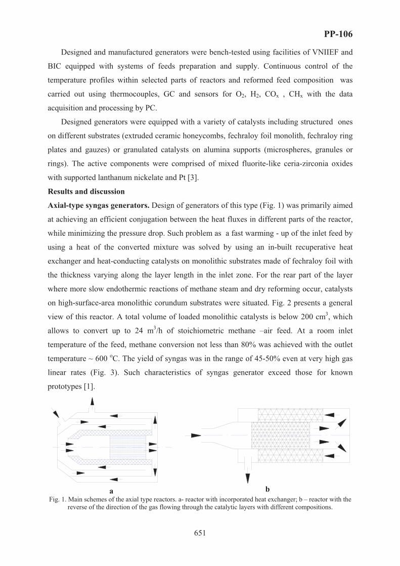
PP-106
651
Designed and manufactured generators were bench-tested using facilities of VNIIEF and
BIC equipped with systems of feeds preparation and supply. Continuous control of the
temperature profiles within selected parts of reactors and reformed feed composition was
carried out using thermocouples, GC and sensors for O2, H2, COx , CHx with the data
acquisition and processing by PC.
Designed generators were equipped with a variety of catalysts including structured ones
on different substrates (extruded ceramic honeycombs, fechraloy foil monolith, fechraloy ring
plates and gauzes) or granulated catalysts on alumina supports (microspheres, granules or
rings). The active components were comprised of mixed fluorite-like ceria-zirconia oxides
with supported lanthanum nickelate and Pt [3].
Results and discussion
Axial-type syngas generators. Design of generators of this type (Fig. 1) was primarily aimed
at achieving an efficient conjugation between the heat fluxes in different parts of the reactor,
while minimizing the pressure drop. Such problem as a fast warming - up of the inlet feed by
using a heat of the converted mixture was solved by using an in-built recuperative heat
exchanger and heat-conducting catalysts on monolithic substrates made of fechraloy foil with
the thickness varying along the layer length in the inlet zone. For the rear part of the layer
where more slow endothermic reactions of methane steam and dry reforming occur, catalysts
on high-surface-area monolithic corundum substrates were situated. Fig. 2 presents a general
view of this reactor. A total volume of loaded monolithic catalysts is below 200 cm3, which
allows to convert up to 24 m3/h of stoichiometric methane –air feed. At a room inlet
temperature of the feed, methane conversion not less than 80% was achieved with the outlet
temperature ~ 600 oC. The yield of syngas was in the range of 45-50% even at very high gas
linear rates (Fig. 3). Such characteristics of syngas generator exceed those for known
prototypes [1].
� bFig. 1. Main schemes of the axial type reactors. a- reactor with incorporated heat exchanger; b – reactor with the
reverse of the direction of the gas flowing through the catalytic layers with different compositions.
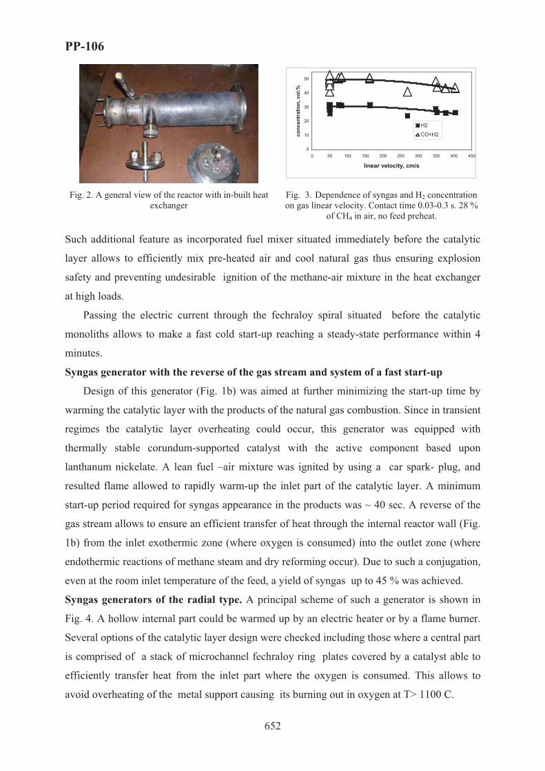
PP-106
652
0
10
20
30
40
50
0 50 100 150 200 250 300 350 400 450
linear velocity, cm/s
conc
entr
atio
n, v
ol.%
H2
�+�2
Fig. 2. A general view of the reactor with in-built heat exchanger
Fig. 3. Dependence of syngas and H2 concentration on gas linear velocity. Contact time 0.03-0.3 s. 28 %
of CH4 in air, no feed preheat.
Such additional feature as incorporated fuel mixer situated immediately before the catalytic
layer allows to efficiently mix pre-heated air and cool natural gas thus ensuring explosion
safety and preventing undesirable ignition of the methane-air mixture in the heat exchanger
at high loads.
Passing the electric current through the fechraloy spiral situated before the catalytic
monoliths allows to make a fast cold start-up reaching a steady-state performance within 4
minutes.
Syngas generator with the reverse of the gas stream and system of a fast start-up
Design of this generator (Fig. 1b) was aimed at further minimizing the start-up time by
warming the catalytic layer with the products of the natural gas combustion. Since in transient
regimes the catalytic layer overheating could occur, this generator was equipped with
thermally stable corundum-supported catalyst with the active component based upon
lanthanum nickelate. A lean fuel –air mixture was ignited by using a car spark- plug, and
resulted flame allowed to rapidly warm-up the inlet part of the catalytic layer. A minimum
start-up period required for syngas appearance in the products was ~ 40 sec. A reverse of the
gas stream allows to ensure an efficient transfer of heat through the internal reactor wall (Fig.
1b) from the inlet exothermic zone (where oxygen is consumed) into the outlet zone (where
endothermic reactions of methane steam and dry reforming occur). Due to such a conjugation,
even at the room inlet temperature of the feed, a yield of syngas up to 45 % was achieved.
Syngas generators of the radial type. A principal scheme of such a generator is shown in
Fig. 4. A hollow internal part could be warmed up by an electric heater or by a flame burner.
Several options of the catalytic layer design were checked including those where a central part
is comprised of a stack of microchannel fechraloy ring plates covered by a catalyst able to
efficiently transfer heat from the inlet part where the oxygen is consumed. This allows to
avoid overheating of the metal support causing its burning out in oxygen at T> 1100 C.

PP-106
653
Fig. 4. A principal scheme of the syngas generator of the radial type
Fig. 5. Methane conversion and syngas yield vs. contact time for radial-type syngas generator with
combined (ring plates + microspherical catalyst) layer
Around the central part, catalytic layers of a different types were situated including those on
heat-conducting substrates (Fe-Cr-Al gauzes or felt with supported active component),
granulated catalysts based upon alumina microspheres or rings etc, or their combination. This
allows to ensure an efficient heat transfer in the radial direction as well as to minimize the
pressure drop. At the feed rate up to 10 m3/h of the stoichiometric natural gas –air mixture,
this design allows to achieve syngas yield up to 50% at contact times up to 0.1 s (Fig. 5).
Conclusions
Approaches to design of compact syngas generators of the axial and radial types to be
used in fuel processors for mobile and stationary fuel cells with the capacity up to 10 kWt
were developed, experimental prototypes were manufactured and bench-tested. Integration of
the start-up systems for start-up, reaction feed preheat and using of original heat-conducting
catalysts and reactor parts to conjugate the heat fluxes within processor allowed to ensure a
compact size of reactors (not exceeding 1L per 5 kWt of syngas thermal power) with syngas
yield in the range of 45-55%.
Acknowledgements. This work is supported by ISTC 2529 Project.
References[1] C. Song, Catal.Today 77 (2002) 17.
[2] V. Sobyanin, V. Sadykov, V. Kirillov et al. Proc. Intern. Hydrogen Energy Congress and Exhibition IHEC 2005, Istanbul, Turkey, 13-15 July 2005.
[3] V. Sadykov et al, Kinetics and Catalysis, 46 (2005) 227.

PP-107
654
QUANTUM-CHEMICAL RESEARCH OF INHIBITOR ACTION
MECHANISM
Kukueva V.V., Kirillov A.A.
Fire Safety Institute, Onoprienko 8, Cherkassy, Ukraine, 18034
FAX: +380472-55-09-71, e-mail: [email protected]
Inhibitors use for the delay, but sometimes and packed stops of chain reactions. Study of
inhibition actions of fire suppressant powder on processes of combustion presents a big
interest for the chemical kinetics, as far as hard surface of particles of powder can serve a
good catalyst of heterogeneous ruins of carriers of reactionary chains. In the gas phase of
molecule of powdered inhibitor (in the event of the evaporation) or their "splinter" (in the
event of the decomposition), entering in reactions with active centers of flame (�•, �•, ��3•,
��•), can slow a process of spreading a combustion in gas mixtures.
Action of powder can be stipulated as an increasing of velocity heterogeneous ruins of
carriers of reactionary chains, so and homogeneous reactions following after the evaporation
of particles of powder. For the clarification of question on that, through what channel is
realized inhibition action of powder on processes of combustion - homogeneous or
heterogeneous, vital importance has information on warm up particles of powder in the flame.
Necessary condition to realization of homogeneous mechanism is having warmed up particles
before such temperatures, which will ensure sufficiently greater velocity of evaporation.
Unfortunately reliable experimental methods for execution of the similar measurements are
very limited therefore greater value gain approximate theoretical calculations. The general
goal is the prediction of measurable catalytic kinetics based on mechanistic information for
every elementary reaction step in the overall cycle, as well as competing phenomena
operative at catalytic conditions. A competition exists between the rate of dissociation and the
rate of recombination with negative catalyst. Quantum-chemical methods are reliable tools
which can be used to probe ideas and predict properties, that is, structure and energetic. They
have made important contributions toward mechanistic understandings of various catalytic
chemistries through reaction mode analysis in terms of detailed orbital interactions [1].
The present model stresses the importance of gas phase reactions of hydrogen atoms. A
critical review of the literature is in progress and some of the preliminary observations are
presented. Important hydrogen atom reactions can be divided into three categories:
(1) The rate limiting branching reaction, H• + O2 ¿ OH• + O•.

PP-107
655
(2) Bimolecular reactions, H2 + RX ¿ H2 or HX + R’, with inhibition expected if the
new radical, R’, is less reactive than the hydrogen atom.
(3) Recombination reactions, H• + R + M ¿HR + M.
The mechanism of homogeneous inhibition of flame was discussed from three
standpoints: first, the possibility that flame inhibition is an equilibrium phenomena was
investigated by calculating adiabatic flame compositions and temperatures; second, the
possibility that a partial equilibrium established before three body reactions become important
was investigated; and third, the possibility that inhibition is controlled by kinetic phenomena
early in the flame was investigated using an ultra simple flame model. It was concluded that
neither equilibrium nor partial equilibrium changes in radical concentration and temperature
were large enough to account for the effects of chemical inhibitors. Therefore, inhibition was
believed to be kinetic phenomena.
The model proposed for examining the kinetic effects and understanding the details of the
inhibition process consists of two reaction regions: (1) a low temperature initial region where
radicals are destroyed; recombination is dominate here because of the negative temperature
dependence of the reaction rate; and (2) a branching zone where high radical concentrations
are produced. This region occurs at temperatures higher than the recombination region, but
still significantly below the final adiabatic flame temperature. The two regions are coupled by
diffusion. The boundary between the two regions is the point at which the rate of the
branching reaction first balances the recombination reaction. The action of the inhibitor is
postulated to be the addition of terms in the initial radical sink region. This forces the cross
over temperature up and radical concentrations down in agreement with observations. If
radical scavenging reactions are dominant in inhibition, the model predicts that the reduction
the burning velocity is significant. The scavenging effectiveness of inhibitor molecules is very
difficult to investigate experimentally. Besides it is impossible predict correctly if inhibition
happens by whole molecules or separated particles after decomposition. Theoretical methods
give us possibility to research such unstable reactions.
The scavenging agent can be the inhibitor itself, or its stable and unstable breakdown
products. The elementary reactions during the flame inhibition have been investigated by the
ab initio method with 6-31 G basis set. The scavenging efficacy during intermolecular
interaction between active centers of flame (O•, OH•, H•) and flame inhibitors destruction
products have been estimated by the binding energy value. The most effective fire
suppressants have been choosing for the study: diethyl amine ((C2H5)2NH) and three fluorine
bromine methane CF3Br. The destruction ways of the inhibitor molecules shows the active
inhibition agents. For the diethyl amine the more probable reaction channel for destruction:

PP-107
656
(�2�5)2NH ¿ 2�2�5•+ NH: ( 0
298ΔΗ =39,19 kcal/mol), three fluorine bromine methane:
CF3Br ¿ CF3• + Br• ( 0
298ΔΗ =33,77 kcal/mol). The following step of research was the
calculation of intermolecular interaction between active centers of flame (ACF) and active
inhibiting components. The results of calculations are shown in the table 1.
Table 1. The calculation by ab initio method in the 6-31 G basis set of the interaction between active centers of flame and destruction products of fire suppressants
Active inhibiting components @/@
ACF NH• �2�5
• CF3• Br•
2 H• 0.0935 0.1344 0.1398 0.0819 3 OH• 0.3949 0.0781 1.7278 0.0077 5 O• 0.1194 0.1811 - 9.8216
As we can see from the calculation results the most efficient scavenger of active centers of
flame is bromine atom because it can to bind as well as H• and OH•. For the diethyl amine
destruction leads to three active components, which can interact with H• (NH• + 2H • ¿ NH3)
and OH• (�2�5• + OH•¿ �2�5OH). So, the inhibiting activity has been explained by the
quantum-chemical calculations. In generally the fire suppressants destruction products can be
arranged in such order by their activity: Br • ¿ �2�5 •¿ NH•. As far as the halogenated fire
suppressants are dangerous for ecology of the environment, we can recommend the
application of the diethyl amine as inhibitor agents in the chain combustion. These results are
in good agreement with experimental results [1].
Thus, results of our research can confirm the inhibition mechanism [2] as following:
X + Inh (+M) ¿ InhX (+M) (R.1)
X + InhX ¿ X2 + Inh (R.2)
X + X ¿ X2 (R.3)
where X – active centre of flame, ?nd Inh represents the inhibiting species. Inherent in these
reactions is not only the scavenging of the radical be the inhibitor species but also its
regeneration. Hence, an amplifying effect occurs, as each inhibitor molecule is able to
neutralize more than one reactive radical. So among investigated in our work inhibitors the
most effective is diethyl amine, because almost all of destruction products act on the all of
active reaction centers, in spite of the fact that for molecule CF3Br destruction and interaction
energy significantly less.
References 1. N.Vora, J.E.Siow, N.M.Laurendeau, Combustion and flame 126: 1393-1401 (2001) 2. Babushok V., linteris G.T., Tsang W., and Reinelt D., Combustion and flame, 115: 551-560 (1998)

PP-108
657
NANOFIBROUS CARBON AS A CATALYST
FOR SELECTIVE OXIDATION OF HYDROGEN SULPHIDE
Gennady G. Kuvshinov*, Vasiliy V. Shinkarev**, Alexey M. Glushenkov*,
Maxim N. Boyko*, Dmitriy G. Kuvshinov*
*Novosibirsk State Technical University, Department of Chemical Engineering, Pr.Karla
Marksa, 20, Novosibirsk, Russia, 630092, fax: 007(383)3460801, email: [email protected]
**Boreskov Institute of Catalysis SB RAS, Group of Catalytic Technologies of Carbon
Materials Synthesis, Pr.Akademika Lavrentieva, 5, Novosibirsk, Russia, 630090,
fax: 007(383)3308056, email: [email protected]
1. Introduction
Hydrogen sulphide is one of the most toxic and dangerous for ecosphere materials. The
most common way for it to get into atmosphere is through man-caused factors, since most of
the natural resources, including copper ore and energy resources (such as oil, gas, coil,
geothermal vapor etc.) comprise considerable amounts H2S. Processing of hydrogen sulphide
into sulphur is preferable from the ecological standpoint, because elementary sulphur is a
safe, universal and easy transported raw material for various manufactures. The only large-
scale technology for obtaining the sulfur from the sulfur-bearing gas today is the Clauss
multi-stage process [1]. Though because of the process’s reversibility it is impossible to
obtain the 100% conversion of hydrogen sulphide for one stage. The direct selective oxidation
of H2S by molecular oxygen makes it possible to reduce the number of stages and to rise the
efficiency of desulfurization, to miniaturize the equipment.
It is known that for direct H2S oxidation the metal-oxide catalysts and activated carbons
[2] can be used. The significant disadvantage of metal-oxide catalysts is their deactivation, or
considerable reduction of selectivity, or unstability in excess of oxygen and water vapors. The
application of activated carbon is effective in low temperatures only (lower the 150 °C), that
is why they can be used in periodic mode only.
Nanofibrous carbonaceous materials (NFC) produced in the hydrocarbons
decomposition with 8-group metals catalysts are the materials of the new class and can be
applied in various spheres. Recently the unique properties of NFC have been discovered. NFC
can catalyze the reaction of selective molecular oxygen oxidation of hydrogen sulphide[3].

PP-108
658
The goal of the research was to study the influence of the NFC samples’ structure, of the
remains of metal phase of original catalyst of NFC synthesis and water vapor content in
reaction medium on activity and selectivity of hydrogen sulphide direct oxidation into sulfur.
2. Samples
NFC samples were obtained in the result of decomposition of methane over nickel-
containing catalysts in the form of mesoporous granules of diameters less then 0,5 mm, which
consist of tightly twisted graphite-like fibers or nanotubes of diameters of 5-150 nm. The
inner surface of granules is made of graphite basal planes or edges of graphite basal planes,
which orient to the surface angularly dependent of NFC origin catalyst. The NFC-1, NFC-2
and NFC-3 samples was synthesized form methane in the temperature of 675 and 550 0�
correspondingly.
Table 1 - Samples description.
Sample Original catalyst composition, %
Carbon yield, gCFC/gcat
Specific surface area ABET, m2/g
NFC-1 62 Fe – 8 Ni / Al2O3 122 155 NFC-2 10 Cu – 80 Ni / Al2O3 230 251 NFC-3 90 Ni / Al2O3 80 110
3. Experimental techniques
Catalytic properties of NFC were investigated in flow reactor. The catalyst bed was
fluidized by the reactor oscillating in an axial direction. The typical conditions are:
temperature of 200 °�, gas mixture 1 % vol. H2S + 15 % vol. O2 (30-times excess oxygen to
stoichiometric content), the rest is helium, gas hourly space velocity (GHSV) 3100 hr-1. 4. Results and discussion
The obtained data on the change of conversion of hydrogen sulphide and selectivity of
its transformation into sulfur against time are presented on the Fig. 1. The highest selectivity
(about 89 %) is typical for NFC-1. There is an interesting initial fall of selectivity and its
posterior rise to almost the same level. It is the evidence of the fact that there was possibly the
gradual formation of non-selective compounds on which the total oxidation of hydrogen
sulphide took place. This corresponds the area of falling selectivity. Then there was a rapid
formation of selective surface compounds – it corresponds the area of selectivity’s rise to the
previous level. NFC-2 sample demonstrated the lower but stable selectivity. NFC-1 sample
shows higher selectivity due to the fact that its surface (graphite planes) has less surface
energy comparing to the one of NFC-2 (the ends of basal planes). NFC-3 proved to be the
least selective and stable.

PP-108
659
The most active sample is NFC-2 (Fig. 1), where hydrogen sulphide conversion was
about 95 %. It is possible to suppose that the difference between NFC-1 and NFC-2 as in the
case of selectivity can be linked with the difference of structure of carbonaceous fibers, and
their surface in particular: the ends of basal planes have higher surface energy comparing to
the surface energy of basal planes, and due to this the processes of reagents sorption can go
faster on the surface of NFC-2, and this results in the rising activity. Moreover the specific
surface area of NFC-2 sample is 1,6-times bigger than the one of NFC-1 (Table 1).
Figure 1 -Deactivation patterns with time on stream. GHSV=3100 hr-1, T=200 0C
Figure 2 - Deactivation patterns with time on stream. GHSV=3100 hr-1, T=200 0C
The study of samples, obtained over copper-nickel catalysts with different carbon yields
demonstrated that with the growth of the yield the selectivity rises and the conversion falls
[5]. Indeed, it is known that the hydrogen sulphide oxidation over nickel catalysts can be
realized quite effectively in temperature of already 100 °� [6], that is why even non-
significant access of hydrogen sulphide and oxygen to metal surface in 200 °� can lead to the
decrease of selectivity due to the oxidation of H2S into SO2. It can explain the low selectivity
of NFC-3, and the samples with low specific yield of carbon per weight unit of catalyst. The
0 5 10 15 20 250
20
40
60
80
100
H2S
con
vers
ion,
%
Time, hr
NFC-1, NFC-2, NFC-3
0 5 10 15 20 250
20
40
60
80
100
Sel
ectiv
ity to
sul
fur,
%
Time, hr
NFC-1, NFC-2, NFC-3
0 5 10 15 20 250
20
40
60
80
100
H2S
con
vers
ion,
%
Time, hr
NFC-3, NFC-3-H2O
0 5 10 15 20 250
20
40
60
80
100
Sel
ectiv
ity to
sul
fur,
%
Time, hr
NFC-3, NFC-3-H2O

PP-108
660
unstable work of NFC-3 can be explained by the sulfur accumulation on the surface and its
cyclic burning in the conditions of excess oxygen under the catalytic influence of the metal
phase.
Catalytic properties of the NFC-3-H2O with addition of the 40 % vol water vapor in gas
stream was significant changed (Fig. 2), catalyst began to work more stable. Selectivity with
time on stream practically didn’t decreased and was about 95 % during whole experiment. At
the same time some falling of the activity of the NFC-3-H2O sample have taken place.
5. Conclusion
Thus the samples with the highest activity and selectivity are those with graphite planes
which are situated perpendicularly to the axis of fiber and nanotube. And nanotubes have
higher selectivity, though copper-nickel sample possess higher activity. An addition of the 40
% vol. of water vapor in initial gas mixture significantly improves catalytic properties of the
NFC formed by the set of put one into another coned graphite basal planes. It is possible to
increase the selectivity by decreasing the influence of metal phase, i.e. by obtaining the NFC
with the bigger specific yield of carbon. It is possible to additionally increase the selectivity
by synthesizing the NFC samples with more ordered structure of the surface: the defects bear
higher activity and can catalyze the total oxidation of hydrogen sulphide. The activity of
samples can be increased by decreasing the diameters of fibers.
References [1] British Patent Application No.3608, 1882.
[2] O.Bankovski and R.Pastemak, Ger. (East) Pat.12.805, Mar. 1, 1957.
[3] Kuvshinov G.G., Moguilnykh J.I., Lebedev M.J., Kuvshinov D.G., Zavarukhin S.G. The method to obtain the elemental sulfur. Patent 2111164, 1997.
[4] Mogilnykh Yu. I., Kuvshinov G. G., and Lebedev M. Yu. //Filamentary carbon as a catalyst of hydrogen sulfide oxidation to sulfur. Extended abstracts of conference "EUROCARBON '98", Strasbourg, France, pp. 445-446, 1998.
[5] G.G. Kuvshinov, V.V. Shinkarev, A.M. Glushenkov, M.N. Boyko, D.G. Kuvshinov. Catalytic Properties of Nanofibrous Carbon in Selective Oxidation of Hydrogen Sulphide. // The Seventh World Congress on Recovery, Recycling and Re-integration is held in Beijing, People’s Republic of China, September 25~29, 2005. p. 8.
[6] N. Keller, C. Pham-Huu, C. Crouzet, M.J. Ledoux, S. Savin-Poncet, J.B. Nougayrede, J. Bousquet. Direct oxidation of H2S into S. New catalysts and processes based on SiC support. Catalysis Today, 53 (1999) 535-542.

PP-109
661
C7 HYDROISOMERIZATION ON ZIRCONIA SUPPORTED
CATALYSTS
Yan Liu
Applied Catalysis Group, Institute of Chemical and Engineering Sciences, 1 Pesek Road,
Jurong Island, Singapore 627833; Email: [email protected]; Fax: 0065-63166182
New environmental regulations impose the elimination of regulated gasoline additives
such as tetraethyl lead and the reduction of aromatic compounds because of their detrimental
environmental effects [1], which may be accompanied by a loss in the octane number.
Consequently there has been a sharp rise in the requirements for octane enhancement
processes. One potential way is to isomerize the straight-chain paraffins, which are a major
constituent in some crude oil fractions, with a low octane number, into their branched isomers
with a higher octane number. Such isomers are ready to be used as a blending stock for
gasoline obtained from reforming to produce “ultra clean” fuel.
The current catalytic processes for alkane isomerization and alkylation require liquid
acids (e.g., H2SO4, HF, AlCl3) or halogen-promoted metal oxides (e.g., Cl-Al2O3), which pose
significant containment, corrosion, and environmental challenges [2]. These problems can be
circumvented by the development of strong solid acid catalysts consisting of metal oxides.
Recently, metal oxides promoted by sulfur compounds have been studied as strong solid acid
catalysts, especially SOx promoted zirconia containing noble metal to inhibit deactivation [3].
However, their low isomerization selectivity for C7-alkanes, their poor stability, and their
tendency to form volatile sulfur compounds during catalysis and regeneration limit their
applicability in isomerization and alkylation process. Tungesten oxide based materials
comprise another interesting class of solid acids. The small and highly charged W6+ cations
are found in several solid acids such as WOx dispersed on Al2O3 and ZrO2 [4,5]. In this work,
ZrO2 supported Pt/WO3 solid acid catalysts promoted by Y2O3 and ZnO, in addition to ZrO2
supported Pt/PO43- catalysts, were studied and compared with Pt/ catalysts for n-C7
hydroisomerization.
Experimental
Zr(OH)4, Y(OH)3-Zr(OH)4, Zn(OH)2-Zr(OH)4 were prepared by precipitation. Pt,
WO3, and PO43- were introduced by impregnation. XRD, XPS, SEM, and an automated
adsorption apparatus were employed for characterization. Catalytic activity analysis was

PP-109
662
carried out at atmospheric pressure in a tubular quartz glass, fixed-bed reactor. Before
catalytic measurements, the catalysts were reduced by hydrogen for activation. The outlet gas
mixture was analyzed using on-line GC.
Results and Discussion
Pt/WO3/ZrO2 catalysts modified by Y2O3 and ZnO are employed in n-C7
hydroisomerization reaction and compared with Pt/PO43-/ZrO2 and Pt/� catalysts. It is found
that Pt/WO3/ZrO2 shows good activities for n-C7 hydroisomerization. N-C7 conversion and C7
isomers selectivity can be 78.5% and 75.1%, respectively, at 250 oC. It is comparable with
that for Pt/� catalysts with Si/2Al ratio at 100, which is 87.1% for n-C7 conversion and 75.5%
for C7 isomers selectivity. When 1% Y2O3 is introduced to Pt/WO3/ZrO2 catalysts, n-C7
conversion keeps almost the same at 79.2% while C7 isomers selectivity obviously increases
to 89.1%. It is due to Y2O3 can stabilize the tetragonal phase [6,7]. However, the n-C7
conversion decrease with large amount of Y2O3 added while the C7 isomers selectivity
increase along with the amount of Y2O3, as shown in Fig. 1 (250 oC). It is also found that the
precipitation agent can affect the activities for Pt/WO3/Y2O3-ZrO2 catalysts. The catalysts
using NH3 as the precipitate show much higher activities than the catalysts using urea and
NaOH as the precipitates.
0 5 10 15 200
20
40
60
80
100
Con
v. o
r Se
l. (%
)
Y2O3 content (%)
conversion (%) selectivity (%)
Fig. 1 The effect of Y2O3 amount on n-C7 catalytic performance.
Among the catalysts investigated, Pt/PO43-/ZrO2 shows the lowest activity for n-C7
hydroisomerization. The n-C7 conversion and C7 isomers selectivity can only be 2.2% and
36.2% at 250 oC (42.1% and 37.1% at 300 oC), which is much lower than those for
Pt/WO3/ZrO2 and Pt/� catalysts. It is due to the weak acidity for PO43-. The further

PP-109
663
experiments found that the activity for Pt/PO43-/ZrO2 decrease with the reaction time at 300 oC.
After 48 h, the n-C7 conversion and C7 isomers selectivity can only be slightly higher than
30%. It is suggested PO43-/ZrO2 has the low stability. Previous investigation indicates the
activity for Pt/WO3/ZnO-ZrO2 can keep stable at least 82 h with 80.9% n-C7 conversion and
89.1% C7 isomers selectivity at 250 oC.
References: 1. I. E. Maxwell, J. E. Naber, Catal. Lett. 12 (1992) 105.
2. J. M. Thomas, Sci. Am. 266 (1992) 112.
3. E. Iglesia, S. L. Soled, G. M. Kramer, J. Catal. 144 (1993) 238.
4. S. L. Soled, G. B. Mc Vicker, L. L. Murrell, L. G. Sherman, N. C. Dispenziere, S. L. Hsu, D. Waldman, J.Catal. 111 (1998) 286.
5. M. Hino, K. Arata, J. Chem. Soc. Chem. Commun. (1987) 1259.
6. M. Li, Z. Feng, P. Ying, Q. Xin, C. Li, Phys. Chem. Chem. Phys. 5 (2003) 5326.
7. A. Gedanken, R. Reisfeld, E. Sominski, O. Palchik, Y. Koltypin, G. Panczer, M. Gaft, H. Minti, J. Phys. Chem. B 104 (2000) 7057.

PP-110
664
PREPARATION AND CHARACTERIZATION OF HETEROGENEOUS
ENZYMATIC CATALYST FOR BIODIESEL PRODUCTION
*A. Macario1, G. Giordano1, L. Setti2, A. Parise3, E. Perri3, J.M. Campelo4, D. Luna4
1Dip. Ing. Chim. & Mat., Università della Calabria, I-87030 Rende (CS), Italy 2Dip. Chim. Ind. & Mat., Università degli Studi di Bologna, I- 40136 Bologna – Italy
3Exsperimental Institute of Olive-Growing, I-87030 Rende (CS), Italy 4Dip. Org. Chem., Cordoba University, Av. San Alberto Magno s/n, E-14004 Cordoba - Spain
*Corresponding author. Fax +39.0984.49.66.55; e-mail: [email protected]
In this paper, the preparation and characterization of the Rhizomucor miehei
Lipase/zeolite catalyst is reported. In order to obtain an efficient heterogeneous enzymatic
catalyst two different immobilization method of Lipase enzyme on zeolite type supports are
investigated. Concerning the adsorption method, the zeolite materials have been prepared in
order to obtain supports having different physical-chemical surface properties. The
immobilization test shows that the zeolitic support prepared in F- media allow to attach the
highest protein amount (280 mg/g) with respect to those ones obtained in alkaline system
(200 mg/g). An immobilization yield of 99% by covalent attachment is obtained. A simple
and fast method for testing the catalytic activity by an alkyl ester hydrolysis reaction was used
in order to investigate the interactions between the enzyme and the support. Stability, leaching
and total productivity of the immobilized enzyme were also measured. These preliminary
catalytic results let to choose the more suitable Lipase/Support system to use as catalyst for
tuning of the heterogeneous enzymatic transesterification reaction of olive oil.
Introduction
The conventional biodiesel technology involves the use of inorganic homogeneous basic
catalyst (sodium hydroxide, potassium hydroxide and sodium or potassium methoxide) and
methanol. Particularly, the potassium hydroxide is the most efficient basic catalysts, because
its highest reaction kinetic rate compared to the NaOH and NaOMe catalysts [1]. The main
disadvantages of a homogeneous basic catalyst is the presence of saponification reaction
during the transesterification process, that reduce the biodiesel production efficiency. The
amount of soap-products increases as a function of free fatty acids into the triglycerides
source. Moreover, if the vegetable oil and the alcohol used are not water-free, the biodiesel
yield decreases because the hydrolysis of esters could take place. At the contrary, the

PP-110
665
enzymatic transesterification allows to obtain a process without any by-product and starting
from any triglycerides source. In presence of an alcohol (methanol, ethanol, etc.) lipases are
able to catalyze the alcoholysis reaction. Glycerol is the by-product of the reaction which can
be easily separated from the produced esters by centrifugation. In general the reaction
conditions of an enzymatic process needs less energy consuming and neutral pH. In order to
improve the lipase stability, the enzyme immobilization is an attractive method for industrial
applications. There are several method for the enzymatic immobilization: adsorption, covalent
binding, cross-linking and containment in a barrier (e.g. microencapsulation, entrapment and
confinement). The zeolites and related materials have potentially interesting properties, such
as hydrophobic/hydrophilic behavior, acid/basic character, mechanical and chemical
resistance so that the use of these materials as enzyme-support is of great interest. Additional
advantages is represented by their easy water dispersion/recuperation. Therefore, the
compositional and structural variances of molecular sieves offer a powerful tool for tuning the
carrier adsorption properties. The immobilization of Lipase enzyme in biodiesel production
combines the enzymatic transesterification advantages with those of a heterogeneous
catalysis. Moreover, the particularly conformation of lipase enzyme suggests that the most
suitable immobilization method of this enzyme have to involve the “lid” region of the same
enzyme in order to obtain the activation of its catalytic center [2]. Immobilization by
adsorption technique permits a suitable interaction between enzyme and support surface that
allow to obtain the request enzyme adsorbed in the “open” conformation. At the contrary, the
covalent attachment presents a stable enzyme immobilization without its “interfacial
activation”. In the present work the adsorption of lipase enzyme on Silicalite-1 type zeolites
and the covalent attachment of the same enzyme on functionalized Sepiolite/AlPO4 material,
are described. The preliminary catalytic results show that the acid-basic interactions between
enzyme and the external surface of the support allow the opening of the lid-enzyme and the
activation of the catalytic enzyme centre. The performance of the so prepared heterogeneous
biocatalyst are evaluated in the biodiesel production by the transesterification of olive oil with
methanol and in solvent-free system.
Experimental
The preparation of Silicalite-1 type zeolites and the Sepiolite/AlPO4 functionalized
material were carried in according to the procedure published elsewhere [3-5]. The amount of
adsorbed enzyme was evaluated by UV adsorption method (λ = 280 nm), while the amount of
the enzyme covalently attached was determined by the measurements of the hydrolysis esters
activity using a fast and simple colorimetric method of the initial immobilization solution and

PP-110
666
the supernatant obtained after immobilization. The hydrolysis of methyl myristate to myristic
acid, carried at 40°C and pH 7, is the preliminary catalytic test used to know the immobilized
enzyme conformation. The transesterification reaction was carried out at 40 °C and with
methanol/oil molar ratio equal to 5/1. The triglycerides source has been the olive oil (79.9 %
in oleic acid and 16.1% in palmitic acid). At pre-determined time, 2 μl aliquots of reaction
medium were taken and diluted in n-hexane for GC-analysis. For quantitative analysis, the
methyl pentadecanoate was used as standard ester.
Results and discussion
The results of the immobilization technique by adsorption show that the protein is
preferably adsorbed on the surface of the support synthesized in fluoride media (F-S2
containing 280 mg/g of Lipase). For these materials, the presence of five-coordinate silicon
[SiO4/2F]- units might generate electrostatic bonds between the amino acid of the enzyme and
the support surface. Concerning the materials synthesized in alkaline media (S2 containing
200 mg/g of Lipase), the weak acid silanol groups constitute the main support surface sites
involved during the protein adsorption. However, the highest immobilization yield was
obtained by the covalent technique on Sepiolite/AlPO4 in the presence of 433 mg/g of Lipase.
These different kind of enzyme bindings have a strong influence on the immobilized lipase
conformation and, then, on the catalytic activity of the heterogeneous biocatalyst (Figure 1).
In fact it is possible to observe that the highest methyl ester conversion occurs when the
enzyme is physically adsorbed on the support S2 (Silicalite-1 synthesized in alkaline system)
(Figure 1). For this support type, the binding forces with the enzyme are the acid-basic ones
and, probably, occur between the acid Si-OH zeolite groups and the basic aminoacid Arginina
that constitutes the hinge region of the lid-enzyme [6].
0102030405060708090
100
S2 F-S2 Sepiolite/AlPO4
%
Immobilization yield (%)Conversion (%)
0102030405060708090
100
1 2 3 4
Reaction cylces
Conv
ersi
on (%
)
Sep/AlPO4S2
Figure 1. Lipase immobilization yield and methyl myristate conversion after 24 h of reaction at 40°C.
Figure 2. Stability of immobilized Lipase during four batch reuses in the hydrolysis of methyl myristate reaction.
When the enzyme is covalently attached on the functionalized Sepiolite/AlPO4 support,
the highest amount of enzyme is immobilized by very stable bonds, no leaching occurs until

PP-110
667
four reaction cycles but the total productivity of the enzyme is lower than that obtained with
the lipase adsorbed on the S2 support by acid-basic interaction (Figure 2 and 3). These last
results suggest that the most covalently immobilized enzyme is not completely active.
After these preliminary activity
test, the Lipase/S2 and
Lipase/Sepiolite/AlPO4 catalyst are
used in the transesterification reaction.
The Lipase adsorbed (80 mg) by acid-
basic interaction on the S2 support
shows the same oleic acid conversion
(69%) which was obtained by the free
enzyme (100 mg) after only 2 hour of
reaction at 40 °C. Concerning the
Lipase covalently attached on the
Sepiolite/AlPO4, about the same immobilized enzyme amount (73 mg) allows to obtain a
oleic acid conversion of 22%. These preliminary transesterification tests confirm the results
obtained by the hydrolysis reaction about the final conformation of the immobilized enzyme.
The simple regeneration of the support used for the Lipase immobilization is an important
aspect to be considered in the heterogeneous catalyst preparation. The deactivated enzyme on
the support S2 was completely removed by simple thermal treatment (4 hours at 400 °C in air)
and the regenerated support showed the same immobilization yield as in the first application.
Moreover, the activity of the Lipase adsorbed on the regenerated support remains unaltered.
Finally, the optimization of the transesterification parameters are necessary in order to
increase the methyl esters produced by the understudied immobilized biocatalysts prepared.
References [1] B. Freedman, E.H. Pryde, T.L. Mounts, J. Am. Oil Chem. Soc., 61 (1984) 1638-1643. [2] R. Fernandez-Lafuente, P. Armisen, P. Sabuquillo, G. Fernandez-Lorente, J.M. Guisan, Chem. Phys. Lipids,
93 (1998) 185-197. [3] Macario A., Katovic A., Giordano G., L. Forni, F. Carloni, A. Filippini, L. Setti, Stud. Surf. Sci. Catal.,155
(2005) 381-394 [4] Frontera P., Macario A., Katovic A., Crea F., Giordano G., Stud. Surf. Sci. Catal., 158/A (2005) 383-390 [5] F.M. Bautista, M.C. Bravo, J.M. Campelo, A. Garcia, D. Luna, J.M. Marinas, A.A. Romero, J. Chem.
Technol. Biotechnol, 72 (1998) 249-254 [6] S. Herrgard, C.J. Gibas, S. Subramaniam, Biochemistry, 39 (2000) 2921-2930
Figure 3. Productivity of heterogeneous Lipase catalyst in the methyl myristate hydrolysis reaction (four batch reuses). Comparison with the productivity of 100 mg of free lipase for each batch use.
0
0.0005
0.001
0.0015
0.002
0.0025
0.003
0.0035
0.004
0.0045
0.005
S2 F-S2 Sepiolite/AlPO4 Free Lipase
Prod
uctiv
ity
(mg
Miri
stic
Aci
d/ m
g En
zym
e * h
)

PP-111
668
PRODUCTION OF HYDROGEN BY STEAM REFORMING OF
ETHANOL USING Co AND Ni CATALYSTS SUPPORTED ON
PEROVSKITE-TYPE OXIDES
M. Matsukata, K. Urasaki, K. Ishikawa, K. Tokunaga, Y. Sekine and E. Kikuchi
Department of Applied Chemistry, Waseda University, 3-4-1, Okubo, Shinjuku, Tokyo,
169-8555, Japan; *Tel&Fax: +81-3-5286- 3850, E-mail: [email protected]
Abstract
H2 production by steam reforming of ethanol was examined using Co or Ni catalysts
supported on LaAlO3, SrTiO3 and BaTiO3. Their catalytic activities and resistance to coking
were compared to those of conventional Co or Ni catalysts supported on MgO and γ-Al2O3. Co
and Ni catalysts supported on LaAlO3 and SrTiO3 showed higher catalytic activities and better
long-term stabilities than those supported on MgO. We found that LaAlO3 and SrTiO3 could
suppress carbon deposition, which caused the deactivation of Co and Ni catalysts supported on
MgO. Co/BaTiO3 showed a lower catalytic activity and poorer coke resistance. TEM study
indicated that the particle size of Co over BaTiO3 was larger than that over SrTiO3. We consider
that the lattice oxygen in perovskites may play positive roles in hindering coking and
Co/SrTiO3 has more frequent participation of lattice oxygen in ethanol steam reforming in
comparison with Co/BaTiO3.
Introduction
In recent years, H2 production by the catalytic steam reforming of ethanol (equations (1)
and (2)) has been studied as one of effective methods for utilizing biomass–derived ethanol
without energy intensive and rather expensive distillation processes. Among non-precious
metals, supported Co and Ni catalysts are catalytically active for the steam reforming of ethanol,
while coke formation and sintering often cause catalyst deactivation1,2. An effective approach
to developing a highly active and stable catalysts is to focus on the selection and modification
of catalyst supports. Several researchers pointed out that La2O33, ZnO4 and MgO5 were
effective as supports for Co or Ni in the steam reforming of ethanol.
C2H5OH + H2O � 2CO + 4H2 (1)
C2H5OH + 3H2O � 2CO2 + 6H2 (2)

PP-111
669
We have previously reported that Ni/LaAlO3 and Ni/SrTiO3 show high catalytic activities
and durabilities for the steam reforming of methane at 1073 K possibly because the lattice
oxygen in perovskites promotes the oxidation of CHx and hinders the production of inactive
carbonaceous species6. Based on these results, we have tried to apply SrTiO3 to Co and Ni
catalysts for the steam reforming of ethanol at 823 K and found that SrTiO3 is suitable as the
support of Co and Ni in comparison with conventional MgO7. The aim of this study was to
investigate the catalytic activities and stabilities of Co and Ni catalysts supported on perovskites
including SrTiO3, LaAlO3 and BaTiO3 for the steam reforming of ethanol in detail.
Experimental
The preparation methods of Co and Ni catalysts supported on LaAlO3, SrTiO3 and
BaTiO3 were described elsewhere6,7. The amounts of Co and Ni loaded were 5 wt% as metal.
Catalytic activities were tested in a continuous flow reactor with a fixed bed of catalyst at 823
K and atmospheric pressure, and a molar H2O/C2H5OH fed was 10. Before starting the
activity test, catalysts were reduced at 873 K for 1 h in a hydrogen stream.
Results and Discussion
Steam reforming of ethanol has been performed using Co catalysts supported on
perovskite-type oxides including LaAlO3, SrTiO3 and BaTiO3, MgO and γ-Al2O3. Table 1
summarizes the results. Hydrogen yield was defined as FH2out × 100 / (3 × FC2H5OHin + FH2O
in),
where FH2out is the formation rate of hydrogen, FC2H5OHout is the feed rate of ethanol, and FH2O
in
is the feed rate of H2.
Catalytic activities of Co and Ni catalysts significantly depended on the kind of catalyst
support. Although Co/γ-Al2O3 gave the highest ethanol conversion among the catalysts tested,
a larger parts of ethanol was consumed to give C2H4 resulting in a low H2 yield. It is known
that the dehydration of ethanol (C2H5OH � C2H4 + H2O) dominantly proceeds on an acidic
Al2O3 support to give C2H4 selectively3,4,9–11. On the other hand, the products over other
catalysts tested were composed of H2, CO, CO2 and CH4. Other products such as oxygenated
compounds and acetylene were not detected.
Co/MgO and Ni/MgO featured similar levels of conversion. While the levels of ethanol
conversion over Co/MgO and Ni/MgO after 15 min on stream were 54% and 49%, respectively,
both catalysts deactivated rapidly in the first hour of reaction. Deactivation, which occurred in
both cases of Co/MgO and Ni/MgO, was hardly observed in the cases of Co/SrTiO3 and
Co/LaAlO3, both of which kept higher conversion levels of ethanol of ca. 63 % and 58 %,
respectively, even after 300 min. Although deactivating rapidly during the first hour of reaction,

PP-111
670
Ni/LaAlO3 and Ni/SrTiO3 showed better durability than Co/MgO and Ni/MgO, keeping higher
ethanol conversion levels of 45.6 and 49.7 %, respectively, after 300 min.
The deposition of coke is one of the major reasons for catalyst deactivation in the steam
reforming of ethanol. We evaluated the amounts of coke deposited on the Co and Ni catalysts.
Fig. 1 shows the quantities of deposited coke after the reaction for 2 and/or 5 h. Almost of
coke accumulated on Co/MgO and Ni/MgO in the early stage of reaction and the amounts of
coke after 2 h of reaction were hardly changed. The amounts of deposited coke on Co or Ni
catalysts supported on perovskite were smaller than Co/MgO or Ni/MgO. Among the
perovskite-supported catalysts, the amounts of coke deposited on Co/SrTiO3 and Co/LaAlO3,
which kept the levels of high ethanol conversion during reaction were much smaller, 9 and 11
mg, respectively. We supposed that the lattice oxygen in perovskites may play a positive role
in oxidation of deposited coke and/or CHx fragment adsorbed on Co or Ni as previously
proposed6 with study of the steam reforming of methane.
As described above, SrTiO3 and LaAlO3 were suitable as the support of Co and Ni
catalysts in the steam reforming of ethanol, while BaTiO3 caused both the decrease in ethanol
conversion and carbon deposition. For the purpose of examining such large differences in
catalytic activities among Co/perovskite catalysts tested, both the size distribution and the
average size of Co particles were determined by counting more than 100 particles observed in
TEM micrographs. Fig. 2 shows Co particle size distributions for Co/SrTiO3 and Co/BaTiO3.
The Co particle size over SrTiO3 was obviously smaller than that over BaTiO3; the average
Co particle sizes over SrTiO3 and
BaTiO3 were 39 and 79 nm, respectively.
These results imply that the dispersion of
Co governs both the catalytic activity
and coke resistance of Co/perovskite in
the steam reforming of ethanol. As
previously described6,7, we consider that
the lattice oxygen in perovskites plays
positives roles in hindering coking. It can,
thus, be deduced that more frequent
participation of lattice oxygen due to
higher dispersion of Co on SrTiO3
contributed to its higher catalytic activity
and durability in comparison with Co/BaTiO3.
0 20 40 60 80 100
Ni/MgO (5 h)Ni/MgO (2 h)Co/MgO (5 h)Co/MgO (2 h)
Ni/LaAlO3 (5 h)
Ni/SrTiO3 (5 h)
CO/BaTiO3 (5 h)
Co/LaAlO3 (5 h)
Co/SrTiO3 (5 h)
Amounts of deposited carbon / mg g-cat-1
Fig. 1. Amount of deposited carbon.

PP-111
671
Table 1. Catalytic activities of Co and Ni catalysts for the steam reforming of ethanol
Yield / % Catalyst
aTOS /min
Conv./ % CO CO2 CH4 C2H4 H2
Co/MgO 15 54.0 16.7 31.9 5.5 0 19.5
300 30.1 11.1 15.7 3.2 0 10.5
Ni/MgO 15 49.3 15.4 26.3 7.7 0 15.1
300 27.2 8.6 14.5 4.1 0 8.2
Co/SrTiO3 15 60.9 27.3 24.2 9.4 0 19.8
300 67.7 21.0 38.2 8.5 0 23.9
Ni/SrTiO3 15 60.3 18.8 30.6 11.0 0 18.5
300 45.6 16.4 23.0 6.2 0 15.0
Co/LaAlO3 15 58.3 16.3 36.7 5.3 0 22.5
300 56.0 15.7 34.9 5.5 0 20.7
Ni/LaAlO3 15 62.1 13.1 40.2 8.8 0 22.3
300 49.7 11.4 31.8 6.5 0 17.7
Co/BaTiO3 15 39.9 22.1 12.4 5.4 0 18.1
300 24.8 12.2 9.2 3.4 0 9.3
Co/γ-Al2O3 180 98.4 6.1 2.0 3.8 86.5 0.8
a Time on stream
(a)
0
10
20
30
40
50
0 20 40 60 80 100 120 140
Particle size / nm
Parti
cle
size
dis
trib
utio
n / %
0
10
20
30
40
50
0 20 40 60 80 100 120 140
Particle size / nm
Parti
cle
size
dis
trib
utio
n / %
(b)
0
10
20
30
40
50
0 20 40 60 80 100 120 140
Particle size / nm
Parti
cle
size
dis
trib
utio
n / %
0
10
20
30
40
50
0 20 40 60 80 100 120 140
Particle size / nm
Parti
cle
size
dis
trib
utio
n / %
Fig. 2. Size distribution for (a) Co/SrTiO3 and (b) Co/BaTiO3.
References 1. A. Haryanto, S. Fernando, N. Murali, S. Adhikari, Energy & Fuels, 19, 2098 (2005). 2. F. Haga, T. Nakajima, H. Miya, and S. Mishima, Catal. Lett. 48, 223 (1997). 3. A. N. Fatsikostas, D. I. Kondarides, X. E. Verykios, Chem. Commun., 851 (2000). 4. J. Llorca, N. Homs, J. Sales, P. R. Piscina, J. Catal., 209, 306 (2002). 5. S. Cavallaro, N. Mondello, S. Freni, J. Power Sources, 102, 198 (2002). 6. K. Urasaki, Y. Sekine, S. Kawabe, E. Kikuchi, M. Matsukata, Appl. Catal. A., 286, 23 (2005).
7. K. Urasaki, T. Tokunaga, Y. Sekine, E. Kikuchi, M. Matsukata, Chem. Lett., 34, 668 (2005).

PP-112
672
MICROWAVE PLASMA REACTOR FOR PRODUCTION OF
HYDROGEN AND NANODISPERSIBLE CARBON MATERIAL
FROM NATURAL GAS
1Polygalov Yu. I., 1Stepanov V.P., 1Medvedev Yu. V., 2Galanov S.I., 2Sidorova O.I., 3Zherlitsyn A.G., 3Shejan V.P.
1Joint Stock Company "Tomskgazprom", 73, Bol′shaya Podgornaya, 634000, Tomsk, Russia,
E-mail: [email protected] 2Tomsk State University, 36, Lenin Ave., 634050, Tomsk, Russia, E-mail: [email protected]
3State Scientific Institution "Nuclear Physics Institute" (NPI), 2a, Lenin Avenue, 634050,
Tomsk, Russia, E-mail: [email protected]
The opportunity of the production of nanodispersible carbon material and hydrogen from
natural gas was considered. In process was used the combination of metallic catalysts and the
influence of microwave field on catalyst and methane. In the course of reactions occurs
accumulation of hydrogen, which promotes origination of hydrogen plasma. The hydrogen
plasma cleans the surface of catalyst from formed carbon with carrying out carbon from a
reactor.
The dependence of methane conversion, velocity of carbon formation from a material of
the catalyst gives in table 1.
Table 1. The parameters of reaction (temperature of the catalyst 600 °�)
The catalyst Conversion of methane, %
Concentration of �2, %vol.
Concentration of C2+, %vol.
Velocity of carbon formation, g/cm3Ûh
TiNi 42.4 52.3 8.8 0.27 AlNi 15.8 28.3 2.2 0.1
Ni 79.6 84.9 4.0 0.51 Fe 54.6 69.4 2.2 0.35 Mo 77.6 84.6 3.1 0.5 Ti 27.9 43.4 2.5 0.18
Si (granule) 29.3 43.3 4.2 0.19 W (strand) 15.7 25.7 4.7 liquid
The combination of catalytic processes with plasma processes results to the occurrence of
complex dependences for endothermic reactions of decomposition of methane. The reduction
of time of contact of gas mixture with the catalyst at preservation of linear speed of methane

PP-112
673
results to the reduction of methane conversion and concentration of hydrogen at the
concentration �2+ hydrocarbons is constant (figure 1, 2).
Figure 1.
Figure 2.
Figure 3.
The increase of linear velocity of methane results to the reduction of methane conversion
and yield of hydrogen at the increase of concentration �2+ hydrocarbons in reactionary gases
(figure 3).
40,00
45,00
50,00
55,00
60,00
65,00
70,00
75,00
80,00
85,00
0 0,5 1 1,5 2 2,5 3
time of contact, s
�CH4, %
KCH4
KCH4
KCH4
CH2
CH2
CH2
CC2+CC2+CC2+
0,00
10,00
20,00
30,00
40,00
50,00
60,00
70,00
80,00
90,00
6,2 12,4 15,5linear velocity, cm/s
%
0,00
10,00
20,00
30,00
40,00
50,00
60,00
70,00
80,00
0 0,5 1 1,5 2 2,5 3
time of contact, s
C, %
H2 CH4 C2H4 C2H2

PP-112
674
The structure of nanodispersible a carbon material is depending on the used catalyst
(table 2).
Table 2. The dependency of correlation amorphous carbon and nanotubes from used catalysts
Contents of carbon nanotubes (%) and size (nm) Composition of
catalyst % nm
Contents of amorphous carbon (%)
TiNi 46.13 9.12 45.00 AlNi 33.14 10.57 55.00
Ni 56.51 7.12…14.92 21.24 Fe 78.24 3.70…12.40 4.04 Mo 24.91 26.26…37.22 64.89 Ti 23.05 5.8…11.6 -
The rest is a graphite and ortacarbon.
The ortacarbon is formed only on Ni containing catalysts – Ni, AlNi and TiNi.
When carrying out of reaction without catalyst in plasma category occurs the change of
methane conversion from 1.5 before 17 % and is accompanied formation C2-C4 hydrocarbons
and fluid hydrocarbons.

PP-113
675
THE KINETICS OF HOMOGENEOUS CATALYTIC METHANE
OXIDATION
Beata Michalkiewicz
Szczecin University of Technology, ul. Pulaskiego 10, 70-322 Szczecin, Poland,
fax: 489144946 86, [email protected]
Introduction
Despite being the most abundant and least expensive hydrocarbon feed stocks available,
methane finds limited use as a starting material for the chemical industry. The heterogeneous
catalytic oxidation of methane to methanol and formaldehyde at high temperatures has been
investigated by many authors [1-3]. However, both conversion and selectivity are too low (yield
below 10%) [3]. The methane activation requires high temperature, where the chemistry is
dominated by radical pathways. Under such conditions, reactivity is determined by C–H bond
strength. The desired products – oxygenates – are unstable intermediates, which in the presence
of oxygen suffer fast consecutive reactions to carbon oxides. The relative reactivity of methane
compared to methanol over heterogeneous catalyst is at last 20–fold higher.
A novel high-yield system for the catalytic conversion of methane to methanol was
published in 1992 by Catalytica Inc. [4]. Homogeneous reaction took place at 180oC and 3.5
MPa in concentrated sulfuric acid and was catalyzed by mercuric sulfate. The desired
intermediate reaction product was methyl bisulfate, which was hydrolyzed to methanol. The
highest methanol yield was 43%. The great advantage of using a strong acid as a solvent is
that the alcohol formed is protected either as the ester or by protonation [5]. The better results
were achieved when catalytic system dichloro(η-2{2,2’-bipyrimidyl} platinum(II) – fuming
sulfuric acid was applied by Catlytica Inc. (72% yield) [6]. The palladium trifluoroacetate-
trifluoroacetic acid mixture resulted in achieving CF3CO2CH3 with a 60% yield [7].
Experimental
The aim of the investigation is to examine the kinetics of the methane conversion to methyl
bisulfate. The process was carried out at 160oC in the autoclave containing 100 cm3 of oleum.
Platinum chloride(IV) was used as a catalyst. In a typical experiment concentration of PtCl4
was 0.0015 mol⋅dm-3. Methane partial pressure was varied from 3.0 to 6.8 MPa. Sulfur trioxide
concentration in oleum was ranging from 0.40 – 5.65 mol⋅dm-3. The experiments last 2 – 22 h.
The mixture of oleum and PtCl4 was sealed into a stainless steel autoclave lined with

PP-113
676
Teflon and then pressurized with methane. The process was terminated by stopping the
heating and stirring, and cooling the reactor with water. The gases and liquid postreaction
mixture after treatment with water were analyzed by gas chromatography. Methyl bisulfate
was analyzed quantitatively as methanol after water treatment. CH3OSO3H presence as the
reaction product was confirmed by 13C NMR.
Results and discussion
It was found that the following reactions took place:
CH4 + SO3 + H2SO4 → CH3OSO3H + SO2 + H2O
CH4 + 4SO3 → CO2 + 4SO2 + 2H2O
H2O + SO3 → H2SO4
Only when the process lasted 18 h or longer carbon dioxide was observed. The highest
carbon dioxide yield was 2% after 22 h. Practically, the only product of methane oxidation is
oleum CH3OSO3H.
In order to investigate the influence of the sulfur trioxide concentration in oleum on the
methyl bisulfate concentration, the first series of the experiment were carried. In this study time
of the reaction was 2 hours and the initial methane pressure 4.5 MPa. In the second series, the
dependence of the reaction rate on sulfur trioxide concentration and the methane pressure was
investigated. In this case the initial pressure of methane was altered, and the initial sulfur
trioxide concentration in oleum (5.95 mol/dm3) and reaction time remained the same.
Therefore the reaction rate (r) equation in this system was postulated as follows:
)p(f)C(frrrdt
dC434CH3 CH2SO1)p()SO(
E ⋅=⋅== (1)
3SOE C,C – methyl bisulfate, sulfur trioxide concentration [mol⋅dm-3]
4CHp – methane partial pressure [MPa]
)C(fr33 SO1)SO( = – function of the sulfur trioxide concentration in the reaction rate equation
)p(fr44CH CH2)p( = – function of the methane partial pressure in the reaction rate equation
The next experiments were carried out by initial pressure of methane 4.5 MPa, 5.95
mol/dm3sulfur trioxide concentration in oleum. Only the reaction time was modified (Fig. 1).
It was found that for the first three hours the ester concentration and time exhibited the
linear dependence. The value of the slope is 0.144. One can conclude that the reaction rate
after two hours is 0.144 (the initial pressure 4.5 MPa, the initial SO3 concentration
5.95 mol/dm3). The same value of the reaction rate was obtained by the division of the ester

PP-113
677
concentration after two hours by the factor of two. We can generalize that the experimental
reaction rate ( expr )can be obtain by the division of the value of the ester concentration by the
reaction time (up to three hours): expEE rt
Cdt
dC≈
ΔΔ
≈
0 5 10 15 20 250
0.2
0.4
0.6
0.8
1.0
1.2
1.4
time [h]
conc
entra
tion
[mol
dm
]-3
Fig. 1. The plot of ester concentration vs. time. Temperature 160oC, SO3: 5.95 mol/dm3, CH4: 4.5 MPa.
For the first and second series of experiments the values of expr were calculated basing on
the above-mentioned equation. The average values of the 3SOC and
4CHp were taken into
further consideration. It was found that )C(fr33 SO1)SO( = is linear function. The slope is
equal 0.0226 and y-intercept 0.0251.
The function of methane partial pressure in reaction rate equation (1) –
)C(fr)p(f
34
SO1
expCH2 = can be determine from a plot, where y=
)C(fr
3SO1
exp and x=
4CHp .
It was found that: 2.0)p(0033.0)p(f 4CHCH2 44
+=
The rate of the methane to the ester conversion is a function of the sulfur trioxide
concentration and the methane partial pressure:
( )( )2.0)p(0033.00251.0C0226.0r 4CHSO 43
++= (2)
After applying of the initial values of sulfur trioxide concentration and methane partial
pressure:
( ) ( )[ ]76.59C37.2p11.1C2C000076.0dt
dCr 4ECH0ESO0
E43
+−+−== (3)
3SO0C – the initial SO3 concentration in oleum [mol dm-3]
4CH0p – the initial methane partial pressure [MPa]
The calculation of the theoretical rate of methane to ester conversion when reaction lasted

PP-113
678
longer than two hours, was based on equation (3).
The experimental values of the reaction rate was obtained by graphical differentiation of
the parameters plotted in figure 1. The comparison of the experimental and theoretical values
of the rate versus time are shown in Fig. 2.
0 5 10 15 20 250
0.02
0.04
0.06
0.08
0.10
0.12
0.14
0.16
time [h]
reac
tion
rate
[mol
dm
h]
-3-1
Fig. 2. The experimental and theoretical reaction rate vs. time. � - experimental, ♦ - theoretical
Conclusion
Theoretical equation of the reaction rate for methane to ester conversion was found. The
model provide an excellent agreement between the experimental and theoretical rate versus
time in the process of the methane to ester conversion. This observation let one calculate the
reaction rate and the ester concentration in any moment of the process up to 22 hours. The
estimation of the equation (3) is a step towards the projection of the industrial reactor for the
mass production of the methyl bisulfate.
Acknowledgements. This research project was financially supported by the State Committee for Scientific
Research of Poland under contract No 3 T09 B 001 27.
I thank Professor W. Arabczyk for his help and discussion about the results.
References 1. US Patent 5 220 080
2. Labieger, J.A., Fuel Processing Technology 1995, 42, 325.
3. Kiyoshi O., Wang Y. Appl. Catal. A, 2001, 222, 145–161.
4. WO14738 (1992)
5. Sen, A, Benvenuto, M.A., Lin, M., Hutson A.C., Basickes, N. J . Am. Chem. Soc. 1994, 116, 998.
6. Periana, R. A.; Taube, D. J.; Gamble, S.; Taube, H.; Satoh, T.; Fujii, H. Science 1998, 280, 560.
7 Gretz, E.; Oliver, T. F.; Sen, A. J. Am. Chem. Soc. 1987, 109, 8109.

PP-114
679
TWO PHASE PROCESS OF PROPYLENE DIMERIZATION IN
IONIC LIQUIDS USING NICKEL-CONTAINING DITHIOSYSTEMS
F.A. Nasirov, F.M. Novruzova, A.M. Aslanbeyli, A.H. Azizov
Institute of Petrochemical Processes of Azerbaijan National Academy of Sciences,
30, Khodjaly av., AZ 1025, Baku, Azerbaijan, phone/fax: (99412) 4904204
E-mail: [email protected]
Ionic liquids offer the potential for ground-breaking changes to synthesis routes and unit
operations in the chemical industry. Ionic liquids are liquid at room temperature, highly polar,
yet no coordinating (ideal for catalytic reactions), they can be made immiscible with water
and/or a number of organic solvents (providing flexibility for a number of reaction and
separation schemes), and they do not emit volatile organic compounds, providing a basis for
“green chemistry.” This creates new opportunities for two phase catalytic reactions, and
combined reaction/separation processes.
The nickel-catalyzed dimerisation of lower olefins in ionic liquids containing
chloroaluminate anions is probably the most investigated reaction in ionic liquids. As early as
1990 the group of Chauvin Y. at the Institut François du Petrole (IFP) reported the nickel-
catalyzed dimerisation of propene in 1-butyl-3-methyl-imidazolium chloroaluminate ionic
liquid (bmimAlCl4) [1,2]. The catalyst precursor consisted of L2NiCl2 (L=Ph3P or pyridine) in
combination with EtAlCl2 (bmimCl/AlCl3/EtAlCl2=1/1.2/0.25) and the active catalyst is a
cationic nickel (II) complex, [LNiCH2CH3]+AlCl4-, formed by reaction of L2NiCl2 with
EtAlCl2. Since ionic liquids promote the dissociation of ionic metal complexes it was
envisaged that they would have a beneficial effect on this reaction. This proved to be the case:
at 5 °C and atmospheric pressure productivities (~ 250 kg dimers/ g Ni) much higher than
those observed in organic solvents were achieved (25 kg dimers/g Ni.hour). The mixture of
dimers obtained contains 2,3-dimethylbutenes as the major component (83%).
Therefore development of propylene dimerisation process in ionic liquids using nickel-
containing catalytic dithiosystems on the base of organic dithiocompounds of nickel (DTC-
Ni, such as O,O-dithiophosphates, N,N-dithiocarbamates, xhantogenates) and aluminum
organic compounds (AOC, such as dialkylaluminum chlorides, alkylaluminumdichlorides,
aluminoxanes) – DTC-Ni+AOC, along with the possibility for creation of new technology
favours also elimination of the existing economic, technological and ecological problems

PP-114
680
caused by purification and drying of solvents as well as by washing off, isolation and drying
of reaction products, etc.
As a solvent were used chloroaluminate and zinc chloride type ionic liquids based on
pyridine or imidazole. In their presence nickel-containing catalytic dithiosystems show very
high catalytic activity and the process productivity reaches 720-1000 kg of dimers/g Ni.hour
whereas the productivity of usual process in organic solvents reaches 25-50 kg of dimers/g
Ni.hour, and that of the analog of commercial process “Dimersol” carrying out in ionic liquids
is 250 kg of dimers/g Ni.
In the process along with propylene dimers, trimers and tetramers are also obtained but
portion of dimers fraction in reaction products achieves 92-96 %. Such high-octane
components as 4-methylpentenes, 2-methylpentenes, 2,3-dimethylbutenes prevail in dimers
fraction. The octane number of dimers fraction obtained is 95-97 and it may be used as a
high-octane additive to motor gasolines or in isoprene production.
Unlike the usual homogeneous process in organic solvents the technology of two-phase
propylene dimerisation process in ionic liquids is very simple and insolubility of the reaction
products obtained in ionic liquids allows separating them easily from catalyst that reduces
significantly the energetic expenses.
The nickel-containing catalytic dithiosystem remains selectively dissolved in the ionic
liquid phase, which permits both simple extraction of pure products and efficient recycling of
the liquid catalyst phase. In addition to the ease of product/catalyst separation, the key
benefits from using the ionic liquid solvent are the increased activity of the catalyst
(productivity >1000 kg dimers/g Ni.hour), better selectivity to desirable dimers (rather than
higher oligomers), and the efficient use of valuable catalysts through simple recycling of the
ionic liquid. The possibility for catalyst regeneration and its reuse considerably reduces its
consumption and cost of the main product, not causing the ecological problems.
Propylene dimerisation process was conducted either batch wise or in a semi-continuous
way. Batch experiments were carried out in a 500 mL autoclave flask containing a magnetic
stirring bar and the flask was immersed in a cooling bath. Semi-continuous experiments were
carried out in a 150 mL double walled glass reactor containing a magnetic stirring bar with
constant supply of neat gaseous propylene at atmospheric pressure.
References 1. Chauvin Y., Gilbert B., Guibard I.. Catalytic dimerisation of alkenes by nickel-complexes in
Organochloroaluminate molten-salts. J. Chem. Soc., Chem. Commun., 1990, 1715–1716. 2. Chauvin Y., Einloft S., Olivier H. Catalytic dimerisation of propene by nickel-phosphine complexes in
1-butyl-3-methylimidazolium chloride/AlEtxCl3-x ionic liquids. Ind. Eng. Chem. Res. 1995, 34, 1149–1155.

PP-115
681
BUTADIENE GAS PHASE POLYMERISATION WITH
COBALT-CONTAINING CATALYTIC DITHIOSYSTEMS
F.A. Nasirov, F.M. Novruzova, S.S. Salmanov
Institute of Petrochemical Processes of Azerbaijan National Academy of Sciences, 30,
Khodjaly ave., AZ 1025, Baku, Azerbaijan, phone/fax: (99412) 4904204.
E-mail: [email protected]
Recently, processes of gas phase polymerization of olefins using heterogenized highly efficient homogenous catalytic systems have become widespread. Solvents are not used in these processes, therefore there are no technological, economic and ecological problems concerning cleaning and drying the solvent, washing off catalyst residues from the polymerizate, polymer degassing, polymer solubility, viscosity of reaction medium, etc.
Because gas phase polymerization is conducted without solvent in the process, the complicate procedures of aggregation and separation of polymer from solution, which are needed in solution polymerization, are excluded from gas phase polymerization. This leads to not only cutting down the cost of construction and operation, but also reducing environmental pollution. On the other hand, it also avoids the shortages of bulk polymerization such as low conversion, polymer quality difficult to control and the danger of violent polymerization, which are due to system viscosity enhancing rapidly with the increase of conversion and reaction heat being difficult to diffuse in bulk polymerization. Although the gas phase polymerization technology of ethylene and propylene has been industrialized for a long time, gas phase polymerization of butadiene has just been studied.
Study on gas phase polymerization of butadiene was firstly carried out by Berlin Technical University and Bayer Company in 1994 with a getraegerten neodymium catalyst [1,2]. The main reasons for delaying transfer of production of polydienes from liquid phase technology to gas phase one, are low activity of the known catalytic systems and deterioration in quality indices of the polymers obtained because of catalyst residues. Bifunctional homogeneous nickel- and cobalt-containing dithiosystems developed IPCP of Azerbaijan National Academy of Sciences have high catalytic activity in the process of butadiene solution polymerization as well as high stabilizing efficiency in the process of photo- and thermo oxidative ageing of the end product, therefore they are free of the abovementioned shortcomings. In this connection, development of new technologies for gas phase polymerization of butadiene into 1,4-cis polybutadiene using homogenous highly effective

PP-115
682
cobalt-containing catalytic dithiosystems heterogenized upon different supports is a topical problem and has a scientific and practical importance.
Bifunctional catalytic dithiosystems on the base of organic dithiocompounds of cobalt (DTC-Co, such as O,O-disubstituted dithiophosphates, N,N-dithiocarbamates, etc.) and aluminum organic compounds (AOC, such as dialkylaluminumchlorides, alkylaluminum-dichlorides, aluminoxanes, etc.) - DTC-Co+AOC, has been heterogenized on aluminum oxides or silica gels supports (dehydrated by heating at 25-105, 105-170 and above 1700C) by the methods of direct deposition or pre-alumination. Catalysts heterogenized on various samples of supports show a very high activity, and polybutadiene containing 1,4-cis links 93-96% is formed. Output of gas phase polymerization of butadiene using heterogenized cobalt-containing dithiosystems reaches 1700 kg PBD/g. Co. hour, this is much higher than the output of liquid phase process using the same homogenous catalysts (40 kg PBD/g. Co. hour) and gas phase process of Berlin Technical University (250 kg PBD/mole. Nd. hour).
Gas phase polymerization of butadiene was carried out in a fluidized-bed 200 ml reactor, which has been long recognized as one of the main roads for producing polyolefins. In this process small catalyst particles are continuously fed into a fluidized-bed reactor. They grow due to reaction with the incoming fluidizing gas. The larger product particles are continuously withdrawn at the bottom.
Butadiene - Gas
Inert gas - Nitrogen Cat
alys
t
Rec
ycle
But
adie
ne
Iner
tgas
-Nitr
ogen
Polybutadiene
1
4
2
3
Fig. Principal scheme of butadiene gas phase polymerization laboratory unit
1 – equipment for fresh-made catalyst;2- reactor;3 – net-filter; 4 – equipment for carried away catalyst and polymer.
References 1. Sylvester, G., Vernalekeu, H., Eur. Pat. Appl., EP 647657. 2. Eberstein, C., Garmatter, B., Reichert, K. H. et al. Gas-phase polymerization of butadiene, Chemie Ingenieur
Technik, 1996, 68, 820.

PP-116
683
DEVELOPMENT OF CATALYTIC SYSTEMS FOR ACETALDEHYDE
PRODUCTION BY ETHANOL DEHYDROGENATION
Nougmanov Evgeniy, Egorova Ekaterina, Antonyuk Sergey
M.V. Lomonosov Moscow State Academy of Fine Chemical Technology
Russia, 119571, Moscow, Vernadskiy avenue, 86, fax: 246-48-23,
E-mail: [email protected]
Last years in the world chemical industry the necessity of the decision of environmental
problems is got a special urgency. These problems can solved due to creation of the new,
alternative manufactures described by a minimum quantity of harmful waste products and
basing renewed sources of raw material.
One of the most perspective directions of chemical industry development is application of
bioethanol for manufacture of valuable chemical compounds. It allows to leave from oil
dependence. The biotechnology developing by fast rates already now enables to make ethanol
on non-polluting technologies from organic waste products and biomass by their conversion
by enzymes of a microbic origin. The vegetative biomass is a renewed source of organic raw
material and due to a huge annual gain is capable to solve completely human needs for fuel
and chemical products. The opportunity of use for biological processing waste products and
by-products allows to create practically without waste manufactures. Huge progress has been
achieved by Danish company Novozymes. It managed to reduce in 30 times cost and to
increase efficiency of enzymes used at bioethanol production. Worldwide conducted
researches allow to speak about substantial growth of competitiveness of manufacture of
bioethanol which in the modern conditions demanding reduction of use of oil products can
take a key place in industrial organic synthesis.
One of ways of bioethanol processing is its catalytic dehydrogenation with production of
acetaldehyde - important intermediate product of organic synthesis. The main industrial
method of acetaldehyde reception is ethylene oxidation in the presence of PdCl2 and CuCl2
water solutions. It has a number of lacks. It is characterized by formation of a lot toxic
chlororganic by-products and a plenty of sewage. Besides, ethylene used as initial raw
material is based on processing of oil raw that results to rise of its price. At the same time,
acetaldehyde production by ethanol dehydrogenation in the presence of heterogeneous
catalysts has a number of advantages: absence of toxic wastes, soft conditions of the process

PP-116
684
and formation of hydrogen, which can be used in other processes. Initial raw material is only
ethyl alcohol, which production from biomass allows not using oil raw. However the
development of new highly active, selective and stable catalytic systems is necessary for
effective realization of ethanol dehydrogenation with all set forth above advantages.
This study is devoted to development of new catalysts for acetaldehyde synthesis with
application of carbon material sibunit as a support. Sibunit represents a new class of porous
carbon-carbon composite and it is very perspective for using in catalysis. Most important
advantage of sibunit is its high chemical purity that can render essential beneficial effect on
selectivity of catalytic systems prepared on its base.
Earlier carried out research have shown, that the most effective in acetaldehyde synthesis
is the sibunit supported catalyst containing 3 wt.% of copper. Yield of acetaldehyde was
54,4%. As it is known, one of the primary goals of catalytic systems development is search of
optimum conditions of catalysts pretreatment, during which the formation of an active
component occurs. Therefore, the influence of calcination and reduction conditions of cooper-
containing catalysts on its activity and selectivity in the ethanol dehydrogenation was studed.
Calcination of copper-containing catalysts was carried out in argon flow at temperatures 200,
300 and 400��. Then all samples was reduced in hydrogen and researched in ethanol
dehydrogenation. Researches have shown, that introduction of a stage of pre-calcination
renders significant influence on process parameters, increasing both activity, and selectivity
of catalysts. The selectivity of catalysts increased when calcination temperature raised, and
reached maximum values in the presence of the sample calcinated at 400�� (Fig. 1). The stage
of previously reduction of catalysts in hydrogen flow results in increasing of the main product
01020304050607080
Conversion, % Selectivity, % Yield, %
Fig. 1. Ethanol conversion, selectivity and yield of acetaldehyde in the presence of copper-containing catalysts calcinated at different temperatures without calc. 200�� 300�� 400��
0
10
20
30
40
50
60
70
80
Conversion, % Selectivity, % Yield, %
Fig. 2. Ethanol conversion, selectivity and yield of acetaldehyde in the presence of reduced and unreduced copper-containing catalysts
without reduction reduced

PP-116
685
yield only by increase of initial alcohol conversion comparing with unreduced catalyst
(Fig. 2). The temperature of reduction does not influence. Thus, the maximum yield of
acetaldehyde was 69,2% in the presence of the sample, which was previously calcinated in
argon flow and reduced in hydrogen flow at 400��.
The extremely important characteristic of catalysts which is necessary for introduction of
new systems in the industry is their stability. However based on sibunit copper-containing
catalysts sharply decreased the activity in the field of high temperatures. As have shown by
researches, this fact is caused by change of a degree of copper oxidation under action of the
reactionary environment. Duration of stable work of such catalyst in optimum conditions was
only 30 hours. Then activity of the catalyst decreased.
Introduction of promotional additives is one of the ways to increase the catalytic systems
stability. We investigated an opportunity of chrome oxide introduction into copper-containing
catalysts as a promotional additive.
Addition of chrome oxide into catalyst has allowed to raise activity of system in the field
of temperatures above 400�C. Alcohol conversion was more than twice above than in the
presence of unpromoted catalyst. Yield of acetaldehyde was 63,3% despite of smaller
selectivity. Besides, introduction of chrome oxide additive has allowed to increase duration of
stable work of the catalyst considerably. In the conditions of process providing the maximal
yield of acetaldehyde such system, can work stably not less than 80 hours.
Thus, as a result of the done work the effective copper-containing catalysts based on
carbon material sibunit for acetaldehyde synthesis by ethanol dehydrogenation have been
developed. It will allow to make acetaldehyde by ecologically purer technology independent
of oil raw material.

PP-117
686
Fe2O3-MODIFIED/SiC AS A NEW AND ACTIVE CATALYST FOR
DEEP SELECTIVE OXIDATION OF HIGH CONCENTRATIONS OF
H2S INTO ELEMENTAL SULFUR
Patrick Nguyen1, Jean-Mario Nhut1, David Edouard1, Marc-Jacques Ledoux1,
Cuong Pham-Huu1, Charlotte Pham2
1Laboratoire des Matériaux, Surfaces et procédés pour la Catalyse (LMSPC), UMR 7515 du
CNRS-ECPM, 25, rue Becquerel, F67087 Strasbourg, France 2European Laboratory for Catalysis and Surface Science (ELCASS)
Sicat, 14 , avenue Hoche, 75008 Paris, France
Due to its high toxicity, hydrogen sulfide (H2S) must be removed as much as possible
before being released from natural gas plants and petroleum refineries into the atmosphere.
The catalytic selective oxidation of trace amount of H2S by air has been extensively studied
and details concerning this process were summarized in a series of review articles (1-2). The
general trend is to selectively transform the H2S into elemental sulfur by the equilibrated
Claus process: 2 H2S + SO2 ↔ (3/n) Sn + 2 H2O (1). However, thermodynamic limitations of
the Claus equilibrium reaction fix the maximum conversion level to about 97 %. This led to
the development of new processes to deal with the Claus tail-gas, based on the direct
oxidation of the remaining traces (� 1 vol. %) of H2S in order to meet ever stricter legislation
requirements. In the tail-gas processes, the remaining H2S is catalytically oxidized into
elemental sulfur in the presence of oxygen. Recently, it has been reported that silicon carbide
based catalyst exhibits a high catalytic activity for this reaction either in a discontinuous-
mode (reaction temperature � 100 °C) or in a continuous-mode (reaction temperature � 180
°C) (3-4).The aim of this work is to present the latest development of the SiC based catalyst.
The drastic reaction conditions were deliberately chosen in order to illustrate the extremely
high performance of such catalyst compared to traditional catalysts supported on alumina or
silica. The catalytic results obtained will be compared with those available in the open
literature. It has been observed that under these extreme conditions (high temperatures and
high H2S concentrations) the Fe2O3/SiC catalyst still exhibits high catalytic performance
compared to those observed on the traditional catalysts supported on alumina or silica. The
high intrinsic thermal conductivity and the high chemical inertness of the support were
advanced to explain the observed results. The advanced hypothesis was also confirmed by

PP-117
687
theoretical simulation experiments based on the evolution of the thermal profile of the catalyst
bed in an industrial micropilot setup.
The support employed is a �-SiC (face cubic centred) synthesized according to the gas-
solid reaction between the SiO vapour and solid carbon finely dispersed throughout the matrix
of the precursor (5,6). The support was in an extrudate form (2 x 6 mm, diameter x length)
with a specific surface area measured by BET of 24 m2/g and was mainly constituted by a
meso- and macropores while no trace of micropores was observed. The active phase was
deposited on the support via an incipient wetness impregnation method using a
Fe(NO3)3,6H2O dissolved in a solution containing water and glycerol (80:20 v:v %). After
impregnation the solid was oven dried at 100 °C and calcinated in air at 350 °C for 2 h in
order to decompose the salt precursor into its corresponding oxide.
The influence of the reaction temperature was conducted between 230 and 320 °C and
the results obtained are presented in Figure 1. On the alumina based catalyst the sulfur
selectivity is high at low reaction temperature and then rapidly drops when the reaction
temperature attains 280 °C and higher. The SiC-based catalyst exhibits a different trend as the
sulfur selectivity (81%) remains almost higher at the reaction temperature of 300 °C. This
exceptional behaviour was attributed to the high thermal conductivity of the �-SiC which
avoids local hot spots formation.
40
50
60
70
80
90
100
200 220 240 260 280 300 320 340Temperature
%
SiC SiO2Al2O3
Figure 1: Sulfur yield of the silicon
carbide based catalyst (SiC), alumina
based catalyst (Al2O3) and the most active
catalyst which is the commercial one
(SiO2).
The influence of the H2S concentration on the activity and sulfur selectivity was carried
out between 1 and 2.7 vol.% of H2S. The O2-to-H2S molar ratio was kept constant at 5. As
shown in Table 1, even at high H2S concentration, the sulphur selectivity remains very high.
Catalysts based on isolating supports i.e. alumina and silica are not able to treat more than
1.5% H2S in the feed.

PP-117
688
[H2S] (vol.%) Conversion (%) Selectivity (%) Yield (%)
1.0 98 96 94
2.0 97 96 93 2.7 97 93 90
Table 1: Conversion, selectivity and yield of the catalyst as a function of the concentration of H2S in the feed.
For analysis effect of chemical reaction on the temperature profile in the catalytic bed, a
simple dynamic heterogeneous model is proposed (7). This model takes in account the heat
transfer (between fluid and solid phases) and thermal conductivity of the solid phase. The
following heterogeneous model is described by equations (1)–(5)
Basic balance equation for the heterogeneous model:
- Energy balance for the fluid:
( ) 0=−+∂
∂sgc
gggg TTha
zT
Cpu ρ (1)
- Energy balance for the solid phase:
( ) ( ) ( ) ( ) ),(1 2
2
ssscseff
axowensinsgcs
ss TrHazTTTathTThat
TCp ωλρε Δ−+∂∂+−+−=∂
∂− (2)
- Mass balance for the fluid:
( ) 0=−+∂∂
sgcdgg
gg akzu ωωρωρ (3)
- Mass balance for the solid phase:
( )g
ssgd
rMk ρωω =− (4)
A first order kinetic may be generally assumed for chemical reaction:
(5)
The boundary conditions:
;00
=∂∂=∂
∂== Hz
s
z
s
zT
zT KTT
zg 15,5930
0==
= ; 0
0ωω =
=zg ;
int
111,h
ehh
ztubeexin
++=∀λ
Initial conditions are t=0, 15.5930=== TTT gs
For the simulations, the feed composition of the gas was similar to these used in the
experiment plant and only the inlet flow rates are changed (industrial conditions). As
predicted, the silicon carbide based catalyst exhibits a very smooth temperature profile as
shown in Figure 3.a (1% H2S in the feed) and 3.b (2.7% H2S in the feed). In the case of the
alumina based catalyst, a gradient of temperature from the top to the end of the bed is
( ) ( ) MRTEkCRT
Ekr gs
s
as
s
as
ρω−=−= expexp 00

PP-117
689
observed. This difference of temperature (Δ(Ts(z=0)- Ts(z=H)=22K) is more pronounced with
2.7% of H2S (i.e ΔTad=40K) versus 15K for 1% of H2S. This increase of temperature on the
catalyst surface was expected to be responsible for the bad selectivity (oxidation of the
sulphur witch leads to the formation of SO2).
Figure 3. Simulations of temperatures profiles of the catalyst bed from different catalyst; a. 1% H2S in the feed, b. 2.7% H2S in the feed.
Conclusion
In summary, we have shown that SiC supported iron-based active phase represents a
new and extremely selective catalyst for performing a high-temperature selective oxidation of
H2S into elemental sulfur. The combination of the high thermal conductivity and the chemical
inertness of the support avoids hot spots formation during the reaction leading to the high
activity and sulfur selectivity even at high reaction temperature and in the presence of high
H2S concentration. The high desulfurization activity of the SiC-based catalyst allows
envisaging the possibility to suppress the last Claus reactor which represents a great
advantage regarding the cost investment of the desulfurization process.
References 1. J. Wieckowska, Catal. Today 24 (1995) 405
2. Sulphur, 250, (1997). 45.
3.N. Keller, C. Pham-Huu, C. Estournes, M.J. Ledoux, Applied Catal. A :Gen. 234 (2002) 191.
4. N. Keller, C. Pham-Huu, M.J. Ledoux, Applied Catal. A :Gen. 217 (2001) 205.
5. M.J. Ledoux, J. Guille, S. Hantzer, D. Dubots, U.S. Pat. No. 4914070 (1990).
6. M.J. Ledoux, S; Hantzer, C. Pham-Huu, J. Guille, M.P. Desaneaux, J. Catal.., 114 (1988) 176.
a b

PP-118
690
THE INVESTIGATION OF STATIONARY STATES NUMBER
OF CATALYTIC REACTIONS
Patmar E.S. and Koltsov N.I.
Department of Physical Chemistry, Chuvash State University, Cheboksary, Russia
e-mail: [email protected]
One of the important problems of reaction kinetics of heterogeneous catalysis
characterised by critical phenomena is the investigation of their internal stationary states
stationary states (ISS) - stationary states having no zero coordinates. The wide-spread way of
investigating ISS is constructing kinetic curves in the coordinates - rate (r) to one of reagents
(CA) concentration. The kinetic curves can have complex forms: S - hysteresis, isola, self-
crossing and mushroom. The characteristic peculiarity of these curves is the possibility of
existing not less than three ISS, two of them are stable and one is unstable. Besides the above-
mentioned curves there can exist kinetic curves of more complex form. This proves that more
than three ISS can appear. The method of the estimation of ISS number both upper and lower
is described in this paper. It helps to determine their real number. The lower bound is based
on the action that at first an arbitrary stage complex of the investigated scheme is taken the
boundary stationary stages (BSS) number is analysed (BSS are stationary states having at
least one zero coordinate). Then the types (zero coordinates number) of these BSS are
determined. After that the investigated mechanism stages (not included into the initial stage
complex) are added in succession. The appearing of new BSS and the motion direction of the
obtained at the previous stage BSS in a reaction simplex are fixed. There are some cases. If a
BSS type does not decrease, then ISS formation does not take place. If the type decrease then
the possibility of BSS converting into ISS arises. Sometimes it converts into the non-physical
region (one of the coordinates becomes negative). It is worth noting that BSS can disappear
that is it transfers into a complex plane. This happens, however, if BSS is multiple. This is a
rare case because multiple roots are degeneration ones. The previous ISS can disappear but
we are able to avoid it if to take small values of rate constants of added stages. Thus adding
stages in succession we get a mechanism at each step which approaches to the initial one. The
number at some steps can increase, this helps to estimate the lower bound of the ISS number
for the reaction initial mechanism.

PP-118
691
The ISS upper bound estimation is the following. For example, there is an algebraic
equation system which describes the stationary behaviour of a concrete catalytic reaction. At
first this equation system is brought to a trinomial form. Let some equation has more than
three terms (monomials). Let's choose any two terms and take a new variable which is equal
to these monomials sum. Then in the initial equation the term number decreases by unity
because instead of two terms a new one equal to their sum appears. Having done this action
several times we get a system in which every equation has not more than three members.
Then the base variable and equation are selected, the differentiation of the base equation via
the base variable take place. We get an equation of the initial system variables and their
derivatives. To find these derivatives the equation system which is obtained from the initial
one by excluding the base equation is differentiated. The number of solutions of the initial
system is not more than by unity surpasses the number of solutions of the obtained system.
Consequently the analysis of the obtained system decision shows if this system can have two
solutions. If the obtained system is unsolvable then the research work is over. If it is solvable
then with the new system (after some steps of the above-mentioned procedure) we learn if the
initial system has tree solutions.
Let's analyse the application of this method for a reaction of carbon monoxide catalytic
oxidation proceeding via the following scheme:
1. CO K KCO+ ⇔ , 4. 2 32 2KCO KO CO KCO+ + � ,
2. 2 22K O KO+ � , 5. KCO K CO2 2� + , (1)
3. KCO KO KCO K+ � +2 ,
where K - are active centres on the catalyst surface. Having applied the above described
methods to scheme (1) we get the data that the ISS lower bound is equal to six and upper
bound is equal six too. This results in the fact that the maximal possible ISS number for an
experimental reaction is equal to six. Fig. 1 illustrates this fact.
Applying this method reaction mechanisms of carbon monoxide and hydrogen catalytic
oxidation are selected which ISS number can be more than five. Some of these reactions
schemes are given in the table.

PP-118
692
Fig. 1 The dependence of the concentration of absorbed carbon monoxide on the catalyst surface from the concentration of gas CO
Reaction mechanism Lowerbound
Upperbound
1 2 22. ,O K KO+ = 2 2 2. ,KO KCO K CO+ = +
3 2. ,C O K KCO KCO+ + = 4 2 22 2. ,CO KO K KCO+ + =
5 22 2 2 2 2. ,O KO KCO KO CO+ + = +
6 2 2 22 2. KCO K CO= +
9 9
1 2 22. ,K O KO+ � 2 2 2. ,K H KH+ =3 22 2 2 2. ( ) ,KO KH H O O K OH+ + + � 4 2 22 2 2. ( ) ,K OH KH O O= +
5 2 32 2 2 2. ( )K OH KH O H K H O+ + = +
5 8
In some cases the lower and upper bounds do not coincide. This shows that there is some
limitation of this method. The main peculiarity is determination of ISS number without
numerous numerical experiments. Thus we have developed the method which can be used for
stationary states number estimation of heterogeneous catalytic reactions.

PP-119
693
SURFACE CHARACTERISATION OF ALKALINE-EARTH METAL
OXIDE CATALYSTS BY TEST REACTIONS
A. Saadi*, R. Merabti, Z. Rassoul
Laboratoire de Chimie du Gaz Naturel, Institut de Chimie, USTHB, BP32 El-Alia, 16111
Bab-Ezzouar, Algeria. Fax:+ 213 21 24 73 11, E-mail address: [email protected].
The acid-base properties of metal oxides play a key role in catalysis1. The adsorption and reaction of alcohols on metal surfaces plays an important role in determining the surface chemistry of a number of important catalytic processes2 because of its application to produce a various intermediates and compounds3. In the past few years, various reduction reactions in gas phase have been studied to synthesize valuable intermediate products on fine chemicals4.Benzaldehyde reduction is one of theses reactions who can provide information about nature and properties of surface centers5.
The present work deals with acid-base properties of alkali-earth metal oxide catalysts (MgO, CaO, BaO, SrO). Isopropanol decomposition and benzaldehyde reduction were used as probe reactions for characterizing the surface properties. They were characterized by their BET specific area, XRD and FTIR spectra. The catalytic performances were carried out in a quartz fixed bed reactor with 0,2g samples (P= 1 atm, Treaction = 100 – 350°C) after H2 or N2
pre-treatment at 350°C. The results obtained by isopropanol decomposition show propene and acetone were
produced competitively with yields depending on nature of the oxide and reaction temperature. The obtained order of acetone productivity was attributed to basic surface and propene productivity to acid surface character of alkali earth metal oxides. The different studies have provided evidence of the dissociative adsorption of isopropanol and the formation of isopropoxide species which decompose at high temperature to acetone and/or propene.
The results obtained by benzaldehyde reduction show that benzyl alcohol is produced by the Cannizzaro reaction under nitrogen flow on MgO oxide and by direct hydrogenation under dihydrogen on irreducible oxides such as CaO, BaO, and SrO. The Cannizzaro reaction involves the basic hydroxyl groups and is followed by the reduction of benzoate species by H2 to benzaldehyde. Toluene and benzene were produced at high temperature reaction under nitrogen and dihydrogen flow over alkali earth oxides from a reaction involving benzyl alcoholate species, under H2 by means of consecutive reduction reactions and under N2 by alkoxy species.
1 R.M.Rioux, M.A.Vannice, J.Catal. 216 (2003) 362-376. 2 D.Haffad, A.Chambellan, J.C.Lavalley, J.Mol.Catal. A : Chemical 168 (2001) 153. 3 A.Gervasini, J.Fenyvesi, A.Auroux, Catal.Lett. 43 (1997) 219. 4 A.Saadi, Z.Rassoul, M.M.Bettahar, Stud.Surf.Sci.Catal. 130 (2000) 2261. 5 A.Saadi. R.Merabti, M.M.Bettahar, Z.Rassoul. J.Soc.Alg.Chim. 11 (2) (2001) 231-240.

PP-120
694
MATHEMATICAL MODELING OF REACTIVE DISTILLATION
COLUMN FOR THE PRODUCTION OF ETHYLENE GLYCOL
Samoilov N.A.1, Mnushkin I.A.2, Mnushkina O.I.2
Ufa State Petroleum Technical University1 and “Peton” Company2,
Kosmonavtov St., 1, Ufa, 450062, Russia, E-mail [email protected]
At the last time years have received increased attention for elaboration of reactive distillation
apparatuses which joint chemical process and separation of reaction products in the same
column. This is allowed essential intensify the process because simplify of technological
scheme of unit and carrying out its optimization. Reactive distillation columns can be
attractive and employment in such processes chemical technology as etherification,
hydrolyze, oxidation, isomerization et all in which chemical stage of process carrying out in
range of boiling temperatures of components reaction mixture on a few contact mass transfer
trays [1], in particular in process production of ethylene glycol.
The direct hydrolysis of ethylene oxide be most widespread method production of ethylene
glycol. The glycols produced can further reacting with ethylene oxide to produce the
unwanted by-products: di-ethylene, three-ethylene and tetra-ethylene glycols.
Synthesis of ethylene glycol carrying out in liquid phase at increasing temperatures (near
480 K) and pressure (1.5-2 MPa) at surplus of water.
Technological scheme of process is sufficiently cumbersome and include besides reactor three
vaporizers and block rectification columns for removal of unwanted components from goods
ethylene glycol. That complicated technological scheme in principle can be replaced by one
apparatus – reactive distillation column.
It is peculiarity of reactive distillation column working that appearing possible circulation of
water plenty in column by practical total conversion of ethylene oxide. In that case, upper part
of column is working in regime of infinity reflux ratio (total reflux) what increasing efficiency
of rectification [1].
Modeling of reactive distillation column is can complicated as well that that simulation model
of reaction and rectification processes usually are fulfill by a different methodical
fundamentals. Rectification process as a rule calculated by models of static on the base of
conception of theoretical tray which ensure improvement of equilibrium between vapor and

PP-120
695
liquid passed in infinity time ; that maybe allowed avoid of using such difficult characteristics
as surface contact phases, coefficient of mass transfer, hydrodynamic structure of currents on
the real contact tray, etc. From another side, modeling of chemical process required take into
account kinetics of process. We united both considered approach to decision of problem in
one combined static-kinetics model of reactive distillation column.
The kernel of combined static-kinetics model is model of rectification process in complicated
composition column which be equivalent for any system of simple columns [2]. Where that
model was elaborated, there are foreseeing bring feed on the every tray, partial or total
remove vapor and liquid phases out of tray after finishing of mass transfer. That phases can
bring as feeds on the other trays of composition column. Working out model of column was
adapted to present problem by supplement of algorithm with blocks of mixture of feed with
circulate stream and calculation of chemical transformation on the theoretical tray which at
the same time play a part of reaction zone (Fig. 1).
Fig.1. Scheme streams of model reaction tray for calculation of reactive distillation column: 1 – mix part, 2 – reaction part, 3 – fractionating part. - liquid streams, - vapor streams.
• sufficient limitation – composition of reaction mixture mast guarantee high purity of
main product.
Plate to plate calculations of columns are used the modified relaxation method. At first the
column is fill up with clear water.
It is bring to light following peculiarity of working reactive distillation column.
It is adoption following assumption by work
out of mathematical model of reactive
distillation column:
• hydrodynamic of streams on the tray
is described with model ideal oust;
• relative volatility of fractionate
components is receive as constant by high of
column. Ethylene glycol is using as standard
component.
Reactive distillation column can efficient put
into practice by overcome twine difficulties:
• necessary limitatio – time of reaction
• is not more than time being of
streams in reaction zone;
Ethylene oxide Water
1 2 3

PP-120
696
Calculations of compositions reaction mixture arriving at maximum going out of ethylene
glycol (at typical for industrial conditions correlation water : ethylene oxide in feed near 6 : 1
[3] are showed that maximum concentration ethylene glycol do not dependence from
temperature of hydrolysis and equal 12.5-12.7 %mol. Increase of temperature in range 373-
493 K is reducing concentration of un-reacting ethylene oxide nearly on the three cut above.
Increase of multiple water: ethylene oxide in range 2-100 is essential increasing concentration
ethylene glycol (from 68 to 99 % mol) in potential residual fraction. Residuum of high degree
of purity with concentration of ethylene glycol 99.2 % is correspond to goods product of first
quality and may it using without supplementary purification. Thus, limitation by purity of
ethylene glycol which may receive in reactive distillation column is overcome by selection of
correlation water: ethylene oxide in initial reaction feed mixture.
On the base of results modeling of process receiving ethylene glycol may be recommend level
of correlation water: ethylene oxide in reaction zone entrance after mixed feed with recycling
water (that water have only small soiling of organic substances) in the reactive distillation
column on the level (30-40) : 1. Further increasing maintenance of water in feed can not give
essential positive effect and only lead to increasing of energetic expenditure for realization of
process (Fig. 2). The appraisal of ensure necessary residence time in reaction zone on
rectification tray of column is carry out on the base calculation kinetics of ethylene glycol
synthesis
.
Fig.2.Dependence of maximum concentration ethylene glycol in potential residuum of column from correlation number water : ethylene oxide in initial feed mixture at temperature in reaction zone 493 K Such, working out model of reaction distillation column is guarantee realization of examined
limitations and assumptions.
0,50,60,70,80,9
11,1
0 50 100 150Correlation number
Con
cent
ratio
n, m
olar
frac
nion
For all that, achievement maximum
quantity of ethylene glycol is very
stable from residence time near 0.4
min. because practical absence
ethylene oxide in reaction mixture
is suppressing unwanted reactions.
Calculation of real stay time stream
of reflux in reaction zone of
column with productivity by
ethylene glycol 6.2 t/h at
correlation water : ethylene oxide
at range (30-70):1 said that
residence time of reaction mixture
near 0.56 min (Fig.3).

PP-120
697
Fig.3. Kinetic syntheses of ethylene glycol at 493 K and correlation water: ethylene oxide 29.3 : 1. 1 – ethylene glycol, 2 – water. Rτ – residence time reaction mixture on the tray
a b Fig.4. Profiles temperature (a) and concentration (b) water (1) and ethylene glycol (2)
by trays of column Continuous lines – is calculations by model at 0.1 MPa,
punctuated lines – is calculations by model at 1.5 MPa , points – data of [1]. Conclusion
1. It is work out adequacy combine static-kinetics model of reactive distillation column for production ethylene glycol.
2. The residence time of reaction mixture on the tray is enough for completely finishing of reaction. Limitation by purity of ethylene glycol which may receive in reactive distillation column is overcome by selection of correlation water: ethylene oxide in initial reaction feed mixture and temperature of process.
References 1. Cardoso M.F., Salcedo R.L., Feyo de Azevedo S. et al. Optimization of reactive distillation processes with
simulated annealing. //Chem. Engineering Sci., 2000, v.55, p.5059. 2. Kondratjev A.A., Samoilov N.A. Rectification columns with intermediate heat- and mass transfer section. //
Journal of Applied Chem. , 1997, v. 70, 9, p. 1512 (In Russian). 3. Diment O.N., Kazansky K.S., Miroshnikov F.M. Glycols and other products from ethylene and propylene
oxides. Moscow : Chemistry , 1976, 373 p.
00,0050,01
0,0150,02
0,0250,03
0,035
0 0,5 1 1,5 2
Time of reaction, min
Con
cent
ratio
n, m
olar
frac
tion
Rτ
2 1
300
350
400
450
500
550
600
1 3 5 7 9
Tem
pera
ture
, K
Tray number Tray number
0
0,2
0,4
0,6
0,8
1
1 3 5 7 9
Con
cent
ratio
n, m
olar
frac
tion
It is compare results of calculation
reactive distillation column by
work out static-kinetics model with
data of paper [1] in which are take
into account only two from four
reactions of process hydrolysis
from ethylene oxide. The
acceptable likeness profiles
temperature and concentration
water and ethylene glycol by trays
of column is indirect testify about
adequacy of work out combined
mathematical model of column
(Fig. 4).

PP-121
698
DEVELOPMENT OF THE MATHEMATICAL MODEL OF PROCESS
OF PYROLYSIS OF DEAROMATIZED DISTILLED GASOLINE
IN THE PRESENCE OF FUEL GAS
Aliyev A.M., Babayev A.I., Tairov A.Z., Mamedov Z.A.
Institute of Chemical Problems of National Academy of Science of Azerbaijan,Baku, Azerbaijan, [email protected]
The purpose of the present work is to increase the efficiency of process of the
pyrolysis by added to dearomatized distilled gasolene of fuel gas. Dearomatized gasoline is a
distilled gasoline which is alkilated with &-olefins C9-C12 in the presence of catalyst –
AlCl3; the obtained alkilaters are extracted as highindex alkilbenzene oils.
The investigation of process of pyrolysis of dearomatized distilled gasoline in the
presence of fuel gas was carried out at temperatures, 800-8400C and contact times 0.5÷0.9 sec
at different ratio; gasoline: fuel gas (85:15; 90:10; 95:5).
The results of analysis of carried out experiments showed that pyrolysis gasoline in the
presence of fuel gas allows increasing the yield of ethylene 5.0÷6.0%. Under these conditions
the gasification was increased on 10-12% also increased the yield of the light resins and the
yield of heavy resins was decreased.
The increasing of partial pressures of methane and hydrogen in the system increases of
the rate reaction of demethylation as a result the yield of benzene increases.
An addition of fuel gas to dearomatized distilled gasoline decreases the coke
deposition in the process of pyrolysis because of termination of the reaction of growth of
highconcentrated semiproducts of coke deposition. In addition the fuel gas contains 0.22
mg/m3 sulfur compounds which are inhibitors for reaction of formation of pyrolysis reactor
on 5-7 days.
While pyrolysis of the distilled gasoline fractions a large number of the reactants take
part and it is not possible to describe all their conversions. For developing of mechanism of
this process we have used the method of chemical generalization of the reactants on group
hydrocarbon composition [1]. While investigation of continuous mixtures such generalization

PP-121
699
is convenient. The composition of raw gasoline fraction was characterized the following
groups:
1. Paraffin hydrocarbons (P)
2. Naphthenes (N)
3. Aromatic hydrocarbons (A)
The main of primary products while pyrolysiz of gasoline in our work were taken:
hydrogen, methane, ethylene, propylene, butadiene, butenes, normal paraffin hydrocarbons.
The listed products of primary reaction take part also in the secondary conversions.
Acetylene is a product of dehydrogenation of ethylene. Aromatic hydrocarbons were
formed while secondary interactions of low olefin hydrocarbons; their concentrating between
each other and with dien hydrocarbons form the high molecular compounds.
Taking into account chemical generalization of initial substances, the products of the
reaction and the most essential chemical conversion we have suggested the generalization
chemical and secondary reactions of pyrolysis conversion of gasoline:
1
2
3
4
11 2 12 4 13 2 4 14 2 4 15 3 6 16 4 6 17 4 8
21 2 22 4 23 2 4 24 2 4 25 3 6 26 4 6 27 4 8
4 10 31 2 32 4 33 2 4 34 2 3 35 3 6
3 8 41 2 42 4 43 2 4 44 2
W
W
W
W
P v H v CH v C H v P v C H v C H v C H
N v H v CH v C H v P v C H v C H v C H A
C H v H v CH v C H v P v C H
C H v H v CH v C H v P
−
−
−
⎯⎯→ + + + + + +
⎯⎯→ + + + + + + +
⎯⎯→ + + + +
⎯⎯→ + + + +5
6
7
8
45 3 6
2 6 51 2 52 4 53 2 4 54 3 6 55 4 6
2 4 61 2 62 2 4
71 2 4 72 3 6 73 4 8 74 75 2
81 4 6 82
W
W
W
W
v C H
C H v H v CH v C H v C H v C H
C H v H v C H
v C H v C H v C H v A v H
v C H v A C
⎯⎯→ + + + +
⎯⎯→ +
+ + ⎯⎯→ +
+ ⎯⎯→
(1)
P2-3- parafins with 2-4 carbon atoms; C – high molecular compounds; Vij – mass coefficients
equal the mass fractions of the products formed while pyrolysys of gasoline; Wj – rate of
reaction.
In accordance with mechanism (1), pyrolysys of dearomatized distilled gasoline are
described by 8 reactions primary and secondary conversions with 12 current components.
Mathematical model of the process can be presented the following form:

PP-121
700
111 1 21 2 31 3 41 4 51 5 61 6 75 7
212 1 22 2 32 3 42 4 52 5
313 1 23 2 33 3 43 4 53 5 6 71 7
414 1 24 2 34 3 44 4
515 1 25 2 35 3 45 4 54 5
c
c
c
c
c
G dg v W v W v W v W v W v W v WdV
G dg v W v W v W v W v WdV
G dg v W v W v W v W v W W v WdV
G dg v W v W v W v WdV
G dg v W v W v W v W v WdV
= + + + + + +
= + + + +
= + + + + − +
= + + +
= + + + + 72 7
616 1 26 2 55 5 81 8
717 1 27 2 73 7
828 2 74 7 82 8
962 6
108
111
122
c
c
c
c
c
c
c
v W
G dg v W v W v W v WdV
G dg v W v W v WdV
G dg v W v W v WdV
G dg v WdV
G dg WdV
G dg WdV
G dg WdV
−
= + + −
= + −
= + −
=
=
= −
= −
where gi(i=1,12) – mass fraction of hydrogen, methane, ethylene, paraffin hydrocarbons C2-
C4, propylene, butadiene, butanes, aromatic hydrocarbons, acetylene, high molecular
compounds, paraffin and naphthene hydrocarbons of the gasoline.
Suggested mathematical model (2) have given possibility to take account of regime
parameters, compositions and expenditure of raw material while calculating of material
balance of the process pyrolysis and can be used for control of the process.
Literature
1. Yu.M.Zhorov, Modeling of Physico-Chemical Processes of Oil Processing and Petrochemistry, M., Khimiya, 1978, 375 $
(2)

PP-122
701
STUDY OF KINETIC REGULARITIES OF N-PROPYL ALCOHOL OXIDATION REACTION OVER POLYFUNCTIONAL
ZEOLITE CATALYST CuCaA
A.M. Aliyev, D.B. Tagiyev, S.S. Fatullayeva, S.M. Mejidova, F.A. Kuliyev
Department of Biophysical and Bioorganic Chemistry, Azerbaijan Medical University 23, Bakikhanov str, 1022, Baku, Azerbaijan
fax: (99412)4903520; e-mail: [email protected]
Summary
The results of investigations of oxidative conversion of n-propyl alcohol with
participation of molecular oxygen over synthetic and natural zeolites of the different types
modified by cations Cu2+, Pd2+, Sn2+, Zn2+ have shown that by the regulation of zeolite
structure, nature and concentration of promoted metals and also temperature, contact time,
mole ratio of reagents, oxidation of n-propyl alcohol can be directed to the formation of
propionic aldehyde, propionic acid or propylpropionate. It has been established that
polyfunctional zeolite catalyst CuCaA containing 3.0 wt.% Cu2+ shows a high activity and
selectivity in the direct oxidation of n-propyl alcohol into propionic acid at relatively low
temperatures.
Introduction
The heterogeneous catalytic oxidative conversion of aliphatic alcohols is a highly
perspective method of obtaining of carboxylic acids. The known catalysts (transition metals
over the different carriers, oxides of the transition metals and etc.) are not effective for the
given process because of the proceeding of the numerous side reactions under their
influence and high temperature of the process [1]. Although, zeolite catalysts modified by
cations of the transition metals decrease temperature of the process and show a high acti-
vity, however, the selectivity regulation of heterogeneous catalytic conversion of aliphatic
alcohols with the aim of the preferential formation of one of the valuable products
(aldehyde, acid, ester) is embarrassed with insufficient studying of the mechanism of these
processes [2]. The present paper is dedicated to the study of kinetic regularities of
proceeding of the oxidative conversion reaction of n-propyl alcohol into propionic acid over
polyfunctional zeolite catalyst CuCaA containing 3.0 wt.% Cu2+ ions.
Experimental
Both natural – clinoptilolite (SiO2/Al2O3=8.68) of Aidag field and mordenite
(SiO2/Al2O3=9.6) of Chananab field of Azerbaijan and synthetic zeolites – NaA

PP-122
702
(SiO2/Al2O3=2.0), CaA (SiO2/Al2O3=1.9), Na£ (SiO2/Al2O3=2.9), NaY (SiO2/Al2O3=4.2)
modified by ion-exchange method with Cu2+, Pd2+, Sn2+, Zn2+ cations have been studied in this
reaction. The catalytic tests of the activity of the synthesized samples of metalzeolite catalysts
and study of the kinetic regularities of the reaction of n-propyl alcohol oxidation were carried
out on a flow installation with the fixed bed of catalyst. The experimental kinetic
investigations of vapor-phase oxidation reaction of n-propyl alcohol into propionic acid were
carried out over zeolite catalyst CuCaA (Cu2+-3.0 wt.%) at pressure 101.325 kPa, in the range
of the reaction temperatures 453-523 �, space velocity 900-4500 h-1 and partial pressures of
reagents � = 5-40 kPa, � = 5-40 kPa and under the conditions ensuring the running of
the reaction in the kinetic area. Catalyst CuCaA (Cu2+-3.0 wt.%) was prepared by ion-
exchange method. Before studying catalyst CuCaA (2 cm3) was activated by air current at 723
K, GHSV=2400 h-1 for 2 hours and then cooled up to the reaction temperature. The reaction
products were analyzed by GC and IR-spectroscopy.
Results and discussion
Catalysts prepared on the basis of zeolite CaA are highly more active in the reaction of
direct oxidation of n-propyl alcohol into propionic acid than ones prepared on the basis of
synthetic and natural zeolites of X, Y types, clinoptilolite and mordenite. Comparison of
obtained data has shown that zeolite CuCaA containing 3.0 wt.% Cu2+ cations is the most
effective catalyst for the given reaction. The kinetic regularities of the reaction of oxidative
conversion of n-propyl alcohol into propionic acid have been investigated over zeolite catalyst
CuCaA (Cu2+-3 wt.%). The given results showed that with increasing of partial pressure of
n-propyl alcohol selectivity of process on propionic acid is increased at temperatures 453-
498 K. The yield of propionic acid reaches maximal value (66.4%) at partial pressure of n-
propyl alcohol 10 kPa (T=498 K) and then yield of propionic acid begins to decrease. The
decrease of yield of propionic acid can be explained in such way that at the given partial
pressure of oxygen (P =30 kPa) relatively high partial pressures of n-propyl alcohol
prevent to the coordination of oxygen to the active centers of metalzeolite catalyst. The
increase of partial pressure of oxygen at temperatures T= 453-498 K results in the negligible
increase of selectivity of the process on propionic acid and increase the yield of propionic
acid. The results of the carried out investigations have also shown that the greatest yield of
propionic acid and the greatest selectivity of the process on propionic acid are observed at
relatively low space velocity (900 h-1) and reach to maximal value in the range of
temperatures 488-498 K.
C3H7OH O2
O2
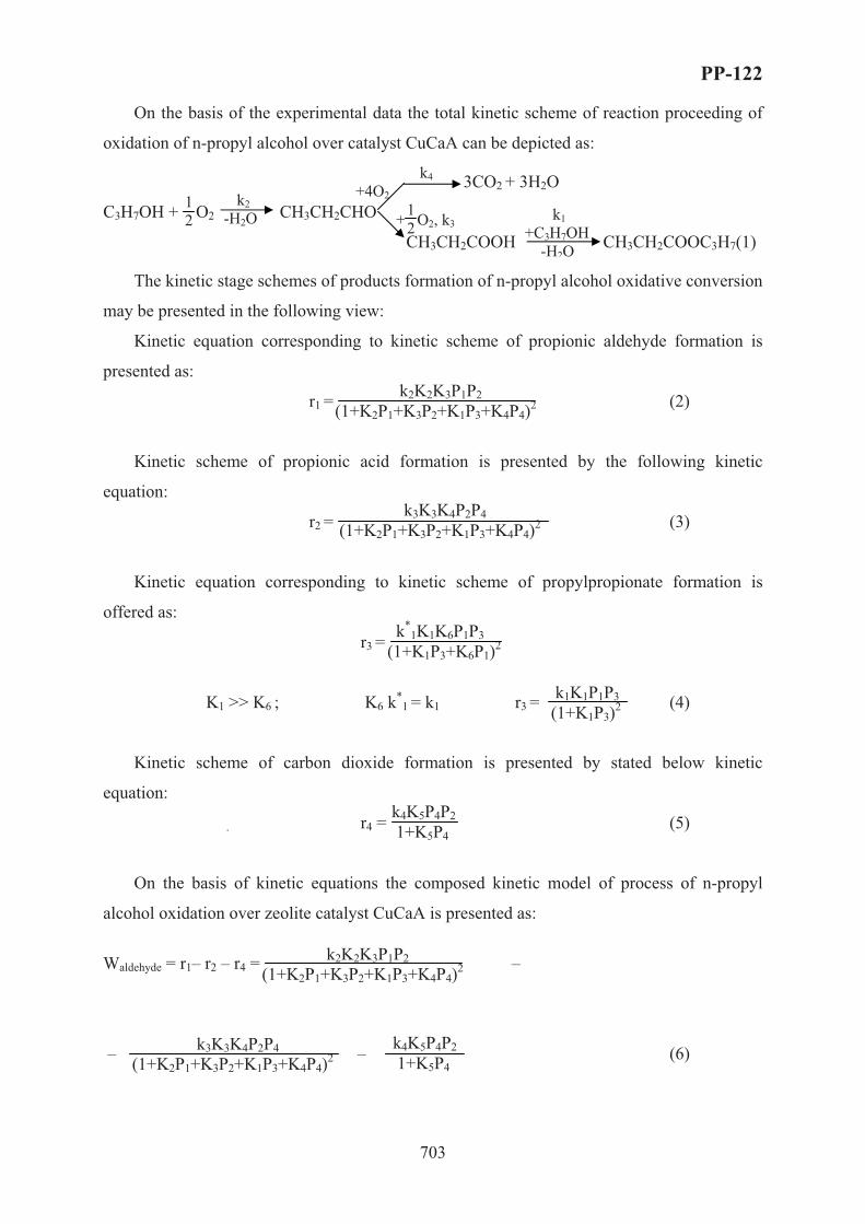
PP-122
703
On the basis of the experimental data the total kinetic scheme of reaction proceeding of
oxidation of n-propyl alcohol over catalyst CuCaA can be depicted as:
3CO2 + 3H2O C3H7OH + O2 CH3CH2CHO
CH3CH2COOH CH3CH2COOC3H7(1)
The kinetic stage schemes of products formation of n-propyl alcohol oxidative conversion
may be presented in the following view:
Kinetic equation corresponding to kinetic scheme of propionic aldehyde formation is
presented as:
r1 = (2)
Kinetic scheme of propionic acid formation is presented by the following kinetic
equation:
r2 = (3)
Kinetic equation corresponding to kinetic scheme of propylpropionate formation is
offered as:
r3 =
K1 >> K6 ; K6 k*1 = k1 r3 = (4)
Kinetic scheme of carbon dioxide formation is presented by stated below kinetic
equation:
r4 = (5)
On the basis of kinetic equations the composed kinetic model of process of n-propyl
alcohol oxidation over zeolite catalyst CuCaA is presented as:
Waldehyde = r1– r2 – r4 = –
– – (6)
k2 -H2O
k1 +C3H7OH -H2O
1 2 + O2, k3
1 2
k4 +4O2
·
k*1K1K6P1P3
(1+K1P3+K6P1)2
k2K2K3P1P2 (1+K2P1+K3P2+K1P3+K4P4)2
k3K3K4P2P4 (1+K2P1+K3P2+K1P3+K4P4)2
k1K1P1P3 (1+K1P3)2
k4K5P4P2 1+K5P4
k2K2K3P1P2 (1+K2P1+K3P2+K1P3+K4P4)2
k3K3K4P2P4 (1+K2P1+K3P2+K1P3+K4P4)2
k4K5P4P2 1+K5P4

PP-122
704
Wacid = r2 – r3 = – (7)
Wester = r3 = (8) W = r4 = (9)
where �1, �2, �3 _ �4 – partial pressures of alcohol, oxygen, acid and aldehyde; k1, k2, k3 _ k4
– constants of the reaction rate of ester, aldehyde, acid and carbon dioxide; K1, K2, K3 _ K4 –
constants of adsorption equilibrium of acid, alcohol, oxygen and aldehyde.
This model was subjected to statistical analysis on the basis of experimental kinetic data.
On the basis of aforecited kinetic equations of n-propyl alcohol oxidation reaction into
propionic acid by means of comparison of experimental and calculated kinetic data the kinetic
parameters of the given model have been determined.
Conclusion
The results of investigations of catalytic oxidative conversion reaction of n-propyl
alcohol with the participation of molecular oxygen have shown that, from the number of
catalysts prepared on the basis of natural and synthesized zeolites, the process of oxidative
conversion of n-propyl alcohol into propionic acid proceeds with the high activity and
selectivity over zeolite CaA containing 3.0 wt.% Cu2+. The kinetic regularities of the reaction
over zeolite catalyst CuCaA have been studied. On the basis of experimental data kinetic
scheme of n-propyl alcohol oxidation reaction has been proposed and kinetic model of the
present process has been developed.
References [1] M.A.Wassel, N.Kh.Allahverdova, K.Y.Adjamov, Collect.Czechosl.Chem.Commun., 57 (1992) 446.
[2]L.Jinglin, L.Bin, L.Jiang and et al., J.Catal., 20 (1999) 429.
$�2
k3K3K4P2P4 (1+K2P1+K3P2+K1P3+K4P4)2
k1K1P1P3 (1+K1P3)2
k1K1P1P3 (1+K1P3)2
k4K5P4P2 1+K5P4

PP-123
705
CATALYTIC PROPERTIES OF THE PROTON CONDUCTORS:
Sr3CaZr0.5Ta1.5O8.75, BaCe0.9Y0.1O2.95 AND Ba3Ca1.18Nb1.82O8.73
FOR REVERSE WATER GAS SHIFT
Hermenegildo de A.L. Viana, John T.S. Irvine
School of Chemistry, University of St. Andrews, KY16 9ST, Scotland
A renewable hydrocarbon-based hydrogen economy is a very promising scenario. Such
a technology is acceptable if it does not generate additional CO2. However, there are two
key barriers for the implementation of a hydrocarbon-based hydrogen economy: separation
and concentration of CO2 from air exhaust stream and efficient conversion of CO2 to
hydrocarbon fuels.
Solid oxides with high surface areas have been used as supports for precious metals as
catalysts. One of the most common catalysts for this reaction is ceria supported catalysts due
to oxygen exchange properties. Among the precious metals, Pt supported by ceria has been
well studied; however, Pd, Rh or even Au have been shown to be effective also.1
This study shows that the cerate BaCe0.9Y0.1O2.9 or other proton conductors
Sr3CaZr0.5Ta1.5O8.75, 5 and Ba3Ca1.18Nb1.82O8.73 are active heterogeneous catalysts for the
reverse water gas shift (RWGS) reaction.
The reaction studied was the reverse water gas shift (RWGS) reaction (reaction 1) which
allows the reduction of CO2 to CO. This CO might be used as a chemical feedstock for the
Fischer-Tropsch synthesis of higher hydrocarbons, the oxy-synthesis or the synthesis of
oxygenates.2
OHCOHCO 222 +⇔+ �Hº298=41kJ/mol [1]
05
101520253035404550
350 450 550 650 750 850
Temperature (C)
% C
onve
rsio
n (%
)
BCN18BCY10BlankSCZTAl2O3
Figure 1 – RWGS reaction rate of conversion against temperature

PP-123
706
Their maximum rate of conversion of CO2 to CO is obtained with BCY10 reaching 45%
CO conversion by 900ºC (figure 1). Both BCN18 and SCZT have shown smaller rates of
conversion. At low temperatures, SCZT has shown a good conversion onset temperature,
starting to convert CO2 into CO at 400ºC. Their stability and degradation after being exposed
to H2/CO2 atmospheres is also investigated.
[1] – D. Tibiletti, S.P. The, G. Rothenberg, Journal of Catalysis 225 (2004) 489-497
[2] – D.J. Moon, J.W. Ryu, Catalysis Today 87 (2003) 255-264

PP-124
707
ANALYSIS OF GENETIC ALGORITHM OPERATORS IN THE
PRODUCTIVITY OF AN INDUSTRIAL REACTOR
Victorino, I.R.S. and Maciel Filho, R.
Laboratory of Optimization, Design and Advanced Control.
Department of Chemical Processes. School of Chemical Engineering.
State University of Campinas (UNICAMP)
P.O. Box 6066, 13081-970, Campinas, SP, Brazil,
Tel.:+55-19-37883971; Fax: +55-19-3788396
E-mails:[email protected] / [email protected]
Introduction
Genetic Algorithms (GAs) have obtained great popularity in the last decades, since
this have shown great potential and ability to solve complex problems of optimization in
diverse industrial fields, including chemical engineering process. Several optimization classic
techniques have been used with this objective, but generally these techniques are not efficient,
mainly when the complexity of the problem is large due to non-linearity and process variable
interactions.
The genetic algorithms are based on the genetics and natural evolution principles of
the species. The mechanism of the Genetic Algorithms technique occurs with successive
modifications of the individuals or chromosomes (artificial structures) of population through
the application of selection, crossover, and mutation operators. The application of Genetic
Algorithms needs to develop a representative objective function of the reactor model, where
this objective function evaluates the quality of determined solutions, being used as main
criterion in approaches of great potential in industrial applications.
This work has as objective the development of an optimization methodology, using
genetic algorithms, as evolutionary technical coupled with the concepts of evolutionary
operation to be applied in deterministic mathematical models.
The process considered is a multiphase catalytic reactor, where hydrogenations
reactions take place. A series of parallel and consecutive reactions may happen, so that the

PP-124
708
reactor has to be operated in a suitable way to achieve high conversion as well as high
selectivity. The reactor is constituted of a series of tubes, which are immersed in a boiler. In
fact, they consist of concentrical tubes. The reactants flow through the tubular as well as
through the external annular region, while the thermal fluid flows inside the other regions.
The model is considered in the steady-state.
The study was related to a specific cyclic alcohol (CA) production, optimizing some
important operational parameters. A deterministic model based on the equations of mass
conservation, energy and moment was developed and validated with real operational data.
The study was made analyzing the genetic operators sensibility and influence in the
specific cyclic alcohol productivity. In order to do this, some genetic operators and parameters
had been studied and analyzed as: two crossover types (one-point and uniform) and the
variation of crossover rates, the presence or not mutation operator types, the variation
mutation rates and the consequences in the increase of the production.
This study observed the influence of some genetic operators and parameters in the
improvement of the reactor performance. The results showed an increase in the CA
productivity (considerable increase CA production) with changes in the operational
parameters analyzed and showing that this optimization procedure is very robust and efficient.
Results
The GA procedure revealed to be very efficient and robust for all the considered
situations. Several testes with different population sizes, crossover and mutation values allow
to conclude that the optimization by GA works well without be so dependent of its design
values as well as the initial value. Optimization of the same problem by conventional methods
(as SQP) was not possible to be obtained in all the cases considered in this work.
In the Figures 1 and 2 are shown some results considering the influence of the
population size (npz), crossover rates (%) and the crossover form in the CA productivity
(mass rate normalized). It is verified in this study that using the one-point crossover form,
values better of CA rates are reached, meaning more raised productivity of the desired
product. This situation is important therefore the amount produced to the long time is
considerable, diminishing costs and increasing the profitability.

PP-124
709
Level 1
Rate Crossover (%)
0,3 0,4 0,5 0,6 0,7 0,8 0,9
CA
(Nor
mal
ized
)
0,660
0,662
0,664
0,666
0,668
npz = 20 - Unnpz = 30 - Unnpz = 40 - Unnpz = 50 - Un
Level 1
Crossover Rate (%)
0,3 0,4 0,5 0,6 0,7 0,8 0,9
CA
(Nor
mal
ized
)
0,660
0,662
0,664
0,666
0,668
npz = 20 - UPnpz = 30 - UPnpz = 40 - UPnpz = 50 - UP
Figure 1. Analysis crossover rate and the population
size and influence in the Cyclic Alcohol (CA) mass rate
normalized - Uniform Crossover (Un).
Figure 2. Analysis crossover rate and the population
size and influence in the Cyclic Alcohol (CA) mass rate
normalized – One-Point Crossover (UP).
Other analyses will be carried through considering the mutation form and rate, and its
influence in the CA productivity.
References 1. Bäck, T., Fogel, D. B. and Michalewicz, T. (2000). editors. Evolutionary Computation 1: Basic
Algorithms and Operators. Institute of Physics Publishing, 2000. 2. Carroll, D. L. (1996). “Chemical Laser Modeling with Genetic Algorithms”. AIAA Journal, Vol. 34, No.
2, February. 3. Coussemant, F. and Jungers, J. C. (1950). “La Cinétique de L´Hydrogénation Catalytique des Phénols”.
Bull. Soc. Chim. Bel., vol. 59, pp. 295-326. 4. Deb, K. (1998). “Genetic algorithms in search and optimization: The technique and applications”.
Proceedings of International Workshop on Soft Computing and Intelligent Systems, Calcutta, India: Machine Intelligence Unit, Indian Statistical Institute, pp. 58 – 87.
5. Froment, G. F. and Bischoff, K. B. (1990). “Chemical Reactor Analysis and Design”. John Wiley and Sons, 2ed., 664pp, New York.
6. Goldberg D. E. (1989). Genetic Algorithms in Search, Optimization, and Machine Learning. Addison-Wesley Publishing Company, INC.
7. Goldberg, D. E. and Deb, K. (1991). A Comparison of Selection Schemes Used in Genetic Algorithms, Foundation of Genetic Algorithms, edited by G. J. E. Rawlins, pp. 69-93.
8. Holland, J. H. (1992). Adaptation in Natural and Artificial Systems. University of Michigan Press, 2nd. 9. Hongqing C., Jingxian Y., Lishan K., Yuping C. and Yongyan C. (1999). The Kinetic Evolutionary
Modeling of Complex Systems of Chemical Reactions. Computers e Chemistry, 23, pp. 143-151. 10. Moros, R., Kalies, H., Rex, H. G. and Schaffarczyk, St. (1996). A Genetic Algorithm for Generating
Initial Parameter Estimations for Kinetic Models of Catalytic Processs. Computers Chem.Engineering, Vol. 20, No. 10, pp. 1257-1270.
11. Santana, P. L. (1995). Mathematical Modeling for three phase reactor: deterministic, neural and hybrid models, PhD Thesis, School of Chemical Engineering, Unicamp, São Paulo, Brazil (in Portuguese).
12. Simant R. U. and Kalyanmoy D. (1997). Optimal Design of an Ammonia Synthesis Reactor Using Genetic Algorithms. Computers Chem. Engineering, Vol. 21, No. 1, pp. 87-92.
13. Syswerda, G. (1989). Uniform Crossover in Genetic Algorithms. In J. D. Schaffer (Ed.), Proceedings of The Third International Conference on Genetic Algorithms, pp. 2-9.
14. Vasco de Toledo, E.C.., Santana, P.L., Wolf-Maciel, M.R., Maciel Filho, R. (2001). Dynamic modelling of a three-phase catalytic slurry reactor, Chem. Eng. Sci., 56, 6055-6061.
15. Wehrens, R and Buyders, M. C. (1998). Evolutionary Optimisation: A tutorial. Trends in Analytical Chemistry, Vol. 17, No. 4.

PP-125
710
EVALUATION OF GENETIC ALGORITHM CODING TO
OPTIMIZATION OF A CYCLIC ALCOHOL INDUSTRIAL REACTOR
Victorino, I.R.S. and Maciel Filho, R.
Laboratory of Optimization, Design and Advanced Control.
Department of Chemical Processes. School of Chemical Engineering.
State University of Campinas (UNICAMP)
P.O. Box 6066, 13081-970, Campinas, SP, Brazil,
Tel.:+55-19-37883971; Fax: +55-19-3788396
E-mails:[email protected] / [email protected]
Introduction
Evolutionary Algorithms as Genetic Algorithms (GAs) have gained great popularity
since the last decade. The GAs have shown great potentiality and ability to decide complex
problems of optimization in diverse fields, including Chemical Engineering. In this paper the
main objective is to investigate the GAs performance for the optimization of an example
related the industrial reactor of Cyclic Alcohol production. The intention is to find out optimal
operating conditions so that the conversion might be optimized but at the same time
constraints as temperatures inside the reactor does not be violated, the side products be
minimized and a restrict range of reactant concentration at the reactor exit be guaranteed. This
is important for environmental restriction and difficulties to the optimization problem.
As a case study is considered an industrial hydrogenation multiphase catalytic reactor
to obtain a Cyclic Alcohol (CA). The system is analyzed for different level of operational
requirements. The reactor consists of concentrical tubes, with the reactants flowing through
the internal tubular part, while the coolant circulates through the inner anulles. The
mathematical equations of the deterministic model are based on conservation principles
(mass, energy and momentum ) for the reactants and for the coolant and validated with real
operational data. Industrial data of temperature are available and they will be used in the
development and validation of the model. The model is written in steady-state regimen with
the plug-flow assumption.

PP-125
711
The main task is to develop and implement a GA code coupled in this reactor
mathematical model, considering the analysis and comparison among two coding types
inherent the Genetic Algorithms (binary and floating-point coding), in the optimization of
reactor operational parameters. This analysis considers the use of specific genetic parameters
of each coding type, and the respective influences in the reaction performance (CA
productivity increase). The choice of an appropriate structure (representation or coding) for
solutions (individuals) of a determined problem is a major determining factor to GAs success.
The intention is to show that this technique is suitable for cyclic alcohol production
maximization obtaining good results with operational improvements (reduction catalyst rate,
reduction main reactant rate – Benzylic Alcohol and undesired product rate – Cycloalkane),
analyzing two coding types and the influence that these have in the reactor performance (CA
productivity increase). The reduction main reactant rate must be considered, mainly when the
emissions occur in high concentrations causing damages to the environment.
The results shown that, the method is very robust procedure which allows the reactor
to be operated of high level of performance, restricting the emissions of toxic reactant and
reducing the undesirable products.
The GA code coupled to the reactor model showed to be a very efficient technique
for reactor optimization. Similar problems or other systems can be studied for verification of
his efficiency.
At this point is welcome to remember the difficulties formal when conventional
optimization as SQP are used. The results are dependent upon the initial values and a
relatively high number of convergence difficulties are relatively common for large
dimensional problem. This was not the case for the GA.
The process can be optimized in relation to other parameters that in future works will
be considered, such as the kinetic parameters and the orders of reaction, besides others being
studied.
PP-126
712
OPTIMIZATION BASED ON GENETIC ALGORITHMS:
APPLICATION TO INDUSTRIAL REACTOR PRODUCTION
Victorino, I.R.S. and Maciel Filho, R.
Laboratory of Optimization, Design and Advanced Control.
Department of Chemical Processes. School of Chemical Engineering.
State University of Campinas (UNICAMP)
P.O. Box 6066, 13081-970, Campinas, SP, Brazil,
Tel.:+55-19-37883971; Fax: +55-19-3788396
E-mails:[email protected] / [email protected]
Introduction
In the last decades, with the increase of the competitiveness of the world market
(reduction of costs, prices increase of the productivity and efficiency of the productive
processes) there was a great interest in to improve and to optimize the processes of chemical
industries. Several optimization classic techniques have been used with this intention, but
many of those techniques are not efficient, mainly when the problem is complex, and
typically a high number of variables of the processes, non-linearity models that supply many
possible solutions, and constraints that have to be considered lead the problem to be of
difficult solution. As alternative a class of algorithms, denominated of Genetic Algorithms (an
evolutionary algorithms category) present good potential to be used as a tool for complex and
large scale systems.
Genetic Algorithms (GAs) are general-purpose search techniques for resolution of
complex problems. They are based on the genetics and natural evolution principles of the
species. The GAs work through repeated modifications in an artificial structures population
denominated of individuals (chromosomes or set of solutions) applying the selection,
crossover, and mutation operators. The evaluation of optimization happens with an objective
function (fitness) that determines the performance of the genetic process. The fitness could be
understood as the capacity of the individuals to survive in a natural environment.
This work has as objective the development of an optimization methodology, using
Genetic Algorithms (GAs), as evolutionary procedure coupled with the concepts of

PP-126
713
evolutionary operation to be applied in deterministic mathematical models. As case study an
industrial multiphase catalytic reactor was considered. The reactor is tubular in shape and is
built-up with concentric tubes using the same concept of the auto-thermal reactors, with
coolant fluid flow in the external annular. The mathematical equations of the deterministic
model are based on conservation principles (mass, energy and momentum) for the reactants
and for the coolant fluid and validated with real operational data. Industrial data of
temperature are available and they are used in the development and validation of the model.
The model is written in steady-state with the plug-flow assumption.
The studied example was related to production of a specific cyclical alcohol (CA),
optimizing some important operational parameters.
The interest of this work is to show that the Genetic Algorithms technique can be
useful to CA production maximization, obtaining good results with operational improvements
(reduction catalyst rate, reduction main reactant rate – benzilic alcohol (BA) and undesired
product rate – cycloalkane (C)). Some cares must be considered, mainly with the reactants
emissions (main reactant- benzilic alcohol) that occur in high concentrations causing damages
to the environment.
This study observed the influence of some genetic parameters in the increase of the
cyclic alcohol productivity. The parameters (genetic parameters) considered involved the
population size, crossover types with variation of crossover rates. The used coding was the
binary form.
The results are quit good, showing high performance in the CA productivity
(considerable increase CA production) with changes in the operational parameters analyzed
and showing that this optimization procedure is very robust and efficient. The results point
out that this technique is very promising to deal with large scale system with complex
behavior due to non-linearity and variable interactions.
Results
In the following figures, it is evaluated the application of the GAs in the optimization
of the selected parameters, six coolant fluid outflows, (Qri’s), outflow of catalyst (Qcat) and the
reactant feed temperature (T0). The results are represented in Figures 1, 2 and 3 respectively.
In the Figure 1 shows the optimization profile with the generations adopted in the
simulation of Level 1 production. This level can to be understood as a specific operational

PP-126
714
form. The reactor performance improvement is reached as verified in the in the same figure
(Figure 1).
The Figures 2 and 3 present the molar fractions profiles of two main components.
These are Cyclic Alcohol (CA) (desired product) and Benzylic Alcohol (BA) (main reactant
BA). The values are normalized.
Level 1
Number of Generations
0 100 200 300 400 500 600
CA
(Nor
mal
ized
)
0,64
0,65
0,66
0,67
0,68
Not OptimizedOptimized
Figure 1. Profile CA productivity (mass rate normalized) for production Level 1 with the optimization
evolution.
Level 1
Axial Reactor Length (m)
0 20 40 60 80 100 120 140
BA
Mol
e Fr
actio
n (%
)
0,0
0,2
0,4
0,6
0,8
1,0
Not OptimizedOptimized
Level 1
Axial Reactor Length (m)
0 20 40 60 80 100 120 140
CA
Mol
e Fr
actio
n (%
)
0,0
0,2
0,4
0,6
0,8
1,0
Not OptimizedOptimized
Figure 2. Main reactant (BA) mole fraction to the
long the reactor length. Considering 500 generations.
Figure 3. Product (CA) mole fraction to the long the
reactor length. Considering 500 generations.

PP-126
715
The GA code coupled to the reactor model showed to be a very efficient technique for
reactor optimization. Similar problems or other systems can be studied for verification of his
efficiency.
References
1. Bäck, T., Fogel, D. B. and Michalewicz, T. (2000). editors. Evolutionary Computation 1: Basic
Algorithms and Operators. Institute of Physics Publishing, 2000.
2. Carroll, D. L. (1996). “Chemical Laser Modeling with Genetic Algorithms”. AIAA Journal, Vol. 34, No.
2, February.
3. Coussemant, F. and Jungers, J. C. (1950). “La Cinétique de L´Hydrogénation Catalytique des Phénols”.
Bull. Soc. Chim. Bel., vol. 59, pp. 295-326.
4. Deb, K. (1998). “Genetic algorithms in search and optimization: The technique and applications”.
Proceedings of International Workshop on Soft Computing and Intelligent Systems, Calcutta, India:
Machine Intelligence Unit, Indian Statistical Institute, pp. 58 – 87.
5. Froment, G. F. and Bischoff, K. B. (1990). “Chemical Reactor Analysis and Design”. John Wiley and
Sons, 2ed., 664pp, New York.
6. Goldberg D. E. (1989). Genetic Algorithms in Search, Optimization, and Machine Learning. Addison-
Wesley Publishing Company, INC.
7. Goldberg, D. E. and Deb, K. (1991). A Comparison of Selection Schemes Used in Genetic Algorithms,
Foundation of Genetic Algorithms, edited by G. J. E. Rawlins, pp. 69-93.
8. Holland, J. H. (1992). Adaptation in Natural and Artificial Systems. University of Michigan Press, 2nd.
9. Hongqing C., Jingxian Y., Lishan K., Yuping C. and Yongyan C. (1999). The Kinetic Evolutionary
Modeling of Complex Systems of Chemical Reactions. Computers e Chemistry, 23, pp. 143-151.
10. Moros, R., Kalies, H., Rex, H. G. and Schaffarczyk, St. (1996). A Genetic Algorithm for Generating
Initial Parameter Estimations for Kinetic Models of Catalytic Processs. Computers Chem.Engineering,
Vol. 20, No. 10, pp. 1257-1270.
11. Santana, P. L. (1995). Mathematical Modeling for three phase reactor: deterministic, neural and hybrid
models, PhD Thesis, School of Chemical Engineering, Unicamp, São Paulo, Brazil (in Portuguese).
12. Simant R. U. and Kalyanmoy D. (1997). Optimal Design of an Ammonia Synthesis Reactor Using
Genetic Algorithms. Computers Chem. Engineering, Vol. 21, No. 1, pp. 87-92.
13. Syswerda, G. (1989). Uniform Crossover in Genetic Algorithms. In J. D. Schaffer (Ed.), Proceedings of
The Third International Conference on Genetic Algorithms, pp. 2-9.
14. Vasco de Toledo, E.C.., Santana, P.L., Wolf-Maciel, M.R., Maciel Filho, R. (2001). Dynamic modelling
of a three-phase catalytic slurry reactor, Chem. Eng. Sci., 56, 6055-6061.
15. Wehrens, R and Buyders, M. C. (1998). Evolutionary Optimisation: A tutorial. Trends in Analytical
Chemistry, Vol. 17, No. 4.

PP-127
716
EXPERIMENTAL STUDY OF THE HALIDE-FREE CARBONYLATION
OF DIMETHYL ETHER
G.G. Volkova, M.A. Shuvaeva, A.A. Budneva, E.A. Paukshtis
Boreskov Institute of Catalysis SB RAS, Pr. Akademika Lavrentieva 5,
Novosibirsk, 630090, Russia
Acetic acid is an important industrial chemical which is manufactured on a large scale. The main route to acetic acid is through the carbonylation of methanol in the Monsanto process which uses a homogeneous rhodium catalyst and halide promoter [1]. Main disadvantages of this process are: a) halides are highly corrosive and are poisons for many types of catalysts b) it is difficult to separate the products and catalyst. These problems may be overcome by developing heterogeneous catalyst that can operate effectively without halide promoter.
Studies at Boreskov Institute of Catalysis have shown that acidic cesium salts of 12-tangstophosphoric acid promoted with rhodium revealed high activity in the iodide-free carbonylation of the dimethyl ether (DME) to methyl acetate (MA) [2-3] that is one order of magnitude higher than the activity of the rhodium salts of the same acid supported on silica [4]. DME is more favorable for carbonylation than methanol because it can be produced from syn-gas more effectively [5].
CH3-O-CH3 + CO → CH3-CO-O-CH3 Investigations of the reaction over 1%Rh/Cs1.5H1.5PW12O40 catalyst were carried out at the excess CO, ratio DME : CO =1:19 and 1:10, temperature = 200, 220 and 250oC; space velocity = 2, 5, 10 liters hour-1, pressure 10 atm. It was observed that DME conversion increased with temperature and contact time raise. It was also shown that DME conversion was inversely proportional to initial DME concentration and it did not depend on CO concentration. The rate constants and activation energy for DME carbonylation at the excess CO were evaluate assuming that the reaction is first order in DME. E=12,3 Kcal mol-1. It may be suggested that DME carbonylation reaction occurs through Eley-Rideal route where CO molecule from gas phase interacts with adsorbed molecule of DME: 1. DME+ [ ] = [DME]; 2. [DME] + CO ¿ MA + [ ].
References 1. M.J. Howard, M.D. Jones, M.S. Roberts and S.A. Taylor, Catal.Today, 18 (1993) 325. 2. G.G. Volkova, L.M. Plyasova, A.N. Salanov, G.N. Kustova, T.M. Yurieva, V.A. Likholobov, Catal.Lett. 80
(2002) 175. 3. G.G. Volkova, L.M. Plyasova, L.N. Shkuratova, A.A. Budneva, E.A. Paukshtis, M.N. Timofeeva, V.A.
Likholobov, Stud. Sur. Sci. Catal., 147 (2004) 403. 4. W.R.Wegman, European Patent 0353 722 (1989). 5. T. Shikada, Y. Ohno, T. Ogawa, M. Ono, M. Mizuguchi, K. Tomura, K. Fugimoto, Stud. Sur. Sci.
Catal., 119 (1998) 515.

PP-128
717
MATHEMATIC MODELING OF THE CONTINUOUS PROCESS FOR
SYNTHESIS OF NANOFIBROUS CARBON IN THE REACTOR WITH
A MOVING CATALYST BED AND GAS FLOW RECYCLING
Zavarukhin S.G., Kuvshinov G.G. and Ananyev I.V.*
Boreskov Institute of Catalysis SB RAS, Pr. Akademika Lavrentieva, 5, Novosibirsk 630090,
Russia, Fax: 007 3833 308056, e-mail: [email protected] *Novosibirsk State Technical University, K. Marx avenue, 20, Novosibirsk 630092, Russia
Nanofibrous carbon (NFC) is a porous carbon material formed upon decomposition of gas
carbons on the metal catalysts at the temperature 500-800oC. The uniqueness of this material
is that it contains filaments 10-150 nm in diameter formed on the metal catalyst particles of
the same dimensions. The present-day catalysts permit production of NFC as strong granules
(3-6) mm in diameter, made by densely interlaced carbon filaments, in which the
concentration of carbon is as high as 99.8%. The samples of such NFC materials have been
obtained in the lab-scale and pilot reactors producing to 3 kg of carbon during an operation
period [1]. Since the prospect of commercialization of the granular NFC production is very
encouraging, a topical problem is the development of calculation methods of this process
performance in different reactors, including the continuous reactors.
A moving catalyst bed reactor with intense gas flow recycling, which provides constant
gas composition and temperature inside the reactor, is very promising for production of NFC.
In this work we suggest a mathematical technique to calculate the process using the above
mentioned reactor and 90 wt.% Ni-Al2O3 catalyst [2] and methane.
In stating the mathematical model, we made the following assumptions:
1. Recycling gas factor is sufficiently high, which provides the ideal mixing in the gas
phase and isothermal process.
2. Particle sizes and the catalyst bed thickness are sufficiently low, which permits one to
neglect inter and external diffusion resistance values and to assume that the process proceeds
in the kinetic region.
3. The catalyst moves without mixing and its parameters are determined by longitudinal
coordinate of the reactor.
4. The process is stationary and proceeds at temperature T and pressure P.
The reactor is schematically shown in Fig. 1, where a stirrer provides an ideal gas mixing.

PP-128
718
Fig. 1. Schematic of the reactor.
At the left of the schematic, a catalyst is fed at Jc (kg/h) and methane at Q (m3/h at
standard conditions). The carbonized catalyst and a methane-hydrogen mixture are released
on the right side. The reactor volume was chosen so that to provide a catalyst charge weight
of m0. It is required to determine characteristics of the catalyst and gas at the reactor outlet
(specific carbon content c1 and conversion of methane x).
In the calculations we used a kinetic model of NFC formation from CH4-H2 at
atmospheric pressure in the presence of a high-loaded Ni catalyst to account for catalyst
deactivation [3]. According to the model, the catalyst state is characterized at every instant by
two parameters: weight of the formed carbon per catalyst weight unit c (kg/kg) (specific
carbon content) and relative catalyst activity a, which obey the following equations:
ardtdc
m= (1)
carkdtda
ma2−= (2)
where t is time (h), rm is the maximal specific rate of carbon formation depending on the gas
mixture composition and temperature (kg/h kg).
22
22
4
)1( HH
p
HCH
m pkKpp
kr+
−= (3)
pCH4, pH2 are partial pressures of methane and hydrogen (bar), respectively, Kp is the
equilibrium constant of the methane decomposition into carbon and hydrogen, ka, k, kH are the
coefficients whose dependence on temperature is given in ref. [3].
Since a moving catalyst is carbonized under the conditions of constant gas mixture
composition, the specific carbon concentration at the reactor outlet c1 can be determined by
Reactor
Methane
Catalyst
Q
J§
Methane Hydrogen
Catalyst Carbon

PP-128
719
integrating a system of equations (1)-(2) with the initial conditions such as c = 0 and a = 1
when t = 0.
)(1 τm
mm c
rthcc = (4)
where cm is the maximal specific content of carbon on the catalyst, which equals:
mam rk
c 2= (5)
where τ is the time of catalyst stay in the reactor, � = m0/Jk.
Gas composition in the reactor, which can be characterized by partial pressure of
hydrogen, was calculated from the equation of carbon balance between gas and catalyst (the
carbon formed upon methane decomposition is released from the reactor along with the
catalyst)
1cJxJ kc = (6)
where Jc (kg/h) is the flux of carbon in methane feedstock, 4.22
12 QJc⋅= .
When solving eq. (6) with respect to pH2, one takes into account that pCH4 = P – pH2 and
the conversion of methane is associated with the value of partial hydrogen pressure by the
following dependence:
2
2
2 H
H
pPpx−
= (7)
For computational convenience and analysis, we introduced specific parameters jk = Jk/m0,
jc = Jc/m0 and q = Q/m0, which permit to write equation (6) as
))()(()()(
2
222
kHm
HmHmkHc jpc
prthpcjpxj = (8)
As pH2 is determined from the numerical solution of eq. (8), the conversion of methane
was calculated by eq. (7) and specific carbon content at the reactor outlet was obtained using
the following dependence, which yields from eq. (6):
xjjck
c=1 (9)
Fig. 2 shows the computational results of specific carbon content at the reactor outlet
versus specific catalyst consumption at the following reaction conditions: T = 823 K, P = 1
bar, q = 120 m3/h·kg and jk ranges from 0.02 to 0.1 kg/h·kg. The figure suggests that at the
fixed consumption of methane, there exist an optimal consumption of the catalyst, which

PP-128
720
allows a maximal specific yield of carbon that is typical of other continuous processes [4].
The maximal value of c1 (156 kg/kg), achieved at jk = 0.053 kg/h·kg, approximates the value
of specific carbon yield in the batch reactor of ideal mixing of catalyst particles and gas
obtained at similar temperature and specific methane consumption (159 kg/kg), which is
characterized by maximal specific yield as compared to the other types of the reactors [3,5].
80
100
120
140
160
0,02 0,04 0,06 0,08 0,1
j k , kg/h kg
c 1,kg/kg
Fig. 2. Specific carbon content on the catalyst at the reactor outlet c1 versus jk at T = 823 K,
P = 1 bar, q = 120 m3/h·kg.
References 1. Kuvshinov G.G., Zavarukhin S.G., Mogilnykh Yu.I. et al //Khim. Prom–st (Moscow). 1998. 5. P. 300.
2. Goncharova O.V., Avdeeva L.B., Fenelonov V.B. et al //Kinetics and Catalysis. 1995. V. 36. P. 268.
3. Zavarukhin S.G., Kuvshinov G.G. //Appl. Catal. A. 2004. V. 272. P. 219.
4. Zavarukhin S.G., Kuvshinov G.G. //Eurasian ChemTech Journal. 2004. V. 6. P. 201.
5. Zavarukhin S.G. and Kuvshinov G.G. //XV International Conference on Chemical Reactors
"CHEMREACTOR-15", Helsinki, Finland, June 5-8, 2001. Novosibirsk, 2001. P. 185.

721
XVII International Conference on Chemical Reactors Post-Symposium “Catalytic Processing of Renewable Sources: Fuel, Energy, Chemicals”
Plenary Lectures PL-1 Gilbert Froment FUNDAMENTAL KINETIC MODELING FOR REACTOR DESIGN AND SIMULATION ................................................................................................................. 7
PL-2 Bair Balzhinimaev WOVEN FIBER GLASS MATERIALS AS A NEW GENERATION OF STRUCTURED CATALYSTS ........................................................................................... 8
PL-3 Dmitry Murzin IS IT WORTH DOING KINETIC MODELLING IN ASYMMETRIC HETEROGENEOUS CATALYSIS OF FINE CHEMICALS?............................................... 10
PL-4 Ji�í Hanika, V. Jiricny, J. Kolena, J. Lederer, V. Stanek, V. Tukac TRICKLE BED REACTOR OPERATION UNDER FORCED LIQUID FEED RATE MODULATION ................................................................................................ 13
PL-5 Constantinos G. Vayenas MONOLITHIC ELECTROPROMOTED REACTORS: FROM FUNDAMENTALS TO PRACTICAL DEVICES ..................................................... 17
PL-6 Valeriy Kirillov, Vladimir Sobyanin HYDROGEN PRODUCTION FOR FUEL CELLS................................................................ 21
PL-7 Angeliki Lemonidou ALTERNATIVE CATALYTIC PROCESSES FOR LIGHT OLEFINS PRODUCTION: FROM LAB TO PRACTICE................................................................................................... 23
PL-8 Jean-Claude Charpentier IN THE FRAME OF GLOBALISATION AND SUSTAINABILITY, SOME TRACKS FOR THE FUTURE OF CHEMICAL AND CATALYTIC PROCESS ENGINEERING............................................................................. 26
Oral Presentations Section 1. Kinetics of catalytic reactions OP-1-1 Heracleous E., Lemonidou A.A., Vasalos I.A. KINETIC MODELLING OF ETHANE OXIDATIVE DEHYDROGENATION OVER Ni-Nb-O MIXED OXIDE CATALYSTS.................................................................... 32
722
OP-1-2 Calabro' V., De Paola M.G., Curcio S., Iorio G. KINETICS OF ENZYMATIC TRANS-ESTERIFICATION OF LOW QUALITY OLIVE OIL FOR THE PRODUCTION OF BIODIESEL ...................................................... 36
OP-1-3 Lazman M.Z. REACTION RATE EQUATION OF COMPLEX CATALYTIC REACTION IN TERMS OF HYPERGEOMETRIC SERIES ..................................................................... 40
OP-1-4 Gosiewski K., Warmuzinski K., Jaschik M., Tanczyk M. KINETICS FOR THERMAL OXIDATION OF LEAN METHANE – AIR MIXTURES IN REVERSE FLOW REACTORS......................................................................................... 44
OP-1-5 Santa Cruz B.G.V., Kerleaua Ph., Pitaulta I., Meille V., Heurtauxb F. CHOICE OF A REACTOR TO STUDY KINETICS OF HYDROGEN RELEASE FROM METHYLCYCLOHEXANE....................................................................................... 47
OP-1-6 Kraehnert R. KINETICS OF AMMONIA OXIDATION OVER PLATINUM FOIL STUDIED IN A NOVEL MICRO-STRUCTURED QUARTZ REACTOR............................................. 51
OP-1-7 Thömmes T., Reitzmann A., Kraushaar-Czarnetzki B. VAPOUR PHASE EPOXIDATION OF PROPENE USING N2O AS AN OXIDANT: REACTION NETWORK, KINETICS AND CATALYST DEACTIVATION...................... 55
OP-1-8 Fernandes J.L., Pinheiro C.I., Oliveira N., Ribeiro F.R., Inverno J., Santos M.A. KINETIC MODELLING OF AN INDUSTRIAL FLUIDIZED CATALYTIC CRACKING (FCC) PROCESS ............................................................................................... 58
OP-1-9 Ivanchev S.S., Pavlyuchenko V.N., Tyulmankov V.P., Myakin S.V. EMULSION POLYMERIZATION SYSTEMS AS INTERCONNECTED CONTROLLABLE MICROREACTORS ............................................................................... 62
OP-1-10 Chee Wee Q., Jie Bu CARRY OUT CATALYTIC EPOXIDATION IN REACTION CALORIMETER: KINETICS AND MECHANISM STUDIES ........................................................................... 63
OP-1-11 Ostrovskii N.M. CATALYST DEACTIVATION WITH RESIDUAL ACTIVITY - HISTORY, MODELS, MECHANISMS AND EXAMPLES..................................................................... 66

723
Section 2. Physico-chemical and mathematical bases of the processes in chemical reactors OP-2-1 Blumich B., Datsevich L.B., Jess A., Oehmichen T., Ren X., Stapf S. OSCILLATIONS IN CATALYST PORES: FROM THEORY TO PRACTICE ................... 71
OP-2-2 Kurkina E.S. MATHEMATICAL MODELING OF SPATIO-TEMPORAL PATTERN FORMATION IN THE NO+CO/Pt(100) REACTION ........................................................... 74
OP-2-3 Horn R., Degenstein N.J., Williams K.A., Schmidt L.D. TRANSIENT AND PROFILE MEASUREMENTS IN SYNGAS FORMATION BY AUTOTHERMAL CATALYTIC PARTIAL OXIDATION OF CH4 ON Rh FOAMS ......... 76
OP-2-4 Peskov N.V., Slinko M.M., Korchak V.N. MATHEMATICAL MODELLING OF THE NONLINEAR BEHAVIOUR DURING METHANE OXIDATION OVER Ni CATALYSTS.............................................................. 80
OP-2-5 Aldaco R., Garea A., Irabien A. MODELLING OF PARTICLE GROWTH: APPLICATION TO WATER TREATMENT IN A FLUIDIZED BED REACTOR .............................................................. 83
OP-2-6 Pisarenko E.V., Pisarenko V.N., Ziyatdinov A.Sh. ANALYSIS, MODELING AND SIMULATION OF CATALYTIC PROCESS OF HIGH PURITY ETHYLENE PRODUCTION.................................................................. 87
OP-2-7 Van Geem K.M., Žajdlík R., Reyniers M.F., Marin G.B. DIMENSIONAL ANALYSIS AS A TOOL FOR SCALING UP AND DOWN STEAM CRACKING COILS.................................................................................................. 89
OP-2-8 Volkovskii V.V., Semendyaeva N.L., Kurkina E.S. SPATIO-TEMPORAL PHENOMENA IN CATALYTIC CO OXIDATION: SIMULATION RESULTS....................................................................................................... 93
OP-2-9 Ates A., Reitzmann A. INVESTIGATION OF N2O DECOMPOSITION AND SURFACE OXYGEN FORMATION ON Fe-MFI WITH TRANSIENT RESPONSE METHODS.......................... 95
OP-2-10 Shvets V.F., Kozlovskiy R.A., Kozlovskiy I.A., Makarov M.G., Suchkov J.P., Koustov A.V., Zavelev D.E. SIMULATION OF THE REACTOR’S UNIT FOR CATALYTIC ETHYLENE OXIDE HYDRATION....................................................................................... 99

724
OP-2-11 Boz N., Dogu T. REACTION MECHANISM OF TAME SYNTHESIS FROM DIFFUSE-REFLECTANCE FTIR ANALYSIS.................................................................... 101
OP-2-12 Bobrova L.N., Zolotarsky I.A., Sobyanin V.A., Parmon V.N. SYNGAS FORMATION FROM GASOLINE IN ADIABATIC REACTOR: THERMODYNAMIC APROACH AND EXPERIMENTAL OBSERVATIONS............... 105
OP-2-13 Elgarnia M., Debbah S., Saidan J., Mustafa I. SYNTHETIC FUEL FROM CATALYTIC DEGRADATION OF WASTE POLYMERS OVER SOLID ACID ZEOLITES ................................................................... 109
OP-2-14 Myshlyavtsev A.V., Myshlyavtseva M.D. SELF-SUSTAINED OSCILLATIONS FOR LANGMUIR-HINSHELWOOD MECHANISM ....................................................................................................................... 110
Section 3. Catalytic processes and reactors development: modeling, optimization and catalyst design OP-3-1 Bareiss A., Reitzmann A., Kraushaar-Czarnetzki B., Schimmoller B., Schulz H., Pratsinis S.E. STRUCTURED REACTORS PACKED WITH CERAMIC FOAMS FOR THE PARTIAL OXIDATION OF O-XYLENE TO PHTHALIC ANHYDRIDE ........................ 115
OP-3-2 Nau M., Richrath M., Gruenewald M., Agar D.W. DESORPTIVE COOLING OF FIXED-BED CHEMICAL REACTORS: A PRACTICAL ALTERNATIVE TO MICROREACTORS................................................ 119
OP-3-3 Reshetnikov S.I., Ivanov E.A., Startsev A.N. BENZENE HYDROGENATION IN THE THIOPHENE PRESENCE OVER THE SULFIDE Ni-Mo/γ-Al2O3 CATALYST UNDER PERIODIC OPERATION: KINETICS AND PROCESS MODELING ........................................................................................................ 121
OP-3-4 Bruk L.G., Timashova E.A., Gorodsky S.N., Oshanina I.V., Temkin O.N. NEW CATALYTIC SYSTEM FOR CONJUGATED OXIDATION OF CARBON MONOXIDE, SOLVENT, AND HYDROCARBOXYLATION OF CYCLOHEXENE..... 125
OP-3-5 Gunduz G., Dimitrova R., Y�lmaz S. CATALYTIC ACTIVITY OF HETEROPOLYTUNGSTIC ACID ENCAPSULATED INTO MESOPOROUS MATERIAL STRUCTURE ............................................................ 128
OP-3-6 Galvita V., Sundmacher K. HYDROGEN PURIFICATION FOR LOW TEMPERATURE FUEL CELLS BASED ON AN IRON REDOX CYCLE IN A PERIODICALLY OPERATED CATALYTIC REACTOR................................................................................ 132

725
OP-3-7 Hartmann V.L. VARIOUS MODELS OF GAS-SOLID REACTION IN ESTIMATION OF SULFUR REMOVAL CATALYST BED SERVICE TIME................................................................. 135
OP-3-8 Laska U., Frost C.G., Plucinski P.K., Price G.J. MAGNETIC FLUID MATERIALS FOR HOMOGENEOUS CATALYSIS ...................... 139
OP-3-9 Kaliya M.L., Erenburg A., Herskowitz M. DEVELOPMENT OF NOVEL CATALYTIC SYSTEM FOR SELECTIVE HYDROGENATION OF "IMINE" TO SERTRALINE IN TRICKLE BED REACTOR.... 143
OP-3-10 Babkin V.S., Namyatov I.G., Maksimov Yu.M., Kirdyashkin A.I. A NEW BASE APPROACH TO DEVELOPING POROUS BURNERS ............................ 145
OP-3-11 Maki-Arvela P.E., Denecheau A., Alho K., Warna J., Eranen K., Salmi T., Murzin D.Yu. ENHANCING CONSECUTIVE REACTIONS DURING THREE PHASE HYDROGENATION WITH A SEMIBATCH LIQUID PHASE ......................................... 149
OP-3-12 Dobrynkin N., Batygina M., Noskov A., Parmon V., Tsyrulnikov P., Shlyapin D., Besson M., Gallezot P. WET AIR OXIDATION OF PHENOL AND ACETIC ACID IN THE TRICKLE BED REACTOR .................................................................................... 153
OP-3-13 Bouvier C., Buijs W. ISOPROPYLATION OF NAPHTHALENE OVER SEVERAL ZEOLITIC CATALYSTS: HY AND BIPOM’S................................................................... 157
OP-3-14 Paloukis F., Neophytides S. THE AUTOTHERMAL SYNGAS PRODUCTION IN SOLID OXIDE FUEL CELLS UNDER FLOW REVERSAL CONDITIONS .............................................. 158
OP-3-15 Palomares A.E., Prato J.G. DESIGN OF A CATALYST FOR THE DENITRIFICATION OF NATURAL WATER. THE IMPORTANCE OF THE REACTOR DESIGN........................................................... 162
OP-3-16 Pavlova S., Sadykov V., Vostrikov Z., Snegurenko O., Shigarov A., Skomorokhov V., KuzminV., Kirillov V., Pokrovskaya S. PARTIAL OXIDATION OF METHANE TO SYNTHESIS GAS AT SHORT CONTACT TIMES IN AN AUTOTHERMAL REACTOR WITH MONOLITH CATALYSTS........... 165
OP-3-17 Zagoruiko A.N. SIMULATION OF SELECTIVE REACTIONS PERFORMANCE IN TRANSIENT REGIMES WITH PERIODICAL SEPARATE FEEDING OF REAGENTS. CASE STUDY: PROPANE OXIDATIVE DEHYDROGENATION IN ADIABATIC V-Ti CATALYST BED ............................................................................. 169

726
OP-3-18 Subrahmanyam Ch., Renken A., Kiwi-Minsker L. NOVEL CATALYTIC PLASMA REACTOR FOR THE ABATEMENT OF DILUTED VOLATILE ORGANIC COMPOUNDS ...................................................... 173
OP-3-19 Pokrovskaya S.A., Slinko M.G. SELECTIVITY OF OXIDATION PROCESSES IN FLUIDIZED BED REACTOR UNDER CATALYST UNSTEADY STATE ........................................................................ 175
OP-3-20 Saveliev A.M., Kondratjev Ju.N., Sofiev A.E., Ivanchev S.S. MATHEMATICAL MODELING AND EXPERIMENTAL STUDY OF HIGH PRESSURE ETHYLENE POLYMERIZATION REACTORS............................................ 179
OP-3-21 Wang F., Zhao N., Li J., Wei We, Sun Y. MODELING AND SIMULATION OF THE DIMETHYL CARBONATE (DMC) SYNTHESIS PROCESS IN REACTIVE DISTILLATION REACTOR WITH A NONEQUILIBRIUM MODEL.............................................................................................. 183
OP-3-22 Yilmaz S., Gulec H., Artok L. CITRAL HYDROGENATION OVER DIFFERENT ZEOLITES AND MCM-41 SUPPORTED Ni AND Ni-Sn CATALYSTS........................................................................ 187
OP-3-23 Dallos C.G., Kafarov V., Maciel R. A TWO DIMENSIONAL STEADY-STATE MODEL OF THE GAS-SOLID-SOLID REACTOR. EXAMPLE OF THE PARTIAL OXIDATION OF METHANE TO METHANOL ......................................................................................................................... 191
OP-3-24 Antoniadis A., Takavakoglou V., Zalidis G., Poulios I. SYNERGETIC USE OF HETEROGENEOUS PHOTOCATALYSIS AND CONSTRUCTED WETLANDS IN WASTEWATER TREATMENT: PRELIMINARY RESULTS OF COMPATIBILITY AND EFFECTIVENESS ....................................................................... 193
Section 4. Catalytic technologies in fuel and energy production – hydrogen production – production of environmentally safe fuel– environmentally friendly energetics
OP-4-1 Aristov Y.I., Chalaev D., Dawoud B., Heifets L.I., Popel O., Restuccia G. SOLAR DRIVEN THERMOCHEMICAL REFRIGERATOR: AT THE INTERFACE BETWEEN CHEMICAL AND THERMAL ENGINEERING............................................. 198
OP-4-2 Kolb G., Men Y., Schurer J., Tiemann D., Wichert M., Zapf R., Hessel V., Lowe H. FUEL PROCESSING IN MICROSTRUCTURED HEAT-EXCHANGER REACTORS - A PRACTICAL COMPARISON OF DIFFERENT FUELS FROM METHANOL TO DIESEL .................................................................................................... 202

727
OP-4-3 Italiano G., Espro C., Arena F., Frusteri F., Parmaliana A. CATALYTIC DECOMPOSITION OF NATURAL GAS FOR COx-FREE HYDROGEN PRODUCTION IN A STRUCTURED MULTILAYER REACTOR ................................... 205
OP-4-4 Basile A., Iulianelli A., Gallucci F., Tosti S., Drioli E. HYDROGEN PRODUCTION BY METHANOL STEAM REFORMING AND ETHANOL STEAM REFORMING IN MEMBRANE REACTORS: AN EXPERIMENTAL STUDY ............................................................................................ 209
OP-4-5 Kuz'min A.E. FISCHER-TROPSCH SYNTHESIS FIXED-BED REACTOR: A NEW CHANCE FOR OLD TECHNOLOGY ................................................................... 212
OP-4-6 Mahfud F.H., Melian de Cabrera I.V., Heeres H.J. UPGRADING OF FLASH PYROLYSIS LIQUID BY REACTIVE DISTILLATION USING A HIGH-BOILING ALCOHOL IN THE PRESENCE OF SOLID CATALYSTS .............. 214
OP-4-7 Al-Khattaf S. 1, 2, 4-TRIMETHYLBENZENE TRANSFORMATION OVER Y-ZEOLITE BASED CATALYST: EFFECT OF ACIDITY..................................................................... 218
OP-4-8 Fiorot S., Galletti C., Specchia S., Saracco G., Specchia V. WATER GAS SHIFT CATALYSTS FOR FUEL PROCESSOR: FROM FIXED BED TO MICROCHANNEL REACTORS ................................................. 220
OP-4-9 Lange de Oliveira A., Kolb P. PARALLIZED REACTOR SYSTEM FOR HIGH-THROUGHPUT-TESTING OF HYDROGEN STORAGE MATERIALS........................................................................ 224
OP-4-10 Solymosi F., Széchenyi A. AROMATIZATION OF ISO-OCTANE ON Mo2C CATALYSTS...................................... 226
OP-4-11 Bouaid A., Martinez M., Aracil J. A COMPARATIVE STUDY OF THE PRODUCTION OF ETHYL ESTERS FROM VEGETABLE OILS AS A BIODIESEL FUEL ....................................................... 228
OP-4-12 Itkulova Sh.S., Zakumbaeva G.D., Chanysheva I.S., Komashko L.V. PRODUCTION OF SYNTHESIS GAS BY REFORMING OF METHANE IN PRESENCE OF WATER OVER BIMETALLIC SUPPORTED CATALYSTS ................. 229
OP-4-13 Ismagilov Z.R., Michurin E.M., Ismagilov I.Z., Kerzhentsev M.A., Zagoruiko A.N., Rebrov E.V., M.H.J.M. de Croon, Schouten J.C. STUDY OF OXIDATION OF ORGANIC COMPOUNDS IN A MICROSTRUCTURED CATALYTIC REACTOR ......................................................... 233

728
Post-Symposium “Catalytic Processing of Renewable Sources: Fuel, Energy, Chemicals”
Plenary Lectures PLS-1 Boris Kuznetsov PRESENT TRENDS IN CATALYTIC PROCESSING OF RENEWABLE PLANT BIOMASS INTO VALUABLE PRODUCTS ......................................................... 237
PLS-2 Grassi G., Norbert Vasen, Conti L., S. Mascia LOW COST PRODUCTION OF BIO-HYDROGEN FROM AGRI-PELLETS.................. 241
Oral presentations PS-1 Iliopoulou E.F., Antonakou E.V., Karakoulia S.A., Lappas A.A., Vasalos I.A., Triantafyllidis K.S. CATALYTIC PYROLYSIS OF BIOMASS BY MESOPOROUS MATERIALS: EFFECT OF STEAM STABILITY AND ACIDITY OF Al-MCM-41 CATALYSTS ........ 246
PS-2 Spadaro L., Arena F., Bonura G., Di Blasi O., Frusteri F. OXYGENATED ADDITIVES PRODUCTION FOR DIESEL FUELS .............................. 250
PS-3 Kirillov V.A., Meshcheryakov V.D., Sobyanin V.A. BIOETHANOL AS AN ADVANCED FUEL FOR FUEL CELL POWER PLANTS......... 254
PS-4 Hernandez L., Kafarov V. CATALYTIC PROCESSING OF BIOETHANOL COMBINED WITH FUEL CELL SYSTEM FOR ENVIRONMENTALLY FRIENDLY ENERGY PRODUCTION.............. 258
PS-5 Yagiz F., Kazan D., Akin A.N. BIODIESEL PRODUCTION FROM WASTE OILS BY USING LIPASE IMMOBILIZED ON HYDROTALCITE AND ZEOLITES ................................................. 262
PS-6 Arzamendi G., Campo I., Arguinarena E., Montes M., Gandia L. SYNTHESIS OF BIODIESEL WITH HETEROGENEOUS CATALYSTS: NaOH SUPPORTED ON ALUMINA AND SILICA....................................................................... 265
PS-7 Kechagiopoulos P., Voutetakis S.S., Lemonidou A.A., Iordanidis A.A., Vasalos I.A. STEAM REFORMING OF BIO-OIL IN A FIXED BED REACTOR FOR THE PRODUCTION OF HYDROGEN......................................................................................... 269
PS-8 Dauenhauer P.J., Salge J., Wanat E., Schmidt L.D. RENEWABLE HYDROGEN AND CHEMICALS BY AUTOTHERMAL REFORMING OF ALCOHOLS, ETHYLENE GLYCOL, AND GLYCEROL................... 273

729
PS-9 Maksimchuk N.V., Melgunov M.S., Mrowiec-Bialon J., Jarzebski A.B., Parmon V.N., Semikolenov V.A., Kholdeeva O.A. OXIDATION OF α-PINENE WITH O2 AND AQUEOUS H2O2 OVER SINGLE SITE CATALYSTS ............................................................................................................... 275
PS-10 Markus H., Plomp A., Maki-Arvela P.E., Kumar N., Krijn P. de Jong, Bitter J. H., Murzin D.Yu. REACTION OF THE NATURAL LIGNAN HYDROXYMATAIRESINOL OVER PALLADIUM ON CARBON NANOFIBRES...................................................................... 279
PS-11 Lanitou O., Dimotikali D., Yiannakopoulou E., Papadopoulos K. ENVIRONMENTALLY FRIENDLY NOVEL HYBRIDIZED CHIRAL ORGANO-INORGANIC CATALYSTS FOR EPOXIDATION AND ALKYLATION REACTIONS .............................................................................................. 282
PS-12 Simakova I.L., Deliy I.V., Romanenko A.V., Voropaev I.N. SYNTHESIS OF SATURATED FATTY ACIDS FROM NATURAL OIL RESOURCES OVER Pd/C CATALYST IN FIXED-BED FLOW CHEMICAL REACTOR..................... 286
PS-13 Yakovlev V.A., Yelestky P.M., Lebedev M.Yu., Ermakov D.Yu., Parmon V.N. PREPARATION AND INVESTIGATION OF NANOSTRUCTURAL CARBONACEOUS COMPOSITES FROM THE HIGH-ASH BIOMASS ......................... 290
PS-14 Sulman E.M., AlfyorovV., Misnikov O., Afanasjev A., Kumar N., Murzin D. THE DEVELOPMENT OF THE METHOD OF LOW – TEMPERATURE PEAT PYROLYSIS ON THE BASIS OF ALUMOSILICATE CATALYTIC SYSTEM .............. 294
PS-15 Khlebnikova T.B., Sapegina Yu.V., Konev V.N., Pai Z.P., Tolstikov A.G. NOVEL CHIRAL LIGANDS FOR CATALYSTS OF ASYMMETRIC REACTIONS DERIVED FROM NATURAL TERPENES ......................................................................... 295
PS-16 Bono A., Fong N.L., Sarbatly R. Hj., Krishnaiah D. XANTHAN GUM PRODUCTION USING FED-BATCH CONTINUOUS RECYCLED PACKED BED BIOREACTOR ...................................................................... 298
PS-17 Snare M.R., Kubickova I., Maki-Arvela P., Eranen K., Backman H., Murzin D.Yu. PRODUCTION OF DIESEL FUEL FROM RENEWABLE FEEDS: KINETICS OF ETHYL STEARATE DECARBOXYLATION .............................................................. 302
PS-18 Kumar N., Seelam P. K., Heikkila T., Lehto V.-P., Salmi T., Murzin D.Yu. ISOMERIZATION OF N-BUTANE OVER Pd-H-MCM-22 AND H-MCM-22 ZEOLITE CATALYSTS: INFLUENCE OF ACIDITY AND CATALYST SYNTHESIS METHODS ...................................................................... 306

730
PS-19 Tokarev A.V., Murzina E.V., Kuusisto J., Mikkola J.-P., Kustov L.M., Murzin D.Yu. LACTOSE OXIDATION ON GOLD CATALYSTS ........................................................... 309
PS-20 Ceylan S., Kazan D., Unal S., Sayar A.Alp. BIOETHANOL FROM HAZELNUT HUSK........................................................................ 313
PS-21 Yandieva F.A., Tsodikov M.V., Kugel V.Ya., Kliger G. Yu., Gekhman A.E., Moiseev I.I. ENVIRONMENTALLY FRIENDLY FUEL FROM RENEWABLE RAW MATERIALS......................................................................................................................... 314
XVII International Conference on Chemical Reactors
Poster Presentations
PP-1 Aksenov D.G., Klimov O.V., Echevsky G.V. THE PROCESS SYNTHESIS OF PREMIUM MOTOR FUELS FROM HIGH-SULFUR STRAIGHT-RUN DISTILLATES OVER COMBINATION OF ZEOLITE CATALYSTS WITH HYDROTREATING CATALYST – THE BIMF-2 PROCESS......................................................................................... 316
PP-2 Avgoropoulos G., Papavasiliou J., Papadopoulou Ch., IoannidesT., Matralis H. EFFECT OF GOLD LOADING ON THE PHYSICOCHEMICAL AND CATALYTIC PROPERTIES OF Au/-Fe2O3 CATALYSTS FOR THE PREFERENTIAL CO OXIDATION REACTION................................................. 320
PP-3 Barelko V., Ivanova A., Pribitkova K., Andrianova Z. ON THE THEORY OF SPATIAL-TEMPORAL INSTABILITY IN CATALYTIC TRANSFORMATIONS ON ELECTRODES OF HYDROGEN-HYDROCARBONS FUEL CELLS........................................................................ 324
PP-4 Barelko V.V., Bykov L.A., Onischenko V.Ya., Ivanyuk A.G., Chepelenko V.N., Kurbatov M.G., Gorshkova N.V., Shults V.A., Bogidaev R.Yu., Spakhova L.V. NEW TYPE OF PLATINOID CATALYTIC GAUZES FOR OXIDIZING CONVERSION OF AMMONIA (nitric acid industry) .......................................... 326
PP-5 Bashir S., Edreder E. MEASUREMENT OF TIME CONSTANT FOR OXYGEN ELECTRODE ........ 327
PP-6 Casanovas A., Llorca J. PREPARATION AND STABILITY OF COATED CERAMIC MONOLITHS FOR HYDROGEN PRODUCTION BY STEAM REFORMING OF ETHANOL ............................................................................... 328
PP-7 Chumachenko V.A., Kashkin V.N., Samarina A.S. EXPERIMENTAL STUDY OF TURBULENT REGIMES IN FLUIDISED BED OF MICROSPHERICAL CATALYST......................................................... 331
PP-8 Doluda V.Y., Sulman E., Matveeva V., Sulman M., Lakina N., Sidorov A., Valetskiy P., Bronstein L. KINETICS OF PHENOL OXIDATION OVER HYPERCROSSLINKED POLYSTERENE IMPREGNATED WITH Pt NANOPARTICALS ..................... 335

731
PP-9 El-Shora H.M. THE EFFECT OF GROWTH REGULATORS AND CHEMICAL MODIFICATION ON CHLOROPLAST FERREDOXIN-NADP REDUCTASE OF CHENOPODIUM ALBUM ..................................................... 338
PP-10 Ersoz Y., Yildirim R., Akin A.N. DEVELOPMENT OF AN ACTIVE Pt BASED CATALYST FOR H2 PRODUCTION BY HYDROLYSIS OF NaBH4.................................................... 339
PP-11 Galletti C., Fiorot S., Specchia S., Saracco G., Secchia V. CATALYTIC PERFORMANCE OF Au-TiO2 CATALYSTS PREPARED BY DEPOSITION-PRECIPITATION FOR CO PREFERENTIAL OXIDATION IN H2-RICH GASES.......................................................................................................... 342
PP-12 Gallucci F., Basile A., Iulianelli A., Drioli E. SIMULATION STUDY OF A MEMBRANE METHANOL REFORMER FOR HYDROGEN PRODUCTION: HIGH RECOVERY IN COUNTER-CURRENT MODE ..................................................................................................................... 346
PP-13 Georgescu V., Dobrescu G., Papa F., Popa V.T. KINETIC ANALYSIS OF TOTAL OXIDATION OF BENZENE USING MIXED OXIDES TYPE CATALYSTS Cu-Cr SUPPORTED ON Al2O3 + SiO2 ............... 349
PP-14 Gharib A., Bamoharrama F.F., Roshani M., Jahangir M. HETEROPOLY ACID H3PW12O40/SiO2 CATALYZED SYNTHESIS OF BENZOCAINE UNDER SOLVENT-FREE CONDITION ................................... 351
PP-15 Bamoharram F.F., Roshani M., Gharib A., Jahangir M. PREYSSLER HETEROPOLYACID AS GREEN, ECO-FRIENDLY AND REUSABLE CATALYST FOR HIGHLY SELECTIVE SYNTHESIS OF PHENYLSALICYLATES ...................................................................................... 352
PP-16 Glikina I., Glikin M. SPECIFIC CATALYST INFLUENCE TO PROCESSES FOR AEROSOL NANOCATALYSIS TECHNOLOGY................................................................... 354
PP-17 Tarasov V., Glikin M., Glikina I. HYDROGEN PRODUCTION TECHNOLOGY BY NATURAL GAS PYROLYSIS WITH ENERGY SAVING ..................................................................................... 358
PP-18 Gorodsky S.N., Bruk L.G., Temkin O.N. THE CRITICAL PHENOMENA IN THE DYNAMICS OF THE HOMOGENEOUS CATALYTIC PROCESSES ................................................... 362
PP-19 Gorodsky S.N., Kasatkina O. V., Bruk L.G., Temkin O.N. NEW OSCILLATING REACTION - OXIDATIVE CARBONYLATION OF PHENYLACETYLENE TO ANHYDRIDE OF PHENYLMALEIC ACID ......... 364
PP-20 Han Y.-F., Chen F.X., Zhong Z.Y., Widjaja E., Chen L.W., Wong W.L., Dou J. CATALYTIC WET OXIDATION OF ETHANOL BY H2O2 ON NANOSIZED Mn2O3/SBA-15- PREPARATION, CHARACTERIZAION AND KINETICS..... 367
PP-21 Hanif A., Thaib A., Yagus A.D., Purwanto W.W., Mulia K., Saputra A.H. GAS TO LIQUIDS (GTL) AS AN OPTION IN MONETIZING STRANDED GAS FIELD. FEASIBILITY ANALYSES USING INTEGRATED PROCESS ROUTES............................................................................................... 371

732
PP-22 Primo O., Rivero M.J., Ortiz I., Irabien A. MATHEMATICAL MODELLING OF PHENOL PHOTOOXIDATION. KINETICS OF THE PROCESS TOXICITY.......................................................... 372
PP-23 Ishmaev N.M., Morozov I.V., Lermontov A.S., Fedorova A.A., Burdeynaya T.N., Tretyakov V.F. SYNTHESIS OF CATALYSTS ON THE BASE OF CERIA-ZIRCONIA OXIDES IN MOLTEN AMMONIUM NITRATE BY USING MICROWAVE IRRADIATION....................................................................................................... 376
PP-24 Ivanova A.S., Slavinskaya E.M., Zaikovskii V.I., Polukhina I.N., Chub O.V., Noskov A.S. FORMATION OF THE Pt(O)/Si(Ca)O2 NANOFIBERS UPON THE REACTION OF PLATINUM AEROSOL PARTICLES WITH A CALCIUM- AND SILICON-CONTAINING MATERIAL................................... 380
PP-25 Isupova L.A., Zolotarskii I.A., Kulikovskaya N.A., Marchuk A.A., Sutormina E.F., Sadykov V.A., Noskov A.S. DESIGN OF THE TWO-STAGE AMMONIA OXIDATION CATALYTIC SYSTEM FOR MEDIUM PRESSURE NITRIC ACID PLANTS......................... 384
PP-26 Damyanova S., Arishtirova K., Pawelec B., Fierro J.L.G., Petrov L. PtNi CATALYSTS FOR DRY REFORMING OF METHANE............................ 387
PP-27 Jia Z., Liu Z., Zhao Y., Yang J. EFFECT OF H2O ON ABSORPTION OF FLUE GAS SO2 OVER A CuO/Al2O3 CATALYST - A MICRO-KINETICS STUDY...................................................... 390
PP-28 Su J., Liu Z., Zhang X., Liu Q. SCR OF NO OVER A HONEYCOMB CuO/Al2O3/CORDIERITE - EFFECT OF AMMONIA PRETREATMENT ON CuO/Al2O3 COATING AND SCR ACTIVITY ..................................................................................................... 394
PP-29 Zhao Y., Liu Z., Jia Z., Yang J. PRODUCTION OF ELEMENTAL SULFUR BY H2-REGENERATION OF SO2-ADSORBED CuO/Al2O3 .......................................................................... 397
PP-30 Kafarov V., Jimenez F., Nunez M. EXPERIMENTATION IN INDUSTRIAL HYDROTREATMENT REACTOR WITH APPLICATION OF ARTIFICIAL INTELLIGENCE FOR SELECTION OF CATALYSTS WITH DESIRED PHYSICO-CHEMICAL PROPERTIES ..... 401
PP-31 Kafarov V., Jimenez F., Nunez M. MODELING OF INDUSTRIAL REACTOR FOR HYDROTREATMENT OF VACUUM GAS OILS. JOINT HYDRODESULFURIZATION, HYDRODENITROGENATION AND HYDRODEAROMATIZATION REACTIONS .......................................................................................................... 405
PP-32 Kasaikina O.T., Maximova T.V., Kartasheva Z.S., Pisarenko L.M. CATALYSIS OF THE HYDROCARBON AND OIL OXIDATION BY TETRAALKYAMMONIUM SALTS .................................................................... 409

733
PP-33 Kashkin V.N., Ovchinnikova E.V., Kagyrmanova A.P., Bibin V.N., Popova G. Ya., Zolotarsky I.A., Zenkovetz G.A., Andrushkevich T.V. INVESTIGATION OF REACTION KINETICS AND INTRAPARTICLE DIFFUSION LIMITATION OF �-PICOLINE OXIDATION TO NICOTINIC ACID.................................................................................................. 410
PP-34 Kagyrmanova A.P., Zolotarsky I.A., Smirnov E.I., Vernikovskaya N.V. THEORETICAL BASIS FOR STEAM REFORMING CATALYST SIZING ..... 414
PP-35 Kasimov R.M., Mamedov E.M METHOD OF DEFINITION OF MOISTURE CONTENT IN OIL PRODUCTS............................................................................................................ 418
PP-36 Kharlampidi Kh.E., Karalin E.A., Abramov A.G., Ksenofontov D.V. REDUCING OF AN ENERGY CONSUMPTION IN THE PROCESS OF THE VAPOR-PHASE DEHYDRATION OF METHYLPHENYLCARBINOL BY THE USE OF A COMPOSITE HEAT CARRIERS ........................................ 420
PP-37 Kibar M.E., Ozdemir E., Yildlrim R., Akin A.N. AN EFFECTIVE CoOX-CuOX-CeO2 CATALYST FOR PREFERENTIAL OXIDATION OF CO.............................................................................................. 423
PP-38 Kikhtyanin O.V., Toktarev A.V., Urzuntsev G.A., Vostrikova L.A., Echevsky G.V. IMPROVEMENT OF TEMPERATURE CHARACTERISTICS OF DIESEL FRACTIONS AND LUBE CUTS BY THEIR HYDROISOMERIZATION ON Pt-SAPO-31 CATALYST................................................................................ 425
PP-39 Kirillov V.A., Fadeev S.I.*, Kuzin N.A. , Shigarov A.B. MODELING OF A HEAT-COUPLED CATALYTIC REACTOR WITH COCURRENT OXIDATION AND CONVERSION FLOWS .............................. 429
PP-40 Klenov O.P., Noskov A.S. A SIMULATION OF THE STEADY-STATE FLOW AND CHEMISTRY IN THE PACKED BED REACTOR ...................................................................... 433
PP-41 Klimov O.V., Aksenov D.G., Kodenev E.G., Echevski G.V., Meged A.A., Korsakov S.N., Tlekhurai G.N., Adzhiyev A.Yu. MULTI-VARIANT PRODUCTION OF HIGH-OCTANE GASOLINE AND LOW-FREEZING DIESEL FUEL BY “BIMF” TECHNOLOGY ........................ 437
PP-42 Konuspayev S.R., Schaimardan M., Backman H., Murzin D.Yu. KINETICS OF BENZENE HYDROGENATION ON Rh/C ................................. 441
PP-43 Kovalenko G.A., Sukhinin S.V., Perminova L.V., Tanashev Yu.Yu. VORTEX REACTORS FOR HETEROGENEOUS DIFFUSION-CONTROLLED PROCESSES. ENZYMATIC LIQUID-SOLID PROCESS OF STARCH SACCHARIFICATION.......................................................................................... 444
PP-44 Kozlovskiy R.A., Kozlovskiy I.A., Shvets V.F., Makarov M.G., Suchkov J.P., Kapustin A.E., Zavelev D.E. SIMULATION OF THE CATALYST DEACTIVATION IN SELECTIVE ETHYLENE GLYCOL PRODUCTION................................................................ 446
PP-45 Luts T., Suprun W., Papp H. CATALYTIC EPOXIDATION OF CYCLOOCTENE BY IMMOBILIZED SALEN COMPLEXES ........................................................................................... 448

734
PP-46 Makarshin L.L., Andreev D.V., Pavlova S.N., Sadykov V.A., Snegurenko O.I., Privezentsev V.V., Gulevich A.V., Ulianitsky V.Yu., Sobyanin V.A., Parmon V.N. OVERALL PERFORMANCE OF THE CATALYST IN A MICROREACTOR FOR THE METHANE PARTIAL OXIDATION .................................................. 451
PP-47 Makeev A.G., Kevrekidis I.G. EQUATION-FREE BIFURCATION ANALYSIS OF THE LATTICE-GAS MODELS OF CATALYTIC REACTIONS ........................................................... 455
PP-48 Mezentseva N., Reshetnikov S., Sadykov V., Frolova-Borchert Yu., Muzykantov V., Paukshtis E., Alikina G., Lukashevich A., Kuznetsova T., Pavlova S., Snegurenko O., Vostrikov Z., Tikhov S., Parmon V. DYNAMICS OF THE METHANE PARTIAL OXIDATION INTO SYNGAS AT SHORT CONTACT TIMES ON MONOLITHIC CATALYSTS: EFFECT OF THE LATTICE OXYGEN MOBILITY AND ITS MODELING.................... 457
PP-49 Mikaelyan A.R., Asatryan N.L., Akarmazyan S.S., Torosyan G.H. RECENT DEVELOPMENT OF CONVENIENT METHODS OF SYNTHESIS OF CHLORO CARBOXYLIC ACIDS ON THE BASIS OF LIQUID PHASE OXIDATION OF SUBSTITUTED VINYL CHLORIDES.................................... 461
PP-50 Minyukova T.P., Itenberg I.Sh., Khassin A.A., Sipatrov A.G., Dokuchits E.V., Terent’ev V.Ya., Khristolyubov A.P., Brizitskii O.F., Yurieva T.M. PERMEABLE CATALYTIC MEMBRANE FOR COMPACT APPARATUS FOR HYDROGEN-RICH GASES DEEP CLEANING FROM CO...................... 465
PP-51 Baeg Jin-Ook, Moon S., Chang H. NOVEL ZnBiGaO4 PHOTOCATALYST FOR VISIBLE LIGHT PHOTOCATALYTIC HYDROGEN PRODUCTION........................................... 469
PP-52 Moon S., Lee Hyun-Mi, So Won-Wook, Baeg Jin-Ook, Chang H. PHOTOCATALYTIC HYDROGEN PRODUCTION OF CdS COMPOSITE FILMS BASED ON TITANIA-NANOTUBE........................................................ 473
PP-53 Oliva C., Chiarello G.L., Cappelli S., Rossetti I., Kryukov A., Forni L. EFFECT OF PREPARATION PARAMETERS ON ACTIVITY OF La1-xCexCoO3 PEROVSKITES FOR ENERGY PRODUCTION BY THE CATALYTIC FLAMELESS COMBUSTION OF METHANE.................................................... 477
PP-54 Pai Z.P., Khlebnikov B.M. FUNGICIDE (FUNAC-S) TECHNOLOGY USING THE PHASE-TRANSFER CATALYSIS METHOD............................................. 481
PP-55 Sapegina Yu.V., Selivanova N.V., Khlebnikova T.B., Pai Z.P., Tolstikov A.G. SYNTHESIS OF EPOXY COMPOUNDS FROM RENEWABLE RAW MATERIALS.......................................................................................................... 483
PP-56 Panagiotopoulou P., Papavasiliou J., Avgouropoulos G., Ioannides T., Kondarides D.I. WATER-GAS SHIFT ACTIVITY OF DOPED Pt/CeO2 CATALYSTS............... 485
PP-57 Parvulescu V., Cioatera N., Somacescu S., Telipan G., Ignat M., Albu B.G., Su B.L. MESOPOROUS ZrO2-TiO2-Y2O3 FOR FUEL CELLS APPLICATIONS............ 489

735
PP-58 Parvulescu V.I., Todorova S., Kadinov G., Tenchev K., Tableta Cr., Suc B.L. BENZENE TO PHENOL OXIDATION ON TRANSITION METALS INCORPORATING MESOPOROUS SILICAS .................................................... 492
PP-59 Pavlova S., Yaseneva P., Sadykov V., Sobyanin V., Sukhe, Makarshin L., Gribovskii A., Andreev D., Moroz E., Burgina E. HYDROGEN PRODUCTION BY STEAM REFORMING OF METHANOL OVER GRANULATED AND PLATE-TYPE Cu-BASED CATALYSTS........... 496
PP-60 Pedernera M., Pina J., Borio D.O. KINETIC EVALUATION OF CARBON FORMATION IN A MEMBRANE REACTOR FOR METHANE REFORMING ........................................................ 500
PP-61 Peskov N.V., Chernavsky A.P., Chernavsky P.A. MONTE CARLO SIMULATION OF METALLIC NANOPARTICLE OXIDATION .......................................................................................................... 504
PP-62 Poladli P., Papp H. ISOMERIZATION OF XYLENES OVER DIFFERENT ZEOLITES: TEMPORAL ANALYSIS OF PRODUCTS STUDY ............................................ 507
PP-63 Podyacheva O.Yu, Nemudry A.P., Shikina N.V., Kuznetsov V.V., Schevchenko E.A., Lyakhov N.Z., Ismagilov Z.R. DEVELOPMENT OF OXYGEN PERMEABLE MEMBRANE REACTOR....... 509
PP-64 Popel O., Frid S., Sharonov S. DYNAMIC SIMULATION OF SOLAR DRIVEN THERMOCHEMICAL REFRIGERATOR IN DIFFERENT CLIMATIC CONDITIONS ......................... 512
PP-65 Popova G.Ya., Andrushkevich T.V., Chesalov Yu.A. THE FORMALDEHYDE OXIDATION TO FORMIC ACID. IN SITU FTIR KINETIC STUDY OF SURFACE COMPOUNDS TRANSFORMATION ON VANADIA –TITANIA CATALYST .............................................................. 516
PP-66 Raudaskoski R.H., Turpeinen E., Keiski R.L. EVALUATION OF CO AND CO2 BASED METHANOL SYNTHESES USING ASPEN PLUS SIMULATION SOFTWARE............................................ 520
PP-67 Reshetnikov S.I., Ivanov E.A. MATHEMATICAL MODELING OF TOLUENE OXYDATION ON VANADIA/TITANIA CATALYST UNDER UNSTEADY STATE CONDITIONS........................................................................................... 524
PP-68 Volkova G.G., Shkuratova L.N., Budneva A.A., Paukshtis E.A., Reshetnikov S.I. KINETICS OF THE N-HEXANE SKELETAL ISOMERIZATION OVER NEW SULFATED ZIRCONIA CATALYSTS IN FIXED-BED REACTOR ................. 528
PP-69 Rossetti I., Ferrero F., Pernicone N., Forni L. KINETIC STUDY OF AMMONIA SYNTHESIS OVER Ru/C CATALYST...... 530
PP-70 Salaev M.A., Shmotin V.S., Knyazev A.S., Vodyankina O.V., Kurina L.N. EXPERIMENTAL STUDY OF FEATURES OF THE ETHYLENE GLYCOL OXIDATION PROCESS ........................................................................................ 534
PP-71 Schactlivaya S.V., Kondratiev D.N., Shvets V.F., Kozlovskiy R.A. MODEL OF THE REACTOR FOR BUTYL LACTATE PRODUCTION........... 537

736
PP-72 Simagina V.I., Storozhenko P.A., Netskina O.V., Komova �.V. THE DEVELOPMENT OF PORTABLE HYDROGEN GENERATORS............ 539
PP-73 Simakova I.L., Simonov M.N., Minyukova T.P., Khassin A.A. DEVELOPMENT OF BIOBASED CATALYTIC PROCESS: PECULIARITIES OF LACTIC ACID TO 1,2-PROPANDIOL HYDROGENATION OVER VARIOUS COPPER-CONTAINING CATALYSTS ............................................ 541
PP-74 Smirnov E.I., Kireenkov V.V., Ermakov Yu.P., Kuzmin V.A., Kuzin N.A., Kirillov V.A. AUTOTHERMAL REFORMING OF GASOLINE FOR VEHICLES APPLICATION....................................................................................................... 545
PP-75 Snytnikov V.N., Snytnikov Vl.N., Micshenko T.I., Sklyar O.P., Parmon V.N. DEHYDROGENATION OF ETHANE TO ETHENE IN "WALL-LESS" REACTOR .............................................................................................................. 548
PP-76 Staroverov D.V., Varlamova E.V., Suchkov Yu.P., Shvets V.F. MATHEMATICAL MODELING OF A MULTIPHASE REACTOR OF AN AQUEOUS ALKALI OXIDATION OF PRIMARY ALCOHOLS....................... 549
PP-77 Xiao F., Zhang D., Piao Z., Zhao N., Wei We, Sun Y. SYNTHESIS OF 1,5-NAPHTHALENE DICARBAMATE BY METHOXYCARBONYLATION OF 1,5-NAPHTHALENE DIAMINE WITH DIMETHYL CARBONATE IN THE PRESENCE OF ZINC CYCLOHEXANEBUTYRATE DIHYDRATE ..................................................... 553
PP-78 Tanaka T., Yamazoe S., Teramura K. MECHANISM OF PHOTO-DRIVEN NO SCR WITH AMMONIA OVER TITANIA PHOTOCATALYST ............................................................................. 557
PP-79 Tanashev Y.Y., Lakhmostov V.S., Danilevich V.V., Balashov V.A., Pinakov V.I., Ivanova A.S., Isupova L.A., Kruglyakov V.Yu., Zolotarsky I.A., Parmon V.N. THE CENTRIFUGAL FLASH REACTORS OF NEW DESIGN AND LOW-WASTE PREPARATION OF ALUMINA FROM THE CTA PRODUCT ............................................................................................ 560
PP-80 Tolkachev N.N., Sinelnikov V.V., Stakheev A.Yu. PROPANE OXIDATION BY CHEMICALLY BOUND OXYGEN OVER Pt/TiO2/Al2O3 AND Pt/CeO2/Al2O3........................................................................ 562
PP-81 Tretyakov V.F., Berezina L.A., Lermontov A.S., Burdeynaya T.N., Matyshak V.A. METHANOL CONVERSION TO HYDROGEN ON INDUSTRIAL CATALYSTS: SURFACE REACTIONS AND MECHANISM ........................... 565
PP-82 Tretyakov V.F., Burdeynaya T.N., Lermontov A.S., Mastyunina T.N. THE INFLUENCE OF METAL OXIDE ADDITION TO INDUSTRIAL H-ZSM-5 CATALYST ON ETHANOL CONVERSION TO MOTOR FUELS AND AROMATIC HYDROCARBONS ......................................................................... 567
PP-83 Tungatarova S.A., Dossumov K., Salakhova R.Kh., Masalimova B.K., Turlygazhaeva D.Zh. OXIDATIVE CONVERSION OF METHANE TO SYNTHESIS-GAS AND HYDROGEN OVER POLYCOMPONENT OXIDE CATALYSTS..................... 570

737
PP-84 Urzhuntsev G.A., Kikhtyanin O.V., Toktarev A.V., Echevsky G.V. ISOMERIZATION OF LIGHT PARAFFINES OVER ANION-DOPPED MIXED OXIDES .................................................................................................... 574
PP-85 Vernikovskaya N.V., Bobrova L.N., Zolotarskii I.A. TRANSIENT BEHAVIOR OF THE METHANE PARTIAL OXIDATION IN A SHORT CONTACT TIME REACTOR: MODELING ON THE BASE OF CATALYST DETAILED CHEMISTRY ............................................................... 578
PP-86 Vosmerikov A.V., Masenkis A.M., Vagin A.I., Vosmerikova L.N., Echevskii G.V., Milostnov S.P., Barbashin Ya.Ye., Popov A.P., Kozlov V.V., Kodenev Y.G. CATALYTIC CONVERSION OF LIGHT HYDROCARBONS INTO VALUABLE LIQUID PRODUCTS....................................................................... 582
PP-87 Vulic T., Reitzmann A., Hadnadjev M., Suchorski Y., Marinkovic-Neducin R., Weiss H. PHYSICO-CHEMICAL CHARACTERISTICS OF Mg-Al-Fe LAYERED DOUBLE HYDROXIDE BASED CATALYSTS IN CORRELATION TO N2O ABATEMENT.......................................................................................... 586
PP-88 Yildiz M., Boz N., Canakci M., Akin A.N. INVESTIGATION OF REACTION CONDITIONS ON BIODIESEL PRODUCTION WITH HYDROTALCITE, ZEOLITE, AND SULPHATED OXIDES ................................................................................ 590
PP-89 Birsoy O., Yilmaz S., Artok L., Bayraktar O. THE SKELETAL ISOMERISATION OF 1-BUTENE OVER H-ZSM-5 MODIFIED BY ION EXCHANGE AND IMPREGNATION............................... 592
PP-90 Yurieva T.M., Baronskaya N.A., Minyukova T.P., Demeshkina M.P., Khassin A.A., Dimov S.V., Kuznetsov V.V., Terentiev V.Ya., Khristolyubov A.P., Brizitskiy O.F. COMPACT REACTOR FOR WATER GAS SHIFT REACTION OVER HEAT-CONDUCTING CATALYSTS ...................................................... 596
PP-91 Zagoruiko A.N., Mokrinskii V.V., Chumakova N.A., Bukhtiarova G.A., Vanag S.V., Borisova T.V., Isaeva G.G., Tsyrulnikov P.G., Smolikov M.D., Kozorog B.G. SELECTIVE CATALYTIC OXIDATION OF HYDROGEN SULFIDE FOR CLEANUP OF CLAUS TAIL GASES: STARTUP OF INDUSTRIAL INSTALLATION AT OMSK REFINERY ............................................................ 600
PP-92 Zagoruiko A.N., Veniaminov S.A., Veniaminova I.N., Balzhinimaev B.S. KINETIC INSTABILITIES AND INTRA-THREAD DIFFUSION LIMITATIONS IN CO OXIDATION REACTION AT Pt/FIBER-GLASS CATALYSTS..................................................................... 604
PP-93 Zarubica A., Kovacevic M., Putanov P., Boskovic G. ACTIVITY AND REGENERABILTY OF SULFATED ZIRCONIA AS A FUNCTION OF CATALYST PRECURSOR AND PRETREATMENT CONDITIONS ........................................................................................................ 608
PP-94 Zhong Z., Shoucang Shen, Yi-Fan Han PREPARATION OF Au/γ-Al2O3-NANOFIBERS CATALYST FOR OXIDATION OF CO AT LOW TEMPERATURES .................................... 612

738
PP-95 Lapidus A.L., Antonyuk S.N., Egorova E.V., Golosman E.Z. PRODUCTION OF HYDROGEN BY CATALYTIC DECOMPOSITION OF WATER-METHANOL MIXTURES ............................................................... 615
PP-96 Barrera Zapata R., Villa de P. A., Montes de C. C. LIMONENE EPOXIDATION OVER PW-AMBERLITE IN A TRIPHASIC SYSTEM ................................................................................................................. 619
PP-97 Bykov V.I., KisilevN.V., Tsybenova S.B. THE CRITICAL PHEMOMENA AND THE CATALYST SURFACE TOPOLOGY ........................................................................................ 623
PP-98 Bykov V.I., Tsybenova S.B. THE THERMOCATALYTIC OSCILLATORS .................................................... 625
PP-99 Filimonov S.N., Khairulin S.R., Ismagilov Z.R. STUDY OF THE COMBINED ZEOLITE-CONTAINING ADSORBENT LAYER FOR SWEETENING OF NATURAL GAS UTILIZED AT THE «ORENBURGGAZPROM Ltd.»............................................................. 628
PP-100 Brushtein E.A., Golovnya E.V., Vanchurin V.I EXPERIMENTAL-COMMERCIAL STUDIES OF CATALYTIC SYSTEMS FOR AMMONIA OXIDATION PROCESS ....................................... 632
PP-101 Gubaydullin I.M., Gubaydullin I.I. RELATIONAL DATABASE SYSTEM MANAGER OF COMPLEX REACTIONS IN THE PRESENCE OF ZIRCONIUM CATALYST (C2H5)2ZrCl2 ..................... 636
PP-102 Ibadzadeh I.U., Bogatov V.V. APPLIED SOFTWARE PACKAGE OF CHEMICAL HETEROGENIC-CATALYTIC PROCESSES’ COMPUTER MODELLIING................................. 640
PP-103 Itskova P.G. MATHEMATICAL MODELLING OF THE EPITAXIAL REACTOR STABILITY......................................................................................... 641
PP-104 Ivaschuk O.S., Skachko S.V., Mel’nyk J.R., Reutskyy V.V. RESEARCH OF INFLUENCING OF CATALYTIC SOLUTIONS ON THE PROCESS OF OXIDIZATION OF CYCLOHEXANE.......................... 646
PP-105 Kravtsov A.V., Ivanchina E.D., Galushin S.A., Filintseva E.P. INCREASE OF REACTOR BLOCK RUN EFFECTIVENESS OF GASOLINE REFORMING PROCESS BY APPLICATION OF COMPUTER CONTROL SYSTEM OF Pt-CATALYSTS .............................................................................. 648
PP-106 Khristolyubov A.P., Brizitskii O.F., Terentyev V.Ya., Sadykov V.A., Pavlova S.N., Vostrikov Z.Yu., Kuzmin V.A. DESIGN OF COMPACT GENERATORS OF SYNGAS BY PARTIAL OXIDATION OF THE NATURAL GAS .............................................................. 650
PP-107 Kukueva V.V., Kirillov A.A. QUANTUM-CHEMICAL RESEARCH OF INHIBITOR ACTION MECHANISM ........................................................................................ 654
PP-108 Kuvshinov G.G., Shinkarev V.V., Glushenkov A.M., Boyko M.N., Kuvshinov D.G. NANOFIBROUS CARBON AS A CATALYST FOR SELECTIVE OXIDATION OF HYDROGEN SULPHIDE......................................................... 657

739
PP-109 Liu Y. C7 HYDROISOMERIZATION ON ZIRCONIA SUPPORTED CATALYSTS.......................................................................................................... 661
PP-110 Macario A., Giordano G., Setti L., Parise A., Perri E., Campelo J.M., Luna D. PREPARATION AND CHARACTERIZATION OF HETEROGENEOUS ENZYMATIC CATALYST FOR BIODIESEL PRODUCTION .......................... 664
PP-111 Matsukata M., Urasaki K., Ishikawa K., Tokunaga K., Sekine Y., Kikuchi E. PRODUCTION OF HYDROGEN BY STEAM REFORMING OF ETHANOL USING Co AND Ni CATALYSTS SUPPORTED ON PEROVSKITE-TYPE OXIDES .................................................................................................................. 668
PP-112 Polygalov Yu.I., Stepanov V.P., Medvedev Y.V., Galanov S.I., Sidorova O.I., Zherlitsyn A.G., Shejan V.P. MICROWAVE PLASMA REACTOR FOR PRODUCTION OF HYDROGEN AND NANODISPERSIBLE CARBON MATERIAL FROM NATURAL GAS ........................................................................................ 672
PP-113 Michalkiewicz B. THE KINETICS OF HOMOGENEOUS CATALYTIC METHANE OXIDATION...................................................................................... 675
PP-114 Nasirov F.A., Novruzova F.M., Aslanbeyli A.M., Azizov A.H. TWO PHASE PROCESS OF PROPYLENE DIMERIZATION IN IONIC LIQUIDS USING NICKEL-CONTAINING DITHIOSYSTEMS......................... 679
PP-115 Nasirov F.A., Novruzova F.M., Salmanov S.S. BUTADIENE GAS PHASE POLYMERISATION WITH COBALT-CONTAINING CATALYTIC DITHIOSYSTEMS.............................. 681
PP-116 Nougmanov E., Egorova E., Antonyuk S. DEVELOPMENT OF CATALYTIC SYSTEMS FOR ACETALDEHYDE PRODUCTION BY ETHANOL DEHYDROGENATION ................................... 683
PP-117 Nguyen P., Nhut J-M., Edouard D., Pham-Huu C., Pham C. Fe2O3-MODIFIED/SiC AS A NEW AND ACTIVE CATALYST FOR DEEP SELECTIVE OXIDATION OF HIGH CONCENTRATIONS OF H2S INTO ELEMENTAL SULFUR ................................................................ 686
PP-118 Patmar E.S., Koltsov N.I. THE INVESTIGATION OF STATIONARY STATES NUMBER OF CATALYTIC REACTIONS............................................................................. 690
PP-119 Saadi A., Merabti R., Rassoul Z. SURFACE CHARACTERISATION OF ALKALINE-EARTH METAL OXIDE CATALYSTS BY TEST REACTIONS.................................................... 693
PP-120 Samoilov N.A., Mnushkin I.A., Mnushkina O.I. MATHEMATICAL MODELING OF REACTIVE DISTILLATION COLUMN FOR THE PRODUCTION OF ETHYLENE GLYCOL...................... 694
PP-121 Aliyev A.M., Babayev A.I., Tairov A.Z., Mamedov Z.A. DEVELOPMENT OF THE MATHEMATICAL MODEL OF PROCESS OF PYROLYSIS OF DEAROMATIZED DISTILLED GASOLINE IN THE PRESENCE OF FUEL GAS................................................................................... 698

740
PP-122 Aliyev A.M., Tagiyev D.B., Fatullayeva S.S., Mejidova S.M., Kuliyev F.A. STUDY OF KINETIC REGULARITIES OF N-PROPYL ALCOHOL OXIDATION REACTION OVER POLYFUNCTIONAL ZEOLITE CATALYST CuCaA............................................................................................... 701
PP-123 Viana H. de A. L., Irvine J.T.S. CATALYTIC PROPERTIES OF THE PROTON CONDUCTORS: Sr3CaZr0.5Ta1.5O8.75, BaCe0.9Y0.1O2.95 AND Ba3Ca1.18Nb1.82O8.73 FOR REVERSE WATER GAS SHIFT........................................................................... 705
PP-124 Victorino I.R.S., Maciel Filho R. ANALYSIS OF GENETIC ALGORITHM OPERATORS IN THE PRODUCTIVITY OF AN INDUSTRIAL REACTOR.......................................... 707
PP-125 Victorino I.R.S., Maciel Filho R. EVALUATION OF GENETIC ALGORITHM CODING TO OPTIMIZATION OF A CYCLIC ALCOHOL INDUSTRIAL REACTOR ....................................... 710
PP-126 Victorino I.R.S., Maciel Filho R. OPTIMIZATION BASED ON GENETIC ALGORITHMS: APPLICATION TO INDUSTRIAL REACTOR PRODUCTION......................... 712
PP-127 G.G. Volkova, M.A. Shuvaeva, A.A. Budneva, E.A. Paukshtis EXPERIMENTAL STUDY OF THE HALIDE-FREE CARBONYLATION OF DIMETHYL ETHER..................................................... 716
PP-128 Zavarukhin S.G., Kuvshinov G.G., Ananyev I.V. MATHEMATIC MODELING OF THE CONTINUOUS PROCESS FOR SYNTHESIS OF NANOFIBROUS CARBON IN THE REACTOR WITH A MOVING CATALYST BED AND GAS FLOW RECYCLING....................... 717
CONTENT ............................................................................................................................ 721
List of participants ............................................................................................................... 741

741
XVII International Conference on Chemical Reactors Post-Symposium “Catalytic Processing of Renewable Sources:
Fuel, Energy, Chemicals”
List of participants Svetlana V. Ablizina Ministry of Education and Sciences RF Tverskaya str., 11 103906 Moscow Russia Tel.: +7 495 629 0390
Ayse N. Akin Kocaeli University 41040 Kocaeli Turkey Tel.: +90 262 335 0123 Fax: +90 262 335 5241 E-mail: [email protected]
Dmitry G. Aksenov Boreskov Institute of Catalysis SB RAS pr. Akademika Lavrentieva, 5 630090 Novosibirsk Russia Tel.: +7 383 330 9827 Fax: +7 383 330 8056 E-mail: [email protected]
Sulaiman Al-Khattaf King Fahd University of Petroleum and MineralsP.O. Box 989 31261 Dhahran Saudi Arabia Tel.: 009 663 860 1429 Fax: 009 663 860 4234 E-mail: [email protected]
Tamara V. Andrushkevich Boreskov Institute of Catalysis SB RAS pr. Akademika Lavrentieva, 5 630090 Novosibirsk Russia Fax: +7 383 330 8056 E-mail: [email protected]
A. Antoniadis Aristotle University of Thessaloniki 54124 Thessaloniki Greece Tel.: +30 2310 997785 Fax: +30 2310 997709 E-mail: [email protected]
Sergey N. Antonyuk Lomonosov Moscow State Academy of Fine Chemical Technology pr. Vernadskogo, 86 119571 Moscow Russia Tel.: +7 495 246 4823 Fax: +7 495 246 4823 E-mail: [email protected]
José Aracil Complutense University 28040 Madrid Spain Tel.: 34 913 944 175 Fax: 34 913 944 167 E-mail: [email protected]
Yury I. Aristov Boreskov Institute of Catalysis SB RAS pr. Akademika Lavrentieva, 5 630090 Novosibirsk Russia Tel.: +7 383 330 9573 Fax: +7 383 330 9573 E-mail: [email protected]
Gurutze Arzamendi Public University of Navarre Campus de Arrosadía. Edificio los Acebos 31006 Pamplona Spain E-mail: [email protected]
Ayten Ates Cumhuriyet University 58140 Sivas Turkey Tel.: +90 537 962 1742 Fax: +90 346 219 1179 E-mail: [email protected]
George Avgouropoulos Foundation for Research and Technology-Hellas (FORTH), Institute of Chemical Engineering and High Temperature Chemical Processes (ICE/HT) Stadiou street, Platani, P.O. Box 1414 GR-26504 Patras Greece Tel.: +30 2610 965268 Fax: +30 2610 965223 E-mail: [email protected]

742
Viatcheslav S. Babkin Institute of Chemical Kinetics and Combustion SB RAS Institutskaya avenue, 3 630090 Novosibirsk Russia Tel.: +7 383 333 0217 Fax: +7 383 330 7350 E-mail: [email protected]
Bair S. Balzhinimaev Boreskov Institute of Catalysis SB RAS 630090 Novosibirsk pr. Akademika Lavrentieva, 5 Russia Tel.: +7 383 330 9770 Fax: +7 383 330 8056 E-mail: [email protected]
Viktor V. Barelko Institute of Problems of Chemical Physics RAS 142432 Chernogolovka Russia Tel.: +7 096 522 1817 Fax: +7 096 522 1260 E-mail: [email protected]
Sohbi Bashir Petroleum Research Centre 123 Tripoli Libya Tel.: 00218 21 483 6821 Fax: 00218 21 483 6820 E-mail: [email protected]
Angelo Basile Research Institute on Membrane and Modelling of Chemical Reactors, c/o University of Calabria 87030 RENDE (CS) via P. BUCCI, cubo 17/C Italy Tel.: +39 0984 492013 Fax: +39 0984 402103 E-mail: [email protected]
Jamaleddin M. Ben Saidan Industrial Research Department 3616638 Tripoli-Libya Libya Tel.: 002 182 148 30022 Fax: 002 182 148 0031 E-mail: [email protected]
Leonid A. Bykov Institute of Problems of Chemical Physics RAS 142432 Chernogolovka Russia E-mail: [email protected]
Jesús Blanco Instituto de Catálisis y Petroleoquímica Calle Marie Curie, 2 28049 Madrid Spain Tel.: + 34 91 585 4802 Fax: + 34 91 585 4789 E-mail: [email protected]
Ludmilla N. Bobrova Boreskov Institute of Catalysis SB RAS pr. Akademika Lavrentieva, 5 630090 Novosibirsk Russia Tel.: +7 383 330 6278 Fax: +7 383 330 8056 E-mail: [email protected]
Daniel O. Borio Universidad Nacional del Sur, UNS – CONICET Camino La Carrindanga Km. 7 8000 Bahía Blanca Argentina Tel.: 0054 291 486 1700 Ext:266 Fax: 54 291 486 1600 E-mail: [email protected]
Goran Boskovic Faculty of Technology, University of Novi Sad Bul. Cara Lazara 1 21000 Novi Sad Serbia & Montenegro E-mail: [email protected]
Christophe Bouvier Delft University of Technology Julianalaan 136 2628 BL Delft The Netherlands Tel.: +31 15 27 85879 Fax: +31 15 278 5006 E-mail: [email protected]
Nezahat Boz Kocaeli University 41040 Kocaeli/Izmit Turkey Tel.: +90 262 335 1148/1217 Fax: +90 262 335 5241 E-mail: [email protected]
Oleg F. Brizitskiy Russian Federal Nuclear Center – All-Russian Scientific Research Institute of Experimental Physics 37, Mira ave. 607190 Sarov, Nizhegorodsky region Russia Tel.: +7 831 304 6537 Fax: +7 831 304 0032 E-mail: [email protected]

743
Lev G. Bruk Lomonosov Moscow State Academy of Fine Chemical Technology pr. Vernadskogo, 86 119571 Moscow Russia Tel.: +7 495 936 8904 Fax: +7 495 434 8711 E-mail: [email protected]
Jie Bu Institute of Chemical and Engineering Sciences No 1 Pesek Road 627833 Island Singapore Tel.: +65 679 63951 Fax: +65 631 66185 E-mail: [email protected]
Wim Buijs Delft University of Technology Julianalaan 136 2628 BL Delft The Netherlands Tel.: +31 15 278 6133 Fax: +31 15 278 5006 E-mail: [email protected]
Valerii I. Bykov Bauman Moscow State Technical University 105005 Moscow Russia E-mail: [email protected]
Vincenza Calabro' Departmento of Chemical Engineering - University of Calabria VIA P.BUCCI - Cubo 45/A 87030 Rende (CS) Italy Tel.: +39 0984 496703 Fax: +39 0984 496655 E-mail: [email protected]
Albert Casanovas Universitat Politècnica de Catalunya Avda. Diagonal, 647 Ed.Etseib 08028 Barcelona Spain E-mail: [email protected]
Selim Ceylan Marmara University Göztepe34722 Istanbul Turkey Tel.: +90 216 348 02 92728 E-mail: [email protected]
Supriya Kumar Chakraborty Embassy of Russia in Bangladesh 1205 Dhaka Bangladesh Tel.: 0088 02 9118531 Fax: 0088 02 8125972 E-mail: [email protected]
Subrahmanyam Challapalli Ecole Polytechnique Fédéral de Lausanne (LGRC-EPFL)1015 Lausanne Switzerland Tel.: +41 21 693 3183 Fax: +41 21 693 3190 E-mail: [email protected]
Jean-Claude Charpentier Department of Chemical Engineering/CNRS BP 2077 Villeurbanne cedex France Tel.: +33 4 72 43 16 70 Fax: +33 4 72 43 17 02 E-mail: [email protected]
Victor N. Chepelenko Moscow Special Alloys Processing Plant Obrucheva str., 31 117246 Moscow Russia Tel.: +7 495 334 7362 Fax: +7 495 334 9277 E-mail: [email protected]
Victor A. Chumachenko Boreskov Institute of Catalysis SB RAS pr. Akademika Lavrentieva, 5 630090 Novosibirsk RussiaFax: +7 383 330 8056 E-mail: [email protected]
Carlos Gregorio Dallos Universidad Industrial De Santander Calle 9, Carrera 27 678 Bucaramanga Colombia E-mail: [email protected]
Sonia Damyanova Institue of Catalysis. Bulgarian Academy of Science Acad. G. Bonchev str., block 11 1113 Sofia Bulgaria Tel.: +359 297 92588 Fax: +359 297 12967 E-mail: [email protected]

744
Leonid B. Datsevich University of Bayreuth Universitaetsstr. 30 D95447 Bayreuth Germany Tel.: +49 921 55432 E-mail: [email protected]
Kusman D. Dossumov D.V. Sokolsky Institute of Organic Catalysis and Electrochemistry D. Kunaev str. 050010 Almaty Kazakhstan Tel.: +7 3272 916632 Fax: +7 3272 915722 E-mail: [email protected]
Pilar De Frutos Repsol Carretera de Extremadura A-5 Km 18 28931 Mostoles (Madrid) España Tel.: 349 134 87674 Fax: 349 134 88613 E-mail: [email protected]
Nikolay M. Dobrynkin Boreskov Institute of Catalysis SB RAS pr. Akademika Lavrentieva, 5 630090 Novosibirsk Russia Tel.: +7 383 330 9491 Fax: +7 383 330 6878 E-mail: [email protected]
Valentin Yu. Doluda Tver State Technical University A. Nikitin str., 22 170000 Tver Russia Tel.: +7 4822 449348 Fax: +7 4822 449317 E-mail: [email protected]
Gennadii V. Echevsky Boreskov Institute of Catalysis SB RAS pr. Akademika Lavrentieva, 5 630090 Novosibirsk Russia Tel.: +7 383 330 9827 Fax: +7 383 330 9056 E-mail: [email protected]
Elmahboub Edreder Petroleum Research Centre 123 Tripoli Libya Tel.: 00218 21 483 6821 Fax: 00218 21 483 6820 E-mail: [email protected]
Ekaterina V. Egorova Lomonosov Moscow State Academy of Fine Chemical Technology pr. Vernadskogo, 86 119571 Moscow Russia Tel.: +7 495 246 4823 Fax: +7 495 434 8711 E-mail: [email protected]
Hamed Mohammed El-ShoraMansoura University 050 Mansoura Egypt Tel.: 0101 109771 Fax: 0101 109771 E-mail: [email protected]
Anna A. Fedorova Lomonosov Moscow State University 123103 Moscow Russia Tel.: +7 495 042 1376 Fax: +7 495 939 0998 E-mail: [email protected]
Joana Fernandes Instituto Superior Técnico Avenida Rovisco Pais, 1 1049-001 Lisboa Portugal Tel.: +351 21 841 7887 Fax: +351 21 841 9198 E-mail: [email protected]
Sergey N. Filimonov "Orenburggazprom" Octyabrya str., 60 460000 Orenburg Russia Tel.: +7 353 273 0175 Fax: +7 353 273 0072 E-mail: [email protected]
Sabina Fiorot Politecnico of Turin C.so Duca degli Abruzzi 24 10129 Turin Italy Tel.: +39 011 564 4709 Fax: +39 011 564 4699 E-mail: [email protected]
Lucio Forni University of Milan via Golgi, 19 I-20133 Milano Italy Tel.: +39 02 503 14289 Fax: +39 02 503 14300 E-mail: [email protected]

745
Sergey M. Foshkin Russian Center of Science and Culture in AthensTravella, 7, Kato, Halandri 15232 Athens Greece Tel.: +30 210 677 85 67 Fax: +30 210 677 85 67 E-mail: [email protected]
Gilbert Froment Texas A&M University, Department of Chemical Engineering USA E-mail: [email protected]
Francesco Frusteri Istituto di Tecnologie Avanzate per l'Energia Via S. Lucia sopra Contesse 5 98126 Mesina Italy Tel.: +39 090 624233 Fax: +39 090 624247 E-mail: [email protected]
Camilla Galletti Politecnico di Torino corso Duce degli Abruzzi 24 10146 Torino Italy Fax: +39 011 564 4699 E-mail: [email protected]
Fausto Gallucci Research Institute on Membrane and Modelling of Chemical Reactors, c/o University of Calabria via P. BUCCI, cubo 17/C 87030 Rende (CS) Italy Tel.: +39 0984 492011 Fax: +39 0984 402103 E-mail: [email protected]
Sergey A. Galushin Tomsk Polytechnic University Lenina str., 30 634050 Tomsk Russia Tel.: +7 382 2 563443 Fax: +7 382 2 563435 E-mail: [email protected]
Vladimir Galvita Max-Plank-Institute for Dynamics of Complex Technical Systems Sandtorstr. 1 39104 Magdeburg Germany Tel.: +49 391 611 0391 E-mail: [email protected]
Luis Gandía Public University of Navarre Campus de Arrosadía. Edificio los Acebos 31006 Pamplona Spain Tel.: 34 948 169605 E-mail: [email protected]
Vasile Georgescu Romanian Academy, Chemical Physics Institute, Ilie Murgulescu Independentei Splai str., 202 060041 Bucharest Romania Tel.: +40 213 167912 Fax: +40 213 121147 E-mail: [email protected]
Ali Gharib Islamic Azad University P.O. Box 91375-4193 Mashhad Iran Fax: 0098 212 053784E-mail: [email protected]
Irene Glikina Vladimir Dal Eastern-Ukrainian National University, Severodonetsk Technological InstituteSovetskiy av., 59-A 93400 Severodonetsk Ukraine Fax: +38 064 524 0342 E-mail: [email protected]
Egor V. Golovnya JSC "Alvigo-M" Shosse Entuziastov, 38 111123 Moscow Russia Tel.: +7 495 232 1465 Fax: +7 495 232 9906 E-mail: [email protected]
Sergey N. Gorodsky Moscow State Academy of Fine Chemical Technology 119751 Moscow Russia Tel.: +7 495 936 8906 Fax: +7 495 434 8711 E-mail: [email protected]
Maria Goula Technological Educational Institute of Western Macedonia, Pollution Control Technologies Department Koila50 100 Kozani Greece Tel.: +30 24610 40161 (int. 121) Fax: +30 24610 39682 E-mail: [email protected]

746
Milica Hadnadjev Faculty of Technology, University of Novi Sad Bul. Cara Lazara 1 21000 Novi Sad Serbia & Montenegro E-mail: [email protected]
Yi-Fan Han Institute of Chemical and Engineering Sciences 1, Pesek Road, Jurong Island 627833 Singapore Singapore Tel.: +65 679 63806 Fax: +65 631 66182 E-mail: [email protected]
Ahmad Hanif PERTAMINA UPSTREAM Jl. Merdeka Timur No.6 10110 Jakarta Indonesia Tel.: 62 21 352 1564 Fax: 62 21 350 8029 E-mail: [email protected]
Jiri Hanika Institute of Chemical Process Fundamentals, Czech Academy of Sciences Rozvojova 135 165 02 Prague 6 Czech Republic Tel.: +420 220 390 286 Fax: +420 220 920 661 E-mail: [email protected]
Vladimir L. Hartmann JSC Novomoskovsk Institute of Nitrogen IndustryKirova str., 11 301650 Novomoskovsk Russia Tel.: +7 487 62 71661 Fax: +7 087 62 71661 E-mail: [email protected]
Eleni Heracleous Department of Chemical Engineering, Aristotle University of Thessaloniki 54006 Thessaloniki Greece Tel.: +30 2310 996199 Fax: +30 2310 996184 E-mail: [email protected]
Raimund Horn University of Minnesota, Department of Chemical Engineering & Materials Science Washington Avenue 421 SE, 432 Amundson Hall 55455 MN Minneapolis USA Tel.: 001 612 625 8806 E-mail: [email protected]
Iraida Ibadzadeh Institute of Chemical Problems, National Academy of Sciences of Azerbaijan 29, Husein-Javid ave 370143 Baku Azerbaijan Tel.: +994 439 4159 E-mail: [email protected]
Eleni Iliopoulou CPERI / CERTH 6th Charilaou-Thermi road 57001 Thessaloniki Greece Tel.: +30 2310 498312 Fax: +30 2310 498380 E-mail: [email protected]
Arthur Iordanidis ABB Switzerland Ltd Segelhofstrasse 1 K / P.O. Box CH-5405 Baden-Dattwil Switzerland Tel.: +41 58 586 7577 Fax: +41 58 586 7314 E-mail: [email protected]
Angel Irabien Departamento Ingenieria Quimica y QI. Universidad de Cantabria Avda de los Castros, s/n. 39005 Santander Spain Tel.: +34 9422 01597 Fax: +34 9422 01591 E-mail: [email protected]
Nikolay A. Ishmaev Lomonosov Moscow State University Lenynskie Gory 119992 Moscow Russia Tel.: +7 495 148 2408 Fax: +7 495 939 0998 E-mail: [email protected]
Zinfer R. Ismagilov Boreskov Institute of Catalysis SB RAS pr. Akademika Lavrentieva, 5 630090 Novosibirsk Russia Tel.: +7 383 330 6219 Fax: +7 383 339 7352 E-mail: [email protected]
Lyubov A. Isupova Boreskov Institute of Catalysis SB RAS pr. Akademika Lavrentieva, 5 630090 Novosibirsk Russia Tel.: +7 383 330 8763 Fax: +7 383 330 8056 E-mail: [email protected]

747
Giuseppe Italiano Chimica Industriale ed Ingegneria dei Materiali, Università degli Studi di Messina, Salita Sperone, 31 98166 Messina Italy E-mail: [email protected]
Sholpan Itkulova D.V. Sokolsky Institute of Organic Catalysis and Electrochemistry 142, Kunaev str. 050100 Almaty Kazakhstan Tel.: +7 3272 916826 Fax: +7 3272 915722 E-mail: [email protected]
Polina G. Itskova Al-Farabi Kazakh National University Karasai Batyr str., 95 a 480078 Almaty CIS, Kazakhstan Tel.: +7 3272 926022 E-mail: [email protected]
Sergey S. Ivanchev St. Petersburg Department of the Boreskov Institute of Catalysis SB RAS pr. Dobrolyubova, 14 197198 St. Petersburg Russia Tel.: +7 812 238 0890 Fax: +7 812 233 0002 E-mail: [email protected]
Alexandra S. Ivanova Boreskov Institute of Catalysis SB RAS pr. Akademika Lavrentieva, 5 630090 Novosibirsk Russia Tel.: +7 383 330 8762 Fax: +7 383 330 8056 E-mail: [email protected]
Viatcheslav Kafarov Chemical Engineering School, Industrial University of Santander 678 Bucaramanga Colombia Tel.: +57 7 634 4746 Fax: +57 7 634 4684 E-mail: [email protected]
Aigana Kagyrmanova Boreskov Institute of Catalysis SB RAS pr. Akademika Lavrentieva, 5 630090 Novosibirsk Russia Tel.: +7 383 339 7558 Fax: +7 383 330 8056 E-mail: [email protected]
Mark L Kaliya Ben-Gurion University of the Negev P.O. Box 65384105 Beer-Sheva Israel Tel.: 972 8 6461 449 Fax: 972 8 6479 427 E-mail: [email protected]
Zoya S. Kartasheva Semenov Institute of Chemical Physics RAS Kosygin str., 4 119991 Moscow ��� � Tel.: +7 495 939 7169 Fax: +7 495 651 2191 E-mail: [email protected]
Olga T. Kasaikina Semenov Institute of Chemical Physics RAS Kosygin str., 4 119991 Moscow Russia Tel.: +7 495 939 7169 Fax: +7 495 651 2191 E-mail: [email protected]
Rasim Mustafa Kasimov Institute of Chemical Problems, Azerbaijan National Academy of Sciences 29, Husein Javid pr. AZ0143 Baku Azerbaijan Tel.: 99412 439 4159 E-mail: [email protected]
Vadim V. Kas'yanov Ben Gurion University of the Negev Hashalom 1, POB 653 84105 Beer-Sheva Israel Tel.: 972 8 647 9317 Fax: 972 8 647 2960 E-mail: [email protected]
Panagiotis Kechagiopoulos Chemical Process Engineering Research Institute, Centre for Research and Technology HellasP.O. Box 361 GR-57001 Thermi-Thessaloniki Greece Tel.: +30 2310498318 E-mail: [email protected]
Kharlampiy Kharlampidi Kazan State Technological University Kalr Marks str., 68 420015 Kazan Russia Tel.: +7 843 231 4352 Fax: +7 843 231 4162 E-mail: [email protected]

748
Tatiana B. Khlebnikova Boreskov Institute of Catalysis SB RAS pr. Akademika Lavrentieva, 5 630090 Novosibirsk Russia Tel.: +7 383 333 1609 Fax: +7 383 330 8056 E-mail: [email protected]
Aleksandr P. Khristolubov Russian Federal Nuclear Center – All-Russian Scientific Research Institute of Experimental Physics 37, Mira ave. 607190 Sarov, Nizhegorodsky region Russia E-mail: [email protected]
Murat Efgan Kibar Kocaeli University 41040 Kocaeli Turkey Tel.: +90 262 335 0123 Fax: +90 262 335 5241 E-mail: [email protected]
Oleg V. Kikhtyanin Boreskov Institute of Catalysis SB RAS pr. Akademika Lavrentieva, 5 630090 Novosibirsk Russia Tel.: +7 383 330 9827 Fax: +7 383 330 8056 E-mail: [email protected]
Valery A. Kirillov Boreskov Institute of Catalysis SB RAS pr. Akademika Lavrentieva, 5 630090 Novosibirsk Russia Tel.: +7 383 330 6187 Fax: +7 383 330 8056 E-mail: [email protected]
Oleg P. Klenov Boreskov Institute of Catalysis SB RAS pr. Akademika Lavrentieva, 5 630090 Novosibirsk Russia Tel.: +7 383 330 6278 Fax: +7 383 230 8056 E-mail: [email protected]
Oleg V. Klimov Boreskov Institute of Catalysis SB RAS pr. Akademika Lavrentieva, 5 630090 Novosibirsk Russia Tel.: +7 383 330 9827 Fax: +7 383 330 8056 E-mail: [email protected]
Gunther Kolb Institut für Mikrotechnik Mainz GmbH (IMM) Carl-Zeiss-Str.18-20 D-55129 Mainz Germany Tel.: +49 6131 990341 E-mail: [email protected]
Jury N. Kondratjev Central R&D Institute for Complex Automation 8, Mozhaisky Val MoscowRussia Tel.: +7 495 240 4871 Fax: +7 495 240 4206 E-mail: [email protected]
Gennadii S. Kopachev Ministry of Education and Sciences RF Tverskaya str., 11 103906 Moscow Russia Tel.: +7 495 629 65 57 Fax: +7 495 629 65 57
Ivan A. Kozlovskii Mendeleev University of Chemical Technology of Russia 9 Miusskaya Square 125047 Moscow Russia Tel.: +7 495 978 9554 Fax: +7 495 978 9554 E-mail: [email protected]
Roman A. Kozlovskiy Mendeleev University of Chemical Technology of Russia 9 Miusskaya Square 125047 Moscow Russia Tel.: +7 495 978 9554 Fax: +7 495 978 9554 E-mail: [email protected]
Ralph Kraehnert Leibniz-Institut fur Katalyse e. V. an der Universitat Rostock Richard-Willstaetter-Str. 12 D-12489 Berlin Germany E-mail: [email protected]
Duduku Krishnaiah Chemical Engineering Programme, School of Engineering and Information Technology, University Malaysia Sabah 88999 Sabah Malaysia Tel.: +60 88 320000 Extn. 3059 Fax: +60 88 320348 E-mail: [email protected]

749
Vitalina V. Kukueva Fire Safety Institute Onoprienko str., 8 18034 Cherkassy Ukraine Tel.: 380472 438923 Fax: 380472 456157 E-mail: [email protected]
Narendra Kumar Laboratory of Industrial Chemistry, Åbo Akademi University Biskopsgatan 8 20500 Turku Finland Tel.: +358 2 215 4555 Fax: +358 2 215 4555 E-mail: [email protected]
Elena S. Kurkina Lomonosov Moscow State University Lenynskie Gory 119899 Moscow Russia Tel.: +7 095 939 4079 Fax: +7 095 939 2596 E-mail: [email protected]
Andrey V. Kustov Mendeleev University of Chemical Technology of Russia 9 Miusskaya Square 125047 Moscow Russia Tel.: +7 495 978 9554 Fax: +7 495 978 9554 E-mail: [email protected]
Alexey E. Kuz'min Topchiev Institute of Petrochemical Synthesis RAS Leninsky pr., 29 119991 Moscow Russia Tel.: +7 495 955 4152 E-mail: [email protected]
Boris N. Kuznetsov Institute of Chemistry and Chemical Technology SB RAS K. Marx street, 42 660049 Krasnoyarsk Russia Tel.: +7 3912 494894 Fax: +7 3912 439342 E-mail: [email protected]
Tatiana G. Kuznetsova Boreskov Institute of Catalysis SB RAS pr. Akademika Lavrentieva, 5 630090 Novosibirsk Russia Tel.: +7 383 330 8764 Fax: +7 383 330 8056 E-mail: [email protected]
Armin Lange de Oliveira hte Aktiengesellschaft Kurpfalzring 104 D-69123 Heidelberg Germany Fax: +49.6221 749 7177 E-mail: [email protected]
Oriana Lanitou Institute of Physical Chemistry 15310 Athens Greece Tel.: +30 210 650 3634 Fax: +30 210 651 1766 E-mail: [email protected]
Urszula Laska University of Bath Claverton Down BA2 7AY Bath United Kingdom Tel.: +44 1225 385865 Fax: +44 1225 385713 E-mail: [email protected]
Mark Z. Lazman Aspen Technology Inc. 900–125-9th Avenue SE T2P1H5 Calgary Canada Tel.: 403 303 1000 Fax: 403 303 0927 E-mail: [email protected]
Angeliki Lemonidou Aristotle University of Thessaloniki, Department of Chemical Engineering P.O. Box 1517, University Campus 54124 Thessaloniki Greece Tel.: +30 2310 996273 Fax: +30 2310 996184 E-mail: [email protected]
Evgenii E. Levchenko Russian Center of International Scientific and Cultural Cooperation Vozdvizhenka str., 14 101999 Moscow Russia Tel.: +7 495 290 15 50 E-mail: [email protected]
Zhenyu Liu State Key Laboratory of Coal Conversion, Institute of Coal Chemistry, Chinese Academy of Sciences 030001 Taiyuan China Fax: +86 351 404 8571 E-mail: [email protected]
750
Jordi Llorca Institut de Tècniques Energètiques. Universitat Politècnica de Catalunya Diagonal 647, Ed. ETSEIB 08028 Barcelona Spain Tel.: +34 934 011708 Fax: +34 934 017149 E-mail: [email protected]
Tatiana Luts Universität Leipzig, Fakultät für Chemie und Mineralogie, Institut für Technische Chemie Linnéstrasse 3 04103 Leipzig Germany Tel.: +49 341 973 6306 Fax: +49 341 973 6349 E-mail: [email protected]
Anastasia Macario University of Calabria via P. Bucci 87036 Rende Italy Tel.: +39 0984 496667 Fax: +39 0984 496655 E-mail: [email protected]
F.H. Mahfud Faculty of Matchematics and Natural Science, University of Groningen Nijenborgh 4 9747AG Groningen The Netherlands Tel.: +31 50 363 4497 Fax: +31 50 363 4479 E-mail: [email protected]
Mikhail G. Makarov Mendeleev University of Chemical Technology of Russia 9 Miusskaya Square 125047 Moscow Russia Tel.: +7 495 978 9554 Fax: +7 495 978 9554 E-mail: [email protected]
Lev L. Makarshin Boreskov Institute of Catalysis SB RAS pr. Akademika Lavrentieva, 5 630090 Novosibirsk Russia Tel.: +7 383 330 7831 Fax: +7 383 330 8056 E-mail: [email protected]
Alexei G. Makeev Lomonosov Moscow State University Lenynskie Gory 119899 Moscow Russia Tel.: +7 495 939 4079 Fax: +7 495 939 2596 E-mail: [email protected]
Päivi Elisa Mäki-Arvela Åbo Akademi University Biskopsgatan 8 20500 Turku Finalnd Tel.: +358 221 54424 Fax: +358 221 54479 E-mail: [email protected]
Nataliya V. Maksimchuk Boreskov Institute of Catalysis SB RAS pr. Akademika Lavrentieva, 5 630090 Novosibirsk Russia Tel.: +7 383 330 6877 Fax: +7 383 330 8056 E-mail: [email protected]
Taiana V. Maksimova Semenov Institute of Chemical Physics RAS Kosygin str., 4 119991 Moscow ��� � Tel.: +7 495 939 7169 Fax: +7 495 651 2191 E-mail: [email protected]
Heidi Markus Laboratory of Industrial Chemistry, Åbo Akademi University Biskopsgatan 8 20500 Turku Finland E-mail: [email protected]
Masahiko Matsukata Department of Applied Chemistry, Waseda University 3-4-1 Okubo, Shinjuku-ku 169-8555 Tokyo Japan Tel.: +81 3 5286 3850 Fax: +81 3 5286 3850 E-mail: [email protected]
Yury V. MedvedevJSC "Tomskgazprom"634050 Tomsk Russia E-mail: [email protected]

751
Valerie Meille Laboratoire de Génie des Procédés Catalytiques - CNRS/CPE Lyon 43, bd du 11 nov. 1918 69616 Villeurbanne France E-mail: [email protected]
NataIia V. Mezentseva Boreskov Institute of Catalysis SB RAS pr. Akademika Lavrentieva, 5 630090 Novosibirsk Russia Tel.: +7 383 330 8763 Fax: +7 383 330 8056 E-mail: [email protected]
Tatyana P. Minyukova Boreskov Institute of Catalysis SB RAS pr. Akademika Lavrentieva, 5 630090 Novosibirsk Russia Tel.: +7 383 330 9109 Fax: +7 383 330 8056 E-mail: [email protected]
Olesya I. Mnushkina PETON Company Stroitelniy proezd 7A, k. 28 125424 Moscow Russia Tel.: +7 495 787 7824 Fax: +7 495 787 7824 E-mail: [email protected]
Antonio Monzón University of Zaragoza Pedro cerbuna, 12. Ciudad Universitaria 50009 Zaragoza Spain Tel.: +34 976 761157 Fax: +34 976 762142 E-mail: [email protected]
Sang-Jin Moon Korea Research Institute of Chemical Technology 100 Jang-Dong, Yuseong 305-343 Daejon Republic of Korea Tel.: +82 42 860 7517 Fax: +82 42 860 7590 E-mail: [email protected]
Dmitry Yu. Murzin Laboratory of Industrial Chemistry, Åbo Akademi University Biskopsgatan 8 20500 Turku Finland Tel.: +358 2 215 4985 Fax: +358 2 215 4479 E-mail: [email protected]
Victor. Mushakov Ministry of Education and Sciences RF Tverskaya str., 11 103906 Moscow Russia Tel.: +7 495 629 5293 Fax: +7 495 629 7188
Alexander V. Myshlyavtsev Omsk Technical State University Mira av., 11 644050 Omsk Russia Tel.: +7 3812 653407 Fax: +7 3812 653407 E-mail: [email protected]
Fizuli Akber oglu Nasirov Institute of Petrochemical Processes of Azerbaijan National Academy of Sciences Khodjaly av., 30 AZ1027 Baku Azerbaijan Tel.: 99412 490 4204 Fax: 99412 490 4204 E-mail: [email protected]
Manuel Nau University of Dortmund Dortmund Germany Tel.: +49 231 755 4316 Fax: +49 231 755 2698 E-mail: [email protected]
Stylianos Neophytides Institute of Chemical Engineering and High Temperature Chemical Processes Greece E-mail: [email protected]
Patrick Nguyen Laboratoire des Matériaux et Surfaces Procédés pour la Catalyse (LMSPC) 25 rue Becquerel 67087 Strasbourg France Tel.: +33 3 90 242633 Fax: +33 3 90 242674 E-mail: [email protected]
Alexander S. Noskov Boreskov Institute of Catalysis SB RAS pr. Akademika Lavrentieva, 5 630090 Novosibirsk Russia Tel.: +7 383 330 6878 Fax: +7 383 330 6878 E-mail: [email protected]

752
Evgeniy Nougmanov Lomonosov Moscow State Academy of Fine Chemical Technology pr. Vernadskogo, 86 119571 Moscow Russia Tel.: +7 495 246 4823 Fax: +7 495 246 4823 E-mail: [email protected]
Farida M. Novruzova Institute of Petrochemical Processes of Azerbaijan National Academy of Sciences Khodjaly av., 30 AZ1027 Baku Azerbaijan Tel.: 994 12 490 4204 Fax: 994 12 490 4204 E-mail: [email protected]
Cesare Oliva University of Milan, Department of Physical Chemistry and Electrochemistry via Golgi 19 I-20133 Milan Italy Tel.: +39 02 50314270 Fax: +39 02 50314300 E-mail: [email protected]
Inmaculada Ortiz Universidad de Cantabria 39005 Santander Spain Tel.: +34 942 201585 Fax: +34 942 201591 E-mail: [email protected]
Nickolay M. Ostrovskii AD Hemijska Industrija HIPOL Industrijska zona 25250 Odzaci Serbia and Montenegro Tel.: 381 25 743221 Fax: 381 25 743452 E-mail: [email protected]
Emel Ozdemir Kocaeli University 41040 Kocaeli Turkey Tel.: +90 262 335 0123 Fax: +90 262 335 5241 E-mail: [email protected]
Zinaida P. Pai Boreskov Institute of Catalysis SB RAS pr. Akademika Lavrentieva, 5 630090 Novosibirsk Russia Tel.: +7 383 3 397264 Fax: +7 383 3 308056 E-mail: [email protected]
Antonio Eduardo Palomares Universidad Politecnica de Valencia Micer Masco 12-5 46022 Valencia Spain Tel.: +34 963 879632 Fax: +34 963 877639 E-mail: [email protected]
Joan Papavasiliou Foundation for Research and Technology Hellas (FORTH), Institute of Chemical Engineering and High Temperature Chemical Processes (ICE/HT) Stadiou Str., Rio 26504 Patras Greece Tel.: +30 2610 965268 Fax: +30 2610 965223 E-mail: [email protected]
Adolfo Parmaliana Chimica Industriale ed Ingegneria dei Materiali, Università degli Studi di Messina, Salita Sperone, 31 98166 Messina Italy Tel.: +39 090 676 5606 Fax: +39 090 391518 E-mail: [email protected]
Viorica Ion Parvulescu Romanian Academy, Institute of Physical Chemistry Splaiul Independentei 202 060021 Bucharest Romania Tel.: +40 21 316 7912 Fax: +40 21 312 1147 E-mail: [email protected]
Edison Patmar Chuvash State University Moskovskii pr., 15 428015 Cheboksary Russia Tel.: +7 8352 498792 Fax: +7 8252 458278 E-mail: [email protected]
Svetlana N. Pavlova Boreskov Institute of Catalysis SB RAS pr. Akademika Lavrentieva, 5 630090 Novosibirsk Russia Tel.: +7 383 330 5672 Fax: +7 383 330 8056 E-mail: [email protected]

753
Nicola Pernicone Via Pansa 7 28100 Novara Italy Tel.: +39 348 601 9730 Fax: +39 0321 624241 E-mail: [email protected]
Nikolai V. Peskov Lomonosov Moscow State University Lenynskie Gory 119992 Moscow Russia Tel.: +7 495 939 4079 Fax: +7 495 939 2596 E-mail: [email protected]
Elena V. Pisarenko Mendeleev University of Chemical Technology of Russia 9 Miusskaya Square 125047 Moscow Russia Tel.: +7 495 978 6589 Fax: +7 495 200 4204 E-mail: [email protected]
Vitaliy N. Pisarenko Mendeleev University of Chemical Technology of Russia 9 Miusskaya Square 125047 Moscow Russia Tel.: +7 495 978 6589 Fax: +7 495 200 4204 E-mail: [email protected]
Irina V. Pivovarova Boreskov Institute of Catalysis SB RAS pr. Akademika Lavrentieva, 5 630090 Novosibirsk Russia Tel.: +7 383 330 6878 Fax: +7 383 330 6878 E-mail: [email protected]
Pawel Krzysztof Plucinski University of Bath Claverton Down BA2 7AY Bath United Kingdom Tel.: +44 1225 386961 Fax: +44 1225 385713 E-mail: [email protected]
Olga Yu. Podyacheva Boreskov Institute of Catalysis SB RAS pr. Akademika Lavrentieva, 5 630090 Novosibirsk Russia Tel.: +7 383 3 397357 Fax: +7 383 3 397352 E-mail: [email protected]
Svetlana A. Pokrovskaya Boreskov Institute of Catalysis SB RAS pr. Akademika Lavrentieva, 5 630090 Novosibirsk Russia Tel.: +7 383 330 6278 Fax: +7 383 330 6278 E-mail: [email protected]
Polad Firuz Poladli Institut für Technishe Chemie Linnestrasse 3 04103 Leipzig Germany Tel.: +49 341 36306 E-mail: [email protected]
Oleg S. Popel Institute of High Temperatures RAS Izhorskaya str., 13/19 125412 Moscow Russia Tel.: +7 495 484 2374 Fax: +7 495 484 2374 E-mail: [email protected]
Galina Ya. Popova Boreskov Institute of Catalysis SB RAS pr. Akademika Lavrentieva, 5 630090 Novosibirsk Russia Tel.: +7 383 339 7296 Fax: +7 383 330 8056 E-mail: [email protected]
Ademola Misbau Rabiu University of Cape Town 7701 Cape Town South Africa Tel.: +27 73 192 1434 Fax: +27 21 650 4051 E-mail: [email protected]
Riitta Hannele Raudaskoski University of Oulu P.O. Box 4300 90014 Oulu Finland Tel.: +358 8 553 2362 Fax: +358 8 553 2369 E-mail: [email protected]
Andreas Reitzmann Institute of Chemical Process Engineering (CVT), University of Karlsruhe Kaiserstr. 12 76131 Karlsruhe Germany Tel.: +49 721 608 3848 Fax: +49 721 608 6118 E-mail: [email protected]

754
Vladimir A. Remnyev Boreskov Institute of Catalysis SB RAS pr. Akademika Lavrentieva, 5 630090 Novosibirsk Russia Tel.: +7 383 330 8846 Fax: +7 383 330 8056 E-mail: [email protected]
Sergey I. Reshetnikov Boreskov Institute of Catalysis SB RAS pr. Akademika Lavrentieva, 5 630090 Novosibirsk Russia Tel.: +7 383 333 1618 Fax: +7 383 330 8056 E-mail: [email protected]
Tatiana V. Reshetnyak Boreskov Institute of Catalysis SB RAS 630090 Novosibirsk Russia Tel.: +7 383 339 7305 Fax: +7 383 330 8056 E-mail: [email protected]
Ilenia Rossetti Dip. Chimica Fisica ed Elettrochimica - Università degli Studi di Milano v. C. Golgi 19 I-20133 Milano Italy Tel.: +39 02 50314308 Fax: +39 02 50314300 E-mail: [email protected]
Adel Saadi Faculté de Chimie, USTHB BP 32 El Alia, Bab-Ezzouar 16111 Algiers Algeria E-mail: [email protected]
Mikhail A. Salaev Tomsk State University Lenina str., 36 634027 Tomsk Russia Tel.: +7 3822 775618 E-mail: [email protected]
Naum A. Samoilov Ufa State Petroleum Technical University Kosmonavtov str., 1 450062 Ufa Russia Tel.: +7 3472 420932 Fax: +7 3472 420932 E-mail: [email protected]
Norio Sato TOYOTA MOTOR EURTOPE NV/SA Hoge Wei 33 1930 Zaventem Belgium Tel.: + 32 2 712 3145 Fax: + 32 2 712 3169 E-mail: [email protected]
Lanny D. Schmidt University of Minnesota – Twin Cities, Department of Chemical Engineering & Materials Science 151 Amundson Hall, 421 Washington Avenue SE MN 55455 Minneapolis USA Fax: +1 612 626 7246 E-mail: [email protected]
Nataliya L. Semendyaeva Lomonosov Moscow State University Lenynskie Gory 119899 Moscow Russia Tel.: +7 495 939 4079 Fax: +7 495 939 2596 E-mail: [email protected]
Maria Shuvaeva Boreskov Institute of Catalysis SB RAS pr. Akademika Lavrentieva, 5 630090 Novosibirsk Russia Tel.: +7 495 339 7289 Fax: +7 383 330 8056 E-mail: [email protected]
Valeriy F. Shvets Mendeleev University of Chemical Technology of Russia 9 Miusskaya Square 125047 Moscow Russia Tel.: +7 495 978 9589 Fax: +7 495 973 3136 E-mail: [email protected]
Valentina I. Simagina Boreskov Institute of Catalysis SB RAS pr. Akademika Lavrentieva, 5 630090 Novosibirsk Russia Tel.: +7 383 3307336 Fax: +7 383 3307336 E-mail: [email protected]

755
Irina L. Simakova Boreskov Institite of Catalysis SB RAS pr. Akademika Lavrentieva, 5 630090 Novosibirsk Russia Tel.: +7 383 330 6222 Fax: +7 383 330 8056 E-mail: [email protected]
Evgeniy I. Smirnov Boreskov Institute of Catalysis SB RAS pr. Akademika Lavrentieva, 5 630090 Novosibirsk Russia Tel.: +7 383 330 9491 Fax: +7 383 330 6187 E-mail: [email protected]
Mathias Raoul Wilhelm Snåre Laboratory of Industrial Chemistry, Åbo Akademi University Biskopsgatan 8 20500 Turku Finland Tel.: +358 2 215 4431 E-mail: [email protected]
Valery N. Snytnikov Boreskov Institute of Catalysis SB RAS pr. Akademika Lavrentieva, 5 630090 Novosibirsk Russia Tel.: +7 383 339 7308 Fax: +7 383 330 8056 E-mail: [email protected]
Frigyes Solymosi Institute of Solid State and Radiochemistry, University of Szeged P.O.Box 168 H-6701 Szeged Hungary Tel.: +36 62 420 678 Fax: +36 62 420 678 E-mail: [email protected]
Alexey A. Spiridonov Boreskov Institute of Catalysis SB RAS pr. Akademika Lavrentieva, 5 630090 Novosibirsk Russia Tel.: +7 383 339 7309 Fax: +7 383 330 8056 E-mail: [email protected]
Dmitry V. Staroverov Mendeleev University of Chemical Technology of Russia 9 Miusskaya Square 125047 Moscow Russia Tel.: +7 495 978 95 54 Fax: +7 495 978 95 54 E-mail: [email protected]
Esfir M. Sulman Tver State Technical University A. Nikitin str., 22 170000 Tver Russia Tel.: +7 4822 449348 Fax: +7 4822 449317 E-mail: [email protected]
Yuhan Sun State Key Laboratory of Coal Conversion, Institute of Coal Chemistry, Chinese Academy of Sciences 27, Taoyuan Nanlu Taiyuan 030001 Taiyuan China Tel.: +86 351 405 3801 Fax: +86 351 404 1153 E-mail: [email protected]
Vasileios Takavakoglou Aristotle University of Thessaloniki 54124 Thessaloniki Greece Tel.: +30 2310 998769 Fax: +30 2310 998739 E-mail: [email protected]
Tsunehiro Tanaka Department of Molecular Engineering, Kyoto University 6158510 Kyoto Japan Tel.: +81 753 832558 Fax: +81 753 832561 E-mail: [email protected]
Yury Yu. Tanashev Boreskov Institute of Catalysis SB RAS pr. Akademika Lavrentieva, 5 630090 Novosibirsk Russia Tel.: +7 383 330 7831 Fax: +7 383 330 8056 E-mail: [email protected]
Vadim Tarasov Vladimir Dal Eastern-Ukrainian National University, Severodonetsk Technological InstituteSovetskiy av., 59-A 93400 Severodonetsk Ukraine E-mail: [email protected]
Valerii Ya. Terentiev Russian Federal Nuclear Center – All-Russian Scientific Research Institute of Experimental Physics 37, Mira ave. 607190 Sarov, Nizhegorodsky region Russia Tel.: +7 831 304 2790 Fax: +7 831 304 0032 E-mail: [email protected]

756
Fernand Charles Thyrion Louvain-la-Neuve 1, voie Minckelers 1348 Louvain-la-Neuve Belgium Tel.: +32 10 472327 Fax: +32 10 472321 E-mail: [email protected]
Anton V. Tokarev Åbo Akademi University Biskopsgatan 8 20500 Turku Finland Fax: +358 2 215 4479 E-mail: [email protected]
Nikolay N. Tolkachev Zelinsky Institute of Organic Chemistry RAS 47, Leninsky pr. 119991 Moscow Russia Tel.: +7 495 137 6277 E-mail: [email protected]
Gagik Hovhannes Torosyan State Engineering University of Armenia 109 Teryan Street 375 009 Yerevan Armenia Tel.: +374 1 582327 Fax: +374 1 545843 E-mail: [email protected]
Valentin F. Tretyakov Topchiev Institute of Petrochemical Synthesis RAS Leninskii pr., 29 119991 Moscow Russia Tel.: +7 495 955 4271 Fax: +7 495 230 2224 E-mail: [email protected]
Svetlana A. Tungatarova D.V. Sokolsky Institute of Organic Catalysis and Electrochemistry D. Kunaev str. 050010 Almaty Kazakhstan Tel.: +7 3272 916632 Fax: +7 3272 915722 E-mail: [email protected]
Valery B. Ukraintsev Technological Institute Moskovsky pr., 26 190013 St. Petersburg Russia Tel.: +7 812 259 4787 Fax: +7 812 112 7781 E-mail: [email protected]
Gleb A. Urzhuntsev Boreskov Institute of Catalysis SB RAS pr. Akademika Lavrentieva, 5 630090 Novosibirsk Russia Tel.: +7 383 330 9827 Fax: +7 383 330 8056 E-mail: [email protected]
Kevin M. Van Geem University of Gent Krijgslaan 281, S5 9000 Gent Belgium Tel.: +32 9 264 5678 Fax: +32 9 264 4999 E-mail: [email protected]
Norbert N. Vasen ETA - Renewable Energies Piazza Savonarola, 10 50132 Florence Italy Tel.: +39 055 500 2174 Fax: +39 055 573425 E-mail: [email protected]
Constantinos G. Vayenas University of Patras, Department of Chemical Engineering Caratheodory 1, St. GR-26500 Patras Greece Tel.: +30 2610 997576 Fax: +30 2610 997269 E-mail: [email protected]
Nadezhda V. Vernikovskaya Boreskov Institute of Catalysis SB RAS pr. Akademika Lavrentieva, 5 630090 Novosibirsk Russia Tel.: +7 383 339 7558 Fax: +7 383 330 6878 E-mail: [email protected]
Igor Ricardo de Victorino State University of Campinas (UNICAMP) Zeferino Vaz University City 13081-970 Campinas Brasil Tel.: +55 1937 883971 Fax: +55 1937 883965 E-mail: [email protected]
Hermenegildo de A. L. Viana University of St. Andrews KY16 9ST Scotland E-mail: [email protected]

757
Alexander V. Vosmerikov Institute of Petroleum Chemistry SB RAS Akademichesky Avenue, 3 634021 Tomsk Russia Tel.: +7 3822 491021 Fax: +7 3822 491457 E-mail: [email protected]
Tatjana Vulic University of Novi Sad, Faculty of Technology Bul. Cara Lazara 1 21000 Novi Sad Serbia & Montenegro Fax: +381 21 450413 E-mail: [email protected]
Krzysztof Warmuzinski Institute of Chemical Engineering, Polish Academy of Sciences ul. Baltycka, 5 44-100 Gliwice Poland Tel.: +48 32 231 0318 Fax: +48 32 231 0318 E-mail: [email protected]
We Wei State Key Laboratory of Coal Conversion, Institute of Coal Chemistry, Chinese Academy of Sciences 27, Taoyuan Nanlu Taiyuan 030001 Taiyuan China Tel.: +86 351 405 3801 Fax: +86 351 404 1153 E-mail: [email protected]
Vadim A. Yakovlev Boreskov Institute of Catalysis SB RAS pr. Akademika Lavrentieva, 5 630090 Novosibirsk Russia Tel.: +7 383 330 6254 Fax: +7 383 330 8056 E-mail: [email protected]
Fatima A. Yandieva Topchiev Institute of Petrochemical Synthesis RAS Leninskii pr., 29 119991 Moscow Russia Tel.: +7 495 955 4239 Fax: +7 495 954 4798 E-mail: [email protected]
Meltem Yildiz Kocaeli University Veziroglu Campus (VINSAN) 41040 Kocaeli/Izmit Turkey Tel.: +90 262 335 1148/1258 Fax: +90 262 335 5241 E-mail: [email protected]
Selahattin Yilmaz Izmir Institute of Technology 35430 Izmir Turkey Tel.: +90 232 750 6659 Fax: +90 232 750 6645 E-mail: [email protected]
Tamara M. Yurieva Boreskov Institute of Catalysis SB RAS pr. Akademika Lavrentieva, 5 690090 Novosibirsk Russia Tel.: +7 383 330 9109 Fax: +7 383 330 8056 E-mail: [email protected]
Andrey N. Zagoruiko Boreskov Institute of Catalysis SB RAS pr. Akademika Lavrentieva, 5 630090 Novosibirsk Russia Tel.: +7 383 3309491 Fax: +7 383 3306878 E-mail: [email protected]
Tatiana V. Zamulina Boreskov Institute of Catalysis SB RAS pr. Akademika Lavrentieva, 5 630090 Novosibirsk Russia Tel.: +7 383 330 6297 Fax: +7 383 330 8056 E-mail: [email protected]
Aleksandra Zarubica Faculty of Technology, University of Novi Sad Bul. Cara Lazara 1 21000 Novi Sad Serbia & Montenegro E-mail: [email protected]
Ziyi Zhong Institute of Chemical and Engineering Sciences 1, Pesek Road, Jurong Island 627833 Singapore Singapore Tel.: +65 6796 3809 Fax: +65 6316 6182 E-mail: [email protected]
Yurii N. Zhukov FSUE "Biysk Oleum Plant" 659315 Biysk Russia Tel.: +7 385 4 234370 Fax: +7 385 4 234370 E-mail: [email protected]
Tatiana E. Zhukova Ministry of Education and Sciences RF Tverskaya str., 11 103906 Moscow Russia Tel.:+7 495 629 4212
XVII International Conference on Chemical Reactors
CHEMREACTOR-17
Editor: Professor Alexander S. Noskov
The abstracts are printed as presented, and all responsibilities we address to the authors. Some abstracts underwent a correction of misprints and rather mild editing procedure.
Compilers: Tatiana V. Zamulina
Elena L Mikhailenko
Computer processing of text: Natalia A. Tsygankova
Cover design and Disk maker: Alexey A. Spiridonov
Ö��@_$?|� # @!±?`{ 14.04.2006 ��¤®?` 60¯84/8 (�4) Ö!±.\. 95 Ý?§?¨ �_¤?^ 200
�`@!±?`?|� |? @�\_�¤?Ø_±!$§�® ©±?$`§! _¨�?`!\{$§��� �`�!\? ¹|$`_`©`? §?`?\_¨? _®. ´.�. ¸�¤!$§�#? �__¤$§��� �`�!\!|_ª ���
630090, ��#�$__¤$§, @¤. �§?�!®_§? Õ?#¤!|`{!#?, 5