XR-G SERIES GENERAL INFORMATION ABOUT ROBOT
48
ROBOT Integrated compact type XR-G SERIES GENERAL INFORMATION ABOUT ROBOT
Transcript of XR-G SERIES GENERAL INFORMATION ABOUT ROBOT

ROBOT
Integrated compact type
XR-G SERIES
GENERAL INFORMATION ABOUT ROBOT

Copyright © 2008-2011 DENSO WAVE INCORPORATED All rights reserved.
No part of this publication may be reproduced in any form or by any means without permission in writing from the publisher.
Specifications are subject to change without prior notice.
All products and company names mentioned are trademarks or registered trademarks of their respective holders.

Preface
Thank you for purchasing this high-speed, high-accuracy assembly robot.
Before operating your robot, read this manual carefully to safely get the maximum benefit from your robot in your assembling operations.
Robot series and/or models covered by this manual
Series Model
XR-G series (Integrated compact robot)
XR-43***G
NOTE 1: Model names listed above apply to the models of robot systems. The model names of robot units are followed by M. If the robot system model is XR-43***G, for example, the robot unit model is XR-43***GM.
NOTE 2: Asterisks (***) in model names denote 3 codes meaning the arm length and motion strokes of axes.
IMPORTANT
To ensure operator safety, be sure to read the precautions and instructions given in "SAFETY
PRECAUTIONS".

How this book is organized
This book is just one part of the robot documentation set. This book consists of SAFETY PRECAUTIONS, chapters one through five, and appendix.
Chapter 1 Packing List of the Robot Lists the standard components contained in the product package and optional components.
Chapter 2 Configuration of the Robot System Illustrates the configuration of the robot system and describes the component names of the robot unit and controller.
Chapter 3 Specifications of the Robot Unit Describes the specifications, motion space, robot positioning time, air piping and signal wiring, and engineering-design notes for robot hands.
Chapter 4 Specifications of the Robot Controller Lists the specifications of the robot controller and controller setting table (SETPRM LIST).
Chapter 5 Warranty Describes the warranty period and coverage.
Appendix How to Use the Manual Pack CD

Contents
Chapter1 Packing List of the Robot................................................................................................................................ 1
1.1 Standard Components.............................................................................................................................................. 1 1.2 Optional Components.............................................................................................................................................. 2
Chapter2 Configuration of the Robot System................................................................................................................ 5
2.1 Configurators........................................................................................................................................................... 5 2.2 Names of Robot Unit Components and Motion Direction ...................................................................................... 6
2.2.1 Robot Unit Components and Motion Direction .............................................................................................. 6 2.2.2 Name Plate ...................................................................................................................................................... 7 2.2.3 Warning Label................................................................................................................................................. 8
2.3 Names of the Robot Controller Components........................................................................................................... 9
Chapter3 Specifications of the Robot Unit ................................................................................................................... 10
3.1 Robot Specifications.............................................................................................................................................. 10 3.2 Outer Dimension and Workable Space of the Robot Unit ..................................................................................... 11 3.3 Figures of XR-G series robot................................................................................................................................. 13 3.4 Robot Positioning Time......................................................................................................................................... 16 3.5 Electrical Wiring and Air Piping of the Robot Unit............................................................................................... 18
3.5.1 Air Piping and Signal Wiring........................................................................................................................ 18 3.5.2 Specifications of Solenoid Valve (option)..................................................................................................... 19 3.5.3 Mounting the Optional Valve ........................................................................................................................ 20 3.5.4 Original Thread Holes for Wiring and Piping ............................................................................................... 22 3.5.5 Notes for Signal Cabling and Air Piping....................................................................................................... 23 3.5.6 Installing Hand Control Cabling Kit (Optional) ........................................................................................... 24
3.6 Engineering-design Notes for Robot Hands .......................................................................................................... 25 3.7 Stopping Time and Distance (Angle) at an Emergency Stop................................................................................. 28
Chapter4 Robot Controller Specifications.................................................................................................................... 30
4.1 Specifications ........................................................................................................................................................ 30 4.2 Outer Dimensions.................................................................................................................................................. 32 4.3 Controller Setting Table......................................................................................................................................... 33
Chapter5 Warranty ........................................................................................................................................................ 35
Chapter6 Appendix......................................................................................................................................................... 36
6.1 Operating time of each axis ................................................................................................................................... 36 6.2 Conformity with Standards by Robot Model......................................................................................................... 40


Chapter 1 Packing List of the Robot
1
Chapter1 Packing List of the Robot
1.1 Standard Components The components listed below are contained in the product package.
Standard Components
No. Item Qty.
(1) Robot unit 1
(2) Robot controller 1
(3) Power cable (5m) 1
(4) Motor & encoder cable (Note1) (Option) 1
(5) Manuals (“Manual Pack CD” and “Safety Precautions”) 1 set
(6) WINCAPSIII install CD (Trial version) 1
(7) Spare fuses for robot controller 3
(8) Pendantless connector (Dummy connector) 1
(9) Connector set for hand control signals (for CN20 and CN21) 1 set
(10) Direction indicator label (Note2) 1
(11) Warning label (Note3) 1
(12) Spare output IC for robot controller 1
(13) Eyebolts (for transportation) *Attached to the robot unit when shipped. 2
(14) Short sockets for robot controller 2
Note1: Choose a motor & encoder cable from the table below to order. The 20-m motor & encoder cable (standard/splash-proof) is not available for controllers equipped with extended-joint options or UL-Listed robot units. The internal cable bending radius shall be at least 200 mm. Excessive bending will result in broken lead wires.
Item Part No.
Standard cable 4m 410141-4400
Standard cable 4m 410141-3611
Standard cable 6m 410141-3621
Standard cable 12m 410141-3631
Standard cable 20m 410141-4440
Note2: After installation, attach the direction indicator label in a position on the robot unit that can be easily seen. Note3: Attach the warning label on the robot safety fence or other location where workers will easily notice it. If
necessary, prepare a plate for attaching the seal.

2
1.2 Optional Components
The table below lists the optional components. Optional Components (1)
Classification No. Item Remarks Part No.
(8m) Incl. Nos. 1-1 and 1-2. 410149-09401 Standard I/O cable set
(15m) Incl. Nos. 1-1 and 1-2. 410149-0950
(8m) 410141-27001-1 I/O cable for Mini I/O (68 pins)
(15m) 410141-2710
(8m) 410141-17401-2 I/O cable for HAND I/O (20 pins)
(15m) 410141-1750
(8m) 410141-30502 I/O cable for Parallel I/O board (96 pins)
(15m) 410141-3060
(8m) 410141-3580
I/O cables
3 I/O cable for SAFETY I/O (36 pins)
(Only for global type) (15m) 410141-3590
(4m) With cable 410100-1572
(8m) With cable 410100-15824 Teach pendant
(12m) With cable 410100-1592
Japanese indication 410109-0392(4m)
English indication 410109-0402
Japanese indication 410109-0412(8m)
English indication 410109-0422
Japanese indication 410109-0432
5 Mini-pendant kit
(Incl. cable and WINCAPSIII Light)
(12m) English indication 410109-0442
(4m) For TP, MP 410141-3711
Operation devices
6 Pendant extension cable (8m) For TP, MP 410141-3721
Programming support tool
7 WINCAPSIII
CD-ROM (common to the languages--Japanese, English, German, Korean, and Chinese)
410090-0980
NPN 410010-3320Shipped as installed on the controller PNP 410010-3330
NPN 410010-33408 Parallel I/O board
Shipped as individual boards (supply part) PNP 410010-3350
For Slave station 410010-3370
For Master station 410010-3380Shipped as installed
on the controller For Master & slave station 410010-3390
For Slave station 410010-3400
For Master station 410010-3410
9 DeviceNet board
Shipped as individual boards (supply part)
For Master & slave station 410010-3480
Shipped as installed on the controller 410010-343010 CC-Link board Shipped as individual boards (supply
part)410010-3440
Shipped as installed on the controller 410010-3460
Optional boards for the robot controller
11 Conveyor tracking board Shipped as individual boards (supply part)
410010-3470

Chapter 1 Packing List of the Robot
3
Optional Components (2)
Classification No. Item Remarks Part No.
Shipped after integrated in the controller
410006-0260
12 Optional function for RS232C board Board manufacturer: CONTEC CO., LTD.Model: COM-2P(PCI)H Added when the board is
purchased as a spare part 410006-0270
Shipped after integrated in the controller
410006-0280
13 Optional function for S-LINK V board Board manufacturer: SUNX CO., LTD Model: SL-VPCI Added when the board is
purchased as a spare part 410006-0290
Shipped after integrated in the controller
410006-0300
14
Optional function for PROFIBUS-DP slaveboard Board manufacturer: Hilscher GmbH
Model: CIF50-DPS\DENSO Added when the board is purchased as a spare part
410006-0310
Shipped after integrated in the controller
410006-0800
15 EtherNet/IP function Board manufacturer: Hilscher GmbH Model: CIFX 50-RE\DENSO Added when the board is
purchased as a spare part 410006-0810
Optional functions
(For own optional board etc.)
16 Optional function for memory extension Extension only upon controller shipment (3.25 MB to 5.5 MB)
410006-0320
17 Controller protection box 410181-0091
Optional box 18 I/O conversion box
For interchangeability with RC5 type controller
410181-0100
CD Manuals 19 Manual Pack CD Contained in the robot package 410002-2661
20 Instruction manual for XR-G, full set Incl. C & D 410009-0870
C Instruction manual for XR-G, basic set Incl. C-1 to C-3 410009-0850
C-1 GENERAL INFORMATION ABOUT ROBOT For XR-G 410002-3210
C-2 RC7M CONTROLLER MANUAL For RC7M controller 410002-2430
C-3 ERROR CODE TABLES 410002-3370
D Instruction manual for XR-G, extension set Incl. D-1 to D-7 410009-0830
D-1 INSTALLATION & MAINTENANCE GUIDE For XR-G 410002-3230
D-2 STARTUP HANDBOOK 410002-2750
D-3 SETTING-UP MANUAL 410002-3310
D-4 PROGRAMMER'S MANUAL (I) 410002-3330
D-5 PROGRAMMER'S MANUAL (II) 410002-3350
D-6 Panel Designer USER’S MANUAL 410002-6480
Optional manuals
(Printed materials, English edition)
D-7 OPTIONS MANUAL For RC7M controller 410002-2650

4
Optional Components (3)
Classification No. Item Remarks Part No.
21 Valve assembly Single shipment (supply part)
4-station manifold valve 410640-0230
22 Valve assembly Robot mounting shipping
4-station manifold valve 410640-0330
23 Hand control cabling kit 410879-0470
Optional cabling /piping kit
24 Hand control cable 2m 410870-3350
25 Full-range stand 411759-0010Optional stand
26 Half-range stand 411759-0020

Chapter 2 Configuration of the Robot System
5
Chapter2 Configuration of the Robot System
2.1 Configurators
The figure below shows configurators of the typical robot system.
(1) Robot unit
(2) Robot controller
(3) Power cable
(4) Motor & encoder cable (Option)
(5) Manuals
(6) WINCAPSIII install CD (Trial version)
(7) Spare fuses for robot controller
(8) Pendantless connector (Note 2)
(9) Connector set for hand control signals (for CN20 and CN21)
(10) Direction indicator label
(11) Warning label
(12) Spare output IC for robot controller
(13) Eyebolts (for transportation) *Attached to the robot until when shipped.
(14) Short sockets for robot controller
I/O conversion box (option)
PLC (prepared by customer)
I/O cable (option)
Optional boardPersonal computer (prepared by customer)
Printer (prepared by customer)
Teach pendant (option)
Mini pendant (option)
Controller protection box (option)
WINCAPSIII (option)
Note1: Components with numbers in () are the standard components contained in the product package listed
on page 1. Note2: The pendantless connector is attached to the robot controller when no teach pendant is connected.
Configurators of the Robot System (XR-G series)

6
2.2 Names of Robot Unit Components and Motion Direction 2.2.1 Robot Unit Components and Motion Direction The figure below shows the names of the components of the robot unit and the motion direction of each axis.
Robot Unit Components and Motion Direction (XR-43***G)
NOTE: The flange and the whole of the 1st axis may be coated with rust
preventive oil which does not affect the robot function. If spattering of the oil could be a problem when the robot is in use, wipe it off before use.

Chapter 2 Configuration of the Robot System
7
2.2.2 Name Plate
The name plate is affixed in the base part, which includes serial number of the robot, robot model, and day of manufacturer, etc.
The serial number is the figure which identifies the robot of each customer and it is paired with the figure of the controller.
Name Plate Sample (XR-G series)
8
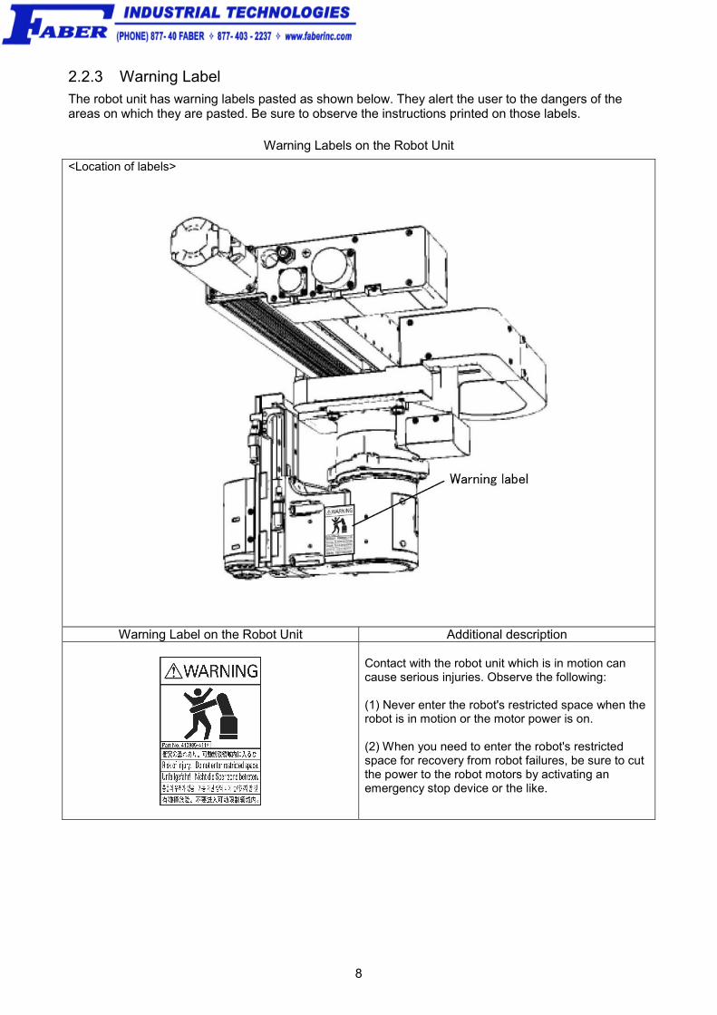
2.2.3 Warning Label The robot unit has warning labels pasted as shown below. They alert the user to the dangers of the areas on which they are pasted. Be sure to observe the instructions printed on those labels.
Warning Labels on the Robot Unit
<Location of labels>
Warning Label on the Robot Unit Additional description
Contact with the robot unit which is in motion can cause serious injuries. Observe the following: (1) Never enter the robot's restricted space when the robot is in motion or the motor power is on. (2) When you need to enter the robot's restricted space for recovery from robot failures, be sure to cut the power to the robot motors by activating an emergency stop device or the like.

Chapter 2 Configuration of the Robot System
9
2.3 Names of the Robot Controller Components The figure below shows the names of the robot controller components. Note: For warning and caution labels pasted on the controller, refer to the RC7M CONTROLLER
MANUAL.
Connectors for XR-G Series
Connector No.
Marking Name
CN1 RS-232C Serial interface connector CN2 USB USB connector (2 lines) CN3 PENDANT Teach pendant connector CN4 LAN Ethernet connector CN5 Mini I/O I/O connector CN6 INPUT AC Power supply connector CN7 MOTOR Motor connector CN9 HAND I/O HAND I/O connector CN10 SAFETY I/O SAFETY I/O connector (Only for global type)

10
Chapter3 Specifications of the Robot Unit
3.1 Robot Specifications
The table below lists the specifications of the XR-G series robots.
Robot Unit Specifications of the XR-G Series

Chapter 3 Specifications of the Robot Unit
11
3.2 Outer Dimension and Workable Space of the Robot Unit
The outer dimensions and workable space of the XR-G series are shown on this and the following pages.
Outer Dimensions and Workable Space of the XR-4341*G

12
(mm)L1(X-axis stroke) Model L2 L3 L4 L5 L6 L7 L8 L9 L10
760 XR-437**GM 1101 1239.1 791.2 70.2 1171.2 1361.2 6X150=900 450 14
1060 XR-43A**GM 1401 1539.1 913.7 42.7 1443.7 1633.7 8X150=1200 600 18
R1(R-axis arm length) Model R2 R3
200 XR-43*1*GM 195.6 107.7
250 XR-43*2*GM 244.6 157.7
300 XR-43*3*GM 293.4 207.7
Z(Z-axis stroke) Model
135 XR-43**1GM
200 XR-43**2GM
Outer Dimensions and Workable Space of the XR-437**G and XR-43A**G

Chapter 3 Specifications of the Robot Unit
13
3.3 Figures of XR-G series robot The XR-G series of robots takes two different shoulder figures--RIGHTY and LEFTY, according to the angle of R axis.
Shoulder Figure The coverage of the arm is divided into RIGHTY and LEFTY as shown below.

14
Restricted Space Determined by Mechanical Ends for Each Figure The restricted space of each figure differs depending upon the mechanical end position on the R axis.
The illustrations below are viewed from the top of the XR-G series.
(*) The restricted space narrows by 5 to 7 mm in the direction of Y axis.

Chapter 3 Specifications of the Robot Unit
15
Notes on making palletizing programs Palletizing programs need to be created so that the whole areas of pallets are within the restricted space of a figure since the XR-G cannot change the figure during palletizing.
In teaching also, be sure to teach the four corners of each pallet in the same figure.
Workaround for pallets that cannot be arranged for one figure When it is impossible to arrange a pallet for one figure, as a workaround, separate the pallet into two and access each in each figure to avoid an error.

16
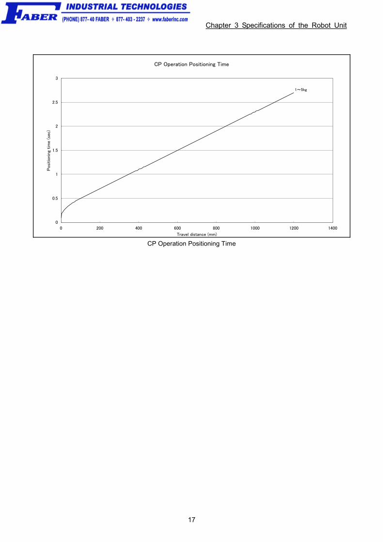
3.4 Robot Positioning Time
Positioning time for the XR-G series
1. The graphs given on the following pages show the positioning times used to calculate the cycle time. See Chapter 6 Appendix for operating time of each axis.
2. Positioning time refers to the time length required from the start of robot operation to the arrival at the target positioning point.
3. After the robot moves to and passes the target positioning point, vibration will be dampened and the robot will be positioned at the target positioning point as shown in the figure below. This vibration dampening time is not considered in those graphs.
Caution (1) The vibration dampening time depends on factors such as
the weight of the hand. If the robot is to be used in such a way that it overshoots or if the vibration damping time is of great concern, test the robot carefully beforehand.
(2) If acceleration begins before residual vibration of the robot
stops, an overcurrent error (code starts from ERROR6120; the first digit represents the axis number) may be displayed. In this case, take one of the following measures:
• Lower the deceleration of the preceding operation with a DECEL command to reduce residual vibration.
• Keep the robot on standby with a DELAY command until residual vibration stops.
• Lower acceleration with an ACCEL command.
(3) Operate the robot with the optimum payload setting in accordance with the hand weight and workpiece weight. If not, a robot failure may result.
Vibration Dampening Time
Chapter 3 Specifications of the Robot Unit
17
CP Operation Positioning Time
0
0.5
1
1.5
2
2.5
3
0 200 400 600 800 1000 1200 1400
Travel distance (mm)
Posi
tioni
ng t
ime
(sec
)
1~5kg
CP Operation Positioning Time

18
3.5 Electrical Wiring and Air Piping of the Robot Unit
Make electrical wiring and air piping of the hand or tool to be attached to the arm end, referring to the example given below. Use robot instrumentation cables (manufactured by Daikyo Denshi) or equivalent for electrical wiring.
Caution: - Supply dry air filtered through an air filter (Recommended filtration rating: 5 μm or below).
- Before piping, blow the air tube out with dry air to clean out the inside (flushing); otherwise, any chips, cutting oil, dust or dirt remaining in the air tube may result in a damaged valve.
- Do not pass wires or pipes other than those provided by DENSO through the cable bear of the 1st axis. Doing so may break or damage them.
3.5.1 Air Piping and Signal Wiring
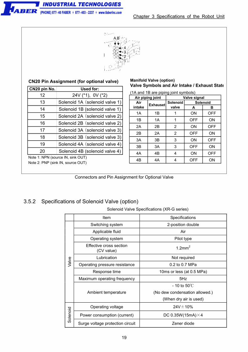
The XR-G series robot is equipped with 10 signal lines and an air pipe (φ8) in it. Manifold valve with 4 systems (φ4x8) is available as option.
Note 1: Pins #1 to #10 on CN21 and those on CN20 are connected with each other. The allowable current per line is 1A. Note 2: Use the attached connector sets for CN20 and CN21.
Connector set part No. Part No. Model and part name Appearance
410877-0170 SRCN6A25-24S(round type connector)
(for CN20) Japan Aviation Electronics Industry Ltd.
410877-0180 JMLP1610M(L type plug connector)
(for CN21) DDK Electronics, Inc.
410889-0030
Signal Wiring, Air Piping and Connectors of the Robot Unit
Chapter 3 Specifications of the Robot Unit
19
A B
4321
CN20 Pin Assignment (for optional valve)
CN20 pin No. Used for:
12 24V (*1), 0V (*2)
13 Solenoid 1A (solenoid valve 1)
14 Solenoid 1B (solenoid valve 1)
15 Solenoid 2A (solenoid valve 2)
16 Solenoid 2B (solenoid valve 2)
17 Solenoid 3A (solenoid valve 3)
18 Solenoid 3B (solenoid valve 3)
19 Solenoid 4A (solenoid valve 4)
20 Solenoid 4B (solenoid valve 4)Note 1: NPN (source IN, sink OUT)
Note 2: PNP (sink IN, source OUT)
Manifold Valve (option)Valve Symbols and Air Intake / Exhaust State
(1A and 1B are piping joint symbols)Air piping joint Valve signal
SolenoidA B
1A 1B 1 ON OFF
1B 1A 1 OFF ON
2A 2B 2 ON OFF
2B 2A 2 OFF ON
3A 3B 3 ON OFF
3B 3A 3 OFF ON
4A 4B 4 ON OFF
4B 4A 4 OFF ON
Airintake
ExhausetSolenoid
valve
Connectors and Pin Assignment for Optional Valve
3.5.2 Specifications of Solenoid Valve (option) Solenoid Valve Specifications (XR-G series)
Item Specifications
Switching system 2-position double
Applicable fluid Air
Operating system Pilot type
Effective cross section (CV value)
1.2mm2
Lubrication Not required
Operating pressure resistance 0.2 to 0.7 MPa
Response time 10ms or less (at 0.5 MPa)
Maximum operating frequency 5Hz
Val
ve
Ambient temperature
- 10 to 50℃
(No dew condensation allowed.)
(When dry air is used)
Operating voltage 24V±10%
Power consumption (current) DC 0.35W(15mA)×4
Sol
eno
id
Surge voltage protection circuit Zener diode

20
3.5.3 Mounting the Optional Valve
Mount the optional valve using the procedure given below.
Caution: - Supply dry air filtered through an air filter (Recommended filtration rating: 5 μm or below).
- Before piping, blow the air tube out with dry air to clean out the inside (flushing); otherwise, any chips, cutting oil, dust or dirt remaining in the air tube may result in a damaged valve.
4STEP 1 Peel the seal off the cover. Remove the four hexagonal socket-head bolts (M4) to take off the cover.
4STEP 2 Secure the optional valve to the cover with two bolts (M4). Tightening torque: 3.7 0.7 N・m

Chapter 3 Specifications of the Robot Unit
21
4STEP 3 Connect the red and blue connectors and the air tube to the optional valve.
4STEP 4 Mount the cover combined with the optional valve to the robot unit, taking care not to squeeze the wires or air tube. Make sure that the air tube is not folded. Tightening torque: 3.7 0.7 N・m

22
3.5.4 Original Thread Holes for Wiring and Piping
Original Thread Holes for Wiring and Piping (XR-G Series)

Chapter 3 Specifications of the Robot Unit
23
3.5.5 Notes for Signal Cabling and Air Piping
Do not fix optional cable or piping together with the existing cable for T-axis. Doing so may break the T-axis cable.
NOTE: Maintenance and inspection of the robot unit sometimes requires removing and installing the covers. Mount the stays for wiring and piping so that they will not interfere with removal/installation of the covers.
Existing Cable for T-axis

24
3.5.6 Installing Hand Control Cabling Kit (Optional)
Hand Control Cabling Kit for XR-G series (Part No. 410879-0470) is available.
Install the cable next to the existing cable, referring to the instructions below.
Note: Fix the cable, taking care not to pull, fold or loosen it.
Use the hand control cable (Part No. 410870-3350) to replace the cable.
Hand Control Cabling Kit Installation Drawing

Chapter 3 Specifications of the Robot Unit
25
3.6 Engineering-design Notes for Robot Hands
Design a robot hand so that it will satisfy conditions (1) to (3) described below.
Caution: Strictly observe these engineering-design notes. Otherwise, the
clamped sections of the robot unit will become loose, rattle or be
out of position. In the worst case, the mechanical parts of the
robot unit and the robot controller may be damaged.
(1) Mass of hand
The total mass of a hand (including workpiece) should be less than the maximum allowable payload of the robot. Be sure to include the mass of wiring and piping used for hands.
Total mass of hand ≤ Maximum allowable payload (incl. workpiece)
NOTE: The maximum allowable payload refers to a mass of payload that you have preset.
(2) Center of gravity of hand
The center of gravity of a hand (including workpiece) should be located within the range specified in the figure below.
Maximum allowable moment of inertia: 0.05kgm2
Allowable Range of Center of Gravity Position of Hand

26
(3) Moment of inertia around the T-axis
The moment of inertia of a hand (including workpiece) around the T-axis should be less than the maximum allowable moment of inertia around the T-axis of the robot.
Moment of inertia of hand
around the T-axis (incl. workpiece)
≦ Maximum allowable
moment of inertia
(XR-G series: 0.05kgm2)
Calculate the moment of inertia around the T-axis, referring to the table on the next page.

Chapter 3 Specifications of the Robot Unit
27
Moment-of-inertia Formulas
1. Cylinder (1)
(Axis of rotation = Center axis)
4. Sphere
(Axis of rotation = Center axis)
2. Cylinder (2)
(The axis of rotation passes through the center of gravity.)
5. Center of gravity is not on the axis of ratation.
3. Rectangular parallelepiped
(The axis of rotation passes through the center of gravity.)
I : Moment of inertia (kgm2)
m : Mass (kg)
r : Radius (m)
a,b,c, L : Length (m)
Calculation example : When calculating the moment of inertia of a complicated shape, divide it into simpleparts as much as possible for easier calculations.
As shown in the figure below, divide the hand into three parts ((1), (2), (3)).
Calculation Example of Moment of Inertia of Hand around the T-axis
(1) 0.19 kg
(2) 0.123 kg
(3) 0.98 kg
Moment of inertia around T-axis of (1): I1 (from 3 and 5 in the above table)
Moment of inertia around T-axis of (2): I2 (from 1 and 5 in the above table)
Moment of inertia around T-axis of (3): I3 (from 1 and 5 in the above table)
Moment of inertia of entire hand around T-axis: I
Center of robot flange
28
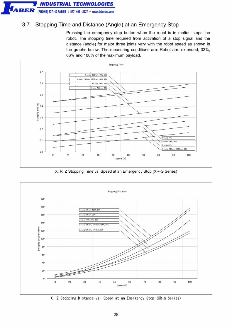
3.7 Stopping Time and Distance (Angle) at an Emergency Stop
Pressing the emergency stop button when the robot is in motion stops the robot. The stopping time required from activation of a stop signal and the distance (angle) for major three joints vary with the robot speed as shown in the graphs below. The measuring conditions are: Robot arm extended, 33%, 66% and 100% of the maximum payload.
Stopping Time
0.0
0.1
0.2
0.3
0.4
0.5
0.6
0.7
10 20 30 40 50 60 70 80 90 100
Speed (%)
Sto
ppin
g tim
e (s)
X-axis: 450mm 33%
X-axis: 450mm 100%, 66%
X-axis: 760mm, 1060mm 100%, 66%
X-axis: 760mm, 1060mm 33%
R-axis 100%, 66%
R-axis 33%
Z-axis 33%
Z-axis 100%, 66%
X, R, Z Stopping Time vs. Speed at an Emergency Stop (XR-G Series)
Stopping Distance
0
20
40
60
80
100
120
140
160
180
200
10 20 30 40 50 60 70 80 90 100
Speed (%)
Sto
ppin
g dis
tance (m
m)
X-axis:450mm 100%, 66%
X-axis:450mm 33%
Z-axis 100%, 66%, 33%
X-axis:760mm, 1060mm 100%, 66%
X-axis:760mm, 1060mm 33%
X, Z Stopping Distance vs. Speed at an Emergency Stop (XR-G Series)

Chapter 3 Specifications of the Robot Unit
29
Stopping Angle
0
10
20
30
40
50
60
70
80
10 20 30 40 50 60 70 80 90 100
Speed (%)
Sto
ppin
g A
ngl
e (deg)
R-axis 33%
R-axis 100% , 66%
R-axis Stopping Angle vs. Speed at an Emergency Stop (XR-G Series)

30
Chapter4 Robot Controller Specifications
4.1 Specifications The table below lists the specifications of the robot controllers for XR-G series.
RC7M Controller Specifications (XR-G Series) (1)
Item Specifications
Applicable robot Integrated compact type (XR-G)
Model RC7M-XRG4BA-**
Control system PTP, CP 3-dimensional linear, 3-dimensional circular
No. of controllable axes Up to four axes simultaneously
Drive system All axes: all digital AC servo
Language used DENSO robot language (conforming to SLIM)
Memory capacity 3.25MB (equivalent to 10,000 steps, or 30,000 points)
Teaching system 1) Remote teaching 2) Numerical input (MDI)
Mini I/O Input signals: 8 user open points + 11 fixed system points Output signals: 8 user open points + 14 fixed system points (Note: In global type, some fixed system points are not used.) Standard
I/O HAND I/O
Input signals: 8 user open points
Output signals: 8 user open points
SAFETY I/O (Only for Global type)
Input signals: 6 fixed system points
Output signals: 5 fixed system points
2 boards Input signals: Additional 80 user open points
Output signals: Additional 96 user open points Parallel I/O board
(option) 1 board Input signals: Additional 40 user open points
Output signals: Additional 48 user open points
Master & slave
Input signals: 1024 points (Master) + 256 points (Slave)
Output signals: 1024 points (Master) + 256 points (Slave)
Master Input signals: 1024 points
Output signals: 1024 points
DeviceNet board
(option)
Slave Input signals: 256 points
Output signals: 256 points
External signals (I/O)
CC- Link (option)
Slave Input signals: 384 points Output signals: 384 points(including remote registers RWw and RWr)
External communication
RS-232C: 1 line
Ethernet: 1 line
USB: 2 lines (flash memory drive available)
Extension slot 3 (For an optional board)
Self-diagnosis function Overrun, servo error, memory error, input error, etc.
Timer function 0.02 to 10sec. (in units of 1/60 sec.)
Error display Error codes will be issued to the external I/O. Error messages will be displayed in English on the teach pendant (option) Error codes will be displayed on the mini pendant (option)

Chapter 4 Robot Controller Specifications
31
RC7M Controller Specifications (XR-G Series) (2)
Item Specification
Motor & encoder cable (option)
2m, 4m, 6m, 12m, 20m (Standard type)
I/O cable (option)
8m, 15m (For Mini I/O, HAND I/O, Optional board for parallel I/O and SAFETY I/O)
Cables
Power cable 5m
Environmental conditions
(in operation)
Temperature: 0 to 40℃
Humidity: 90% RH or less (no condensation allowed)
Power source 3-phase: 200VAC-15% to 230VAC+10%, 50/60Hz, 1.8KVA Single-phase: 230VAC-10% to 230VAC+10%, 50/60Hz, 1.8KVA
Degree of protection IP20
Weight
Standard type: approx. 17 kg
Global type with safety board: approx. 18kg
Global type with safety box: approx. 21kg
Cautions for Use of the Robot Controller
WARNING ・ DO NOT touch fins. Their hot surfaces may cause severe burns. ・ DO NOT insert fingers or foreign objects into openings. Doing so may cause bodily injury. ・ Before opening the controller cover and accessing the inside of the controller for
maintenance, be sure to turn off the power switch, disconnect the power cable, and wait 3 minutes or more. This is for protecting you from electric shock.
・ DO NOT connect or disconnect connector to/from the controller when the power is applied. Doing so may cause electric shock or controller failure.
CAUTION IN INSTALLATION
・ This controller does not meet dust-proof, splash-proof or explosion-proof specifications. ・ Read the user's manuals before installation. ・ Do not place anything on the controller or apply impact.

32
4.2 Outer Dimensions
Figure below shows the outer dimensions of the robot controller.
Outer Dimensions of RC7M Robot Controller

Chapter 4 Robot Controller Specifications
33
4.3 Controller Setting Table
The controller setting table given in Figure below is attached to the controller. It shows the software version, the next replacement dates of the memory backup battery and encoder backup battery, etc.
<Content THE SETPRM LIST> SOFTWARE Ver. The version of the main software for the controller is entered. DATE OF RENEWING BAT.
The next replacement dates of the memory backup battery and encoder backup battery are entered.
TYPE The model of the robot system is entered. *The model name of the robot system is coded as shown on the next page.
SUBASSEMBLY The type and position of the controller IPM board are described.
34
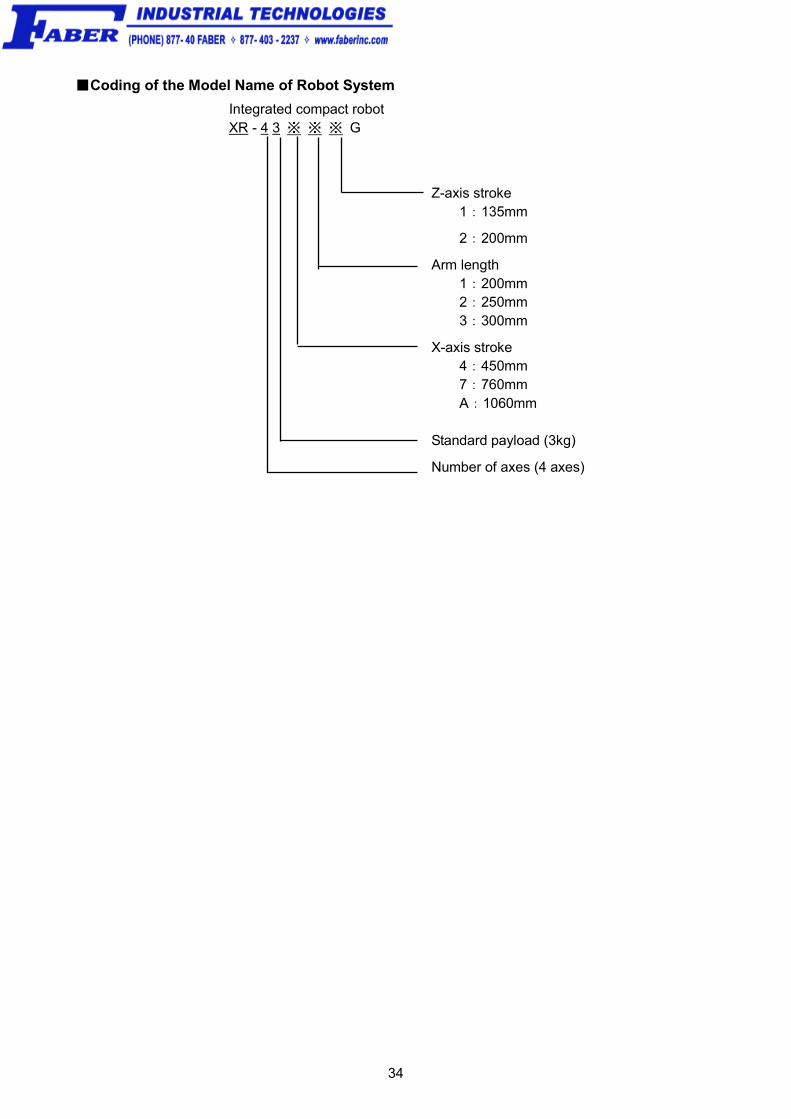
■Coding of the Model Name of Robot System
Integrated compact robot XR - 4 3 ※ ※ ※ G
Z-axis stroke 1:135mm
2:200mm
Arm length 1:200mm 2:250mm 3:300mm
X-axis stroke 4:450mm 7:760mm A:1060mm Standard payload (3kg)
Number of axes (4 axes)

Chapter5 Warranty
35
Chapter5 Warranty
DENSO manufactures robots under strict quality control. In case of failure, we warrant the robot under the following conditions:
Warranty Period
The warranty shall be effective for one year from the date of purchase.
Warranty Coverage
DENSO shall repair the robot free of charge when a failure occurs and is attributable to the design, manufacture or material of the robot within the warranty period in spite of proper use.
Items Not Covered
Failures, which arise from one of the following, shall not be covered by the warranty even if the robot is under warranty:
(1) Failures caused by improper repair, modification, transfer or handling by you or a third party;
(2) Failures caused by the use of a part or oil/fat other than those specified by
DENSO;
(3) Failures caused by a fire, salt damage, earthquake, storm/flood or other acts of God;
(4) Failures caused by the use of the robot in an environment other than the environment specified by DENSO, such as dust and water ingress;
(5) Failures caused by a worn-out consumable, such as a fan filter;
(6) Failures caused by improper performance or non-performance of lubrication, maintenance or inspections stated in this owner's manual; and
(7) Damages other than the robot repair costs.

36
Chapter6 Appendix
6.1 Operating time of each axis
X-axis Positioning Time
0
0.2
0.4
0.6
0.8
1
1.2
0 200 400 600 800 1000
Travel distance (mm)
Posi
tioni
ng t
ime
(sec
)
X:1060mm
X:760mm
X:450mm
X-axis Positioning Time
R-axis Positioning Time R:200mm
0
0.2
0.4
0.6
0.8
1
1.2
0 50 100 150 200 250 300 350 400
Travel distance (deg)
Posi
tioni
ng t
ime
(sec
)
5kg
1kg
R-axis Positioning Time R:200mm

Chapter 6 Appendix
37
R-axis Positioning Time R:250mm
0
0.2
0.4
0.6
0.8
1
1.2
1.4
0 50 100 150 200 250 300 350 400
Travel distance (deg)
Posi
tioni
ng t
ime
(sec
)
5kg
1kg
R-axis Positioning Time R:250mm
R-axis Positioning Time R:300mm
0
0.2
0.4
0.6
0.8
1
1.2
1.4
1.6
0 50 100 150 200 250 300 350 400
Travel distance (deg)
Posi
tionin
g tim
e (
sec)
5kg
1kg
R-axis Positioning Time R:300mm

38
Z-axis Positioning Time R:200mm
0
0.1
0.2
0.3
0.4
0.5
0.6
0 20 40 60 80 100 120 140 160 180 200
Travel distance (mm)
Posi
tioni
ng t
ime
(sec
)
5kg
1kg
Z-axis Positioning Time R:200mm
Z-axis Positioning Time R:250mm
0
0.1
0.2
0.3
0.4
0.5
0.6
0 20 40 60 80 100 120 140 160 180 200
Travel distance (mm)
Posi
tioni
ng t
ime
(sec
)
5kg
1kg
Z-axis Positioning Time R:250mm

Chapter 6 Appendix
39
Z-axis Positioning Time R:300mm
0
0.1
0.2
0.3
0.4
0.5
0.6
0 20 40 60 80 100 120 140 160 180 200
Travel distance (mm)
Posi
tionin
g tim
e (se
c)
5kg
1kg
Z-axis Positioning Time R:300mm
T-axis Positioning Time
0
0.2
0.4
0.6
0.8
1
1.2
0 50 100 150 200 250 300 350
Travel distance (deg)
Posi
tioni
ng t
ime
(sec
)
5kg
4kg
3kg
~2kg
T-axis Positioning Time

40
6.2 Conformity with Standards by Robot Model For information on conformity with standards, refer to "Conformity with Standards by Robot Model" in the Additional Information section of the RC7M controller manual pack CD SUPPLEMENT.

Integrated compact robot XR-G SERIES
GENERAL INFORMATION ABOUT ROBOT First Edition March 2008 Sixth Edition April 2011 Seventh Edition October 2011 DENSO WAVE INCORPORATED
The purpose of this manual is to provide accurate information in the handling and operating of the robot. Please feel free to send your comments regarding any errors or omissions you may have found, or any suggestions you may have for generally improving the manual.
In no event will DENSO WAVE INCORPORATED be liable for any direct or indirect damages resulting from the application of the information in this manual.
10N**C