Cisco IOS XR Routing Configuration Guide for the … IOS XR Routing Configuration Guide for the...
564
Cisco IOS XR Routing Configuration Guide for the Cisco XR 12000 Series Router, Release 4.0 Americas Headquarters Cisco Systems, Inc. 170 West Tasman Drive San Jose, CA 95134-1706 USA http://www.cisco.com Tel: 408 526-4000 800 553-NETS (6387) Fax: 408 527-0883 Text Part Number: OL-23246-02
Transcript of Cisco IOS XR Routing Configuration Guide for the … IOS XR Routing Configuration Guide for the...

Cisco IOS XR Routing Configuration Guide for the Cisco XR 12000Series Router, Release 4.0
Americas HeadquartersCisco Systems, Inc.170 West Tasman DriveSan Jose, CA 95134-1706USAhttp://www.cisco.comTel: 408 526-4000 800 553-NETS (6387)Fax: 408 527-0883
Text Part Number: OL-23246-02

THE SPECIFICATIONS AND INFORMATION REGARDING THE PRODUCTS IN THIS MANUAL ARE SUBJECT TO CHANGE WITHOUT NOTICE. ALL STATEMENTS,INFORMATION, AND RECOMMENDATIONS IN THIS MANUAL ARE BELIEVED TO BE ACCURATE BUT ARE PRESENTED WITHOUT WARRANTY OF ANY KIND,EXPRESS OR IMPLIED. USERS MUST TAKE FULL RESPONSIBILITY FOR THEIR APPLICATION OF ANY PRODUCTS.
THE SOFTWARE LICENSE AND LIMITEDWARRANTY FOR THE ACCOMPANYING PRODUCT ARE SET FORTH IN THE INFORMATION PACKET THAT SHIPPED WITHTHE PRODUCT AND ARE INCORPORATED HEREIN BY THIS REFERENCE. IF YOU ARE UNABLE TO LOCATE THE SOFTWARE LICENSE OR LIMITED WARRANTY,CONTACT YOUR CISCO REPRESENTATIVE FOR A COPY.
The Cisco implementation of TCP header compression is an adaptation of a program developed by the University of California, Berkeley (UCB) as part of UCB's public domain versionof the UNIX operating system. All rights reserved. Copyright © 1981, Regents of the University of California.
NOTWITHSTANDINGANYOTHERWARRANTYHEREIN, ALL DOCUMENT FILES AND SOFTWARE OF THESE SUPPLIERS ARE PROVIDED “AS IS"WITH ALL FAULTS.CISCO AND THE ABOVE-NAMED SUPPLIERS DISCLAIM ALL WARRANTIES, EXPRESSED OR IMPLIED, INCLUDING, WITHOUT LIMITATION, THOSE OFMERCHANTABILITY, FITNESS FORA PARTICULAR PURPOSEANDNONINFRINGEMENTORARISING FROMACOURSEOFDEALING, USAGE, OR TRADE PRACTICE.
IN NO EVENT SHALL CISCO OR ITS SUPPLIERS BE LIABLE FOR ANY INDIRECT, SPECIAL, CONSEQUENTIAL, OR INCIDENTAL DAMAGES, INCLUDING, WITHOUTLIMITATION, LOST PROFITS OR LOSS OR DAMAGE TO DATA ARISING OUT OF THE USE OR INABILITY TO USE THIS MANUAL, EVEN IF CISCO OR ITS SUPPLIERSHAVE BEEN ADVISED OF THE POSSIBILITY OF SUCH DAMAGES.
Any Internet Protocol (IP) addresses used in this document are not intended to be actual addresses. Any examples, command display output, and figures included in the document are shownfor illustrative purposes only. Any use of actual IP addresses in illustrative content is unintentional and coincidental.
Cisco and the Cisco logo are trademarks or registered trademarks of Cisco and/or its affiliates in the U.S. and other countries. To view a list of Cisco trademarks, go to this URL: http://www.cisco.com/go/trademarks. Third-party trademarks mentioned are the property of their respective owners. The use of the word partner does not imply a partnershiprelationship between Cisco and any other company. (1110R)
© 2013 Cisco Systems, Inc. All rights reserved.
C O N T E N T S
P r e f a c e Preface xxi
Changes to This Document xxi
Obtaining Documentation and Submitting a Service Request xxi
C H A P T E R 1 Implementing BGP 1
Prerequisites for Implementing BGP 3
Information About Implementing BGP 3
BGP Functional Overview 3
BGP Router Identifier 4
BGP Default Limits 5
BGP Next Hop Tracking 5
Next Hop as the IPv6 Address of Peering Interface 6
Scoped IPv4/VPNv4 Table Walk 7
Reordered Address Family Processing 7
New Thread for Next-Hop Processing 7
show, clear, and debug Commands 7
Autonomous System Number Formats in BGP 8
2-byte Autonomous System Number Format 8
4-byte Autonomous System Number Format 8
as-format Command 8
BGP Configuration 8
Configuration Modes 9
Router Configuration Mode 9
Router Address Family Configuration Mode 9
Neighbor Configuration Mode 9
Neighbor Address Family Configuration Mode 9
VRF Configuration Mode 9
Cisco IOS XR Routing Configuration Guide for the Cisco XR 12000 Series Router, Release 4.0 OL-23246-02 iii

VRF Address Family Configuration Mode 10
VRF Neighbor Configuration Mode 10
VRF Neighbor Address Family Configuration Mode 10
VPNv4 Address Family Configuration Mode 10
VPNv6 Address Family Configuration Mode 10
L2VPN Address Family Configuration Mode 10
Neighbor Submode 11
Configuration Templates 12
Template Inheritance Rules 13
Viewing Inherited Configurations 17
show bgp neighbors 17
show bgp af-group 18
show bgp session-group 19
show bgp neighbor-group 20
No Default Address Family 21
Routing Policy Enforcement 22
Table Policy 23
Update Groups 24
BGP Update Generation and Update Groups 24
BGP Update Group 24
BGP Cost Community 24
How BGP Cost Community Influences the Best Path Selection Process 25
Cost Community Support for Aggregate Routes and Multipaths 26
Influencing Route Preference in a Multiexit IGP Network 27
BGP Cost Community Support for EIGRP MPLS VPN PE-CE with Back-door
Links 28
Adding Routes to the Routing Information Base 29
BGP Best Path Algorithm 29
Comparing Pairs of Paths 30
Order of Comparisons 32
Best Path Change Suppression 32
Administrative Distance 33
Multiprotocol BGP 34
Route Dampening 36
Minimizing Flapping 37
Cisco IOS XR Routing Configuration Guide for the Cisco XR 12000 Series Router, Release 4.0iv OL-23246-02
Contents
BGP Routing Domain Confederation 37
BGP Route Reflectors 37
Default Address Family for show Commands 41
Distributed BGP 41
MPLS VPN Carrier Supporting Carrier 42
BGP Keychains 43
IPv6/IPv6 VPN Provider Edge Transport over MPLS 43
IPv6 Provider Edge Multipath 44
VPNv4/VPNv6 over the IP Core Using L2TPv3 Tunnels 44
BGP Multicast VPN 45
BGP Nonstop Routing 46
BGP Best-External Path 48
BGP Prefix Independent Convergence Unipath Primary/Backup 49
BGP Local Label Retention 49
Command Line Interface (CLI) Consistency for BGP Commands 50
BGP Additional Paths 50
iBGP Multipath Load Sharing 50
How to Implement BGP on Cisco IOS XR Software 51
Enabling BGP Routing 51
Configuring a Routing Domain Confederation for BGP 55
Resetting an eBGP Session Immediately Upon Link Failure 57
Logging Neighbor Changes 57
Adjusting BGP Timers 57
Changing the BGP Default Local Preference Value 59
Configuring the MED Metric for BGP 60
Configuring BGP Weights 61
Tuning the BGP Best-Path Calculation 63
Indicating BGP Back-door Routes 65
Configuring Aggregate Addresses 67
Redistributing iBGP Routes into IGP 69
Redistributing Prefixes into Multiprotocol BGP 70
Configuring BGP Route Dampening 73
Applying Policy When Updating the Routing Table 79
Setting BGP Administrative Distance 81
Configuring a BGP Neighbor Group and Neighbors 82
Cisco IOS XR Routing Configuration Guide for the Cisco XR 12000 Series Router, Release 4.0 OL-23246-02 v
Contents
Configuring a Route Reflector for BGP 85
Configuring BGP Route Filtering by Route Policy 87
Configuring BGP Next-Hop Trigger Delay 90
Disabling Next-Hop Processing on BGP Updates 91
Configuring BGP Community and Extended-Community Advertisements 93
Configuring the BGP Cost Community 96
Configuring Software to Store Updates from a Neighbor 100
Configuring Distributed BGP 103
Configuring a VPN Routing and Forwarding Instance in BGP 105
Defining Virtual Routing and Forwarding Tables in Provider Edge Routers 105
Configuring the Route Distinguisher 108
Configuring BGP to Advertise VRF Routes for Multicast VPN from PE to PE 109
Advertising VRF Routes for MVPNv4 from PE to PE 110
Advertising VRF Routes for MVPNv6 from PE to PE 115
Configuring PE-PE or PE-RR Interior BGP Sessions 120
Configuring Route Reflector to Hold Routes That Have a Defined Set of RT
Communities 123
Configuring BGP as a PE-CE Protocol 125
Redistribution of IGPs to BGP 129
Configuring Keychains for BGP 132
Configuring an MDT Address Family Session in BGP 134
Disabling a BGP Neighbor 139
Resetting Neighbors Using BGP Inbound Soft Reset 141
Resetting Neighbors Using BGP Outbound Soft Reset 142
Resetting Neighbors Using BGP Hard Reset 143
Clearing Caches, Tables, and Databases 144
Displaying System and Network Statistics 144
Displaying BGP Process Information 146
Monitoring BGP Update Groups 148
Configuring BGP Nonstop Routing 149
Configuring Best-External Path Advertisement 150
Installing Primary Backup Path for Prefix Independent Convergence (PIC) 152
Retaining Allocated Local Label for Primary Path 154
Configuring BGP Additional Paths 156
Configuring iBGP Multipath Load Sharing 158
Cisco IOS XR Routing Configuration Guide for the Cisco XR 12000 Series Router, Release 4.0vi OL-23246-02
Contents
Configuration Examples for Implementing BGP 160
Enabling BGP: Example 160
Displaying BGP Update Groups: Example 161
BGP Neighbor Configuration: Example 162
BGP Confederation: Example 162
BGP Route Reflector: Example 164
BGP MDT Address Family Configuration: Example 165
BGP Nonstop Routing Configuration: Example 165
Best-External Path Advertisement Configuration: Example 165
Primary Backup Path Installation: Example 166
Allocated Local Label Retention: Example 166
iBGP Multipath Loadsharing Configuration: Example 166
Configuring BGP Additional Paths: Example 166
Where to Go Next 167
Additional References 167
C H A P T E R 2 Implementing EIGRP 171
Prerequisites for Implementing EIGRP 172
Restrictions for Implementing EIGRP 172
Information About Implementing EIGRP 172
EIGRP Functional Overview 173
EIGRP Features 173
EIGRP Components 173
EIGRP Configuration Grouping 174
EIGRP Configuration Modes 175
EIGRP Interfaces 176
Redistribution for an EIGRP Process 176
Metric Weights for EIGRP Routing 176
Mismatched K Values 177
Goodbye Message 177
Percentage of Link Bandwidth Used for EIGRP Packets 178
Floating Summary Routes for an EIGRP Process 178
Split Horizon for an EIGRP Process 180
Adjustment of Hello Interval and Hold Time for an EIGRP Process 181
Stub Routing for an EIGRP Process 181
Cisco IOS XR Routing Configuration Guide for the Cisco XR 12000 Series Router, Release 4.0 OL-23246-02 vii
Contents
Route Policy Options for an EIGRP Process 182
EIGRP Layer 3 VPN PE-CE Site-of-Origin 183
Router Interoperation with the Site-of-Origin Extended Community 183
IPv6 and IPv6 VPN Provider Edge Support over MPLS and IP 184
EIGRP v4/v6 Authentication Using Keychain 184
How to Implement EIGRP 184
Enabling EIGRP Routing 184
Configuring Route Summarization for an EIGRP Process 187
Redistributing Routes for EIGRP 189
Creating a Route Policy and Attaching It to an EIGRP Process 191
Configuring Stub Routing for an EIGRP Process 194
Configuring EIGRP as a PE-CE Protocol 196
Redistributing BGP Routes into EIGRP 199
Monitoring EIGRP Routing 201
Configuring an EIGRP Authentication Keychain 204
Configuring an Authentication Keychain for an IPv4/IPv6 Interface on a Default
VRF 205
Configuring an Authentication Keychain for an IPv4/IPv6 Interface on a Nondefault
VRF 206
Configuration Examples for Implementing EIGRP 208
Configuring a Basic EIGRP Configuration: Example 208
Configuring an EIGRP Stub Operation: Example 209
Configuring an EIGRP PE-CE Configuration with Prefix-Limits: Example 209
Configuring an EIGRP Authentication Keychain: Example 210
Additional References 210
C H A P T E R 3 Implementing IS-IS 213
Prerequisites for Implementing IS-IS 215
Restrictions for Implementing IS-IS 215
Information About Implementing IS-IS 215
IS-IS Functional Overview 215
Key Features Supported in the Cisco IOS XR IS-IS Implementation 215
IS-IS Configuration Grouping 216
IS-IS Configuration Modes 216
Router Configuration Mode 216
Cisco IOS XR Routing Configuration Guide for the Cisco XR 12000 Series Router, Release 4.0viii OL-23246-02
Contents
Router Address Family Configuration Mode 216
Interface Configuration Mode 216
Interface Address Family Configuration Mode 217
IS-IS Interfaces 217
Multitopology Configuration 217
IPv6 Routing and Configuring IPv6 Addressing 217
Limit LSP Flooding 218
Flood Blocking on Specific Interfaces 218
Mesh Group Configuration 218
Maximum LSP Lifetime and Refresh Interval 218
Single-Topology IPv6 Support 219
Multitopology IPv6 Support 219
IS-IS Authentication 219
Nonstop Forwarding 220
Multi-Instance IS-IS 221
Multiprotocol Label Switching Traffic Engineering 221
Overload Bit on Router 221
Overload Bit Configuration During Multitopology Operation 221
IS-IS Overload Bit Avoidance 222
Default Routes 222
Attached Bit on an IS-IS Instance 222
IS-IS Support for Route Tags 223
Multicast-Intact Feature 223
Multicast Topology Support Using IS-IS 223
MPLS Label Distribution Protocol IGP Synchronization 224
MPLS LDP-IGP Synchronization Compatibility with LDP Graceful Restart 224
MPLS LDP-IGP Synchronization Compatibility with IGP Nonstop Forwarding 224
Label Distribution Protocol IGP Auto-configuration 224
MPLS TE Forwarding Adjacency 225
MPLS TE Interarea Tunnels 225
IP Fast Reroute 225
IS-IS Over GRE Interfaces 226
How to Implement IS-IS 226
Enabling IS-IS and Configuring Level 1 or Level 2 Routing 226
Configuring Single Topology for IS-IS 228
Cisco IOS XR Routing Configuration Guide for the Cisco XR 12000 Series Router, Release 4.0 OL-23246-02 ix
Contents
Configuring Multitopology Routing 234
Restrictions for Configuring Multitopology Routing 234
Information About Multitopology Routing 234
Configuring a Global Topology and Associating It with an Interface 234
Enabling an IS-IS Topology 236
Placing an Interface in a Topology in IS-IS 238
Configuring a Routing Policy 239
Configuring Multitopology for IS-IS 241
Controlling LSP Flooding for IS-IS 241
Configuring Nonstop Forwarding for IS-IS 245
Configuring Authentication for IS-IS 248
Configuring Keychains for IS-IS 250
Configuring MPLS Traffic Engineering for IS-IS 252
Tuning Adjacencies for IS-IS 254
Setting SPF Interval for a Single-Topology IPv4 and IPv6 Configuration 258
Customizing Routes for IS-IS 260
Configuring MPLS LDP IS-IS Synchronization 263
Enabling Multicast-Intact 265
Tagging IS-IS Interface Routes 267
Setting the Priority for Adding Prefixes to the RIB 269
Configuring IP/LDP Fast Reroute 271
Configuring IS-IS Overload Bit Avoidance 274
Configuration Examples for Implementing IS-IS 275
Configuring Single-Topology IS-IS for IPv6: Example 275
Configuring Multitopology IS-IS for IPv6: Example 275
Redistributing IS-IS Routes Between Multiple Instances: Example 275
Tagging Routes: Example 276
Configuring IS-IS Overload Bit Avoidance: Example 276
Where to Go Next 277
Additional References 277
C H A P T E R 4 Implementing OSPF 281
Prerequisites for Implementing OSPF 283
Information About Implementing OSPF 283
OSPF Functional Overview 284
Cisco IOS XR Routing Configuration Guide for the Cisco XR 12000 Series Router, Release 4.0x OL-23246-02
Contents
Key Features Supported in the Cisco IOS XR Software OSPF Implementation 285
Comparison of Cisco IOS XR Software OSPFv3 and OSPFv2 285
OSPF Hierarchical CLI and CLI Inheritance 286
OSPF Routing Components 286
Autonomous Systems 287
Areas 287
Backbone Area 288
Stub Area 288
Not-so-Stubby Area 288
Routers 288
Area Border Routers 288
Autonomous System Boundary Routers (ASBR) 289
Interior Routers 289
OSPF Process and Router ID 289
Supported OSPF Network Types 290
Route Authentication Methods for OSPF 290
Plain Text Authentication 290
MD5 Authentication 290
Authentication Strategies 290
Key Rollover 291
Neighbors and Adjacency for OSPF 291
Designated Router (DR) for OSPF 291
Default Route for OSPF 291
Link-State Advertisement Types for OSPF Version 2 292
Link-State Advertisement Types for OSPFv3 292
Virtual Link and Transit Area for OSPF 294
OSPFv2 Sham Link Support for MPLS VPN 294
OSPFv2 SPF Prefix Prioritization 296
Route Redistribution for OSPF 298
OSPF Shortest Path First Throttling 298
Nonstop Forwarding for OSPF Version 2 299
Graceful Restart for OSPFv3 299
Modes of Graceful Restart Operation 300
Restart Mode 300
Helper Mode 300
Cisco IOS XR Routing Configuration Guide for the Cisco XR 12000 Series Router, Release 4.0 OL-23246-02 xi
Contents
Graceful Restart Requirements and Restrictions 301
Warm Standby and Nonstop Routing for OSPF Version 2 302
Warm Standby for OSPF Version 3 302
Multicast-Intact Support for OSPF 302
Load Balancing in OSPF Version 2 and OSPFv3 303
Multi-Area Adjacency for OSPF Version 2 303
Label Distribution Protocol IGP Auto-configuration for OSPF 304
OSPF Authentication Message Digest Management 304
GTSM TTL Security Mechanism for OSPF 305
Path Computation Element for OSPFv2 305
OSPF Queue Tuning Parameters 305
OSPF IP Fast Reroute Loop Free Alternate 306
How to Implement OSPF 306
Enabling OSPF 306
Configuring Stub and Not-So-Stubby Area Types 309
Configuring Neighbors for Nonbroadcast Networks 312
Configuring Authentication at Different Hierarchical Levels for OSPF Version 2 317
Controlling the Frequency That the Same LSA Is Originated or Accepted for OSPF 321
Creating a Virtual Link with MD5 Authentication to Area 0 for OSPF 323
Examples 327
Summarizing Subnetwork LSAs on an OSPF ABR 328
Redistributing Routes from One IGP into OSPF 330
Configuring OSPF Shortest Path First Throttling 333
Examples 336
Configuring Nonstop Forwarding Specific to Cisco for OSPF Version 2 336
Configuring OSPF Version 2 for MPLS Traffic Engineering 339
Examples 342
Configuring OSPFv3 Graceful Restart 343
Displaying Information About Graceful Restart 345
Configuring an OSPFv2 Sham Link 346
Enabling Nonstop Routing for OSPFv2 350
Enabling Nonstop Routing for OSPFv3 351
Configuring OSPFv2 SPF Prefix Prioritization 352
Enabling Multicast-intact for OSPFv2 355
Associating Interfaces to a VRF 356
Cisco IOS XR Routing Configuration Guide for the Cisco XR 12000 Series Router, Release 4.0xii OL-23246-02
Contents
Configuring OSPF as a Provider Edge to Customer Edge (PE-CE) Protocol 358
Creating Multiple OSPF Instances (OSPF Process and a VRF) 361
Configuring Multi-area Adjacency 363
Configuring Label Distribution Protocol IGP Auto-configuration for OSPF 365
Configuring LDP IGP Synchronization: OSPF 367
Configuring Authentication Message Digest Management for OSPF 368
Examples 370
Configuring Generalized TTL Security Mechanism (GTSM) for OSPF 371
Examples 374
Verifying OSPF Configuration and Operation 374
Configuring OSPF Queue Tuning Parameters 377
Configuring IP Fast Reroute Loop-free Alternate 378
Enabling IPFRR LFA 378
Excluding an Interface From IP Fast Reroute Per-link Computation 380
Configuration Examples for Implementing OSPF 381
Cisco IOS XR Software for OSPF Version 2 Configuration: Example 381
CLI Inheritance and Precedence for OSPF Version 2: Example 382
MPLS TE for OSPF Version 2: Example 383
ABR with Summarization for OSPFv3: Example 384
ABR Stub Area for OSPFv3: Example 384
ABR Totally Stub Area for OSPFv3: Example 384
Configuring OSPFv2 SPF Prefix Prioritization: Example 384
Route Redistribution for OSPFv3: Example 385
Virtual Link Configured Through Area 1 for OSPFv3: Example 385
Virtual Link Configured with MD5 Authentication for OSPF Version 2: Example 386
VPN Backbone and Sham Link Configured for OSPF Version 2: Example 387
OSPF Queue Tuning Parameters Configuration: Example 388
Where to Go Next 388
Additional References 388
C H A P T E R 5 Implementing and Monitoring RIB 393
Prerequisites for Implementing RIB 394
Information About RIB Configuration 394
Overview of RIB 394
RIB Data Structures in BGP and Other Protocols 395
Cisco IOS XR Routing Configuration Guide for the Cisco XR 12000 Series Router, Release 4.0 OL-23246-02 xiii
Contents
RIB Administrative Distance 395
RIB Support for IPv4 and IPv6 396
RIB Statistics 396
IPv6 Provider Edge IPv6 and IPv6 VPN Provider Edge Transport over MPLS 396
RIB Quarantining 397
Flex-LSR Label Switch Processor 140 397
How to Deploy and Monitor RIB 397
Verifying RIB Configuration Using the Routing Table 398
Verifying Networking and Routing Problems 398
Disabling RIB Next-hop Dampening 400
Configuration Examples for RIB Monitoring 401
Output of show route Command: Example 401
Output of show route backup Command: Example 402
Output of show route best-local Command: Example 402
Output of show route connected Command: Example 402
Output of show route local Command: Example 403
Output of show route longer-prefixes Command: Example 403
Output of show route next-hop Command: Example 403
Where to Go Next 404
Additional References 404
C H A P T E R 6 Implementing RIP 407
Prerequisites for Implementing RIP 408
Information About Implementing RIP 408
RIP Functional Overview 408
Split Horizon for RIP 409
Route Timers for RIP 409
Route Redistribution for RIP 410
Default Administrative Distances for RIP 410
Routing Policy Options for RIP 411
Authentication Using Keychain in RIP 412
In-bound RIP Traffic on an Interface 412
Out-bound RIP Traffic on an Interface 413
How to Implement RIP 413
Enabling RIP 414
Cisco IOS XR Routing Configuration Guide for the Cisco XR 12000 Series Router, Release 4.0xiv OL-23246-02
Contents
Customizing RIP 416
Control Routing Information 418
Creating a Route Policy for RIP 421
Configuring RIP Authentication Keychain 423
Configuring RIP Authentication Keychain for IPv4 Interface on a Non-default VRF 423
Configuring RIP Authentication Keychain for IPv4 Interface on Default VRF 425
Configuration Examples for Implementing RIP 427
Configuring a Basic RIP Configuration: Example 427
Configuring RIP on the Provider Edge: Example 428
Adjusting RIP Timers for each VRF Instance: Example 428
Configuring Redistribution for RIP: Example 429
Configuring Route Policies for RIP: Example 429
Configuring Passive Interfaces and Explicit Neighbors for RIP: Example 430
Controlling RIP Routes: Example 430
Configuring RIP Authentication Keychain: Example 430
Additional References 431
C H A P T E R 7 Implementing Routing Policy 433
Prerequisites for Implementing Routing Policy 435
Restrictions for Implementing Routing Policy 435
Information About Implementing Routing Policy 435
Routing Policy Language 435
Routing Policy Language Overview 435
Routing Policy Language Structure 436
Names 436
Sets 436
as-path-set 437
community-set 438
extcommunity-set 439
prefix-set 442
rd-set 443
Routing Policy Language Components 444
Routing Policy Language Usage 444
Routing Policy Configuration Basics 446
Policy Definitions 446
Cisco IOS XR Routing Configuration Guide for the Cisco XR 12000 Series Router, Release 4.0 OL-23246-02 xv
Contents
Parameterization 447
Parameterization at Attach Points 448
Global Parameterization 448
Semantics of Policy Application 449
Boolean Operator Precedence 449
Multiple Modifications of the Same Attribute 449
When Attributes Are Modified 450
Default Drop Disposition 451
Control Flow 451
Policy Verification 452
Range Checking 452
Incomplete Policy and Set References 452
Attached Policy Modification 452
Verification of Attribute Comparisons and Actions 453
Policy Statements 453
Remark 453
Disposition 454
Action 455
If 456
Boolean Conditions 457
apply 458
Attach Points 458
BGP Policy Attach Points 459
Additional-Path 459
Aggregation 459
Dampening 460
Default Originate 461
Neighbor Export 461
Neighbor Import 462
Network 462
Redistribute 462
Show BGP 463
Table Policy 464
Import 465
Export 465
Cisco IOS XR Routing Configuration Guide for the Cisco XR 12000 Series Router, Release 4.0xvi OL-23246-02
Contents

Retain Route-Target 466
Allocate-Label 466
Neighbor-ORF 467
Next-hop 467
Clear-Policy 468
Debug 468
BGP Attributes and Operators 469
OSPF Policy Attach Points 485
Default-Information Originate 485
Redistribute 485
Area-in 486
Area-out 486
SPF Prefix-priority 487
OSPF Attributes and Operators 487
OSPFv3 Policy Attach Points 488
Default-Information Originate 488
Redistribute 488
OSPFv3 Attributes and Operators 489
IS-IS Policy Attach Points 489
Redistribute 490
Default-Information Originate 490
Inter-area-propagate 490
IS-IS Attributes and Operators 491
EIGRP Policy Attach Points 492
Default-Accept-In 492
Default-Accept-Out 492
Policy-In 492
Policy-Out 493
If-Policy-In 493
If-Policy-Out 493
Redistribute 493
EIGRP Attributes and Operators 494
RIP Policy Attach Points 495
Default-Information Originate 495
Redistribute 496
Cisco IOS XR Routing Configuration Guide for the Cisco XR 12000 Series Router, Release 4.0 OL-23246-02 xvii
Contents
Global-Inbound 496
Global-Outbound 496
Interface-Inbound 496
Interface-Outbound 496
RIP Attributes and Operators 497
PIM Policy Attach Points 498
rpf-topology 498
PIM Attributes and Operators 499
Attached Policy Modification 499
Nonattached Policy Modification 499
Editing Routing Policy Configuration Elements 500
Editing Routing Policy Configuration Elements Using the Nano Editor 500
Editing Routing Policy Configuration Elements Using the Emacs Editor 500
Editing Routing Policy Configuration Elements Using the Vim Editor 502
Editing Routing Policy Configuration Elements Using the CLI 502
How to Implement Routing Policy 502
Defining a Route Policy 502
Attaching a Routing Policy to a BGP Neighbor 503
Modifying a Routing Policy Using a Text Editor 505
Configuration Examples for Implementing Routing Policy 507
Routing Policy Definition: Example 507
Simple Inbound Policy: Example 507
Modular Inbound Policy: Example 508
Translating Cisco IOS Route Maps to Cisco IOS XR Routing Policy Language:
Example 509
Additional References 509
C H A P T E R 8 Implementing Static Routes 511
Prerequisites for Implementing Static Routes 512
Restrictions for Implementing Static Routes 512
Information About Implementing Static Routes 512
Static Route Functional Overview 513
Default Administrative Distance 513
Directly Connected Routes 514
Recursive Static Routes 514
Cisco IOS XR Routing Configuration Guide for the Cisco XR 12000 Series Router, Release 4.0xviii OL-23246-02
Contents
Fully Specified Static Routes 515
Floating Static Routes 515
Default VRF 515
IPv4 and IPv6 Static VRF Routes 515
IPv6/IPv6 VPN Provider Edge Transport over MPLS 516
How to Implement Static Routes 516
Configuring a Static Route 516
Configuring a Static Route Under Multicast SAFI 518
Configuring a Floating Static Route 520
Configuring Static Routes Between PE-CE Routers 521
Changing the Maximum Number of Allowable Static Routes 523
Associating a VRF with a Static Route 525
Configuration Examples 527
Configuring Traffic Discard: Example 527
Configuring a Fixed Default Route: Example 527
Configuring a Floating Static Route: Example 527
Configuring a Static Route Between PE-CE Routers: Example 528
Where to Go Next 528
Additional References 528
Cisco IOS XR Routing Configuration Guide for the Cisco XR 12000 Series Router, Release 4.0 OL-23246-02 xix
Contents

Cisco IOS XR Routing Configuration Guide for the Cisco XR 12000 Series Router, Release 4.0xx OL-23246-02
Contents
Preface
The Cisco IOS XR Routing Configuration Guide for the Cisco XR 12000 Series Router preface containsthese sections:
• Changes to This Document, page xxi
• Obtaining Documentation and Submitting a Service Request, page xxi
Changes to This DocumentTable 1 lists the technical changes made to this document since it was first printed.
Table 1: Changes to This Document
Change SummaryDateRevision
Updated with fast-reroute per-linkand fast-reroute per-prefixcomputation feature for Release4.0.1
December 2010OL-23246-02
Initial release of this document.September 2010OL-23246-01
Obtaining Documentation and Submitting a Service RequestFor information on obtaining documentation, submitting a service request, and gathering additional information,see the monthlyWhat's New in Cisco Product Documentation, which also lists all new and revised Ciscotechnical documentation, at:
http://www.cisco.com/en/US/docs/general/whatsnew/whatsnew.html
Subscribe to theWhat's New in Cisco Product Documentation as a Really Simple Syndication (RSS) feedand set content to be delivered directly to your desktop using a reader application. The RSS feeds are a freeservice and Cisco currently supports RSS version 2.0.
Cisco IOS XR Routing Configuration Guide for the Cisco XR 12000 Series Router, Release 4.0 OL-23246-02 xxi

Cisco IOS XR Routing Configuration Guide for the Cisco XR 12000 Series Router, Release 4.0xxii OL-23246-02
PrefaceObtaining Documentation and Submitting a Service Request
C H A P T E R 1Implementing BGP
Border Gateway Protocol (BGP) is an Exterior Gateway Protocol (EGP) that allows you to create loop-freeinterdomain routing between autonomous systems. An autonomous system is a set of routers under a singletechnical administration. Routers in an autonomous system can use multiple Interior Gateway Protocols(IGPs) to exchange routing information inside the autonomous system and an EGP to route packets outsidethe autonomous system.
This module provides the conceptual and configuration information for BGP on Cisco IOS XR software.
For more information about BGP on the Cisco IOS XR software and complete descriptions of the BGPcommands listed in this module, see Related Documents, on page 167 section of this module. To locatedocumentation for other commands that might appear while performing a configuration task, search onlinein the Cisco IOS XR software master command index.
Note
Feature History for Implementing BGP
ModificationRelease
This feature was introduced.Release 3.2
VPN routing and forwarding (VRF) support was added, includinginformation on VRF command modes and command syntax.
BGP cost community information was added.
Release 3.3.0
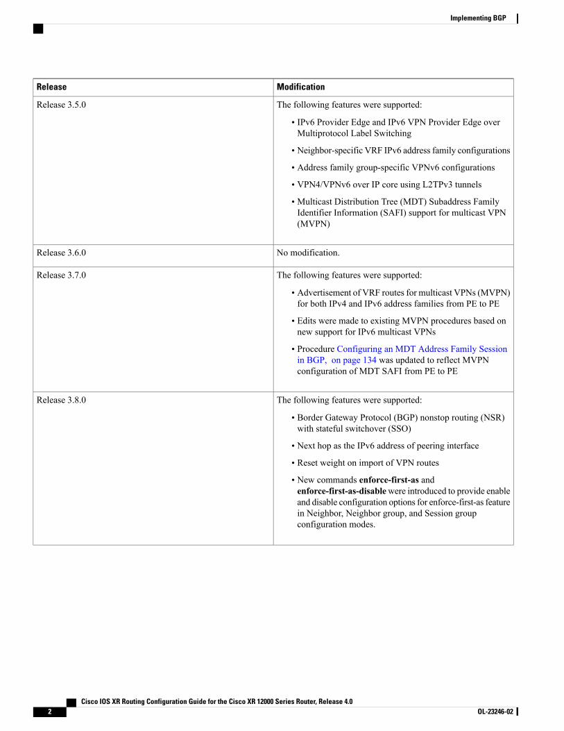
The following features were supported:
• Four-byte autonomous system (AS) number
• Carrier supporting carrier (CSC) for BGP was added. SeeCisco IOS XR Multiprotocol Label Switching ProtocolConfiguration Guide for information
• Key chains
Release 3.4.0
Cisco IOS XR Routing Configuration Guide for the Cisco XR 12000 Series Router, Release 4.0 OL-23246-02 1
ModificationRelease
The following features were supported:
• IPv6 Provider Edge and IPv6 VPN Provider Edge overMultiprotocol Label Switching
• Neighbor-specific VRF IPv6 address family configurations
• Address family group-specific VPNv6 configurations
• VPN4/VPNv6 over IP core using L2TPv3 tunnels
• Multicast Distribution Tree (MDT) Subaddress FamilyIdentifier Information (SAFI) support for multicast VPN(MVPN)
Release 3.5.0
No modification.Release 3.6.0
The following features were supported:
• Advertisement of VRF routes for multicast VPNs (MVPN)for both IPv4 and IPv6 address families from PE to PE
• Edits were made to existing MVPN procedures based onnew support for IPv6 multicast VPNs
• Procedure Configuring an MDT Address Family Sessionin BGP, on page 134 was updated to reflect MVPNconfiguration of MDT SAFI from PE to PE
Release 3.7.0
The following features were supported:
• Border Gateway Protocol (BGP) nonstop routing (NSR)with stateful switchover (SSO)
• Next hop as the IPv6 address of peering interface
• Reset weight on import of VPN routes
• New commands enforce-first-as andenforce-first-as-disablewere introduced to provide enableand disable configuration options for enforce-first-as featurein Neighbor, Neighbor group, and Session groupconfiguration modes.
Release 3.8.0
Cisco IOS XR Routing Configuration Guide for the Cisco XR 12000 Series Router, Release 4.02 OL-23246-02
Implementing BGP
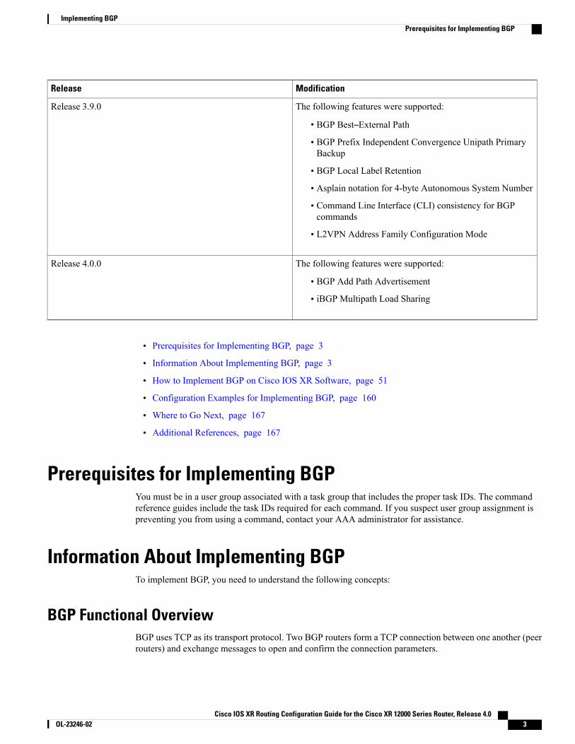
ModificationRelease
The following features were supported:
• BGP Best–External Path
• BGP Prefix Independent Convergence Unipath PrimaryBackup
• BGP Local Label Retention
• Asplain notation for 4-byte Autonomous System Number
• Command Line Interface (CLI) consistency for BGPcommands
• L2VPN Address Family Configuration Mode
Release 3.9.0
The following features were supported:
• BGP Add Path Advertisement
• iBGP Multipath Load Sharing
Release 4.0.0
• Prerequisites for Implementing BGP, page 3
• Information About Implementing BGP, page 3
• How to Implement BGP on Cisco IOS XR Software, page 51
• Configuration Examples for Implementing BGP, page 160
• Where to Go Next, page 167
• Additional References, page 167
Prerequisites for Implementing BGPYou must be in a user group associated with a task group that includes the proper task IDs. The commandreference guides include the task IDs required for each command. If you suspect user group assignment ispreventing you from using a command, contact your AAA administrator for assistance.
Information About Implementing BGPTo implement BGP, you need to understand the following concepts:
BGP Functional OverviewBGP uses TCP as its transport protocol. Two BGP routers form a TCP connection between one another (peerrouters) and exchange messages to open and confirm the connection parameters.
Cisco IOS XR Routing Configuration Guide for the Cisco XR 12000 Series Router, Release 4.0 OL-23246-02 3
Implementing BGPPrerequisites for Implementing BGP
BGP routers exchange network reachability information. This information is mainly an indication of the fullpaths (BGP autonomous system numbers) that a route should take to reach the destination network. Thisinformation helps construct a graph that shows which autonomous systems are loop free and where routingpolicies can be applied to enforce restrictions on routing behavior.
Any two routers forming a TCP connection to exchange BGP routing information are called peers or neighbors.BGP peers initially exchange their full BGP routing tables. After this exchange, incremental updates are sentas the routing table changes. BGP keeps a version number of the BGP table, which is the same for all of itsBGP peers. The version number changes whenever BGP updates the table due to routing information changes.Keepalive packets are sent to ensure that the connection is alive between the BGP peers and notificationpackets are sent in response to error or special conditions.
For information on configuring BGP to distribute Multiprotocol Label Switching (MPLS) Layer 3 virtualprivate network (VPN) information, see the Cisco IOS XRMultiprotocol Label Switching ConfigurationGuide for the Cisco XR 12000 Series Router
For information on BGP support for Bidirectional Forwarding Detection (BFD), see the Cisco IOS XRInterface and Hardware Configuration Guide for the Cisco XR 12000 Series Router and the Cisco IOSXR Interface and Hardware Command Reference for the Cisco XR 12000 Series Router.
Note
BGP Router IdentifierFor BGP sessions between neighbors to be established, BGP must be assigned a router ID. The router ID issent to BGP peers in the OPEN message when a BGP session is established.
BGP attempts to obtain a router ID in the following ways (in order of preference):
• By means of the address configured using the bgp router-id command in router configuration mode.
• By using the highest IPv4 address on a loopback interface in the system if the router is booted with savedloopback address configuration.
• By using the primary IPv4 address of the first loopback address that gets configured if there are not anyin the saved configuration.
If none of these methods for obtaining a router ID succeeds, BGP does not have a router ID and cannot establishany peering sessions with BGP neighbors. In such an instance, an error message is entered in the system log,and the show bgp summary command displays a router ID of 0.0.0.0.
After BGP has obtained a router ID, it continues to use it even if a better router ID becomes available. Thisusage avoids unnecessary flapping for all BGP sessions. However, if the router ID currently in use becomesinvalid (because the interface goes down or its configuration is changed), BGP selects a new router ID (usingthe rules described) and all established peering sessions are reset.
We strongly recommend that the bgp router-id command is configured to prevent unnecessary changesto the router ID (and consequent flapping of BGP sessions).
Note
Cisco IOS XR Routing Configuration Guide for the Cisco XR 12000 Series Router, Release 4.04 OL-23246-02
Implementing BGPBGP Router Identifier
BGP Default LimitsCisco IOS XRBGP imposes maximum limits on the number of neighbors that can be configured on the routerand on the maximum number of prefixes that are accepted from a peer for a given address family. Thislimitation safeguards the router from resource depletion caused by misconfiguration, either locally or on theremote neighbor. The following limits apply to BGP configurations:
• The default maximum number of peers that can be configured is 4000. The default can be changed usingthe bgp maximum neighbor command. The limit range is 1 to 15000. Any attempt to configureadditional peers beyond the maximum limit or set the maximum limit to a number that is less than thenumber of peers currently configured will fail.
• To prevent a peer from flooding BGP with advertisements, a limit is placed on the number of prefixesthat are accepted from a peer for each supported address family. The default limits can be overriddenthrough configuration of the maximum-prefix limit command for the peer for the appropriate addressfamily. The following default limits are used if the user does not configure the maximum number ofprefixes for the address family:
◦512K (524,288) prefixes for IPv4 unicast.
◦128K (131,072) prefixes for IPv4 multicast.
◦128K (131,072) prefixes for IPv6 unicast.
◦128K (131,072) prefixes for IPv6 multicast
◦512K (524,288) prefixes for VPNv4 unicast
◦512K (524,288) prefixes for VPNv6 unicast
A cease notification message is sent to the neighbor and the peering with the neighbor is terminatedwhen the number of prefixes received from the peer for a given address family exceeds the maximumlimit (either set by default or configured by the user) for that address family.
It is possible that the maximum number of prefixes for a neighbor for a given address family has beenconfigured after the peering with the neighbor has been established and a certain number of prefixeshave already been received from the neighbor for that address family. A cease notification message issent to the neighbor and peering with the neighbor is terminated immediately after the configuration ifthe configured maximum number of prefixes is fewer than the number of prefixes that have already beenreceived from the neighbor for the address family.
BGP Next Hop TrackingBGP receives notifications from the Routing Information Base (RIB) when next-hop information changes(event-driven notifications). BGP obtains next-hop information from the RIB to:
• Determine whether a next hop is reachable.
• Find the fully recursed IGP metric to the next hop (used in the best-path calculation).
• Validate the received next hops.
• Calculate the outgoing next hops.
• Verify the reachability and connectedness of neighbors.
Cisco IOS XR Routing Configuration Guide for the Cisco XR 12000 Series Router, Release 4.0 OL-23246-02 5
Implementing BGPBGP Default Limits
BGP is notified when any of the following events occurs:
• Next hop becomes unreachable
• Next hop becomes reachable
• Fully recursed IGP metric to the next hop changes
• First hop IP address or first hop interface change
• Next hop becomes connected
• Next hop becomes unconnected
• Next hop becomes a local address
• Next hop becomes a nonlocal address
Reachability and recursed metric events trigger a best-path recalculation.Note
Event notifications from the RIB are classified as critical and noncritical. Notifications for critical and noncriticalevents are sent in separate batches. However, a noncritical event is sent along with the critical events if thenoncritical event is pending and there is a request to read the critical events.
• Critical events are related to the reachability (reachable and unreachable), connectivity (connected andunconnected), and locality (local and nonlocal) of the next hops. Notifications for these events are notdelayed.
• Noncritical events include only the IGPmetric changes. These events are sent at an interval of 3 seconds.A metric change event is batched and sent 3 seconds after the last one was sent.
The next-hop trigger delay for critical and noncritical events can be configured to specify a minimum batchinginterval for critical and noncritical events using the nexthop trigger-delay command. The trigger delay isaddress family dependent.
The BGP next-hop tracking feature allows you to specify that BGP routes are resolved using only next hopswhose routes have the following characteristics:
• To avoid the aggregate routes, the prefix length must be greater than a specified value.
• The source protocol must be from a selected list, ensuring that BGP routes are not used to resolve nexthops that could lead to oscillation.
This route policy filtering is possible because RIB identifies the source protocol of route that resolved a nexthop as well as the mask length associated with the route. The nexthop route-policy command is used tospecify the route-policy.
For information on route policy filtering for next hops using the next-hop attach point, see the ImplementingRouting Policy Language on Cisco IOS XR Software module of Cisco IOS XR Routing ConfigurationGuide (this publication).
Next Hop as the IPv6 Address of Peering InterfaceBGP can carry IPv6 prefixes over an IPv4 session. The next hop for the IPv6 prefixes can be set through anexthop policy. In the event that the policy is not configured, the nexthops are set as the IPv6 address of the
Cisco IOS XR Routing Configuration Guide for the Cisco XR 12000 Series Router, Release 4.06 OL-23246-02
Implementing BGPBGP Next Hop Tracking
peering interface (IPv6 neighbor interface or IPv6 update source interface, if any one of the interfaces isconfigured).
If the nexthop policy is not configured and neither the IPv6 neighbor interface nor the IPv6 update sourceinterface is configured, the next hop is the IPv4 mapped IPv6 address.
Scoped IPv4/VPNv4 Table WalkTo determine which address family to process, a next-hop notification is received by first dereferencing thegateway context associated with the next hop, then looking into the gateway context to determine whichaddress families are using the gateway context. The IPv4 unicast and VPNv4 unicast address families sharethe same gateway context, because they are registered with the IPv4 unicast table in the RIB. As a result, boththe global IPv4 unicast table and the VPNv4 table are processed when an IPv4 unicast next-hop notificationis received from the RIB. A mask is maintained in the next hop, indicating whether the next hop belongs toIPv4 unicast or VPNv4 unicast, or both. This scoped table walk localizes the processing in the appropriateaddress family table.
Reordered Address Family ProcessingThe Cisco IOS XR software walks address family tables based on the numeric value of the address family.When a next-hop notification batch is received, the order of address family processing is reordered to thefollowing order:
• IPv4 tunnel
• VPNv4 unicast
• VPNv6 unicast
• IPv4 labeled unicast
• IPv4 unicast
• IPv4 MDT
• IPv4 multicast
• IPv6 unicast
• IPv6 multicast
• IPv6 labeled unicast
New Thread for Next-Hop ProcessingThe critical-event thread in the spkr process handles only next-hop, Bidirectional Forwarding Detection (BFD),and fast-external-failover (FEF) notifications. This critical-event thread ensures that BGP convergence is notadversely impacted by other events that may take a significant amount of time.
show, clear, and debug CommandsThe show bgp nexthops command provides statistical information about next-hop notifications, the amountof time spent in processing those notifications, and details about each next hop registered with the RIB. Theclear bgp nexthop performance-statistics command ensures that the cumulative statistics associated with
Cisco IOS XR Routing Configuration Guide for the Cisco XR 12000 Series Router, Release 4.0 OL-23246-02 7
Implementing BGPBGP Next Hop Tracking
the processing part of the next-hop show command can be cleared to help in monitoring. The clear bgpnexthop registration command performs an asynchronous registration of the next hop with the RIB. See theBGP Commands on Cisco IOS XR Softwaremodule of Cisco IOS XR Routing Command Reference for theCisco XR 12000 Series Routerfor information on the next-hop show and clear commands.
The debug bgp nexthop command displays information on next-hop processing. The out keyword providesdebug information only about BGP registration of next hops with RIB. The in keyword displays debuginformation about next-hop notifications received from RIB. The out keyword displays debug informationabout next-hop notifications sent to the RIB. See the BGP Debug Commands on Cisco IOS XR Softwaremodule of Cisco IOS XR Routing Debug Command Reference for the Cisco XR 12000 Series Router .
Autonomous System Number Formats in BGPAutonomous system numbers (ASNs) are globally unique identifiers used to identify autonomous systems(ASs) and enable ASs to exchange exterior routing information between neighboring ASs. A unique ASN isallocated to each AS for use in BGP routing. ASNs are encoded as 2-byte numbers and 4-byte numbers inBGP.
2-byte Autonomous System Number FormatThe 2-byte ASNs are represented in asplain notation. The 2-byte range is 1 to 65535.
4-byte Autonomous System Number FormatTo prepare for the eventual exhaustion of 2-byte Autonomous SystemNumbers (ASNs), BGP has the capabilityto support 4-byte ASNs. The 4-byte ASNs are represented both in asplain and asdot notations.
The byte range for 4-byte ASNs in asplain notation is 1-4294967295. The AS is represented as a 4-bytedecimal number. The 4-byte ASN asplain representation is defined in draft-ietf-idr-as-representation-01.txt.
For 4-byte ASNs in asdot format, the 4-byte range is 1.0 to 65535.65535 and the format is:
high-order-16-bit-value-in-decimal . low-order-16-bit-value-in-decimal
The BGP 4-byte ASN capability is used to propagate 4-byte-based AS path information across BGP speakersthat do not support 4-byte AS numbers. See draft-ietf-idr-as4bytes-12.txt for information on increasing thesize of an ASN from 2 bytes to 4 bytes. AS is represented as a 4-byte decimal number
as-format CommandThe as-format command configures the ASN notation to asdot. The default value, if the as-format commandis not configured, is asplain.
BGP ConfigurationBGP in Cisco IOS XR software follows a neighbor-based configuration model that requires that allconfigurations for a particular neighbor be grouped in one place under the neighbor configuration. Peer groupsare not supported for either sharing configuration between neighbors or for sharing update messages. Theconcept of peer group has been replaced by a set of configuration groups to be used as templates in BGPconfiguration and automatically generated update groups to share update messages between neighbors.
Cisco IOS XR Routing Configuration Guide for the Cisco XR 12000 Series Router, Release 4.08 OL-23246-02
Implementing BGPAutonomous System Number Formats in BGP
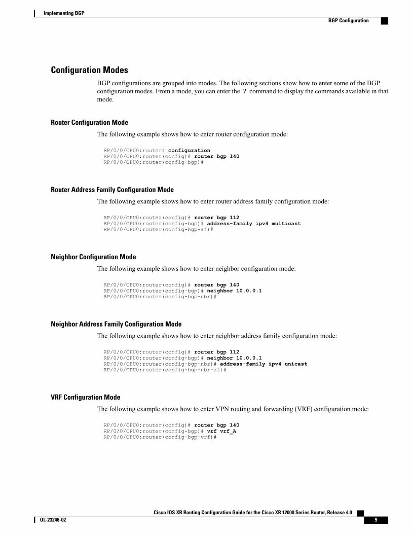
Configuration ModesBGP configurations are grouped into modes. The following sections show how to enter some of the BGPconfiguration modes. From a mode, you can enter the ? command to display the commands available in thatmode.
Router Configuration Mode
The following example shows how to enter router configuration mode:
RP/0/0/CPU0:router# configurationRP/0/0/CPU0:router(config)# router bgp 140RP/0/0/CPU0:router(config-bgp)#
Router Address Family Configuration Mode
The following example shows how to enter router address family configuration mode:
RP/0/0/CPU0:router(config)# router bgp 112RP/0/0/CPU0:router(config-bgp)# address-family ipv4 multicastRP/0/0/CPU0:router(config-bgp-af)#
Neighbor Configuration Mode
The following example shows how to enter neighbor configuration mode:
RP/0/0/CPU0:router(config)# router bgp 140RP/0/0/CPU0:router(config-bgp)# neighbor 10.0.0.1RP/0/0/CPU0:router(config-bgp-nbr)#
Neighbor Address Family Configuration Mode
The following example shows how to enter neighbor address family configuration mode:
RP/0/0/CPU0:router(config)# router bgp 112RP/0/0/CPU0:router(config-bgp)# neighbor 10.0.0.1RP/0/0/CPU0:router(config-bgp-nbr)# address-family ipv4 unicastRP/0/0/CPU0:router(config-bgp-nbr-af)#
VRF Configuration Mode
The following example shows how to enter VPN routing and forwarding (VRF) configuration mode:
RP/0/0/CPU0:router(config)# router bgp 140RP/0/0/CPU0:router(config-bgp)# vrf vrf_ARP/0/0/CPU0:router(config-bgp-vrf)#
Cisco IOS XR Routing Configuration Guide for the Cisco XR 12000 Series Router, Release 4.0 OL-23246-02 9
Implementing BGPBGP Configuration
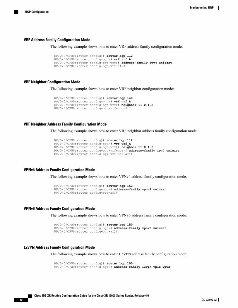
VRF Address Family Configuration Mode
The following example shows how to enter VRF address family configuration mode:
RP/0/0/CPU0:router(config)# router bgp 112RP/0/0/CPU0:router(config-bgp)# vrf vrf_ARP/0/0/CPU0:router(config-bgp-vrf)# address-family ipv4 unicastRP/0/0/CPU0:router(config-bgp-vrf-af)#
VRF Neighbor Configuration Mode
The following example shows how to enter VRF neighbor configuration mode:
RP/0/0/CPU0:router(config)# router bgp 140RP/0/0/CPU0:router(config-bgp)# vrf vrf_ARP/0/0/CPU0:router(config-bgp-vrf)# neighbor 11.0.1.2RP/0/0/CPU0:router(config-bgp-vrf-nbr)#
VRF Neighbor Address Family Configuration Mode
The following example shows how to enter VRF neighbor address family configuration mode:
RP/0/0/CPU0:router(config)# router bgp 112RP/0/0/CPU0:router(config-bgp)# vrf vrf_ARP/0/0/CPU0:router(config-bgp-vrf)# neighbor 11.0.1.2RP/0/0/CPU0:router(config-bgp-vrf-nbr)# address-family ipv4 unicastRP/0/0/CPU0:router(config-bgp-vrf-nbr-af)#
VPNv4 Address Family Configuration Mode
The following example shows how to enter VPNv4 address family configuration mode:
RP/0/0/CPU0:router(config)# router bgp 152RP/0/0/CPU0:router(config-bgp)# address-family vpnv4 unicastRP/0/0/CPU0:router(config-bgp-af)#
VPNv6 Address Family Configuration Mode
The following example shows how to enter VPNv6 address family configuration mode:
RP/0/0/CPU0:router(config)# router bgp 150RP/0/0/CPU0:router(config-bgp)# address-family vpnv6 unicastRP/0/0/CPU0:router(config-bgp-af)#
L2VPN Address Family Configuration Mode
The following example shows how to enter L2VPN address family configuration mode:
RP/0/0/CPU0:router(config)# router bgp 100RP/0/0/CPU0:router(config-bgp)# address-family l2vpn vpls-vpws
Cisco IOS XR Routing Configuration Guide for the Cisco XR 12000 Series Router, Release 4.010 OL-23246-02
Implementing BGPBGP Configuration
RP/0/0/CPU0:router(config-bgp-af)#
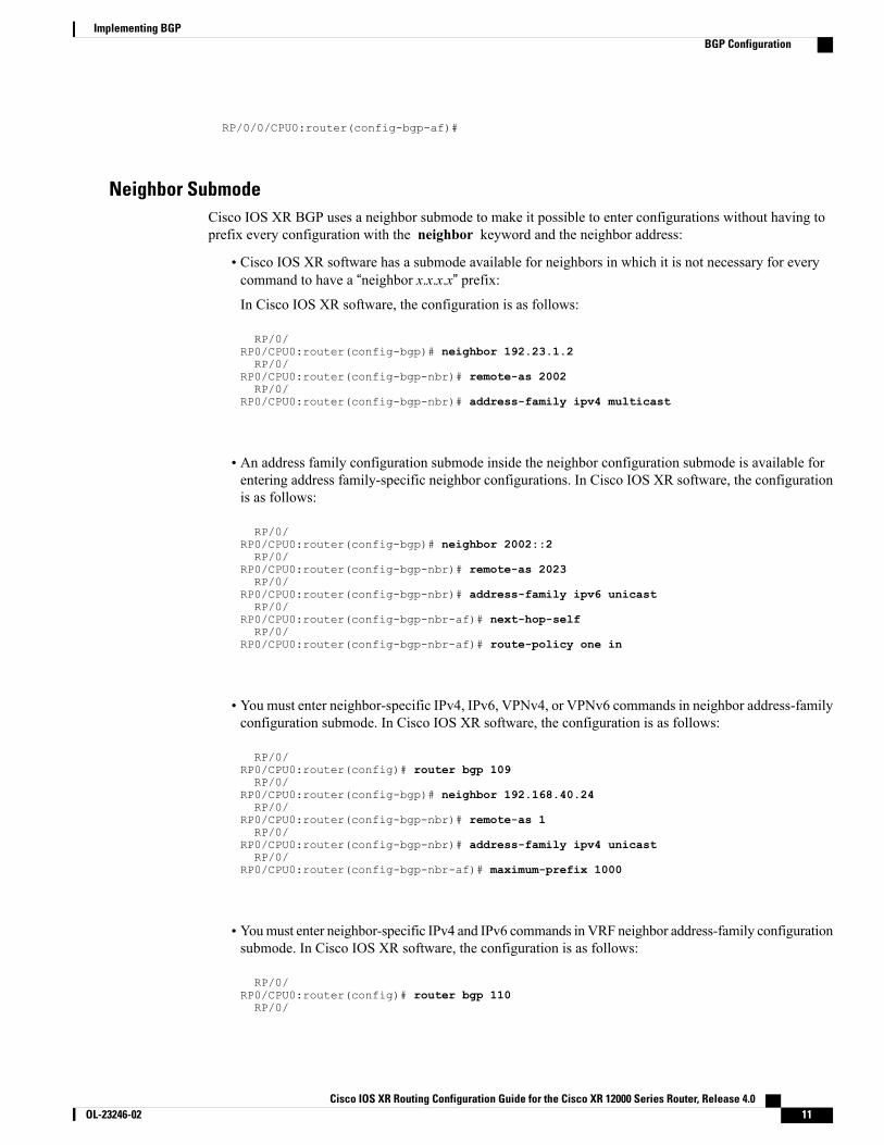
Neighbor Submode Cisco IOS XR BGP uses a neighbor submode to make it possible to enter configurations without having toprefix every configuration with the neighbor keyword and the neighbor address:
• Cisco IOS XR software has a submode available for neighbors in which it is not necessary for everycommand to have a “neighbor x.x.x.x” prefix:In Cisco IOS XR software, the configuration is as follows:
RP/0/RP0/CPU0:router(config-bgp)# neighbor 192.23.1.2RP/0/
RP0/CPU0:router(config-bgp-nbr)# remote-as 2002RP/0/
RP0/CPU0:router(config-bgp-nbr)# address-family ipv4 multicast
• An address family configuration submode inside the neighbor configuration submode is available forentering address family-specific neighbor configurations. In Cisco IOS XR software, the configurationis as follows:
RP/0/RP0/CPU0:router(config-bgp)# neighbor 2002::2RP/0/
RP0/CPU0:router(config-bgp-nbr)# remote-as 2023RP/0/
RP0/CPU0:router(config-bgp-nbr)# address-family ipv6 unicastRP/0/
RP0/CPU0:router(config-bgp-nbr-af)# next-hop-selfRP/0/
RP0/CPU0:router(config-bgp-nbr-af)# route-policy one in
• You must enter neighbor-specific IPv4, IPv6, VPNv4, or VPNv6 commands in neighbor address-familyconfiguration submode. In Cisco IOS XR software, the configuration is as follows:
RP/0/RP0/CPU0:router(config)# router bgp 109RP/0/
RP0/CPU0:router(config-bgp)# neighbor 192.168.40.24RP/0/
RP0/CPU0:router(config-bgp-nbr)# remote-as 1RP/0/
RP0/CPU0:router(config-bgp-nbr)# address-family ipv4 unicastRP/0/
RP0/CPU0:router(config-bgp-nbr-af)# maximum-prefix 1000
• Youmust enter neighbor-specific IPv4 and IPv6 commands in VRF neighbor address-family configurationsubmode. In Cisco IOS XR software, the configuration is as follows:
RP/0/RP0/CPU0:router(config)# router bgp 110RP/0/
Cisco IOS XR Routing Configuration Guide for the Cisco XR 12000 Series Router, Release 4.0 OL-23246-02 11
Implementing BGPBGP Configuration
RP0/CPU0:router(config-bgp)# vrf vrf_ARP/0/
RP0/CPU0:router(config-bgp-vrf)# neighbor 11.0.1.2RP/0/
RP0/CPU0:router(config-bgp-vrf-nbr)# address-family ipv4 unicastRP/0/
RP0/CPU0:router(config-bgp-vrf-nbr-af)# route-policy pass all in
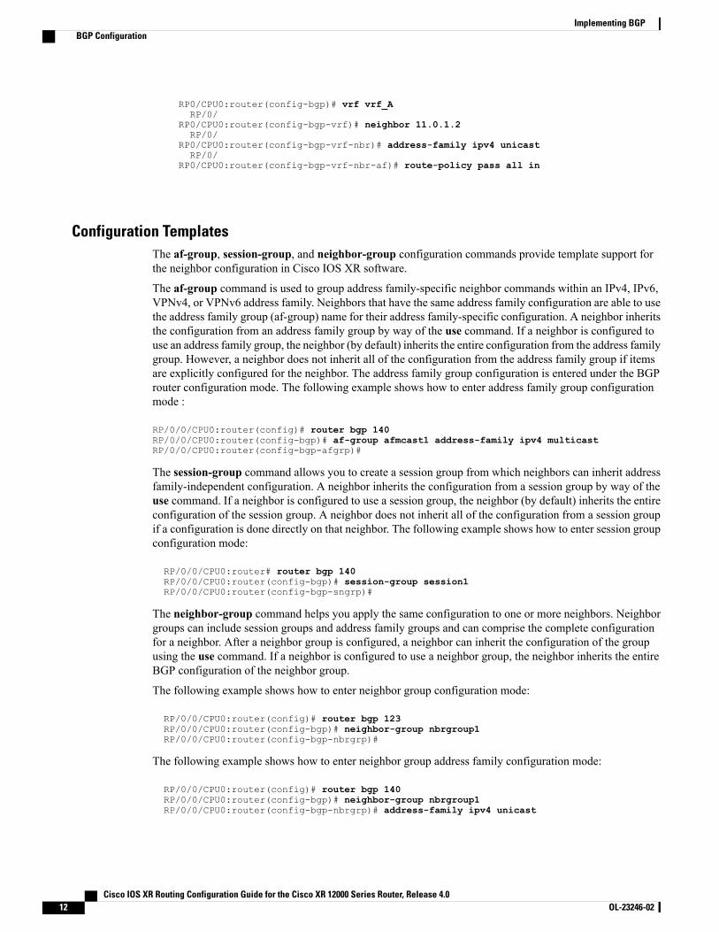
Configuration TemplatesThe af-group, session-group, and neighbor-group configuration commands provide template support forthe neighbor configuration in Cisco IOS XR software.
The af-group command is used to group address family-specific neighbor commands within an IPv4, IPv6,VPNv4, or VPNv6 address family. Neighbors that have the same address family configuration are able to usethe address family group (af-group) name for their address family-specific configuration. A neighbor inheritsthe configuration from an address family group by way of the use command. If a neighbor is configured touse an address family group, the neighbor (by default) inherits the entire configuration from the address familygroup. However, a neighbor does not inherit all of the configuration from the address family group if itemsare explicitly configured for the neighbor. The address family group configuration is entered under the BGProuter configuration mode. The following example shows how to enter address family group configurationmode :
RP/0/0/CPU0:router(config)# router bgp 140RP/0/0/CPU0:router(config-bgp)# af-group afmcast1 address-family ipv4 multicastRP/0/0/CPU0:router(config-bgp-afgrp)#
The session-group command allows you to create a session group from which neighbors can inherit addressfamily-independent configuration. A neighbor inherits the configuration from a session group by way of theuse command. If a neighbor is configured to use a session group, the neighbor (by default) inherits the entireconfiguration of the session group. A neighbor does not inherit all of the configuration from a session groupif a configuration is done directly on that neighbor. The following example shows how to enter session groupconfiguration mode:
RP/0/0/CPU0:router# router bgp 140RP/0/0/CPU0:router(config-bgp)# session-group session1RP/0/0/CPU0:router(config-bgp-sngrp)#
The neighbor-group command helps you apply the same configuration to one or more neighbors. Neighborgroups can include session groups and address family groups and can comprise the complete configurationfor a neighbor. After a neighbor group is configured, a neighbor can inherit the configuration of the groupusing the use command. If a neighbor is configured to use a neighbor group, the neighbor inherits the entireBGP configuration of the neighbor group.
The following example shows how to enter neighbor group configuration mode:
RP/0/0/CPU0:router(config)# router bgp 123RP/0/0/CPU0:router(config-bgp)# neighbor-group nbrgroup1RP/0/0/CPU0:router(config-bgp-nbrgrp)#
The following example shows how to enter neighbor group address family configuration mode:
RP/0/0/CPU0:router(config)# router bgp 140RP/0/0/CPU0:router(config-bgp)# neighbor-group nbrgroup1RP/0/0/CPU0:router(config-bgp-nbrgrp)# address-family ipv4 unicast
Cisco IOS XR Routing Configuration Guide for the Cisco XR 12000 Series Router, Release 4.012 OL-23246-02
Implementing BGPBGP Configuration
RP/0/0/CPU0:router(config-bgp-nbrgrp-af)#
• However, a neighbor does not inherit all of the configuration from the neighbor group if items areexplicitly configured for the neighbor. In addition, some part of the configuration of the neighbor groupcould be hidden if a session group or address family group was also being used.
Configuration grouping has the following effects in Cisco IOS XR software:
• Commands entered at the session group level define address family-independent commands (the samecommands as in the neighbor submode).
• Commands entered at the address family group level define address family-dependent commands for aspecified address family (the same commands as in the neighbor-address family configuration submode).
• Commands entered at the neighbor group level define address family-independent commands and addressfamily-dependent commands for each address family (the same as all available neighbor commands),and define the use command for the address family group and session group commands.
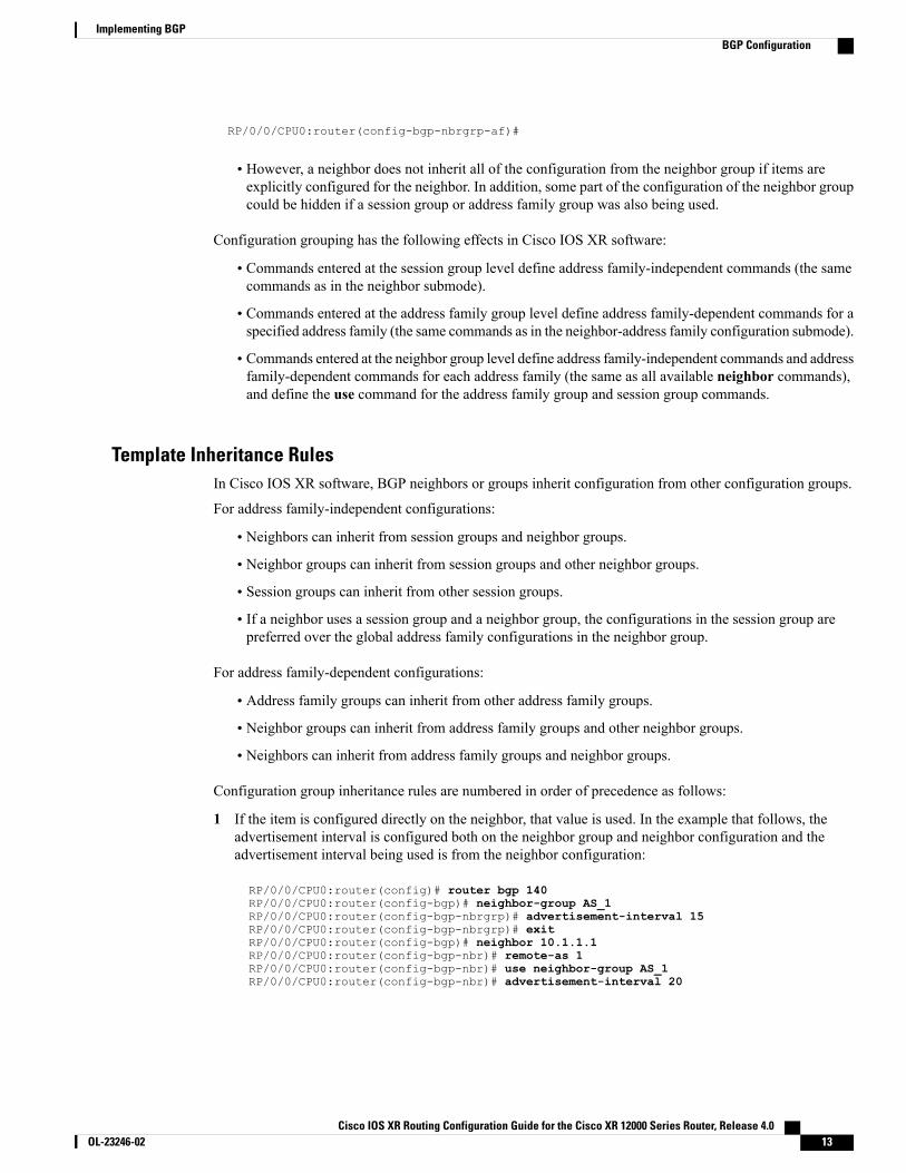
Template Inheritance RulesIn Cisco IOS XR software, BGP neighbors or groups inherit configuration from other configuration groups.
For address family-independent configurations:
• Neighbors can inherit from session groups and neighbor groups.
• Neighbor groups can inherit from session groups and other neighbor groups.
• Session groups can inherit from other session groups.
• If a neighbor uses a session group and a neighbor group, the configurations in the session group arepreferred over the global address family configurations in the neighbor group.
For address family-dependent configurations:
• Address family groups can inherit from other address family groups.
• Neighbor groups can inherit from address family groups and other neighbor groups.
• Neighbors can inherit from address family groups and neighbor groups.
Configuration group inheritance rules are numbered in order of precedence as follows:
1 If the item is configured directly on the neighbor, that value is used. In the example that follows, theadvertisement interval is configured both on the neighbor group and neighbor configuration and theadvertisement interval being used is from the neighbor configuration:
RP/0/0/CPU0:router(config)# router bgp 140RP/0/0/CPU0:router(config-bgp)# neighbor-group AS_1RP/0/0/CPU0:router(config-bgp-nbrgrp)# advertisement-interval 15RP/0/0/CPU0:router(config-bgp-nbrgrp)# exitRP/0/0/CPU0:router(config-bgp)# neighbor 10.1.1.1RP/0/0/CPU0:router(config-bgp-nbr)# remote-as 1RP/0/0/CPU0:router(config-bgp-nbr)# use neighbor-group AS_1RP/0/0/CPU0:router(config-bgp-nbr)# advertisement-interval 20
Cisco IOS XR Routing Configuration Guide for the Cisco XR 12000 Series Router, Release 4.0 OL-23246-02 13
Implementing BGPBGP Configuration

The following output from the show bgp neighbors command shows that the advertisement interval usedis 20 seconds:
RP/0/0/CPU0:router# show bgp neighbors 10.1.1.1
BGP neighbor is 10.1.1.1, remote AS 1, local AS 140, external linkRemote router ID 0.0.0.0BGP state = IdleLast read 00:00:00, hold time is 180, keepalive interval is 60 secondsReceived 0 messages, 0 notifications, 0 in queueSent 0 messages, 0 notifications, 0 in queueMinimum time between advertisement runs is 20 seconds
For Address Family: IPv4 UnicastBGP neighbor version 0Update group: 0.1eBGP neighbor with no inbound or outbound policy; defaults to 'drop'Route refresh request: received 0, sent 00 accepted prefixesPrefix advertised 0, suppressed 0, withdrawn 0, maximum limit 524288Threshold for warning message 75%
Connections established 0; dropped 0Last reset 00:00:14, due to BGP neighbor initializedExternal BGP neighbor not directly connected.
2 Otherwise, if an item is configured to be inherited from a session-group or neighbor-group and on theneighbor directly, then the configuration on the neighbor is used. If a neighbor is configured to be inheritedfrom session-group or af-group, but no directly configured value, then the value in the session-group oraf-group is used. In the example that follows, the advertisement interval is configured on a neighbor groupand a session group and the advertisement interval value being used is from the session group:
RP/0/0/CPU0:router(config)# router bgp 140RP/0/0/CPU0:router(config-bgp)# session-group AS_2RP/0/0/CPU0:router(config-bgp-sngrp)# advertisement-interval 15RP/0/0/CPU0:router(config-bgp-sngrp)# exitRP/0/0/CPU0:router(config-bgp)# neighbor-group AS_1RP/0/0/CPU0:router(config-bgp-nbrgrp)# advertisement-interval 20RP/0/0/CPU0:router(config-bgp-nbrgrp)# exitRP/0/0/CPU0:router(config-bgp)# neighbor 192.168.0.1RP/0/0/CPU0:router(config-bgp-nbr)# remote-as 1RP/0/0/CPU0:router(config-bgp-nbr)# use session-group AS_2RP/0/0/CPU0:router(config-bgp-nbr)# use neighbor-group AS_1
The following output from the show bgp neighbors command shows that the advertisement interval usedis 15 seconds:
RP/0/0/CPU0:router# show bgp neighbors 192.168.0.1
BGP neighbor is 192.168.0.1, remote AS 1, local AS 140, external linkRemote router ID 0.0.0.0BGP state = IdleLast read 00:00:00, hold time is 180, keepalive interval is 60 secondsReceived 0 messages, 0 notifications, 0 in queueSent 0 messages, 0 notifications, 0 in queueMinimum time between advertisement runs is 15 seconds
For Address Family: IPv4 UnicastBGP neighbor version 0Update group: 0.1eBGP neighbor with no inbound or outbound policy; defaults to 'drop'Route refresh request: received 0, sent 00 accepted prefixesPrefix advertised 0, suppressed 0, withdrawn 0, maximum limit 524288Threshold for warning message 75%
Connections established 0; dropped 0Last reset 00:03:23, due to BGP neighbor initialized
Cisco IOS XR Routing Configuration Guide for the Cisco XR 12000 Series Router, Release 4.014 OL-23246-02
Implementing BGPBGP Configuration
External BGP neighbor not directly connected.
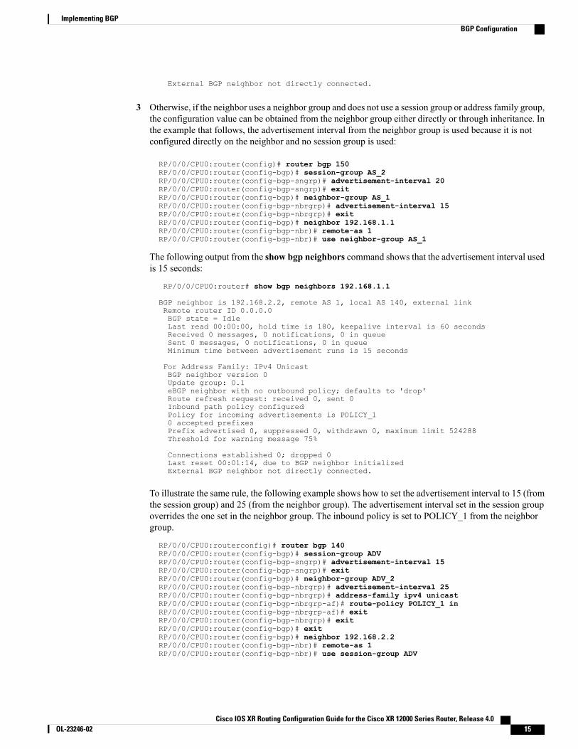
3 Otherwise, if the neighbor uses a neighbor group and does not use a session group or address family group,the configuration value can be obtained from the neighbor group either directly or through inheritance. Inthe example that follows, the advertisement interval from the neighbor group is used because it is notconfigured directly on the neighbor and no session group is used:
RP/0/0/CPU0:router(config)# router bgp 150RP/0/0/CPU0:router(config-bgp)# session-group AS_2RP/0/0/CPU0:router(config-bgp-sngrp)# advertisement-interval 20RP/0/0/CPU0:router(config-bgp-sngrp)# exitRP/0/0/CPU0:router(config-bgp)# neighbor-group AS_1RP/0/0/CPU0:router(config-bgp-nbrgrp)# advertisement-interval 15RP/0/0/CPU0:router(config-bgp-nbrgrp)# exitRP/0/0/CPU0:router(config-bgp)# neighbor 192.168.1.1RP/0/0/CPU0:router(config-bgp-nbr)# remote-as 1RP/0/0/CPU0:router(config-bgp-nbr)# use neighbor-group AS_1
The following output from the show bgp neighbors command shows that the advertisement interval usedis 15 seconds:
RP/0/0/CPU0:router# show bgp neighbors 192.168.1.1
BGP neighbor is 192.168.2.2, remote AS 1, local AS 140, external linkRemote router ID 0.0.0.0BGP state = IdleLast read 00:00:00, hold time is 180, keepalive interval is 60 secondsReceived 0 messages, 0 notifications, 0 in queueSent 0 messages, 0 notifications, 0 in queueMinimum time between advertisement runs is 15 seconds
For Address Family: IPv4 UnicastBGP neighbor version 0Update group: 0.1eBGP neighbor with no outbound policy; defaults to 'drop'Route refresh request: received 0, sent 0Inbound path policy configuredPolicy for incoming advertisements is POLICY_10 accepted prefixesPrefix advertised 0, suppressed 0, withdrawn 0, maximum limit 524288Threshold for warning message 75%
Connections established 0; dropped 0Last reset 00:01:14, due to BGP neighbor initializedExternal BGP neighbor not directly connected.
To illustrate the same rule, the following example shows how to set the advertisement interval to 15 (fromthe session group) and 25 (from the neighbor group). The advertisement interval set in the session groupoverrides the one set in the neighbor group. The inbound policy is set to POLICY_1 from the neighborgroup.
RP/0/0/CPU0:routerconfig)# router bgp 140RP/0/0/CPU0:router(config-bgp)# session-group ADVRP/0/0/CPU0:router(config-bgp-sngrp)# advertisement-interval 15RP/0/0/CPU0:router(config-bgp-sngrp)# exitRP/0/0/CPU0:router(config-bgp)# neighbor-group ADV_2RP/0/0/CPU0:router(config-bgp-nbrgrp)# advertisement-interval 25RP/0/0/CPU0:router(config-bgp-nbrgrp)# address-family ipv4 unicastRP/0/0/CPU0:router(config-bgp-nbrgrp-af)# route-policy POLICY_1 inRP/0/0/CPU0:router(config-bgp-nbrgrp-af)# exitRP/0/0/CPU0:router(config-bgp-nbrgrp)# exitRP/0/0/CPU0:router(config-bgp)# exitRP/0/0/CPU0:router(config-bgp)# neighbor 192.168.2.2RP/0/0/CPU0:router(config-bgp-nbr)# remote-as 1RP/0/0/CPU0:router(config-bgp-nbr)# use session-group ADV
Cisco IOS XR Routing Configuration Guide for the Cisco XR 12000 Series Router, Release 4.0 OL-23246-02 15
Implementing BGPBGP Configuration
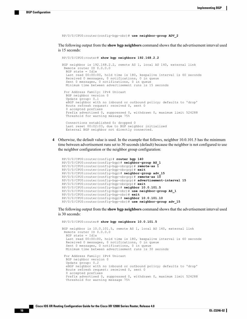
RP/0/0/CPU0:router(config-bgp-nbr)# use neighbor-group ADV_2
The following output from the show bgp neighbors command shows that the advertisement interval usedis 15 seconds:
RP/0/0/CPU0:router# show bgp neighbors 192.168.2.2
BGP neighbor is 192.168.2.2, remote AS 1, local AS 140, external linkRemote router ID 0.0.0.0BGP state = IdleLast read 00:00:00, hold time is 180, keepalive interval is 60 secondsReceived 0 messages, 0 notifications, 0 in queueSent 0 messages, 0 notifications, 0 in queueMinimum time between advertisement runs is 15 seconds
For Address Family: IPv4 UnicastBGP neighbor version 0Update group: 0.1eBGP neighbor with no inbound or outbound policy; defaults to 'drop'Route refresh request: received 0, sent 00 accepted prefixesPrefix advertised 0, suppressed 0, withdrawn 0, maximum limit 524288Threshold for warning message 75%
Connections established 0; dropped 0Last reset 00:02:03, due to BGP neighbor initializedExternal BGP neighbor not directly connected.
4 Otherwise, the default value is used. In the example that follows, neighbor 10.0.101.5 has the minimumtime between advertisement runs set to 30 seconds (default) because the neighbor is not configured to usethe neighbor configuration or the neighbor group configuration:
RP/0/0/CPU0:router(config)# router bgp 140RP/0/0/CPU0:router(config-bgp)# neighbor-group AS_1RP/0/0/CPU0:router(config-bgp-nbrgrp)# remote-as 1RP/0/0/CPU0:router(config-bgp-nbrgrp)# exitRP/0/0/CPU0:router(config-bgp)# neighbor-group adv_15RP/0/0/CPU0:router(config-bgp-nbrgrp)# remote-as 10RP/0/0/CPU0:router(config-bgp-nbrgrp)# advertisement-interval 15RP/0/0/CPU0:router(config-bgp-nbrgrp)# exitRP/0/0/CPU0:router(config-bgp)# neighbor 10.0.101.5RP/0/0/CPU0:router(config-bgp-nbr)# use neighbor-group AS_1RP/0/0/CPU0:router(config-bgp-nbr)# exitRP/0/0/CPU0:router(config-bgp)# neighbor 10.0.101.10RP/0/0/CPU0:router(config-bgp-nbr)# use neighbor-group adv_15
The following output from the show bgp neighbors command shows that the advertisement interval usedis 30 seconds:
RP/0/0/CPU0:router# show bgp neighbors 10.0.101.5
BGP neighbor is 10.0.101.5, remote AS 1, local AS 140, external linkRemote router ID 0.0.0.0BGP state = IdleLast read 00:00:00, hold time is 180, keepalive interval is 60 secondsReceived 0 messages, 0 notifications, 0 in queueSent 0 messages, 0 notifications, 0 in queueMinimum time between advertisement runs is 30 seconds
For Address Family: IPv4 UnicastBGP neighbor version 0Update group: 0.2eBGP neighbor with no inbound or outbound policy; defaults to 'drop'Route refresh request: received 0, sent 00 accepted prefixesPrefix advertised 0, suppressed 0, withdrawn 0, maximum limit 524288Threshold for warning message 75%
Cisco IOS XR Routing Configuration Guide for the Cisco XR 12000 Series Router, Release 4.016 OL-23246-02
Implementing BGPBGP Configuration
Connections established 0; dropped 0Last reset 00:00:25, due to BGP neighbor initializedExternal BGP neighbor not directly connected.
The inheritance rules used when groups are inheriting configuration from other groups are the same as therules given for neighbors inheriting from groups.
Viewing Inherited ConfigurationsYou can use the following show commands to view BGP inherited configurations:
show bgp neighbors
Use the show bgp neighbors command to display information about the BGP configuration for neighbors.
• Use the configuration keyword to display the effective configuration for the neighbor, including anysettings that have been inherited from session groups, neighbor groups, or address family groups usedby this neighbor.
• Use the inheritance keyword to display the session groups, neighbor groups, and address family groupsfrom which this neighbor is capable of inheriting configuration.
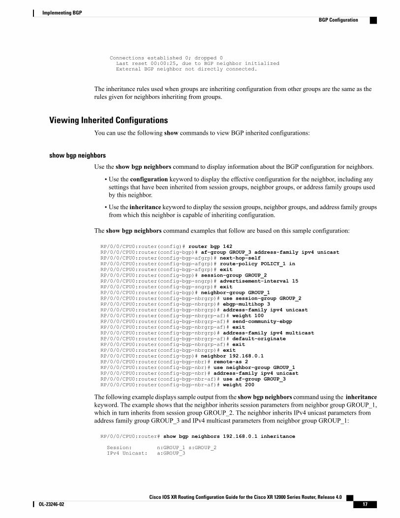
The show bgp neighbors command examples that follow are based on this sample configuration:
RP/0/0/CPU0:router(config)# router bgp 142RP/0/0/CPU0:router(config-bgp)# af-group GROUP_3 address-family ipv4 unicastRP/0/0/CPU0:router(config-bgp-afgrp)# next-hop-selfRP/0/0/CPU0:router(config-bgp-afgrp)# route-policy POLICY_1 inRP/0/0/CPU0:router(config-bgp-afgrp)# exitRP/0/0/CPU0:router(config-bgp)# session-group GROUP_2RP/0/0/CPU0:router(config-bgp-sngrp)# advertisement-interval 15RP/0/0/CPU0:router(config-bgp-sngrp)# exitRP/0/0/CPU0:router(config-bgp)# neighbor-group GROUP_1RP/0/0/CPU0:router(config-bgp-nbrgrp)# use session-group GROUP_2RP/0/0/CPU0:router(config-bgp-nbrgrp)# ebgp-multihop 3RP/0/0/CPU0:router(config-bgp-nbrgrp)# address-family ipv4 unicastRP/0/0/CPU0:router(config-bgp-nbrgrp-af)# weight 100RP/0/0/CPU0:router(config-bgp-nbrgrp-af)# send-community-ebgpRP/0/0/CPU0:router(config-bgp-nbrgrp-af)# exitRP/0/0/CPU0:router(config-bgp-nbrgrp)# address-family ipv4 multicastRP/0/0/CPU0:router(config-bgp-nbrgrp-af)# default-originateRP/0/0/CPU0:router(config-bgp-nbrgrp-af)# exitRP/0/0/CPU0:router(config-bgp-nbrgrp)# exitRP/0/0/CPU0:router(config-bgp)# neighbor 192.168.0.1RP/0/0/CPU0:router(config-bgp-nbr)# remote-as 2RP/0/0/CPU0:router(config-bgp-nbr)# use neighbor-group GROUP_1RP/0/0/CPU0:router(config-bgp-nbr)# address-family ipv4 unicastRP/0/0/CPU0:router(config-bgp-nbr-af)# use af-group GROUP_3RP/0/0/CPU0:router(config-bgp-nbr-af)# weight 200
The following example displays sample output from the show bgp neighbors command using the inheritancekeyword. The example shows that the neighbor inherits session parameters from neighbor group GROUP_1,which in turn inherits from session group GROUP_2. The neighbor inherits IPv4 unicast parameters fromaddress family group GROUP_3 and IPv4 multicast parameters from neighbor group GROUP_1:
RP/0/0/CPU0:router# show bgp neighbors 192.168.0.1 inheritance
Session: n:GROUP_1 s:GROUP_2IPv4 Unicast: a:GROUP_3
Cisco IOS XR Routing Configuration Guide for the Cisco XR 12000 Series Router, Release 4.0 OL-23246-02 17
Implementing BGPBGP Configuration
IPv4 Multicast: n:GROUP_1
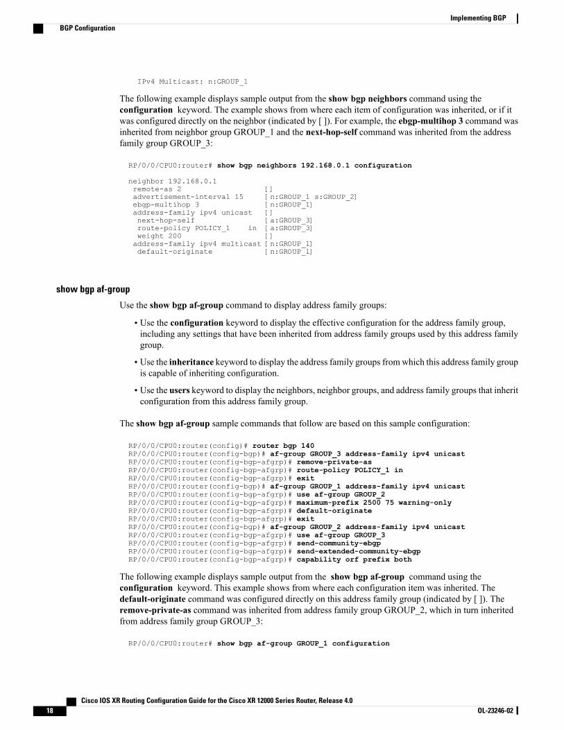
The following example displays sample output from the show bgp neighbors command using theconfiguration keyword. The example shows from where each item of configuration was inherited, or if itwas configured directly on the neighbor (indicated by [ ]). For example, the ebgp-multihop 3 command wasinherited from neighbor group GROUP_1 and the next-hop-self command was inherited from the addressfamily group GROUP_3:
RP/0/0/CPU0:router# show bgp neighbors 192.168.0.1 configuration
neighbor 192.168.0.1remote-as 2 []advertisement-interval 15 [n:GROUP_1 s:GROUP_2]ebgp-multihop 3 [n:GROUP_1]address-family ipv4 unicast []next-hop-self [a:GROUP_3]route-policy POLICY_1 in [a:GROUP_3]weight 200 []address-family ipv4 multicast [n:GROUP_1]default-originate [n:GROUP_1]
show bgp af-group
Use the show bgp af-group command to display address family groups:
• Use the configuration keyword to display the effective configuration for the address family group,including any settings that have been inherited from address family groups used by this address familygroup.
• Use the inheritance keyword to display the address family groups fromwhich this address family groupis capable of inheriting configuration.
• Use the users keyword to display the neighbors, neighbor groups, and address family groups that inheritconfiguration from this address family group.
The show bgp af-group sample commands that follow are based on this sample configuration:
RP/0/0/CPU0:router(config)# router bgp 140RP/0/0/CPU0:router(config-bgp)# af-group GROUP_3 address-family ipv4 unicastRP/0/0/CPU0:router(config-bgp-afgrp)# remove-private-asRP/0/0/CPU0:router(config-bgp-afgrp)# route-policy POLICY_1 inRP/0/0/CPU0:router(config-bgp-afgrp)# exitRP/0/0/CPU0:router(config-bgp)# af-group GROUP_1 address-family ipv4 unicastRP/0/0/CPU0:router(config-bgp-afgrp)# use af-group GROUP_2RP/0/0/CPU0:router(config-bgp-afgrp)# maximum-prefix 2500 75 warning-onlyRP/0/0/CPU0:router(config-bgp-afgrp)# default-originateRP/0/0/CPU0:router(config-bgp-afgrp)# exitRP/0/0/CPU0:router(config-bgp)# af-group GROUP_2 address-family ipv4 unicastRP/0/0/CPU0:router(config-bgp-afgrp)# use af-group GROUP_3RP/0/0/CPU0:router(config-bgp-afgrp)# send-community-ebgpRP/0/0/CPU0:router(config-bgp-afgrp)# send-extended-community-ebgpRP/0/0/CPU0:router(config-bgp-afgrp)# capability orf prefix both
The following example displays sample output from the show bgp af-group command using theconfiguration keyword. This example shows from where each configuration item was inherited. Thedefault-originate command was configured directly on this address family group (indicated by [ ]). Theremove-private-as command was inherited from address family group GROUP_2, which in turn inheritedfrom address family group GROUP_3:
RP/0/0/CPU0:router# show bgp af-group GROUP_1 configuration
Cisco IOS XR Routing Configuration Guide for the Cisco XR 12000 Series Router, Release 4.018 OL-23246-02
Implementing BGPBGP Configuration
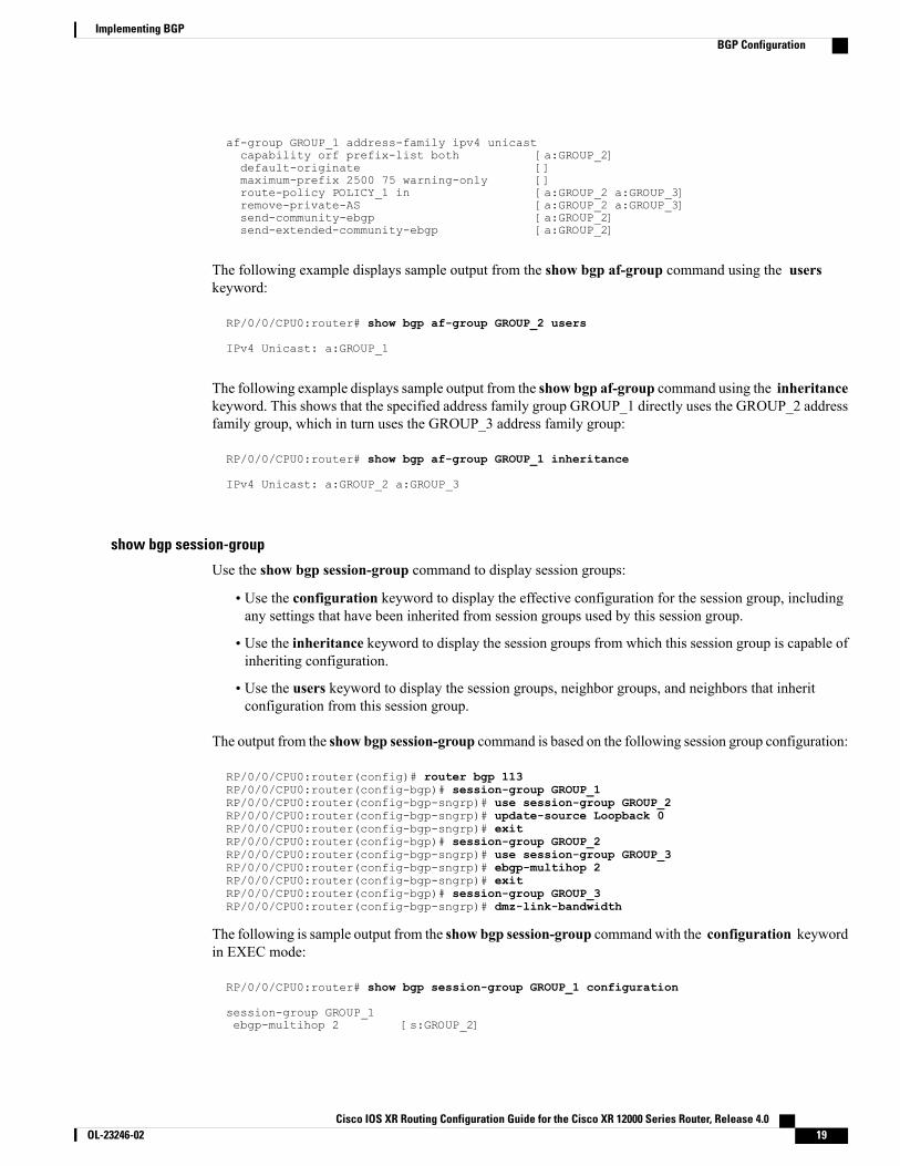
af-group GROUP_1 address-family ipv4 unicastcapability orf prefix-list both [a:GROUP_2]default-originate []maximum-prefix 2500 75 warning-only []route-policy POLICY_1 in [a:GROUP_2 a:GROUP_3]remove-private-AS [a:GROUP_2 a:GROUP_3]send-community-ebgp [a:GROUP_2]send-extended-community-ebgp [a:GROUP_2]
The following example displays sample output from the show bgp af-group command using the userskeyword:
RP/0/0/CPU0:router# show bgp af-group GROUP_2 users
IPv4 Unicast: a:GROUP_1
The following example displays sample output from the show bgp af-group command using the inheritancekeyword. This shows that the specified address family group GROUP_1 directly uses the GROUP_2 addressfamily group, which in turn uses the GROUP_3 address family group:
RP/0/0/CPU0:router# show bgp af-group GROUP_1 inheritance
IPv4 Unicast: a:GROUP_2 a:GROUP_3
show bgp session-group
Use the show bgp session-group command to display session groups:
• Use the configuration keyword to display the effective configuration for the session group, includingany settings that have been inherited from session groups used by this session group.
• Use the inheritance keyword to display the session groups from which this session group is capable ofinheriting configuration.
• Use the users keyword to display the session groups, neighbor groups, and neighbors that inheritconfiguration from this session group.
The output from the show bgp session-group command is based on the following session group configuration:
RP/0/0/CPU0:router(config)# router bgp 113RP/0/0/CPU0:router(config-bgp)# session-group GROUP_1RP/0/0/CPU0:router(config-bgp-sngrp)# use session-group GROUP_2RP/0/0/CPU0:router(config-bgp-sngrp)# update-source Loopback 0RP/0/0/CPU0:router(config-bgp-sngrp)# exitRP/0/0/CPU0:router(config-bgp)# session-group GROUP_2RP/0/0/CPU0:router(config-bgp-sngrp)# use session-group GROUP_3RP/0/0/CPU0:router(config-bgp-sngrp)# ebgp-multihop 2RP/0/0/CPU0:router(config-bgp-sngrp)# exitRP/0/0/CPU0:router(config-bgp)# session-group GROUP_3RP/0/0/CPU0:router(config-bgp-sngrp)# dmz-link-bandwidth
The following is sample output from the show bgp session-group commandwith the configuration keywordin EXEC mode:
RP/0/0/CPU0:router# show bgp session-group GROUP_1 configuration
session-group GROUP_1ebgp-multihop 2 [s:GROUP_2]
Cisco IOS XR Routing Configuration Guide for the Cisco XR 12000 Series Router, Release 4.0 OL-23246-02 19
Implementing BGPBGP Configuration

update-source Loopback0 []dmz-link-bandwidth [s:GROUP_2 s:GROUP_3]
The following is sample output from the show bgp session-group command with the inheritance keywordshowing that the GROUP_1 session group inherits session parameters from the GROUP_3 and GROUP_2session groups:
RP/0/0/CPU0:router# show bgp session-group GROUP_1 inheritance
Session: s:GROUP_2 s:GROUP_3
The following is sample output from the show bgp session-group command with the users keyword showingthat both the GROUP_1 andGROUP_2 session groups inherit session parameters from the GROUP_3 sessiongroup:
RP/0/0/CPU0:router# show bgp session-group GROUP_3 users
Session: s:GROUP_1 s:GROUP_2
show bgp neighbor-group
Use the show bgp neighbor-group command to display neighbor groups:
• Use the configuration keyword to display the effective configuration for the neighbor group, includingany settings that have been inherited from neighbor groups used by this neighbor group.
• Use the inheritance keyword to display the address family groups, session groups, and neighbor groupsfrom which this neighbor group is capable of inheriting configuration.
• Use the users keyword to display the neighbors and neighbor groups that inherit configuration from thisneighbor group.
The examples are based on the following group configuration:
RP/0/0/CPU0:router(config)# router bgp 140RP/0/0/CPU0:router(config-bgp)# af-group GROUP_3 address-family ipv4 unicastRP/0/0/CPU0:router(config-bgp-afgrp)# remove-private-asRP/0/0/CPU0:router(config-bgp-afgrp)# soft-reconfiguration inboundRP/0/0/CPU0:router(config-bgp-afgrp)# exitRP/0/0/CPU0:router(config-bgp)# af-group GROUP_2 address-family ipv4 unicastRP/0/0/CPU0:router(config-bgp-afgrp)# use af-group GROUP_3RP/0/0/CPU0:router(config-bgp-afgrp)# send-community-ebgpRP/0/0/CPU0:router(config-bgp-afgrp)# send-extended-community-ebgpRP/0/0/CPU0:router(config-bgp-afgrp)# capability orf prefix bothRP/0/0/CPU0:router(config-bgp-afgrp)# exitRP/0/0/CPU0:router(config-bgp)# session-group GROUP_3RP/0/0/CPU0:router(config-bgp-sngrp)# timers 30 90RP/0/0/CPU0:router(config-bgp-sngrp)# exitRP/0/0/CPU0:router(config-bgp)# neighbor-group GROUP_1RP/0/0/CPU0:router(config-bgp-nbrgrp)# remote-as 1982RP/0/0/CPU0:router(config-bgp-nbrgrp)# use neighbor-group GROUP_2RP/0/0/CPU0:router(config-bgp-nbrgrp)# address-family ipv4 unicastRP/0/0/CPU0:router(config-bgp-nbrgrp-af)# exitRP/0/0/CPU0:router(config-nbrgrp)# exitRP/0/0/CPU0:router(config-bgp)# neighbor-group GROUP_2RP/0/0/CPU0:router(config-bgp-nbrgrp)# use session-group GROUP_3RP/0/0/CPU0:router(config-bgp-nbrgrp)# address-family ipv4 unicastRP/0/0/CPU0:routerconfig-bgp-nbrgrp-af)# use af-group GROUP_2RP/0/0/CPU0:router(config-bgp-nbrgrp-af)# weight 100
Cisco IOS XR Routing Configuration Guide for the Cisco XR 12000 Series Router, Release 4.020 OL-23246-02
Implementing BGPBGP Configuration
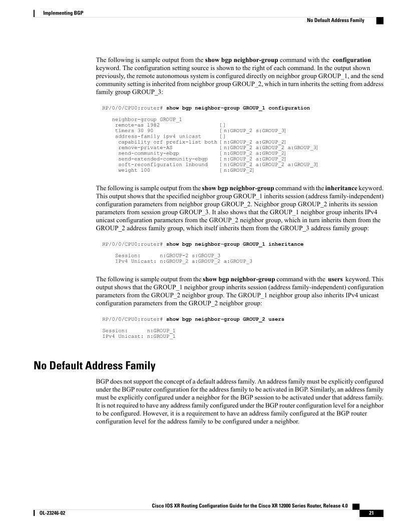
The following is sample output from the show bgp neighbor-group command with the configurationkeyword. The configuration setting source is shown to the right of each command. In the output shownpreviously, the remote autonomous system is configured directly on neighbor group GROUP_1, and the sendcommunity setting is inherited from neighbor group GROUP_2, which in turn inherits the setting from addressfamily group GROUP_3:
RP/0/0/CPU0:router# show bgp neighbor-group GROUP_1 configuration
neighbor-group GROUP_1remote-as 1982 []timers 30 90 [n:GROUP_2 s:GROUP_3]address-family ipv4 unicast []capability orf prefix-list both [n:GROUP_2 a:GROUP_2]remove-private-AS [n:GROUP_2 a:GROUP_2 a:GROUP_3]send-community-ebgp [n:GROUP_2 a:GROUP_2]send-extended-community-ebgp [n:GROUP_2 a:GROUP_2]soft-reconfiguration inbound [n:GROUP_2 a:GROUP_2 a:GROUP_3]weight 100 [n:GROUP_2]
The following is sample output from the show bgp neighbor-group commandwith the inheritance keyword.This output shows that the specified neighbor group GROUP_1 inherits session (address family-independent)configuration parameters from neighbor group GROUP_2. Neighbor group GROUP_2 inherits its sessionparameters from session group GROUP_3. It also shows that the GROUP_1 neighbor group inherits IPv4unicast configuration parameters from the GROUP_2 neighbor group, which in turn inherits them from theGROUP_2 address family group, which itself inherits them from the GROUP_3 address family group:
RP/0/0/CPU0:router# show bgp neighbor-group GROUP_1 inheritance
Session: n:GROUP-2 s:GROUP_3IPv4 Unicast: n:GROUP_2 a:GROUP_2 a:GROUP_3
The following is sample output from the show bgp neighbor-group command with the users keyword. Thisoutput shows that the GROUP_1 neighbor group inherits session (address family-independent) configurationparameters from the GROUP_2 neighbor group. The GROUP_1 neighbor group also inherits IPv4 unicastconfiguration parameters from the GROUP_2 neighbor group:
RP/0/0/CPU0:router# show bgp neighbor-group GROUP_2 users
Session: n:GROUP_1IPv4 Unicast: n:GROUP_1
No Default Address FamilyBGP does not support the concept of a default address family. An address family must be explicitly configuredunder the BGP router configuration for the address family to be activated in BGP. Similarly, an address familymust be explicitly configured under a neighbor for the BGP session to be activated under that address family.It is not required to have any address family configured under the BGP router configuration level for a neighborto be configured. However, it is a requirement to have an address family configured at the BGP routerconfiguration level for the address family to be configured under a neighbor.
Cisco IOS XR Routing Configuration Guide for the Cisco XR 12000 Series Router, Release 4.0 OL-23246-02 21
Implementing BGPNo Default Address Family
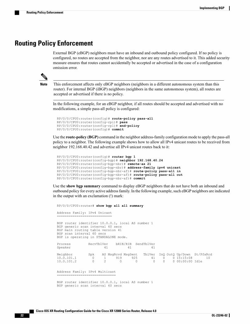
Routing Policy EnforcementExternal BGP (eBGP) neighbors must have an inbound and outbound policy configured. If no policy isconfigured, no routes are accepted from the neighbor, nor are any routes advertised to it. This added securitymeasure ensures that routes cannot accidentally be accepted or advertised in the case of a configurationomission error.
This enforcement affects only eBGP neighbors (neighbors in a different autonomous system than thisrouter). For internal BGP (iBGP) neighbors (neighbors in the same autonomous system), all routes areaccepted or advertised if there is no policy.
Note
In the following example, for an eBGP neighbor, if all routes should be accepted and advertised with nomodifications, a simple pass-all policy is configured:
RP/0/0/CPU0:router(config)# route-policy pass-allRP/0/0/CPU0:router(config-rpl)# passRP/0/0/CPU0:router(config-rpl)# end-policyRP/0/0/CPU0:router(config)# commit
Use the route-policy (BGP) command in the neighbor address-family configuration mode to apply the pass-allpolicy to a neighbor. The following example shows how to allow all IPv4 unicast routes to be received fromneighbor 192.168.40.42 and advertise all IPv4 unicast routes back to it:
RP/0/0/CPU0:router(config)# router bgp 1RP/0/0/CPU0:router(config-bgp)# neighbor 192.168.40.24RP/0/0/CPU0:router(config-bgp-nbr)# remote-as 21RP/0/0/CPU0:router(config-bgp-nbr)# address-family ipv4 unicastRP/0/0/CPU0:router(config-bgp-nbr-af)# route-policy pass-all inRP/0/0/CPU0:router(config-bgp-nbr-af)# route-policy pass-all outRP/0/0/CPU0:router(config-bgp-nbr-af)# commit
Use the show bgp summary command to display eBGP neighbors that do not have both an inbound andoutbound policy for every active address family. In the following example, such eBGP neighbors are indicatedin the output with an exclamation (!) mark:
RP/0/0/CPU0:router# show bgp all all summary
Address Family: IPv4 Unicast============================
BGP router identifier 10.0.0.1, local AS number 1BGP generic scan interval 60 secsBGP main routing table version 41BGP scan interval 60 secsBGP is operating in STANDALONE mode.
Process RecvTblVer bRIB/RIB SendTblVerSpeaker 41 41 41
Neighbor Spk AS MsgRcvd MsgSent TblVer InQ OutQ Up/Down St/PfxRcd10.0.101.1 0 1 919 925 41 0 0 15:15:08 1010.0.101.2 0 2 0 0 0 0 0 00:00:00 Idle
Address Family: IPv4 Multicast==============================
BGP router identifier 10.0.0.1, local AS number 1BGP generic scan interval 60 secs
Cisco IOS XR Routing Configuration Guide for the Cisco XR 12000 Series Router, Release 4.022 OL-23246-02
Implementing BGPRouting Policy Enforcement
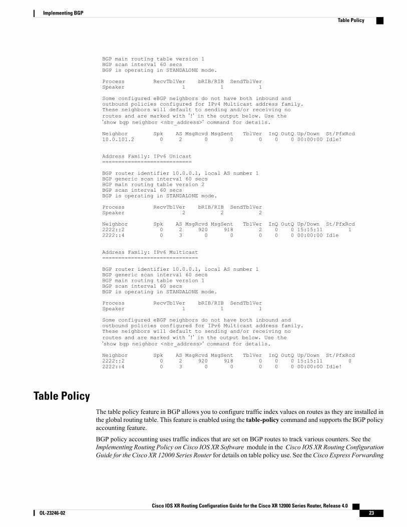
BGP main routing table version 1BGP scan interval 60 secsBGP is operating in STANDALONE mode.
Process RecvTblVer bRIB/RIB SendTblVerSpeaker 1 1 1
Some configured eBGP neighbors do not have both inbound andoutbound policies configured for IPv4 Multicast address family.These neighbors will default to sending and/or receiving noroutes and are marked with ’!’ in the output below. Use the’show bgp neighbor <nbr_address>’ command for details.
Neighbor Spk AS MsgRcvd MsgSent TblVer InQ OutQ Up/Down St/PfxRcd10.0.101.2 0 2 0 0 0 0 0 00:00:00 Idle!
Address Family: IPv6 Unicast============================
BGP router identifier 10.0.0.1, local AS number 1BGP generic scan interval 60 secsBGP main routing table version 2BGP scan interval 60 secsBGP is operating in STANDALONE mode.
Process RecvTblVer bRIB/RIB SendTblVerSpeaker 2 2 2
Neighbor Spk AS MsgRcvd MsgSent TblVer InQ OutQ Up/Down St/PfxRcd2222::2 0 2 920 918 2 0 0 15:15:11 12222::4 0 3 0 0 0 0 0 00:00:00 Idle
Address Family: IPv6 Multicast==============================
BGP router identifier 10.0.0.1, local AS number 1BGP generic scan interval 60 secsBGP main routing table version 1BGP scan interval 60 secsBGP is operating in STANDALONE mode.
Process RecvTblVer bRIB/RIB SendTblVerSpeaker 1 1 1
Some configured eBGP neighbors do not have both inbound andoutbound policies configured for IPv6 Multicast address family.These neighbors will default to sending and/or receiving noroutes and are marked with ’!’ in the output below. Use the’show bgp neighbor <nbr_address>’ command for details.
Neighbor Spk AS MsgRcvd MsgSent TblVer InQ OutQ Up/Down St/PfxRcd2222::2 0 2 920 918 0 0 0 15:15:11 02222::4 0 3 0 0 0 0 0 00:00:00 Idle!
Table PolicyThe table policy feature in BGP allows you to configure traffic index values on routes as they are installed inthe global routing table. This feature is enabled using the table-policy command and supports the BGP policyaccounting feature.
BGP policy accounting uses traffic indices that are set on BGP routes to track various counters. See theImplementing Routing Policy on Cisco IOS XR Software module in the Cisco IOS XR Routing ConfigurationGuide for the Cisco XR 12000 Series Router for details on table policy use. See theCisco Express Forwarding
Cisco IOS XR Routing Configuration Guide for the Cisco XR 12000 Series Router, Release 4.0 OL-23246-02 23
Implementing BGPTable Policy
Commands on Cisco IOS XR Software module in the Cisco IOS XR IP Addresses and Services CommandReference for the Cisco XR 12000 Series Router for details on BGP policy accounting.
Table policy also provides the ability to drop routes from the RIB based on match criteria. This feature canbe useful in certain applications and should be used with caution as it can easily create a routing ‘black hole’where BGP advertises routes to neighbors that BGP does not install in its global routing table and forwardingtable.
Update GroupsThe BGP Update Groups feature contains an algorithm that dynamically calculates and optimizes updategroups of neighbors that share outbound policies and can share the update messages. The BGPUpdate Groupsfeature separates update group replication from peer group configuration, improving convergence time andflexibility of neighbor configuration.
To use this feature, you must understand the following concepts:
Related Topics
BGP Update Generation and Update Groups , on page 24BGP Update Group , on page 24
BGP Update Generation and Update GroupsThe BGP Update Groups feature separates BGP update generation from neighbor configuration. The BGPUpdate Groups feature introduces an algorithm that dynamically calculates BGP update group membershipbased on outbound routing policies. This feature does not require any configuration by the network operator.Update group-based message generation occurs automatically and independently.
BGP Update GroupWhen a change to the configuration occurs, the router automatically recalculates update group membershipsand applies the changes.
For the best optimization of BGP update group generation, we recommend that the network operator keepsoutbound routing policy the same for neighbors that have similar outbound policies. This feature containscommands for monitoring BGP update groups. For more information about the commands, see MonitoringBGP Update Groups, on page 148.
BGP Cost CommunityThe BGP cost community is a nontransitive extended community attribute that is passed to internal BGP(iBGP) and confederation peers but not to external BGP (eBGP) peers. The cost community feature allowsyou to customize the local route preference and influence the best-path selection process by assigning costvalues to specific routes. The extended community format defines generic points of insertion (POI) thatinfluence the best-path decision at different points in the best-path algorithm.
The cost community attribute is applied to internal routes by configuring the set extcommunity cost commandin a route policy. See the Routing Policy Language Commands on Cisco IOS XR Software module of CiscoIOS XR Routing Command Reference for information on the set extcommunity cost command. The costcommunity set clause is configured with a cost community ID number (0–255) and cost community number
Cisco IOS XR Routing Configuration Guide for the Cisco XR 12000 Series Router, Release 4.024 OL-23246-02
Implementing BGPUpdate Groups
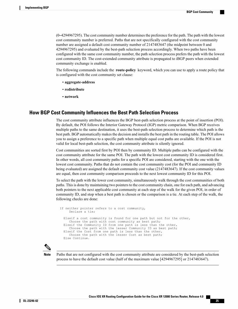
(0–4294967295). The cost community number determines the preference for the path. The path with the lowestcost community number is preferred. Paths that are not specifically configured with the cost communitynumber are assigned a default cost community number of 2147483647 (the midpoint between 0 and4294967295) and evaluated by the best-path selection process accordingly. When two paths have beenconfigured with the same cost community number, the path selection process prefers the path with the lowestcost community ID. The cost-extended community attribute is propagated to iBGP peers when extendedcommunity exchange is enabled.
The following commands include the route-policy keyword, which you can use to apply a route policy thatis configured with the cost community set clause:
• aggregate-address
• redistribute
• network
How BGP Cost Community Influences the Best Path Selection ProcessThe cost community attribute influences the BGP best-path selection process at the point of insertion (POI).By default, the POI follows the Interior Gateway Protocol (IGP) metric comparison. When BGP receivesmultiple paths to the same destination, it uses the best-path selection process to determine which path is thebest path. BGP automatically makes the decision and installs the best path in the routing table. The POI allowsyou to assign a preference to a specific path when multiple equal cost paths are available. If the POI is notvalid for local best-path selection, the cost community attribute is silently ignored.
Cost communities are sorted first by POI then by community ID. Multiple paths can be configured with thecost community attribute for the same POI. The path with the lowest cost community ID is considered first.In other words, all cost community paths for a specific POI are considered, starting with the one with thelowest cost community. Paths that do not contain the cost community cost (for the POI and community IDbeing evaluated) are assigned the default community cost value (2147483647). If the cost community valuesare equal, then cost community comparison proceeds to the next lowest community ID for this POI.
To select the path with the lower cost community, simultaneously walk through the cost communities of bothpaths. This is done by maintaining two pointers to the cost community chain, one for each path, and advancingboth pointers to the next applicable cost community at each step of the walk for the given POI, in order ofcommunity ID, and stop when a best path is chosen or the comparison is a tie. At each step of the walk, thefollowing checks are done:
If neither pointer refers to a cost community,Declare a tie;
Elseif a cost community is found for one path but not for the other,Choose the path with cost community as best path;
Elseif the Community ID from one path is less than the other,Choose the path with the lesser Community ID as best path;
Elseif the Cost from one path is less than the other,Choose the path with the lesser Cost as best path;
Else Continue.
Paths that are not configured with the cost community attribute are considered by the best-path selectionprocess to have the default cost value (half of the maximum value [4294967295] or 2147483647).
Note
Cisco IOS XR Routing Configuration Guide for the Cisco XR 12000 Series Router, Release 4.0 OL-23246-02 25
Implementing BGPBGP Cost Community
Applying the cost community attribute at the POI allows you to assign a value to a path originated or learnedby a peer in any part of the local autonomous system or confederation. The cost community can be used as a“tie breaker” during the best-path selection process. Multiple instances of the cost community can be configuredfor separate equal cost paths within the same autonomous system or confederation. For example, a lower costcommunity value can be applied to a specific exit path in a network with multiple equal cost exit points, andthe specific exit path is preferred by the BGP best-path selection process. See the scenario describedinInfluencing Route Preference in a Multiexit IGP Network, on page 27.
The cost community comparison in BGP is enabled by default. Use the bgp bestpath cost-communityignore command to disable the comparison.
Note
SeeBGP Best Path Algorithm, on page 29 for information on the BGP best-path selection process.
Cost Community Support for Aggregate Routes and MultipathsThe BGP cost community feature supports aggregate routes and multipaths. The cost community attributecan be applied to either type of route. The cost community attribute is passed to the aggregate or multipathroute from component routes that carry the cost community attribute. Only unique IDs are passed, and onlythe highest cost of any individual component route is applied to the aggregate for each ID. If multiple componentroutes contain the same ID, the highest configured cost is applied to the route. For example, the followingtwo component routes are configured with the cost community attribute using an inbound route policy:
• 10.0.0.1
◦POI=IGP
◦cost community ID=1
◦cost number=100
• 192.168.0.1
◦POI=IGP
◦cost community ID=1
◦cost number=200
If these component routes are aggregated or configured as a multipath, the cost value 200 is advertised,because it has the highest cost.
If one or more component routes do not carry the cost community attribute or the component routes areconfigured with different IDs, then the default value (2147483647) is advertised for the aggregate ormultipath route. For example, the following three component routes are configured with the costcommunity attribute using an inbound route policy. However, the component routes are configured withtwo different IDs.
• 10.0.0.1
◦POI=IGP
◦cost community ID=1
◦cost number=100
Cisco IOS XR Routing Configuration Guide for the Cisco XR 12000 Series Router, Release 4.026 OL-23246-02
Implementing BGPBGP Cost Community
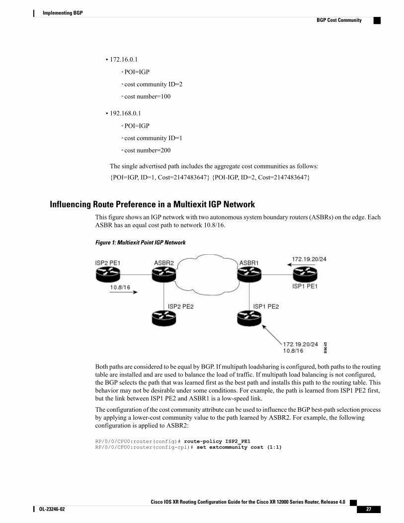
• 172.16.0.1
◦POI=IGP
◦cost community ID=2
◦cost number=100
• 192.168.0.1
◦POI=IGP
◦cost community ID=1
◦cost number=200
The single advertised path includes the aggregate cost communities as follows:
{POI=IGP, ID=1, Cost=2147483647} {POI-IGP, ID=2, Cost=2147483647}
Influencing Route Preference in a Multiexit IGP NetworkThis figure shows an IGP network with two autonomous system boundary routers (ASBRs) on the edge. EachASBR has an equal cost path to network 10.8/16.
Figure 1: Multiexit Point IGP Network
Both paths are considered to be equal by BGP. If multipath loadsharing is configured, both paths to the routingtable are installed and are used to balance the load of traffic. If multipath load balancing is not configured,the BGP selects the path that was learned first as the best path and installs this path to the routing table. Thisbehavior may not be desirable under some conditions. For example, the path is learned from ISP1 PE2 first,but the link between ISP1 PE2 and ASBR1 is a low-speed link.
The configuration of the cost community attribute can be used to influence the BGP best-path selection processby applying a lower-cost community value to the path learned by ASBR2. For example, the followingconfiguration is applied to ASBR2:
RP/0/0/CPU0:router(config)# route-policy ISP2_PE1RP/0/0/CPU0:router(config-rpl)# set extcommunity cost (1:1)
Cisco IOS XR Routing Configuration Guide for the Cisco XR 12000 Series Router, Release 4.0 OL-23246-02 27
Implementing BGPBGP Cost Community
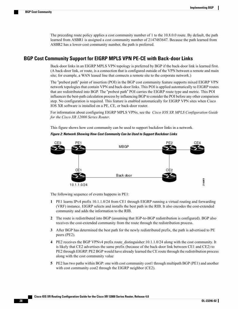
The preceding route policy applies a cost community number of 1 to the 10.8.0.0 route. By default, the pathlearned from ASBR1 is assigned a cost community number of 2147483647. Because the path learned fromASBR2 has a lower-cost community number, the path is preferred.
BGP Cost Community Support for EIGRP MPLS VPN PE-CE with Back-door LinksBack-door links in an EIGRP MPLS VPN topology is preferred by BGP if the back-door link is learned first.(A back-door link, or route, is a connection that is configured outside of the VPN between a remote and mainsite; for example, a WAN leased line that connects a remote site to the corporate network.)
The “prebest path” point of insertion (POI) in the BGP cost community feature supports mixed EIGRP VPNnetwork topologies that contain VPN and back-door links. This POI is applied automatically to EIGRP routesthat are redistributed into BGP. The “prebest path” POI carries the EIGRP route type and metric. This POIinfluences the best-path calculation process by influencing BGP to consider the POI before any other comparisonstep. No configuration is required. This feature is enabled automatically for EIGRP VPN sites when CiscoIOS XR software is installed on a PE, CE, or back-door router.
For information about configuring EIGRP MPLS VPNs, see the Cisco IOS XR MPLS Configuration Guidefor the Cisco XR 12000 Series Router.
This figure shows how cost community can be used to support backdoor links in a network.Figure 2: Network Showing How Cost Community Can be Used to Support Backdoor Links
The following sequence of events happens in PE1:
1 PE1 learns IPv4 prefix 10.1.1.0/24 from CE1 through EIGRP running a virtual routing and forwarding(VRF) instance. EIGRP selects and installs the best path in the RIB. It also encodes the cost-extendedcommunity and adds the information to the RIB.
2 The route is redistributed into BGP (assuming that IGP-to-BGP redistribution is configured). BGP alsoreceives the cost-extended community from the route through the redistribution process.
3 After BGP has determined the best path for the newly redistributed prefix, the path is advertised to PEpeers (PE2).
4 PE2 receives the BGP VPNv4 prefix route_distinguisher:10.1.1.0/24 along with the cost community. Itis likely that CE2 advertises the same prefix (because of the back-door link between CE1 and CE2) toPE2 through EIGRP. PE2 BGPwould have already learned the CE route through the redistribution processalong with the cost community value
5 PE2 has two paths within BGP: one with cost community cost1 through multipath BGP (PE1) and anotherwith cost community cost2 through the EIGRP neighbor (CE2).
Cisco IOS XR Routing Configuration Guide for the Cisco XR 12000 Series Router, Release 4.028 OL-23246-02
Implementing BGPBGP Cost Community
6 PE2 runs the enhanced BGP best-path calculation.
7 PE2 installs the best path in the RIB passing the appropriate cost community value.
8 PE2 RIB has two paths for 10.1.1.0/24: one with cost community cost2 added by EIGRP and another withthe cost community cost1 added by BGP. Because both the route paths have cost community, RIB comparesthe costs first. The BGP path has the lower cost community, so it is selected and downloaded to the RIB.
9 PE2 RIB redistributes the BGP path into EIGRP with VRF. EIGRP runs a diffusing update algorithm(DUAL) because there are two paths, and selects the BGP-redistributed path.
10 PE2 EIGRP advertises the path to CE2 making the path the next hop for the prefix to send the traffic overthe MPLS network.
Adding Routes to the Routing Information BaseIf a nonsourced path becomes the best path after the best-path calculation, BGP adds the route to the RoutingInformation Base (RIB) and passes the cost communities along with the other IGP extended communities.
When a route with paths is added to the RIB by a protocol, RIB checks the current best paths for the routeand the added paths for cost extended communities. If cost-extended communities are found, the RIB comparesthe set of cost communities. If the comparison does not result in a tie, the appropriate best path is chosen. Ifthe comparison results in a tie, the RIB proceeds with the remaining steps of the best-path algorithm. If a costcommunity is not present in either the current best paths or added paths, then the RIB continues with theremaining steps of the best-path algorithm. See BGP Best Path Algorithm, on page 29 for information onthe BGP best-path algorithm.
BGP Best Path AlgorithmBGP routers typically receivemultiple paths to the same destination. The BGP best-path algorithm determinesthe best path to install in the IP routing table and to use for forwarding traffic. This section describes the CiscoIOS XR software implementation of BGP best-path algorithm, as specified in Section 9.1 of the InternetEngineering Task Force (IETF) Network Working Group draft-ietf-idr-bgp4-24.txt document.
The BGP best-path algorithm implementation is in three parts:
• Part 1—Compares two paths to determine which is better.
• Part 2—Iterates over all paths and determines which order to compare the paths to select the overall bestpath.
• Part 3—Determines whether the old and new best paths differ enough so that the new best path shouldbe used.
The order of comparison determined by Part 2 is important because the comparison operation is nottransitive; that is, if three paths, A, B, and C exist, such that when A and B are compared, A is better, andwhen B and C are compared, B is better, it is not necessarily the case that when A and C are compared,A is better. This nontransitivity arises because the multi exit discriminator (MED) is compared only amongpaths from the same neighboring autonomous system (AS) and not among all paths.
Note
Cisco IOS XR Routing Configuration Guide for the Cisco XR 12000 Series Router, Release 4.0 OL-23246-02 29
Implementing BGPBGP Best Path Algorithm
Comparing Pairs of PathsPerform the following steps to compare two paths and determine the better path:
1 If either path is invalid (for example, a path has the maximum possibleMED value or it has an unreachablenext hop), then the other path is chosen (provided that the path is valid).
2 If the paths have unequal pre-bestpath cost communities, the path with the lower pre-bestpath costcommunity is selected as the best path.
See BGP Cost Community, on page 24 for details on how cost communities are compared.Note
3 If the paths have unequal weights, the path with the highest weight is chosen.
The weight is entirely local to the router, and can be set with the weight command or using a routingpolicy.
Note
4 If the paths have unequal local preferences, the path with the higher local preference is chosen.
If a local preference attribute was received with the path or was set by a routing policy, then that value isused in this comparison. Otherwise, the default local preference value of 100 is used. The default valuecan be changed using the bgp default local-preference command.
Note
5 If one of the paths is a redistributed path, which results from a redistribute or network command, thenit is chosen. Otherwise, if one of the paths is a locally generated aggregate, which results from anaggregate-address command, it is chosen.
Step 1 through Step 4 implement the “Path Selection with BGP”of RFC 1268.Note
6 If the paths have unequal AS path lengths, the path with the shorter AS path is chosen. This step is skippedif bgp bestpath as-path ignore command is configured.
When calculating the length of the AS path, confederation segments are ignored, and AS sets count as 1.Note
eiBGP specifies internal and external BGP multipath peers. eiBGP allows simultaneous use of internaland external paths.
Note
7 If the paths have different origins, the path with the lower origin is selected. Interior Gateway Protocol(IGP) is considered lower than EGP, which is considered lower than INCOMPLETE.
8 If appropriate, the MED of the paths is compared. If they are unequal, the path with the lower MED ischosen.
Cisco IOS XR Routing Configuration Guide for the Cisco XR 12000 Series Router, Release 4.030 OL-23246-02
Implementing BGPBGP Best Path Algorithm
A number of configuration options exist that affect whether or not this step is performed. In general, theMED is compared if both paths were received from neighbors in the same AS; otherwise the MEDcomparison is skipped. However, this behavior is modified by certain configuration options, and there arealso some corner cases to consider.
If the bgp bestpath med always command is configured, then the MED comparison is always performed,regardless of neighbor AS in the paths. Otherwise, MED comparison depends on the AS paths of the twopaths being compared, as follows:
• If a path has no AS path or the AS path starts with an AS_SET, then the path is considered to beinternal, and the MED is compared with other internal paths.
• If the AS path starts with an AS_SEQUENCE, then the neighbor AS is the first AS number in thesequence, and the MED is compared with other paths that have the same neighbor AS.
• If the AS path contains only confederation segments or starts with confederation segments followedby an AS_SET, then the MED is not compared with any other path unless the bgp bestpath medconfed command is configured. In that case, the path is considered internal and theMED is comparedwith other internal paths.
• If the AS path starts with confederation segments followed by an AS_SEQUENCE, then the neighborAS is the first AS number in the AS_SEQUENCE, and the MED is compared with other paths thathave the same neighbor AS.
If noMED attribute was received with the path, then theMED is considered to be 0 unless the bgp bestpathmed missing-as-worst command is configured. In that case, if no MED attribute was received, the MEDis considered to be the highest possible value.
Note
9 If one path is received from an external peer and the other is received from an internal (or confederation)peer, the path from the external peer is chosen.
10 If the paths have different IGP metrics to their next hops, the path with the lower IGP metric is chosen.
11 If the paths have unequal IP cost communities, the path with the lower IP cost community is selected asthe best path.
See the BGP Cost Community, on page 24 for details on how cost communities are compared.Note
12 If all path parameters in Step 1 through Step 10 are the same, then the router IDs are compared. If the pathwas received with an originator attribute, then that is used as the router ID to compare; otherwise, therouter ID of the neighbor from which the path was received is used. If the paths have different router IDs,the path with the lower router ID is chosen.
Where the originator is used as the router ID, it is possible to have two paths with the same router ID. Itis also possible to have two BGP sessions with the same peer router, and therefore receive two paths withthe same router ID.
Note
13 If the paths have different cluster lengths, the path with the shorter cluster length is selected. If a path wasnot received with a cluster list attribute, it is considered to have a cluster length of 0.
Cisco IOS XR Routing Configuration Guide for the Cisco XR 12000 Series Router, Release 4.0 OL-23246-02 31
Implementing BGPBGP Best Path Algorithm
14 Finally, the path received from the neighbor with the lower IP address is chosen. Locally generated paths(for example, redistributed paths) are considered to have a neighbor IP address of 0.
Order of ComparisonsThe second part of the BGP best-path algorithm implementation determines the order in which the pathsshould be compared. The order of comparison is determined as follows:
1 The paths are partitioned into groups such that within each group the MED can be compared among allpaths. The same rules as in Comparing Pairs of Paths, on page 30 are used to determine whether MEDcan be compared between any two paths. Normally, this comparison results in one group for each neighborAS. If the bgp bestpath med always command is configured, then there is just one group containing allthe paths.
2 The best path in each group is determined. Determining the best path is achieved by iterating through allpaths in the group and keeping track of the best one seen so far. Each path is compared with the best-so-far,and if it is better, it becomes the new best-so-far and is compared with the next path in the group.
3 A set of paths is formed containing the best path selected from each group in Step 2. The overall best pathis selected from this set of paths, by iterating through them as in Step 2.
Best Path Change SuppressionThe third part of the implementation is to determine whether the best-path change can be suppressed ornot—whether the new best path should be used, or continue using the existing best path. The existing bestpath can continue to be used if the new one is identical to the point at which the best-path selection algorithmbecomes arbitrary (if the router-id is the same). Continuing to use the existing best path can avoid churn inthe network.
This suppression behavior does not comply with the IETF Networking Working Groupdraft-ietf-idr-bgp4-24.txt document, but is specified in the IETF Networking Working Groupdraft-ietf-idr-avoid-transition-00.txt document.
Note
The suppression behavior can be turned off by configuring the bgp bestpath compare-routerid command.If this command is configured, the new best path is always preferred to the existing one.
Otherwise, the following steps are used to determine whether the best-path change can be suppressed:
1 If the existing best path is no longer valid, the change cannot be suppressed.
2 If either the existing or new best paths were received from internal (or confederation) peers or were locallygenerated (for example, by redistribution), then the change cannot be suppressed. That is, suppression ispossible only if both paths were received from external peers.
3 If the paths were received from the same peer (the paths would have the same router-id), the change cannotbe suppressed. The router ID is calculated using rules in Comparing Pairs of Paths, on page 30.
4 If the paths have different weights, local preferences, origins, or IGP metrics to their next hops, then thechange cannot be suppressed. Note that all these values are calculated using the rules in Comparing Pairsof Paths, on page 30.
Cisco IOS XR Routing Configuration Guide for the Cisco XR 12000 Series Router, Release 4.032 OL-23246-02
Implementing BGPBGP Best Path Algorithm

5 If the paths have different-lengthAS paths and the bgp bestpath as-path ignore command is not configured,then the change cannot be suppressed. Again, the AS path length is calculated using the rules in ComparingPairs of Paths, on page 30.
6 If theMED of the paths can be compared and theMEDs are different, then the change cannot be suppressed.The decision as to whether the MEDs can be compared is exactly the same as the rules in Comparing Pairsof Paths, on page 30, as is the calculation of the MED value.
7 If all path parameters in Step 1 through Step 6 do not apply, the change can be suppressed.
Administrative DistanceAn administrative distance is a rating of the trustworthiness of a routing information source. In general, thehigher the value, the lower the trust rating. For information on specifying the administrative distance for BGP,see the BGP Commands module of the Cisco IOS XR Routing Command Reference for the Cisco XR 12000Series Router
Normally, a route can be learned throughmore than one protocol. Administrative distance is used to discriminatebetween routes learned from more than one protocol. The route with the lowest administrative distance isinstalled in the IP routing table. By default, BGP uses the administrative distances shown in Table 2: BGPDefault Administrative Distances, on page 33.
Table 2: BGP Default Administrative Distances
FunctionDefault ValueDistance
Applied to routes learned fromeBGP.
20External
Applied to routes learned fromiBGP.
200Internal
Applied to routes originated by therouter.
200Local
Distance does not influence the BGP path selection algorithm, but it does influence whether BGP-learnedroutes are installed in the IP routing table.
Note
In most cases, when a route is learned through eBGP, it is installed in the IP routing table because of itsdistance (20). Sometimes, however, two ASs have an IGP-learned back-door route and an eBGP-learned
Cisco IOS XR Routing Configuration Guide for the Cisco XR 12000 Series Router, Release 4.0 OL-23246-02 33
Implementing BGPAdministrative Distance
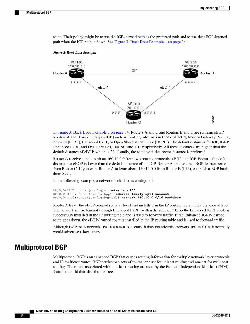
route. Their policy might be to use the IGP-learned path as the preferred path and to use the eBGP-learnedpath when the IGP path is down. See Figure 3: Back Door Example , on page 34.
Figure 3: Back Door Example
In Figure 3: Back Door Example , on page 34, Routers A and C and Routers B and C are running eBGP.Routers A and B are running an IGP (such as Routing Information Protocol [RIP], Interior Gateway RoutingProtocol [IGRP], Enhanced IGRP, or Open Shortest Path First [OSPF]). The default distances for RIP, IGRP,Enhanced IGRP, and OSPF are 120, 100, 90, and 110, respectively. All these distances are higher than thedefault distance of eBGP, which is 20. Usually, the route with the lowest distance is preferred.
Router A receives updates about 160.10.0.0 from two routing protocols: eBGP and IGP. Because the defaultdistance for eBGP is lower than the default distance of the IGP, Router A chooses the eBGP-learned routefrom Router C. If you want Router A to learn about 160.10.0.0 from Router B (IGP), establish a BGP backdoor. See .
In the following example, a network back-door is configured:
RP/0/0/CPU0:router(config)# router bgp 100RP/0/0/CPU0:router(config-bgp)# address-family ipv4 unicastRP/0/0/CPU0:router(config-bgp-af)# network 160.10.0.0/16 backdoor
Router A treats the eBGP-learned route as local and installs it in the IP routing table with a distance of 200.The network is also learned through Enhanced IGRP (with a distance of 90), so the Enhanced IGRP route issuccessfully installed in the IP routing table and is used to forward traffic. If the Enhanced IGRP-learnedroute goes down, the eBGP-learned route is installed in the IP routing table and is used to forward traffic.
Although BGP treats network 160.10.0.0 as a local entry, it does not advertise network 160.10.0.0 as it normallywould advertise a local entry.
Multiprotocol BGPMultiprotocol BGP is an enhanced BGP that carries routing information for multiple network layer protocolsand IP multicast routes. BGP carries two sets of routes, one set for unicast routing and one set for multicastrouting. The routes associated with multicast routing are used by the Protocol Independent Multicast (PIM)feature to build data distribution trees.
Cisco IOS XR Routing Configuration Guide for the Cisco XR 12000 Series Router, Release 4.034 OL-23246-02
Implementing BGPMultiprotocol BGP

Multiprotocol BGP is useful when you want a link dedicated to multicast traffic, perhaps to limit whichresources are used for which traffic. Multiprotocol BGP allows you to have a unicast routing topology differentfrom a multicast routing topology providing more control over your network and resources.
In BGP, the only way to perform interdomain multicast routing was to use the BGP infrastructure that wasin place for unicast routing. Perhaps you want all multicast traffic exchanged at one network access point(NAP). If those routers were not multicast capable, or there were differing policies for which you wantedmulticast traffic to flow, multicast routing could not be supported without multiprotocol BGP.
It is possible to configure BGP peers that exchange both unicast and multicast network layer reachabilityinformation (NLRI), but you cannot connect multiprotocol BGP clouds with a BGP cloud. That is, youcannot redistribute multiprotocol BGP routes into BGP.
Note
Figure 4: Noncongruent Unicast and Multicast Routes, on page 35 illustrates simple unicast and multicasttopologies that are incongruent, and therefore are not possible without multiprotocol BGP.
Autonomous systems 100, 200, and 300 are each connected to two NAPs that are FDDI rings. One is usedfor unicast peering (and therefore the exchange of unicast traffic). The Multicast Friendly Interconnect (MFI)ring is used for multicast peering (and therefore the exchange of multicast traffic). Each router is unicast andmulticast capable.
Figure 4: Noncongruent Unicast and Multicast Routes
Figure 5: Multicast BGP Environment, on page 36 is a topology of unicast-only routers and multicast-onlyrouters. The two routers on the left are unicast-only routers (that is, they do not support or are not configuredto performmulticast routing). The two routers on the right are multicast-only routers. Routers A and B supportboth unicast and multicast routing. The unicast-only and multicast-only routers are connected to a single NAP.
In Figure 5: Multicast BGP Environment, on page 36, only unicast traffic can travel from Router A to theunicast routers to Router B and back. Multicast traffic could not flow on that path, so another routing table isrequired. Multicast traffic uses the path from Router A to the multicast routers to Router B and back.
Figure 5: Multicast BGP Environment, on page 36 illustrates a multiprotocol BGP environment with aseparate unicast route and multicast route from Router A to Router B. Multiprotocol BGP allows these routes
Cisco IOS XR Routing Configuration Guide for the Cisco XR 12000 Series Router, Release 4.0 OL-23246-02 35
Implementing BGPMultiprotocol BGP
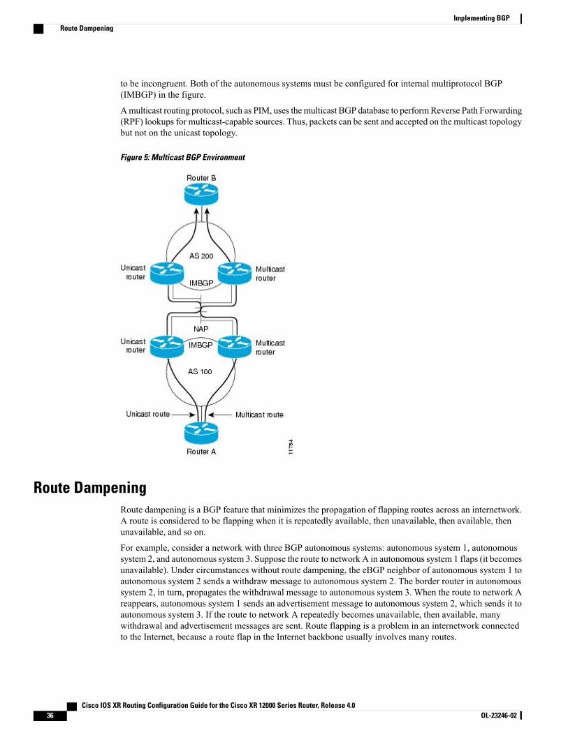
to be incongruent. Both of the autonomous systems must be configured for internal multiprotocol BGP(IMBGP) in the figure.
Amulticast routing protocol, such as PIM, uses themulticast BGP database to performReverse Path Forwarding(RPF) lookups for multicast-capable sources. Thus, packets can be sent and accepted on the multicast topologybut not on the unicast topology.
Figure 5: Multicast BGP Environment
Route DampeningRoute dampening is a BGP feature that minimizes the propagation of flapping routes across an internetwork.A route is considered to be flapping when it is repeatedly available, then unavailable, then available, thenunavailable, and so on.
For example, consider a network with three BGP autonomous systems: autonomous system 1, autonomoussystem 2, and autonomous system 3. Suppose the route to network A in autonomous system 1 flaps (it becomesunavailable). Under circumstances without route dampening, the eBGP neighbor of autonomous system 1 toautonomous system 2 sends a withdraw message to autonomous system 2. The border router in autonomoussystem 2, in turn, propagates the withdrawal message to autonomous system 3. When the route to network Areappears, autonomous system 1 sends an advertisement message to autonomous system 2, which sends it toautonomous system 3. If the route to network A repeatedly becomes unavailable, then available, manywithdrawal and advertisement messages are sent. Route flapping is a problem in an internetwork connectedto the Internet, because a route flap in the Internet backbone usually involves many routes.
Cisco IOS XR Routing Configuration Guide for the Cisco XR 12000 Series Router, Release 4.036 OL-23246-02
Implementing BGPRoute Dampening
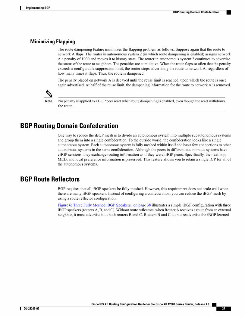
Minimizing FlappingThe route dampening feature minimizes the flapping problem as follows. Suppose again that the route tonetwork A flaps. The router in autonomous system 2 (in which route dampening is enabled) assigns networkA a penalty of 1000 and moves it to history state. The router in autonomous system 2 continues to advertisethe status of the route to neighbors. The penalties are cumulative.When the route flaps so often that the penaltyexceeds a configurable suppression limit, the router stops advertising the route to network A, regardless ofhow many times it flaps. Thus, the route is dampened.
The penalty placed on network A is decayed until the reuse limit is reached, upon which the route is onceagain advertised. At half of the reuse limit, the dampening information for the route to network A is removed.
No penalty is applied to a BGP peer reset when route dampening is enabled, even though the reset withdrawsthe route.
Note
BGP Routing Domain ConfederationOne way to reduce the iBGP mesh is to divide an autonomous system into multiple subautonomous systemsand group them into a single confederation. To the outside world, the confederation looks like a singleautonomous system. Each autonomous system is fully meshed within itself and has a few connections to otherautonomous systems in the same confederation. Although the peers in different autonomous systems haveeBGP sessions, they exchange routing information as if they were iBGP peers. Specifically, the next hop,MED, and local preference information is preserved. This feature allows you to retain a single IGP for all ofthe autonomous systems.
BGP Route ReflectorsBGP requires that all iBGP speakers be fully meshed. However, this requirement does not scale well whenthere are many iBGP speakers. Instead of configuring a confederation, you can reduce the iBGP mesh byusing a route reflector configuration.
Figure 6: Three Fully Meshed iBGP Speakers, on page 38 illustrates a simple iBGP configuration with threeiBGP speakers (routers A, B, and C).Without route reflectors, when Router A receives a route from an externalneighbor, it must advertise it to both routers B and C. Routers B and C do not readvertise the iBGP learned
Cisco IOS XR Routing Configuration Guide for the Cisco XR 12000 Series Router, Release 4.0 OL-23246-02 37
Implementing BGPBGP Routing Domain Confederation
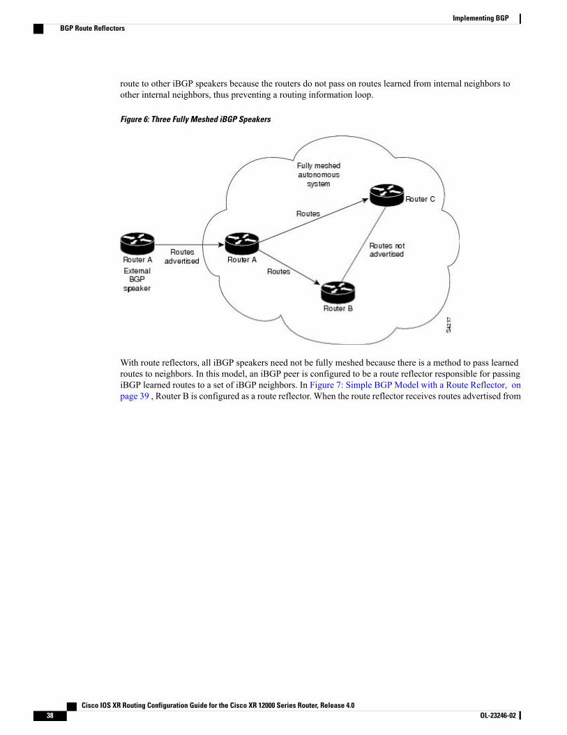
route to other iBGP speakers because the routers do not pass on routes learned from internal neighbors toother internal neighbors, thus preventing a routing information loop.
Figure 6: Three Fully Meshed iBGP Speakers
With route reflectors, all iBGP speakers need not be fully meshed because there is a method to pass learnedroutes to neighbors. In this model, an iBGP peer is configured to be a route reflector responsible for passingiBGP learned routes to a set of iBGP neighbors. In Figure 7: Simple BGP Model with a Route Reflector, onpage 39 , Router B is configured as a route reflector. When the route reflector receives routes advertised from
Cisco IOS XR Routing Configuration Guide for the Cisco XR 12000 Series Router, Release 4.038 OL-23246-02
Implementing BGPBGP Route Reflectors
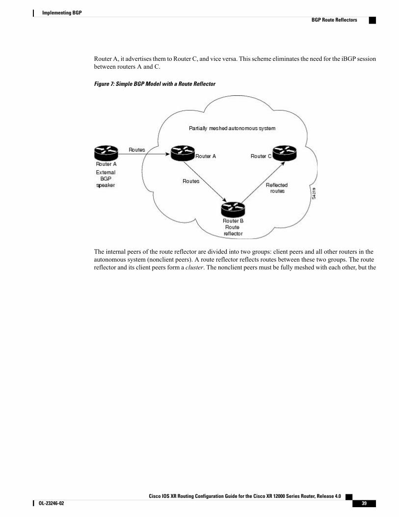
Router A, it advertises them to Router C, and vice versa. This scheme eliminates the need for the iBGP sessionbetween routers A and C.
Figure 7: Simple BGP Model with a Route Reflector
The internal peers of the route reflector are divided into two groups: client peers and all other routers in theautonomous system (nonclient peers). A route reflector reflects routes between these two groups. The routereflector and its client peers form a cluster. The nonclient peers must be fully meshed with each other, but the
Cisco IOS XR Routing Configuration Guide for the Cisco XR 12000 Series Router, Release 4.0 OL-23246-02 39
Implementing BGPBGP Route Reflectors
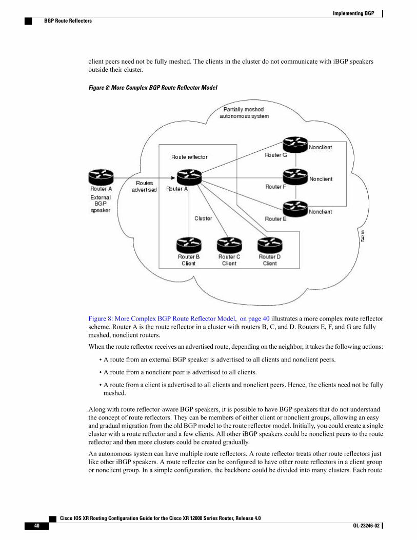
client peers need not be fully meshed. The clients in the cluster do not communicate with iBGP speakersoutside their cluster.
Figure 8: More Complex BGP Route Reflector Model
Figure 8: More Complex BGP Route Reflector Model, on page 40 illustrates a more complex route reflectorscheme. Router A is the route reflector in a cluster with routers B, C, and D. Routers E, F, and G are fullymeshed, nonclient routers.
When the route reflector receives an advertised route, depending on the neighbor, it takes the following actions:
• A route from an external BGP speaker is advertised to all clients and nonclient peers.
• A route from a nonclient peer is advertised to all clients.
• A route from a client is advertised to all clients and nonclient peers. Hence, the clients need not be fullymeshed.
Along with route reflector-aware BGP speakers, it is possible to have BGP speakers that do not understandthe concept of route reflectors. They can be members of either client or nonclient groups, allowing an easyand gradual migration from the old BGPmodel to the route reflector model. Initially, you could create a singlecluster with a route reflector and a few clients. All other iBGP speakers could be nonclient peers to the routereflector and then more clusters could be created gradually.
An autonomous system can have multiple route reflectors. A route reflector treats other route reflectors justlike other iBGP speakers. A route reflector can be configured to have other route reflectors in a client groupor nonclient group. In a simple configuration, the backbone could be divided into many clusters. Each route
Cisco IOS XR Routing Configuration Guide for the Cisco XR 12000 Series Router, Release 4.040 OL-23246-02
Implementing BGPBGP Route Reflectors
reflector would be configured with other route reflectors as nonclient peers (thus, all route reflectors are fullymeshed). The clients are configured to maintain iBGP sessions with only the route reflector in their cluster.
Usually, a cluster of clients has a single route reflector. In that case, the cluster is identified by the router IDof the route reflector. To increase redundancy and avoid a single point of failure, a cluster might have morethan one route reflector. In this case, all route reflectors in the cluster must be configured with the cluster IDso that a route reflector can recognize updates from route reflectors in the same cluster. All route reflectorsserving a cluster should be fully meshed and all of them should have identical sets of client and nonclientpeers.
By default, the clients of a route reflector are not required to be fully meshed and the routes from a client arereflected to other clients. However, if the clients are fully meshed, the route reflector need not reflect routesto clients.
As the iBGP learned routes are reflected, routing information may loop. The route reflector model has thefollowing mechanisms to avoid routing loops:
• Originator ID is an optional, nontransitive BGP attribute. It is a 4-byte attributed created by a routereflector. The attribute carries the router ID of the originator of the route in the local autonomous system.Therefore, if a misconfiguration causes routing information to come back to the originator, the informationis ignored.
• Cluster-list is an optional, nontransitive BGP attribute. It is a sequence of cluster IDs that the route haspassed. When a route reflector reflects a route from its clients to nonclient peers, and vice versa, itappends the local cluster ID to the cluster-list. If the cluster-list is empty, a new cluster-list is created.Using this attribute, a route reflector can identify if routing information is looped back to the same clusterdue to misconfiguration. If the local cluster ID is found in the cluster-list, the advertisement is ignored.
Default Address Family for show CommandsMost of the show commands provide address family (AFI) and subaddress family (SAFI) arguments (seeRFC 1700 and RFC 2858 for information on AFI and SAFI). The Cisco IOS XR software parser provides theability to set the afi and safi so that it is not necessary to specify them while running a show command. Theparser commands are:
• set default-afi { ipv4 | ipv6 | all }
• set default-safi { unicast | multicast | all }
The parser automatically sets the default afi value to ipv4 and default safi value to unicast . It is necessaryto use only the parser commands to change the default afi value from ipv4 or default safi value from unicast. Any afi or safi keyword specified in a show command overrides the values set using the parser commands.Use the following show default-afi-safi-vrf command to check the currently set value of the afi and safi.
Distributed BGPDistributed BGP splits BGP functionality into three process types:
• BGP process manager—Responsible for verifying configuration changes and for calculating andpublishing the distribution of neighbors among BGP speaker processes.
There is a single instance of this process.
Cisco IOS XR Routing Configuration Guide for the Cisco XR 12000 Series Router, Release 4.0 OL-23246-02 41
Implementing BGPDefault Address Family for show Commands
• bRIB process—Responsible for performing the best-path calculation of routes (receives partial bestpaths from the speaker). The best route is installed into the bRIB and is advertised back to all speakers.See the BGP Best Path Algorithm, on page 29 for information on best-path calculation. The bRIBprocess is also responsible for installing routes in the RIB, and for handling routes redistributed fromthe RIB. To accommodate route leaking from one RIB to another, bRIB may register for redistributionfrom multiple RIB routes into a single route in the bRIB process.
There is a single instance of this process for each address family.
• BGP speaker process—Responsible for handling all BGP connections to peers. The speaker storesreceived paths in the RIB and performs a partial best-path calculation, advertising the partial best pathsto the bRIB (limited best-path calculation). Speakers perform a limited best-path calculation because tocompare Multi Exit Discriminators (MEDs), paths need to be compared from the same AS but may notbe received on the same speaker. Because BGP speakers do not have access to the entire BGP local RIB,BGP speakers can perform only a limited best-path calculation. (These are Step 1 through Step 7 in theBGP Best Path Algorithm, on page 29.) Only the best paths are advertised to the bRIB to reducespeaker/bRIB interprocess communications (IPC) and to reduce the number of paths to be processed inthe bRIB. BGP speakers can only mark a path as active only after learning the result of the full best-pathcalculation from the bRIB. Neighbor import and export policies are imposed by the speaker.
If the bgp bestpath med always command is enabled, complete best-path calculation happens insidespeaker process.When the bgp bestpathmed always command is not enabled, speakers calculate partialbest paths only (performs the best-path steps up to the MED comparison) and send them to bRIB. bRIBcalculates the final best path (performs all the steps in the best-path calculation).When the bgp bestpathmed always command is enabled, speakers can compare the MED across all ASs, allowing the speakerto calculate a single best path to send it to bRIB. bRIB is the ultimate process that calculates the finalbest path, but when the bgp bestpath med always command is enabled, the speakers send a single bestpath instead of potentially sending multiple partial best paths.
There are multiple instances of this process in which each instance is responsible for a subset of BGPpeer connections.
Up to a total 15 speakers for all address families and one bRIB for each address family (IPv4, IPv6, andVPNv4) are supported.
Distributed BGP is used to reduce the impact that a fault in one address family has on another address family.For example, you can have one speaker with only IPv6 neighbors (peering to IPv6 addresses) and a separatespeaker with only IPv4 neighbors (peering to IPv4 addresses), and yet another speaker with only VPNv4provider edge (PE) or customer edge (CE) neighbors (peering to IPv4 addresses distinct from the non-VPNneighbors). In this scenario, there is no overlap in processes (bgp, brib, and rib) between IPv4, IPv6, andVPNv4. Therefore, a bgp, brib, or rib process crash affects only one address family. Distributed BGP alsoallows more CPU capacity for receiving, computing, and sending BGP routing updates. When in distributedBGP mode, you can control the number of distributed speakers that are enabled, as well as which neighborsare assigned to each speaker. If no distributed speakers are enabled, BGP operates in standalone mode. If atleast one distributed speaker is enabled, BGP operates in distributed mode.
MPLS VPN Carrier Supporting CarrierCarrier supporting carrier (CSC) is a term used to describe a situation in which one service provider allowsanother service provider to use a segment of its backbone network. The service provider that provides thesegment of the backbone network to the other provider is called the backbone carrier. The service providerthat uses the segment of the backbone network is called the customer carrier.
Cisco IOS XR Routing Configuration Guide for the Cisco XR 12000 Series Router, Release 4.042 OL-23246-02
Implementing BGPMPLS VPN Carrier Supporting Carrier
A backbone carrier offers Border Gateway Protocol and Multiprotocol Label Switching (BGP/MPLS) VPNservices. The customer carrier can be either:
• An Internet service provider (ISP) (By definition, an ISP does not provide VPN service.)
• A BGP/MPLS VPN service provider
You can configure a CSC network to enable BGP to transport routes and MPLS labels between the backbonecarrier provider edge (PE) routers and the customer carrier customer edge (CE) routers using multiple paths.The benefits of using BGP to distribute IPv4 routes and MPLS label routes are:
• BGP takes the place of an Interior Gateway Protocol (IGP) and Label Distribution Protocol (LDP) in aVPN routing and forwarding (VRF) table. You can use BGP to distribute routes andMPLS labels. Usinga single protocol instead of two simplifies the configuration and troubleshooting.
• BGP is the preferred routing protocol for connecting two ISPs, mainly because of its routing policiesand ability to scale. ISPs commonly use BGP between two providers. This feature enables those ISPsto use BGP.
For detailed information on configuring MPLS VPN CSC with BGP, see the Implementing MPLS Layer 3VPNs on Cisco IOS XR Software module of the Cisco IOS XR MPLS Configuration Guide for theCisco XR 12000 Series Router.
BGP KeychainsBGP keychains enable keychain authentication between two BGP peers. The BGP endpoints must both complywith draft-bonica-tcp-auth-05.txt and a keychain on one endpoint and a password on the other endpoint doesnot work.
See the Cisco IOS XR System Security Configuration Guide for the Cisco XR 12000 Series Router forinformation on keychain management.
BGP is able to use the keychain to implement hitless key rollover for authentication. Key rollover specificationis time based, and in the event of clock skew between the peers, the rollover process is impacted. Theconfigurable tolerance specification allows for the accept window to be extended (before and after) by thatmargin. This accept window facilitates a hitless key rollover for applications (for example, routing andmanagement protocols).
The key rollover does not impact the BGP session, unless there is a keychain configuration mismatch at theendpoints resulting in no common keys for the session traffic (send or accept).
IPv6/IPv6 VPN Provider Edge Transport over MPLSIPv6 Provider Edge (6PE) and IPv6 VPN Provider Edge (6VPE) leverages the existing Multiprotocol LabelSwitching (MPLS) IPv4 core infrastructure for IPv6 transport. 6PE and 6VPE enables IPv6 sites to communicatewith each other over anMPLS IPv4 core network usingMPLS label switched paths (LSPs). This feature reliesonmultiprotocol Border Gateway Protocol (BGP) extensions in the IPv4 network configuration on the provideredge (PE) router, to exchange IPv6 reachability information in addition to anMPLS label for each IPv6 addressprefix to be advertised. Edge routers are configured to be dual stack running both IPv4 and IPv6, and use theIPv4-mapped IPv6 address for IPv6 prefix reachability exchange.
For detailed information on configuring 6PE and 6VPE over MPLS, see Cisco IOS XRMPLS ConfigurationGuide for the Cisco XR 12000 Series Router .
Cisco IOS XR Routing Configuration Guide for the Cisco XR 12000 Series Router, Release 4.0 OL-23246-02 43
Implementing BGPBGP Keychains
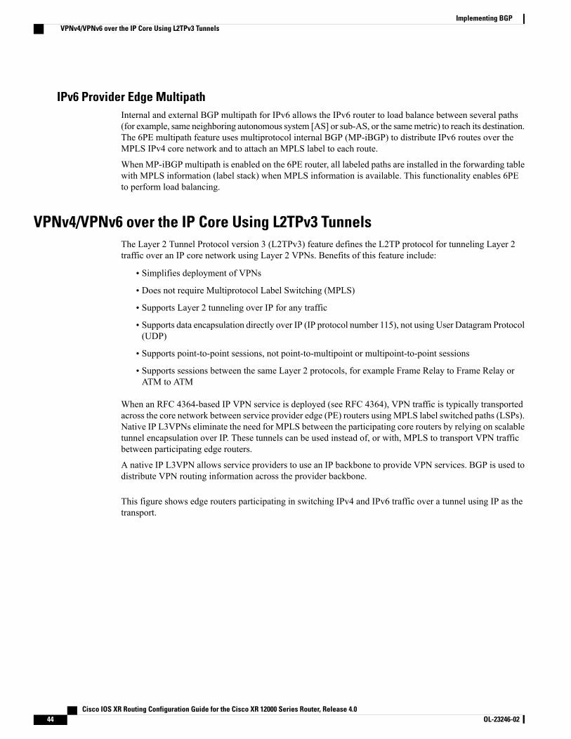
IPv6 Provider Edge MultipathInternal and external BGP multipath for IPv6 allows the IPv6 router to load balance between several paths(for example, same neighboring autonomous system [AS] or sub-AS, or the samemetric) to reach its destination.The 6PE multipath feature uses multiprotocol internal BGP (MP-iBGP) to distribute IPv6 routes over theMPLS IPv4 core network and to attach an MPLS label to each route.
When MP-iBGP multipath is enabled on the 6PE router, all labeled paths are installed in the forwarding tablewith MPLS information (label stack) when MPLS information is available. This functionality enables 6PEto perform load balancing.
VPNv4/VPNv6 over the IP Core Using L2TPv3 TunnelsThe Layer 2 Tunnel Protocol version 3 (L2TPv3) feature defines the L2TP protocol for tunneling Layer 2traffic over an IP core network using Layer 2 VPNs. Benefits of this feature include:
• Simplifies deployment of VPNs
• Does not require Multiprotocol Label Switching (MPLS)
• Supports Layer 2 tunneling over IP for any traffic
• Supports data encapsulation directly over IP (IP protocol number 115), not using User Datagram Protocol(UDP)
• Supports point-to-point sessions, not point-to-multipoint or multipoint-to-point sessions
• Supports sessions between the same Layer 2 protocols, for example Frame Relay to Frame Relay orATM to ATM
When an RFC 4364-based IP VPN service is deployed (see RFC 4364), VPN traffic is typically transportedacross the core network between service provider edge (PE) routers usingMPLS label switched paths (LSPs).Native IP L3VPNs eliminate the need for MPLS between the participating core routers by relying on scalabletunnel encapsulation over IP. These tunnels can be used instead of, or with, MPLS to transport VPN trafficbetween participating edge routers.
A native IP L3VPN allows service providers to use an IP backbone to provide VPN services. BGP is used todistribute VPN routing information across the provider backbone.
This figure shows edge routers participating in switching IPv4 and IPv6 traffic over a tunnel using IP as thetransport.
Cisco IOS XR Routing Configuration Guide for the Cisco XR 12000 Series Router, Release 4.044 OL-23246-02
Implementing BGPVPNv4/VPNv6 over the IP Core Using L2TPv3 Tunnels
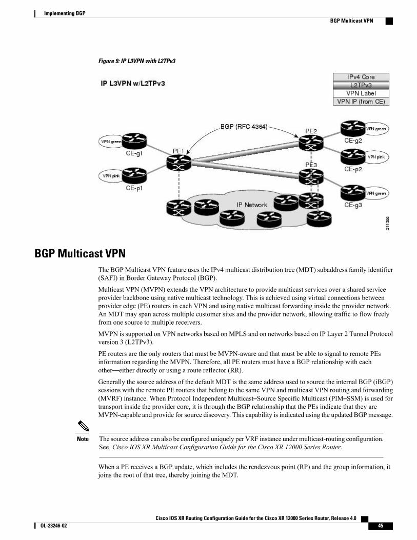
Figure 9: IP L3VPN with L2TPv3
BGP Multicast VPNThe BGPMulticast VPN feature uses the IPv4 multicast distribution tree (MDT) subaddress family identifier(SAFI) in Border Gateway Protocol (BGP).
Multicast VPN (MVPN) extends the VPN architecture to provide multicast services over a shared serviceprovider backbone using native multicast technology. This is achieved using virtual connections betweenprovider edge (PE) routers in each VPN and using native multicast forwarding inside the provider network.An MDT may span across multiple customer sites and the provider network, allowing traffic to flow freelyfrom one source to multiple receivers.
MVPN is supported on VPN networks based on MPLS and on networks based on IP Layer 2 Tunnel Protocolversion 3 (L2TPv3).
PE routers are the only routers that must be MVPN-aware and that must be able to signal to remote PEsinformation regarding the MVPN. Therefore, all PE routers must have a BGP relationship with eachother—either directly or using a route reflector (RR).
Generally the source address of the default MDT is the same address used to source the internal BGP (iBGP)sessions with the remote PE routers that belong to the same VPN and multicast VPN routing and forwarding(MVRF) instance. When Protocol Independent Multicast–Source Specific Multicast (PIM–SSM) is used fortransport inside the provider core, it is through the BGP relationship that the PEs indicate that they areMVPN-capable and provide for source discovery. This capability is indicated using the updated BGPmessage.
The source address can also be configured uniquely per VRF instance under multicast-routing configuration.See Cisco IOS XR Multicast Configuration Guide for the Cisco XR 12000 Series Router.
Note
When a PE receives a BGP update, which includes the rendezvous point (RP) and the group information, itjoins the root of that tree, thereby joining the MDT.
Cisco IOS XR Routing Configuration Guide for the Cisco XR 12000 Series Router, Release 4.0 OL-23246-02 45
Implementing BGPBGP Multicast VPN
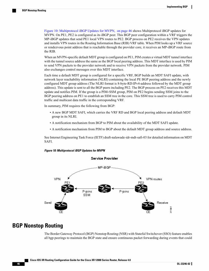
Figure 10: Multiprotocol iBGP Updates for MVPN, on page 46 shows Multiprotocol iBGP updates forMVPN. On PE1, PE2 is configured as its iBGP peer. This BGP peer configuration within a VRF triggers theMP-iBGP updates that send PE1 local VPN routes to PE2. BGP process on PE2 receives the VPN updatesand installs VPN routes in the Routing Information Base (RIB) VRF table. When PIM looks up a VRF sourceor rendezvous point address that is reachable through the provider core, it receives an MP-iBGP route fromthe RIB.
When anMVPN-specific defaultMDT group is configured on PE1, PIM creates a virtualMDT tunnel interfacewith the tunnel source address the same as the BGP local peering address. This MDT interface is used by PIMto send VPN packets to the provider network and to receive VPN packets from the provider network. PIMalso exchanges control messages over this MDT interface.
Each time a default MDT group is configured for a specific VRF, BGP builds an MDT SAFI update, withnetwork layer reachability information (NLRI) containing the local PE BGP peering address and the newlyconfigured MDT group address (The NLRI format is 8-byte-RD:IPv4-address followed by the MDT groupaddress). This update is sent to all the BGP peers including PE2. The BGP process on PE2 receives this MDTupdate and notifies PIM. If the group is a PIM–SSM group, PIM on PE2 begins sending SSM joins to theBGP peering address on PE1 to establish an SSM tree in the core. This SSM tree is used to carry PIM controltraffic and multicast data traffic in the corresponding VRF.
In summary, PIM requires the following from BGP:
• A new BGP MDT SAFI, which carries the VRF RD and BGP local peering address and default MDTgroup in its NLRI.
• A notification mechanism from BGP to PIM about the availability of the MDT SAFI update.
• A notification mechanism from PIM to BGP about the default MDT group address and source address.
See Internet Engineering Task Force (IETF) draft-nalawade-idr-mdt-safi-03 for detailed information onMDTSAFI.
Figure 10: Multiprotocol iBGP Updates for MVPN
BGP Nonstop RoutingThe Border Gateway Protocol (BGP) Nonstop Routing (NSR) with Stateful Switchover (SSO) feature enablesall bgp peerings to maintain the BGP state and ensure continuous packet forwarding during events that could
Cisco IOS XR Routing Configuration Guide for the Cisco XR 12000 Series Router, Release 4.046 OL-23246-02
Implementing BGPBGP Nonstop Routing
interrupt service. Under NSR, events that might potentially interrupt service are not visible to peer routers.Protocol sessions are not interrupted and routing states are maintained across process restarts and switchovers.
BGP NSR provides nonstop routing during the following events:
• Route processor switchover
• Process crash or process failure of BGP or TCP
In case of process crash or process failure, NSR will be maintained only if nsrprocess-failures switchover command is configured. In the event of process failuresof active instances, the nsr process-failures switchover configures failover as a recoveryaction and switches over to a standby route processor (RP) or a standby distributed routeprocessor (DRP) thereby maintaining NSR.
The nsr process-failures switchover command maintains both the NSR and BGPsessions in the event of a BGP or TCP process restart. Without configuring the nsrprocess-failures switchover, restarting the BGP or TCP process causes BGP flap. Thisis an expected behavior.
Note
• In-Service System Upgrade (ISSU)
• Minimum Disruption Restart (MDR)
During route processor switchover and In-Service System Upgrade (ISSU), NSR is achieved by statefulswitchover (SSO) of both TCP and BGP.
NSR does not force any software upgrades on other routers in the network, and peer routers are not requiredto support NSR.
When a route processor switchover occurs due to a fault, the TCP connections and the BGP sessions aremigrated transparently to the standby route processor, and the standby route processor becomes active. Theexisting protocol state is maintained on the standby route processor when it becomes active, and the protocolstate does not need to be refreshed by peers.
Events such as soft reconfiguration and policy modifications can trigger the BGP internal state to change. Toensure state consistency between active and standby BGP processes during such events, the concept of post-itis introduced that act as synchronization points.
BGP NSR provides the following features:
• NSR-related alarms and notifications
• Configured and operational NSR states are tracked separately
• NSR statistics collection
• NSR statistics display using show commands
• XML schema support
• Auditing mechanisms to verify state synchronization between active and standby instances
• CLI commands to enable and disable NSR
NSR can be provisioned on a multishelf router, especially if distributed BGP is configured. The followingguidelines should be observed when provisioning NSR on a multishelf router:
Cisco IOS XR Routing Configuration Guide for the Cisco XR 12000 Series Router, Release 4.0 OL-23246-02 47
Implementing BGPBGP Nonstop Routing
•When provisioning NSR for line cards installed on a single rack, provision the active and standbyapplications on the distributed route processor (DRP) of that rack. If a rack failure occurs, sessions aredropped, because all line cards go down.
•When provisioning NSR for line cards installed on different racks, use one of the following three options:
◦Provision the active and standby applications on a distributed route processor (DRP) redundantpair, where there is a separate route processor in each rack. This configuration uses up tworevenue-producing line-card slots on each rack, but is the most secure configuration.
◦Provision the active and standby application instances using distributed BGP so that the routingsessions on one rack are serviced by a speaker on that rack. The speaker’s standby instance is ona distributed route processor (DRP) on the same rack. If a rack failure occurs, it affects only thesessions on that rack and does not result in NSR loss.
◦Provision the active and standby applications on a distributed route processor (DRP) pair that spanstwo racks. In this configuration, the active/standby role of the line cards is not dependent on theactive/standby role of the DRPs. This is called flexible process redundancy and provides for rackloss and efficient use of LC slots.
Sessions on line cards in a lost rack are not protected with any of the above options,because there is no line-card redundancy. These options ensure only that sessions onother racks are not affected by a lost rack. However, lost sessions from a lost rack maycause some traffic loss on other racks, because destinations learned through those lostsessions may no longer have alternate routes. Also, rack loss may cause the CPUs onroute processors of active racks to slow as they attempt to define new paths for someroutes.
Note
BGP Best-External PathThe Border Gateway Protocol (BGP) best–external path functionality supports advertisement of thebest–external path to the iBGP and Route Reflector peers when a locally selected bestpath is from an internalpeer.
BGP selects one best path and one backup path to every destination. By default, selects one best path .Additionally, BGP selects another bestpath from among the remaining external paths for a prefix. Only asingle path is chosen as the best–external path and is sent to other PEs as the backup path.BGP calculates the best–external path only when the best path is an iBGP path. If the best path is an eBGPpath, then best–external path calculation is not required.The procedure to determine the best–external path is as follows:
1 Determine the best path from the entire set of paths available for a prefix.
2 Eliminate the current best path.
3 Eliminate all the internal paths for the prefix.
4 From the remaining paths, eliminate all the paths that have the same next hop as that of the current bestpath.
Cisco IOS XR Routing Configuration Guide for the Cisco XR 12000 Series Router, Release 4.048 OL-23246-02
Implementing BGPBGP Best-External Path

5 Rerun the best path algorithm on the remaining set of paths to determine the best–external path.
BGP considers the external and confederations BGP paths for a prefix to calculate the best–external path.BGP advertises the best path and the best–external path as follows:
• On the primary PE—advertises the best path for a prefix to both its internal and external peers
• On the backup PE—advertises the best path selected for a prefix to the external peers and advertises thebest–external path selected for that prefix to the internal peers
The advertise best-external command enables the advertisement of the best–external path in global addressfamily and VRF address family configuration modes.
BGP Prefix Independent Convergence Unipath Primary/BackupThe Border Gateway Protocol Prefix Independent Convergence Unipath (BGP PIC Unipath) primary/backupfeature provides the capability to install a backup path into the forwarding table. Installing the backup pathprovides prefix independent convergence in the event of a primary PE–CE link failure.
The primary/backup path provides a mechanism for BGP to determine a backup best path. The backup bestpath acts as a backup to the overall best path, which is the primary best path. BGP programs both the pathsinto the Forwarding Information Base (FIB).
The procedure to determine the backup best path is as follows:
1 Determine the best path from the entire set of paths available for a prefix.
2 Eliminate the current best path.
3 Eliminate all the paths that have the same next hop as that of the current best path.
4 Rerun the best path algorithm on the remaining set of paths to determine the backup best path.
The PE-CE local convergence is in the order of four to five seconds for 10000 prefixes. Installing a backuppath on the linecards, so that the Forwarding Information Base (FIB) can immediately switch to an alternatepath, in the event of a primary PE-CE link failure reduces the convergence time.
In the case of primary PE-CE link failure, the FIB starts forwarding the received traffic towards the backupPE. FIB will continue forwarding the received traffic towards the backup PE for the duration of the networkconvergence. Since the approach of using a backup path is independent to the prefixes, Prefix IndependentConvergence Unipath functionality provides a prefix independent sub second convergence.
The additional-paths selection command installs the backup path in the Forwarding Information Base (FIB)to enable primary backup path.
BGP Local Label RetentionWhen a primary PE-CE link fails, BGP withdraws the route corresponding to the primary path along with itslocal label and programs the backup path in the Routing Information Base (RIB) and the Forwarding InformationBase (FIB), by default.
However, until all the internal peers of the primary PE reconverge to use the backup path as the new bestpath,the traffic continues to be forwarded to the primary PE with the local label that was allocated for the primarypath. Hence the previously allocated local label for the primary path must be retained on the primary PE for
Cisco IOS XR Routing Configuration Guide for the Cisco XR 12000 Series Router, Release 4.0 OL-23246-02 49
Implementing BGPBGP Prefix Independent Convergence Unipath Primary/Backup
some configurable time after the reconvergence. BGP Local Label Retention feature enables the retention ofthe local label for a specified period. If no time is specified, the local lable is retained for a default value offive minutes.
The retain local-label command enables the retention of the local label until the network is converged.
Command Line Interface (CLI) Consistency for BGP CommandsFrom Cisco IOS XR Release 3.9.0 onwards, the Border Gateway Protocol (BGP) commands use disablekeyword to disable a feature. The keyword inheritance-disable disables the inheritance of the featureproperties from the parent level.
BGP Additional PathsThe Border Gateway Protocol (BGP) Additional Paths feature modifies the BGP protocol machinery for aBGP speaker to be able to send multiple paths for a prefix. This gives 'path diversity' in the network. The addpath enables BGP prefix independent convergence (PIC) at the edge routers.
BGP add path enables add path advertisement in an iBGP network and advertises the following types of pathsfor a prefix:
• Backup paths—to enable fast convergence and connectivity restoration.
• Group-best paths—to resolve route oscillation.
• All paths—to emulate an iBGP full-mesh.
Add path is not be supported withMDT, tunnel, and L2VPN address families and eBGPpeerings.
Note
iBGP Multipath Load SharingWhen a Border Gateway Protocol (BGP) speaking router that has no local policy configured, receives multiplenetwork layer reachability information (NLRI) from the internal BGP (iBGP) for the same destination, therouter will choose one iBGP path as the best path. The best path is then installed in the IP routing table of therouter.
The iBGP Multipath Load Sharing feature enables the BGP speaking router to select multiple iBGP paths asthe best paths to a destination. The best paths or multipaths are then installed in the IP routing table of therouter.
When there are multiple border BGP routers having reachability information heard over eBGP, if no localpolicy is applied, the border routers will choose their eBGP paths as best. They advertise that bestpath insidethe ISP network. For a core router, there can be multiple paths to the same destination, but it will select onlyone path as best and use that path for forwarding. iBGP multipath load sharing adds the ability to enable loadsharing among multiple equi-distant paths.
Configuring multiple iBGP best paths enables a router to evenly share the traffic destined for a particular site.
Cisco IOS XR Routing Configuration Guide for the Cisco XR 12000 Series Router, Release 4.050 OL-23246-02
Implementing BGPCommand Line Interface (CLI) Consistency for BGP Commands

The iBGP Multipath Load Sharing feature functions similarly in a Multiprotocol Label Switching (MPLS)Virtual Private Network (VPN) with a service provider backbone.
For multiple paths to the same destination to be considered as multipaths, the following criteria must be met:
• All attributes must be the same. The attributes include weight, local preference, autonomous systempath (entire attribute and not just length), origin code, Multi Exit Discriminator (MED), and InteriorGateway Protocol (iGP) distance.
• The next hop router for each multipath must be different.
Even if the criteria are met and multiple paths are considered multipaths, the BGP speaking router will stilldesignate one of the multipaths as the best path and advertise this best path to its neighbors.
How to Implement BGP on Cisco IOS XR Software
Enabling BGP RoutingPerform this task to enable BGP routing and establish a BGP routing process. Configuring BGP neighbors isincluded as part of enabling BGP routing.
At least one neighbor and at least one address family must be configured to enable BGP routing. At leastone neighbor with both a remote AS and an address family must be configured globally using the addressfamily and remote as commands.
Note
Before You Begin
BGP must be able to obtain a router identifier (for example, a configured loopback address). At least, oneaddress family must be configured in the BGP router configuration and the same address family must also beconfigured under the neighbor.
If the neighbor is configured as an external BGP (eBGP) peer, youmust configure an inbound and outboundroute policy on the neighbor using the route-policy command.
Note
Cisco IOS XR Routing Configuration Guide for the Cisco XR 12000 Series Router, Release 4.0 OL-23246-02 51
Implementing BGPHow to Implement BGP on Cisco IOS XR Software
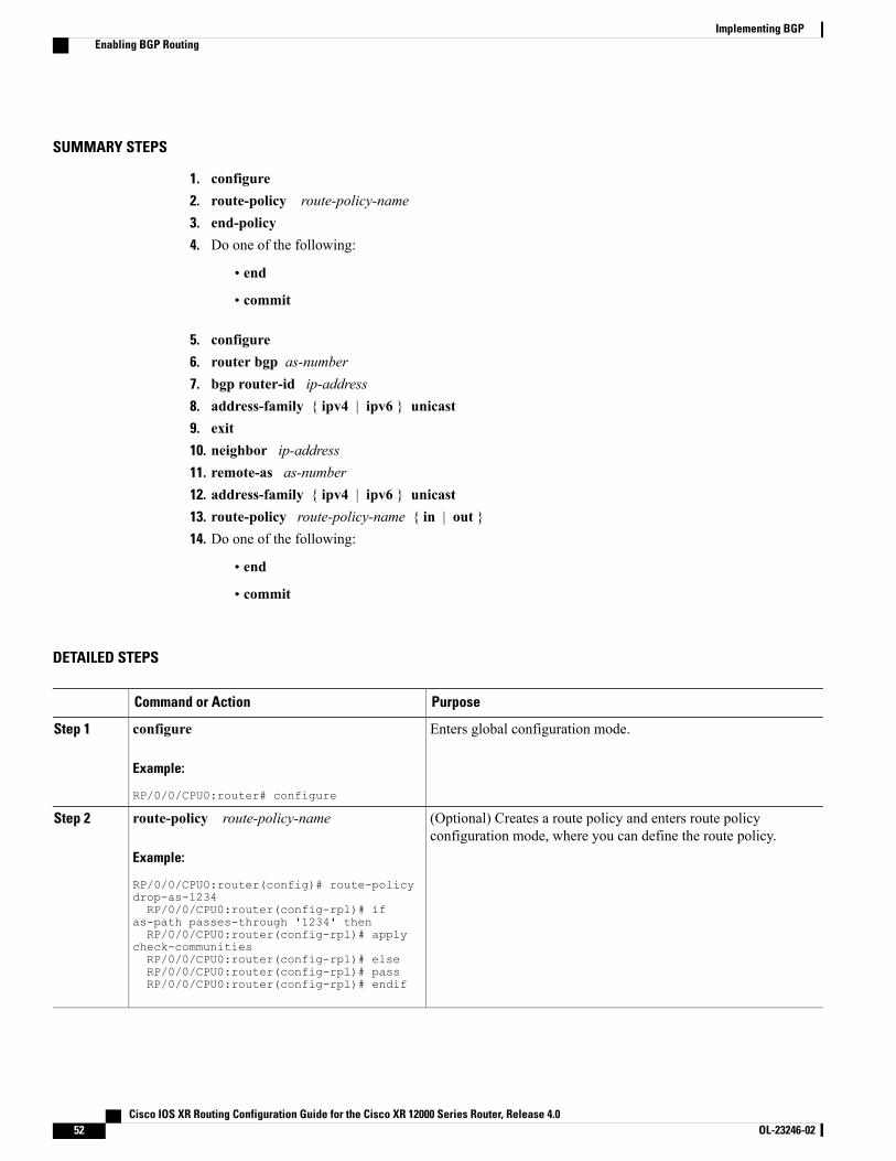
SUMMARY STEPS
1. configure2. route-policy route-policy-name3. end-policy4. Do one of the following:
• end
• commit
5. configure6. router bgp as-number7. bgp router-id ip-address8. address-family { ipv4 | ipv6 } unicast9. exit10. neighbor ip-address11. remote-as as-number12. address-family { ipv4 | ipv6 } unicast13. route-policy route-policy-name { in | out }14. Do one of the following:
• end
• commit
DETAILED STEPS
PurposeCommand or Action
Enters global configuration mode.configure
Example:
RP/0/0/CPU0:router# configure
Step 1
(Optional) Creates a route policy and enters route policyconfiguration mode, where you can define the route policy.
route-policy route-policy-name
Example:
RP/0/0/CPU0:router(config)# route-policy
Step 2
drop-as-1234RP/0/0/CPU0:router(config-rpl)# if
as-path passes-through '1234' thenRP/0/0/CPU0:router(config-rpl)# apply
check-communitiesRP/0/0/CPU0:router(config-rpl)# elseRP/0/0/CPU0:router(config-rpl)# passRP/0/0/CPU0:router(config-rpl)# endif
Cisco IOS XR Routing Configuration Guide for the Cisco XR 12000 Series Router, Release 4.052 OL-23246-02
Implementing BGPEnabling BGP Routing
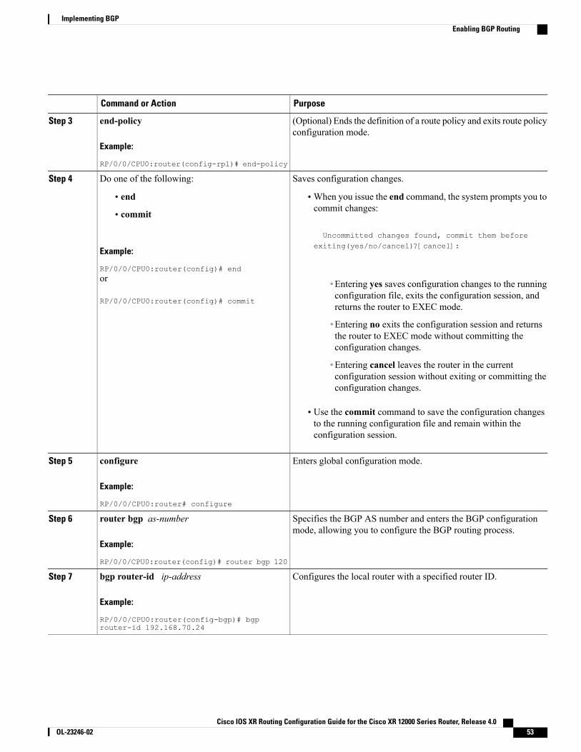
PurposeCommand or Action
(Optional) Ends the definition of a route policy and exits route policyconfiguration mode.
end-policy
Example:
RP/0/0/CPU0:router(config-rpl)# end-policy
Step 3
Saves configuration changes.Do one of the following:Step 4
• end •When you issue the end command, the system prompts you tocommit changes:
Uncommitted changes found, commit them before
• commit
Example:
RP/0/0/CPU0:router(config)# end
exiting(yes/no/cancel)?[cancel]:
or
RP/0/0/CPU0:router(config)# commit
◦Entering yes saves configuration changes to the runningconfiguration file, exits the configuration session, andreturns the router to EXEC mode.
◦Entering no exits the configuration session and returnsthe router to EXEC mode without committing theconfiguration changes.
◦Entering cancel leaves the router in the currentconfiguration session without exiting or committing theconfiguration changes.
• Use the commit command to save the configuration changesto the running configuration file and remain within theconfiguration session.
Enters global configuration mode.configure
Example:
RP/0/0/CPU0:router# configure
Step 5
Specifies the BGP AS number and enters the BGP configurationmode, allowing you to configure the BGP routing process.
router bgp as-number
Example:
RP/0/0/CPU0:router(config)# router bgp 120
Step 6
Configures the local router with a specified router ID.bgp router-id ip-address
Example:
RP/0/0/CPU0:router(config-bgp)# bgprouter-id 192.168.70.24
Step 7
Cisco IOS XR Routing Configuration Guide for the Cisco XR 12000 Series Router, Release 4.0 OL-23246-02 53
Implementing BGPEnabling BGP Routing
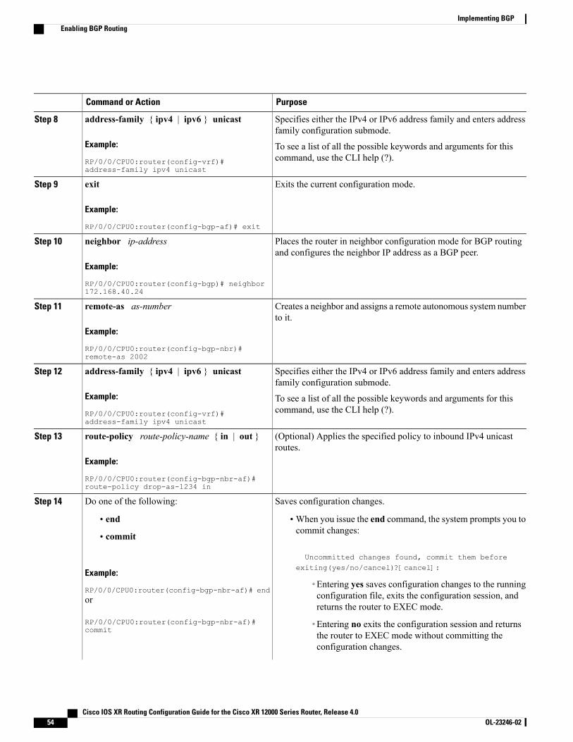
PurposeCommand or Action
Specifies either the IPv4 or IPv6 address family and enters addressfamily configuration submode.
address-family { ipv4 | ipv6 } unicast
Example:
RP/0/0/CPU0:router(config-vrf)#address-family ipv4 unicast
Step 8
To see a list of all the possible keywords and arguments for thiscommand, use the CLI help (?).
Exits the current configuration mode.exit
Example:
RP/0/0/CPU0:router(config-bgp-af)# exit
Step 9
Places the router in neighbor configuration mode for BGP routingand configures the neighbor IP address as a BGP peer.
neighbor ip-address
Example:
RP/0/0/CPU0:router(config-bgp)# neighbor172.168.40.24
Step 10
Creates a neighbor and assigns a remote autonomous system numberto it.
remote-as as-number
Example:
RP/0/0/CPU0:router(config-bgp-nbr)#remote-as 2002
Step 11
Specifies either the IPv4 or IPv6 address family and enters addressfamily configuration submode.
address-family { ipv4 | ipv6 } unicast
Example:
RP/0/0/CPU0:router(config-vrf)#address-family ipv4 unicast
Step 12
To see a list of all the possible keywords and arguments for thiscommand, use the CLI help (?).
(Optional) Applies the specified policy to inbound IPv4 unicastroutes.
route-policy route-policy-name { in | out }
Example:
RP/0/0/CPU0:router(config-bgp-nbr-af)#route-policy drop-as-1234 in
Step 13
Saves configuration changes.Do one of the following:Step 14
• end •When you issue the end command, the system prompts you tocommit changes:
Uncommitted changes found, commit them beforeexiting(yes/no/cancel)?[cancel]:
• commit
Example:
RP/0/0/CPU0:router(config-bgp-nbr-af)# end◦Entering yes saves configuration changes to the runningconfiguration file, exits the configuration session, andreturns the router to EXEC mode.
or
RP/0/0/CPU0:router(config-bgp-nbr-af)#commit
◦Entering no exits the configuration session and returnsthe router to EXEC mode without committing theconfiguration changes.
Cisco IOS XR Routing Configuration Guide for the Cisco XR 12000 Series Router, Release 4.054 OL-23246-02
Implementing BGPEnabling BGP Routing

PurposeCommand or Action
◦Entering cancel leaves the router in the currentconfiguration session without exiting or committing theconfiguration changes.
• Use the commit command to save the configuration changesto the running configuration file and remain within theconfiguration session.
Configuring a Routing Domain Confederation for BGPPerform this task to configure the routing domain confederation for BGP. This includes specifying aconfederation identifier and autonomous systems that belong to the confederation.
Configuring a routing domain confederation reduces the internal BGP (iBGP)mesh by dividing an autonomoussystem into multiple autonomous systems and grouping them into a single confederation. Each autonomoussystem is fully meshed within itself and has a few connections to another autonomous system in the sameconfederation. The confederation maintains the next hop and local preference information, and that allowsyou to retain a single Interior Gateway Protocol (IGP) for all autonomous systems. To the outside world, theconfederation looks like a single autonomous system.
SUMMARY STEPS
1. configure2. router bgp as-number3. bgp confederation identifier as-number4. bgp confederation peers as-number5. Do one of the following:
• end
• commit
DETAILED STEPS
PurposeCommand or Action
Enters global configuration mode.configure
Example:
RP/0/0/CPU0:router# configure
Step 1
Cisco IOS XR Routing Configuration Guide for the Cisco XR 12000 Series Router, Release 4.0 OL-23246-02 55
Implementing BGPConfiguring a Routing Domain Confederation for BGP
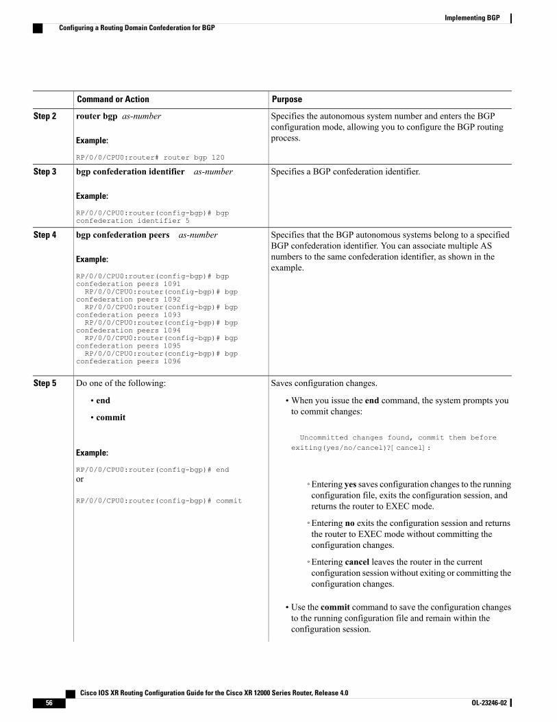
PurposeCommand or Action
Specifies the autonomous system number and enters the BGPconfiguration mode, allowing you to configure the BGP routingprocess.
router bgp as-number
Example:
RP/0/0/CPU0:router# router bgp 120
Step 2
Specifies a BGP confederation identifier.bgp confederation identifier as-number
Example:
RP/0/0/CPU0:router(config-bgp)# bgpconfederation identifier 5
Step 3
Specifies that the BGP autonomous systems belong to a specifiedBGP confederation identifier. You can associate multiple AS
bgp confederation peers as-number
Example:
RP/0/0/CPU0:router(config-bgp)# bgp
Step 4
numbers to the same confederation identifier, as shown in theexample.
confederation peers 1091RP/0/0/CPU0:router(config-bgp)# bgp
confederation peers 1092RP/0/0/CPU0:router(config-bgp)# bgp
confederation peers 1093RP/0/0/CPU0:router(config-bgp)# bgp
confederation peers 1094RP/0/0/CPU0:router(config-bgp)# bgp
confederation peers 1095RP/0/0/CPU0:router(config-bgp)# bgp
confederation peers 1096
Saves configuration changes.Do one of the following:Step 5
• end •When you issue the end command, the system prompts youto commit changes:
Uncommitted changes found, commit them before
• commit
Example:
RP/0/0/CPU0:router(config-bgp)# end
exiting(yes/no/cancel)?[cancel]:
or
RP/0/0/CPU0:router(config-bgp)# commit
◦Entering yes saves configuration changes to the runningconfiguration file, exits the configuration session, andreturns the router to EXEC mode.
◦Entering no exits the configuration session and returnsthe router to EXEC mode without committing theconfiguration changes.
◦Entering cancel leaves the router in the currentconfiguration session without exiting or committing theconfiguration changes.
• Use the commit command to save the configuration changesto the running configuration file and remain within theconfiguration session.
Cisco IOS XR Routing Configuration Guide for the Cisco XR 12000 Series Router, Release 4.056 OL-23246-02
Implementing BGPConfiguring a Routing Domain Confederation for BGP
PurposeCommand or Action
Resetting an eBGP Session Immediately Upon Link FailureBy default, if a link goes down, all BGP sessions of any directly adjacent external peers are immediately reset.Use the bgp fast-external-fallover disable command to disable automatic resetting. Turn the automatic resetback on using the no bgp fast-external-fallover disable command.
eBGP sessions flap when the node reaches 3500 eBGP sessions with BGP timer values set as 10 and 30. Tosupport more than 3500 eBGP sessions, increase the packet rate by using the lpts pifib hardware policelocation location-id command. Following is a sample configuration to increase the eBGP sessions:RP/0/0/CPU0:router#configureRP/0/0/CPU0:router(config)#lpts pifib hardware police location 0/2/CPU0RP/0/0/CPU0:router(config-pifib-policer-per-node)#flow bgp configured rate 4000RP/0/0/CPU0:router(config-pifib-policer-per-node)#flow bgp known rate 4000RP/0/0/CPU0:router(config-pifib-policer-per-node)#flow bgp default rate 4000RP/0/0/CPU0:router(config-pifib-policer-per-node)#commit
Logging Neighbor ChangesLogging neighbor changes is enabled by default. Use the log neighbor changes disable command to turn offlogging. The no log neighbor changes disable command can also be used to turn logging back on if it hasbeen disabled.
Adjusting BGP TimersPerform this task to set the timers for BGP neighbors.
BGP uses certain timers to control periodic activities, such as the sending of keepalive messages and theinterval after which a neighbor is assumed to be down if no messages are received from the neighbor duringthe interval. The values set using the timers bgp command in router configuration mode can be overriddenon particular neighbors using the timers command in the neighbor configuration mode.
SUMMARY STEPS
1. configure2. router bgp as-number3. timers bgp keepalive hold-time4. neighbor ip-address5. timers keepalive hold-time6. Do one of the following:
• end
• commit
Cisco IOS XR Routing Configuration Guide for the Cisco XR 12000 Series Router, Release 4.0 OL-23246-02 57
Implementing BGPResetting an eBGP Session Immediately Upon Link Failure

DETAILED STEPS
PurposeCommand or Action
Enters global configuration mode.configure
Example:
RP/0/0/CPU0:router# configure
Step 1
Specifies the autonomous system number and enters the BGPconfigurationmode, allowing you to configure the BGP routing process.
router bgp as-number
Example:
RP/0/0/CPU0:router(config)# router bgp123
Step 2
Sets a default keepalive time and a default hold time for all neighbors.timers bgp keepalive hold-time
Example:
RP/0/0/CPU0:router(config-bgp)# timersbgp 30 90
Step 3
Places the router in neighbor configuration mode for BGP routing andconfigures the neighbor IP address as a BGP peer.
neighbor ip-address
Example:
RP/0/0/CPU0:router(config-bgp)# neighbor172.168.40.24
Step 4
(Optional) Sets the keepalive timer and the hold-time timer for the BGPneighbor.
timers keepalive hold-time
Example:
RP/0/0/CPU0:router(config-bgp-nbr)#timers 60 220
Step 5
Saves configuration changes.Do one of the following:Step 6
• end •When you issue the end command, the system prompts you tocommit changes:
Uncommitted changes found, commit them before
• commit
Example:
RP/0/0/CPU0:router(config-bgp-nbr)# end
exiting(yes/no/cancel)?[cancel]:
or
RP/0/0/CPU0:router(config-bgp-nbr)#commit
◦Entering yes saves configuration changes to the runningconfiguration file, exits the configuration session, and returnsthe router to EXEC mode.
◦Entering no exits the configuration session and returns therouter to EXECmode without committing the configurationchanges.
Cisco IOS XR Routing Configuration Guide for the Cisco XR 12000 Series Router, Release 4.058 OL-23246-02
Implementing BGPAdjusting BGP Timers

PurposeCommand or Action
◦Entering cancel leaves the router in the current configurationsession without exiting or committing the configurationchanges.
• Use the commit command to save the configuration changes tothe running configuration file and remain within the configurationsession.
Changing the BGP Default Local Preference ValuePerform this task to set the default local preference value for BGP paths.
SUMMARY STEPS
1. configure2. router bgp as-number3. bgp default local-preference value4. Do one of the following:
• end
• commit
DETAILED STEPS
PurposeCommand or Action
Enters global configuration mode.configure
Example:
RP/0/0/CPU0:router# configure
Step 1
Specifies the autonomous system number and enters the BGP configurationmode, allowing you to configure the BGP routing process.
router bgp as-number
Example:
RP/0/0/CPU0:router(config)# router bgp120
Step 2
Cisco IOS XR Routing Configuration Guide for the Cisco XR 12000 Series Router, Release 4.0 OL-23246-02 59
Implementing BGPChanging the BGP Default Local Preference Value
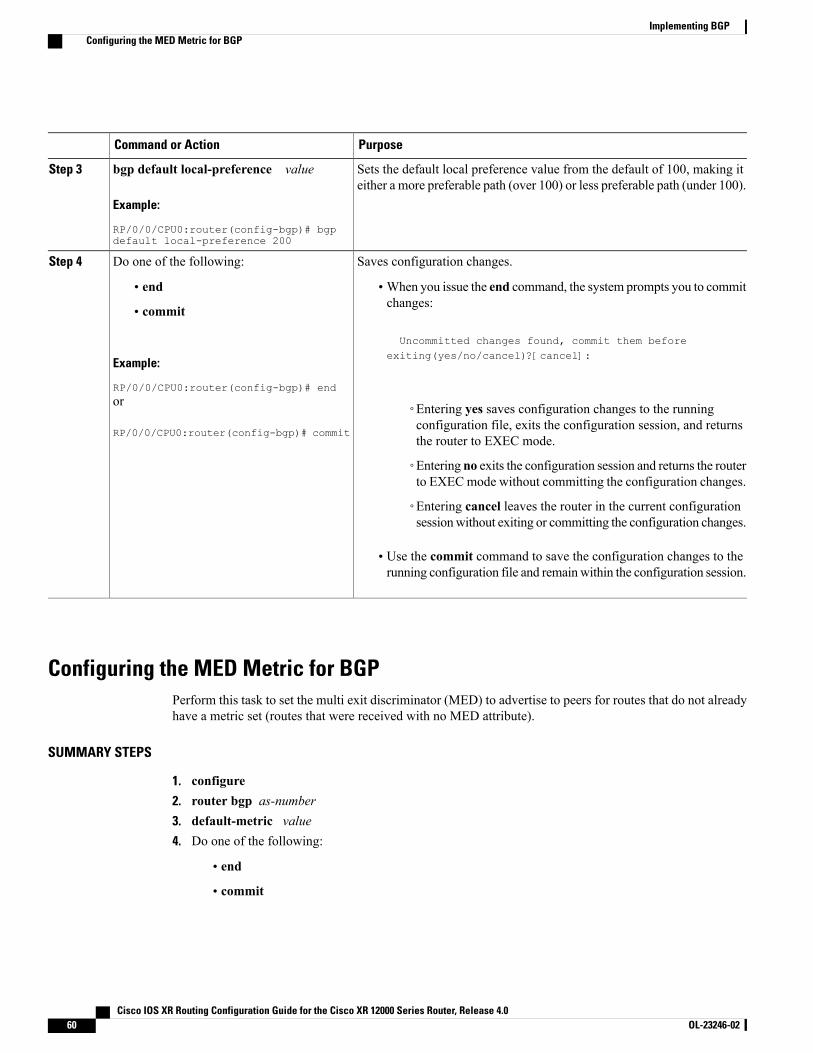
PurposeCommand or Action
Sets the default local preference value from the default of 100, making iteither a more preferable path (over 100) or less preferable path (under 100).
bgp default local-preference value
Example:
RP/0/0/CPU0:router(config-bgp)# bgpdefault local-preference 200
Step 3
Saves configuration changes.Do one of the following:Step 4
• end •When you issue the end command, the system prompts you to commitchanges:
Uncommitted changes found, commit them before
• commit
Example:
RP/0/0/CPU0:router(config-bgp)# end
exiting(yes/no/cancel)?[cancel]:
or
RP/0/0/CPU0:router(config-bgp)# commit
◦Entering yes saves configuration changes to the runningconfiguration file, exits the configuration session, and returnsthe router to EXEC mode.
◦Entering no exits the configuration session and returns the routerto EXECmode without committing the configuration changes.
◦Entering cancel leaves the router in the current configurationsessionwithout exiting or committing the configuration changes.
• Use the commit command to save the configuration changes to therunning configuration file and remainwithin the configuration session.
Configuring the MED Metric for BGPPerform this task to set the multi exit discriminator (MED) to advertise to peers for routes that do not alreadyhave a metric set (routes that were received with no MED attribute).
SUMMARY STEPS
1. configure2. router bgp as-number3. default-metric value4. Do one of the following:
• end
• commit
Cisco IOS XR Routing Configuration Guide for the Cisco XR 12000 Series Router, Release 4.060 OL-23246-02
Implementing BGPConfiguring the MED Metric for BGP
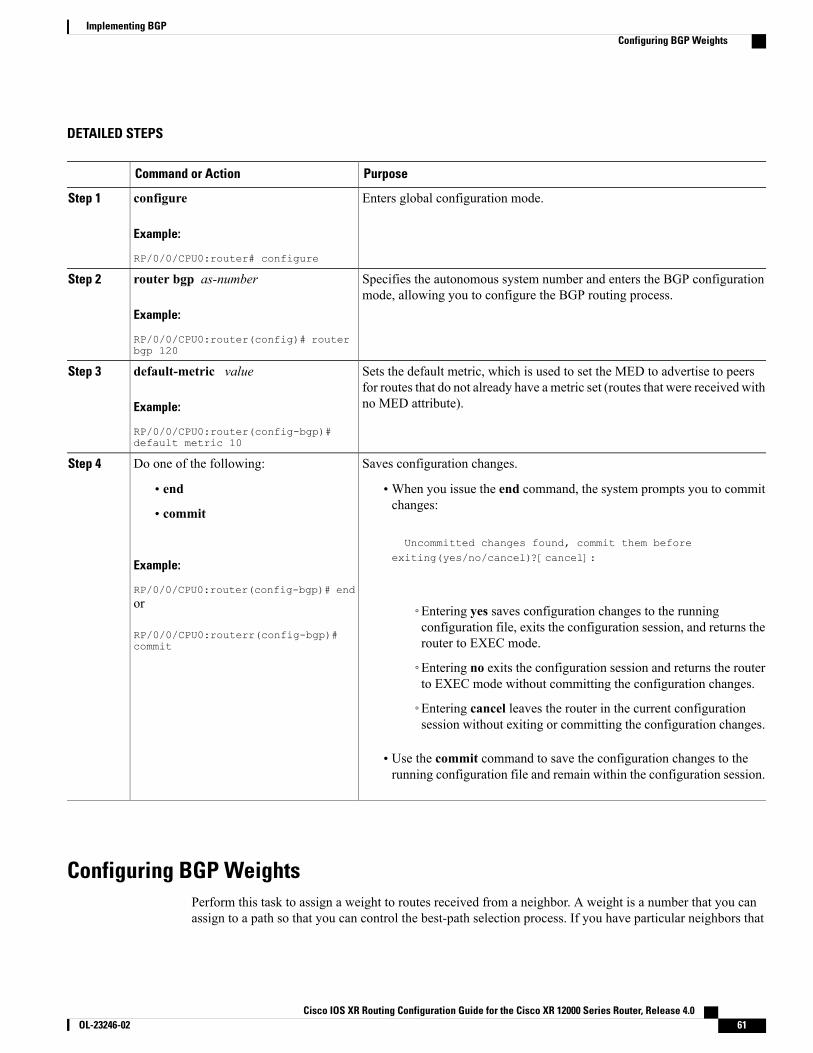
DETAILED STEPS
PurposeCommand or Action
Enters global configuration mode.configure
Example:
RP/0/0/CPU0:router# configure
Step 1
Specifies the autonomous system number and enters the BGP configurationmode, allowing you to configure the BGP routing process.
router bgp as-number
Example:
RP/0/0/CPU0:router(config)# routerbgp 120
Step 2
Sets the default metric, which is used to set the MED to advertise to peersfor routes that do not already have a metric set (routes that were received withno MED attribute).
default-metric value
Example:
RP/0/0/CPU0:router(config-bgp)#default metric 10
Step 3
Saves configuration changes.Do one of the following:Step 4
• end •When you issue the end command, the system prompts you to commitchanges:
Uncommitted changes found, commit them before
• commit
Example:
RP/0/0/CPU0:router(config-bgp)# end
exiting(yes/no/cancel)?[cancel]:
or
RP/0/0/CPU0:routerr(config-bgp)#commit
◦Entering yes saves configuration changes to the runningconfiguration file, exits the configuration session, and returns therouter to EXEC mode.
◦Entering no exits the configuration session and returns the routerto EXEC mode without committing the configuration changes.
◦Entering cancel leaves the router in the current configurationsession without exiting or committing the configuration changes.
• Use the commit command to save the configuration changes to therunning configuration file and remain within the configuration session.
Configuring BGP WeightsPerform this task to assign a weight to routes received from a neighbor. A weight is a number that you canassign to a path so that you can control the best-path selection process. If you have particular neighbors that
Cisco IOS XR Routing Configuration Guide for the Cisco XR 12000 Series Router, Release 4.0 OL-23246-02 61
Implementing BGPConfiguring BGP Weights
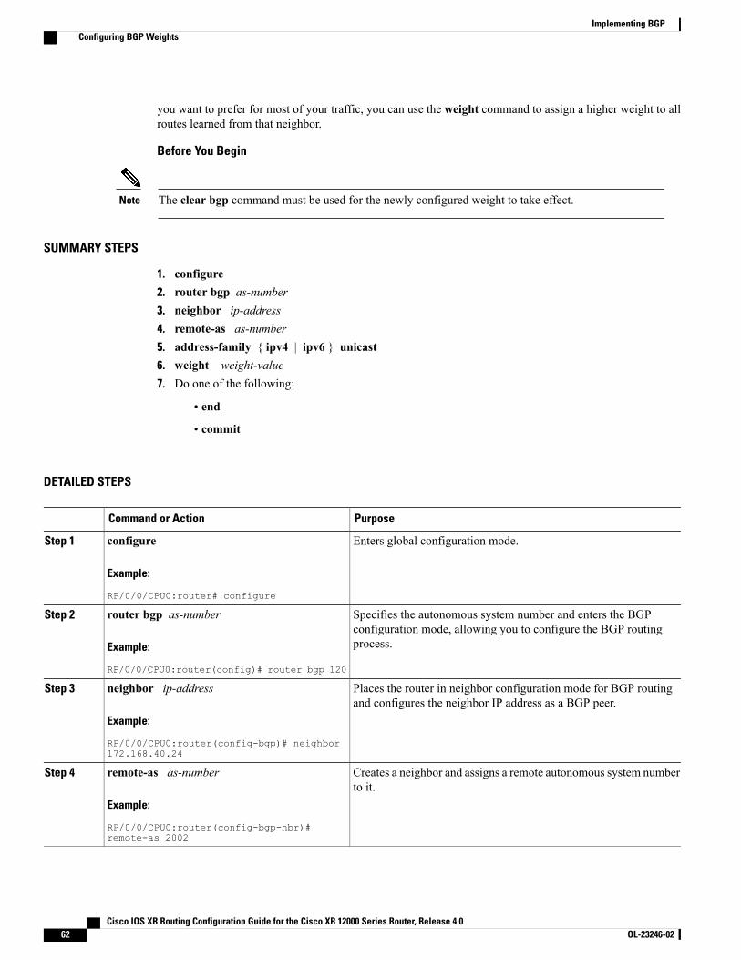
you want to prefer for most of your traffic, you can use the weight command to assign a higher weight to allroutes learned from that neighbor.
Before You Begin
The clear bgp command must be used for the newly configured weight to take effect.Note
SUMMARY STEPS
1. configure2. router bgp as-number3. neighbor ip-address4. remote-as as-number5. address-family { ipv4 | ipv6 } unicast6. weight weight-value7. Do one of the following:
• end
• commit
DETAILED STEPS
PurposeCommand or Action
Enters global configuration mode.configure
Example:
RP/0/0/CPU0:router# configure
Step 1
Specifies the autonomous system number and enters the BGPconfiguration mode, allowing you to configure the BGP routingprocess.
router bgp as-number
Example:
RP/0/0/CPU0:router(config)# router bgp 120
Step 2
Places the router in neighbor configuration mode for BGP routingand configures the neighbor IP address as a BGP peer.
neighbor ip-address
Example:
RP/0/0/CPU0:router(config-bgp)# neighbor172.168.40.24
Step 3
Creates a neighbor and assigns a remote autonomous system numberto it.
remote-as as-number
Example:
RP/0/0/CPU0:router(config-bgp-nbr)#remote-as 2002
Step 4
Cisco IOS XR Routing Configuration Guide for the Cisco XR 12000 Series Router, Release 4.062 OL-23246-02
Implementing BGPConfiguring BGP Weights
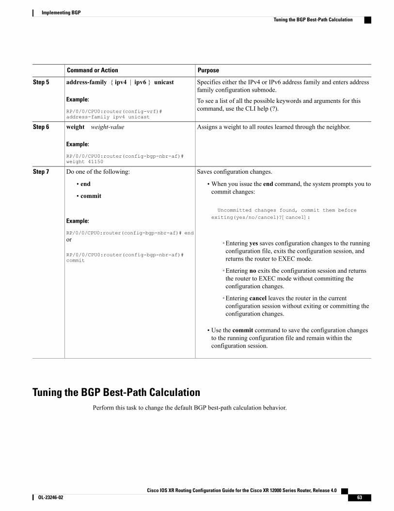
PurposeCommand or Action
Specifies either the IPv4 or IPv6 address family and enters addressfamily configuration submode.
address-family { ipv4 | ipv6 } unicast
Example:
RP/0/0/CPU0:router(config-vrf)#address-family ipv4 unicast
Step 5
To see a list of all the possible keywords and arguments for thiscommand, use the CLI help (?).
Assigns a weight to all routes learned through the neighbor.weight weight-value
Example:
RP/0/0/CPU0:router(config-bgp-nbr-af)#weight 41150
Step 6
Saves configuration changes.Do one of the following:Step 7
• end •When you issue the end command, the system prompts you tocommit changes:
Uncommitted changes found, commit them before
• commit
Example:
RP/0/0/CPU0:router(config-bgp-nbr-af)# end
exiting(yes/no/cancel)?[cancel]:
or
RP/0/0/CPU0:router(config-bgp-nbr-af)#commit
◦Entering yes saves configuration changes to the runningconfiguration file, exits the configuration session, andreturns the router to EXEC mode.
◦Entering no exits the configuration session and returnsthe router to EXEC mode without committing theconfiguration changes.
◦Entering cancel leaves the router in the currentconfiguration session without exiting or committing theconfiguration changes.
• Use the commit command to save the configuration changesto the running configuration file and remain within theconfiguration session.
Tuning the BGP Best-Path CalculationPerform this task to change the default BGP best-path calculation behavior.
Cisco IOS XR Routing Configuration Guide for the Cisco XR 12000 Series Router, Release 4.0 OL-23246-02 63
Implementing BGPTuning the BGP Best-Path Calculation
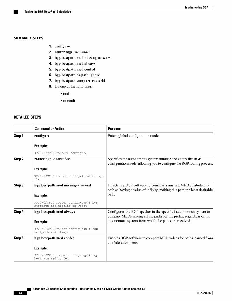
SUMMARY STEPS
1. configure2. router bgp as-number3. bgp bestpath med missing-as-worst4. bgp bestpath med always5. bgp bestpath med confed6. bgp bestpath as-path ignore7. bgp bestpath compare-routerid8. Do one of the following:
• end
• commit
DETAILED STEPS
PurposeCommand or Action
Enters global configuration mode.configure
Example:
RP/0/0/CPU0:router# configure
Step 1
Specifies the autonomous system number and enters the BGPconfigurationmode, allowing you to configure the BGP routing process.
router bgp as-number
Example:
RP/0/0/CPU0:router(config)# router bgp126
Step 2
Directs the BGP software to consider a missing MED attribute in apath as having a value of infinity, making this path the least desirablepath.
bgp bestpath med missing-as-worst
Example:
RP/0/0/CPU0:router(config-bgp)# bgpbestpath med missing-as-worst
Step 3
Configures the BGP speaker in the specified autonomous system tocompare MEDs among all the paths for the prefix, regardless of theautonomous system from which the paths are received.
bgp bestpath med always
Example:
RP/0/0/CPU0:router(config-bgp)# bgpbestpath med always
Step 4
Enables BGP software to compare MED values for paths learned fromconfederation peers.
bgp bestpath med confed
Example:
RP/0/0/CPU0:router(config-bgp)# bgpbestpath med confed
Step 5
Cisco IOS XR Routing Configuration Guide for the Cisco XR 12000 Series Router, Release 4.064 OL-23246-02
Implementing BGPTuning the BGP Best-Path Calculation

PurposeCommand or Action
Configures the BGP software to ignore the autonomous system lengthwhen performing best-path selection.
bgp bestpath as-path ignore
Example:
RP/0/0/CPU0:router(config-bgp)# bgpbestpath as-path ignore
Step 6
Configure the BGP speaker in the autonomous system to compare therouter IDs of similar paths.
bgp bestpath compare-routerid
Example:
RP/0/0/CPU0:router(config-bgp)# bgpbestpath compare-routerid
Step 7
Saves configuration changes.Do one of the following:Step 8
• end •When you issue the end command, the system prompts you tocommit changes:
Uncommitted changes found, commit them beforeexiting(yes/no/cancel)?[cancel]:
• commit
Example:
RP/0/0/CPU0:router(config-bgp)# end◦Entering yes saves configuration changes to the runningconfiguration file, exits the configuration session, andreturns the router to EXEC mode.
or
RP/0/0/CPU0:router(config-bgp)# commit ◦Entering no exits the configuration session and returns therouter to EXECmode without committing the configurationchanges.
◦Entering cancel leaves the router in the current configurationsession without exiting or committing the configurationchanges.
• Use the commit command to save the configuration changes tothe running configuration file and remain within the configurationsession.
Indicating BGP Back-door RoutesPerform this task to set the administrative distance on an external Border Gateway Protocol (eBGP) route tothat of a locally sourced BGP route, causing it to be less preferred than an Interior Gateway Protocol (IGP)route.
Cisco IOS XR Routing Configuration Guide for the Cisco XR 12000 Series Router, Release 4.0 OL-23246-02 65
Implementing BGPIndicating BGP Back-door Routes
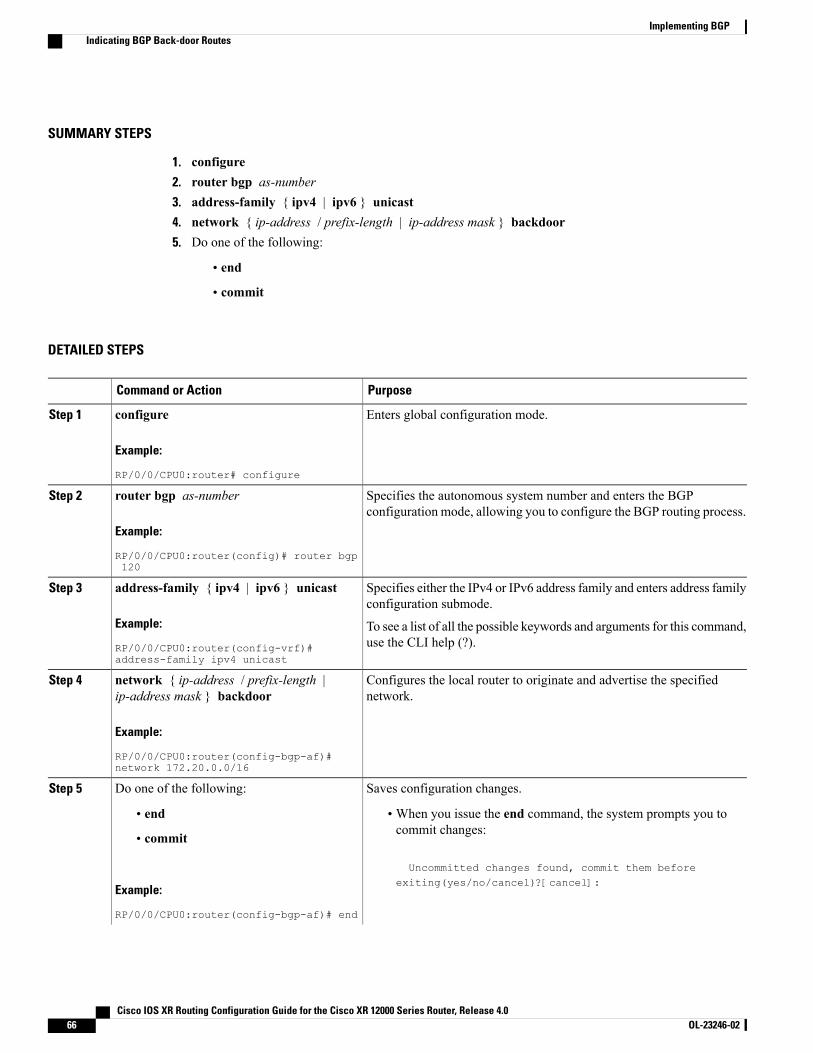
SUMMARY STEPS
1. configure2. router bgp as-number3. address-family { ipv4 | ipv6 } unicast4. network { ip-address / prefix-length | ip-address mask } backdoor5. Do one of the following:
• end
• commit
DETAILED STEPS
PurposeCommand or Action
Enters global configuration mode.configure
Example:
RP/0/0/CPU0:router# configure
Step 1
Specifies the autonomous system number and enters the BGPconfiguration mode, allowing you to configure the BGP routing process.
router bgp as-number
Example:
RP/0/0/CPU0:router(config)# router bgp120
Step 2
Specifies either the IPv4 or IPv6 address family and enters address familyconfiguration submode.
address-family { ipv4 | ipv6 } unicast
Example:
RP/0/0/CPU0:router(config-vrf)#address-family ipv4 unicast
Step 3
To see a list of all the possible keywords and arguments for this command,use the CLI help (?).
Configures the local router to originate and advertise the specifiednetwork.
network { ip-address / prefix-length |ip-address mask } backdoor
Example:
RP/0/0/CPU0:router(config-bgp-af)#network 172.20.0.0/16
Step 4
Saves configuration changes.Do one of the following:Step 5
• end •When you issue the end command, the system prompts you tocommit changes:
Uncommitted changes found, commit them beforeexiting(yes/no/cancel)?[cancel]:
• commit
Example:
RP/0/0/CPU0:router(config-bgp-af)# end
Cisco IOS XR Routing Configuration Guide for the Cisco XR 12000 Series Router, Release 4.066 OL-23246-02
Implementing BGPIndicating BGP Back-door Routes
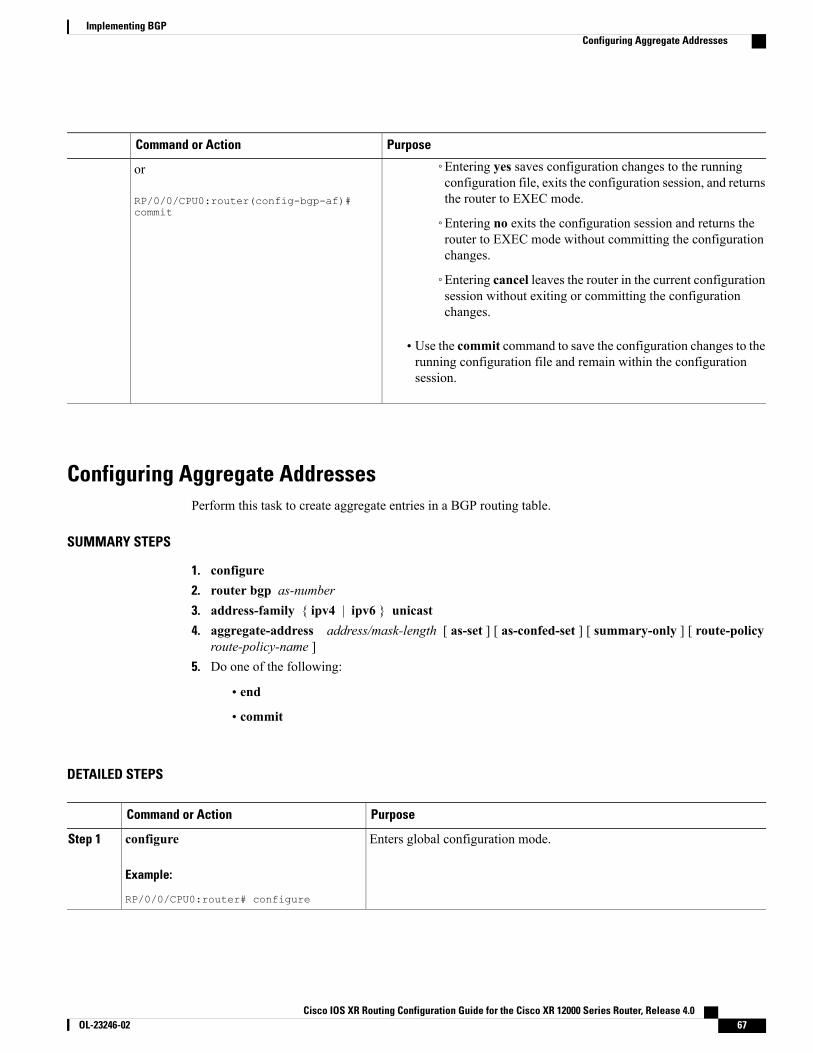
PurposeCommand or Action
◦Entering yes saves configuration changes to the runningconfiguration file, exits the configuration session, and returnsthe router to EXEC mode.
or
RP/0/0/CPU0:router(config-bgp-af)#commit
◦Entering no exits the configuration session and returns therouter to EXEC mode without committing the configurationchanges.
◦Entering cancel leaves the router in the current configurationsession without exiting or committing the configurationchanges.
• Use the commit command to save the configuration changes to therunning configuration file and remain within the configurationsession.
Configuring Aggregate AddressesPerform this task to create aggregate entries in a BGP routing table.
SUMMARY STEPS
1. configure2. router bgp as-number3. address-family { ipv4 | ipv6 } unicast4. aggregate-address address/mask-length [ as-set ] [ as-confed-set ] [ summary-only ] [ route-policy
route-policy-name ]5. Do one of the following:
• end
• commit
DETAILED STEPS
PurposeCommand or Action
Enters global configuration mode.configure
Example:
RP/0/0/CPU0:router# configure
Step 1
Cisco IOS XR Routing Configuration Guide for the Cisco XR 12000 Series Router, Release 4.0 OL-23246-02 67
Implementing BGPConfiguring Aggregate Addresses
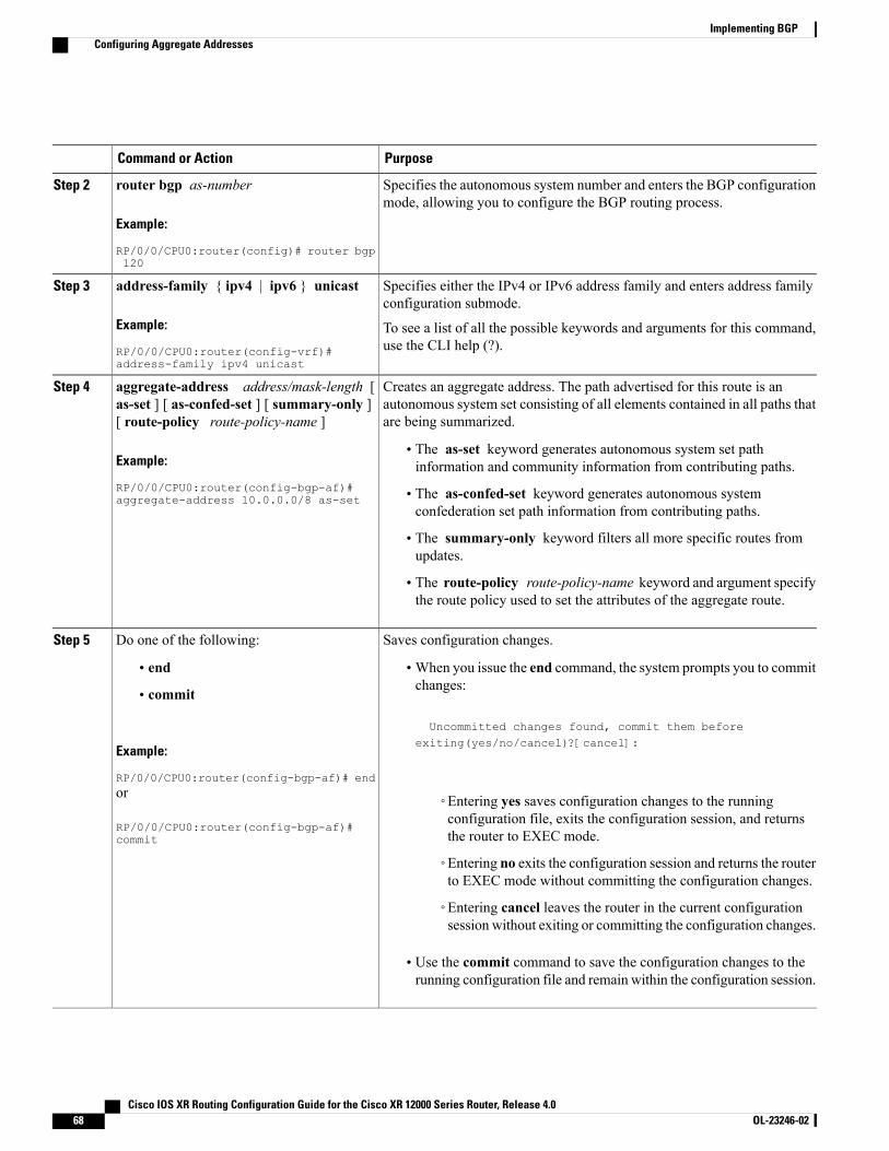
PurposeCommand or Action
Specifies the autonomous system number and enters the BGP configurationmode, allowing you to configure the BGP routing process.
router bgp as-number
Example:
RP/0/0/CPU0:router(config)# router bgp120
Step 2
Specifies either the IPv4 or IPv6 address family and enters address familyconfiguration submode.
address-family { ipv4 | ipv6 } unicast
Example:
RP/0/0/CPU0:router(config-vrf)#address-family ipv4 unicast
Step 3
To see a list of all the possible keywords and arguments for this command,use the CLI help (?).
Creates an aggregate address. The path advertised for this route is anautonomous system set consisting of all elements contained in all paths thatare being summarized.
aggregate-address address/mask-length [as-set ] [ as-confed-set ] [ summary-only ][ route-policy route-policy-name ]
Step 4
Example:
RP/0/0/CPU0:router(config-bgp-af)#aggregate-address 10.0.0.0/8 as-set
• The as-set keyword generates autonomous system set pathinformation and community information from contributing paths.
• The as-confed-set keyword generates autonomous systemconfederation set path information from contributing paths.
• The summary-only keyword filters all more specific routes fromupdates.
• The route-policy route-policy-name keyword and argument specifythe route policy used to set the attributes of the aggregate route.
Saves configuration changes.Do one of the following:Step 5
• end •When you issue the end command, the system prompts you to commitchanges:
Uncommitted changes found, commit them before
• commit
Example:
RP/0/0/CPU0:router(config-bgp-af)# end
exiting(yes/no/cancel)?[cancel]:
or
RP/0/0/CPU0:router(config-bgp-af)#commit
◦Entering yes saves configuration changes to the runningconfiguration file, exits the configuration session, and returnsthe router to EXEC mode.
◦Entering no exits the configuration session and returns the routerto EXEC mode without committing the configuration changes.
◦Entering cancel leaves the router in the current configurationsession without exiting or committing the configuration changes.
• Use the commit command to save the configuration changes to therunning configuration file and remain within the configuration session.
Cisco IOS XR Routing Configuration Guide for the Cisco XR 12000 Series Router, Release 4.068 OL-23246-02
Implementing BGPConfiguring Aggregate Addresses
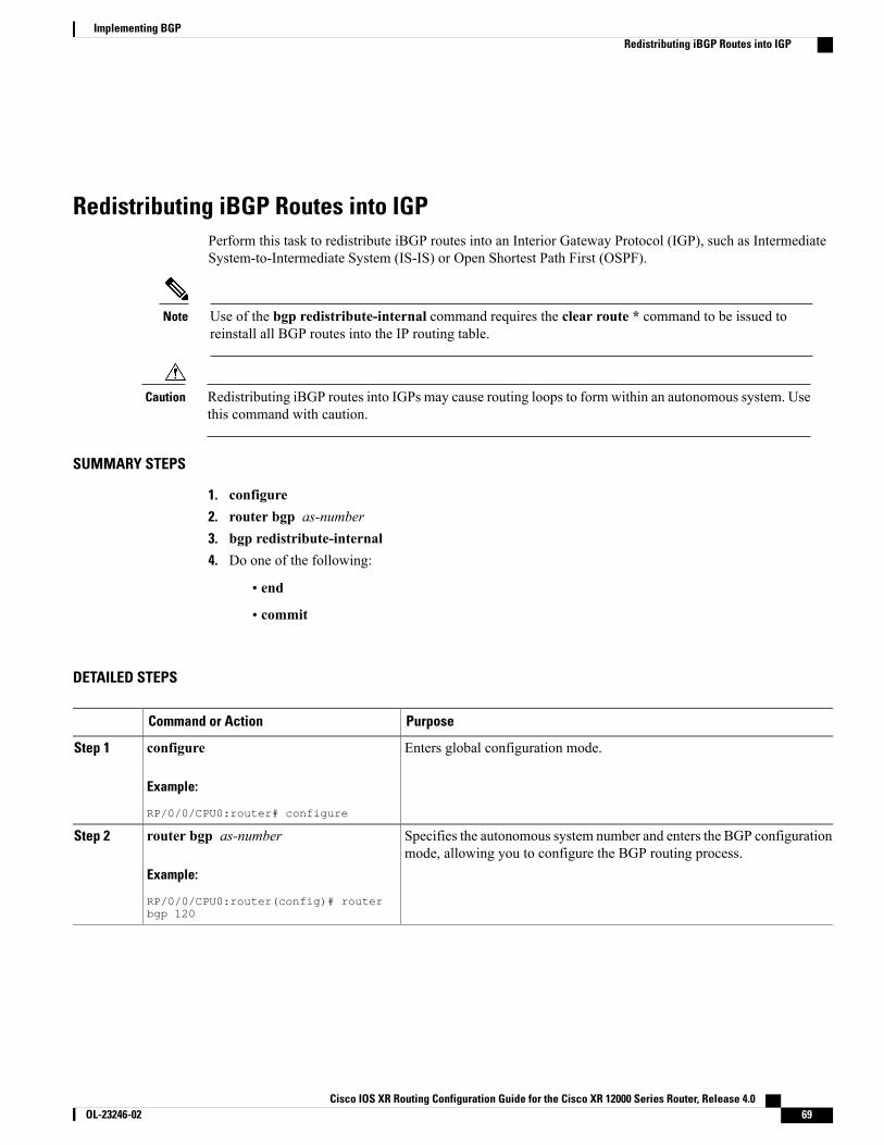
Redistributing iBGP Routes into IGPPerform this task to redistribute iBGP routes into an Interior Gateway Protocol (IGP), such as IntermediateSystem-to-Intermediate System (IS-IS) or Open Shortest Path First (OSPF).
Use of the bgp redistribute-internal command requires the clear route * command to be issued toreinstall all BGP routes into the IP routing table.
Note
Redistributing iBGP routes into IGPs may cause routing loops to form within an autonomous system. Usethis command with caution.
Caution
SUMMARY STEPS
1. configure2. router bgp as-number3. bgp redistribute-internal4. Do one of the following:
• end
• commit
DETAILED STEPS
PurposeCommand or Action
Enters global configuration mode.configure
Example:
RP/0/0/CPU0:router# configure
Step 1
Specifies the autonomous system number and enters the BGP configurationmode, allowing you to configure the BGP routing process.
router bgp as-number
Example:
RP/0/0/CPU0:router(config)# routerbgp 120
Step 2
Cisco IOS XR Routing Configuration Guide for the Cisco XR 12000 Series Router, Release 4.0 OL-23246-02 69
Implementing BGPRedistributing iBGP Routes into IGP
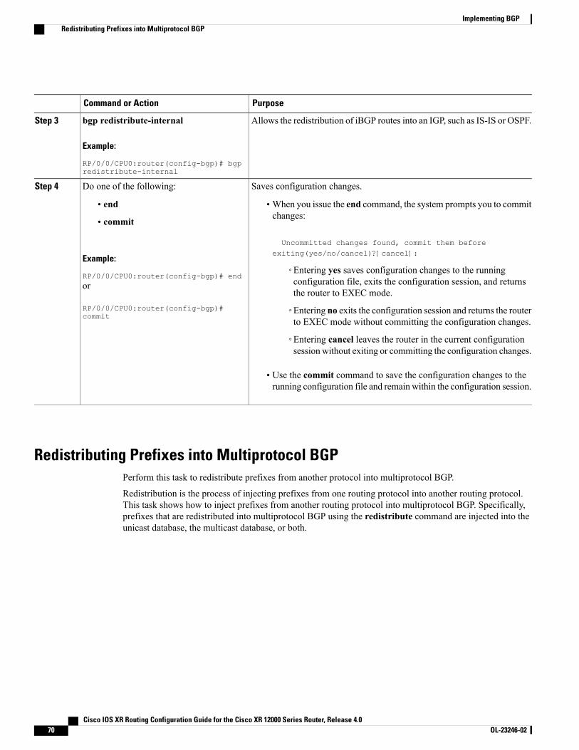
PurposeCommand or Action
Allows the redistribution of iBGP routes into an IGP, such as IS-IS or OSPF.bgp redistribute-internal
Example:
RP/0/0/CPU0:router(config-bgp)# bgpredistribute-internal
Step 3
Saves configuration changes.Do one of the following:Step 4
• end •When you issue the end command, the system prompts you to commitchanges:
Uncommitted changes found, commit them beforeexiting(yes/no/cancel)?[cancel]:
• commit
Example:
RP/0/0/CPU0:router(config-bgp)# end◦Entering yes saves configuration changes to the runningconfiguration file, exits the configuration session, and returnsthe router to EXEC mode.
or
RP/0/0/CPU0:router(config-bgp)#commit
◦Entering no exits the configuration session and returns the routerto EXEC mode without committing the configuration changes.
◦Entering cancel leaves the router in the current configurationsession without exiting or committing the configuration changes.
• Use the commit command to save the configuration changes to therunning configuration file and remain within the configuration session.
Redistributing Prefixes into Multiprotocol BGPPerform this task to redistribute prefixes from another protocol into multiprotocol BGP.
Redistribution is the process of injecting prefixes from one routing protocol into another routing protocol.This task shows how to inject prefixes from another routing protocol into multiprotocol BGP. Specifically,prefixes that are redistributed into multiprotocol BGP using the redistribute command are injected into theunicast database, the multicast database, or both.
Cisco IOS XR Routing Configuration Guide for the Cisco XR 12000 Series Router, Release 4.070 OL-23246-02
Implementing BGPRedistributing Prefixes into Multiprotocol BGP
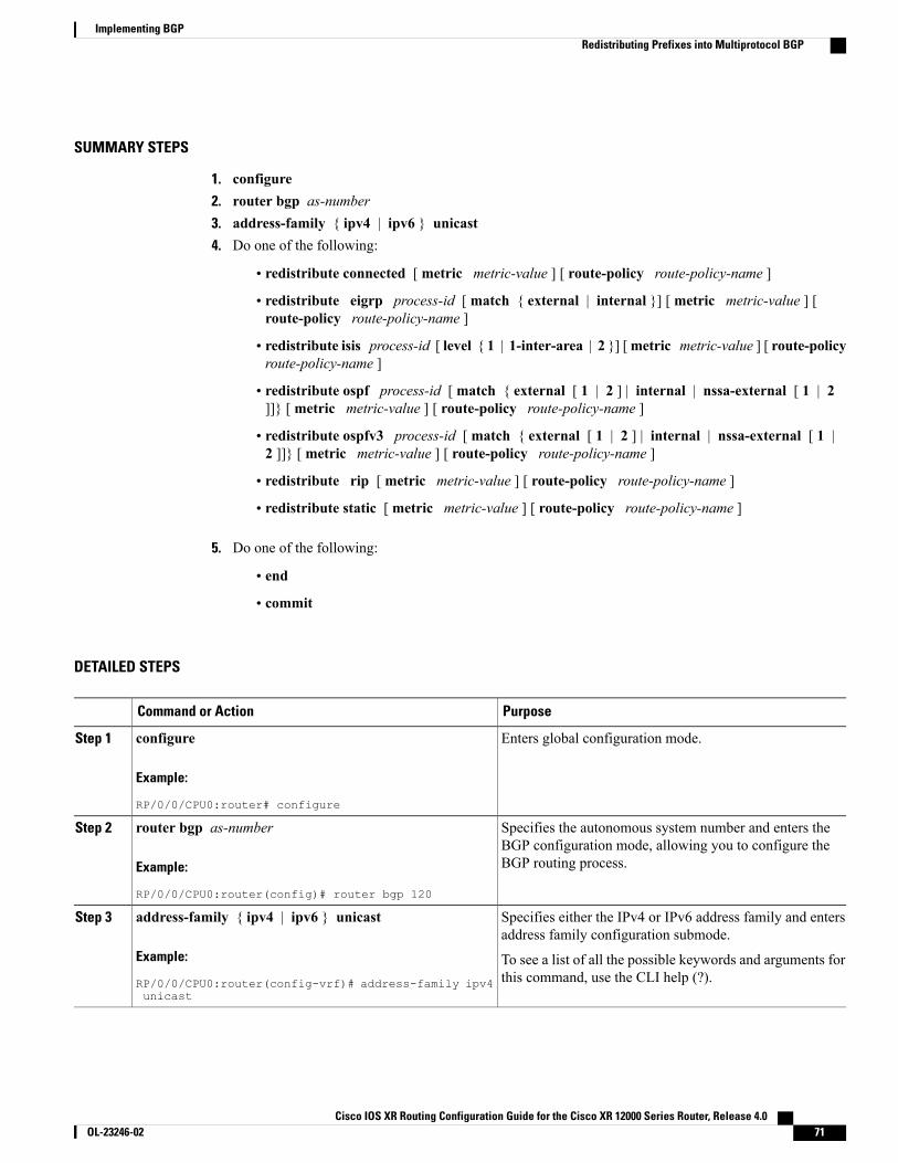
SUMMARY STEPS
1. configure2. router bgp as-number3. address-family { ipv4 | ipv6 } unicast4. Do one of the following:
• redistribute connected [ metric metric-value ] [ route-policy route-policy-name ]
• redistribute eigrp process-id [ match { external | internal }] [ metric metric-value ] [route-policy route-policy-name ]
• redistribute isis process-id [ level { 1 | 1-inter-area | 2 }] [metric metric-value ] [ route-policyroute-policy-name ]
• redistribute ospf process-id [ match { external [ 1 | 2 ] | internal | nssa-external [ 1 | 2]]} [ metric metric-value ] [ route-policy route-policy-name ]
• redistribute ospfv3 process-id [ match { external [ 1 | 2 ] | internal | nssa-external [ 1 |2 ]]} [ metric metric-value ] [ route-policy route-policy-name ]
• redistribute rip [ metric metric-value ] [ route-policy route-policy-name ]
• redistribute static [ metric metric-value ] [ route-policy route-policy-name ]
5. Do one of the following:
• end
• commit
DETAILED STEPS
PurposeCommand or Action
Enters global configuration mode.configure
Example:
RP/0/0/CPU0:router# configure
Step 1
Specifies the autonomous system number and enters theBGP configuration mode, allowing you to configure theBGP routing process.
router bgp as-number
Example:
RP/0/0/CPU0:router(config)# router bgp 120
Step 2
Specifies either the IPv4 or IPv6 address family and entersaddress family configuration submode.
address-family { ipv4 | ipv6 } unicast
Example:
RP/0/0/CPU0:router(config-vrf)# address-family ipv4unicast
Step 3
To see a list of all the possible keywords and arguments forthis command, use the CLI help (?).
Cisco IOS XR Routing Configuration Guide for the Cisco XR 12000 Series Router, Release 4.0 OL-23246-02 71
Implementing BGPRedistributing Prefixes into Multiprotocol BGP
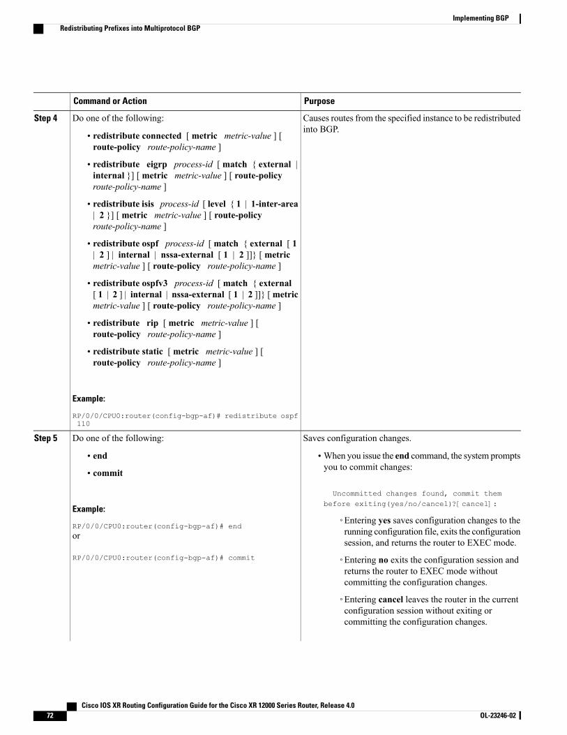
PurposeCommand or Action
Causes routes from the specified instance to be redistributedinto BGP.
Do one of the following:Step 4
• redistribute connected [ metric metric-value ] [route-policy route-policy-name ]
• redistribute eigrp process-id [ match { external |internal }] [ metric metric-value ] [ route-policyroute-policy-name ]
• redistribute isis process-id [ level { 1 | 1-inter-area| 2 }] [ metric metric-value ] [ route-policyroute-policy-name ]
• redistribute ospf process-id [ match { external [ 1| 2 ] | internal | nssa-external [ 1 | 2 ]]} [ metricmetric-value ] [ route-policy route-policy-name ]
• redistribute ospfv3 process-id [ match { external[ 1 | 2 ] | internal | nssa-external [ 1 | 2 ]]} [metricmetric-value ] [ route-policy route-policy-name ]
• redistribute rip [ metric metric-value ] [route-policy route-policy-name ]
• redistribute static [ metric metric-value ] [route-policy route-policy-name ]
Example:
RP/0/0/CPU0:router(config-bgp-af)# redistribute ospf110
Saves configuration changes.Do one of the following:Step 5
• end •When you issue the end command, the system promptsyou to commit changes:
Uncommitted changes found, commit thembefore exiting(yes/no/cancel)?[cancel]:
• commit
Example:
RP/0/0/CPU0:router(config-bgp-af)# end◦Entering yes saves configuration changes to therunning configuration file, exits the configurationsession, and returns the router to EXEC mode.
or
RP/0/0/CPU0:router(config-bgp-af)# commit ◦Entering no exits the configuration session andreturns the router to EXEC mode withoutcommitting the configuration changes.
◦Entering cancel leaves the router in the currentconfiguration session without exiting orcommitting the configuration changes.
Cisco IOS XR Routing Configuration Guide for the Cisco XR 12000 Series Router, Release 4.072 OL-23246-02
Implementing BGPRedistributing Prefixes into Multiprotocol BGP
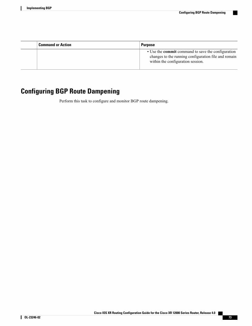
PurposeCommand or Action
• Use the commit command to save the configurationchanges to the running configuration file and remainwithin the configuration session.
Configuring BGP Route DampeningPerform this task to configure and monitor BGP route dampening.
Cisco IOS XR Routing Configuration Guide for the Cisco XR 12000 Series Router, Release 4.0 OL-23246-02 73
Implementing BGPConfiguring BGP Route Dampening
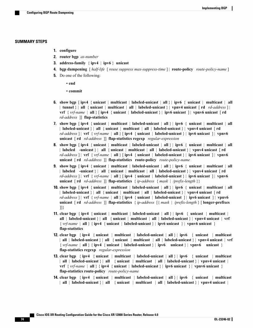
SUMMARY STEPS
1. configure2. router bgp as-number3. address-family { ipv4 | ipv6 } unicast4. bgp dampening [ half-life [ reuse suppress max-suppress-time ] | route-policy route-policy-name ]5. Do one of the following:
• end
• commit
6. show bgp [ ipv4 { unicast | multicast | labeled-unicast | all } | ipv6 { unicast | multicast | all| tunnel } | all { unicast | multicast | all | labeled-unicast } | vpnv4 unicast [ rd rd-address ] |vrf { vrf-name | all } [ ipv4 { unicast | labeled-unicast } | ipv6 unicast ] | vpnv6 unicast [ rdrd-address ]] flap-statistics
7. show bgp [ ipv4 { unicast | multicast | labeled-unicast | all } | ipv6 { unicast | multicast | all| labeled-unicast } | all { unicast | multicast | all | labeled-unicast } | vpnv4 unicast [ rdrd-address ] | vrf { vrf-name | all } [ ipv4 { unicast | labeled-unicast } | ipv6 unicast ] | vpnv6unicast [ rd rd-address ]] flap-statistics regexp regular-expression
8. show bgp [ ipv4 { unicast | multicast | labeled-unicast | all } | ipv6 { unicast | multicast | all| labeled -unicast } | all { unicast | multicast | all | labeled-unicast } | vpnv4 unicast [ rdrd-address ] | vrf { vrf-name | all } [ ipv4 { unicast | labeled-unicast } | ipv6 unicast ] | vpnv6unicast [ rd rd-address ]] flap-statistics route-policy route-policy-name
9. show bgp [ ipv4 { unicast | multicast | labeled-unicast | all } | ipv6 { unicast | multicast | all| labeled -unicast } | all { unicast | multicast | all | labeled-unicast } | vpnv4 unicast [ rdrd-address ] | vrf { vrf-name | all } [ ipv4 { unicast | labeled-unicast } | ipv6 unicast ] | vpnv6unicast [ rd rd-address ]] flap-statistics { ip-address { mask | /prefix-length }}
10. show bgp [ ipv4 { unicast | multicast | labeled-unicast | all } | ipv6 { unicast | multicast | all| labeled-unicast } | all { unicast | multicast | all | labeled-unicast } | vpnv4 unicast [ rdrd-address ] | vrf { vrf-name | all } [ ipv4 { unicast | labeled-unicast ] | ipv6 unicast ] | vpnv6unicast [ rd rd-address ]] flap-statistics { ip-address [{ mask | /prefix-length } [ longer-prefixes]]}
11. clear bgp { ipv4 { unicast | multicast | labeled-unicast | all } | ipv6 { unicast | multicast |all | labeled-unicast } | all { unicast | multicast | all | labeled-unicast } | vpnv4 unicast | vrf{ vrf-name | all } { ipv4 { unicast | labeled-unicast } | ipv6 unicast } | vpnv6 unicast }flap-statistics
12. clear bgp { ipv4 { unicast | multicast | labeled-unicast | all } | ipv6 { unicast | multicast| all | labeled-unicast } | all { unicast | multicast | all | labeled-unicast } | vpnv4 unicast | vrf{ vrf-name | all } { ipv4 { unicast | labeled-unicast } | ipv6 unicast } | vpnv6 unicast }flap-statistics regexp regular-expression
13. clear bgp { ipv4 { unicast | multicast | labeled-unicast | all } | ipv6 { unicast | multicast| all | labeled-unicast } | all { unicast | multicast | all | labeled-unicast } | vpnv4 unicast |vrf { vrf-name | all } { ipv4 { unicast | labeled-unicast } | ipv6 unicast } | vpnv6 unicast }flap-statistics route-policy route-policy-name
14. clear bgp { ipv4 { unicast | multicast | labeled-unicast | all } | ipv6 { unicast | multicast| all | labeled-unicast } | all { unicast | multicast | all | labeled-unicast } | vpnv4 unicast |
Cisco IOS XR Routing Configuration Guide for the Cisco XR 12000 Series Router, Release 4.074 OL-23246-02
Implementing BGPConfiguring BGP Route Dampening
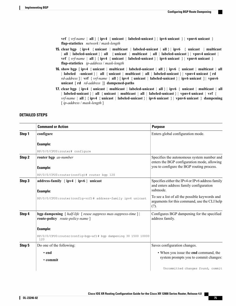
vrf { vrf-name | all } { ipv4 { unicast | labeled-unicast } | ipv6 unicast } | vpnv6 unicast }flap-statistics network / mask-length
15. clear bgp { ipv4 { unicast | multicast | labeled-unicast | all } | ipv6 { unicast | multicast| all | labeled-unicast } | all { unicast | multicast | all | labeled-unicast } | vpnv4 unicast |vrf { vrf-name | all } { ipv4 { unicast | labeled-unicast } | ipv6 unicast } | vpnv6 unicast }flap-statistics ip-address / mask-length
16. show bgp [ ipv4 { unicast | multicast | labeled-unicast | all } | ipv6 { unicast | multicast | all| labeled -unicast } | all { unicast | multicast | all | labeled-unicast } | vpnv4 unicast [ rdrd-address ] | vrf { vrf-name | all } [ ipv4 { unicast | labeled-unicast } | ipv6 unicast ] | vpnv6unicast [ rd rd-address ]] dampened-paths
17. clear bgp { ipv4 { unicast | multicast | labeled-unicast | all } | ipv6 { unicast | multicast | all| labeled-unicast } | all { unicast | multicast | all | labeled-unicast } | vpnv4 unicast | vrf {vrf-name | all } { ipv4 { unicast | labeled-unicast } | ipv6 unicast } | vpnv6 unicast } dampening[ ip-address / mask-length ]
DETAILED STEPS
PurposeCommand or Action
Enters global configuration mode.configure
Example:
RP/0/0/CPU0:router# configure
Step 1
Specifies the autonomous system number andenters the BGP configuration mode, allowingyou to configure the BGP routing process.
router bgp as-number
Example:
RP/0/0/CPU0:router(config)# router bgp 120
Step 2
Specifies either the IPv4 or IPv6 address familyand enters address family configurationsubmode.
address-family { ipv4 | ipv6 } unicast
Example:
RP/0/0/CPU0:router(config-vrf)# address-family ipv4 unicast
Step 3
To see a list of all the possible keywords andarguments for this command, use the CLI help(?).
Configures BGP dampening for the specifiedaddress family.
bgp dampening [ half-life [ reuse suppress max-suppress-time ] |route-policy route-policy-name ]
Example:
RP/0/0/CPU0:router(config-bgp-af)# bgp dampening 30 1500 10000120
Step 4
Saves configuration changes.Do one of the following:Step 5
• end •When you issue the end command, thesystem prompts you to commit changes:
Uncommitted changes found, commit
• commit
Cisco IOS XR Routing Configuration Guide for the Cisco XR 12000 Series Router, Release 4.0 OL-23246-02 75
Implementing BGPConfiguring BGP Route Dampening
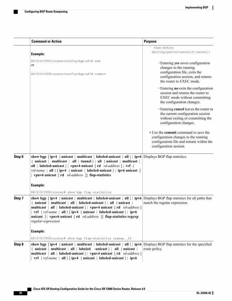
PurposeCommand or Action
Example:
RP/0/0/CPU0:router(config-bgp-af)# end
them beforeexiting(yes/no/cancel)?[cancel]:
◦Entering yes saves configurationchanges to the running
or
RP/0/0/CPU0:router(config-bgp-af)# commit configuration file, exits theconfiguration session, and returnsthe router to EXEC mode.
◦Entering no exits the configurationsession and returns the router toEXEC mode without committingthe configuration changes.
◦Entering cancel leaves the router inthe current configuration sessionwithout exiting or committing theconfiguration changes.
• Use the commit command to save theconfiguration changes to the runningconfiguration file and remain within theconfiguration session.
Displays BGP flap statistics.show bgp [ ipv4 { unicast | multicast | labeled-unicast | all } | ipv6{ unicast | multicast | all | tunnel } | all { unicast | multicast |
Step 6
all | labeled-unicast } | vpnv4 unicast [ rd rd-address ] | vrf {vrf-name | all } [ ipv4 { unicast | labeled-unicast } | ipv6 unicast ]| vpnv6 unicast [ rd rd-address ]] flap-statistics
Example:
RP/0/0/CPU0:router# show bgp flap statistics
Displays BGP flap statistics for all paths thatmatch the regular expression.
show bgp [ ipv4 { unicast | multicast | labeled-unicast | all } | ipv6{ unicast | multicast | all | labeled-unicast } | all { unicast |multicast | all | labeled-unicast } | vpnv4 unicast [ rd rd-address ]
Step 7
| vrf { vrf-name | all } [ ipv4 { unicast | labeled-unicast } | ipv6unicast ] | vpnv6 unicast [ rd rd-address ]] flap-statistics regexpregular-expression
Example:
RP/0/0/CPU0:router# show bgp flap-statistics regexp _1$
Displays BGP flap statistics for the specifiedroute policy.
show bgp [ ipv4 { unicast | multicast | labeled-unicast | all } | ipv6{ unicast | multicast | all | labeled -unicast } | all { unicast |multicast | all | labeled-unicast } | vpnv4 unicast [ rd rd-address ]
Step 8
| vrf { vrf-name | all } [ ipv4 { unicast | labeled-unicast } | ipv6
Cisco IOS XR Routing Configuration Guide for the Cisco XR 12000 Series Router, Release 4.076 OL-23246-02
Implementing BGPConfiguring BGP Route Dampening

PurposeCommand or Action
unicast ] | vpnv6 unicast [ rd rd-address ]] flap-statisticsroute-policy route-policy-name
Example:
RP/0/0/CPU0:router(config)# show bgp flap-statisticsroute-policy policy_A
Displays BGP flap for the specified prefix.show bgp [ ipv4 { unicast | multicast | labeled-unicast | all } | ipv6{ unicast | multicast | all | labeled -unicast } | all { unicast |
Step 9
multicast | all | labeled-unicast } | vpnv4 unicast [ rd rd-address ]| vrf { vrf-name | all } [ ipv4 { unicast | labeled-unicast } | ipv6unicast ] | vpnv6 unicast [ rd rd-address ]] flap-statistics {ip-address { mask | /prefix-length }}
Example:
RP/0/0/CPU0:router# show bgp flap-statistics 172.20.1.1
Displays BGP flap statistics for more specificentries for the specified IP address.
show bgp [ ipv4 { unicast | multicast | labeled-unicast | all } | ipv6{ unicast | multicast | all | labeled-unicast } | all { unicast |multicast | all | labeled-unicast } | vpnv4 unicast [ rd rd-address ]
Step 10
| vrf { vrf-name | all } [ ipv4 { unicast | labeled-unicast ] | ipv6unicast ] | vpnv6 unicast [ rd rd-address ]] flap-statistics {ip-address [{ mask | /prefix-length } [ longer-prefixes ]]}
Example:
RP/0/0/CPU0:router# show bgp flap-statistics 172.20.1.1longer-prefixes
Clears BGP flap statistics for all routes.clear bgp { ipv4 { unicast | multicast | labeled-unicast | all } | ipv6{ unicast | multicast | all | labeled-unicast } | all { unicast |
Step 11
multicast | all | labeled-unicast } | vpnv4 unicast | vrf { vrf-name| all } { ipv4 { unicast | labeled-unicast } | ipv6 unicast } | vpnv6unicast } flap-statistics
Example:
RP/0/0/CPU0:router# clear bgp all all flap-statistics
Clears BGP flap statistics for all paths thatmatch the specified regular expression.
clear bgp { ipv4 { unicast | multicast | labeled-unicast | all } |ipv6 { unicast | multicast | all | labeled-unicast } | all { unicast| multicast | all | labeled-unicast } | vpnv4 unicast | vrf { vrf-name
Step 12
| all } { ipv4 { unicast | labeled-unicast } | ipv6 unicast } | vpnv6unicast } flap-statistics regexp regular-expression
Example:
RP/0/0/CPU0:router# clear bgp ipv4 unicast flap-statisticsregexp _1$
Cisco IOS XR Routing Configuration Guide for the Cisco XR 12000 Series Router, Release 4.0 OL-23246-02 77
Implementing BGPConfiguring BGP Route Dampening

PurposeCommand or Action
Clears BGP flap statistics for the specifiedroute policy.
clear bgp { ipv4 { unicast | multicast | labeled-unicast | all } |ipv6 { unicast | multicast | all | labeled-unicast } | all { unicast| multicast | all | labeled-unicast } | vpnv4 unicast | vrf { vrf-name
Step 13
| all } { ipv4 { unicast | labeled-unicast } | ipv6 unicast } | vpnv6unicast } flap-statistics route-policy route-policy-name
Example:
RP/0/0/CPU0:router# clear bgp ipv4 unicast flap-statisticsroute-policy policy_A
Clears BGP flap statistics for the specifiednetwork.
clear bgp { ipv4 { unicast | multicast | labeled-unicast | all } |ipv6 { unicast | multicast | all | labeled-unicast } | all { unicast| multicast | all | labeled-unicast } | vpnv4 unicast | vrf { vrf-name
Step 14
| all } { ipv4 { unicast | labeled-unicast } | ipv6 unicast } | vpnv6unicast } flap-statistics network / mask-length
Example:
RP/0/0/CPU0:router# clear bgp ipv4 unicast flap-statistics192.168.40.0/24
Clears BGP flap statistics for routes receivedfrom the specified neighbor.
clear bgp { ipv4 { unicast | multicast | labeled-unicast | all } |ipv6 { unicast | multicast | all | labeled-unicast } | all { unicast| multicast | all | labeled-unicast } | vpnv4 unicast | vrf { vrf-name
Step 15
| all } { ipv4 { unicast | labeled-unicast } | ipv6 unicast } | vpnv6unicast } flap-statistics ip-address / mask-length
Example:
RP/0/0/CPU0:router# clear bgp ipv4 unicast flap-statistics172.20.1.1
Displays the dampened routes, including thetime remaining before they are unsuppressed.
show bgp [ ipv4 { unicast | multicast | labeled-unicast | all } | ipv6{ unicast | multicast | all | labeled -unicast } | all { unicast |multicast | all | labeled-unicast } | vpnv4 unicast [ rd rd-address ]
Step 16
| vrf { vrf-name | all } [ ipv4 { unicast | labeled-unicast } | ipv6unicast ] | vpnv6 unicast [ rd rd-address ]] dampened-paths
Example:
RP/0/0/CPU0:router# show bgp dampened paths
Clears route dampening information andunsuppresses the suppressed routes.
clear bgp { ipv4 { unicast | multicast | labeled-unicast | all } | ipv6{ unicast | multicast | all | labeled-unicast } | all { unicast |
Step 17
multicast | all | labeled-unicast } | vpnv4 unicast | vrf { vrf-name
Cisco IOS XR Routing Configuration Guide for the Cisco XR 12000 Series Router, Release 4.078 OL-23246-02
Implementing BGPConfiguring BGP Route Dampening
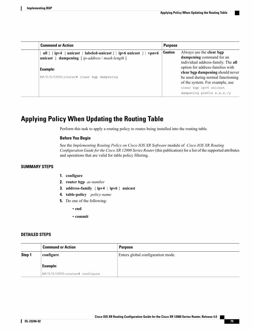
PurposeCommand or Action
Always use the clear bgpdampening command for anindividual address-family. The alloption for address-families withclear bgp dampening should neverbe used during normal functioningof the system. For example, useclear bgp ipv4 unicast
dampening prefix x.x.x./y
Caution| all } { ipv4 { unicast | labeled-unicast } | ipv6 unicast } | vpnv6unicast } dampening [ ip-address / mask-length ]
Example:
RP/0/0/CPU0:router# clear bgp dampening
Applying Policy When Updating the Routing TablePerform this task to apply a routing policy to routes being installed into the routing table.
Before You Begin
See the Implementing Routing Policy on Cisco IOS XR Software module of Cisco IOS XR RoutingConfiguration Guide for the Cisco XR 12000 Series Router (this publication) for a list of the supported attributesand operations that are valid for table policy filtering.
SUMMARY STEPS
1. configure2. router bgp as-number3. address-family { ipv4 | ipv6 } unicast4. table-policy policy-name5. Do one of the following:
• end
• commit
DETAILED STEPS
PurposeCommand or Action
Enters global configuration mode.configure
Example:
RP/0/0/CPU0:router# configure
Step 1
Cisco IOS XR Routing Configuration Guide for the Cisco XR 12000 Series Router, Release 4.0 OL-23246-02 79
Implementing BGPApplying Policy When Updating the Routing Table
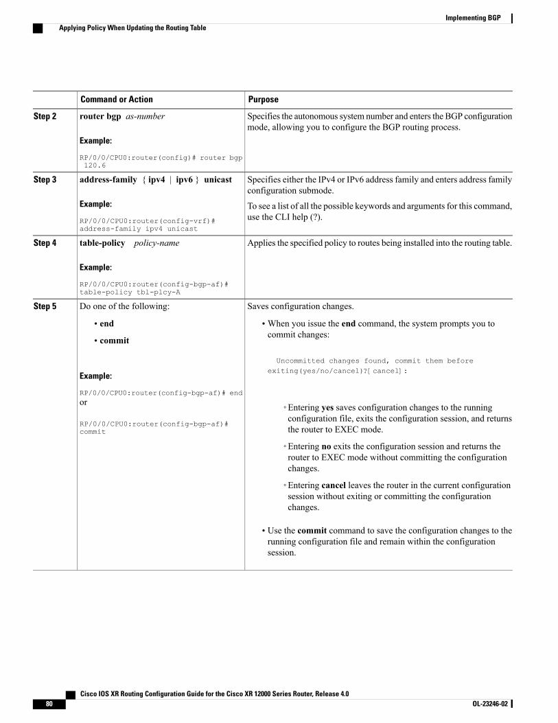
PurposeCommand or Action
Specifies the autonomous system number and enters the BGP configurationmode, allowing you to configure the BGP routing process.
router bgp as-number
Example:
RP/0/0/CPU0:router(config)# router bgp120.6
Step 2
Specifies either the IPv4 or IPv6 address family and enters address familyconfiguration submode.
address-family { ipv4 | ipv6 } unicast
Example:
RP/0/0/CPU0:router(config-vrf)#address-family ipv4 unicast
Step 3
To see a list of all the possible keywords and arguments for this command,use the CLI help (?).
Applies the specified policy to routes being installed into the routing table.table-policy policy-name
Example:
RP/0/0/CPU0:router(config-bgp-af)#table-policy tbl-plcy-A
Step 4
Saves configuration changes.Do one of the following:Step 5
• end •When you issue the end command, the system prompts you tocommit changes:
Uncommitted changes found, commit them before
• commit
Example:
RP/0/0/CPU0:router(config-bgp-af)# end
exiting(yes/no/cancel)?[cancel]:
or
RP/0/0/CPU0:router(config-bgp-af)#commit
◦Entering yes saves configuration changes to the runningconfiguration file, exits the configuration session, and returnsthe router to EXEC mode.
◦Entering no exits the configuration session and returns therouter to EXEC mode without committing the configurationchanges.
◦Entering cancel leaves the router in the current configurationsession without exiting or committing the configurationchanges.
• Use the commit command to save the configuration changes to therunning configuration file and remain within the configurationsession.
Cisco IOS XR Routing Configuration Guide for the Cisco XR 12000 Series Router, Release 4.080 OL-23246-02
Implementing BGPApplying Policy When Updating the Routing Table
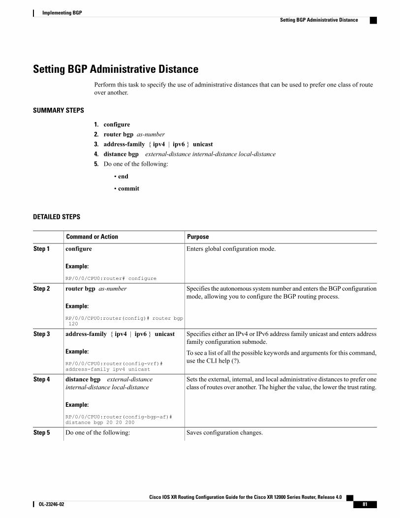
Setting BGP Administrative DistancePerform this task to specify the use of administrative distances that can be used to prefer one class of routeover another.
SUMMARY STEPS
1. configure2. router bgp as-number3. address-family { ipv4 | ipv6 } unicast4. distance bgp external-distance internal-distance local-distance5. Do one of the following:
• end
• commit
DETAILED STEPS
PurposeCommand or Action
Enters global configuration mode.configure
Example:
RP/0/0/CPU0:router# configure
Step 1
Specifies the autonomous system number and enters the BGP configurationmode, allowing you to configure the BGP routing process.
router bgp as-number
Example:
RP/0/0/CPU0:router(config)# router bgp120
Step 2
Specifies either an IPv4 or IPv6 address family unicast and enters addressfamily configuration submode.
address-family { ipv4 | ipv6 } unicast
Example:
RP/0/0/CPU0:router(config-vrf)#address-family ipv4 unicast
Step 3
To see a list of all the possible keywords and arguments for this command,use the CLI help (?).
Sets the external, internal, and local administrative distances to prefer oneclass of routes over another. The higher the value, the lower the trust rating.
distance bgp external-distanceinternal-distance local-distance
Example:
RP/0/0/CPU0:router(config-bgp-af)#distance bgp 20 20 200
Step 4
Saves configuration changes.Do one of the following:Step 5
Cisco IOS XR Routing Configuration Guide for the Cisco XR 12000 Series Router, Release 4.0 OL-23246-02 81
Implementing BGPSetting BGP Administrative Distance
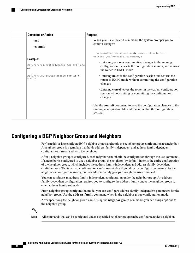
PurposeCommand or Action
•When you issue the end command, the system prompts you tocommit changes:
Uncommitted changes found, commit them beforeexiting(yes/no/cancel)?[cancel]:
• end
• commit
Example:
RP/0/0/CPU0:router(config-bgp-af)# end◦Entering yes saves configuration changes to the runningconfiguration file, exits the configuration session, and returnsthe router to EXEC mode.or
RP/0/0/CPU0:router(config-bgp-af)#commit
◦Entering no exits the configuration session and returns therouter to EXEC mode without committing the configurationchanges.
◦Entering cancel leaves the router in the current configurationsession without exiting or committing the configurationchanges.
• Use the commit command to save the configuration changes to therunning configuration file and remain within the configurationsession.
Configuring a BGP Neighbor Group and NeighborsPerform this task to configure BGP neighbor groups and apply the neighbor group configuration to a neighbor.A neighbor group is a template that holds address family-independent and address family-dependentconfigurations associated with the neighbor.
After a neighbor group is configured, each neighbor can inherit the configuration through the use command.If a neighbor is configured to use a neighbor group, the neighbor (by default) inherits the entire configurationof the neighbor group, which includes the address family-independent and address family-dependentconfigurations. The inherited configuration can be overridden if you directly configure commands for theneighbor or configure session groups or address family groups through the use command.
You can configure an address family-independent configuration under the neighbor group. An addressfamily-dependent configuration requires you to configure the address family under the neighbor group toenter address family submode.
From neighbor group configuration mode, you can configure address family-independent parameters for theneighbor group. Use the address-family command when in the neighbor group configuration mode.
After specifying the neighbor group name using the neighbor group command, you can assign options tothe neighbor group.
All commands that can be configured under a specified neighbor group can be configured under a neighbor.Note
Cisco IOS XR Routing Configuration Guide for the Cisco XR 12000 Series Router, Release 4.082 OL-23246-02
Implementing BGPConfiguring a BGP Neighbor Group and Neighbors
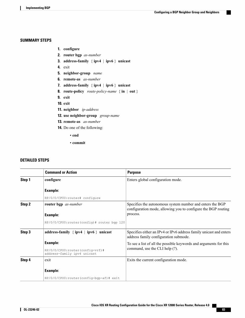
SUMMARY STEPS
1. configure2. router bgp as-number3. address-family { ipv4 | ipv6 } unicast4. exit5. neighbor-group name6. remote-as as-number7. address-family { ipv4 | ipv6 } unicast8. route-policy route-policy-name { in | out }9. exit10. exit11. neighbor ip-address12. use neighbor-group group-name13. remote-as as-number14. Do one of the following:
• end
• commit
DETAILED STEPS
PurposeCommand or Action
Enters global configuration mode.configure
Example:
RP/0/0/CPU0:router# configure
Step 1
Specifies the autonomous system number and enters the BGPconfiguration mode, allowing you to configure the BGP routingprocess.
router bgp as-number
Example:
RP/0/0/CPU0:router(config)# router bgp 120
Step 2
Specifies either an IPv4 or IPv6 address family unicast and entersaddress family configuration submode.
address-family { ipv4 | ipv6 } unicast
Example:
RP/0/0/CPU0:router(config-vrf)#address-family ipv4 unicast
Step 3
To see a list of all the possible keywords and arguments for thiscommand, use the CLI help (?).
Exits the current configuration mode.exit
Example:
RP/0/0/CPU0:router(config-bgp-af)# exit
Step 4
Cisco IOS XR Routing Configuration Guide for the Cisco XR 12000 Series Router, Release 4.0 OL-23246-02 83
Implementing BGPConfiguring a BGP Neighbor Group and Neighbors
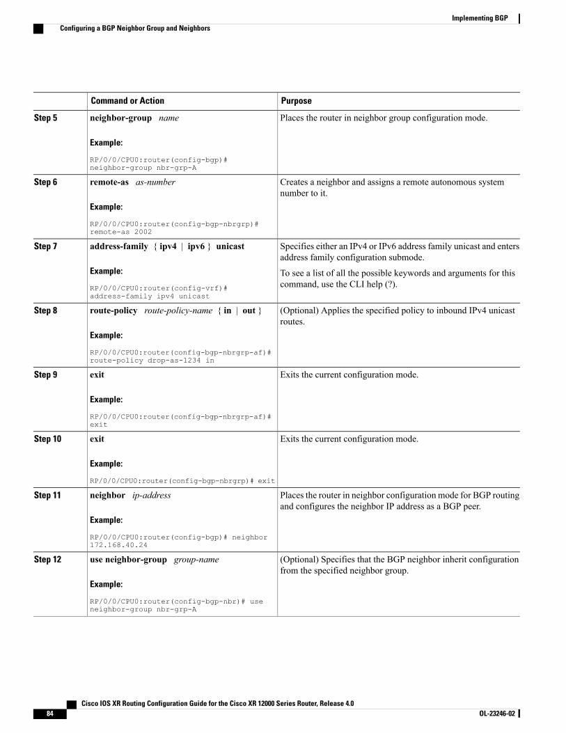
PurposeCommand or Action
Places the router in neighbor group configuration mode.neighbor-group name
Example:
RP/0/0/CPU0:router(config-bgp)#neighbor-group nbr-grp-A
Step 5
Creates a neighbor and assigns a remote autonomous systemnumber to it.
remote-as as-number
Example:
RP/0/0/CPU0:router(config-bgp-nbrgrp)#remote-as 2002
Step 6
Specifies either an IPv4 or IPv6 address family unicast and entersaddress family configuration submode.
address-family { ipv4 | ipv6 } unicast
Example:
RP/0/0/CPU0:router(config-vrf)#address-family ipv4 unicast
Step 7
To see a list of all the possible keywords and arguments for thiscommand, use the CLI help (?).
(Optional) Applies the specified policy to inbound IPv4 unicastroutes.
route-policy route-policy-name { in | out }
Example:
RP/0/0/CPU0:router(config-bgp-nbrgrp-af)#route-policy drop-as-1234 in
Step 8
Exits the current configuration mode.exit
Example:
RP/0/0/CPU0:router(config-bgp-nbrgrp-af)#exit
Step 9
Exits the current configuration mode.exit
Example:
RP/0/0/CPU0:router(config-bgp-nbrgrp)# exit
Step 10
Places the router in neighbor configuration mode for BGP routingand configures the neighbor IP address as a BGP peer.
neighbor ip-address
Example:
RP/0/0/CPU0:router(config-bgp)# neighbor172.168.40.24
Step 11
(Optional) Specifies that the BGP neighbor inherit configurationfrom the specified neighbor group.
use neighbor-group group-name
Example:
RP/0/0/CPU0:router(config-bgp-nbr)# useneighbor-group nbr-grp-A
Step 12
Cisco IOS XR Routing Configuration Guide for the Cisco XR 12000 Series Router, Release 4.084 OL-23246-02
Implementing BGPConfiguring a BGP Neighbor Group and Neighbors
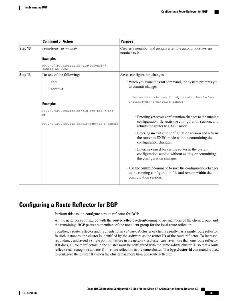
PurposeCommand or Action
Creates a neighbor and assigns a remote autonomous systemnumber to it.
remote-as as-number
Example:
RP/0/0/CPU0:router(config-bgp-nbr)#remote-as 2002
Step 13
Saves configuration changes.Do one of the following:Step 14
• end •When you issue the end command, the system prompts youto commit changes:
Uncommitted changes found, commit them before
• commit
Example:
RP/0/0/CPU0:router(config-bgp-nbr)# end
exiting(yes/no/cancel)?[cancel]:
or
RP/0/0/CPU0:router(config-bgp-nbr)# commit
◦Entering yes saves configuration changes to the runningconfiguration file, exits the configuration session, andreturns the router to EXEC mode.
◦Entering no exits the configuration session and returnsthe router to EXEC mode without committing theconfiguration changes.
◦Entering cancel leaves the router in the currentconfiguration session without exiting or committingthe configuration changes.
• Use the commit command to save the configuration changesto the running configuration file and remain within theconfiguration session.
Configuring a Route Reflector for BGPPerform this task to configure a route reflector for BGP.
All the neighbors configured with the route-reflector-clientcommand are members of the client group, andthe remaining iBGP peers are members of the nonclient group for the local route reflector.
Together, a route reflector and its clients form a cluster. A cluster of clients usually has a single route reflector.In such instances, the cluster is identified by the software as the router ID of the route reflector. To increaseredundancy and avoid a single point of failure in the network, a cluster can have more than one route reflector.If it does, all route reflectors in the cluster must be configured with the same 4-byte cluster ID so that a routereflector can recognize updates from route reflectors in the same cluster. The bgp cluster-id command is usedto configure the cluster ID when the cluster has more than one route reflector.
Cisco IOS XR Routing Configuration Guide for the Cisco XR 12000 Series Router, Release 4.0 OL-23246-02 85
Implementing BGPConfiguring a Route Reflector for BGP

SUMMARY STEPS
1. configure2. router bgp as-number3. bgp cluster-id cluster-id4. neighbor ip-address5. remote-as as-number6. address-family { ipv4 | ipv6 } unicast7. route-reflector-client8. Do one of the following:
• end
• commit
DETAILED STEPS
PurposeCommand or Action
Enters global configuration mode.configure
Example:
RP/0/0/CPU0:router# configure
Step 1
Specifies the autonomous system number and enters the BGPconfiguration mode, allowing you to configure the BGP routingprocess.
router bgp as-number
Example:
RP/0/0/CPU0:router(config)# router bgp 120
Step 2
Configures the local router as one of the route reflectors serving thecluster. It is configured with a specified cluster ID to identify thecluster.
bgp cluster-id cluster-id
Example:
RP/0/0/CPU0:router(config-bgp)# bgpcluster-id 192.168.70.1
Step 3
Places the router in neighbor configuration mode for BGP routingand configures the neighbor IP address as a BGP peer.
neighbor ip-address
Example:
RP/0/0/CPU0:router(config-bgp)# neighbor
Step 4
172.168.40.24
Creates a neighbor and assigns a remote autonomous system numberto it.
remote-as as-number
Example:
RP/0/0/CPU0:router(config-bgp-nbr)#remote-as 2003
Step 5
Cisco IOS XR Routing Configuration Guide for the Cisco XR 12000 Series Router, Release 4.086 OL-23246-02
Implementing BGPConfiguring a Route Reflector for BGP
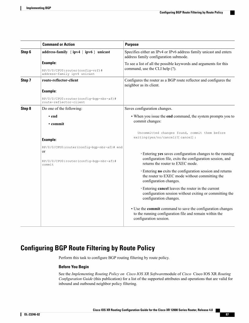
PurposeCommand or Action
Specifies either an IPv4 or IPv6 address family unicast and entersaddress family configuration submode.
address-family { ipv4 | ipv6 } unicast
Example:
RP/0/0/CPU0:router(config-vrf)#address-family ipv4 unicast
Step 6
To see a list of all the possible keywords and arguments for thiscommand, use the CLI help (?).
Configures the router as a BGP route reflector and configures theneighbor as its client.
route-reflector-client
Example:
RP/0/0/CPU0:router(config-bgp-nbr-af)#route-reflector-client
Step 7
Saves configuration changes.Do one of the following:Step 8
• end •When you issue the end command, the system prompts you tocommit changes:
Uncommitted changes found, commit them before
• commit
Example:
RP/0/0/CPU0:router(config-bgp-nbr-af)# end
exiting(yes/no/cancel)?[cancel]:
or
RP/0/0/CPU0:router(config-bgp-nbr-af)#commit
◦Entering yes saves configuration changes to the runningconfiguration file, exits the configuration session, andreturns the router to EXEC mode.
◦Entering no exits the configuration session and returnsthe router to EXEC mode without committing theconfiguration changes.
◦Entering cancel leaves the router in the currentconfiguration session without exiting or committing theconfiguration changes.
• Use the commit command to save the configuration changesto the running configuration file and remain within theconfiguration session.
Configuring BGP Route Filtering by Route PolicyPerform this task to configure BGP routing filtering by route policy.
Before You Begin
See the Implementing Routing Policy on Cisco IOS XR Softwaremodule of Cisco Cisco IOS XR RoutingConfiguration Guide (this publication) for a list of the supported attributes and operations that are valid forinbound and outbound neighbor policy filtering.
Cisco IOS XR Routing Configuration Guide for the Cisco XR 12000 Series Router, Release 4.0 OL-23246-02 87
Implementing BGPConfiguring BGP Route Filtering by Route Policy
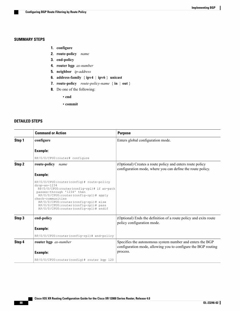
SUMMARY STEPS
1. configure2. route-policy name3. end-policy4. router bgp as-number5. neighbor ip-address6. address-family { ipv4 | ipv6 } unicast7. route-policy route-policy-name { in | out }8. Do one of the following:
• end
• commit
DETAILED STEPS
PurposeCommand or Action
Enters global configuration mode.configure
Example:
RP/0/0/CPU0:router# configure
Step 1
(Optional) Creates a route policy and enters route policyconfiguration mode, where you can define the route policy.
route-policy name
Example:
RP/0/0/CPU0:router(config)# route-policy
Step 2
drop-as-1234RP/0/0/CPU0:router(config-rpl)# if as-pathpasses-through '1234' thenRP/0/0/CPU0:router(config-rpl)# apply
check-communitiesRP/0/0/CPU0:router(config-rpl)# elseRP/0/0/CPU0:router(config-rpl)# passRP/0/0/CPU0:router(config-rpl)# endif
(Optional) Ends the definition of a route policy and exits routepolicy configuration mode.
end-policy
Example:
RP/0/0/CPU0:router(config-rpl)# end-policy
Step 3
Specifies the autonomous system number and enters the BGPconfiguration mode, allowing you to configure the BGP routingprocess.
router bgp as-number
Example:
RP/0/0/CPU0:router(config)# router bgp 120
Step 4
Cisco IOS XR Routing Configuration Guide for the Cisco XR 12000 Series Router, Release 4.088 OL-23246-02
Implementing BGPConfiguring BGP Route Filtering by Route Policy
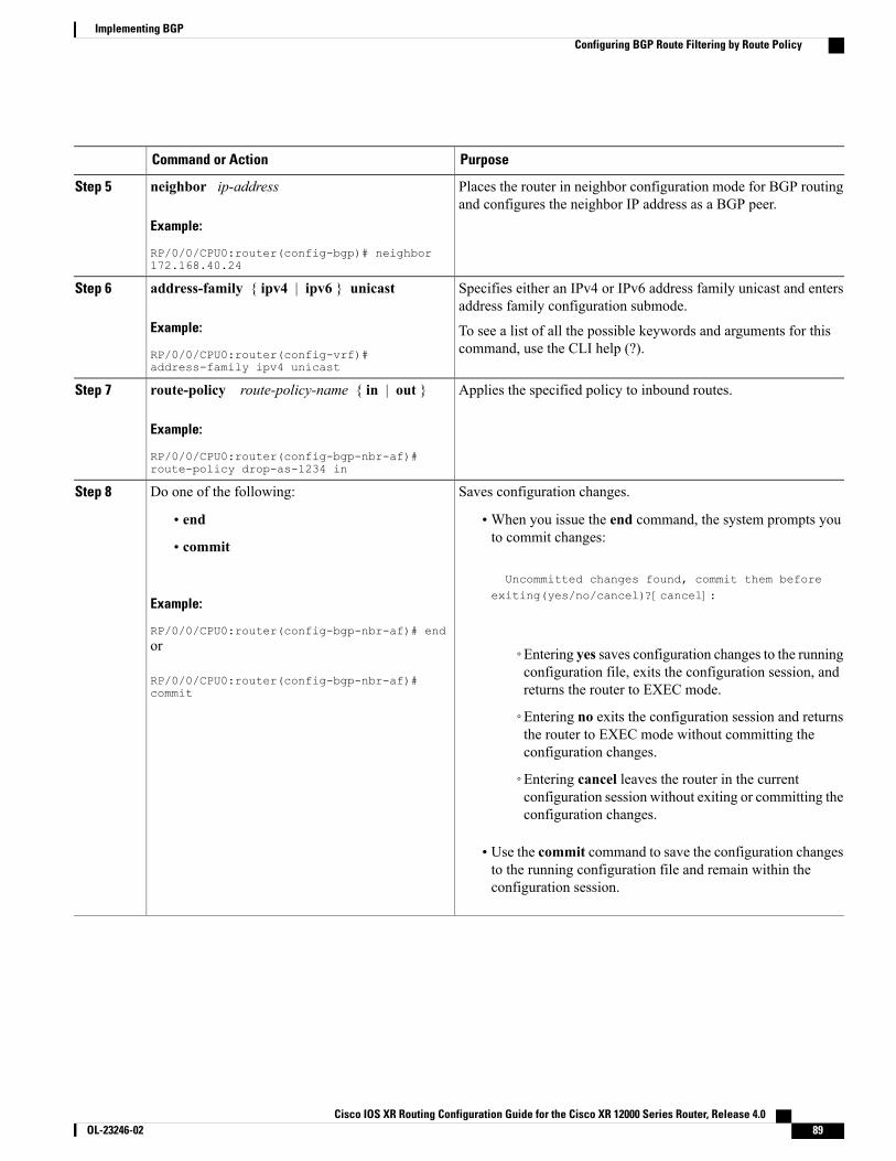
PurposeCommand or Action
Places the router in neighbor configuration mode for BGP routingand configures the neighbor IP address as a BGP peer.
neighbor ip-address
Example:
RP/0/0/CPU0:router(config-bgp)# neighbor172.168.40.24
Step 5
Specifies either an IPv4 or IPv6 address family unicast and entersaddress family configuration submode.
address-family { ipv4 | ipv6 } unicast
Example:
RP/0/0/CPU0:router(config-vrf)#address-family ipv4 unicast
Step 6
To see a list of all the possible keywords and arguments for thiscommand, use the CLI help (?).
Applies the specified policy to inbound routes.route-policy route-policy-name { in | out }
Example:
RP/0/0/CPU0:router(config-bgp-nbr-af)#route-policy drop-as-1234 in
Step 7
Saves configuration changes.Do one of the following:Step 8
• end •When you issue the end command, the system prompts youto commit changes:
Uncommitted changes found, commit them before
• commit
Example:
RP/0/0/CPU0:router(config-bgp-nbr-af)# end
exiting(yes/no/cancel)?[cancel]:
or
RP/0/0/CPU0:router(config-bgp-nbr-af)#commit
◦Entering yes saves configuration changes to the runningconfiguration file, exits the configuration session, andreturns the router to EXEC mode.
◦Entering no exits the configuration session and returnsthe router to EXEC mode without committing theconfiguration changes.
◦Entering cancel leaves the router in the currentconfiguration session without exiting or committing theconfiguration changes.
• Use the commit command to save the configuration changesto the running configuration file and remain within theconfiguration session.
Cisco IOS XR Routing Configuration Guide for the Cisco XR 12000 Series Router, Release 4.0 OL-23246-02 89
Implementing BGPConfiguring BGP Route Filtering by Route Policy
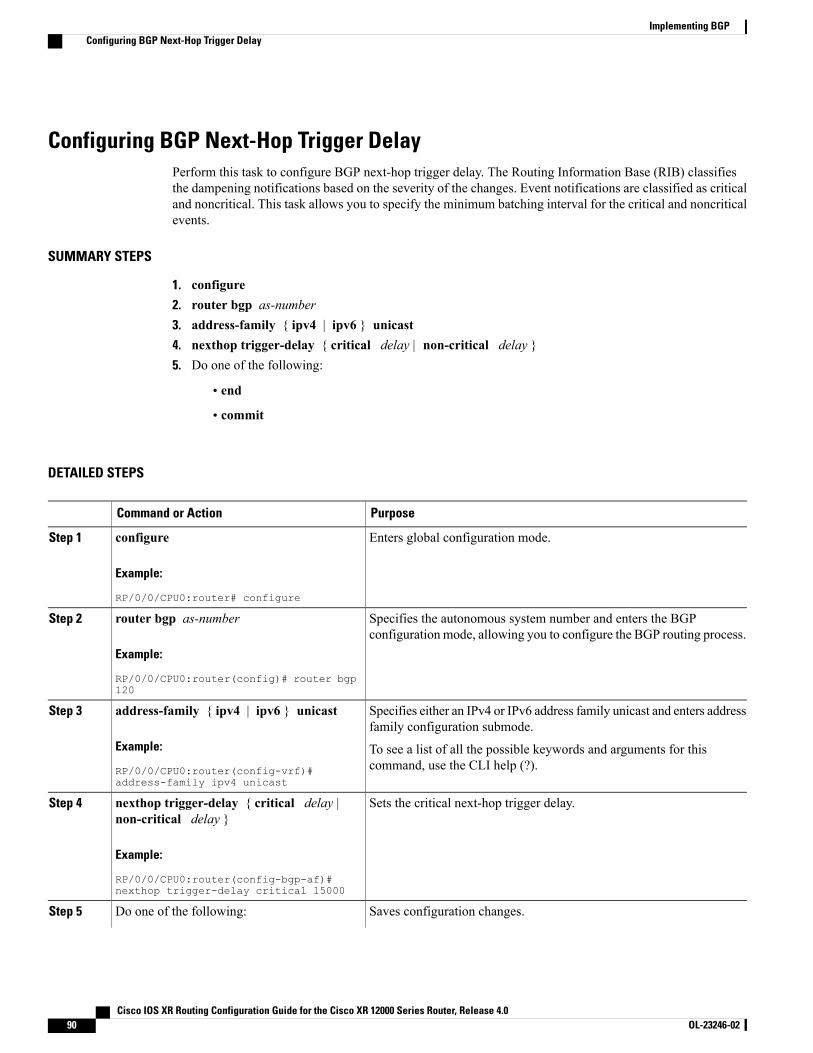
Configuring BGP Next-Hop Trigger DelayPerform this task to configure BGP next-hop trigger delay. The Routing Information Base (RIB) classifiesthe dampening notifications based on the severity of the changes. Event notifications are classified as criticaland noncritical. This task allows you to specify the minimum batching interval for the critical and noncriticalevents.
SUMMARY STEPS
1. configure2. router bgp as-number3. address-family { ipv4 | ipv6 } unicast4. nexthop trigger-delay { critical delay | non-critical delay }5. Do one of the following:
• end
• commit
DETAILED STEPS
PurposeCommand or Action
Enters global configuration mode.configure
Example:
RP/0/0/CPU0:router# configure
Step 1
Specifies the autonomous system number and enters the BGPconfiguration mode, allowing you to configure the BGP routing process.
router bgp as-number
Example:
RP/0/0/CPU0:router(config)# router bgp120
Step 2
Specifies either an IPv4 or IPv6 address family unicast and enters addressfamily configuration submode.
address-family { ipv4 | ipv6 } unicast
Example:
RP/0/0/CPU0:router(config-vrf)#address-family ipv4 unicast
Step 3
To see a list of all the possible keywords and arguments for thiscommand, use the CLI help (?).
Sets the critical next-hop trigger delay.nexthop trigger-delay { critical delay |non-critical delay }
Step 4
Example:
RP/0/0/CPU0:router(config-bgp-af)#nexthop trigger-delay critical 15000
Saves configuration changes.Do one of the following:Step 5
Cisco IOS XR Routing Configuration Guide for the Cisco XR 12000 Series Router, Release 4.090 OL-23246-02
Implementing BGPConfiguring BGP Next-Hop Trigger Delay
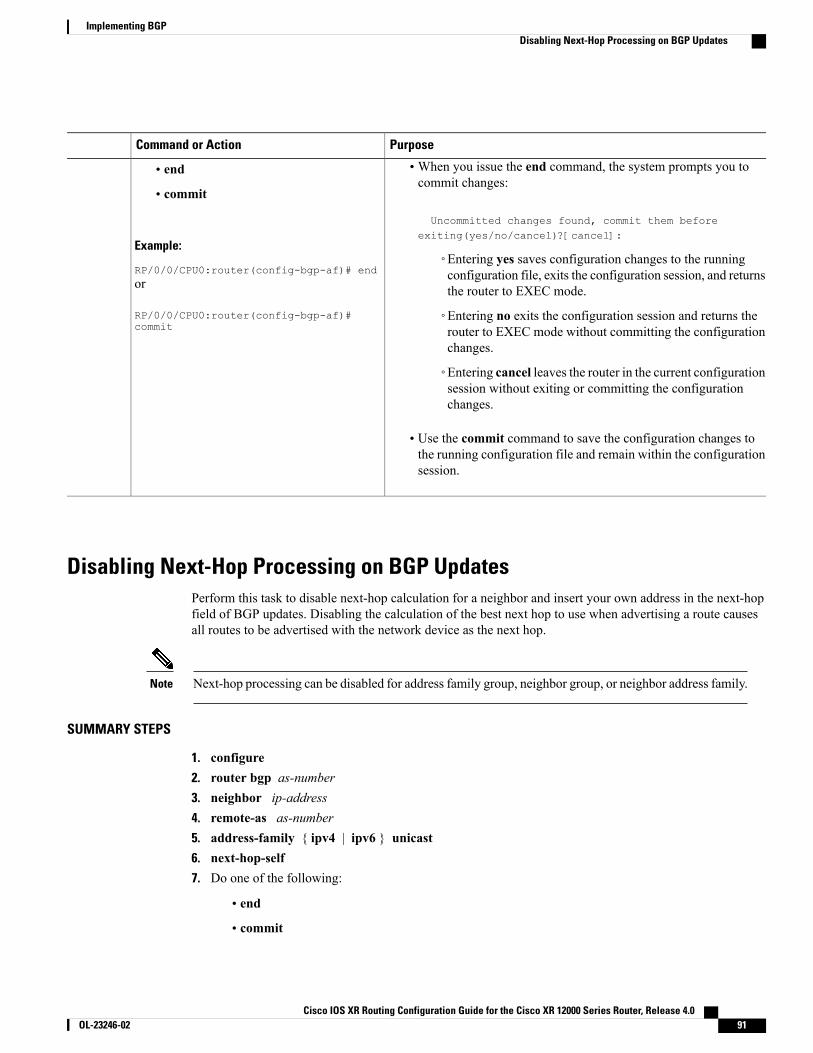
PurposeCommand or Action
•When you issue the end command, the system prompts you tocommit changes:
Uncommitted changes found, commit them beforeexiting(yes/no/cancel)?[cancel]:
• end
• commit
Example:
RP/0/0/CPU0:router(config-bgp-af)# end◦Entering yes saves configuration changes to the runningconfiguration file, exits the configuration session, and returnsthe router to EXEC mode.or
RP/0/0/CPU0:router(config-bgp-af)#commit
◦Entering no exits the configuration session and returns therouter to EXEC mode without committing the configurationchanges.
◦Entering cancel leaves the router in the current configurationsession without exiting or committing the configurationchanges.
• Use the commit command to save the configuration changes tothe running configuration file and remain within the configurationsession.
Disabling Next-Hop Processing on BGP UpdatesPerform this task to disable next-hop calculation for a neighbor and insert your own address in the next-hopfield of BGP updates. Disabling the calculation of the best next hop to use when advertising a route causesall routes to be advertised with the network device as the next hop.
Next-hop processing can be disabled for address family group, neighbor group, or neighbor address family.Note
SUMMARY STEPS
1. configure2. router bgp as-number3. neighbor ip-address4. remote-as as-number5. address-family { ipv4 | ipv6 } unicast6. next-hop-self7. Do one of the following:
• end
• commit
Cisco IOS XR Routing Configuration Guide for the Cisco XR 12000 Series Router, Release 4.0 OL-23246-02 91
Implementing BGPDisabling Next-Hop Processing on BGP Updates
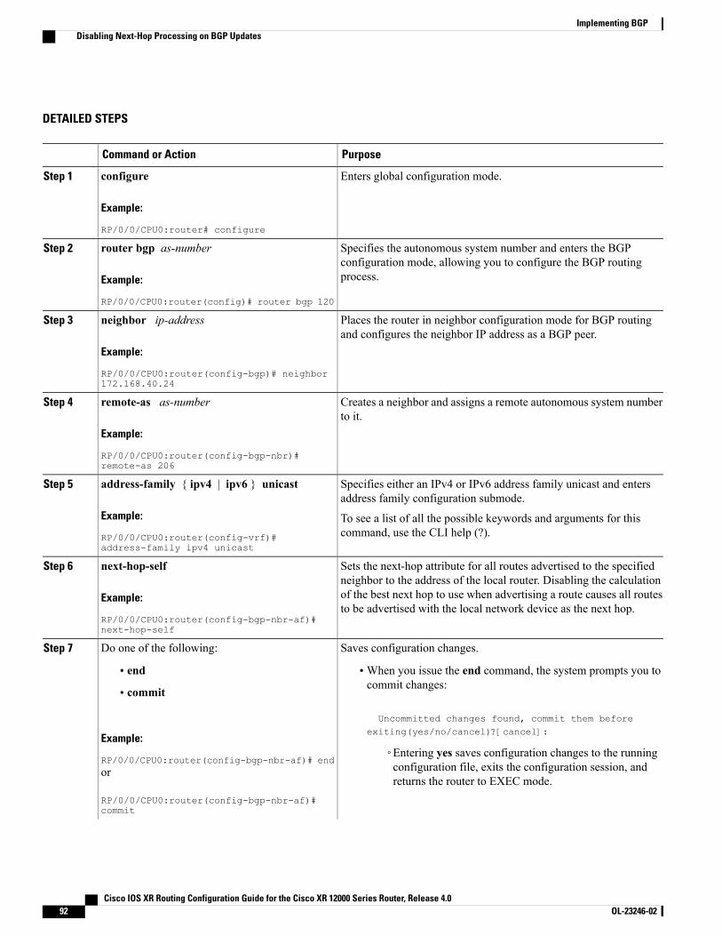
DETAILED STEPS
PurposeCommand or Action
Enters global configuration mode.configure
Example:
RP/0/0/CPU0:router# configure
Step 1
Specifies the autonomous system number and enters the BGPconfiguration mode, allowing you to configure the BGP routingprocess.
router bgp as-number
Example:
RP/0/0/CPU0:router(config)# router bgp 120
Step 2
Places the router in neighbor configuration mode for BGP routingand configures the neighbor IP address as a BGP peer.
neighbor ip-address
Example:
RP/0/0/CPU0:router(config-bgp)# neighbor172.168.40.24
Step 3
Creates a neighbor and assigns a remote autonomous system numberto it.
remote-as as-number
Example:
RP/0/0/CPU0:router(config-bgp-nbr)#remote-as 206
Step 4
Specifies either an IPv4 or IPv6 address family unicast and entersaddress family configuration submode.
address-family { ipv4 | ipv6 } unicast
Example:
RP/0/0/CPU0:router(config-vrf)#address-family ipv4 unicast
Step 5
To see a list of all the possible keywords and arguments for thiscommand, use the CLI help (?).
Sets the next-hop attribute for all routes advertised to the specifiedneighbor to the address of the local router. Disabling the calculation
next-hop-self
Example:
RP/0/0/CPU0:router(config-bgp-nbr-af)#next-hop-self
Step 6
of the best next hop to use when advertising a route causes all routesto be advertised with the local network device as the next hop.
Saves configuration changes.Do one of the following:Step 7
• end •When you issue the end command, the system prompts you tocommit changes:
Uncommitted changes found, commit them beforeexiting(yes/no/cancel)?[cancel]:
• commit
Example:
RP/0/0/CPU0:router(config-bgp-nbr-af)# end◦Entering yes saves configuration changes to the runningconfiguration file, exits the configuration session, andreturns the router to EXEC mode.
or
RP/0/0/CPU0:router(config-bgp-nbr-af)#commit
Cisco IOS XR Routing Configuration Guide for the Cisco XR 12000 Series Router, Release 4.092 OL-23246-02
Implementing BGPDisabling Next-Hop Processing on BGP Updates
PurposeCommand or Action
◦Entering no exits the configuration session and returns therouter to EXEC mode without committing theconfiguration changes.
◦Entering cancel leaves the router in the currentconfiguration session without exiting or committing theconfiguration changes.
• Use the commit command to save the configuration changes tothe running configuration file and remain within theconfiguration session.
Configuring BGP Community and Extended-Community AdvertisementsPerform this task to specify that community/extended-community attributes should be sent to an eBGPneighbor. These attributes are not sent to an eBGP neighbor by default. By contrast, they are always sent toiBGP neighbors. This section provides examples on how to enable sending community attributes. Thesend-community-ebgp keyword can be replaced by the send-extended-community-ebgp keyword toenable sending extended-communities.
If the send-community-ebgp command is configured for a neighbor group or address family group, allneighbors using the group inherit the configuration. Configuring the command specifically for a neighboroverrides inherited values.
BGP community and extended-community filtering cannot be configured for iBGP neighbors. Communitiesand extended-communities are always sent to iBGP neighbors under IPv4, IPv6, VPNv4, andMDT addressfamilies.
Note
Cisco IOS XR Routing Configuration Guide for the Cisco XR 12000 Series Router, Release 4.0 OL-23246-02 93
Implementing BGPConfiguring BGP Community and Extended-Community Advertisements
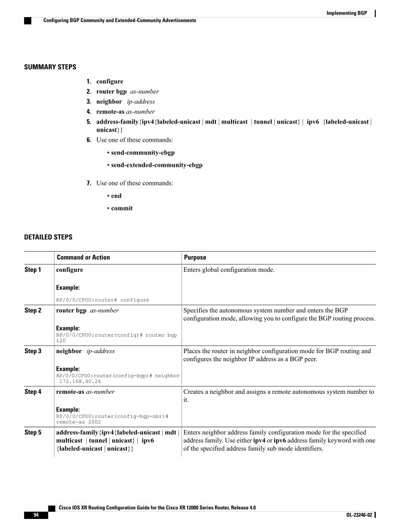
SUMMARY STEPS
1. configure2. router bgp as-number3. neighbor ip-address4. remote-as as-number5. address-family{ipv4{labeled-unicast |mdt |multicast | tunnel | unicast} | ipv6 {labeled-unicast |
unicast}}6. Use one of these commands:
• send-community-ebgp
• send-extended-community-ebgp
7. Use one of these commands:
• end
• commit
DETAILED STEPS
PurposeCommand or Action
Enters global configuration mode.configure
Example:
RP/0/0/CPU0:router# configure
Step 1
Specifies the autonomous system number and enters the BGPconfiguration mode, allowing you to configure the BGP routing process.
router bgp as-number
Example:RP/0/0/CPU0:router(config)# router bgp120
Step 2
Places the router in neighbor configuration mode for BGP routing andconfigures the neighbor IP address as a BGP peer.
neighbor ip-address
Example:RP/0/0/CPU0:router(config-bgp)# neighbor172.168.40.24
Step 3
Creates a neighbor and assigns a remote autonomous system number toit.
remote-as as-number
Example:RP/0/0/CPU0:router(config-bgp-nbr)#remote-as 2002
Step 4
Enters neighbor address family configuration mode for the specifiedaddress family. Use either ipv4 or ipv6 address family keyword with oneof the specified address family sub mode identifiers.
address-family{ipv4{labeled-unicast |mdt |multicast | tunnel | unicast} | ipv6{labeled-unicast | unicast}}
Step 5
Cisco IOS XR Routing Configuration Guide for the Cisco XR 12000 Series Router, Release 4.094 OL-23246-02
Implementing BGPConfiguring BGP Community and Extended-Community Advertisements

PurposeCommand or Action
Example:RP/0/0/CPU0:router(config-bgp-nbr)#address-family ipv6 unicast
IPv6 address family mode supports these sub modes:
• labeled-unicast
• unicast
IPv4 address family mode supports these sub modes:
• labeled-unicast
• mdt
• multicast
• tunnel
• unicast
Refer the address-family (BGP) command in BGP Commands moduleof Cisco IOS XR Routing Command Reference for the Cisco XR 12000Series Router for more information on the Address Family Submodesupport.
Specifies that the router send community attributes or extended communityattributes (which are disabled by default for eBGP neighbors) to aspecified eBGP neighbor.
Use one of these commands:Step 6
• send-community-ebgp
• send-extended-community-ebgp
Example:RP/0/0/CPU0:router(config-bgp-nbr-af)#send-community-ebgporRP/0/0/CPU0:router(config-bgp-nbr-af)#send-extended-community-ebgp
Saves configuration changes.Use one of these commands:Step 7
• end •When you issue the end command, the system prompts you tocommit changes:
Uncommitted changes found, commit thembefore exiting(yes/no/cancel)? [cancel]:
• commit
Example:
RP/0/0/CPU0:router(config)# end◦Entering yes saves configuration changes to the runningconfiguration file, exits the configuration session, and returnsthe router to EXEC mode.
or
RP/0/0/CPU0:router(config)# commit ◦Entering no exits the configuration session and returns therouter to EXEC mode without committing the configurationchanges.
Cisco IOS XR Routing Configuration Guide for the Cisco XR 12000 Series Router, Release 4.0 OL-23246-02 95
Implementing BGPConfiguring BGP Community and Extended-Community Advertisements
PurposeCommand or Action
◦Entering cancel leaves the router in the current configurationsession without exiting or committing the configurationchanges.
• Use the commit command to save the configuration changes to therunning configuration file, and remain within the configurationsession.
Configuring the BGP Cost CommunityPerform this task to configure the BGP cost community.
BGP receives multiple paths to the same destination and it uses the best-path algorithm to decide which is thebest path to install in RIB. To enable users to determine an exit point after partial comparison, the costcommunity is defined to tie-break equal paths during the best-path selection process.
Cisco IOS XR Routing Configuration Guide for the Cisco XR 12000 Series Router, Release 4.096 OL-23246-02
Implementing BGPConfiguring the BGP Cost Community
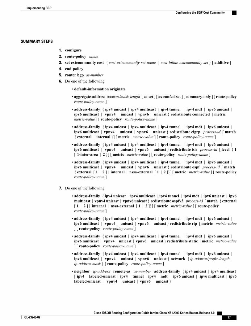
SUMMARY STEPS
1. configure2. route-policy name3. set extcommunity cost { cost-extcommunity-set-name | cost-inline-extcommunity-set } [ additive ]4. end-policy5. router bgp as-number6. Do one of the following:
• default-information originate
• aggregate-address address/mask-length [ as-set ] [ as-confed-set ] [ summary-only ] [ route-policyroute-policy-name ]
• address-family { ipv4 unicast | ipv4 multicast | ipv4 tunnel | ipv4 mdt | ipv6 unicast |ipv6 multicast | vpnv4 unicast | vpnv6 unicast } redistribute connected [ metricmetric-value ] [ route-policy route-policy-name ]
• address-family { ipv4 unicast | ipv4 multicast | ipv4 tunnel | ipv4 mdt | ipv6 unicast |ipv6 multicast | vpnv4 unicast | vpnv6 unicast } redistribute eigrp process-id [ match{ external | internal }] [ metric metric-value ] [ route-policy route-policy-name ]
• address-family { ipv4 unicast | ipv4 multicast | ipv4 tunnel | ipv4 mdt | ipv6 unicast |ipv6 multicast | vpnv4 unicast | vpnv6 unicast } redistribute isis process-id [ level { 1| 1-inter-area | 2 }] [ metric metric-value ] [ route-policy route-policy-name ]
• address-family { ipv4 unicast | ipv4 multicast | ipv4 tunnel | ipv4 mdt | ipv6 unicast |ipv6 multicast | vpnv4 unicast | vpnv6 unicast } redistribute ospf process-id [ match{ external [ 1 | 2 ] | internal | nssa-external [ 1 | 2 ]}] [metric metric-value ] [ route-policyroute-policy-name ]
7. Do one of the following:
• address-family { ipv4 unicast | ipv4 multicast | ipv4 tunnel | ipv4 mdt | ipv6 unicast | ipv6multicast | vpnv4 unicast | vpnv6 unicast } redistribute ospfv3 process-id [match { external[ 1 | 2 ] | internal | nssa-external [ 1 | 2 ]}] [ metric metric-value ] [ route-policyroute-policy-name ]
• address-family { ipv4 unicast | ipv4 multicast | ipv4 tunnel | ipv4 mdt | ipv6 unicast |ipv6 multicast | vpnv4 unicast | vpnv6 unicast } redistribute rip [metric metric-value] [ route-policy route-policy-name ]
• address-family { ipv4 unicast | ipv4 multicast | ipv4 tunnel | ipv4 mdt | ipv6 unicast |ipv6 multicast | vpnv4 unicast | vpnv6 unicast } redistribute static [metric metric-value] [ route-policy route-policy-name ]
• address-family { ipv4 unicast | ipv4 multicast | ipv4 tunnel | ipv4 mdt | ipv6 unicast |ipv6 multicast | vpnv4 unicast | vpnv6 unicast } network { ip-address/prefix-length |ip-address mask } [ route-policy route-policy-name ]
• neighbor ip-address remote-as as-number address-family { ipv4 unicast | ipv4 multicast| ipv4 labeled-unicast | ipv4 tunnel | ipv4 mdt | ipv6 unicast | ipv6 multicast | ipv6labeled-unicast | vpnv4 unicast | vpnv6 unicast }
Cisco IOS XR Routing Configuration Guide for the Cisco XR 12000 Series Router, Release 4.0 OL-23246-02 97
Implementing BGPConfiguring the BGP Cost Community

• route-policy route-policy-name { in | out }
8. Do one of the following:
• end
• commit
9. show bgp [ vrf vrf-name ] ip-address
DETAILED STEPS
PurposeCommand or Action
Enters global configuration mode.configure
Example:
RP/0/0/CPU0:router# configure
Step 1
Enters route policy configuration mode andspecifies the name of the route policy to beconfigured.
route-policy name
Example:
RP/0/0/CPU0:router(config)# route-policy costA
Step 2
Specifies the BGP extended communityattribute for cost.
set extcommunity cost { cost-extcommunity-set-name |cost-inline-extcommunity-set } [ additive ]
Example:
RP/0/0/CPU0:router(config)# set extcommunity cost cost_A
Step 3
Ends the definition of a route policy and exitsroute policy configuration mode.
end-policy
Example:
RP/0/0/CPU0:router(config)# end-policy
Step 4
Enters BGP configuration mode allowing youto configure the BGP routing process.
router bgp as-number
Example:
RP/0/0/CPU0:router(config)# router bgp 120
Step 5
Applies the cost community to the attach point(route policy).
Do one of the following:Step 6
• default-information originate
• aggregate-address address/mask-length [ as-set ] [ as-confed-set] [ summary-only ] [ route-policy route-policy-name ]
• address-family { ipv4 unicast | ipv4 multicast | ipv4 tunnel |ipv4 mdt | ipv6 unicast | ipv6 multicast | vpnv4 unicast |vpnv6 unicast } redistribute connected [ metric metric-value] [ route-policy route-policy-name ]
Cisco IOS XR Routing Configuration Guide for the Cisco XR 12000 Series Router, Release 4.098 OL-23246-02
Implementing BGPConfiguring the BGP Cost Community
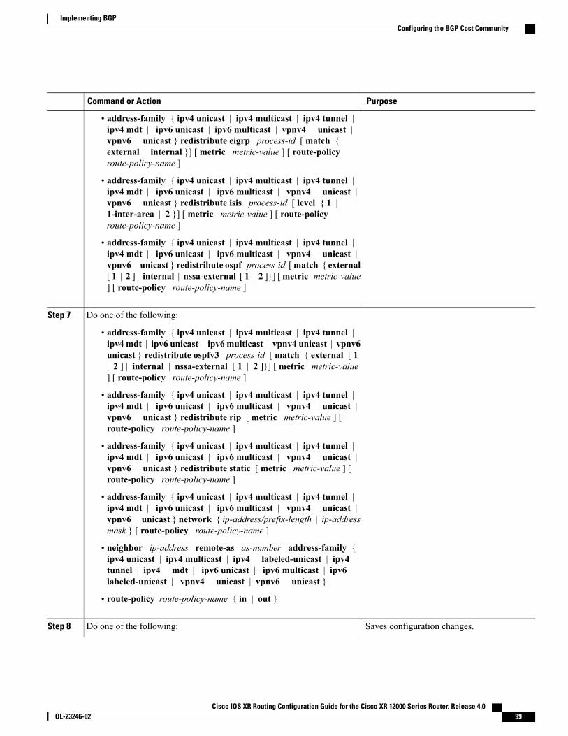
PurposeCommand or Action
• address-family { ipv4 unicast | ipv4 multicast | ipv4 tunnel |ipv4 mdt | ipv6 unicast | ipv6 multicast | vpnv4 unicast |vpnv6 unicast } redistribute eigrp process-id [ match {external | internal }] [ metric metric-value ] [ route-policyroute-policy-name ]
• address-family { ipv4 unicast | ipv4 multicast | ipv4 tunnel |ipv4 mdt | ipv6 unicast | ipv6 multicast | vpnv4 unicast |vpnv6 unicast } redistribute isis process-id [ level { 1 |1-inter-area | 2 }] [ metric metric-value ] [ route-policyroute-policy-name ]
• address-family { ipv4 unicast | ipv4 multicast | ipv4 tunnel |ipv4 mdt | ipv6 unicast | ipv6 multicast | vpnv4 unicast |vpnv6 unicast } redistribute ospf process-id [match { external[ 1 | 2 ] | internal | nssa-external [ 1 | 2 ]}] [metric metric-value] [ route-policy route-policy-name ]
Do one of the following:Step 7
• address-family { ipv4 unicast | ipv4 multicast | ipv4 tunnel |ipv4 mdt | ipv6 unicast | ipv6 multicast | vpnv4 unicast | vpnv6unicast } redistribute ospfv3 process-id [ match { external [ 1| 2 ] | internal | nssa-external [ 1 | 2 ]}] [ metric metric-value] [ route-policy route-policy-name ]
• address-family { ipv4 unicast | ipv4 multicast | ipv4 tunnel |ipv4 mdt | ipv6 unicast | ipv6 multicast | vpnv4 unicast |vpnv6 unicast } redistribute rip [ metric metric-value ] [route-policy route-policy-name ]
• address-family { ipv4 unicast | ipv4 multicast | ipv4 tunnel |ipv4 mdt | ipv6 unicast | ipv6 multicast | vpnv4 unicast |vpnv6 unicast } redistribute static [ metric metric-value ] [route-policy route-policy-name ]
• address-family { ipv4 unicast | ipv4 multicast | ipv4 tunnel |ipv4 mdt | ipv6 unicast | ipv6 multicast | vpnv4 unicast |vpnv6 unicast } network { ip-address/prefix-length | ip-addressmask } [ route-policy route-policy-name ]
• neighbor ip-address remote-as as-number address-family {ipv4 unicast | ipv4 multicast | ipv4 labeled-unicast | ipv4tunnel | ipv4 mdt | ipv6 unicast | ipv6 multicast | ipv6labeled-unicast | vpnv4 unicast | vpnv6 unicast }
• route-policy route-policy-name { in | out }
Saves configuration changes.Do one of the following:Step 8
Cisco IOS XR Routing Configuration Guide for the Cisco XR 12000 Series Router, Release 4.0 OL-23246-02 99
Implementing BGPConfiguring the BGP Cost Community
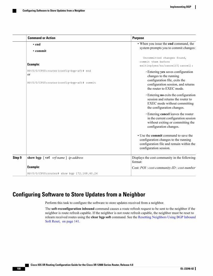
PurposeCommand or Action
•When you issue the end command, thesystem prompts you to commit changes:
Uncommitted changes found,
• end
• commit
Example:
RP/0/0/CPU0:router(config-bgp-af)# end
commit them beforeexiting(yes/no/cancel)?[cancel]:
◦Entering yes saves configurationchanges to the runningor
RP/0/0/CPU0:router(config-bgp-af)# commitconfiguration file, exits theconfiguration session, and returnsthe router to EXEC mode.
◦Entering no exits the configurationsession and returns the router toEXEC mode without committingthe configuration changes.
◦Entering cancel leaves the routerin the current configuration sessionwithout exiting or committing theconfiguration changes.
• Use the commit command to save theconfiguration changes to the runningconfiguration file and remain within theconfiguration session.
Displays the cost community in the followingformat:
show bgp [ vrf vrf-name ] ip-address
Example:
RP/0/0/CPU0:router# show bgp 172.168.40.24
Step 9
Cost: POI : cost-community-ID : cost-number
Configuring Software to Store Updates from a NeighborPerform this task to configure the software to store updates received from a neighbor.
The soft-reconfiguration inbound command causes a route refresh request to be sent to the neighbor if theneighbor is route refresh capable. If the neighbor is not route refresh capable, the neighbor must be reset torelearn received routes using the clear bgp soft command. See the Resetting Neighbors Using BGP InboundSoft Reset, on page 141.
Cisco IOS XR Routing Configuration Guide for the Cisco XR 12000 Series Router, Release 4.0100 OL-23246-02
Implementing BGPConfiguring Software to Store Updates from a Neighbor
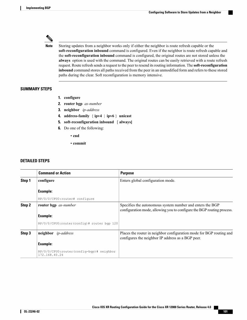
Storing updates from a neighbor works only if either the neighbor is route refresh capable or thesoft-reconfiguration inbound command is configured. Even if the neighbor is route refresh capable andthe soft-reconfiguration inbound command is configured, the original routes are not stored unless thealways option is used with the command. The original routes can be easily retrieved with a route refreshrequest. Route refresh sends a request to the peer to resend its routing information. The soft-reconfigurationinbound command stores all paths received from the peer in an unmodified form and refers to these storedpaths during the clear. Soft reconfiguration is memory intensive.
Note
SUMMARY STEPS
1. configure2. router bgp as-number3. neighbor ip-address4. address-family { ipv4 | ipv6 } unicast5. soft-reconfiguration inbound [ always]6. Do one of the following:
• end
• commit
DETAILED STEPS
PurposeCommand or Action
Enters global configuration mode.configure
Example:
RP/0/0/CPU0:router# configure
Step 1
Specifies the autonomous system number and enters the BGPconfigurationmode, allowing you to configure the BGP routing process.
router bgp as-number
Example:
RP/0/0/CPU0:router(config)# router bgp 120
Step 2
Places the router in neighbor configuration mode for BGP routing andconfigures the neighbor IP address as a BGP peer.
neighbor ip-address
Example:
RP/0/0/CPU0:router(config-bgp)# neighbor172.168.40.24
Step 3
Cisco IOS XR Routing Configuration Guide for the Cisco XR 12000 Series Router, Release 4.0 OL-23246-02 101
Implementing BGPConfiguring Software to Store Updates from a Neighbor
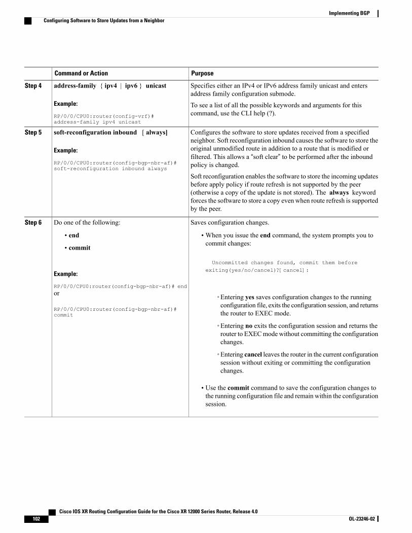
PurposeCommand or Action
Specifies either an IPv4 or IPv6 address family unicast and entersaddress family configuration submode.
address-family { ipv4 | ipv6 } unicast
Example:
RP/0/0/CPU0:router(config-vrf)#address-family ipv4 unicast
Step 4
To see a list of all the possible keywords and arguments for thiscommand, use the CLI help (?).
Configures the software to store updates received from a specifiedneighbor. Soft reconfiguration inbound causes the software to store the
soft-reconfiguration inbound [ always]
Example:
RP/0/0/CPU0:router(config-bgp-nbr-af)#soft-reconfiguration inbound always
Step 5
original unmodified route in addition to a route that is modified orfiltered. This allows a “soft clear” to be performed after the inboundpolicy is changed.
Soft reconfiguration enables the software to store the incoming updatesbefore apply policy if route refresh is not supported by the peer(otherwise a copy of the update is not stored). The always keywordforces the software to store a copy even when route refresh is supportedby the peer.
Saves configuration changes.Do one of the following:Step 6
• end •When you issue the end command, the system prompts you tocommit changes:
Uncommitted changes found, commit them before
• commit
Example:
RP/0/0/CPU0:router(config-bgp-nbr-af)# end
exiting(yes/no/cancel)?[cancel]:
or
RP/0/0/CPU0:router(config-bgp-nbr-af)#commit
◦Entering yes saves configuration changes to the runningconfiguration file, exits the configuration session, and returnsthe router to EXEC mode.
◦Entering no exits the configuration session and returns therouter to EXECmode without committing the configurationchanges.
◦Entering cancel leaves the router in the current configurationsession without exiting or committing the configurationchanges.
• Use the commit command to save the configuration changes tothe running configuration file and remain within the configurationsession.
Cisco IOS XR Routing Configuration Guide for the Cisco XR 12000 Series Router, Release 4.0102 OL-23246-02
Implementing BGPConfiguring Software to Store Updates from a Neighbor

Configuring Distributed BGPPerform this task to configure distributed BGP. Configuring distributed BGP includes starting the speakerprocess and allocating the speaker process to a neighbor.
Before You Begin
If BGP is running in standalone mode, the clear bgp current-mode or clear bgp vrf all * command mustbe used to switch from standalone mode to distributed mode.
Note
SUMMARY STEPS
1. configure2. router bgp as-number3. distributed speaker id4. commit5. address-family { ipv4 | ipv6 } unicast6. exit7. neighbor ip-address8. remote-as as-number9. speaker-id id10. address-family { ipv4 | ipv6 } unicast11. end12. clear bgp current-mode
DETAILED STEPS
PurposeCommand or Action
Enters global configuration mode.configure
Example:
RP/0/0/CPU0:router# configure
Step 1
Specifies the autonomous system number and enters the BGPconfiguration mode, allowing you to configure the BGP routingprocess.
router bgp as-number
Example:
RP/0/0/CPU0:router(config)# router bgp 120
Step 2
Specifies the speaker process to start.distributed speaker id
Example:
RP/0/0/CPU0:router(config-bgp)# distributedspeaker 2
Step 3
Cisco IOS XR Routing Configuration Guide for the Cisco XR 12000 Series Router, Release 4.0 OL-23246-02 103
Implementing BGPConfiguring Distributed BGP
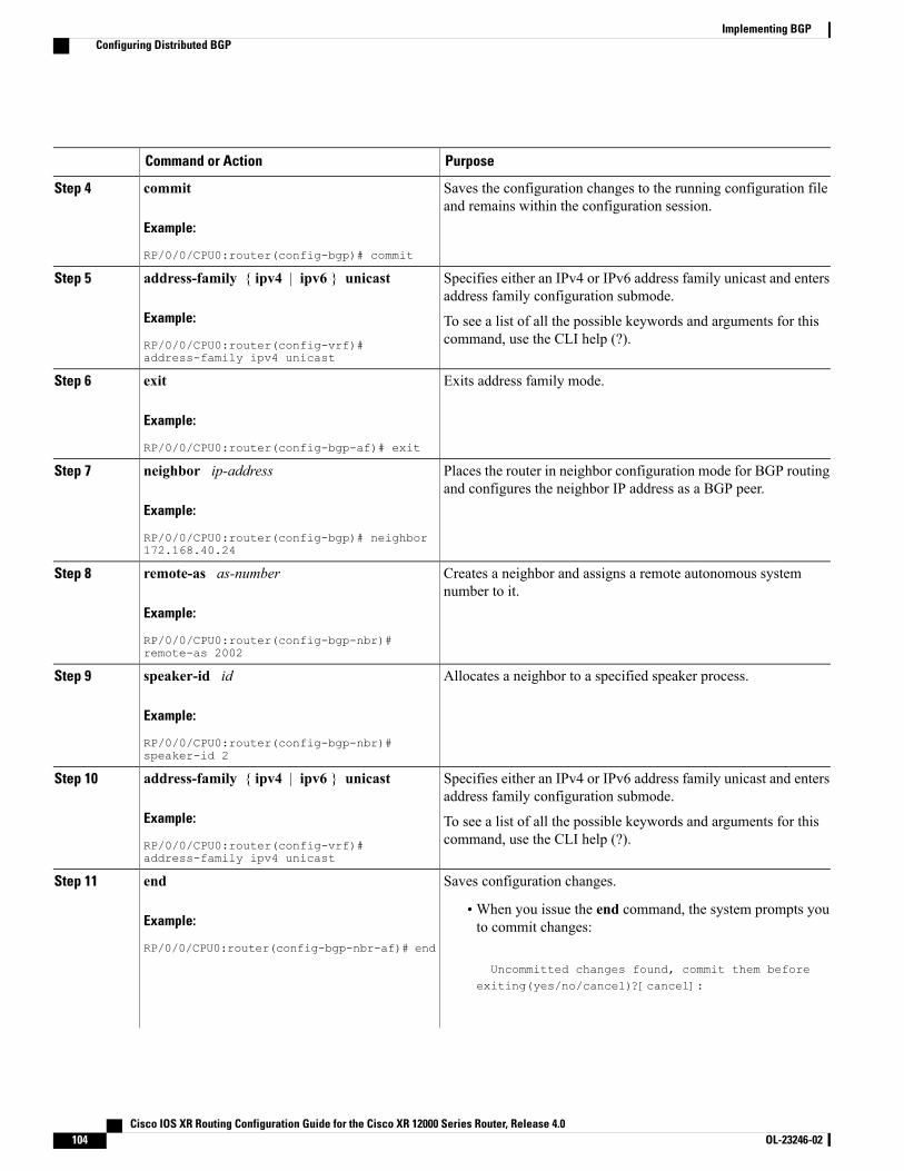
PurposeCommand or Action
Saves the configuration changes to the running configuration fileand remains within the configuration session.
commit
Example:
RP/0/0/CPU0:router(config-bgp)# commit
Step 4
Specifies either an IPv4 or IPv6 address family unicast and entersaddress family configuration submode.
address-family { ipv4 | ipv6 } unicast
Example:
RP/0/0/CPU0:router(config-vrf)#address-family ipv4 unicast
Step 5
To see a list of all the possible keywords and arguments for thiscommand, use the CLI help (?).
Exits address family mode.exit
Example:
RP/0/0/CPU0:router(config-bgp-af)# exit
Step 6
Places the router in neighbor configuration mode for BGP routingand configures the neighbor IP address as a BGP peer.
neighbor ip-address
Example:
RP/0/0/CPU0:router(config-bgp)# neighbor172.168.40.24
Step 7
Creates a neighbor and assigns a remote autonomous systemnumber to it.
remote-as as-number
Example:
RP/0/0/CPU0:router(config-bgp-nbr)#remote-as 2002
Step 8
Allocates a neighbor to a specified speaker process.speaker-id id
Example:
RP/0/0/CPU0:router(config-bgp-nbr)#speaker-id 2
Step 9
Specifies either an IPv4 or IPv6 address family unicast and entersaddress family configuration submode.
address-family { ipv4 | ipv6 } unicast
Example:
RP/0/0/CPU0:router(config-vrf)#address-family ipv4 unicast
Step 10
To see a list of all the possible keywords and arguments for thiscommand, use the CLI help (?).
Saves configuration changes.endStep 11
Example:
RP/0/0/CPU0:router(config-bgp-nbr-af)# end
•When you issue the end command, the system prompts youto commit changes:
Uncommitted changes found, commit them beforeexiting(yes/no/cancel)?[cancel]:
Cisco IOS XR Routing Configuration Guide for the Cisco XR 12000 Series Router, Release 4.0104 OL-23246-02
Implementing BGPConfiguring Distributed BGP
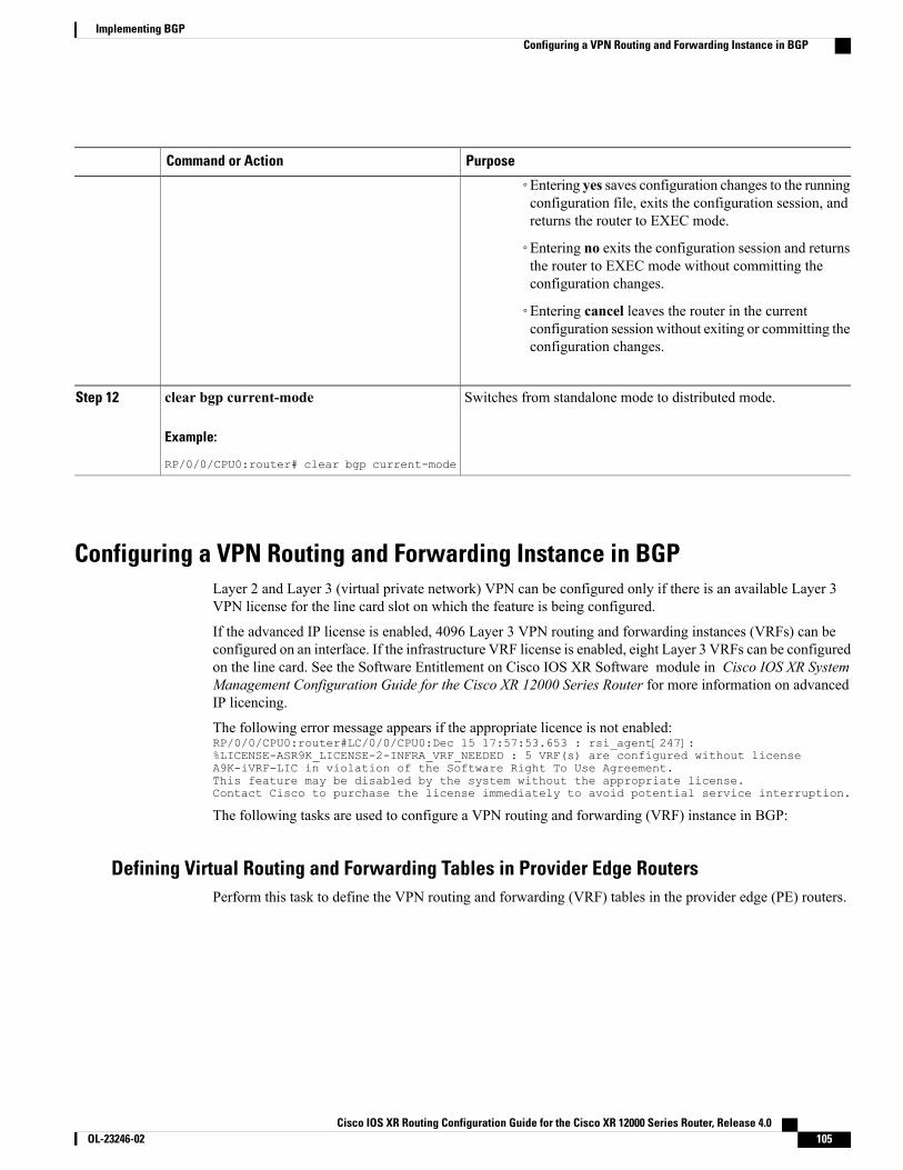
PurposeCommand or Action
◦Entering yes saves configuration changes to the runningconfiguration file, exits the configuration session, andreturns the router to EXEC mode.
◦Entering no exits the configuration session and returnsthe router to EXEC mode without committing theconfiguration changes.
◦Entering cancel leaves the router in the currentconfiguration session without exiting or committing theconfiguration changes.
Switches from standalone mode to distributed mode.clear bgp current-mode
Example:
RP/0/0/CPU0:router# clear bgp current-mode
Step 12
Configuring a VPN Routing and Forwarding Instance in BGPLayer 2 and Layer 3 (virtual private network) VPN can be configured only if there is an available Layer 3VPN license for the line card slot on which the feature is being configured.
If the advanced IP license is enabled, 4096 Layer 3 VPN routing and forwarding instances (VRFs) can beconfigured on an interface. If the infrastructure VRF license is enabled, eight Layer 3 VRFs can be configuredon the line card. See the Software Entitlement on Cisco IOS XR Software module in Cisco IOS XR SystemManagement Configuration Guide for the Cisco XR 12000 Series Router for more information on advancedIP licencing.
The following error message appears if the appropriate licence is not enabled:RP/0/0/CPU0:router#LC/0/0/CPU0:Dec 15 17:57:53.653 : rsi_agent[247]:%LICENSE-ASR9K_LICENSE-2-INFRA_VRF_NEEDED : 5 VRF(s) are configured without licenseA9K-iVRF-LIC in violation of the Software Right To Use Agreement.This feature may be disabled by the system without the appropriate license.Contact Cisco to purchase the license immediately to avoid potential service interruption.
The following tasks are used to configure a VPN routing and forwarding (VRF) instance in BGP:
Defining Virtual Routing and Forwarding Tables in Provider Edge RoutersPerform this task to define the VPN routing and forwarding (VRF) tables in the provider edge (PE) routers.
Cisco IOS XR Routing Configuration Guide for the Cisco XR 12000 Series Router, Release 4.0 OL-23246-02 105
Implementing BGPConfiguring a VPN Routing and Forwarding Instance in BGP
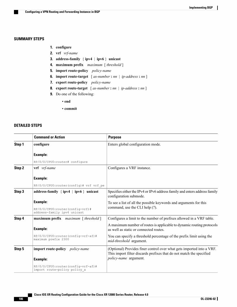
SUMMARY STEPS
1. configure2. vrf vrf-name3. address-family { ipv4 | ipv6 } unicast4. maximum prefix maximum [ threshold ]5. import route-policy policy-name6. import route-target [ as-number : nn | ip-address : nn ]7. export route-policy policy-name8. export route-target [ as-number : nn | ip-address : nn ]9. Do one of the following:
• end
• commit
DETAILED STEPS
PurposeCommand or Action
Enters global configuration mode.configure
Example:
RP/0/0/CPU0:router# configure
Step 1
Configures a VRF instance.vrf vrf-name
Example:
RP/0/0/CPU0:router(config)# vrf vrf_pe
Step 2
Specifies either the IPv4 or IPv6 address family and enters address familyconfiguration submode.
address-family { ipv4 | ipv6 } unicast
Example:
RP/0/0/CPU0:router(config-vrf)#address-family ipv4 unicast
Step 3
To see a list of all the possible keywords and arguments for thiscommand, use the CLI help (?).
Configures a limit to the number of prefixes allowed in a VRF table.maximum prefix maximum [ threshold ]Step 4
Example:
RP/0/0/CPU0:router(config-vrf-af)#maximum prefix 2300
Amaximum number of routes is applicable to dynamic routing protocolsas well as static or connected routes.
You can specify a threshold percentage of the prefix limit using themid-threshold argument.
(Optional) Provides finer control over what gets imported into a VRF.This import filter discards prefixes that do not match the specifiedpolicy-name argument.
import route-policy policy-name
Example:
RP/0/0/CPU0:router(config-vrf-af)#import route-policy policy_a
Step 5
Cisco IOS XR Routing Configuration Guide for the Cisco XR 12000 Series Router, Release 4.0106 OL-23246-02
Implementing BGPConfiguring a VPN Routing and Forwarding Instance in BGP
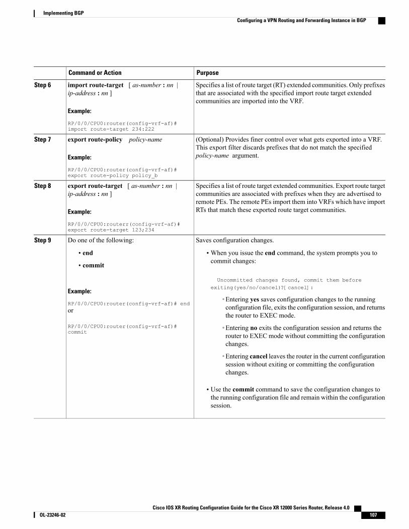
PurposeCommand or Action
Specifies a list of route target (RT) extended communities. Only prefixesthat are associated with the specified import route target extendedcommunities are imported into the VRF.
import route-target [ as-number : nn |ip-address : nn ]
Example:
RP/0/0/CPU0:router(config-vrf-af)#import route-target 234:222
Step 6
(Optional) Provides finer control over what gets exported into a VRF.This export filter discards prefixes that do not match the specifiedpolicy-name argument.
export route-policy policy-name
Example:
RP/0/0/CPU0:router(config-vrf-af)#export route-policy policy_b
Step 7
Specifies a list of route target extended communities. Export route targetcommunities are associated with prefixes when they are advertised to
export route-target [ as-number : nn |ip-address : nn ]
Step 8
remote PEs. The remote PEs import them into VRFs which have importRTs that match these exported route target communities.Example:
RP/0/0/CPU0:routerr(config-vrf-af)#export route-target 123;234
Saves configuration changes.Do one of the following:Step 9
• end •When you issue the end command, the system prompts you tocommit changes:
Uncommitted changes found, commit them beforeexiting(yes/no/cancel)?[cancel]:
• commit
Example:
RP/0/0/CPU0:router(config-vrf-af)# end◦Entering yes saves configuration changes to the runningconfiguration file, exits the configuration session, and returnsthe router to EXEC mode.
or
RP/0/0/CPU0:router(config-vrf-af)#commit
◦Entering no exits the configuration session and returns therouter to EXEC mode without committing the configurationchanges.
◦Entering cancel leaves the router in the current configurationsession without exiting or committing the configurationchanges.
• Use the commit command to save the configuration changes tothe running configuration file and remain within the configurationsession.
Cisco IOS XR Routing Configuration Guide for the Cisco XR 12000 Series Router, Release 4.0 OL-23246-02 107
Implementing BGPConfiguring a VPN Routing and Forwarding Instance in BGP
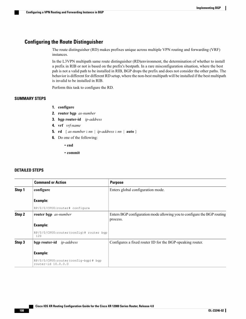
Configuring the Route DistinguisherThe route distinguisher (RD) makes prefixes unique across multiple VPN routing and forwarding (VRF)instances.
In the L3VPN multipath same route distinguisher (RD)environment, the determination of whether to installa prefix in RIB or not is based on the prefix's bestpath. In a rare misconfiguration situation, where the bestpah is not a valid path to be installed in RIB, BGP drops the prefix and does not consider the other paths. Thebehavior is different for different RD setup, where the non-best multipath will be installed if the best multipathis invalid to be installed in RIB.
Perform this task to configure the RD.
SUMMARY STEPS
1. configure2. router bgp as-number3. bgp router-id ip-address4. vrf vrf-name5. rd { as-number : nn | ip-address : nn | auto }6. Do one of the following:
• end
• commit
DETAILED STEPS
PurposeCommand or Action
Enters global configuration mode.configure
Example:
RP/0/0/CPU0:router# configure
Step 1
Enters BGP configurationmode allowing you to configure the BGP routingprocess.
router bgp as-number
Example:
RP/0/0/CPU0:router(config)# router bgp120
Step 2
Configures a fixed router ID for the BGP-speaking router.bgp router-id ip-address
Example:
RP/0/0/CPU0:router(config-bgp)# bgprouter-id 10.0.0.0
Step 3
Cisco IOS XR Routing Configuration Guide for the Cisco XR 12000 Series Router, Release 4.0108 OL-23246-02
Implementing BGPConfiguring a VPN Routing and Forwarding Instance in BGP
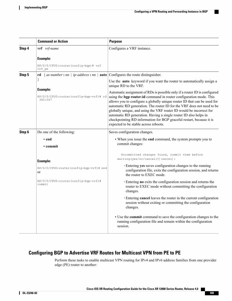
PurposeCommand or Action
Configures a VRF instance.vrf vrf-name
Example:
RP/0/0/CPU0:router(config-bgp)# vrfvrf_pe
Step 4
Configures the route distinguisher.rd { as-number : nn | ip-address : nn | auto}
Step 5
Use the auto keyword if you want the router to automatically assign aunique RD to the VRF.
Example:
RP/0/0/CPU0:router(config-bgp-vrf)# rd345:567
Automatic assignment of RDs is possible only if a router ID is configuredusing the bgp router-id command in router configuration mode. Thisallows you to configure a globally unique router ID that can be used forautomatic RD generation. The router ID for the VRF does not need to beglobally unique, and using the VRF router ID would be incorrect forautomatic RD generation. Having a single router ID also helps incheckpointing RD information for BGP graceful restart, because it isexpected to be stable across reboots.
Saves configuration changes.Do one of the following:Step 6
• end •When you issue the end command, the system prompts you tocommit changes:
Uncommitted changes found, commit them beforeexiting(yes/no/cancel)?[cancel]:
• commit
Example:
RP/0/0/CPU0:router(config-bgp-vrf)# end◦Entering yes saves configuration changes to the runningconfiguration file, exits the configuration session, and returnsthe router to EXEC mode.
or
RP/0/0/CPU0:router(config-bgp-vrf)#commit
◦Entering no exits the configuration session and returns therouter to EXEC mode without committing the configurationchanges.
◦Entering cancel leaves the router in the current configurationsession without exiting or committing the configurationchanges.
• Use the commit command to save the configuration changes to therunning configuration file and remain within the configurationsession.
Configuring BGP to Advertise VRF Routes for Multicast VPN from PE to PEPerform these tasks to enable multicast VPN routing for IPv4 and IPv6 address families from one provideredge (PE) router to another:
Cisco IOS XR Routing Configuration Guide for the Cisco XR 12000 Series Router, Release 4.0 OL-23246-02 109
Implementing BGPConfiguring a VPN Routing and Forwarding Instance in BGP
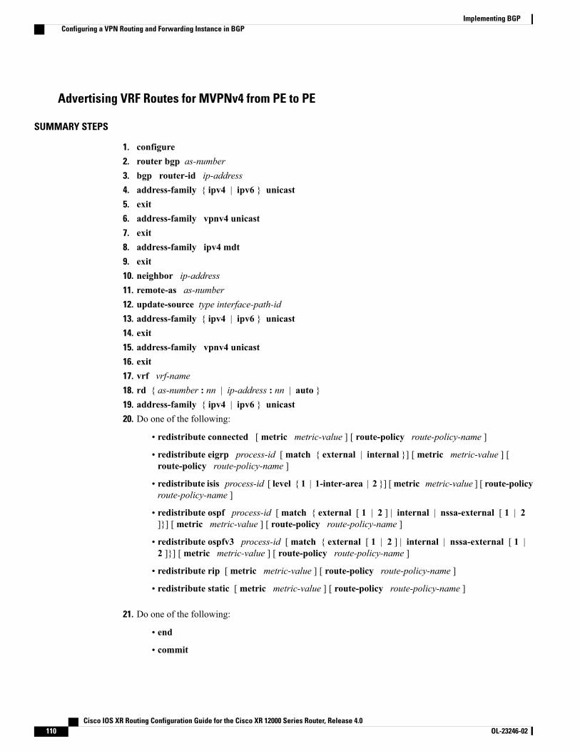
Advertising VRF Routes for MVPNv4 from PE to PE
SUMMARY STEPS
1. configure2. router bgp as-number3. bgp router-id ip-address4. address-family { ipv4 | ipv6 } unicast5. exit6. address-family vpnv4 unicast7. exit8. address-family ipv4 mdt9. exit10. neighbor ip-address11. remote-as as-number12. update-source type interface-path-id13. address-family { ipv4 | ipv6 } unicast14. exit15. address-family vpnv4 unicast16. exit17. vrf vrf-name18. rd { as-number : nn | ip-address : nn | auto }19. address-family { ipv4 | ipv6 } unicast20. Do one of the following:
• redistribute connected [ metric metric-value ] [ route-policy route-policy-name ]
• redistribute eigrp process-id [ match { external | internal }] [ metric metric-value ] [route-policy route-policy-name ]
• redistribute isis process-id [ level { 1 | 1-inter-area | 2 }] [metric metric-value ] [ route-policyroute-policy-name ]
• redistribute ospf process-id [ match { external [ 1 | 2 ] | internal | nssa-external [ 1 | 2]}] [ metric metric-value ] [ route-policy route-policy-name ]
• redistribute ospfv3 process-id [ match { external [ 1 | 2 ] | internal | nssa-external [ 1 |2 ]}] [ metric metric-value ] [ route-policy route-policy-name ]
• redistribute rip [ metric metric-value ] [ route-policy route-policy-name ]
• redistribute static [ metric metric-value ] [ route-policy route-policy-name ]
21. Do one of the following:
• end
• commit
Cisco IOS XR Routing Configuration Guide for the Cisco XR 12000 Series Router, Release 4.0110 OL-23246-02
Implementing BGPConfiguring a VPN Routing and Forwarding Instance in BGP
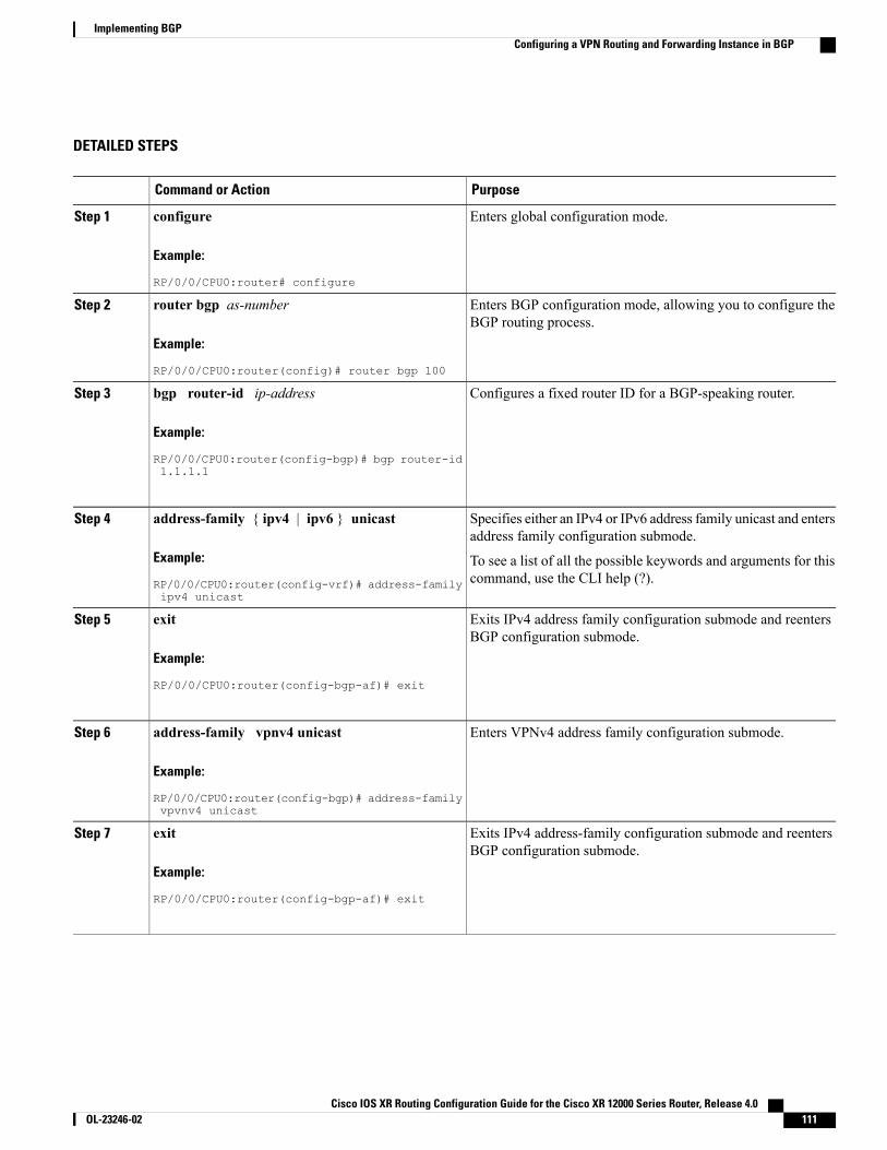
DETAILED STEPS
PurposeCommand or Action
Enters global configuration mode.configure
Example:
RP/0/0/CPU0:router# configure
Step 1
Enters BGP configuration mode, allowing you to configure theBGP routing process.
router bgp as-number
Example:
RP/0/0/CPU0:router(config)# router bgp 100
Step 2
Configures a fixed router ID for a BGP-speaking router.bgp router-id ip-address
Example:
RP/0/0/CPU0:router(config-bgp)# bgp router-id
Step 3
1.1.1.1
Specifies either an IPv4 or IPv6 address family unicast and entersaddress family configuration submode.
address-family { ipv4 | ipv6 } unicast
Example:
RP/0/0/CPU0:router(config-vrf)# address-familyipv4 unicast
Step 4
To see a list of all the possible keywords and arguments for thiscommand, use the CLI help (?).
Exits IPv4 address family configuration submode and reentersBGP configuration submode.
exit
Example:
RP/0/0/CPU0:router(config-bgp-af)# exit
Step 5
Enters VPNv4 address family configuration submode.address-family vpnv4 unicast
Example:
RP/0/0/CPU0:router(config-bgp)# address-familyvpvnv4 unicast
Step 6
Exits IPv4 address-family configuration submode and reentersBGP configuration submode.
exit
Example:
RP/0/0/CPU0:router(config-bgp-af)# exit
Step 7
Cisco IOS XR Routing Configuration Guide for the Cisco XR 12000 Series Router, Release 4.0 OL-23246-02 111
Implementing BGPConfiguring a VPN Routing and Forwarding Instance in BGP
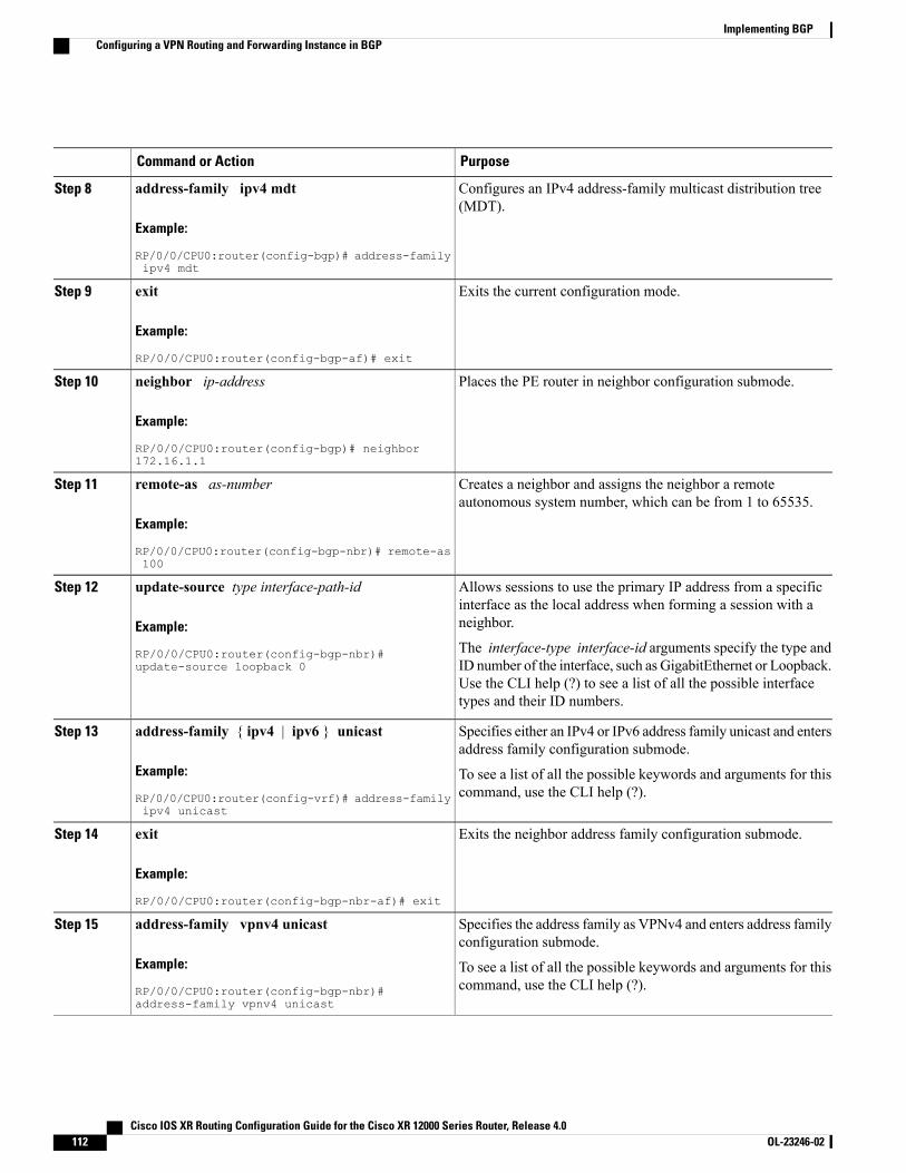
PurposeCommand or Action
Configures an IPv4 address-family multicast distribution tree(MDT).
address-family ipv4 mdt
Example:
RP/0/0/CPU0:router(config-bgp)# address-familyipv4 mdt
Step 8
Exits the current configuration mode.exit
Example:
RP/0/0/CPU0:router(config-bgp-af)# exit
Step 9
Places the PE router in neighbor configuration submode.neighbor ip-address
Example:
RP/0/0/CPU0:router(config-bgp)# neighbor172.16.1.1
Step 10
Creates a neighbor and assigns the neighbor a remoteautonomous system number, which can be from 1 to 65535.
remote-as as-number
Example:
RP/0/0/CPU0:router(config-bgp-nbr)# remote-as100
Step 11
Allows sessions to use the primary IP address from a specificinterface as the local address when forming a session with aneighbor.
update-source type interface-path-id
Example:
RP/0/0/CPU0:router(config-bgp-nbr)#update-source loopback 0
Step 12
The interface-type interface-id arguments specify the type andID number of the interface, such as GigabitEthernet or Loopback.Use the CLI help (?) to see a list of all the possible interfacetypes and their ID numbers.
Specifies either an IPv4 or IPv6 address family unicast and entersaddress family configuration submode.
address-family { ipv4 | ipv6 } unicast
Example:
RP/0/0/CPU0:router(config-vrf)# address-familyipv4 unicast
Step 13
To see a list of all the possible keywords and arguments for thiscommand, use the CLI help (?).
Exits the neighbor address family configuration submode.exit
Example:
RP/0/0/CPU0:router(config-bgp-nbr-af)# exit
Step 14
Specifies the address family as VPNv4 and enters address familyconfiguration submode.
address-family vpnv4 unicast
Example:
RP/0/0/CPU0:router(config-bgp-nbr)#address-family vpnv4 unicast
Step 15
To see a list of all the possible keywords and arguments for thiscommand, use the CLI help (?).
Cisco IOS XR Routing Configuration Guide for the Cisco XR 12000 Series Router, Release 4.0112 OL-23246-02
Implementing BGPConfiguring a VPN Routing and Forwarding Instance in BGP
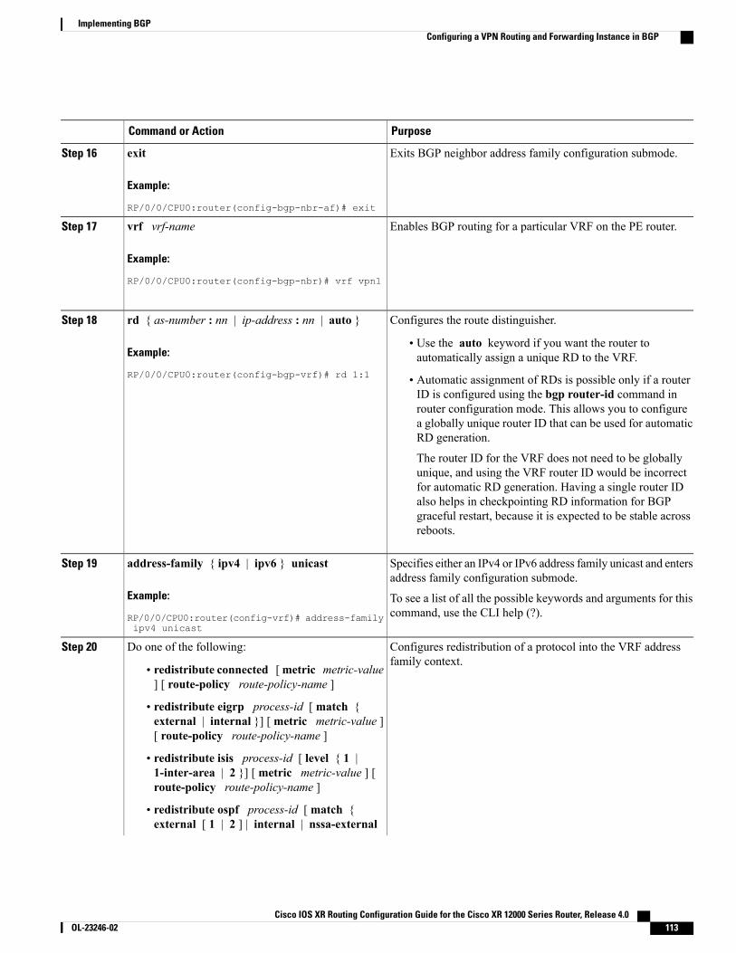
PurposeCommand or Action
Exits BGP neighbor address family configuration submode.exit
Example:
RP/0/0/CPU0:router(config-bgp-nbr-af)# exit
Step 16
Enables BGP routing for a particular VRF on the PE router.vrf vrf-name
Example:
RP/0/0/CPU0:router(config-bgp-nbr)# vrf vpn1
Step 17
Configures the route distinguisher.rd { as-number : nn | ip-address : nn | auto }Step 18
Example:
RP/0/0/CPU0:router(config-bgp-vrf)# rd 1:1
• Use the auto keyword if you want the router toautomatically assign a unique RD to the VRF.
• Automatic assignment of RDs is possible only if a routerID is configured using the bgp router-id command inrouter configuration mode. This allows you to configurea globally unique router ID that can be used for automaticRD generation.
The router ID for the VRF does not need to be globallyunique, and using the VRF router ID would be incorrectfor automatic RD generation. Having a single router IDalso helps in checkpointing RD information for BGPgraceful restart, because it is expected to be stable acrossreboots.
Specifies either an IPv4 or IPv6 address family unicast and entersaddress family configuration submode.
address-family { ipv4 | ipv6 } unicast
Example:
RP/0/0/CPU0:router(config-vrf)# address-familyipv4 unicast
Step 19
To see a list of all the possible keywords and arguments for thiscommand, use the CLI help (?).
Configures redistribution of a protocol into the VRF addressfamily context.
Do one of the following:Step 20
• redistribute connected [metric metric-value] [ route-policy route-policy-name ]
• redistribute eigrp process-id [ match {external | internal }] [metric metric-value ][ route-policy route-policy-name ]
• redistribute isis process-id [ level { 1 |1-inter-area | 2 }] [ metric metric-value ] [route-policy route-policy-name ]
• redistribute ospf process-id [ match {external [ 1 | 2 ] | internal | nssa-external
Cisco IOS XR Routing Configuration Guide for the Cisco XR 12000 Series Router, Release 4.0 OL-23246-02 113
Implementing BGPConfiguring a VPN Routing and Forwarding Instance in BGP
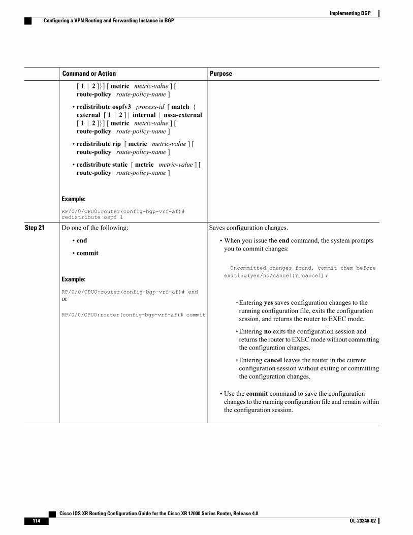
PurposeCommand or Action
[ 1 | 2 ]}] [ metric metric-value ] [route-policy route-policy-name ]
• redistribute ospfv3 process-id [ match {external [ 1 | 2 ] | internal | nssa-external[ 1 | 2 ]}] [ metric metric-value ] [route-policy route-policy-name ]
• redistribute rip [ metric metric-value ] [route-policy route-policy-name ]
• redistribute static [ metric metric-value ] [route-policy route-policy-name ]
Example:
RP/0/0/CPU0:router(config-bgp-vrf-af)#redistribute ospf 1
Saves configuration changes.Do one of the following:Step 21
• end •When you issue the end command, the system promptsyou to commit changes:
Uncommitted changes found, commit them before
• commit
Example:
RP/0/0/CPU0:router(config-bgp-vrf-af)# end
exiting(yes/no/cancel)?[cancel]:
or
RP/0/0/CPU0:router(config-bgp-vrf-af)# commit
◦Entering yes saves configuration changes to therunning configuration file, exits the configurationsession, and returns the router to EXEC mode.
◦Entering no exits the configuration session andreturns the router to EXECmode without committingthe configuration changes.
◦Entering cancel leaves the router in the currentconfiguration session without exiting or committingthe configuration changes.
• Use the commit command to save the configurationchanges to the running configuration file and remain withinthe configuration session.
Cisco IOS XR Routing Configuration Guide for the Cisco XR 12000 Series Router, Release 4.0114 OL-23246-02
Implementing BGPConfiguring a VPN Routing and Forwarding Instance in BGP
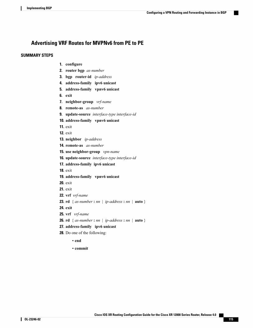
Advertising VRF Routes for MVPNv6 from PE to PE
SUMMARY STEPS
1. configure2. router bgp as-number3. bgp router-id ip-address4. address-family ipv6 unicast5. address-family vpnv6 unicast6. exit7. neighbor-group vrf-name8. remote-as as-number9. update-source interface-type interface-id10. address-family vpnv6 unicast11. exit12. exit13. neighbor ip-address14. remote-as as-number15. use neighbor-group vpn-name16. update-source interface-type interface-id17. address-family ipv6 unicast18. exit19. address-family vpnv6 unicast20. exit21. exit22. vrf vrf-name23. rd { as-number : nn | ip-address : nn | auto }24. exit25. vrf vrf-name26. rd { as-number : nn | ip-address : nn | auto }27. address-family ipv6 unicast28. Do one of the following:
• end
• commit
Cisco IOS XR Routing Configuration Guide for the Cisco XR 12000 Series Router, Release 4.0 OL-23246-02 115
Implementing BGPConfiguring a VPN Routing and Forwarding Instance in BGP
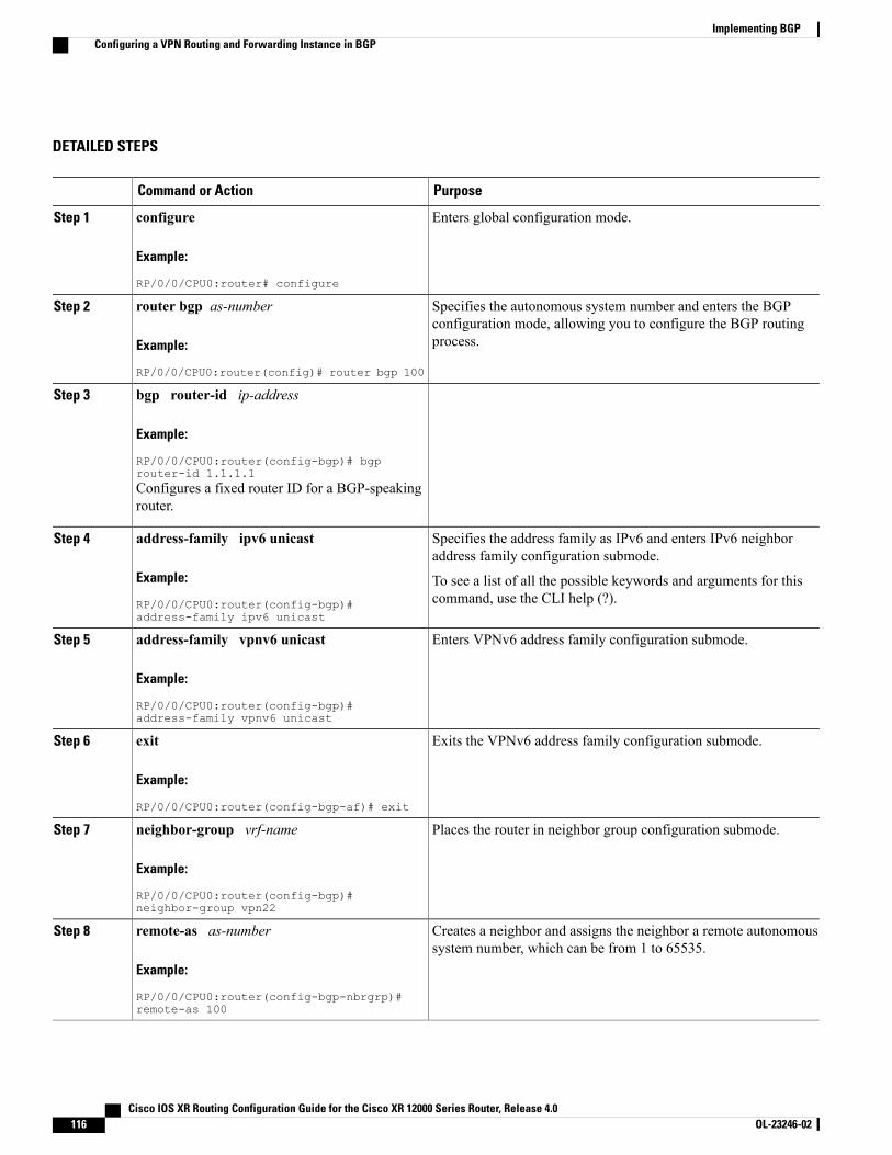
DETAILED STEPS
PurposeCommand or Action
Enters global configuration mode.configure
Example:
RP/0/0/CPU0:router# configure
Step 1
Specifies the autonomous system number and enters the BGPconfiguration mode, allowing you to configure the BGP routingprocess.
router bgp as-number
Example:
RP/0/0/CPU0:router(config)# router bgp 100
Step 2
bgp router-id ip-addressStep 3
Example:
RP/0/0/CPU0:router(config-bgp)# bgprouter-id 1.1.1.1Configures a fixed router ID for a BGP-speakingrouter.
Specifies the address family as IPv6 and enters IPv6 neighboraddress family configuration submode.
address-family ipv6 unicast
Example:
RP/0/0/CPU0:router(config-bgp)#address-family ipv6 unicast
Step 4
To see a list of all the possible keywords and arguments for thiscommand, use the CLI help (?).
Enters VPNv6 address family configuration submode.address-family vpnv6 unicast
Example:
RP/0/0/CPU0:router(config-bgp)#address-family vpnv6 unicast
Step 5
Exits the VPNv6 address family configuration submode.exit
Example:
RP/0/0/CPU0:router(config-bgp-af)# exit
Step 6
Places the router in neighbor group configuration submode.neighbor-group vrf-name
Example:
RP/0/0/CPU0:router(config-bgp)#neighbor-group vpn22
Step 7
Creates a neighbor and assigns the neighbor a remote autonomoussystem number, which can be from 1 to 65535.
remote-as as-number
Example:
RP/0/0/CPU0:router(config-bgp-nbrgrp)#remote-as 100
Step 8
Cisco IOS XR Routing Configuration Guide for the Cisco XR 12000 Series Router, Release 4.0116 OL-23246-02
Implementing BGPConfiguring a VPN Routing and Forwarding Instance in BGP
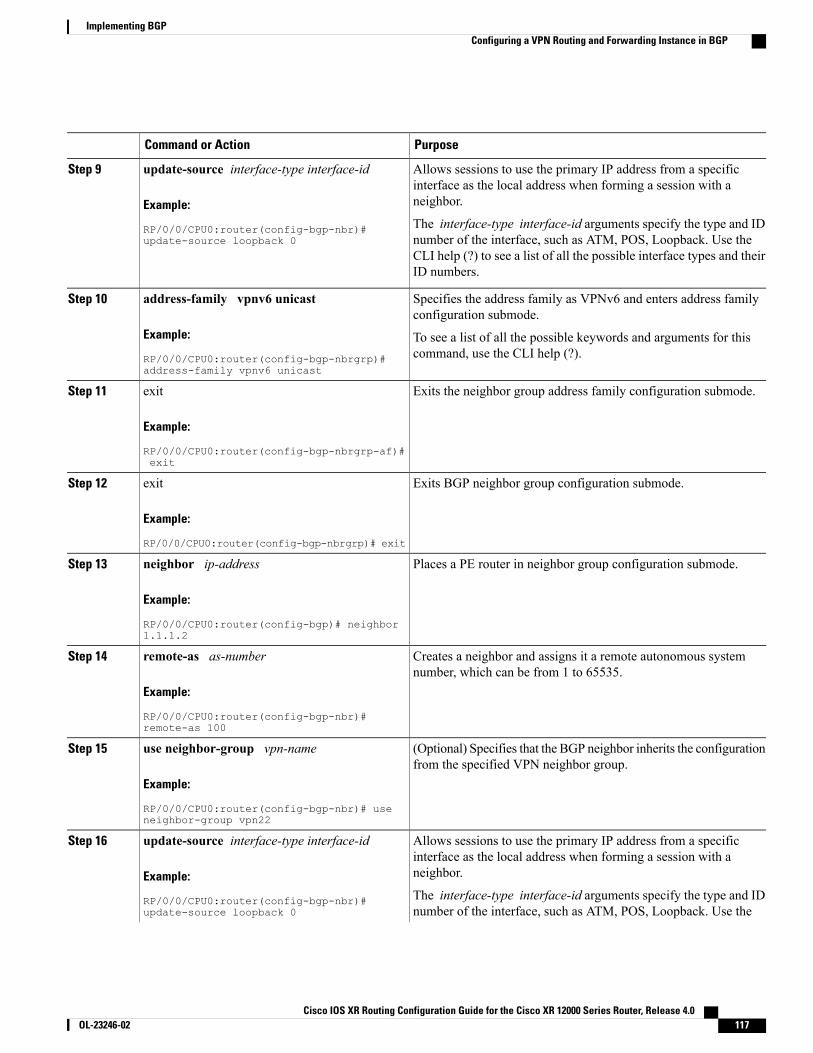
PurposeCommand or Action
Allows sessions to use the primary IP address from a specificinterface as the local address when forming a session with aneighbor.
update-source interface-type interface-id
Example:
RP/0/0/CPU0:router(config-bgp-nbr)#update-source loopback 0
Step 9
The interface-type interface-id arguments specify the type and IDnumber of the interface, such as ATM, POS, Loopback. Use theCLI help (?) to see a list of all the possible interface types and theirID numbers.
Specifies the address family as VPNv6 and enters address familyconfiguration submode.
address-family vpnv6 unicast
Example:
RP/0/0/CPU0:router(config-bgp-nbrgrp)#address-family vpnv6 unicast
Step 10
To see a list of all the possible keywords and arguments for thiscommand, use the CLI help (?).
Exits the neighbor group address family configuration submode.exit
Example:
RP/0/0/CPU0:router(config-bgp-nbrgrp-af)#exit
Step 11
Exits BGP neighbor group configuration submode.exit
Example:
RP/0/0/CPU0:router(config-bgp-nbrgrp)# exit
Step 12
Places a PE router in neighbor group configuration submode.neighbor ip-address
Example:
RP/0/0/CPU0:router(config-bgp)# neighbor1.1.1.2
Step 13
Creates a neighbor and assigns it a remote autonomous systemnumber, which can be from 1 to 65535.
remote-as as-number
Example:
RP/0/0/CPU0:router(config-bgp-nbr)#remote-as 100
Step 14
(Optional) Specifies that the BGP neighbor inherits the configurationfrom the specified VPN neighbor group.
use neighbor-group vpn-name
Example:
RP/0/0/CPU0:router(config-bgp-nbr)# useneighbor-group vpn22
Step 15
Allows sessions to use the primary IP address from a specificinterface as the local address when forming a session with aneighbor.
update-source interface-type interface-id
Example:
RP/0/0/CPU0:router(config-bgp-nbr)#update-source loopback 0
Step 16
The interface-type interface-id arguments specify the type and IDnumber of the interface, such as ATM, POS, Loopback. Use the
Cisco IOS XR Routing Configuration Guide for the Cisco XR 12000 Series Router, Release 4.0 OL-23246-02 117
Implementing BGPConfiguring a VPN Routing and Forwarding Instance in BGP
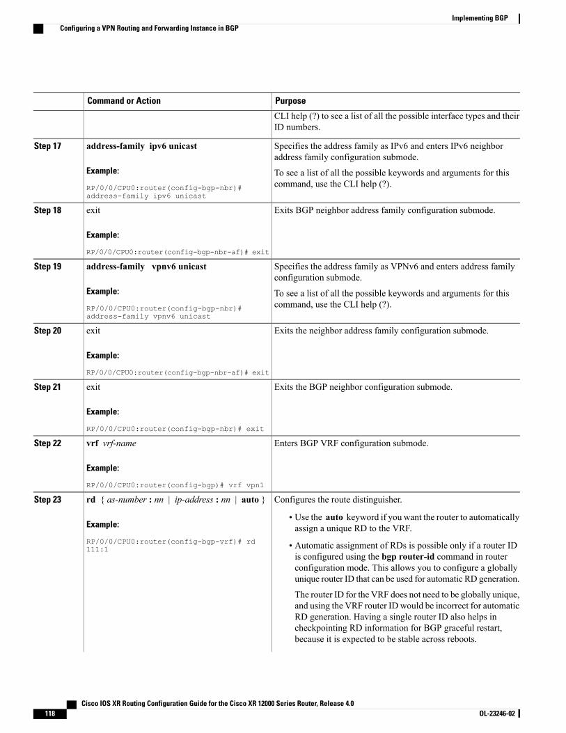
PurposeCommand or Action
CLI help (?) to see a list of all the possible interface types and theirID numbers.
Specifies the address family as IPv6 and enters IPv6 neighboraddress family configuration submode.
address-family ipv6 unicast
Example:
RP/0/0/CPU0:router(config-bgp-nbr)#address-family ipv6 unicast
Step 17
To see a list of all the possible keywords and arguments for thiscommand, use the CLI help (?).
Exits BGP neighbor address family configuration submode.exit
Example:
RP/0/0/CPU0:router(config-bgp-nbr-af)# exit
Step 18
Specifies the address family as VPNv6 and enters address familyconfiguration submode.
address-family vpnv6 unicast
Example:
RP/0/0/CPU0:router(config-bgp-nbr)#address-family vpnv6 unicast
Step 19
To see a list of all the possible keywords and arguments for thiscommand, use the CLI help (?).
Exits the neighbor address family configuration submode.exit
Example:
RP/0/0/CPU0:router(config-bgp-nbr-af)# exit
Step 20
Exits the BGP neighbor configuration submode.exit
Example:
RP/0/0/CPU0:router(config-bgp-nbr)# exit
Step 21
Enters BGP VRF configuration submode.vrf vrf-name
Example:
RP/0/0/CPU0:router(config-bgp)# vrf vpn1
Step 22
Configures the route distinguisher.rd { as-number : nn | ip-address : nn | auto }Step 23
Example:
RP/0/0/CPU0:router(config-bgp-vrf)# rd111:1
• Use the auto keyword if you want the router to automaticallyassign a unique RD to the VRF.
• Automatic assignment of RDs is possible only if a router IDis configured using the bgp router-id command in routerconfiguration mode. This allows you to configure a globallyunique router ID that can be used for automatic RD generation.
The router ID for the VRF does not need to be globally unique,and using the VRF router ID would be incorrect for automaticRD generation. Having a single router ID also helps incheckpointing RD information for BGP graceful restart,because it is expected to be stable across reboots.
Cisco IOS XR Routing Configuration Guide for the Cisco XR 12000 Series Router, Release 4.0118 OL-23246-02
Implementing BGPConfiguring a VPN Routing and Forwarding Instance in BGP
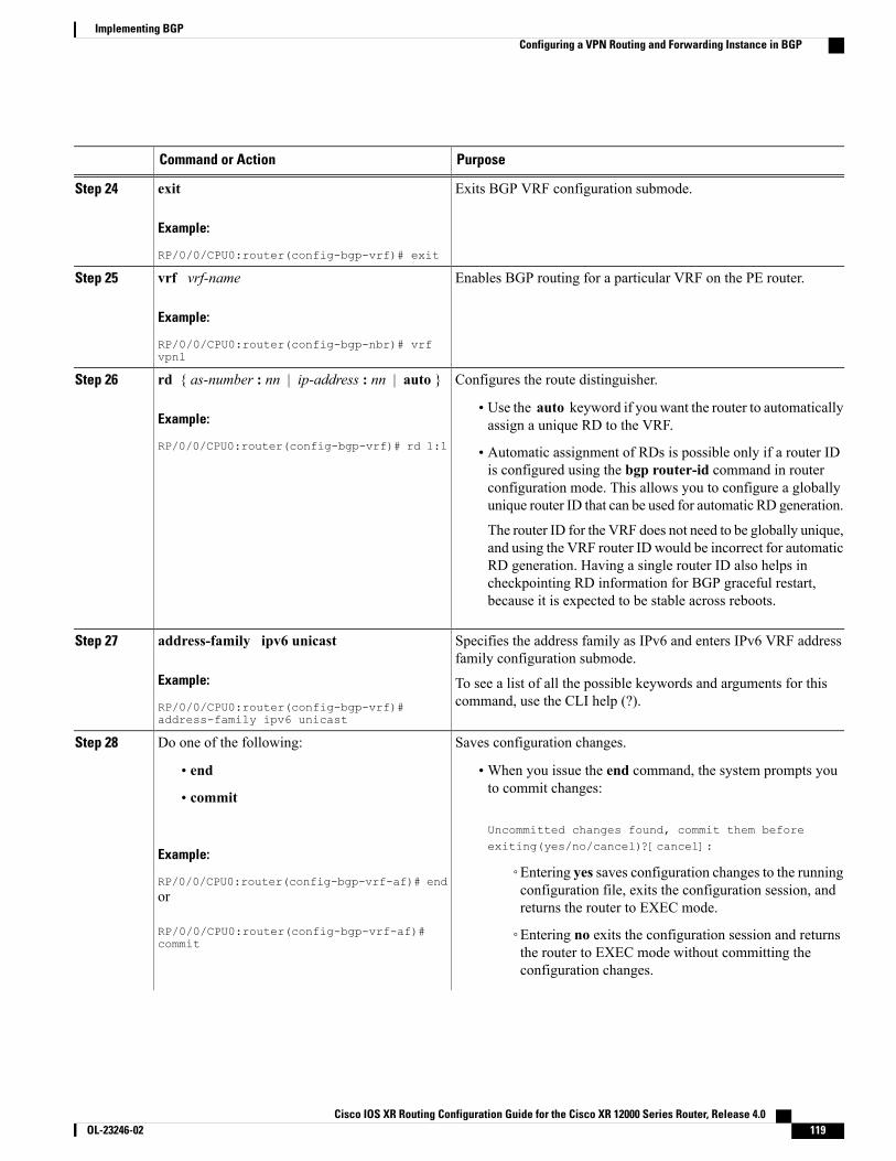
PurposeCommand or Action
Exits BGP VRF configuration submode.exit
Example:
RP/0/0/CPU0:router(config-bgp-vrf)# exit
Step 24
Enables BGP routing for a particular VRF on the PE router.vrf vrf-name
Example:
RP/0/0/CPU0:router(config-bgp-nbr)# vrfvpn1
Step 25
Configures the route distinguisher.rd { as-number : nn | ip-address : nn | auto }Step 26
Example:
RP/0/0/CPU0:router(config-bgp-vrf)# rd 1:1
• Use the auto keyword if you want the router to automaticallyassign a unique RD to the VRF.
• Automatic assignment of RDs is possible only if a router IDis configured using the bgp router-id command in routerconfiguration mode. This allows you to configure a globallyunique router ID that can be used for automatic RD generation.
The router ID for the VRF does not need to be globally unique,and using the VRF router ID would be incorrect for automaticRD generation. Having a single router ID also helps incheckpointing RD information for BGP graceful restart,because it is expected to be stable across reboots.
Specifies the address family as IPv6 and enters IPv6 VRF addressfamily configuration submode.
address-family ipv6 unicast
Example:
RP/0/0/CPU0:router(config-bgp-vrf)#address-family ipv6 unicast
Step 27
To see a list of all the possible keywords and arguments for thiscommand, use the CLI help (?).
Saves configuration changes.Do one of the following:Step 28
• end •When you issue the end command, the system prompts youto commit changes:
Uncommitted changes found, commit them beforeexiting(yes/no/cancel)?[cancel]:
• commit
Example:
RP/0/0/CPU0:router(config-bgp-vrf-af)# end◦Entering yes saves configuration changes to the runningconfiguration file, exits the configuration session, andreturns the router to EXEC mode.
or
RP/0/0/CPU0:router(config-bgp-vrf-af)#commit
◦Entering no exits the configuration session and returnsthe router to EXEC mode without committing theconfiguration changes.
Cisco IOS XR Routing Configuration Guide for the Cisco XR 12000 Series Router, Release 4.0 OL-23246-02 119
Implementing BGPConfiguring a VPN Routing and Forwarding Instance in BGP
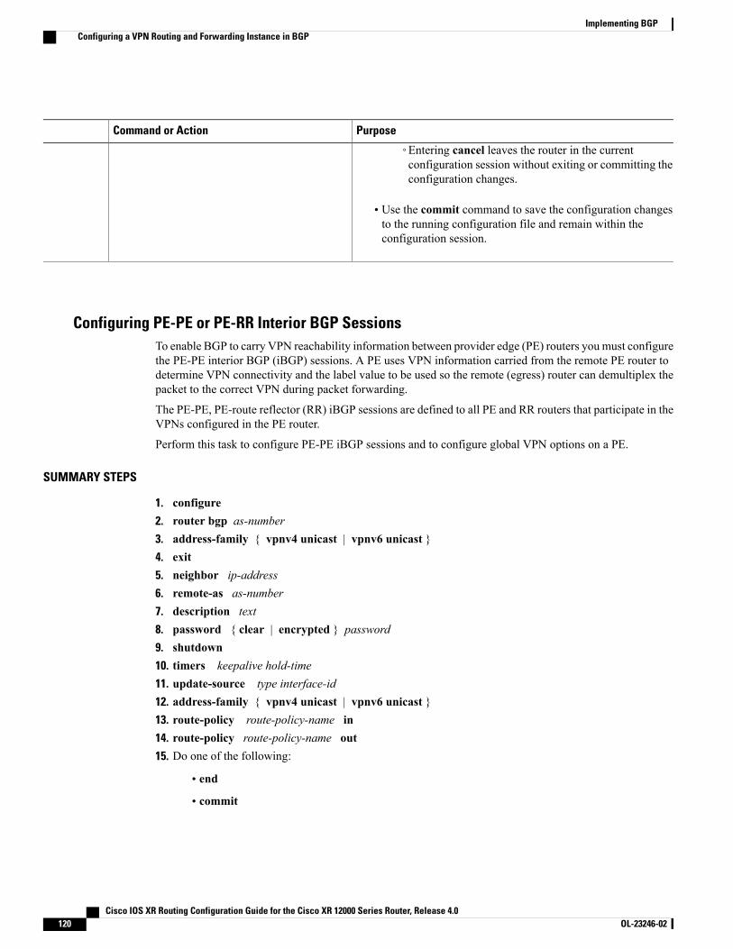
PurposeCommand or Action
◦Entering cancel leaves the router in the currentconfiguration session without exiting or committing theconfiguration changes.
• Use the commit command to save the configuration changesto the running configuration file and remain within theconfiguration session.
Configuring PE-PE or PE-RR Interior BGP SessionsTo enable BGP to carry VPN reachability information between provider edge (PE) routers you must configurethe PE-PE interior BGP (iBGP) sessions. A PE uses VPN information carried from the remote PE router todetermine VPN connectivity and the label value to be used so the remote (egress) router can demultiplex thepacket to the correct VPN during packet forwarding.
The PE-PE, PE-route reflector (RR) iBGP sessions are defined to all PE and RR routers that participate in theVPNs configured in the PE router.
Perform this task to configure PE-PE iBGP sessions and to configure global VPN options on a PE.
SUMMARY STEPS
1. configure2. router bgp as-number3. address-family { vpnv4 unicast | vpnv6 unicast }4. exit5. neighbor ip-address6. remote-as as-number7. description text8. password { clear | encrypted } password9. shutdown10. timers keepalive hold-time11. update-source type interface-id12. address-family { vpnv4 unicast | vpnv6 unicast }13. route-policy route-policy-name in14. route-policy route-policy-name out15. Do one of the following:
• end
• commit
Cisco IOS XR Routing Configuration Guide for the Cisco XR 12000 Series Router, Release 4.0120 OL-23246-02
Implementing BGPConfiguring a VPN Routing and Forwarding Instance in BGP
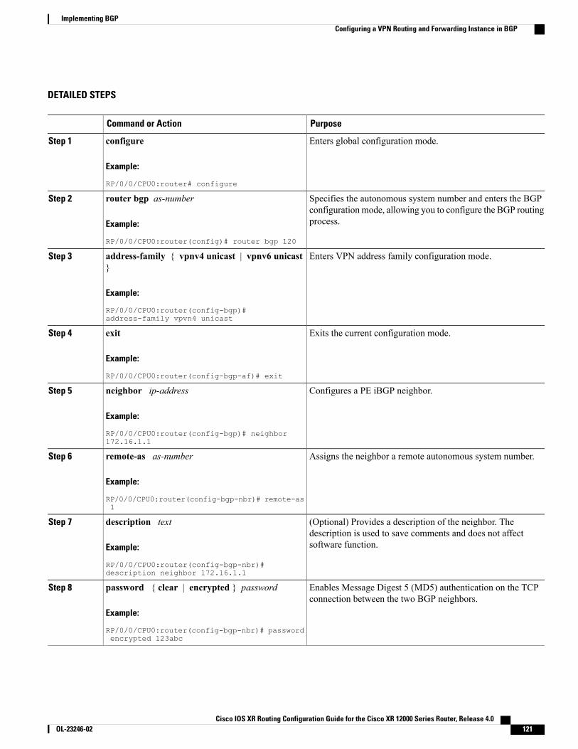
DETAILED STEPS
PurposeCommand or Action
Enters global configuration mode.configure
Example:
RP/0/0/CPU0:router# configure
Step 1
Specifies the autonomous system number and enters the BGPconfiguration mode, allowing you to configure the BGP routingprocess.
router bgp as-number
Example:
RP/0/0/CPU0:router(config)# router bgp 120
Step 2
Enters VPN address family configuration mode.address-family { vpnv4 unicast | vpnv6 unicast}
Step 3
Example:
RP/0/0/CPU0:router(config-bgp)#address-family vpvn4 unicast
Exits the current configuration mode.exit
Example:
RP/0/0/CPU0:router(config-bgp-af)# exit
Step 4
Configures a PE iBGP neighbor.neighbor ip-address
Example:
RP/0/0/CPU0:router(config-bgp)# neighbor172.16.1.1
Step 5
Assigns the neighbor a remote autonomous system number.remote-as as-number
Example:
RP/0/0/CPU0:router(config-bgp-nbr)# remote-as1
Step 6
(Optional) Provides a description of the neighbor. Thedescription is used to save comments and does not affectsoftware function.
description text
Example:
RP/0/0/CPU0:router(config-bgp-nbr)#description neighbor 172.16.1.1
Step 7
Enables Message Digest 5 (MD5) authentication on the TCPconnection between the two BGP neighbors.
password { clear | encrypted } password
Example:
RP/0/0/CPU0:router(config-bgp-nbr)# passwordencrypted 123abc
Step 8
Cisco IOS XR Routing Configuration Guide for the Cisco XR 12000 Series Router, Release 4.0 OL-23246-02 121
Implementing BGPConfiguring a VPN Routing and Forwarding Instance in BGP

PurposeCommand or Action
Terminates any active sessions for the specified neighbor andremoves all associated routing information.
shutdown
Example:
RP/0/0/CPU0:router(config-bgp-nbr)# shutdown
Step 9
Set the timers for the BGP neighbor.timers keepalive hold-time
Example:
RP/0/0/CPU0:router(config-bgp-nbr)# timers12000 200
Step 10
Allows iBGP sessions to use the primary IP address from aspecific interface as the local address when forming an iBGPsession with a neighbor.
update-source type interface-id
Example:
RP/0/0/CPU0:router(config-bgp-nbr)#update-source gigabitEthernet 0/1/5/0
Step 11
Enters VPN neighbor address family configuration mode.address-family { vpnv4 unicast | vpnv6 unicast}
Step 12
Example:
RP/0/0/CPU0:router(config-bgp-nbr)#address-family vpvn4 unicast
Specifies a routing policy for an inbound route. The policy canbe used to filter routes or modify route attributes.
route-policy route-policy-name in
Example:
RP/0/0/CPU0:router(config-bgp-nbr-af)#route-policy pe-pe-vpn-in in
Step 13
Specifies a routing policy for an outbound route. The policycan be used to filter routes or modify route attributes.
route-policy route-policy-name out
Example:
RP/0/0/CPU0:router(config-bgp-nbr-af)#route-policy pe-pe-vpn-out out
Step 14
Saves configuration changes.Do one of the following:Step 15
• end •When you issue the end command, the system promptsyou to commit changes:
Uncommitted changes found, commit them before
• commit
Example:
RP/0/0/CPU0:router(config-bgp-nbr-af)# end
exiting(yes/no/cancel)?[cancel]:
◦Entering yes saves configuration changes to therunning configuration file, exits the configurationsession, and returns the router to EXEC mode.
or
RP/0/0/CPU0:router(config-bgp-nbr-af)# commit
Cisco IOS XR Routing Configuration Guide for the Cisco XR 12000 Series Router, Release 4.0122 OL-23246-02
Implementing BGPConfiguring a VPN Routing and Forwarding Instance in BGP
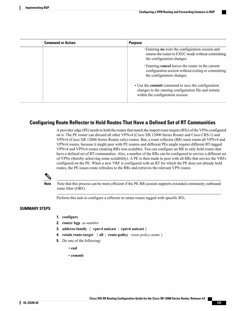
PurposeCommand or Action
◦Entering no exits the configuration session andreturns the router to EXECmodewithout committingthe configuration changes.
◦Entering cancel leaves the router in the currentconfiguration session without exiting or committingthe configuration changes.
• Use the commit command to save the configurationchanges to the running configuration file and remainwithin the configuration session.
Configuring Route Reflector to Hold Routes That Have a Defined Set of RT CommunitiesA provider edge (PE) needs to hold the routes that match the import route targets (RTs) of the VPNs configuredon it. The PE router can discard all other VPNv4 (Cisco XR 12000 Series Router and Cisco CRS-1) andVPNv6 (Cisco XR 12000 Series Router only) routes. But, a route reflector (RR) must retain all VPNv4 andVPNv6 routes, because it might peer with PE routers and different PEs might require different RT-taggedVPNv4 and VPNv6 routes (making RRs non-scalable). You can configure an RR to only hold routes thathave a defined set of RT communities. Also, a number of the RRs can be configured to service a different setof VPNs (thereby achieving some scalability). A PE is then made to peer with all RRs that service the VRFsconfigured on the PE. When a new VRF is configured with an RT for which the PE does not already holdroutes, the PE issues route refreshes to the RRs and retrieves the relevant VPN routes.
Note that this process can be more efficient if the PE-RR session supports extended community outboundroute filter (ORF).
Note
Perform this task to configure a reflector to retain routes tagged with specific RTs.
SUMMARY STEPS
1. configure2. router bgp as-number3. address-family { vpnv4 unicast | vpnv6 unicast }4. retain route-target { all | route-policy route-policy-name }5. Do one of the following:
• end
• commit
Cisco IOS XR Routing Configuration Guide for the Cisco XR 12000 Series Router, Release 4.0 OL-23246-02 123
Implementing BGPConfiguring a VPN Routing and Forwarding Instance in BGP

DETAILED STEPS
PurposeCommand or Action
Enters global configuration mode.configure
Example:
RP/0/0/CPU0:router# configure
Step 1
Specifies the autonomous system number and enters the BGPconfiguration mode, allowing you to configure the BGP routingprocess.
router bgp as-number
Example:
RP/0/0/CPU0:router(config)# router bgp 120
Step 2
Enters VPN address family configuration mode.address-family { vpnv4 unicast | vpnv6unicast }
Step 3
Example:
RP/0/0/CPU0:router(config-bgp)#address-family vpvn4 unicast
Configures a reflector to retain routes tagged with particular RTs. Usethe route-policy-name argument for the policy name that lists the
retain route-target { all | route-policyroute-policy-name }
Step 4
extended communities that a path should have in order for the RR toretain that path.Example:
RP/0/0/CPU0:router(config-bgp-af)# retainroute-target route-policy rr_ext-comm
The all keyword is not required, because this is the defaultbehavior of a route reflector.
Note
Saves configuration changes.Do one of the following:Step 5
• end •When you issue the end command, the system prompts you tocommit changes:
Uncommitted changes found, commit them before
• commit
Example:
RP/0/0/CPU0:router(config-bgp-nbr-af)# end
exiting(yes/no/cancel)?[cancel]:
or
RP/0/0/CPU0:router(config-bgp-nbr-af)#commit
◦Entering yes saves configuration changes to the runningconfiguration file, exits the configuration session, andreturns the router to EXEC mode.
◦Entering no exits the configuration session and returns therouter to EXECmodewithout committing the configurationchanges.
◦Entering cancel leaves the router in the currentconfiguration session without exiting or committing theconfiguration changes.
Cisco IOS XR Routing Configuration Guide for the Cisco XR 12000 Series Router, Release 4.0124 OL-23246-02
Implementing BGPConfiguring a VPN Routing and Forwarding Instance in BGP
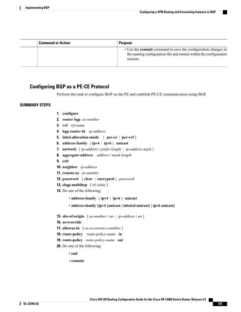
PurposeCommand or Action
• Use the commit command to save the configuration changes tothe running configuration file and remain within the configurationsession.
Configuring BGP as a PE-CE ProtocolPerform this task to configure BGP on the PE and establish PE-CE communication using BGP.
SUMMARY STEPS
1. configure2. router bgp as-number3. vrf vrf-name4. bgp router-id ip-address5. label-allocation-mode { per-ce | per-vrf }6. address-family { ipv4 | ipv6 } unicast7. network { ip-address / prefix-length | ip-address mask }8. aggregate-address address / mask-length9. exit10. neighbor ip-address11. remote-as as-number12. password { clear | encrypted } password13. ebgp-multihop [ ttl-value ]14. Do one of the following:
• address-family { ipv4 | ipv6 } unicast
• address-family {ipv4 {unicast | labeled-unicast} | ipv6 unicast}
15. site-of-origin [ as-number : nn | ip-address : nn ]16. as-override17. allowas-in [ as-occurrence-number ]18. route-policy route-policy-name in19. route-policy route-policy-name out20. Do one of the following:
• end
• commit
Cisco IOS XR Routing Configuration Guide for the Cisco XR 12000 Series Router, Release 4.0 OL-23246-02 125
Implementing BGPConfiguring a VPN Routing and Forwarding Instance in BGP

DETAILED STEPS
PurposeCommand or Action
Enters global configuration mode.configure
Example:
RP/0/0/CPU0:router# configure
Step 1
Specifies the autonomous system number and enters the BGPconfiguration mode, allowing you to configure the BGP routingprocess.
router bgp as-number
Example:
RP/0/0/CPU0:router(config)# router bgp 120
Step 2
Enables BGP routing for a particular VRF on the PE router.vrf vrf-name
Example:
RP/0/0/CPU0:router(config-bgp)# vrf vrf_pe_2
Step 3
Configures a fixed router ID for a BGP-speaking router.bgp router-id ip-address
Example:
RP/0/0/CPU0:router(config-bgp-vrf)# bgprouter-id 172.16.9.9
Step 4
Configures the MPLS/VPN label allocation mode.label-allocation-mode { per-ce | per-vrf }Step 5
Example:
RP/0/0/CPU0:router(config-bgp-vrf)#label-allocation-mode per-ce
• The per-ce keyword configures the per-CE label allocationmode to avoid an extra lookup on the PE router and conservelabel space (per-prefix is the default label allocation mode).In this mode, the PE router allocates one label for everyimmediate next-hop (in most cases, this would be a CErouter). This label is directly mapped to the next hop, sothere is no VRF route lookup performed during dataforwarding. However, the number of labels allocated wouldbe one for each CE rather than one for each VRF. BecauseBGP knows all the next hops, it assigns a label for each nexthop (not for each PE-CE interface). When the outgoinginterface is a multiaccess interface and the media accesscontrol (MAC) address of the neighbor is not known,Address Resolution Protocol (ARP) is triggered duringpacket forwarding.
• The per-vrf keyword configures the same label to be usedfor all the routes advertised from a unique VRF.
Cisco IOS XR Routing Configuration Guide for the Cisco XR 12000 Series Router, Release 4.0126 OL-23246-02
Implementing BGPConfiguring a VPN Routing and Forwarding Instance in BGP
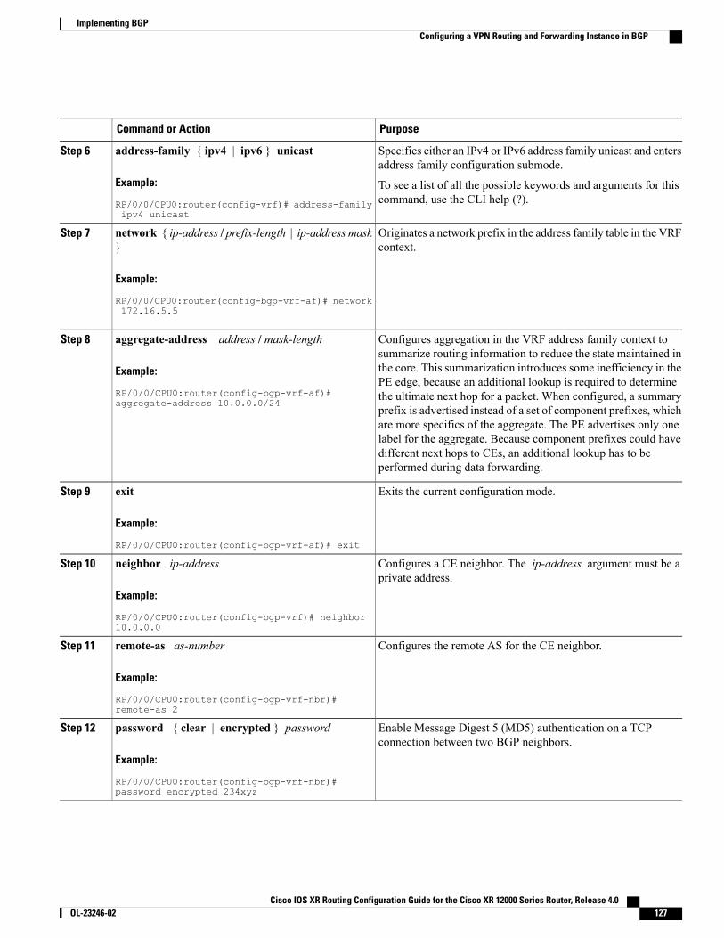
PurposeCommand or Action
Specifies either an IPv4 or IPv6 address family unicast and entersaddress family configuration submode.
address-family { ipv4 | ipv6 } unicast
Example:
RP/0/0/CPU0:router(config-vrf)# address-familyipv4 unicast
Step 6
To see a list of all the possible keywords and arguments for thiscommand, use the CLI help (?).
Originates a network prefix in the address family table in the VRFcontext.
network { ip-address / prefix-length | ip-address mask}
Example:
RP/0/0/CPU0:router(config-bgp-vrf-af)# network
Step 7
172.16.5.5
Configures aggregation in the VRF address family context tosummarize routing information to reduce the state maintained in
aggregate-address address / mask-length
Example:
RP/0/0/CPU0:router(config-bgp-vrf-af)#aggregate-address 10.0.0.0/24
Step 8
the core. This summarization introduces some inefficiency in thePE edge, because an additional lookup is required to determinethe ultimate next hop for a packet. When configured, a summaryprefix is advertised instead of a set of component prefixes, whichare more specifics of the aggregate. The PE advertises only onelabel for the aggregate. Because component prefixes could havedifferent next hops to CEs, an additional lookup has to beperformed during data forwarding.
Exits the current configuration mode.exit
Example:
RP/0/0/CPU0:router(config-bgp-vrf-af)# exit
Step 9
Configures a CE neighbor. The ip-address argument must be aprivate address.
neighbor ip-address
Example:
RP/0/0/CPU0:router(config-bgp-vrf)# neighbor10.0.0.0
Step 10
Configures the remote AS for the CE neighbor.remote-as as-number
Example:
RP/0/0/CPU0:router(config-bgp-vrf-nbr)#remote-as 2
Step 11
Enable Message Digest 5 (MD5) authentication on a TCPconnection between two BGP neighbors.
password { clear | encrypted } password
Example:
RP/0/0/CPU0:router(config-bgp-vrf-nbr)#password encrypted 234xyz
Step 12
Cisco IOS XR Routing Configuration Guide for the Cisco XR 12000 Series Router, Release 4.0 OL-23246-02 127
Implementing BGPConfiguring a VPN Routing and Forwarding Instance in BGP
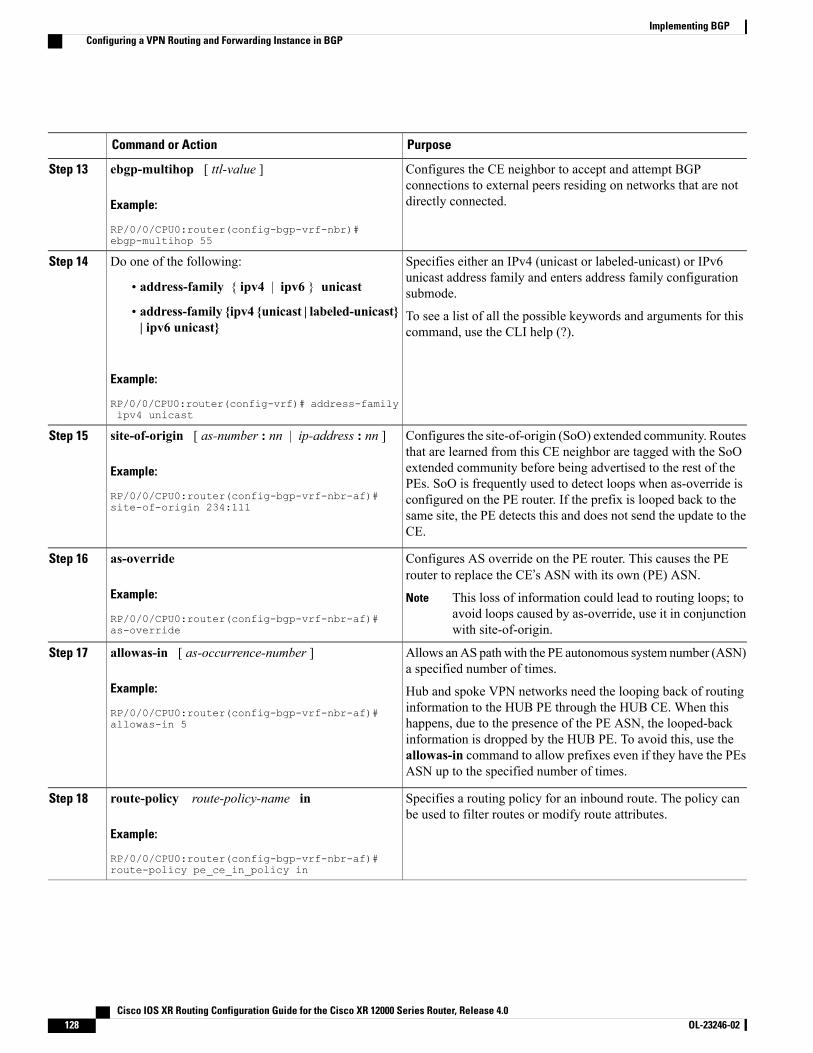
PurposeCommand or Action
Configures the CE neighbor to accept and attempt BGPconnections to external peers residing on networks that are notdirectly connected.
ebgp-multihop [ ttl-value ]
Example:
RP/0/0/CPU0:router(config-bgp-vrf-nbr)#ebgp-multihop 55
Step 13
Specifies either an IPv4 (unicast or labeled-unicast) or IPv6unicast address family and enters address family configurationsubmode.
Do one of the following:Step 14
• address-family { ipv4 | ipv6 } unicast
• address-family {ipv4 {unicast | labeled-unicast}| ipv6 unicast}
To see a list of all the possible keywords and arguments for thiscommand, use the CLI help (?).
Example:
RP/0/0/CPU0:router(config-vrf)# address-familyipv4 unicast
Configures the site-of-origin (SoO) extended community. Routesthat are learned from this CE neighbor are tagged with the SoO
site-of-origin [ as-number : nn | ip-address : nn ]
Example:
RP/0/0/CPU0:router(config-bgp-vrf-nbr-af)#site-of-origin 234:111
Step 15
extended community before being advertised to the rest of thePEs. SoO is frequently used to detect loops when as-override isconfigured on the PE router. If the prefix is looped back to thesame site, the PE detects this and does not send the update to theCE.
Configures AS override on the PE router. This causes the PErouter to replace the CE’s ASN with its own (PE) ASN.
as-override
Example:
RP/0/0/CPU0:router(config-bgp-vrf-nbr-af)#as-override
Step 16
This loss of information could lead to routing loops; toavoid loops caused by as-override, use it in conjunctionwith site-of-origin.
Note
Allows anAS pathwith the PE autonomous system number (ASN)a specified number of times.
allowas-in [ as-occurrence-number ]
Example:
RP/0/0/CPU0:router(config-bgp-vrf-nbr-af)#allowas-in 5
Step 17
Hub and spoke VPN networks need the looping back of routinginformation to the HUB PE through the HUB CE. When thishappens, due to the presence of the PE ASN, the looped-backinformation is dropped by the HUB PE. To avoid this, use theallowas-in command to allow prefixes even if they have the PEsASN up to the specified number of times.
Specifies a routing policy for an inbound route. The policy canbe used to filter routes or modify route attributes.
route-policy route-policy-name in
Example:
RP/0/0/CPU0:router(config-bgp-vrf-nbr-af)#route-policy pe_ce_in_policy in
Step 18
Cisco IOS XR Routing Configuration Guide for the Cisco XR 12000 Series Router, Release 4.0128 OL-23246-02
Implementing BGPConfiguring a VPN Routing and Forwarding Instance in BGP
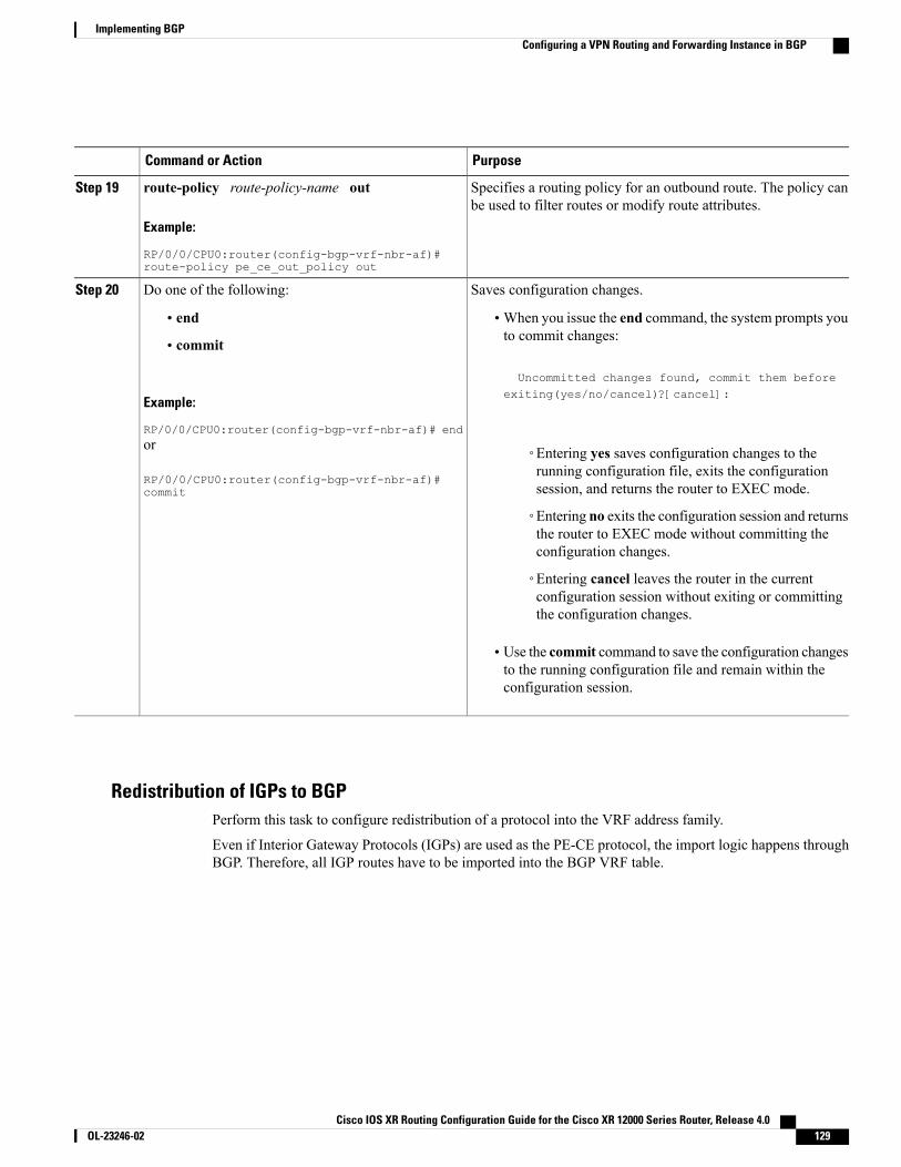
PurposeCommand or Action
Specifies a routing policy for an outbound route. The policy canbe used to filter routes or modify route attributes.
route-policy route-policy-name out
Example:
RP/0/0/CPU0:router(config-bgp-vrf-nbr-af)#route-policy pe_ce_out_policy out
Step 19
Saves configuration changes.Do one of the following:Step 20
• end •When you issue the end command, the system prompts youto commit changes:
Uncommitted changes found, commit them before
• commit
Example:
RP/0/0/CPU0:router(config-bgp-vrf-nbr-af)# end
exiting(yes/no/cancel)?[cancel]:
or
RP/0/0/CPU0:router(config-bgp-vrf-nbr-af)#commit
◦Entering yes saves configuration changes to therunning configuration file, exits the configurationsession, and returns the router to EXEC mode.
◦Entering no exits the configuration session and returnsthe router to EXEC mode without committing theconfiguration changes.
◦Entering cancel leaves the router in the currentconfiguration session without exiting or committingthe configuration changes.
• Use the commit command to save the configuration changesto the running configuration file and remain within theconfiguration session.
Redistribution of IGPs to BGPPerform this task to configure redistribution of a protocol into the VRF address family.
Even if Interior Gateway Protocols (IGPs) are used as the PE-CE protocol, the import logic happens throughBGP. Therefore, all IGP routes have to be imported into the BGP VRF table.
Cisco IOS XR Routing Configuration Guide for the Cisco XR 12000 Series Router, Release 4.0 OL-23246-02 129
Implementing BGPConfiguring a VPN Routing and Forwarding Instance in BGP
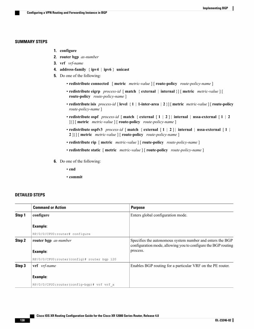
SUMMARY STEPS
1. configure2. router bgp as-number3. vrf vrf-name4. address-family { ipv4 | ipv6 } unicast5. Do one of the following:
• redistribute connected [ metric metric-value ] [ route-policy route-policy-name ]
• redistribute eigrp process-id [ match { external | internal }] [ metric metric-value ] [route-policy route-policy-name ]
• redistribute isis process-id [ level { 1 | 1-inter-area | 2 }] [metric metric-value ] [ route-policyroute-policy-name ]
• redistribute ospf process-id [ match { external [ 1 | 2 ] | internal | nssa-external [ 1 | 2]}] [ metric metric-value ] [ route-policy route-policy-name ]
• redistribute ospfv3 process-id [ match { external [ 1 | 2 ] | internal | nssa-external [ 1 |2 ]}] [ metric metric-value ] [ route-policy route-policy-name ]
• redistribute rip [ metric metric-value ] [ route-policy route-policy-name ]
• redistribute static [ metric metric-value ] [ route-policy route-policy-name ]
6. Do one of the following:
• end
• commit
DETAILED STEPS
PurposeCommand or Action
Enters global configuration mode.configure
Example:
RP/0/0/CPU0:router# configure
Step 1
Specifies the autonomous system number and enters the BGPconfigurationmode, allowing you to configure the BGP routingprocess.
router bgp as-number
Example:
RP/0/0/CPU0:router(config)# router bgp 120
Step 2
Enables BGP routing for a particular VRF on the PE router.vrf vrf-name
Example:
RP/0/0/CPU0:router(config-bgp)# vrf vrf_a
Step 3
Cisco IOS XR Routing Configuration Guide for the Cisco XR 12000 Series Router, Release 4.0130 OL-23246-02
Implementing BGPConfiguring a VPN Routing and Forwarding Instance in BGP
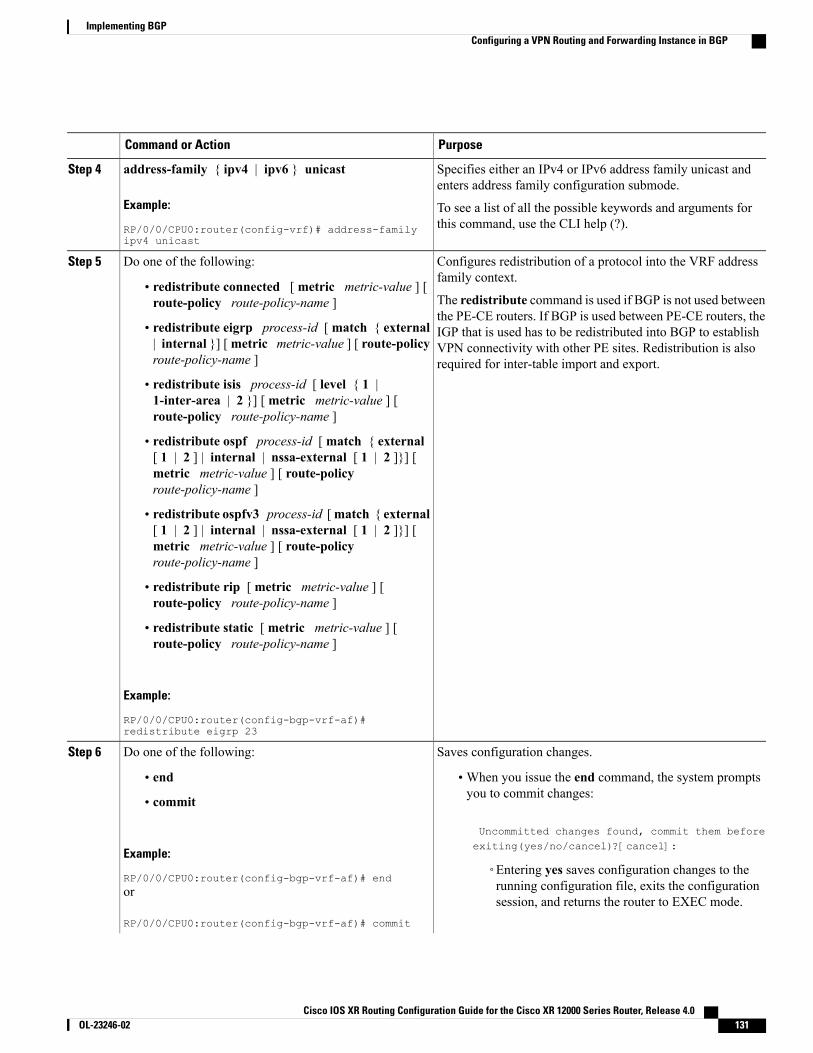
PurposeCommand or Action
Specifies either an IPv4 or IPv6 address family unicast andenters address family configuration submode.
address-family { ipv4 | ipv6 } unicast
Example:
RP/0/0/CPU0:router(config-vrf)# address-familyipv4 unicast
Step 4
To see a list of all the possible keywords and arguments forthis command, use the CLI help (?).
Configures redistribution of a protocol into the VRF addressfamily context.
Do one of the following:Step 5
• redistribute connected [ metric metric-value ] [route-policy route-policy-name ] The redistribute command is used if BGP is not used between
the PE-CE routers. If BGP is used between PE-CE routers, the• redistribute eigrp process-id [match { external| internal }] [metric metric-value ] [ route-policyroute-policy-name ]
IGP that is used has to be redistributed into BGP to establishVPN connectivity with other PE sites. Redistribution is alsorequired for inter-table import and export.
• redistribute isis process-id [ level { 1 |1-inter-area | 2 }] [ metric metric-value ] [route-policy route-policy-name ]
• redistribute ospf process-id [ match { external[ 1 | 2 ] | internal | nssa-external [ 1 | 2 ]}] [metric metric-value ] [ route-policyroute-policy-name ]
• redistribute ospfv3 process-id [match { external[ 1 | 2 ] | internal | nssa-external [ 1 | 2 ]}] [metric metric-value ] [ route-policyroute-policy-name ]
• redistribute rip [ metric metric-value ] [route-policy route-policy-name ]
• redistribute static [ metric metric-value ] [route-policy route-policy-name ]
Example:
RP/0/0/CPU0:router(config-bgp-vrf-af)#redistribute eigrp 23
Saves configuration changes.Do one of the following:Step 6
• end •When you issue the end command, the system promptsyou to commit changes:
Uncommitted changes found, commit them beforeexiting(yes/no/cancel)?[cancel]:
• commit
Example:
RP/0/0/CPU0:router(config-bgp-vrf-af)# end◦Entering yes saves configuration changes to therunning configuration file, exits the configurationsession, and returns the router to EXEC mode.
or
RP/0/0/CPU0:router(config-bgp-vrf-af)# commit
Cisco IOS XR Routing Configuration Guide for the Cisco XR 12000 Series Router, Release 4.0 OL-23246-02 131
Implementing BGPConfiguring a VPN Routing and Forwarding Instance in BGP
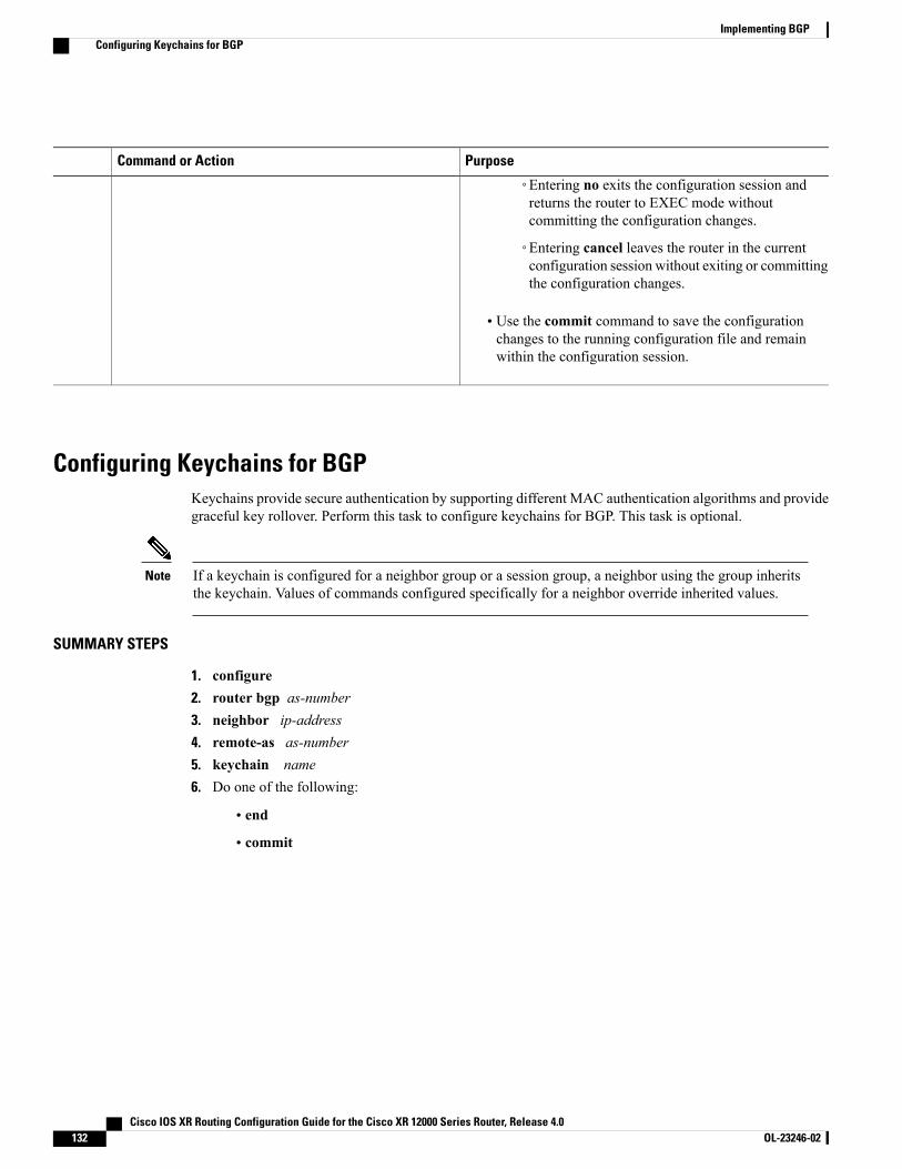
PurposeCommand or Action
◦Entering no exits the configuration session andreturns the router to EXEC mode withoutcommitting the configuration changes.
◦Entering cancel leaves the router in the currentconfiguration session without exiting or committingthe configuration changes.
• Use the commit command to save the configurationchanges to the running configuration file and remainwithin the configuration session.
Configuring Keychains for BGPKeychains provide secure authentication by supporting different MAC authentication algorithms and providegraceful key rollover. Perform this task to configure keychains for BGP. This task is optional.
If a keychain is configured for a neighbor group or a session group, a neighbor using the group inheritsthe keychain. Values of commands configured specifically for a neighbor override inherited values.
Note
SUMMARY STEPS
1. configure2. router bgp as-number3. neighbor ip-address4. remote-as as-number5. keychain name6. Do one of the following:
• end
• commit
Cisco IOS XR Routing Configuration Guide for the Cisco XR 12000 Series Router, Release 4.0132 OL-23246-02
Implementing BGPConfiguring Keychains for BGP

DETAILED STEPS
PurposeCommand or Action
Enters global configuration mode.configure
Example:
RP/0/0/CPU0:router# configure
Step 1
Specifies the autonomous system number and enters the BGPconfigurationmode, allowing you to configure the BGP routing process.
router bgp as-number
Example:
RP/0/0/CPU0:router(config)# router bgp120
Step 2
Places the router in neighbor configuration mode for BGP routing andconfigures the neighbor IP address as a BGP peer.
neighbor ip-address
Example:
RP/0/0/CPU0:router(config-bgp)# neighbor172.168.40.24
Step 3
Creates a neighbor and assigns a remote autonomous system numberto it.
remote-as as-number
Example:
RP/0/0/CPU0:router(config-bgp-nbr)#remote-as 2002
Step 4
Configures keychain-based authentication.keychain name
Example:
RP/0/0/CPU0:router(config-bgp-nbr)#keychain kych_a
Step 5
Saves configuration changes.Do one of the following:Step 6
• end •When you issue the end command, the system prompts you tocommit changes:
Uncommitted changes found, commit them before
• commit
Example:
RP/0/0/CPU0:router(config-bgp-nbr)# end
exiting(yes/no/cancel)?[cancel]:
or
RP/0/0/CPU0:router(config-bgp-nbr)#commit
◦Entering yes saves configuration changes to the runningconfiguration file, exits the configuration session, and returnsthe router to EXEC mode.
◦Entering no exits the configuration session and returns therouter to EXECmode without committing the configurationchanges.
Cisco IOS XR Routing Configuration Guide for the Cisco XR 12000 Series Router, Release 4.0 OL-23246-02 133
Implementing BGPConfiguring Keychains for BGP
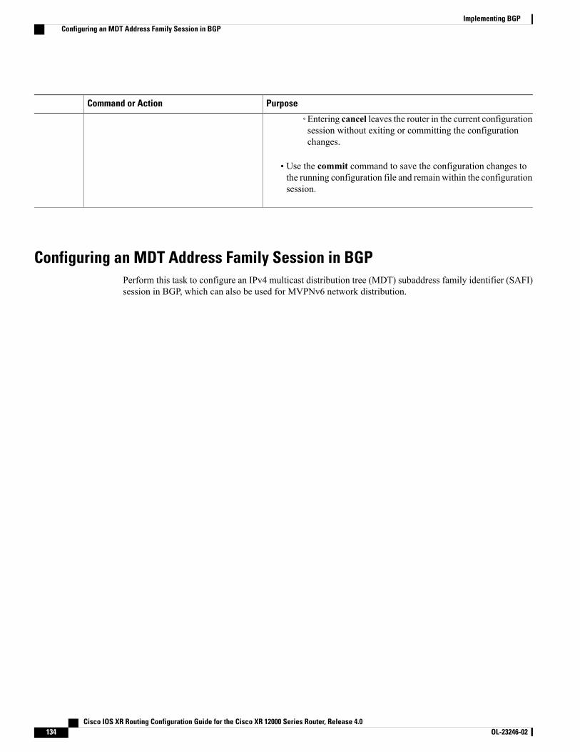
PurposeCommand or Action
◦Entering cancel leaves the router in the current configurationsession without exiting or committing the configurationchanges.
• Use the commit command to save the configuration changes tothe running configuration file and remain within the configurationsession.
Configuring an MDT Address Family Session in BGPPerform this task to configure an IPv4 multicast distribution tree (MDT) subaddress family identifier (SAFI)session in BGP, which can also be used for MVPNv6 network distribution.
Cisco IOS XR Routing Configuration Guide for the Cisco XR 12000 Series Router, Release 4.0134 OL-23246-02
Implementing BGPConfiguring an MDT Address Family Session in BGP
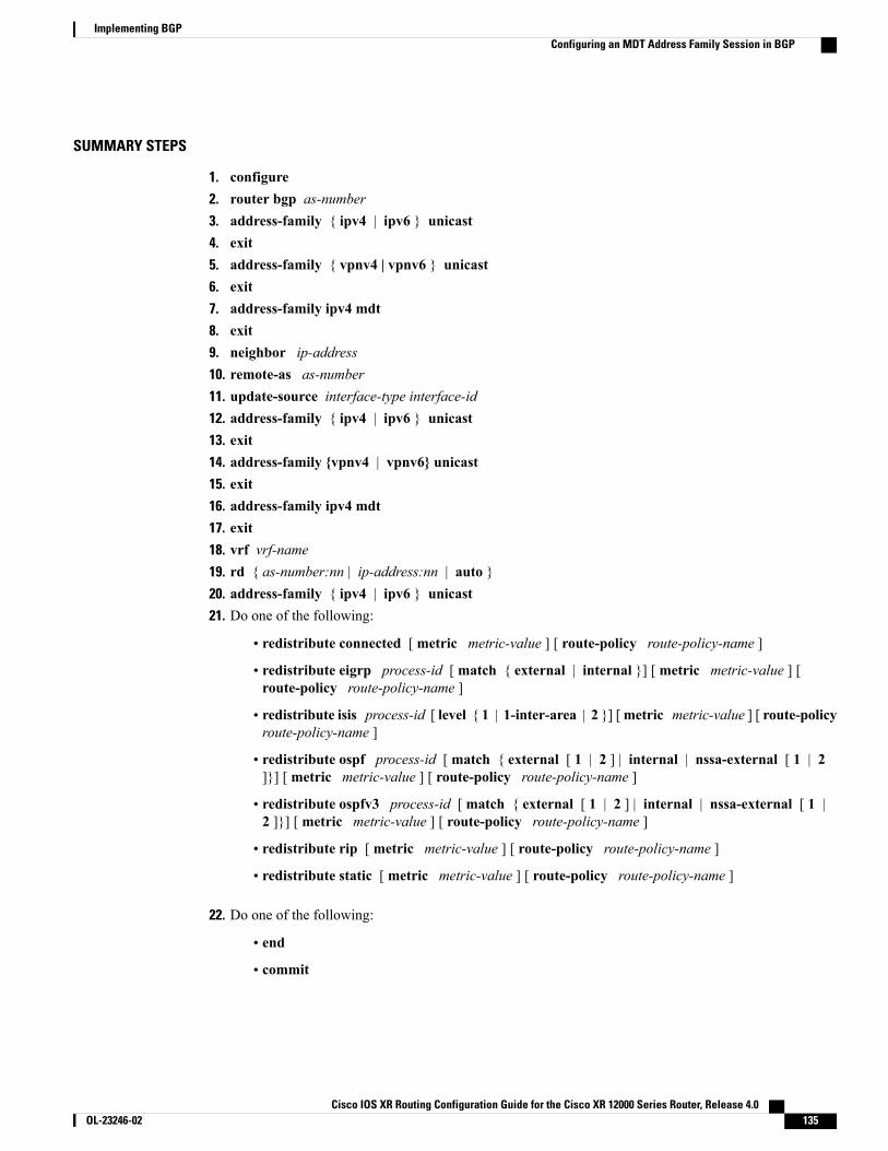
SUMMARY STEPS
1. configure2. router bgp as-number3. address-family { ipv4 | ipv6 } unicast4. exit5. address-family { vpnv4 | vpnv6 } unicast6. exit7. address-family ipv4 mdt8. exit9. neighbor ip-address10. remote-as as-number11. update-source interface-type interface-id12. address-family { ipv4 | ipv6 } unicast13. exit14. address-family {vpnv4 | vpnv6} unicast15. exit16. address-family ipv4 mdt17. exit18. vrf vrf-name19. rd { as-number:nn | ip-address:nn | auto }20. address-family { ipv4 | ipv6 } unicast21. Do one of the following:
• redistribute connected [ metric metric-value ] [ route-policy route-policy-name ]
• redistribute eigrp process-id [ match { external | internal }] [ metric metric-value ] [route-policy route-policy-name ]
• redistribute isis process-id [ level { 1 | 1-inter-area | 2 }] [metric metric-value ] [ route-policyroute-policy-name ]
• redistribute ospf process-id [ match { external [ 1 | 2 ] | internal | nssa-external [ 1 | 2]}] [ metric metric-value ] [ route-policy route-policy-name ]
• redistribute ospfv3 process-id [ match { external [ 1 | 2 ] | internal | nssa-external [ 1 |2 ]}] [ metric metric-value ] [ route-policy route-policy-name ]
• redistribute rip [ metric metric-value ] [ route-policy route-policy-name ]
• redistribute static [ metric metric-value ] [ route-policy route-policy-name ]
22. Do one of the following:
• end
• commit
Cisco IOS XR Routing Configuration Guide for the Cisco XR 12000 Series Router, Release 4.0 OL-23246-02 135
Implementing BGPConfiguring an MDT Address Family Session in BGP

DETAILED STEPS
PurposeCommand or Action
Enters global configuration mode.configure
Example:
RP/0/0/CPU0:router# configure
Step 1
Specifies the autonomous system number and enters the BGPconfiguration mode, allowing you to configure the BGP routingprocess.
router bgp as-number
Example:
RP/0/0/CPU0:router(config)# router bgp 120
Step 2
Specifies either an IPv4 or IPv6 address family unicast and entersaddress family configuration submode.
address-family { ipv4 | ipv6 } unicast
Example:
RP/0/0/CPU0:router(config-vrf)#address-family ipv4 unicast
Step 3
To see a list of all the possible keywords and arguments for thiscommand, use the CLI help (?).
Exits the current configuration mode.exit
Example:
RP/0/0/CPU0:router(config-bgp-af)# exit
Step 4
Specifies the address family and enters the address familyconfiguration submode.
address-family { vpnv4 | vpnv6 } unicast
Example:
RP/0/0/CPU0:router(config-bgp)#address-family vpnv4 unicast
Step 5
To see a list of all the possible keywords and arguments for thiscommand, use the CLI help (?).
Required if you are configuring multicast MVPN. Ifconfiguring MVPNv6, use the vpnv6 keyword
Note
Exits the current configuration mode.exit
Example:
RP/0/0/CPU0:router(config-bgp-af)# exit
Step 6
Specifies the multicast distribution tree (MDT) address family.address-family ipv4 mdt
Example:
RP/0/0/CPU0:router(config-bgp)#address-family ipv4 mdt
Step 7
Exits the current configuration mode.exit
Example:
RP/0/0/CPU0:router(config-bgp-af)# exit
Step 8
Cisco IOS XR Routing Configuration Guide for the Cisco XR 12000 Series Router, Release 4.0136 OL-23246-02
Implementing BGPConfiguring an MDT Address Family Session in BGP
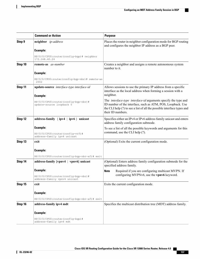
PurposeCommand or Action
Places the router in neighbor configuration mode for BGP routingand configures the neighbor IP address as a BGP peer.
neighbor ip-address
Example:
RP/0/0/CPU0:router(config-bgp)# neighbor172.168.40.24
Step 9
Creates a neighbor and assigns a remote autonomous systemnumber to it.
remote-as as-number
Example:
RP/0/0/CPU0:router(config-bgp-nbr)# remote-as2002
Step 10
Allows sessions to use the primary IP address from a specificinterface as the local address when forming a session with aneighbor.
update-source interface-type interface-id
Example:
RP/0/0/CPU0:router(config-bgp-nbr)#update-source loopback 0
Step 11
The interface-type interface-id arguments specify the type andID number of the interface, such as ATM, POS, Loopback. Usethe CLI help (?) to see a list of all the possible interface types andtheir ID numbers.
Specifies either an IPv4 or IPv6 address family unicast and entersaddress family configuration submode.
address-family { ipv4 | ipv6 } unicast
Example:
RP/0/0/CPU0:router(config-vrf)#address-family ipv4 unicast
Step 12
To see a list of all the possible keywords and arguments for thiscommand, use the CLI help (?).
(Optional) Exits the current configuration mode.exit
Example:
RP/0/0/CPU0:router(config-bgp-nbr-af)# exit
Step 13
(Optional) Enters address family configuration submode for thespecified address family.
address-family {vpnv4 | vpnv6} unicast
Example:
RP/0/0/CPU0:router(config-bgp-nbr)#address-family vpnv4 unicast
Step 14
Required if you are configuring multicast MVPN. Ifconfiguring MVPNv6, use the vpnv6 keyword.
Note
Exits the current configuration mode.exit
Example:
RP/0/0/CPU0:router(config-bgp-nbr-af)# exit
Step 15
Specifies the multicast distribution tree (MDT) address family.address-family ipv4 mdt
Example:
RP/0/0/CPU0:router(config-bgp)#address-family ipv4 mdt
Step 16
Cisco IOS XR Routing Configuration Guide for the Cisco XR 12000 Series Router, Release 4.0 OL-23246-02 137
Implementing BGPConfiguring an MDT Address Family Session in BGP
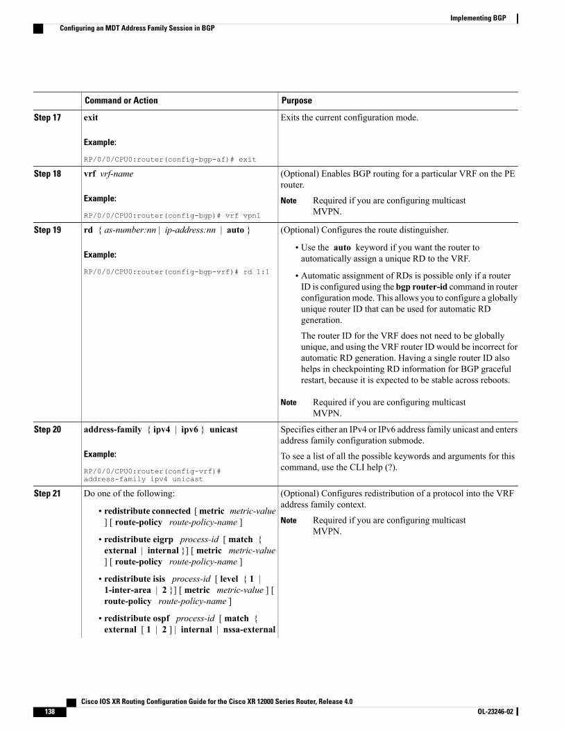
PurposeCommand or Action
Exits the current configuration mode.exit
Example:
RP/0/0/CPU0:router(config-bgp-af)# exit
Step 17
(Optional) Enables BGP routing for a particular VRF on the PErouter.
vrf vrf-name
Example:
RP/0/0/CPU0:router(config-bgp)# vrf vpn1
Step 18
Required if you are configuring multicastMVPN.
Note
(Optional) Configures the route distinguisher.rd { as-number:nn | ip-address:nn | auto }Step 19
Example:
RP/0/0/CPU0:router(config-bgp-vrf)# rd 1:1
• Use the auto keyword if you want the router toautomatically assign a unique RD to the VRF.
• Automatic assignment of RDs is possible only if a routerID is configured using the bgp router-id command in routerconfiguration mode. This allows you to configure a globallyunique router ID that can be used for automatic RDgeneration.
The router ID for the VRF does not need to be globallyunique, and using the VRF router ID would be incorrect forautomatic RD generation. Having a single router ID alsohelps in checkpointing RD information for BGP gracefulrestart, because it is expected to be stable across reboots.
Required if you are configuring multicastMVPN.
Note
Specifies either an IPv4 or IPv6 address family unicast and entersaddress family configuration submode.
address-family { ipv4 | ipv6 } unicast
Example:
RP/0/0/CPU0:router(config-vrf)#address-family ipv4 unicast
Step 20
To see a list of all the possible keywords and arguments for thiscommand, use the CLI help (?).
(Optional) Configures redistribution of a protocol into the VRFaddress family context.
Do one of the following:Step 21
• redistribute connected [metric metric-value] [ route-policy route-policy-name ] Required if you are configuring multicast
MVPN.Note
• redistribute eigrp process-id [ match {external | internal }] [ metric metric-value] [ route-policy route-policy-name ]
• redistribute isis process-id [ level { 1 |1-inter-area | 2 }] [ metric metric-value ] [route-policy route-policy-name ]
• redistribute ospf process-id [ match {external [ 1 | 2 ] | internal | nssa-external
Cisco IOS XR Routing Configuration Guide for the Cisco XR 12000 Series Router, Release 4.0138 OL-23246-02
Implementing BGPConfiguring an MDT Address Family Session in BGP
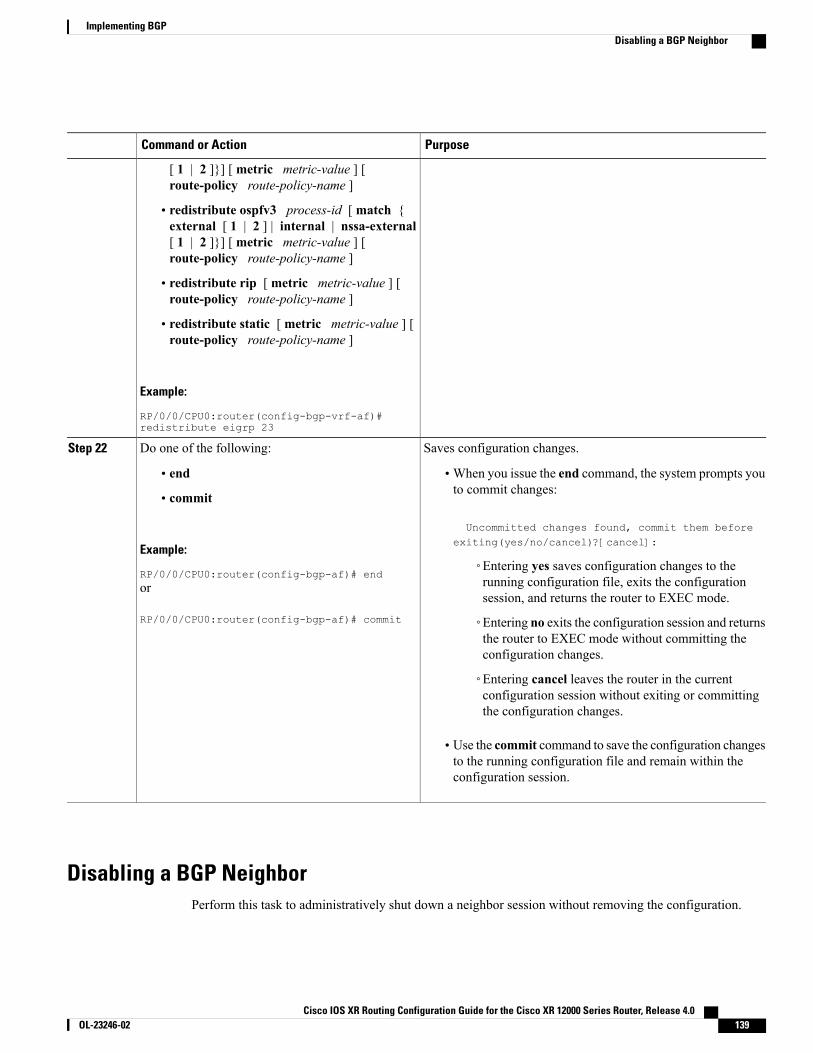
PurposeCommand or Action
[ 1 | 2 ]}] [ metric metric-value ] [route-policy route-policy-name ]
• redistribute ospfv3 process-id [ match {external [ 1 | 2 ] | internal | nssa-external[ 1 | 2 ]}] [ metric metric-value ] [route-policy route-policy-name ]
• redistribute rip [ metric metric-value ] [route-policy route-policy-name ]
• redistribute static [ metric metric-value ] [route-policy route-policy-name ]
Example:
RP/0/0/CPU0:router(config-bgp-vrf-af)#redistribute eigrp 23
Saves configuration changes.Do one of the following:Step 22
• end •When you issue the end command, the system prompts youto commit changes:
Uncommitted changes found, commit them beforeexiting(yes/no/cancel)?[cancel]:
• commit
Example:
RP/0/0/CPU0:router(config-bgp-af)# end◦Entering yes saves configuration changes to therunning configuration file, exits the configurationsession, and returns the router to EXEC mode.
or
RP/0/0/CPU0:router(config-bgp-af)# commit ◦Entering no exits the configuration session and returnsthe router to EXEC mode without committing theconfiguration changes.
◦Entering cancel leaves the router in the currentconfiguration session without exiting or committingthe configuration changes.
• Use the commit command to save the configuration changesto the running configuration file and remain within theconfiguration session.
Disabling a BGP NeighborPerform this task to administratively shut down a neighbor session without removing the configuration.
Cisco IOS XR Routing Configuration Guide for the Cisco XR 12000 Series Router, Release 4.0 OL-23246-02 139
Implementing BGPDisabling a BGP Neighbor
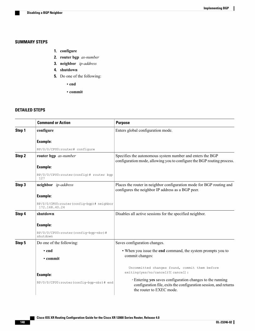
SUMMARY STEPS
1. configure2. router bgp as-number3. neighbor ip-address4. shutdown5. Do one of the following:
• end
• commit
DETAILED STEPS
PurposeCommand or Action
Enters global configuration mode.configure
Example:
RP/0/0/CPU0:router# configure
Step 1
Specifies the autonomous system number and enters the BGPconfigurationmode, allowing you to configure the BGP routing process.
router bgp as-number
Example:
RP/0/0/CPU0:router(config)# router bgp127
Step 2
Places the router in neighbor configuration mode for BGP routing andconfigures the neighbor IP address as a BGP peer.
neighbor ip-address
Example:
RP/0/0/CPU0:router(config-bgp)# neighbor172.168.40.24
Step 3
Disables all active sessions for the specified neighbor.shutdown
Example:
RP/0/0/CPU0:router(config-bgp-nbr)#shutdown
Step 4
Saves configuration changes.Do one of the following:Step 5
• end •When you issue the end command, the system prompts you tocommit changes:
Uncommitted changes found, commit them beforeexiting(yes/no/cancel)?[cancel]:
• commit
Example:
RP/0/0/CPU0:router(config-bgp-nbr)# end◦Entering yes saves configuration changes to the runningconfiguration file, exits the configuration session, and returnsthe router to EXEC mode.
Cisco IOS XR Routing Configuration Guide for the Cisco XR 12000 Series Router, Release 4.0140 OL-23246-02
Implementing BGPDisabling a BGP Neighbor
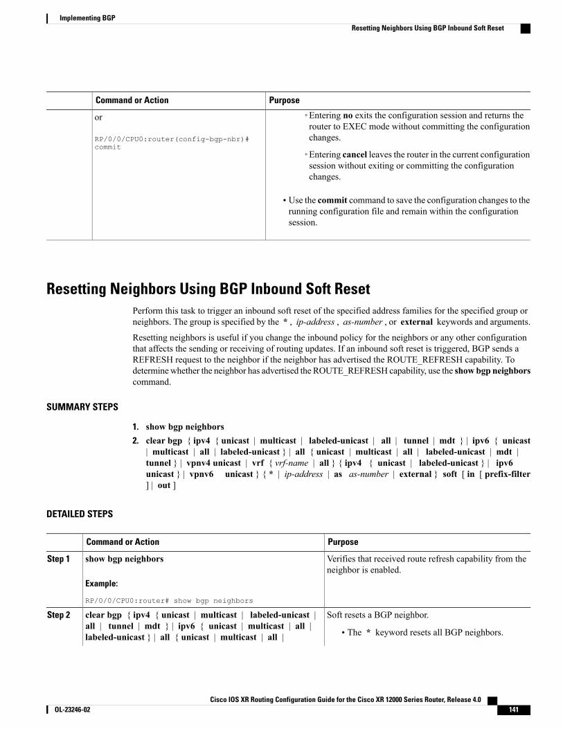
PurposeCommand or Action
or
RP/0/0/CPU0:router(config-bgp-nbr)#commit
◦Entering no exits the configuration session and returns therouter to EXEC mode without committing the configurationchanges.
◦Entering cancel leaves the router in the current configurationsession without exiting or committing the configurationchanges.
• Use the commit command to save the configuration changes to therunning configuration file and remain within the configurationsession.
Resetting Neighbors Using BGP Inbound Soft ResetPerform this task to trigger an inbound soft reset of the specified address families for the specified group orneighbors. The group is specified by the * , ip-address , as-number , or external keywords and arguments.
Resetting neighbors is useful if you change the inbound policy for the neighbors or any other configurationthat affects the sending or receiving of routing updates. If an inbound soft reset is triggered, BGP sends aREFRESH request to the neighbor if the neighbor has advertised the ROUTE_REFRESH capability. Todeterminewhether the neighbor has advertised the ROUTE_REFRESH capability, use the show bgp neighborscommand.
SUMMARY STEPS
1. show bgp neighbors2. clear bgp { ipv4 { unicast | multicast | labeled-unicast | all | tunnel | mdt } | ipv6 { unicast
| multicast | all | labeled-unicast } | all { unicast | multicast | all | labeled-unicast | mdt |tunnel } | vpnv4 unicast | vrf { vrf-name | all } { ipv4 { unicast | labeled-unicast } | ipv6unicast } | vpnv6 unicast } { * | ip-address | as as-number | external } soft [ in [ prefix-filter] | out ]
DETAILED STEPS
PurposeCommand or Action
Verifies that received route refresh capability from theneighbor is enabled.
show bgp neighbors
Example:
RP/0/0/CPU0:router# show bgp neighbors
Step 1
Soft resets a BGP neighbor.clear bgp { ipv4 { unicast | multicast | labeled-unicast |all | tunnel | mdt } | ipv6 { unicast | multicast | all |
Step 2
• The * keyword resets all BGP neighbors.labeled-unicast } | all { unicast | multicast | all |
Cisco IOS XR Routing Configuration Guide for the Cisco XR 12000 Series Router, Release 4.0 OL-23246-02 141
Implementing BGPResetting Neighbors Using BGP Inbound Soft Reset

PurposeCommand or Action
• The ip-address argument specifies the address ofthe neighbor to be reset.
labeled-unicast | mdt | tunnel } | vpnv4 unicast | vrf {vrf-name | all } { ipv4 { unicast | labeled-unicast } | ipv6unicast } | vpnv6 unicast } { * | ip-address | as as-number| external } soft [ in [ prefix-filter ] | out ]
• The as-number argument specifies that allneighbors that match the autonomous systemnumber be reset.
Example:
RP/0/0/CPU0:router# clear bgp ipv4 unicast 10.0.0.1soft in
• The external keyword specifies that all externalneighbors are reset.
Resetting Neighbors Using BGP Outbound Soft ResetPerform this task to trigger an outbound soft reset of the specified address families for the specified group orneighbors. The group is specified by the * , ip-address , as-number , or external keywords and arguments.
Resetting neighbors is useful if you change the outbound policy for the neighbors or any other configurationthat affects the sending or receiving of routing updates.
If an outbound soft reset is triggered, BGP resends all routes for the address family to the given neighbors.
To determine whether the neighbor has advertised the ROUTE_REFRESH capability, use the show bgpneighbors command.
SUMMARY STEPS
1. show bgp neighbors2. clear bgp { ipv4 { unicast | multicast | labeled-unicast | all | tunnel | } | ipv6 { unicast |
multicast | all | labeled-unicast } | all { unicast | multicast | all | labeled-unicast | mdt | tunnel} | vpnv4 unicast | vrf { vrf-name | all } { ipv4 { unicast | labeled-unicast } | ipv6 unicast } |vpnv6 unicast } { * | ip-address | as as-number | external } soft out
DETAILED STEPS
PurposeCommand or Action
Verifies that received route refresh capability from theneighbor is enabled.
show bgp neighbors
Example:
RP/0/0/CPU0:router# show bgp neighbors
Step 1
Soft resets a BGP neighbor.clear bgp { ipv4 { unicast | multicast | labeled-unicast |all | tunnel | } | ipv6 { unicast | multicast | all |
Step 2
• The * keyword resets all BGP neighbors.labeled-unicast } | all { unicast | multicast | all |labeled-unicast | mdt | tunnel } | vpnv4 unicast | vrf { • The ip-address argument specifies the address of
the neighbor to be reset.vrf-name | all } { ipv4 { unicast | labeled-unicast } | ipv6
Cisco IOS XR Routing Configuration Guide for the Cisco XR 12000 Series Router, Release 4.0142 OL-23246-02
Implementing BGPResetting Neighbors Using BGP Outbound Soft Reset
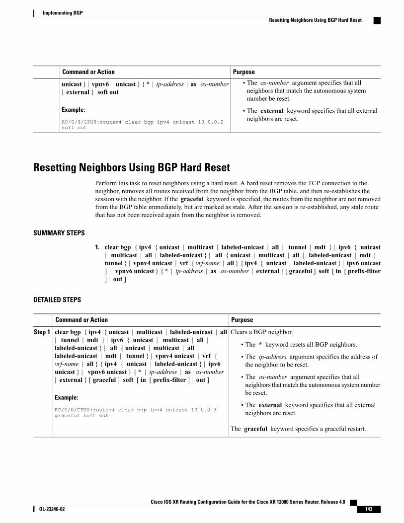
PurposeCommand or Action
unicast } | vpnv6 unicast } { * | ip-address | as as-number| external } soft out
• The as-number argument specifies that allneighbors that match the autonomous systemnumber be reset.
Example:
RP/0/0/CPU0:router# clear bgp ipv4 unicast 10.0.0.2soft out
• The external keyword specifies that all externalneighbors are reset.
Resetting Neighbors Using BGP Hard ResetPerform this task to reset neighbors using a hard reset. A hard reset removes the TCP connection to theneighbor, removes all routes received from the neighbor from the BGP table, and then re-establishes thesession with the neighbor. If the graceful keyword is specified, the routes from the neighbor are not removedfrom the BGP table immediately, but are marked as stale. After the session is re-established, any stale routethat has not been received again from the neighbor is removed.
SUMMARY STEPS
1. clear bgp { ipv4 { unicast | multicast | labeled-unicast | all | tunnel | mdt } | ipv6 { unicast| multicast | all | labeled-unicast } | all { unicast | multicast | all | labeled-unicast | mdt |tunnel } | vpnv4 unicast | vrf { vrf-name | all } { ipv4 { unicast | labeled-unicast } | ipv6 unicast} | vpnv6 unicast } { * | ip-address | as as-number | external } [ graceful ] soft [ in [ prefix-filter] | out ]
DETAILED STEPS
PurposeCommand or Action
Clears a BGP neighbor.clear bgp { ipv4 { unicast | multicast | labeled-unicast | all| tunnel | mdt } | ipv6 { unicast | multicast | all |
Step 1
• The * keyword resets all BGP neighbors.labeled-unicast } | all { unicast | multicast | all |labeled-unicast | mdt | tunnel } | vpnv4 unicast | vrf { • The ip-address argument specifies the address of
the neighbor to be reset.vrf-name | all } { ipv4 { unicast | labeled-unicast } | ipv6unicast } | vpnv6 unicast } { * | ip-address | as as-number| external } [ graceful ] soft [ in [ prefix-filter ] | out ] • The as-number argument specifies that all
neighbors that match the autonomous system numberbe reset.
Example:
RP/0/0/CPU0:router# clear bgp ipv4 unicast 10.0.0.3graceful soft out
• The external keyword specifies that all externalneighbors are reset.
The graceful keyword specifies a graceful restart.
Cisco IOS XR Routing Configuration Guide for the Cisco XR 12000 Series Router, Release 4.0 OL-23246-02 143
Implementing BGPResetting Neighbors Using BGP Hard Reset
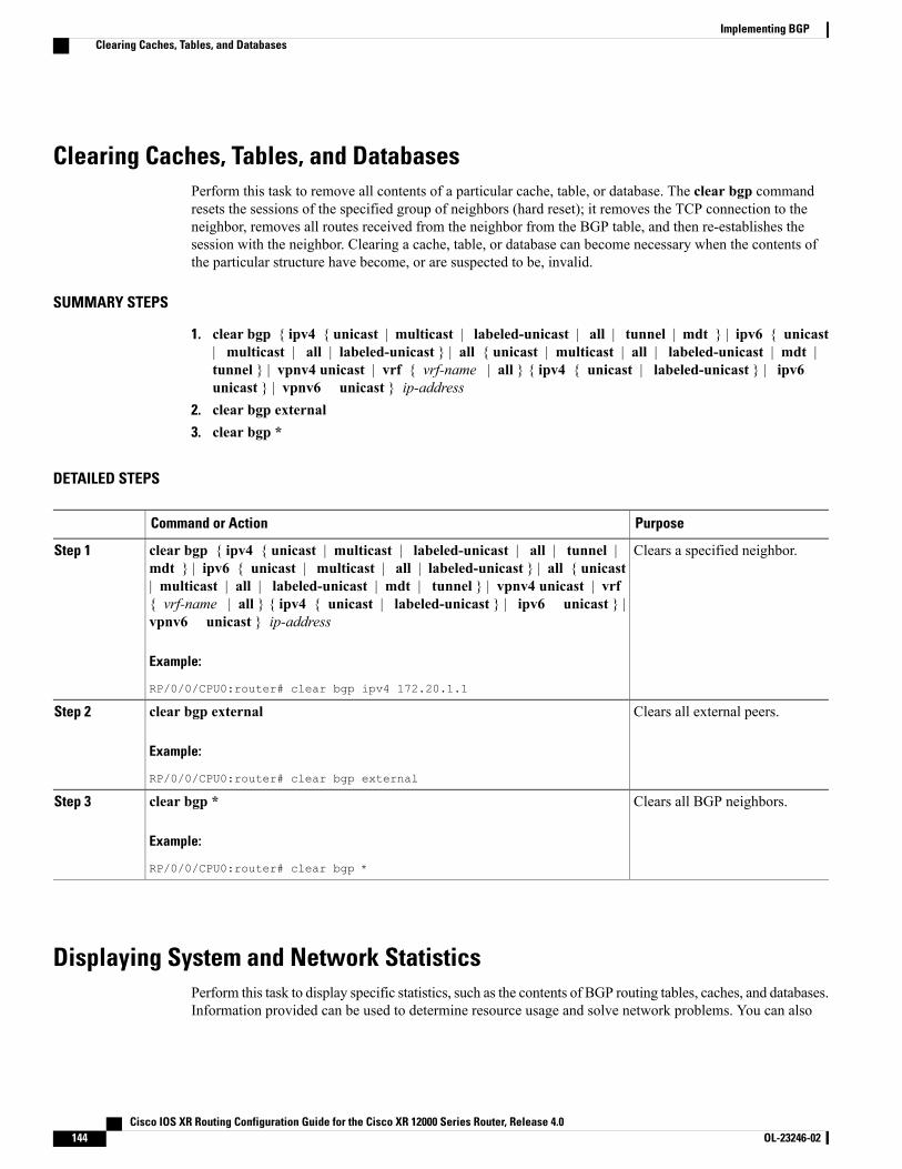
Clearing Caches, Tables, and DatabasesPerform this task to remove all contents of a particular cache, table, or database. The clear bgp commandresets the sessions of the specified group of neighbors (hard reset); it removes the TCP connection to theneighbor, removes all routes received from the neighbor from the BGP table, and then re-establishes thesession with the neighbor. Clearing a cache, table, or database can become necessary when the contents ofthe particular structure have become, or are suspected to be, invalid.
SUMMARY STEPS
1. clear bgp { ipv4 { unicast | multicast | labeled-unicast | all | tunnel | mdt } | ipv6 { unicast| multicast | all | labeled-unicast } | all { unicast | multicast | all | labeled-unicast | mdt |tunnel } | vpnv4 unicast | vrf { vrf-name | all } { ipv4 { unicast | labeled-unicast } | ipv6unicast } | vpnv6 unicast } ip-address
2. clear bgp external3. clear bgp *
DETAILED STEPS
PurposeCommand or Action
Clears a specified neighbor.clear bgp { ipv4 { unicast | multicast | labeled-unicast | all | tunnel |mdt } | ipv6 { unicast | multicast | all | labeled-unicast } | all { unicast
Step 1
| multicast | all | labeled-unicast | mdt | tunnel } | vpnv4 unicast | vrf{ vrf-name | all } { ipv4 { unicast | labeled-unicast } | ipv6 unicast } |vpnv6 unicast } ip-address
Example:
RP/0/0/CPU0:router# clear bgp ipv4 172.20.1.1
Clears all external peers.clear bgp external
Example:
RP/0/0/CPU0:router# clear bgp external
Step 2
Clears all BGP neighbors.clear bgp *
Example:
RP/0/0/CPU0:router# clear bgp *
Step 3
Displaying System and Network StatisticsPerform this task to display specific statistics, such as the contents of BGP routing tables, caches, and databases.Information provided can be used to determine resource usage and solve network problems. You can also
Cisco IOS XR Routing Configuration Guide for the Cisco XR 12000 Series Router, Release 4.0144 OL-23246-02
Implementing BGPClearing Caches, Tables, and Databases
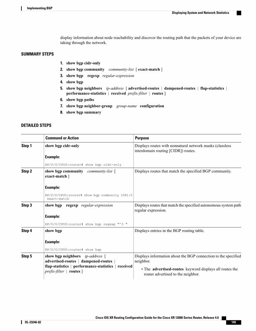
display information about node reachability and discover the routing path that the packets of your device aretaking through the network.
SUMMARY STEPS
1. show bgp cidr-only2. show bgp community community-list [ exact-match ]3. show bgp regexp regular-expression4. show bgp5. show bgp neighbors ip-address [ advertised-routes | dampened-routes | flap-statistics |
performance-statistics | received prefix-filter | routes ]6. show bgp paths7. show bgp neighbor-group group-name configuration8. show bgp summary
DETAILED STEPS
PurposeCommand or Action
Displays routes with nonnatural network masks (classlessinterdomain routing [CIDR]) routes.
show bgp cidr-only
Example:
RP/0/0/CPU0:router# show bgp cidr-only
Step 1
Displays routes that match the specified BGP community.show bgp community community-list [exact-match ]
Step 2
Example:
RP/0/0/CPU0:router# show bgp community 1081:5exact-match
Displays routes that match the specified autonomous system pathregular expression.
show bgp regexp regular-expression
Example:
RP/0/0/CPU0:router# show bgp regexp "^3 "
Step 3
Displays entries in the BGP routing table.show bgp
Example:
RP/0/0/CPU0:router# show bgp
Step 4
Displays information about the BGP connection to the specifiedneighbor.
show bgp neighbors ip-address [advertised-routes | dampened-routes |
Step 5
flap-statistics | performance-statistics | receivedprefix-filter | routes ] • The advertised-routes keyword displays all routes the
router advertised to the neighbor.
Cisco IOS XR Routing Configuration Guide for the Cisco XR 12000 Series Router, Release 4.0 OL-23246-02 145
Implementing BGPDisplaying System and Network Statistics

PurposeCommand or Action
Example:
RP/0/0/CPU0:router# show bgp neighbors10.0.101.1
• The dampened-routes keyword displays the dampenedroutes that are learned from the neighbor.
• The flap-statistics keyword displays flap statistics of theroutes learned from the neighbor.
• The performance-statistics keyword displaysperformance statistics relating to work done by the BGPprocess for this neighbor.
• The received prefix-filter keyword and argument displaythe received prefix list filter.
• The routes keyword displays routes learned from theneighbor.
Displays all BGP paths in the database.show bgp paths
Example:
RP/0/0/CPU0:router# show bgp paths
Step 6
Displays the effective configuration for a specified neighborgroup, including any configuration inherited by this neighborgroup.
show bgp neighbor-group group-nameconfiguration
Example:
RP/0/0/CPU0:router# show bgp neighbor-groupgroup_1 configuration
Step 7
Displays the status of all BGP connections.show bgp summary
Example:
RP/0/0/CPU0:router# show bgp summary
Step 8
Displaying BGP Process InformationPerform this task to display specific BGP process information.
Cisco IOS XR Routing Configuration Guide for the Cisco XR 12000 Series Router, Release 4.0146 OL-23246-02
Implementing BGPDisplaying BGP Process Information
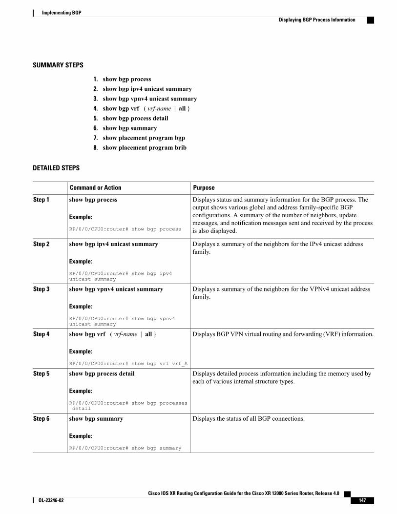
SUMMARY STEPS
1. show bgp process2. show bgp ipv4 unicast summary3. show bgp vpnv4 unicast summary4. show bgp vrf ( vrf-name | all }5. show bgp process detail6. show bgp summary7. show placement program bgp8. show placement program brib
DETAILED STEPS
PurposeCommand or Action
Displays status and summary information for the BGP process. Theoutput shows various global and address family-specific BGP
show bgp process
Example:
RP/0/0/CPU0:router# show bgp process
Step 1
configurations. A summary of the number of neighbors, updatemessages, and notification messages sent and received by the processis also displayed.
Displays a summary of the neighbors for the IPv4 unicast addressfamily.
show bgp ipv4 unicast summary
Example:
RP/0/0/CPU0:router# show bgp ipv4unicast summary
Step 2
Displays a summary of the neighbors for the VPNv4 unicast addressfamily.
show bgp vpnv4 unicast summary
Example:
RP/0/0/CPU0:router# show bgp vpnv4unicast summary
Step 3
Displays BGPVPN virtual routing and forwarding (VRF) information.show bgp vrf ( vrf-name | all }
Example:
RP/0/0/CPU0:router# show bgp vrf vrf_A
Step 4
Displays detailed process information including the memory used byeach of various internal structure types.
show bgp process detail
Example:
RP/0/0/CPU0:router# show bgp processesdetail
Step 5
Displays the status of all BGP connections.show bgp summary
Example:
RP/0/0/CPU0:router# show bgp summary
Step 6
Cisco IOS XR Routing Configuration Guide for the Cisco XR 12000 Series Router, Release 4.0 OL-23246-02 147
Implementing BGPDisplaying BGP Process Information
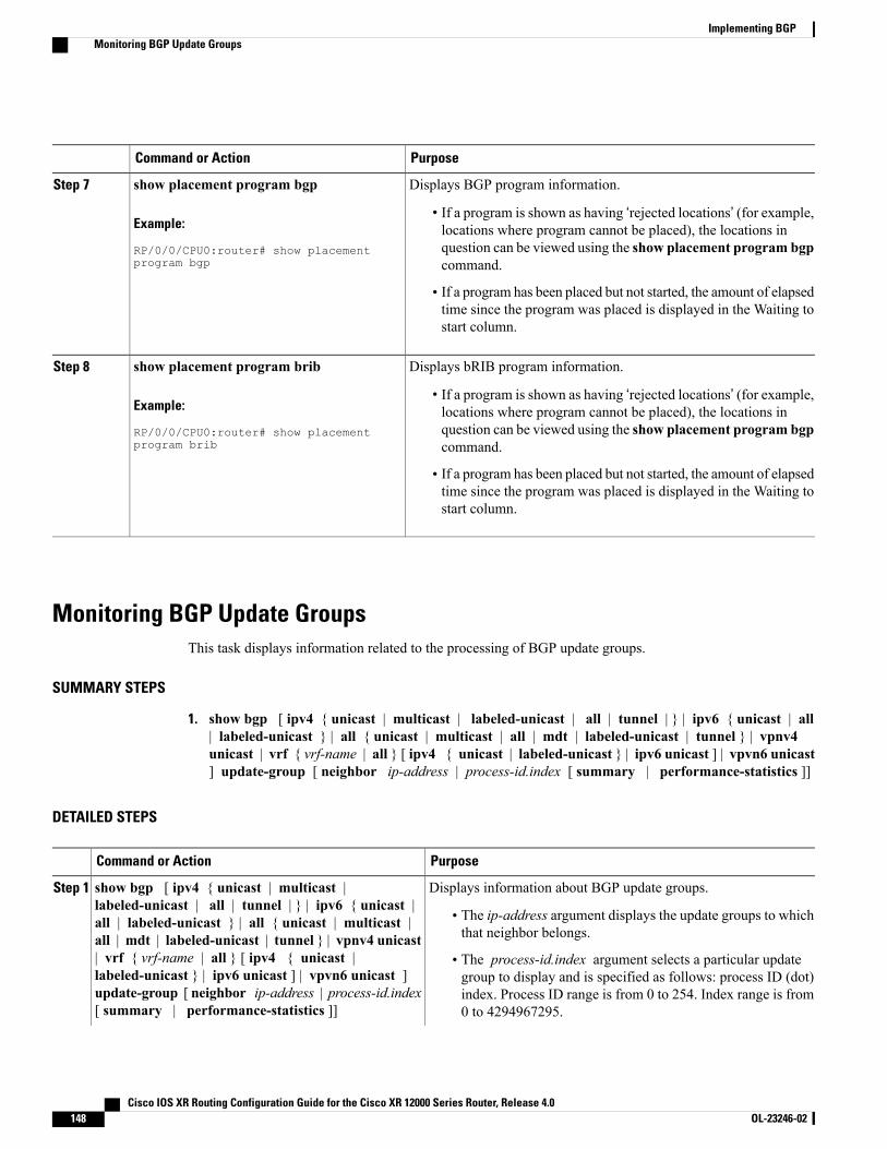
PurposeCommand or Action
Displays BGP program information.show placement program bgpStep 7
Example:
RP/0/0/CPU0:router# show placementprogram bgp
• If a program is shown as having ‘rejected locations’ (for example,locations where program cannot be placed), the locations inquestion can be viewed using the show placement program bgpcommand.
• If a program has been placed but not started, the amount of elapsedtime since the program was placed is displayed in the Waiting tostart column.
Displays bRIB program information.show placement program bribStep 8
Example:
RP/0/0/CPU0:router# show placementprogram brib
• If a program is shown as having ‘rejected locations’ (for example,locations where program cannot be placed), the locations inquestion can be viewed using the show placement program bgpcommand.
• If a program has been placed but not started, the amount of elapsedtime since the program was placed is displayed in the Waiting tostart column.
Monitoring BGP Update GroupsThis task displays information related to the processing of BGP update groups.
SUMMARY STEPS
1. show bgp [ ipv4 { unicast | multicast | labeled-unicast | all | tunnel | } | ipv6 { unicast | all| labeled-unicast } | all { unicast | multicast | all | mdt | labeled-unicast | tunnel } | vpnv4unicast | vrf { vrf-name | all } [ ipv4 { unicast | labeled-unicast } | ipv6 unicast ] | vpvn6 unicast] update-group [ neighbor ip-address | process-id.index [ summary | performance-statistics ]]
DETAILED STEPS
PurposeCommand or Action
Displays information about BGP update groups.show bgp [ ipv4 { unicast | multicast |labeled-unicast | all | tunnel | } | ipv6 { unicast |
Step 1
• The ip-address argument displays the update groups to whichthat neighbor belongs.
all | labeled-unicast } | all { unicast | multicast |all | mdt | labeled-unicast | tunnel } | vpnv4 unicast| vrf { vrf-name | all } [ ipv4 { unicast | • The process-id.index argument selects a particular update
group to display and is specified as follows: process ID (dot)labeled-unicast } | ipv6 unicast ] | vpvn6 unicast ]update-group [ neighbor ip-address | process-id.index[ summary | performance-statistics ]]
index. Process ID range is from 0 to 254. Index range is from0 to 4294967295.
Cisco IOS XR Routing Configuration Guide for the Cisco XR 12000 Series Router, Release 4.0148 OL-23246-02
Implementing BGPMonitoring BGP Update Groups
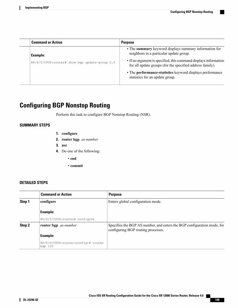
PurposeCommand or Action
Example:
RP/0/0/CPU0:router# show bgp update-group 0.0
• The summary keyword displays summary information forneighbors in a particular update group.
• If no argument is specified, this command displays informationfor all update groups (for the specified address family).
• The performance-statistics keyword displays performancestatistics for an update group.
Configuring BGP Nonstop RoutingPerform this task to configure BGP Nonstop Routing (NSR).
SUMMARY STEPS
1. configure2. router bgp as-number3. nsr4. Do one of the following:
• end
• commit
DETAILED STEPS
PurposeCommand or Action
Enters global configuration mode.configure
Example:
RP/0/0/CPU0:router# configure
Step 1
Specifies the BGP AS number, and enters the BGP configuration mode, forconfiguring BGP routing processes.
router bgp as-number
Example:
RP/0/0/CPU0:router(config)# routerbgp 120
Step 2
Cisco IOS XR Routing Configuration Guide for the Cisco XR 12000 Series Router, Release 4.0 OL-23246-02 149
Implementing BGPConfiguring BGP Nonstop Routing
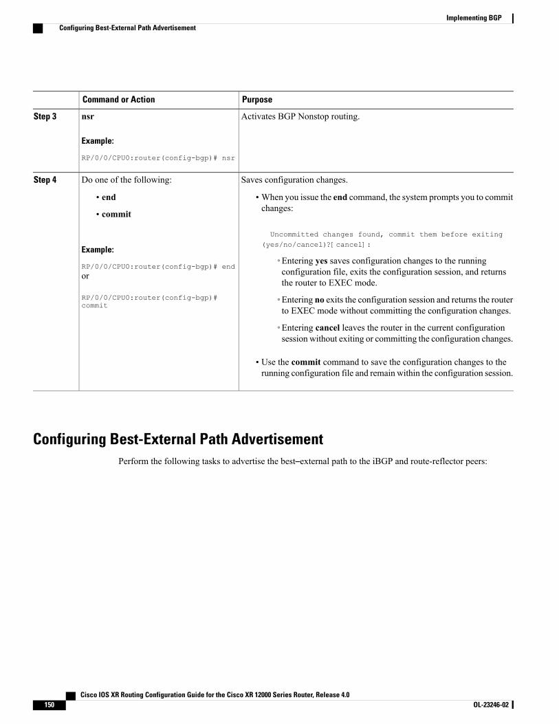
PurposeCommand or Action
Activates BGP Nonstop routing.nsr
Example:
RP/0/0/CPU0:router(config-bgp)# nsr
Step 3
Saves configuration changes.Do one of the following:Step 4
• end •When you issue the end command, the system prompts you to commitchanges:
Uncommitted changes found, commit them before exiting(yes/no/cancel)?[cancel]:
• commit
Example:
RP/0/0/CPU0:router(config-bgp)# end◦Entering yes saves configuration changes to the runningconfiguration file, exits the configuration session, and returnsthe router to EXEC mode.
or
RP/0/0/CPU0:router(config-bgp)#commit
◦Entering no exits the configuration session and returns the routerto EXEC mode without committing the configuration changes.
◦Entering cancel leaves the router in the current configurationsession without exiting or committing the configuration changes.
• Use the commit command to save the configuration changes to therunning configuration file and remain within the configuration session.
Configuring Best-External Path AdvertisementPerform the following tasks to advertise the best–external path to the iBGP and route-reflector peers:
Cisco IOS XR Routing Configuration Guide for the Cisco XR 12000 Series Router, Release 4.0150 OL-23246-02
Implementing BGPConfiguring Best-External Path Advertisement
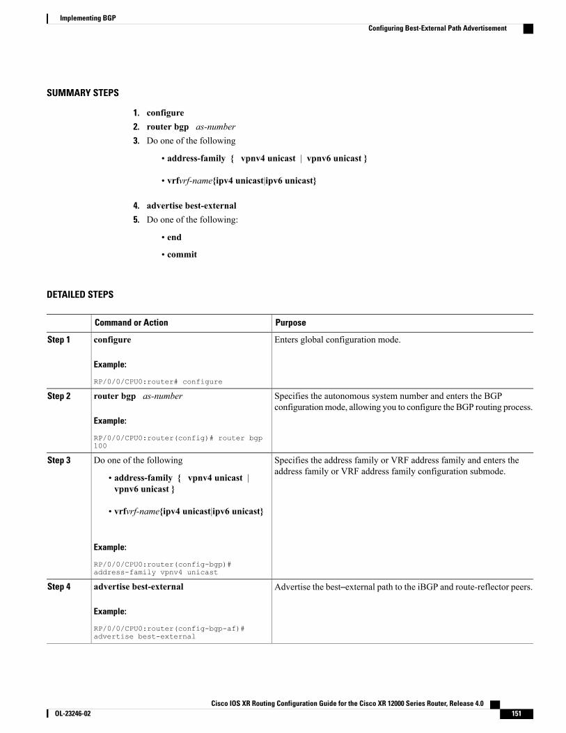
SUMMARY STEPS
1. configure2. router bgp as-number3. Do one of the following
• address-family { vpnv4 unicast | vpnv6 unicast }
• vrfvrf-name{ipv4 unicast|ipv6 unicast}
4. advertise best-external5. Do one of the following:
• end
• commit
DETAILED STEPS
PurposeCommand or Action
Enters global configuration mode.configure
Example:
RP/0/0/CPU0:router# configure
Step 1
Specifies the autonomous system number and enters the BGPconfigurationmode, allowing you to configure the BGP routing process.
router bgp as-number
Example:
RP/0/0/CPU0:router(config)# router bgp100
Step 2
Specifies the address family or VRF address family and enters theaddress family or VRF address family configuration submode.
Do one of the followingStep 3
• address-family { vpnv4 unicast |vpnv6 unicast }
• vrfvrf-name{ipv4 unicast|ipv6 unicast}
Example:
RP/0/0/CPU0:router(config-bgp)#address-family vpnv4 unicast
Advertise the best–external path to the iBGP and route-reflector peers.advertise best-external
Example:
RP/0/0/CPU0:router(config-bgp-af)#advertise best-external
Step 4
Cisco IOS XR Routing Configuration Guide for the Cisco XR 12000 Series Router, Release 4.0 OL-23246-02 151
Implementing BGPConfiguring Best-External Path Advertisement
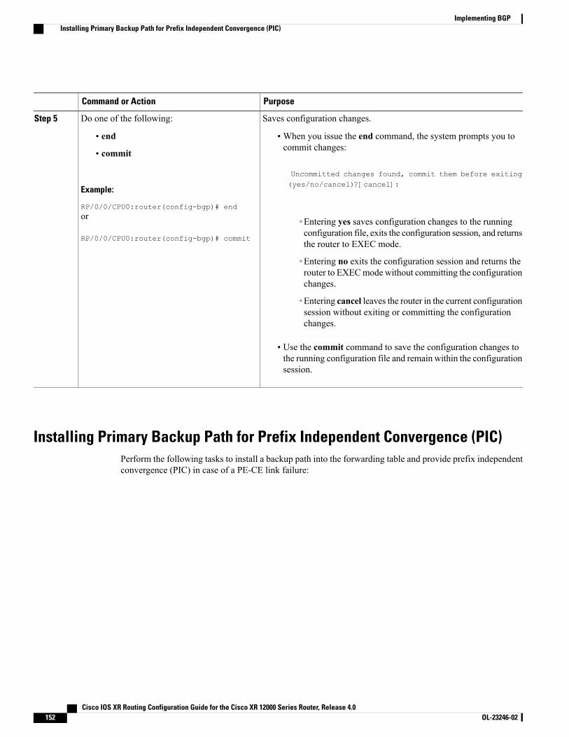
PurposeCommand or Action
Saves configuration changes.Do one of the following:Step 5
• end •When you issue the end command, the system prompts you tocommit changes:
Uncommitted changes found, commit them before exiting
• commit
Example:
RP/0/0/CPU0:router(config-bgp)# end
(yes/no/cancel)?[cancel]:
or
RP/0/0/CPU0:router(config-bgp)# commit
◦Entering yes saves configuration changes to the runningconfiguration file, exits the configuration session, and returnsthe router to EXEC mode.
◦Entering no exits the configuration session and returns therouter to EXECmode without committing the configurationchanges.
◦Entering cancel leaves the router in the current configurationsession without exiting or committing the configurationchanges.
• Use the commit command to save the configuration changes tothe running configuration file and remain within the configurationsession.
Installing Primary Backup Path for Prefix Independent Convergence (PIC)Perform the following tasks to install a backup path into the forwarding table and provide prefix independentconvergence (PIC) in case of a PE-CE link failure:
Cisco IOS XR Routing Configuration Guide for the Cisco XR 12000 Series Router, Release 4.0152 OL-23246-02
Implementing BGPInstalling Primary Backup Path for Prefix Independent Convergence (PIC)
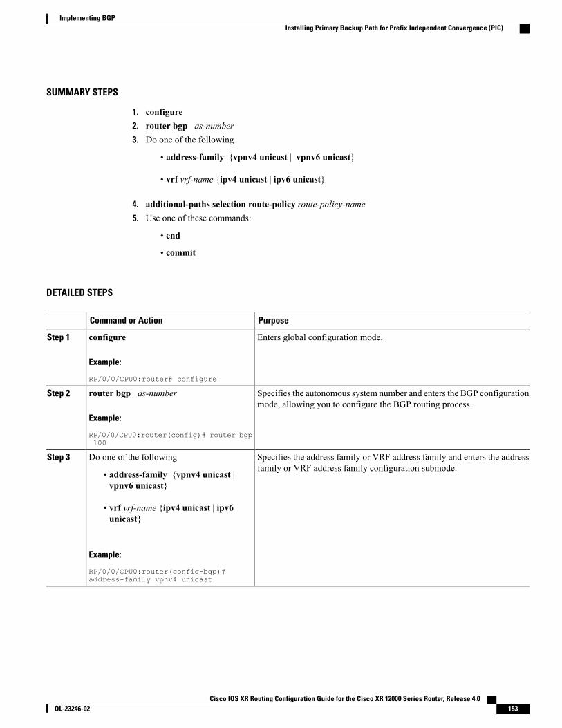
SUMMARY STEPS
1. configure2. router bgp as-number3. Do one of the following
• address-family {vpnv4 unicast | vpnv6 unicast}
• vrf vrf-name {ipv4 unicast | ipv6 unicast}
4. additional-paths selection route-policy route-policy-name5. Use one of these commands:
• end
• commit
DETAILED STEPS
PurposeCommand or Action
Enters global configuration mode.configure
Example:
RP/0/0/CPU0:router# configure
Step 1
Specifies the autonomous system number and enters the BGP configurationmode, allowing you to configure the BGP routing process.
router bgp as-number
Example:
RP/0/0/CPU0:router(config)# router bgp100
Step 2
Specifies the address family or VRF address family and enters the addressfamily or VRF address family configuration submode.
Do one of the followingStep 3
• address-family {vpnv4 unicast |vpnv6 unicast}
• vrf vrf-name {ipv4 unicast | ipv6unicast}
Example:
RP/0/0/CPU0:router(config-bgp)#address-family vpnv4 unicast
Cisco IOS XR Routing Configuration Guide for the Cisco XR 12000 Series Router, Release 4.0 OL-23246-02 153
Implementing BGPInstalling Primary Backup Path for Prefix Independent Convergence (PIC)
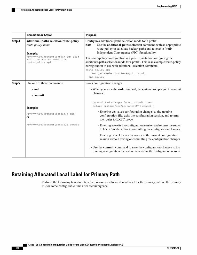
PurposeCommand or Action
Configures additional paths selection mode for a prefix.Use the additional-paths selection command with an appropriateroute-policy to calculate backup paths and to enable PrefixIndependent Convergence (PIC) functionality.
Noteadditional-paths selection route-policyroute-policy-name
Example:RP/0/0/CPU0:router(config-bgp-af)#additional-paths selectionroute-policy ap1
Step 4
The route-policy configuration is a pre-requisite for configuring theadditional-paths selectionmode for a prefix . This is an example route-policyconfiguration to use with additional-selection command:route-policy ap1
set path-selection backup 1 installend-policy
Saves configuration changes.Use one of these commands:Step 5
• end •When you issue the end command, the system prompts you to commitchanges:
Uncommitted changes found, commit thembefore exiting(yes/no/cancel)? [cancel]:
• commit
Example:
RP/0/0/CPU0:router(config)# end◦Entering yes saves configuration changes to the runningconfiguration file, exits the configuration session, and returnsthe router to EXEC mode.
or
RP/0/0/CPU0:router(config)# commit ◦Entering no exits the configuration session and returns the routerto EXEC mode without committing the configuration changes.
◦Entering cancel leaves the router in the current configurationsession without exiting or committing the configuration changes.
• Use the commit command to save the configuration changes to therunning configuration file, and remainwithin the configuration session.
Retaining Allocated Local Label for Primary PathPerform the following tasks to retain the previously allocated local label for the primary path on the primaryPE for some configurable time after reconvergence:
Cisco IOS XR Routing Configuration Guide for the Cisco XR 12000 Series Router, Release 4.0154 OL-23246-02
Implementing BGPRetaining Allocated Local Label for Primary Path
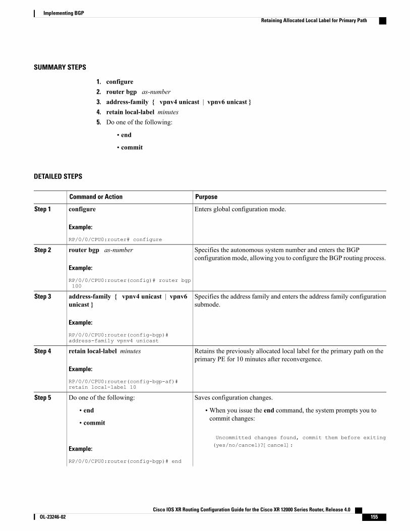
SUMMARY STEPS
1. configure2. router bgp as-number3. address-family { vpnv4 unicast | vpnv6 unicast }4. retain local-label minutes5. Do one of the following:
• end
• commit
DETAILED STEPS
PurposeCommand or Action
Enters global configuration mode.configure
Example:
RP/0/0/CPU0:router# configure
Step 1
Specifies the autonomous system number and enters the BGPconfiguration mode, allowing you to configure the BGP routing process.
router bgp as-number
Example:
RP/0/0/CPU0:router(config)# router bgp100
Step 2
Specifies the address family and enters the address family configurationsubmode.
address-family { vpnv4 unicast | vpnv6unicast }
Example:
RP/0/0/CPU0:router(config-bgp)#address-family vpnv4 unicast
Step 3
Retains the previously allocated local label for the primary path on theprimary PE for 10 minutes after reconvergence.
retain local-label minutes
Example:
RP/0/0/CPU0:router(config-bgp-af)#retain local-label 10
Step 4
Saves configuration changes.Do one of the following:Step 5
• end •When you issue the end command, the system prompts you tocommit changes:
Uncommitted changes found, commit them before exiting(yes/no/cancel)?[cancel]:
• commit
Example:
RP/0/0/CPU0:router(config-bgp)# end
Cisco IOS XR Routing Configuration Guide for the Cisco XR 12000 Series Router, Release 4.0 OL-23246-02 155
Implementing BGPRetaining Allocated Local Label for Primary Path
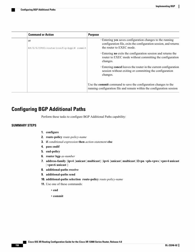
PurposeCommand or Action
◦Entering yes saves configuration changes to the runningconfiguration file, exits the configuration session, and returnsthe router to EXEC mode.
or
RP/0/0/CPU0:router(config-bgp)# commit
◦Entering no exits the configuration session and returns therouter to EXEC mode without committing the configurationchanges.
◦Entering cancel leaves the router in the current configurationsession without exiting or committing the configurationchanges.
Use the commit command to save the configuration changes to therunning configuration file and remain within the configuration session
Configuring BGP Additional PathsPerform these tasks to configure BGP Additional Paths capability:
SUMMARY STEPS
1. configure2. route-policy route-policy-name3. if conditional-expression then action-statement else4. pass endif5. end-policy6. router bgp as-number7. address-family {ipv4 {unicast |multicast} | ipv6 {unicast |multicast | l2vpn vpls-vpws | vpnv4 unicast
| vpnv6 unicast }8. additional-paths receive9. additional-paths send10. additional-paths selection route-policy route-policy-name11. Use one of these commands:
• end
• commit
Cisco IOS XR Routing Configuration Guide for the Cisco XR 12000 Series Router, Release 4.0156 OL-23246-02
Implementing BGPConfiguring BGP Additional Paths
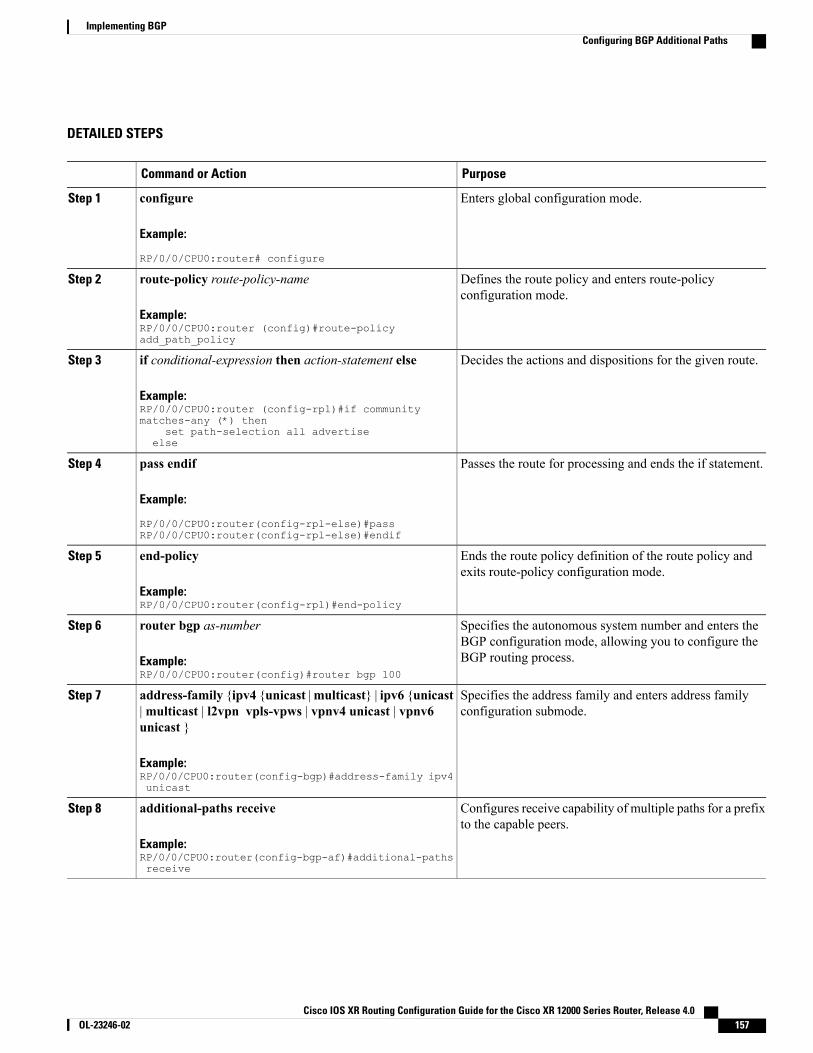
DETAILED STEPS
PurposeCommand or Action
Enters global configuration mode.configure
Example:
RP/0/0/CPU0:router# configure
Step 1
Defines the route policy and enters route-policyconfiguration mode.
route-policy route-policy-name
Example:RP/0/0/CPU0:router (config)#route-policyadd_path_policy
Step 2
Decides the actions and dispositions for the given route.if conditional-expression then action-statement else
Example:RP/0/0/CPU0:router (config-rpl)#if communitymatches-any (*) then
Step 3
set path-selection all advertiseelse
Passes the route for processing and ends the if statement.pass endif
Example:
RP/0/0/CPU0:router(config-rpl-else)#passRP/0/0/CPU0:router(config-rpl-else)#endif
Step 4
Ends the route policy definition of the route policy andexits route-policy configuration mode.
end-policy
Example:RP/0/0/CPU0:router(config-rpl)#end-policy
Step 5
Specifies the autonomous system number and enters theBGP configuration mode, allowing you to configure theBGP routing process.
router bgp as-number
Example:RP/0/0/CPU0:router(config)#router bgp 100
Step 6
Specifies the address family and enters address familyconfiguration submode.
address-family {ipv4 {unicast |multicast} | ipv6 {unicast|multicast | l2vpn vpls-vpws | vpnv4 unicast | vpnv6unicast }
Step 7
Example:RP/0/0/CPU0:router(config-bgp)#address-family ipv4unicast
Configures receive capability of multiple paths for a prefixto the capable peers.
additional-paths receive
Example:RP/0/0/CPU0:router(config-bgp-af)#additional-pathsreceive
Step 8
Cisco IOS XR Routing Configuration Guide for the Cisco XR 12000 Series Router, Release 4.0 OL-23246-02 157
Implementing BGPConfiguring BGP Additional Paths
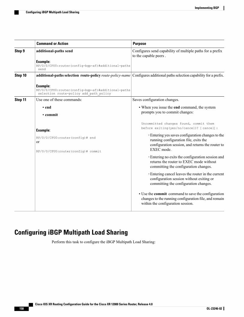
PurposeCommand or Action
Configures send capability of multiple paths for a prefixto the capable peers .
additional-paths send
Example:RP/0/0/CPU0:router(config-bgp-af)#additional-pathssend
Step 9
Configures additional paths selection capability for a prefix.additional-paths selection route-policy route-policy-name
Example:RP/0/0/CPU0:router(config-bgp-af)#additional-pathsselection route-policy add_path_policy
Step 10
Saves configuration changes.Use one of these commands:Step 11
• end •When you issue the end command, the systemprompts you to commit changes:
Uncommitted changes found, commit thembefore exiting(yes/no/cancel)? [cancel]:
• commit
Example:
RP/0/0/CPU0:router(config)# end◦Entering yes saves configuration changes to therunning configuration file, exits theor
RP/0/0/CPU0:router(config)# commit
configuration session, and returns the router toEXEC mode.
◦Entering no exits the configuration session andreturns the router to EXEC mode withoutcommitting the configuration changes.
◦Entering cancel leaves the router in the currentconfiguration session without exiting orcommitting the configuration changes.
• Use the commit command to save the configurationchanges to the running configuration file, and remainwithin the configuration session.
Configuring iBGP Multipath Load SharingPerform this task to configure the iBGP Multipath Load Sharing:
Cisco IOS XR Routing Configuration Guide for the Cisco XR 12000 Series Router, Release 4.0158 OL-23246-02
Implementing BGPConfiguring iBGP Multipath Load Sharing
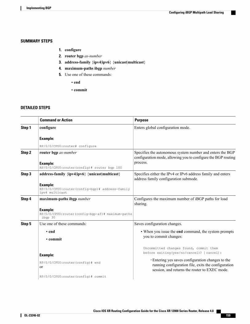
SUMMARY STEPS
1. configure2. router bgp as-number3. address-family {ipv4|ipv6} {unicast|multicast}4. maximum-paths ibgp number5. Use one of these commands:
• end
• commit
DETAILED STEPS
PurposeCommand or Action
Enters global configuration mode.configure
Example:
RP/0/0/CPU0:router# configure
Step 1
Specifies the autonomous system number and enters the BGPconfigurationmode, allowing you to configure the BGP routingprocess.
router bgp as-number
Example:RP/0/0/CPU0:router(config)# router bgp 100
Step 2
Specifies either the IPv4 or IPv6 address family and entersaddress family configuration submode.
address-family {ipv4|ipv6} {unicast|multicast}
Example:RP/0/0/CPU0:router(config-bgp)# address-familyipv4 multicast
Step 3
Configures the maximum number of iBGP paths for loadsharing.
maximum-paths ibgp number
Example:RP/0/0/CPU0:router(config-bgp-af)# maximum-pathsibgp 30
Step 4
Saves configuration changes.Use one of these commands:Step 5
• end •When you issue the end command, the system promptsyou to commit changes:
Uncommitted changes found, commit thembefore exiting(yes/no/cancel)? [cancel]:
• commit
Example:
RP/0/0/CPU0:router(config)# end◦Entering yes saves configuration changes to therunning configuration file, exits the configurationsession, and returns the router to EXEC mode.
or
RP/0/0/CPU0:router(config)# commit
Cisco IOS XR Routing Configuration Guide for the Cisco XR 12000 Series Router, Release 4.0 OL-23246-02 159
Implementing BGPConfiguring iBGP Multipath Load Sharing
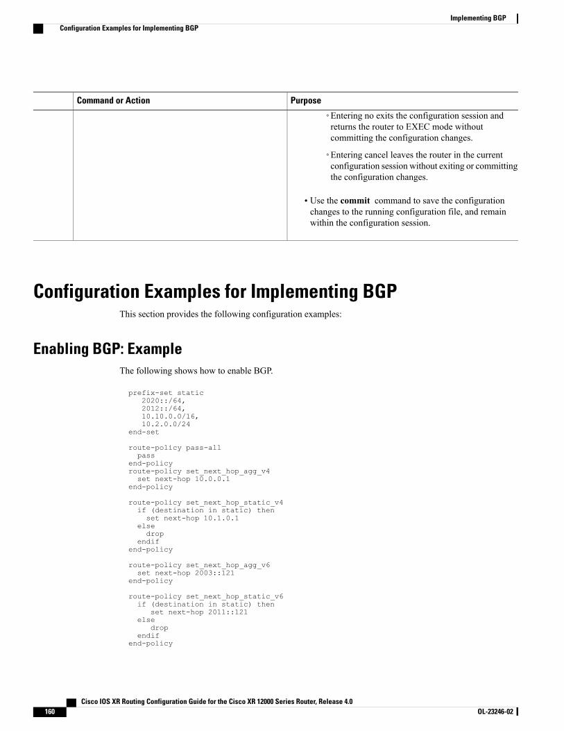
PurposeCommand or Action
◦Entering no exits the configuration session andreturns the router to EXEC mode withoutcommitting the configuration changes.
◦Entering cancel leaves the router in the currentconfiguration session without exiting or committingthe configuration changes.
• Use the commit command to save the configurationchanges to the running configuration file, and remainwithin the configuration session.
Configuration Examples for Implementing BGPThis section provides the following configuration examples:
Enabling BGP: ExampleThe following shows how to enable BGP.
prefix-set static2020::/64,2012::/64,10.10.0.0/16,10.2.0.0/24
end-set
route-policy pass-allpass
end-policyroute-policy set_next_hop_agg_v4set next-hop 10.0.0.1
end-policy
route-policy set_next_hop_static_v4if (destination in static) thenset next-hop 10.1.0.1
elsedrop
endifend-policy
route-policy set_next_hop_agg_v6set next-hop 2003::121
end-policy
route-policy set_next_hop_static_v6if (destination in static) then
set next-hop 2011::121else
dropendif
end-policy
Cisco IOS XR Routing Configuration Guide for the Cisco XR 12000 Series Router, Release 4.0160 OL-23246-02
Implementing BGPConfiguration Examples for Implementing BGP
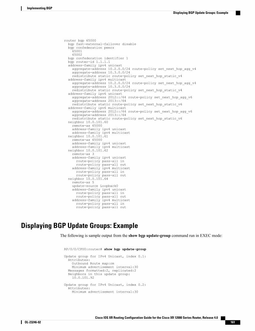
router bgp 65000bgp fast-external-fallover disablebgp confederation peers6500165002
bgp confederation identifier 1bgp router-id 1.1.1.1address-family ipv4 unicastaggregate-address 10.2.0.0/24 route-policy set_next_hop_agg_v4aggregate-address 10.3.0.0/24redistribute static route-policy set_next_hop_static_v4
address-family ipv4 multicastaggregate-address 10.2.0.0/24 route-policy set_next_hop_agg_v4aggregate-address 10.3.0.0/24redistribute static route-policy set_next_hop_static_v4
address-family ipv6 unicastaggregate-address 2012::/64 route-policy set_next_hop_agg_v6aggregate-address 2013::/64redistribute static route-policy set_next_hop_static_v6
address-family ipv6 multicastaggregate-address 2012::/64 route-policy set_next_hop_agg_v6aggregate-address 2013::/64redistribute static route-policy set_next_hop_static_v6
neighbor 10.0.101.60remote-as 65000address-family ipv4 unicastaddress-family ipv4 multicast
neighbor 10.0.101.61remote-as 65000address-family ipv4 unicastaddress-family ipv4 multicast
neighbor 10.0.101.62remote-as 3address-family ipv4 unicastroute-policy pass-all inroute-policy pass-all out
address-family ipv4 multicastroute-policy pass-all inroute-policy pass-all out
neighbor 10.0.101.64remote-as 5update-source Loopback0address-family ipv4 unicastroute-policy pass-all inroute-policy pass-all out
address-family ipv4 multicastroute-policy pass-all inroute-policy pass-all out
Displaying BGP Update Groups: ExampleThe following is sample output from the show bgp update-group command run in EXEC mode:
RP/0/0/CPU0:router# show bgp update-group
Update group for IPv4 Unicast, index 0.1:Attributes:Outbound Route map:rmMinimum advertisement interval:30
Messages formatted:2, replicated:2Neighbors in this update group:10.0.101.92
Update group for IPv4 Unicast, index 0.2:Attributes:Minimum advertisement interval:30
Cisco IOS XR Routing Configuration Guide for the Cisco XR 12000 Series Router, Release 4.0 OL-23246-02 161
Implementing BGPDisplaying BGP Update Groups: Example

Messages formatted:2, replicated:2Neighbors in this update group:10.0.101.91
BGP Neighbor Configuration: ExampleThe following example shows how BGP neighbors on an autonomous system are configured to shareinformation. In the example, a BGP router is assigned to autonomous system 109, and two networks are listedas originating in the autonomous system. Then the addresses of three remote routers (and their autonomoussystems) are listed. The router being configured shares information about networks 131. 108.0.0 and 192.31.7.0 with the neighbor routers. The first router listed is in a different autonomous system; the secondneighbor and remote-as commands specify an internal neighbor (with the same autonomous system number)at address 131. 108.234.2; and the third neighbor and remote-as commands specify a neighbor on a differentautonomous system.
route-policy pass-allpassend-policyrouter bgp 109address-family ipv4 unicastnetwork
131.108.0.0 255.0.0.0
network 192.31.7.0 255.0.0.0
neighbor131.108.200.1
remote-as 167exit
address-family ipv4 unicastroute-policy pass-all inroute-policy pass-out outneighbor
131.108.234.2
remote-as 109exit
address-family ipv4 unicastneighbor
150.136.64.19
remote-as 99exit
address-family ipv4 unicastroute-policy pass-all inroute-policy pass-all out
BGP Confederation: ExampleThe following is a sample configuration that shows several peers in a confederation. The confederation consistsof three internal autonomous systems with autonomous system numbers 6001, 6002, and 6003. To the BGPspeakers outside the confederation, the confederation looks like a normal autonomous systemwith autonomoussystem number 666 (specified using the bgp confederation identifier command).
In a BGP speaker in autonomous system 6001, the bgp confederation peers command marks the peers fromautonomous systems 6002 and 6003 as special eBGP peers. Hence, peers 171. 69.232.55 and 171. 69.232.56
Cisco IOS XR Routing Configuration Guide for the Cisco XR 12000 Series Router, Release 4.0162 OL-23246-02
Implementing BGPBGP Neighbor Configuration: Example
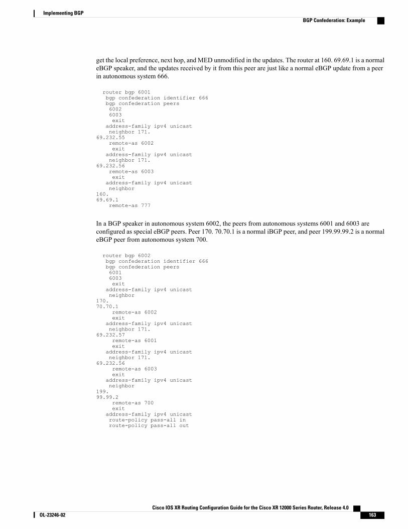
get the local preference, next hop, and MED unmodified in the updates. The router at 160. 69.69.1 is a normaleBGP speaker, and the updates received by it from this peer are just like a normal eBGP update from a peerin autonomous system 666.
router bgp 6001bgp confederation identifier 666bgp confederation peers60026003exit
address-family ipv4 unicastneighbor 171.
69.232.55remote-as 6002exit
address-family ipv4 unicastneighbor 171.
69.232.56remote-as 6003exit
address-family ipv4 unicastneighbor
160.69.69.1
remote-as 777
In a BGP speaker in autonomous system 6002, the peers from autonomous systems 6001 and 6003 areconfigured as special eBGP peers. Peer 170. 70.70.1 is a normal iBGP peer, and peer 199.99.99.2 is a normaleBGP peer from autonomous system 700.
router bgp 6002bgp confederation identifier 666bgp confederation peers60016003exit
address-family ipv4 unicastneighbor
170.70.70.1
remote-as 6002exit
address-family ipv4 unicastneighbor 171.
69.232.57remote-as 6001exit
address-family ipv4 unicastneighbor 171.
69.232.56remote-as 6003exit
address-family ipv4 unicastneighbor
199.99.99.2
remote-as 700exit
address-family ipv4 unicastroute-policy pass-all inroute-policy pass-all out
Cisco IOS XR Routing Configuration Guide for the Cisco XR 12000 Series Router, Release 4.0 OL-23246-02 163
Implementing BGPBGP Confederation: Example
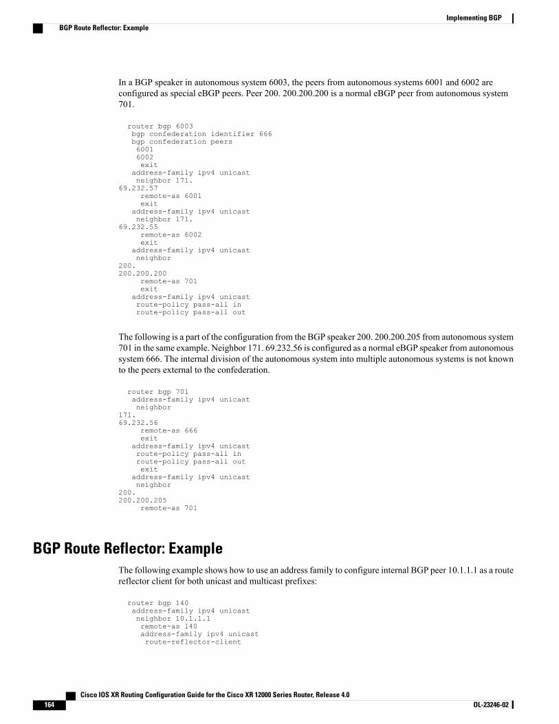
In a BGP speaker in autonomous system 6003, the peers from autonomous systems 6001 and 6002 areconfigured as special eBGP peers. Peer 200. 200.200.200 is a normal eBGP peer from autonomous system701.
router bgp 6003bgp confederation identifier 666bgp confederation peers60016002exit
address-family ipv4 unicastneighbor 171.
69.232.57remote-as 6001exit
address-family ipv4 unicastneighbor 171.
69.232.55remote-as 6002exit
address-family ipv4 unicastneighbor
200.200.200.200
remote-as 701exit
address-family ipv4 unicastroute-policy pass-all inroute-policy pass-all out
The following is a part of the configuration from the BGP speaker 200. 200.200.205 from autonomous system701 in the same example. Neighbor 171. 69.232.56 is configured as a normal eBGP speaker from autonomoussystem 666. The internal division of the autonomous system into multiple autonomous systems is not knownto the peers external to the confederation.
router bgp 701address-family ipv4 unicastneighbor
171.69.232.56
remote-as 666exit
address-family ipv4 unicastroute-policy pass-all inroute-policy pass-all outexit
address-family ipv4 unicastneighbor
200.200.200.205
remote-as 701
BGP Route Reflector: ExampleThe following example shows how to use an address family to configure internal BGP peer 10.1.1.1 as a routereflector client for both unicast and multicast prefixes:
router bgp 140address-family ipv4 unicastneighbor 10.1.1.1remote-as 140address-family ipv4 unicastroute-reflector-client
Cisco IOS XR Routing Configuration Guide for the Cisco XR 12000 Series Router, Release 4.0164 OL-23246-02
Implementing BGPBGP Route Reflector: Example

exitaddress-family ipv4 multicastroute-reflector-client
BGP MDT Address Family Configuration: ExampleThe following example shows how to configure an MDT address family in BGP:router bgp 10
bgp router-id 10.0.0.2address-family ipv4 unicastaddress-family vpnv4 unicastaddress-family ipv4 mdt
!neighbor 1.1.1.1
remote-as 11update-source Loopback0address-family ipv4 unicastaddress-family vpnv4 unicastaddress-family ipv4 md
!
BGP Nonstop Routing Configuration: ExampleThe following example shows how to enable BGP NSR:
RP/0/0/CPU0:router# configureRP/0/0/CPU0:router(config)# router bgp 120RP/0/0/CPU0:router(config-bgp)# nsrRP/0/0/CPU0:router(config-bgp)# end
The following example shows how to disable BGP NSR:
RP/0/0/CPU0:router# configureRP/0/0/CPU0:router(config)# router bgp 120RP/0/0/CPU0:router(config-bgp)# no nsrRP/0/0/CPU0:router(config-bgp)# end
Best-External Path Advertisement Configuration: ExampleThe following example shows how to configure Best–External Path Advertisement:
router bgp 100address-family l2vpn vpls-vpwsadvertise best-external
end
Cisco IOS XR Routing Configuration Guide for the Cisco XR 12000 Series Router, Release 4.0 OL-23246-02 165
Implementing BGPBGP MDT Address Family Configuration: Example
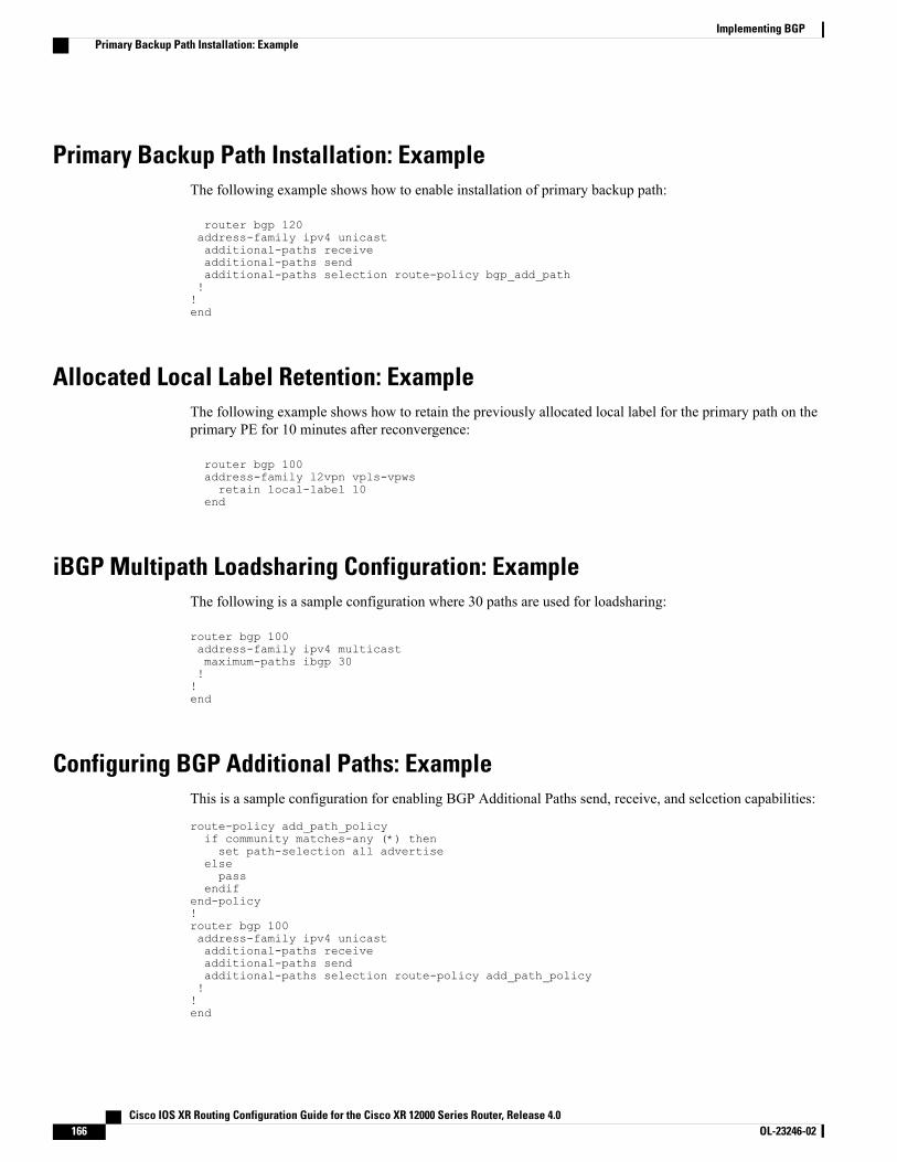
Primary Backup Path Installation: ExampleThe following example shows how to enable installation of primary backup path:
router bgp 120address-family ipv4 unicastadditional-paths receiveadditional-paths sendadditional-paths selection route-policy bgp_add_path!!end
Allocated Local Label Retention: ExampleThe following example shows how to retain the previously allocated local label for the primary path on theprimary PE for 10 minutes after reconvergence:
router bgp 100address-family l2vpn vpls-vpwsretain local-label 10
end
iBGP Multipath Loadsharing Configuration: ExampleThe following is a sample configuration where 30 paths are used for loadsharing:
router bgp 100address-family ipv4 multicastmaximum-paths ibgp 30!!end
Configuring BGP Additional Paths: ExampleThis is a sample configuration for enabling BGP Additional Paths send, receive, and selcetion capabilities:
route-policy add_path_policyif community matches-any (*) thenset path-selection all advertise
elsepass
endifend-policy!router bgp 100address-family ipv4 unicastadditional-paths receiveadditional-paths sendadditional-paths selection route-policy add_path_policy!!end
Cisco IOS XR Routing Configuration Guide for the Cisco XR 12000 Series Router, Release 4.0166 OL-23246-02
Implementing BGPPrimary Backup Path Installation: Example
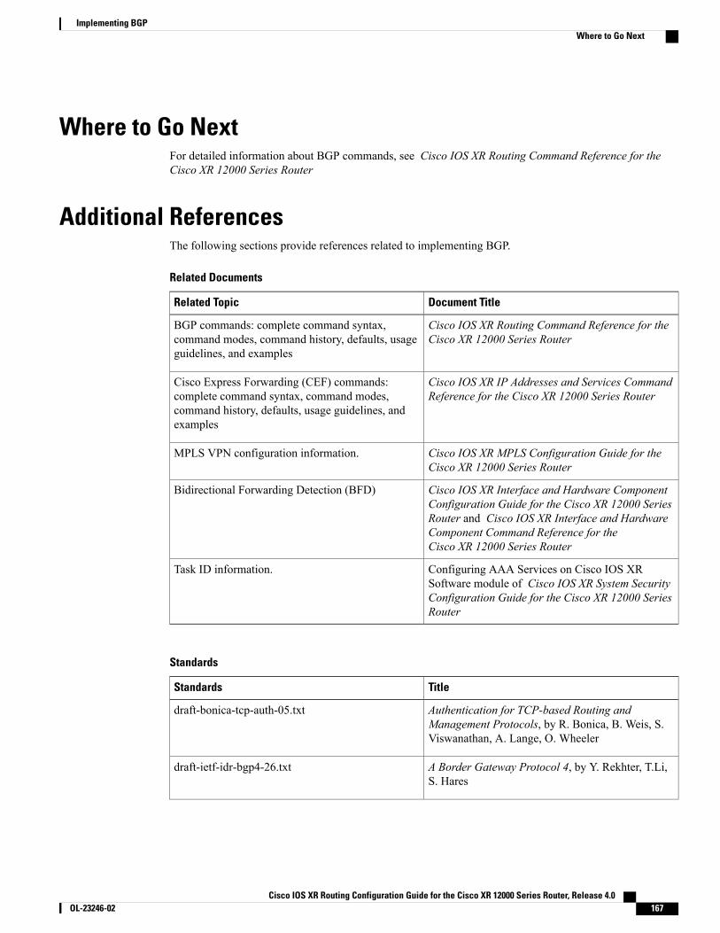
Where to Go NextFor detailed information about BGP commands, see Cisco IOS XR Routing Command Reference for theCisco XR 12000 Series Router
Additional ReferencesThe following sections provide references related to implementing BGP.
Related Documents
Document TitleRelated Topic
Cisco IOS XR Routing Command Reference for theCisco XR 12000 Series Router
BGP commands: complete command syntax,command modes, command history, defaults, usageguidelines, and examples
Cisco IOS XR IP Addresses and Services CommandReference for the Cisco XR 12000 Series Router
Cisco Express Forwarding (CEF) commands:complete command syntax, command modes,command history, defaults, usage guidelines, andexamples
Cisco IOS XR MPLS Configuration Guide for theCisco XR 12000 Series Router
MPLS VPN configuration information.
Cisco IOS XR Interface and Hardware ComponentConfiguration Guide for the Cisco XR 12000 SeriesRouter and Cisco IOS XR Interface and HardwareComponent Command Reference for theCisco XR 12000 Series Router
Bidirectional Forwarding Detection (BFD)
Configuring AAA Services on Cisco IOS XRSoftware module of Cisco IOS XR System SecurityConfiguration Guide for the Cisco XR 12000 SeriesRouter
Task ID information.
Standards
TitleStandards
Authentication for TCP-based Routing andManagement Protocols, by R. Bonica, B. Weis, S.Viswanathan, A. Lange, O. Wheeler
draft-bonica-tcp-auth-05.txt
A Border Gateway Protocol 4, by Y. Rekhter, T.Li,S. Hares
draft-ietf-idr-bgp4-26.txt
Cisco IOS XR Routing Configuration Guide for the Cisco XR 12000 Series Router, Release 4.0 OL-23246-02 167
Implementing BGPWhere to Go Next
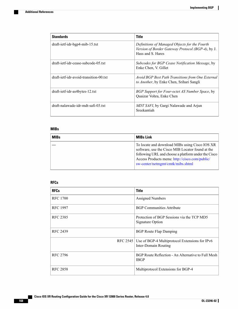
TitleStandards
Definitions of Managed Objects for the FourthVersion of Border Gateway Protocol (BGP-4), by J.Hass and S. Hares
draft-ietf-idr-bgp4-mib-15.txt
Subcodes for BGP Cease Notification Message, byEnke Chen, V. Gillet
draft-ietf-idr-cease-subcode-05.txt
Avoid BGP Best Path Transitions from One Externalto Another, by Enke Chen, Srihari Sangli
draft-ietf-idr-avoid-transition-00.txt
BGP Support for Four-octet AS Number Space, byQuaizar Vohra, Enke Chen
draft-ietf-idr-as4bytes-12.txt
MDT SAFI, by Gargi Nalawade and ArjunSreekantiah
draft-nalawade-idr-mdt-safi-03.txt
MIBs
MIBs LinkMIBs
To locate and download MIBs using Cisco IOS XRsoftware, use the Cisco MIB Locator found at thefollowingURL and choose a platform under the CiscoAccess Products menu: http://cisco.com/public/sw-center/netmgmt/cmtk/mibs.shtml
—
RFCs
TitleRFCs
Assigned NumbersRFC 1700
BGP Communities AttributeRFC 1997
Protection of BGP Sessions via the TCP MD5Signature Option
RFC 2385
BGP Route Flap DampingRFC 2439
Use of BGP-4 Multiprotocol Extensions for IPv6Inter-Domain Routing
RFC 2545
BGP Route Reflection - An Alternative to Full MeshIBGP
RFC 2796
Multiprotocol Extensions for BGP-4RFC 2858
Cisco IOS XR Routing Configuration Guide for the Cisco XR 12000 Series Router, Release 4.0168 OL-23246-02
Implementing BGPAdditional References
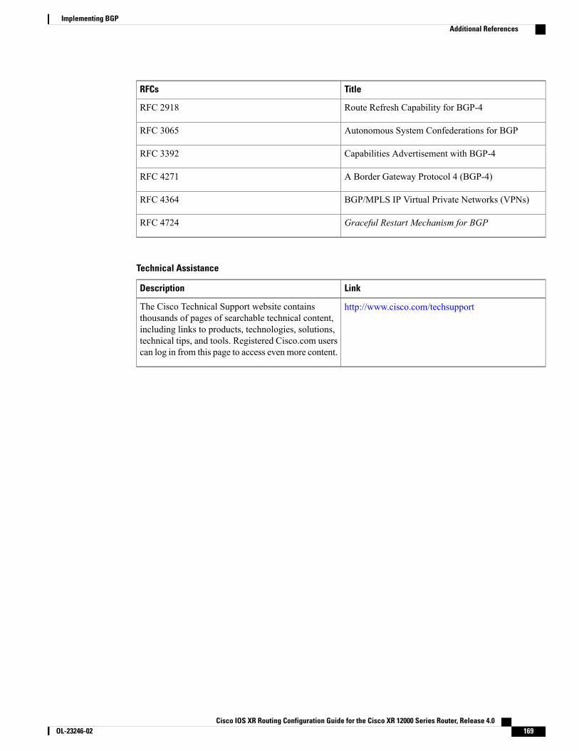
TitleRFCs
Route Refresh Capability for BGP-4RFC 2918
Autonomous System Confederations for BGPRFC 3065
Capabilities Advertisement with BGP-4RFC 3392
A Border Gateway Protocol 4 (BGP-4)RFC 4271
BGP/MPLS IP Virtual Private Networks (VPNs)RFC 4364
Graceful Restart Mechanism for BGPRFC 4724
Technical Assistance
LinkDescription
http://www.cisco.com/techsupportThe Cisco Technical Support website containsthousands of pages of searchable technical content,including links to products, technologies, solutions,technical tips, and tools. Registered Cisco.com userscan log in from this page to access evenmore content.
Cisco IOS XR Routing Configuration Guide for the Cisco XR 12000 Series Router, Release 4.0 OL-23246-02 169
Implementing BGPAdditional References

Cisco IOS XR Routing Configuration Guide for the Cisco XR 12000 Series Router, Release 4.0170 OL-23246-02
Implementing BGPAdditional References
C H A P T E R 2Implementing EIGRP
The Enhanced Interior Gateway Routing Protocol (EIGRP) is an enhanced version of IGRP developed byCisco. This module describes the concepts and tasks you need to implement basic EIGRP configurationusing Cisco IOS XR software. EIGRP uses distance vector routing technology, which specifies that a routerneed not know all the router and link relationships for the entire network. Each router advertises destinationswith a corresponding distance and upon receiving routes, adjusts the distance and propagates the informationto neighboring routes.
For EIGRP configuration information related to the following features, see the Related Documents, on page210 section of this module.
• Multiprotocol Label Switching (MPLS) Layer 3 Virtual Private Network (VPN)
• Site of Origin (SoO) Support
For more information about EIGRP on the Cisco IOSXR software and complete descriptions of the EIGRPcommands listed in this module, see the Related Documents, on page 210 section of this module. To locatedocumentation for other commands that might appear while executing a configuration task, search onlinein the Cisco IOS XR software master command index.
Note
Feature History for Implementing EIGRP on Cisco IOS XRSoftwareModificationRelease
This feature was introduced.Release 3.3.0
Four-byte autonomous system (AS) number support was added.Release 3.4.0
IPv6 address family and IPv6VPN routing and forwarding (VRF)address family support was added.
IPv6 Provider Edge and IPv6 VPN Provider Edge Transport overMultiprotocol Label Switching Infrastructure support was added.
Release 3.5.0
No modification.Release 3.6.0
No modification.Release 3.7.0
Cisco IOS XR Routing Configuration Guide for the Cisco XR 12000 Series Router, Release 4.0 OL-23246-02 171
ModificationRelease
EIGRP Authentication Keychain feature was added.Release 3.8.0
No modification.Release 3.9.0
• Prerequisites for Implementing EIGRP, page 172
• Restrictions for Implementing EIGRP , page 172
• Information About Implementing EIGRP, page 172
• How to Implement EIGRP , page 184
• Configuration Examples for Implementing EIGRP , page 208
• Additional References, page 210
Prerequisites for Implementing EIGRPYou must be in a user group associated with a task group that includes the proper task IDs. The commandreference guides include the task IDs required for each command. If you suspect user group assignment ispreventing you from using a command, contact your AAA administrator for assistance.
Restrictions for Implementing EIGRPThe following restrictions are employed when running EIGRP on this version of Cisco IOS XR software:
• Only one instance of an EIGRP process is supported.
• Bidirectional Forwarding Detection (BFD) feature and the Simple Network Management Protocol(SNMP) MIB are not supported.
• Interface static routes are not automatically redistributed into EIGRP, because there are no networkcommands.
• Metric configuration (either through the default-metric command or a route policy) is required forredistribution of connected and static routes.
• Auto summary is disabled by default.
• Stub leak maps are not supported.
Information About Implementing EIGRPTo implement EIGRP, you need to understand the following concepts:
Cisco IOS XR Routing Configuration Guide for the Cisco XR 12000 Series Router, Release 4.0172 OL-23246-02
Implementing EIGRPPrerequisites for Implementing EIGRP
EIGRP Functional OverviewEnhanced Interior Gateway Routing Protocol (EIGRP) is an interior gateway protocol suited for many differenttopologies and media. EIGRP scales well and provides extremely quick convergence times with minimalnetwork traffic.
EIGRP has very low usage of network resources during normal operation. Only hello packets are transmittedon a stable network. When a change in topology occurs, only the routing table changes are propagated andnot the entire routing table. Propagation reduces the amount of load the routing protocol itself places on thenetwork. EIGRP also provides rapid convergence times for changes in the network topology.
The distance information in EIGRP is represented as a composite of available bandwidth, delay, load utilization,and link reliability with improved convergence properties and operating efficiency. The fine-tuning of linkcharacteristics achieves optimal paths.
The convergence technology that EIGRP uses is based on research conducted at SRI International and employsan algorithm referred to as the Diffusing Update Algorithm (DUAL). This algorithm guarantees loop-freeoperation at every instant throughout a route computation and allows all devices involved in a topology changeto synchronize at the same time. Routers that are not affected by topology changes are not involved inrecomputations. The convergence time with DUAL rivals that of any other existing routing protocol.
EIGRP FeaturesEIGRP offers the following features:
• Fast convergence—The DUAL algorithm allows routing information to converge as quickly as anycurrently available routing protocol.
• Partial updates—EIGRP sends incremental updates when the state of a destination changes, instead ofsending the entire contents of the routing table. This feature minimizes the bandwidth required for EIGRPpackets.
• Neighbor discovery mechanism—This is a simple hello mechanism used to learn about neighboringrouters. It is protocol independent.
• Variable-length subnet masks (VLSMs).
• Arbitrary route summarization.
• Scaling—EIGRP scales to large networks.
The following key features are supported in the Cisco IOS XR implementation:
• Support for IPv4 and IPv6 address families.
• Provider Edge (PE)-Customer Edge (CE) protocol support with Site of Origin (SoO) and Border GatewayProtocol (BGP) cost community support.
• PECE protocol support for MPLS and L2TPv3-based-IP L3VPNs.
EIGRP ComponentsEIGRP has the following four basic components:
Cisco IOS XR Routing Configuration Guide for the Cisco XR 12000 Series Router, Release 4.0 OL-23246-02 173
Implementing EIGRPEIGRP Functional Overview
• Neighbor discovery or neighbor recovery
• Reliable transport protocol
• DUAL finite state machine
• Protocol-dependent modules
Neighbor discovery or neighbor recovery is the process that routers use to dynamically learn of other routerson their directly attached networks. Routers must also discover when their neighbors become unreachable orinoperative. Neighbor discovery or neighbor recovery is achieved with low overhead by periodically sendingsmall hello packets. As long as hello packets are received, the Cisco IOS XR software can determine that aneighbor is alive and functioning. After this status is determined, the neighboring routers can exchange routinginformation.
The reliable transport protocol is responsible for guaranteed, ordered delivery of EIGRP packets to all neighbors.It supports intermixed transmission of multicast and unicast packets. Some EIGRP packets must be sentreliably and others need not be. For efficiency, reliability is provided only when necessary. For example, ona multiaccess network that has multicast capabilities (such as Ethernet) it is not necessary to send hello packetsreliably to all neighbors individually. Therefore, EIGRP sends a single multicast hello with an indication inthe packet informing the receivers that the packet need not be acknowledged. Other types of packets (such asupdates) require acknowledgment, which is indicated in the packet. The reliable transport has a provision tosend multicast packets quickly when unacknowledged packets are pending. This provision helps to ensurethat convergence time remains low in the presence of various speed links.
The DUAL finite state machine embodies the decision process for all route computations. It tracks all routesadvertised by all neighbors. DUAL uses the distance information (known as a metric) to select efficient,loop-free paths. DUAL selects routes to be inserted into a routing table based on a calculation of the feasibilitycondition. A successor is a neighboring router used for packet forwarding that has a least-cost path to adestination that is guaranteed not to be part of a routing loop. When there are no feasible successors but thereare neighbors advertising the destination, a recomputation must occur. This is the process whereby a newsuccessor is determined. The amount of time required to recompute the route affects the convergence time.Recomputation is processor intensive; it is advantageous to avoid unneeded recomputation. When a topologychange occurs, DUAL tests for feasible successors. If there are feasible successors, it uses any it finds to avoidunnecessary recomputation.
The protocol-dependent modules are responsible for network layer protocol-specific tasks. An example is theEIGRP module, which is responsible for sending and receiving EIGRP packets that are encapsulated in IP.It is also responsible for parsing EIGRP packets and informing DUAL of the new information received. EIGRPasks DUAL to make routing decisions, but the results are stored in the IP routing table. EIGRP is alsoresponsible for redistributing routes learned by other IP routing protocols.
EIGRP Configuration GroupingCisco IOS XR software groups all EIGRP configuration under router EIGRP configuration mode, includinginterface configuration portions associated with EIGRP. To display EIGRP configuration in its entirety, usethe show running-config router eigrp command. The command output displays the running configurationfor the configured EIGRP instance, including the interface assignments and interface attributes.
Cisco IOS XR Routing Configuration Guide for the Cisco XR 12000 Series Router, Release 4.0174 OL-23246-02
Implementing EIGRPEIGRP Configuration Grouping
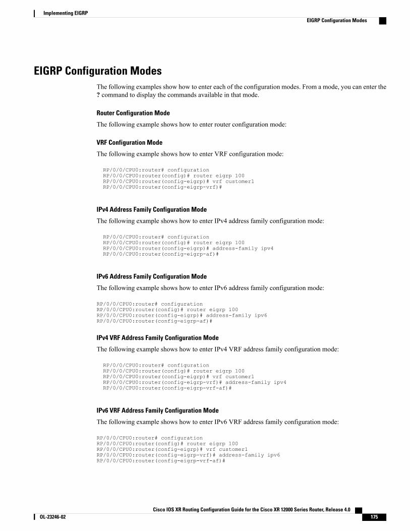
EIGRP Configuration ModesThe following examples show how to enter each of the configuration modes. From a mode, you can enter the? command to display the commands available in that mode.
Router Configuration Mode
The following example shows how to enter router configuration mode:
VRF Configuration Mode
The following example shows how to enter VRF configuration mode:
RP/0/0/CPU0:router# configurationRP/0/0/CPU0:router(config)# router eigrp 100RP/0/0/CPU0:router(config-eigrp)# vrf customer1RP/0/0/CPU0:router(config-eigrp-vrf)#
IPv4 Address Family Configuration Mode
The following example shows how to enter IPv4 address family configuration mode:
RP/0/0/CPU0:router# configurationRP/0/0/CPU0:router(config)# router eigrp 100RP/0/0/CPU0:router(config-eigrp)# address-family ipv4RP/0/0/CPU0:router(config-eigrp-af)#
IPv6 Address Family Configuration Mode
The following example shows how to enter IPv6 address family configuration mode:
RP/0/0/CPU0:router# configurationRP/0/0/CPU0:router(config)# router eigrp 100RP/0/0/CPU0:router(config-eigrp)# address-family ipv6RP/0/0/CPU0:router(config-eigrp-af)#
IPv4 VRF Address Family Configuration Mode
The following example shows how to enter IPv4 VRF address family configuration mode:
RP/0/0/CPU0:router# configurationRP/0/0/CPU0:router(config)# router eigrp 100RP/0/0/CPU0:router(config-eigrp)# vrf customer1RP/0/0/CPU0:router(config-eigrp-vrf)# address-family ipv4RP/0/0/CPU0:router(config-eigrp-vrf-af)#
IPv6 VRF Address Family Configuration Mode
The following example shows how to enter IPv6 VRF address family configuration mode:
RP/0/0/CPU0:router# configurationRP/0/0/CPU0:router(config)# router eigrp 100RP/0/0/CPU0:router(config-eigrp)# vrf customer1RP/0/0/CPU0:router(config-eigrp-vrf)# address-family ipv6RP/0/0/CPU0:router(config-eigrp-vrf-af)#
Cisco IOS XR Routing Configuration Guide for the Cisco XR 12000 Series Router, Release 4.0 OL-23246-02 175
Implementing EIGRPEIGRP Configuration Modes
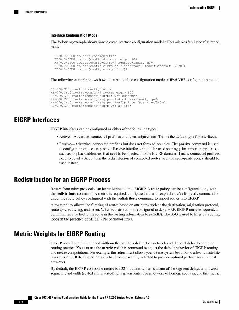
Interface Configuration Mode
The following example shows how to enter interface configurationmode in IPv4 address family configurationmode:
RP/0/0/CPU0:router# configurationRP/0/0/CPU0:router(config)# router eigrp 100RP/0/0/CPU0:router(config-eigrp)# address-family ipv4RP/0/0/CPU0:router(config-eigrp-af)# interface GigabitEthernet 0/3/0/0RP/0/0/CPU0:router(config-eigrp-af-if)#
The following example shows how to enter interface configuration mode in IPv6 VRF configuration mode:
RP/0/0/CPU0:router# configurationRP/0/0/CPU0:router(config)# router eigrp 100RP/0/0/CPU0:router(config-eigrp)# vrf customer1RP/0/0/CPU0:router(config-eigrp-vrf)# address-family ipv6RP/0/0/CPU0:router(config-eigrp-vrf-af)# interface POS0/5/0/0RP/0/0/CPU0:router(config-eigrp-vrf-af-if)#
EIGRP InterfacesEIGRP interfaces can be configured as either of the following types:
• Active—Advertises connected prefixes and forms adjacencies. This is the default type for interfaces.
• Passive—Advertises connected prefixes but does not form adjacencies. The passive command is usedto configure interfaces as passive. Passive interfaces should be used sparingly for important prefixes,such as loopback addresses, that need to be injected into the EIGRP domain. If many connected prefixesneed to be advertised, then the redistribution of connected routes with the appropriate policy should beused instead.
Redistribution for an EIGRP ProcessRoutes from other protocols can be redistributed into EIGRP. A route policy can be configured along withthe redistribute command. A metric is required, configured either through the default-metric command orunder the route policy configured with the redistribute command to import routes into EIGRP.
A route policy allows the filtering of routes based on attributes such as the destination, origination protocol,route type, route tag, and so on. When redistribution is configured under a VRF, EIGRP retrieves extendedcommunities attached to the route in the routing information base (RIB). The SoO is used to filter out routingloops in the presence of MPSL VPN backdoor links.
Metric Weights for EIGRP RoutingEIGRP uses the minimum bandwidth on the path to a destination network and the total delay to computerouting metrics. You can use themetric weights command to adjust the default behavior of EIGRP routingandmetric computations. For example, this adjustment allows you to tune system behavior to allow for satellitetransmission. EIGRP metric defaults have been carefully selected to provide optimal performance in mostnetworks.
By default, the EIGRP composite metric is a 32-bit quantity that is a sum of the segment delays and lowestsegment bandwidth (scaled and inverted) for a given route. For a network of homogeneous media, this metric
Cisco IOS XR Routing Configuration Guide for the Cisco XR 12000 Series Router, Release 4.0176 OL-23246-02
Implementing EIGRPEIGRP Interfaces
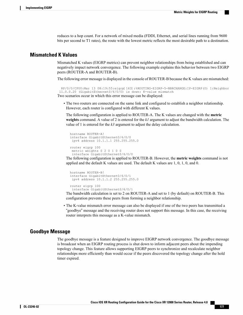
reduces to a hop count. For a network of mixed media (FDDI, Ethernet, and serial lines running from 9600bits per second to T1 rates), the route with the lowest metric reflects the most desirable path to a destination.
Mismatched K ValuesMismatched K values (EIGRP metrics) can prevent neighbor relationships from being established and cannegatively impact network convergence. The following example explains this behavior between two EIGRPpeers (ROUTER-A and ROUTER-B).
The following error message is displayed in the console of ROUTER-B because the K values are mismatched:
RP/0/0/CPU0:Mar 13 08:19:55:eigrp[163]:%ROUTING-EIGRP-5-NBRCHANGE:IP-EIGRP(0) 1:Neighbor11.0.0.20 (GigabitEthernet0/6/0/0) is down: K-value mismatchTwo scenarios occur in which this error message can be displayed:
• The two routers are connected on the same link and configured to establish a neighbor relationship.However, each router is configured with different K values.
The following configuration is applied to ROUTER-A. The K values are changed with themetricweights command. A value of 2 is entered for the k1 argument to adjust the bandwidth calculation. Thevalue of 1 is entered for the k3 argument to adjust the delay calculation.
hostname ROUTER-A!interface GigabitEthernet0/6/0/0ipv4 address 10.1.1.1 255.255.255.0
router eigrp 100metric weights 0 2 0 1 0 0interface GigabitEthernet0/6/0/0
The following configuration is applied to ROUTER-B. However, themetric weights command is notapplied and the default K values are used. The default K values are 1, 0, 1, 0, and 0.
hostname ROUTER-B!interface GigabitEthernet0/6/0/1ipv4 address 10.1.1.2 255.255.255.0
router eigrp 100interface GigabitEthernet0/6/0/1
The bandwidth calculation is set to 2 on ROUTER-A and set to 1 (by default) on ROUTER-B. Thisconfiguration prevents these peers from forming a neighbor relationship.
• The K-value mismatch error message can also be displayed if one of the two peers has transmitted a“goodbye” message and the receiving router does not support this message. In this case, the receivingrouter interprets this message as a K-value mismatch.
Goodbye MessageThe goodbye message is a feature designed to improve EIGRP network convergence. The goodbye messageis broadcast when an EIGRP routing process is shut down to inform adjacent peers about the impendingtopology change. This feature allows supporting EIGRP peers to synchronize and recalculate neighborrelationships more efficiently than would occur if the peers discovered the topology change after the holdtimer expired.
Cisco IOS XR Routing Configuration Guide for the Cisco XR 12000 Series Router, Release 4.0 OL-23246-02 177
Implementing EIGRPMetric Weights for EIGRP Routing
The following message is displayed by routers that run a supported release when a goodbye message isreceived:
RP/0/0/CPU0:Mar 13 09:13:17:eigrp[163]:%ROUTING-EIGRP-5-NBRCHANGE: IP-EIGRP(0) 1: Neighbor10.0.0.20 (GigabitEthernet0/6/0/0) is down: Interface Goodbye receivedA Cisco router that runs a software release that does not support the goodbye message can misinterpret themessage as a K-value mismatch and display the following message:RP/0/0/CPU0:Mar 13 09:13:17:eigrp[163]:%ROUTING-EIGRP-5-NBRCHANGE: IP-EIGRP(0) 1: Neighbor10.0.0.20 (GigabitEthernet0/6/0/0) is down: K-value mismatch
The receipt of a goodbye message by a nonsupporting peer does not disrupt normal network operation.The nonsupporting peer terminates the session when the hold timer expires. The sending and receivingrouters reconverge normally after the sender reloads.
Note
Percentage of Link Bandwidth Used for EIGRP PacketsBy default, EIGRP packets consume a maximum of 50 percent of the link bandwidth, as configured with thebandwidth interface configuration command. You might want to change that value if a different level of linkutilization is required or if the configured bandwidth does not match the actual link bandwidth (it may havebeen configured to influence route metric calculations).
Floating Summary Routes for an EIGRP ProcessYou can also use a floating summary route when configuring the summary-address command. The floatingsummary route is created by applying a default route and administrative distance at the interface level. Thefollowing scenario illustrates the behavior of this enhancement.
Figure 11: Floating Summary Route Is Applied to Router-B, on page 179 shows a network with three routers,Router-A, Router-B, and Router-C. Router-A learns a default route from elsewhere in the network and thenadvertises this route to Router-B. Router-B is configured so that only a default summary route is advertisedto Router-C. The default summary route is applied to interface 0/1 on Router-Bwith the following configuration:
RP/0/0/CPU0:router(config)# router eigrp 100RP/0/0/CPU0:router(config-eigrp)# address-family ipv4RP/0/0/CPU0:router(config-eigrp-af)# interface GigabitEthernet 0/3/0/0RP/0/0/CPU0:router(config-eigrp-af-if)# summary-address 100.0.0.0 0.0.0.0
Cisco IOS XR Routing Configuration Guide for the Cisco XR 12000 Series Router, Release 4.0178 OL-23246-02
Implementing EIGRPPercentage of Link Bandwidth Used for EIGRP Packets
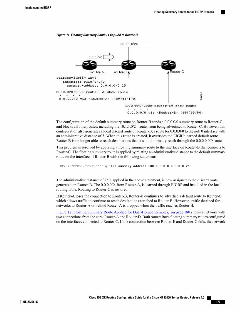
Figure 11: Floating Summary Route Is Applied to Router-B
The configuration of the default summary route on Router-B sends a 0.0.0.0/0 summary route to Router-Cand blocks all other routes, including the 10.1.1.0/24 route, from being advertised to Router-C. However, thisconfiguration also generates a local discard route on Router-B, a route for 0.0.0.0/0 to the null 0 interface withan administrative distance of 5. When this route is created, it overrides the EIGRP learned default route.Router-B is no longer able to reach destinations that it would normally reach through the 0.0.0.0.0/0 route.
This problem is resolved by applying a floating summary route to the interface on Router-B that connects toRouter-C. The floating summary route is applied by relating an administrative distance to the default summaryroute on the interface of Router-B with the following statement:
RP/0/0/CPU0:router(config-if)# summary-address 100 0.0.0.0 0.0.0.0 250
The administrative distance of 250, applied in the above statement, is now assigned to the discard routegenerated on Router-B. The 0.0.0.0/0, from Router-A, is learned through EIGRP and installed in the localrouting table. Routing to Router-C is restored.
If Router-A loses the connection to Router-B, Router-B continues to advertise a default route to Router-C,which allows traffic to continue to reach destinations attached to Router-B. However, traffic destined fornetworks to Router-A or behind Router-A is dropped when the traffic reaches Router-B.
Figure 12: Floating Summary Route Applied for Dual-Homed Remotes, on page 180 shows a network withtwo connections from the core: Router-A and Router-D. Both routers have floating summary routes configuredon the interfaces connected to Router-C. If the connection between Router-E and Router-C fails, the network
Cisco IOS XR Routing Configuration Guide for the Cisco XR 12000 Series Router, Release 4.0 OL-23246-02 179
Implementing EIGRPFloating Summary Routes for an EIGRP Process

continues to operate normally. All traffic flows from Router-C through Router-B to the hosts attached toRouter-A and Router-D.
Figure 12: Floating Summary Route Applied for Dual-Homed Remotes
However, if the link between Router-D and Router-E fails, the network may dump traffic into a black holebecause Router-E continues to advertise the default route (0.0.0.0/0) to Router-C, as long as at least one link(other than the link to Router-C) to Router-E is still active. In this scenario, Router-C still forwards traffic toRouter-E, but Router-E drops the traffic creating the black hole. To avoid this problem, you should configurethe summary address with an administrative distance on only single-homed remote routers or areas in whichonly one exit point exists between the segments of the network. If two or more exit points exist (from onesegment of the network to another), configuring the floating default route can cause a black hole to form.
Split Horizon for an EIGRP ProcessSplit horizon controls the sending of EIGRP update and query packets. When split horizon is enabled on aninterface, update and query packets are not sent for destinations for which this interface is the next hop.Controlling update and query packets in this manner reduces the possibility of routing loops.
By default, split horizon is enabled on all interfaces.
Split horizon blocks route information from being advertised by a router on any interface from which thatinformation originated. This behavior usually optimizes communications among multiple routing devices,particularly when links are broken. However, with nonbroadcast networks (such as Frame Relay and SMDS),situations can arise for which this behavior is less than ideal. For these situations, including networks in whichyou have EIGRP configured, you may want to disable split horizon.
Cisco IOS XR Routing Configuration Guide for the Cisco XR 12000 Series Router, Release 4.0180 OL-23246-02
Implementing EIGRPSplit Horizon for an EIGRP Process

Adjustment of Hello Interval and Hold Time for an EIGRP ProcessYou can adjust the interval between hello packets and the hold time.
Routing devices periodically send hello packets to each other to dynamically learn of other routers on theirdirectly attached networks. This information is used to discover neighbors and learn when neighbors becomeunreachable or inoperative. By default, hello packets are sent every 5 seconds.
You can configure the hold time on a specified interface for a particular EIGRP routing process designatedby the autonomous system number. The hold time is advertised in hello packets and indicates to neighborsthe length of time they should consider the sender valid. The default hold time is three times the hello interval,or 15 seconds.
Stub Routing for an EIGRP ProcessThe EIGRP Stub Routing feature improves network stability, reduces resource usage, and simplifies stubrouter configuration.
Stub routing is commonly used in a hub-and-spoke network topology. In a hub-and-spoke network, one ormore end (stub) networks are connected to a remote router (the spoke) that is connected to one or moredistribution routers (the hub). The remote router is adjacent only to one or more distribution routers. The onlyroute for IP traffic to follow into the remote router is through a distribution router. This type of configurationis commonly used in WAN topologies in which the distribution router is directly connected to a WAN. Thedistribution router can be connected to many more remote routers. Often, the distribution router is connectedto 100 or more remote routers. In a hub-and-spoke topology, the remote router must forward all nonlocaltraffic to a distribution router, so it becomes unnecessary for the remote router to hold a complete routingtable. Generally, the distribution router need not send anything more than a default route to the remote router.
When using the EIGRP Stub Routing feature, you need to configure the distribution and remote routers touse EIGRP and configure only the remote router as a stub. Only specified routes are propagated from theremote (stub) router. The stub router responds to all queries for summaries, connected routes, redistributedstatic routes, external routes, and internal routes with the message “inaccessible.” A router that is configuredas a stub sends a special peer information packet to all neighboring routers to report its status as a stub router.
Any neighbor that receives a packet informing it of the stub status does not query the stub router for anyroutes, and a router that has a stub peer does not query that peer. The stub router depends on the distributionrouter to send the proper updates to all peers.
This figure shows a simple hub-and-spoke configuration.
Cisco IOS XR Routing Configuration Guide for the Cisco XR 12000 Series Router, Release 4.0 OL-23246-02 181
Implementing EIGRPAdjustment of Hello Interval and Hold Time for an EIGRP Process
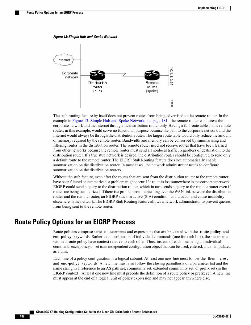
Figure 13: Simple Hub-and-Spoke Network
The stub routing feature by itself does not prevent routes from being advertised to the remote router. In theexample in Figure 13: Simple Hub-and-Spoke Network, on page 181 , the remote router can access thecorporate network and the Internet through the distribution router only. Having a full route table on the remoterouter, in this example, would serve no functional purpose because the path to the corporate network and theInternet would always be through the distribution router. The larger route table would only reduce the amountof memory required by the remote router. Bandwidth and memory can be conserved by summarizing andfiltering routes in the distribution router. The remote router need not receive routes that have been learnedfrom other networks because the remote router must send all nonlocal traffic, regardless of destination, to thedistribution router. If a true stub network is desired, the distribution router should be configured to send onlya default route to the remote router. The EIGRP Stub Routing feature does not automatically enablesummarization on the distribution router. In most cases, the network administrator needs to configuresummarization on the distribution routers.
Without the stub feature, even after the routes that are sent from the distribution router to the remote routerhave been filtered or summarized, a problemmight occur. If a route is lost somewhere in the corporate network,EIGRP could send a query to the distribution router, which in turn sends a query to the remote router even ifroutes are being summarized. If there is a problem communicating over theWAN link between the distributionrouter and the remote router, an EIGRP stuck in active (SIA) condition could occur and cause instabilityelsewhere in the network. The EIGRP Stub Routing feature allows a network administrator to prevent queriesfrom being sent to the remote router.
Route Policy Options for an EIGRP ProcessRoute policies comprise series of statements and expressions that are bracketed with the route-policy andend-policy keywords. Rather than a collection of individual commands (one for each line), the statementswithin a route policy have context relative to each other. Thus, instead of each line being an individualcommand, each policy or set is an independent configuration object that can be used, entered, andmanipulatedas a unit.
Each line of a policy configuration is a logical subunit. At least one new line must follow the then , else ,and end-policy keywords. A new line must also follow the closing parenthesis of a parameter list and thename string in a reference to an AS path set, community set, extended community set, or prefix set (in theEIGRP context). At least one new line must precede the definition of a route policy or prefix set. A new linemust appear at the end of a logical unit of policy expression and may not appear anywhere else.
Cisco IOS XR Routing Configuration Guide for the Cisco XR 12000 Series Router, Release 4.0182 OL-23246-02
Implementing EIGRPRoute Policy Options for an EIGRP Process
This is the command to set the EIGRP metric in a route policy:
RP/0/0/CPU0:router(config-rpl)# set eigrp-metric bandwidth delay reliability loading mtuThis is the command to provide EIGRP offset list functionality in a route policy:
RP/0/0/CPU0:router(config-rpl)# add eigrp-metric bandwidth delay reliability loading mtuA route policy can be used in EIGRP only if all the statements are applicable to the particular EIGRP attachpoint. The following commands accept a route policy:
• default-information allowed—Match statements are allowed for destination. No set statements areallowed.
• route-policy—Match statements are allowed for destination, next hop, and tag. Set statements areallowed for eigrp-metric and tag.
• redistribute—Match statements are allowed for destination, next hop, source-protocol, tag and route-type.Set statements are allowed for eigrp-metric and tag.
The range for setting a tag is 0 to 255 for internal routes and 0 to 4294967295 for external routes.
EIGRP Layer 3 VPN PE-CE Site-of-OriginThe EIGRP MPLS and IP VPN PE-CE Site-of-Origin (SoO) feature introduces the capability to filterMultiprotocol Label Switching (MPLS) and IP Virtual Private Network (VPN) traffic on a per-site basis forEIGRP networks. SoO filtering is configured at the interface level and is used to manage MPLS and IP VPNtraffic and to prevent transient routing loops from occurring in complex and mixed network topologies.
Router Interoperation with the Site-of-Origin Extended CommunityThe configuration of the SoO extended community allows routers that support this feature to identify the sitefrom which each route originated. When this feature is enabled, the EIGRP routing process on the PE or CErouter checks each received route for the SoO extended community and filters based on the following conditions:
• A received route from BGP or a CE router contains a SoO value that matches the SoO value on thereceiving interface:
◦If a route is received with an associated SoO value that matches the SoO value that is configuredon the receiving interface, the route is filtered out because it was learned from another PE routeror from a backdoor link. This behavior is designed to prevent routing loops.
• A received route from a CE router is configured with a SoO value that does not match:
◦If a route is received with an associated SoO value that does not match the SoO value that isconfigured on the receiving interface, the route is accepted into the EIGRP topology table so thatit can be redistributed into BGP.
◦If the route is already installed in the EIGRP topology table but is associated with a different SoOvalue, the SoO value from the topology table is used when the route is redistributed into BGP.
• A received route from a CE router does not contain a SoO value:
Cisco IOS XR Routing Configuration Guide for the Cisco XR 12000 Series Router, Release 4.0 OL-23246-02 183
Implementing EIGRPEIGRP Layer 3 VPN PE-CE Site-of-Origin
If a route is received without a SoO value, the route is accepted into the EIGRP topology table,and the SoO value from the interface that is used to reach the next-hop CE router is appended tothe route before it is redistributed into BGP.
◦
When BGP and EIGRP peers that support the SoO extended community receive these routes, they alsoreceive the associated SoO values and pass them to other BGP and EIGRP peers that support the SoOextended community. This filtering is designed to prevent transient routes from being relearned fromthe originating site, which prevents transient routing loops from occurring.
In conjunction with BGP cost community, EIGRP, BGP, and the RIB ensure that paths over the MPLSVPN core are preferred over backdoor links.
For MPLS and IP VPN and SoO configuration information, see Implementing MPLS Layer 3 VPNs inthe Cisco IOS XR Multiprotocol Label Switching Configuration Guide.
IPv6 and IPv6 VPN Provider Edge Support over MPLS and IPIPv6 Provider Edge (6PE) and IPv6 VPN Provider Edge (6VPE) uses the existing IP and Multiprotocol LabelSwitching (MPLS) IPv4 core infrastructure for IPv6 transport. 6PE and 6VPE enable IPv6 sites to communicatewith each other over an IP and MPLS IPv4 core network using MPLS label switched paths (LSPs).
EIGRP is an Interior Gateway Protocol (IGP) that supports the 6PE or 6VPE provider edge-to-customer edgeprotocol by supporting the configuration of IPv6 address families in EIGRPVRF and exchanging IPv6 routingupdates in the L3VPN environment
For detailed information on configuring 6PE and 6VPE over MPLS and IP, see Cisco IOS XR MPLSConfiguration Guide for the Cisco XR 12000 Series Router.
EIGRP v4/v6 Authentication Using KeychainEIGRP authentication using keychain introduces the capability to authenticate EIGRP protocol packets on aper-interface basis. The EIGRP routing authentication provides a mechanism to authenticate all EIGRP protocoltraffic on one or more interfaces, based on Message Digest 5 (MD5) authentication.
The EIGRP routing authentication uses the Cisco IOS XR software security keychain infrastructure to storeand retrieve secret keys and to authenticate incoming and outgoing traffic on a per-interface basis.
How to Implement EIGRPThis section contains instructions for the following tasks:
To save configuration changes, you must commit changes when the system prompts you.Note
Enabling EIGRP RoutingThis task enables EIGRP routing and establishes an EIGRP routing process.
Cisco IOS XR Routing Configuration Guide for the Cisco XR 12000 Series Router, Release 4.0184 OL-23246-02
Implementing EIGRPIPv6 and IPv6 VPN Provider Edge Support over MPLS and IP

Before You Begin
Although you can configure EIGRP before you configure an IP address, no EIGRP routing occurs until atleast one IP address is configured.
SUMMARY STEPS
1. configure2. router eigrp as-number3. address-family { ipv4 | ipv6 }4. router-id id5. default-metric bandwidth delay reliability loading mtu6. distance internal-distance external-distance7. interface type interface-path-id8. holdtime seconds9. bandwidth-percent percent10. Do one of the following:
• end
• commit
DETAILED STEPS
PurposeCommand or Action
Enters global configuration mode.configure
Example:
RP/0/0/CPU0:router# configure
Step 1
Specifies the autonomous system number of the routing process toconfigure an EIGRP routing process.
router eigrp as-number
Example:
RP/0/0/CPU0:router(config)# router eigrp100
Step 2
Enters an address family configuration mode.address-family { ipv4 | ipv6 }
Example:
RP/0/0/CPU0:router(config-eigrp)#address-family ipv4
Step 3
(Optional) Configures a router-id for an EIGRP process.router-id idStep 4
Example:
RP/0/0/CPU0:router(config-eigrp)#router-id 172.20.1.1
It is good practice to use the router-id command to explicitlyspecify a unique 32-bit numeric value for the router ID. Thisaction ensures that EIGRP can function regardless of theinterface address configuration.
Note
Cisco IOS XR Routing Configuration Guide for the Cisco XR 12000 Series Router, Release 4.0 OL-23246-02 185
Implementing EIGRPEnabling EIGRP Routing
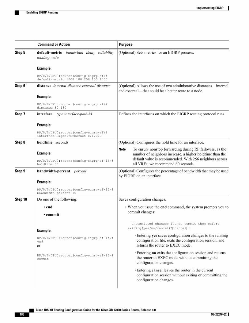
PurposeCommand or Action
(Optional) Sets metrics for an EIGRP process.default-metric bandwidth delay reliabilityloading mtu
Step 5
Example:
RP/0/0/CPU0:router(config-eigrp-af)#default-metric 1000 100 250 100 1500
(Optional) Allows the use of two administrative distances—internaland external—that could be a better route to a node.
distance internal-distance external-distance
Example:
RP/0/0/CPU0:router(config-eigrp-af)#distance 80 130
Step 6
Defines the interfaces on which the EIGRP routing protocol runs.interface type interface-path-id
Example:
RP/0/0/CPU0:router(config-eigrp-af)#interface GigabitEthernet 0/1/0/0
Step 7
(Optional) Configures the hold time for an interface.holdtime secondsStep 8
Example:
RP/0/0/CPU0:router(config-eigrp-af-if)#holdtime 30
To ensure nonstop forwarding during RP failovers, as thenumber of neighbors increase, a higher holdtime than thedefault value is recommended. With 256 neighbors acrossall VRFs, we recommend 60 seconds.
Note
(Optional) Configures the percentage of bandwidth that may be usedby EIGRP on an interface.
bandwidth-percent percent
Example:
RP/0/0/CPU0:router(config-eigrp-af-if)#bandwidth-percent 75
Step 9
Saves configuration changes.Do one of the following:Step 10
• end •When you issue the end command, the system prompts you tocommit changes:
Uncommitted changes found, commit them beforeexiting(yes/no/cancel)?[cancel]:
• commit
Example:
RP/0/0/CPU0:router(config-eigrp-af-if)#end
◦Entering yes saves configuration changes to the runningconfiguration file, exits the configuration session, andreturns the router to EXEC mode.or
RP/0/0/CPU0:router(config-eigrp-af-if)#commit
◦Entering no exits the configuration session and returnsthe router to EXEC mode without committing theconfiguration changes.
◦Entering cancel leaves the router in the currentconfiguration session without exiting or committing theconfiguration changes.
Cisco IOS XR Routing Configuration Guide for the Cisco XR 12000 Series Router, Release 4.0186 OL-23246-02
Implementing EIGRPEnabling EIGRP Routing
PurposeCommand or Action
• Use the commit command to save the configuration changesto the running configuration file and remain within theconfiguration session.
Configuring Route Summarization for an EIGRP ProcessThis task configures route summarization for an EIGRP process.
You can configure a summary aggregate address for a specified interface. If any more specific routes are inthe routing table, EIGRP advertises the summary address from the interface with a metric equal to the minimumof all more specific routes.
Before You Begin
You should not use the summary-address summarization command to generate the default route (0.0.0.0)from an interface. This command creates an EIGRP summary default route to the null 0 interface with anadministrative distance of 5. The low administrative distance of this default route can cause this route todisplace default routes learned from other neighbors from the routing table. If the default route learnedfrom the neighbors is displaced by the summary default route or the summary route is the only defaultroute present, all traffic destined for the default route does not leave the router; instead, this traffic is sentto the null 0 interface, where it is dropped.
The recommended way to send only the default route from a given interface is to use a route-policycommand.
Note
SUMMARY STEPS
1. configure2. router eigrp as-number3. address-family { ipv4 | ipv6 }4. route-policy name out5. interface type interface-path-id6. summary-address ip-address { / length | mask } [ admin-distance ]7. Do one of the following:
• end
• commit
Cisco IOS XR Routing Configuration Guide for the Cisco XR 12000 Series Router, Release 4.0 OL-23246-02 187
Implementing EIGRPConfiguring Route Summarization for an EIGRP Process
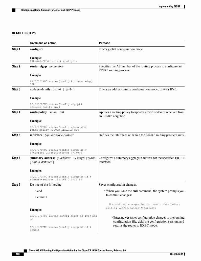
DETAILED STEPS
PurposeCommand or Action
Enters global configuration mode.configure
Example:RRP/0/0/CPU0:router# configure
Step 1
Specifies the AS number of the routing process to configure anEIGRP routing process.
router eigrp as-number
Example:
RP/0/0/CPU0:router(config)# router eigrp100
Step 2
Enters an address family configuration mode, IPv4 or IPv6.address-family { ipv4 | ipv6 }
Example:
RP/0/0/CPU0:router(config-eigrp)#address-family ipv4
Step 3
Applies a routing policy to updates advertised to or received froman EIGRP neighbor.
route-policy name out
Example:
RP/0/0/CPU0:router(config-eigrp-af)#route-policy FILTER_DEFAULT out
Step 4
Defines the interfaces on which the EIGRP routing protocol runs.interface type interface-path-id
Example:
RP/0/0/CPU0:router(config-eigrp-af)#interface GigabitEthernet 0/1/0/0
Step 5
Configures a summary aggregate address for the specified EIGRPinterface.
summary-address ip-address { / length | mask }[ admin-distance ]
Example:
RP/0/0/CPU0:router(config-eigrp-af-if)#summary-address 192.168.0.0/16 95
Step 6
Saves configuration changes.Do one of the following:Step 7
• end •When you issue the end command, the system prompts youto commit changes:
Uncommitted changes found, commit them before
• commit
Example:
RP/0/0/CPU0:router(config-eigrp-af-if)# end
exiting(yes/no/cancel)?[cancel]:
◦Entering yes saves configuration changes to the runningconfiguration file, exits the configuration session, andreturns the router to EXEC mode.
or
RP/0/0/CPU0:router(config-eigrp-af-if)#commit
Cisco IOS XR Routing Configuration Guide for the Cisco XR 12000 Series Router, Release 4.0188 OL-23246-02
Implementing EIGRPConfiguring Route Summarization for an EIGRP Process
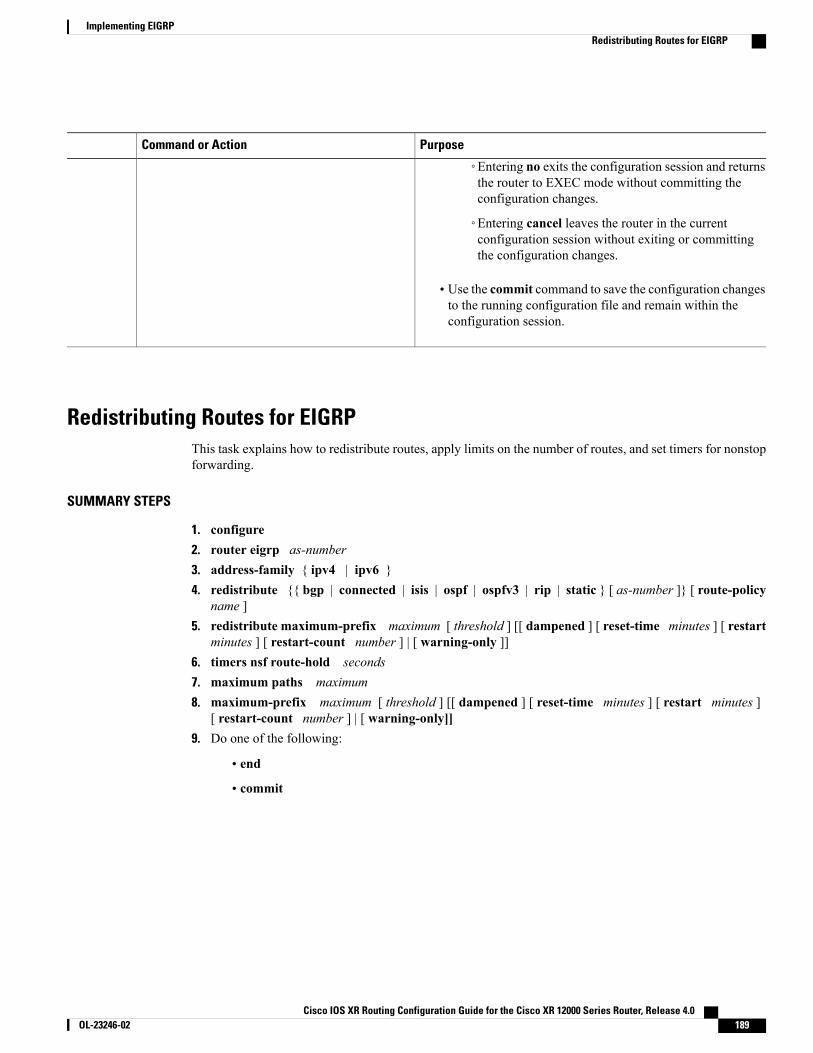
PurposeCommand or Action
◦Entering no exits the configuration session and returnsthe router to EXEC mode without committing theconfiguration changes.
◦Entering cancel leaves the router in the currentconfiguration session without exiting or committingthe configuration changes.
• Use the commit command to save the configuration changesto the running configuration file and remain within theconfiguration session.
Redistributing Routes for EIGRPThis task explains how to redistribute routes, apply limits on the number of routes, and set timers for nonstopforwarding.
SUMMARY STEPS
1. configure2. router eigrp as-number3. address-family { ipv4 | ipv6 }4. redistribute {{ bgp | connected | isis | ospf | ospfv3 | rip | static } [ as-number ]} [ route-policy
name ]5. redistribute maximum-prefix maximum [ threshold ] [[ dampened ] [ reset-time minutes ] [ restart
minutes ] [ restart-count number ] | [ warning-only ]]6. timers nsf route-hold seconds7. maximum paths maximum8. maximum-prefix maximum [ threshold ] [[ dampened ] [ reset-time minutes ] [ restart minutes ]
[ restart-count number ] | [ warning-only]]9. Do one of the following:
• end
• commit
Cisco IOS XR Routing Configuration Guide for the Cisco XR 12000 Series Router, Release 4.0 OL-23246-02 189
Implementing EIGRPRedistributing Routes for EIGRP

DETAILED STEPS
PurposeCommand or Action
Enters global configuration mode.configure
Example:
RP/0/0/CPU0:router# configure
Step 1
Specifies the AS number of the routing process to configurean EIGRP routing process.
router eigrp as-number
Example:
RP/0/0/CPU0:router(config)# router eigrp 100
Step 2
Enters an address family configuration mode, IPv4 or IPv6.address-family { ipv4 | ipv6 }
Example:
RP/0/0/CPU0:router(config-eigrp)# address-familyipv4
Step 3
Redistributes the routes from the specified protocol and ASnumber to the EIGRP process. Optionally, the redistributed
redistribute {{ bgp | connected | isis | ospf |ospfv3 | rip | static } [ as-number ]} [ route-policyname ]
Step 4
routes can be filtered into the EIGRP process by providing theroute policy.
Example:
RP/0/0/CPU0:router(config-eigrp-af)#redistribute bgp 100
Limits the maximum number of prefixes that are redistributedto the EIGRP process.
redistribute maximum-prefix maximum [ threshold] [[ dampened ] [ reset-time minutes ] [ restartminutes ] [ restart-count number ] | [ warning-only]]
Step 5
Example:
RP/0/0/CPU0:router(config-eigrp-af)#redistribute maximum-prefix 5000 95 warning-only
Sets the timer that determines how long an NSF-aware EIGRProuter holds routes for an inactive peer.
timers nsf route-hold seconds
Example:
RP/0/0/CPU0:router(config-eigrp-af)# timers nsfroute-hold 120
Step 6
Controls themaximumnumber of parallel routes that the EIGRPcan support.
maximum paths maximum
Example:
RP/0/0/CPU0:router(config-eigrp-af)# maximumpaths 10
Step 7
Cisco IOS XR Routing Configuration Guide for the Cisco XR 12000 Series Router, Release 4.0190 OL-23246-02
Implementing EIGRPRedistributing Routes for EIGRP

PurposeCommand or Action
Limits the number of prefixes that are accepted under an addressfamily by EIGRP.
maximum-prefix maximum [ threshold ] [[dampened ] [ reset-time minutes ] [ restart minutes] [ restart-count number ] | [ warning-only]]
Step 8
Example:
RP/0/0/CPU0:router(config-eigrp-af)#maximum-prefix 50000
Saves configuration changes.Do one of the following:Step 9
• end •When you issue the end command, the system promptsyou to commit changes:
Uncommitted changes found, commit them beforeexiting(yes/no/cancel)?[cancel]:
• commit
Example:
RP/0/0/CPU0:router(config-eigrp-af)# end◦Entering yes saves configuration changes to therunning configuration file, exits the configurationsession, and returns the router to EXEC mode.
or
RP/0/0/CPU0:router(config-eigrp-af)# commit ◦Entering no exits the configuration session andreturns the router to EXEC mode withoutcommitting the configuration changes.
◦Entering cancel leaves the router in the currentconfiguration session without exiting or committingthe configuration changes.
• Use the commit command to save the configurationchanges to the running configuration file and remainwithin the configuration session.
Creating a Route Policy and Attaching It to an EIGRP ProcessThis task defines a route policy and shows how to attach it to an EIGRP process.
A route policy definition consists of the route-policy command and name argument followed by a sequenceof optional policy statements, and then closed with the end-policy command.
A route policy is not useful until it is applied to routes of a routing protocol.
Cisco IOS XR Routing Configuration Guide for the Cisco XR 12000 Series Router, Release 4.0 OL-23246-02 191
Implementing EIGRPCreating a Route Policy and Attaching It to an EIGRP Process
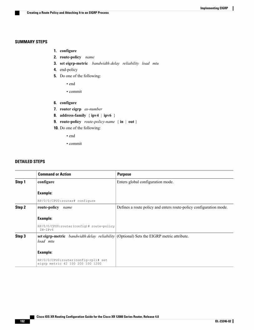
SUMMARY STEPS
1. configure2. route-policy name3. set eigrp-metric bandwidth delay reliability load mtu4. end-policy5. Do one of the following:
• end
• commit
6. configure7. router eigrp as-number8. address-family { ipv4 | ipv6 }9. route-policy route-policy-name { in | out }10. Do one of the following:
• end
• commit
DETAILED STEPS
PurposeCommand or Action
Enters global configuration mode.configure
Example:
RP/0/0/CPU0:router# configure
Step 1
Defines a route policy and enters route-policy configuration mode.route-policy name
Example:
RP/0/0/CPU0:router(config)# route-policyIN-IPv4
Step 2
(Optional) Sets the EIGRP metric attribute.set eigrp-metric bandwidth delay reliabilityload mtu
Step 3
Example:
RP/0/0/CPU0:router(config-rpl)# seteigrp metric 42 100 200 100 1200
Cisco IOS XR Routing Configuration Guide for the Cisco XR 12000 Series Router, Release 4.0192 OL-23246-02
Implementing EIGRPCreating a Route Policy and Attaching It to an EIGRP Process
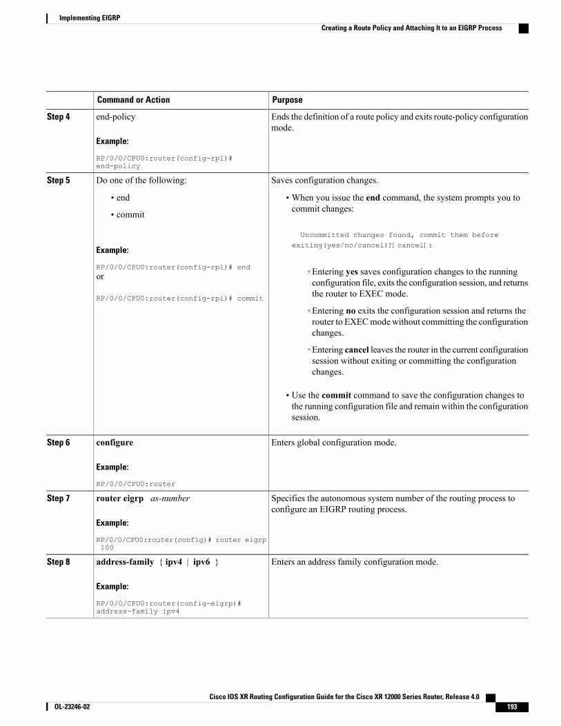
PurposeCommand or Action
Ends the definition of a route policy and exits route-policy configurationmode.
end-policy
Example:
RP/0/0/CPU0:router(config-rpl)#end-policy
Step 4
Saves configuration changes.Do one of the following:Step 5
• end •When you issue the end command, the system prompts you tocommit changes:
Uncommitted changes found, commit them before
• commit
Example:
RP/0/0/CPU0:router(config-rpl)# end
exiting(yes/no/cancel)?[cancel]:
◦Entering yes saves configuration changes to the runningconfiguration file, exits the configuration session, and returnsthe router to EXEC mode.
or
RP/0/0/CPU0:router(config-rpl)# commit
◦Entering no exits the configuration session and returns therouter to EXECmodewithout committing the configurationchanges.
◦Entering cancel leaves the router in the current configurationsession without exiting or committing the configurationchanges.
• Use the commit command to save the configuration changes tothe running configuration file and remain within the configurationsession.
Enters global configuration mode.configure
Example:
RP/0/0/CPU0:router
Step 6
Specifies the autonomous system number of the routing process toconfigure an EIGRP routing process.
router eigrp as-number
Example:
RP/0/0/CPU0:router(config)# router eigrp100
Step 7
Enters an address family configuration mode.address-family { ipv4 | ipv6 }
Example:
RP/0/0/CPU0:router(config-eigrp)#address-family ipv4
Step 8
Cisco IOS XR Routing Configuration Guide for the Cisco XR 12000 Series Router, Release 4.0 OL-23246-02 193
Implementing EIGRPCreating a Route Policy and Attaching It to an EIGRP Process
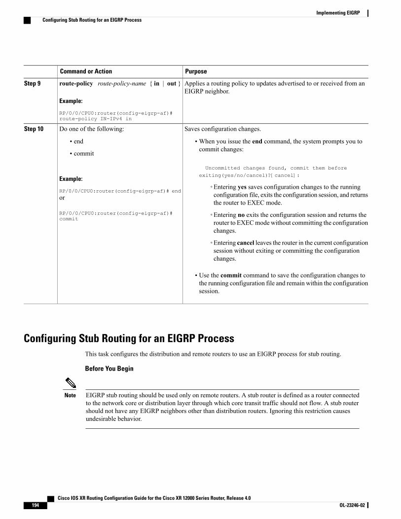
PurposeCommand or Action
Applies a routing policy to updates advertised to or received from anEIGRP neighbor.
route-policy route-policy-name { in | out }
Example:
RP/0/0/CPU0:router(config-eigrp-af)#route-policy IN-IPv4 in
Step 9
Saves configuration changes.Do one of the following:Step 10
• end •When you issue the end command, the system prompts you tocommit changes:
Uncommitted changes found, commit them beforeexiting(yes/no/cancel)?[cancel]:
• commit
Example:
RP/0/0/CPU0:router(config-eigrp-af)# end◦Entering yes saves configuration changes to the runningconfiguration file, exits the configuration session, and returnsthe router to EXEC mode.
or
RP/0/0/CPU0:router(config-eigrp-af)#commit
◦Entering no exits the configuration session and returns therouter to EXECmodewithout committing the configurationchanges.
◦Entering cancel leaves the router in the current configurationsession without exiting or committing the configurationchanges.
• Use the commit command to save the configuration changes tothe running configuration file and remain within the configurationsession.
Configuring Stub Routing for an EIGRP ProcessThis task configures the distribution and remote routers to use an EIGRP process for stub routing.
Before You Begin
EIGRP stub routing should be used only on remote routers. A stub router is defined as a router connectedto the network core or distribution layer through which core transit traffic should not flow. A stub routershould not have any EIGRP neighbors other than distribution routers. Ignoring this restriction causesundesirable behavior.
Note
Cisco IOS XR Routing Configuration Guide for the Cisco XR 12000 Series Router, Release 4.0194 OL-23246-02
Implementing EIGRPConfiguring Stub Routing for an EIGRP Process

SUMMARY STEPS
1. configure2. router eigrp as-number3. address-family { ipv4 | ipv6 }4. stub [ receive-only | {[ connected ] [ redistributed ] [ static ] [ summary ]}]5. Do one of the following:
• end
• commit
6. show eigrp [ ipv4 | ipv6 ] [ vrf { vrf-name | all }] neighbors [ as-number ] [ detail ] [ typeinterface-path-id | static ]
DETAILED STEPS
PurposeCommand or Action
Enters global configuration mode.configure
Example:RRP/0/0/CPU0:router# configure
Step 1
Specifies the autonomous system number of the routing process toconfigure an EIGRP routing process.
router eigrp as-number
Example:
RP/0/0/CPU0:router(config)# router eigrp100
Step 2
Enters an address family configuration mode.address-family { ipv4 | ipv6 }
Example:
RP/0/0/CPU0:router(config-eigrp)#address-family ipv4
Step 3
Configures a router as a stub for EIGRP.stub [ receive-only | {[ connected ] [redistributed ] [ static ] [ summary ]}]
Step 4
Example:
RP/0/0/CPU0:router(config-eigrp-af)# stubreceive-only
Saves configuration changes.Do one of the following:Step 5
• end •When you issue the end command, the system prompts youto commit changes:
Uncommitted changes found, commit them before
• commit
Cisco IOS XR Routing Configuration Guide for the Cisco XR 12000 Series Router, Release 4.0 OL-23246-02 195
Implementing EIGRPConfiguring Stub Routing for an EIGRP Process
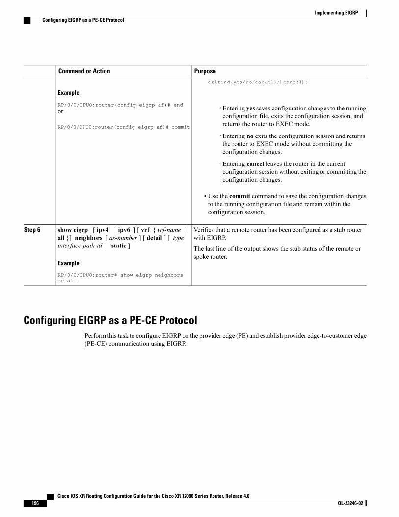
PurposeCommand or Action
Example:
RP/0/0/CPU0:router(config-eigrp-af)# end
exiting(yes/no/cancel)?[cancel]:
◦Entering yes saves configuration changes to the runningconfiguration file, exits the configuration session, andreturns the router to EXEC mode.
or
RP/0/0/CPU0:router(config-eigrp-af)# commit
◦Entering no exits the configuration session and returnsthe router to EXEC mode without committing theconfiguration changes.
◦Entering cancel leaves the router in the currentconfiguration session without exiting or committing theconfiguration changes.
• Use the commit command to save the configuration changesto the running configuration file and remain within theconfiguration session.
Verifies that a remote router has been configured as a stub routerwith EIGRP.
show eigrp [ ipv4 | ipv6 ] [ vrf { vrf-name |all }] neighbors [ as-number ] [ detail ] [ typeinterface-path-id | static ]
Step 6
The last line of the output shows the stub status of the remote orspoke router.
Example:
RP/0/0/CPU0:router# show eigrp neighborsdetail
Configuring EIGRP as a PE-CE ProtocolPerform this task to configure EIGRP on the provider edge (PE) and establish provider edge-to-customer edge(PE-CE) communication using EIGRP.
Cisco IOS XR Routing Configuration Guide for the Cisco XR 12000 Series Router, Release 4.0196 OL-23246-02
Implementing EIGRPConfiguring EIGRP as a PE-CE Protocol
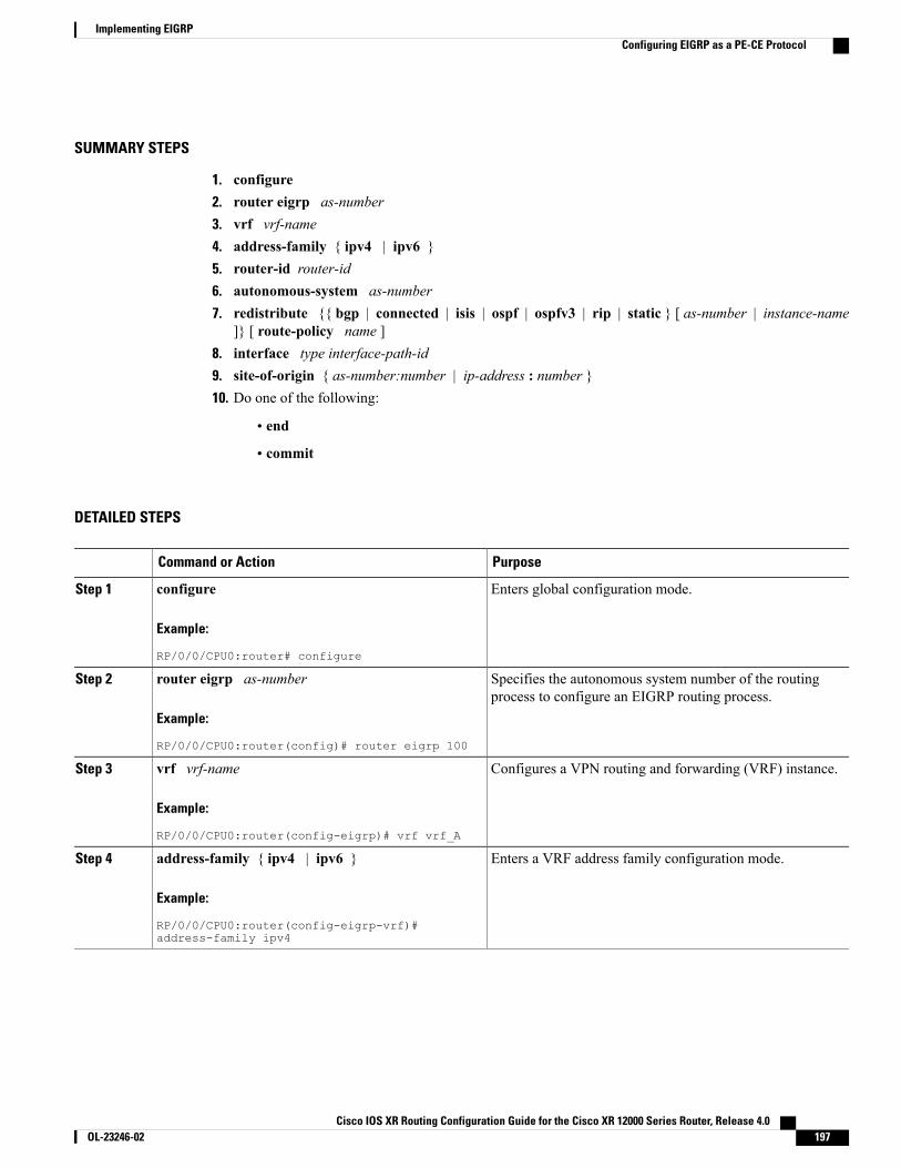
SUMMARY STEPS
1. configure2. router eigrp as-number3. vrf vrf-name4. address-family { ipv4 | ipv6 }5. router-id router-id6. autonomous-system as-number7. redistribute {{ bgp | connected | isis | ospf | ospfv3 | rip | static } [ as-number | instance-name
]} [ route-policy name ]8. interface type interface-path-id9. site-of-origin { as-number:number | ip-address : number }10. Do one of the following:
• end
• commit
DETAILED STEPS
PurposeCommand or Action
Enters global configuration mode.configure
Example:
RP/0/0/CPU0:router# configure
Step 1
Specifies the autonomous system number of the routingprocess to configure an EIGRP routing process.
router eigrp as-number
Example:
RP/0/0/CPU0:router(config)# router eigrp 100
Step 2
Configures a VPN routing and forwarding (VRF) instance.vrf vrf-name
Example:
RP/0/0/CPU0:router(config-eigrp)# vrf vrf_A
Step 3
Enters a VRF address family configuration mode.address-family { ipv4 | ipv6 }
Example:
RP/0/0/CPU0:router(config-eigrp-vrf)#address-family ipv4
Step 4
Cisco IOS XR Routing Configuration Guide for the Cisco XR 12000 Series Router, Release 4.0 OL-23246-02 197
Implementing EIGRPConfiguring EIGRP as a PE-CE Protocol
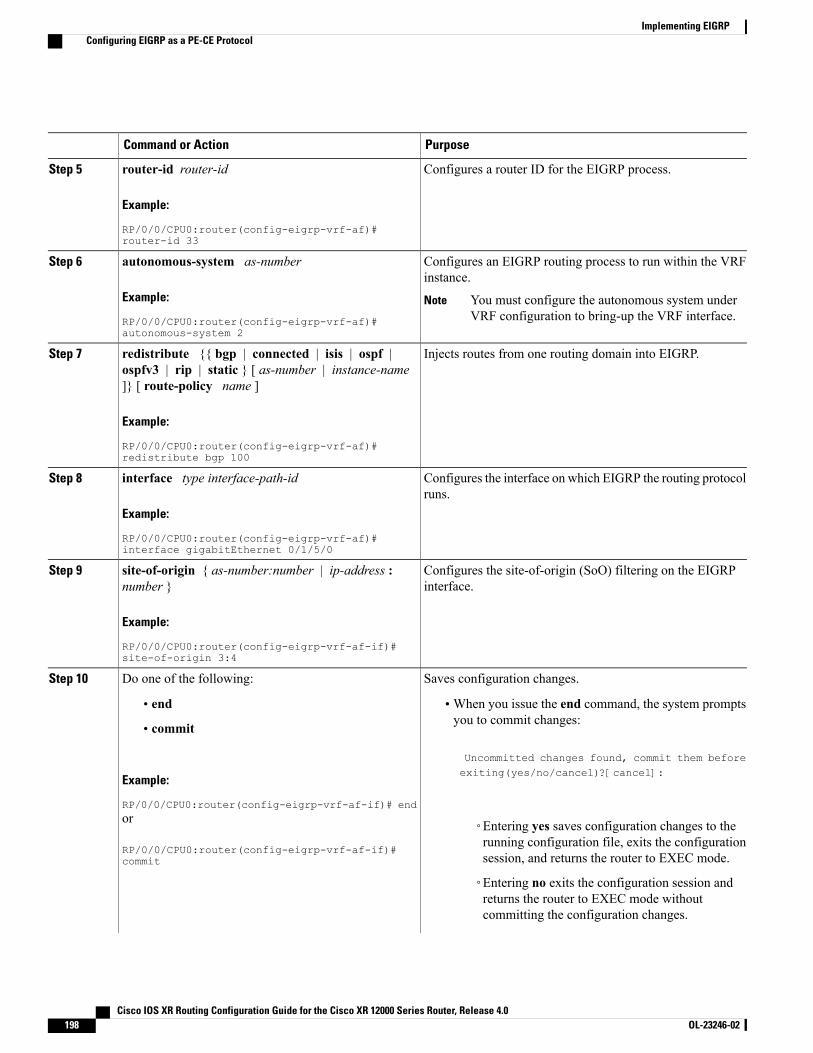
PurposeCommand or Action
Configures a router ID for the EIGRP process.router-id router-id
Example:
RP/0/0/CPU0:router(config-eigrp-vrf-af)#router-id 33
Step 5
Configures an EIGRP routing process to run within the VRFinstance.
autonomous-system as-number
Example:
RP/0/0/CPU0:router(config-eigrp-vrf-af)#autonomous-system 2
Step 6
You must configure the autonomous system underVRF configuration to bring-up the VRF interface.
Note
Injects routes from one routing domain into EIGRP.redistribute {{ bgp | connected | isis | ospf |ospfv3 | rip | static } [ as-number | instance-name]} [ route-policy name ]
Step 7
Example:
RP/0/0/CPU0:router(config-eigrp-vrf-af)#redistribute bgp 100
Configures the interface on which EIGRP the routing protocolruns.
interface type interface-path-id
Example:
RP/0/0/CPU0:router(config-eigrp-vrf-af)#interface gigabitEthernet 0/1/5/0
Step 8
Configures the site-of-origin (SoO) filtering on the EIGRPinterface.
site-of-origin { as-number:number | ip-address :number }
Example:
RP/0/0/CPU0:router(config-eigrp-vrf-af-if)#site-of-origin 3:4
Step 9
Saves configuration changes.Do one of the following:Step 10
• end •When you issue the end command, the system promptsyou to commit changes:
Uncommitted changes found, commit them before
• commit
Example:
RP/0/0/CPU0:router(config-eigrp-vrf-af-if)# end
exiting(yes/no/cancel)?[cancel]:
or
RP/0/0/CPU0:router(config-eigrp-vrf-af-if)#commit
◦Entering yes saves configuration changes to therunning configuration file, exits the configurationsession, and returns the router to EXEC mode.
◦Entering no exits the configuration session andreturns the router to EXEC mode withoutcommitting the configuration changes.
Cisco IOS XR Routing Configuration Guide for the Cisco XR 12000 Series Router, Release 4.0198 OL-23246-02
Implementing EIGRPConfiguring EIGRP as a PE-CE Protocol
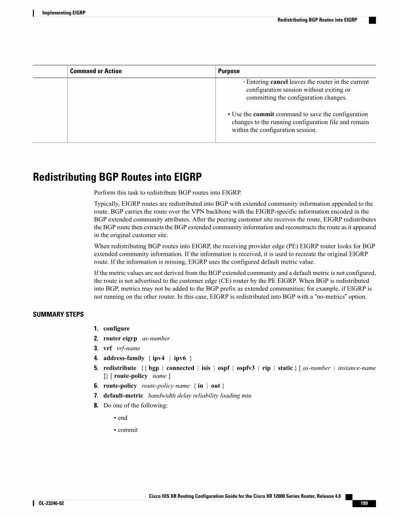
PurposeCommand or Action
◦Entering cancel leaves the router in the currentconfiguration session without exiting orcommitting the configuration changes.
• Use the commit command to save the configurationchanges to the running configuration file and remainwithin the configuration session.
Redistributing BGP Routes into EIGRPPerform this task to redistribute BGP routes into EIGRP.
Typically, EIGRP routes are redistributed into BGP with extended community information appended to theroute. BGP carries the route over the VPN backbone with the EIGRP-specific information encoded in theBGP extended community attributes. After the peering customer site receives the route, EIGRP redistributesthe BGP route then extracts the BGP extended community information and reconstructs the route as it appearedin the original customer site.
When redistributing BGP routes into EIGRP, the receiving provider edge (PE) EIGRP router looks for BGPextended community information. If the information is received, it is used to recreate the original EIGRProute. If the information is missing, EIGRP uses the configured default metric value.
If the metric values are not derived from the BGP extended community and a default metric is not configured,the route is not advertised to the customer edge (CE) router by the PE EIGRP. When BGP is redistributedinto BGP, metrics may not be added to the BGP prefix as extended communities; for example, if EIGRP isnot running on the other router. In this case, EIGRP is redistributed into BGP with a “no-metrics” option.
SUMMARY STEPS
1. configure2. router eigrp as-number3. vrf vrf-name4. address-family { ipv4 | ipv6 }5. redistribute {{ bgp | connected | isis | ospf | ospfv3 | rip | static } [ as-number | instance-name
]} [ route-policy name ]6. route-policy route-policy-name { in | out }7. default-metric bandwidth delay reliability loading mtu8. Do one of the following:
• end
• commit
Cisco IOS XR Routing Configuration Guide for the Cisco XR 12000 Series Router, Release 4.0 OL-23246-02 199
Implementing EIGRPRedistributing BGP Routes into EIGRP
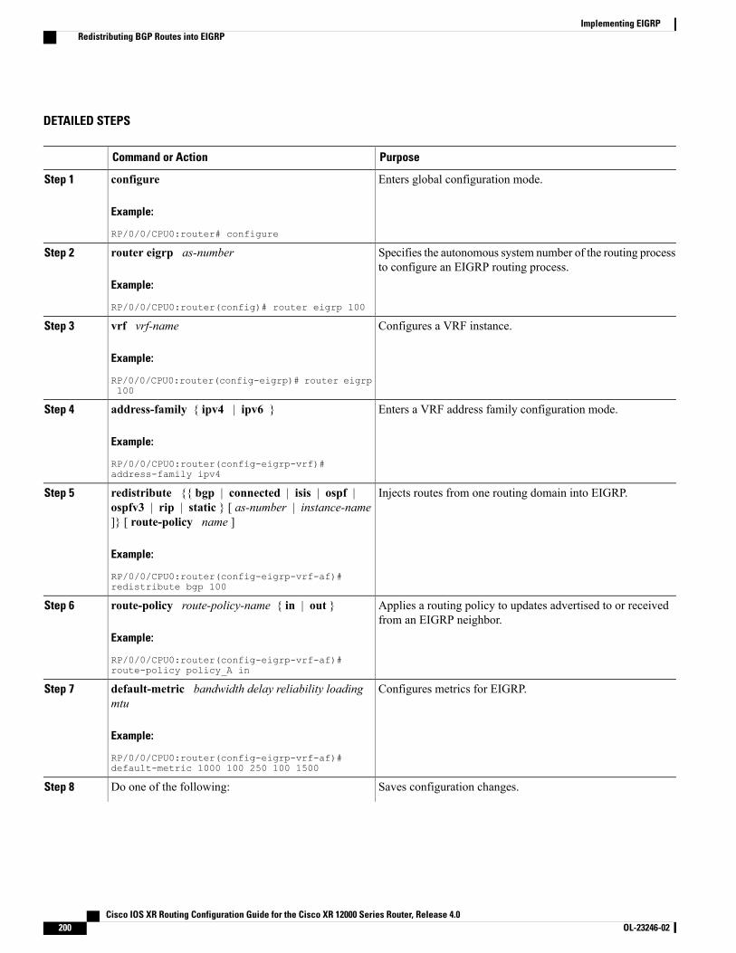
DETAILED STEPS
PurposeCommand or Action
Enters global configuration mode.configure
Example:
RP/0/0/CPU0:router# configure
Step 1
Specifies the autonomous system number of the routing processto configure an EIGRP routing process.
router eigrp as-number
Example:
RP/0/0/CPU0:router(config)# router eigrp 100
Step 2
Configures a VRF instance.vrf vrf-name
Example:
RP/0/0/CPU0:router(config-eigrp)# router eigrp100
Step 3
Enters a VRF address family configuration mode.address-family { ipv4 | ipv6 }
Example:
RP/0/0/CPU0:router(config-eigrp-vrf)#address-family ipv4
Step 4
Injects routes from one routing domain into EIGRP.redistribute {{ bgp | connected | isis | ospf |ospfv3 | rip | static } [ as-number | instance-name]} [ route-policy name ]
Step 5
Example:
RP/0/0/CPU0:router(config-eigrp-vrf-af)#redistribute bgp 100
Applies a routing policy to updates advertised to or receivedfrom an EIGRP neighbor.
route-policy route-policy-name { in | out }
Example:
RP/0/0/CPU0:router(config-eigrp-vrf-af)#route-policy policy_A in
Step 6
Configures metrics for EIGRP.default-metric bandwidth delay reliability loadingmtu
Step 7
Example:
RP/0/0/CPU0:router(config-eigrp-vrf-af)#default-metric 1000 100 250 100 1500
Saves configuration changes.Do one of the following:Step 8
Cisco IOS XR Routing Configuration Guide for the Cisco XR 12000 Series Router, Release 4.0200 OL-23246-02
Implementing EIGRPRedistributing BGP Routes into EIGRP
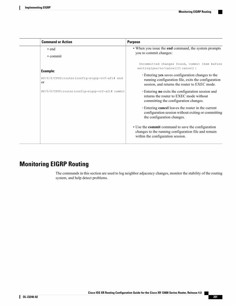
PurposeCommand or Action
•When you issue the end command, the system promptsyou to commit changes:
Uncommitted changes found, commit them beforeexiting(yes/no/cancel)?[cancel]:
• end
• commit
Example:
RP/0/0/CPU0:router(config-eigrp-vrf-af)# end◦Entering yes saves configuration changes to therunning configuration file, exits the configurationsession, and returns the router to EXEC mode.or
RP/0/0/CPU0:router(config-eigrp-vrf-af)# commit ◦Entering no exits the configuration session andreturns the router to EXEC mode withoutcommitting the configuration changes.
◦Entering cancel leaves the router in the currentconfiguration session without exiting or committingthe configuration changes.
• Use the commit command to save the configurationchanges to the running configuration file and remainwithin the configuration session.
Monitoring EIGRP RoutingThe commands in this section are used to log neighbor adjacency changes, monitor the stability of the routingsystem, and help detect problems.
Cisco IOS XR Routing Configuration Guide for the Cisco XR 12000 Series Router, Release 4.0 OL-23246-02 201
Implementing EIGRPMonitoring EIGRP Routing
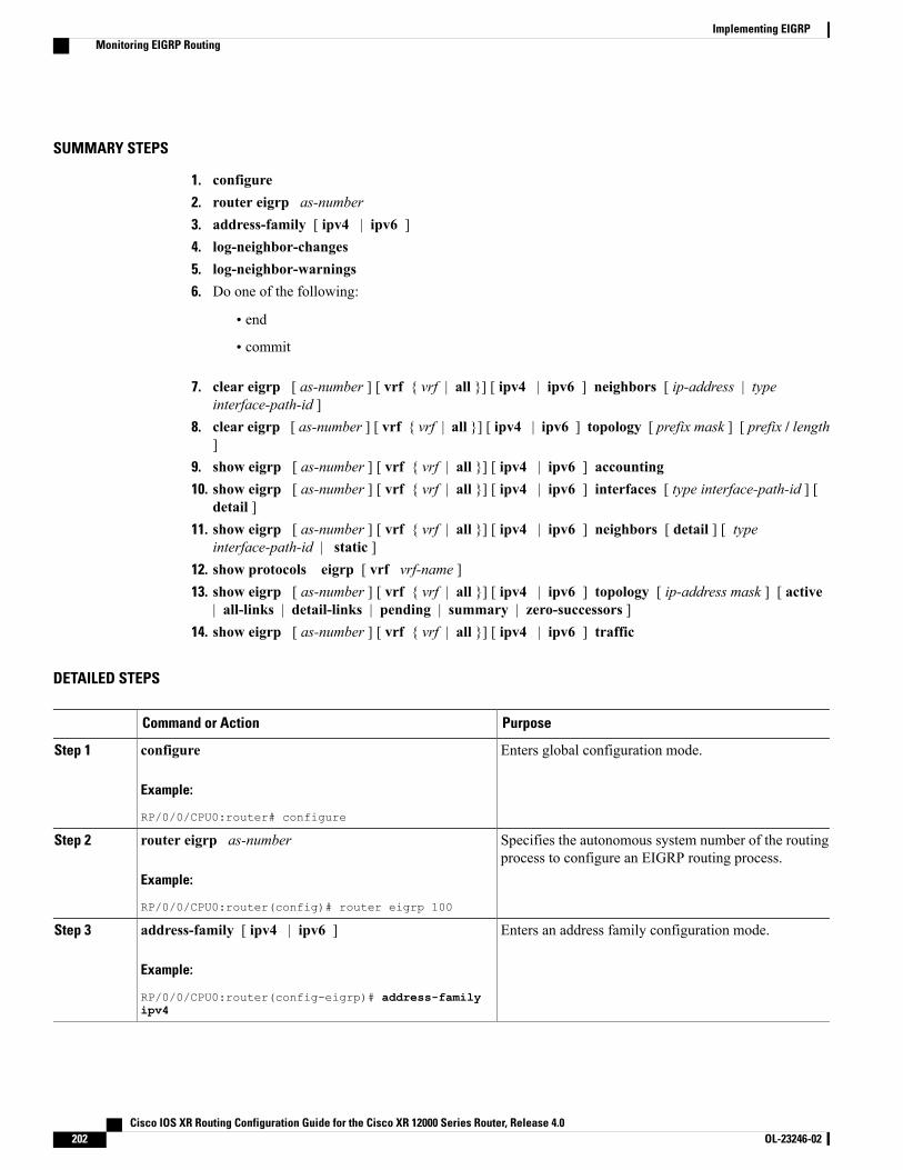
SUMMARY STEPS
1. configure2. router eigrp as-number3. address-family [ ipv4 | ipv6 ]4. log-neighbor-changes5. log-neighbor-warnings6. Do one of the following:
• end
• commit
7. clear eigrp [ as-number ] [ vrf { vrf | all }] [ ipv4 | ipv6 ] neighbors [ ip-address | typeinterface-path-id ]
8. clear eigrp [ as-number ] [ vrf { vrf | all }] [ ipv4 | ipv6 ] topology [ prefix mask ] [ prefix / length]
9. show eigrp [ as-number ] [ vrf { vrf | all }] [ ipv4 | ipv6 ] accounting10. show eigrp [ as-number ] [ vrf { vrf | all }] [ ipv4 | ipv6 ] interfaces [ type interface-path-id ] [
detail ]11. show eigrp [ as-number ] [ vrf { vrf | all }] [ ipv4 | ipv6 ] neighbors [ detail ] [ type
interface-path-id | static ]12. show protocols eigrp [ vrf vrf-name ]13. show eigrp [ as-number ] [ vrf { vrf | all }] [ ipv4 | ipv6 ] topology [ ip-address mask ] [ active
| all-links | detail-links | pending | summary | zero-successors ]14. show eigrp [ as-number ] [ vrf { vrf | all }] [ ipv4 | ipv6 ] traffic
DETAILED STEPS
PurposeCommand or Action
Enters global configuration mode.configure
Example:
RP/0/0/CPU0:router# configure
Step 1
Specifies the autonomous system number of the routingprocess to configure an EIGRP routing process.
router eigrp as-number
Example:
RP/0/0/CPU0:router(config)# router eigrp 100
Step 2
Enters an address family configuration mode.address-family [ ipv4 | ipv6 ]
Example:
RP/0/0/CPU0:router(config-eigrp)# address-familyipv4
Step 3
Cisco IOS XR Routing Configuration Guide for the Cisco XR 12000 Series Router, Release 4.0202 OL-23246-02
Implementing EIGRPMonitoring EIGRP Routing

PurposeCommand or Action
Enables the logging of changes in EIGRP neighboradjacencies.
log-neighbor-changes
Example:
RP/0/0/CPU0:router(config-eigrp-af)#log-neighbor-changes
Step 4
Enables the logging of EIGRP neighbor warningmessages.
log-neighbor-warnings
Example:
RP/0/0/CPU0:router(config-eigrp-af)#log-neighbor-warnings
Step 5
Saves configuration changes.Do one of the following:Step 6
• end •When you issue the end command, the systemprompts you to commit changes:
Uncommitted changes found, commit thembefore exiting(yes/no/cancel)?[cancel]:
• commit
Example:
RP/0/0/CPU0:router(config-eigrp-af)# end◦Entering yes saves configuration changes tothe running configuration file, exits theor
RP/0/0/CPU0:router(config-eigrp-af)# commit
configuration session, and returns the routerto EXEC mode.
◦Entering no exits the configuration sessionand returns the router to EXECmodewithoutcommitting the configuration changes.
◦Entering cancel leaves the router in thecurrent configuration session without exitingor committing the configuration changes.
• Use the commit command to save the configurationchanges to the running configuration file andremain within the configuration session.
Deletes EIGRP and VPN neighbor entries from theappropriate table.
clear eigrp [ as-number ] [ vrf { vrf | all }] [ ipv4 | ipv6] neighbors [ ip-address | type interface-path-id ]
Example:
RP/0/0/CPU0:routerr# clear eigrp 20 neighbors0/1/0/0
Step 7
Deletes EIGRP and VRF topology entries from theappropriate tab.
clear eigrp [ as-number ] [ vrf { vrf | all }] [ ipv4 | ipv6] topology [ prefix mask ] [ prefix / length ]
Example:
RP/0/0/CPU0:router# clear eigrp topology
Step 8
Cisco IOS XR Routing Configuration Guide for the Cisco XR 12000 Series Router, Release 4.0 OL-23246-02 203
Implementing EIGRPMonitoring EIGRP Routing
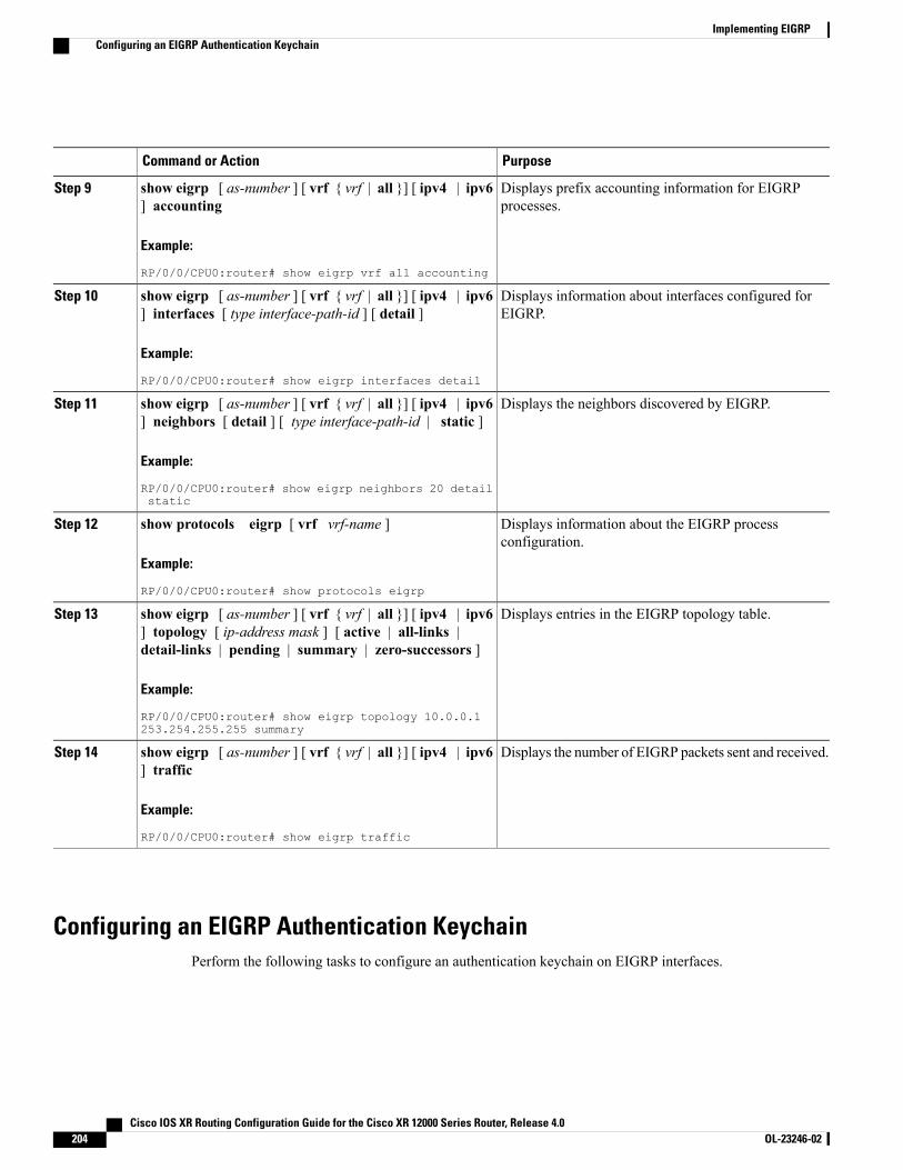
PurposeCommand or Action
Displays prefix accounting information for EIGRPprocesses.
show eigrp [ as-number ] [ vrf { vrf | all }] [ ipv4 | ipv6] accounting
Example:
RP/0/0/CPU0:router# show eigrp vrf all accounting
Step 9
Displays information about interfaces configured forEIGRP.
show eigrp [ as-number ] [ vrf { vrf | all }] [ ipv4 | ipv6] interfaces [ type interface-path-id ] [ detail ]
Example:
RP/0/0/CPU0:router# show eigrp interfaces detail
Step 10
Displays the neighbors discovered by EIGRP.show eigrp [ as-number ] [ vrf { vrf | all }] [ ipv4 | ipv6] neighbors [ detail ] [ type interface-path-id | static ]
Step 11
Example:
RP/0/0/CPU0:router# show eigrp neighbors 20 detailstatic
Displays information about the EIGRP processconfiguration.
show protocols eigrp [ vrf vrf-name ]
Example:
RP/0/0/CPU0:router# show protocols eigrp
Step 12
Displays entries in the EIGRP topology table.show eigrp [ as-number ] [ vrf { vrf | all }] [ ipv4 | ipv6] topology [ ip-address mask ] [ active | all-links |detail-links | pending | summary | zero-successors ]
Step 13
Example:
RP/0/0/CPU0:router# show eigrp topology 10.0.0.1253.254.255.255 summary
Displays the number of EIGRP packets sent and received.show eigrp [ as-number ] [ vrf { vrf | all }] [ ipv4 | ipv6] traffic
Step 14
Example:
RP/0/0/CPU0:router# show eigrp traffic
Configuring an EIGRP Authentication KeychainPerform the following tasks to configure an authentication keychain on EIGRP interfaces.
Cisco IOS XR Routing Configuration Guide for the Cisco XR 12000 Series Router, Release 4.0204 OL-23246-02
Implementing EIGRPConfiguring an EIGRP Authentication Keychain
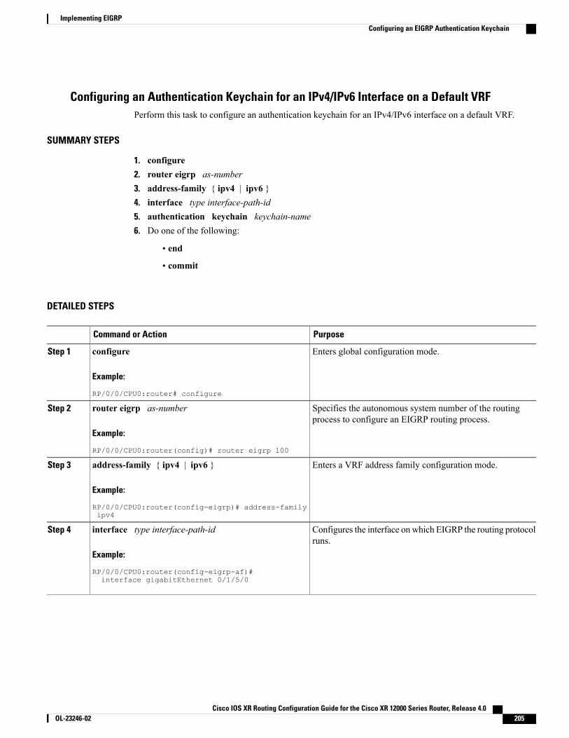
Configuring an Authentication Keychain for an IPv4/IPv6 Interface on a Default VRFPerform this task to configure an authentication keychain for an IPv4/IPv6 interface on a default VRF.
SUMMARY STEPS
1. configure2. router eigrp as-number3. address-family { ipv4 | ipv6 }4. interface type interface-path-id5. authentication keychain keychain-name6. Do one of the following:
• end
• commit
DETAILED STEPS
PurposeCommand or Action
Enters global configuration mode.configure
Example:
RP/0/0/CPU0:router# configure
Step 1
Specifies the autonomous system number of the routingprocess to configure an EIGRP routing process.
router eigrp as-number
Example:
RP/0/0/CPU0:router(config)# router eigrp 100
Step 2
Enters a VRF address family configuration mode.address-family { ipv4 | ipv6 }
Example:
RP/0/0/CPU0:router(config-eigrp)# address-familyipv4
Step 3
Configures the interface on which EIGRP the routing protocolruns.
interface type interface-path-id
Example:
RP/0/0/CPU0:router(config-eigrp-af)#
Step 4
interface gigabitEthernet 0/1/5/0
Cisco IOS XR Routing Configuration Guide for the Cisco XR 12000 Series Router, Release 4.0 OL-23246-02 205
Implementing EIGRPConfiguring an EIGRP Authentication Keychain
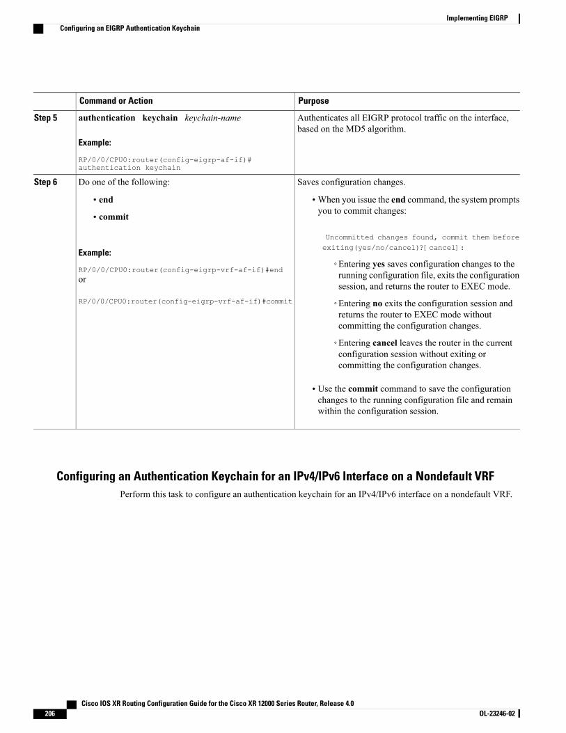
PurposeCommand or Action
Authenticates all EIGRP protocol traffic on the interface,based on the MD5 algorithm.
authentication keychain keychain-name
Example:
RP/0/0/CPU0:router(config-eigrp-af-if)#authentication keychain
Step 5
Saves configuration changes.Do one of the following:Step 6
• end •When you issue the end command, the system promptsyou to commit changes:
Uncommitted changes found, commit them beforeexiting(yes/no/cancel)?[cancel]:
• commit
Example:
RP/0/0/CPU0:router(config-eigrp-vrf-af-if)#end◦Entering yes saves configuration changes to therunning configuration file, exits the configurationsession, and returns the router to EXEC mode.
or
RP/0/0/CPU0:router(config-eigrp-vrf-af-if)#commit ◦Entering no exits the configuration session andreturns the router to EXEC mode withoutcommitting the configuration changes.
◦Entering cancel leaves the router in the currentconfiguration session without exiting orcommitting the configuration changes.
• Use the commit command to save the configurationchanges to the running configuration file and remainwithin the configuration session.
Configuring an Authentication Keychain for an IPv4/IPv6 Interface on a Nondefault VRFPerform this task to configure an authentication keychain for an IPv4/IPv6 interface on a nondefault VRF.
Cisco IOS XR Routing Configuration Guide for the Cisco XR 12000 Series Router, Release 4.0206 OL-23246-02
Implementing EIGRPConfiguring an EIGRP Authentication Keychain
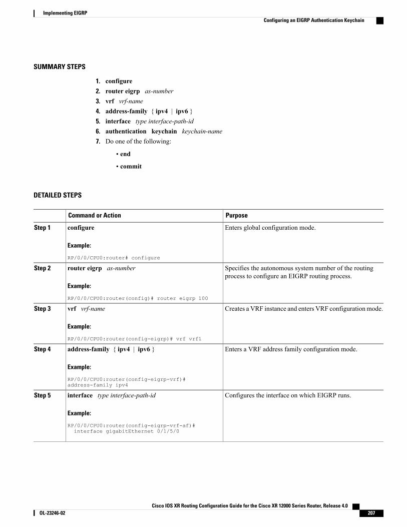
SUMMARY STEPS
1. configure2. router eigrp as-number3. vrf vrf-name4. address-family { ipv4 | ipv6 }5. interface type interface-path-id6. authentication keychain keychain-name7. Do one of the following:
• end
• commit
DETAILED STEPS
PurposeCommand or Action
Enters global configuration mode.configure
Example:
RP/0/0/CPU0:router# configure
Step 1
Specifies the autonomous system number of the routingprocess to configure an EIGRP routing process.
router eigrp as-number
Example:
RP/0/0/CPU0:router(config)# router eigrp 100
Step 2
Creates a VRF instance and enters VRF configurationmode.vrf vrf-name
Example:
RP/0/0/CPU0:router(config-eigrp)# vrf vrf1
Step 3
Enters a VRF address family configuration mode.address-family { ipv4 | ipv6 }
Example:
RP/0/0/CPU0:router(config-eigrp-vrf)#address-family ipv4
Step 4
Configures the interface on which EIGRP runs.interface type interface-path-id
Example:
RP/0/0/CPU0:router(config-eigrp-vrf-af)#
Step 5
interface gigabitEthernet 0/1/5/0
Cisco IOS XR Routing Configuration Guide for the Cisco XR 12000 Series Router, Release 4.0 OL-23246-02 207
Implementing EIGRPConfiguring an EIGRP Authentication Keychain
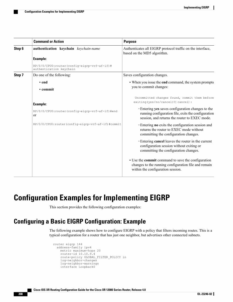
PurposeCommand or Action
Authenticates all EIGRP protocol traffic on the interface,based on the MD5 algorithm.
authentication keychain keychain-name
Example:
RP/0/0/CPU0:router(config-eigrp-vrf-af-if)#authentication keychain
Step 6
Saves configuration changes.Do one of the following:Step 7
• end •When you issue the end command, the system promptsyou to commit changes:
Uncommitted changes found, commit them beforeexiting(yes/no/cancel)?[cancel]:
• commit
Example:
RP/0/0/CPU0:router(config-eigrp-vrf-af-if)#end◦Entering yes saves configuration changes to therunning configuration file, exits the configurationsession, and returns the router to EXEC mode.
or
RP/0/0/CPU0:router(config-eigrp-vrf-af-if)#commit ◦Entering no exits the configuration session andreturns the router to EXEC mode withoutcommitting the configuration changes.
◦Entering cancel leaves the router in the currentconfiguration session without exiting orcommitting the configuration changes.
• Use the commit command to save the configurationchanges to the running configuration file and remainwithin the configuration session.
Configuration Examples for Implementing EIGRPThis section provides the following configuration examples:
Configuring a Basic EIGRP Configuration: ExampleThe following example shows how to configure EIGRP with a policy that filters incoming routes. This is atypical configuration for a router that has just one neighbor, but advertises other connected subnets.
router eigrp 144address-family ipv4metric maximum-hops 20router-id 10.10.9.4route-policy GLOBAL_FILTER_POLICY inlog-neighbor-changeslog-neighbor-warningsinterface Loopback0
Cisco IOS XR Routing Configuration Guide for the Cisco XR 12000 Series Router, Release 4.0208 OL-23246-02
Implementing EIGRPConfiguration Examples for Implementing EIGRP
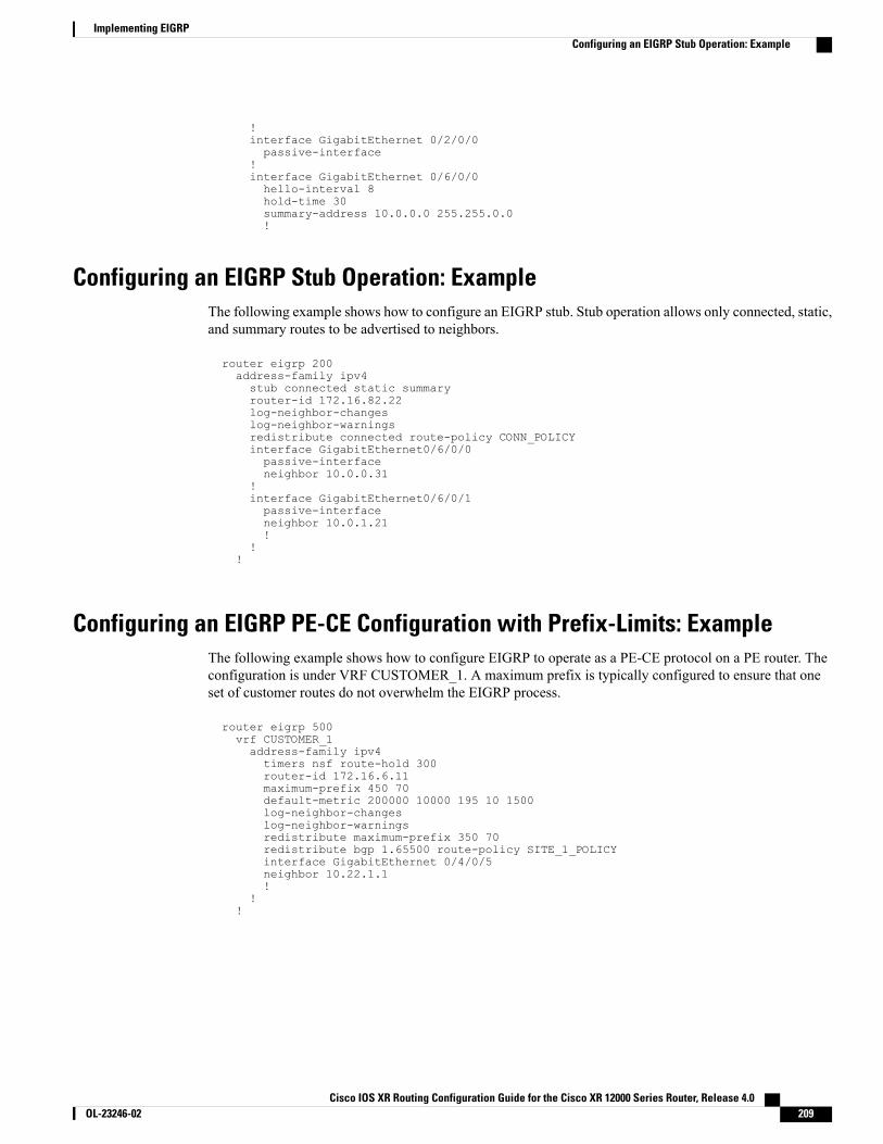
!interface GigabitEthernet 0/2/0/0passive-interface
!interface GigabitEthernet 0/6/0/0hello-interval 8hold-time 30summary-address 10.0.0.0 255.255.0.0!
Configuring an EIGRP Stub Operation: ExampleThe following example shows how to configure an EIGRP stub. Stub operation allows only connected, static,and summary routes to be advertised to neighbors.
router eigrp 200address-family ipv4stub connected static summaryrouter-id 172.16.82.22log-neighbor-changeslog-neighbor-warningsredistribute connected route-policy CONN_POLICYinterface GigabitEthernet0/6/0/0passive-interfaceneighbor 10.0.0.31
!interface GigabitEthernet0/6/0/1passive-interfaceneighbor 10.0.1.21!
!!
Configuring an EIGRP PE-CE Configuration with Prefix-Limits: ExampleThe following example shows how to configure EIGRP to operate as a PE-CE protocol on a PE router. Theconfiguration is under VRF CUSTOMER_1. A maximum prefix is typically configured to ensure that oneset of customer routes do not overwhelm the EIGRP process.
router eigrp 500vrf CUSTOMER_1address-family ipv4timers nsf route-hold 300router-id 172.16.6.11maximum-prefix 450 70default-metric 200000 10000 195 10 1500log-neighbor-changeslog-neighbor-warningsredistribute maximum-prefix 350 70redistribute bgp 1.65500 route-policy SITE_1_POLICYinterface GigabitEthernet 0/4/0/5neighbor 10.22.1.1!
!!
Cisco IOS XR Routing Configuration Guide for the Cisco XR 12000 Series Router, Release 4.0 OL-23246-02 209
Implementing EIGRPConfiguring an EIGRP Stub Operation: Example
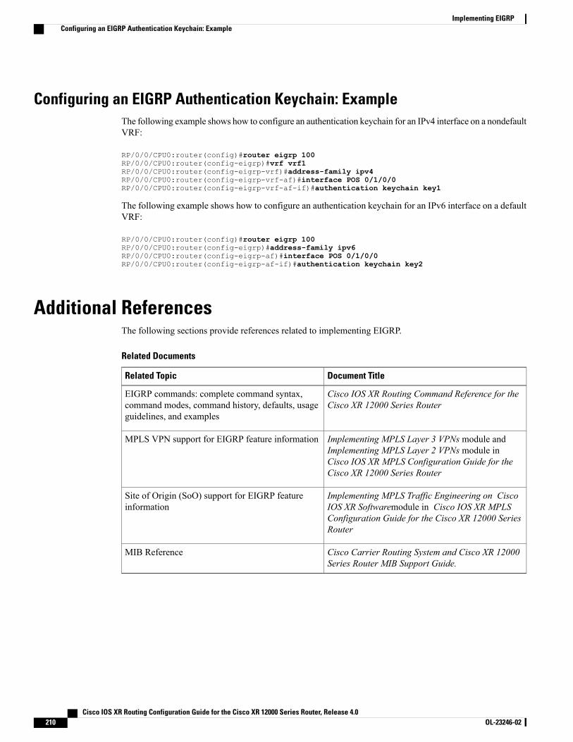
Configuring an EIGRP Authentication Keychain: ExampleThe following example shows how to configure an authentication keychain for an IPv4 interface on a nondefaultVRF:
RP/0/0/CPU0:router(config)#router eigrp 100RP/0/0/CPU0:router(config-eigrp)#vrf vrf1RP/0/0/CPU0:router(config-eigrp-vrf)#address-family ipv4RP/0/0/CPU0:router(config-eigrp-vrf-af)#interface POS 0/1/0/0RP/0/0/CPU0:router(config-eigrp-vrf-af-if)#authentication keychain key1
The following example shows how to configure an authentication keychain for an IPv6 interface on a defaultVRF:
RP/0/0/CPU0:router(config)#router eigrp 100RP/0/0/CPU0:router(config-eigrp)#address-family ipv6RP/0/0/CPU0:router(config-eigrp-af)#interface POS 0/1/0/0RP/0/0/CPU0:router(config-eigrp-af-if)#authentication keychain key2
Additional ReferencesThe following sections provide references related to implementing EIGRP.
Related Documents
Document TitleRelated Topic
Cisco IOS XR Routing Command Reference for theCisco XR 12000 Series Router
EIGRP commands: complete command syntax,command modes, command history, defaults, usageguidelines, and examples
Implementing MPLS Layer 3 VPNs module andImplementing MPLS Layer 2 VPNs module inCisco IOS XR MPLS Configuration Guide for theCisco XR 12000 Series Router
MPLS VPN support for EIGRP feature information
Implementing MPLS Traffic Engineering on CiscoIOS XR Softwaremodule in Cisco IOS XR MPLSConfiguration Guide for the Cisco XR 12000 SeriesRouter
Site of Origin (SoO) support for EIGRP featureinformation
Cisco Carrier Routing System and Cisco XR 12000Series Router MIB Support Guide.
MIB Reference
Cisco IOS XR Routing Configuration Guide for the Cisco XR 12000 Series Router, Release 4.0210 OL-23246-02
Implementing EIGRPConfiguring an EIGRP Authentication Keychain: Example
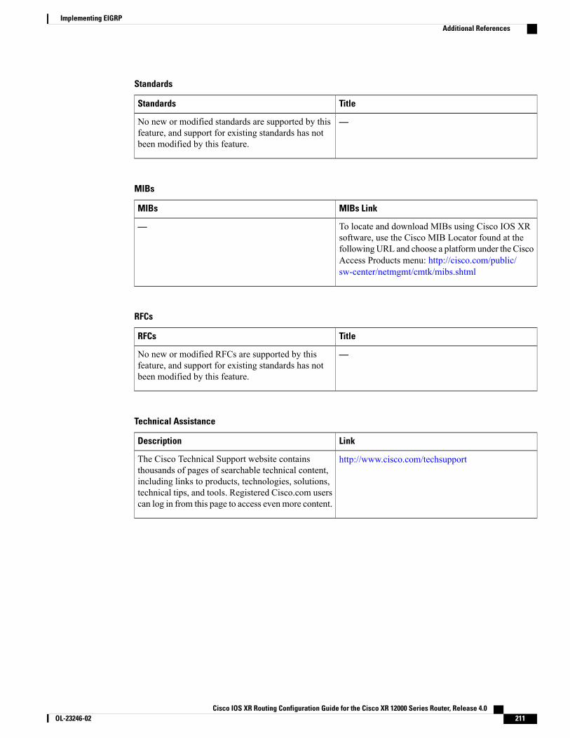
Standards
TitleStandards
—No new or modified standards are supported by thisfeature, and support for existing standards has notbeen modified by this feature.
MIBs
MIBs LinkMIBs
To locate and download MIBs using Cisco IOS XRsoftware, use the Cisco MIB Locator found at thefollowingURL and choose a platform under the CiscoAccess Products menu: http://cisco.com/public/sw-center/netmgmt/cmtk/mibs.shtml
—
RFCs
TitleRFCs
—No new or modified RFCs are supported by thisfeature, and support for existing standards has notbeen modified by this feature.
Technical Assistance
LinkDescription
http://www.cisco.com/techsupportThe Cisco Technical Support website containsthousands of pages of searchable technical content,including links to products, technologies, solutions,technical tips, and tools. Registered Cisco.com userscan log in from this page to access evenmore content.
Cisco IOS XR Routing Configuration Guide for the Cisco XR 12000 Series Router, Release 4.0 OL-23246-02 211
Implementing EIGRPAdditional References

Cisco IOS XR Routing Configuration Guide for the Cisco XR 12000 Series Router, Release 4.0212 OL-23246-02
Implementing EIGRPAdditional References

C H A P T E R 3Implementing IS-IS
Integrated Intermediate System-to-Intermediate System (IS-IS), Internet Protocol Version 4 (IPv4), is astandards-based Interior Gateway Protocol (IGP). Cisco IOS XR software implements the IP routingcapabilities described in International Organization for Standardization (ISO)/International EngineeringConsortium (IEC) 10589 and RFC 1995, and adds the standard extensions for single topology andmultitopology IS-IS for IP Version 6 (IPv6).
This module describes how to implement IS-IS (IPv4 and IPv6) on your Cisco IOS XR network.
For more information about IS-IS on Cisco IOS XR software and complete descriptions of the IS-IScommands listed in this module, refer to the Related Documents, on page 277 section of this module. Tolocate documentation for other commands that might appear while executing a configuration task, searchonline in the Cisco IOS XR Commands Master List for the Cisco XR 12000 Series Router.
Note
Feature History for Implementing IS-IS
ModificationRelease
This feature was introduced.Release 3.2
LDP IGP synchronization support was added for IPv4 unicastaddress families. See theMPLS Label Distribution Protocol IGPSynchronization, on page 224 and ConfiguringMPLSLDP IS-ISSynchronization, on page 263 for more information.
The ispf startup-delay commandwas removed from the SettingSPF Interval for a Single-Topology IPv4 and IPv6 Configuration,on page 258.
Release 3.3.0
Support was added for the following features:
• MPLS TE forwarding adjacency
• MPLS TE interarea tunnels
• Multicast topology
Release 3.4.0
Cisco IOS XR Routing Configuration Guide for the Cisco XR 12000 Series Router, Release 4.0 OL-23246-02 213
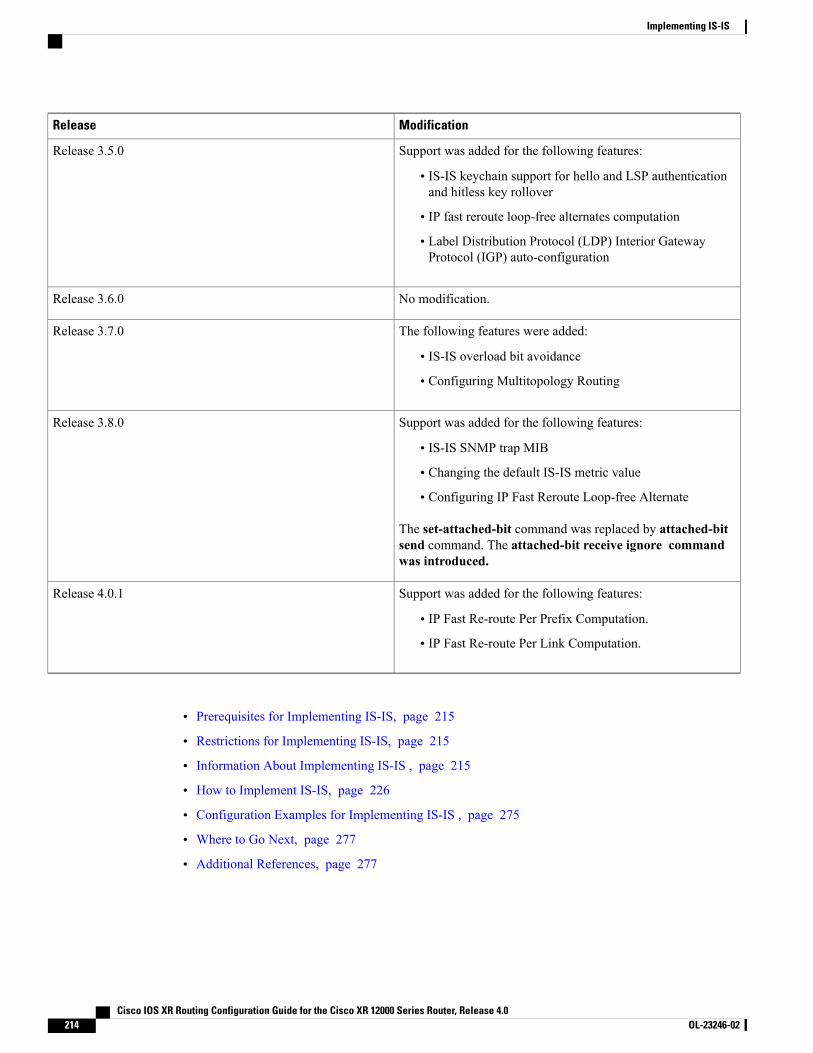
ModificationRelease
Support was added for the following features:
• IS-IS keychain support for hello and LSP authenticationand hitless key rollover
• IP fast reroute loop-free alternates computation
• Label Distribution Protocol (LDP) Interior GatewayProtocol (IGP) auto-configuration
Release 3.5.0
No modification.Release 3.6.0
The following features were added:
• IS-IS overload bit avoidance
• Configuring Multitopology Routing
Release 3.7.0
Support was added for the following features:
• IS-IS SNMP trap MIB
• Changing the default IS-IS metric value
• Configuring IP Fast Reroute Loop-free Alternate
The set-attached-bit command was replaced by attached-bitsend command. The attached-bit receive ignore commandwas introduced.
Release 3.8.0
Support was added for the following features:
• IP Fast Re-route Per Prefix Computation.
• IP Fast Re-route Per Link Computation.
Release 4.0.1
• Prerequisites for Implementing IS-IS, page 215
• Restrictions for Implementing IS-IS, page 215
• Information About Implementing IS-IS , page 215
• How to Implement IS-IS, page 226
• Configuration Examples for Implementing IS-IS , page 275
• Where to Go Next, page 277
• Additional References, page 277
Cisco IOS XR Routing Configuration Guide for the Cisco XR 12000 Series Router, Release 4.0214 OL-23246-02
Implementing IS-IS
Prerequisites for Implementing IS-ISYou must be in a user group associated with a task group that includes the proper task IDs. The commandreference guides include the task IDs required for each command. If you suspect user group assignment ispreventing you from using a command, contact your AAA administrator for assistance.
Restrictions for Implementing IS-ISWhenmultiple instances of IS-IS are being run, an interface can be associated with only one instance (process).Instances may not share an interface.
Information About Implementing IS-ISTo implement IS-IS you need to understand the following concepts:
IS-IS Functional OverviewSmall IS-IS networks are typically built as a single area that includes all routers in the network. As the networkgrows larger, it may be reorganized into a backbone area made up of the connected set of all Level 2 routersfrom all areas, which is in turn connected to local areas. Within a local area, routers know how to reach allsystem IDs. Between areas, routers know how to reach the backbone, and the backbone routers know how toreach other areas.
The IS-IS routing protocol supports the configuration of backbone Level 2 and Level 1 areas and the necessarysupport for moving routing information between the areas. Routers establish Level 1 adjacencies to performrouting within a local area (intra-area routing). Routers establish Level 2 adjacencies to perform routingbetween Level 1 areas (interarea routing).
For Cisco IOS XR software software, each IS-IS instance can support either a single Level 1 or Level 2 area,or one of each. By default, all IS-IS instances automatically support Level 1 and Level 2 routing. You canchange the level of routing to be performed by a particular routing instance using the is-type command.
Key Features Supported in the Cisco IOS XR IS-IS ImplementationThe Cisco IOS XR implementation of IS-IS conforms to the IS-IS Version 2 specifications detailed in RFC1195 and the IPv6 IS-IS functionality based on the Internet Engineering Task Force (IETF) IS-IS WorkingGroup draft-ietf-isis-ipv6.txt document.
The following list outlines key features supported in the Cisco IOS XR implementation:
• Single topology IPv6
• Multitopology
• Nonstop forwarding (NSF), both Cisco proprietary and IETF
• Three-way handshake
• Mesh groups
Cisco IOS XR Routing Configuration Guide for the Cisco XR 12000 Series Router, Release 4.0 OL-23246-02 215
Implementing IS-ISPrerequisites for Implementing IS-IS

• Multiple IS-IS instances
• Configuration of a broadcast medium connecting two networking devices as a point-to-point link
• Fast-flooding with different threads handling flooding and shortest path first (SPF).
For information on IS-IS support for Bidirectional Forwarding Detection (BFD), see Cisco IOS XRInterface and Hardware Component Configuration Guide for the Cisco XR 12000 Series Router andCisco IOS XR Interface and Hardware Component Command Reference for the Cisco XR 12000 SeriesRouter.
Note
IS-IS Configuration GroupingCisco IOS XR groups all of the IS-IS configuration in router IS-IS configuration mode, including the portionof the interface configurations associated with IS-IS. To display the IS-IS configuration in its entirety, usethe show running router isis command. The command output displays the running configuration for allconfigured IS-IS instances, including the interface assignments and interface attributes.
IS-IS Configuration ModesThe following sections show how to enter each of the configuration modes. From a mode, you can enter the? command to display the commands available in that mode.
Router Configuration ModeThe following example shows how to enter router configuration mode:
RP/0/0/CPU0:router# configurationRP/0/0/CPU0:router(config)# router isis ispRP/0/0/CPU0:router(config-isis)#
Router Address Family Configuration ModeThe following example shows how to enter router address family configuration mode:
RP/0/0/CPU0:router(config)# router isis ispRP/0/0/CPU0:router(config-isis)# address-family
ipv4 unicastRP/0/0/CPU0:router(config-isis-af)#
Interface Configuration ModeThe following example shows how to enter interface configuration mode:
RP/0/0/CPU0:router(config)# router isis isp
Cisco IOS XR Routing Configuration Guide for the Cisco XR 12000 Series Router, Release 4.0216 OL-23246-02
Implementing IS-ISIS-IS Configuration Grouping
RP/0/0/CPU0:router(config-isis)# interface GigabitEthernet 0/3/0/0RP/0/0/CPU0:router(config-isis-if)#
Interface Address Family Configuration ModeThe following example shows how to enter interface address family configuration mode:
RP/0/0/CPU0:router(config)# router isis ispRP/0/0/CPU0:router(config-isis)# interface
GigabitEthernet 0 /3/0/0RP/0/0/CPU0:router(config-isis-if)# address-family ipv4 unicastRP/0/0/CPU0:router(config-isis-if-af)#
IS-IS InterfacesIS-IS interfaces can be configured as one of the following types:
• Active—advertises connected prefixes and forms adjacencies. This is the default for interfaces.
• Passive—advertises connected prefixes but does not form adjacencies. The passive command is usedto configure interfaces as passive. Passive interfaces should be used sparingly for important prefixessuch as loopback addresses that need to be injected into the IS-IS domain. If many connected prefixesneed to be advertised then the redistribution of connected routes with the appropriate policy should beused instead.
• Suppressed—does not advertise connected prefixes but forms adjacencies. The suppress command isused to configure interfaces as suppressed.
• Shutdown—does not advertise connected prefixes and does not form adjacencies. The shutdowncommand is used to disable interfaces without removing the IS-IS configuration.
Multitopology ConfigurationCisco IOS XR software supports multitopology for IPv6 IS-IS unless single topology is explicitly configuredin IPv6 address-family configuration mode.
IS-IS supports IP routing and not Open Systems Interconnection (OSI) Connectionless Network Service(CLNS) routing.
Note
IPv6 Routing and Configuring IPv6 AddressingBy default, IPv6 routing is disabled in the Cisco IOS XR software. To enable IPv6 routing, you must assignIPv6 addresses to individual interfaces in the router using the ipv6 enable or ipv6 address command. Seethe Network Stack IPv4 and IPv6 Commands on Cisco IOSXRSoftwaremodule of Cisco IOS XR IP Addressesand Services Command Reference for the Cisco XR 12000 Series Router.
Cisco IOS XR Routing Configuration Guide for the Cisco XR 12000 Series Router, Release 4.0 OL-23246-02 217
Implementing IS-ISIS-IS Interfaces

Limit LSP FloodingLimiting link-state packets (LSP) may be desirable in certain “meshy” network topologies. An example ofsuch a network might be a highly redundant one such as a fully meshed set of point-to-point links over anonbroadcast multiaccess (NBMA) transport. In such networks, full LSP flooding can limit network scalability.One way to restrict the size of the flooding domain is to introduce hierarchy by using multiple Level 1 areasand a Level 2 area. However, two other techniques can be used instead of or with hierarchy: Block floodingon specific interfaces and configure mesh groups.
Both techniques operate by restricting the flooding of LSPs in some fashion. A direct consequence is thatalthough scalability of the network is improved, the reliability of the network (in the face of failures) is reducedbecause a series of failures may prevent LSPs from being flooded throughout the network, even though linksexist that would allow flooding if blocking or mesh groups had not restricted their use. In such a case, thelink-state databases of different routers in the network may no longer be synchronized. Consequences suchas persistent forwarding loops can ensue. For this reason, we recommend that blocking or mesh groups beused only if specifically required, and then only after careful network design.
Flood Blocking on Specific InterfacesWith this technique, certain interfaces are blocked from being used for flooding LSPs, but the remaininginterfaces operate normally for flooding. This technique is simple to understand and configure, but may bemore difficult to maintain and more error prone than mesh groups in the long run. The flooding topology thatIS-IS uses is fine-tuned rather than restricted. Restricting the topology too much (blocking too many interfaces)makes the network unreliable in the face of failures. Restricting the topology too little (blocking too fewinterfaces) may fail to achieve the desired scalability.
To improve the robustness of the network in the event that all nonblocked interfaces drop, use the csnp-intervalcommand in interface configurationmode to force periodic complete sequence number PDUs (CSNPs) packetsto be used on blocked point-to-point links. The use of periodic CSNPs enables the network to becomesynchronized.
Mesh Group ConfigurationConfiguring mesh groups (a set of interfaces on a router) can help to limit flooding. All routers reachable overthe interfaces in a particular mesh group are assumed to be densely connected with each router having at leastone link to every other router. Many links can fail without isolating one or more routers from the network.
In normal flooding, a new LSP is received on an interface and is flooded out over all other interfaces on therouter. With mesh groups, when a new LSP is received over an interface that is part of a mesh group, the newLSP is not flooded over the other interfaces that are part of that mesh group.
Maximum LSP Lifetime and Refresh IntervalBy default, the router sends a periodic LSP refresh every 15 minutes. LSPs remain in a database for 20 minutesby default. If they are not refreshed by that time, they are deleted. You can change the LSP refresh intervalor maximum LSP lifetime. The LSP interval should be less than the LSP lifetime or else LSPs time out beforethey are refreshed. In the absence of a configured refresh interval, the software adjusts the LSP refresh interval,if necessary, to prevent the LSPs from timing out.
Cisco IOS XR Routing Configuration Guide for the Cisco XR 12000 Series Router, Release 4.0218 OL-23246-02
Implementing IS-ISLimit LSP Flooding
Single-Topology IPv6 SupportSingle-topology IPv6 support on Cisco IOS XR software software allows IS-IS for IPv6 to be configured oninterfaces along with an IPv4 network protocol. All interfaces must be configured with the identical set ofnetwork protocols, and all routers in the IS-IS area (for Level 1 routing) or the domain (for Level 2 routing)must support the identical set of network layer protocols on all interfaces.
In single-topology mode, IPv6 topologies work with both narrow and wide metric styles in IPv4 unicasttopology. During single-topology operation, one shortest path first (SPF) computation for each level is usedto compute both IPv4 and IPv6 routes. Using a single SPF is possible because both IPv4 IS-IS and IPv6 IS-ISrouting protocols share a common link topology.
Multitopology IPv6 SupportMultitopology IPv6 support on Cisco IOS XR software for IS-IS assumes that multitopology support isrequired as soon as it detects interfaces configured for both IPv6 and IPv4 within the IS-IS stanza.
Because multitopology is the default behavior in the software, you must explicitly configure IPv6 to use thesame topology as IPv4 to enable single-topology IPv6. Configure the single-topology command in IPv6 routeraddress family configuration submode of the IS-IS router stanza.
IS-IS AuthenticationAuthentication is available to limit the establishment of adjacencies by using the hello-password command,and to limit the exchange of LSPs by using the lsp-password command.
IS-IS supports plain-text authentication, which does not provide security against unauthorized users. Plain-textauthentication allows you to configure a password to prevent unauthorized networking devices from formingadjacencies with the router. The password is exchanged as plain text and is potentially visible to an agent ableto view the IS-IS packets.
When an HMAC-MD5 password is configured, the password is never sent over the network and is insteadused to calculate a cryptographic checksum to ensure the integrity of the exchanged data.
IS-IS stores a configured password using simple encryption. However, the plain-text form of the password isused in LSPs, sequence number protocols (SNPs), and hello packets, which would be visible to a process thatcan view IS-IS packets. The passwords can be entered in plain text (clear) or encrypted form.
To set the domain password, configure the lsp-password command for Level 2; to set the area password,configure the lsp-password command for Level 1.
The keychain feature allows IS-IS to reference configured keychains. IS-IS key chains enable hello and LSPkeychain authentication. Keychains can be configured at the router level (in the case of the lsp-passwordcommand) and at the interface level (in the case of the hello-password command) within IS-IS. Thesecommands reference the global keychain configuration and instruct the IS-IS protocol to obtain securityparameters from the global set of configured keychains.
IS-IS is able to use the keychain to implement hitless key rollover for authentication. ey rollover specificationis time based, and in the event of clock skew between the peers, the rollover process is impacted. Theconfigurable tolerance specification allows for the accept window to be extended (before and after) by thatmargin. This accept window facilitates a hitless key rollover for applications (for example, routing andmanagement protocols).
Cisco IOS XR Routing Configuration Guide for the Cisco XR 12000 Series Router, Release 4.0 OL-23246-02 219
Implementing IS-ISSingle-Topology IPv6 Support
See Cisco IOS XR System Security Guide for the Cisco XR 12000 Series Router for information on keychainmanagement.
Nonstop ForwardingOn Cisco IOS XR software, NSFminimizes the amount of time a network is unavailable to its users followinga route processor (RP) failover. The main objective of NSF is to continue forwarding IP packets and performa graceful restart following an RP failover.
When a router restarts, all routing peers of that device usually detect that the device went down and then cameback up. This transition results in what is called a routing flap, which could spread across multiple routingdomains. Routing flaps caused by routing restarts create routing instabilities, which are detrimental to theoverall network performance. NSF helps to suppress routing flaps in NSF-aware devices, thus reducingnetwork instability.
NSF allows for the forwarding of data packets to continue along known routes while the routing protocolinformation is being restored following an RP failover. When the NSF feature is configured, peer networkingdevices do not experience routing flaps. Data traffic is forwarded through intelligent line cards while thestandby RP assumes control from the failed active RP during a failover. The ability of line cards to remainup through a failover and to be kept current with the Forwarding Information Base (FIB) on the active RP iskey to NSF operation.
When the Cisco IOS XR router running IS-IS routing performs an RP failover, the router must perform twotasks to resynchronize its link-state database with its IS-IS neighbors. First, it must relearn the available IS-ISneighbors on the network without causing a reset of the neighbor relationship. Second, it must reacquire thecontents of the link-state database for the network.
The IS-IS NSF feature offers two options when configuring NSF:
• IETF NSF
• Cisco NSF
If neighbor routers on a network segment are NSF aware, meaning that neighbor routers are running a softwareversion that supports the IETF Internet draft for router restartability, they assist an IETF NSF router that isrestarting. With IETF NSF, neighbor routers provide adjacency and link-state information to help rebuild therouting information following a failover.
In Cisco IOS XR software, Cisco NSF checkpoints (stores persistently) all the state necessary to recover froma restart without requiring any special cooperation from neighboring routers. The state is recovered from theneighboring routers, but only using the standard features of the IS-IS routing protocol. This capability makesCisco NSF suitable for use in networks in which other routers have not used the IETF standard implementationof NSF.
If you configure IETF NSF on the Cisco IOS XR router and a neighbor router does not support IETF NSF,the affected adjacencies flap, but nonstop forwarding is maintained to all neighbors that do support IETFNSF. A restart reverts to a cold start if no neighbors support IETF NSF.
Note
Cisco IOS XR Routing Configuration Guide for the Cisco XR 12000 Series Router, Release 4.0220 OL-23246-02
Implementing IS-ISNonstop Forwarding

Multi-Instance IS-ISYou can configure up to five IS-IS instances. MPLS can run on multiple IS-IS processes as long as theprocesses run on different sets of interfaces. Each interface may be associated with only a single IS-IS instance.Cisco IOSXR software prevents the double-booking of an interface by two instances at configuration time—twoinstances of MPLS configuration causes an error.
Because the Routing Information Base (RIB) treats each of the IS-IS instances as equal routing clients, youmust be careful when redistributing routes between IS-IS instances. The RIB does not know to prefer Level1 routes over Level 2 routes. For this reason, if you are running Level 1 and Level 2 instances, you mustenforce the preference by configuring different administrative distances for the two instances.
Multiprotocol Label Switching Traffic EngineeringThe MPLS TE feature enables an MPLS backbone to replicate and expand the traffic engineering capabilitiesof Layer 2 ATM and Frame Relay networks. MPLS is an integration of Layer 2 and Layer 3 technologies.
For IS-IS, MPLS TE automatically establishes and maintains MPLS TE label-switched paths across thebackbone by using Resource Reservation Protocol (RSVP). The route that a label-switched path uses isdetermined by the label-switched paths resource requirements and network resources, such as bandwidth.Available resources are flooded by using special IS-IS TLV extensions in the IS-IS. The label-switched pathsare explicit routes and are referred to as traffic engineering (TE) tunnels.
Overload Bit on RouterThe overload bit is a special bit of state information that is included in an LSP of the router. If the bit is seton the router, it notifies routers in the area that the router is not available for transit traffic. This capability isuseful in four situations:
1 During a serious but nonfatal error, such as limited memory.
2 During the startup and restart of the process. The overload bit can be set until the routing protocol hasconverged. However, it is not employed during a normal NSF restart or failover because doing so causesa routing flap.
3 During a trial deployment of a new router. The overload bit can be set until deployment is verified, thencleared.
4 During the shutdown of a router. The overload bit can be set to remove the router from the topology beforethe router is removed from service.
Overload Bit Configuration During Multitopology OperationBecause the overload bit applies to forwarding for a single topology, it may be configured and clearedindependently for IPv4 and IPv6 during multitopology operation. For this reason, the overload is set from therouter address family configuration mode. If the IPv4 overload bit is set, all routers in the area do not use therouter for IPv4 transit traffic. However, they can still use the router for IPv6 transit traffic.
Cisco IOS XR Routing Configuration Guide for the Cisco XR 12000 Series Router, Release 4.0 OL-23246-02 221
Implementing IS-ISMulti-Instance IS-IS
IS-IS Overload Bit AvoidanceThe IS-IS overload bit avoidance feature allows network administrators to prevent label switched paths (LSPs)from being disabled when a router in that path has its Intermediate System-to-Intermediate System (IS-IS)overload bit set.
When the IS-IS overload bit avoidance feature is activated, all nodes with the overload bit set, including headnodes, mid nodes, and tail nodes, are ignored, which means that they are still available for use with labelswitched paths (LSPs).
The IS-IS overload bit avoidance feature does not change the default behavior on nodes that have theiroverload bit set if those nodes are not included in the path calculation (PCALC).
Note
The IS-IS overload bit avoidance feature is activated using the following command:
mpls traffic-eng path-selection ignore overload
The IS-IS overload bit avoidance feature is deactivated using the no form of this command:
no mpls traffic-eng path-selection ignore overload
When the IS-IS overload bit avoidance feature is deactivated, nodes with the overload bit set cannot be usedas nodes of last resort.
Default RoutesYou can force a default route into an IS-IS routing domain.Whenever you specifically configure redistributionof routes into an IS-IS routing domain, the Cisco IOS XR software does not, by default, redistribute the defaultroute into the IS-IS routing domain. The default-information originate command generates a default routeinto IS-IS, which can be controlled by a route policy. You can use the route policy to identify the level intowhich the default route is to be announced, and you can specify other filtering options configurable under aroute policy. You can use a route policy to conditionally advertise the default route, depending on the existenceof another route in the routing table of the router.
Attached Bit on an IS-IS InstanceThe attached bit is set in a router that is configured with the is-type command and level-1-2 keyword. Theattached bit indicates that the router is connected to other areas (typically through the backbone). Thisfunctionality means that the router can be used by Level 1 routers in the area as the default route to thebackbone. The attached bit is usually set automatically as the router discovers other areas while computingits Level 2 SPF route. The bit is automatically cleared when the router becomes detached from the backbone.
If the connectivity for the Level 2 instance is lost, the attached bit in the Level 1 instance LSP wouldcontinue sending traffic to the Level 2 instance and cause the traffic to be dropped.
Note
To simulate this behavior when using multiple processes to represent the level-1-2 keyword functionality,you would manually configure the attached bit on the Level 1 process.
Cisco IOS XR Routing Configuration Guide for the Cisco XR 12000 Series Router, Release 4.0222 OL-23246-02
Implementing IS-ISIS-IS Overload Bit Avoidance
IS-IS Support for Route TagsThe IS-IS Support for route tags feature provides the capability to associate and advertise a tag with an IS-ISroute prefix. Additionally, the feature allows you to prioritize the order of installation of route prefixes in theRIB based on a tag of a route. Route tags may also be used in route policy to match route prefixes (for example,to select certain route prefixes for redistribution).
Multicast-Intact FeatureThe multicast-intact feature provides the ability to run multicast routing (PIM) when IGP shortcuts areconfigured and active on the router. Both OSPFv2 and IS-IS support the multicast-intact feature. MPLS TEand IP multicast coexistence is supported in Cisco IOS XR software by using thempls traffic-engmulticast-intact IS-IS or OSPF router command.
You can enable multicast-intact in the IGP when multicast routing protocols (PIM) are configured and IGPshortcuts are configured on the router. IGP shortcuts are MPLS tunnels that are exposed to IGP. The IGPsroute the IP traffic over these tunnels to destinations that are downstream from the egress router of the tunnel(from an SPF perspective). PIM cannot use IGP shortcuts for propagating PIM joins because reverse pathforwarding (RPF) cannot work across a unidirectional tunnel.
When you enable multicast-intact on an IGP, the IGP publishes a parallel or alternate set of equal-cost next-hopsfor use by PIM. These next-hops are called mcast-intact next-hops. The mcast-intact next-hops have thefollowing attributes:
• They are guaranteed not to contain any IGP shortcuts.
• They are not used for unicast routing but are used only by PIM to look up an IPv4 next-hop to a PIMsource.
• They are not published to the FIB.
•When multicast-intact is enabled on an IGP, all IPv4 destinations that were learned through link-stateadvertisements are published with a set equal-cost mcast-intact next-hops to the RIB. This attributeapplies even when the native next-hops have no IGP shortcuts.
• In IS-IS, the max-paths limit is applied by counting both the native and mcast-intact next-hops together.(In OSPFv2, the behavior is slightly different.)
Multicast Topology Support Using IS-ISMulticast topology support allows for the configuration of IS-IS multicast topologies for IPv4 or IPv6 routing.IS-IS maintains a separate topology for multicast and runs a separate Shortest Path First (SPF) over themulticast topology. IS-IS multicast inserts routes from the IS-IS multicast topology into the multicast-unicastRouting Information Base (muRIB) table in the RIB for the corresponding address family. Since PIM usesthe muRIB, PIM uses routes from the multicast topology instead of routes from the unicast topology.
Cisco IOS XR Routing Configuration Guide for the Cisco XR 12000 Series Router, Release 4.0 OL-23246-02 223
Implementing IS-ISIS-IS Support for Route Tags
MPLS Label Distribution Protocol IGP SynchronizationMultiprotocol Label Switching (MPLS) Label Distribution Protocol (LDP) Interior Gateway Protocol (IGP)Synchronization ensures that LDP has completed label exchange before the IGP path is used for switching.MPLS traffic loss can occur in the following two situations:
•When an IGP adjacency is established, the router begins forwarding packets using the new adjacencybefore LDP has exchanged labels with peers on that link.
•When an LDP session closes, the router continues to forward traffic using the link associated with theLDP peer rather than using an alternate path with an established LDP session.
This feature provides a mechanism to synchronize LDP and IS-IS to minimize MPLS packet loss. Thesynchronization is accomplished by changing the link metric for a neighbor IS-IS link-state packet (LSP),based on the state of the LDP session.
When an IS-IS adjacency is established on a link but the LDP session is lost or LDP has not yet completedexchanging labels, IS-IS advertises themaximummetric on that link. In this instance, LDP IS-IS synchronizationis not yet achieved.
In IS-IS, a link with a maximum wide metric (0xFFFFFF) is not considered for shortest path first (SPF).Therefore, the maximum wide metric of -1 (0XFFFFFE) is used with MPLS LDP IGP synchronization.
Note
When LDP IS-IS synchronization is achieved, IS-IS advertises a regular (configured or default) metric onthat link.
MPLS LDP-IGP Synchronization Compatibility with LDP Graceful RestartLDP graceful restart protects traffic when an LDP session is lost. If a graceful restart-enabled LDP sessionfails, MPLS LDP IS-IS synchronization is still achieved on the interface while it is protected by gracefulrestart. MPLS LDP IGP synchronization is eventually lost under the following circumstances:
• LDP fails to restart before the LDP graceful restart reconnect timer expires.
• The LDP session on the protected interface fails to recover before the LDP graceful restart recoverytimer expires.
MPLS LDP-IGP Synchronization Compatibility with IGP Nonstop ForwardingIS-IS nonstop forwarding (NSF) protects traffic during IS-IS process restarts and route processor (RP) failovers.LDP IS-IS synchronization is supported with IS-IS NSF only if LDP graceful restart is also enabled over theinterface. If IS-IS NSF is not enabled, the LDP synchronization state is not retained across restarts and failovers.
Label Distribution Protocol IGP Auto-configurationLabel Distribution Protocol (LDP) Interior Gateway Protocol (IGP) auto-configuration simplifies the procedureto enable LDP on a set of interfaces used by an IGP instance. LDP IGP auto-configuration can be used on a
Cisco IOS XR Routing Configuration Guide for the Cisco XR 12000 Series Router, Release 4.0224 OL-23246-02
Implementing IS-ISMPLS Label Distribution Protocol IGP Synchronization
large number interfaces (for example, when LDP is used for transport in the core) and onmultiple IGP instancessimultaneously.
This feature supports the IPv4 address family for the default VPN routing and forwarding (VRF) instance.
LDP IGP auto-configuration can also be explicitly disabled on individual interfaces under LDP using the igpauto-config disable command. This allows LDP to receive all IGP interfaces except the ones explicitlydisabled.
See Cisco IOS XR MPLS Configuration Guide for the Cisco XR 12000 Series Router for information onconfiguring LDP IGP auto-configuration.
MPLS TE Forwarding AdjacencyMPLS TE forwarding adjacency allows a network administrator to handle a traffic engineering, label switchpath (LSP) tunnel as a link in an Interior Gateway Protocol (IGP) network, based on the Shortest Path First(SPF) algorithm. A forwarding adjacency can be created between routers in the same IS-IS level. The routerscan be locatedmultiple hops from each other. As a result, a TE tunnel is advertised as a link in an IGP network,with the cost of the link associated with it. Routers outside of the TE domain see the TE tunnel and use it tocompute the shortest path for routing traffic throughout the network.
MPLS TE forwarding adjacency is considered in IS-IS SPF only if a two-way connectivity check is achieved.This is possible if the forwarding adjacency is bidirectional or the head end and tail end routers of the MPLSTE tunnel are adjacent.
The MPLS TE forwarding adjacency feature is supported by IS-IS. For details on configuring MPLS TEforwarding adjacency, see the Cisco IOS XR MPLS Configuration Guide for the Cisco XR 12000 SeriesRouter.
MPLS TE Interarea TunnelsMPLS TE interarea tunnels allow you to establish MPLS TE tunnels that span multiple IGP areas (OpenShorted Path First [OSPF]) and levels (IS-IS), removing the restriction that required that both the tunnelheadend and tailend routers be in the same area. The IGP can be either IS-IS or OSPF. See the ConfiguringMPLS Traffic Engineering for IS-IS, on page 252 for information on configuring MPLS TE for IS-IS.
For details on configuring MPLS TE interarea tunnels, see the Cisco IOS XR MPLS Configuration Guide forthe Cisco XR 12000 Series Router.
IP Fast RerouteThe IP Fast Reroute (IPFRR) loop-free alternate (LFA) computation provides protection against link failure.Locally computed repair paths are used to prevent packet loss caused by loops that occur during networkreconvergence after a failure. See IETF draft-ietf-rtgwg-ipfrr-framework-06.txt anddraft-ietf-rtgwg-lf-conv-frmwk-00.txt for detailed information on IPFRR LFA.
IPFRR LFA is different from Multiprotocol Label Switching (MPLS) as it is applicable to networks usingconventional IP routing and forwarding. See Cisco IOS XRMPLS Configuration Guide for the Cisco XR 12000Series Router for information on configuring MPLS IPFRR.
Cisco IOS XR Routing Configuration Guide for the Cisco XR 12000 Series Router, Release 4.0 OL-23246-02 225
Implementing IS-ISMPLS TE Forwarding Adjacency
IS-IS Over GRE InterfacesCisco IOS XR software provides the capability to run IS-IS protocols over Generic Routing Encapsulation(GRE) tunnel interfaces.
For more information on GRE tunnel interfaces, see Implementing BGP on Cisco IOS XR software module.
How to Implement IS-ISThis section contains the following procedures:
To save configuration changes, you must commit changes when the system prompts you.Note
Enabling IS-IS and Configuring Level 1 or Level 2 RoutingThis task explains how to enable IS-IS and configure the routing level for an area.
Configuring the routing level in Step 4 is optional, but is highly recommended to establish the proper levelof adjacencies.
Note
Before You Begin
Although you can configure IS-IS before you configure an IP address, no IS-IS routing occurs until at leastone IP address is configured.
SUMMARY STEPS
1. configure2. router isis instance-id3. net network-entity-title4. is-type { level-1 | level-1-2 | level-2-only }5. Do one of the following:
• end
• commit
6. show isis [ instance instance-id ] protocol
Cisco IOS XR Routing Configuration Guide for the Cisco XR 12000 Series Router, Release 4.0226 OL-23246-02
Implementing IS-ISIS-IS Over GRE Interfaces
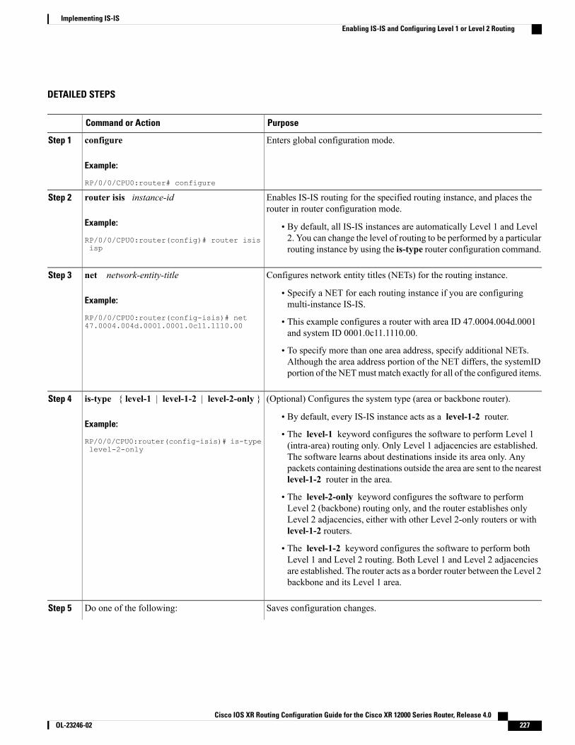
DETAILED STEPS
PurposeCommand or Action
Enters global configuration mode.configure
Example:
RP/0/0/CPU0:router# configure
Step 1
Enables IS-IS routing for the specified routing instance, and places therouter in router configuration mode.
router isis instance-id
Example:
RP/0/0/CPU0:router(config)# router isisisp
Step 2
• By default, all IS-IS instances are automatically Level 1 and Level2. You can change the level of routing to be performed by a particularrouting instance by using the is-type router configuration command.
Configures network entity titles (NETs) for the routing instance.net network-entity-titleStep 3
Example:
RP/0/0/CPU0:router(config-isis)# net47.0004.004d.0001.0001.0c11.1110.00
• Specify a NET for each routing instance if you are configuringmulti-instance IS-IS.
• This example configures a router with area ID 47.0004.004d.0001and system ID 0001.0c11.1110.00.
• To specify more than one area address, specify additional NETs.Although the area address portion of the NET differs, the systemIDportion of the NETmust match exactly for all of the configured items.
(Optional) Configures the system type (area or backbone router).is-type { level-1 | level-1-2 | level-2-only }Step 4
Example:
RP/0/0/CPU0:router(config-isis)# is-typelevel-2-only
• By default, every IS-IS instance acts as a level-1-2 router.
• The level-1 keyword configures the software to perform Level 1(intra-area) routing only. Only Level 1 adjacencies are established.The software learns about destinations inside its area only. Anypackets containing destinations outside the area are sent to the nearestlevel-1-2 router in the area.
• The level-2-only keyword configures the software to performLevel 2 (backbone) routing only, and the router establishes onlyLevel 2 adjacencies, either with other Level 2-only routers or withlevel-1-2 routers.
• The level-1-2 keyword configures the software to perform bothLevel 1 and Level 2 routing. Both Level 1 and Level 2 adjacenciesare established. The router acts as a border router between the Level 2backbone and its Level 1 area.
Saves configuration changes.Do one of the following:Step 5
Cisco IOS XR Routing Configuration Guide for the Cisco XR 12000 Series Router, Release 4.0 OL-23246-02 227
Implementing IS-ISEnabling IS-IS and Configuring Level 1 or Level 2 Routing
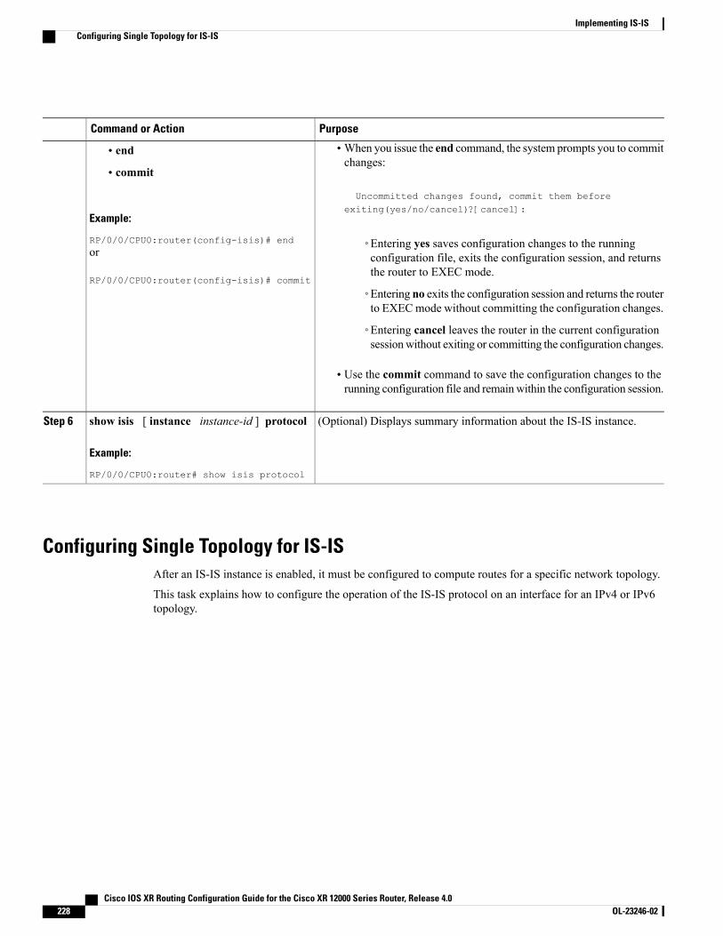
PurposeCommand or Action
•When you issue the end command, the system prompts you to commitchanges:
Uncommitted changes found, commit them before
• end
• commit
Example:
RP/0/0/CPU0:router(config-isis)# end
exiting(yes/no/cancel)?[cancel]:
◦Entering yes saves configuration changes to the runningconfiguration file, exits the configuration session, and returnsthe router to EXEC mode.
or
RP/0/0/CPU0:router(config-isis)# commit
◦Entering no exits the configuration session and returns the routerto EXECmode without committing the configuration changes.
◦Entering cancel leaves the router in the current configurationsessionwithout exiting or committing the configuration changes.
• Use the commit command to save the configuration changes to therunning configuration file and remainwithin the configuration session.
(Optional) Displays summary information about the IS-IS instance.show isis [ instance instance-id ] protocol
Example:
RP/0/0/CPU0:router# show isis protocol
Step 6
Configuring Single Topology for IS-ISAfter an IS-IS instance is enabled, it must be configured to compute routes for a specific network topology.
This task explains how to configure the operation of the IS-IS protocol on an interface for an IPv4 or IPv6topology.
Cisco IOS XR Routing Configuration Guide for the Cisco XR 12000 Series Router, Release 4.0228 OL-23246-02
Implementing IS-ISConfiguring Single Topology for IS-IS
Before You Begin
To enable the router to run in single-topology mode, configure each of the IS-IS interfaces with all of theaddress families enabled and “single-topology” in the address-family IPv6 unicast in the IS-IS routerstanza. You can use either the IPv6 address family or both IPv4 and IPv6 address families, but yourconfiguration must represent the set of all active address families on the router. Additionally, explicitlyenable single-topology operation by configuring it in the IPv6 router address family submode.
Two exceptions to these instructions exist:
Note
1 If the address-family stanza in the IS-IS process contains the adjacency-check disable command,then an interface is not required to have the address family enabled.
2 The single-topology command is not valid in the ipv4 address-family submode.
The default metric style for single topology is narrow metrics. However, you can use either wide metricsor narrow metrics. How to configure them depends on how single topology is configured. If both IPv4and IPv6 are enabled and single topology is configured, the metric style is configured in the address-familyipv4 stanza. You may configure the metric style in the address-family ipv6 stanza, but it is ignored inthis case. If only IPv6 is enabled and single topology is configured, then the metric style is configured inthe address-family ipv6 stanza.
Cisco IOS XR Routing Configuration Guide for the Cisco XR 12000 Series Router, Release 4.0 OL-23246-02 229
Implementing IS-ISConfiguring Single Topology for IS-IS
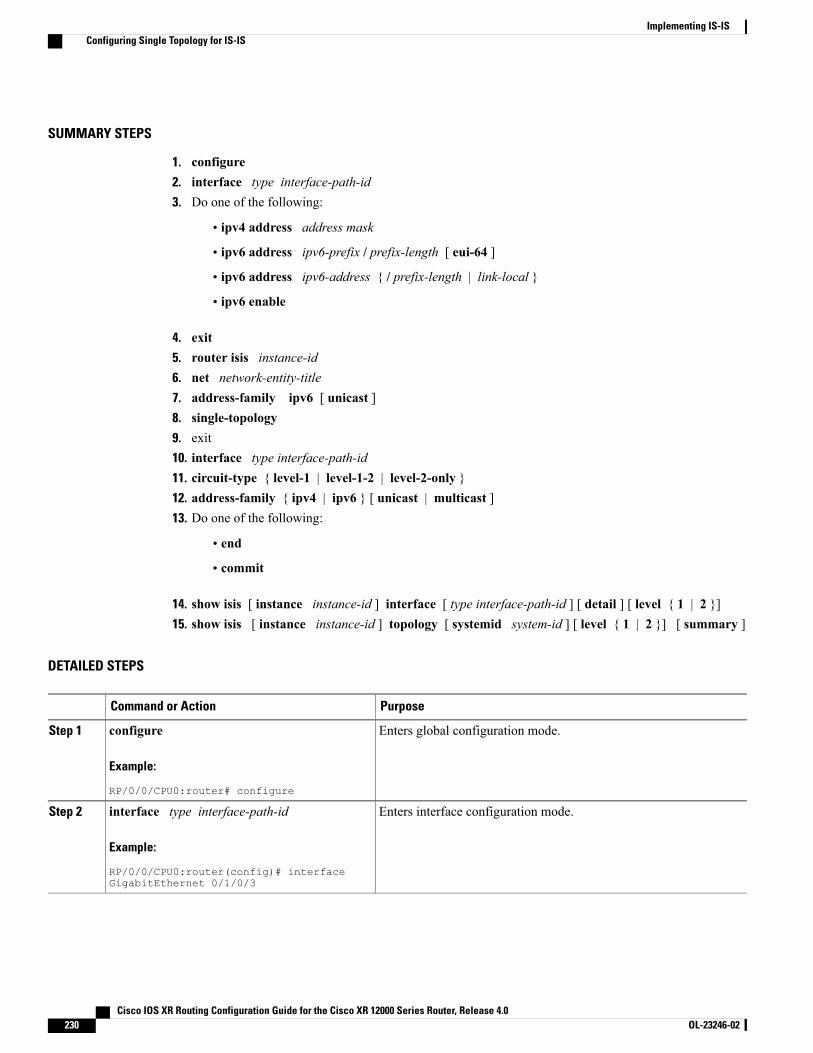
SUMMARY STEPS
1. configure2. interface type interface-path-id3. Do one of the following:
• ipv4 address address mask
• ipv6 address ipv6-prefix / prefix-length [ eui-64 ]
• ipv6 address ipv6-address { / prefix-length | link-local }
• ipv6 enable
4. exit5. router isis instance-id6. net network-entity-title7. address-family ipv6 [ unicast ]8. single-topology9. exit10. interface type interface-path-id11. circuit-type { level-1 | level-1-2 | level-2-only }12. address-family { ipv4 | ipv6 } [ unicast | multicast ]13. Do one of the following:
• end
• commit
14. show isis [ instance instance-id ] interface [ type interface-path-id ] [ detail ] [ level { 1 | 2 }]15. show isis [ instance instance-id ] topology [ systemid system-id ] [ level { 1 | 2 }] [ summary ]
DETAILED STEPS
PurposeCommand or Action
Enters global configuration mode.configure
Example:
RP/0/0/CPU0:router# configure
Step 1
Enters interface configuration mode.interface type interface-path-id
Example:
RP/0/0/CPU0:router(config)# interfaceGigabitEthernet 0/1/0/3
Step 2
Cisco IOS XR Routing Configuration Guide for the Cisco XR 12000 Series Router, Release 4.0230 OL-23246-02
Implementing IS-ISConfiguring Single Topology for IS-IS
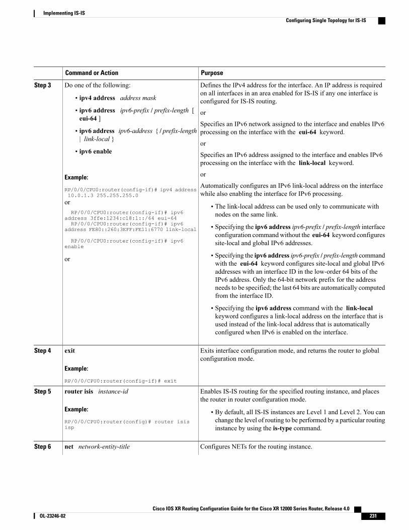
PurposeCommand or Action
Defines the IPv4 address for the interface. An IP address is requiredon all interfaces in an area enabled for IS-IS if any one interface isconfigured for IS-IS routing.
Do one of the following:Step 3
• ipv4 address address mask
• ipv6 address ipv6-prefix / prefix-length [eui-64 ]
or
Specifies an IPv6 network assigned to the interface and enables IPv6processing on the interface with the eui-64 keyword.• ipv6 address ipv6-address { / prefix-length
| link-local }or
• ipv6 enable Specifies an IPv6 address assigned to the interface and enables IPv6processing on the interface with the link-local keyword.
Example:
RP/0/0/CPU0:router(config-if)# ipv4 address10.0.1.3 255.255.255.0
or
Automatically configures an IPv6 link-local address on the interfacewhile also enabling the interface for IPv6 processing.
orRP/0/0/CPU0:router(config-if)# ipv6
address 3ffe:1234:c18:1::/64 eui-64
• The link-local address can be used only to communicate withnodes on the same link.
RP/0/0/CPU0:router(config-if)# ipv6 • Specifying the ipv6 address ipv6-prefix / prefix-length interfaceconfiguration commandwithout the eui-64 keyword configuressite-local and global IPv6 addresses.
address FE80::260:3EFF:FE11:6770 link-local
RP/0/0/CPU0:router(config-if)# ipv6enable
• Specifying the ipv6 address ipv6-prefix / prefix-length commandwith the eui-64 keyword configures site-local and global IPv6
or
addresses with an interface ID in the low-order 64 bits of theIPv6 address. Only the 64-bit network prefix for the addressneeds to be specified; the last 64 bits are automatically computedfrom the interface ID.
• Specifying the ipv6 address command with the link-localkeyword configures a link-local address on the interface that isused instead of the link-local address that is automaticallyconfigured when IPv6 is enabled on the interface.
Exits interface configuration mode, and returns the router to globalconfiguration mode.
exit
Example:
RP/0/0/CPU0:router(config-if)# exit
Step 4
Enables IS-IS routing for the specified routing instance, and placesthe router in router configuration mode.
router isis instance-id
Example:
RP/0/0/CPU0:router(config)# router isisisp
Step 5
• By default, all IS-IS instances are Level 1 and Level 2. You canchange the level of routing to be performed by a particular routinginstance by using the is-type command.
Configures NETs for the routing instance.net network-entity-titleStep 6
Cisco IOS XR Routing Configuration Guide for the Cisco XR 12000 Series Router, Release 4.0 OL-23246-02 231
Implementing IS-ISConfiguring Single Topology for IS-IS
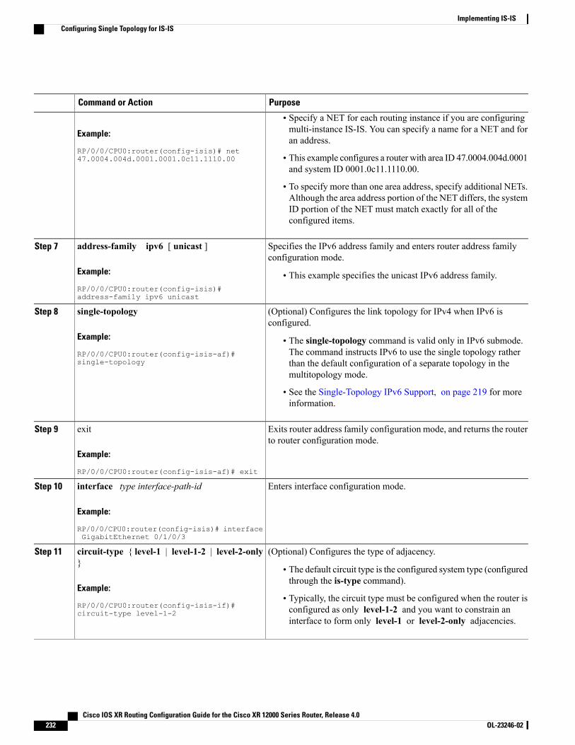
PurposeCommand or Action
Example:
RP/0/0/CPU0:router(config-isis)# net47.0004.004d.0001.0001.0c11.1110.00
• Specify a NET for each routing instance if you are configuringmulti-instance IS-IS. You can specify a name for a NET and foran address.
• This example configures a router with area ID 47.0004.004d.0001and system ID 0001.0c11.1110.00.
• To specify more than one area address, specify additional NETs.Although the area address portion of the NET differs, the systemID portion of the NET must match exactly for all of theconfigured items.
Specifies the IPv6 address family and enters router address familyconfiguration mode.
address-family ipv6 [ unicast ]
Example:
RP/0/0/CPU0:router(config-isis)#address-family ipv6 unicast
Step 7
• This example specifies the unicast IPv6 address family.
(Optional) Configures the link topology for IPv4 when IPv6 isconfigured.
single-topology
Example:
RP/0/0/CPU0:router(config-isis-af)#single-topology
Step 8
• The single-topology command is valid only in IPv6 submode.The command instructs IPv6 to use the single topology ratherthan the default configuration of a separate topology in themultitopology mode.
• See the Single-Topology IPv6 Support, on page 219 for moreinformation.
Exits router address family configuration mode, and returns the routerto router configuration mode.
exit
Example:
RP/0/0/CPU0:router(config-isis-af)# exit
Step 9
Enters interface configuration mode.interface type interface-path-id
Example:
RP/0/0/CPU0:router(config-isis)# interfaceGigabitEthernet 0/1/0/3
Step 10
(Optional) Configures the type of adjacency.circuit-type { level-1 | level-1-2 | level-2-only}
Step 11
• The default circuit type is the configured system type (configuredthrough the is-type command).
Example:
RP/0/0/CPU0:router(config-isis-if)#circuit-type level-1-2
• Typically, the circuit type must be configured when the router isconfigured as only level-1-2 and you want to constrain aninterface to form only level-1 or level-2-only adjacencies.
Cisco IOS XR Routing Configuration Guide for the Cisco XR 12000 Series Router, Release 4.0232 OL-23246-02
Implementing IS-ISConfiguring Single Topology for IS-IS
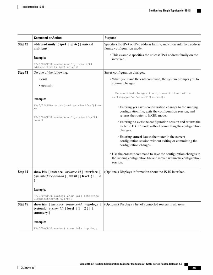
PurposeCommand or Action
Specifies the IPv4 or IPv6 address family, and enters interface addressfamily configuration mode.
address-family { ipv4 | ipv6 } [ unicast |multicast ]
Step 12
Example:
RP/0/0/CPU0:router(config-isis-if)#address-family ipv4 unicast
• This example specifies the unicast IPv4 address family on theinterface.
Saves configuration changes.Do one of the following:Step 13
• end •When you issue the end command, the system prompts you tocommit changes:
Uncommitted changes found, commit them before
• commit
Example:
RP/0/0/CPU0:router(config-isis-if-af)# end
exiting(yes/no/cancel)?[cancel]:
◦Entering yes saves configuration changes to the runningconfiguration file, exits the configuration session, andreturns the router to EXEC mode.
or
RP/0/0/CPU0:router(config-isis-if-af)#commit ◦Entering no exits the configuration session and returns the
router to EXECmodewithout committing the configurationchanges.
◦Entering cancel leaves the router in the currentconfiguration session without exiting or committing theconfiguration changes.
• Use the commit command to save the configuration changes tothe running configuration file and remain within the configurationsession.
(Optional) Displays information about the IS-IS interface.show isis [ instance instance-id ] interface [type interface-path-id ] [ detail ] [ level { 1 | 2}]
Step 14
Example:
RP/0/0/CPU0:router# show isis interfaceGigabitEthernet 0/1/0/1
(Optional) Displays a list of connected routers in all areas.show isis [ instance instance-id ] topology [systemid system-id ] [ level { 1 | 2 }] [summary ]
Step 15
Example:
RP/0/0/CPU0:router# show isis topology
Cisco IOS XR Routing Configuration Guide for the Cisco XR 12000 Series Router, Release 4.0 OL-23246-02 233
Implementing IS-ISConfiguring Single Topology for IS-IS
Configuring Multitopology RoutingThis set of procedures configures multitopology routing, which is used by PIM for reverse-path forwarding(RPF) path selection.
Restrictions for Configuring Multitopology Routing• Only the default VRF is currently supported in a multitopology solution.
• Only protocol-independent multicast (PIM) and intermediate system-intermediate system (IS-IS) routingprotocols are currently supported.
• Topology selection is restricted solely to (S, G) route sources for both SM and SSM. Static and IS-ISare the only interior gateway protocols (IGPs) that support multitopology deployment.
For non-(S, G) route sources like a rendezvous point or bootstrap router (BSR), or when a route policyis not configured, the current policy default remains in effect. In other words, either a unicast-default ormulticast-default table is selected for all sources, based on OSFP/IS-IS/Multiprotocol Border GatewayProtocol (MBGP) configuration.
Although bothmulticast and unicast keywords are available when using the address-family {ipv4 |ipv6} command in routing policy language (RPL), only topologies under multicast SAFI can be configuredglobally.
Note
Information About Multitopology RoutingConfiguring multitopology networks requires the following tasks:
Configuring a Global Topology and Associating It with an InterfaceFollow these steps to enable a global topology in the default VRF and to enable its use with a specific interface.
SUMMARY STEPS
1. configure2. address-family { ipv4 | ipv6 } multicast topology topo-name3. maximum prefix limit4. interface type interface-path-id5. address-family { ipv4 | ipv6 } multicast topology topo-name6. Repeat Step 4 and Step 5 until you have specified all the interface instances you want to associate with
your topologies.7. Do one of the following:
• end
• commit
Cisco IOS XR Routing Configuration Guide for the Cisco XR 12000 Series Router, Release 4.0234 OL-23246-02
Implementing IS-ISConfiguring Multitopology Routing
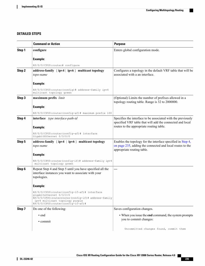
DETAILED STEPS
PurposeCommand or Action
Enters global configuration mode.configure
Example:
RP/0/0/CPU0:router# configure
Step 1
Configures a topology in the default VRF table that will beassociated with a an interface.
address-family { ipv4 | ipv6 } multicast topologytopo-name
Example:
RP/0/0/CPU0:router(config)# address-family ipv4multicast topology green
Step 2
(Optional) Limits the number of prefixes allowed in atopology routing table. Range is 32 to 2000000.
maximum prefix limit
Example:
RP/0/0/CPU0:router(config-af)# maximum prefix 100
Step 3
Specifies the interface to be associated with the previouslyspecified VRF table that will add the connected and localroutes to the appropriate routing table.
interface type interface-path-id
Example:
RP/0/0/CPU0:router(config-af)# interfaceGigabitEthernet 0/3/0/0
Step 4
Enables the topology for the interface specified in Step 4,on page 235, adding the connected and local routes to theappropriate routing table.
address-family { ipv4 | ipv6 } multicast topologytopo-name
Example:
RP/0/0/CPU0:router(config-if)# address-family ipv4multicast topology green
Step 5
—Repeat Step 4 and Step 5 until you have specified all theinterface instances you want to associate with yourtopologies.
Step 6
Example:
RP/0/0/CPU0:router(config-if-af)# interfacegigabitethernet 0/3/2/0RP/0/0/CPU0:routerrouter(config-if)# address-familyipv4 multicast topology purpleRP/0/0/CPU0:router(config-if-af)#
Saves configuration changes.Do one of the following:Step 7
• end •When you issue the end command, the system promptsyou to commit changes:
Uncommitted changes found, commit them
• commit
Cisco IOS XR Routing Configuration Guide for the Cisco XR 12000 Series Router, Release 4.0 OL-23246-02 235
Implementing IS-ISConfiguring Multitopology Routing
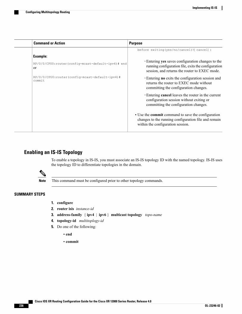
PurposeCommand or Action
Example:
RP/0/0/CPU0:router(config-mcast-default-ipv4)# end
before exiting(yes/no/cancel)?[cancel]:
◦Entering yes saves configuration changes to therunning configuration file, exits the configurationsession, and returns the router to EXEC mode.
or
RP/0/0/CPU0:router(config-mcast-default-ipv4)#commit
◦Entering no exits the configuration session andreturns the router to EXEC mode withoutcommitting the configuration changes.
◦Entering cancel leaves the router in the currentconfiguration session without exiting orcommitting the configuration changes.
• Use the commit command to save the configurationchanges to the running configuration file and remainwithin the configuration session.
Enabling an IS-IS TopologyTo enable a topology in IS-IS, you must associate an IS-IS topology ID with the named topology. IS-IS usesthe topology ID to differentiate topologies in the domain.
This command must be configured prior to other topology commands.Note
SUMMARY STEPS
1. configure2. router isis instance-id3. address-family { ipv4 | ipv6 } multicast topology topo-name4. topology-id multitoplogy-id5. Do one of the following:
• end
• commit
Cisco IOS XR Routing Configuration Guide for the Cisco XR 12000 Series Router, Release 4.0236 OL-23246-02
Implementing IS-ISConfiguring Multitopology Routing
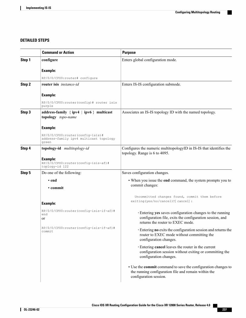
DETAILED STEPS
PurposeCommand or Action
Enters global configuration mode.configure
Example:
RP/0/0/CPU0:router# configure
Step 1
Enters IS-IS configuration submode.router isis instance-id
Example:
RP/0/0/CPU0:router(config)# router isispurple
Step 2
Associates an IS-IS topology ID with the named topology.address-family { ipv4 | ipv6 } multicasttopology topo-name
Step 3
Example:
RP/0/0/CPU0:router(config-isis)#address-family ipv4 multicast topologygreen
Configures the numeric multitopologyID in IS-IS that identifies thetopology. Range is 6 to 4095.
topology-id multitoplogy-id
Example:RP/0/0/CPU0:router(config-isis-af)#toplogy-id 122
Step 4
Saves configuration changes.Do one of the following:Step 5
• end •When you issue the end command, the system prompts you tocommit changes:
Uncommitted changes found, commit them before
• commit
Example:
RP/0/0/CPU0:router(config-isis-if-af)#end
exiting(yes/no/cancel)?[cancel]:
◦Entering yes saves configuration changes to the runningconfiguration file, exits the configuration session, andreturns the router to EXEC mode.
or
RP/0/0/CPU0:router(config-isis-if-af)#commit ◦Entering no exits the configuration session and returns the
router to EXEC mode without committing theconfiguration changes.
◦Entering cancel leaves the router in the currentconfiguration session without exiting or committing theconfiguration changes.
• Use the commit command to save the configuration changes tothe running configuration file and remain within theconfiguration session.
Cisco IOS XR Routing Configuration Guide for the Cisco XR 12000 Series Router, Release 4.0 OL-23246-02 237
Implementing IS-ISConfiguring Multitopology Routing
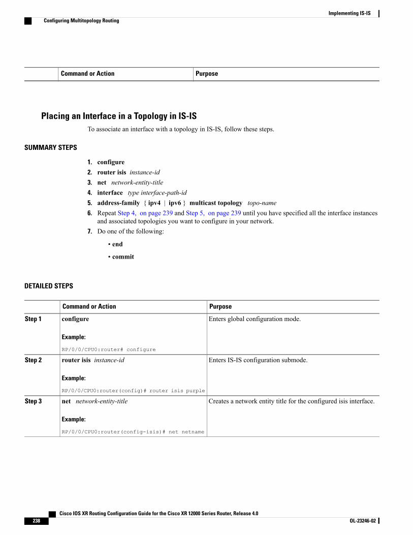
PurposeCommand or Action
Placing an Interface in a Topology in IS-ISTo associate an interface with a topology in IS-IS, follow these steps.
SUMMARY STEPS
1. configure2. router isis instance-id3. net network-entity-title4. interface type interface-path-id5. address-family { ipv4 | ipv6 } multicast topology topo-name6. Repeat Step 4, on page 239 and Step 5, on page 239 until you have specified all the interface instances
and associated topologies you want to configure in your network.7. Do one of the following:
• end
• commit
DETAILED STEPS
PurposeCommand or Action
Enters global configuration mode.configure
Example:
RP/0/0/CPU0:router# configure
Step 1
Enters IS-IS configuration submode.router isis instance-id
Example:
RP/0/0/CPU0:router(config)# router isis purple
Step 2
Creates a network entity title for the configured isis interface.net network-entity-title
Example:
RP/0/0/CPU0:router(config-isis)# net netname
Step 3
Cisco IOS XR Routing Configuration Guide for the Cisco XR 12000 Series Router, Release 4.0238 OL-23246-02
Implementing IS-ISConfiguring Multitopology Routing

PurposeCommand or Action
Enters isis interface configuration submode and creates aninterface instance.
interface type interface-path-id
Example:
RP/0/0/CPU0:router(config-isis)# interfacegigabitethernet 0/3/0/0
Step 4
address-family { ipv4 | ipv6 } multicast topologytopo-name
Step 5 • Enters isis address-family interface configuration submode.
• Places the interface instance into a topology.
Example:
RP/0/0/CPU0:router(config-isis-if)#address-family ipv4 multicast topology green
—Repeat Step 4, on page 239 and Step 5, on page 239until you have specified all the interface instances and
Step 6
associated topologies you want to configure in yournetwork.
Saves configuration changes.Do one of the following:Step 7
• end •When you issue the end command, the system promptsyou to commit changes:
Uncommitted changes found, commit them before
• commit
Example:
RP/0/0/CPU0:router(config-isis-if-af)# end
exiting(yes/no/cancel)?[cancel]:
◦Entering yes saves configuration changes to therunning configuration file, exits the configurationsession, and returns the router to EXEC mode.
or
RP/0/0/CPU0:router(config-isis-if-af)# commit
◦Entering no exits the configuration session andreturns the router to EXECmode without committingthe configuration changes.
◦Entering cancel leaves the router in the currentconfiguration session without exiting or committingthe configuration changes.
• Use the commit command to save the configurationchanges to the running configuration file and remain withinthe configuration session.
Configuring a Routing PolicyFor more information about creating a routing policy and about the set rpf-topology command, seeCisco IOS XR Routing Command Reference for the Cisco XR 12000 Series Router.
Cisco IOS XR Routing Configuration Guide for the Cisco XR 12000 Series Router, Release 4.0 OL-23246-02 239
Implementing IS-ISConfiguring Multitopology Routing
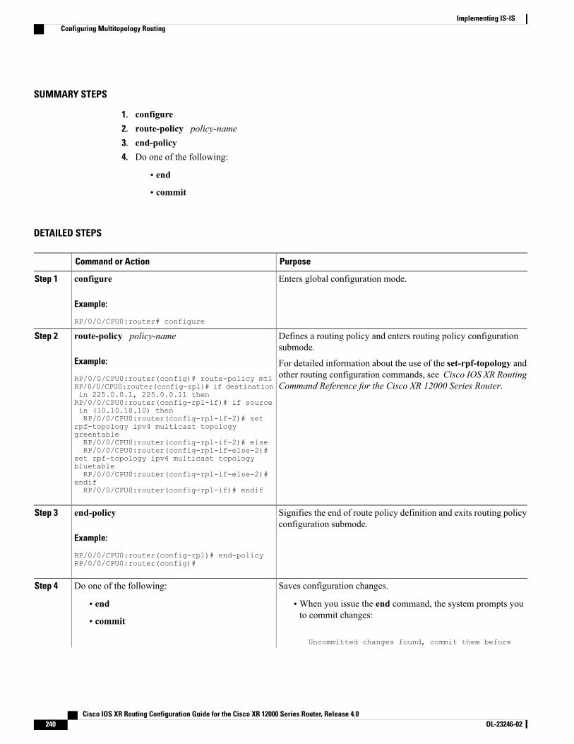
SUMMARY STEPS
1. configure2. route-policy policy-name3. end-policy4. Do one of the following:
• end
• commit
DETAILED STEPS
PurposeCommand or Action
Enters global configuration mode.configure
Example:
RP/0/0/CPU0:router# configure
Step 1
Defines a routing policy and enters routing policy configurationsubmode.
route-policy policy-name
Example:
RP/0/0/CPU0:router(config)# route-policy mt1
Step 2
For detailed information about the use of the set-rpf-topology andother routing configuration commands, see Cisco IOS XR RoutingCommand Reference for the Cisco XR 12000 Series Router.RP/0/0/CPU0:router(config-rpl)# if destination
in 225.0.0.1, 225.0.0.11 thenRP/0/0/CPU0:router(config-rpl-if)# if sourcein (10.10.10.10) thenRP/0/0/CPU0:router(config-rpl-if-2)# set
rpf-topology ipv4 multicast topologygreentableRP/0/0/CPU0:router(config-rpl-if-2)# elseRP/0/0/CPU0:router(config-rpl-if-else-2)#
set rpf-topology ipv4 multicast topologybluetableRP/0/0/CPU0:router(config-rpl-if-else-2)#
endifRP/0/0/CPU0:router(config-rpl-if)# endif
Signifies the end of route policy definition and exits routing policyconfiguration submode.
end-policy
Example:
RP/0/0/CPU0:router(config-rpl)# end-policy
Step 3
RP/0/0/CPU0:router(config)#
Saves configuration changes.Do one of the following:Step 4
• end •When you issue the end command, the system prompts youto commit changes:
Uncommitted changes found, commit them before
• commit
Cisco IOS XR Routing Configuration Guide for the Cisco XR 12000 Series Router, Release 4.0240 OL-23246-02
Implementing IS-ISConfiguring Multitopology Routing

PurposeCommand or Action
Example:
RP/0/0/CPU0:router(config)# end
exiting(yes/no/cancel)?[cancel]:
◦Entering yes saves configuration changes to the runningconfiguration file, exits the configuration session, andreturns the router to EXEC mode.
or
RP/0/0/CPU0:router(config)# commit ◦Entering no exits the configuration session and returnsthe router to EXEC mode without committing theconfiguration changes.
◦Entering cancel leaves the router in the currentconfiguration session without exiting or committing theconfiguration changes.
• Use the commit command to save the configuration changesto the running configuration file and remain within theconfiguration session.
Configuring Multitopology for IS-ISMultitopology is configured in the sameway as the single topology. However, the single - topology commandis omitted, invoking the default multitopology behavior. This task is optional.
Controlling LSP Flooding for IS-ISFlooding of LSPs can limit network scalability. You can control LSP flooding by tuning your LSP databaseparameters on the router globally or on the interface. This task is optional.
Many of the commands to control LSP flooding contain an option to specify the level to which they apply.Without the option, the command applies to both levels. If an option is configured for one level, the otherlevel continues to use the default value. To configure options for both levels, use the command twice. Forexample:
RP/0/0/CPU0:router(config-isis)# lsp-refresh-interval 1200 level 2RP/0/0/CPU0:router(config-isis)# lsp-refresh-interval 1100 level 1
Cisco IOS XR Routing Configuration Guide for the Cisco XR 12000 Series Router, Release 4.0 OL-23246-02 241
Implementing IS-ISConfiguring Multitopology for IS-IS

SUMMARY STEPS
1. configure2. router isis instance-id3. lsp-refresh-interval seconds [ level { 1 | 2 }]4. lsp-check-interval seconds [ level { 1 | 2 }]5. lsp-gen-interval { [ initial-wait initial | secondary-wait secondary | maximum-wait maximum
] ... } [ level { 1 | 2 }]6. lsp-mtu bytes [ level { 1 | 2 }]7. max-lsp-lifetime seconds [ level { 1 | 2 }]8. ignore-lsp-errors disable9. interface type interface-path-id10. lsp-interval milliseconds [ level { 1 | 2 }]11. csnp-interval seconds [ level { 1 | 2 }]12. retransmit-interval seconds [ level { 1 | 2 }]13. retransmit-throttle-interval milliseconds [ level { 1 | 2 }]14. mesh-group { number | blocked }15. Do one of the following:
• end
• commit
16. show isis interface [ type interface-path-id | level { 1 | 2 }] [ brief ]17. show isis [ instance instance-id ] database [ level { 1 | 2 }] [ detail | summary | verbose ] [ * |
lsp-id ]18. show isis [ instance instance-id ] lsp-log [ level { 1 | 2 }]19. show isis database-log [ level { 1 | 2 }]
DETAILED STEPS
PurposeCommand or Action
Enters global configuration mode.configure
Example:
RP/0/0/CPU0:router# configure
Step 1
Enables IS-IS routing for the specified routing instance, and placesthe router in router configuration mode.
router isis instance-id
Example:
RP/0/0/CPU0:router(config)# router isis isp
Step 2
• You can change the level of routing to be performed by aparticular routing instance by using the is-type routerconfiguration command.
Cisco IOS XR Routing Configuration Guide for the Cisco XR 12000 Series Router, Release 4.0242 OL-23246-02
Implementing IS-ISControlling LSP Flooding for IS-IS
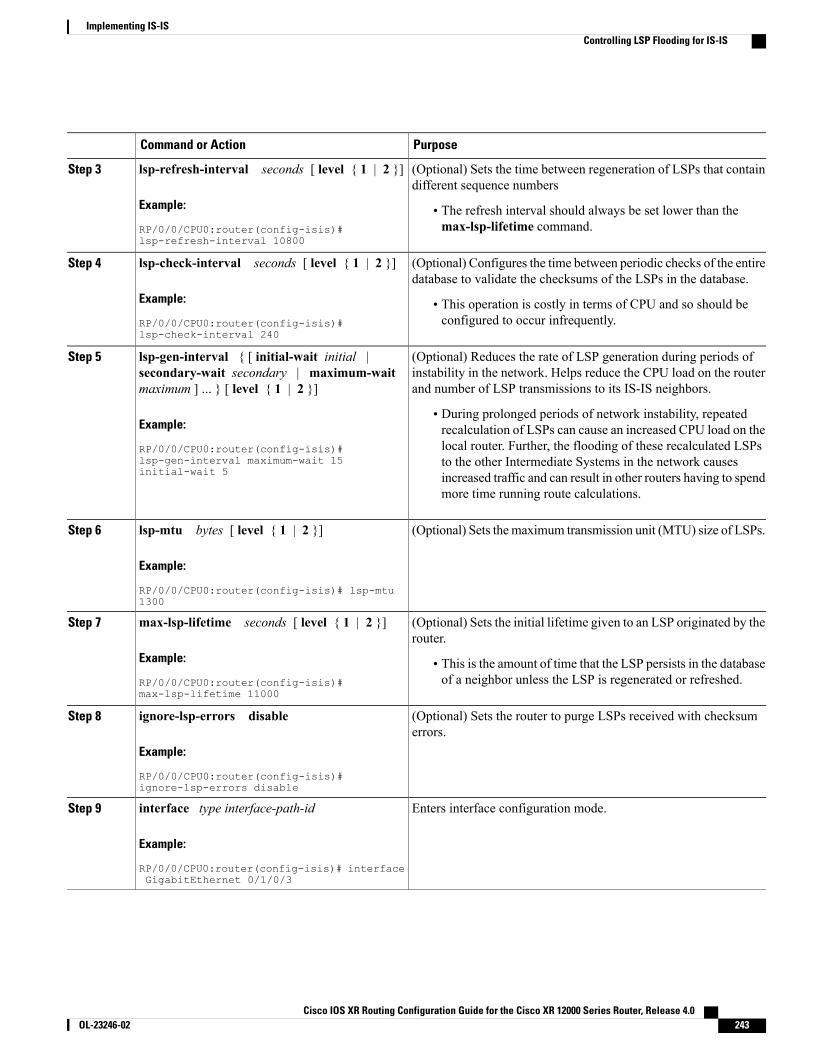
PurposeCommand or Action
(Optional) Sets the time between regeneration of LSPs that containdifferent sequence numbers
lsp-refresh-interval seconds [ level { 1 | 2 }]
Example:
RP/0/0/CPU0:router(config-isis)#lsp-refresh-interval 10800
Step 3
• The refresh interval should always be set lower than themax-lsp-lifetime command.
(Optional) Configures the time between periodic checks of the entiredatabase to validate the checksums of the LSPs in the database.
lsp-check-interval seconds [ level { 1 | 2 }]
Example:
RP/0/0/CPU0:router(config-isis)#lsp-check-interval 240
Step 4
• This operation is costly in terms of CPU and so should beconfigured to occur infrequently.
(Optional) Reduces the rate of LSP generation during periods ofinstability in the network. Helps reduce the CPU load on the routerand number of LSP transmissions to its IS-IS neighbors.
lsp-gen-interval { [ initial-wait initial |secondary-wait secondary | maximum-waitmaximum ] ... } [ level { 1 | 2 }]
Step 5
Example:
RP/0/0/CPU0:router(config-isis)#
• During prolonged periods of network instability, repeatedrecalculation of LSPs can cause an increased CPU load on thelocal router. Further, the flooding of these recalculated LSPsto the other Intermediate Systems in the network causeslsp-gen-interval maximum-wait 15
initial-wait 5 increased traffic and can result in other routers having to spendmore time running route calculations.
(Optional) Sets themaximum transmission unit (MTU) size of LSPs.lsp-mtu bytes [ level { 1 | 2 }]
Example:
RP/0/0/CPU0:router(config-isis)# lsp-mtu1300
Step 6
(Optional) Sets the initial lifetime given to an LSP originated by therouter.
max-lsp-lifetime seconds [ level { 1 | 2 }]
Example:
RP/0/0/CPU0:router(config-isis)#max-lsp-lifetime 11000
Step 7
• This is the amount of time that the LSP persists in the databaseof a neighbor unless the LSP is regenerated or refreshed.
(Optional) Sets the router to purge LSPs received with checksumerrors.
ignore-lsp-errors disable
Example:
RP/0/0/CPU0:router(config-isis)#ignore-lsp-errors disable
Step 8
Enters interface configuration mode.interface type interface-path-id
Example:
RP/0/0/CPU0:router(config-isis)# interfaceGigabitEthernet 0/1/0/3
Step 9
Cisco IOS XR Routing Configuration Guide for the Cisco XR 12000 Series Router, Release 4.0 OL-23246-02 243
Implementing IS-ISControlling LSP Flooding for IS-IS
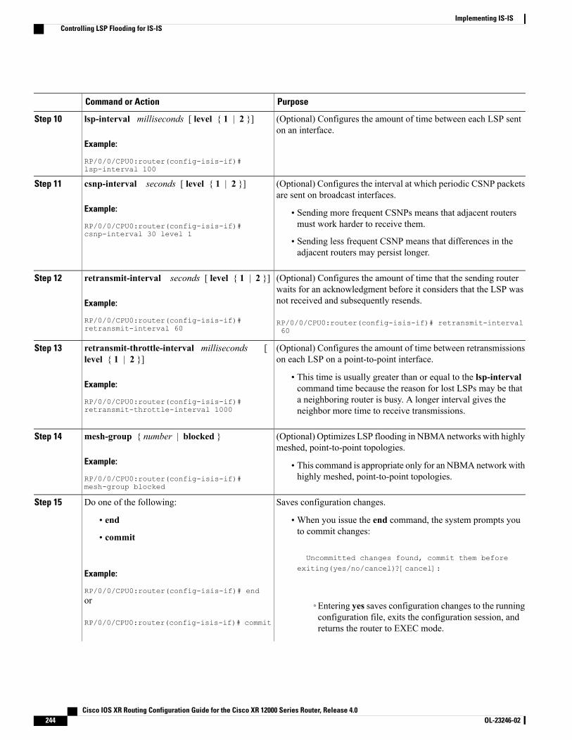
PurposeCommand or Action
(Optional) Configures the amount of time between each LSP senton an interface.
lsp-interval milliseconds [ level { 1 | 2 }]
Example:
RP/0/0/CPU0:router(config-isis-if)#lsp-interval 100
Step 10
(Optional) Configures the interval at which periodic CSNP packetsare sent on broadcast interfaces.
csnp-interval seconds [ level { 1 | 2 }]
Example:
RP/0/0/CPU0:router(config-isis-if)#csnp-interval 30 level 1
Step 11
• Sending more frequent CSNPs means that adjacent routersmust work harder to receive them.
• Sending less frequent CSNP means that differences in theadjacent routers may persist longer.
(Optional) Configures the amount of time that the sending routerwaits for an acknowledgment before it considers that the LSP wasnot received and subsequently resends.
retransmit-interval seconds [ level { 1 | 2 }]
Example:
RP/0/0/CPU0:router(config-isis-if)#retransmit-interval 60
Step 12
RP/0/0/CPU0:router(config-isis-if)# retransmit-interval60
(Optional) Configures the amount of time between retransmissionson each LSP on a point-to-point interface.
retransmit-throttle-interval milliseconds [level { 1 | 2 }]
Step 13
Example:
RP/0/0/CPU0:router(config-isis-if)#retransmit-throttle-interval 1000
• This time is usually greater than or equal to the lsp-intervalcommand time because the reason for lost LSPs may be thata neighboring router is busy. A longer interval gives theneighbor more time to receive transmissions.
(Optional) Optimizes LSP flooding in NBMA networks with highlymeshed, point-to-point topologies.
mesh-group { number | blocked }
Example:
RP/0/0/CPU0:router(config-isis-if)#mesh-group blocked
Step 14
• This command is appropriate only for an NBMAnetwork withhighly meshed, point-to-point topologies.
Saves configuration changes.Do one of the following:Step 15
• end •When you issue the end command, the system prompts youto commit changes:
Uncommitted changes found, commit them before
• commit
Example:
RP/0/0/CPU0:router(config-isis-if)# end
exiting(yes/no/cancel)?[cancel]:
or
RP/0/0/CPU0:router(config-isis-if)# commit
◦Entering yes saves configuration changes to the runningconfiguration file, exits the configuration session, andreturns the router to EXEC mode.
Cisco IOS XR Routing Configuration Guide for the Cisco XR 12000 Series Router, Release 4.0244 OL-23246-02
Implementing IS-ISControlling LSP Flooding for IS-IS
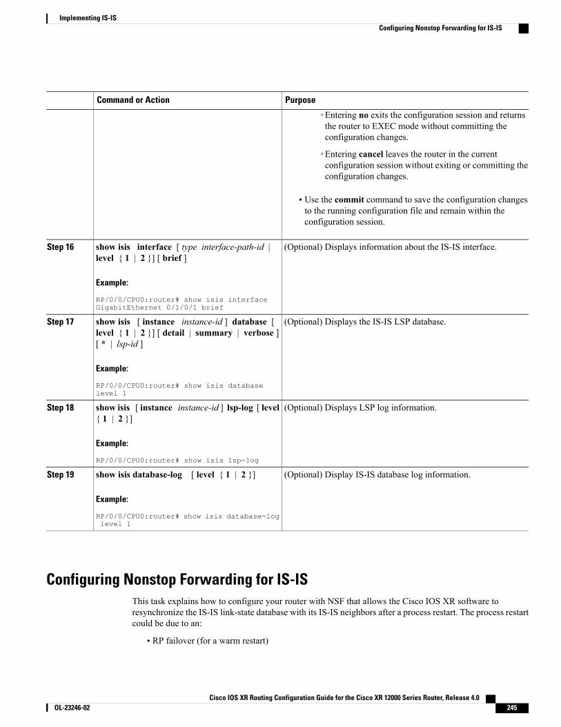
PurposeCommand or Action
◦Entering no exits the configuration session and returnsthe router to EXEC mode without committing theconfiguration changes.
◦Entering cancel leaves the router in the currentconfiguration session without exiting or committing theconfiguration changes.
• Use the commit command to save the configuration changesto the running configuration file and remain within theconfiguration session.
(Optional) Displays information about the IS-IS interface.show isis interface [ type interface-path-id |level { 1 | 2 }] [ brief ]
Step 16
Example:
RP/0/0/CPU0:router# show isis interfaceGigabitEthernet 0/1/0/1 brief
(Optional) Displays the IS-IS LSP database.show isis [ instance instance-id ] database [level { 1 | 2 }] [ detail | summary | verbose ][ * | lsp-id ]
Step 17
Example:
RP/0/0/CPU0:router# show isis databaselevel 1
(Optional) Displays LSP log information.show isis [ instance instance-id ] lsp-log [ level{ 1 | 2 }]
Step 18
Example:
RP/0/0/CPU0:router# show isis lsp-log
(Optional) Display IS-IS database log information.show isis database-log [ level { 1 | 2 }]
Example:
RP/0/0/CPU0:router# show isis database-loglevel 1
Step 19
Configuring Nonstop Forwarding for IS-ISThis task explains how to configure your router with NSF that allows the Cisco IOS XR software toresynchronize the IS-IS link-state database with its IS-IS neighbors after a process restart. The process restartcould be due to an:
• RP failover (for a warm restart)
Cisco IOS XR Routing Configuration Guide for the Cisco XR 12000 Series Router, Release 4.0 OL-23246-02 245
Implementing IS-ISConfiguring Nonstop Forwarding for IS-IS

• Simple process restart (due to an IS-IS reload or other administrative request to restart the process)
• IS-IS software upgrade
In all cases, NSF mitigates link flaps and loss of user sessions. This task is optional.
SUMMARY STEPS
1. configure2. router isis instance-id3. nsf { cisco | ietf }4. nsf interface-expires number5. nsf interface-timer seconds6. nsf lifetime seconds7. Do one of the following:
• end
• commit
8. show running-config [ command ]
DETAILED STEPS
PurposeCommand or Action
Enters global configuration mode.configure
Example:
RP/0/0/CPU0:router# configure
Step 1
Enables IS-IS routing for the specified routing instance, and places the routerin router configuration mode.
router isis instance-id
Example:
RP/0/0/CPU0:router(config)# routerisis isp
Step 2
• You can change the level of routing to be performed by a particularrouting instance by using the is-type router configuration command.
Enables NSF on the next restart.nsf { cisco | ietf }Step 3
Example:
RP/0/0/CPU0:router(config-isis)# nsfietf
• Enter the cisco keyword to run IS-IS in heterogeneous networks thatmight not have adjacent NSF-aware networking devices.
• Enter the ietf keyword to enable IS-IS in homogeneous networkswhere all adjacent networking devices support IETF draft-basedrestartability.
Cisco IOS XR Routing Configuration Guide for the Cisco XR 12000 Series Router, Release 4.0246 OL-23246-02
Implementing IS-ISConfiguring Nonstop Forwarding for IS-IS
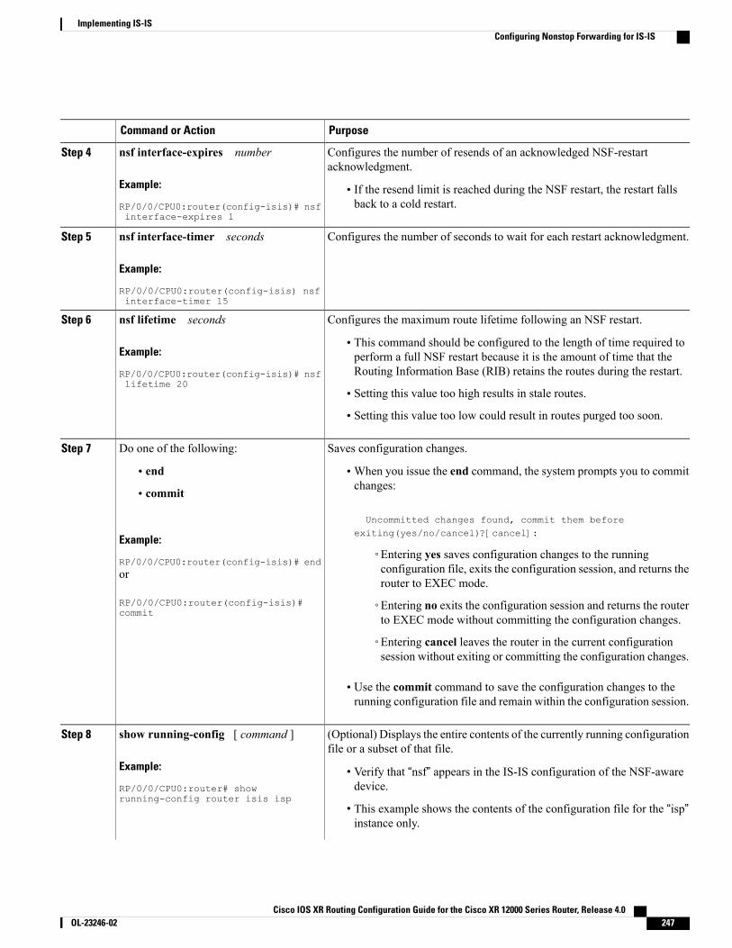
PurposeCommand or Action
Configures the number of resends of an acknowledged NSF-restartacknowledgment.
nsf interface-expires number
Example:
RP/0/0/CPU0:router(config-isis)# nsfinterface-expires 1
Step 4
• If the resend limit is reached during the NSF restart, the restart fallsback to a cold restart.
Configures the number of seconds to wait for each restart acknowledgment.nsf interface-timer seconds
Example:
RP/0/0/CPU0:router(config-isis) nsfinterface-timer 15
Step 5
Configures the maximum route lifetime following an NSF restart.nsf lifetime secondsStep 6
Example:
RP/0/0/CPU0:router(config-isis)# nsflifetime 20
• This command should be configured to the length of time required toperform a full NSF restart because it is the amount of time that theRouting Information Base (RIB) retains the routes during the restart.
• Setting this value too high results in stale routes.
• Setting this value too low could result in routes purged too soon.
Saves configuration changes.Do one of the following:Step 7
• end •When you issue the end command, the system prompts you to commitchanges:
Uncommitted changes found, commit them beforeexiting(yes/no/cancel)?[cancel]:
• commit
Example:
RP/0/0/CPU0:router(config-isis)# end◦Entering yes saves configuration changes to the runningconfiguration file, exits the configuration session, and returns therouter to EXEC mode.
or
RP/0/0/CPU0:router(config-isis)#commit
◦Entering no exits the configuration session and returns the routerto EXEC mode without committing the configuration changes.
◦Entering cancel leaves the router in the current configurationsession without exiting or committing the configuration changes.
• Use the commit command to save the configuration changes to therunning configuration file and remain within the configuration session.
(Optional) Displays the entire contents of the currently running configurationfile or a subset of that file.
show running-config [ command ]
Example:
RP/0/0/CPU0:router# showrunning-config router isis isp
Step 8
• Verify that “nsf” appears in the IS-IS configuration of the NSF-awaredevice.
• This example shows the contents of the configuration file for the “isp”instance only.
Cisco IOS XR Routing Configuration Guide for the Cisco XR 12000 Series Router, Release 4.0 OL-23246-02 247
Implementing IS-ISConfiguring Nonstop Forwarding for IS-IS
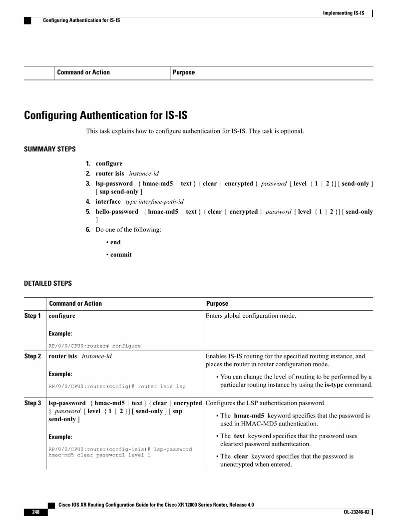
PurposeCommand or Action
Configuring Authentication for IS-ISThis task explains how to configure authentication for IS-IS. This task is optional.
SUMMARY STEPS
1. configure2. router isis instance-id3. lsp-password { hmac-md5 | text } { clear | encrypted } password [ level { 1 | 2 }] [ send-only ]
[ snp send-only ]4. interface type interface-path-id5. hello-password { hmac-md5 | text } { clear | encrypted } password [ level { 1 | 2 }] [ send-only
]6. Do one of the following:
• end
• commit
DETAILED STEPS
PurposeCommand or Action
Enters global configuration mode.configure
Example:
RP/0/0/CPU0:router# configure
Step 1
Enables IS-IS routing for the specified routing instance, andplaces the router in router configuration mode.
router isis instance-id
Example:
RP/0/0/CPU0:router(config)# router isis isp
Step 2
• You can change the level of routing to be performed by aparticular routing instance by using the is-type command.
Configures the LSP authentication password.lsp-password { hmac-md5 | text } { clear | encrypted} password [ level { 1 | 2 }] [ send-only ] [ snpsend-only ]
Step 3
• The hmac-md5 keyword specifies that the password isused in HMAC-MD5 authentication.
Example:
RP/0/0/CPU0:router(config-isis)# lsp-passwordhmac-md5 clear password1 level 1
• The text keyword specifies that the password usescleartext password authentication.
• The clear keyword specifies that the password isunencrypted when entered.
Cisco IOS XR Routing Configuration Guide for the Cisco XR 12000 Series Router, Release 4.0248 OL-23246-02
Implementing IS-ISConfiguring Authentication for IS-IS
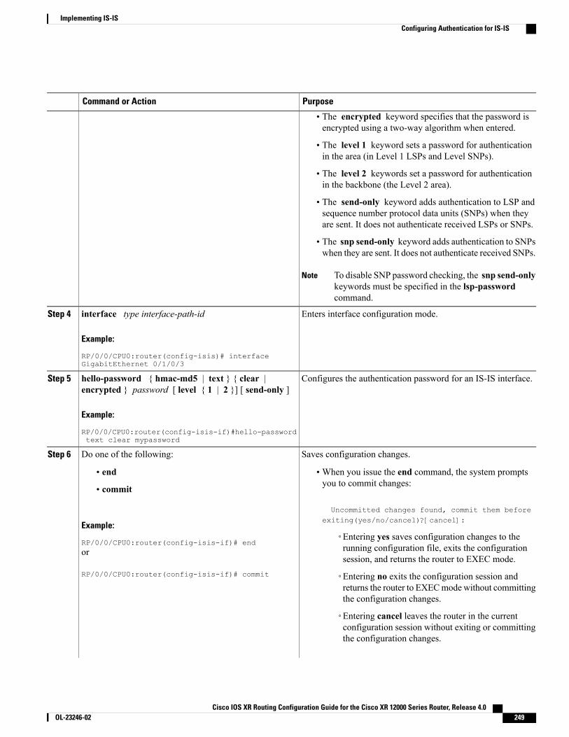
PurposeCommand or Action
• The encrypted keyword specifies that the password isencrypted using a two-way algorithm when entered.
• The level 1 keyword sets a password for authenticationin the area (in Level 1 LSPs and Level SNPs).
• The level 2 keywords set a password for authenticationin the backbone (the Level 2 area).
• The send-only keyword adds authentication to LSP andsequence number protocol data units (SNPs) when theyare sent. It does not authenticate received LSPs or SNPs.
• The snp send-only keyword adds authentication to SNPswhen they are sent. It does not authenticate received SNPs.
To disable SNP password checking, the snp send-onlykeywords must be specified in the lsp-passwordcommand.
Note
Enters interface configuration mode.interface type interface-path-id
Example:
RP/0/0/CPU0:router(config-isis)# interfaceGigabitEthernet 0/1/0/3
Step 4
Configures the authentication password for an IS-IS interface.hello-password { hmac-md5 | text } { clear |encrypted } password [ level { 1 | 2 }] [ send-only ]
Step 5
Example:
RP/0/0/CPU0:router(config-isis-if)#hello-passwordtext clear mypassword
Saves configuration changes.Do one of the following:Step 6
• end •When you issue the end command, the system promptsyou to commit changes:
Uncommitted changes found, commit them beforeexiting(yes/no/cancel)?[cancel]:
• commit
Example:
RP/0/0/CPU0:router(config-isis-if)# end◦Entering yes saves configuration changes to therunning configuration file, exits the configurationsession, and returns the router to EXEC mode.
or
RP/0/0/CPU0:router(config-isis-if)# commit ◦Entering no exits the configuration session andreturns the router to EXECmode without committingthe configuration changes.
◦Entering cancel leaves the router in the currentconfiguration session without exiting or committingthe configuration changes.
Cisco IOS XR Routing Configuration Guide for the Cisco XR 12000 Series Router, Release 4.0 OL-23246-02 249
Implementing IS-ISConfiguring Authentication for IS-IS
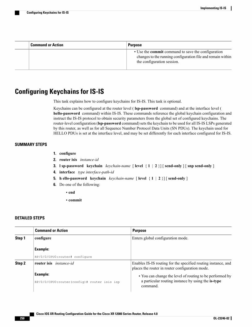
PurposeCommand or Action
• Use the commit command to save the configurationchanges to the running configuration file and remain withinthe configuration session.
Configuring Keychains for IS-ISThis task explains how to configure keychains for IS-IS. This task is optional.
Keychains can be configured at the router level ( lsp-password command) and at the interface level (hello-password command) within IS-IS. These commands reference the global keychain configuration andinstruct the IS-IS protocol to obtain security parameters from the global set of configured keychains. Therouter-level configuration (lsp-password command) sets the keychain to be used for all IS-IS LSPs generatedby this router, as well as for all Sequence Number Protocol Data Units (SN PDUs). The keychain used forHELLO PDUs is set at the interface level, and may be set differently for each interface configured for IS-IS.
SUMMARY STEPS
1. configure2. router isis instance-id3. l sp-password keychain keychain-name [ level { 1 | 2 }] [ send-only ] [ snp send-only ]4. interface type interface-path-id5. h ello-password keychain keychain-name [ level { 1 | 2 }] [ send-only ]6. Do one of the following:
• end
• commit
DETAILED STEPS
PurposeCommand or Action
Enters global configuration mode.configure
Example:
RP/0/0/CPU0:router# configure
Step 1
Enables IS-IS routing for the specified routing instance, andplaces the router in router configuration mode.
router isis instance-id
Example:
RP/0/0/CPU0:router(config)# router isis isp
Step 2
• You can change the level of routing to be performed bya particular routing instance by using the is-typecommand.
Cisco IOS XR Routing Configuration Guide for the Cisco XR 12000 Series Router, Release 4.0250 OL-23246-02
Implementing IS-ISConfiguring Keychains for IS-IS
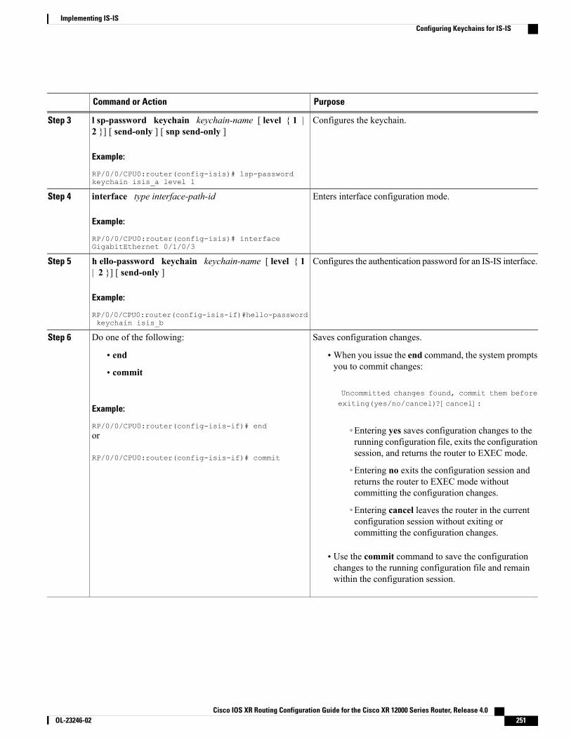
PurposeCommand or Action
Configures the keychain.l sp-password keychain keychain-name [ level { 1 |2 }] [ send-only ] [ snp send-only ]
Step 3
Example:
RP/0/0/CPU0:router(config-isis)# lsp-passwordkeychain isis_a level 1
Enters interface configuration mode.interface type interface-path-id
Example:
RP/0/0/CPU0:router(config-isis)# interfaceGigabitEthernet 0/1/0/3
Step 4
Configures the authentication password for an IS-IS interface.h ello-password keychain keychain-name [ level { 1| 2 }] [ send-only ]
Step 5
Example:
RP/0/0/CPU0:router(config-isis-if)#hello-passwordkeychain isis_b
Saves configuration changes.Do one of the following:Step 6
• end •When you issue the end command, the system promptsyou to commit changes:
Uncommitted changes found, commit them before
• commit
Example:
RP/0/0/CPU0:router(config-isis-if)# end
exiting(yes/no/cancel)?[cancel]:
◦Entering yes saves configuration changes to therunning configuration file, exits the configurationsession, and returns the router to EXEC mode.
or
RP/0/0/CPU0:router(config-isis-if)# commit
◦Entering no exits the configuration session andreturns the router to EXEC mode withoutcommitting the configuration changes.
◦Entering cancel leaves the router in the currentconfiguration session without exiting orcommitting the configuration changes.
• Use the commit command to save the configurationchanges to the running configuration file and remainwithin the configuration session.
Cisco IOS XR Routing Configuration Guide for the Cisco XR 12000 Series Router, Release 4.0 OL-23246-02 251
Implementing IS-ISConfiguring Keychains for IS-IS
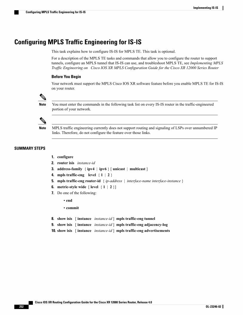
Configuring MPLS Traffic Engineering for IS-ISThis task explains how to configure IS-IS for MPLS TE. This task is optional.
For a description of the MPLS TE tasks and commands that allow you to configure the router to supporttunnels, configure an MPLS tunnel that IS-IS can use, and troubleshoot MPLS TE, see Implementing MPLSTraffic Engineering on Cisco IOS XR MPLS Configuration Guide for the Cisco XR 12000 Series Router
Before You Begin
Your network must support the MPLS Cisco IOS XR software feature before you enable MPLS TE for IS-ISon your router.
You must enter the commands in the following task list on every IS-IS router in the traffic-engineeredportion of your network.
Note
MPLS traffic engineering currently does not support routing and signaling of LSPs over unnumbered IPlinks. Therefore, do not configure the feature over those links.
Note
SUMMARY STEPS
1. configure2. router isis instance-id3. address-family { ipv4 | ipv6 } [ unicast | multicast ]4. mpls traffic-eng level { 1 | 2 }5. mpls traffic-eng router-id { ip-address | interface-name interface-instance }6. metric-style wide [ level { 1 | 2 }]7. Do one of the following:
• end
• commit
8. show isis [ instance instance-id ] mpls traffic-eng tunnel9. show isis [ instance instance-id ] mpls traffic-eng adjacency-log10. show isis [ instance instance-id ] mpls traffic-eng advertisements
Cisco IOS XR Routing Configuration Guide for the Cisco XR 12000 Series Router, Release 4.0252 OL-23246-02
Implementing IS-ISConfiguring MPLS Traffic Engineering for IS-IS
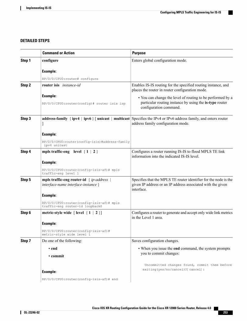
DETAILED STEPS
PurposeCommand or Action
Enters global configuration mode.configure
Example:
RP/0/0/CPU0:router# configure
Step 1
Enables IS-IS routing for the specified routing instance, andplaces the router in router configuration mode.
router isis instance-id
Example:
RP/0/0/CPU0:router(config)# router isis isp
Step 2
• You can change the level of routing to be performed by aparticular routing instance by using the is-type routerconfiguration command.
Specifies the IPv4 or IPv6 address family, and enters routeraddress family configuration mode.
address-family { ipv4 | ipv6 } [ unicast | multicast]
Example:
RP/0/0/CPU0:router(config-isis)#address-familyipv4 unicast
Step 3
Configures a router running IS-IS to flood MPLS TE linkinformation into the indicated IS-IS level.
mpls traffic-eng level { 1 | 2 }
Example:
RP/0/0/CPU0:router(config-isis-af)# mplstraffic-eng level 1
Step 4
Specifies that the MPLS TE router identifier for the node is thegiven IP address or an IP address associated with the giveninterface.
mpls traffic-eng router-id { ip-address |interface-name interface-instance }
Example:
RP/0/0/CPU0:router(config-isis-af)# mplstraffic-eng router-id loopback0
Step 5
Configures a router to generate and accept only wide linkmetricsin the Level 1 area.
metric-style wide [ level { 1 | 2 }]
Example:
RP/0/0/CPU0:router(config-isis-af)#metric-style wide level 1
Step 6
Saves configuration changes.Do one of the following:Step 7
• end •When you issue the end command, the system promptsyou to commit changes:
Uncommitted changes found, commit them beforeexiting(yes/no/cancel)?[cancel]:
• commit
Example:
RP/0/0/CPU0:router(config-isis-af)# end
Cisco IOS XR Routing Configuration Guide for the Cisco XR 12000 Series Router, Release 4.0 OL-23246-02 253
Implementing IS-ISConfiguring MPLS Traffic Engineering for IS-IS
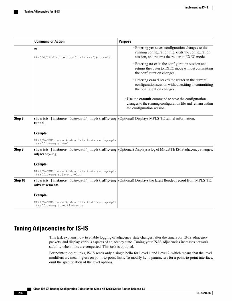
PurposeCommand or Action
◦Entering yes saves configuration changes to therunning configuration file, exits the configurationsession, and returns the router to EXEC mode.
or
RP/0/0/CPU0:router(config-isis-af)# commit
◦Entering no exits the configuration session andreturns the router to EXECmodewithout committingthe configuration changes.
◦Entering cancel leaves the router in the currentconfiguration session without exiting or committingthe configuration changes.
• Use the commit command to save the configurationchanges to the running configuration file and remainwithinthe configuration session.
(Optional) Displays MPLS TE tunnel information.show isis [ instance instance-id ] mpls traffic-engtunnel
Step 8
Example:
RP/0/0/CPU0:router# show isis instance isp mplstraffic-eng tunnel
(Optional) Displays a log ofMPLS TE IS-IS adjacency changes.show isis [ instance instance-id ] mpls traffic-engadjacency-log
Step 9
Example:
RP/0/0/CPU0:router# show isis instance isp mplstraffic-eng adjacency-log
(Optional) Displays the latest flooded record from MPLS TE.show isis [ instance instance-id ] mpls traffic-engadvertisements
Step 10
Example:
RP/0/0/CPU0:router# show isis instance isp mplstraffic-eng advertisements
Tuning Adjacencies for IS-ISThis task explains how to enable logging of adjacency state changes, alter the timers for IS-IS adjacencypackets, and display various aspects of adjacency state. Tuning your IS-IS adjacencies increases networkstability when links are congested. This task is optional.
For point-to-point links, IS-IS sends only a single hello for Level 1 and Level 2, which means that the levelmodifiers are meaningless on point-to-point links. To modify hello parameters for a point-to-point interface,omit the specification of the level options.
Cisco IOS XR Routing Configuration Guide for the Cisco XR 12000 Series Router, Release 4.0254 OL-23246-02
Implementing IS-ISTuning Adjacencies for IS-IS
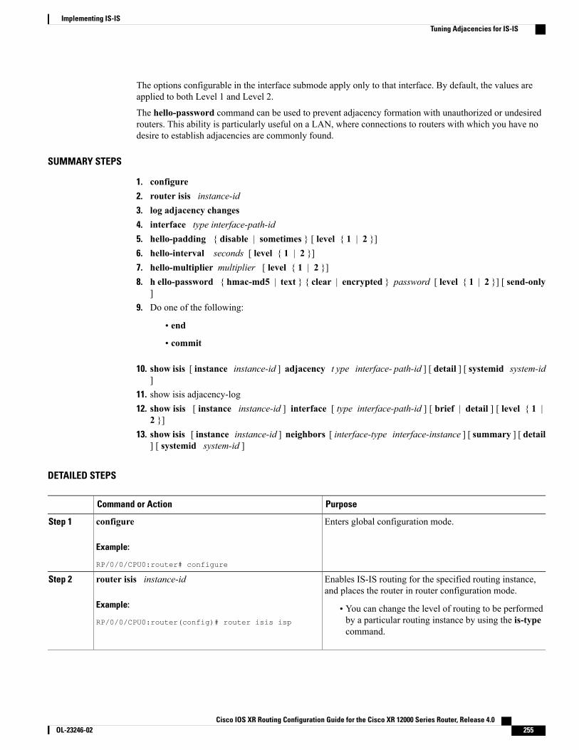
The options configurable in the interface submode apply only to that interface. By default, the values areapplied to both Level 1 and Level 2.
The hello-password command can be used to prevent adjacency formation with unauthorized or undesiredrouters. This ability is particularly useful on a LAN, where connections to routers with which you have nodesire to establish adjacencies are commonly found.
SUMMARY STEPS
1. configure2. router isis instance-id3. log adjacency changes4. interface type interface-path-id5. hello-padding { disable | sometimes } [ level { 1 | 2 }]6. hello-interval seconds [ level { 1 | 2 }]7. hello-multiplier multiplier [ level { 1 | 2 }]8. h ello-password { hmac-md5 | text } { clear | encrypted } password [ level { 1 | 2 }] [ send-only
]9. Do one of the following:
• end
• commit
10. show isis [ instance instance-id ] adjacency t ype interface- path-id ] [ detail ] [ systemid system-id]
11. show isis adjacency-log12. show isis [ instance instance-id ] interface [ type interface-path-id ] [ brief | detail ] [ level { 1 |
2 }]13. show isis [ instance instance-id ] neighbors [ interface-type interface-instance ] [ summary ] [ detail
] [ systemid system-id ]
DETAILED STEPS
PurposeCommand or Action
Enters global configuration mode.configure
Example:
RP/0/0/CPU0:router# configure
Step 1
Enables IS-IS routing for the specified routing instance,and places the router in router configuration mode.
router isis instance-id
Example:
RP/0/0/CPU0:router(config)# router isis isp
Step 2
• You can change the level of routing to be performedby a particular routing instance by using the is-typecommand.
Cisco IOS XR Routing Configuration Guide for the Cisco XR 12000 Series Router, Release 4.0 OL-23246-02 255
Implementing IS-ISTuning Adjacencies for IS-IS

PurposeCommand or Action
Generates a log message when an IS-IS adjacency changesstate (up or down).
log adjacency changes
Example:
RP/0/0/CPU0:router(config-isis)# log adjacencychanges
Step 3
Enters interface configuration mode.interface type interface-path-id
Example:
RP/0/0/CPU0:router(config-isis)# interfaceGigabitEthernet 0/1/0/3
Step 4
Configures padding on IS-IS hello PDUs for an IS-ISinterface on the router.
hello-padding { disable | sometimes } [ level { 1 | 2 }]
Example:
RP/0/0/CPU0:router(config-isis-if)# hello-paddingsometimes
Step 5
• Hello padding applies to only this interface and notto all interfaces.
Specifies the length of time between hello packets that thesoftware sends.
hello-interval seconds [ level { 1 | 2 }]
Example:
RP/0/0/CPU0:router(config-isis-if)#hello-interval6
Step 6
Specifies the number of IS-IS hello packets a neighbor mustmiss before the router should declare the adjacency as down.
hello-multiplier multiplier [ level { 1 | 2 }]
Example:
RP/0/0/CPU0:router(config-isis-if)#hello-multiplier 10
Step 7
• A higher value increases the networks tolerance fordropped packets, but also may increase the amount oftime required to detect the failure of an adjacent router.
• Conversely, not detecting the failure of an adjacentrouter can result in greater packet loss.
Specifies that this system include authentication in the hellopackets and requires successful authentication of the hellopacket from the neighbor to establish an adjacency.
h ello-password { hmac-md5 | text } { clear |encrypted } password [ level { 1 | 2 }] [ send-only ]
Example:
RP/0/0/CPU0:router(config-isis-if)# hello-passwordtext clear mypassword
Step 8
Saves configuration changes.Do one of the following:Step 9
• end •When you issue the end command, the systemprompts you to commit changes:
Uncommitted changes found, commit them
• commit
Example:
RP/0/0/CPU0:router(config-isis-if)# end
before exiting(yes/no/cancel)?[cancel]:
Cisco IOS XR Routing Configuration Guide for the Cisco XR 12000 Series Router, Release 4.0256 OL-23246-02
Implementing IS-ISTuning Adjacencies for IS-IS

PurposeCommand or Action
◦Entering yes saves configuration changes to therunning configuration file, exits the
or
RP/0/0/CPU0:router(config-isis-if)# commit configuration session, and returns the router toEXEC mode.
◦Entering no exits the configuration session andreturns the router to EXEC mode withoutcommitting the configuration changes.
◦Entering cancel leaves the router in the currentconfiguration session without exiting orcommitting the configuration changes.
• Use the commit command to save the configurationchanges to the running configuration file and remainwithin the configuration session.
(Optional) Displays IS-IS adjacencies.show isis [ instance instance-id ] adjacency t ypeinterface- path-id ] [ detail ] [ systemid system-id ]
Step 10
Example:
RP/0/0/CPU0:router# show isis instance ispadjacency
(Optional) Displays a log of the most recent adjacency statetransitions.
show isis adjacency-log
Example:
RP/0/0/CPU0:router# show isis adjacency-log
Step 11
(Optional) Displays information about the IS-IS interface.show isis [ instance instance-id ] interface [ typeinterface-path-id ] [ brief | detail ] [ level { 1 | 2 }]
Step 12
Example:
RP/0/0/CPU0:router# show isis interfaceGigabitEthernet 0/1/0/1 brief
(Optional) Displays information about IS-IS neighbors.show isis [ instance instance-id ] neighbors [interface-type interface-instance ] [ summary ] [ detail ][ systemid system-id ]
Step 13
Example:
RP/0/0/CPU0:router# show isis neighbors summary
Cisco IOS XR Routing Configuration Guide for the Cisco XR 12000 Series Router, Release 4.0 OL-23246-02 257
Implementing IS-ISTuning Adjacencies for IS-IS
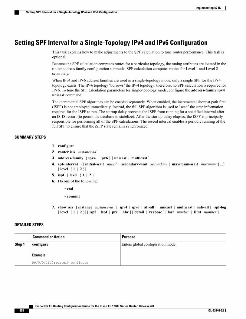
Setting SPF Interval for a Single-Topology IPv4 and IPv6 ConfigurationThis task explains how to make adjustments to the SPF calculation to tune router performance. This task isoptional.
Because the SPF calculation computes routes for a particular topology, the tuning attributes are located in therouter address family configuration submode. SPF calculation computes routes for Level 1 and Level 2separately.
When IPv4 and IPv6 address families are used in a single-topology mode, only a single SPF for the IPv4topology exists. The IPv6 topology “borrows” the IPv4 topology; therefore, no SPF calculation is required forIPv6. To tune the SPF calculation parameters for single-topology mode, configure the address-family ipv4unicast command.
The incremental SPF algorithm can be enabled separately. When enabled, the incremental shortest path first(ISPF) is not employed immediately. Instead, the full SPF algorithm is used to “seed” the state informationrequired for the ISPF to run. The startup delay prevents the ISPF from running for a specified interval afteran IS-IS restart (to permit the database to stabilize). After the startup delay elapses, the ISPF is principallyresponsible for performing all of the SPF calculations. The reseed interval enables a periodic running of thefull SPF to ensure that the iSFP state remains synchronized.
SUMMARY STEPS
1. configure2. router isis instance-id3. address-family { ipv4 | ipv6 } [ unicast | multicast ]4. spf-interval {[ initial-wait initial | secondary-wait secondary | maximum-wait maximum ] ...}
[ level { 1 | 2 }]5. ispf [ level { 1 | 2 }]6. Do one of the following:
• end
• commit
7. show isis [ instance instance-id ] [[ ipv4 | ipv6 | afi-all ] [ unicast | multicast | safi-all ]] spf-log[ level { 1 | 2 }] [ ispf | fspf | prc | nhc ] [ detail | verbose ] [ last number | first number ]
DETAILED STEPS
PurposeCommand or Action
Enters global configuration mode.configure
Example:
RP/0/0/CPU0:router# configure
Step 1
Cisco IOS XR Routing Configuration Guide for the Cisco XR 12000 Series Router, Release 4.0258 OL-23246-02
Implementing IS-ISSetting SPF Interval for a Single-Topology IPv4 and IPv6 Configuration
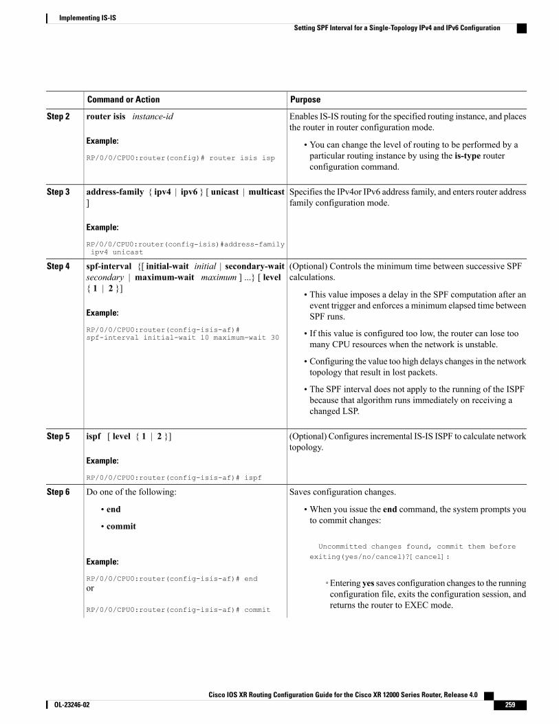
PurposeCommand or Action
Enables IS-IS routing for the specified routing instance, and placesthe router in router configuration mode.
router isis instance-id
Example:
RP/0/0/CPU0:router(config)# router isis isp
Step 2
• You can change the level of routing to be performed by aparticular routing instance by using the is-type routerconfiguration command.
Specifies the IPv4or IPv6 address family, and enters router addressfamily configuration mode.
address-family { ipv4 | ipv6 } [ unicast | multicast]
Example:
RP/0/0/CPU0:router(config-isis)#address-familyipv4 unicast
Step 3
(Optional) Controls the minimum time between successive SPFcalculations.
spf-interval {[ initial-wait initial | secondary-waitsecondary | maximum-wait maximum ] ...} [ level{ 1 | 2 }]
Step 4
• This value imposes a delay in the SPF computation after anevent trigger and enforces a minimum elapsed time betweenSPF runs.Example:
RP/0/0/CPU0:router(config-isis-af)#spf-interval initial-wait 10 maximum-wait 30 • If this value is configured too low, the router can lose too
many CPU resources when the network is unstable.
• Configuring the value too high delays changes in the networktopology that result in lost packets.
• The SPF interval does not apply to the running of the ISPFbecause that algorithm runs immediately on receiving achanged LSP.
(Optional) Configures incremental IS-IS ISPF to calculate networktopology.
ispf [ level { 1 | 2 }]
Example:
RP/0/0/CPU0:router(config-isis-af)# ispf
Step 5
Saves configuration changes.Do one of the following:Step 6
• end •When you issue the end command, the system prompts youto commit changes:
Uncommitted changes found, commit them before
• commit
Example:
RP/0/0/CPU0:router(config-isis-af)# end
exiting(yes/no/cancel)?[cancel]:
◦Entering yes saves configuration changes to the runningconfiguration file, exits the configuration session, andreturns the router to EXEC mode.
or
RP/0/0/CPU0:router(config-isis-af)# commit
Cisco IOS XR Routing Configuration Guide for the Cisco XR 12000 Series Router, Release 4.0 OL-23246-02 259
Implementing IS-ISSetting SPF Interval for a Single-Topology IPv4 and IPv6 Configuration
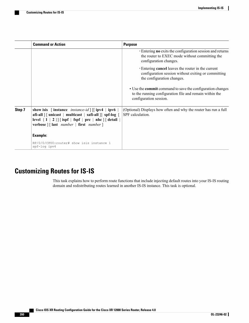
PurposeCommand or Action
◦Entering no exits the configuration session and returnsthe router to EXEC mode without committing theconfiguration changes.
◦Entering cancel leaves the router in the currentconfiguration session without exiting or committingthe configuration changes.
• Use the commit command to save the configuration changesto the running configuration file and remain within theconfiguration session.
(Optional) Displays how often and why the router has run a fullSPF calculation.
show isis [ instance instance-id ] [[ ipv4 | ipv6 |afi-all ] [ unicast | multicast | safi-all ]] spf-log [level { 1 | 2 }] [ ispf | fspf | prc | nhc ] [ detail |verbose ] [ last number | first number ]
Step 7
Example:
RP/0/0/CPU0:router# show isis instance 1spf-log ipv4
Customizing Routes for IS-ISThis task explains how to perform route functions that include injecting default routes into your IS-IS routingdomain and redistributing routes learned in another IS-IS instance. This task is optional.
Cisco IOS XR Routing Configuration Guide for the Cisco XR 12000 Series Router, Release 4.0260 OL-23246-02
Implementing IS-ISCustomizing Routes for IS-IS
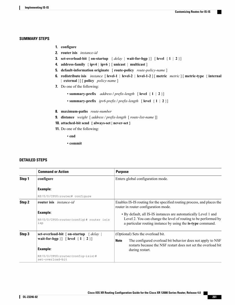
SUMMARY STEPS
1. configure2. router isis instance-id3. set-overload-bit [ on-startup { delay | wait-for-bgp }] [ level { 1 | 2 }]4. address-family { ipv4 | ipv6 } [ unicast | multicast ]5. default-information originate [ route-policy route-policy-name ]6. redistribute isis instance [ level-1 | level-2 | level-1-2 ] [metric metric ] [metric-type { internal
| external }] [ policy policy-name ]7. Do one of the following:
• summary-prefix address / prefix-length [ level { 1 | 2 }]
• summary-prefix ipv6-prefix / prefix-length [ level { 1 | 2 }]
8. maximum-paths route-number9. distance weight [ address / prefix-length [ route-list-name ]]10. attached-bit send { always-set | never-set }11. Do one of the following:
• end
• commit
DETAILED STEPS
PurposeCommand or Action
Enters global configuration mode.configure
Example:
RP/0/0/CPU0:router# configure
Step 1
Enables IS-IS routing for the specified routing process, and places therouter in router configuration mode.
router isis instance-id
Example:
RP/0/0/CPU0:router(config)# router isisisp
Step 2
• By default, all IS-IS instances are automatically Level 1 andLevel 2. You can change the level of routing to be performed bya particular routing instance by using the is-type command.
(Optional) Sets the overload bit.set-overload-bit [ on-startup { delay |wait-for-bgp }] [ level { 1 | 2 }]
Step 3
The configured overload bit behavior does not apply to NSFrestarts because the NSF restart does not set the overload bitduring restart.
Note
Example:
RP/0/0/CPU0:router(config-isis)#set-overload-bit
Cisco IOS XR Routing Configuration Guide for the Cisco XR 12000 Series Router, Release 4.0 OL-23246-02 261
Implementing IS-ISCustomizing Routes for IS-IS
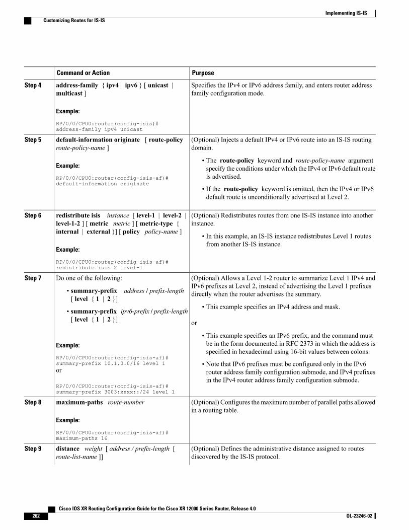
PurposeCommand or Action
Specifies the IPv4 or IPv6 address family, and enters router addressfamily configuration mode.
address-family { ipv4 | ipv6 } [ unicast |multicast ]
Example:
RP/0/0/CPU0:router(config-isis)#address-family ipv4 unicast
Step 4
(Optional) Injects a default IPv4 or IPv6 route into an IS-IS routingdomain.
default-information originate [ route-policyroute-policy-name ]
Step 5
Example:
RP/0/0/CPU0:router(config-isis-af)#default-information originate
• The route-policy keyword and route-policy-name argumentspecify the conditions under which the IPv4 or IPv6 default routeis advertised.
• If the route-policy keyword is omitted, then the IPv4 or IPv6default route is unconditionally advertised at Level 2.
(Optional) Redistributes routes from one IS-IS instance into anotherinstance.
redistribute isis instance [ level-1 | level-2 |level-1-2 ] [ metric metric ] [ metric-type {internal | external }] [ policy policy-name ]
Step 6
• In this example, an IS-IS instance redistributes Level 1 routesfrom another IS-IS instance.
Example:
RP/0/0/CPU0:router(config-isis-af)#redistribute isis 2 level-1
(Optional) Allows a Level 1-2 router to summarize Level 1 IPv4 andIPv6 prefixes at Level 2, instead of advertising the Level 1 prefixesdirectly when the router advertises the summary.
Do one of the following:Step 7
• summary-prefix address / prefix-length[ level { 1 | 2 }]
• This example specifies an IPv4 address and mask.• summary-prefix ipv6-prefix / prefix-length[ level { 1 | 2 }] or
Example:
RP/0/0/CPU0:router(config-isis-af)#summary-prefix 10.1.0.0/16 level 1
• This example specifies an IPv6 prefix, and the command mustbe in the form documented in RFC 2373 in which the address isspecified in hexadecimal using 16-bit values between colons.
• Note that IPv6 prefixes must be configured only in the IPv6router address family configuration submode, and IPv4 prefixesin the IPv4 router address family configuration submode.
or
RP/0/0/CPU0:router(config-isis-af)#summary-prefix 3003:xxxx::/24 level 1
(Optional) Configures the maximum number of parallel paths allowedin a routing table.
maximum-paths route-number
Example:
RP/0/0/CPU0:router(config-isis-af)#maximum-paths 16
Step 8
(Optional) Defines the administrative distance assigned to routesdiscovered by the IS-IS protocol.
distance weight [ address / prefix-length [route-list-name ]]
Step 9
Cisco IOS XR Routing Configuration Guide for the Cisco XR 12000 Series Router, Release 4.0262 OL-23246-02
Implementing IS-ISCustomizing Routes for IS-IS
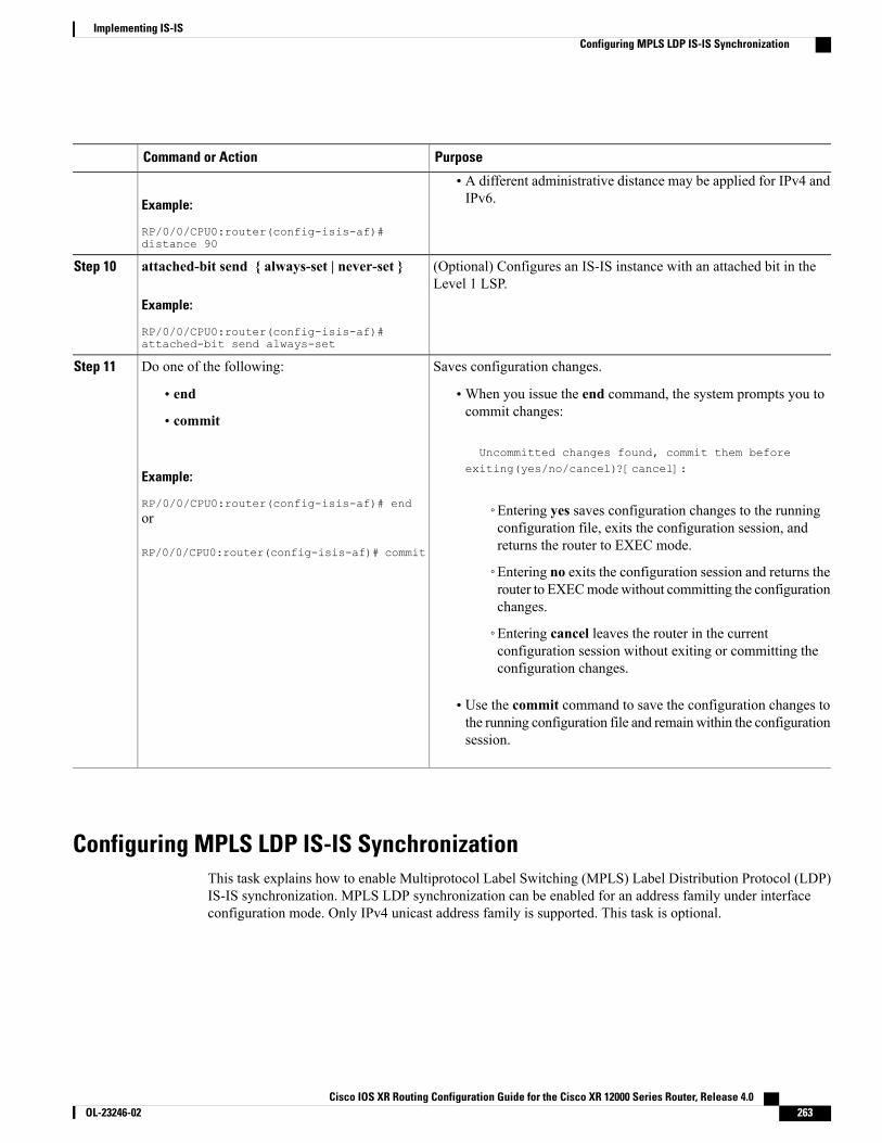
PurposeCommand or Action
Example:
RP/0/0/CPU0:router(config-isis-af)#distance 90
• A different administrative distance may be applied for IPv4 andIPv6.
(Optional) Configures an IS-IS instance with an attached bit in theLevel 1 LSP.
attached-bit send { always-set | never-set }
Example:
RP/0/0/CPU0:router(config-isis-af)#attached-bit send always-set
Step 10
Saves configuration changes.Do one of the following:Step 11
• end •When you issue the end command, the system prompts you tocommit changes:
Uncommitted changes found, commit them before
• commit
Example:
RP/0/0/CPU0:router(config-isis-af)# end
exiting(yes/no/cancel)?[cancel]:
◦Entering yes saves configuration changes to the runningconfiguration file, exits the configuration session, andreturns the router to EXEC mode.
or
RP/0/0/CPU0:router(config-isis-af)# commit
◦Entering no exits the configuration session and returns therouter to EXECmodewithout committing the configurationchanges.
◦Entering cancel leaves the router in the currentconfiguration session without exiting or committing theconfiguration changes.
• Use the commit command to save the configuration changes tothe running configuration file and remain within the configurationsession.
Configuring MPLS LDP IS-IS SynchronizationThis task explains how to enable Multiprotocol Label Switching (MPLS) Label Distribution Protocol (LDP)IS-IS synchronization. MPLS LDP synchronization can be enabled for an address family under interfaceconfiguration mode. Only IPv4 unicast address family is supported. This task is optional.
Cisco IOS XR Routing Configuration Guide for the Cisco XR 12000 Series Router, Release 4.0 OL-23246-02 263
Implementing IS-ISConfiguring MPLS LDP IS-IS Synchronization
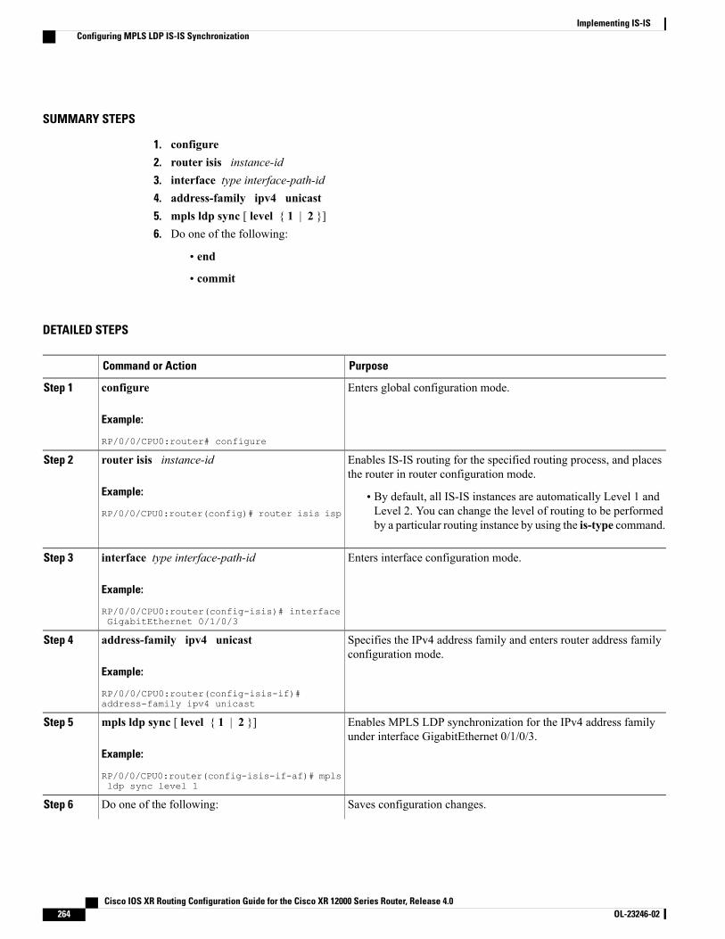
SUMMARY STEPS
1. configure2. router isis instance-id3. interface type interface-path-id4. address-family ipv4 unicast5. mpls ldp sync [ level { 1 | 2 }]6. Do one of the following:
• end
• commit
DETAILED STEPS
PurposeCommand or Action
Enters global configuration mode.configure
Example:
RP/0/0/CPU0:router# configure
Step 1
Enables IS-IS routing for the specified routing process, and placesthe router in router configuration mode.
router isis instance-id
Example:
RP/0/0/CPU0:router(config)# router isis isp
Step 2
• By default, all IS-IS instances are automatically Level 1 andLevel 2. You can change the level of routing to be performedby a particular routing instance by using the is-type command.
Enters interface configuration mode.interface type interface-path-id
Example:
RP/0/0/CPU0:router(config-isis)# interfaceGigabitEthernet 0/1/0/3
Step 3
Specifies the IPv4 address family and enters router address familyconfiguration mode.
address-family ipv4 unicast
Example:
RP/0/0/CPU0:router(config-isis-if)#address-family ipv4 unicast
Step 4
Enables MPLS LDP synchronization for the IPv4 address familyunder interface GigabitEthernet 0/1/0/3.
mpls ldp sync [ level { 1 | 2 }]
Example:
RP/0/0/CPU0:router(config-isis-if-af)# mplsldp sync level 1
Step 5
Saves configuration changes.Do one of the following:Step 6
Cisco IOS XR Routing Configuration Guide for the Cisco XR 12000 Series Router, Release 4.0264 OL-23246-02
Implementing IS-ISConfiguring MPLS LDP IS-IS Synchronization
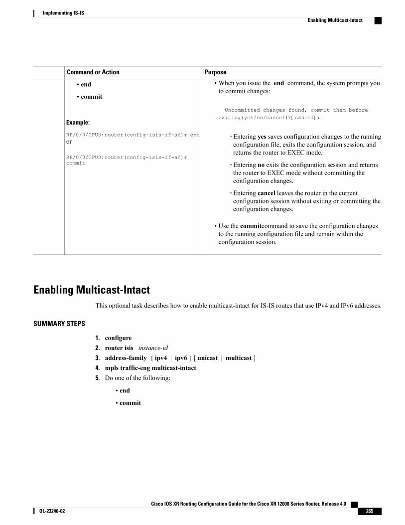
PurposeCommand or Action
•When you issue the end command, the system prompts youto commit changes:
Uncommitted changes found, commit them before
• end
• commit
Example:
RP/0/0/CPU0:router(config-isis-if-af)# end
exiting(yes/no/cancel)?[cancel]:
◦Entering yes saves configuration changes to the runningconfiguration file, exits the configuration session, andreturns the router to EXEC mode.
or
RP/0/0/CPU0:router(config-isis-if-af)#commit ◦Entering no exits the configuration session and returns
the router to EXEC mode without committing theconfiguration changes.
◦Entering cancel leaves the router in the currentconfiguration session without exiting or committing theconfiguration changes.
• Use the commitcommand to save the configuration changesto the running configuration file and remain within theconfiguration session.
Enabling Multicast-IntactThis optional task describes how to enable multicast-intact for IS-IS routes that use IPv4 and IPv6 addresses.
SUMMARY STEPS
1. configure2. router isis instance-id3. address-family { ipv4 | ipv6 } [ unicast | multicast ]4. mpls traffic-eng multicast-intact5. Do one of the following:
• end
• commit
Cisco IOS XR Routing Configuration Guide for the Cisco XR 12000 Series Router, Release 4.0 OL-23246-02 265
Implementing IS-ISEnabling Multicast-Intact

DETAILED STEPS
PurposeCommand or Action
Enters global configuration mode.configure
Example:
RP/0/0/CPU0:router# configure
Step 1
Enables IS-IS routing for the specified routing process, and places therouter in router configuration mode. In this example, the IS-IS instanceis called isp.
router isis instance-id
Example:
RP/0/0/CPU0:router(config)# router isisisp
Step 2
Specifies the IPv4 or IPv6 address family, and enters router addressfamily configuration mode.
address-family { ipv4 | ipv6 } [ unicast |multicast ]
Example:
RP/0/0/CPU0:router(config-isis)#address-family ipv4 unicast
Step 3
Enables multicast-intact.mpls traffic-eng multicast-intact
Example:
RP/0/0/CPU0:router(config-isis-af)# mplstraffic-eng multicast-intact
Step 4
Saves configuration changes.Do one of the following:Step 5
• end •When you issue the end command, the system prompts you tocommit changes:
Uncommitted changes found, commit them before
• commit
Example:
RP/0/0/CPU0:router(config-isis-af)# end
exiting(yes/no/cancel)?[cancel]:
◦Entering yes saves configuration changes to the runningconfiguration file, exits the configuration session, and returnsthe router to EXEC mode.
or
RP/0/0/CPU0:router(config-isis-af)#commit ◦Entering no exits the configuration session and returns the
router to EXECmode without committing the configurationchanges.
◦Entering cancel leaves the router in the current configurationsession without exiting or committing the configurationchanges.
• Use the commit command to save the configuration changes tothe running configuration file and remain within the configurationsession.
Cisco IOS XR Routing Configuration Guide for the Cisco XR 12000 Series Router, Release 4.0266 OL-23246-02
Implementing IS-ISEnabling Multicast-Intact
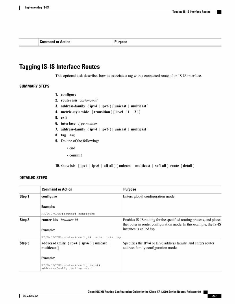
PurposeCommand or Action
Tagging IS-IS Interface RoutesThis optional task describes how to associate a tag with a connected route of an IS-IS interface.
SUMMARY STEPS
1. configure2. router isis instance-id3. address-family { ipv4 | ipv6 } [ unicast | multicast ]4. metric-style wide [ transition ] [ level { 1 | 2 }]5. exit6. interface type number7. address-family { ipv4 | ipv6 } [ unicast | multicast ]8. tag tag9. Do one of the following:
• end
• commit
10. show isis [ ipv4 | ipv6 | afi-all ] [ unicast | multicast | safi-all ] route [ detail ]
DETAILED STEPS
PurposeCommand or Action
Enters global configuration mode.configure
Example:
RP/0/0/CPU0:router# configure
Step 1
Enables IS-IS routing for the specified routing process, and placesthe router in router configuration mode. In this example, the IS-ISinstance is called isp.
router isis instance-id
Example:
RP/0/0/CPU0:router(config)# router isis isp
Step 2
Specifies the IPv4 or IPv6 address family, and enters routeraddress family configuration mode.
address-family { ipv4 | ipv6 } [ unicast |multicast ]
Example:
RP/0/0/CPU0:router(config-isis)#address-family ipv4 unicast
Step 3
Cisco IOS XR Routing Configuration Guide for the Cisco XR 12000 Series Router, Release 4.0 OL-23246-02 267
Implementing IS-ISTagging IS-IS Interface Routes
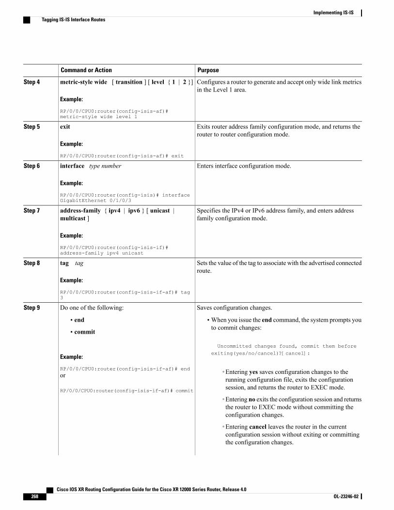
PurposeCommand or Action
Configures a router to generate and accept only wide link metricsin the Level 1 area.
metric-style wide [ transition ] [ level { 1 | 2 }]
Example:
RP/0/0/CPU0:router(config-isis-af)#metric-style wide level 1
Step 4
Exits router address family configuration mode, and returns therouter to router configuration mode.
exit
Example:
RP/0/0/CPU0:router(config-isis-af)# exit
Step 5
Enters interface configuration mode.interface type number
Example:
RP/0/0/CPU0:router(config-isis)# interfaceGigabitEthernet 0/1/0/3
Step 6
Specifies the IPv4 or IPv6 address family, and enters addressfamily configuration mode.
address-family { ipv4 | ipv6 } [ unicast |multicast ]
Example:
RP/0/0/CPU0:router(config-isis-if)#address-family ipv4 unicast
Step 7
Sets the value of the tag to associate with the advertised connectedroute.
tag tag
Example:
RP/0/0/CPU0:router(config-isis-if-af)# tag3
Step 8
Saves configuration changes.Do one of the following:Step 9
• end •When you issue the end command, the system prompts youto commit changes:
Uncommitted changes found, commit them before
• commit
Example:
RP/0/0/CPU0:router(config-isis-if-af)# end
exiting(yes/no/cancel)?[cancel]:
◦Entering yes saves configuration changes to therunning configuration file, exits the configurationsession, and returns the router to EXEC mode.
or
RP/0/0/CPU0:router(config-isis-if-af)# commit
◦Entering no exits the configuration session and returnsthe router to EXEC mode without committing theconfiguration changes.
◦Entering cancel leaves the router in the currentconfiguration session without exiting or committingthe configuration changes.
Cisco IOS XR Routing Configuration Guide for the Cisco XR 12000 Series Router, Release 4.0268 OL-23246-02
Implementing IS-ISTagging IS-IS Interface Routes
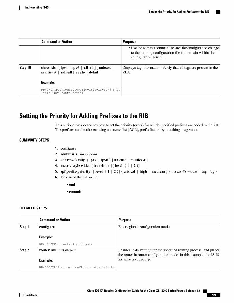
PurposeCommand or Action
• Use the commit command to save the configuration changesto the running configuration file and remain within theconfiguration session.
Displays tag information. Verify that all tags are present in theRIB.
show isis [ ipv4 | ipv6 | afi-all ] [ unicast |multicast | safi-all ] route [ detail ]
Example:
RP/0/0/CPU0:router(config-isis-if-af)# showisis ipv4 route detail
Step 10
Setting the Priority for Adding Prefixes to the RIBThis optional task describes how to set the priority (order) for which specified prefixes are added to the RIB.The prefixes can be chosen using an access list (ACL), prefix list, or by matching a tag value.
SUMMARY STEPS
1. configure2. router isis instance-id3. address-family { ipv4 | ipv6 } [ unicast | multicast ]4. metric-style wide [ transition ] [ level { 1 | 2 }]5. spf prefix-priority [ level { 1 | 2 }] { critical | high | medium } { access-list-name | tag tag }6. Do one of the following:
• end
• commit
DETAILED STEPS
PurposeCommand or Action
Enters global configuration mode.configure
Example:
RP/0/0/CPU0:router# configure
Step 1
Enables IS-IS routing for the specified routing process, and placesthe router in router configuration mode. In this example, the IS-ISinstance is called isp.
router isis instance-id
Example:
RP/0/0/CPU0:router(config)# router isis isp
Step 2
Cisco IOS XR Routing Configuration Guide for the Cisco XR 12000 Series Router, Release 4.0 OL-23246-02 269
Implementing IS-ISSetting the Priority for Adding Prefixes to the RIB

PurposeCommand or Action
Specifies the IPv4 or IPv6 address family, and enters router addressfamily configuration mode.
address-family { ipv4 | ipv6 } [ unicast |multicast ]
Example:
RP/0/0/CPU0:router(config-isis)#address-family ipv4 unicast
Step 3
Configures a router to generate and accept only wide-link metricsin the Level 1 area.
metric-style wide [ transition ] [ level { 1 | 2}]
Example:
RP/0/0/CPU0:router(config-isis-af)#metric-style wide level 1
Step 4
Installs all routes tagged with the value 3 first.spf prefix-priority [ level { 1 | 2 }] { critical |high | medium } { access-list-name | tag tag }
Step 5
Example:
RP/0/0/CPU0:router(config-isis-af)# spfprefix-priority high tag 3
Saves configuration changes.Do one of the following:Step 6
• end •When you issue the end command, the system prompts youto commit changes:
Uncommitted changes found, commit them before
• commit
Example:
RP/0/0/CPU0:router(config-isis-af)# end
exiting(yes/no/cancel)?[cancel]:
◦Entering yessaves configuration changes to the runningconfiguration file, exits the configuration session, andreturns the router to EXEC mode.
or
RP/0/0/CPU0:router(config-isis-af)# commit
◦Entering no exits the configuration session and returnsthe router to EXEC mode without committing theconfiguration changes.
◦Entering cancel leaves the router in the currentconfiguration session without exiting or committing theconfiguration changes.
• Use the commit command to save the configuration changesto the running configuration file and remain within theconfiguration session.
Cisco IOS XR Routing Configuration Guide for the Cisco XR 12000 Series Router, Release 4.0270 OL-23246-02
Implementing IS-ISSetting the Priority for Adding Prefixes to the RIB
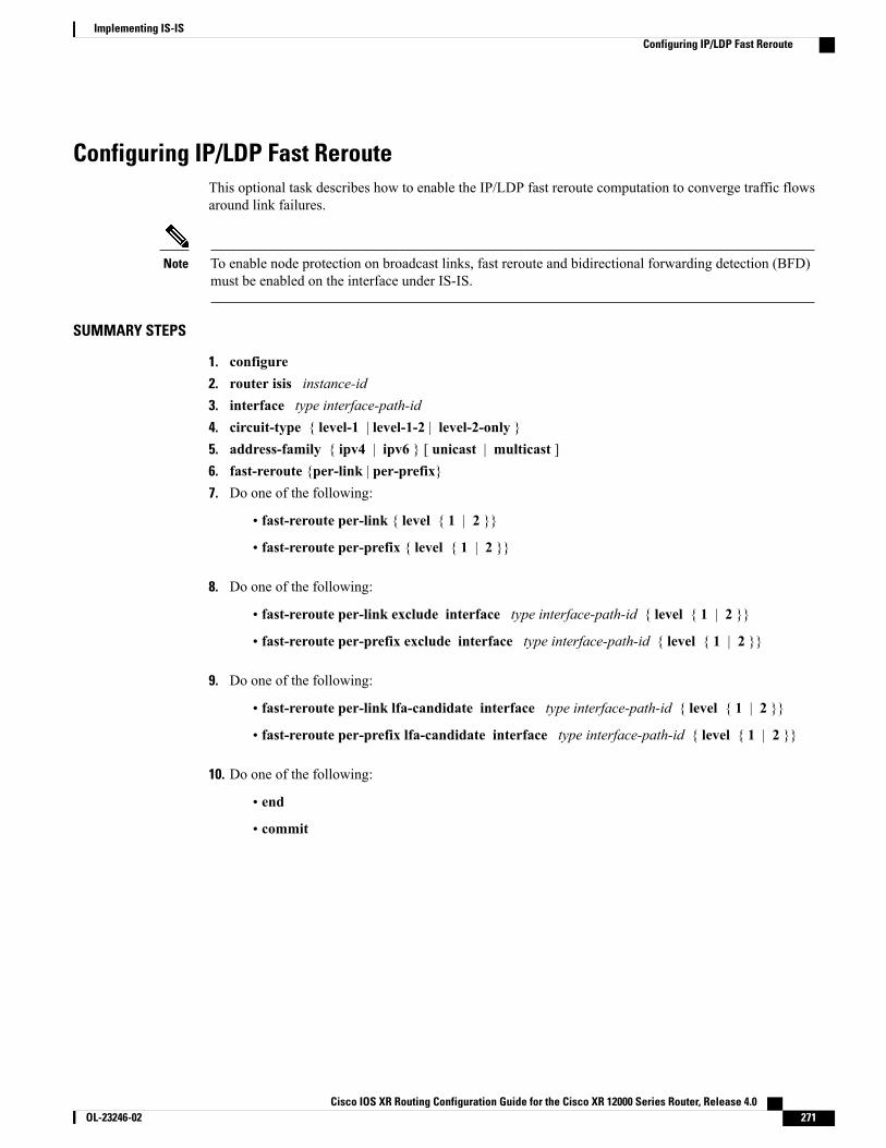
Configuring IP/LDP Fast RerouteThis optional task describes how to enable the IP/LDP fast reroute computation to converge traffic flowsaround link failures.
To enable node protection on broadcast links, fast reroute and bidirectional forwarding detection (BFD)must be enabled on the interface under IS-IS.
Note
SUMMARY STEPS
1. configure2. router isis instance-id3. interface type interface-path-id4. circuit-type { level-1 | level-1-2 | level-2-only }5. address-family { ipv4 | ipv6 } [ unicast | multicast ]6. fast-reroute {per-link | per-prefix}7. Do one of the following:
• fast-reroute per-link { level { 1 | 2 }}
• fast-reroute per-prefix { level { 1 | 2 }}
8. Do one of the following:
• fast-reroute per-link exclude interface type interface-path-id { level { 1 | 2 }}
• fast-reroute per-prefix exclude interface type interface-path-id { level { 1 | 2 }}
9. Do one of the following:
• fast-reroute per-link lfa-candidate interface type interface-path-id { level { 1 | 2 }}
• fast-reroute per-prefix lfa-candidate interface type interface-path-id { level { 1 | 2 }}
10. Do one of the following:
• end
• commit
Cisco IOS XR Routing Configuration Guide for the Cisco XR 12000 Series Router, Release 4.0 OL-23246-02 271
Implementing IS-ISConfiguring IP/LDP Fast Reroute
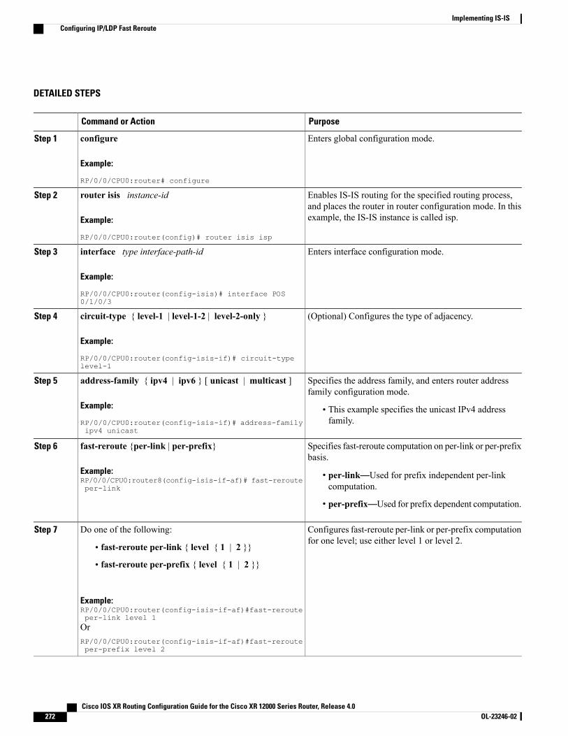
DETAILED STEPS
PurposeCommand or Action
Enters global configuration mode.configure
Example:
RP/0/0/CPU0:router# configure
Step 1
Enables IS-IS routing for the specified routing process,and places the router in router configuration mode. In thisexample, the IS-IS instance is called isp.
router isis instance-id
Example:
RP/0/0/CPU0:router(config)# router isis isp
Step 2
Enters interface configuration mode.interface type interface-path-id
Example:
RP/0/0/CPU0:router(config-isis)# interface POS0/1/0/3
Step 3
(Optional) Configures the type of adjacency.circuit-type { level-1 | level-1-2 | level-2-only }
Example:
RP/0/0/CPU0:router(config-isis-if)# circuit-typelevel-1
Step 4
Specifies the address family, and enters router addressfamily configuration mode.
address-family { ipv4 | ipv6 } [ unicast | multicast ]
Example:
RP/0/0/CPU0:router(config-isis-if)# address-familyipv4 unicast
Step 5
• This example specifies the unicast IPv4 addressfamily.
Specifies fast-reroute computation on per-link or per-prefixbasis.
fast-reroute {per-link | per-prefix}
Example:RP/0/0/CPU0:router8(config-isis-if-af)# fast-rerouteper-link
Step 6
• per-link—Used for prefix independent per-linkcomputation.
• per-prefix—Used for prefix dependent computation.
Configures fast-reroute per-link or per-prefix computationfor one level; use either level 1 or level 2.
Do one of the following:Step 7
• fast-reroute per-link { level { 1 | 2 }}
• fast-reroute per-prefix { level { 1 | 2 }}
Example:RP/0/0/CPU0:router(config-isis-if-af)#fast-rerouteper-link level 1OrRP/0/0/CPU0:router(config-isis-if-af)#fast-rerouteper-prefix level 2
Cisco IOS XR Routing Configuration Guide for the Cisco XR 12000 Series Router, Release 4.0272 OL-23246-02
Implementing IS-ISConfiguring IP/LDP Fast Reroute
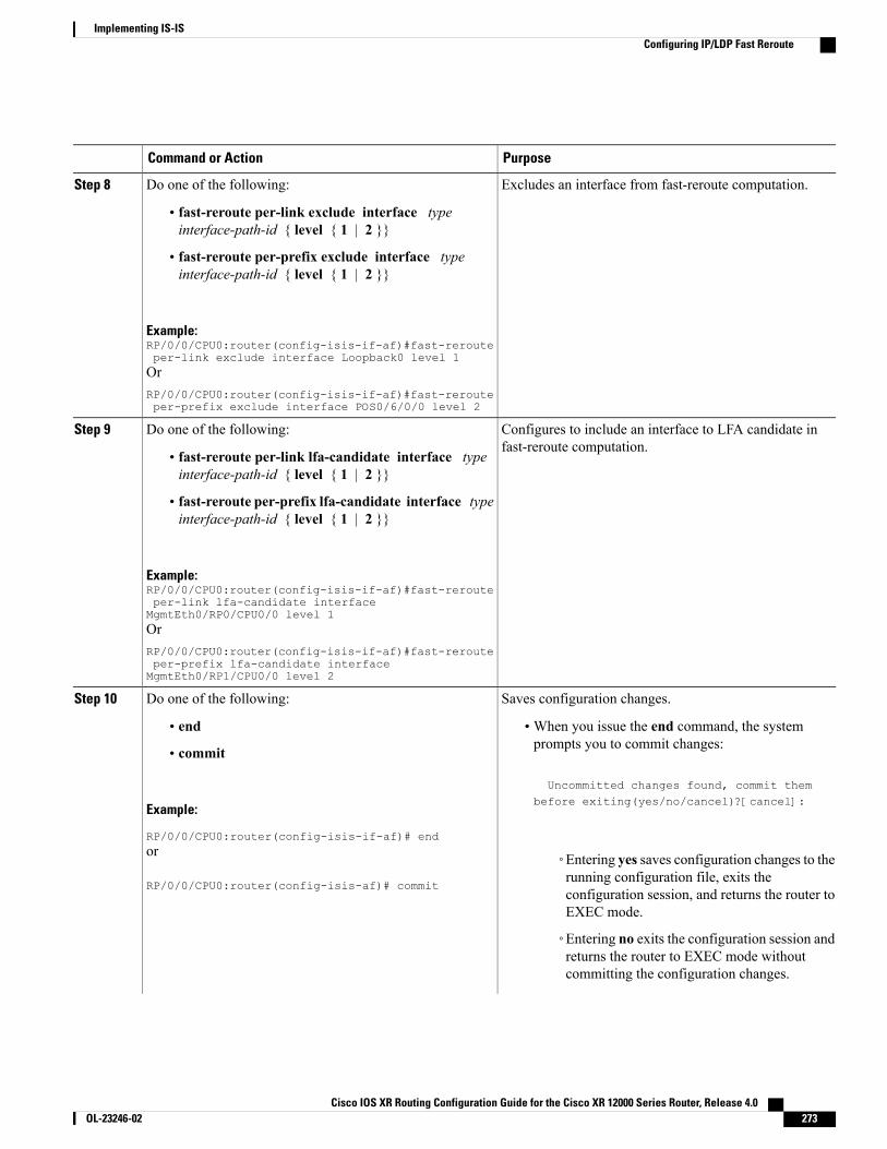
PurposeCommand or Action
Excludes an interface from fast-reroute computation.Do one of the following:Step 8
• fast-reroute per-link exclude interface typeinterface-path-id { level { 1 | 2 }}
• fast-reroute per-prefix exclude interface typeinterface-path-id { level { 1 | 2 }}
Example:RP/0/0/CPU0:router(config-isis-if-af)#fast-rerouteper-link exclude interface Loopback0 level 1OrRP/0/0/CPU0:router(config-isis-if-af)#fast-rerouteper-prefix exclude interface POS0/6/0/0 level 2
Configures to include an interface to LFA candidate infast-reroute computation.
Do one of the following:Step 9
• fast-reroute per-link lfa-candidate interface typeinterface-path-id { level { 1 | 2 }}
• fast-reroute per-prefix lfa-candidate interface typeinterface-path-id { level { 1 | 2 }}
Example:RP/0/0/CPU0:router(config-isis-if-af)#fast-rerouteper-link lfa-candidate interfaceMgmtEth0/RP0/CPU0/0 level 1OrRP/0/0/CPU0:router(config-isis-if-af)#fast-rerouteper-prefix lfa-candidate interfaceMgmtEth0/RP1/CPU0/0 level 2
Saves configuration changes.Do one of the following:Step 10
• end •When you issue the end command, the systemprompts you to commit changes:
Uncommitted changes found, commit them
• commit
Example:
RP/0/0/CPU0:router(config-isis-if-af)# end
before exiting(yes/no/cancel)?[cancel]:
or
RP/0/0/CPU0:router(config-isis-af)# commit
◦Entering yes saves configuration changes to therunning configuration file, exits theconfiguration session, and returns the router toEXEC mode.
◦Entering no exits the configuration session andreturns the router to EXEC mode withoutcommitting the configuration changes.
Cisco IOS XR Routing Configuration Guide for the Cisco XR 12000 Series Router, Release 4.0 OL-23246-02 273
Implementing IS-ISConfiguring IP/LDP Fast Reroute
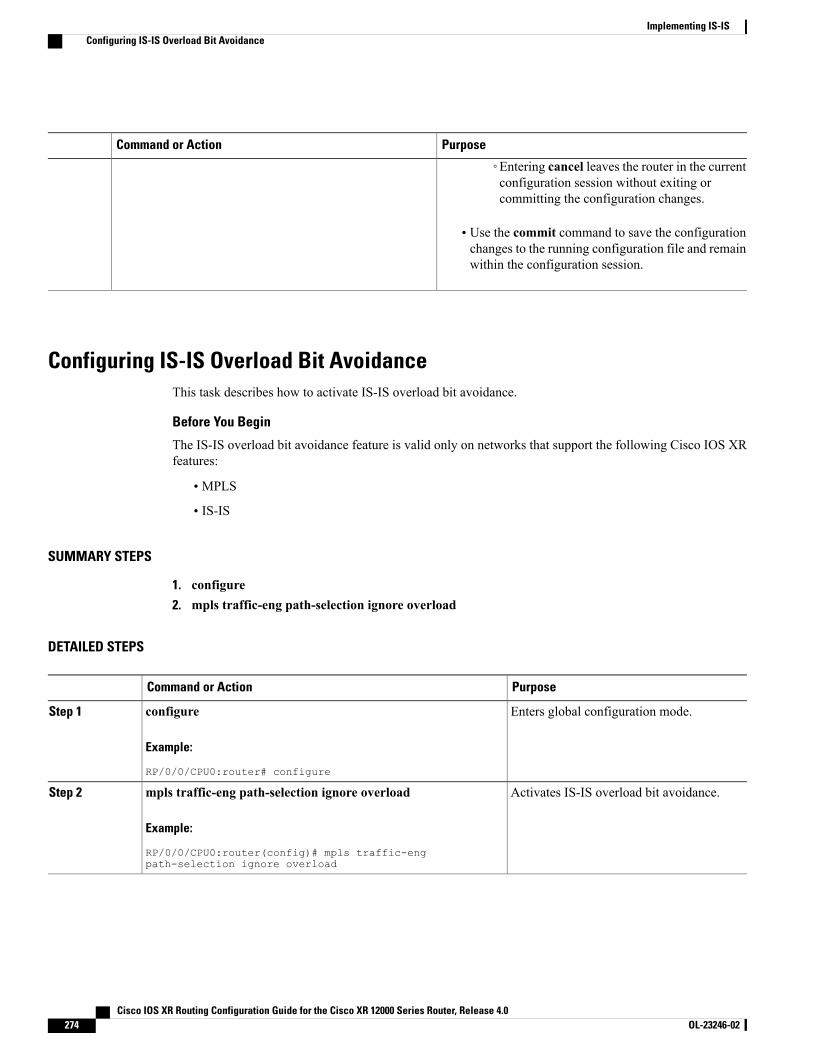
PurposeCommand or Action
◦Entering cancel leaves the router in the currentconfiguration session without exiting orcommitting the configuration changes.
• Use the commit command to save the configurationchanges to the running configuration file and remainwithin the configuration session.
Configuring IS-IS Overload Bit AvoidanceThis task describes how to activate IS-IS overload bit avoidance.
Before You Begin
The IS-IS overload bit avoidance feature is valid only on networks that support the following Cisco IOS XRfeatures:
• MPLS
• IS-IS
SUMMARY STEPS
1. configure2. mpls traffic-eng path-selection ignore overload
DETAILED STEPS
PurposeCommand or Action
Enters global configuration mode.configure
Example:
RP/0/0/CPU0:router# configure
Step 1
Activates IS-IS overload bit avoidance.mpls traffic-eng path-selection ignore overload
Example:
RP/0/0/CPU0:router(config)# mpls traffic-engpath-selection ignore overload
Step 2
Cisco IOS XR Routing Configuration Guide for the Cisco XR 12000 Series Router, Release 4.0274 OL-23246-02
Implementing IS-ISConfiguring IS-IS Overload Bit Avoidance

Configuration Examples for Implementing IS-ISThis section provides the following configuration examples:
Configuring Single-Topology IS-IS for IPv6: ExampleThe following example shows single-topology mode being enabled. An IS-IS instance is created, the NET isdefined, IPv6 is configured along with IPv4 on an interface, and IPv4 link topology is used for IPv6.
This configuration allows POS interface 0/3/0/0 to form adjacencies for both IPv4 and IPv6 addresses.
router isis ispnet 49.0000.0000.0001.00address-family ipv6 unicastsingle-topologyinterface POS0/3/0/0address-family ipv4 unicast!address-family ipv6 unicast!exit
!interface POS0/3/0/0ipv4 address 10.0.1.3 255.255.255.0ipv6 address 2001::1/64
Configuring Multitopology IS-IS for IPv6: ExampleThe following example shows multitopology IS-IS being configured in IPv6.
router isis ispnet 49.0000.0000.0001.00interface POS0/3/0/0address-family ipv6 unicastmetric-style wide level 1exit
!interface POS0/3/0/0ipv6 address 2001::1/64
Redistributing IS-IS Routes Between Multiple Instances: ExampleThe following example shows usage of the attached-bit send always-set and redistribute commands. Twoinstances, instance “1” restricted to Level 1 and instance “2” restricted to Level 2, are configured.The Level 1 instance is propagating routes to the Level 2 instance using redistribution. Note that theadministrative distance is explicitly configured higher on the Level 2 instance to ensure that Level 1 routesare preferred.
Attached bit is being set for the Level 1 instance since it is redistributing routes into the Level 2 instance.Therefore, instance “1” is a suitable candidate to get from the area to the backbone.
router isis 1is-type level-2-only
Cisco IOS XR Routing Configuration Guide for the Cisco XR 12000 Series Router, Release 4.0 OL-23246-02 275
Implementing IS-ISConfiguration Examples for Implementing IS-IS
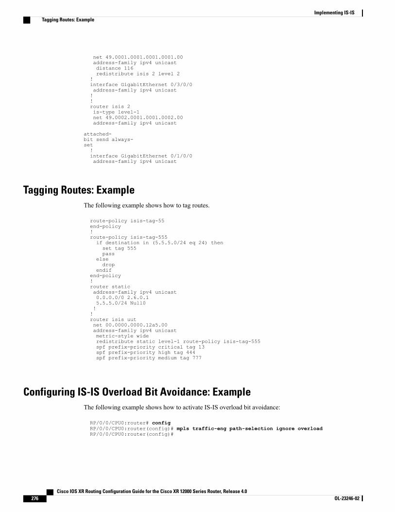
net 49.0001.0001.0001.0001.00address-family ipv4 unicastdistance 116redistribute isis 2 level 2
!interface GigabitEthernet 0/3/0/0address-family ipv4 unicast!!router isis 2is-type level-1net 49.0002.0001.0001.0002.00address-family ipv4 unicast
attached-bit send always-set!interface GigabitEthernet 0/1/0/0address-family ipv4 unicast
Tagging Routes: ExampleThe following example shows how to tag routes.
route-policy isis-tag-55end-policy!route-policy isis-tag-555if destination in (5.5.5.0/24 eq 24) thenset tag 555pass
elsedrop
endifend-policy!router staticaddress-family ipv4 unicast0.0.0.0/0 2.6.0.15.5.5.0/24 Null0!!router isis uutnet 00.0000.0000.12a5.00address-family ipv4 unicastmetric-style wideredistribute static level-1 route-policy isis-tag-555spf prefix-priority critical tag 13spf prefix-priority high tag 444spf prefix-priority medium tag 777
Configuring IS-IS Overload Bit Avoidance: ExampleThe following example shows how to activate IS-IS overload bit avoidance:
RP/0/0/CPU0:router# configRP/0/0/CPU0:router(config)# mpls traffic-eng path-selection ignore overloadRP/0/0/CPU0:router(config)#
Cisco IOS XR Routing Configuration Guide for the Cisco XR 12000 Series Router, Release 4.0276 OL-23246-02
Implementing IS-ISTagging Routes: Example
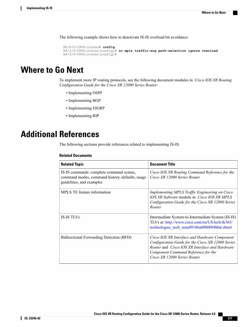
The following example shows how to deactivate IS-IS overload bit avoidance:
RP/0/0/CPU0:router# configRP/0/0/CPU0:router(config)# no mpls traffic-eng path-selection ignore overloadRP/0/0/CPU0:router(config)#
Where to Go NextTo implement more IP routing protocols, see the following document modules in Cisco IOS XR RoutingConfiguration Guide for the Cisco XR 12000 Series Router:
• Implementing OSPF
• Implementing BGP
• Implementing EIGRP
• Implementing RIP
Additional ReferencesThe following sections provide references related to implementing IS-IS.
Related Documents
Document TitleRelated Topic
Cisco IOS XR Routing Command Reference for theCisco XR 12000 Series Router
IS-IS commands: complete command syntax,command modes, command history, defaults, usageguidelines, and examples
Implementing MPLS Traffic Engineering on CiscoIOS XR Software module in Cisco IOS XR MPLSConfiguration Guide for the Cisco XR 12000 SeriesRouter
MPLS TE feature information
Intermediate System-to-Intermediate System (IS-IS)TLVs at: http://www.cisco.com/en/US/tech/tk365/technologies_tech_note09186a0080094bbd.shtml
IS-IS TLVs
Cisco IOS XR Interface and Hardware ComponentConfiguration Guide for the Cisco XR 12000 SeriesRouter and Cisco IOS XR Interface and HardwareComponent Command Reference for theCisco XR 12000 Series Router
Bidirectional Forwarding Detection (BFD)
Cisco IOS XR Routing Configuration Guide for the Cisco XR 12000 Series Router, Release 4.0 OL-23246-02 277
Implementing IS-ISWhere to Go Next
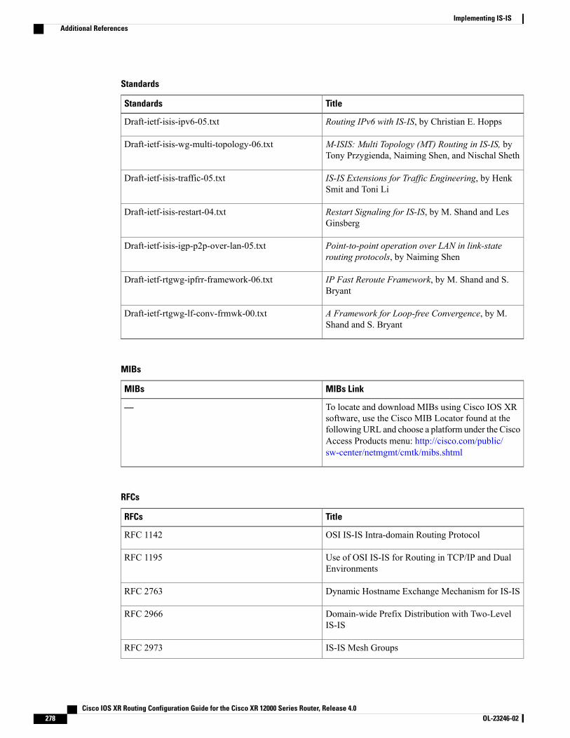
Standards
TitleStandards
Routing IPv6 with IS-IS, by Christian E. HoppsDraft-ietf-isis-ipv6-05.txt
M-ISIS: Multi Topology (MT) Routing in IS-IS, byTony Przygienda, Naiming Shen, and Nischal Sheth
Draft-ietf-isis-wg-multi-topology-06.txt
IS-IS Extensions for Traffic Engineering, by HenkSmit and Toni Li
Draft-ietf-isis-traffic-05.txt
Restart Signaling for IS-IS, by M. Shand and LesGinsberg
Draft-ietf-isis-restart-04.txt
Point-to-point operation over LAN in link-staterouting protocols, by Naiming Shen
Draft-ietf-isis-igp-p2p-over-lan-05.txt
IP Fast Reroute Framework, by M. Shand and S.Bryant
Draft-ietf-rtgwg-ipfrr-framework-06.txt
A Framework for Loop-free Convergence, by M.Shand and S. Bryant
Draft-ietf-rtgwg-lf-conv-frmwk-00.txt
MIBs
MIBs LinkMIBs
To locate and download MIBs using Cisco IOS XRsoftware, use the Cisco MIB Locator found at thefollowingURL and choose a platform under the CiscoAccess Products menu: http://cisco.com/public/sw-center/netmgmt/cmtk/mibs.shtml
—
RFCs
TitleRFCs
OSI IS-IS Intra-domain Routing ProtocolRFC 1142
Use of OSI IS-IS for Routing in TCP/IP and DualEnvironments
RFC 1195
Dynamic Hostname Exchange Mechanism for IS-ISRFC 2763
Domain-wide Prefix Distribution with Two-LevelIS-IS
RFC 2966
IS-IS Mesh GroupsRFC 2973
Cisco IOS XR Routing Configuration Guide for the Cisco XR 12000 Series Router, Release 4.0278 OL-23246-02
Implementing IS-ISAdditional References
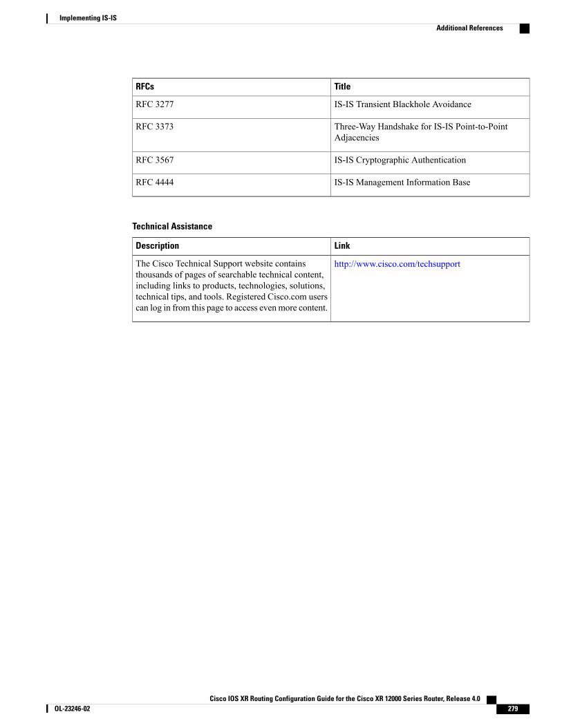
TitleRFCs
IS-IS Transient Blackhole AvoidanceRFC 3277
Three-Way Handshake for IS-IS Point-to-PointAdjacencies
RFC 3373
IS-IS Cryptographic AuthenticationRFC 3567
IS-IS Management Information BaseRFC 4444
Technical Assistance
LinkDescription
http://www.cisco.com/techsupportThe Cisco Technical Support website containsthousands of pages of searchable technical content,including links to products, technologies, solutions,technical tips, and tools. Registered Cisco.com userscan log in from this page to access evenmore content.
Cisco IOS XR Routing Configuration Guide for the Cisco XR 12000 Series Router, Release 4.0 OL-23246-02 279
Implementing IS-ISAdditional References

Cisco IOS XR Routing Configuration Guide for the Cisco XR 12000 Series Router, Release 4.0280 OL-23246-02
Implementing IS-ISAdditional References

C H A P T E R 4Implementing OSPF
Open Shortest Path First (OSPF) is an Interior Gateway Protocol (IGP) developed by the OSPF workinggroup of the Internet Engineering Task Force (IETF). Designed expressly for IP networks, OSPF supportsIP subnetting and tagging of externally derived routing information. OSPF also allows packet authenticationand uses IP multicast when sending and receiving packets.
OSPF Version 3 (OSPFv3) expands on OSPF Version 2, providing support for IPv6 routing prefixes.
This module describes the concepts and tasks you need to implement both versions of OSPF on yourCisco XR 12000 Series Router . The term “OSPF" implies both versions of the routing protocol, unlessotherwise noted.
For more information about OSPF on Cisco IOS XR software and complete descriptions of the OSPFcommands listed in this module, see the Related Documents, on page 388 section of this module. To locatedocumentation for other commands that might appear during execution of a configuration task, searchonline in the Cisco IOS XR Commands Master List for the Cisco XR 12000 Series Router
Note
Feature History for Implementing OSPF
ModificationRelease
This feature was introduced.Release 3.2
Support was added for OSPFv3 Graceful Restart.Release 3.2.2
Support was added for the following features:
• Multicast-Intact for OSPFv2
• Interface Association to a VRF
• OSPF Provider Edge to Customer Edge (PE-CE) Protocol
• Multiple OSPF Instances (OSPF Process and a VRF)
• RPL-based Type 3 Filtering
• LSA Pacing
Release 3.3.0
Cisco IOS XR Routing Configuration Guide for the Cisco XR 12000 Series Router, Release 4.0 OL-23246-02 281
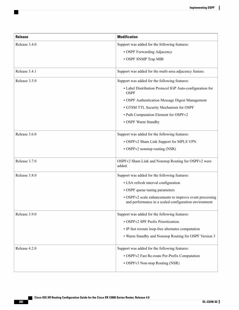
ModificationRelease
Support was added for the following features:
• OSPF Forwarding Adjacency
• OSPF SNMP Trap MIB
Release 3.4.0
Support was added for the multi-area adjacency feature.Release 3.4.1
Support was added for the following features:
• Label Distribution Protocol IGP Auto-configuration forOSPF
• OSPF Authentication Message Digest Management
• GTSM TTL Security Mechanism for OSPF
• Path Computation Element for OSPFv2
• OSPF Warm Standby
Release 3.5.0
Support was added for the following features:
• OSPFv2 Sham Link Support for MPLS VPN
• OSPFv2 nonstop routing (NSR)
Release 3.6.0
OSPFv2 Sham Link and Nonstop Routing for OSPFv2 wereadded.
Release 3.7.0
Support was added for the following features:
• LSA refresh interval configuration
• OSPF queue tuning parameters
• OSPFv2 scale enhancements to improve event processingand performance in a scaled configuration environment
Release 3.8.0
Support was added for the following features:
• OSPFv2 SPF Prefix Prioritization.
• IP fast reroute loop-free alternates computation
•Warm Standby and Nonstop Routing for OSPF Version 3
Release 3.9.0
Support was added for the following features:
• OSPFv2 Fast Re-route Per-Prefix Computation
• OSPFv3 Non-stop Routing (NSR)
Release 4.2.0
Cisco IOS XR Routing Configuration Guide for the Cisco XR 12000 Series Router, Release 4.0282 OL-23246-02
Implementing OSPF
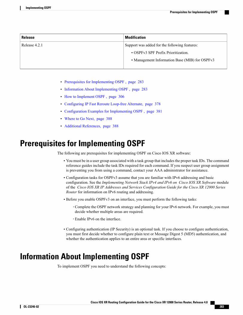
ModificationRelease
Support was added for the following features:
• OSPFv3 SPF Prefix Prioritization.
• Management Information Base (MIB) for OSPFv3
Release 4.2.1
• Prerequisites for Implementing OSPF , page 283
• Information About Implementing OSPF , page 283
• How to Implement OSPF , page 306
• Configuring IP Fast Reroute Loop-free Alternate, page 378
• Configuration Examples for Implementing OSPF , page 381
• Where to Go Next, page 388
• Additional References, page 388
Prerequisites for Implementing OSPFThe following are prerequisites for implementing OSPF on Cisco IOS XR software:
• Youmust be in a user group associated with a task group that includes the proper task IDs. The commandreference guides include the task IDs required for each command. If you suspect user group assignmentis preventing you from using a command, contact your AAA administrator for assistance.
• Configuration tasks for OSPFv3 assume that you are familiar with IPv6 addressing and basicconfiguration. See the Implementing Network Stack IPv4 and IPv6 on Cisco IOS XR Software moduleof the Cisco IOS XR IP Addresses and Services Configuration Guide for the Cisco XR 12000 SeriesRouter for information on IPv6 routing and addressing.
• Before you enable OSPFv3 on an interface, you must perform the following tasks:
◦Complete the OSPF network strategy and planning for your IPv6 network. For example, you mustdecide whether multiple areas are required.
◦Enable IPv6 on the interface.
• Configuring authentication (IP Security) is an optional task. If you choose to configure authentication,you must first decide whether to configure plain text or Message Digest 5 (MD5) authentication, andwhether the authentication applies to an entire area or specific interfaces.
Information About Implementing OSPFTo implement OSPF you need to understand the following concepts:
Cisco IOS XR Routing Configuration Guide for the Cisco XR 12000 Series Router, Release 4.0 OL-23246-02 283
Implementing OSPFPrerequisites for Implementing OSPF
OSPF Functional OverviewOSPF is a routing protocol for IP. It is a link-state protocol, as opposed to a distance-vector protocol. Alink-state protocol makes its routing decisions based on the states of the links that connect source and destinationmachines. The state of the link is a description of that interface and its relationship to its neighboring networkingdevices. The interface information includes the IP address of the interface, network mask, type of network towhich it is connected, routers connected to that network, and so on. This information is propagated in varioustypes of link-state advertisements (LSAs).
A router stores the collection of received LSA data in a link-state database. This database includes LSA datafor the links of the router. The contents of the database, when subjected to the Dijkstra algorithm, extract datato create an OSPF routing table. The difference between the database and the routing table is that the databasecontains a complete collection of raw data; the routing table contains a list of shortest paths to knowndestinations through specific router interface ports.
OSPF is the IGP of choice because it scales to large networks. It uses areas to partition the network into moremanageable sizes and to introduce hierarchy in the network. A router is attached to one or more areas in anetwork. All of the networking devices in an area maintain the same complete database information about thelink states in their area only. They do not know about all link states in the network. The agreement of thedatabase information among the routers in the area is called convergence.
At the intradomain level, OSPF can import routes learned using Intermediate System-to-Intermediate System(IS-IS). OSPF routes can also be exported into IS-IS. At the interdomain level, OSPF can import routes learnedusing Border Gateway Protocol (BGP). OSPF routes can be exported into BGP.
Unlike Routing Information Protocol (RIP), OSPF does not provide periodic routing updates. On becomingneighbors, OSPF routers establish an adjacency by exchanging and synchronizing their databases. After that,only changed routing information is propagated. Every router in an area advertises the costs and states of itslinks, sending this information in an LSA. This state information is sent to all OSPF neighbors one hop away.All the OSPF neighbors, in turn, send the state information unchanged. This flooding process continues untilall devices in the area have the same link-state database.
To determine the best route to a destination, the software sums all of the costs of the links in a route to adestination. After each router has received routing information from the other networking devices, it runs theshortest path first (SPF) algorithm to calculate the best path to each destination network in the database.
The networking devices running OSPF detect topological changes in the network, flood link-state updates toneighbors, and quickly converge on a new view of the topology. Each OSPF router in the network soon hasthe same topological view again. OSPF allows multiple equal-cost paths to the same destination. Since alllink-state information is flooded and used in the SPF calculation, multiple equal cost paths can be computedand used for routing.
On broadcast and nonbroadcast multiaccess (NBMA) networks, the designated router (DR) or backup DRperforms the LSA flooding. On point-to-point networks, flooding simply exits an interface directly to aneighbor.
OSPF runs directly on top of IP; it does not use TCP or User Datagram Protocol (UDP). OSPF performs itsown error correction by means of checksums in its packet header and LSAs.
In OSPFv3, the fundamental concepts are the same as OSPF Version 2, except that support is added for theincreased address size of IPv6. New LSA types are created to carry IPv6 addresses and prefixes, and theprotocol runs on an individual link basis rather than on an individual IP-subnet basis.
OSPF typically requires coordination among many internal routers: Area Border Routers (ABRs), which arerouters attached to multiple areas, and Autonomous System Border Routers (ASBRs) that export reroutesfrom other sources (for example, IS-IS, BGP, or static routes) into the OSPF topology. At a minimum,
Cisco IOS XR Routing Configuration Guide for the Cisco XR 12000 Series Router, Release 4.0284 OL-23246-02
Implementing OSPFOSPF Functional Overview
OSPF-based routers or access servers can be configured with all default parameter values, no authentication,and interfaces assigned to areas. If you intend to customize your environment, you must ensure coordinatedconfigurations of all routers.
Key Features Supported in the Cisco IOS XR Software OSPF ImplementationThe Cisco IOS XR Software implementation of OSPF conforms to the OSPF Version 2 and OSPF Version3 specifications detailed in the Internet RFC 2328 and RFC 2740, respectively.
The following key features are supported in the Cisco IOS XR Software implementation:
• Hierarchy—CLI hierarchy is supported.
• Inheritance—CLI inheritance is supported.
• Stub areas—Definition of stub areas is supported.
• NSF—Nonstop forwarding is supported.
• SPF throttling—Shortest path first throttling feature is supported.
• LSA throttling—LSA throttling feature is supported.
• Fast convergence—SPF and LSA throttle timers are set, configuring fast convergence. The OSPF LSAthrottling feature provides a dynamic mechanism to slow down LSA updates in OSPF during networkinstability. LSA throttling also allows faster OSPF convergence by providing LSA rate limiting inmilliseconds.
• Route redistribution—Routes learned using any IP routing protocol can be redistributed into any otherIP routing protocol.
• Authentication—Plain text and MD5 authentication among neighboring routers within an area issupported.
• Routing interface parameters—Configurable parameters supported include interface output cost,retransmission interval, interface transmit delay, router priority, router “dead” and hello intervals, andauthentication key.
• Virtual links—Virtual links are supported.
• Not-so-stubby area (NSSA)—RFC 1587 is supported.
• OSPF over demand circuit—RFC 1793 is supported.
Comparison of Cisco IOS XR Software OSPFv3 and OSPFv2Much of the OSPFv3 protocol is the same as in OSPFv2. OSPFv3 is described in RFC 2740.
The key differences between the Cisco IOS XR Software OSPFv3 and OSPFv2 protocols are as follows:
• OSPFv3 expands on OSPFv2 to provide support for IPv6 routing prefixes and the larger size of IPv6addresses.
•When using an NBMA interface in OSPFv3, users must manually configure the router with the list ofneighbors. Neighboring routers are identified by the link local address of the attached interface of theneighbor.
Cisco IOS XR Routing Configuration Guide for the Cisco XR 12000 Series Router, Release 4.0 OL-23246-02 285
Implementing OSPFKey Features Supported in the Cisco IOS XR Software OSPF Implementation
• Unlike in OSPFv2, multiple OSPFv3 processes can be run on a link.
• LSAs in OSPFv3 are expressed as “prefix and prefix length” instead of “address and mask.”
• The router ID is a 32-bit number with no relationship to an IPv6 address.
OSPF Hierarchical CLI and CLI InheritanceCisco IOS XR Software introduces new OSPF configuration fundamentals consisting of hierarchical CLI andCLI inheritance.
Hierarchical CLI is the grouping of related network component information at defined hierarchical levels suchas at the router, area, and interface levels. Hierarchical CLI allows for easier configuration, maintenance, andtroubleshooting of OSPF configurations. When configuration commands are displayed together in theirhierarchical context, visual inspections are simplified. Hierarchical CLI is intrinsic for CLI inheritance to besupported.
With CLI inheritance support, you need not explicitly configure a parameter for an area or interface. InCisco IOS XR Software, the parameters of interfaces in the same area can be exclusively configured with asingle command, or parameter values can be inherited from a higher hierarchical level—such as from the areaconfiguration level or the router ospf configuration levels.
For example, the hello interval value for an interface is determined by this precedence “IF” statement:If the hello interval command is configured at the interface configuration level, then use the interface configuredvalue, else
If the hello interval command is configured at the area configuration level, then use the area configured value,else
If the hello interval command is configured at the router ospf configuration level, then use the router ospfconfigured value, else
Use the default value of the command.
Understanding hierarchical CLI and CLI inheritance saves you considerable configuration time. SeeConfiguring Authentication at Different Hierarchical Levels for OSPFVersion 2, on page 317 to understandhow to implement these fundamentals. In addition, Cisco IOS XR Software examples are provided inConfiguration Examples for Implementing OSPF , on page 381.
Tip
OSPF Routing ComponentsBefore implementing OSPF, you must know what the routing components are and what purpose they serve.They consist of the autonomous system, area types, interior routers, ABRs, and ASBRs.
This figure illustrates the routing components in an OSPF network topology.
Cisco IOS XR Routing Configuration Guide for the Cisco XR 12000 Series Router, Release 4.0286 OL-23246-02
Implementing OSPFOSPF Hierarchical CLI and CLI Inheritance

Figure 14: OSPF Routing Components
Autonomous SystemsThe autonomous system is a collection of networks, under the same administrative control, that share routinginformation with each other. An autonomous system is also referred to as a routing domain. Figure 14: OSPFRouting Components, on page 286 shows two autonomous systems: 109 and 65200. An autonomous systemcan consist of one or more OSPF areas.
AreasAreas allow the subdivision of an autonomous system into smaller, more manageable networks or sets ofadjacent networks. As shown in Figure 14: OSPF Routing Components, on page 286, autonomous system109 consists of three areas: Area 0, Area 1, and Area 2.
OSPF hides the topology of an area from the rest of the autonomous system. The network topology for anarea is visible only to routers inside that area. When OSPF routing is within an area, it is called intra-arearouting. This routing limits the amount of link-state information flood into the network, reducing routingtraffic. It also reduces the size of the topology information in each router, conserving processing and memoryrequirements in each router.
Also, the routers within an area cannot see the detailed network topology outside the area. Because of thisrestricted view of topological information, you can control traffic flow between areas and reduce routingtraffic when the entire autonomous system is a single routing domain.
Cisco IOS XR Routing Configuration Guide for the Cisco XR 12000 Series Router, Release 4.0 OL-23246-02 287
Implementing OSPFOSPF Routing Components
Backbone Area
A backbone area is responsible for distributing routing information between multiple areas of an autonomoussystem. OSPF routing occurring outside of an area is called interarea routing.
The backbone itself has all properties of an area. It consists of ABRs, routers, and networks only on thebackbone. As shown in Figure 14: OSPF Routing Components, on page 286, Area 0 is an OSPF backbonearea. Any OSPF backbone area has a reserved area ID of 0.0.0.0.
Stub Area
A stub area is an area that does not accept route advertisements or detailed network information external tothe area. A stub area typically has only one router that interfaces the area to the rest of the autonomous system.The stub ABR advertises a single default route to external destinations into the stub area. Routers within astub area use this route for destinations outside the area and the autonomous system. This relationship conservesLSA database space that would otherwise be used to store external LSAs flooded into the area. In Figure 14:OSPF Routing Components, on page 286, Area 2 is a stub area that is reached only through ABR 2. Area 0cannot be a stub area.
Not-so-Stubby Area
A Not-so-Stubby Area (NSSA) is similar to the stub area. NSSA does not flood Type 5 external LSAs fromthe core into the area, but can import autonomous system external routes in a limited fashion within the area.
NSSA allows importing of Type 7 autonomous system external routes within an NSSA area by redistribution.These Type 7 LSAs are translated into Type 5 LSAs by NSSAABRs, which are flooded throughout the wholerouting domain. Summarization and filtering are supported during the translation.
Use NSSA to simplify administration if you are a network administrator that must connect a central site usingOSPF to a remote site that is using a different routing protocol.
Before NSSA, the connection between the corporate site border router and remote router could not be run asan OSPF stub area because routes for the remote site could not be redistributed into a stub area, and tworouting protocols needed to be maintained. A simple protocol like RIP was usually run and handled theredistribution.With NSSA, you can extend OSPF to cover the remote connection by defining the area betweenthe corporate router and remote router as an NSSA. Area 0 cannot be an NSSA.
RoutersThe OSPF network is composed of ABRs, ASBRs, and interior routers.
Area Border Routers
An area border routers (ABR) is a router with multiple interfaces that connect directly to networks in two ormore areas. An ABR runs a separate copy of the OSPF algorithm and maintains separate routing data for eacharea that is attached to, including the backbone area. ABRs also send configuration summaries for their attachedareas to the backbone area, which then distributes this information to other OSPF areas in the autonomoussystem. In Figure 14: OSPF Routing Components, on page 286, there are two ABRs. ABR 1 interfaces Area1 to the backbone area. ABR 2 interfaces the backbone Area 0 to Area 2, a stub area.
Cisco IOS XR Routing Configuration Guide for the Cisco XR 12000 Series Router, Release 4.0288 OL-23246-02
Implementing OSPFOSPF Routing Components

Autonomous System Boundary Routers (ASBR)
An autonomous system boundary router (ASBR) provides connectivity from one autonomous system toanother system. ASBRs exchange their autonomous system routing information with boundary routers inother autonomous systems. Every router inside an autonomous system knows how to reach the boundaryrouters for its autonomous system.
ASBRs can import external routing information from other protocols like BGP and redistribute them asAS-external (ASE) Type 5 LSAs to the OSPF network. If the Cisco IOS XR router is an ASBR, you canconfigure it to advertise VIP addresses for content as autonomous system external routes. In this way, ASBRsflood information about external networks to routers within the OSPF network.
ASBR routes can be advertised as a Type 1 or Type 2 ASE. The difference between Type 1 and Type 2 ishow the cost is calculated. For a Type 2 ASE, only the external cost (metric) is considered when multiplepaths to the same destination are compared. For a Type 1 ASE, the combination of the external cost and costto reach the ASBR is used. Type 2 external cost is the default and is always more costly than an OSPF routeand used only if no OSPF route exists.
Interior Routers
An interior router (such as R1 in Figure 14: OSPF Routing Components, on page 286) is attached to one area(for example, all the interfaces reside in the same area).
OSPF Process and Router IDAn OSPF process is a logical routing entity running OSPF in a physical router. This logical routing entityshould not be confused with the logical routing feature that allows a system administrator (known as theCisco IOS XR Software Owner) to partition the physical box into separate routers.
A physical router can run multiple OSPF processes, although the only reason to do so would be to connecttwo or more OSPF domains. Each process has its own link-state database. The routes in the routing table arecalculated from the link-state database. One OSPF process does not share routes with another OSPF processunless the routes are redistributed.
Each OSPF process is identified by a router ID. The router IDmust be unique across the entire routing domain.OSPF obtains a router ID from the following sources, in order of decreasing preference:
• By default, when the OSPF process initializes, it checks if there is a router-id in the checkpointingdatabase.
• The 32-bit numeric value specified by the OSPF router-id command in router configuration mode. (Thisvalue can be any 32-bit value. It is not restricted to the IPv4 addresses assigned to interfaces on thisrouter, and need not be a routable IPv4 address.)
• The ITAL selected router-id.
• The primary IPv4 address of an interface over which this OSPF process is running. The first interfaceaddress in the OSPF interface is selected.
We recommend that the router ID be set by the router-id command in router configuration mode. SeparateOSPF processes could share the same router ID, in which case they cannot reside in the same OSPF routingdomain.
Cisco IOS XR Routing Configuration Guide for the Cisco XR 12000 Series Router, Release 4.0 OL-23246-02 289
Implementing OSPFOSPF Process and Router ID
Supported OSPF Network TypesOSPF classifies different media into the following types of networks:
• NBMA networks
• Point-to-point networks (POS)
• Broadcast networks (Gigabit Ethernet)
• Point-to-multipoint
You can configure your Cisco IOSXR network as either a broadcast or an NBMA network. Using this feature,you can configure broadcast networks as NBMA networks when, for example, you have routers in yournetwork that do not support multicast addressing.
Route Authentication Methods for OSPFOSPF Version 2 supports two types of authentication: plain text authentication and MD5 authentication. Bydefault, no authentication is enabled (referred to as null authentication in RFC 2178).
OSPV Version 3 supports all types of authentication except key rollover.
Plain Text AuthenticationPlain text authentication (also known as Type 1 authentication) uses a password that travels on the physicalmedium and is easily visible to someone that does not have access permission and could use the password toinfiltrate a network. Therefore, plain text authentication does not provide security. It might protect against afaulty implementation of OSPF or a misconfigured OSPF interface trying to send erroneous OSPF packets.
MD5 AuthenticationMD5 authentication provides a means of security. No password travels on the physical medium. Instead, therouter uses MD5 to produce a message digest of the OSPF packet plus the key, which is sent on the physicalmedium. Using MD5 authentication prevents a router from accepting unauthorized or deliberately maliciousrouting updates, which could compromise your network security by diverting your traffic.
MD5 authentication supports multiple keys, requiring that a key number be associated with a key.Note
See OSPF Authentication Message Digest Management, on page 304.
Authentication StrategiesAuthentication can be specified for an entire process or area, or on an interface or a virtual link. An interfaceor virtual link can be configured for only one type of authentication, not both. Authentication configured foran interface or virtual link overrides authentication configured for the area or process.
If you intend for all interfaces in an area to use the same type of authentication, you can configure fewercommands if you use the authentication command in the area configuration submode (and specify the
Cisco IOS XR Routing Configuration Guide for the Cisco XR 12000 Series Router, Release 4.0290 OL-23246-02
Implementing OSPFSupported OSPF Network Types

message-digest keyword if you want the entire area to use MD5 authentication). This strategy requires fewercommands than specifying authentication for each interface.
Key RolloverTo support the changing of an MD5 key in an operational network without disrupting OSPF adjacencies (andhence the topology), a key rollover mechanism is supported. As a network administrator configures the newkey into the multiple networking devices that communicate, some time exists when different devices are usingboth a new key and an old key. If an interface is configured with a new key, the software sends two copiesof the same packet, each authenticated by the old key and new key. The software tracks which devices startusing the new key, and the software stops sending duplicate packets after it detects that all of its neighborsare using the new key. The software then discards the old key. The network administrator must then removethe old key from each the configuration file of each router.
Neighbors and Adjacency for OSPFRouters that share a segment (Layer 2 link between two interfaces) become neighbors on that segment. OSPFuses the hello protocol as a neighbor discovery and keep alivemechanism. The hello protocol involves receivingand periodically sending hello packets out each interface. The hello packets list all known OSPF neighborson the interface. Routers become neighbors when they see themselves listed in the hello packet of the neighbor.After two routers are neighbors, they may proceed to exchange and synchronize their databases, which createsan adjacency. On broadcast and NBMA networks all neighboring routers have an adjacency.
Designated Router (DR) for OSPFOn point-to-point and point-to-multipoint networks, the Cisco IOS XR software floods routing updates toimmediate neighbors. No DR or backup DR (BDR) exists; all routing information is flooded to each router.
On broadcast or NBMA segments only, OSPF minimizes the amount of information being exchanged on asegment by choosing one router to be a DR and one router to be a BDR. Thus, the routers on the segmenthave a central point of contact for information exchange. Instead of each router exchanging routing updateswith every other router on the segment, each router exchanges information with the DR and BDR. The DRand BDR relay the information to the other routers. On broadcast network segments the number of OSPFpackets is further reduced by the DR and BDR sending such OSPF updates to a multicast IP address that allOSPF routers on the network segment are listening on.
The software looks at the priority of the routers on the segment to determine which routers are the DR andBDR. The router with the highest priority is elected the DR. If there is a tie, then the router with the higherrouter ID takes precedence. After the DR is elected, the BDR is elected the same way. A router with a routerpriority set to zero is ineligible to become the DR or BDR.
Default Route for OSPFType 5 (ASE) LSAs are generated and flooded to all areas except stub areas. For the routers in a stub area tobe able to route packets to destinations outside the stub area, a default route is injected by the ABR attachedto the stub area.
The cost of the default route is 1 (default) or is determined by the value specified in the default-cost command.
Cisco IOS XR Routing Configuration Guide for the Cisco XR 12000 Series Router, Release 4.0 OL-23246-02 291
Implementing OSPFNeighbors and Adjacency for OSPF

Link-State Advertisement Types for OSPF Version 2Each of the following LSA types has a different purpose:
• Router LSA (Type 1)—Describes the links that the router has within a single area, and the cost of eachlink. These LSAs are flooded within an area only. The LSA indicates if the router can compute pathsbased on quality of service (QoS), whether it is an ABR or ASBR, and if it is one end of a virtual link.Type 1 LSAs are also used to advertise stub networks.
• Network LSA (Type 2)—Describes the link state and cost information for all routers attached to amultiaccess network segment. This LSA lists all the routers that have interfaces attached to the networksegment. It is the job of the designated router of a network segment to generate and track the contentsof this LSA.
• Summary LSA for ABRs (Type 3)—Advertises internal networks to routers in other areas (interarearoutes). Type 3 LSAs may represent a single network or a set of networks aggregated into one prefix.Only ABRs generate summary LSAs.
• Summary LSA for ASBRs (Type 4)—Advertises an ASBR and the cost to reach it. Routers that aretrying to reach an external network use these advertisements to determine the best path to the next hop.ABRs generate Type 4 LSAs.
• Autonomous system external LSA (Type 5)—Redistributes routes from another autonomous system,usually from a different routing protocol into OSPF.
• Autonomous system external LSA (Type 7)—Provides for carrying external route information withinan NSSA. Type 7 LSAsmay be originated by and advertised throughout an NSSA. NSSAs do not receiveor originate Type 5 LSAs. Type 7 LSAs are advertised only within a single NSSA. They are not floodedinto the backbone area or into any other area by border routers.
• Intra-area-prefix LSAs (Type 9)—A router can originate multiple intra-area-prefix LSAs for every routeror transit network, each with a unique link-state ID. The link-state ID for each intra-area-prefix LSAdescribes its association to either the router LSA or network LSA and contains prefixes for stub andtransit networks.
• Area local scope (Type 10)—Opaque LSAs are not flooded past the borders of their associated area.
• Link-state (Type 11)—The LSA is flooded throughout the AS. The flooding scope of Type 11 LSAsare equivalent to the flooding scope of AS-external (Type 5) LSAs. Similar to Type 5 LSAs, the LSAis rejected if a Type 11 opaque LSA is received in a stub area from a neighboring router within the stubarea. Type 11 opaque LSAs have these attributes:
◦LSAs are flooded throughout all transit areas.
◦LSAs are not flooded into stub areas from the backbone.
◦LSAs are not originated by routers into their connected stub areas.
Link-State Advertisement Types for OSPFv3Each of the following LSA types has a different purpose:
Cisco IOS XR Routing Configuration Guide for the Cisco XR 12000 Series Router, Release 4.0292 OL-23246-02
Implementing OSPFLink-State Advertisement Types for OSPF Version 2

• Router LSA (Type 1)—Describes the link state and costs of a the router link to the area. These LSAsare flooded within an area only. The LSA indicates whether the router is an ABR or ASBR and if it isone end of a virtual link. Type 1 LSAs are also used to advertise stub networks. In OSPFv3, these LSAshave no address information and are network protocol independent. In OSPFv3, router interfaceinformation may be spread across multiple router LSAs. Receivers must concatenate all router LSAsoriginated by a given router before running the SPF calculation.
• Network LSA (Type 2)—Describes the link state and cost information for all routers attached to amultiaccess network segment. This LSA lists all OSPF routers that have interfaces attached to the networksegment. Only the elected designated router for the network segment can generate and track the networkLSA for the segment. In OSPFv3, network LSAs have no address information and arenetwork-protocol-independent.
• Interarea-prefix LSA for ABRs (Type 3)—Advertises internal networks to routers in other areas (interarearoutes). Type 3 LSAs may represent a single network or set of networks aggregated into one prefix.Only ABRs generate Type 3 LSAs. In OSPFv3, addresses for these LSAs are expressed as “prefix andprefix length” instead of “address and mask.” The default route is expressed as a prefix with length 0.
• Interarea-router LSA for ASBRs (Type 4)—Advertises an ASBR and the cost to reach it. Routers thatare trying to reach an external network use these advertisements to determine the best path to the nexthop. ABRs generate Type 4 LSAs.
• Autonomous system external LSA (Type 5)—Redistributes routes from another autonomous system,usually from a different routing protocol into OSPF. In OSPFv3, addresses for these LSAs are expressedas “prefix and prefix length” instead of “address and mask.” The default route is expressed as a prefixwith length 0.
• Autonomous system external LSA (Type 7)—Provides for carrying external route information withinan NSSA. Type 7 LSAsmay be originated by and advertised throughout an NSSA. NSSAs do not receiveor originate Type 5 LSAs. Type 7 LSAs are advertised only within a single NSSA. They are not floodedinto the backbone area or into any other area by border routers.
• Link LSA (Type 8)—Has link-local flooding scope and is never flooded beyond the link with which itis associated. Link LSAs provide the link-local address of the router to all other routers attached to thelink or network segment, inform other routers attached to the link of a list of IPv6 prefixes to associatewith the link, and allow the router to assert a collection of Options bits to associate with the networkLSA that is originated for the link.
• Intra-area-prefix LSAs (Type 9)—A router can originate multiple intra-area-prefix LSAs for every routeror transit network, each with a unique link-state ID. The link-state ID for each intra-area-prefix LSAdescribes its association to either the router LSA or network LSA and contains prefixes for stub andtransit networks.
An address prefix occurs in almost all newly defined LSAs. The prefix is represented by three fields: PrefixLength, Prefix Options, and Address Prefix. In OSPFv3, addresses for these LSAs are expressed as “prefixand prefix length” instead of “address and mask.” The default route is expressed as a prefix with length 0.Inter-area-prefix and intra-area-prefix LSAs carry all IPv6 prefix information that, in IPv4, is included inrouter LSAs and network LSAs. TheOptions field in certain LSAs (router LSAs, network LSAs, interarea-routerLSAs, and link LSAs) has been expanded to 24 bits to provide support for OSPF in IPv6.
In OSPFv3, the sole function of link-state ID in interarea-prefix LSAs, interarea-router LSAs, and autonomoussystem external LSAs is to identify individual pieces of the link-state database. All addresses or router IDsthat are expressed by the link-state ID in OSPF Version 2 are carried in the body of the LSA in OSPFv3.
Cisco IOS XR Routing Configuration Guide for the Cisco XR 12000 Series Router, Release 4.0 OL-23246-02 293
Implementing OSPFLink-State Advertisement Types for OSPFv3
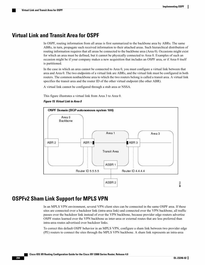
Virtual Link and Transit Area for OSPFIn OSPF, routing information from all areas is first summarized to the backbone area by ABRs. The sameABRs, in turn, propagate such received information to their attached areas. Such hierarchical distribution ofrouting information requires that all areas be connected to the backbone area (Area 0). Occasions might existfor which an area must be defined, but it cannot be physically connected to Area 0. Examples of such anoccasion might be if your company makes a new acquisition that includes an OSPF area, or if Area 0 itselfis partitioned.
In the case in which an area cannot be connected to Area 0, you must configure a virtual link between thatarea and Area 0. The two endpoints of a virtual link are ABRs, and the virtual link must be configured in bothrouters. The common nonbackbone area to which the two routers belong is called a transit area. A virtual linkspecifies the transit area and the router ID of the other virtual endpoint (the other ABR).
A virtual link cannot be configured through a stub area or NSSA.
This figure illustrates a virtual link from Area 3 to Area 0.Figure 15: Virtual Link to Area 0
OSPFv2 Sham Link Support for MPLS VPNIn an MPLS VPN environment, several VPN client sites can be connected in the same OSPF area. If thesesites are connected over a backdoor link (intra-area link) and connected over the VPN backbone, all trafficpasses over the backdoor link instead of over the VPN backbone, because provider edge routers advertiseOSPF routes learned over the VPN backbone as inter-area or external routes that are less preferred thanintra-area routes advertised over backdoor links.
To correct this default OSPF behavior in an MPLS VPN, configure a sham link between two provider edge(PE) routers to connect the sites through the MPLS VPN backbone. A sham link represents an intra-area
Cisco IOS XR Routing Configuration Guide for the Cisco XR 12000 Series Router, Release 4.0294 OL-23246-02
Implementing OSPFVirtual Link and Transit Area for OSPF
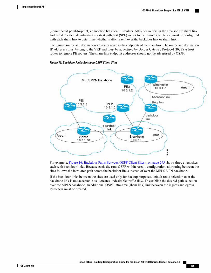
(unnumbered point-to-point) connection between PE routers. All other routers in the area see the sham linkand use it to calculate intra-area shortest path first (SPF) routes to the remote site. A cost must be configuredwith each sham link to determine whether traffic is sent over the backdoor link or sham link.
Configured source and destination addresses serve as the endpoints of the sham link. The source and destinationIP addresses must belong to the VRF and must be advertised by Border Gateway Protocol (BGP) as hostroutes to remote PE routers. The sham-link endpoint addresses should not be advertised by OSPF.
Figure 16: Backdoor Paths Between OSPF Client Sites
For example, Figure 16: Backdoor Paths Between OSPF Client Sites , on page 295 shows three client sites,each with backdoor links. Because each site runs OSPF within Area 1 configuration, all routing between thesites follows the intra-area path across the backdoor links instead of over the MPLS VPN backbone.
If the backdoor links between the sites are used only for backup purposes, default route selection over thebackbone link is not acceptable as it creates undesirable traffic flow. To establish the desired path selectionover the MPLS backbone, an additional OSPF intra-area (sham link) link between the ingress and egressPErouters must be created.
Cisco IOS XR Routing Configuration Guide for the Cisco XR 12000 Series Router, Release 4.0 OL-23246-02 295
Implementing OSPFOSPFv2 Sham Link Support for MPLS VPN
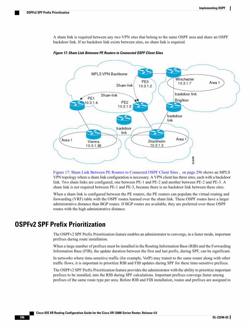
A sham link is required between any two VPN sites that belong to the same OSPF area and share an OSPFbackdoor link. If no backdoor link exists between sites, no sham link is required.
Figure 17: Sham Link Between PE Routers to Connected OSPF Client Sites
Figure 17: Sham Link Between PE Routers to Connected OSPF Client Sites , on page 296 shows an MPLSVPN topology where a sham link configuration is necessary. AVPN client has three sites, each with a backdoorlink. Two sham links are configured, one between PE-1 and PE-2 and another between PE-2 and PE-3. Asham link is not required between PE-1 and PE-3, because there is no backdoor link between these sites.
When a sham link is configured between the PE routers, the PE routers can populate the virtual routing andforwarding (VRF) table with the OSPF routes learned over the sham link. These OSPF routes have a largeradministrative distance than BGP routes. If BGP routes are available, they are preferred over these OSPFroutes with the high administrative distance.
OSPFv2 SPF Prefix PrioritizationThe OSPFv2 SPF Prefix Prioritization feature enables an administrator to converge, in a faster mode, importantprefixes during route installation.
When a large number of prefixes must be installed in the Routing Information Base (RIB) and the ForwardingInformation Base (FIB), the update duration between the first and last prefix, during SPF, can be significant.
In networks where time-sensitive traffic (for example, VoIP) may transit to the same router along with othertraffic flows, it is important to prioritize RIB and FIB updates during SPF for these time-sensitive prefixes.
The OSPFv2 SPF Prefix Prioritization feature provides the administrator with the ability to prioritize importantprefixes to be installed, into the RIB during SPF calculations. Important prefixes converge faster amongprefixes of the same route type per area. Before RIB and FIB installation, routes and prefixes are assigned to
Cisco IOS XR Routing Configuration Guide for the Cisco XR 12000 Series Router, Release 4.0296 OL-23246-02
Implementing OSPFOSPFv2 SPF Prefix Prioritization
various priority batch queues in the OSPF local RIB, based on specified route policy. The RIB priority batchqueues are classified as "critical," "high," "medium," and "low," in the order of decreasing priority.
When enabled, prefix alters the sequence of updating the RIB with this prefix priority:
Critical > High > Medium > Low
As soon as prefix priority is configured, /32 prefixes are no longer preferred by default; they are placed in thelow-priority queue, if they are not matched with higher-priority policies. Route policies must be devised toretain /32s in the higher-priority queues (high-priority or medium-priority queues).
Priority is specified using route policy, which can be matched based on IP addresses or route tags. DuringSPF, a prefix is checked against the specified route policy and is assigned to the appropriate RIB batch priorityqueue.
These are examples of this scenario:
• If only high-priority route policy is specified, and no route policy is configured for a medium priority:
◦Permitted prefixes are assigned to a high-priority queue.
◦Unmatched prefixes, including /32s, are placed in a low-priority queue.
• If both high-priority and medium-priority route policies are specified, and no maps are specified forcritical priority:
◦Permitted prefixes matching high-priority route policy are assigned to a high-priority queue.
◦Permitted prefixes matching medium-priority route policy are placed in a medium-priority queue.
◦Unmatched prefixes, including /32s, are moved to a low-priority queue.
• If both critical-priority and high-priority route policies are specified, and no maps are specified formedium priority:
◦Permitted prefixes matching critical-priority route policy are assigned to a critical-priority queue.
◦Permitted prefixes matching high-priority route policy are assigned to a high-priority queue.
◦Unmatched prefixes, including /32s, are placed in a low-priority queue.
• If only medium-priority route policy is specified and no maps are specified for high priority or criticalpriority:
◦Permitted prefixes matchingmedium-priority route policy are assigned to a medium-priority queue.
◦Unmatched prefixes, including /32s, are placed in a low-priority queue.
Use the [no] spf prefix-priority route-policy rpl command to prioritize OSPFv2 prefix installation intothe global RIB during SPF.
SPF prefix prioritization is disabled by default. In disabled mode, /32 prefixes are installed into theglobal RIB, before other prefixes. If SPF prioritization is enabled, routes are matched against theroute-policy criteria and are assigned to the appropriate priority queue based on the SPF priority set.Unmatched prefixes, including /32s, are placed in the low-priority queue.
Cisco IOS XR Routing Configuration Guide for the Cisco XR 12000 Series Router, Release 4.0 OL-23246-02 297
Implementing OSPFOSPFv2 SPF Prefix Prioritization
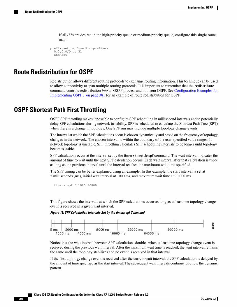
If all /32s are desired in the high-priority queue or medium-priority queue, configure this single routemap:
prefix-set ospf-medium-prefixes0.0.0.0/0 ge 32end-set
Route Redistribution for OSPFRedistribution allows different routing protocols to exchange routing information. This technique can be usedto allow connectivity to span multiple routing protocols. It is important to remember that the redistributecommand controls redistribution into an OSPF process and not from OSPF. See Configuration Examples forImplementing OSPF , on page 381 for an example of route redistribution for OSPF.
OSPF Shortest Path First ThrottlingOSPF SPF throttling makes it possible to configure SPF scheduling in millisecond intervals and to potentiallydelay SPF calculations during network instability. SPF is scheduled to calculate the Shortest Path Tree (SPT)when there is a change in topology. One SPF run may include multiple topology change events.
The interval at which the SPF calculations occur is chosen dynamically and based on the frequency of topologychanges in the network. The chosen interval is within the boundary of the user-specified value ranges. Ifnetwork topology is unstable, SPF throttling calculates SPF scheduling intervals to be longer until topologybecomes stable.
SPF calculations occur at the interval set by the timers throttle spf command. The wait interval indicates theamount of time to wait until the next SPF calculation occurs. Each wait interval after that calculation is twiceas long as the previous interval until the interval reaches the maximum wait time specified.
The SPF timing can be better explained using an example. In this example, the start interval is set at5 milliseconds (ms), initial wait interval at 1000 ms, and maximum wait time at 90,000 ms.
timers spf 5 1000 90000
This figure shows the intervals at which the SPF calculations occur as long as at least one topology changeevent is received in a given wait interval.Figure 18: SPF Calculation Intervals Set by the timers spf Command
Notice that the wait interval between SPF calculations doubles when at least one topology change event isreceived during the previous wait interval. After the maximum wait time is reached, the wait interval remainsthe same until the topology stabilizes and no event is received in that interval.
If the first topology change event is received after the current wait interval, the SPF calculation is delayed bythe amount of time specified as the start interval. The subsequent wait intervals continue to follow the dynamicpattern.
Cisco IOS XR Routing Configuration Guide for the Cisco XR 12000 Series Router, Release 4.0298 OL-23246-02
Implementing OSPFRoute Redistribution for OSPF

If the first topology change event occurs after the maximum wait interval begins, the SPF calculation is againscheduled at the start interval and subsequent wait intervals are reset according to the parameters specified inthe timers throttle spf command. Notice in Figure 19: Timer Intervals Reset After Topology Change Event,on page 299that a topology change event was received after the start of the maximum wait time interval andthat the SPF intervals have been reset.
Figure 19: Timer Intervals Reset After Topology Change Event
Nonstop Forwarding for OSPF Version 2Cisco IOS XR Software NSF for OSPF Version 2 allows for the forwarding of data packets to continue alongknown routes while the routing protocol information is being restored following a failover. With NSF, peernetworking devices do not experience routing flaps. During failover, data traffic is forwarded through intelligentline cards while the standby Route Processor (RP) assumes control from the failed RP. The ability of linecards to remain up through a failover and to be kept current with the Forwarding Information Base (FIB) onthe active RP is key to Cisco IOS XR Software NSF operation.
Routing protocols, such as OSPF, run only on the active RP or DRP and receive routing updates from theirneighbor routers. When an OSPF NSF-capable router performs an RP failover, it must perform two tasks toresynchronize its link-state database with its OSPF neighbors. First, it must relearn the available OSPFneighbors on the network without causing a reset of the neighbor relationship. Second, it must reacquire thecontents of the link-state database for the network.
As quickly as possible after an RP failover, the NSF-capable router sends an OSPF NSF signal to neighboringNSF-aware devices. This signal is in the form of a link-local LSA generated by the failed-over router. Neighbornetworking devices recognize this signal as a cue that the neighbor relationship with this router should not bereset. As the NSF-capable router receives signals from other routers on the network, it can begin to rebuildits neighbor list.
After neighbor relationships are reestablished, the NSF-capable router begins to resynchronize its databasewith all of its NSF-aware neighbors. At this point, the routing information is exchanged between the OSPFneighbors. After this exchange is completed, the NSF-capable device uses the routing information to removestale routes, update the RIB, and update the FIB with the new forwarding information. OSPF on the routerand the OSPF neighbors are now fully converged.
Graceful Restart for OSPFv3The OSPFv3 Graceful Restart feature preserves the data plane capability in the following circumstances:
• RP failure, resulting in a switchover to the backup processor
• Planned OSPFv3 process restart, such as software upgrade or downgrade
Cisco IOS XR Routing Configuration Guide for the Cisco XR 12000 Series Router, Release 4.0 OL-23246-02 299
Implementing OSPFNonstop Forwarding for OSPF Version 2
• Unplanned OSPFv3 process restart, such as a process crash
This feature supports nonstop data forwarding on established routes while the OSPFv3 routing protocol isrestarting. Therefore, this feature enhances high availability of IPv6 forwarding.
Modes of Graceful Restart OperationThe two operational modes that a router can be in for this feature are restart mode and helper mode. Restartmode occurs when the OSPFv3 process is doing a graceful restart. Helper mode refers to the neighbor routersthat continue to forward traffic on established OSPFv3 routes while OSPFv3 is restarting on a neighboringrouter.
Restart Mode
When the OSPFv3 process starts up, it determines whether it must attempt a graceful restart. The determinationis based on whether graceful restart was previously enabled. (OSPFv3 does not attempt a graceful restart uponthe first-time startup of the router.) When OSPFv3 graceful restart is enabled, it changes the purge timer inthe RIB to a nonzero value. See Configuring OSPFv3 Graceful Restart, on page 343,for descriptions of howto enable and configure graceful restart.
During a graceful restart, the router does not populate OSPFv3 routes in the RIB. It tries to bring up fulladjacencies with the fully adjacent neighbors that OSPFv3 had before the restart. Eventually, the OSPFv3process indicates to the RIB that it has converged, either for the purpose of terminating the graceful restart(for any reason) or because it has completed the graceful restart.
The following are general details about restart mode. More detailed information on behavior and certainrestrictions and requirements appears in Graceful Restart Requirements and Restrictions, on page 301 section.
• If OSPFv3 attempts a restart too soon after the most recent restart, the OSPFv3 process is most likelycrashing repeatedly, so the new graceful restart stops running. To control the period between allowablegraceful restarts, use the graceful-restart interval command.
•When OSFPv3 starts a graceful restart with the first interface that comes up, a timer starts running tolimit the duration (or lifetime) of the graceful restart. You can configure this period with thegraceful-restart lifetime command. On each interface that comes up, a grace LSA (Type 11) is floodedto indicate to the neighboring routers that this router is attempting graceful restart. The neighbors enterinto helper mode.
• The designated router and backup designated router check of the hello packet received from the restartingneighbor is bypassed, because it might not be valid.
Helper Mode
Helper mode is enabled by default. When a (helper) router receives a grace LSA (Type 11) from a router thatis attempting a graceful restart, the following events occur:
• If helper mode has been disabled through the graceful-restart helper disable command, the routerdrops the LSA packet.
• If helper mode is enabled, the router enters helper mode if all of the following conditions are met:
◦The local router itself is not attempting a graceful restart.
◦The local (helping) router has full adjacency with the sending neighbor.
Cisco IOS XR Routing Configuration Guide for the Cisco XR 12000 Series Router, Release 4.0300 OL-23246-02
Implementing OSPFGraceful Restart for OSPFv3

◦The value of lsage (link state age) in the received LSA is less than the requested grace period.
◦The sender of the grace LSA is the same as the originator of the grace LSA.
• Upon entering helper mode, a router performs its helper function for a specific period of time. This timeperiod is the lifetime value from the router that is in restart mode—minus the value of lsage in thereceived grace LSA. If the graceful restart succeeds in time, the helper’s timer is stopped before it expires.If the helper’s timer does expire, the adjacency to the restarting router is brought down, and normalOSPFv3 functionality resumes.
• The dead timer is not honored by the router that is in helper mode.
• A router in helper mode ceases to perform the helper function in any of the following cases:
◦The helper router is able to bring up a FULL adjacency with the restarting router.
◦The local timer for the helper function expires.
Graceful Restart Requirements and RestrictionsThe requirements for supporting the Graceful Restart feature include:
• Cooperation of a router’s neighbors during a graceful restart. In relation to the router on which OSPFv3is restarting, each router is called a helper.
• All neighbors of the router that does a graceful restart must be capable of doing a graceful restart.
• A graceful restart does not occur upon the first-time startup of a router.
• OSPFv3 neighbor information and database information are not check-pointed.
• An OSPFv3 process rebuilds adjacencies after it restarts.
• To ensure consistent databases after a restart, the OSPFv3 configuration must be identical to theconfiguration before the restart. (This requirement applies to self-originated information in the localdatabase.) A graceful restart can fail if configurations change during the operation. In this case, dataforwarding would be affected. OSPFv3 resumes operation by regenerating all its LSAs andresynchronizing its database with all its neighbors.
• Although IPv6 FIB tables remain unchanged during a graceful restart, these tables eventually mark theroutes as stale through the use of a holddown timer. Enough time is allowed for the protocols to rebuildstate information and converge.
• The router on which OSPFv3 is restarting must send OSPFv3 hellos within the dead interval of theprocess restart. Protocols must be able to retain adjacencies with neighbors before the adjacency deadtimer expires. The default for the dead timer is 40 seconds. If hellos do not arrive on the adjacency beforethe dead timer expires, the router takes down the adjacency. The OSPFv3 Graceful Restart feature doesnot function properly if the dead timer is configured to be less than the time required to send hellos afterthe OSPFv3 process restarts.
• Simultaneous graceful restart sessions on multiple routers are not supported on a single network segment.If a router determines that multiple routers are in restart mode, it terminates any local graceful restartoperation.
Cisco IOS XR Routing Configuration Guide for the Cisco XR 12000 Series Router, Release 4.0 OL-23246-02 301
Implementing OSPFGraceful Restart for OSPFv3
• This feature utilizes the available support for changing the purge time of existing OSPFv3 routes in theRouting Information Base (RIB). When graceful restart is enabled, the purge timer is set to 90 secondsby default. If graceful restart is disabled, the purge timer setting is 0.
• This feature has an associated grace LSA. This link-scope LSA is type11.
• According to the RFC, the OSPFv3 process should flush all old, self-originated LSAs during a restart.With the Graceful Restart feature, however, the router delays this flushing of unknown self-originatedLSAs during a graceful restart. OSPFv3 can learn new information and build new LSAs to replace theold LSAs. When the delay is over, all old LSAs are flushed.
• If graceful restart is enabled, the adjacency creation time of all the neighbors is saved in the systemdatabase (SysDB). The purpose for saving the creation time is so that OSPFv3 can use the originaladjacency creation time to display the uptime for that neighbor after the restart.
Warm Standby and Nonstop Routing for OSPF Version 2OSPFv2 warm standby provides high availability across RP switchovers. With warm standby extensions,each process running on the active RP has a corresponding standby process started on the standby RP. Astandby OSPF process can send and receive OSPF packets with no performance impact to the active OSPFprocess.
Nonstop routing (NSR) allows an RP failover, process restart, or in-service upgrade to be invisible to peerrouters and ensures that there is minimal performance or processing impact. Routing protocol interactionsbetween routers are not impacted by NSR. NSR is built on the warm standby extensions. NSR alleviates therequirement for Cisco NSF and IETF graceful restart protocol extensions.
Warm Standby for OSPF Version 3This feature helps OSPFv3 to initialize itself prior to Fail over (FO) and be ready to function before the failureoccurs. It reduces the downtime during switchover. By default, the router sends hello packets every 40 seconds.
With warm standby process for each OSPF process running on the Active Route Processor, the correspondingOSPF process must start on the Standby RP. There are no changes in configuration for this feature.
Warm-Standby is always enabled. This is an advantage for the systems running OSPFv3 as their IGP whenthey do RP failover.
Multicast-Intact Support for OSPFThe multicast-intact feature provides the ability to run multicast routing (PIM) when IGP shortcuts areconfigured and active on the router. Both OSPFv2 and IS-IS support the multicast-intact feature.
You can enable multicast-intact in the IGP when multicast routing protocols (PIM) are configured and IGPshortcuts are configured on the router. IGP shortcuts are MPLS tunnels that are exposed to IGP. The IGProutes IP traffic over these tunnels to destinations that are downstream from the egress router of the tunnel(from an SPF perspective). PIM cannot use IGP shortcuts for propagating PIM joins, because reverse pathforwarding (RPF) cannot work across a unidirectional tunnel.
When you enable multicast-intact on an IGP, the IGP publishes a parallel or alternate set of equal-cost nexthops for use by PIM. These next hops are called mcast-intact next hops. The mcast-intact next hops have thefollowing attributes:
Cisco IOS XR Routing Configuration Guide for the Cisco XR 12000 Series Router, Release 4.0302 OL-23246-02
Implementing OSPFWarm Standby and Nonstop Routing for OSPF Version 2
• They are guaranteed not to contain any IGP shortcuts.
• They are not used for unicast routing but are used only by PIM to look up an IPv4 next-hop to a PIMsource.
• They are not published to the FIB.
•When multicast-intact is enabled on an IGP, all IPv4 destinations that were learned through link-stateadvertisements are published with a set equal-cost mcast-intact next hops to the RIB. This attributeapplies even when the native next hops have no IGP shortcuts.
In OSPF, the max-paths (number of equal-cost next hops) limit is applied separately to the native andmcast-intact next hops. The number of equal cost mcast-intact next hops is the same as that configured forthe native next hops.
Load Balancing in OSPF Version 2 and OSPFv3When a router learns multiple routes to a specific network by using multiple routing processes (or routingprotocols), it installs the route with the lowest administrative distance in the routing table. Sometimes therouter must select a route from among many learned by using the same routing process with the sameadministrative distance. In this case, the router chooses the path with the lowest cost (or metric) to thedestination. Each routing process calculates its cost differently; the costs may need to be manipulated toachieve load balancing.
OSPF performs load balancing automatically. If OSPF finds that it can reach a destination through more thanone interface and each path has the same cost, it installs each path in the routing table. The only restrictionon the number of paths to the same destination is controlled by themaximum-paths (OSPF) command.
The range for maximum paths is 1 to 16 and the default number of maximum paths is 16.
Multi-Area Adjacency for OSPF Version 2The multi-area adjacency feature for OSPFv2 allows a link to be configured on the primary interface in morethan one area so that the link could be considered as an intra-area link in those areas and configured as apreference over more expensive paths.
This feature establishes a point-to-point unnumbered link in an OSPF area. A point-to-point link provides atopological path for that area, and the primary adjacency uses the link to advertise the link consistent withdraft-ietf-ospf-multi-area-adj-06.
The following are multi-area interface attributes and limitations:
• Exists as a logical construct over an existing primary interface for OSPF; however, the neighbor stateon the primary interface is independent of the multi-area interface.
• Establishes a neighbor relationship with the corresponding multi-area interface on the neighboring router.A mixture of multi-area and primary interfaces is not supported.
• Advertises an unnumbered point-to-point link in the router link state advertisement (LSA) for thecorresponding area when the neighbor state is full.
• Created as a point-to-point network type. You can configure multi-area adjacency on any interface whereonly two OSF speakers are attached. In the case of native broadcast networks, the interface must beconfigured as an OPSF point-to-point type using the network point-to-point command to enable theinterface for a multi-area adjacency.
Cisco IOS XR Routing Configuration Guide for the Cisco XR 12000 Series Router, Release 4.0 OL-23246-02 303
Implementing OSPFLoad Balancing in OSPF Version 2 and OSPFv3
• Inherits the Bidirectional Forwarding Detection (BFD) characteristics from its primary interface. BFDis not configurable under a multi-area interface; however, it is configurable under the primary interface.
The multi-area interface inherits the interface characteristics from its primary interface, but some interfacecharacteristics can be configured under the multi-area interface configuration mode as shown below:
RP/0/0/CPU0:router(config-ospf-ar)# multi-area-interface GigabitEthernet 0/1/0/3RP/0/0/CPU0:router(config-ospf-ar-mif)# ?authentication Enable authenticationauthentication-key Authentication password (key)cost Interface costcost-fallback Cost when cumulative bandwidth goes below the thesholddatabase-filter Filter OSPF LSA during synchronization and floodingdead-interval Interval after which a neighbor is declared deaddistribute-list Filter networks in routing updateshello-interval Time between HELLO packetsmessage-digest-key Message digest authentication password (key)mtu-ignore Enable/Disable ignoring of MTU in DBD packetspacket-size Customize size of OSPF packets upto MTUretransmit-interval Time between retransmitting lost link state advertisementstransmit-delay Estimated time needed to send link-state update packet
RP/0/0/CPU0:router(config-ospf-ar-mif)#
Label Distribution Protocol IGP Auto-configuration for OSPFLabel Distribution Protocol (LDP) Interior Gateway Protocol (IGP) auto-configuration simplifies the procedureto enable LDP on a set of interfaces used by an IGP instance, such as OSPF. LDP IGP auto-configuration canbe used on a large number of interfaces (for example, when LDP is used for transport in the core) and onmultiple OSPF instances simultaneously.
This feature supports the IPv4 unicast address family for the default VPN routing and forwarding (VRF)instance.
LDP IGP auto-configuration can also be explicitly disabled on an individual interface basis under LDP usingthe igp auto-config disable command. This allows LDP to receive all OSPF interfacesminus the ones explicitlydisabled.
See Cisco IOS XR MPLS Configuration Guide for the Cisco XR 12000 Series Router for information onconfiguring LDP IGP auto-configuration.
OSPF Authentication Message Digest ManagementAll OSPF routing protocol exchanges are authenticated and the method used can vary depending on howauthentication is configured. When using cryptographic authentication, the OSPF routing protocol uses theMessage Digest 5 (MD5) authentication algorithm to authenticate packets transmitted between neighbors inthe network. For each OSPF protocol packet, a key is used to generate and verify a message digest that isappended to the end of the OSPF packet. The message digest is a one-way function of the OSPF protocolpacket and the secret key. Each key is identified by the combination of interface used and the key identification.An interface may have multiple keys active at any time.
To manage the rollover of keys and enhance MD5 authentication for OSPF, you can configure a container ofkeys called a keychain with each key comprising the following attributes: generate/accept time, keyidentification, and authentication algorithm.
Cisco IOS XR Routing Configuration Guide for the Cisco XR 12000 Series Router, Release 4.0304 OL-23246-02
Implementing OSPFLabel Distribution Protocol IGP Auto-configuration for OSPF
GTSM TTL Security Mechanism for OSPFOSPF is a link state protocol that requires networking devices to detect topological changes in the network,flood Link State Advertisement (LSA) updates to neighbors, and quickly converge on a new view of thetopology. However, during the act of receiving LSAs from neighbors, network attacks can occur, becausethere are no checks that unicast or multicast packets are originating from a neighbor that is one hop away ormultiple hops away over virtual links.
For virtual links, OSPF packets travel multiple hops across the network; hence, the TTL value can bedecremented several times. For these type of links, a minimum TTL value must be allowed and accepted formultiple-hop packets.
To filter network attacks originating from invalid sources traveling over multiple hops, the Generalized TTLSecurity Mechanism (GTSM), RFC 3682, is used to prevent the attacks. GTSM filters link-local addressesand allows for only one-hop neighbor adjacencies through the configuration of TTL value 255. The TTL valuein the IP header is set to 255 when OSPF packets are originated, and checked on the received OSPF packetsagainst the default GTSM TTL value 255 or the user configured GTSM TTL value, blocking unauthorizedOSPF packets originated from TTL hops away.
Path Computation Element for OSPFv2A PCE is an entity (component, application, or network node) that is capable of computing a network pathor route based on a network graph and applying computational constraints.
PCE is accomplished when a PCE address and client is configured for MPLS-TE. PCE communicates its PCEaddress and capabilities to OSPF then OSPF packages this information in the PCEDiscovery type-length-value(TLV) (Type 2) and reoriginates the RI LSA. OSPF also includes the Router Capabilities TLV (Type 1) inall its RI LSAs. The PCE Discovery TLV contains the PCE address sub-TLV (Type 1) and the Path ScopeSub-TLV (Type 2).
The PCE Address Sub-TLV specifies the IP address that must be used to reach the PCE. It should be aloop-back address that is always reachable, this TLV is mandatory, and must be present within the PCEDiscovery TLV. The Path Scope Sub-TLV indicates the PCE path computation scopes, which refers to thePCE ability to compute or participate in the computation of intra-area, inter-area, inter-AS or inter-layer TELSPs.
PCE extensions to OSPFv2 include support for the Router Information Link State Advertisement (RI LSA).OSPFv2 is extended to receive all area scopes (LSA Types 9, 10, and 11). However, OSPFv2 originates onlyarea scope Type 10.
For detailed information for the Path Computation Element feature see the Implementing MPLS TrafficEngineering on Cisco IOS XR Softwaremodule of the Cisco IOS XR MPLS Configuration Guide for theCisco XR 12000 Series Router and the following IETF drafts:
• draft-ietf-ospf-cap-09
• draft-ietf-pce-disco-proto-ospf-00
OSPF Queue Tuning ParametersThe OSPF queue tuning parameters configuration allows you to:
Cisco IOS XR Routing Configuration Guide for the Cisco XR 12000 Series Router, Release 4.0 OL-23246-02 305
Implementing OSPFGTSM TTL Security Mechanism for OSPF
• Limit the number of continuous incoming events processed.
• Set the maximum number of rate-limited link-state advertisements (LSAs) processed per run.
• Limit the number of summary or external Type 3 to Type 7 link-state advertisements (LSAs) processedper shortest path first (SPF) iteration within a single SPF run.
• Set the high watermark for incoming priority events.
OSPF IP Fast Reroute Loop Free AlternateThe OSPF IP Fast Reroute Loop Free Alternates computation provides:
• Fast rerouting capability by using IP forwarding and routing
• Handles failure in the line cards in minimum time
How to Implement OSPFThis section contains the following procedures:
Enabling OSPFThis task explains how to perform the minimumOSPF configuration on your router that is to enable an OSPFprocess with a router ID, configure a backbone or nonbackbone area, and then assign one or more interfaceson which OSPF runs.
Before You Begin
Although you can configure OSPF before you configure an IP address, no OSPF routing occurs until at leastone IP address is configured.
Cisco IOS XR Routing Configuration Guide for the Cisco XR 12000 Series Router, Release 4.0306 OL-23246-02
Implementing OSPFOSPF IP Fast Reroute Loop Free Alternate
SUMMARY STEPS
1. configure2. Do one of the following:
• router ospf process-name
• router ospfv3 process-name
3. router-id { router-id }4. area area-id5. interface type interface-path-id6. Repeat Step 5 for each interface that uses OSPF.7. log adjacency changes [ detail ] [ enable | disable ]8. Do one of the following:
• end
• commit
DETAILED STEPS
PurposeCommand or Action
Enters global configuration mode.configure
Example:
RP/0/0/CPU0:router# configure
Step 1
Enables OSPF routing for the specified routing process and placesthe router in router configuration mode.
Do one of the following:Step 2
• router ospf process-nameor
• router ospfv3 process-nameEnables OSPFv3 routing for the specified routing process and placesthe router in router ospfv3 configuration mode.
Example:
RP/0/0/CPU0:router(config)# router ospf 1
The process-name argument is any alphanumeric stringno longer than 40 characters.
Note
or
RP/0/0/CPU0:router(config)# router ospfv3 1
Configures a router ID for the OSPF process.router-id { router-id }Step 3
Example:
RP/0/0/CPU0:router(config-ospf)# router-id192.168.4.3
We recommend using a stable IP address as the routerID.
Note
Cisco IOS XR Routing Configuration Guide for the Cisco XR 12000 Series Router, Release 4.0 OL-23246-02 307
Implementing OSPFEnabling OSPF
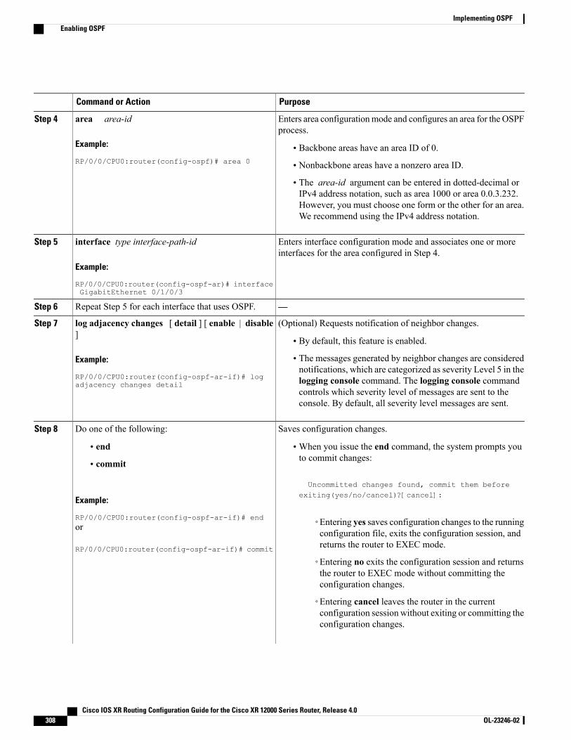
PurposeCommand or Action
Enters area configurationmode and configures an area for the OSPFprocess.
area area-id
Example:
RP/0/0/CPU0:router(config-ospf)# area 0
Step 4
• Backbone areas have an area ID of 0.
• Nonbackbone areas have a nonzero area ID.
• The area-id argument can be entered in dotted-decimal orIPv4 address notation, such as area 1000 or area 0.0.3.232.However, you must choose one form or the other for an area.We recommend using the IPv4 address notation.
Enters interface configuration mode and associates one or moreinterfaces for the area configured in Step 4.
interface type interface-path-id
Example:
RP/0/0/CPU0:router(config-ospf-ar)# interfaceGigabitEthernet 0/1/0/3
Step 5
—Repeat Step 5 for each interface that uses OSPF.Step 6
(Optional) Requests notification of neighbor changes.log adjacency changes [ detail ] [ enable | disable]
Step 7
• By default, this feature is enabled.
Example:
RP/0/0/CPU0:router(config-ospf-ar-if)# logadjacency changes detail
• The messages generated by neighbor changes are considerednotifications, which are categorized as severity Level 5 in thelogging console command. The logging console commandcontrols which severity level of messages are sent to theconsole. By default, all severity level messages are sent.
Saves configuration changes.Do one of the following:Step 8
• end •When you issue the end command, the system prompts youto commit changes:
Uncommitted changes found, commit them before
• commit
Example:
RP/0/0/CPU0:router(config-ospf-ar-if)# end
exiting(yes/no/cancel)?[cancel]:
◦Entering yes saves configuration changes to the runningconfiguration file, exits the configuration session, andreturns the router to EXEC mode.
or
RP/0/0/CPU0:router(config-ospf-ar-if)# commit
◦Entering no exits the configuration session and returnsthe router to EXEC mode without committing theconfiguration changes.
◦Entering cancel leaves the router in the currentconfiguration session without exiting or committing theconfiguration changes.
Cisco IOS XR Routing Configuration Guide for the Cisco XR 12000 Series Router, Release 4.0308 OL-23246-02
Implementing OSPFEnabling OSPF
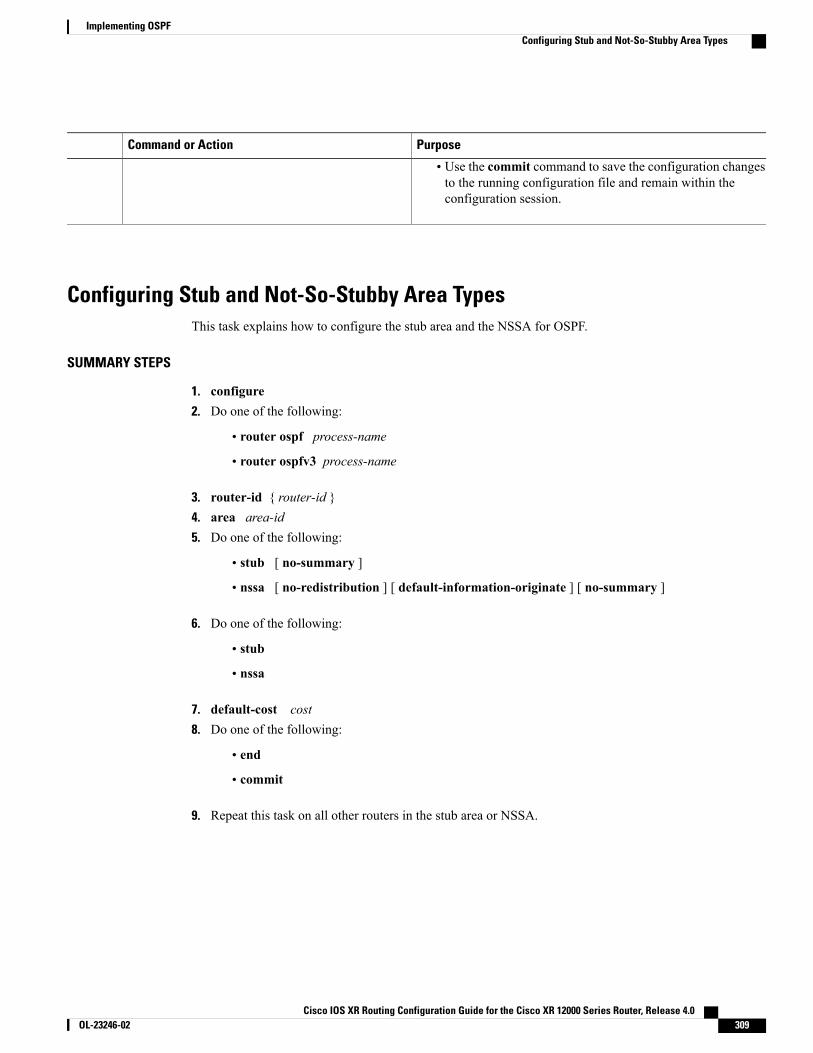
PurposeCommand or Action
• Use the commit command to save the configuration changesto the running configuration file and remain within theconfiguration session.
Configuring Stub and Not-So-Stubby Area TypesThis task explains how to configure the stub area and the NSSA for OSPF.
SUMMARY STEPS
1. configure2. Do one of the following:
• router ospf process-name
• router ospfv3 process-name
3. router-id { router-id }4. area area-id5. Do one of the following:
• stub [ no-summary ]
• nssa [ no-redistribution ] [ default-information-originate ] [ no-summary ]
6. Do one of the following:
• stub
• nssa
7. default-cost cost8. Do one of the following:
• end
• commit
9. Repeat this task on all other routers in the stub area or NSSA.
Cisco IOS XR Routing Configuration Guide for the Cisco XR 12000 Series Router, Release 4.0 OL-23246-02 309
Implementing OSPFConfiguring Stub and Not-So-Stubby Area Types

DETAILED STEPS
PurposeCommand or Action
Enters global configuration mode.configure
Example:
RP/0/0/CPU0:router# configure
Step 1
Enables OSPF routing for the specified routing process and placesthe router in router configuration mode.
Do one of the following:Step 2
• router ospf process-nameor
• router ospfv3 process-nameEnables OSPFv3 routing for the specified routing process andplaces the router in router ospfv3 configuration mode.
Example:
RP/0/0/CPU0:router(config)# router ospf 1
The process-name argument is any alphanumeric stringno longer than 40 characters.
Note
or
RP/0/0/CPU0:router(config)# router ospfv3 1
Configures a router ID for the OSPF process.router-id { router-id }Step 3
Example:
RP/0/0/CPU0:router(config-ospf)# router-id192.168.4.3
We recommend using a stable IP address as the routerID.
Note
Enters area configuration mode and configures a nonbackbonearea for the OSPF process.
area area-id
Example:
RP/0/0/CPU0:router(config-ospf)# area 1
Step 4
• The area-id argument can be entered in dotted-decimal orIPv4 address notation, such as area 1000 or area 0.0.3.232.However, you must choose one form or the other for anarea. We recommend using the IPv4 address notation.
Defines the nonbackbone area as a stub area.Do one of the following:Step 5
• stub [ no-summary ] • Specify the no-summary keyword to further reduce thenumber of LSAs sent into a stub area. This keyword prevents• nssa [ no-redistribution ] [
default-information-originate ] [ no-summary ] the ABR from sending summary link-state advertisements(Type 3) in the stub area.
Example:
RP/0/0/CPU0:router(config-ospf-ar)# stub nosummary
or
Defines an area as an NSSA.
or
RP/0/0/CPU0:router(config-ospf-ar)# nssano-redistribution
Cisco IOS XR Routing Configuration Guide for the Cisco XR 12000 Series Router, Release 4.0310 OL-23246-02
Implementing OSPFConfiguring Stub and Not-So-Stubby Area Types

PurposeCommand or Action
(Optional) Turns off the options configured for stub and NSSAareas.
Do one of the following:Step 6
• stub• If you configured the stub andNSSA areas using the optionalkeywords ( no-summary , no-redistribution ,• nssadefault-information-originate , and no-summary ) in
Example:
RP/0/0/CPU0:router(config-ospf-ar)# stub
Step 5, you must now reissue the stub and nssa commandswithout the keywords—rather than using the no form ofthe command.
or
RP/0/0/CPU0:router(config-ospf-ar)# nssa
• For example, the no nssa default-information-originateform of the command changes the NSSA area into a normalarea that inadvertently brings down the existing adjacenciesin that area.
(Optional) Specifies a cost for the default summary route sentinto a stub area or an NSSA.
default-cost cost
Example:
RP/0/0/CPU0:router(config-ospf-ar)#default-cost15
Step 7
• Use this command only on ABRs attached to the NSSA. Donot use it on any other routers in the area.
• The default cost is 1.
Saves configuration changes.Do one of the following:Step 8
• end •When you issue the end command, the system prompts youto commit changes:
Uncommitted changes found, commit them before
• commit
Example:
RP/0/0/CPU0:router(config-ospf-ar)# end
exiting(yes/no/cancel)?[cancel]:
◦Entering yes saves configuration changes to therunning configuration file, exits the configurationsession, and returns the router to EXEC mode.
or
RP/0/0/CPU0:router(config-ospf-ar)# commit
◦Entering no exits the configuration session and returnsthe router to EXEC mode without committing theconfiguration changes.
◦Entering cancel leaves the router in the currentconfiguration session without exiting or committingthe configuration changes.
• Use the commit command to save the configuration changesto the running configuration file and remain within theconfiguration session.
—Repeat this task on all other routers in the stub area orNSSA.
Step 9
Cisco IOS XR Routing Configuration Guide for the Cisco XR 12000 Series Router, Release 4.0 OL-23246-02 311
Implementing OSPFConfiguring Stub and Not-So-Stubby Area Types
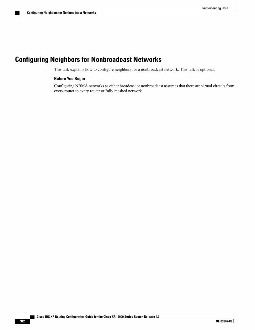
Configuring Neighbors for Nonbroadcast NetworksThis task explains how to configure neighbors for a nonbroadcast network. This task is optional.
Before You Begin
Configuring NBMA networks as either broadcast or nonbroadcast assumes that there are virtual circuits fromevery router to every router or fully meshed network.
Cisco IOS XR Routing Configuration Guide for the Cisco XR 12000 Series Router, Release 4.0312 OL-23246-02
Implementing OSPFConfiguring Neighbors for Nonbroadcast Networks
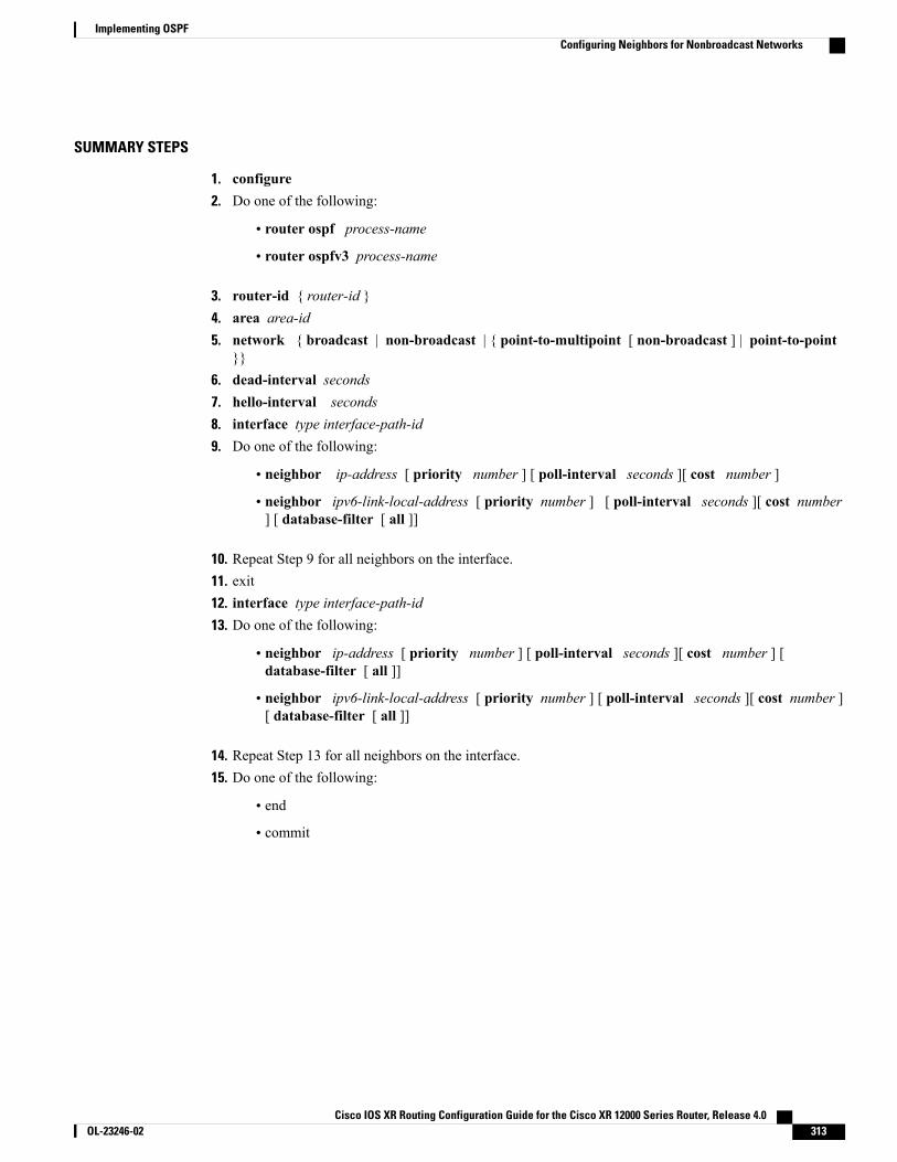
SUMMARY STEPS
1. configure2. Do one of the following:
• router ospf process-name
• router ospfv3 process-name
3. router-id { router-id }4. area area-id5. network { broadcast | non-broadcast | { point-to-multipoint [ non-broadcast ] | point-to-point
}}6. dead-interval seconds7. hello-interval seconds8. interface type interface-path-id9. Do one of the following:
• neighbor ip-address [ priority number ] [ poll-interval seconds ][ cost number ]
• neighbor ipv6-link-local-address [ priority number ] [ poll-interval seconds ][ cost number] [ database-filter [ all ]]
10. Repeat Step 9 for all neighbors on the interface.11. exit12. interface type interface-path-id13. Do one of the following:
• neighbor ip-address [ priority number ] [ poll-interval seconds ][ cost number ] [database-filter [ all ]]
• neighbor ipv6-link-local-address [ priority number ] [ poll-interval seconds ][ cost number ][ database-filter [ all ]]
14. Repeat Step 13 for all neighbors on the interface.15. Do one of the following:
• end
• commit
Cisco IOS XR Routing Configuration Guide for the Cisco XR 12000 Series Router, Release 4.0 OL-23246-02 313
Implementing OSPFConfiguring Neighbors for Nonbroadcast Networks

DETAILED STEPS
PurposeCommand or Action
Enters global configuration mode.configure
Example:
RP/0/0/CPU0:router# configure
Step 1
Enables OSPF routing for the specified routing process and places therouter in router configuration mode.
Do one of the following:Step 2
• router ospf process-nameor
• router ospfv3 process-nameEnables OSPFv3 routing for the specified routing process and placesthe router in router ospfv3 configuration mode.
Example:
RP/0/0/CPU0:router(config)# router ospf 1
The process-name argument is any alphanumeric string nolonger than 40 characters.
Note
or
RP/0/0/CPU0:router(config)# router ospfv31
Configures a router ID for the OSPF process.router-id { router-id }Step 3
Example:
RP/0/0/CPU0:router(config-ospf)# router-id192.168.4.3
We recommend using a stable IP address as the routerID.
Note
Enters area configuration mode and configures an area for the OSPFprocess.
area area-id
Example:
RP/0/0/CPU0:router(config-ospf)# area 0
Step 4
• The example configures a backbone area.
• The area-id argument can be entered in dotted-decimal or IPv4address notation, such as area 1000 or area 0.0.3.232. However,youmust choose one form or the other for an area.We recommendusing the IPv4 address notation.
Configures the OSPF network type to a type other than the default fora given medium.
network { broadcast | non-broadcast | {point-to-multipoint [ non-broadcast ] |point-to-point }}
Step 5
• The example sets the network type to NBMA.
Example:
RP/0/0/CPU0:router(config-ospf-ar)# networknon-broadcast
(Optional) Sets the time to wait for a hello packet from a neighborbefore declaring the neighbor down.
dead-interval seconds
Example:
RP/0/0/CPU0:router(config-ospf-ar)#dead-interval 40
Step 6
Cisco IOS XR Routing Configuration Guide for the Cisco XR 12000 Series Router, Release 4.0314 OL-23246-02
Implementing OSPFConfiguring Neighbors for Nonbroadcast Networks
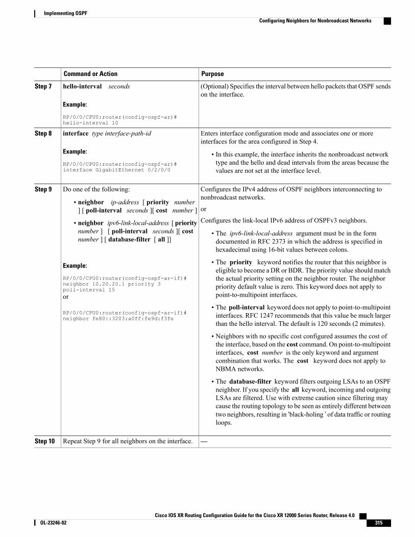
PurposeCommand or Action
(Optional) Specifies the interval between hello packets that OSPF sendson the interface.
hello-interval seconds
Example:
RP/0/0/CPU0:router(config-ospf-ar)#hello-interval 10
Step 7
Enters interface configuration mode and associates one or moreinterfaces for the area configured in Step 4.
interface type interface-path-id
Example:
RP/0/0/CPU0:router(config-ospf-ar)#interface GigabitEthernet 0/2/0/0
Step 8
• In this example, the interface inherits the nonbroadcast networktype and the hello and dead intervals from the areas because thevalues are not set at the interface level.
Configures the IPv4 address of OSPF neighbors interconnecting tononbroadcast networks.
Do one of the following:Step 9
• neighbor ip-address [ priority number] [ poll-interval seconds ][ cost number ] or
Configures the link-local IPv6 address of OSPFv3 neighbors.• neighbor ipv6-link-local-address [ prioritynumber ] [ poll-interval seconds ][ costnumber ] [ database-filter [ all ]]
• The ipv6-link-local-address argument must be in the formdocumented in RFC 2373 in which the address is specified inhexadecimal using 16-bit values between colons.
Example:
RP/0/0/CPU0:router(config-ospf-ar-if)#
• The priority keyword notifies the router that this neighbor iseligible to become a DR or BDR. The priority value should matchthe actual priority setting on the neighbor router. The neighbor
neighbor 10.20.20.1 priority 3poll-interval 15 priority default value is zero. This keyword does not apply to
point-to-multipoint interfaces.or
RP/0/0/CPU0:router(config-ospf-ar-if)#neighbor fe80::3203:a0ff:fe9d:f3fe
• The poll-interval keyword does not apply to point-to-multipointinterfaces. RFC 1247 recommends that this value be much largerthan the hello interval. The default is 120 seconds (2 minutes).
• Neighbors with no specific cost configured assumes the cost ofthe interface, based on the cost command. On point-to-multipointinterfaces, cost number is the only keyword and argumentcombination that works. The cost keyword does not apply toNBMA networks.
• The database-filter keyword filters outgoing LSAs to an OSPFneighbor. If you specify the all keyword, incoming and outgoingLSAs are filtered. Use with extreme caution since filtering maycause the routing topology to be seen as entirely different betweentwo neighbors, resulting in ‘black-holing ’ of data traffic or routingloops.
—Repeat Step 9 for all neighbors on the interface.Step 10
Cisco IOS XR Routing Configuration Guide for the Cisco XR 12000 Series Router, Release 4.0 OL-23246-02 315
Implementing OSPFConfiguring Neighbors for Nonbroadcast Networks

PurposeCommand or Action
Enters area configuration mode.exit
Example:
RP/0/0/CPU0:router(config-ospf-ar-if)# exit
Step 11
Enters interface configuration mode and associates one or moreinterfaces for the area configured in Step 4.
interface type interface-path-id
Example:
RP/0/0/CPU0:router(config-ospf-ar)#interface GigabitEthernet 0/3/0/1
Step 12
• In this example, the interface inherits the nonbroadcast networktype and the hello and dead intervals from the areas because thevalues are not set at the interface level.
Configures the IPv4 address of OSPF neighbors interconnecting tononbroadcast networks.
Do one of the following:Step 13
• neighbor ip-address [ priority number ][ poll-interval seconds ][ cost number ] [database-filter [ all ]]
or
Configures the link-local IPv6 address of OSPFv3 neighbors.• neighbor ipv6-link-local-address [ prioritynumber ] [ poll-interval seconds ][ costnumber ] [ database-filter [ all ]]
• The ipv6-link-local-address argument must be in the formdocumented in RFC 2373 in which the address is specified inhexadecimal using 16-bit values between colons.
• The priority keyword notifies the router that this neighbor iseligible to become a DR or BDR. The priority value should matchExample:
RP/0/RP0/CPU0:router(config-ospf-ar)# neighbor10.34.16.6
the actual priority setting on the neighbor router. The neighborpriority default value is zero. This keyword does not apply topoint-to-multipoint interfaces.or
RP/0/RP0/CPU0:router(config-ospf-ar)# neighborfe80::3203:a0ff:fe9d:f3f
• The poll-interval keyword does not apply to point-to-multipointinterfaces. RFC 1247 recommends that this value be much largerthan the hello interval. The default is 120 seconds (2 minutes).
• Neighbors with no specific cost configured assumes the cost ofthe interface, based on the cost command. On point-to-multipointinterfaces, cost number is the only keyword and argumentcombination that works. The cost keyword does not apply toNBMA networks.
• The database-filter keyword filters outgoing LSAs to an OSPFneighbor. If you specify the all keyword, incoming and outgoingLSAs are filtered. Use with extreme caution since filtering maycause the routing topology to be seen as entirely different betweentwo neighbors, resulting in ‘black-holing ’ or routing loops.
—Repeat Step 13 for all neighbors on the interface.Step 14
Saves configuration changes.Do one of the following:Step 15
Cisco IOS XR Routing Configuration Guide for the Cisco XR 12000 Series Router, Release 4.0316 OL-23246-02
Implementing OSPFConfiguring Neighbors for Nonbroadcast Networks
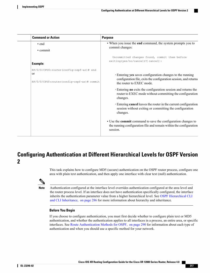
PurposeCommand or Action
•When you issue the end command, the system prompts you tocommit changes:
Uncommitted changes found, commit them before
• end
• commit
Example:
RP/0/0/CPU0:router(config-ospf-ar)# end
exiting(yes/no/cancel)?[cancel]:
or
RP/0/0/CPU0:router(config-ospf-ar)# commit
◦Entering yes saves configuration changes to the runningconfiguration file, exits the configuration session, and returnsthe router to EXEC mode.
◦Entering no exits the configuration session and returns therouter to EXECmode without committing the configurationchanges.
◦Entering cancel leaves the router in the current configurationsession without exiting or committing the configurationchanges.
• Use the commit command to save the configuration changes tothe running configuration file and remain within the configurationsession.
Configuring Authentication at Different Hierarchical Levels for OSPF Version2
This task explains how to configure MD5 (secure) authentication on the OSPF router process, configure onearea with plain text authentication, and then apply one interface with clear text (null) authentication.
Authentication configured at the interface level overrides authentication configured at the area level andthe router process level. If an interface does not have authentication specifically configured, the interfaceinherits the authentication parameter value from a higher hierarchical level. See OSPF Hierarchical CLIand CLI Inheritance, on page 286 for more information about hierarchy and inheritance.
Note
Before You Begin
If you choose to configure authentication, you must first decide whether to configure plain text or MD5authentication, and whether the authentication applies to all interfaces in a process, an entire area, or specificinterfaces. See Route Authentication Methods for OSPF, on page 290 for information about each type ofauthentication and when you should use a specific method for your network.
Cisco IOS XR Routing Configuration Guide for the Cisco XR 12000 Series Router, Release 4.0 OL-23246-02 317
Implementing OSPFConfiguring Authentication at Different Hierarchical Levels for OSPF Version 2

SUMMARY STEPS
1. configure2. router ospf process-name3. router-id { router-id }4. authentication [ message-digest | null ]5. message-digest-key key-id md5 { key | clear key | encrypted key | LINE}6. area area-id7. interface type interface-path-id8. Repeat Step 7 for each interface that must communicate, using the same authentication.9. exit10. area area-id11. authentication [ message-digest | null ]12. interface type interface-path-id13. Repeat Step 12 for each interface that must communicate, using the same authentication.14. interface type interface-path-id15. authentication [ message-digest | null ]16. Do one of the following:
• end
• commit
DETAILED STEPS
PurposeCommand or Action
Enters global configuration mode.configure
Example:
RP/0/0/CPU0:router# configure
Step 1
Enables OSPF routing for the specified routing process andplaces the router in router configuration mode.
router ospf process-name
Example:
RP/0/0/CPU0:router(config)# router ospf 1
Step 2
The process-name argument is any alphanumericstring no longer than 40 characters.
Note
Configures a router ID for the OSPF process.router-id { router-id }
Example:
RP/0/0/CPU0:router(config-ospf)# router-id192.168.4.3
Step 3
Enables MD5 authentication for the OSPF process.authentication [ message-digest | null ]Step 4
Cisco IOS XR Routing Configuration Guide for the Cisco XR 12000 Series Router, Release 4.0318 OL-23246-02
Implementing OSPFConfiguring Authentication at Different Hierarchical Levels for OSPF Version 2
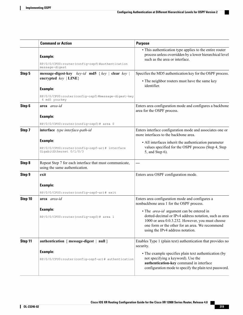
PurposeCommand or Action
Example:
RP/0/0/CPU0:router(config-ospf)#authenticationmessage-digest
• This authentication type applies to the entire routerprocess unless overridden by a lower hierarchical levelsuch as the area or interface.
Specifies theMD5 authentication key for the OSPF process.message-digest-key key-id md5 { key | clear key |encrypted key | LINE}
Step 5
• The neighbor routers must have the same keyidentifier.
Example:
RP/0/0/CPU0:router(config-ospf)#message-digest-key4 md5 yourkey
Enters area configuration mode and configures a backbonearea for the OSPF process.
area area-id
Example:
RP/0/0/CPU0:router(config-ospf)# area 0
Step 6
Enters interface configuration mode and associates one ormore interfaces to the backbone area.
interface type interface-path-id
Example:
RP/0/0/CPU0:router(config-ospf-ar)# interfaceGigabitEthernet 0/1/0/3
Step 7
• All interfaces inherit the authentication parametervalues specified for the OSPF process (Step 4, Step5, and Step 6).
—Repeat Step 7 for each interface that must communicate,using the same authentication.
Step 8
Enters area OSPF configuration mode.exit
Example:
RP/0/0/CPU0:router(config-ospf-ar)# exit
Step 9
Enters area configuration mode and configures anonbackbone area 1 for the OSPF process.
area area-id
Example:
RP/0/0/CPU0:router(config-ospf)# area 1
Step 10
• The area-id argument can be entered indotted-decimal or IPv4 address notation, such as area1000 or area 0.0.3.232. However, you must chooseone form or the other for an area. We recommendusing the IPv4 address notation.
Enables Type 1 (plain text) authentication that provides nosecurity.
authentication [ message-digest | null ]
Example:
RP/0/0/CPU0:router(config-ospf-ar)# authentication
Step 11
• The example specifies plain text authentication (bynot specifying a keyword). Use theauthentication-key command in interfaceconfiguration mode to specify the plain text password.
Cisco IOS XR Routing Configuration Guide for the Cisco XR 12000 Series Router, Release 4.0 OL-23246-02 319
Implementing OSPFConfiguring Authentication at Different Hierarchical Levels for OSPF Version 2
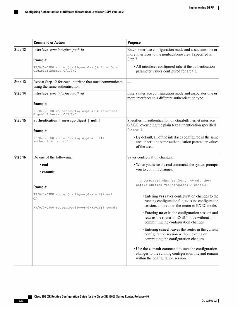
PurposeCommand or Action
Enters interface configuration mode and associates one ormore interfaces to the nonbackbone area 1 specified inStep 7.
interface type interface-path-id
Example:
RP/0/0/CPU0:router(config-ospf-ar)# interfaceGigabitEthernet 0/1/0/0
Step 12
• All interfaces configured inherit the authenticationparameter values configured for area 1.
—Repeat Step 12 for each interface that must communicate,using the same authentication.
Step 13
Enters interface configuration mode and associates one ormore interfaces to a different authentication type.
interface type interface-path-id
Example:
RP/0/0/CPU0:router(config-ospf-ar)# interfaceGigabitEthernet 0/3/0/0
Step 14
Specifies no authentication on GigabitEthernet interface0/3/0/0, overriding the plain text authentication specifiedfor area 1.
authentication [ message-digest | null ]
Example:
RP/0/0/CPU0:router(config-ospf-ar-if)#authentication null
Step 15
• By default, all of the interfaces configured in the samearea inherit the same authentication parameter valuesof the area.
Saves configuration changes.Do one of the following:Step 16
• end •When you issue the end command, the system promptsyou to commit changes:
Uncommitted changes found, commit them
• commit
Example:
RP/0/0/CPU0:router(config-ospf-ar-if)# end
before exiting(yes/no/cancel)?[cancel]:
◦Entering yes saves configuration changes to therunning configuration file, exits the configurationsession, and returns the router to EXEC mode.
or
RP/0/0/CPU0:router(config-ospf-ar-if)# commit
◦Entering no exits the configuration session andreturns the router to EXEC mode withoutcommitting the configuration changes.
◦Entering cancel leaves the router in the currentconfiguration session without exiting orcommitting the configuration changes.
• Use the commit command to save the configurationchanges to the running configuration file and remainwithin the configuration session.
Cisco IOS XR Routing Configuration Guide for the Cisco XR 12000 Series Router, Release 4.0320 OL-23246-02
Implementing OSPFConfiguring Authentication at Different Hierarchical Levels for OSPF Version 2
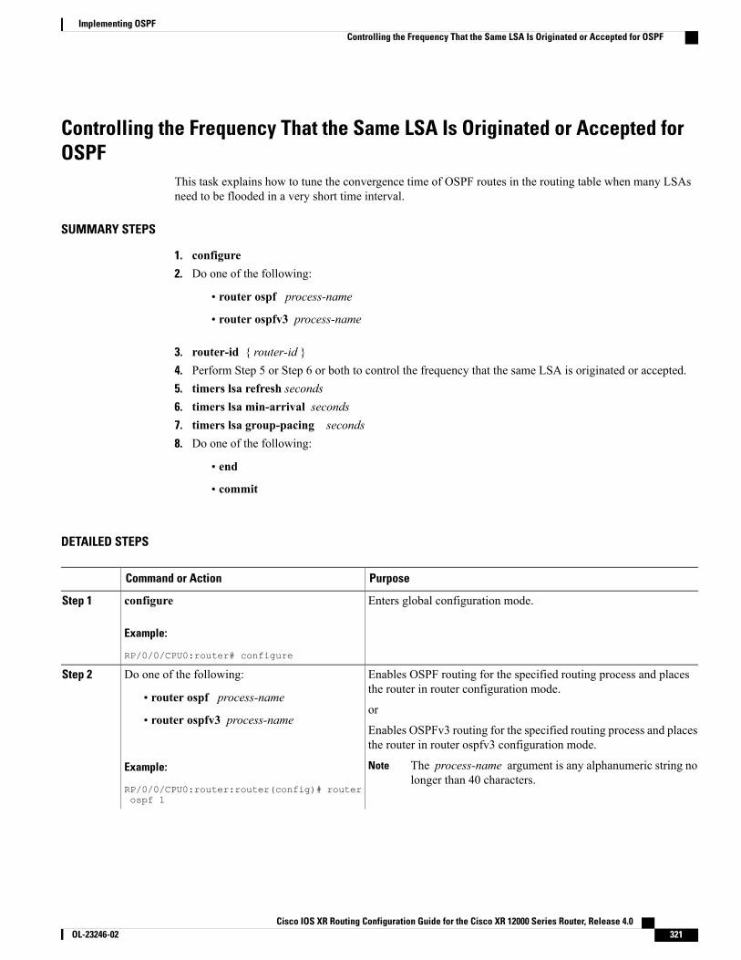
Controlling the Frequency That the Same LSA Is Originated or Accepted forOSPF
This task explains how to tune the convergence time of OSPF routes in the routing table when many LSAsneed to be flooded in a very short time interval.
SUMMARY STEPS
1. configure2. Do one of the following:
• router ospf process-name
• router ospfv3 process-name
3. router-id { router-id }4. Perform Step 5 or Step 6 or both to control the frequency that the same LSA is originated or accepted.5. timers lsa refresh seconds6. timers lsa min-arrival seconds7. timers lsa group-pacing seconds8. Do one of the following:
• end
• commit
DETAILED STEPS
PurposeCommand or Action
Enters global configuration mode.configure
Example:
RP/0/0/CPU0:router# configure
Step 1
Enables OSPF routing for the specified routing process and placesthe router in router configuration mode.
Do one of the following:Step 2
• router ospf process-nameor
• router ospfv3 process-nameEnables OSPFv3 routing for the specified routing process and placesthe router in router ospfv3 configuration mode.
Example:
RP/0/0/CPU0:router:router(config)# routerospf 1
The process-name argument is any alphanumeric string nolonger than 40 characters.
Note
Cisco IOS XR Routing Configuration Guide for the Cisco XR 12000 Series Router, Release 4.0 OL-23246-02 321
Implementing OSPFControlling the Frequency That the Same LSA Is Originated or Accepted for OSPF
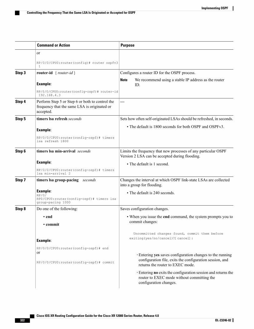
PurposeCommand or Action
or
RP/0/0/CPU0:router(config)# router ospfv31
Configures a router ID for the OSPF process.router-id { router-id }Step 3
Example:
RP/0/0/CPU0:router(config-ospf)# router-id192.168.4.3
We recommend using a stable IP address as the routerID.
Note
—Perform Step 5 or Step 6 or both to control thefrequency that the same LSA is originated oraccepted.
Step 4
Sets how often self-originated LSAs should be refreshed, in seconds.timers lsa refresh secondsStep 5
Example:
RP/0/0/CPU0:router(config-ospf)# timers
• The default is 1800 seconds for both OSPF and OSPFv3.
lsa refresh 1800
Limits the frequency that new processes of any particular OSPFVersion 2 LSA can be accepted during flooding.
timers lsa min-arrival seconds
Example:
RP/0/0/CPU0:router(config-ospf)# timerslsa min-arrival 2
Step 6
• The default is 1 second.
Changes the interval at which OSPF link-state LSAs are collectedinto a group for flooding.
timers lsa group-pacing seconds
Example:RP/0/RP0/CPU0:router(config-ospf)# timers lsagroup-pacing 1000
Step 7
• The default is 240 seconds.
Saves configuration changes.Do one of the following:Step 8
• end •When you issue the end command, the system prompts you tocommit changes:
Uncommitted changes found, commit them before
• commit
Example:
RP/0/0/CPU0:router(config-ospf)# end
exiting(yes/no/cancel)?[cancel]:
or
RP/0/0/CPU0:router(config-ospf)# commit
◦Entering yes saves configuration changes to the runningconfiguration file, exits the configuration session, andreturns the router to EXEC mode.
◦Entering no exits the configuration session and returns therouter to EXEC mode without committing theconfiguration changes.
Cisco IOS XR Routing Configuration Guide for the Cisco XR 12000 Series Router, Release 4.0322 OL-23246-02
Implementing OSPFControlling the Frequency That the Same LSA Is Originated or Accepted for OSPF

PurposeCommand or Action
◦Entering cancel leaves the router in the currentconfiguration session without exiting or committing theconfiguration changes.
• Use the commit command to save the configuration changes tothe running configuration file and remain within theconfiguration session.
Creating a Virtual Link with MD5 Authentication to Area 0 for OSPFThis task explains how to create a virtual link to your backbone (area 0) and apply MD5 authentication. Youmust perform the steps described on both ABRs, one at each end of the virtual link. To understand virtuallinks, see Virtual Link and Transit Area for OSPF, on page 294 .
After you explicitly configure area parameter values, they are inherited by all interfaces bound to thatarea—unless you override the values and configure them explicitly for the interface. An example isprovided in Virtual Link Configured with MD5 Authentication for OSPF Version 2: Example, on page386.
Note
Before You Begin
The following prerequisites must be met before creating a virtual link with MD5 authentication to area 0:
• You must have the router ID of the neighbor router at the opposite end of the link to configure the localrouter. You can execute the show ospf or show ospfv3 command on the remote router to get its routerID.
• For a virtual link to be successful, you need a stable router ID at each end of the virtual link. You donot want them to be subject to change, which could happen if they are assigned by default. (See OSPFProcess and Router ID, on page 289 for an explanation of how the router ID is determined.) Therefore,we recommend that you perform one of the following tasks before configuring a virtual link:
◦Use the router-id command to set the router ID. This strategy is preferable.
◦Configure a loopback interface so that the router has a stable router ID.
• Before configuring your virtual link for OSPF Version 2, you must decide whether to configure plaintext authentication, MD5 authentication, or no authentication (which is the default). Your decisiondetermines whether you need to perform additional tasks related to authentication.
Cisco IOS XR Routing Configuration Guide for the Cisco XR 12000 Series Router, Release 4.0 OL-23246-02 323
Implementing OSPFCreating a Virtual Link with MD5 Authentication to Area 0 for OSPF

If you decide to configure plain text authentication or no authentication, see the authentication commandprovided in OSPF Commands on Cisco IOS XR Software module in Cisco IOS XR Routing CommandReference for the Cisco XR 12000 Series Router.
Note
SUMMARY STEPS
1. Do one of the following:
• show ospf [ process-name ]
• show ospfv3 [ process-name ]
2. configure3. Do one of the following:
• router ospf process-name
• router ospfv3 process-name
4. router-id { router-id }5. area area-id6. virtual-link router-id7. authentication message-digest8. message-digest-key key-id md5 { key | clear key | encrypted key }9. Repeat all of the steps in this task on the ABR that is at the other end of the virtual link. Specify the same
key ID and key that you specified for the virtual link on this router.10. Do one of the following:
• end
• commit
11. Do one of the following:
• show ospf [ process-name ] [ area-id ] virtual-links
• show ospfv3 [ process-name ] virtual-links
DETAILED STEPS
PurposeCommand or Action
(Optional) Displays general information about OSPFrouting processes.
Do one of the following:Step 1
• show ospf [ process-name ]• The output displays the router ID of the localrouter. You need this router ID to configure theother end of the link.
Cisco IOS XR Routing Configuration Guide for the Cisco XR 12000 Series Router, Release 4.0324 OL-23246-02
Implementing OSPFCreating a Virtual Link with MD5 Authentication to Area 0 for OSPF
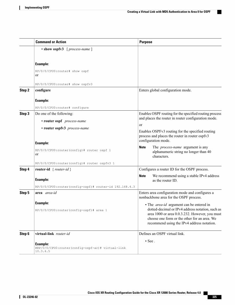
PurposeCommand or Action
• show ospfv3 [ process-name ]
Example:
RP/0/0/CPU0:router# show ospfor
RP/0/0/CPU0:router# show ospfv3
Enters global configuration mode.configure
Example:
RP/0/0/CPU0:router# configure
Step 2
Enables OSPF routing for the specified routing processand places the router in router configuration mode.
Do one of the following:Step 3
• router ospf process-nameor
• router ospfv3 process-nameEnables OSPFv3 routing for the specified routingprocess and places the router in router ospfv3configuration mode.
Example:
RP/0/0/CPU0:router(config)# router ospf 1The process-name argument is anyalphanumeric string no longer than 40characters.
Note
or
RP/0/0/CPU0:router(config)# router ospfv3 1
Configures a router ID for the OSPF process.router-id { router-id }Step 4
Example:
RP/0/0/CPU0:router(config-ospf)# router-id 192.168.4.3
We recommend using a stable IPv4 addressas the router ID.
Note
Enters area configuration mode and configures anonbackbone area for the OSPF process.
area area-id
Example:
RP/0/0/CPU0:router(config-ospf)# area 1
Step 5
• The area-id argument can be entered indotted-decimal or IPv4 address notation, such asarea 1000 or area 0.0.3.232. However, you mustchoose one form or the other for an area. Werecommend using the IPv4 address notation.
Defines an OSPF virtual link.virtual-link router-idStep 6
Example:RRP/0/0/CPU0:router(config-ospf-ar)# virtual-link10.3.4.5
• See .
Cisco IOS XR Routing Configuration Guide for the Cisco XR 12000 Series Router, Release 4.0 OL-23246-02 325
Implementing OSPFCreating a Virtual Link with MD5 Authentication to Area 0 for OSPF
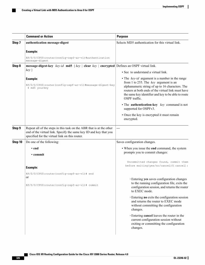
PurposeCommand or Action
Selects MD5 authentication for this virtual link.authentication message-digest
Example:
RP/0/0/CPU0:router(config-ospf-ar-vl)#authenticationmessage-digest
Step 7
Defines an OSPF virtual link.message-digest-key key-id md5 { key | clear key | encryptedkey }
Step 8
• See to understand a virtual link.
Example:
RP/0/0/CPU0:router(config-ospf-ar-vl)#message-digest-key4 md5 yourkey
• The key-id argument is a number in the rangefrom 1 to 255. The key argument is analphanumeric string of up to 16 characters. Therouters at both ends of the virtual link must havethe same key identifier and key to be able to routeOSPF traffic.
• The authentication-key key command is notsupported for OSPFv3.
• Once the key is encrypted it must remainencrypted.
—Repeat all of the steps in this task on the ABR that is at the otherend of the virtual link. Specify the same key ID and key that youspecified for the virtual link on this router.
Step 9
Saves configuration changes.Do one of the following:Step 10
• end •When you issue the end command, the systemprompts you to commit changes:
Uncommitted changes found, commit them
• commit
Example:
RP/0/0/CPU0:router(config-ospf-ar-vl)# end
before exiting(yes/no/cancel)?[cancel]:
or
RP/0/0/CPU0:router(config-ospf-ar-vl)# commit
◦Entering yes saves configuration changesto the running configuration file, exits theconfiguration session, and returns the routerto EXEC mode.
◦Entering no exits the configuration sessionand returns the router to EXEC modewithout committing the configurationchanges.
◦Entering cancel leaves the router in thecurrent configuration session withoutexiting or committing the configurationchanges.
Cisco IOS XR Routing Configuration Guide for the Cisco XR 12000 Series Router, Release 4.0326 OL-23246-02
Implementing OSPFCreating a Virtual Link with MD5 Authentication to Area 0 for OSPF
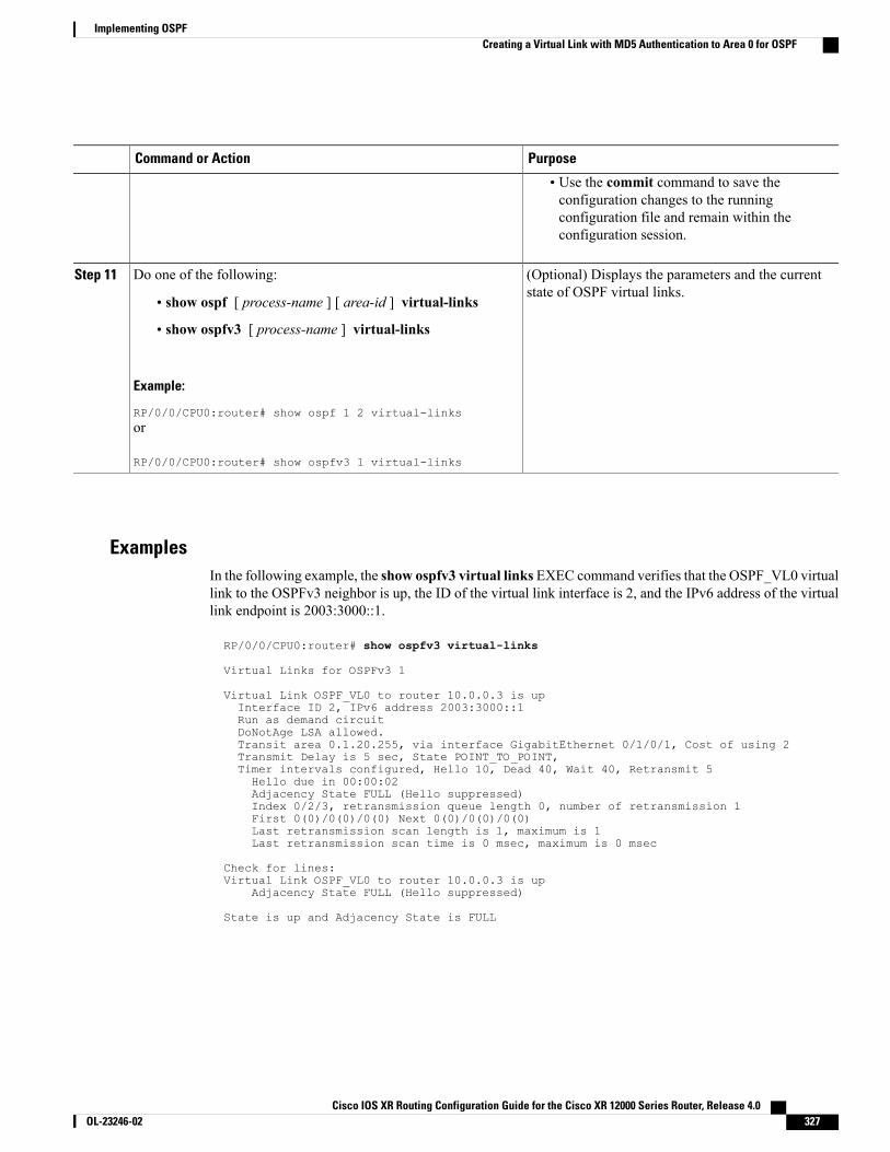
PurposeCommand or Action
• Use the commit command to save theconfiguration changes to the runningconfiguration file and remain within theconfiguration session.
(Optional) Displays the parameters and the currentstate of OSPF virtual links.
Do one of the following:Step 11
• show ospf [ process-name ] [ area-id ] virtual-links
• show ospfv3 [ process-name ] virtual-links
Example:
RP/0/0/CPU0:router# show ospf 1 2 virtual-linksor
RP/0/0/CPU0:router# show ospfv3 1 virtual-links
ExamplesIn the following example, the show ospfv3 virtual links EXEC command verifies that the OSPF_VL0 virtuallink to the OSPFv3 neighbor is up, the ID of the virtual link interface is 2, and the IPv6 address of the virtuallink endpoint is 2003:3000::1.
RP/0/0/CPU0:router# show ospfv3 virtual-links
Virtual Links for OSPFv3 1
Virtual Link OSPF_VL0 to router 10.0.0.3 is upInterface ID 2, IPv6 address 2003:3000::1Run as demand circuitDoNotAge LSA allowed.Transit area 0.1.20.255, via interface GigabitEthernet 0/1/0/1, Cost of using 2Transmit Delay is 5 sec, State POINT_TO_POINT,Timer intervals configured, Hello 10, Dead 40, Wait 40, Retransmit 5Hello due in 00:00:02Adjacency State FULL (Hello suppressed)Index 0/2/3, retransmission queue length 0, number of retransmission 1First 0(0)/0(0)/0(0) Next 0(0)/0(0)/0(0)Last retransmission scan length is 1, maximum is 1Last retransmission scan time is 0 msec, maximum is 0 msec
Check for lines:Virtual Link OSPF_VL0 to router 10.0.0.3 is up
Adjacency State FULL (Hello suppressed)
State is up and Adjacency State is FULL
Cisco IOS XR Routing Configuration Guide for the Cisco XR 12000 Series Router, Release 4.0 OL-23246-02 327
Implementing OSPFCreating a Virtual Link with MD5 Authentication to Area 0 for OSPF
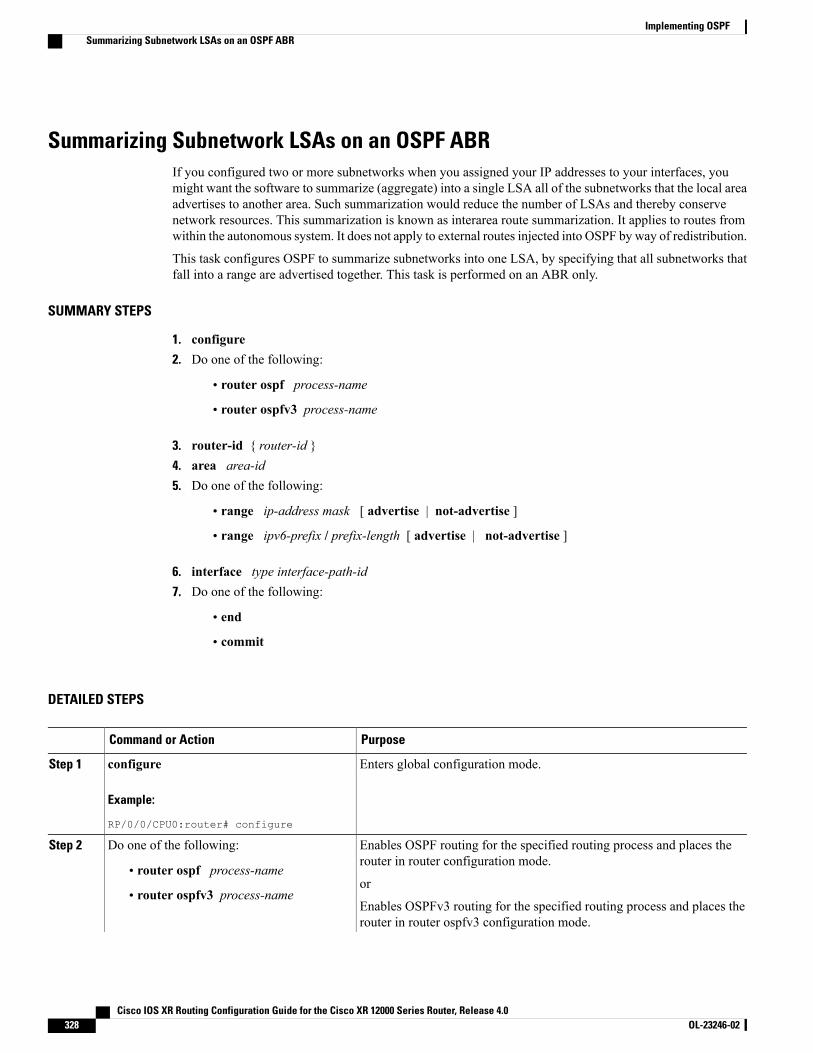
Summarizing Subnetwork LSAs on an OSPF ABRIf you configured two or more subnetworks when you assigned your IP addresses to your interfaces, youmight want the software to summarize (aggregate) into a single LSA all of the subnetworks that the local areaadvertises to another area. Such summarization would reduce the number of LSAs and thereby conservenetwork resources. This summarization is known as interarea route summarization. It applies to routes fromwithin the autonomous system. It does not apply to external routes injected into OSPF by way of redistribution.
This task configures OSPF to summarize subnetworks into one LSA, by specifying that all subnetworks thatfall into a range are advertised together. This task is performed on an ABR only.
SUMMARY STEPS
1. configure2. Do one of the following:
• router ospf process-name
• router ospfv3 process-name
3. router-id { router-id }4. area area-id5. Do one of the following:
• range ip-address mask [ advertise | not-advertise ]
• range ipv6-prefix / prefix-length [ advertise | not-advertise ]
6. interface type interface-path-id7. Do one of the following:
• end
• commit
DETAILED STEPS
PurposeCommand or Action
Enters global configuration mode.configure
Example:
RP/0/0/CPU0:router# configure
Step 1
Enables OSPF routing for the specified routing process and places therouter in router configuration mode.
Do one of the following:Step 2
• router ospf process-nameor
• router ospfv3 process-nameEnables OSPFv3 routing for the specified routing process and places therouter in router ospfv3 configuration mode.
Cisco IOS XR Routing Configuration Guide for the Cisco XR 12000 Series Router, Release 4.0328 OL-23246-02
Implementing OSPFSummarizing Subnetwork LSAs on an OSPF ABR
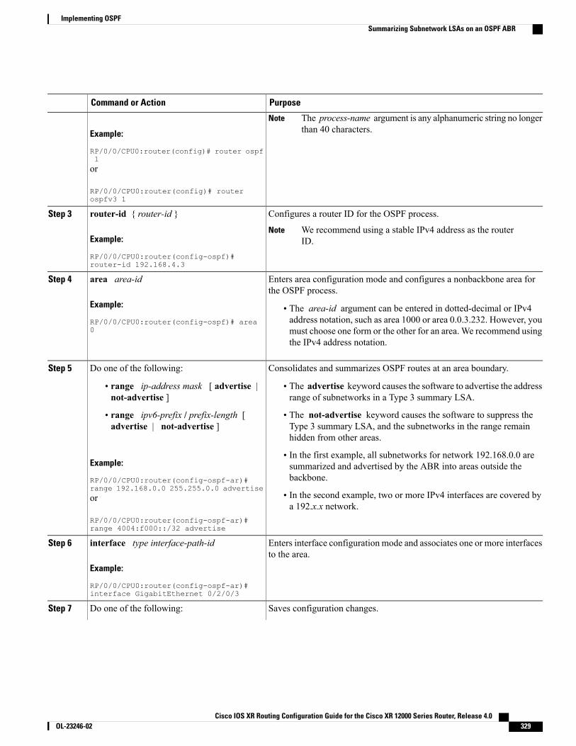
PurposeCommand or Action
Example:
RP/0/0/CPU0:router(config)# router ospf1
The process-name argument is any alphanumeric string no longerthan 40 characters.
Note
or
RP/0/0/CPU0:router(config)# routerospfv3 1
Configures a router ID for the OSPF process.router-id { router-id }Step 3
Example:
RP/0/0/CPU0:router(config-ospf)#router-id 192.168.4.3
We recommend using a stable IPv4 address as the routerID.
Note
Enters area configuration mode and configures a nonbackbone area forthe OSPF process.
area area-id
Example:
RP/0/0/CPU0:router(config-ospf)# area0
Step 4
• The area-id argument can be entered in dotted-decimal or IPv4address notation, such as area 1000 or area 0.0.3.232. However, youmust choose one form or the other for an area. We recommend usingthe IPv4 address notation.
Consolidates and summarizes OSPF routes at an area boundary.Do one of the following:Step 5
• range ip-address mask [ advertise |not-advertise ]
• The advertise keyword causes the software to advertise the addressrange of subnetworks in a Type 3 summary LSA.
• The not-advertise keyword causes the software to suppress theType 3 summary LSA, and the subnetworks in the range remainhidden from other areas.
• range ipv6-prefix / prefix-length [advertise | not-advertise ]
Example:
RP/0/0/CPU0:router(config-ospf-ar)#range 192.168.0.0 255.255.0.0 advertise
• In the first example, all subnetworks for network 192.168.0.0 aresummarized and advertised by the ABR into areas outside thebackbone.
• In the second example, two or more IPv4 interfaces are covered bya 192.x.x network.
or
RP/0/0/CPU0:router(config-ospf-ar)#range 4004:f000::/32 advertise
Enters interface configuration mode and associates one or more interfacesto the area.
interface type interface-path-id
Example:
RP/0/0/CPU0:router(config-ospf-ar)#interface GigabitEthernet 0/2/0/3
Step 6
Saves configuration changes.Do one of the following:Step 7
Cisco IOS XR Routing Configuration Guide for the Cisco XR 12000 Series Router, Release 4.0 OL-23246-02 329
Implementing OSPFSummarizing Subnetwork LSAs on an OSPF ABR
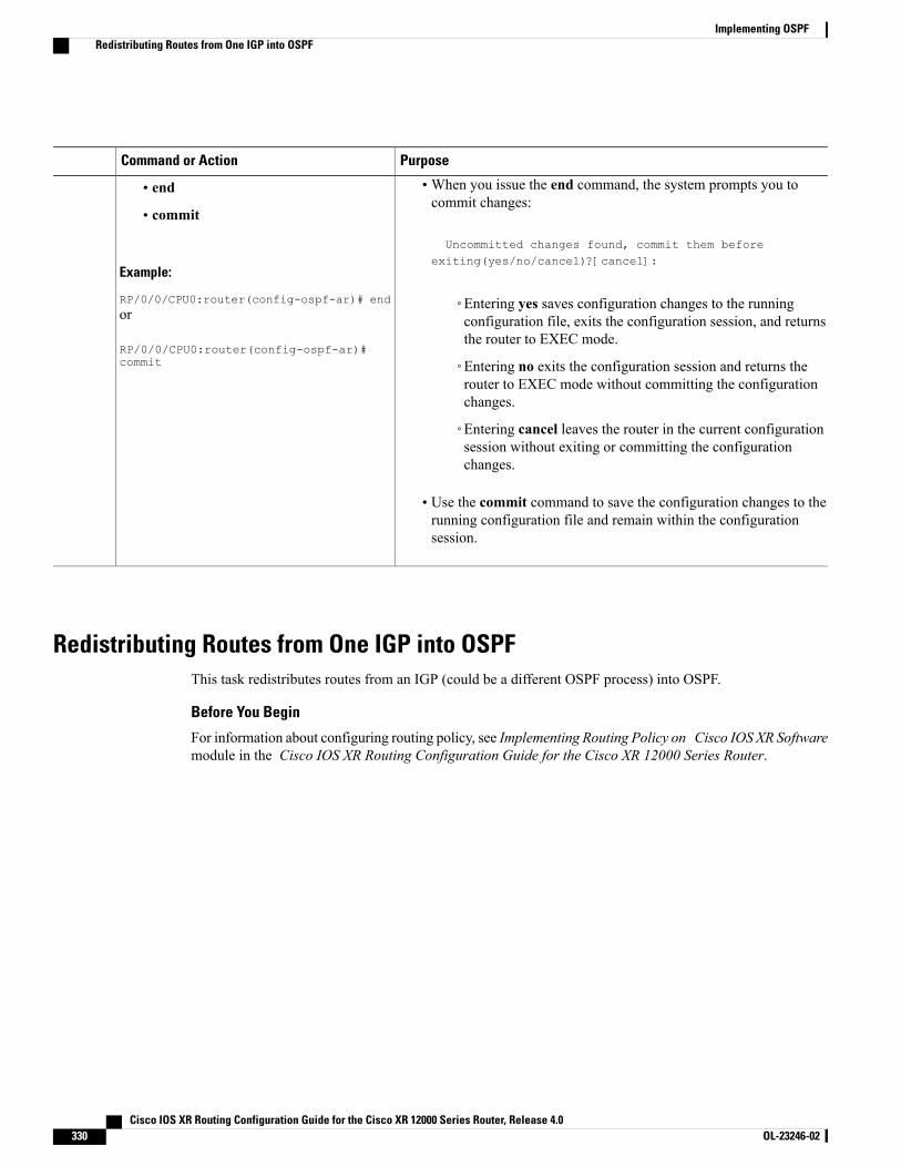
PurposeCommand or Action
•When you issue the end command, the system prompts you tocommit changes:
Uncommitted changes found, commit them before
• end
• commit
Example:
RP/0/0/CPU0:router(config-ospf-ar)# end
exiting(yes/no/cancel)?[cancel]:
◦Entering yes saves configuration changes to the runningconfiguration file, exits the configuration session, and returnsthe router to EXEC mode.
or
RP/0/0/CPU0:router(config-ospf-ar)#commit ◦Entering no exits the configuration session and returns the
router to EXEC mode without committing the configurationchanges.
◦Entering cancel leaves the router in the current configurationsession without exiting or committing the configurationchanges.
• Use the commit command to save the configuration changes to therunning configuration file and remain within the configurationsession.
Redistributing Routes from One IGP into OSPFThis task redistributes routes from an IGP (could be a different OSPF process) into OSPF.
Before You Begin
For information about configuring routing policy, see Implementing Routing Policy on Cisco IOS XR Softwaremodule in the Cisco IOS XR Routing Configuration Guide for the Cisco XR 12000 Series Router.
Cisco IOS XR Routing Configuration Guide for the Cisco XR 12000 Series Router, Release 4.0330 OL-23246-02
Implementing OSPFRedistributing Routes from One IGP into OSPF
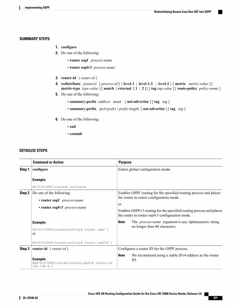
SUMMARY STEPS
1. configure2. Do one of the following:
• router ospf process-name
• router ospfv3 process-name
3. router-id { router-id }4. redistribute protocol [ process-id ] { level-1 | level-1-2 | level-2 } [ metric metric-value ] [
metric-type type-value ] [ match { external [ 1 | 2 ]} [ tag tag-value ] [ route-policy policy-name ]5. Do one of the following:
• summary-prefix address mask [ not-advertise ] [ tag tag ]
• summary-prefix ipv6-prefix / prefix-length [ not-advertise ] [ tag tag ]
6. Do one of the following:
• end
• commit
DETAILED STEPS
PurposeCommand or Action
Enters global configuration mode.configure
Example:
RP/0/0/CPU0:router# configure
Step 1
Enables OSPF routing for the specified routing process and placesthe router in router configuration mode.
Do one of the following:Step 2
• router ospf process-nameor
• router ospfv3 process-nameEnables OSPFv3 routing for the specified routing process and placesthe router in router ospfv3 configuration mode.
Example:
RP/0/0/CPU0:router(config)# router ospf 1
The process-name argument is any alphanumeric stringno longer than 40 characters.
Note
or
RP/0/0/CPU0:router(config)# router ospfv3 1
Configures a router ID for the OSPF process.router-id { router-id }Step 3
Example:RRP/0/0/CPU0:router(config-ospf)# router-id192.168.4.3
We recommend using a stable IPv4 address as the routerID.
Note
Cisco IOS XR Routing Configuration Guide for the Cisco XR 12000 Series Router, Release 4.0 OL-23246-02 331
Implementing OSPFRedistributing Routes from One IGP into OSPF
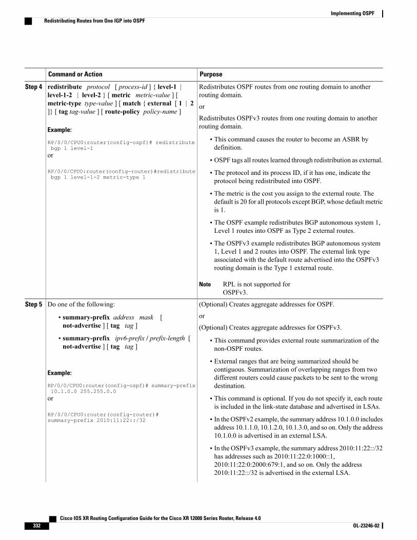
PurposeCommand or Action
Redistributes OSPF routes from one routing domain to anotherrouting domain.
redistribute protocol [ process-id ] { level-1 |level-1-2 | level-2 } [ metric metric-value ] [
Step 4
metric-type type-value ] [ match { external [ 1 | 2]} [ tag tag-value ] [ route-policy policy-name ]
or
Redistributes OSPFv3 routes from one routing domain to anotherrouting domain.Example:
RP/0/0/CPU0:router(config-ospf)# redistributebgp 1 level-1
• This command causes the router to become an ASBR bydefinition.
or
RP/0/0/CPU0:router(config-router)#redistributebgp 1 level-1-2 metric-type 1
• OSPF tags all routes learned through redistribution as external.
• The protocol and its process ID, if it has one, indicate theprotocol being redistributed into OSPF.
• The metric is the cost you assign to the external route. Thedefault is 20 for all protocols except BGP, whose default metricis 1.
• The OSPF example redistributes BGP autonomous system 1,Level 1 routes into OSPF as Type 2 external routes.
• The OSPFv3 example redistributes BGP autonomous system1, Level 1 and 2 routes into OSPF. The external link typeassociated with the default route advertised into the OSPFv3routing domain is the Type 1 external route.
RPL is not supported forOSPFv3.
Note
(Optional) Creates aggregate addresses for OSPF.Do one of the following:Step 5
or• summary-prefix address mask [not-advertise ] [ tag tag ] (Optional) Creates aggregate addresses for OSPFv3.
• summary-prefix ipv6-prefix / prefix-length [not-advertise ] [ tag tag ]
• This command provides external route summarization of thenon-OSPF routes.
• External ranges that are being summarized should becontiguous. Summarization of overlapping ranges from twoExample:
RP/0/0/CPU0:router(config-ospf)# summary-prefix10.1.0.0 255.255.0.0
different routers could cause packets to be sent to the wrongdestination.
or
RP/0/0/CPU0:router(config-router)#summary-prefix 2010:11:22::/32
• This command is optional. If you do not specify it, each routeis included in the link-state database and advertised in LSAs.
• In the OSPFv2 example, the summary address 10.1.0.0 includesaddress 10.1.1.0, 10.1.2.0, 10.1.3.0, and so on. Only the address10.1.0.0 is advertised in an external LSA.
• In the OSPFv3 example, the summary address 2010:11:22::/32has addresses such as 2010:11:22:0:1000::1,2010:11:22:0:2000:679:1, and so on. Only the address2010:11:22::/32 is advertised in the external LSA.
Cisco IOS XR Routing Configuration Guide for the Cisco XR 12000 Series Router, Release 4.0332 OL-23246-02
Implementing OSPFRedistributing Routes from One IGP into OSPF
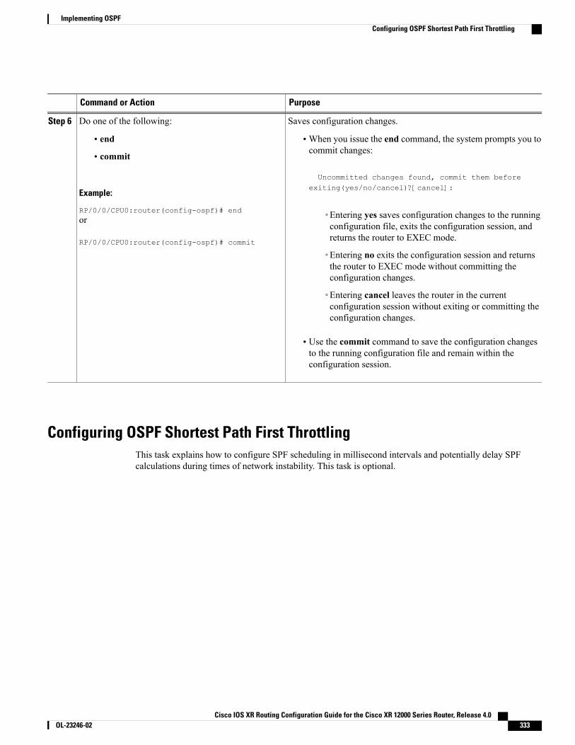
PurposeCommand or Action
Saves configuration changes.Do one of the following:Step 6
• end •When you issue the end command, the system prompts you tocommit changes:
Uncommitted changes found, commit them before
• commit
Example:
RP/0/0/CPU0:router(config-ospf)# end
exiting(yes/no/cancel)?[cancel]:
◦Entering yes saves configuration changes to the runningconfiguration file, exits the configuration session, andreturns the router to EXEC mode.
or
RP/0/0/CPU0:router(config-ospf)# commit
◦Entering no exits the configuration session and returnsthe router to EXEC mode without committing theconfiguration changes.
◦Entering cancel leaves the router in the currentconfiguration session without exiting or committing theconfiguration changes.
• Use the commit command to save the configuration changesto the running configuration file and remain within theconfiguration session.
Configuring OSPF Shortest Path First ThrottlingThis task explains how to configure SPF scheduling in millisecond intervals and potentially delay SPFcalculations during times of network instability. This task is optional.
Cisco IOS XR Routing Configuration Guide for the Cisco XR 12000 Series Router, Release 4.0 OL-23246-02 333
Implementing OSPFConfiguring OSPF Shortest Path First Throttling
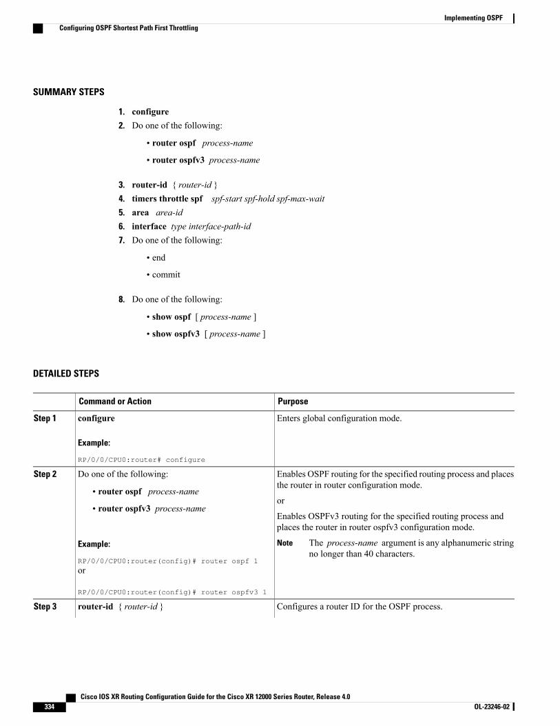
SUMMARY STEPS
1. configure2. Do one of the following:
• router ospf process-name
• router ospfv3 process-name
3. router-id { router-id }4. timers throttle spf spf-start spf-hold spf-max-wait5. area area-id6. interface type interface-path-id7. Do one of the following:
• end
• commit
8. Do one of the following:
• show ospf [ process-name ]
• show ospfv3 [ process-name ]
DETAILED STEPS
PurposeCommand or Action
Enters global configuration mode.configure
Example:
RP/0/0/CPU0:router# configure
Step 1
Enables OSPF routing for the specified routing process and placesthe router in router configuration mode.
Do one of the following:Step 2
• router ospf process-nameor
• router ospfv3 process-nameEnables OSPFv3 routing for the specified routing process andplaces the router in router ospfv3 configuration mode.
Example:
RP/0/0/CPU0:router(config)# router ospf 1
The process-name argument is any alphanumeric stringno longer than 40 characters.
Note
or
RP/0/0/CPU0:router(config)# router ospfv3 1
Configures a router ID for the OSPF process.router-id { router-id }Step 3
Cisco IOS XR Routing Configuration Guide for the Cisco XR 12000 Series Router, Release 4.0334 OL-23246-02
Implementing OSPFConfiguring OSPF Shortest Path First Throttling
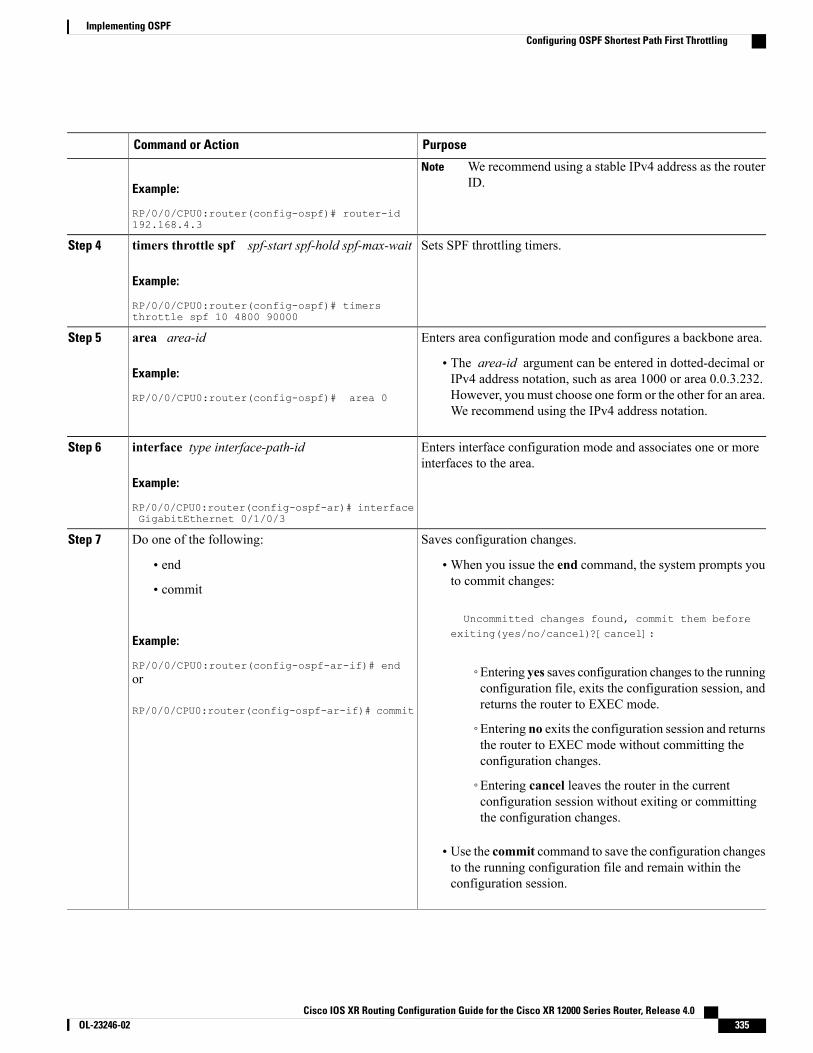
PurposeCommand or Action
Example:
RP/0/0/CPU0:router(config-ospf)# router-id192.168.4.3
We recommend using a stable IPv4 address as the routerID.
Note
Sets SPF throttling timers.timers throttle spf spf-start spf-hold spf-max-wait
Example:
RP/0/0/CPU0:router(config-ospf)# timersthrottle spf 10 4800 90000
Step 4
Enters area configuration mode and configures a backbone area.area area-idStep 5
Example:
RP/0/0/CPU0:router(config-ospf)# area 0
• The area-id argument can be entered in dotted-decimal orIPv4 address notation, such as area 1000 or area 0.0.3.232.However, youmust choose one form or the other for an area.We recommend using the IPv4 address notation.
Enters interface configuration mode and associates one or moreinterfaces to the area.
interface type interface-path-id
Example:
RP/0/0/CPU0:router(config-ospf-ar)# interfaceGigabitEthernet 0/1/0/3
Step 6
Saves configuration changes.Do one of the following:Step 7
• end •When you issue the end command, the system prompts youto commit changes:
Uncommitted changes found, commit them before
• commit
Example:
RP/0/0/CPU0:router(config-ospf-ar-if)# end
exiting(yes/no/cancel)?[cancel]:
◦Entering yes saves configuration changes to the runningconfiguration file, exits the configuration session, andreturns the router to EXEC mode.
or
RP/0/0/CPU0:router(config-ospf-ar-if)# commit
◦Entering no exits the configuration session and returnsthe router to EXEC mode without committing theconfiguration changes.
◦Entering cancel leaves the router in the currentconfiguration session without exiting or committingthe configuration changes.
• Use the commit command to save the configuration changesto the running configuration file and remain within theconfiguration session.
Cisco IOS XR Routing Configuration Guide for the Cisco XR 12000 Series Router, Release 4.0 OL-23246-02 335
Implementing OSPFConfiguring OSPF Shortest Path First Throttling
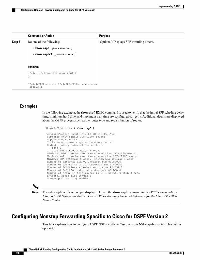
PurposeCommand or Action
(Optional) Displays SPF throttling timers.Do one of the following:Step 8
• show ospf [ process-name ]
• show ospfv3 [ process-name ]
Example:
RP/0/0/CPU0:router# show ospf 1or
RP/0/0/CPU0:router# RP/0/RP0/CPU0:router# showospfv3 2
ExamplesIn the following example, the show ospf EXEC command is used to verify that the initial SPF schedule delaytime, minimum hold time, and maximum wait time are configured correctly. Additional details are displayedabout the OSPF process, such as the router type and redistribution of routes.
RP/0/0/CPU0:router# show ospf 1
Routing Process "ospf 1" with ID 192.168.4.3Supports only single TOS(TOS0) routesSupports opaque LSAIt is an autonomous system boundary routerRedistributing External Routes from,
ospf 2Initial SPF schedule delay 5 msecsMinimum hold time between two consecutive SPFs 100 msecsMaximum wait time between two consecutive SPFs 1000 msecsMinimum LSA interval 5 secs. Minimum LSA arrival 1 secsNumber of external LSA 0. Checksum Sum 00000000Number of opaque AS LSA 0. Checksum Sum 00000000Number of DCbitless external and opaque AS LSA 0Number of DoNotAge external and opaque AS LSA 0Number of areas in this router is 1. 1 normal 0 stub 0 nssaExternal flood list length 0Non-Stop Forwarding enabled
For a description of each output display field, see the show ospf command in the OSPF Commands onCisco IOS XR Softwaremodule in Cisco IOS XR Routing Command Reference for the Cisco XR 12000Series Router.
Note
Configuring Nonstop Forwarding Specific to Cisco for OSPF Version 2This task explains how to configure OSPF NSF specific to Cisco on your NSF-capable router. This task isoptional.
Cisco IOS XR Routing Configuration Guide for the Cisco XR 12000 Series Router, Release 4.0336 OL-23246-02
Implementing OSPFConfiguring Nonstop Forwarding Specific to Cisco for OSPF Version 2
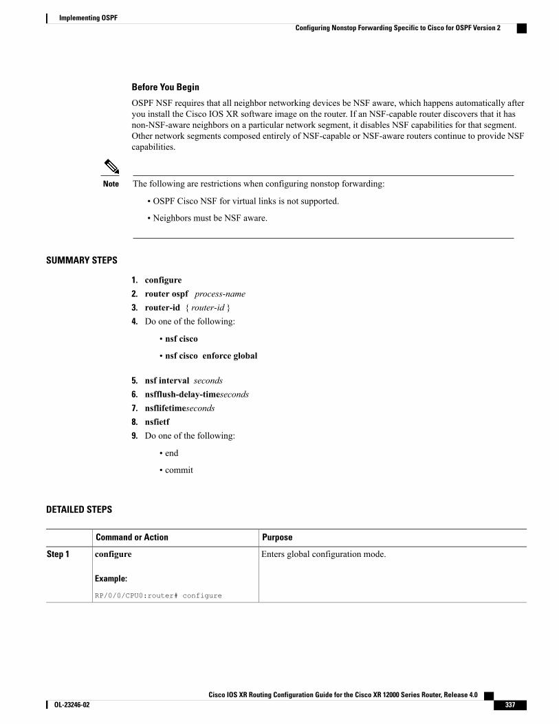
Before You Begin
OSPF NSF requires that all neighbor networking devices be NSF aware, which happens automatically afteryou install the Cisco IOS XR software image on the router. If an NSF-capable router discovers that it hasnon-NSF-aware neighbors on a particular network segment, it disables NSF capabilities for that segment.Other network segments composed entirely of NSF-capable or NSF-aware routers continue to provide NSFcapabilities.
The following are restrictions when configuring nonstop forwarding:Note
• OSPF Cisco NSF for virtual links is not supported.
• Neighbors must be NSF aware.
SUMMARY STEPS
1. configure2. router ospf process-name3. router-id { router-id }4. Do one of the following:
• nsf cisco
• nsf cisco enforce global
5. nsf interval seconds6. nsfflush-delay-timeseconds7. nsflifetimeseconds8. nsfietf9. Do one of the following:
• end
• commit
DETAILED STEPS
PurposeCommand or Action
Enters global configuration mode.configure
Example:
RP/0/0/CPU0:router# configure
Step 1
Cisco IOS XR Routing Configuration Guide for the Cisco XR 12000 Series Router, Release 4.0 OL-23246-02 337
Implementing OSPFConfiguring Nonstop Forwarding Specific to Cisco for OSPF Version 2
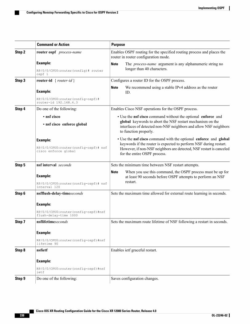
PurposeCommand or Action
Enables OSPF routing for the specified routing process and places therouter in router configuration mode.
router ospf process-name
Example:
RP/0/0/CPU0:router(config)# routerospf 1
Step 2
The process-name argument is any alphanumeric string nolonger than 40 characters.
Note
Configures a router ID for the OSPF process.router-id { router-id }Step 3
Example:
RP/0/0/CPU0:router(config-ospf)#router-id 192.168.4.3
We recommend using a stable IPv4 address as the routerID.
Note
Enables Cisco NSF operations for the OSPF process.Do one of the following:Step 4
• nsf cisco • Use the nsf cisco command without the optional enforce andglobal keywords to abort the NSF restart mechanism on the• nsf cisco enforce global interfaces of detected non-NSF neighbors and allow NSF neighborsto function properly.
Example:
RP/0/0/CPU0:router(config-ospf)# nsfcisco enforce global
• Use the nsf cisco command with the optional enforce and globalkeywords if the router is expected to perform NSF during restart.However, if non-NSF neighbors are detected, NSF restart is canceledfor the entire OSPF process.
Sets the minimum time between NSF restart attempts.nsf interval secondsStep 5
Example:
RP/0/0/CPU0:router(config-ospf)# nsfinterval 120
When you use this command, the OSPF process must be up forat least 90 seconds before OSPF attempts to perform an NSFrestart.
Note
Sets the maximum time allowed for external route learning in seconds.nsfflush-delay-timeseconds
Example:
RP/0/0/CPU0:router(config-ospf)#nsfflush-delay-time 1000
Step 6
Sets the maximum route lifetime of NSF following a restart in seconds.nsflifetimeseconds
Example:
RP/0/0/CPU0:router(config-ospf)#nsflifetime 90
Step 7
Enables ietf graceful restart.nsfietf
Example:
RP/0/0/CPU0:router(config-ospf)#nsfietf
Step 8
Saves configuration changes.Do one of the following:Step 9
Cisco IOS XR Routing Configuration Guide for the Cisco XR 12000 Series Router, Release 4.0338 OL-23246-02
Implementing OSPFConfiguring Nonstop Forwarding Specific to Cisco for OSPF Version 2
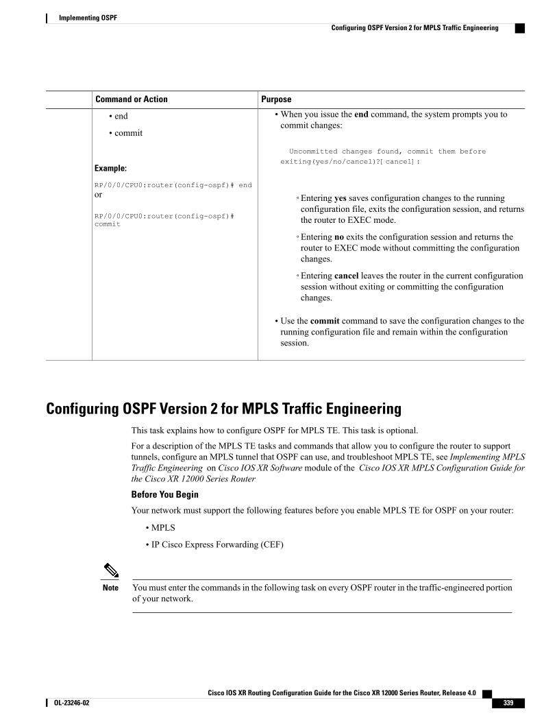
PurposeCommand or Action
•When you issue the end command, the system prompts you tocommit changes:
Uncommitted changes found, commit them before
• end
• commit
Example:
RP/0/0/CPU0:router(config-ospf)# end
exiting(yes/no/cancel)?[cancel]:
or
RP/0/0/CPU0:router(config-ospf)#commit
◦Entering yes saves configuration changes to the runningconfiguration file, exits the configuration session, and returnsthe router to EXEC mode.
◦Entering no exits the configuration session and returns therouter to EXEC mode without committing the configurationchanges.
◦Entering cancel leaves the router in the current configurationsession without exiting or committing the configurationchanges.
• Use the commit command to save the configuration changes to therunning configuration file and remain within the configurationsession.
Configuring OSPF Version 2 for MPLS Traffic EngineeringThis task explains how to configure OSPF for MPLS TE. This task is optional.
For a description of the MPLS TE tasks and commands that allow you to configure the router to supporttunnels, configure an MPLS tunnel that OSPF can use, and troubleshoot MPLS TE, see Implementing MPLSTraffic Engineering on Cisco IOS XR Softwaremodule of the Cisco IOS XR MPLS Configuration Guide forthe Cisco XR 12000 Series Router
Before You Begin
Your network must support the following features before you enable MPLS TE for OSPF on your router:
• MPLS
• IP Cisco Express Forwarding (CEF)
Youmust enter the commands in the following task on every OSPF router in the traffic-engineered portionof your network.
Note
Cisco IOS XR Routing Configuration Guide for the Cisco XR 12000 Series Router, Release 4.0 OL-23246-02 339
Implementing OSPFConfiguring OSPF Version 2 for MPLS Traffic Engineering
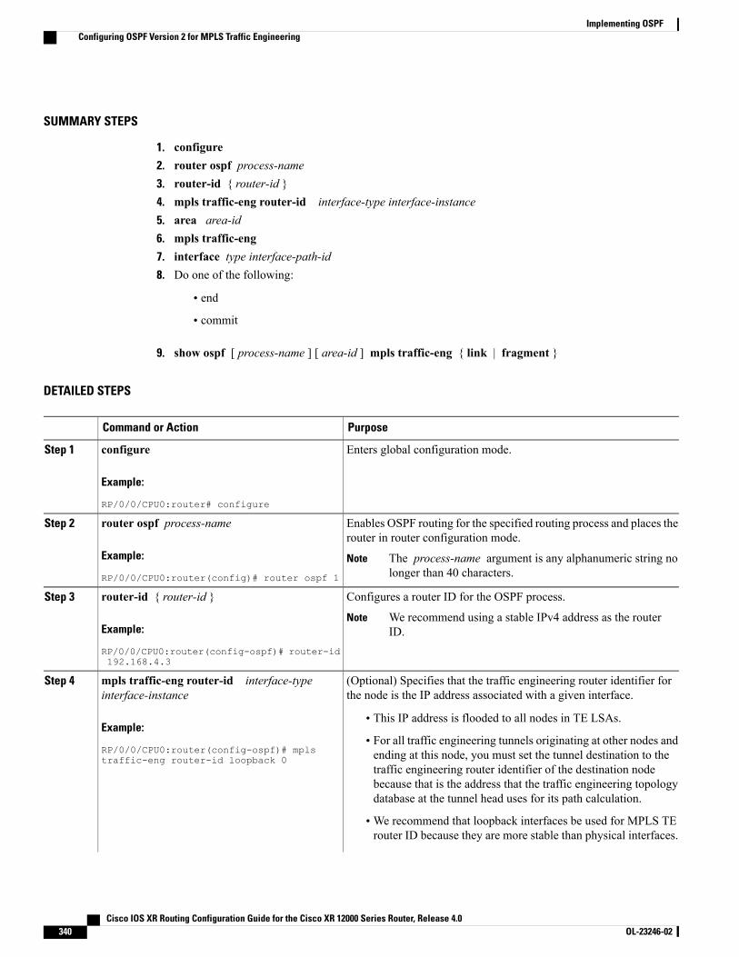
SUMMARY STEPS
1. configure2. router ospf process-name3. router-id { router-id }4. mpls traffic-eng router-id interface-type interface-instance5. area area-id6. mpls traffic-eng7. interface type interface-path-id8. Do one of the following:
• end
• commit
9. show ospf [ process-name ] [ area-id ] mpls traffic-eng { link | fragment }
DETAILED STEPS
PurposeCommand or Action
Enters global configuration mode.configure
Example:
RP/0/0/CPU0:router# configure
Step 1
Enables OSPF routing for the specified routing process and places therouter in router configuration mode.
router ospf process-name
Example:
RP/0/0/CPU0:router(config)# router ospf 1
Step 2
The process-name argument is any alphanumeric string nolonger than 40 characters.
Note
Configures a router ID for the OSPF process.router-id { router-id }Step 3
Example:
RP/0/0/CPU0:router(config-ospf)# router-id192.168.4.3
We recommend using a stable IPv4 address as the routerID.
Note
(Optional) Specifies that the traffic engineering router identifier forthe node is the IP address associated with a given interface.
mpls traffic-eng router-id interface-typeinterface-instance
Step 4
Example:
RP/0/0/CPU0:router(config-ospf)# mplstraffic-eng router-id loopback 0
• This IP address is flooded to all nodes in TE LSAs.
• For all traffic engineering tunnels originating at other nodes andending at this node, you must set the tunnel destination to thetraffic engineering router identifier of the destination nodebecause that is the address that the traffic engineering topologydatabase at the tunnel head uses for its path calculation.
•We recommend that loopback interfaces be used for MPLS TErouter ID because they are more stable than physical interfaces.
Cisco IOS XR Routing Configuration Guide for the Cisco XR 12000 Series Router, Release 4.0340 OL-23246-02
Implementing OSPFConfiguring OSPF Version 2 for MPLS Traffic Engineering
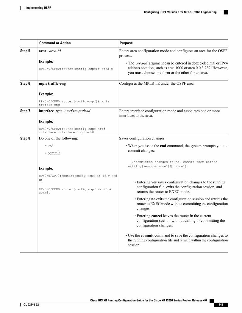
PurposeCommand or Action
Enters area configuration mode and configures an area for the OSPFprocess.
area area-id
Example:
RP/0/0/CPU0:router(config-ospf)# area 0
Step 5
• The area-id argument can be entered in dotted-decimal or IPv4address notation, such as area 1000 or area 0.0.3.232. However,you must choose one form or the other for an area.
Configures the MPLS TE under the OSPF area.mpls traffic-eng
Example:
RP/0/0/CPU0:router(config-ospf)# mplstraffic-eng
Step 6
Enters interface configuration mode and associates one or moreinterfaces to the area.
interface type interface-path-id
Example:
RP/0/0/CPU0:router(config-ospf-ar)#interface interface loopback0
Step 7
Saves configuration changes.Do one of the following:Step 8
• end •When you issue the end command, the system prompts you tocommit changes:
Uncommitted changes found, commit them before
• commit
Example:
RP/0/0/CPU0:router(config-ospf-ar-if)# end
exiting(yes/no/cancel)?[cancel]:
or
RP/0/0/CPU0:router(config-ospf-ar-if)#commit
◦Entering yes saves configuration changes to the runningconfiguration file, exits the configuration session, andreturns the router to EXEC mode.
◦Entering no exits the configuration session and returns therouter to EXECmodewithout committing the configurationchanges.
◦Entering cancel leaves the router in the currentconfiguration session without exiting or committing theconfiguration changes.
• Use the commit command to save the configuration changes tothe running configuration file and remainwithin the configurationsession.
Cisco IOS XR Routing Configuration Guide for the Cisco XR 12000 Series Router, Release 4.0 OL-23246-02 341
Implementing OSPFConfiguring OSPF Version 2 for MPLS Traffic Engineering
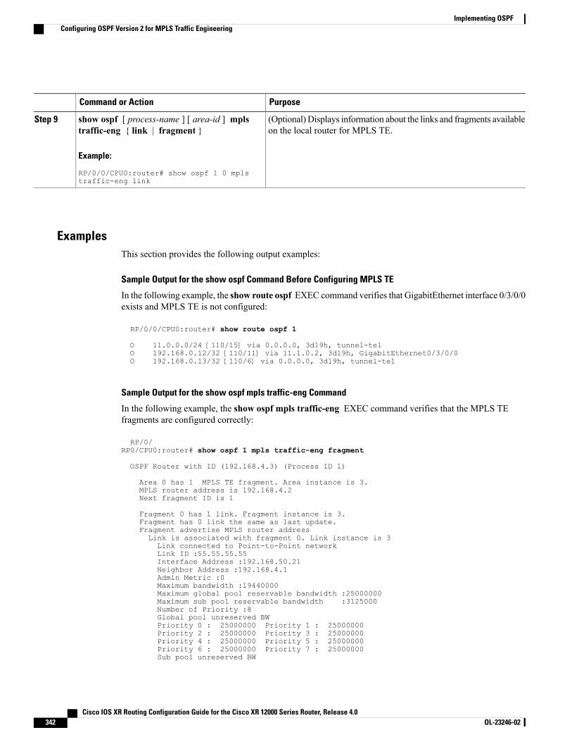
PurposeCommand or Action
(Optional) Displays information about the links and fragments availableon the local router for MPLS TE.
show ospf [ process-name ] [ area-id ] mplstraffic-eng { link | fragment }
Example:
RP/0/0/CPU0:router# show ospf 1 0 mplstraffic-eng link
Step 9
ExamplesThis section provides the following output examples:
Sample Output for the show ospf Command Before Configuring MPLS TE
In the following example, the show route ospf EXEC command verifies that GigabitEthernet interface 0/3/0/0exists and MPLS TE is not configured:
RP/0/0/CPU0:router# show route ospf 1
O 11.0.0.0/24 [110/15] via 0.0.0.0, 3d19h, tunnel-te1O 192.168.0.12/32 [110/11] via 11.1.0.2, 3d19h, GigabitEthernet0/3/0/0O 192.168.0.13/32 [110/6] via 0.0.0.0, 3d19h, tunnel-te1
Sample Output for the show ospf mpls traffic-eng Command
In the following example, the show ospf mpls traffic-eng EXEC command verifies that the MPLS TEfragments are configured correctly:
RP/0/RP0/CPU0:router# show ospf 1 mpls traffic-eng fragment
OSPF Router with ID (192.168.4.3) (Process ID 1)
Area 0 has 1 MPLS TE fragment. Area instance is 3.MPLS router address is 192.168.4.2Next fragment ID is 1
Fragment 0 has 1 link. Fragment instance is 3.Fragment has 0 link the same as last update.Fragment advertise MPLS router addressLink is associated with fragment 0. Link instance is 3Link connected to Point-to-Point networkLink ID :55.55.55.55Interface Address :192.168.50.21Neighbor Address :192.168.4.1Admin Metric :0Maximum bandwidth :19440000Maximum global pool reservable bandwidth :25000000Maximum sub pool reservable bandwidth :3125000Number of Priority :8Global pool unreserved BWPriority 0 : 25000000 Priority 1 : 25000000Priority 2 : 25000000 Priority 3 : 25000000Priority 4 : 25000000 Priority 5 : 25000000Priority 6 : 25000000 Priority 7 : 25000000Sub pool unreserved BW
Cisco IOS XR Routing Configuration Guide for the Cisco XR 12000 Series Router, Release 4.0342 OL-23246-02
Implementing OSPFConfiguring OSPF Version 2 for MPLS Traffic Engineering

Priority 0 : 3125000 Priority 1 : 3125000Priority 2 : 3125000 Priority 3 : 3125000Priority 4 : 3125000 Priority 5 : 3125000Priority 6 : 3125000 Priority 7 : 3125000Affinity Bit :0
In the following example, the show ospf mpls traffic-eng EXEC command verifies that the MPLS TE linkson area instance 3 are configured correctly:
RP/0/0/CPU0:router# show ospf mpls traffic-eng link
OSPF Router with ID (192.168.4.1) (Process ID 1)
Area 0 has 1 MPLS TE links. Area instance is 3.
Links in hash bucket 53.Link is associated with fragment 0. Link instance is 3Link connected to Point-to-Point networkLink ID :192.168.50.20Interface Address :192.168.20.50Neighbor Address :192.168.4.1Admin Metric :0Maximum bandwidth :19440000Maximum global pool reservable bandwidth :25000000Maximum sub pool reservable bandwidth :3125000Number of Priority :8Global pool unreserved BWPriority 0 : 25000000 Priority 1 : 25000000Priority 2 : 25000000 Priority 3 : 25000000Priority 4 : 25000000 Priority 5 : 25000000Priority 6 : 25000000 Priority 7 : 25000000Sub pool unreserved BWPriority 0 : 3125000 Priority 1 : 3125000Priority 2 : 3125000 Priority 3 : 3125000Priority 4 : 3125000 Priority 5 : 3125000Priority 6 : 3125000 Priority 7 : 3125000Affinity Bit :0
Sample Output for the show ospf Command After Configuring MPLS TE
In the following example, the show route ospf EXEC command verifies that the MPLS TE tunnels replacedGigabitEthernet interface 0/3/0/0 and that configuration was performed correctly:
RP/0/0/CPU0:router# show route ospf 1
O E2 192.168.10.0/24 [110/20] via 0.0.0.0, 00:00:15, tunnel2O E2 192.168.11.0/24 [110/20] via 0.0.0.0, 00:00:15, tunnel2O E2 192.168.1244.0/24 [110/20] via 0.0.0.0, 00:00:15, tunnel2O 192.168.12.0/24 [110/2] via 0.0.0.0, 00:00:15, tunnel2
Configuring OSPFv3 Graceful RestartThis task explains how to configure a graceful restart for an OSPFv3 process. This task is optional.
Cisco IOS XR Routing Configuration Guide for the Cisco XR 12000 Series Router, Release 4.0 OL-23246-02 343
Implementing OSPFConfiguring OSPFv3 Graceful Restart
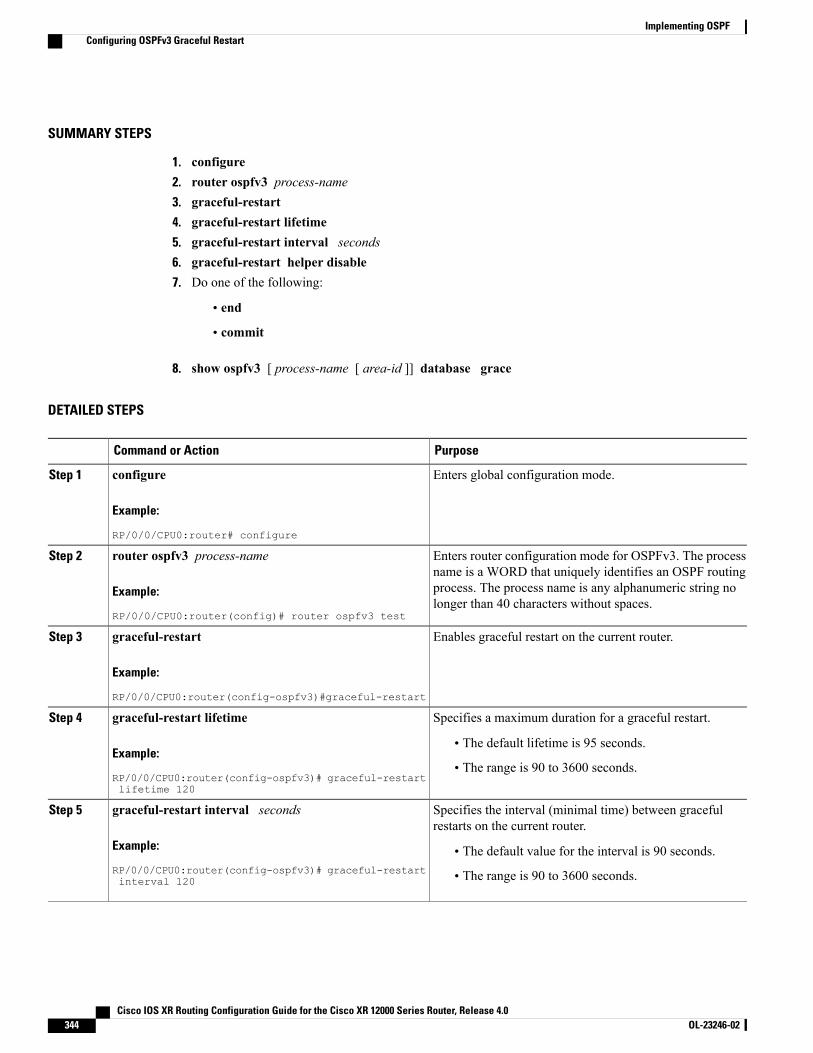
SUMMARY STEPS
1. configure2. router ospfv3 process-name3. graceful-restart4. graceful-restart lifetime5. graceful-restart interval seconds6. graceful-restart helper disable7. Do one of the following:
• end
• commit
8. show ospfv3 [ process-name [ area-id ]] database grace
DETAILED STEPS
PurposeCommand or Action
Enters global configuration mode.configure
Example:
RP/0/0/CPU0:router# configure
Step 1
Enters router configuration mode for OSPFv3. The processname is a WORD that uniquely identifies an OSPF routing
router ospfv3 process-name
Example:
RP/0/0/CPU0:router(config)# router ospfv3 test
Step 2
process. The process name is any alphanumeric string nolonger than 40 characters without spaces.
Enables graceful restart on the current router.graceful-restart
Example:
RP/0/0/CPU0:router(config-ospfv3)#graceful-restart
Step 3
Specifies a maximum duration for a graceful restart.graceful-restart lifetimeStep 4
Example:
RP/0/0/CPU0:router(config-ospfv3)# graceful-restartlifetime 120
• The default lifetime is 95 seconds.
• The range is 90 to 3600 seconds.
Specifies the interval (minimal time) between gracefulrestarts on the current router.
graceful-restart interval seconds
Example:
RP/0/0/CPU0:router(config-ospfv3)# graceful-restartinterval 120
Step 5
• The default value for the interval is 90 seconds.
• The range is 90 to 3600 seconds.
Cisco IOS XR Routing Configuration Guide for the Cisco XR 12000 Series Router, Release 4.0344 OL-23246-02
Implementing OSPFConfiguring OSPFv3 Graceful Restart

PurposeCommand or Action
Disables the helper capability.graceful-restart helper disable
Example:
RP/0/0/CPU0:router(config-ospfv3)# graceful-restarthelper disable
Step 6
Saves configuration changes.Do one of the following:Step 7
• end •When you issue the end command, the system promptsyou to commit changes:
Uncommitted changes found, commit them
• commit
Example:
RP/0/0/CPU0:router(config-ospfv3)# end
before exiting(yes/no/cancel)?[cancel]:
◦Entering yes saves configuration changes to therunning configuration file, exits the configurationsession, and returns the router to EXEC mode.
or
RP/0/0/CPU0:router(config-ospfv3)# commit
◦Entering no exits the configuration session andreturns the router to EXEC mode withoutcommitting the configuration changes.
◦Entering cancel leaves the router in the currentconfiguration session without exiting orcommitting the configuration changes.
• Use the commit command to save the configurationchanges to the running configuration file and remainwithin the configuration session.
Displays the state of the graceful restart link.show ospfv3 [ process-name [ area-id ]] database grace
Example:
RP/0/0/CPU0:router# show ospfv3 1 database grace
Step 8
Displaying Information About Graceful RestartThis section describes the tasks you can use to display information about a graceful restart.
• To see if the feature is enabled and when the last graceful restart ran, use the show ospf command. Tosee details for an OSPFv3 instance, use the show ospfv3 process-name [ area-id ] database gracecommand.
Cisco IOS XR Routing Configuration Guide for the Cisco XR 12000 Series Router, Release 4.0 OL-23246-02 345
Implementing OSPFConfiguring OSPFv3 Graceful Restart
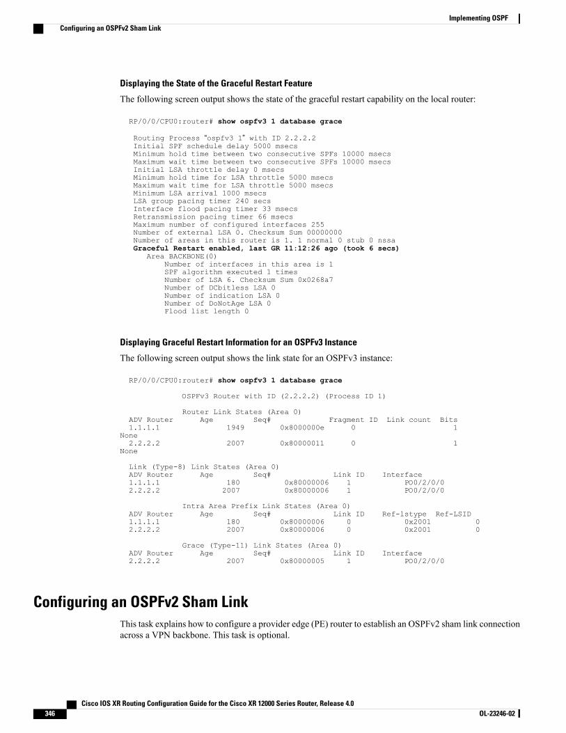
Displaying the State of the Graceful Restart Feature
The following screen output shows the state of the graceful restart capability on the local router:
RP/0/0/CPU0:router# show ospfv3 1 database grace
Routing Process “ospfv3 1” with ID 2.2.2.2Initial SPF schedule delay 5000 msecsMinimum hold time between two consecutive SPFs 10000 msecsMaximum wait time between two consecutive SPFs 10000 msecsInitial LSA throttle delay 0 msecsMinimum hold time for LSA throttle 5000 msecsMaximum wait time for LSA throttle 5000 msecsMinimum LSA arrival 1000 msecsLSA group pacing timer 240 secsInterface flood pacing timer 33 msecsRetransmission pacing timer 66 msecsMaximum number of configured interfaces 255Number of external LSA 0. Checksum Sum 00000000Number of areas in this router is 1. 1 normal 0 stub 0 nssaGraceful Restart enabled, last GR 11:12:26 ago (took 6 secs)
Area BACKBONE(0)Number of interfaces in this area is 1SPF algorithm executed 1 timesNumber of LSA 6. Checksum Sum 0x0268a7Number of DCbitless LSA 0Number of indication LSA 0Number of DoNotAge LSA 0Flood list length 0
Displaying Graceful Restart Information for an OSPFv3 Instance
The following screen output shows the link state for an OSPFv3 instance:
RP/0/0/CPU0:router# show ospfv3 1 database grace
OSPFv3 Router with ID (2.2.2.2) (Process ID 1)
Router Link States (Area 0)ADV Router Age Seq# Fragment ID Link count Bits1.1.1.1 1949 0x8000000e 0 1
None2.2.2.2 2007 0x80000011 0 1
None
Link (Type-8) Link States (Area 0)ADV Router Age Seq# Link ID Interface1.1.1.1 180 0x80000006 1 PO0/2/0/02.2.2.2 2007 0x80000006 1 PO0/2/0/0
Intra Area Prefix Link States (Area 0)ADV Router Age Seq# Link ID Ref-lstype Ref-LSID1.1.1.1 180 0x80000006 0 0x2001 02.2.2.2 2007 0x80000006 0 0x2001 0
Grace (Type-11) Link States (Area 0)ADV Router Age Seq# Link ID Interface2.2.2.2 2007 0x80000005 1 PO0/2/0/0
Configuring an OSPFv2 Sham LinkThis task explains how to configure a provider edge (PE) router to establish an OSPFv2 sham link connectionacross a VPN backbone. This task is optional.
Cisco IOS XR Routing Configuration Guide for the Cisco XR 12000 Series Router, Release 4.0346 OL-23246-02
Implementing OSPFConfiguring an OSPFv2 Sham Link
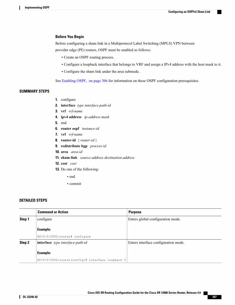
Before You Begin
Before configuring a sham link in a Multiprotocol Label Switching (MPLS) VPN between
provider edge (PE) routers, OSPF must be enabled as follows:
• Create an OSPF routing process.
• Configure a loopback interface that belongs to VRF and assign a IPv4 address with the host mask to it.
• Configure the sham link under the area submode.
See Enabling OSPF, on page 306 for information on these OSPF configuration prerequisites.
SUMMARY STEPS
1. configure2. interface type interface-path-id3. vrf vrf-name4. ipv4 address ip-address mask5. end6. router ospf instance-id7. vrf vrf-name8. router-id { router-id }9. redistribute bgp process-id10. area area-id11. sham-link source-address destination-address12. cost cost13. Do one of the following:
• end
• commit
DETAILED STEPS
PurposeCommand or Action
Enters global configuration mode.configure
Example:
RP/0/0/CPU0:router# configure
Step 1
Enters interface configuration mode.interface type interface-path-id
Example:
RP/0/0/CPU0:router(config)# interface loopback 3
Step 2
Cisco IOS XR Routing Configuration Guide for the Cisco XR 12000 Series Router, Release 4.0 OL-23246-02 347
Implementing OSPFConfiguring an OSPFv2 Sham Link
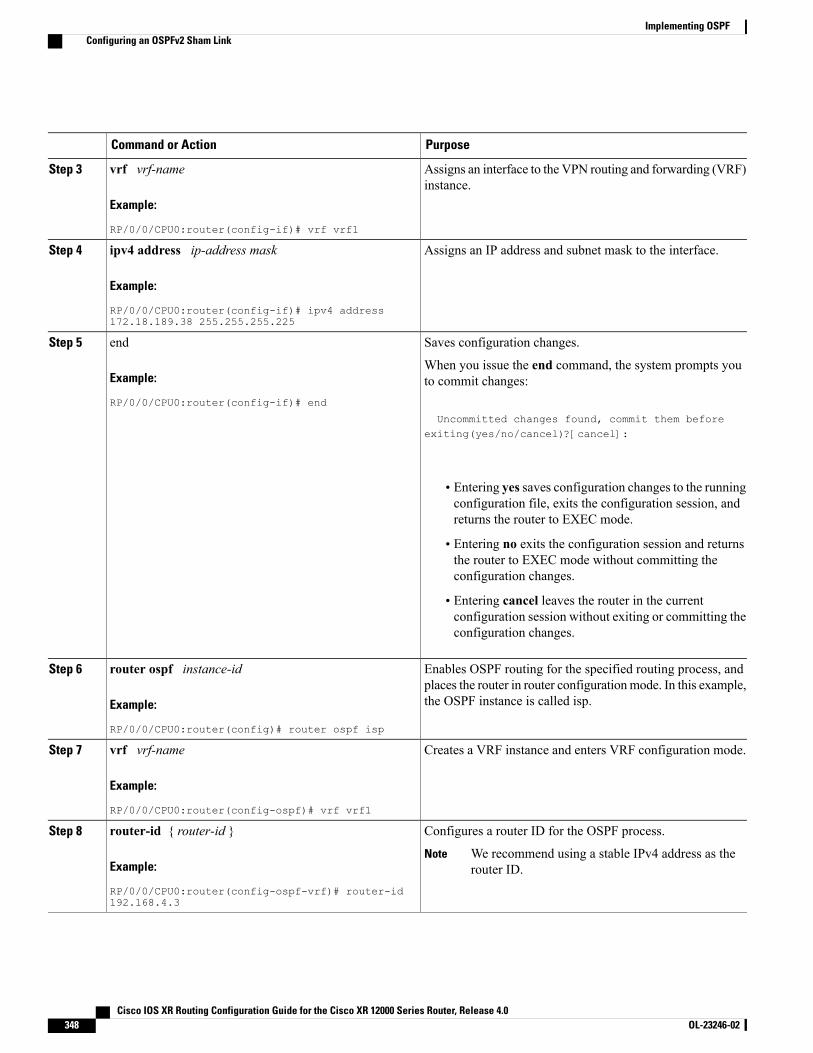
PurposeCommand or Action
Assigns an interface to the VPN routing and forwarding (VRF)instance.
vrf vrf-name
Example:
RP/0/0/CPU0:router(config-if)# vrf vrf1
Step 3
Assigns an IP address and subnet mask to the interface.ipv4 address ip-address mask
Example:
RP/0/0/CPU0:router(config-if)# ipv4 address172.18.189.38 255.255.255.225
Step 4
Saves configuration changes.endStep 5
Example:
RP/0/0/CPU0:router(config-if)# end
When you issue the end command, the system prompts youto commit changes:
Uncommitted changes found, commit them beforeexiting(yes/no/cancel)?[cancel]:
• Entering yes saves configuration changes to the runningconfiguration file, exits the configuration session, andreturns the router to EXEC mode.
• Entering no exits the configuration session and returnsthe router to EXEC mode without committing theconfiguration changes.
• Entering cancel leaves the router in the currentconfiguration session without exiting or committing theconfiguration changes.
Enables OSPF routing for the specified routing process, andplaces the router in router configurationmode. In this example,the OSPF instance is called isp.
router ospf instance-id
Example:
RP/0/0/CPU0:router(config)# router ospf isp
Step 6
Creates a VRF instance and enters VRF configuration mode.vrf vrf-name
Example:
RP/0/0/CPU0:router(config-ospf)# vrf vrf1
Step 7
Configures a router ID for the OSPF process.router-id { router-id }Step 8
Example:
RP/0/0/CPU0:router(config-ospf-vrf)# router-id192.168.4.3
We recommend using a stable IPv4 address as therouter ID.
Note
Cisco IOS XR Routing Configuration Guide for the Cisco XR 12000 Series Router, Release 4.0348 OL-23246-02
Implementing OSPFConfiguring an OSPFv2 Sham Link
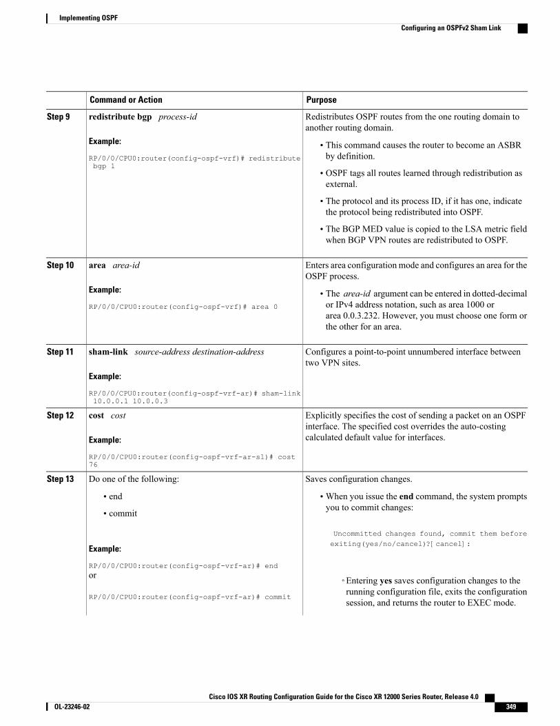
PurposeCommand or Action
Redistributes OSPF routes from the one routing domain toanother routing domain.
redistribute bgp process-id
Example:
RP/0/0/CPU0:router(config-ospf-vrf)# redistributebgp 1
Step 9
• This command causes the router to become an ASBRby definition.
• OSPF tags all routes learned through redistribution asexternal.
• The protocol and its process ID, if it has one, indicatethe protocol being redistributed into OSPF.
• The BGP MED value is copied to the LSA metric fieldwhen BGP VPN routes are redistributed to OSPF.
Enters area configuration mode and configures an area for theOSPF process.
area area-id
Example:
RP/0/0/CPU0:router(config-ospf-vrf)# area 0
Step 10
• The area-id argument can be entered in dotted-decimalor IPv4 address notation, such as area 1000 orarea 0.0.3.232. However, you must choose one form orthe other for an area.
Configures a point-to-point unnumbered interface betweentwo VPN sites.
sham-link source-address destination-address
Example:
RP/0/0/CPU0:router(config-ospf-vrf-ar)# sham-link10.0.0.1 10.0.0.3
Step 11
Explicitly specifies the cost of sending a packet on an OSPFinterface. The specified cost overrides the auto-costingcalculated default value for interfaces.
cost cost
Example:
RP/0/0/CPU0:router(config-ospf-vrf-ar-sl)# cost76
Step 12
Saves configuration changes.Do one of the following:Step 13
• end •When you issue the end command, the system promptsyou to commit changes:
Uncommitted changes found, commit them before
• commit
Example:
RP/0/0/CPU0:router(config-ospf-vrf-ar)# end
exiting(yes/no/cancel)?[cancel]:
or
RP/0/0/CPU0:router(config-ospf-vrf-ar)# commit
◦Entering yes saves configuration changes to therunning configuration file, exits the configurationsession, and returns the router to EXEC mode.
Cisco IOS XR Routing Configuration Guide for the Cisco XR 12000 Series Router, Release 4.0 OL-23246-02 349
Implementing OSPFConfiguring an OSPFv2 Sham Link

PurposeCommand or Action
◦Entering no exits the configuration session andreturns the router to EXEC mode withoutcommitting the configuration changes.
◦Entering cancel leaves the router in the currentconfiguration session without exiting orcommitting the configuration changes.
• Use the commit command to save the configurationchanges to the running configuration file and remainwithin the configuration session.
Enabling Nonstop Routing for OSPFv2This optional task describes how to enable nonstop routing (NSR) for OSPFv2 process. NSR is disabled bydefault. When NSR is enabled, OSPF process on the active RP synchronizes all necessary data and states withthe OSPF process on the standby RP. When the switchover happens, OSPF process on the newly active RPhas all the necessary data and states to continue running and does not require any help from its neighbors.
SUMMARY STEPS
1. configure2. router ospf instance-id3. nsr4. Use one of these commands:
• end
• commit
DETAILED STEPS
PurposeCommand or Action
Enters global configuration mode.configure
Example:RP/0/0/CPU0:router# configure
Step 1
Enables OSPF routing for the specified routing process, and places the routerin router configuration mode. In this example, the OSPF instance is calledisp.
router ospf instance-id
Example:RP/0/0/CPU0:router(config)# routerospf isp
Step 2
Cisco IOS XR Routing Configuration Guide for the Cisco XR 12000 Series Router, Release 4.0350 OL-23246-02
Implementing OSPFEnabling Nonstop Routing for OSPFv2
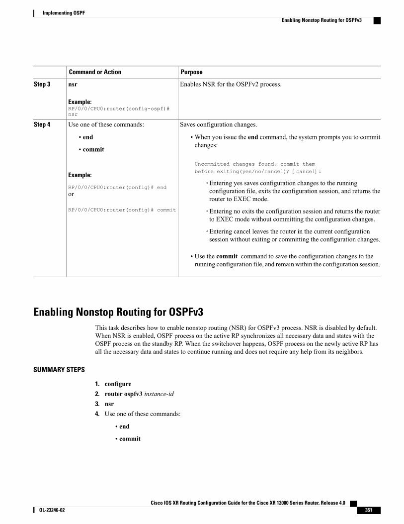
PurposeCommand or Action
Enables NSR for the OSPFv2 process.nsr
Example:RP/0/0/CPU0:router(config-ospf)#nsr
Step 3
Saves configuration changes.Use one of these commands:Step 4
• end •When you issue the end command, the system prompts you to commitchanges:
Uncommitted changes found, commit thembefore exiting(yes/no/cancel)? [cancel]:
• commit
Example:
RP/0/0/CPU0:router(config)# end◦Entering yes saves configuration changes to the runningconfiguration file, exits the configuration session, and returns therouter to EXEC mode.
or
RP/0/0/CPU0:router(config)# commit ◦Entering no exits the configuration session and returns the routerto EXEC mode without committing the configuration changes.
◦Entering cancel leaves the router in the current configurationsession without exiting or committing the configuration changes.
• Use the commit command to save the configuration changes to therunning configuration file, and remain within the configuration session.
Enabling Nonstop Routing for OSPFv3This task describes how to enable nonstop routing (NSR) for OSPFv3 process. NSR is disabled by default.When NSR is enabled, OSPF process on the active RP synchronizes all necessary data and states with theOSPF process on the standby RP. When the switchover happens, OSPF process on the newly active RP hasall the necessary data and states to continue running and does not require any help from its neighbors.
SUMMARY STEPS
1. configure2. router ospfv3 instance-id3. nsr4. Use one of these commands:
• end
• commit
Cisco IOS XR Routing Configuration Guide for the Cisco XR 12000 Series Router, Release 4.0 OL-23246-02 351
Implementing OSPFEnabling Nonstop Routing for OSPFv3
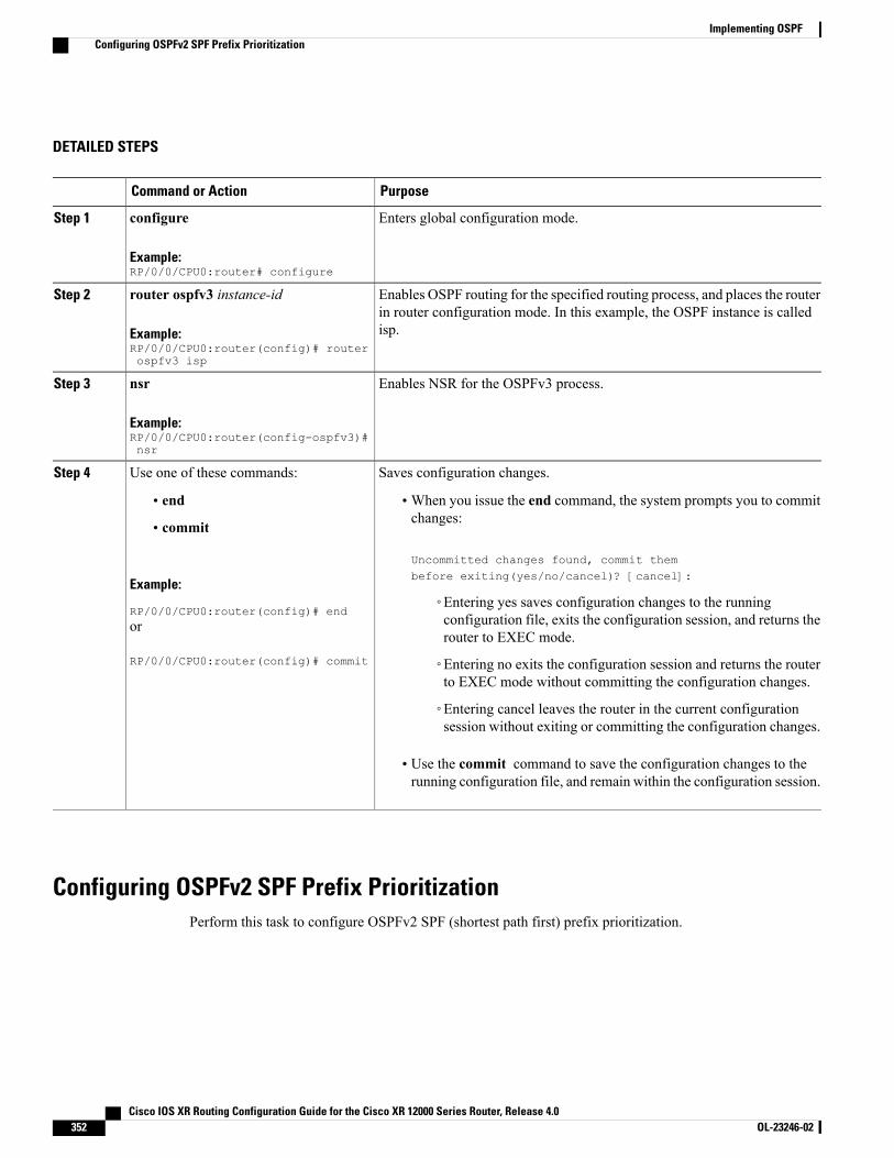
DETAILED STEPS
PurposeCommand or Action
Enters global configuration mode.configure
Example:RP/0/0/CPU0:router# configure
Step 1
Enables OSPF routing for the specified routing process, and places the routerin router configuration mode. In this example, the OSPF instance is calledisp.
router ospfv3 instance-id
Example:RP/0/0/CPU0:router(config)# routerospfv3 isp
Step 2
Enables NSR for the OSPFv3 process.nsr
Example:RP/0/0/CPU0:router(config-ospfv3)#nsr
Step 3
Saves configuration changes.Use one of these commands:Step 4
• end •When you issue the end command, the system prompts you to commitchanges:
Uncommitted changes found, commit thembefore exiting(yes/no/cancel)? [cancel]:
• commit
Example:
RP/0/0/CPU0:router(config)# end◦Entering yes saves configuration changes to the runningconfiguration file, exits the configuration session, and returns therouter to EXEC mode.
or
RP/0/0/CPU0:router(config)# commit ◦Entering no exits the configuration session and returns the routerto EXEC mode without committing the configuration changes.
◦Entering cancel leaves the router in the current configurationsession without exiting or committing the configuration changes.
• Use the commit command to save the configuration changes to therunning configuration file, and remain within the configuration session.
Configuring OSPFv2 SPF Prefix PrioritizationPerform this task to configure OSPFv2 SPF (shortest path first) prefix prioritization.
Cisco IOS XR Routing Configuration Guide for the Cisco XR 12000 Series Router, Release 4.0352 OL-23246-02
Implementing OSPFConfiguring OSPFv2 SPF Prefix Prioritization
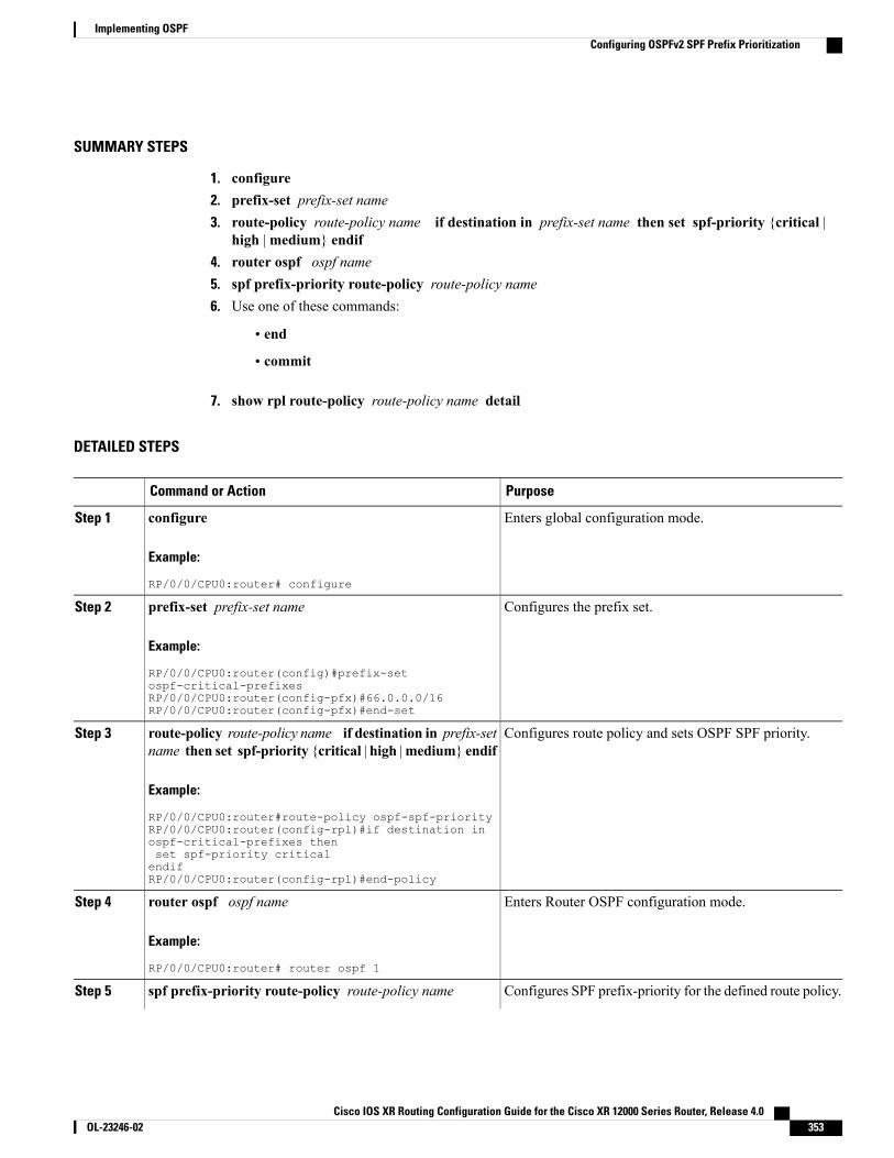
SUMMARY STEPS
1. configure2. prefix-set prefix-set name3. route-policy route-policy name if destination in prefix-set name then set spf-priority {critical |
high |medium} endif4. router ospf ospf name5. spf prefix-priority route-policy route-policy name6. Use one of these commands:
• end
• commit
7. show rpl route-policy route-policy name detail
DETAILED STEPS
PurposeCommand or Action
Enters global configuration mode.configure
Example:
RP/0/0/CPU0:router# configure
Step 1
Configures the prefix set.prefix-set prefix-set name
Example:
RP/0/0/CPU0:router(config)#prefix-set
Step 2
ospf-critical-prefixesRP/0/0/CPU0:router(config-pfx)#66.0.0.0/16RP/0/0/CPU0:router(config-pfx)#end-set
Configures route policy and sets OSPF SPF priority.route-policy route-policy name if destination in prefix-setname then set spf-priority {critical | high |medium} endif
Step 3
Example:
RP/0/0/CPU0:router#route-policy ospf-spf-priorityRP/0/0/CPU0:router(config-rpl)#if destination inospf-critical-prefixes thenset spf-priority criticalendifRP/0/0/CPU0:router(config-rpl)#end-policy
Enters Router OSPF configuration mode.router ospf ospf name
Example:
RP/0/0/CPU0:router# router ospf 1
Step 4
Configures SPF prefix-priority for the defined route policy.spf prefix-priority route-policy route-policy nameStep 5
Cisco IOS XR Routing Configuration Guide for the Cisco XR 12000 Series Router, Release 4.0 OL-23246-02 353
Implementing OSPFConfiguring OSPFv2 SPF Prefix Prioritization
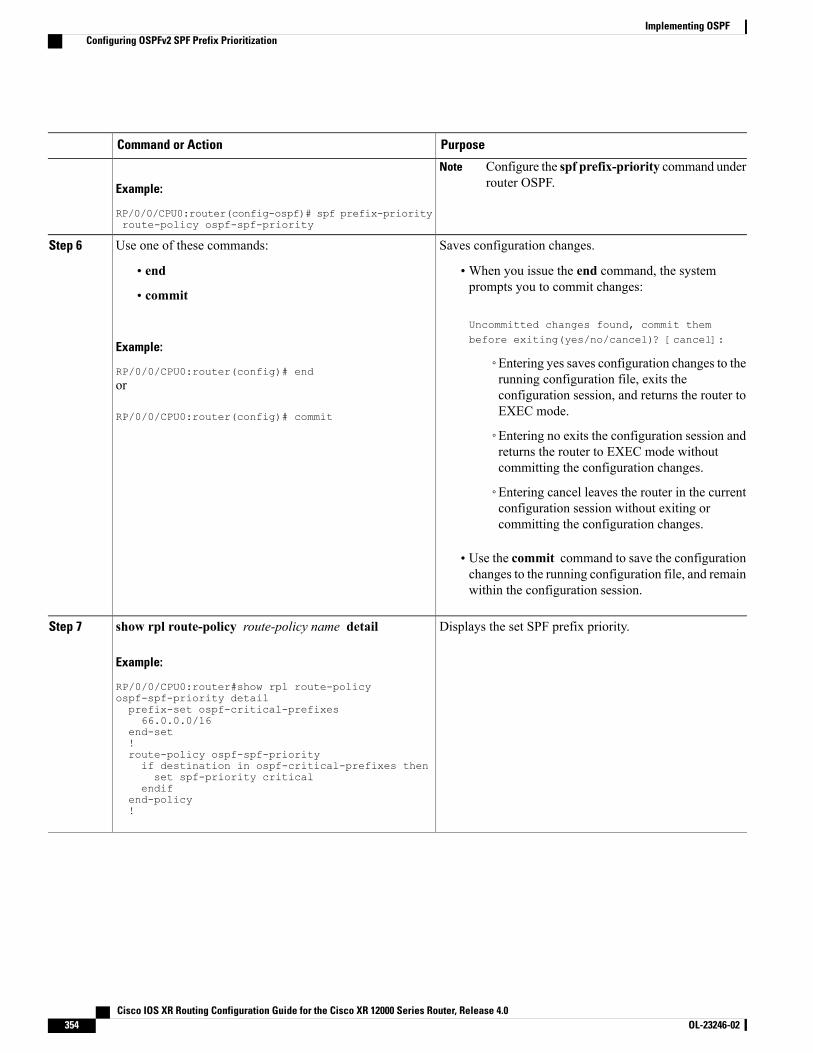
PurposeCommand or Action
Example:
RP/0/0/CPU0:router(config-ospf)# spf prefix-priorityroute-policy ospf-spf-priority
Configure the spf prefix-priority command underrouter OSPF.
Note
Saves configuration changes.Use one of these commands:Step 6
• end •When you issue the end command, the systemprompts you to commit changes:
Uncommitted changes found, commit thembefore exiting(yes/no/cancel)? [cancel]:
• commit
Example:
RP/0/0/CPU0:router(config)# end◦Entering yes saves configuration changes to therunning configuration file, exits theor
RP/0/0/CPU0:router(config)# commit
configuration session, and returns the router toEXEC mode.
◦Entering no exits the configuration session andreturns the router to EXEC mode withoutcommitting the configuration changes.
◦Entering cancel leaves the router in the currentconfiguration session without exiting orcommitting the configuration changes.
• Use the commit command to save the configurationchanges to the running configuration file, and remainwithin the configuration session.
Displays the set SPF prefix priority.show rpl route-policy route-policy name detail
Example:
RP/0/0/CPU0:router#show rpl route-policy
Step 7
ospf-spf-priority detailprefix-set ospf-critical-prefixes66.0.0.0/16
end-set!route-policy ospf-spf-priorityif destination in ospf-critical-prefixes thenset spf-priority critical
endifend-policy!
Cisco IOS XR Routing Configuration Guide for the Cisco XR 12000 Series Router, Release 4.0354 OL-23246-02
Implementing OSPFConfiguring OSPFv2 SPF Prefix Prioritization

Enabling Multicast-intact for OSPFv2This optional task describes how to enable multicast-intact for OSPFv2 routes that use IPv4 addresses.
SUMMARY STEPS
1. configure2. router ospf instance-id3. mpls traffic-eng multicast-intact4. Do one of the following:
• end
• commit
DETAILED STEPS
PurposeCommand or Action
Enters global configuration mode.configure
Example:
RP/0/0/CPU0:router# configure
Step 1
Enables OSPF routing for the specified routing process, and places therouter in router configuration mode. In this example, the OSPF instanceis called isp.
router ospf instance-id
Example:
RP/0/0/CPU0:router(config)# routerospf isp
Step 2
Enables multicast-intact.mpls traffic-eng multicast-intact
Example:
RP/0/0/CPU0:router(config-ospf)# mplstraffic-eng multicast-intact
Step 3
Saves configuration changes.Do one of the following:Step 4
• end •When you issue the end command, the system prompts you to commitchanges:
Uncommitted changes found, commit them before
• commit
Example:
RP/0/0/CPU0:router(config-ospf)# end
exiting(yes/no/cancel)?[cancel]:
or
RP/0/0/CPU0:router(config-ospf)#commit
◦Entering yes saves configuration changes to the runningconfiguration file, exits the configuration session, and returnsthe router to EXEC mode.
Cisco IOS XR Routing Configuration Guide for the Cisco XR 12000 Series Router, Release 4.0 OL-23246-02 355
Implementing OSPFEnabling Multicast-intact for OSPFv2
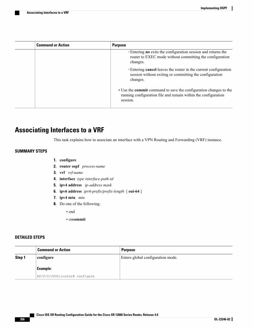
PurposeCommand or Action
◦Entering no exits the configuration session and returns therouter to EXEC mode without committing the configurationchanges.
◦Entering cancel leaves the router in the current configurationsession without exiting or committing the configurationchanges.
• Use the commit command to save the configuration changes to therunning configuration file and remain within the configurationsession.
Associating Interfaces to a VRFThis task explains how to associate an interface with a VPN Routing and Forwarding (VRF) instance.
SUMMARY STEPS
1. configure2. router ospf process-name3. vrf vrf-name4. interface type interface-path-id5. ipv4 address ip-address mask6. ipv6 address ipv6-prefix/prefix-length [ eui-64 ]7. ipv4 mtu mtu8. Do one of the following:
• end
• orcommit
DETAILED STEPS
PurposeCommand or Action
Enters global configuration mode.configure
Example:
RP/0/0/CPU0:router# configure
Step 1
Cisco IOS XR Routing Configuration Guide for the Cisco XR 12000 Series Router, Release 4.0356 OL-23246-02
Implementing OSPFAssociating Interfaces to a VRF
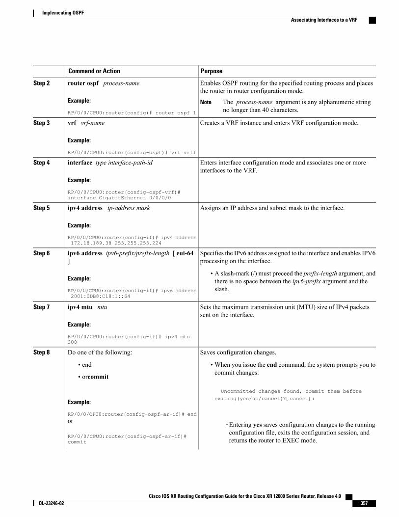
PurposeCommand or Action
Enables OSPF routing for the specified routing process and placesthe router in router configuration mode.
router ospf process-name
Example:
RP/0/0/CPU0:router(config)# router ospf 1
Step 2
The process-name argument is any alphanumeric stringno longer than 40 characters.
Note
Creates a VRF instance and enters VRF configuration mode.vrf vrf-name
Example:
RP/0/0/CPU0:router(config-ospf)# vrf vrf1
Step 3
Enters interface configuration mode and associates one or moreinterfaces to the VRF.
interface type interface-path-id
Example:
RP/0/0/CPU0:router(config-ospf-vrf)#interface GigabitEthernet 0/0/0/0
Step 4
Assigns an IP address and subnet mask to the interface.ipv4 address ip-address mask
Example:
RP/0/0/CPU0:router(config-if)# ipv4 address172.18.189.38 255.255.255.224
Step 5
Specifies the IPv6 address assigned to the interface and enables IPV6processing on the interface.
ipv6 address ipv6-prefix/prefix-length [ eui-64]
Step 6
Example:
RP/0/0/CPU0:router(config-if)# ipv6 address2001:0DB8:C18:1::64
• A slash-mark (/) must preceed the prefix-length argument, andthere is no space between the ipv6-prefix argument and theslash.
Sets the maximum transmission unit (MTU) size of IPv4 packetssent on the interface.
ipv4 mtu mtu
Example:
RP/0/0/CPU0:router(config-if)# ipv4 mtu300
Step 7
Saves configuration changes.Do one of the following:Step 8
• end •When you issue the end command, the system prompts you tocommit changes:
Uncommitted changes found, commit them before
• orcommit
Example:
RP/0/0/CPU0:router(config-ospf-ar-if)# end
exiting(yes/no/cancel)?[cancel]:
or
RP/0/0/CPU0:router(config-ospf-ar-if)#commit
◦Entering yes saves configuration changes to the runningconfiguration file, exits the configuration session, andreturns the router to EXEC mode.
Cisco IOS XR Routing Configuration Guide for the Cisco XR 12000 Series Router, Release 4.0 OL-23246-02 357
Implementing OSPFAssociating Interfaces to a VRF
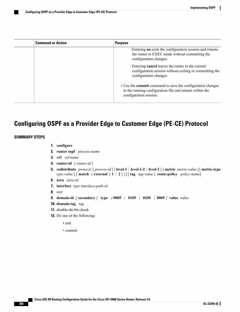
PurposeCommand or Action
◦Entering no exits the configuration session and returnsthe router to EXEC mode without committing theconfiguration changes.
◦Entering cancel leaves the router in the currentconfiguration session without exiting or committing theconfiguration changes.
• Use the commit command to save the configuration changesto the running configuration file and remain within theconfiguration session.
Configuring OSPF as a Provider Edge to Customer Edge (PE-CE) Protocol
SUMMARY STEPS
1. configure2. router ospf process-name3. vrf vrf-name4. router-id { router-id }5. redistribute protocol [ process-id ] { level-1 | level-1-2 | level-2 } [metric metric-value ] [metric-type
type-value ] [ match { external [ 1 | 2 ] }] [ tag tag-value ] route-policy policy-name]6. area area-id7. interface type interface-path-id8. exit9. domain-id [ secondary ] type { 0005 | 0105 | 0205 | 8005 } value value10. domain-tag tag11. disable-dn-bit-check12. Do one of the following:
• end
• commit
Cisco IOS XR Routing Configuration Guide for the Cisco XR 12000 Series Router, Release 4.0358 OL-23246-02
Implementing OSPFConfiguring OSPF as a Provider Edge to Customer Edge (PE-CE) Protocol

DETAILED STEPS
PurposeCommand or Action
Enters global configuration mode.configure
Example:
RP/0/0/CPU0:router# configure
Step 1
Enables OSPF routing for the specified routingprocess and places the router in router configurationmode.
router ospf process-name
Example:
RP/0/0/CPU0:router(config)# router ospf 1
Step 2
The process-name argument is anyalphanumeric string no longer than 40characters.
Note
Creates a VRF instance and enters VRF configurationmode.
vrf vrf-name
Example:
RP/0/0/CPU0:router(config-ospf)# vrf vrf1
Step 3
Configures a router ID for the OSPF process.router-id { router-id }Step 4
Example:
RP/0/0/CPU0:router(config-ospf-vrf)# router-id 192.168.4.3
We recommend using a stable IPv4 addressas the router ID.
Note
Redistributes OSPF routes from one routing domainto another routing domain.
redistribute protocol [ process-id ] { level-1 | level-1-2 | level-2} [ metric metric-value ] [ metric-type type-value ] [ match {external [ 1 | 2 ] }] [ tag tag-value ] route-policy policy-name]
Step 5
• This command causes the router to become anASBR by definition.
Example:
RP/0/0/CPU0:router(config-ospf-vrf)# redistribute bgp 1level-1
• OSPF tags all routes learned throughredistribution as external.
• The protocol and its process ID, if it has one,indicate the protocol being redistributed intoOSPF.
• The metric is the cost you assign to the externalroute. The default is 20 for all protocols exceptBGP, whose default metric is 1.
• The example shows the redistribution of BGPautonomous system 1, Level 1 routes into OSPFas Type 2 external routes.
Enters area configuration mode and configures anarea for the OSPF process.
area area-id
Example:
RP/0/0/CPU0:router(config-ospf-vrf)# area 0
Step 6
• The area-id argument can be entered indotted-decimal or IPv4 address notation, such
Cisco IOS XR Routing Configuration Guide for the Cisco XR 12000 Series Router, Release 4.0 OL-23246-02 359
Implementing OSPFConfiguring OSPF as a Provider Edge to Customer Edge (PE-CE) Protocol
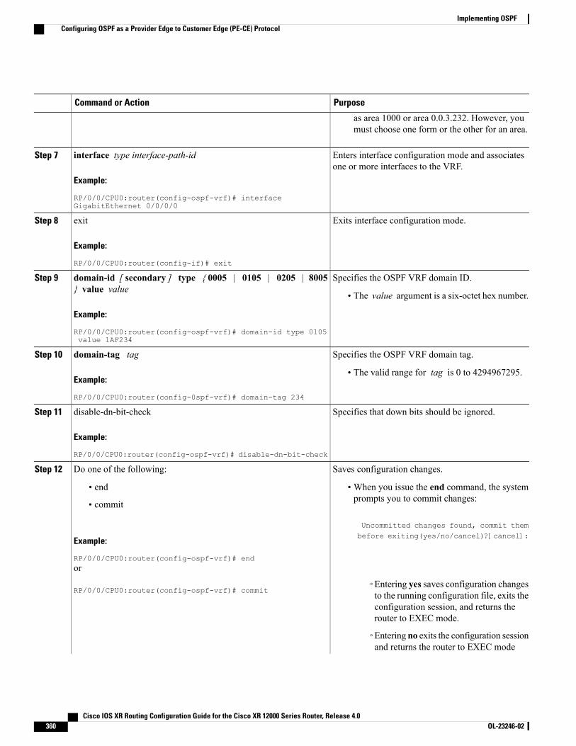
PurposeCommand or Action
as area 1000 or area 0.0.3.232. However, youmust choose one form or the other for an area.
Enters interface configuration mode and associatesone or more interfaces to the VRF.
interface type interface-path-id
Example:
RP/0/0/CPU0:router(config-ospf-vrf)# interfaceGigabitEthernet 0/0/0/0
Step 7
Exits interface configuration mode.exit
Example:
RP/0/0/CPU0:router(config-if)# exit
Step 8
Specifies the OSPF VRF domain ID.domain-id [ secondary ] type { 0005 | 0105 | 0205 | 8005} value value
Step 9
• The value argument is a six-octet hex number.
Example:
RP/0/0/CPU0:router(config-ospf-vrf)# domain-id type 0105value 1AF234
Specifies the OSPF VRF domain tag.domain-tag tagStep 10
Example:
RP/0/0/CPU0:router(config-0spf-vrf)# domain-tag 234
• The valid range for tag is 0 to 4294967295.
Specifies that down bits should be ignored.disable-dn-bit-check
Example:
RP/0/0/CPU0:router(config-ospf-vrf)# disable-dn-bit-check
Step 11
Saves configuration changes.Do one of the following:Step 12
• end •When you issue the end command, the systemprompts you to commit changes:
Uncommitted changes found, commit them
• commit
Example:
RP/0/0/CPU0:router(config-ospf-vrf)# end
before exiting(yes/no/cancel)?[cancel]:
or
RP/0/0/CPU0:router(config-ospf-vrf)# commit◦Entering yes saves configuration changesto the running configuration file, exits theconfiguration session, and returns therouter to EXEC mode.
◦Entering no exits the configuration sessionand returns the router to EXEC mode
Cisco IOS XR Routing Configuration Guide for the Cisco XR 12000 Series Router, Release 4.0360 OL-23246-02
Implementing OSPFConfiguring OSPF as a Provider Edge to Customer Edge (PE-CE) Protocol
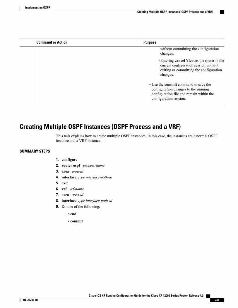
PurposeCommand or Action
without committing the configurationchanges.
◦Entering cancel Yleaves the router in thecurrent configuration session withoutexiting or committing the configurationchanges.
• Use the commit command to save theconfiguration changes to the runningconfiguration file and remain within theconfiguration session.
Creating Multiple OSPF Instances (OSPF Process and a VRF)This task explains how to create multiple OSPF instances. In this case, the instances are a normal OSPFinstance and a VRF instance.
SUMMARY STEPS
1. configure2. router ospf process-name3. area area-id4. interface type interface-path-id5. exit6. vrf vrf-name7. area area-id8. interface type interface-path-id9. Do one of the following:
• end
• commit
Cisco IOS XR Routing Configuration Guide for the Cisco XR 12000 Series Router, Release 4.0 OL-23246-02 361
Implementing OSPFCreating Multiple OSPF Instances (OSPF Process and a VRF)
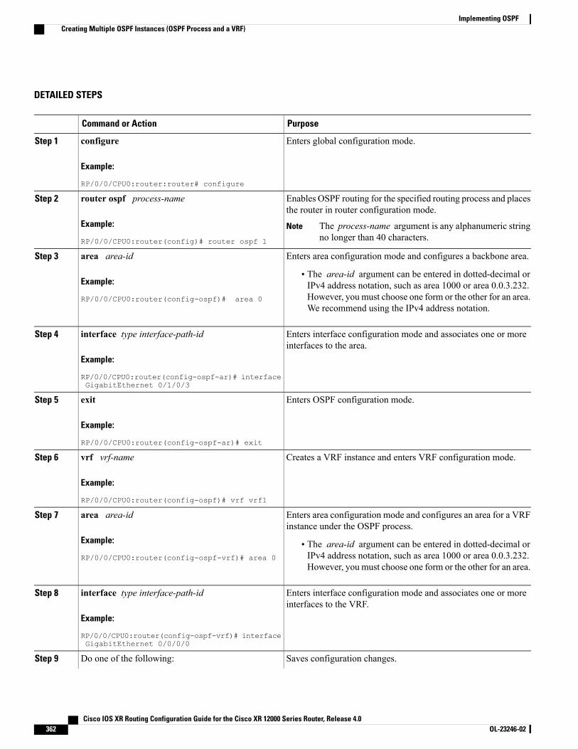
DETAILED STEPS
PurposeCommand or Action
Enters global configuration mode.configure
Example:
RP/0/0/CPU0:router:router# configure
Step 1
Enables OSPF routing for the specified routing process and placesthe router in router configuration mode.
router ospf process-name
Example:
RP/0/0/CPU0:router(config)# router ospf 1
Step 2
The process-name argument is any alphanumeric stringno longer than 40 characters.
Note
Enters area configuration mode and configures a backbone area.area area-idStep 3
Example:
RP/0/0/CPU0:router(config-ospf)# area 0
• The area-id argument can be entered in dotted-decimal orIPv4 address notation, such as area 1000 or area 0.0.3.232.However, you must choose one form or the other for an area.We recommend using the IPv4 address notation.
Enters interface configuration mode and associates one or moreinterfaces to the area.
interface type interface-path-id
Example:
RP/0/0/CPU0:router(config-ospf-ar)# interfaceGigabitEthernet 0/1/0/3
Step 4
Enters OSPF configuration mode.exit
Example:
RP/0/0/CPU0:router(config-ospf-ar)# exit
Step 5
Creates a VRF instance and enters VRF configuration mode.vrf vrf-name
Example:
RP/0/0/CPU0:router(config-ospf)# vrf vrf1
Step 6
Enters area configuration mode and configures an area for a VRFinstance under the OSPF process.
area area-id
Example:
RP/0/0/CPU0:router(config-ospf-vrf)# area 0
Step 7
• The area-id argument can be entered in dotted-decimal orIPv4 address notation, such as area 1000 or area 0.0.3.232.However, you must choose one form or the other for an area.
Enters interface configuration mode and associates one or moreinterfaces to the VRF.
interface type interface-path-id
Example:
RP/0/0/CPU0:router(config-ospf-vrf)# interfaceGigabitEthernet 0/0/0/0
Step 8
Saves configuration changes.Do one of the following:Step 9
Cisco IOS XR Routing Configuration Guide for the Cisco XR 12000 Series Router, Release 4.0362 OL-23246-02
Implementing OSPFCreating Multiple OSPF Instances (OSPF Process and a VRF)

PurposeCommand or Action
•When you issue the end command, the system prompts youto commit changes:
Uncommitted changes found, commit them before
• end
• commit
Example:
RP/0/0/CPU0:router(config-ospf-ar-if)# end
exiting(yes/no/cancel)?[cancel]:
◦Entering yes saves configuration changes to the runningconfiguration file, exits the configuration session, andreturns the router to EXEC mode.
or
RP/0/0/CPU0:router(config-ospf-ar-if)# commit
◦Entering no exits the configuration session and returnsthe router to EXEC mode without committing theconfiguration changes.
◦Entering cancel leaves the router in the currentconfiguration session without exiting or committingthe configuration changes.
• Use the commit command to save the configuration changesto the running configuration file and remain within theconfiguration session.
Configuring Multi-area AdjacencyThis task explains how to create multiple areas on an OSPF primary interface.
Before You Begin
You can configure multi-area adjacency on any interface where only two OSF speakers are attached. Inthe case of native broadcast networks, the interface must be configured as an OPSF point-to-point typeusing the network point-to-point command to enable the interface for a multi-area adjacency.
Note
Cisco IOS XR Routing Configuration Guide for the Cisco XR 12000 Series Router, Release 4.0 OL-23246-02 363
Implementing OSPFConfiguring Multi-area Adjacency
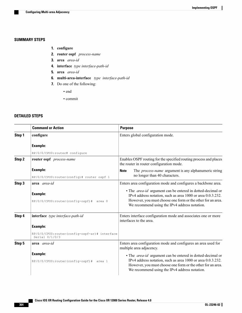
SUMMARY STEPS
1. configure2. router ospf process-name3. area area-id4. interface type interface-path-id5. area area-id6. multi-area-interface type interface-path-id7. Do one of the following:
• end
• commit
DETAILED STEPS
PurposeCommand or Action
Enters global configuration mode.configure
Example:
RP/0/0/CPU0:router# configure
Step 1
Enables OSPF routing for the specified routing process and placesthe router in router configuration mode.
router ospf process-name
Example:
RP/0/0/CPU0:router(config)# router ospf 1
Step 2
The process-name argument is any alphanumeric stringno longer than 40 characters.
Note
Enters area configuration mode and configures a backbone area.area area-idStep 3
Example:
RP/0/0/CPU0:router(config-ospf)# area 0
• The area-id argument can be entered in dotted-decimal orIPv4 address notation, such as area 1000 or area 0.0.3.232.However, youmust choose one form or the other for an area.We recommend using the IPv4 address notation.
Enters interface configuration mode and associates one or moreinterfaces to the area.
interface type interface-path-id
Example:
RP/0/0/CPU0:router(config-ospf-ar)# interfaceSerial 0/1/0/3
Step 4
Enters area configuration mode and configures an area used formultiple area adjacency.
area area-id
Example:
RP/0/0/CPU0:router(config-ospf)# area 1
Step 5
• The area-id argument can be entered in dotted-decimal orIPv4 address notation, such as area 1000 or area 0.0.3.232.However, youmust choose one form or the other for an area.We recommend using the IPv4 address notation.
Cisco IOS XR Routing Configuration Guide for the Cisco XR 12000 Series Router, Release 4.0364 OL-23246-02
Implementing OSPFConfiguring Multi-area Adjacency
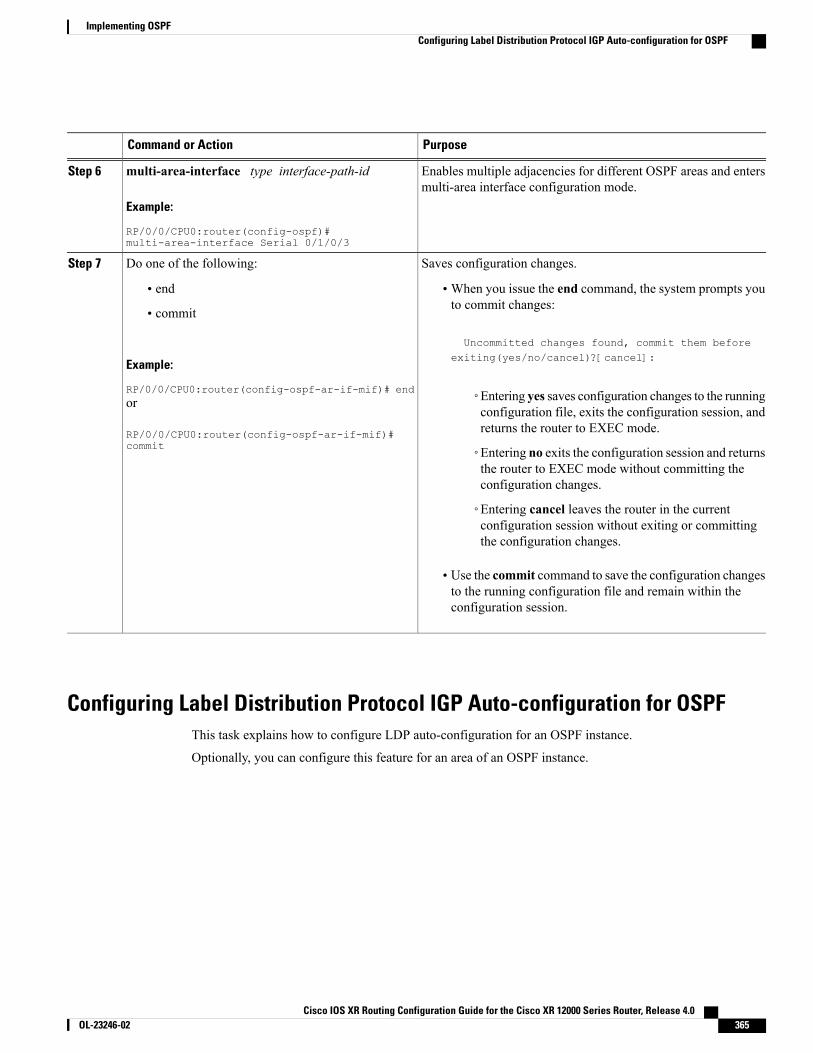
PurposeCommand or Action
Enables multiple adjacencies for different OSPF areas and entersmulti-area interface configuration mode.
multi-area-interface type interface-path-id
Example:
RP/0/0/CPU0:router(config-ospf)#multi-area-interface Serial 0/1/0/3
Step 6
Saves configuration changes.Do one of the following:Step 7
• end •When you issue the end command, the system prompts youto commit changes:
Uncommitted changes found, commit them before
• commit
Example:
RP/0/0/CPU0:router(config-ospf-ar-if-mif)# end
exiting(yes/no/cancel)?[cancel]:
◦Entering yes saves configuration changes to the runningconfiguration file, exits the configuration session, andreturns the router to EXEC mode.
or
RP/0/0/CPU0:router(config-ospf-ar-if-mif)#commit ◦Entering no exits the configuration session and returns
the router to EXEC mode without committing theconfiguration changes.
◦Entering cancel leaves the router in the currentconfiguration session without exiting or committingthe configuration changes.
• Use the commit command to save the configuration changesto the running configuration file and remain within theconfiguration session.
Configuring Label Distribution Protocol IGP Auto-configuration for OSPFThis task explains how to configure LDP auto-configuration for an OSPF instance.
Optionally, you can configure this feature for an area of an OSPF instance.
Cisco IOS XR Routing Configuration Guide for the Cisco XR 12000 Series Router, Release 4.0 OL-23246-02 365
Implementing OSPFConfiguring Label Distribution Protocol IGP Auto-configuration for OSPF
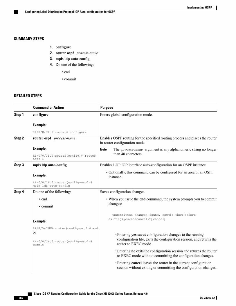
SUMMARY STEPS
1. configure2. router ospf process-name3. mpls ldp auto-config4. Do one of the following:
• end
• commit
DETAILED STEPS
PurposeCommand or Action
Enters global configuration mode.configure
Example:
RP/0/0/CPU0:router# configure
Step 1
Enables OSPF routing for the specified routing process and places the routerin router configuration mode.
router ospf process-name
Example:
RP/0/0/CPU0:router(config)# routerospf 1
Step 2
The process-name argument is any alphanumeric string no longerthan 40 characters.
Note
Enables LDP IGP interface auto-configuration for an OSPF instance.mpls ldp auto-configStep 3
Example:
RP/0/0/CPU0:router(config-ospf)#mpls ldp auto-config
• Optionally, this command can be configured for an area of an OSPFinstance.
Saves configuration changes.Do one of the following:Step 4
• end •When you issue the end command, the system prompts you to commitchanges:
Uncommitted changes found, commit them before
• commit
Example:
RP/0/0/CPU0:router(config-ospf)# end
exiting(yes/no/cancel)?[cancel]:
or
RP/0/0/CPU0:router(config-ospf)#commit
◦Entering yes saves configuration changes to the runningconfiguration file, exits the configuration session, and returns therouter to EXEC mode.
◦Entering no exits the configuration session and returns the routerto EXEC mode without committing the configuration changes.
◦Entering cancel leaves the router in the current configurationsession without exiting or committing the configuration changes.
Cisco IOS XR Routing Configuration Guide for the Cisco XR 12000 Series Router, Release 4.0366 OL-23246-02
Implementing OSPFConfiguring Label Distribution Protocol IGP Auto-configuration for OSPF
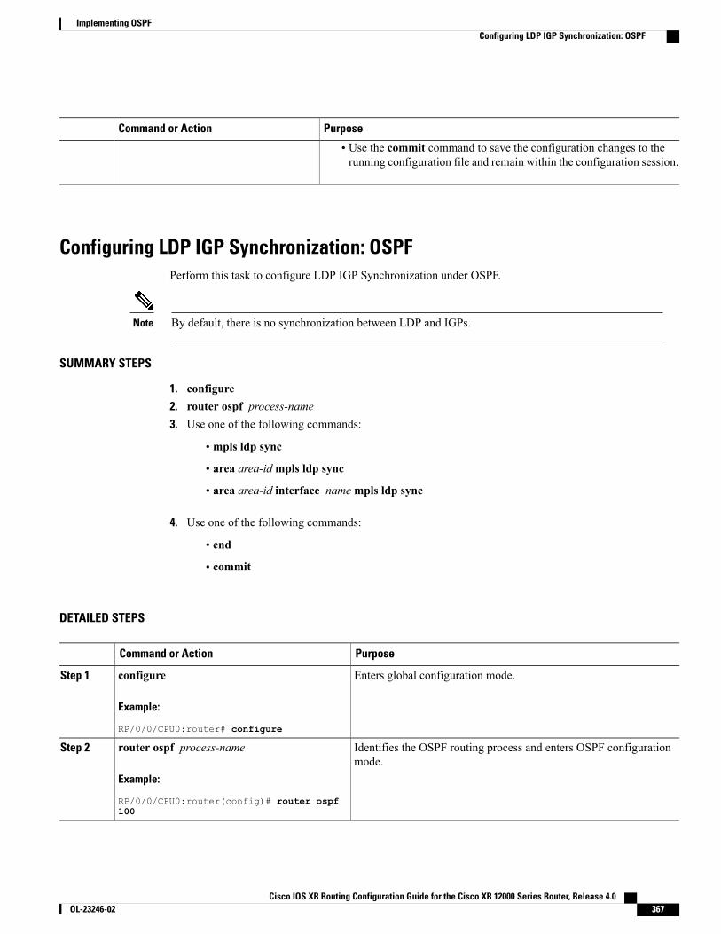
PurposeCommand or Action
• Use the commit command to save the configuration changes to therunning configuration file and remain within the configuration session.
Configuring LDP IGP Synchronization: OSPFPerform this task to configure LDP IGP Synchronization under OSPF.
By default, there is no synchronization between LDP and IGPs.Note
SUMMARY STEPS
1. configure2. router ospf process-name3. Use one of the following commands:
• mpls ldp sync
• area area-idmpls ldp sync
• area area-id interface namempls ldp sync
4. Use one of the following commands:
• end
• commit
DETAILED STEPS
PurposeCommand or Action
Enters global configuration mode.configure
Example:
RP/0/0/CPU0:router# configure
Step 1
Identifies the OSPF routing process and enters OSPF configurationmode.
router ospf process-name
Example:
RP/0/0/CPU0:router(config)# router ospf100
Step 2
Cisco IOS XR Routing Configuration Guide for the Cisco XR 12000 Series Router, Release 4.0 OL-23246-02 367
Implementing OSPFConfiguring LDP IGP Synchronization: OSPF
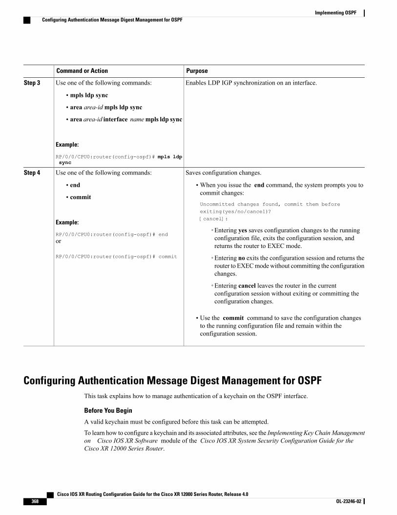
PurposeCommand or Action
Enables LDP IGP synchronization on an interface.Use one of the following commands:Step 3
• mpls ldp sync
• area area-idmpls ldp sync
• area area-id interface namempls ldp sync
Example:
RP/0/0/CPU0:router(config-ospf)# mpls ldpsync
Saves configuration changes.Use one of the following commands:Step 4
• end •When you issue the end command, the system prompts you tocommit changes:
Uncommitted changes found, commit them beforeexiting(yes/no/cancel)?[cancel]:
• commit
Example:
RP/0/0/CPU0:router(config-ospf)# end◦Entering yes saves configuration changes to the runningconfiguration file, exits the configuration session, andreturns the router to EXEC mode.
or
RP/0/0/CPU0:router(config-ospf)# commit ◦Entering no exits the configuration session and returns therouter to EXECmodewithout committing the configurationchanges.
◦Entering cancel leaves the router in the currentconfiguration session without exiting or committing theconfiguration changes.
• Use the commit command to save the configuration changesto the running configuration file and remain within theconfiguration session.
Configuring Authentication Message Digest Management for OSPFThis task explains how to manage authentication of a keychain on the OSPF interface.
Before You Begin
A valid keychain must be configured before this task can be attempted.
To learn how to configure a keychain and its associated attributes, see the Implementing Key ChainManagementon Cisco IOS XR Software module of the Cisco IOS XR System Security Configuration Guide for theCisco XR 12000 Series Router.
Cisco IOS XR Routing Configuration Guide for the Cisco XR 12000 Series Router, Release 4.0368 OL-23246-02
Implementing OSPFConfiguring Authentication Message Digest Management for OSPF
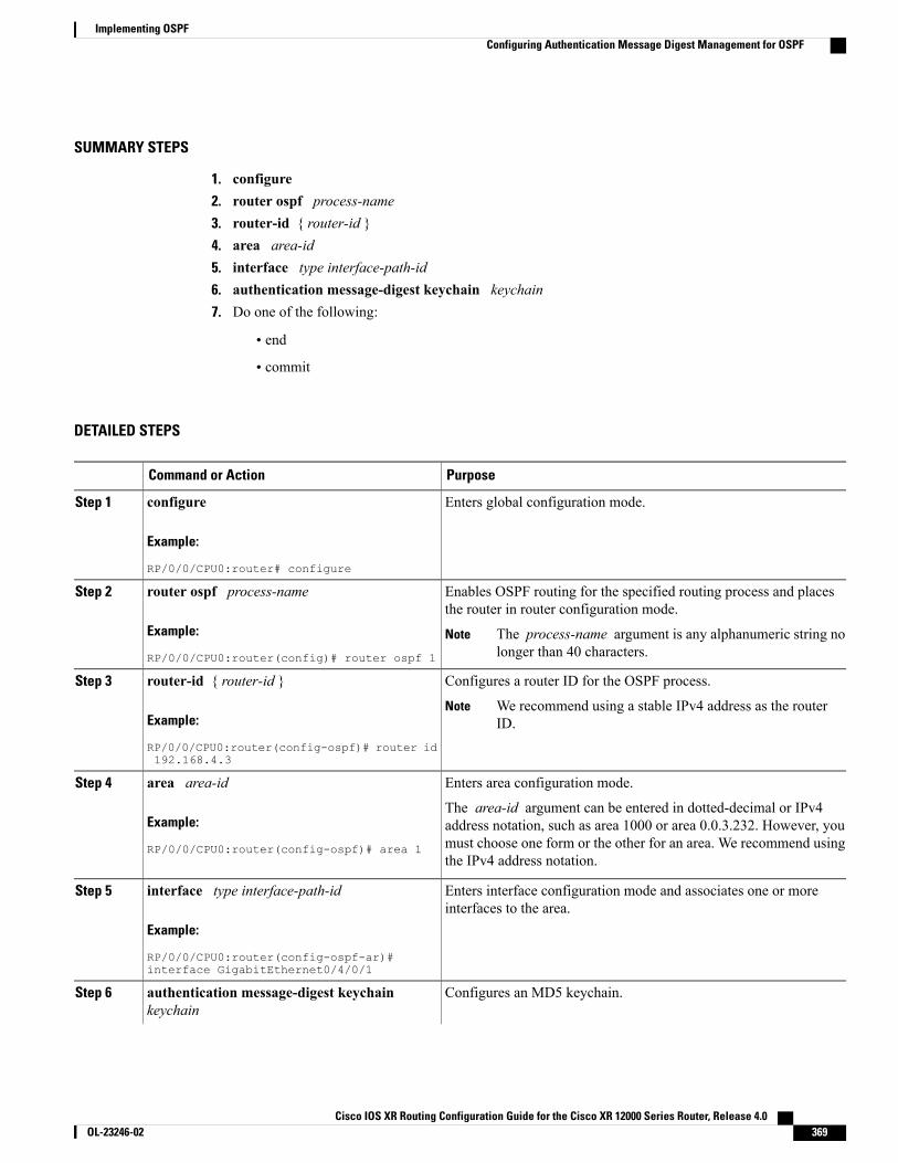
SUMMARY STEPS
1. configure2. router ospf process-name3. router-id { router-id }4. area area-id5. interface type interface-path-id6. authentication message-digest keychain keychain7. Do one of the following:
• end
• commit
DETAILED STEPS
PurposeCommand or Action
Enters global configuration mode.configure
Example:
RP/0/0/CPU0:router# configure
Step 1
Enables OSPF routing for the specified routing process and placesthe router in router configuration mode.
router ospf process-name
Example:
RP/0/0/CPU0:router(config)# router ospf 1
Step 2
The process-name argument is any alphanumeric string nolonger than 40 characters.
Note
Configures a router ID for the OSPF process.router-id { router-id }Step 3
Example:
RP/0/0/CPU0:router(config-ospf)# router id192.168.4.3
We recommend using a stable IPv4 address as the routerID.
Note
Enters area configuration mode.area area-idStep 4
Example:
RP/0/0/CPU0:router(config-ospf)# area 1
The area-id argument can be entered in dotted-decimal or IPv4address notation, such as area 1000 or area 0.0.3.232. However, youmust choose one form or the other for an area. We recommend usingthe IPv4 address notation.
Enters interface configuration mode and associates one or moreinterfaces to the area.
interface type interface-path-id
Example:
RP/0/0/CPU0:router(config-ospf-ar)#interface GigabitEthernet0/4/0/1
Step 5
Configures an MD5 keychain.authentication message-digest keychainkeychain
Step 6
Cisco IOS XR Routing Configuration Guide for the Cisco XR 12000 Series Router, Release 4.0 OL-23246-02 369
Implementing OSPFConfiguring Authentication Message Digest Management for OSPF

PurposeCommand or Action
In the example, the ospf_intl keychain must be configuredbefore you attempt this step.
Note
Example:
RP/0/0/CPU0:router(config-ospf-ar-if)#authentication message-digest keychainospf_int1
Saves configuration changes.Do one of the following:Step 7
• end •When you issue the end command, the system prompts you tocommit changes:
Uncommitted changes found, commit them before
• commit
Example:
RP/0/0/CPU0:router(config-ospf-ar-if)# end
exiting(yes/no/cancel)?[cancel]:
or
RP/0/0/CPU0:router(config-ospf-ar-if)#commit
◦Entering yes saves configuration changes to the runningconfiguration file, exits the configuration session, andreturns the router to EXEC mode.
◦Entering no exits the configuration session and returns therouter to EXEC mode without committing theconfiguration changes.
◦Entering cancel leaves the router in the currentconfiguration session without exiting or committing theconfiguration changes.
• Use the commit command to save the configuration changes tothe running configuration file and remain within theconfiguration session.
ExamplesThe following example shows how to configure the keychain ospf_intf_1 that contains five key IDs. Eachkey ID is configured with different send-lifetime values; however, all key IDs specify the same text stringfor the key.
key chain ospf_intf_1key 1send-lifetime 11:30:30 May 1 2007 duration 600cryptographic-algorithm MD5Tkey-string clear ospf_intf_1key 2send-lifetime 11:40:30 May 1 2007 duration 600cryptographic-algorithm MD5key-string clear ospf_intf_1key 3send-lifetime 11:50:30 May 1 2007 duration 600cryptographic-algorithm MD5
Cisco IOS XR Routing Configuration Guide for the Cisco XR 12000 Series Router, Release 4.0370 OL-23246-02
Implementing OSPFConfiguring Authentication Message Digest Management for OSPF
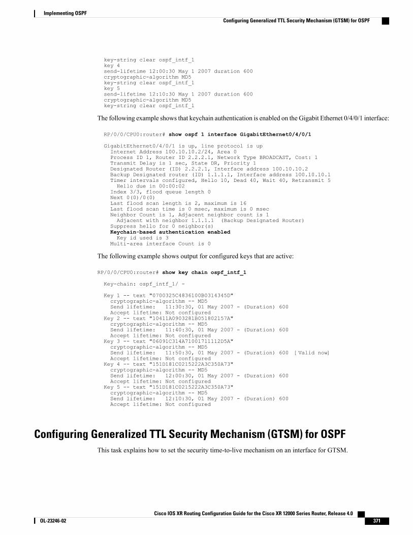
key-string clear ospf_intf_1key 4send-lifetime 12:00:30 May 1 2007 duration 600cryptographic-algorithm MD5key-string clear ospf_intf_1key 5send-lifetime 12:10:30 May 1 2007 duration 600cryptographic-algorithm MD5key-string clear ospf_intf_1
The following example shows that keychain authentication is enabled on the Gigabit Ethernet 0/4/0/1 interface:
RP/0/0/CPU0:router# show ospf 1 interface GigabitEthernet0/4/0/1
GigabitEthernet0/4/0/1 is up, line protocol is upInternet Address 100.10.10.2/24, Area 0Process ID 1, Router ID 2.2.2.1, Network Type BROADCAST, Cost: 1Transmit Delay is 1 sec, State DR, Priority 1Designated Router (ID) 2.2.2.1, Interface address 100.10.10.2Backup Designated router (ID) 1.1.1.1, Interface address 100.10.10.1Timer intervals configured, Hello 10, Dead 40, Wait 40, Retransmit 5Hello due in 00:00:02
Index 3/3, flood queue length 0Next 0(0)/0(0)Last flood scan length is 2, maximum is 16Last flood scan time is 0 msec, maximum is 0 msecNeighbor Count is 1, Adjacent neighbor count is 1Adjacent with neighbor 1.1.1.1 (Backup Designated Router)
Suppress hello for 0 neighbor(s)Keychain-based authentication enabledKey id used is 3
Multi-area interface Count is 0
The following example shows output for configured keys that are active:
RP/0/0/CPU0:router# show key chain ospf_intf_1
Key-chain: ospf_intf_1/ -
Key 1 -- text "0700325C4836100B0314345D"cryptographic-algorithm -- MD5Send lifetime: 11:30:30, 01 May 2007 - (Duration) 600Accept lifetime: Not configured
Key 2 -- text "10411A0903281B051802157A"cryptographic-algorithm -- MD5Send lifetime: 11:40:30, 01 May 2007 - (Duration) 600Accept lifetime: Not configured
Key 3 -- text "06091C314A71001711112D5A"cryptographic-algorithm -- MD5Send lifetime: 11:50:30, 01 May 2007 - (Duration) 600 [Valid now]Accept lifetime: Not configured
Key 4 -- text "151D181C0215222A3C350A73"cryptographic-algorithm -- MD5Send lifetime: 12:00:30, 01 May 2007 - (Duration) 600Accept lifetime: Not configured
Key 5 -- text "151D181C0215222A3C350A73"cryptographic-algorithm -- MD5Send lifetime: 12:10:30, 01 May 2007 - (Duration) 600Accept lifetime: Not configured
Configuring Generalized TTL Security Mechanism (GTSM) for OSPFThis task explains how to set the security time-to-live mechanism on an interface for GTSM.
Cisco IOS XR Routing Configuration Guide for the Cisco XR 12000 Series Router, Release 4.0 OL-23246-02 371
Implementing OSPFConfiguring Generalized TTL Security Mechanism (GTSM) for OSPF
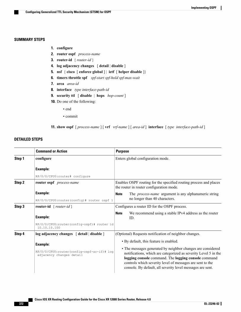
SUMMARY STEPS
1. configure2. router ospf process-name3. router-id { router-id }4. log adjacency changes [ detail | disable ]5. nsf { cisco [ enforce global ] | ietf [ helper disable ]}6. timers throttle spf spf-start spf-hold spf-max-wait7. area area-id8. interface type interface-path-id9. security ttl [ disable | hops hop-count ]10. Do one of the following:
• end
• commit
11. show ospf [ process-name ] [ vrf vrf-name ] [ area-id ] interface [ type interface-path-id ]
DETAILED STEPS
PurposeCommand or Action
Enters global configuration mode.configure
Example:
RP/0/0/CPU0:router# configure
Step 1
Enables OSPF routing for the specified routing process and placesthe router in router configuration mode.
router ospf process-name
Example:
RP/0/0/CPU0:router(config)# router ospf 1
Step 2
The process-name argument is any alphanumeric stringno longer than 40 characters.
Note
Configures a router ID for the OSPF process.router-id { router-id }Step 3
Example:
RP/0/0/CPU0:router(config-ospf)# router id10.10.10.100
We recommend using a stable IPv4 address as the routerID.
Note
(Optional) Requests notification of neighbor changes.log adjacency changes [ detail | disable ]Step 4
Example:
RP/0/0/CPU0:router(config-ospf-ar-if)# logadjacency changes detail
• By default, this feature is enabled.
• The messages generated by neighbor changes are considerednotifications, which are categorized as severity Level 5 in thelogging console command. The logging console commandcontrols which severity level of messages are sent to theconsole. By default, all severity level messages are sent.
Cisco IOS XR Routing Configuration Guide for the Cisco XR 12000 Series Router, Release 4.0372 OL-23246-02
Implementing OSPFConfiguring Generalized TTL Security Mechanism (GTSM) for OSPF
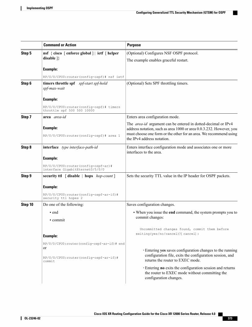
PurposeCommand or Action
(Optional) Configures NSF OSPF protocol.nsf { cisco [ enforce global ] | ietf [ helperdisable ]}
Step 5
The example enables graceful restart.
Example:
RP/0/0/CPU0:router(config-ospf)# nsf ietf
(Optional) Sets SPF throttling timers.timers throttle spf spf-start spf-holdspf-max-wait
Step 6
Example:
RP/0/0/CPU0:router(config-ospf)# timersthrottle spf 500 500 10000
Enters area configuration mode.area area-idStep 7
Example:
RP/0/0/CPU0:router(config-ospf)# area 1
The area-id argument can be entered in dotted-decimal or IPv4address notation, such as area 1000 or area 0.0.3.232. However, youmust choose one form or the other for an area. We recommend usingthe IPv4 address notation.
Enters interface configuration mode and associates one or moreinterfaces to the area.
interface type interface-path-id
Example:
RP/0/0/CPU0:router(config-ospf-ar)#interface GigabitEternet0/5/0/0
Step 8
Sets the security TTL value in the IP header for OSPF packets.security ttl [ disable | hops hop-count ]
Example:
RP/0/0/CPU0:router(config-ospf-ar-if)#security ttl hopes 2
Step 9
Saves configuration changes.Do one of the following:Step 10
• end •When you issue the end command, the system prompts you tocommit changes:
Uncommitted changes found, commit them before
• commit
Example:
RP/0/0/CPU0:router(config-ospf-ar-if)# end
exiting(yes/no/cancel)?[cancel]:
or
RP/0/0/CPU0:router(config-ospf-ar-if)#commit
◦Entering yes saves configuration changes to the runningconfiguration file, exits the configuration session, andreturns the router to EXEC mode.
◦Entering no exits the configuration session and returnsthe router to EXEC mode without committing theconfiguration changes.
Cisco IOS XR Routing Configuration Guide for the Cisco XR 12000 Series Router, Release 4.0 OL-23246-02 373
Implementing OSPFConfiguring Generalized TTL Security Mechanism (GTSM) for OSPF
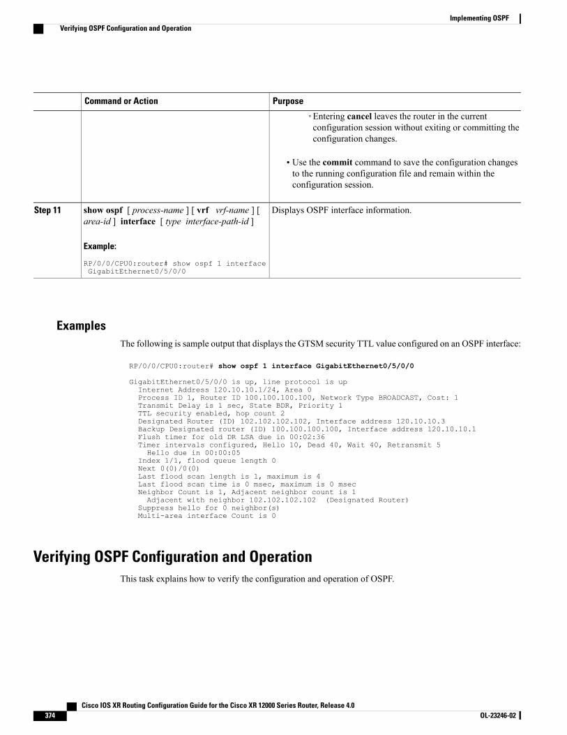
PurposeCommand or Action
◦Entering cancel leaves the router in the currentconfiguration session without exiting or committing theconfiguration changes.
• Use the commit command to save the configuration changesto the running configuration file and remain within theconfiguration session.
Displays OSPF interface information.show ospf [ process-name ] [ vrf vrf-name ] [area-id ] interface [ type interface-path-id ]
Step 11
Example:
RP/0/0/CPU0:router# show ospf 1 interfaceGigabitEthernet0/5/0/0
ExamplesThe following is sample output that displays the GTSM security TTL value configured on an OSPF interface:
RP/0/0/CPU0:router# show ospf 1 interface GigabitEthernet0/5/0/0
GigabitEthernet0/5/0/0 is up, line protocol is upInternet Address 120.10.10.1/24, Area 0Process ID 1, Router ID 100.100.100.100, Network Type BROADCAST, Cost: 1Transmit Delay is 1 sec, State BDR, Priority 1TTL security enabled, hop count 2Designated Router (ID) 102.102.102.102, Interface address 120.10.10.3Backup Designated router (ID) 100.100.100.100, Interface address 120.10.10.1Flush timer for old DR LSA due in 00:02:36Timer intervals configured, Hello 10, Dead 40, Wait 40, Retransmit 5Hello due in 00:00:05
Index 1/1, flood queue length 0Next 0(0)/0(0)Last flood scan length is 1, maximum is 4Last flood scan time is 0 msec, maximum is 0 msecNeighbor Count is 1, Adjacent neighbor count is 1Adjacent with neighbor 102.102.102.102 (Designated Router)
Suppress hello for 0 neighbor(s)Multi-area interface Count is 0
Verifying OSPF Configuration and OperationThis task explains how to verify the configuration and operation of OSPF.
Cisco IOS XR Routing Configuration Guide for the Cisco XR 12000 Series Router, Release 4.0374 OL-23246-02
Implementing OSPFVerifying OSPF Configuration and Operation
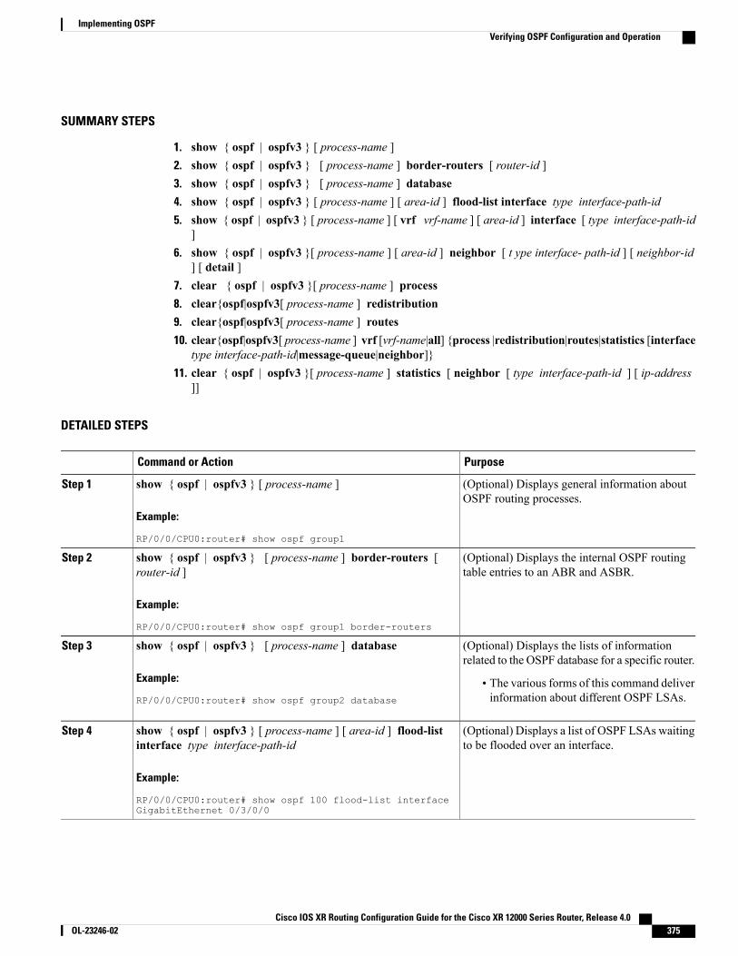
SUMMARY STEPS
1. show { ospf | ospfv3 } [ process-name ]2. show { ospf | ospfv3 } [ process-name ] border-routers [ router-id ]3. show { ospf | ospfv3 } [ process-name ] database4. show { ospf | ospfv3 } [ process-name ] [ area-id ] flood-list interface type interface-path-id5. show { ospf | ospfv3 } [ process-name ] [ vrf vrf-name ] [ area-id ] interface [ type interface-path-id
]6. show { ospf | ospfv3 }[ process-name ] [ area-id ] neighbor [ t ype interface- path-id ] [ neighbor-id
] [ detail ]7. clear { ospf | ospfv3 }[ process-name ] process8. clear{ospf|ospfv3[ process-name ] redistribution9. clear{ospf|ospfv3[ process-name ] routes10. clear{ospf|ospfv3[ process-name ] vrf [vrf-name|all] {process |redistribution|routes|statistics [interface
type interface-path-id|message-queue|neighbor]}11. clear { ospf | ospfv3 }[ process-name ] statistics [ neighbor [ type interface-path-id ] [ ip-address
]]
DETAILED STEPS
PurposeCommand or Action
(Optional) Displays general information aboutOSPF routing processes.
show { ospf | ospfv3 } [ process-name ]
Example:
RP/0/0/CPU0:router# show ospf group1
Step 1
(Optional) Displays the internal OSPF routingtable entries to an ABR and ASBR.
show { ospf | ospfv3 } [ process-name ] border-routers [router-id ]
Example:
RP/0/0/CPU0:router# show ospf group1 border-routers
Step 2
(Optional) Displays the lists of informationrelated to the OSPF database for a specific router.
show { ospf | ospfv3 } [ process-name ] database
Example:
RP/0/0/CPU0:router# show ospf group2 database
Step 3
• The various forms of this command deliverinformation about different OSPF LSAs.
(Optional) Displays a list of OSPF LSAs waitingto be flooded over an interface.
show { ospf | ospfv3 } [ process-name ] [ area-id ] flood-listinterface type interface-path-id
Example:
RP/0/0/CPU0:router# show ospf 100 flood-list interfaceGigabitEthernet 0/3/0/0
Step 4
Cisco IOS XR Routing Configuration Guide for the Cisco XR 12000 Series Router, Release 4.0 OL-23246-02 375
Implementing OSPFVerifying OSPF Configuration and Operation
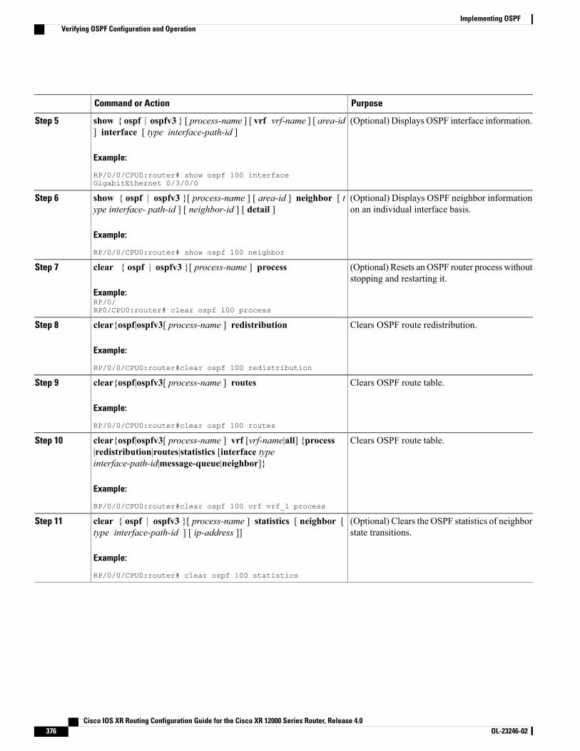
PurposeCommand or Action
(Optional) Displays OSPF interface information.show { ospf | ospfv3 } [ process-name ] [ vrf vrf-name ] [ area-id] interface [ type interface-path-id ]
Step 5
Example:
RP/0/0/CPU0:router# show ospf 100 interfaceGigabitEthernet 0/3/0/0
(Optional) Displays OSPF neighbor informationon an individual interface basis.
show { ospf | ospfv3 }[ process-name ] [ area-id ] neighbor [ type interface- path-id ] [ neighbor-id ] [ detail ]
Example:
RP/0/0/CPU0:router# show ospf 100 neighbor
Step 6
(Optional) Resets an OSPF router process withoutstopping and restarting it.
clear { ospf | ospfv3 }[ process-name ] process
Example:RP/0/RP0/CPU0:router# clear ospf 100 process
Step 7
Clears OSPF route redistribution.clear{ospf|ospfv3[ process-name ] redistribution
Example:
RP/0/0/CPU0:router#clear ospf 100 redistribution
Step 8
Clears OSPF route table.clear{ospf|ospfv3[ process-name ] routes
Example:
RP/0/0/CPU0:router#clear ospf 100 routes
Step 9
Clears OSPF route table.clear{ospf|ospfv3[ process-name ] vrf [vrf-name|all] {process|redistribution|routes|statistics [interface typeinterface-path-id|message-queue|neighbor]}
Step 10
Example:
RP/0/0/CPU0:router#clear ospf 100 vrf vrf_1 process
(Optional) Clears the OSPF statistics of neighborstate transitions.
clear { ospf | ospfv3 }[ process-name ] statistics [ neighbor [type interface-path-id ] [ ip-address ]]
Example:
RP/0/0/CPU0:router# clear ospf 100 statistics
Step 11
Cisco IOS XR Routing Configuration Guide for the Cisco XR 12000 Series Router, Release 4.0376 OL-23246-02
Implementing OSPFVerifying OSPF Configuration and Operation

Configuring OSPF Queue Tuning ParametersThe following procedures explain how to limit the number of continuous incoming events processed, how toset the maximum number of rate-limited link-state advertisements (LSAs) processed per run, how to limit thenumber of summary or external Type 3 to Type 7 link-state advertisements (LSAs) processed per shortestpath first (SPF) run, and how to set the high watermark for incoming priority events.
SUMMARY STEPS
1. configure2. router ospf process-name3. queue dispatch incoming count4. queue dispatch rate-limited-lsa count5. queue dispatch spf-lsa-limit count6. queue limit { high | medium | low } count
DETAILED STEPS
PurposeCommand or Action
Enters global configuration mode.configure
Example:
RP/0/0/CPU0:router# configure
Step 1
Enables OSPF routing for the specified routing process andplaces the router in router configuration mode.
router ospf process-name
Example:
RP/0/0/CPU0:router# router ospf ospf1
Step 2
The process-name argument is any alphanumericstring no longer than 40 characters.
Note
Limits the number of continuous incoming events processed.queue dispatch incoming count
Example:
RP/0/0/CPU0:router# queue dispatch incoming 30
Step 3
Sets the maximum number of rate-limited link-stateadvertisements (LSAs) processed per run.
queue dispatch rate-limited-lsa count
Example:
RP/0/0/CPU0:router# queue dispatchrate-limited-lsa 3000
Step 4
Limits the number of summary or external Type 3 to Type 7link-state advertisements (LSAs) processed per shortest pathfirst (SPF) run.
queue dispatch spf-lsa-limit count
Example:
RP/0/0/CPU0:router# queue dispatchspf-lsa-limit 2000
Step 5
Cisco IOS XR Routing Configuration Guide for the Cisco XR 12000 Series Router, Release 4.0 OL-23246-02 377
Implementing OSPFConfiguring OSPF Queue Tuning Parameters
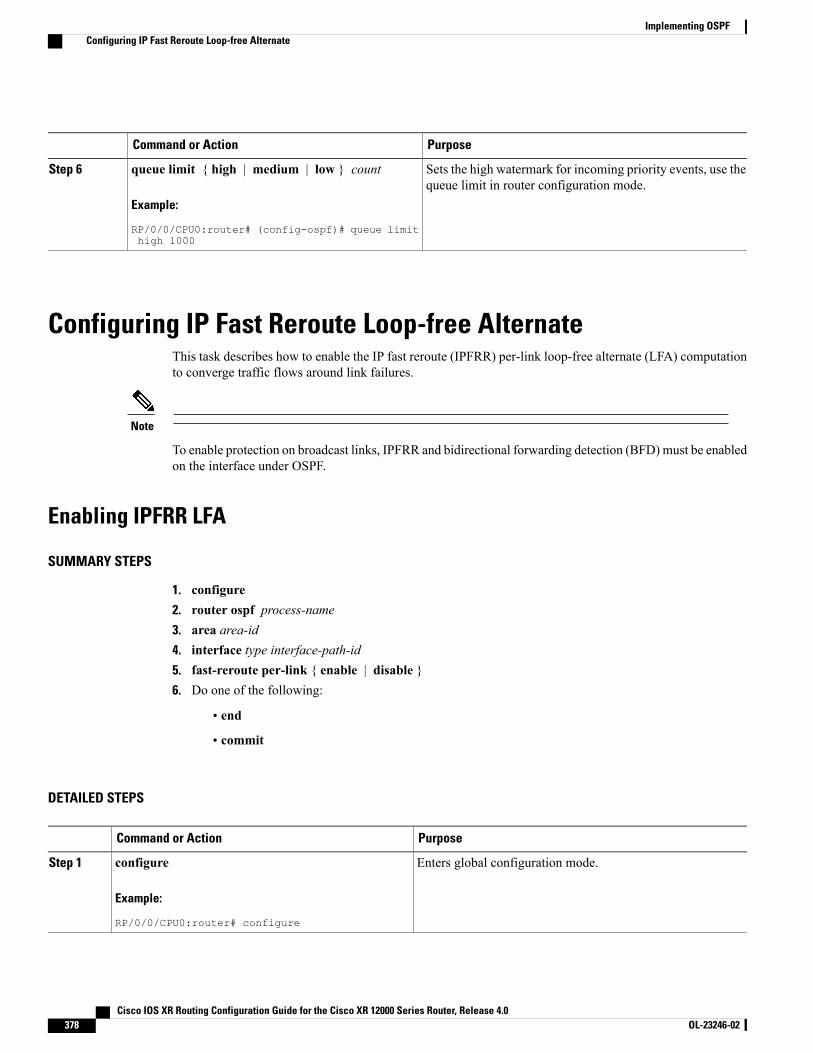
PurposeCommand or Action
Sets the high watermark for incoming priority events, use thequeue limit in router configuration mode.
queue limit { high | medium | low } count
Example:
RP/0/0/CPU0:router# (config-ospf)# queue limithigh 1000
Step 6
Configuring IP Fast Reroute Loop-free AlternateThis task describes how to enable the IP fast reroute (IPFRR) per-link loop-free alternate (LFA) computationto converge traffic flows around link failures.
Note
To enable protection on broadcast links, IPFRR and bidirectional forwarding detection (BFD) must be enabledon the interface under OSPF.
Enabling IPFRR LFA
SUMMARY STEPS
1. configure2. router ospf process-name3. area area-id4. interface type interface-path-id5. fast-reroute per-link { enable | disable }6. Do one of the following:
• end
• commit
DETAILED STEPS
PurposeCommand or Action
Enters global configuration mode.configure
Example:
RP/0/0/CPU0:router# configure
Step 1
Cisco IOS XR Routing Configuration Guide for the Cisco XR 12000 Series Router, Release 4.0378 OL-23246-02
Implementing OSPFConfiguring IP Fast Reroute Loop-free Alternate

PurposeCommand or Action
Enables OSPF routing for the specified routing process andplaces the router in router configuration mode.
router ospf process-name
Example:
RP/0/0/CPU0:router(config)# router ospf
Step 2
Enters area configuration mode.area area-id
Example:
RP/0/0/CPU0:router(config-ospf)#area 1
Step 3
Enters interface configuration mode and associates one or moreinterfaces to the area. .
interface type interface-path-id
Example:
RP/0/0/CPU0:router(config-ospf-ar)# interfaceGigabitEternet0/5/0/0
Step 4
Enables or disables per-link LFA computation for the interface.fast-reroute per-link { enable | disable }
Example:RP/0/0/CPU0:router(config-ospf-ar)#fast-rerouteper-link enable
Step 5
Saves configuration changes.Do one of the following:Step 6
• end •When you issue the end command, the system promptsyou to commit changes:
Uncommitted changes found, commit them before
• commit
Example:
RP/0/0/CPU0:router(config-ospf-ar)# end
exiting(yes/no/cancel)?[cancel]:
◦Entering yes saves configuration changes to therunning configuration file, exits the configurationsession, and returns the router to EXEC mode.
or
RP/0/0/CPU0:router(config-ospf-ar)# commit
◦Entering no exits the configuration session andreturns the router to EXEC mode withoutcommitting the configuration changes.
◦Entering cancel leaves the router in the currentconfiguration session without exiting or committingthe configuration changes.
• Use the commit command to save the configurationchanges to the running configuration file and remainwithin the configuration session.
Cisco IOS XR Routing Configuration Guide for the Cisco XR 12000 Series Router, Release 4.0 OL-23246-02 379
Implementing OSPFEnabling IPFRR LFA
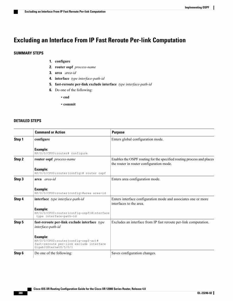
Excluding an Interface From IP Fast Reroute Per-link Computation
SUMMARY STEPS
1. configure2. router ospf process-name3. area area-id4. interface type interface-path-id5. fast-reroute per-link exclude interface type interface-path-id6. Do one of the following:
• end
• commit
DETAILED STEPS
PurposeCommand or Action
Enters global configuration mode.configure
Example:RP/0/0/CPU0:router# configure
Step 1
Enables the OSPF routing for the specified routing process and placesthe router in router configuration mode.
router ospf process-name
Example:RP/0/0/CPU0:router(config)# router ospf
Step 2
Enters area configuration mode.area area-id
Example:RP/0/0/CPU0:router(config)#area area-id
Step 3
Enters interface configuration mode and associates one or moreinterfaces to the area.
interface type interface-path-id
Example:RP/0/0/CPU0:router(config-ospf)#interfacetype interface-path-id
Step 4
Excludes an interface from IP fast reroute per-link computation.fast-reroute per-link exclude interface typeinterface-path-id
Step 5
Example:RP/0/0/CPU0:router(config-ospf-ar)#fast-reroute per-link exclude interfaceGigabitEternet0/5/0/1
Saves configuration changes.Do one of the following:Step 6
Cisco IOS XR Routing Configuration Guide for the Cisco XR 12000 Series Router, Release 4.0380 OL-23246-02
Implementing OSPFExcluding an Interface From IP Fast Reroute Per-link Computation
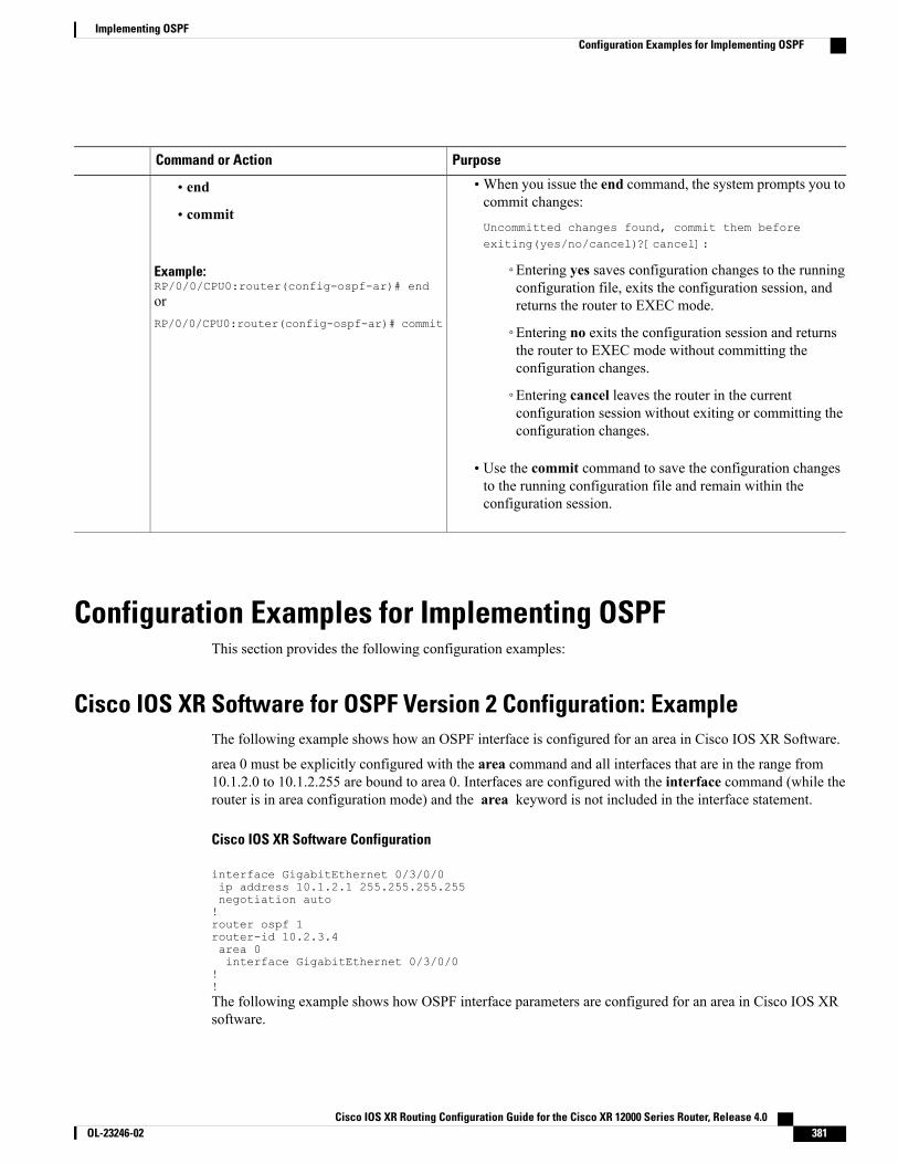
PurposeCommand or Action
•When you issue the end command, the system prompts you tocommit changes:
Uncommitted changes found, commit them beforeexiting(yes/no/cancel)?[cancel]:
• end
• commit
Example:RP/0/0/CPU0:router(config-ospf-ar)# end
◦Entering yes saves configuration changes to the runningconfiguration file, exits the configuration session, andreturns the router to EXEC mode.or
RP/0/0/CPU0:router(config-ospf-ar)# commit◦Entering no exits the configuration session and returnsthe router to EXEC mode without committing theconfiguration changes.
◦Entering cancel leaves the router in the currentconfiguration session without exiting or committing theconfiguration changes.
• Use the commit command to save the configuration changesto the running configuration file and remain within theconfiguration session.
Configuration Examples for Implementing OSPFThis section provides the following configuration examples:
Cisco IOS XR Software for OSPF Version 2 Configuration: ExampleThe following example shows how an OSPF interface is configured for an area in Cisco IOS XR Software.
area 0 must be explicitly configured with the area command and all interfaces that are in the range from10.1.2.0 to 10.1.2.255 are bound to area 0. Interfaces are configured with the interface command (while therouter is in area configuration mode) and the area keyword is not included in the interface statement.
Cisco IOS XR Software Configuration
interface GigabitEthernet 0/3/0/0ip address 10.1.2.1 255.255.255.255negotiation auto!router ospf 1router-id 10.2.3.4area 0interface GigabitEthernet 0/3/0/0
!!The following example shows how OSPF interface parameters are configured for an area in Cisco IOS XRsoftware.
Cisco IOS XR Routing Configuration Guide for the Cisco XR 12000 Series Router, Release 4.0 OL-23246-02 381
Implementing OSPFConfiguration Examples for Implementing OSPF
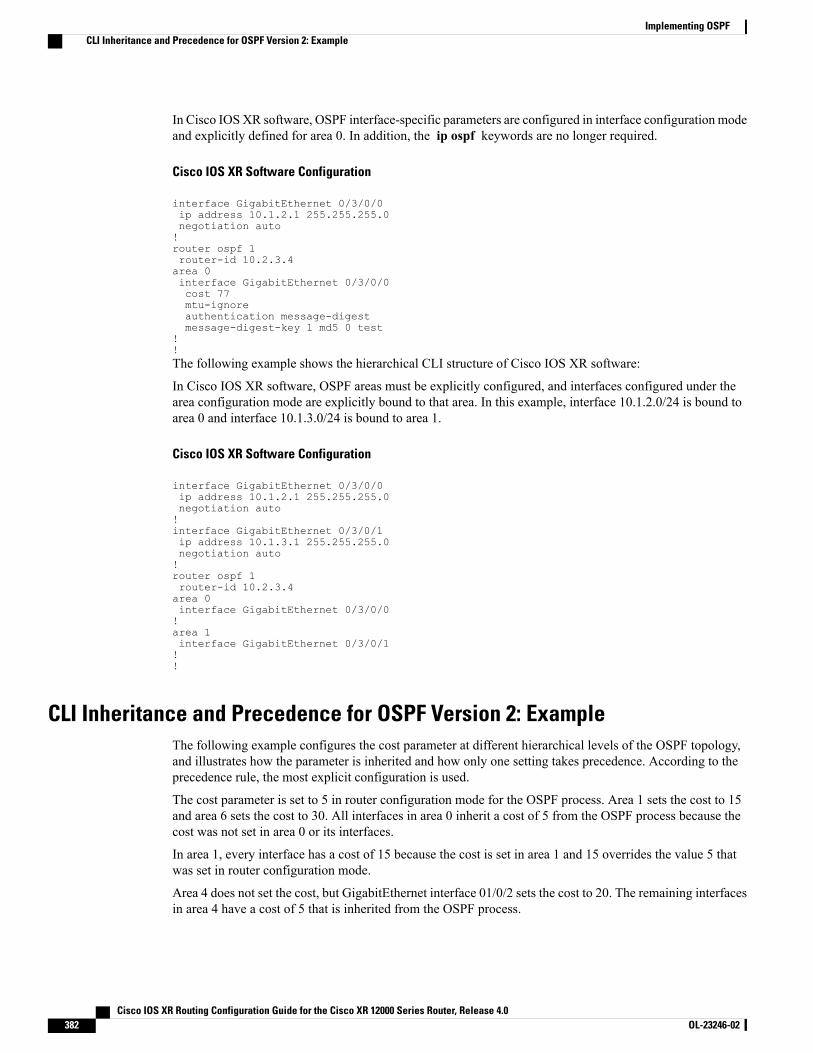
In Cisco IOS XR software, OSPF interface-specific parameters are configured in interface configuration modeand explicitly defined for area 0. In addition, the ip ospf keywords are no longer required.
Cisco IOS XR Software Configuration
interface GigabitEthernet 0/3/0/0ip address 10.1.2.1 255.255.255.0negotiation auto!router ospf 1router-id 10.2.3.4area 0interface GigabitEthernet 0/3/0/0cost 77mtu-ignoreauthentication message-digestmessage-digest-key 1 md5 0 test
!!The following example shows the hierarchical CLI structure of Cisco IOS XR software:
In Cisco IOS XR software, OSPF areas must be explicitly configured, and interfaces configured under thearea configuration mode are explicitly bound to that area. In this example, interface 10.1.2.0/24 is bound toarea 0 and interface 10.1.3.0/24 is bound to area 1.
Cisco IOS XR Software Configuration
interface GigabitEthernet 0/3/0/0ip address 10.1.2.1 255.255.255.0negotiation auto!interface GigabitEthernet 0/3/0/1ip address 10.1.3.1 255.255.255.0negotiation auto!router ospf 1router-id 10.2.3.4area 0interface GigabitEthernet 0/3/0/0!area 1interface GigabitEthernet 0/3/0/1!!
CLI Inheritance and Precedence for OSPF Version 2: ExampleThe following example configures the cost parameter at different hierarchical levels of the OSPF topology,and illustrates how the parameter is inherited and how only one setting takes precedence. According to theprecedence rule, the most explicit configuration is used.
The cost parameter is set to 5 in router configuration mode for the OSPF process. Area 1 sets the cost to 15and area 6 sets the cost to 30. All interfaces in area 0 inherit a cost of 5 from the OSPF process because thecost was not set in area 0 or its interfaces.
In area 1, every interface has a cost of 15 because the cost is set in area 1 and 15 overrides the value 5 thatwas set in router configuration mode.
Area 4 does not set the cost, but GigabitEthernet interface 01/0/2 sets the cost to 20. The remaining interfacesin area 4 have a cost of 5 that is inherited from the OSPF process.
Cisco IOS XR Routing Configuration Guide for the Cisco XR 12000 Series Router, Release 4.0382 OL-23246-02
Implementing OSPFCLI Inheritance and Precedence for OSPF Version 2: Example
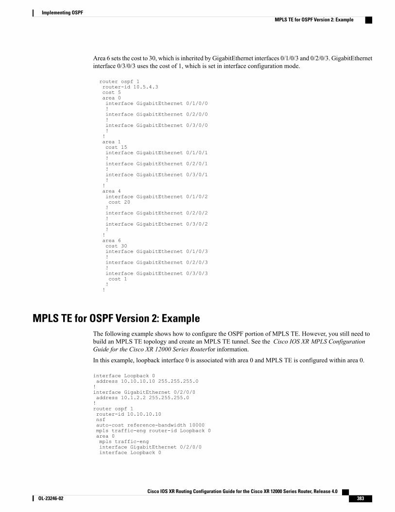
Area 6 sets the cost to 30, which is inherited by GigabitEthernet interfaces 0/1/0/3 and 0/2/0/3. GigabitEthernetinterface 0/3/0/3 uses the cost of 1, which is set in interface configuration mode.
router ospf 1router-id 10.5.4.3cost 5area 0interface GigabitEthernet 0/1/0/0!interface GigabitEthernet 0/2/0/0!interface GigabitEthernet 0/3/0/0!!area 1cost 15interface GigabitEthernet 0/1/0/1!interface GigabitEthernet 0/2/0/1!interface GigabitEthernet 0/3/0/1!!area 4interface GigabitEthernet 0/1/0/2cost 20!interface GigabitEthernet 0/2/0/2!interface GigabitEthernet 0/3/0/2!!area 6cost 30interface GigabitEthernet 0/1/0/3!interface GigabitEthernet 0/2/0/3!interface GigabitEthernet 0/3/0/3cost 1!!
MPLS TE for OSPF Version 2: ExampleThe following example shows how to configure the OSPF portion of MPLS TE. However, you still need tobuild an MPLS TE topology and create an MPLS TE tunnel. See the Cisco IOS XR MPLS ConfigurationGuide for the Cisco XR 12000 Series Routerfor information.
In this example, loopback interface 0 is associated with area 0 and MPLS TE is configured within area 0.
interface Loopback 0address 10.10.10.10 255.255.255.0!interface GigabitEthernet 0/2/0/0address 10.1.2.2 255.255.255.0!router ospf 1router-id 10.10.10.10nsfauto-cost reference-bandwidth 10000mpls traffic-eng router-id Loopback 0area 0mpls traffic-enginterface GigabitEthernet 0/2/0/0interface Loopback 0
Cisco IOS XR Routing Configuration Guide for the Cisco XR 12000 Series Router, Release 4.0 OL-23246-02 383
Implementing OSPFMPLS TE for OSPF Version 2: Example
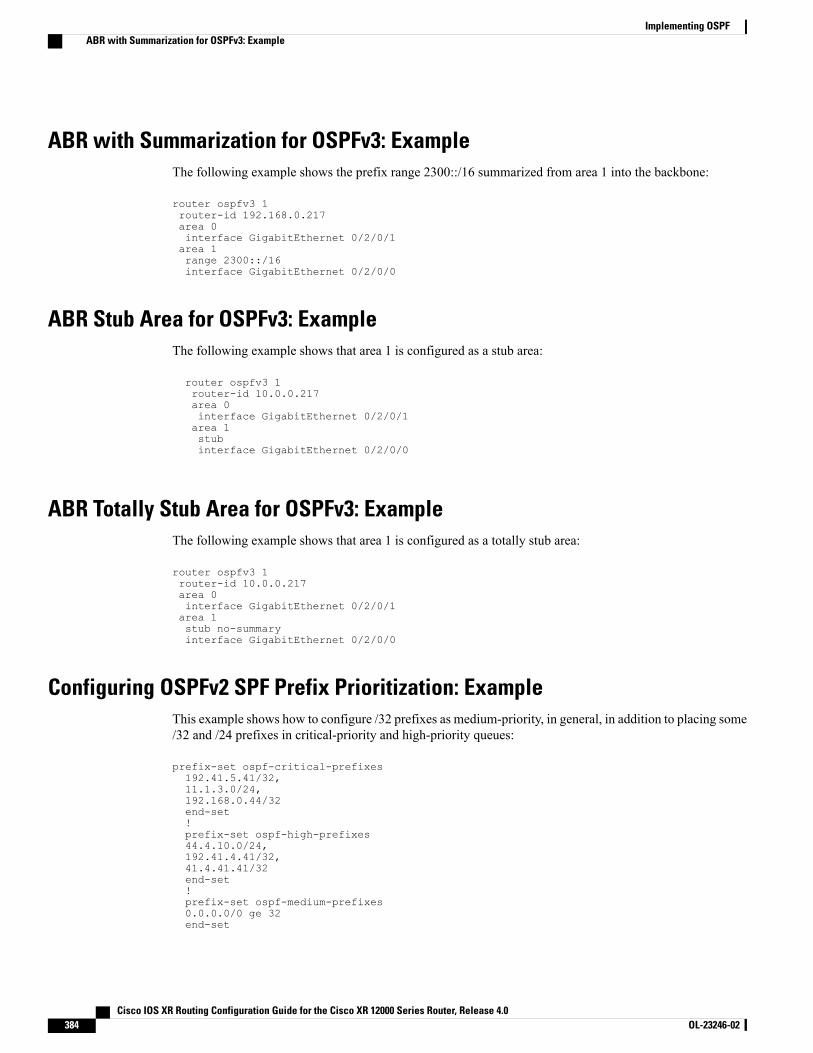
ABR with Summarization for OSPFv3: ExampleThe following example shows the prefix range 2300::/16 summarized from area 1 into the backbone:
router ospfv3 1router-id 192.168.0.217area 0interface GigabitEthernet 0/2/0/1area 1range 2300::/16interface GigabitEthernet 0/2/0/0
ABR Stub Area for OSPFv3: ExampleThe following example shows that area 1 is configured as a stub area:
router ospfv3 1router-id 10.0.0.217area 0interface GigabitEthernet 0/2/0/1area 1stubinterface GigabitEthernet 0/2/0/0
ABR Totally Stub Area for OSPFv3: ExampleThe following example shows that area 1 is configured as a totally stub area:
router ospfv3 1router-id 10.0.0.217area 0interface GigabitEthernet 0/2/0/1area 1stub no-summaryinterface GigabitEthernet 0/2/0/0
Configuring OSPFv2 SPF Prefix Prioritization: ExampleThis example shows how to configure /32 prefixes as medium-priority, in general, in addition to placing some/32 and /24 prefixes in critical-priority and high-priority queues:
prefix-set ospf-critical-prefixes192.41.5.41/32,11.1.3.0/24,192.168.0.44/32end-set!prefix-set ospf-high-prefixes44.4.10.0/24,192.41.4.41/32,41.4.41.41/32end-set!prefix-set ospf-medium-prefixes0.0.0.0/0 ge 32end-set
Cisco IOS XR Routing Configuration Guide for the Cisco XR 12000 Series Router, Release 4.0384 OL-23246-02
Implementing OSPFABR with Summarization for OSPFv3: Example
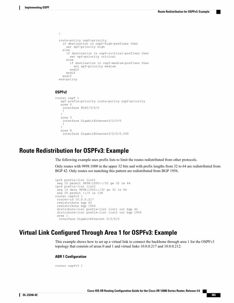
!
route-policy ospf-priorityif destination in ospf-high-prefixes thenset spf-priority high
elseif destination in ospf-critical-prefixes thenset spf-priority critical
elseif destination in ospf-medium-prefixes thenset spf-priority medium
endifendif
endifend-policy
OSPFv2router ospf 1
spf prefix-priority route-policy ospf-priorityarea 0interface POS0/3/0/0!!area 3interface GigabitEthernet0/2/0/0!!area 8interface GigabitEthernet0/2/0/0.590
Route Redistribution for OSPFv3: ExampleThe following example uses prefix lists to limit the routes redistributed from other protocols.
Only routes with 9898:1000 in the upper 32 bits and with prefix lengths from 32 to 64 are redistributed fromBGP 42. Only routes not matching this pattern are redistributed from BGP 1956.
ipv6 prefix-list list1seq 10 permit 9898:1000::/32 ge 32 le 64ipv6 prefix-list list2seq 10 deny 9898:1000::/32 ge 32 le 64seq 20 permit ::/0 le 128router ospfv3 1router-id 10.0.0.217redistribute bgp 42redistribute bgp 1956distribute-list prefix-list list1 out bgp 42distribute-list prefix-list list2 out bgp 1956area 1interface GigabitEthernet 0/2/0/0
Virtual Link Configured Through Area 1 for OSPFv3: ExampleThis example shows how to set up a virtual link to connect the backbone through area 1 for the OSPFv3topology that consists of areas 0 and 1 and virtual links 10.0.0.217 and 10.0.0.212:
ABR 1 Configuration
router ospfv3 1
Cisco IOS XR Routing Configuration Guide for the Cisco XR 12000 Series Router, Release 4.0 OL-23246-02 385
Implementing OSPFRoute Redistribution for OSPFv3: Example
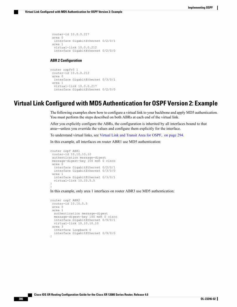
router-id 10.0.0.217area 0interface GigabitEthernet 0/2/0/1area 1virtual-link 10.0.0.212interface GigabitEthernet 0/2/0/0
ABR 2 Configuration
router ospfv3 1router-id 10.0.0.212area 0interface GigabitEthernet 0/3/0/1area 1virtual-link 10.0.0.217interface GigabitEthernet 0/2/0/0
Virtual Link Configured with MD5 Authentication for OSPF Version 2: ExampleThe following examples show how to configure a virtual link to your backbone and applyMD5 authentication.You must perform the steps described on both ABRs at each end of the virtual link.
After you explicitly configure the ABRs, the configuration is inherited by all interfaces bound to thatarea—unless you override the values and configure them explicitly for the interface.
To understand virtual links, see Virtual Link and Transit Area for OSPF, on page 294.
In this example, all interfaces on router ABR1 use MD5 authentication:
router ospf ABR1router-id 10.10.10.10authentication message-digestmessage-digest-key 100 md5 0 ciscoarea 0interface GigabitEthernet 0/2/0/1interface GigabitEthernet 0/3/0/0area 1interface GigabitEthernet 0/3/0/1virtual-link 10.10.5.5
!!In this example, only area 1 interfaces on router ABR3 use MD5 authentication:
router ospf ABR2router-id 10.10.5.5area 0area 1authentication message-digestmessage-digest-key 100 md5 0 ciscointerface GigabitEthernet 0/9/0/1virtual-link 10.10.10.10area 3interface Loopback 0interface GigabitEthernet 0/9/0/0
!
Cisco IOS XR Routing Configuration Guide for the Cisco XR 12000 Series Router, Release 4.0386 OL-23246-02
Implementing OSPFVirtual Link Configured with MD5 Authentication for OSPF Version 2: Example
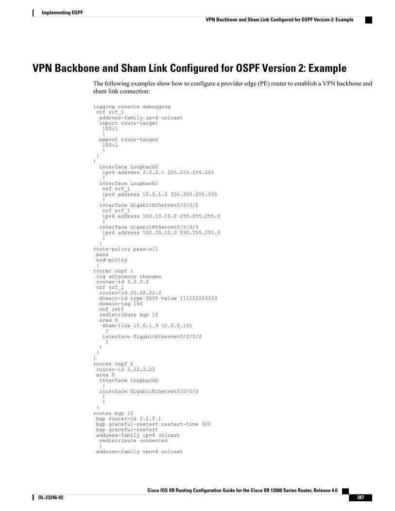
VPN Backbone and Sham Link Configured for OSPF Version 2: ExampleThe following examples show how to configure a provider edge (PE) router to establish a VPN backbone andsham link connection:
logging console debuggingvrf vrf_1address-family ipv4 unicastimport route-target100:1!export route-target100:1!
!!interface Loopback0ipv4 address 2.2.2.1 255.255.255.255!interface Loopback1vrf vrf_1ipv4 address 10.0.1.3 255.255.255.255!interface GigabitEthernet0/2/0/2vrf vrf_1ipv4 address 100.10.10.2 255.255.255.0!interface GigabitEthernet0/2/0/3ipv4 address 100.20.10.2 255.255.255.0!!
route-policy pass-allpassend-policy!router ospf 1log adjacency changesrouter-id 2.2.2.2vrf vrf_1router-id 22.22.22.2domain-id type 0005 value 111122223333domain-tag 140nsf ietfredistribute bgp 10area 0sham-link 10.0.1.3 10.0.0.101!interface GigabitEthernet0/2/0/2!
!!!router ospf 2router-id 2.22.2.22area 0interface Loopback0!interface GigabitEthernet0/2/0/3!!
!router bgp 10bgp router-id 2.2.2.1bgp graceful-restart restart-time 300bgp graceful-restartaddress-family ipv4 unicastredistribute connected!address-family vpnv4 unicast
Cisco IOS XR Routing Configuration Guide for the Cisco XR 12000 Series Router, Release 4.0 OL-23246-02 387
Implementing OSPFVPN Backbone and Sham Link Configured for OSPF Version 2: Example

!neighbor 2.2.2.2remote-as 10update-source Loopback0address-family ipv4 unicast!address-family vpnv4 unicast!!vrf vrf_1rd 100:1address-family ipv4 unicastredistribute connected route-policy pass-allredistribute ospf 1 match internal external!!!mpls ldprouter-id 2.2.2.1interface GigabitEthernet0/2/0/3!!
OSPF Queue Tuning Parameters Configuration: ExampleThe following example shows how to configure the OSPF queue tuning parameters:
router ospf 100queue dispatch incoming 30queue limit high 1500queue dispatch rate-limited-lsa 1000queue dispatch spf-lsa-limit 2000
Where to Go NextTo configure route maps through the RPL for OSPF Version 2, see Implementing Routing Policy onCisco IOS XR Software module.
To build an MPLS TE topology, create tunnels, and configure forwarding over the tunnel for OSPF Version2; see Cisco IOS XR MPLS Configuration Guide for the Cisco XR 12000 Series Router.
Additional ReferencesThe following sections provide references related to implementing OSPF.
Related Documents
Document TitleRelated Topic
Cisco IOS XR Routing Command Reference for theCisco XR 12000 Series Router
OSPF and OSPFv3 commands: complete commandsyntax, commandmodes, command history, defaults,usage guidelines, and examples
Cisco IOS XR Routing Configuration Guide for the Cisco XR 12000 Series Router, Release 4.0388 OL-23246-02
Implementing OSPFOSPF Queue Tuning Parameters Configuration: Example
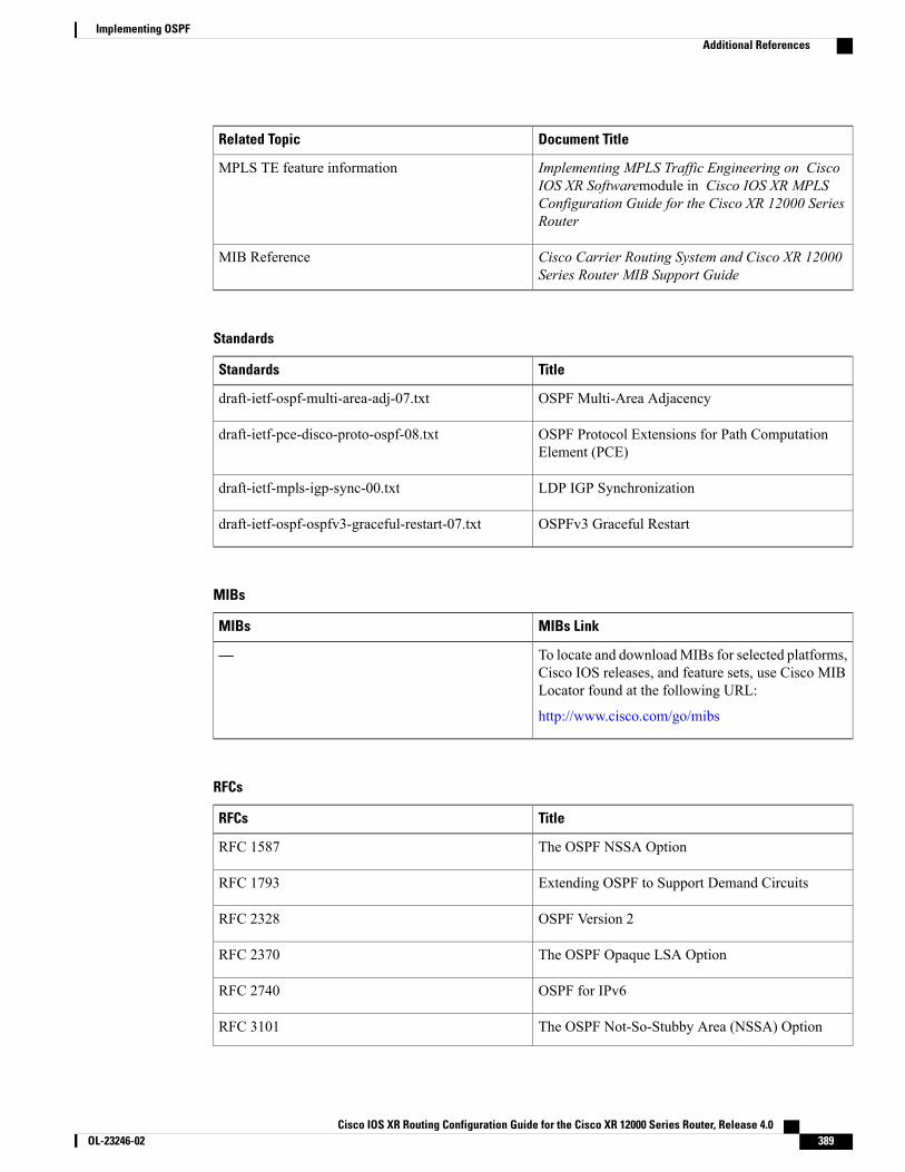
Document TitleRelated Topic
Implementing MPLS Traffic Engineering on CiscoIOS XR Softwaremodule in Cisco IOS XR MPLSConfiguration Guide for the Cisco XR 12000 SeriesRouter
MPLS TE feature information
Cisco Carrier Routing System and Cisco XR 12000Series Router MIB Support Guide
MIB Reference
Standards
TitleStandards
OSPF Multi-Area Adjacencydraft-ietf-ospf-multi-area-adj-07.txt
OSPF Protocol Extensions for Path ComputationElement (PCE)
draft-ietf-pce-disco-proto-ospf-08.txt
LDP IGP Synchronizationdraft-ietf-mpls-igp-sync-00.txt
OSPFv3 Graceful Restartdraft-ietf-ospf-ospfv3-graceful-restart-07.txt
MIBs
MIBs LinkMIBs
To locate and downloadMIBs for selected platforms,Cisco IOS releases, and feature sets, use Cisco MIBLocator found at the following URL:
http://www.cisco.com/go/mibs
—
RFCs
TitleRFCs
The OSPF NSSA OptionRFC 1587
Extending OSPF to Support Demand CircuitsRFC 1793
OSPF Version 2RFC 2328
The OSPF Opaque LSA OptionRFC 2370
OSPF for IPv6RFC 2740
The OSPF Not-So-Stubby Area (NSSA) OptionRFC 3101
Cisco IOS XR Routing Configuration Guide for the Cisco XR 12000 Series Router, Release 4.0 OL-23246-02 389
Implementing OSPFAdditional References

TitleRFCs
OSPF Stub Router AdvertisementRFC 3137
Alternative Implementations of OSPF Area BorderRouters
RFC 3509
Graceful OSPF RestartRFC 3623
Traffic Engineering (TE) Extensions to OSPFVersion2
RFC 3630
The Generalized TTL Security Mechanism (GTSM)RFC 3682
Calculating Interior Gateway Protocol (IGP) RoutesOver Traffic Engineering Tunnels
RFC 3906
OSPF Refresh and Flooding Reduction in StableTopologies
RFC 4136
Label Switched Paths (LSP) Hierarchy withGeneralized Multi-Protocol Label Switching(GMPLS) Traffic Engineering (TE)
RFC 4206
Protocol Extensions for Support of Diffserv-awareMPLS Traffic Engineering
RFC 4124
Using a Link State Advertisement (LSA) Options Bitto Prevent Looping in BGP/MPLS IP Virtual PrivateNetworks (VPNs) ownbit Extension for L3VPN
RFC 4576
OSPF as the Provider/Customer Edge Protocol forBGP/MPLS IP Virtual Private Networks (VPNs)
RFC 4577
OSPF Version 2 Management Information BaseRFC 4750
OSPF Out-of-Band Link State Database (LSDB)Resynchronization
RFC 4811
OSPF Restart SignalingRFC 4812
OSPF Link-Local SignalingRFC 4813
Extensions to OSPF for Advertising Optional RouterCapabilities
RFC 4970
Cisco IOS XR Routing Configuration Guide for the Cisco XR 12000 Series Router, Release 4.0390 OL-23246-02
Implementing OSPFAdditional References
Technical Assistance
LinkDescription
http://www.cisco.com/techsupportThe Cisco Technical Support website containsthousands of pages of searchable technical content,including links to products, technologies, solutions,technical tips, and tools. Registered Cisco.com userscan log in from this page to access evenmore content.
Cisco IOS XR Routing Configuration Guide for the Cisco XR 12000 Series Router, Release 4.0 OL-23246-02 391
Implementing OSPFAdditional References

Cisco IOS XR Routing Configuration Guide for the Cisco XR 12000 Series Router, Release 4.0392 OL-23246-02
Implementing OSPFAdditional References
C H A P T E R 5Implementing and Monitoring RIB
Routing Information Base (RIB) is a distributed collection of information about routing connectivity amongall nodes of a network. Each router maintains a RIB containing the routing information for that router. RIBstores the best routes from all routing protocols that are running on the system.
This module describes how to implement and monitor RIB on Cisco IOS XR network.
Formore information about RIB on the Cisco IOSXR software and complete descriptions of RIB commandslisted in this module, see the Additional References section of this module.
To locate documentation for other commands that might appear during the execution of a configurationtask, search online in the Cisco IOS XR Commands Master List for the Cisco XR 12000 Series Router.
Note
Feature History for Implementing and Monitoring RIB
ModificationRelease
This feature was introduced.Release 3.2
VPN routing and forwarding (VRF) support was added to thecommand syntax.
Release 3.3.0
RIB statistics support was added using the show rib statisticscommand. Disabling RIB next-hop dampening was supported.
Release 3.4.0
The following features were supported:
• IPv6 Provider Edge and IPv6 VPN Provider Edge overMultiprotocol Label Switching
• RIB quarantining
Release 3.5.0
No modification.Release 3.6.0
No modification.Release 3.7.0
Cisco IOS XR Routing Configuration Guide for the Cisco XR 12000 Series Router, Release 4.0 OL-23246-02 393
ModificationRelease
No modification.Release 3.8.0
No modification.Release 3.9.0
• Prerequisites for Implementing RIB, page 394
• Information About RIB Configuration, page 394
• How to Deploy and Monitor RIB, page 397
• Configuration Examples for RIB Monitoring, page 401
• Where to Go Next, page 404
• Additional References, page 404
Prerequisites for Implementing RIB• Youmust be in a user group associated with a task group that includes the proper task IDs. The commandreference guides include the task IDs required for each command. If you suspect user group assignmentis preventing you from using a command, contact your AAA administrator for assistance.
• RIB is distributed with the base Cisco IOSXR software; as such, it does not have any special requirementsfor installation. The following are the requirements for base software installation:
◦Router
◦Cisco IOS XR software
◦Base package
Information About RIB ConfigurationTo implement the Cisco RIB feature, you must understand the following concepts:
Overview of RIBEach routing protocol selects its own set of best routes and installs those routes and their attributes in RIB.RIB stores these routes and selects the best ones from among all routing protocols. Those routes are downloadedto the line cards for use in forwarding packets. The acronym RIB is used both to refer to RIB processes andthe collection of route data contained within RIB.
Within a protocol, routes are selected based on the metrics in use by that protocol. A protocol downloads itsbest routes (lowest or tied metric) to RIB. RIB selects the best overall route by comparing the administrativedistance of the associated protocol.
Cisco IOS XR Routing Configuration Guide for the Cisco XR 12000 Series Router, Release 4.0394 OL-23246-02
Implementing and Monitoring RIBPrerequisites for Implementing RIB
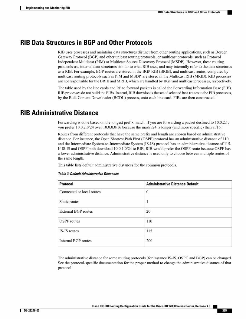
RIB Data Structures in BGP and Other ProtocolsRIB uses processes and maintains data structures distinct from other routing applications, such as BorderGateway Protocol (BGP) and other unicast routing protocols, or multicast protocols, such as ProtocolIndependent Multicast (PIM) or Multicast Source Discovery Protocol (MSDP). However, these routingprotocols use internal data structures similar to what RIB uses, and may internally refer to the data structuresas a RIB. For example, BGP routes are stored in the BGP RIB (BRIB), and multicast routes, computed bymulticast routing protocols such as PIM and MSDP, are stored in the Multicast RIB (MRIB). RIB processesare not responsible for the BRIB andMRIB, which are handled by BGP and multicast processes, respectively.
The table used by the line cards and RP to forward packets is called the Forwarding Information Base (FIB).RIB processes do not build the FIBs. Instead, RIB downloads the set of selected best routes to the FIB processes,by the Bulk Content Downloader (BCDL) process, onto each line card. FIBs are then constructed.
RIB Administrative DistanceForwarding is done based on the longest prefix match. If you are forwarding a packet destined to 10.0.2.1,you prefer 10.0.2.0/24 over 10.0.0.0/16 because the mask /24 is longer (and more specific) than a /16.
Routes from different protocols that have the same prefix and length are chosen based on administrativedistance. For instance, the Open Shortest Path First (OSPF) protocol has an administrative distance of 110,and the Intermediate System-to-Intermediate System (IS-IS) protocol has an administrative distance of 115.If IS-IS and OSPF both download 10.0.1.0/24 to RIB, RIB would prefer the OSPF route because OSPF hasa lower administrative distance. Administrative distance is used only to choose between multiple routes ofthe same length.
This table lists default administrative distances for the common protocols.
Table 3: Default Administrative Distances
Administrative Distance DefaultProtocol
0Connected or local routes
1Static routes
20External BGP routes
110OSPF routes
115IS-IS routes
200Internal BGP routes
The administrative distance for some routing protocols (for instance IS-IS, OSPF, and BGP) can be changed.See the protocol-specific documentation for the proper method to change the administrative distance of thatprotocol.
Cisco IOS XR Routing Configuration Guide for the Cisco XR 12000 Series Router, Release 4.0 OL-23246-02 395
Implementing and Monitoring RIBRIB Data Structures in BGP and Other Protocols
Changing the administrative distance of a protocol on some but not all routers can lead to routing loopsand other undesirable behavior. Doing so is not recommended.
Note
RIB Support for IPv4 and IPv6In Cisco IOS XR software, RIB tables support multicast and unicast routing.
The default routing tables for Cisco IOS XR software RIB are the unicast and the multicast-unicast RIB tablesfor IPv4 and IPv6 routing, respectively. For multicast routing, routing protocols insert unicast routes into themulticast-unicast RIB table. Multicast protocols then use the information to build multicast routes (which inturn are stored in the MRIB). See the multicast documentation for more information on using and configuringmulticast.
RIB processes ipv4_rib and ipv6_rib run on the RP card. If process placement functionality is available andsupported by multiple RPs in the router, RIB processes can be placed on any available node.
RIB StatisticsRIB supports statistics for messages (requests) flowing between the RIB and its clients. Protocol clients sendmessages to the RIB (for example, route add, route delete, and next-hop register, and so on). RIB also sendsmessages (for example, redistribute routes, advertisements, next-hop notifications, and so on). These statisticsare used to gather information about what messages have been sent and the number of messages that havebeen sent. These statistics provide counters for the various messages that flow between the RIB server andits clients. The statistics are displayed using the show rib statistics command.
RIB maintains counters for all requests sent from a client including:
• Route operations
• Table registrations
• Next-hop registrations
• Redistribution registrations
• Attribute registrations
• Synchronization completion
RIB also maintains counters for all requests sent by the RIB. The configuration will disable the RIB next-hopdampening feature. As a result, RIB notifies client immediately when a next hop that client registered for isresolved or unresolved.
RIB also maintains the results of the requests.
IPv6 Provider Edge IPv6 and IPv6 VPN Provider Edge Transport over MPLSIPv6 Provider Edge (6PE) and IPv6 VPN Provider Edge (6VPE) leverages the existing Multiprotocol LabelSwitching (MPLS) IPv4 core infrastructure for IPv6 transport. 6PE and 6VPE enables IPv6 sites to communicatewith each other over an MPLS IPv4 core network using MPLS label switched paths (LSPs).
Cisco IOS XR Routing Configuration Guide for the Cisco XR 12000 Series Router, Release 4.0396 OL-23246-02
Implementing and Monitoring RIBRIB Support for IPv4 and IPv6
RIB supports 6PE and 6VPE by providing 6VPE next hops. The next-hop information is stored in an opaquedatabase in RIB, which is populated by protocol clients with data to be sent to the Forwarding InformationBase (FIB).
For detailed information about configuring 6PE and 6VPE overMPLS, see Cisco IOS XRMPLSConfigurationGuide for the Cisco XR 12000 Series Router.
RIB QuarantiningRIB quarantining solves the problem in the interaction between routing protocols and the RIB. The problemis a persistent oscillation between the RIB and routing protocols that occurs when a route is continuouslyinserted and then withdrawn from the RIB, resulting in a spike in CPU use until the problem is resolved. Ifthere is no damping on the oscillation, then both the protocol process and the RIB process have high CPUuse, affecting the rest of the system as well as blocking out other protocol and RIB operations. This problemoccurs when a particular combination of routes is received and installed in the RIB. This problem typicallyhappens as a result of a network misconfiguration. However, because the misconfiguration is across thenetwork, it is not possible to detect the problem at configuration time on any single router.
The quarantining mechanism detects mutually recursive routes and quarantines the last route that completesthe mutual recursion. The quarantined route is periodically evaluated to see if the mutual recursion has goneaway. If the recursion still exists, the route remains quarantined. If the recursion has gone away, the route isreleased from its quarantine.
The following steps are used to quarantine a route:
1 RIB detects when a particular problematic path is installed.
2 RIB sends a notification to the protocol that installed the path.
3 When the protocol receives the quarantine notification about the problem route, it marks the route as being“quarantined.” If it is a BGP route, BGP does not advertise reachability for the route to its neighbors.
4 Periodically, RIB tests all its quarantined paths to see if they can now safely be installed (moved fromquarantined to "Ok to use" state). A notification is sent to the protocol to indicate that the path is now safeto use.
Flex-LSR Label Switch Processor 140The Label Switch Processor 140 line card is a scaled down version of Cisco CRS 3 line card. The Flex -LSRfeature imposes these limits to download of routes and labels:
• 16K IPv4 and IPv6 unicast (including VRF) routes
• 8K IPv4 and IPv6 multicast routes
• 100K labels
How to Deploy and Monitor RIBTo deploy and monitor RIB, you must understand the following concepts:
Cisco IOS XR Routing Configuration Guide for the Cisco XR 12000 Series Router, Release 4.0 OL-23246-02 397
Implementing and Monitoring RIBRIB Quarantining
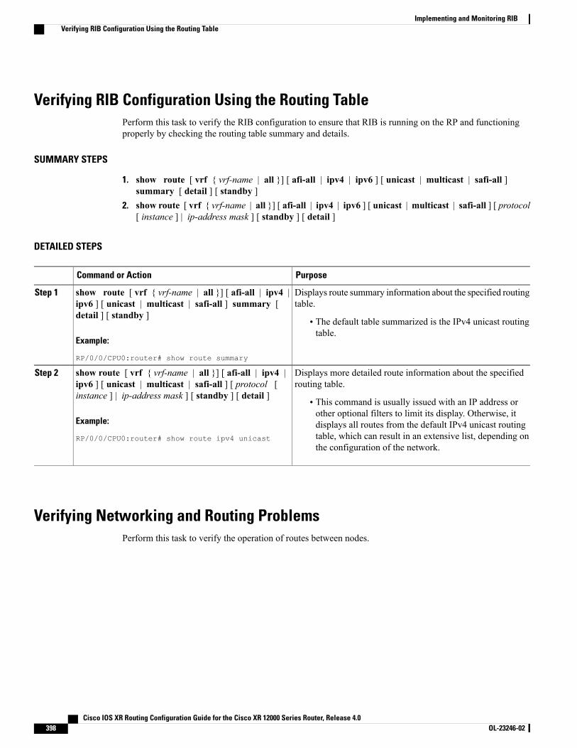
Verifying RIB Configuration Using the Routing TablePerform this task to verify the RIB configuration to ensure that RIB is running on the RP and functioningproperly by checking the routing table summary and details.
SUMMARY STEPS
1. show route [ vrf { vrf-name | all }] [ afi-all | ipv4 | ipv6 ] [ unicast | multicast | safi-all ]summary [ detail ] [ standby ]
2. show route [ vrf { vrf-name | all }] [ afi-all | ipv4 | ipv6 ] [ unicast | multicast | safi-all ] [ protocol[ instance ] | ip-address mask ] [ standby ] [ detail ]
DETAILED STEPS
PurposeCommand or Action
Displays route summary information about the specified routingtable.
show route [ vrf { vrf-name | all }] [ afi-all | ipv4 |ipv6 ] [ unicast | multicast | safi-all ] summary [detail ] [ standby ]
Step 1
• The default table summarized is the IPv4 unicast routingtable.
Example:
RP/0/0/CPU0:router# show route summary
Displays more detailed route information about the specifiedrouting table.
show route [ vrf { vrf-name | all }] [ afi-all | ipv4 |ipv6 ] [ unicast | multicast | safi-all ] [ protocol [instance ] | ip-address mask ] [ standby ] [ detail ]
Step 2
• This command is usually issued with an IP address orother optional filters to limit its display. Otherwise, it
Example:
RP/0/0/CPU0:router# show route ipv4 unicast
displays all routes from the default IPv4 unicast routingtable, which can result in an extensive list, depending onthe configuration of the network.
Verifying Networking and Routing ProblemsPerform this task to verify the operation of routes between nodes.
Cisco IOS XR Routing Configuration Guide for the Cisco XR 12000 Series Router, Release 4.0398 OL-23246-02
Implementing and Monitoring RIBVerifying RIB Configuration Using the Routing Table

SUMMARY STEPS
1. show route [vrf {vrf-name | all }] [ afi-all | ipv4 | ipv6 ] [ unicast | multicast | safi-all ] [ protocol[ instance ] | ip-address mask ] [ standby ] [ detail ]
2. show route [ vrf { vrf-name | all }] [ afi-all | ipv4 | ipv6 ] [ unicast | multicast | safi-all ] backup[ ip-address ] [ standby ]
3. show route [ vrf { vrf-name | all }] [ ipv4 | ipv6 ] [ unicast | multicast | safi-all ] best-localip-address [ standby ]
4. show route [ vrf { vrf-name | all }] [ afi-all | ipv4 | ipv6 ] [ unicast | multicast | safi-all ]connected [ standby ]
5. show route [ vrf { vrf-name | all }] [ afi-all | ipv4 | ipv6 ] [ unicast | multicast | safi-all ] local[ interface ] [ standby ]
6. show route [ vrf { vrf-name | all }] [ ipv4 | ipv6 ] [ unicast | multicast | safi-all ] longer-prefixes{ ip-address mask | ip-address / prefix-length } [ standby ]
7. show route [ vrf { vrf-name | all }] [ ipv4 | ipv6 ] [ unicast | multicast | safi-all ] next-hopip-address [ standby ]
DETAILED STEPS
PurposeCommand or Action
Displays the current routes in RIB.show route [vrf {vrf-name | all }] [ afi-all | ipv4 | ipv6 ] [ unicast |multicast | safi-all ] [ protocol [ instance ] | ip-address mask ] [ standby] [ detail ]
Step 1
Example:
RP/0/0/CPU0:router# show route list list1 bgp aspo ipv4 unicast192.168.1.11/8
Displays backup routes in RIB.show route [ vrf { vrf-name | all }] [ afi-all | ipv4 | ipv6 ] [ unicast |multicast | safi-all ] backup [ ip-address ] [ standby ]
Step 2
Example:
RP/0/0/CPU0:router# show route ipv4 unicast backup 192.168.1.11/8
Displays the best-local address to use forreturn packets from the given destination.
show route [ vrf { vrf-name | all }] [ ipv4 | ipv6 ] [ unicast | multicast| safi-all ] best-local ip-address [ standby ]
Example:
RP/0/0/CPU0:router# show route ipv4 unicast best-local192.168.1.11/8
Step 3
Displays the current connected routes ofthe routing table.
show route [ vrf { vrf-name | all }] [ afi-all | ipv4 | ipv6 ] [ unicast| multicast | safi-all ] connected [ standby ]
Example:
RP/0/0/CPU0:router# show route ipv4 unicast connected
Step 4
Cisco IOS XR Routing Configuration Guide for the Cisco XR 12000 Series Router, Release 4.0 OL-23246-02 399
Implementing and Monitoring RIBVerifying Networking and Routing Problems
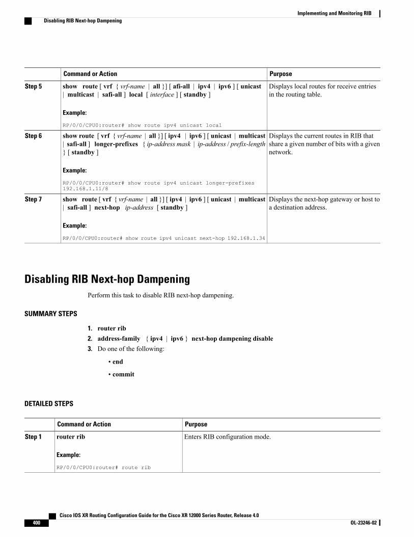
PurposeCommand or Action
Displays local routes for receive entriesin the routing table.
show route [ vrf { vrf-name | all }] [ afi-all | ipv4 | ipv6 ] [ unicast| multicast | safi-all ] local [ interface ] [ standby ]
Example:
RP/0/0/CPU0:router# show route ipv4 unicast local
Step 5
Displays the current routes in RIB thatshare a given number of bits with a givennetwork.
show route [ vrf { vrf-name | all }] [ ipv4 | ipv6 ] [ unicast | multicast| safi-all ] longer-prefixes { ip-address mask | ip-address / prefix-length} [ standby ]
Example:
RP/0/0/CPU0:router# show route ipv4 unicast longer-prefixes192.168.1.11/8
Step 6
Displays the next-hop gateway or host toa destination address.
show route [ vrf { vrf-name | all }] [ ipv4 | ipv6 ] [ unicast | multicast| safi-all ] next-hop ip-address [ standby ]
Example:
RP/0/0/CPU0:router# show route ipv4 unicast next-hop 192.168.1.34
Step 7
Disabling RIB Next-hop DampeningPerform this task to disable RIB next-hop dampening.
SUMMARY STEPS
1. router rib2. address-family { ipv4 | ipv6 } next-hop dampening disable3. Do one of the following:
• end
• commit
DETAILED STEPS
PurposeCommand or Action
Enters RIB configuration mode.router rib
Example:
RP/0/0/CPU0:router# route rib
Step 1
Cisco IOS XR Routing Configuration Guide for the Cisco XR 12000 Series Router, Release 4.0400 OL-23246-02
Implementing and Monitoring RIBDisabling RIB Next-hop Dampening

PurposeCommand or Action
Disables next-hop dampening for IPv4 address families.address-family { ipv4 | ipv6 } next-hopdampening disable
Step 2
Example:
RP/0/0/CPU0:router(config-rib)# addressfamily ipv4 next-hop dampening disable
Saves configuration changes.Do one of the following:Step 3
• end •When you issue the end command, the system prompts you tocommit changes:
Uncommitted changes found, commit them beforeexiting(yes/no/cancel)?[cancel]:
• commit
Example:
RP/0/0/CPU0:router(config-rib)# end◦Entering yes saves configuration changes to the runningconfiguration file, exits the configuration session, and returnsthe router to EXEC mode.
or
RP/0/0/CPU0:router(config-rib)# commit ◦Entering no exits the configuration session and returns therouter to EXEC mode without committing the configurationchanges.
◦Entering cancel leaves the router in the current configurationsession without exiting or committing the configurationchanges.
• Use the commit command to save the configuration changes to therunning configuration file and remain within the configurationsession.
Configuration Examples for RIB MonitoringRIB is not configured separately for the Cisco IOS XR system. RIB computes connectivity of the router withother nodes in the network based on input from the routing protocols. RIB may be used to monitor andtroubleshoot the connections between RIB and its clients, but it is essentially used to monitor routingconnectivity between the nodes in a network. This section contains displays from the show commands usedto monitor that activity.
Output of show route Command: ExampleThe following is sample output from the show route command when entered without an address:
RP/0/0/CPU0:router# show route
Cisco IOS XR Routing Configuration Guide for the Cisco XR 12000 Series Router, Release 4.0 OL-23246-02 401
Implementing and Monitoring RIBConfiguration Examples for RIB Monitoring
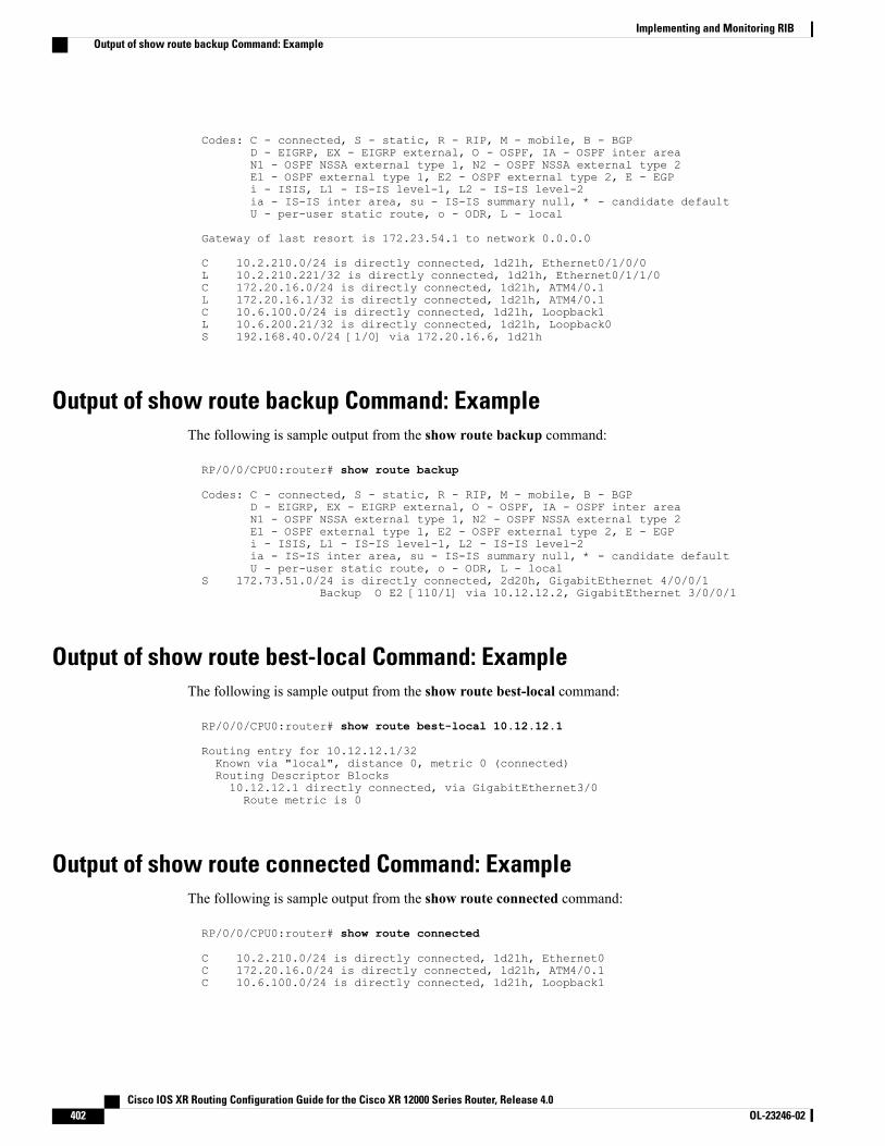
Codes: C - connected, S - static, R - RIP, M - mobile, B - BGPD - EIGRP, EX - EIGRP external, O - OSPF, IA - OSPF inter areaN1 - OSPF NSSA external type 1, N2 - OSPF NSSA external type 2E1 - OSPF external type 1, E2 - OSPF external type 2, E - EGPi - ISIS, L1 - IS-IS level-1, L2 - IS-IS level-2ia - IS-IS inter area, su - IS-IS summary null, * - candidate defaultU - per-user static route, o - ODR, L - local
Gateway of last resort is 172.23.54.1 to network 0.0.0.0
C 10.2.210.0/24 is directly connected, 1d21h, Ethernet0/1/0/0L 10.2.210.221/32 is directly connected, 1d21h, Ethernet0/1/1/0C 172.20.16.0/24 is directly connected, 1d21h, ATM4/0.1L 172.20.16.1/32 is directly connected, 1d21h, ATM4/0.1C 10.6.100.0/24 is directly connected, 1d21h, Loopback1L 10.6.200.21/32 is directly connected, 1d21h, Loopback0S 192.168.40.0/24 [1/0] via 172.20.16.6, 1d21h
Output of show route backup Command: ExampleThe following is sample output from the show route backup command:
RP/0/0/CPU0:router# show route backup
Codes: C - connected, S - static, R - RIP, M - mobile, B - BGPD - EIGRP, EX - EIGRP external, O - OSPF, IA - OSPF inter areaN1 - OSPF NSSA external type 1, N2 - OSPF NSSA external type 2E1 - OSPF external type 1, E2 - OSPF external type 2, E - EGPi - ISIS, L1 - IS-IS level-1, L2 - IS-IS level-2ia - IS-IS inter area, su - IS-IS summary null, * - candidate defaultU - per-user static route, o - ODR, L - local
S 172.73.51.0/24 is directly connected, 2d20h, GigabitEthernet 4/0/0/1Backup O E2 [110/1] via 10.12.12.2, GigabitEthernet 3/0/0/1
Output of show route best-local Command: ExampleThe following is sample output from the show route best-local command:
RP/0/0/CPU0:router# show route best-local 10.12.12.1
Routing entry for 10.12.12.1/32Known via "local", distance 0, metric 0 (connected)Routing Descriptor Blocks10.12.12.1 directly connected, via GigabitEthernet3/0Route metric is 0
Output of show route connected Command: ExampleThe following is sample output from the show route connected command:
RP/0/0/CPU0:router# show route connected
C 10.2.210.0/24 is directly connected, 1d21h, Ethernet0C 172.20.16.0/24 is directly connected, 1d21h, ATM4/0.1C 10.6.100.0/24 is directly connected, 1d21h, Loopback1
Cisco IOS XR Routing Configuration Guide for the Cisco XR 12000 Series Router, Release 4.0402 OL-23246-02
Implementing and Monitoring RIBOutput of show route backup Command: Example
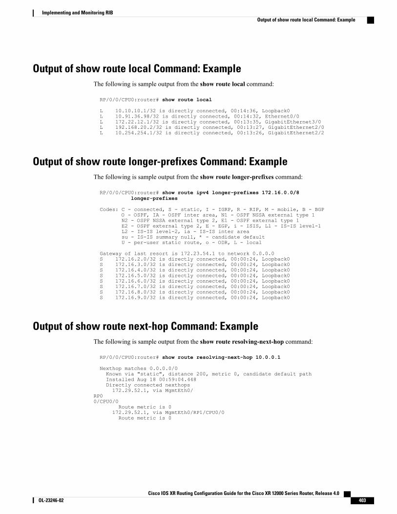
Output of show route local Command: ExampleThe following is sample output from the show route local command:
RP/0/0/CPU0:router# show route local
L 10.10.10.1/32 is directly connected, 00:14:36, Loopback0L 10.91.36.98/32 is directly connected, 00:14:32, Ethernet0/0L 172.22.12.1/32 is directly connected, 00:13:35, GigabitEthernet3/0L 192.168.20.2/32 is directly connected, 00:13:27, GigabitEthernet2/0L 10.254.254.1/32 is directly connected, 00:13:26, GigabitEthernet2/2
Output of show route longer-prefixes Command: ExampleThe following is sample output from the show route longer-prefixes command:
RP/0/0/CPU0:router# show route ipv4 longer-prefixes 172.16.0.0/8longer-prefixes
Codes: C - connected, S - static, I - IGRP, R - RIP, M - mobile, B - BGPO - OSPF, IA - OSPF inter area, N1 - OSPF NSSA external type 1N2 - OSPF NSSA external type 2, E1 - OSPF external type 1E2 - OSPF external type 2, E - EGP, i - ISIS, L1 - IS-IS level-1L2 - IS-IS level-2, ia - IS-IS inter areasu - IS-IS summary null, * - candidate defaultU - per-user static route, o - ODR, L - local
Gateway of last resort is 172.23.54.1 to network 0.0.0.0S 172.16.2.0/32 is directly connected, 00:00:24, Loopback0S 172.16.3.0/32 is directly connected, 00:00:24, Loopback0S 172.16.4.0/32 is directly connected, 00:00:24, Loopback0S 172.16.5.0/32 is directly connected, 00:00:24, Loopback0S 172.16.6.0/32 is directly connected, 00:00:24, Loopback0S 172.16.7.0/32 is directly connected, 00:00:24, Loopback0S 172.16.8.0/32 is directly connected, 00:00:24, Loopback0S 172.16.9.0/32 is directly connected, 00:00:24, Loopback0
Output of show route next-hop Command: ExampleThe following is sample output from the show route resolving-next-hop command:
RP/0/0/CPU0:router# show route resolving-next-hop 10.0.0.1
Nexthop matches 0.0.0.0/0Known via "static", distance 200, metric 0, candidate default pathInstalled Aug 18 00:59:04.448Directly connected nexthops172.29.52.1, via MgmtEth0/
RP00/CPU0/0
Route metric is 0172.29.52.1, via MgmtEth0/RP1/CPU0/0Route metric is 0
Cisco IOS XR Routing Configuration Guide for the Cisco XR 12000 Series Router, Release 4.0 OL-23246-02 403
Implementing and Monitoring RIBOutput of show route local Command: Example

Where to Go NextFor additional information on the protocols that interact with RIB, you may want to see the followingpublications:
• ImplementingMPLS Layer 3 VPNs in Cisco IOS XRMPLSConfigurationGuide for the Cisco XR 12000Series Router
• Implementing BGP in Cisco IOS XR Routing Configuration Guide for the Cisco XR 12000 Series Router
• Implementing EIGRP in Cisco IOS XR Routing Configuration Guide for the Cisco XR 12000 SeriesRouter
• Implementing IS-IS in Cisco IOS XR Routing Configuration Guide for the Cisco XR 12000 SeriesRouter
• Implementing OSPF in Cisco IOS XR Routing Configuration Guide for the Cisco XR 12000 SeriesRouter
• Implementing RIP in Cisco IOS XR Routing Configuration Guide for the Cisco XR 12000 Series Router
• RIB Commands in Cisco IOS XR Routing Command Reference for the Cisco XR 12000 Series Router
Additional ReferencesRelated Documents
Document TitleRelated Topic
RIB Commands on Cisco IOS XR Software inCisco IOS XR Routing Command Reference for theCisco XR 12000 Series Router
Routing Information Base commands: completecommand syntax, commandmodes, command history,defaults, usage guidelines, and examples
Standards and RFCs
TitleStandard/RFC
IP Fast Reroute Framework, by M. Shand and S.Bryant
Draft-ietf-rtgwg-ipfrr-framework-06.txt
A Framework for Loop-free Convergence, by M.Shand and S. Bryant
Draft-ietf-rtgwg-lf-conv-frmwk-00.txt
—No new or modified RFCs are supported by thisfeature, and support for existing RFCs has not beenmodified by this feature.
Cisco IOS XR Routing Configuration Guide for the Cisco XR 12000 Series Router, Release 4.0404 OL-23246-02
Implementing and Monitoring RIBWhere to Go Next
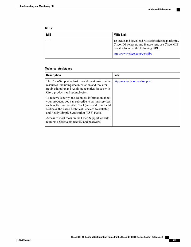
MIBs
MIBs LinkMIB
To locate and downloadMIBs for selected platforms,Cisco IOS releases, and feature sets, use Cisco MIBLocator found at the following URL:
http://www.cisco.com/go/mibs
—
Technical Assistance
LinkDescription
http://www.cisco.com/supportThe Cisco Support website provides extensive onlineresources, including documentation and tools fortroubleshooting and resolving technical issues withCisco products and technologies.
To receive security and technical information aboutyour products, you can subscribe to various services,such as the Product Alert Tool (accessed from FieldNotices), the Cisco Technical Services Newsletter,and Really Simple Syndication (RSS) Feeds.
Access to most tools on the Cisco Support websiterequires a Cisco.com user ID and password.
Cisco IOS XR Routing Configuration Guide for the Cisco XR 12000 Series Router, Release 4.0 OL-23246-02 405
Implementing and Monitoring RIBAdditional References

Cisco IOS XR Routing Configuration Guide for the Cisco XR 12000 Series Router, Release 4.0406 OL-23246-02
Implementing and Monitoring RIBAdditional References
C H A P T E R 6Implementing RIP
The Routing Information Protocol (RIP) is a classic distance vector Interior Gateway Protocol (IGP) designedto exchange information within an autonomous system (AS) of a small network.
This module describes the concepts and tasks to implement basic RIP routing. Cisco IOS XR softwaresupports a standard implementation of RIP Version 2 (RIPv2) that supports backward compatibility withRIP Version 1 (RIPv1) as specified by RFC 2453.
For RIP configuration information related to the following features, see the Related Documents, on page431 section of this module.
• Multiprotocol Label Switching (MPLS) Layer 3 Virtual Private Network (VPN)
• Site of Origin (SoO) Support
For more information about RIP on the Cisco IOS XR software and complete descriptions of the RIPcommands listed in this module, see the Related Documents, on page 431 section of this module. To locatedocumentation for other commands that might appear while performing a configuration task, search onlinein the Cisco IOS XR Commands Master List for the Cisco XR 12000 Series Router.
Note
Feature History for Implementing RIP
ModificationRelease
This feature was introduced.Release 3.3.0
No modification.Release 3.4.0
Four-byte autonomous system (AS) number support was added.Release 3.5.0
No modification.Release 3.6.0
No modification.Release 3.7.0
No modification.Release 3.8.0
Cisco IOS XR Routing Configuration Guide for the Cisco XR 12000 Series Router, Release 4.0 OL-23246-02 407
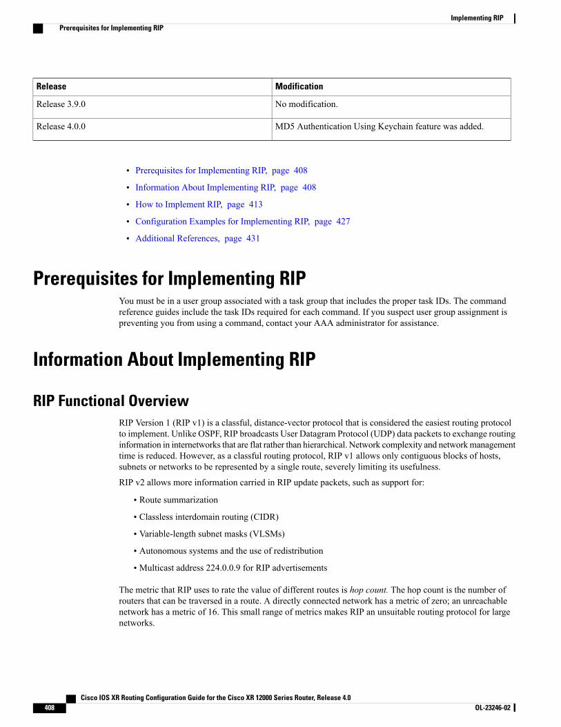
ModificationRelease
No modification.Release 3.9.0
MD5 Authentication Using Keychain feature was added.Release 4.0.0
• Prerequisites for Implementing RIP, page 408
• Information About Implementing RIP, page 408
• How to Implement RIP, page 413
• Configuration Examples for Implementing RIP, page 427
• Additional References, page 431
Prerequisites for Implementing RIPYou must be in a user group associated with a task group that includes the proper task IDs. The commandreference guides include the task IDs required for each command. If you suspect user group assignment ispreventing you from using a command, contact your AAA administrator for assistance.
Information About Implementing RIP
RIP Functional OverviewRIP Version 1 (RIP v1) is a classful, distance-vector protocol that is considered the easiest routing protocolto implement. Unlike OSPF, RIP broadcasts User Datagram Protocol (UDP) data packets to exchange routinginformation in internetworks that are flat rather than hierarchical. Network complexity and networkmanagementtime is reduced. However, as a classful routing protocol, RIP v1 allows only contiguous blocks of hosts,subnets or networks to be represented by a single route, severely limiting its usefulness.
RIP v2 allows more information carried in RIP update packets, such as support for:
• Route summarization
• Classless interdomain routing (CIDR)
• Variable-length subnet masks (VLSMs)
• Autonomous systems and the use of redistribution
• Multicast address 224.0.0.9 for RIP advertisements
The metric that RIP uses to rate the value of different routes is hop count. The hop count is the number ofrouters that can be traversed in a route. A directly connected network has a metric of zero; an unreachablenetwork has a metric of 16. This small range of metrics makes RIP an unsuitable routing protocol for largenetworks.
Cisco IOS XR Routing Configuration Guide for the Cisco XR 12000 Series Router, Release 4.0408 OL-23246-02
Implementing RIPPrerequisites for Implementing RIP
Routing information updates are advertised every 30 seconds by default, and new updates discovered fromneighbor routers are stored in a routing table.
Only RIP Version 2 (RIP v2), as specified in RFC 2453, is supported on Cisco IOS XR software and, bydefault, the software only sends and receives RIP v2 packets. However, you can configure the software tosend, or receive, or both, only Version 1 packets or only Version 2 packets or both version type packets perinterface.
Here are some good reasons to use RIP:
• Compatible with diverse network devices
• Best for small networks, because there is very little overhead, in terms of bandwidth used, configuration,and management time
• Support for legacy host systems
Because of RIP’s ease of use, it is implemented in networks worldwide.
Split Horizon for RIPNormally, routers that are connected to broadcast-type IP networks and that use distance-vector routingprotocols employ the split horizonmechanism to reduce the possibility of routing loops. Split horizon blocksinformation about routes from being advertised by a router out of any interface from which that informationoriginated. This behavior usually optimizes communications among multiple routers, particularly when linksare broken.
If an interface is configured with secondary IP addresses and split horizon is enabled, updates might not besourced by every secondary address. One routing update is sourced per network number unless split horizonis disabled.
The split horizon feature is enabled by default. In general, we recommend that you do not change thedefault state of split horizon unless you are certain that your operation requires the change in order toproperly advertise routes.
Note
Route Timers for RIPRIP uses several timers that determine such variables as the frequency of routing updates, the length of timebefore a route becomes invalid, and other parameters. You can adjust these timers to tune routing protocolperformance to better suit your internetwork needs, by making the following timer adjustments to:
• The rate (time in seconds between updates) at which routing updates are sent
• The interval of time (in seconds) after which a route is declared invalid
• The interval (in seconds) during which routing information regarding better paths is suppressed
• The amount of time (in seconds) that must pass before a route is removed from the RIP topology table
• The amount of time delay between RIP update packets
Cisco IOS XR Routing Configuration Guide for the Cisco XR 12000 Series Router, Release 4.0 OL-23246-02 409
Implementing RIPSplit Horizon for RIP
The first four timer adjustments are configurable by the timers basic command. The output-delay commandchanges the amount of time delay between RIP update packets. See Customizing RIP, on page 416 forconfiguration details.
It also is possible to tune the IP routing support in the software to enable faster convergence of the various IProuting algorithms and quickly drop back to redundant routers, if necessary. The total result is to minimizedisruptions to end users of the network in situations in which quick recovery is essential.
Route Redistribution for RIPRedistribution is a feature that allows different routing domains, to exchange routing information. Networkingdevices that route between different routing domains are called boundary routers, and it is these devices thatinject the routes from one routing protocol into another. Routers within a routing domain only have knowledgeof routes internal to the domain unless route redistribution is implemented on the boundary routers.
When running RIP in your routing domain, you might find it necessary to use multiple routing protocolswithin your internetwork and redistribute routes between them. Some common reasons are:
• To advertise routes from other protocols into RIP, such as static, connected, OSPF, and BGP.
• To migrate from RIP to a new Interior Gateway Protocol (IGP) such as EIGRP.
• To retain routing protocol on some routers to support host systems, but upgrade routers for otherdepartment groups.
• To communicate among a mixed-router vendor environment. Basically, you might use a protocol specificto Cisco in one portion of your network and use RIP to communicate with devices other than Ciscodevices.
Further, route redistribution gives a company the ability to run different routing protocols in work groups orareas in which each is particularly effective. By not restricting customers to using only a single routing protocol,Cisco IOS XR route redistribution is a powerful feature that minimizes cost, while maximizing technicaladvantage through diversity.
When it comes to implementing route redistribution in your internetwork, it can be very simple or verycomplex. An example of a simple one-way redistribution is to log into a router on which RIP is enabled anduse the redistribute static command to advertise only the static connections to the backbone network to passthrough the RIP network. For complex cases in which you must consider routing loops, incompatible routinginformation, and inconsistent convergence time, you must determine why these problems occur by examininghow Cisco routers select the best path when more than one routing protocol is running administrative cost.
Default Administrative Distances for RIPAdministrative distance is used as a measure of the trustworthiness of the source of the IP routing information.When a dynamic routing protocol such as RIP is configured, and you want to use the redistribution featureto exchange routing information, it is important to know the default administrative distances for other routesources so that you can set the appropriate distance weight.
This table lists the Default Administrative Distances of Routing Protocols.
Cisco IOS XR Routing Configuration Guide for the Cisco XR 12000 Series Router, Release 4.0410 OL-23246-02
Implementing RIPRoute Redistribution for RIP
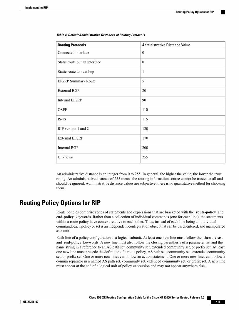
Table 4: Default Administrative Distances of Routing Protocols
Administrative Distance ValueRouting Protocols
0Connected interface
0Static route out an interface
1Static route to next hop
5EIGRP Summary Route
20External BGP
90Internal EIGRP
110OSPF
115IS-IS
120RIP version 1 and 2
170External EIGRP
200Internal BGP
255Unknown
An administrative distance is an integer from 0 to 255. In general, the higher the value, the lower the trustrating. An administrative distance of 255 means the routing information source cannot be trusted at all andshould be ignored. Administrative distance values are subjective; there is no quantitative method for choosingthem.
Routing Policy Options for RIPRoute policies comprise series of statements and expressions that are bracketed with the route-policy andend-policy keywords. Rather than a collection of individual commands (one for each line), the statementswithin a route policy have context relative to each other. Thus, instead of each line being an individualcommand, each policy or set is an independent configuration object that can be used, entered, andmanipulatedas a unit.
Each line of a policy configuration is a logical subunit. At least one new line must follow the then , else ,and end-policy keywords. A new line must also follow the closing parenthesis of a parameter list and thename string in a reference to an AS path set, community set, extended community set, or prefix set. At leastone new line must precede the definition of a route policy, AS path set, community set, extended communityset, or prefix set. One or more new lines can follow an action statement. One or more new lines can follow acomma separator in a named AS path set, community set, extended community set, or prefix set. A new linemust appear at the end of a logical unit of policy expression and may not appear anywhere else.
Cisco IOS XR Routing Configuration Guide for the Cisco XR 12000 Series Router, Release 4.0 OL-23246-02 411
Implementing RIPRouting Policy Options for RIP
Authentication Using Keychain in RIPAuthentication using keychain in Cisco IOS XR Routing Information Protocol (RIP) provides mechanism toauthenticate all RIP protocol traffic on RIP interface, based keychain authentication. This mechanism usesthe Cisco IOS XR security keychain infrastructure to store and retrieve secret keys and use it to authenticatein-bound and out-going traffic on per-interface basis.
Keychain management is a common method of authentication to configure shared secrets on all entities thatexchange secrets such as keys, before establishing trust with each other. Routing protocols and networkmanagement applications on Cisco IOS XR software often use authentication to enhance security whilecommunicating with peers.
The Cisco IOS XR software system security component implements various system security featuresincluding keychain management. Refer these documents for detailed information on keychain managementconcepts, configuration tasks, examples, and command used to configure keychain management.
Tip
• Implementing KeychainManagementmodule in Cisco IOS XR System Security Configuration Guidefor the Cisco XR 12000 Series Router
• Keychain Management Commands module in Cisco IOS XR System Security Command Referencefor the Cisco XR 12000 Series Router
The keychain by itself has no relevance; therefore, it must be used by an application that needs tocommunicate by using the keys (for authentication) with its peers. The keychain provides a securemechanism to handle the keys and rollover based on the lifetime. The Cisco IOSXR keychain infrastructuretakes care of the hit-less rollover of the secret keys in the keychain.
Note
Once you have configured a keychain in the IOS XR keychain database and if the same has been configuredon a particular RIP interface, it will be used for authenticating all incoming and outgoing RIP traffic on thatinterface. Unless an authentication keychain is configured on a RIP interface (on the default VRF or anon-default VRF), all RIP traffic will be assumed to be authentic and authentication mechanisms for in-boundRIP traffic and out-bound RIP traffic will be not be employed to secure it.
RIP employs two modes of authentication: keyed message digest mode and clear text mode. Use theauthentication keychain keychain-namemode {md5 | text} command to configure authentication using thekeychain mechanism.
In cases where a keychain has been configured on RIP interface but the keychain is actually not configuredin the keychain database or keychain is not configured with MD5 cryptographic algorithm, all incoming RIPpackets on the interface will be dropped. Outgoing packets will be sent without any authentication data.
In-bound RIP Traffic on an InterfaceThese are the verification criteria for all in-bound RIP packets on a RIP interface when the interface isconfigured with a keychain.
Cisco IOS XR Routing Configuration Guide for the Cisco XR 12000 Series Router, Release 4.0412 OL-23246-02
Implementing RIPAuthentication Using Keychain in RIP
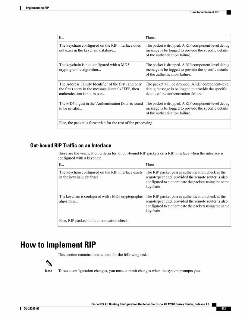
Then...If...
The packet is dropped. A RIP component-level debugmessage is be logged to provide the specific detailsof the authentication failure.
The keychain configured on the RIP interface doesnot exist in the keychain database...
The packet is dropped. A RIP component-level debugmessage is be logged to provide the specific detailsof the authentication failure.
The keychain is not configured with a MD5cryptographic algorithm...
The packet will be dropped. A RIP component-leveldebug message is be logged to provide the specificdetails of the authentication failure.
The Address Family Identifier of the first (and onlythe first) entry in the message is not 0xFFFF, thenauthentication is not in use...
The packet is dropped. A RIP component-level debugmessage is be logged to provide the specific detailsof the authentication failure.
TheMD5 digest in the ‘Authentication Data’ is foundto be invalid...
Else, the packet is forwarded for the rest of the processing.
Out-bound RIP Traffic on an InterfaceThese are the verification criteria for all out-bound RIP packets on a RIP interface when the interface isconfigured with a keychain.
ThenIf...
The RIP packet passes authentication check at theremote/peer end, provided the remote router is alsoconfigured to authenticate the packets using the samekeychain.
The keychain configured on the RIP interface existsin the keychain database ...
The RIP packet passes authentication check at theremote/peer end, provided the remote router is alsoconfigured to authenticate the packets using the samekeychain.
The keychain is configuredwith aMD5 cryptographicalgorithm...
Else, RIP packets fail authentication check.
How to Implement RIPThis section contains instructions for the following tasks:
To save configuration changes, you must commit changes when the system prompts you.Note
Cisco IOS XR Routing Configuration Guide for the Cisco XR 12000 Series Router, Release 4.0 OL-23246-02 413
Implementing RIPHow to Implement RIP

Enabling RIPThis task enables RIP routing and establishes a RIP routing process.
Before You Begin
Although you can configure RIP before you configure an IP address, no RIP routing occurs until at least oneIP address is configured.
SUMMARY STEPS
1. configure2. router rip3. neighbor ip-address4. broadcast-for-v25. interface type interface-path-id6. receive version { 1 | 2 | 1 2 }7. send version { 1 | 2 | 1 2 }8. Do one of the following:
• end
• commit
DETAILED STEPS
PurposeCommand or Action
Enters global configuration mode.configure
Example:
RP/0/0/CPU0:router# configure
Step 1
Configures a RIP routing process.router rip
Example:
RP/0/0/CPU0:router(config)# router rip
Step 2
(Optional) Defines a neighboring router with which to exchange RIPprotocol information.
neighbor ip-address
Example:
RP/0/0/CPU0:router(config-rip)# neighbor172.160.1.2
Step 3
Cisco IOS XR Routing Configuration Guide for the Cisco XR 12000 Series Router, Release 4.0414 OL-23246-02
Implementing RIPEnabling RIP
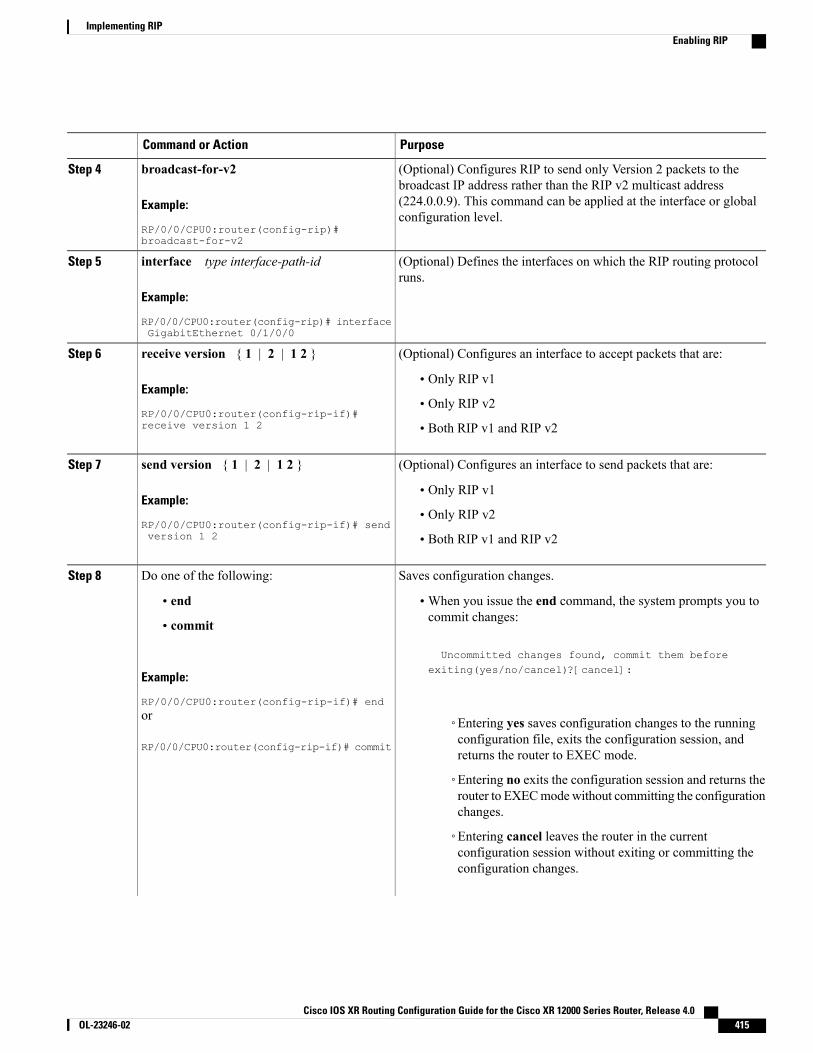
PurposeCommand or Action
(Optional) Configures RIP to send only Version 2 packets to thebroadcast IP address rather than the RIP v2 multicast address
broadcast-for-v2
Example:
RP/0/0/CPU0:router(config-rip)#broadcast-for-v2
Step 4
(224.0.0.9). This command can be applied at the interface or globalconfiguration level.
(Optional) Defines the interfaces on which the RIP routing protocolruns.
interface type interface-path-id
Example:
RP/0/0/CPU0:router(config-rip)# interfaceGigabitEthernet 0/1/0/0
Step 5
(Optional) Configures an interface to accept packets that are:receive version { 1 | 2 | 1 2 }Step 6
Example:
RP/0/0/CPU0:router(config-rip-if)#receive version 1 2
• Only RIP v1
• Only RIP v2
• Both RIP v1 and RIP v2
(Optional) Configures an interface to send packets that are:send version { 1 | 2 | 1 2 }Step 7
Example:
RP/0/0/CPU0:router(config-rip-if)# sendversion 1 2
• Only RIP v1
• Only RIP v2
• Both RIP v1 and RIP v2
Saves configuration changes.Do one of the following:Step 8
• end •When you issue the end command, the system prompts you tocommit changes:
Uncommitted changes found, commit them before
• commit
Example:
RP/0/0/CPU0:router(config-rip-if)# end
exiting(yes/no/cancel)?[cancel]:
or
RP/0/0/CPU0:router(config-rip-if)# commit
◦Entering yes saves configuration changes to the runningconfiguration file, exits the configuration session, andreturns the router to EXEC mode.
◦Entering no exits the configuration session and returns therouter to EXECmodewithout committing the configurationchanges.
◦Entering cancel leaves the router in the currentconfiguration session without exiting or committing theconfiguration changes.
Cisco IOS XR Routing Configuration Guide for the Cisco XR 12000 Series Router, Release 4.0 OL-23246-02 415
Implementing RIPEnabling RIP
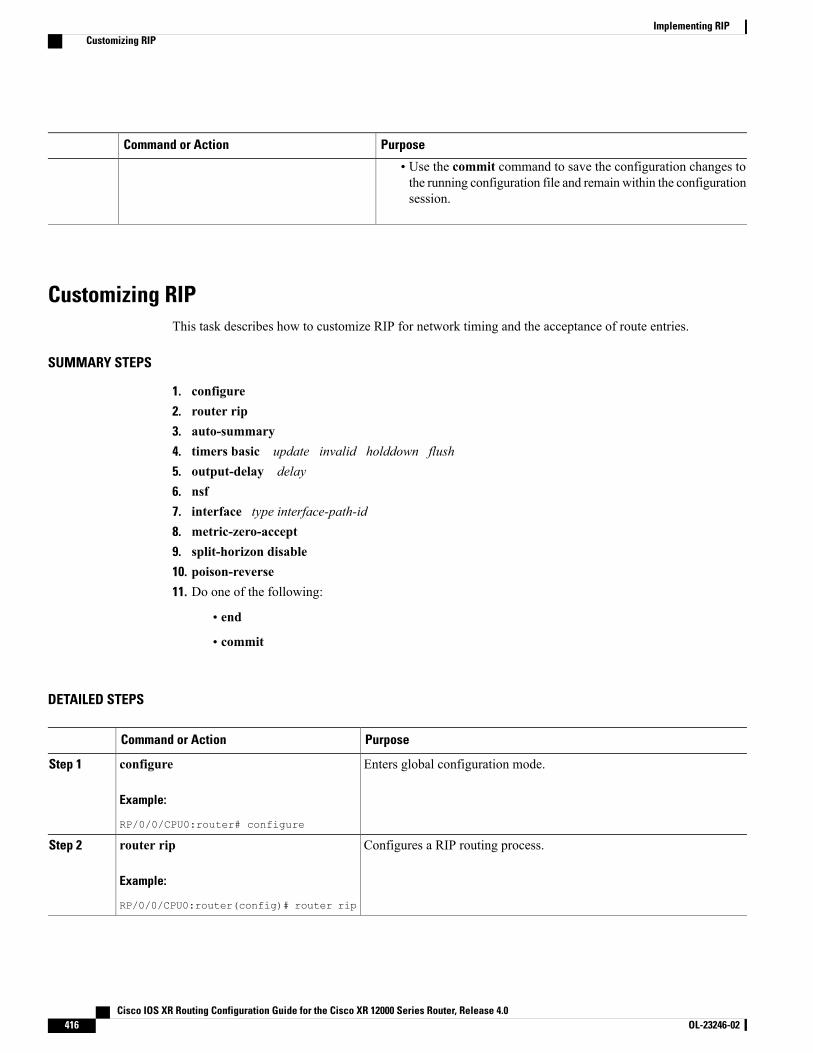
PurposeCommand or Action
• Use the commit command to save the configuration changes tothe running configuration file and remain within the configurationsession.
Customizing RIPThis task describes how to customize RIP for network timing and the acceptance of route entries.
SUMMARY STEPS
1. configure2. router rip3. auto-summary4. timers basic update invalid holddown flush5. output-delay delay6. nsf7. interface type interface-path-id8. metric-zero-accept9. split-horizon disable10. poison-reverse11. Do one of the following:
• end
• commit
DETAILED STEPS
PurposeCommand or Action
Enters global configuration mode.configure
Example:
RP/0/0/CPU0:router# configure
Step 1
Configures a RIP routing process.router rip
Example:
RP/0/0/CPU0:router(config)# router rip
Step 2
Cisco IOS XR Routing Configuration Guide for the Cisco XR 12000 Series Router, Release 4.0416 OL-23246-02
Implementing RIPCustomizing RIP
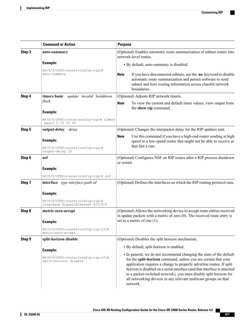
PurposeCommand or Action
(Optional) Enables automatic route summarization of subnet routes intonetwork-level routes.
auto-summary
Example:
RP/0/0/CPU0:router(config-rip)#auto-summary
Step 3
• By default, auto-summary is disabled.
If you have disconnected subnets, use the no keyword to disableautomatic route summarization and permit software to sendsubnet and host routing information across classful networkboundaries.
Note
(Optional) Adjusts RIP network timers.timers basic update invalid holddownflush
Step 4
To view the current and default timer values, view output fromthe show rip command.
Note
Example:
RP/0/0/CPU0:router(config-rip)# timersbasic 5 15 15 30
(Optional) Changes the interpacket delay for the RIP updates sent.output-delay delayStep 5
Example:
RP/0/0/CPU0:router(config-rip)#output-delay 10
Use this command if you have a high-end router sending at highspeed to a low-speed router that might not be able to receive atthat fast a rate.
Note
(Optional) Configures NSF on RIP routes after a RIP process shutdownor restart.
nsf
Example:
RP/0/0/CPU0:router(config-rip)# nsf
Step 6
(Optional) Defines the interfaces on which the RIP routing protocol runs.interface type interface-path-id
Example:
RP/0/0/CPU0:router(config-rip)#interface GigabitEthernet 0/1/0/0
Step 7
(Optional) Allows the networking device to accept route entries receivedin update packets with a metric of zero (0). The received route entry isset to a metric of one (1).
metric-zero-accept
Example:
RP/0/0/CPU0:router(config-rip-if)#metro-zero-accept
Step 8
(Optional) Disables the split horizon mechanism.split-horizon disableStep 9
Example:
RP/0/0/CPU0:router(config-rip-if)#split-horizon disable
• By default, split horizon is enabled.
• In general, we do not recommend changing the state of the defaultfor the split-horizon command, unless you are certain that yourapplication requires a change to properly advertise routes. If splithorizon is disabled on a serial interface (and that interface is attachedto a packet-switched network), you must disable split horizon forall networking devices in any relevant multicast groups on thatnetwork.
Cisco IOS XR Routing Configuration Guide for the Cisco XR 12000 Series Router, Release 4.0 OL-23246-02 417
Implementing RIPCustomizing RIP
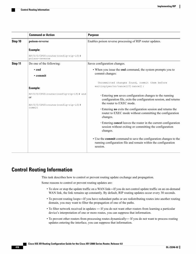
PurposeCommand or Action
Enables poison reverse processing of RIP router updates.poison-reverse
Example:
RP/0/0/CPU0:router(config-rip-if)#poison-reverse
Step 10
Saves configuration changes.Do one of the following:Step 11
• end •When you issue the end command, the system prompts you tocommit changes:
Uncommitted changes found, commit them before
• commit
Example:
RP/0/0/CPU0:router(config-rip-if)# end
exiting(yes/no/cancel)?[cancel]:
◦Entering yes saves configuration changes to the runningconfiguration file, exits the configuration session, and returnsthe router to EXEC mode.
or
RP/0/0/CPU0:router(config-rip-if)#commit ◦Entering no exits the configuration session and returns the
router to EXEC mode without committing the configurationchanges.
◦Entering cancel leaves the router in the current configurationsession without exiting or committing the configurationchanges.
• Use the commit command to save the configuration changes to therunning configuration file and remain within the configurationsession.
Control Routing InformationThis task describes how to control or prevent routing update exchange and propagation.
Some reasons to control or prevent routing updates are:
• To slow or stop the update traffic on a WAN link—If you do not control update traffic on an on-demandWAN link, the link remains up constantly. By default, RIP routing updates occur every 30 seconds.
• To prevent routing loops—If you have redundant paths or are redistributing routes into another routingdomain, you may want to filter the propagation of one of the paths.
• To filter network received in updates— If you do not want other routers from learning a particulardevice’s interpretation of one or more routes, you can suppress that information.
• To prevent other routers from processing routes dynamically— If you do not want to process routingupdates entering the interface, you can suppress that information.
Cisco IOS XR Routing Configuration Guide for the Cisco XR 12000 Series Router, Release 4.0418 OL-23246-02
Implementing RIPControl Routing Information
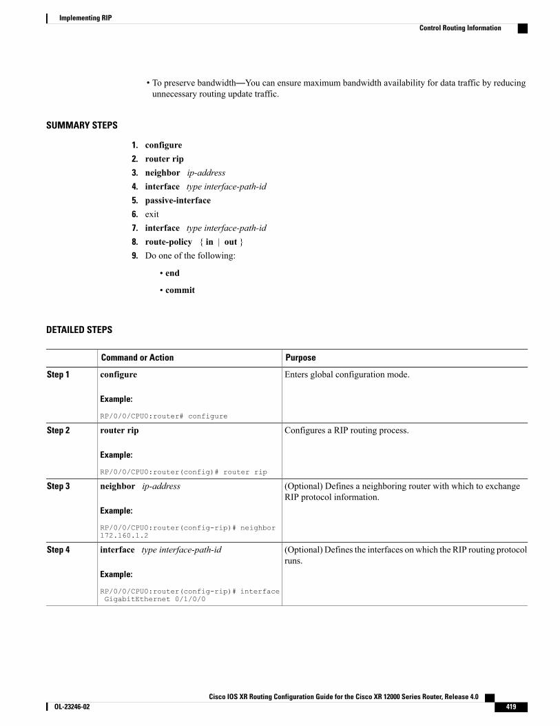
• To preserve bandwidth—You can ensure maximum bandwidth availability for data traffic by reducingunnecessary routing update traffic.
SUMMARY STEPS
1. configure2. router rip3. neighbor ip-address4. interface type interface-path-id5. passive-interface6. exit7. interface type interface-path-id8. route-policy { in | out }9. Do one of the following:
• end
• commit
DETAILED STEPS
PurposeCommand or Action
Enters global configuration mode.configure
Example:
RP/0/0/CPU0:router# configure
Step 1
Configures a RIP routing process.router rip
Example:
RP/0/0/CPU0:router(config)# router rip
Step 2
(Optional) Defines a neighboring router with which to exchangeRIP protocol information.
neighbor ip-address
Example:
RP/0/0/CPU0:router(config-rip)# neighbor172.160.1.2
Step 3
(Optional) Defines the interfaces on which the RIP routing protocolruns.
interface type interface-path-id
Example:
RP/0/0/CPU0:router(config-rip)# interfaceGigabitEthernet 0/1/0/0
Step 4
Cisco IOS XR Routing Configuration Guide for the Cisco XR 12000 Series Router, Release 4.0 OL-23246-02 419
Implementing RIPControl Routing Information
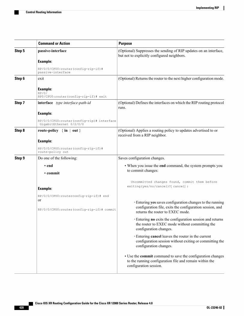
PurposeCommand or Action
(Optional) Suppresses the sending of RIP updates on an interface,but not to explicitly configured neighbors.
passive-interface
Example:
RP/0/0/CPU0:router(config-rip-if)#passive-interface
Step 5
(Optional) Returns the router to the next higher configuration mode.exit
Example:RP/0/RP0/CPU0:router(config-rip-if)# exit
Step 6
(Optional) Defines the interfaces on which the RIP routing protocolruns.
interface type interface-path-id
Example:
RP/0/0/CPU0:router(config-rip)# interfaceGigabitEthernet 0/2/0/0
Step 7
(Optional) Applies a routing policy to updates advertised to orreceived from a RIP neighbor.
route-policy { in | out }
Example:
RP/0/0/CPU0:router(config-rip-if)#route-policy out
Step 8
Saves configuration changes.Do one of the following:Step 9
• end •When you issue the end command, the system prompts youto commit changes:
Uncommitted changes found, commit them before
• commit
Example:
RP/0/0/CPU0:routerconfig-rip-if)# end
exiting(yes/no/cancel)?[cancel]:
or
RP/0/0/CPU0:router(config-rip-if)# commit
◦Entering yes saves configuration changes to the runningconfiguration file, exits the configuration session, andreturns the router to EXEC mode.
◦Entering no exits the configuration session and returnsthe router to EXEC mode without committing theconfiguration changes.
◦Entering cancel leaves the router in the currentconfiguration session without exiting or committing theconfiguration changes.
• Use the commit command to save the configuration changesto the running configuration file and remain within theconfiguration session.
Cisco IOS XR Routing Configuration Guide for the Cisco XR 12000 Series Router, Release 4.0420 OL-23246-02
Implementing RIPControl Routing Information
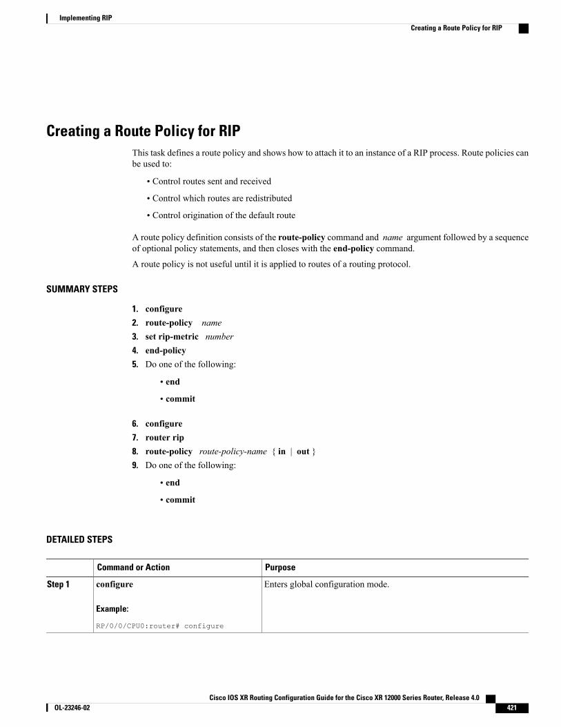
Creating a Route Policy for RIPThis task defines a route policy and shows how to attach it to an instance of a RIP process. Route policies canbe used to:
• Control routes sent and received
• Control which routes are redistributed
• Control origination of the default route
A route policy definition consists of the route-policy command and name argument followed by a sequenceof optional policy statements, and then closes with the end-policy command.
A route policy is not useful until it is applied to routes of a routing protocol.
SUMMARY STEPS
1. configure2. route-policy name3. set rip-metric number4. end-policy5. Do one of the following:
• end
• commit
6. configure7. router rip8. route-policy route-policy-name { in | out }9. Do one of the following:
• end
• commit
DETAILED STEPS
PurposeCommand or Action
Enters global configuration mode.configure
Example:
RP/0/0/CPU0:router# configure
Step 1
Cisco IOS XR Routing Configuration Guide for the Cisco XR 12000 Series Router, Release 4.0 OL-23246-02 421
Implementing RIPCreating a Route Policy for RIP
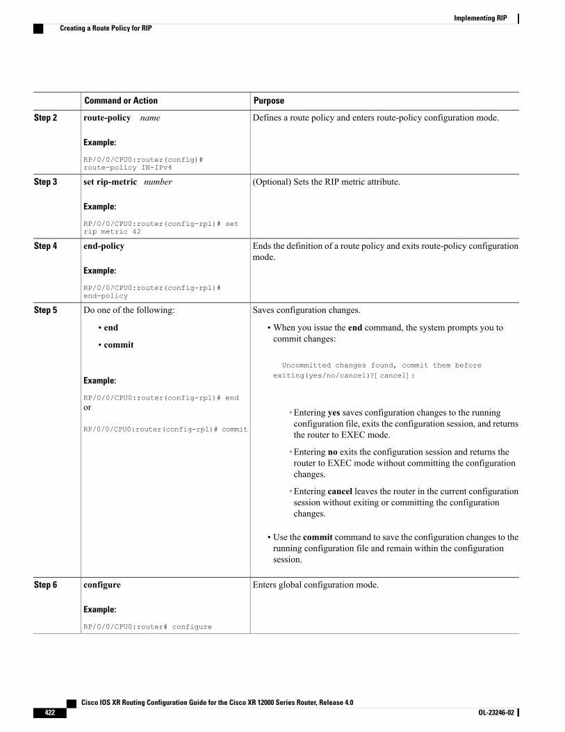
PurposeCommand or Action
Defines a route policy and enters route-policy configuration mode.route-policy name
Example:
RP/0/0/CPU0:router(config)#route-policy IN-IPv4
Step 2
(Optional) Sets the RIP metric attribute.set rip-metric number
Example:
RP/0/0/CPU0:router(config-rpl)# setrip metric 42
Step 3
Ends the definition of a route policy and exits route-policy configurationmode.
end-policy
Example:
RP/0/0/CPU0:router(config-rpl)#end-policy
Step 4
Saves configuration changes.Do one of the following:Step 5
• end •When you issue the end command, the system prompts you tocommit changes:
Uncommitted changes found, commit them before
• commit
Example:
RP/0/0/CPU0:router(config-rpl)# end
exiting(yes/no/cancel)?[cancel]:
or
RP/0/0/CPU0:router(config-rpl)# commit
◦Entering yes saves configuration changes to the runningconfiguration file, exits the configuration session, and returnsthe router to EXEC mode.
◦Entering no exits the configuration session and returns therouter to EXEC mode without committing the configurationchanges.
◦Entering cancel leaves the router in the current configurationsession without exiting or committing the configurationchanges.
• Use the commit command to save the configuration changes to therunning configuration file and remain within the configurationsession.
Enters global configuration mode.configure
Example:
RP/0/0/CPU0:router# configure
Step 6
Cisco IOS XR Routing Configuration Guide for the Cisco XR 12000 Series Router, Release 4.0422 OL-23246-02
Implementing RIPCreating a Route Policy for RIP
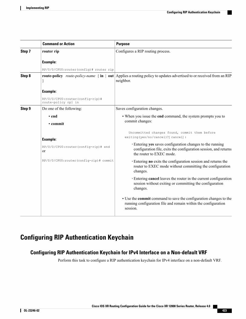
PurposeCommand or Action
Configures a RIP routing process.router rip
Example:
RP/0/0/CPU0:router(config)# router rip
Step 7
Applies a routing policy to updates advertised to or received from an RIPneighbor.
route-policy route-policy-name { in | out}
Example:
RP/0/0/CPU0:router(config-rip)#route-policy rp1 in
Step 8
Saves configuration changes.Do one of the following:Step 9
• end •When you issue the end command, the system prompts you tocommit changes:
Uncommitted changes found, commit them beforeexiting(yes/no/cancel)?[cancel]:
• commit
Example:
RP/0/0/CPU0:router(config-rip)# end◦Entering yes saves configuration changes to the runningconfiguration file, exits the configuration session, and returnsthe router to EXEC mode.
or
RP/0/0/CPU0:router(config-rip)# commit ◦Entering no exits the configuration session and returns therouter to EXEC mode without committing the configurationchanges.
◦Entering cancel leaves the router in the current configurationsession without exiting or committing the configurationchanges.
• Use the commit command to save the configuration changes to therunning configuration file and remain within the configurationsession.
Configuring RIP Authentication Keychain
Configuring RIP Authentication Keychain for IPv4 Interface on a Non-default VRFPerform this task to configure a RIP authentication keychain for IPv4 interface on a non-default VRF.
Cisco IOS XR Routing Configuration Guide for the Cisco XR 12000 Series Router, Release 4.0 OL-23246-02 423
Implementing RIPConfiguring RIP Authentication Keychain
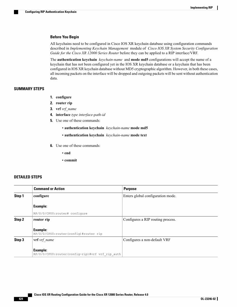
Before You Begin
All keychains need to be configured in Cisco IOS XR keychain database using configuration commandsdescribed in Implementing Keychain Management module of Cisco IOS XR System Security ConfigurationGuide for the Cisco XR 12000 Series Router before they can be applied to a RIP interface/VRF.
The authentication keychain keychain-name andmode md5 configurations will accept the name of akeychain that has not been configured yet in the IOS XR keychain database or a keychain that has beenconfigured in IOSXR keychain database withoutMD5 cryptographic algorithm. However, in both these cases,all incoming packets on the interface will be dropped and outgoing packets will be sent without authenticationdata.
SUMMARY STEPS
1. configure2. router rip3. vrf vrf_name4. interface type interface-path-id5. Use one of these commands:
• authentication keychain keychain-namemode md5
• authentication keychain keychain-namemode text
6. Use one of these commands:
• end
• commit
DETAILED STEPS
PurposeCommand or Action
Enters global configuration mode.configure
Example:
RP/0/0/CPU0:router# configure
Step 1
Configures a RIP routing process.router rip
Example:RP/0/0/CPU0:router(config)#router rip
Step 2
Configures a non-default VRFvrf vrf_name
Example:RP/0/0/CPU0:router(config-rip)#vrf vrf_rip_auth
Step 3
Cisco IOS XR Routing Configuration Guide for the Cisco XR 12000 Series Router, Release 4.0424 OL-23246-02
Implementing RIPConfiguring RIP Authentication Keychain
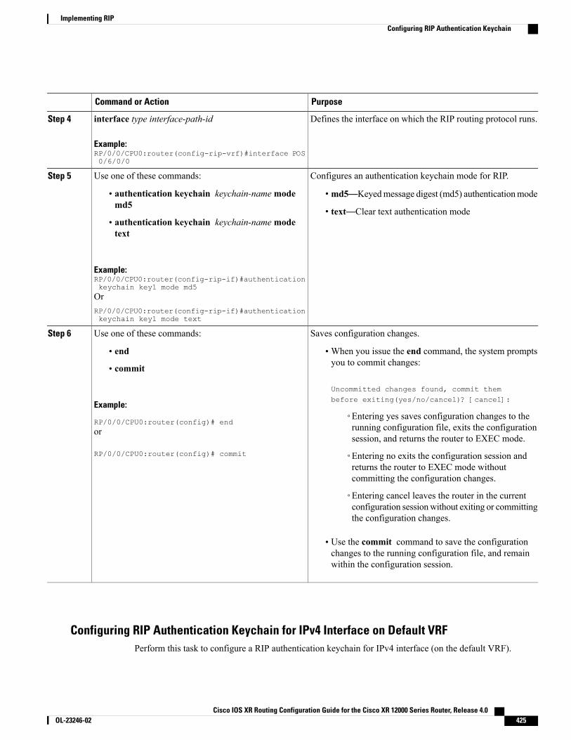
PurposeCommand or Action
Defines the interface on which the RIP routing protocol runs.interface type interface-path-id
Example:RP/0/0/CPU0:router(config-rip-vrf)#interface POS0/6/0/0
Step 4
Configures an authentication keychain mode for RIP.Use one of these commands:Step 5
• md5—Keyedmessage digest (md5) authenticationmode• authentication keychain keychain-namemodemd5
• text—Clear text authentication mode• authentication keychain keychain-namemodetext
Example:RP/0/0/CPU0:router(config-rip-if)#authenticationkeychain key1 mode md5OrRP/0/0/CPU0:router(config-rip-if)#authenticationkeychain key1 mode text
Saves configuration changes.Use one of these commands:Step 6
• end •When you issue the end command, the system promptsyou to commit changes:
Uncommitted changes found, commit thembefore exiting(yes/no/cancel)? [cancel]:
• commit
Example:
RP/0/0/CPU0:router(config)# end◦Entering yes saves configuration changes to therunning configuration file, exits the configurationsession, and returns the router to EXEC mode.
or
RP/0/0/CPU0:router(config)# commit ◦Entering no exits the configuration session andreturns the router to EXEC mode withoutcommitting the configuration changes.
◦Entering cancel leaves the router in the currentconfiguration sessionwithout exiting or committingthe configuration changes.
• Use the commit command to save the configurationchanges to the running configuration file, and remainwithin the configuration session.
Configuring RIP Authentication Keychain for IPv4 Interface on Default VRFPerform this task to configure a RIP authentication keychain for IPv4 interface (on the default VRF).
Cisco IOS XR Routing Configuration Guide for the Cisco XR 12000 Series Router, Release 4.0 OL-23246-02 425
Implementing RIPConfiguring RIP Authentication Keychain
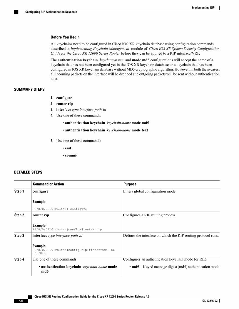
Before You Begin
All keychains need to be configured in Cisco IOS XR keychain database using configuration commandsdescribed in Implementing Keychain Management module of Cisco IOS XR System Security ConfigurationGuide for the Cisco XR 12000 Series Router before they can be applied to a RIP interface/VRF.
The authentication keychain keychain-name andmode md5 configurations will accept the name of akeychain that has not been configured yet in the IOS XR keychain database or a keychain that has beenconfigured in IOSXR keychain database withoutMD5 cryptographic algorithm. However, in both these cases,all incoming packets on the interface will be dropped and outgoing packets will be sent without authenticationdata.
SUMMARY STEPS
1. configure2. router rip3. interface type interface-path-id4. Use one of these commands:
• authentication keychain keychain-namemode md5
• authentication keychain keychain-namemode text
5. Use one of these commands:
• end
• commit
DETAILED STEPS
PurposeCommand or Action
Enters global configuration mode.configure
Example:
RP/0/0/CPU0:router# configure
Step 1
Configures a RIP routing process.router ripStep 2
Example:RP/0/0/CPU0:router(config)#router rip
Defines the interface on which the RIP routing protocol runs.interface type interface-path-id
Example:RP/0/0/CPU0:router(config-rip)#interface POS0/6/0/0
Step 3
Configures an authentication keychain mode for RIP.Use one of these commands:Step 4
• md5—Keyedmessage digest (md5) authenticationmode• authentication keychain keychain-namemodemd5
Cisco IOS XR Routing Configuration Guide for the Cisco XR 12000 Series Router, Release 4.0426 OL-23246-02
Implementing RIPConfiguring RIP Authentication Keychain
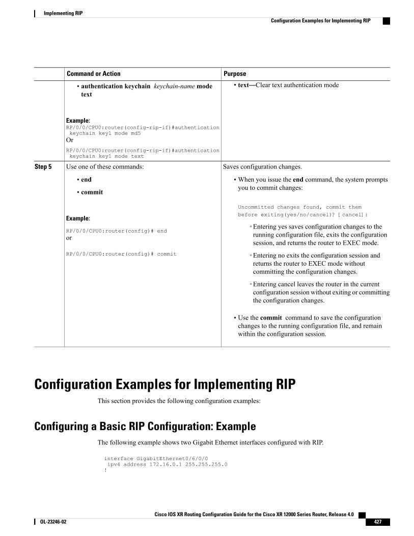
PurposeCommand or Action
• text—Clear text authentication mode• authentication keychain keychain-namemodetext
Example:RP/0/0/CPU0:router(config-rip-if)#authenticationkeychain key1 mode md5OrRP/0/0/CPU0:router(config-rip-if)#authenticationkeychain key1 mode text
Saves configuration changes.Use one of these commands:Step 5
• end •When you issue the end command, the system promptsyou to commit changes:
Uncommitted changes found, commit thembefore exiting(yes/no/cancel)? [cancel]:
• commit
Example:
RP/0/0/CPU0:router(config)# end◦Entering yes saves configuration changes to therunning configuration file, exits the configurationsession, and returns the router to EXEC mode.
or
RP/0/0/CPU0:router(config)# commit ◦Entering no exits the configuration session andreturns the router to EXEC mode withoutcommitting the configuration changes.
◦Entering cancel leaves the router in the currentconfiguration session without exiting or committingthe configuration changes.
• Use the commit command to save the configurationchanges to the running configuration file, and remainwithin the configuration session.
Configuration Examples for Implementing RIPThis section provides the following configuration examples:
Configuring a Basic RIP Configuration: ExampleThe following example shows two Gigabit Ethernet interfaces configured with RIP.
interface GigabitEthernet0/6/0/0ipv4 address 172.16.0.1 255.255.255.0!
Cisco IOS XR Routing Configuration Guide for the Cisco XR 12000 Series Router, Release 4.0 OL-23246-02 427
Implementing RIPConfiguration Examples for Implementing RIP
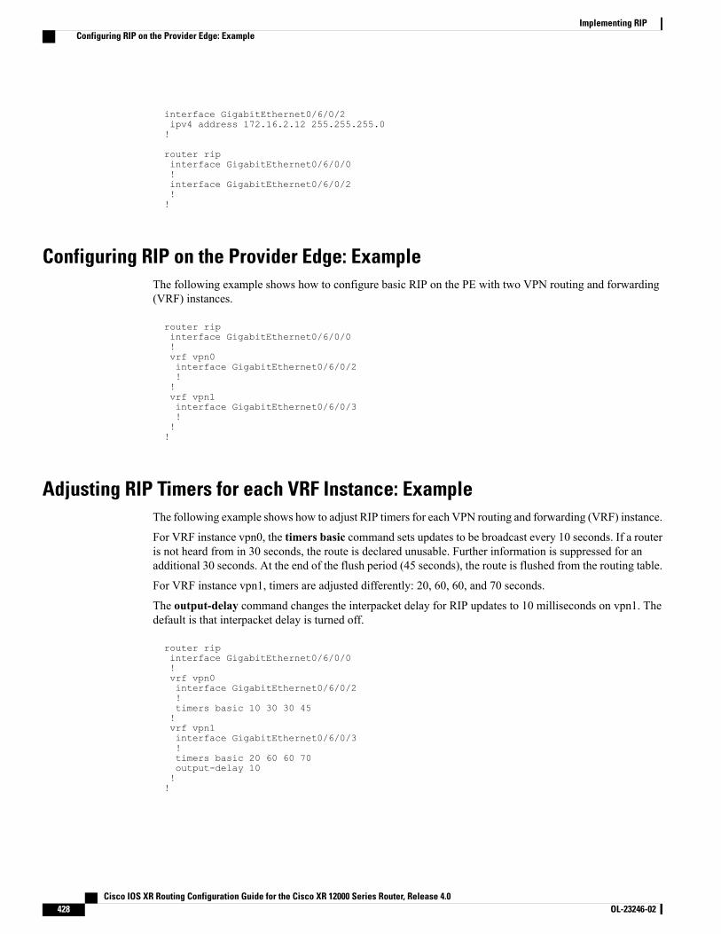
interface GigabitEthernet0/6/0/2ipv4 address 172.16.2.12 255.255.255.0!
router ripinterface GigabitEthernet0/6/0/0!interface GigabitEthernet0/6/0/2!!
Configuring RIP on the Provider Edge: ExampleThe following example shows how to configure basic RIP on the PE with two VPN routing and forwarding(VRF) instances.
router ripinterface GigabitEthernet0/6/0/0!vrf vpn0interface GigabitEthernet0/6/0/2!!vrf vpn1interface GigabitEthernet0/6/0/3!!!
Adjusting RIP Timers for each VRF Instance: ExampleThe following example shows how to adjust RIP timers for each VPN routing and forwarding (VRF) instance.
For VRF instance vpn0, the timers basic command sets updates to be broadcast every 10 seconds. If a routeris not heard from in 30 seconds, the route is declared unusable. Further information is suppressed for anadditional 30 seconds. At the end of the flush period (45 seconds), the route is flushed from the routing table.
For VRF instance vpn1, timers are adjusted differently: 20, 60, 60, and 70 seconds.
The output-delay command changes the interpacket delay for RIP updates to 10 milliseconds on vpn1. Thedefault is that interpacket delay is turned off.
router ripinterface GigabitEthernet0/6/0/0!vrf vpn0interface GigabitEthernet0/6/0/2!timers basic 10 30 30 45!vrf vpn1interface GigabitEthernet0/6/0/3!timers basic 20 60 60 70output-delay 10!!
Cisco IOS XR Routing Configuration Guide for the Cisco XR 12000 Series Router, Release 4.0428 OL-23246-02
Implementing RIPConfiguring RIP on the Provider Edge: Example
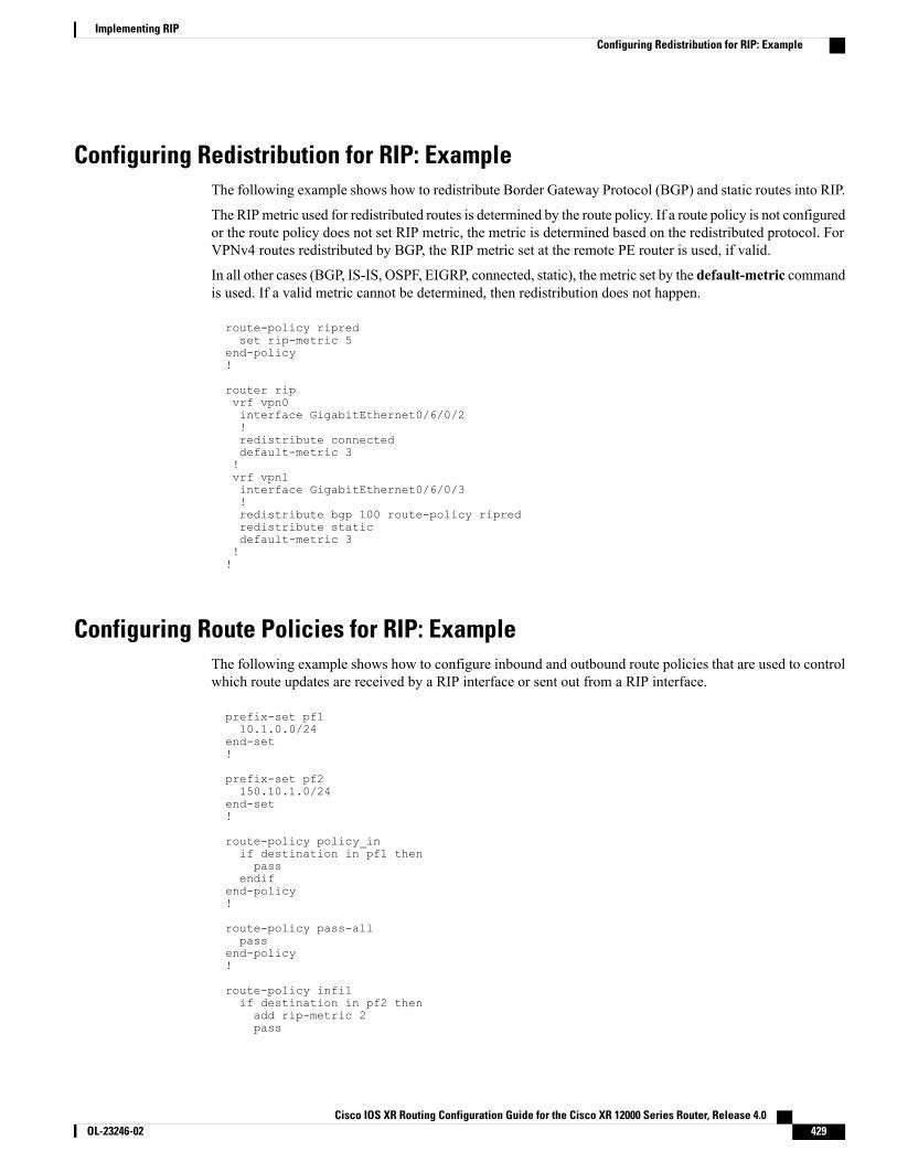
Configuring Redistribution for RIP: ExampleThe following example shows how to redistribute Border Gateway Protocol (BGP) and static routes into RIP.
The RIPmetric used for redistributed routes is determined by the route policy. If a route policy is not configuredor the route policy does not set RIP metric, the metric is determined based on the redistributed protocol. ForVPNv4 routes redistributed by BGP, the RIP metric set at the remote PE router is used, if valid.
In all other cases (BGP, IS-IS, OSPF, EIGRP, connected, static), the metric set by the default-metric commandis used. If a valid metric cannot be determined, then redistribution does not happen.
route-policy ripredset rip-metric 5
end-policy!
router ripvrf vpn0interface GigabitEthernet0/6/0/2!redistribute connecteddefault-metric 3!vrf vpn1interface GigabitEthernet0/6/0/3!redistribute bgp 100 route-policy ripredredistribute staticdefault-metric 3!!
Configuring Route Policies for RIP: ExampleThe following example shows how to configure inbound and outbound route policies that are used to controlwhich route updates are received by a RIP interface or sent out from a RIP interface.
prefix-set pf110.1.0.0/24
end-set!
prefix-set pf2150.10.1.0/24
end-set!
route-policy policy_inif destination in pf1 thenpass
endifend-policy!
route-policy pass-allpass
end-policy!
route-policy infilif destination in pf2 thenadd rip-metric 2pass
Cisco IOS XR Routing Configuration Guide for the Cisco XR 12000 Series Router, Release 4.0 OL-23246-02 429
Implementing RIPConfiguring Redistribution for RIP: Example
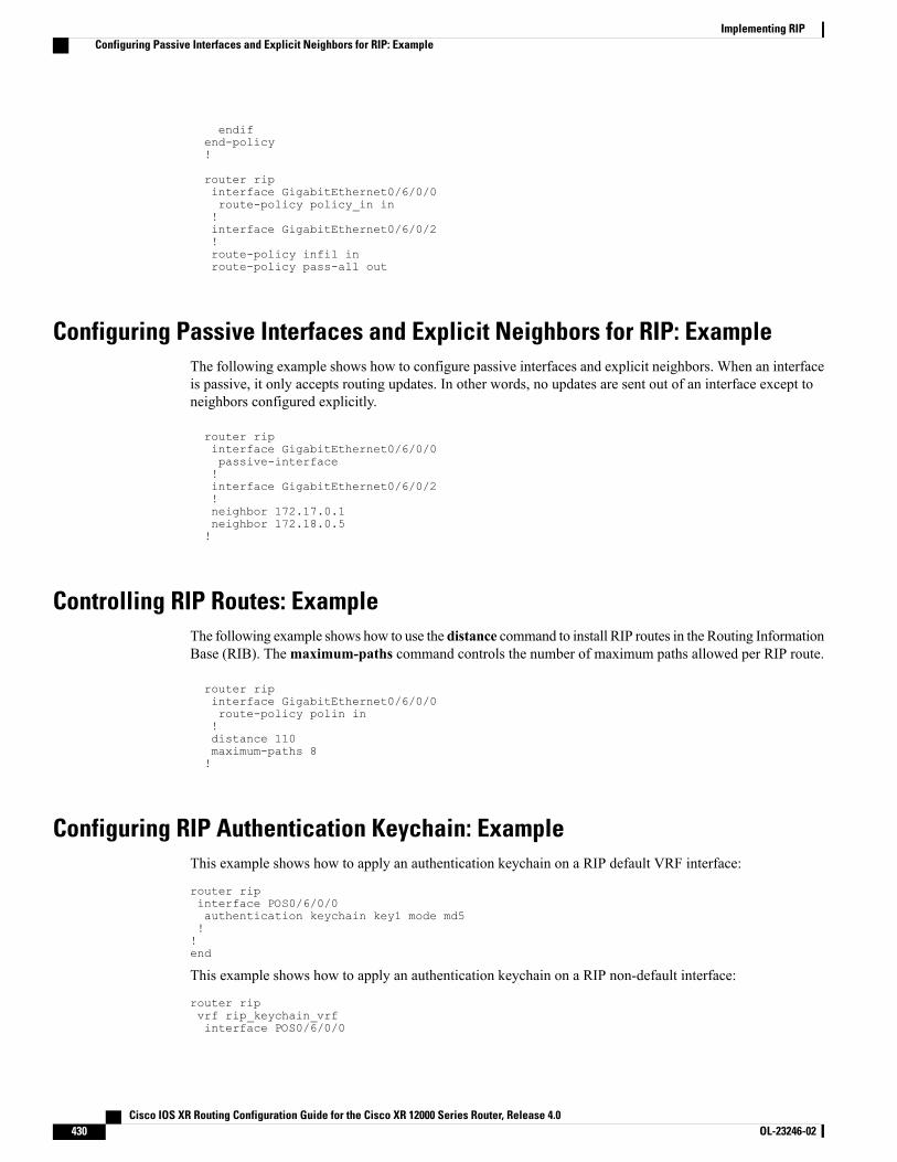
endifend-policy!
router ripinterface GigabitEthernet0/6/0/0route-policy policy_in in!interface GigabitEthernet0/6/0/2!route-policy infil inroute-policy pass-all out
Configuring Passive Interfaces and Explicit Neighbors for RIP: ExampleThe following example shows how to configure passive interfaces and explicit neighbors. When an interfaceis passive, it only accepts routing updates. In other words, no updates are sent out of an interface except toneighbors configured explicitly.
router ripinterface GigabitEthernet0/6/0/0passive-interface!interface GigabitEthernet0/6/0/2!neighbor 172.17.0.1neighbor 172.18.0.5!
Controlling RIP Routes: ExampleThe following example shows how to use the distance command to install RIP routes in the Routing InformationBase (RIB). Themaximum-paths command controls the number of maximum paths allowed per RIP route.
router ripinterface GigabitEthernet0/6/0/0route-policy polin in!distance 110maximum-paths 8!
Configuring RIP Authentication Keychain: ExampleThis example shows how to apply an authentication keychain on a RIP default VRF interface:
router ripinterface POS0/6/0/0authentication keychain key1 mode md5!!end
This example shows how to apply an authentication keychain on a RIP non-default interface:
router ripvrf rip_keychain_vrfinterface POS0/6/0/0
Cisco IOS XR Routing Configuration Guide for the Cisco XR 12000 Series Router, Release 4.0430 OL-23246-02
Implementing RIPConfiguring Passive Interfaces and Explicit Neighbors for RIP: Example
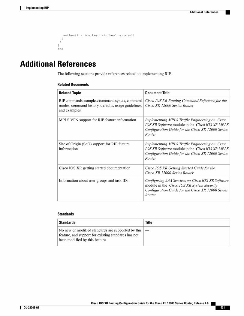
authentication keychain key1 mode md5!!!end
Additional ReferencesThe following sections provide references related to implementing RIP.
Related Documents
Document TitleRelated Topic
Cisco IOS XR Routing Command Reference for theCisco XR 12000 Series Router
RIP commands: complete command syntax, commandmodes, command history, defaults, usage guidelines,and examples
Implementing MPLS Traffic Engineering on CiscoIOS XR Softwaremodule in the Cisco IOS XRMPLSConfiguration Guide for the Cisco XR 12000 SeriesRouter
MPLS VPN support for RIP feature information
Implementing MPLS Traffic Engineering on CiscoIOS XR Softwaremodule in the Cisco IOS XRMPLSConfiguration Guide for the Cisco XR 12000 SeriesRouter
Site of Origin (SoO) support for RIP featureinformation
Cisco IOS XR Getting Started Guide for theCisco XR 12000 Series Router
Cisco IOS XR getting started documentation
Configuring AAA Services on Cisco IOS-XR Softwaremodule in the Cisco IOS XR System SecurityConfiguration Guide for the Cisco XR 12000 SeriesRouter
Information about user groups and task IDs
Standards
TitleStandards
—No new or modified standards are supported by thisfeature, and support for existing standards has notbeen modified by this feature.
Cisco IOS XR Routing Configuration Guide for the Cisco XR 12000 Series Router, Release 4.0 OL-23246-02 431
Implementing RIPAdditional References
MIBs
MIBs LinkMIBs
To locate and download MIBs using Cisco IOS XRsoftware, use the Cisco MIB Locator found at thefollowingURL and choose a platform under the CiscoAccess Products menu:
http://cisco.com/public/sw-center/netmgmt/cmtk/mibs.shtml
—
RFCs
TitleRFCs
RIP Version 2RFC 2453
Technical Assistance
LinkDescription
http://www.cisco.com/techsupportThe Cisco Technical Support website containsthousands of pages of searchable technical content,including links to products, technologies, solutions,technical tips, and tools. Registered Cisco.com userscan log in from this page to access evenmore content.
Cisco IOS XR Routing Configuration Guide for the Cisco XR 12000 Series Router, Release 4.0432 OL-23246-02
Implementing RIPAdditional References
C H A P T E R 7Implementing Routing Policy
A routing policy instructs the router to inspect routes, filter them, and potentially modify their attributes asthey are accepted from a peer, advertised to a peer, or redistributed from one routing protocol to another.
This module describes how routing protocols make decisions to advertise, aggregate, discard, distribute,export, hold, import, redistribute and modify the routes based on configured routing policy.
The routing policy language (RPL) provides a single, straightforward language in which all routing policyneeds can be expressed. RPL was designed to support large-scale routing configurations. It greatly reducesthe redundancy inherent in previous routing policy configuration methods. RPL streamlines the routingpolicy configuration, reduces system resources required to store and process these configurations, andsimplifies troubleshooting.
For more information about routing policy on the Cisco IOS XR software and complete descriptions ofthe routing policy commands listed in this module, see the Related Documents, on page 509 section ofthis module. To locate documentation for other commands that might appear during execution of aconfiguration task, search online in the Cisco IOS XR Commands Master List for the Cisco XR 12000Series Router.
Note
Feature History for Implementing Routing Policy
ModificationRelease
This feature was introduced.Release 3.2
Support was added for EIGRP, RIP policy, clear-policy, debug,OSPF area-in, and OSPF area-out attach points.
Release 3.3.0
Support was added for the BGP next-hop attach point. Supportwas also added for null sets and global parameterization.
Release 3.4.0
Cisco IOS XR Routing Configuration Guide for the Cisco XR 12000 Series Router, Release 4.0 OL-23246-02 433
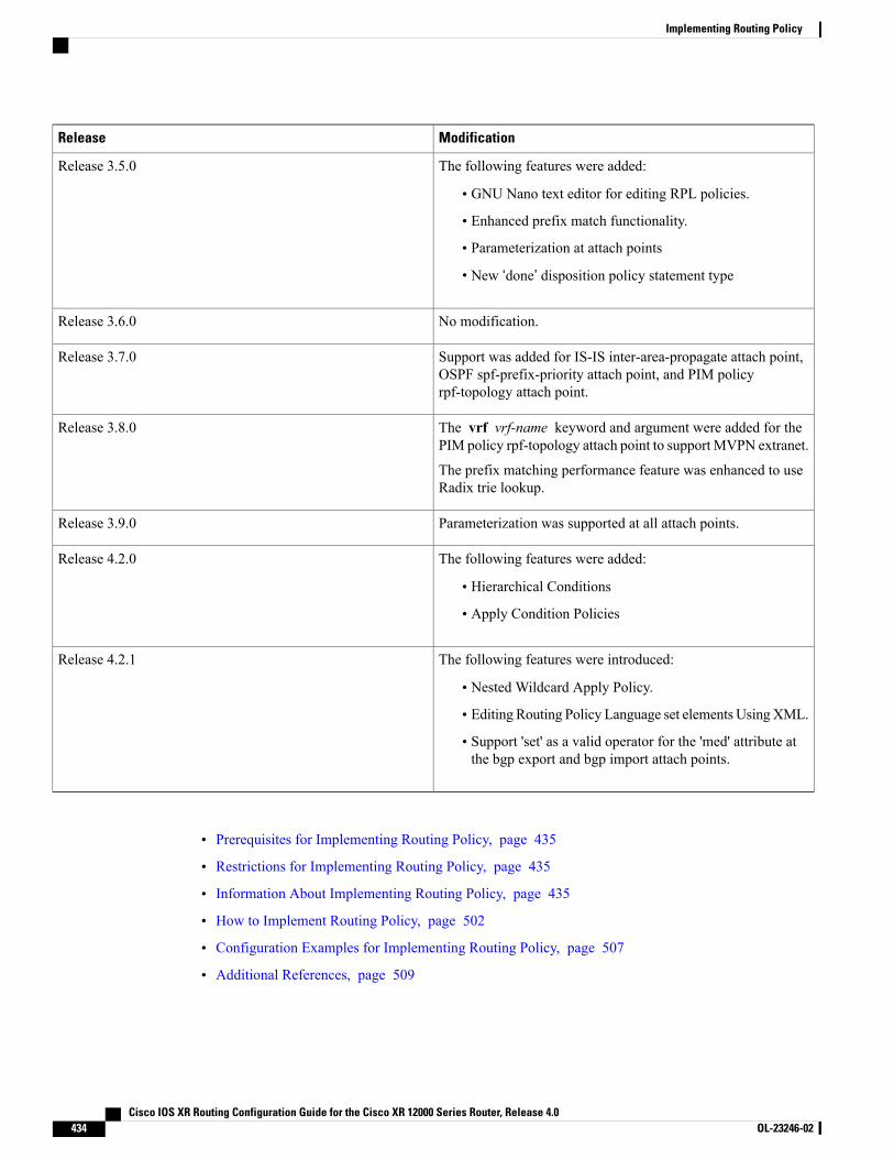
ModificationRelease
The following features were added:
• GNU Nano text editor for editing RPL policies.
• Enhanced prefix match functionality.
• Parameterization at attach points
• New ‘done’ disposition policy statement type
Release 3.5.0
No modification.Release 3.6.0
Support was added for IS-IS inter-area-propagate attach point,OSPF spf-prefix-priority attach point, and PIM policyrpf-topology attach point.
Release 3.7.0
The vrf vrf-name keyword and argument were added for thePIM policy rpf-topology attach point to support MVPN extranet.
The prefix matching performance feature was enhanced to useRadix trie lookup.
Release 3.8.0
Parameterization was supported at all attach points.Release 3.9.0
The following features were added:
• Hierarchical Conditions
• Apply Condition Policies
Release 4.2.0
The following features were introduced:
• Nested Wildcard Apply Policy.
• Editing Routing Policy Language set elements UsingXML.
• Support 'set' as a valid operator for the 'med' attribute atthe bgp export and bgp import attach points.
Release 4.2.1
• Prerequisites for Implementing Routing Policy, page 435
• Restrictions for Implementing Routing Policy, page 435
• Information About Implementing Routing Policy, page 435
• How to Implement Routing Policy, page 502
• Configuration Examples for Implementing Routing Policy, page 507
• Additional References, page 509
Cisco IOS XR Routing Configuration Guide for the Cisco XR 12000 Series Router, Release 4.0434 OL-23246-02
Implementing Routing Policy

Prerequisites for Implementing Routing PolicyThe following are prerequisites for implementing Routing Policy on Cisco IOS XR Software:
• Youmust be in a user group associated with a task group that includes the proper task IDs. The commandreference guides include the task IDs required for each command. If you suspect user group assignmentis preventing you from using a command, contact your AAA administrator for assistance.
• Border Gateway Protocol (BGP), integrated Intermediate System-to-Intermediate System (IS-IS), orOpen Shortest Path First (OSPF) must be configured in your network.
Restrictions for Implementing Routing PolicyThese restrictions apply when working with Routing Policy Language implementation on Cisco IOS XRsoftware:
• An individual policy definition of up to 1000 statements are supported. The total number of statementswithin a policy can be extended to 4000 statements using hierarchical policy constructs. However, thislimit is restricted with the use of apply statements.
•When a policy that is attached directly or indirectly to an attach point needs to be modified, a singlecommit operation cannot be performed when:
• Removing a set or policy referred by another policy that is attached to any attach point directly orindirectly.
• Modifying the policy to remove the reference to the same set or policy that is getting removed.
The commit must be performed in two steps:
1 Modify the policy to remove the reference to the policy or set and then commit.
2 Remove the policy or set and commit.
Information About Implementing Routing PolicyTo implement RPL, you need to understand the following concepts:
Routing Policy LanguageThis section contains the following information:
Routing Policy Language OverviewRPL was developed to support large-scale routing configurations. RPL has several fundamental capabilitiesthat differ from those present in configurations oriented to traditional route maps, access lists, and prefix lists.The first of these capabilities is the ability to build policies in a modular form. Common blocks of policy can
Cisco IOS XR Routing Configuration Guide for the Cisco XR 12000 Series Router, Release 4.0 OL-23246-02 435
Implementing Routing PolicyPrerequisites for Implementing Routing Policy
be defined and maintained independently. These common blocks of policy can then be applied from otherblocks of policy to build complete policies. This capability reduces the amount of configuration informationthat needs to be maintained. In addition, these common blocks of policy can be parameterized. Thisparameterization allows for policies that share the same structure but differ in the specific values that are setor matched against to be maintained as independent blocks of policy. For example, three policies that areidentical in every way except for the local preference value they set can be represented as one commonparameterized policy that takes the varying local preference value as a parameter to the policy.
The policy language introduces the notion of sets. Sets are containers of similar data that can be used in routeattribute matching and setting operations. Four set types exist: prefix-sets, community-sets, as-path-sets, andextcommunity-sets. These sets hold groupings of IPv4 or IPv6 prefixes, community values, AS path regularexpressions, and extended community values, respectively. Sets are simply containers of data. Most sets alsohave an inline variant. An inline set allows for small enumerations of values to be used directly in a policyrather than having to refer to a named set. Prefix lists, community lists, and AS path lists must be maintainedeven when only one or two items are in the list. An inline set in RPL allows the user to place small sets ofvalues directly in the policy body without having to refer to a named set.
Decision making, such as accept and deny, is explicitly controlled by the policy definitions themselves. RPLcombines matching operators, which may use set data, with the traditional Boolean logic operators AND, OR,and NOT into complex conditional expressions. All matching operations return a true or false result. Theexecution of these conditional expressions and their associated actions can then be controlled by using simpleif then, elseif, and else structures, which allow the evaluation paths through the policy to be fully specified bythe user.
Routing Policy Language StructureThis section describes the basic structure of RPL.
Names
The policy language provides two kinds of persistent, namable objects: sets and policies. Definition of theseobjects is bracketed by beginning and ending command lines. For example, to define a policy named test, theconfiguration syntax would look similar to the following:
route-policy test[ . . . policy statements . . . ]end-policy
Legal names for policy objects can be any sequence of the upper- and lowercase alphabetic characters; thenumerals 0 to 9; and the punctuation characters period, hyphen, and underscore. A name must begin with aletter or numeral.
Sets
In this context, the term set is used in its mathematical sense to mean an unordered collection of uniqueelements. The policy language provides sets as a container for groups of values for matching purposes. Setsare used in conditional expressions. The elements of the set are separated by commas. Null (empty) sets areallowed.
In the following example:
prefix-set backup-routes# currently no backup routes are defined
Cisco IOS XR Routing Configuration Guide for the Cisco XR 12000 Series Router, Release 4.0436 OL-23246-02
Implementing Routing PolicyRouting Policy Language Overview

end-set
a condition such as:
if destination in backup-routes then
evaluates as FALSE for every route, because there is no match-condition in the prefix set that it satisfies.
Five kinds of sets exist: as-path-set, on page 437, community-set, on page 438, extcommunity-set, on page439, prefix-set, on page 442, and rd-set, on page 443. You may want to perform comparisons against a smallnumber of elements, such as two or three community values, for example. To allow for these comparisons,the user can enumerate these values directly. These enumerations are referred to as inline sets. Functionally,inline sets are equivalent to named sets, but allow for simple tests to be inline. Thus, comparisons do notrequire that a separate named set be maintained when only one or two elements are being compared. See theset types described in the following sections for the syntax. In general, the syntax for an inline set is acomma-separated list surrounded by parentheses as follows: (element-entry , element-entry , element-entry,...element-entry), where element-entry is an entry of an item appropriate to the type of usage such as a prefixor a community value.
The following is an example using an inline community set:
route-policy sample-inlineif community matches-any ([10..15]:100) thenset local-preference 100endifend-policy
The following is an equivalent example using the named set test-communities:
community-set test-communities10:100,11:100,12:100,13:100,14:100,15:100end-set
route-policy sampleif community matches-any test-communities thenset local-preference 100endifend-policy
Both of these policies are functionally equivalent, but the inline form does not require the configuration ofthe community set just to store the six values. You can choose the form appropriate to the configurationcontext. In the following sections, examples of both the named set version and the inline form are providedwhere appropriate.
as-path-set
An AS path set comprises operations for matching an AS path attribute. The matching operations are:
• dfa-regex: DFA style regular expression
• ios-regex: Traditional IOS style regular expression
• length: Length of BGP AS-path
Cisco IOS XR Routing Configuration Guide for the Cisco XR 12000 Series Router, Release 4.0 OL-23246-02 437
Implementing Routing PolicyRouting Policy Language Overview
• neighbor-is: BGP AS-path neighbor is
• originates-from: BGP AS-path originates-from
• passes-through: BGP AS-path passes-through
• unique-length: Length of BGP AS-path ignoring duplicates
Named Set Form
The named set form uses the ios-regex keyword to indicate the type of regular expression and requires singlequotation marks around the regular expression.
The following is a sample definition of a named AS path set:
as-path-set aset1ios-regex ’_42$’,ios-regex ’_127$’end-set
This AS path set comprises two elements. When used in a matching operation, this AS path set matches anyroute whose AS path ends with either the autonomous system (AS) number 42 or 127.
To remove the named AS path set, use the no as-path-set aset1 command-line interface (CLI) command.
Regular expression matching is CPU intensive. The policy performance can be substantially improved byeither collapsing the regular expression patterns together to reduce the total number of regular expressioninvocations or by using equivalent native as-path match operations such as ‘as-path neighbor-is’, ‘as-pathoriginates-from’ or ‘as-path passes-through’.
Note
Inline Set Form
The inline set form is a parenthesized list of comma-separated expressions, as follows:
(ios-regex '_42$', ios-regex '_127$')
This set matches the same AS paths as the previously named set, but does not require the extra effort ofcreating a named set separate from the policy that uses it.
community-set
A community-set holds community values for matching against the BGP community attribute. A communityis a 32-bit quantity. Integer community values must be split in half and expressed as two unsigned decimalintegers in the range from 0 to 65535, separated by a colon. Single 32-bit community values are not allowed.The following is the named set form:
Named Set Form
community-set cset112:34,12:56,12:78,internet
Cisco IOS XR Routing Configuration Guide for the Cisco XR 12000 Series Router, Release 4.0438 OL-23246-02
Implementing Routing PolicyRouting Policy Language Overview

end-set
Inline Set Form
(12:34, 12:56, 12:78)($as:34, $as:$tag1, 12:78, internet)
The inline form of a community-set also supports parameterization. Each 16-bit portion of the communitymay be parameterized. See the Parameterization, on page 447 for more information.
RPL provides symbolic names for the standard well-known community values: internet is 0:0, no-export is65535:65281, no-advertise is 65535:65282, and local-as is 65535:65283.
RPL also provides a facility for using wildcards in community specifications. A wildcard is specified byinserting an asterisk (*) in place of one of the 16-bit portions of the community specification; the wildcardindicates that any value for that portion of the community matches. Thus, the following policy matches allcommunities in which the autonomous system part of the community is 123:
community-set cset3123:*
end-set
Every community set must contain at least one community value. Empty community sets are invalid and arerejected.
extcommunity-set
An extended community-set is analogous to a community-set except that it contains extended communityvalues instead of regular community values. It also supports named forms and inline forms. There are threetypes of extended community sets: cost, soo, and rt.
As with community sets, the inline form supports parameterization within parameterized policies. Eitherportion of the extended community value can be parameterized.
Wildcards (*) and regular expressions are allowed for extended community set elements.
Every extended community-set must contain at least one extended community value. Empty extendedcommunity-sets are invalid and rejected.
The following are syntactic examples:
Named Form for Extcommunity-set Cost
A cost set is an extcommunity set used to store cost EIGRP Cost Community type extended community typecommunities.
extcommunity-set cost a_cost_setIGP:1:10
end-set
These options are supported under extended community set Cost:
RP/0/0/CPU0:router(config)#extcommunity-set cost cost_setRP/0/0/CPU0:router(config-ext)#?#-remark Remark beginning with '#'<0-255> decimal numberabort Discard RPL definition and return to top level configend-set End of set definition
Cisco IOS XR Routing Configuration Guide for the Cisco XR 12000 Series Router, Release 4.0 OL-23246-02 439
Implementing Routing PolicyRouting Policy Language Overview

exit Exit from this submodeigp: Cost Community with IGP as point of insertionpre-bestpath: Cost Community with Pre-Bestpath as point of insertionshow Show partial RPL configuration
DescriptionOption
Remark beginning with '#'#-remark
decimal number<0-255>
Discard RPL definition and return to top level configabort
End of set definitionend-set
Exit from this submodeexit
Cost Community with IGP as point of insertionigp:
Cost Community with Pre-Bestpath as point of insertionpre-bestpath:
Show partial RPL configurationshow
Named Form for Extcommunity-set RT
An rt set is an extcommunity set used to store BGPRoute Target (RT) extended community type communities:
extcommunity-set rt a_rt_set1.2.3.4:6661234:666,1.2.3.4:777,4567:777
end-set
Inline Set Form for Extcommunity-set RT
(1.2.3.4:666, 1234:666, 1.2.3.4:777, 4567:777)($ipadrr:666, 1234:$tag, 1.2.3.4:777, $tag2:777)
These options are supported under extended community set RT:
RP/0/0/CPU0:router(config)#extcommunity-set rt rt_setRP/0/0/CPU0:router(config-ext)#?#-remark Remark beginning with '#'* Wildcard (any community or part thereof)<1-4294967295> 32-bit decimal number<1-65535> 16-bit decimal numberA.B.C.D/M:N Extended community - IPv4 prefix formatA.B.C.D:N Extended community - IPv4 formatASN:N Extended community - ASPLAIN formatX.Y:N Extended community - ASDOT formatabort Discard RPL definition and return to top level configdfa-regex DFA style regular expressionend-set End of set definitionexit Exit from this submodeios-regex Traditional IOS style regular expressionshow Show partial RPL configuration
DescriptionOption
Remark beginning with '#'#-remark
Wildcard (any community or part thereof)*
Cisco IOS XR Routing Configuration Guide for the Cisco XR 12000 Series Router, Release 4.0440 OL-23246-02
Implementing Routing PolicyRouting Policy Language Overview

DescriptionOption
32-bit decimal number<1-4294967295>
16-bit decimal number<1-65535>
Extended community - IPv4 prefix formatA.B.C.D/M:N
Extended community - IPv4 formatA.B.C.D:N
Extended community - ASPLAIN formatASN:N
Extended community - ASDOT formatX.Y:N
Discard RPL definition and return to top level configabort
DFA style regular expressiondfa-regex
End of set definitionend-set
Exit from this submodeexit
Traditional IOS style regular expressionios-regex
Show partial RPL configurationshow
Named Form for Extcommunity-set Soo
A soo set is an extcommunity set used to store BGP Site-of-Origin (SoO) extended community typecommunities:
extcommunity-set soo a_soo_set1.1.1.1:100,100:200
end-set
These options are supported under extended community set Soo:
RP/0/0/CPU0:router(config)#extcommunity-set soo soo_setRP/0/0/CPU0:router(config-ext)#?#-remark Remark beginning with '#'* Wildcard (any community or part thereof)<1-4294967295> 32-bit decimal number<1-65535> 16-bit decimal numberA.B.C.D/M:N Extended community - IPv4 prefix formatA.B.C.D:N Extended community - IPv4 formatASN:N Extended community - ASPLAIN formatX.Y:N Extended community - ASDOT formatabort Discard RPL definition and return to top level configdfa-regex DFA style regular expressionend-set End of set definitionexit Exit from this submodeios-regex Traditional IOS style regular expressionshow Show partial RPL configuration
DescriptionOption
Remark beginning with '#'#-remark
Wildcard (any community or part thereof)*
32-bit decimal number<1-4294967295>
Cisco IOS XR Routing Configuration Guide for the Cisco XR 12000 Series Router, Release 4.0 OL-23246-02 441
Implementing Routing PolicyRouting Policy Language Overview
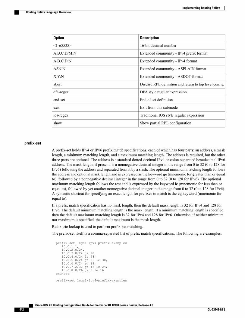
DescriptionOption
16-bit decimal number<1-65535>
Extended community - IPv4 prefix formatA.B.C.D/M:N
Extended community - IPv4 formatA.B.C.D:N
Extended community - ASPLAIN formatASN:N
Extended community - ASDOT formatX.Y:N
Discard RPL definition and return to top level configabort
DFA style regular expressiondfa-regex
End of set definitionend-set
Exit from this submodeexit
Traditional IOS style regular expressionios-regex
Show partial RPL configurationshow
prefix-set
A prefix-set holds IPv4 or IPv6 prefix match specifications, each of which has four parts: an address, a masklength, a minimum matching length, and a maximum matching length. The address is required, but the otherthree parts are optional. The address is a standard dotted-decimal IPv4 or colon-separated hexadecimal IPv6address. The mask length, if present, is a nonnegative decimal integer in the range from 0 to 32 (0 to 128 forIPv6) following the address and separated from it by a slash. The optional minimum matching length followsthe address and optional mask length and is expressed as the keyword ge (mnemonic for greater than or equalto), followed by a nonnegative decimal integer in the range from 0 to 32 (0 to 128 for IPv6). The optionalmaximum matching length follows the rest and is expressed by the keyword le (mnemonic for less than orequal to), followed by yet another nonnegative decimal integer in the range from 0 to 32 (0 to 128 for IPv6).A syntactic shortcut for specifying an exact length for prefixes to match is the eq keyword (mnemonic forequal to).
If a prefix match specification has no mask length, then the default mask length is 32 for IPv4 and 128 forIPv6. The default minimum matching length is the mask length. If a minimum matching length is specified,then the default maximum matching length is 32 for IPv4 and 128 for IPv6. Otherwise, if neither minimumnor maximum is specified, the default maximum is the mask length.
Radix trie lookup is used to perform prefix-set matching.
The prefix-set itself is a comma-separated list of prefix match specifications. The following are examples:
prefix-set legal-ipv4-prefix-examples10.0.1.1,10.0.2.0/24,10.0.3.0/24 ge 28,10.0.4.0/24 le 28,10.0.5.0/24 ge 26 le 30,10.0.6.0/24 eq 28,10.0.7.2/32 ge 16 le 24,10.0.8.0/26 ge 8 le 16
end-set
prefix-set legal-ipv6-prefix-examples
Cisco IOS XR Routing Configuration Guide for the Cisco XR 12000 Series Router, Release 4.0442 OL-23246-02
Implementing Routing PolicyRouting Policy Language Overview
2001:0:0:1::/64,2001:0:0:2::/64 ge 96,2001:0:0:2::/64 ge 96 le 100,2001:0:0:2::/64 eq 100
end-set
The first element of the prefix-set matches only one possible value, 10.0.1.1/32 or the host address 10.0.1.1.The second element matches only one possible value, 10.0.2.0/24. The third element matches a range of prefixvalues, from 10.0.3.0/28 to 10.0.3.255/32. The fourth element matches a range of values, from 10.0.4.0/24 to10.0.4.240/28. The fifth element matches prefixes in the range from 10.0.5.0/26 to 10.0.5.252/30. The sixthelement matches any prefix of length 28 in the range from 10.0.6.0/28 through 10.0.6.240/28. The seventhelement matches any prefix of length 32 in the range 10.0.[0..255].2/32 (from 10.0.0.2/32 to 10.0.255.2). Theeighth element matches any prefix of length 26 in the range 10.[0..255].8.0/26 (from 10.0.8.0/26 to10.255.8.0/26).
The following prefix-set consists entirely of invalid prefix match specifications:
prefix-set ILLEGAL-PREFIX-EXAMPLES10.1.1.1 ge 16,10.1.2.1 le 16,10.1.3.0/24 le 23,10.1.4.0/24 ge 33,10.1.5.0/25 ge 29 le 28
end-set
Neither the minimum length nor maximum length is valid without a mask length. For IPv4, the minimumlength must be less than 32, the maximum length of an IPv4 prefix. For IPv6, the minimum length must beless than 128, the maximum length of an IPv6 prefix. The maximum length must be equal to or greater thanthe minimum length.
rd-set
An rd-set is used to create a set with route distinguisher (RD) elements. An RD set is a 64-bit value prependedto an IPv4 address to create a globally unique Border Gateway Protocol (BGP) VPN IPv4 address.
You can define RD values with the following commands:
• a.b.c.d:m:*—BGP VPN RD in IPv4 format with a wildcard character. For example,10.0.0.2:255.255.0.0:*.
• a.b.c.d/m:n—BGP VPN RD in IPv4 format with a mask. For example, 10.0.0.2:255.255.0.0:666.
• a.b.c.d:**—BGPVPNRD in IPv4 format with a wildcard character. For example, 10.0.0.2:255.255.0.0.
• a.b.c.d:n— BGP VPN RD in IPv4 format. For example, 10.0.0.2:666.
• asn:*— BGP VPN RD in ASN format with a wildcard character. For example, 10002:255.255.0.0.
• asn:n—BGP VPN RD in ASN format. For example, 10002:666.
The following is an example of an rd-set:
rd-set rdset110.0.0.0/8:*,10.0.0.0/8:777,10.0.0.0:*,10.0.0.0:777,65000:*,65000:777
end-set
Cisco IOS XR Routing Configuration Guide for the Cisco XR 12000 Series Router, Release 4.0 OL-23246-02 443
Implementing Routing PolicyRouting Policy Language Overview
Routing Policy Language ComponentsFour main components in the routing policy language are involved in defining, modifying, and using policies:the configuration front end, policy repository, execution engine, and policy clients themselves.
The configuration front end (CLI) is the mechanism to define and modify policies. This configuration is thenstored on the router using the normal storage means and can be displayed using the normal configurationshow commands.
The second component of the policy infrastructure, the policy repository, has several responsibilities. First,it compiles the user-entered configuration into a form that the execution engine can understand. Second, itperforms much of the verification of policies; and it ensures that defined policies can actually be executedproperly. Third, it tracks which attach points are using which policies so that when policies are modified theappropriate clients are properly updated with the new policies relevant to them.
The third component is the execution engine. This component is the piece that actually runs policies as theclients request. The process can be thought of as receiving a route from one of the policy clients and thenexecuting the actual policy against the specific route data.
The fourth component is the policy clients (the routing protocols). This component calls the execution engineat the appropriate times to have a given policy be applied to a given route, and then perform some number ofactions. These actions may include deleting the route if policy indicated that it should be dropped, passingalong the route to the protocol decision tree as a candidate for the best route, or advertising a policy modifiedroute to a neighbor or peer as appropriate.
Routing Policy Language UsageThis section provides basic routing policy language usage examples. See the How to Implement RoutingPolicy, on page 502 for detailed information on how to implement routing policy language.
Pass PolicyPass Policy
The following example shows how the policy accepts all presented routes without modifying the routes.
route-policy quickstart-passpassend-policy
Drop Everything Policy
The following example shows how the policy explicitly rejects all routes presented to it. This type of policyis used to ignore everything coming from a specific peer.
route-policy quickstart-dropdropend-policy
Ignore Routes with Specific AS Numbers in the Path
The following example shows the policy definition in three parts. First, the as-path-set command definesthree regular expressions to match against an AS path. Second, the route-policy command applies the AS
Cisco IOS XR Routing Configuration Guide for the Cisco XR 12000 Series Router, Release 4.0444 OL-23246-02
Implementing Routing PolicyRouting Policy Language Overview

path set to a route. If the AS path attribute of the route matches the regular expression defined with theas-path-set command, the protocol refuses the route. Third, the route policy is attached to BGP neighbor10.0.1.2. BGP consults the policy named ignore_path_as on routes received (imported) from neighbor 10.0.1.2.
as-path-set ignore_pathios-regex '_11_',ios-regex '_22_',ios-regex '_33_'end-set
route-policy ignore_path_asif as-path in ignore_path thendropelsepassendifend-policy
router bgp 2neighbor 10.0.1.2 address-family ipv4 unicast policy ignore_path_as in
Set Community Based on MED
The following example shows how the policy tests the MED of a route and modifies the community attributeof the route based on the value of the MED. If the MED value is 127, the policy adds the community 123:456to the route. If the MED value is 63, the policy adds the value 123:789 to the community attribute of the route.Otherwise, the policy removes the community 123:123 from the route. In any case, the policy instructs theprotocol to accept the route.
route-policy quickstart-medif med eq 127 thenset community (123:456) additiveelseif med eq 63 thenset community (123:789) additiveelsedelete community in (123:123)endifpassend-policy
Set Local Preference Based on Community
The following example shows how the community-set named quickstart-communities defines communityvalues. The route policy named quickstart-localpref tests a route for the presence of the communities specifiedin the quickstart-communities community set. If any of the community values are present in the route, theroute policy sets the local preference attribute of the route to 31. In any case, the policy instructs the protocolto accept the route.
community-set quickstart-communities987:654,987:543,987:321,987:210end-set
route-policy quickstart-localprefif community matches-any quickstart-communities thenset local-preference 31endifpassend-policy
Cisco IOS XR Routing Configuration Guide for the Cisco XR 12000 Series Router, Release 4.0 OL-23246-02 445
Implementing Routing PolicyRouting Policy Language Overview
Persistent Remarks
The following example shows how comments are placed in the policy to clarify the meaning of the entries inthe set and the statements in the policy. The remarks are persistent, meaning they remain attached to the policy.For example, remarks are displayed in the output of the show running-config command. Adding remarks tothe policy makes the policy easier to understand, modify at a later date, and troubleshoot if an unexpectedbehavior occurs.
prefix-set rfc1918# These are the networks defined as private in RFC1918 (including# all subnets thereof)10.0.0.0/8 ge 8,172.16.0.0/12 ge 12,192.168.0.0/16 ge 16end-set
route-policy quickstart-remarks# Handle routes to RFC1918 networksif destination in rfc1918 then# Set the community such that we do not export the routeset community (no-export) additive
endifend-policy
Routing Policy Configuration BasicsRoute policies comprise series of statements and expressions that are bracketed with the route-policy andend-policy keywords. Rather than a collection of individual commands (one for each line), the statementswithin a route policy have context relative to each other. Thus, instead of each line being an individualcommand, each policy or set is an independent configuration object that can be used, entered, andmanipulatedas a unit.
Each line of a policy configuration is a logical subunit. At least one new line must follow the then , else ,and end-policy keywords. A new line must also follow the closing parenthesis of a parameter list and thename string in a reference to an AS path set, community set, extended community set, or prefix set. At leastone new line must precede the definition of a route policy, AS path set, community set, extended communityset, or prefix set. One or more new lines can follow an action statement. One or more new lines can follow acomma separator in a named AS path set, community set, extended community set, or prefix set. A new linemust appear at the end of a logical unit of policy expression and may not appear anywhere else.
Policy DefinitionsPolicy definitions create named sequences of policy statements. A policy definition consists of the CLIroute-policy keyword followed by a name, a sequence of policy statements, and the end-policy keyword.For example, the following policy drops any route it encounters:
route-policy drop-everythingdropend-policy
The name serves as a handle for binding the policy to protocols. To remove a policy definition, issue the noroute-policy name command.
Cisco IOS XR Routing Configuration Guide for the Cisco XR 12000 Series Router, Release 4.0446 OL-23246-02
Implementing Routing PolicyRouting Policy Configuration Basics
Policies may also refer to other policies such that common blocks of policy can be reused. This reference toother policies is accomplished by using the apply statement, as shown in the following example:
route-policy check-as-1234if as-path passes-through ‘1234.5’ thenapply drop-everythingelsepassendifend-policy
The apply statement indicates that the policy drop-everything should be executed if the route underconsideration passed through autonomous system 1234.5 before it is received. If a route that has autonomoussystem 1234.5 in its AS path is received, the route is dropped; otherwise, the route is accepted withoutmodification. This policy is an example of a hierarchical policy. Thus, the semantics of the apply statementare just as if the applied policy were cut and pasted into the applying policy:
route-policy check-as-1234-primeif as-path passes-through '1234.5' then
dropelse
passendifend-policy
You may have as many levels of hierarchy as desired. However, many levels may be difficult to maintain andunderstand.
ParameterizationIn addition to supporting reuse of policies using the apply statement, policies can be defined that allow forparameterization of some of the attributes. The following example shows how to define a parameterized policynamed param-example. In this case, the policy takes one parameter, $mytag. Parameters always begin witha dollar sign and consist otherwise of any alphanumeric characters. Parameters can be substituted into anyattribute that takes a parameter.
In the following example, a 16-bit community tag is used as a parameter:
route-policy param-example ($mytag)set community (1234:$mytag) additiveend-policy
This parameterized policy can then be reused with different parameterization, as shown in the followingexample. In this manner, policies that share a common structure but use different values in some of theirindividual statements can be modularized. For details on which attributes can be parameterized, see theindividual attribute sections.
route-policy origin-10if as-path originates-from ‘10.5’ thenapply param-example(10.5)elsepassendifend-policy
route-policy origin-20if as-path originates-from ‘20.5’ then
Cisco IOS XR Routing Configuration Guide for the Cisco XR 12000 Series Router, Release 4.0 OL-23246-02 447
Implementing Routing PolicyParameterization
apply param-example(20.5)elsepassendifend-policy
The parameterized policy param-example provides a policy definition that is expanded with the values providedas the parameters in the apply statement. Note that the policy hierarchy is always maintained, Thus, if thedefinition of param-example changes, then the behavior of origin_10 and origin_20 changes to match.
The effect of the origin-10 policy is that it adds the community 1234:10 to all routes that pass through thispolicy and have an AS path indicating the route originated from autonomous system 10. The origin-20 policyis similar except that it adds to community 1234:20 for routes originating from autonomous system 20.
Parameterization at Attach PointsIn addition to supporting parameterization using the apply statement described in the Parameterization, onpage 447, policies can also be defined that allow for parameterization the attributes at attach points.Parameterization is supported at all attach points.
In the following example, we define a parameterized policy "param-example". In this example, the policytakes two parameters "$mymed" and “$prefixset”. Parameters always begin with a dollar sign, and consistotherwise of any alphanumeric characters. Parameters can be substituted into any attribute that takes a parameter.In this example we are passing a MED value and prefix set name as parameters.
route-policy param-example ($mymed, $prefixset)if destination in $prefixset thenset med $mymedendif
end-policy
This parameterized policy can then be reused with different parameterizations as shown in the example below.In this manner, policies that share a common structure but use different values in some of their individualstatements can be modularized. For details on which attributes can be parameterized, see the individualattributes for each protocol.
router bgp 2neighbor 10.1.1.1remote-as 3address-family ipv4 unicastroute-policy param-example(10, prefix_set1)route-policy param-example(20, prefix_set2)
The parameterized policy param-example provides a policy definition that is expanded with the values providedas the parameters in the neighbor route-policy in and out statement.
Global ParameterizationRPL supports the definition of systemwide global parameters that can be used inside policy definition. Globalparameters can be configured as follows:
Policy-globalglbpathtype ‘ebgp’glbtag ‘100’
end-global
Cisco IOS XR Routing Configuration Guide for the Cisco XR 12000 Series Router, Release 4.0448 OL-23246-02
Implementing Routing PolicyParameterization

The global parameter values can be used directly inside a policy definition similar to the local parameters ofparameterized policy. In the following example, the globalparam argument, which makes use of the globalparameters gbpathtype and glbtag, is defined for a nonparameterized policy.
route-policy globalparamif path-type is $glbpathtype thenset tag $glbtag
endifend-policy
When a parameterized policy has a parameter name “collision” with a global parameter name, parameterslocal to policy definition take precedence, effectively masking off global parameters. In addition, a validationmechanism is in place to prevent the deletion of a particular global parameter if it is referred by any policy.
Semantics of Policy ApplicationThis section discusses how routing policies are evaluated and applied. The following concepts are discussed:
Boolean Operator PrecedenceBoolean expressions are evaluated in order of operator precedence, from left to right. The highest precedenceoperator is NOT, followed by AND, and then OR. The following expression:
med eq 10 and not destination in (10.1.3.0/24) or community matches-any ([10..25]:35)
if fully parenthesized to display the order of evaluation, would look like this:
(med eq 10 and (not destination in (10.1.3.0/24))) or community matches-any ([10..25]:35)
The inner NOT applies only to the destination test; the AND combines the result of the NOT expression withthe Multi Exit Discriminator (MED) test; and the OR combines that result with the community test. If theorder of operations are rearranged:
not med eq 10 and destination in (10.1.3.0/24) or community matches-any ([10..25]:35)
then the expression, fully parenthesized, would look like the following:((not med eq 10) and destination in (10.1.3.0/24)) or community matches-any ([10..25]:35)
Multiple Modifications of the Same AttributeWhen a policy replaces the value of an attribute multiple times, the last assignment wins because all actionsare executed. Because the MED attribute in BGP is one unique value, the last value to which it gets set towins. Therefore, the following policy results in a route with a MED value of 12:
set med 9set med 10set med 11set med 12
Cisco IOS XR Routing Configuration Guide for the Cisco XR 12000 Series Router, Release 4.0 OL-23246-02 449
Implementing Routing PolicySemantics of Policy Application
This example is trivial, but the feature is not. It is possible to write a policy that effectively changes the valuefor an attribute. For example:
set med 8if community matches-any cs1 thenset local-preference 122if community matches-any cs2 thenset med 12endifendif
The result is a route with a MED of 8, unless the community list of the route matches both cs1 and cs2, inwhich case the result is a route with a MED of 12.
In the case in which the attribute being modified can contain only one value, it is easy to think of this case asthe last statement wins. However, a few attributes can contain multiple values and the result of multiple actionson the attribute is cumulative rather than as a replacement. The first of these cases is the use of the additivekeyword on community and extended community evaluation. Consider a policy of the form:
route-policy community-addset community (10:23)set community (10:24) additiveset community (10:25) additiveend-policy
This policy sets the community string on the route to contain all three community values: 10:23, 10:24, and10:25.
The second of these cases is AS path prepending. Consider a policy of the form:
route-policy prepend-exampleprepend as-path 2.5 3prepend as-path 666.5 2end-policy
This policy prepends 666.5 666.5 2.5 2.5 2.5 to the AS path. This prepending is a result of all actions beingtaken and to the AS path being an attribute that contains an array of values rather than a simple scalar value.
When Attributes Are ModifiedA policy does not modify route attribute values until all tests have been completed. In other words, comparisonoperators always run on the initial data in the route. Intermediate modifications of the route attributes do nothave a cascading effect on the evaluation of the policy. Take the following example:
ifmed eq 12 thenset med 42if med eq 42 thendropendifendif
This policy never executes the drop statement because the second test (med eq 42) sees the original, unmodifiedvalue of the MED in the route. Because the MED has to be 12 to get to the second test, the second test alwaysreturns false.
Cisco IOS XR Routing Configuration Guide for the Cisco XR 12000 Series Router, Release 4.0450 OL-23246-02
Implementing Routing PolicySemantics of Policy Application
Default Drop DispositionAll route policies have a default action to drop the route under evaluation unless the route has been modifiedby a policy action or explicitly passed. Applied (nested) policies implement this disposition as though theapplied policy were pasted into the point where it is applied.
Consider a policy to allow all routes in the 10 network and set their local preference to 200 while droppingall other routes. You might write the policy as follows:
route-policy twoif destination in (10.0.0.0/8 ge 8 le 32) thenset local-preference 200endifend-policy
route-policy oneapply twoend-policy
It may appear that policy one drops all routes because it neither contains an explicit pass statement nor modifiesa route attribute. However, the applied policy does set an attribute for some routes and this disposition ispassed along to policy one. The result is that policy one passes routes with destinations in network 10, anddrops all others.
Control FlowPolicy statements are processed sequentially in the order in which they appear in the configuration. Policiesthat hierarchically reference other policy blocks are processed as if the referenced policy blocks had beendirectly substituted inline. For example, if the following policies are defined:
route-policy oneset weight 100end-policy
route-policy twoset med 200end-policy
route-policy threeapply twoset community (2:666) additiveend-policy
route-policy fourapply oneapply threepassend-policy
Policy four could be rewritten in an equivalent way as follows:
route-policy four-equivalentset weight 100set med 200set community (2:666) additivepassend-policy
Cisco IOS XR Routing Configuration Guide for the Cisco XR 12000 Series Router, Release 4.0 OL-23246-02 451
Implementing Routing PolicySemantics of Policy Application
The pass statement is not required and can be removed to represent the equivalent policy in another way.Note
Policy VerificationSeveral different types of verification occur when policies are being defined and used.
Range Checking
As policies are being defined, some simple verifications, such as range checking of values, is done. Forexample, the MED that is being set is checked to verify that it is in a proper range for the MED attribute.However, this range checking cannot cover parameter specifications because they may not have defined valuesyet. These parameter specifications are verified when a policy is attached to an attach point. The policyrepository also verifies that there are no recursive definitions of policy, and that parameter numbers are correct.At attach time, all policies must be well formed. All sets and policies that they reference must be defined andhave valid values. Likewise, any parameter values must also be in the proper ranges.
Incomplete Policy and Set References
As long as a given policy is not attached at an attach point, the policy is allowed to refer to nonexistent setsand policies, which allows for freedom of workflow. You can build configurations that reference sets or policyblocks that are not yet defined, and then can later fill in those undefined policies and sets, thereby achievingmuch greater flexibility in policy definition. Every piece of policy you want to reference while defining apolicy need not exist in the configuration. Thus, a user can define a policy sample that references the policybar using an apply statement even if the policy bar does not exist. Similarly, a user can enter a policy statementthat refers to a nonexistent set.
However, the existence of all referenced policies and sets is enforced when a policy is attached. If you attemptto attach the policy sample with the reference to an undefined policy bar at an inbound BGP policy using theneighbor 1.2.3.4 address-family ipv4 unicast policy sample in command, the configuration attempt isrejected because the policy bar does not exist.
Likewise, you cannot remove a route policy or set that is currently in use at an attach point because thisremoval would result in an undefined reference. An attempt to remove a route policy or set that is currentlyin use results in an error message to the user.
A condition exists that is referred to as a null policy in which the policy bar exists but has no statements,actions, or dispositions in it. In other words, the policy bar does exist as follows:
route-policy barend-policy
This is a valid policy block. It effectively forces all routes to be dropped because it is a policy block that nevermodifies a route, nor does it include the pass statement. Thus, the default action of drop for the policy blockis followed.
Attached Policy Modification
Policies that are in use do, on occasion, need to be modified. Traditionally, configuration changes are doneby completely removing the relevant configuration and then re-entering it. However, this allows for a window
Cisco IOS XR Routing Configuration Guide for the Cisco XR 12000 Series Router, Release 4.0452 OL-23246-02
Implementing Routing PolicySemantics of Policy Application
of time in which no policy is attached and the default action takes place. RPL provides a mechanism for anatomic change so that if a policy is redeclared, or edited using a text editor, the new configuration is appliedimmediately—which allows for policies that are in use to be changed without having a window of time inwhich no policy is applied at the given attach point.
Verification of Attribute Comparisons and Actions
The policy repository knows which attributes, actions, and comparisons are valid at each attach point. Whena policy is attached, these actions and comparisons are verified against the capabilities of that particular attachpoint. Take, for example, the following policy definition:
route-policy badset med 100set level level-1-2set ospf-metric 200end-policy
This policy attempts to perform actions to set the BGP attribute med, IS-IS attribute level, and OSPF attributecost. The system allows you to define such a policy, but it does not allow you to attach such a policy. If youhad defined the policy bad and then attempted to attach it as an inbound BGP policy using the BGPconfiguration statement neighbor 1.2.3.4 address-family ipv4 unicast route-policy bad in the systemwouldreject this configuration attempt. This rejection results from the verification process checking the policy andrealizing that while BGP could set the MED, it has no way of setting the level or cost as the level and costare attributes of IS-IS and OSPF, respectively. Instead of silently omitting the actions that cannot be done,the system generates an error to the user. Likewise, a valid policy in use at an attach point cannot be modifiedin such a way as to introduce an attempt to modify a nonexistent attribute or to compare against a nonexistentattribute. The verifiers test for nonexistent attributes and reject such a configuration attempt.
Policy StatementsFour types of policy statements exist: remark, disposition (drop and pass), action (set), and if (comparator).
RemarkA remark is text attached to policy configuration but otherwise ignored by the policy language parser. Remarksare useful for documenting parts of a policy. The syntax for a remark is text that has each line prepended witha pound sign (#):
# This is a simple one-line remark.
# This# is a remark# comprising multiple# lines.
In general, remarks are used between complete statements or elements of a set. Remarks are not supported inthe middle of statements or within an inline set definition.
Unlike traditional !-comments in the CLI, RPL remarks persist through reboots and when configurations aresaved to disk or a TFTP server and then loaded back onto the router.
Cisco IOS XR Routing Configuration Guide for the Cisco XR 12000 Series Router, Release 4.0 OL-23246-02 453
Implementing Routing PolicyPolicy Statements
DispositionIf a policy modifies a route, by default the policy accepts the route. RPL provides a statement to force theopposite—the drop statement. If a policy matches a route and executes a drop, the policy does not accept theroute. If a policy does not modify the route, by default the route is dropped. To prevent the route from beingdropped, the pass statement is used.
The drop statement indicates that the action to take is to discard the route. When a route is dropped, no furtherexecution of policy occurs. For example, if after executing the first two statements of a policy the dropstatement is encountered, the policy stops and the route is discarded.
All policies have a default drop action at the end of execution.Note
The pass statement allows a policy to continue executing even though the route has not been modified. Whena policy has finished executing, any route that has been modified in the policy or any route that has receiveda pass disposition in the policy, successfully passes the policy and completes the execution. If route policyB_rp is applied within route policy A_rp, execution continues from policy A_rp to policy B_rp and back topolicy A_rp provided prefix is not dropped by policy B_rp.
route-policy A_rpset community (10:10)apply B_rp
end-policy!
route-policy B_rpif destination in (121.23.0.0/16 le 32, 155.12.0.0/16 le 32) thenset community (121:155) additiveendif
end-policy!
By default, a route is dropped at the end of policy processing unless either the policymodifies a route attributeor it passes the route by means of an explicit pass statement. For example, if route-policy B is applied withinroute-policy A, then execution continues from policy A to policy B and back to policy A, provided the prefixis not dropped by policy B.
route-policy Aif as-path neighbor-is '123' thenapply Bpolicy statement N
end-policy
Whereas the following policies pass all routes that they evaluate.
route-policy PASS-ALLpassend-policy
route-policy SET-LPREFset local-preference 200end-policy
In addition to being implicitly dropped, a route may be dropped by an explicit drop statement.Drop statementscause a route to be dropped immediately so that no further policy processing is done. Note also that a drop
Cisco IOS XR Routing Configuration Guide for the Cisco XR 12000 Series Router, Release 4.0454 OL-23246-02
Implementing Routing PolicyPolicy Statements
statement overrides any previously processed pass statements or attribute modifications. For example, thefollowing policy drops all routes. The first pass statement is executed, but is then immediately overridden bythe drop statement. The second pass statement never gets executed.
route-policy DROP-EXAMPLEpassdroppassend-policy
When one policy applies another, it is as if the applied policy were copied into the right place in the applyingpolicy, and then the same drop-and-pass semantics are put into effect. For example, policies ONE and TWOare equivalent to policy ONE-PRIME:
route-policy ONEapply twoif as-path neighbor-is '123' thenpassendifend-policy
route-policy TWOif destination in (10.0.0.0/16 le 32) thendropendifend-policy
route-policy ONE-PRIMEif destination in (10.0.0.0/16 le 32) thendropendifif as-path neighbor-is '123' thenpassendifend-policy
Because the effect of an explicit drop statement is immediate, routes in 10.0.0.0/16 le 32 are dropped withoutany further policy processing. Other routes are then considered to see if they were advertised by autonomoussystem 123. If they were advertised, they are passed; otherwise, they are implicitly dropped at the end of allpolicy processing.
The done statement indicates that the action to take is to stop executing the policy and accept the route. Whenencountering a done statement, the route is passed and no further policy statements are executed. Allmodifications made to the route prior to the done statement are still valid.
ActionAn action is a sequence of primitive operations that modify a route. Most actions, but not all, are distinguishedby the set keyword. In a route policy, actions can be grouped together. For example, the following is a routepolicy comprising three actions:
route-policy actionsset med 217set community (12:34) additivedelete community in (12:56)end-policy
Cisco IOS XR Routing Configuration Guide for the Cisco XR 12000 Series Router, Release 4.0 OL-23246-02 455
Implementing Routing PolicyPolicy Statements
IfIn its simplest form, an if statement uses a conditional expression to decide which actions or dispositionsshould be taken for the given route. For example:
if as-path in as-path-set-1 thendropendif
The example indicates that any routes whose AS path is in the set as-path-set-1 are dropped. The contents ofthe then clause may be an arbitrary sequence of policy statements.
The following example contains two action statements:
if origin is igp thenset med 42prepend as-path 73.5 5endif
The CLI provides support for the exit command as an alternative to the endif command.
The if statement also permits an else clause, which is executed if the if condition is false:
if med eq 8 thenset community (12:34) additiveelseset community (12:56) additiveendif
The policy language also provides syntax, using the elseif keyword, to string together a sequence of tests:
if med eq 150 thenset local-preference 10elseif med eq 200 thenset local-preference 60elseif med eq 250 thenset local-preference 110elseset local-preference 0endif
The statements within an if statement may themselves be if statements, as shown in the following example:
if community matches-any (12:34,56:78) thenif med eq 150 thendropendifset local-preference 100endif
This policy example sets the value of the local preference attribute to 100 on any route that has a communityvalue of 12:34 or 56:78 associated with it. However, if any of these routes has a MED value of 150, then theseroutes with either the community value of 12:34 or 56:78 and a MED of 150 are dropped.
Cisco IOS XR Routing Configuration Guide for the Cisco XR 12000 Series Router, Release 4.0456 OL-23246-02
Implementing Routing PolicyPolicy Statements
Policy grammar allows user to enter simple if statements with optional else clauses on the same line.However, the grammar is restricted to single action or disposition statement. For detailed command options,enter match statement on a separate line.
Note
Boolean ConditionsIn the previous section describing the if statement, all of the examples use simple Boolean conditions thatevaluate to either true or false. RPL also provides a way to build compound conditions from simple conditionsby means of Boolean operators.
Three Boolean operators exist: negation (not), conjunction (and), and disjunction (or). In the policy language,negation has the highest precedence, followed by conjunction, and then by disjunction. Parentheses may beused to group compound conditions to override precedence or to improve readability.
The following simple condition:
med eq 42
is true only if the value of the MED in the route is 42, otherwise it is false.
A simple condition may also be negated using the not operator:
not next-hop in (10.0.2.2)
Any Boolean condition enclosed in parentheses is itself a Boolean condition:
(destination in prefix-list-1)
A compound condition takes either of two forms. It can be a simple expression followed by the and operator,itself followed by a simple condition:
med eq 42 and next-hop in (10.0.2.2)
A compound condition may also be a simpler expression followed by the or operator and then another simplecondition:
origin is igp or origin is incomplete
An entire compound condition may be enclosed in parentheses:
(med eq 42 and next-hop in (10.0.2.2))
The parentheses may serve to make the grouping of subconditions more readable, or they may force theevaluation of a subcondition as a unit.
Cisco IOS XR Routing Configuration Guide for the Cisco XR 12000 Series Router, Release 4.0 OL-23246-02 457
Implementing Routing PolicyPolicy Statements
In the following example, the highest-precedence not operator applies only to the destination test, the andoperator combines the result of the not expression with the community test, and the or operator combinesthat result with the MED test.
med eq 10 or not destination in (10.1.3.0/24) and community matches-any ([12..34]:[56..78])
With a set of parentheses to express the precedence, the result is the following:
med eq 10 or ((not destination in (10.1.3.0/24)) and community matches-any([12..34]:[56..78])
The following is another example of a complex expression:
(origin is igp or origin is incomplete or not med eq 42) and next-hop in (10.0.2.2)
The left conjunction is a compound condition enclosed in parentheses. The first simple condition of the innercompound condition tests the value of the origin attribute; if it is Interior Gateway Protocol (IGP), then theinner compound condition is true. Otherwise, the evaluation moves on to test the value of the origin attributeagain, and if it is incomplete, then the inner compound condition is true. Otherwise, the evaluation moves tocheck the next component condition, which is a negation of a simple condition.
applyAs discussed in the sections on policy definitions and parameterization of policies, the apply commandexecutes another policy (either parameterized or unparameterized) from within another policy, which allowsfor the reuse of common blocks of policy. When combined with the ability to parameterize common blocksof policy, the apply command becomes a powerful tool for reducing repetitive configuration.
Attach PointsPolicies do not become useful until they are applied to routes, and for policies to be applied to routes theyneed to be made known to routing protocols. In BGP, for example, there are several situations where policiescan be used, the most common of these is defining import and export policy. The policy attach point is thepoint in which an association is formed between a specific protocol entity, in this case a BGP neighbor, anda specific named policy. It is important to note that a verification step happens at this point. Each time a policyis attached, the given policy and any policies it may apply are checked to ensure that the policy can be validlyused at that attach point. For example, if a user defines a policy that sets the IS-IS level attribute and thenattempts to attach this policy as an inbound BGP policy, the attempt would be rejected because BGP routesdo not carry IS-IS attributes. Likewise, when policies are modified that are in use, the attempt to modify thepolicy is verified against all current uses of the policy to ensure that the modification is compatible with thecurrent uses.
Each protocol has a distinct definition of the set of attributes (commands) that compose a route. For example,BGP routes may have a community attribute, which is undefined in OSPF. Routes in IS-IS have a levelattribute, which is unknown to BGP. Routes carried internally in the RIB may have a tag attribute.
When a policy is attached to a protocol, the protocol checks the policy to ensure the policy operates usingroute attributes known to the protocol. If the protocol uses unknown attributes, then the protocol rejects theattachment. For example, OSPF rejects attachment of a policy that tests the values of BGP communities.
Cisco IOS XR Routing Configuration Guide for the Cisco XR 12000 Series Router, Release 4.0458 OL-23246-02
Implementing Routing PolicyAttach Points
The situation is made more complex by the fact that each protocol has access to at least two distinct routetypes. In addition to native protocol routes, for example BGP or IS-IS, some protocol policy attach pointsoperate on RIB routes, which is the common central representation. Using BGP as an example, the protocolprovides an attach point to apply policy to routes redistributed from the RIB to BGP. An attach point dealingwith two different kinds of routes permits a mix of operations: RIB attribute operations for matching and BGPattribute operations for setting.
The protocol configuration rejects attempts to attach policies that perform unsupported operations.Note
The following sections describe the protocol attach points, including information on the attributes (commands)and operations that are valid for each attach point.
See Cisco IOS XR Routing Command Reference for the Cisco XR 12000 Series Router for more informationon the attributes and operations.
New para for test
BGP Policy Attach PointsThis section describes each of the BGP policy attach points and provides a summary of the BGP attributesand operators.
Additional-Path
The additional-path attach point provides increased control based on various attribute match operations. Thisattach point is used to decide whether a route-policy should be used to select additional-paths for a BGPspeaker to be able to send multiple paths for the prefix.
The add path enables BGP prefix independent convergence (PIC) at the edge routers.
This example shows how to set a route-policy "add-path-policy" to be used for enabling selection of additionalpaths:router bgp 100address-family ipv4 unicastadditional-paths selection route-policy add-path-policy
Aggregation
The aggregation attach point generates an aggregate route to be advertised based on the conditional presenceof subcomponents of that aggregate. Policies attached at this attach point are also able to set any of the validBGP attributes on the aggregated routes. For example, the policy could set a community value or a MED onthe aggregate that is generated. The specified aggregate is generated if any routes evaluated by the namedpolicy pass the policy. More specifics of the aggregate are filtered using the suppress-route keyword. Anyactions taken to set attributes in the route affect attributes on the aggregate.
In the policy language, the configuration is controlled by which routes pass the policy. The suppress map wasused to selectively filter or suppress specific components of the aggregate when the summary-only flag is notset. In other words, when the aggregate and more specific components are being sent, some of the morespecific components can be filtered using a suppress map. In the policy language, this is controlled by selectingthe route and setting the suppress flag. The attribute-map allowed the user to set specific attributes on theaggregated route. In the policy language, setting attributes on the aggregated route is controlled by normalaction operations.
Cisco IOS XR Routing Configuration Guide for the Cisco XR 12000 Series Router, Release 4.0 OL-23246-02 459
Implementing Routing PolicyAttach Points
In the following example, the aggregate address 10.0.0.0/8 is generated if there are any component routes inthe range 10.0.0.0/8 ge 8 le 25 except for 10.2.0.0/24. Because summary-only is not set, all components ofthe aggregate are advertised. However, the specific component 10.1.0.0 are suppressed.
route-policy sampleif destination in (10.0.0.0/8 ge 8 le 25) thenset community (10:33)
endifif destination in (10.2.0.0/24) thendrop
endifif destination in (10.1.0.0/24) thensuppress-route
endifend-policy
router bgp 2address-family ipv4aggregate-address 10.0.0.0/8 route-policy sample...
The effect of aggregation policy on the attributes of the aggregate is cumulative. Every time an aggregationpolicymatches a more specific route, the set operations in the policymaymodify the aggregate. The aggregatein the following example has a MED value that varies according to the number of more specific routes thatcomprise the aggregate.
route-policy bumping-aggregationset med +5
end-policy
If there are three matching more specific routes, the MED of the aggregate is the default plus 15; if there areseventeen more specific routes, the MED of the aggregate is the default plus 85.
The order that the aggregation policy is applied to prefix paths is deterministic but unspecified. That is, agiven set of routes always appears in the same order, but there is no way to predict the order.
A drop in aggregation policy does not prevent generation of an aggregate, but it does prevent the current morespecific route from contributing to the aggregate. If another more specific route gives the route a pass, theaggregate is generated. Only one more specific pass is required to generate an aggregate.
Dampening
The dampening attach point controls the default route-dampening behavior within BGP. Unless overriddenby a more specific policy on the associate peer, all routes in BGP apply the associated policy to set theirdampening attributes.
The following policy sets dampening values for BGP IPv4 unicast routes. Those routes that are more specificthan a /25 take longer to recover after they have been dampened than routes that are less specific than /25.
route-policy sample_dampif destination in (0.0.0.0/0 ge 25) thenset dampening halflife 30 others default
elseset dampening halflife 20 others default
endifend-policy
router bgp 2address-family ipv4 unicastbgp dampening route-policy sample_damp
Cisco IOS XR Routing Configuration Guide for the Cisco XR 12000 Series Router, Release 4.0460 OL-23246-02
Implementing Routing PolicyAttach Points

.
.
.
Default Originate
The default originate attach point allows the default route (0.0.0.0/0) to be conditionally generated andadvertised to a peer, based on the presence of other routes. It accomplishes this configuration by evaluatingthe associated policy against routes in the Routing Information Base (RIB). If any routes pass the policy, thedefault route is generated and sent to the relevant peer.
The following policy generates and sends a default-route to the BGP neighbor 10.0.0.1 if any routes that match10.0.0.0/8 ge 8 le 32 are present in the RIB.
route-policy sample-originateif rib-has-route in (10.0.0.0/8 ge 8 le 32) then
passendif
end-policy
router bgp 2neighbor 10.0.0.1remote-as 3address-family ipv4 unicastdefault-originate policy sample-originate...
Neighbor Export
The neighbor export attach point selects the BGP routes to send to a given peer or group of peers. The routesare selected by running the set of possible BGP routes through the associated policy. Any routes that pass thepolicy are then sent as updates to the peer or group of peers. The routes that are sent may have had their BGPattributes altered by the policy that has been applied.
The following policy sends all BGP routes to neighbor 10.0.0.5. Routes that are tagged with any communityin the range 2:100 to 2:200 are sent with a MED of 100 and a community of 2:666. The rest of the routes aresent with a MED of 200 and a community of 2:200.
route-policy sample-exportif community matches-any (2:[100-200]) thenset med 100set community (2:666)
elseset med 200set community (2:200)
endifend-policy
router bgp 2neighbor 10.0.0.5remote-as 3
address-family ipv4 unicastroute-policy sample-export out...
Cisco IOS XR Routing Configuration Guide for the Cisco XR 12000 Series Router, Release 4.0 OL-23246-02 461
Implementing Routing PolicyAttach Points
Neighbor Import
The neighbor import attach point controls the reception of routes from a specific peer. All routes that arereceived by a peer are run through the attached policy. Any routes that pass the attached policy are passed tothe BGP Routing Information Base (BRIB) as possible candidates for selection as best path routes.
When a BGP import policy is modified, it is necessary to rerun all the routes that have been received fromthat peer against the new policy. The modified policy may now discard routes that were previously allowedthrough, allow through previously discarded routes, or change the way the routes are modified. A newconfiguration option in BGP (bgp auto-policy-soft-reset) that allows this modification to happen automaticallyin cases for which either soft reconfiguration is configured or the BGP route-refresh capability has beennegotiated.
The following example shows how to receive routes from neighbor 10.0.0.1. Any routes received with thecommunity 3:100 have their local preference set to 100 and their community tag set to 2:666. All other routesreceived from this peer have their local preference set to 200 and their community tag set to 2:200.
route-policy sample_importif community matches-any (3:100) thenset local-preference 100set community (2:666)
elseset local-preference 200set community (2:200)
endifend-policy
router bgp 2neighbor 10.0.0.1remote-as 3address-family ipv4 unicastroute-policy sample_import in...
Network
The network attach point controls the injection of routes from the RIB into BGP. A route policy attached atthis point is able to set any of the valid BGP attributes on the routes that are being injected.
The following example shows a route policy attached at the network attach point that sets the well-knowncommunity no-export for any routes more specific than /24:
route-policy NetworkControlif destination in (0.0.0.0/0 ge 25) thenset community (no-export) additive
endifend-policy
router bgp 2address-family ipv4 unicastnetwork 172.16.0.5/27 route-policy NetworkControl
Redistribute
The redistribute attach point allows routes from other sources to be advertised by BGP. The policy attachedat this point is able to set any of the valid BGP attributes on the routes that are being redistributed. Likewise,
Cisco IOS XR Routing Configuration Guide for the Cisco XR 12000 Series Router, Release 4.0462 OL-23246-02
Implementing Routing PolicyAttach Points

selection operators allow a user to control what route sources are being redistributed and which routes fromthose sources.
The following example shows how to redistribute all routes from OSPF instance 12 into BGP. If OSPF werecarrying a default route, it is dropped. Routes carrying a tag of 10 have their local preference set to 300 andthe community value of 2:666 and no-advertise attached. All other routes have their local preference set to200 and a community value of 2:100 set.
route-policy sample_redistributeif destination in (0.0.0.0/0) thendrop
endifif tag eq 10 then
set local-preference 300set community (2:666, no-advertise)
elseset local-preference 200set community (2:100)
endifend-policy
router bgp 2address-family ipv4 unicastredistribute ospf 12 route-policy sample_redistribute..
Show BGP
The show bgp attach point allows the user to display selected BGP routes that pass the given policy. Anyroutes that are not dropped by the attached policy are displayed in a manner similar to the output of the showbgp command.
In the following example, the show bgp route-policy command is used to display any BGP routes carryinga MED of 5:
route-policy sample-displayif med eq 5 thenpass
endifend-policy!show bgp route-policy sample-display
A show bgp policy route-policy command also exists, which runs all routes in the RIB past the named policyas if the RIB were an outbound BGP policy. This command then displays what each route looked like beforeit was modified and after it was modified, as shown in the following example:
RP/0/RP0/CPU0:router# show rpl route-policy test2
route-policy test2if (destination in (10.0.0.0/8 ge 8 le 32)) thenset med 333
endifend-policy!RP/0/
RP0/CPU0:router# show bgp
BGP router identifier 10.0.0.1, local AS number 2BGP main routing table version 11
Cisco IOS XR Routing Configuration Guide for the Cisco XR 12000 Series Router, Release 4.0 OL-23246-02 463
Implementing Routing PolicyAttach Points
BGP scan interval 60 secsStatus codes:s suppressed, d damped, h history, * valid, > best
i - internal, S staleOrigin codes:i - IGP, e - EGP, ? - incomplete
Network Next Hop Metric LocPrf Weight Path*> 10.0.0.0 10.0.1.2 10 0 3 ?*> 10.0.0.0/9 10.0.1.2 10 0 3 ?*> 10.0.0.0/10 10.0.1.2 10 0 3 ?*> 10.0.0.0/11 10.0.1.2 10 0 3 ?*> 10.1.0.0/16 10.0.1.2 10 0 3 ?*> 10.3.30.0/24 10.0.1.2 10 0 3 ?*> 10.3.30.128/25 10.0.1.2 10 0 3 ?*> 10.128.0.0/9 10.0.1.2 10 0 3 ?*> 10.255.0.0/24 10.0.101.2 1000 555 0 100 e*> 10.255.64.0/24 10.0.101.2 1000 555 0 100 e....
RP/0/RP0/CPU0:router# show bgp policy route-policy test2
10.0.0.0/8 is advertised to 10.0.101.2
Path info:neighbor:10.0.1.2 neighbor router id:10.0.1.2valid external best
Attributes after inbound policy was applied:next hop:10.0.1.2MET ORG ASorigin:incomplete neighbor as:3 metric:10aspath:3
Attributes after outbound policy was applied:next hop:10.0.1.2MET ORG ASorigin:incomplete neighbor as:3 metric:333aspath:2 3
...
Table Policy
The table policy attach point allows the user to configure traffic-index values on routes as they are installedinto the global routing table. This attach point supports the BGP policy accounting feature. BGP policyaccounting uses the traffic indexes that are set on the BGP routes to track various counters. This way, routeroperators can select different sets of BGP route attributes using the matching operations and then set differenttraffic indexes for each different class of route they are interested in tracking.
The following example shows how to set the traffic index to 10 in IPv4 unicast routes that originated fromautonomous system 10.33. Likewise, any IPv4 unicast routes that originated from autonomous system 11.60have their traffic index set to 11 when they are installed into the FIB. These traffic indexes are then used tocount traffic being forwarded on these routes inline cards by enabling the BGP policy accounting counterson the interfaces of interest.
route-policy sample-tableif as-path originates-from ‘10.33’ thenset traffic-index 10
elseif as-path originates-from ‘11.60’ thenset traffic-index 11
endifend-policy
router bgp 2address-family ipv4 unicasttable-policy sample-table...
Cisco IOS XR Routing Configuration Guide for the Cisco XR 12000 Series Router, Release 4.0464 OL-23246-02
Implementing Routing PolicyAttach Points

Import
The import attach point provides control over the import of routes from the global VPN IPv4 table to aparticular VPN routing and forwarding (VRF) instance.
For Layer 3 VPN networks, provider edge (PE) routers learn of VPN IPv4 routes through the MultiprotocolInternal Border Gateway Protocol (MP-iBGP) from other PE routers and automatically filters out routeannouncements that do not contain route targets that match any import route targets of its VRFs.
This automatic route filtering happens without RPL configuration; however, to provide more control over theimport of routes in a VRF, you can configure a VRF import policy.
The following example shows how to perform matches based on a route target extended community and thensets the next hop. If the route has route target value 10:91, then the next hop is set to 172.16.0.1. If the routehas route target value 11:92, then the next hop is set to 172.16.0.2. If the route has Site-of-Origin (SoO) value10:111111 or 10:111222, then the route is dropped. All other non-matching routes are dropped.
route-policy bgpvrf_importif extcommunity rt matches-any (10:91) thenset next-hop 172.16.0.1
elseif extcommunity rt matches-every (11:92) thenset next-hop 172.16.0.2
elseif extcommunity soo matches-any (10:111111, 10:111222) thenpass
endifend-policy
vrf vrf_importaddress-family ipv4 unicastimport route-policy bgpvrf_import...
Export
The export attach point provides control over the export of routes from a particular VRF to a global VPNIPv4 table.
For Layer 3 VPN networks, export route targets are added to the VPN IPv4 routes when VRF IPv4 routes areconverted into VPN IPv4 routes and advertised through the MP-iBGP to other PE routers (or flow from oneVRF to another within a PE router).
A set of export route targets is configured with the VRF without RPL configuration; however, to set routetargets conditionally, you can configure a VRF export policy.
The following example shows some match and set operations supported for the export route policy. If a routematches 172.16.1.0/24 then the route target extended community is set to 10:101, and the weight is set to 211.If the route does not match 172.16.1.0/24 but the origin of the route is egp, then the local preference is set to212 and the route target extended community is set to 10:101. If the route does not match those specifiedcriteria, then the route target extended community 10:111222 is added to the route. In addition, RT 10:111222is added to the route that matches any of the previous conditions as well.
route-policy bgpvrf_exportif destination in (172.16.1.0/24) thenset extcommunity rt (10:101)set weight 211
elseif origin is egp thenset local-preference 212set extcommunity rt (10:101)
Cisco IOS XR Routing Configuration Guide for the Cisco XR 12000 Series Router, Release 4.0 OL-23246-02 465
Implementing Routing PolicyAttach Points
endifset extcommunity rt (10:111222) additive
end-policy
vrf vrf-exportaddress-family ipv4 unicastexport route-policy bgpvrf-export...
Retain Route-Target
The retain route target attach point within BGP allows the specification of match criteria based only on routetarget extended community. The attach point is useful at the route reflector (RR) or at the Autonomous SystemBoundary Router (ASBR).
Typically, an RR has to retain all IPv4 VPN routes to peer with its PE routers. These PEs might require routerstagged with different route target IPv4 VPN routes resulting in non-scalable RRs. You can achieve scalabilityif you configure an RR to retain routes with a defined set of route target extended communities, and a specificset of VPNs to service.
Another reason to use this attach point is for an ASBR. ASBRs do not require that VRFs be configured, butneed this configuration to retain the IPv4 VPN prefix information.
The following example shows how to configure the route policy retainer and apply it to the retain route targetattach point. The route is accepted if the route contains route target extended communities 10:615, 10:6150,and 15.15.15.15.15:15. All other non-matching routes are dropped.
extcommunity-set rt rtset10:615,10:6150,15.15.15.15.15:15end-set
route-policy retainerif extcommunity rt matches-any rtset1 thenpass
endifend-policy
router bgp 2address-family vpnv4 unicastretain route-target route-policy retainer...
Allocate-Label
The allocate-label attach point provides increased control based on various attribute match operations. Thisattach point is typically used in inter-AS option C to decide whether the label should be allocated or not whensending updates to the neighbor for the IPv4 labeled unicast address family. The attribute setting actionssupported are for pass and drop.
The following example shows how to configure a route policy that passes the prefix 0.0.0.0 with prefix length0. Label allocation happens only if prefix 0.0.0.0 exists.
route-policy label_policyif destination in (0.0.0.0/0) then
Cisco IOS XR Routing Configuration Guide for the Cisco XR 12000 Series Router, Release 4.0466 OL-23246-02
Implementing Routing PolicyAttach Points
passendif
end-policy
router bgp 2vrf vrf1rd auto
address-family ipv4 unicastallocate-label route-policy label-policy...
Neighbor-ORF
The neighbor-orf attach point provides the filtering of incoming BGP route updates using only prefix-basedmatching. In addition to using this as an inbound filter, the prefixes and disposition (drop or pass) are sent toupstream neighbors as an Outbound Route Filter (ORF) to allow them to perform filtering.
The following example shows how to configure a route policy orf-preset and apply it to the neighbor ORFattach point. The prefix of the route is dropped if it matches any prefix specified in orf-preset (172.16.1.0/24,172.16.5.0/24, 172.16.11.0/24). In addition to this inbound filtering, BGP also sends these prefix entries tothe upstream neighbor with a permit or deny so that the neighbor can filter updates before sending them onto their destination.
prefix-set orf-preset172.16.1.0/24,172.16.5.0/24,172.16.11.0/24
end-set
route-policy policy-orfif orf prefix in orf-preset thendrop
endifif orf prefix in (172.16.3.0/24, 172.16.7.0/24, 172.16.13.0/24) thenpass
endif
router bgp 2neighbor 1.1.1.1remote-as 3address-family ipv4 unicastorf route-policy policy-orf
.
.
.
Next-hop
The next-hop attach point provides increased control based on protocol and prefix-based match operations.The attach point is typically used to decide whether to act on a next-hop notification (up or down) event.
Support for next-hop tracking allows BGP to monitor reachability for routes in the Routing Information Base(RIB) that can directly affect BGP prefixes. The route policy at the BGP next-hop attach point helps limitnotifications delivered to BGP for specific prefixes. The route policy is applied on RIB routes. Typically,route policies are used in conjunction with next-hop tracking to monitor non-BGP routes.
Cisco IOS XR Routing Configuration Guide for the Cisco XR 12000 Series Router, Release 4.0 OL-23246-02 467
Implementing Routing PolicyAttach Points
The following example shows how to configure the BGP next-hop tracking feature using a route policy tomonitor static or connected routes with the prefix 10.0.0.0 and prefix length 8.
route-policy nxthp_policy_Aif destination in (10.0.0.0/8) and protocol in (static, connected) thenpass
endifend-policy
router bgp 2address-family ipv4 unicastnexthop route-policy nxthp_policy_A...
Clear-Policy
The clear-policy attach point provides increased control based on various AS path match operations whenusing a clear bgp command. This attach point is typically used to decide whether to clear BGP flap statisticsbased on AS-path-based match operations.
The following example shows how to configure a route policy where the in operator evaluates to true if oneor more of the regular expression matches in the set my-as-set successfully match the AS path associated withthe route. If it is a match, then the clear command clears the associated flap statistics.
as-path-set my-as-setios-regex '_12$',ios-regex '_13$'
end-set
route-policy policy_aif as-path in my-as-set thenpass
elsedrop
endifend-policy
clear bgp ipv4 unicast flap-statistics route-policy policy_a
Debug
The debug attach point provides increased control based on prefix-based match operations. This attach pointis typically used to filter debug output for various BGP commands based on the prefix of the route.
The following example shows how to configure a route policy that will only pass the prefix 20.0.0.0 withprefix length 8; therefore, the debug output shows up only for that prefix.
route-policy policy_bif destination in (10.0.0.0/8) thenpass
elsedrop
endifend-policy
debug bgp update policy_b
Cisco IOS XR Routing Configuration Guide for the Cisco XR 12000 Series Router, Release 4.0468 OL-23246-02
Implementing Routing PolicyAttach Points
BGP Attributes and Operators
This table summarizes the BGP attributes and operators per attach points.
Table 5: BGP Attributes and Operators
SetMatchAttributeAttach Point
set—path-selectionadditional-paths
—matches-every
is-empty
matches-any
community
Cisco IOS XR Routing Configuration Guide for the Cisco XR 12000 Series Router, Release 4.0 OL-23246-02 469
Implementing Routing PolicyAttach Points
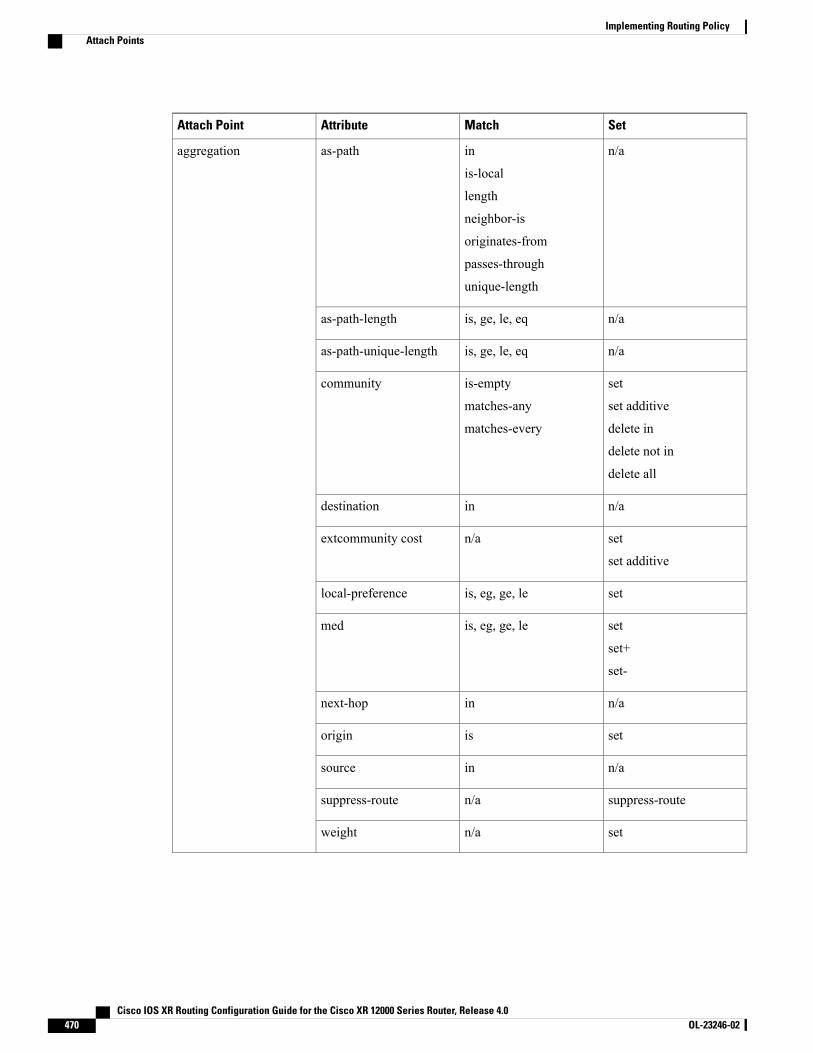
SetMatchAttributeAttach Point
n/ain
is-local
length
neighbor-is
originates-from
passes-through
unique-length
as-pathaggregation
n/ais, ge, le, eqas-path-length
n/ais, ge, le, eqas-path-unique-length
set
set additive
delete in
delete not in
delete all
is-empty
matches-any
matches-every
community
n/aindestination
set
set additive
n/aextcommunity cost
setis, eg, ge, lelocal-preference
set
set+
set-
is, eg, ge, lemed
n/ainnext-hop
setisorigin
n/ainsource
suppress-routen/asuppress-route
setn/aweight
Cisco IOS XR Routing Configuration Guide for the Cisco XR 12000 Series Router, Release 4.0470 OL-23246-02
Implementing Routing PolicyAttach Points

SetMatchAttributeAttach Point
n/ain
is-local
length
neighbor-is
originates-from
passes-through
unique-length
as-pathallocate-label
n/ais, ge, le, eqas-path-length
n/ais, ge, le, eqas-path-unique-length
n/ais-empty
matches-any
matches-every
community
n/aindestination
setn/alabel
n/ais, ge, le, eqlocal-preference
n/ais, eg, ge, lemed
n/ainnext-hop
n/aisorigin
n/ainsource
n/ain
is-local
length
neighbor-is
originates-from
passes-through
unique-length
as-pathclear-policy
Cisco IOS XR Routing Configuration Guide for the Cisco XR 12000 Series Router, Release 4.0 OL-23246-02 471
Implementing Routing PolicyAttach Points
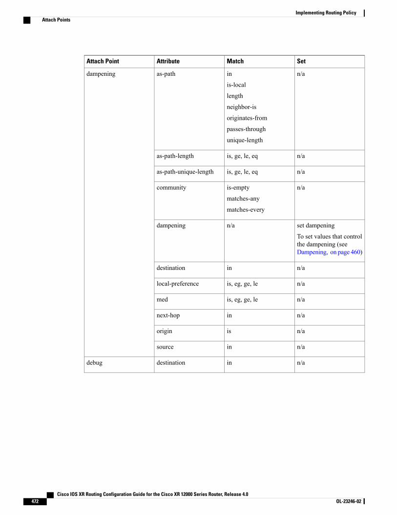
SetMatchAttributeAttach Point
n/ain
is-local
length
neighbor-is
originates-from
passes-through
unique-length
as-pathdampening
n/ais, ge, le, eqas-path-length
n/ais, ge, le, eqas-path-unique-length
n/ais-empty
matches-any
matches-every
community
set dampening
To set values that controlthe dampening (seeDampening, on page 460)
n/adampening
n/aindestination
n/ais, eg, ge, lelocal-preference
n/ais, eg, ge, lemed
n/ainnext-hop
n/aisorigin
n/ainsource
n/aindestinationdebug
Cisco IOS XR Routing Configuration Guide for the Cisco XR 12000 Series Router, Release 4.0472 OL-23246-02
Implementing Routing PolicyAttach Points
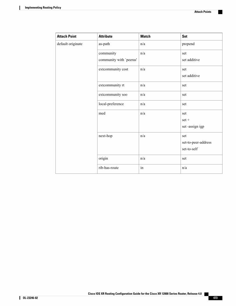
SetMatchAttributeAttach Point
prependn/aas-pathdefault originate
set
set additive
n/acommunity
community with `peeras'
set
set additive
n/aextcommunity cost
setn/aextcommunity rt
setn/aextcommunity soo
setn/alocal-preference
set
set +
set -assign igp
n/amed
set
set-to-peer-address
set-to-self
n/anext-hop
setn/aorigin
n/ainrib-has-route
Cisco IOS XR Routing Configuration Guide for the Cisco XR 12000 Series Router, Release 4.0 OL-23246-02 473
Implementing Routing PolicyAttach Points
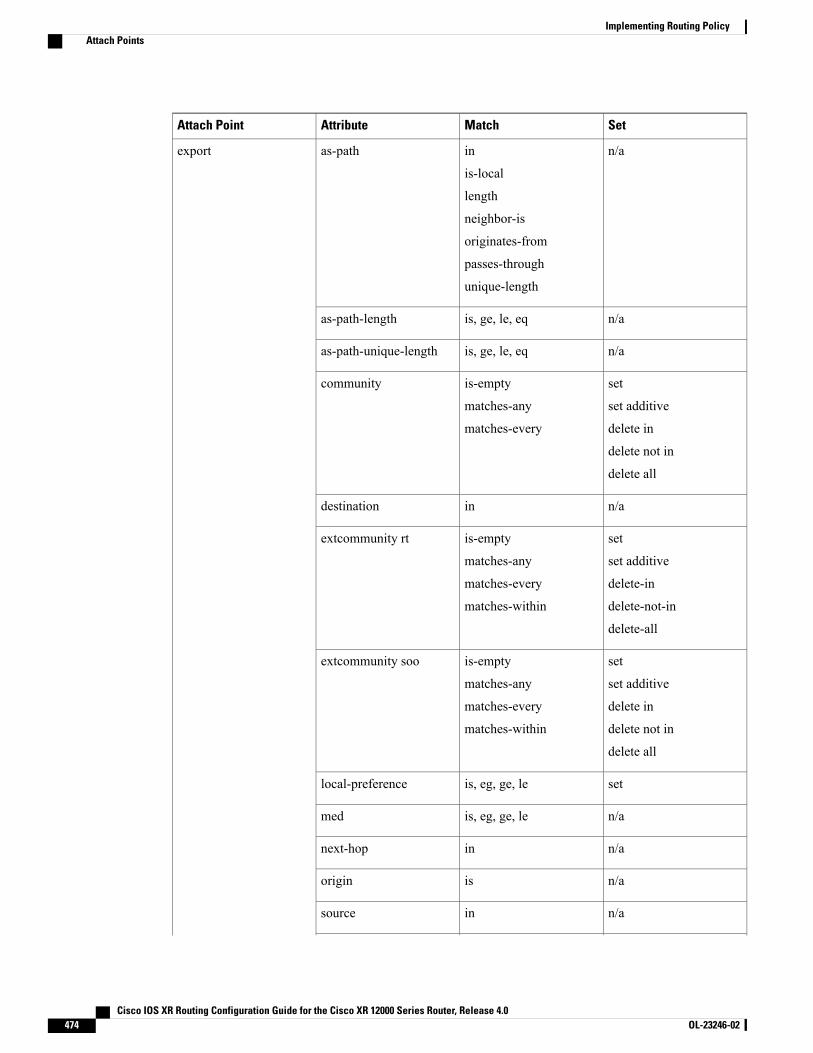
SetMatchAttributeAttach Point
n/ain
is-local
length
neighbor-is
originates-from
passes-through
unique-length
as-pathexport
n/ais, ge, le, eqas-path-length
n/ais, ge, le, eqas-path-unique-length
set
set additive
delete in
delete not in
delete all
is-empty
matches-any
matches-every
community
n/aindestination
set
set additive
delete-in
delete-not-in
delete-all
is-empty
matches-any
matches-every
matches-within
extcommunity rt
set
set additive
delete in
delete not in
delete all
is-empty
matches-any
matches-every
matches-within
extcommunity soo
setis, eg, ge, lelocal-preference
n/ais, eg, ge, lemed
n/ainnext-hop
n/aisorigin
n/ainsource
Cisco IOS XR Routing Configuration Guide for the Cisco XR 12000 Series Router, Release 4.0474 OL-23246-02
Implementing Routing PolicyAttach Points

SetMatchAttributeAttach Point
setn/aweight
Cisco IOS XR Routing Configuration Guide for the Cisco XR 12000 Series Router, Release 4.0 OL-23246-02 475
Implementing Routing PolicyAttach Points

SetMatchAttributeAttach Point
n/ain
is-local
length
neighbor-is
originates-from
passes-through
unique-length
as-pathimport
n/ais, ge, le, eqas-path-length
n/ais, ge, le, eqas-path-unique-length
n/ais-empty
matches-any
matches-every
community
n/aindestination
n/ais-empty
matches-any
matches-every
matches-within
extcommunity rt
n/ais-empty
matches-any
matches-every
matches-within
extcommunity soo
setis, ge, le, eqlocal-preference
n/ais, eg, ge, lemed
set
set peer address
set destination vrf
innext-hop
n/aisorigin
n/ainsource
setn/aweight
Cisco IOS XR Routing Configuration Guide for the Cisco XR 12000 Series Router, Release 4.0476 OL-23246-02
Implementing Routing PolicyAttach Points

SetMatchAttributeAttach Point
prepend
prepend most-recent
replace
in
is-local
length
neighbor-is
originates-from
passes-through
unique-length
as-pathneighbor-in
n/ais, ge, le, eqas-path-length
n/ais, ge, le, eqas-path-unique-length
set
set additive
delete in
delete not in
delete all
is-empty
matches-any
matches-every
communitycommunitywith ‘peeras’
n/aindestination
set
set additive
n/aextcommunity cost
set additive
delete-in
delete-not-in
delete-all
is-empty
matches-any
matches-every
matches-within
extcommunity rt
n/ais-empty
matches-any
matches-every
matches-within
extcommunity soo
setis, ge, le, eqlocal-preference
set
set+
set-
is, eg, ge, lemed
innext-hop
Cisco IOS XR Routing Configuration Guide for the Cisco XR 12000 Series Router, Release 4.0 OL-23246-02 477
Implementing Routing PolicyAttach Points
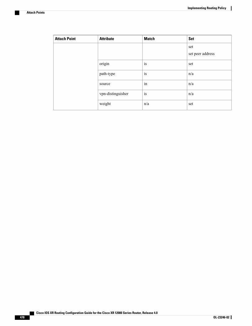
SetMatchAttributeAttach Point
set
set peer address
setisorigin
n/aispath-type
n/ainsource
n/aisvpn-distinguisher
setn/aweight
Cisco IOS XR Routing Configuration Guide for the Cisco XR 12000 Series Router, Release 4.0478 OL-23246-02
Implementing Routing PolicyAttach Points
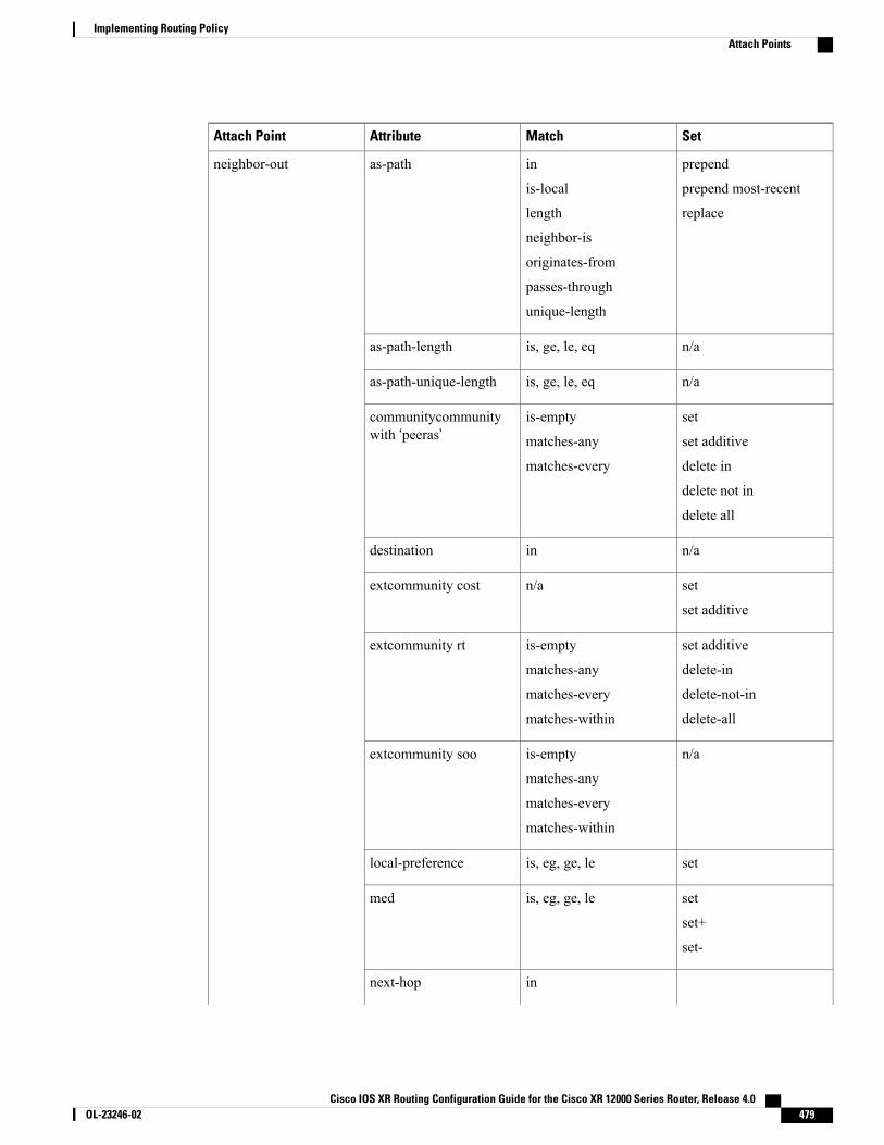
SetMatchAttributeAttach Point
prepend
prepend most-recent
replace
in
is-local
length
neighbor-is
originates-from
passes-through
unique-length
as-pathneighbor-out
n/ais, ge, le, eqas-path-length
n/ais, ge, le, eqas-path-unique-length
set
set additive
delete in
delete not in
delete all
is-empty
matches-any
matches-every
communitycommunitywith ‘peeras’
n/aindestination
set
set additive
n/aextcommunity cost
set additive
delete-in
delete-not-in
delete-all
is-empty
matches-any
matches-every
matches-within
extcommunity rt
n/ais-empty
matches-any
matches-every
matches-within
extcommunity soo
setis, eg, ge, lelocal-preference
set
set+
set-
is, eg, ge, lemed
innext-hop
Cisco IOS XR Routing Configuration Guide for the Cisco XR 12000 Series Router, Release 4.0 OL-23246-02 479
Implementing Routing PolicyAttach Points
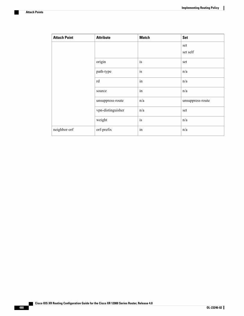
SetMatchAttributeAttach Point
set
set self
setisorigin
n/aispath-type
n/ainrd
n/ainsource
unsuppress-routen/aunsuppress-route
setn/avpn-distinguisher
n/aisweight
n/ainorf-prefixneighbor-orf
Cisco IOS XR Routing Configuration Guide for the Cisco XR 12000 Series Router, Release 4.0480 OL-23246-02
Implementing Routing PolicyAttach Points

SetMatchAttributeAttach Point
prependn/aas-pathnetwork
set
set additive
delete in
delete not in
delete all
n/acommunity
n/aindestination
set
set additive
n/aextcommunity cost
setn/alocal-preference
set
set+
set-
n/amed
setn/anext-hop
setn/aorigin
isroute-type
n/ais, eg, ge, letag
setn/aweight
n/aindestinationnext-hop
n/ais,inprotocol
Cisco IOS XR Routing Configuration Guide for the Cisco XR 12000 Series Router, Release 4.0 OL-23246-02 481
Implementing Routing PolicyAttach Points
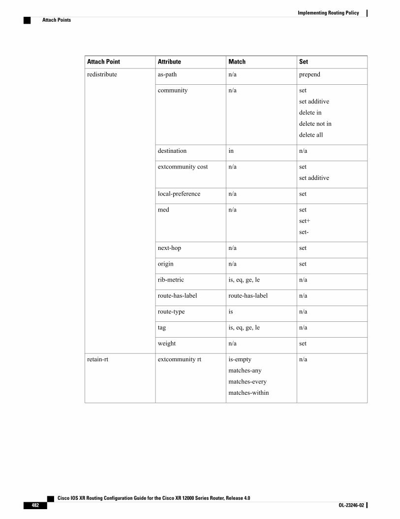
SetMatchAttributeAttach Point
prependn/aas-pathredistribute
set
set additive
delete in
delete not in
delete all
n/acommunity
n/aindestination
set
set additive
n/aextcommunity cost
setn/alocal-preference
set
set+
set-
n/amed
setn/anext-hop
setn/aorigin
n/ais, eq, ge, lerib-metric
n/aroute-has-labelroute-has-label
n/aisroute-type
n/ais, eq, ge, letag
setn/aweight
n/ais-empty
matches-any
matches-every
matches-within
extcommunity rtretain-rt
Cisco IOS XR Routing Configuration Guide for the Cisco XR 12000 Series Router, Release 4.0482 OL-23246-02
Implementing Routing PolicyAttach Points
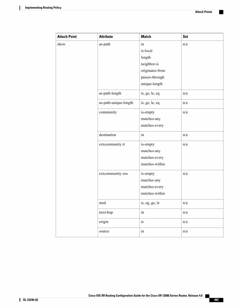
SetMatchAttributeAttach Point
n/ain
is-local
length
neighbor-is
originates-from
passes-through
unique-length
as-pathshow
n/ais, ge, le, eqas-path-length
n/ais, ge, le, eqas-path-unique-length
n/ais-empty
matches-any
matches-every
community
n/aindestination
n/ais-empty
matches-any
matches-every
matches-within
extcommunity rt
n/ais-empty
matches-any
matches-every
matches-within
extcommunity soo
n/ais, eg, ge, lemed
n/ainnext-hop
n/aisorigin
n/ainsource
Cisco IOS XR Routing Configuration Guide for the Cisco XR 12000 Series Router, Release 4.0 OL-23246-02 483
Implementing Routing PolicyAttach Points
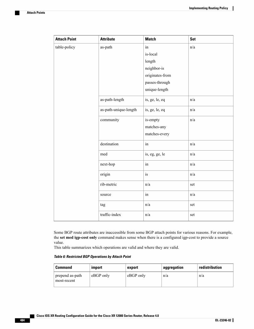
SetMatchAttributeAttach Point
n/ain
is-local
length
neighbor-is
originates-from
passes-through
unique-length
as-pathtable-policy
n/ais, ge, le, eqas-path-length
n/ais, ge, le, eqas-path-unique-length
n/ais-empty
matches-any
matches-every
community
n/aindestination
n/ais, eg, ge, lemed
n/ainnext-hop
n/aisorigin
setn/arib-metric
n/ainsource
setn/atag
setn/atraffic-index
Some BGP route attributes are inaccessible from some BGP attach points for various reasons. For example,the set med igp-cost only command makes sense when there is a configured igp-cost to provide a sourcevalue.This table summarizes which operations are valid and where they are valid.
Table 6: Restricted BGP Operations by Attach Point
redistributionaggregationexportimportCommand
n/an/aeBGP onlyeBGP onlyprepend as-pathmost-recent
Cisco IOS XR Routing Configuration Guide for the Cisco XR 12000 Series Router, Release 4.0484 OL-23246-02
Implementing Routing PolicyAttach Points
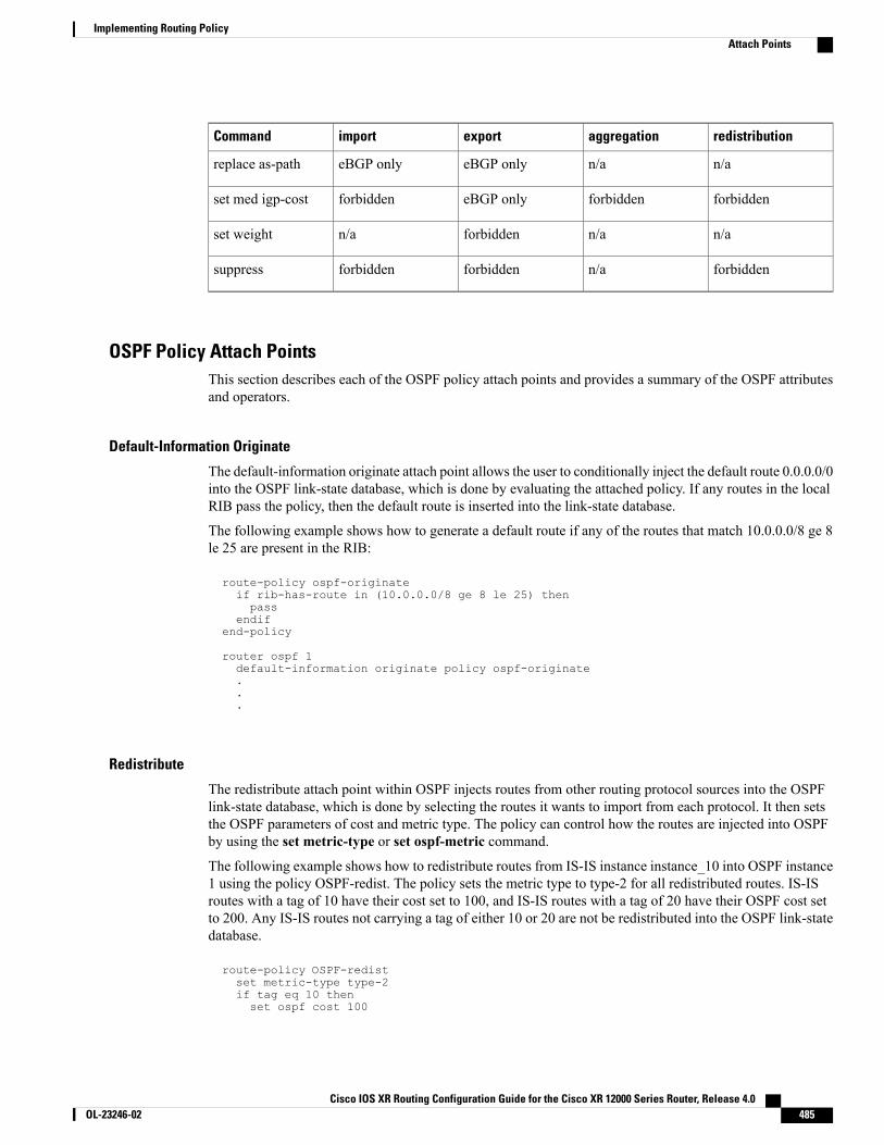
redistributionaggregationexportimportCommand
n/an/aeBGP onlyeBGP onlyreplace as-path
forbiddenforbiddeneBGP onlyforbiddenset med igp-cost
n/an/aforbiddenn/aset weight
forbiddenn/aforbiddenforbiddensuppress
OSPF Policy Attach PointsThis section describes each of the OSPF policy attach points and provides a summary of the OSPF attributesand operators.
Default-Information Originate
The default-information originate attach point allows the user to conditionally inject the default route 0.0.0.0/0into the OSPF link-state database, which is done by evaluating the attached policy. If any routes in the localRIB pass the policy, then the default route is inserted into the link-state database.
The following example shows how to generate a default route if any of the routes that match 10.0.0.0/8 ge 8le 25 are present in the RIB:
route-policy ospf-originateif rib-has-route in (10.0.0.0/8 ge 8 le 25) thenpass
endifend-policy
router ospf 1default-information originate policy ospf-originate...
Redistribute
The redistribute attach point within OSPF injects routes from other routing protocol sources into the OSPFlink-state database, which is done by selecting the routes it wants to import from each protocol. It then setsthe OSPF parameters of cost and metric type. The policy can control how the routes are injected into OSPFby using the set metric-type or set ospf-metric command.
The following example shows how to redistribute routes from IS-IS instance instance_10 into OSPF instance1 using the policy OSPF-redist. The policy sets the metric type to type-2 for all redistributed routes. IS-ISroutes with a tag of 10 have their cost set to 100, and IS-IS routes with a tag of 20 have their OSPF cost setto 200. Any IS-IS routes not carrying a tag of either 10 or 20 are not be redistributed into the OSPF link-statedatabase.
route-policy OSPF-redistset metric-type type-2if tag eq 10 thenset ospf cost 100
Cisco IOS XR Routing Configuration Guide for the Cisco XR 12000 Series Router, Release 4.0 OL-23246-02 485
Implementing Routing PolicyAttach Points

elseif tag eq 20 thenset ospf cost 200
elsedrop
endifend-policyrouter ospf 1redistribute isis instance_10 policy OSPF-redist...
Area-in
The area-in attach point within OSPF allows you to filter inbound OSPF type-3 summary link-stateadvertisements (LSAs). The attach point provides prefix-based matching and hence increased control forfiltering type-3 summary LSAs.
The following example shows how to configure the prefix for OSPF summary LSAs. If the prefix matchesany of 111.105.3.0/24, 111.105.7.0/24, 111.105.13.0/24, it is accepted. If the prefix matches any of111.106.3.0/24, 111.106.7.0/24, 111.106.13.0/24, it is dropped.
route-policy OSPF-area-inif destination in (
111.105.3.0/24,111.105.7.0/24,111.105.13.0/24) then
dropendifif destination in (
111.106.3.0/24,111.106.7.0/24,111.106.13.0/24) then
passendif
end-policy
router ospf 1area 1route-policy OSPF-area-in in
Area-out
The area-out attach point within OSPF allows you to filter outbound OSPF type-3 summary LSAs. The attachpoint provides prefix-based matching and, hence, increased control for filtering type-3 summary LSAs.
The following example shows how to configure the prefix for OSPF summary LSAs. If the prefix matchesany of 211.105.3.0/24, 211.105.7.0/24, 211.105.13.0/24, it is announced. If the prefix matches any of.105.3.0/24, 212.105.7.0/24, 212.105.13.0/24, it is dropped and not announced.
route-policy OSPF-area-outif destination in (
211.105.3.0/24,211.105.7.0/24,211.105.13.0/24) then
dropendifif destination in (
212.105.3.0/24,212.105.7.0/24,212.105.13.0/24) then
passendif
Cisco IOS XR Routing Configuration Guide for the Cisco XR 12000 Series Router, Release 4.0486 OL-23246-02
Implementing Routing PolicyAttach Points
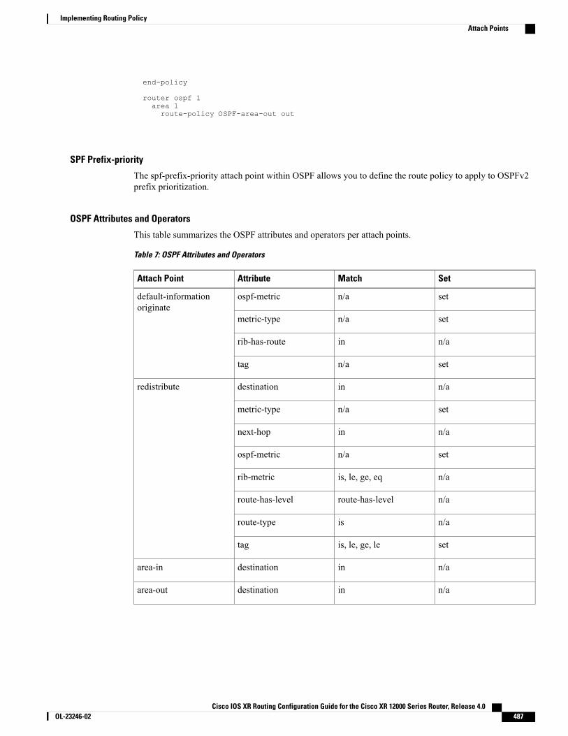
end-policy
router ospf 1area 1route-policy OSPF-area-out out
SPF Prefix-priority
The spf-prefix-priority attach point within OSPF allows you to define the route policy to apply to OSPFv2prefix prioritization.
OSPF Attributes and Operators
This table summarizes the OSPF attributes and operators per attach points.
Table 7: OSPF Attributes and Operators
SetMatchAttributeAttach Point
setn/aospf-metricdefault-informationoriginate
setn/ametric-type
n/ainrib-has-route
setn/atag
n/aindestinationredistribute
setn/ametric-type
n/ainnext-hop
setn/aospf-metric
n/ais, le, ge, eqrib-metric
n/aroute-has-levelroute-has-level
n/aisroute-type
setis, le, ge, letag
n/aindestinationarea-in
n/aindestinationarea-out
Cisco IOS XR Routing Configuration Guide for the Cisco XR 12000 Series Router, Release 4.0 OL-23246-02 487
Implementing Routing PolicyAttach Points
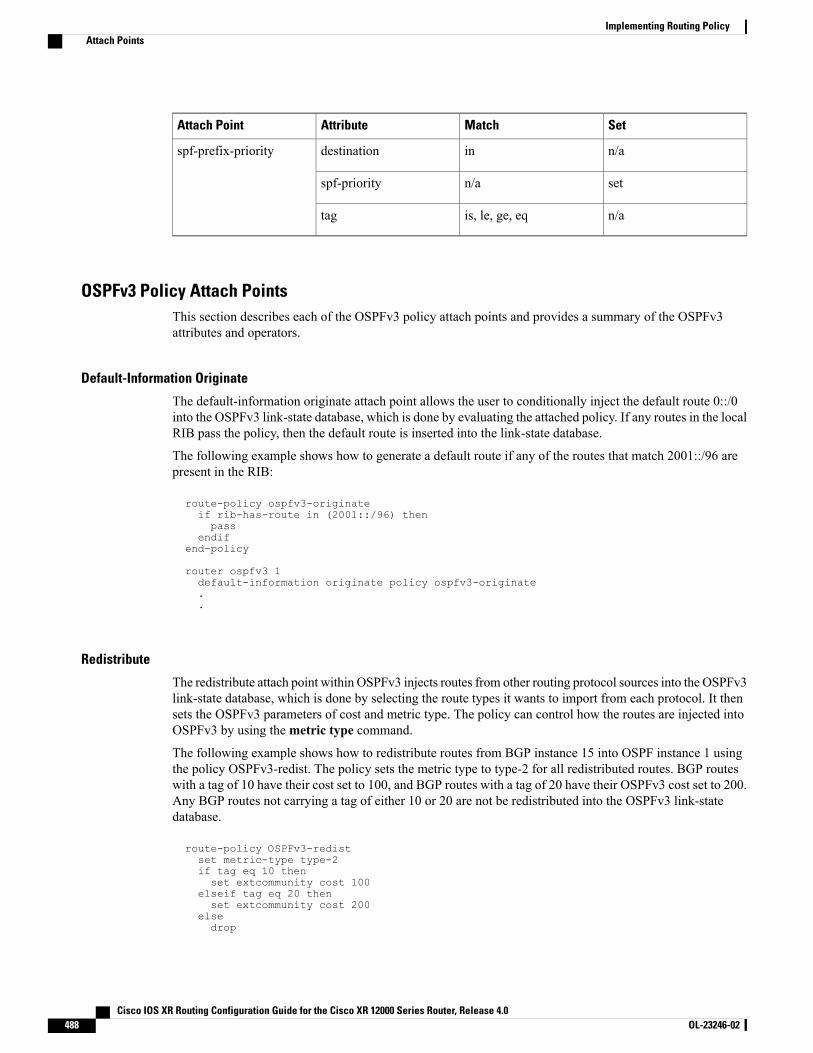
SetMatchAttributeAttach Point
n/aindestinationspf-prefix-priority
setn/aspf-priority
n/ais, le, ge, eqtag
OSPFv3 Policy Attach PointsThis section describes each of the OSPFv3 policy attach points and provides a summary of the OSPFv3attributes and operators.
Default-Information Originate
The default-information originate attach point allows the user to conditionally inject the default route 0::/0into the OSPFv3 link-state database, which is done by evaluating the attached policy. If any routes in the localRIB pass the policy, then the default route is inserted into the link-state database.
The following example shows how to generate a default route if any of the routes that match 2001::/96 arepresent in the RIB:
route-policy ospfv3-originateif rib-has-route in (2001::/96) thenpass
endifend-policy
router ospfv3 1default-information originate policy ospfv3-originate..
Redistribute
The redistribute attach point within OSPFv3 injects routes from other routing protocol sources into the OSPFv3link-state database, which is done by selecting the route types it wants to import from each protocol. It thensets the OSPFv3 parameters of cost and metric type. The policy can control how the routes are injected intoOSPFv3 by using themetric type command.
The following example shows how to redistribute routes from BGP instance 15 into OSPF instance 1 usingthe policy OSPFv3-redist. The policy sets the metric type to type-2 for all redistributed routes. BGP routeswith a tag of 10 have their cost set to 100, and BGP routes with a tag of 20 have their OSPFv3 cost set to 200.Any BGP routes not carrying a tag of either 10 or 20 are not be redistributed into the OSPFv3 link-statedatabase.
route-policy OSPFv3-redistset metric-type type-2if tag eq 10 thenset extcommunity cost 100
elseif tag eq 20 thenset extcommunity cost 200
elsedrop
Cisco IOS XR Routing Configuration Guide for the Cisco XR 12000 Series Router, Release 4.0488 OL-23246-02
Implementing Routing PolicyAttach Points
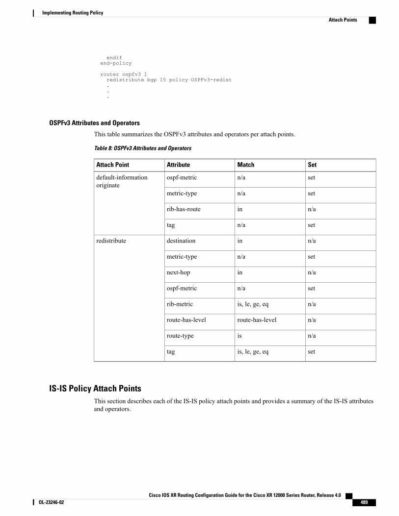
endifend-policy
router ospfv3 1redistribute bgp 15 policy OSPFv3-redist...
OSPFv3 Attributes and Operators
This table summarizes the OSPFv3 attributes and operators per attach points.
Table 8: OSPFv3 Attributes and Operators
SetMatchAttributeAttach Point
setn/aospf-metricdefault-informationoriginate
setn/ametric-type
n/ainrib-has-route
setn/atag
n/aindestinationredistribute
setn/ametric-type
n/ainnext-hop
setn/aospf-metric
n/ais, le, ge, eqrib-metric
n/aroute-has-levelroute-has-level
n/aisroute-type
setis, le, ge, eqtag
IS-IS Policy Attach PointsThis section describes each of the IS-IS policy attach points and provides a summary of the IS-IS attributesand operators.
Cisco IOS XR Routing Configuration Guide for the Cisco XR 12000 Series Router, Release 4.0 OL-23246-02 489
Implementing Routing PolicyAttach Points
Redistribute
The redistribute attach point within IS-IS allows routes from other protocols to be readvertised by IS-IS. Thepolicy is a set of control structures for selecting the types of routes that a user wants to redistribute into IS-IS.The policy can also control which IS-IS level the routes are injected into and at what metric values.
The following example shows how to redistribute routes from IS-IS instance 1 into IS-IS instance instance_10using the policy ISIS-redist. This policy sets the level to level-1-2 for all redistributed routes. OSPF routeswith a tag of 10 have their metric set to 100, and IS-IS routes with a tag of 20 have their IS-IS metric set to200. Any IS-IS routes not carrying a tag of either 10 or 20 are not be redistributed into the IS-IS database.
route-policy ISIS-redistset level level-1-2if tag eq 10 thenset isis-metric 100
elseif tag eq 20 thenset isis-metric 200
elsedrop
endifend-policy
router isis instance_10address-family ipv4 unicastredistribute ospf 1 policy ISIS-redist...
Default-Information Originate
The default-information originate attach point within IS-IS allows the default route 0.0.0.0/0 to be conditionallyinjected into the IS-IS route database.
The following example shows how to generate an IPv4 unicast default route if any of the routes that match10.0.0.0/8 ge 8 le 25 is present in the RIB. The cost of the IS-IS route is set to 100 and the level is set tolevel-1-2 on the default route that is injected into the IS-IS database.
route-policy isis-originateif rib-has-route in (10.0.0.0/8 ge 8 le 25) thenset metric 100set level level-1-2
endifend-policy
router isis instance_10address-family ipv4 unicastdefault-information originate policy isis_originate.
Inter-area-propagate
The inter-area-propagate attach point within IS-IS allows the prefixes to be conditionally propagated fromone level to another level within the same IS-IS instance.
The following example shows how to allow prefixes to be leaked from the level 1 LSP into the level 2 LSPif any of the prefixes match 10.0.0.0/8 ge 8 le 25.
route-policy isis-propagate
Cisco IOS XR Routing Configuration Guide for the Cisco XR 12000 Series Router, Release 4.0490 OL-23246-02
Implementing Routing PolicyAttach Points
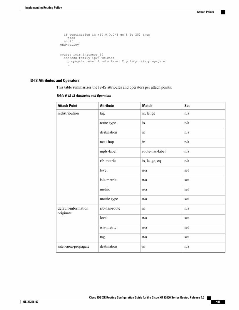
if destination in (10.0.0.0/8 ge 8 le 25) thenpass
endifend-policy
router isis instance_10address-family ipv4 unicastpropagate level 1 into level 2 policy isis-propagate.
IS-IS Attributes and Operators
This table summarizes the IS-IS attributes and operators per attach points.
Table 9: IS-IS Attributes and Operators
SetMatchAttributeAttach Point
n/ais, le, getagredistribution
n/aisroute-type
n/aindestination
n/ainnext-hop
n/aroute-has-labelmpls-label
n/ais, le, ge, eqrib-metric
setn/alevel
setn/aisis-metric
setn/ametric
setn/ametric-type
n/ainrib-has-routedefault-informationoriginate
setn/alevel
setn/aisis-metric
setn/atag
n/aindestinationinter-area-propagate
Cisco IOS XR Routing Configuration Guide for the Cisco XR 12000 Series Router, Release 4.0 OL-23246-02 491
Implementing Routing PolicyAttach Points
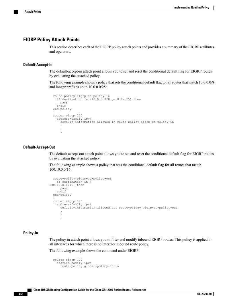
EIGRP Policy Attach PointsThis section describes each of the EIGRP policy attach points and provides a summary of the EIGRP attributesand operators.
Default-Accept-In
The default-accept-in attach point allows you to set and reset the conditional default flag for EIGRP routesby evaluating the attached policy.
The following example shows a policy that sets the conditional default flag for all routes that match 10.0.0.0/8and longer prefixes up to 10.0.0.0/25:
route-policy eigrp-cd-policy-inif destination in (10.0.0.0/8 ge 8 le 25) thenpass
endifend-policy!router eigrp 100address-family ipv4default-information allowed in route-policy eigrp-cd-policy-in...
Default-Accept-Out
The default-accept-out attach point allows you to set and reset the conditional default flag for EIGRP routesby evaluating the attached policy.
The following example shows a policy that sets the conditional default flag for all routes that match100.10.0.0/16:
route-policy eigrp-cd-policy-outif destination in (
200.10.0.0/16) thenpass
endifend-policy!router eigrp 100address-family ipv4default-information allowed out route-policy eigrp-cd-policy-out...
Policy-In
The policy-in attach point allows you to filter and modify inbound EIGRP routes. This policy is applied toall interfaces for which there is no interface inbound route policy.
The following example shows the command under EIGRP:
router eigrp 100address-family ipv4route-policy global-policy-in in
Cisco IOS XR Routing Configuration Guide for the Cisco XR 12000 Series Router, Release 4.0492 OL-23246-02
Implementing Routing PolicyAttach Points
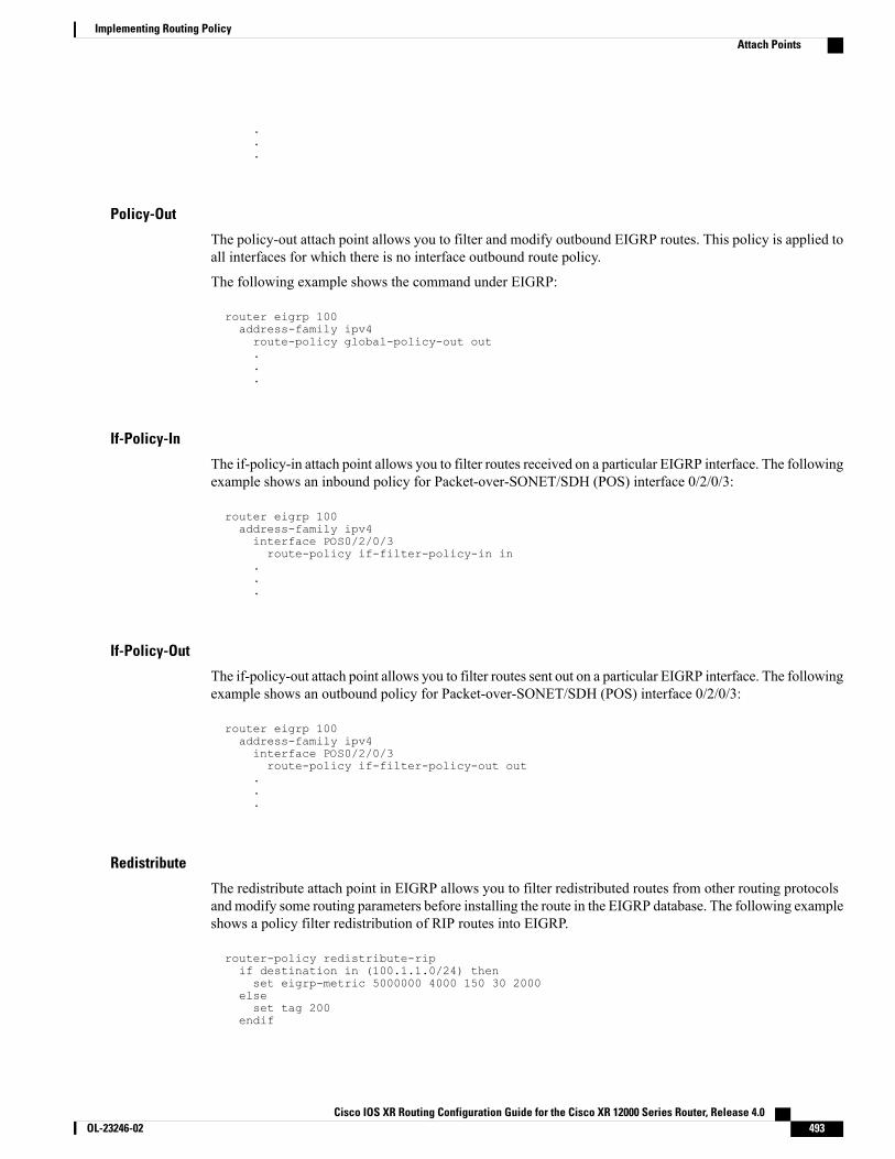
.
.
.
Policy-Out
The policy-out attach point allows you to filter and modify outbound EIGRP routes. This policy is applied toall interfaces for which there is no interface outbound route policy.
The following example shows the command under EIGRP:
router eigrp 100address-family ipv4route-policy global-policy-out out...
If-Policy-In
The if-policy-in attach point allows you to filter routes received on a particular EIGRP interface. The followingexample shows an inbound policy for Packet-over-SONET/SDH (POS) interface 0/2/0/3:
router eigrp 100address-family ipv4interface POS0/2/0/3route-policy if-filter-policy-in in
.
.
.
If-Policy-Out
The if-policy-out attach point allows you to filter routes sent out on a particular EIGRP interface. The followingexample shows an outbound policy for Packet-over-SONET/SDH (POS) interface 0/2/0/3:
router eigrp 100address-family ipv4interface POS0/2/0/3route-policy if-filter-policy-out out
.
.
.
Redistribute
The redistribute attach point in EIGRP allows you to filter redistributed routes from other routing protocolsand modify some routing parameters before installing the route in the EIGRP database. The following exampleshows a policy filter redistribution of RIP routes into EIGRP.
router-policy redistribute-ripif destination in (100.1.1.0/24) thenset eigrp-metric 5000000 4000 150 30 2000
elseset tag 200
endif
Cisco IOS XR Routing Configuration Guide for the Cisco XR 12000 Series Router, Release 4.0 OL-23246-02 493
Implementing Routing PolicyAttach Points
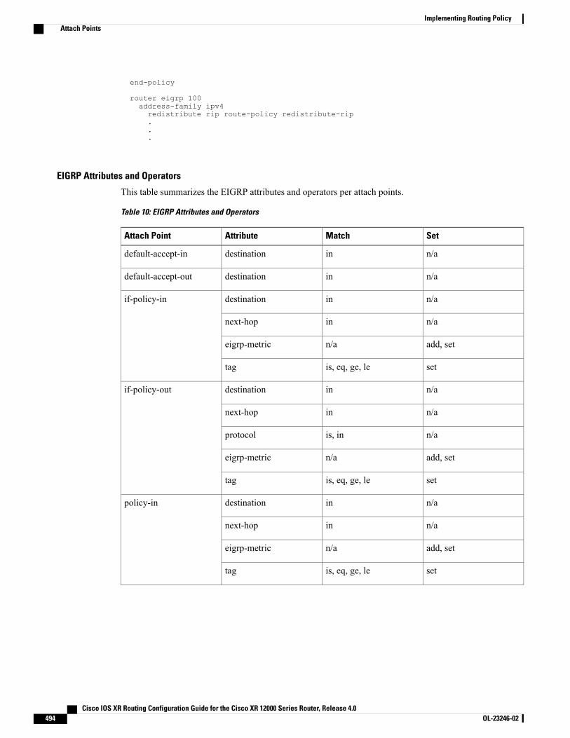
end-policy
router eigrp 100address-family ipv4redistribute rip route-policy redistribute-rip...
EIGRP Attributes and Operators
This table summarizes the EIGRP attributes and operators per attach points.
Table 10: EIGRP Attributes and Operators
SetMatchAttributeAttach Point
n/aindestinationdefault-accept-in
n/aindestinationdefault-accept-out
n/aindestinationif-policy-in
n/ainnext-hop
add, setn/aeigrp-metric
setis, eq, ge, letag
n/aindestinationif-policy-out
n/ainnext-hop
n/ais, inprotocol
add, setn/aeigrp-metric
setis, eq, ge, letag
n/aindestinationpolicy-in
n/ainnext-hop
add, setn/aeigrp-metric
setis, eq, ge, letag
Cisco IOS XR Routing Configuration Guide for the Cisco XR 12000 Series Router, Release 4.0494 OL-23246-02
Implementing Routing PolicyAttach Points
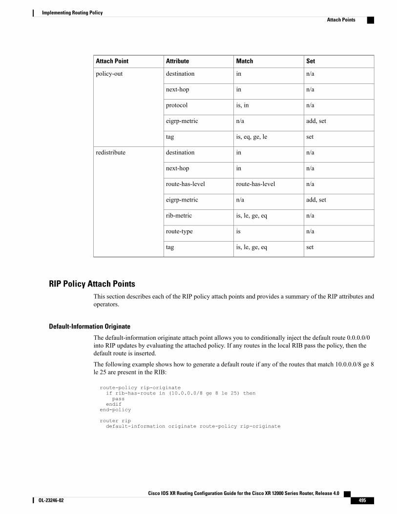
SetMatchAttributeAttach Point
n/aindestinationpolicy-out
n/ainnext-hop
n/ais, inprotocol
add, setn/aeigrp-metric
setis, eq, ge, letag
n/aindestinationredistribute
n/ainnext-hop
n/aroute-has-levelroute-has-level
add, setn/aeigrp-metric
n/ais, le, ge, eqrib-metric
n/aisroute-type
setis, le, ge, eqtag
RIP Policy Attach PointsThis section describes each of the RIP policy attach points and provides a summary of the RIP attributes andoperators.
Default-Information Originate
The default-information originate attach point allows you to conditionally inject the default route 0.0.0.0/0into RIP updates by evaluating the attached policy. If any routes in the local RIB pass the policy, then thedefault route is inserted.
The following example shows how to generate a default route if any of the routes that match 10.0.0.0/8 ge 8le 25 are present in the RIB:
route-policy rip-originateif rib-has-route in (10.0.0.0/8 ge 8 le 25) thenpass
endifend-policy
router ripdefault-information originate route-policy rip-originate
Cisco IOS XR Routing Configuration Guide for the Cisco XR 12000 Series Router, Release 4.0 OL-23246-02 495
Implementing Routing PolicyAttach Points

Redistribute
The redistribution attach point within RIP allows you to inject routes from other routing protocol sources intothe RIP database.
The following example shows how to inject OSPF routes into RIP:
route-policy redist-ospfset rip-metric 5
end-policy
router ripredistribute ospf 1 route-policy redist-ospf
Global-Inbound
The global-inbound attach point for RIP allows you to filter or update inbound RIP routes that match a routepolicy.
The following example shows how to filter the inbound RIP routes that match the route policy named rip-in:
router riproute-policy rip-in in
Global-Outbound
The global-outbound attach point for RIP allows you to filter or update outbound RIP routes that match aroute-policy.
The following example shows how to filter the outbound RIP routes that match the route policy named rip-out:
router riproute-policy rip-out out
Interface-Inbound
The interface-inbound attach point allows you to filter or update inbound RIP routes that match a route policyfor a specific interface.
The following example shows how to filter inbound RIP routes that match the route policy for interface0/1/0/1:
router ripinterface GigabitEthernet0/1/0/1route-policy rip-in in
Interface-Outbound
The interface-outbound attach point allows you to filter or update outbound RIP routes that match a routepolicy for a specific interface.
Cisco IOS XR Routing Configuration Guide for the Cisco XR 12000 Series Router, Release 4.0496 OL-23246-02
Implementing Routing PolicyAttach Points
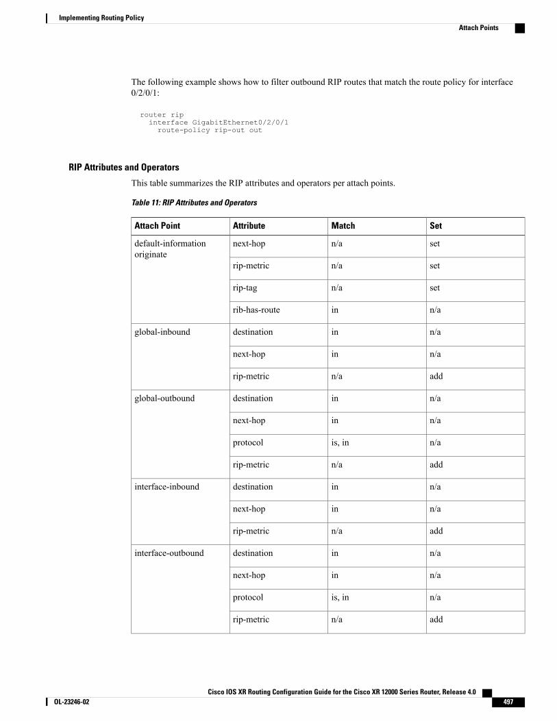
The following example shows how to filter outbound RIP routes that match the route policy for interface0/2/0/1:
router ripinterface GigabitEthernet0/2/0/1route-policy rip-out out
RIP Attributes and Operators
This table summarizes the RIP attributes and operators per attach points.
Table 11: RIP Attributes and Operators
SetMatchAttributeAttach Point
setn/anext-hopdefault-informationoriginate
setn/arip-metric
setn/arip-tag
n/ainrib-has-route
n/aindestinationglobal-inbound
n/ainnext-hop
addn/arip-metric
n/aindestinationglobal-outbound
n/ainnext-hop
n/ais, inprotocol
addn/arip-metric
n/aindestinationinterface-inbound
n/ainnext-hop
addn/arip-metric
n/aindestinationinterface-outbound
n/ainnext-hop
n/ais, inprotocol
addn/arip-metric
Cisco IOS XR Routing Configuration Guide for the Cisco XR 12000 Series Router, Release 4.0 OL-23246-02 497
Implementing Routing PolicyAttach Points
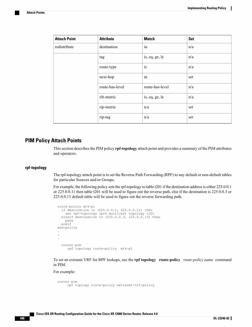
SetMatchAttributeAttach Point
n/aindestinationredistribute
n/ais, eq, ge, letag
n/aisroute-type
setinnext-hop
n/aroute-has-levelroute-has-level
n/ais, eq, ge, lerib-metric
setn/arip-metric
setn/arip-tag
PIM Policy Attach PointsThis section describes the PIM policy rpf-topology attach point and provides a summary of the PIM attributesand operators.
rpf-topology
The rpf-topology attach point is to set the Reverse Path Forwarding (RPF) to any default or non-default tablesfor particular Sources and/or Groups.
For example, the following policy sets the rpf-topology to table t201 if the destination address is either 225.0.0.1or 225.0.0.11 then table t201 will be used to figure out the reverse path, else if the destination is 225.0.0.3 or225.0.0.13 default table will be used to figure out the reverse forwarding path.
route-policy mt4-p1if destination in (225.0.0.1, 225.0.0.11) thenset rpf-topology ipv4 multicast topology t201
elseif destination in (225.0.0.3, 225.0.0.13) thenpass
endifend-policy...
router pimrpf topology route-policy mt4-p1
To set an extranet VRF for RPF lookups, use the rpf topology route-policy route-policy name commandin PIM.
For example:
router pimrpf toplogy route-policy extranet-vrf-policy
Cisco IOS XR Routing Configuration Guide for the Cisco XR 12000 Series Router, Release 4.0498 OL-23246-02
Implementing Routing PolicyAttach Points

route-policy extranet-vrf-policyif destination in (225.1.1.1/32) thenset rpf-topology vrf parent-vrf
elsepass
end-policy
Set the rpf-topology attribute for PIM to default VRF to extranet the IGMP joins for Multicast VRFOverride to function.
Note
PIM Attributes and Operators
This table summarizes the PIM attributes and operators for the rpf-topology attach point.
Table 12: PIM Attributes and Operators
SetMatchAttributeAttach Point
n/aindestinationrpf-topology
n/ainsource
setn/arpf-topology
Attached Policy ModificationPolicies that are in use do, on occasion, need to be modified. In the traditional configuration model, a policymodification would be done by completely removing the policy and re-entering it. However, this model allowsfor a window of time in which no policy is attached and default actions to be used, which is an opportunityfor inconsistencies to exist. To close this window of opportunity, you can modify a policy in use at an attachpoint by respecifying it, which allows for policies that are in use to be changed, without having a window oftime in which no policy is applied at the given attach point.
A route policy or set that is in use at an attach point cannot be removed because this removal would resultin an undefined reference. An attempt to remove a route policy or set that is in use at an attach point resultsin an error message to the user.
Note
Nonattached Policy ModificationAs long as a given policy is not attached at an attach point, the policy is allowed to refer to nonexistent setsand policies. Configurations can be built that reference sets or policy blocks that are not yet defined, and thenlater those undefined policies and sets can be filled in. This method of building configurations gives muchgreater flexibility in policy definition. Every piece of policy you want to reference while defining a policy
Cisco IOS XR Routing Configuration Guide for the Cisco XR 12000 Series Router, Release 4.0 OL-23246-02 499
Implementing Routing PolicyAttached Policy Modification
need not exist in the configuration. Thus, you can define a policy sample1 that references a policy sample2using an apply statement even if the policy sample2 does not exist. Similarly, you can enter a policy statementthat refers to a nonexistent set.
However, the existence of all referenced policies and sets is enforced when a policy is attached. Thus, if auser attempts to attach the policy sample1 with the reference to an undefined policy sample2 at an inboundBGP policy using the statement neighbor 1.2.3.4 address-family ipv4 unicast policy sample1 in, theconfiguration attempt is rejected because the policy sample2 does not exist.
Editing Routing Policy Configuration ElementsRPL is based on statements rather than on lines. That is, within the begin-end pair that brackets policy statementsfrom the CLI, a new line is merely a separator, the same as a space character.
The CLI provides the means to enter and delete route policy statements. RPL provides a means to edit thecontents of the policy between the begin-end brackets, using a text editor. The following text editors areavailable on Cisco IOS XR software for editing RPL policies:
• Nano (default)
• Emacs
• Vim
Editing Routing Policy Configuration Elements Using the Nano Editor
To edit the contents of a routing policy using the Nano editor, use the following CLI command in EXECmode:
edit route-policy
name
nano
A copy of the route policy is copied to a temporary file and the editor is launched. After editing, enter Ctrl-Xto save the file and exit the editor. The available editor commands are displayed on screen.
Detailed information on using the Nano editor is available at this URL: http://www.nano-editor.org/.
Not all Nano editor features are supported on Cisco IOS XR software.
Editing Routing Policy Configuration Elements Using the Emacs Editor
To edit the contents of a routing policy using the Emacs editor, use the following CLI command in EXECmode:
edit
route-policy
Cisco IOS XR Routing Configuration Guide for the Cisco XR 12000 Series Router, Release 4.0500 OL-23246-02
Implementing Routing PolicyNonattached Policy Modification
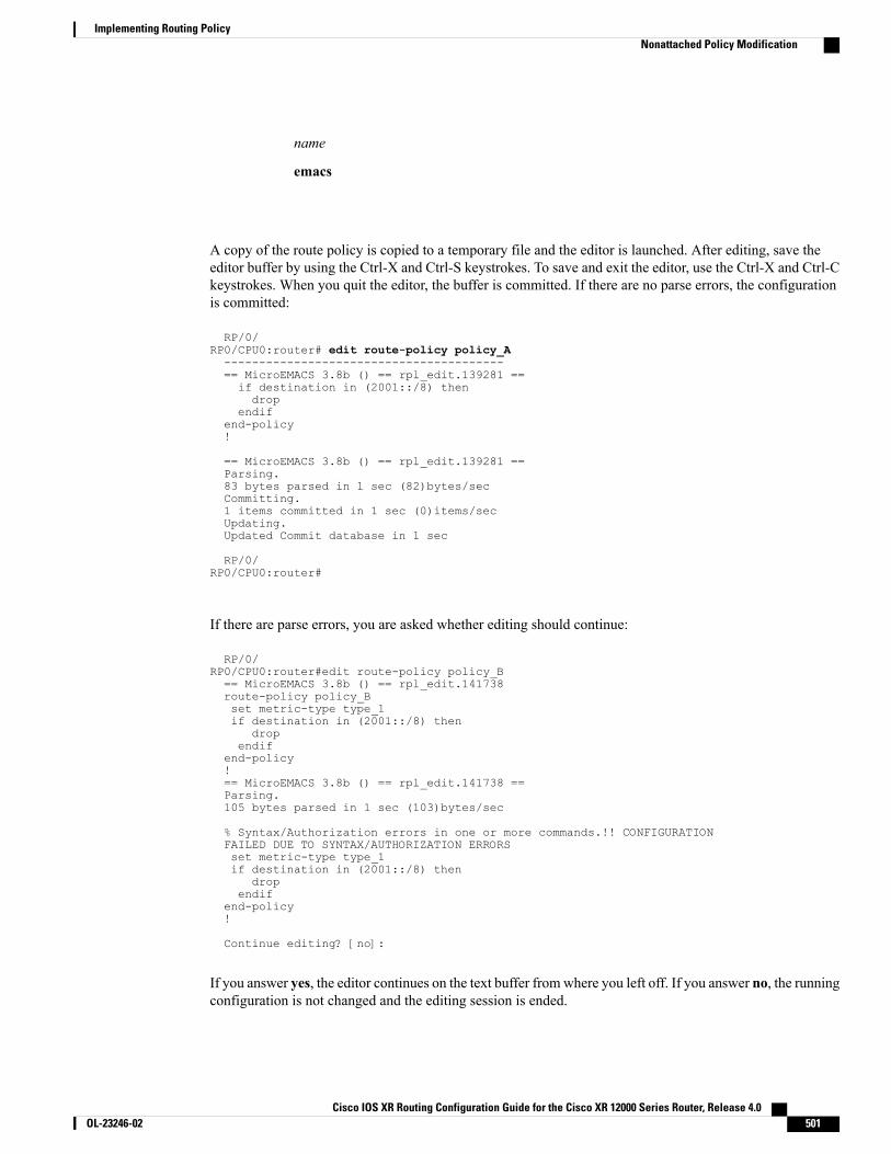
name
emacs
A copy of the route policy is copied to a temporary file and the editor is launched. After editing, save theeditor buffer by using the Ctrl-X and Ctrl-S keystrokes. To save and exit the editor, use the Ctrl-X and Ctrl-Ckeystrokes. When you quit the editor, the buffer is committed. If there are no parse errors, the configurationis committed:
RP/0/RP0/CPU0:router# edit route-policy policy_A----------------------------------------== MicroEMACS 3.8b () == rpl_edit.139281 ==if destination in (2001::/8) thendrop
endifend-policy!
== MicroEMACS 3.8b () == rpl_edit.139281 ==Parsing.83 bytes parsed in 1 sec (82)bytes/secCommitting.1 items committed in 1 sec (0)items/secUpdating.Updated Commit database in 1 sec
RP/0/RP0/CPU0:router#
If there are parse errors, you are asked whether editing should continue:
RP/0/RP0/CPU0:router#edit route-policy policy_B== MicroEMACS 3.8b () == rpl_edit.141738route-policy policy_Bset metric-type type_1if destination in (2001::/8) then
dropendif
end-policy!== MicroEMACS 3.8b () == rpl_edit.141738 ==Parsing.105 bytes parsed in 1 sec (103)bytes/sec
% Syntax/Authorization errors in one or more commands.!! CONFIGURATIONFAILED DUE TO SYNTAX/AUTHORIZATION ERRORSset metric-type type_1if destination in (2001::/8) then
dropendif
end-policy!
Continue editing? [no]:
If you answer yes, the editor continues on the text buffer fromwhere you left off. If you answer no, the runningconfiguration is not changed and the editing session is ended.
Cisco IOS XR Routing Configuration Guide for the Cisco XR 12000 Series Router, Release 4.0 OL-23246-02 501
Implementing Routing PolicyNonattached Policy Modification
Editing Routing Policy Configuration Elements Using the Vim Editor
Editing elements of a routing policy with Vim (Vi IMproved) is similar to editing them with Emacs exceptfor some feature differences such as the keystrokes to save and quit. To write to a current file and exit, usethe :wq or :x or ZZ keystrokes. To quit and confirm, use the :q keystrokes. To quit and discard changes, usethe :q! keystrokes.
You can reference detailed online documentation for Vim at this URL: http://www.vim.org/
Editing Routing Policy Configuration Elements Using the CLI
The CLI allows you to enter and delete route policy statements. You can complete a policy configurationblock by entering applicable commands such as end-policy or end-set. Alternatively, the CLI interpreterallows you to use the exit command to complete a policy configuration block. The abort command is usedto discard the current policy configuration and return to global configuration mode.
How to Implement Routing PolicyThis section contains the following procedures:
Defining a Route PolicyThis task explains how to define a route policy.
If you want to modify an existing routing policy using the command-line interface (CLI), youmust redefinethe policy by completing this task.
Note
SUMMARY STEPS
1. configure2. route-policy name [ parameter1 , parameter2 , . . . , parameterN ]3. end-policy4. Do one of the following:
• end
• commit
Cisco IOS XR Routing Configuration Guide for the Cisco XR 12000 Series Router, Release 4.0502 OL-23246-02
Implementing Routing PolicyHow to Implement Routing Policy
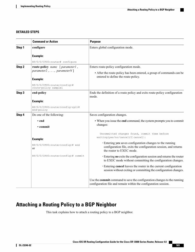
DETAILED STEPS
PurposeCommand or Action
Enters global configuration mode.configure
Example:
RP/0/0/CPU0:router# configure
Step 1
Enters route-policy configuration mode.route-policy name [ parameter1 ,parameter2 , . . . , parameterN ]
Step 2
• After the route-policy has been entered, a group of commands can beentered to define the route-policy.
Example:
RP/0/0/CPU0:router(config)#route-policy sample1
Ends the definition of a route policy and exits route-policy configurationmode.
end-policy
Example:
RP/0/0/CPU0:router(config-rpl)#end-policy
Step 3
Saves configuration changes.Do one of the following:Step 4
• end •When you issue the end command, the system prompts you to commitchanges:
Uncommitted changes found, commit them beforeexiting(yes/no/cancel)?[cancel]:
• commit
Example:
RP/0/0/CPU0:router(config)# end◦Entering yes saves configuration changes to the runningconfiguration file, exits the configuration session, and returnsthe router to EXEC mode.
or
RP/0/0/CPU0:router(config)# commit ◦Entering no exits the configuration session and returns the routerto EXEC mode without committing the configuration changes.
◦Entering cancel leaves the router in the current configurationsession without exiting or committing the configuration changes.
Use the commit command to save the configuration changes to the runningconfiguration file and remain within the configuration session.
Attaching a Routing Policy to a BGP NeighborThis task explains how to attach a routing policy to a BGP neighbor.
Cisco IOS XR Routing Configuration Guide for the Cisco XR 12000 Series Router, Release 4.0 OL-23246-02 503
Implementing Routing PolicyAttaching a Routing Policy to a BGP Neighbor

Before You Begin
A routing policy must be preconfigured and well defined prior to it being applied at an attach point. If a policyis not predefined, an error message is generated stating that the policy is not defined.
SUMMARY STEPS
1. configure2. router bgp as-number3. neighbor ip-address4. address-family { ipv4 unicast | ipv4 multicast | ipv4 labeled-unicast | ipv4 tunnel | ipv4 mdt |
ipv6 unicast | ipv6 multicast | ipv6 labeled-unicast | vpnv4 unicast | vpnv6 unicast }5. route-policy policy-name { in | out }6. Do one of the following:
• end
• commit
DETAILED STEPS
PurposeCommand or Action
Enters global configuration mode.configure
Example:
RP/0/0/CPU0:router# configure
Step 1
Configures a BGP routing process and enters router configurationmode.
router bgp as-number
Example:
RP/0/0/CPU0:router(config)# router bgp 125
Step 2
• The as-number argument identifies the autonomous system inwhich the router resides. Valid values are from 0 to 65535.Private autonomous system numbers that can be used ininternal networks range from 64512 to 65535.
Specifies a neighbor IP address.neighbor ip-address
Example:
RP/0/0/CPU0:router(config-bgp)# neighbor10.0.0.20
Step 3
Specifies the address family.address-family { ipv4 unicast | ipv4 multicast| ipv4 labeled-unicast | ipv4 tunnel | ipv4 mdt
Step 4
| ipv6 unicast | ipv6 multicast | ipv6labeled-unicast | vpnv4 unicast | vpnv6 unicast}
Cisco IOS XR Routing Configuration Guide for the Cisco XR 12000 Series Router, Release 4.0504 OL-23246-02
Implementing Routing PolicyAttaching a Routing Policy to a BGP Neighbor

PurposeCommand or Action
Example:
RP/0/0/CPU0:router(config-bgp-nbr)#address-family ipv4 unicast
Attaches the route-policy, which must be well formed andpredefined.
route-policy policy-name { in | out }
Example:
RP/0/0/CPU0:router(config-bgp-nbr-af)#route-policy example1 in
Step 5
Saves configuration changes.Do one of the following:Step 6
• end •When you issue the end command, the system prompts youto commit changes:
Uncommitted changes found, commit them beforeexiting(yes/no/cancel)?[cancel]:
• commit
Example:
RP/0/0/CPU0:router(config-bgp-nbr-af)# end◦Entering yes saves configuration changes to the runningconfiguration file, exits the configuration session, andreturns the router to EXEC mode.
or
RP/0/0/CPU0:router(config-bgp-nbr-af)#commit
◦Entering no exits the configuration session and returnsthe router to EXEC mode without committing theconfiguration changes.
◦Entering cancel leaves the router in the currentconfiguration session without exiting or committing theconfiguration changes.
Use the commit command to save the configuration changes to therunning configuration file and remain within the configurationsession.
Modifying a Routing Policy Using a Text EditorThis task explains how to modify an existing routing policy using a text editor. See Editing Routing PolicyConfiguration Elements, on page 500 for information on text editors.
Cisco IOS XR Routing Configuration Guide for the Cisco XR 12000 Series Router, Release 4.0 OL-23246-02 505
Implementing Routing PolicyModifying a Routing Policy Using a Text Editor
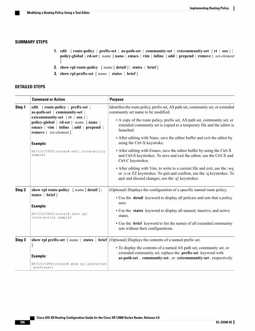
SUMMARY STEPS
1. edit { route-policy | prefix-set | as-path-set | community-set | extcommunity-set { rt | soo } |policy-global | rd-set } name [ nano | emacs | vim | inline { add | prepend | remove } set-element]
2. show rpl route-policy [ name [ detail ] | states | brief ]3. show rpl prefix-set [ name | states | brief ]
DETAILED STEPS
PurposeCommand or Action
Identifies the route policy, prefix set, AS path set, community set, or extendedcommunity set name to be modified.
edit { route-policy | prefix-set |as-path-set | community-set |
Step 1
extcommunity-set { rt | soo } |• A copy of the route policy, prefix set, AS path set, community set, orextended community set is copied to a temporary file and the editor islaunched.
policy-global | rd-set } name [ nano |emacs | vim | inline { add | prepend |remove } set-element ]
Example:
RP/0/0/CPU0:router# edit route-policysample1
• After editing with Nano, save the editor buffer and exit the editor byusing the Ctrl-X keystroke.
• After editing with Emacs, save the editor buffer by using the Ctrl-Xand Ctrl-S keystrokes. To save and exit the editor, use the Ctrl-X andCtrl-C keystrokes.
• After editing with Vim, to write to a current file and exit, use the :wqor :x or ZZ keystrokes. To quit and confirm, use the :q keystrokes. Toquit and discard changes, use the :q! keystrokes.
(Optional) Displays the configuration of a specific named route policy.show rpl route-policy [ name [ detail ] |states | brief ]
Step 2
• Use the detail keyword to display all policies and sets that a policyuses.
Example:
RP/0/0/CPU0:router# show rplroute-policy sample2
• Use the states keyword to display all unused, inactive, and activestates.
• Use the brief keyword to list the names of all extended communitysets without their configurations.
(Optional) Displays the contents of a named prefix set.show rpl prefix-set [ name | states | brief]
Step 3
• To display the contents of a named AS path set, community set, orextended community set, replace the prefix-set keyword withas-path-set , community-set , or extcommunity-set , respectively.Example:
RP/0/0/CPU0:router# show rpl prefix-setprefixset1
Cisco IOS XR Routing Configuration Guide for the Cisco XR 12000 Series Router, Release 4.0506 OL-23246-02
Implementing Routing PolicyModifying a Routing Policy Using a Text Editor

Configuration Examples for Implementing Routing PolicyThis section provides the following configuration examples:
Routing Policy Definition: ExampleIn the following example, a BGP route policy named sample1 is defined using the route-policy name command.The policy compares the network layer reachability information (NLRI) to the elements in the prefix set test.If it evaluates to true, the policy performs the operations in the then clause. If it evaluates to false, the policyperforms the operations in the else clause, that is, sets the MED value to 200 and adds the community 2:100to the route. The final steps of the example commit the configuration to the router, exit configuration mode,and display the contents of route policy sample1.
configureroute-policy sample1if destination in test thendropelseset med 200set community (2:100) additiveendifend-policyendshow config running route-policy sample1Building configuration...route-policy sample1if destination in test thendropelseset med 200set community (2:100) additiveendifend-policy
Simple Inbound Policy: ExampleThe following policy discards any route whose network layer reachability information (NLRI) specifies aprefix longer than /24, and any route whose NLRI specifies a destination in the address space reserved byRFC 1918. For all remaining routes, it sets the MED and local preference, and adds a community to the listin the route.
For routes whose community lists include any values in the range from 101:202 to 106:202 that have a 16-bittag portion containing the value 202, the policy prepends autonomous system number 2 twice, and adds thecommunity 2:666 to the list in the route. Of these routes, if the MED is either 666 or 225, then the policy setsthe origin of the route to incomplete, and otherwise sets the origin to IGP.
For routes whose community lists do not include any of the values in the range from 101:202 to 106:202, thepolicy adds the community 2:999 to the list in the route.
prefix-set too-specific0.0.0.0/0 ge 25 le 32end-set
prefix-set rfc191810.0.0.0/8 le 32,172.16.0.0/12 le 32,192.168.0.0/16 le 32
Cisco IOS XR Routing Configuration Guide for the Cisco XR 12000 Series Router, Release 4.0 OL-23246-02 507
Implementing Routing PolicyConfiguration Examples for Implementing Routing Policy
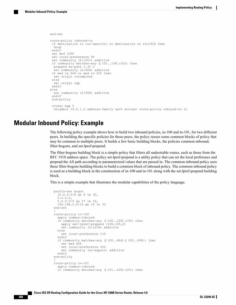
end-set
route-policy inbound-txif destination in too-specific or destination in rfc1918 thendropendifset med 1000set local-preference 90set community (2:1001) additiveif community matches-any ([101..106]:202) thenprepend as-path 2.30 2set community (2:666) additiveif med is 666 or med is 225 thenset origin incompleteelseset origin igpendifelseset community (2:999) additiveendifend-policy
router bgp 2neighbor 10.0.1.2 address-family ipv4 unicast route-policy inbound-tx in
Modular Inbound Policy: ExampleThe following policy example shows how to build two inbound policies, in-100 and in-101, for two differentpeers. In building the specific policies for those peers, the policy reuses some common blocks of policy thatmay be common to multiple peers. It builds a few basic building blocks, the policies common-inbound,filter-bogons, and set-lpref-prepend.
The filter-bogons building block is a simple policy that filters all undesirable routes, such as those from theRFC 1918 address space. The policy set-lpref-prepend is a utility policy that can set the local preference andprepend the AS path according to parameterized values that are passed in. The common-inbound policy usesthese filter-bogons building blocks to build a common block of inbound policy. The common-inbound policyis used as a building block in the construction of in-100 and in-101 along with the set-lpref-prepend buildingblock.
This is a simple example that illustrates the modular capabilities of the policy language.
prefix-set bogon10.0.0.0/8 ge 8 le 32,0.0.0.0,0.0.0.0/0 ge 27 le 32,192.168.0.0/16 ge 16 le 32
end-set!route-policy in-100apply common-inboundif community matches-any ([100..120]:135) thenapply set-lpref-prepend (100,100,2)set community (2:1234) additive
elseset local-preference 110
endifif community matches-any ([100..666]:[100..999]) thenset med 444set local-preference 200set community (no-export) additive
endifend-policy!route-policy in-101apply common-inboundif community matches-any ([101..200]:201) then
Cisco IOS XR Routing Configuration Guide for the Cisco XR 12000 Series Router, Release 4.0508 OL-23246-02
Implementing Routing PolicyModular Inbound Policy: Example
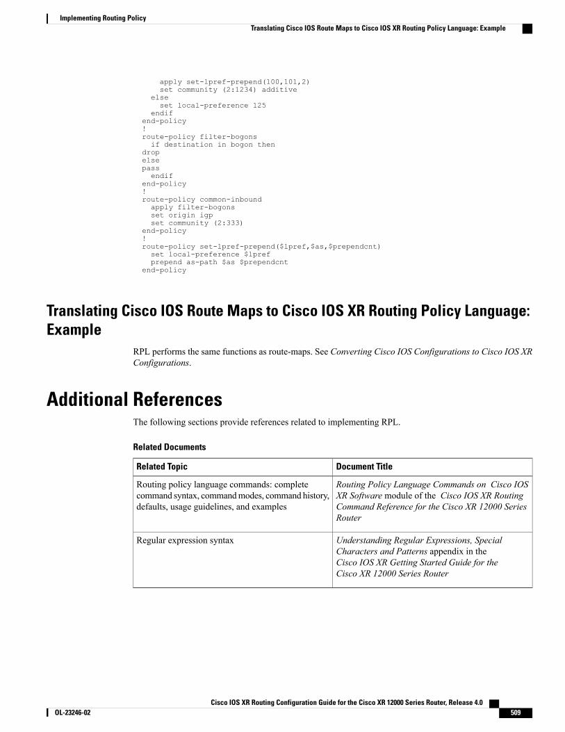
apply set-lpref-prepend(100,101,2)set community (2:1234) additive
elseset local-preference 125
endifend-policy!route-policy filter-bogonsif destination in bogon then
dropelsepassendif
end-policy!route-policy common-inboundapply filter-bogonsset origin igpset community (2:333)
end-policy!route-policy set-lpref-prepend($lpref,$as,$prependcnt)set local-preference $lprefprepend as-path $as $prependcnt
end-policy
Translating Cisco IOS Route Maps to Cisco IOS XR Routing Policy Language:Example
RPL performs the same functions as route-maps. See Converting Cisco IOS Configurations to Cisco IOS XRConfigurations.
Additional ReferencesThe following sections provide references related to implementing RPL.
Related Documents
Document TitleRelated Topic
Routing Policy Language Commands on Cisco IOSXR Software module of the Cisco IOS XR RoutingCommand Reference for the Cisco XR 12000 SeriesRouter
Routing policy language commands: completecommand syntax, commandmodes, command history,defaults, usage guidelines, and examples
Understanding Regular Expressions, SpecialCharacters and Patterns appendix in theCisco IOS XR Getting Started Guide for theCisco XR 12000 Series Router
Regular expression syntax
Cisco IOS XR Routing Configuration Guide for the Cisco XR 12000 Series Router, Release 4.0 OL-23246-02 509
Implementing Routing PolicyTranslating Cisco IOS Route Maps to Cisco IOS XR Routing Policy Language: Example
Standards
TitleStandards
—No new or modified standards are supported by thisfeature, and support for existing standards has notbeen modified by this feature.
MIBs
MIBs LinkMIBs
To locate and download MIBs using Cisco IOS XRsoftware, use the Cisco MIB Locator found at thefollowingURL and choose a platform under the CiscoAccess Products menu: http://cisco.com/public/sw-center/netmgmt/cmtk/mibs.shtml
—
RFCs
TitleRFCs
A Border Gateway Protocol 4 (BGP-4)RFC 1771
BGP Extended Communities AttributeRFC 4360
Technical Assistance
LinkDescription
http://www.cisco.com/techsupportThe Cisco Technical Support website containsthousands of pages of searchable technical content,including links to products, technologies, solutions,technical tips, and tools. Registered Cisco.com userscan log in from this page to access evenmore content.
Cisco IOS XR Routing Configuration Guide for the Cisco XR 12000 Series Router, Release 4.0510 OL-23246-02
Implementing Routing PolicyAdditional References
C H A P T E R 8Implementing Static Routes
This module describes how to implement static routes.
Static routes are user-defined routes that cause packets moving between a source and a destination to takea specified path. Static routes can be important if the Cisco IOS XR software cannot build a route to aparticular destination. They are useful for specifying a gateway of last resort to which all unroutable packetsare sent.
For more information about static routes on the Cisco IOS XR software and complete descriptions of thestatic routes commands listed in this module, see the Related Documents, on page 529 section of thismodule. To locate documentation for other commands that might appear while executing a configurationtask, search online in the Cisco IOS XR Commands Master List for the Cisco XR 12000 Series Router.
Note
Feature History for Implementing Static Routes
ModificationRelease
This feature was introduced.Release 3.2
Support for configuring static routes in static router configurationmode was added.
The route command was replaced with the router staticcommand.
The routemaximum commandwas replacedwith themaximumpath command.
VPN routing and forwarding (VRF) support was added to thecommand syntax.
Release 3.3.0
No modification.Release 3.4.0
IPv6 Provider Edge and IPv6 VPN Provider Edge overMultiprotocol Label Switching support was added.
Release 3.5.0
No modification.Release 3.6.0
Cisco IOS XR Routing Configuration Guide for the Cisco XR 12000 Series Router, Release 4.0 OL-23246-02 511
ModificationRelease
No modification.Release 3.7.0
No modification.Release 3.8.0
No modification.Release 3.9.0
The Enhanced Object Tracking for IP Static feature was added.Release 4.2.1
• Prerequisites for Implementing Static Routes, page 512
• Restrictions for Implementing Static Routes, page 512
• Information About Implementing Static Routes, page 512
• How to Implement Static Routes, page 516
• Configuration Examples, page 527
• Where to Go Next, page 528
• Additional References, page 528
Prerequisites for Implementing Static RoutesYou must be in a user group associated with a task group that includes the proper task IDs. The commandreference guides include the task IDs required for each command. If you suspect user group assignment ispreventing you from using a command, contact your AAA administrator for assistance.
Restrictions for Implementing Static RoutesThese restrictions apply while implementing Static Routes:
• Static routing to an indirect next hop, (any prefix learnt through the RIB and may be more specific overthe AIB), that is part of a local subnet requires configuring static routes in the global table indicatingthe egress interfaces as next hop. To avoid forward drop, configure static routes in the global tableindicating the next-hop IP address to be the next hop.
• Generally, a route is learnt from the AIB in the global table and is installed in the FIB. However, thisbehavior will not be replicated to leaked prefixes. Because the AIB from the global table is not presentin the VRF, the leaked FIB entry takes reference from the RIB rather than the same view as the globaltable, which also relies on the AIB. This could lead to inconsistencies in forwarding behavior.
Information About Implementing Static RoutesTo implement static routes you need to understand the following concepts:
Cisco IOS XR Routing Configuration Guide for the Cisco XR 12000 Series Router, Release 4.0512 OL-23246-02
Implementing Static RoutesPrerequisites for Implementing Static Routes
Static Route Functional OverviewStatic routes are entirely user configurable and can point to a next-hop interface, next-hop IP address, or both.In Cisco IOS XR software, if an interface was specified, then the static route is installed in the RoutingInformation Base (RIB) if the interface is reachable. If an interface was not specified, the route is installed ifthe next-hop address is reachable. The only exception to this configuration is when a static route is configuredwith the permanent attribute, in which case it is installed in RIB regardless of reachability.
Specifying the next-hop IP address is not mandatory for static routes configuration. However, next-hop IPaddress is mandatory for Protocol Independent Multicast (PIM) to use the next-hop information correctly.
When configuring static routes on Cisco IOS XR software, pointing to next-hop interface, a Reverse PathForwarding (RPF) check for multicast might not point to the correct PIM neighbor if there are multiple staticroutes for the destination across multiple interfaces. Next-hop IP address must be specified to address thissituation.
Networking devices forward packets using route information that is either manually configured or dynamicallylearned using a routing protocol. Static routes are manually configured and define an explicit path betweentwo networking devices. Unlike a dynamic routing protocol, static routes are not automatically updated andmust be manually reconfigured if the network topology changes. The benefits of using static routes includesecurity and resource efficiency. Static routes use less bandwidth than dynamic routing protocols, and no CPUcycles are used to calculate and communicate routes. The main disadvantage to using static routes is the lackof automatic reconfiguration if the network topology changes.
Static routes can be redistributed into dynamic routing protocols, but routes generated by dynamic routingprotocols cannot be redistributed into the static routing table. No algorithm exists to prevent the configurationof routing loops that use static routes.
Static routes are useful for smaller networks with only one path to an outside network and to provide securityfor a larger network for certain types of traffic or links to other networks that need more control. In general,most networks use dynamic routing protocols to communicate between networking devices but may have oneor two static routes configured for special cases.
For information on configuring static routes to distribute Multiprotocol Label Switching (MPLS) Layer 3virtual private network (VPN) information, seeCisco IOS XRMultiprotocol Label Switching ConfigurationGuide.
Note
Default Administrative DistanceStatic routes have a default administrative distance of 1. A low number indicates a preferred route. By default,static routes are preferred to routes learned by routing protocols. Therefore, you can configure an administrativedistance with a static route if you want the static route to be overridden by dynamic routes. For example, youcould have routes installed by the Open Shortest Path First (OSPF) protocol with an administrative distanceof 120. To have a static route that would be overridden by an OSPF dynamic route, specify an administrativedistance greater than 120.
Cisco IOS XR Routing Configuration Guide for the Cisco XR 12000 Series Router, Release 4.0 OL-23246-02 513
Implementing Static RoutesStatic Route Functional Overview
Directly Connected RoutesThe routing table considers the static routes that point to an interface as “directly connected.”Directly connectednetworks are advertised by IGP routing protocols if a corresponding interface command is contained underthe router configuration stanza of that protocol.
In directly attached static routes, only the output interface is specified. The destination is assumed to be directlyattached to this interface, so the packet destination is used as the next hop address. The following exampleshows how to specify that all destinations with address prefix 2001:0DB8::/32 are directly reachable throughinterface GigabitEthernet 0/5/0/0:
RP/0/0/CPU0:router(config)# router staticRP/0/0/CPU0:router(config-static)# address-family ipv6 unicastRP/0/0/CPU0:router(config-static-afi)# 2001:0DB8::/32 gigabitethernet 0/5/0/0
Directly attached static routes are candidates for insertion in the routing table only if they refer to a validinterface; that is, an interface that is both up and has IPv4 or IPv6 enabled on it.
Recursive Static RoutesIn a recursive static route, only the next hop is specified. The output interface is derived from the next hop.The following example shows how to specify that all destinations with address prefix 2001:0DB8::/32 arereachable through the host with address 2001:0DB8:3000::1:
RP/0/0/CPU0:router(config)# router staticRP/0/0/CPU0:router(config-static)# address-family ipv6 unicastRP/0/0/CPU0:router(config-static-afi)# 2001:0DB8::/32 2001:0DB8:3000::1
A recursive static route is valid (that is, it is a candidate for insertion in the routing table) only when thespecified next hop resolves, either directly or indirectly, to a valid output interface, provided the route doesnot self-recurse, and the recursion depth does not exceed the maximum IPv6 forwarding recursion depth.
A route self-recurses if it is itself used to resolve its own next hop. If a static route becomes self-recursive,RIB sends a notification to static routes to withdraw the recursive route.
Assuming a BGP route 2001:0DB8:3000::0/16 with next hop of 2001:0DB8::0104, the following static routewould not be inserted into the IPv6 RIB because the BGP route next hop resolves through the static route andthe static route resolves through the BGP route making it self-recursive:
RP/0/0/CPU0:router(config)# router staticRP/0/0/CPU0:router(config-static)# address-family ipv6 unicastRP/0/0/CPU0:router(config-static-afi)# 001:0DB8::/32 2001:0DB8:3000::1
This static route is not inserted into the IPv6 routing table because it is self-recursive. The next hop of thestatic route, 2001:0DB8:3000:1, resolves through the BGP route 2001:0DB8:3000:0/16, which is itself arecursive route (that is, it only specifies a next hop). The next hop of the BGP route, 2001:0DB8::0104,resolves through the static route. Therefore, the static route would be used to resolve its own next hop.
It is not normally useful to manually configure a self-recursive static route, although it is not prohibited.However, a recursive static route that has been inserted in the routing table may become self-recursive as aresult of some transient change in the network learned through a dynamic routing protocol. If this occurs, thefact that the static route has become self-recursive will be detected and it will be removed from the routingtable, although not from the configuration. A subsequent network change may cause the static route to nolonger be self-recursive, in which case it is re-inserted in the routing table.
Cisco IOS XR Routing Configuration Guide for the Cisco XR 12000 Series Router, Release 4.0514 OL-23246-02
Implementing Static RoutesDirectly Connected Routes
Fully Specified Static RoutesIn a fully specified static route, both the output interface and next hop are specified. This form of static routeis used when the output interface is multiaccess and it is necessary to explicitly identify the next hop. Thenext hop must be directly attached to the specified output interface. The following example shows a definitionof a fully specified static route:
RP/0/0/CPU0:router(config)# router staticRP/0/0/CPU0:router(config-static)# address-family ipv6 unicastRP/0/0/CPU0:router(config-static-afi)# 2001:0DB8::/32 Gigethernet0/0/0/0 2001:0DB8:3000::1A fully specified route is valid (that is, a candidate for insertion into the routing table) when the specifiedinterface, IPv4 or IPv6, is enabled and up.
Floating Static RoutesFloating static routes are static routes that are used to back up dynamic routes learned through configuredrouting protocols. A floating static route is configured with a higher administrative distance than the dynamicrouting protocol it is backing up. As a result, the dynamic route learned through the routing protocol is alwayspreferred to the floating static route. If the dynamic route learned through the routing protocol is lost, thefloating static route is used in its place. The following example shows how to define a floating static route:
RP/0/0/CPU0:router(config)# router staticRP/0/0/CPU0:router(config-static)# address-family ipv6 unicastRP/0/0/CPU0:router(config-static-afi)# 2001:0DB8::/32 2001:0DB8:3000::1 210
Any of the three types of static routes can be used as a floating static route. A floating static route must beconfigured with an administrative distance that is greater than the administrative distance of the dynamicrouting protocol because routes with smaller administrative distances are preferred.
By default, static routes have smaller administrative distances than dynamic routes, so static routes arepreferred to dynamic routes.
Note
Default VRFA static route is always associated with a VPN routing and forwarding (VRF) instance. The VRF can be thedefault VRF or a specified VRF. Specifying a VRF, using the vrf vrf-name command, allows you to enterVRF configuration mode for a specific VRF where you can configure a static route. If a VRF is not specified,a default VRF static route is configured.
IPv4 and IPv6 Static VRF RoutesAn IPv4 or IPv6 static VRF route is the same as a static route configured for the default VRF. The IPv4 andIPV6 address families are supported in each VRF.
Cisco IOS XR Routing Configuration Guide for the Cisco XR 12000 Series Router, Release 4.0 OL-23246-02 515
Implementing Static RoutesFully Specified Static Routes
IPv6/IPv6 VPN Provider Edge Transport over MPLSIPv6 Provider Edge (6PE) and IPv6 VPN Provider Edge (6VPE) leverages the existing Multiprotocol LabelSwitching (MPLS) IPv4 core infrastructure for IPv6 transport. 6PE and 6VPE enables IPv6 sites to communicatewith each other over an MPLS IPv4 core network using MPLS label switched paths (LSPs).
Static routes can be configured under the default VRF for 6PE functionality and under IPv6 VPN routing andforwarding (VRF) instances for 6VPE functionality.
For detailed information about configuring 6PE and 6VPE overMPLS, see Cisco IOS XRMPLSConfigurationGuide for the Cisco XR 12000 Series Router.
How to Implement Static RoutesThis section contains the following procedures:
Configuring a Static RouteThis task explains how to configure a static route.
SUMMARY STEPS
1. configure2. router static3. vrf vrf-name4. address-family { ipv4 | ipv6 } { unicast | multicast }5. prefix mask [vrf vrf-name ] { ip-address | interface-type interface-instance } [ distance ] [ description
text ] [ tag tag ] [ permanent ]6. Do one of the following:
• end
• commit
DETAILED STEPS
PurposeCommand or Action
Enters global configuration mode.configure
Example:
RP/0/0/CPU0:router# configure
Step 1
Cisco IOS XR Routing Configuration Guide for the Cisco XR 12000 Series Router, Release 4.0516 OL-23246-02
Implementing Static RoutesIPv6/IPv6 VPN Provider Edge Transport over MPLS
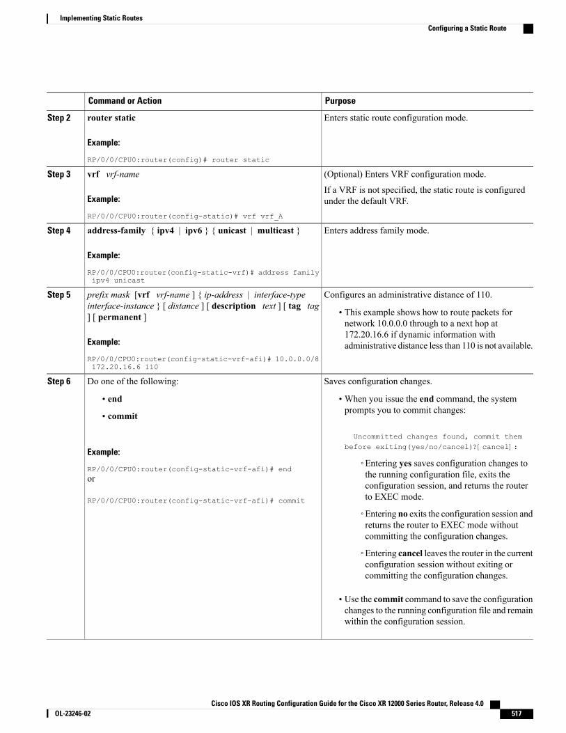
PurposeCommand or Action
Enters static route configuration mode.router static
Example:
RP/0/0/CPU0:router(config)# router static
Step 2
(Optional) Enters VRF configuration mode.vrf vrf-nameStep 3
Example:
RP/0/0/CPU0:router(config-static)# vrf vrf_A
If a VRF is not specified, the static route is configuredunder the default VRF.
Enters address family mode.address-family { ipv4 | ipv6 } { unicast | multicast }
Example:
RP/0/0/CPU0:router(config-static-vrf)# address familyipv4 unicast
Step 4
Configures an administrative distance of 110.prefix mask [vrf vrf-name ] { ip-address | interface-typeinterface-instance } [ distance ] [ description text ] [ tag tag] [ permanent ]
Step 5
• This example shows how to route packets fornetwork 10.0.0.0 through to a next hop at
Example:
RP/0/0/CPU0:router(config-static-vrf-afi)# 10.0.0.0/8172.20.16.6 110
172.20.16.6 if dynamic information withadministrative distance less than 110 is not available.
Saves configuration changes.Do one of the following:Step 6
• end •When you issue the end command, the systemprompts you to commit changes:
Uncommitted changes found, commit thembefore exiting(yes/no/cancel)?[cancel]:
• commit
Example:
RP/0/0/CPU0:router(config-static-vrf-afi)# end◦Entering yes saves configuration changes tothe running configuration file, exits theor
RP/0/0/CPU0:router(config-static-vrf-afi)# commit
configuration session, and returns the routerto EXEC mode.
◦Entering no exits the configuration session andreturns the router to EXEC mode withoutcommitting the configuration changes.
◦Entering cancel leaves the router in the currentconfiguration session without exiting orcommitting the configuration changes.
• Use the commit command to save the configurationchanges to the running configuration file and remainwithin the configuration session.
Cisco IOS XR Routing Configuration Guide for the Cisco XR 12000 Series Router, Release 4.0 OL-23246-02 517
Implementing Static RoutesConfiguring a Static Route
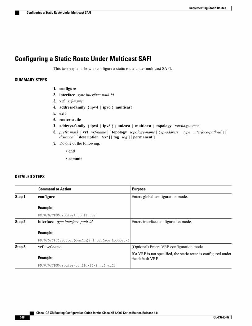
Configuring a Static Route Under Multicast SAFIThis task explains how to configure a static route under multicast SAFI.
SUMMARY STEPS
1. configure2. interface type interface-path-id3. vrf vrf-name4. address-family { ipv4 | ipv6 } multicast5. exit6. router static7. address-family { ipv4 | ipv6 } { unicast | multicast } topology topology-name8. prefix mask [ vrf vrf-name ] [ topology topology-name ] { ip-address | type interface-path-id } [
distance ] [ description text ] [ tag tag ] [ permanent ]9. Do one of the following:
• end
• commit
DETAILED STEPS
PurposeCommand or Action
Enters global configuration mode.configure
Example:
RP/0/0/CPU0:router# configure
Step 1
Enters interface configuration mode.interface type interface-path-id
Example:
RP/0/0/CPU0:router(config)# interface Loopback0
Step 2
(Optional) Enters VRF configuration mode.vrf vrf-nameStep 3
Example:
RP/0/0/CPU0:router(config-if)# vrf vrf1
If a VRF is not specified, the static route is configured underthe default VRF.
Cisco IOS XR Routing Configuration Guide for the Cisco XR 12000 Series Router, Release 4.0518 OL-23246-02
Implementing Static RoutesConfiguring a Static Route Under Multicast SAFI
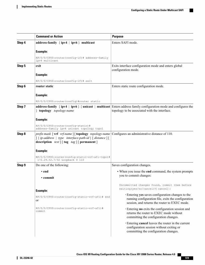
PurposeCommand or Action
Enters SAFI mode.address-family { ipv4 | ipv6 } multicast
Example:
RP/0/0/CPU0:router(config-if)# address-familyipv4 multicast
Step 4
Exits interface configuration mode and enters globalconfiguration mode.
exit
Example:
RP/0/0/CPU0:router(config-if)# exit
Step 5
Enters static route configuration mode.router static
Example:
RP/0/0/CPU0:router(config)#router static
Step 6
Enters address family configuration mode and configures thetopology to be associated with the interface.
address-family { ipv4 | ipv6 } { unicast | multicast} topology topology-name
Example:
RP/0/0/CPU0:router(config-static)#address-family ipv4 unicast topology topo1
Step 7
Configures an administrative distance of 110.prefix mask [ vrf vrf-name ] [ topology topology-name] { ip-address | type interface-path-id } [ distance ] [description text ] [ tag tag ] [ permanent ]
Step 8
Example:
RP/0/0/CPU0:router(config-static-vrf-afi-topo)#172.29.52.7/32 Loopback 0 110
Saves configuration changes.Do one of the following:Step 9
• end •When you issue the end command, the system promptsyou to commit changes:
Uncommitted changes found, commit them beforeexiting(yes/no/cancel)?[cancel]:
• commit
Example:
RP/0/0/CPU0:router(config-static-vrf-afi)# end◦Entering yes saves configuration changes to therunning configuration file, exits the configurationsession, and returns the router to EXEC mode.
or
RP/0/0/CPU0:router(config-static-vrf-afi)#commit
◦Entering no exits the configuration session andreturns the router to EXEC mode withoutcommitting the configuration changes.
◦Entering cancel leaves the router in the currentconfiguration session without exiting orcommitting the configuration changes.
Cisco IOS XR Routing Configuration Guide for the Cisco XR 12000 Series Router, Release 4.0 OL-23246-02 519
Implementing Static RoutesConfiguring a Static Route Under Multicast SAFI
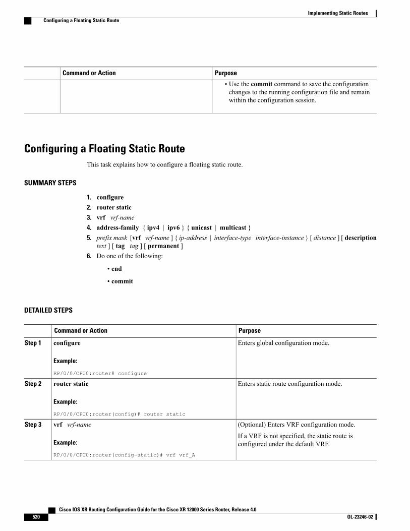
PurposeCommand or Action
• Use the commit command to save the configurationchanges to the running configuration file and remainwithin the configuration session.
Configuring a Floating Static RouteThis task explains how to configure a floating static route.
SUMMARY STEPS
1. configure2. router static3. vrf vrf-name4. address-family { ipv4 | ipv6 } { unicast | multicast }5. prefix mask [vrf vrf-name ] { ip-address | interface-type interface-instance } [ distance ] [ description
text ] [ tag tag ] [ permanent ]6. Do one of the following:
• end
• commit
DETAILED STEPS
PurposeCommand or Action
Enters global configuration mode.configure
Example:
RP/0/0/CPU0:router# configure
Step 1
Enters static route configuration mode.router static
Example:
RP/0/0/CPU0:router(config)# router static
Step 2
(Optional) Enters VRF configuration mode.vrf vrf-nameStep 3
Example:
RP/0/0/CPU0:router(config-static)# vrf vrf_A
If a VRF is not specified, the static route isconfigured under the default VRF.
Cisco IOS XR Routing Configuration Guide for the Cisco XR 12000 Series Router, Release 4.0520 OL-23246-02
Implementing Static RoutesConfiguring a Floating Static Route
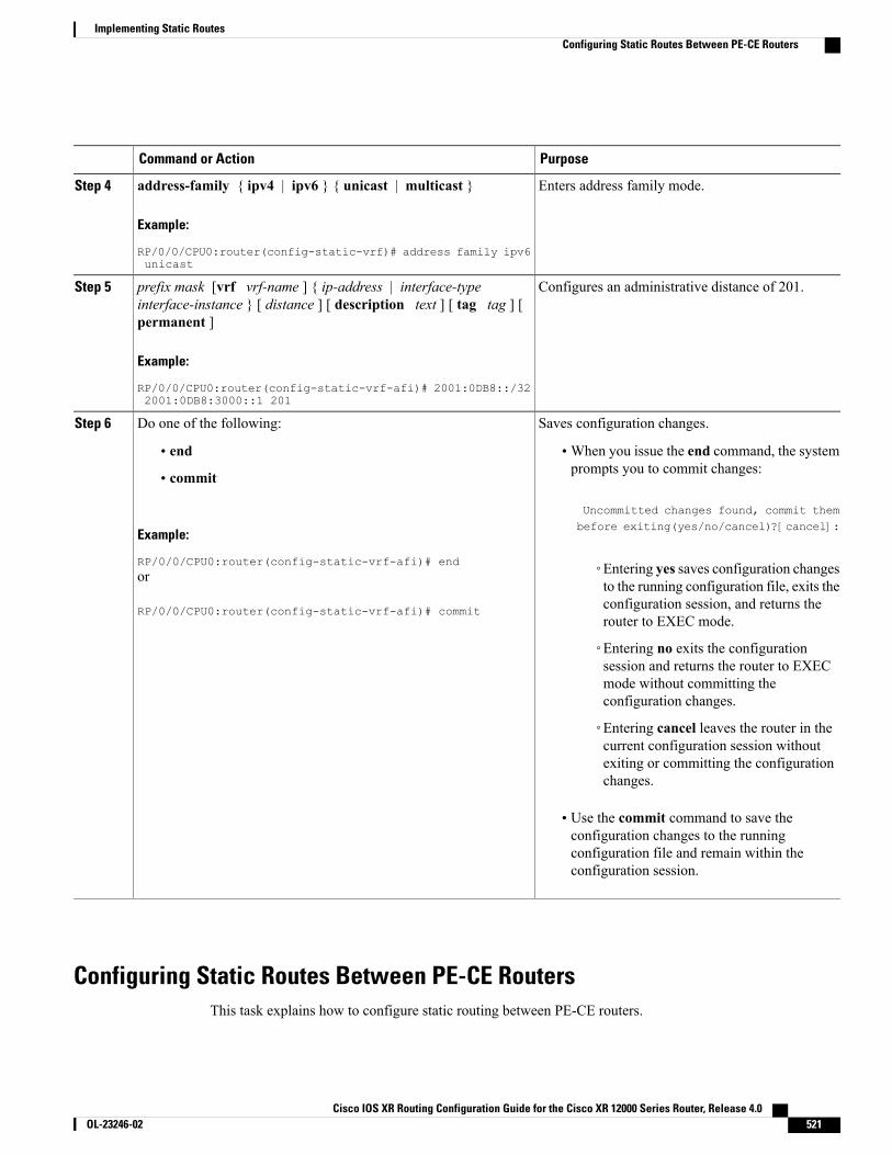
PurposeCommand or Action
Enters address family mode.address-family { ipv4 | ipv6 } { unicast | multicast }
Example:
RP/0/0/CPU0:router(config-static-vrf)# address family ipv6unicast
Step 4
Configures an administrative distance of 201.prefix mask [vrf vrf-name ] { ip-address | interface-typeinterface-instance } [ distance ] [ description text ] [ tag tag ] [permanent ]
Step 5
Example:
RP/0/0/CPU0:router(config-static-vrf-afi)# 2001:0DB8::/322001:0DB8:3000::1 201
Saves configuration changes.Do one of the following:Step 6
• end •When you issue the end command, the systemprompts you to commit changes:
Uncommitted changes found, commit them
• commit
Example:
RP/0/0/CPU0:router(config-static-vrf-afi)# end
before exiting(yes/no/cancel)?[cancel]:
◦Entering yes saves configuration changesto the running configuration file, exits the
or
RP/0/0/CPU0:router(config-static-vrf-afi)# commit configuration session, and returns therouter to EXEC mode.
◦Entering no exits the configurationsession and returns the router to EXECmode without committing theconfiguration changes.
◦Entering cancel leaves the router in thecurrent configuration session withoutexiting or committing the configurationchanges.
• Use the commit command to save theconfiguration changes to the runningconfiguration file and remain within theconfiguration session.
Configuring Static Routes Between PE-CE RoutersThis task explains how to configure static routing between PE-CE routers.
Cisco IOS XR Routing Configuration Guide for the Cisco XR 12000 Series Router, Release 4.0 OL-23246-02 521
Implementing Static RoutesConfiguring Static Routes Between PE-CE Routers
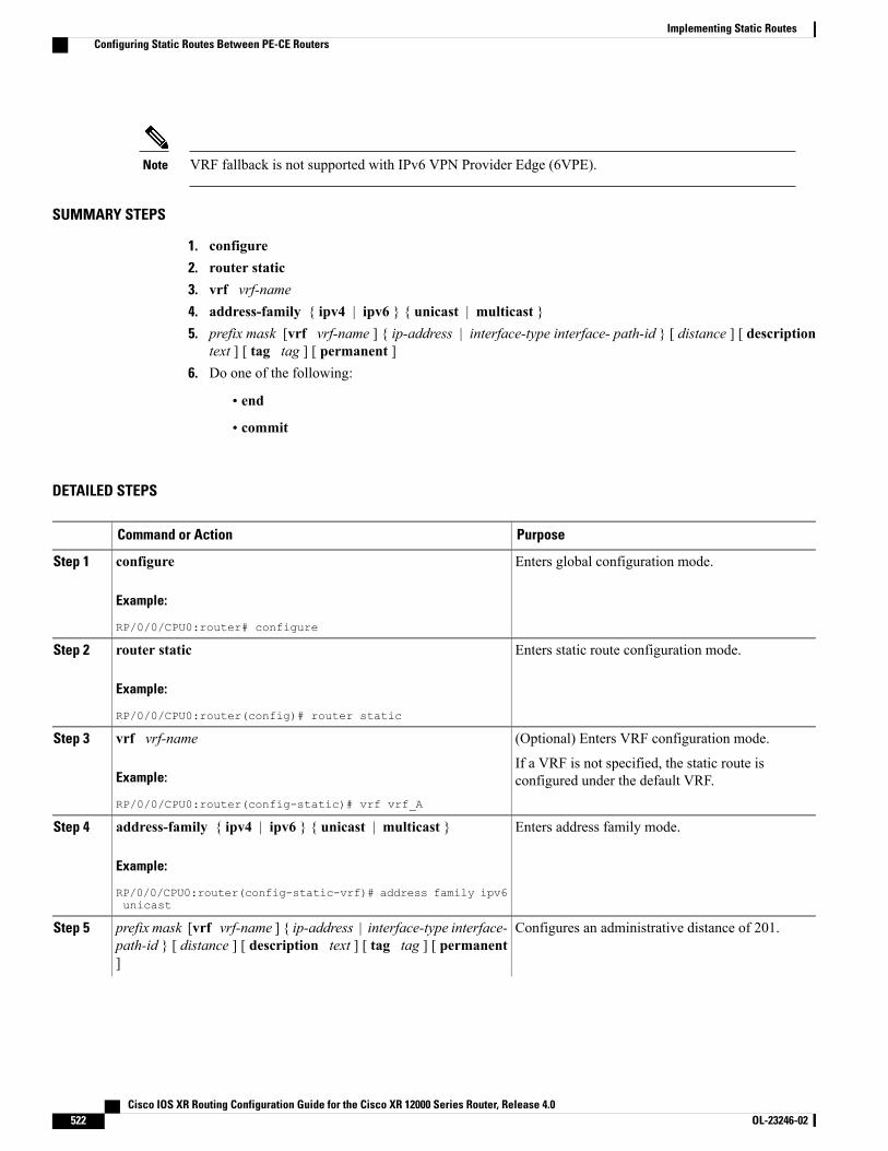
VRF fallback is not supported with IPv6 VPN Provider Edge (6VPE).Note
SUMMARY STEPS
1. configure2. router static3. vrf vrf-name4. address-family { ipv4 | ipv6 } { unicast | multicast }5. prefix mask [vrf vrf-name ] { ip-address | interface-type interface- path-id } [ distance ] [ description
text ] [ tag tag ] [ permanent ]6. Do one of the following:
• end
• commit
DETAILED STEPS
PurposeCommand or Action
Enters global configuration mode.configure
Example:
RP/0/0/CPU0:router# configure
Step 1
Enters static route configuration mode.router static
Example:
RP/0/0/CPU0:router(config)# router static
Step 2
(Optional) Enters VRF configuration mode.vrf vrf-nameStep 3
Example:
RP/0/0/CPU0:router(config-static)# vrf vrf_A
If a VRF is not specified, the static route isconfigured under the default VRF.
Enters address family mode.address-family { ipv4 | ipv6 } { unicast | multicast }
Example:
RP/0/0/CPU0:router(config-static-vrf)# address family ipv6unicast
Step 4
Configures an administrative distance of 201.prefix mask [vrf vrf-name ] { ip-address | interface-type interface-path-id } [ distance ] [ description text ] [ tag tag ] [ permanent]
Step 5
Cisco IOS XR Routing Configuration Guide for the Cisco XR 12000 Series Router, Release 4.0522 OL-23246-02
Implementing Static RoutesConfiguring Static Routes Between PE-CE Routers
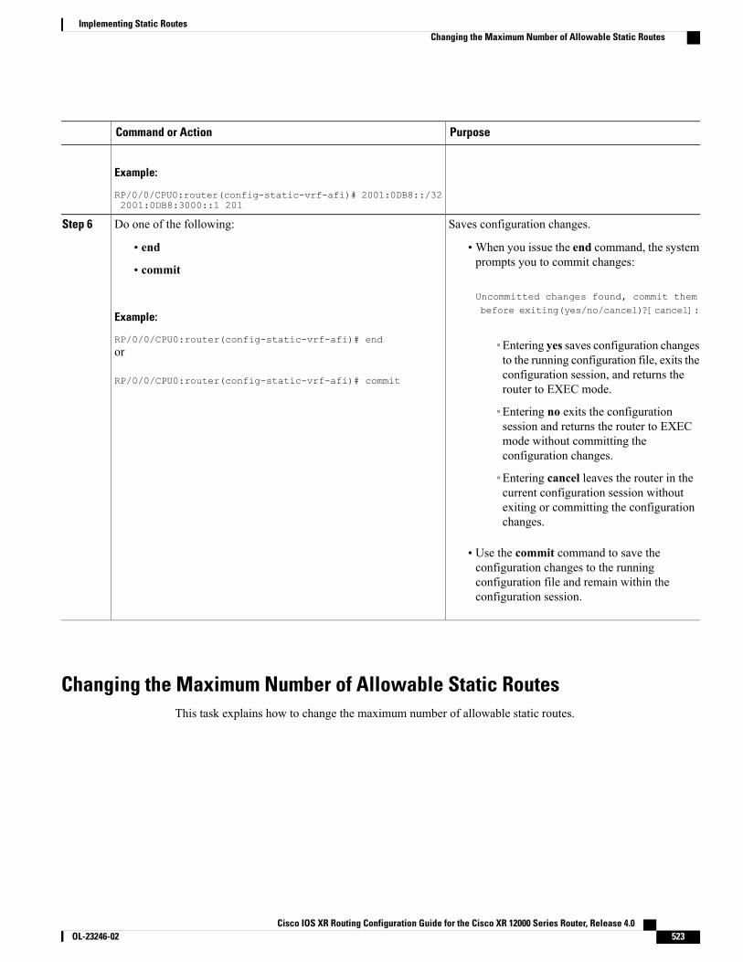
PurposeCommand or Action
Example:
RP/0/0/CPU0:router(config-static-vrf-afi)# 2001:0DB8::/322001:0DB8:3000::1 201
Saves configuration changes.Do one of the following:Step 6
• end •When you issue the end command, the systemprompts you to commit changes:
Uncommitted changes found, commit them
• commit
Example:
RP/0/0/CPU0:router(config-static-vrf-afi)# end
before exiting(yes/no/cancel)?[cancel]:
◦Entering yes saves configuration changesto the running configuration file, exits the
or
RP/0/0/CPU0:router(config-static-vrf-afi)# commit configuration session, and returns therouter to EXEC mode.
◦Entering no exits the configurationsession and returns the router to EXECmode without committing theconfiguration changes.
◦Entering cancel leaves the router in thecurrent configuration session withoutexiting or committing the configurationchanges.
• Use the commit command to save theconfiguration changes to the runningconfiguration file and remain within theconfiguration session.
Changing the Maximum Number of Allowable Static RoutesThis task explains how to change the maximum number of allowable static routes.
Cisco IOS XR Routing Configuration Guide for the Cisco XR 12000 Series Router, Release 4.0 OL-23246-02 523
Implementing Static RoutesChanging the Maximum Number of Allowable Static Routes
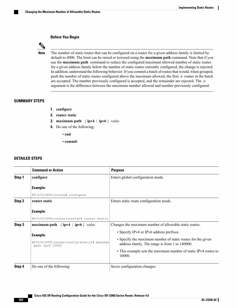
Before You Begin
The number of static routes that can be configured on a router for a given address family is limited bydefault to 4000. The limit can be raised or lowered using themaximum path command. Note that if youuse themaximum path command to reduce the configured maximum allowed number of static routesfor a given address family below the number of static routes currently configured, the change is rejected.In addition, understand the following behavior: If you commit a batch of routes that would, when grouped,push the number of static routes configured above the maximum allowed, the first n routes in the batchare accepted. The number previously configured is accepted, and the remainder are rejected. The nargument is the difference between the maximum number allowed and number previously configured.
Note
SUMMARY STEPS
1. configure2. router static3. maximum path { ipv4 | ipv6 } value4. Do one of the following:
• end
• commit
DETAILED STEPS
PurposeCommand or Action
Enters global configuration mode.configure
Example:
RP/0/0/CPU0:router# configure
Step 1
Enters static route configuration mode.router static
Example:
RP/0/0/CPU0:router(config)# router static
Step 2
Changes the maximum number of allowable static routes.maximum path { ipv4 | ipv6 } valueStep 3
Example:
RP/0/0/CPU0:router(config-static)# maximumpath ipv4 10000
• Specify IPv4 or IPv6 address prefixes.
• Specify the maximum number of static routes for the givenaddress family. The range is from 1 to 140000.
• This example sets the maximum number of static IPv4 routes to10000.
Saves configuration changes.Do one of the following:Step 4
Cisco IOS XR Routing Configuration Guide for the Cisco XR 12000 Series Router, Release 4.0524 OL-23246-02
Implementing Static RoutesChanging the Maximum Number of Allowable Static Routes
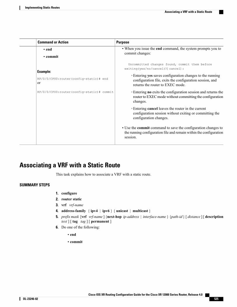
PurposeCommand or Action
•When you issue the end command, the system prompts you tocommit changes:
Uncommitted changes found, commit them beforeexiting(yes/no/cancel)?[cancel]:
• end
• commit
Example:
RP/0/0/CPU0:router(config-static)# end◦Entering yes saves configuration changes to the runningconfiguration file, exits the configuration session, andreturns the router to EXEC mode.or
RP/0/0/CPU0:router(config-static)# commit ◦Entering no exits the configuration session and returns therouter to EXECmodewithout committing the configurationchanges.
◦Entering cancel leaves the router in the currentconfiguration session without exiting or committing theconfiguration changes.
• Use the commit command to save the configuration changes tothe running configuration file and remain within the configurationsession.
Associating a VRF with a Static RouteThis task explains how to associate a VRF with a static route.
SUMMARY STEPS
1. configure2. router static3. vrf vrf-name4. address-family { ipv4 | ipv6 } { unicast | multicast }5. prefix mask [vrf vrf-name ] {next-hop ip-address | interface-name } {path-id } [ distance ] [ description
text ] [ tag tag ] [ permanent ]6. Do one of the following:
• end
• commit
Cisco IOS XR Routing Configuration Guide for the Cisco XR 12000 Series Router, Release 4.0 OL-23246-02 525
Implementing Static RoutesAssociating a VRF with a Static Route
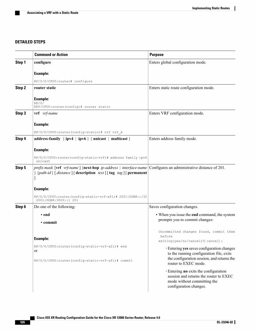
DETAILED STEPS
PurposeCommand or Action
Enters global configuration mode.configure
Example:
RP/0/0/CPU0:router# configure
Step 1
Enters static route configuration mode.router static
Example:RP/0/RP0/CPU0:router(config)# router static
Step 2
Enters VRF configuration mode.vrf vrf-name
Example:
RP/0/0/CPU0:router(config-static)# vrf vrf_A
Step 3
Enters address family mode.address-family { ipv4 | ipv6 } { unicast | multicast }
Example:
RP/0/0/CPU0:router(config-static-vrf)# address family ipv6unicast
Step 4
Configures an administrative distance of 201.prefix mask [vrf vrf-name ] {next-hop ip-address | interface-name} {path-id } [ distance ] [ description text ] [ tag tag ] [ permanent]
Step 5
Example:
RP/0/0/CPU0:router(config-static-vrf-afi)# 2001:0DB8::/322001:0DB8:3000::1 201
Saves configuration changes.Do one of the following:Step 6
• end •When you issue the end command, the systemprompts you to commit changes:
Uncommitted changes found, commit them
• commit
Example:
RP/0/0/CPU0:router(config-static-vrf-afi)# end
beforeexiting(yes/no/cancel)?[cancel]:
◦Entering yes saves configuration changesto the running configuration file, exits
or
RP/0/0/CPU0:router(config-static-vrf-afi)# commit the configuration session, and returns therouter to EXEC mode.
◦Entering no exits the configurationsession and returns the router to EXECmode without committing theconfiguration changes.
Cisco IOS XR Routing Configuration Guide for the Cisco XR 12000 Series Router, Release 4.0526 OL-23246-02
Implementing Static RoutesAssociating a VRF with a Static Route
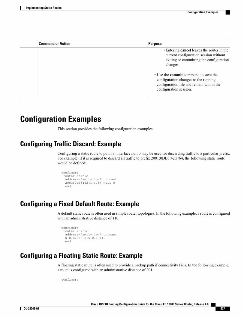
PurposeCommand or Action
◦Entering cancel leaves the router in thecurrent configuration session withoutexiting or committing the configurationchanges.
• Use the commit command to save theconfiguration changes to the runningconfiguration file and remain within theconfiguration session.
Configuration ExamplesThis section provides the following configuration examples:
Configuring Traffic Discard: ExampleConfiguring a static route to point at interface null 0 may be used for discarding traffic to a particular prefix.For example, if it is required to discard all traffic to prefix 2001:0DB8:42:1/64, the following static routewould be defined:
configurerouter staticaddress-family ipv6 unicast2001:0DB8:42:1::/64 null 0end
Configuring a Fixed Default Route: ExampleA default static route is often used in simple router topologies. In the following example, a route is configuredwith an administrative distance of 110.
configurerouter staticaddress-family ipv4 unicast0.0.0.0/0 2.6.0.1 110end
Configuring a Floating Static Route: ExampleA floating static route is often used to provide a backup path if connectivity fails. In the following example,a route is configured with an administrative distance of 201.
configure
Cisco IOS XR Routing Configuration Guide for the Cisco XR 12000 Series Router, Release 4.0 OL-23246-02 527
Implementing Static RoutesConfiguration Examples
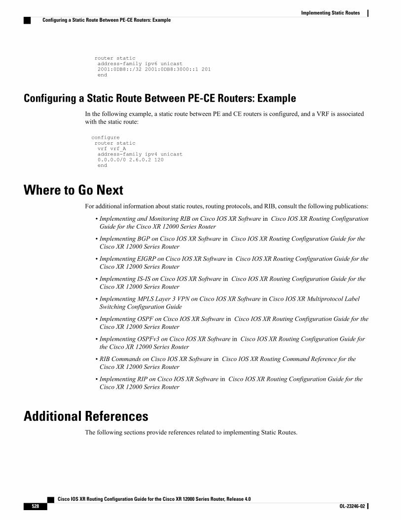
router staticaddress-family ipv6 unicast2001:0DB8::/32 2001:0DB8:3000::1 201end
Configuring a Static Route Between PE-CE Routers: ExampleIn the following example, a static route between PE and CE routers is configured, and a VRF is associatedwith the static route:
configurerouter staticvrf vrf_Aaddress-family ipv4 unicast0.0.0.0/0 2.6.0.2 120end
Where to Go NextFor additional information about static routes, routing protocols, and RIB, consult the following publications:
• Implementing and Monitoring RIB on Cisco IOS XR Software in Cisco IOS XR Routing ConfigurationGuide for the Cisco XR 12000 Series Router
• Implementing BGP on Cisco IOS XR Software in Cisco IOS XR Routing Configuration Guide for theCisco XR 12000 Series Router
• Implementing EIGRP on Cisco IOS XR Software in Cisco IOS XR Routing Configuration Guide for theCisco XR 12000 Series Router
• Implementing IS-IS on Cisco IOS XR Software in Cisco IOS XR Routing Configuration Guide for theCisco XR 12000 Series Router
• Implementing MPLS Layer 3 VPN on Cisco IOS XR Software in Cisco IOS XR Multiprotocol LabelSwitching Configuration Guide
• Implementing OSPF on Cisco IOS XR Software in Cisco IOS XR Routing Configuration Guide for theCisco XR 12000 Series Router
• Implementing OSPFv3 on Cisco IOS XR Software in Cisco IOS XR Routing Configuration Guide forthe Cisco XR 12000 Series Router
• RIB Commands on Cisco IOS XR Software in Cisco IOS XR Routing Command Reference for theCisco XR 12000 Series Router
• Implementing RIP on Cisco IOS XR Software in Cisco IOS XR Routing Configuration Guide for theCisco XR 12000 Series Router
Additional ReferencesThe following sections provide references related to implementing Static Routes.
Cisco IOS XR Routing Configuration Guide for the Cisco XR 12000 Series Router, Release 4.0528 OL-23246-02
Implementing Static RoutesConfiguring a Static Route Between PE-CE Routers: Example
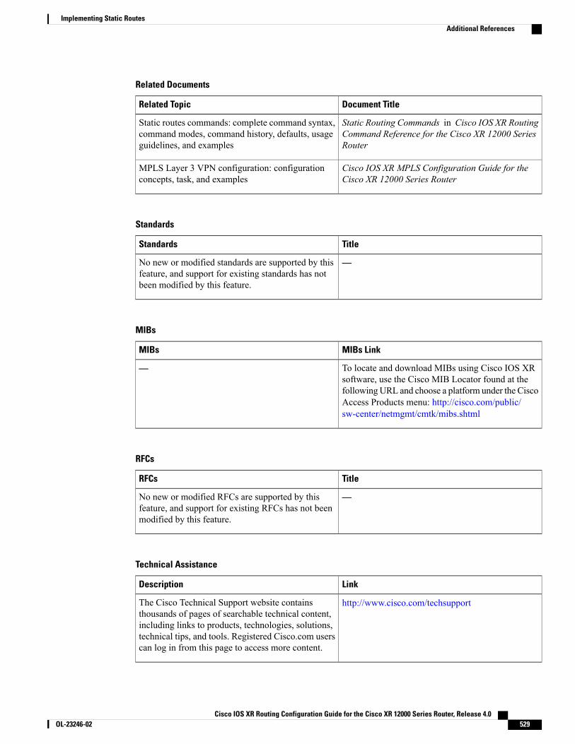
Related Documents
Document TitleRelated Topic
Static Routing Commands in Cisco IOS XR RoutingCommand Reference for the Cisco XR 12000 SeriesRouter
Static routes commands: complete command syntax,command modes, command history, defaults, usageguidelines, and examples
Cisco IOS XR MPLS Configuration Guide for theCisco XR 12000 Series Router
MPLS Layer 3 VPN configuration: configurationconcepts, task, and examples
Standards
TitleStandards
—No new or modified standards are supported by thisfeature, and support for existing standards has notbeen modified by this feature.
MIBs
MIBs LinkMIBs
To locate and download MIBs using Cisco IOS XRsoftware, use the Cisco MIB Locator found at thefollowingURL and choose a platform under the CiscoAccess Products menu: http://cisco.com/public/sw-center/netmgmt/cmtk/mibs.shtml
—
RFCs
TitleRFCs
—No new or modified RFCs are supported by thisfeature, and support for existing RFCs has not beenmodified by this feature.
Technical Assistance
LinkDescription
http://www.cisco.com/techsupportThe Cisco Technical Support website containsthousands of pages of searchable technical content,including links to products, technologies, solutions,technical tips, and tools. Registered Cisco.com userscan log in from this page to access more content.
Cisco IOS XR Routing Configuration Guide for the Cisco XR 12000 Series Router, Release 4.0 OL-23246-02 529
Implementing Static RoutesAdditional References

Cisco IOS XR Routing Configuration Guide for the Cisco XR 12000 Series Router, Release 4.0530 OL-23246-02
Implementing Static RoutesAdditional References
I N D E X
(MDT) multicast distribution tree 134
A
ABRs (area border routers ) 288ABRs (area border routers) 288action 455additional-path attach point 459address family command 9, 216adjacencies, tuning 254adjacency 301adjacency (OSPFv2) 291administrative distance 395, 410, 513administrative distance, static routes 513aggregation 459allocate label 466apply command 458Area Border Routers (ABRs) 288area-in 486area-out 486as-path-set, inline set form 437as-path-set, named set form 437ASBRs (autonomous system boundary routers) 289associating with VRF 525attached 499attached bit on an instance 222attached bit on an IS-IS instance 222attaching to BGP neighbor 503attributes 447, 449authentication 290, 291, 317
configuring (OSPFv2) 317MD5 (OSPFv2) 290route, key rollover (OSPFv2) 291strategies 290
authentication keychain configuration 204authentication using keychain 184authentication using keychain in RIP 412authentication, configuring 248, 317autonomous system number format 8autonomous systems 287
B
backbone area 288bandwidth 418benefits 408bestpath algorithm 29address-family ipv4 mdt command 135, 136BGP (Border Gateway Protocol) 1, 3, 4, 5, 6, 8, 9, 11, 12, 13, 17, 22,
24, 29, 34, 41, 42, 43, 44, 45, 134, 161, 459, 460, 461, 462, 463, 464, 465, 466, 467, 468
IPv6 prefixes over IPv4 session 6(MDT) multicast distribution tree 134autonomous system number format 8bestpath algorithm 29BGP keychains 43bgp router submode 9
router bgp command 9bidirectional forwarding detection 3configuration 11, 13
grouping 11inheriting 13inheriting templates 13
default address family 41description 1distributed BGP 41functional overview 3inheritance, monitoring 17IPv6 and IPv6 VPN provider edge transport over MPLS 43IPv6 provider edge multipath 44MPLS VPN carrier supporting carrier 42multicast VPN 45multiprotocol 34neighbors, maximum limits on 5policy attach points 459, 460, 461, 462, 463, 464, 465, 466, 467, 468
aggregation 459allocate label 466clear policy 468dampening 460debug 468default originate 461export 465import 465
Cisco IOS XR Routing Configuration Guide for the Cisco XR 12000 Series Router, Release 4.0 OL-23246-02 IN-1
BGP (Border Gateway Protocol) (continued)policy attach points (continued)
neighbor export 461neighbor import 462neighbor-orf 467network 462next-hop 467redistribute 462retain route target 466show bgp 463table policy 464
policy attach points, aggregation 459router bgp neighbor group address family configurationmode,address family command 12router identifier 4routing policy, enforcing 22update groups 24, 161
description 24example 161
VPNv4 andVPNv6 over the IP core using L2TPv3 tunnels 44bgp add path 50retain route-target command 123, 124BGP configuration 24bgp cost community 24bgp dampening command 73table-policy command 79, 80bgp global address family submode 9
address family command 9distance bgp command 81aggregate-address command 67, 68, 125, 127BGP keychains 43weight command 62, 63route-reflector-client command 86, 87bgp neighbor address family submode 9, 217
neighbor address family command 9route-policy (BGP) command 88, 89next-hop-self command 91, 92soft-reconfiguration inbound command 101, 102bgp neighbor command 11bgp neighbor group submode 12
neighbor-group command 12update-source command 120, 122bgp neighbor submode 9, 11, 216
bgp neighbor command 11neighbor command 9, 216
timers command 120, 122shutdown command 120, 122, 140keychain command 132, 133password command 120, 121, 125, 127BGP Non-Stop Routing 149
configuring 149BGP nonstop routing 46bgp nsr configuration example 165BGP prefix independent convergence 49
bgp confederation identifier command 55, 56bgp bestpath med confed command 64bgp confederation peers command 55, 56bgp router submode 9
router bgp command 9bgp router-id command 108, 125, 126bgp bestpath med always command 64bgp bestpath med missing-as-worst command 64bgp default local-preference command 59, 60timers bgp command 57, 58bgp bestpath as-path ignore command 64, 65bgp bestpath compare-routerid command 64, 65bgp session group submode 12BGP update generation 24BGP update groups example 161bgp VPNv4 address family submode 10bgp VPNv6 address family submode 10export route-policy command 106, 107redistribute connected command 110, 113, 130, 131bgp vrf address family submode 10import route-policy command 106maximum prefix command 106import route-targe command 106, 107rd command 108, 109as-override command 125, 128site-of-origin command 125, 128allowas-in command 125, 128bgp VRF neighbor address family submode 10ebgp-multihop command 125, 128bgp VRF neighbor submode 10bgp vrf submode 9label-allocation-mode per-ce command 125, 126bidirectional forwarding detection 3Boolean operator precedence 449Boolean operators, types 457
C
CIDR 408Cisco IOS and Cisco IOS XR software differences,
configuration 216grouped 216
Cisco IOS XR OSPFv3 and OSPFv2 differences 285clear policy 468CLI (command-line interface) inheritance 286CLI inheritance 286community-set, inline set form 438community-set, named set form 438components 444configuration 11, 13, 215, 216, 221, 226, 228, 241, 312, 333, 339, 346
grouped configuration 216grouping 11
Cisco IOS XR Routing Configuration Guide for the Cisco XR 12000 Series Router, Release 4.0IN-2 OL-23246-02
Index
configuration (continued)inheriting 13inheriting templates 13Level 1 or Level 2 routing 226MPLS TE 339multitopology 241neighbors, nonbroadcast networks 312restrictions 215sham-links 346single topology 228SPF throttling 333
configuration and operation, verifying 374configuration basics 446configuration between PE-CE routers 521configuration elements, editing 500configuration, grouped 216configurations (BGP) 13configuring 149, 221, 241, 245, 330, 343, 363
graceful restart 343configuring (OSPFv2) 317configuring authentication 250configuring bgp additional paths 156configuring BGP Additional Paths 166
example 166connected 514control or prevent routing updates 418controlling 241controlling frequency 321controlling the frequency 321cost community, BGP 24creating 323customizing (IS-IS) 260customizing routes 260
D
dampening 460dampening, route 36data structures in BGP and other protocols 395debug 468default 222, 291
IS-IS 222OSPFv2 291
default address family 21, 41default drop disposition 451default originate 461, 485, 488, 490default route 291default routes 222default-accept-in 492default-accept-out 492default-information originate 495defined 513
defining 502definitions 446deploying 397description 1, 24, 213, 221, 281, 298, 299, 393designate router (DR) 291Designate Router (DR) 291designated router (DR) 291Designated Router (DR) 291displaying information 345disposition 454distributed BGP 41
E
EIGRP 184, 204authentication keychain configuration 204authentication using keychain 184
EIGRP () 492policy attach points 492
default-accept-in 492EIGRP (Enhanced Interior Gateway Routing Protocol) 173, 180,
181, 182, 194, 492, 493features 173hello interval and hold time 181overview 173policy attach points 492, 493
default-accept-out 492if-policy-in 493if-policy-out 493policy-in 492policy-out 493redistribute 493
policy attach points, default-accept-in 492restrictions 194routing policy options 182split horizon 180stub routing 181
elseif 456enabling 226, 306enabling multicast-intact 265, 355enforcing, BGP 22exaibgp multipath loadsharing configuration 166show eigrp traffic command 202, 204clear eigrp neighbors command" 202, 203show isis spf-log command 258, 260show eigrp interfaces command 202, 204EXEC mode 17, 18, 19, 20
show bgp af-group command 18show bgp inheritance command 17show bgp neighbor command 17show bgp neighbor-group command 20
edit command 506
Cisco IOS XR Routing Configuration Guide for the Cisco XR 12000 Series Router, Release 4.0 OL-23246-02 IN-3
Index
show eigrp topology command 202, 204clear eigrp topology command 202, 203show rpl route-policy command 506show isis mpls command 252, 254clear ospf command 375, 376
See also clear ospfv3 commandshow isis command 226, 228export 465extended community set, inline form 439extended community set, named form 439
F
features 173filter network updates 418floating 515, 520, 521floating configuration 520forwarding adjacency 225functional overview 3, 215, 284, 394
G
Generalized TTL Security Mechanism (GTSM), TTL value 305Generalized TTLSecurityMechanism (GTSM),configuring virtuallinks 305global parameters 448global-inbound 496global-inbound, policy attach points 496graceful restart 299, 343graceful-restart helper command 300graceful-restart interval command 300graceful-restart lifetime command 300grouped 216grouped configuration 216grouping 11
H
hello interval and hold time 181hop count 408
I
ibgp multipath load sharing 158iBGP Multipath Load Sharing 50if 456if-policy-in 493if-policy-out 493
implementing 435prerequisites 435
implementing in 435prerequisites 435
import 465inheritance 13, 17
configurations (BGP) 13monitoring 17
inheritance, monitoring 17inheriting 13inheriting templates 13instance and router ID 289inter-area-propagate 490interarea tunnels 225interface attributes and limitations 303interface command 185, 186, 307, 308, 414, 415
See also router ospfv3 configuration submodeinterface-inbound 496interface-outbound 496interior routers 289IP fast reroute 225, 271IPv4 and IPv6 support 396IPv6 217, 219, 396
IS-IS support 219multitopology 219single-topology 219
RIB support 396routing 217
IPv6 and IPv6 VPN provider edge transport 396, 516IPv6 and IPv6 VPN provider edge transport over MPLS 43, 396IPv6 prefixes over IPv4 session 6IPv6 provider edge multipath 44IPv6 routing 217IPv6 support 219IS-IS 222IS-IS (Intermediate System-to-Intermediate System) 213, 215,
216, 217, 218, 219, 220, 221, 222, 226, 228, 241, 245, 248, 250, 254, 258, 260, 263, 265, 267, 269, 271, 490
configuration, grouped 216adjacencies, tuning 254attached bit on an instance 222authentication, configuring 248Cisco IOS and Cisco IOS XR software differences,
configuration 216grouped 216
configuration 215, 216, 226, 228, 241grouped configuration 216Level 1 or Level 2 routing 226multitopology 241restrictions 215single topology 228
configuring authentication 250customizing routes 260default routes 222
Cisco IOS XR Routing Configuration Guide for the Cisco XR 12000 Series Router, Release 4.0IN-4 OL-23246-02
Index
IS-IS (Intermediate System-to-Intermediate System) (continued)description 213enabling 226enabling multicast-intact 265functional overview 215grouped configuration 216IP fast reroute 271IPv6 routing 217Level 1 or Level 2 routing, configuration 226LSP flooding 218, 241
controlling 241lifetime maximum 218limiting 218
MPLS LDP IS-IS synchronization 263MPLS TE 221
description 221multi-instance IS-IS 221multitopology, configuring 241nonstop forwarding 220, 245
configuring 245overload bit 221
configuring 221on router 221
policy attach points 490default originate 490inter-area-propagate 490redistribute 490
priority for prefixes added to RIB 269restrictions, configuring 215set SPF interval 258single topology,configuring 228single topology,IPv6 support 219tagging IS-IS interface routes 267
IS-IS address family submode 216IS-IS Overload Bit Avoidance 222IS-IS support 219
multitopology 219single-topology 219
K
key rollover 291keychains 43
L
L2TPv3 tunnels 44LDP IGP synchronization 224LDP IS-IS synchronization 263Level 1 or Level 2 routing 226Level 1 or Level 2 routing, configuration 226
lifetime maximum 218limiting 218link-state advertisement (LSA) 292, 301
OSPFv2 292OSPFv3 292, 301
load balancing 303loop-free alternate 225LSA 292, 321, 328
controlling frequency 321controlling the frequency 321on an OSPF ABR 328types 292
LSP flooding 218, 241controlling 241lifetime maximum 218limiting 218mesh group configuration 218on specific interfaces 218
lsp-check-interval command 242, 243
M
maximum limits (BGP) 5maximum number of routes 523maximum path command 524MD5 290MD5 (OSPFv2) 290MD5 authentication 290mesh group configuration 218Message Digest 5 (MD5) authentication 304message statistics 396metrics 408modification 449modifying 505monitor 148monitoring 17, 397MPLS 224, 396, 516
LDP IGP synchronization 224IPv6 and IPv6 VPN provider edge transport 396, 516
MPLS layer 3 VPN 513MPLS LDP IGP 224MPLS LDP IGP synchronization 224MPLS LDP IS-IS synchronization 263MPLS TE 221, 339
description 221MPLS TE (Multiprotocol Label Switching traffic engineering)
configuring 339OSPFv2 339
MPLS TE (Multiprotocol Label Switching traffic engineering),configuring for OSPFv2 339MPLS TE forwarding adjacency 225MPLS TE interarea tunnels 225
Cisco IOS XR Routing Configuration Guide for the Cisco XR 12000 Series Router, Release 4.0 OL-23246-02 IN-5
Index

MPLS TE, configuring 339MPLS VPN carrier supporting carrier 42multi-area adjacency 303, 363
configuring 363interface attributes and limitations 303overview 303
multi-instance IS-IS 221multicast topology 223multicast VPN 45multicast-intact 223, 302
OSPFv2 302multiprotocol 34multiprotocol BGP 34Multiprotocol Label Switching (MPLS) 263
LDP IS-IS synchronization 263Multiprotocol Label Switching traffic engineering (MPLS TE),configuring fir IS-IS 252multitopology 219, 241, 275
(example) 275configuring 241
multitopology routing 234multitopology, configuring 241
N
names 436NBMA networks 290neighbor address family command 9, 217neighbor command 9, 216, 414neighbor command (OSPFv2 313, 315
OSPFv3) 313, 315See also ospfv3 interface configuration submode
neighbor export 461neighbor import 462neighbor-group command 12neighbor-orf 467neighbors 5, 291
adjacency (OSPFv2) 291maximum limits (BGP) 5
neighbors, adjacency 291neighbors, configuring nonbroadcast networks 312neighbors, maximum limits on 5neighbors, nonbroadcast networks 312neighbors, nonbroadcast networks, configuring 312network 462next-hop 467nonattached 499nonstop forwarding 220, 245, 299, 336
configuring 245description 299
not-so-stubby area 288
O
on an OSPF ABR 328on router 221on specific interfaces 218OSPF 305, 377
queue tuning parameters 305queue tuning parameters configuration 377
hello-interval (OSPF) command 313, 315See also ospfv3 area configuration submode
dead interval command command 313, 314See also ospfv3 area configuration submode
network command 313, 314See also ospfv3 area configuration submode
default-cost command 309, 311See also ospfv3 area configuration submode
nssa command 309, 310See also ospfv3 area configuration submode
authentication message-digest command 324, 326virtual-link command 324, 325OSPFv2 223, 291, 292, 302, 339
multicast-intact 223OSPFv2 (Open Shortest Path First Version 2) 281, 284, 285, 286,
289, 290, 291, 292, 294, 298, 299, 306, 309, 312, 317, 321, 323, 328, 330, 333, 336, 339, 346, 355, 374, 485, 486, 488
authentication, configuring 317Cisco IOS XR OSPFv3 and OSPFv2 differences 285CLI (command-line interface) inheritance 286configuration 312, 339, 346
MPLS TE 339neighbors, nonbroadcast networks 312sham-links 346
configuration and operation, verifying 374default route 291description 281designate router (DR) 291Designate Router (DR) 291enabling 306enabling multicast-intact 355functional overview 284instance and router ID 289LSA 292, 321, 328
controlling the frequency 321on an OSPF ABR 328types 292
MD5 authentication 290MPLS TE, configuring 339neighbors, adjacency 291neighbors, nonbroadcast networks, configuring 312nonstop forwarding 299, 336
description 299policy attach points 485, 486, 488
area-in 486area-out 486
Cisco IOS XR Routing Configuration Guide for the Cisco XR 12000 Series Router, Release 4.0IN-6 OL-23246-02
Index
OSPFv2 (Open Shortest Path First Version 2) (continued)policy attach points (continued)
default originate 485redistribute 485, 488
route authentication methods 290, 291key rollover 291MD5 290plain text 290strategies 290
route redistribution 298, 330configuring 330description 298
sham-link 346Shortest Path First (SPF) throttling 298
description 298Shortest Path First (SPF) throttling,configuring 333SPF throttling, configuring 333stub and not-so-stubby area types, configuring 309supported OSPF network types 290
NBMA networks 290point to point networks 290
virtual link 294, 323creating 323transit area 294
OSPFv3 292, 299, 301graceful restart 299
OSPFv3 (Open Shortest Path First Version 3) 281, 284, 285, 286, 289, 291, 292, 294, 301, 303, 306, 309, 312, 321, 328, 330, 333, 343, 374, 485, 488
Cisco IOS XR OSPFv3 and OSPFv2 differences 285CLI inheritance 286configuration 333
SPF throttling 333configuration and operation, verifying 374configuring 343
graceful restart 343default route 291description 281enabling 306functional overview 284instance and router ID 289link-state advertisement (LSA) 301load balancing 303LSA 292, 321, 328
controlling frequency 321on an OSPF ABR 328types 292
neighbors, configuring nonbroadcast networks 312policy attach points 485, 488
default originate 488redistribute 485, 488
routes, redistribute 330SPF (Shortest Path First) throttling configuring 333stub and not-so-stubby area types, configuring 309
OSPFv3 (Open Shortest Path First Version 3) (continued)virtual link, description 294
OSPFv3 Graceful Restart feature 299, 301, 345, 346adjacency 301displaying information 345, 346
OSPFv3 SPF 296default-information originate command 261, 262nsf command 246, 416, 417mpls traffic-eng router-id command 340timers throttle spf command 334, 335, 372, 373
See also ospfv3 interface configuration submodempls traffic-eng area command 340, 341nsf interval command 337, 338overload bit 221
configuration 221configuring 221on router 221
overview 173, 303, 435
P
parameterization 447PCE extensions to OSPFv2 305PIM 223plain text 290point to point networks 290point-to-point networks 290policy 446, 447, 449, 451, 452, 453
attributes 447, 449Boolean operator precedence 449configuration basics 446default drop disposition 451definitions 446statement processing 451statements, types 453verification 452
policy attach points 459, 460, 461, 462, 463, 464, 465, 466, 467, 468, 485, 486, 488, 490, 492, 493, 495, 496
aggregation 459allocate label 466area-in 486area-out 486clear policy 468dampening 460debug 468default originate 461, 485, 488, 490default-accept-in 492default-accept-out 492default-information originate 495export 465global-inbound 496if-policy-in 493
Cisco IOS XR Routing Configuration Guide for the Cisco XR 12000 Series Router, Release 4.0 OL-23246-02 IN-7
Index
policy attach points (continued)if-policy-out 493import 465inter-area-propagate 490interface-inbound 496interface-outbound 496neighbor export 461neighbor import 462neighbor-orf 467network 462next-hop 467policy-in 492policy-out 493redistribute 462, 485, 488, 490, 493, 496retain route target 466show bgp 463table policy 464
policy attach points, aggregation 459policy attach points, default-accept-in 492policy attributes 447, 449
parameterization 447modification 449
policy-in 492policy-out 493policy, modifying 499
attached 499nonattached 499
prefix prioritization 296OSPFv2 SPF 296
prefix-set 442prerequisites 394, 435priority for prefixes added to RIB 269
Q
quarantining 397queue tuning parameters 305queue tuning parameters configuration 377
R
recursive 514redistribute 462, 485, 488, 490, 493, 496redistribute (OSPFv2, OSPFv3) 330redistributing (OSPFv2, OSPFv3) 330redistribution 410remark 453restrictions 194, 215restrictions, configuring 215retain route target 466RFC 2328, OSPF Version 2 285
RFC 2453, RIP Version 2 408RFC 2740 OSPFv3 285RFC 3682 305
Generalized TTL Security Mechanism (GTSM), TTLvalue 305
RIB 396, 397statistics 396quarantining 397
RIB (Routing Information Base) 393, 394, 395, 396, 397, 401administrative distance 395data structures in BGP and other protocols 395deploying 397description 393examples 401functional overview 394IPv4 and IPv6 support 396monitoring 397prerequisites 394
RIB quarantining 397RIB statistics 396RIB support 396RIP (Routing Information Protocol ) 496
global-inbound, policy attach points 496policy attach points 496
global-inbound 496RIP (Routing Information Protocol) 408, 409, 410, 411, 418, 421,
495, 496administrative distance 410benefits 408CIDR 408control or prevent routing updates 418metrics 408redistribution 410route policy creation 421route timers 409routing policy options 411bandwidth 418filter network updates 418hop count 408policy attach points 495, 496
default-information originate 495global-inbound 496interface-inbound 496interface-outbound 496redistribute 496
routing loops 418split horizon, enabling IP 409VLSMs (variable-length subnet masks) 408WAN link 418
RIP v2 supported features 408route authentication methods 290, 291
key rollover 291MD5 290plain text 290
Cisco IOS XR Routing Configuration Guide for the Cisco XR 12000 Series Router, Release 4.0IN-8 OL-23246-02
Index
route authentication methods (continued)strategies 290
route dampening 36route policy creation 421route-policy command 52, 88, 120, 122, 125, 128, 187, 188, 192, 419, 420, 421, 422, 502, 503end-policy command 52, 53route redistribution 298, 330
configuring 330description 298
route redistribution (OSPFv2, OSPFv3) 298route reflectors 37route tags 223route timers 409set eigrp-metric command 192route-policy pass-all command 22route, key rollover (OSPFv2) 291router bgp command 9router bgp neighbor group address family configurationmode,address family command 12maximum-prefix command 189, 191log-neighbor-warnings command 202, 203default-metric command 185, 186redistribute command 189, 190, 197, 198, 199, 200stub command 195, 309, 310
See also ospfv3 area configuration submoderedistribute maximum-prefix 189, 190log-neighbor-changes command 202, 203maximum paths command 189, 190distance command 185, 186timers nsf route-hold command 189, 190router eigrp command 185summary-address command 187, 188holdtime command 185, 186bandwidth-percent command 185, 186router identifier 4mpls traffic-engineering multicast-intact command 265, 266mpls traffic-eng command 252, 253ispf command 258, 259attached-bit send command 261, 263single-topology command 230, 232spf prefix-priority command 269, 270redistribute isis command 261, 262metric-style wide command 267, 268, 269, 270spf-interval command 258, 259address-family (IS-IS) command 230, 232nsf interface-expires command 246, 247sp-refresh-interval command 242, 243is-type command 226, 227max-lsp-lifetime command 242, 243ignore-lsp-errors command 242, 243lsp-password command 248net command 226, 227lsp-mtu command 242, 243
lsp-gen-interval command 242, 243nsf interface-timer command 246, 247tag command 267, 268retransmit-interval command 242, 244hello-padding command 255, 256mesh-group command 242, 244router isis interface configuration submode 230, 231hello-password command 248, 249, 255, 256hello-interval (IS-IS) command 255, 256hello-multiplier command 255, 256csnp-interval command 242, 244retransmit-throttle-interval command 242, 244router ospf command 307timers lsa refresh command 321, 322
See also router ospfv3 configuration submodemessage-digest-key command 318, 319summary-prefix command 331, 332
See also router ospfv3 configuration submodelog adjacency changes command 307, 308, 372
See also ospfv3 interface configuration submodetimers lsa gen-interval command 321, 322
See also outer ospfv3 configuration submodeauthentication command (OSPFv2) 318range command 328, 329
See also router ospfv3 configuration submodetimers lsa group-pacing command 321, 322
See also outer ospfv3 configuration submoderouter-id command 307
See also router ospfv3 configuration submodetimers lsa min-interval command 321, 322
See also outer ospfv3 configuration submodearea command 307, 308
See also router ospfv3 configuration submoderouter ospfv3 command 307router rib command 400address-family command 400, 401router rip command 414receive version command 414, 415output-delay command 416, 417send version command 414, 415split-horizon disable command 416, 417metric-zero-accept command 416, 417broadcast-for-v2 command 414, 415poison-reverse command 416, 418auto-summary command 416, 417timers basic command 416, 417passive-interface command 419, 420router static command 524routes 222, 260, 275, 291, 330
customizing (IS-IS) 260default 222, 291
IS-IS 222OSPFv2 291
redistribute (OSPFv2, OSPFv3) 330
Cisco IOS XR Routing Configuration Guide for the Cisco XR 12000 Series Router, Release 4.0 OL-23246-02 IN-9
Index
routes (continued)redistribute IS-IS routes (example) 275redistribute IS-IS routes example 275redistributing (OSPFv2, OSPFv3) 330
routes, redistribute 330routing 217routing components 287, 288, 289, 291
ABRs (area border routers ) 288Area Border Routers (ABRs) 288ASBRs (autonomous system boundary routers) 289autonomous systems 287backbone area 288designated router (DR) 291Designated Router (DR) 291interior routers 289not-so-stubby area 288stub area 288
routing domain confederation 37routing loops 418routing policy 22, 435, 453, 454, 455, 456, 500, 502, 503, 505, 507, 508
attaching to BGP neighbor 503configuration elements, editing 500defining 502defining (example) 507enforcing, BGP 22implementing 435
prerequisites 435implementing in 435
prerequisites 435inbound (example) 507modifying 505modular inbound (example) 508statements 453, 454, 455, 456
action 455disposition 454elseif 456if 456remark 453
Routing Policy 435restrictions, configuring routing policy 435
routing policy options 182, 411routing policy, enforcing 22RPL (routing policy language) 435, 436, 437, 438, 439, 442, 444, 446,
447, 449, 451, 452, 453, 457Boolean operators, types 457components 444overview 435policy 446, 447, 449, 451, 452, 453
attributes 447, 449Boolean operator precedence 449configuration basics 446default drop disposition 451definitions 446statement processing 451
RPL (routing policy language) (continued)policy (continued)
statements, types 453verification 452
policy attributes 447, 449parameterization 447modification 449
structure 436, 437, 438, 439, 442as-path-set, inline set form 437as-path-set, named set form 437community-set, inline set form 438, 439community-set, named set form 438extended community set, inline form 439extended community set, named form 439names 436prefix-set 442sets 436
S
security ttl command 372, 373set SPF interval 258set-overload-bit command 261sets 436sham-link 346sham-links 346Shortest Path First (SPF) throttling 298
description 298Shortest Path First (SPF) throttling, configuring 333show bgp 463show bgp af-group command 18show bgp cidr-only command 145show bgp command 145show bgp community command 145show bgp inheritance command 17show bgp ipv4 unicast summary command 147show bgp neighbor command 17show bgp neighbor-group command 20, 145, 146show bgp neighbors command 145show bgp paths command 145, 146show bgp process command 147show bgp process detail command 147show bgp session-group command 19show bgp summary command 145, 146, 147show bgp vpnv4 unicast summary command 147show bgp vrf command 147show eigrp accounting command 202, 204show eigrp neighbors command 195, 196, 202, 204show isis database command 242, 245show isis database-log command 242, 245show isis interface command 255, 257show isis lsp-log command 242, 245
Cisco IOS XR Routing Configuration Guide for the Cisco XR 12000 Series Router, Release 4.0IN-10 OL-23246-02
Index
show isis mpls traffic-eng adjacency-log command 252, 254show isis mpls traffic-eng advertisements command 252, 254show isis neighbors command 255, 257show isis topology command 230, 233show ospf command 324show ospfv3 command 324, 325show placement program bgp command 147, 148show placement program brib command 147, 148show protocols eigrp command 202, 204show running-config command 246, 247single topology 228single topology,configuring 228single topology,IPv6 support 219single-topology 219, 258, 275
configuring (example) 275IPv6 support 219set SPF interval 258
specified 515SPF (Shortest Path First) throttling configuring 333SPF throttling 333SPF throttling, configuring 333
OSPFv2 (Open Shortest Path First Version 2) 333split horizon 180split horizon, enabling IP 409statement processing 451statements 453, 454, 455, 456
action 455disposition 454elseif 456if 456remark 453
statements, types 453static routes 513, 514, 515, 520, 521, 523, 525
administrative distance 513associating with VRF 525configuration between PE-CE routers 521connected 514defined 513floating 515, 520, 521floating configuration 520maximum number of routes 523MPLS layer 3 VPN 513recursive 514specified 515
statistics 396strategies 290structure 436, 437, 438, 439, 442
as-path-set, inline set form 437as-path-set, named set form 437community-set, inline set form 438community-set, named set form 438extended community set, inline form 439extended community set, named form 439names 436
structure (continued)prefix-set 442sets 436
stub and not-so-stubby area types, configuring 309stub area 288stub area types, configuring (OSPFv3) 309stub routing 181router isis address family submode 261, 262supported OSPF network types 290
NBMA networks 290point to point networks 290
synchronization 224MPLS LDP IGP 224
T
table policy 464tagging IS-IS interface routes 267transit area 294transit area (OSPFv2) 294types 292
U
update groups 24, 148BGP configuration 24BGP update generation 24description 24monitor 148
V
verification 452virtual link 294, 323
creating 323transit area 294transit area (OSPFv2) 294
virtual link, description 294VLSMs (variable-length subnet masks) 408VPNv4 address family command 10VPNv4 and VPNv6 over the IP core using L2TPv3 tunnels 44VPNv6 address family command 10VRF address family command 10export route-target command 106, 107VRF command 9VRF neighbor address family command 10VRF neighbor command 10
Cisco IOS XR Routing Configuration Guide for the Cisco XR 12000 Series Router, Release 4.0 OL-23246-02 IN-11
Index

W WAN link 418
Cisco IOS XR Routing Configuration Guide for the Cisco XR 12000 Series Router, Release 4.0IN-12 OL-23246-02
Index