XM678D IO Manual - Emerson Electric · 2018-05-30 · XM678D Controllers for Multiplexed Cabinets...
76
XM678D Controllers for Multiplexed Cabinets with Interior Stepper Driver Installation and Operation Manual for Software Release 2.8 026-1219 Rev 3
Transcript of XM678D IO Manual - Emerson Electric · 2018-05-30 · XM678D Controllers for Multiplexed Cabinets...

XM678D Controllers for Multiplexed Cabinets with Interior Stepper Driver Installation and Operation Manual for Software Release 2.8
026-1219 Rev 3


Emerson 1065 Big Shanty Road NW, Suite 100
Kennesaw, GA 30144770-425-2724 • www.emerson.com


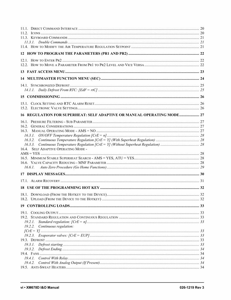
Table of Contents • v
Table of Contents1 INTRODUCTION.......................................................................................................................................................... 1
1.1. GENERAL PRECAUTIONS AND WARNINGS.................................................................................................................... 1
2 BEFORE PROCEEDING ............................................................................................................................................. 1
2.1. SOFTWARE RELEASE OF XM678D ............................................................................................................................... 1
3 OVERVIEW ................................................................................................................................................................... 2
3.1. GENERAL DESCRIPTION................................................................................................................................................ 23.2. ORDERING CODE .......................................................................................................................................................... 2
4 QUICK REFERENCE GUIDE IN RUNNING THE SELF ADAPTIVE REGULATION .................................... 2
5 INSTALLATION AND MOUNTING ......................................................................................................................... 4
6 WIRING DIAGRAM AND CONNECTIONS ............................................................................................................ 5
6.1. IMPORTANT NOTE......................................................................................................................................................... 56.2. WIRING GUIDELINES .................................................................................................................................................... 56.3. XM678D WIRING AND CONNECTIONS ........................................................................................................................ 56.4. VALVE CONNECTIONS AND CONFIGURATION .............................................................................................................. 6
6.4.1. Types of Cables and Max Length.......................................................................................................................... 66.4.2. Valve Selection...................................................................................................................................................... 66.4.3. 4-Wire Valves (Bipolar) ........................................................................................................................................ 96.4.4. 5- to 6-Wire Valves (Unipolar) ............................................................................................................................. 9
6.5. WIRING CONNECTION OF EMERSON EX3 VALVE ........................................................................................................ 96.5.1. Solenoid Valve Connection ................................................................................................................................... 96.5.2. EX3 with 24Vac Coil: Transformer Capacity....................................................................................................... 96.5.3. Stepper Valve Connection................................................................................................................................... 106.5.4. EX3-C230............................................................................................................................................................ 10
6.6. ABSOLUTE MAXIMUM POWER.................................................................................................................................... 106.7. KEYBOARD DISPLAY CX660...................................................................................................................................... 116.8. LAN CONNECTION ..................................................................................................................................................... 116.9. SENSORS FOR SUPERHEAT CONTROL ......................................................................................................................... 116.10. HOW TO USE A SINGLE PRESSURE TRANSDUCER ON MULTIPLEXED APPLICATIONS .............................................. 126.11. HOW TO CONNECT THE MONITORING SYSTEM........................................................................................................ 126.12. DIGITAL INPUTS........................................................................................................................................................ 136.13. ANALOG OUTPUT ..................................................................................................................................................... 13
7 BATTERY BACK UP CONNECTION..................................................................................................................... 14
7.1. XEC SUPERCAP CONNECTION.................................................................................................................................... 147.2. EMERSON ECP-024 CONNECTION.............................................................................................................................. 15
8 WIRING LAYOUT FOR SHARING A PRESSURE TRANSDUCER ON A LAN.............................................. 15
9 PRESSURE TRANSDUCER SETUP ........................................................................................................................ 17
9.1. RS485 NET MONITORING TEMPERATURES ................................................................................................................ 179.1.1. RS485 Connection............................................................................................................................................... 18
9.2. HOW TO ENABLE A PRESSURE PROBE TO SHARE ACROSS THE LAN ........................................................................ 18
10 WIRING CONNECTION TO SITE SUPERVISOR ............................................................................................. 19
11 USER INTERFACE .................................................................................................................................................. 20
vi • XM678D I&O Manual 026-1219 Rev 3
11.1. DIRECT COMMAND INTERFACE ................................................................................................................................ 2011.2. ICONS ........................................................................................................................................................................ 2011.3. KEYBOARD COMMANDS ........................................................................................................................................... 21
11.3.1. Double Commands ........................................................................................................................................... 2111.4. HOW TO MODIFY THE AIR TEMPERATURE REGULATION SETPOINT ........................................................................ 21
12 HOW TO PROGRAM THE PARAMETERS (PR1 AND PR2) ........................................................................... 22
12.1. HOW TO ENTER PR2 ................................................................................................................................................. 2212.2. HOW TO MOVE A PARAMETER FROM PR1 TO PR2 LEVEL AND VICE VERSA .......................................................... 22
13 FAST ACCESS MENU.............................................................................................................................................. 23
14 MULTIMASTER FUNCTION MENU (SEC) ........................................................................................................ 24
14.1. SYNCHRONIZED DEFROST......................................................................................................................................... 2514.1.1. Daily Defrost From RTC: [EdF = rtC] ........................................................................................................... 25
15 COMMISSIONING ................................................................................................................................................... 26
15.1. CLOCK SETTING AND RTC ALARM RESET............................................................................................................... 2615.2. ELECTRONIC VALVE SETTINGS................................................................................................................................. 26
16 REGULATION FOR SUPERHEAT: SELF ADAPTIVE OR MANUAL OPERATING MODE..................... 27
16.1. PRESSURE FILTERING - SUB PARAMETER................................................................................................................. 2716.2. GENERAL CONSIDERATIONS ..................................................................................................................................... 2716.3. MANUAL OPERATING MODE - AMS = NO ............................................................................................................. 27
16.3.1. ON/OFF Temperature Regulation [CrE = n].................................................................................................. 2816.3.2. Continuous Temperature Regulation [CrE = Y] (With Superheat Regulation) .............................................. 2816.3.3. Continuous Temperature Regulation [CrE = Y] (Without Superheat Regulation) ......................................... 28
16.4. SELF ADAPTIVE OPERATING MODE - AMS = YES ........................................................................................................................................................................ 2816.5. MINIMUM STABLE SUPERHEAT SEARCH - AMS = YES, ATU = YES..................................................................... 2816.6. VALVE CAPACITY REDUCING - MNF PARAMETER .................................................................................................. 28
16.6.1. Auto Zero Procedure (Go Home Functions).................................................................................................. 29
17 DISPLAY MESSAGES.............................................................................................................................................. 30
17.1. ALARM RECOVERY ................................................................................................................................................... 31
18 USE OF THE PROGRAMMING HOT KEY ......................................................................................................... 32
18.1. DOWNLOAD (FROM THE HOTKEY TO THE DEVICE).................................................................................................. 3218.2. UPLOAD (FROM THE DEVICE TO THE HOTKEY) ....................................................................................................... 32
19 CONTROLLING LOADS......................................................................................................................................... 33
19.1. COOLING OUTPUT..................................................................................................................................................... 3319.2. STANDARD REGULATION AND CONTINUOUS REGULATION ..................................................................................... 33
19.2.1. Standard regulation: [CrE = n]....................................................................................................................... 3319.2.2. Continuous regulation: [CrE = Y] ........................................................................................................................................................................ 3319.2.3. Evaporator valves: [CrE = EUP].................................................................................................................... 33
19.3. DEFROST ................................................................................................................................................................... 3319.3.1. Defrost starting ................................................................................................................................................ 3319.3.2. Defrost Ending ................................................................................................................................................. 34
19.4. FANS ......................................................................................................................................................................... 3419.4.1. Control With Relay........................................................................................................................................... 3419.4.2. Control With Analog Output (If Present)......................................................................................................... 34
19.5. ANTI-SWEAT HEATERS............................................................................................................................................. 34

Table of Contents • vii
19.6. AUXILIARY OUTPUT ................................................................................................................................................. 35
20 TECHNICAL DATA ................................................................................................................................................. 36
21 UL RATINGS............................................................................................................................................................. 38
22 E2 MODBUS NETWORK WIRING ....................................................................................................................... 39
23 ECT MODBUS NETWORKING TO E2S .............................................................................................................. 40
23.1. COM PORT ASSOCIATIONS - E2 VERSIONS 4.0 AND ABOVE................................................................................... 4023.2. E2 SETUP OF DEVICES.............................................................................................................................................. 41
23.2.1. Set Up Network Ports....................................................................................................................................... 4123.2.2. Add and Connect the Device............................................................................................................................ 41
23.3. WIRING TYPES.......................................................................................................................................................... 4223.4. MODBUS TERMINATION BLOCKS........................................................................................................................... 43
24 DEFAULT PARAMETER MAP.............................................................................................................................. 44
25 XM678D CONTROLLER ASSOCIATION AND REPLACEMENT PROCEDURE........................................ 61
24.1. OVERVIEW ................................................................................................................................................................ 6124.2. CASE CIRCUIT OUTPUT CONNECTIONS .................................................................................................................... 6124.3. DEFROST SYNCHRONIZATION................................................................................................................................... 6124.4. CASE CIRCUIT INPUT CONNECTIONS........................................................................................................................ 61
24.4.1. Associating the XM678D with Case Control Circuit in E2 ............................................................................. 6124.4.2. Replacing the XM678D on E2 ......................................................................................................................... 63
APPENDIX A - ALTERNATE MODBUS COM WIRING METHOD FOR E2, XR, XM, AND XEV DEVICES .65


General Precautions and Warnings Introduction • 1
1 Introduction
1.1. General Precautions and Warnings
Please read the following safety precautions and warnings before using this manual:
2 Before Proceeding
2.1. Software Release of XM678D
1. Look at the software release of XM678D printed on the label of the controller.
2. If the software release is 2.8, proceed with this manual; otherwise contact Emerson Retail Solutions for the correct manual.
WARNING! An isolated transformer for the XM678D power supply must be used. Do not share power with any other devices.
CAUTION!
• This manual is part of the product and should be kept near the device for easy and quick
reference.• The device should not be used for purposes different from those described in this manual. It cannot be used as a safety device.• Check the application limits before proceeding.
SAFETY PRECAUTIONS AND WARNINGS!
• Check that the supply voltage is correct before connecting the device.
• Do not expose to water or moisture: use the controller only within the operating limits and avoid sudden temperature changes with high atmospheric humidity to prevent condensation from forming.
• Warning! Disconnect all electrical connections before performing any kind of maintenance.
• Fit the probe where it is not accessible by the end user. The device must not be opened.
• In case of failure or faulty operation, send the device back to the distributor or to Emerson Retail Solutions (see address) with a detailed description of the fault.
• Verify the maximum current that can be applied to each relay (see Section 20, Technical Data).
• Ensure that the wires for probes, loads, and the power supply are separated and far enough from each other without crossing or intertwining.
• In case of applications in industrial environments, the use of main filters (our mod. FT1) in parallel with inductive loads could be useful.
Figure 2-1 - Software Release of XM678D

2 • XM678D I&O Manual 026-1219 Rev 3
3 Overview
3.1. General DescriptionThe XM678D controller is a microprocessor based controller for multiplexed cabinets suitable for applications on medium or low temperature. It can be inserted in a proprietary Local Area Network (LAN) with up to eight (8) different sections that can operate, depending on the programming, as standalone controllers or by following the commands coming from the other sections. The XM678D controller is provided with six (6) relay outputs to control the solenoid valve, defrost that can be either electrical or hot gas, evaporator fans, lights, an auxiliary output and an alarm output, and with the stepper valve driver. It also has six (6) probe inputs: for temperature control, defrost end temperature control, display and the fourth can be used for application with virtual probe or for inlet/outlet air temperature measurement. The fifth and sixth probe inputs are used to evaluate and control the superheat. The XM678D is also equipped with three (3) free contact digital inputs that are fully configurable by parameters.The Hotkey connector allows simple programming of the controller. The optional direct serial output RS485 that is MODBUS compatible permits simple XWEB interfacing. Optionally, an RTC is available. Depending on the model, the Hotkey connector can be used to connect the X-REP display.
3.2. Ordering Code
4 Quick Reference Guide in Running the Self Adaptive Regulation
1. After wiring the XM678D; configure the type of valve, bipolar or unipolar, via tEu (Default tEu = bP: bipolar) and tEP (Default tEP =0) parameters or through the manual settings. See Section 6.4., Valve Connections and Configuration for details.
2. Set the proper gas via Fty parameter.
Preset gas is R404A.
Device Name Emerson Code
XM678D 318-6600
Table 3-1 - Product Ordering Code
NOTE: For Alco EX4, EX5, EX6 tEP = 11.
For EX3: tEP = 12
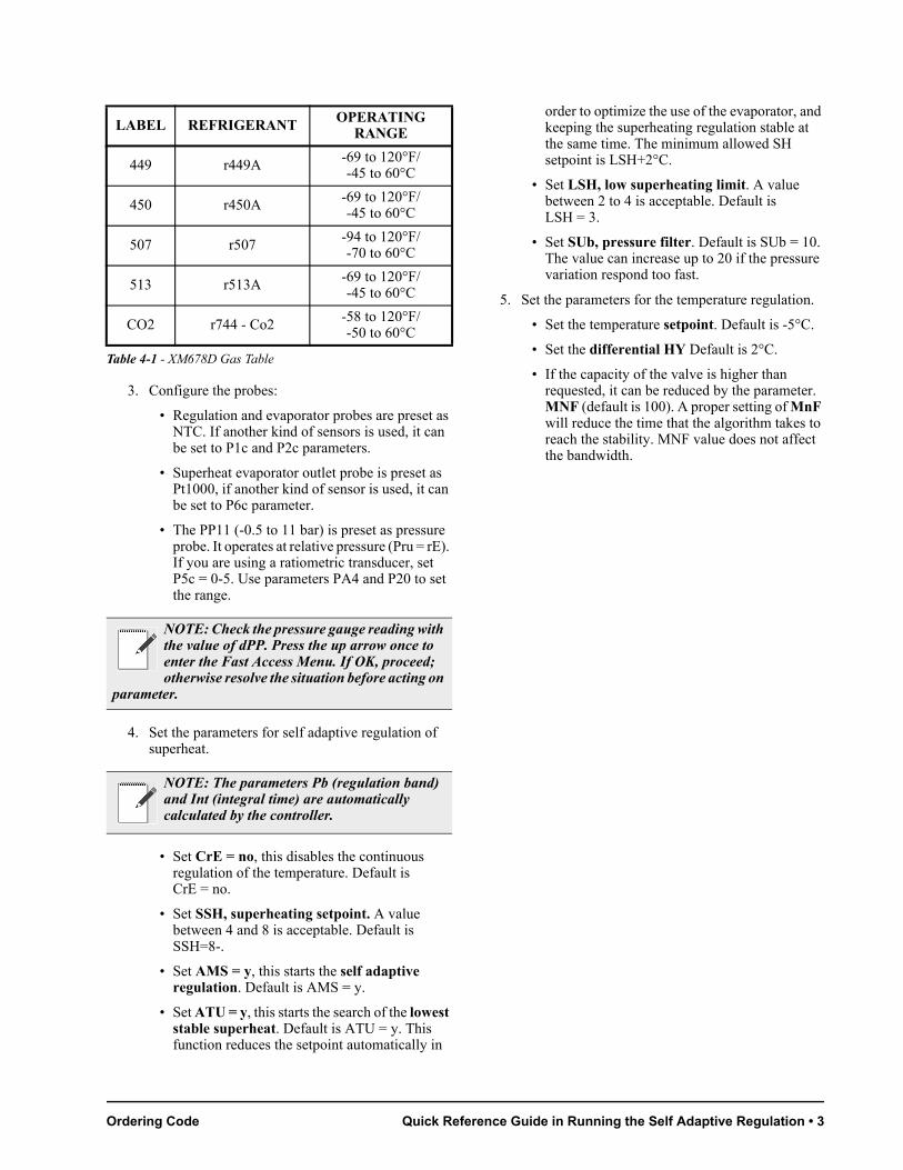
LABEL REFRIGERANT OPERATING RANGE
R22 r22 -58 to 120°F/-50 to 60°C
134 r134A -58 to 120°F/-50 to 60°C
290 r290 - Propane -58 to 120°F/-50 to 60°C
404 r404A -94 to 120°F/-70 to 60°C
47A r407A -58 to 120°F/-50 to 60°C
47C r407C -58 to 120°F/-50 to 60°C
47F r4107F -58 to 120°F/-50 to 60°C
410 r410A -58 to 120°F/-50 to 60°C
448 r448A -69 to 120°F/-45 to 60°C
Table 4-1 - XM678D Gas Table
Ordering Code Quick Reference Guide in Running the Self Adaptive Regulation • 3
3. Configure the probes:
• Regulation and evaporator probes are preset as NTC. If another kind of sensors is used, it can be set to P1c and P2c parameters.
• Superheat evaporator outlet probe is preset as Pt1000, if another kind of sensor is used, it can be set to P6c parameter.
• The PP11 (-0.5 to 11 bar) is preset as pressure probe. It operates at relative pressure (Pru = rE). If you are using a ratiometric transducer, set P5c = 0-5. Use parameters PA4 and P20 to set the range.
4. Set the parameters for self adaptive regulation of superheat.
• Set CrE = no, this disables the continuous regulation of the temperature. Default is CrE = no.
• Set SSH, superheating setpoint. A value between 4 and 8 is acceptable. Default is SSH=8-.
• Set AMS = y, this starts the self adaptive regulation. Default is AMS = y.
• Set ATU = y, this starts the search of the lowest stable superheat. Default is ATU = y. This function reduces the setpoint automatically in
order to optimize the use of the evaporator, and keeping the superheating regulation stable at the same time. The minimum allowed SH setpoint is LSH+2°C.
• Set LSH, low superheating limit. A value between 2 to 4 is acceptable. Default is LSH = 3.
• Set SUb, pressure filter. Default is SUb = 10. The value can increase up to 20 if the pressure variation respond too fast.
5. Set the parameters for the temperature regulation.
• Set the temperature setpoint. Default is -5°C.
• Set the differential HY Default is 2°C.
• If the capacity of the valve is higher than requested, it can be reduced by the parameter. MNF (default is 100). A proper setting of MnF will reduce the time that the algorithm takes to reach the stability. MNF value does not affect the bandwidth.
449 r449A -69 to 120°F/-45 to 60°C
450 r450A -69 to 120°F/-45 to 60°C
507 r507 -94 to 120°F/-70 to 60°C
513 r513A -69 to 120°F/-45 to 60°C
CO2 r744 - Co2 -58 to 120°F/-50 to 60°C
NOTE: Check the pressure gauge reading with the value of dPP. Press the up arrow once to enter the Fast Access Menu. If OK, proceed; otherwise resolve the situation before acting on
parameter.
NOTE: The parameters Pb (regulation band) and Int (integral time) are automatically calculated by the controller.
LABEL REFRIGERANT OPERATING RANGE
Table 4-1 - XM678D Gas Table

4 • XM678D I&O Manual 026-1219 Rev 3
5 Installation and Mounting
The XM678D controller can function without any user interface, but normal application is with the CX660 keyboard.
The CX660 keyboard should be mounted on a vertical panel, in a 29 x 71 mm hole, and secured using the special bracket supplied (Figure 5-1).The temperature range allowed for correct operation is 0 to 60°C. Avoid places subject to strong vibrations, corrosive gases, excessive dirt or humidity. The same recommendations apply to probes. Allow air to circulate through the cooling holes.
Figure 5-1 - XM678D Installation and Mounting
Figure 5-2 - XM678D Dimensions

Important Note Wiring Diagram and Connections • 5
6 Wiring Diagram and Connections
6.1. Important NoteThe XM device is supplied with a disconnectable terminal block to connect cables with a cross-section of up to 1.6 mm2 for all low voltage connections: RS485, LAN, probes, digital inputs, and keyboard. Other inputs, power supply and relay connections are provided with a screw terminal block or Faston connection (5.0 mm). Heat-resistant cables have to be used. Before connecting the cables, verify that the power supply complies with the controller’s requirements. Separate the probe cables from the power supply cables, outputs and power connections. Do not exceed the maximum current allowed on each relay. In case of heavier loads, use a suitable external relay. Maximum current allowed for all loads is 16A.The probes should be mounted with the bulb upwards to prevent damages due to casual liquid infiltration. It is recommended to place the thermostat probe away from air streams to measure the average room temperature correctly. Place the defrost termination probe among the evaporator fans in the coldest place (where most ice is formed) and far from heaters or from the warmest place during defrost to prevent premature defrost termination.
6.2. Wiring Guidelines
6.3. XM678D Wiring and Connections
DEVICE TYPE RETAIL SOLUTIONS
ANALOG TEMP SENSORDIGITAL INPUT
BELDEN #8761 #22-2 SHIELDEDRetail Solutions P/N 035-0002
RS-485 NETWORK BELDEN #8761 #22-2 SHIELDEDRetail Solutions P/N 035-0002BELDEN #8641 #24-2 SHIELDEDRetail Solutions P/N 135-8641
PRESSURE TRANSDUCER
**BELDEN #8771 #22-3 SHIELDEDRetail Solutions P/N 135-8771**#8771 for alternate 600v rated wire use BELDEN #8618 16 AWG
*STEPPER VALVE
Use valve manufacturer’s harness with a maximum length not to exceed 30 feet (10 meters).
POWER LOADS AND VALVE
Allow a maximum wire size of 14 AWG (2 mm2).
Table 6-1 - Wiring Guidelines
Figure 6-1 - XM678D Wiring and Connections

6 • XM678D I&O Manual 026-1219 Rev 3
6.4. Valve Connections and Configuration6.4.1. Types of Cables and Max
LengthTo connect the valve to the controller, use only the shielded cables with section greater than or equal to 0.823 mm2 (AWG18). A twisted shielded cable with the above specification is suggested. Don’t connect the shield to the ground, keep it floating. The maximum distance between an XM controller and a valve must not exceed 10 meters.
6.4.2. Valve SelectionTo avoid possible problems, before connecting the valve configure the driver by making the right changes on the parameters.
a. Select the kind of motor (tEU parameter)
b. Check if the valve is present in the tEP parameter shown in Table 6-2.
*Note that Sporlan has issued new valve setting recommendations for the following valves. Refer to Sporlan Bulletin F100-10-4 June 5, 2017 for more information. Sporlan recommends manually entering these settings (Table 6-3 below) if you have these valve models. Refer to the XM Release Notes P/N 026-4256 for more information.
NOTE: In any case, the unique and valid reference has to be considered the data sheet made by valve manufacturer. Emerson Retail Solutions cannot be considered responsible in case of valve damage due to incorrect settings.
CAUTION:
1. Configure the driver by making the correct changes on the parameters before connecting the valve. Select the kind of motor (tEU parameter) and check if the valve is present in the tEP parameter table (Table 6-2).
2. The maximum distance between an XM controller and a valve must not exceed 10 meters. Use only shielded cables with section greater than or equal to 0.325 mm² (AWG22). A twisted shielded cable with the above specification is suggested. Don’t connect the shield to any ground, leave it floating.
For valve settings, refer to the manufacturer’s data sheet. The manufacturer will not be responsible for any case of valve damage due to incorrect valve settings.
Type of Stepper Motor
Half/Full Step -
Kind of Motor
Movement
Minimum Number of
Steps
Maximum
Number of Steps
Current per Phase
Holding Current
per Phase
Step Rate
tEPVALVE MODEL tEU
(bip/unip)HFS
(Half/full)LSt
(steps x10)
USt(steps x10)
CPP(mA x10)
CHd(mA x10)
Sr(step/sec)
0 MANUAL SETTINGS Par Par Par Par Par Par Par
1 Danfoss ETS-25/50 bP FUL 7 262 10 10 300
2 Danfoss ETS-100 bP FUL 10 353 10 10 300
3 Danfoss ETS-250/400 bP FUL 11 381 10 10 300
4 *Sporlan SEI 0.5-11 bP FUL 0 159 12 0 200
5 *Sporlan SER 1.5-20 bP FUL 0 159 12 0 200
Table 6-2 - XM678D Stepper Valve and Default Values

Valve Connections and Configuration Wiring Diagram and Connections • 7
If your valve is listed in Table 6-2, select the valve using the tEP parameter. This way, you can be sure of the correct configuration.For connection modes of valves of different manufacturers, refer to Table 6-4 and Table 6-5.It is highly recommended that the maximum distance of the stepper valve harness length between the valve and the XM678D controller must not exceed 30 feet (10 meters).If the valve harness length must be extended beyond 30 feet (10 meters), Emerson Retail Solutions provides an Inductor Extender (P/N 335-3500) for use with Sporlan Valves only.The Inductor Extender (P/N 335-3500) is only for use with Sporlan Bipolar 4-wire stepper valves with 100 ohm or 75 ohm phase resistance.When using the Inductor Extender, the XM678D controller CPP parameter setting must be less than 20; otherwise the Valve, Controller, and/or Inductor Extender will be damaged or have its life expectancy drastically shortened.
Refer to Table 6-2 for the list of the XM series controller supported Sporlan Stepper valves. The Inductor Extender can only be used with Sporlan Bipolar Stepper valves that have a setting of 16 or 12 in the CPP column.The recommended CPP parameter should not be increased to create AC voltage at the valve, if the valve harness length is over 30 feet, an Inductor Extender must be added into the 4-wire valve harness.When using the Inductor Extender (P/N 335-3500), any stepper valve harness extensions must not exceed 170 feet total length.Use 14 AWG wire for valve harness extensions in conduit. If the valve harness extension is not in conduit, use 16 AWG or 14 AWG shielded cable with the shield terminated to an earth grounded chassis. For valve harness extensions over 100 feet, 14 AWG shielded cable is recommended.Using an AC volt meter to measure voltage at the Valve will not produce accurate results with a voltage chopper constant current stepper valve drivers as used in XM678D controllers.Instead, an AC current meter can be used to measure valve milliamps as a field verification method.
6 *Sporlan SEI 30 bP FUL 0 319 16 0 200
0 *Sporlan SER(I) G,J,K See Table 6-3 below for the recommended Sporlan valve manual settings
8 *Sporlan SEI 50 bP FUL 0 638 12 bP 200
9 *Sporlan SEH(I) 100 bP FUL 0 638 12 bP 200
0 *Sporlan SEH(I) 175 See Table 6-3 below for the recommended Sporlan valve manual settings
11Emerson EX4-EX5-EX6
bP FUL 5 7550
10 500
12 Emerson EX3 uP HAF 2 33 0 0 50
tEP SPORLAN MODEL
Minimum Number of
Steps
LSt (steps x10)
Maximum Number of Steps
USt (steps x10)
Current per Phase
CPP (mA x10)
Holding Current
per Phase
CHd (mA x10)
Step Rate
Sr (steps/sec)
Extra Steps During Closing Phase
ESt (steps x10)
Kind of Motor
Movement
HFS
0 SER-AA, A, B, C, D 0 250 7 0 200 12 FUL
0SERI-F, G, J, K, LCDS(T)-2, 4, 7
0250 8 0 200 12 FUL
0SEH(I)-175, P, 400, T CDS(T)-9, 17
0638 8 0 200 32 FUL
Table 6-3 - Recommended Sporlan Valve Manual Settings
Table 6-2 - XM678D Stepper Valve and Default Values

8 • XM678D I&O Manual 026-1219 Rev 3
If the current measurement using the method described below is less than the recommended value by more than 20%, the CPP parameter may be increased by up to 2 (12 to 14 or 16 to 18). The CPP parameter must be less than 20 when using the Inductor Extender (P/N 335-3500).For a CPP parameter of 12, the measured current should be near 120 mA AC, for a CPP setting of 16, the measured current should be near 160 mA AC.Below is a description of using an AC current meter to test a stepper valve:Using an AC Volt meter to measure the voltage across a stepper valve will not produce accurate results if the valve is driven by a voltage chopper constant current valve driver. XM678D controllers use a voltage chopper constant current stepper valve driver.The stepper valve voltage can be checked by using an in-line True RMS AC current meter. The AC current meter will produce a more accurate reading than AC voltage due to the valve drive switching the voltage to the valve on and off at a frequency much higher than a voltmeter can read. The voltage chopper constant current valve driver maintains a constant AC current through the valve while the valve is moving, which makes an AC mA meter ideal to test the valve. The current can be read in each of the stepper valves two windings/phases. Due to the fact that current unlike voltage is the same at any point in a wire, the current test can be performed at the XM678 controller or at the valve, and will have the same results. It is no longer necessary to take apart the case or get on a lift to access the valve, the in-line current test can be performed at the most convenient location.An AC clamp meter will not have enough resolution to read the stepper valve milliamps.If the current meter used is not a True RMS meter, the readings will be approximately10% higher due to the stepper drive producing square waves and not sine waves.
1. Power down the XM678D controller.
2. Disconnect the Sporlan valve white wire from the XM678D controller.
3. Connect the meter red lead from the meter 10A terminal to the Sporlan valve white wire.
4. Connect the meter black lead from the meter COM terminal to the XM678D controller where the Sporlan white wire was removed.
5. Change the meter dial selector to AC amps (~A).
6. Note the mA terminal on the meter. It should be labeled 400 mA or 300 mA.
7. Power up the XM678D controller.
8. Cycle the valve and verify the meter AC amp reading is less than 0.3A.
9. If step 8 reading was less than 0.3A, power down the XM678D controller and move the meter red lead from the meter 10A terminal to the meter 400 mA or 300mA terminal.
10. If the meter dial selector has an AC mA selection (~mA), change to the AC mA selection.
11. Power up the XM/678D controller.
12. Cycle the valve and record the maximum constant meter AC mA reading.
13. The mA reading should be within 20% of the Phase current CPP setting.
14. The valve voltage can be calculated by multiplying the mA reading by the valve coil resistance. For example: 102 mA x 100 ohm valve coil = 10.2V. 150mA x 75 ohm valve coil = 11.25V.
The 2nd valve coil current/voltage can be tested by repeating the above procedure on the Sporlan valve Green wire and XM678D controller.The in-line AC mA meter is also compatible with the constant voltage stepper valve drivers used in the MultiFlex ESR, CC100, and CCB.
CAUTION: 0.3A is 300mA; if the AC amp reading in step 8 was above your meters mA terminal label: STOP and check. DO NOT proceed or your meter will be damaged.

Wiring Connection of Emerson EX3 Valve Wiring Diagram and Connections • 9
6.4.3. 4-Wire Valves (Bipolar)
45 BLUE WHITE BLACK
46 BROWN BLACK WHITE
47 BLACK RED RED
48 WHITE GREEN GREEN
6.4.4. 5- to 6-Wire Valves (Unipolar)
45 ORANGE ORANGE
46 RED RED
47 YELLOW YELLOW
48 BLACK BLACK
49 – Common GRAY GRAY
6.5. Wiring Connection of Emerson EX3 Valve
XM678D and EX3 ConnectionThe EX3 valve integrates a solenoid valve with positive shut off on the top and a stepper valve.
6.5.1. Solenoid Valve Connectiona. Verify the coil voltage of solenoid valve and ensure
that it is the same voltage with relay output.
b. Set oA1 or oA6 = E3r (solenoid coil of EX3). Any other setting of the oA1 or oA6 parameter can damage the solenoid valve.
c. With oA1 = E3r connect the solenoid valve to the terminals 11-12.
d. With oA6 = E3r connect the solenoid valve to the terminals 17-18.
6.5.2. EX3 with 24Vac Coil: Transformer Capacity
When the coil of the EX3 is at 24Vac and a unique transformer is used to supply both the controller and the coil of the valve, a 40VCA transformer must be used like TF40D. Any transformer with lower capacity can damage the valve or the controller.
Connection numbering ALCO EX4/5/6/7/8
SPORLAN SEI-SEH-SER
DANFOSS ETS
Table 6-4 - 4-Wire Valves (Bipolar)
Connection numbering
SPORLAN SAGINOMIYA
Table 6-5 - 5- to 6-Wire Valves (Unipolar)
NOTE: After making the connection, switch the XM controller OFF and ON to make sure that the valve is positioned properly.
NOTE: The solenoid coil will be energized every time the temperature regulation is on and de-energized when the temperature regulation is off and during the standby of the controller.

10 • XM678D I&O Manual 026-1219 Rev 3
6.5.3. Stepper Valve ConnectionThe EX3 unipolar valve has to be connected to the following terminals listed in Table 6-6.
6.5.4. EX3-C230E.I connection of EX3 with oA1 = E3r and 230V coil of solenoid valve.
6.6. Absolute Maximum Power
XM678D is capable of driving a wide range of stepper valves. Table 6-7 lists the maximum amount of current that the actuator can supply to the stepper wiring. The 640-0041 or 640-0040 (24V out, 20VA min) transformer should be used.
XM678D EX3
Terminal 49 Grey wire
Terminal 48 Blue wire
Terminal 47 Black wire
Terminal 46 Brown wire
Terminal 45 White wire
Table 6-6 - EX3 Unipolar Valve Terminals
Figure 6-2 - EX3-C230 Connection
NOTE: The electrical power absorption of the valve is not related to the valve’s refrigeration power. Before using the actuator, please read the technical manual of the valve supplied by
the manufacturer and check the maximum current used to drive the valve; verify that the values are lower than those indicated in Table 6-7.
VALVE TYPE
BIPOLAR VALVES(4 wires)
Max Current 0.9A
UNIPOLAR VALVES(5-6 wires)
Max Current 0.33A
Table 6-7 - Absolute Maximum Power
Keyboard Display CX660 Wiring Diagram and Connections • 11
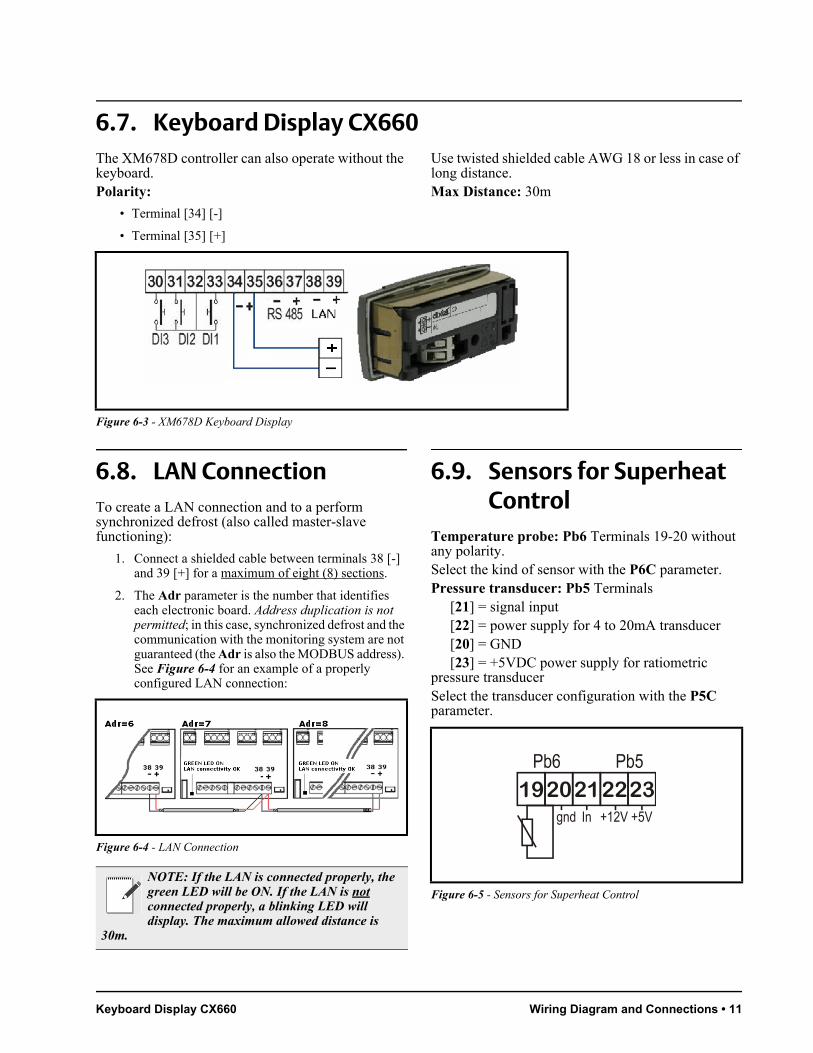
6.7. Keyboard Display CX660The XM678D controller can also operate without the keyboard.Polarity:
• Terminal [34] [-]
• Terminal [35] [+]
Use twisted shielded cable AWG 18 or less in case of long distance.Max Distance: 30m
6.8. LAN ConnectionTo create a LAN connection and to a perform synchronized defrost (also called master-slave functioning):
1. Connect a shielded cable between terminals 38 [-] and 39 [+] for a maximum of eight (8) sections.
2. The Adr parameter is the number that identifies each electronic board. Address duplication is not permitted; in this case, synchronized defrost and the communication with the monitoring system are not guaranteed (the Adr is also the MODBUS address). See Figure 6-4 for an example of a properly configured LAN connection:
6.9. Sensors for Superheat Control
Temperature probe: Pb6 Terminals 19-20 without any polarity.Select the kind of sensor with the P6C parameter.Pressure transducer: Pb5 Terminals
[21] = signal input[22] = power supply for 4 to 20mA transducer[20] = GND[23] = +5VDC power supply for ratiometric
pressure transducerSelect the transducer configuration with the P5C parameter.
Figure 6-3 - XM678D Keyboard Display
Figure 6-4 - LAN Connection
NOTE: If the LAN is connected properly, the green LED will be ON. If the LAN is not connected properly, a blinking LED will display. The maximum allowed distance is
30m.
Figure 6-5 - Sensors for Superheat Control

12 • XM678D I&O Manual 026-1219 Rev 3
6.10. How to Use a Single Pressure Transducer on Multiplexed Applications
A working LAN connection is required (green LED lit on all XM678D boards of the same LAN). Connect and configure the pressure transducer only on one XM678D of the network. Afterwards, the pressure value read by that single transducer will be used by each device connected to the same LAN.To read the pressure value, press the up arrow button to access the fast selection menu and read the value of the following parameters:
• dPP - measured pressure (only on the master device)
• dP5 - temperature value obtained from the pressure value (temperature conversion)
• rPP - pressure value read from remote location (only for slave devices)
Examples of error messages:
• dPP = Err -> the local transducer read an incorrect value; the pressure value is out of range of the pressure transducer or the P5C parameter is incorrect. Check if any of the above causes the error, otherwise replace the transducer.
• rPF -> there is an error in the remote pressure transducer. Check the status of the board (GREEN LED); if the LED is OFF, then the LAN is not functioning, otherwise, check the remote pressure transducer.
Last Checks about the Superheat:On the fast access menu:
• dPP - the value read by the gauge.
• dP6 - the value read by the temperature probe, the
temperature of the gas on the evaporator outlet.
• SH - the value of the superheat. The nA or err message means that the superheat cannot be read at the moment and the value is not available.
6.11. How to Connect the Monitoring System
• Connect through terminals 36 [-] and 37 [+].
• Use a shielded twisted cable (for example, Belden 8762 or CAT 5 cable).
• The maximum allowable distance is 1 kilometer.
• Do not connect the shield wire to the earth or ground terminals of the device. Use insulation tapes to avoid accidental contacts.
Only one controller for each LAN should be connected to the RS485 connection.
The Adr parameter is the number that identifies each electronic board. Address duplication is not permitted; in this case, synchronized defrost and the communication with the monitoring system are not guaranteed (the Adr is also the MODBUS address).
Figure 6-6 - Pressure Transducer on Multiplexed Applications
Figure 6-7 - Connecting the Monitoring System
Figure 6-8 - Connecting Monitoring Systems

Digital Inputs Wiring Diagram and Connections • 13
6.12. Digital Inputs
• Terminals [30] through [33] are all free of voltage.
• Use a shielded cable for distances higher than one meter.
For each digital input, configure the parameters: i1P (polarity of activation), i1F (function of the input), and i1d (delay of signaling).The i1P can be set to: cL= active when closed; or oP= active when opened.The i1F parameter can be set to: EAL= external alarm, Bal= serious lock alarm, PAL= pressure switch alarm, dor= door switch, dEF= external defrost, AUS= auxiliary activation command, LiG= light activation, OnF= board On/OFF, FHU= do not use this configuration, ES= day/night, or HdY= do not use this configuration.The i1d parameter is for the delay of activation.For the other digital inputs, same set of parameters is present: i2P, i2F, i2d, i3P, i3F, i3d.
6.13. Analog Output
• Can be set between 4 to 20mA and 0 to 10VDC.
• Use a CABCJ15 cable for connections.
The analog output is located near the terminal [39] on a two-pin connector. The analog output can be used to control anti-sweat heaters using a chopped phased controller, XRPW500 (500 watt) or family, XVxxD or XVxxK.
Figure 6-9 - Digital Inputs
Figure 6-10 - Analog Output

14 • XM678D I&O Manual 026-1219 Rev 3
7 Battery Back Up Connection
7.1. XEC Supercap ConnectionXEC Supercap is designed to be used with Dixell products (XM678D, XEV, IEV, and others); compatibility with Dixell devices has to be verified in the user manual/technical sheet of the device. If problems occur, contact Dixell Service department at 770-425-2724.
Wiring Connection
NOTE: XEC Supercap and XM678D must be powered by two different transformers; failure on observance of this rule may result to damage to the XEC Supercap and/or to the
connected XM678D.
XM678D XEC
Terminal 61 (+) Terminal 4 (12Vdc)
Terminal 62 (-) Terminal 3 (gnd)
Table 7-1 - XM678D and XEC Wiring Connection
Figure 7-1 - XM678D - XEC Supercap Connection

Emerson ECP-024 Connection Wiring Layout for Sharing a Pressure Transducer on a LAN • 15
7.2. Emerson ECP-024 Connection
The Emerson ECP-024 rechargeable accumulator can be connected to the XM678D to close the stepper valve in case of power interruption. Please refer to the ECP-024 manuals for the terms and conditions of use and limitations.
Wiring Connection
8 Wiring Layout for Sharing a Pressure Transducer on a LAN
XM678D ECP-024
Terminal 61 (+) Terminal +
Terminal 62 (-) Terminal -
Table 7-2 - XM678D and XEC Wiring Connection
16 • XM678D I&O Manual 026-1219 Rev 3
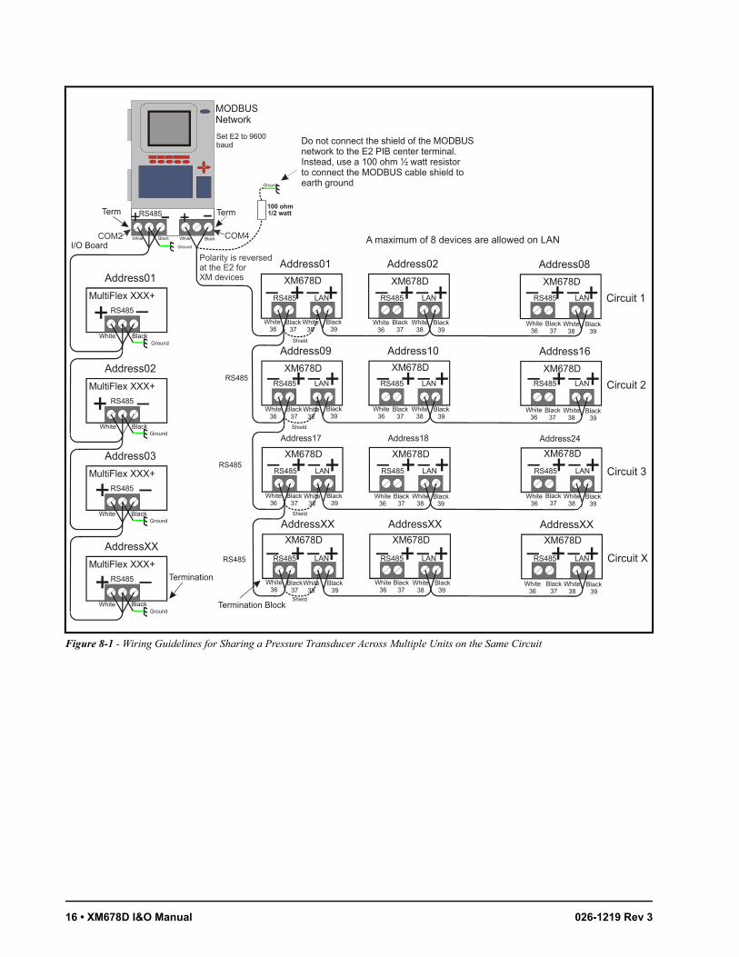
Figure 8-1 - Wiring Guidelines for Sharing a Pressure Transducer Across Multiple Units on the Same Circuit
XM678D
Address01
LANRS485
Black39
White38
MultiFlex XXX+
Address01
RS485
BlackWhiteGround
RS485
BlackWhite
Ground
BlackWhite
Black37
White 36
XM678D
Address02
XM678D
Address08
Circuit 1
XM678D
Address09
XM678D
Address10
XM678D
Address16
Circuit 2
XM678D
Address17
XM678D
Address18
XM678D
Address24
Circuit 3
XM678D
AddressXX
XM678D
AddressXX
XM678D
AddressXX
Circuit X
MultiFlex XXX+
Address02
RS485
MultiFlex XXX+
Address03
RS485
MultiFlex XXX+
AddressXX
RS485
LANRS485 LANRS485
LANRS485LANRS485 LANRS485
LANRS485LANRS485 LANRS485
Black39
White38
Black37
White36
Black39
White38
Black37
White36
Black39
White38
Black37
White36
Black39
White38
Black37
White36
Black39
White38
Black37
White36
Black39
White38
Black37
White36
Black39
White38
Black37
White36
Black39
White38
Black37
White36
Black39
White38
Black37
White36
Black 39
White38
Black37
White36
Black39
White38
Black37
White36
BlackWhiteGround
BlackWhiteGround
BlackWhiteGround
Termination
I/O Board
+ +
Ground
Do not connect the shield of the MODBUSnetwork to the E2 PIB center terminal.Instead, use a 100 ohm ½ watt resistorto connect the MODBUS cable shield to earth ground
100 ohm1/2 watt
+ +
RS485
RS485
RS485
+ + + +
+ + + + + +
+ + + + + +
+ + + + + +LANRS485LANRS485 LANRS485
Shield
Shield
Shield
Shield
+
+
+
+
MODBUS Network
Term
Set E2 to 9600baud
Term
Termination Block
A maximum of 8 devices are allowed on LANCOM4COM2
Polarity is reversed at the E2 for XM devices
RS485 Net Monitoring Temperatures Pressure Transducer Setup • 17
9 Pressure Transducer Setup
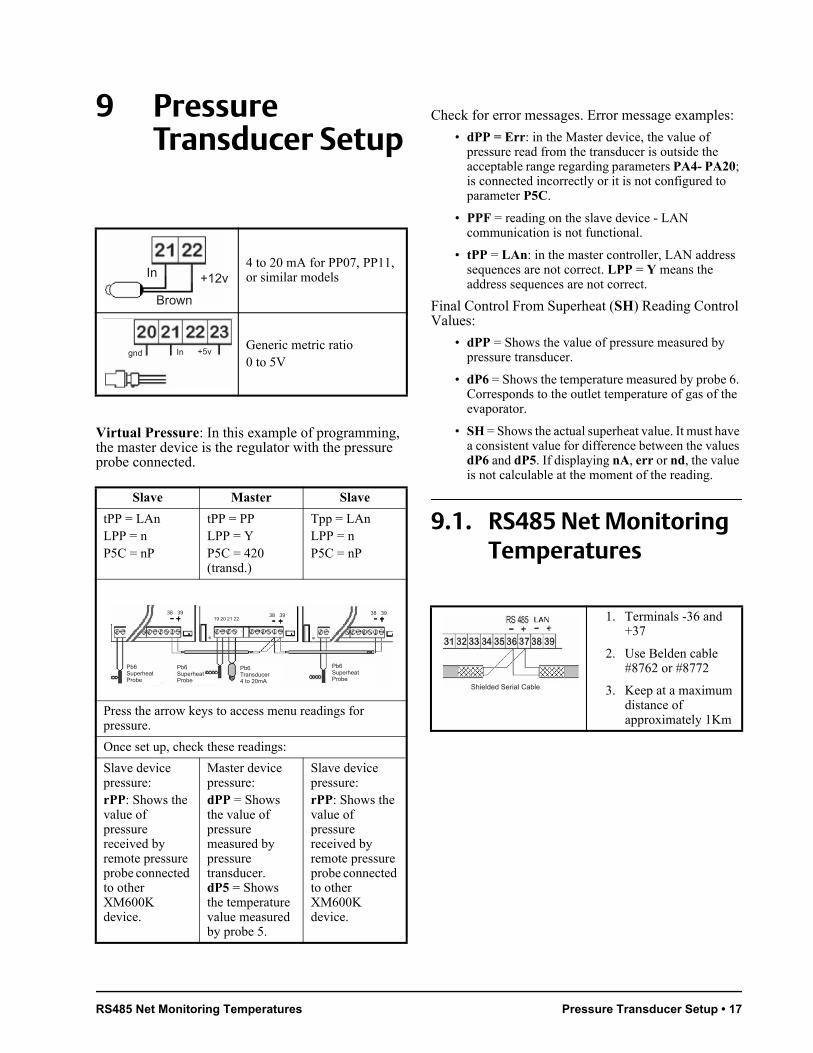
Virtual Pressure: In this example of programming, the master device is the regulator with the pressure probe connected.
tPP = LAnLPP = nP5C = nP
tPP = PPLPP = YP5C = 420 (transd.)
Tpp = LAnLPP = nP5C = nP
Pb6SuperheatProbe
Pb6SuperheatProbe
Pb6Transducer4 to 20mA
Pb6SuperheatProbe
38 3919 20 21 22
38 39 38 39
Press the arrow keys to access menu readings for pressure.
Once set up, check these readings:
Slave device pressure:rPP: Shows the value of pressure received by remote pressure probe connected to other XM600K device.
Master device pressure:dPP = Shows the value of pressure measured by pressure transducer.dP5 = Shows the temperature value measured by probe 5.
Slave device pressure:rPP: Shows the value of pressure received by remote pressure probe connected to other XM600K device.
Check for error messages. Error message examples:
• dPP = Err: in the Master device, the value of pressure read from the transducer is outside the acceptable range regarding parameters PA4- PA20; is connected incorrectly or it is not configured to parameter P5C.
• PPF = reading on the slave device - LAN communication is not functional.
• tPP = LAn: in the master controller, LAN address sequences are not correct. LPP = Y means the address sequences are not correct.
Final Control From Superheat (SH) Reading Control Values:
• dPP = Shows the value of pressure measured by pressure transducer.
• dP6 = Shows the temperature measured by probe 6. Corresponds to the outlet temperature of gas of the evaporator.
• SH = Shows the actual superheat value. It must have a consistent value for difference between the values dP6 and dP5. If displaying nA, err or nd, the value is not calculable at the moment of the reading.
9.1. RS485 Net Monitoring Temperatures
4 to 20 mA for PP07, PP11, or similar models
Generic metric ratio0 to 5V
Slave Master Slave
Brown
In +12v
gnd In +5v
1. Terminals -36 and +37
2. Use Belden cable #8762 or #8772
3. Keep at a maximum distance of approximately 1Km
Shielded Serial Cable
18 • XM678D I&O Manual 026-1219 Rev 3
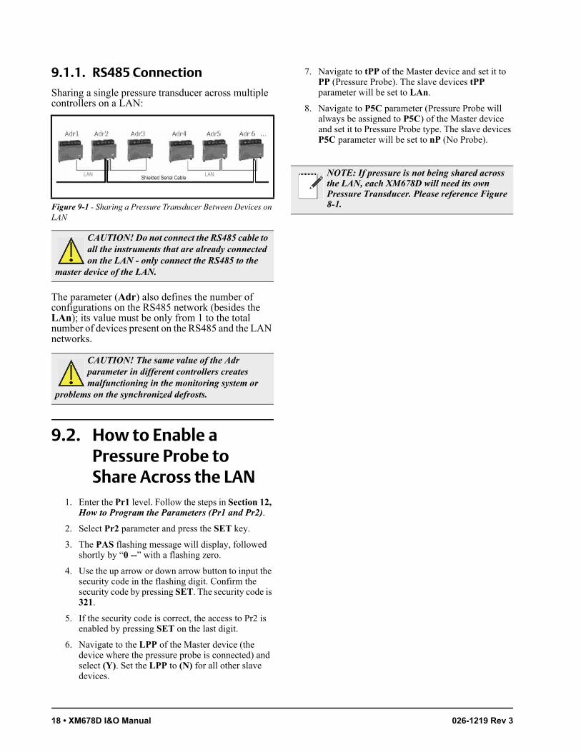
9.1.1. RS485 ConnectionSharing a single pressure transducer across multiple controllers on a LAN:
The parameter (Adr) also defines the number of configurations on the RS485 network (besides the LAn); its value must be only from 1 to the total number of devices present on the RS485 and the LAN networks.
9.2. How to Enable a Pressure Probe to Share Across the LAN
1. Enter the Pr1 level. Follow the steps in Section 12, How to Program the Parameters (Pr1 and Pr2).
2. Select Pr2 parameter and press the SET key.
3. The PAS flashing message will display, followed shortly by “0 --” with a flashing zero.
4. Use the up arrow or down arrow button to input the security code in the flashing digit. Confirm the security code by pressing SET. The security code is 321.
5. If the security code is correct, the access to Pr2 is enabled by pressing SET on the last digit.
6. Navigate to the LPP of the Master device (the device where the pressure probe is connected) and select (Y). Set the LPP to (N) for all other slave devices.
7. Navigate to tPP of the Master device and set it to PP (Pressure Probe). The slave devices tPP parameter will be set to LAn.
8. Navigate to P5C parameter (Pressure Probe will always be assigned to P5C) of the Master device and set it to Pressure Probe type. The slave devices P5C parameter will be set to nP (No Probe).
Figure 9-1 - Sharing a Pressure Transducer Between Devices on LAN
CAUTION! Do not connect the RS485 cable to all the instruments that are already connected on the LAN - only connect the RS485 to the
master device of the LAN.
CAUTION! The same value of the Adr parameter in different controllers creates malfunctioning in the monitoring system or
problems on the synchronized defrosts.
LAN LANShielded Serial Cable
NOTE: If pressure is not being shared across the LAN, each XM678D will need its own Pressure Transducer. Please reference Figure 8-1.

How to Enable a Pressure Probe to Share Across the LAN Wiring Connection to Site Supervisor • 19
10 Wiring Connection to Site Supervisor
Figure 10-1 - Site Supervisor Wiring

20 • XM678D I&O Manual 026-1219 Rev 3
11 User Interface
11.1. Direct Command Interface
11.2. Icons
Cooling Output
Light Fan The output is activated when the icon is ON. A delay is present when the icon is blinking.
MEASUREMENT UNIT
°C, Bar, and (time) are ON depending on the selection.
Defrost Auxiliary relay
Energy SavingMultimaster enabled
Generic alarm Clock/time
DURING PROGRAMMING: The measurement units of temperature and pressure will blink.
Figure 11-1 - XM678D Front Panel
Table 11-1- Icons
LIGHTON/OFF Light relay
SETPress and release: Show set point
UP ARROWPress and release: Fast access menuPress for 3”: SEC menubrowse parameter; increase the value
ON/OFFPress and hold 3”: device ON/OFF
DOWN ARROWPress and release:ON/OFF Aux Relay
browse parameter,decrease the value
Keyboard Commands User Interface • 21
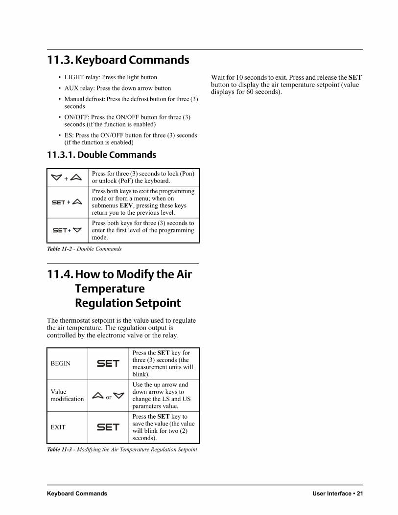
11.3. Keyboard Commands• LIGHT relay: Press the light button
• AUX relay: Press the down arrow button
• Manual defrost: Press the defrost button for three (3) seconds
• ON/OFF: Press the ON/OFF button for three (3) seconds (if the function is enabled)
• ES: Press the ON/OFF button for three (3) seconds (if the function is enabled)
11.3.1.
+ Press for three (3) seconds to lock (Pon) or unlock (PoF) the keyboard.
Press both keys to exit the programming mode or from a menu; when on submenus EEV, pressing these keys return you to the previous level.
Press both keys for three (3) seconds to enter the first level of the programming mode.
Double Commands
11.4. How to Modify the Air Temperature Regulation Setpoint
The thermostat setpoint is the value used to regulate the air temperature. The regulation output is controlled by the electronic valve or the relay.
BEGIN
Press the SET key for three (3) seconds (the measurement units will blink).
Value modification or
Use the up arrow and down arrow keys to change the LS and US parameters value.
EXIT
Press the SET key to save the value (the value will blink for two (2) seconds).
Wait for 10 seconds to exit. Press and release the SET button to display the air temperature setpoint (value displays for 60 seconds).
Table 11-2 - Double Commands
Table 11-3 - Modifying the Air Temperature Regulation Setpoint

22 • XM678D I&O Manual 026-1219 Rev 3
12 How to Program the Parameters (Pr1 and Pr2)
The device has two programming levels: Pr1 (direct access) and Pr2 (password-protected, access for higher level users).
ACCESS to Pr1
Press for three (3) seconds to enter the first programming level (Pr1).
Select item or
Press the up arrow or down arrow key to select the parameter or submenu.
Show value Press the SET button.
Modify or Press the up arrow or
down arrow key to change the value.
Confirm and store
Press SET (the value will blink for three (3) seconds and then display the next parameter).
EXIT
Press to exit the programming mode, or wait for 10 seconds to exit.
12.1. How to Enter Pr2To enter Pr2 programming menu:
1. Press SET+ down arrow keys for three (3) seconds to enter Pr1 menu (the first label will display).
2. Press down arrow until the Pr2 label displays and then press SET.
3. A blinking “PAS” label displays. Wait for a few seconds.
4. When a blinking “0 - -” displays, enter the password [321] by pressing the up arrow and down arrow keys. Press SET to save.
GENERAL STRUCTURE: The first two items, rtC and EEV, are related to the submenus of the other parameters.
• Pressing the SET + up arrow keys on the rtC or EEV submenu returns you to the parameter list.
• Pressing the SET + up arrow keys on the parameter list exits the screen.
12.2. How to Move a Parameter From Pr1 to Pr2 Level and Vice Versa
Enter the Pr2 level. Select the desired parameter then press the SET+ down arrow keys. If the LED on the left-hand side of the screen is ON, it means that the parameter is present in Pr1 level; if the LED is OFF, it means that the parameter is not present in Pr1 (Only Pr2).
Table 12-1 - Programming the Parameters (Pr1 and Pr2)
Figure 12-1 - General Structure
How to Move a Parameter From Pr1 to Pr2 Level and Vice Versa Fast Access Menu • 23
13 Fast Access Menu
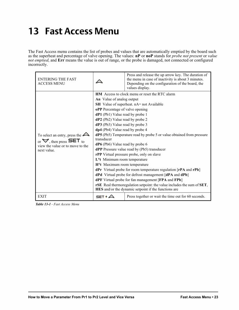
The Fast Access menu contains the list of probes and values that are automatically emptied by the board such as the superheat and percentage of valve opening. The values: nP or noP stands for probe not present or value not emptied, and Err means the value is out of range, or the probe is damaged, not connected or configured incorrectly.
ENTERING THE FAST ACCESS MENU
Press and release the up arrow key. The duration of the menu in case of inactivity is about 3 minutes. Depending on the configuration of the board, the values display.
To select an entry, press the
or , then press to view the value or to move to the next value.
HM Access to clock menu or reset the RTC alarmAn Value of analog outputSH Value of superheat. nA= not AvailableoPP Percentage of valve openingdP1 (Pb1) Value read by probe 1dP2 (Pb2) Value read by probe 2dP3 (Pb3) Value read by probe 3dp4 (Pb4) Value read by probe 4dP5 (Pb5) Temperature read by probe 5 or value obtained from pressure transducerdP6 (Pb6) Value read by probe 6dPP Pressure value read by (Pb5) transducerrPP Virtual pressure probe, only on slaveL°t Minimum room temperatureH°t Maximum room temperaturedPr Virtual probe for room temperature regulation [rPA and rPb]dPd Virtual probe for defrost management [dPA and dPb]dPF Virtual probe for fan management [FPA and FPb]rSE Real thermoregulation setpoint: the value includes the sum of SET, HES and/or the dynamic setpoint if the functions are
EXIT Press together or wait the time out for 60 seconds.
Table 13-1 - Fast Access Menu

24 • XM678D I&O Manual 026-1219 Rev 3
14 Multimaster Function Menu (SEC)
The function “section” SEC is enabled when the icon is lit. It allows entering in the remote programming mode from a keyboard not physically connected to the board through the LAN functionality.
EXAMPLES:
1. To modify the same parameter values in all the devices connected to the LAN: enter the multimaster menu. Select and confirm ALL. Exit from the multimaster menu. Enter the programming menu and change the required parameter values. The new values will be changed on all devices connected to the LAN.
2. To modify a parameter value in the device with [Adr = 35]: find the relevant indexed section (the one linked to [Adr = 35]). Enter the multimaster
menu. Select and confirm this section from the multimaster menu. Exit from the multimaster menu. Enter the programming menu and change the required parameter value.
3. If the alarm nod is present: enter the multimaster menu. Select and confirm the LOC section. Exit from multimaster menu.
Figure 14-1 - Multimaster Function Menu (SEC)
Action Button or display Notes
Enter menu Press the up arrow key for about three (3) seconds, the icon will be ON.
Waiting for action SEC The menu to change the section will be entered. SEC label will be displayed.
Enter section list Press SET to confirm. The following list will be available to select the proper network function.
Select proper function or
LOCALLSE1SEnSE8
To gain access only to the local device.To gain access to all the devices connected to the LAN.To gain access to the device with 1st Adr (*)…To gain access to the device with 8th Adr (*)
Confirm Select and confirm an entry by pressing SET button.
Exit menu Press SET and up arrow together or wait about 10 seconds.
Table 14-1 - Multimaster Function Menu Action Buttons(*) The devices on the LAN are indexed by using the Adr parameter (in ascending order).
CAUTION! At the end of programming, select
the LOC section to switch OFF the icon.

Synchronized Defrost Multimaster Function Menu (SEC) • 25
14.1. Synchronized DefrostThe synchronized defrost allows multiple defrosts to be managed from different boards connected through the LAN connection. In this way, the boards can perform simultaneous defrosts with the possibility to end them in a synchronized manner.
The LSn and LAn parameter are used only to show the actual settings (read only). See Figure 14-2 for an example of configuration:
14.1.1. Daily Defrost From RTC: [EdF = rtC]
• IdF Parameter: For safety reason, force the value of Idf at +1 with respect to the interval between the two Ld parameters. The IdF timer is restarted after defrost
and at every power ON.
• DEFROST START: At the time selected by the parameters Ld1 to Ld6 or Sd1 to Sd6.
• DEFROST END: If the probes reach the dtE temperature or for maximum MdF time.
• SAFETY and RtC or RtF ALARM: With clock alarm, the device will use the parameters IdF, dtE and MdF.
• MULTIMASTER DEFROST: All the probes with clock
CAUTION! In this case, the Adr parameter cannot be duplicated because defrost cannot be managed correctly.
BEGIN
Press for three (3) seconds, the EEU or other will be showed. The measurement unit blinks.
Find Adr
Press the down arrow key several times to find the Adr parameter, then press SET.
Modify Adr or
Set the value of Adr parameter, then press SET to confirm the parameter.
EXITPress both keys to exit from menu or wait for about 10 seconds.
Table 14-2 - Synchronized Defrost Keys
Figure 14-2 - Configuration Example
CAUTION! Do not set [EdF = rtC] and [CPb = n].
ParUnit A (RTC)
Unit B (RTC)
Unit C (RTC)
Adr n N + 1 N + 2
IdF9 hours safety 9 hours safety 9 hours safety
MdF 45 min safety 45 min safety 45 min safety
dtE 12°C safety 12°C safety 12°C safety
Ld1 06:00 1° 06:00 1° 06:00 1°
Ld2 14:00 2° 14:00 2° 14:00 2°
Ld3 22:00 3° 22:00 3° 22:00 3°
Table 14-3 - Multimaster Defrost Example
26 • XM678D I&O Manual 026-1219 Rev 3
15 Commissioning
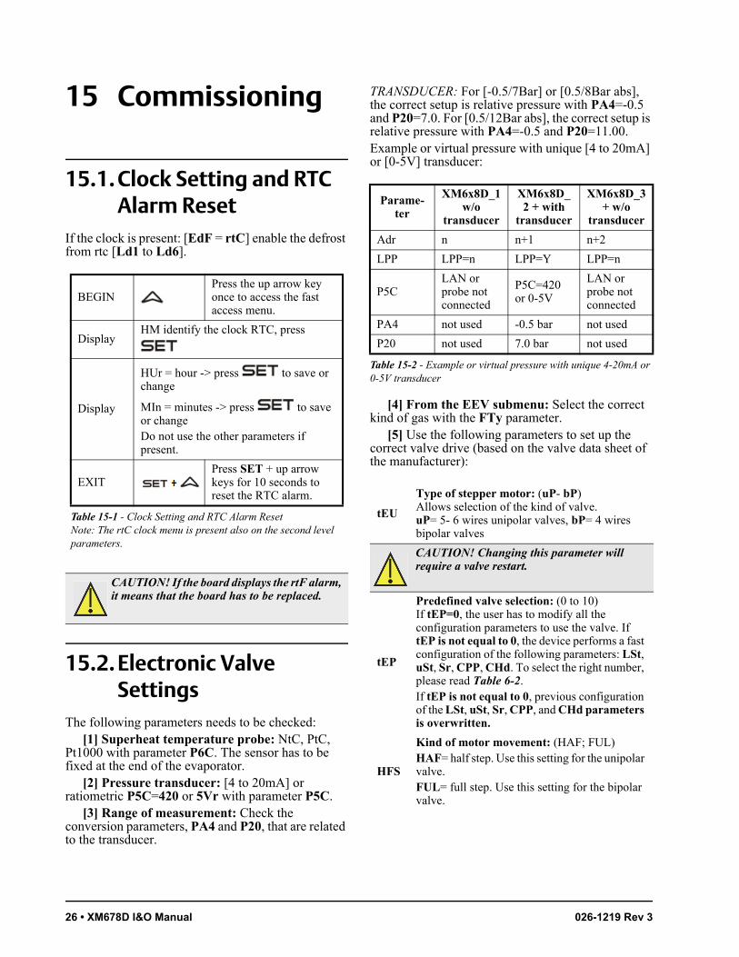
15.1. Clock Setting and RTC Alarm Reset
If the clock is present: [EdF = rtC] enable the defrost from rtc [Ld1 to Ld6].
BEGINPress the up arrow key once to access the fast access menu.
DisplayHM identify the clock RTC, press
Display
HUr = hour -> press to save or change
MIn = minutes -> press to save or changeDo not use the other parameters if present.
EXITPress SET + up arrow keys for 10 seconds to reset the RTC alarm.
15.2. Electronic Valve Settings
The following parameters needs to be checked:[1] Superheat temperature probe: NtC, PtC,
Pt1000 with parameter P6C. The sensor has to be fixed at the end of the evaporator.
[2] Pressure transducer: [4 to 20mA] or ratiometric P5C=420 or 5Vr with parameter P5C.
[3] Range of measurement: Check the conversion parameters, PA4 and P20, that are related to the transducer.
TRANSDUCER: For [-0.5/7Bar] or [0.5/8Bar abs], the correct setup is relative pressure with PA4=-0.5 and P20=7.0. For [0.5/12Bar abs], the correct setup is relative pressure with PA4=-0.5 and P20=11.00.Example or virtual pressure with unique [4 to 20mA] or [0-5V] transducer:
Adr n n+1 n+2
LPP LPP=n LPP=Y LPP=n
P5CLAN or probe not connected
P5C=420 or 0-5V
LAN or probe not connected
PA4 not used -0.5 bar not used
P20 not used 7.0 bar not used
[4] From the EEV submenu: Select the correct kind of gas with the FTy parameter.
[5] Use the following parameters to set up the correct valve drive (based on the valve data sheet of the manufacturer):
Table 15-1 - Clock Setting and RTC Alarm ResetNote: The rtC clock menu is present also on the second level parameters.
CAUTION! If the board displays the rtF alarm, it means that the board has to be replaced.
Parame-ter
XM6x8D_1w/o
transducer
XM6x8D_2 + with
transducer
XM6x8D_3 + w/o
transducer
Table 15-2 - Example or virtual pressure with unique 4-20mA or 0-5V transducer
tEU
Type of stepper motor: (uP- bP)Allows selection of the kind of valve.uP= 5- 6 wires unipolar valves, bP= 4 wires bipolar valves
CAUTION! Changing this parameter will require a valve restart.
tEP
Predefined valve selection: (0 to 10)If tEP=0, the user has to modify all the configuration parameters to use the valve. If tEP is not equal to 0, the device performs a fast configuration of the following parameters: LSt, uSt, Sr, CPP, CHd. To select the right number, please read Table 6-2.If tEP is not equal to 0, previous configuration of the LSt, uSt, Sr, CPP, and CHd parameters is overwritten.
HFS
Kind of motor movement: (HAF; FUL)HAF= half step. Use this setting for the unipolar valve.FUL= full step. Use this setting for the bipolar valve.
Pressure Filtering - Sub Parameter Regulation for Superheat: Self Adaptive or Manual Operating Mode • 27
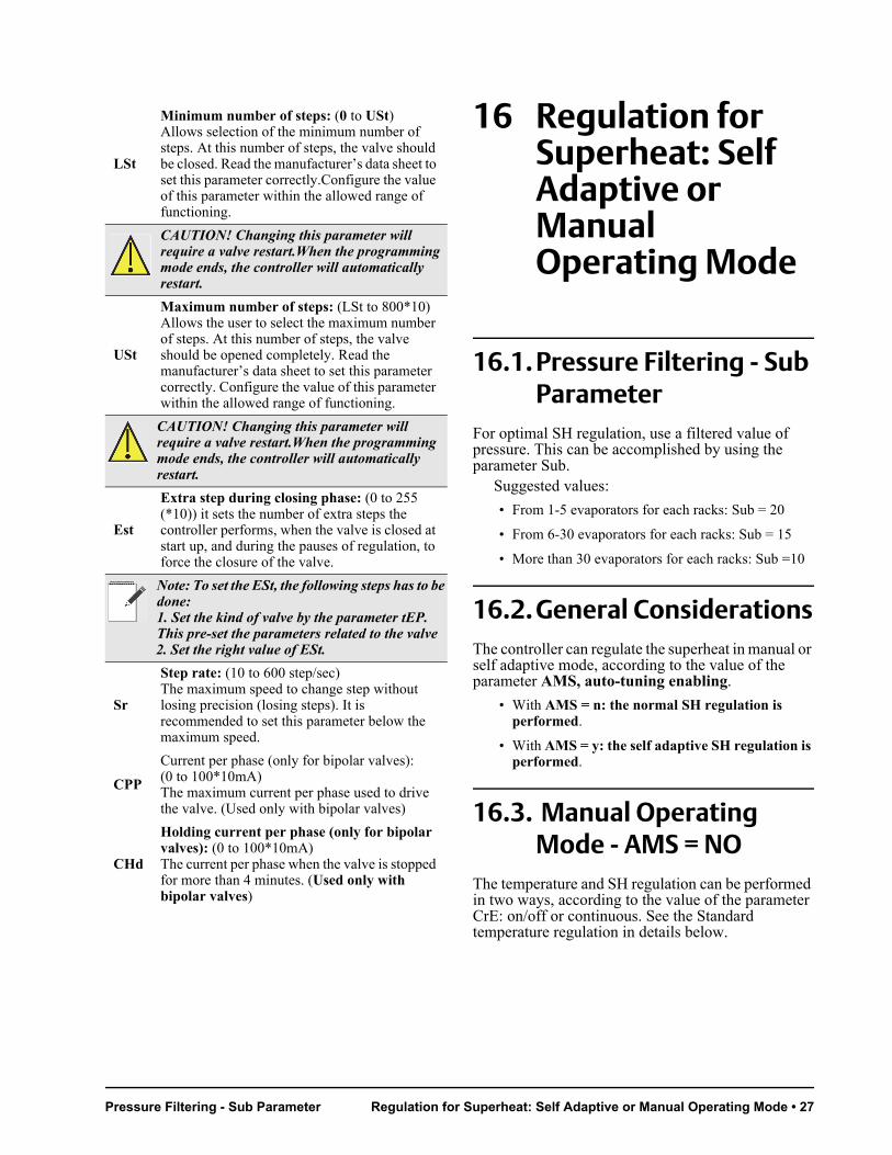
16 Regulation for Superheat: Self Adaptive or Manual Operating Mode
16.1. Pressure Filtering - Sub Parameter
For optimal SH regulation, use a filtered value of pressure. This can be accomplished by using the parameter Sub.
Suggested values:
• From 1-5 evaporators for each racks: Sub = 20
• From 6-30 evaporators for each racks: Sub = 15
• More than 30 evaporators for each racks: Sub =10
16.2. General ConsiderationsThe controller can regulate the superheat in manual or self adaptive mode, according to the value of the parameter AMS, auto-tuning enabling.
• With AMS = n: the normal SH regulation is performed.
• With AMS = y: the self adaptive SH regulation is performed.
16.3. Manual Operating Mode - AMS = NO
The temperature and SH regulation can be performed in two ways, according to the value of the parameter CrE: on/off or continuous. See the Standard temperature regulation in details below.
LSt
Minimum number of steps: (0 to USt)Allows selection of the minimum number of steps. At this number of steps, the valve should be closed. Read the manufacturer’s data sheet to set this parameter correctly.Configure the value of this parameter within the allowed range of functioning.
CAUTION! Changing this parameter will require a valve restart.When the programming mode ends, the controller will automatically restart.
USt
Maximum number of steps: (LSt to 800*10)Allows the user to select the maximum number of steps. At this number of steps, the valve should be opened completely. Read the manufacturer’s data sheet to set this parameter correctly. Configure the value of this parameter within the allowed range of functioning.
CAUTION! Changing this parameter will require a valve restart.When the programming mode ends, the controller will automatically restart.
Est
Extra step during closing phase: (0 to 255 (*10)) it sets the number of extra steps the controller performs, when the valve is closed at start up, and during the pauses of regulation, to force the closure of the valve.
Note: To set the ESt, the following steps has to be done:1. Set the kind of valve by the parameter tEP. This pre-set the parameters related to the valve
2. Set the right value of ESt.
Sr
Step rate: (10 to 600 step/sec)The maximum speed to change step without losing precision (losing steps). It is recommended to set this parameter below the maximum speed.
CPP
Current per phase (only for bipolar valves): (0 to 100*10mA)The maximum current per phase used to drive the valve. (Used only with bipolar valves)
CHd
Holding current per phase (only for bipolar valves): (0 to 100*10mA)The current per phase when the valve is stopped for more than 4 minutes. (Used only with bipolar valves)
28 • XM678D I&O Manual 026-1219 Rev 3
16.3.1. ON/OFF Temperature Regulation [CrE = n]
1. Temperature regulation is ON/OFF and it depends on the Setpoint and HY parameter (differential). Valve is closed when the temperature reaches the setpoint and open when the temperature is higher than setpoint + differential.
2. With more pauses normally also the humidity is larger.
3. Regulation pauses can be realized using the Sti and Std parameters (during these pauses the valve is closed).
16.3.2. Continuous Temperature Regulation [CrE = Y] (With Superheat Regulation)
1. The HY parameter becomes the temperature band for PI control. A good default value is 5°C.
2. The regulation of injection is continuous and the
cooling output is always ON. The icon is always ON except for the defrost phase.
3. The superheat is regulated following the SSH parameter.
4. Regulation pauses can be realized using Sti and Std parameters (during these pauses the valve is closed).
5. Increasing the Int integral time can decrease the speed of reaction of the regulator on the HY band.
16.3.3. Continuous Temperature Regulation [CrE = Y] (Without Superheat Regulation)
1. The HY parameter becomes the temperature band for PI control. A good default value is 5°C.
2. The regulation of injection is continuous and the
cooling output is always ON. The icon is always ON except for the defrost phase.
3. The superheat is not regulated because the valve is at the end of the evaporator. There is another valve at the beginning of the evaporator.
4. Regulation pauses can be realized using Sti and Std parameters (during these pauses the valve is closed).
5. Increasing the Int integral time can decrease the speed of reaction of the regulator on the HY band.
16.4. Self Adaptive Operating Mode - AMS = YES
Auto-adaptive means to find and maintain the condition of the lowest super heating according to the load and environmental conditions present in a given time on the evaporator.The parameter AMS enables the self adaptive mode in the superheat regulation.In this functioning the values of Pb and inC parameter are automatically set by the controller according to the kind of applications and the response of the system.With the AMS = YES, CrE must be set to NO.The self adaptive algorithm does not affect the functions related to the forced opening of the valve in special situations, such as:
• Forced opening of the valve at start of regulation, parameter SFd (percentage) and SFd (time).
• Forced opening of the valve after defrost, parameter oPd (percentage) and Pdd (time).
16.5. Minimum Stable Superheat Search - AMS = YES, ATU = YES
With the parameter ATU, the minimum stable superheat search function is enabled.With ATU = yES, controllers start searching the minimum stable value for the SH. The minimum admitted value in any case is LSH + 2°C (4°F). Take it in consideration, before setting LSH value.
16.6. Valve Capacity Reducing - MNF Parameter
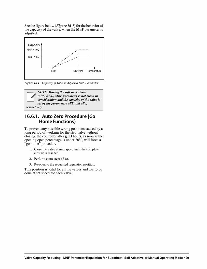
The parameter MnF reduce the capacity of the valve, to fine tune the valve to the evaporator.The regulation band is not affected from the modification of the MnF parameter.
Valve Capacity Reducing - MNF Parameter Regulation for Superheat: Self Adaptive or Manual Operating Mode • 29
See the figure below (Figure 16-1) for the behavior of the capacity of the valve, when the MnF parameter is adjusted.
16.6.1. Auto Zero Procedure (Go Home Functions)
To prevent any possible wrong positions caused by a long period of working for the step valve without closing, the controller after gTH hours, as soon as the opening open percentage is under 20%, will force a “go home” procedure:
1. Close the valve at max speed until the complete closure is reached.
2. Perform extra steps (Est).
3. Re-open to the requested regulation position.
This position is valid for all the valves and has to be done at set speed for each valve.
Figure 16-1 - Capacity of Valve in Adjusted MnF Parameter
NOTE: During the soft start phase (oPE, SFd), MnF parameter is not taken in consideration and the capacity of the valve is set by the parameters oPE and oPd,
respectively.
30 • XM678D I&O Manual 026-1219 Rev 3
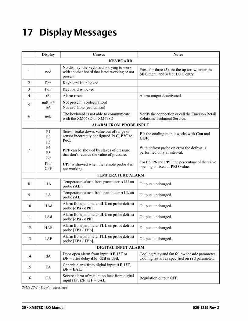
17 Display Messages
Display Causes Notes
KEYBOARD
1 nodNo display: the keyboard is trying to work with another board that is not working or not present
Press for three (3) sec the up arrow, enter the SEC menu and select LOC entry.
2 Pon Keyboard is unlocked
3 PoF Keyboard is locked
4 rSt Alarm reset Alarm output deactivated.
5 noP, nPnA
Not present (configuration)Not available (evaluation)
6 noLThe keyboard is not able to communicate with the XM668D or XM678D
Verify the connection or call the Emerson Retail Solutions Technical Service.
ALARM FROM PROBE INPUT
7
P1P2P3P4P5P6
PPFCPF
Sensor brake down, value out of range or sensor incorrectly configured P1C, P2C to P6C.
PPF can be showed by slaves of pressure that don’t receive the value of pressure.
CPF is showed when the remote probe 4 is not working.
P1: the cooling output works with Con and COF,
With defrost probe on error the defrost is performed only at interval.
For P5, P6 and PPF: the percentage of the valve opening is fixed at PEO value.
TEMPERATURE ALARM
8 HA Temperature alarm from parameter ALU on probe rAL.
Outputs unchanged.
9 LA Temperature alarm from parameter ALL on probe rAL.
Outputs unchanged.
10 HAdAlarm from parameter dLU on probe defrost probe [dPa / dPb]. Outputs unchanged.
11 LAdAlarm from parameter dLU on probe defrost probe [dPa / dPb]. Outputs unchanged.
12 HAFAlarm from parameter FLU on probe defrost probe [FPa / FPb]. Outputs unchanged.
13 LAFAlarm from parameter FLL on probe defrost probe [FPa / FPb]. Outputs unchanged.
DIGITAL INPUT ALARM
14 dA Door open alarm from input i1F, i2F or i3F = after delay d1d, d2d or d3d.
Cooling relay and fan follow the odc parameter. Cooling restart as specified on rrd parameter.
15 EA Generic alarm from digital input i1F, i2F, i3F = EAL.
16 CA Severe alarm of regulation lock from digital input i1F, i2F, i3F = bAL.
Regulation output OFF.
Table 17-1 - Display Messages
Alarm Recovery Display Messages • 31
17.1. Alarm RecoveryProbe alarms P1, P2, P3, and P4 start some seconds after the fault in the related probe; they automatically stop some seconds after the probe restarts normal operation. Check the connections before replacing the probe.Temperature alarms HA, LA, HA2, and LA2 automatically stop as soon as the temperature returns to normal values.Alarms EA and CA (with i1F = bAL) recover as soon as the digital input is disabled. Alarm CA (with i1F = PAL) recovers only by switching OFF and ON the device.
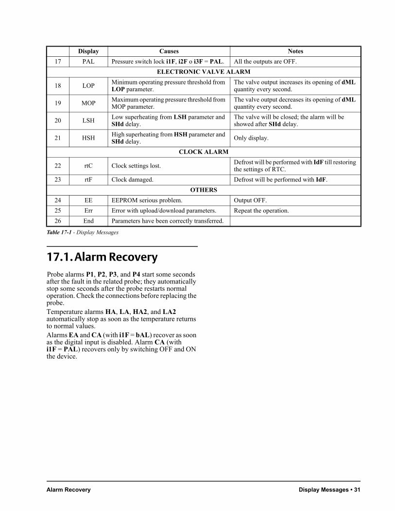
17 PAL Pressure switch lock i1F, i2F o i3F = PAL. All the outputs are OFF.
ELECTRONIC VALVE ALARM
18 LOP Minimum operating pressure threshold from LOP parameter.
The valve output increases its opening of dML quantity every second.
19 MOP Maximum operating pressure threshold from MOP parameter.
The valve output decreases its opening of dML quantity every second.
20 LSH Low superheating from LSH parameter and SHd delay.
The valve will be closed; the alarm will be showed after SHd delay.
21 HSH High superheating from HSH parameter and SHd delay.
Only display.
CLOCK ALARM
22 rtC Clock settings lost.Defrost will be performed with IdF till restoring the settings of RTC.
23 rtF Clock damaged. Defrost will be performed with IdF.
OTHERS
24 EE EEPROM serious problem. Output OFF.
25 Err Error with upload/download parameters. Repeat the operation.
26 End Parameters have been correctly transferred.
Display Causes Notes
Table 17-1 - Display Messages

32 • XM678D I&O Manual 026-1219 Rev 3
18 Use of the Programming Hot Key
XM controllers can download or upload the parameter list from its own non-volatile internal memory to the Hot Key and vice-versa through a 5-pin connector. The Hot Key will not change the Adr.
18.1. Download (From the Hotkey to the Device)
1. Turn OFF the controller by pressing the on/off
button for five (5) seconds. OFF will display.
Insert the Hot Key into the 5-pin connector labeled HOT-KEY, and then turn the controller back ON by pressing the on/off button again for five (5) seconds. The normal temperature value will display to indicate the controller is ON.
2. The parameter list of the Hot Key is downloaded into the controller memory automatically and doL will display. After 10 seconds, the controller will start working with the new parameters.
3. End will display at the end of the data transfer phase if the controller is programmed correctly. Err will display if there is an error or failure in programming.
• End = correct programming. This means the controller will start regularly with the new programming.
• Err = failed programming. In this case, turn the controller OFF and then ON if you want to restart the download again or remove the Hot Key to abort the operation.
4. Remove the Hot Key.
Note: The procedure may fail if the firmware version and the controller models are different.
18.2. Upload (From the Device to the Hotkey)
1. When the XM controller is ON, insert the Hot Key into the 5-pin connector labeled HOT-KEY.
2. Press and release the up arrow button.3. The upload will begin, and UPL will blink on the
display. End will display at the end of the data transfer phase if a successful upload has occurred. Err will display if there is an error or failure in programming.
• End = correct programming.
• Err = failed programming. In this case, press the SET key if you want to restart the programming again or remove the unprogrammed Hot Key.
4. Remove the Hot Key.
Note: The upload procedure will overwrite everything previously uploaded from the last Hot Key upload.
Cooling Output Controlling Loads • 33
19 Controlling Loads
19.1. Cooling OutputRegulation is performed according to the temperature measured by the thermostat probe (physical probe or virtual probe) obtained by a weighted average between the two probes following the formula:
If the temperature increases and reaches the setpoint plus differential, the solenoid valve opens and then closes when the temperature reaches the setpoint value again.In case of error in the thermostat probe, the opening and closing time of the solenoid valve is configured by the Con and CoF parameters.
19.2. Standard Regulation and Continuous Regulation
The regulation can be performed in three ways:
• Standard regulation - the goal of the first regulation (standard regulation) is to reach the best superheat via a classic temperature regulation obtained using hysteresis.
• Continuous regulation - the second regulation allows the valve to realize a high performance temperature regulation with a good factor of superheat precision. This kind of regulation can be used only in centralized plants and is available only with the electronic expansion valve by selecting the [CrE = Y] parameter.
• Use of evaporator valves - the third kind of regulation is through the use of evaporator valves [CrE = EUP]; in this configuration, the valve is placed at the end of the evaporator. In any case, the regulation is performed via the PI regulator that determines the valve opening percentage.
19.2.1. Standard regulation: [CrE = n]The HY parameter is the differential for the standard ON/OFF regulation. In this case, the int parameter is neglected.
19.2.2. Continuous regulation: [CrE = Y]
The HY parameter is the proportional band of the PI that is in charge of the room temperature regulation. It is recommended to use at least [HY = 12°F/6.0°C]. The int parameter is the integral time of the same PI regulator. Increasing the int parameter causes the PI regulator to react slowly and is true vice versa. To disable the integral part of regulation, set [int = 0].
19.2.3. Evaporator valves: [CrE = EUP]In this case, the system performs a regulation of the temperature without considering the superheat (in fact, the valve is at the end of the evaporator). The HY parameter is the proportional band for the temperature regulation and int is the integral time for the regulation. In this case, there is no superheat regulation.
19.3. Defrost19.3.1. Defrost startingIn any case, the device checks the temperature that is read by the configured defrost probe before starting the defrost, after that:
• (If RTC is present) Two defrost modes are available through the tdF parameter: defrost with electrical heater and hot gas defrost. The defrost interval is controlled by the parameter EdF: (EdF = rtC) defrost is made in real time depending on the hours set in the parameters Ld1 to Ld6 in workdays and in Sd1 to Sd6 on holidays; (EdF = in) the defrost is made every IdF time.
• Defrost cycle starting can be operated locally (manual activation by means of the keyboard or digital input or end of interval time) or the command can come from the master defrost unit of the LAN. In this case, the controller will operate the defrost cycle following the parameters it has programmed. At the end of the drip time, it will wait until all the other controllers of the LAN finish their defrost cycle before restarting the normal regulation of the temperature according to dEM parameter.
• Each time any of the LAN controller begins a defrost cycle, it issues the command into the network making all the other controllers start their own cycle. This allows a perfect synchronization of
value_-for_room_regu-
lation= (rPA*rPE + rPb*[100-rPE])
100

34 • XM678D I&O Manual 026-1219 Rev 3
the defrost in the whole multiplexed cabinet according to the LMd parameter.
• Differential defrost: Selecting the dPA and dPb probes and by changing the dtP and ddP parameters, the defrost can be started when the difference between dPA and dPb probes is lower than dtP for all ddP time. This is useful to start defrost when a low thermal exchange is detected. If [ddP = 0], this function is disabled.
19.3.2. Defrost Ending• When defrost is started via rtC, the maximum
defrost duration is obtained from the Md parameter and the defrost end temperature is obtained from the dtE parameter (and dtS if two defrost probes are selected).
• If dPA and dPb are present and [d2P = Y], the device stops the defrost procedure when dPA is higher than dtE temperature and dPb is higher than dtS temperature.
At the end of defrost, the drip time is controlled through the Fdt parameter.
19.4. Fans19.4.1. Control With RelayThe fan control mode is selected by means of the FnC parameter:
• C-n = running with the solenoid valve, OFF during defrost
• C-Y = running with the solenoid valve, ON during defrost
• O-n = continuous mode, OFF during defrost
• O-Y = continuous mode, ON during defrost
An additional parameter FSt provides the setting of the temperature, detected by the evaporator probe, above which the fans are always OFF. This can be used to verify that air is circulated only if this temperature is lower than set in the FSt.
19.4.2. Control With Analog Output (If Present)
The modulating output [trA = rEG] works in a proportional manner (excluding the first AMt seconds where the fans speed is the maximum; 10 seconds is the minimum value). The regulation setpoint is relative to the regulation setpoint and is indicated by ASr, the proportional band is always located above the [SET + ASr] value and its value is PbA. The fans are at minimum speed AMi when the
temperature read by the fan probe is [SET + ASr] and the fan is at maximum speed (AMA) when the temperature is [SET + ASr + PbA].
19.5. Anti-Sweat HeatersAnti-sweat heater regulation can be performed with the on board relay (if OA6 = AC) or with the analog output (if present by setting trA = AC). However, the regulation can be performed in two ways:
• Without real dewpoint information: in this case the default value for dewpoint is used (SdP parameter).
• Receiving dewpoint from XWEB5000 system: the SdP parameter is overwritten when a valid value for dewpoint is received from XWEB. In case the XWEB link is lost, SdP is the value that will be used for safety.
The best performance can be obtained using probe 4. In this case, the regulation follows the chart illustrated in Figure 19-2:
Figure 19-1 - Control With Analog Output
Figure 19-2 - Anti-Sweat Heaters

Auxiliary Output Controlling Loads • 35
Probe 4 should be placed on the showcase glass. For each cabinet, only one probe 4 (P4) can be used; the P4 will send its value to the other sections that are connected to the LAN.Functioning with Probe 4 within the LAN:
Adr n n + 1 n + 2
LCP LCP = n LCP = Y LCP = n
P4CLAN or probe not connected
P4C = NTC, PtC or PtM
LAN or probe not connected
trA trA = AC if the device has the analog output
OA6 OA6 = AC if the device will use the AUX relay for regulation
Functioning Without Probe 4:
In this case, regulation is performed by switching the auxiliary relay ON and OFF on a 60-minute time base. The ON time will be the AMt value, so that the relay will be ON for AMt minutes and OFF for [60-AMt] minutes.In case of P4 error or if P4 is absent, the output is at AMA value for the AMt time then the output is at 0 value for the time [255 - AMt] time performing a simple PWM modulation.
19.6. Auxiliary OutputThe auxiliary output is switched ON and OFF by means of the corresponding digital input or by pressing and releasing the down arrow key.
ParameterXM6x8D_1
Without Probe 4
XM6x8D_2 + With Probe 4
XM6x8D_3+ Without Probe 4
Table 19-1 - Functioning with Probe 4 within the LAN
Parameter XM6x8D Without Probe 4
P4C nP
AMt % of ON
Table 19-2 - Functioning Without Probe 4
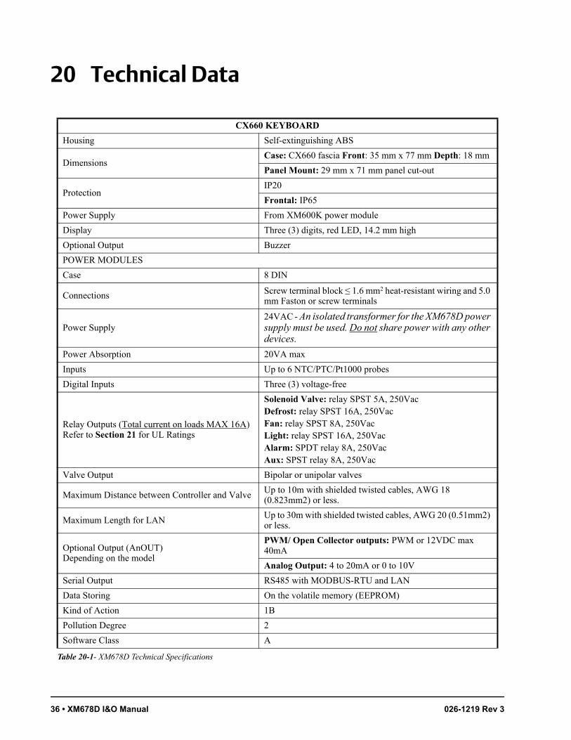
36 • XM678D I&O Manual 026-1219 Rev 3
20 Technical Data
CX660 KEYBOARD
Housing Self-extinguishing ABS
DimensionsCase: CX660 fascia Front: 35 mm x 77 mm Depth: 18 mm
Panel Mount: 29 mm x 71 mm panel cut-out
ProtectionIP20
Frontal: IP65
Power Supply From XM600K power module
Display Three (3) digits, red LED, 14.2 mm high
Optional Output Buzzer
POWER MODULES
Case 8 DIN
Connections Screw terminal block ≤ 1.6 mm2 heat-resistant wiring and 5.0 mm Faston or screw terminals
Power Supply24VAC - An isolated transformer for the XM678D power supply must be used. Do not share power with any other devices.
Power Absorption 20VA max
Inputs Up to 6 NTC/PTC/Pt1000 probes
Digital Inputs Three (3) voltage-free
Relay Outputs (Total current on loads MAX 16A) Refer to Section 21 for UL Ratings
Solenoid Valve: relay SPST 5A, 250Vac Defrost: relay SPST 16A, 250VacFan: relay SPST 8A, 250Vac Light: relay SPST 16A, 250Vac Alarm: SPDT relay 8A, 250Vac Aux: SPST relay 8A, 250Vac
Valve Output Bipolar or unipolar valves
Maximum Distance between Controller and ValveUp to 10m with shielded twisted cables, AWG 18 (0.823mm2) or less.
Maximum Length for LANUp to 30m with shielded twisted cables, AWG 20 (0.51mm2) or less.
Optional Output (AnOUT)Depending on the model
PWM/ Open Collector outputs: PWM or 12VDC max 40mA
Analog Output: 4 to 20mA or 0 to 10V
Serial Output RS485 with MODBUS-RTU and LAN
Data Storing On the volatile memory (EEPROM)
Kind of Action 1B
Pollution Degree 2
Software Class A
Table 20-1- XM678D Technical Specifications

Auxiliary Output Technical Data • 37
Operating Temperature 32 to 140°F (0 to 60°C)
Storage Temperature -13 to 140°F (-25°C to 60°C)
Relative Humidity 20 to 85% (no condensing)
Measuring and Regulation Range
NTC probe: -58 to 230°F (-40 to 110°C)
PTC probe: -67 to 302°F (-50 to 150°C)
Pt1000 probe: -148 to 212°F (-100 to 100°C)
Resolution 1°C or 1°F or 0.1°C (selectable)
Accuracy(ambient temperature 77°F (25°C))
±0.5 °C ±1 digit
Table 20-1- XM678D Technical Specifications
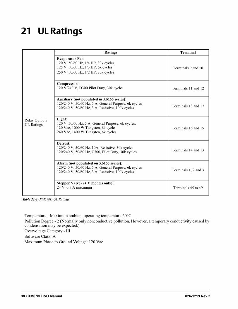
38 • XM678D I&O Manual 026-1219 Rev 3
21 UL Ratings
Relay Outputs UL Ratings
Evaporator Fan:120 V, 50/60 Hz, 1/4 HP, 30k cycles125 V, 50/60 Hz, 1/3 HP, 6k cycles250 V, 50/60 Hz, 1/2 HP, 30k cycles
Terminals 9 and 10
Compressor:120 V/240 V, D300 Pilot Duty, 30k cycles Terminals 11 and 12
Auxiliary (not populated in XM66 series):120/240 V, 50/60 Hz, 5 A, General Purpose, 6k cycles120/240 V, 50/60 Hz, 3 A, Resistive, 100k cycles Terminals 18 and 17
Light:120 V, 50/60 Hz, 5 A, General Purpose, 6k cycles, 120 Vac, 1000 W Tungsten, 6k cycles240 Vac, 1400 W Tungsten, 6k cycles
Terminals 16 and 15
Defrost:120/240 V, 50/60 Hz, 10A, Resistive, 30k cycles120/240 V, 50/60 Hz, C300, Pilot Duty, 30k cycles Terminals 14 and 13
Alarm (not populated on XM66 series):120/240 V, 50/60 Hz, 5 A, General Purpose, 6k cycles120/240 V, 50/60 Hz, 3 A, Resistive, 100k cycles Terminals 1, 2 and 3
Stepper Valve (24 V models only):24 V, 0.9 A maximum Terminals 45 to 49
Temperature - Maximum ambient operating temperature 60°CPollution Degree - 2 (Normally only nonconductive pollution. However, a temporary conductivity caused by condensation may be expected.)Overvoltage Category - IIISoftware Class: AMaximum Phase to Ground Voltage: 120 Vac
Ratings Terminal
Table 21-1- XM678D UL Ratings
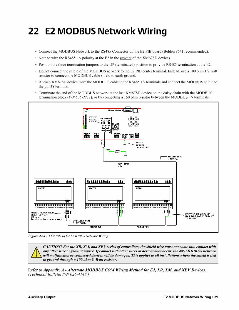
Auxiliary Output E2 MODBUS Network Wiring • 39
22 E2 MODBUS Network Wiring
• Connect the MODBUS Network to the RS485 Connector on the E2 PIB board (Belden 8641 recommended).
• Note to wire the RS485 +/- polarity at the E2 in the reverse of the XM678D devices.
• Position the three termination jumpers to the UP (terminated) position to provide RS485 termination at the E2.
• Do not connect the shield of the MODBUS network to the E2 PIB center terminal. Instead, use a 100 ohm 1/2 watt resistor to connect the MODBUS cable shield to earth ground.
• At each XM678D device, wire the MODBUS cable to the RS485 +/- terminals and connect the MODBUS shield to the pin 38 terminal.
• Terminate the end of the MODBUS network at the last XM678D device on the daisy chain with the MODBUS termination block (P/N 535-2711), or by connecting a 150 ohm resistor between the MODBUS +/- terminals.
Refer to Appendix A - Alternate MODBUS COM Wiring Method for E2, XR, XM, and XEV Devices. (Technical Bulletin P/N 026-4148.)
Figure 22-1 - XM678D to E2 MODBUS Network Wiring
CAUTION! For the XR, XM, and XEV series of controllers, the shield wire must not come into contact with any other wire or ground source. If contact with other wires or devices does occur, the 485 MODBUS network will malfunction or connected devices will be damaged. This applies to all installations where the shield is tied to ground through a 100 ohm ½ Watt resistor.

40 • XM678D I&O Manual 026-1219 Rev 3
23 ECT MODBUS Networking to E2s
Connecting a XM678D controller to an E2 requires the E2 to be version 2.84 or above. Contact Emerson Retail Solutions for upgrade information if the controller is a version before 2.84.
An E2 has up to three COM ports that can be assigned for MODBUS communication: COM2, an RS485 port on the E2 power interface board, and COM4 and COM6, which are optional ports requiring expansion cards. COM4 is recommended for MODBUS connection of XM678D units.
COM ports can only be used for one function; in other words, if COM2 is set up as the I/O network, you cannot connect MODBUS devices to COM2. Ensure your E2 is equipped with an RS485 COM Card (P/N 637-4890) and configured in E2 General Services (, Serial tab) to enable COM4 or an E2 Expansion COM Card (P/N 637-4871) to enable COM6.
Connect the MODBUS network cable to the three-terminal connector on the COM port you wish to assign as MODBUS. Reverse polarity of +/- on RS485 cable from E2 to the device.
23.1. COM Port Associations - E2 Versions 4.0 and Above
An E2 has three COM ports that can be assigned for MODBUS communication (COM2). COM ports can only be used for one function; in other words, if COM2 is set up as the I/O network, you cannot connect MODBUS devices to COM2. Ensure your E2 is configured in E2 General Services (, Serial tab) to enable COM4 or COM6.
Figure 23-1 - Location of E2 Com Ports (E2 versions 3.xx and Below)
E2 PIB COM PORT ASSOCIATIONS
COM1
COM4
COM6
COM2
Serial DeviceRS485 COM Port (2 Connectors)
RS485 COM Card (2 Connectors) Serial Device
RS232 Port
POWER INTERFACE BOARD (PIB)
E2 Modem/Expansion COM Card MountedAbove PIB
Plug-In ModemCard
COM3
E2 Enclosure (Right Side)
RS485
RS232
Figure 23-2 - MODBUS Networking
Figure 23-3 - Location of E2 Com Ports - E2 PIB Board (E2 versions 4.0 and Above)
E2XM678D
#1
TERMINATED,BIASED(ALL 3 JUMPERSIN UP POSITION)
XM678D
#2
XM678D
#3
E2 PIB COM PORT ASSOCIATIONS
COM1
Serial DeviceRS232 Port
POWER INTERFACE BOARD (PIB)
E2 Enclosure (Right Side)
COM2 COM6 COM4
Serial DeviceRS485 COM Ports
Plug-InModemCard
COM3
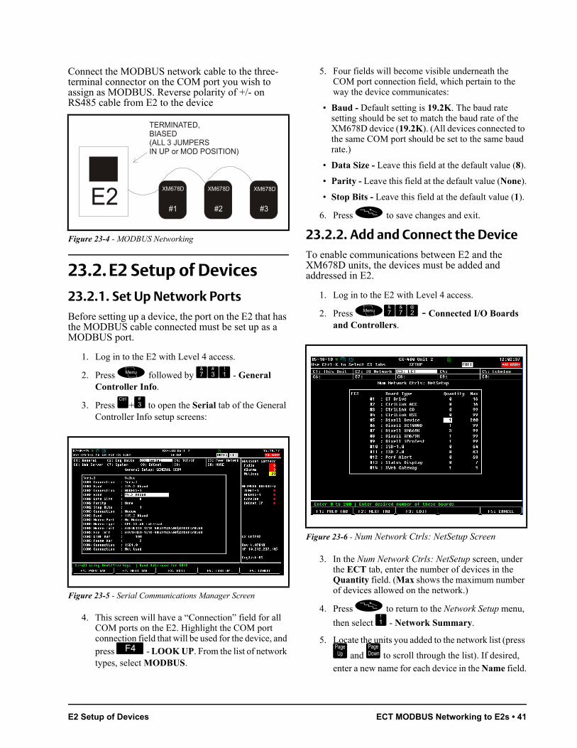
E2 Setup of Devices ECT MODBUS Networking to E2s • 41
Connect the MODBUS network cable to the three-terminal connector on the COM port you wish to assign as MODBUS. Reverse polarity of +/- on RS485 cable from E2 to the device
23.2. E2 Setup of Devices23.2.1. Set Up Network PortsBefore setting up a device, the port on the E2 that has the MODBUS cable connected must be set up as a MODBUS port.
1. Log in to the E2 with Level 4 access.
2. Press followed by - General Controller Info.
3. Press + to open the Serial tab of the General Controller Info setup screens:
4. This screen will have a “Connection” field for all COM ports on the E2. Highlight the COM port connection field that will be used for the device, and press - LOOK UP. From the list of network types, select MODBUS.
5. Four fields will become visible underneath the COM port connection field, which pertain to the way the device communicates:
• Baud - Default setting is 19.2K. The baud rate setting should be set to match the baud rate of the XM678D device (19.2K). (All devices connected to the same COM port should be set to the same baud rate.)
• Data Size - Leave this field at the default value (8).
• Parity - Leave this field at the default value (None).
• Stop Bits - Leave this field at the default value (1).
6. Press to save changes and exit.
23.2.2. Add and Connect the DeviceTo enable communications between E2 and the XM678D units, the devices must be added and addressed in E2.
1. Log in to the E2 with Level 4 access.
2. Press - Connected I/O Boards and Controllers.
3. In the Num Network Ctrls: NetSetup screen, under the ECT tab, enter the number of devices in the Quantity field. (Max shows the maximum number of devices allowed on the network.)
4. Press to return to the Network Setup menu,
then select - Network Summary.
5. Locate the units you added to the network list (press
and to scroll through the list). If desired, enter a new name for each device in the Name field.
Figure 23-4 - MODBUS Networking
Figure 23-5 - Serial Communications Manager Screen
E2XM678D
#1 #3
TERMINATED,BIASED(ALL 3 JUMPERSIN UP or MOD POSITION)
XM678D XM678D
Figure 23-6 - Num Network Ctrls: NetSetup Screen

42 • XM678D I&O Manual 026-1219 Rev 3
6. By default, each device in the network list has a board number of 0. To set the address and begin communication, choose the device and press . In the list of MODBUS devices, choose the address number corresponding to the XM678D address set up through the front display, and press to select it. A window will open where you can specify the address of the controller. If a network ID has already been selected, its name will be shown next to the network ID in this list. If the network ID you are trying to assign has already been used, you must set the address on this device to a different number that is not being used.
7. Repeat Steps 5 and 6 until each device has a name and address.
8. When finished, press to return to the Net-
work Setup menu, then press - Network Sum-mary (Figure 23-7). Locate the devices you set up, and look at each device’s status in the Status field. You will see one of the following messages:
• Online - The device is communicating normally.
• Offline - The device is not communicating, has not been commissioned, is not functional, or is not powered up. Verify the device is powered up, wired correctly, and has the proper network address, baud rate, and parity.
• Unknown - The device is not communicating or has not been commissioned. Verify the device is powered up, wired correctly, and has the proper network address, baud rate, and parity.
• No Port - No port is set up in the E2 Serial Configuration Manager to be a MODBUS port.
• Wrong FW Rev - This message is likely caused by the device having a firmware version older than the minimum revision required by E2 for communication. Replace the device with a new one or a device that has the latest version of firmware on it.
23.3. Wiring TypesEmerson Retail Solutions specifies Belden #8761 shielded twisted pair cables for use as MODBUS wiring (or Belden #82761 and Belden #88761 for plenum installations).
Figure 23-7 - Network Summary Screen
Figure 23-8 - List of MODBUS Devices
Figure 23-9 - Network Summary Screen
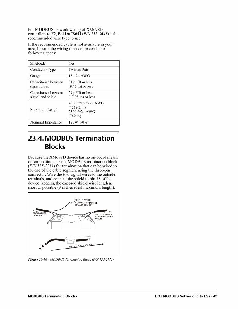
MODBUS Termination Blocks ECT MODBUS Networking to E2s • 43
For MODBUS network wiring of XM678D controllers to E2, Belden #8641 (P/N 135-8641) is the recommended wire type to use.
If the recommended cable is not available in your area, be sure the wiring meets or exceeds the following specs:
Shielded? Yes
Conductor Type Twisted Pair
Gauge 18 - 24 AWG
Capacitance between signal wires
31 pF/ft or less(9.45 m) or less
Capacitance between signal and shield
59 pF/ft or less(17.98 m) or less
Maximum Length
4000 ft/18 to 22 AWG(1219.2 m)2500 ft/24 AWG(762 m)
Nominal Impedance 120W±50W
23.4. MODBUS Termination Blocks
Because the XM678D device has no on-board means of termination, use the MODBUS termination block (P/N 535-2711) for termination that can be wired to the end of the cable segment using the three-pin connector. Wire the two signal wires to the outside terminals, and connect the shield to pin 38 of the device, keeping the exposed shield wire length as short as possible (3 inches ideal maximum length).
Figure 23-10 - MODBUS Termination Block (P/N 535-2711)
SHIELD WIRE(CONNECT TO OF LAST DEVICE)
PIN 38
FROM OTHERDEVICES TO LAST DEVICE
AT END OF DAISY CHAIN

44 • XM678D I&O Manual 026-1219 Rev 3
24 Default Parameter Map
The first column numbers are simple indexes not related to the position on the device menu. The total amount of parameters can be different depending on the applications. SUBMENUS: V1...V30 ELECTRONIC VALVE belongs to EEV.
Label Value Description Range Notes
EEU ELECTRONIC VALVE
By pressing SET you can enter the electronic expansion valve submenu.
FtY 290 Kind of gas
Type of gas used by plant. Fundamental parameter for correct functioning of all system.
LABEL REFRIGERANT OPERATING RANGE
R22 r22-58 to 120°F/-50 to 60°C
134 r134A-58 to 120°F/-50 to 60°C
290 r290 – Propane-58 to 120°F/-50 to 60°C
404 r404A-94 to 120°F/-70 to 60°C
47A r407A-58 to 120°F/-50 to 60°C
47C r407C-58 to 120°F/-50 to 60°C
47F r407F-58 to 120°F/-50 to 60°C
410 r410A-58 to 120°F/-50 to 60°C
448 r448A-69 to 120°F/-45 to 60°C
449 r449A-69 to 120°F/-45 to 60°C
450 r450A-69 to 120°F/-45 to 60°C
507 r507-94 to 120°F/-70 to 60°C
513 r513A-69 to 120°F/-45 to 60°C
CO2 r744 - Co2-58 to 120°F/-50 to 60°C
Table 24-1 - Default Parameter Map

MODBUS Termination Blocks Default Parameter Map • 45
Atu nMinimum STABLE
superheat search No; YesThis parameter enables the search of the minimum stable superheat. The lowest admitted value is LSH+2°C.
AMS nSelf adaptive SH
regulation enabling No; Yes
This parameter enables the self adaptive regulation of the superheat. CrE = no must to be set, when this function is enabled.
SSH 9 Superheat setpoint[1°F to 45°F]
[0.1°C to 25.5°C]This is the value used to regulate the superheat.
Pb 36 Proportional band[1°F to 108°F]
[0.1°C to 60.0°C]
The valve changes its opening on the band [SSH, SSH + Pb]. At SSH value of superheat the valve will be at 0% (without integral contribution) and at [SSH + Pb] value of superheat the valve will be at MnF. For values bigger than [SSH + Pb] the valve is completely opened.
rS -3Proportional band
reset[-12.0°C to 12.0°C]
It allows to move the regulation band, above or below the SH setpoint.
inC 220Integration time for
superheat regulation
0 to 255s -
PEO 0Valve opening in case of error on probes P5 or P6
0 to 100%If a temporary probe error occurs, valve opening percentage is PEo until PEd time is elapsed.
OPE 85
Start opening percentage for the time SFD. It’s not
limited by the MnF parameter.
0 to 100%Opening valve percentage when the start function is active. This phase duration is SFd time.
SFd 0.0Duration of soft start phase with opening at OPE
0.0 to 42min00sec (252)
Set start function duration and post-defrost duration. During this phase the alarms are neglected.Format: min.10secResolution: 10sec
OPd 85
Valve opening percentage during
hot gas defrost. It’s not limited by the MnF parameter.
0 to 100%Opening valve percentage during hot gas defrost. During hot gas defrost there is no SH control.
MnF 100
Maximum percentage of
opening admitted (during normal
functioning)
0 to 100%
During the regulation it sets the maximum valve opening percentage. This value is not used during the SFd phase (soft start) and during hot gas defrost, where the fixed percentage of the valve opening is set by oPd.
Label Value Description Range Notes
Table 24-1 - Default Parameter Map
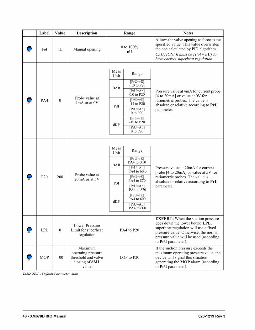
46 • XM678D I&O Manual 026-1219 Rev 3
Fot nU Manual opening0 to 100%
nU
Allows the valve opening to force to the specified value. This value overwrites the one calculated by PID algorithm. CAUTION! It must be [Fot = nU] to have correct superheat regulation.
PA4 0Probe value at 4mA or at 0V
Meas Unit Range
BAR
[PrU=rE] -1.0 to P20
[PrU=Ab] 0.0 to P20
PSI
[PrU=rE] -14 to P20
[PrU=Ab] 0 to P20
dKP
[PrU=rE] -10 to P20
[PrU=Ab] 0 to P20
Pressure value at 4mA for current probe [4 to 20mA] or value at 0V for ratiometric probes. The value is absolute or relative according to PrU parameter.
P20 200 Probe value at 20mA or at 5V
Meas Unit Range
BAR
[PrU=rE] PA4 to 60.0
[PrU=Ab] PA4 to 60.0
PSI
[PrU=rE] PA4 to 870
[PrU=Ab] PA4 to 870
dKP
[PrU=rE] PA4 to 600
[PrU=Ab] PA4 to 600
Pressure value at 20mA for current probe [4 to 20mA] or value at 5V for ratiometric probes. The value is absolute or relative according to PrU parameter.
LPL 0Lower Pressure
Limit for superheat regulation
PA4 to P20
EXPERT: When the suction pressure goes down the lower bound LPL, superheat regulation will use a fixed pressure value. Otherwise, the normal pressure value will be used (according to PrU parameter).
MOP 100
Maximum operating pressure threshold and valve
closing of dML value
LOP to P20
If the suction pressure exceeds the maximum operating pressure value, the device will signal this situation generating the MOP alarm (according to PrU parameter).
Label Value Description Range Notes
Table 24-1 - Default Parameter Map
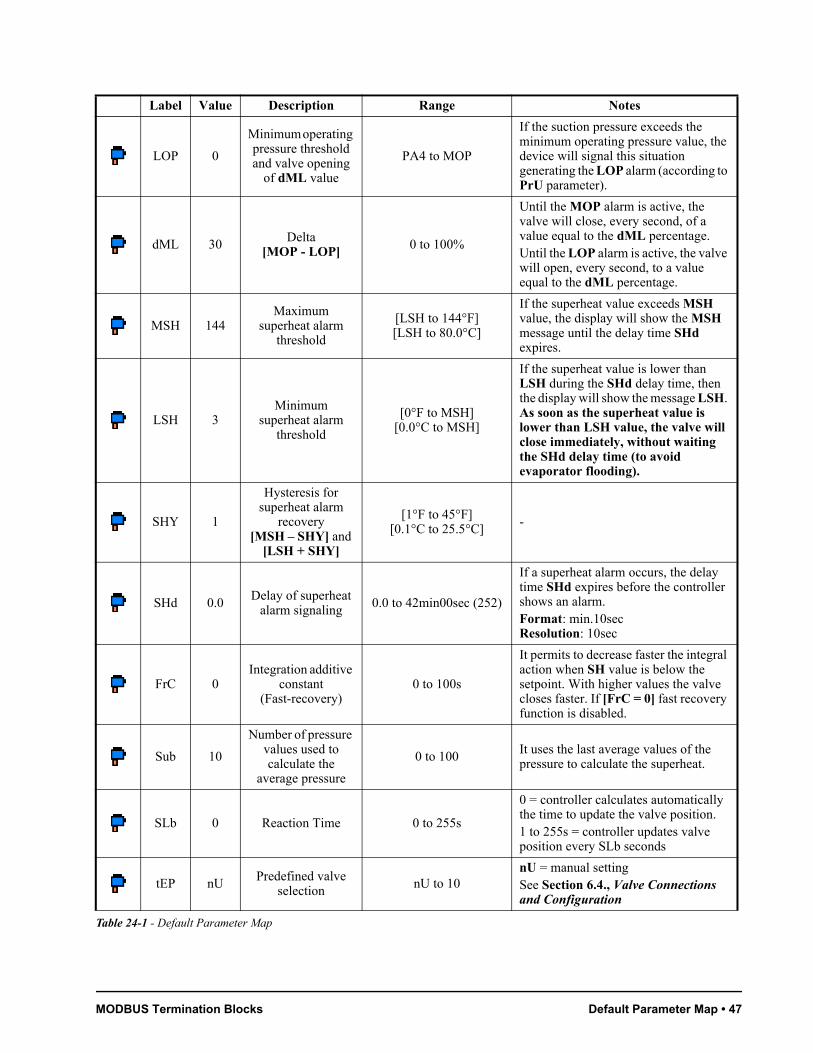
MODBUS Termination Blocks Default Parameter Map • 47
LOP 0
Minimum operating pressure threshold and valve opening
of dML value
PA4 to MOP
If the suction pressure exceeds the minimum operating pressure value, the device will signal this situation generating the LOP alarm (according to PrU parameter).
dML 30 Delta [MOP - LOP]
0 to 100%
Until the MOP alarm is active, the valve will close, every second, of a value equal to the dML percentage.Until the LOP alarm is active, the valve will open, every second, to a value equal to the dML percentage.
MSH 144Maximum
superheat alarm threshold
[LSH to 144°F][LSH to 80.0°C]
If the superheat value exceeds MSH value, the display will show the MSH message until the delay time SHd expires.
LSH 3Minimum
superheat alarm threshold
[0°F to MSH][0.0°C to MSH]
If the superheat value is lower than LSH during the SHd delay time, then the display will show the message LSH. As soon as the superheat value is lower than LSH value, the valve will close immediately, without waiting the SHd delay time (to avoid evaporator flooding).
SHY 1
Hysteresis for superheat alarm
recovery [MSH – SHY] and
[LSH + SHY]
[1°F to 45°F][0.1°C to 25.5°C]
-
SHd 0.0Delay of superheat
alarm signaling0.0 to 42min00sec (252)
If a superheat alarm occurs, the delay time SHd expires before the controller shows an alarm.Format: min.10secResolution: 10sec
FrC 0Integration additive
constant (Fast-recovery)
0 to 100s
It permits to decrease faster the integral action when SH value is below the setpoint. With higher values the valve closes faster. If [FrC = 0] fast recovery function is disabled.
Sub 10
Number of pressure values used to calculate the
average pressure
0 to 100 It uses the last average values of the pressure to calculate the superheat.
SLb 0 Reaction Time 0 to 255s
0 = controller calculates automatically the time to update the valve position.1 to 255s = controller updates valve position every SLb seconds
tEP nUPredefined valve
selectionnU to 10
nU = manual settingSee Section 6.4., Valve Connections and Configuration
Label Value Description Range Notes
Table 24-1 - Default Parameter Map

48 • XM678D I&O Manual 026-1219 Rev 3
tEU bP Kind of valve uP; bPuP = unipolar valve (5-6 wires)bP = bipolar valve (4 wires)
HSF FULKind of motor
movementHAF; FUL
HAF = half step. Use this setting for the unipolar valve.FUL = half step. Use this setting for the bipolar valve.
LSt 0
Minimum number of steps where the
valve can be considered as
completely closed
0 to USt (* 10) For manual adjusting of the valve.
USt 0Maximum number of steps that can be
performedLSt to 800 (* 10) For manual adjusting of the valve.
ESt 0Extra steps in closing phase
0 to 255 (*10)Extra steps done by the valve during closing phase to assure the valve closes completely.
Sr 10
Step rate: the speed to change step. A
too high value causes incorrect
driving
10 to 600 (steps/sec) For manual adjusting of the valve.
CPP 0Current per phase
during bipolar valve driving
0 to 100 (* 10mA) For manual adjusting of the valve.
CHd 0
Current per phase to maintain the actual
position (Holding current)
0 to 100 (* 10mA) For manual adjusting of the valve.
GtH 0 Auto zero function 0 to 15h
To prevent any possible wrong position caused by a long period without closing the valve, the controller after gtH hours, as soon as the opening open percentage is under 20%, will force complete closer of the valve, and then will restart working.
REGULATION
SET -5.0 Setpoint LS to US Target setpoint for temperature regulation.
HY 18 Differential[1°F to 45°F]
[0.1°C to 25.5°C]
If [CrE = n] then HY is the hysteresis for ON/OFF thermoregulation. If [CrE = Y] or [CrE = EUP] then HY is the proportional band for temperature PI controller. On these cases the value should be greater than 5°C.
Label Value Description Range Notes
Table 24-1 - Default Parameter Map

MODBUS Termination Blocks Default Parameter Map • 49
int 220Integral time for
room temperature regulation
0 to 255s
This value is used only when [CrE = Y] or [CrE = EUP]. It is the integral time for thermoregulation: high values mean slower regulation.0 (zero) = no integral action
CrE YContinuous regulation activation
n(0); Y(1); EUP(2)
With [CrE = Y] or [CrE = EUP], the regulation becomes PI, HY becomes a band and int an integral time.n = standard regulationY = continuous regulation, to be used only in centralized plantsEUP = evaporator valves(See Section 19.2., Standard Regulation and Continuous Regulation)
LS -50 Minimum setpoint[-67°F to SET]
[-55.0°C to SET]Sets the minimum acceptable value for the setpoint.
US 70 Maximum setpoint[SET to 302°F]
[SET to 150.0°C]Sets the maximum acceptable value for the setpoint.
odS 0 Outputs activation delay at start up
0 to 255min
This function is enabled at the initial startup of the device and inhibits any output activation for the period of time set in this parameter (AUX and Light can work).
AC 0 Anti-short cycle delay
0 to 60min Interval between the solenoid valve stop and the following restart.
CCt 0.0Continuous cycle
duration 0.0 to 24h00min (144)
Compressor ON time during continuous cycle: Allows the length of the continuous cycle to set: compressor stays ON without interruption for the CCt time. It can be used, for instance, when the room is filled with new products. Format: hours.10minResolution: 10min
CCS 36Continuous cycle
setpoint[-67°F to 302°F]
[-55.0°C to 150.0°C]Setpoint for continuous cycle: value used during the continuous cycle.
Con 15Compressor ON time with faulty
probe0 to 255min
Solenoid valve ON time with faulty probe: Time during which the solenoid valve is ON in case of faulty thermostat probe. With COn = 0, solenoid valve is always OFF.
CoF 30Compressor OFF time with faulty
probe0 to 255min
Solenoid valve OFF time with faulty probe: Time during which the solenoid valve is OFF in case of faulty thermostat probe. With COF = 0, solenoid valve is always ON.
Label Value Description Range Notes
Table 24-1 - Default Parameter Map
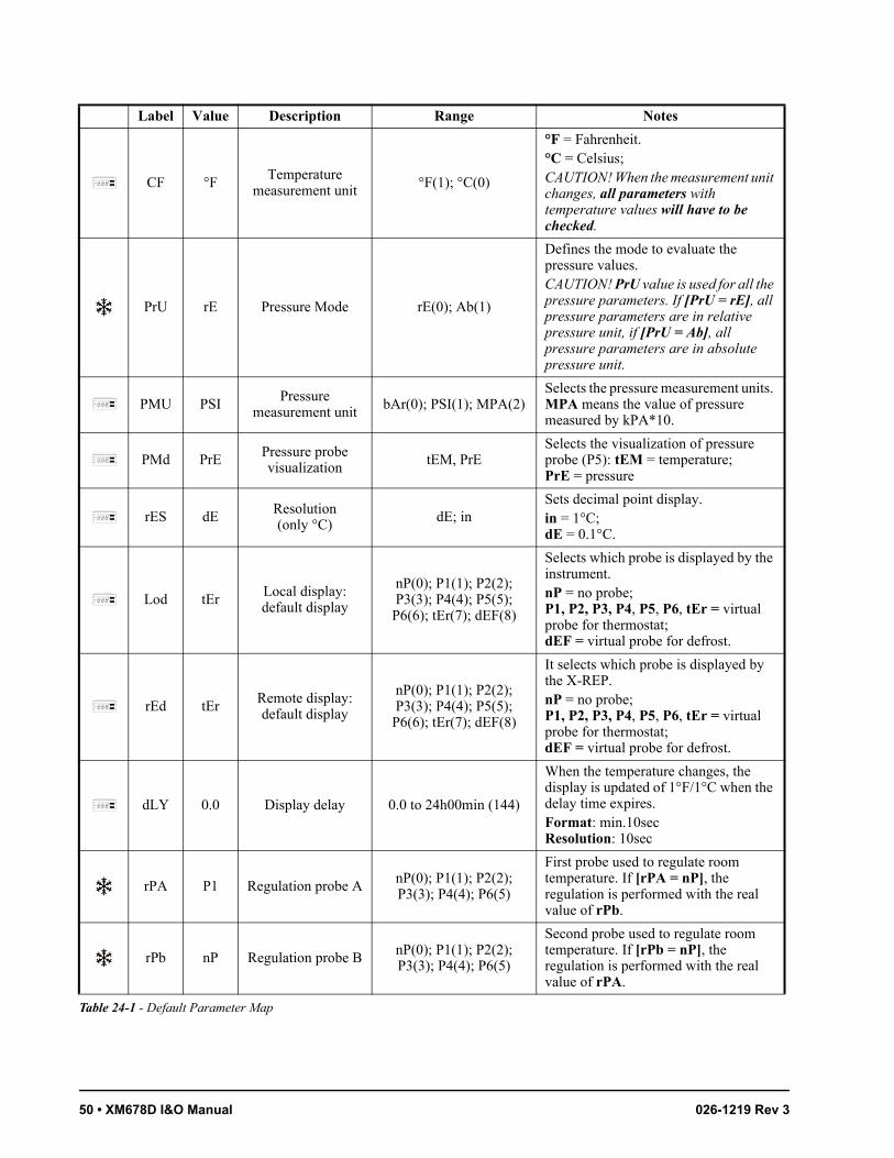
50 • XM678D I&O Manual 026-1219 Rev 3
CF °FTemperature
measurement unit°F(1); °C(0)
°F = Fahrenheit. °C = Celsius;CAUTION! When the measurement unit changes, all parameters with temperature values will have to be checked.
PrU rE Pressure Mode rE(0); Ab(1)
Defines the mode to evaluate the pressure values. CAUTION! PrU value is used for all the pressure parameters. If [PrU = rE], all pressure parameters are in relative pressure unit, if [PrU = Ab], all pressure parameters are in absolute pressure unit.
PMU PSIPressure
measurement unitbAr(0); PSI(1); MPA(2)
Selects the pressure measurement units. MPA means the value of pressure measured by kPA*10.
PMd PrE Pressure probe visualization
tEM, PrESelects the visualization of pressure probe (P5): tEM = temperature; PrE = pressure
rES dE Resolution (only °C)
dE; inSets decimal point display.in = 1°C; dE = 0.1°C.
Lod tErLocal display: default display
nP(0); P1(1); P2(2); P3(3); P4(4); P5(5);
P6(6); tEr(7); dEF(8)
Selects which probe is displayed by the instrument. nP = no probe; P1, P2, P3, P4, P5, P6, tEr = virtual probe for thermostat;dEF = virtual probe for defrost.
rEd tErRemote display: default display
nP(0); P1(1); P2(2); P3(3); P4(4); P5(5);
P6(6); tEr(7); dEF(8)
It selects which probe is displayed by the X-REP. nP = no probe;P1, P2, P3, P4, P5, P6, tEr = virtual probe for thermostat; dEF = virtual probe for defrost.
dLY 0.0 Display delay 0.0 to 24h00min (144)
When the temperature changes, the display is updated of 1°F/1°C when the delay time expires. Format: min.10secResolution: 10sec
rPA P1 Regulation probe AnP(0); P1(1); P2(2); P3(3); P4(4); P6(5)
First probe used to regulate room temperature. If [rPA = nP], the regulation is performed with the real value of rPb.
rPb nP Regulation probe BnP(0); P1(1); P2(2); P3(3); P4(4); P6(5)
Second probe used to regulate room temperature. If [rPb = nP], the regulation is performed with the real value of rPA.
Label Value Description Range Notes
Table 24-1 - Default Parameter Map
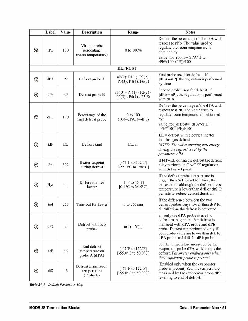
MODBUS Termination Blocks Default Parameter Map • 51
rPE 100Virtual probe
percentage (room temperature)
0 to 100%
Defines the percentage of the rPA with respect to rPb. The value used to regulate the room temperature is obtained by:value_for_room = (rPA*rPE + rPb*(100-rPE))/100
DEFROST
dPA P2 Defrost probe AnP(0); P1(1); P2(2); P3(3); P4(4); P6(5)
First probe used for defrost. If [dPA = nP], the regulation is performed by time.
dPb nP Defrost probe B nP(0) - P1(1) - P2(2) - P3(3) - P4(4) - P5(5)
Second probe used for defrost. If [dPb = nP], the regulation is performed with dPA.
dPE 100 Percentage of the first defrost probe
0 to 100 (100=dPA, 0=dPb)
Defines the percentage of the dPA with respect to dPb. The value used to regulate room temperature is obtained by:value_for_defrost= (dPA*dPE + dPb*(100-dPE))/100
tdF EL Defrost kind EL; in
EL = defrost with electrical heaterin = hot gas defrostNOTE: The valve opening percentage during the defrost is set by the parameter oPd.
Srt 302Heater setpoint during defrost
[-67°F to 302°F][-55.0°C to 150°C]
If tdF=EL during the defrost the defrost relay perform an ON/OFF regulation with Srt as set point.
Hyr 4 Differential for heater
[1°F to 45°F][0.1°C to 25.5°C]
If the defrost probe temperature is bigger than Srt for all tod time, the defrost ends although the defrost probe temperature is lower than dtE or dtS. It permits to reduce defrost duration.
tod 255 Time out for heater 0 to 255minIf the difference between the two defrost probes stays lower than dtP for all ddP time the defrost is activated;
dP2 nDefrost with two
probes n(0) – Y(1)
n= only the dPA probe is used to defrost management; Y= defrost is managed with dPA probe and dPb probe. Defrost can performed only if both probe value are lower than dtE for dPA probe and dtS for dPb probe
dtE 46End defrost
temperature on probe A (dPA)
[-67°F to 122°F][-55.0°C to 50.0°C]
Set the temperature measured by the evaporator probe dPA which stops the defrost. Parameter enabled only when the evaporator probe is present.
dtS 46Defrost termination
temperature (Probe B)
[-67°F to 122°F][-55.0°C to 50.0°C]
(Enabled only when the evaporator probe is present) Sets the temperature measured by the evaporator probe dPb resulting to end of defrost.
Label Value Description Range Notes
Table 24-1 - Default Parameter Map

52 • XM678D I&O Manual 026-1219 Rev 3
idF 6 Defrost interval 0 to 120hours
Sets the time interval between the beginning of two defrost cycles. [idF = 0]: the defrost can only be activated manually, or through RS485 or from an external contact or from the LAN.
MdF 45(Maximum) defrost
duration0 to 255min
When dPA is not present, it sets the defrost duration, otherwise it sets the maximum duration for defrost.
dSd 0 Defrost start delay after request
0 to 255minUseful when different defrost start times are necessary to avoid overloading the plant.
dFd itDisplay during
defrostrt; it; SEt; dEF
rt = real temperature for Lod probeit = initial temperature (reading when defrost start)SEt = setpoint valuedEF = “dEF” label is visualized
dAd 30 Display delay 0 to 255minSet the maximum time between the end of defrost and the restarting of the real room temperature display.
Fdt 0 Drain downtime after defrost
0 to 255min
Time interval between reaching the defrost termination temperature and the restoration of the control’s normal operation. This time allows the evaporator to eliminate water drops that might have formed due to defrost. The fan and the thermoregulation outputs are OFF during this time.
dPo nDefrost at power
ON n; YFirst defrost after startup:Y = immediatelyn = after the idF time
dAF 0.0Defrost delay after continuous cycle
0.0 to 24h00min (144)
Time interval between the end of the fast freezing cycle and the following defrost related to it.Format: hours.10min Resolution: 10min
FAN
FPA P2 Fan probe AnP(0); P1(1); P2(2); P3(3); P4(4); P6(5)
First probe used for fan. If [FPA = nP], the regulation is performed with real value of FPb.
FnC O-n Fan operating mode C-n; C-Y; O-n; O-Y
C-n = running with the solenoid valve, OFF during the defrostC-Y = running with the solenoid valve, ON during the defrostO-n = continuous mode, OFF during the defrostO-Y = continuous mode, ON during the defrost
Label Value Description Range Notes
Table 24-1 - Default Parameter Map
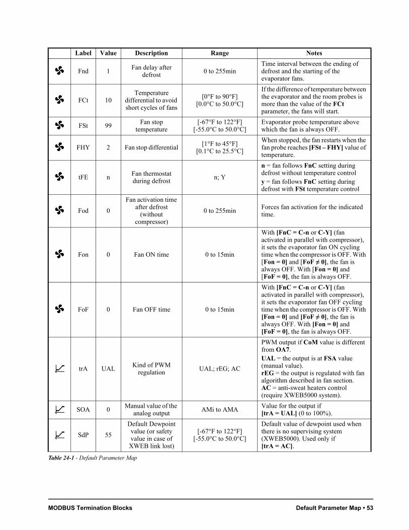
MODBUS Termination Blocks Default Parameter Map • 53
Fnd 1Fan delay after
defrost 0 to 255minTime interval between the ending of defrost and the starting of the evaporator fans.
FCt 10Temperature
differential to avoid short cycles of fans
[0°F to 90°F][0.0°C to 50.0°C]
If the difference of temperature between the evaporator and the room probes is more than the value of the FCt parameter, the fans will start.
FSt 99Fan stop
temperature[-67°F to 122°F]
[-55.0°C to 50.0°C]Evaporator probe temperature above which the fan is always OFF.
FHY 2 Fan stop differential[1°F to 45°F]
[0.1°C to 25.5°C]
When stopped, the fan restarts when the fan probe reaches [FSt – FHY] value of temperature.
tFE n Fan thermostat during defrost
n; Y
n = fan follows FnC setting during defrost without temperature controly = fan follows FnC setting during defrost with FSt temperature control
Fod 0
Fan activation time after defrost
(without compressor)
0 to 255minForces fan activation for the indicated time.
Fon 0 Fan ON time 0 to 15min
With [FnC = C-n or C-Y] (fan activated in parallel with compressor), it sets the evaporator fan ON cycling time when the compressor is OFF. With [Fon = 0] and [FoF ≠ 0], the fan is always OFF. With [Fon = 0] and [FoF = 0], the fan is always OFF.
FoF 0 Fan OFF time 0 to 15min
With [FnC = C-n or C-Y] (fan activated in parallel with compressor), it sets the evaporator fan OFF cycling time when the compressor is OFF. With [Fon = 0] and [FoF ≠ 0], the fan is always OFF. With [Fon = 0] and [FoF = 0], the fan is always OFF.
trA UAL Kind of PWM regulation
UAL; rEG; AC
PWM output if CoM value is different from OA7. UAL = the output is at FSA value (manual value).rEG = the output is regulated with fan algorithm described in fan section.AC = anti-sweat heaters control (require XWEB5000 system).
SOA 0Manual value of the
analog outputAMi to AMA
Value for the output if [trA = UAL] (0 to 100%).
SdP 55
Default Dewpoint value (or safety value in case of
XWEB link lost)
[-67°F to 122°F][-55.0°C to 50.0°C]
Default value of dewpoint used when there is no supervising system (XWEB5000). Used only if [trA = AC].
Label Value Description Range Notes
Table 24-1 - Default Parameter Map

54 • XM678D I&O Manual 026-1219 Rev 3
ASr 1Differential for fan/offset for
anti-sweat heater
[-45°F to 45°F][-25.5°C to 25.5°C]
trA = AC: dewpoint offset.trA = rEG: differential for modulating fan regulation.
PbA 10Proportional band
for modulating output
[1°F to 45°F][0.1°C to 25.5°C]
Differential for anti-sweat heaters
AMi 0Minimum output for modulating
output0 to AMA Minimum value for analog output:
(0 to AMA)
AMA 100Maximum output for modulating
outputAMi to 100
Maximum value for analog output: (AMi to 100)
AMt 20
Time with fan at maximum speed or ON time for relay
on anti-sweat regulation
[10 to 60s] or [10 to 60min]
trA = AC: Anti-sweat heaters cycle period.trA = rEG: Time with fan at maximum speed.The fan works at maximum speed during this time. If intended for fan, time is based in seconds; for anti-sweat regulation, the time is based in minutes.
ALARM
rAL tErProbe for room
temperature alarmnP; P1; P2; P3; P4; P6;
tErSelects the probe used to signal the alarm temperature.
ALC Ab
Room temperature alarm
configuration: relative to setpoint
or absolute
rE; Ab
rE = High and Low alarms related to the setpoint.Ab = High and Low alarms related to the absolute temperature.
ALU 41High room
temperature alarm setting
[0.0°C to 32.0°C] or[ALL to 150.0°C]
ALC = rE: [32°F to 90°F] or [0.0°C to 32 °C]ALC = Ab: [ALL to 302°F] or [ALL to 150°C]When this temperature is reached and the ALd delay time is expired, the HA alarm will be enabled.
ALL -25Low room
temperature alarm setting
[0.0°C to 50.0°C] or[-55.0°C to ALU]
ALC = rE: [32°F to 90°F] or [0.0°C to 32.0°C]ALC = Ab: [-67.0°F to ALU] or [-55.0°C to ALU]After this temperature is reached and the ALd delay time is expired, the LA alarm will be enabled.
AHY 2Differential for
room temperature alarm
[1°F to 45°F][0.1°C to 25.5°C]
Threshold recovery after a temperature alarm.
ALd 60Room temperature
alarm delay 0 to 255minTime interval between the detection of an alarm condition and the corresponding alarm signaling.
Label Value Description Range Notes
Table 24-1 - Default Parameter Map
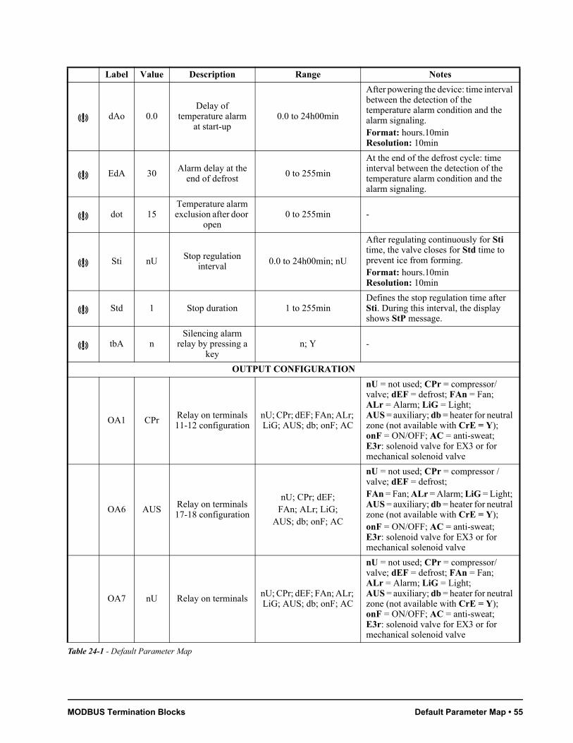
MODBUS Termination Blocks Default Parameter Map • 55
dAo 0.0Delay of
temperature alarm at start-up
0.0 to 24h00min
After powering the device: time interval between the detection of the temperature alarm condition and the alarm signaling.Format: hours.10min Resolution: 10min
EdA 30Alarm delay at the
end of defrost0 to 255min
At the end of the defrost cycle: time interval between the detection of the temperature alarm condition and the alarm signaling.
dot 15Temperature alarm exclusion after door
open0 to 255min -
Sti nU Stop regulation interval
0.0 to 24h00min; nU
After regulating continuously for Sti time, the valve closes for Std time to prevent ice from forming.Format: hours.10min Resolution: 10min
Std 1 Stop duration 1 to 255minDefines the stop regulation time after Sti. During this interval, the display shows StP message.
tbA nSilencing alarm
relay by pressing a key
n; Y -
OUTPUT CONFIGURATION
OA1 CPr Relay on terminals 11-12 configuration
nU; CPr; dEF; FAn; ALr; LiG; AUS; db; onF; AC
nU = not used; CPr = compressor/valve; dEF = defrost; FAn = Fan; ALr = Alarm; LiG = Light; AUS = auxiliary; db = heater for neutral zone (not available with CrE = Y); onF = ON/OFF; AC = anti-sweat; E3r: solenoid valve for EX3 or for mechanical solenoid valve
OA6 AUSRelay on terminals 17-18 configuration
nU; CPr; dEF; FAn; ALr; LiG;
AUS; db; onF; AC
nU = not used; CPr = compressor / valve; dEF = defrost; FAn = Fan; ALr = Alarm; LiG = Light; AUS = auxiliary; db = heater for neutral zone (not available with CrE = Y);onF = ON/OFF; AC = anti-sweat; E3r: solenoid valve for EX3 or for mechanical solenoid valve
OA7 nU Relay on terminals nU; CPr; dEF; FAn; ALr; LiG; AUS; db; onF; AC
nU = not used; CPr = compressor/valve; dEF = defrost; FAn = Fan; ALr = Alarm; LiG = Light; AUS = auxiliary; db = heater for neutral zone (not available with CrE = Y); onF = ON/OFF; AC = anti-sweat; E3r: solenoid valve for EX3 or for mechanical solenoid valve
Label Value Description Range Notes
Table 24-1 - Default Parameter Map
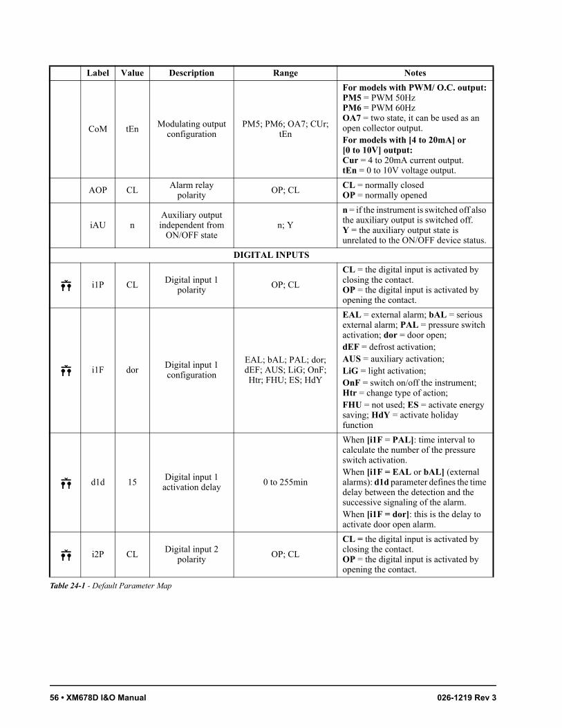
56 • XM678D I&O Manual 026-1219 Rev 3
CoM tEn Modulating output configuration
PM5; PM6; OA7; CUr; tEn
For models with PWM/ O.C. output:PM5 = PWM 50HzPM6 = PWM 60HzOA7 = two state, it can be used as an open collector output.For models with [4 to 20mA] or [0 to 10V] output:Cur = 4 to 20mA current output.tEn = 0 to 10V voltage output.
AOP CLAlarm relay
polarity OP; CLCL = normally closedOP = normally opened
iAU nAuxiliary output independent from
ON/OFF staten; Y
n = if the instrument is switched off also the auxiliary output is switched off.Y = the auxiliary output state is unrelated to the ON/OFF device status.
DIGITAL INPUTS
i1P CL Digital input 1 polarity
OP; CL
CL = the digital input is activated by closing the contact.OP = the digital input is activated by opening the contact.
i1F dorDigital input 1 configuration
EAL; bAL; PAL; dor; dEF; AUS; LiG; OnF; Htr; FHU; ES; HdY
EAL = external alarm; bAL = serious external alarm; PAL = pressure switch activation; dor = door open; dEF = defrost activation; AUS = auxiliary activation; LiG = light activation; OnF = switch on/off the instrument; Htr = change type of action; FHU = not used; ES = activate energy saving; HdY = activate holiday function
d1d 15Digital input 1
activation delay 0 to 255min
When [i1F = PAL]: time interval to calculate the number of the pressure switch activation. When [i1F = EAL or bAL] (external alarms): d1d parameter defines the time delay between the detection and the successive signaling of the alarm. When [i1F = dor]: this is the delay to activate door open alarm.
i2P CLDigital input 2
polarityOP; CL
CL = the digital input is activated by closing the contact.OP = the digital input is activated by opening the contact.
Label Value Description Range Notes
Table 24-1 - Default Parameter Map

MODBUS Termination Blocks Default Parameter Map • 57
i2F LiGDigital input 2 configuration
EAL; bAL; PAL; dor; dEF; AUS; LiG; OnF; Htr; FHU; ES; HdY
EAL = external alarm; bAL = serious external alarm; PAL = pressure switch activation; dor = door open; dEF = defrost activation; AUS = auxiliary activation; LiG = light activation; OnF = switch on/off the instrument; Htr = change type of action; FHU = not used; ES = activate energy saving; HdY = activate holiday function.
d2d 5 Digital input 2 activation delay
0 to 255min
When [i2F = PAL]: time interval to calculate the number of the pressure switch activation.When [i2F = EAL or bAL] (external alarms): d2d parameter defines the time delay between the detection and the successive signaling of the alarm.When [i2F = dor]: this is the delay to activate door open alarm.
i3P CL Digital input 3 polarity
OP; CL
CL = the digital input is activated by closing the contact.OP = the digital input is activated by opening the contact.
i3F ESDigital input 3 configuration
EAL; bAL; PAL; dor; dEF; AUS; LiG; OnF; Htr; FHU; ES; HdY
EAL = external alarm; bAL = serious external alarm; PAL = pressure switch activation; dor = door open; dEF = defrost activation; AUS = auxiliary activation; LiG = light activation; OnF = switch on/off the instrument; Htr = change type of action; FHU = not used; ES = activate energy saving; HdY = activate holiday function.
d3d 0Digital input 3
activation delay0 to 255min
When [i3F = PAL]: time interval to calculate the number of the pressure switch activation. When [i3F = EAL or bAL] (external alarms): d3d parameter defines the time delay between the detection and the successive signaling of the alarm. When [i3F = dor]: this is the delay to activate door open alarm.
nPS 15Number of pressure switch activations
before lock0 to 15
Number of pressure switch activation, during the d1d, d2d and d3d interval, before signaling the alarm event [i1F, i2F or i3F = PAL]. If the nPS activation in the d1d, d2d or d3d time is reached, switch off and on the instrument to restart normal regulation.
Label Value Description Range Notes
Table 24-1 - Default Parameter Map

58 • XM678D I&O Manual 026-1219 Rev 3
OdC F-CCompressor and fan
status with door open
no; FAn; CPr; F-Cno = normal; Fan = Fan OFF; CPr = Compressor OFF; F_C = both Compressor and Fan OFF
rrd 15Output restart delay
with door open0 to 255min
The outputs stopped by the OdC parameter can restart after the rrd time.
ENERGY SAVING
ESP P1Energy saving probe selection
nP; P1; P2; P3; P4; P6; tEr -
HES 0Temperature
increasing during Energy Saving
[-54°F to 54°F][-30.0°C to 30.0°C]
Sets the increasing value of the setpoint during the Energy Saving cycle.
PEL nU
Energy saving activation when
Light or/and AUX are switched OFF
nU(0); LIG(1); AUS(2); LEA(3)
Energy saving enabled when:LiG: light switched OFFAUS: AUX switched OFFLEA: both light and AUX switched OFFnU: function not used
LAN MANAGEMENT
LMd YDefrost
Synchronizationn; Y
n = the section does not send a global defrost command.Y = the section sends a command to start defrost to other controllers.
dEM YDefrost end
Synchronization n; Y
n = the end of the LAN defrosts are independent.Y = the end of the LAN defrosts are synchronized.
LSP nLAN setpoint
Synchronizationn; Y
n = the setpoint value is modified only in the local section.Y = the section setpoint, when modified, is updated to the same value on all the other sections.
LdS n
LAN Display Synchronization (temperature sent
via LAN)
n; Y
n = the setpoint value is modified only in the local section.Y = the value displayed by the section is sent to all the other sections.
LOF nLAN ON/OFF
Synchronizationn; Y
This parameter indicates if the ON/OFF command of the section will act also on all the other sections:n = the ON/OF command acts only in the local section.Y = the ON/OFF command is sent to all the other sections.
LLi YLAN Light
Synchronizationn; Y
This parameter indicates if the light command of the section will act also on all the other sections: n = the light command acts only in the local section.Y = the light command is sent to all the other sections.
Label Value Description Range Notes
Table 24-1 - Default Parameter Map
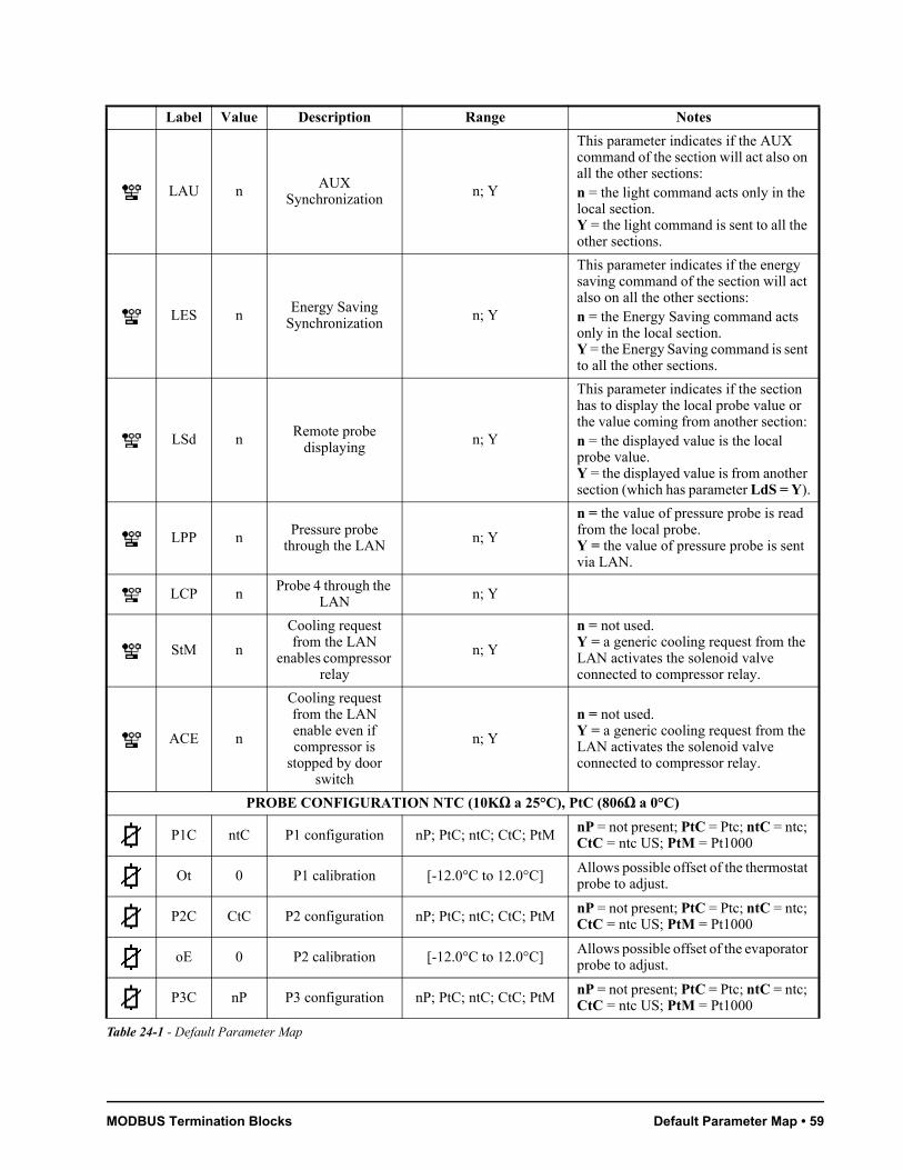
MODBUS Termination Blocks Default Parameter Map • 59
LAU nAUX
Synchronizationn; Y
This parameter indicates if the AUX command of the section will act also on all the other sections: n = the light command acts only in the local section.Y = the light command is sent to all the other sections.
LES nEnergy Saving
Synchronizationn; Y
This parameter indicates if the energy saving command of the section will act also on all the other sections: n = the Energy Saving command acts only in the local section.Y = the Energy Saving command is sent to all the other sections.
LSd nRemote probe
displayingn; Y
This parameter indicates if the section has to display the local probe value or the value coming from another section: n = the displayed value is the local probe value.Y = the displayed value is from another section (which has parameter LdS = Y).
LPP n Pressure probe through the LAN
n; Y
n = the value of pressure probe is read from the local probe.Y = the value of pressure probe is sent via LAN.
LCP nProbe 4 through the
LAN n; Y
StM n
Cooling request from the LAN
enables compressor relay
n; Y
n = not used.Y = a generic cooling request from the LAN activates the solenoid valve connected to compressor relay.
ACE n
Cooling request from the LAN enable even if compressor is
stopped by door switch
n; Y
n = not used.Y = a generic cooling request from the LAN activates the solenoid valve connected to compressor relay.
PROBE CONFIGURATION NTC (10KΩ a 25°C), PtC (806Ω a 0°C)
P1C ntC P1 configuration nP; PtC; ntC; CtC; PtMnP = not present; PtC = Ptc; ntC = ntc; CtC = ntc US; PtM = Pt1000
Ot 0 P1 calibration [-12.0°C to 12.0°C]Allows possible offset of the thermostat probe to adjust.
P2C CtC P2 configuration nP; PtC; ntC; CtC; PtMnP = not present; PtC = Ptc; ntC = ntc; CtC = ntc US; PtM = Pt1000
oE 0 P2 calibration [-12.0°C to 12.0°C]Allows possible offset of the evaporator probe to adjust.
P3C nP P3 configuration nP; PtC; ntC; CtC; PtMnP = not present; PtC = Ptc; ntC = ntc; CtC = ntc US; PtM = Pt1000
Label Value Description Range Notes
Table 24-1 - Default Parameter Map

60 • XM678D I&O Manual 026-1219 Rev 3
O3 0 P3 calibration [-12.0°C to 12.0°C]Allows possible offset of the probe 3 to adjust.
P4C nP P4 configurationnP; PtC; ntC; CtC; PtM;
LAN
nP = not present; PtC = Ptc; ntC = ntc; CtC = ntc US; PtM = Pt1000; LAN = value received from master
O4 0 P4 calibration [-12.0°C to 12.0°C] Allows possible offset of the probe 4 to adjust.
P5C 5Vr P5 configurationnP; PtC; ntC; CtC;
PtM; 420; 5Vr; LAN
nP = not present; PtC = Ptc; ntC = ntc; CtC = ntc US; PtM = Pt1000; 420 = 4 to 20mA; 5Vr = 0 to 5V ratiometric; LAN = value received from master
o5 0 P5 calibration [-12.0°C to 12.0°C]Allows possible offset of the probe 5 to adjust.
P6C CtC P6 configuration nP; PtC; ntC; CtC; PtMnP = not present; PtC = Ptc; ntC = ntc; CtC = ntc US; PtM = Pt1000.
o6 0 P6 calibration [-12.0°C to 12.0°C] Allows possible offset of the probe 6 to adjust.
SERVICE
CLt - - -ON/OFF
percentage (C.R.O.) (read only)Shows the effective cooling time calculated by XM600 during regulation (cooling time percentage).
tMd - - -
Time remaining before the next
defrost activation (only for interval
defrost)
(read only) Shows the time before the next defrost when interval defrost is selected.
LSn Auto Number of devices in the LAN
1 to 8 (read only) Shows the number of sections available in the LAN.
LAn AutoList of address of the LAN devices
1 to 247 (read only)Identifies the device address (1 to LSn) inside the local network of multiplexed cabinet controller.
Adr 1 MODBUS address 1 to 247Identifies the device address when connected to a MODBUS compatible monitoring system.
br 96 Baud rate 96, 192 Baud rate selection.
rEL 2.5 Firmware release (read only) Microprocessor firmware release.
Ptb - - - Parameter table (read only) Shows the original code of the parameter map.
Pr2 - - - Pr2 menu access (read only) Access to the protected parameter list.
Label Value Description Range Notes
Table 24-1 - Default Parameter Map
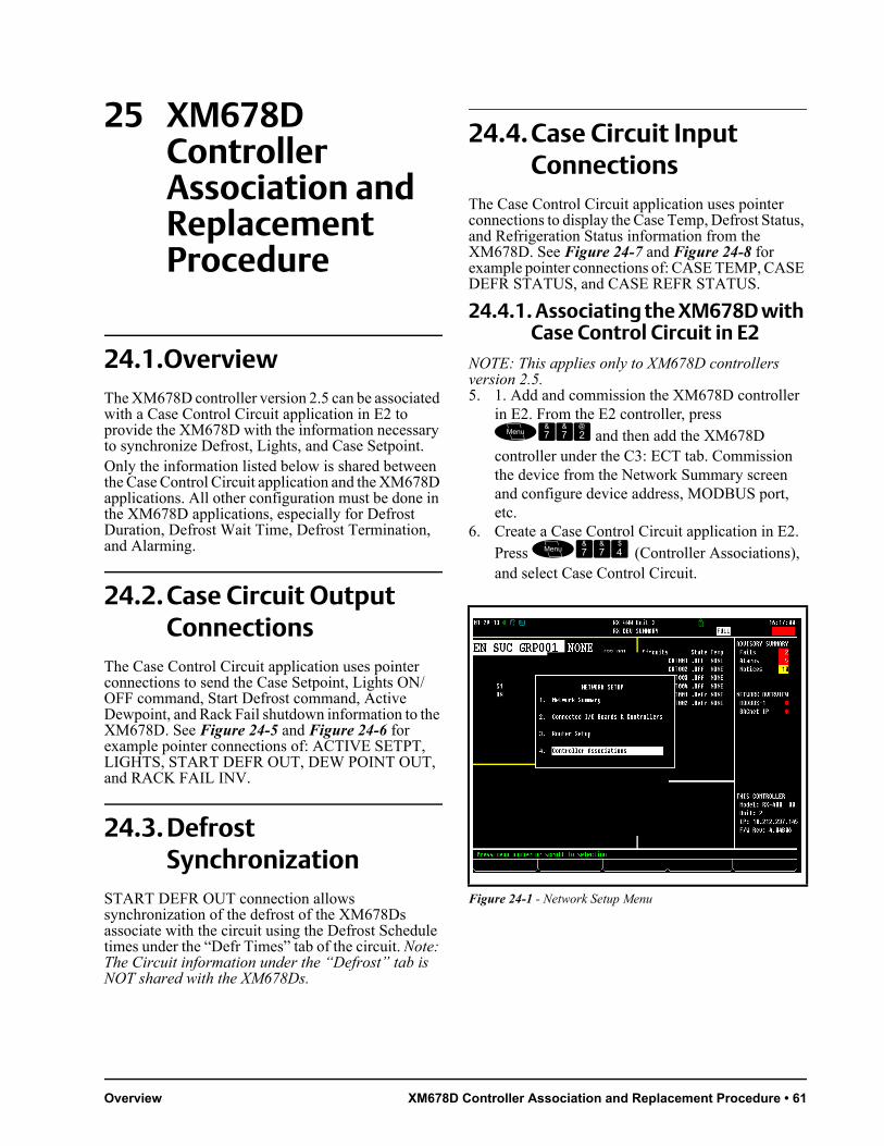
Overview XM678D Controller Association and Replacement Procedure • 61
25 XM678D Controller Association and Replacement Procedure
24.1.OverviewThe XM678D controller version 2.5 can be associated with a Case Control Circuit application in E2 to provide the XM678D with the information necessary to synchronize Defrost, Lights, and Case Setpoint.Only the information listed below is shared between the Case Control Circuit application and the XM678D applications. All other configuration must be done in the XM678D applications, especially for Defrost Duration, Defrost Wait Time, Defrost Termination, and Alarming.
24.2. Case Circuit Output Connections
The Case Control Circuit application uses pointer connections to send the Case Setpoint, Lights ON/OFF command, Start Defrost command, Active Dewpoint, and Rack Fail shutdown information to the XM678D. See Figure 24-5 and Figure 24-6 for example pointer connections of: ACTIVE SETPT, LIGHTS, START DEFR OUT, DEW POINT OUT, and RACK FAIL INV.
24.3. Defrost Synchronization
START DEFR OUT connection allows synchronization of the defrost of the XM678Ds associate with the circuit using the Defrost Schedule times under the “Defr Times” tab of the circuit. Note: The Circuit information under the “Defrost” tab is NOT shared with the XM678Ds.
24.4. Case Circuit Input Connections
The Case Control Circuit application uses pointer connections to display the Case Temp, Defrost Status, and Refrigeration Status information from the XM678D. See Figure 24-7 and Figure 24-8 for example pointer connections of: CASE TEMP, CASE DEFR STATUS, and CASE REFR STATUS.
24.4.1. Associating the XM678D with Case Control Circuit in E2
NOTE: This applies only to XM678D controllers version 2.5.5. 1. Add and commission the XM678D controller
in E2. From the E2 controller, press and then add the XM678D controller under the C3: ECT tab. Commission the device from the Network Summary screen and configure device address, MODBUS port, etc.
6. Create a Case Control Circuit application in E2. Press (Controller Associations), and select Case Control Circuit.
Figure 24-1 - Network Setup Menu
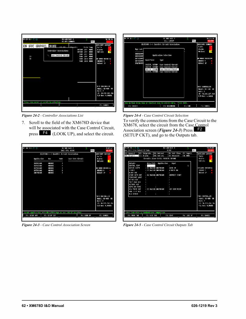
62 • XM678D I&O Manual 026-1219 Rev 3
7. Scroll to the field of the XM678D device that will be associated with the Case Control Circuit, press (LOOK UP), and select the circuit.
To verify the connections from the Case Circuit to the XM678, select the circuit from the Case Control Association screen (Figure 24-3) Press (SETUP CKT), and go to the Outputs tab.
Figure 24-2 - Controller Associations List
Figure 24-3 - Case Control Association Screen
Figure 24-4 - Case Control Circuit Selection
Figure 24-5 - Case Control Circuit Outputs Tab

Case Circuit Input Connections XM678D Controller Association and Replacement Procedure • 63
24.4.2. Replacing the XM678D on E2
1. Press and press the down arrow key to scroll down and highlight XM678D.
2. Press to enter the Summary screen.
3. Press (SETUP) to enter the Setup screen.4. On the C1: General tab, check if the CfgSyn
Action parameter is set to Send E2 Cfg to Device.
5. If CfgSyn Action is not visible, press and at the same time to view full options. The word FULL should appear on the upper right-hand corner of the screen.
If the CfgSyn Action parameter is not set to Send E2 Cfg to Device:1. Press (LOOK UP).
2. Select Send E2 Cfg to Device and press or
.3. Disconnect and remove the faulty XM678D
device from the network.4. Connect the new XM678D.5. Assign the address of the faulty XM678D to the
new XM678D using the CX660 keyboard.6. Once the address has been assigned, press and check if the new XM678D is online.
7. Press and press the down arrow key to scroll down and highlight XM678D.
8. Press to enter the Summary screen.
Figure 24-6 - Advance Tab
Figure 24-7 - Case Temps
Figure 24-8 - Case States
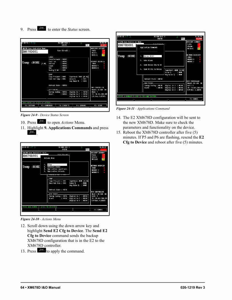
64 • XM678D I&O Manual 026-1219 Rev 3
9. Press to enter the Status screen.
10. Press to open Actions Menu.11. Highlight 9. Applications Commands and press .
12. Scroll down using the down arrow key and highlight Send E2 Cfg to Device. The Send E2 Cfg to Device command sends the backup XM678D configuration that is in the E2 to the XM678D controller.
13. Press to apply the command.
14. The E2 XM678D configuration will be sent to the new XM678D. Make sure to check the parameters and functionality on the device.
15. Reboot the XM678D controller after five (5) minutes. If P5 and P6 are flashing, resend the E2 Cfg to Device and reboot after five (5) minutes.
Figure 24-9 - Device Status Screen
Figure 24-10 - Actions Menu
Figure 24-11 - Applications Command

Appendix A - Alternate MODBUS COM Wiring Method for E2, XR, XM, and XEV Devices
OverviewTo simplify MODBUS communication wiring with E2, (both Standard and Enhanced versions) XR, XM, and XEV series devices, the alternate method outlined below may be used.
Wire TypeUse Belden 8761 or equivalent cable.
ShieldDO NOT connect the shield to the device. Keep the shield continuous throughout a network segment. The shield must be twisted together and insulated with electrical tape or heatshrink at each device within a network segment. Securely connect the shield to an earth grounded chassis at each end of a network segment.
TerminationEach network segment must be biased and terminated at the E2 controller’s end (all three jumpers in the MOD position for E2 Enhanced, or all three jumpers in the UP position for E2 Standard) and terminated with a 150 ohm resistor at the other end of the network segment (150 ohms between the two communication wires).
RecommendedFor reliable communication on some installations, it may be necessary to connect a 100 ohm resistor between the XR, XM, or XEV device’s previously identified ground terminal and earth ground.
Some E2 MODBUS COM Ports Can Support Two Network Segments
For E2 Enhanced 4.x Controller HardwareCOM2 supports two network segments: one on connector RS485-COM2A, and the second on connector RS485-COM2B.
COM4 supports two network segments: one on connector RS485-COM4A, and the second on connector RS485-COM4B.
COM6 only supports one network segment on connector RS485-COM6.
For E2 Standard 3.x Controller HardwareCOM2 supports two network segments: one on connector RS485-1A, and the second on connector RS485-1B.
For information on the maximum recommended number of XR, XM, and XEV devices for each network segment (load and bandwidth calculations), contact Emerson Retail Solutions Technical Support at 770-425-2724.
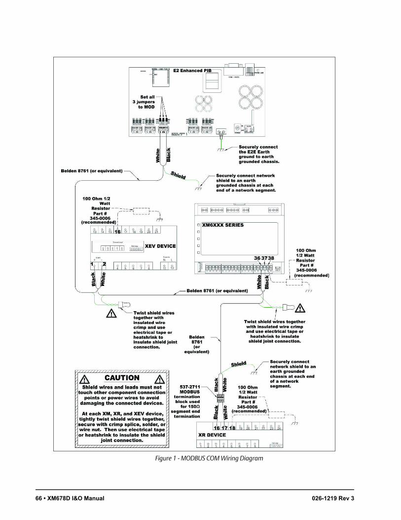
Figure 1 - MODBUS COM Wiring Diagram
66 • XM678D I&O Manual 026-1219 Rev 3


For Technical Support call 770-425-2724 or email [email protected]
The contents of this publication are presented for informational purposes only and they are not to be construed as warranties or guarantees, express or implied, regarding the products or services described herein or their use or applicability. Emerson Climate Technologies Retail Solutions, Inc. and/or its affiliates (collectively “Emerson”), reserves the right to modify the designs or specifications of such products at any time without notice. Emerson does not assume responsibility for the selection, use or maintenance of any product. Responsibility for proper selection, use and maintenance of any product remains solely with the purchaser and end-user.
026-1219 Emerson is a trademark of Emerson Electric Co. ©2017 Emerson Climate Technologies Retail Solutions, Inc. All rights reserved.