XLPE ARMOURED CABLES - Ramesh Cable ARMOURED CABLES.pdf · Wi r es & Ca b les _ Polycab 650/1100...
15
xLPE INSULATED HEAVY DUTY CABLES 650/1100 V. xLPE INSULATED HEAVY DUTY CABLES 650/1100 V. ISO 9001:2000 IS : 69 4
Transcript of XLPE ARMOURED CABLES - Ramesh Cable ARMOURED CABLES.pdf · Wi r es & Ca b les _ Polycab 650/1100...

xLPE INSULATED HEAVY DUTY CABLES 650/1100 V.xLPE INSULATED HEAVY DUTY CABLES 650/1100 V.
ISO9001:2000
IS : 69 4

P r o d u c t r a n g e
¦ L.T. Pvc & xLPe Power cabLes wiTh coPPer /
aLuminium conducTor (650 / 1100 v. uPTo
4 core x 630 sq. mm., 1 core x 1000 sq. mm.)
¦ L.T. Pvc & xLPe conTroL cabLes
(650 / 1100 v. uPTo
61 core x 1.5 & 2.5 sq. mm.)
¦ h.T. xLPe cabLes uPTo 19/33 Kv.
¦ insTrumenTaTion cabLes screened /
unscreened TyPe in Pvc / LdPe
¦ Thermo-couPLe comPensaTing & exTension cabLes
¦ frLs / fr / hr / hffr / hofr / rubber / LdPe
–Power, conTroL & insTrumenTaTion cabLes
fLexibLes & housewires (singLe & muLTicore) ¦
¦ raiLway signaLLing cabLes
¦ fire survivaL, Zero haLogen cabLes
¦ TeLePhone cabLes – dry & jeLLy fiLLed
¦ auTomobiLe cabLes & harnesses
¦ mining / weLding – rubber cabLes
ePr / siLicone / high TemP. cabLes ¦
submersibLe cabLes / winding wires¦
¦ sTrucTured cabLes / co-axieL cabLes
¦ aeriaL bunched cabLes
¦ Lan caT-5/5e cabLes
¦ oPTicaL fibre cabLes*
(*under development)

_Wi r es & Ca b les
Polycab 650/1100 Volts XlPE cablEs
C o n t e n t s Table No.
• Contents
• Iso 9000 Certificate
• Advantage of XLPe Cables
• selection of Power Cables
• Comparison of PVC & XLPe Cables
• technical Data
1) Conductor Resistance 1
2) Comparative Current Ratings for PVC & XLPE Cables 2
3) Comparative Short Circuit Ratings for PVC & XLPE Cables 3
4) Capacitance Values 4
5) Reactance Values 5
6) Current Ratings / Rating Factors
7) Group Rating Factors for Single Core Cables
8) Group Rating Factors for Multi Core Cables
• Weight and Dimension Data for 650 / 1100 Volts XLPe Insulated Cables
1) 1Core - Unarmoured and Armoured Aluminium & Copper Cables 1 – 2
2) 2Core - Unarmoured and Armoured Aluminium & Copper Cables 3 – 4
3) 3Core - Unarmoured and Armoured Aluminium & Copper Cables 5 – 6
4) 3.5Core- Unarmoured and Armoured Aluminium & Copper Cables 7 – 8
5) 4Core - Unarmoured and Armoured Aluminium & Copper Cables 9 – 10
6) Multicore Control Cable with 1.5 Sq.mm. Copper Conductor 11
7) Multicore Control Cable with 2.5 Sq.mm. Copper Conductor 12
• Handling storage & Laying of cables

_ Wi res & C ab les

_Wi r es & Ca b les
INTRO DUCTION
POLYCAB has established its name in India and abroad for its quality and commitment to customer
satisfaction.
To meet eve r incre asing demand of POLYCAB c able s, POLYCAB has put up a new st ate of the
art manufacturing unit at Daman (U.T.). The manufac turing of XLPE insulated heav y duty cables
is by adoptation of latest technology. The XLPE cables are manufactured as per IS-7098 Part-1 & Part-
2 and can be manufactured to meet the requirements of any international standards like BS – 5467,
IEC-60502, DIN etc.
The XLPE compound used is obtained from reputed international sources meeting all required parameters.
The cables are manufactured in highly quality conscious environment with testing and inspection
done from raw-materials to finished cable stage. The assurance to the quality is further ensured by ISI
certification on cables and ISO-9002 certification by UL, USA.
XLPE CabLEs
The XLPE insulated heavy duty cables were introduced worldwide in mid sixties. These cable s
have overcome the limitations of PVC Insulated Cables, such as thermal degradation, poor moisture
resistant and thermoplastic in nature.
The advantages of XLPE Insulated cables in comparision to those of PVC insulated cables are as under :-
(A) teCHnICAL ADVAntAges :
• Higher current rating, higher short Circuit Rating. Approx. 1.2 times that of PVC.
• Thermosetting in nature.
• Higher insulation resistance – 1000 times more than PVC cables.
• Better Resistance to surge currents.
• Low Dielectric Losses.
• Better resistance to chemicals and corrosion.
• Longer service life.
• Comparatively higher cable operating temperature 90 C and short circuit temperature 250 C.o o
(B) CommerCIAL ADVAntAges :
• Lower laying cost because of comparatively smaller diameter of cable and lighter weight.*
• Requiring less size of cable trays / supports.
• One size lower cables can be used as compared to PVC insulated cable. **
* Density of XLPE is lower than PVC
** For longer cable length voltage drop shall be considered.

_ Wi res & C ab les
sELECTION Of POwER CabLEs
Power cables are generally selected considering the application. However following factors are important
for selection of suitable cable construction required to transport electrical energy from one end to the
other.
• Maximum operating voltage.
• Insulation level.
• Frequency.
• Load to be carried.
• Possible overloading duration & magnitude.
• Route length and voltage drop.
• Mode of in sulation c onsidering installation e nviron ment such as ambient & ground
temperature chemical & physical properties of soil.
• Flame retardant properties.
• Plant safety requirements.
All sizes of POLYCAB XLPE cables are designed to standard operating conditions in India and abroad
The standards adopted are considering the geographic / climatic conditions and general applications
of power for utilities, distribution and general purposes.
Th e c ables are m anufac ture d c onform ing to Ind ian & I nt ern at ional sp ec ification for X LPE
Insulated cables. Customer specific requirements can also be met.
Polycab is manufacturers wide ra nge of cables, it is therefore important that while
placing enquiries or orders, as much information as possible should be furnished, so that the enquir ies
and orders are dealt quickly and efficiently .
PaRamETERs REqUIRED aRE as UNDER
• Voltage Grade – 1100 Volts.
• Relevant Indian Standard – IS - 7098 (Part-1) – 1988 or
International standard – IEC - 60502 & BS - 5467, DIN.
• Number of cores – Single, Two, Three, Three & Half or Four Cores.
• Conductor – Size, wherever applicable size of reduced neutral conductor.
• Conductor Material – Copper/Aluminium.
• Type of Insulation – XLPE.
• Type of Inner Sheathing – PVC Wrapped/PVC Extruded.
• Type of Armour – Unarmoured/Strip Armoured/Wire Armoured/ Tape Armoured.
• Type of Outer Sheath – PVC/Flame Retardant/Flame Retardant Low Smoke/Zero Halogen (LSOH).
• Length of cable required and drum lengths.

_Wi r es & Ca b les
TabLE – 1
** Conductor Technical Information for Single Core and Multicore cables conforming to IS-8130/’1984
(Stranded – Class-2) Copper & Aluminium Conductors.
Nominal Minimum no. of wires Max. D.C. Resistance A.C. Resistance at 90 Co
Size of at 20 Co
Conductor Non Compacted Plain Aluminium Plain Aluminium
Compacted Round /Shaped Copper Copper
Sq.mm CU. ALU. CU. ALU. Ohm/Km Ohm/Km Ohm/Km Ohm/Km
1.5 * 3 3 - - 12.1 18.10 15.5 23.17
2.5 * 3 3 - - 7.41 12.10 9.48 15.50
4 * 7 3 - - 4.61 7.41 5.90 9.48
6 * 7 3 - - 3.08 4.61 3.94 5.90
10 * 7 7 6 - 1.83 3.08 2.34 3.94
16 7 7 6 6 1.15 1.91 1.47 2.44
25 7 7 6 6 0.727 1.20 0.930 1.54
35 7 7 6 6 0.524 0.868 0.671 1.11
50 19 19 6 6 0.387 0.641 0.495 0.82
70 19 19 12 12 0.268 0.443 0.343 0.567
95 19 19 15 15 0.193 0.320 0.247 0.410
120 37 37 18 15 0.153 0.253 0.196 0.324
150 37 37 18 15 0.124 0.206 0.159 0.264
185 37 37 30 30 0.0991 0.164 0.127 0.210
240 61 37 34 30 0.0754 0.125 0.0965 0.160
300 61 61 34 30 0.0601 0.100 0.0769 0.128
400 61 61 53 53 0.0470 0.0778 0.0602 0.100
500 61 61 53 53 0.0366 0.0605 0.0468 0.0774
630 91 91 53 53 0.0283 0.0469 0.0362 0.0600
800 91 91 53 53 0.0221 0.0367 0.0283 0.0470
1000 91 91 53 53 0.0176 0.0291 0.0225 0.0372
* These sizes can be manufactured with solid conductor having single strand.
** Conductor meeting requirements of IEC-228 and BS 6360 can also be manufactured.

_ Wi res & C ab les
TabLE – 2
Comparative Current Ratings of 650/1100 Volts Multicore heavy duty PVC Insulated Cables & XLPE Insulated Cables.
(3, 3.5 & 4 Core Unarmoured / Armoured PVC Sheathed Cables with Aluminium Conductor.
Nominal 3, 3.5 & 4 Core PVC Insulated & Sheathed 3, 3.5 & 4 Core XLPE Insulated & Sheathed
Size of Cables as per IS - 1554 (Part-1) 1988 Cables as per IS - 7098 (Part-1) 1988
of cable In Ground In Air Approx Inground In Air Approx
Voltage Drop Voltage Drop
Sq.mm Amp Amp Mv / amp / mtr Amp Amp Mv / amp / mtr
16 60 51 4.0 73 70 4.20
25 76 70 2.5 94 96 2.70
35 92 86 1.8 113 117 1.90
50 110 105 1.3 133 142 1.40
70 135 130 0.93 164 179 0.99
95 165 155 0.68 196 221 0.72
120 185 180 0.54 223 257 0.58
150 210 205 0.46 249 292 0.48
185 235 240 0.38 282 337 0.39
240 275 280 0.28 326 399 0.31
300 305 315 0.25 367 455 0.26
400 335 375 0.20 420 530 0.21
TabLE – 3
Comparison of Short Circuit Rating for 1 Second duration for * PVC & XLPE Insulated Cables ** with Copper and Aluminium
Conductors. (Current in kAmps)
Nominal Size PVC Insulated XLPE Insulated
Sq.mm Copper Aluminium Copper Aluminium
1.5 0.173 – 0.21 –
2.5 0.283 – 0.36 –
4 0.46 0.303 0.57 0.38
6 0.690 0.455 0.86 0.57
10 1.15 0.758 1.40 0.94
16 1.84 1.21 2.30 1.50
* PVC Type ‘A’ Insulation as per IS-5831 ’84.25 2.88 1.90 3.60 2.40 ** PVC Cables as per IS-1554 (Part-1)-1988.35 4.03 2.65 5.00 3.30 ** XLPE Cables as per IS-7098 (Part-1)-1988.
50 5.75 3.79 7.10 4.70
70 8.05 5.31 10.00 6.60 1) Max. Conductor Temperature during
95 10.90 7.20 13.60 9.00 operation PVC XLPE
70 C 90 C120 13.80 9.10 17.10 11.30 o o
150 17.30 11.40 21.40 14.20 2) Max. Conductor Temperature During
185 21.30 14.02 26.40 17.50 Short circuit. 160 C 250 Co o
240 27.60 18.20 34.30 22.60
Formula relating Short Circuit Rating with duration300 34.50 22.80 42.90 28.30
400 46.00 30.40 57.10 37.70 It = I sh Where
500 57.50 38.00 71.40 47.20 vt It = Short Circuit Rating for t Seconds. 630 72.50 47.25 90.00 59.40 t = duration in seconds800 92.00 60.00 114.30 75.50 Ish = Short Circuit rating for 1 second.1000 115.00 75.00 142.90 94.30

_Wi r es & Ca b les
TabLE – 4
CAPACItAnCe
APProXImAte CAPACItAnCe (microfarads/km) 1.1 kV XLPe CABLes.
Nominal Area Single Core Three, Three &
of Conductor Unarmoured Armoured Two Core Half and
in sq. mm Four Core
1.5 0.19 – 0.051 0.15
2.5 0.24 – 0.058 0.18
4 0.29 – 0.065 0.22
6 0.34 – 0.071 0.25
10 0.43 0.32 0.081 0.31
16 0.51 0.38 0.088 0.36 25 0.49 0.38 0.089 0.41
35 0.57 0.44 0.096 0.47
50 0.58 0.46 0.098 0.50
70 0.63 0.51 0.10 0.53
95 0.73 0.59 0.11 0.61
120 0.74 0.61 0.11 0.63
150 0.73 0.61 0.11 0.64
185 0.69 0.59 0.11 0.65
240 0.74 0.64 0.11 0.66
300 0.80 0.69 0.12 0.67
400 0.83 0.70 0.12 0.67
500 0.83 0.71 0.12 0.69
630 0.87 0.75 0.11 0.73
800 0.92 0.78 – –
1000 0.94 0.81 – –
TabLE – 5
reACtAnCe
APProXImAte reACtAnCe At 50 Hz (ohm/km) 1.1 kV XLPe CABLes.
Nominal Area Single Core
of Conductor Unarmoured Armoured Multi Core
in sq. mm
1.5 0.155 – 0.107
2.5 0.142 – 0.0985
4 0.132 – 0.0927
6 0.123 – 0.0884
10 0.114 0.134 0.0837
16 0.108 0.125 0.0808
25 0.103 0.120 0.0805
35 0.0986 0.114 0.078350 0.0937 0.108 0.0750
70 0.0900 0.102 0.0740
95 0.0865 0.100 0.0724
120 0.0841 0.0968 0.0712150 0.0839 0.0941 0.0716
185 0.0836 0.0932 0.0718
240 0.0813 0.0900 0.0710300 0.0795 0.0881 0.0705
400 0.0787 0.0873 0.0704
500 0.0779 0.0859 0.0702630 0.0785 0.0843 0.0698
800 0.0755 0.0826 –1000 0.0752 0.0825 –

_ Wi res & C ab les
CUR RENT Ra TINGs
POLYCab RECOmmENDaTIONs fOR CURRENT RaTINGs:
The current rating of power cable is defined by the maximum intensity of current (amperes) which can
flow continuously through the cable, under permanent loading conditions, without any risk of damaging
the cable or deterioration of its electrical properties.
The value given in the tables are valid for one circuit in a three phase system under conditions specified.
For grouping cables rating factors must be used.
The current carrying capacities mentioned in PoLYCABtechnical data are intended as a guide, to assist
operating engineers in selecting cables for safety and reliability.
Basic assumptions and conditions of installation :-
• Ambient Ground Temperature : 30° C.
• Ambient Air Temperature : 40° C.
• Depth of cable burial : 750 mm.
• Thermal resistivity of soil : 150° C. Cm/W
• Max. conductor Temperature
for Continuous Operation : 90° C.
• Max. Conductor Temperature
for Short Circuit : 250° C.
Single core cables are installed as indicated in the table. Spacing between cables in flat formation
is as indicated.
For three and four core cables, it is usual to assume the same current carrying capacity for four cores
cables as for three core cables. Our calculated values are based actually on three cores cables. These
values are suitable with enough accuracy also for four core cables in most cases. Only for large four
core cables in air the values may be found to be too conservative, due to the large cable surface and
consequent high heat dissipation factor.
To obtain the maximum current carrying capacity of a cable operating at different conditions from the
standard. Various rating factors are to be multiplied, as follows :-
I a = K x I s in amperes
Where ;
I a : Current rating at actual operating conditions (amperes)
I s : Current rating at standard operating conditions (amperes)
K : Rating factor as, applicable.

_Wi r es & Ca b les
Ra TING faCTORs
1) For AIr AnD grounD temPerAture.
A. rating factors for variation in ambient air temperature
Ambient Temp (°C) 25 30 35 40 45 50
Rating Factors 1.14 1.10 1.04 1.00 0.95 0.90
B. rating factors for variation in ground temperature
Ground Temp (°C) 15 20 25 30 35 40
Rating Factors 1.12 1.08 1.03 1.00 0.96 0.91
2) For DePtH oF LAYIng (CABLes LAID DIreCt In tHe grounD).
Depth of laying Size
Cm Upto 25 mm Above 25 mm Upto 300 mm Above 300 mm 2 2 2 2
75 1.0 1.00 1.00
90 0.99 0.98 0.97
105 0.98 0.97 0.96
120 0.97 0.96 0.95
150 0.96 0.94 0.92
180 or more 0.95 0.93 0.91
3) For VArIAtIon In tHermAL resIstIVIt Y oF soIL (t WoAnD tHree AnD muLt ICore
CABLes LAID DIreCt In tHe grounD).
Nominal area of Two cables touching for values of Thermal Resistivity of soil in °C
conductor mm cm / W2
100 120 150 200 250 300
1.5 1.10 1.05 1.00 0.92 0.86 0.81
2.5 1.10 1.05 1.00 0.92 0.86 0.81
4 1.10 1.05 1.00 0.92 0.86 0.81
6 1.10 1.05 1.00 0.92 0.86 0.81
10 1.10 1.06 1.00 0.92 0.85 0.80
16 1.12 1.06 1.00 0.91 0.84 0.79
25 1.14 1.08 1.00 0.91 0.84 0.78
35 1.15 1.08 1.00 0.91 0.84 0.77
50 1.15 1.08 1.00 0.91 0.84 0.77
70 1.15 1.08 1.00 0.90 0.83 0.76
95 1.15 1.08 1.00 0.90 0.83 0.76
120 1.17 1.09 1.00 0.90 0.82 0.76
150 1.17 1.09 1.00 0.90 0.82 0.75
185 1.18 1.09 1.00 0.89 0.81 0.75
240 1.18 1.09 1.00 0.89 0.81 0.75
300 1.18 1.09 1.00 0.89 0.81 0.75
400 1.19 1.10 1.00 0.89 0.81 0.75

_0 Wi res & C ab les
GR OUP R aTING faC TOR s
fOR sINGLE CORE CabLEs
A) Cables laid direct in the ground in horizontal formation.
No. of Trefoils in Distance between Trefoils
Group Touching 15 cm 30 cm 45 cm
2 0.78 0.81 0.85 0.88
3 0.68 0.71 0.77 0.81
4 0.61 0.65 0.72 0.76
5 0.56 0.61 0.68 0.73
B) Cables laid in ducts in horizontal formation.
No. of Trefoils in Distance between Trefoils
Group Touching 45 cm 60 cm
2 0.87 0.90 0.91
3 0.79 0.83 0.86
4 0.74 0.79 0.82
5 0.71 0.76 0.80
C) Cables laid on racks / trays in covered trench with having restricted air circulation,
trefoils are separated by two cable diameter horizontally and the trays are in tiers having
30 cm distance.
No. racks / trays in No. of Trefoils in Horizontal Formation
tiers 1 2 3
1 0.95 0.90 0.88
2 0.90 0.85 0.83
3 0.88 0.83 0.81
6 0.86 0.81 0.79
D) as above C. but cables lad in open air.
No. racks / trays in No. of Trefoils in Horizontal Formation
tiers 1 2 3
1 1 0.98 0.96
2 1 0.95 0.93
3 1 0.94 0.92
6 1 0.93 0.90

__Wi r es & Ca b les
fOR mULTI CORE CabLEs
A) Cables laid on cable trays exposed to air, the cables spaced by one cable diameter
trays are in tiers spaced by 30 cm. the clearanc between the wall and the cable is 25
mm. No. of cables trays in Distance between Trefoils
tier 1 2 3 6 9
1 1 0.98 0.96 0.93 0.92
2 1 0.95 0.93 0.90 0.89
3 1 0.94 0.92 0.89 0.88
6 1 0.93 0.90 0.87 0.86
B) Cables laid inside concrete trench with removable covers on cable trays having restricted
circulation. the cables spaced by one cable diameter and trays are in tiers spaced by
mm. the clearance of the cable from the wall is 25 mm.
No. of cables trays in No. of cables
tier 1 2 3 6 9
1 0.95 0.90 0.88 0.85 0.84
2 0.90 0.85 0.83 0.81 0.80
3 0.88 0.83 0.81 0.79 0.78
6 0.86 0.81 0.79 0.77 0.76
C) Cables laid on cable trays exposed to air, the cable touching and trays are in tiers spaced
by 30 cm. the clearance between the wall and the cable is 25 mm.
No. of cables trays No. of cables per tray
1 2 3 6 9
1 1 0.84 0.80 0.75 0.73
2 1 0.80 0.76 0.71 0.69
3 1 0.78 0.74 0.70 0.68
6 1 0.76 0.72 0.68 0.66
D) Cables laid direct in ground in horizontal formation.
No. of cables in Distance of cables
Group Touching 15 cm 30 cm 45 cm
2 0.79 0.82 0.87 0.90
3 0.69 0.75 0.79 0.83
4 0.62 0.69 0.74 0.79
5 0.58 0.65 0.72 0.76
6 0.54 0.61 0.69 0.75
e) Cables laid in single way ducts / pipes in horizontal formation.
No. of cables in Distance of cables
Group Touching 30 cm 45 cm 60 cm
2 0.88 0.90 0.92 0.94
3 0.82 0.84 0.87 0.89
4 0.77 0.80 0.84 0.87
5 0.74 0.78 0.82 0.85
6 0.71 0.76 0.81 0.84
__ Wi res & C ab les __Wi r es & Ca b les__ Wi res & C ab les __Wi r es & Ca b les__ Wi res & C ab les __ Wi res & C ab les __Wi r es & Ca b les_0 Wi res & C ab les __Wi r es & Ca b les__ Wi res & C ab les
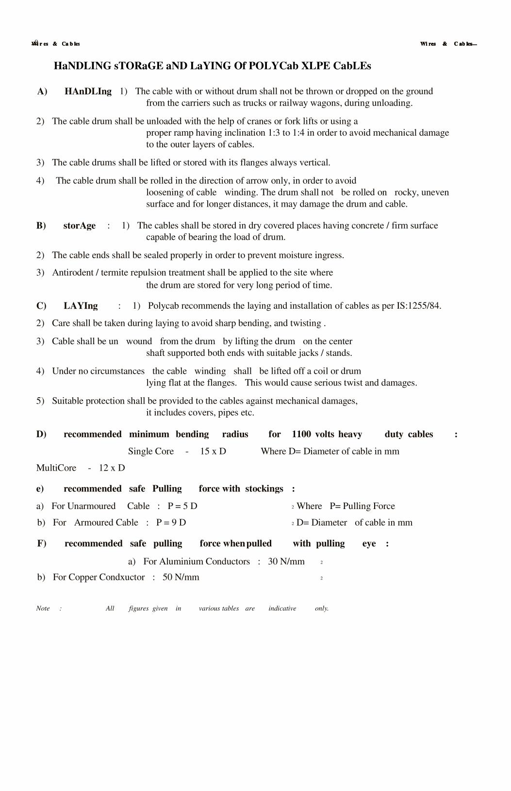
HaNDLING sTORaGE aND LaYING Of POLYCab XLPE CabLEs
A) HAnDLIng: 1) The cable with or without drum shall not be thrown or dropped on the ground
from the carriers such as trucks or railway wagons, during unloading.
2) The cable drum shall be unloaded with the help of cranes or fork lifts or using a
proper ramp having inclination 1:3 to 1:4 in order to avoid mechanical damage
to the outer layers of cables.
3) The cable drums shall be lifted or stored with its flanges always vertical.
4) The cable drum shall be rolled in the direction of arrow only, in order to avoid
loosening of cable winding. The drum shall not be rolled on rocky, uneven
surface and for longer distances, it may damage the drum and cable.
B) storAge : 1) The cables shall be stored in dry covered places having concrete / firm surface
capable of bearing the load of drum.
2) The cable ends shall be sealed properly in order to prevent moisture ingress.
3) Antirodent / termite repulsion treatment shall be applied to the site where
the drum are stored for very long period of time.
C) LAYIng : 1) Polycab recommends the laying and installation of cables as per IS:1255/84.
2) Care shall be taken during laying to avoid sharp bending, and twisting .
3) Cable shall be un wound from the drum by lifting the drum on the center
shaft supported both ends with suitable jacks / stands.
4) Under no circumstances the cable winding shall be lifted off a coil or drum
lying flat at the flanges. This would cause serious twist and damages.
5) Suitable protection shall be provided to the cables against mechanical damages,
it includes covers, pipes etc.
D) recommended minimum bending radius for 1100 volts heavy duty cables :
Single Core - 15 x D Where D= Diameter of cable in mm
MultiCore - 12 x D
e) recommended safe Pulling force with stockings :
a) For Unarmoured Cable : P = 5 D Where P= Pulling Force2
b) For Armoured Cable : P = 9 D D= Diameter of cable in mm 2
F) recommended safe pulling force when pulled with pulling eye :
a) For Aluminium Conductors : 30 N/mm 2
b) For Copper Condxuctor : 50 N/mm 2
Note : All figures given in various tables are indicative only.

Ravi Chhabria
Ramesh Cable Coprn.
461 Budhwar Peth,
Near Pasodiya Vithoba Temple
Pune 411 002
Ph no 020-24454590,24496021/2, 24459241/2
Mobile 9822048581