
HT XLPE CABLES - Weldforcecablecoindia.com/brochure/HT_XLPE_IS7098_II_upto45kv.pdfFlame Retardant...
28
TECHNICAL DETAILS HT XLPE CABLES UPTO 45Kv POLYCAB WIRES PVT LTD
Transcript of HT XLPE CABLES - Weldforcecablecoindia.com/brochure/HT_XLPE_IS7098_II_upto45kv.pdfFlame Retardant...

TECHNICAL DETAILS
HT XLPE CABLES UPTO 45Kv
POLYCAB WIRES PVT LTD
C O N T E N T S
• INTRODUCTION
• ADVANTAGE OF POLYCAB XLPE CABLES
• SELECTION OF CABLES
• TECHNICAL DATA
Conductor Resistance
Current Rating
Cable Short Circuit Rating
Capacitance & Reactance
Rating Factors
Important Formulae
• WEIGHT, DIMENSION DATA & CURRENT CARRYING
CAPACITY OF CABLES
• HANDLING STORAGE & LAYING OF CABLES
POLYCAB WIRES PVT LTD Page 2 of 28

POLYCAB – PERFORMANCE
POLYCAB has earned trust and reputation in India and abroad by winning the customer confidence. Several thousands kilometers of XLPE Cables in the voltage range of 6.6 kV, 11 kV, 22 kV and 33 kV have been manufactured and are in operation in India and abroad.
POLYCAB cables are the preferred choice in Power plants, Process plants, Distribution system, heavy industries and various utilities.
MANUFACTURING PROCESS HIGHLIGHTS
POLYCAB has most modern and state of art manufacturing facilities for XLPE Insulation. It has True Tripple Extrusion & Dust free environment for XLPE insulation, ON-LINE thickness Measurement and Control, fitted on with the best Dry Cure CCV (Continuous Catenary Vulcanization) Lines.
CCV Line
POLYCAB – XLPE HIGH VOLTAGE CABLES (H.T.)
From the beginning of 20th Century, Paper Insulated Oil Impregnated lead sheathed Power Cables were the unanimous choice of Power Engineers for underground transmission and distribution, due to their excellent electrical and thermal properties. The cables which were laid in 1950 in our country are still in operation.
These cables were heavy due to lead sheath and were not suitable for vertical runs as in that case the oil got accumulated in the lower portion of the cables. Any puncture in the lead sheath lead to cable failure as the electrical properties of Manila Paper weakens in the presence of moisture. The jointing of the cables also required a special skill. Cables up to 132 kV were made with paper insulation and they are still in the service. Polymer technology made in a rapid stride during and after second world war and we witnessed a Plastic revolution. Various plastics like PVC,
POLYETHYLENE, NYLON, POLYESTER etc, were invented and put to commercial use during this period. Plastics can be divided in to two categories: 1) Thermosetting 2) Thermoplastics.
Thermosetting plastics are those plastics which set when the heat and pressure are applied due to formation of intra molecular bonds and subsequently heating will not soften them. Bakelite, Mellamine, UF Resins are coming in this category.
Thermoplastics are the plastics which become soft on application of heat and become hard when the heat is removed. PVC, Polyethylene, Nylon, Polystyrene are thermoplastics and they can be recycled.
POLYCAB WIRES PVT LTD Page 3 of 28
PVC is a versatile plastic and it is a compound of various chemicals. Its properties can be varied to a great extend by changing the proportion of its ingredients. It has found a wide application in LT Power Cables, Building wires, Flexibles, Auto Cables, etc.
It is a thermoplastic and it can be operated continuously at 70oC. Due to its higher Dielectric constant, the cables with PVC Insulation has a higher capacitance and hence it is not preferred as insulating material for HT Cable and Telecommunication cables.
Polyethylene has got excellent electrical properties. Its dielectric constant is 2.3 and hence it is found wide application in Telecommunication filed as insulating material Polyethylene can be operated continuously at 65oC and hence it has found little application in Power Cables.
In Sixties, Scientists found that the linear molecular chains of Polyethylene can be inter-linked by adding some peroxide and thus its thermal rating can be upgraded. Due to cross linking, the Polyethylene turns from thermoplastic to thermosetting and it can be operated at 85oC continuously. It can withstand 230oC temperature under short circuit compared to 150oC for PVC. Due to thermosetting nature of the cross-linked polyethylene, its scrap cannot be recycled.
Cross-linked Polyethylene which is commonly known as XLPE is invariably used as insulating material for HT Cables. Cables up to 230 kV with XLPE Insulation are in commercial use.
XLPE Insulated cables are lighter in weight, easy to install and terminate and unaffected by moisture and most of the chemicals.
CONSTRUCTION OF HT CABLES: 1. Conductor: Stranded Class 2 - Annealed
Plain / Tinned Copper / Aluminium - IS:8130 / IEC 60228/ BS 6360.
2. Conductor Screen: Extruded semi-conducting compound – IS:7098 Part 2, IEC:60502 Part – 2, BS:6622, BS:7835.
3. Insulation: XLPE – IS:7098 Part 2, IEC:60502 Part – 2, BS:6622, BS:7835.
4. Insulation Non-metallic Screen: Extruded semi-conducting compound – IS:7098 Part 2, IEC:60502 Part – 2, BS:6622, BS:7835.
5. Insulation Metallic Screen: Copper Wire / Tape or Aluminium Wire / Strip – IS:7098 Part 2, IEC:60502 Part – 2, BS:6622, BS:7835.
6. Fillers: Non Hygroscopic PVC * / Polypropelene Fiber to maintain roundness of cable.
7. Inner sheath/Bedding: PVC ST 2 as per IS:7098 Part 2, IEC:60502 Part – 2, BS:6622, LSOH to BS:7835.
8. Armour: IS:7098 Part 2, IS: 3975, IEC:60502 Part – 2, BS:6622, BS:7835.
9. Outer Sheath: PVC ST 2, FR, FRLS as per IS:7098 Part 2, IEC:60502 Part – 2, BS:6622, LSOH to BS:7835.
* Weights given in the Tables are with PVC Fillers.
POLYCAB WIRES PVT LTD Page 4 of 28
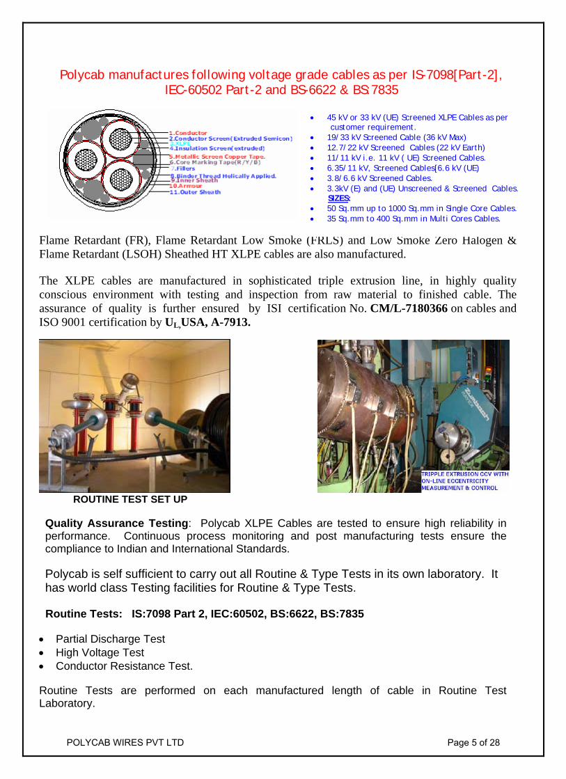
Polycab manufactures following voltage grade cables as per IS-7098[Part-2],
IEC-60502 Part-2 and BS-6622 & BS:7835
Flame Retardant (FR), Flame Retardant Low Smoke (FRLS) and Low Smoke Zero Halogen & Flame Retardant (LSOH) Sheathed HT XLPE cables are also manufactured. The XLPE cables are manufactured in sophisticated triple extrusion line, in highly quality conscious environment with testing and inspection from raw material to finished cable. The assurance of quality is further ensured by ISI certification No. CM/L-7180366 on cables and ISO 9001 certification by UL,USA, A-7913.
ROUTINE TEST SET UP Quality Assurance Testing: Polycab XLPE Cables are tested to ensure high reliability in performance. Continuous process monitoring and post manufacturing tests ensure the compliance to Indian and International Standards. Polycab is self sufficient to carry out all Routine & Type Tests in its own laboratory. It has world class Testing facilities for Routine & Type Tests.
Routine Tests: IS:7098 Part 2, IEC:60502, BS:6622, BS:7835 • Partial Discharge Test • High Voltage Test • Conductor Resistance Test.
Routine Tests are performed on each manufactured length of cable in Routine Test Laboratory.
• 45 kV or 33 kV (UE) Screened XLPE Cables as per customer requirement. • 19/33 kV Screened Cable (36 kV Max) • 12.7/22 kV Screened Cables (22 kV Earth) • 11/11 kV i.e. 11 kV ( UE) Screened Cables. • 6.35/11 kV, Screened Cables[6.6 kV (UE) • 3.8/6.6 kV Screened Cables. • 3.3kV (E) and (UE) Unscreened & Screened Cables. SIZES: • 50 Sq.mm up to 1000 Sq.mm in Single Core Cables. • 35 Sq.mm to 400 Sq.mm in Multi Cores Cables.
POLYCAB WIRES PVT LTD Page 5 of 28

Type Tests: IS:7098 Part 2, IEC:60502, BS:6622, BS:7835
a) Electrical Type Tests
b) Non-Electrical Type Tests
c) Special Tests
The cable samples are type tested in-house to ensure conformance as to various standards.
NON-ELECTRICAL TYPE TEST LABORATORY IMPULSE TEST SET UP Polycab cables of various voltage grades are type tested at CPRI Bangalore & ERDA Vadodara. Short circuit tests on cable conductor and armour are successfully carried at CPRI Bhopal &
ERDA Vadodara.
POLYCAB WIRES PVT LTD Page 6 of 28

ADVANTAGES OF POLYCAB XLPE
CABLES 1) Higher Electrical Strength Retention
2) Higher Short Circuit Rating
3) Better Electrical , Mechanical & Thermal Properties
4) Easy Jointing & Termination
Selection of Cables.
Power Cables are generally selected considering the application. However, following factors are important for selection of suitable cable construction required to transport electrical energy from one end to the other. 1) Maximum operating voltage,
2) Fault Level,
3) Load to be carried,
4) Possible overloading duration & magnitude,
5) Route length and voltage drop.
6) Mode of installation considering install-lation environment such as ambient & ground temperature chemical & physical properties of soil.
7) Flame retardant properties.
All sizes of POLYCAB XLPE cables are designed to standard operating conditions in India and abroad. The standards adopted are considering the geographical/climatical conditions and
general applications of power for utilities, distribution and generation purposes. The cables are manufactured conforming to Indian & International cables specifications for XLPE Insulated cables. Customer specific requirements can also be met. Polycab is manufacturing wide range of cables, so it is important that while placing enquiries or orders, as much information as possible shall be given to Polycab, so that the enquiries and orders are dealt quickly and efficiently.
POLYCAB GUIDELINES FOR SELECTION OF CABLE
1) Voltage Grade – 1.9 / 3.3 kV (E), 3.3 / 3.3 kV (UE), 3.8 / 6.6 kV (E) , 6.6 / 6.6 kV (UE), 6.35 / 11 kV (E), 11 / 11 kV (UE), 12.7 / 22 kV (E) & 33 kV (E), 33 kV (UE) & 45 kV
2) Relevant Indian Standard – IS-7098 (Part-2) – 1985 or International standard – IEC-60502 (Part-2), BS-6622 & BS:7835.
3) Number of cores. – Single & Three.
4) Conductor – Size - 50 Sq.mm to 1000 Sq.mm in Single Core Cables & 25 Sq.mm to 400 Sq.mm in 3Core cables.
5) Conductor Material- Copper/Aluminium
6) Type of Insulation – XLPE
7) Type of Inner Sheathing – PVC Wrapped/PVC Extruded.
8) Type of Armour – Unarmoured / Strip Armoured/Wire Armoured.
9) Type of Outer Sheath – PVC/Flame
Retardant/Flame Retardant Low Smoke / Zero Halogen (LSOH).
10) Length of cable required and drum length.
POLYCAB WIRES PVT LTD Page 7 of 28

The details to the above Guidelines are given in tables.
Table –1
*Conductor Technical Information for Single Core and Multicore cables conforming to IS-8130 /1984 ( Stranded –Class-2) Copper & Aluminium Conductors.
Nominal Size of
Minimum No. of wires
Max. D.C. Resistance at 20oC
A.C. Resistance at 90oC
Conductor Compacted Round /Shaped
Plain Copper Aluminium Plain Copper Aluminium
Sq.mm CU. ALU. Ohm/Km Ohm/Km Ohm/Km Ohm/Km 25 6 6 0.727 1.20 0.930 1.54 35 6 6 0.524 0.868 0.671 1.11 50 6 6 0.387 0.641 0.495 0.82 70 12 12 0.268 0.443 0.343 0.567 95 15 15 0.193 0.320 0.247 0.410 120 18 15 0.153 0.253 0.196 0.324 150 18 15 0.124 0.206 0.159 0.264 185 30 30 0.0991 0.164 0.127 0.210 240 34 30 0.0754 0.125 0.0965 0.160 300 34 30 0.0601 0.100 0.0769 0.130 400 53 53 0.0470 0.0778 0.0602 0.10 500 53 53 0.0366 0.0605 0.0468 0.0774 630 53 53 0.0283 0.0469 0.0362 0.060 800 53 53 0.0221 0.0367 0.0283 0.0470
1000 53 53 0.0176 0.0291 0.0225 0.0372
* Conductor meeting requirements of IEC-60228 and BS 6360 can also be manufactured.
Table-2
SHORT CIRCUIT RATING FOR 1 SECOND DURATION FOR COPPER AND ALUMINIUM XLPE CABLES (CURRENT IN K. AMPS)
Nominal Size XLPE Insulated Sq.mm Copper Aluminium XLPE Cables as per IS-7098 (Part-2)-1985
25 3.6 2.4 35 5.0 3.3 1) Max. Conductor Temperature during operation: 90oC 50 7.1 4.7 70 10.0 6.6 2) Max. Conductor Temperature during short Circuit: 250oC 95 13.6 9.0 120 17.1 11.3 Formula relating Short Circuit Rating with duration 150 21.4 14.2 It =I sh Where 185 26.4 17.5 √ t It = Short Circuit Rating for t Seconds. 240 34.3 22.6 t = duration in seconds 300 42.9 28.3 I sh = Short Circuit rating for 1 second. 400 57.1 37.7 500 71.4 47.2 630 90.0 59.4 800 114.3 75.5
1000 142.9 94.3
POLYCAB WIRES PVT LTD Page 8 of 28

Table – 3 CAPACITANCE
Approximate Capacitance (Microfarads/km) for Single Core Cables
Size Voltage Grade(kV) 1.9/3.3&
3.3/3.3 3.8/6.6 6.6/6.6 &
6.35/11 11/11 12.7/22 19/33
50 0.30 0.27 0.23 0.16 0.15 0.12 70 0.34 0.31 0.27 0.18 0.17 0.14 95 0.39 0.34 0.31 0.20 0.19 0.15 120 0.43 0.37 0.33 0.22 0.20 0.16 150 0.49 0.42 0.36 0.24 0.22 0.17 185 0.52 0.44 0.39 0.25 0.24 0.18 240 0.59 0.50 0.43 0.28 0.26 0.20 300 0.67 0.53 0.48 0.32 0.30 0.23 400 0.76 0.55 0.53 0.36 0.33 0.25 500 0.77 0.57 0.50 0.39 0.36 0.27 630 0.81 0.64 0.69 0.43 0.40 0.29 800 0.86 0.73 0.79 0.49 0.45 0.33 1000 0.88 0.80 0.88 0.53 0.49 0.35
Table – 4 CAPACITANCE
Approximate Capacitance ( Microfarads/km) For Three Core Cables
Size Voltage Grade(kV) 1.9/3.3&
3.3/3.3 3.8/6.6 6.6/6.6 &
6.35/11 11/11 12.7/22 19/33
25 0.21 0.22 0.18 0.14 35 0.24 0.25 0.21 0.16 0.15 50 0.27 0.27 0.22 0.17 0.16 0.12 70 0.31 0.31 0.25 0.19 0.18 0.14 95 0.35 0.35 0.29 0.21 0.20 0.15 120 0.39 0.38 0.31 0.23 0.22 0.16 150 0.42 0.43 0.34 0.25 0.23 0.18 185 0.46 0.45 0.36 0.27 0.25 0.18 240 0.51 0.51 0.41 0.30 0.28 0.20 300 0.57 0.54 0.46 0.33 0.31 0.23 400 0.63 0.57 0.52 0.37 0.34 0.25
WIRES & CABLES
POLYCAB WIRES PVT LTD Page 9 of 28

Table – 5 REACTANCE
Approximate Reactance At 50 Hz( Ohms/km) For Single Core Cables Size Voltage Grade(kV)
1.9/3.3& 3.3/3.3
3.8/6.6 6.6/6.6 & 6.35/11
11/11 12.7/22 19/33
Arm Un-Arm Arm Un-Arm Arm Un-Arm Arm Un-Arm Arm Un-Arm Arm Un-Arm
50 0.115 0.104 0.119 0.110 0.133 0.127 0.133 0.125 0.137 0.130 0.147 0.140 70 0.109 0.098 0.113 0.105 0.123 0.118 0.126 0.119 0.130 0.123 0.141 0.133 95 0.104 0.095 0.108 0.100 0.116 0.111 0.120 0.114 0.124 0.116 0.135 0.127 120 0.100 0.092 0.104 0.101 0.112 0.107 0.117 0.110 0.119 0.112 0.130 0.122 150 0.096 0.088 0.101 0.093 0.109 0.104 0.112 0.106 0.115 0.107 0.126 0.118 185 0.094 0.087 0.099 0.091 0.107 0.101 0.110 0.103 0.114 0.105 0.124 0.115 240 0.091 0.084 0.096 0.089 0.104 0.097 0.106 0.100 0.110 0.101 0.118 0.110 300 0.088 0.081 0.093 0.086 0.100 0.094 0.102 0.096 0.105 0.097 0.112 0.105 400 0.086 0.079 0.091 0.085 0.096 0.091 0.098 0.092 0.101 0.093 0.119 0.102 500 0.085 0.078 0.088 0.083 0.093 0.089 0.095 0.090 0.988 0.091 0.105 0.099 630 0.083 0.077 0.087 0.081 0.092 0.086 0.094 0.087 0.095 0.089 0.101 0.096 800 0.081 0.076 0.085 0.077 0.089 0.084 0.091 0.085 0.092 0.086 0.097 0.092 1000 0.082 0.075 0.084 0.076 0.087 0.082 0.088 0.083 0.090 0.085 0.096 0.090 Table – 6 REACTANCE
Approximate Reactance At 50 Hz( Ohms/km) For Three Core Cables
Size Voltage Grade(kV) 1.9/3.3&
3.3/3.3 3.8/6.6 6.6/6.6 &
6.35/11 11/11 12.7/22 19/33
25 0.098 0.109 0.116 0.152 35 0.094 0.104 0.111 0.144 0.147 50 0.087 0.098 0.104 0.137 0.140 0.133 70 0.084 0.094 0.100 0.129 0.132 0.125 95 0.081 0.090 0.095 0.123 0.125 0.121 120 0.078 0.087 0.092 0.117 0.120 0.116 150 0.076 0.085 0.089 0.114 0.116 0.112 185 0.075 0.083 0.087 0.110 0.113 0.110 240 0.073 0.081 0.085 0.106 0.108 0.105 300 0.072 0.079 0.082 0.103 0.105 0.100 400 0.071 0.078 0.079 0.099 0.101 0.097
Note: All figures given in various tables are indicative only.
POLYCAB WIRES PVT LTD Page 10 of 28

CURRENT RATINGS POLYCAB RECOMMENDATIONS FOR
CURRENT RATINGS: The current rating of power cable is defined by the maximum intensity of current (amperes) which can flow continuously through the cable, under permanent loading conditions, without any risk of damaging the cable or deterioration of its electrical properties. The value given in the tables are valid for one circuit in a three phase system under conditions specified. For grouping cables rating factors must be used. The current carrying capacities mentioned in POLYCAB technical data are intended as a guide, to assist operating engineers in selecting cables for safety and reliability. Basic assumptions and conditions of installation:- 1) Maximum Conductor Temperature : 90oC 2) Ambient Ground Temperature : 30o C 3) Ambient Air Temperature : 40o C 4) Thermal resistivity of soil : 150o C.
Cm/W Depth of laying (to the highest point of the cables laid direct in the ground ) 3.3, 6.6 & 11kV Cables : 90 cm 22 and 33kV Cables : 105 cm
*Max. Conductor temperature at the end of a short circuit : 250oC To obtain the maximum current carrying capacity of a cable operating at different conditions from the standard, various rating factors are to be multiplied, as follows :- I a = K X Is in amperes Where ; I a : Current rating at actual operating conditions (amperes) Is : Current rating at standard operating conditions (amperes) K : Rating factor as, applicable.
POLYCAB WIRES PVT LTD Page 11 of 28

RATING FACTORS
A). FOR AIR AND GROUND TEMPERATURE. A. Rating factors for variation in ambient air temperature.
Ambient Temp (oC) 25 30 35 40 45 50 Rating Factors 1.14 1.10 1.04 1.00 0.95 0.90
B. Rating factors for variation in ground temperature. Ground Temp (oC) 15 20 25 30 35 40 45
Rating Factors 1.12 1.08 1.03 1.00 0.96 0.91 0.87 B). FOR DEPTH OF LAYING (CABLES LAID DIRECT IN THE GROUND) Depth of laying (cm) 3.3kV, 6.6kV & 11kV all sizes 22kV & 33 kV all Size
90 105 120 150
180 or more
1.00 0.99 0.98 0.96 0.95
__ 1.00 0.99 0.97 0.96
C). FOR VARIATION IN THERMAL RESISTIVITY OF SOIL Thermal
Resistivity of Soil (occm/w)
100 120 150 200 250 300
Factor 1.20 1.11 1.0 0.89 0.80 0.73
GROUP RATING FACTORS FOR SINGLE-CORE CABLES:- A). Cables laid direct in the ground in horizontal formation.
Number of trefoils in group
Spacing between trefoils 3.3 to 22kV cables
33 kV Cables.
Touching 15cm 30cm 45cm Touching 15cm 30cm 45cm 2 0.78 0.81 0.85 0.88 0.80 0.82 0.85 0.88 3 0.68 0.71 0.77 0.81 0.68 0.71 0.76 0.79 4 0.61 0.65 0.72 0.76 0.62 0.65 0.71 0.75 5 0.56 0.61 0.68 0.73 0.57 0.60 0.67 0.72 B). Cables laid on Racks / Trays in covered trench with removable covers where air circulation is restricted, Trefoils are separated by two cable diameter horizontally and the trays are in tiers having 300 mm distance.
No. of Trefoils in Horizontal formation No. racks/trays in tiers 1 2 3
1 2 3 6
0.95 0.90 0.88 0.86
0.90 0.85 0.83 0.81
0.88 0.83 0.81 0.79
C). As above B. but cables laid in open air. 1 2 3 6
1 1 1 1
0.98 0.95 0.94 0.93
0.96 0.93 0.92 0.90
POLYCAB WIRES PVT LTD Page 12 of 28

GROUP RATING FACTORS
FOR MULTI-CORE CABLES: A). Cables laid inside concrete trench with removable covers ,on cable trays where air circulation is restricted . The cables spaced by one cable diameter and trays are in tiers spaced by 300 mm. The clearance between the wall and the cable is 25 mm.
No. of cables No. of cables trays in tier 1 2 3 6 9 1 2 3 6
0.95 0.90 0.88 0.86t
0.90 0.85 0.83 0.81
0.88 0.83 0.81 0.79
0.85 0.81 0.79 0.77
0.84 0.80 0.78 0.76
B) Cable laid on cable trays exposed to air , the cables spaced by one cable diameter and trays are in tiers spaced by 300 mm. The clearance of the cable from the wall is 25 mm.
No. of cables No. of cables trays in tier 1 2 3 6 9 1 2 3 6
1 1 1 1
0.98 0.95 0.94 0.93
0.96 0.93 0.92 0.90
0.93 0.90 0.89 0.87
0.92 0.89 0.88 0.86
C).Cables laid on cable trays exposed to air, the cables touching and trays are in tiers spaced by 300 mm. The clearance between the wall and the cable is 25 mm.
No. of cables per tray No. of cables trays.
1 2 3 6 9 1 2 3 6
1 1 1 1
0.84 0.80 0.78 0.76
0.80 0.76 0.74 0.72
0.75 0.71 0.70 0.68
0.73 0.69 0.68 0.66
D). Cables laid direct in ground in horizontal formation Distance of cables No. of cables in
group Touching 15mm 30mm 45mm 2 3 4 5 6
0.79 0.69 0.62 0.58 0.54
0.82 0.75 0.69 0.65 0.61
0.87 0.79 0.74 0.72 0.69
0.90 0.83 0.79 0.76 0.75
POLYCAB WIRES PVT LTD Page 13 of 28

3.8 / 6.6 KV ( E ) HT XLPE SINGLE CORE ALUMINIUM CONDUCTOR CABLES"POLYCAB" SINGLE CORE ALUMINIUM CONDUCTOR, XLPE INSULATED, UNARMOURED & ARMOURED CABLES
CONFORMING TO IS: 7098 PART-2/1985:
Nominal Size
of Conducto
r
Nominal Thick
ness of X
LPE
Insulat
ion
Nominal Thick
ness of P
VC Outer
Sheath
Approx. Overa
ll Diam
eter o
f
Cable.
Approx. W
eight o
f Cab
le.
Minimum Thick
ness
of Inner
Shea
th
Nominal Dim
ensio
n of Stri
p
Minimum Thick
ness of P
VC
Outer Sh
eath
Approx. Overa
ll Diam
eter o
f
Cable.
Approx. W
eight o
f Cab
le.
Nominal Dim
ensio
n of R
ound
Wire
Minimum Thick
ness of P
VC
Outer Sh
eath
Approx. Overa
ll Diam
eter o
f
Cable.
Approx. W
eight o
f Cab
le.
In Ground at
30 C.
In Duct
at 30
o C.
In Air a
t 40o C.
*Norm
al Deli
very Len
gth.
Sq.mm. mm Mtrs.mm
mm mm Kg/Km mm mm mm Kg/Km mm mm mm Kg/Km Amps. Amps. Amps.
35 2.8 2.0 20.0 450 0.30 0.8 1.4 21.0 550 1.6 1.40 22.5 620 120 105 135 50050 2.8 2.0 21.0 500 0.30 0.8 1.4 22.0 600 1.6 1.40 23.5 700 140 125 165 50070 2.8 2.0 23.0 600 0.30 0.8 1.4 24.0 730 1.6 1.40 25.5 800 170 150 205 50095 2.8 2.0 24.5 730 0.30 0.8 1.4 25.5 850 1.6 1.40 27.0 950 205 180 250 500
120 2.8 2.0 26.0 840 0.30 0.8 1.4 27.0 950 1.6 1.40 29.0 1050 230 205 290 500150 2.8 2.0 27.0 950 0.30 0.8 1.4 28.5 1100 1.6 1.56 30.5 1200 260 230 330 500185 2.8 2.0 29.0 1100 0.30 0.8 1.56 31.0 1250 1.6 1.56 32.5 1400 295 260 380 500240 2.8 2.2 32.0 1330 0.40 0.8 1.56 33.0 1500 2.0 1.56 35.5 1700 340 300 455 500300 3.0 2.2 34.5 1550 0.40 0.8 1.56 36.0 1750 2.0 1.56 38.0 2000 385 335 520 500400 3.3 2.2 38.5 1960 0.40 0.8 1.56 40.0 2180 2.0 1.72 42.5 2450 440 385 620 500500 3.5 2.4 42.0 2400 0.50 0.8 1.72 43.5 2650 2.0 1.88 46.5 2950 500 435 720 500630 3.5 2.4 45.5 2850 0.50 0.8 1.88 47.5 3200 2.0 1.88 50.0 3450 570 495 840 500800 3.5 2.6 50.0 3470 0.50 0.8 1.88 51.0 3750 2.5 2.04 55.0 4300 640 550 970 500
1000 3.6 2.8 55.0 4230 0.60 0.8 2.04 56.5 4600 2.5 2.20 60.5 5150 710 610 1100 500
3.8 / 6.6 KV ( E ) HT XLPE SINGLE CORE COPPER CONDUCTOR CABLES"POLYCAB" SINGLE CORE COPPER CONDUCTOR, XLPE INSULATED, UNARMOURED & ARMOURED CABLES
CONFORMING TO IS: 7098 PART-2/1985:
Sq.mm. mmUNARMOURED
CABLEALUMINIUM STRIP ARMOURED CABLE
ALUMINIUM ROUND WIRE ARMOURED CABLE
CURRENT CARRYING
Mtrs.mm
Nominal Size
of Conducto
r
Nominal Thick
ness of X
LPE
Insulat
ion
Nominal Thick
ness of P
VC Outer
Sheath
Approx. Overa
ll Diam
eter o
f
Cable.
Approx. W
eight o
f Cab
le
Minimum Thick
ness
of Inner
Shea
th
Nominal Dim
ensio
n of Stri
p
Minimum Thick
ness
of PVC O
uter Sh
eath
Approx. Overa
ll
Diamete
r of C
able.
Approx. W
eight o
f Cab
le.
Nominal Dim
ensio
n
of Aluminium Round W
ire.
Minimum Thick
ness
of PVC O
uter Sh
eath
Approx. Overa
ll
Diamete
r of C
able.
Approx. W
eight o
f Cab
le.
In Ground at
30o C.
In Duct
at 30
o C.
In Air a
t 40o C.
*Norm
al Deli
very Len
gth.
mm Mtrs.Sq.mm. mmmm mm Kg/Km mm mm mm Kg/Km mm mm mm Kg/Km Amps. Amps. Amps.
35 2.8 2.0 20.0 670 0.30 0.8 1.4 21.0 770 1.6 1.40 22.5 840 155 135 175 50050 2.8 2.0 21.0 810 0.30 0.8 1.4 22.0 910 1.6 1.40 23.5 1010 180 160 215 50070 2.8 2.0 23.0 1030 0.30 0.8 1.4 24.0 1160 1.6 1.40 25.5 1230 220 195 265 50095 2.8 2.0 24.5 1320 0.30 0.8 1.4 25.5 1440 1.6 1.40 27.0 1540 265 235 325 500
120 2.8 2.0 26.0 1580 0.30 0.8 1.4 27.0 1690 1.6 1.40 29.0 1790 300 265 375 500150 2.8 2.0 27.0 1880 0.30 0.8 1.4 28.5 2030 1.6 1.56 30.5 2130 335 295 425 500185 2.8 2.0 29.0 2250 0.30 0.8 1.56 31.0 2400 1.6 1.56 32.5 2550 380 330 490 500240 2.8 2.2 32.0 2820 0.40 0.8 1.56 33.0 2990 2.0 1.56 35.5 3190 435 385 580 500300 3.0 2.2 34.5 3410 0.40 0.8 1.56 36.0 3610 2.0 1.56 38.0 3860 490 430 670 500400 3.3 2.2 38.5 4440 0.40 0.8 1.56 40.0 4660 2.0 1.72 42.5 4930 560 485 780 500500 3.5 2.4 42.0 5500 0.50 0.8 1.72 43.5 5750 2.0 1.88 46.5 6050 630 550 900 500630 3.5 2.4 45.5 6750 0.50 0.8 1.88 47.5 7100 2.0 1.88 50.0 7350 710 610 1040 500800 3.5 2.6 50.0 8430 0.50 0.8 1.88 51.0 8710 2.5 2.04 55.0 9260 780 670 1180 500
1000 3.6 2.8 55.0 10430 0.60 0.8 2.04 56.5 10800 2.5 2.20 60.5 11350 850 730 1310 500
The above data is approximate and subject to manufacturing tolerance.* Delivery Length tolerance is + 5 %. Length more than normal as per customer request.
mm Mtrs.Sq.mm. mmCURRENT
CARRYINGUNARMOURED
CABLEALUMINIUM STRIP ARMOURED CABLE
ALUMINIUM ROUND WIRE ARMOURED CABLE
TABLE - 7
TABLE - 8
POLYCAB WIRES PVT LTD Page 14 of 28
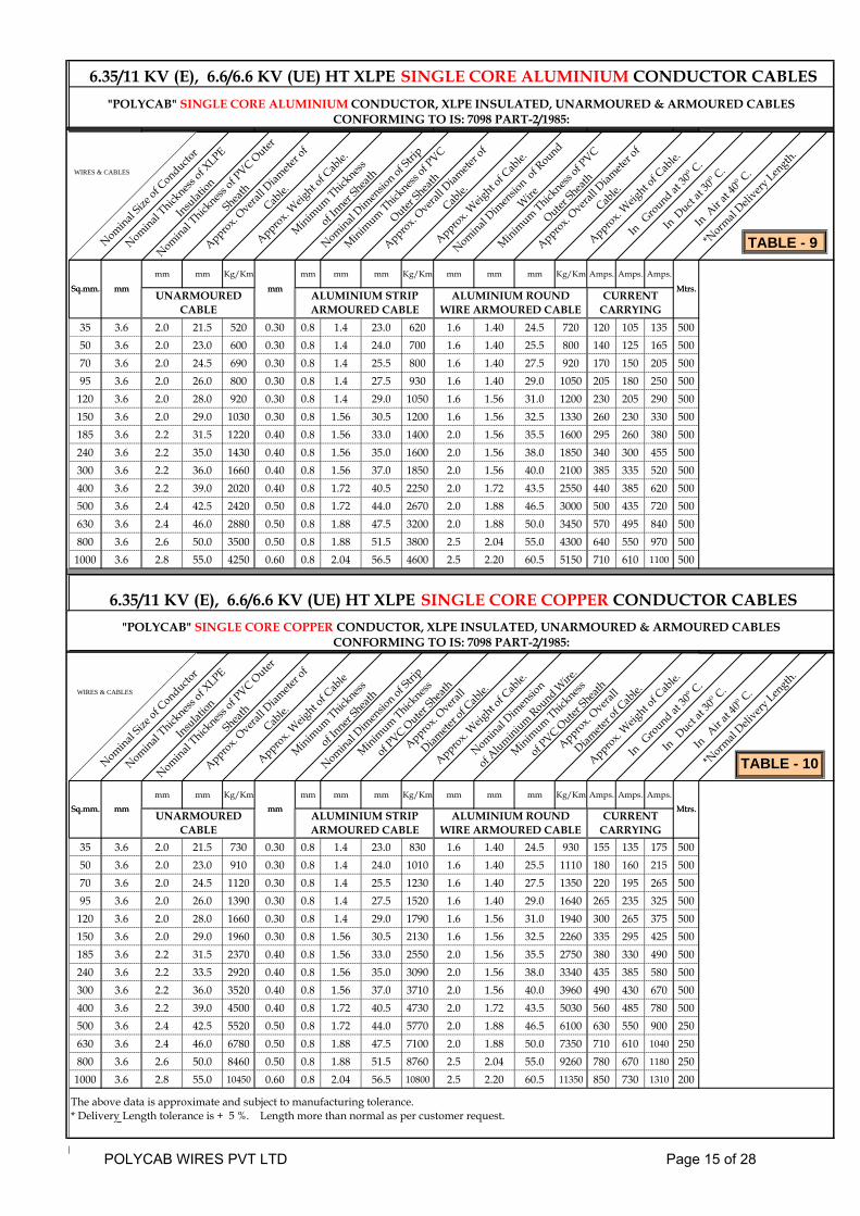
6.35/11 KV (E), 6.6/6.6 KV (UE) HT XLPE SINGLE CORE ALUMINIUM CONDUCTOR CABLES"POLYCAB" SINGLE CORE ALUMINIUM CONDUCTOR, XLPE INSULATED, UNARMOURED & ARMOURED CABLES
CONFORMING TO IS: 7098 PART-2/1985:
Nominal Size
of Conducto
r
Nominal Thick
ness of X
LPE
Insulat
ion
Nominal Thick
ness of P
VC Outer
Sheath
Approx. Overa
ll Diam
eter o
f
Cable.
Approx. W
eight o
f Cab
le.
Minimum Thick
ness
of Inner
Shea
th
Nominal Dim
ensio
n of Stri
p
Minimum Thick
ness of P
VC
Outer Sh
eath
Approx. Overa
ll Diam
eter o
f
Cable.
Approx. W
eight o
f Cab
le.
Nominal Dim
ensio
n of R
ound
Wire
Minimum Thick
ness of P
VC
Outer Sh
eath
Approx. Overa
ll Diam
eter o
f
Cable.
Approx. W
eight o
f Cab
le.
In Ground at
30o C.
In Duct
at 30
o C.
In Air a
t 40o C.
*Norm
al Deli
very Len
gth.
Mtrs.mmSq.mm. mm
mm mm Kg/Km mm mm mm Kg/Km mm mm mm Kg/Km Amps. Amps. Amps.
35 3.6 2.0 21.5 520 0.30 0.8 1.4 23.0 620 1.6 1.40 24.5 720 120 105 135 50050 3.6 2.0 23.0 600 0.30 0.8 1.4 24.0 700 1.6 1.40 25.5 800 140 125 165 50070 3.6 2.0 24.5 690 0.30 0.8 1.4 25.5 800 1.6 1.40 27.5 920 170 150 205 50095 3.6 2.0 26.0 800 0.30 0.8 1.4 27.5 930 1.6 1.40 29.0 1050 205 180 250 500
120 3.6 2.0 28.0 920 0.30 0.8 1.4 29.0 1050 1.6 1.56 31.0 1200 230 205 290 500150 3.6 2.0 29.0 1030 0.30 0.8 1.56 30.5 1200 1.6 1.56 32.5 1330 260 230 330 500185 3.6 2.2 31.5 1220 0.40 0.8 1.56 33.0 1400 2.0 1.56 35.5 1600 295 260 380 500240 3.6 2.2 35.0 1430 0.40 0.8 1.56 35.0 1600 2.0 1.56 38.0 1850 340 300 455 500300 3.6 2.2 36.0 1660 0.40 0.8 1.56 37.0 1850 2.0 1.56 40.0 2100 385 335 520 500400 3.6 2.2 39.0 2020 0.40 0.8 1.72 40.5 2250 2.0 1.72 43.5 2550 440 385 620 500500 3.6 2.4 42.5 2420 0.50 0.8 1.72 44.0 2670 2.0 1.88 46.5 3000 500 435 720 500630 3.6 2.4 46.0 2880 0.50 0.8 1.88 47.5 3200 2.0 1.88 50.0 3450 570 495 840 500800 3.6 2.6 50.0 3500 0.50 0.8 1.88 51.5 3800 2.5 2.04 55.0 4300 640 550 970 500
1000 3.6 2.8 55.0 4250 0.60 0.8 2.04 56.5 4600 2.5 2.20 60.5 5150 710 610 1100 500
Mtrs.mm
6.35/11 KV (E), 6.6/6.6 KV (UE) HT XLPE SINGLE CORE COPPER CONDUCTOR CABLES"POLYCAB" SINGLE CORE COPPER CONDUCTOR, XLPE INSULATED, UNARMOURED & ARMOURED CABLES
CONFORMING TO IS: 7098 PART-2/1985:
Sq.mm. mmUNARMOURED
CABLEALUMINIUM STRIP ARMOURED CABLE
ALUMINIUM ROUND WIRE ARMOURED CABLE
CURRENT CARRYING
Nominal Size
of Conducto
r
Nominal Thick
ness of X
LPE
Insulat
ion
Nominal Thick
ness of P
VC Outer
Sheath
Approx. Overa
ll Diam
eter o
f
Cable.
Approx. W
eight o
f Cab
le
Minimum Thick
ness
of Inner
Shea
th
Nominal Dim
ensio
n of Stri
p
Minimum Thick
ness
of PVC O
uter Sh
eath
Approx. Overa
ll
Diamete
r of C
able.
Approx. W
eight o
f Cab
le.
Nominal Dim
ensio
n
of Aluminium Round W
ire.
Minimum Thick
ness
of PVC O
uter Sh
eath
Approx. Overa
ll
Diamete
r of C
able.
Approx. W
eight o
f Cab
le.
In Ground at
30o C.
In Duct
at 30
o C.
In Air a
t 40o C.
*Norm
al Deli
very Len
gth.
mm Mtrs.Sq.mm. mmmm mm Kg/Km mm mm mm Kg/Km mm mm mm Kg/Km Amps. Amps. Amps.
35 3.6 2.0 21.5 730 0.30 0.8 1.4 23.0 830 1.6 1.40 24.5 930 155 135 175 50050 3.6 2.0 23.0 910 0.30 0.8 1.4 24.0 1010 1.6 1.40 25.5 1110 180 160 215 50070 3.6 2.0 24.5 1120 0.30 0.8 1.4 25.5 1230 1.6 1.40 27.5 1350 220 195 265 50095 3.6 2.0 26.0 1390 0.30 0.8 1.4 27.5 1520 1.6 1.40 29.0 1640 265 235 325 500
120 3.6 2.0 28.0 1660 0.30 0.8 1.4 29.0 1790 1.6 1.56 31.0 1940 300 265 375 500150 3.6 2.0 29.0 1960 0.30 0.8 1.56 30.5 2130 1.6 1.56 32.5 2260 335 295 425 500185 3.6 2.2 31.5 2370 0.40 0.8 1.56 33.0 2550 2.0 1.56 35.5 2750 380 330 490 500240 3.6 2.2 33.5 2920 0.40 0.8 1.56 35.0 3090 2.0 1.56 38.0 3340 435 385 580 500300 3.6 2.2 36.0 3520 0.40 0.8 1.56 37.0 3710 2.0 1.56 40.0 3960 490 430 670 500400 3.6 2.2 39.0 4500 0.40 0.8 1.72 40.5 4730 2.0 1.72 43.5 5030 560 485 780 500500 3.6 2.4 42.5 5520 0.50 0.8 1.72 44.0 5770 2.0 1.88 46.5 6100 630 550 900 250630 3.6 2.4 46.0 6780 0.50 0.8 1.88 47.5 7100 2.0 1.88 50.0 7350 710 610 1040 250800 3.6 2.6 50.0 8460 0.50 0.8 1.88 51.5 8760 2.5 2.04 55.0 9260 780 670 1180 250
1000 3.6 2.8 55.0 10450 0.60 0.8 2.04 56.5 10800 2.5 2.20 60.5 11350 850 730 1310 200
The above data is approximate and subject to manufacturing tolerance.* Delivery Length tolerance is + 5 %. Length more than normal as per customer request.
mm Mtrs.Sq.mm. mmCURRENT
CARRYINGUNARMOURED
CABLEALUMINIUM STRIP ARMOURED CABLE
ALUMINIUM ROUND WIRE ARMOURED CABLE
WIRES & CABLES
WIRES & CABLES
TABLE - 9
TABLE - 10
POLYCAB WIRES PVT LTD Page 15 of 28

11 / 11 KV ( UE ) HT XLPE SINGLE CORE ALUMINIUM CONDUCTOR CABLES"POLYCAB" SINGLE CORE ALUMINIUM CONDUCTOR, XLPE INSULATED, UNARMOURED & ARMOURED CABLES
CONFORMING TO IS: 7098 PART-2/1985:
Nominal Size
of Conducto
r
Nominal Thick
ness of X
LPE
Insulat
ion
Nominal Thick
ness of P
VC Outer
Sheath
Approx. Overa
ll Diam
eter o
f
Cable.
Approx. W
eight o
f Cab
le.
Minimum Thick
ness
of Inner
Shea
th
Nominal Dim
ensio
n of Stri
p
Minimum Thick
ness of P
VC
Outer Sh
eath
Approx. Overa
ll Diam
eter o
f
Cable.
Approx. W
eight o
f Cab
le.
Nominal Dim
ensio
n of R
ound
Wire
Minimum Thick
ness of P
VC
Outer Sh
eath
Approx. Overa
ll Diam
eter o
f
Cable.
Approx. W
eight o
f Cab
le.
In Ground at
30o C.
In Duct
at 30
o C.
In Air a
t 40o C.
*Norm
al Deli
very Len
gth.
Sq.mm. mm Mtrs.mm
mm mm Kg/Km mm mm mm Kg/Km mm mm mm Kg/Km Amps. Amps. Amps.
35 5.5 2.0 25.5 670 0.30 0.8 1.4 27.0 800 1.6 1.40 28.5 900 120 105 135 50050 5.5 2.0 26.5 750 0.30 0.8 1.4 28.0 900 1.6 1.56 30.0 1000 140 125 165 50070 5.5 2.0 28.5 850 0.30 0.8 1.56 30.0 1050 1.6 1.56 31.5 1150 170 150 205 50095 5.5 2.0 30.0 980 0.30 0.8 1.56 32.0 1200 2.0 1.56 34.0 1350 205 180 250 500
120 5.5 2.2 32.0 1150 0.40 0.8 1.56 33.5 1300 2.0 1.56 36.0 1500 230 205 290 500150 5.5 2.2 33.5 1260 0.40 0.8 1.56 35.0 1450 2.0 1.56 37.0 1650 260 230 330 500185 5.5 2.2 35.5 1430 0.40 0.8 1.56 37.0 1600 2.0 1.56 39.0 1850 295 260 380 500240 5.5 2.2 37.5 1650 0.40 0.8 1.56 39.0 1850 2.0 1.72 42.0 2150 340 300 455 500300 5.5 2.2 39.5 1900 0.40 0.8 1.72 41.5 2150 2.0 1.72 44.0 2400 385 335 520 500400 5.5 2.4 43.0 2300 0.50 0.8 1.72 45.0 2600 2.0 1.88 47.5 2900 440 385 620 500500 5.5 2.4 46.0 2700 0.50 0.8 1.88 48.0 3000 2.5 2.04 52.0 3500 500 435 720 500630 5.5 2.6 50.0 3200 0.50 0.8 1.88 51.5 3500 2.5 2.04 55.0 4050 570 495 840 500800 5.5 2.8 54.0 3880 0.60 0.8 2.04 56.0 4200 2.5 2.2 60.0 4800 640 550 970 500
1000 5.5 2.8 59.0 4600 0.60 0.8 2.2 61.0 5000 2.5 2.36 65.0 5650 710 610 1100 500
11 / 11 KV ( UE ) HT XLPE SINGLE CORE COPPER CONDUCTOR CABLES"POLYCAB" SINGLE CORE COPPER CONDUCTOR, XLPE INSULATED, UNARMOURED & ARMOURED CABLES
CONFORMING TO IS: 7098 PART-2/1985:
Sq.mm. mmUNARMOURED
CABLEALUMINIUM STRIP ARMOURED CABLE
ALUMINIUM ROUND WIRE ARMOURED CABLE
CURRENT CARRYING
Mtrs.mm
Nominal Size
of Conducto
r
Nominal Thick
ness of X
LPE
Insulat
ion
Nominal Thick
ness of P
VC Outer
Sheath
Approx. Overa
ll Diam
eter o
f
Cable.
Approx. W
eight o
f Cab
le
Minimum Thick
ness
of Inner
Shea
th
Nominal Dim
ensio
n of Stri
p
Minimum Thick
ness
of PVC O
uter Sh
eath
Approx. Overa
ll
Diamete
r of C
able.
Approx. W
eight o
f Cab
le.
Nominal Dim
ensio
n
of Aluminium Round W
ire.
Minimum Thick
ness
of PVC O
uter Sh
eath
Approx. Overa
ll
Diamete
r of C
able.
Approx. W
eight o
f Cab
le.
In Ground at
30o C.
In Duct
at 30
o C.
In Air a
t 40o C.
*Norm
al Deli
very Len
gth.
mm Mtrs.Sq.mm. mmmm mm Kg/Km mm mm mm Kg/Km mm mm mm Kg/Km Amps. Amps. Amps.
35 5.5 2.0 25.5 880 0.30 0.8 1.4 27.0 1010 1.6 1.40 28.5 1110 155 135 175 50050 5.5 2.0 26.5 1060 0.30 0.8 1.4 28.0 1210 1.6 1.56 30.0 1310 180 160 215 50070 5.5 2.0 28.5 1280 0.30 0.8 1.56 30.0 1480 1.6 1.56 31.5 1580 220 195 265 50095 5.5 2.0 30.0 1570 0.30 0.8 1.56 32.0 1790 2.0 1.56 34.0 1940 265 235 325 500
120 5.5 2.2 32.0 1890 0.40 0.8 1.56 33.5 2040 2.0 1.56 36.0 2240 300 265 375 500150 5.5 2.2 33.5 2190 0.40 0.8 1.56 35.0 2380 2.0 1.56 37.0 2580 335 295 425 500185 5.5 2.2 35.5 2580 0.40 0.8 1.56 37.0 2750 2.0 1.56 39.0 3000 380 330 490 500240 5.5 2.2 37.5 3140 0.40 0.8 1.56 39.0 3340 2.0 1.72 42.0 3640 435 385 580 500300 5.5 2.2 39.5 3760 0.40 0.8 1.72 41.5 4010 2.0 1.72 44.0 4260 490 430 670 500400 5.5 2.4 43.0 4780 0.50 0.8 1.72 45.0 5080 2.0 1.88 47.5 5380 560 485 780 500500 5.5 2.4 46.0 5800 0.50 0.8 1.88 48.0 6100 2.5 2.04 52.0 6600 630 550 900 500630 5.5 2.6 50.0 7100 0.50 0.8 1.88 51.5 7400 2.5 2.04 55.0 7950 710 610 1040 500800 5.5 2.8 54.0 8830 0.60 0.8 2.04 56.0 9150 2.5 2.2 60.0 9750 780 670 1180 500
1000 5.5 2.8 59.0 10800 0.60 0.8 2.2 61.0 11200 2.5 2.36 65.0 11850 850 730 1310 500
The above data is approximate and subject to manufacturing tolerance.* Delivery Length tolerance is + 5 %. Length more than normal as per customer request.
mm Mtrs.Sq.mm. mmCURRENT
CARRYINGUNARMOURED
CABLEALUMINIUM STRIP ARMOURED CABLE
ALUMINIUM ROUND WIRE ARMOURED CABLE
WIRES & CABLES
WIRES & CABLES
TABLE - 11
TABLE - 12
POLYCAB WIRES PVT LTD Page 16 of 28
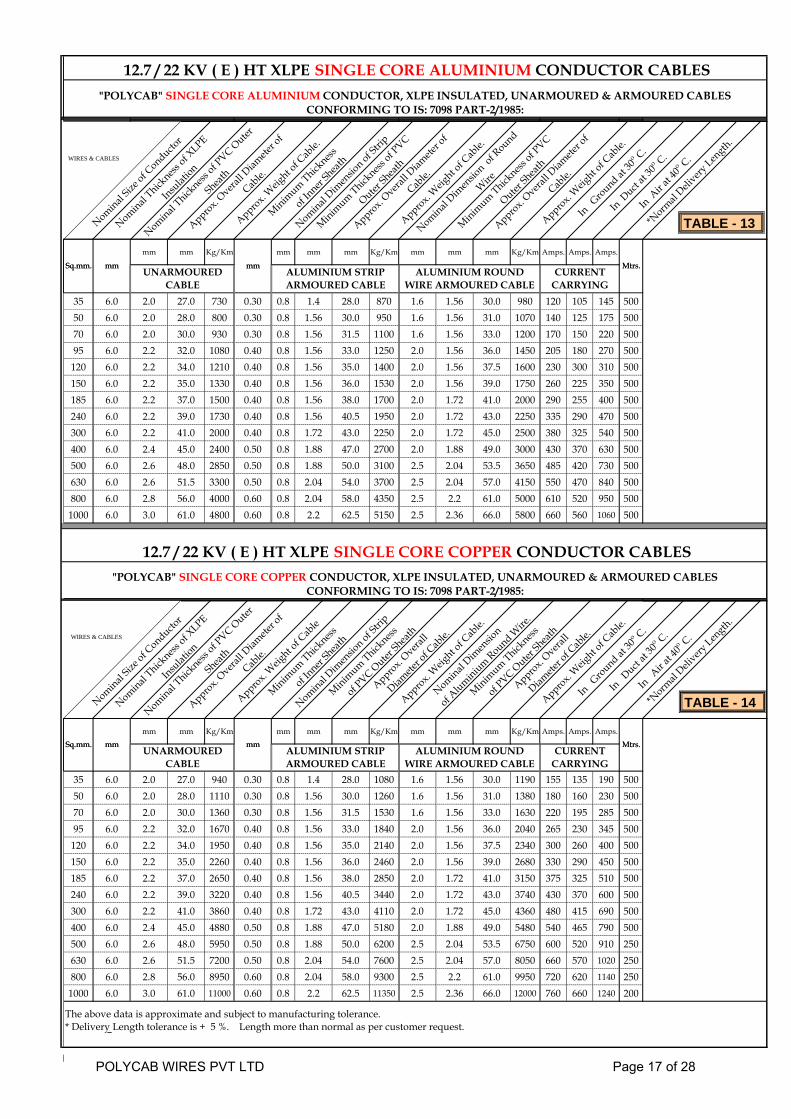
12.7 / 22 KV ( E ) HT XLPE SINGLE CORE ALUMINIUM CONDUCTOR CABLES"POLYCAB" SINGLE CORE ALUMINIUM CONDUCTOR, XLPE INSULATED, UNARMOURED & ARMOURED CABLES
CONFORMING TO IS: 7098 PART-2/1985:
Nominal Size
of Conducto
r
Nominal Thick
ness of X
LPE
Insulat
ion
Nominal Thick
ness of P
VC Outer
Sheath
Approx. Overa
ll Diam
eter o
f
Cable.
Approx. W
eight o
f Cab
le.
Minimum Thick
ness
of Inner
Shea
th
Nominal Dim
ensio
n of Stri
p
Minimum Thick
ness of P
VC
Outer Sh
eath
Approx. Overa
ll Diam
eter o
f
Cable.
Approx. W
eight o
f Cab
le.
Nominal Dim
ensio
n of R
ound
Wire
Minimum Thick
ness of P
VC
Outer Sh
eath
Approx. Overa
ll Diam
eter o
f
Cable.
Approx. W
eight o
f Cab
le.
In Ground at
30o C.
In Duct
at 30
o C.
In Air a
t 40o C.
*Norm
al Deli
very Len
gth.
Mtrs.mmSq.mm. mm
mm mm Kg/Km mm mm mm Kg/Km mm mm mm Kg/Km Amps. Amps. Amps.
35 6.0 2.0 27.0 730 0.30 0.8 1.4 28.0 870 1.6 1.56 30.0 980 120 105 145 50050 6.0 2.0 28.0 800 0.30 0.8 1.56 30.0 950 1.6 1.56 31.0 1070 140 125 175 50070 6.0 2.0 30.0 930 0.30 0.8 1.56 31.5 1100 1.6 1.56 33.0 1200 170 150 220 50095 6.0 2.2 32.0 1080 0.40 0.8 1.56 33.0 1250 2.0 1.56 36.0 1450 205 180 270 500
120 6.0 2.2 34.0 1210 0.40 0.8 1.56 35.0 1400 2.0 1.56 37.5 1600 230 300 310 500150 6.0 2.2 35.0 1330 0.40 0.8 1.56 36.0 1530 2.0 1.56 39.0 1750 260 225 350 500185 6.0 2.2 37.0 1500 0.40 0.8 1.56 38.0 1700 2.0 1.72 41.0 2000 290 255 400 500240 6.0 2.2 39.0 1730 0.40 0.8 1.56 40.5 1950 2.0 1.72 43.0 2250 335 290 470 500300 6.0 2.2 41.0 2000 0.40 0.8 1.72 43.0 2250 2.0 1.72 45.0 2500 380 325 540 500400 6.0 2.4 45.0 2400 0.50 0.8 1.88 47.0 2700 2.0 1.88 49.0 3000 430 370 630 500500 6.0 2.6 48.0 2850 0.50 0.8 1.88 50.0 3100 2.5 2.04 53.5 3650 485 420 730 500630 6.0 2.6 51.5 3300 0.50 0.8 2.04 54.0 3700 2.5 2.04 57.0 4150 550 470 840 500800 6.0 2.8 56.0 4000 0.60 0.8 2.04 58.0 4350 2.5 2.2 61.0 5000 610 520 950 500
1000 6.0 3.0 61.0 4800 0.60 0.8 2.2 62.5 5150 2.5 2.36 66.0 5800 660 560 1060 500
Mtrs.mm
12.7 / 22 KV ( E ) HT XLPE SINGLE CORE COPPER CONDUCTOR CABLES"POLYCAB" SINGLE CORE COPPER CONDUCTOR, XLPE INSULATED, UNARMOURED & ARMOURED CABLES
CONFORMING TO IS: 7098 PART-2/1985:
Sq.mm. mmUNARMOURED
CABLEALUMINIUM STRIP ARMOURED CABLE
ALUMINIUM ROUND WIRE ARMOURED CABLE
CURRENT CARRYING
Nominal Size
of Conducto
r
Nominal Thick
ness of X
LPE
Insulat
ion
Nominal Thick
ness of P
VC Outer
Sheath
Approx. Overa
ll Diam
eter o
f
Cable.
Approx. W
eight o
f Cab
le
Minimum Thick
ness
of Inner
Shea
th
Nominal Dim
ensio
n of Stri
p
Minimum Thick
ness
of PVC O
uter Sh
eath
Approx. Overa
ll
Diamete
r of C
able.
Approx. W
eight o
f Cab
le.
Nominal Dim
ensio
n
of Aluminium Round W
ire.
Minimum Thick
ness
of PVC O
uter Sh
eath
Approx. Overa
ll
Diamete
r of C
able.
Approx. W
eight o
f Cab
le.
In Ground at
30o C.
In Duct
at 30
o C.
In Air a
t 40o C.
*Norm
al Deli
very Len
gth.
mm Mtrs.Sq.mm. mmmm mm Kg/Km mm mm mm Kg/Km mm mm mm Kg/Km Amps. Amps. Amps.
35 6.0 2.0 27.0 940 0.30 0.8 1.4 28.0 1080 1.6 1.56 30.0 1190 155 135 190 50050 6.0 2.0 28.0 1110 0.30 0.8 1.56 30.0 1260 1.6 1.56 31.0 1380 180 160 230 50070 6.0 2.0 30.0 1360 0.30 0.8 1.56 31.5 1530 1.6 1.56 33.0 1630 220 195 285 50095 6.0 2.2 32.0 1670 0.40 0.8 1.56 33.0 1840 2.0 1.56 36.0 2040 265 230 345 500
120 6.0 2.2 34.0 1950 0.40 0.8 1.56 35.0 2140 2.0 1.56 37.5 2340 300 260 400 500150 6.0 2.2 35.0 2260 0.40 0.8 1.56 36.0 2460 2.0 1.56 39.0 2680 330 290 450 500185 6.0 2.2 37.0 2650 0.40 0.8 1.56 38.0 2850 2.0 1.72 41.0 3150 375 325 510 500240 6.0 2.2 39.0 3220 0.40 0.8 1.56 40.5 3440 2.0 1.72 43.0 3740 430 370 600 500300 6.0 2.2 41.0 3860 0.40 0.8 1.72 43.0 4110 2.0 1.72 45.0 4360 480 415 690 500400 6.0 2.4 45.0 4880 0.50 0.8 1.88 47.0 5180 2.0 1.88 49.0 5480 540 465 790 500500 6.0 2.6 48.0 5950 0.50 0.8 1.88 50.0 6200 2.5 2.04 53.5 6750 600 520 910 250630 6.0 2.6 51.5 7200 0.50 0.8 2.04 54.0 7600 2.5 2.04 57.0 8050 660 570 1020 250800 6.0 2.8 56.0 8950 0.60 0.8 2.04 58.0 9300 2.5 2.2 61.0 9950 720 620 1140 250
1000 6.0 3.0 61.0 11000 0.60 0.8 2.2 62.5 11350 2.5 2.36 66.0 12000 760 660 1240 200
The above data is approximate and subject to manufacturing tolerance.* Delivery Length tolerance is + 5 %. Length more than normal as per customer request.
mm Mtrs.Sq.mm. mmCURRENT
CARRYINGUNARMOURED
CABLEALUMINIUM STRIP ARMOURED CABLE
ALUMINIUM ROUND WIRE ARMOURED CABLE
WIRES & CABLES
WIRES & CABLES
TABLE - 13
TABLE - 14
POLYCAB WIRES PVT LTD Page 17 of 28

19 / 33 KV ( E ) HT XLPE SINGLE CORE ALUMINIUM CONDUCTOR CABLES"POLYCAB" SINGLE CORE ALUMINIUM CONDUCTOR, XLPE INSULATED, UNARMOURED & ARMOURED CABLES
CONFORMING TO IS: 7098 PART-2/1985:
Nominal Size
of Conducto
r
Nominal Thick
ness of X
LPE
Insulat
ion
Nominal Thick
ness of P
VC Outer
Sheath
Approx. Overa
ll Diam
eter o
f
Cable.
Approx. W
eight o
f Cab
le.
Minimum Thick
ness
of Inner
Shea
th
Nominal Dim
ensio
n of Stri
p
Minimum Thick
ness of P
VC
Outer Sh
eath
Approx. Overa
ll Diam
eter o
f
Cable.
Approx. W
eight o
f Cab
le.
Nominal Dim
ensio
n of R
ound
Wire
Minimum Thick
ness of P
VC
Outer Sh
eath
Approx. Overa
ll Diam
eter o
f
Cable.
Approx. W
eight o
f Cab
le.
In Ground at
30o C.
In Duct
at 30
o C.
In Air a
t 40o C.
*Norm
al Deli
very Len
gth.
Sq.mm. mm Mtrs.mm
mm mm Kg/Km mm mm mm Kg/Km mm mm mm Kg/Km Amps. Amps. Amps.
95 8.8 2.2 37.5 1400 0.40 0.8 1.56 39.0 1610 2.0 1.72 41.5 1900 205 180 270 500
120 8.8 2.2 39.0 1550 0.40 0.8 1.72 41.0 1800 2.0 1.72 43.0 2050 230 300 310 500
150 8.8 2.2 40.0 1700 0.40 0.8 1.72 42.0 1950 2.0 1.72 44.5 2200 260 225 350 500
185 8.8 2.4 43.0 1900 0.50 0.8 1.72 44.5 2200 2.0 1.88 47.0 2500 290 255 400 500
240 8.8 2.4 45.0 2200 0.50 0.8 1.88 47.0 2500 2.0 1.88 49.5 2760 335 290 470 500
300 8.8 2.6 48.0 2500 0.50 0.8 1.88 49.0 2750 2.0 2.04 52.0 3100 380 325 540 500
400 8.8 2.6 51.0 2900 0.50 0.8 2.04 52.5 3250 2.0 2.04 55.0 3550 430 370 630 500
500 8.8 2.8 54.0 3400 0.60 0.8 2.04 56.0 3700 2.5 2.2 60.0 4250 485 420 730 500
630 8.8 2.8 57.5 3900 0.60 0.8 2.2 60.0 4300 2.5 2.36 63.0 4900 550 470 840 500
800 8.8 3.0 62.0 4600 0.60 0.8 2.36 64.0 5050 2.5 2.36 67.0 5600 610 520 950 500
1000 8.8 3.2 67.0 5450 0.70 0.8 2.36 69.0 5900 2.5 2.52 72.5 6550 660 560 1060 500
19 / 33 KV ( E ) HT XLPE SINGLE CORE COPPER CONDUCTOR CABLES"POLYCAB" SINGLE CORE COPPER CONDUCTOR, XLPE INSULATED, UNARMOURED & ARMOURED CABLES
CONFORMING TO IS: 7098 PART-2/1985:
Sq.mm. mmUNARMOURED
CABLEALUMINIUM STRIP ARMOURED CABLE
ALUMINIUM ROUND WIRE ARMOURED CABLE
CURRENT CARRYING
Mtrs.mm
Nominal Size
of Conducto
r
Nominal Thick
ness of X
LPE
Insulat
ion
Nominal Thick
ness of P
VC Outer
Sheath
Approx. Overa
ll Diam
eter o
f
Cable.
Approx. W
eight o
f Cab
le
Minimum Thick
ness
of Inner
Shea
th
Nominal Dim
ensio
n of Stri
p
Minimum Thick
ness
of PVC O
uter Sh
eath
Approx. Overa
ll
Diamete
r of C
able.
Approx. W
eight o
f Cab
le.
Nominal Dim
ensio
n
of Aluminium Round W
ire.
Minimum Thick
ness
of PVC O
uter Sh
eath
Approx. Overa
ll
Diamete
r of C
able.
Approx. W
eight o
f Cab
le.
In Ground at
30o C.
In Duct
at 30
o C.
In Air a
t 40o C.
*Norm
al Deli
very Len
gth.
mm Mtrs.Sq.mm. mmmm mm Kg/Km mm mm mm Kg/Km mm mm mm Kg/Km Amps. Amps. Amps.
95 8.8 2.2 37.5 1610 0.40 0.8 1.56 39.0 1820 2.0 1.72 41.5 2110 265 230 345 500
120 8.8 2.2 39.0 1860 0.40 0.8 1.72 41.0 2110 2.0 1.72 43.0 2360 300 260 400 500
150 8.8 2.2 40.0 2130 0.40 0.8 1.72 42.0 2380 2.0 1.72 44.5 2630 330 290 450 500
185 8.8 2.4 43.0 2490 0.50 0.8 1.72 44.5 2790 2.0 1.88 47.0 3090 375 325 510 500
240 8.8 2.4 45.0 2940 0.50 0.8 1.88 47.0 3240 2.0 1.88 49.5 3500 430 370 600 500
300 8.8 2.6 48.0 3430 0.50 0.8 1.88 49.0 3680 2.0 2.04 52.0 4030 480 415 690 500
400 8.8 2.6 51.0 4050 0.50 0.8 2.04 52.5 4400 2.0 2.04 55.0 4700 540 465 790 250
500 8.8 2.8 54.0 4890 0.60 0.8 2.04 56.0 5190 2.5 2.2 60.0 5740 600 520 910 250
630 8.8 2.8 57.5 5760 0.60 0.8 2.2 60.0 6160 2.5 2.36 63.0 6760 660 570 1020 250
800 8.8 3.0 62.0 7080 0.60 0.8 2.36 64.0 7530 2.5 2.36 67.0 8080 720 620 1140 250
1000 8.8 3.2 67.0 8550 0.70 0.8 2.36 69.0 9000 2.5 2.52 72.5 9650 760 660 1240 200
The above data is approximate and subject to manufacturing tolerance.* Delivery Length tolerance is + 5 %. Length more than normal as per customer request.
mm Mtrs.Sq.mm. mmCURRENT
CARRYINGUNARMOURED
CABLEALUMINIUM STRIP ARMOURED CABLE
ALUMINIUM ROUND WIRE ARMOURED CABLE
WIRES & CABLES
WIRES & CABLES
TABLE - 15
TABLE - 16
POLYCAB WIRES PVT LTD Page 18 of 28

1.9/3.3 KV (E) & 3.3/3.3 KV (UE) HT XLPE THREE CORE ALUMINIUM CONDUCTOR CABLES"POLYCAB" THREE CORE ALUMINIUM CONDUCTOR, XLPE INSULATED, UNARMOURED & ARMOURED
SCREENED CABLES CONFORMING TO IS: 7098 PART-2/1985:
Nominal Size
of Conducto
r
Nominal Thick
ness of X
LPE
Insulat
ion
Minimum Thick
ness
of PVC In
ner Shea
th
Nominal Thick
ness of P
VC Outer
Sheath
Approx. Overa
ll Diam
eter o
f
Cable.
Approx. W
eight o
f Cab
le.
Nominal Dim
ensio
n of GI F
lat
Strip
Minimum Thick
ness of P
VC
Outer Sh
eath
Approx. Overa
ll Diam
eter o
f
Cable.
Approx. W
eight o
f Cab
le.
Nominal Dim
ensio
n of GI
Round Wire
Minimum Thick
ness of P
VC
Outer Sh
eath
Approx. Overa
ll Diam
eter o
f
Cable.
Approx. W
eight o
f Cab
le.
In Ground at
30o C.
In Duct
at 30
o C.
In Air a
t 40o C.
*Norm
al Deli
very Len
gth.
Sq.mm. mm Mtrs.mm
mm mm Kg/Km mm mm mm Kg/Km mm mm mm Kg/Km Amps. Amps. Amps.
35 2.2 0.4 2.2 38.0 1500 0.8 1.56 37.0 1950 2.0 1.72 40.5 2600 115 94 120 500
50 2.2 0.4 2.2 40.0 1700 0.8 1.72 39.5 2200 2.0 1.72 42.5 2900 135 10 145 500
70 2.2 0.5 2.4 44.5 2150 0.8 1.72 44.0 2650 2.0 1.88 47.0 3450 165 140 185 500
95 2.2 0.5 2.6 48.5 2600 0.8 1.88 47.5 3150 2.5 2.04 51.5 4400 195 165 225 500
120 2.2 0.5 2.6 52.0 3000 0.8 2.04 51.5 3650 2.5 2.04 55.5 5000 220 185 355 500
150 2.2 0.6 2.8 55.5 3500 0.8 2.04 54.5 4100 2.5 2.2 58.5 5550 245 210 295 500
185 2.2 0.6 3.0 60.0 4150 0.8 2.2 59.0 4800 2.5 2.36 63.0 6350 280 235 340 500
240 2.2 0.7 3.0 65.0 4900 0.8 2.36 64.5 5750 2.5 2.36 68.0 7350 320 270 400 500
300 2.2 0.7 3.2 70.0 5850 0.8 2.52 70.0 6650 3.15 2.68 75.0 9250 360 305 460 500
400 2.2 0.7 3.6 78.0 7300 0.8 2.68 76.5 8100 3.15 2.84 82.0 11000 410 350 535 500
1.9/3.3 KV (E) & 3.3/3.3 (UE) KV HT XLPE THREE CORE COPPER CONDUCTOR CABLES"POLYCAB" THREE CORE COPPER CONDUCTOR, XLPE INSULATED, UNARMOURED & ARMOURED
SCREENED CABLES CONFORMING TO IS: 7098 PART-2/1985:
Sq.mm. mmUNARMOURED
CABLEFORMED WIRE / STRIP
ARMOURED CABLEROUND WIRE
ARMOURED CABLECURRENT
CARRYING
Mtrs.mm
Nominal Size
of Conducto
r
Nominal Thick
ness of X
LPE
Insulat
ion
Minimum Thick
ness
of PVC In
ner Shea
th
Nominal Thick
ness of P
VC Outer
Sheath
Approx. Overa
ll Diam
eter o
f
Cable.
Approx. W
eight o
f Cab
le.
Nominal Dim
ensio
n of GI F
lat
Strip
Minimum Thick
ness of P
VC
Outer Sh
eath
Approx. Overa
ll Diam
eter o
f
Cable.
Approx. W
eight o
f Cab
le.
Nominal Dim
ensio
n of GI
Round Wire
Minimum Thick
ness of P
VC
Outer Sh
eath
Approx. Overa
ll Diam
eter o
f
Cable.
Approx. W
eight o
f Cab
le.
In Ground at
30o C.
In Duct
at 30
o C.
In Air a
t 40o C.
*Norm
al Deli
very Len
gth.
Mtrs.Sq.mm. mm mm
mm mm Kg/Km mm mm mm Kg/Km mm mm mm Kg/Km Amps. Amps. Amps.
35 2.2 0.4 2.2 38.0 2130 0.8 1.56 37.0 2580 2.0 1.72 40.5 3230 145 120 155 500
50 2.2 0.4 2.2 40.0 2630 0.8 1.72 39.5 3130 2.0 1.72 42.5 3830 170 145 190 500
70 2.2 0.5 2.4 44.5 3440 0.8 1.72 44.0 3940 2.0 1.88 47.0 4740 210 175 235 500
95 2.2 0.5 2.6 48.5 4370 0.8 1.88 47.5 4920 2.5 2.04 51.5 6170 250 210 290 500
120 2.2 0.5 2.6 52.0 5220 0.8 2.04 51.5 5870 2.5 2.04 55.5 7220 285 240 330 500
150 2.2 0.6 2.8 55.5 6290 0.8 2.04 54.5 6890 2.5 2.2 58.5 8340 315 270 375 500
185 2.2 0.6 3.0 60.0 7600 0.8 2.2 59.0 8250 2.5 2.36 63.0 9800 355 300 435 500
240 2.2 0.7 3.0 65.0 9370 0.8 2.36 64.5 10220 2.5 2.36 68.0 11820 410 350 510 500
300 2.2 0.7 3.2 70.0 11430 0.8 2.52 70.0 12230 3.15 2.68 75.0 14830 460 390 590 500
400 2.2 0.7 3.6 78.0 14740 0.8 2.68 76.5 15540 3.15 2.84 82.0 18440 520 440 670 250
The above data is approximate and subject to manufacturing tolerance.* Delivery Length tolerance is + 5 %. Length more than normal as per customer request.
Mtrs.Sq.mm. mmCURRENT
CARRYINGUNARMOURED
CABLEFORMED WIRE / STRIP
ARMOURED CABLEROUND WIRE
ARMOURED CABLE
mm
WIRES & CABLES
WIRES & CABLES
TABLE - 17
TABLE - 18
POLYCAB WIRES PVT LTD Page 19 of 28
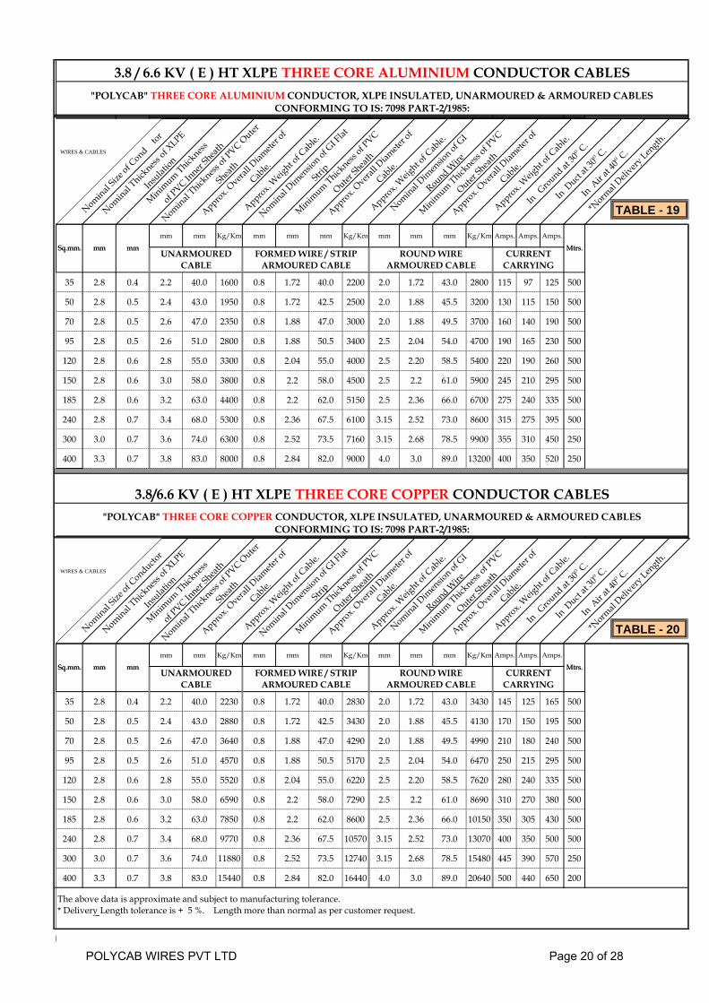
3.8 / 6.6 KV ( E ) HT XLPE THREE CORE ALUMINIUM CONDUCTOR CABLES"POLYCAB" THREE CORE ALUMINIUM CONDUCTOR, XLPE INSULATED, UNARMOURED & ARMOURED CABLES
CONFORMING TO IS: 7098 PART-2/1985:
Nominal Size
of Cond
tor
Nominal Thick
ness of X
LPE
Insulat
ion
Minimum Thick
ness
of PVC In
ner Shea
th
Nominal Thick
ness of P
VC Outer
Sheath
Approx. Overa
ll Diam
eter o
f
Cable.
Approx. W
eight o
f Cab
le.
Nominal Dim
ensio
n of GI F
lat
Strip
Minimum Thick
ness of P
VC
Outer Sh
eath
Approx. Overa
ll Diam
eter o
f
Cable.
Approx. W
eight o
f Cab
le.
Nominal Dim
ensio
n of GI
Round Wire
Minimum Thick
ness of P
VC
Outer Sh
eath
Approx. Overa
ll Diam
eter o
f
Cable.
Approx. W
eight o
f Cab
le.
In Ground at
30o C.
In Duct
at 30
o C.
In Air a
t 40o C.
*Norm
al Deli
very Len
gth.
Mtrs.mmSq.mm. mm
mm mm Kg/Km mm mm mm Kg/Km mm mm mm Kg/Km Amps. Amps. Amps.
35 2.8 0.4 2.2 40.0 1600 0.8 1.72 40.0 2200 2.0 1.72 43.0 2800 115 97 125 500
50 2.8 0.5 2.4 43.0 1950 0.8 1.72 42.5 2500 2.0 1.88 45.5 3200 130 115 150 500
70 2.8 0.5 2.6 47.0 2350 0.8 1.88 47.0 3000 2.0 1.88 49.5 3700 160 140 190 500
95 2.8 0.5 2.6 51.0 2800 0.8 1.88 50.5 3400 2.5 2.04 54.0 4700 190 165 230 500
120 2.8 0.6 2.8 55.0 3300 0.8 2.04 55.0 4000 2.5 2.20 58.5 5400 220 190 260 500
150 2.8 0.6 3.0 58.0 3800 0.8 2.2 58.0 4500 2.5 2.2 61.0 5900 245 210 295 500
185 2.8 0.6 3.2 63.0 4400 0.8 2.2 62.0 5150 2.5 2.36 66.0 6700 275 240 335 500
240 2.8 0.7 3.4 68.0 5300 0.8 2.36 67.5 6100 3.15 2.52 73.0 8600 315 275 395 500
300 3.0 0.7 3.6 74.0 6300 0.8 2.52 73.5 7160 3.15 2.68 78.5 9900 355 310 450 250
400 3.3 0.7 3.8 83.0 8000 0.8 2.84 82.0 9000 4.0 3.0 89.0 13200 400 350 520 250
Mtrs.mm
3.8/6.6 KV ( E ) HT XLPE THREE CORE COPPER CONDUCTOR CABLES"POLYCAB" THREE CORE COPPER CONDUCTOR, XLPE INSULATED, UNARMOURED & ARMOURED CABLES
CONFORMING TO IS: 7098 PART-2/1985:
Sq.mm. mmUNARMOURED
CABLEFORMED WIRE / STRIP
ARMOURED CABLEROUND WIRE
ARMOURED CABLECURRENT
CARRYING
Nominal Size
of Conducto
r
Nominal Thick
ness of X
LPE
Insulat
ion
Minimum Thick
ness
of PVC In
ner Shea
th
Nominal Thick
ness of P
VC Outer
Sheath
Approx. Overa
ll Diam
eter o
f
Cable.
Approx. W
eight o
f Cab
le.
Nominal Dim
ensio
n of GI F
lat
Strip
Minimum Thick
ness of P
VC
Outer Sh
eath
Approx. Overa
ll Diam
eter o
f
Cable.
Approx. W
eight o
f Cab
le.
Nominal Dim
ensio
n of GI
Round Wire
Minimum Thick
ness of P
VC
Outer Sh
eath
Approx. Overa
ll Diam
eter o
f
Cable.
Approx. W
eight o
f Cab
le.
In Ground at
30o C.
In Duct
at 30
o C.
In Air a
t 40o C.
*Norm
al Deli
very Len
gth.
Mtrs.Sq.mm. mm mm
mm mm Kg/Km mm mm mm Kg/Km mm mm mm Kg/Km Amps. Amps. Amps.
35 2.8 0.4 2.2 40.0 2230 0.8 1.72 40.0 2830 2.0 1.72 43.0 3430 145 125 165 500
50 2.8 0.5 2.4 43.0 2880 0.8 1.72 42.5 3430 2.0 1.88 45.5 4130 170 150 195 500
70 2.8 0.5 2.6 47.0 3640 0.8 1.88 47.0 4290 2.0 1.88 49.5 4990 210 180 240 500
95 2.8 0.5 2.6 51.0 4570 0.8 1.88 50.5 5170 2.5 2.04 54.0 6470 250 215 295 500
120 2.8 0.6 2.8 55.0 5520 0.8 2.04 55.0 6220 2.5 2.20 58.5 7620 280 240 335 500
150 2.8 0.6 3.0 58.0 6590 0.8 2.2 58.0 7290 2.5 2.2 61.0 8690 310 270 380 500
185 2.8 0.6 3.2 63.0 7850 0.8 2.2 62.0 8600 2.5 2.36 66.0 10150 350 305 430 500
240 2.8 0.7 3.4 68.0 9770 0.8 2.36 67.5 10570 3.15 2.52 73.0 13070 400 350 500 500
300 3.0 0.7 3.6 74.0 11880 0.8 2.52 73.5 12740 3.15 2.68 78.5 15480 445 390 570 250
400 3.3 0.7 3.8 83.0 15440 0.8 2.84 82.0 16440 4.0 3.0 89.0 20640 500 440 650 200
The above data is approximate and subject to manufacturing tolerance.* Delivery Length tolerance is + 5 %. Length more than normal as per customer request.
Mtrs.Sq.mm. mmCURRENT
CARRYINGUNARMOURED
CABLEFORMED WIRE / STRIP
ARMOURED CABLEROUND WIRE
ARMOURED CABLE
mm
WIRES & CABLES
WIRES & CABLES
TABLE - 19
TABLE - 20
POLYCAB WIRES PVT LTD Page 20 of 28

6.35 / 11 KV ( E ) HT XLPE THREE CORE ALUMINIUM CONDUCTOR CABLES"POLYCAB" THREE CORE ALUMINIUM CONDUCTOR, XLPE INSULATED, UNARMOURED & ARMOURED CABLES
CONFORMING TO IS: 7098 PART-2/1985:
Nominal Size
of Conducto
r
Nominal Thick
ness of X
LPE
Insulat
ion
Minimum Thick
ness
of PVC In
ner Shea
th
Nominal Thick
ness of P
VC Outer
Sheath
Approx. Overa
ll Diam
eter o
f
Cable.
Approx. W
eight o
f Cab
le.
Nominal Dim
ensio
n of GI F
lat
Strip
Minimum Thick
ness of P
VC
Outer Sh
eath
Approx. Overa
ll Diam
eter o
f
Cable.
Approx. W
eight o
f Cab
le.
Nominal Dim
ensio
n of GI
Round Wire
Minimum Thick
ness of P
VC
Outer Sh
eath
Approx. Overa
ll Diam
eter o
f
Cable.
Approx. W
eight o
f Cab
le.
In Ground at
30o C.
In Duct
at 30
o C.
In Air a
t 40o C.
*Norm
al Deli
very Len
gth.
Sq.mm. mm Mtrs.mm
mm mm Kg/Km mm mm mm Kg/Km mm mm mm Kg/Km Amps. Amps. Amps.
35 3.6 0.5 2.4 42.5 1950 0.8 1.72 42.5 2500 2.0 1.88 45.5 3250 115 97 125 500
50 3.6 0.5 2.6 46.0 2250 0.8 1.88 46.0 2850 2.5 2.04 49.5 4000 130 115 150 500
70 3.6 0.5 2.6 48.5 2650 0.8 1.88 49.0 3300 2.5 2.04 52.5 4600 160 140 190 500
95 3.6 0.6 2.8 53.0 3150 0.8 2.04 53.0 3850 2.5 2.20 56.5 5250 190 165 230 500
120 3.6 0.6 2.8 56.0 3600 0.8 2.2 56.0 4400 2.5 2.20 59.5 5850 220 190 260 500
150 3.6 0.6 3.0 59.0 4100 0.8 2.2 59.0 4900 2.5 2.36 63.0 6450 245 210 295 500
185 3.6 0.7 3.2 63.0 4850 0.8 2.36 63.0 5650 3.15 2.52 68.0 8100 275 240 335 500
240 3.6 0.7 3.4 68.0 5700 0.8 2.52 38.0 6600 3.15 2.68 73.0 9250 315 275 395 500
300 3.6 0.7 3.6 73.0 6650 0.8 2.68 73.0 7600 3.15 2.84 78.0 10400 355 310 450 250
400 3.6 0.7 3.8 80.0 8100 0.8 2.84 80.0 9100 4.0 3.0 86.5 13450 400 350 520 250
6.35 / 11 KV ( E ) HT XLPE THREE CORE COPPER CONDUCTOR CABLES"POLYCAB" THREE CORE COPPER CONDUCTOR, XLPE INSULATED, UNARMOURED & ARMOURED CABLES
CONFORMING TO IS: 7098 PART-2/1985:
Sq.mm. mmUNARMOURED
CABLEFORMED WIRE / STRIP
ARMOURED CABLEROUND WIRE
ARMOURED CABLECURRENT
CARRYING
Mtrs.mm
Nominal Size
of Conducto
r
Nominal Thick
ness of X
LPE
Insulat
ion
Minimum Thick
ness
of PVC In
ner Shea
th
Nominal Thick
ness of P
VC Outer
Sheath
Approx. Overa
ll Diam
eter o
f
Cable.
Approx. W
eight o
f Cab
le.
Nominal Dim
ensio
n of GI F
lat
Strip
Minimum Thick
ness of P
VC
Outer Sh
eath
Approx. Overa
ll Diam
eter o
f
Cable.
Approx. W
eight o
f Cab
le.
Nominal Dim
ensio
n of GI
Round Wire
Minimum Thick
ness of P
VC
Outer Sh
eath
Approx. Overa
ll Diam
eter o
f
Cable.
Approx. W
eight o
f Cab
le.
In Ground at
30o C.
In Duct
at 30
o C.
In Air a
t 40o C.
*Norm
al Deli
very Len
gth.
Mtrs.Sq.mm. mm mm
mm mm Kg/Km mm mm mm Kg/Km mm mm mm Kg/Km Amps. Amps. Amps.
35 3.6 0.5 2.4 42.5 2580 0.8 1.72 42.5 3130 2.0 1.88 45.5 3880 145 125 165 500
50 3.6 0.5 2.6 46.0 3180 0.8 1.88 46.0 3780 2.5 2.04 49.5 4930 170 150 195 500
70 3.6 0.5 2.6 48.5 3940 0.8 1.88 49.0 4590 2.5 2.04 52.5 5890 210 180 240 500
95 3.6 0.6 2.8 53.0 4920 0.8 2.04 53.0 5620 2.5 2.20 56.5 7020 250 215 295 500
120 3.6 0.6 2.8 56.0 5820 0.8 2.2 56.0 6620 2.5 2.20 59.5 8070 280 240 335 500
150 3.6 0.6 3.0 59.0 6890 0.8 2.2 59.0 7690 2.5 2.36 63.0 9240 310 270 380 500
185 3.6 0.7 3.2 63.0 8300 0.8 2.36 63.0 9100 3.15 2.52 68.0 11550 350 305 430 500
240 3.6 0.7 3.4 68.0 10170 0.8 2.52 38.0 11070 3.15 2.68 73.0 13720 400 350 500 250
300 3.6 0.7 3.6 73.0 12230 0.8 2.68 73.0 13180 3.15 2.84 78.0 15980 445 390 570 250
400 3.6 0.7 3.8 80.0 15540 0.8 2.84 80.0 16540 4.0 3.0 86.5 20890 500 440 650 250
The above data is approximate and subject to manufacturing tolerance.* Delivery Length tolerance is + 5 %. Length more than normal as per customer request.
Mtrs.Sq.mm. mmCURRENT
CARRYINGUNARMOURED
CABLEFORMED WIRE / STRIP
ARMOURED CABLEROUND WIRE
ARMOURED CABLE
mm
WIRES & CABLES
WIRES & CABLES
TABLE - 21
TABLE - 22
POLYCAB WIRES PVT LTD Page 21 of 28

11 / 11 KV ( UE ) HT XLPE THREE CORE ALUMINIUM CONDUCTOR CABLES"POLYCAB" THREE CORE ALUMINIUM CONDUCTOR, XLPE INSULATED, UNARMOURED & ARMOURED CABLES
CONFORMING TO IS: 7098 PART-2/1985:
Nominal Size
of Conducto
r
Nominal Thick
ness of X
LPE
Insulat
ion
Minimum Thick
ness
of PVC In
ner Shea
th
Nominal Thick
ness of P
VC Outer
Sheath
Approx. Overa
ll Diam
eter o
f
Cable.
Approx. W
eight o
f Cab
le.
Nominal Dim
ensio
n of GI F
lat
Strip
Minimum Thick
ness of P
VC
Outer Sh
eath
Approx. Overa
ll Diam
eter o
f
Cable.
Approx. W
eight o
f Cab
le.
Nominal Dim
ensio
n of GI
Round Wire
Minimum Thick
ness of P
VC
Outer Sh
eath
Approx. Overa
ll Diam
eter o
f
Cable.
Approx. W
eight o
f Cab
le.
In Ground at
30o C.
In Duct
at 30
o C.
In Air a
t 40o C.
*Norm
al Deli
very Len
gth.
Mtrs.mmSq.mm. mm
mm mm Kg/Km mm mm mm Kg/Km mm mm mm Kg/Km Amps. Amps. Amps.
35 5.5 0.5 2.8 51.5 2700 0.8 2.04 51.5 3400 2.5 2.20 55.0 4750 115 97 125 500
50 5.5 0.6 2.8 54.5 3050 0.8 2.2 55.0 3800 2.5 2.20 58.0 5200 130 115 150 500
70 5.5 0.6 3.0 58.0 3550 0.8 2.2 58.0 4300 2.5 2.36 61.5 5900 160 140 190 500
95 5.5 0.6 3.2 62.0 4100 0.8 2.36 62.0 4900 3.15 2.52 66.5 7250 190 165 230 500
120 5.5 0.7 3.2 65.0 4650 0.8 2.36 65.0 5500 3.15 2.52 70.0 8000 220 190 260 500
150 5.5 0.7 3.4 68.5 5200 0.8 2.52 68.5 6100 3.15 2.68 73.0 8650 245 210 295 500
185 5.5 0.7 3.4 71.5 5900 0.8 2.68 71.5 6950 3.15 2.84 77.0 9650 275 240 335 500
240 5.5 0.7 3.6 77.0 6850 0.8 2.84 77.0 7900 3.15 3.0 82.0 10850 315 275 395 250
300 5.5 0.7 3.8 81.5 7850 0.8 3.0 81.5 8950 4.0 3.0 88.0 13250 355 310 450 250
400 5.5 0.7 4.0 88.0 9400 0.8 3.0 88.0 10500 4.0 3.0 94.5 15200 400 350 520 250
Mtrs.mm
11 / 11 KV ( UE ) HT XLPE THREE CORE COPPER CONDUCTOR CABLES"POLYCAB" THREE CORE COPPER CONDUCTOR, XLPE INSULATED, UNARMOURED & ARMOURED CABLES
CONFORMING TO IS: 7098 PART-2/1985:
Sq.mm. mmUNARMOURED
CABLEFORMED WIRE / STRIP
ARMOURED CABLEROUND WIRE
ARMOURED CABLECURRENT
CARRYING
Nominal Size
of Conducto
r
Nominal Thick
ness of X
LPE
Insulat
ion
Minimum Thick
ness
of PVC In
ner Shea
th
Nominal Thick
ness of P
VC Outer
Sheath
Approx. Overa
ll Diam
eter o
f
Cable.
Approx. W
eight o
f Cab
le.
Nominal Dim
ensio
n of GI F
lat
Strip
Minimum Thick
ness of P
VC
Outer Sh
eath
Approx. Overa
ll Diam
eter o
f
Cable.
Approx. W
eight o
f Cab
le.
Nominal Dim
ensio
n of GI
Round Wire
Minimum Thick
ness of P
VC
Outer Sh
eath
Approx. Overa
ll Diam
eter o
f
Cable.
Approx. W
eight o
f Cab
le.
In Ground at
30o C.
In Duct
at 30
o C.
In Air a
t 40o C.
*Norm
al Deli
very Len
gth.
Mtrs.Sq.mm. mm mm
mm mm Kg/Km mm mm mm Kg/Km mm mm mm Kg/Km Amps. Amps. Amps.
35 5.5 0.5 2.8 51.5 3330 0.8 2.04 51.5 4030 2.5 2.20 55.0 5380 145 125 165 500
50 5.5 0.6 2.8 54.5 3980 0.8 2.2 55.0 4730 2.5 2.20 58.0 6130 170 150 195 500
70 5.5 0.6 3.0 58.0 4840 0.8 2.2 58.0 5590 2.5 2.36 61.5 7190 210 180 240 500
95 5.5 0.6 3.2 62.0 5870 0.8 2.36 62.0 6670 3.15 2.52 66.5 9020 250 215 295 500
120 5.5 0.7 3.2 65.0 6870 0.8 2.36 65.0 7720 3.15 2.52 70.0 10220 280 240 335 500
150 5.5 0.7 3.4 68.5 7990 0.8 2.52 68.5 8890 3.15 2.68 73.0 11440 310 270 380 500
185 5.5 0.7 3.4 71.5 9350 0.8 2.68 71.5 10400 3.15 2.84 77.0 13100 350 305 430 250
240 5.5 0.7 3.6 77.0 11320 0.8 2.84 77.0 12370 3.15 3.0 82.0 15320 400 350 500 250
300 5.5 0.7 3.8 81.5 13430 0.8 3.0 81.5 14530 4.0 3.0 88.0 18830 445 390 570 250
400 5.5 0.7 4.0 88.0 16840 0.8 3.0 88.0 17940 4.0 3.0 94.5 22640 500 440 650 250
The above data is approximate and subject to manufacturing tolerance.* Delivery Length tolerance is + 5 %. Length more than normal as per customer request.
Mtrs.Sq.mm. mmCURRENT
CARRYINGUNARMOURED
CABLEFORMED WIRE / STRIP
ARMOURED CABLEROUND WIRE
ARMOURED CABLE
mm
WIRES & CABLES
WIRES & CABLES
TABLE - 23
TABLE - 24
POLYCAB WIRES PVT LTD Page 22 of 28

12.7 / 22 KV ( E ) HT XLPE THREE CORE ALUMINIUM CONDUCTOR CABLES"POLYCAB" THREE CORE ALUMINIUM CONDUCTOR, XLPE INSULATED, UNARMOURED & ARMOURED CABLES
CONFORMING TO IS: 7098 PART-2/1985:
Nominal Size
of Conducto
r
Nominal Thick
ness of X
LPE
Insulat
ion
Minimum Thick
ness
of PVC In
ner Shea
th
Nominal Thick
ness of P
VC Outer
Sheath
Approx. Overa
ll Diam
eter o
f
Cable.
Approx. W
eight o
f Cab
le.
Nominal Dim
ensio
n of GI F
lat
Strip
Minimum Thick
ness of P
VC
Outer Sh
eath
Approx. Overa
ll Diam
eter o
f
Cable.
Approx. W
eight o
f Cab
le.
Nominal Dim
ensio
n of GI
Round Wire
Minimum Thick
ness of P
VC
Outer Sh
eath
Approx. Overa
ll Diam
eter o
f
Cable.
Approx. W
eight o
f Cab
le.
In Ground at
30o C.
In Duct
at 30
o C.
In Air a
t 40o C.
*Norm
al Deli
very Len
gth.
Sq.mm. mm Mtrs.mm
mm mm Kg/Km mm mm mm Kg/Km mm mm mm Kg/Km Amps. Amps. Amps.
70 6.0 0.6 3.0 60.0 3850 0.8 2.36 60.0 4700 2.5 2.36 63.5 6250 160 140 190 500
95 6.0 0.7 3.2 64.0 4450 0.8 2.36 64.0 5300 3.15 2.52 69.0 7750 190 170 230 500
120 6.0 0.7 3.4 67.5 5050 0.8 2.52 67.5 5900 3.15 2.68 72.0 8500 215 190 265 500
150 6.0 0.7 3.4 70.5 5550 0.8 2.68 70.5 6500 3.15 2.68 75.5 9200 240 215 300 250
185 6.0 0.7 3.6 74.0 6300 0.8 2.68 74.0 7250 3.15 2.84 79.0 10150 270 240 340 250
240 6.0 0.7 3.8 79.5 7300 0.8 2.84 79.0 8300 4.0 3.0 85.5 12600 310 275 400 250
300 6.0 0.7 4.0 84.0 8300 0.8 3.0 83.5 9350 4.0 3.0 90.0 13850 350 310 455 250
400 6.0 0.7 4.0 90.5 9850 0.8 3.0 90.5 10950 4.0 3.0 96.5 15800 395 355 530 250
12.7 / 22 KV ( E ) HT XLPE THREE CORE COPPER CONDUCTOR CABLES"POLYCAB" THREE CORE COPPER CONDUCTOR, XLPE INSULATED, UNARMOURED & ARMOURED CABLES
CONFORMING TO IS: 7098 PART-2/1985:
Sq.mm. mmUNARMOURED
CABLEFORMED WIRE / STRIP
ARMOURED CABLEROUND WIRE
ARMOURED CABLECURRENT
CARRYING
Mtrs.mm
Nominal Size
of Conducto
r
Nominal Thick
ness of X
LPE
Insulat
ion
Minimum Thick
ness
of PVC In
ner Shea
th
Nominal Thick
ness of P
VC Outer
Sheath
Approx. Overa
ll Diam
eter o
f
Cable.
Approx. W
eight o
f Cab
le.
Nominal Dim
ensio
n of GI F
lat
Strip
Minimum Thick
ness of P
VC
Outer Sh
eath
Approx. Overa
ll Diam
eter o
f
Cable.
Approx. W
eight o
f Cab
le.
Nominal Dim
ensio
n of GI
Round Wire
Minimum Thick
ness of P
VC
Outer Sh
eath
Approx. Overa
ll Diam
eter o
f
Cable.
Approx. W
eight o
f Cab
le.
In Ground at
30o C.
In Duct
at 30
o C.
In Air a
t 40o C.
*Norm
al Deli
very Len
gth.
Mtrs.Sq.mm. mm mm
mm mm Kg/Km mm mm mm Kg/Km mm mm mm Kg/Km Amps. Amps. Amps.
70 6.0 0.6 3.0 60.0 5140 0.8 2.36 60.0 5990 2.5 2.36 63.5 7540 205 180 245 500
95 6.0 0.7 3.2 64.0 6220 0.8 2.36 64.0 7070 3.15 2.52 69.0 9520 245 215 300 500
120 6.0 0.7 3.4 67.5 7270 0.8 2.52 67.5 8120 3.15 2.68 72.0 10720 275 245 340 500
150 6.0 0.7 3.4 70.5 8340 0.8 2.68 70.5 9290 3.15 2.68 75.5 11990 305 275 385 250
185 6.0 0.7 3.6 74.0 9750 0.8 2.68 74.0 10700 3.15 2.84 79.0 13600 345 305 435 250
240 6.0 0.7 3.8 79.5 11770 0.8 2.84 79.0 12770 4.0 3.0 85.5 17070 395 350 510 250
300 6.0 0.7 4.0 84.0 13880 0.8 3.0 83.5 14930 4.0 3.0 90.0 19430 440 390 580 250
400 6.0 0.7 4.0 90.5 17290 0.8 3.0 90.5 18390 4.0 3.0 96.5 23240 495 440 660 200
The above data is approximate and subject to manufacturing tolerance.* Delivery Length tolerance is + 5 %. Length more than normal as per customer request.
Mtrs.Sq.mm. mmCURRENT
CARRYINGUNARMOURED
CABLEFORMED WIRE / STRIP
ARMOURED CABLEROUND WIRE
ARMOURED CABLE
mm
WIRES & CABLES
WIRES & CABLES
TABLE - 25
TABLE - 26
POLYCAB WIRES PVT LTD Page 23 of 28

19 / 33 KV ( E ) HT XLPE THREE CORE ALUMINIUM CONDUCTOR CABLES"POLYCAB" THREE CORE ALUMINIUM CONDUCTOR, XLPE INSULATED, UNARMOURED & ARMOURED CABLES
CONFORMING TO IS: 7098 PART-2/1985:
Nominal Size
of Conducto
r
Nominal Thick
ness of X
LPE
Insulat
ion
Minimum Thick
ness
of PVC In
ner Shea
th
Nominal Thick
ness of P
VC Outer
Sheath
Approx. Overa
ll Diam
eter o
f
Cable.
Approx. W
eight o
f Cab
le.
Nominal Dim
ensio
n of GI F
lat
Strip
Minimum Thick
ness of P
VC
Outer Sh
eath
Approx. Overa
ll Diam
eter o
f
Cable.
Approx. W
eight o
f Cab
le.
Nominal Dim
ensio
n of GI
Round Wire
Minimum Thick
ness of P
VC
Outer Sh
eath
Approx. Overa
ll Diam
eter o
f
Cable.
Approx. W
eight o
f Cab
le.
In Ground at
30o C.
In Duct
at 30
o C.
In Air a
t 40o C.
*Norm
al Deli
very Len
gth.
Mtrs.mmSq.mm. mm
mm mm Kg/Km mm mm mm Kg/Km mm mm mm Kg/Km Amps. Amps. Amps.
95 8.8 0.7 3.6 77.0 6050 0.8 2.84 77.0 7100 3.15 3.0 82.0 10050 190 170 230 500
120 8.8 0.7 3.8 80.0 6750 0.8 2.84 80.0 7750 4.0 3.0 86.5 12100 215 190 265 500
150 8.8 0.7 4.0 83.0 7400 0.8 3.0 83.5 8400 4.0 3.0 90.0 12800 240 215 300 250
185 8.8 0.7 4.0 87.0 8150 0.8 3.0 87.0 9250 4.0 3.0 93.0 13900 270 240 340 250
240 8.8 0.7 4.0 91.5 9150 0.8 3.0 91.5 10300 4.0 3.0 98.0 15150 310 275 400 250
300 8.8 0.7 4.0 96.0 10200 0.8 3.0 93.0 11350 4.0 3.0 102.0 16450 350 310 455 250
400 8.8 0.7 4.0 102.5 11800 0.8 3.0 102.5 13100 4.0 3.0 109.0 18550 395 355 530 250
Mtrs.mm
19 / 33 KV ( E ) HT XLPE THREE CORE COPPER CONDUCTOR CABLES"POLYCAB" THREE CORE COPPER CONDUCTOR, XLPE INSULATED, UNARMOURED & ARMOURED CABLES
CONFORMING TO IS: 7098 PART-2/1985:
Sq.mm. mmUNARMOURED
CABLEFORMED WIRE / STRIP
ARMOURED CABLEROUND WIRE
ARMOURED CABLECURRENT
CARRYING
Nominal Size
of Conducto
r
Nominal Thick
ness of X
LPE
Insulat
ion
Minimum Thick
ness
of PVC In
ner Shea
th
Nominal Thick
ness of P
VC Outer
Sheath
Approx. Overa
ll Diam
eter o
f
Cable.
Approx. W
eight o
f Cab
le.
Nominal Dim
ensio
n of GI F
lat
Strip
Minimum Thick
ness of P
VC
Outer Sh
eath
Approx. Overa
ll Diam
eter o
f
Cable.
Approx. W
eight o
f Cab
le.
Nominal Dim
ensio
n of GI
Round Wire
Minimum Thick
ness of P
VC
Outer Sh
eath
Approx. Overa
ll Diam
eter o
f
Cable.
Approx. W
eight o
f Cab
le.
In Ground at
30o C.
In Duct
at 30
o C.
In Air a
t 40o C.
*Norm
al Deli
very Len
gth.
Mtrs.Sq.mm. mm mm
mm mm Kg/Km mm mm mm Kg/Km mm mm mm Kg/Km Amps. Amps. Amps.
95 8.8 0.7 3.6 77.0 7820 0.8 2.84 77.0 8870 3.15 3.0 82.0 11820 245 215 300 250
120 8.8 0.7 3.8 80.0 8970 0.8 2.84 80.0 9970 4.0 3.0 86.5 14320 275 245 340 250
150 8.8 0.7 4.0 83.0 10190 0.8 3.0 83.5 11190 4.0 3.0 90.0 15590 305 275 385 250
185 8.8 0.7 4.0 87.0 11600 0.8 3.0 87.0 12700 4.0 3.0 93.0 17350 345 305 435 250
240 8.8 0.7 4.0 91.5 13620 0.8 3.0 91.5 14770 4.0 3.0 98.0 19620 395 350 510 250
300 8.8 0.7 4.0 96.0 15780 0.8 3.0 93.0 16930 4.0 3.0 102.0 22030 440 390 580 200
400 8.8 0.7 4.0 102.5 19240 0.8 3.0 102.5 20540 4.0 3.0 109.0 25990 495 440 660 200
The above data is approximate and subject to manufacturing tolerance.* Delivery Length tolerance is + 5 %. Length more than normal as per customer request.
Mtrs.Sq.mm. mmCURRENT
CARRYINGUNARMOURED
CABLEFORMED WIRE / STRIP
ARMOURED CABLEROUND WIRE
ARMOURED CABLE
mm
WIRES & CABLES
WIRES & CABLES
TABLE - 27
TABLE - 28
POLYCAB WIRES PVT LTD Page 24 of 28
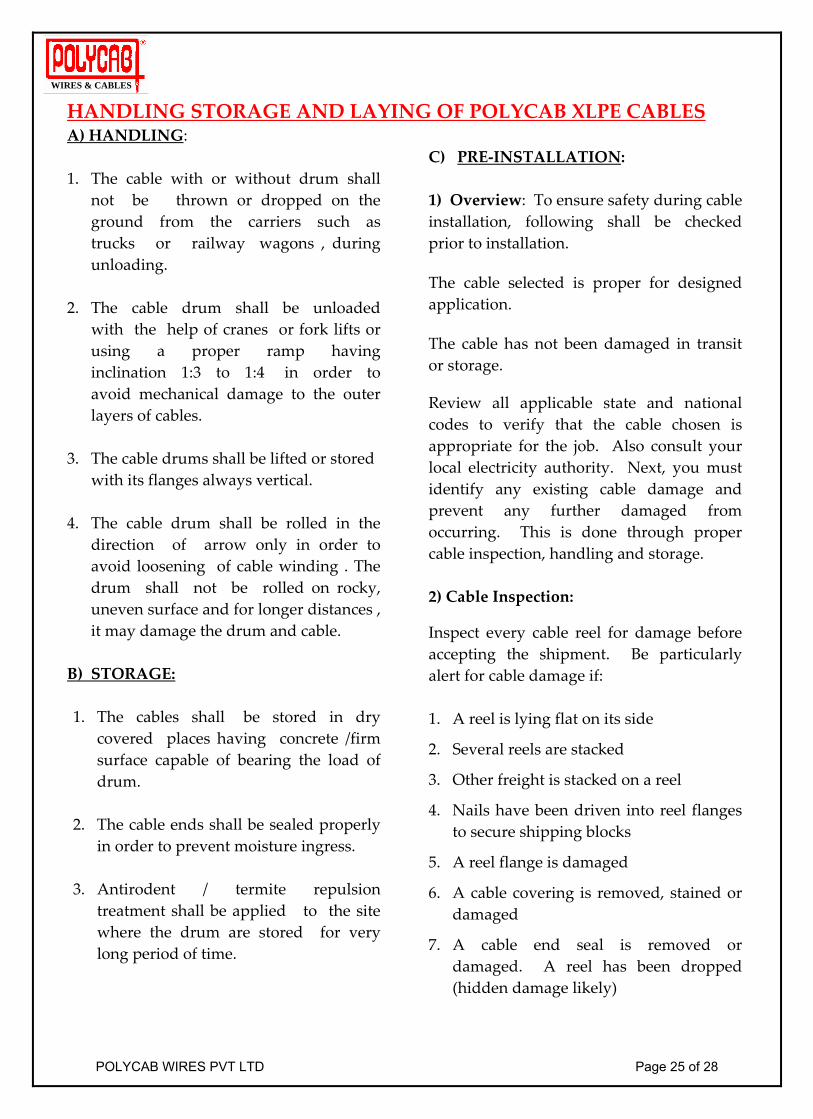
HANDLING STORAGE AND LAYING OF POLYCAB XLPE CABLES A) HANDLING: 1. The cable with or without drum shall
not be thrown or dropped on the ground from the carriers such as trucks or railway wagons , during unloading.
2. The cable drum shall be unloaded
with the help of cranes or fork lifts or using a proper ramp having inclination 1:3 to 1:4 in order to avoid mechanical damage to the outer layers of cables.
3. The cable drums shall be lifted or stored
with its flanges always vertical. 4. The cable drum shall be rolled in the
direction of arrow only in order to avoid loosening of cable winding . The drum shall not be rolled on rocky, uneven surface and for longer distances , it may damage the drum and cable.
B) STORAGE: 1. The cables shall be stored in dry
covered places having concrete /firm surface capable of bearing the load of drum.
2. The cable ends shall be sealed properly
in order to prevent moisture ingress. 3. Antirodent / termite repulsion
treatment shall be applied to the site where the drum are stored for very long period of time.
C) PRE-INSTALLATION: 1) Overview: To ensure safety during cable installation, following shall be checked prior to installation. The cable selected is proper for designed application. The cable has not been damaged in transit or storage.
Review all applicable state and national codes to verify that the cable chosen is appropriate for the job. Also consult your local electricity authority. Next, you must identify any existing cable damage and prevent any further damaged from occurring. This is done through proper cable inspection, handling and storage. 2) Cable Inspection:
Inspect every cable reel for damage before accepting the shipment. Be particularly alert for cable damage if: 1. A reel is lying flat on its side
2. Several reels are stacked
3. Other freight is stacked on a reel
4. Nails have been driven into reel flanges to secure shipping blocks
5. A reel flange is damaged
6. A cable covering is removed, stained or damaged
7. A cable end seal is removed or damaged. A reel has been dropped (hidden damage likely)
WIRES & CABLES
POLYCAB WIRES PVT LTD Page 25 of 28

D) CABLE HANDLING: Remove all nails and staples from the reel flanges before moving a reel, and avoid all objects that could crush, damage or impact the cables when moving. NEVER used the cable as a means to move a reel. When unreeling, observe recommended bending radii, use swivels to prevent twisting and avoid overruns. E). LAYING: 1. Polycab recommend the laying and
installation of cables as per IS:1255/84.
2. Care shall be taken during laying to avoid sharp bending , and twisting.
3. Cable shall be un wound from the drum by lifting the drum on the center
4. shaft supported both ends with suitable jacks / stands.
5. Under no circumstances the cable winding shall be lifted off a coil or drum lying flat at the flanges. This would cause serious twist and damages.
6. Suitable protection shall be provided to the cables against mechanical damages, it includes covers, pipes etc.
F) Recommended minimum bending radius for Heavy Duty cables.
Single Core : 20 x D Multicore : 15 x D Where D= Diameter of cable in mm
G) Recommended safe Pulling force with stockings:- a). For Unarmoured Cable: P = 5 D2 Where P= Pulling Force b). For Armoured Cable : P = 9 D2 Where D= Diameter of cable in mm H) Recommended safe pulling force when pulled with pulling eye :- a) For Aluminium Conductors : 30 N/mm2 b) For Copper Conductor : 50 N/mm2
IMPORTANT FORMULAE * TO CALCULATE VARIOUS ELECTRICAL
PARAMETERS OF CABLES
1) Inductance: L = K+ 0.2 loge 2S(mH/km) d
where K = Constant for different stranded conductors S = Axial Spacing between Cables & Conductors in mm. d = Conductor Diameter No. of wires in Conductor K 7 0.0642 19 0.0554 37 0.0528 61 0.0514 Above 61 0.0500
2) Reactance: X = 2π f x L x 10-3 Ω / km
where f = frequency L = Inductance
POLYCAB WIRES PVT LTD Page 26 of 28

3) Impedance: Z = (R2 + X2) ½ Ω / km
Where R = A.C Resistance at operating temperature Ω / km X = Reactance
4) Charging Current = A = Uo x 2π x f x C x 10-6 Ω / km 1) Voltage Drop: For 3 Core Cables : √3 x Z V/A/Mtr For 1 Core Cables : 2 x Z
Where Z = Impedance 6) Capacitance: C = Er ( µf / km)
18 loge (D/d)
where Er = Relative Permitivity for XLPE : 2.3 D = Dia over Insulation d = Dia over conductor 8) Dielectric loss in watts per km/phase
= 2π f x C Uo2 tan 10-6
(watt / km per phase)
where C = Capacitance Uo = Power frequency voltage between conductor & earth Tan = Dielectric power factor = 0.0003 for XLPE
9) Voltage Induced in Sheath ES = IXm
where I = conductor current (A)
Xm = 2π fM x 10–3 (Ω / km) M = 0.2 loge 2S (mH/km) dm S = Distance between Cable Centres, dm = Mean Diameter of Sheath 10) Short Circuit Rating
I2 = K2 S2 loge θ1 +β T θ0 +β where I = Short circuit (R.M.S over duration) in Amps. T = Duration of short circuit in second
K = Constant – 226 for Copper, 148 for Aluminium, 78 for Steel S = Area of Conductor in mm2
θ1 = Final Temperature of Conductor or Armour
θ0 = Initial Temperature of Conductor or Armour
β = Reciprocal of the temperature coefficient of resistance of the conductor per o C at 0 o C
β = Constant – 228 for Aluminium 202 for Steel, 234.5 for Copper * source BICC handbook
WIRES & CABLES
POLYCAB WIRES PVT LTD Page 27 of 28
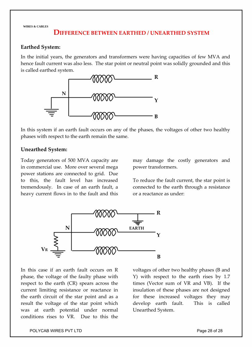
DIFFERENCE BETWEEN EARTHED / UNEARTHED SYSTEM Earthed System:
In the initial years, the generators and transformers were having capacities of few MVA and hence fault current was also less. The star point or neutral point was solidly grounded and this is called earthed system. R
N
Y
B In this system if an earth fault occurs on any of the phases, the voltages of other two healthy phases with respect to the earth remain the same. Unearthed System:
Today generators of 500 MVA capacity are in commercial use. More over several mega power stations are connected to grid. Due to this, the fault level has increased tremendously. In case of an earth fault, a heavy current flows in to the fault and this
may damage the costly generators and power transformers. To reduce the fault current, the star point is connected to the earth through a resistance or a reactance as under:
R N EARTH Y
VR B In this case if an earth fault occurs on R phase, the voltage of the faulty phase with respect to the earth (CR) spears across the current limiting resistance or reactance in the earth circuit of the star point and as a result the voltage of the star point which was at earth potential under normal conditions rises to VR. Due to this the
voltages of other two healthy phases (B and Y) with respect to the earth rises by 1.7 times (Vector sum of VR and VB). If the insulation of these phases are not designed for these increased voltages they may develop earth fault. This is called Unearthed System.
WIRES & CABLES
POLYCAB WIRES PVT LTD Page 28 of 28


