MA7200 Modbus Manual - dynamatic.com · 7200MA MODBUS Application Notes A C D 5/29 7200MA MODBUS...
29
A 莊 C 馮 D 1/29 7200MA MODBUS MANUAL.DOC 2001/06/05 7200MA RS-485 MODBUS Communication Application Manual
-
Upload
nguyenhanh -
Category
Documents
-
view
232 -
download
0
Transcript of MA7200 Modbus Manual - dynamatic.com · 7200MA MODBUS Application Notes A C D 5/29 7200MA MODBUS...

A
莊C
馮D
1/29
7200MA MODBUS MANUAL.DOC 2001/06/05
7200MA
RS-485 MODBUS Communication
Application Manual
7200MA MODBUS Application Notes
A C D
2/29
7200MA MODBUS MANUAL.DOC 2001/06/05
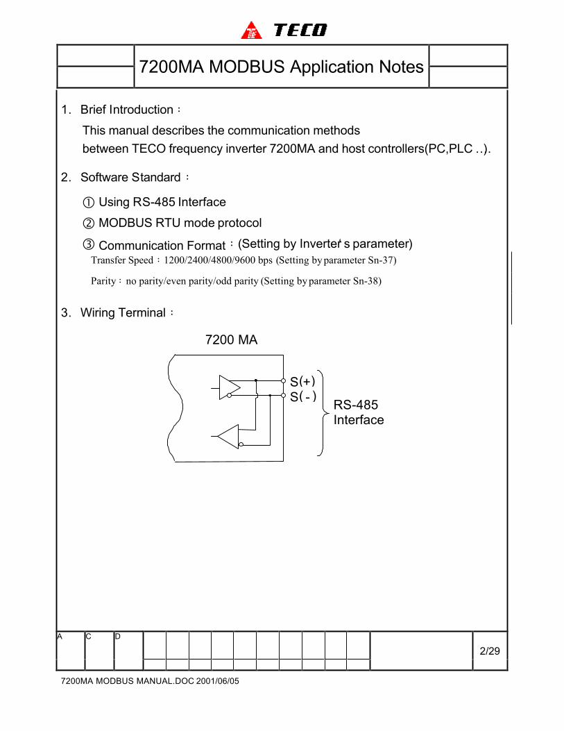
1. Brief Introduction:
This manual describes the communication methods
between TECO frequency inverter 7200MA and host controllers(PC,PLC …).
2. Software Standard:
� Using RS-485 Interface
� MODBUS RTU mode protocol
� Communication Format:(Setting by Inverter‘ s parameter)
Transfer Speed:1200/2400/4800/9600 bps (Setting by parameter Sn-37)
Parity:no parity/even parity/odd parity (Setting by parameter Sn-38)
3. Wiring Terminal:
S( - )S(+)
RS-485Interface
7200 MA

7200MA MODBUS Application Notes
A C D
3/29
7200MA MODBUS MANUAL.DOC 2001/06/05
4. Related parameters for MODBUS communication:
(1) Node address
Sn-36 =1~31 -------------------------- Inverter Node address (Default = 1)
(2) Transfer Speed (baud rate)
Sn-37 = 0 ------------------------------- 1200 Bps
= 1 ------------------------------- 2400 Bps (Default = 1)
= 2 ------------------------------- 4800 Bps
= 3------------------------------- 9600 Bps
(3) Data Parity
Sn-38 = 0 ------------------------------- No Parity (Default = 0)
= 1 ------------------------------- Even Parity
= 2 ------------------------------- Odd Parity
(4) Stopping method while RS485 Communication Fault
Sn-39 = 0 ------------------------------- Decelerating to stop by Bn-02
(Default = 0)
= 1 ------------------------------- Coasting to stop
= 2 ------------------------------- Decelerating to stop by Bn-04
= 3 ------------------------------- Continuous operation
(Can be stop by STOP Key)
(5) Time-out Check
Cn-27 = 00.0 s ------------------------ Don‘ t care
= 01.0 s ------------------------ Checked error (Default = 01.0 s)

7200MA MODBUS Application Notes
A C D
4/29
7200MA MODBUS MANUAL.DOC 2001/06/05
5. Inverter connected with host controller:
(1) Operation procedure
� Inverter power turn on,Set the related parameters
� Connect inverter and host controller
� Host controller sends communication message
(2) Communication status indication of inverter
We can set the Run/Stop command (Sn-04) or Frequency Reference
(Sn-05) by RS485. Inverter will display “ Alarm RS-485” if it does not
receive any message from host controller after power on 5 seconds. This
display will disappear while inverter had received messages from host
controller.
We can set Time-out Check. Inverter will display “ Alarm RS-485” if it does
not receive any message in Time-out (Cn-27).
Parameter Sn-39 will decide the “ Alarm RS-485” display format.
Sn-39 = 0,Decelerate to stop by Bn-02 (“ Alarm RS-485” light up)
= 1,Coasting to stop (“ Alarm RS-485” light up)
= 2,Decelerate to stop by Bn-04 (“ Alarm RS-485” light up)
= 3,Continuous operation (“ Alarm RS-485” flash)
7200MA MODBUS Application Notes
A C D
5/29
7200MA MODBUS MANUAL.DOC 2001/06/05
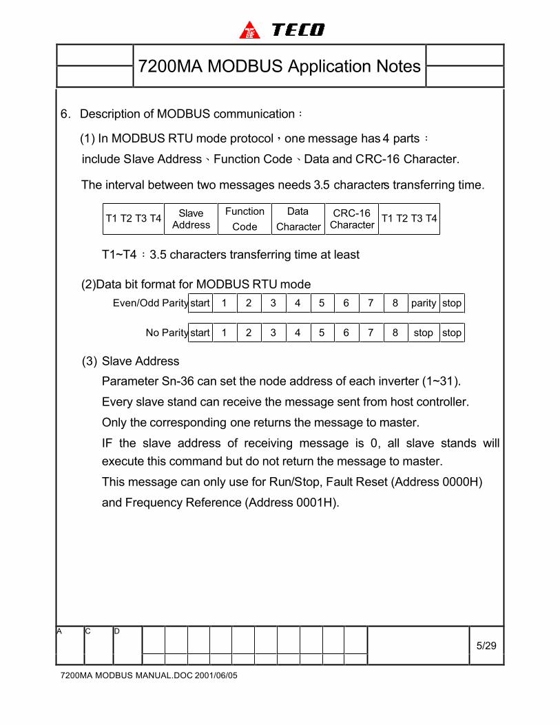
6. Description of MODBUS communication:
(1) In MODBUS RTU mode protocol,one message has 4 parts:
include Slave Address、Function Code、Data and CRC-16 Character.
The interval between two messages needs 3.5 characters transferring time.
T1 T2 T3 T4Slave
Address
Function
Code
Data
Character
CRC-16Character
T1 T2 T3 T4
T1~T4:3.5 characters transferring time at least
(2)Data bit format for MODBUS RTU mode
Even/Odd Paritystart 1 2 3 4 5 6 7 8 parity stop
No Parity start 1 2 3 4 5 6 7 8 stop stop
(3) Slave Address
Parameter Sn-36 can set the node address of each inverter (1~31).
Every slave stand can receive the message sent from host controller.
Only the corresponding one returns the message to master.
IF the slave address of receiving message is 0, all slave stands will
execute this command but do not return the message to master.
This message can only use for Run/Stop, Fault Reset (Address 0000H)
and Frequency Reference (Address 0001H).
7200MA MODBUS Application Notes
A C D
6/29
7200MA MODBUS MANUAL.DOC 2001/06/05
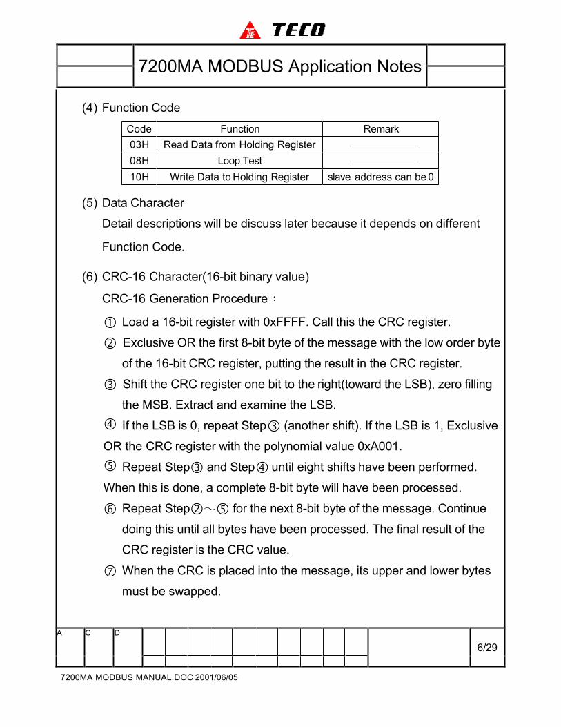
(4) Function Code
Code Function Remark
03H Read Data from Holding Register
08H Loop Test
10H Write Data to Holding Register slave address can be 0
(5) Data Character
Detail descriptions will be discuss later because it depends on different
Function Code.
(6) CRC-16 Character(16-bit binary value)
CRC-16 Generation Procedure:
� Load a 16-bit register with 0xFFFF. Call this the CRC register.
� Exclusive OR the first 8-bit byte of the message with the low order byte
of the 16-bit CRC register, putting the result in the CRC register.
� Shift the CRC register one bit to the right(toward the LSB), zero filling
the MSB. Extract and examine the LSB.
� If the LSB is 0, repeat Step� (another shift). If the LSB is 1, Exclusive
OR the CRC register with the polynomial value 0xA001.
� Repeat Step� and Step� until eight shifts have been performed.
When this is done, a complete 8-bit byte will have been processed.
� Repeat Step�∼� for the next 8-bit byte of the message. Continue
doing this until all bytes have been processed. The final result of the
CRC register is the CRC value.
� When the CRC is placed into the message, its upper and lower bytes
must be swapped.
7200MA MODBUS Application Notes
A C D
7/29
7200MA MODBUS MANUAL.DOC 2001/06/05
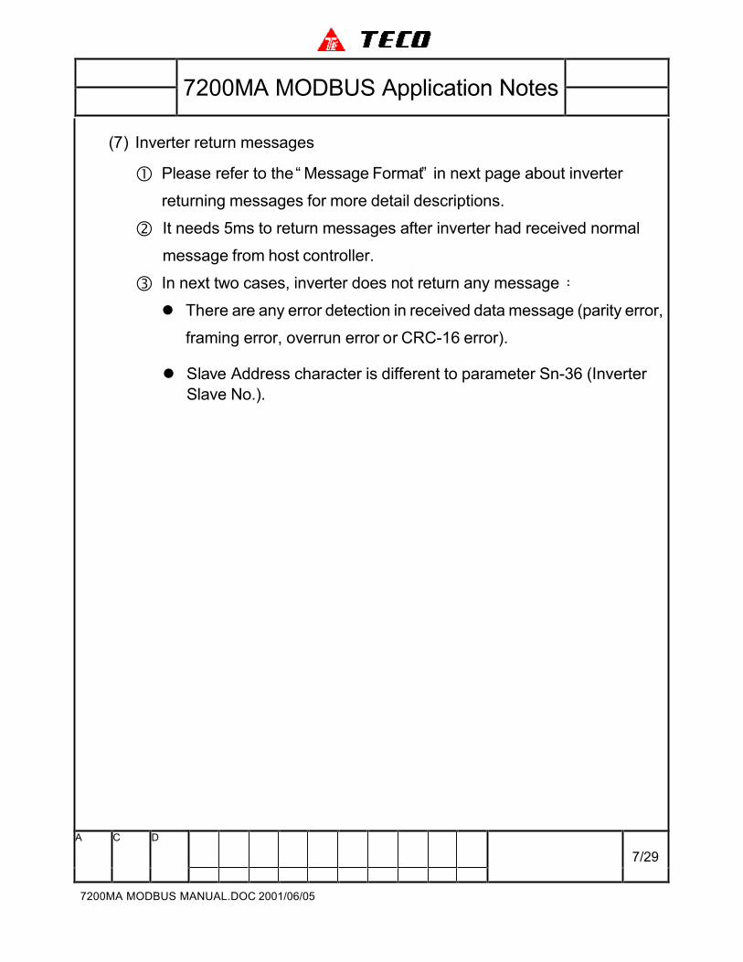
(7) Inverter return messages
� Please refer to the “ Message Format” in next page about inverter
returning messages for more detail descriptions.
� It needs 5ms to return messages after inverter had received normal
message from host controller.
� In next two cases, inverter does not return any message:
l There are any error detection in received data message (parity error,
framing error, overrun error or CRC-16 error).
l Slave Address character is different to parameter Sn-36 (Inverter
Slave No.).
7200MA MODBUS Application Notes
A C D
8/29
7200MA MODBUS MANUAL.DOC 2001/06/05
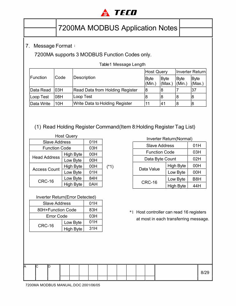
7. Message Format:
7200MA supports 3 MODBUS Function Codes only.
Table1 Message Length
Host Query Inverter Return
Function Code Description Byte(Min.)
Byte(Max.)
Byte(Min.)
Byte(Max.)
Data Read 03H Read Data from Holding Register 8 8 7 37
Loop Test 08H Loop Test 8 8 8 8
Data Write 10H Write Data to Holding Register 11 41 8 8
(1) Read Holding Register Command(Item 8:Holding Register Tag List)
Host Query
Slave Address 01H
Function Code 03H
High Byte 00HHead Address
Low Byte 00H
High Byte 00HAccess Count
Low Byte 01H
(*1)
Low Byte 84HCRC-16
High Byte 0AH
Inverter Return(Error Detected)
Slave Address 01H
80H+Function Code 83H
Error Code 03H
Low Byte 01HCRC-16
High Byte 31H
Inverter Return(Normal)
Slave Address 01H
Function Code 03H
Data Byte Count 02H
High Byte 00HData Value
Low Byte 00H
Low Byte B8HCRC-16
High Byte 44H
*1 Host controller can read 16 registers
at most in each transferring message.
7200MA MODBUS Application Notes
A C D
9/29
7200MA MODBUS MANUAL.DOC 2001/06/05
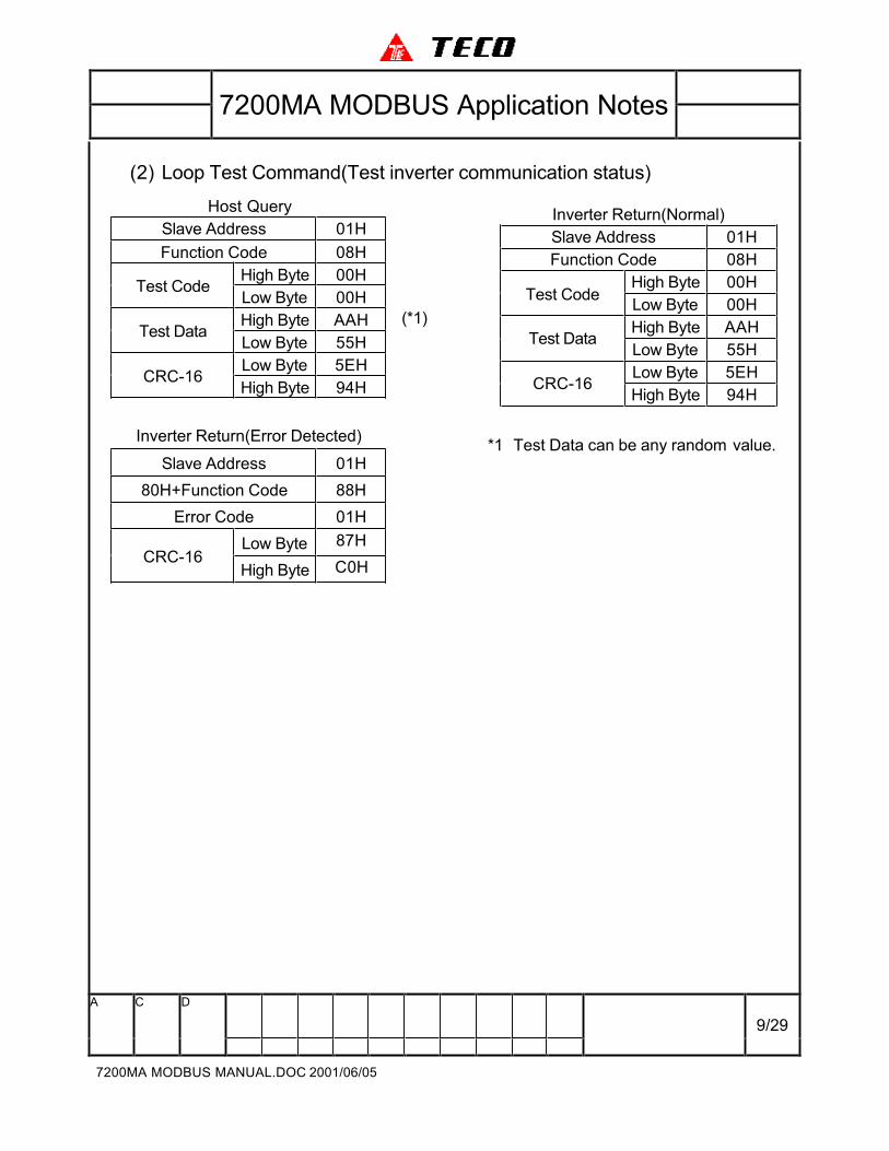
(2) Loop Test Command(Test inverter communication status)
Host Query
Slave Address 01H
Function Code 08H
High Byte 00HTest Code
Low Byte 00H
High Byte AAHTest Data
Low Byte 55H
Low Byte 5EH
(*1)
CRC-16High Byte 94H
Inverter Return(Error Detected)
Slave Address 01H
80H+Function Code 88H
Error Code 01H
Low Byte 87HCRC-16
High Byte C0H
Inverter Return(Normal)
Slave Address 01H
Function Code 08H
High Byte 00HTest Code
Low Byte 00H
High Byte AAHTest Data
Low Byte 55H
Low Byte 5EHCRC-16
High Byte 94H
*1 Test Data can be any random value.
7200MA MODBUS Application Notes
A C D
10/29
7200MA MODBUS MANUAL.DOC 2001/06/05
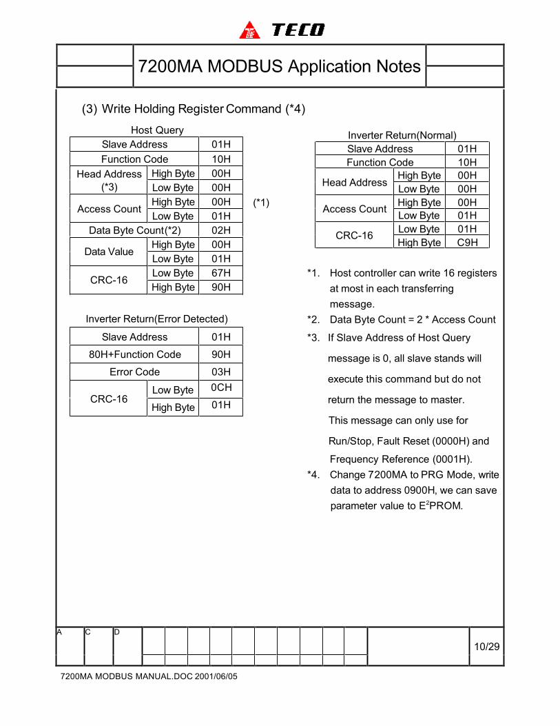
(3) Write Holding Register Command (*4)
Host Query
Slave Address 01H
Function Code 10H
High Byte 00HHead Address
(*3) Low Byte 00H
High Byte 00HAccess Count
Low Byte 01H
(*1)
Data Byte Count(*2) 02H
High Byte 00HData Value
Low Byte 01H
Low Byte 67HCRC-16
High Byte 90H
Inverter Return(Error Detected)
Slave Address 01H
80H+Function Code 90H
Error Code 03H
Low Byte 0CHCRC-16
High Byte 01H
Inverter Return(Normal)
Slave Address 01H
Function Code 10H
High Byte 00HHead Address
Low Byte 00H
High Byte 00HAccess Count
Low Byte 01H
Low Byte 01HCRC-16
High Byte C9H
*1. Host controller can write 16 registers
at most in each transferring
message.
*2. Data Byte Count = 2 * Access Count
*3. If Slave Address of Host Query
message is 0, all slave stands will
execute this command but do not
return the message to master.
This message can only use for
Run/Stop, Fault Reset (0000H) and
Frequency Reference (0001H).
*4. Change 7200MA to PRG Mode, write
data to address 0900H, we can save
parameter value to E2PROM.
7200MA MODBUS Application Notes
A C D
11/29
7200MA MODBUS MANUAL.DOC 2001/06/05
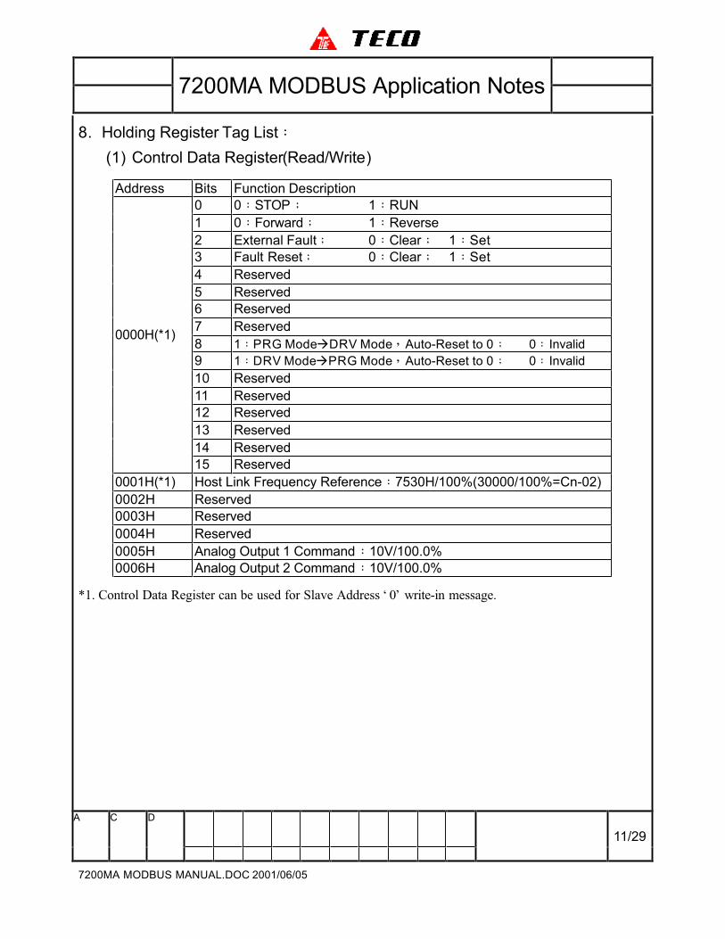
8. Holding Register Tag List:
(1) Control Data Register(Read/Write)
Address Bits Function Description
0 0:STOP; 1:RUN
1 0:Forward; 1:Reverse
2 External Fault; 0:Clear; 1:Set
3 Fault Reset; 0:Clear; 1:Set
4 Reserved
5 Reserved
6 Reserved
7 Reserved
8 1:PRG ModeàDRV Mode,Auto-Reset to 0; 0:Invalid
9 1:DRV ModeàPRG Mode,Auto-Reset to 0; 0:Invalid
10 Reserved
11 Reserved
12 Reserved
13 Reserved
14 Reserved
0000H(*1)
15 Reserved
0001H(*1) Host Link Frequency Reference:7530H/100%(30000/100%=Cn-02)
0002H Reserved
0003H Reserved
0004H Reserved
0005H Analog Output 1 Command:10V/100.0%
0006H Analog Output 2 Command:10V/100.0%
*1. Control Data Register can be used for Slave Address ‘ 0’ write-in message.

7200MA MODBUS Application Notes
A C D
12/29
7200MA MODBUS MANUAL.DOC 2001/06/05
Address Bits Function Description
0 Relay Output(RA-RB-RC) Command; 0:Clear; 1:Set
1 Digital Output(DO1) Command; 0:Clear; 1:Set
2 Digital Output(DO2) Command; 0:Clear; 1:Set
3 Reserved
4 Reserved
5 Reserved
6 Reserved
7 Reserved
8 Reserved
9 Reserved
10 Reserved
11 Reserved
12 Reserved
13 Reserved
14 Reserved
0007H
15 Reserved
0008H Reserved
0009H Reserved
000AH Reserved
000BH Reserved
000CH Reserved
000DH Reserved
000EH Reserved
000FH Reserved

7200MA MODBUS Application Notes
A C D
13/29
7200MA MODBUS MANUAL.DOC 2001/06/05
(2) Monitor Data Register(Read Only)
Address Bits Function Description
0 1:Running
1 1:Zero Speed
2 1:Reverse
3 1:Inverter Ready
4 1:DRV Mode; 0:PRG Mode
5 1:440V Series; 0:220V Series
6 1:Inverter Alarm
7 1:Inverter Fault
8 1:Reserved
9 1:Reserved
10 1:Reserved
11 1:LCD Digital Operator
12
13
14
0020H
15
0001:Parameter Setting Invalid0010:Multi-Function Digital Input Parameter Setting Invalid0011:Auto-Run Mode Parameter Setting Invalid0100:V/F Pattern Parameter Setting Invalid0101:Frequency Limit Parameter Setting Invalid0110:Jump Frequency Parameter Setting Invalid0111:PG Parameter Setting Invalid1000:Reserved1001:Reserved1010:Reserved1011:Reserved1100:Reserved1101:Reserved1110:Reserved1111:Reserved
7200MA MODBUS Application Notes
A C D
14/29
7200MA MODBUS MANUAL.DOC 2001/06/05
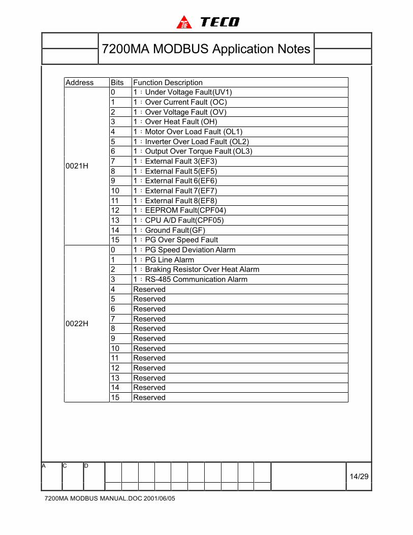
Address Bits Function Description
0 1:Under Voltage Fault(UV1)
1 1:Over Current Fault (OC)
2 1:Over Voltage Fault (OV)
3 1:Over Heat Fault (OH)
4 1:Motor Over Load Fault (OL1)
5 1:Inverter Over Load Fault (OL2)
6 1:Output Over Torque Fault (OL3)
7 1:External Fault 3(EF3)
8 1:External Fault 5(EF5)
9 1:External Fault 6(EF6)
10 1:External Fault 7(EF7)
11 1:External Fault 8(EF8)
12 1:EEPROM Fault(CPF04)
13 1:CPU A/D Fault(CPF05)
14 1:Ground Fault(GF)
0021H
15 1:PG Over Speed Fault
0 1:PG Speed Deviation Alarm
1 1:PG Line Alarm
2 1:Braking Resistor Over Heat Alarm
3 1:RS-485 Communication Alarm
4 Reserved
5 Reserved
6 Reserved
7 Reserved
8 Reserved
9 Reserved
10 Reserved
11 Reserved
12 Reserved
13 Reserved
14 Reserved
0022H
15 Reserved
7200MA MODBUS Application Notes
A C D
15/29
7200MA MODBUS MANUAL.DOC 2001/06/05
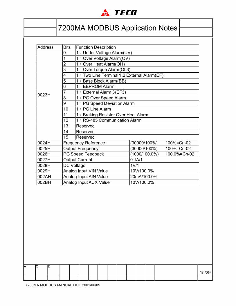
Address Bits Function Description
0 1:Under Voltage Alarm(UV)
1 1:Over Voltage Alarm(OV)
2 1:Over Heat Alarm(OH)
3 1:Over Torque Alarm(OL3)
4 1:Two Line Terminal 1,2 External Alarm(EF)
5 1:Base Block Alarm(BB)
6 1:EEPROM Alarm
7 1:External Alarm 3(EF3)
8 1:PG Over Speed Alarm
9 1:PG Speed Deviation Alarm
10 1:PG Line Alarm
11 1:Braking Resistor Over Heat Alarm
12 1:RS-485 Communication Alarm
13 Reserved
14 Reserved
0023H
15 Reserved
0024H Frequency Reference (30000/100%) 100%=Cn-02
0025H Output Frequency (30000/100%) 100%=Cn-02
0026H PG Speed Feedback (1000/100.0%) 100.0%=Cn-02
0027H Output Current 0.1A/1
0028H DC Voltage 1V/1
0029H Analog Input VIN Value 10V/100.0%
002AH Analog Input AIN Value 20mA/100.0%
002BH Analog Input AUX Value 10V/100.0%
7200MA MODBUS Application Notes
A C D
16/29
7200MA MODBUS MANUAL.DOC 2001/06/05
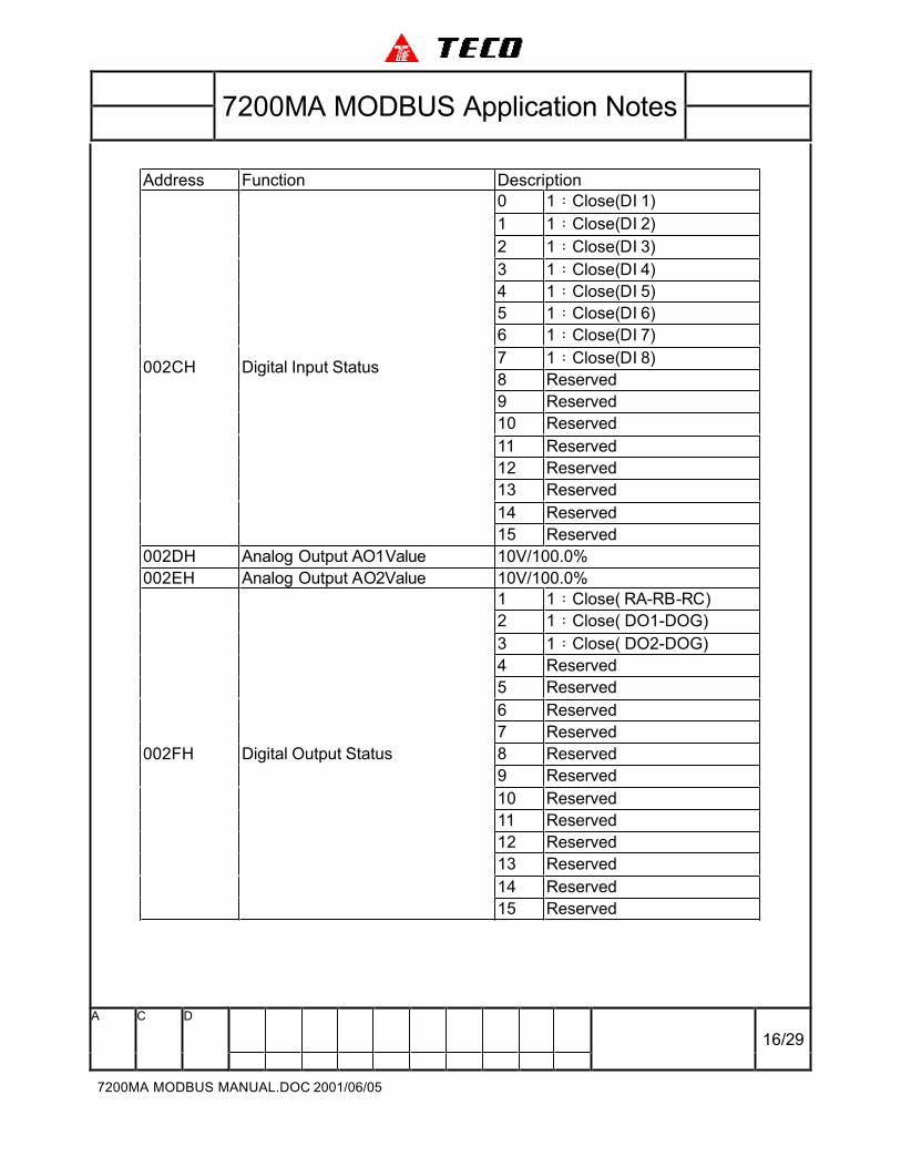
Address Function Description
0 1:Close(DI 1)
1 1:Close(DI 2)
2 1:Close(DI 3)
3 1:Close(DI 4)
4 1:Close(DI 5)
5 1:Close(DI 6)
6 1:Close(DI 7)
7 1:Close(DI 8)
8 Reserved
9 Reserved
10 Reserved
11 Reserved
12 Reserved
13 Reserved
14 Reserved
002CH Digital Input Status
15 Reserved
002DH Analog Output AO1Value 10V/100.0%
002EH Analog Output AO2Value 10V/100.0%
1 1:Close( RA-RB-RC)
2 1:Close( DO1-DOG)
3 1:Close( DO2-DOG)
4 Reserved
5 Reserved
6 Reserved
7 Reserved
8 Reserved
9 Reserved
10 Reserved
11 Reserved
12 Reserved
13 Reserved
14 Reserved
002FH Digital Output Status
15 Reserved
7200MA MODBUS Application Notes
A C D
17/29
7200MA MODBUS MANUAL.DOC 2001/06/05
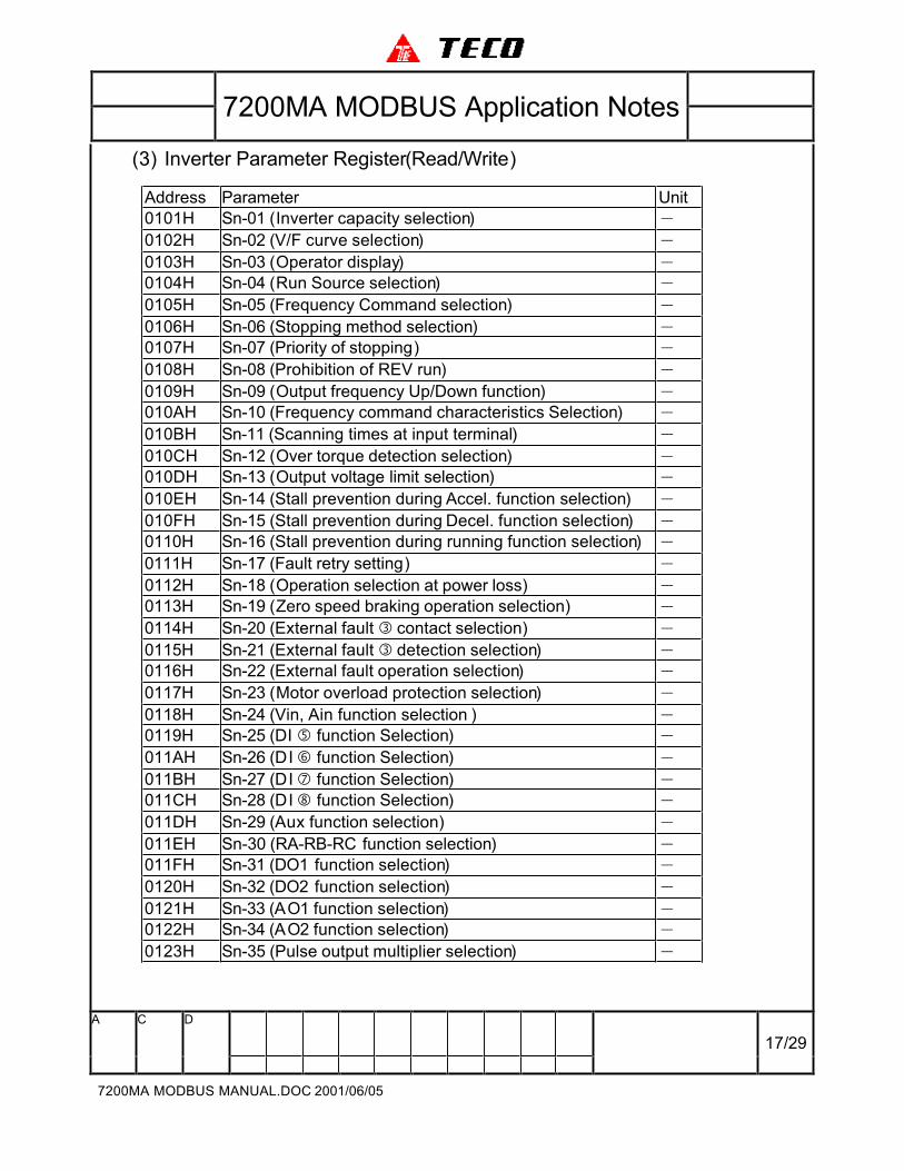
(3) Inverter Parameter Register(Read/Write)
Address Parameter Unit
0101H Sn-01 (Inverter capacity selection) -0102H Sn-02 (V/F curve selection) -0103H Sn-03 (Operator display) -0104H Sn-04 (Run Source selection) -0105H Sn-05 (Frequency Command selection) -0106H Sn-06 (Stopping method selection) -0107H Sn-07 (Priority of stopping) -0108H Sn-08 (Prohibition of REV run) -0109H Sn-09 (Output frequency Up/Down function) -010AH Sn-10 (Frequency command characteristics Selection) -010BH Sn-11 (Scanning times at input terminal) -010CH Sn-12 (Over torque detection selection) -010DH Sn-13 (Output voltage limit selection) -010EH Sn-14 (Stall prevention during Accel. function selection) -010FH Sn-15 (Stall prevention during Decel. function selection) -0110H Sn-16 (Stall prevention during running function selection) -0111H Sn-17 (Fault retry setting) -0112H Sn-18 (Operation selection at power loss) -0113H Sn-19 (Zero speed braking operation selection) -0114H Sn-20 (External fault � contact selection) -0115H Sn-21 (External fault � detection selection) -0116H Sn-22 (External fault operation selection) -0117H Sn-23 (Motor overload protection selection) -0118H Sn-24 (Vin, Ain function selection ) -0119H Sn-25 (DI � function Selection) -011AH Sn-26 (DI � function Selection) -011BH Sn-27 (DI � function Selection) -011CH Sn-28 (DI � function Selection) -011DH Sn-29 (Aux function selection) -011EH Sn-30 (RA-RB-RC function selection) -011FH Sn-31 (DO1 function selection) -0120H Sn-32 (DO2 function selection) -0121H Sn-33 (AO1 function selection) -0122H Sn-34 (AO2 function selection) -0123H Sn-35 (Pulse output multiplier selection) -
7200MA MODBUS Application Notes
A C D
18/29
7200MA MODBUS MANUAL.DOC 2001/06/05
Address Parameter Unit
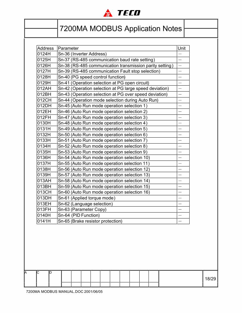
0124H Sn-36 (Inverter Address) -0125H Sn-37 (RS-485 communication baud rate setting) -0126H Sn-38 (RS-485 communication transmission parity setting ) -0127H Sn-39 (RS-485 communication Fault stop selection) -0128H Sn-40 (PG speed control function) -0129H Sn-41 (Operation selection at PG open circuit) -012AH Sn-42 (Operation selection at PG large speed deviation) -012BH Sn-43 (Operation selection at PG over speed deviation) -012CH Sn-44 (Operation mode selection during Auto Run) -012DH Sn-45 (Auto Run mode operation selection 1) -012EH Sn-46 (Auto Run mode operation selection 2) -012FH Sn-47 (Auto Run mode operation selection 3) -0130H Sn-48 (Auto Run mode operation selection 4) -0131H Sn-49 (Auto Run mode operation selection 5) -0132H Sn-50 (Auto Run mode operation selection 6) -0133H Sn-51 (Auto Run mode operation selection 7) -0134H Sn-52 (Auto Run mode operation selection 8) -0135H Sn-53 (Auto Run mode operation selection 9) -0136H Sn-54 (Auto Run mode operation selection 10) -0137H Sn-55 (Auto Run mode operation selection 11) -0138H Sn-56 (Auto Run mode operation selection 12) -0139H Sn-57 (Auto Run mode operation selection 13) -013AH Sn-58 (Auto Run mode operation selection 14) -013BH Sn-59 (Auto Run mode operation selection 15) -013CH Sn-60 (Auto Run mode operation selection 16) -013DH Sn-61 (Applied torque mode) -013EH Sn-62 (Language selection) -013FH Sn-63 (Parameter Copy) -0140H Sn-64 (PID Function) -0141H Sn-65 (Brake resistor protection) -
7200MA MODBUS Application Notes
A C D
19/29
7200MA MODBUS MANUAL.DOC 2001/06/05
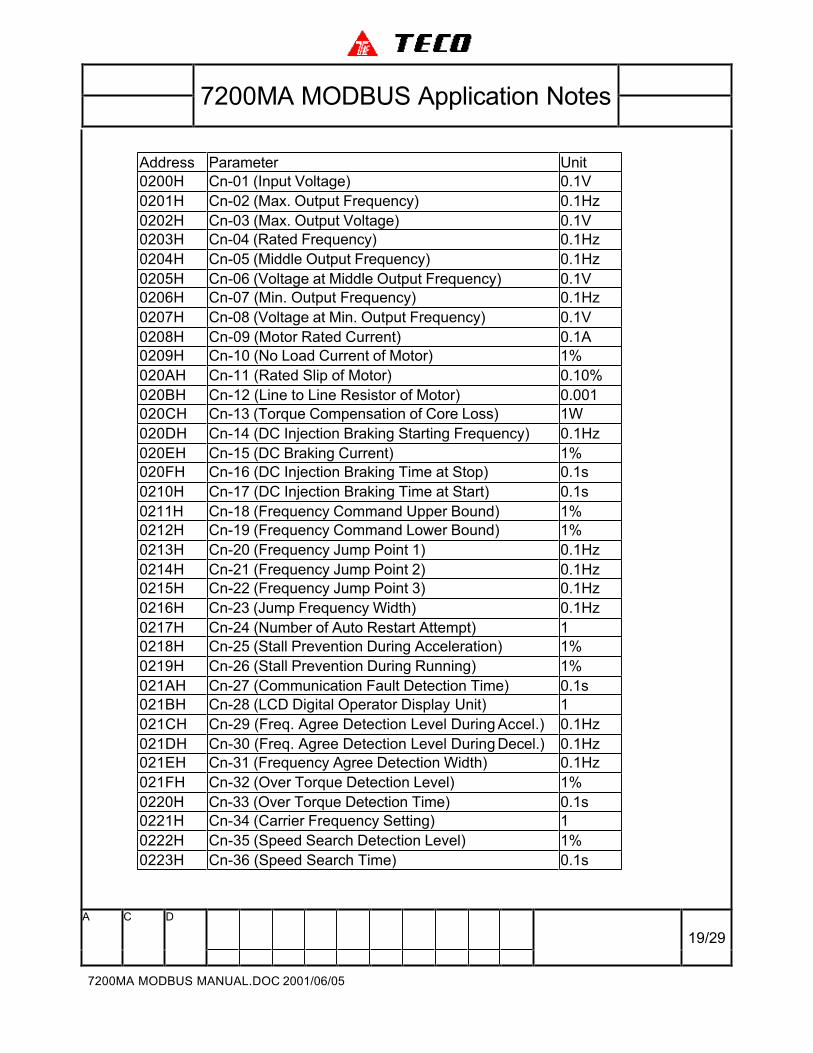
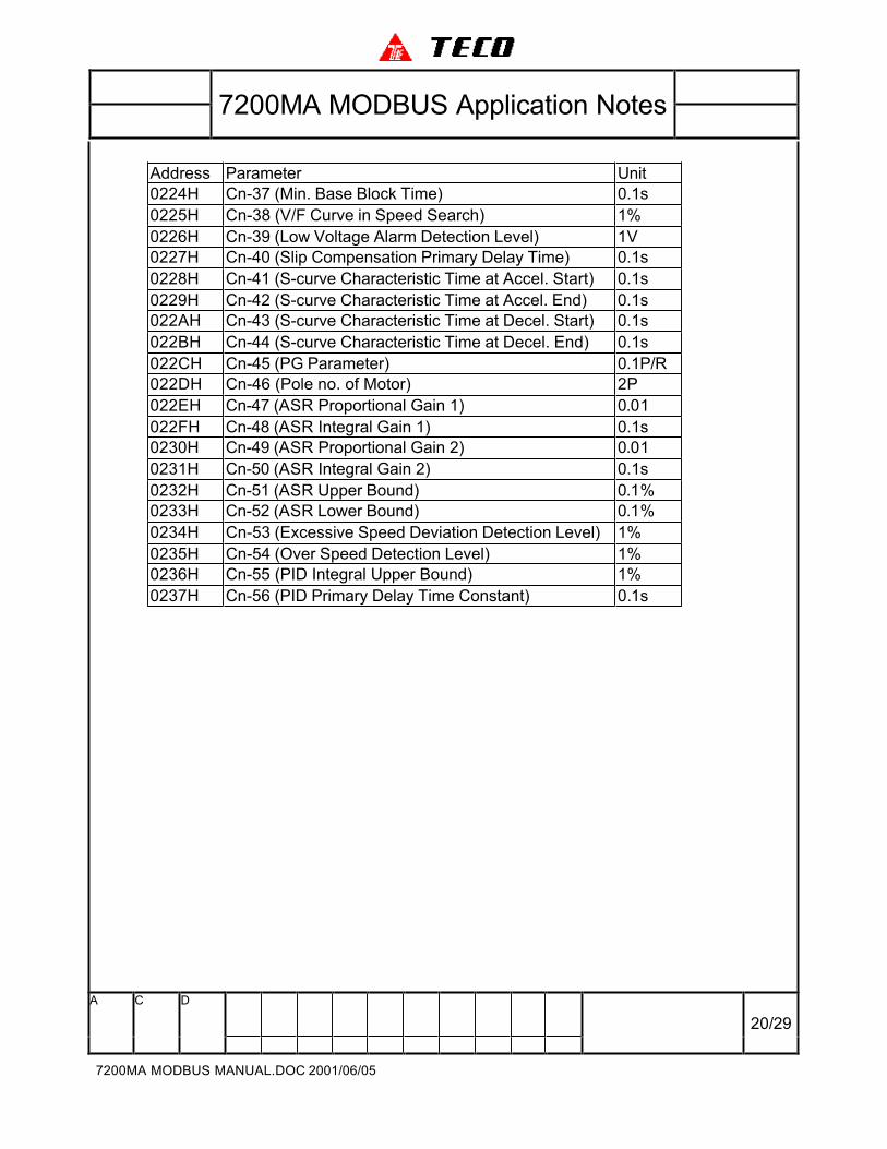
Address Parameter Unit
0200H Cn-01 (Input Voltage) 0.1V
0201H Cn-02 (Max. Output Frequency) 0.1Hz
0202H Cn-03 (Max. Output Voltage) 0.1V
0203H Cn-04 (Rated Frequency) 0.1Hz
0204H Cn-05 (Middle Output Frequency) 0.1Hz
0205H Cn-06 (Voltage at Middle Output Frequency) 0.1V
0206H Cn-07 (Min. Output Frequency) 0.1Hz
0207H Cn-08 (Voltage at Min. Output Frequency) 0.1V
0208H Cn-09 (Motor Rated Current) 0.1A
0209H Cn-10 (No Load Current of Motor) 1%
020AH Cn-11 (Rated Slip of Motor) 0.10%
020BH Cn-12 (Line to Line Resistor of Motor) 0.001
020CH Cn-13 (Torque Compensation of Core Loss) 1W
020DH Cn-14 (DC Injection Braking Starting Frequency) 0.1Hz
020EH Cn-15 (DC Braking Current) 1%
020FH Cn-16 (DC Injection Braking Time at Stop) 0.1s
0210H Cn-17 (DC Injection Braking Time at Start) 0.1s
0211H Cn-18 (Frequency Command Upper Bound) 1%
0212H Cn-19 (Frequency Command Lower Bound) 1%
0213H Cn-20 (Frequency Jump Point 1) 0.1Hz
0214H Cn-21 (Frequency Jump Point 2) 0.1Hz
0215H Cn-22 (Frequency Jump Point 3) 0.1Hz
0216H Cn-23 (Jump Frequency Width) 0.1Hz
0217H Cn-24 (Number of Auto Restart Attempt) 1
0218H Cn-25 (Stall Prevention During Acceleration) 1%
0219H Cn-26 (Stall Prevention During Running) 1%
021AH Cn-27 (Communication Fault Detection Time) 0.1s
021BH Cn-28 (LCD Digital Operator Display Unit) 1
021CH Cn-29 (Freq. Agree Detection Level During Accel.) 0.1Hz
021DH Cn-30 (Freq. Agree Detection Level During Decel.) 0.1Hz
021EH Cn-31 (Frequency Agree Detection Width) 0.1Hz
021FH Cn-32 (Over Torque Detection Level) 1%
0220H Cn-33 (Over Torque Detection Time) 0.1s
0221H Cn-34 (Carrier Frequency Setting) 1
0222H Cn-35 (Speed Search Detection Level) 1%
0223H Cn-36 (Speed Search Time) 0.1s
7200MA MODBUS Application Notes
A C D
20/29
7200MA MODBUS MANUAL.DOC 2001/06/05
Address Parameter Unit
0224H Cn-37 (Min. Base Block Time) 0.1s
0225H Cn-38 (V/F Curve in Speed Search) 1%
0226H Cn-39 (Low Voltage Alarm Detection Level) 1V
0227H Cn-40 (Slip Compensation Primary Delay Time) 0.1s
0228H Cn-41 (S-curve Characteristic Time at Accel. Start) 0.1s
0229H Cn-42 (S-curve Characteristic Time at Accel. End) 0.1s
022AH Cn-43 (S-curve Characteristic Time at Decel. Start) 0.1s
022BH Cn-44 (S-curve Characteristic Time at Decel. End) 0.1s
022CH Cn-45 (PG Parameter) 0.1P/R
022DH Cn-46 (Pole no. of Motor) 2P
022EH Cn-47 (ASR Proportional Gain 1) 0.01
022FH Cn-48 (ASR Integral Gain 1) 0.1s
0230H Cn-49 (ASR Proportional Gain 2) 0.01
0231H Cn-50 (ASR Integral Gain 2) 0.1s
0232H Cn-51 (ASR Upper Bound) 0.1%
0233H Cn-52 (ASR Lower Bound) 0.1%
0234H Cn-53 (Excessive Speed Deviation Detection Level) 1%
0235H Cn-54 (Over Speed Detection Level) 1%
0236H Cn-55 (PID Integral Upper Bound) 1%
0237H Cn-56 (PID Primary Delay Time Constant) 0.1s
7200MA MODBUS Application Notes
A C D
21/29
7200MA MODBUS MANUAL.DOC 2001/06/05
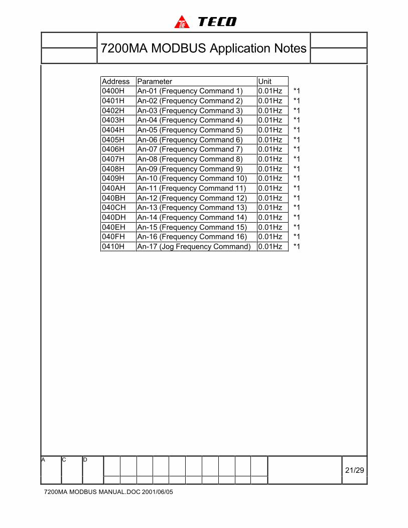
Address Parameter Unit
0400H An-01 (Frequency Command 1) 0.01Hz *1
0401H An-02 (Frequency Command 2) 0.01Hz *1
0402H An-03 (Frequency Command 3) 0.01Hz *1
0403H An-04 (Frequency Command 4) 0.01Hz *1
0404H An-05 (Frequency Command 5) 0.01Hz *1
0405H An-06 (Frequency Command 6) 0.01Hz *1
0406H An-07 (Frequency Command 7) 0.01Hz *1
0407H An-08 (Frequency Command 8) 0.01Hz *1
0408H An-09 (Frequency Command 9) 0.01Hz *1
0409H An-10 (Frequency Command 10) 0.01Hz *1
040AH An-11 (Frequency Command 11) 0.01Hz *1
040BH An-12 (Frequency Command 12) 0.01Hz *1
040CH An-13 (Frequency Command 13) 0.01Hz *1
040DH An-14 (Frequency Command 14) 0.01Hz *1
040EH An-15 (Frequency Command 15) 0.01Hz *1
040FH An-16 (Frequency Command 16) 0.01Hz *1
0410H An-17 (Jog Frequency Command) 0.01Hz *1

7200MA MODBUS Application Notes
A C D
22/29
7200MA MODBUS MANUAL.DOC 2001/06/05
Address Parameter Unit
0500H Bn-01 (Acceleration Time 1) 0.1s *1
0501H Bn-02 (Deceleration Time 1) 0.1s *1
0502H Bn-03 (Acceleration Time 2) 0.1s *1
0503H Bn-04 (Deceleration Time 2) 0.1s *1
0504H Bn-05 (Analog Frequency Cmd. Gain (Voltage)) 0.1% *1
0505H Bn-06 (Analog Frequency Cmd. Bias (Voltage)) 0.1% *1
0506H Bn-07 (Analog Frequency Cmd. Gain (Current)) 0.1% *1
0507H Bn-08 (Analog Frequency Cmd. Bias (Current)) 0.1% *1
0508H Bn-09 (Multi-Function Analog Input Gain) 0.1% *1
0509H Bn-10 (Multi-Function Analog Input Bias) 0.1% *1
050AH Bn-11 (Auto Torque Boost Gain) 0.1 *1
050BH Bn-12 (Monitor 1) 1 *1
050CH Bn-13 (Monitor 2) 1 *1
050DH Bn-14 (Multi-Function Analog Output AO1 Gain) 0.01 *1
050EH Bn-15 (Multi-Function Analog Output AO2 Gain) 0.01 *1
050FH Bn-16 (PID Detection Gain) 0.01 *1
0510H Bn-17 (PID Proportional Gain) 0.01 *1
0511H Bn-18 (PID Integral Time) 0.01s *1
0512H Bn-19 (PID Differential Time) 0.01s *1
0513H Bn-20 (PID Bias) 1% *1
0514H Bn-21 (1‘ st Step Time Under Auto Run Mode) 0.1s *1
0515H Bn-22 (2‘ nd Step Time Under Auto Run Mode) 0.1s *1
0516H Bn-23 (3‘ rd Step Time Under Auto Run Mode) 0.1s *1
0517H Bn-24 (4‘ th Step Time Under Auto Run Mode) 0.1s *1
0518H Bn-25 (5‘ th Step Time Under Auto Run Mode) 0.1s *1
0519H Bn-26 (6‘ th Step Time Under Auto Run Mode) 0.1s *1
051AH Bn-27 (7‘ th Step Time Under Auto Run Mode) 0.1s *1
051BH Bn-28 (8‘ th Step Time Under Auto Run Mode) 0.1s *1
051CH Bn-29 (9‘ th Step Time Under Auto Run Mode) 0.1s *1
051DH Bn-30 (10‘ th Step Time Under Auto Run Mode) 0.1s *1
051EH Bn-31 (11‘ th Step Time Under Auto Run Mode) 0.1s *1
051FH Bn-32 (12‘ th Step Time Under Auto Run Mode) 0.1s *1
0520H Bn-33 (13‘ th Step Time Under Auto Run Mode) 0.1s *1
0521H Bn-34 (14‘ th Step Time Under Auto Run Mode) 0.1s *1
0522H Bn-35 (15‘ th Step Time Under Auto Run Mode) 0.1s *1
0523H Bn-36 (16‘ th Step Time Under Auto Run Mode) 0.1s *1
7200MA MODBUS Application Notes
A C D
23/29
7200MA MODBUS MANUAL.DOC 2001/06/05
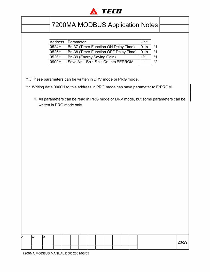
Address Parameter Unit
0524H Bn-37 (Timer Function ON Delay Time) 0.1s *1
0525H Bn-38 (Timer Function OFF Delay Time) 0.1s *1
0526H Bn-39 (Energy Saving Gain) 1% *1
0900H Save An、Bn、Sn、Cn into EEPROM - *2
*1. These parameters can be written in DRV mode or PRG mode.
*2. Writing data 0000H to this address in PRG mode can save parameter to E2PROM.
※ All parameters can be read in PRG mode or DRV mode, but some parameters can be
written in PRG mode only.
7200MA MODBUS Application Notes
A C D
24/29
7200MA MODBUS MANUAL.DOC 2001/06/05
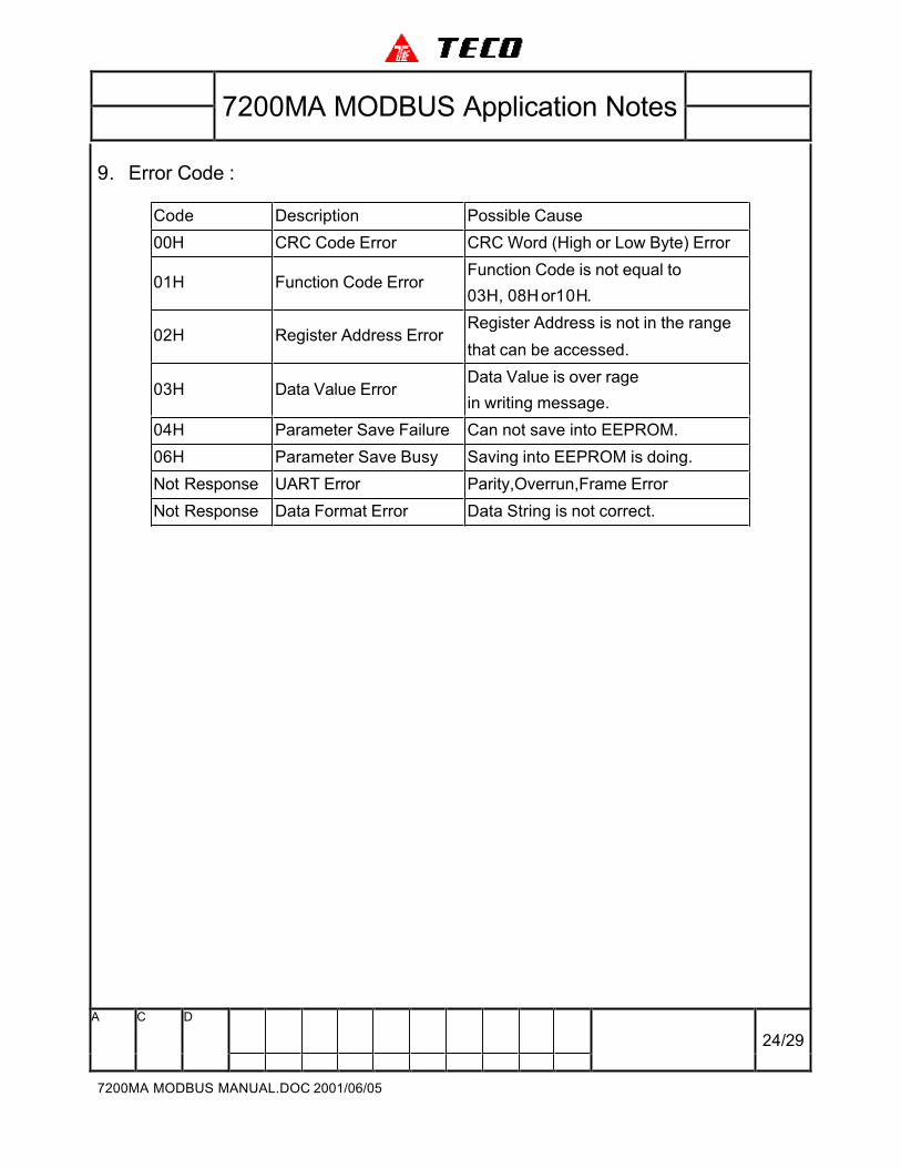
9. Error Code :
Code Description Possible Cause
00H CRC Code Error CRC Word (High or Low Byte) Error
01H Function Code ErrorFunction Code is not equal to
03H, 08H or10H.
02H Register Address ErrorRegister Address is not in the range
that can be accessed.
03H Data Value ErrorData Value is over rage
in writing message.
04H Parameter Save Failure Can not save into EEPROM.
06H Parameter Save Busy Saving into EEPROM is doing.
Not Response UART Error Parity,Overrun,Frame Error
Not Response Data Format Error Data String is not correct.

7200MA MODBUS Application Notes
A C D
25/29
7200MA MODBUS MANUAL.DOC 2001/06/05
10.Example of RS-485 communication application:
Firstly, Set Inverter parameters
Sn-36 = 5 (Inverter Slave Address),Sn-37,Sn-38,Sn-39,Cn-27.
Sn-04 = 2 (Run/Stop by RS-485)
Sn-05 = 2 (Frequency Reference by RS-485)
Sn-30 = 22 (RA Output by RS-485), Sn-31 = 22 (DO1Output by RS-485)
Secondly, Host Controller can control the inverter 7200MA via RS-485 serial
communication by executing the following procedures:
Fout
100%
50%
-50%
Fwd
Rev
SetClear
Digital Output
RA-RB-RC
Set Clear
Digital Output
DO1-DOG
Step1 Step2 Step3 Step4
(1) Run 7200MA forward with 100% Speed. Set DO1-DOG.
(2) Run 7200MA forward with 50% Speed. Clear DO1-DOG. Set RA-RB-RC.
(3) Run 7200MA reverse with 50% Speed. Set RA-RB-RC.
(4) Stop 7200MA. Set RA-RB-RC.

7200MA MODBUS Application Notes
A C D
26/29
7200MA MODBUS MANUAL.DOC 2001/06/05
Step 1
Host Query
Slave Address 01H
Function Code 10H
High Byte 00HHead Address
Low Byte 00H
High Byte 00HAccess Count
Low Byte 08H
Data Byte Count 10H
High Byte 00HData Value1
Low Byte 01H
High Byte 75HData Value2
Low Byte 30H
High Byte 00HData Value3
Low Byte 00H
High Byte 00HData Value4
Low Byte 00H
High Byte 00HData Value5
Low Byte 00H
High Byte 00HData Value6
Low Byte 00H
High Byte 00HData Value7
Low Byte 00H
High Byte 00HData Value8
Low Byte 02H
Low Byte 6CHCRC-16
High Byte 49H
Inverter Return
Slave Address 01H
Function Code 10H
High Byte 00HHead Address
Low Byte 00H
High Byte 00HAccess Count
Low Byte 08H
Low Byte C1HCRC-16
High Byte CFH
Data Value1 of Address 0000H = 0001H: Run 7200MA Forward.
Data Value2 of Address 0001H = 7530H: Speed Reference 100%
(corresponding to Maximum Frequency Cn-02).
Data Value8 of Address 0007H = 0002H:Set DO1-DOG.
※ When inverter received this message, it will start and accelerate to 100%
speed in forward direction, digital output terminal DO1-DOG Set.

7200MA MODBUS Application Notes
A C D
27/29
7200MA MODBUS MANUAL.DOC 2001/06/05
Step 2
Host Query
Slave Address 01H
Function Code 10H
High Byte 00HHead Address
Low Byte 00H
High Byte 00HAccess Count
Low Byte 08H
Data Byte Count 10H
High Byte 00HData Value1
Low Byte 01H
High Byte 3AHData Value2
Low Byte 98H
High Byte 00HData Value3
Low Byte 00H
High Byte 00HData Value4
Low Byte 00H
High Byte 00HData Value5
Low Byte 00H
High Byte 00HData Value6
Low Byte 00H
High Byte 00HData Value7
Low Byte 00H
High Byte 00HData Value8
Low Byte 01H
Low Byte FDHCRC-16
High Byte 2EH
Inverter Return
Slave Address 01H
Function Code 10H
High Byte 00HHead Address
Low Byte 00H
High Byte 00HAccess Count
Low Byte 08H
Low Byte C1HCRC-16
High Byte CFH
Data Value1 of Address 0000H = 0001H: Run 7200MA Forward.
Data Value2 of Address 0001H = 3A98H: Speed Reference 50%
Data Value8 of Address 0007H = 0001H: Set RA-RB-RC.
※ When inverter received this message, it will start and decelerate to 50%
speed in forward direction, digital output terminal DO1-DOG clear, digital
output RA-RB-RC set.

7200MA MODBUS Application Notes
A C D
28/29
7200MA MODBUS MANUAL.DOC 2001/06/05
Step 3
Host Query
Slave Address 01H
Function Code 10H
High Byte 00HHead Address
Low Byte 00H
High Byte 00HAccess Count
Low Byte 08H
Data Byte Count 10H
High Byte 00HData Value1
Low Byte 03H
High Byte 3AHData Value2
Low Byte 98H
High Byte 00HData Value3
Low Byte 00H
High Byte 00HData Value4
Low Byte 00H
High Byte 00HData Value5
Low Byte 00H
High Byte 00HData Value6
Low Byte 00H
High Byte 00HData Value7
Low Byte 00H
High Byte 00HData Value8
Low Byte 01H
Low Byte 7FHCRC-16
High Byte 2FH
Inverter Return
Slave Address 01H
Function Code 10H
High Byte 00HHead Address
Low Byte 00H
High Byte 00HAccess Count
Low Byte 08H
Low Byte C1HCRC-16
High Byte CFH
Data Value1 of Address 0000H = 0003H: Run 7200MA Reverse.
Data Value2 of Address 0001H = 3A98H: Speed Reference 50%
Data Value8 of Address 0007H = 0001H: Set RA-RB-RC.
※ When inverter received this message, it will start and decelerate to 50%
speed in reverse direction, digital output terminal DO1-DOG clear, digital
output RA-RB-RC set.

7200MA MODBUS Application Notes
A C D
29/29
7200MA MODBUS MANUAL.DOC 2001/06/05
Step 4
Host Query
Slave Address 01H
Function Code 10H
High Byte 00HHead Address
Low Byte 00H
High Byte 00HAccess Count
Low Byte 00H
Data Byte Count 02H
High Byte 00HData Value1
Low Byte 00H
Low Byte A6HCRC-16
High Byte 50H
Inverter Return
Slave Address 01H
Function Code 10H
High Byte 00HHead Address
Low Byte 00H
High Byte 00HAccess Count
Low Byte 01H
Low Byte C1HCRC-16
High Byte CFH
Data Value1 of Address 0000H = 0000H: Stop 7200MA
※ When inverter received this message, it will stop and decelerate to zero
speed, digital output terminal DO1-DOG and RA-RB-RC do not change
their status.