X-Ray and Gamma-Ray Measuring - nvlpubs.nist.gov · CalibrationofX-Rayand nist_^^...
102
Calibration of X-Ray and nist_^^ Gamma-Ray Measuring Publication Instruments 250-58 Paul J. LampertI Michelle O'Brien
Transcript of X-Ray and Gamma-Ray Measuring - nvlpubs.nist.gov · CalibrationofX-Rayand nist_^^...

Calibration of X-Ray and nist_^^
Gamma-Ray Measuring Publication
Instruments 250-58
Paul J. LampertI
Michelle O'Brien
fhe National Institute of Standards and Technology was established in 1988 by Congress to "assist industry in
the development of technology . . . needed to improve product quality, to modernize manufacturing processes, to
ensure product reliability . . . and to facilitate rapid commercialization ... of products based on new scientific
discoveries."
NIST, originally founded as the National Bureau of Standards in 1901, works to strengthen U.S. industry's
competitiveness; advance science and engineering; and improve public health, safety, and the environment. One
of the agency's basic functions is to develop, maintain, and retain custody of the national standards of
measurement, and provide the means and methods for comparing standards used in science, engineering,
manufacturing, commerce, industry, and education with the standards adopted or recognized by the Federal
Government.
As an agency of the U.S. Commerce Department's Technology Administration, NIST conducts basic and
applied research in the physical sciences and engineering, and develops measurement techniques, test
methods, standards, and related services. The Institute does generic and precompetitive work on new and
advanced technologies. NIST's research facilities are located at Gaithersburg, MD 20899, and at Boulder, CO 80303.
Major technical operating units and their principal activities are listed below. For more information contact the
Publications and Program Inquiries Desk, 301-975-3058.
Office of the Director• National Quality Program
• International and Academic Affairs
Technology Services• standards Services
• Technology Partnerships
• Measurement Services
• Information Services
Advanced Technology Program• Economic Assessment• Information Technology and Applications
• Chemistry and Life Sciences
• Materials and Manufactunng Technology
• Electronics and Photonics Technology
Manufacturing Extension PartnershipProgram• Regional Programs• National Programs
• Program Development
Electronics and Electrical EngineeringLaboratory• Microelectronics
• Law Enforcement Standards
• Electricity
• Semiconductor Electronics
• Radio-Frequency Technology^
• Electromagnetic Technology^
• Optoelectronics^
Materials Science and EngineeringLaboratory• Intelligent Processing of Materials
• Ceramics
• Materials Reliability^
• Polymers
• Metallurgy
• NIST Center for Neutron Research
Chemical Science and TechnologyLaboratory• Biotechnology
• Physical and Chemical Properties^
• Analytical Chemistry
• Process Measurements• Surface and Microanalysis Science
Physics Laboratory• Electron and Optical Physics
• Atomic Physics
• Optical Technology
• Ionizing Radiation
• Time and Frequency^
• Quantum Physics'
Manufacturing EngineeringLaboratory• Precision Engineering
• Manufacturing Metrology
• Intelligent Systems• Fabrication Technology
• Manufacturing Systems Integration
Building and Fire ResearchLaboratory• Applied Economics• Structures
• Building Materials
• Building Environment
• Fire Safety Engineering
• Fire Science
Information Technology Laboratory• Mathematical and Computational Sciences^
• Advanced Network Technologies
• Computer Security
• Information Access• High Performance Systems and Services
• Distributed Computing and Information Services
• Software Diagnostics and Conformance Testing
• Statistical Engineering
'At Boulder, CO 80303.
^Some elements at Boulder, CO.

NIST Special Publication 250-58
NIST MEASUREMENT SERVICES:Calibration of X-Ray and Gamma-RayIVIeasuring Instruments
Paul J. Lamperti
Michelle O'Brien
Ionizing Radiation Division
Physics Laboratory
National Institute of Standards and Technology
Gaithersburg, MD 20899-8460
Supersedes NIST Special Publication 250-16 (March 1988)
April 2001
U.S. Department of CommerceDonald L. Evans, Secretary
Technology Administration
Dr. Karen H. Brown, Acting Under Secretary of Commerce for Technology
National Institute of Standards and Technology
Dr. Karen H. Brown, Acting Director
Certain commercial entities, equipment, or materials may be identified in this document in order to
describe an experimental procedure or concept adequately. Such identification is not intended to imply
recommendation or endorsement by the National Institute of Standards and Technology, nor is it intended
to imply that the entities, materials, or equipment are necessarily the best available for the purpose.
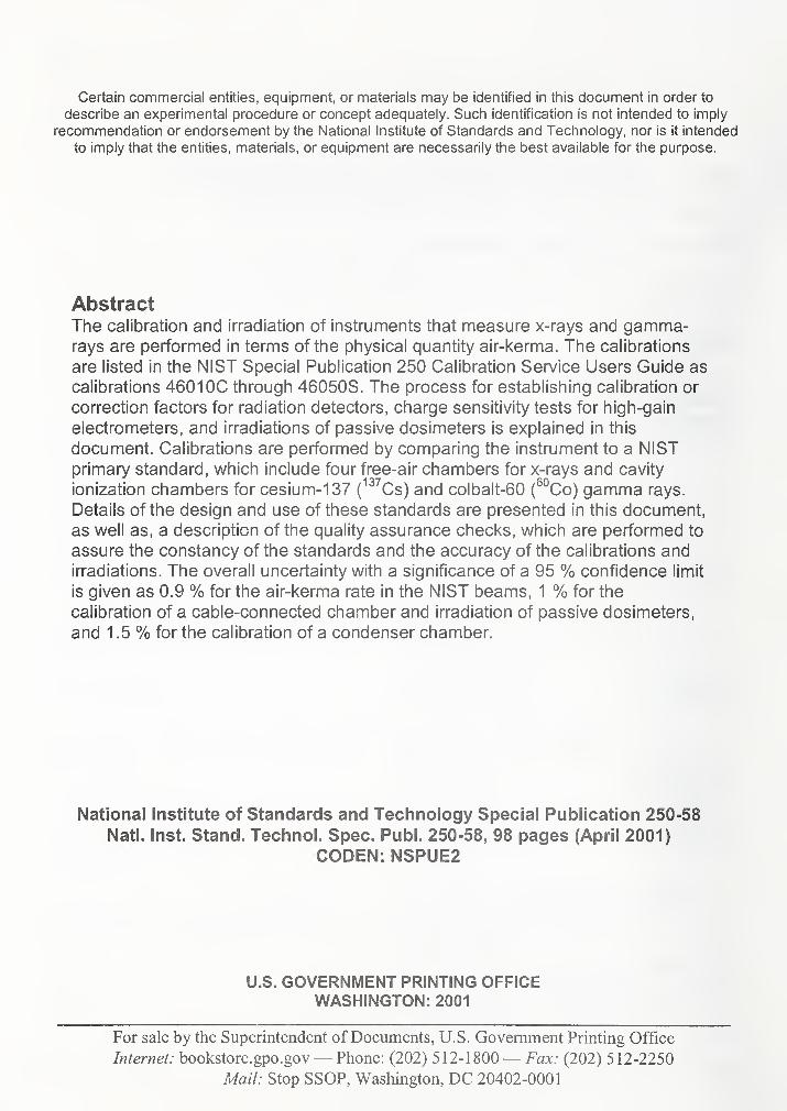
AbstractThe calibration and irradiation of instruments tliat measure x-rays and gamma-rays are performed in terms of tlie piiysical quantity air-kerma. The calibrations
are listed in the NIST Special Publication 250 Calibration Service Users Guide as
calibrations 4601 OC through 46050S. The process for establishing calibration or
correction factors for radiation detectors, charge sensitivity tests for high-gain
electrometers, and irradiations of passive dosimeters is explained in this
document. Calibrations are performed by comparing the instrument to a NISTprimary standard, which include four free-air chambers for x-rays and cavity
ionization chambers for cesium-137 (^^'^Cs) and colbalt-60 (^°Co) gamma rays.
Details of the design and use of these standards are presented in this document,
as well as, a description of the quality assurance checks, which are performed to
assure the constancy of the standards and the accuracy of the calibrations andirradiations. The overall uncertainty with a significance of a 95 % confidence limit
is given as 0.9 % for the air-kerma rate in the NIST beams, 1 % for the
calibration of a cable-connected chamber and irradiation of passive dosimeters,
and 1 .5 % for the calibration of a condenser chamber.
National institute of Standards and Technology Special Publication 250-58
Natl. Inst. Stand. Technol. Spec. Publ. 250-58, 98 pages (April 2001)CODEN: NSPUE2
U.S. GOVERNMENT PRINTING OFFICEWASHINGTON: 2001
For sale by the Superintendent of Documents, U.S. Government Printing Office
Internet: bookstore.gpo.gov— Phone: (202) 5 1 2- 1 800— Fax- (202) 512-2250
Mail: Stop SSOP, Washington, DC 20402-0001
Foreword
This edition of the National Institute of Standards and Technology (NIST) Special Publication
250 Series is a revision to the NBS Special Publication 250-16 Calibration of X-Ray and
Gamma-Ray Measuring Instruments document. The original work has been reorganized,
rewritten and supplemented to reflect the changes with the calibration services since 1988. Paul
Lamperti and Michelle O'Brien wish to acknowledge the contributions of R. Loevinger, J.
Weaver and the late T. Loftus.
iii
Abstract
Table of Contents
Page
ii
Foreword iii
List of tables iv
List of figures vii
1.0 Scope 1
2.0 References documents 1
2.1 International organization for standardization
2.2 National Institute for Standards and Technology
3.0 Terminology
3.1 Descriptions of terms specific to this document
3.2 Keywords 2
4.0 Calibration service f, : 3
4.1 Description of services 3
4.2 Beam qualities for calibration of x-ray
measuring instruments 4
5.0 Design philosophy and theory 13
6.0 X-ray calibration services 13
6.1 X-ray calibration ranges 13
6.2 X-ray exposure calibration standards 13
6.3 Calculation of air kerma 19
6.4 Wyckoff-Attix (50 kV to 300 kV) free-air
ionization chamber corrections 20
6.5 Ritz (20 kV to 100 kV) free-air ionization
chamber corrections 24
6.6 Lamperti (10 kV to 20 kV) free-air ionization
chamber corrections 27
6.7 Attix (20 kV to 50 kV) free-air ionization
chamber corrections 29
6.8 Comparison of standard free-air ionization
chambers 31
7.0 Gamma-ray air kerma standards and calibration ranges 35
7.1 Cavity-chamber standards 35
7.2 Gamma-ray sources 36
7.3 Calibration of gamma-ray beams 37
7.4 Useful beam size 39
8.0 lonization-chamber current-measurement techniques 41
8.1 Background and history 41
8.2 Electrometers 42
iv
8.3 Ionization current measurement-console equipment 42
8.3.1 X-ray calibration data acquisition system 42
8.3.2 Gamma-ray calibration data acquisition system 45
8.4 Pre-calibration tests of instruments 46
8.4.1 Charger/reader linearity test 46
8.4.2 Testing of readers for cable-connected probes 47
8.4.3 Testing of instruments to be calibrated in
electrical units 47
9.0 Support equipment calibrations 47
9. 1 Capacitor calibrations 47
9.2 Temperature indicator calibrations 47
9.3 Pressure indicator calibrations \^ 48
10.0 Operating procedures 48
10.1 Administrative procedures " 48
10.2 Calibration of integrating-type instruments 49
10.2.1 Condenser chambers 49
10.2.2 Cable-connected instruments 51
10.3 Calibration of current-type instruments 52
10.3.1 X-ray calibrations 52
10.3.2 Gamma-ray calibrations 52
10.4 In-house calibration checks 52
10.5 Test of high-quality feedback electrometers 53
10.6 Irradiation of passive and electronic dosimeters 54
10.6.1 General considerations and procedures 54
10.6.2 Exposure techniques 54
11.0 Assessment of uncertainty 54
12.0 Safety considerations 58
12.1 Radiation safety 58
12.2 High-voltage safety 59
References 60
Attachment 1 : X-ray beam qualities offered at the NBS prior to 1986 63
Attachment 2: Additional references - databooks 65
Attachment 3 : Attix chamber schematics 67
Attachment 4: History of the measurement of current 70
Attachment 5: Typical ionization chamber calibration report 75
Attachment 6: Typical TLD calibration report 81
Attachment 7: Typical electrometer calibration report 84
v

List of Tables
Table 4- 1 . Calibration conditions for x-ray and gamma-ray measuring
instruments
Table 4-2. Mammography x-ray beam-quality parameters
Table 4-3. ISO X-Ray Beam Quality Parameters
Table 6- 1 . Description of the NIST x-ray systems
Table 6-2. Important dimensions and parameters for the NIST standard
free-air ionization chambers
6
10
12
14
14
Table 6-3. Summary of calculations from ref [3] for percent loss and gain
of ionization due to lack of plate separation and scattered photons
in the Wyckoff-Attix free-air ionization chamber
Table 6-4. Comparison of x-ray beam filtrations used for data reported in
ref. [3] with filtrations presently used for conventional
calibration conditions
20
21
Table 6-5. Data used to compute corrections for the Wyckoff-Attix standard
free-air chamber for conventional calibration conditions 22
Table 6-6. Comparison of the ka values currently used to those values
computed from the least squares equation
Table 6-7. Products of all air-kerma-rate-independent corrections for the
Wyckoff-Attix free-air ionization chamber
Table 6-8. Mass air-attenuation coefficients and air attenuation corrections
for the Ritz free-air ionization chamber
23
24
25
Table 6-9. Computation of electron-loss corrections for the Ritz free-air
ionization chamber 26
Table 6-10. Summary of corrections for the Ritz free-air ionization
chamber 27
Table 6-11.
Table 6-12.
Recombination corrections for the Lamperti free-air ionization chamber 28
Summary of correction factors for Lamperti free-air
ionization chamber 29
VI

Table 6-13. Correction factors for the Attix free-air ionization
chamber 30
Table 6-14. Results of the comparison of the Lamperti standard with the
BIPM standard 32
Table 6-15. Results of the comparison of the Ritz standard with the BIPMstandard 32
Table 6-16. Comparison of the Lamperti chamber to the 50 kV NFLstandard 32
Table 6-17. Comparison oi the Ritz chamber to the NFL 50 kVstandard 33
Table 6-18. Comparison of the Ritz chamber to the NFL 300 kVStandard 33
Table 6-19. Comparison results for the mammography standard 33
Table 6-20. Recent "in-house" comparisons standards 34
Table 7-1. Dimensions of spherical graphite ionization chambers 35
Table 7-2. Gamma-ray source locations and nominal activities of
sources as oi January 1 , 1 999 36
Table 7-3. Constants for computing exposure rate corrected for decayC jI 1 j11for the horizontal beam sources 37
Table 7-4. Data and positioning for calibration of vertical-beam
gamma-ray sources in room B036 38
Table 7-5. Constants for computing useful beam radii for the horizontal
and vertical beam calibration ranges 40
Table 7-6. Beam size defined by 50% radiographic density
contour for vertical-beam gamma-ray sources, for specific
collimator settings 41
Table 8-1. Parameters of the straight line fits for the temperature probe
calibrations used in the x-ray ranges 44
Table 8-2. Low-energy Fantak unit voltage calibration 44
vii

Table 8-3. High-energy Pantak unit voltage calibration 45
Table 8-4. Temperature probe parameters for the gamma source
calibration ranges 46
Table 10-1. Analysis of three NIST check chambers for the period
of 1979 to 1997 53
Table 11-1. Uncertainty analysis for tungsten x and gamma-ray
air-kerma rates 55
Table 11-2. Uncertainty analysis for gamma-ray calibrations 56
Table 11-3. Uncertainty analysis for air-kerma rates with the Attix
chamber 56
Table 1 1-4. Uncertainty analysis for mammography calibrations 57
Table 11-5. Explanation of various components of the uncertainty
analyses 57
Table 11.6. Summary of expanded uncertainties 58
viii

List of Figures
Fig. 4-1 . Graph of generating constant potential against half-value layer for
the beam qualities used in the x-ray calibration range 7
Fig. 4-2. Graph of homogeneity coefficients against aluminum half-value
layer for the L, M, H and S filtrations 8
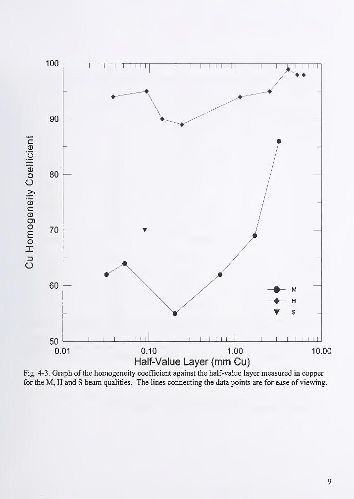
Fig. 4-3. Graph of the homogeneity coefficient against the half-value layer
measured in copper for the M, H and S beam qualities 9
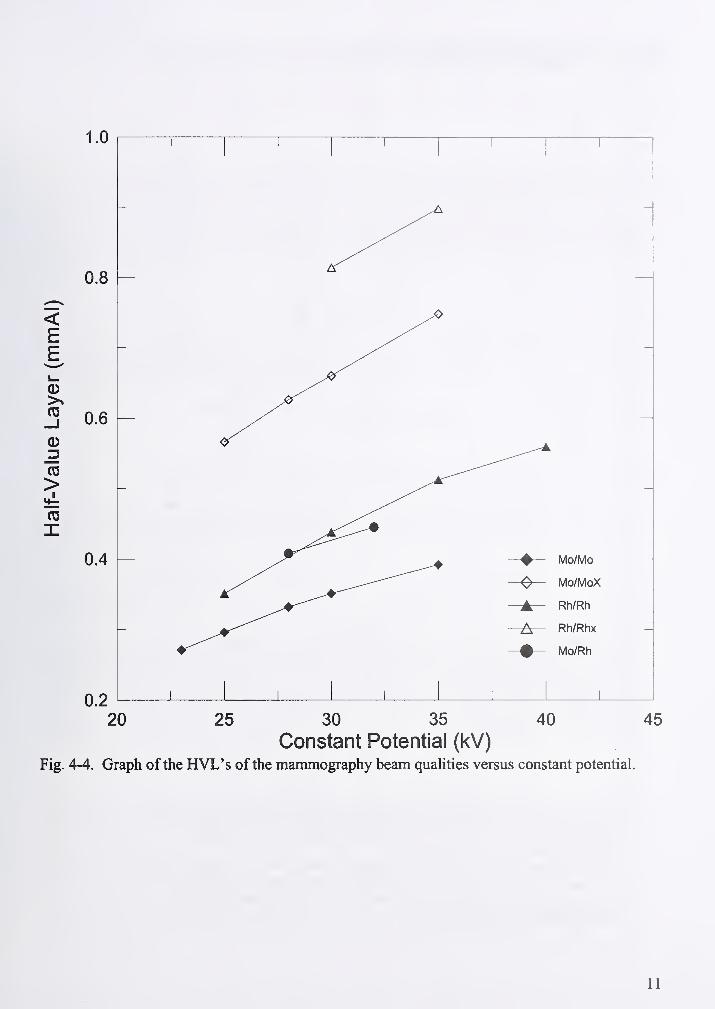
Fig. 4-4. Graph of the HVL's of the mammography beam qualities versus
constant potential 1
1
Fig. 6-1. Schematic of 300 kV x-ray range 15
Fig. 6-2. Schematic ofmammography calibration range 15
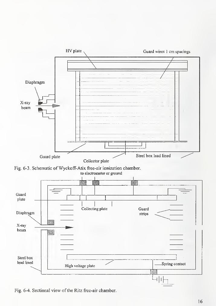
Fig. 6-3. Schematic of Wyckoff-Atix free-air ionization chamber 16
Fig. 6-4. Sectional view of the Ritz free-air chamber 16
Fig. 6-5. Schematic cross-sectional views of the Lamperti free-air
chamber 17
Fig. 6-6. Schematic of Attix free-air chamber 18
Fig. 7-1. Port detail for horizontal ^°Co, 5 mm diameter source 36
ix

1. Scope
1.1 This document describes the x-ray and gamma-ray calibration services provided by the
Ionizing Radiation Division, Radiation Interactions and Dosimetry Group at the National
Institute of Standards and Technology (NIST). The calibration and irradiation of x-ray and
gamma-ray instruments are performed in terms of the physical quantity air kerma. The
calibrations are listed in NIST Special Publication 250 [1] as calibrations 460 IOC through
46050S. Calibration or correction factors are provided for radiation detectors, charge sensitivity
is tested for high-gain electrometers, and passive dosimeters are irradiated to known quantities of
radiation. Calibrations are performed by comparing the instrument to a NIST primary standard,
which include free-air chambers for x-rays and cavity ionization chambers for cesium- 137
('^^Cs) and cobalt-60 (^Vo) gamma rays. A variety of quality assurance checks are performed to
assure the constancy of the standards and the accuracy of the calibrations and irradiations. The
overall uncertainty (considered to have the approximate significance of a 95 % confidence limit)
is given as 0.9 % for the air-kerma rate in the NIST beams, 1 % for calibration of a
cable-connected chamber and irradiation of passive dosimeters, and 1.5 % for calibration of a
condenser chamber.
2.0 Referenced documents
2.1 International Organization for Standardization
ISO/IS 4037-1:1996 X and gamma reference radiations for calibrating dosimeters and dose rate
meters and for determining their responses as a function ofphoton energy - Part 1 . : Radiation
characteristics and production methods
2.2 National Institute of Standards and Technology
NBS Special Publication 250-16 Calibration ofX-Ray and Gamma Measuring Instruments
SP 250 NIST Calibration Services Users Guide 1998
NBS Handbook 64 Design of Free-Air Ionization Chambers
NBS Handbook 78 Report of the International Commission on Radiological Units and
Measurements
NIST Special Publication 811 Guide for the Use of the International System of Units (SI)
NIST Technical Note 1297 Guidelines for Evaluating and Expressing the Uncertainty ofNISTMeasurements
3. Terminology
3.1 Descriptions of terms specific to this document
3.1.1 air kerma - the quotient of dE,^ by dm, where dE,,. is the sum of the initial kinetic energies
of all electrons liberated by photons in a volume element of air and dm is the mass of air in that
volume element. The SI unit of air kerma is the gray (Gy).
1

3. 1 .2 beam quality - used to refer to a specific x-ray beam with a characteristic half-value layer
and produced by a constant potential kilovoltage.
3.1.3 calibration - the process whereby the response of a dosimeter or measuring instrument is
characterized through comparison with an appropriate national standard.
3. 1 .4 calibration factor - the quotient of the air kerma in the absence of the chamber and the
charge generated by that radiation in the ionization chamber, expressed in units of Gy/C.
3.1.5 correction factor - the quotient of the air kerma or exposure in the absence of the chamber
and the electrometer reading with the ionization chamber.
3.1.6 effective energy - the energy of monoenergetic x-ray beam which has the same half-value
layer as the spectrum in question.
3. 1 .7 exposure - exposure (X) is the quotient ofdQ by dm, where dQ is the sum of the electrical
charges on all the ions of one sign produced in air when all the electrons are completely stopped
in air. The SI unit of exposure is the coulomb per kilogram (C/kg); the special unit of exposure,
the roentgen (R), is equal to exactly 2.58E-4 C/kg.
3.1.8 half-value layer - (HVL) the thickness of the specified material added as a beam
attenuator that reduces the air kerma rate by one half of the unattenuated beam air kerma rate
value.
3.1.9 homogeneity coefficient - (HC) the ratio of the first to the second half-value layer.
3.1.10 monitor instrument - an instrument used to monitor the stability of the air kerma rate
during an irradiation.
3.1.11 quarter-value layer - (QVL) the thickness of the specified material added as a beamattenuator that reduces the air kerma rate to one quarter of the unattenuated beam air kerma rate
value.
3.1.12 second half-value layer - the difference between the quarter-value layer and the half-
value layer.
3.1.13 x-ray unit - system comprising of a high voltage generator, an x-ray tube and an x-ray
controller.
3.2 Key words
air kerma; calibration; cavity chamber; cesium- 137 gamma rays; cobalt-60 gamma rays;
exposure; free-air chamber; half-value layer; ionization chambers; mammography chamber
calibrations; primary standard; standard; uncertainty estimate; x rays.
2
4. Calibration service
This report describes the status of the calibration service for x-ray and gamma-ray
measuring instruments, as of January 1999. The physical quantities air-kerma and exposure,
calibration by substitution, and the properties of the x-ray and gamma-ray beams used in the
NIST services are described in this document. This service guide explains the details of the
calibration systems and their measurement standards, the instruments and techniques for
measuring current and charge, and the analyses of calibration data. Tests applied to the
instruments being calibrated, as well as the tests and calibrations performed on NIST laboratory
equipment, and the associated assessment of uncertainty are covered. The operating procedures,
including the administrative procedures and methods of handling and calibrating the instruments,
and the irradiation of passive dosimeters, are included in this guide. The document concludes
with a brief discussion of the necessary safety considerations.
4.1 Description of service
The NIST, Ionizing Radiation Division, Radiation Interactions and Dosimetry Group
receives a variety of instruments for calibration, test, or irradiation in x- or gamma-ray beams.
These services are assigned test numbers 460 IOC through 46050S in NIST Publication 250 [1]
available from the NIST Technology Services, Office of Measurement Services, Calibration
Program Office. Calibration factors or correction factors are provided for radiation detectors.
The charge sensitivity of a high-gain electrometer can be tested at any one set of switch positions
in conjunction with a calibration factor. Dosimeters can be given known exposures of x-ray or
gamma-ray radiation. Calibrations and irradiations are performed in terms of the physical
quantities air kerma and exposure.
The quantity air kerma characterizes a beam of photons or neutrons in terms of the
energy transferred to any material. For the calibration service described in this document,
consideration is limited to photon beams in air. Air kerma is the total energy per unit mass
transferred from an x-ray beam to air. Air kerma, A^^,^, is the quotient of dE^^ by dm, where dE,^ is
the sum of the initial kinetic energies of all electrons liberated by photons in a volume element of
air and dm is the mass of air in that volume element. Then
K.-—- (4-1)air J y' ' J
dm
The SI unit of air kerma is the gray (Gy), which equals one joule per kilogram; the special unit of
air kerma is the rad, which equals 0.01 Gy.
The quantity exposure characterizes an x-ray or gamma-ray beam in terms of the electric
charge liberated through the ionization of air. Exposure is defined as the total charge per unit
mass liberated in air by a photon beam and is represented by the equation:
where dQ is the sum of the electrical charges on all the ions of one sign produced in air when all
the electrons liberated by photons in a volume element of air whose mass is dm are completely
3
stopped in air. The SI unit of exposure is the coulomb per kilogram (C/kg); the special unit of
exposure, the roentgen (R), is equal to exactly 2.58E-4 C/kg. The ionization arising from the
absorption of bremsstrahlung emitted by the secondary electrons is not included in dQ. Except
for this small difference, significant only at high energies, the exposure as defined above is the
ionization equivalent of air kerma. The relationship between exposure and air kerma can be
expressed as a simple equation:
X-K...-^^^ (4-3)air2.58^-4 {WIe)
where W/e is the mean energy per unit charge expended in air by electrons, and g is the fraction
of the initial kinetic energy of secondary electrons dissipated in air through radiative processes.
The currently accepted value of W/e is 33.97 J/C [2] and g is negligible for the x-ray beams of
interest. The currently accepted g values for ^°Co and '^^Cs beams are 0.32 % and 0.16 %,respectively.
Only ionization chambers known to be stable and reproducible are accepted for
calibration in this program. Institutions submitting ionization chambers for calibration are
strongly urged to perform stability checks involving redundant measurements in highly
reproducible radiation fields before sending their instruments to NIST, and to repeat those
checks after NIST calibration, and again at suitable intervals. Instruments submitted for
calibration, and material submitted for irradiation, must be shipped in reusable containers.
An x-ray tube produces bremsstrahlung spectra, inhomogeneous beams with photon
energies from very low values to a high-energy cutoff given by the maximum potential applied
to the x-ray tube. These beams are customarily filtered with a high purity metal to reduce the
unwanted low-energy x-rays. Three x-ray calibration ranges are used for the calibration
services. Two of the ranges contain x-ray tubes with tungsten anodes. The x-ray beams from
these anodes are filtered with aluminum, copper, tin or lead. Two anode types are offered for the
mammography calibration service, molybdenum (Mo) and rhodium (Rh). The Mo generated x-
ray beams are filtered with Mo, Al, or Rh foils, while the Rh beams are filtered with Rh and Al
foils. It is conventional to characterize the "quality" of the filtered x-ray beam in terms of the
thickness of aluminum or copper required to reduce the air kerma rate to 50 % and to 25 % of its
original value. These thicknesses are called the half-value layer (HVL) and the quarter-value
layer (QVL). The HVL and QVL measurements must be made using good-geometry attenuation
in order to obtain accurate and reproducible numbers. The homogeneity coefficient (HC) is the
ratio of the first to the second HVL, often expressed as a percent. A HC value near 1 (or 100 %)indicates that the filtration has produced an approximately homogeneous beam that is
approaching monoenergetic conditions.
4.2 Beam qualities for calibration of x-ray and gamma-ray measuring instruments
The 32 NIST tungsten x-ray beam qualities are divided into three groups according to
filtrafion, i.e., light (L), moderate (M), and heavy (H) filtradon. The beam codes consist of a
letter L, M, or H, followed by the generating constant potential in kilovolts. For example. Ml 00
indicates moderate filtration and 100 kV constant potential. The special (S) series beam codes,
S60 and S75 have characteristics that are not consistent with those of the L, M, and H groups.
4
The qualities for each group were chosen so that relatively smooth curves result for the graph of
tube potential versus HVL. Table 4-1 gives a complete listing of beam codes currently available
at NIST. The NBS beam codes used prior to January 1986 are listed in Attachment 1 . Recent
changes to filtration, due to the x-ray tube replacement, are shown in footnote g. Due to changes
in the physical setup of the low-energy calibration facility, the LI 0, LI 5, HI 0 and HI 5 beamqualities are now used with a source-to-detector distance of 50 cm, instead of the previous 25 cmdistance. The resulting changes to the half-value layers are given in Table 4-1. Depending on the
energy response and design of the ionization chamber, the calibration factors for a specific
ionization chamber often fall on smooth curves when plotted against HVL In this case, all
calibration points have been chosen from a single group, L, M, or H. If calibration points are
chosen from more than one group, discontinuities will occur, hence no attempt should be made
to interpolate between such calibration factors. Figure 4-1 is a graph of the HVL against the
generating constant potential. Figure 4-2 is a graph of the HC against the HVL, measured in
aluminum. Figure 4-3 shows the HVL and HC measured in copper against the generating
constant potential.
The mammographic beam qualities offered at NIST were chosen to cover the range of
HVLs of x-ray beams found in clinical settings. The beam codes which name the beam qualities
are a combination of the chemical symbol of the anode and the filter respectively, followed by
the constant potential in kilovolts. The letter "x" ends the beam codes which name the exit beamqualities. The exit beam qualities, which represent the transmission of the x-rays through the
breast, are generated by an additional filtration of 2.0 mm of Al. The mammographic beamqualities offered are listed in Table 4-2. Figure 4-4 is the graph of the HVL measured in
aluminum against generating constant potential.
The ISO x-ray beam qualities are now available at NIST. A list of all ISO beams offered
at NIST is found in Table 4-3. The NIST H group of qualities agrees with the ISO narrow
spectrum (NS) qualities recommended by the ISO document 4037, referred to in section 2 . The
ISO recommendations extend from 300 kV to 40 kV, below which the NIST H group has been
extended to 1 0 kV in agreement with practice at the national metrology institute of Germany,
Physikalisch-Technische Bundesanstalt (PTB). The NIST M group of qualities is in agreement
with the recommendation for radiation therapy calibration in lEC Publication 73 1
.
The selection ofbeam qualities for instrument calibration depends on the situation of interest.
The H qualities are usually used for calibration for radiation protection instrumentation, since
these beams have the narrowest spectrum at each generating potential, and probably most nearly
approximate radiation that has penetrated a protective barrier. The M qualities are usually used
for calibration of radiation therapy instruments. The L qualities are predominately for calibration
of instruments used for measurement of unfiltered or lightly filtered beams that give high
exposure rates, as is often the case in radiation biology and Grenz-ray therapy. The Mo and Rhbeam qualities are offered to simulate the clinical mammographic beams.
5

Table 4- 1 . Calibration conditions for x-ray and gamma-ray measuring instruments
Beamcode'
Additional Filteration Half-value layer Homogeneity
coefficient
"
Effective
energy''
Distance
Al Cu Sn Pb Al Cu Al Cu (keV) (cm;
(mm) (mm) (mm) (mm) (mm) (mm)
X-Rav Beam Qualities
LIO^ 0.035 89 50
L15' 0.057 68 50
L20 0.069 73 50
L30^ 0.30 0.22 63 50
L40® 0.53 0.50 59 50
L50^ 0.71 0.76 60 50
L80^ 1.45 1.83 57 50
LlOO 1.98 2.77 57 50
M20^ 0.27 0.15 69 50
M30 0.5 0.36 65 50
M40^ 0.89 0.73 69 50
M50^ 1.07 1.02 66 50
M60 1.56 1.68 66
M80 2.61 2.97 67
MlOO 5.0 5.02 73
M120 6.87 6.79 77
M150 5.0 0.25 10.2 0.67 87 62
M200 4.1 1.12 14.9 1.69 95 69
M250 5.0 3.2 18.5 3.2 98 86
M300 4.0 6 5 22.0 5.3 100 97
HIO'^ 0.105 0.05 91 50
0.5 0.153 86 50
H20^ 1.01 0.36 91 50
H30^ 4.50 1.23 93 50
H40^ 4.53 0.26 2.90 90 50
H50 4.0 0.1 4.2 0.142 92 90 38
H60 4.0 0.61 6.0 0.24 94 89 46
HlOO 4.0 5.2 13.5 1.14 100 94 80
H150 4.0 4.0 1 '51 1 7 0 1 \J\J 9'^ 1 ?0
H200 4.0 0.6 4.16 0.77 19.8 4.1 100 99 166
H250 4.0 0.6 1.04 2.72 22.0 5.2 100 98 211
H300 4.1 3.0 5.0 23.0 6.2 99 98 252
S60 4.35 2.77 72
S75 1.50 1.86 63 50
Gamma-Ray Beam Qualities
'"Cs 10.8
14.9
662
1250
a For the x-ray beam codes, the letter indicates light (L), moderate (M), heavy (H) and special filtration (S), and the number
is the constant potential in kilovolts.
b The additonal filtration value does not include the inherent filtration. The inherent filtration is approximately 1.0 mm Be
for beam codes LIO-LIOO, M20-M50, H10-H40 and S75; and 7.0 mm Be for beam codes M60-M300, H50-H300 and S60
plus the filtration resulting from the transmission monitors,
c The homogeneity coefficient is taken as 100(lst HVL / 2nd HVL).
d The effective energy is for which it is believed to be a meaningful characterization of the beam quality.
e The distance shown is that between the radiation source and the detector center or the reference line. For the beam codes
where no distance is listed, the distance ranges between 78 and 200 cm, depending on the desirable beam size,
f Changes to the HVL from the 1986 value, result from a change in the distance from 25 cm to 50 cm.
g To match the previous HVL, changes in the additional filtration value were required with the installation of a new x-ray
tube in 1997.
6
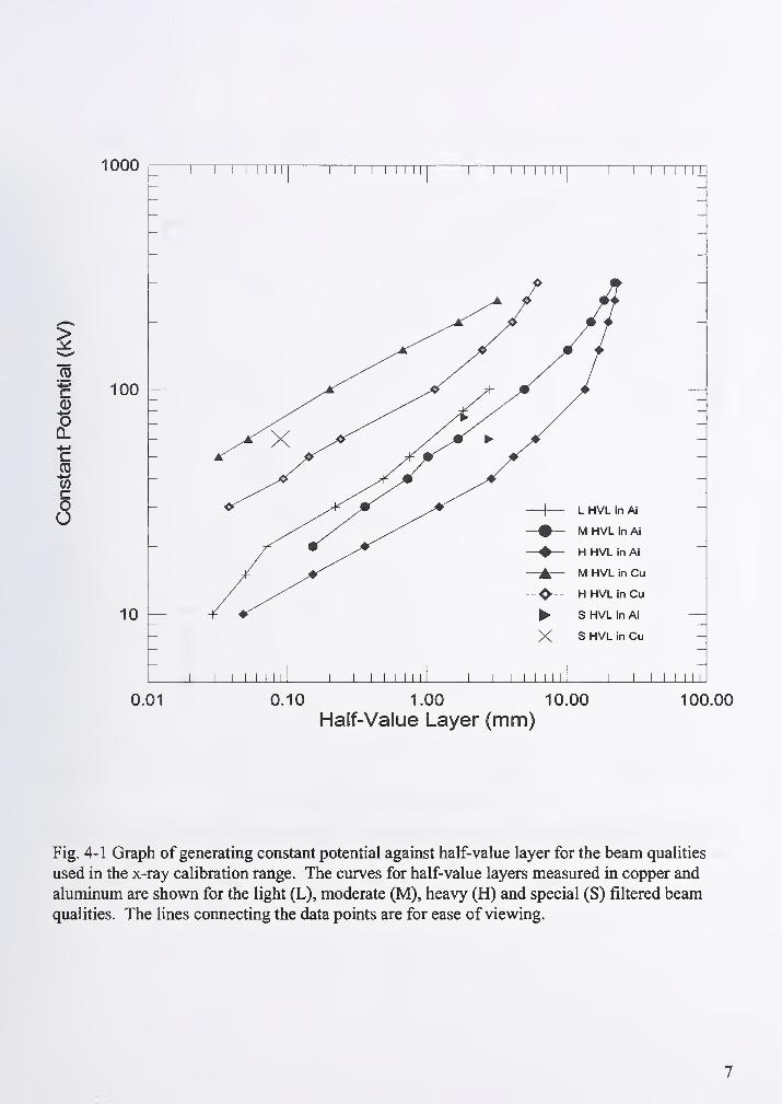
Fig. 4-1 Graph of generating constant potential against half-value layer for the beam qualities
used in the x-ray calibration range. The curves for half-value layers measured in copper and
aluminum are shown for the light (L), moderate (M), heavy (H) and special (S) filtered beamqualities. The lines connecting the data points are for ease of viewing.
7

1 I MINI
X s
0.01 0.10 1.00 10.00 100.00
Half-Value Layer (mm Al)
Fig. 4-2. Graph ofhomogeneity coefficients against aluminum half-value layer for the L, M, Hand S filtrations. The lines connecting the data points are for ease of veiwing.
8
50 I \ ^ I I I I I 1 1 \ \ I Min i \ \I I I I I I
0.01 0.10 1.00 10.00
Half-Value Layer (mm Cu)Fig. 4-3. Graph of the homogeneity coefficient against the half-value layer measured in copper
for the M, H and S beam qualities. The lines connecting the data points are for ease of viewing.
9
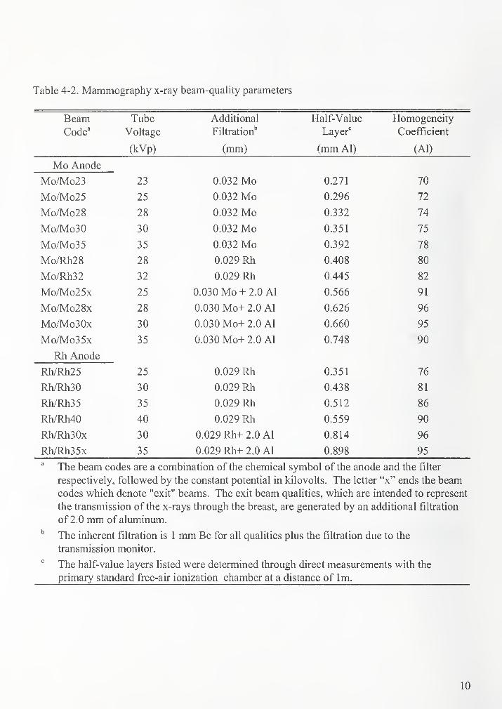
Table 4-2. Mammography x-ray beam-quality parameters
Beam Tube Additional Half-Value Homogeneity
Code' Voltage Filtration'' Layer'' Coefficient
(kVp) (mm) (mm Al) (Al)
Mo Anode
Mo/Mo23 23 0.032 Mo 0.271 70
Mo/Mo25 25 0.032 Mo 0.296 72
Mo/Mo28 28 0.032 Mo 0.332 74
Mo/Mo30 30 0.032 Mo 0.351 75
Mo/Mo35 35 0.032 Mo 0.392 78
Mo/Rh28 28 0.029 Rh 0.408 80
Mo/Rh32 32 0.029 Rh 0.445 82
Mo/Mo25x 25 0.030 Mo + 2.0 Al 0.566 91
Mo/Mo28x 28 0.030 Mo+ 2.0 Al 0.626 96
Mo/Mo30x 30 0.030 Mo+ 2.0 Al 0.660 95
Mo/Mo35x 35 0.030 Mo+ 2.0 Al 0.748 90
Rh Anode
Rh/Rh25 25 0.029 Rh 0.351 76
Rh/Rh30 30 0.029 Rh 0.438 81
Rh/Rh35 35 0.029 Rh 0.512 86
Rh/Rh40 40 0.029 Rh 0.559 90
Rh/Rh30x 30 0.029 Rh+ 2.0 Al 0.814 96
Rh/Rh35x 35 0.029 Rh+ 2.0 Al 0.898 95
" The beam codes are a combination of the chemical symbol of the anode and the filter
respectively, followed by the constant potential in kilovolts. The letter "x" ends the beamcodes which denote "exit" beams. The exit beam qualities, which are intended to represent
the transmission of the x-rays through the breast, are generated by an additional filtration
of 2.0 mm of aluminum.
The inherent filtration is 1 mm Be for all qualities plus the filtration due to the
transmission monitor.
" The half-value layers listed were determined through direct measurements with the
primary standard free-air ionization chamber at a distance of Im.
10
1.0
0.2 I ^ L_ \ \ \ 1 \ 1 \ 1
20 25 30 35 40 45
Constant Potential (kV)
Fig. 4-4. Graph of the HVL's of the mammography beam quahties versus constant potential.
11

Table 4-3. ISO X-Ray Beam Quality Parameters
Beam Added Filtration (mm)" First HVL Second HVLCode' Al Cu Sn Pb mmAl mmC mmAl mmCuHKIO 0.04 0 OS
HK20 0 1 sU. 1 J 0.13 0 16
HK30 0.39 0 SQ
HK60 'X 1 Q 0.08 0 1 1U. 1 1
HKIOO ^ on 0 1 s 0.31 0 46
HK200 lis 1.72 9 4"?
HK250 1 fiO - 2.52 J.J/
HK280 3.45 4 07
HK300 9 S 1 3.46 4 91
WS60 0 1U.J 0.18 0 91U.Z. 1
WS80 0 SW.J 0.35 0 44
WSllO 9 0 0.96
WS150 1 031 .UJ 1.88 9 1 3
WS200 9 01 3.09 3 35J .J J
WS250 4 01 4.30 4 SOT^.JU
WS300 f\ S4 5.23 S 18J.JO
NSIO n HQS 0.051 u.uuu
NS15 0 AQ\}.'-ty 0.15 U. 1 o
NS20 ft QO 0.32
NS25 0.69
NS30 1.16 1
NS40 0 91'
0.085 0 0Q9
NS60-
0 0.25 0 96
NS80 9 0 0.59 0 66
NSlOO S 0 1.13 1 IQ
NS120 4 QO 1 04*^ .yy 1 .ut- 1.70 1 8S
NS150 9 SOJU 2.40
NS200 9 04 9 Q8 4.09
NS250 9 01 9 Q7^.u 1 ^.y 1 5.26 S "^9
NS300 9 QQ 4 qq 6.17 6 30
LKIO 0 30 0.062
LK20 0.43
LK30 0 1 X 1.48
LK35 0 9S 2.16 9 ^f^
LK55 1 1 q1.1!/ 0.26
LK70 9 64 0.51
LKIOO (j.dI 1.0 1.27
1.0 4.0 9 04
LK170 1.0 3.0 1.5 3.47
LK210 0.5 2.0 3.5 4.54
LK240 0.5 2.0 5.5 5.26
In the beam codes, the letters indicate low air kerma rate (LK), high air kerma rate (HK),
narrow spectrum (NS), and wide spectrum (WS); and the number is the constant
potential in kilovolts.
The inherent filtration is a combination of the filtration due to the monitor chamber plus
approximately 1 .0 mm Be for beam codes produced at tube potentials of 30 kV and
below, approximately 7.0 mm Be for HK60 and HKIOO and for all other techniques the
inherent filtration is adjusted to 4 mm Al.

5. Design philosophy and theory
X-ray calibrations are performed by using the substitution method. Using this method, the air
kerma or air-kerma rate is determined at some point in space by a free-air chamber. The
instrument to be calibrated is then placed at the same point in space as the standard and the
response of the instrument is determined. The calibration factor is the quotient of the air kerma,
i^air in the absence of the chamber, and the charge, Q, generated by that radiation in the
ionization chamber:
KirCalibration Factor = —^ (5-1)
Q
The correction factor is the quotient of the air kerma or exposure, in the absence of the chamber,
and the electrometer reading with the ionization chamber:
KirCorrection Factor = — (5-2a)
electrometer reading
Correction Factor =X
(5-2b)electrometer reading
Gamma-ray calibrations are performed by using previously calibrated beams and correcting for
decay. Details of the calibration of gamma-ray beams are given in Section 7.
6. X-ray calibration services
6.1 X-ray ranges
Three x-ray calibration ranges are available for instrument calibrations. One range is used
for tungsten x-rays generated at constant potentials of 1 0 kV to 1 00 kV, the other is used for
tungsten x-rays generated at potentials of 50 kV to 300 kV. The mammography x-rays are
generated at constant potentials of 23 kV to 40 kV. Table 6-1 describes some of the features of
the x-ray systems utilized in each calibration range. A schematic of the 300-kV system is given
in Fig. 6-1. A schematic of the mammography range is given in Fig. 6-2.
6.2 X-ray air kerma calibration standards
Standardization of x-ray beams for the quantity air kerma or exposure is carried out at NIST by
means of four free-air ionization chamber standards. These standards are discussed in Refs.
[3,4,5]. Figures 6-3 to 6-5 show cross-sectional views of the three free-air chambers used in the
tungsten x-ray ranges. Figure 6-6 is a schematic of the standard for mammography. The
important dimensions of the free-air chambers are given in Table 6-2. With reference to Table
6-2, note that the free-air chambers become larger as the x-ray energy increases. At low x-ray
energies, the air attenuation air path between the defining diaphragm and the collector center
needs to be minimized. On the other hand, at high x-ray energies a sufficient air path is needed
13

Table 6-1. Description of the NIST x-ray systems.
Features Unipolar^ Bipolar'' Mammography
Manufacturer Pantak Pantak Gulmay
Output voltage (kV) 5 to 100 5 to 320 5 to 50
Output current (mA) 0.5 to 80 0.5 to 30 0.1 to 40
Output power (kW) up to 3.2 up to 4.2 up to 1.2
kV adjustment (kV) 0.1 0.1 0.1
mA adjustment (mA) 0.01 0.01 0.1
Fixed anode material W W Mo or Rh
Tube window (mm Be) 1 3 1
Focal spot size (mm) 3x3 4x4 ^^ X 4 " and 5 X 5
'
''Generator and tube were installed in December of 1997.
''Generator was installed in February of 1998 with the existing x-ray tube.
"Two x-ray tubes are used in the mammography calibration range with the same generator.
'^Size of the Mo anode in tube installed in 1994.
^Size of the Rh anode in tube installed in 1994.
Table 6-2. Important dimensions and parameters for the NIST standard free-air ionization
chambers
Chamber X-ray tube
potential
(kV)
Plate
separation
(mm)
Plate
height
(mm)
Collector
length
(mm)
Diaphragm
diameter/ID
(mm)
Air
absorption
length
(mm)
Electric
field
strength
(V/cm)
Lamperti 10-60 40 50 10.146 4.994/5S 39.02 750
Attix 10-50 variable
209 max
87=' variable 10.00/ 1 Ou 212.7" variable
Ritz 20- 100 90 90 70.030 10.00/lOA 127.39 55
Wyckoff- Attix
50 - 300 200 268 100.80 10.00/1 OB 308 250
^ Inner diameter of the cylindrical chamber.'' This is variable; the value shown is what is used for routine use.
14

Telescope
Lead and
steel
housing
I
Safety shutter
Beam aperture
Test
chamber
Monitor chamber
X-ray beam~ cehTerrme
Beam defining
filter
X-ray tube Timing shutter
Movable
support carriage
Fig. 6-1. Schematic of 300 kV x-ray range.
Collimating
shutter
apparatus
Filter
wheel
Translating
x-ray tube
mount
Mo anode
Rh anode
Free-air
ionization
chamber
i
Test
chamber
carriage
Free-air
ionization
chamber
X-ray beam
centerline
Generator
Beam
aperture
wheel
Test chamber
] ^ moimts
Translating
support cart
Alignment
laser
Alignment
telescope
Fig. 6-2. Schematic ofmammography calibration range.
15
HV plate Guard wires 1 cm spacings
Diaphragm
X-ray
beam
Guard plate Steel box lead lined
Collector plate
Fig. 6-3. Schematic of Wyckoff-Atix free-air ionization chamber.
to electrometer or ground
I I I
Guard
plate
Diaphragm
X-ray
beam
Collecting plate Guard
strips
Steel box
lead linedHigh voltage plate
-Spring contact
nFig. 6-4. Sectional view of the Ritz free-air chamber.

Sectional Side Elevation
1---
11 -
Fig. 6-5. Schematic cross-sectional views of the Lamperti free-air chamber.
1. Lead to measuring system, 2. lead to thermistor readout, 3. thermistor, 4. brass collector plate,
5. brass guard plate, 6. brass guard ring, 7. tungsten diaphragm, 8. brass high voltage plate, 9.
supporting insulator, 10. brass ground case, 11. high voltage lead, 12. lead to midpoint of
potential divider, 13. brass radiation shield, A. shows orientation for the second diagram, section
A-A.
17
Beamdefining
aperture
Signal
Collecting electrodeExit
Moveable Plate
Guard
Sensitive collecting volume
EntranceHV bias
ushrod
Stepping motor slide 2
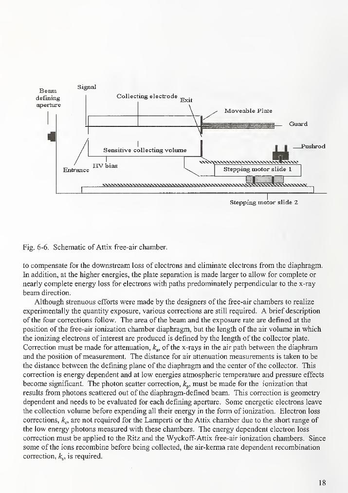
Fig. 6-6. Schematic of Attix free-air chamber.
to compensate for the downstream loss of electrons and eliminate electrons from the diaphragm.
In addition, at the higher energies, the plate separation is made larger to allow for complete or
nearly complete energy loss for electrons with paths predominately perpendicular to the x-ray
beam direction.
Although strenuous efforts were made by the designers of the free-air chambers to realize
experimentally the quantity exposure, various corrections are still required. A brief description
of the four corrections follow. The area of the beam and the exposure rate are defined at the
position of the free-air ionization chamber diaphragm, but the length of the air volume in which
the ionizing electrons of interest are produced is defined by the length of the collector plate.
Correction must be made for attenuation, k^, of the x-rays in the air path between the diaphram
and the position of measurement. The distance for air attenuation measurements is taken to be
the distance between the defining plane of the diaphragm and the center of the collector. This
correction is energy dependent and at low energies atmospheric temperature and pressure effects
become significant. The photon scatter correction, k^, must be made for the ionization that
results fi-om photons scattered out of the diaphragm-defined beam. This correction is geometry
dependent and needs to be evaluated for each defining aperture. Some energetic electrons leave
the collection volume before expending all their energy in the form of ionization. Electron loss
corrections, k^, are not required for the Lamperti or the Attix chamber due to the short range of
the low energy photons measured with these chambers. The energy dependent electron loss
correction must be applied to the Ritz and the Wyckoff-Attix free-air ionization chambers. Since
some of the ions recombine before being collected, the air-kerma rate dependent recombination
correction, k^, is required.
18

6.3 Calculation of air kerma
For a free-air ionization chamber with volume V, the air-kerma rate is determined by the relation
K-^ — T^^i (6-1)
"air ciair
where
K ^ the air-kerma rate (Gy/s),
I
y = the mass ionization current measured by the standard (Cs"' kg"'),
Pair
V = the volume of the standard (m^),
p^,y= the density of air at the ambient conditions of temperature and pressure (kg m ),
PTPair = Po— (6-2)
p„ = the density of air at reference conditions, 1.293 x 10'^ (kg m"^)
T = the ambient temperature (K)
P = the ambient pressure (Pa)
T„ = the reference temperature (K)
P„ = the reference pressure (Pa),
is the mean energy expended by an electron of charge e to produce an ion paire
in dry air; the value used at NIST is 33.97 JC"',
= is the fraction of the initial electron energy lost by radiative processes lost in air; g
is negligible for the x-ray beams of interest and 0.32 % and 0.16 % for the ^°Co
and '^''Cs respectively,
nk; = the product of all the necessary non-dimensional corrections.
The largest correction at low energies is that due to the air attenuation of the x-ray fluence along
the air path length, L between the reference plane and the center of the collecting volume. The
correction factor is calculated using the following equation:
= exp(^I) = exp(-^pl) (6-3)P
where
— = the mass air-attenuation coefficient, experimentally determined (m^kg"')
P'
p = the density of air at the ambient conditions of temperature and pressure (kg m"^)
and
L = the air absorption length or air path length (m).
19

6.4 Wyckoff-Attix (50 kV to 300 kV) free-air ionization chamber corrections
The correction for electron loss is
K = \ - ILA^jm (6-4)
and the correction for scattered photon contribution is
k^ - \ - (6-5)
In equation (6-4), E,. is the percent electron contribution, a loss, beyond a radius r of an x-ray
beam, is the percent scattered photon contribution, a gain, beyond radius r, and Ap is the
fraction of each annular area that contributes to the summation. The calculations of the
corrections for electron loss, and photon contribution, k^, are based on data from Ref. [3] and
the work of Ritz [6]. One should refer to Ref. [3] if calculations are to be made. A summary of
the results of the calculations discussed in Ref [3] are found in Table 6-3 which lists the percent
loss and gain of ionization due to lack of plate separation and scattered photons in the Wyckoff-
Attix chamber. The beam code designations from Table 4- 1 are used in Table 6-3 to associate the
data derived from Ref [3] with present-day x-ray beam conditions. The corrections for gain of
ionization are calculated from a plot of corrections derived from data in Ref [3] versus Al HVL.The corrections for electron loss are calculated from data in Ref [3] generated for beamconditions very nearly the same as present-day conditions, (see Table 6-4). It is assumed that the
differences are not significant. The exceptions to this assumption include the H300, M80 and
Ml 20. The correction for electron loss is estimated by interpolation.
Table 6-3. Summary of calculations from ref [3] for percent loss and gain of ionization due to
lack of plate separation and scattered photons in the Wyckoff-Attix free-air ionization chamber
Beam Code S Ap (%) I Ap S, (%)
M60,H60 0 0.69
MlOO 0 0.56
M150 -0.16 0.41
M200 -0.36 0.39
M250 -0.48 0.36
M300 -0.81 0.33
HlOO -0.08 0.56
H150 -0.77 0.41
H200 -0.81 0.39
H250 -0.23 0.36
H300^ 0.33
^The 300-kV filtration of 4 mm Cu is not comparable with the H300 composite filtration.
20

Table 6-4. Comparison of x-ray beam filtrations used for data reported in ref [3] with titrations
presently used for conventional calibration conditions
Reference [3]
X-ray
NBS SP-250
tube Inherent
potential filter Pb
(kV) (mm) (mm)
Added Filter
Sn Cu(mm) (mm)
Al
(mm)
Inherent
filter
(mm)Pb
(mm)
Added Filter
Sn Cu(mm) (mm)
Al
(mm)
Moderately Filtered Beams (M)
60 3 Al 3 Be 1.51
100 3 Al 1.0 3 Be 5.0
150 3 Al 0.23 1.0 3 Be 0.25 5.0
200 3 Al 0.50 1.0 3 Be 1.21 4.1
250 3 Al 1.0 1.0 3 Be 3.20 5.0
300 3 Cu 3 Be 6.5 4.0
Heavily Filtered Beams (H)
50 ( no data) 3 Be 0.10 4.0
60 ( no data) 3 Be 0.61 4.0
100 3 Al 0.53 3 Be 5.2 4.0
150 3 Al 1.53 4.0 3 Be 1.51 4.0 4.0
200 3 Al 0.7 4.0 0.59 3 Be 0.77 4.16 0.60 4.0
250 3 Al 2.7 1.0 0.59 3 Be 2.72 1.04 0.60 4.0
300 ( no data) 3 Be 5.0 3.0 4.1
The percent corrections, YApE^ and YApS^ used for the Wyckoff-Attix chamber and the
products of all exposure-rate-independent corrections for each beam code are given in Table 6-5.
Comparison of columns 3 and 4 of Table 6-5 with columns 2 and 3 of Table 6-3 shows there is
good agreement, in general, between the data calculated in the review from Ref [3] and the data
presently used. Corrections for electron loss, YApE^, for beams M300 and H300 are estimated
from figure 9 of Ref [3], and may be slightly in error since the filtration of these reference
beams is not the same as that of the present-day M300 and H300 beams. The trends in the
corrections in this energy range have been considered and a type B uncertainty for lApE^ of 0.07
% has been estimated for M300 and 0.15 % for H300.
The corrections given in Table 6-5 for air attenuation, k^, in the Wyckoff-Attix free-air
ionization appear to be nearly a linear function of the logarithm of the HVL in copper for the
beam qualities of interest, see Ref [1] of Attachment 2. The data points cover the range of CuHVL's for the M and H beam qualities except for M60 and H300. The values for those
21

Table 6-5. Data used to compute corrections for the Wyckoff-Attix standard free-air chamber
for conventional calibration conditions
Beam Code
100(1-
S Ap
lOO(l-kp)
S Ap S. ^k^/k,
M60 1.0203'' 0.77 0.9924 1.0140
MlOO 1.0097 0.60 0.9940 1.0052
M150 1.0068 -0.15 0.40 0.9975 1.0058
M200 1.0055'' -0.40^ 0.39" 1.0001 1.0071
M250 1.0045 -0.50 0.36 1.0014 1.0074
M300 1.0039^ -0.62 0.32' 1.0030 1.0084
H50 1.0103 0.63 0.9937 1.0055
H60 1.0088'' 0.55' 0.9945 1.0048
HlOO 1.0060" -0.04 o.4r 0.9963 1.0038
H150 1.0050 -0.68 0.35 1.0033 1.0098
H200 1.0043 -0.82 0.35 1.0047 1.0106
H250 1.0040 -0.26 0.35 0.9991 1.0046
H300 1.0038'' -0.62'* o.3r 1.0031 1.0084
S60 1.0131 0.70 0.9930 1.0075
^ An energy independent correction factor of 1.0015 for non-planarity of the guard-collector
plate system is included in the product of nkj.
*' Estimated from a graph of k^ versus HVL in mm of Cu." Estimated to be essentially the same beam quality as the previous beam code MFC.^ Calculated using figure 9 of reference 1
.
' Predicted from the least squares fit: I S, = 0.9912 + 1.816 E-3 log,(HVL in mm Al).
conditions are estimated from a semilog curve fit.
The data points, found in Ref [1] of Attachment 2, when fitted to a logarithmic curve using the
method of least squares provide the following equation:
= 1.0067 - 2.0229x10"^ log,o(//KZ mm Cu) (6-6)
The correlation coefficient is 0.96. A comparison of the data, estimated and computed using
the least-squares-derived equation is shown in Table 6-6.
The recombination corrections for all the NIST free-air ionization chambers are based on
measurements of ionization currents at several collection potentials, with air kerma-rate as a
parameter. In accord with the method of Scott and Greening [9], the inverse of the ionization
currents are plotted against the inverse of the squares of the collection potentials. Extrapolation
of the plotted data to 1/E^ = 0 predicts the inverse of the saturation ionization current. If the
ionization currents are normalized to the current measured at the normal operating collection
potential, the inverse of the intercept at 1/E^ = 0 is the recombination correction for that particular
22
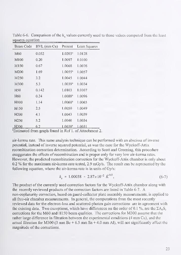
Table 6-6. Comparison of the values currently used to those values computed from the least
squares equation
Beam Code HVL (mm Cu) Present Least Squares
M60 0.052 1.0203' 1.0128
MlOO 0.20 1.0097 1.0100
M150 0.67 1.0068 1.0076
M200 1.69 1.0055^ 1.0057
M250 3.2 1.0045 1.0044
M300 5.3 1.0039' 1.0034
H50 0.142 1.0103 1.0107
H60 0.24 1.0088' 1.0096
HlOO 1.14 1.0060' 1.0065
H150 2.5 1.0050 1.0049
H200 4.1 1.0043 1.0039
H250 5.2 1.0040 1.0034
H300 6.2 1.0038' 1.0031
^Estimated from graph found in Ref 1. of Attachment 2.
air-kerma rate. This same analysis technique can be performed w^ith an abscissa of inverse
potential, instead of inverse squared potential, as was the case for the Wyckoff-Attix
recombination correction determination. According to Scott and Greening, this procedure
exaggerates the effects of recombination and is proper only for very low air-kerma rates.
However, the predicted recombination correction for the Wyckoff-Attix chamber is only about
0.2 % for the maximum air-kerma rate tested, 2.9 mGy/s. The result can be represented by the
following equation, where the air-kerma rate is in units of Gy/s:
= 1.00038 + l.SlxlQ-^ (6-7)
The product of the currently used correction factors for the Wyckoff-Attix chamber along with
the recently reviewed products of the correction factors are listed in Table 6-7. Anon-coplanarity correction, based on guard-collector plate assembly measurements, is applied to
all free-air chamber measurements. In general, the computations from the most recently
reviewed data for the electron-loss and scattered-photon gain corrections are in agreement with
the existing data. Two exceptions, which have differences on the order of 0.1 %, are the lApSr
corrections for the M60 and HI 50 beam qualities. The corrections for M300 assume that the
rather large difference in filtration between the experimental conditions (4 mm Cu), and the
actual filtration for M300 (3 mm Be + 6.5 mm Sn + 4.0 mm Al), will not significantly affect the
magnitude of the corrections.
23
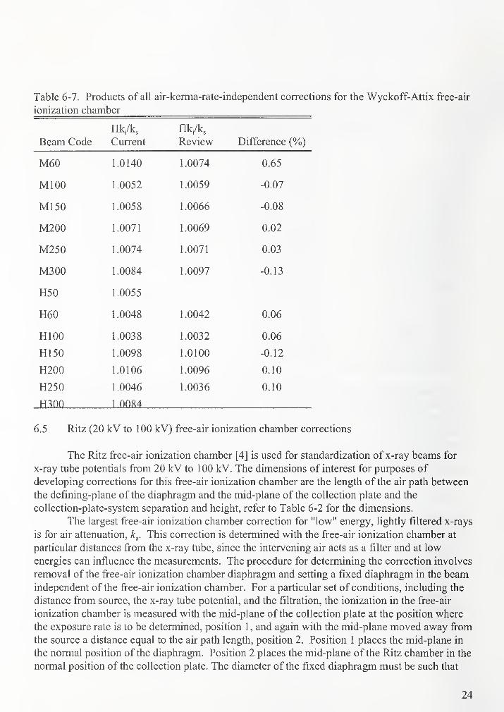
Table 6-7. Products of all air-kerma-rate-independent corrections for the Wyckoff-Attix free-air
ionization chamber
Beam Code
nk/k.
Current
nk/k^
Review Difference iVo)
M60 1.0140 1.0074 0.65
MlOO 1.0052 1.0059 -0.07
M150 1.0058 1.0066 -0.08
iVlZWu 1 0071 1 OO^^Q 0 09u.uz
M250 1.0074 1.0071 0.03
M300 1.0084 1.0097 -0.13
xIjU 1 oo^ ^
H60 1.0048 1.0042 0.06
HlOO 1.0038 1.0032 0.06
H150 1.0098 1.0100 -0.12
HlOO 1.0106 1.0096 0.10
H250 1.0046 1.0036 0.10
H300 1 0084
6.5 Ritz (20 kV to 100 kV) free-air ionization chamber corrections
The Ritz free-air ionization chamber [4] is used for standardization of x-ray beams for
x-ray tube potentials from 20 kV to 100 kV. The dimensions of interest for purposes of
developing corrections for this free-air ionization chamber are the length of the air path between
the defming-plane of the diaphragm and the mid-plane of the collection plate and the
collection-plate-system separation and height, refer to Table 6-2 for the dimensions.
The largest free-air ionization chamber correction for "low" energy, lightly filtered x-rays
is for air attenuation, k^. This correction is determined with the free-air ionization chamber at
particular distances from the x-ray tube, since the intervening air acts as a filter and at low
energies can influence the measurements. The procedure for determining the correction involves
removal of the free-air ionization chamber diaphragm and setting a fixed diaphragm in the beamindependent of the free-air ionization chamber. For a particular set of conditions, including the
distance from source, the x-ray tube potential, and the filtration, the ionization in the free-air
ionization chamber is measured with the mid-plane of the collection plate at the position where
the exposure rate is to be determined, position 1 , and again with the mid-plane moved away from
the source a distance equal to the air path length, position 2. Position 1 places the mid-plane in
the normal position of the diaphragm. Position 2 places the mid-plane of the Ritz chamber in the
normal position of the collection plate. The diameter of the fixed diaphragm must be such that
24

the defined beam in its entirety is intercepted by the free-air ionization chamber at the two
measurement positions. The ratio of the currents measured at position 1 and position 2 is the air
attenuation correction factor for the conditions of measurement. These conditions include the
atmospheric temperature and pressure since the attenuation is dependent on the density of the air.
The attenuation correction is computed for a pressure of 99.992 kPa and a temperature of 293.15
K, (dry air density of 1.189 mg-cm"^) to provide a correction factor representative of normal
room conditions. If the experimentally determined attenuation coefficients, |i/p, are so large that
normal variations in room conditions produce significant differences in the correction, then the
difference in air density from 1.189 mg-cm"^ must be taken into account. The conditions pertain
for all x-ray beams with HVLs less than 0.22 mm Al. The effect on of changes in temperature
and pressure from reference conditions must be taken into account using equation 6-3. A list of
the air-attenuation coefficients and values for for the Ritz are listed in Table 6-8. See Ref [7]
for a list of calculated mass attenuation coefficients. These have been verified recently using the
Attix chamber for a direct determination of the correction.
Table 6-8. Mass air-attenuation coefficients and air attenuation corrections for the Ritz free-air
ionization chamber
Beam Code HVL(mm Al) (cmVmg)
Air Attenuation
Correction (kj^
L20 0.071 8.2293E-3 1.1327"
L30 0.22 3.2392E-3 1.0503"
L40 0.49 1.6816E-3 1.0258
L50 0.75 1.2163E-3 1.0186
L80 1.83 7.3175E-4 1.0111
LlOO 2.8 4.3435E-4 1.0066
M20 0.152 4.0835E-3 1.0639"
M30 0.36 1.8811E-3 1.0288
M40 0.73 1.1051E-3 1.0169
M50 1.02 7.4192E-4 1.0113
H20 0.36 1.6190E-3 1.0248
H30 1.23 5.8048E-4 1.0088
H40 ?9 3 9078F,-4 1 00S9^ The air attenuation corrections were determined with the defining plane of the Ritz chamber at
50 cm, for an air-path length of 127.39 mm." These corrections vary significantly with changes in atmospheric temperature and pressure.
For ambient conditions, k^ is calculated using k^ = exp (|iiL).
The electron-loss corrections, k^, for the Ritz free-air ionization chamber are taken from
data in the 1959 publication on the design of free-air ionization chambers [6]. The dimensions of
the Ritz free-air ionization chamber are such that the ionization loss due to loss of electrons
25

occurs only at the upper end of the x-ray energy range for which this free-air ionization chamber
is used. Therefore, only figures 10 and 14 of Ref 6 are required for calculation of the
corrections for beam codes S75 and LI 00. These data, used in conjunction with the fractional
areas inside the collection-plate system for different radii, provide the required corrections for
ionization loss. For this calculation, the plate separation is reduced from 9 cm to 8 cm to account
for the 1-cm-diameter free-air ionization chamber beam defining diaphragm and to simulate the
required zero-beam diameter. The results of the calculations shown in Table 6-9 do not differ by
more than 0.1 % from the corrections for electron loss presently used for these conditions. Since
no data are published for the L80 x-ray beam condition, the correction for electron-loss is
estimated by interpolation following the curvature of the data for E, at 60, 75, and 100 kV with 3
mm Al added filtration. The estimated correction is 0.12 %, which is not significantly different
Table 6-9. Computation of electron-loss corrections for the Ritz free-air ionization chamber
Radius S75 LI 00
Inner Outer Ap ApE, ApE,
(cm) (cm) (%) (%) (%) (%)
0 4.0 1.00 -0.10 -0.10 -0.60 -0.60
4.0 4.5 0.58 0.035 0.02 0.20 0.12
4.5 5.0 0.28 0.024 0,01 0.13 0.04
ke -0.07 -0.44
from the presently used correction. A detailed analysis of the corrections is currently
underway. The calculations, which consider x-ray beam penumbra effects on the magnitude of
the corrections can be found in Ref 3 of Attachment 2.
Corrections for the scattered-photon contribution to the ionization in the free-air
ionization chamber are derived from Ritz [6] and Allisy and Roux [9]. The percent scattered-
photon contributions within different radii, and appropriate multipliers for several x-ray beam
conditions, are given in Ritz [6], figure 15 and table 1, respectively. The data of Ritz, Allisy and
Roux were combined and by means of least-squares fit for vs. HVL measured in Al, the
following logarithmic equation was developed:
kp = 0.9956 + IxWhog^^iHYL mm Al) (6-8)
The values of k^ for the Ritz free-air ionization chamber, listed in Table 6-10, are computed from
this equation. For convenience, the products of all rate-independent corrections for the Ritz
chamber are provided in the last column of Table 6-10.
• The recombination corrections for the Ritz free-air ionization chamber are calculated
from an equation of the same form as was developed for the Wyckoff-Attix free-air
ionization chamber and described in a previous section. The Scott and Greening extrapolation
procedure for air-kerma rates ranging from 0.6 mGy/s to 4.2 mOy/s yields the following
logarithmic equations:
= 1 + %.lU6x\0-^K,{Gyls) (6-9)
26
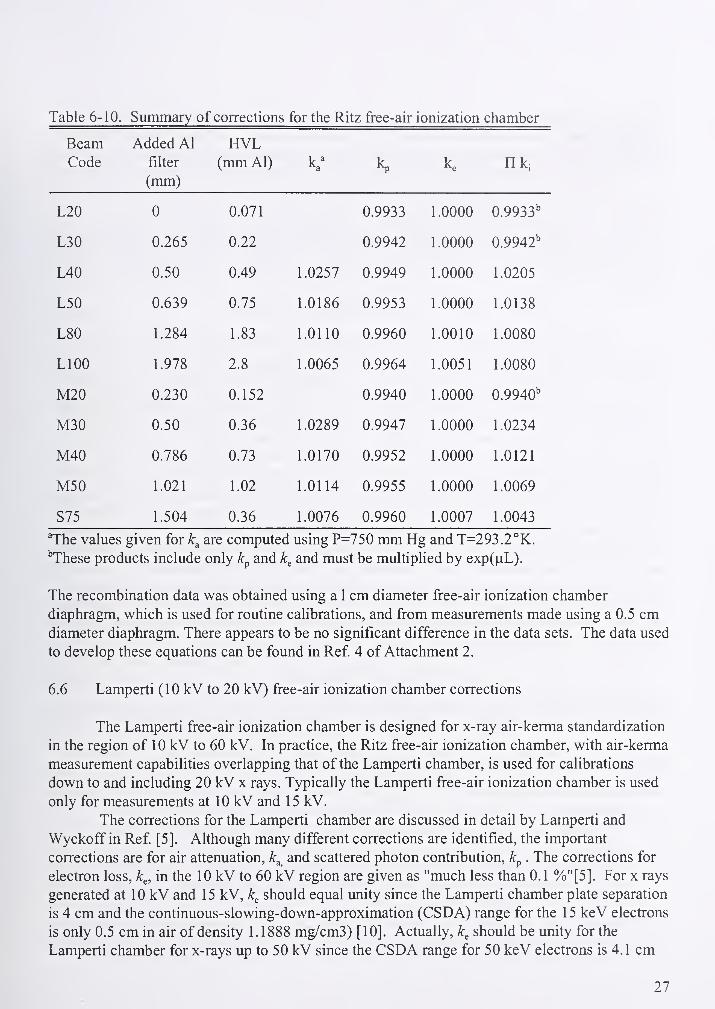
1 doie D- 1 u. Summary of corrections for the Ritz free-air ionization chamber
Beam Added Al HVLCode filter (mm Al)
1 a
ka K n kj
(mm)
L20 U 0.071 0.9933 1.0000 0.9933"
L30 0.265 0.22 0.9942 1.0000 0.9942"
L40 0.50 0.49 1.0257 0.9949 1.0000 1.0205
T C f\L50 0.639 0.75 1.0186 0.9953 1.0000 1.0138
L80 1.284 1.83 1.0110 0.9960 1.0010 1.0080
LlOO 1.978 2.8 1.0065 0.9964 1.0051 1.0080
M20 0.230 0.152 0.9940 1.0000 0.9940"
M30 0.50 0.36 1.0289 0.9947 1.0000 1.0234
M40 0.786 0.73 1.0170 0.9952 1.0000 1.0121
M50 1.021 1.02 1.0114 0.9955 1.0000 1.0069
S75 1.504 0.36 1.0076 0.9960 1.0007 1.0043
The values given for are computed using P=750 mm Hg and T=293.2°K.
"These products include only and k^ and must be multiplied by exp(fiL).
The recombination data was obtained using a 1 cm diameter free-air ionization chamber
diaphragm, which is used for routine calibrations, and from measurements made using a 0.5 cmdiameter diaphragm. There appears to be no significant difference in the data sets. The data used
to develop these equations can be found in Ref 4 of Attachment 2.
6.6 Lamperti (10 kV to 20 kV) free-air ionization chamber corrections
The Lamperti free-air ionization chamber is designed for x-ray air-kerma standardization
in the region of 10 kV to 60 kV. In practice, the Ritz free-air ionization chamber, with air-kerma
measurement capabilities overlapping that of the Lamperti chamber, is used for calibrations
down to and including 20 kV x rays. Typically the Lamperti free-air ionization chamber is used
only for measurements at 10 kV and 15 kV.
The corrections for the Lamperti chamber are discussed in detail by Lamperti and
Wyckoff in Ref [5]. Although many different corrections are identified, the important
corrections are for air attenuation, k^ and scattered photon contribution, . The corrections for
electron loss, k^, in the 10 kV to 60 kV region are given as "much less than 0.1 %"[5]. For x rays
generated at 10 kV and 15 kV, k^ should equal unity since the Lamperti chamber plate separation
is 4 cm and the continuous-slowing-down-approximation (CSDA) range for the 15 keV electrons
is only 0.5 cm in air of density 1.1888 mg/cm3) [10]. Actually, k^ should be unity for the
Lamperti chamber for x-rays up to 50 kV since the CSDA range for 50 keV electrons is 4.1 cm
27
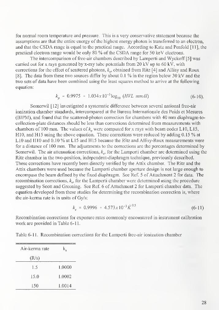
for normal room temperature and pressure. This is a very conservative statement because the
assumptions are that the entire energy of the highest energy photon is transferred to an electron,
and that the CSDA range is equal to the practical range. According to Katz and Penfold [1 1], the
practical electron range would be only 80 % of the CSDA range for 50 keV electrons.
The intercomparison of free-air chambers described by Lamperti and Wyckoff [5] was
carried out for x rays generated by x-ray tube potentials from 20 kV up to 60 kV, with
corrections for the effect of scattered photons, k^, obtained from Ritz [4] and Allisy and Roux
[8]. The data from these two sources differ by about 0.1 % in the region below 30 kV and the
two sets of data have been combined using the least squares method to arrive at the following
equation:
kp = 0.9975 + 1.034xlO"Mog,o {HVL mmAl) (6-10).
Somerwil [12] investigated a systematic difference between several national free-air
ionization chamber standards, intercompared at the Bureau Internationale des Poids et Mesures
(BIPM), and found that the scattered-photon correction for chambers with 40 mm diaphragm-to-
collection-plate distances should be less than corrections determined from measurements with
chambers of 100 mm. The values of k^ were computed for x rays with beam codes LIO, L15,
HIO, and HI 5 using the above equation. These corrections were reduced by adding 0.15 % at
LIO and HIO and 0.10 % at L 15 and H15 because the Ritz and Allisy-Roux measurements were
for a distance of 100 mm. The adjustments to the corrections are the percentages determined by
Somerwil. The air attenuation corrections, k^, for the Lamperti chamber are determined using the
Ritz chamber in the two-position, independent-diaphragm technique, previously described.
These corrections have recently been directly verified by the Attix chamber. The Ritz and the
Attix chambers were used because the Lamperti chamber aperture design is not large enough to
encompass the beam defined by the fixed diaphragm. See Ref. 5 of Attachment 2 for data. The
recombination corrections, k^, for the Lamperti chamber were determined using the procedure
suggested by Scott and Greening. See Ref. 6 of Attachment 2 for Lamperti chamber data. The
equation developed from these studies for determining the recombination correction is, where
the air-kerma rate is in units of Gy/s:
k^ = 0.9996 + 4.573x10"^ A:^-^ (6-11)
Recombination corrections for exposure rates commonly encountered in instrument calibration
work are provided in Table 6-11.
Table 6-11. Recombination corrections for the Lamperti free-air ionization chamber
Air-kerma rate ks
(R/s)
1.5 1.0000
15.0 1.0002
150 1.0014
28
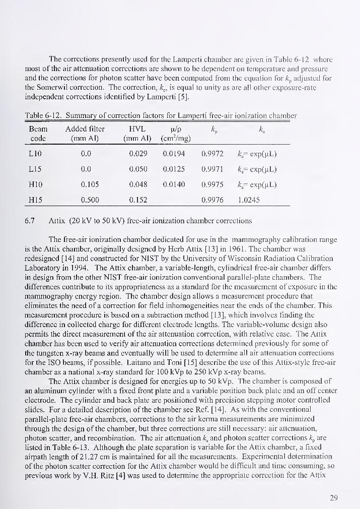
The corrections presently used for the Lamperti chamber are given in Table 6-12 where
most of the air attenuation corrections are shown to be dependent on temperature and pressure
and the corrections for photon scatter have been computed from the equation for adjusted for
the Somerwil correction. The correction, k^, is equal to unity as are all other exposure-rate
independent corrections identified by Lamperti [5].
Beamcode
Added filter
(mm Al)
HVL(mm Al) (cmVmg)
K K
LIO 0.0 0.029 0.0194 0.9972 k = exp(|iL)
L15 0.0 0.050 0.0125 0.9971 k = exp(^L)
HIO 0.105 0.048 0.0140 0.9975 k = exp(^L)
H15 0.500 0.152 0.9976 1.0245
6.7 Attix (20 kV to 50 kV) free-air ionization chamber corrections
The free-air ionization chamber dedicated for use in the mammography calibration range
is the Attix chamber, originally designed by Herb Attix [13] in 1961. The chamber was
redesigned [14] and constructed for NIST by the University of Wisconsin Radiation Calibration
Laboratory in 1994. The Attix chamber, a variable-length, cylindrical free-air chamber differs
in design from the other NIST free-air ionization conventional parallel-plate chambers. The
differences contribute to its appropriateness as a standard for the measurement of exposure in the
mammography energy region. The chamber design allows a measurement procedure that
eliminates the need of a correction for field inhomogeneities near the ends of the chamber. This
measurement procedure is based on a subtraction method [13], which involves finding the
difference in collected charge for different electrode lengths. The variable-volume design also
permits the direct measurement of the air attenuation correction, with relative ease. The Attix
chamber has been used to verify air attenuation corrections determined previously for some of
the tungsten x-ray beams and eventually will be used to determine all air attenuation corrections
for the ISO beams, if possible. Laitano and Toni [15] describe the use of this Attix-style free-air
chamber as a national x-ray standard for 100 kVp to 250 kVp x-ray beams.
The Attix chamber is designed for energies up to 50 kVp. The chamber is composed of
an aluminum cylinder with a fixed front plate and a variable position back plate and an off center
electrode. The cylinder and back plate are positioned with precision stepping motor controlled
slides. For a detailed description of the chamber see Ref [14]. As with the conventional
parallel-plate free-air chambers, corrections to the air kerma measurements are minimized
through the design of the chamber, but three corrections are still necessary: air attenuation,
photon scatter, and recombination. The air attenuation and photon scatter corrections k^ are
listed in Table 6-13. Although the plate separation is variable for the Attix chamber, a fixed
airpath length of 2 1 .27 cm is maintained for all the measurements. Experimental determination
of the photon scatter correction for the Attix chamber would be difficult and time consuming, so
previous work by V.H. Ritz [4] was used to determine the appropriate correction for the Attix
29

chamber for each available aperture. Table 6-13 lists the photon scatter corrections for a 1 cmaperture. The recombination correction was determined using the procedure suggested by Scott
and Greening [9]. The recombination correction is calculated from the following equation where
air-kerma rate is in units ofmGy/s:
= 1.0002 + Q.m9k,{mGyls) (6-12)
Table 6-13. Correction factors for the Attix free-air ionization chamber
BeamCode
Half-Value
Layer
(mm Al)
Air Density
P
(g/cm3)
u/d
(cmVg)
Air
Attenuation
Correction
Photon
Scatter
Correction
Mo/Mo23 U.271 1.179 h-3 O AAO 1 1 AC /I1.U54 A C\C\AC\0.9949
A /T /AT ^ CMo/Mo25 A AZT0.296
1 1 OA T~? O1.180 E-3 1 AO 1 A1.9819 1 A C 1
1.U51A AACA0.9950
A /T /AT" OMo/Mo28 0.332 1 1 O 1 T? O1.181 E-3 1.8284
1 r\ An1.047 A AACA0.9950
Mo/Mo30 A T C 1
0.35
1
1 1 O 1 T7 O1.181 b-3 1.676 1 A /I 01.043 A AAC 10.9951
Mo/Mo35 A T A'^0.392 1.175 b-3 1.56931 A /I
1.04A AACO0.9952
Mo/Rh28 A /I AO0.408 1 1 O /I O1.184 h-3 1 C 1 o c
1.51851 AO A1.039
A AAC)0.9952
Mo/Rh32 3445 1.185 E-31 A A 1
1.44161 A O T1.037
A AA C O0.9953
Mo/Jylo25x (J.JOO 1.1 / / E-3 U.83(J4 1 AT 11.021 A AAC C0.995 J
Mo/Mo28x 0.626 1.177 E-3 0.908 1.023 0.9956
Mo/Mo30x 0.66 1.179 E-3 0.8287 1.021 0.9956
Mo/Mo35x 0.748 1.177 E-3 0.7911 1.02 0.9957
Rh/Rh25 0.351 1.184 E-3 1.7098 1.044 0.9951
Rh/Rh30 0.438 1.189 E-3 1.5134 1.039 0.9952
Rh/Rh35 0.512 1.187 E-3 1.2857 1.033 0.9954
Rh/Rh40 0.559 1.185 E-3 1.326 1.034 0.9954
Rh/Rh30x 0.814 1.186 E-3 0.6684 1.017 0.9958
Rh/Rh35x 0.898 1.181 E-3 0.6709 1.017 0.9959
The air kerma determination with the Attix chamber involves the collection of charge
with various plate configurations. By changing the volume of the Attix chamber and knowing
the corresponding change in length of the collecting electrode, the air kerma can be determined
with a minimum of two different plate configurations. Although the minimum number of plate
configurations needed to determine the air kerma is two, four measurements are conducted, with
the fourth being a repeat of the first position. The electrode length is changed by 5 cm with each
30

plate configuration.
For routine measurements, the defining point of the Attix chamber, is positioned at one
meter from the focal spot of the x-ray source. However, for the determination of the HVL's and
the air attenuation corrections, the defining point of the aperture is positioned at 78.73 cm and
the chamber center at one meter from the focal spot. A constant plate separation and chamber
distance firom the focal spot is maintained for the HVL measurements. For the air attenuation
correction measurements, a fixed plate separation is maintained, while the center of the chamber
is moved back 21.27 cm, the air path length. The air attenuation correction for the Attix
chamber, is the ratio of the charge collected when the chamber center is at 100 cm to the charge
at 121.27 cm from the focal spot. Attachment 3 contains schematics which show the chamber
configuration for HVL and air attenuation measurements and the chamber position for a routine
measurement procedure. The average of the three resulting ratios of the change in charge to
change in electrode length is calculated and used in the air kerma calculation as a component of
the mass ionization current.
6.8 Comparison of standard fi"ee-air ionization chambers
The NIST standard free-air chambers have been compared with each other and with the
standards of other nations, to test their congruity where their measurement capabilities overlap.
The most recent results from the 1998 BIPM-NIST and the 1998 NPL-NIST comparison are
listed in Tables 6-14 to 6-18. Complete details including the uncertainties of the comparison
can be found in Ref [16] and [17].
The Attix chamber was indirectly compared to the German national standard, using a
NIST reference-class ionization chamber. The measurment of air kerma was made with both the
German and the NIST mammography standards and a calibration factor was established for the
NIST reference-class ionization chamber at both institutes. The Attix chamber was also
compared indirectly through the use of the Ritz chamber at the NPL, Teddington, UK. The
results of this indirect comparison are given in Table 6-19.
The latest "in-house" comparison results for the Atdx, Lamperti and Ritz chambers are
listed in Table 6-20. The Wyckoff-Attix and Ritz chamber comparisons have been conducted
periodically since 1958. The Lamperti and Ritz chambers have been compared numerous times
since 1961. From all previous comparisons, the mean difference between the Lamperti and Ritz
chambers in the 20 to 50 kV region was found to be less than 0.4 %. The mean difference
between the Wyckoff-Attix and Ritz chambers was found to be 0.5 % in the region between 60
and 100 kV. No adjustment is made for these differences since they are well within the
maximum difference of 1 .2 % estimated by the ICRU, and the comparisons give no indication
which member of the pair is to be considered the more reliable. Before establishing the Attix
chamber as a primary standard it was compared to the Ritz and the Lamperti chambers. The
complete details of the Ritz to Attix comparison are given in Ref [18]. The comparison results
are listed in Table 6-20 and show agreement to be better than 0.35 %. The unpublished
comparison results of the Lamperti to the Attix chamber are also listed.
31

Table 6-14. Results of the comparison of the Lamperti standard with the BIPM standard
Generating potential Half-value layer NIST/BIPM(kV) (mm Al) 1998
10 0.036 0.9950
30.;
0.176 0.9961
25 0.250 0.9968
50(b) 1.021 0.9948
50(a) 2.257 0.9938
Table 6-15. Results of the comparison of the Ritz standard with the BIPM standard
Generating potential Half-value layer NIST/BIPM(kV) (mmAl) 1998
30 0.176 0.9943
25 r 0.250 0.9949
50(b) 1.021 0.9938
50(a) 2.257 0.9956
80 3.01 0.9902
100 4.00 0.9947
Table 6-16. Comparison of the Lamperti chamber to the 50 kV NPL standard
Generating potential Half-value layer NIST/BIPM(kV) (mm Al) 1998
10 0.036 0.9951
11.5 0.05 1.0006
14 0.07 0.9996
16 0.1 0.9995
20 0.15 0.9992
32

Table 6-17. Comparison of the Ritz chamber to the NPL 50 kV standard
Generating potential
(kV)
Half-value layer
(mm Al)
NIST/BIPM1998
20 0.15 0.9977
24 0.25 0.9978
34 0.35 0.9989
41 0.5 0.9973
44 0.7 0.9983
50 1.0 0.9983
Table 6-18. Comparison of the Ritz chamber to the NPL 300 kV standard
Generating potential
(kV)
Half-value layer
(mm Al)
NIST/BIPM1998
50 1 0.9981
80 2.9 0.9941
Table 6-19. Comparison results for the mammography standard
Beam Quality Half-value layer NIST/PTB^
(mm Al)
NIST/NPL''
Mo/Mo25 0.296 1.005
Mo/Mo28 0.332 0.996
Mo/Mo30 0.351 0.999
Mo/Mo35 0.392 1.002
Mo/Mo25x 0.566 0.999
Mo/Mo28x 0.626 0.994
Mo/Mo30x 0.660 1.005
Mo/Mo35x 0.748 1.004
^ These results were obtained through the use of a transfer standard ionization chamber.
These results were obtained through the use of the Ritz chamber and transfered to the Attix
chamber.
33

Table 6-20. Recent "in-house" comparisons standards
Beam quality Half-value layer Ritz/Attix Lamperti/Attix
Mo/Mo23 0.271 0.998
Mo/Mo25 0.296 0.997 0.998
Mo/Mo28 0.332 0.997 0.999
Mo/Mo30 0.351 0.999 0.997
Mo/Mo35 0.392 0.998 0.998
Mo/Rh28 0.408 0.997
Mo/Rh32 0.445 0.997
Mo/Mo25x 0.566 1.001
Mo/Mo28x 0.626 1.001
Mo/Mo30x 0.66 1.001
Mo/Mo35x 0.748 1.000
Rh/Rh25 0.351 0.997
Rh/Rh30 0.438 0.997
Rh/Rh35 0.512 0.999
Rh/Rh40 0.559 0.998 1.004
Rh/Rh30x 0.814 1.000
RhyRh35x 0.898 1.000
L15 0.057 1.007^
L20 0.071 0.999 1.004^
M20 0.152 1.002 1.004^
L30 0.22 0.998
M30 0.36 1.002 1.003^
M40 0.73 1.000
M50 1.02 0.998 0.999'
*This is a comparison of the Lamperti chamber to the Ritz chamber using the new tungsten low-
energy x-ray tube.
34
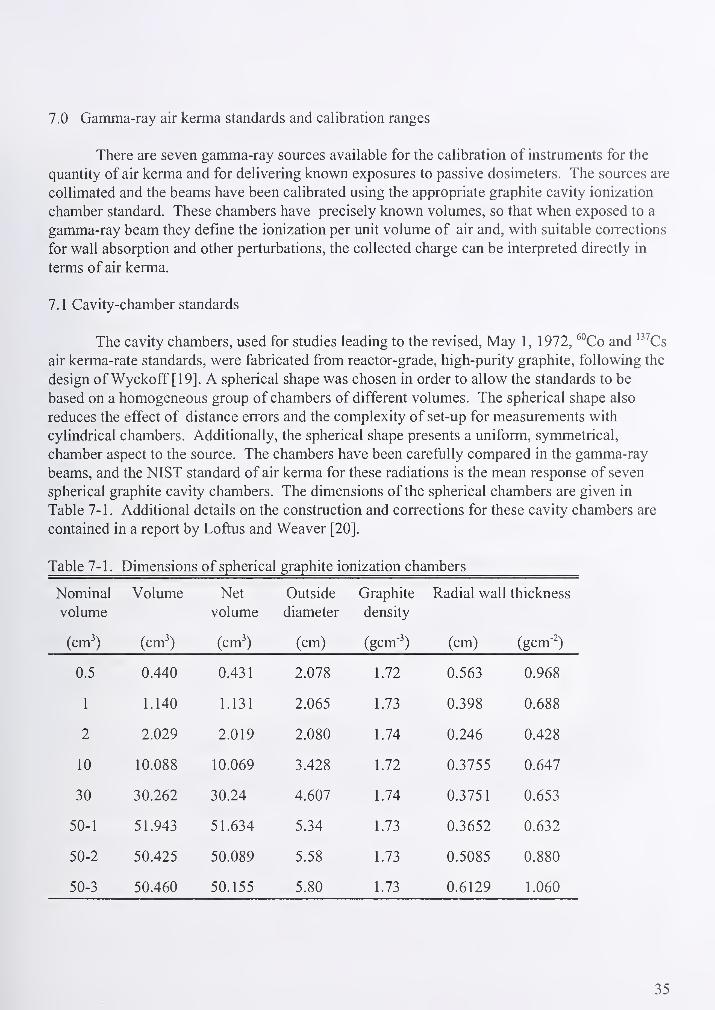
7.0 Gamma-ray air kerma standards and calibration ranges
There are seven gamma-ray sources available for the calibration of instruments for the
quantity of air kerma and for delivering known exposures to passive dosimeters. The sources are
collimated and the beams have been calibrated using the appropriate graphite cavity ionization
chamber standard. These chambers have precisely known volumes, so that when exposed to a
gamma-ray beam they define the ionization per unit volume of air and, with suitable corrections
for wall absorption and other perturbations, the collected charge can be interpreted directly in
terms of air kerma.
7.1 Cavity-chamber standards
The cavity chambers, used for studies leading to the revised. May 1, 1972, ^°Co and '^^Cs
air kerma-rate standards, were fabricated from reactor-grade, high-purity graphite, following the
design of Wyckoff [19]. A spherical shape was chosen in order to allow the standards to be
based on a homogeneous group of chambers of different volumes. The spherical shape also
reduces the effect of distance errors and the complexity of set-up for measurements with
cylindrical chambers. Additionally, the spherical shape presents a uniform, symmetrical,
chamber aspect to the source. The chambers have been carefully compared in the gamma-ray
beams, and the NIST standard of air kerma for these radiations is the mean response of seven
spherical graphite cavity chambers. The dimensions of the spherical chambers are given in
Table 7-1. Additional details on the construction and corrections for these cavity chambers are
contained in a report by Loftus and Weaver [20].
Table 7-1. Dimensions of spherical graphite ionization chambers
Nominal
volume
(cm^)
Volume
(cm^)
Net
volume
(cm^)
Outside
diameter
(cm)
Graphite
density
(gcm-^)
Radial wall thickness
(cm) (gcm-2)
0.5 0.440 0.431 2.078 1.72 0.563 0.968
1 1.140 1.131 2.065 1.73 0.398 0.688
2 2.029 2.019 2.080 1.74 0.246 0.428
10 10.088 10.069 3.428 1.72 0.3755 0.647
30 30.262 30.24 4.607 1.74 0.3751 0.653
50-1 51.943 51.634 5.34 1.73 0.3652 0.632
50-2 50.425 50.089 5.58 1.73 0.5085 0.880
50-3 50.460 50.155 5.80 1.73 0.6129 1.060
35

7.2 Gamma-ray sources
The location, nominal activity, and orientation of the gamma-ray sources used for
instrument calibrations are given in Table 7-2. Figure 7-1 is a schematic of a irradiator housing
a ''Co gamma-ray source typical of the horizontal gamma-ray source geometries used at NIST.
Table 7-2. Gamma-ray source locations and nominal activities of sources as of January 1, 1999
Radionuclide Activity
(bq)
Location Orientation
^^Co 2.7 E13 B034 vertical
"Co 1.5 E14 B036 vertical
"Co 1.3 Ell B021B horizontal
"Co 9.6 E09 B015B horizontal
'^^Cs 3.1 E13 B036 vertical
'3^Cs 5.8 E12 B021A horizontal
^^^Cs 6.3 Ell B015A horizontal
Fig. 7-1. Port detail for horizontal ^°Co 5 mm diameter source.
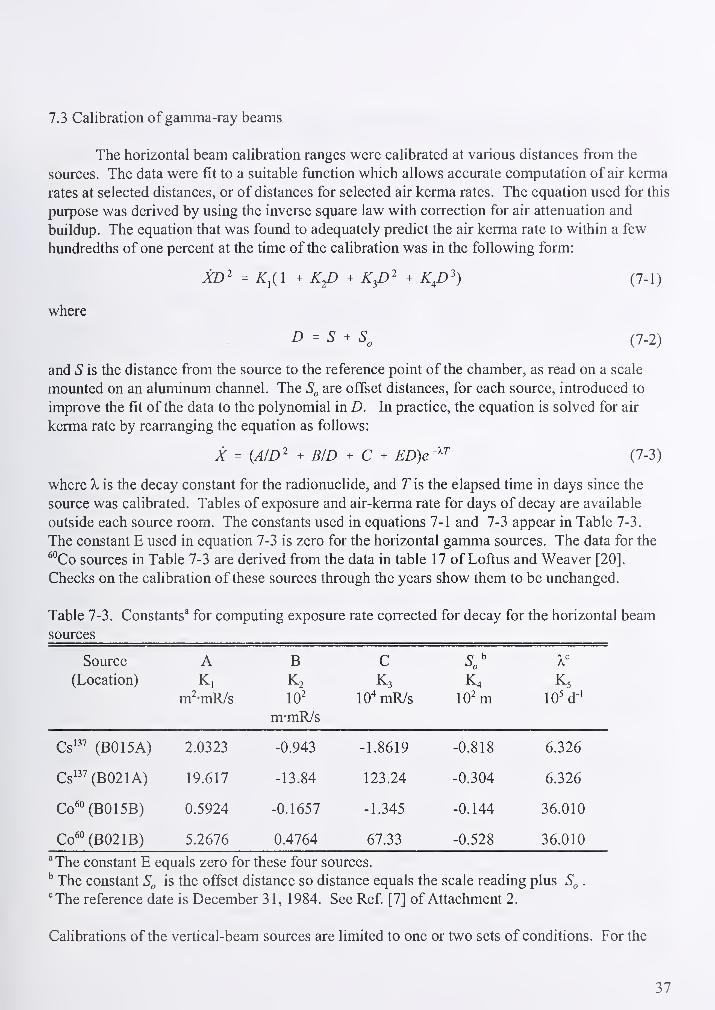
7.3 Calibration of gamma-ray beams
The horizontal beam calibration ranges were calibrated at various distances from the
sources. The data were fit to a suitable function which allows accurate computation of air kerma
rates at selected distances, or of distances for selected air kerma rates. The equation used for this
purpose was derived by using the inverse square law with correction for air attenuation and
buildup. The equation that was found to adequately predict the air kerma rate to within a few
hundredths of one percent at the time of the calibration was in the following form:
XD^ = ^i(l + KJD + + K^D^) (7-1)
where
D - S ^ (7-2)
and S is the distance from the source to the reference point of the chamber, as read on a scale
mounted on an aluminum channel. The are offset distances, for each source, introduced to
improve the fit of the data to the polynomial in D. In practice, the equation is solved for air
kerma rate by rearranging the equation as follows:
X = (A/D^ + B/D + C + ED)e'^^ (7-3)
where X is the decay constant for the radionuclide, and T is the elapsed time in days since the
source was calibrated. Tables of exposure and air-kerma rate for days of decay are available
outside each source room. The constants used in equations 7- 1 and 7-3 appear in Table 7-3
.
The constant E used in equation 7-3 is zero for the horizontal gamma sources. The data for the
^°Co sources in Table 7-3 are derived from the data in table 17 of Loftus and Weaver [20].
Checks on the calibration of these sources through the years show them to be unchanged.
Table 7-3. Constants^ for computing exposure rate corrected for decay for the horizontal beam
sources
Source A B C(Location) K, K2 K3 K4 K5
m^-mR/s 10^ 10' mR/s lO^m 10'd-'
m-mR/s
Cs'^^ (BO 15A) 2.0323 -0.943 -1.8619 -0.818 6.326
Cs'" (B021A) 19.617 -13.84 123.24 -0.304 6.326
Co'° (B015B) 0.5924 -0.1657 -1.345 -0.144 36.010
Co'° (B021B) 5.2676 0.4764 67.33 -0.528 36.010
^The constant E equals zero for these four sources.
The constant is the offset distance so distance equals the scale reading plus .
^The reference date is December 31, 1984. See Ref [7] of Attachment 2.
Calibrations of the vertical-beam sources are limited to one or two sets of conditions. For the
37
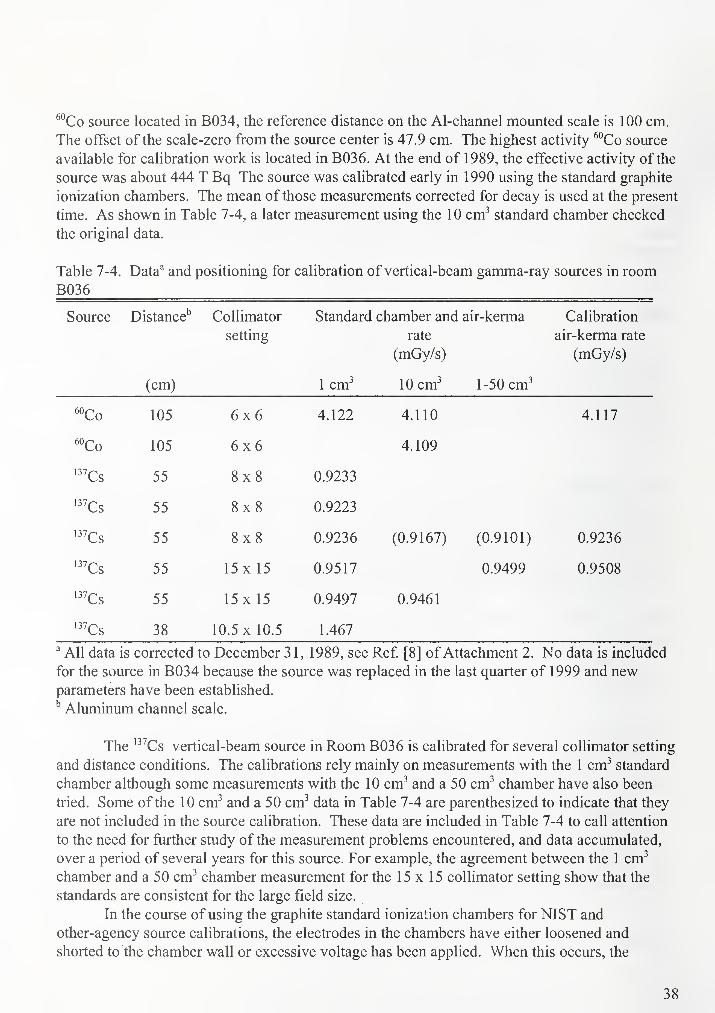
''Co source located in B034, the reference distance on the Al-channel mounted scale is 100 cm.
The offset of the scale-zero from the source center is 47.9 cm. The highest activity ^°Co source
available for calibration work is located in B036. At the end of 1989, the effective activity of the
source was about 444 T Bq The source was calibrated early in 1 990 using the standard graphite
ionization chambers. The mean of those measurements corrected for decay is used at the present
time. As shown in Table 7-4, a later measurement using the 10 cm-' standard chamber checked
the original data.
Table 7-4. Data^ and positioning for calibration of vertical-beam gamma-ray sources in room
B036
Source Distance'' Collimator
setting
Standard chamber and
rate
(mGy/s)
air-kerma Calibration
air-kerma rate
(mGy/s)
(cm) 1 cm^ 10 cm^ 1-50 cm^
"Co 105 6x6 4.122 4.110 4.117
"Co 105 6x6 4.109
'^^Cs 55 8x8 0.9233
'''Cs 55 8x8 0.9223
'''Cs 55 8x8 0.9236 (0.9167) (0.9101) 0.9236
'''Cs 55 15 X 15 0.9517 0.9499 0.9508
55 15x 15 0.9497 0.9461
'^^Cs 38 10.5 X 10.5 1.467
^ All data is corrected to December 31, 1989, see Ref [8] of Attachment 2. No data is included
for the source in B034 because the source was replaced in the last quarter of 1999 and newparameters have been established.
Aluminum channel scale.
The '^^Cs vertical-beam source in Room B036 is calibrated for several collimator setting
and distance conditions. The calibrations rely mainly on measurements with the 1 cm^ standard
chamber although some measurements with the 10 cm^ and a 50 cm^ chamber have also been
tried. Some of the 10 cm^ and a 50 cm^ data in Table 7-4 are parenthesized to indicate that they
are not included in the source calibration. These data are included in Table 7-4 to call attention
to the need for further study of the measurement problems encountered, and data accumulated,
over a period of several years for this source. For example, the agreement between the 1 cm^
chamber and a 50 cm^ chamber measurement for the 15x15 collimator setting show that the
standards are consistent for the large field size.
In the course of using the graphite standard ionization chambers for NIST and
other-agency source calibrations, the electrodes in the chambers have either loosened and
shorted to the chamber wall or excessive voltage has been applied. When this occurs, the
38

electrodes are weakened and carbon is deposited on the high-voltage insulator. The 1 cm\ 10
cm^ and 30 cm^ chambers are particularly prone to this problem since the electrodes have
diameters less than 1 mm and, with the present stem design, are difficult to anchor securely in
position. It has been necessary on several occasions to straighten or replace these electrodes and
to clean or replace the high-voltage insulators and chamber stems. Subsequent checks of source
calibrations, in particular using the 1 cm^ chamber, indicate that the relationship of that chamber
to the others, established under ideal conditions in 1972, may no longer hold. Measurements of
the high-air kerma-rate sources after the last repair of the Icm^ chamber were several tenths of
one percent higher than the reference data. This is shown to some extent in Table 7-4 where the
latest data taken on the '^''Cs source for the 8x8 collimator setting is higher than the previous
measurements. Some 1 cm^ chamber exposure data not included in Table 7-4 indicate a
difference between present and earlier measurements of as much as 0.4 %. On the other hand,
measurements at low air kerma rates at 1 meter from the '^^Cs source in Rm B021A show
agreement between the 1 cm^ standard and a 50 cm^ or the 10 cm^ standard to be within 0.02 %and 0.01 % respectively. See Ref. [9] of Attachment 2. The net cavity volume for the 1 cm^
chamber was measured to be 1.1297 cm^ following the last repair, which involved the
replacement of electrode and refurbishment of the high voltage electrode. See Ref. [10] of
Attachment 2.
The main difficulty in reproducing air kerma calibration data involves the Icm^ chamber.
A small-volume standard chamber is required for high air kerma rate measurements, and in
beams that may be uniform only over small areas. See Ref. [1 1] of Attachment 2 for details.
However, small-volume chambers have unwanted extra-cameral volumes in the vicinity of the
high voltage insulator and stems that can have a large effect on the chamber response to
radiation, therefore data is taken at both polarities. Additional difficulties of another sort arise in
comparing data over a period of years when different measurement equipment may be used, see
for example Ref. [12] of Attachment 2. The uncertainty statement given by Loftus and Weaver
[20] is only representative in the short term and for optimum conditions. In order to maintain the
overall uncertainty of 0.7 %, the primary standards are carefully preserved and not used as
working standards.
7.4. Useful beam size
The "useful beam" radius for the gamma-ray sources is defined as the distance from the
center of a radiograph of the beam to the point where the density of the film is 90 % of the center
density, minus the difference in distance between the 90 % and 50 % density measurements.
With R^O' the radius of the 90 % density contour, and R50, the radius of the 50 % density contour,
the usefiil beam radius (UB) is computed as follows:
i?,, = K6 X SD + K7 (7-4)
i?on = K8 X SD + K9 (7-5)
UB = R.. - (R50 (7-6)
UB = 2i?on - R50 (7-7)
39
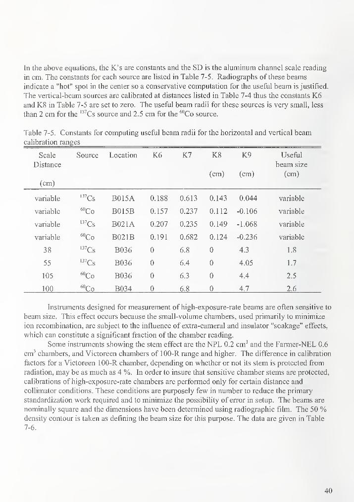
In the above equations, the K's are constants and the SD is the aluminum channel scale reading
in cm. The constants for each source are listed in Table 7-5. Radiographs of these beams
indicate a "hot" spot in the center so a conservative computation for the useful beam is justified.
The vertical-beam sources are calibrated at distances listed in Table 7-4 thus the constants K6and K8 in Table 7-5 are set to zero. The useful beam radii for these sources is very small, less
than 2 cm for the '^''Cs source and 2.5 cm for the ^°Co source.
Table 7-5. Constants for computing useful beam radii for the horizontal and vertical beam
calibration ranges
Scale
Distance
(cm)
Source Location K6 K7 K8
(cm)
K9
(cm)
Useful
beam size
(cm)
variable '^^Cs B015A 0.188 0.613 0.143 0.044 variable
variable ''Co B015B 0.157 0.237 0.112 -0.106 variable
variable '^^Cs B021A 0.207 0.235 0.149 -1.068 variable
variable "Co B021B 0.191 0.682 0.124 -0.236 variable
38 '''Cs B036 0 6.8 0 4.3 1.8
55 '^^Cs B036 0 6.4 0 4.05 1.7
105 ^°Co B036 0 6.3 0 4.4 2.5
100 "Co B034 0 6.8 0 4.7 2.6
Instruments designed for measurement of high-exposure-rate beams are often sensitive to
beam size. This effect occurs because the small-volume chambers, used primarily to minimize
ion recombination, are subject to the influence of extra-cameral and insulator "soakage" effects,
which can constitute a significant fraction of the chamber reading.
Some instruments showing the stem effect are the NPL 0.2 cm^ and the Farmer-NEL 0.6
cm^ chambers, and Victoreen chambers of 100-R range and higher. The difference in calibration
factors for a Victoreen 100-R chamber, depending on whether or not its stem is protected from
radiation, may be as much as 4 %. In order to insure that sensitive chamber stems are protected,
calibrations of high-exposure-rate chambers are performed only for certain distance and
collimator conditions. These conditions are purposely few in number to reduce the primary
standardization work required and to minimize the possibility of error in setup. The beams are
nominally square and the dimensions have been determined using radiographic film. The 50 %density contour is taken as defining the beam size for this purpose. The data are given.in Table
7-6.
40
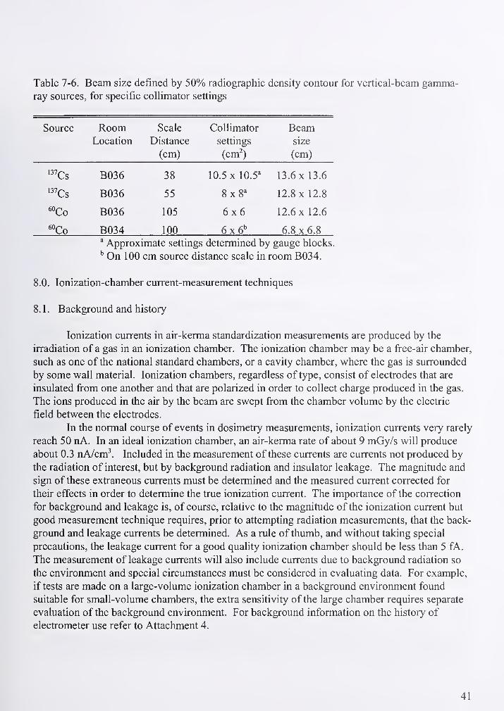
Table 7-6. Beam size defined by 50% radiographic density contour for vertical-beam gamma-
ray sources, for specific collimator settings
Source Room Scale Collimator BeamLocation Distance settings size
(cm) (cm') (cm)
^"Cs B036 38 10.5 X 10.5'' 13.6 X 13.6
•^^Cs B036 55 8x8^ 12.8 X 12.8
''Co B036 105 6x6 12.6 X 12.6
''Co B034 100 6x6" 6.8x6.8" Approximate settings determined by gauge blocks.
''On 100 cm source distance scale in room B034.
8.0. lonization-chamber current-measurement techniques
8.1. Background and history
Ionization currents in air-kerma standardization measurements are produced by the
irradiation of a gas in an ionization chamber. The ionization chamber may be a free-air chamber,
such as one of the national standard chambers, or a cavity chamber, where the gas is surrounded
by some wall material. Ionization chambers, regardless of type, consist of electrodes that are
insulated from one another and that are polarized in order to collect charge produced in the gas.
The ions produced in the air by the beam are swept from the chamber volume by the electric
field between the electrodes.
In the normal course of events in dosimetry measurements, ionization currents very rarely
reach 50 nA. In an ideal ionization chamber, an air-kerma rate of about 9 mGy/s will produce
about 0.3 nA/cm^. Included in the measurement of these currents are currents not produced by
the radiation of interest, but by background radiation and insulator leakage. The magnitude and
sign of these extraneous currents must be determined and the measured current corrected for
their effects in order to determine the true ionization current. The importance of the correction
for background and leakage is, of course, relative to the magnitude of the ionization current but
good measurement technique requires, prior to attempting radiation measurements, that the back-
ground and leakage currents be determined. As a rule of thumb, and without taking special
precautions, the leakage current for a good quality ionization chamber should be less than 5 fA.
The measurement of leakage currents will also include currents due to background radiation so
the environment and special circumstances must be considered in evaluating data. For example,
if tests are made on a large-volume ionization chamber in a background environment found
suitable for small-volume chambers, the extra sensitivity of the large chamber requires separate
evaluation of the background environment. For background information on the history of
electrometer use refer to Attachment 4.
41

8.2. Electrometers
The Keithley Model 616 electrometer' was used for many years by the NIST Radiation
Interactions and Dosimetry Group due to the versatility and the ability to use external calibrated
capacitors. Keithley offers several other models, the 617 and the 6512, that provide the
appropriate features for NIST calibration work. The Radiation Interactions and Dosimetry Group
has used NIST calibrated air-dielectric capacitors of nominal capacitance, 100 pF and 1000 pF,
and good quality 10 nF and 100 nF polystyrene capacitors in a chassis, which were then mounted
with electrometers in measurement consoles containing other control and measurement
equipment. In recent years, the Keithley 617, 617-HiQ and the 6512 with their internal
capacitors have been integrated into the measurement control systems, where at one point only
Keithley 616 and 642 resided. The accuracy and stability for data collected with the internal
capacitors of the newer electrometers in the charge mode, eliminates the need for external
capacitors. These electrometers are routinely calibrated using the NIST calibrated capacitors.
This is discussed in a later section.
8.3. Ionization current measurement-console equipment
X- and gamma-ray-produced ionization currents are, for the most part, measured
automatically, although capability exists to use manual methods. Due to recent upgrades, there
are two types of data acquisition systems (DAS) in use in the x-ray and gamma-ray calibration
ranges. One system is used exclusively for measurements made with the x-ray sets and the
second is a portable system used for measurements made with the gamma-ray sources.
8.3.1. X-ray calibration data acquisition system
Data are acquired for x-ray standardization by measurement of all conditions relevant to
establishing the x-ray air-kerma rate at a particular distance from the x-ray tube target. The data
acquired consists of data for the computation of ionization currents, parameter data, and
measurement system test and information data. Data used to determine the ionization currents
includes the electrometer charge measurements, the atmospheric pressure and pertinent air
temperatures, and the shutter-open time interval. The parameter data includes the x~ray tube
current and potential, the x-ray tube target-to-reference point distance, and the beam defining
filter thickness and the diaphragm diameters. Test data includes the measurements of the collec-
tion potentials on the standard free-air chamber, the monitor chamber, and the chamber being
calibrated, if appropriate. All data is acquired through National Instrument's LabViewinterfacing. All charge measurements are corrected for the temperature and pressure at the time
of the charge collection.
The temperature sensors in the 300-kV range used to measure room, free-air chamber,
and monitor air temperatures are two-wire thermistors manufactured by Yellow Springs Inc.
Certain commercial equipment, instruments, or materials are identified in this paper to foster
understanding. Such identification does not imply recommendation or endorsement by the National Institute of
Standards and Technology, nor does it imply that the materials or equipment identified are necessarily the best
available for the purpose.
42
(YSI). The sensors are connected to YSI model 43TN readouts. The YSI readout is a bridge
circuit which, when unbalanced, provides a voltage proportional to the temperature. There are
four YSI temperature probes used in conjunction with measurements on the 100 kV calibration
range. The thermistors for the Ritz free-air ionization chamber and the Lamperti free-air
ionization chamber are manually switched to a single YSI readout. The parameters of the
calibration equations for some of these probes are found in Table 8-1. These probes are
calibrated at least annually and the required fit parameters are entered into the data acquisition
software. Shown in Table 8-1. are the most recent parameters. In the Mammography Facility
the Hart 5613 platinum resistance thermometers and Hart 1502 digital thermometers are used for
air temperature measurements in the vicinity of the Attix free-air chamber, the monitor chamber
and the test chambers. The calibration correction is applied internally to the 1502 digital meters
therefore no calibration equation is given here.
The atmospheric pressure for the low and high-energy tungsten sets is measured by the
Setra digital barometer and powered by a NIST power supply serial no. 2561. The output
voltage is calibrated for pressure measurements in units of millimeters of Hg. A conversion to
the unit of pascal is applied in the calculation of the calibration factor. The equation used for
computing the pressure is:
P{mmHg) = -3ASS +94.336(voltage) (8-1)
In the mammography range, a Setra 370 barometer is interfaced through RS232 to the data
acquisition software. Any necessary correction is applied directly through software as part of the
air kerma calculation.
The low-energy Pantak generator was calibrated in December of 1997 and the high-
energy Pantak in February of 1998, using a calibrated (Test No. 722/G44568) high-voltage
divider (Seifert Voltage Divider SN 720479). The procedure for a voltage calibration requires
the use of the calibrated voltage divider, a calibrated high precision digital multimeter, and a 10
000 ohm resistor. The Pantak high resolution voltage display reading, corresponding to the
calibrated tube voltage was also determined. Since the calibrations showed some dependence of
the voltage on the tube current, the results are given as a function of current for each tube voltage
setting. Found in Tables 8-2 and 8-3 are the parameters of each linear fit ( = mx+h) where x is
the display reading of the HP voltmeter used to monitor x-ray tube current and y is the ratio used
to calculate the appropriate voltage HP voltmeter display for the desired nominal voltage.
The tube voltage of the mammography x-ray system has been measured using a Dynalzer
voltage divider, and verified with spectrometer measurements. No adjustment is required to be
made to the MPl controller kV display. Without an available NIST calibrated voltage divider,
the tube voltage has been established to within ± 50 eV of the display setting to the best of our
ability.
All time signals are controlled by a National Instrument data acquisition card which
contains two 24-bit, 20 MHZ counters/timers. The signal to the timers is a pulse produced by a
photodiode when its light beam is interrupted by a flag on the shutter mechanism. Uponinitiating the exposure, counting commences only on receipt of the photodiode pulse. At the end
of the preset time interval, the shutter is caused to close but the clock continues to count until the
edge of the shutter crosses the portal mid-point. The timing shutter operation in both the 100 kVand the 300 kV x-ray range has recently been modified to use air cylinder controlled solonoids.
The 300 kV machine also has a safety shutter which opens before, and closes after, the timing
43

shutter. The lead thickness in the timing shutter was minimized for mechanical purposes but is
of sufficient thickness to prevent significant effects on instrument readings in the interval
between operation of the two shutters.
The charge measurements are acquired through the use of Keithley 617, 617-HiQ and
6512 electrometers. The internal capacitors of the electrometers are calibrated annually and any
necessary correction is applied as part of the air kerma calculation. Five electrometers, three
6512 and two 617-HiQ, are maintained for use in the low and high-energy range. Four
electrometers are maintained in the mammography range, two standard capacitance range
electrometers (20 nC), a 617 HIQ (20 ^C), and a midrange 617 (200 nC). The HIQ is dedicated
for use with the monitor chamber and the midrange 617 is used for collecting charge on the
Attix chamber. The two 20 nC capacitance range electrometers are used for the customer
chambers.
Table 8-1. Parameters of the straight line fits for the temperature probe calibrations used in the
Temperature probe
location
slope" intercept"
Wyckoff-Attix chamber -101.384 30.252
300 kV Test chamber -101.904 31.246
Lamperti chamber -92.611 28.740
Ritz chamber -100.007 29.540
100 kV Test chamber -105.031 30.766
'Parameters from calibration performed in September of 1999.
Table 8-2. Low-energy Pantak unit voltage calibration
Nominal Voltage Slope Y - Intercept
10 -0.134 12.472
15 -0.092 12.510
20 -0.068 12.09
30 -0.045 12.518
40 -0.034 12.524
50 -0.026 12.513
55 -0.025 12.521
60 -0.023 12.513
70 -0.021 12.513
75' -0.020 12.511
80 -0.016 12.500
100 -0.024 12.502
44

Table 8-3. High-energy Pantak unit voltage calibration
Nominal Voltage olope Y - Intercept
50 0.222 40.456
55 0.193 40.503
60 0.176 40.500
70 0.146 40.491
80 0.129 40.455
100 0.102 40.431
110 0.084 40.449
120 0.084 40.432
125 0.077 40.451
150 0.070 40.432
170 0.062 40.417
200 0.059 40.384
210 0.055 40.379
240 0.059 40.333
250 0.054 40.325
280 0062 40.260
300 0.065 40.211
8.3.2 Gamma-ray calibration data acquisition system
Calibration and measurements using the gamma-ray sources in rooms B034, B036, B021, and
BO 15 are conducted using a mobile measurement console consisting of all instrumentation
required for measurement and standardization of ionization currents. This data acquisition
system is a Visual Basic interfacing system, which can automatically acquire all or some of the
calibration data for cable-connected instruments and passive or other types of cable-connected
instruments, such as those with their own readout. The mobile console contains a Keithley
Model 616 electrometer, a Setra Model 350A digital barometer and a Digitec Model 5810 digital
thermometer. Each cable connected instrument has as analog output signal. The feedback
elements for the electrometer selector switch in the "volts" position are capacitors mounted in a
capacitor-selector chassis. The equations for computing temperature are dependent on the
thermistor used and, for measurements in control room BO 19, the signals are taken from YSI
readouts mounted in the source control consoles. The equation used for computing atmospheric
pressure from the Setra device, and the data for converting the analog signals from the thermistor
probes to air temperatures in each calibration range and from the pressure transducer to
atmospheric pressure are stored in the computer program. The temperature straight line fit
paramaters follow in Table 8-4 .
45
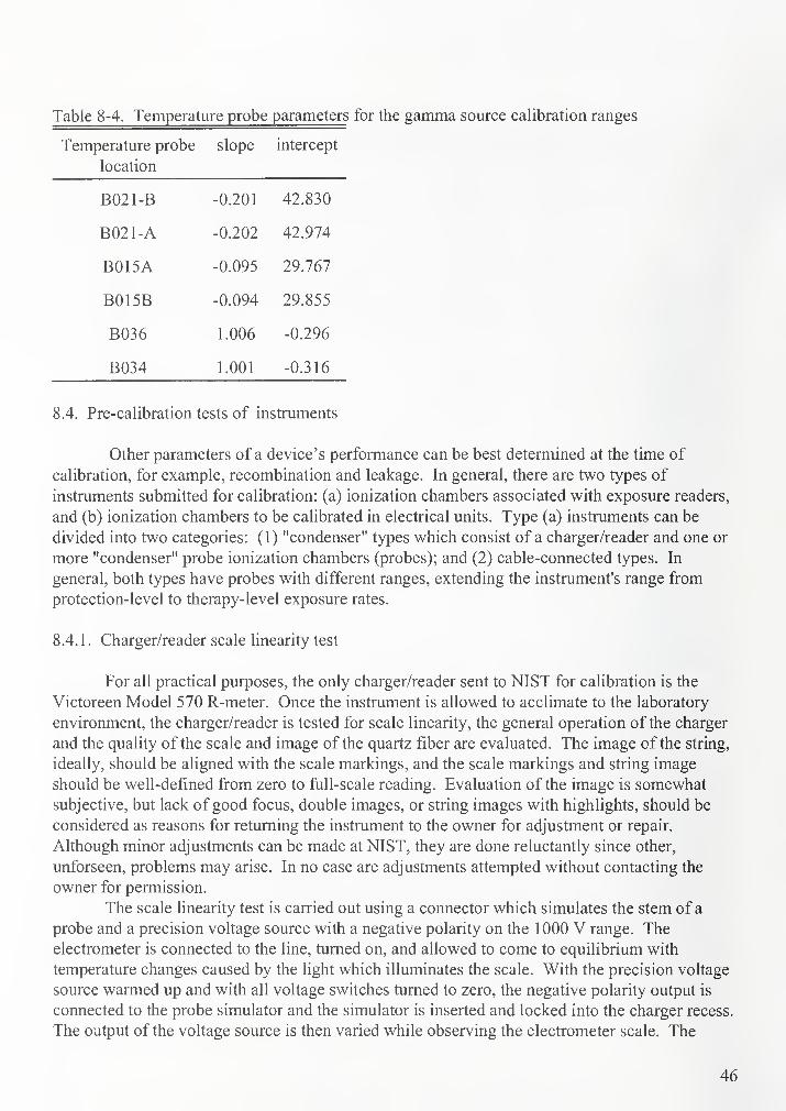
Table 8-4. Temperature probe parameters for the gamma source calibration ranges
Temperature probe
location
slope intercept
B021-B -0.201 42.830
B021-A -0.202 42.974
B015A -0.095 29.767
B015B -0.094 29.855
B036 1.006 -0.296
B034 1.001 -0.316
8.4. Pre-calibration tests of instruments
Other parameters of a device's performance can be best determined at the time of
calibration, for example, recombination and leakage. In general, there are two types of
instruments submitted for calibration: (a) ionization chambers associated with exposure readers,
and (b) ionization chambers to be calibrated in electrical units. Type (a) instruments can be
divided into two categories: (1) "condenser" types which consist of a charger/reader and one or
more "condenser" probe ionization chambers (probes); and (2) cable-connected types. In
general, both types have probes with different ranges, extending the instrument's range from
protection-level to therapy-level exposure rates.
8.4.1. Charger/reader scale linearity test
For all practical purposes, the only charger/reader sent to NIST for calibration is the
Victoreen Model 570 R-meter. Once the instrument is allowed to acclimate to the laboratory
environment, the charger/reader is tested for scale linearity, the general operation of the charger
and the quality of the scale and image of the quartz fiber are evaluated. The image of the string,
ideally, should be aligned with the scale markings, and the scale markings and string image
should be well-defined from zero to full-scale reading. Evaluation of the image is somewhat
subjective, but lack of good focus, double images, or string images with highlights, should be
considered as reasons for returning the instrument to the owner for adjustment or repair.
Although minor adjustments can be made at NIST, they are done reluctantly since other,
unforseen, problems may arise. In no case are adjustments attempted without contacting the
owner for permission.
The scale linearity test is carried out using a connector which simulates the stem of a
probe and a precision voltage source with a negative polarity on the 1000 V range. The
electrometer is connected to the line, turned on, and allowed to come to equilibrium with
temperature changes caused by the light which illuminates the scale. With the precision voltage
source warmed up and with all voltage switches turned to zero, the negative polarity output is
connected to the probe simulator and the simulator is inserted and locked into the charger recess.
The output of the voltage source is then varied while observing the electrometer scale. The
46

potential from the voltage source is increased until the image of the string coincides with the
zero marking on the scale. The potential is recorded for "VO" on the index card and, decreasing
the potential, data are recorded for the (20, 40, 50, 60, 80 and 100) % of full-scale reading. This
data is then used for the calibration report.
8.4.2. Testing of readers for cable-connected probes
While the scale linearity of this type of reader is not tested, it is important to check the
collecting potential used for the probe. Some readers have a switch or button that will permit a
"self test." For those instruments where this convenience is not available, one needs to turn on
the reader alone, then using a high input impedance meter, careftilly measure the collecting
potential at the probe input connector. Comparison of the observed value should be made with
nominal value given in the instruction book for the instrument.
8.4.3. Testing of instruments to be calibrated in electrical units
The pre-calibration testing of ionization chambers to be calibrated in electrical units involves
only a test for communication to the atmosphere. Experience has shown that rarely does an
instrument fail to communicate with the atmosphere due to modem construction techniques.
Additional testing of this type of instrument for leakage and settling down time are performed
during the course of the calibration. An estimate of the recombination effect is made during
calibration, at the highest air-kerma rate, by making measurements at full and half collecting
potential.
9.0 Support equipment calibrations
9.1. Capacitor calibrations
Periodically, since 1956, the reference capacitors are submitted to the NIST Electronics
and Electical Engineering Laboratory, Electricity Division for calibration. The capacitors range
in capacitance from (100, 1000, 10 000 and 100 000) pF. Some typical long-term calibration
results have an uncertainty stated by the Electricity Division of no more than ± 0.05 %. The
uncertainty is interpreted by the Electricity Division as equivalent to three standard deviations.
Typical reproducibility for the last forty years is 0.02 %.
9.2. Temperature indicator calibrations
A liquid-in-glass thermometer and various probe and meter combinations are periodically
calibrated by the NIST Chemical Science and Technology Laboratory, Process Measurements
Division. In order to facilitate the temperature indicator calibrations, the calibrated
liquid-in-glass thermometer is used to calibrate a quartz crystal thermometer, maintained by the
NIST Radiation Interactions and Dosimetry Group. The quartz thermometer is then used to
transfer the calibration to other temperature probes and thermistors in a controlled temperature
bath annually or whenever the need arises.
47
9.3. Pressure indicator calibrations
An aneroid barometer, Wallace and Tierman, Model FA 139, Serial Number XXI 1242,
as well as various other laboratory reference barometers are periodically calibrated by the NISTProcess Measurments Division. Calibrations of individual pressure indicators used at the various
sources are made by placing the calibrated barometer alongside the instrument to be tested and
connecting both to a variable pressure device. The instrument readings are compared over a
range of pressures that is somewhat larger than normally expected. Data is taken with increasing
and with decreasing pressure. The comparisons are made directly or through voltage signals. Acorrection factor is obtained from this data for each pressure indicator. This calibration
procedure is conducted annually or more frequently if the need arises.
10.0. Operating procedures
10.1. Administrative procedures
The recommended procedure for requesting a NIST calibration service is outlined in
NIST Calibration Services Users Guide. In practice, however, customers request calibration
service in a variety of ways. Typically a new, or first-time customer will establish contact with
the Radiation Interactions and Dosimetry Group by telephone, letter, e-mail or fax requesting
information regarding techniques offered, charges, backlog time, turnaround time, and
shipping/mailing information. At this stage, there is generally an opportunity to discuss with the
prospective customer appropriate qualities of radiation for the type of service being requested
and methods of shipment to reduce the risk of damage. The customer is informed that a purchase
order must be received at NIST before an official calibration is performed. The purchase order
can be sent with the instrument to be calibrated or can be sent separately by fax, mail or e-mail.
In addition to an authorization for payment, the purchase order should include a detailed
description of the calibration request, including beam quality codes, instrument model and serial
numbers, name and telephone number of a technical contact. If an incomplete purchase order is
received, every effort is made to get a detailed description of the service requested.
Upon receipt of the purchase order, a checklist, acceptance letter and a customer test
folder is generated. A copy of the purchase order, the final copy of the calibration report, the
calibration raw data and summary sheets and any documents of correspondence between the
customer or the Office of Measurement Services (O.S.), Calibration Program Office are
maintained in the customer's calibration report folder filed by the unique dosimetry group (DG)
number. After copying the purchase order for the customer folder, the original purchase order,
along with a request for a test folder, should be sent to the O.S.. A test folder will be sent by
O.S. and will contain the original purchase order and appropriate forms. The test folder's unique
number is used as one of the identifiers on the calibration report.
When instruments arrive for calibration, they are unpacked and inspected for
damage. Special attention is given to the condition and type of connector. If an adaptor is sent
with the chamber this should be noted on the inventory list along with the description of the
chamber. Shipping damage is reported to the NIST shipping department. When an instrument
arrives in a state of disrepair that is obvious by visual inspection, the customer is notified, and a
decision is made whether to return the instrument to the customer, or if the repair is minor, have
NIST personnel perform the repair.
48
After the instrument has been cahbrated the calibration report is generated. Currently the
reports are generated in WordPerfect or MicrosoftWord. Templates are available to simplify this
procedure and to ensure consistency in the reporting format. Sample reports are found as
Attachment 5.
The final copy of the calibration report is reviewed and initialed by the preparer and an
additional reviewer and then given to the group leader for review. After the group leader
approves and initials the report, it is sent to the Division Office for signature. Upon return, two
copies are made. The original is mailed to the customer, one copy is filed in the customer folder,
and one copy is added to the test folder. After all requested calibration work is completed the
fees are computed and NIST fonn 64 is generated using the ISSC database. One copy is filed in
the test folder and one in the customer folder or DG file folder, one copy is kept in the
Calibration Log and one copy and the original is sent to the Administrative Officer for the
Radiation Interactions and Dosimetry Group. The test folder is then signed and returned to the
calibration program. Shipping request forms are prepared after the Division Chief signs off on a
calibration report and returns it to the Group office. The instrument is packed either in its
original container or in a more suitable one if necessary.
TLD exposure calibration reports are generated in a different manner than the instrument
calibration reports. The data are taken and entered in a data book. After review, the data are
transferred to a TLD calibration report form, see Attachment 6 and a DG number is assigned.
The report is reviewed for correctness, initialed, then sent for signatures and handled in the same
manner as the instrument calibration reports.
10.2. Calibration of integrating-type instruments
10.2.1. Condenser chambers
10.2.1.1. General considerations
This type of instrument consists of a charger/reader and a variety of removable condenser
probes. As mentioned previously, the only charger/reader sent to NIST for calibration is the
Victoreen Model 570 R-meter along with appropriate condenser chambers (probes). The
Victoreen condenser R-meter has been so widely used in radiation dosimetry for such a long
period of time, that it merits a special description. A Victoreen condenser chamber consists of
an ionization chamber with an air volume of a few cubic centimeters mounted at one end of a
shielded stem containing a solid dielectric storage condenser. Connection with the chamber is
made through a contact at the other end of the stem, this being covered by a close-fitting cap
when the chamber is in use. For charging the chamber, or reading its potential after irradiation,
the cap is removed and the stem is plugged into a socket in the charger/reader. This
charger/reader contains a quartz-fiber electrometer, which is observed through a low-power
microscope having a scale calibrated directly in roentgens. The probes are of various volumes,
allowing for a variety of total exposures ranging from 10 mR to 250 R full scale. The wall
thickness varies according to probe model. For those models where the wall thickness is
insufficient for the energy of the radiation requested, an equilibrium shell must be added.
49

10.2.1.2. X-ray calibrations
X-ray calibrations are performed using the substitution method: the standard is used to
measure the exposure rate at a given point in space, then the instrument to be calibrated is placed
at that point and exposed to the same calibrated x-ray source under the same conditions. The
probe's response is normalized to 101.325 kPa (760 mm Hg) pressure and 295.15 K (22 °C).
Prior to calibration, the test chamber is first aligned in the x-ray beam. Generally this can
be done while the x-ray set is warming up. A variety of holders are available, depending on the
probe being calibrated. The test chamber is placed in a holder and the laser beam is used to
determine vertical and horizontal alignment. The cross-hair reticle of a telemicroscope is set to
the defining plane of the appropriate free-air chamber prior to final alignment of the probe. For
the Wyckoff-Attix (50 kV to 300 kV) chamber, the defining plane is the white line on the
aperture holder. For the Ritz (20 kV to 100 kV) chamber, the defining plane is exactly 15.00
mm beyond the white line on the aperture holder in the downstream direction from the x-ray
source. For the Lamperti (10 kV to 20 kV) chamber, the defining plane is exactly 20.00 mmdownstream from the source from the scribed line on the plastic insert that fits into the
removable shield and touches the front face of the aperture. For the Attix (10 kV to 50 kV)
chamber, the defining plane is the scribed line in the brass aperture holder. Adjustment of the
test chamber position to the defining plane is accomplished by sighting through the
telemicroscope which was previously aligned on the defining plane of the free-air chamber.
Motorized slides are then used to adjust the test chamber reference point to the standard defining
plane. Control of the motorized slides is accomplished using a control box located in the vicinity
of each telemicroscope. Condenser-type probes are right cylinders, or have rounded-top
cylindrical thimbles or thin end windows. For the first two types, the chamber reference plane is
the mid-plane of the thimble. For the latter, the grooved line on the thimble is the reference
plane. The thin window chamber is calibrated with its axis parallel to the beam axis, while the
other two types are calibrated with the chamber axes perpendicular to the beam axis.
A further consideration in x-ray calibration is choice of an appropriate beam size. For
this purpose a parameter called the "beam size" is compared to the largest dimension of the
active volume. The general practice is to use a beam size that is only a few centimeters larger
than the active volume size so as to minimize irradiation of inappropriate volumes in the probe
stem. For x-rays, as opposed to high energy gamma-rays, this is of secondary importance since
the chamber stem attenuates the radiation considerably. The beam size of the x-ray beams, for
all beam defining apertures for the vertical and horizontal beam position has been determined
using an Exradin Al ion chamber, as well as film. The usefiil beam size is the point where the
ratio of the optical density to the center of the film reveals a change of less than 0.5 %. The rafio
of the intensity as measured with the ion chamber of the center to the outer point of the useful
beam should also change less than 0.5 %.
Leakage measurements are taken prior to calibration after a pre-irradiation. If the
leakage is a significant fraction of the expected exposure reading, either the probe is cleaned or
is not calibrated. In addition, leakage measurements are made at the time of calibration. Again,
if the leakage is found to be a significant fraction of the expected reading, the insulators are
cleaned using canned dry gas. Since the gas is cold due to expansion, some time must be allowed
for the chamber to equilibrate with room temperature. If the cleaning procedure is not
successful, the calibration is terminated.
50
10.2.1.3. Gamma-ray calibrations
The instruments to be calibrated using gamma-ray beams are calibrated in essentially the
same way as in the x-ray beams. The primary difference is that in the gamma-ray beams, a NIST
standard is not used at the time of calibration. Instead, a previously determined value of the air-
kerma rate is corrected for decay to the time of calibration. As with the x-ray calibrations, a
check chamber is used. The source-to-chamber distance is set by sighting the telemicroscope on
the appropriate scale distance.
All the horizontal sources in rooms BO 15A, B015B, B021A, and B021B allow scale
distances from 35 cm to 300 cm, and have a fixed collimator size. The probe to be calibrated is
adjusted to the beam center-line using the laser beam associated with each source. The chamber
is then centered in the telemicroscope scale-reticle. An exception to this technique is when the
probe is larger than 10 cm. The technique for set-up then involves measuring the probe in the
direction of the beam using metric calipers and determining the radius. The probe is then placed
in the beam, aligned as above, and adjusted so that the front or back of the chamber is tangent to
the telemicroscope cross-hairs.
10.2.2. Cable-connected instruments
10.2.2.1. General considerations
This type of instrument consists of an electrometer-type readout connected by cable to
the probe. Details of the theory of operation, measurement techniques, modes of operation, etc.,
are best described by the instruction manual for each model. All units provide a collecting
potential for the probe. The value of the collecting potential can be obtained from the instruction
manual; good operating procedure dictates that this parameter be tested prior to calibrating the
probe, preferably upon arrival of the instrument at NIST. If the potential is found to be outside
specifications, it may require replacement of often unique type batteries or returning the
instrument to the customer for repair.
10.2.2.2. X-ray calibrations
Alignment of these types of probes is the same as for condenser chambers. A limited
variety of probe holders are on hand for this type of instrument. There are occasions when no
specific chamber holder exists for a chamber to be calibrated; on these occasions, available
holders must be adapted or modified accordingly. In all instances, care must be taken to reduce
or eliminate scattering material from the beam.
The calibration procedure for this type of instrument is only slightly different from that
for condenser-type. Having a direct readout makes it convenient to take into account any small
leakage/background effects. The procedure used is to unground the reader for the same length of
time to be used in the exposure measurements. One can then correct the final value by either
adding or subtracting the "leakage." The reason this technique is used for this type of
instrument, and not for the condenser-type, is that the readouts on the cable-connected type allow
for a more precise reading unlike the electrometers of condenser-types which are generally
readable only to 1 %.
51

10.2.2.3. Gamma-ray calibrations
This type of calibration is basically the same as for x-rays, and essentially no different
from the gamma-ray calibration of condenser chambers.
10.3. Calibration of current-type instruments
Background information about current-type instruments is given in Section 8.1.
10.3.1. X-ray calibrations
Section 8.3.1 gives a description of the data-acquisition system and the ionization current
measuring systems. The setup techniques for these types of chambers is basically the same as
for both of the integrating-type probes described above, although some additional steps need to
be taken. After mounting and aligning the chamber in the fixture and applying the collection
potential, the collecting voltage is checked at the chamber. This insures that the voltage
connection has been made. Also with certain Triax-to-BNC adapters a short-circuit occurs if the
triaxial portion of this adapter (at high voltage) is grounded. It is good practice to insulate this
adapter and tape it in place so that movement of the instrument mount does not cause the cable to
shift or bind. It is also important to keep all connections out of the radiation beam, thereby
reducing errors due to contributions from extra-cameral volumes.
10.3.2. Gamma-ray calibrations
The calibration techniques used for current-type instruments are basically the same as the
techniques described above for the gamma-ray calibration of integrating type instruments. As
with x-ray calibrations, it is necessary to check the chamber collecting potential at the chamber.
Care should be taken in shielding the signal lead connections from the beam and from scattered
radiation. Errors of as much as 5 % can be introduced, even in the scattered beam, if shielding is
not employed.
10.4. In-house calibration checks
The long-term reliability ofNIST dosimetry calibrations depends on the stability of the
NIST air-kerma standards. For gamma rays, the NIST air-kerma standard is the mean response
of six spherical graphite ionization chambers, which are periodically compared. For x-rays, the
NIST air-kerma standard is the response of the appropriate free-air chamber; the four free-air
chambers are also periodically compared. The in-house calibration checks are intended to check
both the stability of the NIST standards and the reliability of the calibration procedures.
Two methods are used to verify a calibration. The first is to calibrate a NIST chamber
which has a calibration history and is similar to the customer's chamber. The second check is an
examination of previous calibrations of the customer's instrument at the same beam quality. If
the discrepancy is significant, greater than 0.2 % for current-type probes, and greater than 1 %for integrating-type instruments, an investigation is warranted. When there are several previous
calibrations of the customer's instrument at any one beam quality, one can estimate the
52
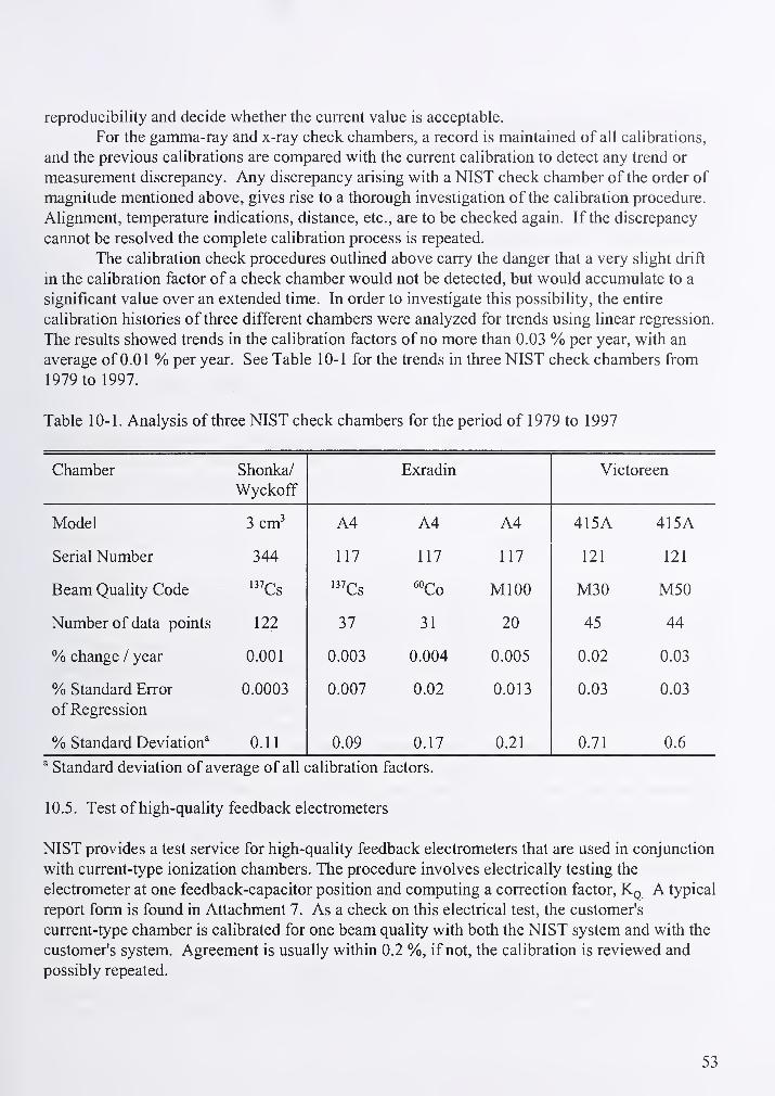
reproducibility and decide whether the current value is acceptable.
For the gamma-ray and x-ray check chambers, a record is maintained of all calibrations,
and the previous calibrations are compared with the current calibration to detect any trend or
measurement discrepancy. Any discrepancy arising with a NIST check chamber of the order of
magnitude mentioned above, gives rise to a thorough investigation of the calibration procedure.
Alignment, temperature indications, distance, etc., are to be checked again. If the discrepancy
cannot be resolved the complete calibration process is repeated.
The calibration check procedures outlined above carry the danger that a very slight drift
in the calibration factor of a check chamber would not be detected, but would accumulate to a
significant value over an extended time. In order to investigate this possibility, the entire
calibration histories of three different chambers were analyzed for trends using linear regression.
The results showed trends in the calibration factors of no more than 0.03 % per year, with an
average of 0.01 % per year. See Table 10-1 for the trends in three NIST check chambers from
1979 to 1997.
Table 10-1. Analysis of three NIST check chambers for the period of 1979 to 1997
Chamber Shonka/
Wyckoff
Exradin Victoreen
Model 3 cm^ A4 A4 A4 415A 415A
Serial Number 344 117 117 117 121 121
Beam Quality Code •^^Cs •^^Cs ''Co MlOO M30 M50
Number of data points 122 37 31 20 45 44
% change / year 0.001 0.003 0.004 0.005 0.02 0.03
% Standard Error
of Regression
0.0003 0.007 0.02 0.013 0.03 0.03
% Standard Deviation^ 0.11 0.09 0.17 0.21 0.71 0.6
" Standard deviation of average of all calibration factors.
10.5. Test of high-quality feedback electrometers
NIST provides a test service for high-quality feedback electrometers that are used in conjunction
with current-type ionization chambers. The procedure involves electrically testing the
electrometer at one feedback-capacitor position and computing a correction factor. Kg A typical
report form is found in Attachment 7. As a check on this electrical test, the customer's
current-type chamber is calibrated for one beam quality with both the NIST system and with the
customer's system. Agreement is usually within 0.2 %, if not, the calibration is reviewed and
possibly repeated.
53

10.6. Irradiation of passive and electronic dosimeters
10.6.1 General considerations and procedures
Dosimeters received at NIST for irradiation in terms of air kerma or exposure are the type used
for personnel protection. The air kerma from x-rays, ''^Cs and/or ^°Co requested by the customer
can be delivered to passive and electronic dosimeters.
10.6.2 Exposure techniques
For both x- and gamma-ray exposures, the dosimeters are mounted either on a scatter-free frame
or a 30 cm x 30 cm x 15 cm methylmethacrylate phantom at a distance such that the beam is
uniform over the area of irradiation. The irradiation distance is the source-to-badge-middle
when using the scatter-free frame. When using the phantom, the irradiation distance is the
source-to-phantom front surface. No correction is made for the distance of the badge-to-
phantom offset. Gamma-ray exposures are performed at a scale distance of 195 cm or 300 cm.
The air kerma is obtained from the charts associated with each source, corrected for decay. All
irradiation details are recorded in a data book. After review of the results in the data book, the
badge identification numbers, air-kerma levels, date of irradiation and a DG number are
transferred to a TLD report form, see Attachment 6.
11.0 Assessment of uncertainty
The method of uncertainty assessment follows the NIST policy of expressing uncertainty,
as outlined in the NIST Technical Note 1297. Conventional statistical estimates are given as
standard deviations of the mean, and are designated as "Type A," which can be considered to be
objective estimates. All other uncertainty estimates, which are designated "Type B," are
subjective estimates, based on extensive experience. The "Type B" uncertainties are estimated
so as to correspond approximately to one standard deviation. The Type A and Type B estimates
are combined according to the usual rule for combining standard deviations, by taking the square
root of the sum of the squares, the quadratic sum. The quadratic sum of the two types of
uncertainty is then considered to be the combined uncertainty, which is in turn multiplied by the
coverage factor, two, to give an expanded uncertainty. The uncertainty is considered to have the
approximate significance of a 95 % confidence limit. Table 11-1. lists the details of the
assessment of uncertainty in the air kerma rates determined for the tungsten x-ray beams by the
free-air ionization chambers, and as determined for gamma-ray beams by the set of spherical
graphite cavity ionization chambers. Table 11-2. lists the details of the assessment of
uncertainty in the calibration of current-type ionization chambers and condenser-type chambers
used with their electrometers, and also in the irradiation of passive dosimeters, conducted with
X- and gamma-rays. Table 1 1-3 lists the details of the assessment of uncertainty in air-kerma
rates determined for the mammographic x-ray beams by the Attix chamber. Table 1 1 -4 lists the
uncertainty components for the calibration of instruments used for mammography. Table 11-5
gives a brief description of some of the uncertainty components. Since the estimates of
uncertainty vary lightly with beam qualities, methods of measurement, and rate, in each case the
largest value is used for the estimate. In an official calibration, measurements could be repeated
54
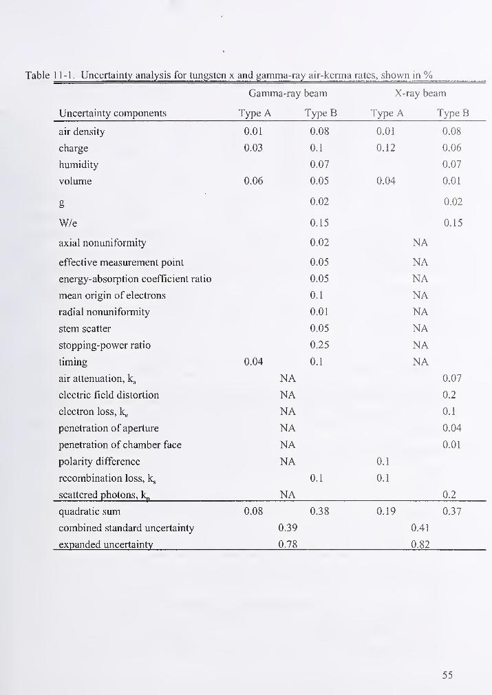
11-1. Uncertainty analysis for tungsten x and gamma-ray air-kerma rates, shown in %Gamma-ray beam X-ray beam
Uncertainty components Type A Type B Type A Type B
air density 0.01 0.08 0.01 0.08
charge 0.03 0.1 0.12 0.06
humidity 0.07 0.07
volume 0.06 0.05 0.04 0.01
g 0.02 0.02
W/e 0.15 0.15
axial nonuniformity 0.02 NA
eiieciive measurement pomi U.UJ XT A
energy-absorption coefficient ratio A A^ XT AISA
mean origin of electrons (\ 1U. 1
XT AJNA
radial nonuniformity A A1U.U 1XT AJNA
blCIIl aCaiicr A AS XTA
Sioppmg-power raiio A 9SU.ZJ XT A
iimmg A 1U. 1 XT A
air attenuation, "NT A A (YlU.U /
electric field distortion NA 0.2
electron loss, k^ NA 0.1
penetration of aperture NA 0.04
penetration of chamber face NA 0.01
polarity difference NA 0.1
recombination loss, k^ 0.1 0.1
scattered photons, NA 0.2
quadratic sum
combined standard uncertainty
expanded uncertainty
0.08
0.39
0.78
0.38 0.19
0.41
0.82
0.37
55
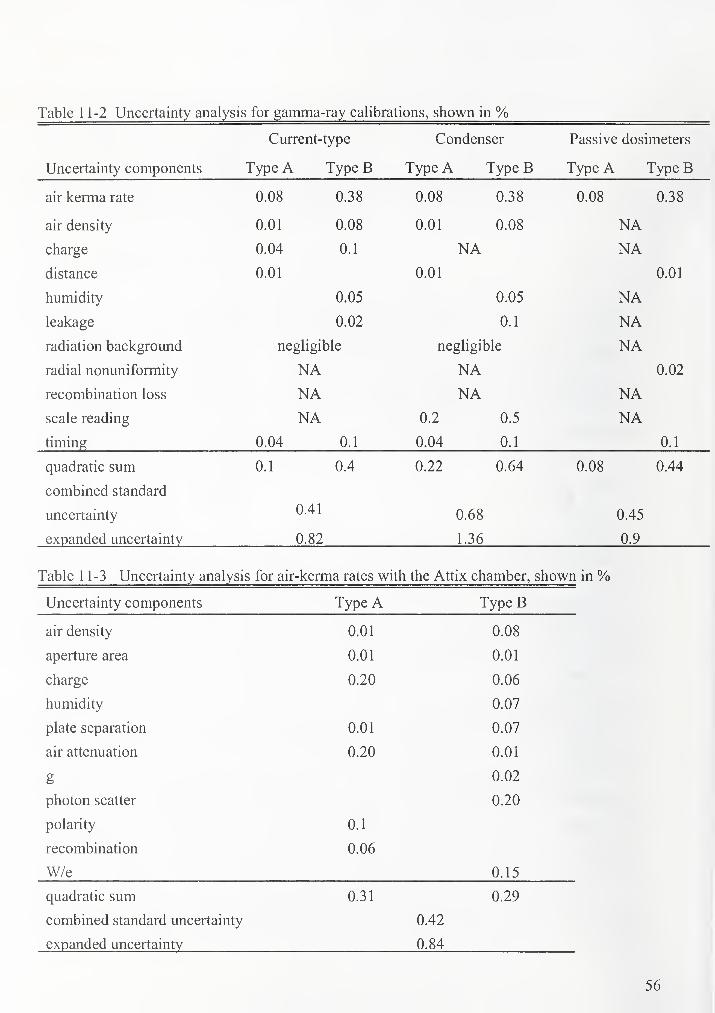
Table 1 1-2 Uncertainty analysis for gamma-ray calibrations, shown in %Current-type Condenser Passive dosimeters
Uncertainty components Type A Type B Type A Type B Type A Type B
air kerma rate 0.08 0.38 0.08 0.38 0.08 0.38
air density 0.01 0.08 0.01 0.08 NAcharge 0.04 0.1 NA NAdistance 0.01 0.01 0.01
humidity 0.05 0.05 NAleakage 0.02 0.1 NAradiation background negligible negligible NAradial nonuniformity NA NA 0.02
recombination loss NA NA NAscale reading NA 0.2 0.5 NAtiming 0.04 0.1 0.04 0.1 0.1
quadratic sum 0.1 0.4 0.22 0.64 0.08 0.44
combined standard
uncertainty 0.41 0.68 0.45
expanded uncertainty 0.82 1.36 0.9
Table 1 1-3 Uncertainty analysis for air-kerma rates with the Attix chamber, shown in %Uncertainty components Type A Type B
air density 0.01 0.08
aperture area 0.01 0.01
charge 0.20 0.06
humidity 0.07
plate separation 0.01 0.07
air attenuation 0.20 0.01
0.02
photon scatter 0.20
polarity 0.1
recombination 0.06
W/e 0.15
quadratic sum 0.31 0.29
combined standard uncertainty 0.42
expanded uncertainty 0.84
56j
i
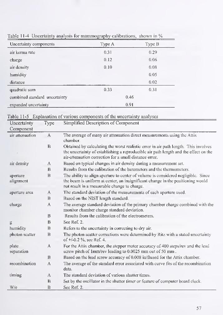
Table 1 1-4 Uncertainty analysis for mammography calibrations, shown in %Uncertainty components Type A Type B
air kerma rate 0.31 0.29
charge 0.12 0.06
air density 0.10 0.08
humidity 0.05
distance 0.02
quadratic sum 0.33 0.31
combined standard uncertainty 0.46
expanded uncertainty 0.91
Table 1 1-5 Explanation of various components of the uncertainty analyses
uncenamiy Type oimpiiiiea uescnpiion oi L^omponeni
v^uiiipuiiciii
air attenuation A The average oi many air attenuation direct measurements using the Attix
cnamoer.
B Obtained by calculating the worst realistic error in air path length. This involves
UlC UIICCI lallliy Ui CdlaUllalllllg a ICpiUUULIUlc all paUl Icll^lll dllU lllC CilCCl Oil lllc
air-attenuation correction for a small distance error.
air density A Based on typical changes in air density during a measurement set.
B Results from the calibration of the barometers and the thermometers.
aperture B The ability to align aperture to center of volume is considered negligible. Since
alignment the beam is uniform at center, an insignificant change in the positioning would
not result in a measurable change to charge.
aperture area A The standard deviation of the measurements of each aperture used.
B Based on the NIST length standard.
charge A The average standard deviation of the primary chamber charge combined with the
monitor chamber charge standard deviation.
B Results from the calibration of the electrometers.
g B See Ref 2.
humidity B Refers to the uncertainty in correcting to dry air.
photon scatter B The photon scatter corrections were determined by Ritz with a stated uncertainty
of+/-0.2%, see Ref 4.
plate A For the Attix chamber, the stepper motor accuracy of 400 steps/rev and the lead
separation screw pitch of 1mm/rev leading to 0.0025 mm out of 50 mm .
B Based on the lead screw accuracy of 0.008 in/ftused for the Attix chamber.
recombination A The average of the standard error associated with curve fits of the recombination
data.
timing A The standard deviation of various shutter times.
B Set by the oscillator in the shutter timer or feature of computer board clock.
W/e B See Ref 2.
57

to maintain optimal conditions. Table 1 1-6 gives a summary of expanded uncertainties for each
type of calibration.
Table 1 1 .6 Summary of expanded uncertainties
Tungsten X-rays and Gamma Rays Mammography X-rays
air kerma rate 0.8 % air kerma rate 0.9 %
cable connected chambers 1 %
passive dosimeters 1 % ionization chambers 1 %
condenser chambers 1.5%
The Type A components are generally less significant than the Type B components. This
arises from the complexity of the interaction of ionizing radiation with matter: it is never
possible to account fiilly for the numerous second-order effects, but it is usual during air-kerma
calibrations at NIST to repeat measurements until the Type A component of the uncertainty is
smaller than the Type B component. The measurement of volume is an exception, but this is not
a routine measurement and both components are small.
12. Safety considerations
The main safety consideration is radiation protection. As described below, every effort is made
to avoid any possibility of radiation exposure, even though it would be highly unlikely that
serious exposures could occur accidentally. Another safety consideration is exposure to high
voltage, such as exists on ionization chambers and standard chambers during calibration. There
is no danger of high voltage related to the x-ray generators since the equipment now in use has
no exposed high voltage in a normal operating mode. All radiation areas in the building are
marked with striped tape and dosimeters must be worn by all personnel.
12.1. Radiation safety
12.1.1 X-ray calibration ranges
First and foremost, the three x-ray source ranges are designed to eliminate any possible exposure
to x-radiation. The 100 kV x-ray tube is interlocked with its power supply in such a way that if
the tube is moved from a safe position, i.e., away from a lead shutter, the high-voltage is turned
off Recent changes to the shielding of this tube eliminated the leakage radiation that once
occurred between the shutter assembly and the tube window at 90°. Flashing red lights signal
any malfunction to the shutter and an audible area radiation detector has been recently
implemented as a back-up precaution. The 300 kV x-ray tube is enclosed in a housing of 19 mmPb and 6.4 mm steel. There is a 25 mm lead safety shutter and a 12.7 mm lead timing shutter in
front of the beam portal. Both x-ray calibration ranges are protected by lead-lined doors that are
interlocked in a fail-safe manner with the shutters. This means that the shutter or shutters cannot
be opened if the door interlock is open. Where no door exits, as in one area of the 300 kV x-ray
58

range, a light beam is used for protection. In addition, a time-delay device inside the 300 kVx-ray range must be actuated upon leaving or the shutter cannot be opened. As a further
indication of radiation danger, two red lights are turned on whenever the shutter or shutters are
open. A flashing red light associated with the 300 kV x-ray set indicates high voltage is on the
x-ray tube. The mammography range shielding door is interlocked with the x-ray tube shutter.
If the door is opened or is not fully closed, the shutter will return to the shielding position. Anaudible alarm will sound if the shutter is not fully closed. Red lights illuminate when the shutter
is opened. Additional lead shielding surrounds the x-ray tube, which must be in the shielding
position for power to be applied to the x-ray tube. No area radiation monitor is used due to the
extremely narrow beam and the low scatter conditions resulting from the low energy x-rays used
in the mammography range.
12, 1 .2. Gamma-ray calibration ranges
All doors giving access to the gamma-ray calibration ranges have interlocks as required
by the Nuclear Regulatory Commission regulations. The vertical-beam rooms have a time-delay
device inside the room that must be actuated before leaving the radiation area. Automatic
shielding doors protect occupants in the control area ofB036 from the sources. In addition to the
above safety features, a radiation detector with indicator lights and an audible signal is in each
gamma calibration range. A second radiation detector located in the vertical beam area, between
the shielding door of the vertical beams and the outer door, alarms whenever the interlock is
broken during an irradiation. At each entrance to a gamma-ray calibration range, a set of two red
lights indicates a "beam on" condition.
12.2. High-voltage safety
The only danger that exists from high voltage comes from the free-air ionization
chambers, the customer chamber, and the x-ray calibration range monitor chambers. To prevent
dangerous electric shock, almost all power supplies contain current-limiting resistors in the
high-voltage circuit. Common sense is dictated when working around ionization chambers that
have exposed high-voltage electrodes. Appropriate warning signs are posted. The risk of high
voltage from the Attix chamber is minimized by surrounding the chamber with protective cover.
59
REFERENCES
1. Marshal, J.L.,ed. NIST Calibraiton Services Users Gide, NIST (U.S.) Spec. Publ. 250; 1998
January. Available on-line: http://www.ts.nist.gov/calibrations.
2. Boutillon, M. and Perroche-Roux, A.M., Re-evaluation of the W value for electrons in dry
air, Phys. Med. Biol., 32, 213-219 (1987).
3. Wyckoff, H. O. and Attix, F. H., Design of free-air ionization chambers, National Bureau of
Standards Handbook 64, 1957.
4. Ritz, V. H., Standard free-air chamber for the measurement of low energy x rays (20-100
kilovolts-constant-potential), J. Res. Nat. Bur. Stand. (U.S.), 64C, 49-53 (1960).
5. Lamperti, P. J. and Wyckoff, H. O., NBS free-air chamber for measurement of 10 to 60 kV x
rays, J. Res. Nat. Bur. Stand. (U.S.), 69C, 39-47 (1965).
6. Ritz, V. H., Design of free-air ionization chambers for the soft x ray region (20-100 kV),
Radiology, 73, 911-922 (1959).
7. Hubbell, J. H., Photon mass attenuation and energy-absorption coefficients from 1 keV to 20
MeV, Int. J. Appl. Radiat. Isot. 33, 1269-1290 (1982).
8. AUisy, A. and Roux, A, M., Contribution a la measure des rayons roentgen dans le domaines
de5 a 50 kV, Acta Radiologica, 55, 57-74 (1961).
9. Scott, P. B. and Greening, J. R., The determination of saturation currents in free-air ionization
chambers by extrapolation methods, Phys. Med. Biol. 8, 5 1-57 (1963).
10. Berger, M. J. and Seltzer, S. M., Stopping powers and ranges of electrons and positrons,
NBSIR 82-2550-A (2nd Ed.) (1983).
11. Katz, L. and Penfold, A. S., Range-energy relations for electrons and the determination of
beta-ray end-point energies by absorption. Rev. Mod. Phys. 24, 28-44 (1952).
12. Somerwil, A., Photon scatter correction in low-energy x radiation measurements, influence
ofbeam path length in standard free-air chambers, Metrologia 8, 2 (1972).
13. Attix, F. H.,"Electronic equilibrium in free-air chambers and a proposed new chamber
design," Naval Research Laboratory Report No. 5646, 1961.
14. Coletti, J.G., Pearson, D. W. and DeWerd, L.A., "Mammography exposure standards:
Design and characterization of free-air ionization chamber," Rev. Sci Instrum. 66, 2574-
2577(1995).
15. Laitano, R.F. and Toni, M.P. "The primary exposure standard ofENEA for medium energy
60
x-rays. Characteristics and measurement procedures," Report RT/PROT (83) 27,
Laboratorio di Metrologia della Radiazioni lonizzani ENEA, CRE Casaccia, c.p. 2400
Roma, Italia, 1984.
16. Bums, D.T., Lamperti, P. and O'Brien, M. "Comparison of the NIST and BIPM Air-Kerma
Standards for Measurements in the Low-Energy X-Ray Range," J.Res. Natl. Inst. Stand.
Technol. 104, 135 (1999).
17. Lamperti, P., O'Brien, M., Sander, T. and Williams, T. "Comparison of the NIST and NPLAir-Kerma Standards for Measurements in the Low-Energy X-Ray Range,"J.Res. Natl.
Inst. Stand. Technol. 105, 701 (2000).
18. Coletti, J. G., Pearson, D. W., DeWerd, L.A., O'Brien, C. M. and Lamperti, P.J.
"Comparison of exposure standards in the mammography x-ray region," Med. Phys.
24(8), 1263-1267 (1997).
19. Report of the International Commission on Radiological Units and Measurements (ICRU),
National Bureau of Standards Handbook 78, p. 19, 1959.
20. Loftus, T. P. and Weaver, J. T., Standardization of 60Co and 137Cs gamma-ray beams in
terms of exposure, J. Res. Nat. Bur. Stand. (U.S.), 78A, 465-476 (1974).
21. Hoag, J. B. and Korff, S. A., Electron and Nuclear Physics, Chap. 17, pages 404-435, D.
Van Nostrand Co., Inc. 250 Fourth Ave., New York, NY, (1948).
22. Taylor, L. S. and Singer, G., Note on the guarded-field x-ray ionization chamber. Radiology
26, 322-325 (1936).
23. Taylor, L. S., The precise measurement of x-ray dosage, Radiology 14, 372 (1930).
24. Boag, J. W., Distortion of the electric field in an ionization chamber due to the difference in
potenfial between guard ring and collector, Phys. Med. Biol. 9, 25-32 (1964).
25. Day, F. H. and Attix, F. H., Methods for current measurement with a vibrating reed
electrometer. Nat. Bur. Stand. (U.S.), Report 2080 (1952).
26. Loevinger, R., Precision measurement with the total-feedback electrometer. Phys. Med. Biol.
2, 267-279 (1966).
27. Keithley, J. F., Yeager, J. R., and Erdman, R. R., Low Level Measurements, Keithley
Instruments, Inc., 28775 Aurora Road, Cleveland, OH 44139 (1984).
28. Frederiksen, T. M., Intuitive IC Op Amps, National Semiconductor Corp., Santa Clara, CA.
(1984).
29. Instruction Manual, Model 616 Digital Electrometer, Keithley Instruments, Inc.. 28775
61

Aurora Road, Cleveland, OH 44139 (1977).
30. Instruction Manual, Model 642 Electrometer, Keithley Instruments, Inc., 28775 Aurora
Road, Cleveland, OH 44139 (1980).
31. Rutkowski, G. B., Handbook of Integrated-Circuit Operational Amplifiers, Prentice-Hall,
Inc., Englewood Cliffs, NJ (1975).
62
Attachment 1 : X-Ray Beam Qualities offered at NBS Prior to 1986
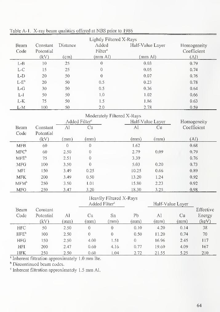
1 dulc r\- 1
.
X-ray beam qualities offered at NBS prior to 1986
Lightly Filtered X-Rays
Beam Constant Distance Added Half-Value Layer Homogeneity
Code r oiennai Filter^' Coeriicient
V
;
(mm Al) (mm Al) (Al)
1 0 75 0 0.03 n TOU. / y
1 J 0 0.05 n 7/1U. /4
L-L) 50 Q 0.07 U. /o
L-E'' 20 50 0.5 0.23 0.78
L-G 30 50 0.5 0.36 0.64
L-I 50 50 1.0 1.02 0.66
L-K 75 50 1.5 1.86 0.63
T -Vf 1 nn 50 2.0 2.78
Moderately Filtered X-Rays
Added Filter'^ Half-Value Layer Homogeneity
Beam Constant Al Cu Al Cu Coemcient
Code r oieniidi
(k'V^ (mm) (mm) (mm) (mm)
MrrJ \J\J 0 0 1.62 U.oo
2.50 0 2.79 0.09 n 70u. /y
iVlr r!, /5 2.51 3.39 u. /o
MFG 100 3.50 0 5.03 0.20 0.73
MFI 150 3.49 0.25 10.25 0.66 0.89
MFK 200 3.49 0.50 13.20 1.24 0.92
MFM"' 250 3.50 1.01 15.80 2.23 0.92
MFD Zjv 3.47 3.20 18.30 3.25 0.98
Heavily Filtered X-Rays
Added Filter'^ Half-Value Layer
Beam Constant Effective
Code i oieniidi Al Cu Sn Pb Al Cu Energy
(KV ) (mm) (mm) (mm) (mm) (mm) (mm) (keV)
HFC 50 2.50 0 0 0.10 4.20 0.14 38
HFE" 100 2.50 0 0 0.50 11.20 0.74 70
HFG 150 2.50 4.00 1.51 0 16.96 2.45 117
HFI 200 2.47 0.60 4.16 0.77 19.60 4.09 167
HFK 250 2.50 0.60 1.04 2.72 21.55 5.25 210
^ Inherent filtration approximately 1 .0 mm Be.
^ Discontinued beam codes.
Inherent filtration approximately 1.5 mm Al.
64
Attachment 2 : Additional references - data books
The references listed in this attachment are NIST registered laboratory data books (DB) or
binders which are located in B033 of the Radiation Physics building. The references are
identified by the data book identification number and the page number.
1. DB848 page 110 (DB 848:1 10), DB 331:92-1 17 and DB 527:081
2. DB852:11
3. A loose-leaf binder entitled "Supplement to DB776, Free-Air Ionization Chamber
Comparisons."
4. See DB592, DB624, and DB638. The data plots used for extrapoladons are filed in a file
cabinet in Rm. B033 under the general title "Free-Air Ionization Chamber
Recombination." Further analyses of the data are recorded in a three-ring binder entitled,
"Supplement No. 1 to DB 592, DB624 and DB638; 10-60 kV and 20-100 kV Free-Air
Ionization Chamber Comparison."
5. DB752:143-162.
6. See DB592, DB624 and DB638. Also found in binder entitled "Supplement No.l to DB592,
DB624 and DB638" and in file folders under the general title "Free-Air Chamber
Recombination," all filed in Rm. B-033.
7. DB750:1 18, DB744:203, DB717:127 and DB717:125.
8. DB799:34, DB817:52, DB750:201, DB799:44 and 60, DB817:121,131 and 141, DB799:70,
DB817:138and DB817:121.
9. DB817:155.
10. DB817:94.
11. DB799:10-llandDB817:17.
12. DB817:51-52.
66
Attachment 3 : Attix chamber schematics

.21.27 cm
Chamber Center
1 m from Source
-^1.27 cm
Fig. A3-1. Attix chamber configuration for half-value layer and air attenuation measurements.
68

Chamber Center
2 1 .27 cm from Aperture
Aperture
1 m from source
15.5 cm
Fig. A3-2. Attix chamber configuration for the two smallest positions of routine calibrations.
Chamber Center
21.27 cm from Aperture
Aperture
1 m from source
8 cm
25 cm
"
10.5 cm'
Fig.A3 -3 Attix chamber configuration for the two largest positions for an air-kerma
measurement.
69
Attachment 4 : The history of the measurement of current
70

Until high-gain negative-feedback ampHfiers were introduced, electrometers used for
ionization current measurements were used as null detectors. Charge, or current, was measured
by manually nulling the signal on the most sensitive range of the electrometer. In the null
method of measurement, determination of stray capacitance in the system and voltage calibration
of the electrometer are unnecessary but it is necessary in free-air chambers to maintain the null
such that the collector plate potential is very near the guard-plate potential. A difference in
potential between the guard and collector plates in a free-air chamber distorts the electric field
and deforms the defined air volume. Measurements of exposure will then be in error, see Ref.
[21-23] for a more detailed description of this subject.
The VRE was an improvement over direct-current, vacuum-tube electrometers not only
because it utilized negative feedback but, being an AC amplifier, the problem of zero drift was
essendally eliminated. Negative feedback automatically maintains the inner electrode of an
ionization chamber near the guard potential and minimizes field distortion. For many years,
VRE's were used at NIST as null detectors [3,24]. The gain of the VRE's was found on occasion
to be much less than the design gain of 1000; gains as low as 250 were found, which could lead
to reading errors of up to several percent in the collected charge. Loevinger [25] derived
corrections for electrometer current measurements and showed that the gain of several VRE's
varied with scale reading and polarity. Sources of information for the following discussion are
given in Ref. [25-31].
The high-gain, negative-feedback amplifier is the type of operational amplifier used in
electrometers for measurement of small currents from ionization chambers. These amplifiers
have a high impedance input and, an essential characteristic for free-air ionization chambers, the
input terminal maintains the collector plate virtually at ground potential. A negative-feedback
electrometer with resisdve feedback element is shown in Fig. A3-1. The signal current l^^^ from
an ionization chamber impresses a signal on the input terminal of the operational amplifier,
which generates an output voltage Vq. Part or all ofVq is fed back (from the load resistor RJthrough the feedback resistor Rf to the input terminal, so as to oppose the input signal. The
output voltage is larger than the resultant input voltage Vj in the ratio
G = Vo^yr (A3-1)
where G is the amplifier gain. In modem electrometers, such as the Keithley 616, G > 104, so
for present purposes V, can be neglected compared to Vq, and
Kig=^o- (A3-2)
For operational amplifiers with large input resistance, for which the input voltage Vi~ 0, there
can be no current through the amplifier, and the current through the feedback resistor is equal to
the ionization chamber current Li„. Therefore
Kis=Vp (A3-3)
and finally
^sig-^o^^f (A3-4)
This is the relationship used for measuring current when using a resistive feedback element.
71
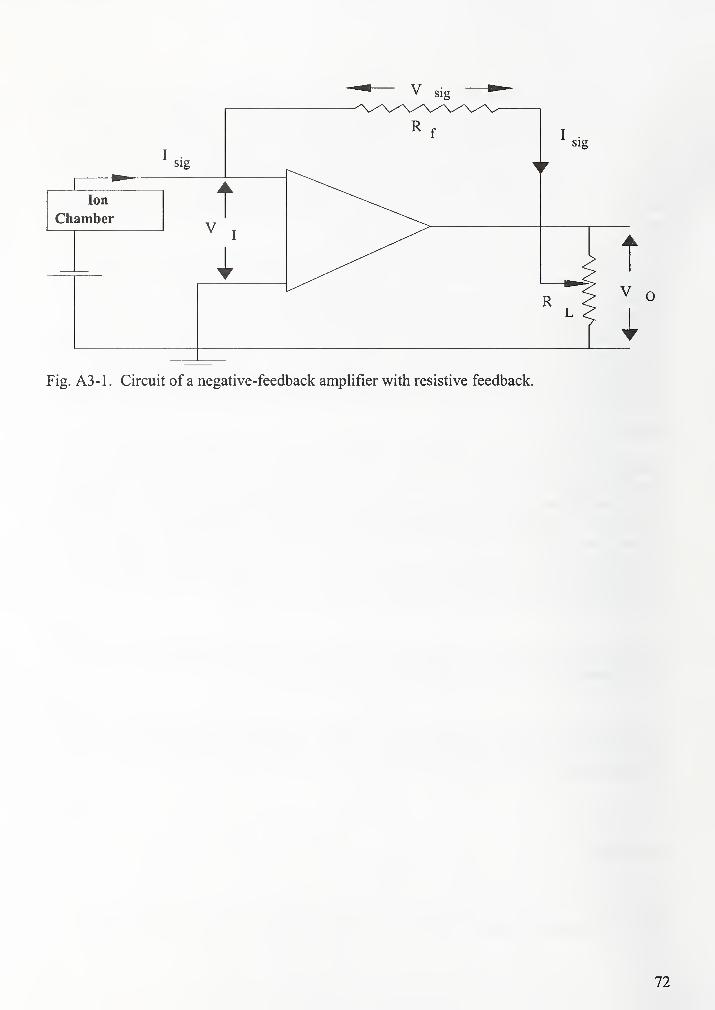
Fig. A3-1 . Circuit of a negative-feedback amplifier with resistive feedback.
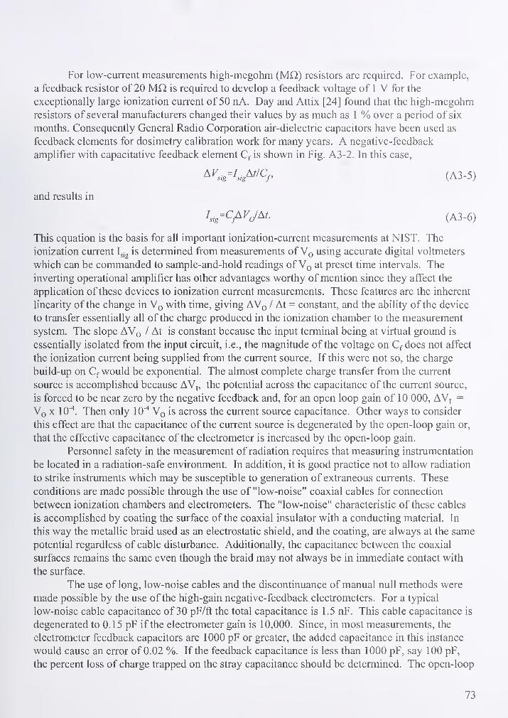
For low-current measurements high-megohm (MQ.) resistors are required. For example,
a feedback resistor of 20 Mfl is required to develop a feedback voltage of 1 V for the
exceptionally large ionization current of 50 nA. Day and Attix [24] found that the high-megohm
resistors of several manufacturers changed their values by as much as 1 % over a period of six
months. Consequently General Radio Corporation air-dielectric capacitors have been used as
feedback elements for dosimetry calibration work for many years. A negative-feedback
amplifier with capacitative feedback element Cf is shown in Fig. A3-2. In this case,
^K>,-I..s^"Cp (A3-5)
and results in
^sig=CjAVJAt. (A3-6)
This equation is the basis for all important ionization-current measurements at NIST. The
ionization current Ig^g is determined from measurements of Vq using accurate digital voltmeters
which can be commanded to sample-and-hold readings of Vq at preset time intervals. The
inverting operational amplifier has other advantages worthy of mention since they affect the
application of these devices to ionization current measurements. These features are the inherent
linearity of the change in Vq with time, giving AVq / At = constant, and the ability of the device
to transfer essentially all of the charge produced in the ionization chamber to the measurement
system. The slope AVq / At is constant because the input terminal being at virtual ground is
essentially isolated from the input circuit, i.e., the magnitude of the voltage on Cf does not affect
the ionization current being supplied from the current source. If this were not so, the charge
build-up on Cf would be exponential. The almost complete charge transfer from the current
source is accomplished because AV,, the potential across the capacitance of the current source,
is forced to be near zero by the negative feedback and, for an open loop gain of 10 000, AV, =
Vq X 10 Then only lO""* Vq is across the current source capacitance. Other ways to consider
this effect are that the capacitance of the current source is degenerated by the open-loop gain or,
that the effective capacitance of the electrometer is increased by the open-loop gain.
Personnel safety in the measurement of radiation requires that measuring instrumentation
be located in a radiation-safe environment. In addition, it is good practice not to allow radiation
to strike instruments which may be susceptible to generation of extraneous currents. These
conditions are made possible through the use of "low-noise" coaxial cables for connection
between ionization chambers and electrometers. The "low-noise" characteristic of these cables
is accomplished by coating the surface of the coaxial insulator with a conducting material. In
this way the metallic braid used as an electrostatic shield, and the coating, are always at the same
potential regardless of cable disturbance. Additionally, the capacitance between the coaxial
surfaces remains the same even though the braid may not always be in immediate contact with
the surface.
The use of long, low-noise cables and the discontinuance of manual null methods were
made possible by the use of the high-gain negative-feedback electrometers. For a typical
low-noise cable capacitance of 30 pF/ft the total capacitance is 1.5 nF. This cable capacitance is
degenerated to 0.15 pF if the electrometer gain is 10,000. Since, in most measurements, the
electrometer feedback capacitors are 1000 pF or greater, the added capacitance in this instance
would cause an error of 0.02 %. If the feedback capacitance is less than 1000 pF, say 100 pF,
the percent loss of charge trapped on the stray capacitance should be determined. The open-loop
73
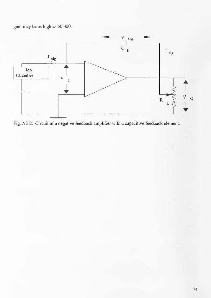
gain may be as high as 50 000.
Fig. A3 -2. Circuit of a negative feedback amplifier with a capacitive feedback element.

Attachment 5 : Typical ionization chamber calibration report
National Institute of Standards and Technology
REPORT OF AIR-KERMA CALIBRATIONOF
ADDRESS 1
ADDRESS 2
ADDRESS 3
Radiation Detection Chamber: Make, Model, SN
Measurements performed by Michelle O'Brien
Report reviewed by Paul Lamperti
Report approved by Stephen M. Seltzer
For the Director
National Institute of Standards and Technology
by
Bert M. Coursey, Chief
Ionizing Radiation Division
Physics Laboratory
Information on technical aspects of this report may be obtained from Michelle O'Brien,
National Institute of Standards and Technology, 100 Bureau Drive Stop 8460, Gaithersburg,
MD 20899, (301) 975-2014. Report format revised 5/00.
NisrNationol Institute of Standard: and Technology
Technology Adminrslrolion, U.S. Deporlmenl of Commerce
DG:XXXXX/00TF:XXXXXX-00
Report Date: 0/0/00
Page # of
#
76
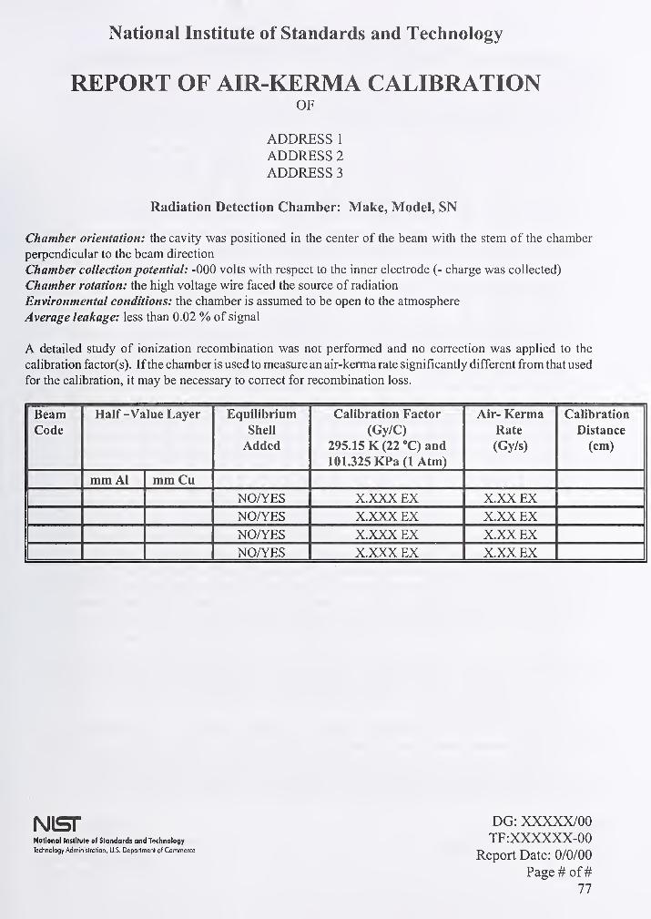
National Institute of Standards and Technology
REPORT OF AIR-KERMA CALIBRATIONOF
ADDRESS 1
ADDRESS 2
ADDRESS 3
Radiation Detection Chamber: Make, Model, SN
Chamber orientation: the cavity was positioned in the center of the beam with the stem of the chamber
perpendicular to the beam direction
Chamber collection potential: -000 volts with respect to the inner electrode (- charge was collected)
Chamber rotation: the high voltage wire faced the source of radiation
Environmental conditions: the chamber is assumed to be open to the atmosphere
Average leakage: less than 0.02 % of signal
A detailed study of ionization recombination was not performed and no correction was applied to the
calibration factor(s). Ifthe chamber is used to measure an air-kerma rate significantly different from that used
for the calibration, it may be necessary to correct for recombination loss.
BeamCode
Half -Value Layer Equilibrium
Shell
Added
Calibration Factor
(Gy/C)
295.15 K (22 "C) and
101.325 KPa (1 Atm)
Air- KermaRate
(Gy/s)
Calibration
Distance
(cm)
mm Al mm Cu
NOA^ES X.XXX EX X.XX EXNO/YES X.XXX EX X.XX EXNOrfES X.XXX EX X.XX EXNO/YES X.XXX EX X.XX EX
|\)lSr DG: XXXXX/00National Institute o( Standards and Technology TF:XXXXXX-00Technology Adminislrolion, U.S. Deportmenl of Commerce
RcpOFt DstC* 0/0/00
Page # of
#
77

Conventional Calibration Conditions
for X- and Gamma-Ray Measuring Instruments
O Cell 11
code
Additional Filtration ^ Half-value layer Homogeneity
coefficient
i^llCL'llvc
energy
Al
(mm)
Cu(mm)
Sn
(mm)
Pb
(mm)
Al
(mm)
Cu(mm)
Al Cu (keV)
X-Ray Beam Qualities
LIO 0.035 89
L15 0.057 68
L20 0.069 73
L30 0.30 0.22 63
L40 0.53 0.50 59
L50 0.71 0.76 60
L80 1.45 1.83 57
LlOO 1.98 2.77 57
M20 0.27 0.15 69
M30 0.5 0.36 65
M40 0.89 0.73 69
M50 1.07 1.02 66
M60 1.56 1.68 66
M80 2.61 2.97 67
MlOO 5.0 5.02 73
M120 6.87 6.79 77
M150 5.0 0.25 10.2 0.67 87 62
M200 4.1 1.12 14.9 1.69 95 69
M250 5.0 3.2 18.5 3.2 98 86
M300 4.0 6.5 22.0 5.3 100 97
HIO 0.105 0.05 91
H15 0.5 0.153 86
H20 1.01 0.36 91
HBO 4.50 1.23 93
H40 4.53 0.26 2.90 90
H50 4.0 0.1 4.2 0.142 92 90 38
H60 4.0 0.61 6.0 0.24 94 89 46
HlOO 4.0 5.2 13.5 1.14 100 94 80
H150 4.0 4.0 1.51 17.0 2.5 100 95 120
H200 4.0 0.6 4.16 0.77 19.8 4.1 100 99 166
H250 4.0 0.6 1.04 2.72 22.0 5.2 100 98 211
H300 4.1 3.0 5.0 23.0 6.2 99 98 252
S60 4.35 2.77 72
S75 1.50 1.86 63
Gamma-Ray Beam Qualities
137cs 10.8 662
14.9 1250
^The additional filtration value does not include the inherent filtration. The inherent filtration is
approximately 1.0 mm Be for beam codes LIO-LIOO, M20-M50, H10-H40 and S75; and 3.0 mm Be for
beam codes M60-M300, H50-H300 and S60.
NisrNational Institute of Standards and Technology
Technology Adminislralion, U.S. Deportmenl of Commerce
DG: XXXXX/00TF:XXXXXX-00
Report Date: 0/0/00
Page # of
#
78
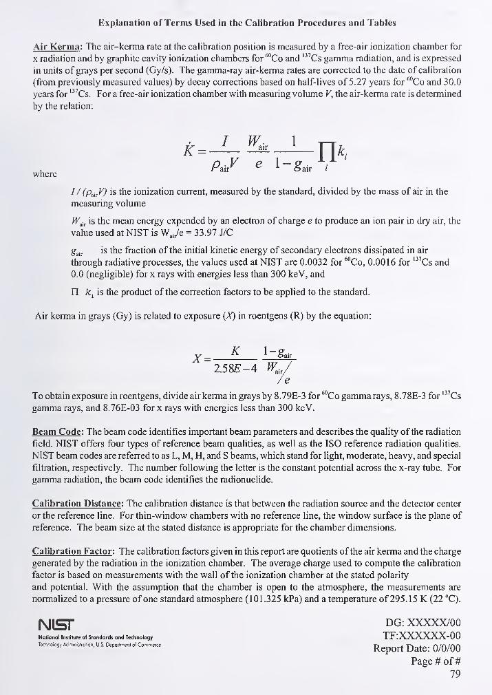
Explanation of Terms Used in tiie Calibration Procedures and Tables
Air Kerma : The air-kerma rate at the calibration position is measured by a free-air ionization chamber for
X radiation and by graphite cavity ionization chambers for ^"Co and ''^Cs gamma radiation, and is expressed
in units of grays per second (Gy/s). The gamma-ray air-kerma rates are corrected to the date of cahbration
(from previously measured values) by decay corrections based on half-lives of 5.27 years for ^'^Co and 30.0
years for '"Cs. For a free-air ionization chamber with measuring volume V, the air-kerma rate is determined
by the relation:
where>air I
I / (p^^y) is the ionization current, measured by the standard, divided by the mass of air in the
measuring volume
fF^ir is the mean energy expended by an electron of charge e to produce an ion pair in dry air, the
value used at NIST is WJe = 33.97 J/C
g^i^ is the fraction of the initial kinetic energy of secondary electrons dissipated in air
through radiative processes, the values used at NIST are 0.0032 for ^°Co, 0.0016 for '"Cs and
0.0 (negligible) for x rays with energies less than 300 keV, and
n A:, is the product of the correction factors to be applied to the standard.
Air kerma in grays (Gy) is related to exposure {X) in roentgens (R) by the equation:
x=2.58^-4 W.
To obtain exposure in roentgens, divide air kerma in grays by 8.79E-3 for ^''Co gamma rays, 8.78E-3 for '"Cs
gamma rays, and 8.76E-03 for x rays with energies less than 300 keV.
Beam Code ; The beam code identifies important beam parameters and describes the quality ofthe radiation
field. NIST offers four types of reference beam qualities, as well as the ISO reference radiation qualities.
NIST beam codes are referred to as L, M, H, and S beams, which stand for light, moderate, heavy, and special
filtration, respectively. The number following the letter is the constant potential across the x-ray tube. For
gamma radiation, the beam code identifies the radionuclide.
Calibration Distance ; The calibration distance is that between the radiation source and the detector center
or the reference line. For thin-window chambers with no reference line, the window surface is the plane of
reference. The beam size at the stated distance is appropriate for the chamber dimensions.
Calibration Factor ; The calibration factors given in this report are quotients ofthe air kerma and the charge
generated by the radiation in the ionization chamber. The average charge used to compute the calibration
factor is based on measurements with the wall of the ionization chamber at the stated polarity
and potential. With the assumption that the chamber is open to the atmosphere, the measurements are
normalized to a pressure of one standard atmosphere (101.325 kPa) and a temperature of 295.15 K (22 °C).
|\)[SJ- DG: XXXXX/00National Institute of Standards and Technology TF:XXXXXX-00Technology Administration, U.S. DeparlmenI of Commetce
RcpOFt DfltC* 0/0/00
Page # of
#
79
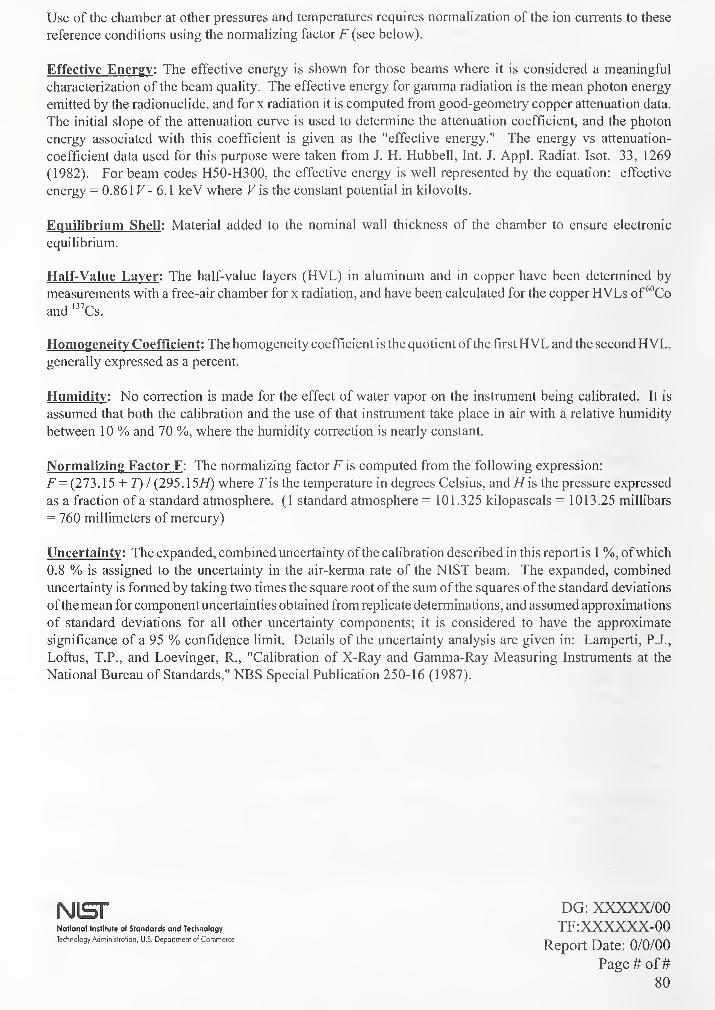
Use of the chamber at other pressures and temperatures requires normalization of the ion currents to these
reference conditions using the normalizing factor F (see below).
Effective Energy : The effective energy is shown for those beams where it is considered a meaningful
characterization of the beam quality. The effective energy for gamma radiation is the mean photon energy
emitted by the radionuclide, and for x radiation it is computed from good-geometry copper attenuation data.
The initial slope of the attenuation curve is used to determine the attenuation coefficient, and the photon
energy associated with this coefficient is given as the "effective energy." The energy vs attenuation-
coefficient data used for this purpose were taken from J. H. Hubbell, Int. J. Appl. Radiat. Isot. 33, 1269
(1982). For beam codes H50-H300, the effective energy is well represented by the equation: effective
energy = 0.861 F - 6.1 keV where Fis the constant potential in kilovolts.
Equilibrium Shell ; Material added to the nominal wall thickness of the chamber to ensure electronic
equilibrium.
Half-Value Layer : The half-value layers (HVL) in aluminum and in copper have been determined by
measurements with a free-air chamber for x radiation, and have been calculated for the copper HVLs of ''"Co
and '"Cs.
Homogeneity Coefficient : The homogeneity coefficient is the quotient ofthe firstHVL and the second HVL,generally expressed as a percent.
Humidity : No correction is made for the effect of water vapor on the instrument being calibrated. It is
assumed that both the calibration and the use of that instrument take place in air with a relative humidity
between 1 0 % and 70 %, where the humidity correction is nearly constant.
Normalizing Factor F : The normalizing factor F is computed from the following expression:
F= (273.15 + T) I (295.15//) where Tis the temperature in degrees Celsius, and //is the pressure expressed
as a fraction of a standard atmosphere. (1 standard atmosphere = 101.325 kilopascals = 1013.25 millibars
= 760 millimeters of mercury)
Uncertainty : The expanded, combined uncertainty ofthe calibration described in this report is 1 %, ofwhich
0.8 % is assigned to the uncertainty in the air-kerma rate of the NIST beam. The expanded, combined
uncertainty is formed by taking two times the square root ofthe sum ofthe squares ofthe standard deviations
ofthe mean for component uncertainties obtained from replicate determinations, and assumed approximations
of standard deviations for all other uncertainty components; it is considered to have the approximate
significance of a 95 % confidence limit. Details of the uncertainty analysis are given in: Lamperti, P. J.,
Loftus, T.P., and Loevinger, R., "Calibration of X-Ray and Gamma-Ray Measuring Instruments at the
National Bureau of Standards," NBS Special Publication 250-16 (1987).
National Institute of Standards and Technology
Technology Adminislrotion, U.S. Department of Commerce
Nisr DG: XXXXX/00TF:XXXXXX-00
Report Date: 0/0/00
Page # of
#
80

Attachment 6: Typical TLD calibration report
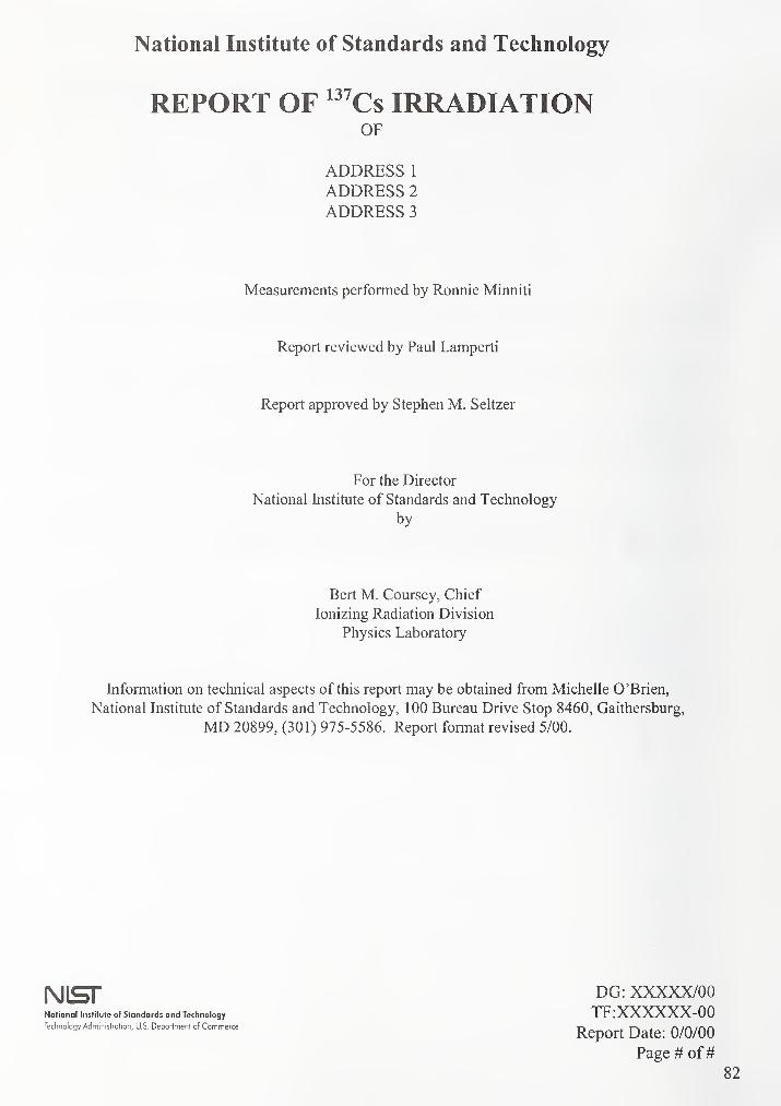
National Institute of Standards and Technology
REPORT OF '''Cs IRRADIATIONOF
ADDRESS 1
ADDRESS 2
ADDRESS 3
Measurements performed by Ronnie Minniti
Report reviewed by Paul Lamperti
Report approved by Stephen M. Seltzer
For the Director
National Institute of Standards and Technology
by
Bert M. Coursey, Chief
Ionizing Radiation Division
Physics Laboratory
Information on technical aspects of this report may be obtained from Michelle O'Brien,
National Institute of Standards and Technology, 1 00 Bureau Drive Stop 8460, Gaithersburg,
MD 20899, (301) 975-5586. Report format revised 5/00.
(VJlSf DG: XXXXX/00National Institute of Standards and Technology TF:XXXXXX-00Technology Administration, U.S- DeporlmenI of Commerce T> _4. t-» j. r\ lf\ /ryrt
Report Date: 0/0/00
Page # of
#
82

National Institute of Standards and Technology
REPORT OF Cs IRRADIATIONOF
ADDRESS 1
ADDRESS 2
ADDRESS 3
Dosimeter Type:
Badge Orientation: front face normal to the incident radiation.
Air Kerma Rate: X.XX EO Gy/s.
TLD Identification Exposed Total Total Irradiation
on Exposure Air- Distance
Phantom (mR) Kerma (cm)
(mGy)
Model NumberYES/NO X.XXX EO X.XX EO 000
YES/NO X.XXX EO X.XX EO 000
See the last three pages of attachment 5 for an example of the remainder of this report.
DG: XXXXX/00National Institute of Standards and Technology TF:XXXXXX-00Technology Adminislrclion, U.S. Department of Commerce
RcpOrt DatC* 0/0/00
Page # of
#

Attachment 7: Typical electrometer calibration report
84
National Institute of Standards and Technology
REPORT OF TESTOF
ADDRESS 1
ADDRESS 2
ADDRESS 3
Electrometer: Make, Model SN
Measurements performed by Michelle O'Brien
Report reviewed by Paul Lamperti
Report approved by Stephen M. Seltzer
National Institute of Standards and Technology
For the Director
by
Bert M. Coursey, Chief
Ionizing Radiation Division
Physics Laboratory
Information on technical aspects ofthis report may be obtained from Michelle O'Brien, National Institute
of Standards and Technology, 100 Bureau Drive Stop 8460, Gaithersburg, MD 20899, (301) 975-2014.
Report format revised 5/00.
National Institute of Standards and Technology
Technology Adminisltolion, U.S. DepartmenI of Commerce
Nisr DG: XXXXX/00TF:XXXXXX-00
Report Date: 0/0/00
Page # of
#
85
THE SP 250 SERIES ON NIST MEASUREMENT SERVICES*
SP 250-1 Spectral Radiance Calibrations
PB87179883
SP 250-2 Far Ultraviolet Detector Standards
PB87227609
SP 250-3 Radiometric Standards in the Vacuum Ultraviolet
PB87227625
SP 250-4 Fricke Dosimetry in High-Energy Electron BeamsPB881 10374
SP 250-5 Alpha-Particle Calibrations
PB881 68620
SP 250-6 Regular Spectral Transmittance
PB881 08550
SP 250-7 Radiance Temperature Calibrations
PB881 23674
SP 250-8 Spectral Reflectance
PB881 09905
SP 250-9 Calibration of Beta-Particle-Emitting Ophthalmic
Applicators
PB881 08535
SP 250-1 0 Radioactivity Calibrations with the "4tt" GammaIonization Chamber and Other Radioactivity
Calibration Capabilities
PB881 23708
SP 250-1 1 Dosimetry for High Dose Applications
PB88201587
SP 250-12 Neutron Personnel Dosimetry
PB87227617
SP 250-13 Activation Foil Irradiation with Californium
Fission Sources
PB88217443
SP 250-14 Activation Foil Irradiation by Reactor Cavity
Fission Sources
PB88217435
SP 250-15 Photometric Calibrations
PB881 53747
SP 250-16 Calibration of X-Ray and Gamma-RayMeasuring Instruments
PB88211826
SP 250-17 The NBS Photodetector Spectral ResponseCalibration Transfer ProgramPB88201595
SP 250-18 Neutron Source Strength Calibrations
PB88211818
SP 250-19 Calibration of Gamma-Ray-EmittingBrachytherapy Sources
PB891 93858
SP 250-20 Spectral Irradiance Calibrations
PB88123781
SP 250-21 Calibration of Beta-Particle Radiation
Instrumentation
PB88201579
SP 250-22 Platinum Resistance Thermometer Calibrations
PB881 38367
SP 250-23 Liquid-in-Glass Thermometer Calibration Service
PB89128888
SP 250-24 Standard Cell Calibrations
PB881 23690
SP 250-25 Calibration Service for Inductive
Voltage Dividers
SP 250-26 NBS Phase Angle Calibration Services
PB88225636
SP 250-27 AC-DC Difference Calibrations
PB892222616
SP 250-28 Solid-state DC Voltage Standard Calibrations
PB881 68703
SP 250-29 Traceable Frequency Calibrations
PB881 68364
SP 250-30 GOES Satellite Time Code Dissemination:
Description and Operation
PB881 68760
SP 250-31 Mass Calibrations
PB89153894
SP 250-32 A Calibration Service for 30 MHz Attenuation
and Phase Shift
PB88238324
SP 250-33 A Calibration Service for Voltage Transformers
and High-Voltage Capacitors
PB882252903
SP 250-34 High Vacuum Standard and Its UsePB891 93841
SP 250-35 The Calibration of Thermocouples
and Thermocouple Materials
PB89209340
SP 250-36 A Calibration Service for Current Transformers
PB91216770
SP 250-37 Photometric Calibrations
PB971 48472
SP 250-38 NIST Leak Calibration Service
PB92149772
SP 250-39 NIST Pressure Calibration Service
PB94164043
SP 250-^0 Absorbed-Dose Calibration of Ionization Chambersin a ^°Co Gamma-Ray BeamNo PB number
SP 250-41 Spectroradiometric Detector Measurements:
Part I- Ultraviolet Detectors and
Part II - Visible to Near-Infrared Detectors
PB98-1 49073
SP 250-42 Sprectroradiometric Detector Measurements:Part III—Infrared Detectors
PB99-1 34371
SP 250-43 Radiance Temperature Calibrations
PB98-141047
SP 250-44 Radiation Processing Dosimetry Calibration
Services and Measurement Assurance ProgramPB98-1 40973
* Entries containing a stock number (SN003-003-) can be purchased from the Superintendent of Documents, U.S. GovernmentPrinting Office, Washington, DC 20402-9325. GPO will accept checks, money orders, VISA, and MasterCard. For more infomation, or to placean order, call (202) 512-1800. Be sure to cite the stock number on all orders.
Entries containing PB numbers can be purchased from the National Technical Information Service, Springfield, VA 22161. NTIS will acceptAmerican Express in addition to the payment methods listed for GPO. For more information or to place an order call (800) 553-6487.Fax: (703) 321-8547. Be sure to cite the PB number on all orders.
Entries without stock or PB numbers are in preparation.
THE SP 250 SERIES ON NIST MEASUREMENT SERVICES* -Continued
SP 250-45 Radiation Processing Dosimetry Calibration
Services: Manual of Calibration Procedures
SN003-003-03514-9, PB98-1 40981
SP 250-46 NIST Multifunction Calibration SystemSN003-003-03515-7, PB98-131279
SP 250-47 NIST Calibration Service for Capacitance
Standards at Low Frequencies
SN003-003-03549-1. PB98-1 44687
SP 250-48 Spectral Reflectance
SN003-003-03545-9, PB98-149016
SP 250-49 NIST Calibration Services for Gas Flow
Meters: Piston Prover and Bell Prover
Gas Flow Facilities
SN003-003-03560-2. PB99-1 07260
SP 250-51 Calibration Service of Optoelectronic
Frequency Response at 1319 nm for
Combined Photodiode/rf Power Sensor
Transfer Standards
SN003-003-03623-4, PB2000-1 03300
SP 250-52 Error Analysis and Calibration Uncertainty of
Capacitance Standards at NISTSN003-003-03633-1 , PB2000-1 03674
SP 250-53 Calibration Service for Spectral Responsivity of
Laser and Optical-Fiber Power Meters at
Wavelengths Between 0.4 p.n\ and 1 .8 [im
SN003-003-03624-2, PB2000-1 02878
SP 250-54 Optical Fiber Power Meter Calibrations at NISTSN003-003-03652-8, PB2000-1 06986
SP 250-56 Optical Fiber Power Meter Nonlinearity Calibrations
at NISTSN003-003-03653-6, PB2000-1 06987
SP 250-57 Measurement Assurance Program for the Spectral
Density of Relative Intensity Noise of Optical Fiber
Sources Near 1 550 nmSN003-003-03658-7, PB2000-1 08256
* Entries containing a stock number (SN003-003-) can be purchased from the Superintendent of Documents, U.S. GovernmentPrinting Office, Washington, DC 20402-9325. GPO will accept checks, money orders, VISA, and MasterCard. For more infomation, or to place
an order, call (202) 512-1800. Be sure to cite the stock number on all orders.
Entries containing PB numbers can be purchased from the National Technical Information Sen/ice, Springfield, VA 221 61 . NTIS will accept
American Express in addition to the payment methods listed for GPO. For more information or to place an order call (800) 553-6487.Fax: (703) 321-8547. Be sure to cite the PB number on all orders.
Entries without stock or PB numbers are in preparation.
AU.S. GOVERNMENT PRINTING OFnCE:2001 -472-068/46009


Technical Publications
Periodical
Journal of Research of the National Institute of Standards and Technology—Reports NIST research and
development in those disciplines of the physical and engineering sciences in which the Institute is active.
These include physics, chemistry, engineering, mathematics, and computer sciences. Papers cover a broad
range of subjects, with major emphasis on measurement methodology and the basic technology underlying
standardization. Also included from time to time are survey articles on topics closely related to the Institute's
technical and scientific programs. Issued six times a year.
Nonperiodicals
Monographs—Major contributions to the technical literature on various subjects related to the Institute's
scientific and technical activities.
Handbooks—Recommended codes of engineering and industrial practice (including safety codes) developed
in cooperation with interested industries, professional organizations, and regulatory bodies.
Special Publications—Include proceedings of conferences sponsored by NIST NIST annual reports, and
other special publications appropriate to this grouping such as wall charts, pocket cards, and bibliographies.
National Standard Reference Data Series—Provides quantitative data on the physical and chemical
properties of materials, compiled from the world's literature and critically evaluated. Developed under a
worldwide program coordinated by NIST under the authority of the National Standard Data Act (Public Law90-396). NOTE: The Journal of Physical and Chemical Reference Data (JPCRD) is published bimonthly for
NIST by the American Institute of Physics (AlP). Subscription orders and renewals are available from AlP,
RO. Box 503284, St. Louis, MO 63150-3284.
Building Science Series—Disseminates technical information developed at the Institute on building
materials, components, systems, and whole structures. The series presents research results, test methods,
and performance criteria related to the structural and environmental functions and the durability and safety
characteristics of building elements and systems.
Technical Notes—Studies or reports which are complete in themselves but restrictive in their treatment of a
subject. Analogous to monographs but not so comprehensive in scope or definitive in treatment of the
subject area. Often serve as a vehicle for final reports of work performed at NIST under the sponsorship of
other government agencies.
Voluntary Product Standards—Developed under procedures published by the Department of Commerce in
Part 10, Title 15, of the Code of Federal Regulations. The standards establish nationally recognized
requirements for products, and provide all concerned interests with a basis for common understanding of the
characteristics of the products. NIST administers this program in support of the efforts of private-sector
standardizing organizations.
Order the following NIST publications—FIPS and NISTIRs—from the National Technical
Information Service, Springfield, VA 22161.
Federal Information Processing Standards Publications (FIPS PUB)—Publications in this series collec-
tively constitute the Federal Information Processing Standards Register. The Register serves as the official
source of information in the Federal Government regarding standards issued by NIST pursuant to the
Federal Property and Administrative Services Act of 1949 as amended. Public Law 89-306 (79 Stat. 1 127),
and as implemented by Executive Order 11717 (38 FR 12315, dated May 11, 1973) and Part 6 of Title 15
CFR (Code of Federal Regulations).
NIST Interagency or Internal Reports (NISTIR)—The series includes interim or final reports on work
performed by NIST for outside sponsors (both government and nongovernment). In general, initial distribution
is handled by the sponsor; public distribution is handled by sales through the National Technical Information
Service, Springfield, VA 22161, in hard copy, electronic media, or microfiche form. NISTIR's may also report
results of NIST projects of transitory or limited interest, including those that will be published subsequently in
more comprehensive form.