X-Plane FMS manual - X-Plane 11 is Herex-plane.com/manuals/FMS_Manual.pdf · 5 The X-Plane 11...
38
1 X-Plane 11 Flight Management System (FMS) Author: Julian Lockwood ([email protected]) Copyright: Laminar Research 2017 Disclaimer The information contained in this document is for simulation use only, within the X-Plane flight simulator. This document is not subject to revision, and has not been checked for accuracy. This document is intended for entertainment only, and may not to be used in situations involving real-life aircraft, or real-life aviation. This document may be copied and distributed by Laminar Research customers for entertainment only.
Transcript of X-Plane FMS manual - X-Plane 11 is Herex-plane.com/manuals/FMS_Manual.pdf · 5 The X-Plane 11...

1
X-Plane 11 Flight Management System (FMS)
Author: Julian Lockwood ([email protected])
Copyright: Laminar Research 2017
Disclaimer The information contained in this document is for simulation use only, within the X-Plane flight simulator. This document is not
subject to revision, and has not been checked for accuracy. This document is intended for entertainment only, and may not to be
used in situations involving real-life aircraft, or real-life aviation.
This document may be copied and distributed by Laminar Research customers for entertainment only.

2
Flight Management Systems ......................................................................................................................... 4
The X-Plane 11 Flight Management System ................................................................................................. 5
The “Pop-Up” CDU ........................................................................................................................................ 5
Invoking, moving, sizing, and closing the “Pop-Up” CDU ............................................................................. 5
Components of the CDU ............................................................................................................................... 7
Programming a Flight Plan ............................................................................................................................ 9
Initializing the CDU .................................................................................................................................... 9
Invoking the Flight Plan Page .................................................................................................................... 9
Programming the Flight Plan Origin ........................................................................................................ 10
Programming the Flight Plan Destination ............................................................................................... 10
Programming the Flight Number ............................................................................................................ 10
Executing the Flight Plan segment .......................................................................................................... 11
Programming the Departure ................................................................................................................... 12
Selecting a Standard Instrument Departure (SID) .................................................................................. 13
Selecting a Standard Instrument Departure (SID) Transition ................................................................. 13
Programming the route segment ........................................................................................................... 14
Programming the Arrival ......................................................................................................................... 15
Selecting a Standard Instrument Arrival (STAR) ..................................................................................... 15
Selecting an Instrument Approach ......................................................................................................... 15
Selecting an Approach Transition ........................................................................................................... 16
Programming Fixes.................................................................................................................................. 17
Programming a FIX for Standard Instrument Departure (VTU6). ........................................................... 18
Programming a FIX for Standard Instrument Arrival (BSR3). .................................................................. 20
VNAV ....................................................................................................................................................... 21
VNAV – Programming a Climb Transition Altitude ................................................................................. 21
VNAV – Programming Climb and Descent Speed Restrictions ............................................................... 22
VNAV - Programming a Cruise Altitude. ................................................................................................. 23
VNAV - Programming a Target Speed ..................................................................................................... 23
VNAV - Programming a Vertical Path Angle (VPA) .................................................................................. 24
Flight Plan Discontinuities ....................................................................................................................... 25
Inserting waypoints into an active Flight Plan ........................................................................................ 27
Deleting waypoints from an active Flight Plan ....................................................................................... 28
Direct To Waypoint ................................................................................................................................. 29

3
Resetting the Flight Plan ......................................................................................................................... 30
Stepping through your route .................................................................................................................. 31
Loading a (saved) Flight Plan ....................................................................................................................... 32
Invoking the Route Menu Page ............................................................................................................... 32
Saving a Flight Plan ..................................................................................................................................... 34
Invoking the Route Menu Page ............................................................................................................... 34
Autopilot Operations .................................................................................................................................. 36
Appendix ..................................................................................................................................................... 37
VENTURA SIX (VTU6) DEPARTURE plate ................................................................................................. 37
BIG SUR THREE (BSR3) ARRIVAL plate .................................................................................................... 38

4
Flight Management Systems
A Flight Management System (FMS) is a centralized computer system used in airliners, and other high-performance aircraft, to manage many of the aircraft systems, including (but not limited to) the flight plan. Contemporary airliners rely on the FMS to automate a wide-variety of tasks, previously performed by navigators and flight engineers. The presence of an FMS reduces the workload in the cockpit, allowing the aircraft to be operated by (usually) just two crew-members. To accomplish its assigned tasks, an FMS will interface with many aircraft systems, including engine, fuel, hydraulic, electrical, and navigation devices such as GPS, the on-board Inertial Navigation System, and the “Nav” radios.
A Flight Management System is an integration of several components, including:
✓ Control Display Unit (CDU)
A small screen and touch-keypad that provides the interface through which the pilot operates the FMS.
✓ Flight Management Computer
The computer hardware and software needed to run the system. This is not visible to the pilot in the cockpit, and is usually
located elsewhere in the aircraft.
✓ Multi-Function Display (MFD)
One or more electronic displays (usually CRT or LCD) that provide the pilot with navigation progress, engine performance, and aircraft system information (depending on the mode selected).

5
The X-Plane 11 Flight Management System
The Laminar Research / X-Plane 11 FMS resembles a system built by Collins and found in regional airliners, and is similar in
operation to the one used in Boeing aircraft, including the 737 (illustrated in this manual).
Rival systems are built by Honeywell and Thales for use in Boeing and Airbus aircraft. Despite differences, both systems perform
many of the same functions.
Due to the immense complexity of a real-life Flight Management System, the version modelled in X-Plane 11 is simplified, and does
not support every capability. However, the functions necessary to program and execute a flight plan are present, including the use of
published arrival and departure procedures (SIDs and STARs) and instrument approaches.
The “Pop-Up” CDU
For convenience, a pop-up CDU is provided in every X-Plane default aircraft that features a Flight Management System. This is a
2D panel that can be moved and sized per the needs of the pilot. For the purposes of this guide, we will present the pop-up CDU
only. However, commands may also be input using the CDU panel built into the 3D cockpit.
Invoking, moving, sizing, and closing the “Pop-
Up” CDU
Invoking the pop-up CDU
To invoke the pop-up CDU panel, position and click the mouse-pointer anywhere inside the DISPLAY area of the CDU panel in the 3D cockpit. See highlighted area in image to left.

6
Moving the pop-up CDU
To move the pop-up CDU panel to the desired location on your computer screen, first place the mouse-pointer anywhere on the outer-frame. The top-center is recommended, as shown here by the white arrow. Now click and drag the pop-up CDU panel to the desired location on your computer screen.
Re-sizing the pop-up CDU
Place the mouse-pointer at the top-center of the CDU frame. Two click-spots will appear. The click-spot in the UPPER-RIGHT of the CDU frame invokes “Window” mode. In this mode, the CDU panel can be re-sized by dragging the window frame - in the same manner as any other window supported by your operating system.
Closing the pop-up CDU
Place the mouse-pointer at the top-center of the CDU frame. Two click-spots will appear. The (red) click-spot in the UPPER-LEFT of the CDU frame closes the pop-up.

7
Components of the CDU
The Control Display Unit (CDU) provides the interface between the pilot and the Flight Management Computer (FMC). It consists of
a display panel, and a series of keys that are grouped together according to their function.
Display This panel provides a simple output display to the pilot, allowing him to program the unit, make commands, and select available options.
Scratch Pad This area of the CDU Display is used for Key Pad input. Inputs made by the pilot are initially displayed here, before a Line Select Key is chosen, to move this text to the appropriate line of the CDU Display (above the scratch pad).
Line Select Keys These keys are used to make selections from the options provided alongside them, in the CDU Display. The keys on the left-side of the unit align with the options on the left-side of the display, and vice-versa.
Key Pad Used to input text into the scratch pad area on the CDU display.

8
Page Keys These keys are used to select the page presented in the Display Area. The primary functions of the CDU are grouped by “Page”. This simplifies the presentation, and provides a logical work-flow to the pilot.
Exec Key This key is used to activate a flight plan, or a segment of a flight plan, or to commit changes to an active flight plan. When the light bar (above the key) is illuminated, this key must be pressed to commit changes that have been input by the pilot, and are currently pending.
Clear Key This key clears text currently displayed in the “Scratch Pad”.

9
Programming a Flight Plan
In this section of the guide, the pilot will program the CDU with a manually input flight plan.
The flight plan used in this example originates at KLAX (Los Angeles International), and terminates at KSFO (San Francisco
International).
We will depart runway 25R at KLAX, and use the VTU5 Standard Instrument Departure (SID), with the RZS Transition waypoint.
The route-segment of the flight plan will be via the “BSR” VOR/DME.
We will arrive runway 28R at KSFO, and use the BSR3 Standard Instrument Arrival (STAR).
The full route is as follows:
KLAX, VTU5, RZS, BSR, BSR3, KSFO
Important Flight plan waypoints and procedures change over time. The sample flight plan used here may no longer be current, and some of these waypoints may not be available for selection during your flight. Loading a previously-saved flight-plan is discussed later in this guide, in the section Loading a (saved) Flight Plan.
Initializing the CDU
Boeing CDUs feature an “INIT REF” or “POS INIT” key that is used to initialize the Flight Management System at the start of a new
flight. This initialization process includes the alignment of the Inertial Navigation System (INS), the computation of V-Speeds, and
several other factors that relate to the aircraft loading and performance. These features are highly specific to the particular type of
aircraft flown, and therefore not available in the X-Plane 11 FMS, which can be used with every aircraft. Therefore, the pilot begins
programming the CDU at the Flight Plan Page.
Invoking the Flight Plan Page
Click the FPLN key to invoke the Flight Plan Page. This page is at the top of the Flight Plan hierarchy, and is used to input the:
✓ Origin and destination airports ✓ The flight number
and
➢ An optional “Company Route” (saved flight plan) ➢ An optional “Via” airway designator (with associated “To” exit point).
The use of an airway designator saves the pilot from the need to manually input the individual waypoints along that segment of the route. The exit waypoint defines the end of that particular segment. For more information regarding “Airways”, see: https://en.wikipedia.org/wiki/Airway_(aviation) Hint: Always use the “CLR” key to remove any existing text in the “Scratch Pad” before inputting new data.
10
Programming the Flight Plan Origin
Using the CDU Key Pad, input the ICAO code of the originating airport, which is this instance is KLAX. The text will appear in the “Scratch Pad”. Click the Line Select Key (highlighted in red in the example to the right) to cut and paste KLAX from the Scratch Pad to the ORIGIN data field (in the Display Area).
Programming the Flight Plan Destination
Using the CDU Key Pad, input the ICAO code of the destination airport, which is this instance is KSFO. The text will appear in the “Scratch Pad”. Click the Line Select Key (highlighted in red in the example to the right) to cut and paste KSFO from the Scratch Pad to the DEST data field (in the Display Area).
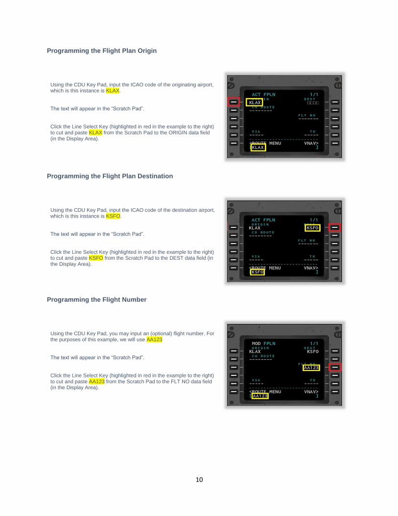
Programming the Flight Number
Using the CDU Key Pad, you may input an (optional) flight number. For the purposes of this example, we will use AA123 The text will appear in the “Scratch Pad”. Click the Line Select Key (highlighted in red in the example to the right) to cut and paste AA123 from the Scratch Pad to the FLT NO data field (in the Display Area).

11
Executing the Flight Plan segment
The EXEC button is illuminated to indicate that your instructions are ready to be executed. Click the EXEC button to activate this segment of the flight plan.

12
Programming the Departure
Click the DEP ARR key to invoke the “Departures and Arrival Index Page”. Click the Line Select Key (highlighted in red in the example to the right) to invoke the “Departures Page”.
Use the NEXT PAGE key to locate the desired runway. In this example, we will be using 25R. Click the Line Select Key (highlighted in red in the example to the right) to select this.
13
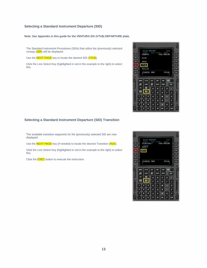
Selecting a Standard Instrument Departure (SID)
Note: See Appendix in this guide for the VENTURA SIX (VTU6) DEPARTURE plate.
The Standard Instrument Procedures (SIDs) that utilize the (previously) selected runway (25R) will be displayed. Use the NEXT PAGE key to locate the desired SID (VTU6). Click the Line Select Key (highlighted in red in the example to the right) to select this.
Selecting a Standard Instrument Departure (SID) Transition
The available transition waypoints for the (previously) selected SID are now displayed. Use the NEXT PAGE key (if needed) to locate the desired Transition (RZS). Click the Line Select Key (highlighted in red in the example to the right) to select this. Click the EXEC button to execute the instruction.

14
Programming the route segment
The route segment is that portion of the flight plan that exists between the departure (waypoints) and the arrival (waypoints). To begin programming the route segment of the flight plan, click the FPLN button, followed by NEXT PAGE.
In our example flight plan, the route segment consists of just a single waypoint – BSR. A more complex flight plan would probably feature multiple waypoints in the route segment, and the steps described here would be repeated for each waypoint. Using the CDU Key Pad, input the waypoint identifier BSR. The text will appear in the “Scratch Pad”. Click the Line Select Key (highlighted in red in the example to the right). This is the next (unused) waypoint in the flight plan.
There are two waypoints that exist with the BSR identifier. Both are VOR transmitters. The CDU displays both, because it is unable to determine which is the desired selection. Click the Line Select Key (highlighted in red in the example to the right), to select the first of the two BSR VOR waypoints. This is the one we require. Hint: It will usually be the closest one! Click the EXEC button to execute the instruction.

15
Programming the Arrival
Click the DEP ARR key to invoke the “Departures and Arrival Index Page”. Click the Line Select Key (highlighted in red in the example to the right) to invoke the “Arrivals Page” (for KSFO).
Selecting a Standard Instrument Arrival (STAR)
Note: See Appendix in this guide for the BIG SUR THREE (BSR3) ARRIVAL plate.
Use the NEXT PAGE key (if needed) to locate the desired STAR. In this example, we will be using BSR3.
Selecting an Instrument Approach
Click the Line Select Key (highlighted in red in the example to the right) to select the desired instrument approach. Only approaches associated with the chosen STAR (BSR3) will be displayed. In this example, we will be using the ILS approach to runway 28R.

16
Selecting an Approach Transition
The available transition routes or initial approach fixes for the previously selected instrument approach are now displayed. Use the NEXT PAGE key (if needed) to locate the desired Transition (MENLO). Click the Line Select Key (highlighted in red in the example to the right) to select this. Click the EXEC button to execute the instruction.

17
Programming Fixes
Sometimes SIDS and STARS require the pilot to input a FIX. Fixes are positions that are derived relative to one or more other
waypoints. Examples would be:
• The intersection of two VOR radials.
• A specific distance from a given VOR, on a given radial.
In this tutorial, the departure SID (VTU6) and arrival STAR (BSR3) both require the CDU to be programmed with a FIX.

18
Programming a FIX for Standard Instrument Departure (VTU6).
Standard Instrument Departure VTU6 requires that the pilot input the Santa Monica VOR (SMO) as a FIX. The fix is reached when
crossing the 154 radial from this VOR.
Note: See Appendix in this guide for the VENTURA SIX (VTU6) DEPARTURE plate.
Click the FIX key to invoke the “FIX INFO Page 1/2”. Page 1 of 2 is now displayed, and we are ready to input the fix associated with the Standard Instrument Departure procedure.
Input the name of the navigation aid that defines the fix. This is the Santa Monica VOR, which has the identifier SMO. Click the Line Select Key (highlighted in red in the example to the right) to move this from the scratch pad to the FIX Reference line.
There are multiple waypoints with the SMO identifier. Click the Line Select Key (highlighted in red in the example to the right) to select the desired waypoint (the closest one).

19
Input the desired radial (154) into the scratch pad. Click the Line Select Key (highlighted in the example to the left) to place this in the “Radial Crossing” line.

20
Programming a FIX for Standard Instrument Arrival (BSR3).
Standard Instrument Arrival BSR3 requires that the pilot input the Woodside VOR (OSI) as a FIX. The fix is reached when crossing
the 038 radial from this VOR.
Note: See Appendix in this guide for the BIG SUR THREE (BSR3) ARRIVAL plate.
Click the NEXT PAGE key to invoke the “FIX INFO Page 2/2”. Page 2 of 2 is now displayed, and we are ready to input the fix associated with the Standard Instrument Arrival procedure.
Input the name of the navigation aid that defines the fix. This is the Woodside VOR, which has the identifier OSI. Click the Line Select Key (highlighted in red in the example to the right) to move this from the scratch pad to the FIX Reference line.
Input the desired radial (038) into the scratch pad. Click the Line Select Key (highlighted in the example to the left) to place this in the “Radial Crossing” line.

21
VNAV
There are three VNAV pages - used to define the vertical navigation profile for the climb, cruise and descent phases of your flight. To invoke the VNAV pages, click the FPLN button, and then click the VNAV Line Select Key (highlighted in red in the example to the right) to select this. Use the NEXT PAGE / PREV PAGE to navigate to between VNAV pages 1, 2, 3.
VNAV – Programming a Climb Transition Altitude
The transition altitude is the published barometric altitude above sea level at which pilots climbing to their cruise level change their
barometric altimeter datum from the regional pressure setting to the ISA standard pressure of 1013hPa or 29.92inHg.
In the US, this is 18,000 feet. Altitudes at, and above this point, are referred to as “Flight Levels”. For example, 18,000 feet pressure
altitude is “Flight Level 180”.
The CDU in X-Plane 11 uses a default value of 18000 feet for the transition altitude – which applies to US airspace.
You may, however, change the transition altitude for a specific airspace that you are operating in during the ascent phase of your
flight.
Use the NEXT PAGE / PREV PAGE to navigate to VNAV page 1/3. Using the CDU Key Pad, input the transition altitude. In this example, we will manually specify a transition altitude of 18,000 feet (even though this is already programmed by default). Use the key pad to Input the desired altitude. The text will appear in the “Scratch Pad”. Click the Line Select Key (highlighted in red in the example to the left) to cut and paste 18000 from the Scratch Pad to the TRANS ALT data field (in the Display Area).

22
VNAV – Programming Climb and Descent Speed Restrictions
During your flight, the speed is likely to be restricted at specific altitudes. For example, in US airspace the speed is normally
restricted to 250 knots at, or below, 10,000 feet.
Use the NEXT PAGE / PREV PAGE to navigate to the VNAV CLIMB page 1/3 or the VNAV DESCEND page 3/3. The CDU in X-Plane 11 uses a default speed restriction of 250 knots at 10000 feet.
You may program up to two speed restrictions. To program a speed restriction, input this into the ‘Scratch Pad’ as shown in the example to the right. Click the Line Select Key alongside the first or second speed restriction. Note that if the line is already populated, the new restriction will replace the existing restriction. In the example to the right, two restrictions have been programmed:
• 200 knots at or below 8,000 feet
• 240 knots at or below 10,000 feet
Note: You may delete the second speed restriction if needed. Click the DEL key, and then the Line Select Key alongside the second speed restriction.

23
VNAV - Programming a Cruise Altitude.
The cruise altitude for this flight will be 28,000 feet, or Flight-Level 280.
Use the NEXT PAGE / PREV PAGE to navigate to VNAV CRUISE page 2/3. or Click the CRZ button as a short-cut to the same page.
Input the cruise altitude into the scratch pad. For Flight-Level 280, input just 280. Click the Line Select Key alongside CRZ ALT.
VNAV - Programming a Target Speed
Aircraft equipped with both and auto-pilot and auto-throttle can maintain a Target Speed, provided this does not conflict with
programmed Speed/Altitude restrictions.
Use the NEXT PAGE / PREV PAGE to navigate to VNAV DESCEND page 3/3. Input the required Target Speed (in knots) into the ‘Scratch Pad’. Click the Line Select Key alongside TGT SPEED to replace this with the new value.

24
VNAV - Programming a Vertical Path Angle (VPA)
The Vertical Path Angle (VPA) is the descent angle in degrees. The default value is 2.5, which means the aircraft will descend at an
angle of 2.5 degrees to the horizontal. In certain circumstances, there may be a need to change this. For example, when making a
steep descent due to terrain, or noise restrictions.
Use the NEXT PAGE / PREV PAGE to navigate to VNAV DESCEND page 3/3. Input the required VPA into the ‘Scratch Pad’. Click the Line Select Key alongside the VPA to replace this with the new value.

25
Flight Plan Discontinuities
Discontinuities occur when route segments within the flight plan cannot be joined together - usually due to missing or ambiguous
waypoints. When this occurs, the discontinuity must be repaired, and the flight plan “stitched together”. Because every discontinuity
is unique to a specific flight plan, this manual cannot provide a method for solving each one. However, the example below does
illustrate the basic method.
Changes to waypoints are made using the LEGS page.
In the example to the right, a discontinuity will be deliberately introduced into our flight plan, by deleting waypoint “BSR”.
The result is a DISCONTINUITY in the flight plan. Waypoints BSR and CARME are no longer present. [See BIG SUR THREE (BSR3) ARRIVAL plate].
To repair the discontinuity, the missing waypoints BSR and CARME must be re-introduced into our flight plan, at the correct locations. BSR is manually keyed into the ‘Scratch Pad’, and inserted alongside the first DISCONTINUITY.
Waypoint BSR is now present in the flight plan. Waypoint CARME is still missing.
26
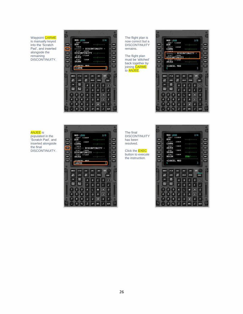
Waypoint CARME is manually keyed into the ‘Scratch Pad’, and inserted alongside the remaining DISCONTINUITY.
The flight plan is now correct but a DISCONTINUITY remains. The flight plan must be ‘stitched’ back together by joining CARME to ANJEE.
ANJEE is populated in the ‘Scratch Pad’, and inserted alongside the final DISCONTINUITY.
The final DISCONTINUITY has been resolved. Click the EXEC button to execute the instruction.

27
Inserting waypoints into an active Flight Plan
During a flight, deviations can occur from the expected route, due to factors such as weather, traffic, and ATC instructions.
Sometimes there is a need to insert a new waypoint into the plan.
Changes to waypoints are made using the LEGS page.
In this example, we will insert waypoint LAX into the flight plan, immediately prior to VTU. Manually key waypoint LAX into the “Scratch Pad”.
Click the Line Select Key alongside VTU. This will insert new waypoint LAX immediately prior to VTU in the flight plan. Stitch the flight plan back together to remove the discontinuity (see Flight Plan Discontinuities earlier in this manual). Click the EXEC button to execute the instruction.

28
Deleting waypoints from an active Flight Plan
During a flight, deviations can occur from the expected route, due to factors such as weather, traffic, and ATC instructions.
Sometimes there is a need to delete new waypoint from the plan.
Changes to waypoints are made using the LEGS page.
In this example, we will delete waypoint LAX from the flight plan. Click the DEL (Delete) Key. Click the Line Select Key alongside waypoint LAX.
Waypoint LAX is removed. Stitch the flight plan back together to remove the discontinuity (see Flight Plan Discontinuities earlier in this manual). Click the EXEC button to execute the instruction.

29
Direct To Waypoint During a flight, deviations can occur from the expected route, due to factors such as weather, traffic, and ATC instructions. Sometimes there is a need to proceed directly to a specific waypoint in your flight plan (bypassing intermediate waypoints). Note: The X-Plane 11 Flight Management Systems works like a Collins 4200 – you cannot execute a ‘Direct-To’ instruction in the LEGS page. Direct To instructions are made using the DIR-INTC page.
In this example, we will fly direct to the VTU waypoint. This will bypass the VECTORS that are provided by ATC in our example flight plan. Click the DIR INTC button. Use the NEXT PAGE or PREV PAGE buttons to bring waypoint VTU into view.
Click the Line Select Key alongside VTU. The Scratch Pad is now populated with your chosen waypoint.
If necessary, use the NEXT PAGE or PREV PAGE buttons until < - - - - - is visible.
Click the Line Select Key alongside < - - - - - Click the EXEC button to execute the instruction.

30
Resetting the Flight Plan
To reset the flight plan, input a new ORIGIN into the ‘Scratch Pad’. Click the Line Select Key alongside ORIGIN.

31
Stepping through your route Before embarking on a flight, it is important to verify the programmed flight plan looks sensible, and does not contain any gaps in continuity. This may be accomplished by stepping through each waypoint in the flight plan (using the CDU), and reconciling this with the route displayed on the Navigation Display (ND). Using the EFIS control unit (highlighted below), rotate the “CTR” button to “Plan”. A plan-view of your route will be displayed on the two Navigation Display units on the instrument panel (also highlighted).
Using the CDU, click the LEGS button to invoke the “ACT LEGS” page. Using the STEP Line Select Key, step through each of the waypoints in your flight plan, and examine the corresponding segment of the route on the Navigation Display unit (highlighted above). Note: The third waypoint of the example flight-plan used in this guide is designated “VECTORS”. That portion of the route will depend on instructions provided by ATC - to join the VTU transition waypoint. This portion of the route will appear as a (legitimate) continuity gap in the flight plan, when viewed on the Navigation Display unit.

32
Loading a (saved) Flight Plan
Flight plans that have been generated previously (and saved in the appropriate format for X-Plane) may be loaded into the Flight
Management System. The following file (extension) types are acceptable:
• FMS (compatible from X-Plane 9 and up, contains only waypoints)
• FLP (compatible with aircraft for both X-Plane and other simulators, supports airways)
• FML (X-Plane 11 internal format, for saving your own flight plans)
Invoking the Route Menu Page
Click the INDEX key to invoke the INDEX Page. Click the ROUTE MENU Line Select Key (highlighted in red in the example to the left) to invoke the ROUTE MENU Page.
Click the CO ROUTE LIST Line Select Key (highlighted in red in the example to the right) to invoke the COMPANY ROUTE LIST Page. Flight plans in .FMS and .FLP format saved previously in the OUTPUT/FMSPLANS folder will be available for selection.

33
Click the Line Select Key alongside the flight plan you are loading (see example to the left). If the desired flight plan is not displayed:
• Click the FPLN Line Select Key
• Manually input the desired filename (without the extension)
• Click the ‘CO ROUTE’ Line Select Key

34
Saving a Flight Plan
Flight plans may be saved for use again later. A saved flight plan in X-Plane 11 uses a. fml extension, and appears in the following
folder:
• X-Plane/Output/FMS Plans/
Before saving a flight plan, ensure that the EXEC button is not illuminated.
Invoking the Route Menu Page
Click the INDEX key to invoke the INDEX Page. Click the ROUTE MENU Line Select Key (highlighted in red in the example to the left) to invoke the ROUTE MENU Page.
Click the PILOT ROUTE LIST Line Select Key (highlighted in red in the example to the right) to invoke the PILOT ROUTE LIST Page.

35
Input the name of your flight plan (without the extension) into the ‘Scratch Pad’. Click the Line Select Key alongside: < - - - - - - - - - Your route has been saved.

36
Autopilot Operations The Autopilot can be coupled to the Flight Management System, to follow the flight plan that was programmed earlier. Autopilot operations differ from aircraft to aircraft, and the example here applies specifically to the X-Plane 11 default Boeing 737. The autopilot is located at the top-center of the instrument panel (highlighted below). When the Lateral Navigation (“LNAV”) button is selected (and illuminated), the autopilot is instructed to follow the lateral component of your flight plan. When the autopilot is engaged, the aircraft will steer according to the desired ground-track. When the Vertical Navigation (“VNAV”) button is selected (and illuminated), the autopilot is instructed to follow the vertical component of your flight plan. When the autopilot is engaged, the aircraft will ascend, or descend, to comply with the altitudes that have been programmed for the segments of your flight plan. To engage the autopilot, set either of the Flight Directors to “ON”, and select (illuminate) the (“A/P Engage CMD”) button. The autopilot will take control of the aircraft, and execute the desired instructions.
37
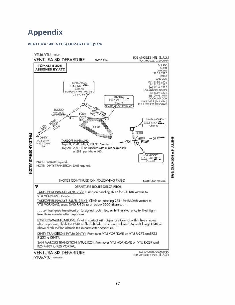
Appendix
VENTURA SIX (VTU6) DEPARTURE plate

38
BIG SUR THREE (BSR3) ARRIVAL plate