x Parameters
50
X-PARAMETERS What is it? Agilent Technologies Eesof Korea Kim, Kyoung-Won
Transcript of x Parameters

X-PARAMETERS
What is it?
Agilent Technologies
Eesof Korea
Kim, Kyoung-Won
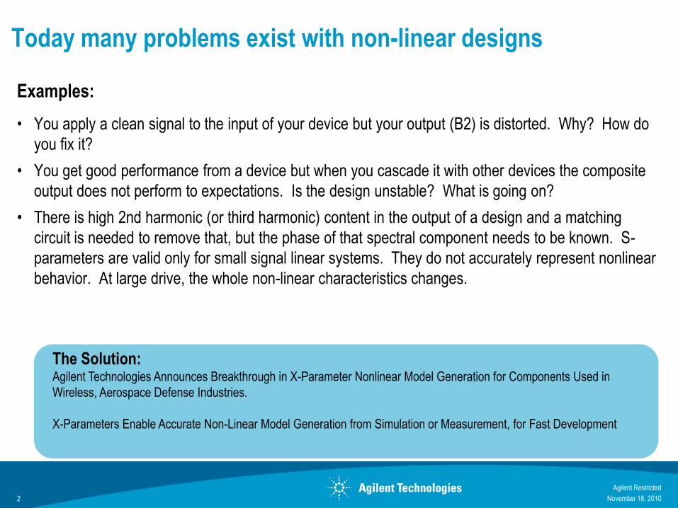
Today many problems exist with non-linear designs
Examples:
• You apply a clean signal to the input of your device but your output (B2) is distorted. Why? How do
you fix it?
• You get good performance from a device but when you cascade it with other devices the composite
output does not perform to expectations. Is the design unstable? What is going on?
• There is high 2nd harmonic (or third harmonic) content in the output of a design and a matching
circuit is needed to remove that, but the phase of that spectral component needs to be known. S-
parameters are valid only for small signal linear systems. They do not accurately represent nonlinear
behavior. At large drive, the whole non-linear characteristics changes.
November 18, 20102
The Solution:Agilent Technologies Announces Breakthrough in X-Parameter Nonlinear Model Generation for Components Used in
Wireless, Aerospace Defense Industries.
X-Parameters Enable Accurate Non-Linear Model Generation from Simulation or Measurement, for Fast Development
Agilent Restricted

Beyond Large-Signal S-ParametersApplications of X-Parameters models in ADS
November 18, 20103
NowA new breakthrough approachCharacterize your devices using X-parameters
X-Parameter model is a real rigorous, scientifically
proven, and unprecedented approach that captures all
non-linearties, amplitude, phase at all harmonics and
with mismatches; and uses these data directly in ADS
for design, simulation, and characterization.
BeforeDesigners Struggle in the design of large
signal non-linear circuitsTraditional non-Linear device models do not
accurately represent actual non-linear device
behavior under all real conditions including large
input signals, mismatches, and higher order
harmonics.
Device model; Max Power;
Linearize; stabilize; etc.
Agilent Restricted

Power amp related customer products flow (food chain)
Power amp chips
Foundry
(Compound)
Cell phones
WiMAX
Power amp moduleBase station
Front end modules
(w/PA)
Chip set/
Reference designFoundry
(Silicon)
GaAs
GaN
CMOS
Semicon
Process
Circuit
Design
System
Design
CMOS
LDMOS
SiGe
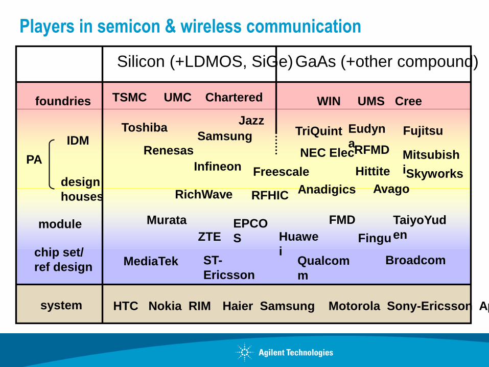
Players in semicon & wireless communication
Samsung
Qualcom
m
PA
foundries
system HTC Nokia RIM Haier Samsung Motorola Sony-Ericsson Apple
Silicon (+LDMOS, SiGe)GaAs (+other compound)
TSMC UMC Chartered WIN UMS Cree
RFMD
Skyworks
module
Infineon
Renesas
Avago
Broadcom
Eudyn
a
Jazz
ST-
EricssonMediaTek
Toshiba TriQuint
Mitsubish
iFreescale
Fujitsu
RichWave Anadigics
chip set/
ref design
Murata EPCO
S
FMD
design
houses
IDMNEC Elec
Hittite
TaiyoYud
enZTE Huawe
iFingu
RFHIC

X-ParametersBridge Between Our Customers
November 18, 20106
Agilent Restricted
ESL
Electronic System Level
Design (ESL)
X-pars
IC Design Houses /
Component Vendor
System Integrators
New Designs
Share IP Protected
X-Parameters file
Existing PartsX-parameters
measurement
NVNA
X-Parameters
Component for ADS
Bottom-up Sim-based verification
Bottom-up meas-based verification
Top-Down Design Specs
Non-Linear
X-Parameters Ideal
Specs

1. an extension of S-parameters to non-linear devices
2. a data library with non-linear information
3. three dimensional CAD file
4. behavioral model
5. a tool for non-linear simulation
Five effective ways to describe X-parameters

linear: S-parameters
1. X-parameters are the mathematical extension of
S-parameters for non-linear devices
InOut
S
non-linear: X-parameters
In
In
OutXIn
In
Out
OutX
S
In
In
In
Real X-parameters are a little more complex, but you
can survive with this knowledge in 90% of the cases!
This fundamental drive
tone is driving the
device to non-linear
21
21

Reflection is measured the same way with the drive tone always provided
at the input
In
OutS
In
In
Out
X
In
Drive tone
Out
OutX
S
In
In
In
In
22
22
This fundamental drive tone is
driving the device to non-linear
linear: S-parameters
non-linear: X-parameters
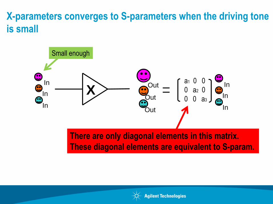
X-parameters converges to S-parameters when the driving tone
is small
In
Out
In
In
Out
OutX
In
In
Ina1 0 0
0 a2 0
0 0 a3
There are only diagonal elements in this matrix.
These diagonal elements are equivalent to S-param.
Small enough

2. X-parameter file is like a library
-- everything is in it --
Vg, Vd, Freq,
GammaLoad,
one page
Frequency
Vg
Load impedance
Vd
Power
X-param
one sector
one book
one series
one bookshelf
one library
Measurement takes from tens of minutes
to a few hours depending on the size of the “library”

3. X-parameter is like a 3-D CAD
-- in a datasheet of an amplifier, “linear” and “non-linear” are mixed --
Non-linear parameters Linear parameters
IMD
Pout vs Pin
P1dB
PAE
S=parameters

Datasheet of an amplifier is like 2-D drawings of a 3-D object
P1dB
S-parameters
IMD
PAE
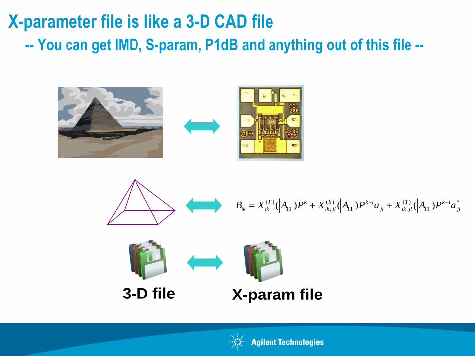
X-parameter file is like a 3-D CAD file
-- You can get IMD, S-param, P1dB and anything out of this file --
X-param file3-D file
( ) ( ) ( ) *
11 , 11 , 11( ) ( ) ( )F k S k l T k l
ik ik ik jl jl ik jl jlB X A P X A P a X A P a

4. X-parameter is a behavioral model
=[X]
an FET is described by many elements
(>100 elements @HBT)
an FET is described by [X]
=[X]an amplifier is described by [X]
=
=
an amplifier is described by providing
the internal circuits
=
an amplifier is described by huge amount
of linear & nonlinear measurement data
before [X]
after [X]
before [X]
after [X]
before [X]
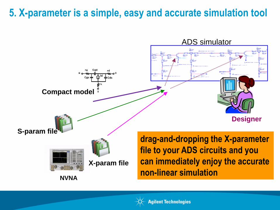
Designer
S-param file
X-param file
ADS simulator
NVNA
Compact model
5. X-parameter is a simple, easy and accurate simulation tool
drag-and-dropping the X-parameter
file to your ADS circuits and you
can immediately enjoy the accurate
non-linear simulation
THE VALUE OF
X-PARAMETERS

18
The Values of Non-Linear X-Parameters
1. IP Protection / Sharing Designs
2. Device Characterization
3. Hierarchical Designs
4. Cascade-able Components & Packaged Parts
5. Load Pull Modeling
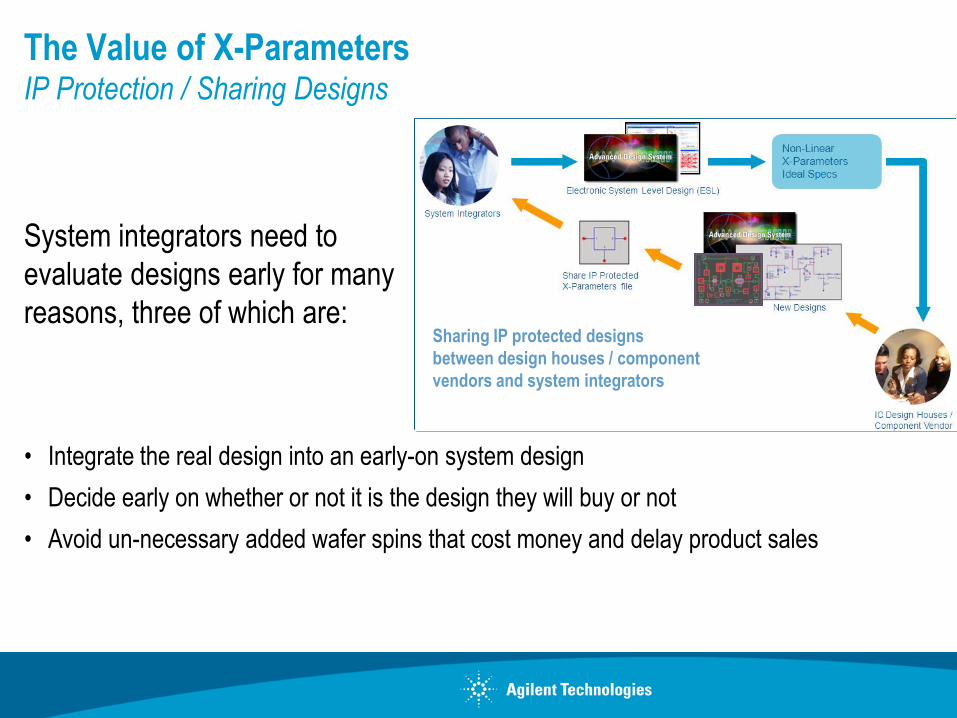
The Value of X-ParametersIP Protection / Sharing Designs
• Integrate the real design into an early-on system design
• Decide early on whether or not it is the design they will buy or not
• Avoid un-necessary added wafer spins that cost money and delay product sales
System integrators need to
evaluate designs early for many
reasons, three of which are:Sharing IP protected designs
between design houses / component
vendors and system integrators

Problem:
Design houses are reluctant to share their real designs due to IP issues. As a result, loss of business
opportunities might occur especially if their competitors were able to share their designs with the system
integrators earlier.
Therefore, Design houses have a dilemma and the system houses are not able to design their system
effectively and on timely fashion.
Solution
X-parameters models protect the IP.
If you wish to send a design to the system integrator, then encapsulating the composite design and
modeling it in an X-parameter representation completely protects the design information, better than
encrypting.
The Value of X-ParametersIP Protection / Sharing Designs

ExamplePut something together fast using Lumped Elements; Create IP protected X-
Parameters model; Send it to System Integrator
Create an X-Parameters model and share it
immediately with the System Integrator

X-ParametersDesign IP Protection
I M N
FET 1
FET 2
Int MN
OMN

Extract X-Parameters model from Simulation
Real PA Circuit Simulation
1 Design Circuit
2 Extract model
3 IP Protected
X-Parameters
File
(see next page)
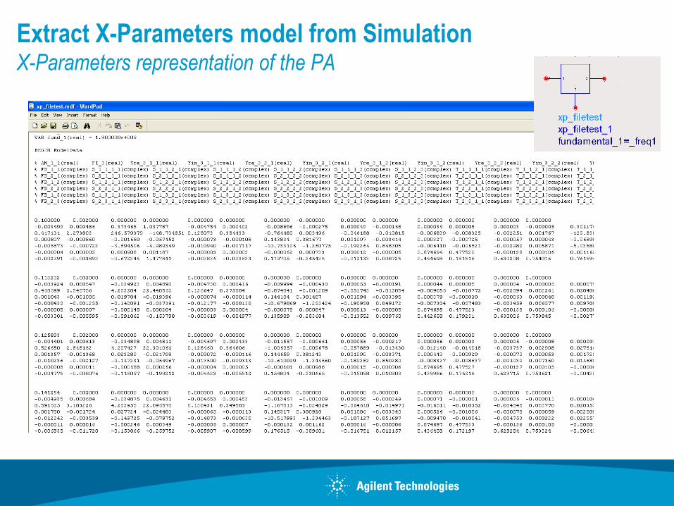
Extract X-Parameters model from SimulationX-Parameters representation of the PA

Extract X-Parameters model from SimulationResults Comparison of real circuit Vs model
Pin / Pout
Phase

X-ParametersDesign IP Protection
X Parameters in ADS
1. Insert X Parameter template which is
already setup for the extraction.
2. Connect your DUT.
3. Modify Power levels and frequencies as
needed.
4. Simulate.XP_Source
XPTerm1Num=1
XP_Loa
d
XPTerm
2Num=2
XP_Bias
XPTerm3Num=3
Amp
Amp1
X-Parameters
X_Param
XP1Freq[1]=1 GHz
Z0=50 Ohm
In ADS 2009 U1, you are able to create simulation based X-Parameters models for your circuits.
You can then share this IP-Protected model with other system integrators who can use the model in ADS
and do higher level system verification on the real virtual design.

Value of X-Parameters models in ADSDevice Characterization
Problem
Circuit-level device models
• Designers often complain about the models
they get from foundries. Many are really not
that accurate.
• It takes an expert, often a Ph.D. working full time to do an excellent job extracting a
compact device model. It also takes time.
Example: New Device level models may take years and many revisions for designers to
adopt and trust them. Even then, foundry models may have limitations that in the past have
forced designers to extract their own customized device models…

Value of X-Parameters models in ADSDevice Characterization
Problem:
Designers are not able to achieve optimum
Power and Power Added Efficiency from their
MMIC designs
due to inaccurate non-linear device models.
They end up excluding the OMN from the
design and build it off-chip, on the board
Chip without the Output Matching Network
Power / Freq Source
Probe
Station
Measure S22
1
2
3
4Design off-chip
Output Matching
Network on Board
Using S22*
Applications of X-Parameters models in ADSDevice Characterization
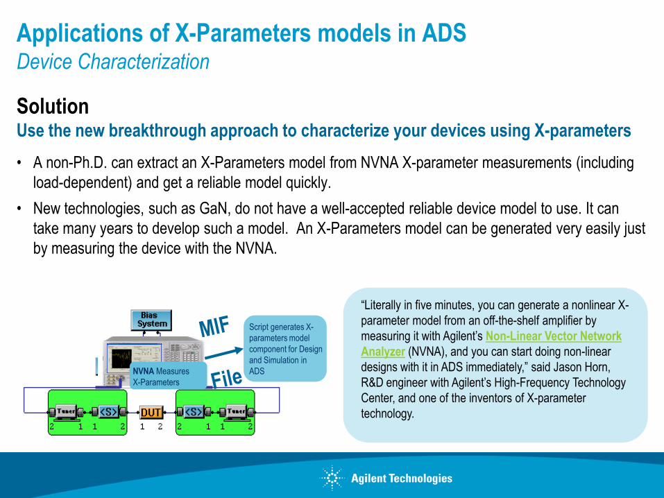
SolutionUse the new breakthrough approach to characterize your devices using X-parameters
• A non-Ph.D. can extract an X-Parameters model from NVNA X-parameter measurements (including
load-dependent) and get a reliable model quickly.
• New technologies, such as GaN, do not have a well-accepted reliable device model to use. It can
take many years to develop such a model. An X-Parameters model can be generated very easily just
by measuring the device with the NVNA.
“Literally in five minutes, you can generate a nonlinear X-
parameter model from an off-the-shelf amplifier by
measuring it with Agilent’s Non-Linear Vector Network
Analyzer (NVNA), and you can start doing non-linear
designs with it in ADS immediately,” said Jason Horn,
R&D engineer with Agilent’s High-Frequency Technology
Center, and one of the inventors of X-parameter
technology.
Script generates X-
parameters model
component for Design
and Simulation in
ADSNVNA Measures
X-Parameters

LTE Driver Amp using Measured X-Parameters FETDevice Characterization
X-Parameters Measurement of an
on-wafer FET device using the NVNA and
Maury Load Pull system
Specs
Gain >20 dB
S11 and S22 < -15 dB
Example

The Value of X-ParametersHierarchical Designs
Problem
System Engineers finds it cumbersome and
slow to use circuit level designs and circuit level
models in hierarchical RF-System simulation –
not practical and very slow
Also, Behavioral models do not accurately
represent the circuits non-linear behavioral in
phase and magnitude at all harmonics

The Value of X-ParametersHierarchical Designs
Solution
Much of the value for X-parameters is in hierarchical design.
One can measure OR simulate a two-stage amplifier and get a X-Parameters
model for that composite structure.
Speeds-up Simulation and trade-off analysis for system design and verification
X-Par
X-Par
X-Par
Replace the whole structure by its X-Parameters model

The Value of X-ParametersCascade able components and Packaged Parts
Problem
You are designing with packaged parts. All you have is a compact model of the circuit at some freq and
some power. You either have to get a model for the package, or use what the foundry gives you for the
part. There are uncertainty in the model.
When cascaded, the effects of the interaction between modules with higher order harmonics and
mismatch is not predictable nor understood
As a results, many problems are encountered in accuracy, delays in integration & test, and time to
market.

The Value of X-ParametersCascade able components and Packaged Parts
Solution
X-Parameters models work directly for packaged parts, including the effects of all the parasitic
and they are cascade able.
If you are designing with packaged parts, X-Parameters models generated from
measurement or simulation is the optimum solution
Simulation Vs Measurement of two cascaded
packaged amps, each of which was separately
modeled by its own measured X-Parameters.
“
”
Literally in five minutes, you can generate a nonlinear
X-parameter model from an off-the-shelf amplifier by
measuring it with Agilent’s Non-Linear Vector Network
Analyzer (NVNA), and you can start doing non-linear
designs with it in ADS immediately,” said Jason Horn,
R&D engineer with Agilent’s High-Frequency Technology
Center, and one of the inventors of X-parameter
technology.
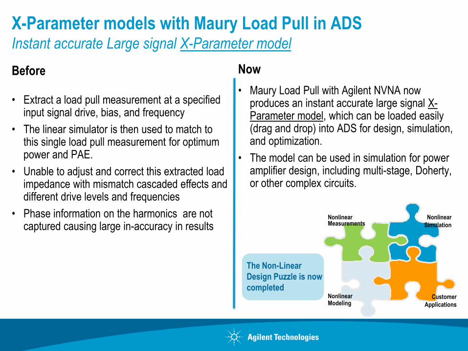
X-Parameter models with Maury Load Pull in ADSInstant accurate Large signal X-Parameter model
Before
• Extract a load pull measurement at a specified input signal drive, bias, and frequency
• The linear simulator is then used to match to this single load pull measurement for optimum power and PAE.
• Unable to adjust and correct this extracted load impedance with mismatch cascaded effects and different drive levels and frequencies
• Phase information on the harmonics are not captured causing large in-accuracy in results
Now
• Maury Load Pull with Agilent NVNA now produces an instant accurate large signal X-Parameter model, which can be loaded easily (drag and drop) into ADS for design, simulation, and optimization.
• The model can be used in simulation for power amplifier design, including multi-stage, Doherty, or other complex circuits.
The Non-Linear
Design Puzzle is now
completedNonlinear Modeling
Nonlinear Measurements
Customer
Applications
Nonlinear
Simulation

Non-Linear X-ParametersA Breakthrough Technology for Non-Linear Design
Agilent NVNA with Maury Load Pull produces an instant large signal
model, which can be loaded easily (drag and drop) into Agilent ADS for
circuit design and simulation. This process is a breakthrough for the
industry.
Script generates
X-parameters
model component
for Design and
Simulation in ADS
Tuners that covers all regions on the Smith Chart (all Impedances)
Cable /
connectors
Load Pull TunerSource Pull Tuner
ADS
NVNA
Measures X-Parameters

The NVNA with Automated Load Pull MeasurementUsing the Maury Load Pull System
Automated Load pull has become a standard tool for characterizing devices operating in other than ideal 50 ohm environments
What is Load Pull?
– Load Pull is “Measurement Vs Impedance”
– Impedances that are located all over the Smith Chart
– Not only 50 ohms
TUNERTUNER
source Load
Stimulus and
Measurement
DUT
Tuners used to vary the
impedance seen by the Device
Under Test (DUT)

Extract X-parameters model from Simulation
“Project View” of the demo

Extract X-parameters model from SimulationDemo # 1- Second stage of two Cascaded MMIC PA’s
Extract model with Pin=
-10 dBm to 5 dBm
Gain
27 dB
Pin
0 dBmPin
-27 dBm
Pout = 26 dBm
1 dB compressed
Gain
26 dB
Operational power setting for LTE Application
Demo #1

Demo 1: Extract X-par model Set-up

Demo 1: X-par model overlaid on PA Results

Conclusions from the demos
• Demo 1 shows the creation of mdf file X-par model with:
Swept Pin, freq, and DC power
Load and source pull – not in this demo but will be available in ADS2009 U1

Extract X-parameters model from SimulationDemo # 2- Compare X-par model, P2D model, and PA
Extract X-par model and P2D model
with Pin= -40 dBm to 10 dBm
Pin
-40 to 10 dBm
Pout = 26 dBm
1 dB compressed
Gain
26 dB

Demo 2: Results

Conclusions from the demos
• Demo 1 shows the creation of mdf file X-par model with:
Swept Pin, freq, and DC power
Load and source pull – not in this demo but will be available in ADS2009 U1
• Demo 2 compares X-par, P2D, and PA with 50 ohm loads:
Only at the fundamental freq and 50 ohm load, the P2D model matches very well with the X-
parameters model and with the PA.
o This confirms our past statement on the accuracy and usefulness of the P2D model.
X-parameters model contains magnitude and phase info on all of the harmonics, where P2D
is good only at the fundamental freq.
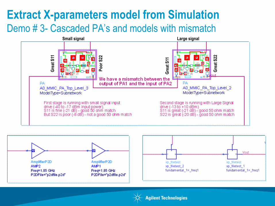
Extract X-parameters model from SimulationDemo # 3- Cascaded PA’s and models with mismatch
Gre
at S
11
Gre
at S
11
Gre
at S
22
Po
or
S22
Small signal Large signal

Demo 3: Results

Conclusions from the demos
• Demo 3
Unlike P2D model which is good only at 50 ohm impedances, X-par model works at all
source and load impedances (available in ADS2009U1 version)
P2D models will have accuracy problems when cascading modules with source and load
mismatch

Demo # 4: Cascaded PA’s and models with Isolator in between to
eliminate mismatch

Demo 4: Results