X-DF FAQ 27.08.2018 - Winterthur Gas & Diesel Ltd.€¦ · Low-pressure X-DF technology is based on...
11
Transcript of X-DF FAQ 27.08.2018 - Winterthur Gas & Diesel Ltd.€¦ · Low-pressure X-DF technology is based on...

2 3
Introduction
X-DF engines are designed to undercut present emission legislation being the most environmentally sustainable solution presently available with low cost, highly efficient and reliable low-pressure gas technology.
What is the running experience of X-DF engines in the field?The first X-DF engines entered commercial operations in 2016 (5RT-flex50DF on the Terntank vessel Ternsund). In mid 2017 the first LNGC powered by two 6X62DF set sail. Many more vessels have followed since reporting great satisfaction from owners and charterers.
The X-DF concept has proven to meet the requirements of merchant ship propulsion in a reliable, safe and economical way. The increasing order intake with multiple repeat orders is an indication of this reliability. For further, up-to-date details on the running experience of WinGD X-DF engines please visit our website at www.wingd.com/......
Contents1. Concept & performance .................................................................... 4
1.1. What are the concepts of low-pressure X-DF engines and high-pressure gas engines? ................................................................................ 4
1.2. What are the main benefits of low-pressure X-DF engines compared to high-pressure gas engines? ................................................................... 4
1.3. Fuel consumption comparison between LP and HP ..................................... 51.4. X-DF engines have reduced output compared to standard low-speed
diesel engines. What are the consequences? .............................................. 51.5. Why is less pilot fuel sufficient for X-DF engines when compared to
high-pressure gas engines? ....................................................................... 6
2. Engine operation .............................................................................. 72.1. How does the fuel change work: from gas to diesel and vice versa? ............ 72.2. Which engine power range is available in gas mode? .................................. 72.3. What is the difference in load acceptance between X-DF engines and
conventional low-speed diesel engine? ...................................................... 72.4. What is the difference in load fluctuation capability between X-DF
engines and conventional low-speed diesel engines? ................................ 82.5. Does gas quality in terms of lower heating value (LHV) have an
impact on low-pressure X-DF engines? ...................................................... 82.6. Does gas quality in terms of methane number (MN) have an impact
on X-DF engines? ........................................................................................ 82.7. What is Dynamic Combustion Control (DCC)? ............................................. 9
3. CAPEX (Capital Expenditure) ......................................................... 103.1. Why does The X-DF solution have lower CAPEX than the high-
pressure gas engine solution? .................................................................. 10
4. OPEX (Operating Expenditure) ........................................................ 124.1. Why does the X-DF solution have lower OPEX than the high-
pressure gas engine solution? .................................................................. 12
5. Engine safety .................................................................................. 145.1. What is knocking? And does it limit engine operation in any way? ............. 145.2. How does the X-DF engine detect and manage gas leakage in the
piston underside? ..................................................................................... 14
6. Emissions ....................................................................................... 166.1. How do X-DF engines comply with IMO Tier III
NOX emission limits in gas mode? ............................................................. 166.2. Are low-pressure X-DF engines also compliant with IMO Tier III
during manoeuvring, starting and stopping? ............................................ 176.3. How much methane is emitted through X-DF engines? ............................. 176.4. What are the consequences of methane emissions? ................................. 186.5. Green House Gases (GHG) emissions of X-DF engines .............................. 19
4 5
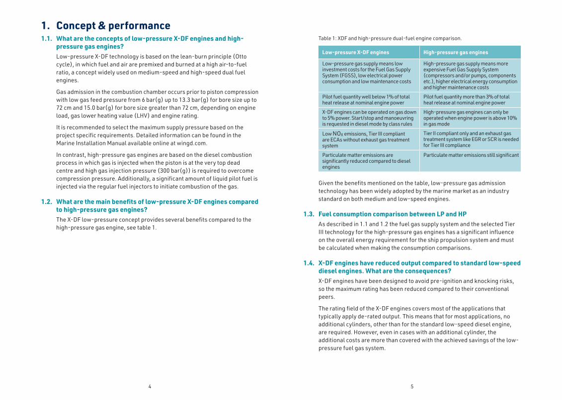
1. Concept & performance1.1. What are the concepts of low-pressure X-DF engines and high-
pressure gas engines?Low-pressure X-DF technology is based on the lean-burn principle (Otto cycle), in which fuel and air are premixed and burned at a high air-to-fuel ratio, a concept widely used on medium-speed and high-speed dual fuel engines.
Gas admission in the combustion chamber occurs prior to piston compression with low gas feed pressure from 6 bar(g) up to 13.3 bar(g) for bore size up to 72 cm and 15.0 bar(g) for bore size greater than 72 cm, depending on engine load, gas lower heating value (LHV) and engine rating.
It is recommended to select the maximum supply pressure based on the project specific requirements. Detailed information can be found in the Marine Installation Manual available online at wingd.com.
In contrast, high-pressure gas engines are based on the diesel combustion process in which gas is injected when the piston is at the very top dead centre and high gas injection pressure (300 bar(g)) is required to overcome compression pressure. Additionally, a significant amount of liquid pilot fuel is injected via the regular fuel injectors to initiate combustion of the gas.
1.2. What are the main benefits of low-pressure X-DF engines compared to high-pressure gas engines?The X-DF low-pressure concept provides several benefits compared to the high-pressure gas engine, see table 1.
Table 1: XDF and high-pressure dual-fuel engine comparison.
Low-pressure X-DF engines High-pressure gas engines
Low-pressure gas supply means low investment costs for the Fuel Gas Supply System (FGSS), low electrical power consumption and low maintenance costs
High-pressure gas supply means more expensive Fuel Gas Supply System (compressors and/or pumps, components etc.), higher electrical energy consumption and higher maintenance costs
Pilot fuel quantity well below 1% of total heat release at nominal engine power
Pilot fuel quantity more than 3% of total heat release at nominal engine power
X-DF engines can be operated on gas down to 5% power. Start/stop and manoeuvring is requested in diesel mode by class rules
High-pressure gas engines can only be operated when engine power is above 10% in gas mode
Low NOX emissions, Tier III compliant are ECAs without exhaust gas treatment system
Tier II compliant only and an exhaust gas treatment system like EGR or SCR is needed for Tier III compliance
Particulate matter emissions are significantly reduced compared to diesel engines
Particulate matter emissions still significant
Given the benefits mentioned on the table, low-pressure gas admission technology has been widely adopted by the marine market as an industry standard on both medium and low-speed engines.
1.3. Fuel consumption comparison between LP and HPAs described in 1.1 and 1.2 the fuel gas supply system and the selected Tier III technology for the high-pressure gas engines has a significant influence on the overall energy requirement for the ship propulsion system and must be calculated when making the consumption comparisons.
1.4. X-DF engines have reduced output compared to standard low-speed diesel engines. What are the consequences?X-DF engines have been designed to avoid pre-ignition and knocking risks, so the maximum rating has been reduced compared to their conventional peers.
The rating field of the X-DF engines covers most of the applications that typically apply de-rated output. This means that for most applications, no additional cylinders, other than for the standard low-speed diesel engine, are required. However, even in cases with an additional cylinder, the additional costs are more than covered with the achieved savings of the low-pressure fuel gas system.

6 7
1.5. Why is less pilot fuel sufficient for X-DF engines when compared to high-pressure gas engines?X-DF engines require significantly less pilot fuel compared to high-pressure gas engines:
Table 2: Specific pilot-fuel consumption comparison between X-DF and high-pressure gas engine (based on an engine bore range of about 70 cm)
X-DF engine High-pressure gas engine
Pilot fuel consumption [g/kWh]
0.8 g/kWh @ 100 % power1.8 g/kWh @ 30 % power
5 g/kWh @ 100 % power11 g/kWh @ 30 % power
The difference in the amount of pilot fuel consumption between X-DF engines and high-pressure gas engines is due to the different working principles, i.e. the Otto process of low-pressure gas engines versus the Diesel process of high-pressure gas engines as described in 1.1.
2. Engine operation2.1. How does the fuel change work: from gas to diesel and vice versa?
When an X-DF engine runs in gas mode, a trip to diesel mode is available on request at any engine power; it is instantaneous and without any loss of engine power or speed. The trip to diesel mode happens automatically if required by the engine control or safety system.
When an X-DF engine runs in diesel mode, transfer to gas mode is available upon request, at engine power in the range of 10 % to 80 % without any loss of power or speed. (see Figure 1).
Figure 1: Changeover procedure between different fuels: Gas, MDO and HFO.
During the changeover procedure from gas to diesel, the cylinder lubricating oil does not need to be changed and can remain on low-BN (base number) oil as specified for X-DF engines. In case higher sulphur liquid fuels are used in diesel or fuel sharing mode, the ‘integrated Automatic Cylinder-oil Transfer’ (iCAT) system will change the lubricating oil to high-BN automatically.
2.2. Which engine power range is available in gas mode?While the engine is operating in gas mode, the engine power can be varied in the range of 5% to 100%, independently if driving a fixed pitch (FPP) or a controllable pitch propeller (CPP). This means from “Dead Slow” up to “Full Speed”. For “starting/stopping “and “manoeuvring mode/reversing” when driving a FPP the class rules require the engine running in diesel mode only.
2.3. What is the difference in load acceptance between X-DF engines and conventional low-speed diesel engine?The load acceptance capability of X-DF engines is similar to that of conventional low-speed diesel engines.
GAS MDO HFO
80 %
Liquid to gas
~1.5h~0.02h
GAS MDO HFO
100 %
Gas to liquid fuel
~1.0h~0.02h

8 9
2.4. What is the difference in load fluctuation capability between X-DF engines and conventional low-speed diesel engines?The load fluctuation capability of X-DF engines is similar to that of conventional low-speed diesel engines.
The operational experience of vessels in service has shown that load fluctuations caused by heavy sea conditions are within the design limits and consequently no changeover to diesel mode is required.
2.5. Does gas quality in terms of lower heating value (LHV) have an impact on low-pressure X-DF engines?The lower heating value (LHV) has no impact on engine performance and output in the range of 28 MJ/Nm3 to 36 MJ/Nm3 (volumetric LHV).
For a LHV below 28 MJ/Nm3, the gas contains an extremely high amount of nitrogen and consequently, the energy supply to the engine will not be sufficient to reach 100 % engine power output. In such case only a lower output would be available in gas mode. This is valid for both low and high-pressure dual-fuel engines.
2.6. Does gas quality in terms of methane number (MN) have an impact on X-DF engines?The engines can operate on Methane Number (MN) as low as 65 with full power output which represents an MN lower than the globally available LNG for bunkering. Accordingly, in practice, there is no impact of MN to the operation of the engine.
Also in tropical conditions, full power output is available with MN≥65 due to the automatic activation of the Dynamic Combustion Control (DCC).
DCC allows full engine power output independent of ambient conditions and engine ratings.
2.7. What is Dynamic Combustion Control (DCC)?WinGD has introduced Dynamic Combustion Control (DCC) to ensure efficient gas combustion and full power output under any operating conditions. The engine remains IMO Tier III compliant even with maximum DCC share amounts.
DCC is a specific engine control feature that maintains the firing pressure at an efficient and safe level. It is automatically activated by an algorithm that continuously monitors cylinder pressures. At high engine power, warm and humid ambient conditions and/or low Methane Number, the cylinder pressure could exceed the normal operation range. In this case a small quantity of diesel (between 3% and 15 % of energy input) is injected by the main fuel injectors which helps to rectify the air-fuel gas ratio (lambda) by reducing the gas amount as well as by increasing the air supply from the turbocharger.
The brake specific energy consumption (BSEC) of the engine remains the same with DCC active. The gas consumption decreases at the same rate as the liquid fuel consumption increases.
DCC is included in the engine control system software of all X-DF engines and is IMO Tier III certified.

10 11
3. CAPEX (Capital Expenditure)3.1. Why does The X-DF solution have lower CAPEX than the high-
pressure gas engine solution?Though the prices of the engines are similar, the cost of the fuel gas supply system (FGSS), such as compressors, pumps, evaporators, heat exchangers, piping system, sensors, valves, etc. is significantly lower for an X-DF engine than for a high-pressure gas engine installation. Further, the X-DF solution is Tier III compliant without any after treatment which is needed for a Tier III compliant high-pressure gas engine solution.
Figure 3: CAPEX comparison between X-DF engines and high-pressure gas engines for a 55,000 dwt tanker with a 50 cm-bore size engine
0 mUSD
5 mUSD
10 mUSD
15 mUSD
0%
20%
40%
60%
80%
100%
120%
Alt. 1 6X52DF Alt. 2 6G50ME-GI
Indica�ve investment costs
Gas system
LNG tank(s)
EGR
Gen-sets
Main engine
Figure 2: CAPEX comparison between X-DF engine and high-pressure gas engine for a 180,000 m3 LNGC.
0 mUSD
10 mUSD
20 mUSD
30 mUSD
0%
20%
40%
60%
80%
100%
120%
140%
160%
Alt. 1 2 x 5X72DF Alt. 2 2x5G70ME-C9.5-GI
Indicative investment costs
Gas system
EGR
Gen-sets
Main engines

12 13
4. OPEX (Operating Expenditure)OPEX consists of consumables and maintenance costs.
4.1. Why does the X-DF solution have lower OPEX than the high-pressure gas engine solution?
ConsumablesThe liquid pilot fuel consumption of X-DF engines is lower than that of a high-pressure gas engine. This means that more energy is supplied to the engine via the fuel gas compared to a high-pressure engine.
The OPEX comparison between a low-pressure X-DF propulsion solution and a high-pressure gas engine propulsion solution requires a detailed analysis taking the following aspects into consideration:
• Main engine consumption
• The ship’s operational profile
• Energy consumption of the fuel gas supply system (compressors, pumps, etc.)
• Additional generator engine load (parasitic load)
• Running hours in ECA areas (Tier III mode)
• Fuel penalty for Tier III mode (high-pressure gas engines only)
• Costs of LNG, MDO, MGO, HFO, NaOH or UREA
A low-pressure X-DF engine propulsion solution has similar accumulated daily consumable costs as a high-pressure gas engine propulsion solution even though the gas consumption is higher.
When operating in Tier III areas, the low-pressure X-DF propulsion solution results in lower consumable costs than the high-pressure gas engine solution as no exhaust gas treatment is needed for compliance. X-DF always features ultra-low NOX and particulate emissions without generating any extra costs. The X-DF has no increased consumption, unlike high-pressure gas engines which require EGR/SCR, increasing the energy consumption on the engine significantly and requiring additional consumables.
The energy consumed by the gas supply system (such as the compressors and/or pumps) is less for a system operated at low pressure.
MaintenanceFuel gas supply system related components are designed for low-pressure only (e.g. pipe class PN16 or similar is selected). This reduces the spare part costs and allows simple and safe maintenance procedures. The crew can safely and independently perform most maintenance tasks during normal port stays. A simple gas system pressure test takes only a few minutes compared to hours on a high-pressure supply system.

14 15
5. Engine safety5.1. What is knocking? And does it limit engine operation in any way?
Knocking is when spontaneous ignition of the last part of the air-gas mixture (end-gas) which has not yet been consumed by the flame, causes an extremely rapid release of energy.
Such instant combustion leads to pressure waves propagating through the combustion chamber. These pressure waves can cause the combustion chamber to resonate at its natural frequency, resulting in a typical audible noise known as “knock”.
In contrast to medium and high-speed Otto-cycle engines, the X-DF engine’s operation and performance are not affected or limited by knocking. Operating the engine with a very lean gas mixture (high air-gas ratio/lambda) and its inherent low revolution speed is the key for the knocking resistance. The limiting factor for X-DF is early combustion and the resulting maximum cylinder pressure, which is controlled with DCC.
The control system of the X-DF engine detects any abnormal combustion and takes corrective actions if required. No operator interference is needed.
5.2. How does the X-DF engine detect and manage gas leakage in the piston underside?X-DF engines have various engine control and safety functions designed to detect gas leakage and to control abnormal engine behaviour.
Leakage of gas in the piston underside could be due to a leaking gas admission valve and/or blow-by gas from broken piston rings. Both cases are monitored and detected by the engine control system:
Severe gas admission valve leakage results in high firing pressure or even knocking and will be detected by the combustion monitoring system (through cylinder pressure sensors or by the knocking sensor).
Small gas admission valve leakage results in a concentration of gas in the piston underside space, which is detected by the gas concentration sensor.
The position of the gas admission valve spindle is constantly monitored by the engine control system for malfunction by proximity sensors.
Severe blow-by of gas from broken piston rings is monitored by the above mentioned systems.
The gas piping in the engine room and on the engine are constantly monitored to detect leakages. The gas piping is double walled and the annular space is constantly ventilated. A gas concentration sensor detects any possible gas leakage and activates an alarm that trips the engine to diesel mode (see Figure 5 and 6).
Cyl
ind
er p
ress
ure
[bar
]
Cyl
ind
er p
ress
ure
[bar
]
Kn
ock
sen
sor s
ign
al
Kn
ock
sen
sor s
ign
al
Cylinder pressure Knock sensor signal
0
20
40
60
80
100
120
140
160
180
Crank angle Crank angle
Figure 4: Cylinder pressure and knocking sensor signal for normal gas operation and for knocking condition (as seen under specially applied testing settings).
Figure 5: Installation concept of gas safe engine room, for engines with external GVU (Gas Valve Unit).
Engine
Gas supply/pressure release
Air suction/release
Gas pipe
Annular space
Inert gas supply/release
Vent
F
Exhaust side
Ventvalve
Ventvalve
Fuel side
Shut-offvalve
Shut-offvalve
Vent valve
Pressureregulating
valve
Inert valve
Shut-off valve
Extraction fan
Flowmeter
Gasfilter
Vent valve
N � supply
Inert valve
Gas detector
Vent
Airsuction
Gassupply
Manualshut-off valve
Mastershut-off valve
N � supply
Adjustableori�ce
Gas/Inertgas
release
Engine room ventilation
Engine room ventilation fan Vent
Dry airsupply
Engine room
1 n
Flanges engine side
Flanges system side

16 17
GVU
Forced engine room ventilationEngine room: gas safe area
GVU enclosure
Annular pipe / GVU enclosure venting
Piston underside gas detectionGas detector
Gas venting pipe
Double-wall fuel gas pipe
GVU venting pipe
from fuel gas
Figure 6: Installation concept of gas safe engine room, for engines with iGPR (integrated Gas Pressure Regulation).
6. Emissions6.1. How do X-DF engines comply with IMO Tier III
NOX emission limits in gas mode?In gas mode, low-pressure dual-fuel engines operate according to the Otto cycle, i.e. the fuel-gas and air are homogeneously pre-mixed in the combustion chamber before ignition.
Together with the high amounts of air, this results in a lean homogeneous combustion with an equal temperature distribution throughout the entire combustion chamber. This contrasts with engines that operate on the Diesel cycle where gas or liquid fuel is injected into the combustion chamber after compression. In this case, the combustion of the flame is very rich, leading to local hotspots in which the nitrogen and oxygen content of the air react with each other, forming NOX.
X-DF engines avoid such hotspots and NOX emissions are significantly reduced, down to merely one third of the set IMO Tier III limit.
X-DF engines require no further NOX reduction systems, such as Exhaust Gas Recirculation (EGR) or Selective Catalytic Reduction (SCR) which are applied to Diesel cycle engines.
6.2. Are low-pressure X-DF engines also compliant with IMO Tier III during manoeuvring, starting and stopping?Yes. X-DF engines comply with IMO Tier III during manoeuvring, when starting and stopping.
For safety reasons the IGF code and IACS rules require that engine starting, stopping and reversing for manoeuvring have to be carried out in diesel operating mode.
This procedure does not violate the IMO Tier III rules since it is defined as part of the Auxiliary Control Devices (ACD) as described in the “IMO Guidance on the application of Regulation 13 of MARPOL Annex VI Tier III requirements to dual-fuel and gas-fuelled engines”.
The ACDs are function or control strategies installed on dual-fuel engines.
6.3. How much methane is emitted through X-DF engines?Every combustion engine has unburned hydro carbon emissions regardless of the process and the size of the engine. Eventually unburned Methane (CH4) forms part of the Total Hydrocarbon (THC) emissions from combustion engines.
The weighted average measurement of THC Emission for an X-DF engine is very low at 2 g/kWh to 3 g/kWh (based on bore range 72 cm to 50 cm) making it the best in its class. A larger engine size results in lower Total Hydrocarbon emissions. Of the total THC emissions indicated, Methane (CH4) is typically measured at 80%. Methane emissions* from X-DF engines can therefore be calculated to be between 1.6 g/kWh and 2.4 g/kWh.
Low-pressure X-DF engines have a benchmark low methane emissions compared to four-stroke medium- and high-speed dual-fuel engines. This low methane emission level is inherent to low-speed two-stroke engine physics and is achieved by optimising the engine’s internal combustion process as well as the combustion chamber design.
For ocean going vessels, no limitations of methane emissions are defined by IMO or any other legal body worldwide. The unburned methane is a loss of gas fuel and is included in the brake specific gas consumption figures in WinGD documentation. Measures to further reduce the methane emissions of X-DF engines are under development.
*Methane emissions or CHF emissions, in common speech, is sometimes referred to as ‘methane slip’

18 19
With the low methane emissions of X-DF engines, the total greenhouse gas balance is positive compared to conventional diesel engines. All emissions that are directly harmful to health and the environment, such as SOX, NOX and particulate matter need to be considered when comparing technologies (see Figure 8). Propulsion systems with X-DF engines are the most environmentally sustainable solutions using fossil fuels. Only use of non-fossil fuels (bio-fuels, synthetic fuels) or wind and solar power will further reduce the greenhouse gas emissions of a vessel propulsion system.
Figure 7: Example of emissions, including CO2 equivalent for THC emissions (methane emissions), based on GWP100=28.
6.4. What are the consequences of methane emissions?Methane, like CO2, is a greenhouse gas that contributes to global warming.
Methane lost to the atmosphere during exploration, transportation or during the combustion process has a more severe global warming impact than CO2, comparing gram to gram. Proper gas exploration, transportation and handling is important to achieve a positive greenhouse gas balance.
In short term, methane has a higher impact on global warming, but because it does not remain in the atmosphere, the impact is reduced over time. Its global warming potential is typically comparable to that of CO2, based on a 100-year or a 20-year basis. In the IPCC/ Kyoto Protocol it is recommended to consider the 100-year period for measuring long-term impact on climate change as the long term global warming is the key focus. The values for calculating the CO2 equivalent have changed over the years, based on more recent research results. The latest values are provided by the IPCC report from 2014. As it is very difficult to consider the right equivalency factor, two different values are provided, based on different calculation methods. One includes additionally assumed “climate-carbon feedbacks” (cc fb) for non-CO2 gases, considering higher additional indirect warming effects (GWP100=34), while the other does not (GWP100=28). IPCC AR5 suggests to use factors without climate-carbon-feedback due to the large uncertainty of the models. Accordingly, the most commonly used conversion factor is 28.
0
1
2
3
4
5
6
7
8
9
10
25 50 75 100
CH4,
spec
ific
[g/k
Wh]
Engine Power [%]
CH4 emissions, gas mode
RT-flex50DF X62DF X72DF
typical lean-burn 4-stroke DF
Figure 8: 3.5% S content is considered for HFO and 0.5% for MDO, X-DF pilot fuel is MDO, ME-GI pilot fuel is HFO
6.5. Green House Gases (GHG) emissions of X-DF enginesWhen comparing the GHG performance of X-DF engines running on LNG with propulsion systems running on residual fuels two factors must be considered: LNG emits 30% less carbon dioxide CO2 during combustion, however methane CH4 is a significant GHG.
Despite that, the total GHG balance is still a reduction of 15-20%, a clear improvement over conventional diesel engines. WinGD’s R&D department continues to be heavily invested in innovative technologies to reduce all emissions and towards a carbon-neutral future for merchant shipping.
LP-DF / Gas HP-DF / Gas Diesel / HFO
0
20
40
60
80
100
NOX
SOX
PM
Emis
sion
val
ues [
%]
CO2 & CO2 equivalent

WinGD® is a registered trademark.
© Copyright, 2018 Winterthur Gas & Diesel Ltd.
www.wingd.com
Winterthur Gas & Diesel Ltd. (WinGD) is a leading developer of two-stroke low-speed gas and diesel engines used for propulsion power in merchant shipping.
WinGD sets the industry standard for reliability, efficiency and environmental sustainability. WinGD provides designs, training and technical support to engine manufacturers, shipbuilders and ship operators worldwide.
WinGD is headquartered in Winterthur, Switzerland, where, as one of the earliest developers of diesel technology, it started the design of large internal combustion engines in 1893 under the “Sulzer” name.