WST Stopper Cylinder - Parker ORIGA U.S.A. · WST Stopper Cylinder Page 27 Cylinder Sizing Pressure...
12
WST Stopper Cylinder Page 25 Specifications Series WST Ø50mm & 80mm Features Media Clean dry compressed air Operating Pressure Range 22 to 102 psi (1.5 to 7 Bar) Max* Pressure 145 psi (10 Bar) Operating Temperature Range 32 to 140°F (0 to 60°C) Operating Speed Range mm/s 50-500 Cushion Urethane Bumper Connecting Port G1/8" (BSP) Lubrication Sealed, lubricated for life Shock Absorber WSAB2012-R WSAB3625-C Mounting Type Flange Plate Stroke Tolerance 0-1.5mm Bore Size and Stroke Length Model Bore Size Stroke WSTV(S) 50, 80 30 WSTSV(S) 50, 80 30 WSTH(S) 50 50 How to adjust the shock absorber The shock absorber is set to maximum damping upon delivery. When in operation, adjust the damping of the shock absorber by adjusting the control collar. For the vertical model, it’s shown above. For the horizontal model, by the graduated collar. Gradually reduce the damping level until the load comes to rest in the correct position, without any shock deceleration of the load. If the load forces the damper to its fully retracted position too rapidly (normally apparent due to a sudden deceleration at the end of stroke), then this may lead to mechanical damage of the unit. In this case, increase the damping to remove the shock deceleration. Periodically regulate the damping of each unit to maintain the shock absorber energy higher than the apparent load energy. *The units are not designed to operate at this pressure. Exceeding the operating pressure range may cause damage to reduce the life of the unit. Shock absorber replacement If correctly set, the shock absorber will operate trouble free. Vertical type Unfasten the head using a spanner while holding the cylinder rod in place. Replace the shock absorber on the piston rod. Refasten the head and readjust the shock absorber. Horizontal type Loosen and remove the locking collar. Remove the shock absorber and replace it. Precautions 1. Please note that if the impact energy exceeds the shock absorber energy that is currently set then the cylinder and frame will absorb the excess energy. 2. Keep all moving parts free from scratches or defects, as they may lead to defective operation. 3. The unit must be securely fastened to a fixed surface, to pre- vent free rotation. Any rotation may lead to incorrect operation or damage. 4. Please keep clear of all moving parts during operation. 5. The sensors are secured by a thread fixing with the mounting slots along the side of the cylinder. To reposition a sensor: Loosen the threaded fastener. Slide the sensor along the groove to its new position. Tighten the threaded fastener locking the sensor in place.
Transcript of WST Stopper Cylinder - Parker ORIGA U.S.A. · WST Stopper Cylinder Page 27 Cylinder Sizing Pressure...

WST Stopper Cylinder
Page 25
Specifications
Series WSTØ50mm & 80mm
FeaturesMedia Clean dry compressed airOperating Pressure Range 22 to 102 psi (1.5 to 7 Bar)Max* Pressure 145 psi (10 Bar)Operating Temperature Range 32 to 140°F (0 to 60°C) Operating Speed Range mm/s 50-500Cushion Urethane BumperConnecting Port G1/8" (BSP)Lubrication Sealed, lubricated for lifeShock Absorber WSAB2012-R WSAB3625-CMounting Type Flange PlateStroke Tolerance 0-1.5mmBore Size and Stroke LengthModel Bore Size StrokeWSTV(S) 50, 80 30WSTSV(S) 50, 80 30WSTH(S) 50 50
How to adjust the shock absorberThe shock absorber is set to maximum damping upon delivery. When in operation, adjustthe damping of the shock absorber by adjusting the control collar. For the vertical model,it’s shown above. For the horizontal model, by the graduated collar.Gradually reduce the damping level until the load comes to rest in the correct position, without any shock deceleration of the load.If the load forces the damper to its fully retracted position too rapidly (normally apparentdue to a sudden deceleration at the end of stroke), then this may lead to mechanical damage of the unit. In this case, increase the damping to remove the shock deceleration.Periodically regulate the damping of each unit to maintain the shock absorber energy higher than the apparent load energy.
*The units are not designed to operate at this pressure. Exceeding the operating pressure range maycause damage to reduce the life of the unit.
Shock absorber replacementIf correctly set, the shock absorber will operate trouble free.Vertical typeUnfasten the head using a spanner while holding the cylinder rod in place.Replace the shock absorber on the piston rod.Refasten the head and readjust the shock absorber.Horizontal typeLoosen and remove the locking collar. Remove the shockabsorber and replace it.
Precautions1. Please note that if the impact energy exceeds the shock
absorber energy that is currently set then the cylinder andframe will absorb the excess energy.
2. Keep all moving parts free from scratches or defects, as theymay lead to defective operation.
3. The unit must be securely fastened to a fixed surface, to pre-vent free rotation. Any rotation may lead to incorrect operationor damage.
4. Please keep clear of all moving parts during operation.5. The sensors are secured by a thread fixing with the mounting
slots along the side of the cylinder.To reposition a sensor:
Loosen the threaded fastener.Slide the sensor along the groove to its new position.Tighten the threaded fastener locking the sensor in place.

W S T V S 5 0 X 3 0 P N
WST Stopper Cylinder
Page 26
Roller Option*:
Pallet Option*:P – Pallet passS – Pallet stopPS – Pallet pass & stop
Version:
Stopper Cylinder:
V – Vertical, Double ActingSV – Vertical, Single ActingH – Horizontal, Double Acting
— – No magnetS – Magnets
Bore & Stroke:V & SV – 50X30
80X30
H – 50X50
N – NylonM – Metal
Ordering Information
Proximity Sensors
*Not available on horizontal type
Order # Description
WE102A/B Reed Type, 2 wire cable, DC10-28V, AC85-115VWE155A/B Reed Type, 3 wire cable, LED, DC4.5V-28VWS3HA/B Reed Type, 2 wire cable, LED, DC10-30V (10-50mA), AC85-115V (10-50nA)WS4HA/B Reed Type, 2 wire cable, LED, DC10-30V (5-25mA), AC85-115V (5-20nA)WS9HA/B Reed Type, 3 wire cable, LED, DC4.5-28V (10-50mA)
WST Stopper Cylinder
Page 27
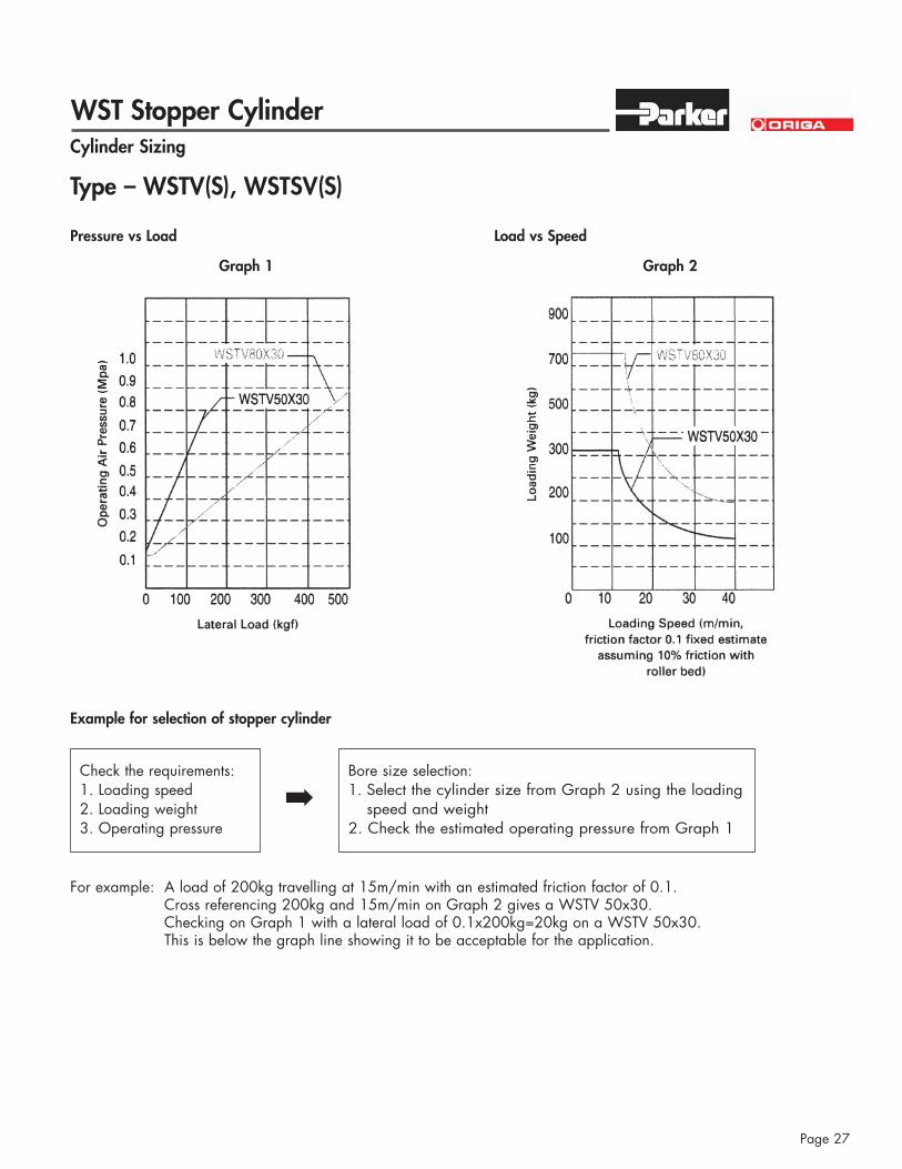
Cylinder Sizing
Pressure vs Load
Graph 1
Load vs Speed
Graph 2
Example for selection of stopper cylinder
Check the requirements:1. Loading speed2. Loading weight3. Operating pressure
Bore size selection:1. Select the cylinder size from Graph 2 using the loading
speed and weight2. Check the estimated operating pressure from Graph 1
!
For example: A load of 200kg travelling at 15m/min with an estimated friction factor of 0.1.Cross referencing 200kg and 15m/min on Graph 2 gives a WSTV 50x30.Checking on Graph 1 with a lateral load of 0.1x200kg=20kg on a WSTV 50x30. This is below the graph line showing it to be acceptable for the application.
Type – WSTV(S), WSTSV(S)
WST Stopper Cylinder
Page 28
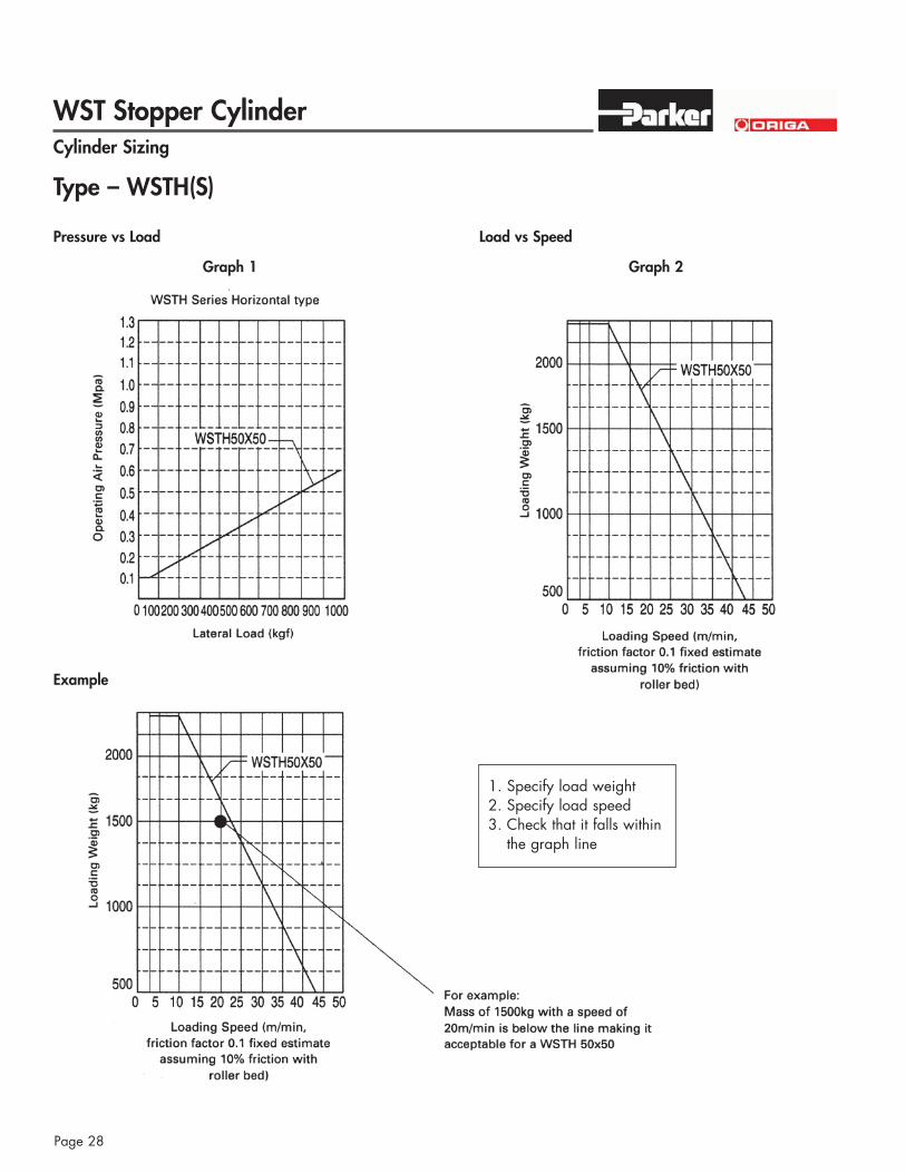
Cylinder Sizing
Pressure vs Load
Graph 1
Example
Load vs Speed
Graph 2
Type – WSTH(S)
1. Specify load weight2. Specify load speed3. Check that it falls within
the graph line

AZ Cylinder
Page 29
FeaturesType ISO 6431
VDMA 24562CETOP RP43P
Series AZConfigurations AZ Double Acting, Single Rod,
Magnetic Piston, CushionsAZD Double Acting, Double Rod,
Magnetic PistonConstruction MaterialsBarrel Extruded Aluminum, Anodized (10µ)End Caps Die Cast AluminumPiston Rod Stainless SteelRod Bearing Teflon Impregnated BronzePiston Molded NBR, (Optional: Viton)Cushions Needle BrassSeals Urethane, (Optional: Viton)End Cap Screws Steel, zinc platedCharacteristicsOperating Temperature Min: -5° F (-20°C)
Max: +176 °F (+80°C)Operating Pressure Min: 15 PSI (1 bar)
Max: 145 PSI (10 bar)Normal Operating Pressure 90 PSI (6 bar)Lubrication Pre-lubricated at factory. If additional lubrication
is required use oil compatible for NBR seal and designed for use in pneumatic systems.
Media Filtered and regulated compressed airInstallation In any positionWeight See chart with mountsStroke Length Up to 500mm - Longer contact factoryTheoretical Forces See Technical Information SheetLoad Capacity See Technical Information SheetSpecificationsPiston Diameter 32 40 50 63 80 100
Port Sizes Metric (G) G1/8 G1/4 G1/4 G3/8 G3/8 G1/2
Rod Diameter mm 12 16 20 20 25 25Cushion LengthsAll Cylinders mm 21 25 28 30 30 37
Specifications
Series AZØ32mm - 100mm
ISO 6431VDMA 24562CETOP RP43P
AZ 5: Double Acting, Single Rod,Magnets, Cushions
AZD 6: Double Acting, Double Rod,Magnets
Features:
Stainless Steel RodMagnetic PistonAdjustable CushionsPre-Lubricated DesignCaptive Cushion Needles
AZ Cylinder
Page 30
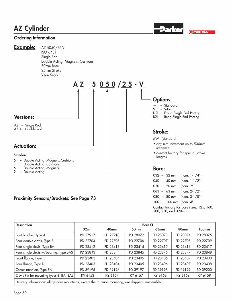
Bore:
A Z 5 0 5 0 / 2 5 - V
Options:
Stroke:
Versions:
Actuation:
032 – 32 mm (nom. 1-1/4")040 – 40 mm (nom. 1-1/2")050 – 50 mm (nom. 2")063 – 63 mm (nom. 2-1/2")080 – 80 mm (nom. 3-1/8")100 – 100 mm (nom. 4")Contact factory for bore sizes: 125, 160,200, 250, and 320mm.
Standard5 – Double Acting, Magnets, Cushions1 – Double Acting, Cushions 6 – Double Acting, Magnets2 – Double Acting
— – StandardV – VitonD2L – Front, Single End PortingB2L – Rear, Single End Porting
MM: (standard)• any mm increment up to 500mm
standard• contact factory for special stroke
lengths
Example: AZ 5050/25-VISO 6431Single RodDouble Acting, Magnets, Cushions50mm Bore25mm StrokeViton Seals
Ordering Information
AZ – Single Rod AZD – Double Rod
Description Bore Ø32mm 40mm 50mm 63mm 80mm 100mm
Foot bracket, Type A PD 27917 PD 27918 PD 28072 PD 28073 PD 28074 PD 28075
Rear double clevis, Type B PD 22704 PD 22705 PD 22706 PD 22707 PD 22708 PD 22709
Rear single clevis, Type BA PD 23412 PD 23413 PD 23414 PD 23415 PD 23416 PD 23417
Rear single clevis w/bearing, Type BAS PD 23843 PD 23844 PD 23845 PD 23846 PD 23847 PD 23848
Front flange, Type C PD 23403 PD 23404 PD 23405 PD 23406 PD 23407 PD 23408
Rear flange, Type D PD 23403 PD 23404 PD 23405 PD 23406 PD 23407 PD 23408
Center trunnion, Type EN PD 39195 PD 39196 PD 39197 PD 39198 PD 39199 PD 39200
Clevis Pin for mounting types B, BA, BAS KY 6153 KY 6154 KY 6157 KY 6156 KY 6158 KY 6159
Delivery information: all cylinder mountings, except the trunnion mounting, are shipped unassembled
Proximity Sensors/Brackets: See Page 73
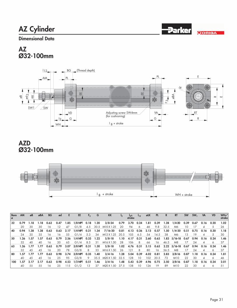
AZ Cylinder
Page 31
Dimensional Data
AZØ32-100mm
VD
Gl2
WH
SW
AM
l12 BG
EE EE
øBA
PL
VA
G
SW1
KKøB
RT
R
E
R Eød2
F 3
LK -
PL
l 8 + stroke
Adjusting screw SW4mm(for cushioning)
(Thread depth)
AZDØ32-100mm
l 8 + stroke WH + stroke
Bore AM øB øBA BG ød E EE F3 G KK l2 l8+ l12 øLK PL R RT SW SW1 VA VD WH+*ø stroke stroke
32 0.79 1.18 1.18 0.63 0.47 1.85 1/8 NPT 0.18 1.20 3/8-24 0.79 3.70 0.24 1.81 0.39 1.28 1/4-20 0.39 0.67 0.16 0.20 1.0220 30 30 16 12 47 G1/8 4.5 30.5 M10 X 1.25 20 94 6 46 9.8 32.5 M6 10 17 4 5 26
40 0.94 1.38 1.38 0.63 0.63 2.17 1/4 NPT 0.21 1.34 7/16-20 0.81 4.13 0.26 2.13 0.57 1.50 1/4-20 0.51 0.75 0.16 0.30 1.1824 35 35 16 16 55 G1/4 5.3 34 M12 X 1.25 20.5 105 6.5 54 14.5 38 M6 13 19 4 5 30
50 1.26 1.57 1.57 0.63 0.79 2.56 1/4 NPT 0.33 1.22 5/8-18 1.10 4.17 0.31 2.60 0.63 1.83 5/16-18 0.67 0.94 0.16 0.24 1.4632 40 40 16 20 65 G1/4 8.5 31 M16 X 1.50 28 106 8 66 16 46.5 M8 17 24 4 6 37
63 1.26 1.77 1.77 0.63 0.79 3.07 3/8 NPT 0.31 1.30 5/8-18 1.02 4.76 0.31 3.15 0.63 2.22 5/16-18 0.67 0.94 0.16 0.24 1.4632 45 45 16 20 78 G3/8 8 33 M16 X 1.50 26 121 8 80 16 56.5 M8 17 24 4 6 37
80 1.57 1.77 1.77 0.63 0.98 3.74 3/8 NPT 0.35 1.40 3/4-16 1.28 5.04 0.39 4.02 0.81 2.83 3/8-16 0.87 1.18 0.16 0.24 1.8140 45 45 16 25 95 G3/8 9 35.5 M20 X 1.50 32.5 128 10 102 20.5 72 M10 22 30 4 6 46
100 1.57 2.17 2.17 0.63 0.98 4.53 1/2 NPT 0.51 1.46 3/4-16 1.48 5.43 0.39 4.96 0.75 3.50 3/8-16 0.87 1.18 0.16 0.24 2.0140 55 55 16 25 115 G1/2 13 37 M20 X 1.50 37.5 138 10 126 19 89 M10 22 30 4 6 51
AZ Cylinder
Page 32
AB AU
AO
TR
E
A
G1
AT
XA + stroke
SA + stroke
S1
S2
D2H8
R
H
H
H4
H6
H3 + stroke
EW
CD
MR
H
H8
L
FL
a!
XD + stroke
S1
D2H7
R
H
H
H4
H6
H3 + stroke
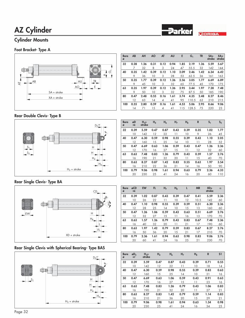
Cylinder Mounts
Foot Bracket- Type A
Rear Double Clevis- Type B
Rear Single Clevis- Type BA
Rear Single Clevis with Spherical Bearing- Type BAS
Bore øD H3+ H4 H6 H7 H8 R S1 S2ø H8 stroke
32 0.39 5.59 0.47 0.87 0.43 0.39 0.35 1.02 1.7710 142 12 22 11 10 9 26 45
40 0.47 6.30 0.59 0.98 0.55 0.39 0.43 1.10 2.0512 160 15 25 14 10 11 28 52
50 0.47 6.69 0.63 1.06 0.59 0.43 0.47 1.26 2.3612 170 16 27 15 11 12 32 60
63 0.63 7.48 0.83 1.26 0.79 0.43 0.59 1.57 2.7616 190 21 32 20 11 15 40 70
80 0.63 8.27 0.87 1.42 0.83 0.55 0.63 1.97 3.5416 210 22 36 21 14 16 50 90
100 0.79 9.06 0.98 1.61 0.94 0.63 0.79 2.36 4.3320 230 25 41 24 16 20 60 110
Bore øCD EW FL H7 H8 L MR XD+ "ø H8 stroke
32 0.39 1.02 0.87 0.43 0.39 0.47 0.41 5.59 2.3610 26 22 11 10 12 10.5 142 60
40 0.47 1.10 0.98 0.55 0.39 0.59 0.51 6.30 2.3612 28 25 14 10 15 13 160 60
50 0.47 1.26 1.06 0.59 0.43 0.63 0.51 6.69 2.7612 32 27 15 11 16 13 170 70
63 0.63 1.57 1.26 0.79 0.43 0.83 0.67 7.48 2.3616 40 32 20 11 21 17 190 60
80 0.63 1.97 1.42 0.79 0.59 0.83 0.67 8.27 2.7616 50 36 20 15 21 17 210 70
100 0.79 2.36 1.61 0.94 0.63 0.98 0.83 9.06 2.7620 60 41 24 16 25 21 230 70
Bore øD2 H3+ H4 H6 H7 H8 R S1ø H7 stroke
32 0.39 5.59 0.47 0.87 0.43 0.39 0.71 0.5510 142 12 22 11 10 18 14
40 0.47 6.30 0.59 0.98 0.55 0.39 0.83 0.6312 160 15 25 14 10 21 16
50 0.47 6.69 0.63 1.06 0.59 0.43 0.91 0.6312 170 16 27 15 11 23 16
63 0.63 7.48 0.83 1.26 0.79 0.43 1.06 0.8316 190 21 32 20 11 27 21
80 0.63 8.27 0.83 1.42 0.79 0.59 1.14 0.8316 210 21 36 20 15 29 21
100 0.79 9.06 0.98 1.61 0.94 0.63 1.34 0.9820 230 25 41 24 16 34 25
Bore AB AH AO AT AU E G1 TR SA+ XA+ø stroke stroke
32 0.28 1.26 0.31 0.12 0.94 1.85 2.19 1.26 5.59 5.677 32 8 3 24 47 55.5 32 142 144
40 0.35 1.42 0.39 0.12 1.10 2.09 2.46 1.42 6.34 6.429 36 10 3 28 53 62.5 36 161 163
50 0.35 1.77 0.39 0.12 1.26 2.56 3.05 1.77 6.69 6.899 45 10 3 32 65 77.5 45 170 175
63 0.35 1.97 0.39 0.12 1.26 2.95 3.44 1.97 7.28 7.489 50 10 3 32 75 87.5 50 185 190
80 0.47 2.48 0.55 0.16 1.61 3.74 4.35 2.48 8.27 8.4612 63 14 4 41 95 110.5 63 210 215
100 0.55 2.80 0.59 0.16 1.61 4.53 5.06 2.95 8.66 9.0614 71 15 4 41 115 128.5 75 220 23
AZ Cylinder
Page 33
TF UF
FB
R
E
W MF
TF UF
FB
R
E
MF
ZF + stroke
XV min. = =
l1
TDe9
UW
TMTL
TL
4 allen screws
XV + 1/2 stroke
XV + stroke max.
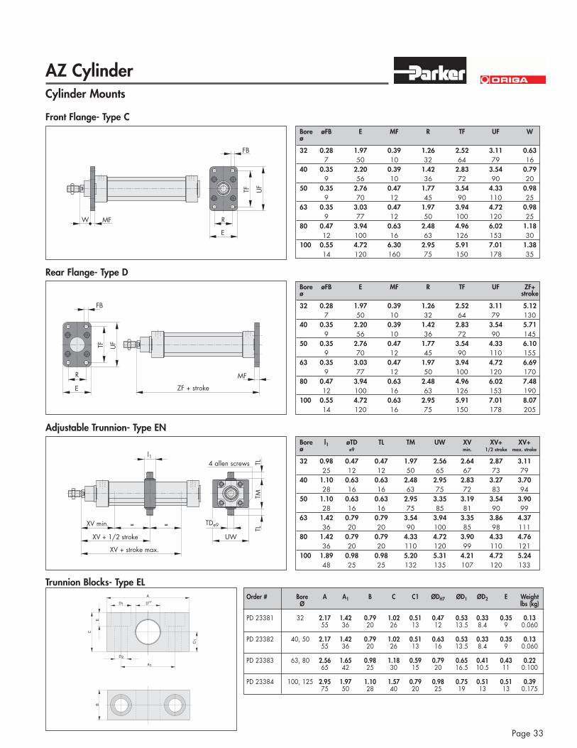
Cylinder Mounts
Front Flange- Type C
Rear Flange- Type D
Adjustable Trunnion- Type EN
Bore øFB E MF R TF UF Wø
32 0.28 1.97 0.39 1.26 2.52 3.11 0.637 50 10 32 64 79 16
40 0.35 2.20 0.39 1.42 2.83 3.54 0.799 56 10 36 72 90 20
50 0.35 2.76 0.47 1.77 3.54 4.33 0.989 70 12 45 90 110 25
63 0.35 3.03 0.47 1.97 3.94 4.72 0.989 77 12 50 100 120 25
80 0.47 3.94 0.63 2.48 4.96 6.02 1.1812 100 16 63 126 153 30
100 0.55 4.72 6.30 2.95 5.91 7.01 1.3814 120 160 75 150 178 35
Bore øFB E MF R TF UF ZF+ø stroke
32 0.28 1.97 0.39 1.26 2.52 3.11 5.127 50 10 32 64 79 130
40 0.35 2.20 0.39 1.42 2.83 3.54 5.719 56 10 36 72 90 145
50 0.35 2.76 0.47 1.77 3.54 4.33 6.109 70 12 45 90 110 155
63 0.35 3.03 0.47 1.97 3.94 4.72 6.699 77 12 50 100 120 170
80 0.47 3.94 0.63 2.48 4.96 6.02 7.4812 100 16 63 126 153 190
100 0.55 4.72 0.63 2.95 5.91 7.01 8.0714 120 16 75 150 178 205
Bore l1 øTD TL TM UW XV XV+ XV+ø e9 min. 1/2 stroke max. stroke
32 0.98 0.47 0.47 1.97 2.56 2.64 2.87 3.1125 12 12 50 65 67 73 79
40 1.10 0.63 0.63 2.48 2.95 2.83 3.27 3.7028 16 16 63 75 72 83 94
50 1.10 0.63 0.63 2.95 3.35 3.19 3.54 3.9028 16 16 75 85 81 90 99
63 1.42 0.79 0.79 3.54 3.94 3.35 3.86 4.3736 20 20 90 100 85 98 111
80 1.42 0.79 0.79 4.33 4.72 3.90 4.33 4.7636 20 20 110 120 99 110 121
100 1.89 0.98 0.98 5.20 5.31 4.21 4.72 5.2448 25 25 132 135 107 120 133
A
D DH71
A1
D2
C
E
C
B
1
Trunnion Blocks- Type ELOrder # Bore A A1 B C C1 ØDH7 ØD1 ØD2 E Weight
Ø lbs (kg)
PD 23381 32 2.17 1.42 0.79 1.02 0.51 0.47 0.53 0.33 0.35 0.1355 36 20 26 13 12 13.5 8.4 9 0.060
PD 23382 40, 50 2.17 1.42 0.79 1.02 0.51 0.63 0.53 0.33 0.35 0.1355 36 20 26 13 16 13.5 8.4 9 0.060
PD 23383 63, 80 2.56 1.65 0.98 1.18 0.59 0.79 0.65 0.41 0.43 0.2265 42 25 30 15 20 16.5 10.5 11 0.100
PD 23384 100, 125 2.95 1.97 1.10 1.57 0.79 0.98 0.75 0.51 0.51 0.3975 50 28 40 20 25 19 13 13 0.175
AZ Cylinder
Page 34
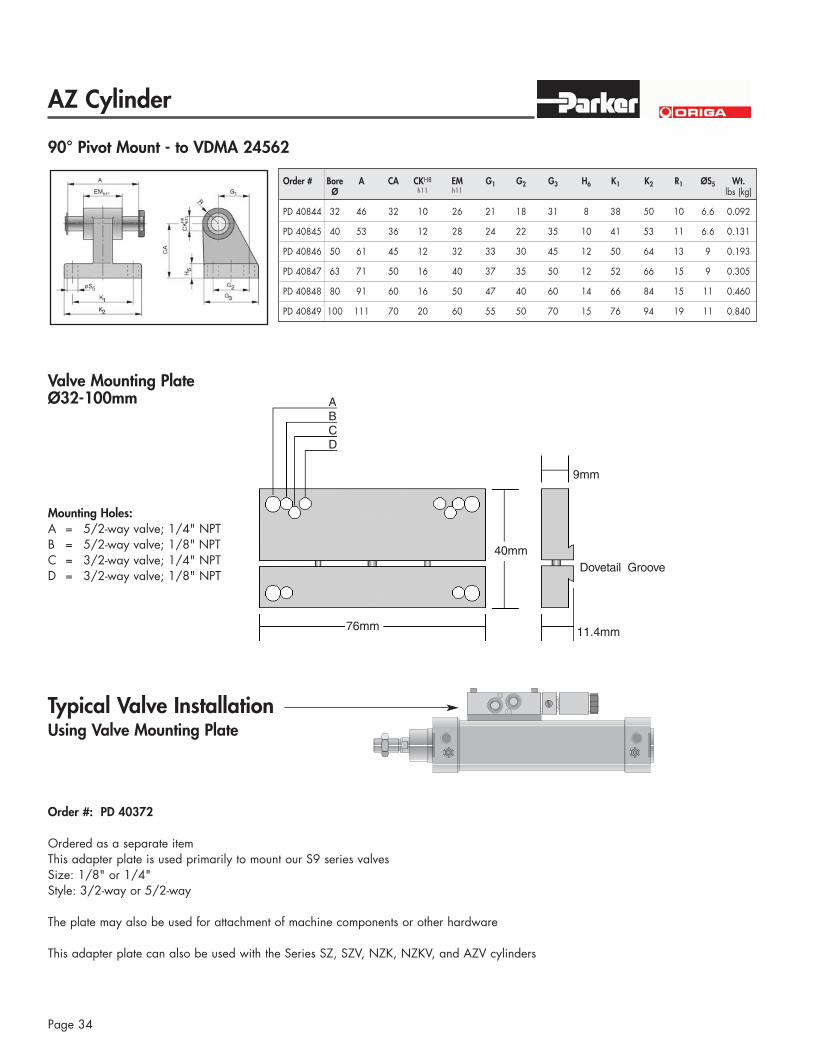
Valve Mounting PlateØ32-100mm
Typical Valve InstallationUsing Valve Mounting Plate
Order #: PD 40372
Ordered as a separate itemThis adapter plate is used primarily to mount our S9 series valves Size: 1/8" or 1/4"Style: 3/2-way or 5/2-way
The plate may also be used for attachment of machine components or other hardware
This adapter plate can also be used with the Series SZ, SZV, NZK, NZKV, and AZV cylinders
Mounting Holes:A = 5/2-way valve; 1/4" NPTB = 5/2-way valve; 1/8" NPTC = 3/2-way valve; 1/4" NPTD = 3/2-way valve; 1/8" NPT
ABCD
9mm
Dovetail Groove
11.4mm
40mm
76mm
90° Pivot Mount - to VDMA 24562
Order # Bore A CA CKH8 EM G1 G2 G3 H6 K1 K2 R1 ØS5 Wt.Ø h11 h11 lbs (kg)
PD 40844 32 46 32 10 26 21 18 31 8 38 50 10 6.6 0.092
PD 40845 40 53 36 12 28 24 22 35 10 41 53 11 6.6 0.131
PD 40846 50 61 45 12 32 33 30 45 12 50 64 13 9 0.193
PD 40847 63 71 50 16 40 37 35 50 12 52 66 15 9 0.305
PD 40848 80 91 60 16 50 47 40 60 14 66 84 15 11 0.460
PD 40849 100 111 70 20 60 55 50 70 15 76 94 19 11 0.840

AZ Cylinder
Page 35
W
X
V
T
U
øP
Z
Order # Bore Ø P T U V W X Z WeightØ lbs (kg)
32 0.39 0.79 0.39 0.79 2.05 1.57 - - 0.18KY 6135 10 20 10 20 52 40 M10x1.25 0.08
40 0.47 0.94 0.47 0.94 2.44 1.89 - - 0.28KY 6136 12 24 12 24 62 48 M12x1.25 0.125
50, 63 0.63 1.26 0.63 1.26 3.27 2.52 - - 0.66KY 6139 16 32 16 32 83 64 M16x1.5 0.3
80, 100 0.79 1.57 0.79 1.57 4.13 3.15 - - 1.15KY 6141 20 40 20 40 105 80 M20x1.5 0.52
125 0.98 1.97 0.98 1.97 5.20 3.94 - - 2.38KY 6142 25 50 25 50 132 max. 100 M24x2 1.08
125 1.18 2.13 1.18 2.17 5.83 4.41 - - 3.31KY 6866 30 54 30 55 148 max. 112 M27x2 1.5
øP
U Z
H7 W1
X
T
U1
V
W
SW
øZ 1
Rod Eye with Spherical Bearing
Order # Bore ØPh7 T U U1 V W W1 X Z Ø Z1 SW WeightØ lbs (kg)
32 0.39 0.59 0.41 0.55 1.10 2.24 0.79 1.69 - - 0.59 0.16KY 6147 10 15 10.5 14 28 57 20 43 M10x1.25 15 17 0.072
40 0.47 0.67 0.47 0.63 1.26 2.60 0.87 1.97 - - 0.69 0.24KY 6148 12 17 12 16 32 66 22 50 M12x1.25 17.5 19 0.107
50, 63 0.63 0.87 0.59 0.83 1.65 3.35 1.10 2.52 - - 0.87 0.46KY 6150 16 22 15 21 42 85 28 64 M16x1.5 22 22 0.21
80, 100 0.79 1.02 0.71 0.98 1.97 4.02 1.30 3.03 - - 1.08 0.84KY 6151 20 26 18 25 50 102 33 77 M20x1.5 27.5 32 0.38
125 0.98 1.22 0.87 1.22 2.36 4.88 1.65 3.70 - - 1.32 2.56KY 6152 25 31 22 31 60 1) 124 1) 422) 94 M24x2 33.5 36 0.65
1) Maximum- dimension2) Minimum- dimension
E
øFAA
4!4!
CSW5 SW1 SW4
SW2B SW3
D
Rod Alignment CouplerOrder # Bore A B C D E ØF SW1 SW2 SW3 SW4 SW5 Weight
Ø lbs (kg)
0.79 0.91 2.76 1.22 0.85 0.01KY 1129 32 M10x1.25 20 23 70 31 21.5 12 30 30 19 17 0.218
0.91 0.91 2.64 1.22 0.85 0.01KY 1131 40 M12x1.25 23 23 67 31 21.5 12 30 30 19 19 0.207
50 1.57 1.26 4.41 1.77 1.32 0.03KY 1133 63 M16x1.5 40 32 112 45 33.5 19 41 41 30 30 0.637
80 1.54 1.65 4.80 2.20 1.32 0.03KY 1134 100 M20x1.5 39 42 122 56 33.5 19 41 41 30 30 0.711
4!4!
Angular Compensation
max
. 2
Radial Compensation for the Center Axis
Dimensions: Bold: INCH, Std.: mm
Rod Mounts
Rod Clevis with Pin
AZ Cylinder
Page 36
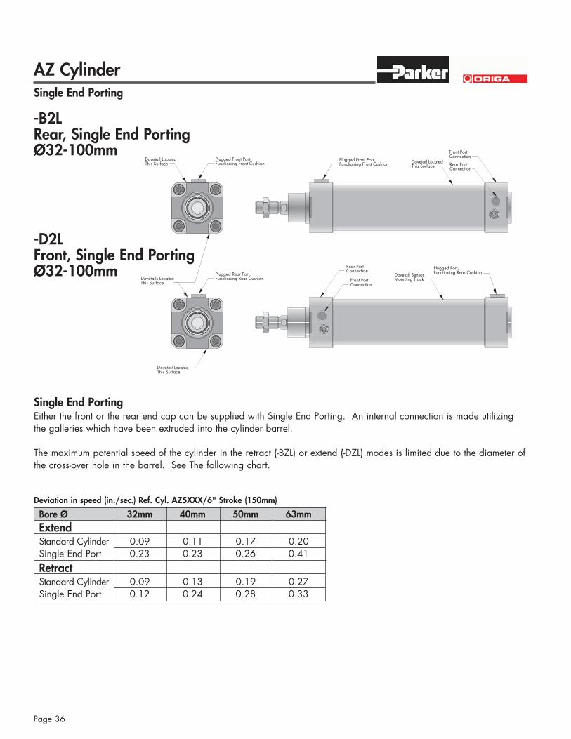
Single End Porting
Plugged Front Port,Functioning Front Cushion Dovetail Located
This Surface
Front PortConnection
Dovetail SensorMounting Track
Plugged Port,Functioning Rear Cushion
Rear PortConnection
Dovetails LocatedThis Surface
Dovetail LocatedThis Surface
Dovetail LocatedThis Surface
Plugged Rear Port,Functioning Rear Cushion
Plugged Front Port,Functioning Front Cushion Rear Port
Connection
Front PortConnection
-B2LRear, Single End PortingØ32-100mm
-D2LFront, Single End PortingØ32-100mm
Single End PortingEither the front or the rear end cap can be supplied with Single End Porting. An internal connection is made utilizingthe galleries which have been extruded into the cylinder barrel.
The maximum potential speed of the cylinder in the retract (-BZL) or extend (-DZL) modes is limited due to the diameter ofthe cross-over hole in the barrel. See The following chart.
Deviation in speed (in./sec.) Ref. Cyl. AZ5XXX/6" Stroke (150mm)
Bore Ø 32mm 40mm 50mm 63mmExtendStandard Cylinder 0.09 0.11 0.17 0.20Single End Port 0.23 0.23 0.26 0.41RetractStandard Cylinder 0.09 0.13 0.19 0.27Single End Port 0.12 0.24 0.28 0.33