
WRAP Coversheet Theses newwrap.warwick.ac.uk/106483/1/WRAP_Theses_Summerfield_1984.pdfAPPENDIX E...
363
warwick.ac.uk/lib-publications A Thesis Submitted for the Degree of PhD at the University of Warwick Permanent WRAP URL: http://wrap.warwick.ac.uk/106483/ Copyright and reuse: This thesis is made available online and is protected by original copyright. Please scroll down to view the document itself. Please refer to the repository record for this item for information to help you to cite it. Our policy information is available from the repository home page. For more information, please contact the WRAP Team at: [email protected]
Transcript of WRAP Coversheet Theses newwrap.warwick.ac.uk/106483/1/WRAP_Theses_Summerfield_1984.pdfAPPENDIX E...

warwick.ac.uk/lib-publications
A Thesis Submitted for the Degree of PhD at the University of Warwick
Permanent WRAP URL:
http://wrap.warwick.ac.uk/106483/
Copyright and reuse:
This thesis is made available online and is protected by original copyright.
Please scroll down to view the document itself.
Please refer to the repository record for this item for information to help you to cite it.
Our policy information is available from the repository home page.
For more information, please contact the WRAP Team at: [email protected]

THE BRITISH LIBRARY DOCUMENT SUPPLY CENTRE
TITLE A SYSTEM S APPROACH TO TH E
CO N TR O L OF C U TTIN G TO O LS WITHIN
A L A R G E -S C A L E M ANUFACTURING ENVIRONMENT
AUTHOR PETER HUMPHREY SUMMERFIELD
INSTITUTION and DATE The U n iv e rs ity of W arwick
Attention is drawn to the fact that the copyright of this thesis rests with its author.
This copy of the thesis has been supplied on condition that anyone who consults it is understood to recognise that its copyright rests with its author and that no information derived from it may be published without the author’s prior written consent.
I i l I ai u i I ai I -g i Boston Spa, Wetl West Yorkshire
— I United Kingdom
TH E B R IT IS H L IB R A R YD O C U M E N T SUPPLY CEN TR E Boston Spa, Wetherby
21|cms R E D U C T IO N X

A S YSTEM S APPROACH TO THE
CO NTROL O F CU TTIN G TOOLS WITHIN
A L A R G E -S C A L E MANUFACTURING ENVIRONMENT
A Th e sis subm itted to
Th e U n iv e rs ity of W arwick
in s u p p lic a tio n fo r the
Degree of D octor of Philosophy
by
P E TER HUMPHREY SUMMERFIELD
C .E N G .. M .I.P R O D.E.. B.Sc. tC N AA ). M.Sc. (WARWICK)
D epartm ent of Engineering
U n iv e rs ity of W arwick
March 1984
CONTENTS
LIST OF APPENDICES ............ vll
LIST OF FIGURES ............ vili
ACKNOWLEDGEMENTS ............ xll
THESIS DEDICATION ............ xiii
SYNOPSIS ............ xiv
LIST OF ABBREVIATIONS ............ xv
INTRODUCTION ............ 1
CHAPTER ONE - COMPANY PROFILE 9 - 1 9
1.1 BL Limited - An Historical Perspective .. .. 9
1.2 Company Structure .. .. .. ll
1.3 Trading Position of BL Limited 11
1.4 Light Medium Cars Group .. .. .. 15
1.4.1 Product Range ............ 15
1.4.2 Birmingham Operations .. .. .. 17
1.4.3 Coventry Engine Plant .. .. .. 18
CHAPTER TWO - COMPANY APPROACH TO TOOL CONTROL .. .. 2 0 - 3 2
2.1 An Historical Perspective 20
2.2 Present Levels of Control 23
2.2.1 Longbridge Plant .. .. .. 27
2.2.2 Drews Lane Plant ............ 29
2.2.3 Coventry Engine Plant .. .. .. 31
2.2.4 Triumph Radford Plant .. .. .. 32
Page No
(i)

Page No
CHAPTER THREE - LITERATURE SURVEY (GENERAL) .. .. 3 3 - 7 9
3.1 Metal Working - An Historical Perspective .. 34
3.2 Systems Theory ............ 36
3.2.1 Systems - A Definition ............ 36
3.2.2 Systems Engineering ............ 36
3.2.3 Systems Theory - An Historical Perspective 37
3.2.4 System Control ............ 39
3.3 Systems - Levels of Focus ............ 40
3.3.1 The Business System ............ 40
3.3.2 The Production System ............ 42 -
3.4 Manufacturing Systems ............ 43
3.4.1 Advancement of Technological Aspects Within
the Manufacturing System ............. 46
3.4.1.1 Machine Tool Design ............ 46
3.4.1.2 Metal Removal Technology . . . . 47
3.4.1.3 Computer Aided Engineering . . . . 52
3.5 Tool Control Systems ............ 55
3.6 Tooling Technology Systems ............ 58
3.6.1 Technological Data bases ............ 59
3.6.2 Machlnabllity Data bases ............ 61
3.6.3 Computerised Process Planning Systems .. 65
3.7 Inventory Control ............ 71
3.7.1 Tool Usage ............ 78
(li)

Page No
CHAPTER FOUR - LITERATURE SURVEY (CLASSIFICATION AND CODING
SYSTEMS ............ 8 0 - 9 6
4.1 An Historical Perspective 80
4.2 Industrial Classification and Coding . . . . 81
4.2.1 Hierarchical Systems 82
4.2.2 Chain Structured Systems ............ 82
4.2.3 NATO System (General) 84
4.2.4 Brisch System (General) 86
4.3 Cutting Tool Classification and Coding Systems 89
4.3.1 Mnemonic Codes 89 -
4.3.2 Commodity Classification 89
4.3.3 Brisch (Cutting Tools) 89
4.3.4 PERA - Sequence Technology ............ 89
4.3.5 PERA - Machinability Data Bank . . . . 93
4.3.6 The Hal System 93
4.3.7 National and Universal Systems . . . . 94
CHAPTER FIVE - A SYSTEMS APPROACH TO TOOL CONTROL .. 97 - 120
5.1 Problem Definition 97
5.1.1 Quantified Statement 99
5.1.2 Qualitative Statement 98
5.2 Systems Overview 99
5.2.1 Research Location 100
5.2.2 Linked Systems 102
5.2.2.1 Authorised Control ............ 103
5.2.2.2 Inputs and Outputs of the
Manufacturing System ............ 105
5.2.2.3 Manufacturing Sub-Systems .. .. 105
5.2.2.4 System Design Concept............ 106
(ill)

5.3 Tool Control System (ATOMS) 112
5.3.1 Technological Control and Update .. .. 114
5.3.2 Management Control .. .. .. 115
5.3.3 Tool Classification and Coding System .. 118
5.3.4 System Operation 119
5.4 Research Methodology 119
CHAPTER SIX - TECHNOLOGICAL CONTROL AND UPDATE (IMPS) 121 - 203
6.1 Data Capture and Analysis 121
6.2 Initial Data Organisation within the IMPS Data Base 136
6.3 Initial Application within the Shop Floor Environment 139
6.3.1 Dedicated Cutting Tool Trials .. .. 144
6.4 Machine Tool Factoring Routine .. .. .. 146
6.4.1 Initial Development 147
6.4.2 Machine Tool Factoring Routine (as
Implemented) 148
6.4.2.1 Factor Calculation ............ 154
6.5 IMPS Algorithm 157
6.5.1 Power Constraint Sub Routine ............ 185
6.5.2 Speed Constraint Sub Routine ............ 187
6.5.3 Conversion of Multi-Diameter Vorkpleces to
'Straight Bar Equivalent' ............ 189
6.5.4 Chipbreaker Style Selection ............ 191
6.6 IMPS Assisted Tool Standardisation Programme .. 196
6.6.1 Tool Supplier Involvement ............ 198
6.6.2 Project Work Presentations ............ 199
6.6.3 Data Collection 199
6.6.4 IMPS Assisted Tool Trials ............ 202
Page No
(iv)

Page No
CHAPTER SEVEN - CLASSIFICATION AND CODING SYSTEMS (ARCLASS) 204 - 227
7.1 Principles of System Design 205
. 7.1.1 Classification 205
7.1.2 Coding ............ - 205
7.2 System Selection and Design 206
7.3 ARCLASS - A System Profile 209
7.3.1 Classification 210
7.3.2 Coding 215
7.4 ARCLASS - System Routing 216
7.4.1 Account Code 216
7.4.2 Commodity Group 218
7.4.3 Technological Specification............ 218
7.4.4 Tool Families 219
7.5 ARCLASS System Expansion 220
7.5.1 Additional System Design Features .. .. 220
7.5.2 End of Code Facility ............ 222
7.5.3 Purpose-Designed Tools 222
7.6 Standard Tooling Catalogue 225
7.7 System Linking 227
CHAPTER EIGHT - TOOL MATERIAL SUPPLY SYSTEM (LINCS) 228 - 248
8.1 Stock Recording - The Existing Situation .. .. 231
8.2 Inventory Control 232
8.3 Stock Control 234
8.3.1 Tool Material Issue 235
8.3.2 Tool Procurement 236
8.3.3 Tool Material Receipt 238
8.4 Flow Control 238
8.4.1 Tool 'Marshalling' 241
(v)

Page No
CHAPTER NINE - RESULTS OF SYSTEM IMPLEMENTATION 249 - 268
9.1 IMPS Core Data Validation 249
9.2 Plant-wide Application of IMPS 254
9.3 Tool Material Supply and Control ............ 259
9.3.1 Stock Control 259
9.3.2 Flow Control 265
9.3.3 Initial System Expansion ............ 268
CHAPTER TEN - SYSTEM EXPANSION AND MAINTENANCE 269 - 284
10.1 Expansion at Plant Level 269
10.1.1 IMPS 270
10.1.2 LINCS .. *.. .. 270
10.1.3 General Expansion of ATOMS ............. 274
10.1.3.1 Tool Design 274
10.1.3.2 Tool Maintenance 275
10.1.3.3 Tool Disposal 277
10.1.4 Plant Level System Maintenance .. .. 277
10.2 Potential Benefits 278
10.3 System Expansion at Operations Level .. .. 281
10.3.1 Stores Rationalisation 281
10.4 Birmingham Operations - System Maintenance .. 282
CONCLUSIONS 285 - 287
REFERENCES 288 - 295
(vi)
LIST OF APPENDICES
Page No
APPENDIX A Machine Tool Profile Coventry 296
Engine Plant
APPENDIX B Sandvlk Limited, Machinablllty Data 297
APPENDIX C Program for Plotting Component 300
Surface Speed/Feed Relationship
APPENDIX D IMPS Program 302
APPENDIX E IMPS Flow Chart 314
APPENDIX F Material Index Creator Program 320
APPENDIX G Machlnability Group Creator Program 322
APPENDIX H File Amender Program 324
APPENDIX I Standard Tooling Catalogue 'Prelim' 326
Program
APPENDIX J Coding System Creator Program 327
APPENDIX K Disk Expansion Program 328
APPENDIX L LINCS - Tool Data File Creation Program 329
APPENDIX M LINCS - Tool Issue/Receipt Program 331
APPENDIX N LINCS - Tool/Component 'Where used' 334
Program
APPENDIX 0 LINCS - Tool Bill of Material 336
Generator Program
APPENDIX P IMPS - Inversion Program 338
LIST OF FIGURES
Page No
FIGURE 1 BL Limited - Organisational Structure 12
FIGURE 2 BL Limited - Profit and Loss Account 1980-81 13
FIGURE 3 BL Limited - Analysis of Sales and Profit
before Tax 14
FIGURE 4 Forecast of New Registrations of Passenger
Cars in the UK 16
FIGURE 5 Birmingham Operations - Individual Plant
Coding Systems 26
FIGURE 6 Influences Affecting Tooling Related
Decision-Making 28
FIGURE 7 The Inputs and Outputs of the Manufacturing
System 45
FIGURE 8 Cutting Speeds 1800 to 1970 49
FIGURE 9 Relative Speed Operating Regions 49
FIGURE 10 Historical Development of CAD/CAM Software
Concepts 54
FIGURE II Manufacturing System Boundaries 56
FIGURE 12 An Overview of Non BL Limited Approaches to
Tool Control 73
FIGURE 13 IBM Limited - Tool Classification and Coding
System 75
FIGURE 14 The Opitz Classification System 83
FIGURE 15 The MICLASS System 85
FIGURE 16 Brlsch Mono and Polycodes 87
FIGURE 17 Brlsch Classification Plan 88
FIGURE 18 General Tool Classification and Coding Systems 90
FIGURE 19 Brisch Monocode - Hard Tipped Tooling 91
(v i l i )

Page No
FIGURE 20 PERA - Tool Classificadon and Coding Systems 92
FIGURE 21 The Hal Tool Classification and Coding System 95
FIGURE 22 National and Universal - Tool Classification
and Coding Systems 96
FIGURE 23 A Controlled Approach to Tooling Decisions 104
FIGURE 24 Tool Control System - Concept 108
FIGURE 25 ATOMS (Automated Tool Management System) -
Concept 113
FIGURE 26 Component Material - Machinability Groupings 123
FIGURE 27 Tool Wear Characteristics 127
FIGURE 28 Flank Wear Characteristics 128
FIGURE 29 ISO Indexable Insert Grading System 130
FIGURE 30 Typical Carbide Grades for Machining 131
FIGURE 31 Development of Flank Wear for Different
Cutting Speeds 135
FIGURE 32 Logarithmic Inversion of v-T Curve 135
FIGURE 33 IMPS Initial Data Organisation Format 137
FIGURE 34 Designation of Indexable Inserts 140
FIGURE 35 IMPS - Data File Structures 158
FIGURE 36 IMPS Machinability Group - Data Formats 159
FIGURE 37 Variable Names Used Throughout IMPS Programs 162
FIGURE 38 Kg (Specific Force) Cutting Values at 90°
Approach Angle 177
FIGURE 39 Variation of Arithmetic Average Roughness
(Ra) with Cutting Speed (V) 180
FIGURE 40 IMPS - System Output 183
FIGURE 41 IMPS - Process Summary Sheets 184
FIGURE 42 A Schematic Representation of the IMPS
Sequence for a Three Operation Task 186
Ox)

Page No
FIGURE 43 Component - Equivalent Length/Dlameter 192
FIGURE 44 IMPS - Chipbreaker Style Selection 195
FIGURE 45 ARCLASS - System Routing 211
FIGURE 46 ARCLASS - System Definition 217
FIGURE 47 ARCLASS - System Expansion 221
FIGURE 48 Examples of Individual Departmental Use of
End Code Characters 223
FIGURE 49 ARCLASS Potential Application —
Purpose-Designed Tools 224
FIGURE 50 Standard Tooling Catalogue Page 226
FIGURE 51 LINCS — Data Configuration — Schematic
Layout 233
FIGURE 52 LINCS - Tool Issue/Receipt (Screen Display) 239
FIGURE 53 LINCS - Tool/Component 'Where Used' Data
(Screen Display) 240
FIGURE 54 LINCS - (CMC) Based File Structure 243
FIGURE 55 Tool 'Marshalling' - Outline of Documentation
Flow for Levels (1) and (2) Control
Procedures 244
FIGURE 56 Tool 'Marshalling' - System Output 246
FIGURE 57 LINCS 'Where Used' File Maintenance 248
FIGURE 58 Summary of IMPS Core Data Results 251
FIGURE 59 Example of Factor Proving IMPS 252
FIGURE 60 IMPS Assisted Tool Trial Report 255
FIGURE 61 IMPS Pilot Operation 256
FIGURE 62 Cutting Condition and Test End Codes 257
FIGURE 63 Annual Tool Cost Savings (Turning Operations) 260
(«)
FIGURE 64
Page No
Reduction of Indexable Insert Tooling at
Coventry Engine Plant during 1981 262
FIGURE 65 The Potential Role of a CADDS Based Standard
Tooling Catalogue 276
FIGURE 66 An Analysis of Tooling Expenditure/Inventory
Values for 1980 (Coventry Engine Plant) 279
FIGURE 67 Overview of the Proposed Birmingham Operations
Tool Control Systems Communications
Network 283
( x l )

ACKNOWLEDGEMENTS
The author gratefully acknowledges the opportunity created in allowing
the research work contained in this thesis to take place, and subsequent
support of Mr W H Horton, Operations Director, Midlands and North,
Austin Rover Limited and Professor S K Bhattacharyya of the Department of
Engineering, University of Warwick.
My gratitude must also go to my wife Christine for her enduring patience
and support, and to my children Victoria and Rebecca.
(xl l )

SYNOPSIS
The control of cutting tools within a large-scale manufacturing
environment has been studied and a routing through a 'linked' tool control
system designed and implemented.
Previous contributions in the field of cutting tool control have
focused upon a number of specialist areas, and these can be divided
into three broad categories:-
(a) At the point of application upon individual machine tools.
(b) The tool planning element within Process Planning systems.
(c) Tool material supply systems.
However, in terms of viewing the problem of tool control from
a Manufacturing Systems perspective, i.e. the study of the 'whole'
system, then this particular subject area has been neglected.
A claim to originality is made with respect to the contents of this
thesis which consider the interactive nature of the essential control
disciplines inherent in (a), (b) and (c) and these are then linked
together within a single tool control system framework.
Applying this linked systems approach to one tooling family (indexable
inserts) within a factory embracing jobbing, batch and flow line
production systems resulted in the achievement of a package of economic
benefits which included significant reductions in related inventory
levels, expenditure, labour content, and through Improvements in the
utilisation and output of selected machine tools.
<xiv)

LIST OF ABBREVIATIONS
CAO Computer Aided Design
CAM Computer Aided Manufacture
NEB National Enterprise Board
ATOMS Automated Tool Management System
IMPS Iterative Machine Parameter Selection
LINCS Linked Inventory Control System
ARCLASS Austin Rover Classification System
£m £ Million
LMC Light Medium Cars
PSF Pressed Steel Fisher
P 4 MC Production and Material Control
BLSL British Leyland Systems Limited
£K £ Thousand
NC Numerical Control
PERA Production Engineering Research Association
CNC Computer Numerical Control
CAPPS Computer Aided Process Planning System
APT Automatically Programmed Tools
BS British Standards
ISO International Standards Organisation
ASM American Society of Metals
CAE Computer Aided Engineering
DOS Disk Operating System
CMC Computer Machinery Company

INTRODUCTION
In an aver-Increasingly competitive world the need for a more
efficient manufacturing sector within the national economy becomes of
paramount importance. Economic recession and its impact on market shares
encourages management to pursue rigorous short-term measures when faced
with threats to business survival. Such measures impact upon all areas of
the business activity and may range from aggressive marketing and
purchasing policies to equally aggressive measures to achieve maximum
utilisation from all existing resources which include employees as well as
facilities. Such activities have been shown to generate considerable
improvements in operational efficiency and can be seen to be long overdue,
removing the shackles of many years of custom and practice within
companies.
To maintain such improvements in business efficiency and generate
confidence in medium-term viability will require the implementation of a
package of measures underpinned by increased investment in new technology.
However, it is Important to recognise that such technology in Itself is
not a panacea, and criticism of under-utilisation of resources so
frequently levelled in the 1970's could well be just as applicable in the
1980's unless management is educated to realise the true potential of
their technological investment. Certainly thought processes and
decision-making based on 'systems' concepts will play a major role in
future business strategies.
Demands for a more visionary approach to management are not new, and
the great milestones with respect to the traditional metal removal
industries are undoubtedly the work of F W Taylor and M E Merchant.
In the first quarter of this century Taylor presented a totally new
concept in management with the introduction of the far-reaching concepts
embraced under the general heading of the 'Principles of Scientific
Mmnagement'. Much of Taylor's management philosophy centred around a
- 1 -

systematic approach to problem-solving utilising many analytical 'tools'
in the process. In terms of metal removal his efforts to improve the
efficiency at the cutting tool/workpiece interface were revolutionary and
involved the study of many areas of manufacturing activity including such
aspects as material supply systems, work measurement, tool classification
and coding systems, and the introduction, with White in 1908, of High
Speed Steel cutting tool materials.
Since the pioneering days of Taylor, metal removal practice and
theory has attracted continuous attention although progress in many direct
and indirectly related fields has not necessarily been in harmony.
Centres of excellence have developed in specialist fields encouraging a
narrow level of focus which can be to the detriment of understanding the
interactive nature of related systems.
Another major step forward in offering a new level of vision to
manufacturing management and related academic research came in the early
1960's with the work of Merchant [lj 1961, who recognsied the potential
applications of systems theory within the manufacturing environment and
this, combined with the advent of micro-chip based technologies, opened up
new horizons in understanding the control mechanisms required to gain
greater productivity at the cutting edge. This interrelated web of
systems theory and general manufacturing technological advancement is
providing greater momentum towards the optimisation of manufacturing
systems and the conceptual ideals of the fully automated factory, a
subject area with which Merchant's name has now become synonymous.
While Merchant offered direction in terms of studying the
manufacturing system as a 'whole' other subsequent work has developed a
more comprehensive understanding of the various sub-systems within the
manufacturing system and their interactive nature. Of particular interest
to the research work contained in this thesis is the study of one specific
sub-system and that is the cutting tool control system.
- 2 -

The need for optimisation of this particular sub-system can vary from
industry to industry. For example, where metal removal costs comprise
only a small percentage of the total product cost then management control
efforts may be directed elsewhere. However, in industries typified by
motor vehicle manufacture, where significant economic investment in capital
and/or manpower is made in the metal removal activity within the
manufacturing process, then the control over the economics of tooling
becomes critically important.
An awareness of the need for a more systematic approach to tool
control has developed over the last fifteen years in the areas of CAD/CAM,
although this tends to concentrate on batch production, utilising a
limited number of cutting tools in the derivatives of relatively new
numerically controlled machine tools. Transferring the philosophies of a
systems approach to tool control within a large-scale manufacturing
environment, where production processes can range from jobbing to flow
line on dedicated manufacturing facilities comprising of predominantly
conventional machine tools whose age span may vary from 0 - 5 0 years, with
an average of 20 years, has been neglected in terms of academic research.
Such an environment is typified by the Power and Transmission
manufacturing facility covered by the Birmingham Operations group of
factories to be found within the Light Medium Cars Group of BL Limited
which have been the focal point of this research.
In common with many other companies there has been a willingness to
recognise the need for gaining control and effecting improvements to the
manufacturing cost base, albeit management effort has been concentrated
upon the control of direct costs (and understandably so, as this is the
area of greatest short-term, visible, efficiency gains). In general,
activity in the control of consumable items (i.e. non product-related)
has attracted less activity at a Corporate level. Contributory factors to
this lack of activity include:-

(a) A stream of Company structure organisational changes which have
resulted in numerous changes in operational responsibility for the
individual factories presently under the umbrella of 'Birmingham
Operations' have discouraged any attempts to gain control over
tooling related areas, allowing individual plants the freedom to
pursue their own approaches to tool control. This situation has
achieved limited functlonal/departmental requirements which often
ignore the impact on other departments and result in the utilisation
of dated cutting technology, duplication of effort particularly in
the storage and maintenance of data, and poorly controlled inventory
levels. This general lack of of control encourages custom and
practice and results in general system abuse, both Internally <by
employees) and externally (by tool suppliers).
(b) A basic lack of awareness by management of the true potential of
implementing a tool control system which initially questions, and
then imposes necessary disciplines on all functions/activities
involved in tool decision-making.
The financial problems encountered by BL Limited in the mid-1970's
are now well documented enough to say that there was a dramatic
deterioration in the Company's trading position with injection of large
amounts of Government aid to ensure continuity of the mainstream business
activity. In the NEB's submission to the Government in December, 1979 of
the Company's performance and the 1980 Corporate Plan and Budget [2], the
reduction of inventory levels and improvements in manufacturing
productivity, both of which had significant implications with respect to
cutting tools, were seen as essential to BL Limited's future survival and
viability.
- * -

Following the NEB's submission, a comprehensive package of measures
was implemented in order to achieve these Corporate objectives, and
amongst them was the initiation of the research activity described in this
thesis. Of major concern at the time was that the consumable tooling and
related inventory for Birmingham Operations was estimated to be in excess
of £7 million and only 'turning over' by value, l.e. £ inventory/£ annual
expenditure, once every fifteen months.
Against this background the writer was given the opportunity to
review in greater depth the problems being encountered in the control of
metal removal tools within Birmingham Operations, and encouraged to initiate
investigations. The content of this thesis is the direct result of that
invitation and describes in detail the design, development and
implementation of a routing through a 'linked' system which controls the
application and supply of new cutting tools. The system was designed on
the principle that tool control must begin with technological control at
the point of application, thereafter, supportive tool material supply
systems were developed. The system as described was implemented in one
factory and, at the initiative of senior management within the Light Medium
Cars Group of BL Limited, is to be expanded into three other factories.
From the onset the broad philosophies offered by Taylor (systematic
approach to problem-solving) and Merchant (concepts of studying production
systems as a 'whole'), have been adopted and the ability to analyse
problems utilising varying levels of focus has proved invaluable;
combining this approach with the communications potential offered by
present-day low cost microprocessors, established the platform on which
the tool control system to be described, was built.
Initial research work moved away from the highly sensitive problem of
excessive tool inventories and concentrated on the tooling problems being
encountered on a small bank of machine tools within a single machine shop
working on the premise that the input requirements of the manufacturing
- 5 -

system dictated the service required from supporting systems. This level
of focus quickly Identified two fundamental problems with respect to
cutting tools» and these were:-
(a) The absence of any Company-wide tooling technology 'standards'
encouraging personnel such as setters, foremen, process engineers,
etc., to make personal decisions on the implementation of cutting
tool type and machine tool operating conditions.
(b) The complete absence of tool material supply systems utilising
flow control principles to service the needs of critical high
component volume machine tools. Existing systems were seen to be
extremely limited stock control systems which were either manually or
partially computer system based.
Later work was to reveal many other tooling related problems, but at
this early stage of research these two significant problems were apparent,
namely the control and update of cutting technology and the physical
supply of the tool material to the individual machine tool. Wishing to
understand the Interactive nature of the problem in greater depth the
level of focus was changed to cover the, as then, three locations
encompassed by Birmingham Operations, i.e. Longbridge, Drews Lane and
Coventry Engine Plants, with a fourth factory, Triumph Radford Plant
joining the Group during 1980. At this level it quickly became apparent
that the problems encountered, typified by the absence of machining
standards, ineffective multiple tool classification systems, inadequate
inventory control systems, etc., were common to all locations and
research effort was being diluted by the spread of geographical activity.
For this reason the research activity concentrated upon one location only,
namely Coventry Engine Plant, which by virtue of the mixed nature of its
6 -

manufacturing activity was considered to be a reasonable reflection of the
operational environment to be found elsewhere within Birmingham
Operations. In principle the objective was to establish a tool control
system routing at a single Plant, prove the benefits, and subsequently
expand the system locally and establish the capability of transferring the
control mechanisms to other manufacturing locations as an operational
Company 'standard' system.
The main body of the following thesis describes the research work
programme at Coventry Engine Plant, from the initial system design concept
through to the implementation of the full system routing and its resulting
economic benefits. The system principle is to optimise tool control at
the factory level and to achieve this objective the span of control'
activity ranges from ensuring the correct technological application at the
level of individual machine tools through to rigid procurement
disciplines, resulting in the external tool suppliers actually being
considered to be an integral part of the overall system. The total system
is known as ATOMS, an acronym for Automated Tool Management System and was
initially designed to establish control over high volume, fast moving
tools, typified by indexible inserts as in the case of this thesis, but
potentially Including such tooling families as twist drills, reamers,
taps, dies, grinding wheels. The system was designed on a modular
basis to facilitate progressive in-house expansion as well as geographic
expansion. In addition, vision has been given to the potential
integration of the system into broader based CAD/CAM systems.
ATOMS comprises two main sub-systems and these are:
(a) IMPS (Iterative Machine Parameter Selection), which is a semi-
generative system for establishing i chnological control and up-date
of the machining parameters at the level of the individual process
operation.

(b) LINCS (Linked Inventory Control System), which Is a component-
volume related tool material supply system utilising the principles
of flow control.
The essential link between the two sections Is a significant character
classification and coding system known as ARCLASS (Austin Rover
Classification System).
The IMPS sub-system is considered to be at the heart of the overall
tool control system (ATOMS) and having established control at the point of
application within the manufacturing system, establishing similar levels
of control within the tool material supply systems became considerably
easier. In principle IMPS generates the Individual operation process
standard which Includes the tool material type/geometry required and
machining parameters at which It is to be operated, ARCLASS provides the
mechanisms for establishing the tool type families that are available for
consideration by the Process Planner and LINCS ensures the supply of the
chosen cutting tool to the manufacturing system and subsequently monitors
the variance from the established tool standard performance, hence the
terminology of 'linked systems'.
The first routing through ATOMS was established for Indexable inserts
with selected areas of the system, notably the Inventory control section,
being expanded to cover other tooling families during the period of
research.

CHAPTER ONE
1.0 COMPANY PROFILE
BL Limited at home and overseas is engaged in the automotive
Industry, providing an extensive range of vehicles, from private cars to
heavy commercial trucks and buses. It also supplies automotive,
industrial and marine engines, carburettors, axles and transmission units
to other manufacturers. The Company plays a strategic role in the economy
of the UK with an annual turnover of £2,869 million (1981), 30Z of which
was exported to some 170 countries, and employs 94,000 people within the
UK with a further 23,000 employed overseas.
1.1 BL LIMITED - AN HISTORICAL PERSPECTIVE
Although elements of the Company can be traced back to 1890 in the
form of the Lancashire Steam Company (which became Leyland Motors in
1907) and the formation of the Standard Motor Company in 1903, the modern-
day structure has evolved from the merger between Leyland and British
Motor Holdings in 1968. The new Company, the British Leyland Motor
Corporation (BLMC) brought together many of the famous names from the
history of motor manufacture; from the Leyland wing. Rover, Alvis,
Standard Triumph, AEC, Scammell and Albion and from BMH, Austin, Morris,
MG, Riley, Wolsley, Jaguar, Daimler and Guy.
This rather unsteady alliance came together during a period of rapid
change and uncertainty, which included such factors as:-
(a) Expansion decisions taken during the boom years of the 1950's
and early 1960's by the traditional motor vehicle manufacturers in
the UK and the USA which resulted in over-capacity and declining
profitability.

(b) The restructuring of the European and Japanese motor vehicle
Industry had taken place which offered a potential threat to existing
markets.
(c) The early 1970's saw a cut-back in the economic growth amongst
the Industrialised nations, sparked off by the accelerating cost of
oil relative to other goods. This heralded the beginning of an
economic recession In 1973 and the demand for vehicles world-wide
dropped dramatically.
This sets the business environment In which the newly formed BLMC had
to operate, and despite a profit before tax of £68 million in 1973/74, a
loss was reported for the first half of the 1974 financial year of £16
million. During the ensuing months BLMC's financial position continued to
deteriorate, overdraft limits had been reached and major Investment
programmes cancelled. As a result of the pending crisis a Government
enquiry was initiated to Investigate the Company's affairs and was led by
Sir Donald Ryder. The 'Ryder Report' was published in April 1975 [3] and
the main recommendations covering a ten-year forward plan Included:-
(a) The need for substantial Government investment.
(b) Restructuring of the Company with a particular emphasis on the
centralisation of key functions.
(c) Rationalisation of the product range.
As a result of Ryder, the business Interests of BLMC were vested in a
new Holding Company, BL Limited, In which a majority shareholding was
transferred to the NEB in February, 1976 and then transferred back to the
Secretary of State for Industry In March, 1981.
The foundations established by Ryder and the subsequent arrival of
Sir Michael Edwardes in 1978 set the scene for significant changes to the
structure and direction of the Company. A summary of the main areas of
activity is as follows.
1.2 COMPANY STRUCTURE
Reference to Figure 1 will show that the BL Company structure as at
April, 1981 was sub-divided into four distinct business groups:
(a) Unipart
(b) Cars
(c) Land Rover
(d) Leyland (Trucks and Buses)
1.3 TRADING POSITION OF BL LIMITED
Reference to Figure 2 details the BL Limited Profit and Loss Account
1980-81 revealing a static sales figures for the consecutive years, but
with a marginal reduction in trading loss, i.e. from £293.9 to £244.6
millions. Reference to Figure 3 shows a two-year trading summary, and
although not totally clear from the figures, the majority of the loss
burden as Identified in the Profit and Loss Account rests with the Cars
Operations.
As with many other companies significant external factors Impacted on
the Company's trading position, and include:-
(a) The strength of sterling combined with high interest and
Inflation rates.
(b) The sharp fall in world-wide demand for cars and vehicles in
general.
- 11 -

B.L
. LT
D.
BO
AR
D,
EX
EC
UT
IVE
C
HA
IRM
AN
, S
IR
MIC
HA
EL
ED
WA
RD
ES
o
12

YEAR EiJOED DECEMBER 31
1980 1981
Sales 2,877.1 2,868.7
Trading Loss 293.9 2A4.6
Interest PayableLess Interest Receivable 93.6 88.3
Loss before Taxation 387.5 332.9
Taxation Charges 3.2 6.3
Loss after Taxation 390.7 339.2
Minority share of Profits of Subsidiaries 5.8 5.8
Loss before Extraordinary items 396.5 3ft5.0
Extraordinary items 139.0 152.0
Loss after Extraordinary items 535.5 ft97.0
N.B. Figures in £ Millions
Source» B.L. Ltd. (ft) 19B1
B.L. LTD. - PROFIT ftNO LOSS ACCOUNT 1980-81
- 13 - Figure 2

YEAR
CARS/UNIPART
LANDROVER LEYLANO
SalesCM
ProfitCM
SalesCM
ProfitCM
SalesCM
ProfitCM
1980 1,769 L283* 452 27 629 L30
1981 1 ,849 L168* 438 17 666 L74
OTHER
ACTIVITIESINTRACROUPSALES
Sales Profit
1980
1981
247
164
220
248
2,877
2,869
L285*
L233*
* Identifies that the majority of the loss burden mas attributable to the cars operations
Source: Extel Statistical Services (5) 1982
B.L. LTD. - ANALYSIS Of SALES AND PROFIT BEfORE TAX
1 4figure 3

In addition, the high level of imported vehicles into the UK market,
as shown in Figure 4, has obviously had a significant impact on the
Company's trading position.
Clearly the Cars Group operates in an extremely competitive business
environment and continual emphasis on greater productivity, cost
containment, and efficient manufacturing witnessed considerable
operational Improvements during 1980/81 and these Include
(a) A 30X reduction in manpower during 1980
(b) A 35X reduction in inventory levels
(c) The ratio of cars produced per employee per year, rose from 10 to 1A
1.4 LIGHT MEDIUM CARS CROUP
The subsidiaries of the LMC Group are:
(a) Austin Morris which provided the locations for the research activity
contained in this thesis.
(b) Rover Triumph
(c) Pressed Steel Fisher (PSF)
(d) Parts of BL Components
1.4.1 Product Range
In line with the recommendations of the Ryder Report the Company is
rationalising its range of vehicles with the objective of offering a
product range which by the mid-1980's will revolve around the derivative
of three basic families of cars, two from the LMC Group and one from
Jaguar. These are as follows:-
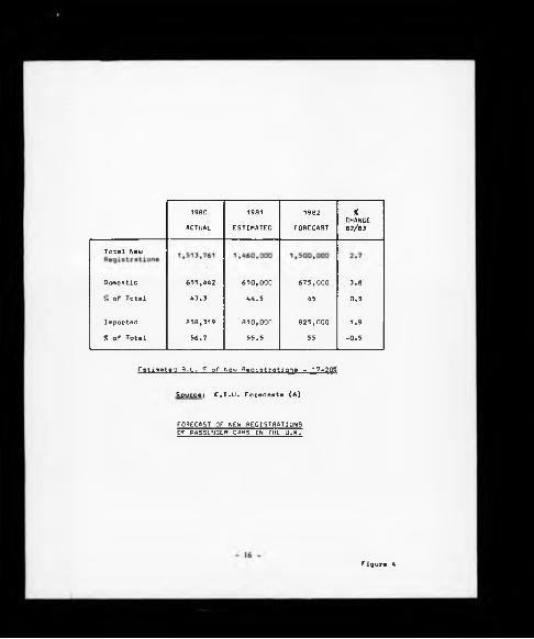
1980
ACTUAL
1981
ESTIMATED
1982
FORECAST
%CHANCE82/83
Total New
Domestic 655,442 650,000 675,000 3.8
Jo oF Total 43.3 44.5 45 0.5
Imported 858,319 810,000 825,000 1.9
% of Total 56.7 55.5 55 -0.5
Estimated B.L. % of Neui Registrations - 17-20%
Source« C.I.U. Forecasts (6)
FORECAST OF NEW REGISTRATIONS OF PASSENGER CARS IN THE U.K.
Figure 4

(a) Metro based at Longbrldge.
(b) LM10, which Is a new 'light medium' car family with an engine
range of 1600 to 2000 c.c. to be assembled at Cowley. The potential
derivatives include:-
(i) LM10, hatch back
(ii) LM11, booted version of the LM10
(iii) LM12, possibly a fastback produced under the Rover marque.
(c) The third car family will be a re-styled Jaguar range, code
named XJ40, which will be far lighter in weight than the existing
range and consistent with world-wide trends towards energy
conservation.
Collaboration with other manufacturers is increasingly playing a more
prominent role in new product development and examples include:-
(a) The Triumph Acclaim, a 1300 c.c. saloon car currently being
assembled at Cowley, is the result of a joint venture between BL
Limited and Honda (Japan). The car involved a £70 million investment
by BL Limited and was launched in October, 1981.
(b) During 1982 a second major concept study was agreed in
collaboration with Honda to design, develop and manufacture a new
range of executive cars, code named project X-X. Production of the
new vehicle is due in 1985.
(c) In March, 1981 the LMC Group signed a component purchasing
agreement with Vokswagen for the supply of VW gearboxes for certain
models in the LM10 range.
1.4.2 Birmingham Operations
The Light Medium Cars Group is divided into three broad areas of
operational responsibility and these are as follows:-
- 1 7 -
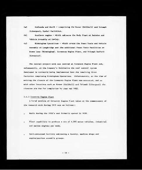
(a) Midlands and North - comprising the Rover (Solihull) and Triumph
(Liverpool, Speke) factories.
(b) Southern region - which embraces the Body Plant at Swindon and
Vehicle Assembly at Cowley.
(c) Birmingham Operations - which covers the Power Train and Vehicle
Assembly at Longbridge and the additional Power Train facilities at
Drews Lane (Birmingham), Coventry Engine Plant, and Triumph Radford
(Coventry).
The initial project work was centred at Coventry Engine Plant and,
subsequently, at the Company's initiative the tool control system
developed is currently being implemented into the remaining three
factories comprising Birmingham Operations. Unfortunately, at the time of
writing the closure of the Coventry Engine Plant was announced, and as
with other locations such as Rover (Solihull) and Triumph (Liverpool) the
closures are due for completion by year end 1982.
1.4.3 Coventry Engine Plant
A brief profile of Coventry Engine Plant taken at the commencement of
the research work during 1979 was as follows
• Built during the 1930's and formally opened in 1938.
• Plant capability to produce a mix of 4,000 motor vehicles, industrial
and marine engines per week. •
• Self-contained facility embracing a foundry, machine shops and
englne/gearbox assembly groups.
- 18 -

2,500 employees.
39.000 standard hours generated per week.
2,280 components are contained In the machining register, being
classified into current (live), spares and non-current spares.
4,130 machine tools ranging from jobbing machines to 'In-line'
transfer machines. Reference to Appendix (A) details the age profile
of the machine tools.
16.000 varieties of cutting tools and related accessories, l.e.
toolholder, clamps, shims etc., are held in stock with an inventory
value in excess of £900K.
52 different component material specifications In a variety of
material forms and metallurgical process conditions are machined. 36
of these specifications are ferrous based and represent the main part
of the machining activity.
19

CHAPTER TWO
2.0 COMPANY APPROACH TO TOOL CONTROL
The requirement to gain control over the supply and application of
cutting tools Is obviously not a new phenomenon within the Individual
Plants now comprising 'Birmingham Operations' and the following Chapter
summarises historical and present-day management contributions within this
specific area of activity.
2.1 AN HISTORICAL PERSPECTIVE
Clearly the two names that are at the historical heart of Birmingham
Operations are Herbert Austin (Longbridge) and William Morris (Coventry
Engine Plant). As the bulk of the project research activity was
concentrated at Coventry Engine Plant (formerly Morris Motors) it is
appropriate that this historical review begins with William Morris.
Early history of the Morris concern commenced with the building of
cycles and motor-cycles in a garage in Long Wall, Oxford, and with the
profits accumulated the foundations of Morris Motors were established. By
1921 the Company was producing 400 vehicles per week and although during
the war years normal activities ceased, in common with most engineering
establishments facilities being utilised for the production of war
materials, the immediate post war years saw a gradual return to normality
and increase in vehicle production. By 1912 volumes had increased to 1000
cars per week and to 1200 per week by 1924, at which stage Morris Motors
was responsible for more than one-third of the total volume of motor cars
produced annually in the United Kingdom.
From these early days William Morris pursued a policy of
decentralised manufacture and from 1923 Morris Motors' Power Train
activity has been centred at Coventry. The initial operational activity
began with the purchase of the Hotchkiss Engines factory which, with
20 -

further expansion, housed all the manufacturing facilities needed to meet
the accelerating demand for power train units. Despite this acquisition
further expansion plans emerged, and in 1928 the 45 acre site of the
present-day Coventry Engine Plant was acquired. During the following
years a purpose-designed factory was built on the site at a cost of
12,000,000 offering three times the floor space of the Hotchkiss factory
and a production capability of up to 4000 units per week. From 1938
onwards the new Morris Engines Plant became the main supplier of the
engines and gearboxes for Morris Motors Limited.
An interesting insight into William Morris' philosophies regarding
the engineering requirement to meet the upsurge in demand and at the same
time control costs is seen in the following quotes 171:—
(a) "A question naturally arises by which process has such meterorlc
progress been possible? To this there can be only one reply, and
that is by an appreciation of - and an aptitude on the part of the
management to apply - a very advanced policy of standardisation."
(b) "The most conspicuous economics are in respect of the number of
machine tools and employees used in the construction of each unit and
the most important item is the reduction of employees."
To achieve the aspirations of (a) and (b), William Morris introduced a
Production Planning Standards Manual in 1925 entitled 'Morris Production
Methods' which deployed many of the analytical techniques embraced in
Taylor's "Scientific Approach to Management" [7], 1925.
Although the standards concentrated predominantly upon machine tool
design, reference is made to the use of standard stock tooling which were
mounted on quick change tool blocks. Similarly, simple guidelines are
given in terms of cutting speeds and feeds.

The manual clearly shows Che Importance given to machine Cool design
during Che period and Che innovation in installing some of Che earliest
mecal working 'in-line' transfer machines in 1924 for Che machining of
flywheels and gearbox cases.
Conversation with personnel employed at Morris Motors during the late
1920's and 1930's, reveals that the foremen and chargehands had the
greatest influence on actually determining machining parameters and the
process planning departments concentrated more on machine tool/Jig and
tool design and 'rate fixing'. This theme of machining from experience
rather than by the adoption of machining standards has remained to this
day.
A positive approach was made by the Austin Motor Company during the
immediate pre and post World War II years with the introduction of 'Austin
Tooling Standards'. These standards are the most comprehensive tooling
standards to be found in the present-day Company and were aimed at
Introducing a standard range of small metal removal tools into the Austin
Morris factories and were part of a series of general engineering
standards covering machine tool, Jig and tool design, component material
specifications, etc. However, in common with the earlier 'Morris'
standards they neglected machinablllty data.
The formation of the BMC in November, 1951 with the union between
Nuffield (Morris) and Austin, brought together two Companies built on
strong engineering traditions and raised the now common problem of
bringing together various sets of engineering standards under one
umbrella. BMC rose to the challenge by developing a series of parts
standards which cross-referenced those of Morris and Austin, but these did
not include a revision of the Austin tooling standards.
Advancement in machine tool technology continued with the
introduction of the first standardised unit head transfer line for the
Austin A40 in the early 1950's. This period also saw BMC building their
own machine tools.
- 22 -

As Che BMC standards evolved during Che lace 1950's Chey appeared to
be directed more towards vehicle assembly and less towards metal removal
technology. The absence of up-to-date tooling standards and associated
machinabillty data continued with process planning engineers being allowed
a great deal of autonomy in the setting of machining parameters.
The merger between Leyland Motor Vehicles and British Motor Holdings
(which became known as the British Motor Corporation - BMC) in 1968
amplified the problems, in terms of tooling standards and control, of the
Austln/Morris merger in 1951 by the bringing together of a large number of
Companies with differing standards and coding systems.
The development and subsequent maintenance of Company-wide
engineering standards has continued, but in the manufacturing arena are
heavily biased towards industrial engineering and vehicle assembly.
Present-day tooling standards date back to 1978 and act only as a general
guideline to preferred suppliers.
This neglect of machinability and tooling standards over many years
within the Power Train Divisions has resulted in a fragmented approach to
tool control encouraging numerous individual departments to become
involved in Influencing tooling related decisions. The net result of this
erosion of process planning based control, namely wide-ranging tool
varieties being held in stock and in use in the machine shops combined
with inadequate coding and stock control systems, is discussed in the
following sub-sections.
2.2 Present Levels of Control
Senior management within the Company were aware for some time of the
lack of adequate tool control systems, but the business requirement to
gain a greater level of control over direct materials has assumed a
greater managerial priority. To understand their concern it is necessary
to take an overview of the tooling activity within Birmingham Operations
23 -

and this can be shown by an analysis of the tooling related inventories at
a point in time and the annual expenditure for the same commodity groups
for factories involved.
This analysis is as follows:-
Annual Expenditure
Jan. 1982 1981
(£ million) (£ million)
Longbridge 4.9 3.53
Drews Lane 0.75 0.85
Coventry Radford 0.10 0.09
Coventry Engines 0.68* 0.81»
6.43 5.28
NBs Figures achieved after the implementation of the system routing as
described in this thesis.
Observations within Chapter Nine will show that in the case of
Coventry Engine Plant the inventory movement by total value was minimal
over a twelve-month period and based on this a similar assumption has been
made, with justification, for the three remaining factories within
Birmingham Operations. Therefore, from this it is possible to gain a
simple, global, indicator of the present levels of control by establishing
an inventory/expenditure ratio for Birmingham Operations as follows:-
6.43 _ ,,*"io 1.22
which shows that there is in excess of fourteen months (1.22 x 12) of
tooling inventory by value held in stock at any one point in time.
Realistically, this should not exceed three to four months if average internal
and external lead times for tool procurement are to be taken as a guide.
- 24 -

From this simple analysis no Individual Plant has established an
acceptable level of control and an insight into existing practices may
help to understand why.
From a Birmingham Operations' viewpoint the following items are
common to all four Plants
(a) Company machinability standards do not exist.
(b) Only very limited Austin tooling standards are in use which
are based on the cutting tool materials and metal removal technology
of the 1950's/60's .
(c) Reference to Figure 5 will show that each Plant has its own
unique classification/coding system for cutting tools. In principle
all of the systems used are based on simple commodity definition
followed by block numeric codes which are expanded chronologically
irrespective of tool dimensions, material grades and geometric
definition. This approach results in an identical cutting tool being
held in stock against a minimum of four different classiflcation/code
numbers within Birmingham Operations.
Further disturbing features with respect to classiflcatlon/codlng
systems Include:-
(i) The custodians of the coding systems for standard tools were
clerically graded P and MC staff with little awareness of the
requirements for technological control.
(ii) Confusion prevailed in the case of special tools, l.e. purpose-
designed, where jig and tool personnel allocated a unique number
which was then given a further number for the purposes of stock
control. A purpose-designed tool could, therefore, be
recognised by numerous codes within the Plant.
25


(d) Individual Plants have been slow to move from labour intensive
inventory control systems, and recent activity in this area has been
fragmented with little 'central' guidance.
(e) Cutting tools may be held in any one of 16 consumable material
stores located throughout Birmingham Operations, thereby compounding
excessive inventory levels.
(f) Inter-Plant and inter-departmental communication with respect to
tooling is extremely poor. This is particularly evident in the area
of technological planning where rigid demarcation lines exist between
Product Design, Divisional Process Planning and local Plant Process
Planning Departments.
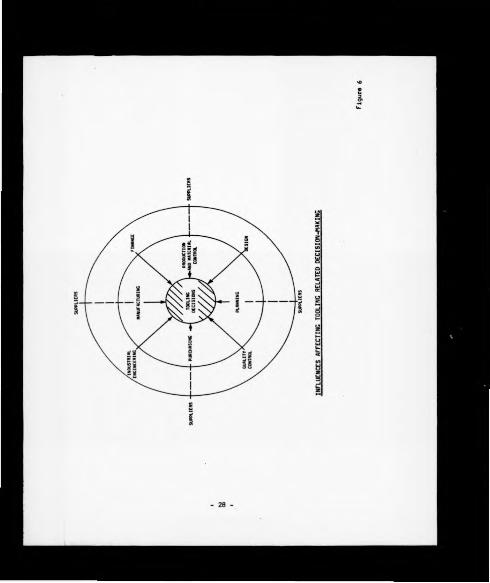
(g) The net result of items (a) to (f) is that custom and practice
prevails and as Figure 6 depicts, numerous personnel from a whole
host of functions can either directly or indirectly influence tooling
related decisions.
A brief historical summary of the actions pursued by individual
Plants to gain control over tooling is as follows.
2.2.1 Longbridge Plant
Although Longbridge was the home of the Austin Tooling Standards
these have eroded with time and today formal control mechanisms are
minimal. A major effort to gain control was instigated by the Tooling
Engineers' Department in 1977 who raised a project proposal to implement a
Ford Motor Company style 'tool block system' in selected areas of
Longbridge. This approach to tool control is aimed at reducing machine
down-time due to non-availability of tools ready and waiting at the point
of predetermined tool change. The scheme was partially implemented in
the East Works Factory but additional inventory requirements and the cost
of supportive facilities prevented any further expansion.
- 27 -
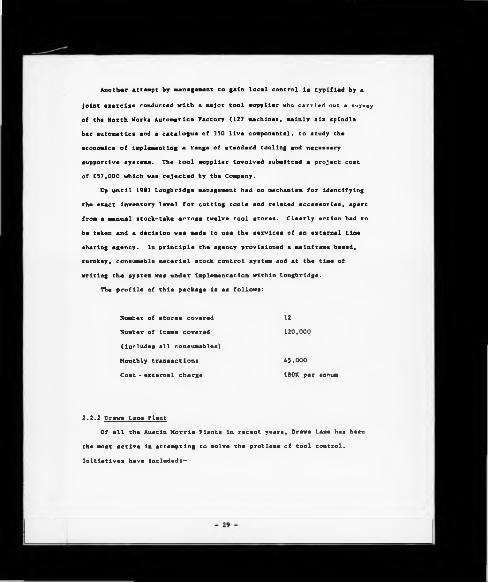
Another attempt by management to gain local control Is typified by a
joint exercise conducted with a major tool supplier who carried out a survey
of the North Works Automatics Factory (127 machines, mainly six spindle
bar automatics and a catalogue of 350 live components), to study the
economics of implementing a range of standard tooling and necessary
supportive systems. The tool supplier involved submitted a project cost
of £57,000 which was rejected by the Company.
Up until 1981 Longbridge management had no mechanism for identifying
the exact inventory level for cutting tools and related accessories, apart
from a manual stock-take across twelve tool stores. Clearly action had to
be taken and a decision was made to use the services of an external time
sharing agency. In principle the agency provisioned a mainframe based,
turnkey, consumable material stock control system and at the time of
writing the system was under implementation within Longbridge.
The profile of this package is as follows:
Number of stores covered
Number of items covered
(Includes all consumables)
Monthly transactions
Cost - external charge
12
120,000
45.000
£80K per annum
2.2.2 Drews Lane Plant
Of all the Austin Morris Plants in recent years, Drews Lane has been
the most active in attempting to solve the problems of tool control.
Initiatives have included:—

(a) October 1976 to June 1977
Extensive efforts were concentrated on the problems of
controlling the inventories of new and reground tools, but despite
the volume of work committed the project floundered on the
industrial relations problems faced by storekeepers refusing to
accommodate additional duties.
(b) January 1978
Again with respect to inventory control, BLSL (the computer
systems division of BL Limited) undertook a review of the existing
problems which endorsed many of the observations of the previous
exercise.
(c) 1979
A decision was taken by local management to implement a BLSL
sponsored non-productive material control system known as *041'.
This system, which was stock control based, was by then over ten
years' old and despite numerous software modifications due to
implementation problems at other BL Limited sites, including Cowley,
Swindon, and Llannelll, has achieved little recognised success.
Again the system is mainframe based, and some three years' later, has
proven to be cumbersome and expensive to run. Line managers were
quick to criticise the system's hard copy reporting features, an
argument that the local Systems Department accept.
Although the decision to implement the 041 system was taken as
long ago as February 1979 its implementation progress has been little
more than chaotic. The main reason for this was that a decision was
taken to completely re-code all of the consumable items before
committing them to the system. This decision led to numerous
problems in that while stores record cards were altered to
accommodate the new coding systems, the process planning operation
sheets were not. The problems caused by the coding exercise were
30 -
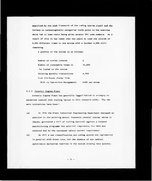
magnified by the weak framework of the coding system itself and the
failure to technologically categorise tools prior to the exercise
which led to some tools being given several 041 code numbers. As a
result of this it has taken over two years to load the records of
8,000 different items to the system with a further 6,000 still
remaining.
A profile of the system is as follows:
Number of stores covered
Number of consumable items to
be loaded to the system
Existing monthly transactions
Cost (In-house charge from
BLSL to Operations Management)
214,000
4,500
E40K per annum
2.2.3 Coventry Engine Plant
Coventry Engine Plant has generally lagged behind in attempts to
establish control over tooling (prior to this research work). The two
main initiatives have been:-
(a) In 1976 the Plant Industrial Engineering Department designed an
addition to the existing manual inventory control system, which in
theory, generated a bill of tooling material against a forward
manufacturing programme for selected components, but this was
rejected due to the increased labour content requirement.
(b) In 1977 a new classification and coding system was implemented
in parallel with Drews Lane, but the absence of any central
maintenance mechanism resulted in the system eroding very quickly.
31

2.2.4 Triumph Radford Plant
The position at Triumph Radford was nearly identical to that of
Coventry Engine Plant with little action taken in terms of tool
control systems, and a heavy reliance on custom and practice.
Therefore, In summary the key factors underpinning the
inadequate tool control systems within Birmingham Operations are as
follows:-
(a) The absence of central control and direction.
(b) General lack of management commitment and understanding of the
control mechanism required.
(c) Present financial control practices discourage any major
initiative in the area of establishing control over consumable
materials. Currently the practice prevails whereby Financial
Controllers set forward operational budget tasks based on an
historical analysis. Therefore, in the case of tooling inventory the
local management are given an annual inventory reduction task,
generally in the order of 10 to 15Z of the total inventory by value,
a nominal target established against the previous year's
known/assumed inventory value.
Achievement of this task discourages local management from
pursuing any initiative to reduce the respective inventories by
considerably larger amounts, or indeed, questioning the requirement
for inventories at all.
All of these problems were not helped by the dynamic nature of the
Company's business organisational structure, which on occasions has
resulted in all four Plants being under the responsibility of individual
Operations Directors.

CHAPTER THREE
3.0 LITERATURE SURVEY (GENERAL)
Publications under the general heading of 'Tool Control' concentrate
predominantly upon stock control systems and offer little In terms of
vision of the problem area in Its broader sense. For this reason early
research effort was directed towards developing an overview of the tool
control problems being faced by Birmingham Operations Management, the
results of which were discussed in the previous Chapter. Having
established this level of understanding it became apparent that the
eventual resolution of the problems encountered would require a multi
disciplinary approach utilising knowledge and expertise from several key
areas, which included:-
(a) General systems theory.
(b) The application of general systems theory within a manufacturing
environment.
(c) The interactive nature of sub-systems.
(d) Classification and coding systems.
(e) The disciplines required to establish control in such areas as:-
(i) The correct application of metal removal technologies.
(ii) The efficient supply of tool material to the machine tools.
(f) Machine tool design and operational capability.
(g) The evaluation and potential application of computer-aided
engineering systems.
Before embarking upon the subject related literature survey it is,
however, appropriate to review the significant events in terms of
technological development with respect to metalworking industry in
general.
33 -

3.1 METALWORKING - AN HISTORICAL PERSPECTIVE
Manufacturing industry as we would recognise it today, only dates
back to the mld-Eighteenth Century and the onset of the Industrial
Revolution. The achievements of this period have been well documented by
Cardwell [8] 1971, Russell [9] 1972, Riggs [10] 1976, and Buffa [11] 1980,
and a summary of their work in terms of benchmarks of the progression of
manufacturing technology, with particular emphasis towards metal removal,
offers fundamental lessons for this and future years.
Advancements in manufacturing technology have resulted, in many cases,
from the demands from other disciplines and notable examples include:-
(a) The pioneering work of Watt in the introduction of the steam
engine created demands from machine tools in terms of the
generation of surfaces, forms and maintenance of component tolerances
that existing metal cutting techniques were incapable of meeting.
From this the machine tool industry was born.
(b) The production of mild steel by Bessemer and alloy steels by
Siemens towards the end of the Nineteenth Century exposed the serious
limitations of the predominant metal cutting material of the day,
hardened carbon steel. The demands for cutting volume steel
production were met by Taylor and White in 1908 with the introduction
of High Speed Steel resulting in a five-fold increase in cutting
speeds. This work also had the impact of directing attention towards
the cutting edge in terms of increased productivity.
(c) The introduction of the model 'T* Ford by Henry Ford in 1903 and
flow-line production in 1913 heralded the age of mass production
technology. In the motor vehicle industries in Europe and the United
States machine tools were designed specifically for mass production
and many supportive analytical systems were introduced by such people
as Gantt, Emerson, Parsons, the Gilbreths, Shewhart and Tippet,
- 34

following In the peth of Taylor's Principles of Scientific
Management.
(d) A combination of new industries such as aerospace with its
non-ferrous alloys and increasing competitiveness in existing
industries placed a greater emphasis on cutting tool performance and
notable developments in this field have included:-
Stellite - Haynes
Tungsten Carbides - Widier
Large Grain Ceramics - Osenberg
High Density Low Grade Ceramics and Synthetic
Diamonds - GEC/Russia
Cubic Boron Nitride - GEC/Russia
Coated Tungsten Carbide Tools - Ulmet UK
Syalons - Lucas Industries UK
(e) The Second World War accelerated technological development and
the immediate post-war years established the foundations for much of
the advanced technology of today including computer science, genetic
engineering, fibre optics/opto electronics, supersonic and space
travel. Many of these developments either individually or combined
have had a major impact in the field of manufacturing.
Before any system design takes place it is necessary to understand
the problem in question and develop a perspective in terms of its
relationship with the overall business activity. To achieve this level
of understanding the most appropriate start point is the field of general
systems theory.
. 1914
. 1926
. 1938
. 1955
. 1965
Late* 1960's
1980
35

3.2 SYSTEMS THEORY
The word 'system* Is commonly found throughout standard management
and scientific text with the result that In many cases Its meaning has
become confused and almost valueless. During the 1960's terms such as
productive, production and manufacturing systems grew in popularity and
similarly the range extended to include flexible, integrated and linked
manufacturing systems all serving to confuse rather than clarify.
Because of this potential for misapplication of terminology there is
a need to revert back to first principles, establish definitions and
develop an historical perspective with respect to systems theory and its
application within manufacturing industry.
3.2.1 Systems - A Definition
Systems definitions abound ranging from the simple (Oxford
Dictionary) to extremely complex (Modern Control Theory); however, for
the purposes of uniformity throughout this thesis a system is defined as,
Uendler [12] 1966:-
" ....... an orderly arrangement of interdependent activities and
related procedures which implements and facilitates the performance
of the major activity of an organisation".
Wendler states further that a system may at times encompass such a wide
range of activities that it becomes difficult to handle in its entirety.
In such cases, the system should be divided into sub-systems, and the sub
systems brought together to form an integrated whole.
3.2.2 Systems Engineering
The systems engineering method recognises each system as a whole even
though composed of diverse, specialised structures and sub-functions.
36

It further recognises that any system has a number of objectives and that
a balance must be achieved in optimising the overall system function
according to the weighted objectives and achieving compatibility of its
parts, Chestnut [13] 1966.
This concept provides a methodology which enables known and new
scientific methods to be represented In a schematic form so that they can
be employed in gaining knowledge of complex facts. It enables problems to
be broken down into individual component parts in a logical manner to
investigate each element without losing the interrelationship to the
overall problem,Buffa [14] 1977.
Systems engineering is often referred to as the 'exact doctrine of
the whole* and It utilises the analytical techniques from many
disciplines, e.g. Control Engineering Theory, Operational Research,
Management Science, Cybernetics, Topology, Communications, Information and
General Systems theories to help understand system design and control and
to study behaviour and performance.
3.2.3 Systems Theory - An Historical Perspective
It would be misleading to imply that the concept of studying the
system as a whole is attributable to engineers. There is little doubt
that the mechanical engineers of the Industrial Revolution and more
notably the later electrical engineers such as Edison and Ferranti were
heavily involved in systems considerations, but the original study of the
total system belongs to the Behavioural Sciences. Pyschologlsts have
consciously used systems concepts since the early 1930's and Angyal (1941
and 1965) provided a forceful statement that the key concepts used to
describe the organisation of living systems required a new logic. Both of
his major works are focused upon the individual biosphere (man In his
environment) and expose the general dynamics involved in system change,
Emery [15] 1970.
37

In 1947 Bertalanffy proposed the concept of general systems theory as
a mechanism for the unification of the science. This theory asserts that
there are properties of systems that do not derive directly from the
Individual components themselves, but from the unique combination of
components that make up the whole. Furthermore, these properties make the
value of the whole (the system) worth more than the simple sum of Its
parts, Buffa [14] 1977.
The Introduction of this conceptual thinking by Bertalanffy broadened
the vision of many scientists and engineers who had been working within
the traditional mechanistic framework which had dominated Nineteenth and
early Twentieth Century thought.
The development of general systems theory coincided with what is now
known as the classical period of control theory. The emphasis was
directed towards frequency response methods with single loop systems which
found mainly industrial application. Random disturbances and the effects
of parameter changes were taken Into account implicitly, but not usually
quantified. Optimisation was usually confined to a choice of parameters
In a fixed structure and not widely used.
These methods had some Important advantages for Industrial
application In that they gave a great deal of insight to a problem, showed
when a single solution existed, and allowed practical constraints to be
taken Into account although the mathematical foundations were Infirm,
Rosenbrock [16] 1975.
The analytical tools grouped together under the umbrella of'Systems
Engineering' enable the construction of system simulation models and the
ability to measure performance before Implementation. The major
limitation of this approach Is that the practical situation Is much less
'tidy' than the theoretical one, resulting In the following sltuatlons:-
(a) It Is not always possible to specify exact requirements.
- 3 8 -

(b) Very often the solution is a compromise of what can be achieved
compared to what would be desired.
(c) Manufacturing problems often admit to more than one satisfactory
solution.
(d) As in many other disciplines, engineering contains an element of
experience and intuitive judgment which cannot be reduced to a
mathematical form.
3.2.4 System Control
One of the prime purposes in developing systems knowledge is to help
achieve satisfactory control. Control as a steering mechanism rather than
the political/economic implications of a suppressive mechanism is essential
if organisations are to remain viable and achieve some, if not all, of its
objectives.
Control Engineering theory is playing a rapidly increasing role in
studying whole and sub-systems. In particular the concepts of feedback
and adaptive control offer significant benefits and the information
generated is the basis for management control. The order of element of a
system can range from:-
(a) First order systems which are capable of maintaining levels of
state during changing exogenous stimuli.
(b) Second order systems which rely upon a feedback mechanism which
anticipate and seek goals.
(c) Third order systems which have the capability of reflective
decision-making.
Practical applications of control theory concepts within
manufacturing industry abound within the field of CAD/CAM.
- 39 -

3.3 SYSTEMS - LEVELS OF FOCUS
A further potential area of confusion Is the term 'whole' or 'total'
system. We all live and function within recognised systems, for instance
they may be family, community, social, economic, political, etc., and
understanding system hierarchy is helped by adjusting levels of focus;
for example, the universe can be taken as a total system comprising two
major sub-systems, natural and man-made. Although this simplified
illustration of a total system neglects the essential aspect of sub-system
interaction it does help to illustrate the concept of hierarchy and
establishes a perspective to one of the lesser systems which is of
particular interest, and that is the business system.
3.3.1 The Business System
A business system can be defined as a motivated force (owner)
obtaining prime resources (raw materials) and subjecting them to regulated
activity (the business activity) performed by producer resources
(premises, staff, machines, etc.), to provide goods or services for
consumers (society's needs and satisfactions) and thus provide profit,
(the owner's needs and satisfactions), Kilgannon [17] 1979.
The business exists in an extremely complex environment consisting
of numerous other systems. The prime consideration of the business
environment is time and space. Time reflects political/economic stability,
availability of skilled labour and resources, etc., while space is
concerned with the physical location of the business; town, county,
country, and continent. Its location within any one of the major power
blocks will influence the nature of trade, customers, suppliers, etc.
The main functional sub-systems within the business system are those
of marketing, financial and production systems, all of which are
supported by a communications system. By way of an example the marketing
system comprises the following sub-systernss-
- 40 -

„ Market research, analysis and assessment
, Advertising and sales promotion
• Publicity
• Customer contact and advice
a Customer order and acceptance
. Sales Inventory and storage
, Distribution
, Customer billing and payment handling
• Customer relations, queries and complaints
The complexities of the business resource/financial management system
go well beyond the boundaries of this thesis, but its importance cannot be
overvalued. Resource management is concerned with the survival of the
business, with its day-to-day efficient running and with its future growth
and development. It is concerned with locating and obtaining resources
and with their maintenance, security and replacement. A broad
classification of resources would be as follows:-
(a) Real Resources
Location:
Materials:
Energy:
Machines:
Information:
Goods and Services:
Land, premises, floor space, etc.
Animal, vegetable and mineral matter.
Wind, gravity, magnetism, etc.
Tools and equipment, aids to, or substitutes
for manpower.
Cumulative or stored useful knowledge.
The processed prime resources.
(b) Token Resources
Token resources are considered as money and credit requesting the
value of the real resources. As such token resources have no value in
themselves, but are used as a medium of exchange, a measure of value
and store of value.4 1 -

Of prime interest is the production system as a sub-system within the
total business activity.
3.3.2 The Production System
Again the question of focus is important; Buffa [11] 1980, defines a
productive system by which we transform resource Inputs to create useful
goods and services, in other words it is a process of transformation or
conversion. This very general definition highlights an Important feature
which is that discussion of production systems is usually weighted towards
machine shop activity where, as with systems engineering, the concepts are
applicable to many other areas where the emphasis may be social, economic
or political where resource inputs would vary considerably.
McPherson [18] 1971 and Spur [19] 1971, help to narrow our vision to
manufacturing Industries by the following definitions:
(a) McPherson
(i) Production system - the general process whereby the utility (or
value added) of raw material, objects, services is increased
overall.
(11) Manufacturing system - the process within a production system
whereby raw materials or piece parts are converted into
completed products and for assemblies and adding value to the
raw materials.
(b)
Spur pursues an even narrower level of focus by limiting his
definitions to the level of the machine tool.
(i) Production system - comprises a plant of machines, devices,
etc., for the production of certain goods.
- 42

(il) Manufacturing system - consists of a machine tool for
transforming a blank workpiece into the shape required by means
of a manufacturing process.
3.4 MANUFACTURING SYSTEMS
The linking of manufacturing facilities is not a new phenomenon and
early systems included manually operated conventional machine tools fed by
automatic means from a common source, combined with a limited number of
machining centres coupled by a palletised loading and unloading. Such a
system was Implemented by the Hughes Aircraft Corporation in the
mid-1950's where three Kearney and Trecker machining centres were linked
to a common feed conveyor, Collins [20] 1980. However, the real break
through in the theory and practice of manufacturing systems came in the
late 1950's with the introduction of micro chip technology and the
subsequent design of reliable, comparatively low cost control systems.
In 1961 Merchant [1] recognised the impact that a combination of
general systems theories and the recently developed micro chip technology
would have within Production Engineering and identified the need for a
'guide pattern' for future research by recognising two key points:-
(a) Employment of the scientific engineering rather than empirical
approach as the effective way to produce major advancement in
production process and methods.
(b) Direction of this scientific engineering effort at the problem
of freeing men from routine tasks of production, thus allowing them to
set their hands and minds to activities which use and develop their
creative activities.
Merchant's concept of manufacturing systems integrated the new
manufacturing technology In a single system of production and in
- A3 -

subsequent years his name became synonymous with the development and
implementation of manufacturing systems theory.
An early development within the United Kingdom of this new approach
to manufacturing was the Implementation of the Molins System 24, Williamson
[21] 1967. The Molins Machine Company Limited produced tobacco processing
and packaging machinery and developed a high output machinery arrangement
based on the use of NC machines, light alloys, automatic work loading and
tool changing over a 24 hour period.
Further advances in the field of manufacturing systems research
followed with the work of Peklenik [22] 1971 and Spur [19] 1971. Although
the level of focus is limited to machine tools, both applied the principle
of feed-back theory to the manufacturing system. Peklenik pursued the
logic of having two major units within a manufacturing closed loop system,
namely the integration of the manufacturing process (m-process) in the
forward loop with the machine tool in the return loop for surface
generation. It was recognised that it was impossible to analyse and
optimise the manufacture of components without considering the interactive
nature of both units.
As Figure 7 shows Spur [19] 1971, identified the Inputs and outputs
of the manufacturing system and this Includes tooling as a sub-system.
However, there are Inherent dangers in the 'black box' approach of control
systems theory as it can discourage appreciation of sub-system
interaction. Riggs [10] 1976 dispelled the concept of a common approach
to manufacturing systems theory by stating that each company in its own
way was a unique manufacturing system with its own sets of problems.
Slnghal [23] 1978 summarises previous work on the importance of synthesis
in production decisions and Illustrates how in cases where there is a low
degree of sub-system Interdependence then Isolated study may be possible
but, in general, sub-system interdependence is the norm. Hammond and Oh
[24] 1973, and Alford [25] 1973, stress the importance of gaining
- 44 -

TOO
L
THE
IN
PU
TS
A
ND
O
UT
PU
TS
OF
THE
MA
NU
FAC
TU
RIN
G
SY
ST
EM
F
igu
re

visibility in manufacturing systems as a prerequisite to developing the
ability to respond to external disturbances; a quality essential to the
assurance of future business survival.
In order to respond effectively to a changing external environment
there is a need to up-date the elements within the manufacturing system;
notable recent developments of such are as given below.
3.4.1 Advancement of Technological Aspects within the Manufacturing System
The evolution of manufacturing systems practice and theory embraces
technological advancement in many separate, yet interrelated disciplines,
and areas of specific interest relating to the research work undertaken
include:-
(a) Machine tool design and operational capability
(b) Metal removal technology.
(c) Computer aided engineering systems.
Each subject area is discussed in the following sub-sections.
3.4.1.1 Machine Tool Design
Koenlgsberger [26] 1974 and Merchant [27] 1977, indicate that
advances will include greater power enabling higher speeds, but with
reduced noise levels, improved rigidity and bearing/slideway design,
utilising composite materials such as concrete, plastics and carbon
fibres. The greatest impact, however, will undoubtedly be in the field of
control systems based on computer technology with particular emphasis on
fault diagnosis. This will be complemented by greater machine tool
accuracy resulting from the incorporation of laser technology.
- 4 6 -

Both abrasive and a combination of conventional cutting processes
with fully self optimising adaptive control systems will be in widespread
use during the 1980's continuing to displace many of the conventional
machining processes. Such machines will have a stand alone application,
but will be part of a versatile manufacturing system, featuring automatic
parts handling between stations, controlled by a central processor.
3.4.1.2 Metal Removal Technology
Despite the increased efforts to improve metal forming techniques
spurred on by the 'economics of waste', the application of metal removal
technology will still have a significant role to play in the manufacturing
industries of the future. Once again, the subject area covers a wide span
of activity, Konig [28] 1980 reviews the advances in conventional metal
removal techniques such as single point and abrasive machining, Including
the increasing role of abrasive machining techniques.
Bellows [29] 1976 reviews the technological advancement with respect
to 'non traditional' material removal processes which can be grouped
together under the general headings of:-
o Predominantly non-mechanical
e Layless
o Involving new energy modes
Examples of such processes Include
(a) Abrasive flow machining
(b) Ultrasonic machining
(c) Electrochemical grinding
(d) Electrochemical turning
(e) Electrical discharge machining
(f) Electron beam machining
(g) Photochemical machining
(h) Thermochemical machining
- 4 7 -

Bellows discusses Che advantages and disadvantages of twenty-six
non-traditional machining processes, and presents an argument for a more
wide-spread application of such technology throughout manufacturing
industry in general.
Of specific interest to the research activity covered by this thesis
are the technological advancements related to single point machining. The
general thrust of such advancement is in the direction of developing tool
materials capable of retaining hot hardness and chemical inertness when
cutting at ever-higher cutting speeds and feed rates whilst achieving
longer, more predictable tool life. The increased cutting speed
capabilities of tool materials over a period of time is shown clearly in
Figure 8, Koenlgsberger [26] 1974, and the relative speed operating
regions for various tool materials is as depicted in Figure 9. A summary
of the progress made in developing single point cutting tool materials is
given below:-
(a) Although widely superseded, High Speed Steel tooling still finds
use in specific applications, mainly those requiring maximum tool
toughness. Recent endeavours to improve tool life characteristics
have Included
• 'Bulk transformation' methods which are mainly cryogenic in
nature and seek to transform residual Austenite to the harder
Martensite.
• The introduction of powder technology to enable the manufacture
of sintered high speed steel tools offering the potential of a
far more homogeneous material structure when compared to the
conventional wrought material.
, Methods of coating the steel material with more wear resistant
BMterials by Chemical Vapour Deposition (CVD) and through ion
implantation.
- 48

3500
»/wn1
CUTTING SPEEDS 1800 TO 1970
p A B n r n F r r i A T F n
Spure«: Kosnigsb«rg«r (26) 1974
RELATIVE SPEED OPERATING REGIONS
4 9

(b) Tungsten carbide tooling has been improved in terms of its
toughness by ensuring greater degrees of purity of the raw materials
and exerting better control over the sintering process to promote
reduced variation in grain size and Improved evenness of distribution
of the mixed Carbide phase, König [28] 1980. This improved degree of
control has meant that benefits in terms of tool toughness have been
achieved without commensurate loss of tool hardness. A warning note
to be struck here, however, is the increasing scarcity and
vulnerability of raw Tungsten material which had led already to the
re-cycling of used carbide tools for subsequent re-use. Potential
detrimental effects of such action in terms of material purity must
be closely monitored.
(c) 'Coated Carbide' tool materials continue to be developed at an
enormous rate to add to the profusion already existing in the market
place, Brookes [30] 1979. Such tools combine the relative toughness
of conventional carbides with the superior wear resistance properties
at elevated temperatures of engineering ceramics (particularly
Aluminium Oxide) or Carbonitrides and Oxycarbldes. The CVD process
enables the production of such combination tools which comprise a
number of discrete layers to ensure compatibility of coefficients of
thermal expansion between successive coatings to prevent layer
separation due to thermal reversed loading. Such tools out-perform
straight carbide tools in suitably rigid set-ups by virtue of their
superior resistance to diffusive wear mechanisms.
(d) Ceramic materials are now being used on an increasingly wide
basis due to the Increased toughness being achieved by improved
process control in the production of 'conventional' engineering
ceramics leading to finer grained structures which are more securely
bonded due to the use of Hot Isostatic Pressing (HIP) techniques.
5 0 -

New materials are also being developed for metal removal purposes the
most notable of which are the Si-Al-O-N materials. This material
family could only previously be produced by hot pressing techniques
with additives to enable liquid phase sintering, a process which left
as a residue secondary crystalline or vitreous phases which impaired
material strength. Fully dense Si-Al-O-N's can now, however, be
achieved by pressureless sintering with Ytteria and offer significant
potential for improvements in cutting tool performance particularly
in the areas of machining grey cast iron and upon exotic aerospace
materials, a subject discussed further by Bhattacharyya [31] 1981.
e) 'Polycrystalline' tool materials fall into two categories,
polycrystalline diamond and polycrystalline cubic boron nitride.
Tools produced from such materials typically comprise a 0.5 mm thick
layer of synthetically produced diamond or CBN of particle size 10 -
100 micrometres in diameter, bonded under high temperature and
pressure (1300 - 2000°C and 50 - 125 KBar) to a tungsten carbide
substrate for toughness. Although such tool materials require care
in use to avoid edge chipping which leads to rapid crack propagation
and tool failure, their potential for operating at elevated operating
parameters is considerable. Polycrystalline diamond which has a
hardness similar to that of single crystal natural diamond at 8000 -
12000 kg/mm3 is best suited due to its hardness and chemical
inertness to machining abrasive non-ferrous and non-metallic
materials such as high Silicon Aluminium alloys, Brasses, Bronzes,
Fibreglass materials and epoxy resins; cutting of Aluminium alloys is
economically performed at cutting speeds of 1600 m/mln and feed rates
of 0.2 mm/rev. The tendency for diamond material to become soluble
in Austenite at temperatures in excess of 700°C however, precludes
its use in the machining of ferrous materials which generate
interfacial tool temperatures in excess of 1000®C. Cubic Boron
51

Nitride, however, can be utilised and although its hardness is less
(typically 3000 - 35000 kg/mm2) it will economically cut ferrous
materials of 60 HR at 100 - 200 m/mln at a feed rate of 0.2 mm/rev.
The continually improving capabilities of tool materials, however,
raises important questions as to whether their true potential can be
exploited includlng:-
(a) Workpiece configuration and its ability to withstand increased
metal removal rates without deformation.
(b) The age and condition.of machines available.
(c) Machine tool 'peripheral' design (i.e. the ability of jigs and
fixtures, etc., to withstand high torques).
(d) Commitment to capital investment where process capabilities are
specified through custom and practice combined with an extremely
cautious approach to the Implementation of new technology.
3.4.1.3 Computer Aided Engineering
Early systems emphasis within manufacturing industry was directed
towards the achievement of management control over such areas as
inventory, goods despatched/received, payroll, etc., but in the subsequent
years the impact of computer based systems is to be seen in all aspects of
the business system activity. This widespread application has been
accelerated by a combination of ongoing reduction in hardware costs and a
similar trend in improvements in system processing capability. Such
technological advancements supported by the increasing availability in
applications orientated software offers the potential for continuing
improvements in management control capability.

Of particular interest is the impact of computer based systems within
manufacturing industries, and reference to Figure 10 indicates that
developments have taken place in three broad areas, namelyt-
(a) Design and drafting - (CAD)
(b) Process planning and scheduling - (CAN)
(c) Fabrication - (CAM)
Evolution in these three related areas has seen the emergence of
linked CAD/CAM systems with further rapid advancement towards the horizons
of the automated factory. Technological development with respect to
computer aided engineering systems have been well publicised describing
advancements in countries such as the USA, Japan, East and West Germany,
Czechoslovakia, Sweden, Norway and in addition, numerous examples
describing CAD and CAM installations can be quoted within the United
Kingdom, although the recent tendency has been to give more wide-spread
publicity to the recent installation of flexible manufacturing systems
(FMS) which link several computer aided systems together. Examples of
this trend include
(a ) Baker Perkins [33] 1980
(b) Dowty Fuel Systems [34] 1981
(c) Normalair Garrett [35] 1981
(d) Babcock Power [36] 1982
(e) British Aerospace [37] 1982
Within the CAD/CAM environment computer based systems applications
can range from corporate mainframe systems through to individual
production process control.
- 53 -

H I S T O R I C A L DEVELO PM ENT O r CA D /CA M SO FTW ARE CO N CEPTS
Figure 10
- 54 -

3.5 TOOL CONTROL SYSTEMS
Despite the wealth of information available on metal removal
technology and its related aspects, the subject of a systems approach to
the control of cutting tools has, in terms of published literature, been
neglected. As a result of his work into the analysis of families of
turned parts, Phillip's Ph.D. thesis [38] 1972, recognised this neglect
and recommended that future research into the requirements and designs of
'complete' tooling systems would be invaluable. However, while this
recognition is Important his use of the word 'complete' is rather
misleading and is directed more towards the achievement of technological
control over the metal removal activities within a cell of machine tools,
and apart from general observations on the ideals of composite tooling and
the benefits of efficient Information retrieval systems, offers little
guidance in terms of the possible development of a 'complete' system
embracing total managerial and technological control.
Although not specially directed towards the problems of tool control,
observations by Bhattacharyya and Coates [39] 1974, when commenting on the
work of Peklenlk [22] 1971, help to establish a framework for the study of
the subject area by identifying three major sub-systems within the overall
production system (reference to Figure 11) and these are:-
(a) The manufacturing system
(b) The manufacturing technology system
(c) The manufacturing management system
Publications that are available consider the tool control
implications within the individual sub-systems, but rarely consider the
implications of system interaction. The exception to this is in the area
of CAD/CAM where consideration is given to the links between the
manufacturing and technology systems. However, while the concepts of
55 -
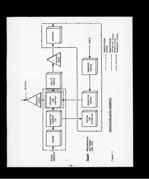
TEC
HN
OLO
GY
S
YS
TE
M
MA
NU
FAC
TU
RIN
G
linking systems Is certainly of interest, research efforts in CAD/CAM
systems are usually aimed at the control of a limited number of computer
controlled machine tools, often in a green field site situation, and do
not reflect the problems encountered in implementing similar concepts into
an established mass production environment utilising, in the main, a wide
range, by type and age, of conventional machine tools and labour intensive
design/planning/manufacturing control systems.
Contributions in the field of tool control within the three
sub-systems as discussed by Bhattacharyya and Coates are as follows
(a) Manufacturing System
Areas of physical control covered at the tool/component interface
include
(i) Sensing probes for setting and measuring
(ii) Automatic tool wear compensation
(ill) Simplified tool changing leading towards automatic tool
changing, l.e. block change tooling
(b) Manufacturing Technology System
There are tooling implications throughout the technology
planning system and key areas Include
(1) Tool design
(ii) Tool development and evaluation
(ill) Various levels of process planning, including:-
- Total process routing
- Individual operation specification
- Tool paths
(c) Manufacturing Management System
Such systems are required to ensure financial control of the
production systems and in terms of tool control cover such areas as:-
- 57 -

(1) Inventory control procedures covering the procurement and supply
of tooling and related Items to the machine tool and monitor
tool material usage variance.
(11) Industrial Engineering procedures which establish tooling
related man-assignment standards and subsequent variance from
the standard, i.e. tool setting, refurbishment, etc.
The degree to which any of the preceding areas are investigated
depends upon the level of focus adopted in the research work; for the
purpose of this research work this is set at achieving the control
of tooling at factory level and not at the level of the individual machine
tool. As later discussion will reveal, the achievement of this criterion
required the setting of a system boundary that went beyond the factory,
and included the external tool suppliers as an integral part of the
overall ATOMS concept. Therefore, whilst an appreciation of the topics
covered in (a) is useful, the main area of attention will be to review
literature which falls into the categories of manufacturing technology/
management systems, i.e. (b) and (c).
3.6 TOOLING TECHNOLOGY SYSTEMS
Spur [19] 1971, pinpoints the heart of the problem by showing the
tool control system as a sub-system of the manufacturing system and
identifies the important technological aspects as being:-
(a) Properties of the tool material
(b) Tool geometry
(c) Toolholders and their placement
In addition, Spur recognised that as a general point manufacturing
sub-systems had yet to be evaluated and considered this to be an important
task for future research.
- 58 -

If Chis direction offered by Spur is to be pursued then tool control
must begin by ensuring the application of the correct technological
specification at the cutting edge, l.e. the achievement of technological
control. The operating efficiency of the machine tool exerts a
predominant influence upon manufacturing costs and the ability to move
towards optimising the manufacturing system begins with the efficiency of
the process planning system. The advent of computer aided engineering
systems has, and will continue to offer, significant contributions in
terms of process planning systems and the two key areas of advancement
are:-
(a) The structuring of technology data bases.
(b) Automated process planning systems.
It is recognised that CAD systems will play an influencial role with
respect to special purpose tool design, but for the purposes of this
literature survey, the emphasis will be towards items (a) and (b) as
stated above, and discussion on each area is contained in the following
sub-sections.
3.6.1 Technological Databases
In a further paper Bhattacharyya and Coates [AO] 1976 take an
overview with respect to such databases and identify the need for
companies to structure them to incorporate all the manufacturing
technology related information requirements of the production sub-systems
described in the preceding section. Essential characteristics of such a
database would include information relating to:-
(a) Machlnabllity
(b) Component material specifications
- 5 9 -

(c) Tooling
(d) Machine cools
(e) Coolant, ecc.
A m [41] 1975 pursues a similar cheme for Che scorage of group
cechnology relaced daca and. MerchanC [27] 1975, visualises chac while such
daCabases may evolve from machinabillCy type daca banks chey will cover a
wider span of accivlcy and are a prerequisite for providing Che
manufacturing information base for CAD/CAM implementation. It is apparent
Chac as companies strive to compete technologically in Che market place
Chen Che structuring and maintenance of such databases will become a pre
requisite for business survival.
It would be misleading to imply that the collection storage and
retrieval of technical information is a new phenomenon. Every engineering
company will have some form of technical data recording system to support
its manufacturing operations. At present most of these are not
computerised and in many cases base data, albeit lacking in consistency and
quality, can be found in non-technology planning departments, e.g.:-
— Finance - assets register
— Purchasing - tool costs
— Industrial Engineering - tool change frequencies
The evolution of computerisation and communications technology has
made the ideals of such databases possible and enables many of the
difficulties traditionally associated with maintaining integrity of data
to be overcome. The information becomes more accessible and as the system
develops the database will be able to serve company-specific needs and
furnish more detailed information than would be found by searching
internatlonal/natlonal data bank files, or by that offered by commercial
technical data software packages.

If Che analysis given by Spur [19] 1971 is to be taken as a starting
point, viz. that tool control begins with the correct technological
specification at the cutting edge/component interface then certain areas
of the proposed technology databases assume priority status, particularly
those relating to machinability data. Because of its importance in a
potential tool control system the subject area is discussed in greater
detail in the following sub-section.
3.6.2 Machinability Databases
Although the term 'machinability' is commonly used throughout
published literature it is difficult to establish a precise definition of
its meaning. The Machining Data Handbook [42] 1972 defines the
machinability characteristic of a component material in terms of:-
(a) Surface integrity
(b) Tool life
(c) Power or force required
Where tool life is generally defined as the cutting time (in minutes)
required to produce a given wear land upon a given tool material when
cutting a given component material at defined machining parameters.
It should be recognised that while the above definition has been
given as a general guideline it does omit comment upon chip form which
will always be a key area for discussion with respect to machinability.
However, using this definition as a starting point it is now possible
to review the subject area of machinability databases. Once again this
can be considered from differing levels of perspective, ranging from the
much publicised national data bases to purpose-designed 'in-house' machining
information which can be unique to individual companies.

At the national level the majority of the machinability data centres
were formed during the late 1960's and early 1970's, many at the
instigation of respective governments. Typically they offer a
wide-ranging machinability based service to their subscribers and include
such activities as:-
(a) Recommendations of cutting conditions
(b) Laboratory data
(c) Workshop data
(d) Literature service
(e) Specialised machining consultancy
Some of the more notable data centres include:-
(a) UK - PERA Machining Data Club, Moore [43] 1974
As the result of a Ministry of Technology feasibility study in
1969 momentum was given to the formation of the PERA machinability
data centre in 1972. The 'club', as PERA prefer to call it, offers
two main services to its subscribers
(i) Regular supplies of machining data bulletins which build up into
volumes of the machining data manual.
(ii) Limited free access to PERA's machining data service whereby
companies can request specific machining information not covered
in the machining data manual.
(b) Japan - National Machining Data Centre (NMDC), Sata et al [44] 1974
Early research by the Japan Society for the promotion of the
Machine Tool Industry recognised the role that a centralised computer
based machinability data bank would play in CAD and CAM. This led to
the formation of the NMDC in 1974 with its heavy bias towards a
NC/CNC-related technical information service.
- 62 -

(c) USA - Machining Data Centre (MDC), Kahles and Field [45] 1974
This government financed body became operational in 1965, and
unlike the Japanese centre, offers a broad-based machinability data
service to many engineering related industries, e.g.
Automotive and farm equipment
Aerospace
Instrument and precision engineering
Machine tools
Shipbuilding
Screw machine production
Foundry
Steel mills
MDC are also responsible for producing and publishing the well
known Machining Data Handbook.
The original thinking behind such centres was sound in that they
accumulated vast stores of information readily available to subscribers.
However, in practice, various factors Including economic and psychological
mitigate the benefit of such data to industry.
Specific problems encountered by MDC and PERA include:-
(a) Cost recovery has been an on-going problem in that while members
are usually willing to pay for data to be generated to provide
solutions for individual machining problems, there is a resistance to
charges for searching or retrieving data that already exists. This
resistance is probably due to an unwillingness to recognise machining
data as a commodity combined with a lack of awareness of the costs
Involved in data collection, storage and retrieval.
A fundamental problem here is the inability to quantify the
- 63 -

value to an individual company of a national information service.
Internal finance procedures may well approve the purchasing of a
machining data handbook, but not the initial registration fees and
on-going access costs to an external data bank; thus technological
updating, an aspect of ever increasing importance to company survival
is foregone.
(b) The lack of accurate data which stems from excessively large
grouping of workpiece and tooling materials when Industry really
needs smaller groupings with accurate data on specific tool material/
workpiece material combinations.
(c) Individual companies may not be truly representative of their
Industry class and generated machlnability data may bear little
relevance.
(d) Many companies are not concerned with the optimisation of
individual machine tools, but rather with the optimisation of costs
of production for an entire Job or production.
Clearly, any refinements required to Improve the limitations Imposed
by (b), (c) and (d) would further compound the cost recovery problem of
<•).
Moving away from the national level of data banks it is becoming
increasingly common for cutting tool suppliers to offer a restricted
machinablllty data service relating to their own products. A prime
example of this is the time sharing facility offered by Carboloy (GE -
USA) to subscribers relating to tungsten carbide and ceramics. Similar
data is now available in hard copy form from the majority of the larger
tool suppliers in the UK market.
Weill and others [46] offer a positive direction in rectifying many
of the weaknesses as identified in this sub-section by stating:-
- 6 4 -

"The development of the automatic manufacturing system has stressed the
need for a rapid access to 'proven' data in the technological field. This
need should be satisfied by simple and cheap data bank systems."
Ueill stresses the difficulty in collecting reliable data from
Industrial sources and proposes ways to overcome certain of the
difficulties encountered. The methodology pursued shows how available
data can be used to determine optimum machining conditions and compares the
results obtained with the results of current data handbooks, notably the
second edition of the Machining Data Handbook [42] 1972. The results of
such comparisons indicated a high degree of overlapping with METCUT data
with respect to feed rate, speed and depth of cut, but compared to the
manuals the data bank offered a more precise evaluation of the machining
conditions, particularly with respect to time and cost Involved. An
additional benefit identified was that the data bank had a high potential
for updating and optimising improvements, the Information for which was
not always available in handbooks.
3.6.3 Computerised Process Planning Systems
An expansion of the machinability data banks has been to link them to
computerised process planning systems. The growth in this area is
directly linked with the development of CAD/CAM systems and begins to set
a base to ensure consistency in a function which has traditionally been
vulnerable to the non-standardisation of process application caused by the
labour intensity and preponderance of personal preference in the process
planning function. The achievement of improved levels of consistency is
essential for two main reasons and these are:-
(a) Process planning is the first stage in the manufacturing process
and is a major determining factor with respect to manufacturing
costs.
- 65 -

(b) As later chapters will show a broader approach to tool control
will be based on disciplined control over metal removal technological
specification and application.
At the highest level of differentiation computer aided process
planning systems (CAPPS) can be classified into one of two categories
(a) Retrieval type systems which are Group Technology orientated and
rely heavily on effective data file organisation and component
classification systems.
(b) Generative type systems which pursue a decision-making process
structured by the use of alogrithms which manipulate engineering
logic through the use of mathematical equations. In principle
truly generative systems are still very much in the conceptual stage
and the present systems generally classified into this category still
require a high proportion of interactive user dialogue to generate
the required decisions.
While the generative systems avoid much of the data storage
problems of the retrieval systems they do require a thorough
understanding of metal removal processes and the use of mathematical
models.
Against this background it is helpful to understand the function of
the more well known systems and to do so it is necessary to establish a
second level of differentiation, and a broadly defined classification would
be as follows:-
(a) Tool motion plan
(b) Process operation plan
(c) Process plan including time and cost estimates
(d) Machine shop scheduling
6 6 -

Referring beck to the three system definition es given Initially by
Peklenlk followed by Bhattacharyya and Coates, Items (a), (b) and the
majority of (c) are considered to be embraced by the management technology
planning system, while Item (d) Is Identified as part of the manufacturing
management control system.
Discussion of the CAM element of CAD/CAM during the 1960's and early
1970's usually centred on the part programming for NC machine tools. With
hindsight this perspective can appear to be very narrow as the activity
under attention really only covered the detailing of the cutter path and
operational process plan for specific machine tools. However, part
programming has become recognised as one of the earliest developments in
the field of computerised process planning systems and the programming
language known as APT (Automatically Programmed Tools) has become
synonymous with the evolution of CAD/CAM systems.
APT was developed by MIT during the years 1955-60 and subsequently
enhanced by several engineering centres in Europe during the 1960's.
Notable work Includes the development of specific APT based NC machining
modules by the Engineering Institutions in Aachen, Berlin and Stuttgart,
resulting ln:-
EXAPT 1 Drilling
EXAPT 2 Turning
EXAPT 3 Milling
During the 1970's a second popular part programming language emerged
known as COMPACT II which is a proprietary system of MDSI (Manufacturing
Data Systems Incorporated). The majority of the present-day commercially
available systems utilise either APT or COMPACT II based languages for NC
tool path generation.
Systems which go beyond the absolute detail of the motion plan and
consider other elements of the process such as cutting conditions, power
required, etc., are typified by the TNO (Netherlands) MITURN turning
- 6 7 -

module [47] 1971. An interesting feature of MITURN is that it was an
early attempt to generate procesa detail for either NC or conventional
machine tools.
Having established the process operation parameters the next step is
to compile the overall process plan. Typically such systems have the
capability, through system/user interactive dialogue, of producing
operation sequences after having given due consideration to such aspects
as machine tool selection, cutting conditions, machining times, etc.
System classification at this level becomes difficult as the majority of
commercially available systems combine generative and retrieval
capabilities. Bearing this 'greyness' in mind examples of computerised
process planning systems include
(a) Systems based predominantly on the generative approach Include
the derivations of the AUTAPP System, Evershelm and others [48] 1980,
and CAPSY (Computer Aided Process Planning System), Spur [49] 1978,
both of which were initially designed for NC turning applications but
have now been expanded to cover other machining processes for both NC
and conventional machine tools.
(b) Information retrieval systems MIPLAN, Schaffer [50] 1981, and
LOCAM,Gibbs [51] 1980. The MIPLAN system is attributable to the work
of TNO (Netherlands) and is the process planning support system to
Computervlsion Limited's CAD Systems and can be classed as a process
plan 'assembler' system working on the principle of planning by
variance, i.e. the standard process plan is generated allowing the
process engineer to concentrate on items which may vary from
standard. The associated component classification system which is
the cornerstone of the MIPLAN system, is known as MICLASS and is
discussed further in Chapter Four.
- 68 -
LOCAM Is based upon a structured Information storage, retrieval
and manipulation process whereby manufacturing related information
can be stored at various levels of applicability, ranging from the
high level 'macros' which contain common generalised data, through to
the more process specific data patterns, and finally to tables of
discrete data. The system allows the user to specify engineering
logic through Interactive dialogue to enable the compilation of the
process plan. A brief Insight into both systems in the form of
system routing demonstrations suggests that MlPLAN adopts a more
mechanistic approach to planning whereas LOCAM encourages flexibility
with a greater emphasis on the achievement of engineering logic through
user input.
Systems which pursue a much broader span of activity Including machine
shop scheduling are typified by PEFAC, Challie 152] 1981, H Walton Technical
Systems Limited, Rassam [53] 1980 and the National Engineering Laboratories
CAPE System [54] 1980. There are similarities between these systems and the
LOCAM system as discussed in the previous paragraph in that all three rely
on data files being established relating to individual company's manu
facturing Information, i.e. machine tool specifications, cutting parameters,
component material specifications, work element times, etc. However, the
emphasis is more towards the development of tlme/cost estimates, work
scheduling, etc., albeit experience to-date appears to have been limited
to small batch work environments. In summary, common features linking the
systems discussed under the general heading of CAPPS include
(a) The concept of fully automated process planning systems are
still very much in their development phase despite dialogue with
respect to fully integrated CAD/CAM systems from national and
international commercial turnkey system suppliers. Kotler [95] 1979,
- 69
gives a further insight into the subject area by stating that the
practical limitations on Implementing such systems is due to the lack
of three dimensional computer aided design modules and the absence of
comprehensive manufacturing data bases which are difficult to achieve
given the great number of product types being designed and the
countless additions to technology.
(b) Systems are designed to reduce costs associated with the
generation and maintenance of the process plan.
(c) In principle they are logic orientated plans designed to take
full advantage of computing facilities.
(d) Experience is showing that these systems are unique to their
operational environment.
(e) The vast majority have been specifically designed for
application to small batch environments although publications are now
available discussing more far-reaching systems under development
within the aerospace and related environments. Kotler [55] 1979,
discusses a computerised production process planning system under
development for the US Army Missile Command, based on an information
retrieval variance approach, and at the time of publication covering
a limited number of machining processes.
Hermann [56] 1979, presents an overview of the ICAM (Integrated
Computer Aided Manufacturing) program which is an ambitious project,
initiated by the US Air Force, to develop a completely integrated
system covering all the computer aids in manufacturing in the
aerospace Industry. Little detail is given with respect to the
approach to be pursued in terms of process planning although the
requirement to link such files of information as cutter selection,
speed and feed selection, form tool design, etc., is identified.
(f) The majority of the systems require files of manufacturing
related data unique to specific companies to be established before
- 70 -

the systems can become operational. This raises serious concerns
because o£ the quality and relevance of such data, much of which may
contain inherent custom and practice, then assumes a significant
level of importance within the functioning of the system. Too often
the system specifications assume that items such as up-to-date tooling
and machinability operational standards are already in existence,
giving little consideration to the realities of having to initially
establish, and then maintain the relevant information.
Clearly the correct application of metal removal process planning
technological standards will play an important role in an eventual tool
control system and it is now necessary to undertake a similar review
within the manufacturing management control system where the control of
the tool material supply to the machine tool and subsequent control over
tool usage are major factors.
3.7 INVENTORY CONTROL
Inventory control is the discipline with which tool control has
traditionally been associated. A literature search under the general
heading of 'Tool Control' will produce encouraging titles but are, in the
main, directed towards small to medium batch work production environments
and either discuss good housekeeping practices (i.e. "tool crib
management"), e.g. Wood 157] 1958, the Tool Engineer's Handbook [58] 1959
and Burnett-Hughes [59] 1962 which are based in the pre-computer age of
the 1950's or on the experience of several individual companies/management
consultants in the Installation of computer based stock/flow control
systems for consumable tools in general, e.g. Mittal [60] 1976, Hebber and
Branl [61] 1976, Kellock [62] and Galgut [63].
To clarify the terminology used the term 'inventory control' is taken
to Include stock and flow control systems, with the following respective
definitions taken from Burbldge [64] 1980.
- 71 -

(a) Stock control systems maintain supplies of materials and parts,
but ordering a new batch every time stocks of an Item drop to a
predetermined level.
(b) Flow control systems determine the quantities to order and their
due dates by calculation from production programmes which are based
on sales forecasts. Both Period Batch Control (PBC) and Material
Requirements Planning (MRP) are derivatives of flow systems.
The importance attached to tool classification and coding systems
does emerge, but as they are Inventory control based, their level of
sophistication rarely goes beyond that of simple alpha/numeric block class
codes, the objective being purely and simply to apply a unique code number
to each individual commodity item. Classification and coding systems
have, however, received microscopic attention in the field of component
statistical analysis for the application of the principles of Group
Technology, and more recently CAD.
In addition to the literature survey several visits to non BL Limited
companies were undertaken to review 'in-house' tool control systems.
Reference to Figure 12 indicates that as with many of the publications on
the subject the emphasis within these companies was very much towards
limited manual orientation/computerised stock control systems utilising
simple block numeric codes. In every instance no action had been taken,
or indeed was planned, in terms of company based machlnabllity and formal
control over tooling standards was minimal. The reasons for this
situation were as follows
(a) It was easier to quantify the justification for an inventory
control system than one that controls metal removal technology.
Dialogue suggested that there was a lack of understanding as to the
real benefits to be achieved through technological control reflecting
7 2 -

>
n31
III111
• I
liilIIItí.Ï2*:í:
1If JulÏ ÛVìii »5
U?ill
-1 V fiI htit Í «'Sî!îill
11‘fIliIls111III
i i 5 ] , ! ! ihd
i l
ilïrî: 1Ili
!{jîì l i
y!iiiliilim; « ■a 31 - - - - - - - -
*1 1 ! 3 I - im
Il jí - - - ,!]HUsi*
-I a «- i n 1 ■V 'S •> •> I 1 1
1 J - ■ ■ • ■> >
I 1 - - - i fí-M iu • ■ - -
*15):■ ] . ?
Ill Illsi.Ill Ili Ili lliii Ili ili
Il |i ■ - II - ■ - • -
P i i ] *> *> - > - s ilh
Sil -’ 5 ■ - - W li - • - 5Î
” ] ■ I) Il II • il -
!=l- ■ - -
li]!-.1 á mif-jíilunii!
-li
11*1
liI ■ - • - - - - -
Ü if! il» ¡III Iss il i! li ìli
i ■Hi ih
1h i
ss
liìÌ3 Ili
AN
OVCH
tflC
W
or W
OW
B.L
. L
TP.
APPH
OAC
HCS
TO
TOO
L CO
NTR
OL
Fiy
ui

very much attitudes of custom and practice - the hallmark of
traditional process planning environments.
(b) In general Inventory control procedures had proven to be
successful in the control of direct materials resulting In the
application of similar control mechanisms for Indirect (consumable)
materials. This approach resulted in tool inventory levels and rate
of turnover, being taken as the simple Indicator as to the efficiency
of the management of tools within the factory.
(c) Standard, off the shelf, software packages are now readily
available headed by IBM's COPICS (Communications Oriented Production
Information and Control System), Walko [65] 1980, modules which
service the requirements of the Manufacturing Management Control
Systems, but offer little more than a data base storage facility for
the basic information required within the Manufacturing Technology
Control System. Typically tool control is discussed in some length
within the COPICS manuals [66] 1981, but control is directed towards
the benefits of tool material requirements planning with minimal
vision and consideration being given to the control and update of the
application of metal removal technology.
Three papers which go marginally beyond the Inventory control based
approach to tool controlare those by Justice and Gaio [67] 1966, Gay and
Moffatt [68] 1974 and Galligan and Mokris [69] 1981.
The interesting features of the work by Justice and Galo, which
describes the implementation of a computerised tool control system at
IBM's manufacturing division (Rochester, USA), includes the principle of a
tool 'tracking system' for reground tools to enable a complete new/
reground tool Inventory status to be generated and the Implementation of a
significant character tool classification and coding system. As Figure 13
shows the system comprises of nine significant characters which represent
74 -


the basic tool shape and material grade followed by characters for tool
geometry condition, number of tools required for a specific machine tool
set up, and finally eleven 'end of code' characters for detailing tool
modifications etc.
This paper is a good example of the author attempting to go beyond
the traditional stock control based systems, but recent communication with
the Company in question reveals that since the paper was published in 1966
the system has not progressed much further, since in terms of possible
linking the tooling definition based classification and coding system to a
more comprehensive machinability standards data base. The present day
system covers 5,000 cutting tools and related spares in total.
Cay and Moffatt concentrate predominantly on the financial control of
tooling through improved P and MC/Finance based systems and make only
passing reference to the need to up-date tooling technology with ongoing
tool trials to compare the products of alternative suppliers against
existing manufacturing data.
Galligan and Mokrls offer an interesting paper on tool control
recognising the advances towards fully integrated manufacturing systems
software and describe in their terminology a 'complete' tool control
system which had recently been Implemented at Braun Engineering, a major
steel extruder in the USA. This system addressed three areas in terms of
control
• Tool inventory control, adopting the principles of flow control
with the generation of tooling bills of material.
« Tool consumption and control.
« Engineering change and control.
Certainly from a tool material supply point of view this paper was
the most comprehensive on the subject area found while undertaking the
literature survey, but their use of the term 'complete system' is rather
misleading as the emphasis is still very much on the traditional approach
- 76 -

of Inventory control and what initially appears to be an extremely
interesting area of the system, namely, engineering change and control
refers purely to monitoring tooling stock implications when introducing
new work to the machine shops.
From the contents of the paper it is apparent that the system has
been developed along similar lines of IBM's COPICS 'communications'
approach to establish closer control over existing inventories and tool
usage. Fundamental limitations with this approach include:-
(a) Such systems control the existing situation, but discourage
thought as to the actual need for tooling inventory, i.e. the
potential for a 'nil inventory* situation.
(b) The economics of tool usage are directly linked to improvements
in cutting tool performance, the control and update of which were not
discussed and therefore by implication are not recognised as a
prerequisite to overall tool control.
Other papers which offer interesting points relating to specific
aspects of tool control include:-
(a) Zeleny [70] 1981, discusses tool flow and transportation
implications with respect to supporting the requirements of
flexible manufacturing systems.
(b) Taylor [71] 1968, discusses the benefits of tool store
centralisation and the need to establish formal control over
reground tools within a mass production environment (Pontiac
Motor Division of General Motors).
In summary, while the papers discussed in this section address the
problem of tool control their level of focus is directed towards the
77 -

requirements of tool material supply systems to the neglect of achieving
the same level of control over the technological parameters of metal
removal.
3.7.1 Tool Psage
The two key factors that emerge in terms of tool usage are:-
(a) Tool re-usability - whereby tools can be returned to the stores,
after regrind, in the same form as which they were issued. This is
particularly applicable to purpose-designed tools such as broaches,
hobbs, shaving cutters, etc., and therefore, there is a requirement
to establish the number of tool lives available per individual tool.
(b) Tool life - is applicable to recycllble and disposable
(indexable Inserts, grinding wheels, etc.) tooling and is usually
measured in terms of:-
(i) The number of components that will be produced until one of the
following limiting factors is reached:
1. Tool deterioration (roughing operations) to a point
immediately prior to catastrophic failure.
2. A pre-defined tool wear limit is reached, i.e. flank/
crater wear as established by the relevant ISO or British
Standard. However, it should be recognised that the
adoption of this discipline would require accurate control
at the cutting edge/component Interface, which is typified
by CNC based activities, and would prove more difficult to
implement and control within a labour intensive,
conventional machine shop environment.
3. Component deterioration (finishing operations) to a point
immediately prior to the excession of component design
tolerances. This category tends to be applicable to high
component volume transfer lines.
78 -

(11) Tool life can also be stated In terms of the number of hours in
use before a tool change Is required, irrespective of tool or
component condition. This approach tends to be used on purpose-
designed, multi-spindle machines, such as chucklng/bar
automatics, whereby total banks of tools are changed at
convenient break points during the shift to maximise machine
productive availability.
All of the items discussed in (a) and (b) should be subject to
Industrial Engineering disciplines where tool change frequencies/tool
regrinds are accurately measured and built Into the standard time from
which point variance from standard can be monitored on an ongoing basis.
Again, for this procedure to work effectively, the Industrial
Engineer requires the support of machinability/tooling standards. If such
standards are not available the engineers resort to custom and practice
with little awareness of the true operational potential of the cutting
tool. This can build In constraints to the overall business efficiency
by allowing non-management personnel, l.e. machine tool setters/operators,
to have a major Influence on the efficiency of tool utilisation.
Once again the question of consistency arises at the process planning
stage and an extension of CAPPS has been the development of MTM (Method
Time Measurement) oriented software packages. A typical example of such a
system is AUTOMAT and COMPUTE, Schofield [72] 1980. AUTOMAT (Automatic
Measurement and Times) is the system name for a suite of programs which
can assist the Industrial Engineer in the design and evaluation of work
tasks covering the two main areas of time and method study. COMPUTE is a
similar package aimed specifically at machine shop based work. As with
the CAPPS survey discussed in sub-section 3.6.3 the effectiveness of MTM
systems will require access to accurate and relevant machlnabllity data
and tooling standards.

CHAPTER FOUR
4.0 LITERATURE SURVEY - CLASSIFICATION AND CODING SYSTEMS
From the onset it is important to recognise the broad division
between the roles of classification and coding systems, and these
are as follows:-
(a) Classification
In classification each commodity is allocated to a specific
class of commodities; the classes themselves are clearly defined,
and are ordered into a structure - commonly hierarchic - showing
the relationship of one class of commodities to another. The
structure may be anything from a highly organised complex structure down
to a simple list of groups, NCC [73] 1968.
(b) Coding
A code is one or more symbols to which an arbitrarily assigned
meaning and/or arrangement has been given which, when deciphered,
communicates specific information or intelligence, Hyde [74] 1976.
4.1 AN HISTORICAL PERSPECTIVE
Classification and coding systems have received varying levels of
attention over a long period of time with early notable advances including
the hierarchical classification of flora and fauna by the Swedish botanist
Linne (1707-1778) and the Dewey numerical classification systems
(1876) which provided 1,000 book classes and relative index.
The importance that F W Taylor attached to the role of classification
systems within his philosophy of 'Scientific Management' is shown by
H K Hatheway, a colleague of Taylor at Tabar Manufacturing in 1904, when
addressing the Taylor Society in 1920 quoted Taylor as saying, Hyde [74]
1976»-
- 80 -

"Classification is essential to an orderly arrangement of the facts
relating to a business and to the orderly conduct of its activities.
During the period of development and installation of a system of
scientific management is is especially helpful to a proper
visualisation and understanding of the business and its problems as
well as the conduct of the work".
4.2 INDUSTRIAL CLASSIFICATION AND CODING
Hyde [74] 1976, defines industrial classification as:-
"A technique for arranging the individual items comprising any aspect
of a business in a logical and systematical hierarchy whereby like
things are brought together by virtue of their similarities, and then
separated by their essential differences".
The importance attached by Taylor to classification systems has since
been endorsed by many observers including Drucker [75] 1954, who although
directing his attention to organisation theory said, to quote: -
"Get the facts, is the first commandment in most texts on decision
making. But this cannot be done until the problem has first been
defined and classified. Until then, no-one can know the facts; one
can only know data. Definition and classification determine which
data is relevant; that is, the facts. They enable the manager to say
what is misleading".
Drucker's observations were well-timed because the immediate post-war
years witnessed considerable advances in the use of industrial
classification systems for information retrieval particularly in the
fields ot Group Technology with the early work of Sokolovsky (1939)
followed by Mitrofanow and Opltz in later years, gave momentum to advances
in the design of 'component statistic* classification systems utilising
hierarchic meaningful character systems as against the more generally
open-ended approach to be found in other areas of statistical analysis.
- 81 -

Houtzeel [76] 1976 summarises the two broad categories of classification
systems to be found within the disciplines covered by the general heading
'Group Technology', and these are:-
(a) Hierarchical (Monocode) systems
(b) Chain-structured (Polycode) systems
A brief description of each category is as follows
4.2.1 Hierarchical Systems
Hierarchical systems are designed primarily for design or engineering
departments. Using a numeric code (typically from six to twelve
characters), these systems provide a means of coding and classifying drawings
to facilitate the retrieval and eliminate unnecessary duplications. In a
hierarchical system, the meaning of an individual character in the part
classification number is dependent on the previous character in the
classification number, and does not represent a discrete bit of independent
information. The first character of the number thus defines a type of
part 'shaft', for example, the second defines a type of shaft, the third
defines a further refinement of the second character, etc. The Opitz
system is a typical example of this category and is shown in Figure 14.
4.2.2 Chain-Structured Systems
Chain-structured classification systems are structured in a different
way. Every character in the part classification number represents
a distinct bit of information, without regard for the previous character.
Every character in the classification number thus represents a
"small building block" of the total part. One character may be used
to define form, for example, the next dimension, etc. By
chaining these blocks together, a complete part can be described
in a manner which is internally consistent with the description

(a) Th g sT»ucTftt cr the main row“ :ooe r.p S'jpple-cntawy cooe
1 2 3 *
s
l
s£
? 1i• si £
(8) an CKAMPLC or secondary cooes roR opération type ano sequence
THE OPITZ CLflSSiriCftTION SYSTEM
83 Figur* 14
of all ocher parts In the system. The MICLASS system developed by TNO
during the mid-1970's Is a typical example of a chain-structured system,
and although difficulty was encountered In obtaining specific information
due to commercial Implications, a general overview of the commodity
categories to be covered by the system, and the more well known component
statistical routings are given in Figures ISa and 15b respectively.
Rose [77] 1977 states that there are In excess of 120 varieties of
Group Technology orientated component classification and coding systems,
the more prominent of which are reviewed by Knight [78] 1972 and system
comparisons are given by Remmerswaal and Schllperoot [79] 1971.
Two systems which have a broader, commercial, applicability are those
of NATO and Brlsch, both of which are discussed in the following sub-section.
A.2.3 NATO System (General)
The classification and coding systems mentioned in the previous
sub-sections are orientated towards establishing control within a
manufacturing environment. A system which goes well beyond the
requirements of manufacturing and into a much broader field of management
control is the NATO equipment codification system which is reviewed at
length by Mitchell [80] 1972. Based on the US 'Federal Catalogue System*
it was adopted as a NATO standard in 1957 and has inbuilt its own
classification, naming and hierarchies of coding systems. Its main
attributes are the grouping of interchangeable products and commodity
specifications. Its limitations for general use include its reliance on a
large confidential data base, the extensive system maintenance required,
and as it is based on non-significant characters nay create compatibility
problems with other in-house technological classification systems.

C L A S S I F I C A T I O N N U M B E RV A R I E S B E T W E E N 6 A N D 3 0 O I G I T S
E LEC TR O N IC S
TOO LIN G
MACHINE TOOL SPARES
MACHINED COMPONENT S T A T I S T I C S (MICLASS)
E T C .
(a) Multiclass Categories
DIMEN SIONS_ MATER lAL __ Am
i 2 3 4 5 6 7 8 9 IO II I2
FORM TOLERANCE
(b) MICLASS - Machined Component Statistics
MICLASS SYSTEM
- 8 5 - Figura 15

4.2.4 Brisch System (General)
There are two types of classificatlon/codlng systems generally
associated with the Management Consultants, Brisch Birn & Partners
Limited. The first system is the well-known 'monocode' which is a typical
example of a significant character hierarchical structure whereby each
code character is qualified by the preceding code and, in turn, qualifies
the succeeding code. In principle the monocodes are used as the universal
code recognised by all functions as the base identification for a component.
The second system, referred to as 'polycodes' are essentially open-
ended strings of significant characters which contain specific information
which is of interest to only a limited number of system users. In practice
the polycodes act as 'trailer' codes to the main monocode, and an overview
of each system is given in Figure 16.
Astrop [81] 1978, expands on the question of system flexibility
by discussing the experiences of several companies in implementing the
broad approach of a concept known as the 'Brisch Wheel' which classifies
a company's business activities into ten main classes, reference to
Figure 17. This simple principle provides a classification structure
which can be moulded to individual company's requirements and part explains
the claim by Brisch-Birn that there is no such thing as a Brisch Classificati
System as no two systems are alike.
Houtzeel [76] 1976 argues that systems such as Brisch, Opitz, etc.,
which are based on product functions have a number of shortcomings.
For example, changes in products require that produce dependent systems
be overhauled. Additionally, visits to certain companies discussed
previously in section 3.7, such as Hopkinsons, Coventry Climax and Aveling
Barford where Brisch based systems are operated across selected commodity
groupings, revealed extremely cumbersome classification/coding manuals
which are error prone to manually orientated paperwork maintenance systems.

FAMILY UNIT
N N N N - N N N
r~CLASS I
SUB-CLASS1111 SYSTEM OF1 MEASURE
SERIES SECTOR
(a) Brisch Monocode
1ST FEATURE
1N 1 N 2 ___A1 * A2 4
MONOCODE POLYCODE
(b) Briach Polycode
X ™ FEATURE
1
Sourcai Hyda (74) 1976
BRISCH MONO AND POLYCODES
Figura 16


4.3 CUTTING TOOL CLASSIFICATION AND CODING SYSTEMS
A review of Che application of classification and coding systems with
respect to cutting tools is contained in the following sub-sections.
4.3.1 Mnemonic Codes
The visits to the companies referred to in section 3.7 revealed that
the majority had Implemented Mnemonic based coding systems. This is not,
perhaps, surprising as Che most well known mnemonic system is F W Taylor's
tool code which formed the basis of Twist Drill Manufacturers' Association
code for perishable tools and was implemented during World War I and was
in continuous use up until World War II when it began to break down due to
an increasing number of varieties. Typical examples of a general mnemonic
code and, more specifically, Taylor's mnemonic code are given in
Figures 18a and 18b respectively.
4.3.2 Commodity Classification
Again a commonly used system quoted in the Tool Engineers' Handbook
158] 1959. As Figure 18c shows, the system is based on successive sub-
classifications, but with the mnemonic system, is prone to erosion with
the introduction of new tooling families.
4.3.3 Brisch (Cutting Tools)
Reference to Figure 19 gives an example of the Brisch (monocode)
system as applied to a specific family of cutting tools, l.e. hard metal
tipped brazed tools.
4.3.4 PERA - Sequence Technology
As part of the work undertaken under the general heading 'Sequence
Technology' PERA pursued a vector analysis approach to the classification
of turning tools, reference to Figure 20a. While this work offers areas
- 89

0.25'
J
HS SS
L
(b) Taylor's Mnemonic Code
T - 10 (MAIN C LAS S) - C U T T I N G TO OL S
T - Il (SECONDARY CLASS) - DRILLS
T - Il - 015 (SUBDIVISION) - l/64"DIA. ( .0I5"I DRILL
(c) Commodity Classification
GENERAL TOOL CLASSIFICATION AND CODING SYSTEMS
- 90 - Figura 18

5 2 4 3 1 - 1 3 1
5 - Claes2 - Sub-Class4 - Croup
’ { - Series11
3
1— Sector
Source» Hyde (74) 1976
BRISCH MONOCODE : HARD TIPPED TOOLING
- 91 Figure 19

Clamant typee expreeaed Star '
E.g. Part-off and Chamfer Tool - 68«
Shape vector PARAMETERS
Source: PER* (82)
(a) PERA - Saouanca Taetmoloov
y oc v v
0 8 0 » 1 S
• - Tool Material Typa 8 - ISO Crada (Application)C - Tool Manufacturer 0 - Manufacturera Coda C - Soaclal Faaturaa
SourcaI PERA (•)) 1978
(b) PERA . Machlnabilit» Opta Bann
PERA - TOOL CLASSIFICATION AND COOING SYSTEMS
Figura 20
of interest the concept Is limited to tool/component statistics and does
not offer a practical approach for developing an overall classification
structure for the wide ranges of cutting tools and related accessories
likely to be in use in mass production industries.
4.3.5 PERA - Machinability Data Bank
The most comprehensive cutting tool classification and coding system
encountered in terms of technological specification/definltion was that
used by PERA for their in-house machinability data bank [83] 1976.
Reference to Figure 20b reveals a chain-structured system which is
purpose-designed to achieve technological control at the cutting edge and
contains significant characters relating to tool material type, material
grade, special features and cutting geometry.
However, as with the previous sub-section this approach has several
weaknesses in terms of practical implementation in industry and these
include: -
(a) The system is clearly purpose-designed and omits such
important features as tool shape, chip breaker styles, etc.
(b) It does not present an overall classification structure for
all cutting tools and accessories.
(c) The number of characters utilised is far too great for
day-to-day industrial operations.
(d) The chain-structured, polycode approach could be confusing
for less technically orientated personnel, i.e. storekeepers,
commercial clerks, etc.
4.3.6 The Hal System
Halevi [84] 1980 discusses the role played by cutting tool
classification and coding with the Hal (Hal meaning all-embracing in
- 93 -

Hebrew) computer orientated manufacturing philosophy. Figures 21a and 21b
identify the system in use which is, yet again, a hierarchical significant
character system.
Halevi recognises the high cost of installing such systems and the
requirement for continuous maintenances-
"New technologies are introduced into the plant, hence creating a
need for new types and groups of materials. Moreover, this system
does not last forever. Reorganisation and changes in the
classification and codes have to be made every six to ten years.
The limitation of the code length also limits the extent to which
the desired secondary objectives are achieved".
4.3.7 National and Universal Systems
In terms of cutting tools there are three broad areas of interest:-
(a) The NATO equipment codification system (initially discussed in
sub-section 4.2.3). Reference to Figure 22a.
(b) British Standards. Reference to Figure 22b.
(c) International Standards Organisation (ISO). Reference
to Figure 22c.
All three are comprehensive systems which provide the opportunity of
linking tool shape, dimensional and material specifications. However, the
weakness in (b) and (c) is that they do not offer a classification
structure for the wide range of cutting tools and accessories to be found
in a machine shop and because of this no Individual system can be as the
working 'in-house' classification and coding system.
- 94

Prafli Tool*
Sub-qrouo - Thraad Cutting Toola, _
Thraad form (a.g. UNC, 3SF, HF) ----Sir* and TP I (or h In aatric unit*) -Typ# and Matarial* (a.g. Firat Tap, h for Staal, Tor Aluminium)Claaa, othar Idantificationa and OoacCxanplai -
Cutting Tool* - Tap3SW ..è- a 20 TPI ------Firat Tap, HSS — —— Claaa II — -------
(a) Thjaad̂ ¡¡.ttlnq Too}*
Prafia - Toola ---------------Main Croup - Cutting Toola -----SuD-Croup - Carblda Brozad Toola Tool Typa (a.g. Turning, Cut-off! Dlmanaion - Sira — — — — Carblda Typ* and Right or Laft —
X X - X 0 2 1 - J 0 1Profla and Main Croup ----Carblda Brazad Toola -----Shank, ISO For« 2 -------Shank i a 1" ---------Carblda Typa P-01 (ISO) RH
(b) Tool, - Cutting - Carpida Brazad
Sourcai Malawi (8*) 1980
THE HAL TOOL CLASSIFICATION AND COOING SYSTEM
- 95 -Figura 21

5 1 3 3 9 9 X X X X X X X
NON - SIGN IF 1C ANT ITEM _ ID E N TIF IC A TIO N NO.
IREFER TO U -K.- MG 99 - A/BB FOR CLASS CODE 5133)
C LAS S IFICATIO N . DRILL B ITS .
CO UNTERBO RES.- COUNTERSINKS :
HAND AND MACHINE
NATION CODE (UK) .
(a) Tha NATO Stock Code
NATUREOF
ABRASIVE
(b) British Standards
An example of the complete designation of a grinding wheel specification
INSERT TAPE
CLEARANCE ANGLE
TOLERANCE
T P M R 16 03 0 8 SJTTTTTTT L VERSION
C U T T IN G EDGE
RAOIUS
TYP E
C U T T IN G EDGE LE N G TH
THICKNESS
(c) International Standards Organisation (ISO)
The designation of an indexable insert
NATIONAL AND UNIVERSAL - TOOL CLASSIFICATION AND CODING SYSTEMS
- 96 - figure 22

CHAPTER FIVE
5.0 A SYSTEMS APPROACH TO TOOL CONTROL
Chapter Two has shown that previous attempts to gain control over
consumable tooling within the Company have lacked direction, which has been
underpinned by the absence of any in-depth understanding of the problem,
and as a result has attracted little attention in terms of senior
management priority. Equally the work of others has concentrated on areas
of specialist activity within the subject area and a systems approach,
i.e. the study of the 'whole' problem to help management achieve control
over tooling at an operations level, has been neglected.
Despite these shortcomings important lessons can be learnt from an
historical analysis as to why the Company has failed to gain control over
such a vital area of its business activity, and certainly direction offered
by others can be utilised in structuring a sound platform from which the
problem of tool control can be analysed and the necessary control
mechanisms developed.
5.1 PROBLEM DEFINITION
The highest level of problem definition is taken from the NEB's
submission to the Government in December 1979 of the Company's 1980
Corporate Plan/Budget [2] in which the reduction of Inventory levels and
improvements in manufacturing productivity were seen to be essential in
terms of BL Limited's future survival and viability.
Clearly the control of cutting tools would have a significant role to
play with respect to inventory levels and productivity and to help begin
to understand the problem in contributing to the achievement of the
objectives, as set by the NEB, the level of research focus was adjusted to
concentrate on the four factories which comprise the Birmingham Operations
Division of the Light Medium Cars Group of Companies.
- 97

The problems being faced by senior management within Birmingham
Operations require quantitative and qualitative statements and these are
given as follows
5.1.1 Quantified Statement
The main features of the Birmingham Operations tooling activity
profile ares-
(a) The number of tool records, i.e. individual tool code numbers,
is estimated to be in excess of 75,000 items being stocked in 16
individual tool stores located throughout Birmingham Operations.
(b) Total inventory £6.43 million.
(c) Annual expenditure £5.28 million.
(d) Inventory turnover ratio “ 6.43 “ 1.22 years, or 14.6 months.5.28
(e) Productivity in terms of metal removal activity is extremely
difficult to measure, but latqr discussion with respect to Coventry
Engine Plant established a simple index of monitoring weekly standard
hours generated by the Power Train cost centres at the Plant compared
to the cutting tool and related accessories inventory.
Therefore, to contribute to the objectives as established by the
NEB the proposed tool control system should be seen to be reducing the
total inventory and subsequent expenditure against the number
of standard hours generated.
5.1.2 Qualitative Statement
A summary of the underlying reasons for the general lack of control
to be found with respect to tooling is as follows:-
- 98 -

(a) An absence of Corporate standards relating to cutting parameters
resulting in widespread disparity in levels of productivity between
work areas.
(b) The lack of a Group-wide tool classification and coding system.
(c) Inadequate stock control systems.
The net results of the inherent inefficiencies contained in (a), (b)
and (c) weres-
(i) Custom and practice prevailing throughout all areas connected
with tooling decision-making.
(ii) Excessive tool stocks.
(iii) Inefficient tool procurement mechanisms due to the prevention of
the potential for Group-wide bulk purchasing.
(iv) The fragmented approach to tooling decision-making was reflected
in the minimal control over the introduction of new tool types leading
to large ranges of tool type varieties being held in stock.
(v) Duplication of effort in indirect hourly paid and staff
functions, i.e. tool setters, storekeepers, process planning and
purchasing.
Simply, the situation was semi-chaotic.
5.2 SYSTEM OVERVIEW
It would be misleading to imply that a system was initially designed
and subsequently implemented. In reality the research began against a back
ground of extremely broad objectives, namely to achieve reductions in
tooling inventories and to contribute to general increases in productivity
within the Birmingham Operations Group of factories. Additionally, while
certain system design prerequisites were in mind from the onset of the
research work, notably the role and early development of IMPS, much of the
interactive nature of ATOMS only became clear when faced with the
- 99 -

practicalities of system implementation into the receiving factory, and
the ensuing management expectation of positive results.
5.2.1 Research Location
From the onset of the research programme a fundamental principle was
adopted which was that the manufacturing requirements of the individual
machine tool dictated the service required from such supportive systems
as tool material supply and control. In other words, the priority was
to achieve efficient 'spindle management'.
Therefore, to begin to understand the requirements of the manufacturing
system, initial research activity moved away from the extremely sensitive
area of excessive tooling inventories and concentrated on the tooling
problems being encountered on a small bank of machine tools within a single
machine shop, i.e. the single- and multi-spindle bar automatics shop at
the Longbridge Plant. This quickly identified two base problems with
respect to cutting tools and these were:-
(a) The absence of any Company-wide tooling technology 'standards'
encouraging personnel such as setters, foremen, process engineers,
etc., to make personal decisions on the implementation of cutting
tool type and machine tool operating conditions. In this environment
formal process planning documentation rapidly became out-of-date,
and in many cases improvements in cutting parameters were as a result
of personal initiative by the local personnel, and were not recorded
for the benefits of other machining locations.
(b) The absence of formal tool material supply systems to service
the requirements of high component volume machine tools which were
critically linked to car assembly demands.
A number of extremely disturbing features came to light in this
area and include:-
- 100 -

(i) The considerable influence that a storekeeper had in terns of
determining stock levels and tool re-order quantities.
(ii) The high level of dialogue that took place between the store
keeper and the machine tool setters in determining alternative
tool choice.
(ill) The informal working relationships that developed between
foremen, tool setters and the representatives of tool supply
companies, resulting in the latter having full access to the
machine shops, a major contributory factor to the wide ranges
of tool varieties held in stock.
At this early stage, a series of tool trials took place on the
machine tools under observation, and by a series of very simple
technological changes an annual saving of £4.5K in direct tool costs
was achieved.
Having achieved this limited level of success local management were
keen to maintain the research work activity at the level of the bar
automatics shop, but it was recognised that this direction would achieve
little in understanding the interactive nature of the problems of tool
control, particularly when viewed from an operational level. Wishing to
understand the problem at a different level of focus, the research activity
was then changed to cover the four factories within Birmingham Operations,
i.e. Longbridge, Drews Lane, Coventry Engines and Triumph Radford. After
a short period of time the range of problems quickly became apparent,
typified by the absence of machining standards, ineffective multiple
tool classification systems, inadequate inventory control systems,
etc., were common to all four locations and research time was being
diluted by the spread of geographical activity. Because of this the
decision was taken to concentrate the research activity at one plant, develop
a routing through a tool control system, validate the benefits, and
- 101 -

subsequently expand the control mechanisms to the remaining locations.
Coventry Engine Plant was chosen as the centre of the research activity
for the following reasons
(a) The manufacturing activity at the Plant ranged from jobbing type
work through to flow line production on major dedicated machining
facilities. In addition to this only one of the 4,130 machine tools
at the Plant was NC based with the remainder being of conventional
design, a situation which typified the Power Train activity
throughout Austin Norris at the time of writing.
(b) Because the Plant was responsible for machining a high level of
component spare parts as well as high volume components, it provided
an opportunity of studying the machinability of the vast majority of
component material specifications to be found within BL Limited.
(c) Because of the mix of components, the range of material
specifications, the age/range and conventional nature of the machine
tools, high tooling inventory-levels and a complete absence of
computerised systems in tooling related areas, it was considered
that, as a whole, the Coventry Engine Plant was a fair reflection of
the tool control problems likely to be encountered elsewhere within
Birmingham Operations.
5.2.2 Linked Systems
Previous chapters have discussed in some detail the tool control
problems being faced by senior management across Birmingham Operations
at the commencement of this research work, and the key factors to
emerge weres-
102

(a) Design criteria for a tool control system should recognise the
requirement to achieve technological control as well as control over
tool material supply.
(b) Custom and practice prevailed.
(c) Attempts to gain control over tooling-related areas had failed
because of parochial attitudes and blinkered vision in terms of
problem definition and understanding.
Against this background a routing through a tool control system was
developed and implemented at Coventry Engine Plant which accommodated the
requirements of item (a), removed the inherent inefficiencies of item (b)
and did not repeat the mistakes of item (c).
5.2.2.1 Authorised Control
Reference to Figure 23 shows a conceptual system design produced
during the early stages of research. A prerequisite to any future system
had to be a recognised authorised in-house control mechanism for tooling
related information and tool material supply, which controlled the tooling
requirements for operational and forward planning activities. Such a
mechanism would act as a system input filter with respect to external,
i.e. non-company related sources, typified by tool suppliers' literature,
academic publications, etc., and likewise internally generated
information, e.g. variance in practice from identified company tooling
technology related standards.
An overview of the development of such a system is contained in the
following sub-sections.
103

SUPPLI
ERS
ACADEMIC RESEARCH
PUBLISHED DATA

5.2.2.2 Inputs and Outputs of the Manufacturing System
Section 5.2.1 gave a brief resume of initial observations with respect
to tool control when studying a small bank of machine tools within the
Longbridge Bar Automatics Machine Shop.
Discussion by Spur [19] 1971, helps to put these initial observations
into a system context with an analysis of the inputs and outputs of the
manufacturing system, reference to Figure 7, page 45. While Spur identifies
the tool control system as a sub-system of the manufacturing system, it
is clear that as a sub-system it cannot be studied in isolation. The
efficiency of the tooling input into the manufacturing system will require
control over the following tooling related aspects
(a) Correct technological application.
(b) Optimal tool material supply.
(c) Environmental control.
Therefore, while the 'black box' approach to manufacturing systems
is of help as a starting point, it can detract from understanding the
complexities of sub-system interaction which is a prerequisite to achieving
the eventual optimisation of the manufacturing system.
Having identified in systems terms the areas of prioritised control
and the implications of sub-system interaction, it is now possible to
turn to others for further direction in system development.
5.2.2.3 Manufacturing Sub-Systems
Section 3.5 made reference to the work of Bhattacharyya and Coates [39],
and Peklenik [22]. Their observations have been utilised as the platform
from which the tool control system to be described in later sections has
been established. Their analysis Identifies three main sub-systems as
being critical to establishing overall control which were identified
- 105 -

in the previous section as:-
(a) Technological control - Manufacturing technology system.
(b) Tool material supply - Manufacturing Management system.
(c) Environmental control - The setting and maintenance of
environmental control standards would require inputs from both
the technology and management systems.
5.2.2.4 System Design Concept
The major influences on the initial tool control system criteria
were:-
(a) System Requirement
To achieve:-
(i) Control over the application of metal removal technology.
(ii) Tool material supply.
(ill) The installation of necessary disciplines to achieve control
over tooling related aspects within the manufacturing systems
environment.
(b) System Design
(i) To avoid replicated data.
(ii) To install a system input control which facilitated
systematic and dynamic update of the data base.
(iii) Capability for system expansion in terms of:-
1. Geographic mobility, i.e. to be installed at several
manufacturing locations and to have the flexibility to
accommodate problems unique to the receiving plant.
2. The provision for technological expansion in terms of
new metal removal processes and techniques.
3. To be mindful of potential expansion links into
larger CAD/CAM systems.
- 106 -

(c) System Management
(i) To utilise the full potential of microprocessor based technology.
(11) To establish a hierarchy of control whereby certain critical
features became the responsibility of a small number of selected,
highly trained personnel within Birmingham Operations.
Reference to Figure 24 shows the eventual system concept which
superimposes the principles of control as identified by Spur, Peklenlk,
Bhattacharyya and Coates, onto additional systems requirements of
restricted authorised control and a Birmingham Operations technological/
economical tooling data base. In principle the data base supports the
requirements of the technology planning and management control systems and
system update can be through either internal feedback in the form of
variance analysis reports from the manufacturing system, or through the
incorporation of external data. An important feature of the concept is that
while the initial system boundaries are shown to be in-house the external
data links are considered to be an essential link in the dynamic update of
the system and, therefore, external bodies such as tool suppliers,
research institutions, etc., are considered to be part of the system
although their input is strictly controlled. Indeed if the "universal level"
of focus as described by Kilgannon [17] 1980, was to be adopted a 'total*
tool control system would question the supply of raw materials utilised by
the tool suppliers, review their internal manufacturing facilities and
their ability to meet the commercial and technical requirements of the
receiving company's business system.
At this stage genuine practical problems as described in the
following items have been given a lesser priority than the achievement of
a tool control system routing. Such aspects include:-
(a) Multiple tool stores and their impact on tool stock levels.
- 107 -

fig
ura

(b) The absence of any formal work schedule control within the Tool
Rooms, with its subsequent impact on tool regrlnd costs.
An insight into the concept of the tool control system is as
follows:-
(a) Technology Planning System
The two broad areas of activity within this sub-system are:-
(i) Design - which includes, components, tools, jigs/fixtures, etc.,
and to a degree can include such aspects as factory layout.
(ii) Process planning - which Includes metal removal and non-metal
removal activities.
The prime activity of this sub-system is to control technically
and economically the operational standards of the manufacturing
system. In a Power Train environment there are tooling implications
throughout the technology planning system ranging from the metal
removal implications at the component design stage, through to
selecting alternative tools for a unique problem that may occur
within the manufacturing system.
Against this background a decision was made to develop a control
mechanism which concentrated on establishing technological
disciplines at the point of metal removal, i.e. machinabillty and
tooling standards. Therefore, the initial decision was to gain
control over the operational requirements for individual process
operations. Having gained this level of control the philosophy would
be to expand the system to combine the individual process operations
to generate process plans, and further expansion would potentially
Include machining economics, and the linking in to Industrial
Engineering standards to facilitate process estimating packages.
- 109 -

Special purpose form tool design requirements were not
considered at this stage apart from the machinability implications of
tool material type and respective tool geometry.
(b) Management Control System
Of prime importance within this sub-system was considered to be
the control of tool material supply combined with a facility to
monitor Industrial Engineering and Finance Departments' 'variance from
operational standards' reports to facilitate formal disciplines
within the Manufacturing System. Other benefits, particularly in
terms of tool procurement, were not given an immediate priority in
the early stages of the system development as it was felt that having
achieved control within the Manufacturing System, the adherence to
the resulting process operational standards would provide a sound
platform from which the Purchasing Department could take advantage.
(c) System Management
Having established a platform for developing the necessary
control over tooling technology, tool material supply and
environmental control, the ongoing maintenance of the control
mechanisms were then considered.
In this area the two key features to be incorporated were:-
(1) Restricted and authorised control of the system.
(ii) Efficient Information storage, retrieval and update.
Further reference to Figure 24 shows that the conceptual system
has the required input/output control in the form of the data base
management system, a term used at this stage in its broadest sense.
In addition, recognition is given to the syncronlsed update of
replicated tooling related data whereby any data used by more than
one functional department is held in a central tool file. Typical
examples of such data and their originating departments include:-
- 1 1 0 -

(i) Classification and coding (Production Engineering)
(ii) Technological specification (Production Engineering)
(iii) Part description (Production Engineering)
(iv) Standard/current cost (Finance)
The originating departments, as shown in brackets, would
maintain responsibility for supplying the update of the specified
data, known as partitioned data, within the central tool file.
Additionally, the respective departments would also have the facility
to update its own local tooling related data. Examples of such data
would include:-
(i) Production Engineering
1. Tool trial evaluations
2. Alternative tool choice
(ii) Finance Department
1. Off-standard reports
(iii) Purchasing Department
1. Supplier evaluation/address
2. Levels of discount
(d) System Operation
The tooling data base would provide and monitor, through
feedback, the operational standards of the manufacturing systems with
respect to tooling related activities. The data would be accessible
through levels of authority by user areas within the technology
planning and management systems, but dynamic update would only be
through a formal control mechanism with, again, levels of authority
for system update.
Conceptually the implementation of such a system would eliminate
the problems discussed in Chapter Two.
- Ill -

The following sub-sections present an overvlev of the stages
involved In moving from such a design concept to the eventual tool
control system implemented at Coventry Engine Plant.
5.3 TOOL CONTROL SYSTEM (ATOMS)
The system routing which was Implemented at Coventry Engine Plant is
known as ATOMS, an acronym for Automated Tool Management System.
Reference to Figure 25 presents an overview of the ATOMS system which Is
divided Into two clearly defined sub-systems; firstly the 'Technological
Control and Update' system which Is essentially a process planning aid,
selecting appropriate cutting tool materials and cutting parameters for
given component material/machine tool combinations; and secondly the
'Management Control' system which comprises four main control features,
and these are:-
(a) Inventory control
(b) Order tracking
(c) Material receiving
(d) Inventory accounting
The essential 'link' between the Technological control/update and
management control sections was the requirement for an effective tool
classification and coding system, the design and development of which
attracted a large proportion of research time. A further insight Into the
two main control sub-systems of ATOMS, and the classlflcatlon/codlng
system, are given in the following sub-sections to help the reader
establish a routing through the system philosophy before commencing the
details of system design, development and Implementation strategy
contained in the following chapters.
- 112 -

figure 25113

5.3.1 Technological Control and Update
The technological control and update sub-system Is known as IMPS
(Iterative Machining Parameter Selection). IMPS Is an Interactive system
designed to act as an aid to process planning engineers working In a conven
tional machine tool environment. The system was Initially developed for
single point turning, and given component design specifications (including
tolerances and material type) and machine tool selection, IMPS offers
the facility to generate the following balanced outputs, aimed specifically
at achieving technological control at the level of the individual machining
process operation:-
. Surface cutting speed
. Rotational speed
. Feed rate
. Depth of cut
. Specific cutting force
. Power requirement
Tool life
. Standard time
. Tool change frequency
. Recommended tool grade
Key features of the IMPS sub-system include:-
(a) Initial algorithms were designed to capture process planning
decision-making procedures, adopting the philosophy of minimising
user input wherever possible.
(b) System output is based on semi-generative principles utilising
a combination of mathematical equations and tables of discrete data.
(c) The system comprises two main files of information and these
aret-
- 114

(i) Component material machinablllty groupings and recommended tool
material types.
(11) Specific component material data.
Ulth respect to Items (1) and (11) above the data has been
established as a result of In-house tool trials thereby reflecting
unique, local operating conditions. Similarly the final IMPS process
operation specifications have been validated within the machine shops
of the receiving factory.
The achievement of the system output validation was established
through the Implementation of 'factoring routines' which were used to
down-rate predicted 'ideal' spindle speeds, and to adjust depth of
cuts, to compensate for machine tool age, condition, structural
design, fixturing arrangements, etc., and for variations in component
surface finish with respect to pre-machlned conditions and hardness,
(d) The system contains Interactive sub-routines where If an
Individual element of the final system process operation
specification is either unachievable, e.g. spindle speed, or Is
undesirable because of other imposed limitations, e.g. balancing tool
lives In multi-tool set-ups; the user has the facility to set an
Individual element as the limiting factor and then reproduce a
'rebalanced'final process specification through user/system dialogue
and the Inbuilt Interactive sub-routine.
5.3.2 Management Control
The main emphasis In the management control system was directed
towards tool material supply/usage control and these disciplines are
covered by a system referred to as LINCS (Linked Inventory Control System).
The key area of control within LINCS Is a file of information known as the
tool/component 'where-used' file. Base information within this file
includes:-
115 -

. Cost centre details.
. Process routings which identify tooling by operation and
machine tool.
. Quantity of tools per operation and respective tool change
frequencies.
The 'where used' file, comprising these simple tables of discrete
information, can be accessed at a primary level by either a tool type or
component type enquiry. The tool type enquiry generates a summary listing
the part identification numbers of all the components upon which the specific
cutting tool is used. Likewise the component type enquiry is structured
in a single level explosion format which generates a tool parts list for
a specific component number.
The base information for the 'where used' file resulted from a major
data collection exercise within the machine shops at Coventry Engine Plant
followed by IMPS assisted cutting tool trials. However, having completed
this task an essential area with respect to tool control had been
established from which a series of applications programs were written,
i.e. tool material issue/receipt, and for the generation of bills of
tooling material support the manufacturing programme by cost centre.
An overview of the inventory control rules adopted reveals that the
cutting tools and related accessories are classified into three broad
categories, these being:-
(a) Standard, 'off the shelf', tools linked to high volume components.
(b) Slow-moving standard tools and low cost special tools.
(c) High unit cost tool e.g. broaches, gear cutters, large grinding wheels.
For the purpose of the ATOMS routing category (a) received the highest
level of attention and the main part of the tool material supply system was
based upon the principles of 'semi-flow control' whereby knowing the
- 116

forward manufacturing programme for all high tool usage components It was
possible to Input this data, supported by applications programs, Into the
tool/component 'where used' data files to generate a gross bill of tooling
material. This material quantity was then adjusted by comparing the gross
requirement to the existing stock level held In the tool stores and
pending deliveries to generate a net bill of material.
Traditional stock control procedures of setting max/min levels and
re-order levels against historical usage patterns were Implemented for
category (b) Items. Category (c) did not receive any detailed attention
during the research work from a systems point of view and control was
undertaken on a manual basis monitoring the forward requirement against
existing stocks and tool regrlnd lives left in the system against lengthy
procurement lead times.
Tool procurement control concentrated on monitoring purchase
requisitions and tool deliveries. In selected areas, notably category (a)
items, the manually Intensive purchase requisition system was abolished in
favour of placing an annual contract with the tool suppliers from which
specific quantities of tools were called off on a weekly basis and
Invoiced against the receiving tool stores. Again by establishing an
estimate for a twelve month forward manufacturing programme It was
possible to combine this data with the tool/component 'where used' files
to generate an annual tooling requirement for major volume components.
Clearly, system feedback is always necessary with this approach for system
update and this was initiated at various levels throughout the overall
ATOMS concept.
Towards the end of the research work a further tool material supply
initiative was taken and this was to develop the routing through a system
concept whereby a tooling bill of material was generated for a specific
cost centre against the following week's manufacturing programme. This
requirement was then delivered in the form of a package of tools by each
117

of the main tool suppliers servicing the needs of the Plant. The system
was referred to as 'Tool Marshalling' and its mechanisms questioned the
need to hold more than seven days' buffer stock of indexable Inserts at
any one moment in time within the Tool Stores at Coventry Engine Plant.
5.3.3 Tool Classification and Coding System
From the onset of the research programme it was recognised that a
common tool classification and coding system would have to be developed,
but its importance did not become apparent until faced with the
practicalities of system Implementation. The system developed is known as
ARCLASS (Austin Rover Classification System), and is the vital link
between the technological control and update system (IMPS) and the
management control system (LINCS). ARCLASS is a semi-significant
classlfication/coding system and its structure can be broken down into
three main elements, and these are:-
(a) Commodity definition
(b) Technological specification
(c) Tool type family specified by dimensional variation
The commodity definition is based on the well-established
hierarchical approach to classification and this element comprises five,
fixed numerically assigned significant characters. The technological
specification is based on a 'chain-linked' approach to classification and
comprises a variable number of alpha/numeric assigned characters. It was
found for system routing purposes that the technological definition could
be accommodated with four fixed significant characters, but logic would
maintain that certain tools not covered by the system routing may require
a greater number of characters to classify individual technological
specifications, and therefore as a concept the number in this element
could be variable.
118 -

The final element, tool type family, was based on a simple block
number system, comprising two fixed non-significant characters. At this
final stage of the classification/coding system, the only classification
variance is the dimensional characteristics of the specific tool and the
simple block numbers are allocated accordingly.
5.3.4 System Operation
The full system (ATOMS) routing is divided into three key elements:-
(a) IMPS determines the technological standard for each individual
process operation, and part of this specification includes
recommended tool material/geometry for a specified component/machine
tool combination.
(b) ARCLASS offers an information retrieval facility whereby an
enquiry can be made relating to the families of tools held in stock
with respect to the IMPS generated tool material/geometry
specification.
(c) Having chosen a specific tool, LINCS then identifies the current
component demand for the tool in question and adjusts accordingly to
accommodate the new requirement.
Therefore, ATOMS controls the tool decision-making process from the
planning stage through to the point of application. Adjustments to each
element with the introduction of new tools, or deletion of old, becomes a
mechanical procedures of system maintenance and update.
5.4 RESEARCH METHODOLOGY
While the concept of a system routing based upon a single tool family
seemed ideal in theory, the practicalities of system Implementation
demanded that in certain sections consideration should be given to other
- 119 -

tool familles/related spares to accommodate the problems of medium-term
system expansion. For this reason later sections will show that while
IMPS was based primarily on single point turning, other sections, notably
ARCLASS and LINCS, were expanded to establish control over several other
tooling families.
Throughout the main body of the research programme the development of
ATOMS was based on a 64k, core memory, microcomputer with associated
peripheral storage.
- 120 -

CHAPTER SIX
6.0 TECHNOLOGICAL CONTROL AND UPDATE (IMPS)
All references relate to the IMPS single point turning module which
was the first machining process to be developed, albeit the logic employed
Is similar for the majority of machining processes.
6.1 DATA CAPTURE AND ANALYSIS
In accepting that the construction of a generative type process
planning module necessitates a degree of generalisation of data in order
to minimise the volume being held, it was clear that the range of
component material specifications being machined within the workshops at
Coventry Engine Plant needed to be grouped together. The criterion used
to establish similarity of materials and thus facilitate grouping was
machinability.
The term machinability is in many ways a nebulous one, but the
definition given by the Metcut Research Associates Inc [42] 1972 suggests
that materials of like machinability should have similar surface
integrity, tool life and power or force requirements when machined under
similar machining conditions. This definition is the one that is accepted
for this thesis with similarity of tool life being the predominant feature.
An analysis conducted upon a Pareto basis (ranked by the product of
production volume and standard production hours per item) of the component
materials being machined at the Plant revealed that a total of 36 ferrous
material specifications predominated. This figure allowed for the
confusing situation which prevailed whereby an identical component
material specification could be quoted on process planning documentation
by any one of three designations
121 -

(•>
(b)
British Standard reference
BL's own internal designation
(c) EN numbers which were still the most commonly used reference
throughout the Plant despite the system's obsolescence.
On the basis of machlnability groupings utilised in various publications
(notably the Machining Data Handbook) and the experience of the tooling
manufacturers, the materials were divided into six machinability groups for
turning, the details of which are given in Figure 26.
It should be noted that non-ferrous machining activity at Coventry
Engine Plant was minimal with a high percentage of aluminium based
processes being outsourced to SU Butec Limited (part of the BL
organisation) and the majority of brass/bronze based components being
machined in the main multi-spindle bar automatics factories at Longbridge
and Drews Lane.
Initially it was considered that the recommended machining parameter
data provided by the Metcut Machining Data Handbook would form the basis
of the IMPS machinability standards. Endeavour to implement the Metcut
recommendations in the shop floor environment proved fruitless, however,
because when applied to similar operations (i.e. similar component materials,
tool material, machining parameters, etc.), disparities in tool life
achieved were noted. It was a point of major concern that Metcut gave a
range of tool lives achieved using their parameters (30-60 minutes), and
no objective criterion given to signify end of tool life; it must, therefore,
be assumed that the effects of the custom and practice surrounding tool changing
in industry was Implicitly included within the tool life range quoted. The
problem of Metcut data generalisation caused by the wide range of data supply
sources and the use of 'judgment' to interpolate and extrapolate beyond
known data points was proving to be a major Impediment.
122 -

COMPOST HAJERIAL HAÇH|NA8{H7T C«QUP1WC5- 123 -
figura 26

To overcome such limitations it was decided to collect the machining
standards data from in-house trials conducted within the machine shops at
Coventry Engine Plant. However, after a short period of time two
fundamental problems were encountered, these being:-
(a) The increased specificity of data caused an inordinate increase
in data volume which began to contradict the philosophy of a
generative type system.
(b) The ability to establish an objective criterion to signify end
of tool life. The heart of this particular problem lay in the long
established custom and practice of machine tool setters/machine
operators changing tools at ‘convenient' times, such as the
commencement of shifts, regardless of flank or crater wear evident
upon the tool, or tool indexing in preference to manual slide
adjustment to compensate for tool wear, etc. Also in the case of
finish turning operations end of tool life is dictated by loss of
component conformity to design tolerances rather than exceeding a
predefined single tool wear limit.
Both of the above approaches seemed, therefore, to suffer inherent
drawbacks and a new approach to the problem was required. There was
clearly a need to establish a criterion for end of tool life upon an
objective basis rather than the ad-hoc methods used upon the shop floor,
and also a need to accommodate (and predict) the variability in that life
which appeared to be strongly influenced by machine tool related
characteristics without descending to a level of detail which would
necessitate the storage of large volumes of data. It was, therefore,
decided that machining data should be obtained under ideal operating
conditions and then validated, utilising a factoring routine, to reflect
the actual operating conditions of the range of production machine tools
- 124

upon which the cutting tools under consideration were used. An attendant
advantage gained by adopting this approach is that the data may be used in
a predictive sense to support machine tool performance capacity
stipulations made at the time of purchase and thereby overcome the problem
of perpetuating mediocre machine tool design features.
Returning to the problem at hand of gathering reference machinability
data, an obvious source appeared to be the tooling vendors responsible for
supplying the cutting tools to Coventry Engine Plant. Of the, as then,
twelve companies supplying indexable inserts to the factory only three
were prepared to be involved in such an exercise:-
(a) Sandvik (UK) Limited - tungsten carbide machining in general.
(b) Seco Tools Limited - tungsten carbide and ceramic machining in general.
(c) SPK Feldtnuehle - specialist ceramic machining.
The problem was discussed in greater depth with the three Companies
involved and a request made to supply comprehensive cutting data for
their respective standard ranges of tools against, in the case of Sandvik
and Seco, the six machinability component materials as discussed earlier,
and in the case of SPK, selected materials from within the groupings. With
respect to the complete range of machinability groupings neither of the
main Companies involved could supply the full range of data, but both
requested further time to run additional in-house tool trials to complete
the data packages as requested.
Therefore, against this background a series of tool trials were
undertaken with the tool suppliers in question, under idealised operating
conditions (within their own respective workshops), upon a range of
machine tools of high static rigidity and dynamic stability, to establish
the tool life for a range of cutting tool materials from within each
machinability group. The criterion adopted to establish end of tool life
- 125 -
conformed, by request, with the recommendations of British Standard 5623
[85] 1979, the limits adopted as signifying end of tool life for sintered
carbide tools being as follows (reference to Figure 27):-
Flank wear - Average land width of 0.3 mm for regular wear in zone B
or
- Maximum land width of 0.6 mm for Irregular wear in zone B.
MOTE:- This flank wear limit should be reached during the secondary,
linear stage of tool wear characteristics, (reference to Figure 28).
For ceramic tooling materials the flank wear life-end criteria are
identical to the above; cratering wear is replaced, however, by
catastrophic failure.
It will be noted that the criterion used to determine end of tool
life by flank wear (generally the more predominant tool wear mechanism
within the automotive environment) is a fixed limit. In the shop-floor
situation, however, the amount of wear achieved on a tool prior to its
removal/indexing is related to component tolerance, particularly upon
finishing operations.
Using the above criteria to signify end of tool life and conducting
single point cutting tests according to the recommendations of BS 5623 to
achieve that amount of wear after fifteen minutes continuous cutting time,
the following mean results were achieved for materials within
machlnablllty group 1 from one supplier (Sandvlk) using three grades of
Tungsten Carbide cutting tool material of differing application ranges
from within the ISO grading system (reference to Figures 29 and 30). These
results are mean values of a spread of data distributed within 10X of the
mean.
126 -

KB s Crater widthKM s Crater centre distanceKT * Crater depth
Source: BS 5623 (85) 1979
TOOL WEAR CHARACTERISTICS
127 Figure 27

FLANK WEAR
PHASE 1 - INITIAL WEARING AWAY OF •SHARP* TOOL FEATURES
PHASE I I - LINEAR, REGULAR WEAR STAGE OF TOOL LIFE
PHASE m - IMPENDING CATASTROPHIC FAILURE
Sources Radford end Richardson (86) 1974
FLANK WEAR CHARACTERISTICS

Feed Rate (mm/rev)
CUTTING SPEED (METRES/MIN) (Tool life “ 15 mins)
Mean Material Hardness “ 110 HB
'Hard' Tool Grade
ISO P 10-30
'Standard' Tool Grade
ISO P15-35
'Tough' Tool Grade
ISO P20-40
0.15 460 450 320
0.25 385 370 265
0.40 335 320 230
0.50 300 285 205
0.60 280 265 190
0.80 240 230 165
Reference Co Appendix B gives further decall based on Sandvlk results
for Che remaining S machinablllty groups although ic should be added Chat
chose shown for groups 3 and 4 reflect an approximate Increase In the
cutting parameters equivalent to 50Z in spindle speed as the result of
further tool trials undertaken at Coventry Engine Plant, a finding
discussed in greater detail within Chapter Mine. In terms of the
remaining two suppliers, Seco and SPK, it was found at this early stage of
system development that the results obtained from the independent cutting
tool trials indicated comparability of tool material grades, l.e. results
were obviously not identical, but were sufficiently close to allow
mediation to give equivalence of data without exceeding the limits of
experimental error. However, the proving of true interchangeability of
tooling in the manufacturing machine shop environment requires a more
detailed discussion. *
*Data given with the kind permission of Sandvlk UK Limited
- 129 -

130Figur« 29
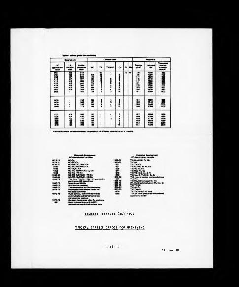
Sourcet Brookes (30) 1979
TYPICAL CARBIOe GRADES FOR MACHINING
131Figure 30

Returning to the Initial discussion on machinability group 1 results,
it is clear that a process planning engineer would not wish to be
restricted to selecting feed rates only from a given table and, therefore,
the facility to interpolate was required. Therefore, the possibility of
utilising an extended Taylor's tool life equation of the form generally
quoted in related text [83] 1976 was considered, i.e.:-
Tool life (minutes) - KVX Sy a* (HV)W (VB)
V Cutting speed
s Feed rate
a Depth of cut
HV Component material hardness
VB Flank wear
K Constant for component/tool material combination
w.x.y.a Exponents (generally negative)
A computer program was then written to plot the logarithm of cutting
speed values on the abcissa and the logarithm of corresponding feed rates
upon the ordinate axis, deduce the best fit straight line by the method of
least squares and calculate the non-par ametrie coefficient of
correlation. A listing of the program is given in Appendix C.
In conducting the analysis upon the data relating to machinability
group 1, given previously, it was found that the plotting of logarithm of
feed rate against the logarithm of relative speeds (l.e. the cutting speed
at a given rate divided by the cutting speed to achieve a IS minute tool
life at a feed rate of 0.8 mm/rev) provided a relationship which yielded a
very high degree of correlation for all three tool material grades across
all machinability groups. The results of analysis for machinability group
1 for the tool materials of one supplier are given below, the comparable
132

results for machinabllity groups 2 to 6 given as Appendix B.
(TOOL LIFE - 15 MINUTES)CUTTING SPEED DETAILS (MEAN MATERIAL HARDNESS - 110 HB)
Feed Rate Hard Tool Standard Tool Tough Tool(mm/rev) Actual
(m/min)Relative* Actual
(m/min)Relative* Actual
(m/min)Relative*
0.15 460 1.916 450 1.957 320 1.939
0.25 385 1.604 370 1.609 265 1.606
0.40 335 1.396 320 1.391 230 1.394
0.50 300 1.250 285 1.239 205 1.242
0.60 280 1.166 265 1.152 190 1.152
0.80 240 1 230 1 165 1
Gradient .616 2.526 -2 557
Intercept - ). 138 0.166 -0 159
Correlation 0.994 0.997 0 996
* (viz. Actual cutting speed divided by cutting speed at datum feed rate of 0.8 mm/rev)
It should be noted that as previously stated the values of speed
corresponding to various feed rates to produce a given tool life are mean
values obtained from experiments which produced a scatter of data to which
a best straight line would have been fitted. Based on this, a very high
correlation of results to a straight line formula would be expected.
In practice, tool life other than 15 minutes may be required (for
example to achieve balanced tool lives upon a multi-tool machine to
minimise down-time due to tool changing) the incorporation of a tool life
'modifier' was needed to enable the amendment of the predicted cutting
speed to produce the desired tool life. This relationship is again
logarithmic in nature (see expression given previously) and is often
referred to as the Taylor tool life equation after F W Taylor who first
accurately monitored the relationship after conducting cutting tests which
133

generated graphs of the type shown in Figure 31 which, when logarithmically
Inverted, appear as shown in Figure 32. The multiplicative Index by which
cutting speed should be downrated to achieve a tool life other than 15
minutes for each of the machlnablllty groupings (one value being taken as
applicable to all tool material grades within the group) Is as given
below:-
Machlnabiliti Group Number1 2 3 * 5 6
Tool 15 (detum) 1 1 1 1 1 ! 1Life 30 0.87 0.87 0.87 0.8* 0.85 0.87(Minutes) 60 0.76 0.76 0.76 0.71 0.73 0.76
SPEED MODIFIER (Multiplicetive)
Agaln, as with the Initial machlnablllty data the speed modifiers
quoted resulted as a Joint Initiative between the writer and the tool
materiel suppliers Involved in the exercise.
The logerithmlc relationship known to exist between tool life and
speed modifier was analysed, using the program as given In Appendix C, and
the results obtained were as follows:
SPEED MODIFIER (Multiplicative)
Machlnablllty Group 1 Group 2 Group 3 Group * Group 5 Group 6Group
Tool Life 15 1 1 1 1 1 1(mins)
30 0.87 0.87 0.87 0.8* 0.85 0.87
60 0.76 0.76 0.76 0.71 0.73 0.76
Slope -0.198 -0.198 -0.198 -0.2*7 -0.227 -0.198
Intercept 0.5* 0.5* 0.5* 0.67 0.613 0.5*
Correlation 0.99 0.99 0.99 0.99 0.99 0.99
It has been found in practice ASM [87] 1979 that although the value
calculated for the gradient tends to hold true In ell conditions, the
- 13* -

I
(Linear Scales)
DEVELOPMENT O r FLAN K WEAR TOR D IF F E R E N T C U T T IN G SPEEOS
figure 31
135 - figure 32

intercept is subject to a degree of fluctuation from one machine tool to
another and should be used with a degree of caution.
It was therefore possible, by combining the known relationship in
terms of graph gradient and intercept between feed rate and cutting speed
and then between cutting speed and tool life for a given component
machinability group, and knowing the base cutting speed at 0.8 mm/rev feed
rate datum point to give a fifteen minutes tool life to generate a cutting
speed appropriate to any tool life and feed rate by interpolation and, if
used with a certain degree of caution, extrapolation beyond known limits
may be used for guidance.
6.2 INITIAL DATA ORGANISATION WITHIN THE IMPS DATA BASE
The parameters derived from the analysis of tool trials conducted
were arranged into the following format within IMPS, all data being held
in sequentially organised floppy diskette text files to maximise storage
potential. Figure 33 depicts graphically the data organisation and
variable names allocated to each item of data, the values shown relating
to materials within machinability group 4. This particular arrangement
permits the identification of the appropriate tungsten carbide tool
clearance angle(s) and generation of the correct cutting speed for a given
input of feed rate and tool life for three grades of cutting tool material
from two tooling suppliers (i.e. Sandvik and Seco) by means of following
formulae which form the cornerstone of the IMPS algorithm written in the
Applesoft BASIC programming language:
S - [ B U S * (EXP ((LOG (F) - Il/Sl)))
* EXP (IL + (SL * (LOG (T)))l
The expression yields the correct cutting speed S (m/min) for a
selected feed rate F (mm/rev) to achieve a tool life T (minutes for the
136


'hard' tool material. Obviously to obtain the cutting speed appropriate
to either of the other two 'classes' to tool material (viz. 'standard' and
'tough') the variables B21S and B31S would respectively replace B11S in
the above expression, and S2, 12, S3 and T3 included also as shown below:-
'Standard' Tool Class:
S - [B21S * (EXP ((LOG (F) -I2/S2)))
* EXP (IL + (SL * (LOG (T)))]
'Tough' Tool Class:
S - (B31S * (EXP ((LOG (F) - I3/S3)))
* EXP (IL + (SL * (LOG (T)))l
It will be noted that since the same base speed, slope and intercept
apply to tool grades within the same class from both suppliers, inter
changeability is an inherent assumption. However, as stated in the
previous section the proving of true interchangeability of tooling within
a manufacturing machine shop environment requires a more detailed study, a
subject area which is discussed later.
The first two items of data held in each machinability group files
are virtually self-explanatory; in order to set realistic limits upon the
parameters to be selected by any user of the IMPS system upper boundaries,
established from workshop practice, were set for maximum depth of cut and
maximum feed rate in the form of the variable MDOC and MFEED respectively.
The subsequent two variables relate to the tungsten carbide tool
clearance angles recommended for use in conjunction with component
materials which comprises the machinability groups. Standard tungsten
carbide inserts are produced in a limited range of clearance angles each
138
of which Is designated by a letter according to the ISO convention as
depicted In Figure 34. Variables WICCg and W2CC? correspond to two such
appropriate letters.
6.3 INITIAL APPLICATION WITHIN THE SHOP-FLOOR ENVIRONMENT
As a result of the initial contribution of, in the main Sandvik and
Seco in the form 'core data', a maximum of three grades of tungsten
carbide cutting tool material were identified against each material
machinabllity grouping, the difference between grades being increased
hardness at the expense of toughness. Clearly the advantage gained from
using the harder tool material is that higher cutting speeds may be
operated at, provided the machine tool is not susceptible to vibration
which could cause catastrophic failure, in which case the utilisation of
'hard' tools is obviated and it becomes permissible to use only a tougher
(and, therefore, less hard) tool material which would withstand the
adverse operating conditions, but would necessitate a reduction in cutting
speed to maintain tool life. Having limited the choice of tool materials
to three grades per component machinabillty grouping, and as later
discussion will reveal, an even more limited choice in terms of ceramic
based tool materials, the final choice was very much dependent on a series
of interrelated factors which included
(a) Component and fixture rigidity
(b) Tool sec up rigidity
(c) Component material surface condition
Recognising the potential complexity of the problem being faced a
decision was made to build a factoring routine into the IMPS algorithm
which made allowances for machining parameters to be encountered, typified
by (a), (b) and (c) above, but including many others as well, in making
139 -

Designation of indexable inserts — metric series Turning Inserts ■ SNMM 12040«-5 « oe 1«
M M 12 04 08
Ta
V Typ« of In»«rt
5 Cutting ««lg« lang». I. In m
"7b II
Source» Seco Ltd. (95) 1980
DESIGNATION OF INDEXABLE INSERTS
140 f i g u r e 34

the final tool choice decision. While the recognition of the problem was
relatively simple, in hindsight, the achievement of a practical solution
was not.
The very early factoring routines were based on qualitative
assessments of the machining parameters being encountered and the
determination of the appropriate tool grade was dependent upon the rating
given to each condition encountered. In this initial form a rudimentary
handbook was produced which served to guide the system user, in an albeit
somewhat subjective manner, towards the determination of which
classification a given shop floor set-up belonged to.
Equipped, therefore, with a procedure for determining the tool
material class most appropriate to a given component/machine tool
combination complete with the necessary logarithmic equations previously
derived, in theory, the correct surface cutting speed for a given feed
rate and tool life was calculable. However, during the course of
implementing the system into the production environment it was found that
there were wide discrepancies in the machining parameters generated by
IMPS compared to the operational standards encountered. Of particular
concern were the tool life predictions which far exceeded those achieved
in practice; for example, extremes of twenty times tool life (predicted)
in certain cases. As a generalisation such extremes predicted/actual
variances could have been due to:
(a) An irrelevant factoring routine.
(b) Invalid core machinabllity data from the tool suppliers.
(c) Operational custom and practice.
Wishing to understand the complexities contained in (a), (b) and (c)
above a decision was made that for the time being the core machlnability
data would be held as correct with further attention to be given to the
factoring routine followed by machine tool operator custom and practice.
- 141 -

With respect to the factoring routine the decision was made to extend
the concept of rating or factoring from its qualitative base to become
quantitative by allocating numeric values to each of the three afore
mentioned machine and tool features and, Initially, downrating the cutting
speed accordingly.
A multiplicative arrangement was the obvious method of achieving the
downrating or factoring and was based upon the premise that if all three
criteria were rated at maximum (i.e. good component and fixture rigidity,
good tool set-up rigidity and bright and true component material pre-
machining condition) then the tool life obtained should approximate closely
to the results obtained in the ideal cutting tests, each feature was thus
accorded the value of unity and the following expression developeds-
Cutting speed to give required tool life
“ Predicted tool life from logarithmic equations
* Rating for component/fixture rigidity
* Rating for material surface pre-machining condition
Descending values were then given for each subsequent rating for each
factor.
The combination of the handbook guide to support the adoption of this
factoring approach led to an improvement in correlation between predicted
and actual tool life data. Continual feedback from shop-floor tests
refined still further the values accorded to each rating of each factor.
A further important additional feature noted during the IMPS
validation shop-floor exercises was the tool life variation caused by
component batch-to-batch machinability differences. Although there are a
variety of features related to material composition which will affect
machinability the most easily measured is material hardness. The IMPS
data base was thus extended to Incorporate the facility to amend cutting
- 1*2 -

speed to compensate for the difference between the workpiece batch
hardness and the mean datum hardness figure of the materials machined
under idealised operating conditions to yield initial data for each
machinability group. In the case of machinability group 1 it will be seen
from Section 6.1 that all data relates to a mean component hardness of
110 HB. The compensating factor applied is of the form:-
Index by which to multiply
speed to compensate for
deviation of batch hardness “ (1 + ( (Batch hardness -
from machinability group Mean Datum) x .04*))
mean hardness
Compensating figure obtained from tests conducted in conjunction with
cutting tool suppliers.
The cutting speed appropriate to a known batch hardness is the
product of the above index and that speed previously generated from the
IMPS data.
The compensating figures for each machinability group are as follows:
Machinability Group Number 1 2 3 4 5 6
CompensatingFigure 0.04 0.04 0.05 0.02 0.04 0.02
Nominal Hardness (HB) 110 150 180 345 200 200
Despite the successful Incorporation of the above compensating figures
into the IMPS data base arrangement, it was still felt necessary to refine
further the factoring methodology, therefore, a far more detailed and
objective method of downrating or factoring was subsequently developed in
143 -
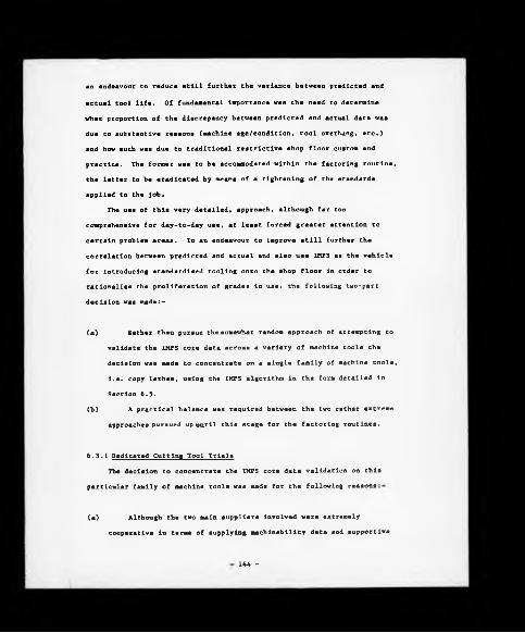
an endeavour to reduce still further the variance between predicted and
actual tool life. Of fundamental Importance was the need to determine
what proportion of the discrepancy between predicted and actual data was
due to substantive reasons (machine age/condltion, tool overhang, etc.)
and how much was due to traditional restrictive shop floor custom and
practice. The former was to be accommodated within the factoring routine,
Che latter to be eradicated by means of a tightening of the standards
applied to the job.
The use of this very detailed, approach, although far too
comprehensive for day-to-day use, at least forced greater attention to
certain problem areas. In an endeavour to improve still further the
correlation between predicted and actual and also use IMPS as the vehicle
for introducing standardised tooling onto the shop floor in order to
rationalise the proliferation of grades in use, the following two-part
decision was made:-
(a) Rather than pursue the somewhat random approach of attempting to
validate the IMPS core data across a variety of machine tools the
decision was made to concentrate on a single family of machine tools,
i.e. copy lathes, using the IMPS algorithm in the form detailed in
Section 6.5.
(b) A practical balance was required between the two rather extreme
approaches pursued up until this stage for the factoring routines.
6.3.1 Dedicated Cutting Tool Trials
The decision to concentrate the IMPS core data validation on this
particular family of machine tools was made for the following reasons
(a) Although the two main suppliers involved were extremely
cooperative in terms of supplying SMchinabillty data and supportive
144 -

information they were both very cautious in releasing comprehensive
details of the machine tools used In the formulation of the data In
question, enough to say that assurances were given that all tests
were carried out on single point turning machines against the
experimental test conditions as stipulated In Section 6.1.
Because of this level of uncertainty the decision was made to
pursue comparable 'ln-house' tool trials on single point turning
machines which would meet the power, rigidity, stability, etc.,
requirements to exploit the true potential of the cutting tools under
consideration. Of the considerable range of turning machines
available to choose, It was considered that a specific family of copy
lathes would be the best suited to the task at hand.
(b) The machine tools In question, twelve in all, had an age span of
0 to 20 years and were used to machine a variety of components from
within the six machlnability groupings already established, albeit
current activity In groups S and 6 was minimal.
(e) Permission was given by local management to use the twelve
machines as a 'test cell' allowing alterations to machining
parameters for the purposes of data validation.
This facility was particularly useful for two key reasons:-
(1) Such a dedicated tool trial facility allowed close observation
of machine tool setter/operator custom and practice.
(11) With the total cooperation shown from management and machine
shop personnel alike it was possible to monitor accurately flank
wear for a given tool life under specified operating conditions.
Against this background a total of twenty-one tool trials were
undertaken covering a period of several weeks, the results of which,
combined with the Improvements In the modified factoring routine contained
In the following sub-section established a firm platform from which the

IMPS system could be developed. The results of this work and their impact
with respect to the tool supplier's initial machlnablllty data are
discussed fully in Chapter Nine.
6.4 MACHINE TOOL FACTORING ROUTINE
Previous discussion has indicated that while recognition was given at
an aarly stage of the research work to the requirement for a machine tool
factoring routine within the IMPS module the final solution was only
arrived at after attempting several routings through the problem. Initial
attempta were based, in the main, upon the subjective opinion of the
system user, and this was considered to be a far from satisfactory
solution. Logically the factoring routine needed to be structured in a
framework governed by quantifiable rules, rather than the existing
approach of utilising qualitative statements with the inherent danger of
inconsistency.
Whenever discussing the subject of machinabillty data emphasis is
usually placed upon such quantifiable areas as component material
speciflcation/surface condition, cutting tool grade/geometry, spindle/
surface speed, depth of cut, feed rate and other parameters contributing
to the actual 'cut'. In studying these items in isolation it is possible
to set up a number of similar machine tools with apparently similar
machining parameters, and yet in practice achieve significantly differing
levels of performance. Clearly a further variable to be taken into
account is the machine itself in that such aspects as machine type,
condition and tool set up mechanisms can radically affect the data at
which it is possible to achieve consistent optimum machine tool
performance.
This problem was particularly apparent at Coventry Engine Plant
whare, unlike many metal removal research facilities, the average age of
the plant machine tools used in component production was twenty years
146

(reference to Appendix A for further details), and in many cases have been
subjected to continuous heavy use. Therefore, in attempting to structure
core machinability data which would have relevance to the factory in
question it was recognised that a machine tool factoring routine would be
required to act as a machinability data 'modifying mechanism' for the
machine tool under observation.
6.4.1 Initial Development
As IMPS was initially developed for single point turning operations
so the subsequent machine tool factoring routine was based upon the key
design/set-up features inherent within single point turning machines,
although it is considered that many of the fundamental principles
contained are applicable to rather more complex machine tools.
In terms of adopting a quantifiably based solution to the problem,
initial work began by considering the basic machine tool design, and the
key features which affect the achievement of optimum machinability
conditions, and at the highest level of focus these were:-
(a) Stiffness
(b) Damping
(c) Forced vibrations
This initial analysis generated a list of 24 factors for consideration
ranging from method of construction and stiffness of the machine tool
elements when reviewing items (a) and (b), to consideration of unbalanced
rotating masses and machine tool age and condition in (c).
Having established this list of factors the first direction pursued
was to weight each factor with respect to its impact upon cutting tool
life with guidance being taken from such sources as:-
(1) Machining Data Handbook, Vol 2, [32] 1980
- 147 -

(il) Koenigsberger [26] 1974
Conceptually, the summation of all the factor weightings equated to
one for a machine tool in theoretically 'perfect' condition and other
machine tools in poor relative condition would yield factors as low as
0.5. These factors were then used as machinability modifiers within the
IMPS module in order to reflect operational conditions.
In principle a machine tool factoring routine had been developed
which improved the correlation between the IMPS predicted and actual
results. This was based in the main upon quantifiable factors the
evaluation of which were governed by rules within a system user's
handbook. Additionally, the information required for the factor
evaluations was readily available to the system user from such sources as:-
(a) Factory records
(b) Machine tool catalogues
(c) The machine tool itself
However, despite this apparent progress the in-house practical
application of system was met with a high level of user resistance due to
the time taken in collecting the data required for establishing the
overall machine tool factor. Because of this the procedure had to be
reviewed once again.
6.4.2 Machine Tool Factoring Routine as Implemented
The key requirements to emerge through the first stages of
development were:-
(a) To maintain the Improved levels of correlation between the IMPS
predicted, and actual results.
(b) To reduce the level of system detail, and time taken to establish
- 148 -

the factor, without departing from a quantifiable approach to the
problem.
(c) Move towards a more system/user Interactive approach.
With these basic requirements In mind research work progressed, resulting
In the following machine tool factoring routine.
The routine divides the machine and respective set-ups Into four main
categories, and these are listed below with the IMPS program variable name
assigned to them shown In brackets
Machine Structure (MST)
Component Rigidity (RR)
Tool Rigidity (TT)
Machine Condition (MC)
Each of the categories has an effect upon the suitability of the machine
tool to perform a specific operation(s), and each Is examined separately.
Unlike the simple accumulative approach discussed in the previous section,
the results are brought together using the following relationships-
F(machine tool factor) ■ A - B
where A - f(MST, RR, TT)
and B - f(MC)
(A) comprises the first three categories which are all machine condition
independent, while ( B ) is a function of the machine condition and is
machine type/set-up independent.
The above relationship ensures that the condition of the machine has
the same net effect upon the factor Irrespective of the machine type and
set-up. This requirement was identified by observations at Coventry
Engine Plant where three machines were used to support one component
operation, i.e. machining axle shafts. Although all three machines were
- 149 -

of similar design, utilising similar tooling and component set-up
arrangements, one of the machines was in a poor state of repair when
compared with the remaining two. Under these circumstances all three
machines had similar values for A but in the case of the machine in poor
condition its resulting value for B had a greater impact in terms of
reducing the overall machine factor value.
As with the system described in the previous section, the machine
factor is a real number rounded to two decimal places with a maximum
value of one (which assumes a 'perfect' machine), and a slightly reduced
minimum value of 0.43. In practice, whenever using IMPS any provisional
machine factor established at 0.65 is automatically declared as 'very low'
by the system and the user is given the opportunity to change the
machine and/or the tooling set-up.
The following sections give the actual questions as seen by the user
upon the microcomputer screen when operating the factoring routine,
combined with their adjusted weightings and a brief explanation for
their relative importance.
The four categories as listed previously are examined separately
during the factoring routine, and in total there are eight questions
relating to the machine and its set-up. These are divided between the
four categories as follows
Category Number No of Questions Subjects Variable IMPS
Program Names
1. Machine 3 M/C body material MMStructure M/C construction CC
M/C mounting WW
2. Component 1 Component rigidity RRRigidity
3. Tool Rigidity 1 Tool Rigidity TT
4. Machine 3 M/C age AACondition Past usage PP
Running condition 00
150

Each question is dealt with separately, and is shown along with all of the
possible answers and their adjusted weightings, commencing with the best
condition.
1. Question: What is the machine body made from?
Answers: 1. Predominantly cast iron (1.0)
2. Predominantly steel (0.975)
3. Other (0.94)
The weightings reflect the fact that iron is a good damping
medium, l.e. having less than half of the modulus of elasticity of
steel. Although the potential damping properties of such materials
as concrete and synthetic granite are recognised, and accordingly
would be given a weighting of 1.0 (i.e. option 1) neither material
was found to be in use at Coventry Engine Plant. Finally the third
category, l.e. other, was added to the factor listings as more of a
cautionary 'safety net' for machine tool structures not falling into
the (a) or (b) category and as such would possibly warrant further
investigation.
2. Question: How is the machine constructed?
Answers: 1. All separate parts (1.0)
2. Separate bed only (0.985)
3. One piece cast body (0.97)
Again this is concerned with damping characteristics, i.e. joint
damping occurs when mating surfaces move in relation to each other.
This is a linear relationship, the joint damping characteristic being
directly proportional to the number of major parts from which the
machine is constructed. Note that this is considered to be less
critical than internal damping from the machine body material,
therefore, explaining why there is a difference in the weightings for
151
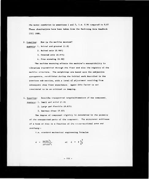
the worst condition in questions 1 and 2, i.e. 0.94 compared to 0.97,
These observations have been taken from the Machining Data Handbook
[32] 1980.
3. Question: How is the machine mounted?
Answers: 1. Bolted and grouted (1.0)
2. Bolted only (0.987)
3. Grouted only (0.975)
4. Free standing (0.96)
The machine mounting affects the machine's susceptibility to
vibration transmitted through the floor and also the rigidity of the
machine structure. The weightings are based upon the subjective
assessments, established during the initial work described in the
previous sub-section, with a level of adjustment resulting from
subsequent shop floor experience. Again this factor is not
considered to be as critical as damping.
4. Question: Describe unsupported lengths/diameters of the component.
Answers: 1. Small and solid (1.0)
2. Large and flexible (0.825)
3. Between these (0.92)
The degree of component rigidity is determined by the geometry
of the unsupported parts of the component. The structural stiffness
of a beam or disc is a function of its cross-sectional area and
overhang:-
i.e. standard mechanical engineering formulae
d - iiiftii „r i - l 43>T(ED4) D
152 -

where d deflection
P - force on the end of been
L - length of overhang
D ■ beam diameter
E - modulus of elasticity
k - constant for unit of measure
The answers given previously are quantified in a users guide to
the factoring routine. The relationships are non-linear and are
based upon the above relationship, specifically that between length
and diameter.
5. Question: Describe tooling rigidity.
This is dealt with in a similar way to component rigidity in
that a long boring bar is more Inclined to deflect under load than a
short copy tool. The three descriptions of the tooling set-up and
their respective weightings are (TT):-
(1) Long overhang/diameter ratio (0.825)
(ii) Short overhang/diameter ratio (1.00)
(Hi) Between the two (0.92)
Again, the definition for items (1) to (ill) was given in a
user's guide.
6. Question: How old is the machine?
Answers: 1. < 5 years (2.24)
2. 6-10 years (2.17)
3. 11-25 years(2.09)
4. > 25 years (2.00)
With respect to this question the machine age could be either
actual age, or age since last major recondition if applicable. The
weightings in this category assume that deterioration of a machine
- 1 5 3 -

Cool is fairly linear with age although machines over 25 years of
age tend Co have their condition compounded by gradual wear, rust and
neglect.
7. Question: Describe the past usage of the machine.
Answers: 1. Light (2.24)
2. Moderate (2.15)
3. Heavy (2.00)
These descriptions were quantified in a user's guide in terms of
feed rate and depth of cut. The relationship between the weightings
is based upon the average rate of metal removal corresponding to each
of the three answers. In addition, note that the overall factor
calculation, age and past usage are multiplied together to give an
indication of the rigours it has been subjected to.
8. Question: Describe running condition of the machine.
Answers: 1. Normal (0.5)
2. Reasonable (0.43)
3. Poor (0.35)
This is a subjective assessment of the condition of the machine
covering such aspects as bearings, slides, lead screws, motor,
toolpost rigidity etc.
6.4.2.1 Factor Calculation
After answering the eight questions the IMPS program contains values
for each variable from which the machine factor calculation takes place.
Therefore, a routing through the system would be as follows:-
F(machine factor) - A - B
where A - f^MST, RR, TT)
and B - f2(MC)
154 -

Element A (machine condition independent factors) comprises
Questions: 1. M/C body material (MM)
2. M/C construction (CC)
3. M/C mounting (WW)
4. Component rigidity(RR)
5. Tool rigidity (TT)
Element B (machine type/set-upindependent :
Questions: 6. M/C age (AA)
7. Past usage (PP)
8. Running condition (00)
Machine structure (MST)
Machine condition (MC)
MST (Machine structure) ■ f^MM.CC.WW)
let MST ■ MM X CC x WW
With the weighting ranges assigned to each variable the value of MST
within the overall machine factor equation will be 1.0.
MC (Machine condition) - f2(AA,PP,00)
let AP - (AA x PP)/10
With the weighting ranges assigned to AA and PP the value of AP will
be 0.5, l.e. maximum value of AP 0 (2.24 x 2.24)/10 - 0.5 to one decimal
place.
let AO - AP + 00
As 00 (machine running condition) has a weighting value 0.5 then the
value of A0 will equate to 1.0
let MC - (1 - A0) x 0.65
1 5 5 -

In principle, the impact of the machine condition element of the
overall machine factor equation will be nil for a machine tool in
'perfect* condition, i.e. where AO - 1. Likewise as the value of AO
decreases, i.e. f2(AA,PP,00)<1 then the impact of MC upon the overall
machine factor equation increases.
The machine condition equation is downrated by a constant 0.65 to
reflect the impact of the variable MC (of a machine in less than perfect
condition) in the overall machine factor equation.
YY (machine factor) ■ f(A, B)
let YY - (MST x RR x TT) - MC
As mentioned previously the maximum weighting value of each question
is already predetermined by the maximum possible factor, i.e. 1.0 and the
structure of the overall equation for YY. Likewise the minimum weighting
value is determined by the minimum possible factor, i.e. 0.43, the
structure of the overall equation, and by the relative overall importance
of each question. Therefore, in the case of the machine condition
independent questions the wider the weighting range, the greater the
impact of the specific factor upon the overall equation, i.e.
Question Number Weighting Range
1. M/C body material 1.0 to 0.94
2. M/C construction 1.0 to 0.97
3. M/C mounting 1.0 to 0.96
4. Unsupported lengths 1.0 to 0.825
5. Tool rigidity 1.0 to 0.825
Within Element A of the equation items (4) and (5) are considered to
have the greatest impact upon spindle speed in practice. It is recognised

that while this may be true for re-tooling existing facilities, which the
factoring routine is directed towards, a different approach may be
required for decision-making procedures relating to the purchase of new,
technologically advanced machine tools, where the factor weighting
criteria may alter.
Likewise a similar analysis of Element B questions will reveal:-
Question Number Weighting Range
6. M/C age
7. Past usage
8. Running condition
2.24 to 2.00
2.24 to 2.00
0.50 to 0.35
Therefore question 8, Running Condition, is considered to have the
greatest Impact upon the machine condition (MC) calculation.
6.5 IMPS ALGORITHM
Previous sections have explained the methodology employed in
obtaining, analysing and organising into data files the component material
related machining information, i.e. recommended tool materials and
associated cutting speed parameters, etc. Attention is now focused upon
the IMPS algorithm which utilises the data held in the machining files to
identify the tool grades appropriate to the component material being
machined, generates the associated cutting parameters calculating basic
machining times, tool change frequency, etc., and finally ascertains by
means of inspecting the Company Standard Tooling Catalogue via the ARCLASS
system whether suitable tooling is already a standard item within the
Company. The detail of the file layouts referred to hereafter are
depicted in Figures 35 and 36. It will be noted that the file named
'Machlnabillty Group 4' is an extended version of Figure 33, the
additional data held relating to the hardness speed modification referred
to in Section 6.3, details of the specific force constant (or kg value)
which facilitates the calculation of power required to remove a volume of
157
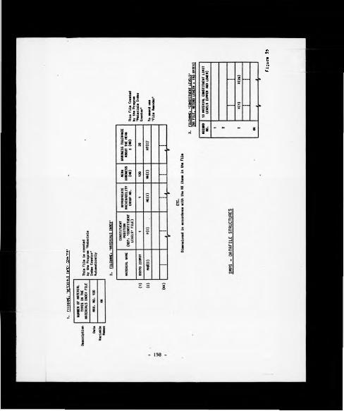
flU
MM
ti
‘hUT
CHUH
INO
CX C
OUNT
CW
Figur« 35

FIL
EN
AM
E:
'MA
CH
IN A
B IL
IT
Y
GR
OU
P 4
*
IMP
S
MA
CH
INA
BIL
ITV
CR
OU
P
- D
ATA
FO
RMA
TS

component material (and lta variation with varying component hardness
values) , and finally data related to the maximum depth of cut recommended to
achieve a related final component size and surface finish tolerance.
A full printout of the IMPS program In APPLESOFT BASIC, utilising the
Apple disk operating system DOS 3.3 Is given In Appendix D. In addition,
a complete routing through the IMPS flowchart Is given In Appendix E and
the materials index creator, machlnabillty group creator and file amender
programs referred to In the following figures and text are contained within
Appendices F, G, and H respectively.
A flowchart to represent the first type of situation to be considered
Is contained In the remainder of this section and details a routing through
the system with a component which requires one 'pass' of the tool to remove
the required amount of stock to produce the final component shape to within
specified limits of size and surface finish. The Items of data being manip
ulated at each point and the floppy diskette based data file from which they
were extracted are given in the following step by step breakdown of the IMPS
flowchart combined with reference to the appropriate lines of the IMPS
algorithm BASIC program.
of CODINGS(I) • NUMBEROFCODES j (I)
160 -

Ac this point of Che algorithm all 'page headings' of Che Company
Standard Tool Catalogue are loaded from disk into the microcomputer Random
Access Memory (RAM). The data files in question are created by initially
running the program 'Prelim', reference to Appendix I, followed by the
program 'Coding System Creator' , reference to Appendix J.
The lines of program 16530 to 16690 are those which enable the
tranferences of data from disk to RAM and the variable names referred to
are those used in Figure 37.
(KK items)
Following on from the previous actions, details of all the workpiece
materials recognised are loaded from disk to RAM. The file 'Materials
Index Counter' which is accessed first gives details of the number of
materials recognised; this amount of data is then loaded from the file
'Material Index' which contains each material name, the positional point P
which is used in Segment 4 of this algorithm, the material group number,
the mean hardness of this workpiece material, and finally the anticipated
161
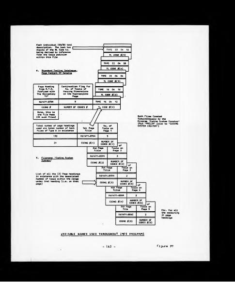
VARIABLE NAMES USED THROUGHOUT IMPS PROGRAMS
- 162 - Figure 37

range of hardness for the material (reference to program line number 24561
to 24690).
Numbers 16694 to 17025)
At this point In the algorithm the system user specifies the
workpiece meterlal to be machined. A check Is then made to verify whether
this material Is contained within the specifications recognised by the
'Materials Index' file. Upon finding reference to the material, the
machlnabllity group to which It belongs is determined via the variable MG
previously loaded. The entire contents of the appropriate 'Machlnabllity
Group' file as depicted In Figure 36 are then loaded Into RAM for
subsequent manipulation.
163

4.
X(l) - X(26)
(13 upper and lower limits)
As shown, details of the allowable levels of workpiece material
constituent elements are loaded into RAM from the Random Access file
'Constituent Levels', the appropriate record position being denoted by the
Variable P previously extracted in Segment 2 from the file 'Materials
Index'. The display is in the bar chart form and utilises the low
resolution graphics capability of the microcomputer. Although it would
appear logical to incorporate such details in the file 'Materials Index',
the loading of this complete file, which takes place in Section 2 of the
algorithm would needlessly consume 11.2 kilobytes of RAM storage.
(Reference to Program Line Numbers 23010 to 25240).
5‘ I____________Display details of recommended Tungsten
Carbide tool grades ('Hard', 'Standard'
and 'Tough') and clearance angles
appropriate to the workpiece material in
question
I- 164 -

As stated, this very short section serves to visually display details
of recommended tool grades and clearance angles (according to ISO
convention) appropriate to the workpiece material. (Reference to Program
Line Numbers 17100 to 17190).
6.
User Input.
______i______Specify anticipated mean
hardness of workpiece
material if known
This segment enables the system user to input details of the mean
hardness of the workpiece material if it is known. Such is often the
case, and if input is made, the value entered overrides the value of MH
already held in RAM as extracted from the file 'Materials Index' in
Segment 2. (Reference to Program Line Numbers 810 to 850).
♦It was soon realised during the development of the IMPS algorithm
that in many Instances a number operations would be carried out upon one
165

machine operating at a fixed spindle speed across a number of diameters (a
prime example being the production, In one pass of the tool, of a multi
diameter component upon a copy lathe operating at a single rotational
speed). This situation caused problems for the IMPS system in that since
IMPS generated a single recommended peripheral cutting speed from which a
rotational speed could be deduced from component dimensions, clearly It
would recommend different rotational speeds for each component diameter;
this situation was not acceptable, and thus in such cases the complex
component would have to be translated Into a straight bar requiring the
same amount of work content. The procedure for achieving such a
conversion is given below as Segment 7a. In the case of single diameter
components or where a multi-diameter component is to be produced upon a
machine with variable speed capability, Segment 7a is clearly not required.
(Reference to Program Line Numbers 860 to 880 which relate to Segment 7.)
Calculate the 'straight bar equivalent'
of a multi-diameter workpiece.
The basis used to obtain the 'straight bar equivalent' of a
multi-diameter workpiece is to ensure that the turning and facing content
of the multi-diameter bar is carried out in the form of turning only upon
the 'straight bar'. A detailed explanation of the logic underpinning this
translation is given in sub-section 6.S.3. (Reference to Program Line
Numbers 13000 to I33I0 which relate to this segment).
166 -

8 .1
Determine maximum depth of
User operation to enable achievement
cut allowable on finishing
of workpiece size tolerance
Input allowed and surface finish MACHINABILITY
the system user
requirement as stipulated by
II GROUP (N) I
U values of DC(I), FT(I),
GROUP (N)
Size Tolerance ST (I)
Finish Tolerance (Previously loaded)
Start O/D
Finish 0/D
The allowable maximum depth of cut is obtained here by examining the
values of the variables ST and FT previously loaded and comparing them
with the surface finish FSF and size tolerance TSF required of the
workpiece as stipulated by the system user; a recommended depth of cut
likely to enable achievement of firstly the surface finish is calculated
and then the depth of cut to enable achievement of the size tolerance is
identified; the smaller of these two depths of cut is selected as
appropriate.
Although productivity maximisation should always be sought in
preceding operations, the objective of the final operation is the
production of a quality component - production of scrap in the final
instance destroys all value added up to that point and is thus
economically highly undesirable. (Reference to Program Line Numbers 890 to
1290) .
- 167

IDetermine 'factor' of machine tool
User to be used In performing operation
"■ by applying numeric values to key
Input machine features. Recommend Tool
Grade
Machine Tool
Features
The IMPS program line numbers with respect to the individual elements
of the machine tool factoring routine as discussed in section 6.A are:-
(a) Program Line Numbers 1380 to 1520 recommend the tool material
grade considered to be the most appropriate on the basis of a known
machine tool factor, i.e. factor established on a previous occasion.
If the factor is unknown then the system user is directed into
the following interactive sub-routines.
(b) Machine structure section, program line numbers 11250 to 11650.
(c) Machine condition section, program line numbers 12020 to 12410.
(d) Component rigidity section, program line numbers 11660 to 11850.
(e) Tool rigidity, program line numbers 11860 to 11990.
Finally, reference to section 6.4.2 will show that the calculation
for the machine tool factor (YY) to be used with IMPS is given in lines
12420 to 12580 where YY “ f(machine structure, component rigidity, tool
rigidity and machine tool condition).
- 168 -

This section serves to determine whether the depth of cut requested/
recommended previously In section 8 is achievable upon the machine
selected based upon the factor generated. MDOC, the maximum depth of cut
possible under ideal conditions is consequently downrated by the factor
FAi and the resulting value checked against the depth of cut requested
D(CNTR). (Reference to Program Line Numbers 1530 to 1600). It is clear
from the above that if the depth of cut requested is unlikely to be able
to be achieved upon the machine selected, the option is offered to either
change the depth of cut or, alternatively, select a machine of a higher
factor. The latter option necessitates repeating segment 9, i.e. the
factoring routine for the new machine.
- 1Display range of tool nose radius and
feed rate combinations which generate
the necessary surface finish as
defined previously (FSF)
169 -

Provided Che feed rate per revolution does not exceed cool nose
radius, Che formulae
/— surface finish
18/3 * R * 1000
provides a relationship between feed rate, tool nose radius (R) and
surface finish.
The lines of program 10005 to 10105 hold surface finish constant and
generate feed rates associated with standard tool nose radii which
generate the desired surface finish.
In addition to facilitating the input of the length of cut, feed rate
and tool life in minutes by the system user, the lines of program 1850 to
1950 check that the feed rate selected is less than MFEED, i.e. that feed
12
iSpecify
° Length of cut
User ° Feed rate
* Tool life (Minutes)
/ SEQUENTIAL I ^ -_______ ^
\AInput Confirm that feed rate MACHINABILITY
stipulated is less chan GROUP (N)
or equal to the maximum
achievable on the machine
Output nose radius of toolJ
Length of cut MFEED
Feed rate (Previously extracted)
Tool life
- 170 -

rate achievable under Ideal conditions, multiplied by the factor derived
from the factoring routine.
Based upon the relationship given in section 11, the tool nose radius
which will enable the achievement of the stipulated surface finish
requirement is output.
... 1Using the values of the variables for
feed rate and depth of cut previously
inputted, the appropriate tool chip-
breaker style is determined.
JAs outlined in sub-section 6.5.A a relationship exists between feed
rate and depth of cut, and the style of chipbreaker which will produce
'acceptable' swarf. The program lines 7610 to 9170 contain the logic
required to generate the appropriate BL chipbreaker reference for position
within the ARCLASS code, i.e. 16-6147l-BTNA-01 (reference to Figure 46 for
the ARCLASS system routing).
» . _________________!_________________Generate recommended peripheral
cutting speed appropriate to
the tool material grade
recommended from relationship
between speed and feed rate
BU S , II, SI,
B21S, 12, S2,
B31S, 13, S3
(previously loaded)
- 171 -
/ SEQUENTIAL N[\ ̂ S\
MACHINABILITY

This operation Is the cornerstone of the IMPS algorithm. As outlined
In Section 6.1, the cutting speed may be generated to give a fifteen
minute tool life for a material of the mean group hardness by the
expression given In the lines of progrsm 13900 to 14100. The tool
material grade recommended was of course, generated In segment 9 above.
The cutting speed generated is that associated with an 'ideal* machine
tool and component arrangement.
With reference to Figure 36, SL is the slope of the Taylor tool life
curve, and IL the Intercept.
As described In Section 6.1 there Is a relationship between cutting
speed and tool life as determined by Taylor. This particular portion of
the IMPS algorithm, l.e. program line numbers 14110 to 14160, serves to
modify the cutting speed previously generated to accommodate any
difference between the standard fifteen minute tool life around which all
file based data is originated and the user's stipulation of tool life
desired.
15 1Modify cutting speed to take
Into account tool life
selected by system user MACHINABILITY
I GROUP (N) I\
SL, IL
(previously extracted)
16, iFactor down cutting speed to maintain
tool life selected under less than
Ideal' machining conditions
1- 172

The purpose of the factoring routine is twofold; firstly, it serves
to recommend the most suitable tooling grade appropriate to the machining
set-up and secondly, it is use<* to downrate the predicted cutting speed
(which is derived from data obtained from cutting trials under ideal
machining conditions) to maintain the selected tool life.
This secondary purpose may b* considered to be a refinement of the
Taylor tool llfe equations used within the IMPS algorithm an approach
supported by the findings of Mayer [87] 1979 _ "To optimlse a machining
operation, of courae, you must know what conditions to select to get the
maximum output, minimum cost, or whatever is desired. Of course, the main
objective is to maximise profit*- In order to do this, some of the
relationship i8 nee<je<jt such a* speed-tool life curves, to predict new
results once a change is made- While one cannot ever exactly predict what
tool life In the plant will be, based on laboratory results, relative
changes can be determined. 0n* the reasons for this is that the
constant in the Taylor equation varies with plant conditions. In a study
of nine diff8r8nt laboratories using the same workpiece and tool
materials, a family of nine separate Taylor curves with similar slopes
were obtained. This shows that the constant in the equations Is dependent
upon the machine. Machines in * Production plant will, of course, behave
in a similar manner".
The program line numbers 14170 to 14190 are used to factor down the
ini**®* ^^*»lised cutting data to compensate for the detrimental effect
that a machining set-up, which is less than ideal, will have upon tool
Ufa-
- 173 -

17.
The final adjustment to be made to the cutting speed Is the
modification required to account for the difference between the mean
hardness of the machinabllity group (around which all file-based data Is
centred) and the mean hardness of the workpiece material (either as
extracted from the diskette file ’Materials Index' or as input by the
system user as discussed in Segment 6). Clearly a 'harder than mean'
workpiece material would require the downrating of cutting speed to
produce the tool life desired, and conversely a 'softer than mean'
workpiece would enable an increase to be made upon cutting speed without
having a detrimental effect upon the tool life selected. (Reference to
Program Line Numbers 14200 to 14260).
- 174 -

ICalculate workpiece rotational speed
and thence the time required to perform
the desired metal removal operation
tThe conversion of peripheral speed to rotational speed is a simple
geometric relationship and program line numbers 14270 to 14280 establish
the time required for the tool to traverse a bar of length L when rotating
at N rpm at a feed rate of F min/rev. *
*0r overriding manual input
175

As shown below, the power required to remove the stipulated amount of
material is given by the formula
Depth of cut * Feed rate * Cutting SpeedPower ■
(peripheral) * Specific cutting force
The final variable, specific cutting force is defined as that amount
of power required to remove a unit amount of material from a workpiece and
a value specific to each machinability group, that value being appropriate
to a nominal group hardness. It is clear that any difference between
workpiece hardness and mean group hardness will influence the specific
force or Kg value, and consequently a facility is provided within the IMPS
algorithm (l.e. line numbers 14285 to 14310) to perform such a
compensation. Details of the logarithmic relationship found to exist
between feed rate and Kg value are given in Figure 38.
2 0 . __________________________ |
Calculate estimated tool change
frequency.
Display all inputs and outputs
1
Tool change frequency is simply calculated by dividing the tool life
selected in minutes (T) by the cutting time (ST$) to give an indication of
expected TCF.
The lines of program 14320 to 14560 also enable the screen display of
all values calculated.
176 -

KS (SPECIFIC FORCE) CUTTING VALUES AT 90° APPROACH ANCLE
Figure 38
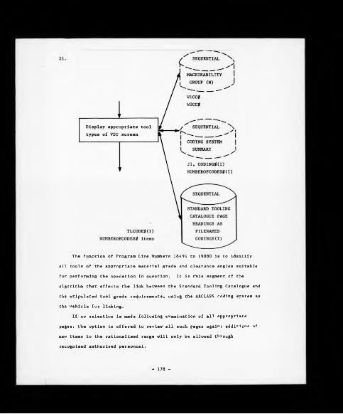
The function of Program Line Numbers 18490 to 19080 is to identify
all tools of the appropriate material grade and clearance angles suitable
for performing the operation in question. It is this segment of the
algorithm that effects the link between the Standard Tooling Catalogue and
the stipulated tool grade requirements, using the ARCLASS coding system as
the vehicle for linking.
If no selection is made following examination of all appropriate
pages, the option is offered to review all such pages again; additions of
new items to the rationalised range will only be allowed through
recognised authorised personnel.
- 178 -

A prediction Is now made within Program Line Number 19110 to 19220 of
the expected surface finish to be produced upon the component according to
the previously used formulae
Surface finish ■ Feed rate2 187T x Nose Radius
Nose radius of the tool is obtained by positional inference from
within the variable TLCODES which is the ISO description of the indexable
insert. It should, however, be noted that the prediction of surface
finish should be used for guidance only, as the formula above is true only
as cutting speed becomes very high (reference to Figure 39).
Essentially the algorithm converts the recommended tool grade into
the letter by which it is designated within the ARCLASS system and is
given a positional reference within the variable CODINGS. Reference to
Figure 46, page 217, will help the reader understand the overall ARCLASS
structure and the character position for the tool grade and other
technological features. Likewise, a positional reference within the same
variable is also given to the recommended clearance angles as previously
extracted from the appropriate 'Machinability Group' file notably V1CCS
and W2CC$, and also for the recommended chipbreaker style, again as
denoted within Figure 46.
Therefore at this stage the various characters within the ARCLASS system
which will have been defined are 61477-B7NA which indicates that the tool
- 179 -

0.14* C mild steel
Figure 39

selected is an Indexable Insert, l.e. 6147 - with a category B tool
material grade, N type clearance angle, and category A chipbreaker style.
The only remaining decisions are:-
1. Tool supplier which will be an automatic system output.
2. Tool style and size which will be selected from the standard
tooling catalogue file.
To activate the process to enable decision (2) to be made a search is
then made of the total contents of the 'Coding System Summary' file which
was previously loaded to RAM from disk in Segment 1 of the algorithm,
Inspecting each 'page heading' in turn to establish whether it conforms
with the above code number restrictions; a case in the affirmative causes
a branch to a loop of the program to open up the appropriate file, such as
X61471-BTNA, and extract the entire contents, viz. the tools of different
sizes which all conform to this generic loading - a page from the Standard
Tooling Catalogue - and display them on screen. A negative result of the
Investigation, however, simply causes the investigation of the next 'page
heading' with the 'Coding System Summary' file.
Upon finding a suitable tool on a displayed page, such as that shown
below:
X61471 - BTNA
-1 TNMG 16 04 12
-2 TNMG 16 04 16
-3 TNMG 22 04 04
The reference number as shown on the extreme left is input by the system
user, and progression may be made onto the next segment of the algorithm.
The previous 22 program segments are sufficient to enable the
selection of recommended tool types from within the Company Standard
Tooling Catalogue and generate associated machining parameters for a
component requiring one pass of the tool for component manufacture.
181

It is, in practice, rare for sufficient machining to produce a final
finished component from the 'rough state' in one operation, thus the IMPS
program was extended to enable the total removal of the desired amount of
stock, so that a final Operation Summary Sheet of the type shown in
Figures 40 and 41 could be produced for the convenience of the Process
Planning Engineers. The ability to accommodate up to ten machining
operations is achieved within the algorithm by the use of the subscript
(CNTR) which is an abbreviation for 'counter' and was used throughout the
program segments as listed previously. For non-finishing operations there
are minor amendments to the IMPS algorithm as depicted graphically in
Appendix E, the major differences being due to the fact that since
iteration occurs between Segments 9 and 22 this eliminates the need to
input again such details as workpiece material specification, workpiece
hardness, etc. Segment 11 is also circumvented and is replaced by what is
effectively an Inversion of it which is inserted between Segments 20 and
21 and lists for a constant feed rate (previously stipulated prior to this
point in the program) an indicated surface finish for varying tool nose
radlus.
It will be noted that the option planning sequence does not begin
at the component start diameter and progressively remove annuli of
material with the final operation being the finishing one as in the
matching sequence in practice; but rather deals with the finishing
operation first and then reverts back to the rough outer diameter working
progressively down to the penultimate operation. The reasoning
underpinning this logic is that the final operation warrants extra
attention over and above the preceding operations due to the fact that the
value added to the component up to that point makes the objective of the
operation the production of a component, within the established design
criteria, rather than the maximisation of productivity levels which is the
case for all other operations. A pictorial representation of the machining
182 -

I TERAT X VI MACHINING PARAMETER SELECT ION
COMPT NO. DAN 0168 COMPT DESCRIPTION MAINSHAFT
INITIAL RESULTS
SPEED FROM FEED SPEED FROM TOOL LIFE SPEED FROM MACHINE FACTOR SPEED FROM COMPONENT HARDNESS
(H/HIN>I- 134 (M/MINlI- 143 (M/MINtl- 110 (M/MINlI- ISO
SURFACE CUTTING SPEED ROTATIONAL SPEED FEED RATE DEPTH OF CUTSPECIFIC CUTTING FORCE • KS’POWER REQUIREMENTTOOL LIFESTANDARD TIMETOOL CHANGE FREQUENCYRECOMMENDED TOOL GRADE
<H/niN>i- (R.P.H)«- (MM/REV)I-
(MM)I- (KG/MM)I-
(MINUTES)I — (MINUTES)I- (COMPTS) I-
1301232
-.3120.37133
(a) Rouphino Operation
X T E R A T I U E M A C H I N I N G P A R A M E T E R
COMPT NO. DAM 016« COMPT DESCRIPTION MA INSHAFT
INITIAL RESULTS
(M/MIN1t — 160 (M/MINlt- 113 IM/MIN)I — 07 (H/MN»I- 116
SPEED FROM FEED SPEED FROM TOOL LIFE SPEED FROM MACHINE FACTOR SPEED FROM COMPONENT HARDNESS
S E L E C T X O N
SURFACE CUTTING SPEED ROTATIONAL SPEED FEED RATE DEPTH OF CUTSPECIFIC CUTTING FORCE ’KS'POWER REQUIREMENTTOOL LIFESTANDARD TIMETOOL CHANGE FREQUENCYRECOMMENDED TOOL GRADE
(n / n iN > i-i r . p . r u -(MM/REV)I —
(MM)I- (KG/MM)I-
<KM> I- (MINUTES) I — (MINUTES) I - (COMPTS)t-
1161060.431-22
16
128SCI 023
(b) Finishing Operation
IMPS - SYSTEM OUTPUT
183 Figure 40

coner.n o . da m 0168 CONPT. DESCR IPT1ON-
MATERIAL GROUP«- 4
OP.NO. LENGTH START 00 0.0.C. SPEED R.P.M. FEED STD.TIME T.C.F.
<m m ) <r«i> <nn> <m /m i n> (MM) c h in s) (OPTS)
lO 228.83 38.74 2 »SO 1232 . 3 . 371 S3
20 228.83 34.74 113 1030 . 43 . 46* 128
! TOOLINQ •
• OP.NO. TOOL SPECIFICATION GRADE CLASSIFICATION
IO SNUN 120408 SC1023 61471 -CSNO-Ol
20 TPGN 160304 SC 1023 61471-CTPD-Ol
IMPS - PROCESS SUMMARY SHEETS
184 Figura 41

sequence and Che variable names used within Che IMPS program are given in
Figure 42.
Of more Importance Chan Che extension of the algorithm to accommodate
multiple operations was the addition of two subroutines that constitute
the 'Iterative' element of the IMPS acronym, that Is a subroutine to
rebalance all outputs such as standard time, tool life, tool change
frequency, etc., for Inadequate machine spindle speed, and a second
routine to rebalance these same outputs for a limited machine power
capability. The need for such routines was of fundamental Importance as
It was often the case that the spindle speed generated by the algorithm
was In excess of that achievable upon the production machine tool actually
to be employed In performing the turning operation, thus the following two
subroutines were designed and implemented.
6.5.1 Power Constraint Subroutine
The purpose of the subroutine (reference to Program Line Numbers
18010 to 18160) Is to make amendments to machining parameters selected
and/or generated to accommodate the fact that Insufficient power was
available at the machine to perform the operation being planned. It Is
recognised that there are one of two options available to reduce the power
requirement, and these are:-
(a) Reduce depth of cut.
(b) Reduce the feed rate to the maximum allowable without exceeding
the power required.
It Is clear from the power calculating formulae that depth of cut has
a linear relationship with power, therefore, the percentage difference Is
achievable power and power predicted will be the percentage reduction
applied to the Input depth of cut to calculate the maximum allowable depth
of cut.
- 185 -

Component Final O.D.
(FFOO)
D(I) represents the sequence of depths of cut used within the IMPS program
A SCHEMATIC REPRESENTATION OF THE IMPS SEQUENCE FOR A THREE-CPE RATI ON TASK
186 - Figure 42

It was assumed that since depth o£ cut has relatively little Influence
upon tool life that no change other than predicted outputs would occur.
The alternative to simply reducing the depth of cut is to 'optimise'
the machining parameters within the power constraint. Given the complex
interrelationships that exist between feed rate, tool life, cutting
speeds, etc., it was decided to maximise feed rate and the Iterative
process for this is contained in Program Line Numbers 18170 to 18420.
The routine simply reduces feed rate from the user input value by
0.01 mm/rev and re-calculates all outputs, checking to see if the
resulting power falls within the constraint power level and speed level
input. If this is not the case then a reiteration takes place, reducing
the feed rate by the decremental amount. When the power value generated
meets with the maximum limit, all standard time and tool change frequency
data, etc., are re-calculated in the normal way. This iterative routine
resulted in acceptable correlation between predicted outputs and actual
results achieved in terms of tool change frequency, standard times, etc.,
as did the 'uniterated' main IMPS program.
6.5.2 Speed Constraint Subroutine
Of far more frequent Importance was the need to rebalance IMPS
outputs to take account of the fact that the predicted output value of
cutting speed was greater than that achievable on a machine, or even for
between the finite speeds that could be selected (only a limited number of
the production machines had infinitely variable speed selections). The
routine in Program Line Numbers 1600 to 16075 was the first approach
towards resolving the problem enabling the system user to input the
maximum speed achievable, and this value was taken to be the final output
of the IMPS algorithm. There then followed what was effectively an
inversion of the sequence and arrangement of the generating lines of the
main IMPS program to determine the new tool life and thus re-calculate the
tool change frequency and standard time.
- 107 -
The major, and wholly unforeseen, problem encountered was that the
resulting Increase In tool life appeared to be grossly out of proportion
with the decrease in cutting speed, and large deviations between predicted
and actual tool life ensued. Since this subroutine was regularly used by
process planning engineers a solution to the problem was required albeit
the logic being pursued appeared to be correct. A further consideration
of the problem guidance was taken from general discussion contained in the
ASM proceedings [87] 1979 which identified the fickle nature of the intercept
within the Taylor tool life equation. The elimination of the Intercept
from the equation used in the subroutine could not be logically justified,
and so, therefore, a relative position was adopted which simply calculated
the new tool life associated with the lower than originally predicted
cutting speed on a percentage basis linked to the Taylor equation. For
example, it is clear from the data given in Section 6.1 that for group (1)
materials, a doubling in tool life requires a 13Z reduction in cutting
speed, thus within this speed constraint subroutine, the Inverse of that
was adopted, as follows
, Predicted speed “ 100 m/mln at tool life T^
• Achievable speed ■ 25 m/min
• Differential index - 2 'doublings' (25 x 2 x 2)
New tool life - Tj x (1 - (2 x .13))
Although this methodology is not as rigorous as the former approach, it
was responsible for Improving the degree of correlation between predicted
and actual results.
Other key subroutines contained within the overall IMPS program
Include
i) Conversion of multi-diameter workpiece« to 'straight bar' equivalents.
11) Chipbreaker style selection.
The function of both are discussed in the following sub-sections.
188 -

6.5.3 Conversion of Multi-diameter Workpieces to 'Straight Bar' Equivalent
A further area for consideration that emerged during the initial tool
trials was a requirement for converting multi-diameter workpieces to
’straight bar' equivalents in order to accommodate the fact that the IMPS
module generates a single recommended peripheral cutting speed which, with
multi-diameter workpieces, necessitates the operation of the machine tool
at different rotational speeds for each diameter, a facility not generally
available upon the majority of the existing turning machines at Coventry
Engine Plant.
The resolution to this problem was the development of a small sub
routine within the main IMPS program, i.e. line numbers 12900 - 13310
which have been derived from the following logic:-
TOOLPATH
1 L.I
The total equivalent length of cut is obviously:
R.) + L.‘2 - '2
- 189

- 190 -

Obviously capered component features are not catered for by the above
expression, and so these must be approximated to 2 diameters each
operating for half Che taper length as shown below:
The requirement for this equivalent length/diameter facility emerged
during the period of factor proving IMPS upon the bank of twelve copy
lathes, and was predominantly used thereafter by the Process Planning
Engineers at Coventry Engine Plant for process estimating. A typical
example of the resultant equivalent length/diameter for a malnshaft Is
given In Figure 43.
For the more widespread IMPS assisted tool trial programme component
complexity demanded a somewhat simple approach, and there was a preference
to adopting the IMPS 'pilot diameter'methodology as discussed within
Chapter Nine for establishing machinability benchmarks.
6.5.4 Chlpbreaker Style Selection
When selecting an Indexable insert for a potential application the
user Is faced with decisions relating to such factors as tool geometry,
size, materlal/surface coating and chipbreaker style. Previous sections
have shown that the ISO designations for insert geometry and size, have,
In the main, been adopted as standard design criteria by Che major tool
- 191 -

3.130 188 2 .163
.060X45*2.000 1.0971.094 1.1471.14- .242
:oo5X45-.23 .030X45*
1 r"nn- — J
MAINSHAFT PAM 0168 ,DIMENSIONS : 5 1 INCHES! 0>0)
I.OII
nu
1.007 DIA- <
himœœ in;or~
nJ
45incr-
™si
<5sontnoi
<5in m tom
<5I'M (8
T 001. PATH
— o - f e -----~ -------------------
MEAN WEAN
1.130 0.9952.000 1.0090.010 *.1410.789 1.2831.095 *.*720.165 1.5600.908 1.1720.237 0.8960.876 1.0950.202 0.8600.587 0.720
-------------
Equivalant length 9.012 in. (228.89 mm)Equivalent diameter s 1.289 in. (32.7ft mm ♦ 6 mm
to allow for roughing D.O.C. * 2 mm and finiahing 0.0.C. s 1 mm)
COMPONENT - E Q U IV A L E N T L E N G T H /O IA H E T E R
Figure 43192

suppliers. In terms of tool material and surface coatings ISO guidelines
do exist in the form of the general P, M and K categories and their
respective sub-divisions, but discussion in later sections will show that
tool supplier grade interchangeability cannot be assumed, and should be
validated through 'in-house' cutting tool trials. However there is one
remaining critical area, with respect to indexable inserts, which is not
supported by ISO guidelines and that is chlpbreaker styles. Recent years
have witnessed the evolution from the traditional top clamp, 'loose'
chipbreakers, for which there is still a limited specialised applications
requirement, through to increasingly complex designs which are now formed
as an integral feature of the base insert during the manufacturing
process.
Chapter Seven will show that for the purposes of ARCLASS designation,
and subsequent IMPS selection, both tool material grade/coatlng and
chipbreaker styles have been placed into broad character defined selection
matrices which accommodate tools from several suppliers on an inter
changeability basis. However, it must be repeated at this stage that
comprehensive, tool interchangeability validation was not established
during the period of research work covered by this thesis, and the ARCLASS
classifications are offered initially as user guidelines, albeit future
research work will confirm, or otherwise, these assumptions.
The grouping of like chipbreaker styles proved to be rather difficult
as many of the geometric definitions were relatively new to the market
place and it was not possible to find, neutral, published literature which
offered any subjective comparisons. Against this background a variety of
chipbreaker styles were taken from the main tool suppliers and classified
in terms of similar geometric features. General validation of these broad
classifications was then undertaken as part of the overall tool trials
discussed in previous sections. The importance attached to chipbreaker
styles and their impact upon cutting conditions, particularly with
193

respect to swarf control. Is shown In the reference sheet of the
documentation used to monitor the ln-house tool trials, reference to
Figure 62, page 257,In that the form of chip which may be produced in a
machining operation has been categorised Into one of eighteen general
varieties. Some such as the loose arc chips (type code 1.3) are likely to
foul around the tool post and/or component with potentially dire
consequences for the machine operator. In addition to the machining
benefits achievable In terms of correct chipbreaker style selection,
manufacturing managers are controlled by Health and Safety legislation
which dictates the avoidance of dangerous machining practices typified by
the generation of the loose arc chip.
Experience has shown that three factors exert the major influence
over the type of chip form produced by any workpiece material, and these
are:-
(a) Depth of cut
(b) Feed rate
(c) Style of chipbreaker
The conventional way of determining suitable combinations Is to
select one chipbreaker style, cut a bar of material using varying
combinations of feed rate and depth of cut, and denote upon a 2-D matrix
of feed rate versus depth of cut the type of chip form produced, reference
to Figure 44a. From this the decision may be taken that chip form types
4.2 and 5.2 are acceptable, therefore, enabling an ’acceptability' frame
to be constructed as shown.
Likewise, by conducting similar trials using different chipbreaker
forms and superimposing 'acceptability' regions onto one matrix, as
depicted In Figure 44b, begins to establish the ground rules for
chipbreaker style selection. From this it will be appreciated that
- 194 -

run
war
t i/
m.
rccp
h«T
C W
ux
. rc
tp h
»re
w/r
n.
ocPTH or cut (—.) figure 44(a)
□cn
Styl* *
Styl* e
figure 44(b)
DCPTH or CUT ( - . ) figure 44(c)Whar* Chipbraakar Styla »
Chipbraakar Styla CChipbraakar Styla C Mtarnativ* Typa B Chipbraakar Styl* B »ltarnatlwa Typ* C Etc.
1 W S - CHIPBREAKEB STYLE SELCCTIOKfigure 44
195

suitable chipbreaker styles are available to cover virtually the whole of
such a matrix, which gives rise to a situation In which any point on the
matrix will have one, two or even three suitable chipbreaker types for any
given combination of feed rate and depth of cut.
The IMPS algorithm, as written, stores details of appropriate
chipbreaker styles in the format as depicted in Figure 44c. Therefore,
by converting feed rate and depth of cut to an x and y co-ordinate the
appropriate preferred chipbreaker styles may be determined.
6.6 IMPS ASSISTED TOOL STANDARDISATION PROGRAMME
Having established an acceptable level of confidence in the
predictive ability of IMPS, combined with further confidence generated by
the tool material grade control mechanisms of the system, the potential
for a factory-wide 'IMPS driven' indexable insert (initially turning)
standardisation exercise had been created. To help understand the problem
being faced a simple profile was established, which is as follows:-
(a) The tool range of indexable inserts held within the tool stores
totalled 785 different varieties, a breakdown of which revealed:-
(1) 572 varieties were turning related.
128 varieties were milling related.
75 varieties were related to other processes, i.e. boring,
threading, part off, etc.
10 varieties for which it was impossible to identify a
positive end use.
(11) The variety range of 785 indexable insert types resulted
in approximately 38,000 individual inserts being held in
stock with a total inventory value of £93.5K, based on
current cost.
(ill) Annual expenditure up to year end 1980 had been £112K.
- 196
(iv) For the existing range of indexable inserts the number of
tool suppliers totalled 12, and the number of individual
tool material specifications equated to 83.
(b) The number of current (live) components being machined was 1150,
albeit the top 200 components accounted for 90% of the standard hours
generated by the Power Train machining activities within the Plant.
(c) An examination of process sheets revealed a high level of
inaccuracy, with the updating of the manually based process planning
system being recognised as a serious problem area.
(d) A variety range of 4,360 tooling related accessories were held
in stock, a high percentage of which were identified as supporting
items, i.e. toolholders, shims, clamps, etc., for the existing range
of indexable inserts.
At the commencement of the research work at Coventry Engine Plant a
strong argument was presented by process planning and tool stores related
personnel justifying the existing range/value of the tooling stocks in
general, but simple indicators suggested considerable improvements in
control could be achieved, examples of which included:-
(a) The inventory/annual expenditure ratio of (£93.5K/£112K) 0.84
indicated that the inventory was being turned over by value once
every ten months for a range of tools, a vast proportion of which
were standard off-the-shelf tools.
(b) The analysis of indexable inserts held in stock indicated that
73% of the variety range were related to turning operations
suggesting that the predictive ability of IMPS combined with inherent
tool material rationalisation mechanisms would have a significant
role to play in terms of establishing control. In addition to these
points the very early benefits established within the Longbridge Bar
- 197 -

Automatics Factory (reference to Section 5.4) were again 'turning'
related, therefore, helping to establish a level of confidence for
the task ahead.
6.6.1 Tool Supplier Involvement
It was recognised at an early stage that the tool suppliers,
particularly those involved in the high volume supply of tooling, would be
an integral part of the overall tool control system. An initial problem
revealed by a simple analysis of the tool stocks was that five suppliers
of indexable inserts were directly responsible for 77Z of the existing
range. This number of suppliers was considered to be a contributory
factor for the wide range of tools and the decision was taken to reduce
this number from five to two suppliers for the purposes of tool
standardisation, these being Sandvik (UK) Limited and Seco Tools Limited.
In addition, the research project was supported in terms of technical
advice by a third Company (SPK Feldmuehle Limited) with respect to low
volume specialist tools.
The two mainstream Companies (Sandvik and Seco) indicated a
willingness to be involved in an exercise lasting for a minimum of twelve
months, and against allocated tool trial areas within the factory each
committed a tooling engineer on a part-time basis to the project to assist
with tool trials. Therefore, in summary, the full project team was:-
(s) The writer
(b) One plant-based process planning engineer on a full time basis.
(c) The equivalent of one full-time tooling engineer if the input of
Sandvik and Seco is combined.
198

6.6.2 Project Work Presentation
The next stage was to generate an awareness throughout the factory of
the requirement for a more effective tool control system and the work
involved to meet this objective. Much of the eventual success of the
ATOMS routine is attributable to regular communications at all levels
within the Company detailing project objectives and progress against
timing plans.
6.6.3 Data Collection
Three fundamental decisions were taken at the commencement of the
exercise:-
(a) Although IMPS could only make a direct contribution in terms of
turning based machining operations the decision was taken to Include
all indexable insert based machining applications in terms of
developing overall Plant tooling standards. Therefore, for assessing
the machinability aspects of such processes as milling, boring,
threading, etc., the more conventional sources would be utilised,
i.e. Metcut, tool supplier's data, University research links, etc.
However, the one main advantage that was gained through the IMPS
(turning) development work was that much of the inherent logic, (l.e.
tool control begins with technological control at the cutting edge
supported by the mechanistic, generative logic, etc.), was applicable
to all metal removal processes. Further IMPS machinability modules
were started during this research work, however for the purposes of
describing the ATOMS routing any reference to other such work will be
minimal.
(b) It was considered that there was only one way to validate all of
the existing indexable inserts standards and supply requirements and
that was, in theory, to visit every machine tool throughout the
199 -

factory and physically record Che data. In practice such an idea
would have taken several months for 1-2 people to complete. The
task, and the research project timescale precluded such a commitment.
However, after discussing the problem with the Manufacturing Manager
an apparent solution emerged, and that was the formation of a task
force comprising the part-time Involvement of all of the machine shop
foremen and machine tool setters in establishing the data base
required. Again, communications were important and a series of
half-day training sessions were given to all members of the task
force, and as a result the way ahead had been prepared to make a very
positive step forward. Under the direct supervision of the writer,
the data collection exercise required three weeks to complete, using
the foremen and setters wherever possible.
(c) Having established the above data base which reflected the Plant
Indexable insert requirement profile, the subsequent validation of a
new rationalised range of standard tools was recognised as the next
major task. After further consideration the resolution to this
particular problem was to limit the tool trial activity to the top
200 machined components within the Plant, which as stated earlier,
represented 90Z of the standard hours generated for the machining
based Power Train activities.
Hence, the standards generated from the top 200 components would
then be used for the remaining 900 plus current components.
Subsequent work, however, did Impose minor alterations to this
strategy for specialist low volume machining operations.
Uith the rules as established in (a), (b) and (c) the necessary
information relating to existing indexable insert requirements was
established. From this base data a simple file of Information was
committed onto the APPLE microcomputer, hereafter known as the 'where-used*
200 -

£11«. An enhancement of the 'where-used' related files plays a very
prominent rola within the tool material supply module, LINCS, and for this
reason the respective file organisations and supportive programs are
discussed in greater detail in Chapter Eight.
The very first 'where-used' file was component orientated, and
enabled an automatic access to current component tooling related details.
Further work enabled a tool orientated access to the data base, and
thereafter, the 'where-used' file could be accessed in terms of component
or tooling related information. This extremely simple data file proved to
be the cornerstone of further work with respect to the tool material
supply element of ATOMS, and at the time was considered to be a useful aid
to functional areas within- the factory.
The component/tooling 'where-used' file highlighted two significant
problems which Plant Management had been unable to quantify previously,
and these were:-
(a) Of the 785 individual varieties of indexable Inserts held in the
tool stores only 436, i.e. 56Z had an identifiable end use.
(b) A random comparison between the tool/component 'where-used' data
and the process planning sheets revealed a 27Z mismatch between what
had been planned (process sheets) and what was actually happening in
practice ('where-used').
As a further step towards establishing control the following actions
were taken:-
(a) A hard copy of the 'where-used' information was given to every
cost centre supervisor and a request made that the tools as indicated
were to become the local areas 'authorised standards', irrespective
of process sheet data, until IMPS based (if turning) tool validation
trials could take place.- 201 -

(b) In the tool stores all Indexable Inserts without an identifiable
end use as per the 'where-used' file were bonded and subsequent issue
against them restricted to all but emergency situations.
6.6.4 IMPS Assisted Tool Trials
Tool trials then commenced across all of the top 200 components
utilising IMPS generated machinability/tool material grade standards for
selected 'pilot' operations upon each component for all turning based
activities, and Metcut/tool supplier data, etc., for the remaining
processes. The philosophy pursued was relatively simple, with the
following guidelines being adhered to:-
(a) If the IMPS predicted standards, validated by tool trials were
seen to be offering the potential of economic improvements then the
revised standard was run on a trial basis for four weeks.
(b) If the IMPS predicted standard only matched the existing
machining parameters, but the existing tooling was not part of the
new proposed standard range of tools, then the tool in question was
replaced with the equivalent IMPS standard tool. Again, this revised
condition was run on a trial basis for four weeks.
(c) If the existing machining parameters Indicated an economic
advantage when compared to the IMPS data then those conditions
remained unaltered and the IMPS data base/tool material range was
extended accordingly to reflect the improved situation.
(d) With respect to the remaining indexable insert related
processes, l.e. milling, boring, threading, etc., similar IMPS type
standards emerged allowing the simple measures in (a), (b) and (c) to
be implemented and, in addition, the respective IMPS type system
frameworks were established, albeit the new machlnabllity modules
were still in their embryonic phase and required a considerable

period of dedicated research time on system development and
refinement to meet the IMPS (turning) operational specification.
(e) Having completed whichever measure was appropriate from (a) to
(d) above each production foreman and local process planning engineer
was then asked to 'sign off' their respective cost centre to the
standards as determined by the tooling validation trials.
(f) As all of the individual cost centres were 'signed off* at
foreman level the local production superintendents were then asked to
audit their areas of responsibility, and this time 'sign off*
complete machine shops, which comprises all of the individual
cost centres.
Upon the completion of the exercise incorporating items (a) to (f) a
factory profile was established to reflect the new standard range of tools
and machining parameters. An overview of the situation revealeds-
(a) The range of indexable inserts actually in use had been
reduced from 436 to 120.
(b) While physical changes in machining parameters had been limited
in consideration to the number of tool trials undertaken, IMPS had
imposed a radical change in one specific area, that of tool change
frequencies, resulting in a considerable economic advantage to the
Company.
The next logical step towards the objective of establishing overall
control was the formation of a standard tooling catalogue in which ARCLASS
(Austin Rover Classification System) was to play a major role. The
development of ARCLASS, and subsequently the standard tooling catalogue
are discussed in the following Chapter.
- 203 -

CHAPTER SEVEN
7.0 CLASSIFICATION AND CODING SYSTEMS (ARCLASS)
The prime objecClve of the ARCLASS classification and coding system is
to act as the technological information link between the IMPS data base and
other supportive systems which initially includes the tool material supply
system (LINCS). Gomblnski [89] 1969 highlighted the difficulties of having
a common system for servicing the requirements of design and production
orientated tasks, and proposed the use of separate purpose-designed systems
for the Product Design and Production Planning Departments which are
complementary to, and interface with each other. This approach may be
desirable to establish control within the confines of the manufacturing
technology planning system, but when the requirements of achieving similar
levels of control within the manufacturing management and manufacturing
systems as defined by Bhattacharyya and Coates [39] 1974 are considered
then the concept of departmentalised, purpose-designed, classification/
coding systems presents significant medium-term maintenance problems and
potential user difficulties in non-technlcal areas. In addition, this
local approach to control can distract management attention from the
requirement to understand sub-system interaction, and their contribution
towards improving the efficiency of the overall business system.
However, as the Tool Management System (ATOMS) as described in
Chapter Five, is underpinned by the achievement of technological control
at the cutting edge then clearly the operational classificatlon/coding
system should utilise a metal removal based technological classification
structure and, where possible, accommodate a compromise of user needs from
within the overall business system. Conceptually, such a system would act
as a 'common language' throughout the Company/Buslness and have provision
for secondary 'end of code' characters to be utilised for specific
individual department's local requirements.
204 -

7.1 PRINCIPLES OF SYSTEM DESIGN
Having established a broad system objective and direction it is then
necessary to understand the essential design features of classification
and coding systems, and these are given in the following two sub-sections.
7.1.1 Classification
(a) The essential needs of the system users must be established and
the best compromise between such requirements achieved.
(b) Only the permanent characteristics, i.e. those which are meant
to last and are not subject to change, contained within the
Information, data, or components should be selected and used in
designing the classification system.
(c) The definition of the classification categories must be precise
and unambiguous.
(d) The classification must be comprehensive, i.e. the categories
are capable of including all that which comes within the scope of
classification.
7.1.2 Coding
After the classification plan has been completed and the data items
Identified within that plan the coding method should be selected. As with
the previous sub-section the basic requirements to be satisfied are as
follows, IBM 190]*-
(a) Expandable - the code must provide space for additional entries
within each classification for new items. There must also be
capacity to expand existing classifications and add new ones to take
care of future changes.
Although difficult to quantify this possible rate of change,
Halevi [84] 1980, indicates with the introduction of new technologies
205 -

Into the plant create an ongoing need to classify and control new
types and groups of materials. Hence, reorganisation and changes In
the classification and codes have to be made every six to ten years.
Additionally, the limitation on code length also limits the extent to
which the desired secondary objectives can be achieved.
(b) Precise - the codes structures must be such that only one code
may be correctly applied to a given time.
(c) Concise - the code should require the least number of
characters to adequately describe each item.
(d) Convenient - the code must be easily understood by each user and
simple to apply, whether encoding or decoding.
(e) Meaningful - if possible, the code Itself should Indicate some
of the characteristics of the items.
(f) Operable - the code should be adequate for present and
anticipated data processing machine methods, as well as for manual
reference.
7.2 SYSTEM SELECTION AND DESIGN
In selecting a potential system the following aspects. In addition to
the features discussed In sub-sections 7.1.1 and 7.1.2 above, were
considered to assume particular Importance
(a) The nature of the business environment Into which the system
will be implemented.
(b) Establishing the system cost/benefit profile.
(c) Implementation timescale.
These key features were used as the benchmarks when assessing the
suitability of the existing systems as discussed in Chapter Four and based
on this accepted cautious approach, the main concerns to emerge were:-
- 206 -

(a) The majority of the systems were orientated towards component
statistics In a batch work environment, with the underlying theme of
achieving control within the manufacturing technology planning system
and not directly in the production business system as a whole.
(b) In committing a major Company to a complete restructuring of its
consumable category materials classificatlon/coding system serious
consideration must be given to:-
(1) Experience in terms of system maintenance and its
vulnerability to medium-term erosion.
(ii) The system's ability to function within a dynamic
environment with particular emphasis on flexibility and
ease of update.
(ill) The quantification of system cost/beneflt and
implementation timescale.
An exception to this appeared to be the Brisch Mono-Code System and
exploratory discussions began with Brlsch-Birn Limited, the licensees of
the system in question. However, after a short period of time the
following concerns emerged
(a) The concept of the Mono-Code was far too rigid and committed the
user from the onset to a classification structure which remained
constant irrespective of the technological complexity of the cutting
involved.
(b) Despite the move by Brisch into component statistical analysis
during the 1960's/70's and the more recent move into the field of
CAD/CAM, Hyde [91] 1981, the roots of the system design are embedded
in commercial areas such as Inventory control and purchasing,
utilising manual rather than computer based systems, and much of this
hereditary design is not suited towards the achievement of
- 207 -

technological control within a manufacturing systems environment.
(c) Apart from the technical limitations the system Implementation
cost was considered to be excessive and a profile of the quotation
received based on the part requirements of Coventry Engine Plant was
as follows:-
(i) For the classificatlon/coding of 9250 tools, 28 man weeks
of consultants' time was required at a standing charge of
£1000 per week.
(ii) Additional costs Included:
s Consultants' expenses (unknown)
s £2500 for a computer program which structured the new
classification/coding system,
o Approximately two man years' input to the project from
BL Limited personnel.
The forecasted benefits from such an investment were given as: —
(Hi) A 15Z reduction in current Inventory by the end of year one
representing an inventory reduction of E150K based on a
total estimated inventory value of £1 million.
Against the known expenditure and estimated savings the pay back
would be in the region of twelve months, but the proposal was rejected by
local management on the basis that the implementation of the ATOMS routing
would provide a platform from which similar savings could be achieved
without having to make the financial investment as identified by
Brisch-Blrn Limited.
Despite not pursuing the Brisch proposal the system offered two
important guidelines which were Incorporated into the eventual
classification/coding system and these were:-
- 208 -

(a) The Brlsch 'classification wheel' as discussed by Astrop [81]
1978 offers a starting point for developing a system which would
embrace any of the items involved within the business operational
activity, i.e. employees, productive/non-productlve materials,
machines, etc.
(b) Hyde [74] 1976 discusses in relation to classification systems
the principles of arranging individual items into a logical and
systematic hierarchy whereby like things are brought together by
virtue of their similarities and then separated by their essential
differences.
A further influence on the eventual system came from the work of
Houtzeel [76] 1976 when commenting on the MICLASS system which classifies
workpieces by their characteristics (such as shape, dimensions, tolerance
requirements and machlnabillty) and not by their functions. Although the
chain structured approach of MICLASS cuts across many of the principles of
Brisch, and the following section will show that a constructive use can be
made of utilising features from both approaches.
7.3 ARCLASS - A SYSTEM PROFILE
It would be misleading to give the impression that the classification/
coding system (ARCLASS) was designed and implemented over a short period
of time. The service and disciplines required from the system only became
apparent when the IMPS and LINCS modules were well into their development
and implementation phases. In addition to this before committing the
final ARCLASS classification plan provisional research work was carried
out into the requirements of several machining processes and related
tooling requirements, i.e. abrasive machining, drilling, tapping, reaming,
etc., to ensure the proposed plan was suitable for servicing medium-term
requirements.
- 209

An additional feature which was 'kept in mind' during this
development phase was a further medium-term systems requirement in that
the eventual system design should be capable of being Integrated into an
automatic classiflcation/coding system by the application of suitable
software. The concept would revolve around automatically generating a new
tool code number by utilising an approach of interactive computing whereby
the user would be automatically guided through the classification system
by a series of prompts. It was recognised at this early stage in system
design that the initial classification plan, i.e. hierarchical, network,
logical, etc., would have a significant influence on the data base design
requirements to facilitate such a self-generating system.
Reference to Figure 45(a) presents a profile of the eventual
classification system. The operational system (as implemented at Coventry
Engine Plant) consists of four main elements, separated by hyphens which
are shown as A, B, C, and D, the functions of which are:-
(a) Element 'A' allocated consumable items, such as cutting tools,
into financial control account categories.
(b) Element 'B' classifies cutting tools and related items into
machining process defined commodity groups.
(c) Element 'C' facilitates the critical technological control
required for linking the IMPS data base to the LINCS tool material
supply system.
(d) Element 'D' classifies specific tool families whereby the only
variance between the items is dimensional.
7.3.1 Classification
Reference to Figure 45(b) gives an overview of the system routing
with the key features being as follows:-
- 210 -
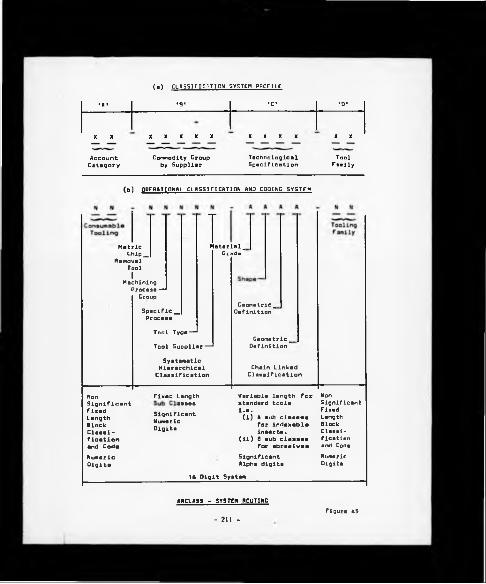
(a) CLASSIFICATION SYSTEM PROFILE
•A* '8' *C* 'O'
X X X X X X X X X X X X X
Account Commodity Croup Technological ToolCategory by Supplier Specification Family
(b) OPERATIONAL CLASSIFICATION AND CODING SYSTEM
MetricChip_
RemovalToolIMachining Process — Croup
1Material_Grade
Specific_Process
Tool Type —Tool Supplier-^
SystematicHierarchicalClassification
Geometric_Definition
Geometric^Definition
Chain Linked Classification
NonSignif ¿cant Fixed Length Block Classification and Coda
Fixed Length
SignificantNumericDigits
Variable length for standard tools i.e.(i) 4 sub classes
for indexable inserts.
(ii) 8 sub classes for abrasives
NonSignificant Fixed Length Block Classification and Code
NumericDigits
Significant Alpha digits
NumericDigits
16 Digit System
ARCLASS - SYSTEM ROUTING
- 211 -Figure 45

(a) The basic system is 16 characters in length (including hyphens)
although the number of characters is not considered to be a limiting
feature.
(b) Element 'A* (characters (1) and (2)) sets the level of focus for
the entire system and comprises a simple, non-significant, block
classification plan of fixed character length. Chapter Four has shown
that the level of focus can vary from the all embracing business
approach of the Brisch Wheel [81] to the specific technological
control disciplines of the PERA machinability data bank system [83].
Clearly the starting point must be somewhere between the two and
indeed this was dictated by the existing BL Limited financial control
procedures which identify consumable materials, of which tooling is a
major element, under a unique account code.
(c) Element 'B' (characters (4) to (8)) is a systematic, significant
character hierarchical classification plan, again of predetermined
length. The principles of formatted matrices typified by the Brisch
and Opitz systems have been adopted for this element.
An Insight into the successive sub-classes contained within
Element 'B', which conceptually will remain constant for all cutting
tools and related spares to be classified, will reveal an attempt has
been made to Install manufacturing logic related to the decision
making process normally pursued by the productlon/process planning
engineer, the flow of which is as follows:-
(1) Character (4) establishes the consumable tooling related
item, as identified by Element 'A', into the following
categories:
o Imperial (measurement system) consumable cutting/forming
tools other than hand tools,
o Imperial tool holders and related spares.
- 212 -

Metric consumable cutting forming tools other than hand
tools.
• Metric tool holders and related spares.
The following sub-classifications will be directed towards cutting
tools rather than spares albeit the classification plans are very
similar, l.e. for a tool relating to a particular process category
read tool holder.
(ii) Character (5) establishes the tool by the manufacturing
process category.
(ill) Character (6) classifies the specific machining proces
group, i.e. milling, turning, grinding, etc.
(iv)
(v)
Character (7) identifies tool type within a defined
machining process family, i.e. single point machining,
turning, brazed tool or indexable insert.
The requirements for the fifth sub-classification, l.e.
Character (8) commodity by supplier, is perhaps less self-
explanatory. For BL Limited to gain commercial benefit in
terms of purchasing discount rates, etc., then the ideal
situation particularly with high usage 'off the shelf'
standard tooling is to have supplier interchangeability
once the respective IMPS machinabllity standards have been
established.
In the case of single and multi point machining this was
found to be difficult to achieve in practice and despite
apparent comparability against ISO tool material grade
charts a wide range of tool performance was encountered as
the result of conducting supplier interchangeability tool
trials. Because of this variance further research work
would be required to enable the desired situation of
interchangeable standard composite tooling.
- 213 -

Therefore, at the time of writing both the IMPS
machinability data and subsequent identification were
linked to specific tool suppliers although provision has
been made within the classification plan to eliminate the
supplier classification once interchangeability has been
established.
(d) Element 'C* (characters (10) to (13)) was found to be the heart
of the system and a level of flexibility was required to accommodate
various technological features. Because of this a decision was made
to move away from the rigid, interdependent hierarchical approach of
Element 'B' and adopt the flexibility of a chain-linked, variable
significant character length, classification plan typified by the
principles contained in the MICLASS system.
The successive sub-classifications contained within Element 'C*
are dictated by the technological requirements of the IMPS
machinability standards and are not Intended to accommodate purpose-
designed cutting tool features as to be found with form tools, etc.
In principle the basic system would comprise four successive sub-
classifications, utilising ISO/BS system definitions wherever
possible. However, if additional technological features required
definition within the overall classification plan then further sub-
classifications would be allowed.
The basic classification plan iss-
(i) Character (10) identifies tool material specification, l.e.
high speed steel, tungsten carbide (uncoated), hot pressed
ceramics, etc.
(II) Character (11) identifies the basic tool shape/style, i.e.
rhomboid (Indexable inserts), quick helix (twist drills),
etc.
- 214 -

(iii) Characters (12) and (13) refer to the basic tool cutting
geometry, i.e. clearance angles, chip breaker styles
(indexable Inserts), twist drill point angles etc.
With respect to all of the sub-classifications within element
'C' standard nomenclature, l.e. BS/ISO etc., have been utilised
wherever possible.
(e) Element 'D' (characters (IS) and (16)) consists of a further
classification to group the tools now defined by specific common
technological features into dimensional families. A simple non
significant fixed character length block classification plan has been
utilised.
The tool family matrices of this element were then used to form
a standard tooling catalogue, a subject discussed in more detail in
Section 7.6.
(f) The overall design of the classification plan provisions for an
'end of code' open-ended data recording facility for local
departmental requirements and this is discussed further in
sub-section 7.5.2.
7.3.2 Coding
Initially the principle of utilising numeric based characters
throughout Elements 'A', 'B', 'C', and 'D' was adopted, but this became
very cumbersome when attempting to accommodate well-established ISO and BS
systems, which are predominantly character based codes, within Element 'C'.
Therefore, as Figure 45 indicates a clear division was made whereby
Elements 'A', 'B' and 'D' with their fixed number of sub-classifications
were identified by numeric characters (excluding 0) and Element 'C', which
is the only variable element, comprises sub-classifications Identified
wherever possible by characters (excluding the letters I, 0 and Q).
- 215 -

Reference to Figure 46 shove e detailed routing through the combined
classlflcatlon/coding system known by the acronym ARCLASS. The example given
for a specific tool family within the general classification of indexable
inserts, has been taken from the standard tooling catalogue as Implemented
as part of the overall ATOMS approach to tool control at Coventry Engine
Plant, and Is a typical example of the ARCLASS style, l.e.
16-6147l-ATNB-01
The hyphens were used for better system visibility and offer a distinctive
breakdown between the main classification elements, with the key variable
Element 'C', l.e. technological control, particularly well highlighted.
7.4 ARCLASS - SYSTEM ROUTING
Further reference to Figure 46 summarises many of the key features as
discussed In the previous sections. Items of particular Interest include
the following.
7.4.1 Account Code
The classification within Element 'A' designates the appropriate
financial accounting code from which all Plant-wide financial reports are
generated.
Typical examples of the two character account codes which are common
to all Birmingham Operations factories are:-
14 Stationery stores
IS Maintenance items
16 Consumable tooling
17 Jigs and fixtures
18 Oil
216 -

mi im
a
- 2 1 7 -

7.4.2 Commodity Group
The distinctive characteristic o£ Element 'B' Is the Initial use of
two dimensional formats for establishing the classification plan and the
subsequent coding system, reflecting the Influence of Brisch and Opltz.
It should be noted that to avoid user misunderstanding with respect to
Interpretation a dictionary of terms and definitions used throughout
ARCLASS is provided as a section within the standard tooling catalogue (to
be discussed in greater detail in Section 7.6)
7.4.3 Technological Specification
The detail contained in the classification categories identified by
the individual characters (10) and (13) highlight a basic problem
encountered while implementing ATOMS and that was the interchangeability
of tools by supplier. In the case of indexable inserts this problem was
compounded by the combined interchangeability requirement of chip breaker
styles as well as tool materials.
The classification plan shown against the respective characters
establishes the framework for possible supplier interchangeability albeit
the following problems would have to be overcome before this objective
could be fully implemented
(a) Tool material (character (10)) - this matrix has been
provisionally structured on the potential for supplier inter
changeability based on information taken from ISO tool material grade
profile charts, and discussions with a limited number of tool
suppliers. The tool material grades shown against each alpha
character are theoretically interchangeable, i.e. similar metal removal
performance standards can be expected from any of the individual
suppliers material grades quoted. Non-acceptable variations in
performance were encountered during interchangeability tool trials
218 -
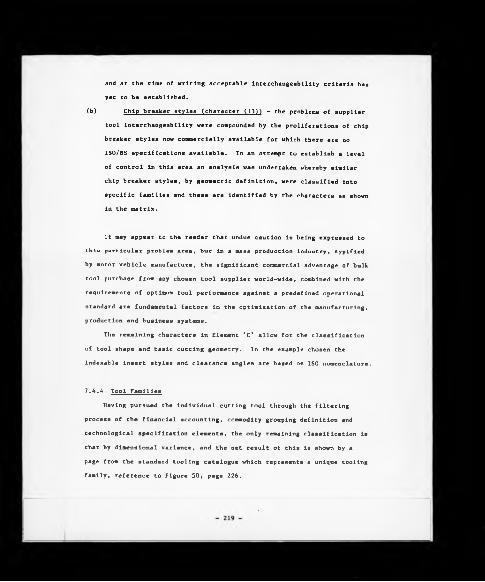
and at the time of writing acceptable interchangeability criteria has
yet to be established.
(b) Chip breaker styles (character (13)) - the problems of supplier
tool interchangeability were compounded by the proliferations of chip
breaker styles now commercially available for which there are no
ISO/BS specifications available. In an attempt to establish a level
of control in this area an analysis was undertaken whereby similar
chip breaker styles, by geometric definition, were classified into
specific families and these are identified by the characters as shown
in the matrix.
It may appear to the reader that undue caution is being expressed to
this particular problem area, but in a mass production industry, typified
by motor vehicle manufacture, the significant commercial advantage of bulk
tool purchase from any chosen tool supplier world-wide, combined with the
requirements of optimum tool performance against a predefined operational
standard are fundamental factors in the optimisation of the manufacturing,
production and business systems.
The remaining characters in Element 'C' allow for the classification
of tool shape and basic cutting geometry. In the example chosen the
indexable insert styles and clearance angles are based on ISO nomenclature.
7.4.4 Tool Families
Having pursued the Individual cutting tool through the filtering
process of the financial accounting, commodity grouping definition and
technological specification elements, the only remaining classification is
that by dimensional variance, and the net result of this is shown by a
page from the standard tooling catalogue which represents a unique tooling
family, reference to Figure 50, page 226.

7.5 SYSTEM EXPANSION
To ensure medium-term system expansion capability a review was
undertaken of several tooling families (Including tool spare parts) in
order to anticipate potential system limitations. The families
investigated were:-
( l ) Drills
(ii) Reamers
(ill) Taps
(iv) Dressing diamonds
( V ) All abrasives
From this review the following observations were made:-
(a) In all cases the format of Elements 'A', 'B' and 'D' were found
to be acceptable, i.e. fixed length classification categories
identified by numeric characters.
(b) The control mechanisms of Element 'C' were expanded by the
requirements of the ISO [92] specifications for grinding wheels due
to: -
(i) The number of characters utilised by the ISO system.
(ii) The utilisation of alpha and numeric characters for
technological specification.
The net result of items (i) and (11) are shown In Figure 47
where Element 'C' has a character length of eight and contains a mix
of alpha and numerics. Neither point is considered to be detrimental
to the overall ARCLASS mechanism in that the system boundaries have
been set between a minimum of 16 characters to a maximum of 20.
7.5.1. Additional System Design Features
Clearly, the difficulty in developing a system routing is to
anticipate all medium-term requirements, and two possible examples could
- 220 -

221
Fig
ure
47

Include local departmental requirements and facilities for classifying
purpose-designed tools. Comments on each are as follows
7.5.2 End of Code Facility
Reference to Figure 48(a) will show that a further Element 'E' has
been added to the operational system and allows for the local requirements
of individual functions to hold specific Information against the code
number Identified. This provision Is open-ended and Is restricted only by
the file address capability of the processor being used and typical
examples of Its use include:-
(a) Regrind characters to show the number of expected regrinds
remaining In a cutting tool.
(b) Additional geometric definition as shown in Figure 48(b).
7.5.3 Purpose-Designed Tools
Reference to Figure 49 shows that a provision has been made for
purpose-designed tools which is not an avenue pursued in this research
activity. However, a modified ARCLASS structure could be designed along
the following lines
(a) Element 'A', account category to remain the same.
(b) Element 'B', identifies the special tool type by machining
process.
(c) Element 'C', would be reduced to accommodate technological
definition only, thereby removing the tool shape classifications.
(d) Element 'D', would now become the tool form/shape category
definition by possibly pursuing a modified chain linked component
type statistical analysis approach to the classification structure.
(e) Again the final element, in this case ’E ’, for tool family
designation would remain fixed at two characters.
- 222 -

(•) Predicting Top! llft_Af..tlntna - I"v»"twy Control
to. of I •tibio— 1
Actual No. of —
Ragrinda
2. Half ToolLift Attaining —
5. Replacement Tool Ragulrod
(b) »actional TQfhnjlgfljcii rwtwtt r9T ■ liBBit p9l"t fattUBI I t
x x x _ x x x x ~ x x : z oC \ v L - * 1 z
Hhtrtiy t Sida Rake OC ■ Claaranca Angla >. a Back Raka y a Approach Anglo
• Includad Angla A a Nota Radius
X, T, Z a Specific Toaturaa.l.o. Cdgt Preparation
EXAMPLES or INDIVIDUAL DEPARTMENTAL USE or END or COPE CHARACTERS
223 Eigur« 48

Figure 4
9

7.6 STANDARD TOOLING CATALOGUE
Chapter Six has shown that the result of the IMPS assisted indexable
insert standardisation programme was to reduce the range of tools actually
in use throughout the machine shops from 436 to 120 varieties. The
next logical stage was to allocate an ARCLASS derived code number to each
individual tool and then amend the 'where used' files to reflect the revised
tool designations. Having completed this task an additional system
benefit became apparent and that was the development of a standard
tooling catalogue, initially to reflect the new standard range of indexable
inserts, followed by the subsequent addition of other tooling families
typified by twist drills and grinding wheels. A typical page from the
standard tooling catalouge, as implemented, is given in Figure 50.
The main role of the catalogue was to act as an operational standard
to which everyone at the factory was committed. From this point onwards
only one individual, the Process Planner associated with the project,
was allowed to amend the catalogue.
In addition to this main theme of control the catalogue was also
intended as an educational aid, containing general discussion and advice
relating to experiences gained during the tool standardisation programme.
Typical sections included:-
(a) A full description of the ARCLASS control principles
(b) Tool wear diagnosis
(c) Swarf control
(d) Tool style equivalents
The issue of the catalogue was particularly well received within
the user areas and for many it was considered to be a tangible result for tool
trial activities which had taken place in the preceding months. Although
the importance of such a catalogue was always recognised in terms of
system implementation, its ready acceptance was a significant factor in
creating a positive working environment for further ATOMS based initiatives.
- 225 -

STANDARD TOOLING CATALOGUE PACE
- 226 - figure 50

7.7 SYSTEM LINKING
Reference to Section 6.5 and Figure 46 will begin to highlight the
links between ARCLASS and the machlnability grouping data files which the
IMPS algorithm manipulates. For example, Figure 36, page 159, shows that
the component machinability group (4) is best machined with tools with
clearance angles N and P, and an appropriate tool grade is (i.e. GC 015)
supplied by Sandvlk, thus all tools with the code format:-
61471-B?N?-??P
would be eligible choices. The approach pursed within the IMPS algorithm
is to search the entire floppy diskette-based Company Standard Tooling
Catalogue to identify the appropriate tooling available, as described in
Section 6.5, along with the methodology which facilitates the nomination
of the most suitable chip breaker style based upon the feed rate and depth
of cut specified for the machining operation.
- 227 -

CHAPTER EIGHT
8.0 TOOL MATERIAL SUPPLY SYSTEM (LINCS)
Having pursued the system routing this far the next logical step is
to establish the factory supply mechanisms for the standard range of tools
in question.
This particular aspect of the research work initially raised a point
of concern in that there appeared to be a danger of apparently
're-inventing the wheel', because unlike the purpose-designed requirements
of the IMPS and ARCLASS stages of the overall tool control concept,
standard material supply software packages were readily available from the
majority of the main hardware suppliers, as a purchasable commodity.
However, rather like the initial appeal of the Brlsch monocode as
discussed in Chapter Four a limited investigation revealed the following
problems
(a) As Chapter Two has shown existing 'in-house' systems were
extremely expensive, with system running costs alone ranging from
£40K to £80K per annum. To avoid any apparent confusion to the
reader due to BL Limited's business organisation, each Plant would
still have to pay similar system operational costs irrespective of
the fact that the system may already be in use elsewhere within the
Organisation.
(b) Experience from reviewing software packages that were
commercially available revealed an emphasis towards direct material
control, and minimal activity in terms of indirect/consumable
materials.
(c) The foundation of the research work was based upon designing and
implementing a routing through a linked systems approach to tool
control, and Involvement with other functions, departments, companies,
- 228

etc., at the critical tool material supply stage imposed totally
unacceptable constraints, examples of which Include
(i) Access to hardware within any of the factories comprising
Birmingham Operations for the purposes of system
development was limited.
(ii) Access to software packages for the purposes of system
modification/enhancement was discouraged at all times.
(iii) Existing systems within Birmingham Operations had
restrictions with respect to the number of characters
allowed within the tool code format. This ranged from a
maximum of 8 characters with the Drews Lane system to 12
with the Longbrldge system; thus effectively preventing
utilisation of the variable length control features
inherent within ARCLASS.
(iv) Involvement with others at any stage of the ATOMS
development imposed constraints in terms of timescale,
system design, flexibility, and a general reluctance to
identify and rectify recognisable operational limitations.
Against this uncertain background the decision was taken to develop a
tool material supply module, hereafter referred to as LINCS (Linked
Inventory Control System), which services the manufacturing management
control systems element of the overall ATOMS concept.
LINCS was developed at two distinct levels, and these were:-
(a) In any sizeable manufacturing concern it is necessary to have
'good housekeeping' disciplines to facilitate control. One such
discipline is the operation of a stock transaction recording system,
l.e. some method of recording to an acceptable level of accuracy,
- 229 -
the flow of, in this instance, tool material and related Information
to and from the manufacturing system.
The three key areas of control established within LINCS are:-
(i) Tool material issue against the bona fide user area as
identified by the data within the 'where used' files.
(ii) Tool material receipt.
(ill) A simplified purchase order tracking facility, although as
later discussion will reveal this element of the system was
replaced with a vastly improved tool procurement mechanism,
(b) Having established the more conventional stock control
procedures as described in (a) a further initiative was taken to make
greater use of the tool/component 'where used' files and develop the
routing through a flow control based material supply system whereby
the tools would be delivered directly to the machine shops against a
forecasted weekly requirement thereby eliminating the need for
certain categories of tools to be held in stock.
This concept is a derivation of the much publicised Japanese
'just in time' method of material supply, known universally as
KANBAN, McElroy [93] 1982, albeit more generally identified with the
supply of direct materials and not consumable/indirect materials
typified by cutting tools and their related spares. However, a
successful departure was made from the traditional approach to tool
material supply and the routing for a KANBAN based flow control
system was designed, and implemented, in two areas and these were:-
(i) A dedicated transfer line.
(ii) A single cost centre containing a mix of conventional
machine tools.
The following sub-sections give an overview of the existing stock
control system encountered at Coventry Engine Plant followed by further
- 230 -

discussions on the various elements of the LINCS module as implemented at
the Plant.
8.1 STOCK RECORDING - THE EXISTING SITUATION
The existing system was manually based and inherent problems stemmed
from the allocation of duplicate tool code numbers, and a general lack of
discipline in the recording of transaction data, resulting in little
correlation between recorded stock levels and actual shelf stock.
Enlargement of these problem areas is as follows
(a) Numerous codes have been allocated to one item of tooling due to
the weak design, and operation, of the coding system used within the
tool stores. The existing coding system which was discussed in some
detail within Chapter Two was Installed at the instigation of the
local Production and Material Control and Financial Control
Departments, was simply sequential, and served merely to allocate a
unique code number to each item; since, however, it had no structure
to facilitate technological grouping of like items, it failed to
achieve this simple objective, thus one tool was held under several
different code numbers at differing locations (bins) within the tool
stores leading to considerable problems in terms of updating
incorrect documentation.
To compound this problem, shop floor supervisors were totally
oblivious to the existence of any coding system, and requested tools
according to the description given by the tool supplier, or
occasionally, by a British Standard (BS) or International Standards
Organisation (ISO) technologically orientated description.
(b) Lack of instantaneous updating of stock card records following
delivery of tooling by suppliers and/or issue to the production
areas. This led to an accumulation of unrecorded transaction data
- 231

which was updated periodically, the timing of which was dependent
upon the department work load. Decisions taken regarding the
requirement to re-order based upon the evidence of stock card records
was clearly being made upon an infirm basis.
8.2 INVENTORY CONTROL
Following rationalisation of the Indexable Insert tooling range the
facility to store, update and Interrogate the records of 120 tooling items
was required. This presented two initial problems, and these were:-
(a) The data base configuration.
(b) Data storage mechanisms.
Figure 51 presents a schematic layout of the eventual data
configuration which is based on an ARCLASS designated file address, which
for the routing shown is 61471-BTNA-01, followed by a hierarchically
structured set of related data records. Examination of the individual
records will reveal that the data base comprises an enhanced version of
the original tool/component 'where used' file, and enables storage of
data required to achieve management control, i.e. finance, stores,
industrial engineering related as well as core information from the IMPS
derived technology data base, l.e. cutting tool geometric and material
grade parameters, etc. As the following sub-sections will show that all
of the stock/flow control mechanisms have been developed by writing
applications programs to interrogate this dynamic data base from various
levels of focus to achieve the desired management control reporting
features.
Because of the relative simplicity of this approach, it is not the
intention to pursue the detailed, step by step, analytical procedure
contained in the IMPS Chapter, but rather to give an overview of the
- 232 -
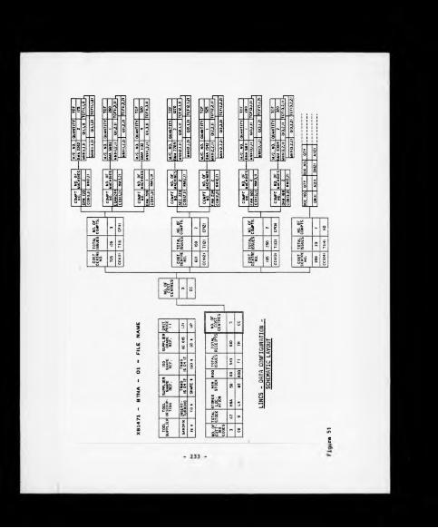

methodology pursued to establish control over tool material supplies and
then refer to relevant appendices for details contained In the applicable
applications program.
The second problem relating to data storage mechanisms centred around
limiting the number of diskettes the system user was being asked to
handle. In hindsight, and with the parallel technological development in
terms of data storage, i.e. Winchester disk drives, this would no longer
be a problem, but during the period of research the APPLE Disk Operating
System (DOS) arranged the diskette directory in a format restricting the
number of possible files to a maximum of 84 in sequential text form, when
in fact the indexable insert tooling LINCS data base required a minimum of
120 file addresses. This problem was resolved by writing the program
detailed in Appendix K which expanded the diskette potential to 175 files,
therefore, resulting in all of the LINCS based data for the tooling family
in question being held on a single density 5 1/4" floppy diskette.
As discussed in Chapter Three the term 'inventory control' is taken
to include stock and flow control systems, and as the following sections
will reveal, both approaches to material control played prominent roles in
the evolution of the LINCS module.
8.3 STOCK CONTROL
The initial activity in terms of establishing control over tool
material supply was to concentrate on three key areas of the tool stores
activity, and these were:-
(.a) Material issue
(b) Material receipt
(c) Re-order procedures
- 234 -

Further comment relating to each aspect is contained in the following
sub-sections.
8.3.1 Tool Material Issue
A greater control over the recording of issues of indexable inserts
was achieved by:-
(a) Disciplined use of the ARCLASS classification and coding system.
(b) Use of the tool/component 'where-used' data to restrict tool
issue to recognised and user departments only.
At the conclusion of the IMPS assisted plant-wide rationalisation
programme it was ensured that each indexable insert was Identified by one
unique code number and duplications had been eliminated. All production
supervisors were given details of such tooling related to component
machining under their control in the form of their local 'where-used'
data, usually by cost centre designation. This represented a marked
departure from past custom and practice, resulting in storekeepers no
longer being required to cross-reference tool descriptions with code
numbers as had previously been the case; hence the elimination of a
serious source of confusion was achieved.
In addition to this a positive use was made of the 'where used' data
to restrict the issue of tooling only to the bona fide end users as
identified by the rationalisation exercise. It was considered that having
completed the IMPS assisted tool rationalisation exercise the only reasons
for tools being withdrawn by unrecognised user cost centres would be due
toî-
(a) An alternative tool was required due to stock-out of the
recommended standard.
- 235 -

(b) Shop floor personnel, l.e. setters, operators, etc., were using
license to experiment still further with alternative tool types.
The first possibility should not have arisen following the
introduction of the well established procedures of component volume linked
max/min levels combined with supportive guarantees from the tool suppliers
to hold adequate stocks of the recognised standard tools within their own
stores. With reference to the second point, in practice it is unrealistic
to suggest that tools should be automatically refused at the point of
issue owing to the technicality that the requesting department is an
unrecognised end user; instead tools were issued provided an authorised
level of Production and Material Control signatory was willing to concur
the issue. All such issues were recorded by the system and a weekly
summary was presented to the Production Engineering Department for
subsequent investigation to identify the existence, or otherwise, of any
recurrent machining problems. Following this investigation the respective
production engineer would then concur, or otherwise, the continued use of
the non-authorised tool.
8.3.2 Tool Procurement
The first move towards applying control over the Inventories held of
the rationalised range of indexable Insert tooling came by endeavouring to
set maximum and minimum stock levels. This exercise highlighted a
fundamental problem experienced within the Company and common to virtually
all large commercial enterprises with labour intensive clerical systems
and that is the time delay in processing paperwork. It was discovered
that in the case of such standard tools as Indexable inserts which are
'off the shelf' items, it took the Company eight weeks from the inception
of a request to purchase tooling (by the local stores personnel) to the
placement of a confirmed order by the central purchasing function with the
- 236 -

tooling supplier; this concurrence route was clearly unacceptable. It
then required a further week for the nominated supplier to complete their
own internal procedures before tools were eventually delivered. The
initial reaction was to include a purchase requisition 'tracking' facility
within LINCS to monitor internal and external lead times as an
anticipatory mechanism to enable stores personnel to check for any
impending deliveries prior to the raising of new requisitions. This
tracking facility was initially implemented, but despite its apparent
usefulness and its general acceptance in the user areas the resource Invested
seemed to be accommodating a problem rather than seeking to overcome
it. The decision was made, therefore, to eliminate this highly labour
intensive approach to tool procurement and adopt a much more
simplified solution to the problem. To this end, an agreement was reached
between Production and Material Control, Finance, and Purchasing functions
to the effect that a 'blanket order' arrangement should exist between
various suppliers and Coventry Engine Plant such that at the local tool
stores level a request for delivery of a given number of tools from within
the new rationalised range would not require central concurrence and
would be placed directly upon the supplier who would in turn, invoice the
Company on a regular basis.
The net result of this action was to decrease the tool procurement
time from eight weeks to one week and in doing so it was then possible to
establish more realistic max/min levels for the 120 tools in question.
This was based on a semi-flow control approach whereby data held in the
'where-used' files provided a link between components a tool was used to
produce, the quantity in use at any one time and an approximate
consumption rate by number of components produced (i.e. utilising
validated tool change frequencies); receipt of monthly manufacturing
programmes enabled the generation of appropriate tool quantities required
to support that production level. Net order quantities were simply the
- 237 -

result of the following equation:-
Net order quantity ” Gross requirement + minimum buffer
stock - stock on hand
8.3.3 Tool Material Receipt
Following on from Improvements In tool Issue and procurement then the
remaining discipline of tool receipt from the suppliers following the
direct placement of orders simply required mechanising to facilitate on
line real time (OLRT) updating to ensure accuracy of records.
Finally, examples of key reporting/control features and supportive
applications programs are as follows:-
(a) Reporting/control features:-
(i) Tool issue/receipt - reference to Figure 52.
(11) Tool/component 'where used' data - reference to Figure 53.
(b) Likewise, the main applications programs utilised are given In
the following Appendlces:-
(i) Tool data file creation program - Appendix L
(11) Tool issue/receipt - Appendix M
(111) Tool component 'where used' data - Appendix N
(Iv) Tool bill of material generator - Appendix 0
8.4 FLOW CONTROL
After a period of consolidation thereby allowing the Initial issue,
procurement, and receipt mechanisms to become established, further
consideration was given to the problem, particularly in terms of tool
procurement and supply. Upon reflection the approach pursued in the
previous section still revolved around the ln-house maintenance of
tooling Inventory with its obvious detrimental effect on the Company's
cash flow position. Attention was therefore focused on developing the
- 230 -

IRUN
PLEASE KEY IN THE TOOL NAME
t —761471-BTNA—Ol
ARCLASS CODE M»X61471-BTNA-01 #COST CENTRE ISSUES TOOL SUPPLIER # 725 120
=SANDVIK # 621 ISOSUPPLIER REF # IQS 250
=TNMG160412 # 999 23STORES LOC’N
=HNACURRENT STOCK
=67MIN.STOCK
=50RE-ORDER Q'TITY
=80TOTAL ISSUES
=543TOTAL RECEIPTS
=610
COST CENTRE999 AUTHORISED ISSUE DOCUMENTS
DOCUMENT NO. IO 53 72 156 159 2 2 0 300
PRESS(RETURN)
NO. OF ISSUES 2
TO CONTINUE
LINC5 - TOOL ISSUC/RECEIPT (SCREEN DISPLAY)
- 239 -Figure 52

~CCQST CENTRE723COMPONENT NO. M/C NO. QUANTITY T.C.F.
DAM133DMA 2262 2 173BMA 2661 2 200
EDAM 244BMA3802 1BMA3803 1
DAM7B8BMA1132 4 320
PRESS (RETURN) TO CONTINUE
'’COST CENTRE621COMPONENT NO. M/C NO. QUANTITY T.C.F.
aec: :3
BMA2789 2BMA2790 2
FAM234BMA1542 1BMA1543 1
PRESS (RETURN) TO CONTINUE
525325
7C0ST CENTRE105COMPONENT NO. M/C NO. QUANTITY T.C.F.
FAM 622BMA5811 l BMAS812 1
BMA6384 2 320BMA6383 2 320
PRESS (RETURN) TO CONTINUE
LINCS - TOOL/COMPONENT 'WHERE USED*DflTft (SCREEN DISPLAY)
Figure 53- 240 -

routing through a material supply system which had the objective of having
tools delivered by suppliers on a weekly basis in 'packages' specific to a
cost centre and/or dedicated machining facility in sufficient quantity to
support the following week's production. The subsequent system routing
which was developed to accommodate this new approach to tool material supply
was known as 'Tool Marshalling' . Discussion in the following sub-section will
reveal that the system takes its name from the physical procedure, as carried
out by the local storekeeper, of marshalling the appropriate tool packages as
delivered by different tool suppliers for specific cost centres.
8.4.1. Tool Marshalling
While the routing for a direct material supply system could be developed
on an APPLE Microcomputer all of the Plant's cost centre details and forward
manufacturing plans were generated from a Plant based (BLSL owned) CMC Sovereigr
minicomputer to which access was finally made available for the purpose of
developing the line side supply of standard indexable inserts. For the
purposes of the initial system routing two distinct levels of activity were
established, the details of which are:-
(a) It was considered that the most sophisticated and detailed supply
situation supportable in both computerised system and personnel
organisation terms was a level of control which enabled a cost centre
to receive its tools in packages specific to each component containing
sufficient quantity to support the following week's production
requirement. Such a method of control was found to be applicable to
cost centres producing a relatively small range of components in high
volume and was referred to as Level 1 control.
(b) For cost centres having a larger range of components, usually
being produced in commensurately smaller quantities, Level 1 control
proved difficult to support because of a number of major difficulties,
the primary one being that since Level 1 control called for the
delivery of one tooling package for each componet in the cost
- 241

centre, a multiplicity of components necessitated the delivery of a
large number of containers which were simply too cumbersome to
transport and, because of the generally lower production figures,
contained few tools. For this reason a less detailed, but more
appropriate level 2 control was devised for such cost centres. Level
2 control provided for the delivery of tools specific to the cost
centre as a whole (i.e. not component specific) on a weekly basis.
When considered in conjunction with the above two levels of control,
the net bill of materials supply system introduced earlier is thus a still
less refined method of control and was, therefore, designated as level 3
control since it worked upon the premise that although tooling
requirements were generated from the 'where used' matrix, tools were held
in the central tool stores and not delivered by the vendor in cost centre
or component-related packages. It is important to understand, however,
that for all three levels of control, the bills of material were generated
on a weekly basis from the same core data held in indexed sequential form
upon the CHC Sovereign computer as shown in Figure 54, the level of
control to be applied for each cost centre being discerned from the
setting of a flag included for that specific purpose.
The detailed mechanism of system operation was as follows and
reference should be made to Figure 55 in association with the text.
Documentation is computer-generated in triplicate from the CMC
Sovereign 'where used' file base (component volume data being extracted
from the Plant Production and Material Control files) upon the Tuesday of
week one with all columns completed up to, and including the 'quantity
required* column which for level 1 is the gross quantity (based upon
component volume and tool consumption rate details) rounded to the nearest
even number and for level 2 is the gross quantity rounded to the nearest
10 to simplify packaging considerations; examples of documentation
- 242 -

figura $4

SE
ND
A
LL
3 C
OP
IES
TO
PM
C rO
R
CH
EC
KIN
G
FOR
OBVI
OUS
ANOM
ALIE
S AN
D SI
GNAT
URE
TOOL 'MARSHALLING* - OUTLINE OF DOCUMENTATION FLOW FOR LEVELS (1) ANO (21 CONTROL PROCEDURES
- 244 - Figur« 55
ST
OR
ES
U
PD
AT
E
COM
PU
TER
IS
SU
E
AN
D
RE
CE
IPT
SY
ST
EM

generated for Level 1 control is given as Figure 56 for cost centre 738,
component number FAM 9433 for suppliers Sandvik and Seco. Following
vetting for anomalies by Production and Material Control the area
supervisor either concurs the computer generated figure as being
appropriate or alternatively amends it to accommodate movements in his
section's tooling buffer stock levels in the 'quantity ordered' column;
two copies are collected on the following day by the supplier and are
retained by the Plant as proof of placement of order. Upon the Friday of
the following week delivery of the tooling to fulfil the order is made
and the two copies of documentation returned by the supplier to the stores
personnel to verify the delivery, acknowledge such in the 'quantity
received' column, and sign the appropr'ate box; one copy is returned to
the supplier as his proof of delivery for invoicing purposes. The one
remaining copy is signed by the production supervisor upon collection of
his package from the tool stores as proof of issue, thus on one document a
full list of signatories signifying concurrence of order, acknowledgement
of receipt and acknowledgement of issue is achieved.
It will be appreciated that this method of delivery entailed far greater
effort on the part of the supplier than was normally the case in
satisfying 'conventional' orders and thus those vendors with only a
minority interest in BL's activities could not justify such involvement
on a cost-benefit basis, such suppliers were thus dealt with in the
conventional ordering manner and for Levels 1 and 2 control, their two
copies of documentation were sent instead of the tool stores keeper who
withdrew the appropriate 'order quantity' from stores' stock and
marshalled this with the Sandvik and Seco deliveries.
It should be noted that this 'marshalling' approach was only implemented
towards the end of the project research activity and, therefore, it was
not possible to quantify the full benefit to the Company in terms of
- 245 -
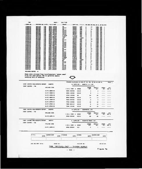
COST CENT« PEOv'IH «POFT INEEPT5
APCLAIS COM
DUt DELIVEPY DATEi - OPMR NOi- PELEAIE NO. - ABV1C1 NOi-
TOOL »MAaSHALLING» - SYSTEM OUTPUT246 figure 56

reduced inventory levels, the near elimination of paperwork systems, etc.
The majority of the benefits to be discussed in the tool material supply
section of the following Chapter are due mainly to the more conventional
stock control mechanisms within IMPS as detailed in the earlier stages of
this Chapter.
Finally, it was always recognised that for LINCS in general
(including the concepts of 'tool marshalling') the update of the
tool/component 'where used' data base was critical to the overall
functioning of the system, and reference to Figure 57 shows the
documentation implemented to achieve this task.
- 247 -

248

CHAPTER NINE
9.0 RESULTS OF SYSTEM IMPLEMENTATION
The system results can be viewed from three levels of focuss-
(*) Initial IMPS core data validation upon the 'test cell' of
twelve copy lathes.
0>) The factory-wide IMPS-'driven' tool standardisation programme,
(c) Tool material supply and control.
Discussion with respect to each area is as follows:-
9.1 IMPS CORE DATA VALIDATION
At first sight the tool range in use upon the twelve machines lacked
any coherent control in terms of standardisation and application, and
because of this a series of cutting tool trials took place to:-
(a) Reduce the number of tool manufacturers supplying tools to the
machines from six to two.
(b) To implement a reduced range of tools upon the machines with
the intention of improving the machining economics wherever possible.
(c) Following (a) and (b) to then establish a set of machinabillty
standards that were considered to be acceptable to the Plant's
Process Planning, Industrial Engineering, and Financial Control
Departments.
The net result of this initial action was to establish control over
the cell of machine tools and effect a number of desired economic
improvements. The next logical step was to evaluate IMPS' predictive
ability against a series of accepted machining standards. This was
- 249 -

possible by linking together the IMPS turning program and the first
compilation of the standard tooling catalogue. This early validation
exercise required the writing of an Inverted form of the IMPS program
(reference to Appendix P) , which enabled the user to specify a particular
grade at the start of the program rather than obtain a grade
recommendation output midway through the algorithm as is the case with
IMPS. This Inverted program, referred to as Factor Proving IMPS, also
enabled base speeds to be modified with the objective of establishing
machlnabillty data which accurately reflected shop floor performance
capabilities. Reference to Figure 58 summarises the overall results from
twenty-one machine tool trials, and reference to Figure 59 gives the
results of a routing through the Factor Proving IMPS routine adopted.
As has already been explained in Chapter Six, an Increase of 50Z in
the datum speeds for machinablllty groups (3) and (4) was considered to be
necessary following these initial core data validation trials. In
analysing the results obtained from this detailed study, such an Increase
may be considered to have been too great, since the predictors for cutting
speed and tool change frequency exceeded the actual values by some 11.63Z
and I7.19Z respectively. It was felt, however, to be appropriate from a
management control perspective to leave the data at these higher levels in
order to produce a high target standard value for speed, tool change
frequency, and standard time rather than to generate data which would be
easily achievable in practice, and would thus not encourage the
exploration of the opportunity to extend tool life, etc.
In 12 of the 21 examples presented tool flank wear normally achieved
in practice was considerably less than the 0.3 mm taken as the criterion
used to designate end of tool life in the cutting tool trials performed by
the individual suppliers which formed the basis of the initial IMPS core
data hence the reference to 'normalised' tool life within the results table.
This 'premature' tool changing was found to be due to two aspects
2 5 0 -

Fig
ura
58

Fig
ur«
59

(a) Firstly, and quits legitimately, tools were changed when
workpiece size tolerances were exceeded.
(b) Secondly, the machine tool setters' custom and practice of
changing tools at 'convenient' times during the shift, l.e. tea
breaks, end of shift etc.
Improvements In setting practices enabled tool life extensions to be
achieved In ten of these twelve cases by an average of some 30Z.
Opportunities for increasing the parameters of depth of cut and feed
rate were less easily achievable given the time constraints under which
the research work was performed, combined with the very real problem of
industrial research that all machine down-time for machine changeovers.
etc., equated to production components lost. It was, however, possible
to elevate the feed rates In two Instances from the original values.
At this Initial core data validation stage the understanding for the
potential to achieve tool Interchangeability between suppliers was less
successful. As has been mentioned previously the Company could gain
significant commercial advantage if the Purchasing function had the
ability to procure 'generic' tool grades from a range of home-based, or
indeed world-wide tool suppliers. Unfortunately before this situation can
be arrived at it is essential that the concept of supplier-based tool
interchangeability has to be proven at the machine tool level against
Company defined manufacturing standards. An early attempt to understand
this problem was made In tool trial numbers 2, 3, 4 and 5, reference to
Figure 58, whereby like tools within the ISO grade profile chart, i.e.
Sandvlk GC 415 and Seco TP 15, were compared to each other under similar
machining conditions. However, this limited exercise, while Indicating small
variance In performance, cannot be taken as conclusive evidence supporting
the potential for interchangeability and the subject area requires a far
greater level of research effort with consideration being given to
- 2 5 3 -

comparisons of Cool material structural compositions as a basis for
Interchangeablllty.
Initial observations are that a lowering In manufacturing standards
may be necessary If wide-spread tool supplier Interchangeability was to be
adopted, and such a measure would not be acceptable from an Operations
Management level of focus unless the cost/benefIts were fully justified.
9.2 PLANT-WIDE APPLICATION OF IMPS
The practice for each turning related cutting tool trial was to
select one operation for generating the theoretical IMPS machlnabillty
standards. Reference to Figures 60 and 61 will show that for component
22G 1096 (first speed gear) operation 20, station 2 (column d) was
selected as the IMPS pilot and key reference data taken from the formal
IMPS output related to:-
(i) Machine tool spindle speed
(11) Tool contact time
(ill) Tool material grade
(iv) Tool change frequency
The details of the coding system referred to In Figure 60 for cutting
condition and test end codes are given in Figure 62.
As IMPS was moved away from the early work at Longbridge and onto the
core data copy lathes it was possible to refine the system, particularly
in the areas of the achievement of component surface tolerances and chip
breaker style selection. However, It was found that the core
machinablllty data only required marginal adjustments In order to reflect
potential turning machinablllty standards Plant-wide.
The net result of conducting this In-depth exercise was as follows:-
(a) Extended tool life was achieved upon 97 operations ranging from
a nominal 5Z to 6S0Z. It should be stressed, however, that although
- 2 5 4 -

233
IMPS ASSISTED TOOL TRIAL REPORT
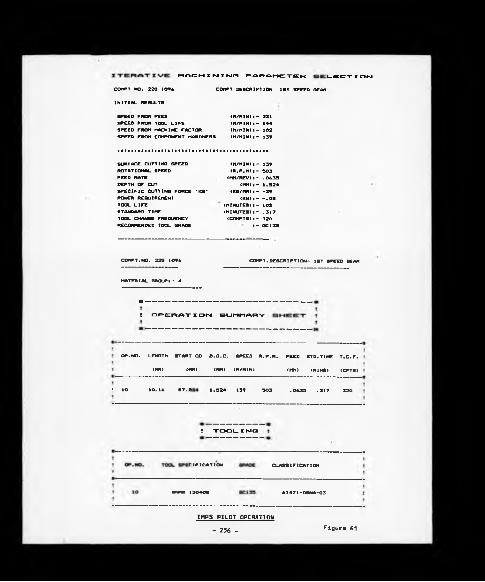
MACHINING PARAMETER CECTX ON
COMPT NO. 220 1096 COMPT DESCRIPTION 1ST SPEED SEAR
INITIAL RESULTS
SPEED FROM FEED SPEED FROM TOOL LIFE SPEED FROM MACHINE FACTOR SPEED FROM COMPONENT HARDNESS
(H/HIN)■— 231 (H/HIN)i- 144 (M/HIN)I- 102 (M/HIN)I- 139
SURFACE CUTTING SPEED ROTATIONAL SPEED FEED RATE DEPTH OF CUTSPECIFIC CUTTING FORCE *KS*POWER REQUIREMENTTOOL LIFESTANDARD TIMETOOL CHANGE FREQUENCYRECOMMENDED TOOL GRADE
(M/HIN)I- 139 (R.P.M)I- 303
<MM/REV)1- .0633 <MM)I — 1.324
(K6/MM) I---39(KW>|- -.OS
(MINUTES)I- 102 (MINUTES)I- .317 (COMPT8) I - 320
I- QC133
COMPT.NO. 22G 1096 COMPT. DESCRIPTION- 1ST SPEED GEAR
MATERIAL GROUP«- 4
* ----- ---
! OPERAT X ON SUMMARY
-------------- -
OP.NO. LENGTH START OD D.O.C. SPEED R.P.H. FEED STD.TIME T.C.F.
(MM) (MM) (MM) (M/HIN) (MM) (MINS) (CPTS)
! IO 10.16 87. G 1.324 139 303 . 0633 . 317 320
I TOOL X fvJC3
:c IF I CAT ION CLASSIFICATION
SNMG 120408 61471—DSNA—03
IMPS PILOT OPERATION
- 256 - figura 61

CUTTINC CONDITION C3DC51. Clean eurface, "o runout or intarruotiona2. Claan eurfaee, moderate runout, no interruption«3. Claan aurfaca, nigh runout (ovar 2 X of inaart)a. Claan aurfaca, aavara runout or interrupted Cutting 5. Scala, minimal runout7. Scala, nigh runout8. Scala, interrupted cutting9. Savara acala, «avara intarruptlona10. Sand, moderate runout
TEST CNO CQOCS
( « ) H H M IM Erl U ri«1. Workpiece alza exceed« tolaranca atlpulatad on oparation2. Workpiece aurfaca finlah exceed« tolaranca atlpulatad on oparation(■) Tggt Cfttgrjg1. flank »aar2. Cratarlng3. Thermel cracking*. Chipping and Braakaga(C) Othar1. Chattar2. UnaccaptaBla chipa3. Limit of machina pomar
J. Built up adga 8. Cdga deformation 7. SpallingB. Scaling off of coating
Sourca; BS 5*23 (B5) 1*75Tool lifa taating mith eingla-polnt turning toola (p. *1)
CUTTINC CONDITION AND TEST END CODES
- 257 - figure 62

these extensions In tool life were obtained, in the main, as a result
of a change in tool material grade, the findings of the
investigations conducted upon the benchmark copy lathes clearly
showed that tools were often being changed needlessly on the basis of
operator/setter custom and practice, thus simply by reappraising the
criteria used by shop floor operatives in the determination of the
end of tool life, tool life extensions were possible. So great was
the concern over needless premature tool changing that a survey was
carried out to measure the typical amounts of flank wear being
achieved upon Inserts discarded by machine operators and returned to
the tool stores for salvage. This analysis revealed that the average
flank wear on discarded tools (450 cutting edges checked) was 0.21 mm.
(b) Increased machining parameters were Implemented upon 10
operations.
(c) Five operations were completely eliminated by increasing the
severity of preceding or subsequent operations.
(d) Only nine additions to the initial standard tooling catalogue
were necessitated.
The above results are those which were Implemented upon the 422
operations investigated with the majority of the increase in tool life
mentioned in (a), and all of the benefits described in (b) and (c) being
applicable to turning operations. In hindsight it is clear that still
further potential for Improvements, particularly in non-turning
operations, existed but this remained unexploited because of the time
necessary to develop IMPS type standards and the subsequent exhaustive
tool trials necessary. These results, however, were sufficiently
encouraging to give the confidence to manufacturing related personnel at
Coventry Engine Plant to Introduce the standard range of inserts to the
remainder of the factory without extensive tool trials being conducted
- 250 -

upon each machine, problems of inadequate tool performance being dealt
with on an exception basis.
A summary of the audited results achieved following this second phase
of activity was as follows:-
(a) Standard range of indexable inserts reduced from 785 to 120
varieties.
(b) 118 standard hours were saved in machine tool setting labour
content per week.
(c) Savings in direct tool costs for turning operations totalling
£20.5K per annum, reference to Figure 63 for the components in
question.
9.3 TOOL MATERIAL SUPPLY AND CONTROL
The tool material supply and control element of ATOMS can be viewed
in terms of three phases of distinct activity, and these were:-
(«) The implementation of basic stock control mechanisms for
indexable inserts only.
(b) The enhancement of (a) to move from stock to flow control
disciplines.
(c) The initial expansion of the ATOMS principles to cover other,
non-indexable insert-related tooling families.
Discussion with respect to the benefits gained from the
implementation of each element is contained in the following sub-sections.
9.3.1 Stock Control
The situation as at January 1981 was an inventory value of £93.5K for
a range of 780 varieties of indexable inserts. There were no formal links
- 259 -

ITEMNO.
COMPONENT MACHINE TOOL TYPE
ANNUAL TOOL COST SAVINC C
C0W1CNTSNO. DESCRIPTION
1 OAM 3092 Pinion Shaft fiahar Lathe €4373.40. Elimination of Tooling • Special Toole Replaced by atandard . Cutting Cdgaa increased fro* 4 to. Tool Crada changed
> RKC 0199 Differential Caaa Hay Special Lathe €2210.00
. Elimination of Tooling
. Special Tools replaced by standard
. Tool Crado Changed
> UKC 4217 Cxtomalflange Crldley €1884.40
. Elimination of Tooling
. Precision tolerance inserts replaced by utility grades
. Tool Crada changed
• DAM 2921 Crankahaft Prieary Caar Oeubla
Spindle€1402.42 . Tool Crado changed
» DAM 4932 2nd Speed Caarf ranter Double Spindle
€1314.80 . Tool Crado changed . Improved chip breaker style
4 TAM 4418 Smivel Hue Ryder Multi Spindle €1432.00 . Tool Crada changed
. Reduction in insert sirs
7 22C 1091 3/ath Coupling Sleeve
Concmatic 4 Spindle Auto Lathe
€1208.24 . Insert Style changed . Tool Crado changad
8 3AM 2923 Prinary Driven Caar
Cridlay 4 Spindle Automatic
€1057.31. Insert Style changad . Tool Credo changed . Improved chip breaking
* TKC 1741 ExtensionShaft
Maxi Turn €979.20. Reduction in Inaart size . Tool Crada changad . Improved Chip breaker style
10 22C 1094 lat Speed CaarConoaatic 4 Spindle Auto Lathe
€937.48. Reduction in Insert alza . Tool Crada changed . Improved Chip breaking
11 RKC 4390 Axle Shaft May Special Lathe €717.12
. Insert Stylo changad
. Tool Crada changed
. Improved chip breaking
12 DAM 7002 U. 3. flange Herbert 2* Capatan €533.20
. Tooling Elimination
. Tool Crada changad
. Improved chip breaking
TOTAL ANNUAL TOOL COST SAVINGS €204?3.97 (IMPS Assisted Turning Operations)
ANNUAL TOOL COST SAVINGS (TURNING OPERATIONS)
- 260 -figura 63

between the forward component manufacturing requirements and the Inventory
levels, and tool re-order quantities were decided by tool stores clerical
and hourly paid staff. Although there was every confidence that the IMPS
assisted tool trials would eventually provide a firm foundation from which
tool material supply procedures could be developed, the full benefits from
this initiative would not be seen for several months. Against this
background a package of simple measures was implemented in order to
establish an improved level of control over the existing situation which,
in hindsight, was preparing the way for the full ATOMS routing
implementation.
Details of the measures taken were as follows:-
(a) A simple discipline was implemented whereby all tooling purchase
requisitions, relating to indexable inserts and spares, raised by the
tool stores staff were independently monitored by the writer,
concurrent with the Initiation of the 'where used' data collection
exercise. Surprisingly, this identified such fundamental errors as:-
(i) Inserts being re-ordered where there was no further requirement
for them, i.e. the component in question was being phased out of
production, but no-one had informed the tool stores.
(ii) It became apparent that the stores personnel were building over
cautious safety levels into their re-ordering levels, and this
was typified by the ordering on one purchase requisition of up
to six months' stock for a standard 'off the shelf' tool. The
main reason given for this defensive approach was a general lack
of confidence in the time taken for purchase requisitions to be
passed through the internal system before the order was actually
placed with the supplier.
Reference to Figure 64 will show that this simple 'portcullis'
action enabled a E12K reduction in Inventory by May.
- 261

RE
DU
CT
ION
o
r IN
DE
XA
BL
E
INS
EH
T
TO
OLI
NG
A
T CO
UEN
TRT
EN
GIN
E
PH
UT
D
UR
ING
1
;81

(b) Midway through this period a clinical review of the Plant's tool
coding and classification system was undertaken which highlighted 49
instances of duplicate coding caused by non-familiarity of stores
personnel with the technological content of tool descriptions, thus
duplications were typified by examples such as the following:-
Code Number Tool Description
SV 22833 TNMC 16 04 08 GC 1025
SV 25221 TNMG 16 04 08 1025 GC
Although the Identification of such mistakes did not have any effect
upon inventory values held since all common items were simply
physically moved to be held in one stores bin location, the
elimination of duplicate codes reduced the coded indexable insert
range by some 49 items from 780 to 731.
(c) By May, the tool/component 'where used' data collection exercise
as described in Section 6.6.3 had been completed and it was possible
to identify all those tooling varieties which were recognised as
coded items for which no claim for requirement had been made by the
production areas. A staggering 295 indexable insert varieties were
found to be redundant, i.e. no end use, with a total inventory value
of £20.5K. This exercise had highlighted a fundamental problem, and
it was agreed with the local management to remove the inserts from
the existing Inventory and place them in a 'bonded stores', the final
use for these tools will be discussed later.
This exercise had therefore reduced, with no effect upon Plant
performance, the Inventory value by £20.5K and reduced the range of
indexable Inserts available for issue by 295 varieties
Instantaneously. At this point in time the Insert inventory figure
was £6IK and comprised some 436 varieties.
- 263 -

(d) In the intervening period between May and August the operation
in the tool stores of the microcomputer based LINCS module was phased
in which controlled all indexable insert stock recording and issue
disciplines and this coupled with the continuation of the purchase
requisition monitoring system described in (a) had the net effect of
a further £14K reduction in inventory.
(e) Running concurrently with the actions described in (a) to (d)
the IMPS assisted tool standardisation exercise was being conducted
which resulted in the implementation in August of the standard range
of 120 indexable insert turning and milling tools to support the
Plant's manufacturing activity. In the space of one weekend the new
ARCLASS based standard tooling catalogue was introduced, which had
the net effect of reducing the range of tools available from 436 to
120 and a further £29K of tools was taken from the inventory and
placed in the bonded stores. By this time the indexable insert
inventory had been reduced by value to £18K. An even greater
reduction had been anticipated, but it was apparent that high levels
of tool stocks for the new standard range of tools had been inherited
from past inadequate stock control procedures.
(f) Between August and October the operation of the LINCS computer-
based stock recording and issue monitoring disciplines, utilising
the tool/component 'where-used' file to monitor whether tool purchase
requisitions were bona fide, was practised and indeed manned by
existing tool stores personnel.
In addition, the elimination of the existing ordering system was
achieved in favour of a locally controlled 'open ordering' procedure,
realistic estimates of order quantities being obtained on a gross
bill of tooling material basis by linking the forward manufacturing
programme into the 'where-used' files which by this time had been
extended to incorporate tool consumption data collected in the course
- 264 -

of the rationalisation exercise. In this way, ordering lead times
were reduced from eight weeks to one, and the confident stipulation
of the range of tools required enabled the two major suppliers, i.e.
Sandvik and Seco, to hold realistic back-up stocks at their own
central warehouses.
Throughout this period extremely low level max/min quantities were
established for each of the 120 variety of inserts which acted as a
buffer stock.
9.3.2 Flow Control
Clearly, by August the full benefits of control were beginning to
emerge and the experience of significant reductions in inventory which
had been achieved, without jeopardising component production, led to the
serious questioning as to whether indexable inserts was a tooling family
for which a 'nil inventory' policy could be applied, viz. the operation of
the Plant without having resources to the holding of back-up 'buffer'
stocks within the tool stores. Having gained an appreciation of the way
in which Japanese industries had applied such 'nil inventory' methodology,
to produce parts via their 'KANBAN' system approach, a tool 'Marshalling'
system for indexable inserts was installed upon one particular cost centre
(i.e. 738) manufacturing two components (FAM 9432, FAM 9433 - Mini Metro
radius arms), controlled by one Production Supervisor. The principles of
the system are outlined in Chapter Eight and referring to the terminology
adopted, this cost centre was operated at a level 1 control, i.e. the most
sophisticated level possible specific to each component in question. As
depicted in Figure 56, page 246, a computer generated report was produced
on a weekly basis for each component upon the cost centre, the package of
tooling being made physically available for collection by the Supervisor
the following week. To support this supply philosophy, deliveries were made
- 265 -

by the Plant's two main suppliers on a weekly basis In packaging
commensurate with the level of control In operation. Tools from the
remaining suppliers (l.e. Kennametal and Valenlte Modco) were extracted
from the main store's stock by stores personnel to complete the tool
requirement package for the cost centre.
Adoption of this philosophy, which guaranteed supply of tools for the
supervisor on a weekly basis eliminated the custom and practice of
holding personal 'contingency' stocks upon the section by virtue of the
Increased confidence level in not encountering a stores 'stock-out'
situation.
Reference to Figure 64 will show that the joint actions from August
onwards reduced the inventory still further to a figure of 111.5K by
October at which stage the ATOMS project was handed over to the Plant for
ongoing maintenance. It is considered that with the further expansion of
the 'Tool Marshalling' system to cover all of the major cost centres at the
Plant would reduce the Inventory to an optimum level of between £4K to £6K.
Finally, two Important aspects should be commented upon:-
(a) While the period January to October 1981 witnessed a reduction
in indexable Insert inventory from £93.5K to £11.5K (an 80%
reduction) there was only a corresponding marginal reduction in the
manufacturing activity at Coventry Engine Plant and this is best
shown by comparing the reduction in standard hours generated by the
machining cost centres for the same period, l.e. 29,500 to 27,650 ( a
6X reduction in manufacturing activity).
(b) In total £49K of Indexable Inserts which had no identifiable end
use were placed in a bonded stores, and this provided a useful
resource in three main areas, which were:-
266 -

(i) The position of the bonded inserts was discussed with the
local Management and the decision was taken to use up the
stock as alternative tools to the recommended standard tool
over a period of time. Therefore, from May onwards every
indexable insert purchase requisition was not only checked
to see if the tools were required, and if they were, the
details of the requisition were then matched against the
list of bonded inserts to establish whether or not a short
term alternative could be found.
This action was found to be particularly successful for
roughing and semi-roughing operations, and due mainly to
the flexibility of the line supervision and machine tool
setters it was possible to utilise £14.5K by value of the
bonded stock.
(ii) Of the remaining bonded stock, i.e. £35K by value at
standard cost, it was discovered that a large percentage of
this total was, in fact, tools sold previously to Coventry
Engine Plant by one supplier, i.e. Sandvik. Therefore, a
commercial agreement was made whereby Sandvik took back
stock valued at £27.5K and in return offered Coventry
Engine Plant £12K of credit to fund the bulk of the new
range of inserts.
(ill) Of the remaining £7.5K's worth of insert bonded stock, the
majority of which were special application tools, efforts
were made to modify them in the toolroom for alternative
use, and as a last resort the remaining tools were
circulated to other Austin Morris Plants for possible use.
267 -

9.3.3 Initial System Expansion
As tha ATOMS routing began to generate significant economic benefits
there was a corresponding request by local management to cover other
tooling families, and as a result two courses of action were initiated,
these being:-
(a) Organise a thorough and exhaustive stocktake of all cutting
tools held in the tool stores, logging 'last movement' dates from the
record cards. This data was then loaded to the Plant minicomputer
from which it was possible to produce a non-moving stock record by
tool value from which Management decision could be made. This
disciplined tool stockholding review system, although tedious, yielded
some significant results for the Plant in terms of Inventory reductions.
(b) An action plan was devised, modelled upon the ATOMS experience,
whereby tool suppliers were involved to establish machlnablllty data,
standard ranges of tools, and methods of supply for abrasives, drills,
tapps and reamers (including all spares, i.e. toolholders, dressing
diamonds etc.).
Unfortunately after commencing the Initial work upon the ATOMS
expansion the Plant closure announcement was made and further work at
Coventry ceased. However, at the conclusion of implementation of the
broad spectrum of activities outlined throughout this Chapter the level of
tooling and related Inventories at Coventry Engine Plant stood at £680K in
October 1981, a reduction of £240K from the January figure of £920K. It
is considered that the continuation of the disciplined Tool Stockholding
Review procedure combined with the controlled expansion of the ATOMS
concepts would have provided the means to reduce still further this
Inventory figure by a significant amount. Further consideration is given
to this argument within the following Chapter.
- 268 -

CHAPTER TEN
10.0 SYSTEM EXPANSION AND MAINTENANCE
Throughout the development and implementation of ATOMS the medium-
term system expansion and maintenance requirements were always strategic
elements within the implementation strategy. From a management control
perspective this can be viewed in terms of:-
(a) The individual plant
(b) Across a number of manufacturing locations, i.e. Operations activity
Discussion on the potential for system expansion, and therefore by
implication the identification of areas of future research work, viewed
from these two levels of focus, is contained in the following
sub-sections.
10.1 EXPANSION AT PLANT LEVEL
Activity at this level can be viewed in terms of a straight forward
expansion of ATOMS to embrace other machining processes, i.e. grinding,
drilling, reaming, tapping, etc., or in terms of developing an even
broader base to ATOMS by incorporating such features as tool design,
maintenance and disposal.
With respect to the first option, irrespective of the process under
review the prioritised mechanistic procedure adopted throughout ATOMS of
initially establishing control at the cutting edge followed by the
implementation of the necessary supportive tool material supply
disciplines, should be pursued.
Specific aspects for consideration when implementing a work programme
for the general expansion of ATOMS include:-
- 269 -
10.1 . IMPS
(a) A major element of the process planning work was found to be
related to component modifications utilising existing, somewhat
dated, manufacturing facilities. This level of work activity
demanded a requirement for the general expansion of the IMPS turning
module to accommodate elements of other process operations generally
associated with single point turning, i.e. boring, forming, facing,
grooving, part off, threading, etc.
(b) It is recognised that the core of the IMPS machinability data is
coated tungsten carbide orientated and, reflects to a large degree,
the process capability of the existing machine tools. While in a limited
number of areas within the plant advanced tooling technology typified
by Polycrystalline Diamond, Cubic Boran Nitride and Si-Al-O-N's were
being utilised the related machinability data had not assumed a high
system user requirement profile within IMPS due to the existing machine
tool/age condition profile.
While Tungsten Carbide based tooling will still have a significant
role to play in the future, its span of activity will be reduced with
the introduction of new high performance machine tools which should
have the capability to exploit the potential of the advanced tooling
technologies. Therefore, recognising this changing profile the IMPS
data base should be extended to cover in more detail the predicted/
actual performance of selected new tooling technologies.
The addition of this data will provide an even stronger platform
from which critical forward planning decisions with respect to
machine tool procurement could be made.
10.1.2 LINCS
One of the major difficulties encountered at Coventry Engine Plant
was that as the improved levels of control over tooling became generally
270

associated with the ATOMS routing, resulting pressures increased from local
management to expand the system concepts to cover other tooling families as
quickly as possible. Clearly, the expansion of all of the ATOMS modules
would take time, particularly development of the IMPS algorithms, and
therefore, it was agreed that an expansion of ARCLASS and LINCS would be
possible to Install an improved level of control, and this was based on
the coverage of existing ranges of grinding wheels, drills, etc. This
short-term system expansion concentrating on ARCLASS and LINCS was of
concern as it resulted in a departure from the ATOMS philosophy of
building the control mechanisms from an IMPS related data base. However,
practically, it did mean that general controls could be established very
quickly and at the initiative of the Plant Management system expansion was
initiated.
This rapid expansion created further pressures in terms of the APPLE
microcomputer and while, in hindsight, it is now recognised that many of
the operational problems encountered could have been minimised with an
increased main memory capability, supported by the benefits of Winchester
hard disk mass data storage technology and a more interactive DOS such as
CP/M. In an attempt to relieve many of the system operatlonal/reliability
limitations the decision was taken to transfer the LINCS module to a
recently installed CMC Sovereign microcomputer which had 50 megabyte hard
disk storage capacity and indexed sequential text file formatting
capabilities. This mini computer with its supportive software and
peripheral hardware, had been obtained by the local management to
implement systems based, Financial and Production and Material Control
(Direct Materials) procedures. One of the major benefits, with respect to
tool control, from this decision was that potentially one piece of
hardware would house the total non-productive material recording systems
for the Plant, and generated management accounting reports of cost centre
tool usage, thus the on-line real time (OLRT) updating and 'where used'
- 271

file extensions served to enhance the LINCS control features.
Additionally, the fact that the product build programme forecasts were
also to be held upon this hardware eliminated the need to manually re-input
such data to generate the forward tooling bill of material; a link into
this file was all that was required.
The technical benefits gained from operating the system upon the
mini-computer supported by its increased reliability, and most importantly
the opportunity that it presented to organise data in an indexed
sequential manner as opposed to the sequential format made mandatory by
the limited APPLE DOS capabilities. The fundamental benefit derived from
index sequential file operation lies in the fact that the essential data
relating to tool change frequency, number of tools utilised upon the
individual operation, and number of edges per tool, could be accessed
equally as quickly by nominating a component number, as by nominating a
tool code number. It will be noted by reference to Figure 54, page 243,
which shows the revised file structures for LINCS suitably structured for
indexed sequential operation, that the record key comprises of a chain of
first level system enquiry information relating to cost centre, component
number, machine number and tool (ARCLASS) number. Likewise, the
subsequent filed data identifies
(a) Quantity of tools upon the operations
(b) Number of cutting edges available
(c) Tool change frequency
The highly interactive nature of the CMC disk operating system
facilitated a very flexible approach to system enquiry by the user.
Typical examples of this flexibility are as follows:-
- 2 7 2

Record Key Data
CostCentre
Comp't No
MachineNo
ToolNo
Qty on Job TCF No of
Edges
Inputs of the known items within the record key and the 'packing' of
unknowns with question mark symbols enables the generation of all
conforming records and data, thus the user input of
??? DAM 477 ? ? ? ------------?
will enable the location and display of the record keys given below:-
CostCentre
Comp't No
MachineNo
ToolNo
Qty on Job TCF No of
Edges
105 DAM 477 BME 1866 X61471-BTNB-01 2 500 6
105 DAM 477 BME 8055 X6147l-BTNA-01 1 500 6
220 DAM 477 BME 1222 X61471-BSNA-01 2 100 8
Likewise, a known tool input would generate all 'where used' details and
so on. This relatively simple facility fulfilled the requirements of
process planning engineers to have rapid access to component related
tooling data, and also enabled changes to planned tooling (in line with
component modifications, etc.) to be quickly recognised by stores
personnel with respect to the holding in stock, and re-ordering of, tool
material for an obsolete component.
Finally, further logical expansions of the LINCS concept would
include
(a) Enhancements in the levels of systems based communications
protocols operating within the Company and with the various tool
suppliers leading to the possible elimination of manually generated
paperwork. This would result in even further requirements of tool
- 2 7 J -
procurement times and internal inventory levels.
(b) A further area of system expansion would be to pursue a somewhat
more radical approach of nominating vendors to become completely
responsible for supply of a predetermined number of tool lives/
cutting edges on a regular basis to selected high component volume
cost centres. In principle this would require the vendor to supply
all the tool families required by the end user to meet his
manufacturing programme and would include standard/purpose-designed,
disposable/reground tools alike.
10.1.3 General Expansion of ATOMS
Despite the improved level of control established through the
implementation of the ATOMS routing it should still be recognised that its
disciplines were aimed specifically at standard tooling, and while many of
the control principles are relevant to special (purpose-designed) tools
the system concept does require further enhancement if the overall problem
of tool control is to be addressed. The remaining areas to be considered
are:-
(a) Design
(b) Maintenance
(c) Disposal
Brief comment upon each item is contained in the following sub-
sections:-
10.1.3.1 Tool Design
The opportunity to link the IMPS and ARC LASS control mechanisms into
a computer aided design (CAD) facility offers Interesting potential in
areas such as:-
- 2 7 4 -
<•> It Is recognised that although IMPS Is a highly interactive
system, it still requires much input of component dimensional
details. The advent of CADS presents an opportunity to incorporate
the IMPS logic and data into a system with enhanced graphics and
digitising capabilities to reduce still further the need for manual
input.
(b) Again the combination of ARCLASS as an Information retrieval
mechanism with a CADS based standard tooling catalogue for standard
and purpose-designed tools alike would offer a service to several
system end users.
Reference to Figure 65 illustrates how standard data files
containing the appropriate graphics and text, which would be
accessible through the ARCLASS designation, could be utilised to
generate a standard tooling information output for use in the key
areas oft-
(i) Manufacturing control
(il) Technology planning
(lii) Craphics based activities
10.1.3.2 Tool Maintenance
The fundamental difference between the tools used to develop the ATOMS
routing and the majority of other cutting tool families is that while
indexable inserts are generally classed as disposable tools, the remainder
require the support of a regrind/redress facility.
It is recognised that this subject area has not been addressed within
the main body of the thesis and represents a further area for
consideration in terms of overall tool management.
Control disciplines required for this subject area to become
accommodated with ATOMS include:-
275

GEOMETRYCONSTRUCTION
ACTUAL/POTENT1AL USER AREAS OF CAD0S-3ASED STANDARD TOOLING CATALOGUES.WITH ARCLASS ACTING AS THE MAIN INFORMATION RETRIEVAL MECHANISM
7 7
MANUFACTURINGCONTROL
TECHNOLOGY/P L A N N IN G
GRAPHICS
INDUSTRIAL ENG.
STOCK CONTROL(LINCS)
PURCHASING
QUALITY CONTROL
HEALTH/SAFETY
- MACHINABILITY DATA(IMPS)
* COMPUTERISED PROCESS PLANNING SHEETS
THE PO TEN TI AL ROLE Of A CAPOS-BASED STANQARD TOOLING CATALOGUE
JIG/TOOLDESIGN
N.C.PARTPROGRAMING
PROCESS PLANNING (STAGE DRGS.J
PRODUCT DESIG?
Eigur« 65

(a) A major limitation encountered at Coventry Engine Plant was the
freedom given to machine tool setters in terms of the free hand
grinding of certain form tools on pedestal grinding machines. This
practice would have to be eliminated, and a discipline implemented
whereby all tool regrinding should take place within a central tool
maintenance facility.
With the necessary enhancements required of IMPS it is envisaged
that the system would control
(1) Regrind tool geometry
(ii) The number of regrinds allowable per tool
The remaining base requirements are the implementation of:-
(i) A factory-wide tool tracking facility to monitor and
control the number of tools actually in the system at any
one moment in time. It is considered that this would
present an interesting Operational Research exercise as the
system would need to identify priority tooling, and also
implement a discipline which ensured that all reground
tools had been used before any new tools were issued from
the tool stores.
(ii) A work scheduling system for the cutter grinding section.
10.1.3.3 Tool Disposal
Possible alternative uses for used tools always presents an
interesting challenge, particularly in re-using finishing tools on
roughing operations, and it is recommended that this 'back stop' facility
is incorporated into the overall system.
10.1.4 Plant Level System Maintenance
In handing the project over to the Plant Management for ongoing
systems maintenance and expansion the following responsibilities were
identifled:- 277

(a) The Process Engineer who had been associated with the project
throughout became the custodian for IMPS and ARCLASS, and the 'where
used' files within LINCS.
(b) One Production and Material Control Analyst to become responsible
fort-
d J Maintenance of the reduced stock levels
(11) The generation of the weekly tooling bills of material
(ill) The operation of the tool 'marshalling' system.
(c) A senior manufacturing manager was given the overall
responsibility for system expansion and towards the end of the period
of research work had commenced upon the following tooling families:
( i ) All abrasives
( i i ) Drills
(ill) Tapps
(iv) Reamers
( V ) Dressing diamonds
POTENTIAL BENEFITS
Although the ATOMS routing was based upon the control of indexable
inserts it is possible to estimate the potential savings across all
tooling families utilised at Coventry Engine Plant.
The previous chapter has shown that the results obtained in terms of
inventory reduction and estimated annual expenditure resulting from the
implementation of the ATOMS routing were:-
(i) An 88Z reduction in Inventory
(11) An estimated I8Z reduction in expenditure
It would be misleading to suggest that such significant savings could
be achieved for all tooling families, but it is considered that for
standard 'off the shelf' tooling, as identified in the main by categories
(I) to (7) in Figure 66, that savlngs/reductions approaching the ATOMS
- 278

ITEMNO.
TOOLFAMILY
1980FULL YEAR
EXPENDITUREINVENTORY VALUE AT STOCK TAKE DECEMBER 1900
1. Abrasives 129.6 139.3
2. Index Inserts 112.0 93.5*3. Twist Drills 79.8 85.79
4. Tool holders 68.3 100.24
5. Tapps and Dies 62.0 66.65
6. Reamers 60.8 65.367. Diamond Tools 51.7 55.58
SUB-TOTAL 564.2 606.42
8. Other Toolss-
Including,
(i) Brazed ))
(ii) Specials ) )
(iii) Forging Dies ))
(iv) Welding Tips )291.7 313.58
(v) Hand )/
(vi) Other )
TOTALS £855.9 £920*
N.B.t (a) All figures in COOO'a.
(b) Inventory items marked thus • were audited figures with the remainder being estimated values based on a ratio of annual expenditure.
AN ANALYSIS OF TOOLING EXPENOITURE/lNVENTORY VALUES fOR 1980 (COVENTRY ENGINE PLANT)
figure 66- 279 -

routing proven levels could be achieved, and the Impact of this would be
as follows:-
(i) Inventory reduction: £606.42 x 70X ” £424.5K
(ii) Expenditure: £564.2 x 15X “ £84.6K
For the remaining tools as identified by item (8) in Figure 66 the
potential savings are considered to be somewhat less, and the following
figures would be more realistic :-
(i) Inventory reduction: £313.58K x SOX - £156.79K
(li) Expenditure: £291.7K x 15X - £43.76K
Therefore, a summary of the potential overall benefits for Coventry
Engine Plant would be:-
(1) Inventory reduction: 63X i.e. from £920K to £339.71K
(ii) Expenditure: 15X i.e. from £855.9K to £727.5K
If the savings resulting from the implementation of the ATOMS routing
as described in this thesis are deducted from these totals, i.e.
(a) Inventory reduction potential - Indexable Insert reduction
achieved "
£580.29K - £84.5K - £495.79K
a once off saving of
£495.79K x 15X - £74.37K
(b) Expenditure reduction potential - estimated indexable insert
reduction achieved “
£128.36K - £20.4 7K - M07.89K per annum
- 280 -

10.3 SYSTEM EXPANSION AT OPERATIONS LEVEL
System expansion to cover Birmingham Operations presents
organisational rather than engineering problems in terms of:-
(a) The number of Plant and Divisionally based Process Planning and
Production and Material Control Departments.
(b) The excessive number of tool stores throughout Birmingham
Operations, which at the time of writing, totalled sixteen.
The possible resolution to these problems is discussed in the
following sub-sections
10.3.1 Stores Rationalisations
Uithln the four factories comprising Birmingham Operations cutting
tools and related items are held in no less than sixteen consumable
material stores, a situation which, historically, is based upon the
operation of labour intensive stock control systems. Standardisation of
computer based inventory control systems and the gradual phasing in of the
ATOMS disciplines offers significant stores rationalisation potential.
Appropriate action should be taken to reduce the number of stores allowed
to hold more than say one week's requirement of tooling related
inventories from sixteen to five, the locations of which should be:-
Longbrldge Power Train 2 stores
Longbrldge Body & Assembly 1 store
Drews Lane/Radford 1 store
Coventry Engine Plant 1 store
Any local stores in addition to these should only be used as distribution
points for the LINCS tool marshalling system.

10.4 BIRMINGHAM OPERATIONS - SYSTEM MAINTENANCE
Finally consideration should be given to the practicalities of
maintaining ATOMS across several manufacturing locations, and reference to
Figure 67 portrays a possible system configuration which has implications
in terms of organisational structures as well as hardware requirements.
Brief comment upon the implementation of such an operational system is
as follows:-
(a) There is a danger that when faced with the cutting tool profile
for Birmingham Operations, in terms of inventory and expenditure
values, the task of attempting to implement an improved tool
management system would appear to be daunting. However, the key
lesson learnt from the ATOMS routing is that the foundation for control
is the development of process specific IMPS data bases, and this would
be true irrespective of the number of factories involved. Indeed,
there is no reason why, with a limited amount of data enhancement
to embrace advanced tooling materials, the single point (turning)
data base developed at Coventry Engine Plant should not be used
as the initial standard for all of Birmingham Operations.
In the absence of a computer aided design facility, the
potential for which was discussed in sub-section 10.1.3.1, it is
considered that all of the IMPS/ARCLASS maintenance and development
is well suited to a microcomputer based medium, and should be under
the direct control of a small select team of highly trained process
engineers who would be divisionally based.
(b) At the Plant level it is recommended that each geographic
location appoints an acknowledged tool controller whose main
functions would be:-
- 282 -

. M
AC
HIN
AS
IL I
TY S
TAN
DA
RD
S
. TO
OLI
NG
STA
ND
AR
DS
IN
CLU
DIN
G
CO
OIN
G A
ND
CLA
SS
IFIC
ATI
ON

(i) The local custodian to ensure the correct Implementation of the
divisionally based IMPS/ARCLASS standards. It Is envisaged that
while the Plant personnel would have a read only access to the
standards, this should not discourage the individuals involved
from submitting any ideas for improving machining conditions
back to the divisionally based authorised control for
evaluation.
(ii) The day-to-day operation of a LINCS based module, in terms of
generating tooling bills of material, etc., would be a local
responsibility and due to the nature of the potentially high
data transaction rate at the Longbridge Plant (presently
estimated at 40.-000 per month for cutting tools) the activity
would be better suited to a minicomputer.
284 -

CONCLUSIONS
While many aspects relating to tool control have been previously studied
It Is argued that the realisation of the full potential of a control system
can only be achieved by defining and prioritising the interdependent nature of
related sub-systems followed by their subsequent linking to form a 'whole'
system.
This thesis has examined a concept whereby the prime sub-system has
been Identified as establishing the correct technological manufacturing
standard at the point of metal removal which is then linked to the necessary
supportive sub-systems to ensure:-
. The ongoing maintenance of that standard.
. The support of component production volume related tool material supply
requirements.
The key system characteristics were found to be:-
. The machinabillty data utilised must reflect the actual manufacturing
environment under consideration as the system output acts as a decision
making aid in the setting of process standards and the evaluation of
alternative methods.
The tool classification and coding system should have flexibility in terms
of character strings with a high level of significance to facilitate
system linking.
. The importance of a very simple tool/component 'where used' data file in
terms of tool material supply and maintaining necessary disciplines was
significant.
The range of benefits gained from this linked systems approach weres-
Improvements in cutting tool performance and machine tool utilisation.
. Reductions in tooling related inventory and expenditure.
. Reductions in direct and indirect labour content.
- 285 -

In order to established a system of this type the following requirements
are necessaryt-
While recognising the sensitivity of many individuals to changes in custom
and practice, the ability to create the opportunity for the implementation
of new ideas was under-pinned by a significant time Investment in selling
those ideas, and supportive education, at all levels within the Company
which resulted in the commitment necessary for progress to be made.
. The introduction of greater control disciplines both internally, i.e. tool
planning, application, supply, and externally over the tool suppliers,
by limiting their spheres of influence within the Company.
. Despite the improved level of control disciplines the tool material
suppliers should still be recognised as an integral element of the overall
tool management system.
. The ability to adjust levels of focus within an overall system boundary
is necessary in terms of problem analysis and for system linking. Over
emphasis upon any one of the three sub-systems within the ATOMS system
would have been to the detriment of understanding the problem of tool
control as a whole.
. Having established a linked systems based solution which functions on
sub-system expansion and medium-term maintenance with respect to data,
hardware, software and personnel training/organisational requirements

PAGINATIONERROR
p 1 9 1

REFERENCES
1. MERCHANT, M.E., "The Manufacturing System Concept in Production
Engineering Research". Annals of the CIRP, Volume X, Part 2,
pp 77-83, 1961
2. BL LIMITED., "Performance in 1979 and the 1980 Corporate Plan and
Budget", pp 11-14 (Internal Company Report)
3. RYDER, SIR DONALD., "British Leyland: The Next Decade" An abridged
version of the report presented to the Secretary of State for
Industry, 1975. Her Majesty's Stationery Office Report No 342
4. BL LIMITED., "Annual Company Report and Accounts" pp 36-44, 1981
5. EXTEL Statistical Services Card No. B1-BN8, Update 6 5 82
6. THE ECONOMIST INTELLIGENCE UNIT LIMITED.. Published Motor Business
Report Numbers 107, 107, 110.
7. MORRIS PRODUCTION METHODS., "The System of continuous Flow as
Applied to Mechanical Manufacture by Morris Engines (Coventry)
Limited", pp 1-3, 1925 (Internal Company Publication)
8. CARDWELL, D.S.L., Technology Science and History: A Short Study of
the Major Developments in the History of Western Mechanical
Technology and their Relationships with Science and Other
Forms of Knowledge - London: Heinemann Educational, 1972.
9. "Science and the Rise of Technology Since 1800" Edited by
Russell, C.A., and Goodman, D.C., - Bristol: Wright, J. 1972
(Open University Set Books)
10. RIGGS, J.L., "Production Systems: Planning, Analysis and Control"
(Second Edition). Wiley/Hamilton, pp 1-6, 16, 1976
11. BUFFA, E.S., "Modern Production/Operations Management". (Sixth
Edition), Wiley & Sons, pp 1-25, 1980
12. WENDLER, C.C., "Total Systems, Characteristics and Implementation"
A Research Study Published by Systems and Procedures
Association, p 14, 1966
- 288 -

13. CHESTNUT, H.t "Systems Engineering Tools" (Second Edition) Wiley &
Sons, p 8, 1966
14. BUFFA, E.S., "Modern Production Management" (Fifth Edition) Wiley/
Hamilton, pp 35, 38-62, 1977
15. ANGYAL, A., "A Logic of Systems", Systems Thinking - Selected
Readings, Edited by Emery, F.E., p 15, pp 17-29 Penguin Modern
Management Readings
16. ROSENBROCK, H.H., "The Future of Control" UMIST Control Systems
Centre, Report No 289, 1975, pp 2-5, presented at the Plentary
Session of the Sixth IFAC Congress, Boston 1975 on "Control
Technology in the Service of Man."
17. KILGANNON, P., "Business Data Processing & Systems Analysis",
Edvard Arnold, pp 3-42, 1979
18. McPHERSON, P.M., "Systems & Manufacture, An Introductory Study"
Proceedings of the CIRP Seminars on Manufacturing Systems Vol
(1), pp 209-249, 1972
19. SPUR, G., "Manufacturing Systems Approach in the Designing of
Machine Tools", Advances in Manufacturing Systems, Edited by
J Peklenik, Pergamon Press, Paper No 2, pp 3-9, 1971
20. COLLINS, J., "Integrated Manufacturing, The State of the Art". The
Production Engineer, pp 41-44, 1980
21. WILLIAMSON, D.T.N., "Molllns System 24 - A New Concept of
Manufacture". Machinery & Production Engineering, pp 544-555,
Sept, 1967
22. PEKLENIK, J., "Modern Methods of Systems Analysis and Production
Engineering Research". Annals of the CIRP, Volume XVIV, pp
745-753, 1971
23. SINGHAL, K., "Integrating Production Decisions" International
Journal of Production Research, Volume 16, No 5, pp 383-393,
1978.
289 -

24.
25.
26.
27.
28.
29.
30.
31.
32.
33.
34.
35.
36.
HAMMOND, J.L. & OH, S.J., "Evolution of Systems Approaches to
Computer Control in Discrete Manufacturing". I.E.E. Trans
Manuf Tech 1.4 pp 4-11, 1973
ALFORD, C., "Design Aspects of Computer Control In Discrete
Manufacturing". I.E.E. Trans Manuf Tech 1.26., 1973
KOENIGSBERGER, F., "Trends in the Design of Metal Cutting Machine
Tools". Annuls of the CIRP, Volume 23/2, pp 255-264, 1974
MERCHANT, M.E., "Considerations of Machining Information Centres
and Their Relation to Manufacturing Systems". Annuls of the
CIRP, Volume 6, pp 3-10, 1977.
KONIG, W., "New Methods of Cutting and Grinding". The Production
Engineer", pp 17-20, Dec, 1980.
BELLOWS, G., "Non Traditional Machining Guide (26) - Newcomers for
Production". Machlnabllity Data Centre Publication No
MDC 76-101, pp 3-7.
BROOKES, K.J.A., "World Directory and Handbook of Hard Metals"
(Second Edition). An Engineers Digest Publication, p 14 A p 59,
1979.
BHATTACHARYYA, S.K., "The Super Ceramic", The Production Engineer,
p 31, Feb 1981.
METCUT RESEARCH ASSOCIATED INC., "Machining Data Handbook" (Third
Edition), Volumes 1 and 2, 1980.
"Dragging the Drawing Office into the Twentieth Century", The
Production Engineer, pp 45-47, Oct 1981.
PEACOCK, G., "How this Job has Taken Dowty Into NC and CAD/CAM",
The Production Engineer, pp 14-16, May 1981.
"Open at Last - Britain's First FMS System". The Production
Engineer, pp 14-16, May 1981.
"The Babcock Way to Higher Productivity", The Production Engineer,
pp 29-30, Jan, 1982
- 290

37. "FMS At British Aerospace". The Production Engineer, pp 18-19,
March 1982.
38. PHILLIPS, A., "Component Family Formation, Analysis of Tools and
Tooling for Turned Parts". PhD Thesis, Birmingham University,
Disc S2.B72. 1972, p95, Section 8.2.2, "Tooling Systems".
39. BHATTACHARYYA, S.K., AND COATES, J.B., "The Assessment of
Manufacturing Technology". Int. J. Prod. Res. Vol 12, No 2,
pp 159-177, 1974
40. COATES, J.B., AND BHATTACHARYYA, S.K., "improve Productivity by
Establishing a Technological Database". Management
Accounting, pp 437-440, Dec 1976.
41. ARN, E.A., "Group Technology", Spinger & Verlag, p 45, 1975.
42. METCUT RESEARCH ASSOCIATES INC. "Machining Data Handbook". (Second
Edition), p 862. 1972.
43. MOORE, A.I.U., "Satisfying Industry's Needs for Improved Data",
Proceedings of the 14th International Machine Tool Design &
Research Conference, pp 691-695, Sept, 1974.
44. SATA, T., FUNITA, N., HIRAMATSU, Y., KOKUBO. H., AND TAKEYAM, H.,
"The Present Stage and Future of the Machinability Data
Service in Japan". Proceedings of the 14th International
Machine Tool Design & Research Conference, pp 685-690, Sept,
1974.
45. KAYLES, J.F., AND FIELD, M., "Applications of Machinability Data
Banks in Industry". Proceedings of the 14th International
Machine Tool Design & Research Conference, pp 697-707, Sept,
1974.
46. WEILL, R., LEMAITRE, F., AGAISE, C., "The Development of
Technological Data Banks for Small Manufacturing Systems".
Proc. of the CIRP Seminars on Manufacturing Systems. Vol 7.,
Nol, pp 15-26, 1978.
291

47. "THE MITURN - Programming System for Lathes", Communication
Metaalinstituut, TNO, Netherlands, 1971
48. EVERSHE1M, U., "Survey About the System Autap", Report from the
Laboratory of Machine Tools and Production Engineering, Aachen
Technical High School. 1980.
49. SPUR, G., ANGER, H.M., ZUNZENDORF, W., STUCKMANN, G., "CAPSY - A
Dialogue System for Computer Aided Manufacturing Process
Planning". Proc of the 19th International Machine Tool Design
and Research Conference, pp 281-288, 1978
50. SCHAFFER, G.H., "implementing CIM", American Machinist, Special
Report 736, pp 152-173, August, 1981
51. "Computer Aided Integrated Systems". Chartered Mechanical
Engineer, pp 84-88, Feb 1980.
52. CHALLIS, H., "Taking the Guesswork Out of Estimating", Metal
Working Production, pp 126-127, March 1981.
53. RASSAM, C., "The Plain English Approach to Production Control",
Engineering Today, p 22, July, 1980.
54. "Microcape User Manuals"
(i) Part I - Data File Specification
(ii) Part II- Program Operation
National Engineering Laboratory, (Microcape Version 80/5, May
1980)
55. KOTLER, R.A., "Computerised Process Planning - Part I".
Manufacturing Technology, No 4, pp 28-36, 1979.
56. HERMAN, G.L., "US Air Force Integrated Computer Aided Manufacture
(ICAM) Program Prospectus", p 44, 1979.
57. WOOD, R.M., "Operation Tool Crib", Tooling & Production, pp 45-47
Dec 1958.
- 292

58. BUHL, W.F., "Identifying Codes and Numbering Systems", Tool
Engineers Handbook (Second Edition), Chapter 8, pp 8-1 to
8-14, 1959.
59. BURNETT-HUGHES, R., "Reducing Waste by Effective Tool Control",
Mass Production, pp 71-76, March 1962.
60. MITTAL, R.C., "Practical Approach Through Systems and Procedures to
Control Tool Consumption and Inventory". Proc Indo Brit Conf
Eng Prod, pp 479-487, Dec 1976.
61. HEBBAR, B.A., AND BRANI, A.R., "Inventory Control System"
Industrial Engineer, pp 41-45, Deb 1976.
62. KELLOCK, B., "Tooling Comes Out of Hiding". Machinery & Production
Engineering, pp 31-32, March 1979.
63. GALGUT, P.E.. "Use of Computers in Production Areas", Cranfield
Institute of Technology, School of Production Studies
(Internal Report)
64. BURBIDGE, J., "What is Wrong with Material Requirements Planning?",
The Production Engineer, pp 57-59, October, 1980.
65. WALKO, J., "Why Computerised Production Control is Vital to
Industry", The Engineer, pp 20-21, Aug 1980.
66. IBM LIMITED, "Communications Orientated Production Information and
Control System". Volumes I-VIII, GBOF-4115, 1981
67. JUSTICE, J.W., AND GAIO, R.A., "Computerised Tool Control",
Production, pp 75-78, July, 1966.
68. GAY, A.D., AND MOFFATT, V.L., "Control of Consumable Tools".
Machinery & Production Engineering, pp 175-178 Feb 1974.
69. GALLICAN, S . , AND MORRIS, M., "Integrating Tool Control into a
Standard Manufacturing System", Production and Inventory
Management, First Quarter, pp 34-57, 1981.
70. ZELENY, J., "Automatic Transport of Tools"., Annals of the CIRP
Volume 30/1 p 349, 1981.
293

71. TAYLOR, A.J., "Crib Centralised Cutting Tool Control", Production
pp 147-149, Jan 1968.
72. SCHOFIELD, N.A., "Computer Aided Work Study Using Automat And
Compute-practical Tools for the Industrial Engineer". Int. J.
Prod. Res., Vol 18, No 2, ppl53-168, 1980
73. "Commodity Coding", The National Computer Centre, 1968.
74. HYDE, F.W., "Helping Management to Manage Better Through
Classification and Coding Databases". Brisch Birn & Partners
Limited, Publication, 1976.
75. DRUCKER, P.,"The Practice of Management, Harper New York, p 358,
1954.
76. HOUTZEEL, A., "Group Technology" Paper presented to the Numerical
Control Society (Technical Conference), Cincinatti, Ohio, 1976
77. ROSE, D.W., SOLBERG, J.J., & BARASH, M.M., "The Optimal Planning of
Computerised Manufacturing Systems". NSF Grant No April 74,
15226, Report No. 5, p 10, 1977
78. KNIGHT, W.A., "Component Classification Systems in Design &
Production", Engineers Digest, pp 77-96, April 1972.
79. REMMERSWAAL, J.L., & SCHILPEROOT, B.A., "An Evaluation of Existing
Classification Systems in Production Engineering",
Metaalinstltuut, TMO, 1971.
80. MITCHELL, H., "Codification in Manufacturing and Materials
Management", Gower Press, 1972.
81. PERA "Production Systems, Sequence Technology, A Dynamic System for
Minimising Machine Set-Up Time". Report No 188.
82. PERA "Machining Data Bank, Development of an Established Data Bank
to Include a Wider Range of Processes, Materials, Cutting
Tools, and Proven Conditions". Machining Report No 302, pp
4-7, Aug 1976.
294

83. HALEVI, G., "The Role of Computers in Manufacturing Processes".
Wiley Interscience Publication, pp 101-103, 207-304, 1980
84. BRITISH STANDARDS INSTITUTION, "Specification for Tool Life Testing
with Single Point Turning Tools", BS 5263:1979, ISO 3685:1977,
pplO,12-13,41.
85. RADFORD, J.D. AND RICHARDSON, D.B., "Production Engineering
Technology" (Second Edition), Macmillan, p 149, 1974.
86. "Utilisation of Machinability Data", Proc from the International
Conference Organised by ASM Panel Discussion II, p 405 and
pp 444-456, 1979.
87. MILOVIC, R., AND WALLBANK, J., "The Machining of Low Carbon Free
Cutting Steels with High Speed Steel Tools". Proc of Int Conf
on Influences of Metallurgy on the Machinability of
Engineering Materials, Illinois, p 27, 1982.
88. GOMBINSKI, J., "Fundamental Aspects of Component Classification"
Annuls of the CIRP, Volume 17/3, pp 367 - 375, 1969.
89. IBM LIMITED, "Data Processing Techniques". GF 20-8093-0, P2.
90. HYDE, W.F., "Improving Productivity by Classification, Coding and
Data Base Administration: The Key to Maximum CAD/CAM and Group
Technology". New York, Marcell Dekker, 1981, (Industrial
Engineering: V6).
91. BRITISH STANDARDS INSTITUTION. "Bonded Abrasive Products - Part I:
Specification for General Features of Types of Abrasive
Wheels, Blocks, Honing Stones, Segments and Profiles". BS
4481: Part I:Appendlx (c) p 11 1981.
92. McELROY, j ., "Making Just-in-Time Production Pay Off". Chiltons
Automotive Industries, pp 77-80, Feb 1982.
93. SANDVIK COROMANT LIMITED, "Introduction to Metal Cutting Tools",
Training Publication - HMT/HME, Section 2.1, 1976
95. SECO TOOLS (UK) LIMITED, "Seco Turning Systems, Basic Education",
Training Publication, p 20
- 295 -

APPENDIX (A)
MACHINE TOOL PROFILE - COVENTRY ENGINE PLANT
The following age profile for the machine tools at
Coventry Engine Plant was established as the result of a Plant-wide
census (12th June, 1980).
Age (years) No of Machines
0 - 5 207
6 - 1 0 647
11 - 15 785
16 - 20 653
21 - 25 317
26 - 30 561
30+ 960
TOTAL 4,130
.*. Average * 20 years
- 296 -

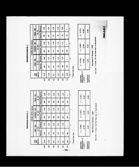

Sheet
3 of 3

ftPPENDIX ( C )
PROGRAM FOR PLOTTING COMPONENT SURFACE SPEED/rEED RELATIONSHIP
3LISTlO DIM X(IOO)20 DIM Y(IOO)23 REM THE ABOVE ARE X,Y CO-ORDINATES INPUT60 REM A & B ARE USED FOR CALCULATION OF BEST FIT LINES E
TC AS ARE C & D BELOW61 DIM 0(lOO),00(100)63 DIM C(IOO)70 DIM D <100)79 CLEAR i TEXT80 HOME : VTAB 8: PRINT "LOGARITHMIC GRAPH PLOTTING MODULE
PRINT81 PRINT — — "i PRINT s PRINT
"MAX NO.OF POINTS IS 100"i PRINT : PRINT "STATISTICAL ANALYSIS OF BEST FIT LINE": PRINT "(USING ’LEAST SQUAR ES’ METHOD) IS ALSO"! PRINT "CONDUCTED."
82 PRINT .. PRINT "TYPE 'END' AS X CO-ORD INPUT TO CEASE"I PRINT ""
85 INPUT "HIT REURN TO CONTINUE:— AA*111 HOME112 PRINT " GRAPH PLOTTING MODULE"120 PRINT " **********************"140 PRINT ""130 PRINT ""155 PRINT "----------------------------------------- "160 PRINT "POINT NO. X VALUE Y VALUE"170 PRINT "--------- "180 POKE 34,9200 REM 2:2::::ttz:2ittt:!t:ttttt:2iittttt:tii:210 REM START INPUTTING POINTS NOW 220 A - 10 250 I - I ♦ 1255 A - A ♦ 1256 IF A > 23 THEN A - 24 260 VTAB As HTAB 3i PRINT I 270 HTAB 19: VTAB A: INPUT X*280 IF X* « "END" THEN 400281 REM ***** GOTO SORT PROGRAM THEN**********290 X(I> - VAL (X*)300 HTAB 30: VTAB A: INPUT Y<I)310 GOTO 230400 REM -------------------------401 REM STATISTICAL ANALYSIS SECTION402 REM ---------------------------403 FOR N - 1 TO (I - l)iX(N) - LOG (X(N)):Y(N) - LOG <Y
(N)>: NEXT N405 FOR N - 1 TO (I - 1):SX - SX ♦ X(N):SY - SY ♦ Y(N):S2X
- S2X (X (N) ~ 2): NEXT N410 FOR N ■ 1 TO (I - 1) : SUMPROD - SUMPROD <X(N) * Y(N>>
: NEXT N413 B - (<<I - 1) * SUMPROD) - (SX * SY) ) / <<<I - I) * S2X
300

i-: ï .
i II ? ! • :*
s ■ ës
J jf jf p
iiiiiiiiüiiiiiiiiim m i m m m m
i î ,
i ! i
U •n i ?
“ Í! I !irg
•?
fiIflîS
II i|
J Iil ï
L
ul H
¿im n £ ?
! :s - i ii=i : i ili f e ¡ ¡ S B i
§ ■ : ! & - s i l g ï ï : i? " = ! 7 5 ¡ | = ^ : ; l s ! > s
so ss i lassassi ¡i III lili liillüli! m i lias I I« S £ 2 * s SS
- 3 0 1 -

APPENDIX ( O )
IMPS - PROGRAM
90lOO1051101201301401301601701801902 0 02 1 02 2 0230240250260270280290300400650660700710720730735740760770780790810
PR# 0 TEXT HOME PRINT PRINT PRINT PRINT PRINT PRINT PRINT PRINT PRINT PRINT PRINT PRINT PRINT PRINT
B.L.LTD (AUSTIN ROVER GROUP)********************
*******************"
ITERATIVE MACHINING” PARAMETER SELECTION" (SINGLE POINT”
TURNING MODULE)”PRINT "•
IMPORTANT! THIS SOFTWARE IS THE”PRINT "PROPERTY OF B.L.LTD. AND SHOULD”PRINT "NOT BE REPRODUCED WITHOUT PRIOR”PRINT "CONSENT FROM P . H . SUMMERFI ELD , "PRINT PRINT PRINT “ "PRINT "HIT ’RETURN’ TO CONTINUE"! GET AA*PR# OTEXTHOMEVTAB (6) ! INPUT "GIVE COMPONENT NO. - ” ; CN*VTAB (14)! PRINT "GIVE COMPONENT DESCRIPTION PRINT ! INPUT CD#IF LEN (CD*) > 15 THEN PRINT i PRINT "PLEASE LIMITO 15 CHARACTERS"i GOTO 730HOMEGOSUB 16300! REM GOSUB 166941 REM GOSUB 23000! REM GOSUB 171001 REM GRADEPRINT ! INPUT "IS BATCH HARDNESS KNOWN <Y OR N)i-”;AA*
INPUT DATA FROM FILES INPUT MATERIAL TYPELOAD Sc DISPLAY CONSTITUENT LEVELS DISPLAY RECOMMENDATIONS FOR CARBIDE
820 IF AA* - "Y* THEN PRINT " "* INPUT "GIVE FIGURE (HB) I — " | MH
823 IF AA* - "Y" THEN GOTO 840 830 MH - H840 PRINT I PRINT "HIT ’RETURN’ TO CONTINUE!-";850 GET AA*860 HOME i VTAB 3i PRINT "FOR ’STEPPED’ COMPONENTS PRODUCE
D ON”! PRINT ""! PRINT "A SINGLE MACHINE SPEED BASIS P LEASE HIT"! PRINT " "i PRINT "THE KEY ’S ’ TO BRANCH TO SUBROUTINE TO"! PRINT " "» PRINT "CALCULATE MEAN DIA. AND LENGTH
- 302 -

- 303 -

- 304

. O- o- o - o - o- o- o-ii i-i ii i-i ii i-i i-i- ¿ -•* - o - O J e - o - o e- o- o- o - o - o - o --r.* -r.* -O - O -O -O -O»•- »•- O - o - © - o- o-
í ¡ i i n n a n ni
oí ¿í ri1 SÍ SÍ SÍ o-,- J.- -© -o -o -O -o=• ii ii- a- ii- a- ii- ii ^ i r i r i r i r i r i r i r miiiiii-iii-iiiiiiiii-i m iiii i i i i i i i i i i i i i i ii
iiiiiiiiiiiiii.t.......iiiiiiiiiiíiii L - o : • ̂ „n^í;íí;íísíísííjíí;íí;í P I • s:Js.*?ss ■* ¡U¡i m M i í iM ¡¿!Isi!íi;H:ílHsi!ÍSÍ
"Ì ' V ¡ ' V V V ! ' SÜSffllí iiifiiiiiüiililiiü i
- 305 -

- 306

? ■:
M , il n , i. j y u i í i
î i i î l i ï i i ; l i Í T ¡ í i i ! t n t i i i i i i i ¡ im m m í i m m m m m
I* £
5 5 .
? ; » • £ * * ; “ * ï ■
J ¡ = i
ü
i = l ¡ ¡ §
£ 801 1- '
l ! i
I I
r ^ rillh n i
1 Hi ä ! &r,ss.
l¡ ¡ ¡mS S S S
h iEi¡SU
! m tüti “ if m m
¡III üi i :? P ¡h £î
3 1 î i l i * | £ Ï " ! î 3 ^ 1 I
¡i¡iiii¡liÍi!!l!iSSSiIiiiii¡8iiiSli!iK!SSi!iS!iS!iSiiIiü

- 300 -

i ! Pi j¡ I
liiiiiìJiiiiiiiii
= i sì ¡s i
I i ! i I j , j ,
1 1 1 ¡i, illiíl"§** i|****ilí| 1 I -■ i * l s!** ¡!ïá i! rai«!l i j h püi'üíüüiiiiiiiüjiüï*,
iitiiii : îiiiîii'itiî' « i üimimiiHifüíi
i J i > I t s
. ¡ ¡ ! i i » ËJ p! í l\ :j! jjji :SI i!!¡5|i il iijgf j¡¡¡iiiiiiiIih¡EÍ!;i§i--- iiiiiiìiiiiiliiiliìiiiiiìlliliìli iiüüflï' infilili l!S!ISi!Si!ii!S!iSl!S!i!SSSS!!B!î
- 309 -
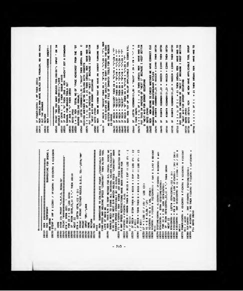
- 3 1 0 -

- 311

- 3 1 2 -

- 3 1 3 -

APPENDIX ( E )
IMPS - FLOW CHART
LOAO ALL PAGE HEADINGS OF COMPANY STANDARD TOOLING CATALOGUE II£. GENERIC ARCLASS COOE) INTO RANDOM ACCESS MEMORY 1RAM)
LOAD DETAILS OF ALL WORKPIECE MATERIALS RECOGNISED FROM DISK INTO RAM
ED"
FILE NAME:- C ODIN G SYSTEM SUMMARY
^ ^SEQUENTIAL^^
FILE NAME:- MATERIALS 1NOEX COUNTER
LOAO ALL OETAILS APPERTAINING TO THE APPROPRIATE MACH1NABIL ITY GROUP INTO RAM
LOAO OETAILS OF WORKPIECE CONSTITUENT LEVELS INTO RAM AND DISPLAY GRAPHICALLY
rDISPLAY OETAILS OF
RECOMMENDEO TUNGSTEN CARPIOE TOOL GRADES.(•HARO*.'STAN DARÒ'4 •TOUGH1) ANO CLEARANCE ANGLES APPROPRIATE TO THE WORKPIECE MATERIAL IN QUESTION
L
(FROM MACH INABILITY GROUP MGUI FILE)
Shaet 1 of 6


- 316 - Sh««t 3 of 6

- 3 1 7 - Sheet U of 6

- 3 1 0 -She«t 5 9f 6

5h««t 6 of 6

APPENPIX ( r )
MATERIAL INPEX CREATOR PROGRAM
3LI8T5 REM MATLS INDEX CREATOR 10 DIM MN*(100)* REM MATL NAME20 DIM X (100,26)* REM MATL CONSTITUENT LIMITS 23 DIM P(100)* REM DETAIL OF POSITION OF MATERIAL CONSTIT
UENT LEVEL IN FILE 'CONSTITUENT LEVELS’30 DIM M G (100)I REM MATL M/CABILITY NOS 40 DIM MH(IOO)* REM MEAN HARDNESS50 DIM HT <100)* REM HARDNESS TOLERANCE ABOUT MEAN 60 HOME70 PRINT "PROGRAM TO CREATE 'MATERIALS INDEX’ FILE"80 PRINT " FROM SCRATCH"90 PRINT ‘•mmmmmmmmmmmmmmmmmmmmmmmmmmmmmmmmmmmmmm”lOO PRINT 110 PRINT 120 PRINT "NOTES*-"130 PRINT "»****"140 PRINT150 PRINT "MAX NO. OF MATERIAL NAMES IS lOO"160 PRINT170 PRINT "USE THE PROGRAM 'FILE AMENDER’ TO "180 PRINT "UPDATE ANY PART OF THE FILE ONCE CREATED"190 VTAB 20200 INPUT "HIT 'RETURN' TO C O N T I N U E * A A *210 REM SECTION TO INPUT DATA 220 HOME230 PRINT "INPUT DATA AS PROMPTED."240 PRINT 230 PRINT260 PRINT "******************************“270 PRINT280 PRINT "TO TERMINATE DATA INPUT (AND THEREBY"* PRINT "O
F COURSE COMMIT DATA TO DISK),GIVE"* PRINT "THE MATERI AL SPEC. AS 'END'"
290 PRINT300 PRINT "«»It*****************«»«««:*****"310 VTAB 20320 INPUT "HIT 'RETURN' TO COMMENCE DATA INPUT*-";AA*330 HOME340 FOR N - 1 TO lOO 350 HOME360 PRINT "DATA ITEM NO*-"*N370 PRINT "--------------------------------- "380 INPUT "GIVE MATERIAL SPEC.*-"*MN*(N>390 IF MN*(N> - "END" THEN N - N - 1* GOTO 940 393 P (N) =* N* REM POSITION OF CONSTITUENT LEVEL DETAILS IN
RA-FILE 'CONSTITUENT LEVELS’400 INPUT "GIVE M/CABILITY GROUP NO. *-" ; MG (N).410 INPUT "GIVE MEAN HARDNESS (HB)*-"jMH(N)420 INPUT "GIVE HARDNESS TOLERANCE ABOUT MEAN («■/-> *-"iHT
(N>430 PRINT " "
- 320 -

!liiili=i=l=iii!l!§§l
- 3 2 1 -

MACHINABILITV CROUP CREATO? P.3QG34M
APPENDIX ( C )
IO D» ■ ""« REM CNTRL-D 20 HOME30 REM PROGRAM TO CREATE MATERIAL MACHINABILITY GROUP FIL
E *40 PRINT "THIS PROGRAM CREATES MACHINABILITY"I PRINT "FILE
S FOR TURNING OPERATIONS"50 PRINT "LOAD A DISK INTO SLOT 6 OF THE APPLE"! PRINT "AN
D ANSWER QUESTIONS AS PROMPTED"60 INPUT "PRESS ’RETURN’ TO CONTINUE*-"»AA«70 HOME80 INPUT "WHAT IS M/CABILITY GROUP NO?«-"»FI*90 INPUT "MAX D.O.C.(MM)*-"jMDOC lOO PRINT ""H O INPUT "MAX FEED RATE (MM/REV) s » MFEED 120 PRINT ""130 INPUT "1ST WC CLEARANCE ANGLE*-"jW1CC*140 PRINT150 INPUT "2ND WC CLEARANCE ANGLE*-"*W2CC*160 PRINT170 INPUT "1ST SUPPLIER’S HARD GRADE:-"; HIS*180 PRINT ""190 INPUT "BASE SPEED(AT 0.8 MM/REV)*-"|B1IS 200 PRINT210 INPUT "SLOPE FOR FEED RATE SPEED COMPENSATION* -"*S1 220 PRINT230 INPUT "INTERCEPT FOR THE ABOVE*-"*II 240 PRINT250 INPUT "1ST SUPPLIER’S STANDARD GRADE*-"*N1S*260 PRINT270 INPUT "BASE SPEED(M/MIN)*-";B21S 280 PRINT290 INPUT "SLOPE FOR FEED RATE COMPENSATION*-"*82 300 PRINT310 INPUT "INTERCEPT FOR THE ABOVE*-"*12 320 PRINT330 INPUT "1ST SUPPLIER’S TOUGH GRADE*-"*T1S*340 PRINT350 INPUT "BASE SPEED*-"*B3IS 360 PRINT370 INPUT "SLOPE FOR FEED RATE COMPENSATION*-"*S3 380 PRINT390 INPUT "INTERCEPT FOR THE ABOVE*-"*13 400 PRINT410 INPUT "SLOPE FOR TOOL LIFE COMPENSATION*-"*SL 420 PRINT430 INPUT “INTERCEPT FOR THE ABOVE*-"*IL 440 PRINT442 INPUT "GIVE MEAN HARDNESS(HB) OF GROUP*-"*H443 PRINT "GIVE HARDNESS MODIFIER(SPEED MULTIPLIER PER 10
HB POINTS FROM MEAN VALUE JUST ENTERED*-"*444 INPUT HM
- 322 -

nullism im i i f i i ü ü
I Ii I
Ms : I I-
¡ I !■M ' M i Ì lit ill
í l iiz 5
I
8«
¡iii
tilliliiHIiíiilMüiiiiSiii iiW H I S S ISS Si U S i i ? 3SSSSSS6gSiSES£SS88S83SS{f2Seî2
ï g ü l i Ü i h r ü s s H s ^ ^ ü i
liil!!!ìiil!li!iliilif!ì
- 323 -

APPENDIX ( H )
TILE AMENDER PROGRAM
3LISTIO REM PROGRAM TO COUNT UP THE NO.OF DATA ITEMS STORED IN
A TEXT FILE AND DISPLAY ITS TOTAL CONTENTS IN BLOCKS OF 10 DATA ITEMS
15 REM *******»*********%********«**********************«
20 HOME 25 HTAB 1230 PRINT "FILEAMENDER PROGRAM"35 PRINT "mmmmmmmmmmmmm-mmmmmmmmmmmmmmmmmmmm......37 PRINT40 PRINT : PRINT "THIS PROGRAM ENABLES THE OPERATOR TO"i PRINT
* PRINT "VIEW THE CONTENTS OF A SEQUENTIAL TEXT"i PRINT l PRINT "FILE IN GROUPS OF 10 DATA ITEMS AT A"* PRINT i PRINT "TIME, AND AMEND 'N’ OF THOSE ITEMS AS"s PRINT : PRINT "NECESSARY"
44 PRINT » PRINT45 PRINT "(THE FILE MAY ALSO HAVE ITEMS APPENDED"» PRINT z
PRINT "TO IT UP TO A LIMIT OF 2000 DATA ITEMS"50 PRINT s PRINT « INPUT "HIT ’RETURN’ KEY TO CONTINUE»-"*100 HOME110 DIM A*(2000)115 HTAB 8120 VTAB 8: PRINT “WHAT IS THE TEXT FILE NAME ?"125 PRINT130 PRINT "*-"** INPUT FI*140 PRINT » INPUT "WHICH SLOT IS IT ON ?»-"*S*150 O* - "OPEN " FI* «■ ", S" S*160 R* - "READ " FI*165 W* - "WRITE " ♦ FI*170 C* - "CLOSE " FI*180 D* - ""* REM CNTRL-D 190 PRINT D*| O*200 PRINT D*|R*210 FOR I - 1 TO 2000 220 ONERR GOTO 1000 230 INPUT A*(I)240 NEXT I 250 PRINT D*|C*260 PRINT "THIS FILE CONTAINS MORE THAN 2000 DATA"* PRINT
» PRINT "ITEMS-AM CLOSING NOW AND TAKING NO ACTION"270 END999 REM *************************************************1000 REM SECTION ARRIVED AT WHEN ONE HAS ENCOUNTERED AN E
RROR STATUS1001 REM --------------------------------------------------
- 324

- 325 -

APPENDIX ( I )
STANDARD TOOLIf.'G CATALOGUE PRELIM PROGRAM
DLIST10 D* - ""i REM CTRL-D20 PRINT D*;"OPEN CODING SYSTEM SUMMARY“30 PRINT D*;"WRITE CODING SYSTEM SUMMARY“40 PRINT “O"! REM PUTTING ZERO IN AS VALUE OF J1 30 PRINT D*{"CLOSE CODING SYSTEM SUMMARY"
- 326 -

APPENDIX (0 )
CODING SYSTEM CREATOR PROGRAM
3 L IS T
10 D* - M,,I REM CTRL-D11 DIM CODNG*(500),NUMBEROFCODES*(300)15 HOME16 PRINT " LOCATE DISK IN SLOT 6”17 PRINT " "! PRINT " ": 'PRINT " M20 INPUT "GIVE FULL CODE N O s ; CODNG*; REM THIS IS THE PA
GE HEADING30 CODNG* - "X" CODNG*: REM MUST PREFIX ALL FILE NAMES W
ITH A LETTER TO CONFORM WITH APPLE DOS REQUIREMENTS 40 INPUT "HOW MANY ITEMS TO GO IN THIS SECTION NUMBER
OPCODES*:N - VAL (NUMBEROFCODES*)50 DIM TLCODE* <N>60 PRINT M - 70 FOR I - 1* TO NSO INPUT "GIVE TOOL DESCRIPTION:TLCODE* < I > : REM THIS IS
THE FULL TOOL CODE 90 NEXT IlOO O* - "OPEN " + CODNG* ",S6"110 W* « "WRITE " CODNG*120 C* - "CLOSE " ♦ CODNG*130 PRINT D*;0*: REM NOW CREATING THE STANDARD TOOLING CA
TALOGUE FILES 140 PRINT D*;W*150 PRINT NUMBEROFCODES*160 FOR I - l TO N 170 PRINT TLCODE*(I)ISO NEXT I 190 PRINT D*;C*200 REM NOW UPDATE ’CODING SYSTEM SUMMARY’ FILE (EFFECTI
VELY THE EQUIVALENT OF AN EXTRA DIRECTORY)210 PRINT D*;"OPEN CODING SYSTEM SUMMARY"220 PRINT D*;“READ CODING SYSTEM SUMMARY"230 INPUT J240 IF J - O THEN 260250 FOR I - 1 TO J: INPUT CODNG* (I > « REM CODE FOR CODE SE
CTOR:INPUT NUMBEROFCODES*(I):REM NO. OF ITEMS STORED W ITHIN THIS CATEGORY:NEXT I
260 J ■ J ♦ 1 270 CODNG*(J) « CODNG*280 NUMBEROFCODES*(J) - NUMBEROFCODES»290 PRINT D*;"CLOSE CODING SYSTEM SUMMARY"300 PRINT D*;"OPEN CODING SYSTEM SUMMARY"310 PRINT D*j"WRITE CODING SYSTEM SUMMARY"320 PRINT J330 FOR I = 1 TO J: PRINT CODNG* (I > : PRINT NUMBEROFCODES* (
I): NEXT I340 PRINT D*;"CLOSE CODING SYSTEM SUMMARY"350 END
- 3 2 7 -

APPENDIX ( K )
DISK EXPANSION P3CG3AM
3 L IS T
O REM RWTS POKES10 DATA 169,12,160,10,32,217,3,68,63,84,1,96,1,0,17,8,32,1
2,0,32,0,0, l, 177, 110,96, 1,32, 73,84,32,63, O, 1,239,216 13 FOR J ■ 3072 TO 3107: READ Nl POKE J,N: NEXT 20 POKE 3094,1: REM SET UP READ CODE30 POKE 3086,17: POKE 3087,0: CALL 3072: POKE 8312,0: POKE
8313,0: POKE 3094,2: CALL 3072: POKE 3094,1 40 POKE 3086,17: POKE 3087,1: CALL 3072: POKE 8193,16* POKE
8194,-12* POKE 3094,2* CALL 3072 30 POKE 3086,16* FOR J - 12 TO 1 STEP - 1* POKE 3087, J* POKE
8194,J - 1: CALL 3072: NEXT 60 POKE 3087, J* POKE 8193,0* POKE 8194,0* CALL 3072
- 328 -

APPENDIX ( L )
LINC5 - TOOL DATA FILE CREATION PROGRAM
3LIST10 DIM CC4<10>20 DIM TI<10>30 DIM CP(IO)40 DIM C04<10,20>30 DIM NM(1O,20)60 DIM MN4(10,20,5) *70 DIM 0(10,20,5)BO DIM TCF <10,20,5)90 DIM DN(10)100 DIM AI(10)110 POKE 33,40s POKE 34,0120 HOME s PRINT s PRINT I PRINT130 PRINT140 PRINT "THIS PROGRAM CALCULATES
MPONENT BUILD VOLUMES"THE B.O.M. FOR GIVEN (
150 PRINT160 PRINT "EACH COMPONENT WILL BE DISPLAYED .FOLLOWED BY
QUESTION MARK"170 PRINT180 PRINT "YOU MUST INPUT THE VOLUME TO BE MADE, FOLLOWED
Y(RETURN)"190 INVERSE200 VTAB <22)1 PRINT "PRESS (RETURN) TO CONTINUE"210 NORMAL220 INPUT A4230 HOME240 TC4 - “COMPONENT DIRECTORY"250 D4 - CHRt (4)260 PRINT D4;"OPEN”;TC4|", S6, D2"270 PRINT D*;"READ";TC4280 INPUT A290 FOR I - 1 TO A300 INPUT TC4 <I)310 NEXT I320 PRINT D4;"CLOSE"|TC4330 PRINT "COMPONENT NUMBER VOLUME"340 POKE 34,2350 FOR I - 1 TO A360 PRINT TC4 <I)|" 7"370 INPUT " “1V(X>380 NEXT I390 INVERSE400 VTAB (22)1 PRINT "PRESS (RETURN) TO CONTINUE"410 NORMAL420 INPUT A4430 TD4 - "TOOL DIRECTORY"440 PRINT D4;"OPEN";TD4J" , S6, D2"450 PRINT D4|"READ";TD4460 INPUT B470 FOR I - 1 TO B480 INPUT TD4 <I>
- 329 -

c :* J * ¡:*!s*
Iiil!II!ii==li=
8
i i:
, I M .í ! Us ü i!
Ü !ai. Í5 ¡g g o ^ g S g a
k T l l I k s ë i i s s B - s s i ^ e a T l s I l r l i r i i ’ l g l t ; S l , 8i i r : ; :
ii¡¡-SIIii(ili!IIlÍIiíÍ Í̂l¡ÍÍÍ!iÍ¡siiÍli!i3ÍHiÍi¡!i-̂ P£SSSs3Slt9IS8S llS 3331S§SSaSeSSSS8E2Sa8ÍS 368£SSES2eB2g í l i I Í l
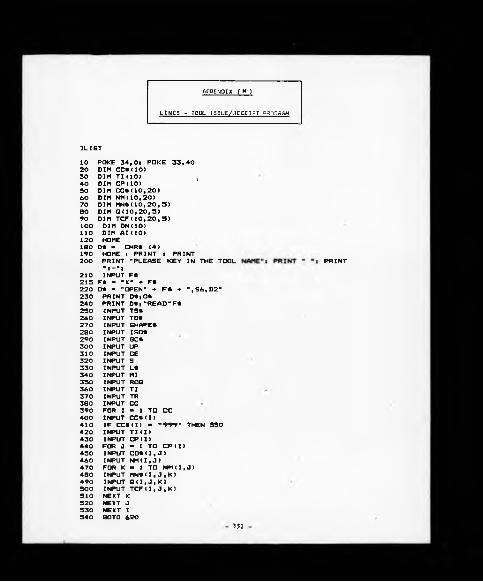
APPENDIX ( M )
LINCS - TOOL I3SUE/3ECEIPT C30SRAH
3LIST10 POKE 34,0s POKE 33,4020 DIM CC*(10)30 DIM TI<10> ;40 DIM CP<10>30 DIM CO*(10,20)60 DIM NM(10,20)70 DIM MN*(10,20,9)80 DIM 0(10,20,5)90 DIM TCF<10,20,5)lOO DIM DN(10)110 DIM AI(10)120 HOME180 D* - CHR* (4)190 HOME J! PRINT z PRINT200 PRINT "PLEASE KEY IN THE TOOL210
"l—"|INPUT F*
215 F» « “X" ♦ F*220 0* - "OPEN” f F* ♦ ", S6, D2"230 PRINT D*;0*240 PRINT D* ;-READ-F*250 INPUT TS*260 INPUT TD*270 INPUT SHAPE*280 INPUT ISO*290 INPUT SC*300 INPUT UP310 INPUT CE320 INPUT S330 INPUT L*340 INPUT MI350 INPUT ROQ360 INPUT TI370 INPUT TR380 INPUT CC390 FOR I ■ 1 TO CC400 INPUT CC*(I)410 IF CC*(I) ■ "999" THEN 550420 INPUT TI (I>430 INPUT CP(I)440 FOR J - 1 TO CP(I>430 INPUT CO*(I,J )460 INPUT NMU, J)470 FOR K ■ 1 TO Nf1(I,J)480 INPUT MN* (I, J,K>490 INPUT Q ( I , J , K >500 INPUT TCF(I,J , K )310 NEXT t(320 NEXT ,I530 NEXT :I540 BOTO 620
331

HI
h* HI j I
f i? ¡ ? s ^ l * ¡ Í l * - 5s Í l 5j s . 5s !
:iSiîirüiâIii!iiliiïiISimi! !¡=i§ i mnmmmmn ummmnnmm
J ií lf t lJ lÜ |ü;. i„ I iimiiiifM m\ !if pi is*: ! Ji 3!?s'âïJs'sB' =5è#‘3ÌSÌÌlÌliÌSÌ!Ì|Ì.Ìll.Ì-Ì_Ì"S = _aS-s;-? = s.̂ §̂
mmi§mimfSMm¡HgmSSií8&88£¡ii£liISmiÍ£ fìlli- 332 -

2190 PRINT TI2200 PRINT TR2210 PRINT CC2220 FOR I - 1 TO CC2230 PRINT CC«<I>2240 IF CC*(I) - "999“ THEN 24002230 PRINT TI(I)2260 PRINT CP(I)2270 FOR J - 1 TO CP<I>2280 PRINT CO*(I,J>2290 PRINT NM< I , J >2300 FOR K « 1 TO NM(I,J )2310 PRINT MN* < I, J , K )2320 PRINT Q(I,J,K>2330 PRINT TCF <I,J,K )2340 NEXT K2350 NEXT J2360 NEXT I2370 PRINT D*;"CLOSE"F*2380 PRINT : PRINT "NEW DATA NOW SAVED"2383 PRINT "DO YOU WANT TO RUN AGAIN?"2388 INPUT A*2392 IF LEFT* (A*, 1) * T THEN RUN2393 PRINT D*|"RUN LINCS GRAPHICS S> MENU, S6, D2‘2400 PRINT TI(I)2410 PRINT ND2420 FOR J - 1 TO ND2430 PRINT DN(J)2440 PRINT AI(I)2430 NEXT J2460 GOTO 2360
333

>
APPENDIX ( H )
L IN C S - TOOL/COMPONENT ’ WHERE USED* PROGRAM
3 LIST5 POKE 34,0* POKE 33,40 IO DIM CC*(10)20 DIM TI<10>30 dim cp(io> ;40 DIM CO*(10,20)30 DIM NM(10,20)60 DIM MN*(IO,20,3)70 DIM 0(10,20,5)80 DIM TCF(10,20,5)90 DIM DN(10) lOO DIM AI(10)110 HOME150 NORMAL160 D* - CHR* (4)170 HOME s PRINT : PRINT180 PRINT "PLEASE KEY IN THE TOOL NAME"*190 INPUT F*191 F t ■ -X" ♦ F*195 O* - "OPEN" ♦ F* +■ ",S6,D2"200 PRINT D*;0*210 PRINT D**"READ"F*220 INPUT TS*230 INPUT TD*240 INPUT SHAPE*230 INPUT ISO*260 INPUT GC*270 INPUT UP280 INPUT CE290 INPUT S300 INPUT L*310 INPUT MI320 INPUT ROQ330 INPUT TI340 INPUT TR330 INPUT CC360 FOR I - 1 TO CC370 INPUT CC*(I )380 IF CC*(I) - "999"390 INPUT TI (I)400 INPUT CP (I)410 FOR J - 1 TO CP(I)420 INPUT CO*(I,J )430 INPUT NM(I,J )440 FOR K ■ 1 TO NM(I,450 INPUT MN*(I,J,K )460 INPUT Q ( I, J ,K)470 INPUT TCF (I, J,K)480 NEXT K490 NEXT J300 NEXT I
- - 334 -
PRINT "* PRINT

... « l i ¡ i í
lï!ïi;lïlllliiis!!iiiü5l!:il.ilfill ü»l!illlü§iiaii!igis 11
lili!»1 îiiiü i í=; ;*==
Ï!
i!i fi
: i
?i
lili. . . .ä j , í í S ! ...
¡liiiiifziiiiimiiiiiiiiMiiiiliiiinliliiiiililSiJcSii» 8 M » i n H 3 ! Í I » » !B H I » H { S a 8 i n S i l l » 8 Í H I S K Í l l l l l

APPENDIX ( 0 )
LINCS - TOOL BILL OF MATERIAL GENERATOR PROGRAM
3LISTlO DIM CC*<10>20 DIM TI(10)30 DIM CP(IO)40 DIM CO* <10,20)50 DIM NM(10,20) '60 DIM MN* <10,20,5)70 DIM Q UO,20,5)80 DIM TCF(10,20,5)90 DIM DN(10) lOO DIM AI(10)110 POKE 33,40: POKE 34,0 113 HOME115 INVERSE : HTAB 8: PRINT "BILL OF MATERIALS (B.O.M.)"117 HTAB 8: PRINT "--------------------------- "118 NORMAL120 PRINT i PRINT I PRINT 130 PRINT140 PRINT "THIS PROGRAM CALCULATES THE B.O.M. FOR GI
VEN COMPONENT BUILD VOLUMES."150 PRINT160 PRINT "EACH COMPONENT WILL BE DISPLAYED, FO
LLOWED BY A QUESTION MARK."170 PRINT180 PRINT "YOU MUST INPUT THE VOLUME TO BE MADE, FO
LLOWED BY (RETURN)."190 INVERSE200 VTAB (22): HTAB 8: PRINT "PRESS(RETURN) TO CONTINUE" 210 NORMAL 220 INPUT A*230 HOME240 TC* - "COMPONENT DIRECTORY"250 D* - CHR* (4)260 PRINT D*; "OPEN";TC*;”,S6,D2"270 PRINT D*; "READ";TC*280 INPUT A290 FOR I - 1 TO A300 INPUT TC* <I)310 NEXT I320 PRINT D*; "CLOSE";TC*330 PRINT "COMPONENT NUMBER VOLUME"335 PRINT "----------------- ------"340 POKE 34,2350 FOR I - 1 TO A360 HTAB 6: PRINT TC*(I)370 VTAB (I 2)1 HTAB 26: INPUT "?"|V(I)380 NEXT I 390 INVERSE400 VTAB (22)1 HTAB 4: PRINT "PRESS (RETURN) TO CONTINUE" 410 NORMAL 420 INPUT A*430 TD* - "TOOL DIRECTORY"
336

I !i
- . . U -, Ii i .! mj
íl!¡l!!!ii!iI¡!Ii==l:!Í5
iÌ k i 1fi !- ?. ! . S híí !¡ i.. MÂW =■ .. Sí ¡iss..5 £.|¡s*iéi¡s4a.5;!=sa.8::5.8írÍ55 sasTis svs77T ílIIÍiIiI¡:¿IiÍÍÍÍÍÍÍÍÍÍÍÍÍÍ¡ÍÍÍÍiÍÍfÍÍÍ¡Í¡iiIiÍI¡¡Íiiii¡!i
- 3 3 7 -
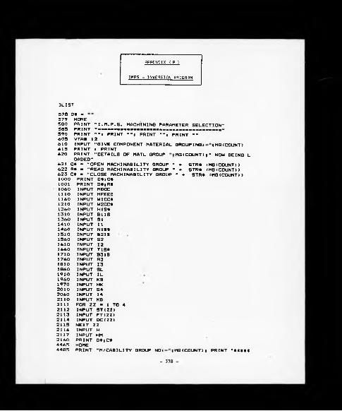
APPENDIX ( P )
IMPS - INVERSION PROGRAM
DLIST578 D* -579 HOME580 PRINT "I.M.P.S. MACHINING PARAMETER SELECTION"585 PRINT "mmmmmmmmmmmmmmmmmmmmmmmmmmmmmmmmmmmmmm"590 PRINT ""i PRINT "M! PRINT -"* PRINT ""605 VTAB 12610 INPUT "GIVE COMPONENT MATERIAL G R O U P I N G * ;MG(COUNT) 615 PRINT t PRINT620 PRINT "DETAILS OF MATL GROUP MG(COUNT)j" NOW BEING L
OADED"621 0* - "OPEN MACH INABILITY GROUP " «■ STR* < MG (COUNT))622 R* - "READ MACHINABILITY GROUP " ♦ STR* (MG(COUNT))623 C* » "CLOSE MACH I NAB ILI T Y GROUP M «■ STR* (MG (COUNT))1000 PRINT D*)0*1001 PRINT D*;R*1060 INPUT MDOC lllO INPUT MFEED 1160 INPUT W1CC*1210 INPUT W2CC*1260 INPUT HIS*1310 INPUT B U S 1360 INPUT SI 1410 INPUT II 1460 INPUT N1S*1510 INPUT B21S 1560 INPUT S2 1610 INPUT 12 1660 INPUT T1S*1710 INPUT B31S 1760 INPUT S3 1810 INPUT 13 1860 INPUT SL 1910 INPUT IL 1960 INPUT KS 1970 INPUT HK 2010 INPUT S4 2060 INPUT 142110 INPUT KD2111 FOR ZZ - 1 TO 42112 INPUT ST(ZZ)2113 INPUT FT(ZZ)2114 INPUT DC(ZZ)2115 NEXT ZZ2116 INPUT H2117 INPUT HM 2160 PRINT D*)C*4465 HOME4485 PRINT "M/CABILITY GROUP N O * j MG(COUNT)* PRINT "*«***
- 338

i mm i mum hhueíu ü i um 1 1 mm ¡§- 339

- 340 -

- 341

- 342

60060T.C.F."PRINT "xasaxssxassnxazsassssssszTSSsssESSsssssxsssssssrssasssx
60063 60067 60070 60080 60090 60110 60130 60150 60170 60190 60210 60222 60225 60230
ZZ » 0IF CNTR ■ 2 THEN 60260 FOR NZ « 2 TO (CNTR - 1)ZZ - ZZ «■ lOi REM DUMMY OP.NO.PRINT ZZ* TAB< 8>PRINT OD(NZ); TAB< 9);PRINT D(NZ); TAB( 5);PRINT INT (S2(NZ) > * TAB( 6);PRINT F (NZ); TAB( 7);PRINT L(NZ)s TAB( 8);PRINT ST* (NZ ) ; TAB ( ID*PRINT TCF(NZ)PRINT ""PRINT "---------------------------------------------------------
60240602506026060270602806029060300603106032060330603406035060360
PRINT ""NEXT NZREM THIS IS THE FINISHING OPERATION DETAILS PRINT (ZZ ♦ 10)* TAB( 8)*PRINT OD(1)* TAB( 9)*PRINT D(1)* TAB( 5);PRINT INT (S2(l>>* TAB( 6)*PRINT F (1)* TAB( 7> *PRINT L (1)* TAB( 8)*PRINT ST* ( 1 > * TAB ( ID*PRINT TCF(l)PRINT ""PRINT "*************»*****************************************
*«*****************"60363 FRINT " "60370 PRINT ""« PRINT "SUMMARY ENDS"60372 PR# O60373 RUN
- 343

THE BRITISH LIBRARY DOCUMENT SUPPLY CENTRE
TITLE A S Y S TEM S APPROACH TO THE
C O N TR O L O F CUTTING TO O LS WITHIN
A L A R G E -S C A L E M ANUFACTURING ENVIRONM ENT
AUTHOR P E TER HUMPHREY SUMMERFIELD
INSTITUTION and DATE
The U n iv e rs ity of W arwick
Attention is drawn to the fact that the copyright of this thesis rests with its author.
This copy of the thesis has been supplied on condition that anyone who consults it is understood to recognise that its copyright rests with its author and that no information derived from it may be published without the author’s prior written consent.
TH E B R IT IS H L IB R A R YD O C U M E N T SUPPLY CENTRE
I— i— zi— i- j t — i—j i — r - j j — |-*i— [ - » Boston Spa, Wetherby West Yorkshire
lcms I------------1------------ 1------------1------------1------------1 United Kingdom
C R n . ° {
21R E D U C TIO N X ...________


