WorldTracker AVL Tech Manual - TrackingTheWorld.Com · WorldTracker AVL User manual...
23
TRACKINGTHEWORLD GSM/GPRS/GPS WorldTracker AVL User Manual WTAVLUM001 Revision: 1.01 TrackingTheWorld www.trackingtheworld.com [email protected]
-
Upload
truongdung -
Category
Documents
-
view
224 -
download
0
Transcript of WorldTracker AVL Tech Manual - TrackingTheWorld.Com · WorldTracker AVL User manual...
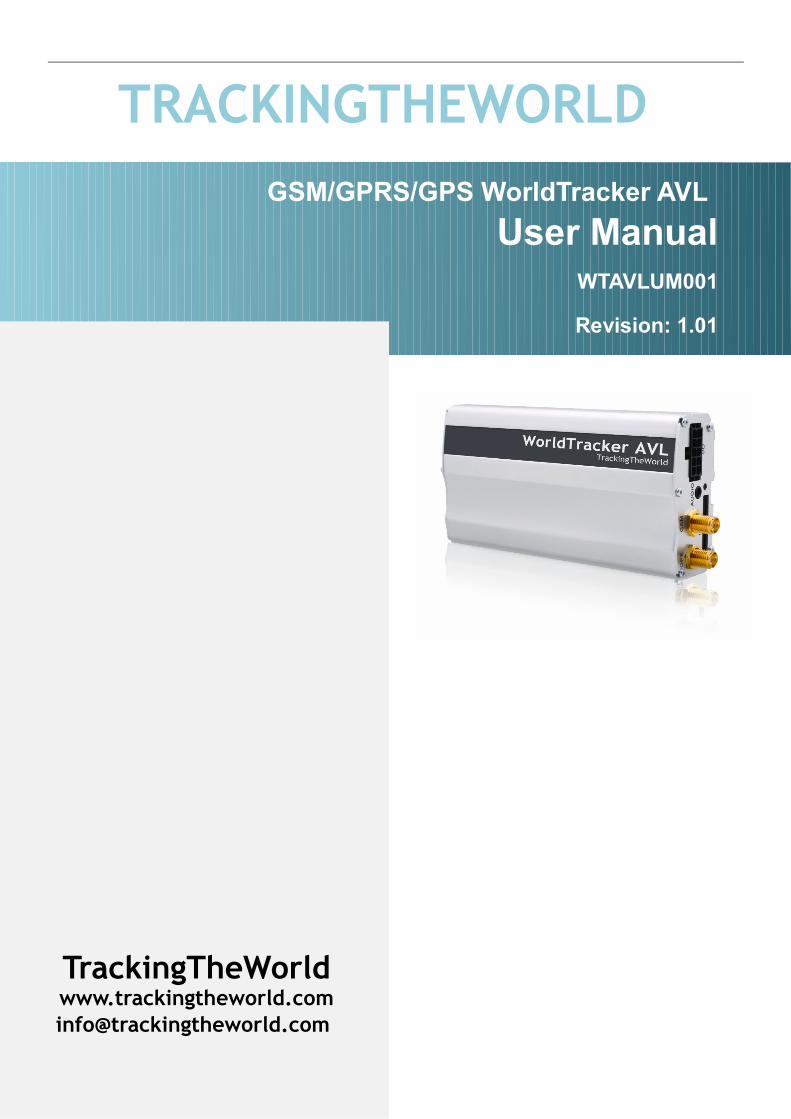
TRACKINGTHEWORLD GSM/GPRS/GPS WorldTracker AVL
User Manual WTAVLUM001
Revision: 1.01
TrackingTheWorldwww.trackingtheworld.cominfo@trackingtheworld.com

Contents
Contents......................................................................................................................................................................................2 Introduction.................................................................................................................................................................................3 Product Overview.......................................................................................................................................................................4
0.1. Appearance..................................................................................................................................................................40.2. Parts List.....................................................................................................................................................................5
1. Interface Description And Installation Guide .........................................................................................................................61.1. SIM Card Interface.....................................................................................................................................................61.2. Antenna Interface........................................................................................................................................................61.2.1. Install Antennas ......................................................................................................................................................71.2.2. GPS antenna specification.......................................................................................................................................71.2.3. GSM antenna specification......................................................................................................................................81.3. Power Interface...........................................................................................................................................................91.3.1. Power Interface Definition......................................................................................................................................91.3.2. Power connection .................................................................................................................................................101.3.3. Ignition Detect.......................................................................................................................................................111.3.4. Ignition Control.....................................................................................................................................................121.4. I/O Interface..............................................................................................................................................................141.4.1. Electrical conditions for digital inputs..................................................................................................................151.4.2. Digital Input without Interrupt .............................................................................................................................161.4.3. Digital Input with Interrupt...................................................................................................................................161.4.4. Analog Input..........................................................................................................................................................161.4.5. Digital Output........................................................................................................................................................171.4.6. Digital Output with Built-in Relay........................................................................................................................181.5. Indicator light Description........................................................................................................................................191.6. Audio Interface.........................................................................................................................................................201.7. RS232 Interface........................................................................................................................................................221.8. Fasten The Device....................................................................................................................................................23
2
WorldTracker AVL User manual TRACKINGTHEWORLD
Introduction
The WorldTracker AVL is a powerful GPS Locator designed for vehicle and asset tracking. With superior receiving sensitivity, fast TTFF (Time to First Fix) and Quad-Band GSM frequencies 850/900/1800/1900, its location can be monitored in real time or specified time intervals and reported to a backend server or other specified terminals. The WorldTracker AVL has multiple input/output interfaces which can be used for monitoring or controlling external devices, including the status of a vehicle, and control of a vehicle with its onboard relay output.
WTAVLUM001 - 3 -
WorldTracker AVL User manual TRACKINGTHEWORLD
Product Overview
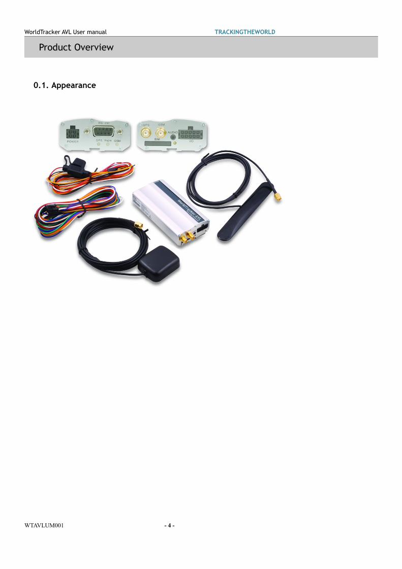
0.1. Appearance
WTAVLUM001 - 4 -

WorldTracker AVL User manual TRACKINGTHEWORLD
0.2. Parts List
Name PictureWorldTracker AVL
Power Cable with fuse
I/O cable
Steel Piece
GPS Antenna
GSM Antenna
12V DC power supply (Optional)
USB-232 data cable (Optional)
Relay (Optional)
WTAVLUM001 - 5 -

WorldTracker AVL User manual TRACKINGTHEWORLD
1. Interface Description And Installation Guide
1.1. SIM Card Interface
To Install the SIM card:Step 1: Press the yellow button on the right side of the SIM card slot to eject the SIM card holder.
Step 2: Place the SIM card on the SIM card holder.Step 3: Install the SIM card holder into the SIM card slot, carefully noting the direction of installation.
1.2. Antenna Interface
TRACAVLUM001 - 6 -

WorldTracker AVL User manual TRACKINGTHEWORLD
1.2.1.Install Antennas
There are two SMA antenna connectors on the WorldTracker AVL, one for GPS and another for GSM. Locate the GSM and GPS antennas inside the box, and connect each to the correct SMA connector as shown below.
1.2.2.GPS antenna specification
TRACAVLUM001 - 7 -
WorldTracker AVL User manual TRACKINGTHEWORLD
GPS antenna: Frequency: 1575.42MHzBandwidth: >5MHzBeamwidth: >120 degSupply voltage: 3.3VPolarization: RHCP or LinearGain: Passive: 0dBi minimum
Active: 15dBImpedance: 50ΩVSWR: ﹤2Noise figure: <3
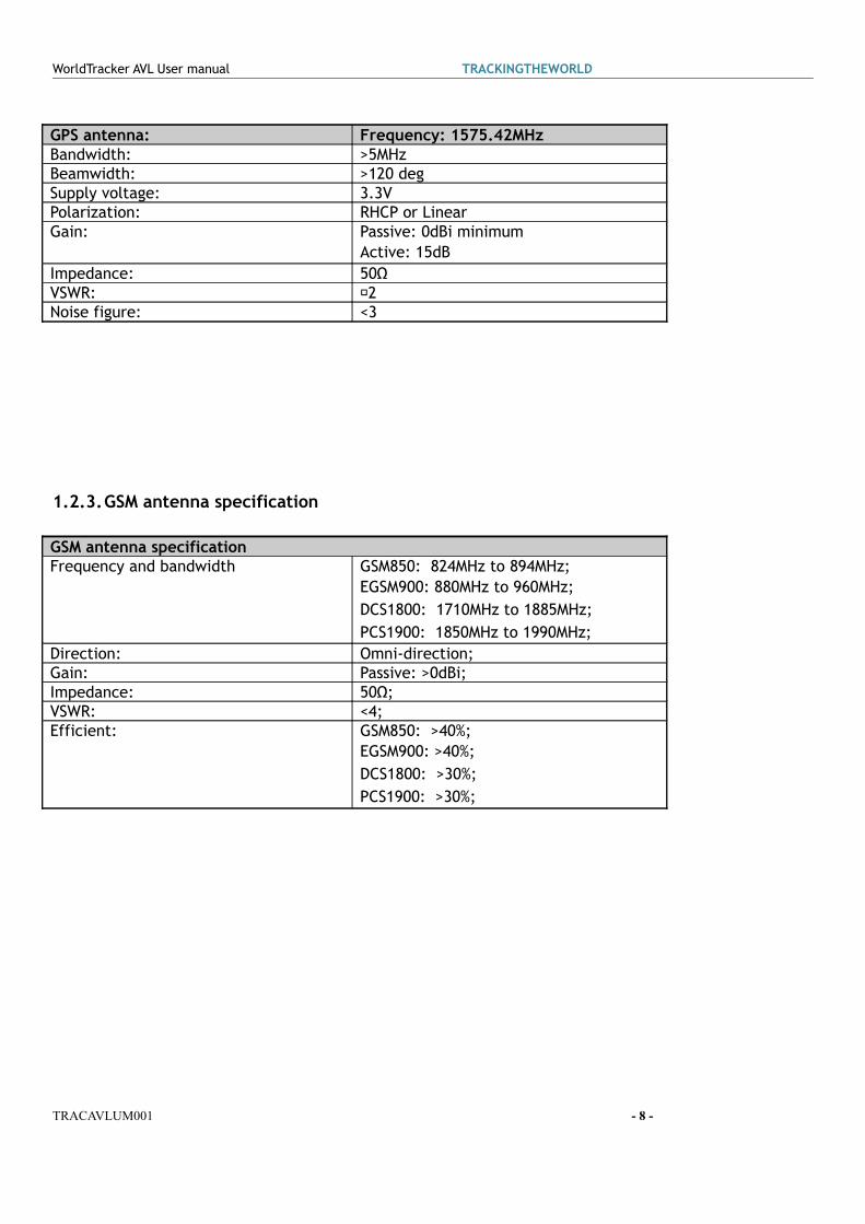
1.2.3.GSM antenna specification
GSM antenna specificationFrequency and bandwidth GSM850: 824MHz to 894MHz;
EGSM900: 880MHz to 960MHz;DCS1800: 1710MHz to 1885MHz;PCS1900: 1850MHz to 1990MHz;
Direction: Omni-direction;Gain: Passive: >0dBi;Impedance: 50Ω;VSWR: <4;Efficient: GSM850: >40%;
EGSM900: >40%;DCS1800: >30%;PCS1900: >30%;
TRACAVLUM001 - 8 -

WorldTracker AVL User manual TRACKINGTHEWORLD
1.3. Power Interface
1.3.1.Power Interface Definition
There are four pins on the power connector:
TRACAVLUM001 - 9 -

WorldTracker AVL User manual TRACKINGTHEWORLD
Index
Color of power cable
Description Recommended Function
1 Red Power (+8V ~ 32V) Power2 Black Ground Ground3 Yellow Input 1
(Digital , Positive Trigger)Ignition Key Detect
4 White Digital Output 1 (Negative Trigger)
1.3.2.Power connection
The input voltage range of the WorldTracker AVL is 8V to 32V DC. The unit can be connected directly to the vehicle’s battery (12V or 24V DC). Refer to the diagram below for establishing a power connection to the WorldTracker AVL.
TRACAVLUM001 - 10 -

WorldTracker AVL User manual TRACKINGTHEWORLD
1.3.3.Ignition Detect
Pin 3 on the power connector is Input 1 (Digital, Positive trigger). Electrical specifications of Pin 3 are:
Logical State Electrical StateActive 5.0V to 32V
TRACAVLUM001 - 11 -

WorldTracker AVL User manual TRACKINGTHEWORLD
Inactive 0V to 3V or Open
TrackingTheWorld strongly recommends connecting Pin 3 to the ignition key to support the power-saver function when the vehicle is off. Please note that input 1 does not have interrupt and the recommended sample rate is 3 seconds.
1.3.4.Ignition Control
Pin 4 of the power connector is Output 1 (Digital, Negative trigger). It is open-drain type with no internal pull-up resistor, which may also be used to control a relay, meaning that the user has to provide a pull-up resistor or a relay coil to any positive voltage (32V max.) to detect an inactive output by voltage. It can
TRACAVLUM001 - 12 -

WorldTracker AVL User manual TRACKINGTHEWORLD
drive a continuous current of 0.2A.
The electrical conditions of it are:Logical State Electrical StateEnable <1.5V, max current is 0.2ADisable Open or the pull-up voltage (max 32V)
Users may use this pin to control a relay output. Refer to the figure below for an example on controlling the ignition key. Please refer to section 3.4.5 for detailed information on how to drive a relay with digital output.
TRACAVLUM001 - 13 -

WorldTracker AVL User manual TRACKINGTHEWORLD
1.4. I/O Interface
There are several inputs and outputs on I/O cable. The following table provides their definitions:Index
Color on I/O cable
Description Recommended Function
1 White Input 2 (Digital , Positive Trigger)2 Black Input 3 (Digital , Positive Trigger,
With interrupt)3 Brown Input 4 (Digital , Negative
Trigger, With interrupt)Panic Button
4 Yellow Input 5 (Digital , Negative Trigger)
5 Gray Input 6 (Analog, Input voltage range : 0 – 28 V)
6 Purple Digital Output 2 (Negative Trigger)
7 Red Digital Output 3 (Negative Trigger)
8 Green Digital Output 4 (Negative Trigger)
9 Orange10 Blue Digital Output 5 (Built in Relay)
TRACAVLUM001 - 14 -

WorldTracker AVL User manual TRACKINGTHEWORLD
1.4.1.Electrical conditions for digital inputs
For negative trigger inputs, the electrical specifications are:Logical State Electrical StateActive 0V to 0.8VInactive 1.7V to 32V or Open
For positive trigger inputs the electrical specifications are:Logical State Electrical StateActive 5.0V to 32VInactive 0V to 3V or Open
Example connections are shown in following figure:
Example connection for positive trigger digital inputs:
Example connection for negative trigger digital inputs:
TRACAVLUM001 - 15 -
WorldTracker AVL User manual TRACKINGTHEWORLD
1.4.2.Digital Input without Interrupt
Input 2 and input 5 are digital inputs which do not have an interrupt. The sample rate for these two digital inputs is 100ms to 25 seconds. The recommend sample rate is 3 seconds. Please note that a high sample rate will also result in high power consumption. Input 2 is positive trigger and Input 5 is negative trigger.
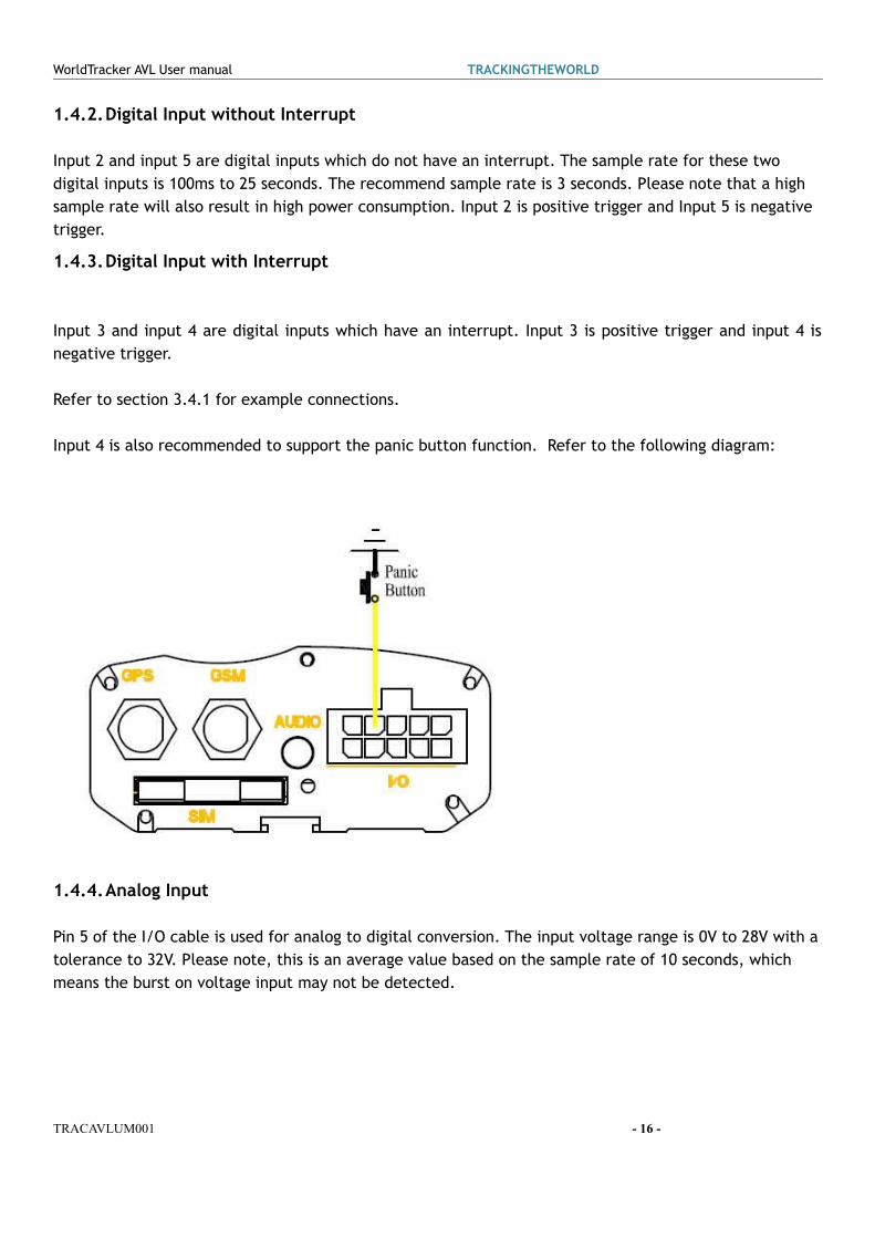
1.4.3.Digital Input with Interrupt
Input 3 and input 4 are digital inputs which have an interrupt. Input 3 is positive trigger and input 4 is negative trigger.
Refer to section 3.4.1 for example connections.
Input 4 is also recommended to support the panic button function. Refer to the following diagram:
1.4.4.Analog Input
Pin 5 of the I/O cable is used for analog to digital conversion. The input voltage range is 0V to 28V with a tolerance to 32V. Please note, this is an average value based on the sample rate of 10 seconds, which means the burst on voltage input may not be detected.
TRACAVLUM001 - 16 -

WorldTracker AVL User manual TRACKINGTHEWORLD
1.4.5.Digital Output
The outputs are an open-drain type with no internal pull-up resistor which may also be used to control a relay. This means that the user must provide a pull-up resistor or a relay coil to any positive voltage (32V max) to detect an inactive output by voltage. Each output can drive a continuous current of 0.2A.
The electrical conditions are:Logical State Electrical StateEnable <1.5V, max current is 0.2ADisable Open or the pull-up voltage (max 32V)
The outputs are used for cutting/restoring GND. See the figures below for example connections:
Example connection to drive an LED.
Example connection to drive a relay.
If the digital output is used to drive a relay, a catch diode is shown across the relay coil. This is necessary to prevent damage to the digital output when the relay is turned off. Many modern relays come with this type of diode pre-installed within the relay itself. If the relay has this diode, ensure the proper relay polarity connection is used. If this diode is not internal, it should be added externally. A common diode such as a 1N4004 will work in most circumstances.
TRACAVLUM001 - 17 -

WorldTracker AVL User manual TRACKINGTHEWORLD
1.4.6.Digital Output with Built-in Relay
The built-in relay output is open-drain type with no internal pull-up resistor. This means that the user must provide a pull-up resistor to any positive voltage to detect an inactive output by voltage. The switch capacity of the relay contact is 60W, so it can drive a continuous current of 2A at the input voltage of 30V, and 1.85A at the input voltage of 32V.
The electrical specifications are:Logical State Electrical StateEnable 0VDisable Open or the pull-up voltage (max 32V)
The output is used for cutting/restoring GND, and it can directly drive a LED. Refer to the figure below.
TRACAVLUM001 - 18 -

WorldTracker AVL User manual TRACKINGTHEWORLD
1.5. Indicator light Description
The WorldTracker AVL contains 3 LEDs. Refer to the table below for information on each LED and their related indications:
Light Event StateGPS LED Stop GPS LED. This LED will typically be
activated for 30 minutes before GPS is stopped. Closed
Stop GPS LED. Within 30-minutes after boot, GPS is set to need mode, with no positioning requirements.Start GPS LED, and no positioning requirements.Start GPS LED. GPS will activate and enable power-saver mode. Once detected, close the GPS static or flameoutNEMA check fail. Slow lightData invalid or no data.GPS is fixing. Fast lightGPS has fixed. Ever-light
PWR LED Stop power LED. This LED will normally activate for 30 minutes before the power is stopped.
Closed
Disable backup battery.Disable backup battery, internal battery is low. Slow flashEnable backup battery, the device is charging. Fast flashEnable backup battery, charging has completed. Ever-light
GSM LED Network searching Fast flashSIM pin lockedNetwork has been registered Slow flash
TRACAVLUM001 - 19 -

WorldTracker AVL User manual TRACKINGTHEWORLD
1.6. Audio Interface
The audio connector on the WorldTracker AVL unit is designed to connect a non-balanced, hands-free audio system. It is designed for use with a 2.5mm stereo plug with the following configuration. It is important to note the common GND. This common GND is used only for audio ground, and should not be used as a power ground. The speaker interface can be connected to a 32ohm speaker or an audio amplifier for driving a louder speaker. A microphone, as shown below, is recommended.
Audio Jack Interface Definition
Example connection for Audio
TRACAVLUM001 - 20 -

WorldTracker AVL User manual TRACKINGTHEWORLD
Microphone Input Characteristics
Parameter Min Type Max UnitWorking Voltage 1.0 1.5 2.0 VWorking Current 200 500 uAExternal Microphone Load Resistance
2.2 k Ohm
Speaker Output Characteristics
Parameter Min Type Max UnitSpeaker load Resistance
16 32 Ohm
Speaker output level 0 2.4 VppMax. driving current limit of speaker
50 mA
TRACAVLUM001 - 21 -
WorldTracker AVL User manual TRACKINGTHEWORLD
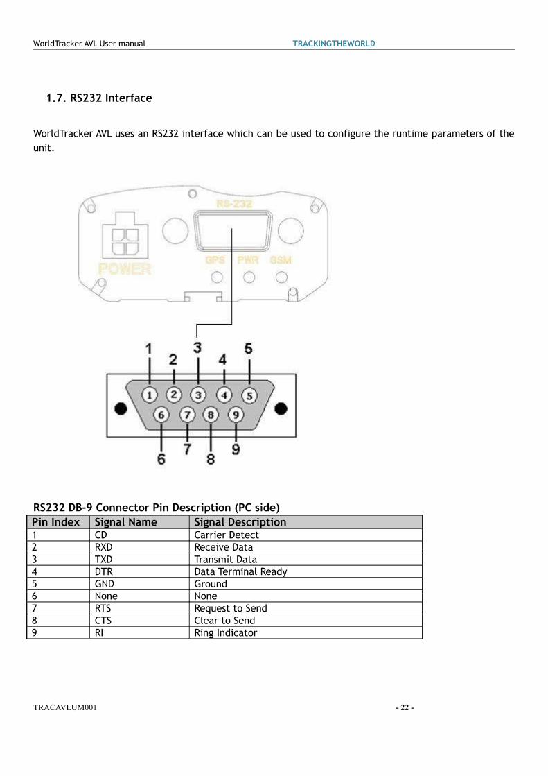
1.7. RS232 Interface
WorldTracker AVL uses an RS232 interface which can be used to configure the runtime parameters of the unit.
RS232 DB-9 Connector Pin Description (PC side)Pin Index Signal Name Signal Description1 CD Carrier Detect2 RXD Receive Data3 TXD Transmit Data4 DTR Data Terminal Ready5 GND Ground 6 None None7 RTS Request to Send8 CTS Clear to Send9 RI Ring Indicator
TRACAVLUM001 - 22 -
WorldTracker AVL User manual TRACKINGTHEWORLD
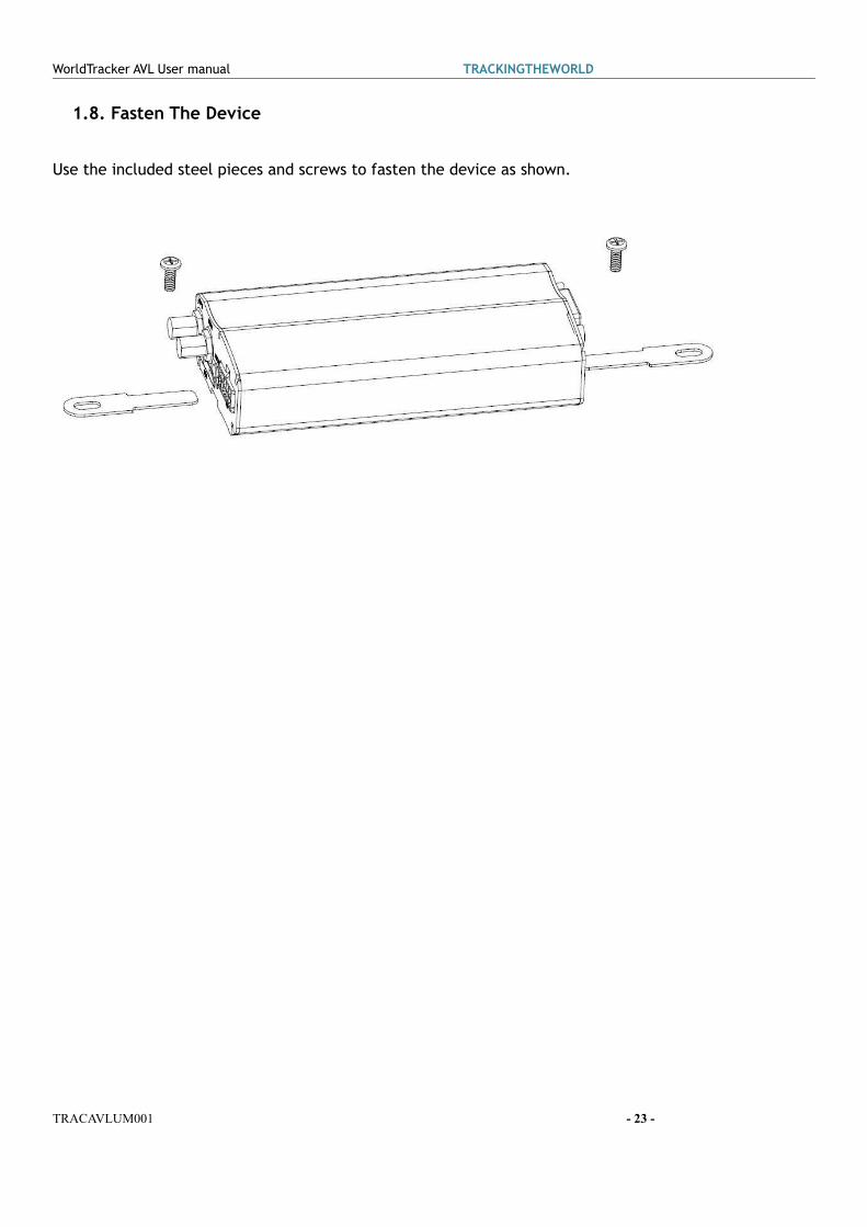
1.8. Fasten The Device
Use the included steel pieces and screws to fasten the device as shown.
TRACAVLUM001 - 23 -