Standard Operating Procedure for the AVL M.O.V.E. Portable ... · gaseous (AVL 493) and particulate...
67
CALIFORNIA AIR RESOURCES BOARD MONITORING & LABORATORY DIVISION FREIGHT EMISSIONS TESTING & RESEARCH BRANCH Standard Operating Procedure for the AVL M.O.V.E. Portable Emission Measurement System (PEMS) Portable Emissions Measurement Section Revision Date: December 18, 2015 Revision: 0.03
Transcript of Standard Operating Procedure for the AVL M.O.V.E. Portable ... · gaseous (AVL 493) and particulate...

CALIFORNIA AIR RESOURCES BOARD MONITORING & LABORATORY DIVISION
FREIGHT EMISSIONS TESTING & RESEARCH BRANCH
Standard Operating Procedure for the AVL M.O.V.E. Portable Emission Measurement System (PEMS)
Portable Emissions Measurement Section
Revision Date: December 18, 2015
Revision: 0.03

California Air Resources Board
Monitoring & Laboratory Division PEM Section
Standard Operating Procedure
AVL M.O.V.E. PEMS DRAFT
Effective Date: 12/18/15 Revision: 0.02
Approved By: J. Karim Page 1 of 66
CONTENTS 1. Purpose ............................................................................................................................. 3
2. Overview of the AVL PEMS .............................................................................................. 3 2.1 Major Components ...................................................................................................................... 4
2.2 Power Requirements .................................................................................................................. 5
3. Safety Requirements ........................................................................................................ 6 3.1 PPE and Work Zone .................................................................................................................... 6
3.2 Designated Staff .......................................................................................................................... 6
4. Setup & Installation .......................................................................................................... 7 4.1 On-Board Installation Guidelines .............................................................................................. 7
4.2 Power Connections ..................................................................................................................... 9
4.3 Gas PEMS Connections ........................................................................................................... 10
4.4 PM PEMS Connections ............................................................................................................. 10
4.5 Communication Connections .................................................................................................. 12
4.6 Flow Meter Installation ............................................................................................................. 13
4.7 GPS Receiver and Temperature/Humidity Sensor Installation ............................................ 13
5. Operation and Testing .....................................................................................................14 5.1 PEMS Power-up ......................................................................................................................... 15
5.2 System Control Software Start-up........................................................................................... 15
5.3 Warm-up ..................................................................................................................................... 18
5.4 Test Set-up ................................................................................................................................. 19
5.4.1 Vehicle Interface Set-up .......................................................................................................... 19
5.4.2 ECU Signal Parameter Set-up (As Needed, Approved by PEM Section Manager) ............... 21
5.4.3 ECU Signal Display Set-up (As Needed, Approved by PEM Section Manager) .................... 22
5.4.4 Main Test Settings................................................................................................................... 23
5.4.5 AVL 493 Zero/Span Settings ................................................................................................... 24
5.4.6 Vehicle Test Information Checks ............................................................................................ 24
5.5 Pre-Test Calibration .................................................................................................................. 25
5.6 PM Filter Loading ...................................................................................................................... 27
5.7 Main Test .................................................................................................................................... 28
5.8 Post-Test Checks ...................................................................................................................... 29
5.9 Data Transfer / Data Management ........................................................................................... 30

California Air Resources Board
Monitoring & Laboratory Division PEM Section
Standard Operating Procedure
AVL M.O.V.E. PEMS DRAFT
Effective Date: 12/18/15 Revision: 0.02
Approved By: J. Karim Page 2 of 66
5.10 System Shut-down .................................................................................................................... 31
5.11 Troubleshooting ........................................................................................................................ 32
5.11.1 Unable to connect via Remote Desktop .................................................................................. 32
5.11.2 There is no communication with the vehicle interface ............................................................ 32
6. Data Processing and Validation Using Concerto ..........................................................33 6.1 Run Concerto............................................................................................................................. 33
6.2 Open Data Files ......................................................................................................................... 34
6.3 Data Processing Setting ........................................................................................................... 35
6.4 Time Alignment of Data ............................................................................................................ 41
6.5 Run Post-Processing ................................................................................................................ 42
6.6 Test Result Reporting and Data Validation ............................................................................ 43
6.6.1 Test Result Reporting ............................................................................................................. 43
6.6.2 Data Validation ........................................................................................................................ 46
6.6.3 Heavy Duty In-Use Compliance Testing Report ..................................................................... 47
7. Maintenance and Calibration ..........................................................................................48 7.1 Gas PEMS Maintenance ........................................................................................................... 48
7.2 PM PEMS Maintenance ............................................................................................................. 49
8. Quality Assurance / Quality Control ...............................................................................51 8.1 10-Point Linearity Check .......................................................................................................... 51
8.2 System Check ............................................................................................................................ 57
8.2.1 Sample Path Check ................................................................................................................ 58
8.2.2 Leak Check ............................................................................................................................. 58
9. Regulatory & Industry References .................................................................................59
10. Related Documents .........................................................................................................59
ATTACHMENTS .......................................................................................................................60 Attachment 1 – Vehicle Test Information Form ................................................................................... 60
Attachment 2 – AVL GAS PEMS Maintenance and Calibration Form ................................................ 61
Attachment 3 – AVL PM PEMS Maintenance and Calibration Form .................................................. 62
Attachment 4 – Linearity Check Log ................................................................................................... 63
Attachment 5 – Linearity Check Template .......................................................................................... 64
Attachment 6 – System Check Worksheet ......................................................................................... 65
Attachment 7 – Heavy Duty In-Use Compliance Testing Report ........................................................ 66
California Air Resources Board
Monitoring & Laboratory Division PEM Section
Standard Operating Procedure
AVL M.O.V.E. PEMS DRAFT
Effective Date: 12/18/15 Revision: 0.02
Approved By: J. Karim Page 3 of 66
1. Purpose
This document provides the standard operating procedure used to collect measurements of gaseous (AVL 493) and particulate matter (PM) (AVL 494) emissions using the AVL M.O.V.E. Portable Emission Measurement System (PEMS) in accordance with the Code of Federal Regulations, Title 40, Part 1065, Subpart J – Field Testing and Portable Emission Measurement Systems (40 CFR Part 1065).
The procedures described provide a general guideline for installation, calibration, maintenance, operation, and data processing.
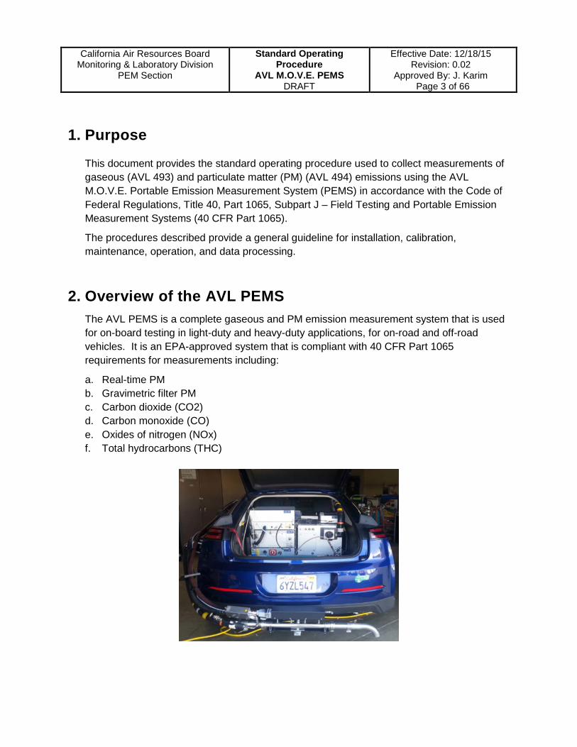
2. Overview of the AVL PEMS The AVL PEMS is a complete gaseous and PM emission measurement system that is used for on-board testing in light-duty and heavy-duty applications, for on-road and off-road vehicles. It is an EPA-approved system that is compliant with 40 CFR Part 1065 requirements for measurements including:
a. Real-time PM b. Gravimetric filter PM c. Carbon dioxide (CO2) d. Carbon monoxide (CO) e. Oxides of nitrogen (NOx) f. Total hydrocarbons (THC)

California Air Resources Board
Monitoring & Laboratory Division PEM Section
Standard Operating Procedure
AVL M.O.V.E. PEMS DRAFT
Effective Date: 12/18/15 Revision: 0.02
Approved By: J. Karim Page 4 of 66
2.1 Major Components
PM PEMS (AVL 494)
The PM PEMS consists of two modules. The Micro Soot Sensor (MSS) module uses the photo-acoustic measurement principle to detect soot particles on a real-time basis. The Gravimetric Filter Module (GFM) is used to collect filter samples of PM. The filter weight data can be used to correct the real-time PM data. The PM sampling line is a 4 meter (m) heated line that is maintained at a constant temperature of 52°C during testing to prevent exhaust particle changes before the sample reaches the MSS detector.
Gas PEMS (AVL 493)
The Gas PEMS consists of three analyzers that measure gaseous components of the emissions. A non-dispersive infrared (NDIR) analyzer measures CO2 and CO concentrations. A non-dispersive ultraviolet (NDUV) analyzer measures NO2 and NO concentrations, from which the NOx concentration is derived. A flame ionization detector (FID) measures THC concentrations. The gas sampling line is a 4 m heated line that is maintained at a constant temperature of 191°C during testing to prevent condensation of volatile components in the exhaust sample.
Gas Bottles
AGM Batteries
Mastervolt Charger
Power Distribution (E-Box)
Gravimetric Filter Module (GFM)
Micro Soot Sensor (MSS)
Gas PEMS
System Control
SEMTECH EFM Box
MV Display
Shut off
Heated Gas Sample Line (4 m)
Heated PM Sample Line (4 m)
SEMTECH Exhaust Flow Meter

California Air Resources Board
Monitoring & Laboratory Division PEM Section
Standard Operating Procedure
AVL M.O.V.E. PEMS DRAFT
Effective Date: 12/18/15 Revision: 0.02
Approved By: J. Karim Page 5 of 66
Exhaust Flow Meter
The exhaust flow meter (EFM) measurement head and EFM control box allow for direct, real-time exhaust flow measurements using Pitot tube and pressure differential calculations. Exhaust flow rate is used to calculate mass emissions.
Communication and Control
The AVL System Control module controls the PEMS system. It also receives the engine control unit (ECU) data via a number of vehicle interface (VI) protocol capabilities including SAE J1939, SAE 1708, and OBD. The System Control communicates with the PM PEMS, Gas PEMS, and EFM using proprietary software. The PEMS components can also be controlled using a browser-based device user interface (DUI) called Device Control.
The System Control also receives GPS and ambient conditions (temperature and humidity) data.
2.2 Power Requirements Typically, for on-road testing, a portable generator that is rated for at least a 2600-watt output will be required. The Mastervolt charger should be plugged into the generator during testing to provide continuous charging to the batteries.
The E-box allows for switching between different voltage sources, such as between network/generator to battery-only, if no generator can be used for the on-road testing. It is recommended that network power is used for warming up the system, then generator power or battery-only while on road.

California Air Resources Board
Monitoring & Laboratory Division PEM Section
Standard Operating Procedure
AVL M.O.V.E. PEMS DRAFT
Effective Date: 12/18/15 Revision: 0.02
Approved By: J. Karim Page 6 of 66
3. Safety Requirements
It is important to create a safe work environment for all testing staff in both the laboratory and field environment.
Follow and understand all ARB safety requirements (as listed in ARB’s Web Site- http://inside.arb.ca.gov/as/safety/HSL.htm) as referenced to compressed cylinder handling and safe laboratory operating practices. Hardcopies of the safety requirements can be obtained from your manager or by contacting the ARB’s Management Services Branch Chief and Equal Employment Opportunity Officer listed on the ARB’s Web Site- www.arb.ca.gov/html/org/orgasd.htm.
Review and become familiar with the manufacturer equipment manuals mentioned in this procedure regarding safety precautions. ARB Staff must observe and follow all the applicable safety requirements and precautions. Report any questions or concerns to the PEM Section Manager.
3.1 PPE and Work Zone During any emissions testing either in the field or in a laboratory environment, staff shall wear proper personal protective equipment (PPE), such as:
• Hearing protection • Safety boots • Safety vest • Safety glasses • Nitrile gloves • Mechanic’s gloves • Back support • Hard hat (required at certain sites operating heavy-duty
equipment)
Use caution when working around vehicles and equipment with moving parts. Minimize fall or trip hazards by properly securing ladders, loose cables, or any other trip hazards.
Keep the work area clean. Read and understand the safety instructions provided in the operation manuals of each instrument being used.
3.2 Designated Staff Staff operating the AVL PEMS must be trained, be able to demonstrate their proficiency, and be approved by the PEM Section Manager.

California Air Resources Board
Monitoring & Laboratory Division PEM Section
Standard Operating Procedure
AVL M.O.V.E. PEMS DRAFT
Effective Date: 12/18/15 Revision: 0.02
Approved By: J. Karim Page 7 of 66
4. Setup & Installation
The installation of the PEMS on a vehicle may require extensive planning and engineering. Determining the configuration of the PEMS and flow meter installation should begin much earlier than when the testing is scheduled to begin. Fabrication of additional brackets to support the PEMS may be required and should be taken into consideration when determining the testing schedule. PEMS installation sholud be approved by PEM Section Manager.
4.1 On-Board Installation Guidelines a. Staff personnel are to inspect the vehicle ahead of time to determine the best
configuration for the flow meter and the PEMS units. If support brackets are required, coordinate with appropriate staff to develop a robust design.
b. The installation of a PEMS on or inside a vehicle must only be carried out by skilled and trained personnel who approved by PEM Section Manager.
c. The PEMS should be placed in a stable location on the vehicle using the provided AVL vibration damping plates. Fabrication of additional brackets may be necessary for a secure installation.
d. Install all units and parts in locations that do not create new blind spots for the vehicle operator.
e. Ratchet straps and zip ties should be used to secure the PEMS and sampling lines. The mounting location will vary depending on the type of vehicle being tested and the available space.
f. Minimize loose cables by securing them with zip ties. g. Be mindful of possible hazards, such as low-hanging tree branches, that could
damage or dismantle any part of the PEMS during operation. h. It is imperative that you secure required gas bottles tightly and securely in a safe
area on the vehicle with locks and safety caps.

California Air Resources Board
Monitoring & Laboratory Division PEM Section
Standard Operating Procedure
AVL M.O.V.E. PEMS DRAFT
Effective Date: 12/18/15 Revision: 0.02
Approved By: J. Karim Page 8 of 66
For laboratory test settings, the AVL PEMS can remain on a cart and placed where sample lines can reach the vehicle tailpipe. Be sure to keep the required gas bottles in an accessible and safe location as well.

California Air Resources Board
Monitoring & Laboratory Division PEM Section
Standard Operating Procedure
AVL M.O.V.E. PEMS DRAFT
Effective Date: 12/18/15 Revision: 0.02
Approved By: J. Karim Page 9 of 66
4.2 Power Connections
Connect the power input cables to the E-box and power output cables to the PEMS modules. The type of connections and number of pins should guide you to the appropriate cables. In the figure below, the names of the ports for each connection are indicated where necessary. Leave all units powered off until the set-up is complete.
X11 X12
X15
System Control EFM
E-box
12 VDC
Gray Power Port
Mastervolt
MV Display
Red Power Port
AGM Batteries
Emergency Stop
X7
X4 X3
X9
X5
MSS
Gas PEMS
GFM
X7
California Air Resources Board
Monitoring & Laboratory Division PEM Section
Standard Operating Procedure
AVL M.O.V.E. PEMS DRAFT
Effective Date: 12/18/15 Revision: 0.02
Approved By: J. Karim Page 10 of 66
4.3 Gas PEMS Connections
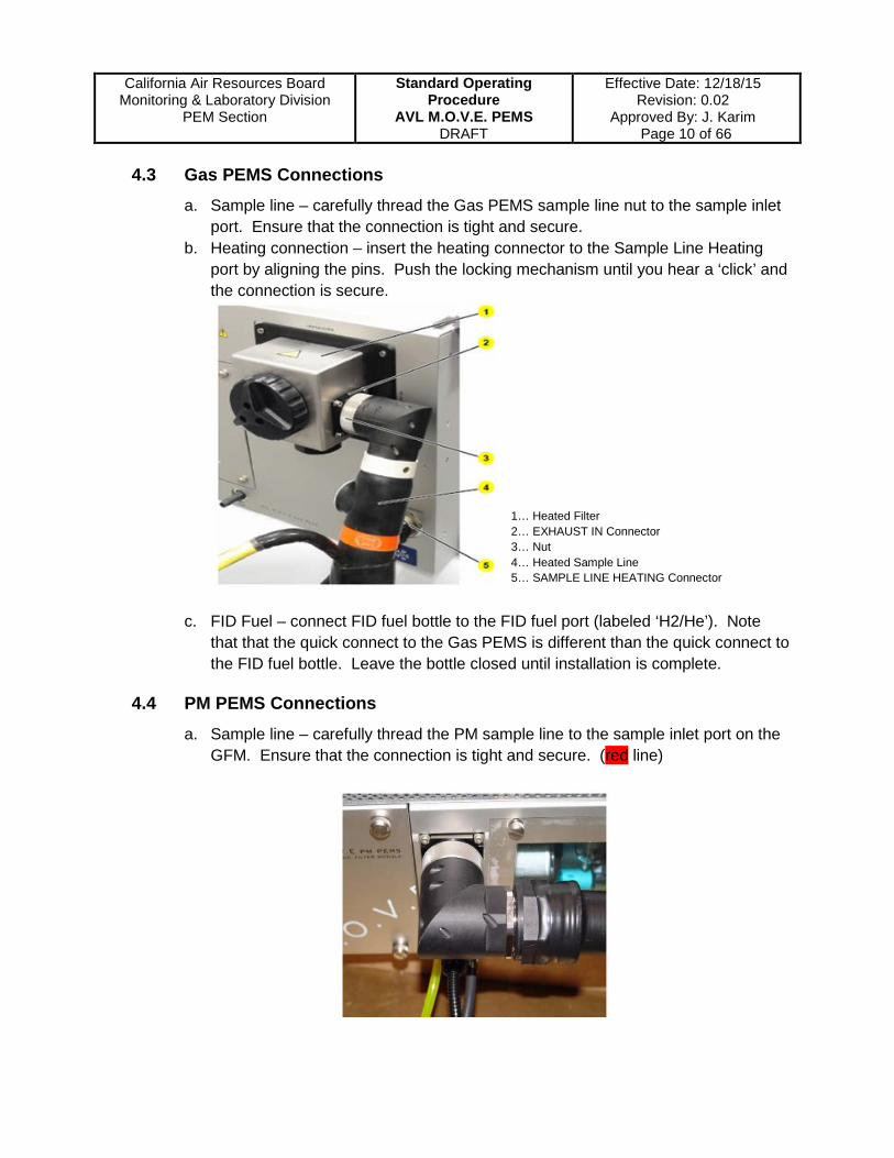
a. Sample line – carefully thread the Gas PEMS sample line nut to the sample inlet port. Ensure that the connection is tight and secure.
b. Heating connection – insert the heating connector to the Sample Line Heating port by aligning the pins. Push the locking mechanism until you hear a ‘click’ and the connection is secure.
c. FID Fuel – connect FID fuel bottle to the FID fuel port (labeled ‘H2/He’). Note that that the quick connect to the Gas PEMS is different than the quick connect to the FID fuel bottle. Leave the bottle closed until installation is complete.
4.4 PM PEMS Connections a. Sample line – carefully thread the PM sample line to the sample inlet port on the
GFM. Ensure that the connection is tight and secure. (red line)
1… Heated Filter 2… EXHAUST IN Connector 3… Nut 4… Heated Sample Line 5… SAMPLE LINE HEATING Connector

California Air Resources Board
Monitoring & Laboratory Division PEM Section
Standard Operating Procedure
AVL M.O.V.E. PEMS DRAFT
Effective Date: 12/18/15 Revision: 0.02
Approved By: J. Karim Page 11 of 66
b. Heating and Sample Path Connections
• Insert the sample heating and dilution cell heating components to the PM PEMS where indicated. (yellow and green lines)
• Connect the tubing from dilution cell to Dilution Air Out port. (blue line)
• Connect the ‘Exhaust From Sensor’ (GFM) to ‘Exhaust Out’ (AVL MSS) using the black rubber tubing…... 1 (red line)
• Connect the ‘Exhaust to Sensor’ (GFM) to the ‘Exhaust In’ (AVL MSS) port using the foam-insulated tubing….. 2 (blue line) Connect the ‘Purge Air Out’ (GFM) to “Purge Air In’ (AVL MSS) using the Teflon tubing….. 3 (yellow line)
AVL Micro Soot Sensor
GFM

California Air Resources Board
Monitoring & Laboratory Division PEM Section
Standard Operating Procedure
AVL M.O.V.E. PEMS DRAFT
Effective Date: 12/18/15 Revision: 0.02
Approved By: J. Karim Page 12 of 66
4.5 Communication Connections
GPS
Gas PEMS X8
System Control RS232 X1
EFM Aux2
GFM X3
MSS X8 X2
X3
Temperature/Humidity
494 PM PEMS 192.168.0.25
493 Gas PEMS 192.168.0.24
MSS
GFM

California Air Resources Board
Monitoring & Laboratory Division PEM Section
Standard Operating Procedure
AVL M.O.V.E. PEMS DRAFT
Effective Date: 12/18/15 Revision: 0.02
Approved By: J. Karim Page 13 of 66
4.6 Flow Meter Installation Installing the flow meter is an involved process that often requires planning ahead in case additional support brackets need to be fabricated. The orientation of the flow meter may vary with each type of test vehicle. The size of the flow meter used may also vary since different types of vehicles use different sized exhaust outlets.
Ensure that the heated sample line is never bent to a radius of less than 250 millimeters (approximately 10 inches).
Upon completion of installation, PEMS staff need to get approval from PEM Section Manager.
4.7 GPS Receiver and Temperature/Humidity Sensor Installation Attach GPS receiver and ambient condition sensor (including ambient temperature, humidity, and pressure) to the front connectors of the AVL System Controller.
GPS Receiver Ambient Temperature/Humidity Sensor

California Air Resources Board
Monitoring & Laboratory Division PEM Section
Standard Operating Procedure
AVL M.O.V.E. PEMS DRAFT
Effective Date: 12/18/15 Revision: 0.02
Approved By: J. Karim Page 14 of 66
5. Operation and Testing
Ensure that all communication and power cables are connected properly and securely: a. All modules are connected to the E-box via the power cables b. All modules are connected to the System Control via the AVL communication cables c. Both PM and Gas PEMS sample lines are connected securely to the units and to the
flow tube and the heating components are also plugged in d. An H2/He bottle is connected to the flame ionization detector (FID) fuel port on the Gas
PEMS e. The appropriate Vehicle Interface cable is connected to the System Control and the test
vehicle (See Section 5.4.1. – Vehicle Interface Setup)
Major connections to check:
A – PM sample line B – PM sample line heating connection C – Gas sample line D – Gas sample line heating connection E – FID fuel port F – Connection to SEMTECH Exhaust Flow Meter (EFM) G – GPS and weather station communication H – FID fuel line connection to bottle
A
B C D
E
F G
H
California Air Resources Board
Monitoring & Laboratory Division PEM Section
Standard Operating Procedure
AVL M.O.V.E. PEMS DRAFT
Effective Date: 12/18/15 Revision: 0.02
Approved By: J. Karim Page 15 of 66
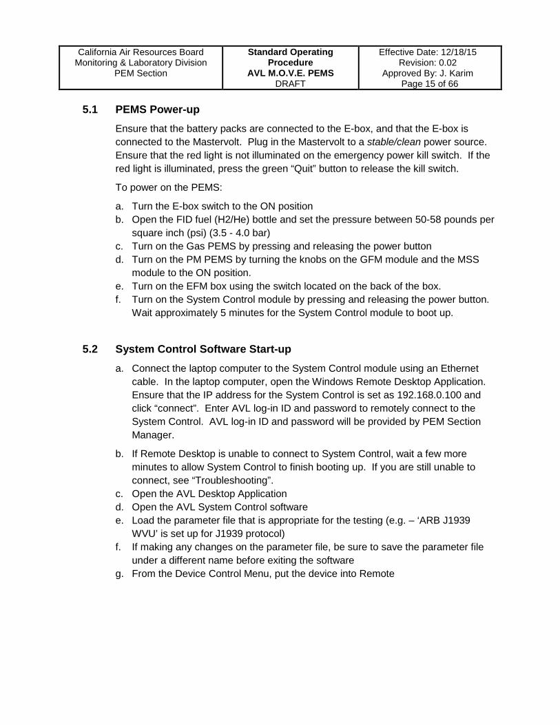
5.1 PEMS Power-up
Ensure that the battery packs are connected to the E-box, and that the E-box is connected to the Mastervolt. Plug in the Mastervolt to a stable/clean power source. Ensure that the red light is not illuminated on the emergency power kill switch. If the red light is illuminated, press the green “Quit” button to release the kill switch.
To power on the PEMS:
a. Turn the E-box switch to the ON position b. Open the FID fuel (H2/He) bottle and set the pressure between 50-58 pounds per
square inch (psi) (3.5 - 4.0 bar) c. Turn on the Gas PEMS by pressing and releasing the power button d. Turn on the PM PEMS by turning the knobs on the GFM module and the MSS
module to the ON position. e. Turn on the EFM box using the switch located on the back of the box. f. Turn on the System Control module by pressing and releasing the power button.
Wait approximately 5 minutes for the System Control module to boot up.
5.2 System Control Software Start-up a. Connect the laptop computer to the System Control module using an Ethernet
cable. In the laptop computer, open the Windows Remote Desktop Application. Ensure that the IP address for the System Control is set as 192.168.0.100 and click “connect”. Enter AVL log-in ID and password to remotely connect to the System Control. AVL log-in ID and password will be provided by PEM Section Manager.
b. If Remote Desktop is unable to connect to System Control, wait a few more minutes to allow System Control to finish booting up. If you are still unable to connect, see “Troubleshooting”.
c. Open the AVL Desktop Application d. Open the AVL System Control software e. Load the parameter file that is appropriate for the testing (e.g. – ‘ARB J1939
WVU’ is set up for J1939 protocol) f. If making any changes on the parameter file, be sure to save the parameter file
under a different name before exiting the software g. From the Device Control Menu, put the device into Remote

California Air Resources Board
Monitoring & Laboratory Division PEM Section
Standard Operating Procedure
AVL M.O.V.E. PEMS DRAFT
Effective Date: 12/18/15 Revision: 0.02
Approved By: J. Karim Page 16 of 66
Ensure that System Control is communicating with the PM PEMS, Gas PEMS, and the EFM box by checking that the module names are highlighted in green:

California Air Resources Board
Monitoring & Laboratory Division PEM Section
Standard Operating Procedure
AVL M.O.V.E. PEMS DRAFT
Effective Date: 12/18/15 Revision: 0.02
Approved By: J. Karim Page 17 of 66
Open the web browser to see the Device Control Software device user interface (DUI) (http://192.168.0.24/ for Gas PEMS DUI, and http://192.168.0.25/ for the PM PEMS DUI). The drop down menu in Device Control allows user to see the status and settings of various instrument parameters. The Device Control DUI is also used for linearity checks (see QA/QC section for details).
Gas PEMS DUI
PM PEMS DUI

California Air Resources Board
Monitoring & Laboratory Division PEM Section
Standard Operating Procedure
AVL M.O.V.E. PEMS DRAFT
Effective Date: 12/18/15 Revision: 0.02
Approved By: J. Karim Page 18 of 66
5.3 Warm-up After PEMS power up, the PEMS system automatically start to warm up. PEMS must be properly warmed up to the appropriate temperature ranges prior to beginning calibration and testing. The target temperature ranges are indicated when hovering the cursor over the parameter box under “Service View Temperatures” in the Device Control browser-based DUI software.
a. Allow the system to warm up for at least one and half hours. b. In the System Control software, open the Device Control menu and put the
device into Pause. Wait for the system to count down and display “Ready”. c. From the Device Control menu, put the device into Standby. d. Check that the device states are shown as “Ready” before proceeding with the
test set-up.
Gas PEMS DUI

California Air Resources Board
Monitoring & Laboratory Division PEM Section
Standard Operating Procedure
AVL M.O.V.E. PEMS DRAFT
Effective Date: 12/18/15 Revision: 0.02
Approved By: J. Karim Page 19 of 66
5.4 Test Set-up 5.4.1 Vehicle Interface Set-up
The vehicle interface (VI) can be set up in two ways, depending on the protocol used. For vehicles using SAE J1939 protocols, the VI can be connected directly to the System Control module. The VI should be connected to the “CAN3 X12” port on the System Control.
For OBD, SAE J1708, and other protocols, the Dearborn adapter is required for VI connection. The Dearborn adapter is connected to the “USB X6 or X7” port on the System Control module.
To ensure that the VI is being recognized, have the vehicle in the key-on state and check in the System Control software that most of the values displayed are non-zero for the engine control module (ECM) parameters. Values will not change, nor reflect actual conditions, until the test vehicle’s engine is turned on.

California Air Resources Board
Monitoring & Laboratory Division PEM Section
Standard Operating Procedure
AVL M.O.V.E. PEMS DRAFT
Effective Date: 12/18/15 Revision: 0.02
Approved By: J. Karim Page 20 of 66
At a minimum, the following ECU parameters should be recording:
Engine Speed Coolant Temperature Engine Load Oil Temperature Vehicle Speed Intake Manifold Temperature Throttle Position Intake Manifold Pressure Input Fuel Rate Intake Manifold Pressure Absolute Fuel Economy mpg Exhaust Temperature Air Mass Flow DPF Regeneration Signal Actual Torque Actual Friction Torque Reference Torque
These parameters are required during post-processing of the test data. Additional parameters may be required depending on the testing needs. Consult with the Project Engineer and PEM Section Manager to determine which additional parameters should be recorded, if any.

California Air Resources Board
Monitoring & Laboratory Division PEM Section
Standard Operating Procedure
AVL M.O.V.E. PEMS DRAFT
Effective Date: 12/18/15 Revision: 0.02
Approved By: J. Karim Page 21 of 66
5.4.2 ECU Signal Parameter Set-up (As Needed, Approved by PEM Section Manager)
Depending on the need, the signal list for obtaining ECU parameters may need to be edited. In the Settings menu, select the Signal list option to open the Signals window. This will display a list of ECU signals that are possibly broadcasted by the vehicle. Review the list of parameters (signals) under the pertinent protocol or communication mode (e.g.- [Kavaser] is typically used for J1939 communication and OBD signals are read by a controller area network [CAN] connection).
Right-click or double-click on the desired parameter to either enable or disable it. A small dialogue window will open with options for the set-up of the signal. The operator typically will not have to change any signal settings.
California Air Resources Board
Monitoring & Laboratory Division PEM Section
Standard Operating Procedure
AVL M.O.V.E. PEMS DRAFT
Effective Date: 12/18/15 Revision: 0.02
Approved By: J. Karim Page 22 of 66
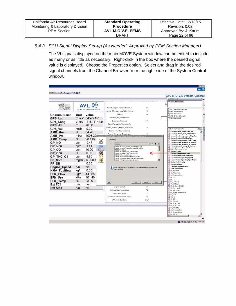
5.4.3 ECU Signal Display Set-up (As Needed, Approved by PEM Section Manager)
The VI signals displayed on the main MOVE System window can be edited to include as many or as little as necessary. Right-click in the box where the desired signal value is displayed. Choose the Properties option. Select and drag in the desired signal channels from the Channel Browser from the right-side of the System Control window.

California Air Resources Board
Monitoring & Laboratory Division PEM Section
Standard Operating Procedure
AVL M.O.V.E. PEMS DRAFT
Effective Date: 12/18/15 Revision: 0.02
Approved By: J. Karim Page 23 of 66
5.4.4 Main Test Settings
Ensure that continuous data acquisition or measurement is stop before editing “Main Test Settings”. From “MOVE System” main tab screen, select the “Main Test Settings” tab. Under “Main Test Settings” tab screen, select “Yes” on “Perform Cyclic Zero Checks” and confirm “3600” on “Duration (between Cyclic Zeros, [s]). When “Perform Cyclic Zero Checks” is selected, the zero air bottle should be opened and connected to the zero port on the Gas PEMS.
Select and drag in the desired signal channels for “Vehicle Velocity” and “Engine Speed” from the Channel Browser from the right-side of the System Control window.
Start/Stop Continuous Acquisition Start/Stop Measurement Stop Continuous Acquisition/Measurement
Main Test Settings

California Air Resources Board
Monitoring & Laboratory Division PEM Section
Standard Operating Procedure
AVL M.O.V.E. PEMS DRAFT
Effective Date: 12/18/15 Revision: 0.02
Approved By: J. Karim Page 24 of 66
5.4.5 AVL 493 Zero/Span Settings
From “MOVE System” main tab screen, select the “AVL 493 Zero/Span Settings” tab. Under “AVL 493 Zero/Span Settings” tab screen, select “2-Synthetic Air” on “Perform Zero Calibration with”. Ensure all the setting values in the “Span Settings” are updated, including Bottle Numbers, Reference Values, and Gas Bottle IDs.
5.4.6 Vehicle Test Information Checks
Fill the first two parts in “Vehicle Test Information Form” (Attachment 1), including the basic test project information, vehicle information, and engine information.
AVL 493 Zero/Span Settings

California Air Resources Board
Monitoring & Laboratory Division PEM Section
Standard Operating Procedure
AVL M.O.V.E. PEMS DRAFT
Effective Date: 12/18/15 Revision: 0.02
Approved By: J. Karim Page 25 of 66
5.5 Pre-Test Calibration
Prior to beginning the Pre-Test, ensure that the PEMS is properly warmed up and the VI is connected. From the “Pre-Test” menu, select “Pre-Test Certification” for In-Use Compliance Testing with all the required calibrations and QA/QC checks. There are two other options in the “Pre-Test” menu, “Pre-Test Flexible” and “Pre-Test Simple for Research & Development”. If “Pre-Test Flexible” is selected, calibrations and QA/QC checks can be selectable to be conducted. If doing a Pre-Test without calibrations and QA/QC checks, select “Pre-Test Simple for Research & Development”.
Enter the test file name and filter ID for the test. The test file should be naming according to the test file naming structure in the PEM Section. If no filter samples are being collected for the test, leave the filter ID as ‘0’ and ensure that there is a dummy filter placed in the Gravimetric Filter Module (GFM). See Section 5.6 for filter loading instructions.
Following the prompts on the software, connect the zero air bottle to the appropriate port on the Gas PEMS and set the pressure to approximately 14.5 psi (1.0 bar). Connect the mixed span gases to the appropriate port on the Gas PEMS and set the bottle pressure to approximately 14.5 psi (1.0 bar). Once calibration is completed with the mixed span gases, connect the NO2 span bottle to the appropriate port on the Gas PEMS and set the bottle pressure to approximately 14.5 psi (1.0 bar). Follow the prompts on the software accurately and do not try to navigate or adjust settings in the software during the calibration process as it may freeze the software.
The required “Pre-Test” calibrations and QA/QC checks are described in 40 CFR Part 1065 Subpart J, including sample probe leak check and zero/span gas analyzer.
Test File Name: yyyymmdd_xxxxxx_nn.iii
where yyyy Year mm Month dd Day xxxxxx CARB Test ID No nn Vehicle No iii i-File No

California Air Resources Board
Monitoring & Laboratory Division PEM Section
Standard Operating Procedure
AVL M.O.V.E. PEMS DRAFT
Effective Date: 12/18/15 Revision: 0.02
Approved By: J. Karim Page 26 of 66
The sampling system for low-flow leak will be conducted according to 40 CFR 1065.935. First, cap/plug the end of sample probe or close a leak-tight valve located in the sample transfer line within 92 cm of the probe. Then, operate all the sample vacuum pumps and verify that the flow through the vacuum-side of the sampling system is less than 0.5% of the system’s normal in-use flowrate (40 CFR 1065.345).
Zero and span in the Pre-Test using the gases that meet the specification of 40CFR 1065.750. The specified span concentration ranges and recommended daily span concentrations for the AVL Gas-PEMS are listed in the following table.
Span Gas Min. Conc. Max. Conc. Recommended CO2 7.5 % 20 % 16 % CO (ppm) 1000 ppm 82000 ppm 1200 ppm NO (ppm) 500 ppm 5000 ppm 1500 ppm NO2 (ppm) 250 ppm 2500 ppm 500 ppm THC (ppmC) 300 ppm 30000 ppm 600 ppm
During the Pre-Test span calibration, AVL MOVE System Control software compares the nominal bottle concentration value for each gas channel with the current reading from gas analyzer. If the difference between the measures gas concentration and the bottle value is greater than 10%, the software will not allow the span calibration. The test engineer needs to confirm the entered bottle values in the “AVL 493 Zero/Span Settings” are correct. If all the bottle values are correct, run the span calibration through the Gas-PEMS DUI software to force the Gas-PEMS to be calibrated. Then, run Pre-Test through the System Control software again. If Pre-Test still not pass, please report to PEM Section Supervisor.
Confirm that a pre-test calibration was conducted on the Vehicle Test Information form (Attachment 1).

California Air Resources Board
Monitoring & Laboratory Division PEM Section
Standard Operating Procedure
AVL M.O.V.E. PEMS DRAFT
Effective Date: 12/18/15 Revision: 0.02
Approved By: J. Karim Page 27 of 66
5.6 PM Filter Loading
Test Engineers/Project Engineers pick up the pre-weighted PM filters from Aerosol Analysis and Methods Evaluation Section (ECARSD/AAMES) according to AAMES’s filter handling procedures and keep in the dust-free environmental chamber. Always wear nitrile gloves when handling PM filters and filter cartridges. Designate a clean area for filter handling where excessive wind and dust is minimized. Have forceps ready for transferring the filter from its original cartridge to the AVL cartridge. Also have the Chain of Custody filter list ready to keep track of which filter was used for which test. The test filter ID must be recorded in Vehicle Test Information form (Attachment 1). To load a new filter into the GFM:
a. Open the access door on the GFM and remove the metal filter cartridge holder by unlocking the holder mechanism
b. Using the AVL filter cartridge transport tool is optional, but is recommended when having to transport the filter over a distance (from the GFM to the filter handling area).
c. After removing the metal filter cartridge holding tray from the GFM module, very carefully pry open the filter cartridge. Do not touch the center sampling area of the filter.
d. Remove the dummy filter and place it in a safe holding place, such as a petri dish with a lid. Take the new filter and using the forceps, carefully place the new filter into the AVL filter cartridge, keeping in mind that the sample will flow from top to bottom. Do not touch the sampling area of the filter at any time.
e. Replace the filter cartridge into the metal holding tray, and return the holding tray into the GFM. Lock the filter sampling mechanism before closing the access door.
Lift and pull left to open

California Air Resources Board
Monitoring & Laboratory Division PEM Section
Standard Operating Procedure
AVL M.O.V.E. PEMS DRAFT
Effective Date: 12/18/15 Revision: 0.02
Approved By: J. Karim Page 28 of 66
5.7 Main Test
Ensure that the system is in Standby mode and is in the “Ready” state.
a. From the Main Test menu, choose “Main Test for Certification”. If you select “Main Test for Research and Development”, the Main Test can be conducted with fully flexible Pre-Test and Post-Test selections. Set an appropriate length of time for the test (in seconds). The main test logging will begin approximately 2-3 seconds after you click “OK”.
b. On the main screen, check that the system status is in “MAIN CYC” mode and
that “Filter ON” is indicated. Ensure that both the PM PEMS and the Gas PEMS are both running, indicated by green in the device status box. Check that the Logging is “ON” and that Logging Duration is continuously counting.

California Air Resources Board
Monitoring & Laboratory Division PEM Section
Standard Operating Procedure
AVL M.O.V.E. PEMS DRAFT
Effective Date: 12/18/15 Revision: 0.02
Approved By: J. Karim Page 29 of 66
c. As the test is coming to an end, be prepared to open
the Stop and Save menu to hit “Stop and Save”. Stopping the Main Test as close as possible to the end of the testing period is crucial when collecting PM filter samples. It is less crucial when a PM filter sample is not being collected and only real-time data will be used.
d. Allow for the system to fully stop the test and get back to the “Ready” state before moving onto any other actions. A countdown will be displayed.
e. During the main test, note the details of the test on the Vehicle Test Information form (Attachment 1).
5.8 Post-Test Checks Ensure that the system is in Standby mode.
a. Connect the zero air bottle and set the pressure to approximately 14.5 psi b. Connect the mixed span gas cylinder to the appropriate port on the Gas PEMS
and set the pressure to approximately 14.5 psi (1.0 bar). c. From the Post-Test menu, choose the Post-Test procedure. Following the
prompts, allow the system to zero the analyzers and then calibrate. When prompted, connect the NO2 span bottle and set the pressure to approximately 14.5 psi (1.0 bar). Following the prompts, allow the system to calibrate.
d. During the post-test, note the details of the post-test on the Vehicle Test Information form (Attachment 1).
California Air Resources Board
Monitoring & Laboratory Division PEM Section
Standard Operating Procedure
AVL M.O.V.E. PEMS DRAFT
Effective Date: 12/18/15 Revision: 0.02
Approved By: J. Karim Page 30 of 66
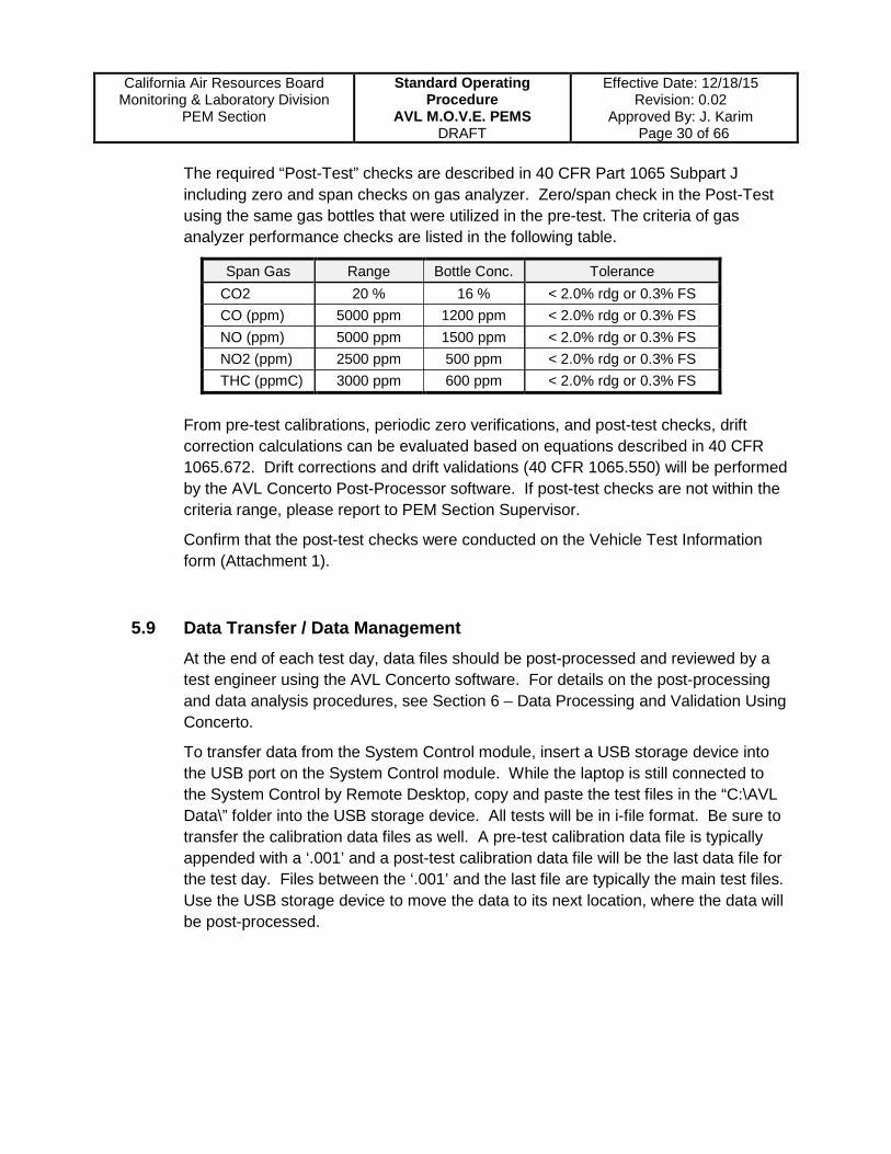
The required “Post-Test” checks are described in 40 CFR Part 1065 Subpart J including zero and span checks on gas analyzer. Zero/span check in the Post-Test using the same gas bottles that were utilized in the pre-test. The criteria of gas analyzer performance checks are listed in the following table.
Span Gas Range Bottle Conc. Tolerance CO2 20 % 16 % < 2.0% rdg or 0.3% FS CO (ppm) 5000 ppm 1200 ppm < 2.0% rdg or 0.3% FS NO (ppm) 5000 ppm 1500 ppm < 2.0% rdg or 0.3% FS NO2 (ppm) 2500 ppm 500 ppm < 2.0% rdg or 0.3% FS THC (ppmC) 3000 ppm 600 ppm < 2.0% rdg or 0.3% FS
From pre-test calibrations, periodic zero verifications, and post-test checks, drift correction calculations can be evaluated based on equations described in 40 CFR 1065.672. Drift corrections and drift validations (40 CFR 1065.550) will be performed by the AVL Concerto Post-Processor software. If post-test checks are not within the criteria range, please report to PEM Section Supervisor.
Confirm that the post-test checks were conducted on the Vehicle Test Information form (Attachment 1).
5.9 Data Transfer / Data Management At the end of each test day, data files should be post-processed and reviewed by a test engineer using the AVL Concerto software. For details on the post-processing and data analysis procedures, see Section 6 – Data Processing and Validation Using Concerto.
To transfer data from the System Control module, insert a USB storage device into the USB port on the System Control module. While the laptop is still connected to the System Control by Remote Desktop, copy and paste the test files in the “C:\AVL Data\” folder into the USB storage device. All tests will be in i-file format. Be sure to transfer the calibration data files as well. A pre-test calibration data file is typically appended with a ‘.001’ and a post-test calibration data file will be the last data file for the test day. Files between the ‘.001’ and the last file are typically the main test files. Use the USB storage device to move the data to its next location, where the data will be post-processed.
California Air Resources Board
Monitoring & Laboratory Division PEM Section
Standard Operating Procedure
AVL M.O.V.E. PEMS DRAFT
Effective Date: 12/18/15 Revision: 0.02
Approved By: J. Karim Page 31 of 66
5.10 System Shut-down
Following a vehicle testing, keep the AVL PEMS on Standby for approximately 20 minutes to allow the system to purge with ambient air. To shut down the system: a. Put the system in Pause mode b. Exit the Device Control DUI software c. Exit the System Control software d. Turn off the two PM modules e. Close the FID fuel bottle and turn off the Gas PEMS by pressing and releasing
the power button. The Gas PEMS will begin a shut-down sequence that will take approximately 5 minutes to complete. At the end of the sequence, the system will turn off automatically.
f. Turn off the System Control computer by pressing and releasing the power button. This will begin a shut-down sequence and System Control will turn off after approximately 2 minutes.
g. Turn off the SEMTECH-EFM box by pressing the switch to the ‘off’ position h. Disconnect the FID fuel line from the Gas PEMS and relieve the pressure in the
line

California Air Resources Board
Monitoring & Laboratory Division PEM Section
Standard Operating Procedure
AVL M.O.V.E. PEMS DRAFT
Effective Date: 12/18/15 Revision: 0.02
Approved By: J. Karim Page 32 of 66
5.11 Troubleshooting
For System Control errors, find the error code found in the Message List window. Look up the error code in the Troubleshooting section of the AVL M.O.V.E manuals. Other possible troubleshooting needs are as follows.
5.11.1 Unable to connect via Remote Desktop
a. Check that the IP address for the System Control in the Remote Desktop window is set to 192.168.0.100. Check that the static IP of the computer is set as 192.168.0.2 (anything but .1 or .100)
b. If the IP addresses are wrong, change them to the correct IP address and attempt to connect again
c. If you are still unable to connect, open the Network Connections window d. Disable network connections and wait for approximately 10 seconds before
enabling network connections again e. Attempt to connect again from Remote Desktop
5.11.2 There is no communication with the vehicle interface
a. Put the vehicle into “key on” mode, without turning on the engine b. If working with the SAE J1939 protocol, ensure that the cable is connected to the
System Control on CAN3 X12. Also ensure that any adapter in the communication line is securely connected. Check that the connection to the vehicle is secure.
c. If working with the OBD connection, ensure that the USB connection is secure. Using electrical tape or tying the connection is recommended to prevent it from disconnecting during testing.
For errors that cannot be resolved by staff, call the AVL Hotline at (800) 352-4343 to report the problem. An AVL engineer will guide you through steps to resolve the problem. Errors or problems can also be logged online through the AVL SalesForce website at https://emea.salesforce.com/sserv/login.jsp?orgId=00D200000007fFR.
California Air Resources Board
Monitoring & Laboratory Division PEM Section
Standard Operating Procedure
AVL M.O.V.E. PEMS DRAFT
Effective Date: 12/18/15 Revision: 0.02
Approved By: J. Karim Page 33 of 66
6. Data Processing and Validation Using Concerto
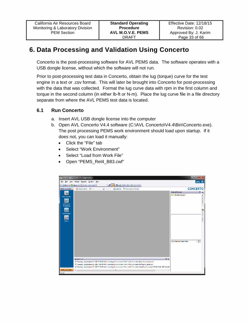
Concerto is the post-processing software for AVL PEMS data. The software operates with a USB dongle license, without which the software will not run.
Prior to post-processing test data in Concerto, obtain the lug (torque) curve for the test engine in a text or .csv format. This will later be brought into Concerto for post-processing with the data that was collected. Format the lug curve data with rpm in the first column and torque in the second column (in either lb-ft or N-m). Place the lug curve file in a file directory separate from where the AVL PEMS test data is located.
6.1 Run Concerto a. Insert AVL USB dongle license into the computer b. Open AVL Concerto V4.4 software (C:\AVL Concerto\V4.4\Bin\Concerto.exe).
The post processing PEMS work environment should load upon startup. If it does not, you can load it manually: • Click the “File” tab • Select “Work Environment” • Select “Load from Work File” • Open “PEMS_Rel4_B83.cwf”

California Air Resources Board
Monitoring & Laboratory Division PEM Section
Standard Operating Procedure
AVL M.O.V.E. PEMS DRAFT
Effective Date: 12/18/15 Revision: 0.02
Approved By: J. Karim Page 34 of 66
c. Load the PEMS Post Processing Layout:
• Select “PEMS Post Processing” on the workflow bar on the left side
• Select “Activate PEMS Post Processing Layout”
• Choose PEMS case configuration file “default.pems_c” or a preset file “xxxxx.pems_c” that have been created
6.2 Open Data Files a. Select “Data Access” on the workflow bar, then
“Open File” b. Open the pre-test, main tests, and post-test (last
file of the test set) i-files • The first i-file is pre-test calibration files, not
the main test files. The last i-file after main tests is the post-test calibration file.
• When an AVL i-file is brought into the Channel Browser, Concerto will assign it a name in the order it was opened. Concerto will name the first file as ‘IFILE1,’ the second as ‘IFILE2,’ and so on.

California Air Resources Board
Monitoring & Laboratory Division PEM Section
Standard Operating Procedure
AVL M.O.V.E. PEMS DRAFT
Effective Date: 12/18/15 Revision: 0.02
Approved By: J. Karim Page 35 of 66
• Open the lug curve file in Concerto. If ASCII formatting windows appears, edit
the lug curve file. While formatting, select the Basechannel checkbox, select Engine Speed from the adjacent drop-down box, select LogPoint as the type of Basechannel, and save this formatting as any name on the next screen.
6.3 Data Processing Setting a. In the “PEMS Case” tab. “Load” to load a previously created post-processing
layout or leave as “default”. Before edit any parameter in the “PEMS Case” tab, select “Save As” and save the layout to another file name. A separate window “Do you want to create general, vehicle, and legislation parameter files with the same name: xxxxx.pems_c?” will be displaced on the screen and click “Yes”.
California Air Resources Board
Monitoring & Laboratory Division PEM Section
Standard Operating Procedure
AVL M.O.V.E. PEMS DRAFT
Effective Date: 12/18/15 Revision: 0.02
Approved By: J. Karim Page 36 of 66
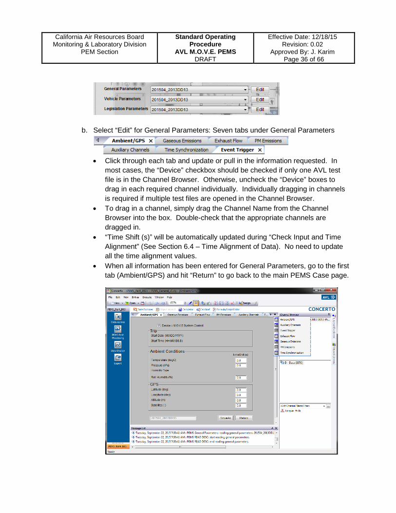
b. Select “Edit” for General Parameters: Seven tabs under General Parameters
• Click through each tab and update or pull in the information requested. In
most cases, the “Device” checkbox should be checked if only one AVL test file is in the Channel Browser. Otherwise, uncheck the “Device” boxes to drag in each required channel individually. Individually dragging in channels is required if multiple test files are opened in the Channel Browser.
• To drag in a channel, simply drag the Channel Name from the Channel Browser into the box. Double-check that the appropriate channels are dragged in.
• “Time Shift (s)” will be automatically updated during “Check Input and Time Alignment” (See Section 6.4 – Time Alignment of Data). No need to update all the time alignment values.
• When all information has been entered for General Parameters, go to the first tab (Ambient/GPS) and hit “Return” to go back to the main PEMS Case page.
California Air Resources Board
Monitoring & Laboratory Division PEM Section
Standard Operating Procedure
AVL M.O.V.E. PEMS DRAFT
Effective Date: 12/18/15 Revision: 0.02
Approved By: J. Karim Page 37 of 66
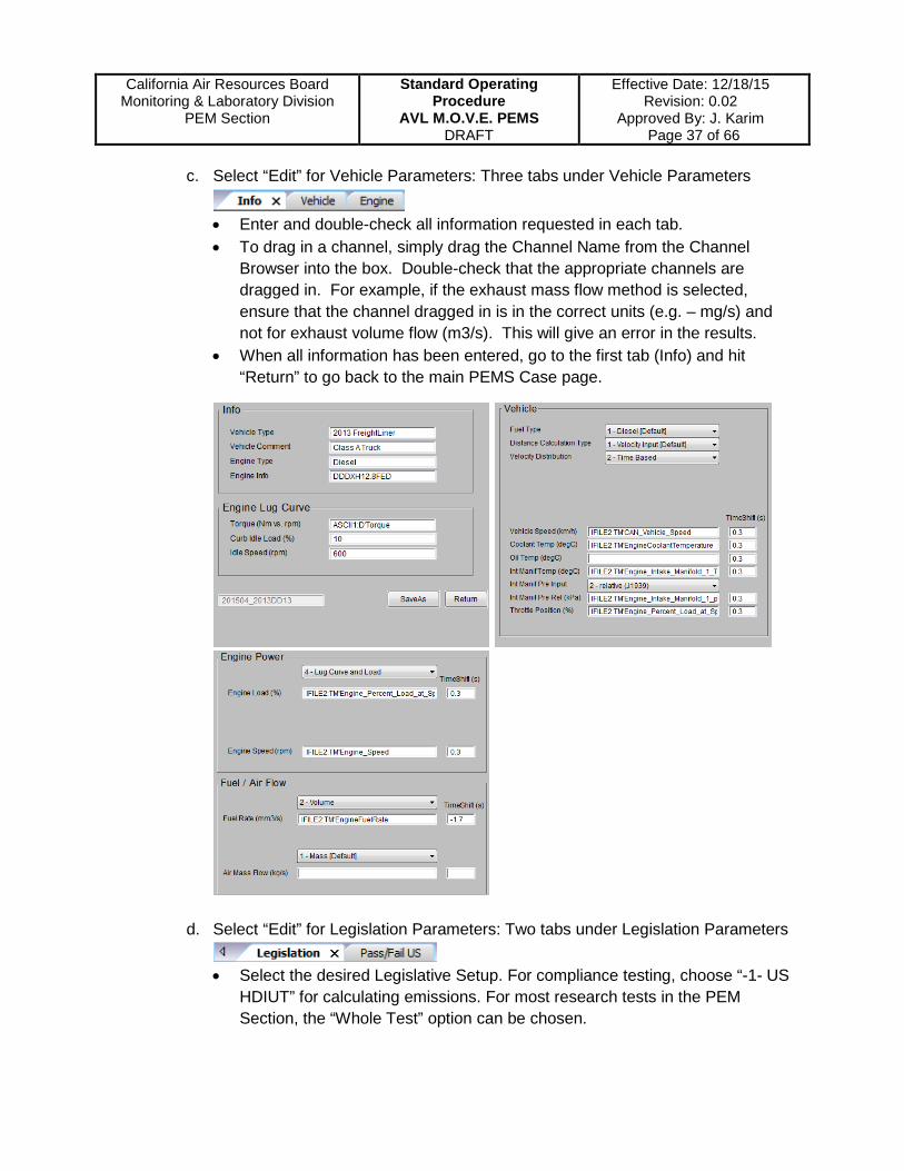
c. Select “Edit” for Vehicle Parameters: Three tabs under Vehicle Parameters
• Enter and double-check all information requested in each tab. • To drag in a channel, simply drag the Channel Name from the Channel
Browser into the box. Double-check that the appropriate channels are dragged in. For example, if the exhaust mass flow method is selected, ensure that the channel dragged in is in the correct units (e.g. – mg/s) and not for exhaust volume flow (m3/s). This will give an error in the results.
• When all information has been entered, go to the first tab (Info) and hit “Return” to go back to the main PEMS Case page.
d. Select “Edit” for Legislation Parameters: Two tabs under Legislation Parameters
• Select the desired Legislative Setup. For compliance testing, choose “-1- US HDIUT” for calculating emissions. For most research tests in the PEM Section, the “Whole Test” option can be chosen.

California Air Resources Board
Monitoring & Laboratory Division PEM Section
Standard Operating Procedure
AVL M.O.V.E. PEMS DRAFT
Effective Date: 12/18/15 Revision: 0.02
Approved By: J. Karim Page 38 of 66
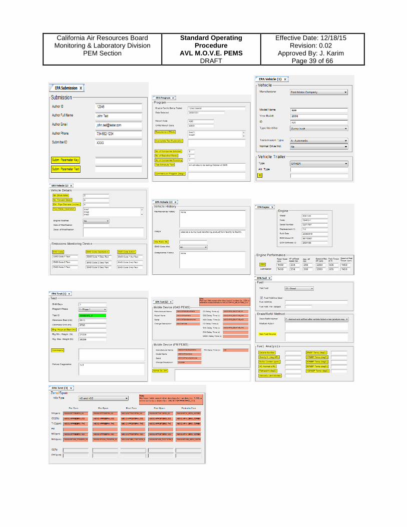
• When there is no NTE Reporting Key for submitting the EPA NTE report, uncheck the “Create Submission Documents”. Finish all the required info in “Pass/Fail US” tab.
• If post-process with NTE Reporting Key, select the checkbox “Create Submission Documents” and 10 more tabs will be displaced. Input all the information in all tabs (shown as next page).
• When all setups under Legislation Parameters have been completed, hit “Return” to go back to the main PEMS Case page. Save the PEMS Case file.
California Air Resources Board
Monitoring & Laboratory Division PEM Section
Standard Operating Procedure
AVL M.O.V.E. PEMS DRAFT
Effective Date: 12/18/15 Revision: 0.02
Approved By: J. Karim Page 39 of 66
California Air Resources Board
Monitoring & Laboratory Division PEM Section
Standard Operating Procedure
AVL M.O.V.E. PEMS DRAFT
Effective Date: 12/18/15 Revision: 0.02
Approved By: J. Karim Page 40 of 66
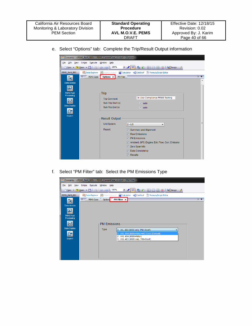
e. Select “Options” tab: Complete the Trip/Result Output information
f. Select “PM Filter” tab: Select the PM Emissions Type

California Air Resources Board
Monitoring & Laboratory Division PEM Section
Standard Operating Procedure
AVL M.O.V.E. PEMS DRAFT
Effective Date: 12/18/15 Revision: 0.02
Approved By: J. Karim Page 41 of 66
6.4 Time Alignment of Data
Following the input of all data and information required for General Parameters, Vehicle Parameters, and Legislation Parameters, select “Check Input and Time Alignment”. The software will begin guiding the user through the time alignment process for ECU channels, gaseous emissions, etc.
a. When aligning the data, the user can zoom into a section of the data by hovering over the x-axis line where the cursor turns into inward arrows ‘ ’. Click “Auto Sync” to align based on the zoomed-in section. Check the correlation quality to check that it is approximately 70% or higher. Values above approximately 70% are acceptable for time alignment. Zoom back out to the entire data set by clicking “Autorange”. Use the best engineering judgment and trial-and-error to time-align the rest of the data.
b. “Time alignment” will be performed between GPS, ECU, Gas PEMS, Exhaust Flow Rate, and Fuel Flow Rate.
c. Note: the AVL Concerto uses Pearson correlation principle for data alignment.

California Air Resources Board
Monitoring & Laboratory Division PEM Section
Standard Operating Procedure
AVL M.O.V.E. PEMS DRAFT
Effective Date: 12/18/15 Revision: 0.02
Approved By: J. Karim Page 42 of 66
6.5 Run Post-Processing
a. Click “Run: Calculate and Plot Results” and wait until the post-processing finish. b. PEMS1 (xxxxxx.ctf) will be created in Channel Browser and results will be
presented in multiple tabs. See “default: Summary” tab to see brake-specific, distance-specific, and fuel-specific test results in addition to other test information.
c. Drift-corrected test results are presented in the following tab titled, “default: Summary (DC)”. Drift corrected results use calibration data to correct data for analyzer drift.

California Air Resources Board
Monitoring & Laboratory Division PEM Section
Standard Operating Procedure
AVL M.O.V.E. PEMS DRAFT
Effective Date: 12/18/15 Revision: 0.02
Approved By: J. Karim Page 43 of 66
6.6 Test Result Reporting and Data Validation
6.6.1 Test Result Reporting
The result pages generated by AVL can be printed, or the content can be copy-pasted to a Microsoft application, such as Excel or Word. Additionally, any number of raw data channels and/or calculated data channels can be exported as a spreadsheet using the following methods:
Method 1:
1. Click the “New” drop-down button, select “Window”, select “Report”, and “Next”.
2. In Object Types, highlight “Tables and Data Lists”, select the first table option, and “Next”.
3. From the Channel Browser, highlight the desired raw data (or calculated emissions) channels under the PEMS1 Category and the Raw Data (or Calculated Emissions) subcategory. Then drag all the data channels into the Datasets window.

California Air Resources Board
Monitoring & Laboratory Division PEM Section
Standard Operating Procedure
AVL M.O.V.E. PEMS DRAFT
Effective Date: 12/18/15 Revision: 0.02
Approved By: J. Karim Page 44 of 66
4. To prevent having missing information in the exported spreadsheet, it is recommended to select (highlight) all available raw data and calculated data channels to export. After dragging in the channels, click “Next”.
5. Choose the Unit as “Auto” or “Time[s]”. Then check the Resolution bubble and set the resolution value to ‘1’. Have the “Interpolate” box checked. Then flick “Finish”.
6. A Report window will be generated. Select the “Export” option in the workflow bar. Choose “Export as ASCII” and save the file to the “AVL Work File” folder.
7. To open the data set or to save as an Excel file, open the Microsoft Excel application. Open the exported text file and click through the steps to format the columns.
8. The data will now be in spreadsheet format that can be further analyzed as needed.
California Air Resources Board
Monitoring & Laboratory Division PEM Section
Standard Operating Procedure
AVL M.O.V.E. PEMS DRAFT
Effective Date: 12/18/15 Revision: 0.02
Approved By: J. Karim Page 45 of 66
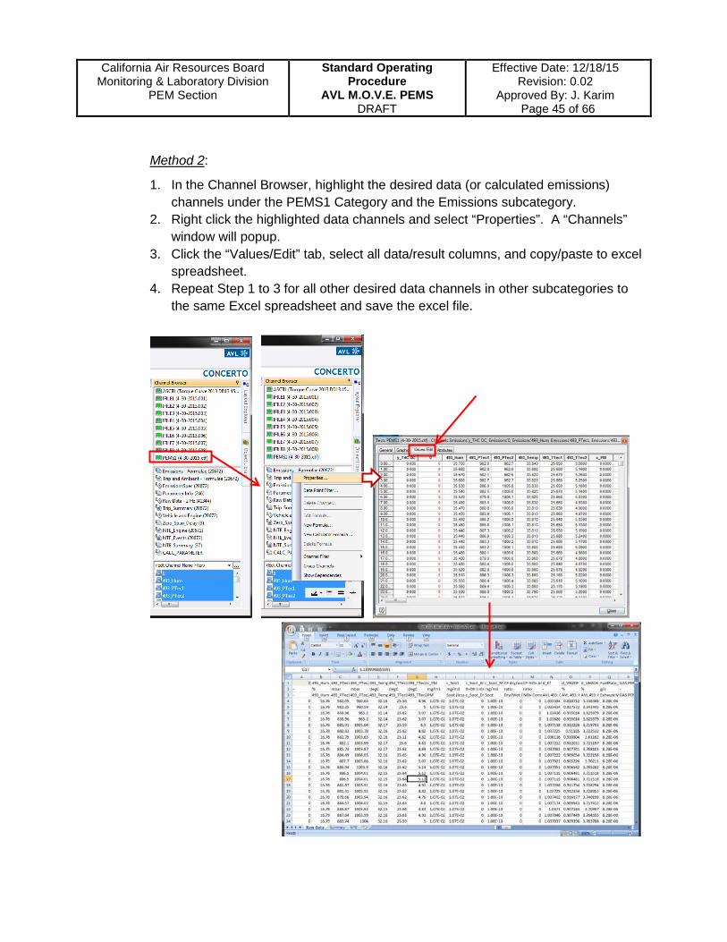
Method 2:
1. In the Channel Browser, highlight the desired data (or calculated emissions) channels under the PEMS1 Category and the Emissions subcategory.
2. Right click the highlighted data channels and select “Properties”. A “Channels” window will popup.
3. Click the “Values/Edit” tab, select all data/result columns, and copy/paste to excel spreadsheet.
4. Repeat Step 1 to 3 for all other desired data channels in other subcategories to the same Excel spreadsheet and save the excel file.

California Air Resources Board
Monitoring & Laboratory Division PEM Section
Standard Operating Procedure
AVL M.O.V.E. PEMS DRAFT
Effective Date: 12/18/15 Revision: 0.02
Approved By: J. Karim Page 46 of 66
After the data/result excel file generated (Method 1 or 2), right click on PEMS1 (xxxxxx.ctf), select “Save Data As…”, and save as type “Transport Files (*.ctf)”.
Back to “File” tab, click “Save As”, select “Container”, and save as type “Container Files (*.ccf)”.
All the raw data and processed result files for each tested vehicle are saved in the same folder in the share drive: “W:\Projects\[Project Name]\[Vehicle ID]\[Test_yyyy-mm-dd_AVL PEMS_Vehicle ID]\”. Additional details of AVL Concerto post-processing and the theoretical basis of calculations can be found in the AVL PEMS Post-Processing Software manual located in this directory: W:\PEMS System Files\Operation Manual\AVL Manual\AVL PEMS Manual\AVL Concerto Guide 2011.
6.6.2 Data Validation
Range validation and drift verification are evaluated according to 40 CFR 1065.935. If the gas analyzer operated above 100% of the gas concentration range at any time

California Air Resources Board
Monitoring & Laboratory Division PEM Section
Standard Operating Procedure
AVL M.O.V.E. PEMS DRAFT
Effective Date: 12/18/15 Revision: 0.02
Approved By: J. Karim Page 47 of 66
during the test, repeat the entire test using the higher analyzer range that the analyzer always operates at less than 100% of the span range.
Drift corrections are calculated according to 40 CFR 1065.672. Use the two sets of brake-specific emission results (uncorrected and corrected) to validate the test cycle for drift following 40 CFR 1065.550. The test cycle is validated for drift if satisfy one of the following criteria:
1. For each test interval of the test cycle and for each measured exhaust constituent, the difference between the uncorrected and the corrected brake-specific emission values over the test interval is within ±4% of the incorrected value or applicable emission standard, whichever is greater.
2. For the entire test cycle and for each measured exhaust constituent, the difference between the uncorrected and the corrected brake-specific emission values over the entire test cycle is within ±4% of the incorrected value or applicable emission standard, whichever is greater. The third calculation of brake-specific emission is required for final reporting. This calculation uses drift-corrected mass (or mass rate) values from each test interval and sets any negative values to zero before calculating the composite brake-specific emission values over the entire test cycle
For the test is not validated for the ±4% drift, the drift-corrected value is less than the standard by at least two times (2X) the absolute difference between the uncorrected and corrected values. The data is still valid for demonstrating compliance with the applicable standard using good engineering judgement.
6.6.3 Heavy Duty In-Use Compliance Testing Report
When post-process with NTE Reporting Key, three EPA reporting files are automatically generated in the folder: “C:\AVL Concerto\WorkEnvironments\PEMS_Rel4_B83\HDUIT\”. The names of these three files are [Case Name].xml, [Case Name]_1Hz.csv, and [Case Name]_Lug_Curve.csv. Move these three files to the same folder of the raw data/result post-processed files: “W:\Projects\[Project Name]\[Vehicle ID]\[Test_yyyy-mm-dd_AVL PEMS_Vehicle ID]\ ”
From these EPA reporting files, transfer the required information and results into the “Heavy Duty In-Use Compliance Testing Report” (Attachment 7). Submit the post-processed test results, including In-Use Compliance Testing Report, AVL Concerto summaries, and the raw data spreadsheets, to the Project Engineer for result discussions and reports. After reviewing by the Project Engineer and PEM Section Supervisor, Project Engineer saves a copy of all required files to the share drive “B:\PEMS Project\Heavy-Duty Diesel In-Use Testing Program\”.

California Air Resources Board
Monitoring & Laboratory Division PEM Section
Standard Operating Procedure
AVL M.O.V.E. PEMS DRAFT
Effective Date: 12/18/15 Revision: 0.02
Approved By: J. Karim Page 48 of 66
7. Maintenance and Calibration
Both the Gas PEMS and PM PEMS should be serviced and maintained according to the schedules (Attachments 2 and 3). Only trained personnel may perform maintenance tasks. An annual service and calibration at the manufacturer’s site is required. AVL Gas PEMS and PM PEMS, including flowmeters, are shipped to AVL North America site in Michigan on an annual basis.
7.1 Gas PEMS Maintenance Any maintenance performed should be documented on AVL Gas PEMS Maintenance and Calibration Form (Attachment 2). For detailed instructions on how to perform the following maintenance tasks, reference the maintenance section of the AVL Gas PEMS Product Guide. From Gas PEMS DUI, click the menu option “Service/Maintenance” and select “Operating Hours” to check the operating hours of Gas PEMS to perform the maintenance services.
a. Check the main filter element of the heated filter on a daily basis. Replace the
filter element, if one of the following conditions is met: • A flow warning is given; • Visible soot layer observed (from 0.5 mm thickness onward); • The flow through the critical orifices drops noticeably; or • Water has been drawn into the system.
b. Replace the dust filters after 200 hours of operation. For detailed instructions on how to perform this task, reference the maintenance section of the AVL Gas PEMS Product Guide.

California Air Resources Board
Monitoring & Laboratory Division PEM Section
Standard Operating Procedure
AVL M.O.V.E. PEMS DRAFT
Effective Date: 12/18/15 Revision: 0.02
Approved By: J. Karim Page 49 of 66
c. Replace the filter unit (coarse and activated-carbon filters) after 250 hours of
operation. The filter unit also has to be changed if using the ambient air port leads to a signal of more than 2 ppm THC on the FID compared to synthetic air or nitrogen from the zero port.
d. Change the inner tube of the heated line after 1000 hours of operation. A new inner tube is also needed if the connection is changed from a straight configuration to a 90-degree configuration, or if the heated line is extended, or pressure drop too high or the HC test still fails in spite of back-purging with HC-free compressed air and filter change.
e. Replace the safety filter of the heated filter after 1000 hours of operation. The filter should also be replaced if one of the following conditions is met: • The main filter element has been damaged • Water has been drawn into the system • Debris from exhaust gas is observed at the surface
f. Replace the O2 sensor after 1000 hours of operation, or if ambient air O2 voltage level is lower than 7.5 mV.
g. In the event that water is drawn into the system, the water trap protecting the NDUV and NDIR analyzers needs to be changed. This operation can only be done by trained personnel. Call the AVL Hotline for guidance or schedule to ship the unit to the AVL facility for maintenance.
7.2 PM PEMS Maintenance Any maintenance performed should be documented on the AVL PM PEMS Maintenance and Calibration Form (Attachment 3). For detailed instruction on how to perform maintenance tasks, reference the maintenance section of the AVL PM PEMS Product Guide. From PM PEMS DUI, click the menu option “Service/Maintenance” and select “Operating Hours” to check the operating hours of PM PEMS to perform the maintenance services.
California Air Resources Board
Monitoring & Laboratory Division PEM Section
Standard Operating Procedure
AVL M.O.V.E. PEMS DRAFT
Effective Date: 12/18/15 Revision: 0.02
Approved By: J. Karim Page 50 of 66
When the system is used for measuring typical soot concentrations in exhaust gas, the following approach is recommended.
a. Perform a visual check of the 3 fine filters on the measuring chamber. If soot layer is obviously visible (from 0.5 mm thickness onward), replace the filter.
b. Perform a visual check of the fine filter of the GFM. If soot layer is obviously visible (from 0.5 mm thickness onward), replace the filter.
c. On a regular basis, disassemble the sample line and purge it with clean shop air. d. Perform a leak check after each new installation and commissioning of the
device. e. After 200 hours of operation, replace the dilution air filter assembly in the service
compartment of the GFM. And clean the pressure reduction unit in case it is used (non-standard, for development tests only).
f. After 300 hours of operation: • Clean the glass tube in the measuring cell • Check the optical components • Replace fine filter at the front of the measuring chamber and in the service
compartment of the GFM • Even if the filter is not yet significantly polluted with soot after 300 operating
hours, it is expected that condensed hydrocarbons, nitrates, ash, etc. have been deposited. Therefore, an exchange is recommended.
• Exchange of the tube in the heated sample line

California Air Resources Board
Monitoring & Laboratory Division PEM Section
Standard Operating Procedure
AVL M.O.V.E. PEMS DRAFT
Effective Date: 12/18/15 Revision: 0.02
Approved By: J. Karim Page 51 of 66
8. Quality Assurance / Quality Control
8.1 10-Point Linearity Check A linearity check verifies that the calibration curves previously established for the gas analyzers remain accurate against the reference gas standards. This check is performed at least every 35 days or after major maintenance. The linearity check follows procedures and calculations prescribed by 40 CFR 1065.307.
Analytical Equipment and Materials
• AVL Gas PEMS and accessories • Horiba SGD-A10 Gas Divider • Calibration gases are required to check a given gas analyzer range during this
procedure. The specific calibration gases needed to complete the test include: - Primary Standard Calibration Gases (± 1% reliability) - Working Span Gases (± 5% reliability) - Zero-Grade Nitrogen (balance gas for mixed gases) - Zero-Grade Air (balance gas for NO2)
Requirements
Staff performing this procedure shall be responsible for documenting all corrective actions and any non-routine occurrences (e.g. – equipment damage, operator errors, etc.) on the Linearity Check Log worksheet (Attachment 4).
a. If any acceptance criteria are not met, staff must notify the PEM Section Manager of any failures and deviations. The AVL M.O.V.E. Gas PEMS becomes unavailable for official testing until corrective action has been taken and all procedures have successfully met the acceptance criteria as stated in this procedure. Staff shall be responsible for documenting any corrective action taken on the Linearity Check Log worksheet (Attachment 4).
b. Staff must verify that the Gas PEMS and the Horiba Gas Divider have a current and valid calibration certificate from the manufacturer.
c. The ambient temperature of the laboratory must remain between 68-86oF during the linearity check procedure.
d. Check that all gas cylinders have valid expiration dates and gas pressures are at least 350 pounds per square inch gauge (psig). Ensure that the ending cylinder pressure following the linearity check does not fall below 300 psig. If the cylinder pressure drops below 300 psig at the end test, then record the exact measured value on the Linearity Check Log worksheet (Attachment 4).

California Air Resources Board
Monitoring & Laboratory Division PEM Section
Standard Operating Procedure
AVL M.O.V.E. PEMS DRAFT
Effective Date: 12/18/15 Revision: 0.02
Approved By: J. Karim Page 52 of 66
e. Concentration values of standard gas bottles should be approximately 90% of the
expected measured range for each gas. For example, if the highest CO measured during vehicle testing is expected to be approximately 1500 ppm, the gas bottle value should be approximately 1350 ppm.
PEMS Set-up
a. Turn on the Gas PEMS and System Control. After remoting into System Control using the laptop, open the Gas PEMS web-based DUI
b. Click “Remote” to request control and put the unit in Pause mode c. Leave Gas PEMS to warm up at least two hours then put the unit in Stand-by
mode
Gas Divider Set-up
a. Turn on the Horiba gas divider by switching on the power button b. Set the Operation to “INT” and the Diluent Gas to “Air” c. Warm up the gas divider unit for at least one hour.
Operation
Dilution Gas Divide %

California Air Resources Board
Monitoring & Laboratory Division PEM Section
Standard Operating Procedure
AVL M.O.V.E. PEMS DRAFT
Effective Date: 12/18/15 Revision: 0.02
Approved By: J. Karim Page 53 of 66
Connections and Pressures
Ensure that the Gas PEMS and the gas divider have been warmed-up for a sufficient amount of time.
a. Connect the N2 bottle to the “Diluent Gas Air” port of the gas divider using a dedicated line
b. Connect the mixed span gas bottle to the “Mixture Gas” inlet of the divider using a dedicated line
c. Connect the “Gas Outlet” port from the divider to the “Span” port of the Gas PEMS
d. Open the N2 and mixed span bottles and ensure that the pressures going out (gauge) are approximately 35 – 40 psi
e. Set the divider to 90% division and ensure that the pressure going in (gauge) to the divider is 30 psi for mixture gas and 25 psi for the N2. The gauges for gas flow into the divider are located in the back.
f. Mixture gas pressure should always be about 5 psi higher than diluent gas pressure. The gauges in the front of the divider are in units of MPa. Ensure that the mixture gas pressure is approximately 0.2 MPa and diluent gas pressure is approximately 0.15 MPa.
g. Adjust the divider flow regulator to approximately 6 – 8 L/min
h. To prevent wasting gases, close the bottles after setting up the pressures until just before beginning the 10-point linearity check.
From mixed span or NO2 bottle
From zero air or N2 bottle
To Gas PEMS

California Air Resources Board
Monitoring & Laboratory Division PEM Section
Standard Operating Procedure
AVL M.O.V.E. PEMS DRAFT
Effective Date: 12/18/15 Revision: 0.02
Approved By: J. Karim Page 54 of 66
Zero, Span, and Audit
While in Standby mode and in “Online View”, click “Service Data Logging” as indicated by the button with a small green arrow.
Data will be saved as a text file to AVL MOVE SC Standard module “C:\Documents and Settings\Administrator\My Documents\AVL\AVL Gas-PEMS\Service Data_Gas-PEMS”. To change the location or name of the file, go to File Settings to make the change before starting service data logging.
Obtain information about each gas cylinder and enter the information in the Linearity Check Log:
• Gas cylinder concentrations (include units) (CO2, CO, THC, NO, NO2) • Gas cylinder number and ARB barcode number (mixed, NO2, zero air, N2) • Gas cylinder pressure • Gas cylinder expiration date
A zero and span calibration is required prior to conducting a 10-point linearity check. This calibration can be done using the web-based DUI.
a. Connect the mixed span and zero air bottles to the Gas PEMS and set the regulator pressure to approximately 7.5 – 14.5 psi.
b. Click the “Zero Audit Span” button to call up the zero, audit, and span window.
c. Select the “Synth Air” port.
d. Zero the analyzers by clicking “Zero Adjust”.
e. Ensure that the analyzers are now reading zero for all gases. If they are not, run the zero adjust once more.
f. In the “Span” tab, ensure that the bottle values that are entered match the bottle you are working with.
g. Select the “Span” port.
h. Select the gases for the mixed span bottle (CO, CO2, THC, NO) and calibrate the analyzers by clicking “Span Adjust”.
i. Connect the NO2 bottle to the Gas PEMS.
Service Data Logging

California Air Resources Board
Monitoring & Laboratory Division PEM Section
Standard Operating Procedure
AVL M.O.V.E. PEMS DRAFT
Effective Date: 12/18/15 Revision: 0.02
Approved By: J. Karim Page 55 of 66
j. Select NO2 in the “Span” tab and calibrate the analyzer by clicking “Span Adjust”
k. In the “Audit” tab, ensure that the bottle gas values match the bottle you are working with.
l. Audit the NO2 gas since it is already connected, then audit the mixed gases
Linearity Check
a. Connect the mixed span gas to the Mixture Gas port and the N2 bottle to the Diluent Gas port on the gas divider and adjust the bottle regulator pressures to approximately 35-40 psi.
b. Connect the Gas Outlet port on the divider to the Span port on the Gas PEMS.
c. Set the divider to 0%.
d. While in Standby and Online View, click the “Span Port” button to open and read from the Span port. The Device State at the top of the window should read “Spangas”.
e. Read and record the analyzer values when the divider is set at 0%, then 100%. Record the pre-zero and pre-span values of the gases on the Linearity Check Log (Attachment 4).
f. Beginning with 0% again, run each divider setting for approximately 2 minute each, sequentially, and record the values on the Linearity Check Log when the readings are stable.
g. When the mixed gases have been read from 0% to 100%, read and record the 0% value and the 100% again.
h. Repeat the procedure (steps c to g) for NO2, using zero air as the balance gas. Using zero air instead of N2 provides better stability for the NO2 concentrations.

California Air Resources Board
Monitoring & Laboratory Division PEM Section
Standard Operating Procedure
AVL M.O.V.E. PEMS DRAFT
Effective Date: 12/18/15 Revision: 0.02
Approved By: J. Karim Page 56 of 66
i. Stop service data logging and put the device into “Pause” mode.
j. Disconnect the NO2 gas line and allow the gas divider to purge on zero air for five minutes by setting the divider to 0%.
k. Retrieve the data file(s) from System Control onto a USB storage device, then shut down the Gas PEMS, System Control, gas divider.
l. Close all gas bottles and disconnect the lines.
Data Processing and File Management
a. Bring the data text file into Excel.
b. Use the Linearity Check Template (see example in Attachment 5) to process the data and verify that the acceptance criteria are met, as indicated by “Pass” on the Linearity Test Summary Table. Acceptance criteria and calculations follow the guidelines prescribed in 40 CFR 1065.307.
CFR 1065.307 Required Linearity Test Criteria: Xmin(a1-1)+a0 a1 SEE r2
Criteria ≤ 1 % · xmax 0.99-1.01 ≤ 1% · xmax ≥ 0.998
c. Submit a hardcopy of the linearity check results to the PEM Section Manager for approval.
d. If no further actions are required, file the hardcopies of the Linearity Check Log (Attachment 4) and the Linearity Check Template (Attachment 5) in the AVL PEMS binder and save the electronic copies in the following directory: W:\PEMS System Files\Instrument QA QC\AVL Gas PEMS

California Air Resources Board
Monitoring & Laboratory Division PEM Section
Standard Operating Procedure
AVL M.O.V.E. PEMS DRAFT
Effective Date: 12/18/15 Revision: 0.02
Approved By: J. Karim Page 57 of 66
8.2 System Check
The system check includes a sample path check to verify that there are no residual contaminants in the sample line and analyzers that can interfere with real concentration readings. It also includes a leak check to ensure there are no leaks along the sample path. It is recommended that a system check is performed following a linearity check and in advance of a test project (40 CFR 1065.345).
Equipment and Materials
a. AVL PEMS and accessories
b. One 1-liter Teflon bag (for mixed span gases)
c. Calibration gases (of mixed gases, CO2, CO, NO, and THC)
Requirements
a. If, during this procedure, any step cannot be completed with the expected event or criteria met, staff must immediately notify the PEM Section Manager regarding all deviations. Staff performing this procedure shall be responsible for documenting all corrective actions and any non-routine occurrences (e.g., equipment damage, operator errors, etc.) on the System Check Worksheet (Attachment 6).
b. If any acceptance criteria are not met, the Gas PEMS becomes unavailable for official testing until corrective action has been taken and all procedures have successfully met the acceptance criteria as stated in this procedure. Staff performing this procedure shall be responsible for documenting any corrective action taken and/or failures on the System Check Worksheet. Corrective actions could include repeating system check procedure after zero and span calibration. It this remains unsuccessful, a linearity check as described in Section 8.1 – Linearity Check must be performed.
c. Check that gas cylinder have valid expiration date and gas pressure of at least 350 pounds per square inch gauge (psig). Check that the cylinder pressure after the system check procedure does not fall below 300 psig. If the cylinder pressure drops below 300 psig, record the pressure value on the System Check Worksheet in the “Comments” field.
Set-up and Preparation
This procedure assumes the PEMS was already powered on and has been warming up for at least 1 hour.

California Air Resources Board
Monitoring & Laboratory Division PEM Section
Standard Operating Procedure
AVL M.O.V.E. PEMS DRAFT
Effective Date: 12/18/15 Revision: 0.02
Approved By: J. Karim Page 58 of 66
8.2.1 Sample Path Check
From the sample path check (dilution-of-span-gas leak test) is conducted according to 40 CFR 1065.345. The "Sample Path Check” requires one Teflon bag – dedicated to the mixed gases (CO2, CO, NO, and THC). Before beginning the sample path check, purge the bag with zero air by filling and emptying them three times. Also, note the concentrations, bottle pressure, barcode number, and expiration date for the gas bottle on the System Check Worksheet.
To Run the Sample Path Procedure:
a. Fill the mixed gases Teflon bag with mixed gases (CO2, CO, NO, and THC). b. Request “Remote” in the Device Control DUI for Gas PEMS, if it is only in the
Monitor state c. Ensure that the Device State is in Standby mode, then turn on Service Data
Logging by clicking the button with the small green arrow d. Connect the mixed gases Teflon bag to the sampling probe at the end of the
heated sample line for the Gas PEMS, making sure the bag valve is open e. Take a reading for 2 minutes (or until the bag is evacuated) and record the
stabilized values on the System Check Worksheet for all gases f. Return to Standby mode, then turn off Service Data Logging g. Retrieve the data file(s) from System Control onto a USB storage device h. Use the Excel version of the System Check Worksheet to process the data
and ensure that the system meets the criteria specified in the worksheet. Verify the measured span gas concentrations are within ±2% (Gas PEMS accuracy) of the span gas concentrations.
8.2.2 Leak Check
A leak check is recommended after every system set-up. It is conducted through the Device Control DUI. The sample probe inlets need to be manually closed for the leak check procedure. Leak checks for the Gas PEMS (sample port, zero port, span port, He/H2 port) are provided automatically through “Service/Maintenance” menu. The zero/span leak check is passed if the leakage rate is below 0.5%.
Leak checks for the PM PEMS are provided through “Service/Maintenance” menu under PM-PEMS Device Control DUI. The leak flow rate criteria to pass the leak check must be less than 10 ml/min to ensure the dilution within ±3% accuracy.

California Air Resources Board
Monitoring & Laboratory Division PEM Section
Standard Operating Procedure
AVL M.O.V.E. PEMS DRAFT
Effective Date: 12/18/15 Revision: 0.02
Approved By: J. Karim Page 59 of 66
9. Regulatory & Industry References
a. Code of Federal Regulations (CFR), Title 40, Subpart J – Field Testing and Portable Emission Measurement Systems
b. Society of Automotive Engineers (SAE) J1939 – Serial Control and Communications Heavy Duty Vehicle Network
c. Society of Automotive Engineers (SAE) J1708 – Serial Data Communications Between Microcomputer Systems in Heavy-Duty Vehicle Applications
10. Related Documents a. AVL 493 Gas PEMS Product Guide
b. AVL 494 PM PEMS Product Guide

California Air Resources Board
Monitoring & Laboratory Division PEM Section
Standard Operating Procedure
AVL M.O.V.E. PEMS DRAFT
Effective Date: 12/18/15 Revision: 0.02
Approved By: J. Karim Page 60 of 66
ATTACHMENTS Attachment 1 – Vehicle Test Information Form
CARB | MLD | PEM Section Version 2015-10-07
VEHICLE TEST INFORMATIONDateSite / Location / RouteTechnicians / EngineersTest Instrument(s)Project Name
Vehicle Information Engine InformationMake MakeModel ModelYear YearLicense No. DisplacementMileage Engine Family
Calibration NotesZeroSpanAuditPre-test ZeroPost-test ZeroPost-test Audit
Tests
Test No.Start time
End time Filter ID
Before/After DPF Notes
Test File Name
Comments
Testing Staff (Print & Sign): Review by (Print & Sign)

California Air Resources Board
Monitoring & Laboratory Division PEM Section
Standard Operating Procedure
AVL M.O.V.E. PEMS DRAFT
Effective Date: 12/18/15 Revision: 0.02
Approved By: J. Karim Page 61 of 66
Attachment 2 – AVL GAS PEMS Maintenance and Calibration Form
Version 2015-10-07
AVL Gas-PEMS Maintenance and Service Form
Date: Instrument: AVL M.O.V.E PEMS
Instrument Maintenance Initials Date NotesDaily
Replace the main filter element of the heated filter Note: Replace the filter if one of the following conditions is met:- Flow warning is output- Markedly visible soot layer (from 0.5 mm thickness onward) is observed- The flow through the critical orifices drops noticeably- Water has been drawn into the system
After 200 Operating HoursReplacing the dust filters
After 250 Operating HoursReplacing the filter unit (coarse and activated-carbon filters)Note: The filter unit also has to be changed if using the ambient air port leads to a signal of more than 2 ppm THC on the FID compared to synthetic air or nitrogen from the Zero port.
After 1000 Operating HoursChange of the inner tube of the heated lineNote: A new inner tube is also needed if the connection is changed from a straight configuration to a 90-degree configuration, or if the heated line is extended, or pressure drop too high or the HC test still fails in spite of backpurging with HC-free compressed air and filter changeReplace the safety filter of the heated filterNote: Replace filter if one of the following conditions is met:- The main filter element has been damaged- Water has been drawn into the system- Debris from exhaust gas is observed at the surfaceReplacing the O2 sensorNote: Replace if ambient air O2 voltage level is lower 7.5 mVReplacing the water trap Note: In case of water was drawn into the system, the water trap protecting the NDUV and NDIR analyzers has to be changed.
Comments:
Service Staff (Print & Sign):
Review by (Print & Sign)
CARB | MLD | PEM Section

California Air Resources Board
Monitoring & Laboratory Division PEM Section
Standard Operating Procedure
AVL M.O.V.E. PEMS DRAFT
Effective Date: 12/18/15 Revision: 0.02
Approved By: J. Karim Page 62 of 66
Attachment 3 – AVL PM PEMS Maintenance and Calibration Form
Version 2015-10-07
AVL PM-PEMS Maintenance and Service Form
Date: Instrument: AVL M.O.V.E PEMS
Instrument Maintenance Initials Date NotesDaily
Before powering up, check the three fine filters on the measuring chamber (visual check). Replace if soot layer is markedly visibleCheck the fine filter of the GFM (visual check)Replace if soot layer is markedly visible
WeeklyDisassemble the sample line and purge it with clean shop airSpan check of the sensitivity
MonthlyVerify linearity laser (4 points)Verify linearity microphone (5 points)
After 200 operating hoursReplace the dilution air filter assembly in the service compartment of GFM. Clean the pressure reduction unit in case it is used.
After 300 operating hoursChange of the inner tube of the heated lineNote: A new inner tube is also needed if the connection is changed from a straight configuration to a 90-degree configuration, or if the heated line is extended, or pressure drop too high or the HC test still fails in spite of backpurging with HC-free compressed air and filter changeClean the glass tube in the measuring cell.Check the optical components.Recommended to replace fine filters at the front of the measuring chamber and in the service compartment of GFM.Exchange of the tube in the heated sample line.
Comments:
Service Staff (Print & Sign):
Review by (Print & Sign)
CARB | MLD | PEM Section
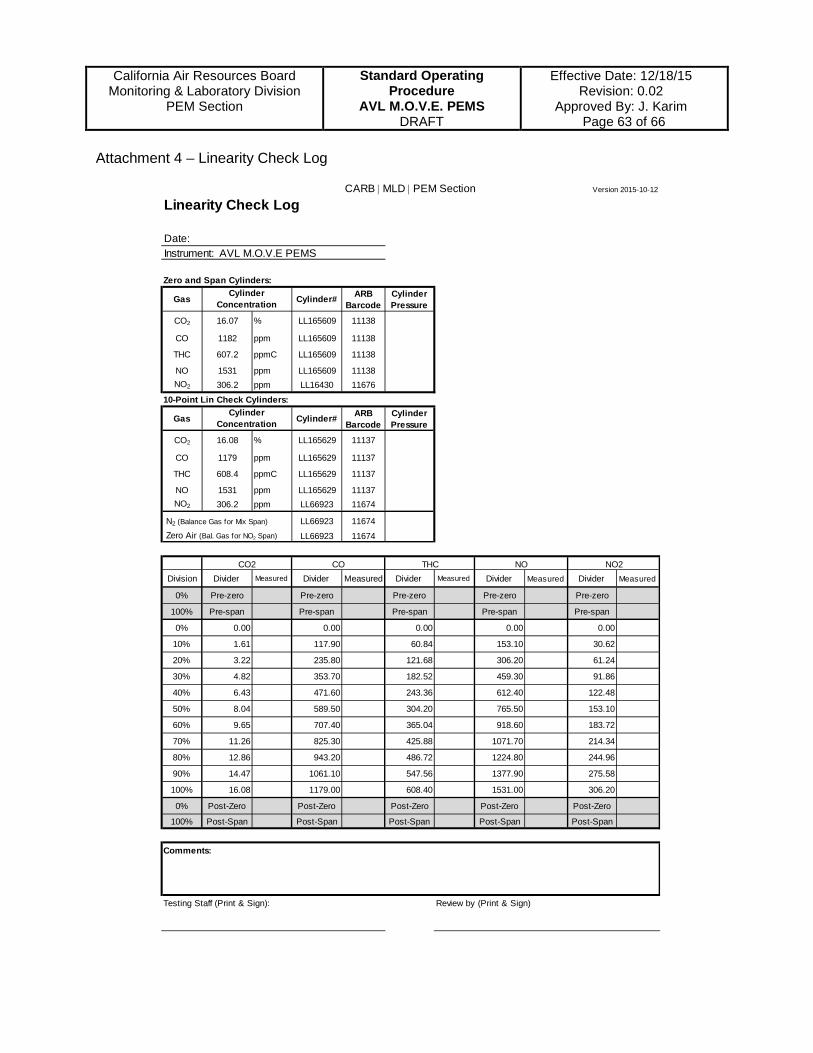
California Air Resources Board
Monitoring & Laboratory Division PEM Section
Standard Operating Procedure
AVL M.O.V.E. PEMS DRAFT
Effective Date: 12/18/15 Revision: 0.02
Approved By: J. Karim Page 63 of 66
Attachment 4 – Linearity Check Log
CARB | MLD | PEM Section Version 2015-10-12
Linearity Check Log
Date: Instrument: AVL M.O.V.E PEMS
Zero and Span Cylinders:
Gas Cylinder# ARB Barcode
Cylinder Pressure
CO2 16.07 % LL165609 11138
CO 1182 ppm LL165609 11138
THC 607.2 ppmC LL165609 11138
NO 1531 ppm LL165609 11138NO2 306.2 ppm LL16430 11676
10-Point Lin Check Cylinders:
Gas Cylinder# ARB Barcode
Cylinder Pressure
CO2 16.08 % LL165629 11137
CO 1179 ppm LL165629 11137
THC 608.4 ppmC LL165629 11137
NO 1531 ppm LL165629 11137NO2 306.2 ppm LL66923 11674
N2 (Balance Gas for Mix Span) LL66923 11674 Zero Air (Bal. Gas for NO2 Span) LL66923 11674
Division Divider Measured Divider Measured Divider Measured Divider Measured Divider Measured
0% Pre-zero Pre-zero Pre-zero Pre-zero Pre-zero
100% Pre-span Pre-span Pre-span Pre-span Pre-span
0% 0.00 0.00 0.00 0.00 0.00
10% 1.61 117.90 60.84 153.10 30.62
20% 3.22 235.80 121.68 306.20 61.24
30% 4.82 353.70 182.52 459.30 91.86
40% 6.43 471.60 243.36 612.40 122.48
50% 8.04 589.50 304.20 765.50 153.10
60% 9.65 707.40 365.04 918.60 183.72
70% 11.26 825.30 425.88 1071.70 214.34
80% 12.86 943.20 486.72 1224.80 244.96
90% 14.47 1061.10 547.56 1377.90 275.58
100% 16.08 1179.00 608.40 1531.00 306.20
0% Post-Zero Post-Zero Post-Zero Post-Zero Post-Zero
100% Post-Span Post-Span Post-Span Post-Span Post-Span
Comments:
Testing Staff (Print & Sign): Review by (Print & Sign)
Cylinder Concentration
Cylinder Concentration
CO2 CO THC NO NO2

California Air Resources Board
Monitoring & Laboratory Division PEM Section
Standard Operating Procedure
AVL M.O.V.E. PEMS DRAFT
Effective Date: 12/18/15 Revision: 0.02
Approved By: J. Karim Page 64 of 66
Attachment 5 – Linearity Check Template
Available as Excel file in: W:\Projects\Linearity Check form\TEMPLATES\AVL MOVE PEMS
Linearity Check ResultsTest Date: Tested by:Linearization testing was performed using procedures specified in CFR40 part 1065.307 with gas standards that are traceableto the National Institute of Standards (NIST). The PEMS listed below is in compliance with EPA regulations provided that emission testing is performed within 35 days from the test date listed on this document.
PEMS Model: AVL MOVE PEMS
Traceability of Gas Standards:Gas Bottle
DescriptionGas
Concentration Cylinder #ARB Barcode
#Cylinder
Pressure (psi)Stated
Accuracy (%)Expiration
Date:
CO2 (%) CO (ppm)THC (ppm)NO (ppm)
NO2 (ppm)
N2 (Balance Gas for Mix Span) ----- -----Zero Air (Balance Gas for NO2) ----- -----
CO2 (%) CO (ppm) THC (ppm) NO (ppm) NO2 (ppm)
RangeAbsolute error limitRelative error limit, % 4 4 4 4 4
CFR 1065.307 Required Linearity Test Criteria:
ǀ Xmin(a1-1)+a0 ǀ a1 SEE r2≤ 1 % · xmax 0.99-1.01 ≤ 1% · xmax ≥ 0.998
CFR 1065.307 Required Linearity Test Summary:
Gas Bottle Value (Xmax) ǀ Xmin(a1-1)+a0 ǀ a1 (slope) SEE r2 Pass/Fail
CO2 (%) Measured Criteria
CO (ppm) Measured Criteria
THC (ppm) Measured Criteria
NO (ppm) Measured Criteria
NO2 (ppm) Measured Criteria
Comments:
Testing Staff (Print & Sign): Review by (Print & Sign)
Matthew RodriquezSecretary for
Environmental Protection
Air Resources BoardMary D. Nichols, Chairman
9480 Telstar Avenue, Suite 4El Monte, California 91731 • www.arb.ca.gov Edmund G. Brown Jr.
Governor

California Air Resources Board
Monitoring & Laboratory Division PEM Section
Standard Operating Procedure
AVL M.O.V.E. PEMS DRAFT
Effective Date: 12/18/15 Revision: 0.02
Approved By: J. Karim Page 65 of 66
Attachment 6 – System Check Worksheet
CARB | MLD | PEM Section Version 2015-10-07
System Check
Date:Instrument: AVL M.O.V.E PEMS
Span checkCylinder Cylinder ARB Cylinder Expiration
Gas Conc. Units No Barcode # Pressure (psi) Date:CO2 %CO ppmTHC ppmNO ppm
PEMS Cylinder PEMS Absolute Percent Pass/FailGas Range Units Conc. Measured Difference Difference Absolute Relative,% CO2 % 2CO ppm 2THC ppm 2NO ppm 2
Comments
PEMS Staff (Print & Sign): Review by (Print & Sign)
PEMS Error limit

California Air Resources Board
Monitoring & Laboratory Division PEM Section
Standard Operating Procedure
AVL M.O.V.E. PEMS DRAFT
Effective Date: 12/18/15 Revision: 0.02
Approved By: J. Karim Page 66 of 66
Attachment 7 – Heavy Duty In-Use Compliance Testing Report
Monitoring and Laboratory Division Date:Portable Emissions Measurement Section Prepared by:
Approved by:
Heavy Duty In-Use Compliance Testing Report
General InformationProject # Engine FamilyVehicle Maker Engine Serial NumberVehicle Model Engine ModelVIN DPF Out Opacity (%)Mileage Date of Opacity TestECM Model ID ECM Software ID
Emission Exhaust Standard Information NTE informationSTD/FEL NTEstd NTEThreshold NTE duration (s)
NMHC (g/bhp-hr) NTE Avg.THC (g/bhp-hr)NOx (g/bhp-hr) NTE Avg.CO (g/bhp-hr)CO (g/bhp-hr) NTE Avg.NOx (g/bhp-hr)PM (g/bhp-hr) NTE Avg.PM (g/bhp-hr)
# of eventsOverall Emission Test Information minimum duration NTE events (s)On-Road Test Date maximum duration NTE event (s)Test # maximum emission THC (g/bhp-hr)Route maximum emission CO (g/bhp-hr)Driver maximum emission NOx (g/bhp-hr)PEMS Operator maximum emission PM (g/bhp-hr)Test Start Time Pass Ratio (If Pass Ratio ≥ 0.90, NTE test is "Pass")Test End Time Pass Ratio THCTest Duration(s) Pass Ratio COTotal Distance Traveled (mile) Pass Ratio NOxTotal Fuel Consumed (gal) Pass Ratio PMOverall Fuel Economy (mpg) Non-Idle Operation (hrs) 3 hrs min.
NTE Pass or Fail?
Comments: