World Leader in Rating Technology OFFSHORE RACING CONGRESS · 2008-12-26 · World Leader in Rating...
39
World Leader in Rating Technology OFFSHO RE RACING CONGRESS International Measure ment Syste m IMS 2009
Transcript of World Leader in Rating Technology OFFSHORE RACING CONGRESS · 2008-12-26 · World Leader in Rating...

1
World Leader in Rating Technology
OFFSHORE RACING CONGRESS
International Measure ment System
IMS 2009

2
Copyright © 2009 Offshore Racing Congress. All rights reserved. Reproduction in whole or in part is only with the permission of the Offshore Racing Congress. Cover picture: ORCi World Championship, Athens 2008 by courtesy Hellenic Offshore Racing Club Margin bars denote rule changes from 2008 version

1
IMS
RUL
E
O R C
World leader in Rating Technology
INTERNATIONAL MEASUREMENT SYSTEM
IMS
2009
Offshore Racing Congress, Ltd.
www.orc.org [email protected]

2
IMS
RUL
E CONTENTS Part A – ADMINISTRATION
A1 Language ........................................................... 3 A2 Abbreviations and Definitions .......................... 3 A3 Authorities ......................................................... 3 A4 ISAF Rules ........................................................ 3 A5 Rules Amendments ........................................ 4 A6 Rules Interpretations ......................................... 4 A7 Measurement ..................................................... 4 Part B – HULL
B1 General .............................................................. 5 B2 Measurement Procedure .................................... 5 B3 Hull Measurements ............................................ 7 B4 Hull Offset File .................................................. 7 B5 Other Hull Measurements .................................. 7 Part C – APPENDAGES
C1 Centerboard ....................................................... 9 C2 Canting Keel ..................................................... 9 C3 Bilge Boards ...................................................... 9 C4 Trim Tabs .......................................................... 9 C5 Dynamic Stability System ................................. 9 Part D – PROPELLER
D1 General ............................................................ 10 D2 Propeller Types ................................................ 10 D3 Propeller Installations ...................................... 10 D4 Propeller Measurements .................................. 10 Part E – STABILITY
E1 General ............................................................ 13 E2 Measurement Trim .......................................... 13 E3 Freeboards ....................................................... 14 E4 Inclining Test ................................................... 14 E5 Water Ballast ................................................... 15 E6 Canting Keel .................................................... 15 Part F – RIG
F1 General ............................................................ 16 F2 Mainsail Hoist ................................................. 16 F3 Mast Heights .................................................... 16 F4 Mast Spar Dimensions ..................................... 16 F5 Boom Spar Dimensions ................................... 17 F6 Rigging measurements ..................................... 17 F7 Spinnaker Pole and Bowsprit ........................... 17 F8 Rig Weight and Centre of Gravity ................... 18 F9 Other Rig Measurements ................................. 18 F10 Mizzen Rig Measurements .............................. 19
Part G – SAILS
G1 General ............................................................ 20 G2 Mainsail ........................................................... 20 G3 Mizzen ............................................................. 20 G4 Jib/Genoa (Including Inner jib) ....................... 20 G5 Mizzen Staysail ............................................... 21 G6 Spinnakers ....................................................... 21 G7 Sail Measurement Stamp ................................. 21 Part H – HEAVY ITEMS
H1 General ............................................................ 23 H2 Anchor & Chain .............................................. 23 H3 Other Heavy Items .......................................... 23
APPENDIX 1 – ACCOMMODATION REGULATIONS
Part 1 – GENERAL
Introduction ..................................................... 24 101 Divisions ......................................................... 24 102 Fundamental Requirements and Definitions ... 24 Part 2 – RACING DIVISION
201 Accomodation Length ..................................... 25 202 Interior Volume ............................................... 25 203 Cabin Sole ....................................................... 26 204 Berths ............................................................... 26 205 Personal Gear Stowage .................................... 26 206 Galley .............................................................. 26 207 Head Compartment .......................................... 27 208 Navigation Table ............................................. 27 209 Hanging Locker(s) .......................................... 27 210 Fresh Water Capacity ...................................... 27 211 Fuel Capacity ................................................... 27 Part 3 – CRUISER/RACER DIVISION
301 Accomodation Length ..................................... 27 302 Interior Volume ............................................... 27 303 Cabin Sole ........................................................ 28 304 Bulkhead, Partition and Panel Construction .... 28 305 Accommodation Areas .................................... 29 306 Living Area ...................................................... 29 307 Sleeping Area ................................................... 29 308 Galley Area ...................................................... 30 309 Head Compartment .......................................... 30 310 Navigation Area ............................................... 31 311 Hanging Locker(s) ........................................... 31 312 Main Hatch/Companionway ............................ 31 313 Cockpit ............................................................ 31 314 Fresh Water Capacity ...................................... 32 315 Fuel Capacity ................................................... 32 316 Scoring Variable Elements .............................. 32 317 Calculation of Accomodation Rating .............. 32
Table of Accomodations ............................................. 34
Index of Symbols ........................................................ 37

3
IMS
RUL
E Part A - ADMINISTRATION A1 Language
A1.1 The official language of the IMS is English and in case of dispute over translations the English text shall prevail.
A1.2 The word "shall" is mandatory and the word "may" is permissive. A2 Abbreviations and Definitions
A2.1 IMS International Measurement System ORC Offshore Racing Congress ISAF International Sailing Federation ERS Equipment Rules of Sailing RRS Racing Rules of Sailing
A2.2 Age Date
a) Age Date shall be the month and year of the first launching when the boat was completed and equipped for sailing. Age Date may be taken either from the owner’s documentary evidence or as month and date of the first measurement afloat.
b) Age Date shall be changed and new measurement shall be required after any hull modifications except:
- change outside the canoe body, defined as the hull surface of the yacht, including transom, continued to the centerline tangentially from the point of final inflection into the keel and skeg
- fairing of new appendages - removal of bumps outside the canoe body outer skin - filling of hollows (e.g., in the IOR after girth area) - forward or aft extensions or reductions of the fair surface of the hull, limited to modifications
only within 0.10*LOA of the forward and/or aft end(s) of LOA
The total of modifications to the canoe body surface shall not exceed 20% of the total surface prior to modification.
A2.3 Series Date shall be the Age Date of the earliest boat of an unmodified series built in the production moulds or jigs.
A2.4 Flotation Date shall be the date when the most recent measurement afloat was completed.
A2.5 Measurement Date shall be the date when the most recent measurement was completed. A3 Authorities
The sole authority for the IMS is the Offshore Racing Congress and it shall be maintained and administered at the ORC's discretion.
A4 ISAF Rules
A4.1 These class rules shall be read in conjunction with the ERS.
A4.2 Except where used in headings, when a term is printed in “bold” the definition in the ERS applies and when a term is printed in “italics” the definition in the RRS applies.
A4.3 When printed in "bold italics" the term is used as measurement taken or recorded by the measurer.
A4.4 RRS 50.4 is not applying.

4
IMS
RUL
E
A5 Rules Amendments
Amendments to the ORC International are subject to the submission by the ORC Nominating bodies and approval of the ORC in accordance with the Articles of Association of ORC Ltd.
A6 Rules Interpretations
The ORC Chief Measurer may at any time issue interpretations or correction of the ORC rules and regulations. Any such interpretation or correction shall be published and then deemed final unless and until overruled by the ORC Management Committee and Congress.
A7 Measurement
A7.1 The term “measurement” shall be taken to include also identification as to type, category, number, material, construction, etc. as may be determined by examination or declaration.
A7.2 Measurements shall be taken from the yacht wherever practicable but where this is unduly difficult the Chief Measurer may approve the use of plans or other such sources of information as he considers reliable.
A7.3 Measurers shall be appointed by the ORC or, with the approval of the ORC, by the Rating Authority. A Measurer shall not measure a yacht of another Rating Authority without the permission of that Authority. No Measurer, assistant, nor Rating Office staff shall participate in the measurement or processing of measurements of a yacht owned, designed or built, wholly or partly, by himself or in which he is an interested party, or in which he has acted as a consultant or has a vested interest. Except for reasonable and brief clarification of points in the Rules, this applies to any consultation or advice on rating values regardless of whether or not any payment is involved.
A7.4 Measurements, unless otherwise specified, shall be taken and recorded to the nearest greater value as follows:
a) Metric system: All measurements shall be in meters to three decimal places except that sail measurements shall be to two places of decimals. Weights shall be in kilograms to one decimal place.
b) Imperial system: All measurements shall be in feet to two decimal places except that sail measurements shall be to one decimal place. Weights shall be in pounds.
A7.5 In case of doubt in any measurement taken or recorded or any procedure, the measurer shall refer his questions, together with the relevant facts, to the ORC Chief Measurer and shall be bound by his interpretation.
A7.6 Boats measured under the IMS Rule before 01/01/2008 shall comply with the rules applicable at the time of measurement.
5
IMS
RUL
E Part B - HULL B1 General
B1.1 Hull shall be monohull only. Canoe body depth in any section shall not decrease towards the center line.
B1.2 A hull measurement shall be performed to create an OFF file describing the lines of the hull together with appendages by using an ORC approved hull measurement machine or any available measurement instrument capable to produce a list of the points in the co-ordinate system as defined herein and detailed in the "ORC OFF File Format" document.
B1.3 The co-ordinate system defining the hull shall be positioned as follows:
a) X axis – longitudinal with 0 at stem and positive towards the stern b) Y axis – transverse with 0 at the centerline and positive towards the beam c) Z axis – vertical with 0 at the waterline and positive upwards
B2 Measurement Procedure
B2.1 The yacht shall be presented for measurement ashore in an accessible location, clear of obstructions, properly and firmly chocked and leveled athwartships and approximately in the same longitudinal trim which it might reasonably be expected to assume when afloat in measurement trim. A centerboard, if any, shall be in its maximum raised position. A centerboard that can be locked to prevent movement while racing, shall be in its locked position and measured as a keel. Rigging shall be slack. All appendages shall be fitted and any fairings shall be in place.
B2.2 Station points shall be taken starting from deepest point to the sheerline at stations from stem to stern as follows:
a) Approximately 20 stations shall be taken from each side spaced with maximum distance of 5% LOA. Within the forward 15% of LOA the spacing between stations shall not be greater than 2.5% of LOA.
b) The forward freeboard station shall normally be placed approximately 0.5 m from the stem.
c) The aft freeboard station shall normally be placed at the aftermost section at which the hull could be girthed without crossing the transom.
d) Stations shall be taken also at the edges of any appendage, at the maximum draft and at any significant change of appendage profile in longitudinal direction.
e) Freeboards stations and at least one midship section shall be taken from both sides at the same distance from the bow.
B2.3 The sheer point at any measurement station shall be defined by the following rules:
a) The sheer point shall normally be the lowest point on the topsides of the hull where a tangent at 45 degrees can be rested on the hull. The sheer point shall not, however, be taken to any point that is above the lowest level of the deck, or its extension where it intersects the topsides at that station. Where any bulwark or rubbing strake is fastened to the yacht, it shall be ignored in determining the sheer point.
b) Where any bulwark is a fair continuation of the line of the topsides of the yacht the sheer point shall be taken on the hull surface at the level of the lowest level of the deck at the station projected through the bulwark.
c) Where the sheer point at any measurement station, as defined above in a) or b), is more than 0.05 * MB inboard of a vertical tangent to the hull at that station, the sheer point at that station will be at the point on the hull a distance of 0.05 * MB inboard from the vertical tangent to the hull.
d) A bulwark shall be interpreted to mean any rail or part of the topsides extending above the lowest level of the deck at that station.

6
IMS
RUL
E
The level of the deck at any transverse station shall be taken to be the lowest level to which the yacht is rendered watertight at that station. Abreast a well or cockpit the sheer point shall be taken to the bulwark provided that this bulwark is in all respects a fair continuation of the hull surface. The sheer line on the bulwark shall be a fair continuation of the sheer line forward and/or aft of a well or cockpit. The edge of the working deck is defined as the most outboard point on the deck at the sheerline.
Various sheer points
Deck Bulwark
Frame
Deck beam
Coveringboard
Topsideplanking
*
“A”
Bulwark
Steel platein lieu of shelf
Wood deck
“B”
*
DeckBulwarkRounded
“C”
*
45º to horizontal
Flatter than 45º
“D”
Deck
*
Steeperthan 45º
45º tohorizontal
Deck
“E”
*
Deck
“F”
*
45º tohorizontal
“G”
*Less than 5% MB
45º
Deck
“H”
*
fair line
“I”
*fair line
5% MB
at 45ºPoint
to horizontal
“J”
*
Deck
fair line
“K”
45º tohorizontal
*
“L”
*

7
IMS
RUL
E
B2.4 If the sheer points on the freeboard stations can not be taken, they may be selected on different points in which case vertical distances shall be recorded in the hull offset file as:
FFPV shall be the vertical distance from the level of the sheer points in the forward freeboard station to the level of the freeboard points.
AFPV shall be the vertical distance from the level of the sheer points in the aft freeboard station to the level of the freeboard points.
B3 Hull Measurements
B3.1 LOA shall be the length overall of a yacht including the whole hull, excluding any spars or projections fixed to the hull such as chainplates, bowsprits, boomkins, pulpits, etc., and as measured between
a) a point forward being the forwardmost of the following points: i) the stem of the yacht, whether carried above the deck level or not, or ii) the bulwarks of the yacht where these are extended above the stem.
b) a point aft, being the extreme after end of the hull and bulwarks or taffrail of the yacht whether at, above, or below deck level. Rubbing strakes at the stern will be included. If a rudder and/or a push-pit extend abaft this point, neither one nor the other will be included.
B3.2 SFFP shall be the horizontal distance from the forward end of LOA to the forward freeboard station.
B3.3 SAFP shall be the horizontal distance from the forward end of LOA to the aft freeboard station.
B3.4 MB shall be the maximum beam.
B3.5 SMB shall be the horizontal distance from the forward end of LOA to the maximum beam station. B4 Hull Offset File
B4.1 Once a hull is completely measured, an OFF file shall be generated using ORC-approved software by the Rating Authority or if needed by the ORC Chief Measurer. Where a number of hulls of the same model are built using the same moulds for hull, keel and rudder, a standard OFF file for that model will be created and no hull measurement will be needed for other boats built from the same mould.
B4.2 Any change of the hull, keel or rudder of a model with existing OFF file shall be re-measured again and a new OFF file shall be created. In case of minor changes new measurements may be taken directly on changed parts by taking new dimensions comparing with existing point co-ordinates and changing them to the new values. Any larger changes shall be re-measured using the same method as on the original model.
B5 Other Hull Measurements
B5.1 Hull construction shall be recorded as one of the following:
a) SOLID: Non-cored, solid E-glass, metal or wood hull and deck, but including also E-glass decks with core material. Where the construction is of wood, the minimum density of any layer shall not be less than 300 kg/m3.
b) CORED: Hull skin of E-glass (see above) or wood, but incorporating a core material of less density than the skin.
c) LIGHT: All other construction types, but excluding the incorporation of any carbon fiber.
d) CARBON: Where carbon fiber has been incorporated anywhere in the construction of the hull and/or deck
For hull and deck construction, a declaration from the owner may be substituted for examination of one or more elements, but all elements are subject to examination at any time in cases of doubt.

8
IMS
RUL
E
B5.2 Honeycomb core In addition to recording the appropriate construction type as above, if a honeycomb core has been incorporated in hull or deck construction, this shall also be recorded as "YES" or "NO".
B5.3 Rudder construction shall be classified as one of the following:
a) STANDARD: Neither rudder nor rudder post contain any carbon fiber.
b) CARBON: Rudder and/or rudder post contain carbon fiber in any amount.
B5.4 Forward Accommodation When the bow forward of the mast is fully fitted out as a separate sleeping or living space built of solid construction, including bunks (pipe berths do not qualify), personal gear stowage, etc., this shall be recorded as "YES" or "NO".

9
IMS
RUL
E Part C - APPENDAGES C1 Centerboard
C1.1 In addition to the hull measurement, a centerboard or drop keel measurement shall be taken as follows:
C1.2 ECM shall be the vertical distance from the lowest point of the hull or fixed keel, whichever is deeper, to the lowest point of the centerboard in its fully lowered position. In the case of tandem centerline centerboards, ECM shall be taken for the centerboard that produces the greatest effective centerboard extension.
C1.3 KCDA shall be the vertical distance from the lowest point of the hull or fixed keel, whichever is deeper to a point directly above the point of maximum thickness of the centerboard in its fully lowered position on a buttock line on the keel or hull offset 2.5 times the maximum thickness of the centerboard from the centerline.
C1.4 WCBA shall be the weight of the centerboard or drop keel in air. Where there is more than one board the weight of the additional board shall be recorded as WCBB.
C1.5 CBDA shall be the vertical distance through which the center of gravity of the centerboard or drop keel can be lowered. When there is more than one board the figure for the additional board shall be recorded as CBDB.
C1.6 Three centerboard chords shall be measured horizontally with the centerboard in the same position as that in which ECM was determined as follows:
a) CBRC shall be the centerboard root chord taken at the upper measurement point of ECM.
b) CBMC shall be the centerboard mid chord taken at 0.50 * ECM below the upper measurement point of ECM.
c) CBTC shall be the centerboard tip chord taken at 0.85 * ECM below the upper measurement point of ECM.
C2 Canting Keel
Canting keel measurement is defined under Part 5 – Stability. C3 Bilge Boards
The location and vertical extension of the bilge boards shall be taken as part of the machine hull machine measurement procedure (Part 3) and their draft determined from the OFF file at various angles of heel.
C4 Trim Tabs
The presence of a movable trim tab shall be recorded. C5 Dynamic Stability System (DSS)
C5.1 DSSS shall be the span of the extended wing measured along the curvature (if any curvature is present).
C5.2 DSSC shall be the maximum chord length.
C5.3 DSST shall be the maximum thickness.
C5.4 DSSA shall be the angle of the wing with the horizontal axis (if the wing is curved the angle will be measured with a line connecting root chord to tip chord).
C5.5 DSSD shall be the distance of the root chord from the centerline of the boat.

10
IMS
RUL
E Part D - PROPELLER D1 General
D1.1 Speed under power with propeller in smooth water and without assistance of wind of shall not be less than 1.811 * LOA ^0.5 where LOA is in meters (LOA^0.5 where LOA is in feet).
D1.2 The propeller shall at all times be ready for use and shall not be retracted, housed or shielded except by a conventional strut or aperture.
D1.3 The propeller shaft exposed to water flow shall be circular in cross section.
D1.4 If any of the requirements from the D1.1, 2 or 3 or are not met, this shall be recorded as "NO PROPELLER".
D2 Propeller Types
D2.1 Solid Propeller shall be a standard model in series production, unaltered, having a minimum of two fixed blades of normal elliptical shape and a maximum width of not less than 0.25 * PRD measured across the driving face of the blade on a chord at right angles to the radius of the blade. Pitch shall not be greater than the propeller diameter. Hub and blade area projected into a plane at right angles to the shaft line shall not be less than 0.2 * PRD^2.
D2.2 Folding Propeller shall be a standard model in series production, unaltered, having a minimum of two blades that fold together pivoting on an axis at right angles to the shaft line when not being used for propulsion or any other propeller not qualifying as a solid propeller.
D2.3 Feathering Propeller shall be a standard model in series production, unaltered, having a minimum of two blades that pivot so as to substantially increase pitch when not being used for propulsion.
D3 Propeller Installations
D3.1 In Aperture installation shall be with solid or three-bladed propeller entirely surrounded in the vertical plane of the shaft line by the keel, skeg, and/or rudder.
D3.2 Strut Drive. The drive train shall be enclosed in a strut and the unit incorporating drive train and strut shall be of a standard model in series production. The surface and shape of the unit may be faired (e.g., with fillers) provided that its function is in no way impaired and none of the dimensions required for measurement of the unit are reduced relative to those as manufactured. For qualified units, where ORC standard dimensions are provided, they shall be used in place of measurements.
D3.3 Housed shaft installation shall be the strut in the form of a molded housing, integral with the hull, enclosing essentially the full length of the shaft as well as the void between the shaft and the hull.
D3.4 Out of Aperture. All other propeller installations. D4 Propeller Measurements
D4.1 PRD shall be the diameter of the propeller disc.
D4.2 PHD shall be the smallest dimension through the shaft centerline of the projected area of the propeller hub.
D4.3 PHL shall be the distance from the shaft end of the propeller hub to the intersection of the blade axis and shaft.
D4.4 PBW shall be the propeller blade width measured across the driving face of the blade on a chord at right angles to the radius of the blade.
11
IMS
RUL
E
D4.5 PSA shall be the angle between the centerline of the propeller shaft and a tangent to a hull buttock line 0.15 m (0.5 ft) off the hull centerline midway between the axis of the propeller blades and the point where the propeller shaft emerges from the hull. This angle approximates the angle between the propeller installation's shaft axis and the water flow past it. Any unfairness or reverse inflection shall be bridged to yield a fair approximation of the slope of the hull body in way of the propeller shaft.
D4.6 PSD shall be the minimum propeller shaft diameter exposed to water flow including that part of the shaft within the strut hub.
D4.7 ESL shall be the length of the exposed shaft measured from the center of the propeller (the intersection of the blade axis and shaft) to the point at which the shaft center line emerges from the hull or appendage. For a boat with a Series Dates 1/1985 or later, ESL shall be the lesser of ESL as defined above or the length of the line 8.0*PSD below the shaft axis and parallel to it measured from the blade axis to the fair line of the aft edge of the keel. If the shaft is not supported by a strut, positioned adjacent to the propeller hub, ESL shall be recorded as zero.
D4.8 EDL shall be the distance, measured along and in prolongation of the propeller shaft, from the center of the propeller to the aft edge of any other strut or fin (except the rudder blade) forward of the propeller.
D4.9 ST1 shall be the minimum projected thickness of the strut at any point between the hull and the shaft.
D4.10 ST2 shall be the minimum width of the strut, (including the strut hub) measured parallel to the shaft.
D4.11 ST3 shall be the maximum width of the strut, measured parallel to the shaft, not above a line 0.3 * PRD above the shaft centerline.
D4.12 ST4 shall be the smallest dimension through the shaft centerline of the projected area of the strut hub within ST2 of the aft end of the strut hub.
D4.13 ST5 shall be the distance, measured perpendicular to the propeller shaft at the forward end of ST2, from the centerline of the shaft to the hull or fair continuation of the hull.
D4.14 If any of ST1 – ST4 measurements for the strut drive installation has been increased by the fairing of the standard production unit, ST1 – ST4 shall be recorded as manufactured.
D4.15 APH shall be the maximum height of the aperture opening measured at right angles to the shaft line.
D4.16 APT and APB shall be the maximum widths of the aperture opening measured parallel to the shaft line at distances not less than PRD / 3.0 above and below the shaft line.
D4.17 For each of the propeller installation types following measurements shall be taken:
a) In Aperture: PRD, APH, APT, APB
b) Out of aperture: PRD, PHD, PHL, PSA, PSD, ESL, ST1, ST2, ST3, ST4, ST5
c) Housed shaft: PRD, PHD, PHL, PSA, PSD, ESL, ST1, ST2, ST3, ST4, ST5
d) Strut Drive: PRD, EDL, ST1, ST2, ST3, ST4, ST5
D4.18 The presence of twin propellers shall be recorded.

12
IMS
RUL
E
Propeller Installation Measurement
Out of Aperture -- 605
Strut Drive -- 607
0.3 x PRD
ST3*
ST2
ST1
ST4
EDL
ST5**
PRD
PRD/3
PRD/3
APT
APB
APT and APB are the maximum aperture widthsmeasured parallel to the propeller shaft, found notless than PRD/3 above and below the shaft centerline.
In Aperture -- 606
APH
Buttock line 0.15m ( 0.50') off hull centerline
*ST3 is the maximum strut widthmeasured parallel to the propellershaft found not more than 0.3 x PRDabove the shaft centerline.
**ST5 is measured perpendicular to theshaft centerline from the hull to the shaftcenterline at the forward end of ST2.
***PSA (Propeller Shaft Angle) may be measured in two steps:
1. Angle between shaft centerline and level datum line 2. Angle between buttock tangent line and level datum line
Add angles to arrive at PSA.
Line tangent to 0.15m buttock ata point halfway along ESL(1)
Trailing edge of keel
ST1
ST4
PHD PRD
PHL
ST3*
ST2
ESL = the lesser of ESL(1) or ESL(2)
ST5**
PSD
PSA***
ESL (1)
ESL (2)
8.0 x PSD0.3 x PRD
13
IMS
RUL
E Part E - STABILITY E1 General
E1.1 Freeboards and inclining test measurement shall be performed in calm water with the boat not depressed from any side through lying to a mooring and with no one aboard in the measurement trim.
E1.2 For the inclining test, a manometer as a "water scale" or an ORC-approved electronic inclinometer shall be used.
E2 Measurement Trim
E2.1 The owner or his representative shall put the yacht in measurement trim by following the procedure defined below. No substitutions are permitted during measurement afloat:
a) All sails shall be removed from the yacht.
b) Ballast shall be fixed below the cabin sole, or as low as possible at any station and fixed to the hull structure to prevent movement. Anchors and chain shall be secured in clearly marked stowage. The batteries shall be secured in their proper stowage.
c) Heads, bowls, sinks shall be dry.
d) Bilges and other areas where water may collect shall be dry. There must be no effort to artificially moisten decks, rig, equipment or gear.
e) All tanks shall be empty, except the fuel tank which can be as empty as possible (recommended) or full with condition recorded as per E2.2(g). If the fuel tank was full, freeboard measurements shall be adjusted reflecting the “sink” effect on Measurement trim resulting from the weight and position of the fuel aboard.
f) Voids in the keel or any other appendage shall be declared and shall be treated as tankage.
g) Navigational and cooking equipment shall be aboard.
h) No clothing, bedding, food or stores shall be aboard.
i) All mattresses, cushions, and pillows must be aboard during measurement and shall be stowed in their normal bunks.
j) All portable gear normally stowed forward shall be placed abaft the foremost mast on the cabin sole.
k) Safety gear shall be stowed in normal position, but not forward of the mast.
l) No life raft or dinghy shall be on board.
m) Centerboard(s) and drop keels shall be fully raised. If any drop keel or movable appendage is to be locked when racing it shall be so locked and the locking device shall be in place.
o) One set of sheets and guys and any running rigging not carried permanently on spars and other portable deck gear used in racing the yacht shall be stowed abaft the mast on the cabin sole.
p) All standing rigging and related fittings used whilst racing shall be attached in their normal positions. Running rigging forward of the mast and all halyards and lifts shall be taken to the foot of the mast and hauled tight. All other pieces of running rigging abaft the mast shall be taken to their aftermost position and hauled tight. All halyard tails shall be taken to their normal working positions. If the halyard weight varies significantly along its length, the tail shall be on the cabin floor for the inclining experiment, with the halyard fully hoisted and attached to a light messenger line. A halyard may be used as a topping lift.
q) Masts shall be raked aft to the limit of their adjustment. Where this limit is forward of the vertical the mast shall be set vertical.
r) Booms shall be secured at the low points of P and PY, as the case may be.

14
IMS
RUL
E
s) No spinnaker pole shall be aboard while measuring freeboards.
t) Hydraulic systems including hydraulic tanks shall be full for measurement and shall remain full when racing.
u) If an outboard motor, where it is the yacht's engine, is to be carried when racing it shall be provided with a proper locker and/or mounting bracket. It shall be in this stowage at the time of measurement and at all times when racing. This stowage shall not be such that the center of gravity of the motor is forward of the foremost mast.
E2.2 Measurement inventory shall be recorded as follows:
a) Interior Ballast: description, weight, distance from stem b) Anchor: weight, distance from stem c) Anchor chain: weight, distance from stem d) Batteries: description, weight, distance from stem e) Tools: weight, distance from stem f) Engine: manufacturer, model g) Tanks: Use, type, capacity, distance from stem, condition at measurement h) Items normally forward but placed abaft the mast for measurement: weight i) Deck equipment placed abaft the mast: weight j) Miscellaneous: description, weight, distance from stem
E3 Freeboards
E3.1 FFM shall be the average of port and starboard freeboards measured vertically from the sheer point to the water level at the section at SFFP from stem.
E3.2 FAM shall be the average of port and starboard freeboards measured vertically from the sheer point to the water level at the section at SAFP from stem.
E3.3 SG shall be the specific gravity of the water sampled from a level 0.3 m below the surface.
E4 Inclining Test
E4.1 The inclining test shall be performed as follows:
a) The boat shall be in measurement trim as defined in E2.
b) Two poles shall simultaneously be positioned port and starboard at the MB station (SMB from the stem) and suspended outboard to provide arms for supporting inclining weights. The poles shall be arranged normal to the boat’s centerline and as nearly horizontal as is possible but allowing sufficient clearance to prevent the weights from touching the water. The poles shall be approximately SPL in length and the yacht's pole or poles shall normally be used when available. If a yacht's pole is not used it shall not be on board.
c) Either a manometer shall be positioned athwart the yacht where it can be read by the measurer or ORC-approved electronic inclinometer shall be placed on the deck.
d) When the poles are rigged and all the weights suspended on the starboard side the datum on the manometer shall be marked. Where an electronic inclinometer is used, the datum position may be recorded four times in succession.
e) If the manometer is used the weights shall be transferred one by one to the port side, weight transferred and manometer reading shall be recorded. As an alternative or when an electronic inclinometer is used, all weights may be transferred at once to the port side, and the resulting angle recorded four times in succession.
f) All the weights shall be suspended on the starboard side once again and the datum on the manometer verified.
15
IMS
RUL
E
E4.2 PLM shall be the length of the manometer from the center line of the fluid reservoir to the centerline of the gauge cylinder recorded in millimeters to one decimal place and shall not be less than 2000.0 mm.
E4.3 GSA shall be the surface area of the manometer gauge in square millimeters.
E4.4 RSA shall be the surface area of the fluid reservoir in square millimeters.
E4.5 When an electronic inclinometer is used PLM shall be recorded as 9000, GSA and RSA as 1.0.
E4.6 WD shall be the horizontal distance from the point of attachment of the starboard weight to the point of attachment of the port weight with the weights distributed equally on the two pole ends. The weights shall be attached so that the weight distance is constant for all tests. The weight distance shall be of the order of MB +2.0 * SPL.
E4.7 W1 ... W4 shall be the total weight suspended from the port pole for each reading of the manometer. They shall be of suitable magnitude to ensure that the largest PD is within:
a) +/- 0.01 * PL of 0.105 * PL for yachts with LOA > 12.5 m b) +/- 0.01* PL of 0.125 * PL for yachts with LOA <= 12.5 m
and the intermediate values are approximately equally spread over the range.
E4.8 PD1 ... PD4 shall be the deflections on the manometer gauge after each weight of the set has been moved, from the datum established in E4.1(d).
E5 Water Ballast
E5.1 WBV shall be the water ballast volume in litres (gallons in imperial units).
E5.2 The inclining test for a yacht equipped with water ballast tanks symmetrical about the yacht’s centerline shall be performed as follows:
a) The inclining test shall be made with ballast tanks empty according to E4.
b) The ballast tank(s) on the starboard side of the yacht shall then be filled pressed up and the resulting angle of list recorded.
c) The port ballast tank(s) shall then also be filled, pressed up and an inclining test shall be repeated with all ballast tanks full.
a) The starboard ballast tank(s) shall then be emptied and the resulting list angle recorded.
E5.3 Measurements recorded for the inclining test with all ballast tanks full shall be the same as in E4 except that the corresponding data field names will include the suffix "W".
E5.4 LIST shall be the average of the port and starboard list angles to the nearest tenth of a degree. If the port and starboard list angles are not approximately equal, the yacht may be deemed not to comply with the provision above for symmetric ballast tankage.
E6 Canting Keel
E6.1 The inclining test for a yacht equipped with a canting keel with symmetric maximum cant angles port and starboard shall be performed as follows:
a) The inclining test shall be made with the canting keel on centerline according to E4.
b) The keel shall then be canted fully to starboard to the maximum angle or to the angle limited by the locking device above which canting keel shall not be canted while racing. The resulting list angle shall be recorded and the angle of the keel relative to the yacht's centerplane also recorded. These measurements shall be repeated and recorded with the keel canted fully to port.
E6.2 LIST shall be the average of the port and starboard list angles to the nearest tenth of a degree. If the port and starboard list angles are not approximately equal, the yacht may be deemed not to comply with the provision above for symmetric cant angles.
E6.3 CANT shall be the average of the port and starboard cant angles.

16
IMS
RUL
E Part F - RIG F1 General
F1.1 Spars shall not be permanently bent. A spar that will straighten when stresses imposed by the rigging are removed does not constitute a permanently bent spar.
F1.2 Masts shall not be rotating. Masts shall be structurally continuous (non-articulating) from the masthead to the step. Masts that are not stepped on the keel shall not be pivoted fore or aft while racing.
F1.3 Boats shall be fitted with a bona-fide forestay. Forestay and shrouds shall be connected by conventional turnbuckles, toggles or link-plates. The mast may be steadied to balance an untensioned backstay only by use of a headsail halyard and its proper winch. A device for measuring jibstay tension is permitted provided that it is incapable of adjusting the stay and has a possible movement of no more than 5mm.
F1.4 The rig shall be measured according to the ERS except otherwise prescribed by the IMS, in which case IMS shall prevail.
F1.5 The following amendments to the ERS shall apply:
a) Mast datum point shall be the intersection of the forward side of the mast, extended as necessary, and horizontal plane at the sheerline abreast the mast.
b) Rigging point shall be the attachment of the forestay to the mast structure, or the intersection of the center line of the forestay with the foreside of the mast where the point of attachment is internal.
c) Upper point of the mast shall be the lowest point of the upper limit mark at the aft edge of the mast or top of the highest sheave used for the main halyard.
d) Outer point of the boom shall be the point on the boom's outer limit mark at the upper edge, nearest the fore end of the boom or the aftermost position to which the sail can possibly extend.
F2 Mainsail Hoist
F2.1 P shall be the distance along the afterside of the mainmast between lower point and upper point.
F2.2 If a sliding gooseneck is used the lower limit mark shall be placed at the height below which the foot shall not be while racing.
F3 Mast Heights
F3.1 IG shall be the forestay height.
F3.2 ISP shall be the spinnaker hoist height.
F3.3 SPS shall be the vertical distance from the mast datum point to the point on the mast intersected by the centerline of the spinnaker pole when set at the highest point on its track or to the lowest point of a painted measurement mark on the mast in which case the pole shall not be attached to the mast above that point while racing.
F3.4 BAS shall be the vertical distance between mast datum point and lower point on the mast.
F4 Mast Spar Dimensions
F4.1 MDT1 shall be the maximum transverse mast spar cross section above 0.5*P from the lower point.
F4.2 MDL1 shall be the maximum fore-and-aft mast spar cross section above 0.5*P from the lower point.

17
IMS
RUL
E
F4.3 MDT2 shall be the minimum transverse mast spar cross section below the upper point.
F4.4 MDL2 shall be the minimum fore-and-aft mast spar cross section below the upper point.
F4.5 TL shall be the vertical distance from the highest point at which MDT1 or MDL1 occurs, whichever is lower, to the upper point.
F4.6 MW shall be the minimum fore-and-aft mast spar cross section below the rigging point and above the lowest spreader.
F4.7 GO shall be the horizontal distance from the rigging point to the after side of the mast or vertical projection of the after side of the mast.
F5 Boom Spar Dimensions
F5.1 E shall be the outer point distance.
F5.2 BD shall be the maximum vertical boom spar cross section.
F5.3 BAL shall be the distance from the point on the boom outer limit mark at the upper edge of the boom, nearest the aft end of the boom to a contrasting measurement band denoting the limit on the boom beyond which no lead for the sheeting of jib/genoa or spinnaker shall be attached. In the absence of such a band BAL shall be measured to the boom end.
F5.4 BWT shall be the boom weight.
F6 Rigging Measurements
F6.1 J shall be the foretriangle base. Where there is the capacity for the mast to be moved at the deck, J shall be measured with the mast at the aftermost limit of adjustment unless a 1 in. (25mm) contrasting measurement band is provided. In this case J shall be measured to the aft edge of the band and the forward face of the mast shall not move aft of this point.
F6.2 SFJ shall be the horizontal distance from the forward end of J to the forward end of LOA (negative if the forward end of J is ahead of the forward end of LOA).
F6.3 CPW shall be the distance between the centers of the bearing points of the chainplates for the upper shrouds of the mainmast.
F6.4 FSP shall be the larger of either:
a) twice the maximum dimension, measured at right angles to the longitudinal axis, of a luff groove device; or
b) the largest dimension of the doubled portion of a wrap-around jib measured at right angles to the luff line when opened out.
F7 Spinnaker Pole and Bowsprit
F7.1 SPL shall be the length of the spinnaker pole when forced outboard in its fitting on the mast and set in a horizontal position athwartships, measured from the center line of the yacht to the extreme outboard end of the pole and any fittings used when a spinnaker is set.
F7.2 TPS shall be the horizontal distance from the foreside of the mast at its lowest point above the deck or coach roof to the point of attachment at deck level of the foremost tacking point of an asymmetric spinnaker or to the extreme forward end of any bowsprit in its maximum extended position.

18
IMS
RUL
E
F8 Rig Weight and Center of Gravity
F8.1 MWT shall be the weight of the mast together with standing rigging with the components dry and the spars fitted only with components with which the yacht will use whilst racing as specified below:
a) The mast shall be completely rigged with standing rigging, running backstays, spreaders, jumpers, lights, antennae, wiring, luff groove device and all other permanently attached fittings, including those turnbuckles which are not permitted to be adjusted while racing.
b) Excluded for measurement shall be running rigging, checkstays, rigging adjusters of any type (hydraulic or otherwise) and any associated blocks and tackle, boom vang and reefing tackle. Halyard messengers of not more than 4mm diameter and weighing not more than 15 grams per meter and only sufficient for convenient re-leading may be used to replace internal portions of running rigging.
c) All wiring, messengers and standing rigging shall be in their proper attached positions, and any slack stretched down and secured along the length of the mast with light material, such as lanyards or tape, with any tails hanging free at the butt.
d) Headboard, luff slides, spinnaker pole cars and any other adjustable devices shall be at their lowest limit of travel.
F8.2 MCG shall be the distance from the vertical center of gravity of the mast together with standing rigging as defined in F8.1 to the lower point on the mast.
F8.3 As appropriate to the size of the mast, the values for MWT and MCG may be found either by measurement at the single point of the center of gravity of the mast and rigging or by measurement of tip and butt weights separately, followed by calculation of these values to be recorded.
F9 Other Rig Measurements
F9.1 Jumper Struts. If the mainmast incorporates jumper struts, this shall be recorded as “YES” or “NO”.
F9.2 Inner forestay. If there is an adjustable inner forestay, this shall be recorded as "ADJUSTABLE". If there is a permanent inner forestay which is only disconnected when gybing, this shall be recorded as "FIXED".
F9.3 Forestay tension.
a) If the uppermost backstay is adjustable, this shall be recorded as “ADJUSTABLE AFT”.
b) If the forestay is adjustable and backstay is fixed, this shall be recorded as "ADJUSTABLE FORWARD".
c) If the forestay is adjustable and backstay is adjustable, this shall be recorded as "ADJUSTABLE AFT & FORWARD".
d) If neither the uppermost backstay nor forestay itself is adjustable, this shall be recorded as "FIXED".
F9.4 Number of spreaders shall be recorded.
F9.5 Number of runners. Running backstays and checkstays (according to the ERS) shall be recorded as “runners”. The number of pairs shall be recorded. Any secondary runner tension adjuster, fitted to the mast within 0.1*IG from the upper attachment point of the runners, shall not be counted as another pair of runners.
F9.6 Jumper Struts. If there is jumper struts, this shall be recorded as “YES” or “NO”.
F9.7 Taper Hollows. If the mast taper has hollows, this shall be recorded as “YES” or “NO”.
F9.8 Carbon mast. If the mast is made of carbon, this shall be recorded as “YES” or “NO”. A carbon mast shall have MWT and MCG measured according to F8.

19
IMS
RUL
E
F10 Mizzen Rig Measurements
F10.1 PY, MDT1Y, MDL1Y, MDT2Y, MDL2Y, TLY, BASY, EY, BDY, BALY shall be taken as corresponding measurements defined in F2 – F5.
F10.2 IY shall be the vertical distance from the mast datum point to the higher of:
a) the center of the highest eyebolt or eye used for a mizzen staysail; or
b) the intersection of the foreside of the mast with the highest strop used for the halyard of a mizzen staysail.
F10.3 EB shall be the distance at deck level between the after side of the mainmast to the foreside of the mizzen mast.
20
IMS
RUL
E Part G - SAILS G1 General
G1.1 A sail shall not be constructed in such a manner that any portion may be completely detached.
G1.2 No device other than a normal leech line shall be used to adjust the curvature of any batten.
G1.3 Sails shall be measured according to the ERS except otherwise prescribed by the IMS, in which case IMS shall prevail.
G1.4 The following amendments to the ERS shall apply:
a) Add new Sail measurement point Seven-Eight Leech Point: The point on the leech equidistant from the head point and the three-quarter leech point.
b) Add new Primary sail dimension for mainsail and genoa/jib Seven-Eight Width: The shortest distance between the seven-eight leech point and the luff.
G2 Mainsail
G2.1 The following measurements shall be taken:
HB shall be the top width except as defined in G2.2 MGT shall be the seven-eight width. MGU shall be the three-quarter width. MGM shall be the half width. MGL shall be the quarter width. MSW shall be the dry weight of the mainsail without battens.
G2.2 If the centerline of a batten pocket is situated above seven-eight leech point, a straight line shall be taken through seven-eight leech point and the centerline of a batten on the leech situated above this point. The interesection of that straight line and the line through the head point at 90º to the luff shall be taken as the point from which HB shall be measured to the head point.
G3 Mizzen
HBY, MGLY, MGMY, MGUY, MGTY shall be taken as corresponding measurements defined in G2. G4 Jib/Genoa (Including Inner Jib)
G4.1 The following measurements shall be taken:
JL shall be the luff length. LPG shall be the luff perpendicular
The following measurements shall also be taken, but need not to be measured if the leech has a clear hollow and if the jib/genoa is not the largest in the sail inventory:
JH shall be the top width. JGT shall be the seven-eight width.
JGU shall be the three-quarter width. JGM shall be the half width. JGL shall be the quarter width.
G4.2 Any device or sail construction used to artificially shorten a luff shall be removed for the JL measurement.
G4.3 The distance between half foot point and half luff point on the genoa/jib shall be not greater than 55% of JL.

21
IMS
RUL
E
G4.4 Jibs shall have LPG of 110% or less of J and may have a maximum of four battens approximately equally spaced between head and clew.
G4.5 Genoas shall have LPG greater than 110% of J and shall not have any battens. Width measurements on genoas shall be smaller than following limits:
JGT - 1.01 * (0.125 * LPG + 0.875 * JH) JGU - 1.01 * (0.25 * LPG + 0.75 * JH) JGM - 1.01 * (0.50 * LPG + JH) JGL - 1.01 * (0.75 * LPG + 0.25 * JH) G5 Mizzen Staysail
Mizzen staysails shall be three-cornered. The longest side edge shall be taken as a luff, the shortest edge shall be taken as a foot, and third edge shall be taken as a leech. The following measurements shall be taken:
YSD shall be the shortest distance that can be measured from head to foot. YSMG shall be the half width. YSF shall be the foot width. G6 Spinnakers
G6.1 The half width of any spinnaker shall be 75% or more of the foot length, except that for a Code 0 type of asymmetric spinnaker half width shall be equal to or more than 55% and less than 75% of the foot length.
G6.2 The symmetric spinnaker shall be symmetric in shape, material and cut, about a line joining the head to the center of the foot. The symmetric spinnaker shall not have adjustable leech lines. Any spinnaker not qualifying as symmetric shall be considered as asymmetric.
G6.3 Battens are not permitted on any spinnaker.
G6.4 The following measurements shall be taken on symmetric spinnaker:
SL shall be the leech length.
SMG shall be the half width.
SF shall be the foot length.
Note: For sails measured before 01/01/2009 SMW shall be the spinnaker maximum width between any two points on the leeches equidistant from the head.
G6.5 The following measurements shall be taken on asymmetric spinnaker and Code 0:
SLU shall be the luff length. SLE shall be the leech length. AMG shall be the half width. ASF shall be the foot length. G7 Sail Measurement Stamp
All sails shall be available for measurement. The measurer shall mark the sails complying with the IMS with an ORC-approved stamp, enter the measurements found, date and sign them. The stamp shall be issued by the Rating Authority which 3-letters national code shall be displayed in the rightmost column of the first row, as shown thus:

22
IMS
RUL
E
ORC measurer: nr.
MNA d m y
SIGNED:

23
IMS
RUL
E Part H - HEAVY ITEMS H1 General
Heavy items affecting pitch gyradius shall be measured or recorded if placed outside of the central zone. The central zone shall lie between 30% LOA and 65 % LOA aft of the zone.
H2 Anchor & Chain
H2.1 To qualify as a heavy item, the anchor with associated chain shall be placed in the forward 30% LOA and carried whilst racing in a locker or compartment accessible from deck, and not stowed within the yacht’s cabin.
H2.2 Anchor weight shall be the weight of anchor and associated chain.
H2.3 Anchor LCG shall be the longitudinal distance of centre of anchor and associated chain from stem.
H3 Other Heavy Items
H3.1 Other heavy items shall be recorded as "YES", "NO" or number if found outside the central zone and complying with appropriate requirements.
H3.2 Anchor Windlass shall be permanently installed and operational with anchor & chain recorded according to H2. If hydraulic or electric, it shall be permanently connected to a hydraulic system, or to AC or DC on board current, of size and power commensurate to the size of the boat, and shall weigh no less than the greater of 2.9 * LOA - 17 (kg) or 15 kg (Dry weight).
H3.3 Bow Thruster shall be at a distance not more than 25% LOA aft of the stem and weight more than the greater of 6.4 * LOA - 46 (kg) or 15 kg.
H3.4 Electric Generator shall be connected to the main electrical system of the boat and weigh more than the greater of 17.5 * LOA - 120 (kg) or 50 kg.
H3.5 Genoa Furler shall be used in association with one headsail only and weight more than the greater of 2.7 * LOA - 16 (kg) or 10 kg.
H3.6 Main Furler shall be capable to furl mainsail when racing and shall not be included in MWT.
H3.7 Heavy Deck shall be of teak veneer or other heavy deck covering material over more than 50% of the working deck area (to include the forward 30% LOA zone), with nominal thickness of at least 9 mm and/or weight of 6 kg/m2.
H3.8 Inner Deck Headliners. Inner deck mouldings and/or liners shall be made of wood, metal or plastic, with a minimum panel weight of 3 kg/m2 and fixed to the inner side of the whole coach roof area as required by the IMS Regulations interior volume requirements, and not less than 50% of the remaining total deck area including 50% of the living/sleeping room forward of the forward mast.
H3.9 Air Conditioning shall be of minimum weight of 19 * LOA - 210 (kg) or 25 kg.
H3.10 Water Heater shall be of minimum weight of 5.5 * LOA - 53 (kg) or 12 kg.
H3.11 Desalinator shall be of minimum weight of 4.6 * LOA - 21 (kg) or 25 kg.

24
IMS
RUL
E Appendix 1 - ACCOMMODATION REGULATIONS PART 1 - GENERAL Introduction
The purpose of these regulations is to control cost, promote safety and crew comfort, and to standardize the accommodation and outfit of the yachts within their respective divisions. Yachts are categorized in two divisions: Racing Division or Cruiser/Racer Division depending on their interior and accommodation features separating those designed for cruising and longer stay on a boat from those primarily designed for racing.
The purpose of the Racing Division requirements is to ensure that boats meet the minimum standards of accommodation in order to provide for comfort of crews and stowage of gear, maintain long term value and to prevent unrated performance advantage from stripping hulls for racing.
The minimum requirements for the Cruiser Racer Division are intended to guarantee as far as possible that boat follow the basic philosophy which include:
• The purpose of the yacht shall be in the first instance cruising. • Accommodation layout and outfit shall be at least comparable to the standards of series
production models which would find a broad market as cruising yachts. • Sacrifice of layout and accommodation to features which are primarily suited to the racing
character of a yacht shall be suppressed. • The yacht without modification is fully suitable and actually used for cruising.
101 Divisions
1. Racing Division - Boats complying with Part 2.
2. Cruiser/Racer Division - Boats complying with Part 3 that may on their own choice join the Racing Division.
3. None - Boats not complying with Part 2 nor Part 3
4. Boats that qualified in the Racing or Cruiser/Racer Division according to the measurements before 01/01/2008 shall comply with the rules applicable at the time of measurement.
5. Boats with Age or Series Date prior to 01/1998 that will be measured for the first time after 01/01/2008 that are not complying completely with Part 2 or Part 3 may be grandfathered in accordance with provisions of the IMS Regulations 2007.
6. Any division of fleets, whether only for scoring purposes or to actually separate fleets on the race course, is at the discretion of National Authorities or local event organizers.
102 Fundamental Requirements and Definitions.
1. All systems relating to living, eating, sleeping, and stowage specified in these regulations shall be arranged in a manner suitable for cruising use and shall operate so as to provide the service function normally associated with the system. Items shall be presented as they are intended to be used. For example, any item intended for use as a berth shall be in place and its function declared at the time of inspection.
2. Designations such as table, berth, sink, stove, refrigerator, and so forth are intended to define the full utility of conventional equipment and whatever weight is customarily associated with it.
3. Designations such as locker, bin and drawer, specify rigid construction and full practicality for convenient and safe segregated stowage usable and accessible under offshore conditions. The contents of all compartments shall be fully secured by doors or other suitable devices.
4. “Permanently Installed” means the items are built in and may not be removed from their permanently installed position for or during racing.

25
IMS
RUL
E
5. Accommodation Length (AL) is intended as a simplified representation of the size of the yacht and provides a reference for quantifying various accommodation requirements.
PART 2 - RACING DIVISION 201 Accommodation Length (AL) shall the lesser of LOA or 3.25*MB. Any fractional excess in AL
beyond a tenth of a meter shall be ignored.
For example: LOA = 10.153 m, MB = 3.261 m AL = 3.25 * 3.261 = 10.59825 Accommodation Length = 10.1 m 202 Interior Volume shall comply with following requirements:
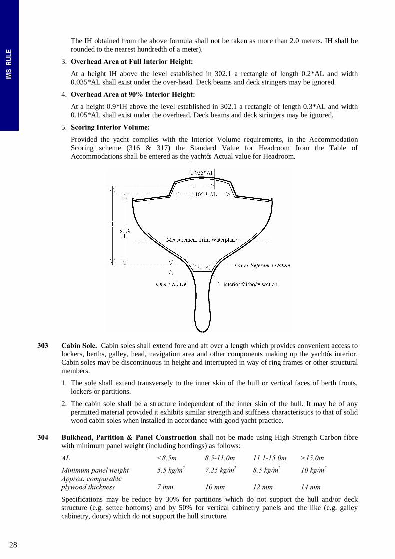
1. Lower Reference Datum. A level datum, parallel to the waterplane in measurement trim, shall be established at a height of 0.001*AL^1.9 above the inside of the hull surface, projected if necessary, at the deepest interior fairbody section which, for this purpose, shall not be found outside the 90% IH overhead area (see 202.4 below). This level is independent of the actual height of the cabin sole.
2. Interior Height (IH) is calculated as (meters):
IH = 0.1143 * AL + 0.3171
The IH obtained from the above formula shall not be taken as more than 2.0 meters. IH shall be rounded to the nearest hundredth of a meter.
3. Overhead Area at Full Interior Height: At a height IH above the level established in 202.1 there shall exist under the overhead a plane of length not less than 0.14*AL and area not less than 0.006*AL^2, ignoring deck beams and deck stringers. The aft extent of this area at the centerline shall lie not forward of a point located 0.55*LOA aft of the stem.
4. Overhead Area at 90% Interior Height: At a height 0.9*IH above the level established in 202.1 there shall exist under the overhead a plane of length not less than 0.19*AL and minimum area 0.019*AL^2. At this defined plane there shall exist a rectangular area for length of 0.15*AL and width not less than 0.1*AL. Deck beams and deck stringers may be ignored.
All types of cut-outs and fitting recesses penetrating into the volume defined by 3 and 4 are forbidden. Only control lines may pass into the coach-roof volume.

26
IMS
RUL
E
203 Cabin Sole shall extend fore and aft over a length which provides convenient access to lockers, berths, galley, head, navigation area and other components making up the yacht’s interior. Cabin soles may be discontinuous in height and interrupted in way of ring frames or other structural members.
1. The sole shall extend transversely to the inner skin of the hull or vertical faces of berth fronts, lockers or partitions.
2. The cabin sole shall be a structure independent of the inner skin of the hull. It may be of any permitted material provided it exhibits similar strength and stiffness characteristics to that of solid wood cabin soles when installed in accordance with good yacht practice.
204 Berths
1. For yachts with an AL of 8.5m or greater each berth shall be at least 1.9m in length measured to the inside of any structure of the berth, bulkheads or partitions encompassing the berth. The minimum width measured in a similar manner to length at the top surface of the mattress shall be 0.6m measured at 1/4 of the berth length. For yachts with an AL of less than 8.5m the minimum length shall be 1.83 m and minimum width shall be 0.55m.
For all yachts the minimum width of a double berth measured as above shall be twice that required for a single berth. The foot and head ends of berths may taper as required by the hull shape.
2. With all berths in the horizontal position the minimum clearance above any mattress at the centerline over half of the length of the berth shall not be less than 0.5m.
3. Mattresses of a size covering the entire surface shall be fitted to all berths; they shall be of a thickness not less than 0.03m. Minimum mattress density shall be 8kg/ m³.
4. For all yachts of Age or Series Date (whichever is earlier) of 1/1/96 or later, the minimum height of the bottom of any hard berth (excluding the mattress) shall be 0.30m above the cabin sole. For yachts with AL of less than 8.5m the minimum height shall be 0.2m.
For minimum number of berths, see Table Minimum.
205 Personal Gear Stowage (clothing, toiletries and miscellaneous articles) shall be provided in the form of built-in lockers. Bilge areas located below the cabin sole and hanging locker volume (see 209 below) shall not be included when measuring space for this stowage requirement. Space under berths shall not be counted except space in the form of fitted drawers which may comprise not more than 30% of the qualifying total volume.
For minimum volume, see Table Minimum. 206 Galley
1. Stoves: All stoves must be gimbaled or fitted with high retaining rails to permit their safe operation underway. For yachts having AL less than 8.5m, the stove shall have at least one burner. For AL 8.5m but less than 11m, two burners. For AL 11m, but not greater than 15m, three burners. For AL over 15m, four burners.
An oven with its own burner or a microwave counts as one burner. To count as a burner, a microwave shall have a sufficient source of power at all times including extended passages at sea.
2. Sinks: For yachts of AL of 8.5m or greater, a sink shall be permanently installed and fitted with a drainage system which permits use underway and of size in keeping with the accommodations of the yacht.
3. Galley Gear Stowage: Seaworthy stowage shall be provided, segregated for a normal complement of cooking utensils, cutlery, glasses, dishes, etc.
4. Food Stowage: To qualify, stowage for food shall be provided in rigid lockers, bins, or other suitable compartments. Spaces below the cabin sole shall not be considered as meeting the requirements.
For minimum volume, see Table Minimum.
27
IMS
RUL
E
207 1. Toilet shall be of approved type permanently installed and operable in compliance with local regulations pertaining to Marine Sanitation Devices and their use. For yachts with an AL of 11m and greater the toilet shall be of a type plumbed for the intake of seawater.
2. Wash Basin: For yachts with an AL of 11m and greater a wash basin shall be permanently installed. It may be fixed, folding or sliding and shall be fitted with a drainage system which permits use underway.
3. Separate Discharge: Sinks and wash basins shall be fitted with separate discharge and not discharge through the toilet system. All seacocks shall be maintained as operational while racing.
208 Navigation Table. A flat area suitable for chart work is required.
1. For yachts of AL 8.5m or greater and commensurate with the size of the yacht, the navigation table or area shall be built with storage for charts, navigational instruments, books, etc.
2. For yachts of AL less than 8.5m counter tops, cabin tables or portable chart boards are acceptable. Where portable chart boards are used, provisions for stowage and securing when in use must be provided.
209 Hanging Locker(s) shall be provided of sufficient dimension to permit hanging garments vertically
and of capacity to accommodate one garment for each required berth, but of not less than 0.06 m³.
210 Fresh Water Capacity: For yachts with an AL of 8.5m and greater, fresh water pumps shall be installed at the sink and wash basin and fresh water shall be contained in permanently installed tankage either of rigid construction or of the bladder type.
For minimum capacity, see Table Minimum.
211 Fuel Capacity: Yachts with inboard engines shall be directly supplied from permanently installed fuel tankage.
For minimum capacity, see Table Minimum. PART 3 – CRUISER/RACER DIVISION 301 Accommodation Length (AL): For yachts with an Age Date or Series Date (whichever is earlier) of
01/02/2005 or later, AL shall be taken as the lesser of LOA or 1.8*(LOA*MB)^0.5.
For yachts of Age or Series Date (whichever is earlier) prior to 01/02/2005, AL = the lesser of LOA or 3.25*MB.
Any fractional excess in AL beyond a tenth of a meter shall be ignored (see 201 for example). 302 Interior Volume.
Interior Volume shall comply with following requirements:
1. Lower Reference Datum. A level datum, parallel to the water-plane in measurement trim, shall be established at a height of 0.001*AL^1.9m above the inside of the hull surface, projected if necessary, at the deepest interior fairbody section which, for this purpose, shall not be found outside the 90% IH overhead area (see 302.4 below). This level is independent of the actual height of the cabin sole.
2. Interior Height (IH) is calculated as (meters):
For AL 8.5m or greater: IH = 1.5758+0.1656*(AL–8.5)^0.5
For AL below 8.5m: IH = 1.5758–0.2220*(8.5–AL)^0.5
28
IMS
RUL
E
The IH obtained from the above formula shall not be taken as more than 2.0 meters. IH shall be rounded to the nearest hundredth of a meter).
3. Overhead Area at Full Interior Height:
At a height IH above the level established in 302.1 a rectangle of length 0.2*AL and width 0.035*AL shall exist under the over-head. Deck beams and deck stringers may be ignored.
4. Overhead Area at 90% Interior Height:
At a height 0.9*IH above the level established in 302.1 a rectangle of length 0.3*AL and width 0.105*AL shall exist under the overhead. Deck beams and deck stringers may be ignored.
5. Scoring Interior Volume:
Provided the yacht complies with the Interior Volume requirements, in the Accommodation Scoring scheme (316 & 317) the Standard Value for Headroom from the Table of Accommodations shall be entered as the yacht’s Actual value for Headroom.
303 Cabin Sole. Cabin soles shall extend fore and aft over a length which provides convenient access to
lockers, berths, galley, head, navigation area and other components making up the yacht’s interior. Cabin soles may be discontinuous in height and interrupted in way of ring frames or other structural members.
1. The sole shall extend transversely to the inner skin of the hull or vertical faces of berth fronts, lockers or partitions.
2. The cabin sole shall be a structure independent of the inner skin of the hull. It may be of any permitted material provided it exhibits similar strength and stiffness characteristics to that of solid wood cabin soles when installed in accordance with good yacht practice.
304 Bulkhead, Partition & Panel Construction shall not be made using High Strength Carbon fibre
with minimum panel weight (including bondings) as follows:
AL <8.5m 8.5-11.0m 11.1-15.0m >15.0m
Minimum panel weight 5.5 kg/m2 7.25 kg/m2 8.5 kg/m2 10 kg/m2 Approx. comparable plywood thickness 7 mm 10 mm 12 mm 14 mm
Specifications may be reduce by 30% for partitions which do not support the hull and/or deck structure (e.g. settee bottoms) and by 50% for vertical cabinetry panels and the like (e.g. galley cabinetry, doors) which do not support the hull structure.

29
IMS
RUL
E
305 Accommodation Areas. The interior of the yacht shall include the following areas (compartments
as required): living area, sleeping area(s), galley area, and as required by yacht size, head compartment and navigation area.
Living areas and sleeping areas shall be separated by means of rigid bulkheads or partitions according to the minimums in the following table. Walk-through openings in these required bulkheads or partitions shall not be wider than 0.70m. For yachts above 14m AL these openings shall have doors of rigid construction.
AL: <8.5m 8.5-14.0m 14.1-18.0m >18.0m Living area 1 1 1 1 Sleeping area(s) 1 1 2 3 No. of bulkheads 0 1 2 3
306 Living Area. A living area (cabin) shall consist of space containing a table and settees. At least
80% of the living area length must be located within the 90% Interior Height area.
1. Table shall be located within the 90% Interior Height Area. For yachts with an AL of 8.5m or greater, to qualify the table surface area for Accommodation Scoring (see 316, 317 & Table), the cabin table shall be of substantial construction and arranged with convenient seating shall be permanently installed. The table may be fixed to the cabin sole or hinged from a bulkhead to facilitate stowage.
2. Settees are required sufficient to allow a number of crew equivalent to the standard number of Berths to sit around the table. Provided it meets the berth requirements, a settee may also be counted as a berth (but see 307.1(a)). To qualify as a settee the units must be in compliance with at least the following minimum requirements:
• Hard bottom type. • Minimum total length of settees measured at the midline: 0.60m * Standard number of berths,
but need not total more than 4.80m • Minimum sitting depth, with cushions in place, 0.40m over 80% of the minimum length. The
ends of the settee may be tapered only as required by the hull shape. • Backrest minimum height 0.30m above seat cushion. • Top of cushions above cabin sole a minimum of 0.30m below 8.5m AL and a minimum of
0.40m for AL 8.5m and greater. • Seating height over top of cushions a minimum of 0.80m below 8.5m AL and a minimum of
0.90m for AL 8.5m and greater.
307 Sleeping Area shall consist of a space containing berths and adequate facilities for personal gear stowage. A 90% Interior Height is required over a minimum width of 0.3m and a minimum length of 0.035*AL.
1. Berths:
(a) Berths which qualify to be counted for Accommodation Scoring (see 316, 317 & Table) shall be of substantial construction in keeping with the requirements for a cruising yacht and shall be fitted with mattresses as set forth in this section. At least half of the berths shall be of the hard bottom type. Where a settee is declared as a berth, at least half of the remaining required berths shall be of the hard-bottom type.
(b) For yachts with an AL of 8.5m or greater each berth shall be at least 1.9m in length measured to the inside of any structure of the berth, bulkheads or partitions encompassing the berth. The minimum width measured in a similar manner to length at the top surface of the mattress shall be 0.6m measured at 1/4 of the berth length.
For yachts with an AL of less than 8.5m the minimum length shall be 1.83m and minimum width shall be 0.55m. For all yachts the minimum width of a double berth measured as above shall be twice that required for a single berth.
The foot and head ends of berths may taper as required by the hull shape.

30
IMS
RUL
E
(c) With all berths in the horizontal position the minimum clearance above any mattress at the centerline over half of the length of the berth shall not be less than 0.5m.
(d) Mattresses of a size covering the entire surface shall be fitted to all berths; they shall be of a
thickness not less than 0.03m for soft bottom berths. For hard bottom berths the minimum thickness shall be 0.1m for yachts with an AL of 8.5m or greater and 0.075m for yachts with an AL of less than 8.5m. Minimum mattress density shall be 8kg/ m³.
(e) For all yachts of Age or Series Date (whichever is earlier) of 01/01/2000 or later, the minimum height of the bottom of any hard berth (excluding the mattress) shall be 0.30m above the cabin sole. For yachts with an AL of less than 8.5m the minimum height shall be 0.2m.
2. Personal Gear Stowage (clothing, toiletries and miscellaneous articles) shall be provided in the form of built in rigid lockers with doors, bins with hatches, and drawers. Bilge areas located below the cabin sole and hanging locker volume (see 311 above) shall not be included when measuring space for this stowage requirement. Space under berths and/or settees shall not be counted except space in the form of fitted drawers which may comprise not more than 30% of the qualifying volume.
308 Galley Area:
A galley area is not permitted in a space counted as a Sleeping Area. Convenient standing space for operation of the galley must be within the Full Interior Height area to allow working in an upright position.
1. Stoves: All Stoves must be gimbaled or fitted with high retaining rails to permit their safe operation underway. For yachts having AL less than 8.5m, the stove shall have at least one burner. For AL 8.5m but less than 11m, two burners. For AL at least 11m, but not greater than 15m, three burners. For AL over 15m, four burners.
An oven with its own burner or a microwave counts as one burner. To count as a burner, a microwave shall have a sufficient source of power at all times including extended passages at sea.
2. Sinks: For yachts of AL of 8.5m or greater, a sink shall be permanently installed and fitted with a drainage system which permits use underway and of size in keeping with the accommodations of the yacht.
3. Galley Gear Stowage: Seaworthy stowage shall be provided, segregated for a normal complement of cooking utensils, cutlery, glasses, dishes, etc.
4. Food Stowage: In addition to the above, to qualify stowage volume for Accommodation Scoring (see 316, 317 & Table), stowage for food (other than refrigerated) shall be provided in rigid lockers, bins, or other suitable compartments. Spaces below the cabin sole shall not be considered as meeting the requirements.
5. Refrigerated Food Stowage: Except where locally or nationally specified otherwise, for yachts with AL of 8.5m or greater, 40% of the Minimum Food Stowage requirement (see Table) shall be in the form of built in, properly insulated ice boxes or refrigerators. Portable ice boxes of any type will not meet the requirements.
309 Head Compartment. The crew space provided for full use of all the head compartment facilities
shall be located within the 90% Interior Height area. For yachts of AL 8.5m and greater, a dedicated head compartment shall be constructed using rigid partitions and a rigid door in such a manner as to totally enclose the compartment when in use. There shall be sufficient space and clearances within the enclosed head compartment with the door shut to permit crew to sit, stand, and turn around.
1. Toilet shall be permanently installed and operable in compliance with local regulations pertaining
to Marine Sanitation Devices and their use. For yachts with an AL of 11m and greater the toilet shall be of a type plumbed for the intake of seawater.

31
IMS
RUL
E
2. Wash Basin: For yachts with an AL of 11m and greater a wash basin shall be permanently installed. It may be fixed, folding or sliding and shall be fitted with a drainage system which permits use underway.
310 Navigation Area. For yachts of 11m AL and greater the navigation area shall form a separated unit
and shall include a chart table, a seat and storage for navigation equipment, charts and books, etc.
For yachts of AL of at least 8.5m but less than 11.0m, the navigation area shall be built with a surface for chart work, storage for charts, navigational instruments, books, etc.
For yachts of AL less than 8.5m, counter tops, cabin tables or portable chart boards are acceptable. Where portable chart boards are used, provisions for stowage and securing when in use must be provided.
For yachts of AL 10.0m and greater, the chart table shall be not less than 0.5 m² in area.
311 Hanging Locker(s) shall be provided of sufficient dimension to permit hanging garments vertically and of capacity to accommodate at least one garment for each qualifying berth (see 307). Total volume shall be not less than 0.04 m³.
312 Main Hatch/Companionway. The main hatch/companionway shall be located within the 90%
Interior Height area, giving access to the interior from a cockpit or deck. It shall be fitted with steps or stairway(s) inclined appropriately for convenient access and the maximum vertical step interval, both inside and outside the hatch, shall not be greater than 0.35m.
313 Cockpit
1. The total of the maximum lengths, found below the working deck, of all cockpits shall not exceed the greater of 0.3*AL or 0.3*LOA.
Cockpit areas open underneath bridgedecks shall be included in the cockpit length. Closed bridgedecks and seats may be excluded from cockpit length provided they are nowhere lower than the local sheerline. For the purpose of measuring cockpit length the aft end of a cockpit shall not be taken aft of the aftermost end of the working deck. Where the cockpit is open aft to the sea, the aftermost end shall not be taken forward of a transverse vertical plane projected through the aftermost location of the upper lifeline.
2. Excluding provision for winch access and wheel clearance, at least the forward 75% of the length of the cockpit shall be surrounded with seatbacks or coamings of minimum height above the mean height of the seats of 0.20m and of minimum height above the local sheerline according to the following table:
AL: <11.0m <=11.0<18.0m >=18.0m Height: 0.10m 0.15m 0.20m
3. The minimum length of cockpit seats, measured along the inboard edge for each side of the cockpit, including any transverse extension fulfilling all the seat requirements listed below, shall not be less than: 0.2*AL*Cockpit Length/(0.3*MAX(AL;LOA), and shall meet the requirements below:
• The seat height above the cockpit sole, taken as the mean height along the seat depth, shall be a minimum of 0.30m for AL below 8.5m and 0.35m for AL 8.5m and greater.
• Seat depth, measured perpendicular to the seat, shall be not less than 0.35m. • Bridge decks which comply with the seat height and depth requirements may be counted. • The width of the cockpit sole, ignoring any which lies outboard of the inboard edge of seats,
shall not be less than 0.6m where AL>8.5m. Eighty percent of the required seating shall be found within a forward percentage of the measured cockpit length. This percentage shall be equal to the lesser of:
100*(1.75 - (Cockpit Length)/(0.3*MAX(AL;LOA)))) or 100.0%.

32
IMS
RUL
E
4. For the purpose of calculating compliance with 313.2 and .3, folding seats shall not be counted.
5. Watertight gear stowage lockers with access from the cockpit shall be arranged with a minimum total volume of 0.2+(0.025*(AL–8.5)) m³. The volume of lockers for bottled gas and liferafts shall not count in complying with this requirement.
314 Fresh Water Capacity: For yachts with an AL of 8.5m and greater, tank capacity for
Accommodation Scoring (see 316, 317 & Table), fresh water pumps shall be installed at the sink and wash basin and fresh water shall be contained in permanently installed tankage either of rigid construction or of the bladder type.
315 Fuel Capacity: To qualify tank capacity for Accommodation Scoring (see 419, 420 & Table),
yachts with inboard engines shall be directly supplied from permanently installed fuel tankage. 316 Scoring Variable Elements
The requirements for certain elements of accommodation, outfit and construction vary by Accommodation Length and are scored under a “soft limits” system providing flexibility in meeting requirements. Under this system, some latitude is allowed in capacities, numbers, areas and volumes, but the deficiencies, sufficiencies and excesses are scored and the total of these must equal at least 100 points of Accommodation Rating. The elements scored and the relative weight given to each in the scoring scheme are:
Weighting Factor
AL: 8.5m or greater less than 8.5m
Berths (number) 30 30 Fresh Water Capacity (liters) 12 N/A Fuel Capacity (liters) 8 8 Food Stowage (cubic meters) 15 10 Personal Gear Stowage (cubic meters) 10 10 Table Area (square meters) 5 N/A Headroom (meters) 20 20
For each element above, the Accommodation Table specifies the requirement according to Accommodation Length. In the Accommodation Table, three values are given for each accommodation element; a Standard value, a Maximum value and a Minimum value. A yacht which was, for its size (AL), designed and outfitted with the Standard number of bunks, Standard fuel capacity and so forth would score exactly 100 as its Accommodation Rating (the minimum for compliance). Elements in excess of Standard will increase the Accommodation Rating and those below Standard will decrease it.
317 Calculation of Accommodation Rating. A yacht with an Accommodation Rating less than 100.0
shall be excluded from racing in the Cruiser/Racer Division.
1. Accommodation Rating.
• For AL 8.5m or greater, Accommodation Rating = the sum of the Accommodation Scores.
• For AL below 8.5m, Accommodation Rating = the sum of the Accommodation Scores + 22.
2. Accommodation Score for any element is calculated as follows:
Accommodation Score = (Actual / Standard) * Weighting Factor
Where:
• “Actual” is the number of qualifying berths, volume of qualifying personal gear stowage and so forth actually found on the yacht.
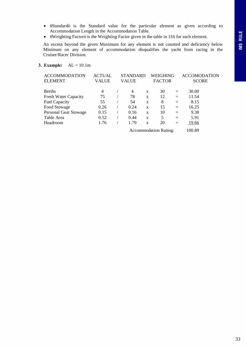
33
IMS
RUL
E
• “Standard” is the Standard value for the particular element as given according to Accommodation Length in the Accommodation Table.
• “Weighting Factor” is the Weighting Factor given in the table in 316 for each element.
An excess beyond the given Maximum for any element is not counted and deficiency below Minimum on any element of accommodation disqualifies the yacht from racing in the Cruiser/Racer Division.
3. Example: AL = 10.1m
ACCOMMODATION ELEMENT
ACTUAL VALUE
STANDARD VALUE
WEIGHING FACTOR
ACCOMODATION SCORE
Berths 4 / 4 x 30 = 30.00 Fresh Water Capacity 75 / 78 x 12 = 11.54 Fuel Capacity 55 / 54 x 8 = 8.15 Food Stowage 0.26 / 0.24 x 15 = 16.25 Personal Gear Stowage 0.15 / 0.16 x 10 = 9.38 Table Area 0.52 / 0.44 x 5 = 5.91 Headroom 1.76 / 1.79 x 20 = 19.66
Accommodation Rating: 100.89

34
IMS
RUL
E
TABLE of ACCOMFMODATIONS *Fuel capacity for gasoline = 1.25 * fuel capacity for diesel NUMBER FRESH WATER DIESEL FUEL FOOD STOWAGE PERSONAL GEAR TABLE AREA HEADROOM OF BERTHS CAPACITY CAPACITY* STOWAGE (LITRES) (LITRES) (CUBIC METRES) (CUBIC METRES) (SQUARE METRES) (METRES)
AL MIN STD MAX MIN STD MAX MIN STD MAX MIN STD MAX MIN STD MAX MIN STD MAX MIN STD MAX 7.0 2 2 2 n/a 12 20 30 0.11 0.12 0.18 0.07 0.08 0.12 n/a 1.30 1.45 1.55 7.1 2 2 2 n/a 12 20 30 0.11 0.12 0.18 0.07 0.08 0.12 n/a 1.30 1.45 1.55 7.2 2 2 2 n/a 12 20 30 0.11 0.12 0.18 0.07 0.08 0.12 n/a 1.30 1.45 1.55 7.3 2 2 2 n/a 12 20 30 0.11 0.12 0.18 0.07 0.08 0.12 n/a 1.30 1.45 1.55 7.4 2 2 2 n/a 12 20 30 0.11 0.12 0.18 0.07 0.08 0.12 n/a 1.30 1.45 1.55 7.5 2 2 2 n/a 12 20 30 0.11 0.12 0.18 0.07 0.08 0.12 n/a 1.30 1.45 1.55 7.6 2 2 2 n/a 12 20 30 0.11 0.12 0.18 0.07 0.08 0.12 n/a 1.30 1.45 1.55 7.7 2 2 2 n/a 12 20 30 0.11 0.12 0.18 0.07 0.08 0.12 n/a 1.30 1.45 1.55 7.8 2 2 2 n/a 12 20 30 0.11 0.12 0.18 0.07 0.08 0.12 n/a 1.30 1.45 1.55 7.9 2 2 2 n/a 12 20 30 0.11 0.12 0.18 0.07 0.08 0.12 n/a 1.30 1.45 1.55 8.0 2 3 4 n/a 12 20 30 0.16 0.18 0.27 0.11 0.12 0.18 n/a 1.30 1.45 1.55 8.1 2 3 4 n/a 12 20 30 0.16 0.18 0.27 0.11 0.12 0.18 n/a 1.30 1.45 1.55 8.2 2 3 4 n/a 12 20 30 0.16 0.18 0.27 0.11 0.12 0.18 n/a 1.30 1.45 1.55 8.3 2 3 4 n/a 12 20 30 0.16 0.18 0.27 0.11 0.12 0.18 n/a 1.30 1.45 1.55 8.4 2 3 4 n/a 13 22 33 0.16 0.18 0.27 0.11 0.12 0.18 n/a 1.30 1.45 1.55 8.5 2 3 4 23 35 52 15 24 36 0.16 0.18 0.27 0.11 0.12 0.18 0.30 0.33 0.40 1.52 1.58 1.64 8.6 2 3 4 24 36 54 16 26 39 0.16 0.18 0.27 0.11 0.12 0.18 0.30 0.33 0.40 1.57 1.63 1.69 8.7 2 3 4 25 38 57 17 28 42 0.16 0.18 0.27 0.11 0.12 0.18 0.30 0.33 0.40 1.59 1.65 1.71 8.8 2 3 4 26 39 58 18 30 45 0.16 0.18 0.27 0.11 0.12 0.18 0.30 0.33 0.40 1.61 1.67 1.73 8.9 2 3 4 27 41 61 20 32 48 0.16 0.18 0.27 0.11 0.12 0.18 0.30 0.33 0.40 1.62 1.68 1.74 9.0 3 4 5 38 57 85 20 33 49 0.22 0.24 0.36 0.14 0.16 0.24 0.40 0.44 0.53 1.63 1.69 1.76 9.1 3 4 5 39 59 88 21 35 52 0.22 0.24 0.36 0.14 0.16 0.24 0.40 0.44 0.53 1.64 1.70 1.77 9.2 3 4 5 40 60 90 23 37 55 0.22 0.24 0.36 0.14 0.16 0.24 0.40 0.44 0.53 1.65 1.71 1.78 9.3 3 4 5 41 62 93 24 39 58 0.22 0.24 0.36 0.14 0.16 0.24 0.40 0.44 0.53 1.66 1.72 1.79 9.4 3 4 5 42 64 96 25 41 61 0.22 0.24 0.36 0.14 0.16 0.24 0.40 0.44 0.53 1.67 1.73 1.80 9.5 3 4 5 44 66 99 26 43 64 0.22 0.24 0.36 0.14 0.16 0.24 0.40 0.44 0.53 1.68 1.74 1.81 9.6 3 4 5 45 68 102 28 45 67 0.22 0.24 0.36 0.14 0.16 0.24 0.40 0.44 0.53 1.69 1.75 1.82 9.7 3 4 5 46 70 105 29 47 70 0.22 0.24 0.36 0.14 0.16 0.24 0.40 0.44 0.53 1.70 1.76 1.82 9.8 3 4 5 48 72 108 30 49 73 0.22 0.24 0.36 0.14 0.16 0.24 0.40 0.44 0.53 1.70 1.76 1.83 9.9 3 4 5 49 74 111 31 50 75 0.22 0.24 0.36 0.14 0.16 0.24 0.40 0.44 0.53 1.71 1.77 1.84 10.0 3 4 5 50 76 114 32 52 78 0.22 0.24 0.36 0.14 0.16 0.24 0.40 0.44 0.53 1.72 1.78 1.85 10.1 3 4 5 52 78 117 33 54 81 0.22 0.24 0.36 0.14 0.16 0.24 0.40 0.44 0.53 1.72 1.79 1.85 10.2 3 4 5 53 80 120 35 56 84 0.22 0.24 0.36 0.14 0.16 0.24 0.40 0.44 0.53 1.73 1.79 1.86 10.3 3 4 5 54 82 123 36 58 87 0.22 0.24 0.36 0.14 0.16 0.24 0.40 0.44 0.53 1.74 1.80 1.87 10.4 3 4 5 56 84 126 37 60 90 0.22 0.24 0.36 0.14 0.16 0.24 0.40 0.44 0.53 1.74 1.80 1.87 10.5 3 4 5 57 86 129 38 62 93 0.22 0.24 0.36 0.14 0.16 0.24 0.40 0.44 0.53 1.75 1.81 1.88 10.6 3 4 5 58 88 132 40 64 96 0.22 0.24 0.36 0.14 0.16 0.24 0.40 0.44 0.53 1.75 1.82 1.88 10.7 4 5 6 75 113 169 41 66 99 0.27 0.30 0.45 0.18 0.20 0.30 0.50 0.55 0.66 1.76 1.82 1.89 10.8 4 5 6 76 115 172 41 67 100 0.27 0.30 0.45 0.18 0.20 0.30 0.50 0.55 0.66 1.76 1.83 1.90 10.9 4 5 6 78 118 177 43 69 103 0.27 0.30 0.45 0.18 0.20 0.30 0.50 0.55 0.66 1.77 1.83 1.90 11.0 4 5 6 80 120 180 44 71 106 0.27 0.30 0.45 0.18 0.20 0.30 0.50 0.55 0.66 1.77 1.84 1.91 11.1 4 5 6 81 122 183 45 73 109 0.27 0.30 0.45 0.18 0.20 0.30 0.50 0.55 0.66 1.78 1.84 1.91 11.2 4 5 6 83 125 187 46 75 112 0.27 0.30 0.45 0.18 0.20 0.30 0.50 0.55 0.66 1.78 1.85 1.92 11.3 4 5 6 84 127 190 48 77 115 0.27 0.30 0.45 0.18 0.20 0.30 0.50 0.55 0.66 1.79 1.85 1.92 11.4 4 5 6 86 130 195 49 79 118 0.27 0.30 0.45 0.18 0.20 0.30 0.50 0.55 0.66 1.79 1.86 1.93 11.5 4 5 6 88 132 198 50 81 121 0.27 0.30 0.45 0.18 0.20 0.30 0.50 0.55 0.66 1.80 1.86 1.93 11.6 4 5 6 90 135 202 51 83 124 0.27 0.30 0.45 0.18 0.20 0.30 0.50 0.55 0.66 1.80 1.87 1.94 11.7 4 5 6 91 137 205 52 84 126 0.27 0.30 0.45 0.18 0.20 0.30 0.50 0.55 0.66 1.81 1.87 1.94 11.8 4 5 6 93 140 210 53 86 129 0.27 0.30 0.45 0.18 0.20 0.30 0.50 0.55 0.66 1.81 1.88 1.95 11.9 4 5 6 94 142 213 55 88 132 0.27 0.30 0.45 0.18 0.20 0.30 0.50 0.55 0.66 1.82 1.88 1.95 12.0 4 5 6 96 145 217 56 90 135 0.27 0.30 0.45 0.18 0.20 0.30 0.50 0.55 0.66 1.82 1.89 1.96 12.1 4 5 6 98 147 220 57 92 138 0.27 0.30 0.45 0.18 0.20 0.30 0.50 0.55 0.66 1.82 1.89 1.96 12.2 4 5 6 100 150 225 58 94 141 0.27 0.30 0.45 0.18 0.20 0.30 0.50 0.55 0.66 1.83 1.89 1.97 12.3 4 5 6 101 152 228 60 96 144 0.27 0.30 0.45 0.18 0.20 0.30 0.50 0.55 0.66 1.83 1.90 1.97 12.4 4 5 6 102 154 231 61 98 147 0.27 0.30 0.45 0.18 0.20 0.30 0.50 0.55 0.66 1.84 1.90 1.98 12.5 4 5 6 104 157 235 62 100 150 0.27 0.30 0.45 0.18 0.20 0.30 0.50 0.55 0.66 1.84 1.91 1.98 12.6 4 5 6 106 159 238 63 101 151 0.27 0.30 0.45 0.18 0.20 0.30 0.50 0.55 0.66 1.84 1.91 1.98 12.7 4 5 6 108 162 243 64 103 154 0.27 0.30 0.45 0.18 0.20 0.30 0.50 0.55 0.66 1.85 1.92 1.99 12.8 4 6 7 131 197 295 65 105 157 0.32 0.36 0.54 0.22 0.24 0.36 0.59 0.66 0.79 1.85 1.92 1.99 12.9 4 6 7 133 200 300 66 107 160 0.32 0.36 0.54 0.22 0.24 0.36 0.59 0.66 0.79 1.86 1.92 2.00 13.0 4 6 7 135 203 304 68 109 163 0.32 0.36 0.54 0.22 0.24 0.36 0.59 0.66 0.79 1.86 1.93 2.00 13.1 4 6 7 137 206 309 69 111 166 0.32 0.36 0.54 0.22 0.24 0.36 0.59 0.66 0.79 1.86 1.93 2.00 13.2 4 6 7 139 209 313 70 113 169 0.32 0.36 0.54 0.22 0.24 0.36 0.59 0.66 0.79 1.87 1.93 2.01 13.3 4 6 7 141 212 318 71 115 172 0.32 0.36 0.54 0.22 0.24 0.36 0.59 0.66 0.79 1.87 1.94 2.01 13.4 4 6 7 143 215 322 72 116 174 0.32 0.36 0.54 0.22 0.24 0.36 0.59 0.66 0.79 1.87 1.94 2.02 13.5 4 6 7 145 218 327 73 118 177 0.32 0.36 0.54 0.22 0.24 0.36 0.59 0.66 0.79 1.88 1.95 2.02 13.6 4 6 7 147 221 331 75 120 180 0.32 0.36 0.54 0.22 0.24 0.36 0.59 0.66 0.79 1.88 1.95 2.02 13.7 4 6 7 149 224 336 76 122 183 0.32 0.36 0.54 0.22 0.24 0.36 0.59 0.66 0.79 1.89 1.95 2.03 13.8 4 6 7 151 227 340 77 124 186 0.32 0.36 0.54 0.22 0.24 0.36 0.59 0.66 0.79 1.89 1.96 2.03 13.9 4 6 7 153 230 345 78 126 189 0.32 0.36 0.54 0.22 0.24 0.36 0.59 0.66 0.79 1.89 1.96 2.04

35
IMS
RUL
E
TABLE of ACCOMMODATIONS *Fuel capacity for gasoline = 1.25 * fuel capacity for diesel NUMBER FRESH WATER DIESEL FUEL FOOD STOWAGE PERSONAL GEAR TABLE AREA HEADROOM OF BERTHS CAPACITY CAPACITY* STOWAGE (LITRES) (LITRES) (CUBIC METRES) (CUBIC METRES) (SQUARE METRES) (METRES)
AL MIN STD MAX MIN STD MAX MIN STD MAX MIN STD MAX MIN STD MAX MIN STD MAX MIN STD MAX 14.0 4 6 7 155 233 349 80 128 192 0.32 0.36 0.54 0.22 0.24 0.36 0.59 0.66 0.79 1.90 1.96 2.04 14.1 4 6 7 157 236 354 81 130 195 0.32 0.36 0.54 0.22 0.24 0.36 0.59 0.66 0.79 1.90 1.97 2.04 14.2 4 6 7 159 239 358 82 132 198 0.32 0.36 0.54 0.22 0.24 0.36 0.59 0.66 0.79 1.90 1.97 2.05 14.3 4 6 7 160 241 361 83 133 199 0.32 0.36 0.54 0.22 0.24 0.36 0.59 0.66 0.79 1.91 1.97 2.05 14.4 4 6 7 162 244 366 84 135 202 0.32 0.36 0.54 0.22 0.24 0.36 0.59 0.66 0.79 1.91 1.98 2.05 14.5 4 6 7 164 247 370 85 137 205 0.32 0.36 0.54 0.22 0.24 0.36 0.59 0.66 0.79 1.91 1.98 2.06 14.6 4 6 7 166 250 375 86 139 208 0.32 0.36 0.54 0.22 0.24 0.36 0.59 0.66 0.79 1.91 1.98 2.06 14.7 4 6 7 168 253 379 88 141 211 0.32 0.36 0.54 0.22 0.24 0.36 0.59 0.66 0.79 1.91 1.98 2.06 14.8 4 6 7 170 256 384 89 143 214 0.32 0.36 0.54 0.22 0.24 0.36 0.59 0.66 0.79 1.91 1.98 2.06 14.9 4 6 7 172 259 388 90 145 217 0.32 0.36 0.54 0.22 0.24 0.36 0.59 0.66 0.79 1.91 1.98 2.06 15.0 5 7 8 204 306 459 91 147 220 0.38 0.42 0.63 0.25 0.28 0.42 0.69 0.77 0.92 1.91 1.98 2.06 15.1 5 7 8 206 309 463 93 149 223 0.38 0.42 0.63 0.25 0.28 0.42 0.69 0.77 0.92 1.91 1.98 2.06 15.2 5 7 8 208 313 469 93 150 225 0.38 0.42 0.63 0.25 0.28 0.42 0.69 0.77 0.92 1.91 1.98 2.06 15.3 5 7 8 210 316 474 95 152 228 0.38 0.42 0.63 0.25 0.28 0.42 0.69 0.77 0.92 1.91 1.98 2.06 15.4 5 7 8 213 320 480 96 154 231 0.38 0.42 0.63 0.25 0.28 0.42 0.69 0.77 0.92 1.91 1.98 2.06 15.5 5 7 8 215 323 484 97 156 234 0.38 0.42 0.63 0.25 0.28 0.42 0.69 0.77 0.92 1.91 1.98 2.06 15.6 5 7 8 218 327 490 98 158 237 0.38 0.42 0.63 0.25 0.28 0.42 0.69 0.77 0.92 1.91 1.98 2.06 15.7 5 7 8 220 330 495 100 160 240 0.38 0.42 0.63 0.25 0.28 0.42 0.69 0.77 0.92 1.91 1.98 2.06 15.8 5 7 8 222 333 499 101 162 243 0.38 0.42 0.63 0.25 0.28 0.42 0.69 0.77 0.92 1.91 1.98 2.06 15.9 5 7 8 224 337 505 102 164 246 0.38 0.42 0.63 0.25 0.28 0.42 0.69 0.77 0.92 1.91 1.98 2.06 16.0 5 7 8 226 340 510 103 166 249 0.38 0.42 0.63 0.25 0.28 0.42 0.69 0.77 0.92 1.91 1.98 2.06 16.1 5 7 8 229 344 516 104 167 250 0.38 0.42 0.63 0.25 0.28 0.42 0.69 0.77 0.92 1.91 1.98 2.06 16.2 5 7 8 231 347 520 105 169 253 0.38 0.42 0.63 0.25 0.28 0.42 0.69 0.77 0.92 1.91 1.98 2.06 16.3 5 7 8 234 351 526 106 171 256 0.38 0.42 0.63 0.25 0.28 0.42 0.69 0.77 0.92 1.91 1.98 2.06 16.4 5 7 8 236 354 531 108 173 259 0.38 0.42 0.63 0.25 0.28 0.42 0.69 0.77 0.92 1.91 1.98 2.06 16.5 5 7 8 238 358 537 109 175 262 0.38 0.42 0.63 0.25 0.28 0.42 0.69 0.77 0.92 1.91 1.98 2.06 16.6 5 7 8 240 361 541 110 177 265 0.38 0.42 0.63 0.25 0.28 0.42 0.69 0.77 0.92 1.91 1.98 2.06 16.7 5 7 8 242 364 546 111 179 268 0.38 0.42 0.63 0.25 0.28 0.42 0.69 0.77 0.92 1.91 1.98 2.06 16.8 5 7 8 245 368 552 113 181 271 0.38 0.42 0.63 0.25 0.28 0.42 0.69 0.77 0.92 1.91 1.98 2.06 16.9 5 7 8 247 371 556 114 183 274 0.38 0.42 0.63 0.25 0.28 0.42 0.69 0.77 0.92 1.91 1.98 2.06 17.0 5 7 8 250 375 562 115 184 276 0.38 0.42 0.63 0.25 0.28 0.42 0.69 0.77 0.92 1.91 1.98 2.06 17.1 6 8 9 288 432 648 116 186 279 0.43 0.48 0.72 0.29 0.32 0.48 0.79 0.88 1.06 1.91 1.98 2.06 17.2 6 8 9 290 436 654 117 188 282 0.43 0.48 0.72 0.29 0.32 0.48 0.79 0.88 1.06 1.91 1.98 2.06 17.3 6 8 9 293 440 660 118 190 285 0.43 0.48 0.72 0.29 0.32 0.48 0.79 0.88 1.06 1.91 1.98 2.06 17.4 6 8 9 296 444 666 120 192 288 0.43 0.48 0.72 0.29 0.32 0.48 0.79 0.88 1.06 1.91 1.98 2.06 17.5 6 8 9 298 448 672 121 194 291 0.43 0.48 0.72 0.29 0.32 0.48 0.79 0.88 1.06 1.91 1.98 2.06 17.6 6 8 9 301 452 678 122 196 294 0.43 0.48 0.72 0.29 0.32 0.48 0.79 0.88 1.06 1.91 1.98 2.06 17.7 6 8 9 304 456 684 123 198 297 0.43 0.48 0.72 0.29 0.32 0.48 0.79 0.88 1.06 1.91 1.98 2.06 17.8 6 8 9 306 460 690 125 200 300 0.43 0.48 0.72 0.29 0.32 0.48 0.79 0.88 1.06 1.91 1.98 2.06 17.9 6 8 9 309 464 696 125 201 301 0.43 0.48 0.72 0.29 0.32 0.48 0.79 0.88 1.06 1.91 1.98 2.06 18.0 6 8 9 312 468 702 126 203 304 0.43 0.48 0.72 0.29 0.32 0.48 0.79 0.88 1.06 1.91 1.98 2.06 18.1 6 8 9 314 472 708 128 205 307 0.43 0.48 0.72 0.29 0.32 0.48 0.79 0.88 1.06 1.91 1.98 2.06 18.2 6 8 9 317 476 714 129 207 310 0.43 0.48 0.72 0.29 0.32 0.48 0.79 0.88 1.06 1.91 1.98 2.06 18.3 6 8 9 320 480 720 130 209 313 0.43 0.48 0.72 0.29 0.32 0.48 0.79 0.88 1.06 1.91 1.98 2.06 18.4 6 8 9 322 483 724 131 211 316 0.43 0.48 0.72 0.29 0.32 0.48 0.79 0.88 1.06 1.91 1.98 2.06 18.5 6 8 9 324 487 730 133 213 319 0.43 0.48 0.72 0.29 0.32 0.48 0.79 0.88 1.06 1.91 1.98 2.06 18.6 6 8 9 327 491 736 134 215 322 0.43 0.48 0.72 0.29 0.32 0.48 0.79 0.88 1.06 1.91 1.98 2.06 18.7 6 8 9 330 495 742 135 217 325 0.43 0.48 0.72 0.29 0.32 0.48 0.79 0.88 1.06 1.91 1.98 2.06 18.8 6 8 9 332 499 748 136 218 327 0.43 0.48 0.72 0.29 0.32 0.48 0.79 0.88 1.06 1.91 1.98 2.06 18.9 6 8 9 335 503 754 137 220 330 0.43 0.48 0.72 0.29 0.32 0.48 0.79 0.88 1.06 1.91 1.98 2.06 19.0 6 8 9 338 507 760 138 222 333 0.43 0.48 0.72 0.29 0.32 0.48 0.79 0.88 1.06 1.91 1.98 2.06 19.1 6 8 9 340 511 766 140 224 336 0.43 0.48 0.72 0.29 0.32 0.48 0.79 0.88 1.06 1.91 1.98 2.06 19.2 7 9 10 386 579 868 141 226 339 0.49 0.54 0.81 0.32 0.36 0.54 0.89 0.99 1.19 1.91 1.98 2.06 19.3 7 9 10 389 584 876 142 228 342 0.49 0.54 0.81 0.32 0.36 0.54 0.89 0.99 1.19 1.91 1.98 2.06 19.4 7 9 10 392 588 882 143 230 345 0.49 0.54 0.81 0.32 0.36 0.54 0.89 0.99 1.19 1.91 1.98 2.06 19.5 7 9 10 395 593 889 145 232 348 0.49 0.54 0.81 0.32 0.36 0.54 0.89 0.99 1.19 1.91 1.98 2.06 19.6 7 9 10 398 597 895 146 234 351 0.49 0.54 0.81 0.32 0.36 0.54 0.89 0.99 1.19 1.91 1.98 2.06 19.7 7 9 10 400 601 901 146 235 352 0.49 0.54 0.81 0.32 0.36 0.54 0.89 0.99 1.19 1.91 1.98 2.06 19.8 7 9 10 404 606 909 148 237 355 0.49 0.54 0.81 0.32 0.36 0.54 0.89 0.99 1.19 1.91 1.98 2.06 19.9 7 9 10 406 610 915 149 239 358 0.49 0.54 0.81 0.32 0.36 0.54 0.89 0.99 1.19 1.91 1.98 2.06 20.0 7 9 10 410 615 922 150 241 361 0.49 0.54 0.81 0.32 0.36 0.54 0.89 0.99 1.19 1.91 1.98 2.06 20.1 7 9 10 412 619 928 151 243 364 0.49 0.54 0.81 0.32 0.36 0.54 0.89 0.99 1.19 1.91 1.98 2.06 20.2 7 9 10 416 624 936 153 245 367 0.49 0.54 0.81 0.32 0.36 0.54 0.89 0.99 1.19 1.91 1.98 2.06 20.3 7 9 10 418 628 942 154 247 370 0.49 0.54 0.81 0.32 0.36 0.54 0.89 0.99 1.19 1.91 1.98 2.06 20.4 7 9 10 421 632 948 155 249 373 0.49 0.54 0.81 0.32 0.36 0.54 0.89 0.99 1.19 1.91 1.98 2.06 20.5 7 9 10 424 637 955 156 251 376 0.49 0.54 0.81 0.32 0.36 0.54 0.89 0.99 1.19 1.91 1.98 2.06 20.6 7 9 10 427 641 961 157 252 378 0.49 0.54 0.81 0.32 0.36 0.54 0.89 0.99 1.19 1.91 1.98 2.06 20.7 7 9 10 430 646 969 158 254 381 0.49 0.54 0.81 0.32 0.36 0.54 0.89 0.99 1.19 1.91 1.98 2.06 20.8 7 9 10 433 650 975 160 256 384 0.49 0.54 0.81 0.32 0.36 0.54 0.89 0.99 1.19 1.91 1.98 2.06 20.9 7 9 10 436 655 982 161 258 387 0.49 0.54 0.81 0.32 0.36 0.54 0.89 0.99 1.19 1.91 1.98 2.06

36
IMS
RUL
E
TABLE of ACCOMMODATIONS *Fuel capacity for gasoline = 1.25 * fuel capacity for diesel NUMBER FRESH WATER DIESEL FUEL FOOD STOWAGE PERSONAL GEAR TABLE AREA HEADROOM OF BERTHS CAPACITY CAPACITY* STOWAGE (LITRES) (LITRES) (CUBIC METRES) (CUBIC METRES) (SQUARE METRES) (METRES)
AL MIN STD MAX MIN STD MAX MIN STD MAX MIN STD MAX MIN STD MAX MIN STD MAX MIN STD MAX 21.0 7 9 10 439 659 988 162 260 390 0.49 0.54 0.81 0.32 0.36 0.54 0.89 0.99 1.19 1.91 1.98 2.06 21.1 7 9 10 442 663 994 163 262 393 0.49 0.54 0.81 0.32 0.36 0.54 0.89 0.99 1.19 1.91 1.98 2.06 21.2 7 9 10 445 668 1002 165 264 396 0.49 0.54 0.81 0.32 0.36 0.54 0.89 0.99 1.19 1.91 1.98 2.06 21.3 8 10 12 498 747 1120 166 266 399 0.54 0.60 0.90 0.36 0.40 0.60 0.99 1.10 1.32 1.91 1.98 2.06 21.4 8 10 12 501 752 1128 167 268 402 0.54 0.60 0.90 0.36 0.40 0.60 0.99 1.10 1.32 1.91 1.98 2.06 21.5 8 10 12 504 757 1135 168 269 403 0.54 0.60 0.90 0.36 0.40 0.60 0.99 1.10 1.32 1.91 1.98 2.06 21.6 8 10 12 508 762 1143 169 271 406 0.54 0.60 0.90 0.36 0.40 0.60 0.99 1.10 1.32 1.91 1.98 2.06 21.7 8 10 12 511 767 1150 170 273 409 0.54 0.60 0.90 0.36 0.40 0.60 0.99 1.10 1.32 1.91 1.98 2.06 21.8 8 10 12 514 772 1158 171 275 412 0.54 0.60 0.90 0.36 0.40 0.60 0.99 1.10 1.32 1.91 1.98 2.06 21.9 8 10 12 518 777 1165 173 277 415 0.54 0.60 0.90 0.36 0.40 0.60 0.99 1.10 1.32 1.91 1.98 2.06 22.0 8 10 12 520 781 1171 174 279 418 0.54 0.60 0.90 0.36 0.40 0.60 0.99 1.10 1.32 1.91 1.98 2.06 22.1 8 10 12 524 786 1179 175 281 421 0.54 0.60 0.90 0.36 0.40 0.60 0.99 1.10 1.32 1.91 1.98 2.06 22.2 8 10 12 527 791 1186 176 283 424 0.54 0.60 0.90 0.36 0.40 0.60 0.99 1.10 1.32 1.91 1.98 2.06 22.3 8 10 12 530 796 1194 178 285 427 0.54 0.60 0.90 0.36 0.40 0.60 0.99 1.10 1.32 1.91 1.98 2.06 22.4 8 10 12 534 801 1201 178 286 429 0.54 0.60 0.90 0.36 0.40 0.60 0.99 1.10 1.32 1.91 1.98 2.06 22.5 8 10 12 537 806 1209 180 288 432 0.54 0.60 0.90 0.36 0.40 0.60 0.99 1.10 1.32 1.91 1.98 2.06 22.6 8 10 12 540 811 1216 181 290 435 0.54 0.60 0.90 0.36 0.40 0.60 0.99 1.10 1.32 1.91 1.98 2.06 22.7 8 10 12 544 816 1224 182 292 438 0.54 0.60 0.90 0.36 0.40 0.60 0.99 1.10 1.32 1.91 1.98 2.06 22.8 8 10 12 547 821 1231 183 294 441 0.54 0.60 0.90 0.36 0.40 0.60 0.99 1.10 1.32 1.91 1.98 2.06 22.9 8 10 12 550 826 1239 185 296 444 0.54 0.60 0.90 0.36 0.40 0.60 0.99 1.10 1.32 1.91 1.98 2.06 23.0 8 10 12 554 831 1246 186 298 447 0.54 0.60 0.90 0.36 0.40 0.60 0.99 1.10 1.32 1.91 1.98 2.06 23.1 8 10 12 557 836 1254 187 300 450 0.54 0.60 0.90 0.36 0.40 0.60 0.99 1.10 1.32 1.91 1.98 2.06 23.2 8 10 12 560 840 1260 188 302 453 0.54 0.60 0.90 0.36 0.40 0.60 0.99 1.10 1.32 1.91 1.98 2.06 23.3 8 10 12 563 845 1267 189 303 454 0.54 0.60 0.90 0.36 0.40 0.60 0.99 1.10 1.32 1.91 1.98 2.06 23.4 8 10 12 566 850 1275 190 305 457 0.54 0.60 0.90 0.36 0.40 0.60 0.99 1.10 1.32 1.91 1.98 2.06 23.5 8 11 13 627 941 1411 191 307 460 0.59 0.66 0.99 0.40 0.44 0.66 0.99 1.10 1.32 1.91 1.98 2.06 23.6 8 11 13 630 946 1419 193 309 463 0.59 0.66 0.99 0.40 0.44 0.66 0.99 1.10 1.32 1.91 1.98 2.06 23.7 8 11 13 634 952 1428 194 311 466 0.59 0.66 0.99 0.40 0.44 0.66 0.99 1.10 1.32 1.91 1.98 2.06 23.8 8 11 13 638 957 1435 195 313 469 0.59 0.66 0.99 0.40 0.44 0.66 0.99 1.10 1.32 1.91 1.98 2.06 23.9 8 11 13 641 962 1443 196 315 472 0.59 0.66 0.99 0.40 0.44 0.66 0.99 1.10 1.32 1.91 1.98 2.06 24.0 8 11 13 645 968 1452 198 317 475 0.59 0.66 0.99 0.40 0.44 0.66 0.99 1.10 1.32 1.91 1.98 2.06 24.1 8 11 13 648 973 1459 199 319 478 0.59 0.66 0.99 0.40 0.44 0.66 0.99 1.10 1.32 1.91 1.98 2.06 24.2 8 11 13 652 979 1468 200 320 480 0.59 0.66 0.99 0.40 0.44 0.66 0.99 1.10 1.32 1.91 1.98 2.06 24.3 8 11 13 656 984 1476 201 322 483 0.59 0.66 0.99 0.40 0.44 0.66 0.99 1.10 1.32 1.91 1.98 2.06 24.4 8 11 13 660 990 1485 202 324 486 0.59 0.66 0.99 0.40 0.44 0.66 0.99 1.10 1.32 1.91 1.98 2.06 24.5 8 11 13 663 995 1492 203 326 489 0.59 0.66 0.99 0.40 0.44 0.66 0.99 1.10 1.32 1.91 1.98 2.06 24.6 8 11 13 666 1000 1500 205 328 492 0.59 0.66 0.99 0.40 0.44 0.66 0.99 1.10 1.32 1.91 1.98 2.06 24.7 8 11 13 670 1006 1509 206 330 495 0.59 0.66 0.99 0.40 0.44 0.66 0.99 1.10 1.32 1.91 1.98 2.06 24.8 8 11 13 674 1011 1516 207 332 498 0.59 0.66 0.99 0.40 0.44 0.66 0.99 1.10 1.32 1.91 1.98 2.06 24.9 8 11 13 678 1017 1525 208 334 501 0.59 0.66 0.99 0.40 0.44 0.66 0.99 1.10 1.32 1.91 1.98 2.06 25.0 8 11 13 681 1022 1533 210 336 504 0.59 0.66 0.99 0.40 0.44 0.66 0.99 1.10 1.32 1.91 1.98 2.06
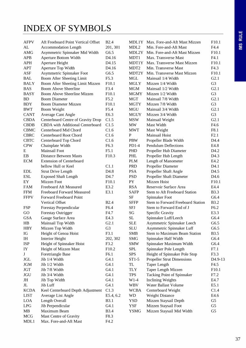
37
IMS
RUL
E INDEX OF SYMBOLS AFPV Aft Freeboard Point Vertical Offset B2.4 AL Accommodation Length 201, 301 AMG Asymmetric Spinnaker Mid Width G6.5 APB Aperture Bottom Width D4.16 APH Aperture Height D4.15 APT Aperture Top Width D4.16 ASF Asymmetric Spinnaker Foot G6.5 BAL Boom After Sheeting Limit F5.3 BALY Boom After Sheeting Limit Mizzen F10.1 BAS Boom Above Sheerline F3.4 BASY Boom Above Sheerline Mizzen F10.1 BD Boom Diameter F5.2 BDY Boom Diameter Mizzen F10.1 BWT Boom Weight F5.4 CANT Average Cant Angle E6.3 CBDA Centerboard Centre of Gravity Drop C1.5 CBDB CBDA with Additional Centerboard C1.5 CBMC Centerboard Mid Chord C1.6 CBRC Centerboard Root Chord C1.6 CBTC Centerboard Top Chord C1.6 CPW Chainplate Width F6.3 E Mainsail Foot F5.1 EB Distance Between Masts F10.3 ECM Extension of Centerboard bellow Hull or Keel C1.1 EDL Strut Drive Length D4.8 ESL Exposed Shaft Length D4.7 EY Mizzen Foot F10.1 FAM Freeboard Aft Measured E3.2 FFM Freeboard Forward Measured E3.1 FFPV Forward Freeboard Point Vertical Offset B2.4 FSP Forestay Perpendicular F6.4 GO Forestay Outrigger F4.7 GSA Gauge Surface Area E4.3 HB Mainsail Top Width G2.1 HBY Mizzen Top Width G3 IG Height of Genoa Hoist F3.1 IH Interior Height 202, 302 ISP Height of Spinnaker Hoist F3.2 IY Height of Mizzen Mast F10.2 J Foretriangle Base F6.1 JGL Jib 1/4 Width G4.1 JGM Jib 1/2 Width G4.1 JGT Jib 7/8 Width G4.1 JGU Jib 3/4 Width G4.1 JH Jib Top Width G4.1 JL Jib Luff G4.1 KCDA Keel Centerboard Depth Adjustment C1.3 LIST Average List Angle E5.4, 6.2 LOA Length Overall B3.1 LPG Jib Perpendicular G4.1 MB Maximum Beam B3.4 MCG Mast Centre of Gravity F8.3 MDL1 Max. Fore-and-Aft Mast F4.2
MDL1Y Max. Fore-and-Aft Mast Mizzen F10.1 MDL2 Min. Fore-and-Aft Mast F4.4 MDL2Y Min. Fore-and-Aft Mast Mizzen F10.1 MDT1 Max. Transverse Mast F4.1 MDT1Y Max. Transverse Mast Mizzen F10.1 MDT2 Min. Transverse Mast F4.3 MDT2Y Min. Transverse Mast Mizzen F10.1 MGL Mainsail 1/4 Width G2.1 MGLY Mizzen 1/4 Width G3 MGM Mainsail 1/2 Width G2.1 MGMY Mizzen 1/2 Width G3 MGT Mainsail 7/8 Width G2.1 MGTY Mizzen 7/8 Width G3 MGU Mainsail 3/4 Width G2.1 MGUY Mizzen 3/4 Width G3 MSW Mainsail Weight G2.1 MW Mast Width F4.6 MWT Mast Weight F8.1 P Mainsail Hoist F2.1 PBW Propeller Blade Width D4.4 PD1-4 Pendulum Deflections E4.8 PHD Propeller Hub Diameter D4.2 PHL Propeller Hub Length D4.3 PLM Length of Manometer E4.2 PRD Propeller Diameter D4.1 PSA Propeller Shaft Angle D4.5 PSD Propeller Shaft Diameter D4.6 PY Mizzen Hoist F10.1 RSA Reservoir Surface Area E4.4 SAFP Stem to Aft Freeboard Station B3.3 SF Spinnaker Foot G6.4 SFFP Stem to Forward Freeboard Station B3.2 SFJ Stem to Forward End of J F6.2 SG Specific Gravity E3.3 SL Spinnaker Luff/Leech G6.4 SLE Asymmetric Spinnaker Leech G6.5 SLU Asymmetric Spinnaker Luff G6.5 SMB Stem to Maximum Beam Station B3.5 SMG Spinnaker Half Width G6.4 SMW Spinnaker Maximum Width G6.4 SPL Spinnaker Pole Length F7.1 SPS Height of Spinnaker Pole Stop F3.3 ST1-5 Propeller Strut Dimensions D4.9-13 TL Taper Length F4.5 TLY Taper Length Mizzen F10.1 TPS Tacking Point of Spinnaker F7.2 W1-4 Inclining Weights E4.7 WBV Water Ballast Volume E5.1 WCBA Centerboard Weight C1.4 WD Weight Distance E4.6 YSD Mizzen Staysail Depth G5 YSF Mizzen Staysail Foot G5 YSMG Mizzen Staysail Mid Width G5