Working Group COFREND « Eddy Current NDT modeling ... · Working Group COFREND « Eddy Current NDT...
16
Working Group COFREND « Eddy Current NDT modeling » Benchmarks for validating and improving simulation codes acceptation Fabrice FOUCHER - EXTENDE Léa MAURICE – EDF CEIDRE Thierry SOLLIER - Institut de Radioprotection et de Sûreté Nucléaire Christophe REBOUD - CEA, LIST, DISC François DENEUVILLE - Vallourec Research Center France Adrien TRILLON - Vallourec Research Center France Pierre THOMAS - EDF R&D 1 French Society for NDT
Transcript of Working Group COFREND « Eddy Current NDT modeling ... · Working Group COFREND « Eddy Current NDT...

Working Group COFREND « Eddy Current NDT modeling »
Benchmarks for validating and improving simulation codes acceptation
Fabrice FOUCHER - EXTENDE
Léa MAURICE – EDF CEIDRE
Thierry SOLLIER - Institut de Radioprotection et de Sûreté Nucléaire
Christophe REBOUD - CEA, LIST, DISC
François DENEUVILLE - Vallourec Research Center France
Adrien TRILLON - Vallourec Research Center France
Pierre THOMAS - EDF R&D
1
French Society for NDT
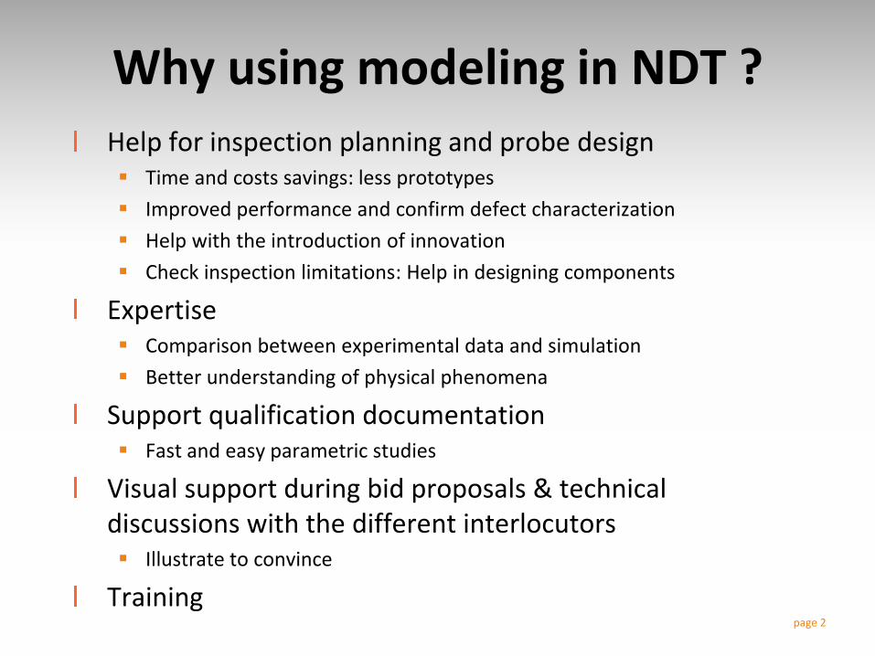
Why using modeling in NDT ?
Help for inspection planning and probe design Time and costs savings: less prototypes
Improved performance and confirm defect characterization
Help with the introduction of innovation
Check inspection limitations: Help in designing components
Expertise Comparison between experimental data and simulation
Better understanding of physical phenomena
Support qualification documentation Fast and easy parametric studies
Visual support during bid proposals & technical discussions with the different interlocutors Illustrate to convince
Trainingpage 2

Simulation Tools for Eddy Current
Simulation tools
Semi-analytical
Numerical
FiniteElements
Code_Carmel3D (current version 2.4.0), developped by LAMEL : collaborative lab between EDF R&D and L2EP (Lille University). Flux3D(current version 11.2), developped by CEDRAT and G2ELAB (Grenoble University)Comsol Multiphysics
Eddy Current module of CIVAplatform, developped by CEA & distributed by EXTENDE
More restrictedcapacities but generally faster and easier to use for non specialists of modeling
Allow to cover a wide scope of configurations
3
Examples of software:

Use of simulation in NDE
2011 ENIQ Recommended Practice 6: The Use of Modelling in Inspection Qualification
Input Data
ValidationsComparisons
Exp / simu
Comparisons
between codes
Simulation Tools
ET NDT industrial
configurations
Experimental data
4
Results: Provide information on the industrial case

Use of simulation in NDE
Working Group: “Modelling of Eddy Current Testing”
Input Data
Validations
Simulation Tools
ET NDT industrial
configurations
Experimental data
5
Results: Provide information on the industrial case

WG « Modelling of Eddy Current Testing»
Members of the group:Industrial end-users : VALLOUREC, EDF, AREVA, SNECMA, DASSAULT AVIATION, AIRBUS GROUP,Research centers: IRSN (in support to French Safety Authorities), CEA, Supélec/CNRS (L2S, LGEP), IREENAEngineering & Consulting : EXTENDENDE system manufacturers: ALPHATEST SYSTEMES
• Define test cases, provide experimental data and simulation results
• Inform the NDE community of simulation software capabilities
Missions of the WG
http://www.cofrend.com/controles-non-destructifs/methodes-de-controle/courant-foucault-et/gt-modelisation/
3 meeting per year with 8 to 13 participants
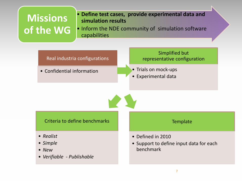
Real industria configurations
• Confidential information
Simplified but representative configuration
• Trials on mock-ups
• Experimental data
Template
• Defined in 2010
• Support to define input data for eachbenchmark
Criteria to define benchmarks
• Realist
• Simple
• New
• Verifiable - Publishable
7
• Define test cases, provide experimental data and simulation results
• Inform the NDE community of simulation software capabilities
Missions of the WG

Example of calculation time evolution for the benchmark « TEAM workshop 8 »
by Finite Element Software
Evaluation criteria of simulation tools for the user: The variety of configurations that can be solved, The accuracy of resuts on these configurations, The computation times, The user interface (GUI) and the necessary numerical expertise required to obtain a good resultThe support service and the evolution of the tool with new releases
0
2
4
6
8
10
12
1995 2000 2005 2010 2015
Co
mp
uta
tio
n t
ime
p
er
pro
be
po
siti
on
(i
n m
n)
Year More & more capabilitiesTo answer more complex
questions
Computation time
Discretisation(ability to mesh finely a configuration for FEM software)Variety of configurations
8
• Define test cases, provide experimental data and simulation results
• Inform the NDE community of simulation software capabilities
Missions of the WG
PRESENTATION OF BENCHMARKS
9
Working Group COFREND : “Modelling of Eddy Current Testing”

Case #2 (EDF - CEA LIST) : Through wall notches in amagnetic conductive slabs
Case #6 (Vallourec, CEA LIST) : Encircling coils testing on stainless steel tubes
Case #7 (CEA, SNECMA) : Model of fatigue cracks by very small flaws in nickel alloycomponent.
Case #8 (CEA LIST) : Remote Field Testing
Case #9 (CEA LIST, WMU) : Bilayer plate with fastener hole
Case #10 (In progress): multilayers with varying electromagnetic properties
Case #6
Case #8 Case #9
Case # 2
TEST CASES
10
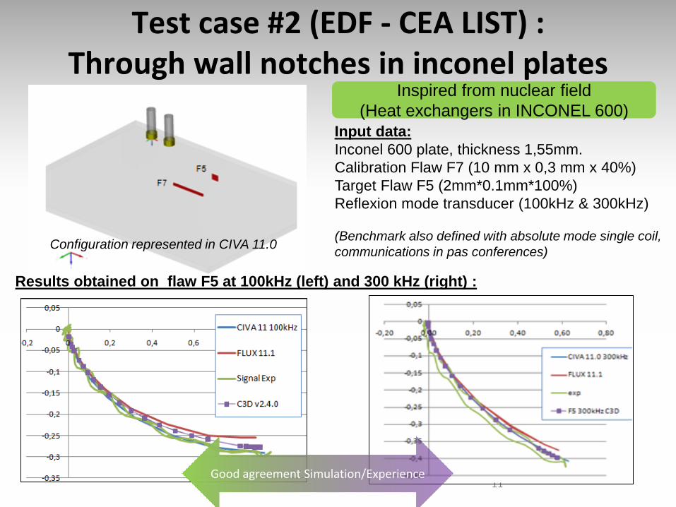
Configuration represented in CIVA 11.0
Input data:
Inconel 600 plate, thickness 1,55mm.
Calibration Flaw F7 (10 mm x 0,3 mm x 40%)
Target Flaw F5 (2mm*0.1mm*100%)
Reflexion mode transducer (100kHz & 300kHz)
(Benchmark also defined with absolute mode single coil,
communications in pas conferences)
Inspired from nuclear field
(Heat exchangers in INCONEL 600)
Test case #2 (EDF - CEA LIST) : Through wall notches in inconel plates
11Good agreement Simulation/Experience
Results obtained on flaw F5 at 100kHz (left) and 300 kHz (right) :
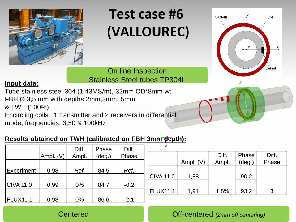
Test case #6(VALLOUREC)
Ampl. (V)
Diff.
Ampl.
Phase
(deg.)
Diff.
Phase
Experiment 0,98 Ref. 84,5 Ref.
CIVA 11.0 0,99 0% 84,7 -0,2
FLUX11.1 0,98 0% 86,6 -2,1
On line Inspection
Stainless Steel tubes TP304L
Results obtained on TWH (calibrated on FBH 3mm depth):
Input data:
Tube stainless steel 304 (1,43MS/m), 32mm OD*8mm wt.
FBH Ø 3,5 mm with depths 2mm,3mm, 5mm
& TWH (100%)
Encircling coils : 1 transmitter and 2 receivers in differential
mode, frequencies: 3,50 & 100kHz
Ampl. (V)
Diff.
Ampl.
Phase
(deg.)
Diff.
Phase
CIVA 11.0 1,88
1,8%
90,2
3FLUX11.1 1,91 93,2
Off-centered (2mm off centering)Centered
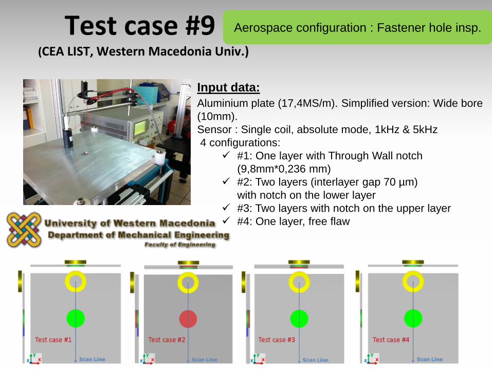
Test case #9(CEA LIST, Western Macedonia Univ.)
Input data:
Aluminium plate (17,4MS/m). Simplified version: Wide bore
(10mm).
Sensor : Single coil, absolute mode, 1kHz & 5kHz
4 configurations:
#1: One layer with Through Wall notch
(9,8mm*0,236 mm)
#2: Two layers (interlayer gap 70 µm)
with notch on the lower layer
#3: Two layers with notch on the upper layer
#4: One layer, free flaw
Aerospace configuration : Fastener hole insp.
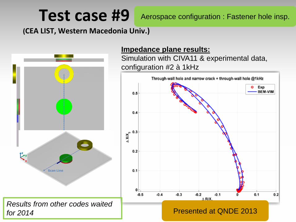
Test case #9(CEA LIST, Western Macedonia Univ.)
Aerospace configuration : Fastener hole insp.
Results from other codes waited
for 2014
Impedance plane results:
Simulation with CIVA11 & experimental data,
configuration #2 à 1kHz
Presented at QNDE 2013
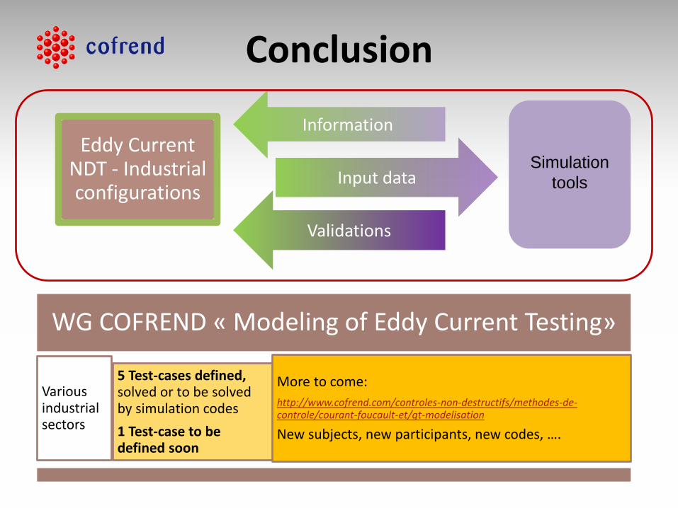
Information
Simulation
toolsInput data
Validations
Eddy Current NDT - Industrialconfigurations
WG COFREND « Modeling of Eddy Current Testing»
Variousindustrialsectors
5 Test-cases defined, solved or to be solvedby simulation codes
1 Test-case to bedefined soon
More to come:
http://www.cofrend.com/controles-non-destructifs/methodes-de-controle/courant-foucault-et/gt-modelisation
New subjects, new participants, new codes, ….
Conclusion

Thanks for your
attention !
Working Group COFREND : “Modelling of Eddy Current Testing”
http://www.cofrend.com/controles-non-destructifs/methodes-de-controle/courant-
foucault-et/gt-modelisation/