WORK PLAN ADDENDUM 2, WATER TREATEMENT SYSTEM …
21
WORK PLAN ADDENDUM 2 WATER TREATMENT SYSTEM DESIGN AND OPERATIONS, MAINTENANCE, AND MONITORING PLAN Callahan Mine Superfund – OU1 Brooksville, Maine Prepared for: Maine Department of Environmental Protection 17 State House Station Augusta, ME 04333-0017 Prepared by: CHARTER ENVIRONMENTAL, INC. 560 Harrison Avenue Boston, MA 02118 April 2013
Transcript of WORK PLAN ADDENDUM 2, WATER TREATEMENT SYSTEM …

WORK PLAN ADDENDUM 2
WATER TREATMENT SYSTEM DESIGN
AND OPERATIONS MAINTENANCE AND MONITORING PLAN
Callahan Mine Superfund ndash OU1 Brooksville Maine
Prepared for
Maine Department of Environmental Protection 17 State House Station
Augusta ME 04333-0017
Prepared by
CHARTER ENVIRONMENTAL INC 560 Harrison Avenue
Boston MA 02118
April 2013
CONTENTS
Page
10 Dewatering Treatment Plan 3
20 Dewatering Fluid Handling and or Treatment 3
30 Dewatering Fluid Collection 3
40 Pre-Treatment Dewatering of Fluid Characterization 3
50 Free-Product Handling 4
60 Dewatering Treatment System 4-5
70 Post-Treatment Testing of Dewatering Fluid Discharges 5
80 Discharge Location 6
90 System Security 6
100 Routine Operations and Maintenance 6-7
110 Storage Frac Tank Cleaninghelliphelliphelliphelliphelliphelliphelliphelliphelliphelliphelliphelliphelliphelliphelliphelliphellip 7-11
Figure 1 ndash Approximate Treatment System Location
Attachment A Treatment System Configuration
Attachment B Treatment System Component Details
Attachment C Daily System Inspection Form
10 Dewatering Plan
This Plan serves as an addendum to the previously approved Work plan for this contract All health and Safety and QAQC procedures established in the previously approved work plan will apply to this addendum This Dewatering Plan serves both as the Design Plan and the Operations Maintenance and Monitoring Plan for the treatment of water that may come in contact with PCB impacted soils within the Callahan Mine property
The primary method of management of water developed from excavations within the PCB impacted areas will be treatment of water through settlement and filtration prior to on-site recharge
20 PCB Impacted water Handling and or Treatment
All dewatering fluid (combined groundwater seepage and surface-water runoff) handling will be performed in accordance with the approved Work Plan applicable Federal State and local regulations laws codes and ordinances using portable dewatering system plants
30 PCB Water Collection
The fluid collection system will consist of a 2-inch sump pump that will be placed in the excavation Gravel will be placed around the pump to minimize the amount of sediment that is pumped into the system Water will be pumped to the treatment system directly The pumps will be plumbed with flexible hoses to the chosen receiving system It is anticipated that the system will only be operated during working hours of the site If additional time to run system is required or if the 2-inch pump is not adequate to dewater an area the system will be evaluated and system changes will be proposed to the MEDEP for approval
40 Pre-Treatment Discharge of Dewatering Fluid Characterization
The initial dewatering fluids will be visually inspected to assess the potential presence of suspended sediment coloration odor sheens andor free product The dewatering fluids will then be pumped through the treatment system
Page 3
50 Free-Product Handling
If free product is identified in any of the pipe tap locations or otherwise observed on-site the MEDEP will be notified Pumps within the sedimentation tank would be relocated to minimize potential for free product to be pumped from the tanks if formed Booms andor pads would be placed within the sedimentation tanks as a precautionary measure to collect any floating product that forms
Booms and pads will be placed in 55-gallon drums for off-site disposal as PCB impacted solids
60 Water Treatment System
A portable water treatment system will be mobilized to the project site to meet the on-site recharge standard of 1ppm A detailed schematic of an available system is contained in Attachment A Component details are contained in Attachment B
Dewatering fluids pumped from the pipe to the dewatering system would be treated using the following basic protocol
a Dewatering fluids will be delivered to a primary 10000-gallon capacity frac tank that will serve as the principal sediment-settling chamber and oilwater separator The frac tank may be equipped with low-level float valves if needed to activate and deactivate an internal submersible pump The pump will be set in the water column of the frac tank to retrieve water from a level approximately two feet below the low-level float and the float switches will be set to assure a maximum settling residence time for water in the tank Replacement pumps will be made available to allow for rapid repair should a pump fail The pump will be powered by a generator
b Filtration will be accomplished by pumping from the frac tank into bag filters placed in series This will be used for final particulate removal from the waste stream and to provide trace oil separation from the water The bag filter that would be used will be a UF Strainrite Model UF 1-180 or equivalent capable of removing particulate matter greater than 25 microns the second bag filter unit will be capable of removing particulate matter to 1 micron The 1 micron filters will be changed regularly to eliminate any slow down to the system
Page 4
70 Post-Treatment Testing of Dewatering Fluid Discharges
Testing of the treatment system effluent to confirm it has successfully treated the water for PCBs The effluent will be plumbed back to the frac tank until the analytical results confirm that the water has been successfully treated The effluent will then be recharged back on-site
Periodic sampling will be the responsibility of CES Inc
CES Inc will supply all labor equipment and materials necessary to obtain accurate representative samples of the water
Upon start-up of the system a sample will be taken before the treatment system and after the treatment system to demonstrate treatment effectiveness
The effluent will be re-circulated to the systemrsquos influent point until the first set of analysis indicates that the system has met the discharge limits Only when analytical demonstrates that the system has met this standard will the effluent be discharge to the discharge point
80 Discharge Location
Treated water will be discharged to a recharge area near the treatment system See Figure 1 for the approximate location of the Treatment System
90 System Security
Elements of the Dewatering Treatment System will be protected from weather and construction hazards as appropriate Insulation heat tape and temporary shelters will be used to protect individual components from freezing or other weather-related hazards as necessary Discharge lines and plumbing between System elements will be placed below ground where necessary so as not to impede construction activities
The Water Treatment System will be located within project boundaries
100 Routine Operations and Maintenance
During operation of the dewatering treatment system daily inspections will be conducted to confirm appropriate system performance and to identify potential maintenance requirements The Daily Inspection Form included in Attachment C will guide daily inspections
Page 5
Pipeline taps will be inspected to confirm free of leaks
Sedimentation tank(s) will be inspected to measure water levels and sediment levels identify the presence of sheens or free product on the water verify float and shutoff switch and associated transfer pump operation Sediment measurements will be recorded on the daily inspection log The daily inspection log can be found in Attachment C If sheens or free product are identified absorbent booms or pads will be placed in the sedimentation tanks and pump levels will be adjusted as appropriate to prevent transfer of separate phase oil If switches or pumps are not operating properly replacement from on-site stock will be performed When accumulated sediment must be removed from the tanks (likely only at the termination of system use or when sediment reaches approximately 4 feet high with in the tank) the system will be stopped pumps will be removed and then the sediment may be pumped or manually removed dewatered by drying tested for disposal characterization in accordance with criteria set forth in the soil management plan and disposed at an appropriate receiving facility along with comparably characterized soil from the Site If a Vacuum truck is used to remove sediment from frac tanks a certification that the interior of the vac truckrsquos holding tank has been cleaned from all prior content will be supplied to the Project Any entry into the sedimentation tanks will be performed according to established confined space entry protocols Sediment removed from frac tanks will be placed in the soil staging and stockpiling area of the site to dry
Bag filters will be inspected to determine if replacement with a new filter is required Replacement filters will be maintained on-site
A visual inspection of the remainder of the dewatering treatment system will be performed to identify any system leakage or evidence of unusual wear Leaks will be corrected immediately and spilled fluids will be cleaned up with absorbents or other appropriate controls
All waste (bag filters sediment in frac tank ect) generated from the system will be disposed of with the gt50ppm PCB waste unless otherwise sampled for disposal characterization
Water being discharged to the recharge area will be inspected visually to verify that no sheen or associated free product is apparent If a sheen or free product is identified the system will be placed in the recirculating mode until the source of the treatment failure is identified
Page 6
Whenever maintenance is performed activities will be completely documented in the daily inspection log The logbook will be maintained on-site
110 Storage Frac Tank Cleaning
Confined Space Entry Procedure will be followed when performing tank cleanings
A confined space provides the potential for unusually high concentrations of contaminants explosive atmospheres limited visibility and restricted movement This section will establish requirements for safe entry into continued work in and safe exit from confined spaces Additional information regarding confined space entry can be found in 29 CFR 192621 29 CFR 1910 and NIOSH 80-106
Definitions
Confined Space A space or work area not designed or intended for normal human occupancy having limited means of egress and poor natural ventilation andor any structure including buildings or rooms which have limited means of egress
Confined Space Entry Permit (CSEP) A document to be initiated by the supervisor of personnel who are to enter into or work in a confined space The Confined Space Entry Permit (CSEP) will be completed by the personnel involved in the entry and approved by the HSO before personnel will be permitted to enter the confined space The CSEP shall be valid only for the performance of the work identified and for the location and time specified The beginning of a new shift with change of personnel will require the issuance of a new CSEP
Confined Space Attendant An individual assigned to monitor the activities of personnel working within a confined space The confined space attendant monitors and provides external assistance to those inside the confined space The confined space attendant summons rescue personnel in the event of emergency and assists the rescue team
General Provisions
When possible confined spaces should be identified with a posted sign which reads Caution - Confined Space
Only personnel trained and knowledgeable of the requirements of these Confined Space Entry Procedures will be authorized to enter a
Page 7
confined space or be a confined space observer A Confined Space Entry Permit (CSEP) must be issued prior to the
performance of any work within a confined space The CSEP will become a part of the permanent and official record of the site
Natural and or mechanical ventilation shall be provided for the confined space prior to initial entry and for the duration of the CSEP Positiveforced mechanical ventilation may be required However care should be taken to not spread contamination outside of the enclosed area
If flammable liquids may be contained within the confined space explosion proof equipment will be used All equipment shall be positively grounded
The contents of any confined space shall where necessary be removed prior to entry All sources of ignition must be removed prior to entry
Hand tools used in confined spaces shall be in good repair explosion proof and spark proof and selected according to intended use Where possible pneumatic power tools are to be used
Hand-held lights and other illumination utilized in confined spaces shall be equipped with guards to prevent contact with the bulb and must be explosion roof
Compressed gas cylinders except cylinders used for self-contained breathing apparatus shall not be taken into confined spaces Gas hoses shall be removed from the space and the supply turned off at the cylinder valve when personnel exit from the confined space
If a confined space requires respiratory equipment or where rescue may be difficult safety belts body harnesses and lifelines will be used The outside observer shall be provided with the same equipment as those working within the confined space
A ladder is required in all confined spaces deeper than the employees shoulders The ladder shall be secured and not removed until all employees have exited the space
Only self-contained breathing apparatus or NIOSH approved airline respirators equipped with a 5-minute emergency air supply (egress bottle) shall be used in untested confined spaces or in any confined space with conditions determined immediately dangerous to life and health
Where air-moving equipment is used to provide ventilation chemicals shall be removed from the vicinity to prevent introduction into the confined space
Vehicles shall not be left running near confined space work or near air-moving equipment being used for confined space ventilation
Smoking in confined spaces will be prohibited at all times Any deviation from these Confined Space Entry Procedures requires
Page 8
the prior permission of the On-Scene Coordinator
Procedure for Confined Space Entry
The HSO and Entry Team shall Evaluate the job to be done and identify the potential hazards before a
job in a confined space is scheduled Ensure that all process piping mechanical and electrical equipment
etc have been disconnected purged blanked-off or locked and tagged as necessary
If possible ensure removal of any standing fluids that may produce toxic or air displacing gases vapors or dust
Initiate a Confined Space Entry Permit (CSEP) in concurrence with the project manager or designated alternative
Ensure that any hot work (welding burning open flames or spark producing operation) that is to be performed in the confined space has been approved by the project manager and is indicated on the CSEP
Ensure that the space is ventilated before starting work in the confined space and for the duration of the time that the work is to be performed in the space
Ensure that the personnel who enter the confined space and the confined space observer helper are familiar with the contents and requirements of this instruction
Ensure remote atmospheric testing of the confined space prior to employee entry and before validationrevalidation of a CSEP to ensure the following
1 Oxygen content between 195 - 230 2 No concentration of combustible gas in the space Sampling
will be done throughout the confined space and specifically at the lowest point in the space
3 The absence of other atmospheric contaminants space has contained toxic corrosive or irritant material
4 If remote testing is not possible Level B PPE is required
Designate whether hot or cold work will be allowed If all tests in 1 through 3 are satisfactory complete the CSEP listing any safety precautions protective equipment or other requirements
Ensure that a copy of the CSEP is posted at the work site a copy is filed with the project supervisor and a copy is furnished to the project manager
Erect personnel retrieval equipment adjacent to entry point Equipment includes tripod winch and tether as well as body harness
Page 9
for occupants to wear during work in the confined space
The CSEP shall be considered void if work in the confined space does not start within one hour after the tests are performed or if significant changes within the confined space atmosphere or job scope occur
The CSEP posted at the work site shall be removed at the completion of the job or the end of the shift whichever is first
Confined Space Attendant
While personnel are inside the confined space a confined space attendant will monitor the activities and provide external assistance to those in the space The attendant will have no other duties which may take his attention away from the work or require him to leave the vicinity of the confined space at any time while personnel are in the space
The confined space attendant shall maintain at least voice contact with all personnel in the confined space Visual contact is preferred if possible
The attendant shall be instructed by his supervisor in the method for contacting rescue personnel in the event of an emergency
If irregularities within the space are detected by the attendant personnel within the space will be ordered to exit
In the event of an emergency the observer must NEVER enter the confined space prior to contacting and receiving assistance from a helper Prior to this time he should attempt to remove personnel with the lifeline and to perform all other rescue functions from outside the space
A helper shall be designated to provide assistance to the confined space attendant in case the observer must enter the confined space to retrieve personnel
Page 10
FIGURE 1
APPROXIMATE LOCATION OF TREATMENT SYSTEM
NOTES 1 CONSTRUCTION SEQUENCING DETAILS ARE OUTLINED IN TECHNICAL
SPECIFICATION SECTION 01 - 1000 - SUMMARY OF WORK
2 TREELINE SHOWN WAS TAKEN FROM AERIAL PHOTOGRAPHY AND SHOULD BE CONSIDERED APPROXIMATE
3 THIS PLAN DEPICTS TOPOGRAPHY AS FOUND AND SURVEYED BY CES INC ON JUNE 26 2012
4 THE ZONES HAVE BEEN CREATED TO PROGRESS THE WORK BASED ON EXISTING TOPOGRAPHY AND STORMWATER DRAINAGE AND TO OPTIMIZE EROSION AND SEDIMENT CONTROLS TRACKING FROM HIGHER CONCENTRATIONS TO LOWER CONCENTRATIONS SHALL NOT BE PERMITTED
5 6 EXCAVATION LOCATIONS REQUIRES EXCAVATION FROM 0-6 BELOW GROUND SURFACE
6 ADJUSTMENTS TO ZONE BOUNDARIES MUST BE APPROVED BY RESIDENT
ZONE 2 COMPLETE
Approximate location of Treatment System
ZONE 1 COMPLETE
EXISTING CLEAN ACCESS ROAD
AREAS OF PONDING WATER
LEGEND
EXISTING 1 CONTOUR
EXISTING 5 CONTOUR
PROPOSED 1 CONTOUR
PROPOSED 5 CONTOUR
EXISTING ACCESS ROAD
PROPOSED DRAINAGE DITCH
REMEDIATION PHASE LIMIT
APPROXIMATE TREELINE
REMEDIATION ZONE
TCLP LEAD ABOVE REGULATORY THRESHOLD
PCB CONCENTRATION 1 - 10 PPM
PCB CONCENTRATION 10 - 50 PPM
PCB CONCENTRATION gt 50 PPM
ACCESS ROAD
CONCRETE RUBBLE
PREVIOUSLY EXCAVATED AREA
STAKE BOUNDING EXCAVATION
gt
01
Bre
wer
Pre
sque
Isle
Tops
ham
465
So
Mai
n S
treet
549
Mai
n S
treet
2 M
ain
Stre
etP
O B
OX
639
PO
BO
X 8
27S
uite
213
CA
LLA
HA
N M
INE
SUPE
RFU
ND
PR
OJE
CT
BR
OO
KSV
ILLE
MA
INE
Bre
wer
ME
Pre
sque
Isle
ME
Tops
ham
ME
T20
7-98
9-48
24T
207-
764-
8412
T 2
07-8
37-6
130
PO
INTS
amp 1
-10p
pm A
RE
A C
HA
NG
E P
ER
MD
EP
09
17
2012
B
LC
AD
DS
P
F20
7-98
9-48
81F
207-
764-
8414
F20
7-83
7-61
99
Mac
hias
Bar
Har
bor
REM
EDIA
TIO
N P
LAN
61 D
ublin
Stre
et13
66 S
tate
Hw
y 10
2P
O B
OX
587
Bar
Har
bor
ME
Mac
hias
ME
T20
7-28
8-05
87T
207-
255-
3270
F20
7-28
8-05
88F
207-
255-
8367
6 E
XCA
VATI
ON
LO
CA
TIO
NS
WW
WC
ES
-MA
INE
CO
M
REMEDIATION PLAN 6 EXCAVATION LOCATIONS 1 = 40
9132012
BBBC ST
AD DSP
5992-09
C-101 1 OF 8
ATTACHMENT A
TREATMENT SYSTEM CONFIGURATION
--
____
--
--
1 1 1 d ~ -r 1 1 _ cI l _Ll - I - I ~I 1-L_bull 1 middott ~-+-~I plusmnI L-1----i---
-$- CHARf~lENVIRONM
CLIENT I SUBJECT ME DEP I Callahan Mine
TASK DESCRIPTION Groundwater Treatment System
bullr ~f~ ~ I t_ffillevt c_yqL~Alil -1i ~~ 1+81J--r I
1 r I I I I I U n~ I tffilr--1 i 1
-t i 11 i I i Uo_l ltJ--j --j +- ~~ lflj - __ I_) -----shy-- 1 I- l----1-+- -- rrJ21 IJI I _j __L~I_ Trjl I T shy
1=1 i_plusmnLH---L--y h+ 1 r 1 I I ~ ~ =i i j -~- t II I I ftl M __ I LL I UJ I I~-- 1 1I
r---1+H-1_ b 1 __l_LI I f---1 I 1 1+ I 1 - 1 ~I ~~+---t---J~ t- +i21J 111 ~~-t+r---r- I1 -r
I I I _L r I ---4-1~ -1-+--i F=I 1_ -Fi ~ tTJ t shy8r- =II--~plusmn11 i I u i - ~ +~--I-=l=l-v~lr----r--w-~ ~-- --1 t- -f --t-J-f=T+- n 11I - _ _j shy _
11 ~1 1 1~i--+---tE~~middottJv_~-t~k~fif 1--+JKr-l---J rba---t __j~ ~~FffftfLL--l--+J--~r---shyI 1--l-i
f-R_gM - I I_~I
-++ I j 10 rl
IR=t=H4+~~~J J_j__
I cw I
___ [_
~-~~ 1--~~~-~~~t~ lJ f- ~ I I
r 1-+ f-t-bull-rPofri -r _J H_J dt_] --r~_~shy___11- - --H -T L++fjl I ___j_J_]II 1-l r--i J J --
1--+--+--1-1~1 I l_tl_~ ~~shyI I+
1 - I bull I I I u I l- - I -~- I ---- I - -~ _L__r j I
1
-l-----l----~-- __ -t -1middot-----r --r I i _ ---------shy~---~-~~~---r r --L----+-~1 1 __l_ 1 middot- -~T 1 r____ r 1 --lri 1
=+ r--++-++-r _ l-t-UT] ++ l___t~7II o~+-j 1tL 11 r ---+-f---1---r----r-r- i ~ L L 1 t igtlt~J f-+ n-- t
--i---~- ~1 _1 1 1 -I 1 r - -1 ~-~-- 1--]~_1 __L-f-i--
1
-~J~j 1
1
~l-r- 1
1 1 Llt
1
J_ L
t 1
i
1 1 r
1 IJ_ -+- f+-t-r
t u~ T
1rshy I
I 1 I ~ __ i~------ - 1
1 I 1 _j --middot-middotmiddotmiddot-- bull 1 ____j___1 --=Lu-~~r----middot~ -ri_J_J1_-+-~ 1-r -r-J_Jr _J_l-1--+- ~middot -f--- i 11
__ __L_J ----+~~-~--shymiddot~ I -rmiddot-----~---- I -~ 1
_ __) ___-- ~- J ~ i --L-~~j I ~_ _______ I 1
- _ 1 1 r-------- 1 1 I --+--+-r----- r _ ~j-middotmiddotmiddotmiddotmiddot middot~- r ~~-+--r-----1-l L ---j -i shy 1 1___ ---~----j- -----i-T j middot I 1 ll 1 L___l___ _J___--1-- 1
r 1 l1 11 -1--------- --r---- 1 )______ I i bull I I I ---- I i I I i ___ ____ -- I I f middot I - shy
--- 1 1 1 _ ~-~--middot------~ 1 1 __[____~i-+---~ 1 ~-------c--Tmiddotr _- ___j__+----~-----shyl_ _l __lr middot 1 1 I --- ir 1 1 1 L_J ___t __ i----~--1 1 - -----j--------r 1 1 1 ~1 r---r i --j------j~---middot1 -i ~~~ -1 ++-l-r 1 J ___11-+ -middot~--j-- 1 -middotmiddot i L_ J--j--J-i i I - L__~----- I I 1_____
- i __ I I I -~-- 1 ~-shy_j__J--t--+---+-------~- --~ __J___I ---+----1----j-middotmiddotmiddot-middot--r--middoti ~~~+--~--~ - middotmiddotmiddotJ-l J
r
Ll__ _j---r--~~-1 J
I i I - -- -~- --1 I I L -~- I I i 1 1I I I I_11- i I --i - t middotmiddotmiddotr r i
J
i _j r-+ i 1 i i -middot L middoti----f---- I I II l IL_li i i--r---j I I -----r--1- I I 1 I -Hmiddot I I i I
i I I I i I I I I~--+-+-T(i II~~ i i i II
ATTACHMENT B
TREATMENT SYSTEM COMPONENT DETAILS
[sect c c N
c c N
K tVtYU Vlltl ~ U 1 I t bull
lJF ampCOX (90s amp180s)
v- SiAAINRITE 2G7middot777bull3100
All 00 Md 180 Slye tater ba~str~ilsr vessels are cle1rl-oed will a recet5cd bas~t a volume displscer permenen~y W9dac to L1e top oNQr and a 304 statll~ sceel vAre o$ rultdnet hasxa Vire meh be~~s LCreaso awitablo firttlol sttfaC6 t~reltgt ~Y 30 compared to e pamiddot~ecec malner gtSmiddot oo Wa otter our 90 UK 180 sJlv ve~S 1 in twO OHarant styles UF 21d COX ampod a varishyety oi pmssure raJngs witt 1SC lsi belrg SW1dafd
Standard Fe~turcs bull Av1abiG In Carbon Sloe 304 and 316
Slsinlesa Steel
bull Adjustable height Iii-pod stand
bull 6~ilt-in volume displace In cover
bulllelorJUet orientation Side-in Bot011middot OJI (sLanderd or Side-In SiIamp-OIJt
bull LcMbull Pf98SJfe drop
bull oa~ cavet se~l bull Avat~le Onng mampte1sts Bvna N En
Vtor A Teflon amp Teloo Ercapsvlated
bull Eisy deanatJillty
bull ~ SS wire~ oaslltet
bull 5yen-E Code ~m) avlil~gtla Oil ltII ui= 91yle veSSGIS
bull Sbullifg Ml~ closures
bull 25 NPI dirferentiat p(cssue g2ugevefll tao
bull Pipamp poundzs frOIil 75 toY NPT AFF or Gvid Oiscoonect connections
391
uqr JO zuu Ult o JltAA 4UllI4BlI7ZZ Robin Rollo ~005
Nov 04 02 Ol3p H A ~ILSON CO 791-883-9623 pc
R 0 S E D A L E P R o D 0 C T s N c
H A WILSON COMPANY[[l How To Order middotManufacturers Represent$tives
PO Box 252 Lexington MA 02420 Model RCO Housing (781) 861-8000 Fax (781) 863-8629 -~middot-middotmiddotmiddotmiddotmiddot
Build an ordering code as shown in the example
Rosedale Products Inc P 0 Box I oas Ann Arbor Ml 481 06
Phone (BOO) 821-5373 or 734) 665-820 I Fax 734) 665-2214 E-Mail filtersros~daleproduascom Website VIMMrosedaleproductscom
cara10g RCD-1 00 SMB02 litl1o tn USA
OUTLei
1middot112 OR ~2NPT INLET
BASKET LINE
22 AOJUSTABLE
_r- TfiUgtOD LEGS
3T4 NPT DRAIN (RC08135
1middot112 OR zbull NPT
(3 9116 OIA KOLES oN 12middot oac
II tUttU (Uttr
7
bull
C)gt j1
UF 1-tBO 2A2NSO 0
l31
Rocommcndad Flow ftample3 and SurfJ~co Aru
Fot the middotf~ recorrvnGnd~ b rates JassAis nEteO a rrlnlmum ioJefoiIUe size ol 2middot ~ The recorrms1del tlow for b~ket and filter combination is tor nominally rated ftlter bamp)amp ro tor OU hlgl eftlclampncy filter beg line
Product Bbullskel Mesh lined Stralntt Bas~t
S~lner
UF -180 300 gpm 220 QP~
Reblner Surl~ce 8a$lmWth AJP Riter Ba9 Sq fl
7Sgpm 225
150 gpm 450
Optional feature$ bull Epoxy coatng electroshy
dl$h and Me coating bull Higher piGS$Ufe ratings
evallable up tc 3000 psi bull Steam Jaeketad middot middot
bull Dllrfrontiel pnnaure gau~ sp~ - 25bull ot S NPT
bull 9ag holo doom dollcea bull Sustan dealgrn
bull SSnlusry CO~iOs
bull Mesh-Uncd bas~- snlining applicampiona shyo mlcrun eld hlg~r
bull Oiher materials ol onslruction e(e Uranium n~ middotaatelloy
The UF Stralnrite Advantag~
bull Recessed basket wtl bullJiellad ~~are cfiSI)Ieco - aiJOY3 for cleaner operatlol btcevse fiQJid Is saverallnches below lid
bull Rswinet ba1kvt with handle - allows ior easy ~nd quick ~cess to filter b~ aod basket
bull Wire rresh retainer basket - 810N$ for tonger fillet tame r~ulrilg it ~
ciWg~ as compold to POr10tatad ba~kets (ramplcr ll psge 14)
bull Double Oirlg seal - ts~ures high qua~Y illlatlon ane miOmlbulles )ypass coa~lial
vUF1middot1SO 2A2N
ri11
UF STRAINRITE 207middot777-3100
ATTACHMENT C
DAILY SYSTEM INSPECTION FORM
DAILY INSPECTION FORM
Date Time ampm
Pipeline Tap Condition
Sheen YN Free Product YN
Influent Sample Collected
Frac Tank No 1 Water Level Sediment Level
Pump Online YN Float Switch Op YN
Shutoff Switch Op YN Sheen YN
Sediment thickness
Free Product YN
Pump to Bag Filter No 1 Pump Online YN Flow Rate gpm
Pump to Bag Filter No 2 Pump Online YN Flow Rate gpm
Pressure Gauges No 1 lbs No 2 lbs
Bag Filters No 1 Replaced YN No 2 Replaced YN
Effluent Samples Intermediate YN Effluent YN
Any system leakage
Any electric power problems
Inspect recharge area for sheens
Total Discharge Time gallons
Health or Safety Concerns
Maintenance Performed
Maintenance Needed
Inspectors Signature
- barcode 547461
- barcodetext SDMS Doc ID 547461

--
____
--
--
1 1 1 d ~ -r 1 1 _ cI l _Ll - I - I ~I 1-L_bull 1 middott ~-+-~I plusmnI L-1----i---
-$- CHARf~lENVIRONM
CLIENT I SUBJECT ME DEP I Callahan Mine
TASK DESCRIPTION Groundwater Treatment System
bullr ~f~ ~ I t_ffillevt c_yqL~Alil -1i ~~ 1+81J--r I
1 r I I I I I U n~ I tffilr--1 i 1
-t i 11 i I i Uo_l ltJ--j --j +- ~~ lflj - __ I_) -----shy-- 1 I- l----1-+- -- rrJ21 IJI I _j __L~I_ Trjl I T shy
1=1 i_plusmnLH---L--y h+ 1 r 1 I I ~ ~ =i i j -~- t II I I ftl M __ I LL I UJ I I~-- 1 1I
r---1+H-1_ b 1 __l_LI I f---1 I 1 1+ I 1 - 1 ~I ~~+---t---J~ t- +i21J 111 ~~-t+r---r- I1 -r
I I I _L r I ---4-1~ -1-+--i F=I 1_ -Fi ~ tTJ t shy8r- =II--~plusmn11 i I u i - ~ +~--I-=l=l-v~lr----r--w-~ ~-- --1 t- -f --t-J-f=T+- n 11I - _ _j shy _
11 ~1 1 1~i--+---tE~~middottJv_~-t~k~fif 1--+JKr-l---J rba---t __j~ ~~FffftfLL--l--+J--~r---shyI 1--l-i
f-R_gM - I I_~I
-++ I j 10 rl
IR=t=H4+~~~J J_j__
I cw I
___ [_
~-~~ 1--~~~-~~~t~ lJ f- ~ I I
r 1-+ f-t-bull-rPofri -r _J H_J dt_] --r~_~shy___11- - --H -T L++fjl I ___j_J_]II 1-l r--i J J --
1--+--+--1-1~1 I l_tl_~ ~~shyI I+
1 - I bull I I I u I l- - I -~- I ---- I - -~ _L__r j I
1
-l-----l----~-- __ -t -1middot-----r --r I i _ ---------shy~---~-~~~---r r --L----+-~1 1 __l_ 1 middot- -~T 1 r____ r 1 --lri 1
=+ r--++-++-r _ l-t-UT] ++ l___t~7II o~+-j 1tL 11 r ---+-f---1---r----r-r- i ~ L L 1 t igtlt~J f-+ n-- t
--i---~- ~1 _1 1 1 -I 1 r - -1 ~-~-- 1--]~_1 __L-f-i--
1
-~J~j 1
1
~l-r- 1
1 1 Llt
1
J_ L
t 1
i
1 1 r
1 IJ_ -+- f+-t-r
t u~ T
1rshy I
I 1 I ~ __ i~------ - 1
1 I 1 _j --middot-middotmiddotmiddot-- bull 1 ____j___1 --=Lu-~~r----middot~ -ri_J_J1_-+-~ 1-r -r-J_Jr _J_l-1--+- ~middot -f--- i 11
__ __L_J ----+~~-~--shymiddot~ I -rmiddot-----~---- I -~ 1
_ __) ___-- ~- J ~ i --L-~~j I ~_ _______ I 1
- _ 1 1 r-------- 1 1 I --+--+-r----- r _ ~j-middotmiddotmiddotmiddotmiddot middot~- r ~~-+--r-----1-l L ---j -i shy 1 1___ ---~----j- -----i-T j middot I 1 ll 1 L___l___ _J___--1-- 1
r 1 l1 11 -1--------- --r---- 1 )______ I i bull I I I ---- I i I I i ___ ____ -- I I f middot I - shy
--- 1 1 1 _ ~-~--middot------~ 1 1 __[____~i-+---~ 1 ~-------c--Tmiddotr _- ___j__+----~-----shyl_ _l __lr middot 1 1 I --- ir 1 1 1 L_J ___t __ i----~--1 1 - -----j--------r 1 1 1 ~1 r---r i --j------j~---middot1 -i ~~~ -1 ++-l-r 1 J ___11-+ -middot~--j-- 1 -middotmiddot i L_ J--j--J-i i I - L__~----- I I 1_____
- i __ I I I -~-- 1 ~-shy_j__J--t--+---+-------~- --~ __J___I ---+----1----j-middotmiddotmiddot-middot--r--middoti ~~~+--~--~ - middotmiddotmiddotJ-l J
r
Ll__ _j---r--~~-1 J
I i I - -- -~- --1 I I L -~- I I i 1 1I I I I_11- i I --i - t middotmiddotmiddotr r i
J
i _j r-+ i 1 i i -middot L middoti----f---- I I II l IL_li i i--r---j I I -----r--1- I I 1 I -Hmiddot I I i I
i I I I i I I I I~--+-+-T(i II~~ i i i II
ATTACHMENT B
TREATMENT SYSTEM COMPONENT DETAILS
[sect c c N
c c N
K tVtYU Vlltl ~ U 1 I t bull
lJF ampCOX (90s amp180s)
v- SiAAINRITE 2G7middot777bull3100
All 00 Md 180 Slye tater ba~str~ilsr vessels are cle1rl-oed will a recet5cd bas~t a volume displscer permenen~y W9dac to L1e top oNQr and a 304 statll~ sceel vAre o$ rultdnet hasxa Vire meh be~~s LCreaso awitablo firttlol sttfaC6 t~reltgt ~Y 30 compared to e pamiddot~ecec malner gtSmiddot oo Wa otter our 90 UK 180 sJlv ve~S 1 in twO OHarant styles UF 21d COX ampod a varishyety oi pmssure raJngs witt 1SC lsi belrg SW1dafd
Standard Fe~turcs bull Av1abiG In Carbon Sloe 304 and 316
Slsinlesa Steel
bull Adjustable height Iii-pod stand
bull 6~ilt-in volume displace In cover
bulllelorJUet orientation Side-in Bot011middot OJI (sLanderd or Side-In SiIamp-OIJt
bull LcMbull Pf98SJfe drop
bull oa~ cavet se~l bull Avat~le Onng mampte1sts Bvna N En
Vtor A Teflon amp Teloo Ercapsvlated
bull Eisy deanatJillty
bull ~ SS wire~ oaslltet
bull 5yen-E Code ~m) avlil~gtla Oil ltII ui= 91yle veSSGIS
bull Sbullifg Ml~ closures
bull 25 NPI dirferentiat p(cssue g2ugevefll tao
bull Pipamp poundzs frOIil 75 toY NPT AFF or Gvid Oiscoonect connections
391
uqr JO zuu Ult o JltAA 4UllI4BlI7ZZ Robin Rollo ~005
Nov 04 02 Ol3p H A ~ILSON CO 791-883-9623 pc
R 0 S E D A L E P R o D 0 C T s N c
H A WILSON COMPANY[[l How To Order middotManufacturers Represent$tives
PO Box 252 Lexington MA 02420 Model RCO Housing (781) 861-8000 Fax (781) 863-8629 -~middot-middotmiddotmiddotmiddotmiddot
Build an ordering code as shown in the example
Rosedale Products Inc P 0 Box I oas Ann Arbor Ml 481 06
Phone (BOO) 821-5373 or 734) 665-820 I Fax 734) 665-2214 E-Mail filtersros~daleproduascom Website VIMMrosedaleproductscom
cara10g RCD-1 00 SMB02 litl1o tn USA
OUTLei
1middot112 OR ~2NPT INLET
BASKET LINE
22 AOJUSTABLE
_r- TfiUgtOD LEGS
3T4 NPT DRAIN (RC08135
1middot112 OR zbull NPT
(3 9116 OIA KOLES oN 12middot oac
II tUttU (Uttr
7
bull
C)gt j1
UF 1-tBO 2A2NSO 0
l31
Rocommcndad Flow ftample3 and SurfJ~co Aru
Fot the middotf~ recorrvnGnd~ b rates JassAis nEteO a rrlnlmum ioJefoiIUe size ol 2middot ~ The recorrms1del tlow for b~ket and filter combination is tor nominally rated ftlter bamp)amp ro tor OU hlgl eftlclampncy filter beg line
Product Bbullskel Mesh lined Stralntt Bas~t
S~lner
UF -180 300 gpm 220 QP~
Reblner Surl~ce 8a$lmWth AJP Riter Ba9 Sq fl
7Sgpm 225
150 gpm 450
Optional feature$ bull Epoxy coatng electroshy
dl$h and Me coating bull Higher piGS$Ufe ratings
evallable up tc 3000 psi bull Steam Jaeketad middot middot
bull Dllrfrontiel pnnaure gau~ sp~ - 25bull ot S NPT
bull 9ag holo doom dollcea bull Sustan dealgrn
bull SSnlusry CO~iOs
bull Mesh-Uncd bas~- snlining applicampiona shyo mlcrun eld hlg~r
bull Oiher materials ol onslruction e(e Uranium n~ middotaatelloy
The UF Stralnrite Advantag~
bull Recessed basket wtl bullJiellad ~~are cfiSI)Ieco - aiJOY3 for cleaner operatlol btcevse fiQJid Is saverallnches below lid
bull Rswinet ba1kvt with handle - allows ior easy ~nd quick ~cess to filter b~ aod basket
bull Wire rresh retainer basket - 810N$ for tonger fillet tame r~ulrilg it ~
ciWg~ as compold to POr10tatad ba~kets (ramplcr ll psge 14)
bull Double Oirlg seal - ts~ures high qua~Y illlatlon ane miOmlbulles )ypass coa~lial
vUF1middot1SO 2A2N
ri11
UF STRAINRITE 207middot777-3100
ATTACHMENT C
DAILY SYSTEM INSPECTION FORM
DAILY INSPECTION FORM
Date Time ampm
Pipeline Tap Condition
Sheen YN Free Product YN
Influent Sample Collected
Frac Tank No 1 Water Level Sediment Level
Pump Online YN Float Switch Op YN
Shutoff Switch Op YN Sheen YN
Sediment thickness
Free Product YN
Pump to Bag Filter No 1 Pump Online YN Flow Rate gpm
Pump to Bag Filter No 2 Pump Online YN Flow Rate gpm
Pressure Gauges No 1 lbs No 2 lbs
Bag Filters No 1 Replaced YN No 2 Replaced YN
Effluent Samples Intermediate YN Effluent YN
Any system leakage
Any electric power problems
Inspect recharge area for sheens
Total Discharge Time gallons
Health or Safety Concerns
Maintenance Performed
Maintenance Needed
Inspectors Signature
- barcode 547461
- barcodetext SDMS Doc ID 547461
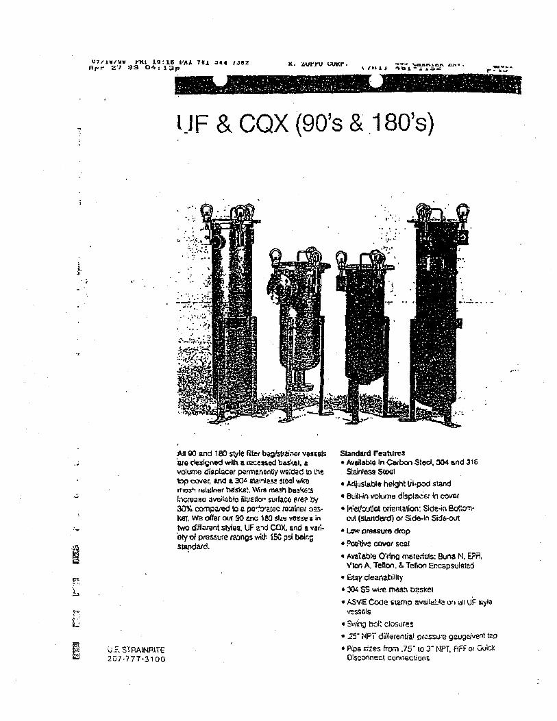