woodLAB FURNITURE PROFESSIONAL · tems experience. IronCAD uses the Windows® "Drag & Drop"...
2
woodLAB FURNITURE PROFESSIONAL CAD/CAM software for the woodworking cabinet making, with manufacturing process, cutting optimizer and CNC programs woodLAB FURNITURE PROFESSIONAL GENERATION OF RULES AND PHASES The operator can define his set of machin- ing rules according either to the geometry (depth, path etc.), either to the file name, material name etc. For example, one can assign a diamond cutter to one material or a widia cutter to another one. TABLE FOR TOOL ASSOCIATION Allows maximum freedom to associate virtual tool names to be used on the CAD with the real tools set up on the CAM. In this mode, the operator who is working with the CAD must not know how the ma- chine is set up, and if several machines are availa- ble, it is not necessary to duplicate the tools codifica- tion. MACHINE SETUP . Allows to define the individual properties of the ma- chine: working coordinates, spindle maximum rota- tion speed, coordinates for tool changing etc. ASSOCIATION TABLE FOR MACHINING Allows to program special machinings to tools as- signed by the operator. For example in the case of a cut, one can assign a machining that will not execute straight from one point to the other, but one that will start from the middle of the path and then reverse to the other point to finish up the machining. This avoids damaging the edges while leading out. Pro- gramming this directly on the CAD would be expen- sive and would require two different machinings, de- fining directions etc. Machining rules can be defined by the operator or by Quality. PARAMETERS MODIFICATION A graphic rendering of the parts and their machining is presented to the operator. On the side of the graphic representation, sorted by face, the machin- ing, their geometric and their technological properties are displayed. Thanks to the contextual menu, it is possible to assign various operations, new geometric properties, or other tools which are defined by the CAD or new tools on geometries that we are design- ing and that have no technological properties yet. It is possible, among other things, to edit the machin- ing direction or the bladed direction, to define a lead- in and a lead-out, to assign repetitive strokes, to ro- tate the part position on the machine and to/or over- turn it and to activate calibrating or not. Modifications can be easily made either before the execution of the part either in correction mode once the automatic processing has been executed. Interface outillage Machining interface Nesting interface WOOD-IT.BE SPRL G. KEYEN AV.22 B-1160 BRUSSELS Tel: + 32 (0)2 672 61 82 GSM: + 32 (0)478 28 49 43 Site: www.woodlab.eu CAM Powered by Quality Industriale SRL Fronema SRL
Transcript of woodLAB FURNITURE PROFESSIONAL · tems experience. IronCAD uses the Windows® "Drag & Drop"...
woodLAB FURNITURE PROFESSIONAL
CAD/CAM software for the woodworking cabinet making, with manufacturing process, cutting optimizer and CNC programs
woodLAB FURNITURE PROFESSIONAL
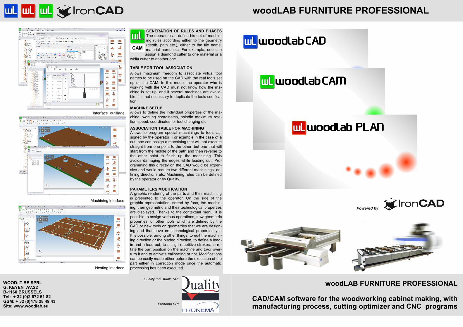
GENERATION OF RULES AND PHASES
The operator can define his set of machin-
ing rules according either to the geometry
(depth, path etc.), either to the file name,
material name etc. For example, one can
assign a diamond cutter to one material or a
widia cutter to another one.
TABLE FOR TOOL ASSOCIATION Allows maximum freedom to associate virtual tool
names to be used on the CAD with the real tools set
up on the CAM. In this mode, the operator who is
working with the CAD must not know how the ma-
chine is set up, and if several machines are availa-
ble, it is not necessary to duplicate the tools codifica-
tion. MACHINE SETUP . Allows to define the individual properties of the ma-
chine: working coordinates, spindle maximum rota-
tion speed, coordinates for tool changing etc. ASSOCIATION TABLE FOR MACHINING Allows to program special machinings to tools as-
signed by the operator. For example in the case of a
cut, one can assign a machining that will not execute
straight from one point to the other, but one that will
start from the middle of the path and then reverse to
the other point to finish up the machining. This
avoids damaging the edges while leading out. Pro-
gramming this directly on the CAD would be expen-
sive and would require two different machinings, de-
fining directions etc. Machining rules can be defined
by the operator or by Quality.
PARAMETERS MODIFICATION A graphic rendering of the parts and their machining
is presented to the operator. On the side of the
graphic representation, sorted by face, the machin-
ing, their geometric and their technological properties
are displayed. Thanks to the contextual menu, it is
possible to assign various operations, new geometric
properties, or other tools which are defined by the
CAD or new tools on geometries that we are design-
ing and that have no technological properties yet.
It is possible, among other things, to edit the machin-
ing direction or the bladed direction, to define a lead-
in and a lead-out, to assign repetitive strokes, to ro-
tate the part position on the machine and to/or over-
turn it and to activate calibrating or not. Modifications
can be easily made either before the execution of the
part either in correction mode once the automatic
processing has been executed.
Interface outillage
Machining interface
Nesting interface
WOOD-IT.BE SPRL G. KEYEN AV.22 B-1160 BRUSSELS Tel: + 32 (0)2 672 61 82 GSM: + 32 (0)478 28 49 43 Site: www.woodlab.eu
CAM
Powered by
Quality Industriale SRL
Fronema SRL
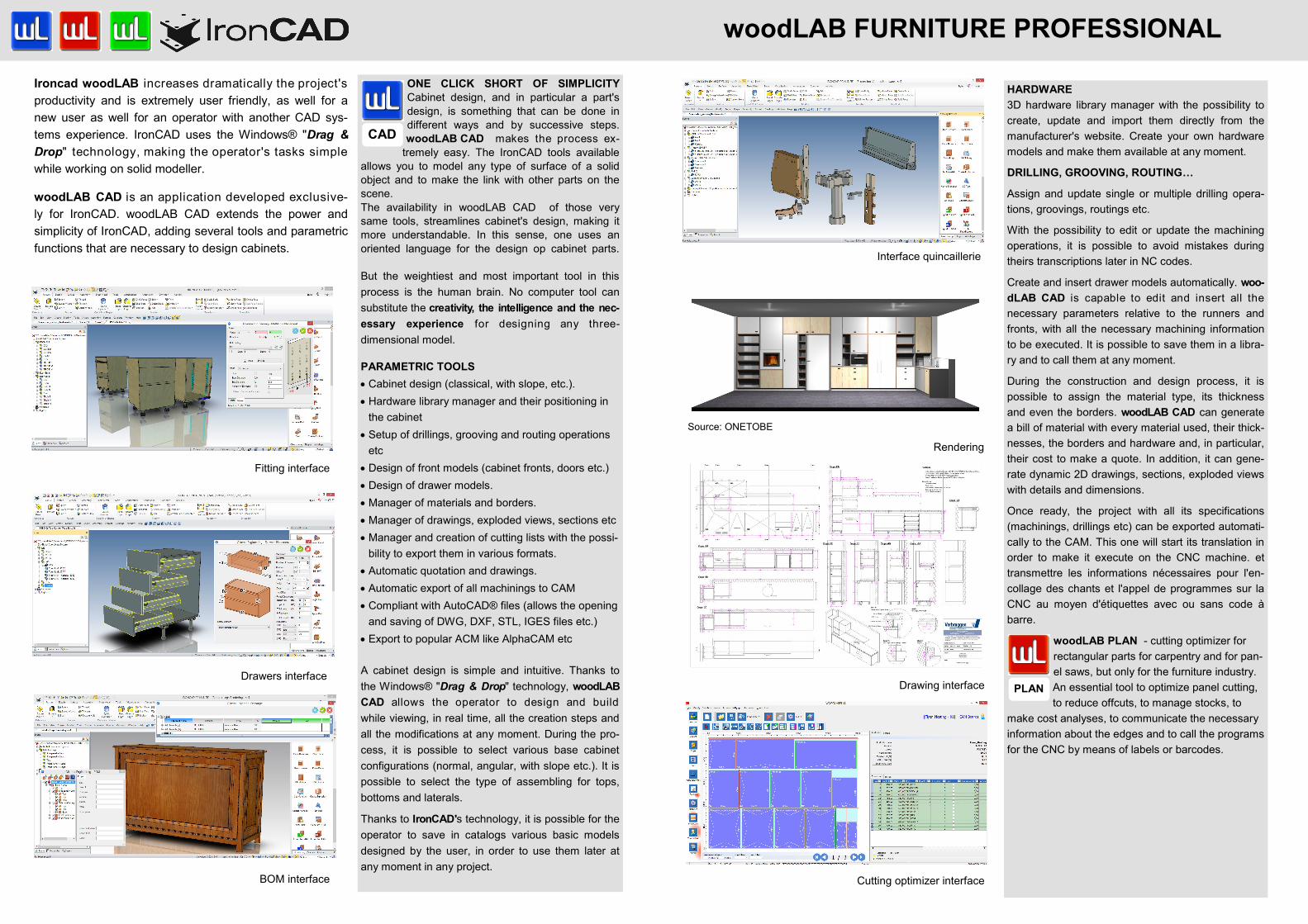
ONE CLICK SHORT OF SIMPLICITY Cabinet design, and in particular a part's
design, is something that can be done in
different ways and by successive steps.
woodLAB CAD makes the process ex-
tremely easy. The IronCAD tools available
allows you to model any type of surface of a solid
object and to make the link with other parts on the
scene.
The availability in woodLAB CAD of those very
same tools, streamlines cabinet's design, making it
more understandable. In this sense, one uses an
oriented language for the design op cabinet parts.
But the weightiest and most important tool in this
process is the human brain. No computer tool can
substitute the creativity, the intelligence and the nec-
essary experience for designing any three-
dimensional model.
PARAMETRIC TOOLS
Cabinet design (classical, with slope, etc.).
Hardware library manager and their positioning in
the cabinet
Setup of drillings, grooving and routing operations
etc
Design of front models (cabinet fronts, doors etc.)
Design of drawer models.
Manager of materials and borders.
Manager of drawings, exploded views, sections etc
Manager and creation of cutting lists with the possi-
bility to export them in various formats.
Automatic quotation and drawings.
Automatic export of all machinings to CAM
Compliant with AutoCAD® files (allows the opening
and saving of DWG, DXF, STL, IGES files etc.)
Export to popular ACM like AlphaCAM etc
A cabinet design is simple and intuitive. Thanks to
the Windows® "Drag & Drop" technology, woodLAB
CAD allows the operator to design and build
while viewing, in real time, all the creation steps and
all the modifications at any moment. During the pro-
cess, it is possible to select various base cabinet
configurations (normal, angular, with slope etc.). It is
possible to select the type of assembling for tops,
bottoms and laterals.
Thanks to IronCAD's technology, it is possible for the
operator to save in catalogs various basic models
designed by the user, in order to use them later at
any moment in any project.
Ironcad woodLAB increases dramatically the project's
productivity and is extremely user friendly, as well for a
new user as well for an operator with another CAD sys-
tems experience. IronCAD uses the Windows® "Drag &
Drop" technology, making the operator's tasks simple
while working on solid modeller.
woodLAB CAD is an application developed exclusive-
ly for IronCAD. woodLAB CAD extends the power and
simplicity of IronCAD, adding several tools and parametric
functions that are necessary to design cabinets.
HARDWARE
3D hardware library manager with the possibility to
create, update and import them directly from the
manufacturer's website. Create your own hardware
models and make them available at any moment.
DRILLING, GROOVING, ROUTING…
Assign and update single or multiple drilling opera-
tions, groovings, routings etc.
With the possibility to edit or update the machining
operations, it is possible to avoid mistakes during
theirs transcriptions later in NC codes.
Create and insert drawer models automatically. woo-
dLAB CAD is capable to edit and insert all the
necessary parameters relative to the runners and
fronts, with all the necessary machining information
to be executed. It is possible to save them in a libra-
ry and to call them at any moment.
During the construction and design process, it is
possible to assign the material type, its thickness
and even the borders. woodLAB CAD can generate
a bill of material with every material used, their thick-
nesses, the borders and hardware and, in particular,
their cost to make a quote. In addition, it can gene-
rate dynamic 2D drawings, sections, exploded views
with details and dimensions.
Once ready, the project with all its specifications
(machinings, drillings etc) can be exported automati-
cally to the CAM. This one will start its translation in
order to make it execute on the CNC machine. et
transmettre les informations nécessaires pour l'en-
collage des chants et l'appel de programmes sur la
CNC au moyen d'étiquettes avec ou sans code à
barre.
woodLAB PLAN - cutting optimizer for
rectangular parts for carpentry and for pan-
el saws, but only for the furniture industry.
An essential tool to optimize panel cutting,
to reduce offcuts, to manage stocks, to
make cost analyses, to communicate the necessary
information about the edges and to call the programs
for the CNC by means of labels or barcodes.
woodLAB FURNITURE PROFESSIONAL
Fitting interface
Drawers interface
BOM interface Cutting optimizer interface
Interface quincaillerie
Rendering
Drawing interface
CAD
PLAN
Source: ONETOBE