WLD 256 Preparation for Pipe Certification I - pcc.edu · Section IX and AWS D1.1. Develop...
58
WLD 256 Preparation for Pipe Certification I
Transcript of WLD 256 Preparation for Pipe Certification I - pcc.edu · Section IX and AWS D1.1. Develop...

WLD 256 Preparation for Pipe Certification I

WLD 256 09/16/05 NSF-ATE Project - Advanced Materials Joining for Tomorrow’s Manufacturing Workforce
2
Index Syllabus
3-9
Math on Metal 10-11
Science on Steel 12-18
Plate Preparation and Welding Information Sheets
19-28
Watt’s Pipe Cutting Information Sheets
29-32
Watt’s Pipe Grinding Information Sheets
33-34
Pipe Fitting Information Sheets
35-42
Work Sheets • Welding Steel Pipe • Welding Vocabulary
43-4445
Craftsmanship Expectations for Welding Projects
46
Welding Projects
47-54
Final Exam Information
55-56
Grading Rubric for Final Exam
57
Assessment Breakdown for the Course
58
Video Training Pipe Welding Made Easy –SMAW 6010/7018 - 2G
Located in Welding Resource Room
This project was supported, in part, by the
National Science Foundation Opinions expressed are those of the authors And not necessarily those of the Foundation

WLD 256 09/16/05 NSF-ATE Project - Advanced Materials Joining for Tomorrow’s Manufacturing Workforce
3
Portland Community College Welding Technology 17705 NW Springville Road Lec/Lab Course Syllabus Portland, OR 97229 Building Location Welding lecture: Bldg 2, Rm 132a/b Welding lab: Bldg 2, Rm 131 Phone (503) 614-7226 Time & Days Morning Shift 7am to 12:50pm Monday through Thursday Afternoon Shift 10:00 to 3:50pm Monday through Thursday Evening Shift 4pm to 9:50 pm Monday through Thursday Instructors Connie Christopher Office Bldg. 2 Rm. 232c, Phone (503) 614-7502 Scott Judy Office Bldg. 2 Rm. 232, Phone (503) 614-7600 Matthew Scott Office Bldg. 2 Rm. 233b, Phone (503) 614-7601 Danny Merrick Office Bldg. 2 Rm. 232d, Phone (503) 614-7603 Introductory Statement WLD 256, Preparation for Pipe Certification I, is a course intended to develop knowledge and skills with the E6010 and E7018 mild steel electrodes when performing various open root groove welds in the horizontal, vertical and overhead positions. The goal of this course is to develop the skills needed to successfully utilize the “keyhole” welding technique when welding the root pass of an open root groove weld with the 6010 electrode and the fill and cap passes with the 7018 electrode. When the student has demonstrated this skill level through successful completion of plate welds the student will then progress to pipe coupons in the horizontal pipe position (2G). This course uses a lecture/lab format that includes classroom discussions and lab demonstrations. Topics covered will include safety, uses, nomenclature, equipment operation and set-up and shutdown procedures for oxyacetylene cutting and shielded metal arc welding. Procedures using the “keyhole” welding technique for the root pass with the 6010 electrode and the fill and cover passes using the 7018 electrode. This is an outcome-based course that will allow the student to work at his/her own pace. It is important to note that the student will be required to follow all safety regulations and complete common cutting and welding projects in accordance with industry standards. The student is expected to complete all the exercises within this training packet.

WLD 256 09/16/05 NSF-ATE Project - Advanced Materials Joining for Tomorrow’s Manufacturing Workforce
4
INTENDED OUTCOMES FOR THE COURSE Function safely in the PCC Welding Shop. • Understand and practice personal safety by using proper protective gear. • Understand and practice hand and power tool safety. • Understand and practice equipment safety for welding and oxy fuel cutting systems. • Understand and maintain a safe work area. Recognize and report dangerous electrical and air/gas hose connections. Understand and practice fire prevention. • Access and explain the importance of the Material Safety Data Sheets (MSDS). Demonstrate professional work ethics • Track training hours on time card. • Perform projects in accordance to specifications and procedures. • Follow oral and written directions in a positive manner. • Manage time productively. • Respect equipment and others. • Demonstrate skill in problem solving and decision-making. • Maintain code quality workmanship standards. Operate oxyfuel portable and track cutting systems in accordance with industry standards • Demonstrate correct setup and shutdown procedures for the hand cutting and track
cutting systems. • Perform oxyfuel cutting with guided practice. Interpret drawings and symbols to accurately layout, prepare and assemble weld joints • Interpret lines, symbols and verbiage on project drawing. • Layout material per drawing specifications. • Use the oxyfuel cutting process to cut material to specified dimensions. • Grind material to meet specifications. • Assemble weld project per specification. Demonstrate complete joint penetration welds with the E6010 and E7018 electrodes to code quality standards in the horizontal, vertical and overhead plate positions and pipe in the horizontal position. • Use correct terminology. Define terms used in the SMAW process. • Equipment identification, setup, shut down, and principles of operation for SMAW. Power source identification and adjustment Welding lead, connections, inspection, and use Electrode identification, characteristics, and use

WLD 256 09/16/05 NSF-ATE Project - Advanced Materials Joining for Tomorrow’s Manufacturing Workforce
5
• Demonstrate correct welding techniques with the E6010 and E7018. Describe variables and their causes and effects to achieve desired results:
Welding current Travel speed Electrode angle Arc length Oscillation Techniques • Demonstrate correct welding techniques per the welding procedure specifications: Horizontal single v-groove plate weld (2G) Vertical single v-groove plate weld (3G) Overhead single v-groove plate weld (4G) Pipe axis vertical single v-groove pipe weld (2G) • Demonstrate visual examination principles and practices in accordance with ASME
Section IX and AWS D1.1. Develop knowledge of A.S.M.E. Section IX pipe welding code requirements in qualification procedures.
Use Welding Procedure Specification (WPS) to set-up and weld qualification coupons. Develop knowledge and skills of the welder qualification procedures on schedule 40 or 80 pipe using E6010 with E7018.
Utilize welding code to reference weld profile inspection. Attendance Policy Students are expected to attend all class meetings for which they are scheduled. Repeated absence will affect the student’s grade. Students must officially withdraw from a class when she/he stops attending. If a student has excessive absences and fails to withdraw, a grade of F will be assigned. Students who do not attend or stop attending class(es) and fail to personally drop within the refund period, will be responsible for all tuition and fees. Full time students (12 credits) are required to attend class daily the entire class period. Part time students are required to schedule their days and hours of attendance with their instructor. Class dates are established at the beginning of the course. Absence from a scheduled class does not entitle a student to extend their course end date. STUDENTS MAY ATTEND SCHEDULED HOURS ONLY. THERE ARE NO MAKE UP HOURS. THE INSTRUCTOR MUST APPROVE ANY CHANGE IN COURSE SCHEDULE.

WLD 256 09/16/05 NSF-ATE Project - Advanced Materials Joining for Tomorrow’s Manufacturing Workforce
6
Course Assignments Reading Packet Information Sheets WLD 256, Information Sheets Welding Principles and Applications, by Larry Jeffus Chapter 5, Shielded Metal Arc Welding of Pipe Chapter 6, Advanced Shielded Metal Arc Welding Writing Work Sheets Welding Steel Pipe Welding Vocabulary Video Training Pipe Welding Made Easy 6010/7018 2G Welding Projects 2G Butt - Single Vee Grove Weld - Open Root (plate) 3G Butt - Single Vee Grove Weld - Open Root (plate) 4G Butt - Single Vee Groove Weld - Open Root (plate) 2G Butt - Single Vee Grove Weld - Open Root (pipe) Final Exam Part One (Closed Book Exam) Part Two (Practical Exam) Required Texts Welding Principles and Applications, by Larry Jeffus Outcome Assessment Policy: The student will be assessed on his/her ability to demonstrate the achievement of course outcomes. The methods of assessment may include one or more of the following: oral or written examinations, quizzes, written assignments, visual inspection techniques, welding tests, safe work habits, task performance and work relations. Grading criteria:
The student's assessment will be based on the following criteria: 20% of grade is based on safe work habits and shop practices. 20% of grade is based on completion of written and reading assignments. 20% of grade is based on demonstrating professional work ethics. 40% of grade is based on completion of welding exercises.

WLD 256 09/16/05 NSF-ATE Project - Advanced Materials Joining for Tomorrow’s Manufacturing Workforce
7
Grading scale: 90 - 100% A – Superior Honor grade indicating excellence. Earned as a result of a combination of
some or all of the following as outlined in the course training packet. Superior examination scores, consistently accurate and prompt completion of assignments, ability of to deal resourcefully with abstract ideas, superior mastery of pertinent skills, and excellence attendance. Probable success in a field relating to the subject or probable continued success in sequential courses.
80 - 89% B - Above average Honor grade indicating competence. Earned as a result of a combination
of some or all of the following as outlined in the course training packet. High examination scores, accurate and prompt completion of assignments, ability to deal with abstract ideas, commendable mastery of pertinent skills and excellent attendance. Probable continued success in sequential courses.
70 - 79% C – Average Standard college grade indicating successful performance earned as a result of a combination of some or all of the following as outlined in the course training packet. Satisfactory examination scores, generally accurate and prompt completion of assignments, ability to deal with abstract ideas, fair mastery of pertinent skills and regular attendance. Sufficient evidence of ability to warrant entering sequential courses.
60 - 69% D – Substandard Substandard but receiving college credit. Substandard grade indicating that the student has met only minimum requirements as outlined in the c course training packet. Earned as a result of some or all of the following:
low examination scores, generally inaccurate, incomplete or late assignments, inadequate grasp of abstract ideas, barely acceptable mastery of pertinent skills, irregular attendance, insufficient evidence of ability to make advisable the enrollment in sequential courses. Does not satisfy requirements for entry into course where prerequisite are specified.
0 - 59% F – Failure Non-passing grade indicating failure to meet minimum requirements as
outlined in the course training packet. Earned as a result of some or all of the following: non-passing examination scores, inaccurate, incomplete or late assignments, failure to cope with abstract ideas, inadequate mastery of pertinent skills, repeated absences from class. Does not satisfy
requirements for entry into course where prerequisites are specified.

WLD 256 09/16/05 NSF-ATE Project - Advanced Materials Joining for Tomorrow’s Manufacturing Workforce
8
Pass Acceptable performance. A grade of “P” represents satisfactory achievement that would have been graded “C” or better on the grading scale, but is given instead of a letter grade. By the end of the eighth (8th) week of class (or equivalent) students shall choose the graded or pass option. By the end of the eighth (8th) week of class or equivalent), students may rescind an earlier request of the pass option.
No Pass No Pass: Unacceptable performance or does not satisfy requirements for entry into courses where prerequisites are specified. This grade may be used in situations where an instructor considers the “F” grade to be inappropriate. The NP mark is disregarded in the computation of the grade point average.
CIPR Course In Progress Re-register A mark used to only for designated classes. To receive credit, a student
must reregister because of equipment usage is required. This may include course in modular or self-paced programs. This mark may also be used in skill-based course to indicate that the student has not attained the skills required to advance to the next level. If the course is not completed within a year, the “CIPR” changes to an “AUD” (Audit) on the transcript unless the course was repeated and a grade earned.
AUD Audit Some courses may allow the students to attend a course without receiving
a grade or credit for the course. Tuition must be paid, and instructor permission must be obtained during the first three weeks of class (or equivalent). Instructors are expected to state on their course handouts any specific audit requirements. Does not satisfy requirements for entry into courses where prerequisites are specified.
Repeated Courses Courses with grades of “D,” “F,” “NP,” or “CIP,” and “CIPR,” may be
repeated for a higher grade. All grades earned will appear on the transcript. The first earned grade of “C” or “P” or better will count in the accumulated credit total. The first grade of “C” or better will be used for the GPA calculation.

WLD 256 09/16/05 NSF-ATE Project - Advanced Materials Joining for Tomorrow’s Manufacturing Workforce
9
SPECIAL If you have a special limitation or disability, which requires support NOTE: services or special assistance please notify your instructor. IMPORTANT:
Grades will no longer be mailed to you automatically. You may request a copy by calling: T.R.A.I.L. at 977-5000 and select Option 4. Or you can access your grades on the World Wide Web at https://banweb.pcc.edu/.
Notice: All projects must be completed in the PCC Welding Lab within your
course time.

WLD 256 09/16/05 NSF-ATE Project - Advanced Materials Joining for Tomorrow’s Manufacturing Workforce
10
Math
on
Metal The Welding Fabrication Industry needs qualified welder fabricators who can deal with a variety of situations on the job. This portion of the training packet explores math as it relates to industry requirements.

WLD 256 09/16/05 NSF-ATE Project - Advanced Materials Joining for Tomorrow’s Manufacturing Workforce
11
Calculating Arc Time versus Preparation Time—WLD 256 For this lab you will need to keep track of all time you spend in performing your required weld projects. After you have completed your projects and recorded all your time you will then compare the amount of time it takes you to prepare the project and finish the project to the actual arc time. Arc time is usually priced out at a higher rate so it is important to know where you are spending your time. ACTIVITY TIME SPENT Plate preparation Cutting Fitting the plate together Tack welding Welding Grinding Fitting up the pipe Tack welding Welding Grinding Post Weld Clean-up Using the above record, determine the total amount of time you spent in: Preparing the parts for the weld:_____________ minutes Arc time: ___________________ minutes Post weld clean up:____________ minutes For the welding projects in this packet calculate the percentage of your time you spent in: Preparation for welding: ________% Arc time _________% Post Weld Clean-up__________% See the math reference packet for details on calculating percentages.
WLD 256 09/16/05 NSF-ATE Project - Advanced Materials Joining for Tomorrow’s Manufacturing Workforce
12
Science
on
Steel The Welding Fabrication Industry needs qualified welder fabricators who can deal with a variety of situations on the job. This portion of the training packet explores science as it relates to industry requirements.

WLD 256 09/16/05 NSF-ATE Project - Advanced Materials Joining for Tomorrow’s Manufacturing Workforce
13
E6010/E7018 Pipe Certification Contents of this Packet
- Introduction - Importance of Code Qualification - Mechanical Properties Testing for Pipe Welding Qualification - Code Requirements - Significance of Bend Testing - Concave Root Surface (Suck Back)
Introduction This packet covers the welder qualification using the combination of E6010 cellulosic electrode for the root pass and E7018 low-hydrogen electrodes for subsequent fill passes deposited in open root pipe welding on mild steel. Although the E6010 and E7018 electrodes operate differently (as discussed in previous science packets), the testing required for welder qualification for most pipe welding codes are similar. E6010 is the deepest-penetrating, all-position electrode. To achieve such deep penetration, the highest amount of cellulose is used in the flux cover. The cellulose also provides large amounts of gaseous shielding with minimal slag. This allows the welder to have a clear view of the keyhole in open root welding. On the other hand, the fill passes are deposited with E7018, which is a lime-based, iron-powder, low-hydrogen electrode. Unlike E6010, the E7018 electrode provides high deposition rate as well as a thick slag to generate the primary source of shielding. Because E6010 is a high-hydrogen electrode, the welder must be certain that the code (he/she is using) allows the use of cellulosic electrodes. If not, all of the passes including the root pass must be deposited with the low-hydrogen E7018 electrode (even though E6010 is the best electrode for open root welding). In some cases, the root pass is deposited by gas tungsten arc welding. Importance of Code Qualification In all industries, there are applicable codes and standards to assure the quality, reproducibility, and adequacy of welded joints. Depending upon the application, a welded joint may need certain mechanical properties; for example, welds on bridges must pass tests for strength, tensile ductility, bend ductility, and Charpy impact toughness. These codes are based on many years of experience. Changes to codes are ongoing to reflect the dynamic changes that taking place in the industry. There are many welding codes to ensure quality welding. For example, the following is a list of only a few typical industries and governing codes for welding quality.

WLD 256 09/16/05 NSF-ATE Project - Advanced Materials Joining for Tomorrow’s Manufacturing Workforce
14
Pressure Vessels ASME Boiler and Pressure Vessel Code (Vol. IX – Welding Qualifications)
Pipe and Pipelines API Standard 1104; Standard for Welding Pipelines and Related Facilities
Pressure Piping ASME Code for Pressure Piping B31 All Steel Structures AWS D1.1 Structural Welding Code –
Steel Buildings AISC Specification for Structural Steel
Buildings Bridges AASHTO/AWS D1.5; Bridge Welding
Code Ships ABS Rules for Building and Classing Steel
Vessels Sheet Metal AWS D9.1; Sheet Metal Welding Code Automotive Frames ANSI/AWS D8.8; Specification for
Automotive Frame Weld Quality Aircraft MIL-STD-1595A; Qualification of
Aircraft, Missile, and Aerospace Fusion Welders
Mechanical Properties Testing for Pipe Welding Qualification In all codes for welded structures and pipe, various degrees of mechanical testing are performed to assure the quality and integrity of the structure. This includes both procedure qualification and welder qualification. For example, the procedure qualification for pipe as well as steel structures in accordance with the AWS D1.1 Structural Steel Welding Code requires that certain welds undergo all-weld-metal tensile testing, transverse-to-weld tensile testing, side bend testing, Charpy v-notch (CVN) impact testing as well as non-destructive testing. Mechanical testing is very important because it ensures that the welding procedure, welder qualification, consumables, and the resulting metallurgy of the weld and heat-affected zone were all acceptable. Welder qualification generally requires less mechanical testing than the procedure qualification; for example, welder qualification typically includes visual, non-destructive testing, and face bend and root bend testing. Code Requirements When a pipeline or pressure piping is going to be built, the owner and contractor agree on the appropriate welding code, which will be needed to govern the acceptability or rejection of structural welds being fabricated. API-1104, ASME Boiler and Pressure Vessel Code and AWS D1.1 Structural Welding Code can be used for pipe and tubing applications. Codes are devised to provide welded joints with acceptable strength, ductility, and CVN impact toughness for the intended application. These codes also provide for procedure qualification requirements and welder qualification. The qualification and certification tests for welders are specially designed to determine the welder’s ability to produce sound welds routinely. To achieve these quality standards, the welder qualification and certification provide the means to ensure acceptable welds.
WLD 256 09/16/05 NSF-ATE Project - Advanced Materials Joining for Tomorrow’s Manufacturing Workforce
15
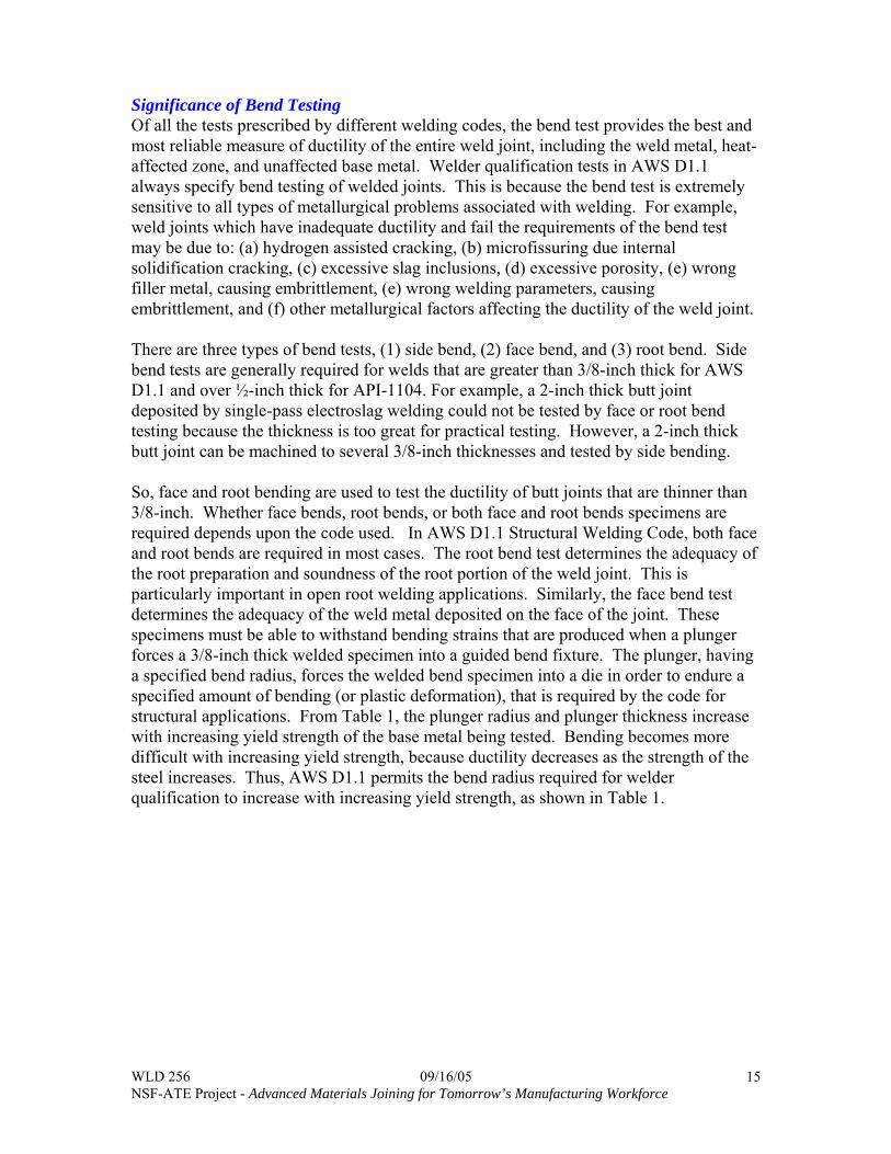
Significance of Bend Testing Of all the tests prescribed by different welding codes, the bend test provides the best and most reliable measure of ductility of the entire weld joint, including the weld metal, heat-affected zone, and unaffected base metal. Welder qualification tests in AWS D1.1 always specify bend testing of welded joints. This is because the bend test is extremely sensitive to all types of metallurgical problems associated with welding. For example, weld joints which have inadequate ductility and fail the requirements of the bend test may be due to: (a) hydrogen assisted cracking, (b) microfissuring due internal solidification cracking, (c) excessive slag inclusions, (d) excessive porosity, (e) wrong filler metal, causing embrittlement, (e) wrong welding parameters, causing embrittlement, and (f) other metallurgical factors affecting the ductility of the weld joint. There are three types of bend tests, (1) side bend, (2) face bend, and (3) root bend. Side bend tests are generally required for welds that are greater than 3/8-inch thick for AWS D1.1 and over ½-inch thick for API-1104. For example, a 2-inch thick butt joint deposited by single-pass electroslag welding could not be tested by face or root bend testing because the thickness is too great for practical testing. However, a 2-inch thick butt joint can be machined to several 3/8-inch thicknesses and tested by side bending. So, face and root bending are used to test the ductility of butt joints that are thinner than 3/8-inch. Whether face bends, root bends, or both face and root bends specimens are required depends upon the code used. In AWS D1.1 Structural Welding Code, both face and root bends are required in most cases. The root bend test determines the adequacy of the root preparation and soundness of the root portion of the weld joint. This is particularly important in open root welding applications. Similarly, the face bend test determines the adequacy of the weld metal deposited on the face of the joint. These specimens must be able to withstand bending strains that are produced when a plunger forces a 3/8-inch thick welded specimen into a guided bend fixture. The plunger, having a specified bend radius, forces the welded bend specimen into a die in order to endure a specified amount of bending (or plastic deformation), that is required by the code for structural applications. From Table 1, the plunger radius and plunger thickness increase with increasing yield strength of the base metal being tested. Bending becomes more difficult with increasing yield strength, because ductility decreases as the strength of the steel increases. Thus, AWS D1.1 permits the bend radius required for welder qualification to increase with increasing yield strength, as shown in Table 1.

WLD 256 09/16/05 NSF-ATE Project - Advanced Materials Joining for Tomorrow’s Manufacturing Workforce
16
Table 1 Specified Bending Parameters for Guided Bend Test for Steel Welds in accordance with AWS D1.1 Structural Welding Code - Steel
Yield Strength Of Base Metal
Plunger Thickness
Plunger Radius
Interior Die Opening
Die Radius
50,000psi and less Over 50,000psi to 90,000psi 90,000psi and greater
1 ½” 2” 2 ½”
¾” 1” 1 ¼”
2 3/8” 2 7/8” 3 3/8”
1 3/16” 1 7/16” 1 11/16”
Furthermore, the bend test for steel welds is very sensitive to the presence of diffusible hydrogen in the weld. Even if non-destructive testing shows a welded steel to be crack-free, the bend test can activate the hydrogen cracking mechanism in steel welds which are susceptible to hydrogen cracking. Thus, there are many metallurgical causes for lack of adequate ductility in a welded structure, and the bend test is best suited to separate the “good” welds from the “bad” welds. Concave Root Surface (Suck Back) The root pass of an open root weld often exhibits “suck back” or a concave root surface in pipe joints as well as open root plate joints. This is due to a complex set of forces, which simultaneously act upon the molten metal in the bottom of the open root. As the open root pass begins to solidify, the weld shrinks and the remaining liquid is stretched across the root face to form a concave root surface or suck-back. The liquid can actually stretch to some degree without burn-through because surface tension acts to hold the molten metal together. The three most important forces acting on the root pass are (1) surface tension of the molten metal, (2) gravity, and (3) arc force. None of these forces are easily controlled by the welder. Surface tension is a beneficial property of the molten weld metal, which tends to hold molten metal together; much like a balloon holds liquid water. Surface tension forces increase with decreasing temperature of the molten weld metal. Gravity always tries to oppose the beneficial effects of surface tension of molten metal in the open root. The effects of gravity are dependent upon the size and weight of the weld pool as well as the welding position used; for example, flat, compared to overhead, compared to vertical-up. The larger the weld pool size of the root pass, the more difficult it will be for surface tension to hold the molten metal in place. Arc force is another complex force, which is provided by the arc in the direction of arc impingement. Arc force increases with increasing amperage. Too high an arc force will burn through the root. With decreasing amperage and decreasing size of root pass, the greater will be the surface tension forces holding the molten pool in place.

WLD 256 09/16/05 NSF-ATE Project - Advanced Materials Joining for Tomorrow’s Manufacturing Workforce
17
Surface tension is the most important beneficial force, because without surface tension, open root welding would not be possible. Without surface tension, the molten metal in the open root would act like water and flow through the root opening. Surface tension is always trying to keep the molten pool from dripping out of the root area. Imagine a balloon full of water, the elastic polymer provides the restraining forces to keep the water in place. If outside forces are too great, the balloon will distort, burst and water will escape. Similarly, in a full-penetration open-root pass, the heat input must be adjusted so that surface tension will hold the molten in the open root opening. The smaller the root pass, the easier it is for surface tension forces to hold the molten metal in place. When the root pass is deposited by E6010 electrode, just the right amount of heat input is needed to produce a keyhole in the joint for full penetration. With too little heat, full penetration will not be achieved; while, with too high heat input, the arc will blow through the joint. At the optimum level of heat, the molten metal is suspended by surface tension forces in the gap of the open root. Surface tension forces overcome gravity and the root pass is achieved.
Quantitatively, the resolved force (F) acting on the weld pool is function of two opposing factors; surface tension force and gravitational force, as shown below:
F = + P γ - ρ g V
P is the periphery length along the root face, γ is the surface (tension) energy, ρ is the molten metal density, g is the acceleration of gravity, and V is the volume of molten metal in the root gap. From this equation, increasing the beneficial surface tension (P γ) force prevents drop-through or burn-through by holding the molten metal in place. Also, the fast freezing flux is very helpful in supporting the suspended molten metal between the two plates. However, the weight of the molten (- ρ g V) is affected by gravity and tries to prevent successful open root welding. Increasing the heat input promotes larger molten pool size and higher molten pool temperatures. This causes a reduction in the surface tension forces holding the weld in place. How does “suck back” develop in the root and what controls the amount of suck back? Surface tension is necessary to hold and suspend the molten metal in the open root without dropping through like water. Surface tension of molten metal in the open root acts as if the molten metal is in an “impervious bag” which prevents liquid from falling through the open root. Fortunately, the surface tension of molten iron is very high; for example, the surface (tension) energy of iron at its melting point is about twice that for aluminum at its melting point. So during solidification, the shrinkage forces between the two root faces pull on the molten pool substantially to produce a concave root surface or suck back. Suck back can be overcome if the welder can provide additional weld metal into the root. This is dangerous because of the increased chance of drop-through. Fortunately, in welding, the use of fast freezing fluxes and good welder skill reduce the occurrence of excessive concave root surfaces.

WLD 256 09/16/05 NSF-ATE Project - Advanced Materials Joining for Tomorrow’s Manufacturing Workforce
18
Science on Steel Worksheet—WLD 256 Name: __________________________ Date: ____________________ Complete each question using complete sentences. 1. List 3 codes that are listed in the science section that apply to welding pipe.
2. What do each of the above codes cover application wise 3. Why does suck back happen? 4. Define Surface Tension (use any source for this definition)

WLD 256 09/16/05 NSF-ATE Project - Advanced Materials Joining for Tomorrow’s Manufacturing Workforce
19
Plate Preparation & Welding Information Sheet Prepare 3/8 inch thick plates to be welded using the “keyhole” technique when welding the root and hot passes of an open root groove weld with the E6010 electrode. The fill and cap passes will be welded out with the E7018 electrode.
1. Use the Track burner to cut a 30-degree bevel angle on the 3/8” plate. Triangle protractors are available in the Tool Room to assist in setting the torch angle.
2. Use a grinder and a file to prepare the groove face and the root land. The groove face should be ground to a shiny appearance with a root face equal to a width of 3/32” of an inch. This is known as a “nickel thickness.”
WLD 256 09/16/05 NSF-ATE Project - Advanced Materials Joining for Tomorrow’s Manufacturing Workforce
20
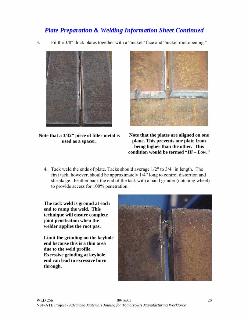
Plate Preparation & Welding Information Sheet Continued 3. Fit the 3/8" thick plates together with a “nickel” face and “nickel root opening.”
Note that a 3/32” piece of filler metal is used as a spacer.
Note that the plates are aligned on one plane. This prevents one plate from being higher than the other. This
condition would be termed “Hi – Low.”
4. Tack weld the ends of plate. Tacks should average 1/2" to 3/4" in length. The
first tack, however, should be approximately 1/4” long to control distortion and shrinkage. Feather back the end of the tack with a hand grinder (notching wheel) to provide access for 100% penetration.
The tack weld is ground at each end to ramp the weld. This technique will ensure complete joint penetration when the welder applies the root pas. Limit the grinding on the keyhole end because this is a thin area due to the weld profile. Excessive grinding at keyhole end can lead to excessive burn through.
WLD 256 09/16/05 NSF-ATE Project - Advanced Materials Joining for Tomorrow’s Manufacturing Workforce
21
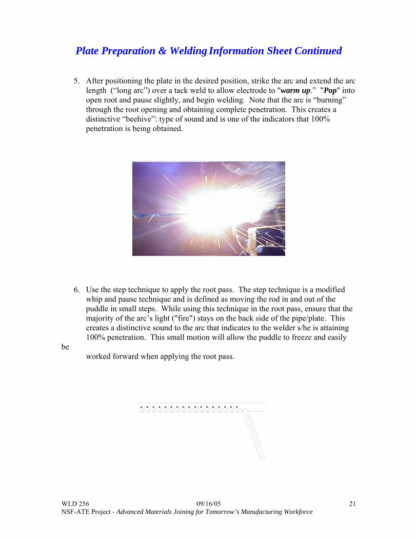
Plate Preparation & Welding Information Sheet Continued 5. After positioning the plate in the desired position, strike the arc and extend the arc
length (“long arc”) over a tack weld to allow electrode to "warm up.” "Pop" into open root and pause slightly, and begin welding. Note that the arc is “burning” through the root opening and obtaining complete penetration. This creates a distinctive “beehive”: type of sound and is one of the indicators that 100% penetration is being obtained.
6. Use the step technique to apply the root pass. The step technique is a modified
whip and pause technique and is defined as moving the rod in and out of the puddle in small steps. While using this technique in the root pass, ensure that the majority of the arc’s light ("fire") stays on the back side of the pipe/plate. This creates a distinctive sound to the arc that indicates to the welder s/he is attaining 100% penetration. This small motion will allow the puddle to freeze and easily
be worked forward when applying the root pass.

WLD 256 09/16/05 NSF-ATE Project - Advanced Materials Joining for Tomorrow’s Manufacturing Workforce
22
Plate Preparation & Welding Information Sheet Continued
7. While welding the root pass, the electrode should be touching the root land or pushed into it slightly. Pushing the electrode into the root land too far will cause undercut on the backside. Use a forward “stepping” motion of 1/2 to 1 electrodes diameter, and then return to the keyhole. It is important to "touch down" into the puddle to help fill undercut on the backside.
Note that the electrode can be held at the top of the root face or pushed into it slightly.
Five variables to control when running the open root pass: • Root land • Root opening • Amperage • Arc length • Travel speed Root Bead Suggestions: • Center stringer when welding, this will help prevent internal undercut or inadequate
penetration (IP). • Keep bead moving forward. • Vary technique for joint fit up.

WLD 256 09/16/05 NSF-ATE Project - Advanced Materials Joining for Tomorrow’s Manufacturing Workforce
23
The ideal keyhole size is just slightly larger then the electrode.
Adjust Technique for Root Fit Up
Narrow gap techniques: • Push electrode into opening • Increase amperage • Grind root area to reduce root land Wide gap technique: • Weld wide section last, hopefully welding the other three quadrants will shrink wide
area. • Reduce Current • Use U-weave • Allow pipe to cool. Internal Undercut: • Electrode is too deep into groove • Amperage is too high • Root opening is too large • Root land is too thin
Stopping techniques
Use a quick step out of the root bead to decrease keyhole size when terminating the weld. Leaving a large keyhole can cause excessive internal root reinforcement.
WLD 256 09/16/05 NSF-ATE Project - Advanced Materials Joining for Tomorrow’s Manufacturing Workforce
24
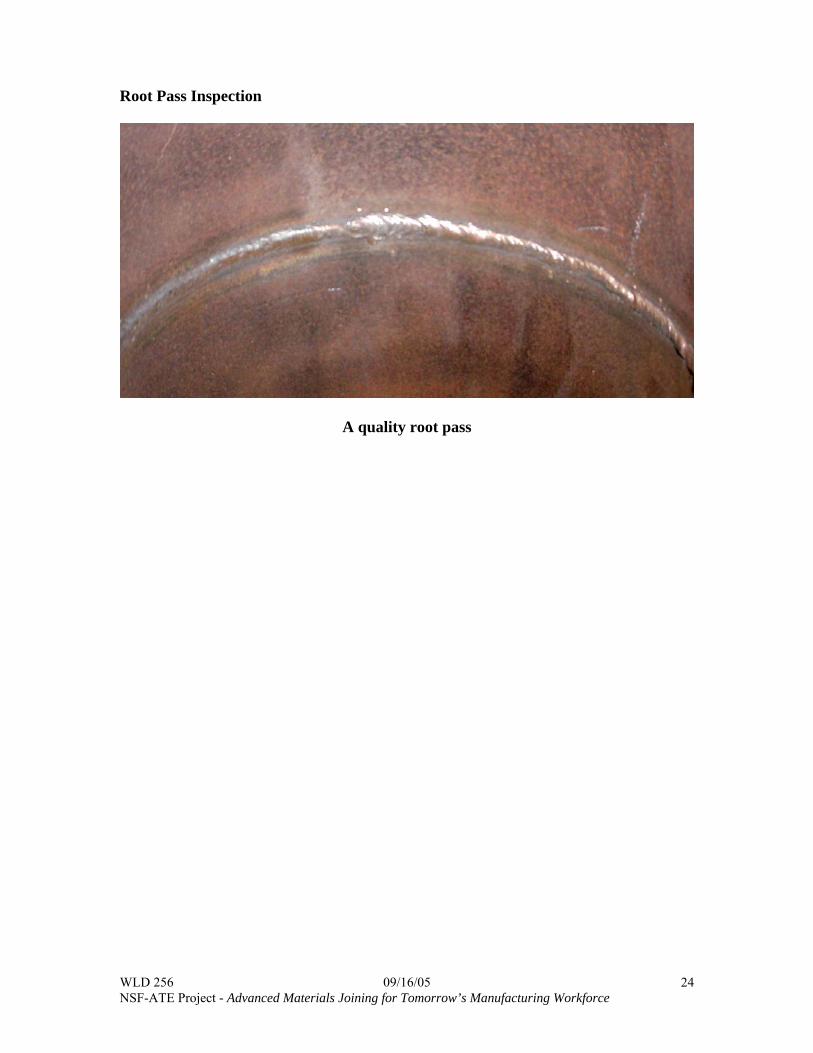
Root Pass Inspection
A quality root pass

WLD 256 09/16/05 NSF-ATE Project - Advanced Materials Joining for Tomorrow’s Manufacturing Workforce
25
Plate Preparation & Welding Information Sheet Continued • Remove the slag from the internal root pass side, and inspect the root for complete
penetration, undercut and excessive penetration. See Craftsmanship Expectations for inspection criteria.
Applying the Hot Pass, Second Pass, with an E6010 using the whip and pause technique.
• Grind root pass clean with a hand grinder prior to applying the hot pass. • Increase amperage 10 to 20 amps above root bead setting. • Use the whip and pause technique with a medium arc length. Use a circling
technique emphasizing the sides of the puddle (“Paint The Walls”) to melt out slag (wagon tracks).
Purpose for the hot pass is to: • Burn out slag (wagon tracks) • Re-contour stringer • Anneal (stress relieve) • Drive out hydrogen in heat affected zone (HAZ)

WLD 256 09/16/05 NSF-ATE Project - Advanced Materials Joining for Tomorrow’s Manufacturing Workforce
26
Plate Preparation & Welding Information Sheet Continued Low Hydrogen Fill and Cover Pass Technique A tight arc length is essential when welding with E7018. The puddle relies on the vaporization of the flux and the molten slag for added shielding. Keep electrode in the puddle at all times, No Whipping Out of the Puddle, to produce a sound weld. Failure to follow these techniques can result in porosity, undercut, slag inclusions, and lower impact strength. Oscillation Techniques • Straight side-to-side weave for the flat, vertical and overhead positions.
Pause slightly at the sides • Slant Loop for the horizontal welding positions.
Pause slightly at the top of the rotation
WLD 256 09/16/05 NSF-ATE Project - Advanced Materials Joining for Tomorrow’s Manufacturing Workforce
27
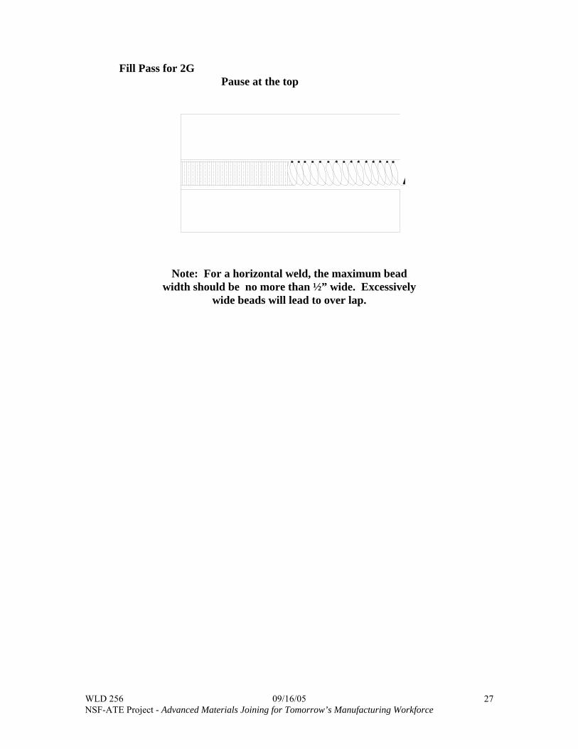
Fill Pass for 2G Pause at the top
Note: For a horizontal weld, the maximum bead width should be no more than ½” wide. Excessively
wide beads will lead to over lap.

WLD 256 09/16/05 NSF-ATE Project - Advanced Materials Joining for Tomorrow’s Manufacturing Workforce
28
Plate Preparation & Welding Information Sheet Continued The Slant Loop technique is also an excellent choice for fill passes. (Stringer bead technique used for cap)
Welding Sequence for the horizontal position (2G).

WLD 256 09/16/05 NSF-ATE Project - Advanced Materials Joining for Tomorrow’s Manufacturing Workforce
29
Watts Pipe Cutter Information Sheet
• The Watts pipe beveler uses oxygen and acetylene to flame cut pipe bevels. All
safety procedures that apply to the track burners and hand torches apply with this pipe beveler.
• Place pipe in jaws and snug jaws down with T-bar wrench. • Swivel cutting head over pipe ensuring there is approximately ¾” clearance between
the cutting tip and pipe. • Slowly hand rotate the pipe referencing the cutting tip to pipe wall distance. For a
quality cut this variation should not exceed 1/16”. Make adjustments when necessary.
• Tighten jaws after alignment is completed.

WLD 256 09/16/05 NSF-ATE Project - Advanced Materials Joining for Tomorrow’s Manufacturing Workforce
30
Watts Pipe Cutter Information Sheet
• Turn on the manifold and adjust cutting pressures. A good starting point is 5 psi for
Acetylene and 40 psi for Oxygen with a cutting tip.
• Turn the Ignite toggle switch ON and open the acetylene needle valve on the back
side of the unit. Light the torch and adjust the acetylene flame so the heavy soot disappears.
Cut Roll Switch
Ignite Switch Fast Roll Switch Acetylene Valve Oxygen Valve Front Side Back Side • Add oxygen, and adjust to a neutral flame.
WLD 256 09/16/05 NSF-ATE Project - Advanced Materials Joining for Tomorrow’s Manufacturing Workforce
31
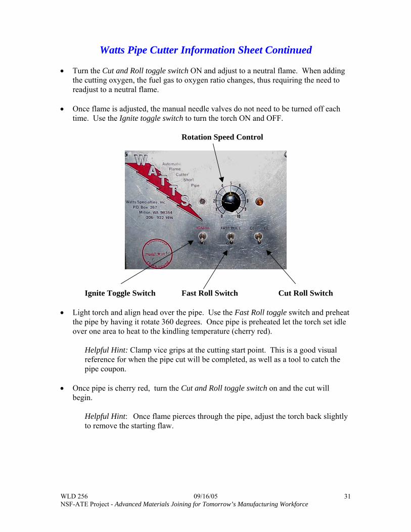
Watts Pipe Cutter Information Sheet Continued
• Turn the Cut and Roll toggle switch ON and adjust to a neutral flame. When adding the cutting oxygen, the fuel gas to oxygen ratio changes, thus requiring the need to readjust to a neutral flame.
• Once flame is adjusted, the manual needle valves do not need to be turned off each
time. Use the Ignite toggle switch to turn the torch ON and OFF.
Rotation Speed Control
Ignite Toggle Switch Fast Roll Switch Cut Roll Switch • Light torch and align head over the pipe. Use the Fast Roll toggle switch and preheat
the pipe by having it rotate 360 degrees. Once pipe is preheated let the torch set idle over one area to heat to the kindling temperature (cherry red).
Helpful Hint: Clamp vice grips at the cutting start point. This is a good visual reference for when the pipe cut will be completed, as well as a tool to catch the pipe coupon.
• Once pipe is cherry red, turn the Cut and Roll toggle switch on and the cut will
begin.
Helpful Hint: Once flame pierces through the pipe, adjust the torch back slightly to remove the starting flaw.

WLD 256 09/16/05 NSF-ATE Project - Advanced Materials Joining for Tomorrow’s Manufacturing Workforce
32
Watts Pipe Cutter Information Sheet Continued
Torch Extension Arm
• Once pipe cut is completed, adjust torch extension arm back to make additional cuts
or remove pipe coupon and replace with next coupon and complete the cutting process.

WLD 256 09/16/05 NSF-ATE Project - Advanced Materials Joining for Tomorrow’s Manufacturing Workforce
33
Watt’s Pipe Grinding Station Information Sheet
• Ensure pipe is cool enough to touch before handling it. • Mount pipe in the rotating fixture ensuring that it is mounted concentrically. • Tighten the thumbscrew ensuring that the pipe is secure.
Thumb Screws • Hand start the pipe fixture rotation and then begin grinding the groove face. • Ensure grinder has enough clearance, so it does not hit or catch on the rotating
fixture.

WLD 256 09/16/05 NSF-ATE Project - Advanced Materials Joining for Tomorrow’s Manufacturing Workforce
34
Watt’s Pipe Grinding Station Information Sheet Continued
• Do not let the fixture rotate too fast. Slow it down frequently so that the pipe is not
thrown from the fixture. • Ensure the grinder is placed in such a way that the sparks are shooting downward. • Ensure screens are in place so no by standers are showered with sparks. • Grind the groove face clean, and then grind the land. For the up hill root pass
technique, use a “nickel land” (the land is ground to a thickness of a nickel which is approximately 3/32”).
• Once grinding is completed, remove pipe coupon, replace with next coupon and
complete the grinding process.

WLD 256 09/16/05 NSF-ATE Project - Advanced Materials Joining for Tomorrow’s Manufacturing Workforce
35
Pipe Fitting Information
1. Pre-assemble pipe coupons together and rotate top pipe to determine best fit-up to eliminate high-low condition and excessive root opening. Once the best fit up is determined, draw a soap stone line to indicate placement of pipe coupons after the spacer is put into place.
High Low
A high-low condition refers to the pipe material being offset at the fit up area. This is due to each pipe coupon not being a perfect circle. The ASME Code only allows 1/16” for high low.
2. Place a spacer wire between the pipes for the proper root opening. Rotate the top pipe to minimize a high low fit-up.

WLD 256 09/16/05 NSF-ATE Project - Advanced Materials Joining for Tomorrow’s Manufacturing Workforce
36
3. Make the first tack weld ½” long between the open ends of the spacer wire. The first tack should only be ½” long to help control distortion. The remaining three tacks should be ¾” long.
4. Remove the spacer wire and reposition it as shown, and weld the second tack opposite the first tack (this is referred to as diametrically opposed to the first tack).

WLD 256 09/16/05 NSF-ATE Project - Advanced Materials Joining for Tomorrow’s Manufacturing Workforce
37
5. Tack weld the two remaining sides starting with the wider of the two sides. At
this point the pipe should have one tack weld at 12, 3, 6 and 9 o’clock positions.
6. Use a hand grinder with a 1/8” thick notching wheel to feather (ramp) the tacks.
The keyhole side of the tack will not need as much grinding. Too much grinding on this end of the tack will potentially cause burn through when welding the root pass.
Minimal grinding at the keyhole end of the tack
WLD 256 09/16/05 NSF-ATE Project - Advanced Materials Joining for Tomorrow’s Manufacturing Workforce
38
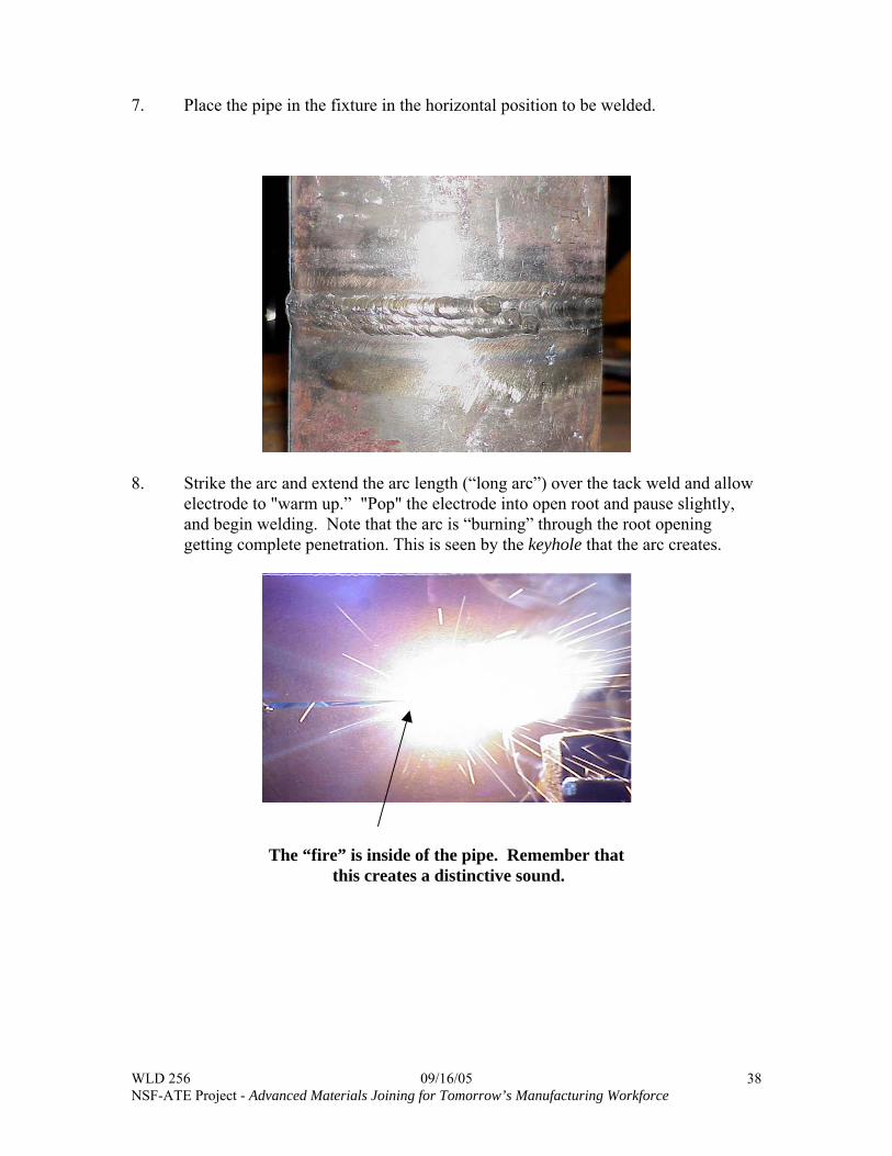
7. Place the pipe in the fixture in the horizontal position to be welded.
8. Strike the arc and extend the arc length (“long arc”) over the tack weld and allow
electrode to "warm up.” "Pop" the electrode into open root and pause slightly, and begin welding. Note that the arc is “burning” through the root opening getting complete penetration. This is seen by the keyhole that the arc creates.
The “fire” is inside of the pipe. Remember that
this creates a distinctive sound.

WLD 256 09/16/05 NSF-ATE Project - Advanced Materials Joining for Tomorrow’s Manufacturing Workforce
39
9. Use the whip and pause technique for the root pass pushing the electrode no more than half way into the root area. Ensure that the "fire" stays on the backside of the pipe. This will create the distinctive sound when obtaining 100% penetration. The small stepping motion will allow the puddle to freeze and the root pass will be easily worked forward. Use a forward “stepping” motion of 1/2 to 1 electrodes diameter, and then returning the electrode to the keyhole. It is important to touch down" in the puddle to help fill undercut on the backside.
Whip and Pause technique Keep the arc tight and step no more than 1 electrode diameter in distance.
Root Pass Arc Length Keep a tight arc when touching down into the puddle. Try not to push electrode
more than ½ way into the root face area.
Remember to keep the puddle moving forward. There is nothing but the puddle to catch itself on the backside of an open root weld. Five variables to control when running the root pass: • Root land • Root opening • Amperage • Arc length • Travel speed Root Bead Suggestions:

WLD 256 09/16/05 NSF-ATE Project - Advanced Materials Joining for Tomorrow’s Manufacturing Workforce
40
• Center root pass (stringer) in the root opening when welding. This will help prevent internal undercut or inadequate penetration (IP).
• Keep the root pass moving. • Vary technique for joint fit up. The soundness of the root pass will be greatly affected by these five variables. The welder will need to learn to control these variables to produce a quality root bead.
Adjust Technique for Root Fit Up Narrow gap techniques: • Push electrode into opening • Increase amperage • Grind root area to reduce root land Wide gap technique: • Weld wide section last, hopefully welding other three quadrants will shrink wide
area. • Reduce current • Use U-weave • Allow the pipe to cool. Internal Undercut: • Electrode is too deep into groove • Amperage is too high • Root opening is too large • Root land is too thin Stopping techniques
Use a quick step out of the root bead to decrease keyhole size when terminating the weld. Leaving a large keyhole can cause excessive root reinforcement on the inside.

WLD 256 09/16/05 NSF-ATE Project - Advanced Materials Joining for Tomorrow’s Manufacturing Workforce
41
Applying the Hot Pass with an 1/8” E6010
• Grind root pass clean with a hand grinder prior to applying the hot pass. • Increase amperage 10 to 20 amps above root bead setting. • Use the whip and pause technique with a medium arc length. Use a circling
technique “Paint The Walls” to remove wagon tracks. Purpose for the hot pass is to: • Burn out slag (wagon tracks) • Re-contour stringer • Anneal (stress relieve) • Drive out hydrogen in heat affected zone (HAZ) Low Hydrogen Fill and Cover Pass Technique A tight arc length is essential when welding with E7018. The puddles relies on vaporization of the flux and the molten slag for shielding. Keep electrode in the puddle at all times. No Whipping Out of the Puddle, to produce a sound weld Failure to follow these techniques may result in porosity, undercut, slag inclusions, or lower impact strength.
Fill Pass for 2G
Pause at the top
Note: For a horizontal weld, the maximum bead width should be no more than ½” wide. Excessively wide beads will lead to over lap.

WLD 256 09/16/05 NSF-ATE Project - Advanced Materials Joining for Tomorrow’s Manufacturing Workforce
42
Cover Passes (Finish Beads) for the 2G
Note that the keyhole end of the root pass is only lightly ground. • Use the Slant Loop Stringer Bead Technique • For the 2G weld, the maximum bead width should not be more than ½” wide.
Excessively wide beads will lead to over lap. • Remove all slag with a wire wheel. Note that a hand file can be used to smooth out
undercut at the weld and the pipe wall interface (toe). Excessive filing will not be permitted because it reduces the pipe wall thickness.
WLD 256 09/16/05 NSF-ATE Project - Advanced Materials Joining for Tomorrow’s Manufacturing Workforce
43
Shielded Metal Arc Welding Pipe—WLD 256 Name: ________________________ Date: _____________________ Directions: Read Chapters 5 and 6 in Welding Principles and Applications and utilize that information to complete the following questions. Answer the questions using complete sentences, and do not hesitate to reference other sections in the text to find an answer. 1. List 5 variables the "welder" faces in running the first pass in an open root single vee groove weld. 2. List three characteristics of a pipe-welding electrode. 3. What is the name of the first pass in a complete joint penetration pipe weld? 4. Describe the difference between pipe and tubing.

WLD 256 09/16/05 NSF-ATE Project - Advanced Materials Joining for Tomorrow’s Manufacturing Workforce
44
5. What is the purpose of a backing ring? 6. What causes root suck back on a concave root surface? 7. What is the purpose of the "hot pass"? 8. On 5G welds, what usually determines the direction of the root pass?

WLD 256 09/16/05 NSF-ATE Project - Advanced Materials Joining for Tomorrow’s Manufacturing Workforce
45
Welding Vocabulary—WLD 256 Name:____________________________ Date: ___________________ Directions: Define the following terms. Use the textbooks in the Welding Resource Room (Bldg 2/132a) if these terms are not in Welding Principles and Applications. Hot pass Keyhole Welding Technique 1G 2G 5G 6G Wagon tracks Whip and Pause Technique

WLD 256 09/16/05 NSF-ATE Project - Advanced Materials Joining for Tomorrow’s Manufacturing Workforce
46
Craftsmanship Expectations for Welding Projects The student should complete the following tasks prior to welding.
1. Thoroughly read each drawing. 2. Make a cutting list for each project. Cut at least two project's assemblies at
a time. This will save a great amount of time. 3. Assemble the welding projects per drawing specifications. 4. Review Welding Procedure portion of the prints to review welding
parameter information. 5. See the instructor for the evaluation.
Factors for grading welding projects are based on the following criteria:
Metal Preparation Project Layout Post Weld Clean-up Oxyfuel cut quality Accurate (+/- 1/16”) Remove Slag/Spatter Grind all cut surfaces clean Limit waste Remove sharp edges
Weld Quality per ASME Section IX and AWS D1.1 VT Criteria Root Pass Cover Pass Reinforcement Flush to 1/16” Flush to 1/8” Undercut 1/32 “ deep 1/32” deep Bead Contour Smooth Transition Smooth Transition Penetration Complete Joint Penetration N/A Cracks None Allowed None Allowed Arc Strikes None Allowed None Allowed Fusion Complete Fusion Required Complete Fusion Required Porosity None Allowed None Allowed

WLD 256 09/16/05 NSF-ATE Project - Advanced Materials Joining for Tomorrow’s Manufacturing Workforce
47
E6010/7018 Butt Joint- Single Vee (2G) ______Project #1 Welding Sequence E6010--Root Pass Utilize the "key hole" step technique E6010--Hot Pass Increase amperage 10 to 20 amps above the root bead setting.
“Paint the walls” to burn out wagon tracks. E7018--Fill and Cap Tight arc is essential, keep the electrode in the puddle-No
Whipping. Use a stringer bead technique. ________________________________________________________________________
Front view of the horizontal groove weld Weld Quality per ASME Section IX and AWS D1.1 VT Criteria Root Pass Cover Pass Reinforcement Undercut Bead Contour Penetration N/A Cracks Arc Strikes Fusion Porosity Grade and Date

WLD 256 09/16/05 NSF-ATE Project - Advanced Materials Joining for Tomorrow’s Manufacturing Workforce
48

WLD 256 09/16/05 NSF-ATE Project - Advanced Materials Joining for Tomorrow’s Manufacturing Workforce
49
E6010/7018 But t Joint- Single Vee (3G) _________ Project #2 Welding Sequence E6010--Root Pass Utilize the "key hole" step technique E6010--Hot Pass Increase amperage 10 to 20 amps above the root bead setting.
“Paint the walls” to burn out wagon tracks. E7018--Fill and Cap Tight arc is essential, keep the electrode in the puddle-No
Whipping. Use the side-to-side or circular technique (Weave bead) for both fill and cap.
________________________________________________________________________
Root Pass View Cover Pass View Weld Quality per ASME Section IX and AWS D1.1 VT Criteria Root Pass Cover Pass Reinforcement Undercut Bead Contour Penetration N/A Cracks Arc Strikes Fusion Porosity Grade and Date

WLD 256 09/16/05 NSF-ATE Project - Advanced Materials Joining for Tomorrow’s Manufacturing Workforce
50

WLD 256 09/16/05 NSF-ATE Project - Advanced Materials Joining for Tomorrow’s Manufacturing Workforce
51
E6010/7018 Butt Joint- Single Vee (4G) ______ Project #3 Welding Sequence E6010--Root Pass Utilize the "key hole" step technique. E6010--Hot Pass Increase amperage 10 to 20 amps above the root bead setting.
“Paint the walls” to burn out wagon tracks. E7018--Fill and Cap Tight arc is essential, keep the electrode in the puddle-No
Whipping. Use the side-to-side or circular technique (Weave bead)
for both fill and cap. ________________________________________________________________________
Cover Pass View Root Pass View Weld Quality per ASME Section IX and AWS D1.1 VT Criteria Root Pass Cover Pass Reinforcement Undercut Bead Contour Penetration N/A Cracks Arc Strikes Fusion Porosity Grade and Date

WLD 256 09/16/05 NSF-ATE Project - Advanced Materials Joining for Tomorrow’s Manufacturing Workforce
52

WLD 256 09/16/05 NSF-ATE Project - Advanced Materials Joining for Tomorrow’s Manufacturing Workforce
53
E6010/7018 Butt Joint- Single Vee Pipe (2G) ______Project #4 Welding Sequence E6010--Root Pass Utilize the "key hole" step technique E6010--Hot Pass Increase amperage 10 to 20 amps above the root bead setting. “Paint the walls” to burn out wagon tracks. E7018--Fill and Cap Tight arc is essential, keep the electrode in the puddle-No
Whipping with E7018. Use a stringer bead technique. ________________________________________________________________________
Weld Quality per ASME Section IX and AWS D1.1 VT Criteria Root Pass Cover Pass Reinforcement Undercut Bead Contour Penetration N/A Cracks Arc Strikes Fusion Porosity Grade and Date

WLD 256 09/16/05 NSF-ATE Project - Advanced Materials Joining for Tomorrow’s Manufacturing Workforce
54

WLD 256 09/16/05 NSF-ATE Project - Advanced Materials Joining for Tomorrow’s Manufacturing Workforce
55
Final Exam Part One This portion of the final exam is a closed book test. Consult with your instructor to determine items that you may need to review. Complete the exam and write all answers on the answer sheet provided. Once completed, return the exam and answer sheet to your instructor. Part Two This portion of the exam is a practical test where you will fabricate and weld a weldment from the drawing attached to the final exam. The evaluation of this portion of the exam will be based on the grading rubric attached.
`

WLD 256 09/16/05 NSF-ATE Project - Advanced Materials Joining for Tomorrow’s Manufacturing Workforce
56

WLD 256 09/16/05 NSF-ATE Project - Advanced Materials Joining for Tomorrow’s Manufacturing Workforce
57
Grading Rubric for the Practical Exam—WLD 256 Name: _______________________________ Course: ____________________ Hold Points
Hold Points are mandatory points in the fabrication process that require the inspector to check your work. You will have the following hold points.
Points Hold Point Instructor’s Evaluation 5 points Blueprint Interpretation and Material Cut List 5 points = 0 errors, all parts labeled and sized correctly 3 points = 1 error in part sizing and/or identification 2 points = 2 errors or more rework required (max points) __________ 10 points Material Layout and Cutting (Tolerances +/- 1/16”) 10 points Layout and cutting to +/-1/16” Smoothness of cut edge to 1/32”
7 points Layout and cutting to +/- 1/8”
Smoothness of cut edge to 1/16” 5 points (Rework Required max points)
Layout and cutting to +/-3/16” Smoothness of cut edge to 3/32” ___________ 10 points Fit-up and Tack weld (Tolerances +/- 1/16”) 10 points
Tolerances +/- 1/16” Straight and square to +/-1/16” 7 Points
Tolerances +/- 1/8” Straight and square to +/-1/8”
5 Points (Rework Required—Max points ) Tolerances +/- 3/16”
Straight and square to +/-3/16” ____________ 15 points Weld Quality Subtract 1 point for each weld discontinuity,
incorrect weld size and incorrect spacing sequence. ____________ 28 points Minimum points acceptable. This equates to the
minimum ASME and AWS D1.1 Code requirements. Total Points ____________

WLD 256 09/16/05 NSF-ATE Project - Advanced Materials Joining for Tomorrow’s Manufacturing Workforce
58
Assessment Breakdown for Course – WLD 256 Percentage
20% Safe work habits and shop practices ________ 20% Student consistently wears apparel and operates equipment
safely. 18%-14% Instructor occasionally reminds students to wear safety
apparel and/or operate equipment safely 12% -10% Instructor needs to consistently remind the student to wear
safety apparel and/or operate equipment safely
20% Completion of reading and writing assignments _________ On time vs. late Complete and accurate responses Grade on a point basis 20% demonstrating professional work ethics _________ Track training hours on time card Performs work in accordance to specifications and procedures Follow directions in a positive manner Manage time productively (time on task) Respects equipment and others Demonstrate skill in problem solving and decision-making 40% of grade is based on completion of welding exercises _________
Complete all projects to industry standards See Project Grading Criteria
TOTAL __________ COURSE GRADE __________