
Wiring Diagramsdms.hvacpartners.com/docs/1005/public/03/38ah-9w.pdfFactory wiring is in accordance...
16
Manufacturer reserves the right to discontinue, or change at any time, specifications or designs without notice and without incurring obligations. Catalog No. 04-56380002-01 Printed in U.S.A. Form 38AH-9W Pg 1 709 4-09 Replaces: 38AH-8W Wiring Diagrams Units Produced After April 20, 2009 (Includes Variable Air Volume ModuPanel™ Control) INDEX Fig. Unit 38AH with Two-Stage Thermostat. . . . . . . . . . . . . . . . . . . . . . . . . . . . . . . . . . . . . . . . 9 One 38AH Dual-Circuit Condensing Unit with ModuPanel Control . . . . . . . . . . . . . . . . . 10 Two 38AH Dual-Circuit Condensing Units with ModuPanel Control . . . . . . . . . . . . . . . . . 11 LEGEND (For Fig. 1-11) UNIT 38AH ELECTRICAL CHARACTERISTICS (V-Ph-Hz) DIAGRAM TYPE FIGURE NO. LABEL DIAGRAM NO. 024-034 208/230-3-60, 460-3-60 Component Arrangement 1 38AH500185-4 Power Schematic 2 38AH500184-5 575-3-60 Component Arrangement 3 38AH500181-4 Power Schematic 4 38AH500180-5 380-3-60 Component Arrangement 5 38AH500183-4 Power Schematic 6 38AH500182-5 230-3-50, 380/415-3-50 346-3-50 Component Arrangement 7 38AH500187-4 Power Schematic 8 38AH500186-5 38AH024-034 Air-Cooled Condensing Units 50/60 Hz AFR — Airflow Relay AFS — Airflow Switch ATS — Air Temperature Switch C — Contactor, Compressor CB — Circuit Breaker CH — Crankcase Heater CM — Control Module COMP — Compressor COTP — Compressor Overtemperature Protection CR — Control Relay DU — Dummy EQUIP — Equipment FC — Fan Contactor FIOP — Factory-Installed Option FM — Fan Motor FR — Fan Relay FU — Fuse GND — Ground HPS — High-Pressure Switch IFC — Indoor (Evaporator) Fan Contactor LLSV — Liquid Line Solenoid Valve LPS — Low-Pressure Switch MMF — Motormaster ® Fuse MMPT — Motormaster Pressure Transducer MPR — ModuPanel Relay NEC — National Electrical Code (U.S.A. Standard) OPS — Oil Pressure Switch PL — Primary PRI — Primary RLA — Rated Load Amps SEC — Secondary TB — Terminal Block TRAN — Transformer U — Unloader VAV — Variable Air Volume Plug Receptacle Terminal Block Connection Unmarked Terminal Marked Splice Unmarked Splice Factory Wiring Field Control Wiring Field Power Wiring Indicates common potential. (Does not represent wiring.)
Transcript of Wiring Diagramsdms.hvacpartners.com/docs/1005/public/03/38ah-9w.pdfFactory wiring is in accordance...

Manufacturer reserves the right to discontinue, or change at any time, specifications or designs without notice and without incurring obligations.Catalog No. 04-56380002-01 Printed in U.S.A. Form 38AH-9W Pg 1 709 4-09 Replaces: 38AH-8W
Wiring DiagramsUnits Produced After April 20, 2009
(Includes Variable Air Volume ModuPanel™ Control)
INDEX
Fig.Unit 38AH with Two-Stage Thermostat. . . . . . . . . . . . . . . . . . . . . . . . . . . . . . . . . . . . . . . . 9One 38AH Dual-Circuit Condensing Unit with ModuPanel Control . . . . . . . . . . . . . . . . . 10Two 38AH Dual-Circuit Condensing Units with ModuPanel Control . . . . . . . . . . . . . . . . . 11
LEGEND (For Fig. 1-11)
UNIT 38AHELECTRICAL
CHARACTERISTICS(V-Ph-Hz)
DIAGRAM TYPE FIGURE NO. LABEL DIAGRAM NO.
024-034
208/230-3-60,460-3-60
Component Arrangement 1 38AH500185-4Power Schematic 2 38AH500184-5
575-3-60Component Arrangement 3 38AH500181-4
Power Schematic 4 38AH500180-5
380-3-60Component Arrangement 5 38AH500183-4
Power Schematic 6 38AH500182-5
230-3-50, 380/415-3-50346-3-50
Component Arrangement 7 38AH500187-4Power Schematic 8 38AH500186-5
38AH024-034Air-Cooled Condensing Units
50/60 Hz
AFR — Airflow RelayAFS — Airflow SwitchATS — Air Temperature SwitchC — Contactor, CompressorCB — Circuit BreakerCH — Crankcase HeaterCM — Control ModuleCOMP — CompressorCOTP — Compressor Overtemperature
ProtectionCR — Control RelayDU — DummyEQUIP — EquipmentFC — Fan ContactorFIOP — Factory-Installed OptionFM — Fan MotorFR — Fan RelayFU — FuseGND — GroundHPS — High-Pressure Switch
IFC — Indoor (Evaporator) Fan Contactor
LLSV — Liquid Line Solenoid ValveLPS — Low-Pressure SwitchMMF — Motormaster® FuseMMPT — Motormaster Pressure
TransducerMPR — ModuPanel RelayNEC — National Electrical Code
(U.S.A. Standard)OPS — Oil Pressure SwitchPL — PrimaryPRI — PrimaryRLA — Rated Load AmpsSEC — SecondaryTB — Terminal BlockTRAN — TransformerU — UnloaderVAV — Variable Air Volume
Plug
Receptacle
Terminal Block Connection
Unmarked Terminal
Marked Splice
Unmarked Splice
Factory Wiring
Field Control Wiring
Field Power Wiring
Indicates common potential. (Does not represent wiring.)
2
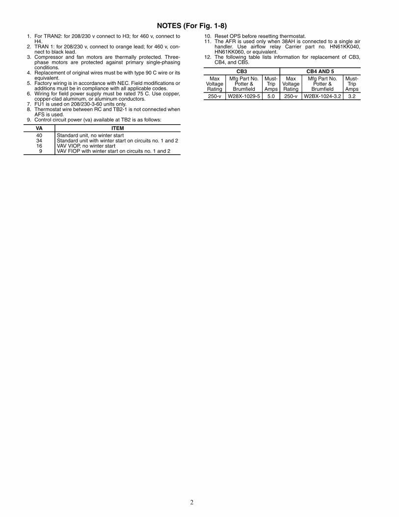
NOTES (For Fig. 1-8)1. For TRAN2: for 208/230 v connect to H3; for 460 v, connect to
H4.2. TRAN 1: for 208/230 v, connect to orange lead; for 460 v, con-
nect to black lead.3. Compressor and fan motors are thermally protected. Three-
phase motors are protected against primary single-phasingconditions.
4. Replacement of original wires must be with type 90 C wire or itsequivalent.
5. Factory wiring is in accordance with NEC. Field modifications oradditions must be in compliance with all applicable codes.
6. Wiring for field power supply must be rated 75 C. Use copper,copper-clad aluminum, or aluminum conductors.
7. FU1 is used on 208/230-3-60 units only.8. Thermostat wire between RC and TB2-1 is not connected when
AFS is used.9. Control circuit power (va) available at TB2 is as follows:
10. Reset OPS before resetting thermostat.11. The AFR is used only when 38AH is connected to a single air
handler. Use airflow relay Carrier part no. HN61KK040,HN61KK060, or equivalent.
12. The following table lists information for replacement of CB3,CB4, and CB5.
VA ITEM40 Standard unit, no winter start34 Standard unit with winter start on circuits no. 1 and 216 VAV VIOP, no winter start
9 VAV FIOP with winter start on circuits no. 1 and 2
CB3 CB4 AND 5Max
VoltageRating
Mfg Part No.Potter &
Brumfield
Must-Trip
Amps
MaxVoltageRating
Mfg Part No.Potter &
Brumfield
Must-Trip
Amps250-v W28X-1029-5 5.0 250-v W2BX-1024-3.2 3.2

3
NOTES (cont)13. The motor-compressor is a thermally protected system. Circuit
breaker must-trip amps are less than or equal to 156% RLA.The following tables list compressor and fan circuit breakerdata.
60 Hz UNITS
50 Hz UNITS
UNITSIZE38AH
MAINVOLTAGE
CONTROLVOLTAGE
COMP CB1 AND 2 MUST-TRIPAMPSHeinemann Airpax
024500 208/230 11524 47-100-85 209-3-2599-372 55
028500 208/230 11524 47-100-76 209-3-2599-410 61
034500 208/230 11524
CB1 47-100-76 209-3-2599-410 61CB2 47-100-82 209-3-2599-311 89
024600 460 11524 CF3-Z33-34 219-3-2600-438 27
028600 460 11524 CF3-Z33-62 219-3-2600-452 31
034600 460 11524
CF3-Z33-62 219-3-2600-452 31CF3-Z33-59 219-3-2600-464 42
024100 575 11524
CB1 CF3-Z33-61 219-3-2600-451 25CB2 CF3-Z33-61 219-3-2600-451 25
028100 575 11524
CB1 CF3-Z33-61 219-3-2600-451 25CB2 CF3-Z33-61 219-3-2600-451 25
034100 575 11524
CB1 CF3-Z33-61 219-3-2600-451 25CB2 CF3-Z229-16 219-3-2600-561 32
024200 380 23024 CF3-Z33-89 219-3-2600-459 33.6
028200 380 23024 CF3-Z228-38 219-3-2600-539 37
034200 380 23024
CF3-Z228-38 219-3-2600-539 37CF3-Z228-39 219-3-2600-540 48
UNITSIZE38AH
MAINVOLTAGE
CONTROLVOLTAGE
COMP CB1 AND 2 MUST-TRIPAMPSHeinemann Airpax
024800 230 23024 47-100-85 209-3-2599-372 55
028800 230 23024 47-100-76 209-3-2599-410 61
034800 230 23024
CB1 47-100-76 209-3-2599-410 61CB2 47-100-82 209-3-2599-311 89
024900 380/415 23024 CF3-Z33-34 219-3-2600-438 27
028900 380/415 23024 CF3-Z33-62 219-3-2600-452 31
034900 380/415 23024
CB1 CF3-Z33-62 219-3-2600-452 31CB2 CF3-Z33-59 219-3-2600-464 42
024300 346 23024 CF3-Z33-89 219-3-2600-459 33.6
028300 346 23024 CF3-Z33-38 219-3-2600-563 37
034300 346 23024
CB1 CF3-Z228-38 219-3-2600-539 37CB2 CF3-Z228-39 219-3-2600-540 20
4
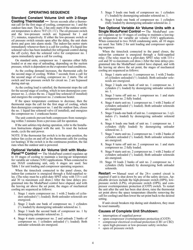
OPERATING SEQUENCE
Standard Constant Volume Unit with 2-StageCooling Thermostat — Seven seconds after a thermo-stat call for the first stage of cooling, compressor no. 1 and theoutdoor fans start. The no. 2 fan only starts if the outdoor ambi-ent temperature is above 70 F (21.1 C). The oil-pressure switchand the low-pressure switch are bypassed for 1 and21/2 minutes, respectively. If either the low-pressure switch oroil pressure switch remain open after the delay, the unit shutsdown and goes into alarm mode. The indoor-fan motor startsimmediately whenever there is a call for cooling. If a liquid linesolenoid valve has been installed (for refrigerant control duringthe off cycle), then the solenoid valve for compressor no. 1opens immediately upon a call for cooling.
On standard units, compressor no. 1 operates either fullyloaded or at one step of unloading, depending on the suctionpressure, which is dependent on the evaporator load conditions.
As the cooling demand increases, the thermostat calls forthe second stage of cooling. Within 7 seconds from a call forthe second stage of cooling, compressor no. 2 starts. The oilswitch and low-pressure switch for circuit no. 2 are bypassedduring start-up.
As the cooling load is satisfied, the thermostat stops the callfor the second stage of cooling, which in turn deenergizes com-pressor no. 2, closes the no. 2 liquid line solenoid (if installed)and energizes the compressor no. 2 crankcase heater.
If the space temperature continues to decrease, then thethermostat stops the call for the first stage of cooling, whichthen deenergizes compressor no. 1 and the outdoor fans, closesthe no. 1 liquid line solenoid valve (if installed), and energizesthe compressor no. 1 crankcase heater.
The unit controls prevent both compressors from reenergiz-ing within 3 minutes from a previous call for operation.
If the unit safeties trip during operation, refer to the Installa-tion Instructions shipped with the unit. To reset the lockoutmode, cycle the unit power.NOTE: If the thermostat fan switch is in the auto position, theindoor fan cycles on and off as the thermostat calls for cooling(or heating). If the switch is in the continuous position, the fanruns when the outdoor unit is powered.
Optional Variable Air Volume Unit with Modu-Panel™ Control — The ModuPanel control regulates upto 10 stages of cooling to maintain a leaving-air temperaturefor variable air volume (VAV) applications. When connected toone 38AH condensing unit, only 6 stages are used. SeeTable 1 for unit loading and compressor operating sequence.
When the timeclock connected to the panel closes, theindoor-fan contactor is energized through a field-supplied re-lay. (The relay must be a pilot-duty SPST relay with 115-v coiland 30 va maximum coil draw.) After the time delays pro-grammed into the ModuPanel control have elapsed, and withthe leaving air above the set point, the stages of mechanicalcooling are sequenced as follows:
1. Stage 1 starts compressor no. 1 with 2 banks of cylin-ders unloaded (1/3 loaded). Both unloader solenoids areenergized.
2. Stage 2 loads one bank of compressor no. 1 cylinders(2/3 loaded) by deenergizing unloader solenoid no. 1.
3. Stage 3 loads the second bank of compressor no. 1 bydeenergizing unloader solenoid no. 2.
4. Stage 4 starts compressor no. 2 and unloads 2 banks ofcompressor no. 1 cylinders unloaded (1/3 loaded). Bothunloader solenoids are energized.
5. Stage 5 loads one bank of compressor no. 1 cylinders(2/3 loaded) by deenergizing unloader solenoid no. 1.
6. Stage 6 loads one bank of compressor no. 1 cylinders(fully loaded) by deenergizing unloader solenoid no. 2.
Two Optional Variable Air Volume Units with aSingle ModuPanel Control — The ModuPanel con-trol regulates up to 10 stages of cooling to maintain a leaving-air temperature for variable air volume (VAV) applications.When connected to two 38AH condensing units, all 10 stagesare used. See Table 2 for unit loading and compressor operat-ing sequence.
When the timeclock connected to the panel closes, theindoor-fan contactor is energized through a field-suppliedrelay. (The relay must be a pilot-duty SPST relay with 115-vcoil and 30 va maximum coil draw.) After the time delays pro-grammed into the ModuPanel control have elapsed, and withthe leaving air above the set point, the stages of mechanicalcooling are sequenced as follows:
1. Stage 1 starts unit no. 1 compressor no. 1 with 2 banksof cylinders unloaded (1/3 loaded). Both unloader sole-noids are energized.
2. Stage 2 loads one bank of unit no. 1 compressor no. 1cylinders (2/3 loaded) by deenergizing unloader solenoidno. 1.
3. Stage 3 turns off unit no. 1 compressor no. 1 and startscompressor no. 2 fully loaded.
4. Stage 4 starts unit no. 1 compressor no. 1 with 2 banks ofcylinders unloaded (1/3 loaded). Both unloader solenoidsare energized.
5. Stage 5 loads one bank of unit no. 1 compressor no. 1 cyl-inders (2/3 loaded) by deenergizing unloader solenoidno. 1.
6. Stage 6 loads one bank of unit no. 1 compressor no. 1cylinders (fully loaded) by deenergizing unloadersolenoid no. 2.
7. Stage 7 starts unit no. 2 compressor no. 1 with 2 banks ofcylinders unloaded (1/3 loaded). Both unloader solenoidsare energized.
8. Stage 8 turns off unit no. 2 compressor no. 1 and startscompressor no. 2 fully loaded.
9. Stage 9 starts unit no. 2 compressor no. 1 with 2 banks ofcylinders unloaded (1/3 loaded). Both unloader solenoidsare energized.
10. Stage 10 loads 2 banks of unit no. 2 compressor no. 1cylinders (fully loaded) by deenergizing both unloadersolenoids.
Restart — Manual reset of the 24-v control circuit isrequired if unit is shut down by any of the safety devices. Ap-plicable devices include the high-pressure switch (HPS), low-pressure switch (LPS), oil-pressure switch (OPS), and com-pressor overtemperature protection (COTP) switch. To restartthe unit after the unit has been shut down, raise the thermostatset point above the space temperature (thereby removing thecall for cooling) and then lower the set point back to the desiredsetting.
If unit circuit breakers trip during unit shutdown, they mustbe reset manually.
Causes of Complete Unit Shutdown:• interruption of supplied power• open compressor overtemperature protection (COTP)• compressor electrical overload protection (CB1 or CB2) • open high-pressure or low-pressure safety switches• open oil pressure switch

5
Table 1 — Unit Loading Sequence with ModuPanel™ Control
Table 2 — Loading Sequence, Two Condensing Units with ModuPanel Control
STAGE NO. CYLINDERSLOADED CYLINDERS
CAPACITY STEP (%)Compressor No. 1 Compressor No. 2
1 2 2 — 172 4 4 — 333 6 6 — 504 8 2 6 675 10 4 6 836 12 6 6 100
STAGE NO. CYLINDERSUNIT 1 LOADED CYLINDERS UNIT 2 LOADED CYLINDERS
CAPACITY STEP (%)CompressorNo. 1
CompressorNo. 2
CompressorNo. 1
CompressorNo. 2
1 2 2 — — — 82 4 4 — — — 173 6 — 6 — — 254 8 2 6 — — 335 10 4 6 — — 416 12 6 6 — — 507 14 6 6 2 — 588 18 6 6 — 6 759 20 6 6 2 6 83
10 24 6 6 6 6 100

6
Fig
. 1 —
Co
mp
on
ent
Arr
ang
emen
t, 3
8AH
024-
034,
208
/230
-3-6
0 an
d 4
60-3
-60
Un
its
a38-7085.eps

7
Fig. 2 — Power Schematic, 38AH024-034, 208/230-3-60 and 460-3-60 Units
a38-7086

8
Fig
. 3 —
Co
mp
on
ent
Arr
ang
emen
t, 3
8AH
024-
034,
575
-3-6
0 U
nit
s
a38-7087
9
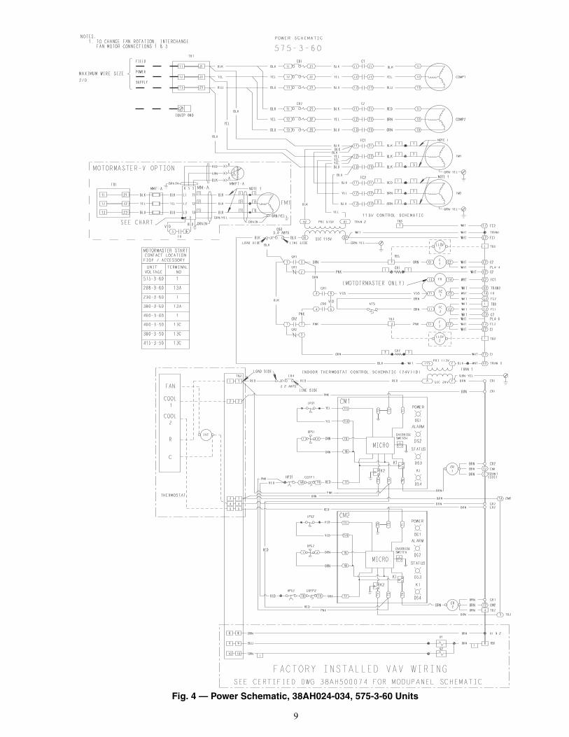
Fig. 4 — Power Schematic, 38AH024-034, 575-3-60 Units
a38-7088

10
Fig
. 5 —
Co
mp
on
ent
Arr
ang
emen
t, 3
8AH
024-
034,
380
-3-6
0 U
nit
s
a38-7089

11
Fig. 6 — Power Schematic, 38AH024-034, 380-3-60 Units
a38-7090

12
Fig
. 7 —
Co
mp
on
ent
Arr
ang
emen
t, 3
8AH
024-
034,
230
-3-5
0, 3
80/4
15-3
-50
and
346
-3-5
0 U
nit
s
a38-7091
13
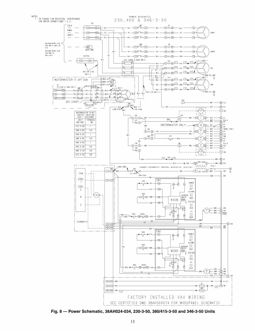
Fig. 8 — Power Schematic, 38AH024-034, 230-3-50, 380/415-3-50 and 346-3-50 Units
a38-7092

14
Fig
. 9 —
Un
it 3
8AH
wit
h T
wo
-Sta
ge
Th
erm
ost
at
*U
se th
erm
osta
t wiri
ng s
how
n he
re fo
r si
ngle
air-
hand
ler
appl
icat
ions
.†C
B3
prot
ects
con
trol
circ
uit a
t the
follo
win
g un
it vo
ltage
s:
**F
or a
sin
gle
air
hand
ler,
LLS
V v
alve
1 i
s to
be
used
on
the
low
er(n
o. 1
) ev
apor
ator
circ
uit.
The
LLS
V v
alve
2 i
s to
be
used
on
the
uppe
r (n
o. 2
) ev
apor
ator
circ
uit.
††O
nly
one
indo
or-f
an c
onta
ctor
is r
equi
red
on s
ingl
e ai
r-ha
ndle
r ap
pli-
catio
ns.
Use
Car
rier
acce
ssor
y pa
rt n
o. 4
0RR
9001
81 f
or i
ndoo
r-fa
nco
ntac
tor.
CO
NT
RO
L C
IRC
UIT
PR
OT
EC
TE
D A
T:(V
-Ph
-Hz)
UN
IT (
V-P
h-H
z)
115-
1-60
208/
230-
3-60
460-
3-60
575-
3-60
230-
1-60
380-
3-60
230-
1-50
230-
3-50
346-
3-50
400-
3-50
NO
TE
S:
1.C
B4
prot
ects
TB
2 ci
rcui
t; C
B3
prot
ects
TB
3 ci
rcui
ts.
2.LL
SV
1 an
d LL
SV
2 ar
e fie
ld s
uppl
ied.
3.O
n 20
8/23
0, 4
60,
and
575-
3-60
uni
ts,
TB
2 is
24-
van
d T
B3
is 1
15-v
. O
n 38
0-3-
60 a
nd 2
30,
346,
and
400-
3-50
uni
ts, T
B2
is 2
4-v
and
TB
3 is
230
-v.
a38-7050.eps

15
a38-7113
SEE
MO
DU
PAN
EL A
CC
ESSO
RY IN
STA
LLAT
ION
FO
R SC
HEM
ATIC
C
→ F
ig. 1
0 —
On
e 38
AH
Du
al-C
ircu
it C
on
den
sin
g U
nit
wit
h M
od
uP
anel
™ C
on
tro
l
NO
TE
S:
1.Fa
ctor
y w
irin
g is
in a
ccor
danc
e w
ith N
atio
nal E
lect
rical
Cod
e (N
EC
). F
ield
mod
ifica
tions
or
addi
tions
mus
t be
in c
ompl
i-an
ce w
ith a
ll ap
plic
able
cod
es.
2.W
irin
g fo
r fie
ld p
ower
sup
ply
mus
t be
rate
d 75
° C
min
imum
. Use
cop
per,
copp
er-c
lad
alum
inum
or
alum
inum
con
duct
ors.
Max
imum
in
com
ing
wire
si
ze
for
mai
n te
rmin
al
bloc
k (T
B1)
is
35
0 m
axim
um
kcm
il (2
30
v).
All
othe
r vo
ltage
s2/
0 m
axim
um.
3.Te
rmin
al b
lock
s T
B2
and
TB
3 ar
e fo
r ex
tern
al fi
eld
cont
rol c
onne
ctio
ns. C
ontr
ol c
onne
ctio
ns a
re to
be
Cla
ss 2
wiri
ng.
4.F
ield
sup
plie
d co
mpo
nent
s (I
FC
, LL
S-1
and
LLS
-2)
mus
t ha
ve a
max
imum
sea
led
coil
ratin
g of
30
va (
.25
amps
at
120
vac,
.13
am
ps a
t 12
0 va
c).
The
rmos
tats
mus
t ha
ve a
pilo
t du
ty r
atin
g of
120
va,
(1
amp
at 1
20 v
ac,
.52
amp
at23
0 va
c). T
he fa
n sw
itch
mus
t ha
ve a
pilo
t dut
y ra
ting
of 3
0 va
(.2
5 am
p at
120
vac
, .13
am
p at
230
vac
). T
he A
FS
mus
tha
ve a
pilo
t dut
y ra
ting
of 3
0 va
(1.
25 a
mps
at 2
4 va
c).
5.R
epla
cem
ent o
f fac
tory
wire
s m
ust b
e w
ith ty
pe 1
05°
C w
ire o
r its
equ
ival
ent.
6.F
ield
-sup
plie
d liq
uid
line
sole
noid
val
ves
inst
alle
d at
the
evap
orat
or a
re r
equi
red
on C
ircui
ts 1
and
2 o
n al
l uni
ts.
7.T
RA
N1
has
75 v
a av
aila
ble
for
field
-inst
alle
d ac
cess
orie
s.8.
Mod
uPan
el c
ontr
ol is
wire
d fo
r on
e ai
r ha
ndle
r on
ly.
709

Manufacturer reserves the right to discontinue, or change at any time, specifications or designs without notice and without incurring obligations.Catalog No. 04-56380002-01 Printed in U.S.A. Form 38AH-9W Pg 16 709 4-09 Replaces: 38AH-8W
Copyright 2009 Carrier Corporation
Fig
. 11
— T
wo
38A
H D
ual
-Cir
cuit
Co
nd
ensi
ng
Un
its
wit
h M
od
uP
anel
™ C
on
tro
l
MP
R
SE
E M
OD
UPA
NE
L A
CC
ES
SO
RY
INS
TALL
ATIO
N F
OR
SC
HE
MAT
IC
SE
E M
OD
UPA
NE
L A
CC
ES
SO
RY
INS
TALL
ATIO
N F
OR
SC
HE
MAT
IC
MP
R
NO
TE
S:
1.Fa
ctor
y w
iring
is
in a
ccor
danc
e w
ith N
atio
nal
Ele
ctri
cal
Cod
e(N
EC
). F
ield
mod
ifica
tions
or
addi
tions
mus
t be
in c
ompl
ianc
e w
ithal
l app
licab
le c
odes
.2.
Wiri
ng f
or f
ield
pow
er s
uppl
y m
ust
be r
ated
75°
C m
inim
um.
Use
copp
er, c
oppe
r-cl
ad a
lum
inum
or
alum
inum
con
duct
ors.
Max
imum
inco
min
g w
ire s
ize
for
mai
n te
rmin
al b
lock
(T
B1)
is
350
kcm
il(2
30 v
). A
ll ot
her
volta
ges
2/0
max
imum
.3.
Term
inal
blo
cks
TB
2 an
d T
B3
are
for
exte
rnal
fiel
d co
ntro
l con
nec-
tions
. Con
trol
con
nect
ions
are
to b
e C
lass
2 w
iring
.4.
Fie
ld s
uppl
ied
com
pone
nts
conn
ecte
d to
TB
3 (e
.g.,
LLS
V1
and
LLS
V2)
can
not e
xcee
d 75
va
tota
l ind
uctiv
e lo
ad a
t 24
vac,
so
that
TR
AN
1 do
es n
ot b
ecom
e ov
erlo
aded
. T
he a
ir ha
ndle
r au
xilia
rym
otor
sta
rter
con
tact
s m
ust
have
a m
inim
um c
onta
ct r
atin
g of
30 v
a at
24
vac.
The
airf
low
sw
itch
mus
t ha
ve a
min
imum
con
tact
ratin
g of
125
va
at 2
4 va
c.5.
Rep
lace
men
t of f
acto
ry w
ires
mus
t be
with
type
105
° C
wire
or
itseq
uiva
lent
.6.
Fie
ld s
uppl
ied
liqui
d lin
e so
leno
id v
alve
s in
stal
led
at t
he e
vapo
ra-
tor
are
requ
ired
on C
ircui
ts 1
and
2 o
n al
l uni
ts.
7.T
RA
N1
has
75 v
a av
aila
ble
for
field
-inst
alle
d ac
cess
orie
s.8.
Mod
uPan
el is
wire
d fo
r on
e ai
r ha
ndle
r on
ly.
9.A
FR
onl
y us
ed w
ith s
ingl
e ai
r ha
ndle
r. U
se H
N61
KK
040,
060
oreq
uiva
lent
.10
.F
or M
PR
, use
HN
61K
K04
0,06
0 or
equ
ival
ent.
![85RX7(50)Wiring Diagrams - wright-here.net50)Wiring_Di… · Symbol in this wiring diagram Parts index Electrical wiring schematic . . . [For 12A Engine] Electrical wiring schematic](https://static.fdocuments.in/doc/165x107/60618b736d48e7606d322842/85rx750wiring-diagrams-wright-here-50wiringdi-symbol-in-this-wiring-diagram.jpg)


![6. Wiring Diagram - weidefamily.net coil Transmission control module ... WIRING DIAGRAM 6. Wiring Diagram. MEMO: 21 WIRING DIAGRAM ... 76 6-3 [D6R2] WIRING DIAGRAM 6.](https://static.fdocuments.in/doc/165x107/5aa0cc3b7f8b9a62178ea5e7/6-wiring-diagram-coil-transmission-control-module-wiring-diagram-6-wiring.jpg)
