Wiring Diagrams - dms.hvacpartners.comdms.hvacpartners.com/docs/1005/public/07/38ah-6w.pdf ·...
36
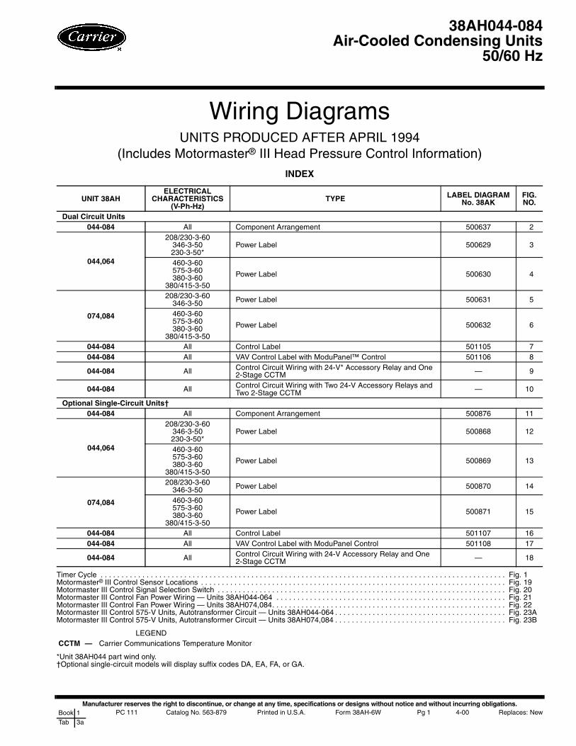
Manufacturer reserves the right to discontinue, or change at any time, specifications or designs without notice and without incurring obligations. PC 111 Catalog No. 563-879 Printed in U.S.A. Form 38AH-6W Pg 1 4-00 Replaces: New Book 1 Tab 3a Wiring Diagrams UNITS PRODUCED AFTER APRIL 1994 (Includes Motormaster ® III Head Pressure Control Information) INDEX Timer Cycle ................................................................................................. Fig. 1 Motormaster ® III Control Sensor Locations ......................................................................... Fig. 19 Motormaster III Control Signal Selection Switch ..................................................................... Fig. 20 Motormaster III Control Fan Power Wiring — Units 38AH044-064 ....................................................... Fig. 21 Motormaster III Control Fan Power Wiring — Units 38AH074,084........................................................ Fig. 22 Motormaster III Control 575-V Units, Autotransformer Circuit — Units 38AH044-064 ......................................... Fig. 23A Motormaster III Control 575-V Units, Autotransformer Circuit — Units 38AH074,084 ......................................... Fig. 23B LEGEND *Unit 38AH044 part wind only. †Optional single-circuit models will display suffix codes DA, EA, FA, or GA. UNIT 38AH ELECTRICAL CHARACTERISTICS (V-Ph-Hz) TYPE LABEL DIAGRAM No. 38AK FIG. NO. Dual Circuit Units 044-084 All Component Arrangement 500637 2 044,064 208/230-3-60 346-3-50 230-3-50* Power Label 500629 3 460-3-60 575-3-60 380-3-60 380/415-3-50 Power Label 500630 4 074,084 208/230-3-60 346-3-50 Power Label 500631 5 460-3-60 575-3-60 380-3-60 380/415-3-50 Power Label 500632 6 044-084 All Control Label 501105 7 044-084 All VAV Control Label with ModuPanel™ Control 501106 8 044-084 All Control Circuit Wiring with 24-V* Accessory Relay and One 2-Stage CCTM — 9 044-084 All Control Circuit Wiring with Two 24-V Accessory Relays and Two 2-Stage CCTM — 10 Optional Single-Circuit Units† 044-084 All Component Arrangement 500876 11 044,064 208/230-3-60 346-3-50 230-3-50* Power Label 500868 12 460-3-60 575-3-60 380-3-60 380/415-3-50 Power Label 500869 13 074,084 208/230-3-60 346-3-50 Power Label 500870 14 460-3-60 575-3-60 380-3-60 380/415-3-50 Power Label 500871 15 044-084 All Control Label 501107 16 044-084 All VAV Control Label with ModuPanel Control 501108 17 044-084 All Control Circuit Wiring with 24-V Accessory Relay and One 2-Stage CCTM — 18 CCTM — Carrier Communications Temperature Monitor 38AH044-084 Air-Cooled Condensing Units 50/60 Hz
Transcript of Wiring Diagrams - dms.hvacpartners.comdms.hvacpartners.com/docs/1005/public/07/38ah-6w.pdf ·...
Manufacturer reserves the right to discontinue, or change at any time, specifications or designs without notice and without incurring obligations.PC 111 Catalog No. 563-879 Printed in U.S.A. Form 38AH-6W Pg 1 4-00 Replaces: NewBook 1
Tab 3a
Wiring DiagramsUNITS PRODUCED AFTER APRIL 1994
(Includes Motormaster® III Head Pressure Control Information)
INDEX
Timer Cycle . . . . . . . . . . . . . . . . . . . . . . . . . . . . . . . . . . . . . . . . . . . . . . . . . . . . . . . . . . . . . . . . . . . . . . . . . . . . . . . . . . . . . . . . . . . . . . . . . Fig. 1Motormaster® III Control Sensor Locations . . . . . . . . . . . . . . . . . . . . . . . . . . . . . . . . . . . . . . . . . . . . . . . . . . . . . . . . . . . . . . . . . . . . . . . . . Fig. 19Motormaster III Control Signal Selection Switch . . . . . . . . . . . . . . . . . . . . . . . . . . . . . . . . . . . . . . . . . . . . . . . . . . . . . . . . . . . . . . . . . . . . . Fig. 20Motormaster III Control Fan Power Wiring — Units 38AH044-064 . . . . . . . . . . . . . . . . . . . . . . . . . . . . . . . . . . . . . . . . . . . . . . . . . . . . . . . Fig. 21Motormaster III Control Fan Power Wiring — Units 38AH074,084. . . . . . . . . . . . . . . . . . . . . . . . . . . . . . . . . . . . . . . . . . . . . . . . . . . . . . . . Fig. 22Motormaster III Control 575-V Units, Autotransformer Circuit — Units 38AH044-064 . . . . . . . . . . . . . . . . . . . . . . . . . . . . . . . . . . . . . . . . . Fig. 23AMotormaster III Control 575-V Units, Autotransformer Circuit — Units 38AH074,084 . . . . . . . . . . . . . . . . . . . . . . . . . . . . . . . . . . . . . . . . . Fig. 23B
LEGEND
*Unit 38AH044 part wind only.†Optional single-circuit models will display suffix codes DA, EA, FA, or GA.
UNIT 38AHELECTRICAL
CHARACTERISTICS(V-Ph-Hz)
TYPE LABEL DIAGRAMNo. 38AK
FIG.NO.
Dual Circuit Units044-084 All Component Arrangement 500637 2
044,064
208/230-3-60346-3-50230-3-50*
Power Label 500629 3
460-3-60575-3-60380-3-60
380/415-3-50
Power Label 500630 4
074,084
208/230-3-60346-3-50 Power Label 500631 5
460-3-60575-3-60380-3-60
380/415-3-50
Power Label 500632 6
044-084 All Control Label 501105 7044-084 All VAV Control Label with ModuPanel™ Control 501106 8
044-084 All Control Circuit Wiring with 24-V* Accessory Relay and One2-Stage CCTM — 9
044-084 All Control Circuit Wiring with Two 24-V Accessory Relays andTwo 2-Stage CCTM — 10
Optional Single-Circuit Units†044-084 All Component Arrangement 500876 11
044,064
208/230-3-60346-3-50230-3-50*
Power Label 500868 12
460-3-60575-3-60380-3-60
380/415-3-50
Power Label 500869 13
074,084
208/230-3-60346-3-50 Power Label 500870 14
460-3-60575-3-60380-3-60
380/415-3-50
Power Label 500871 15
044-084 All Control Label 501107 16044-084 All VAV Control Label with ModuPanel Control 501108 17
044-084 All Control Circuit Wiring with 24-V Accessory Relay and One2-Stage CCTM — 18
CCTM — Carrier Communications Temperature Monitor
38AH044-084Air-Cooled Condensing Units
50/60 Hz

2
OPERATING SEQUENCE
Timer Functions — (See Timer Cycle, Fig. 1.) Eachcompressor is operated by an independent timer motor whichallows for the independent operation of each refrigerationcircuit.NOTE: Optional single-circuit units have one timer motorwhich controls the lead compressor. Lag compressor is con-trolled by CCPS (Capacity Control Pressure Switch).SWITCH A — The timer motor is energized through contactsA-A1 or A-A2. This establishes the Time Guard® functionwhich prevents compressor short-cycling. Start of compressoris delayed approximately 5.5 minutes after shutdown. Com-pressor B1 start-up is delayed 60 seconds after the T2 call-for-cooling by a time-delay relay. This prevents both compressorsfrom starting at the same time.SWITCH B — The compressor is initially energized throughcontacts B-B1.SWITCH D — Contacts D-D1 provide a 2.5-minute bypass ofthe low-pressure switch at start-up for winter-start control. Onsingle-circuit units, contacts D-D2 control start-up of compres-sor A2.SWITCH E — Contacts E-E1 provide a 120-second bypass ofthe oil pressure switch at start-up. If oil pressure does not buildto the required minimum pressure in 120 seconds, the com-pressor shuts down and the control circuit locks out.
Control Circuit Reset — The control circuit locks outif the unit shuts down because of low oil pressure or excessivehigh-side pressure. To reset the control circuit, open and closethe fan circuit breaker (FCB). This will reset the timer motor,and the unit will restart under Time Guard® control. If LPS isnot closed, timer will not function. LPS must be closed at timeof start-up. At start-up, if the low-pressure switch (LPS) is notmade after 2.5 minutes, the unit shuts down. When the pressureis sufficient for the LPS to cut in, the control circuit is ener-gized automatically and start-up proceeds under Time Guardcontrol.
Unit Operation — Circuits A1 and B1 are controlled byindependent circuitry. It is therefore possible to maintain partialcooling capability even if one compressor is inoperable.NOTE: Single-circuit units do not have independent controlcircuitry.
On a call for cooling, the first-stage cooling thermostat TC1closes, energizing the first stage of the condenser fans and tim-er motor TM-A (TM for single-circuit units). After 12 seconds,the timer energizes lead compressor contactor C-A1 and thelead compressor starts. (Circuit A compressor is the lead ondual-circuit units, and compressor A1 is the lead on single-circuit units.) At the same time, solenoid drop relay SDR2 en-ergizes and closes its contacts, which energizes and opens liq-uid line solenoid valve LLS-A (LLS-A1 for single-circuit
units). Circuit A (compressor A1 for single-circuit units) isnow operational.
A set of bypass contacts in timer TM-A allows the circuit Acompressor (compressor A1 for single-circuit units) 120 sec-onds to build sufficient oil pressure. If the oil pressure is insuf-ficient after 120 seconds, circuit A (compressor A1 for single-circuit units) shuts down and must be reset manually.
A second set of bypass contacts in timer TM-A (TM forsingle-circuit units) allows the refrigerant circuit 21/2 minutesto build sufficient low-side pressure. This time delay is a start-up feature for low ambient conditions; no accessory is required.If refrigerant circuit pressure is insufficient to close the low-pressure switch after 21/2 minutes, the circuit A compressor(compressor A1 for single-circuit units) shuts down for 5 min-utes and then automatically attempts to restart. No manual resetis required.FOR DUAL-CIRCUIT UNITS — If circuit A is insufficientfor the cooling requirements, second-stage thermostat TC2closes to bring circuit B on line. Circuit B follows the samesequence of operation as circuit A, except a relay delays circuitB compressor start-up for 40 seconds after a call for cooling.Because circuit A has a 12-second delay after TC1 closes, andcircuit B has a 40-second delay after TC2 closes, the two com-pressors cannot start at the same time.FOR OPTIONAL SINGLE-CIRCUIT UNITS — If com-pressor A1 is insufficient for the cooling requirements, second-stage thermostat TC2 closes, which opens liquid line solenoidvalve LLS-A2. Compressor A2 starts only after the D-D2contacts in timer TM close (approximately 21/2 minutes aftercompressor A1 is energized) and the suction pressure is suffi-cient to close capacity control pressure switches CCPS1 andCCPS2.NOTE: Liquid line solenoid valves must be field-supplied andinstalled at the evaporator for both dual- and optional single-circuit units.INDOOR-FAN OPERATION — When the fan switch on thethermostat is set for automatic operation (AUTO), the field-supplied indoor-fan contactor (IFC) is cycled with the leadcompressor. If the fan switch is set at the continuous position(CONT), the IFC is energized as long as the unit power is on.
Restart After Stoppage by Safety Control —The high-pressure switch and the oil pressure switch must bereset manually by breaking the control power supply at any ofthe following points: control circuit fuse, fan motor circuitbreaker, or the thermostat. Restart follows the Time Guard®control delay.
Stoppage by low-pressure switch results in Time Guardcontrol delay, then unit attempts normal restart.
The compressor motor overcurrent protectors are manual-reset circuit breakers. Reset of control circuit may also benecessary.

3
Head Pressure ControlDual-circuit units: Fan cycling pressure switches (one on eachcircuit) close at 264 ± 7 psig (1820 ± 48 kPag) and open at160 ± 7 psig (869 ± 48 kPag). The fan cycling pressureswitches control fans no. 3, 4, 5, and 6 on sizes 074-084.Optional single-circuit units: Fan cycling pressure switchcloses at 264 ± 7 psig (1829 ± 48 kPag) and opens at 160 ±7 psig (869 ± 48 kPag). The fan cycling pressure switch con-trols fans no. 3 and 4 on all sizes. Sizes 074 and 084 alsoinclude a fan cycling temperature switch to control fans no. 5and 6. The temperature switch is closed when the ambient tem-perature is above 70 F (21 C).
Independent Refrigerant Circuit Controls —Circuits A1 and B1 are controlled by independent circuitry. It istherefore possible to maintain partial cooling capability even ifone compressor or unit module is inoperable.NOTE: Single circuit units do not have independent controlcircuitry.
NOTE: Black denotes closed contacts.
Fig. 1 — Timer Cycle

4
LEGEND (Fig. 2-15)
NOTES (Fig. 2-8 and 11-17)1. 208/230V units are factory wired for 230-v power supply. For 208-v power
supply, connect yellow wire to terminal marked H2. For 460-v power sup-ply, connect yellow wire to terminal marked H4. For 575-v power supply,connect yellow wire to terminal marked H2.
2. For units with 115-v controls, connect black wire to the white lead ofTRAN2. For units with 230-v controls, connect black wire to the red leadof TRAN2. For units with 200-v controls, connect black wire to the bluelead of TRAN2.
3. Terminal blocks TB3, TBX1, and TBX2 are for external field control con-nections. Control connections are to be class 1 wiring.
4. Field-supplied components (IFC, LLS-A1 and LLS-A2) must have a maxi-mum sealed coil rating of 30 va each (0.25 amp at 120 vac, 0.13 amp at230 vac). Thermostats must have a minimum pilot duty rating of 120 va(1 amp at 120 vac). The fan switch must have a minimum pilot duty ratingof 30 va (0.25 amp at 120 vac, 0.13 amp at 230 vac). On VAV units, theAHMS IFC_AUX and control staging contacts must have a minimum pilotduty rating of 120 VA (1 amp at 120 vac).
5. Wiring for field power supply must be rated 75 C minimum. Use copper,copper-clad aluminum, or aluminum conductors. Maximum incoming wiresize for each terminal block is 500 kcmil.
6. Replacement of factory wires must be with type 105 C wire or itsequivalent.
7. Factory wiring is in accordance with National Electrical Code (NEC). Fieldmodifications or additions must be in compliance with all applicablecodes.
8. Compressors and fan motors are thermally protected. Three phasemotors are protected against primary single phasing conditions.
9. Line numbers on the left side of the label diagrams indicate the contactnumber. The numbers on the right side of the label diagrams match thecontacts with their corresponding coils. A plain number indicates normallyopen contacts. An underlined number indicates normally closed contacts.
10. Control circuit power available for field-installed accessories.
ATS — Air Temperature SwitchC — Compressor ContactorCB — Compressor Circuit BreakerCCPS — Capacity Control Pressure SwitchCH — Crankcase HeaterCOMP — CompressorCR — Control RelayDU — Dummy TerminalEQUIP — EquipmentFC — Fan ContactorFCB — Fan Circuit BreakerFCPS — Fan Cycling Pressure SwitchFIOP — Factory-Installed OptionFM — Fan MotorFU — FuseGND — GroundHPS — High-Pressure SwitchIFC — Indoor-Fan ContactorLLS — Liquid Line SolenoidLPR — Low-Pressure RelayLPS — Low-Pressure SwitchMMSN — Motormaster® SensorNEC — National Electrical Code
(U.S.A. Standard, NFPA 70)NFPA — National Fire Protection AssociationOPR — Oil Pressure RelayOPS — Oil Pressure SwitchPL — Plug AssemblyPR — Power Relay
PRI — PrimaryPW — Part-Wind StartSDR — Solenoid Drop RelaySEC — SecondaryTB — Terminal BlockTC — Thermostat, CoolingTDR — Time-Delay RelayTM — Timer MotorTR — Timer RelayTRAN — TransformerU — UnloaderVAV — Variable Air VolumeXL — Across-the-Line Start
Terminal Block Connection
Marked Terminal
Unmarked Terminal
Unmarked Splice
Marked Wire
Factory Wiring
Field WiringIndicates Common Potential;Does Not Represent Wiring

5
Fig
.2—
Du
al-C
ircu
itU
nit
s,C
om
po
nen
tA
rran
gem
ent,
All
Vo
ltag
es

6
Fig
.3—
Du
al-C
ircu
itU
nit
s,P
ow
erL
abel
Dia
gra
m—
Un
its
38A
H04
4-06
4;20
8/23
0-3-
60,3
46-3
-50,
230-
3-50

7
Fig
.4—
Du
al-C
ircu
itU
nit
s,P
ow
erL
abel
Dia
gra
m—
Un
its
38A
H04
4-06
4;46
0-3-
60,5
75-3
-50,
380-
3-60
,380
/415
-3-5
0

8
Fig
.5—
Du
al-C
ircu
itU
nit
s,P
ow
erL
abel
Dia
gra
m—
Un
its
38A
H07
4,08
4;20
8/23
0-3-
60,3
46-3
-50

9
Fig
.6—
Du
al-C
ircu
itU
nit
s,P
ow
erL
abel
Dia
gra
m—
Un
its
38A
H07
4,08
4;46
0-3-
60,5
75-3
-60,
380-
3-60
,380
/415
-3-5
0

10
Con
tinue
don
next
page
Con
tinue
don
next
page

11
Fig
.7—
Du
al-C
ircu
itU
nit
sC
on
tro
lLab
elD
iag
ram
,All
Volt
ages
12
Con
tinue
don
next
page
Con
tinue
don
next
page

13
Fig
.8—
Du
al-C
ircu
itU
nit
s,V
aria
ble
Air
Volu
me
Lab
elD
iag
ram
wit
hTy
pic
alM
od
up
anel
™C
on
tro
lWir
ing
,All
Volt
ages

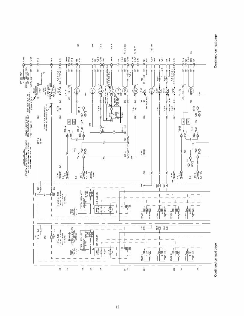
14
Fig. 9 — Control Circuit Wiring with 24-V Accessory Relay andOne 2-Stage Carrier Communications Temperature Monitor, All Voltages (Dual-Circuit Units)
LLS — Liquid Line SolenoidSDR — Solenoid Drop RelayTB — Terminal BlockTR — Timer Relay
Factory WiringField Wiring
*Jumper removed only when separate 24-v transformer power source is used to power the TSR-01 relay pack.†To control heating device and provide automatic indoor-fan operation on heating.
NOTES:1. Liquid line solenoid valve LLS-A is used for solenoid drop on circuit A. Liquid line solenoid valve LLS-B is used for
solenoid drop for circuit B.2. Solenoid drop is a safety feature which prevents refrigerant migration to the compressor during the OFF cycle. It
is recommended on all systems and required on systems where piping exceeds 75 ft in length.3. TSR-01 relay pack uses 10 va. Internal relay contacts are rated for 1 amp/24 vac.
C — Compressor ContactorCR — Control RelayH — Heating Relay (field-supplied
24-v sealed coil,10 va maximum rating)
HD — Heating DeviceIFC — Indoor-Fan ContactorIFR — Indoor-Fan Relay
LEGEND
Continued on next page

15
Fig. 9 — Control Circuit Wiring with 24-V Accessory Relay andOne 2-Stage Carrier Communications Temperature Monitor, All Voltages (Dual-Circuit Units) (cont)

16
LLS — Liquid Line SolenoidSDR — Solenoid Drop RelayTB — Terminal BlockTR — Timer Relay
Factory WiringField Wiring
C — Compressor ContactorCR — Control RelayH — Heating Relay (field-supplied
24-v sealed coil,10 va maximum rating)
HD — Heating DeviceIFC — Indoor-Fan ContactorIFR — Indoor-Fan Relay
Fig. 10 — Control Circuit Wiring with 24-V Accessory Relays andTwo-Stage Carrier Communications Temperature Monitors, All Voltages (Dual-Circuit Units)
*Jumper removed only when separate 24-v transformer power source is used to power the TSR-01 relay pack.†To control heating device and provide automatic indoor-fan operation on heating.
NOTES:1. Liquid line solenoid valve LLS-1 is used for solenoid drop on circuit A. Liquid line solenoid valve LLS-3 is used for
solenoid drop for circuit B.2. Solenoid drop is a safety feature which prevents refrigerant migration to the compressor during the OFF cycle. It
is recommended on all systems and required on systems where piping exceeds 75 ft in length.3. Liquid line solenoid valve LLS-2 is used for capacity control on circuit A system; LLS-4 is used for capacity con-
trol on circuit B system.4. TSR-01 relay pack uses 10 va. Internal relay contacts are rated for 1 amp/24 vac.
LEGEND
Continued on next page

17
Fig. 10 — Control Circuit Wiring with 24-V Accessory Relays andTwo-Stage Carrier Communications Temperature Monitors, All Voltages (Dual-Circuit Units) (cont)

18
Fig
.11
—O
pti
on
alS
ing
le-C
ircu
itU
nit
s,C
om
po
nen
tA
rran
gem
ent,
All
Vo
ltag
es

19
Fig
.12
—O
pti
on
alS
ing
le-C
ircu
itU
nit
sP
ow
erL
abel
Dia
gra
m—
Un
its
38A
H04
4-06
4;20
8/23
0-3-
60,3
46-3
-50,
230-
3-50

20
Fig
.13
—O
pti
on
alS
ing
le-C
ircu
itU
nit
sP
ow
erL
abel
Dia
gra
m—
Un
its
38A
H04
4-06
4;46
0-3-
60,5
75-3
-60,
380-
3-60
,380
/415
-3-5
0

21
Fig
.14
—O
pti
on
alS
ing
le-C
ircu
itU
nit
sP
ow
erL
abel
Dia
gra
m—
Un
its
38A
H07
4,08
4;20
8/23
0-3-
60,3
46-3
-50

22
Con
tinue
don
next
page

23
Fig
.15
—O
pti
on
alS
ing
le-C
ircu
itU
nit
sP
ow
erL
abel
Dia
gra
m—
Un
its
38A
H07
4,08
4;46
0-3-
60,5
75-3
-60,
380-
3-60
,380
/415
-3-5
0

24
Con
tinue
don
next
page

25
Fig
.16
—O
pti
on
alS
ing
le-C
ircu
itU
nit
sC
on
tro
lLab
elD
iag
ram
,All
Volt
ages

26
Con
tinue
don
next
page
Con
tinue
don
next
page

27
Fig
.17
—O
pti
on
alS
ing
le-C
ircu
itU
nit
s,V
aria
ble
Air
Volu
me
Co
ntr
olL
abel
Dia
gra
m,w
ith
Typ
ical
Mo
du
pan
el™
Co
ntr
olW
irin
g,A
llVo
ltag
es
28
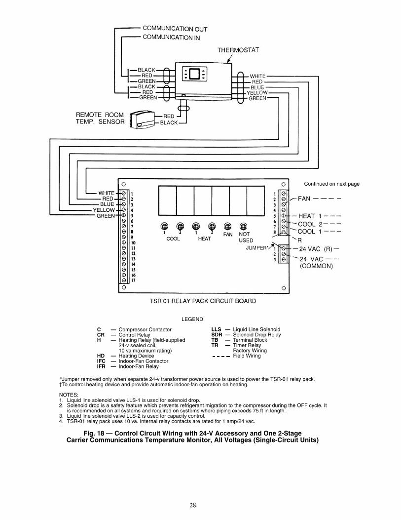
LLS — Liquid Line SolenoidSDR — Solenoid Drop RelayTB — Terminal BlockTR — Timer Relay
Factory WiringField Wiring
C — Compressor ContactorCR — Control RelayH — Heating Relay (field-supplied
24-v sealed coil,10 va maximum rating)
HD — Heating DeviceIFC — Indoor-Fan ContactorIFR — Indoor-Fan Relay
LEGEND
Fig. 18 — Control Circuit Wiring with 24-V Accessory and One 2-StageCarrier Communications Temperature Monitor, All Voltages (Single-Circuit Units)
*Jumper removed only when separate 24-v transformer power source is used to power the TSR-01 relay pack.†To control heating device and provide automatic indoor-fan operation on heating.
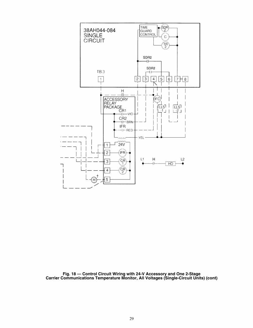
NOTES:1. Liquid line solenoid valve LLS-1 is used for solenoid drop.2. Solenoid drop is a safety feature which prevents refrigerant migration to the compressor during the OFF cycle. It
is recommended on all systems and required on systems where piping exceeds 75 ft in length.3. Liquid line solenoid valve LLS-2 is used for capacity control.4. TSR-01 relay pack uses 10 va. Internal relay contacts are rated for 1 amp/24 vac.
Continued on next page
29
Fig. 18 — Control Circuit Wiring with 24-V Accessory and One 2-StageCarrier Communications Temperature Monitor, All Voltages (Single-Circuit Units) (cont)

30
MOTORMASTER® III CONTROLINSTALLATION
Before installing Motormaster III control, refer to generalinformation in Installation Instructions shipped with the con-trol. Comply with the following instructions when applyingMotormaster III control to 38AH044-084 units. Refer toTable 1 for usage and unit modification data.
Table 1 — Minimum Operating Temperatures
Required ChangesSTEP 1 — WIND BAFFLES AND BRACKETS — Windbaffles and brackets must be field fabricated for 38AH units toensure proper operation at low-ambient temperatures withMotormaster III controls.STEP 2 — INSTALL MOTORMASTER III CON-TROLS — Two Motormaster III controls must be addedfor each unit, one control per refrigerant circuit. See Motor-master III Installation Instructions for proper control mountinglocations.Sensors — Install sensor for thermistor input control in properlocation on condenser coil. See Fig. 19 and Motormaster IIIInstallation Instructions. Connect sensor leads to the purpleand gray control signal leads on the Motormaster III controllocated on the same side of the unit.Control Signal Selection Switch — Remove the cover of theMotormaster III controller. Set switch on Motormaster III con-trol board (underneath cover) to accept the thermistor sensorinput signal. Also, set the frequency selection switch to matchto unit power supply (50 Hz or 60 Hz). See Fig. 20 for switchlocations and proper position. Replace the cover.
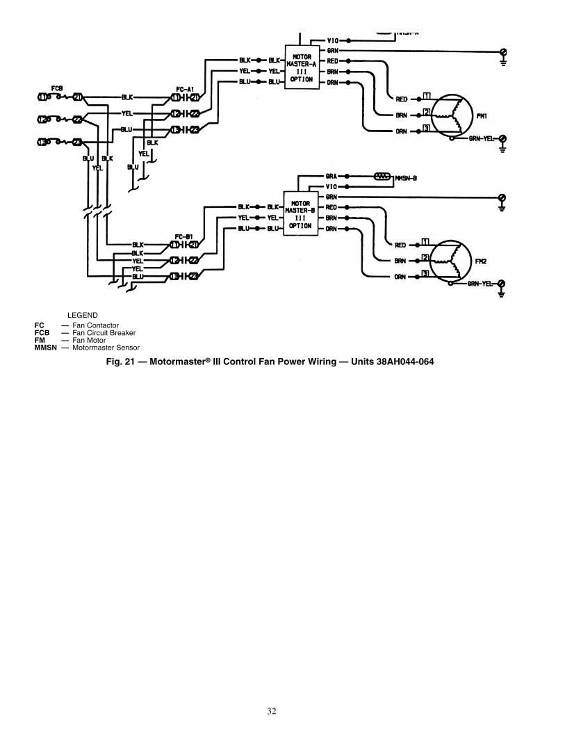
STEP 3 — MAKE ELECTRICAL CONNECTIONS
All the necessary wires required for wiring the Motor-master III controller into the unit wire in the wire harness forthe unit.38AH044-064 Units — Connect the power wires to the con-troller from the appropriate fan contactor, FC-A1 or FC-B1.Remove the red, brown, and orange wires from the fan motorcontactor. Connect the red fan motor wire to the red wire of thecontroller. Connect the brown fan motor wire to the brownwire of the controller. Connect the orange fan motor wire to theorange wire of the controller. See Fig. 21.38AH074,084 Units — Connect the power wires to the con-troller from the appropriate fan contactor, FC-A1 or FC-B1.Remove the red, brown, and orange wires from the fan motorcontactor. Connect the red fan motor wire to the red wire of thecontroller. Connect the brown fan motor wire to brown wire ofthe controller. Connect the orange fan motor wire to the orangewire of the controller. See Fig. 22.NOTE: For 38AH units, if primary voltage is 575 v, two trans-formers (part no. HT01AH851) must be used to lower thesupply voltage to the Motormaster III controller to 460 v. SeeFig. 23A or B.All Sizes — When all electrical connections are made, checkthat they are correct and tight. Restore power to unit. Check thephase sequence indicator on the Motormaster III control. Iflighted, turn off power and reverse L1 (black) and L2 (yellow)power leads. Check that fan motors rotate in the proper direc-tion. To change fan rotation, reverse the red and orange outputleads to the motor. Replace and secure the control box innerpanel. Close and secure the control box door.
UNIT38AH
TEMPERATUREWithout Motormaster III
ControlWith Motormaster III
ControlF C F C
044,054064-084
5035
107.1
–20–20
–29–29
To avoid possibility of electrical shock and personal injury,turn off all power to unit before making electrical connec-tions. Tag all disconnects to alert others not to turn poweron until work is completed.

31
LEGEND
*For thermistor (sensor) signal, move switch to the left.
NOTE: Thermistor is designated in text as “sensor.”
Fig. 20 — Motormaster III Control Signal Selection Switch
GND — Ground
Fig. 19 — Motormaster® III Control Sensor Locations
32
LEGEND
Fig. 21 — Motormaster® III Control Fan Power Wiring — Units 38AH044-064
FC — Fan ContactorFCB — Fan Circuit BreakerFM — Fan MotorMMSN — Motormaster Sensor

33
LEGEND
Fig. 22 — Motormaster® III Control Fan Power Wiring — Units 38AH074, 084
FC — Fan ContactorFCB — Fan Circuit BreakerFM — Fan MotorMMSN — Motormaster Sensor

34
LEGEND
Fig. 23A — Motormaster® III Control 575-v Units, Autotransformer Circuit — Units 38AH044-064
FC — Fan ContactorFCB — Fan Circuit BreakerFM — Fan MotorMMSN — Motormaster SensorTRAN — Transformer

35
LEGEND
Fig. 23B — Motormaster® III Control 575-v Units, Autotransformer Circuit — Units 38AH074, 084
FC — Fan ContactorFCB — Fan Circuit BreakerFM — Fan MotorMMSN — Motormaster SensorTRAN — Transformer

Manufacturer reserves the right to discontinue, or change at any time, specifications or designs without notice and without incurring obligations.PC 111 Catalog No. 563-879 Printed in U.S.A. Form 38AH-6W Pg 36 4-00 Replaces: NewBook 1
Tab 3a
Copyright 2000 Carrier Corporation