Wireless Tissue Palpation: Proof of Concept for a Single ... · Wireless Tissue Palpation: Proof of...
7
Wireless Tissue Palpation: Proof of Concept for a Single Degree of Freedom Marco Beccani, Christian Di Natali, Mark E. Rentschler, Pietro Valdastri Abstract—Palpating tissues and organs to identify hidden tumors or to detect buried vessels is not a viable option in laparoscopic surgery due to lack of force feedback. So far, research toward restoring tactile and kinesthetic sensations in minimally invasive surgery has focused on the distal sensing element or on the proximal rendering of haptic cues. In this work we present a pilot study to assess the feasibility of wireless tissue palpation, where a magnetic device is deployed through a standard surgical trocar and operated to perform tissue palpation without requiring a dedicated entry port. The setup consists of a wireless intra-body device and an external robotic manipulator holding a load cell and a permanent magnet. Embedded in the wireless cylindrical device (12.7 mm in diameter and 27.5 mm in height) is a sensing module, a wireless microcontroller, a battery and a permanent magnet. This preliminary study assessed the precision in reconstructing the indentation depth based on magnetic field measurements at the wireless device (i.e., 0.1 mm accuracy). Experimental trials demonstrated the effectiveness of wireless vertical indentation in detecting the elastic modulus of three different silicone tissue simulators (elastic modulus ranging from 50 kPa to 93 kPa), showing a maximum relative error below 3%. Finally, wireless palpation was used to identify differences in tissue stiffness from a lump embedded into a porcine liver. The reported results have the potential to open a new paradigm in the field of palpation devices, where direct physical connection across the abdominal wall is no longer required. I. I NTRODUCTION T ODAY minimally invasive surgery (MIS) is a popular and widely accepted clinical practice, with more than two million procedures performed in the United States an- nually [?]. Robotic MIS is also increasingly common with more than 2,000 of Intuitive Surgical’s da Vinci platforms installed worldwide [1]. Despite the clear benefits in terms of patient recovery time, pain and scarring after the surgery, both MIS and robotic MIS prevent the surgeon from directly manipulating tissues and organs as is done in open surgery [2]. In particular, laparoscopic instruments used in MIS severely compromise any haptic cues because of friction against the surgical port (i.e., trocar) and the fulcrum effect at the insertion point [3]. The situation gets even worse when considering commercially available robotic MIS platforms, where zero haptic force feedback is available, since the surgical instru- ments are teleoperated from a remote console. Therefore, in MIS and robotic MIS the surgeon has minimal, or no, chance to leverage tactile and kinesthetic sensations in preventing M. Beccani, C. Di Natali, P. Valdastri are with the STORM Lab, Department of Mechanical Engineering, Vanderbilt University, Nashville, TN 37235-1592. Email: [email protected] M. E. Rentschler is with the Department of Mechanical Engineering, University of Colorado, Boulder, CO 80303. Email: [email protected] Fig. 1. Principle of operation for wireless tissue palpation using a wireless palpation device (WPD). accidental tissue damage or to explore non-visible tissue and organ features by palpation. Restoring tactile and kinesthetic sensations in MIS and robotic MIS has been an active research topic for more than two decades [4], [5], with one of the first systems used in a human dating back 1994 [6]. A relevant number of MIS instruments with force and/or tactile sensors have been developed to acquire in vivo data for tissue modeling and simulation [7]–[10], to improve the outcomes of the surgical procedure – preventing excessive forces from being applied to the tissues [3], [11]–[14], or to explore tissues and organs by palpation [2], [15]–[17]. This last functionality is particularly relevant whenever location and boundaries of a hidden tumor must be located – registration with pre-operative imaging is not effective for soft tissues [2], [16], or to identify buried structures (e.g., nerves or blood vessels) that must be avoided during the surgical procedure. MIS devices for tissue palpation developed to date exploit different approaches, such as grasping [5], [9], [12], rolling indentation [2], or vertical indentation [7], [8], [10], [15], [16]. However, the fact that no commercial MIS instruments with embedded force and/or tactile sensors have been adopted clinically so far [18] illustrates that there exists a significant roadblock preventing the translation of potentially transfor- mative prototypes into clinical practice. Focusing on MIS palpation devices, a possible barrier may be that surgeons are not yet willing to devote a surgical port to an instrument whose sole purpose is to palpate tissues. Therefore, providing a tissue indenter that does not require port space may overcome this potential adoption barrier. 2013 IEEE International Conference on Robotics and Automation (ICRA) Karlsruhe, Germany, May 6-10, 2013 978-1-4673-5642-8/13/$31.00 ©2013 IEEE 703
Transcript of Wireless Tissue Palpation: Proof of Concept for a Single ... · Wireless Tissue Palpation: Proof of...

Wireless Tissue Palpation:Proof of Concept for a Single Degree of Freedom
Marco Beccani, Christian Di Natali, Mark E. Rentschler, Pietro Valdastri
Abstract—Palpating tissues and organs to identify hiddentumors or to detect buried vessels is not a viable option inlaparoscopic surgery due to lack of force feedback. So far,research toward restoring tactile and kinesthetic sensations inminimally invasive surgery has focused on the distal sensingelement or on the proximal rendering of haptic cues. In thiswork we present a pilot study to assess the feasibility of wirelesstissue palpation, where a magnetic device is deployed through astandard surgical trocar and operated to perform tissue palpationwithout requiring a dedicated entry port. The setup consists of awireless intra-body device and an external robotic manipulatorholding a load cell and a permanent magnet. Embedded in thewireless cylindrical device (12.7 mm in diameter and 27.5 mmin height) is a sensing module, a wireless microcontroller, abattery and a permanent magnet. This preliminary study assessedthe precision in reconstructing the indentation depth based onmagnetic field measurements at the wireless device (i.e., 0.1 mmaccuracy). Experimental trials demonstrated the effectiveness ofwireless vertical indentation in detecting the elastic modulus ofthree different silicone tissue simulators (elastic modulus rangingfrom 50 kPa to 93 kPa), showing a maximum relative error below3%. Finally, wireless palpation was used to identify differencesin tissue stiffness from a lump embedded into a porcine liver.The reported results have the potential to open a new paradigmin the field of palpation devices, where direct physical connectionacross the abdominal wall is no longer required.
I. INTRODUCTION
TODAY minimally invasive surgery (MIS) is a popularand widely accepted clinical practice, with more than
two million procedures performed in the United States an-nually [?]. Robotic MIS is also increasingly common withmore than 2,000 of Intuitive Surgical’s da Vinci platformsinstalled worldwide [1]. Despite the clear benefits in termsof patient recovery time, pain and scarring after the surgery,both MIS and robotic MIS prevent the surgeon from directlymanipulating tissues and organs as is done in open surgery [2].In particular, laparoscopic instruments used in MIS severelycompromise any haptic cues because of friction against thesurgical port (i.e., trocar) and the fulcrum effect at the insertionpoint [3]. The situation gets even worse when consideringcommercially available robotic MIS platforms, where zerohaptic force feedback is available, since the surgical instru-ments are teleoperated from a remote console. Therefore, inMIS and robotic MIS the surgeon has minimal, or no, chanceto leverage tactile and kinesthetic sensations in preventing
M. Beccani, C. Di Natali, P. Valdastri are with the STORM Lab, Departmentof Mechanical Engineering, Vanderbilt University, Nashville, TN 37235-1592.Email: [email protected]
M. E. Rentschler is with the Department of Mechanical Engineering,University of Colorado, Boulder, CO 80303.Email: [email protected]
Fig. 1. Principle of operation for wireless tissue palpation using a wirelesspalpation device (WPD).
accidental tissue damage or to explore non-visible tissue andorgan features by palpation.
Restoring tactile and kinesthetic sensations in MIS androbotic MIS has been an active research topic for morethan two decades [4], [5], with one of the first systemsused in a human dating back 1994 [6]. A relevant numberof MIS instruments with force and/or tactile sensors havebeen developed to acquire in vivo data for tissue modelingand simulation [7]–[10], to improve the outcomes of thesurgical procedure – preventing excessive forces from beingapplied to the tissues [3], [11]–[14], or to explore tissues andorgans by palpation [2], [15]–[17]. This last functionality isparticularly relevant whenever location and boundaries of ahidden tumor must be located – registration with pre-operativeimaging is not effective for soft tissues [2], [16], or to identifyburied structures (e.g., nerves or blood vessels) that must beavoided during the surgical procedure. MIS devices for tissuepalpation developed to date exploit different approaches, suchas grasping [5], [9], [12], rolling indentation [2], or verticalindentation [7], [8], [10], [15], [16].
However, the fact that no commercial MIS instrumentswith embedded force and/or tactile sensors have been adoptedclinically so far [18] illustrates that there exists a significantroadblock preventing the translation of potentially transfor-mative prototypes into clinical practice. Focusing on MISpalpation devices, a possible barrier may be that surgeons arenot yet willing to devote a surgical port to an instrument whosesole purpose is to palpate tissues. Therefore, providing a tissueindenter that does not require port space may overcome thispotential adoption barrier.
2013 IEEE International Conference on Robotics and Automation (ICRA)Karlsruhe, Germany, May 6-10, 2013
978-1-4673-5642-8/13/$31.00 ©2013 IEEE 703

In this spirit, we propose a wireless approach to tissue in-dentation, where a magnetic palpation device can be deployedthrough a standard trocar and operated without requiring adedicated entry port. In other instances, the patient couldswallow a wireless capsule that is used to remotely palpateorgans through the gastrointestinal tract. Given the novelty ofthe approach, this work aims to demonstrate the feasibility ofwireless indention for a single direction, leaving the extensionto multiple degrees of freedom to future studies.
II. MATERIALS
A. Principle of Operation
Referring to Fig. 1, the approach we propose takes ad-vantage of an external magnetic field source and an intra-body wireless palpation device (WPD) – embedded with aminiature permanent magnet and wireless electronics. TheWPD can be introduced into the abdominal cavity through astandard trocar and positioned on the target by a laparoscopicgrasper. Then, tissue indentation can be obtained by properlymodulating the gradient of the external magnetic field. In orderto generate kinesthetic data, the indentation depth and thepressure applied on the tissue must be known at any giventime. In this pilot study, we restricted the investigation to asingle degree of freedom (i.e., vertical indentation) as a firststep toward proving the feasibility of the proposed approach.
A permanent magnet mounted at the end effector of arobotic manipulator was adopted as external magnetic fieldsource. Considering the two magnets (i.e., the one inside theWPD and the one at the external manipulator) oriented as inFig. 2, we studied the indentation of a tissue sample alongthe vertical direction by cyclically translating the externalmagnet along the Z axis. Neglecting gravity and assuminga pure vertical motion for the WPD, the pressure exertedon the tissue is provided by the ratio of the intermagneticforce along the Z axis, Fz , and the area of the WPD facein contact with the tissue. At the equilibrium, the intensityof Fz can be measured by placing a load cell in betweenthe external permanent magnet and the end effector of themanipulator, as suggested in [19]. For vertical indentation asrepresented in Fig. 2, gravitational force acting on the WPDcan be considered as a preload on the tissue and factored out asan offset in the indentation trial. For any other configuration,an accelerometer can be embedded in the WPD to provide theinclination, thus allowing to quantify the exact contributionof the gravity force, should this vary during indentation. Inthis work, the inertial sensor is primarily used to verify theassumption of pure vertical motion for the WPD.
The indentation depth δ(t) can be evaluated by measuringthe Z component of the magnetic field at the WPD. Inparticular, referring to Fig. 2 and focusing on the tissue loadingphase, it is possible to express the distance between theexternal magnet and the internal magnet at the generic instantt as:
d(t) = d(t0)− δ(t)− dR(t0, t) (1)
Fig. 2. Schematic diagram for wireless vertical indentation at the initial timet0 (left) and at a generic time t (right) during the loading phase.
where dR(t0, t) is the vertical distance traveled by the roboticmanipulator since the beginning of the loading phase occurredin t0. Since the motion of the external magnet is limited to theZ axis and the WPD is aligned on that same direction in virtueof magnetic coupling, we can assume that the Z component ofthe magnetic field at the WPD, Bz(t), is an univocal functionof d(t) [20]:
Bz(t) = Φ[d(t)] (2)
that can be numerically quantified through experimental cali-bration. Therefore, the indentation depth δ(t) can be expressedby merging Eq. 2 with Eq. 1 and rearranging the terms as:
δ(t) = Φ[Bz(t0)]−1 − Φ[Bz(t)]−1 − dR(t0, t). (3)
Since the value of dR(t0, t) is available from the roboticmanipulator encoders and Bz(t) can be measured by placinga Hall effect sensor in the WPD, the total indentation depth canbe computed at any given time during the loading phase. Thesame mathematical formulation applies – mutatis mutandis –to the tissue unloading phase.
A relevant assumption for the proposed approach consistsof considering all the tissue deformation occurring at theinterface with the WPD. This holds true for the schematizationrepresented in Fig. 2 – where the tissue being tested is layingon a rigid support. However, it may not be valid during invivo conditions, where a stiffer organ may lay on a softertissue. This approximation is, however, well accepted in thefield of in vivo tissue indentation, as long as the indentationdepth is relevantly smaller (approximately 10-15% of the totalthickness) than the organ under test.
B. Experimental Platform OverviewThe experimental platform used to assess wireless tissue
palpation for a single degree of freedom is represented in Fig.
704
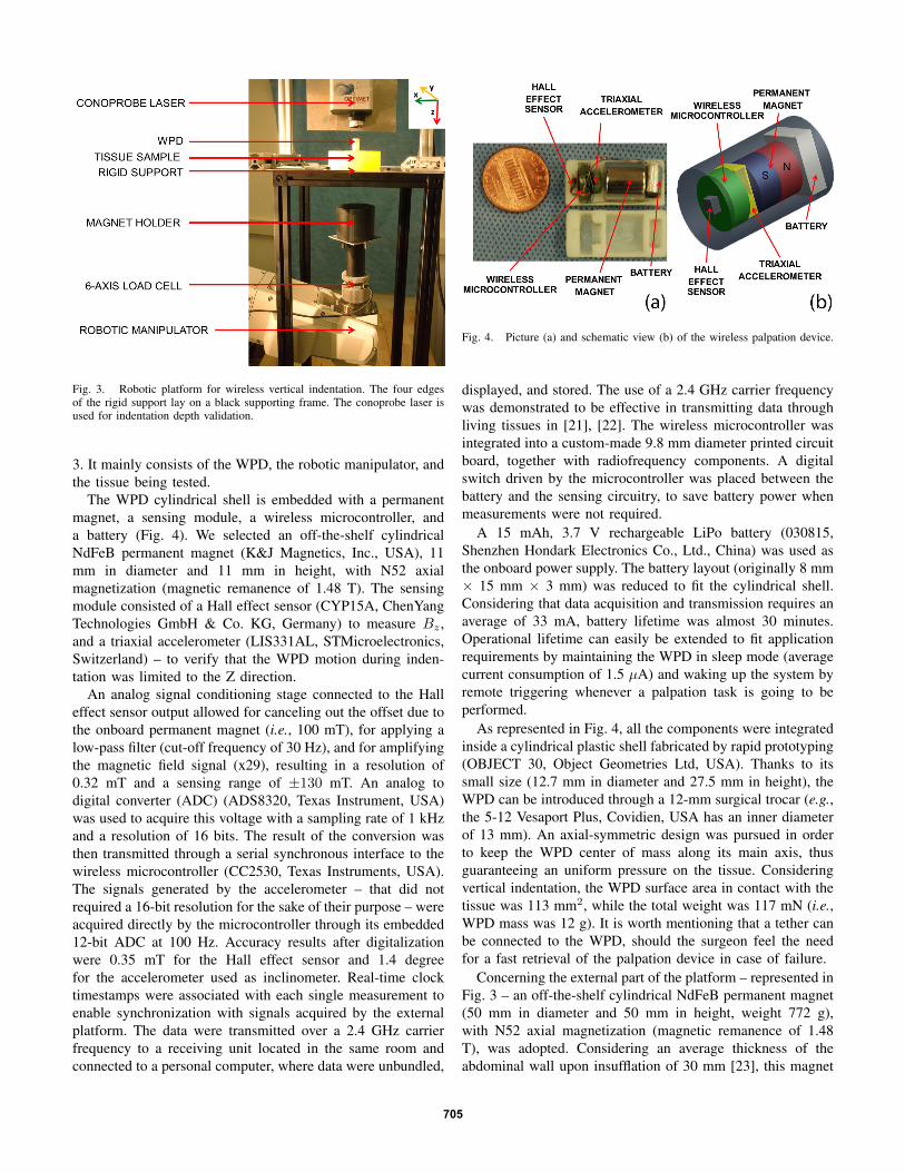
Fig. 3. Robotic platform for wireless vertical indentation. The four edgesof the rigid support lay on a black supporting frame. The conoprobe laser isused for indentation depth validation.
3. It mainly consists of the WPD, the robotic manipulator, andthe tissue being tested.
The WPD cylindrical shell is embedded with a permanentmagnet, a sensing module, a wireless microcontroller, anda battery (Fig. 4). We selected an off-the-shelf cylindricalNdFeB permanent magnet (K&J Magnetics, Inc., USA), 11mm in diameter and 11 mm in height, with N52 axialmagnetization (magnetic remanence of 1.48 T). The sensingmodule consisted of a Hall effect sensor (CYP15A, ChenYangTechnologies GmbH & Co. KG, Germany) to measure Bz ,and a triaxial accelerometer (LIS331AL, STMicroelectronics,Switzerland) – to verify that the WPD motion during inden-tation was limited to the Z direction.
An analog signal conditioning stage connected to the Halleffect sensor output allowed for canceling out the offset due tothe onboard permanent magnet (i.e., 100 mT), for applying alow-pass filter (cut-off frequency of 30 Hz), and for amplifyingthe magnetic field signal (x29), resulting in a resolution of0.32 mT and a sensing range of ±130 mT. An analog todigital converter (ADC) (ADS8320, Texas Instrument, USA)was used to acquire this voltage with a sampling rate of 1 kHzand a resolution of 16 bits. The result of the conversion wasthen transmitted through a serial synchronous interface to thewireless microcontroller (CC2530, Texas Instruments, USA).The signals generated by the accelerometer – that did notrequired a 16-bit resolution for the sake of their purpose – wereacquired directly by the microcontroller through its embedded12-bit ADC at 100 Hz. Accuracy results after digitalizationwere 0.35 mT for the Hall effect sensor and 1.4 degreefor the accelerometer used as inclinometer. Real-time clocktimestamps were associated with each single measurement toenable synchronization with signals acquired by the externalplatform. The data were transmitted over a 2.4 GHz carrierfrequency to a receiving unit located in the same room andconnected to a personal computer, where data were unbundled,
Fig. 4. Picture (a) and schematic view (b) of the wireless palpation device.
displayed, and stored. The use of a 2.4 GHz carrier frequencywas demonstrated to be effective in transmitting data throughliving tissues in [21], [22]. The wireless microcontroller wasintegrated into a custom-made 9.8 mm diameter printed circuitboard, together with radiofrequency components. A digitalswitch driven by the microcontroller was placed between thebattery and the sensing circuitry, to save battery power whenmeasurements were not required.
A 15 mAh, 3.7 V rechargeable LiPo battery (030815,Shenzhen Hondark Electronics Co., Ltd., China) was used asthe onboard power supply. The battery layout (originally 8 mm× 15 mm × 3 mm) was reduced to fit the cylindrical shell.Considering that data acquisition and transmission requires anaverage of 33 mA, battery lifetime was almost 30 minutes.Operational lifetime can easily be extended to fit applicationrequirements by maintaining the WPD in sleep mode (averagecurrent consumption of 1.5 µA) and waking up the system byremote triggering whenever a palpation task is going to beperformed.
As represented in Fig. 4, all the components were integratedinside a cylindrical plastic shell fabricated by rapid prototyping(OBJECT 30, Object Geometries Ltd, USA). Thanks to itssmall size (12.7 mm in diameter and 27.5 mm in height), theWPD can be introduced through a 12-mm surgical trocar (e.g.,the 5-12 Vesaport Plus, Covidien, USA has an inner diameterof 13 mm). An axial-symmetric design was pursued in orderto keep the WPD center of mass along its main axis, thusguaranteeing an uniform pressure on the tissue. Consideringvertical indentation, the WPD surface area in contact with thetissue was 113 mm2, while the total weight was 117 mN (i.e.,WPD mass was 12 g). It is worth mentioning that a tether canbe connected to the WPD, should the surgeon feel the needfor a fast retrieval of the palpation device in case of failure.
Concerning the external part of the platform – represented inFig. 3 – an off-the-shelf cylindrical NdFeB permanent magnet(50 mm in diameter and 50 mm in height, weight 772 g),with N52 axial magnetization (magnetic remanence of 1.48T), was adopted. Considering an average thickness of theabdominal wall upon insufflation of 30 mm [23], this magnet
705

was selected on the basis of numerical analysis [24] to operateat a distance along Z ranging from 35 mm to 75 mm awayfrom the WPD. In this region, the simulated absolute values ofthe field gradient range from 3.75 T/m to 0.6 T/m, respectively.Considering the features of the magnet embedded in the WPD,the expected intermagnetic force spans from 4.7 N to 0.75N. Should the required working distance be increased dueto specific patient constraints (e.g., larger body mass index),an external magnet with different features can be selected byrunning numerical simulations again.
The magnet was embedded in a plastic holder connectedto a 6-axis load cell (MINI45, Ati Indutrial Automation, Inc.,USA), having a resolution of 65 mN for the Z componentof the force. The magnet-load cell assembly was mountedat the end effector of a six degrees of freedom industrialrobot (RV6SDL, Mitsubishi Corp., Japan), presenting a mo-tion resolution of 1 µm along the Z direction. It is worthmentioning that the holder was designed so to space themagnet enough from the load cell and the manipulator toprevent electromagnetic interferences. Data from the load cellwere acquired by a dedicated acquisition board (NI-PCI 6224,National Instruments, USA) at a sampling frequency of 10kHz, and merged with the manipulator position and the signalscoming from the WPD.
The tissue sample being tested – silicone samples (M-F Liquid Plastic, MF Manufacturing, USA) with differentstiffnesses or porcine liver, depending on the trial – was placedon a 2 mm thick rigid support, as represented in Fig. 3.
Finally, the algorithm described by Eq. 3 was implementedin Matlab (Mathworks, USA) upon experimental calibration.In particular, the numerical function Φ−1 was evaluated byplacing the WPD directly on the rigid support and by recordingBz(t) while moving the external magnet at a constant speed(i.e., 3.12 mm/s) from a starting position 75 mm away fromthe rigid support along the Z axis (i.e., dR varying from 0mm to 75 mm, where for dR = 75 mm the top part of theholder was almost in contact with the lower side of the rigidsupport). This measurement was performed for five loading-unloading cycles, and the values were averaged. Given theexponential decay of the magnetic field with distance, a fifth-order polynomial function was used to fit Φ−1, thus obtaining:
d(t) = Φ−1[Bz(t)] =
5∑i=0
ai ·Bz(t)i (4)
with a0 = 185.6 mm, a1 = −6.95 · 103 mm/T, a2 = 1.57 · 104
mm/T2, a3 = −2 · 107 mm/T3, a4 = 1.31 · 107 mm/T4, a5 =−3.51 · 107 mm/T5. The square of the correlation coefficientfor the proposed fitting was R2 = 0.99998.
Since we are proposing a novel method to quantify theelastic modulus of the material being tested, it is interesting toanalyze in detail the error we should expect. Assuming verticalindentation, the error in measuring the stress straightforwardlydepends on the accuracy of the load cell (i.e., 65 mN).Concerning the indentation depth, the polynomial functionin Eq. 4 is applied to a sensor reading affected by a given
uncertainty ∆Bz . Considering δ(t) as expressed in Eq. 3, wecan write its absolute error as a function of ∆Bz and ∆dR:
|∆δ| ≤ |∂Φ−1[Bz(t)]
∂Bz(t)| · |∆Bz|+ |∆dR|. (5)
Considering Eq. 3 and a negligible error in dR – areasonable assumption given the high manipulator positionresolution, we then have
|∆δ| = |5∑
i=1
i · ai ·Bz(t)i−1| · |∆Bz|. (6)
This equation clearly shows how the accuracy of the pro-posed method depends upon the strength of the magnetic fieldat the WPD, which, for the proposed platform, is a function ofthe distance between the external magnet and the WPD. Thus,higher accuracy is obtained in a stronger magnetic field (i.e.,the shorter the distance between the WPD and the externalmagnet).
III. EXPERIMENTAL RESULTS
Experimental validation of single degree of freedom wire-less palpation consisted in three different trials. First, theeffectiveness of the algorithm in reconstructing the indentationdepth from magnetic field values was assessed. Then, threesilicone tissue samples, each with a different elastic modulus,were indented with the proposed approach, and the resultscompared with standard indentation. Finally, a lump wasembedded in a porcine liver and wireless palpation was usedto identify differences in tissue stiffness.
Fig. 5. Tissue indentation depth plotted as a function of dR and measuredvia the conoprobe laser and via the proposed WPD approach.
A. Indentation algorithm assessment
An optical conoscopic holography sensor (Conoprobe, Opti-met, USA) was adopted as reference measurement system. Theconoprobe laser was pointed at the upper circular surface of theWPD, as shown in Fig. 3. The indentation test was performed
706

Fig. 6. Tissue indentation depth error ∆δ as a function of d for the WPDapproach. The two dashed lines represent the envelope of the maximummeasurement error for the tissue indentation depth, ∆δ, as a function of thedistance d.
on a squared silicone tissue sample (elastic modulus 64.49kPa, thickness 35 mm, lateral side 75 mm) for dR varying ata constant speed (i.e., 3.12 mm/s) from 0 mm to 41 mm, wherefor dR = 41 mm the top part of the external magnet holder wasalmost in contact with the lower side of the rigid support. Fiveloading-unloading trials were completed and error analysiswas performed on the acquired data. Accelerometer outputconfirmed that WPD motion was only occurring along the Zdirection.
A typical loading plot for δ(t) acquired with both thereference system and the proposed approach is representedin Fig. 5 as a function of dR. Considering the tissue samplethickness, the rigid support, and the recorded indentationdepth, the distance d from the external magnet to the WPDvaried from 75 mm to 35 mm during the trials.
Concerning the error, the Hall effect sensor measurementspresented a maximum error of ±0.3 mT. By using this value inEq. 6 as ∆Bz , it is possible to plot an envelope of the expectedmaximum measurement error of the tissue indentation depthδ as a function of the distance d (Fig. 6). For all of theacquired measurements, the difference between the conoprobelaser reading and the reconstructed δ always fell within theenvelope. One example is given in Fig. 6. From the same plotit is possible to see that the measurement error for δ is ± 0.1mm at 35 mm, and increasing to ± 0.5 mm at 75 mm.
B. In vitro trials
In order to validate the effectiveness of wireless palpation todetect the elastic modulus like done when using a traditionalindenter, three squared silicone tissue simulators (thickness35 mm, lateral side 75 mm) were fabricated, each with adifferent proportion of hardener (i.e., 20%, 25%, and 30%),thus resulting in different elastic moduli E1, E2, and E3 [25].A traditional vertical indenter was obtained by replacing themagnet holder with a cylindrical probe at the interface with
Fig. 7. Experimental data acquired by standard indentation (a) and bywireless indentation (b) for three different silicone tissue samples.
the load cell. The probe was designed to have the same contactarea as the WPD. The indenter probe was first driven to touchthe surface of the tissue layer with a preload of 0.2 N. Fiveloading-unloading trials – reaching an indentation depth of 3mm – were performed for each tissue sample at a constantspeed of 3.12 mm/s. Stress-strain plots obtained from a singleloading are represented in Fig.7a. Elastic moduli obtained byleast square fitting were E1 = 50.75 kPa (R2 = 0.9973), E2 =64.49 kPa (R2 = 0.9935), and E3 = 93.92 kPa (R2 = 0.9972).
Wireless palpation was then performed on the same three
707

samples. Five loading-unloading trials were performed byfollowing the same protocol described for the assessment ofthe indentation algorithm (see Sec. III-A). The results arereported in Fig. 7b. Also in this case, accelerometer dataconfirmed that WPD motion was always occurring along the Zdirection. Indentation force reached 1.26 N, while indentationdepth ranged from 0.85 mm for the stiffer sample to 1.57mm for the softer sample. Elastic moduli obtained by leastsquare fitting were E1 = 51.51 kPa (R2 = 0.9825), E2 =63.75 kPa (R2 = 0.9802), and E3 = 91.43 kPa (R2 = 0.9608).Considering all the performed trials, the average relative errorfor wireless palpation in measuring the elastic module was1.5%, 1.1% and 2.8% for the tissue samples having E1, E2,and E3, respectively. The largest relative error occurred for thestiffer tissue sample. This can be explained by considering thatthe indentation depth for this sample was the smallest, thus thedistance between the WPD and the external magnet was thelargest among the trials, leading to the largest error.
C. Ex vivo trials
A freshly excised porcine liver (maximum length 250 mm,maximum width 140 mm, maximum thickness 40 mm, weight450 g) was used for the ex vivo trials to verify whether theWPD was able to detect a stiffer area in the organ. Sincein this study the motion of the WPD was not constrained tothe vertical axis, but the sensing technique was limited to thevertical direction, we decided to use a squared lump instead ofa spherical nodule – as suggested in [3] and [15], in order tominimize lateral motions of the WPD. The squared lump wasmade from hard material (Objet VeroWhite material, elasticmodulus stiffer than 1100 MPa) using a rapid prototypingmachine; the lump was 2 mm thick and 16 mm in side, so tocover a larger area than the WPD. The lump was embedded10 mm beneath the tissue surface so as to simulate a hiddenmalignant liver tumor, usually stiffer than the surroundinghealthy tissue.
Wireless indentation was performed 20 mm on the left fromwhere the lump was embedded (i.e., position A in Fig. 8a –WPD during palpation represented in Fig. 8b) and directly ontop of the lump (i.e., position B in Fig. 8a). The same protocoldescribed for the assessment of the indentation algorithm (seeSec. III-A) was followed and the accelerometer data confirmedthat WPD motion was occurring along the Z direction. Theresults are reported in Fig. 9. Indentation force reached 3 N,while maximum indentation depth was 3.5 mm. Elastic moduliobtained by least square fitting at the two positions were EA =46.01 kPa (R2 = 0.9622) and EB = 67.50 kPa (R2 = 0.9669).
IV. CONCLUSIONS AND FUTURE WORK
While most research has focused either on providing forceand tactile sensing at the end effector, or enabling hapticrendering at the user interface, the proposed approach tacklesthe physical connection between the two sides of the palpa-tion instrument. The reported results lead to the conclusionthat wireless vertical indentation is feasible in a laboratorysetting, showing comparable results to traditional indentation
Fig. 8. Liver sample where A and B highlight the positions where wirelesspalpation was performed. The squared lump was embedded 10 mm beneath thetissue in position B, as represented by the squared overlay. Distance betweenposition A and B is 20 mm (a). Side view of the porcine liver with the WPDabove position A (b).
Fig. 9. Experimental data acquired by wireless vertical indentation on onthe liver surface in positions A and B.
techniques. Given the absence of a rigid link between thepalpation probe and the external platform, vibrations andpatient’s respiration will likely affect the measurement whenmoving to in vivo operations. These artifacts can be potentiallyfiltered out thanks to the onboard accelerometer. Undesiredmagnetic interaction with surgical tools can be prevented byusing non-magnetic or plastic instruments.
Given these encouraging – yet preliminary – results, the nextstep is to demonstrate wireless palpation in a more realisticsetting, where the motion of the palpation device is not limitedto a single axis. This further step requires real-time pose (i.e.,position and orientation) detection for the WPD [26], that canbe used together with three-dimensional manipulation [27]–
708
[29] to explore organ surfaces. The inertia of the externalmagnet will likely hamper the measurement of the intermag-netic force by the external load cell. Therefore, alternativetechniques should be pursued to detect indentation pressure,such as measuring the magnetic field gradient at the WPDor integrating a tactile skin [30] on the external surface of theWPD. Rolling indentation [2] is also a possible future directionthat can be addressed by adopting diametrically magnetizedmagnets and ad hoc tissue-device interaction models [31].
ACKNOWLEDGMENT
This work is supported by the National Science Foundationunder Grant No. CNS-1239355 and by the National Centerfor Advancing Translational Sciences under Grant No.UL1-TR000445-06.
REFERENCES
[1] Intuitive Surgical website: www.intuitivesurgical.com .[2] H. Liu, J. Li, X. Song, L. Seneviratne, and K. Althoefer, “Rolling
indentation probe for tissue abnormality identification during minimallyinvasive surgery,” IEEE Trans. Robot., vol. 27, no. 3, pp. 450–460, 2011.
[3] P. Puangmali, H. Liu, L. Seneviratne, P. Dasgupta, and K. Althoefer,“Miniature 3-axis distal force sensor for minimally invasive surgicalpalpation,” IEEE/ASME Trans. Mechatronics, vol. 17, no. 4, pp. 646–656, 2012.
[4] P. Dario and M. Bergamasco, “An advanced robot system for automateddiagnostic tasks through palpation,” IEEE Trans. Biomed. Eng., vol. 35,no. 2, pp. 118–126, 1988.
[5] R. Howe, W. Peine, D. Kantarinis, and J. Son, “Remote palpationtechnology,” IEEE Eng. Med. Biol. Mag., vol. 14, no. 3, pp. 318–323,1995.
[6] T. Ohtsuka, A. Furuse, T. Kohno, J. Nakajima, K. Yagyu, and S. Omata,“Application of a new tactile sensor to thoracoscopic surgery: Experi-mental and clinical study,” The Annals of Thoracic Surgery, vol. 60,no. 3, pp. 610–614, 1995.
[7] M. Ottensmeyer and J. Salisbury, “In vivo data acquisition instrument forsolid organ mechanical property measurement,” in Medical Image Com-puting and Computer-Assisted Intervention – MICCAI 2001. Springer,2001, pp. 975–982.
[8] E. Samur, M. Sedef, C. Basdogan, L. Avtan, and O. Duzgun, “A roboticindenter for minimally invasive measurement and characterization of softtissue response,” Medical Image Analysis, vol. 11, no. 4, pp. 361–373,2007.
[9] J. Rosen, J. Brown, S. De, M. Sinanan, and B. Hannaford, “Biome-chanical properties of abdominal organs in vivo and postmortem undercompression loads,” Journal of Biomechanical Engineering, vol. 130,no. 021020, pp. 1–17, 2008.
[10] K. Lister, Z. Gao, and J. Desai, “Development of in vivo constitutivemodels for liver: Application to surgical simulation,” Annals of Biomed-ical Engineering, vol. 39, pp. 1060–1073, 2011.
[11] O. Van der Meijden and M. Schijven, “The value of haptic feedbackin conventional and robot-assisted minimal invasive surgery and virtualreality training: a current review,” Surgical Endoscopy, vol. 23, pp.1180–1190, 2009.
[12] G. Tholey and J. P. Desai, “A compact and modular laparoscopic grasperwith tri-directional force measurement capability,” ASME Journal ofMedical Devices, vol. 2, no. 3, pp. 031 001–9, 2008.
[13] B. Kubler, U. Seibold, and G. Hirzinger, “Development of actuatedand sensor integrated forceps for minimally invasive robotic surgery,”The International Journal of Medical Robotics and Computer AssistedSurgery, vol. 1, no. 3, pp. 96–107, 2005.
[14] M. Stark, T. Benhidjeb, S. Gidaro, and E. Morales, “The future oftelesurgery: a universal system with haptic sensation,” Journal of theTurkish-German Gynecological Association, vol. 13, no. 1, pp. 74–76,2012.
[15] J. Gwilliam, Z. Pezzementi, E. Jantho, A. Okamura, and S. Hsiao,“Human vs. robotic tactile sensing: Detecting lumps in soft tissue,” inIEEE Haptics Symposium, 2010, pp. 21–28.
[16] G. McCreery, A. Trejos, M. Naish, R. Patel, and R. Malthaner,“Feasibility of locating tumours in lung via kinaesthetic feedback.”The International Journal of Medical Robotics and Computer AssistedSurgery, vol. 4, no. 1, pp. 58–68, 2008.
[17] R. E. Goldman, A. Bajo, and N. Simaan, “Algorithms for autonomousexploration and estimation in compliant environments,” Robotica, 2012,in press, available on-line.
[18] P. Culmer, J. Barrie, R. Hewson, M. Levesley, M. Mon-Williams,D. Jayne, and A. Neville, “Reviewing the technological challengesassociated with the development of a laparoscopic palpation device,”The International Journal of Medical Robotics and Computer AssistedSurgery, vol. 8, no. 2, pp. 146–159, 2012.
[19] B. Laulicht, N. J. Gidmark, A. Tripathi, and E. Mathiowitz, “Localizationof magnetic pills,” Proceedings of the National Academy of Sciences,vol. 108, no. 6, pp. 2252–2257, 2011.
[20] E. P. Furlani, Permanent Magnet and Electromechanical Devices. Aca-demic Press, 2001, pp. 131–135.
[21] P. Valdastri, A. Menciassi, and P. Dario, “Transmission power require-ments for novel ZigBee implants in the gastrointestinal tract,” IEEETrans. Biomed. Eng., vol. 55, no. 6, pp. 1705–1710, 2008.
[22] S. R. Platt, J. A. Hawks, and M. E. Rentschler, “Vision and taskassistance using modular wireless in vivo surgical robots,” IEEE Trans.Biomed. Eng., vol. 56, no. 6, pp. 1700–1710, 2009.
[23] C. Song, A. Alijani, T. Frank, G. Hanna, and A. Cuschieri, “Mechanicalproperties of the human abdominal wall measured in vivo duringinsufflation for laparoscopic surgery,” Surgical Endoscopy, vol. 20, no. 6,pp. 987–990, 2006.
[24] C. Di Natali, T. Ranzani, M. Simi, A. Menciassi, and P. Valdastri,“Trans-abdominal active magnetic linkage for robotic surgery: Conceptdefinition and model assessment,” in Robotics and Automation (ICRA),IEEE International Conference on, 2012, pp. 695–700.
[25] M. Kunkel, A. Moral, R. Westphal, D. Rode, M. Rilk, and F. Wahl,“Using robotic systems in order to determine biomechanical propertiesof soft tissues,” in Studies in Health Technology and Informatics,Proceedings of the 2nd Conference on Applied Biomechanics, vol. 133,no. 3, 2008, p. 156.
[26] C. D. Natali, M. Beccani, and P. Valdastri, “Real-time pose detection formagnetic medical devices,” IEEE Trans. Magn., 2013, in press, availableon-line.
[27] G. Ciuti, P. Valdastri, A. Menciassi, and P. Dario, “Robotic magneticsteering and locomotion of capsule endoscope for diagnostic and surgicalendoluminal procedures,” Robotica, vol. 28, no. 2, pp. 199–207, 2010.
[28] S. Yim and M. Sitti, “Design and rolling locomotion of a magneticallyactuated soft capsule endoscope,” IEEE Trans. Robot., vol. 28, no. 1,pp. 183–194, 2012.
[29] A. W. Mahoney, D. L. Cowan, K. M. Miller, and J. J. Abbott, “Controlof untethered magnetically actuated tools using a rotating permanentmagnet in any position,” in Robotics and Automation (ICRA), IEEEInternational Conference on, 2012, pp. 3375–3380.
[30] Takktile by Y. Tenzer, L. Jentoft, I. Daniher, and Robert Howe:www.takktile.com .
[31] M. E. Rentschler, J. Dumpert, S. R. Platt, K. Lagnernma, D. Oleynikov,and S. M. Farritor, “Modeling, analysis, and experimental study of invivo wheeled robotic mobility,” IEEE Trans. Robot., vol. 22, no. 2, pp.308–321, 2006.
709