
Wireless Power Transfer - CST · PDF fileIntegral Equation Solver good ... in Magnetostatic...
40
CST – COMPUTER SIMULATION TECHNOLOGY | www.cst-taiwan.com.tw Wireless Power Transfer
Transcript of Wireless Power Transfer - CST · PDF fileIntegral Equation Solver good ... in Magnetostatic...

CST – COMPUTER SIMULATION TECHNOLOGY | www.cst-taiwan.com.tw
Wireless Power Transfer

CST – COMPUTER SIMULATION TECHNOLOGY | www.cst-taiwan.com.tw
Some History
1899 - Tesla 1964 - Brown1963 - Schuder
from Garnica et al. (2013) from Schuder et al. (1963) from Brown (1964)

CST – COMPUTER SIMULATION TECHNOLOGY | www.cst-taiwan.com.tw
1990s onward: mobile device charging
Now: commercialization & standardization
Commercialization
greencarreports.com - October 25th
techradar.com - October 18th
consumerreports.org - October 7thtechradar.com - October 16th

CST – COMPUTER SIMULATION TECHNOLOGY | www.cst-taiwan.com.tw
Nearfield Coupling:
Inductive and Resonant Coils
Goals
• maximum power transfer
• high energy efficiency
• range & freedom of movement

CST – COMPUTER SIMULATION TECHNOLOGY | www.cst-taiwan.com.tw
Wireless Charging Example
15 mm
d (= 10 mm)
transmitter
receiver50 Ω
port
chip with
complex
dispersive
impedance
12mm
0.2 mm
frequency:
13.56 MHz(λ = 22.5m)
Simulation issue:electrically small with
small details
frequency domain
technique

CST – COMPUTER SIMULATION TECHNOLOGY | www.cst-taiwan.com.tw
Equivalent Circuit Extraction
Why an equivalent circuit model? Fundamental description of geometry
Can intuitively understand energy transfer
mechanism (inductive vs. capacitive)
Quick what-if analyses by circuit simulation
Final detailed analysis & design in full-wave 3D simulation tool!
CST – COMPUTER SIMULATION TECHNOLOGY | www.cst-taiwan.com.tw
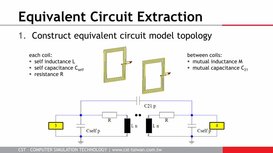
1. Construct equivalent circuit model topology
Equivalent Circuit Extraction
each coil:
self inductance L
self capacitance Cself
resistance R
between coils:
mutual inductance M
mutual capacitance C21

CST – COMPUTER SIMULATION TECHNOLOGY | www.cst-taiwan.com.tw
2. 3D sim. results estimate main component values
Equivalent Circuit Extraction
Z-parameter phase
L1 = L2 ≈ 400 nHM ≈ 26 nH k ≈ 0.065
phases ~ 90º inductive
CST – COMPUTER SIMULATION TECHNOLOGY | www.cst-taiwan.com.tw
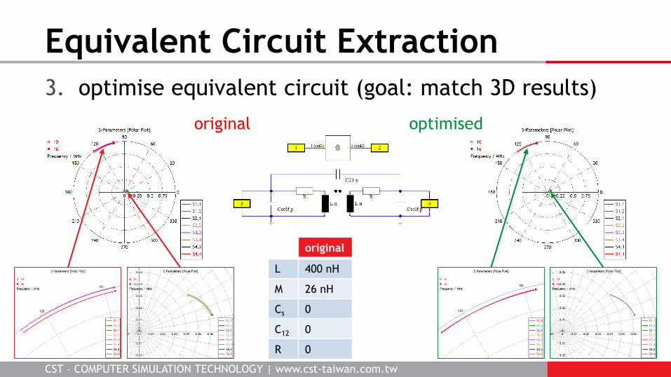
3. optimise equivalent circuit (goal: match 3D results)
Equivalent Circuit Extraction
original optimised
original optimised
L 400 nH 400.5 nH
M 26 nH 26.1 nH
Cs 0 0.27 pF
C12 0 0.13 pF
R 0 0.55 Ω

CST – COMPUTER SIMULATION TECHNOLOGY | www.cst-taiwan.com.tw
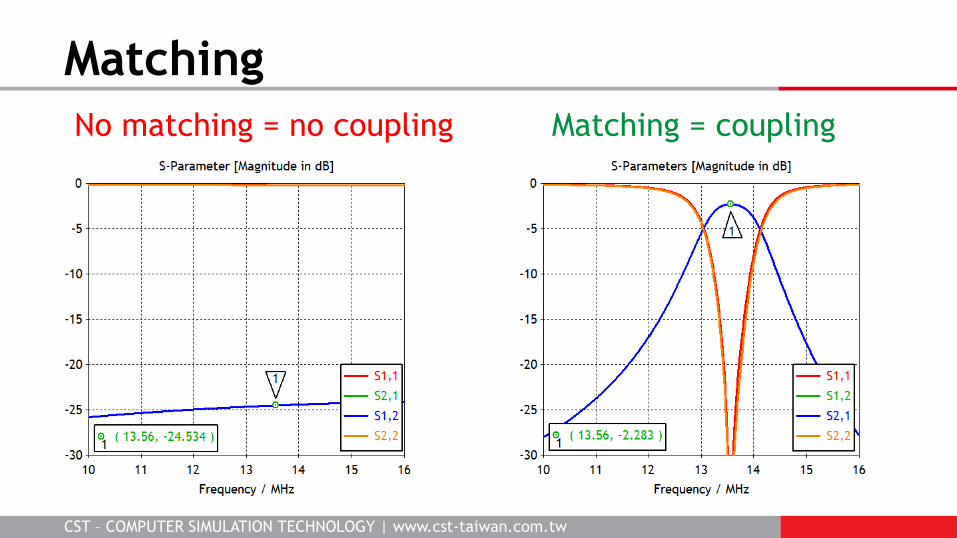
No matching = no coupling Matching = coupling
Matching
CST – COMPUTER SIMULATION TECHNOLOGY | www.cst-taiwan.com.tw
No matching = no coupling Matching = coupling
Matching

CST – COMPUTER SIMULATION TECHNOLOGY | www.cst-taiwan.com.tw
CST DESIGN STUDIO full circuit simulation tool (including harmonic balance)
tight link with 3D EM field results
very flexible optimisation and project construction
general multiport matching
broadband and multiband matching
optimisation using real components
bidirectional link to CST STUDIO SUITE
Matching Options

CST – COMPUTER SIMULATION TECHNOLOGY | www.cst-taiwan.com.tw
Matching in Optenni
various matching circuit optionsCST DS
CST – COMPUTER SIMULATION TECHNOLOGY | www.cst-taiwan.com.tw
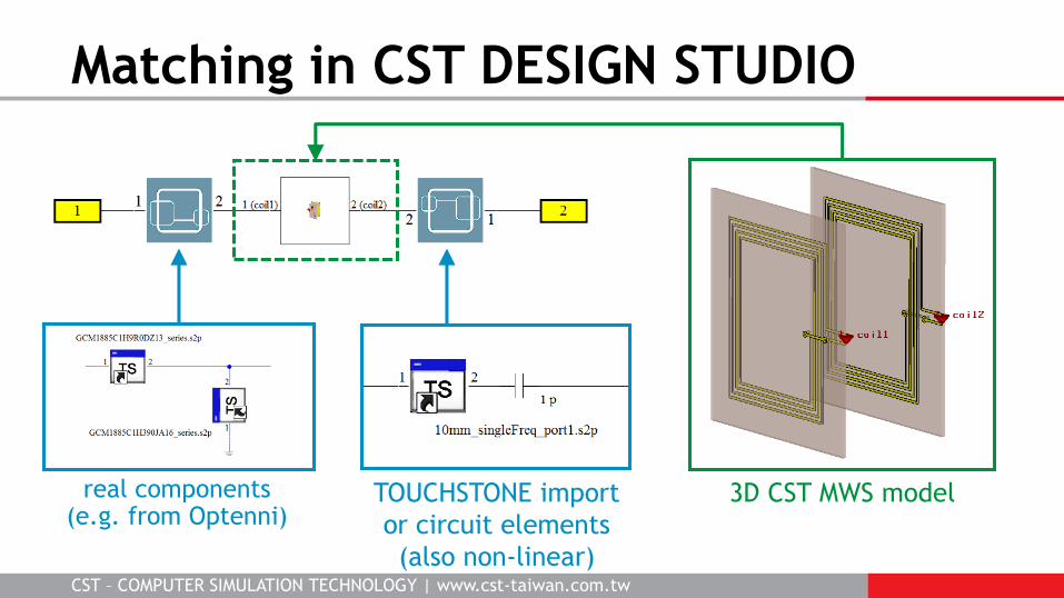
Matching in CST DESIGN STUDIO
real components (e.g. from Optenni)
3D CST MWS modelTOUCHSTONE import
or circuit elements
(also non-linear)

CST – COMPUTER SIMULATION TECHNOLOGY | www.cst-taiwan.com.tw
Impedances!
Port 1: 50 Ω
Port 2: complex and
frequency dependent
Matching in CST DESIGN STUDIO
real components (e.g. from Optenni)
TOUCHSTONE import
or circuit elements
(also non-linear)

CST – COMPUTER SIMULATION TECHNOLOGY | www.cst-taiwan.com.tw
Matching in CST DESIGN STUDIO
“efficiency” = |S21|2
input output
Zport1 = 50 Ω
Zport2 variable
S-parameters

CST – COMPUTER SIMULATION TECHNOLOGY | www.cst-taiwan.com.tw
Matching in CST DESIGN STUDIO
power = V∙I’1 V input output
Zport1 = 0 Ω
Zport2 variable
Pout/Pin ≈ 0.87
Pout = 17 mW
AC Task

CST – COMPUTER SIMULATION TECHNOLOGY | www.cst-taiwan.com.tw
Matching in CST DESIGN STUDIO
power = V∙I’1 V input output
AC Task
Zport1 = 50 Ω
Zport2 variable
Pout/Pin ≈ 0.85
Pout = 4 mW

CST – COMPUTER SIMULATION TECHNOLOGY | www.cst-taiwan.com.tw
Matching in CST DESIGN STUDIO
1V input

CST – COMPUTER SIMULATION TECHNOLOGY | www.cst-taiwan.com.tw
Coil Separation: 2 to 20 mm
matching circuit designed
for 10 mm separation

CST – COMPUTER SIMULATION TECHNOLOGY | www.cst-taiwan.com.tw
Coil Separation
matching circuit designed
for 2 mm separation

CST – COMPUTER SIMULATION TECHNOLOGY | www.cst-taiwan.com.tw
Coil Separation
System Assembly Modelling:
optimise matching circuit for
each separation distance
sweep distance
optimise matching
goal: maximise S21
matching circuit adjusted for each separation
(e.g. Ricketts et al. (2013) or Beh et al. (2013))

CST – COMPUTER SIMULATION TECHNOLOGY | www.cst-taiwan.com.tw
Lateral offset causes large
drop off in coupling
Horizontal Offset & Rotation
x = 0 axially aligned
x = 0
x = ±5 mm
x = ±10 mm
d = 10 mm
CST – COMPUTER SIMULATION TECHNOLOGY | www.cst-taiwan.com.tw
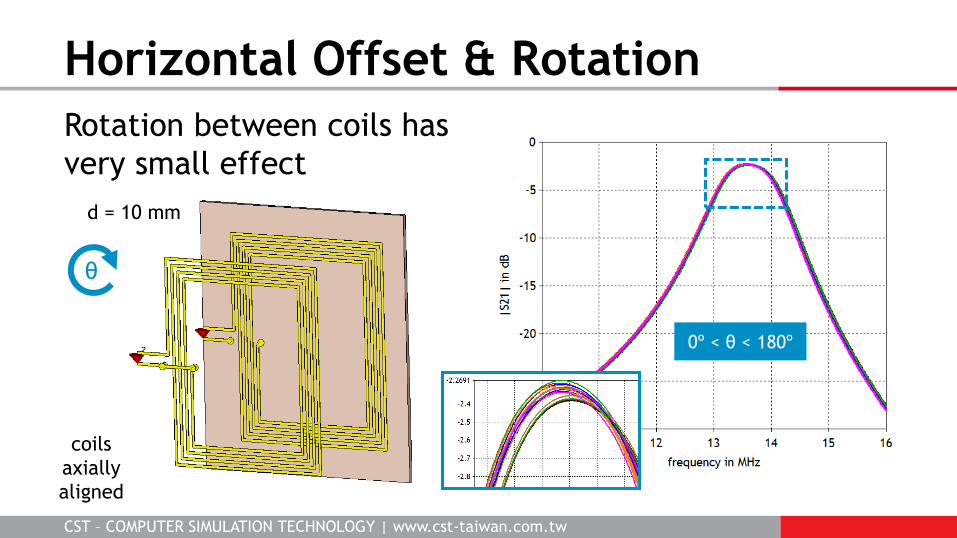
Rotation between coils has
very small effect
Horizontal Offset & Rotation
0º < θ < 180º
coils
axially
aligned
θ
d = 10 mm

CST – COMPUTER SIMULATION TECHNOLOGY | www.cst-taiwan.com.tw
Lateral offset causes large
drop off in coupling
Horizontal Offset & Rotation
x = 0 axially aligned
x = 0
x = ±12 mm
x = ±6 mm
d = 2 mm

CST – COMPUTER SIMULATION TECHNOLOGY | www.cst-taiwan.com.tw
Spiral Coil Design
based on Casanova et al. (2009)
43 mmH-field
magnitude at
2 mm above
coil plane

CST – COMPUTER SIMULATION TECHNOLOGY | www.cst-taiwan.com.tw
Spiral Coil Coupling
x = 0 axially aligned
x = 0
x = ±12 mm
CST – COMPUTER SIMULATION TECHNOLOGY | www.cst-taiwan.com.tw
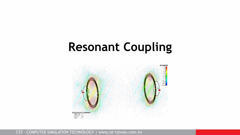
Resonant Coupling

CST – COMPUTER SIMULATION TECHNOLOGY | www.cst-taiwan.com.tw
Resonant Coil Transfer Example
systems of coupled resonators
Integral Equation Solver good
for metal structures
Source: Sample et al. (2011)
drive
loop
load
loop
TX coil RX coil
dcoils
dsource

CST – COMPUTER SIMULATION TECHNOLOGY | www.cst-taiwan.com.tw
1. Add capacitor to resonate drive loop
2. Modify coil geometry for self-resonance
Tuning the Coil
drive
loop
coil
60 cm

CST – COMPUTER SIMULATION TECHNOLOGY | www.cst-taiwan.com.tw
strong coupling
Coupling to Second Coil
strong coupling – but at different frequencies!
d = 30 cm
CST – COMPUTER SIMULATION TECHNOLOGY | www.cst-taiwan.com.tw
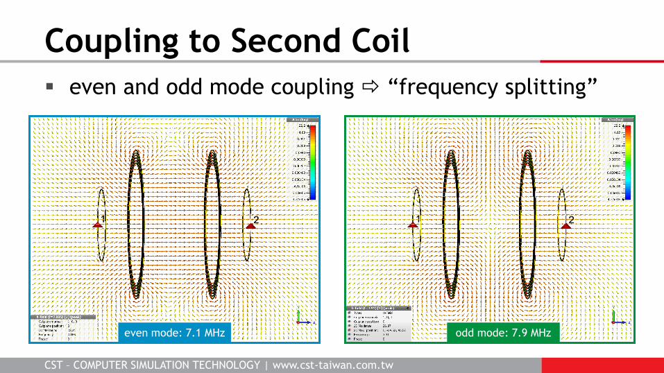
even and odd mode coupling “frequency splitting”
Coupling to Second Coil
even mode: 7.1 MHz odd mode: 7.9 MHz

CST – COMPUTER SIMULATION TECHNOLOGY | www.cst-taiwan.com.tw
good coupling possible but tuning required
Frequency Splitting
Source: Sample et al. (2011)

CST – COMPUTER SIMULATION TECHNOLOGY | www.cst-taiwan.com.tw
strong coupling (S21 = -2.5 dB) even at 110 cm
Critical Coupling Distance

CST – COMPUTER SIMULATION TECHNOLOGY | www.cst-taiwan.com.tw
|S21| coupling insensitive to
±40º rotation of receiving coil
Rotation of Coils
rotation angle
coils 110 cm apart
axially aligned

CST – COMPUTER SIMULATION TECHNOLOGY | www.cst-taiwan.com.tw
Multiple Coils
4.4 m
|S21| of -5.8 dB at 4.4 m coil separation!

CST – COMPUTER SIMULATION TECHNOLOGY | www.cst-taiwan.com.tw
Multiple Coils Around a Corner
|S21| of -5.9 dB for
curved path

CST – COMPUTER SIMULATION TECHNOLOGY | www.cst-taiwan.com.tw
Shielding – High Power
Two coils 10 cm apart
30 turns
1000 A
Coils modelled in
simplified fashion
in Magnetostatic solver
in CST EM STUDIO
Aluminium housing
and ferrite shielding (μr = 1000)

CST – COMPUTER SIMULATION TECHNOLOGY | www.cst-taiwan.com.tw
Shielding – High Power
No shielding Ferrite shield
lower coupling (184 μH)higher field leakage
higher coupling (385 μH)
much lower field leakage

CST – COMPUTER SIMULATION TECHNOLOGY | www.cst-taiwan.com.tw
Wireless power transfer is a field of active research
and an increasing number of commercial applications
Simulation is an important tool in designing wireless
power transfer systems, both nearfield and farfield
CST STUDIO SUITE provides tools for addressing all
aspects of design, from circuit to 3D EM to system
level
Conclusion

![Benchmarking Simulations of Multipactor in Rectangular … · 2009. 11. 10. · CST-PS CST Particle studio (CST-PS) [2] has a PIC solver and a particle tracking solver that allows](https://static.fdocuments.in/doc/165x107/60800288195ac957ef44a24d/benchmarking-simulations-of-multipactor-in-rectangular-2009-11-10-cst-ps-cst.jpg)


![From Surface Equivalence Principle to Modular ... · into smaller subdomains to apply the most suitable solver to each subdo- ... 1 CST { Computer ... method (Chew et al. [2001])](https://static.fdocuments.in/doc/165x107/5b1698367f8b9a686d8cdb48/from-surface-equivalence-principle-to-modular-into-smaller-subdomains-to.jpg)