Wireless Mobile Communication - · PDF fileWireless Mobile Communication Question Bank with...
74
Ajeena A Al- Ameen Engg. College www.edutalks.org Page 1 Wireless Mobile Communication Question Bank with Solutions 2 MARKS QUESTIONS previous question paper questions 1. What is Microcell? State it Drawbacks Microcell network is served by a low power cellular base station and is connected to base station by fiber/microwave link, Drawbacks : Dropped Calls,Cell Dragging Cell Dragging : Slow moving mobiles (pedestrians) may have very slow decay in RSSI and may stay with one Base Station until it has moved deep within another cell. This results in Channel Interference. 2.What are the three basic propagation mechanisms which impact propagation in a mobile communication system ? Reflection ,Diffraction and Scattering are the basic propagation mechanism which impact propagation in mobile communication system. Reflection : occurs when propagating electromagnetic wave impinges upon on object which has very large dimension compared to the wavelength of propagating wave. It occurs from surface of earth and from buildings and walls. Diffraction : Radio path between transmitter and receiver is obstructed by a surface that has sharp irregularities (edges). Scattering : Occurs when medium through which wave travels consists of objects with dimensions that are small compared to the wavelength and where the number of obstrucles per unit volume is large 3.If a cellular operator is allocated 12.5 Mhz for each simplex band and if B t is 12.5 Mhz B guard is 10khz and B c is 30khz find the number of channels available in a FDMA system The number of channels available in FDMA system is N= B t - 2B guard B c = 12.5 *10 6 -2(10*10 3 ) 3*10 3 = 416 4 Define Jamming Margin The level of interference (jamming) that a system is able to accept and still maintain a specified bit error ratio even though the signal to noise ratio is decreasing . Or It is the maximum jamming power to signal power ratio that a spread spectrum receiver can tolerate while still maintaining the specified bit error rate
-
Upload
nguyencong -
Category
Documents
-
view
266 -
download
10
Transcript of Wireless Mobile Communication - · PDF fileWireless Mobile Communication Question Bank with...

Ajeena A Al- Ameen Engg. College
www.edutalks.org Page 1
Wireless Mobile Communication
Question Bank with Solutions
2 MARKS QUESTIONS previous question paper questions
1. What is Microcell? State it Drawbacks
Microcell network is served by a low power cellular base station and is connected to base
station by fiber/microwave link,
Drawbacks : Dropped Calls,Cell Dragging
Cell Dragging : Slow moving mobiles (pedestrians) may have very slow decay in RSSI and
may stay with one Base Station until it has moved deep within another cell.
This results in Channel Interference.
2.What are the three basic propagation mechanisms which impact propagation in a mobile
communication system ?
Reflection ,Diffraction and Scattering are the basic propagation mechanism which impact
propagation in mobile communication system.
Reflection : occurs when propagating electromagnetic wave impinges upon on object which
has very large dimension compared to the wavelength of propagating wave.
It occurs from surface of earth and from buildings and walls.
Diffraction : Radio path between transmitter and receiver is obstructed by a surface that
has sharp irregularities (edges).
Scattering : Occurs when medium through which wave travels consists of objects with
dimensions that are small compared to the wavelength and where the number of
obstrucles per unit volume is large
3.If a cellular operator is allocated 12.5 Mhz for each simplex band and if Bt is 12.5 Mhz Bguard is
10khz and Bc is 30khz find the number of channels available in a FDMA system
The number of channels available in FDMA system is N= Bt - 2Bguard
Bc
= 12.5 *106 -2(10*103)
3*103 = 416
4 Define Jamming Margin
The level of interference (jamming) that a system is able to accept and still maintain a
specified bit error ratio even though the signal to noise ratio is decreasing .
Or
It is the maximum jamming power to signal power ratio that a spread spectrum receiver can
tolerate while still maintaining the specified bit error rate

Ajeena A Al- Ameen Engg. College
www.edutalks.org Page 2
of average powers of interference j and data signal ps
5. What is the cut off frequency of baseband ,Gaussian ,pulse shaping filter used in GSM System?
Baseband filter cut off frequency from few kilohertz to 20 Mhz & Gaussian filter 5 Mhz
6.Why Hexagon Geometry are always proffered ?Explain
Hexagon Compared to circle has largest area and therefore has large number of users.
A Cell must be designed to serve the weakest mobile within footprint
Hexagon cell is universally adopted and manageable in handling performance analysis &
System modeling
Base Station transmitter placed either in centre of cell or in edge of cell,
7. What is trunking in cellular Radio system?
Trunking allows a large number of users to share small number of channels in a cell by
providing access to each user on demand from set of available channels.
In a trunked system each user will be allocated a channel on a per call basis and when
terminated the pervious occupied channel is returned to pool of available channels.
8. Find the far field distance for an antenna with maximum dimension of 1m and operating
frequency of 900 mhz
Df =2D2 /lambda = lambda = C /V = 3*108 /900 * 106 = .33
Df = 2*(1)2 / .33 = 6m
ESSAY Questions
1. Explain adjacent and co channel interference
� Interference and System Capacity
� Interference is the major limiting factor in the performance of cellular radio systems. � Sources of interference
� another mobile in the same cell � a cell in progress in a neighboring cell � other base stations operating in the same frequency band...

Ajeena A Al- Ameen Engg. College
www.edutalks.org Page 3
� Interference on voice channels causes cross talk, where the subscriber hears interference in the background due to an undesired transmission.
� On control channels, interference leads to missed and blocked calls due to errors in the digital signaling.
� Interference is more severe in urban areas, due to the greater RF noise floor and the large number of base stations and mobiles.
� The two major types of system-generated cellular interference are co-channel interference and adjacent channel interference.
� Co-channel Interference and System Capacity
� Frequency reuse implies that in a given coverage area there are several cells that use the same set of frequencies.
� These cells are called co-channel cells, and the interference between signals from these cells is called co-channel interference.
� Unlike thermal noise which can be overcome by increasing the signal-to-noise ratio (SNR), co-channel interference cannot be combated by simply increasing the carrier power of a transmitter.
� This is because an increase in carrier transmit power increases the interference to neighboring co-channel cells.
� To reduce co-channel interference, co-channel cells must be physically separated by a minimum distance to provide sufficient isolation due to propagation.
� When the size of each cell is approximately the same and the base stations transmit the same power, the co-channel interference ratio is independent of the transmitted power and becomes a function of the radius of the cell (R) and the distance between centers of the nearest co-channel cells (D).
� By increasing the ratio of D/R, the spatial separation between co-channel cells relative to the coverage distance of a cell is increased.
� The parameter Q, called the co-channel reuse ratio, is related to the cluster size For a hexagonal Geometry
�
• N small, Q small, larger capacity N large, Q large, better transmission quality due to a small level of co-channel interference.
• signal-to-interference ratio for a mobile receiver which monitors a forward channel:
NR
DQ 3==
∑=
=0
1
i
iiI
S
I
S
Ajeena A Al- Ameen Engg. College
www.edutalks.org Page 4
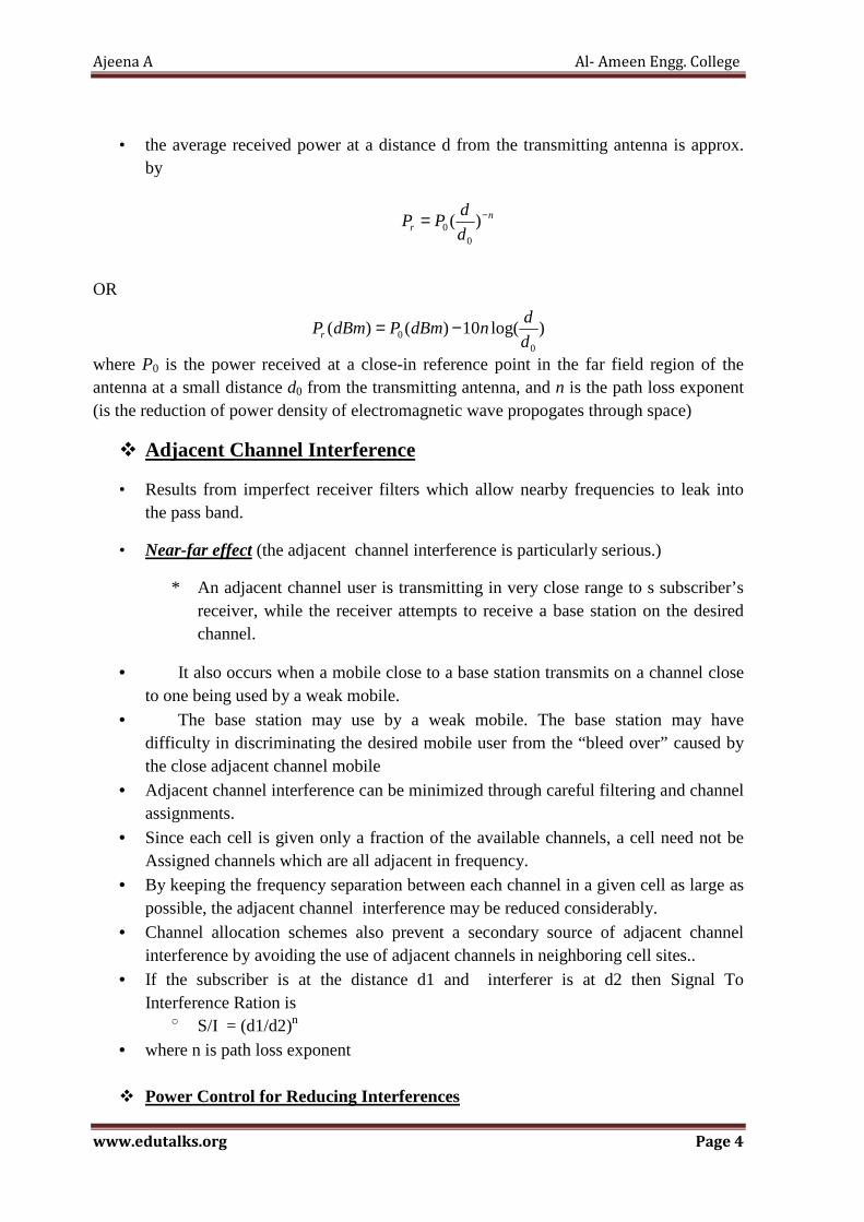
• the average received power at a distance d from the transmitting antenna is approx. by
OR
where P0 is the power received at a close-in reference point in the far field region of the antenna at a small distance d0 from the transmitting antenna, and n is the path loss exponent (is the reduction of power density of electromagnetic wave propogates through space)
� Adjacent Channel Interference
• Results from imperfect receiver filters which allow nearby frequencies to leak into the pass band.
• Near-far effect (the adjacent channel interference is particularly serious.)
* An adjacent channel user is transmitting in very close range to s subscriber’s receiver, while the receiver attempts to receive a base station on the desired channel.
• It also occurs when a mobile close to a base station transmits on a channel close to one being used by a weak mobile.
• The base station may use by a weak mobile. The base station may have difficulty in discriminating the desired mobile user from the “bleed over” caused by the close adjacent channel mobile
• Adjacent channel interference can be minimized through careful filtering and channel assignments.
• Since each cell is given only a fraction of the available channels, a cell need not be Assigned channels which are all adjacent in frequency.
• By keeping the frequency separation between each channel in a given cell as large as possible, the adjacent channel interference may be reduced considerably.
• Channel allocation schemes also prevent a secondary source of adjacent channel interference by avoiding the use of adjacent channels in neighboring cell sites..
• If the subscriber is at the distance d1 and interferer is at d2 then Signal To Interference Ration is
o S/I = (d1/d2)n
• where n is path loss exponent
� Power Control for Reducing Interferences
nr d
dPP −= )(
00
)log(10)()(0
0 d
dndBmPdBmPr −=
Ajeena A Al- Ameen Engg. College
www.edutalks.org Page 5
• In practical cellular radio and personal communication systems, the power levels
transmitted by every mobile unit are under constant control by the serving base stations.
• This is done to ensure that each mobile transmits the smallest power necessary on the reverse channel.
• Power control not only helps prolong battery life, also reduces the signal to interference ratio on the reverse channel.
• It is especially important for CDMA systems, because every user in every cell share the same radio channel. (to reduce the co-channel interference).
2. Derive the expression for blocking probability (Erlang B formula ) of a trunked
system which provides no queuing for blocked calls
Trunking and Grade of Service
• Cellular radio systems rely on trunking to accomodate a large number of users in a limited radio spectrum
• In a trunked radio system, each user is allocated a channel on a per call basis and upon termination of the call, the previously occupied channel is immediately returned to the pool of available channels
• The fundamentals of trunking theory were developed by Erlang • One Erlang represents the amount of traffic intensity carried by a channel that is
completely occupied (i.e. one call-hour per hour or one call-minute per minute) • The GOS is a measure of the ability of a user to access a trunked system during the
busiesthour • GOS is typically given as the likelihood that a call is blocked or the likelihood of a
call experiencing a delay greater than a certain queuing time
• The traffic intensity offered by each user is equal to the call request rate multiplied by the holding time
• Each user generates a traffic intensity of Au Erlangs given by
• For a system containing U user and an unspecified number of channels, the total
offered traffic intensity is
• In a C channel trunked system, if the traffic is equally distributed among the channels, then the traffic intensity per channel is
•
• There are two types of trunked systems: blocked calls cleared and blocked calls delayed

Ajeena A Al- Ameen Engg. College
www.edutalks.org Page 6
• In blocked calls cleared: for every user who requests service, it is assumed there is no setup time and the user is given immediate access to a channel if one is available
• If no channels are available, the requesting user is blocked without access and is free to try again later
• This scenario uses Erlang B formula
•
3. Give the expression of path loss for free space model when antenna gains are 1) Included 2) Excluded
• EM signals when traveling through wireless channels experience fading effects due to various effects.
• But in some cases the transmission is with a direct line of sight between transmitter and receiver such as in satellite communication, such cases Free Space Propagation Model is used to Predict the received signal Strength.
• Free space model predicts that the received power decays as negative square root of the distance. Ie Transmitter Receiver Seperation distance and is given by Friss free space equation
• Friis free space equation is given by
� Where Pt is the transmitted power, � Pr(d) is the received power, � Gt is the transmitter antenna gain, � Gr is the receiver antenna gain, � d is the Tx-Rx separation and � L is the system loss factor depended upon line attenuation, filter losses and
antenna losses • The gain of the antenna is related to the effective aperture of the antenna which in
turn is dependent upon the physical size of the antenna as given below
• Path loss which represents signal attenuation as a positive quantity measured in dB is
defined as the difference between the effective transmitted power and received power and may or may not include the effect of antenna gains.
Ajeena A Al- Ameen Engg. College
www.edutalks.org Page 7
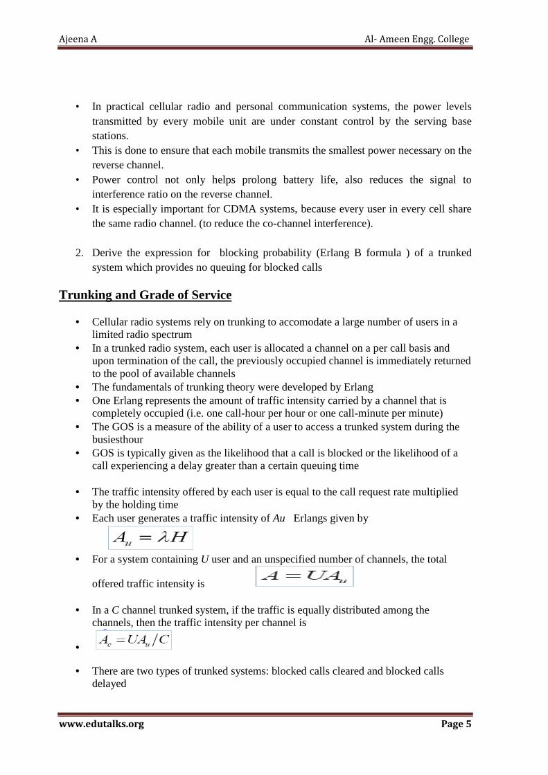
• The path loss for free space model when antenna gains are included is given by
• When antenna gains are excluded the antenna is assumed to have unity gain and path
loss is given by
•
4. Explain three propagation mechanism which impacts propagation in mobile communication system
• Reflection, diffraction and scattering are the three fundamental phenomena that cause signal propagation in a mobile communication system, apart from LOS communication.
• The most important parameter, predicted by propagation models based on above three phenomena, is the received power.
• The physics of the above phenomena may also be used to describe small scale fading and multipath propagation
� REFLECTION
� Reflection occurs when an electromagnetic wave falls on an object, which has very
large dimensions as compared to the wavelength of the propagating wave. For example, such objects can be the earth, buildings and walls.
� When a radio wave falls on another medium having different electrical properties, a part of it is transmitted into it, while some energy is reflected back.
� If the medium on which the electromagnetic wave is incident on a perfect dielectric, some energy is reflected back and some energy is transmitted.
� If the medium is a perfect conductor, all energy is reflected back to the first medium. The amount of energy that is reflected back depends on the polarization of the e.m. wave.,anglae of incidence & frequency of propagating wave.
� The electric field intensity of reflected and transmitted wave can be related to FRESNEL COEFFICIENT gamma.
� POLARIZATION
• Electromagnetic waves are polarized ie because of passive reflectors ,they have instantaneous electromagnetic field components in orthogonal directions in space.
• A Polarized wave can represented as a sum of two spatially orthogonal components � Vertical or horizontal � Left hand or Right hand Circularly Polarized
• Polarization can be used as a degree of freedom for frequency planning

Ajeena A Al- Ameen Engg. College
www.edutalks.org Page 8
� Reflection From Dielectrics
• There is an incident wave. Which broken up into two orthogonal components EI and HI.
• EI is in the plane of the paper. HI is orthogonal to the plane of the paper and it impinges on the surface with another dielectric.
• Part of it is reflected back as an Er and Hr and part of it is transmitted as an ET.
• Parallel” refers to the E-field having direction parallel to the plane of incidence (as in
Figure (a));
• “perpendicular” means perpendicular (normal) to the plane of incidence (as in Figure b)).
• subscripts i, r, and t to refer to the incident, reflected, and transmitted field. • ǫ1, ǫ2, is the permittivity of medium 1 and 2. • µ1, µ2 is the permeability of medium 1 and 2.
• The intrinsic impedance of medium is = √Permeability / Permitivity
• We can calculate how much energy is actually reflected back by knowing the permeability and the permittivity of the dielectric.

Ajeena A Al- Ameen Engg. College
www.edutalks.org Page 9
Permittivity is a measure of how an electric field affects and is affected by a dielectric medium. Permeability is the measure of ability of a material to support the formation of a magnetic field within itself.
� REFLECTION FROM PERFECT CONDUCTORS
• Electromagnetic energy cannot pass through conductors. • Energy doesn’t leak to the other side because all the energy is reflected back.\ • Boundary conditions require that • Øi = Ør Snells Law • Ei = Er for vertical polarization, • Ei = -Er for horizontal polarization.
� TWO RAY GROUND REFLECTION MODEL
• In mobile propagation is the reflection from the ground , This normally occurs when i
do have a line of sight. • We also get a reflection from the ground as well, the reflection from the ground is
also important. • A two ray ground reflection model is often used. It is a simple model but it is a useful
model. • This model is reasonably accurate for predicting large scale signal strength over
several kilometers. In fact, this model is good when the distance between the transmitter and the receiver is large.
• The assumption is that the height of the transmitter is about 50 m or more
• A two-ray model, which consists of two overlapping waves at the receiver, one direct path and one reflected wave from the ground gives a more accurate.
• A simple addition of a single reflected wave shows that power varies inversely with the forth power of the distance between the Tx and the Rx..
• the total received energy at the receiver is the sum of the line of sight path as well as the reflected path ETOT = ELOS + Eg

Ajeena A Al- Ameen Engg. College
www.edutalks.org Page 10
• the total transmitted and received electric fields are
• the path difference is • Two propagating waves arrive at the receiver, one LOS wave which travels a
distance of d’ and another ground reflected wave, that travels d’’ , when T-R
separation distance is very large
• The method of image is used to find the path difference between LOS line Of sight & Ground Reflected Path.
• Once the path difference is known, the phase difference is
• The time difference,
� fc carrier frequency � ƛ wavelength
• the received power as
received power Pr is nothing but the transmit power Pt times Gt the gain of the transmit antenna times gain of the received antenna Gr times square of height of transmitter & receiver antenna line of sight propagation times d squared whole squared
� DIFFRACTION
Ajeena A Al- Ameen Engg. College
www.edutalks.org Page 11
• This occurs when the radio path between the transmitter and receiver is obstructed by
a surface that has sharp irregularities or edges. Edges, corners, bends, etc. will cause
diffraction.
• Diffraction is very important because otherwise without line of sight, it would not be
able to receive any signal from my base station.
• Hence this explains how radio signals can travel urban and rural environments without
a clear line of sight and diffraction can be explained by Huygens principle.
• IT says that all points on a wave front can be considered as point sources for the
production of secondary wavelets.
• When signal transmit form the transmitter T. it radiate in all directions assuming . It‟s
an omnidirectional antenna.
• The wave radiates in all direction.
• The one that hits at a point will generate wavelets which will travel from all directions.
• From Huygens secondary source principle, any point on the wave front will generate its
secondary wavelets.
• The wave which is diffracted and will be received at the receiver.
� FRESNEL ZONE GEOMETRY
•
• The Concept of diffraction loss as a function of the path difference around an
obstruction is explained by Fresnel zones
• Fresnel zone represent successive regions where secondary waves have a path length
from transmitter to receiver greater than the total path length of line of sight path.
• The concentric circle on the plane represent secondary wavelete which propagate to
the receiver
• These circles are called Fresnel Zones
• The successive Fresnel zone have the effect of alternately providing constructive and
destructive interference to the total received signal.
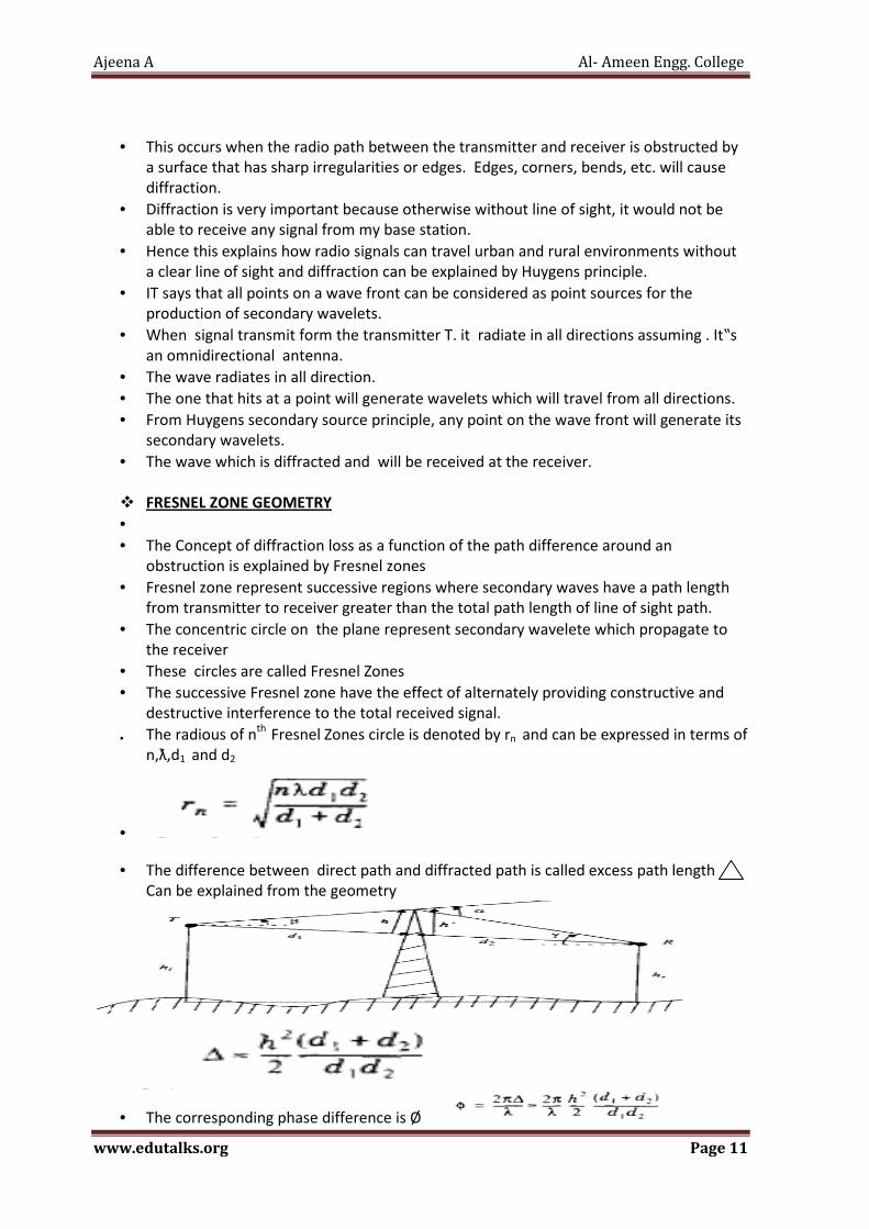
• The radious of nth
Fresnel Zones circle is denoted by rn and can be expressed in terms of
n,ƛ,d1 and d2
•
• The difference between direct path and diffracted path is called excess path length
Can be explained from the geometry
• The corresponding phase difference is Ø
Ajeena A Al- Ameen Engg. College
www.edutalks.org Page 12
• Phase Difference between direct line of sight path and diffracted path is a function of
height and Position of obstruction as well as transmitter and receiver location.
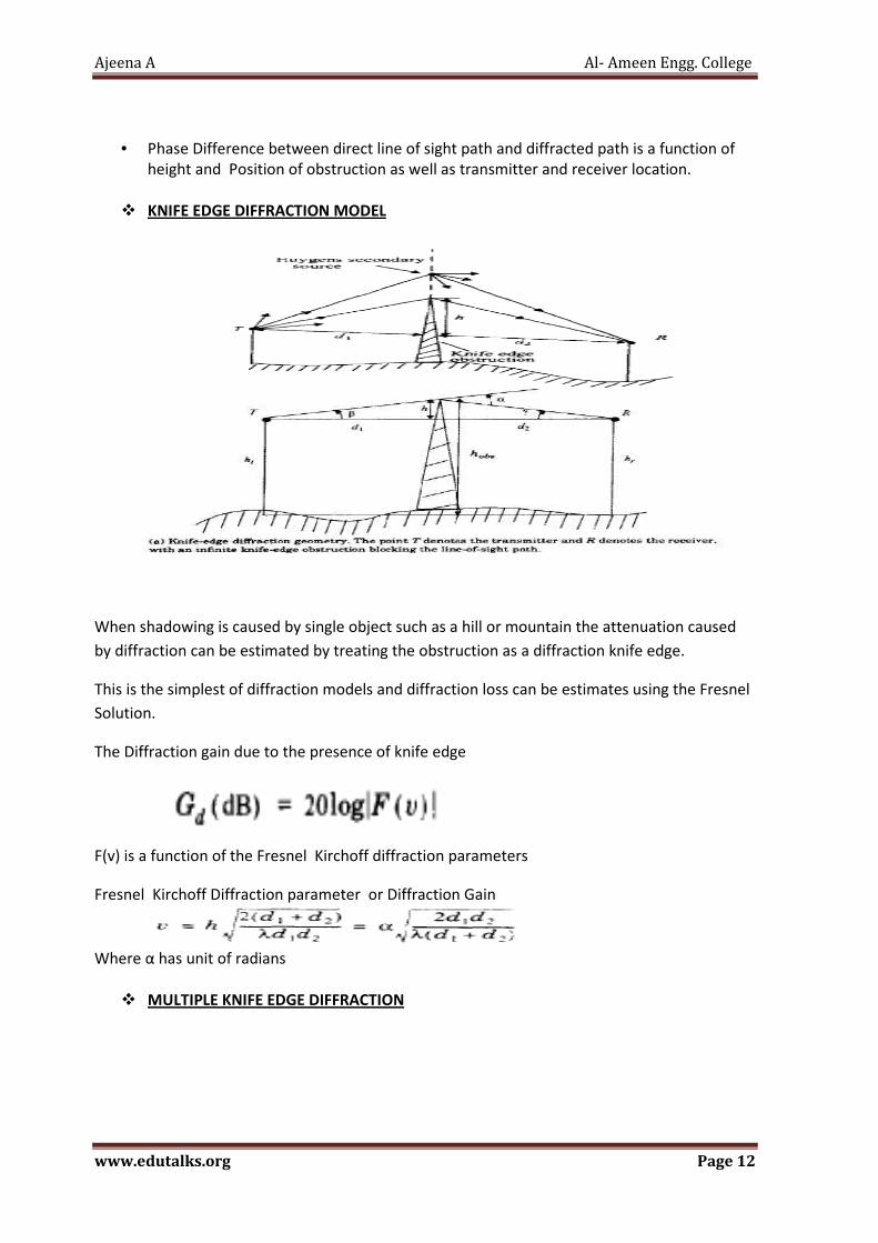
� KNIFE EDGE DIFFRACTION MODEL
When shadowing is caused by single object such as a hill or mountain the attenuation caused
by diffraction can be estimated by treating the obstruction as a diffraction knife edge.
This is the simplest of diffraction models and diffraction loss can be estimates using the Fresnel
Solution.
The Diffraction gain due to the presence of knife edge
F(v) is a function of the Fresnel Kirchoff diffraction parameters
Fresnel Kirchoff Diffraction parameter or Diffraction Gain
Where α has unit of radians
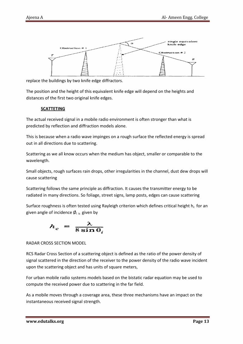
� MULTIPLE KNIFE EDGE DIFFRACTION
Ajeena A Al- Ameen Engg. College
www.edutalks.org Page 13
replace the buildings by two knife edge diffractors.
The position and the height of this equivalent knife edge will depend on the heights and
distances of the first two original knife edges.
SCATTETING
The actual received signal in a mobile radio environment is often stronger than what is
predicted by reflection and diffraction models alone.
This is because when a radio wave impinges on a rough surface the reflected energy is spread
out in all directions due to scattering.
Scattering as we all know occurs when the medium has object, smaller or comparable to the
wavelength.
Small objects, rough surfaces rain drops, other irregularities in the channel, dust dew drops will
cause scattering
Scattering follows the same principle as diffraction. It causes the transmitter energy to be
radiated in many directions. So foliage, street signs, lamp posts, edges can cause scattering
Surface roughness is often tested using Rayleigh criterion which defines critical height hc for an
given angle of incidence Øi is given by
RADAR CROSS SECTION MODEL
RCS Radar Cross Section of a scattering object is defined as the ratio of the power density of
signal scattered in the direction of the receiver to the power density of the radio wave incident
upon the scattering object and has units of square meters,
For urban mobile radio systems models based on the bistatic radar equation may be used to
compute the received power due to scattering in the far field.
As a mobile moves through a coverage area, these three mechanisms have an impact on the
instantaneous received signal strength.

Ajeena A Al- Ameen Engg. College
www.edutalks.org Page 14
if the mobile does have a clear line of sight then diffraction and scattering will not dominate
the propagation. The line of sight exists.we have a clear signal strength.
if a mobile is at street level without line of sight then diffraction and scattering will probably
dominate the propagation. So this is important models exists for all of this.
So it is possible to figure out theoretically and by stimulation how much is the received power
actually obtained .
5) explain concept of multiuser detection • Idea is proposed in 1980 • Primary Idea of Multiuser detection techniques is to cancel the interference and
noise caused by other users
• Total Interference (Includes interference due to other cells also)
• Near Far Problem in CDMA
o Difficulty to implement more sophisticated algorithm at receiver because of limitations of size, cost, weight of handset.
o Solutions to all such problems is Multi-user detection
• It is done by exploiting information of interfering user rather than ignoring the presence of other user like in single user detection technique and help to overcome near far problem
Features
1. Reduced interference leads to capacity increase
2. Alleviates the near/far problem
3. Capability to reject interference created by narrow band

Ajeena A Al- Ameen Engg. College
www.edutalks.org Page 15
4. MUD can be implemented in the BS or mobile, or both
5. In a cellular system, base station (BS) has knowledge of all the chip sequences
6. Capability to achieve diversity in frequency
7. Reduces Complexity and increase in spectral efficiency
8. Robustness to multipath fading
9. Effects of ISI and delay spread is mitigate
� MUD ALGORITHMS
� Issues in practical implementation
� Processing complexity
� Processing delay
� Sensitivity and robustness
� Limitations of MUD
� Capacity improvements only on the uplink would only be partly used anyway in determining overall system capacity
� Cost of doing MUD must be as low as possible so that there is a performance/cost tradeoff advantages
6) State the Properties needed for a signal to be spread spectrum modulated
� Properties needed for signal to spectrum modulated � PN Sequence Properties
� Randomness � Unpredictability
� Two criteria used to validate a PN Sequence � Uniform Distribution � Independence
OptimalMLSE
Decorrelator MMSE
Linear
Multistage Decision-feedback
Successiveinterferencecancellation
Non-linear
Suboptimal
MultiuserReceivers
PARALLEL
INTERFERENCE
CANCELLATION

Ajeena A Al- Ameen Engg. College
www.edutalks.org Page 16
• Uniform distribution � Distribution of numbers in the sequence should be uniform � Frequence of occurance of each of numbers should be approximately
same. � For a stream of binary digits two properties are desired
� Balance property : in long sequence the number of binary ones always one more than the number of 0’s.
� Run property: run is defined as a sequence of all 1-s or a sequence of all 0-s.Among the runs of 1’s and 0’s in each period of sequence one half the runs of each kind are of length one,one fourth of length two,one eigth of length three and so on as long as these fractions represent meaningful number of runs.
� Auto Correlation Property : Autocorrelation function of a maximal length sequence is periodic and binary valued. The periodic autocorrelation of a ±1 m-sequence
is
� Correlation Property : . the cross-correlation of two m-sequences tends to be large. If the codes which are used are not completely orthogonal, the cross-correlation factor is unequal to zero. In this situation the different users are interferers to each other, hence the near-far problem appears
� good auto-and cross-correlation properties
� Independence
� no one value in sequence can be inferred from the others
7)State Data Rates and application of Bluetooth and Zigbee
Bluetooth
� Wireless technology standard for exchanging data over short distance from fixed and mobile devices.
� It connect several devices overcoming problems of synchronization � Data rate 1Mbps � Operate in a range 10m � Range of frequency 2400-2483.5 Mhz and 2.5 Ghz short range operation
� Applications
• Wireless Control of communication between mobile phone and handsfree handset

Ajeena A Al- Ameen Engg. College
www.edutalks.org Page 17
• Communication between mobile and car stereo system • Wireless networking • Low bandwidth application • Transfer file ,contact ,calendar ,remainder between devices
Zigbee
• Can transmit data over a long distance • Low data rate ,long battery life & secure networking • Data rate 20-250Kbps • Range of operation 10-100m • 2.4GHz frequency band
Applications
• ZigBee is used in applications that require only a low data rate, long battery life, and secure networking. wireless light switches, electrical meters with in-home-displays, traffic management systems, and
ther consumer and industrial equipment that requires short-range wireless transfer of data at relatively low rates. Remote sensing & control
8) Explain TDMA
Time Division Multiple Access (TDMA)
• Time division multiple access (TDMA) systems divide the radio spectrum into time slots, and in each slot only one user is allowed to either transmit or receive.
• TDMA systems transmit data in a buffer-and-burst method, thus the transmission for any user is non continuous.
• This implies that, unlike in FDMA systems which accommodate analog FM, digital
data and digital modulation must be used with TDMA.
• The transmission from various users is interlaced into a repeating frame structure as
shown in Figure. It can be seen that a frame consists of a number of slots.
• Each frame is made up of a preamble, an information message, and tail bits.
Ajeena A Al- Ameen Engg. College
www.edutalks.org Page 18
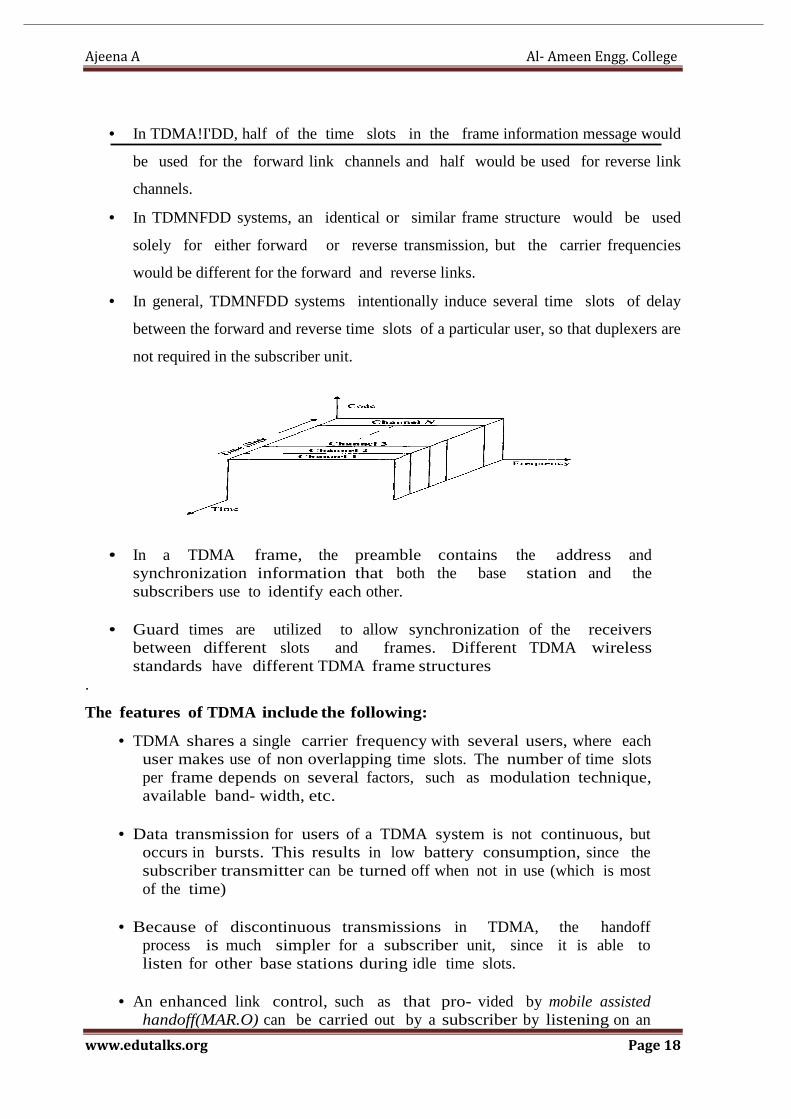
• In TDMA!I'DD, half of the time slots in the frame information message would
be used for the forward link channels and half would be used for reverse link
channels.
• In TDMNFDD systems, an identical or similar frame structure would be used
solely for either forward or reverse transmission, but the carrier frequencies
would be different for the forward and reverse links.
• In general, TDMNFDD systems intentionally induce several time slots of delay
between the forward and reverse time slots of a particular user, so that duplexers are
not required in the subscriber unit.
• In a TDMA frame, the preamble contains the address and synchronization information that both the base station and the subscribers use to identify each other.
• Guard times are utilized to allow synchronization of the receivers between different slots and frames. Different TDMA wireless standards have different TDMA frame structures
.
The features of TDMA include the following:
• TDMA shares a single carrier frequency with several users, where each user makes use of non overlapping time slots. The number of time slots per frame depends on several factors, such as modulation technique, available band- width, etc.
• Data transmission for users of a TDMA system is not continuous, but
occurs in bursts. This results in low battery consumption, since the subscriber transmitter can be turned off when not in use (which is most of the time)
• Because of discontinuous transmissions in TDMA, the handoff
process is much simpler for a subscriber unit, since it is able to listen for other base stations during idle time slots.
• An enhanced link control, such as that pro- vided by mobile assisted
handoff(MAR.O) can be carried out by a subscriber by listening on an

Ajeena A Al- Ameen Engg. College
www.edutalks.org Page 19
idle slot in the TDMA frame.
• TDMA uses different time slots for transmission and reception, thus duplexers are not required.
• Even if FDD is used, a switch rather than a duplexer inside the subscriber
unit is all that is required to switch between transmitter and receiver using TDMA.
• Adaptive equalization is usually necessary in TDMA systems, since the transmission rates are generally very high as compared to FDMA channels.
• In TDMA, the guard time should be minimized. If the transmitted signal at the edges of a time slot are suppressed sharply in order to shorten the guard time, the transmitted spectrum will expand and cause interference to adjacent channels.
• High s y n c h r o n i z a t i o n overhead is required in TDMA systems because of burst transmissions.
• TDMA transmissions are slotted, and this requires the receivers to be
synchronized for each data burst. In addition, guard slots are necessary to separate users, and this results in the TDMA systems having larger overheads as compared to FDMA.
• TDMA has an advantage in that it is possible to allocate different numbers
of time slots per frame to different users. Thus bandwidth can be supplied on demand to different users by concatenating or reassigning time slots based on priority.

Ajeena A Al- Ameen Engg. College
www.edutalks.org Page 20
EFFICIENCY OF TDMA:
• The efficiency of a TDMA system is a measure of the percentage of transmitted data that contains information as opposed to providing overhead for the access scheme.
• The frame efficiency, 'fir• is the percentage of bits per frame which contain transmitted data. Note that the transmitted data may include source and channel coding bits, so the raw end-user efficiency of a system is generally less than 'fir.
• The frame efficiency can be found as follows. • The number of overhead bits per frame is [Zie921],
where, Nr is the number of reference bursts per frame,
N, is the number of traffic bursts per frame,
br is the number of overhead bits per reference burst,
bP is the number of overhead bits per preamble in each slot, and
bg is the number of equivalent bits in each guard time interval.
The total number of bits per frame, br, is
• where Tr is the frame duration,
R is the channel bit rate.
• The frame efficiency is thus given as
Number of channels in TDMA system • The number of TDMA channel slots that can be provided in a TDMA
system is found by multiplying the number of TDMA slots per channel by the number of channels available and is given by
where m is the maximum number of TDMA users supported on each
radio channel. Note that two guard bands, one at the low end of the
allocated frequency band and one at the high end, are required to ensure
that users at
the edge of the band do not "bleed over" into an adjacent radio service.

Ajeena A Al- Ameen Engg. College
www.edutalks.org Page 21
8) Briefly Discuss about IMT2000
� IMT 2000
� The ITU is on accelerated pace to specify the 3G mobile communication standards. � The primary standard for 3G system is referred to as the International Mobile
Telecommunications beyond the year 2000 (IMT-2000)-the goal of which is to support higher data rates that can support multimedia applications, provide a high spectral efficiency, makes as many of the interfaces standard as possible, and provide compatibility to services within the IMT-2000
� Although voice traffic will continue to be the main source of revenue, packet data for internet access, advanced messaging services such as multimedia email, and real-time multimedia for applications such as telemedicine and remote security are envisaged in IMT-2000.
� The requirements for IMT-2000 include improved voice quality (wire line quality), data rates up to 384kbps everywhere and 2Mbps indoor, support for packet and circuit switched data services, seamless incorporation of existing 2G and satellite systems, seamless international roaming, and support for several simultaneous multimedia connections.
� Most of the proposals were based on CDMA as CDMA provides a better voice quality and is more flexible for customized multimedia applications.
� In order to avoid multiple standards, efforts were made to harmonize a single converged global standard.
� Backward compatibility with legacy systems is also a major issue with support for the GSM-MAP and ANSI-41 (the core GSM and IS-41 backbone infrastructures) essential.
� As far as the RTT’s are concerned, there were two major competing proposals- the W-CDMA based on the UMTS Terrestrial Radio Access (UTRA) FDD and TDD proposals and the CDMA2000 proposal that is backward compatible with IS-95.
� The main differences can be summarized as follows [ZEN00]: 1. Although CDMA2000 proposes multiples of 1.2288 Mcps chip rates to allow
greater compatibility with IS-95 (in particular, 3.6864 Mcps is suggested). W-CDMA employs 3.84 Mcps.
2. In IS-95 and CDMA2000, the BSs operate synchronously by obtaining timing from GPS.W-CDMA advocates asynchronous operation to enable deploying picocells within aspects, and t buildings where GPS is not available.
3. The frame length of W-CDMA is 10 ms to ensure small end to end delays, though it is 20 ms in CDMA2000.
� The harmonization activities were initiated via a 3GPP that consisted of members from industry and standard bodies to work on the core network, the radio access network, service and system aspects, and the mobile terminal.
� To include non-GSM technologies, a 3GPP2 was initiated in parallel by ANSI to prepare technical specifications for a 3G mobile system based on CDMA2000 and IS-41 based core network.
� Both 3GPP and 3GPP2 are expected to cooperate in harmonization and consolidation.

Ajeena A Al- Ameen Engg. College
www.edutalks.org Page 22
� An operators harmonization group (OHG) set up at the end of 1998 agreed on a further harmonized Global 3G (G3G) standard that has the following components:
1. Three air-interface standards-two frequency division duplex modes: a direct sequence (DS) mode based on W-CDMA at 3.84 Mcps chip rate, a multi carrier (MC) mode based on CDMA2000 with a chip rate of 3.6864 Mcps, and one time division duplex mode operating at 3.84 Mcps.
2. Support for both GSM-MAP and ANSI-41 with all air-interface modes
3. Support for functionality based synchronous operation 4. Seamless handoff between DS and MC modes, as well as
interoperability of sorts between the UMTS core network and ANSI41.
� The idea is also to minimize the complexity of multimode terminals that include all of the standards.
� Forward Channels in WCDMA and CDMA2000 � The primary a requirements of 3G systems is that they should be able to
support variety of application data rates (from 384 kbps circuit switched connections to 2Mbps in indoor areas) and operation environments.
� This means that there must be support for quality of service and operation from mega cells to picocells.
� The forward channels are referred to as transport channels in the UTRA W-CDMA standard proposed by 3GPP.
� The forward channel modifications are as follows. � In W-CDMA, the BSs can operate in a synchronous fashion that obviates the
need of GPS availability to synchronize base stations. � W-CDMA employs what is known as the orthogonal variable spreading factor
(OVSF) codes. � OVSF codes allow a variable spreading factor technique that maintains
orthogonality between spreading codes of different lengths. � The logical channels are called transport channels in W-CDMA. � CDMA2000 employs multiple carriers to provide a higher data rate
compared with W-CDMA. � Pilot channels are used for fast acquisition and handoff as before. � QPSK modulation is employed before spreading with the Walsh codes to
increase the number of usable Walsh codes. � To support QoS at different rates, a fundamental channel (FCH) for signaling
and a supplemental channel (SCH) for traffic can be made available. � Turbo codes are employed on the forward supplemental channels for high data
rates. � Reverse channels in W-CDMA and CDMA2000
Ajeena A Al- Ameen Engg. College
www.edutalks.org Page 23
� Support for variable data rates and operation in a variety of environments In WCDMA Gold Codes and S(2) cods are used for scrambling on the uplink.
� The periodicity of Gold code is 38400 chips for using a Rake receiver and S(2) codes is 256 chips for employing multiuser detection
� In CDMA 2000 the reverse link is made more symmetrical with forward link in many aspects.
� For instance, a reverse pilot channel is employed between each mobile and the BS for initial acquisition, time tracking, and power control measurement.
� Turbo codes are employed on the reverse supplementary channels. � Variable rate spreading is supported to enable better error correction capability and
variety of data rates
� Handoff and power control in 3G system � CDMA2000 is very similar to IS-95 in terms of power control and handoff
procedures.
� In W-CDMA, a fast power control scheme is used at 1,500 bps as compared with 800
bps with IS-95 and CDMA2000.
� In W-CDMA, the handoff procedure is somewhat different.
� Once again, different sets of pilots are maintained, and the active sets corresponds
to the pilot channels being used for complete the call.
9) Explain in detail about handoff
• When a mobile moves into a different cell while a conversation is in progress, the MSC automatically transfers the call to a new channel belonging to the new base station.
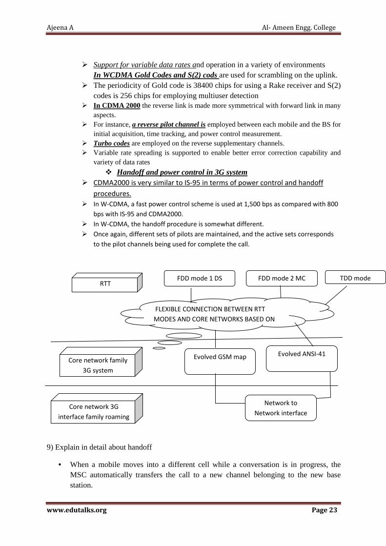
RTT FDD mode 1 DS FDD mode 2 MC TDD mode
FLEXIBLE CONNECTION BETWEEN RTT
MODES AND CORE NETWORKS BASED ON
Core network family
3G system
Evolved ANSI-41 Evolved GSM map
Core network 3G
interface family roaming
Network to
Network interface
Ajeena A Al- Ameen Engg. College
www.edutalks.org Page 24
• This handoff operation not only involves identifying a new base station, but also requires that the voice and control signals be allocated to channels associated with the new base station.
• Handoffs must be performed successfully and as infrequently as possible, and be imperceptible to the users.
• In order to meet these requirements, system designers must specify an optimum signal level at which to initiate a handoff.
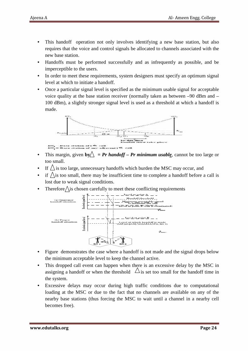
• Once a particular signal level is specified as the minimum usable signal for acceptable voice quality at the base station receiver (normally taken as between –90 dBm and –100 dBm), a slightly stronger signal level is used as a threshold at which a handoff is made.
• This margin, given by = Pr handoff – Pr minimum usable, cannot be too large or
too small. • If is too large, unnecessary handoffs which burden the MSC may occur, and
• if is too small, there may be insufficient time to complete a handoff before a call is lost due to weak signal conditions.
• Therefore ,is chosen carefully to meet these conflicting requirements
• Figure demonstrates the case where a handoff is not made and the signal drops below
the minimum acceptable level to keep the channel active.
• This dropped call event can happen when there is an excessive delay by the MSC in assigning a handoff or when the threshold is set too small for the handoff time in the system.
• Excessive delays may occur during high traffic conditions due to computational loading at the MSC or due to the fact that no channels are available on any of the nearby base stations (thus forcing the MSC to wait until a channel in a nearby cell becomes free).

Ajeena A Al- Ameen Engg. College
www.edutalks.org Page 25
• In deciding when to handoff, it is important to ensure that the drop in the measured signal level is not due to momentary fading and that the mobile is actually moving away from the serving base station.
• In order to ensure this, the base station monitors the signal level for a certain period of time before a handoff is initiated.
• This running average measurement of signal strength should be optimized so that unnecessary handoffs are avoided, while ensuring that necessary handoffs are completed before a call is terminated due to poor signal level.
• The length of time needed to decide if a handoff is necessary depends on the speed at which the vehicle is moving.
• The time over which a call may be maintained within a cell, without handoff, is called the dwell time .
• The dwell time of a particular user is governed by a number of factors, including propagation, interference, distance between the subscriber and the base station, and other time varying effects
• In first generation analog cellular systems,
* Signal strength measurements are made by the base station and supervised by the MSC.
* Additionally, a spare receiver in each base station, called the location receiver, is used to determine signal strengths of mobile users which are in neighboring cells (and appear to be in need of handoff.)
• In today’s second generation systems, handoff decisions are mobile assisted. handoff(MAHO) , handoff decisions are mobile assisted (MAHO).
* mobile units measures the received power from surrounding base stations and report the results to the serving base station.
* A handoff is initiated when the power received from the neighboring cell begins to exceed the power received from the current base station by a certain level or for a certain period of time.
* The MAHO performs at a much faster rate, and is particularly suited for micro cellular environments.
• Intersystem handoff * Moves from one cellular system to a different cellular system controlled by a
different MSC. * It may become a long-distance call and a roamer. * Compatibility between the two MSCs need to be determined.
Different Types Of Handoff
� NO HANDOFF: New Call is made once mobile moves out of range.

Ajeena A Al- Ameen Engg. College
www.edutalks.org Page 26
� Hard handoff : Mobile Unit need to break its connection with BS before connecting to another . Not too Reliable.Results in noticeable break in conversation especially when Mobile unit moving fast between small cells
� Soft handoff : Ability to select between the instantaeous received signals from different base Station is called Soft handoff. A new link is set up to BS before old one is dropped,
Reliable � Intercell handoff ; Mobile Unit moving from current cell to its adjacent cell using
same channel � Intracell handoff :Mobile Unit is in the same cell and channel is changed during
handoff.ie the hand off in which cell is not changed and channel is changed.
• Prioritizing Handoff
• One method for giving priority to handoffs is called the guard channel concept, whereby a fraction of the total available channels in a cell is reserved exclusively for handoff requests from ongoing calls which may be handed off into the cell.
• This method has the disadvantage of reducing the total carried traffic, as fewer channels are allocated to originating calls.
• Guard channels, however, offer efficient spectrum utilization when dynamic channel assignment strategies, which minimize the number of required guard channels by efficient demand-based allocation, are used.
• Queuing of handoff requests is another method to decrease the probability of forced termination of a call due to lack of available channels.
• There is a tradeoff between the decrease in probability of forced termination and total carried traffic.
• Queuing of handoffs is possible due to the fact that there is a finite time interval between the time the received signal level drops below the handoff threshold and the time the call is terminated due to insufficient signal level.
• The delay time and size of the queue is determined from the traffic pattern of the particular service Area
• . It should be noted that queuing does not guarantee a zero probability of forced termination, since large delays will cause the received signal level to drop below the minimum required level to maintain communication and hence lead to forced termination
� Practical Handoff Considerations • In practical cellular systems, several problems arise when attempting to design for a
wide range of mobile velocities. • High speed vehicles pass through the coverage region of a cell within a matter of
seconds, whereas pedestrian users may never need a handoff during a call.

Ajeena A Al- Ameen Engg. College
www.edutalks.org Page 27
• Particularly with the addition of microcells to provide capacity, the MSC can quickly become burdened if high speed users are constantly being passed between very small cells.
• Another practical limitation is the ability to obtain new cell sites.
• Although the cellular concept clearly provides additional capacity through the addition of cell sites, in practice it is difficult for cellular service providers to obtain new physical cell site locations in urban areas.
• By using different antenna heights (often on the same building or tower) and different power levels, it is possible to provide “large” and “small” cells which are co-located at a single location. This technique is called the umbrella
• cell approach and is used to provide large area coverage to high speed users while providing small
• area coverage to users traveling at low speeds.
Figure 3.4 illustrates an umbrella cell which is collocated with some smaller microcells.
• The umbrella cell approach ensures that the number of handoffs is minimized for high speed users and provides additional microcell channels for pedestrian users.
• If a high speed user in the large umbrella cell is approaching the base station, and its velocity is rapidly decreasing, the base station may decide to hand the user into the co-located microcell, without MSC intervention.
� Another practical handoff problem in microcell systems is known as cell dragging.
• Cell dragging results from pedestrian users that provide a very strong signal to the base station.
• Such a situation occurs in an urban environment when there is a line-of-sight (LOS) radio path between
• the subscriber and the base station
• . As the user travels away from the base station at a very slow speed, the average signal strength does not decay rapidly.
• Even when the user has traveled well beyond the designed range of the cell, the received signal at the base station may be above the handoff threshold, thus a handoff may not be made.
• This creates a potential interference and traffic management problem, since the user has meanwhile traveled deep within a neighboring cell.

Ajeena A Al- Ameen Engg. College
www.edutalks.org Page 28
• To solve the cell dragging problem, handoff thresholds and radio coverage parameters must be adjusted carefully.
10) Explain channel assignment strategies
• For efficient utilization of the radio spectrum, a frequency reuse scheme that is consistent with the objectives of increasing capacity and minimizing interference is required.
• A variety of channel assignment strategies have been developed to achieve these objectives.
� Channel assignment strategies can be classified as either fixed or dynamic.
• The choice of channel assignment strategy impacts the performance of the system, particularly as to how calls are managed when a mobile user is handed off from one cell to another.
� Fixed Channel Assignment Strategies • In a fixed channel assignment strategy, each cell is allocated a predetermined set of
voice channels. • Any call attempt within the cell can only be served by the unused channels in that
particular cell. • If all the channels in that cell are occupied, the call is blocked and the subscriber does
not receive service. • Several variations of the fixed assignment strategy exist. In one approach, called the
borrowing strategy, a cell is allowed to borrow channels from a neighboring cell if all of its own channels are already occupied.
• The mobile switching center (MSC) supervises such borrowing procedures and ensures that the borrowing of a channel does not disrupt or interfere with any of the calls in progress in the donor cell.
� Dynamic Channel Assignment Strategies • In a dynamic channel assignment strategy, voice channels are not allocated to different
cells permanently. • Instead, each time a call request is made, the serving base station requests a channel
from the MSC. • The switch then allocates a channel to the requested cell following an algorithm that
takes into account the � likelihood of future blocking within the cell, � the frequency of use of the candidate channel, � the reuse distance of the channel, and � other cost functions
• Accordingly, the MSC only allocates a given frequency if that frequency is not presently in use in the cell or any other cell which falls within the minimum restricted distance of frequency reuse to avoid co-channel interference.
• Dynamic channel assignment reduce the likelihood of blocking, which increases the trunking capacity of the system, since all the available channels in a market are accessible to all of the cells.
Ajeena A Al- Ameen Engg. College
www.edutalks.org Page 29
• Dynamic channel assignment strategies require the MSC to collect real-time data on channel occupancy, traffic distribution, and radio signal strength indications (RSSI) of all channels on a continuous basis.
• This increases the storage and computational load on the system but provides the advantage of increased channel utilization and decreased probability of a blocked call.
11) Explain the cellular system capacity improvement • As the demand for wireless service increases, the number of channels assigned to a
cell eventually becomes insufficient to support the required number of users. • At this point, cellular design techniques are needed to provide more channels per unit
coverage area. • Techniques such as cell splitting, sectoring, and micro zone cell approaches are used
in practice to expand the capacity of cellular systems. • Cell splitting allows an orderly growth of the cellular system. • Sectoring uses directional antennas to further control the interference and frequency
reuse of channels. • The zone microcell concept distributes the coverage of a cell and extends the cell
boundary to hard to-reach places. • While cell splitting increases the number of base stations in order to increase capacity,
sectoring and zone microcells rely on base station antenna placements to improve capacity by reducing co-channel interference.
• . These three popular capacity improvement techniques will be explained in detail. � Cell Splitting • First technique to increase the capacity. • Cell splitting is the process of subdividing a congested cell into smaller cells,
� each with its own base station and � a corresponding reduction in antenna height and � a corresponding reduction in transmitter power.
• Increase the number of base Station deployed and allows an orderly growth of cellular system
• By defining new cells which have a smaller radius than the original cells and by installing these smaller cells (called microcells) between the existing cells, capacity increases due to the additional number of channels per unit area and it increases the number of times that channels are reused.
• The increased number of cells would increase the number of clusters over the coverage region, which in turn would increase the number of channels, and thus capacity, in the coverage area.
• Cell splitting allows a system to grow by replacing large cells with smaller cells, while not upsetting the channel allocation scheme required to maintain the minimum co-channel reuse ratio between co-channel cells.
• Cells are splits with no additional bandwidth or new spectrum usage • Depending on traffic pattern smaller cells may be activated / deactivated inorder to
efficiently use the cell resource • New cell radious is half the original cell • Required Transmit power for new cell
PT2 = PT1/ 2n

Ajeena A Al- Ameen Engg. College
www.edutalks.org Page 30
PT1 Power In original Cell PT2 Power In New Cell nPathloss component
� An example of cell splitting is shown the base stations are placed at corners of the
cells, and the area served by base station A is assumed to be saturated with traffic (i.e., the blocking of base station A exceeds acceptable rates).
� New base stations are therefore needed in the region to increase the number of channels in the area and to reduce the area served by the single base station. , the smaller cells were added in such a way as to preserve the frequency reuse plan of the system.
� Cell Sectoring • cell splitting achieves capacity improvement by essentially rescaling the system. • By decreasing the cell radius R and keeping the co-channel reuse ratio D/R
unchanged, cell splitting increases the number of channels per unit area. • However, another way to increase capacity is to keep the cell radius unchanged and
seek methods to decrease the D/R ratio. As we now show, sectoring increases SIR so that the cluster size may be reduced.
• In this approach, first the SIR is improved using directional antennas, then capacity improvement is achieved by reducing the number of cells in a cluster, thus increasing the frequency reuse.
• However, in order to do this successfully, it is necessary to reduce the relative interference without decreasing the transmit power.
• The co-channel interference in a cellular system may be decreased by replacing a single omnidirectional antenna at the base station by several directional antennas, each radiating within a specified sector.
• By using directional antennas, a given cell will receive interference and transmit with only a fraction of the available co-channel cells. The technique for decreasing co-channel interference and thus increasing system performance by using directional antennas is called sectoring
• The factor by which the co-channel interference is reduced depends on the amount of sectoring used.
• A cell is normally partitioned into three 120° sectors or six 60° sectors or four 900
sectors
o • Below 600 is not prefferd because too many sectors required too many handoffs and
too many antennas. • When sectoring is employed, the channels used in a particular cell are broken down
into sectored groups and are used only within a particular sector,
Ajeena A Al- Ameen Engg. College
www.edutalks.org Page 31
• The base station feeds three 120o directional antennas, each of which radiates into one of the three sectors.
• The channel set serving this cell has also been divided, so that each sector is assigned one-third of the available number cell of channels.
• This technique for reducing co-channel interference wherein by using suitable directional antennas, a given cell would receive interference and transmit with a fraction of available co-channel cells is called 'sectoring'.
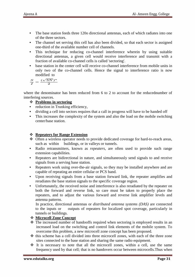
• base station in the center cell will receive co-channel interference from mobile units in only two of the co-channel cells. Hence the signal to interference ratio is now modified to
where the denominator has been reduced from 6 to 2 to account for the reducednumber of interfering sources.
� Problems in sectoring • reduction in Trunking efficiency, • dividing a cell into sectors requires that a call in progress will have to be handed off • This increases the complexity of the system and also the load on the mobile switching
center/base station.
� Repeaters for Range Extension � Often a wireless operator needs to provide dedicated coverage for hard-to-reach areas,
such as within buildings, or in valleys or tunnels. • Radio retransmitters, known as repeaters, are often used to provide such range
extension capabilities. • Repeaters are bidirectional in nature, and simultaneously send signals to and receive
signals from a serving base station. • Repeaters work using over-the-air signals, so they may be installed anywhere and are
capable of repeating an entire cellular or PCS band. • Upon receiving signals from a base station forward link, the repeater amplifies and
reradiates the base station signals to the specific coverage region. • Unfortunately, the received noise and interference is also reradiated by the repeater on
both the forward and reverse link, so care must be taken to properly place the repeaters, and to adjust the various forward and reverse link amplifier levels and antenna patterns. In practice, directional antennas or distributed antenna systems (DAS) are connected to the inputs or outputs of repeaters for localized spot coverage, particularly in tunnels or buildings.
� Microcell Zone Concept � The increased number of handooffs required when sectoring is employed results in an
increased load on the switching and control link elements of the mobile system. To overcome this problem, a new microcell zone concept has been proposed.
� this scheme has a cell divided into three microcell zones, with each of the three zone sites connected to the base station and sharing the same radio equipment.
� It is necessary to note that all the microcell zones, within a cell, use the same frequency used by that cell; that is no handovers occur between microcells.Thus when

Ajeena A Al- Ameen Engg. College
www.edutalks.org Page 32
a mobile user moves between two microcell zones of the cell, the BS simply switches the channel to a different zone site and no physical re-allotment of channel takes place.
� Locating the mobile unit within the cell: An active mobile unit sends a signal to all � zone sites, which in turn send a signal to the BS. A zone selector at the BS uses that � signal to select a suitable zone to serve the mobile unit - choosing the zone with the � strongest signal. � The zone site receives the cellular signal from the base station and transmits that
signal to the mobile phone after amplifcation. � co-channel interference is reduced between the zones and the capacity of system is
increased. � Benefits of the micro-cell zone concept: 1) Interference is reduced in this case as
compared to the scheme in which the cell size is reduced. � 2) Handoffs are reduced (also compared to decreasing the cell size) since the
microcells � within the cell operate at the same frequency; no handover occurs when the mobile
unit moves between the microcells. � 3) Size of the zone apparatus is small. The zone site equipment being small can be
mounted on the side of a building or on poles. � 4) System capacity is increased. The new microcell knows where to locate the mobile
unit in a particular zone of the cell and deliver the power to that zone. • 5)the signal power is reduced, the microcells can be closer and result in an increased
system capacity. However, in a microcellular system, the transmitted power to a mobile phone within a microcell has to be precise; too much power results interference between microcells, while with too little power the signal might not reach the mobile phone.This is a drawback of microcellular systems, since a change in the surrounding (a new building, say, within a microcell) will require a change of the transmission power.
12) Explain Two Ray Ground Reflection Model
• In mobile propagation is the reflection from the ground , This normally occurs when i do have a line of sight.
• We also get a reflection from the ground as well, the reflection from the ground is also important.
• A two ray ground reflection model is often used. It is a simple model but it is a useful model.
• This model is reasonably accurate for predicting large scale signal strength over several kilometers. In fact, this model is good when the distance between the transmitter and the receiver is large.

Ajeena A Al- Ameen Engg. College
www.edutalks.org Page 33
• The assumption is that the height of the transmitter is about 50 m or more
• A two-ray model, which consists of two overlapping waves at the receiver, one direct path and one reflected wave from the ground gives a more accurate.
• A simple addition of a single reflected wave shows that power varies inversely with the forth power of the distance between the Tx and the Rx..
• the total received energy at the receiver is the sum of the line of sight path as well as the reflected path ETOT = ELOS + Eg
• the total transmitted and received electric fields are
• the path difference is • Two propagating waves arrive at the receiver, one LOS wave which travels a distance
of d’ and another ground reflected wave, that travels d’’ , when T-R separation
distance is very large
• The method of image is used to find the path difference between LOS line Of sight & Ground Reflected Path.
• Once the path difference is known, the phase difference is
• The time difference,
� fc carrier frequency � ƛ wavelength
Ajeena A Al- Ameen Engg. College
www.edutalks.org Page 34
• the received power as
received power Pr is nothing but the transmit power Pt times Gt the gain of the transmit antenna times gain of the received antenna Gr times square of height of transmitter & receiver antenna line of sight propagation times d squared whole squared
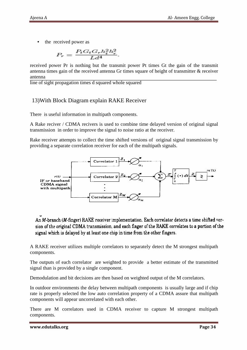
13)With Block Diagram explain RAKE Receiver
There is useful information in multipath components.
A Rake reciver / CDMA recivers is used to combine time delayed version of original signal transmission in order to improve the signal to noise ratio at the receiver.
Rake receiver attempts to collect the time shifted versions of original signal transmission by providing a separate correlation receiver for each of the multipath signals.
A RAKE receiver utilizes multiple correlators to separately detect the M strongest multipath components.
The outputs of each correlator are weighted to provide a better estimate of the transmitted signal than is provided by a single component.
Demodulation and bit decisions are then based on weighted output of the M correlators.
In outdoor environments the delay between multipath components is usually large and if chip rate is properly selected the low auto correlation property of a CDMA assure that multipath components will appear uncorrelated with each other.
There are M correlators used in CDMA receiver to capture M strongest multipath components.
Ajeena A Al- Ameen Engg. College
www.edutalks.org Page 35
A weighting network is used to provide a linear combination of correlator output for bit detection.
Correlator 1 is synchronized to strongest multipath component m1. Correlator 2 with m2 and so on.
If a single correlator is used in the receiver and once the output of single correlator is corrupted by fading , the receiver cannot correct the value.
In a RAKE receiver if the output from correlator by fading the others may not be and the corrupted signal may be discounted through the weighting process
Decisions are based on combination of the M separate decision offeres by the RAKE which can overcome fading and there by improve CDMA reception
The outputs of the M correlators are denoted as Z1,Z2,……… and Zm
They are weighted by α1,α2,…….and αm
The weighting coefficients are based on the power or the SNR from each correlator output,
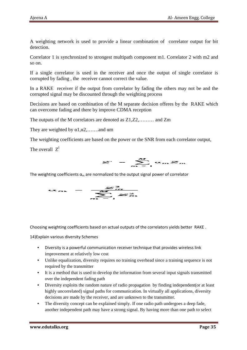
The overall ZI
The weighting coefficients αm are normalized to the output signal power of correlator
Choosing weighting coefficients based on actual outputs of the correlators yields better RAKE .
14)Explain various diversity Schemes
• Diversity is a powerful communication receiver technique that provides wireless link
improvement at relatively low cost • Unlike equalization, diversity requires no training overhead since a training sequence is not
required by the transmitter • It is a method that is used to develop the information from several input signals transmitted
over the independent fading path • Diversity exploits the random nature of radio propagation by finding independent(or at least
highly uncorrelated) signal paths for communication. In virtually all applications, diversity decisions are made by the receiver, and are unknown to the transmitter.
• The diversity concept can be explained simply. If one radio path undergoes a deep fade, another independent path may have a strong signal. By having more than one path to select

Ajeena A Al- Ameen Engg. College
www.edutalks.org Page 36
from, both the instantaneous and average SNRs at the receiver may be improved, often by as much as 20dB to 30 dB
• There are two types of fading- small scale fading and large scale fading.
Microscopic Diversity Technique
• Prevent small scale fading
• These fades are caused by multiple reflections from the surrounding in the vicinity of the
mobile.small scale fades are characterized by deep and rapid amplitude fluctuations which
occur as the mobile moves over distances of just a few wavelengths.
• Small scale fading typically results in a Rayleigh fading distribution of signal strength over
small distances
• Prevented by selecting an antenna which gives strong signal that eliminates small scale
fading
Macroscopic Diversity Techiniques
• Prevent large scale fading • Large scale fading is caused by shadowing due to variation in both the terrain profile
and the nature of the surroundings • In deeply shadowed conditions,the received signal strength at a mobile can drop well
below that of free space • By selecting a base station which is not shadowed when others are,the mobile can
improve the average signal to noise ratio on the forward link.This is called macroscopic diversity,since the mobile is taking advantage of large seperations between the serving base stations.
Types of Diversity
- Space Diversity or Antenna Diversity
- Time Diversity
- Code Diversity
- Polarization Diversity
- Frequency Diversity
Space Diversity
• Space diversity is also known as antenna diversity,is one of the most popular forms of diversity used in wireless systems.Conventional cellular radio systems consist of an elevated base station antenna and a mobile antenna close to the ground.

Ajeena A Al- Ameen Engg. College
www.edutalks.org Page 37
• The existence of direct path between the transmitter and the receiver is not guaranteed and the possibility of a number of scatterers in the vicinity of the mobile suggests a Rayleigh fading signal.
• The signals received from spatially separated antennas on the mobile would have essentially uncorrelated envelopes for antenna seperations of one half wavelength or more.
• The concept of antenna space diversity is also used in base station design.At each cell site,multiple base station receiving antennas are used to provide diversity reception.However,since the important scatterers are generally on the ground in the vicinity of the mobile,the base ststion antennas must be spaced considerably far apart to achieve decorrelation.Seperations on the order of several tens of wavelengths are required at the base station.
• Space diversity can thus be used at either the mobile or base station,or both.
Figure shows block diagram of a space diversity scheme.
Space diversity reception methods can be classified into four categories
1. Selection Diversity
2. Feedback Diversity
3. Maximal Ratio Combining
4. Equal Gain Combining Selection Diversity
• Simplest diversity technique,a block diagram of this method is similar to that shown in above figure.Where m demodulators are used to provide m diversity branches whose gains are adjusted to provide the same average SNR for each branch.
• The receiver branch having the highest instantaneous SNR is connected to the demodulator.The antenna signals themselves could be sampled and the best one sent to a single modulator.
• In practice,the branch with the largest (S+N)/N is used,since it is difficult to measure SNR.

Ajeena A Al- Ameen Engg. College
www.edutalks.org Page 38
Here Eb is the average carrier energy and No is the noise power spectral energy. The instantaneous SNR= instantaneous signal power Mean noise power
• A practical selection diversity system cannot function on a truly instantaneous basis,but must be designed so that the internal time constants of the selection circuitry are shorter than the reciprocal of the signal fading rate. Feedback or Scanning Diversity
• Scanning diversity is very similar to selection diversity except that instead of always using the best of M signals,the M signals are scanned in a fixed sequence until one is found to be above a predetermined threshold.
• This signal is then received until it falls to be below threshold and the scanning process is again initiated.
• The resulting fading statistics are somewhat inferior to those obtained by the other methods
• But the advantage with this method is that it is very simple to implement-only one receiver is required. A block diagram of this method is shown in figure
Maximum ratio combining diversity
• Signals from all of the M branches are weighted according to their individual signal voltage to noise power ratios and then summer
• The individual signal must be co-phased before being summed which generally requires an individual receiver and phasing circuit for each antenna element
• The maximal ratio combining produces an output SNR equal to the sum of the individual SNR
• It has the advantage of producing an output with an acceptable SNR even when none of the individual signals are themselves acceptable

Ajeena A Al- Ameen Engg. College
www.edutalks.org Page 39
• This technique gives the best statistical reduction of fading of any known linear diversity combiner
• Modern DSP technique and digital receivers are making this optimal form of diversity protocol.
Equal gain combining diversity
• Combining all the signals in a co-phased manner with unit gain for all the signal in order to achieve the highest available SNR at the receiver
• In some cases it is not convenient to provide for the variable weighting capability required for true maximal ratio combining
• The branch weights are all set to unity but the signals from each branch are co-phased to provide equal gain combining diversity
• This allows the receiver to exploit signals that are simultaneously received on each branch
• The possibility of producing an acceptable signal from a number of unacceptable inputs is still retained
• The performance is inferior to maximum ratio combining and superior to selection diversity
Frequency diversity
• Frequency diversity transmits information on more than one carrier frequency
• The frequencies are separated by more than one coherence bandwidth of the channel
will not experience the same bandwidth
• If the channels are uncorrelated, the probability of simultaneous fading will be the
product of individual fading probabilities
• Frequency diversity is often employed in microwave line of sight links which carry
several bandwidth in FDM mode
• Due to tropospheric propagation and resulting refraction, deep fading occurs
• 1:Nprotection switching is provided by a radio license
• One frequency is nominally idle but is available on a standby basis to provide
frequency diversity switching of any one of the N other carriers being used on the
same link
• When the diversity is needed,, the appropriate traffic is simply switched to the backup
frequency
Disadvantages

Ajeena A Al- Ameen Engg. College
www.edutalks.org Page 40
• It not only require the spare BW but also requires that many receivers as there are
channels used for the frequency diversity
• The OFDM modulation exploit the frequency diversity by providing the simultaneous
modulation with error control coding across the large BW
Time diversity
• Repeatedly transmits information at time spacing that exceed coherence time of the
channel
• The multiple repetition of the signal will be received with independent fading
condition there by providing diversity
• One modern implementation of time diversity involves the use of rake receiver for
spread spectrum technique CDMA where the multipath channel provides redundancy
in transmitted message
Polarization diversity
• At the base station, space diversity is considerably less practical that at the mobile
because the narrow angle of incident field requires large antenna spacing
• The comparatively high cost of using space diversity at the BS leads to the
consideration of using orthogonal polarisation to exploit polarisation diversity
• The decorrelation for the signal is caused by multiple reflection in the channel
between the mobile and BS antennas
• Measured horizontal and vertical path between the mobile and a BS is uncorrelated
• There is some dependence of the received polarisation on the transmitted polarisation
• Circular and linear polarised antenna have been used to characterize the multipath
signal
• When the path was obstructed the polarisation diversity reduces the multipath delay
spread without significantly decreasing the received power
Theoretical model of polarisation diversity
It is assumed that the signal is transmitted from mobile with horizontal or vertical polarisation
• It is received at the BS by polarisation diversity antenna with two branches
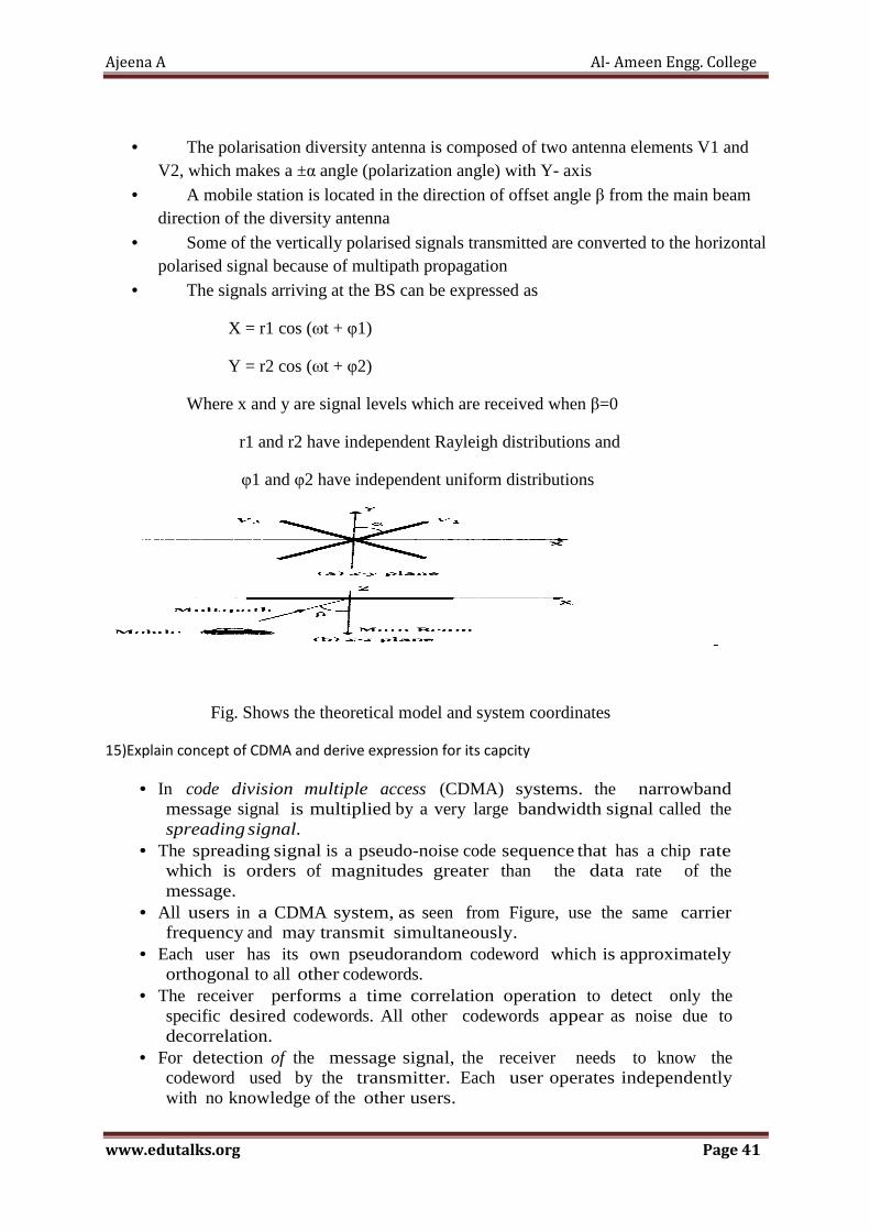
Ajeena A Al- Ameen Engg. College
www.edutalks.org Page 41
• The polarisation diversity antenna is composed of two antenna elements V1 and V2, which makes a ±α angle (polarization angle) with Y- axis
• A mobile station is located in the direction of offset angle β from the main beam direction of the diversity antenna
• Some of the vertically polarised signals transmitted are converted to the horizontal polarised signal because of multipath propagation
• The signals arriving at the BS can be expressed as
X = r1 cos (ωt + φ1)
Y = r2 cos (ωt + φ2)
Where x and y are signal levels which are received when β=0
r1 and r2 have independent Rayleigh distributions and
φ1 and φ2 have independent uniform distributions
Fig. Shows the theoretical model and system coordinates
15)Explain concept of CDMA and derive expression for its capcity
• In code division multiple access (CDMA) systems. the narrowband message signal is multiplied by a very large bandwidth signal called the spreading signal.
• The spreading signal is a pseudo-noise code sequence that has a chip rate which is orders of magnitudes greater than the data rate of the message.
• All users in a CDMA system, as seen from Figure, use the same carrier frequency and may transmit simultaneously.
• Each user has its own pseudorandom codeword which is approximately orthogonal to all other codewords.
• The receiver performs a time correlation operation to detect only the specific desired codewords. All other codewords appear as noise due to decorrelation.
• For detection of the message signal, the receiver needs to know the codeword used by the transmitter. Each user operates independently with no knowledge of the other users.
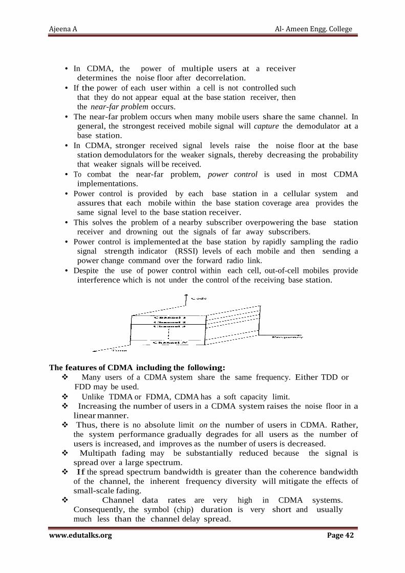
Ajeena A Al- Ameen Engg. College
www.edutalks.org Page 42
• In CDMA, the power of multiple users at a receiver determines the noise floor after decorrelation.
• If the power of each user within a cell is not controlled such that they do not appear equal at the base station receiver, then the near-far problem occurs.
• The near-far problem occurs when many mobile users share the same channel. In general, the strongest received mobile signal will capture the demodulator at a base station.
• In CDMA, stronger received signal levels raise the noise floor at the base station demodulators for the weaker signals, thereby decreasing the probability that weaker signals will be received.
• To combat the near-far problem, power control is used in most CDMA implementations.
• Power control is provided by each base station in a cellular system and assures that each mobile within the base station coverage area provides the same signal level to the base station receiver.
• This solves the problem of a nearby subscriber overpowering the base station receiver and drowning out the signals of far away subscribers.
• Power control is implemented at the base station by rapidly sampling the radio signal strength indicator (RSSI) levels of each mobile and then sending a power change command over the forward radio link.
• Despite the use of power control within each cell, out-of-cell mobiles provide interference which is not under the control of the receiving base station.
The features of CDMA including the following:
� Many users of a CDMA system share the same frequency. Either TDD or FDD may be used.
� Unlike TDMA or FDMA, CDMA has a soft capacity limit. � Increasing the number of users in a CDMA system raises the noise floor in a
linear manner. � Thus, there is no absolute limit on the number of users in CDMA. Rather,
the system performance gradually degrades for all users as the number of users is increased, and improves as the number of users is decreased.
� Multipath fading may be substantially reduced because the signal is spread over a large spectrum.
� If the spread spectrum bandwidth is greater than the coherence bandwidth of the channel, the inherent frequency diversity will mitigate the effects of small-scale fading.
� Channel data rates are very high in CDMA systems. Consequently, the symbol (chip) duration is very short and usually much less than the channel delay spread.

Ajeena A Al- Ameen Engg. College
www.edutalks.org Page 43
� Since PN sequences have low autocorrelation, multi path which is delayed by more than a chip will appear as noise. A RAKE receiver can be used to improve reception by collecting time delayed versions of the required signal.
� Since CDMA uses co-channel cells, it can use macroscopic spatial diversity to provide soft handoff. Soft handoff is performed by the MSC, which can simultaneously monitor a particular user from two or more base stations. The MSC may chose the best version of the signal at any time without switching frequencies.
� Self-jamming is a problem in CDMA system. � Self-jamming arises from the fact that the spreading sequences
of different users are not exactly orthogonal, hence in the despreading of a particular PN code, non-zero contributions to the receiver decision statistic for a desired user arise from the transmissions of other users in the system.
� The near-far problem occurs at a CDMA receiver if an undesired user has a high detected power as compared to the desired user.
� Capacity of CDMA � In CDMA users are separated by different codes but not by frequencies
or time slots as in TDMA and FDMA. In CDMA many users can share the same frequency band and communicate at the same time.
� A channel in TDMA or FDMA is a frequency and a time slot. There is only a limited number of channels, which restrict the number of simultaneous users. In CDMA a channel is a code. There is an almost unlimited number of codes, and thus channels, but it doesn’t mean an unlimited capacity.
� Each user is a source of noise to the receivers of other users (recall the discussion we had on DSSS) or to the receiver in the base station. This will limit the number of users.
� The number of user per cell (the capacity) is determined by the signal to noise ratio. If there are too many users, the noise will be high, the S/N (signal to noise) ratio will be low and reception quality will be poor.
� This is different from TDMA/FDMA, where the capacity is determined by the number of available channels
� n: number of users
� W: total bandwidth
� R: data rate
� Sr: signal to noise ratio
16)Discuss in Detail about Spread Spectrum Techniques
• All of the modulation and demodulation techniques described so far strive to achieve greater power and/or bandwidth efficiency in a stationary additive white Gaussian noise channel.
rSR
Wn
×=

Ajeena A Al- Ameen Engg. College
www.edutalks.org Page 44
• Since bandwidth is a limited resource, one of the primary design objectives of all the modulation schemes detailed thus far is to minimize the required transmission bandwidth.
• Spread spectrum techniques, on the other hand, employ a transmission bandwidth that is several orders of magnitude greater than the minimum required signal bandwidth.
• While this system is very bandwidth inefficient for a single user, the advantage of spread spectrum is that many users can simultaneously use the same bandwidth without significantly interfering with one another.
• In a multiple-user, multiple access interfer-ence (MAl) environment, spread spectrum systems become very bandwidth efficient.
• spread spectrum signals are pseudorandom and have noise-like properties when compared with the digital information data.
• The spreading waveform is controlled by a pseudo-noise (PNJ sequence or pseudo-noise code, which is a binary sequence that appears random but can be reproduced in a deterministic manner by intended receivers.
• Spread spectrum signals are demodulated at the receiver through crosscorrelation with a locally-generated version of the pseudorandom carrier.
• Crosscorrelation with the correct PN sequence despreads the spread spectrum signal and restores the modulated message in the same narrow band as the original data.
• Spread spectrum modulation has many properties that make it particularly well-suited for use in the mobile radio environment. The most important advantage is its inherent interference rejection capability.
• Narrowband interference effects only a small portion of the spread spectrum signal, it can easily be removed through notch filtering without much loss of information.
• Since all users are able to share the same spectrum, spread spectrum may eliminate frequency planning, since all cells can use the same channels.
• Resistance to multipath fading is another fundamental reason for considering spread spectrum systems for wireless communications.

Ajeena A Al- Ameen Engg. College
www.edutalks.org Page 45
� Input is fed into a channel encoder
o Produces analog signal with narrow bandwidth
� Signal is further modulated using sequence of digits
o Spreading code or spreading sequence
o Generated by pseudonoise, or pseudo-random number generator
� Effect of modulation is to increase bandwidth of signal to be transmitted
� On receiving end, digit sequence is used to demodulate the spread spectrum signal
� Signal is fed into a channel decoder to recover data
� Pseudo-random (PN) Sequences
A pseudo-noise ( PN ) sequence is a periodic binary sequence with a noise like waveform that is usually generated by a means of a feed back shift register.
It consists of a shift register made up of m flip-flops and a logic circuit to form a multiloop feedback circuit.
• An m-bit codeword produces a sequence of length 2m-1
• The peak values are 2m-1
• The autocorrelation function is equal to –1 other than at the peaks.
• The O/P sequence contains 2m-1 ones & 2m-1 -1 Zeros.
• Their power density spectrum is uniform so they may used as white noise sources.

Ajeena A Al- Ameen Engg. College
www.edutalks.org Page 46
• A typical matched filter implements convolution using FIR filter whose coefficients are the time inverse of the expected PN sequence to decode the transmitted data.
• If the receiver is not synchronized, then the received signal will propagate through the matched filter, which outputs the complete correlation function.
The output of the FIR filter is the decoded data.
� Properties needed for signal to spectrum modulated � PN Sequence Properties
� Randomness � Unpredictability
� Two criteria used to validate a PN Sequence � Uniform Distribution � Independence
• Uniform distribution � Distribution of numbers in the sequence should be uniform � Frequence of occurance of each of numbers should be approximately
same. � For a stream of binary digits two properties are desired
� Balance property : in long sequence the number of binary ones always one more than the number of 0’s.
� Run property: run is defined as a sequence of all 1-s or a sequence of all 0-s.Among the runs of 1’s and 0’s in each period of sequence one half the runs of each kind are of length one,one fourth of length two,one eigth of length three and so on as long as these fractions represent meaningful number of runs.
� Auto Correlation Property : Autocorrelation function of a maximal length sequence is periodic and binary valued. The periodic autocorrelation of a
±1 m-sequence is
� Correlation Property : . the cross-correlation of two m-sequences tends to be large. If the codes which are used are not completely orthogonal, the cross-correlation factor is unequal to zero. In this situation the different users are interferers to each other, hence the near-far problem appears
� good auto-and cross-correlation properties
� Independence
� no one value in sequence can be inferred from the others
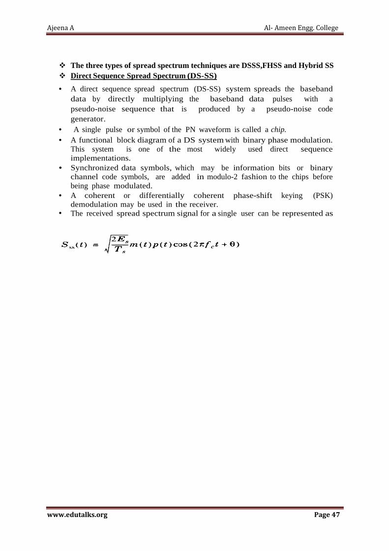
Ajeena A Al- Ameen Engg. College
www.edutalks.org Page 47
� The three types of spread spectrum techniques are DSSS,FHSS and Hybrid SS � Direct Sequence Spread Spectrum (DS-SS)
• A direct sequence spread spectrum (DS-SS) system spreads the baseband
data by directly multiplying the baseband data pulses with a pseudo-noise sequence that is produced by a pseudo-noise code generator.
• A single pulse or symbol of the PN waveform is called a chip. • A functional block diagram of a DS system with binary phase modulation.
This system is one of the most widely used direct sequence implementations.
• Synchronized data symbols, which may be information bits or binary channel code symbols, are added in modulo-2 fashion to the chips before being phase modulated.
• A coherent or differentially coherent phase-shift keying (PSK) demodulation may be used in the receiver.
• The received spread spectrum signal for a single user can be represented as
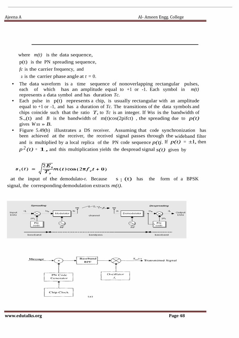
Ajeena A Al- Ameen Engg. College
www.edutalks.org Page 48
where m(t) is the data sequence,
p(t) is the PN spreading sequence,
fc is the carrier frequency, and
a is the carrier phase angle at t = 0.
• The data waveform is a time sequence of nonoverlapping rectangular pulses, each of which has an amplitude equal to +1 or -1. Each symbol in m(t) represents a data symbol and has duration Tc.
• Each pulse in p(t) represents a chip, is usually rectangular with an amplitude equal to +1 or -1, and has a duration of Tc. The transitions of the data symbols and chips coincide such that the ratio T, to Tc is an integer. If Wss is the bandwidth of S.,(t) and B is the bandwidth of m(t)cos(2pifct) , the spreading due to p(t) gives W ss » B.
• Figure 5.49(b) illustrates a DS receiver. Assuming that code synchronization has been achieved at the receiver, the received signal passes through the wideband filter and is multiplied by a local replica of the PN code sequence p(tj. If p(t) = ±l, then
p 2 (t) = 1, and this multiplication yields the despread signal s(t) given by
at the input of the demodulato-r. Because s 1 (t) has the form of a BPSK
signal, the corresponding demodulation extracts m(t).

Ajeena A Al- Ameen Engg. College
www.edutalks.org Page 49
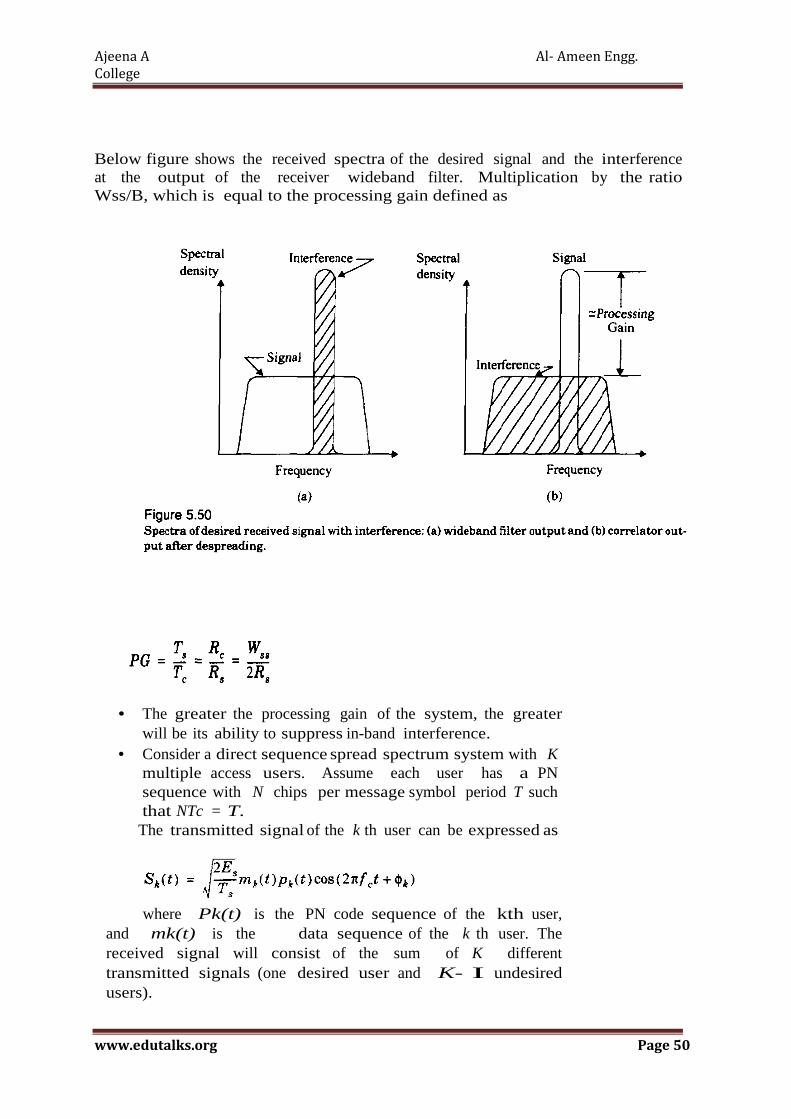
Ajeena A Al- Ameen Engg.
College
www.edutalks.org Page 50
Below figure shows the received spectra of the desired signal and the interference at the output of the receiver wideband filter. Multiplication by the ratio Wss/B, which is equal to the processing gain defined as
• The greater the processing gain of the system, the greater will be its ability to suppress in-band interference.
• Consider a direct sequence spread spectrum system with K multiple access users. Assume each user has a PN sequence with N chips per message symbol period T such that NTc = T. The transmitted signal of the k th user can be expressed as
where Pk(t) is the PN code sequence of the kth user, and mk(t) is the data sequence of the k th user. The received signal will consist of the sum of K different transmitted signals (one desired user and K- I undesired users).

Ajeena A Al- Ameen Engg.
College
www.edutalks.org Page 51
• In practice, the nearfar problem presents difficulty for DS-SS systems. Without careful power control of each mobile user, one close-in user may dominate the received signal energy at a base station, making the Gaussian assumption inaccurat.
• For a large number of users, the bit error rate is limited more by the multiple access interference than by thermal noise .
� Performance Of DSSS
� simple jamming signal at the center frequency of the DSSS system with a form
� the received signal is
Sr(t) = S(t) +Sj(t) + n(t)
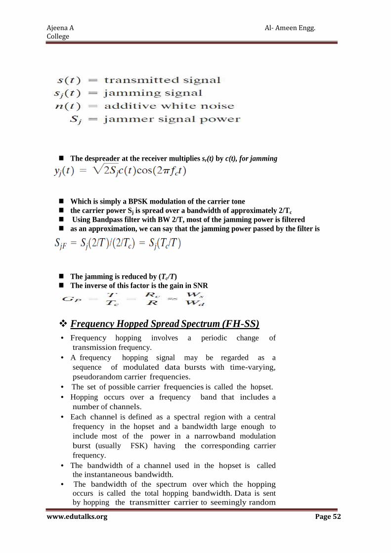
Ajeena A Al- Ameen Engg.
College
www.edutalks.org Page 52
� The despreader at the receiver multiplies sr(t) by c(t), for jamming
� Which is simply a BPSK modulation of the carrier tone � the carrier power Sj is spread over a bandwidth of approximately 2/Tc � Using Bandpass filter with BW 2/T, most of the jamming power is filtered � as an approximation, we can say that the jamming power passed by the filter is
� The jamming is reduced by (Tc/T) � The inverse of this factor is the gain in SNR
� Frequency Hopped Spread Spectrum (FH-SS)
• Frequency hopping involves a periodic change of transmission frequency.
• A frequency hopping signal may be regarded as a sequence of modulated data bursts with time-varying, pseudorandom carrier frequencies.
• The set of possible carrier frequencies is called the hopset. • Hopping occurs over a frequency band that includes a
number of channels. • Each channel is defined as a spectral region with a central
frequency in the hopset and a bandwidth large enough to include most of the power in a narrowband modulation burst (usually FSK) having the corresponding carrier frequency.
• The bandwidth of a channel used in the hopset is called the instantaneous bandwidth.
• The bandwidth of the spectrum over which the hopping occurs is called the total hopping bandwidth. Data is sent by hopping the transmitter carrier to seemingly random
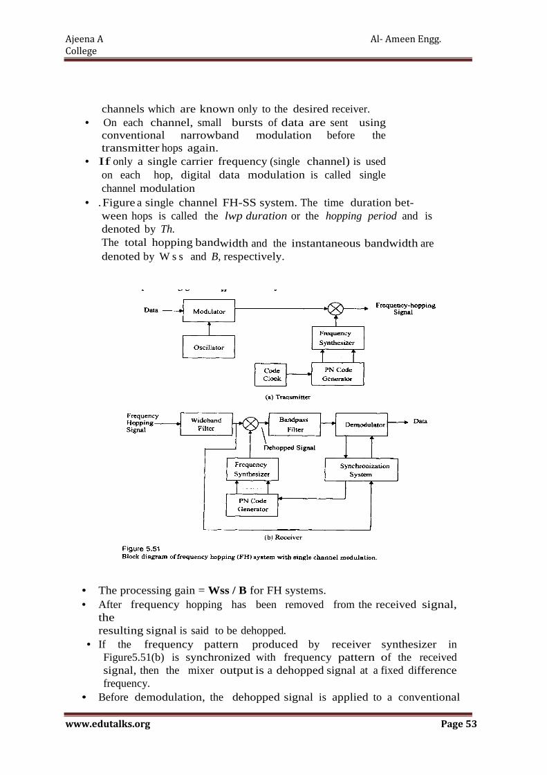
Ajeena A Al- Ameen Engg.
College
www.edutalks.org Page 53
channels which are known only to the desired receiver. • On each channel, small bursts of data are sent using
conventional narrowband modulation before the transmitter hops again.
• If only a single carrier frequency (single channel) is used on each hop, digital data modulation is called single channel modulation
• . Figure a single channel FH-SS system. The time duration bet- ween hops is called the lwp duration or the hopping period and is denoted by Th. The total hopping bandwidth and the instantaneous bandwidth are denoted by W s s and B, respectively.
• The processing gain = Wss / B for FH systems. • After frequency hopping has been removed from the received signal,
the resulting signal is said to be dehopped.
• If the frequency pattern produced by receiver synthesizer in Figure5.51(b) is synchronized with frequency pattern of the received signal, then the mixer output is a dehopped signal at a fixed difference frequency.
• Before demodulation, the dehopped signal is applied to a conventional

Ajeena A Al- Ameen Engg.
College
www.edutalks.org Page 54
receiver. • In FH, whenever an undesired signal occupies a particular hopping
channel,the noise and interference in that channel are translated in frequency so that they enter the demodulator.
• Thus it is possible to have collissions in a FH system where an undesired user transmits in the same channel at the same time as the desired user.
• Frequency hopping may be classified as fast or slow. \ • Fast frequency hopping occurs if there is more than one
frequency hop during each transmitted symbol. Thus, fast frequency hopping implies that the hopping rate equals or exceeds the information symbol rate.
• Slow frequency hopping occurs if one or more symbols are transmitted in the time interval between frequency hops.
• If binary frequency-shift keying (FSK}is used, the pair of possible instanta- neous frequencies changes With each hop.
• The frequency channel occupied by a transmitted symbol is called the transmission channel.
• The channel that would be occupied if the altemative symbol were transmitted is called the complementary channel.
• The frequency hop rate of a FH-SSsystem is determined by the frequency agility of receiver synthesizers, the type of information being transmitted, the amount of redundancy used to code against collisions, and the distance to the nearest potential interferer.
• In FH-SS systems, several users independently hop their carrier frequencies While using BFSK modulation. If two users not simultaneously utilizing the same frequency band, the probability of error for BFSK can be given by
• However, if two users transmit simultaneously in the same frequency
band, a collision, or "hit", occurs. In this case it is reasonable to assume that the probability of error is 0.5. Thus the overall probability of bit error can be modeled as

Ajeena A Al- Ameen Engg.
College
www.edutalks.org Page 55
where ph is the probability of hit, which must be determined. If there are M possible hopping channels (called slots), there is a IIM probability that a given interferer will be present in the desired user's slot.
• FH-SS has an advantage over DS-SS in that it is not as susceptible to the near-far problem. Because signals are generally not utilizing the same frequency simultaneously, the relative power levels of signals are not as critical as in DS- SS. The near-far problem is not totally avoided, however, since there will be some interference caused by stronger signals bleeding into weaker signals due to imperfect filtering of adjacent channels.
• To combat the occasional hits, error-cor- rection coding is required on all transmissions. By applying strong Reed- Solomon or other burst error correcting codes, performance can be increased dra- matically, even with an occassional collision.
Performance of FHSS
� Performance analysis • Major issue: Tx and Rx may use
difference frequency slots • � channel mismatch • SNR for coherent demodulation is
•
Performance is limited by the correctness of frequency-selection
� Assume mismatch probability pd be the probability that there is mismatch in the first j channels
With our simple channel selection rule Average channel mismatch probability For every M transmissions, number of correct matches is Hybrid Spread Spectrum Techniques
1 2
1
0
ˆw here is the num ber of m atched
frequency slot selections am ong selections.
M
j jm
M I
M
−
==
= ∑
( )1 1j
j dP p≤ − −
( )1
0
11 1 .
Jj
J dj
P pJ
−
=
≤ − − ∑
( ) ( )1
0
1ˆ 1 1 1 1J
j
J dj
M M P M pJ
−
=
= − ≥ − − −
∑

Ajeena A Al- Ameen Engg.
College
www.edutalks.org Page 56
• In addition to the frequency hopped and direct sequence,
spread spectrum multiple access techniques, there are certain
other hybrid combinations that pro vide certain advantages.
• These hybrid techniques are described below
� Hybrid FDMA/CDMA (FCDMA)
• This technique can be used as an alternative to the DS-CDMA
technique
• Figure shows the spectrum of this hybrid scheme.
• The available wideband spectrum is divided into a number of
subspectras with smaller bandwidths.
• Each of these smaller sub channels becomes a narrowband
CDMA system having processing gain lower than the original
CDMA system.
• This hybrid system has an advantage in that the required
bandwidth need not be contiguous and different users can be
allot ted different subspectrum bandwidths depending on their
requirements.
• The capacity of this FDMA/CDMA technique is calculated as
the sum of the capacities of a sysm operating in the subspectra
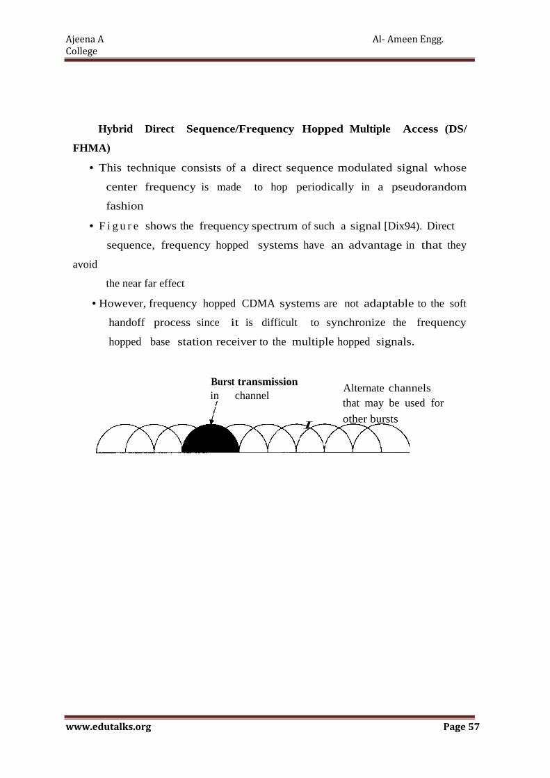
Ajeena A Al- Ameen Engg.
College
www.edutalks.org Page 57
Hybrid Direct Sequence/Frequency Hopped Multiple Access (DS/
FHMA)
• This technique consists of a direct sequence modulated signal whose
center frequency is made to hop periodically in a pseudorandom
fashion
• F i g u r e shows the frequency spectrum of such a signal [Dix94). Direct
sequence, frequency hopped systems have an advantage in that they
avoid
the near far effect
• However, frequency hopped CDMA systems are not adaptable to the soft
handoff process since it is difficult to synchronize the frequency
hopped base station receiver to the multiple hopped signals.
Burst transmission in channel
I
Alternate channels that may be used for
other bursts

Ajeena A Al- Ameen Engg. College
www.edutalks.org Page 58
Frequency spectrum of a hybrid FHIDS system Time Division CDMA (TCDMA)
• In a TCDMA (also called TDMA/ CDMA) system, different spreading
codes are assigned to different cells.
• Within each cell, only one user per cell is allotted a particular time slot.
• Thus at any time, only one CDMA user is transmitting in each cell
• When a handoff takes place, the spreading code of the user is changed
to that of the new cell.
• Using TCDMA has an advantage in that it avoids the near-far effect since
only one user transmits at a time within a cell
Time Division Frequency Hopping (TDFH)
• This multiple access technique has an advantage in severe
multipath or when severe co-channel interference occurs
• . The subscriber can hop to a new frequency at the start of a new TDMA
frame, thus avoiding a severe fade or erasure event on a particular
channel.
• This technique has been adopted for the GSM standard, where the hop
ping sequence is predefined and the subscriber is allowed to hop only on
certain frequencies which are assigned to a cell.
• This scheme also avoids co-channel interference problems between
neighboring cells if two interfering base station transmitters are made
to transmit on different frequencies at different times.
• The use of TDFH can increase the capacity of GSM by several fold.

Ajeena A Al- Ameen Engg. College
www.edutalks.org Page 59
16) Explain FDMA
Frequency Division Multiple Access (FDMA )
• Frequency division multiple access (FDMA) assigns individual channels to individual users.
• Each user is allocated a unique frequency band or channel. • These channels are assigned on demand to users who request
service. • During the period of the call, no other user can share the same
frequency band. • In FDD systems, the users are assigned a channel as a pair of
frequencies; one frequency is used for the forward channel, while the other frequency is used for the reverse channel.
The features of FDMA are as fol lows;
• The FDMA channel carries only one phone circuit at a time.
• If an FDMA channel is not in use, then it sits idle and cannot be used by other users to increase or share capacity. It is essentially a wasted resource.
• After the assignment of a voice channel, the base station and the mobile transmit simultaneously and continuously.
• The bandwidths of FDMA channels are relatively narrow (30 kHz) as each channl supports only one circuit per carrier. That is, FDMA is usually implemnted in narrowband systems.
• The symbol time is large as compared to the average delay spread. This implies.that the amount of intersymbol interference is low and, thus, little or no equalization is required in FDMA narrowband systems.
• The complexity of FDMA mobile systems is lower when compared to TDMA systems, though this is changing as digital signal processing methods improve for TDMA.
• Since FDMA is a continuous transmission scheme, fewer bits are needed for overhead purposes (such as synchronization and framing bits) as compared to TDMA.
• FDMA systems have higher cell site system costs as compared to TDMA sys tems, because of the single channel per carrier design, and the need to use costly bandpass filters to eliminate spurious radiation at the base station.
• The FDMA mobile unit uses duplexers since both the transmitter and receiver operate at the same time. This
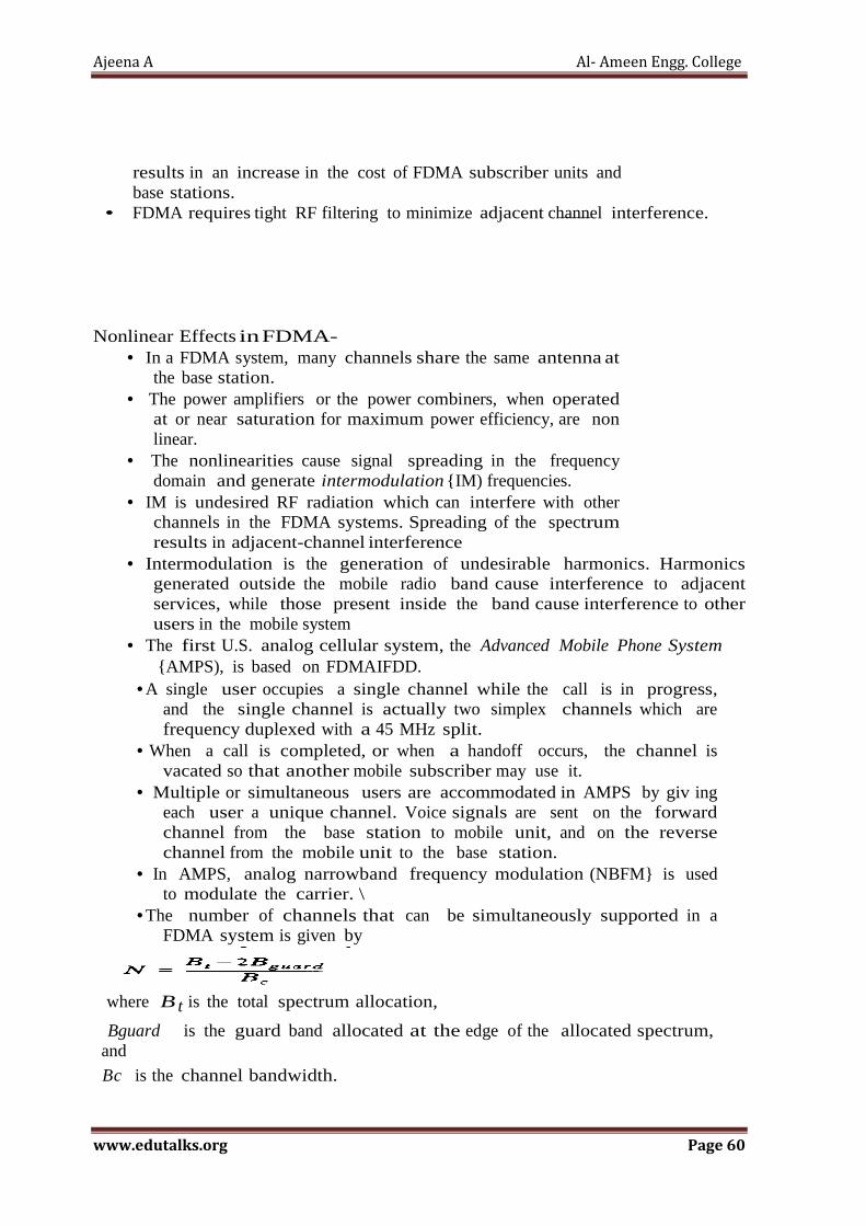
Ajeena A Al- Ameen Engg. College
www.edutalks.org Page 60
results in an increase in the cost of FDMA subscriber units and base stations.
• FDMA requires tight RF filtering to minimize adjacent channel interference. Nonlinear Effects in FDMA-
• In a FDMA system, many channels share the same antenna at the base station.
• The power amplifiers or the power combiners, when operated at or near saturation for maximum power efficiency, are non linear.
• The nonlinearities cause signal spreading in the frequency domain and generate intermodulation {IM) frequencies.
• IM is undesired RF radiation which can interfere with other channels in the FDMA systems. Spreading of the spectrum results in adjacent-channel interference
• Intermodulation is the generation of undesirable harmonics. Harmonics generated outside the mobile radio band cause interference to adjacent services, while those present inside the band cause interference to other users in the mobile system
• The first U.S. analog cellular system, the Advanced Mobile Phone System {AMPS), is based on FDMAIFDD.
• A single user occupies a single channel while the call is in progress, and the single channel is actually two simplex channels which are frequency duplexed with a 45 MHz split.
• When a call is completed, or when a handoff occurs, the channel is vacated so that another mobile subscriber may use it.
• Multiple or simultaneous users are accommodated in AMPS by giv ing each user a unique channel. Voice signals are sent on the forward channel from the base station to mobile unit, and on the reverse channel from the mobile unit to the base station.
• In AMPS, analog narrowband frequency modulation (NBFM} is used to modulate the carrier. \
• The number of channels that can be simultaneously supported in a FDMA system is given by
where B t is the total spectrum allocation,
Bguard is the guard band allocated at the edge of the allocated spectrum, and
Bc is the channel bandwidth.
Ajeena A Al- Ameen Engg. College
www.edutalks.org Page 61
17)Discuss in Detail about GSM architecture ,Servicing frequency band ,Channels/linksand its
objectives
GSM (Global System for Mobile)
� Global System for Mobile (GSM) is second generation cellular system standard that was developed to soke the fragmentation problems of the first cellular systems in Europe.
� GSM is the world's first cellular system to specify digital modulation and network level architectures and services.
� GSM Services and Features � GSM services follow ISDN guidelines and are classified as either tele
services or data services. Teleservices include standard mobile telephony and mobile-originated or base-originated traffic.
� Data services include computer-to- computer communication and packet-switched traffic. User services may be divided into three major categories: • Telephone services, including emergency calling and facsimile. GSM also supports Videotex and Teletex, though they are not integral parts of the GSM standard. • Bearer services or data services which are limited to layers 1, 2, and 3 of the open system interconnection (OSI) reference model. Supported services include packet switched protocols and data rates from 300 bps to 9.6 kbps. Data may be transmitted using either a transparent mode (where GSM provides standard channel coding for the user data) or nontransparent mode (where GSM offers special coding efficiencies based on the particular data interface).
• Supplementary ISDN services, are digital in nature, and include call diversion, closed user groups, and caller identification, and are not available in analog mobile networks. Supplementary services also include the short messaging service (SMS) which allows GSM subscribers and base stations to transmit alphanumeric pages of limited length. while simultaneously carrying normal voice traffic. SMS also provides

Ajeena A Al- Ameen Engg. College
www.edutalks.org Page 62
cell broadcast, which allows GSM base stations to repetitively transmit ASCII messages with as many as fifteen 93-character strings in concatenated fashion.
� From the user's point of view, one of the most remarkable features of GSM is the Subscriber Identity Module (SIM), which is a memory device that stores information such as the subscriber's identification number, the networks and countries where the subscriber is entitled to service, privacy keys, and other user-specific information. � A subscriber uses the SIM with a 4-digit personal ID number to activate
service from any GSM phone. � A second remarkable feature of GSM is the on-the-air privacy which is
pro- vided by the system. � Unlike analog FM cellular phone systems which can be readily
monitored, it is virtually impossible to eavesdrop on a GSM radio trans- mission.
� The privacy is made possible by encrypting the digital bit stream sent by a GSM transmitter, according to a specific secret cryptographic key that is known only to the cellular carrier.
GSM System Architecture
� The GSM system architecture consists of three major interconnected subsystems that interact between themselves and with the users through cer- tain network interfaces.
� The subsystems are the Base Station Subsystem (BSS), Network and Switching Subsystem (NSS), and the Operation Support Subsystem .
� The Mobile Station (MS) is also a subsystem, but is usually considered to be part of the BSS for architecture purposes.
� Equipment and services are designed within GSM to support one or more of these specific subsystems.
� The BSS, also known as the radio subsystem, provides and manages radio transmission paths between the mobile stations and the Mobile Switching Center (MSC).
� The BSS also manages the radio interface between the mobile stations and all other subsystems of GSM.
� Each BSS consists of many Base Station Controllers (BSCs) which connect the MS to the NSS via the MSCs.
� NSS manages switching functions of the system and allows MSC to communicate with other networks such as the PSTN and ISDN.
� The OSS supports the operation and maintenance of GSM and allows system engineers to monitor, diagnose, and troubleshoot all aspects of the GSM system.
� This subsystem interacts with the other GSM subsystems, and is provided solely for the staff of the GSM operating company which provides service facilities for the network.
� Figure shows the block diagram of the GSM system architecture. � The Mobile Stations (MS) communicate with the Base Station Subsystem

Ajeena A Al- Ameen Engg. College
www.edutalks.org Page 63
(BSS) over the radio air interface. � The BSS consists of many BSCs which connect to a single MSC, and each
BSC typically controls up to several hundred Base 1Tansceiver Stations (BTSs). Some of the BTSs may be co-located at the BSC, and others may be remotely distributed and physically connected to the BSC by microwave link or dedicated leased lines.
� Mobile handoffs (called handovers) between two BTSs under the control of the same BSC are handled by the BSC, and not the MSC. This greatly reduces the switching burden of the MSC.
� The NSS handles the switching of GSM calls between external networks and the BSCs in the radio subsystem and is also responsible for managing and providing external access to several customer databases.
� The MSC is the central unit in the NSS and controls the traffic among all of the BSCs. In the NSS, there are three different databases called the Home Location Register (HLR), Visitor Location Register (VLR), and the Authentication Center (AUC).
� The HLR is a database which contains subscriber information and location information for each user who resides in the same city as the MSC.
� Each subscriber in a particular GSM market is assigned a unique International Mobile Subscriber Identity (IMSI), and this number is used to identify each home user. The VLR is a database which temporarily stores the IMSI and customer information for each roaming subscriber who is visiting the coverage area of a particular MSC.
� The VLR is linked between several adjoining MSCs in a particular market or geo- graphic region and contains subscription information of every visiting user in the area.
� Once a roaming mobile is logged in the VLR, the MSC sends the necessary information to the visiting subscriber's HLR so that calls to the roaming mobile can be appropriately routed over the PSTN by the roaming user's HLR.
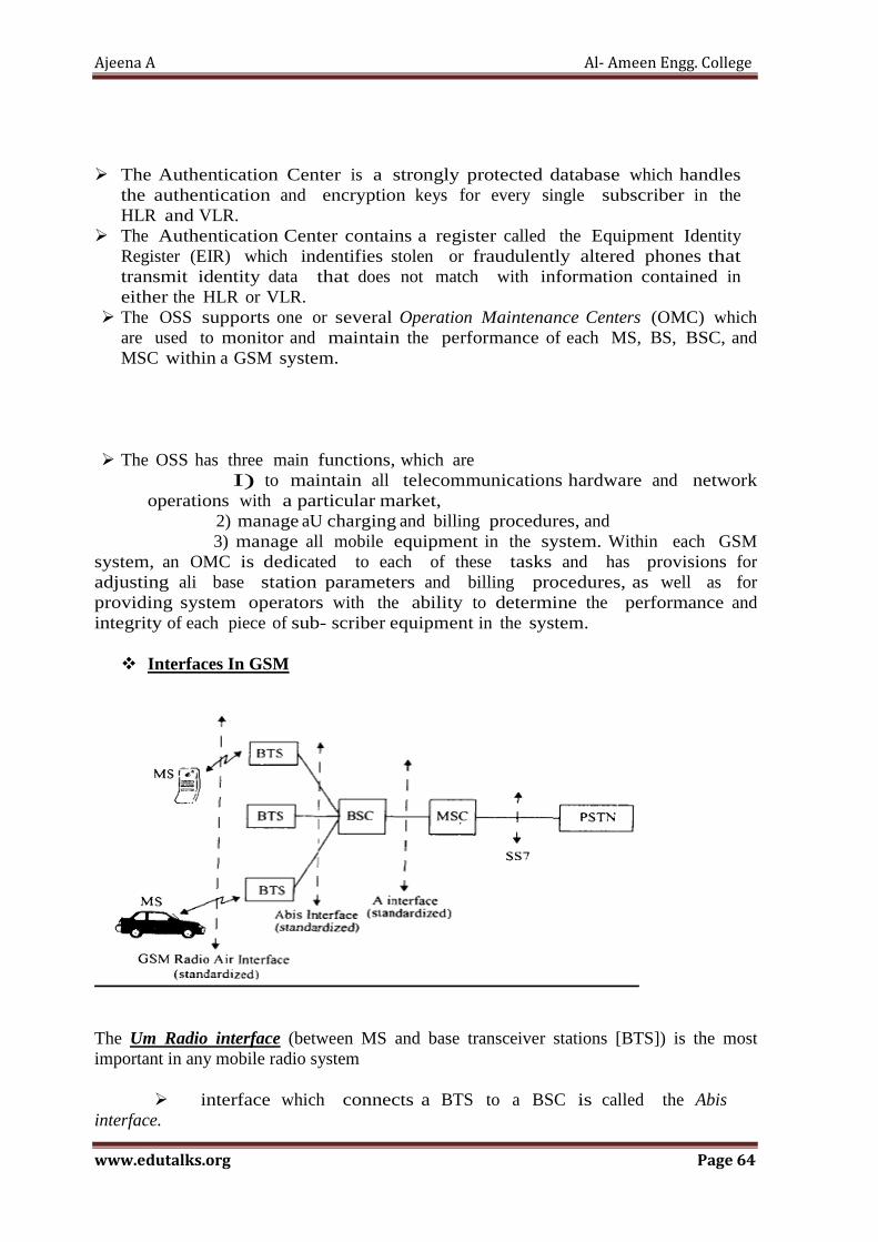
Ajeena A Al- Ameen Engg. College
www.edutalks.org Page 64
� The Authentication Center is a strongly protected database which handles the authentication and encryption keys for every single subscriber in the HLR and VLR.
� The Authentication Center contains a register called the Equipment Identity Register (EIR) which indentifies stolen or fraudulently altered phones that transmit identity data that does not match with information contained in either the HLR or VLR.
� The OSS supports one or several Operation Maintenance Centers (OMC) which are used to monitor and maintain the performance of each MS, BS, BSC, and MSC within a GSM system.
� The OSS has three main functions, which are I) to maintain all telecommunications hardware and network operations with a particular market,
2) manage aU charging and billing procedures, and 3) manage all mobile equipment in the system. Within each GSM
system, an OMC is dedicated to each of these tasks and has provisions for adjusting ali base station parameters and billing procedures, as well as for providing system operators with the ability to determine the performance and integrity of each piece of sub- scriber equipment in the system.
� Interfaces In GSM
The Um Radio interface (between MS and base transceiver stations [BTS]) is the most important in any mobile radio system
� interface which connects a BTS to a BSC is called the Abis interface.

Ajeena A Al- Ameen Engg. College
www.edutalks.org Page 65
The Abis interface carries traffic and maintenance data, and is specified by GSM to be standardized for all manufacturers.
� The BSCs are physically connected via dedicated/leased lines or microwave link to the MSC. The interface between a BSC and a MSC is called the A inter- face, which is standardized within GSM.
� The A interface uses an SS7 protocol called the Signaling Correction Control Part (SCCP) which supports communication between the MSC and the BSS, as well as network messages between the individual subscribers and the MSC.
� The A interface allows a service provider to use base stations and switching equipment made by different manufacturers.
� GSM FREQUENCY BANDS
• The GSM system is a frequency- and time-division system; • each physical channel is characterized by a carrier frequency and a time slot number. • GSM system frequencies include two bands at 900 MHz and 1800 MHz
commonly referred to as the GSM-900 and DCS-1800 systems. • For DCS-1800, there are two sub-bands of 75 MHz in the 1710–1785 MHz and
1805–1880 MHz ranges. GSM-1800 is also called DCS (Digital Cellular Service) • GSM-900 uses 890–915 MHz to send information from the mobile station to the
base station (uplink) and 935–960 MHz for the other direction (downlink), providing 124 RF channels (chanel spacing of 45 MHz is used. Guard bands 100 kHz wide are placed at either end of the range of frequencies.[
• GSM-850 uses 824–849 MHz to send information from the mobile station to the base station (uplink) and 869–894 MHz for the other direction (downlink). Channel numbers are 128
• GSM-850 is also sometimes called GSM-800 because this frequency range was known as the "800 MHz band" .
• GSM-1900 uses 1,850–1,910 MHz to send information from the mobile station to the base station (uplink) and 1,930–1,990 MHz for the other direction (downlink).
• GSM-450 It operates in either 450.4–457.6 MHz paired with 460.4-467.6 MHz
� GSM RADIO LINK / CHANNELS:
1) Physical Channels:
One time slot on one carrier is called physical channel.
2) Logical Channels:
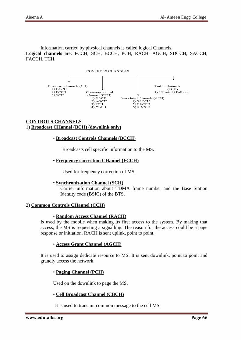
Ajeena A Al- Ameen Engg. College
www.edutalks.org Page 66
Information carried by physical channels is called logical Channels. Logical channels are: FCCH, SCH, BCCH, PCH, RACH, AGCH, SDCCH, SACCH, FACCH, TCH.
CONTROLS CHANNELS 1) Broadcast CHannel (BCH) (downlink only)
• Broadcast Controls Channels (BCCH) Broadcasts cell specific information to the MS.
• Frequency correction CHannel (FCCH) Used for frequency correction of MS.
• Synchronization Channel (SCH) Carrier information about TDMA frame number and the Base Station Identity code (BSIC) of the BTS.
2) Common Controls CHannel (CCH)
• Random Access Channel (RACH) Is used by the mobile when making its first access to the system. By making that access, the MS is requesting a signalling. The reason for the access could be a page response or initiation. RACH is sent uplink, point to point.
• Access Grant Channel (AGCH)
It is used to assign dedicate resource to MS. It is sent downlink, point to point and grandly access the network.
• Paging Channel (PCH)
Used on the downlink to page the MS.
• Cell Broadcast Channel (CBCH)
It is used to transmit common message to the cell MS

Ajeena A Al- Ameen Engg. College
www.edutalks.org Page 67
3) ASSOCIATED CONTROLS CHANNELS (ACCH)
• Slow Associated Controls Channel (SACCH) It is used Measurement reports from the MS to BTS are sent on the uplink. On the downlink the MS receives information from the BTS on what transmitting power to use and also instruction on Timing advance (TA).It is also used for the transmission of short text message in call connected (busy) mode. Controls channel associated with a TCH.
• Fast Associated control Channel (FACCH) Controls channel associated with a TCH.It is mainly used handover information used on uplink and downlink.
• Standalone Dedicated Controls Channel (SDCCH) Used for system signaling during call setup or registration, uplink and downlink, as well as the transmission of short message in idle mode. 4) TRAFFIC CHANNELS (TCH)
• Half rate channels
Used for half rate speech at 6.5kbps or data up to 4.8kbps.
• Full rate channels Used for full rate speech at 13kbps or data up to 9.6kbps.
GSM ADVANTAGES:
• It is a wireless system. So mobile equipment (cell phone) can be on move. • High secrecy in the system. So information cannot be tapped easily. • Easy to carry MS. And consumes less power. • GSM provides more voice channels in limited bandwidth. • Cellular is based on concept of trunking. This allows large number of channels.
18)Explain in detail about TDMA
• Time division multiple access (TDMA) systems divide the radio spectrum into time slots, and in each slot only one user is allowed to either transmit or receive.
• TDMA systems transmit data in a buffer-and-burst method, thus the transmission for any user is non continuous.

Ajeena A Al- Ameen Engg. College
www.edutalks.org Page 68
• This implies that, unlike in FDMA systems which accommodate analog FM, digital data and digital modulation must be used with TDMA.
• The transmission from various users is interlaced into a repeating frame structure as shown in Figure. It can be seen that a frame consists of a number of slots.
• Each frame is made up of a preamble, an information message, and tail bits. • In TDMA!I'DD, half of the time slots in the frame information message would
be used for the forward link channels and half would be used for reverse link channels.
• In TDMNFDD systems, an identical or similar frame structure would be used solely for either forward or reverse transmission, but the carrier frequencies would be different for the forward and reverse links.
• In general, TDMNFDD systems intentionally induce several time slots of delay between the forward and reverse time slots of a particular user, so that duplexers are not required in the subscriber unit.
• In a TDMA frame, the preamble contains the address and synchronization information that both the base station and the subscribers use to identify each other.
• Guard times are utilized to allow synchronization of the receivers between different slots and frames. Different TDMA wireless standards have different TDMA frame structures
. The features of TDMA include the following:
• TDMA shares a single carrier frequency with several users, where each user makes use of non overlapping time slots. The number of time slots per frame depends on several factors, such as modulation technique, available band- width, etc.
• Data transmission for users of a TDMA system is not continuous, but
occurs in bursts. This results in low battery consumption, since the subscriber transmitter can be turned off when not in use (which is most of the time)
• Because of discontinuous transmissions in TDMA, the handoff
process is much simpler for a subscriber unit, since it is able to listen for other base stations during idle time slots.

Ajeena A Al- Ameen Engg. College
www.edutalks.org Page 69
• An enhanced link control, such as that pro- vided by mobile assisted handoff(MAR.O) can be carried out by a subscriber by listening on an idle slot in the TDMA frame.
• TDMA uses different time slots for transmission and reception, thus
duplexers are not required.
• Even if FDD is used, a switch rather than a duplexer inside the subscriber unit is all that is required to switch between transmitter and receiver using TDMA.
• Adaptive equalization is usually necessary in TDMA systems, since the
transmission rates are generally very high as compared to FDMA channels.
• In TDMA, the guard time should be minimized. If the transmitted signal at the edges of a time slot are suppressed sharply in order to shorten the guard time, the transmitted spectrum will expand and cause interference to adjacent channels.
• High synchronization overhead is required in TDMA systems because of
burst transmissions.
• TDMA transmissions are slotted, and this requires the receivers to be synchronized for each data burst. In addition, guard slots are necessary to separate users, and this results in the TDMA systems having larger overheads as compared to FDMA.
• TDMA has an advantage in that it is possible to allocate different numbers of time slots per frame to different users. Thus bandwidth can be supplied on demand to different users by concatenating or reassigning time slots based on priority.

Ajeena A Al- Ameen Engg. College
www.edutalks.org Page 70
EFFICIENCY OF TDMA: • The efficiency of a TDMA system is a measure of the percentage of
transmitted data that contains information as opposed to providing overhead for the access scheme.
• The frame efficiency, 'fir• is the percentage of bits per frame which contain transmitted data. Note that the transmitted data may include source and channel coding bits, so the raw end-user efficiency of a system is generally less than 'fir.
• The frame efficiency can be found as follows. • The number of overhead bits per frame is [Zie921],
where, Nr is the number of reference bursts per frame,
N, is the number of traffic bursts per frame,
br is the number of overhead bits per reference burst,
bP is the number of overhead bits per preamble in each slot, and
bg is the number of equivalent bits in each guard time interval.
The total number of bits per frame, br, is
• where Tr is the frame duration,
R is the channel bit rate.
• The frame efficiency is thus given as
Number of channels in TDMA system • The number of TDMA channel slots that can be provided in a TDMA system
is found by multiplying the number of TDMA slots per channel by the number of channels available and is given by
where m is the maximum number of TDMA users supported on each radio channel. Note that two guard bands, one at the low end of the allocated frequency band and one at the high end, are required to ensure that users at
the edge of the band do not "bleed over" into an adjacent radio service.
Ajeena A Al- Ameen Engg. College
www.edutalks.org Page 71
19) explain in detail UMTS
� UMTS Universal Mobile Telecommunication System
• This is a system capable of providing variety of mobile services to wide range of Global Mobile Communication standards.
• UMTS is being developed by RACE (R&D in advanced Communication technologies in Europe) as 3rd the generation wireless system
• To handle mixed range of traffic , a mixed cell layout ,that would consist of macrocells overlaid on micro and pico cells is one of architecture plan being considered.
• This type of network distribute the traffic with local traffic operating on Macro and Pico cells, while highly mobile traffic is operated on macro cells .thus reducing the number of handoff’s required for fast moving traffic.
• It is easily observed that Macro cells cover the spots not covered by other cells and also provide redundancy in certain areas.
• Thus , Macro cells also be able to avoid failures of overlapped cells. • However major disadvantage of the overlaid architecture is the reduced spectral
efficiency. • The UMTS architecture will provide radio coverage with network of Base Stations
interconnected to each other and to a fixed network exchange.
• A Metropoletian Area Network (MAN) is one possible choices for network interconnections.
� Network Reachability
• The Network maintains a constant location information for each of the terminals. • The Location will be updated by a terminal whenever it changes location area, which is
determined whenever mobile terminal starts receiving a broadcast message.
• The network will also take advantage of distributed network database , for routing of calls one exact location of the mobile has been accessed.

Ajeena A Al- Ameen Engg. College
www.edutalks.org Page 72
Problems
1. If a total of 33 MHz of bandwidth is allocated to a particular FDD cellular telephone system which uses two 25 kHz simplex channels to provide full duplex voice and control channels, compute the number of channels available per cell if a system uses (a) four-cell reuse, (b) seven-cell reuse, and (c) 12-cell reuse. If 1 MHz of the allocated spectrum is dedicated to control channels, determine an equitable distribution of control channels and voice channels in each cell for each of the three systems. Solution Given: Total bandwidth = 33 MHz Channel bandwidth = 25 kHz × 2 simplex channels = 50 kHz/duplex channel Total available channels = 33,000/50 = 660 channels (a) For N = 4, total number of channels available per cell = 660/4 ≈ 165 channels. (b) For N = 7, total number of channels available per cell = 660/7 ≈ 95 channels. (c) For N = 12, total number of channels available per cell = 660/12 ≈ 55 channels. If 1 MHz is used for control channels, it means that there are 1000/50 = 20 control channels out of 660 channels In other words, it has 640 voice channels For N = 4, we have 640/4 = 160 voice channels and 20/4 = 5 control channels per cell For N = 7, we have 640/7 = 92 voice channels and 20/7 = 3 control channels per cell For N = 12, we have 640/12 = 54 voice channels and 20/12 = 1.5 control channels per cell In practice, each cell only need 1 control channel and equitable distribution should apply
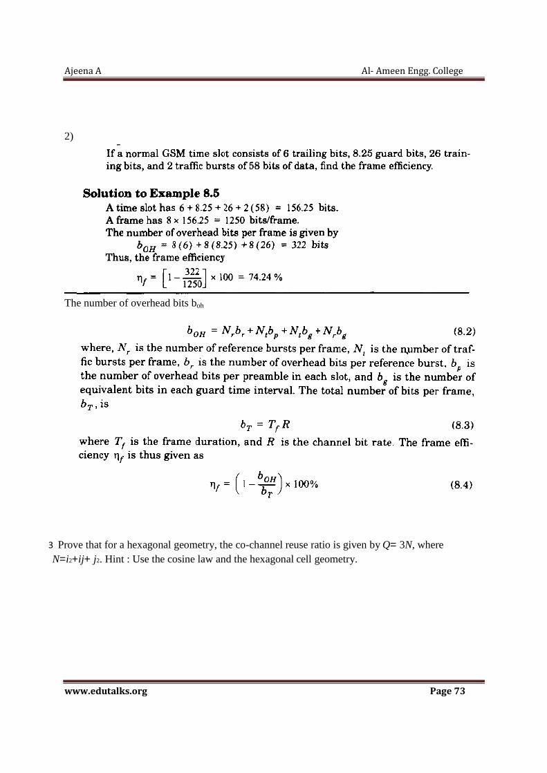
Ajeena A Al- Ameen Engg. College
www.edutalks.org Page 73
2)
The number of overhead bits boh
3 Prove that for a hexagonal geometry, the co-channel reuse ratio is given by Q= 3N, where N=i2+ij+ j2. Hint : Use the cosine law and the hexagonal cell geometry.

Ajeena A Al- Ameen Engg. College
www.edutalks.org Page 74