WIND TURBINE GEARBOXES - · PDF filestudy of any gearbox design ’s reliability to reach...
50
WIND TURBINE GEARBOXES REPORT 2016:279
Transcript of WIND TURBINE GEARBOXES - · PDF filestudy of any gearbox design ’s reliability to reach...

WIND TURBINE GEARBOXESREPORT 2016:279


WIND TURBINE GEARBOXES MAINTENANCE EFFECT ON PRESENT AND FUTURE
GEARBOXES FOR WIND TURBINES
JAN UKONSAARI, VATTENFALL, R&D AND NIKLAS BENNSTEDT, AUTOINVENT
ISBN 978-91-7673-279-3 | © 2016 ENERGIFORSK
Energiforsk AB | Phone: 08-677 25 30 | E-mail: [email protected] | www.energiforsk.se


WIND TURBINE GEARBOXES
5
Foreword
The gearbox is one of the components in wind turbines most prone to cause complications. The costs for maintenance and replacement of gearboxes, along with the costs caused by production losses due to non-functioning gearboxes, constitute a large share of the expenses of operating wind power plants.
The project “Maintenance effect on present and future wind turbine gearboxes” analyzes three types of gearboxes, and how different conditions affect their reliability, that is, the likelihood of reaching a certain life. The results can help identify optimal maintenance methods as well as future gearbox designs, to improve the reliability of wind turbine gearboxes.
“Operation and maintenance” is one of three main research areas in the research program Vindforsk IV. This project has been a part of Vindforsk IV, contributing to it’s objective to provide useful knowledge and innovations to the wind industry. The financiers of Vindforsk IV are The Swedish Energy Agency together with companies in the wind industry, through Energiforsk AB.
This project has been carried out by Jan Ukonsaari (project leader) and Niklas Bennstedt at Vattenfall Research and Development. The reference group has contributed with valuable guidance and comments. Reference group members have been: Hans Sollenberg (OX2), Göran Dalén (Dalen Power), Anders Södergren and Tomas Östberg (Recondoil), Per Anders Östling (Fred Olsen Renewables) Susann Persson (Jämtkraft) and Niklas Bennstedt (Autoinvent).
Stockholm, May 2016
Åsa Elmqvist
Program manager Vindforsk IV

WIND TURBINE GEARBOXES
6
Sammanfattning
Vindkraften ger ett betydande tillskott elenergi och kommer att öka sin andel i framtiden. Förbättrad konkurrenskraft kan erhållas genom att göra vindkrafts-produktionen billigare. Här ses bl.a. en potential att minska totalkostnad för växellådor dvs. minska dess reparationer och utbyten som utgör en stor del av underhålls-kostnaderna. För en slutanvändare är det en utmaning att effektivt minska detta.
I denna studie presenteras ett verktyg som beräknar tillförlitlighet, vilket är sannolikhet att uppnå en viss livslängd, för växellådor med olika mängd information där mer information ger ett mer korrekt resultat. Här används verktyget för att visa på olika faktorers inverkan på tillförlitlighet, såsom oljerenhet (antalet partiklar större än bestämda storlekar i oljan) och oljeviskositet, som kan förändras med åtgärder vid underhåll. Verktyget är även lämpligt att använda för en objektiv bedömning vid val av växellåda till aktuella driftsförhållanden samt lämplighet för förbättrande underhållsåtgärder.
Tillförlitlighet för en typisk 2 MW växellåda med dess ingående planetsteg samt påföljande två parallellsteg (se figur) har utvärderats för åtgärder som att förändra oljerenheten mätt i partikelinnehåll och oljans viskositet som styr oljefilmens tjocklek i lager och kuggar. Även olika belastningsnivåer samt total driftstid på nominell belastning har beräknats för att påvisa inverkan av kapacitetsfaktor för en site. Jämförelse har gjorts med en optimerad version av den typiska växellådan samt en framtida växellåda med ett enklare uppbyggt patenterat växellådskoncept utan planetsteg.
Resultaten visar att oljerenheten är viktig för tillförlitligheten vid nominell belastning motsvarande 20 års livslängd för planetstegen men av mindre betydelse för parallellstegen i de studerade växellådorna (se figur). Speciellt viktigt är att ha god oljerenhet om planetsteget smörjs av oljebadet i växellådan och inte direkt av tillförd filtrerad olja. Motsvarande gäller för oljans viskositet, temperatur och antalet driftstimmar vid hög belastning. Låg viskositet, hög temperatur samt hög produktion påverkar negativt livslängder och ger lägre tillförlitlighet. Antalet reparationer eller växellådsbyten varierar mellan 0,4-1,5 stycken per växellåda under 20 år beroende på
Inkommande axel
Utgående axel
2 Parallellsteg
Planetsteg

7
de undersökta växellådornas driftsförhållanden. Motsvarande är 0,3-1,3 stycken för den optimerade planetväxellådan.
Den framtida växellådan visar på hög tillförlitlighet även vid variationer i driftsförhållanden (se nedre figur) vilket därmed ställer lägre krav på underhållet. Antalet reparationer eller växellådsbyten är uppskattat till 0,15 stycken per växellåda under 20 år oberoende av dess driftsförhållanden. Den höga tillförlitligheten har sin grund i möjliggörandet av en lagerdimensionering för varierande förhållanden samt att antalet viktiga komponenter är färre. I ett planetsteg kan utrymmet för starka lager med lång livslängd i faktiska förhållanden begränsas av kugghjulens dimensioner vilket i så fall ytterligare försämrar tillförlitligheten. Ett faktum för analyserade planetväxellådor.
Denna studie visar exempel på tillförlitlighet för växellådor vid de givna förutsättningarna och ger en inblick i hur specifika växellådor för vindkraft kan undersökas. Metoden eller verktyget kan användas för att studera underhållets betydelse men även en del att ta fram och kontrollera uppfyllnad av relevanta krav vid inköp. Förslag hur detta kan gå till är inkluderat i studien tillsammans med framtida teknik som exempelvis glidlager.
WIND TURBINE GEARBOXES
8
Summary
Wind power provides a significant and increasing portion of the electrical network’s power. Improved competitiveness has led to a decrease in wind power production cost. Furthermore a potential total cost saver can be found for gearboxes by decreasing the number of repairs and exchanges which today stands for a substantial part of the maintenance cost. For an end user it is a challenge to efficiently decrease this cost.
In this study a tool is presented that enables calculation of reliability, which is the probability to reach a certain life, for gearboxes with various amounts of available information. More information will provide for more correct results. Here, the tool is used for calculating the effect on reliability with different factors such as oil cleanliness (number of particles in the oil larger than a certain size) and oil viscosity which can be altered by maintenance measures. The tool is also suitable for an objective judgment in the selection of a gearbox for actual running conditions.
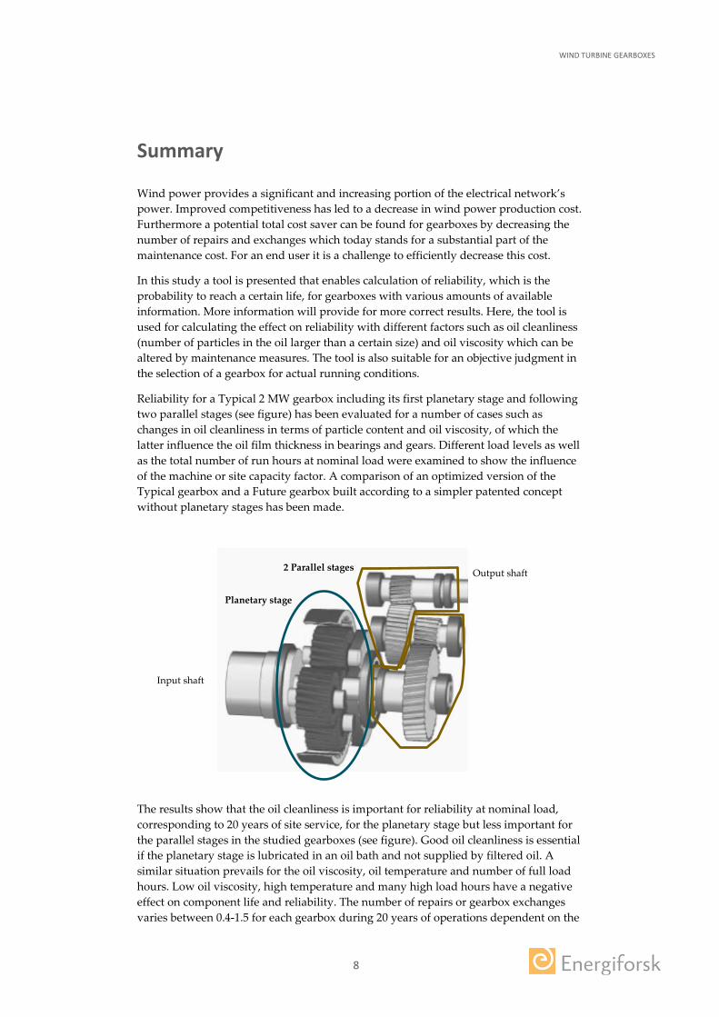
Reliability for a Typical 2 MW gearbox including its first planetary stage and following two parallel stages (see figure) has been evaluated for a number of cases such as changes in oil cleanliness in terms of particle content and oil viscosity, of which the latter influence the oil film thickness in bearings and gears. Different load levels as well as the total number of run hours at nominal load were examined to show the influence of the machine or site capacity factor. A comparison of an optimized version of the Typical gearbox and a Future gearbox built according to a simpler patented concept without planetary stages has been made.
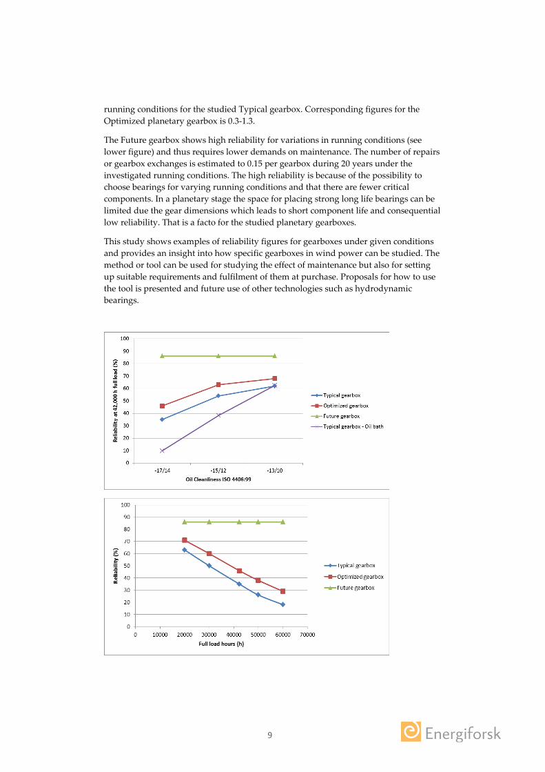
The results show that the oil cleanliness is important for reliability at nominal load, corresponding to 20 years of site service, for the planetary stage but less important for the parallel stages in the studied gearboxes (see figure). Good oil cleanliness is essential if the planetary stage is lubricated in an oil bath and not supplied by filtered oil. A similar situation prevails for the oil viscosity, oil temperature and number of full load hours. Low oil viscosity, high temperature and many high load hours have a negative effect on component life and reliability. The number of repairs or gearbox exchanges varies between 0.4-1.5 for each gearbox during 20 years of operations dependent on the
Input shaft
Output shaft 2 Parallel stages
Planetary stage
9
running conditions for the studied Typical gearbox. Corresponding figures for the Optimized planetary gearbox is 0.3-1.3.
The Future gearbox shows high reliability for variations in running conditions (see lower figure) and thus requires lower demands on maintenance. The number of repairs or gearbox exchanges is estimated to 0.15 per gearbox during 20 years under the investigated running conditions. The high reliability is because of the possibility to choose bearings for varying running conditions and that there are fewer critical components. In a planetary stage the space for placing strong long life bearings can be limited due the gear dimensions which leads to short component life and consequential low reliability. That is a facto for the studied planetary gearboxes.
This study shows examples of reliability figures for gearboxes under given conditions and provides an insight into how specific gearboxes in wind power can be studied. The method or tool can be used for studying the effect of maintenance but also for setting up suitable requirements and fulfilment of them at purchase. Proposals for how to use the tool is presented and future use of other technologies such as hydrodynamic bearings.
WIND TURBINE GEARBOXES
10
List of content
1 Introduction 11 1.1 Technical background 11 1.2 Experience background 12 1.3 Study objective 12 1.4 Definitions of selected words 13 1.5 Nomenclature 15
2 Tool for evaluating gearbox reliability 16 2.1 Required information 17 2.2 Limitations and assumptions for reliability model 18
3 A typical 2 MW gearbox design 19 3.1 Running conditions 20
3.1.1 Load 20 3.1.2 Speed 20 3.1.3 Lubrication 21
3.2 Life of critical components 22 3.2.1 Gears 22 3.2.2 Bearings 22
3.3 Reliability of critical components 23
4 Maintenance effect on life and reliability of a typical gearbox 25 5 An optimized planetary gearbox and a future 2 MW gearbox design 29
5.1 Reliability for the different gearbox designs 30 6 Maintenance effect on life and reliability for the three different gearbox
designs 32 7 Benchmarking wind gearboxes with other industrial applications 36
7.1 Design application factors 36 7.2 Life requirements and reliability 37
8 Suitability discussion for the three gearbox designs in wind applications 38 8.1 Condition monitoring 38 8.2 Lubrication 38 8.3 Weight, size, cost and efficiency 38 8.4 Complexity 39
9 Further use of gearbox reliability tool 40 9.1 further development and Future technologies 40
10 Conclusions 42 11 References 43 12 Appendix 1: Reliability tool details and examples 44
13 Appendix 2 : Gearbox and bearing information 47

WIND TURBINE GEARBOXES
11
1 Introduction
Gearboxes in wind power transform slow speed, high torque wind turbine rotation to higher speed required by the generator, which converts the mechanical power to electricity. Gearbox running conditions are challenging and lifetime expectations are high. Wind power energy production struggles with high costs. The suppliers attempt to offer low cost machines while the end users have high operational costs due in part to gearbox repair and exchanges. Large multi megawatt size, low cost gearboxes that meet life expectation have yet to be observed. This study investigates how maintenance can affect gearbox life of present and future gearboxes by calculating the reliability of today’s typical planetary gearbox design and development possibilities. A reliability tool is presented and tested on the different gearboxes. This tool offers a simple way to perform an objective study of any gearbox design’s reliability to reach expected life.
It is safe to claim that gearbox failures in wind power are considered as a large cost consumer. The mean downtime for failure was in the range of 6-15 days for studied land-based European wind turbines over a 13 year time period with a failure rate of 0.1-0.15 failure/turbine/year [Tavner, 2011, and Windstat Reports 2012]. About 70 % of the gearbox failures are due to bearing failures [Shuangwen, 2013]. A gearbox bearing exchange cost can be from 15 k€ for a simple up-tower replacement to even more than 1 M€ for a larger (+5 MW) gearbox exchange. Off-shore is considered more costly than on-shore. The wind power industry is however still young when machines over 2 MW are considered. The long term experience is limited and the gearboxes which have already failed are considered to be premature failures as opposed to life expectations. It is in the interest of the wind power industry that the production costs are minimized. For gearboxes, the total cost must be considered over the machine’s total life including investment, maintenance, repair and replacements as well as energy efficiency.
1.1 TECHNICAL BACKGROUND
The first commercial serial wind power units used gearboxes originating from other industries. These were conventional parallel stage gearboxes typically with 3 gear stages. The development towards higher power ratings led to larger turbines with higher towers, higher torque and higher gear ratios. The gearboxes became the object of optimization efforts. The planetary gearbox offered a slightly higher power density and lower weight, and most of all, a lower production cost [Hau, 2011].
Manufacturing technology and quality has significantly improved and gear failures have reduced accordingly. Heat treatment, surface finish, tolerance precision and quality control are areas where good progress has been made. The base material quality is still an area where potential improvements can be made.
A new bearing life theory was introduced by SKF in 1989, initiating factors that later on have developed and been included into a general accepted ISO standard [ISO 281:2007]. Bearing quality has improved by introducing clean steel (ex. Explorer “SKF Explorer” or “NSK SuperTough”) while the latest trend is to select bearings with different material treatments such as case hardening or through hardening and various

WIND TURBINE GEARBOXES
12
surface layers such as black oxidization. The effect of the latest trends has not been fully observed but they are not reflected in common bearing life theories. The purpose of this is to reduce the failure modes commonly seen for certain designs under certain conditions causing premature failures in wind power. Typical premature failures include skidding/smearing of the high speed shaft cylindrical roller bearings and white etching cracks (WEC), that can appear as axial cracks. WEC has led to significant investigations and research with different causes proposed [Stadler, 2013, Ruellan, 2014]. Reading material on findings makes it somewhat clear that load is the common factor in all studied cases of WEC , where the formation of WECs are triggered by a “catalyst” such as lubricant additives, current, load dynamics, overload, water and oxygen and the material has more of less strength against WEC formation. The proposed solution for avoiding WEC is sometimes on component level [Budny, 2014] and on system level [Stadler, 2014].
The wind industry has always had frequent discussions on gearbox reliability. Now the discussions are moving from component reliability towards system reliability of several components from their calculated life. The system reliability approach is commonly used in other industries where reliability is essential [Zaretsky, 2007].
1.2 EXPERIENCE BACKGROUND
A common understanding is that bearing failure is most frequently what leads to gearbox failure but root cause of failure is often not verified. Real application experience failures have led to thorough root cause investigations in which several factors have been studied such as operations, yaw, wind load and transport. These factors were seldom found as the root cause or regarded as abnormal conditions. End users have also experienced different magnitudes of problems at different wind sites with identical machine types (or updated versions). The problems seem to escalate at high capacity factor sites, where high load prevails over a longer period of time. Root causes of failure for gears are more likely to be found, and often identified as material quality, surface grinding or hardening process issues. A broken tooth is a somewhat common discovery.
The suppliers’ experiences of gearbox function vary dramatically from the end user experiences. Problems are sometimes admitted but presented track records of good function can be very convincing for purchasers. Gearbox review processes are being performed but it is rare that a reliability control in the sense of fundamental life can be made due to a lack of required input information.
Final conclusions from large machine gearbox failures are too early to state. The cost of unscheduled repair differs from site to site and the machines have run for varying and limited amounts of time. There are also numerous gearbox designs in terms of ratios and design philosophies. For larger machines the concepts of direct drive (no gearbox), high speed generator (≥three stage gearbox) or medium speed generator (one or two stage gearbox) are still competing for market share. The industry has long term experience of smaller machines below 1 MW with a number of examples of good performance.
1.3 STUDY OBJECTIVE
Current situation of high gearbox total life cost should encourage the whole industry and especially the end users to be interested in improving the situation. The quickest

WIND TURBINE GEARBOXES
13
way to see effects of improvements is to perform life extending efforts in maintenance. Basically there are three possibilities for adjustment; oil properties – viscosity, oil treatment, and load. The effect of these maintenance efforts is investigated here by using a reliability tool applied to a current design, an improved current design and a future design. The study purpose is to:
• Introduce a reliability tool simple enough to quickly estimate reliability of any gearbox with limited available information. A tool where the result accuracy increases with more detailed information, which likely will lead to better information flow between the supplier and buyer.
• Use the tool to show examples of
o The reliability effect of improving maintenance efforts for gearboxes with different designs.
o The effect of wind load on reliability.
o Fundamentals of different designs.
1.4 DEFINITIONS OF SELECTED WORDS
Application factor: A factor added to load for dimensioning parameters in a design, normally based on long term experience and knowledge
Bearing arrangement: A bearing configuration – e.g. multiple bearings for a shaft support.
Capacity factor: Ratio of actual power output to possible power output.
Component: A solitary unit that could be a part in a system.
Critical component: A component that is vital for a function.
Dynamic factor: A factor added to the dimensioning parameters in a design, taking known (or assumed) dynamic conditions into consideration.
Elasto Hydrodynamic Lubrication, EHL: Hydrodynamic function of bearing where the surface pressure is high enough to significantly deform the elastic contact surfaces. Separating oil/fluid film is built up by motion between two converging surfaces. The film thickness is relatively low compared to HL but the contact pressure is higher. EHL is typical for rolling contacts.
Failure probability: Chance of failure before an estimated life for a component or a system during a given period under specific operating conditions
Gear stage: A portion (stage) in a gearbox of mating gears typically also including its shafts and bearings.
Gearbox: A system that transmits mechanical work and usually modulates torque/speed, comprising of among other components – gear wheels, bearings and shafts.
Hydrodynamic lubrication, HL: Hydrodynamic function of bearing where the surface separating oil/fluid film is built up by relative motion between two converging

WIND TURBINE GEARBOXES
14
surfaces. The film thickness is relatively large compared to EHL. HL is typical for sliding contacts.
Improving maintenance: An action that increases a system’s (component) reliability and or its expected operating life.
Life: Absolute operating life expectancy for a single component or a system, often expressed in years, hours, revolutions, cycles, etc.
Maintenance: An action that maintains a system’s (component) status during its operating life.
Mechanical input: The mechanical power that actually drives the gearbox.
Nominal input: Rated power driving the gearbox.
Oil cleanliness according to ISO 4406: A standard to classify size and quantity of specific particles in an oil.
Oil viscosity: A measure of internal resistance of an oil to flow.
Parallel stage: A gear stage configuration consisting of cylindrical gears with parallel shafts.
Planetary stage: A gear stage configuration consisting of an annulus gear, planetary gears and a sun gear.
Reliability tool: The reliability tool in this study is a method to calculate reliability.
Reliability: Probability or chance of relative life for a component or a system during a given period under specific operating conditions (Reliability = 1 – Failure probability).
Safety factor: A factor added to the dimensioning parameters in a design, to give a certain margin of safety for unknown conditions.
System: A unit consisting of components or multiple systems, e.g. a gearbox, an engine or a vehicle.

WIND TURBINE GEARBOXES
15
1.5 NOMENCLATURE
a1 Life modification factor for reliability [-]
Lnm Bearing life [million revolutions]
Lnmh Bearing life [hours]
Κ Viscosity ratio [-]
eC Contamination factor [-]
a ISO Life modification factor [-]
L10 Basic rating life [million revolutions]
Cu Fatigue load limit [N]
R Reliability [-]
P, Pr Dynamic equivalent load [N]
SSR Strict series reliability [-]
n Number of components [-]
T Number of years [-]
i, j, t Index for components of years [-]
F Failure probability [-]
VI Viscosity-temperature index [-]
Beta Gear helix angle [°]
fd Dynamic load factor [-]
fk Internal gear deviation factor [-]
f Dynamic factor [-]

WIND TURBINE GEARBOXES
16
2 Tool for evaluating gearbox reliability
The tool or method below is based on a “strict series reliability” approach and it is not new. This approach has been used earlier to calculate system reliability and in wind power it has been presented at seminars [Budny, 2015] and is becoming more and more common. It is also similar, and in some ways identical to the origins from other industry application reliability analyses [Zaretzky, 2007].
This method for evaluating gearbox reliability address the design life of critical components, in this study gears and bearings. The steps are to estimate
1. Component life according to bearing life standard ISO 281:2007
𝐿𝐿𝑛𝑛𝑛𝑛 = 𝑎𝑎1𝑎𝑎𝐼𝐼𝐼𝐼𝐼𝐼𝐿𝐿10, 𝑎𝑎𝐼𝐼𝐼𝐼𝐼𝐼 = 𝑓𝑓 �𝑒𝑒𝐶𝐶𝐶𝐶𝑢𝑢𝐿𝐿10𝑃𝑃
,Κ�
2. Component reliability to reach a certain life
a. 𝑅𝑅 = 𝑒𝑒�ln(100)−( 𝑎𝑎13.85)10/6�
3. System reliability using a strict series approach where every gear and bearing is essential for the gearbox
a. 𝑅𝑅𝐼𝐼𝐼𝐼𝑆𝑆,𝑗𝑗 = ∏ 𝑅𝑅𝑖𝑖,𝑗𝑗𝑛𝑛,𝑇𝑇1,1
4. Failed component distribution
a. Subtract reliability from present year to foregoing year and multiply with the number of gearboxes.
b. Include repaired and re-failed gearboxes in the distribution.
5. Number of repairs or gearbox exchanges during expected machine life, approximate figures can be seen in Table 1.
a. Summarize the number of failed gearboxes
b. Include the repaired and re-failed gearboxes in the summary.
6. Failure probability before any given year j+t if the component/system has survived j number of years.
a. 𝐹𝐹(𝑇𝑇) = 1 − 𝑆𝑆𝑗𝑗+𝑡𝑡𝑆𝑆𝑗𝑗
The method (pt 1-3 above) is more extensively described in Appendix 1, including a few examples.

WIND TURBINE GEARBOXES
17
Table 1. System reliability figure and approximate number of consequential gearbox exchanges or repairs.
Reliability 𝑹𝑹𝑺𝑺𝑺𝑺𝑹𝑹,𝟐𝟐𝟐𝟐 (%)
#Gearbox exchanges/repairs per gearbox during 20 years
95 0.05
90 0.11
80 0.22
70 0.32
60 0.45
50 0.59
40 0.72
30 0.89
20 1.09
10 1,35
5 1.54
1 1.85
2.1 REQUIRED INFORMATION
The model enables estimation of reliability with limited information but the accuracy improves with more detailed information. There are basically two ways of calculating the total reliability, with (pt. 2 below) or without bearing life calculation (pt. 1 below).
1. Reliability according to recommended component requirements
a. Number of gear wheels, R = 0.99 assumed
b. Number of bearings, R = 0.90 assumed
2. Reliability in a more “fair” way can be done with different options of information pt. a-n or pt. o-t below
a. Mechanical input, kW
b. Input speed, rpm
c. Full load duration
d. Oil viscosity, ISO VG and VI or viscosity @40°C and @100°C or viscosity at running temperature
e. Cleanliness class of oil
f. Running temperature of oil
g. Bearing position including Bearing designation
h. Bearing arrangement at position (single, double, triple etc.)
i. Gear type/gear stage (planetary, parallel)
j. Driven gear in first stage (ex. Planet carrier)
k. Nr of planet wheels

WIND TURBINE GEARBOXES
18
l. Gear module/gear stage or shaft distance
m. Nr of teeth for each gear wheel (z1, z2, (z3))
n. Gear tooth helix angle, Beta (°)
Or information as follows – if gear parameters are unknown
o. Mechanical input, kW
p. Input speed, rpm
q. Full load duration
r. Oil viscosity, ISO VG and VI or viscosity @40°C and @100°C or viscosity at running temperature
s. Cleanliness class of oil
t. Running temperature of oil
u. Bearing position including Bearing designation
v. Bearing arrangement at position (single, double, triple etc.)
w. Bearing load at position (axial, radial load)
x. Bearing speed/position
2.2 LIMITATIONS AND ASSUMPTIONS FOR RELIABILITY MODEL
The model is objective and considers only failure modes that are included in current ISO 281 bearing life time calculations. Other failure modes are not included such as skidding/smearing, white etching cracks (WECs), corrosion, poor oil quality, water content, electrical current or misalignment.
The reliability results are sensitive to the reliability figure and number of components. Due to the long life expectations and limitations of failure modes in the life calculations the maximum reliability is set to 0.99. This means that even a bearing or gear component with infinite fatigue life will affect the reliability. Simpler designs with fewer components with long lives give higher values. The maximum limit can be set to higher value, however that can change the preference of different designs.

WIND TURBINE GEARBOXES
19
3 A typical 2 MW gearbox design
A typical gearbox design for a 2 MW machine has one planetary stage and two parallel stages (Figure 1). The planetary stage has two planetary carrier bearings and 9 cylindrical planetary bearings (Figure 2). The two parallel stages have in total three shafts where each shaft has one cylindrical roller bearing and two tapered roller bearings for shaft axial load and guiding. The gearbox has in total 20 bearings and 9 gear wheels. Details of the bearings can be found in Appendix 2. The listed bearings are standard bearings that could be utilized in such gearboxes, hence, the size enables fitting in the gearbox and it is likely that the dynamic load carrying capacities are similar to those found in real applications.
Figure 1. Schematics of a typical 2 MW gearbox design.
Figure 2. Planetary stage and wheel with three cylindrical roller bearings. Input shaft rotates the planetary carrier and planet wheels, the sun wheel is the planetary stage output to intermediate stage.
Input shaft
Input shaft
Output shaft
Parallel stages Parallel stages
Planetarystage
Output shaft Planetarystage

WIND TURBINE GEARBOXES
20
3.1 RUNNING CONDITIONS
The running conditions are the most important details for design, life and reliability estimations. Input rated power is shown below (Table 2), which serves as the baseline condition in this study. The effect of maintenance is demonstrated by adjusting the parameters that that can realistically be changed by a machine owner, these are oil selection (properties) and oil treatment.
Table 2. Basic running conditions for the calculations.
Parameter Value
Power (MW) 2
Input torque (kNm), Rated power input *1.1 1400
Input speed (rpm) 15
Total gear ratio ~108
Oil viscosity (cSt) 320
Oil temperature 65
Oil cleanliness (ISO 4406-99, 4/6/14 mm) -/17/14
3.1.1 Load
Load is the most important factor for selecting required component strength. In wind power the load into the gearbox is primarily torque from the turbine which is the only load considered here. Wind variations will naturally become dynamic loads. However, in this study, the input load for the gearbox is estimated from an example given in IEC standards (Table 3). The load is increased by an additional 10 % of rated generator power to represent the mechanical turbine shaft input torque. Gearbox input torque is determined with input speed and output power multiplied by 1.1.
Load cases in Table 3 have been input into a gearbox geometric model including approximate gear data to calculate bearing forces under different loading conditions. In Ch 2.1 and Appendix 2 some basic data is provided that enables calculation of component loads which will lead to results that in most cases are in the range of the results from gearbox suppliers, and enable further analysis of reliability. Shaft position has been neglected, as their influence on the results is minor. Component load under a certain power output can also be received from the supplier.
Table 3. Load cases for base line calculations.
Run time
Capacity factor
Load case
42226 23% 100%
59570 17% 50%
58900 4% 10%
Sum 160696 44%
3.1.2 Speed
An optimal wind turbine rotational speed is a balance between wind characteristics, efficiency, sound emissions, erosion and blade size. Larger turbines generally rotate slowly with high torque. Typical turbine input shaft rotational speed for a 2 MW machine is between 14 and 20 rpm. The speed for all the gearbox bearings is calculated using the gear ratios .

WIND TURBINE GEARBOXES
21
3.1.3 Lubrication
Mineral oil and different synthetic oils such as poly-alfa-olefine (PAO), poly-alkylene-glycole (PAG) and esters are common lubricants in gearboxes. The fluid properties should preferably suit the entire gearbox. The most important factors are the viscosity and the cleanliness. Other factors are not represented in normal bearing life theories.
Viscosity
The viscosity of the lubricant is important to ensure sufficient surface separating contact oil film, higher viscosity leads to thicker oil film formation. Viscosity is dependent on operating temperature. Mineral oils and synthetic oils normally have different temperature-viscosity coefficients. ISO-VG is a normal standard to state viscosity at 40°C. A viscosity of 320 cSt with a synthetic PAO is common in the typical 2 MW gearbox. At 65°C a viscosity of 87 cSt as a consequence of viscosity index 95 is assumed here.
In bearing calculations the kappa Κ-value indicates the relation between actual and required viscosity to achieve an adequate separating oil film. Κ-value below 1 means that the contact surfaces are not adequately separated and an oil containing extreme pressure additives is recommended, a type of additive that can save a bearing from overload surface damages but also normally reduces long term life. For Κ-values > 10 the bearing can have running conditions that go outside the life theory, the estimated life can be difficult to achieve in reality. Optimal conditions can be found for Κ-values 1-2.5 or very good up to ~5.
A variation between different oil viscosities are studied as well as different operating temperatures.
Cleanliness
ISO 4406:99 is the most common way to characterize the particulate content. Particle contamination is defined by numbers denoting the number of particles per ml fluid for the sizes of particles: particles defined as larger than 4, 6 and 14 μm size respectively. Recommendations are to never exceed ISO -/17/14 during operation [Errichello, 2002]. This means that there can be up to 1300 particles > 6 µm and 160 particles > 14 µm in the oil (Table 4). The value for 4 µm particle size is often not included due to lack of evidential studies showing small particle significant effect on gearbox component life. An earlier study for Vindforsk gives more insight into the subject [Ukonsaari, 2012]. Here the effect of cleanliness is studied for reliability.
Pressure fed filtered oil lubrication is the basic assumption in this study, a situation that is beneficial compared to oil bath lubrication. The typical 2 MW gearbox planetary stage can have both oil bath and pressure fed lubrication.
This study covers cleanliness values between -/17/14 to -/13/10.

WIND TURBINE GEARBOXES
22
Table 4. ISO 4406 codes in Number of particles per ml fluid.
3.2 LIFE OF CRITICAL COMPONENTS
Sufficient life is essential to meet wind power expectations of at least 20 year life times.
3.2.1 Gears
Gears can be modified in numerous ways with each modification affecting the life results. Design of gears is also the gear manufacturer’s specialty. Calculation of gear life cannot be performed in this study with good accuracy. However, estimating gear life according to standard ISO 6336 indicates that there is a challenge to achieve expected life with a reliability of 0.99. A safety factor of 1.25 against surface fatigue and 1.53 on tooth bending fatigue is recommended according to IEC standards in wind power applications. The authors of this study can mention that standard tooth profiles with a strong gear material quality and fine surfaces do not provide for the expected reliability. The gear manufacturers’ gears seem to have significantly better strength than the standard gear. Otherwise the recommended requirements are not fulfilled.
There are 9 gears in the typical 2 MW gearbox. Life is assumed to pass the recommended requirements.
3.2.2 Bearings
Bearing life can be calculated with supplier models or ISO 281:2007. All models give results close to the ISO standard so life in this study is calculated using ISO 281. Bearings that fit into the design have been chosen from standard bearing catalogues. In a real gearbox specially made bearings can be chosen. The difference between the chosen stock bearings and actual real bearings in a typical gearbox should be small and the life results should be close enough to show the range of life.

WIND TURBINE GEARBOXES
23
For the typical gearbox the bearing life of the parallel stages becomes very high, in many cases over 1 Million hours. For the planetary stage the life figures are significantly lower, in many cases bearings barely fulfil the required lifetime to achieve a reliability over 0.9 for each bearing, in other cases they do not fulfil the required life.
3.3 RELIABILITY OF CRITICAL COMPONENTS
To simplify the approach of this study the gear reliability is set to 0.99. For the bearings the reliability is estimated by comparing the load described in Ch 3.1.1 to the resulting life from calculations. The maximum reliability figure for a bearing is set to 0.99. Different site capacity factors are simulated by adding a number of alternative amounts of full load hours (Table 5) . The reliability method is briefly described in Ch 2 and more detailed in Appendix 1.
The reliability shows that it is the planetary stage (Stage I in Figure 3) that is sensitive to the number of full load hours or ~capacity factors (Figure 4). The parallel stages (Stage II and III) have higher reliability compared to the planetary stage.
Table 5. Load cases for reliability calculations, baseline conditions in bold.
Run time
Capacity factor
Load case
Capacity factor cumulative (sum of 10, 50 and respective 100 %)
60000 34% 100% 55%
50000 28% 100% 49%
42226 23% 100% 44%
30000 17% 100% 38%
20000 11% 100% 32%
59570 17% 50% Added to
58900 4% 10% above 100 % load
Figure 3. Gearbox stage definitions for Typical gearbox.
Input shaft
Stage I 11 bearings 5 gears
Output shaft
Stage II 4 bearings 2 gears
Stage III 5 bearings 2 gears

WIND TURBINE GEARBOXES
24
Figure 4. Reliability for different full load hours corresponding to capacity factor (Table 5). Note: Kappa is low for Stage I and high for Stage III.

WIND TURBINE GEARBOXES
25
4 Maintenance effect on life and reliability of a typical gearbox
Three oil cleanliness levels were studied as well as filtered oil supply and oil bath lubrication. For all bearings under all load conditions a cleaner oil gives longer bearing life. But, it is only for the full load that a cleaner oil improves the reliability for the planetary stage (Stage I, Figure 5 and 6). The estimated life for the other stages are sufficient for maintaining constant reliability for the most contaminated oil analysed here. Oil bath lubrication of the planetary stage (Stage I) gives significantly lower reliability compared to filtered oil supply. This gearbox design with oil bath lubrication should benefit from having an off-line filter to provide for generally good bulk oil cleanliness.
At full load an increased oil viscosity provides significantly higher reliability (Figure 7-8). For the parallel stages (II and III) lower viscosity is suitable and for the high speed stage (III) there is a clear benefit of lowering the Κ-value to below 10. For the planetary stage a higher viscosity is recommended for increasing the Κ-value to > 1. At lower load the reliability is not affected by viscosity except for the planetary stage I at 50 % load (Figure 8 and 9)
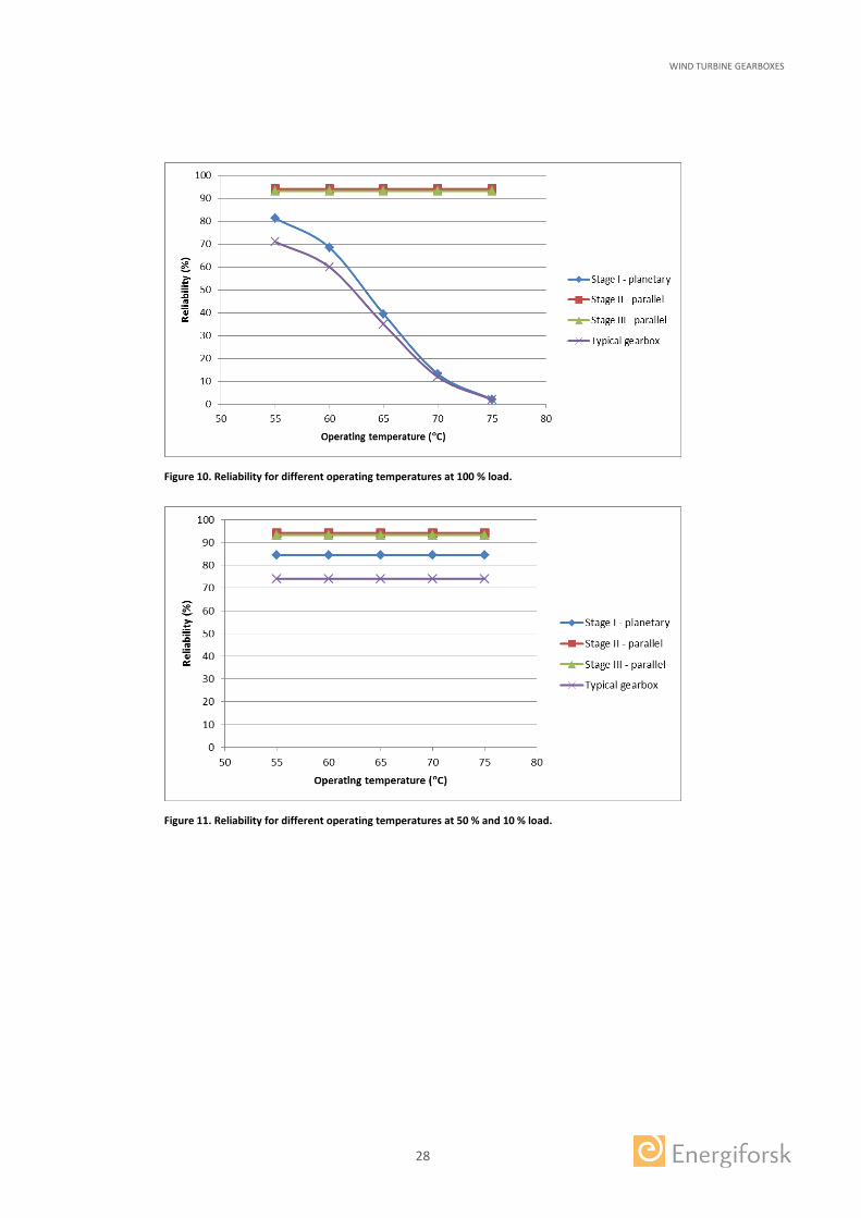
Increased operating temperature gives lower reliability, due to consequential decrease in oil viscosity, for the planetary stage at nominal full load (I, Figure 10-11). Temperature affects the oil viscosity which has an effect on planetary bearing life and reliability. The other stages’ life or reliability are not affected.
Figure 5. Reliability for different oil cleanliness levels at 100 % load. Note: Kappa is low for Stage I and high for Stage III. Type of oil supply to stage II or III shows impact on stage component lives but not on stage reliability.

WIND TURBINE GEARBOXES
26
Figure 6. Reliability for different oil cleanliness levels at 50 % and 10 % load. Note: Kappa is low for Stage I and high for Stage III. Type of oil supply shows impact on component lives but not on stage or gearbox reliability.
Figure 7. Reliability for different oil viscosity at 100 % load.

WIND TURBINE GEARBOXES
27
Figure 8. Reliability for different oil viscosity at 50 % load.
Figure 9. Reliability for different oil viscosity at 10 % load.
WIND TURBINE GEARBOXES
28
Figure 10. Reliability for different operating temperatures at 100 % load.
Figure 11. Reliability for different operating temperatures at 50 % and 10 % load.

WIND TURBINE GEARBOXES
29
5 An optimized planetary gearbox and a future 2 MW gearbox design
Gearboxes have been manufactured for a long time. Improvements and new solutions can be found through history. The reasons for choosing certain gearbox technologies including bearing arrangements can have various origins. It is easy to accept the present way of doing things such as using the complex planetary gearboxes. A gearbox technology that from the beginning in wind power was a bit exclusive and exotic is currently called the ‘conventional planetary gearbox’. The complexity of the planetary stage has led to significant improvement in overall gearbox manufacturing quality. Material treatment, tolerance precision and surface finish today is excellent at serious gearbox suppliers within wind power.
The current gearbox drive train technology in wind power is the benchmark which all upcoming technologies must compete with. A reliable gearbox is essential and improving the reliability is effectively done by reducing the number of critical components and increasing each component’s life. The “the present way of doing things” has been challenged here by letting the simplest gearbox design found until now be compared with the Typical gearbox and an Optimized planetary stage gearbox. The simplest gearbox, here called Future gearbox, is very interesting to evaluate further. In wind industry the focus on quality has led to overall manufacturing improvements (experience, methods and production skills) which applied on such simplified gearbox (patent from 2012) can become a highly competitive reliable alternative to the planetary gearbox types and also to the parallel shaft types . Optimized and Future gearbox designs are realistic and awaits initiative for realization.
The Typical Planetary 2 MW gearbox has 20 bearings and 9 gear wheels. The Optimized planetary gearbox has 14 bearings and 9 gears (Figure 12). The typical gearbox has been optimized by reducing the number of critical components in the gearbox. For the planetary stage three bearings have been removed, one from each planet wheel (Figure 2 vs. Figure 13). One bearing has also been removed from each parallel shaft. Appendix 2 provides more detailed information. The Optimized planetary gearbox planetary stage’s size is unchanged. Increasing the size should enable room for larger bearings with higher load capacity but this might not be possible for a retrofit exchange in an existing machine without substantial modifications.
The Future 2 MW gearbox has 9 bearings and 6 gear wheels (Figure 12) in a parallel shaft layout. Each shaft has two bearings except one that has three (Figure 12 and 13). The reliability and maintenance effect on reliability of the three designs are compared here. Appendix 2 provides more detailed information.
The difference between a standard parallel shaft gearbox and the Future gearbox is the axial force eliminating arrangement [Patent WO 2012/050514 A1]. This is done by having two concentric shafts. The helix angles fully cancel out axial forces and the gearbox casing is only exposed to radial bearing forces. In this study the Future gearbox is presented as a concentric in- and output shaft design. It is also possible to arrange a shaft offset for the out- and input that can enable more retrofit exchanges of present designs. It is also well suited for future implementation of hydrodynamic bearings.

WIND TURBINE GEARBOXES
30
Figure 12. Optimized planetary design (left) and Future gearbox (right).
Figure 13. Planetary wheel two bearing setup in the optimized gearbox (left) and the a future gearbox (right) example of stage and bearing arrangement.
5.1 RELIABILITY FOR THE DIFFERENT GEARBOX DESIGNS
The conditions for the life estimations are identical to those described in Ch. 3.2. Reliability of the different designs for different load durations described in Ch 3.1.1 show that the Optimized version of the planetary gearbox has increased reliability compared to the typical (Figure 15). The Future gearbox is not sensitive to the number of full load hours with significantly higher reliability. The number of parts in the Optimal and Future gear stages differ compared to the Typical gearbox stages (Figure 14 and Figure 3).

WIND TURBINE GEARBOXES
31
Figure 14. Gearbox stage definitions for Optimized (left) and Future gearbox (right).
Figure 15. Reliability for different full load hours corresponding to capacity factor (Table 5). Note: Kappa is low for Stage I and high for Stage III.
Stage I 8 bearings 5 gears
Stage II 3 bearings 2 gears
Stage III 3 bearings 2 gears
Stage I 3 bearings 2 gears
Stage II 3 bearings 2 gears
Stage III 4 bearings 2 gears

WIND TURBINE GEARBOXES
32
6 Maintenance effect on life and reliability for the three different gearbox designs
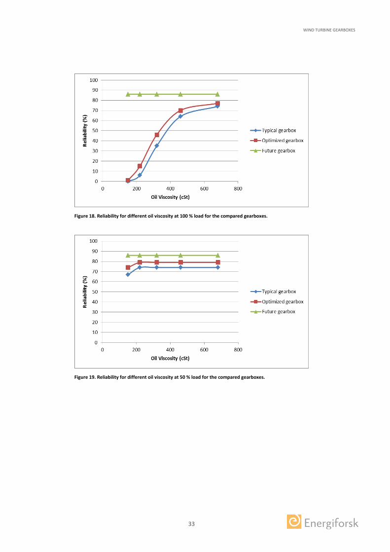
Improving the oil cleanliness, changing the oil viscosity by changing oil or temperature improves the reliability in the Typical and Optimal gearbox type (Figure 16-Figure 22) at full load. At 50 % load level only a minor effect can be seen for low oil viscosity. For all other situations including the Future gearbox type there is no reliability effect on typical maintenance improvements. Of course the improved maintenance will affect component life, but the reliability will not change because it has been limited to a maximum of 99 % for each component in this study.
Figure 16. Reliability for different oil cleanliness levels at 100 % load for the compared gearboxes.
Figure 17. Reliability for different oil cleanliness levels at 50 % and 10 % load for the compared gearboxes.
WIND TURBINE GEARBOXES
33
Figure 18. Reliability for different oil viscosity at 100 % load for the compared gearboxes.
Figure 19. Reliability for different oil viscosity at 50 % load for the compared gearboxes.

WIND TURBINE GEARBOXES
34
Figure 20. Reliability for different oil viscosity at 10 % load for the compared gearboxes.
Figure 21. Reliability for different operating temperatures at 100 % load for the compared gearboxes.

WIND TURBINE GEARBOXES
35
Figure 22. Reliability for different operating temperatures at 50 % and 10 % load for the compared gearboxes.

WIND TURBINE GEARBOXES
36
7 Benchmarking wind gearboxes with other industrial applications
In other industrial applications there are different traditions of building gearboxes. Application experience can be found in tables for how to compensate load for the running conditions, sometimes called service factor, application factor (operating factor) or dynamic factor. Factors for wind applications have not generally found their way into the gearboxes regarding bearing life calculations [Hau, 2013].
7.1 DESIGN APPLICATION FACTORS
By applying application factors from other industrial application on the three designs of the wind turbine gearbox a benchmarking with other industries can be made. The wind power drivetrain has a turbine from which the load is not perfectly uniform. However, the turbine characteristic load is left out of the comparison here. The drivetrain has a gearbox and manufacturing of gears is not perfect. Due to this there is an internal gear deviation factor of fk = 1.07. Manufacturing precision has improved in recent years and even the bearing manufacturer doubts that this factor is correct and it could potentially be neglected. Here, it is included. The driven machine here is a generator, which can be regarded as an electrical machine. A general dynamic factor for an electrical type of driven machine is fd = 1.1 is included here. In total this leads to a total dynamic factor multiplied on the load as f = 1.07*1.1 ≅ 1.18, this can also be called an application factor. A factor of 1.18 is rather low compared to AGMA recommendations of minimum 1.4 for a generator as the driven machine under continuous 24/7 operation.
Implementing this factor on the mechanical load results in significantly worse reliability figures at loads above 50 % for the Typical- and Optimized Gearbox (Figure 23), from 35 % to 5 % for the Typical Gearbox. The future gearbox is un-affected by the implementation of the higher load.
In the planetary stage the planetary bearing inner ring is only loaded on one side and the outer ring rotates, a fixed point inner ring load. Earlier there was a “rotational” factor set to 1.4 [Palmgren, 1943] for stationary inner rings. Investigations and tests showed that this factor was too conservative and was changed to 1.2 in an updated version [Palmgren, 1959] but claimed that a factor of 1.05 was more correct. Testing has not been significant enough to verify the impact on the rotational situation (load). In bearing life standard ISO 2007:281 there are no rotational factors included. However, the fact still remains that an area of the inner ring will be exposed to ~5 times more high load cycles compared to the outer ring. Many failures of the bearing inner rings of the planetary stage have been observed.
The factors mentioned above are not safety factors, they are based on experience of how the load characteristics should be translated into load for bearing life calculations. A safety factor provides a margin against the unknown and should be implemented on top of this.

WIND TURBINE GEARBOXES
37
Figure 23. Typical 2 MW gearbox calculated with internal dynamic factor fk =1.07, external dynamic driven load factor fd = 1.10 (total factor 1.18). Factors are multiplied with mechanical input load.
7.2 LIFE REQUIREMENTS AND RELIABILITY
Wind power gearboxes have high expectations of life compared to other industries. The accepted requirements in general standards are too low for the individual components to achieve a high reliability to reach expected system life.
The Typical 2 MW wind turbine gearbox would not have been rated to 2 MW in many other industrial applications, at least not with the current goal of 20 years of life. It is more likely that this gearbox would have been rated at around 1 MW. This is based on the reliability to reach expected life. However, reliability is not fully considered in all applications but crucial for some such as aerospace. High demands can also be found in marine applications.

WIND TURBINE GEARBOXES
38
8 Suitability discussion for the three gearbox designs in wind applications
The three studied gearboxes have shown significantly different reliability figures to reach expected life. There are more factors than reliability that can be discussed regarding suitability for wind turbine application gearboxes discussed here below. Reading the following discussion should further encourage the discussion of re-evaluating simpler designs for wind turbine gearboxes.
8.1 CONDITION MONITORING
Simple condition monitoring (CM) will both lower the cost and time to find faults to enable better planning of unscheduled repairs. Detection of bearing faults in the planetary stage is a challenge, knowhow and experience in this field is growing. A future 2 MW design without a planetary stage simplifies the CM because the bearing is seated in the sensor structure. A straighter signal path provides for stronger and clearer fault signals while reduction of the number of identical components reduces the risk of signal interference.
8.2 LUBRICATION
Lubrication of critical components is important for ensuring their function. For a planetary stage an arrangement of swivel to rotating system is necessary to provide the bearings with filtered clean oil, other more sophisticated solutions are possible. Many gearboxes at 2 MW size are still oil bath lubricated for the planetary stage. This reduces the control of oil quality into the critical contacts. For the future 2 MW gearbox and the parallel stages filtered oil supply is simpler to arrange.
8.3 WEIGHT, SIZE, COST AND EFFICIENCY
Comparing the three designs becomes foremost a comparison between the first planetary stage and the first parallel stage, however there are more things to compare. A comparison has been made by [Hau, 2013] comparing ship gearboxes to wind turbine gearboxes at 2.5 MW with a service factor 1.6 showed that the weight, size and cost differs significantly between planetary and parallel configurations (1. and 2. In Table 6). Comparison of the Typical 2 MW gearbox here to the Future 2 MW gearbox has quite similar mass, size and cost (3. and 4. inTable 6). Another general comparison [http://www.mitcalc.com/] between parallel stage and planet stage indicate very small differences of power density, weight power and efficiency (Table 7).
Another weight saving option could actually be to have the Future 2 MW gearbox in a welded housing. Such housings are normally avoided as they are susceptible to case cracking and subsequent oil leakage however this can be enabled by utilizing an axial force elimination design [Patent WO 2012/050514 A1].

WIND TURBINE GEARBOXES
39
Table 6. Weight size and cost comparison of different configurations.
Configuration Power rating (kW)
Service factor
Mass (tons) Size
Relative cost %
1. Two planetary One parallel 2500 1.6 17
130
2. Three parallel stages, from Marine appl.
2500 1.6 77
164
3. Typical gearbox 2000 1.0 15
100
4. Future gearbox 2000 1.0 15
100
Table 7. Comparison for selection of parallel and planetary stage transmission.
Transmission type Power optimum (kw)
Power extreme (kw)
Efficiency (%) Developed volume power (dm3/kW)
Weight Power (kg/kW)
Spur gearing 0.12-3000 65000 97-99 0.6-0.2 1.8-0.4
Spur gearing of planets. 50-2000 35000 98-99.5 0.4-0.15 1.8-0.2
8.4 COMPLEXITY
Considering the above discussed subjects in relation to the planetary stage design it becomes clear that a complexity and the number of components are important factors in improving reliability under varying loads. A more complex design has many more details that can fail. A simple design with few components such as the Future 2 MW gearbox should have an advantage. A drawback of the simpler design is the difficulty of manufacturing the first bull gear. However manufacture of the first bull gear is similar to that of the planetary ring gear which has a long history of high quality manufacturing.

WIND TURBINE GEARBOXES
40
9 Further use of gearbox reliability tool
Implementation of the presented systematic calculation method (tool) and the results of reliability can be used in several ways. The following are some proposals:
1) Calculate maintenance effect on present and future gearboxes:
a) Calculate the reliability of the gearboxes under exposed wind conditions or nominal power to reach a certain life to figure out what can be expected in terms of life and repair. To implement an equivalent load containing several load levels must be done carefully because it can lead to inaccurate results when fatigue is evaluated. Special attention should be on high load.
b) Investigate measures in maintenance to improve the reliability
c) Investigate reliability sensitivity of load level by multiplying dynamic factors on nominal load to learn how the gearbox is designed regarding load strength
2) Set requirements for future gearboxes by learning about the situation of present gearboxes, this can include:
a) A dynamic factor to be used on nominal load
b) A minimum gearbox reliability under a certain load conditions
c) Information on how to calculate and evaluate reliability
d) Control the gearboxes according to proposal in 1) a-c above.
e) If the reliability fulfils the requirements, begin reviewing the bearing arrangement for low load conditions and general quality
3) Apply the new requirements for reliability and adjust requirements to future experience:
a) Review the requirements every time before using them
b) Stick to the laws of physics in the first reliability evaluation
9.1 FURTHER DEVELOPMENT AND FUTURE TECHNOLOGIES
There are always possibilities to improve a reliability tool. The tool presented in this study should benefit from including calculation of gear life into reliability. However, required information on gears and material takes more effort if the supplier is not willing to share. Such a tool can very well become a task for the suppliers to develop. Shaft and casing can very well fit into a reliability model. It is also important to keep a reliability tool based on physical life models to maintain the tool objective.
Water in oil is a contamination that has significant influence on bearing life (Figure 24) and this has not been included here. A model including air moist level at site or water content in oil could give a future improvement.
For future technology implementations the tool can still serve as a basis for reliability investigations. In the future there will be an increased use of hydrodynamic bearings. The characteristics of these bearings is that life is very difficult to predict. Either it fails

WIND TURBINE GEARBOXES
41
very quickly due to faulty design/installation or it lasts for a very long time if the conditions remain rather unchanged. Assuming proper design and installation reliability for hydrodynamic bearings of 0.99 is not unreasonable.
There is also ongoing work within American Gear Manufacturer Association (AGMA) on for updating standards for reliability. Next version of the AGMA 6006 will include a way to calculate the gearbox reliability and might also include how to address a few other failure modes besides the standard bearing life fatigue.
Tuning the model with real failure data can show the model accuracy and make way for alternative approaches. This is normally done with statistical Weibull failure distributions [www.Weibull.com]. Statistical approaches for how to handle probabilities of failures dependent on performed inspections and their findings is also possible.
Figure 24. Example of water contamination effect on rolling element bearing life [figure from White, 2000].
WIND TURBINE GEARBOXES
42
10 Conclusions
A tool for gearbox bearing and gear system reliability calculation has been presented. This tool has been used here to evaluate improving maintenance. With limited information any gearbox can be evaluated.
Improving maintenance impact on reliability is beneficial for a design where the basic fundamental reliability is low. Maintenance actions for improving life such as improved oil cleanliness or viscosity increase should be evaluated for implementation. Especially for oil bath lubrication good oil cleanliness can be essential.
Three gearboxes were studied here. A typical planetary gearbox that can be found today, an optimized version of the typical gearbox concept and a future gearbox type. For the typical and optimized gearbox the planetary stage has many components and the planetary bearings have rather short life (even though they fulfil the recommendations). They are sensitive to any change in running conditions and the reliability is affected. The parallel stages and the future gearbox are not sensitive to the changes in running conditions studied here.
The effect of wind load (site capacity factor) has been studied as a variation of the number of full load hours. The planetary stages show low reliability when the number of full load hours increases. The parallel stages and the future gearbox are not sensitive to the to the full load durations used here.
Comparing the wind power gearboxes with other industrial gearbox applications shows that implementation of application factors decreases the reliability significantly for the typical and optimized gearbox while the future gearbox is unaffected.
This study has shown that the studied typical gearbox is not sufficiently dimensioned in the planetary stage to achieve good reliability. That is also the case for the optimized gearbox, which has the same dimensions as the typical for the planetary stage. A larger planetary stage enables fitting of larger, stronger bearings.
The future gearbox is better dimensioned in terms of bearing life. This together with a low number of components gives this gearbox the highest reliability.
This study shows the evaluated reliability for wind turbine gearboxes running under given conditions and with given designs. More gearbox types under varying conditions need to be studied for further conclusions. However, this study has shown that recommended component minimum requirements are not sufficient to provide high reliability in a design with many components. Indications of this can be found in reality with increasing experience.

WIND TURBINE GEARBOXES
43
11 References
A. Ruellan, Understanding White Etching Cracks in Rolling Element Bearings: Reproduction and Influent Tribochemical Drivers, STLE 69th Annual Meeting & Exhibition, Orlando, FL, USA, May 19-22, 2014.
Arvid Palmgren, , Kullagerteknikens grunder (English), Third edition, 1959.
Arvid Palmgren, Kullagerteknikens grunder, 1943.
Erich Hau, Wind Turbines, Fundamentals, Technologies, Application, Economics, Third, translated edition 2013
Erwin V. Zaretsky et. al., Probabilistic Analysis of Space Shuttle Body Flap Actuator Ball Bearings, NASA, 2007.
Jan Ukonsaari and Hans Møller, Oil cleanliness in Wind Power Gearboxes, Elforsk rapport 12:52, 2012.
Joel White, Bearing Failures Dry Up at Weyerhaeuser, Weyerhaeuser, Practicing Oil Analysis (3/2000).
Kenred Stedler and Arno Stubenrauch, Premature bearing failures in industrial gearboxes, Lagerfrühausfälle in Industriegetrieben, ATK 2013.
Rob Budny and Robert Errichello, How To Minimize Axial Cracking Failures, North American Windpower , 2014.
Rob Budny, Reliability Theory Applied to Wind Turbine Gearbox Bearings, GRC 2015 All Members Meeting.
Robert Errichello and Jane Muller, Geartech, Oil Cleanliness in Wind Turbine Gearboxes, Machinery Lubrication Magazine, July 2002.
Shuangwen (Shawn) Sheng, Report on Wind Turbine Subsystem Reliability ─ A Survey of Various Databases, National Renewable Energy Laboratory, June, 2013, NREL/PR-5000-59111.
Tavner, P., How Are We Going to Make Offshore Wind Farms More Reliable?, presented at the 2011 SUPERGEN Wind General Assembly, March 20, Durham University, United Kingdom, 2011.
Windstats Reports, Vols. 19, 22, and 25, Q1 – Q4 in 2006, 2009, and 2012.

WIND TURBINE GEARBOXES
44
12 Appendix 1: Reliability tool details and examples
1. Component life
The component life can be calculated using a simple basic dynamic life L10 (ISO 81):
𝐿𝐿10 = �𝐶𝐶𝑟𝑟𝑃𝑃𝑟𝑟�10
3� [Eq. A1.1]
(10/3 is for rolling element bearings) where Cr is dynamic load rating and Pr dynamic load. Another way of calculating life, adding running conditions, is to use ISO 281:2007 𝐿𝐿𝑛𝑛𝑛𝑛 = 𝑎𝑎1𝑎𝑎𝐼𝐼𝐼𝐼𝐼𝐼𝐿𝐿10 [Eq. A1.2] where 𝑎𝑎𝐼𝐼𝐼𝐼𝐼𝐼 = 𝑓𝑓 �𝑒𝑒𝐶𝐶𝐶𝐶𝑢𝑢𝐿𝐿10
𝑃𝑃, 𝑘𝑘�, eC cleanliness, Cu fatigue load limit, L10 basic dynamic life, k
viscosity ratio ν/ν1 where ν1 is reference kinematic viscosity required to obtain adequate lubrication conditions.
2. Component reliability estimation
Adjustment factor or reliability factor a1 can be found in tables [ISO 281:2007]. A function to simplify reliability estimated can be described as 𝑎𝑎1 = 3.85[𝑙𝑙𝑙𝑙(100/𝑅𝑅)]6 10⁄ [Eq. A1.3] where R = 100-n and n is the component failure probability. The difference between Eq. A1.3 and the table in ISO 281:2007 is below 3 % from 90 to 99 % reliability (Table 8). Eq. A1.3 seems to describe the a1 factor fairly well (Figure 25). Table 8. Reliability and reliability factor.
n R a1 [Eq. A1.3]
a1 [ISO 281]
Diff. Eq. 2.3 vs ISO
10 90 1,00 1 -0,21%
9 91 0,93
8 92 0,87
7 93 0,80
6 94 0,73
5 95 0,65 0,64 1,23%
4 96 0,56 0,55 2,72%
3 97 0,47 0,47 0,83%
2 98 0,37 0,37 0,12%
1 99 0,24 0,25 -2,54%

WIND TURBINE GEARBOXES
45
Figure 25. Plots of Eq. A1.3 and tabulated a1 values in ISO 281:2007.
R can be extracted from having component life L10 and compared to expected life or directly from Ln life where reliability R = 100 – n. R can be taken from Eq. 2.3:
𝑅𝑅 = 𝑒𝑒�ln(100)−( 𝑎𝑎13.85)10/6� [Eq. A1.4] Reliability for any specific year can be found by replacing a1 by a factor of the specific year in relation to expected year (a1 = a1 *specific year/expected years) .
3. System reliability
If every critical component is considered important the system reliability can be based on a strict series reliability. That is the series product of each component i reliability where n is the total number of components.
𝑇𝑇𝑇𝑇𝑇𝑇𝑎𝑎𝑙𝑙 𝑅𝑅𝐼𝐼𝐼𝐼𝑆𝑆 = ∏ 𝑅𝑅𝑖𝑖𝑛𝑛1 [Eq. A1.5]
An example showing the strict series reliability used with standard requirements according to recommended minimum IEC 61400-4 requirements gives for 20 bearings and 9 gears in mesh: (given reliability 0.9 for bearings and 0.99 for gears)
𝑅𝑅𝐼𝐼𝐼𝐼𝑆𝑆 = 0.920 ∗ 0.999 = 0.111 (11.1 %) The RSSR = 11.1 % can be illustrated as “unreliability” or failed percent of gearboxes in a diagram over 20 years of service. This is done by calculating the reliability R for each service year by adjusting the a1 factor with t/T where t is the actual service years and T is the calculated full life time.
𝑅𝑅𝐼𝐼𝐼𝐼𝑆𝑆,𝑗𝑗 = ∏ 𝑅𝑅𝑖𝑖,𝑗𝑗𝑛𝑛,𝑇𝑇1,1 [Eq. A1.6]
Example A1.1: R = 95 % for component i=4 (L10m = 20 years, L5= L10m/0.64), has a reliability to reach j=5 years of service
𝑅𝑅𝑖𝑖,𝑗𝑗 = 𝑅𝑅4,5 = 𝑒𝑒�ln(100)−(0.64∗5/20
3.85 )10/6� = 99.5 %

WIND TURBINE GEARBOXES
46
Example A1.2: R = 90 % for a component i=6 (L10m = 20 years), has a reliability to reach j=10 years of service
𝑅𝑅𝑖𝑖,𝑗𝑗 = 𝑅𝑅6,10 = 𝑒𝑒�ln(100)−(1∗10/203.85 )10/6� = 96.7 %
Example A1.3 : A train set including 120 bearings each dimensioned to reach a life of 3,000,000 km with a reliability of R = 90 %. For the train set to reach 100,000 km (next revision/service):
𝑅𝑅𝐼𝐼𝐼𝐼𝑆𝑆,100000 = �𝑒𝑒�ln(100)−(100,000/3,000,000
3.85 )10/6�
100� 120 = 95.7 %

WIND TURBINE GEARBOXES
47
13 Appendix 2: Gearbox and bearing information
Typical gearbox geometric and bearing information
From the information supplied below it is possible to extract gear forces. How to do this can be found in gear calculation handbooks. For simplifications standard gear values can be used where information is not available. The information below together with other assumptions presented in the study enables calculation of bearing forces, speeds and other running conditions and finally bearing life and reliability.
Position DesignationDynamic load rating, C [N]
Adjusted dynamic load rating, [N]
Static load rating, C0 [N]
Fatigue load limit, Pu [N]
Nominal radial load [N] @ 100% output
Nominal axial load [N] @ 100% output
I B (2x) u/k u/k 1,00 (single) u/k u/k u/k u/k u/kI C (3x3) NU 2248-EX-M1 1830000 0,90 (tripple) 1647000 2800000 295000 358039 -II A NCF 2980 CV 1650000 1,00 (single) 1650000 3450000 310000 89921 -II BA 32064 X 1540000 0,95 (dual) 1463000 3100000 255000 44961 17293II BB 32064 X 1540000 0,95 (dual) 1463000 3100000 255000 44961 100065II C NU 2338 ECMA 1830000 1,00 (single) 1830000 2550000 236000 179842 -III AA 30238 J2 721000 0,95 (dual) 684950 1000000 95000 34134 12191III AB 30238 J2 721000 0,95 (dual) 684950 1000000 95000 34134 46721III B NU 2228 ECML 655000 1,00 (single) 655000 830000 93000 34134 -III CA 30230 429000 0,95 (dual) 407550 560000 57000 17067 6095III CB 32230 J2 737000 0,95 (dual) 700150 1140000 112000 17067 54338
Correction factor for bearing arrangement
Position Shaft distance, [mm] Number of teeth - input, z1 Number of teeth - output, z2 /(z3) Helix angle, B [°]Planetary stage (3x planetary) 434,7 (planetary-sun) 35 (planetary) 19 (sun, output) / 89 (annulus) 6Intermediate stage 643 85 20 10High speed stage 434 103 23 16,5

WIND TURBINE GEARBOXES
48
Optimized gearbox geometric and bearing information
Position DesignationDynamic load rating, C [N]
Adjusted dynamic load rating, [N]
Static load rating, C0 [N]
Fatigue load limit, Pu [N]
Nominal radial load [N] @ 100% output
Nominal axial load [N] @ 100% output
I B (2x) u/k u/k 1,00 (single) u/k u/k u/k u/k u/kI C (3x2) NU 2348-EX-M1 2600000 0,95 (dual) 2470000 3750000 375000 537059 -II BA 32064 X 1540000 1,00 (single) 1540000 3100000 255000 89921 34585II BB 32064 X 1540000 1,00 (single) 1540000 3100000 255000 89921 117358II AA 32044 X 897000 1,00 (single) 897000 1660000 150000 179842 64229III AB 30238 J2 721000 1,00 (single) 721000 1000000 95000 68267 58911III CA 30230 429000 1,00 (single) 429000 560000 57000 34134 12191III CB 32230 J2 737000 1,00 (single) 737000 1140000 112000 34134 60434
Correction factor for bearing arrangement
Position Shaft distance, [mm] Number of teeth - input, z1 Number of teeth - output, z2 /(z3) Helix angle, B [°]Planetary stage (3x planetary) 434,7 (planetary-sun) 35 (planetary) 19 (sun, output) / 89 (annulus) 6Intermediate stage 643 85 20 10High speed stage 434 103 23 16,5

WIND TURBINE GEARBOXES
49
Future gearbox geometric and bearing information
Position DesignationDynamic load rating, C [N]
Adjusted dynamic load rating, [N]
Static load rating, C0 [N]
Fatigue load limit, Pu [N]
Nominal radial load [N] @ 100% output
Nominal axial load [N] @ 100% output
I A C 39/670 M 4900000 1,00 (single) 4900000 11200000 695000 465201 -I B 231/670 CA/W33 10900000 1,00 (single) 10900000 22400000 1370000 465201 68II A C 3184 M 6000000 1,00 (single) 6000000 10400000 710000 930402 -II B 23960 CC/W33 1200000 1,00 (single) 1200000 2500000 200000 181608 44III A C 3148 2320000 1,00 (single) 2320000 3450000 285000 181608 -III B 23048 CC/W33 1290000 1,00 (single) 1290000 2080000 176000 68840 24IV A C 2228 830000 1,00 (single) 830000 1060000 102000 34420 -IV BA 32030 X 369000 0,95 (dual) 350550 655000 65500 17210 6146IV BB 31330 XJ2 781000 0,95 (dual) 741950 1020000 100000 17210 58308
Correction factor for bearing arrangement
Position Shaft distance, [mm] Number of teeth - input, z1 Number of teeth - output, z2 Helix angle, B [°]First stage 825,8 108 19 1,5Intermediate stage 637 85 20 6,2High speed stage 436,8 103 23 17,7

WIND TURBINE GEARBOXES This study concerns what effect different improving maintenance efforts has on present and future gearboxes in wind power. In order to evaluate the effect, a method to calculate the reliability has been utilized. Here denoted as a relia-bility tool.
A typical 2 MW gearbox was compared to an optimized and a future gearbox to show the efforts effect on designs with different fundamental reliability.
The improving maintenance efforts, such as cleaner oil or increased oil viscosi-ty, has good impact on gearboxes with limited fundamental reliability and mar-ginal impact on those with good fundamental reliability. Good oil cleanliness is especially important for the planetary stage that has many critical components and can be oil bath lubricated.
The reliability tool offer possibilities to investigate reliability of any gearbox with various amount of information. Considering gearbox reliability should encourage the development and selection of gearboxes containing fewer components with long life, such as the one called future gearbox in this study. Further real gearboxes should be studied to learn more of their reliability in wind turbines.
Another step forward in Swedish energy researchEnergiforsk – Swedish Energy Research Centre – an industrially owned body dedicated to me-eting the common energy challenges faced by industries, authorities and society. Our vision is to be hub of Swedish energy research and our mission is to make the world of energy smarter! We are actively meeting current energy challenges by developing new ways to store energy, helping to create a fossil free transportation system, establishing new market models for the heat and power sector, developing new materials and regulating the grid. www.energiforsk.se