WIND POWER NATIONAL AEROSPACE LABORATORIES BANGALORE...
42
1 WIND POWER WIND POWER NATIONAL AEROSPACE LABORATORIES BANGALORE WIND TURBINE S. J. Krishna Murthy Deputy Director Propulsion Division NAL, Bangalore
Transcript of WIND POWER NATIONAL AEROSPACE LABORATORIES BANGALORE...

1
WIND POWERWIND POWER
NATIONAL AEROSPACE LABORATORIES
BANGALORE
WIND TURBINE
S. J. Krishna Murthy
Deputy Director
Propulsion Division
NAL, Bangalore

2
� Energy is a major input for the overall socio-
economic development of any society.
� Prices of the fossil fuels are steeply increasing.
� Renewables are expected to play a key role.
� Wind energy is the fastest growing renewable.
� Wind turbines are up to the task of producing
serious amounts of electricity
Propulsion Division
���������������� ���������������������� ��������
�����
Propulsion Division

3
���������������������������
Propulsion Division
���������������������������
Propulsion Division

4
���������������������������
Propulsion Division
���������������������������
Installed Capacity (MW) in 2005Propulsion Division

5
���������������������������
0
2000
4000
6000
8000
10000
Gross Potential 8275 9675 6620 875 5500 3650 1700 5400 3050 450
Installed Capacity 120.6 253.53 410.75 2 28.85 456.15 2 284.76 2040.3 1.1
APGujara
tKarnat
akaKerala MP
Maharashtra
OrissaRajast
hanTN WB
MW
State-wise potential in India (2005)Propulsion Division
�� More than 3000 years old Historical Tracking.More than 3000 years old Historical Tracking.
�� Dates back to 17Dates back to 17thth Century BC in Babylonian Civilization for Century BC in Babylonian Civilization for
irrigation purpose.irrigation purpose.
�� The Persians built windmills in the 7th century A.DThe Persians built windmills in the 7th century A.D.
������ ������������������������ ��
Propulsion Division
6
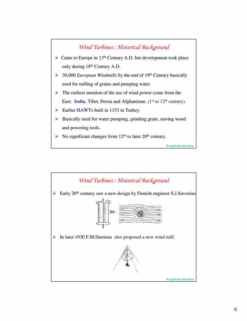
�� Came to Europe in 13Came to Europe in 13thth Century A.D. but development took place Century A.D. but development took place
only during 18only during 18thth Century A.D.Century A.D.
�� 30,000 30,000 European Windmills European Windmills by the end of 19by the end of 19thth Century basicallyCentury basically
used for milling of grains and pumping water.used for milling of grains and pumping water.
�� The earliest mention of the use of wind power come from theThe earliest mention of the use of wind power come from the
East: East: IndiaIndia, Tibet, Persia and Afghanistan., Tibet, Persia and Afghanistan. (1st to 12th century).
�� Earlier HAWTs built in 1153 in Turkey.Earlier HAWTs built in 1153 in Turkey.
�� Basically used for water pumping, grinding grain, sawing woodBasically used for water pumping, grinding grain, sawing wood
and powering toolsand powering tools.
�� No significant changes from 12No significant changes from 12thth to later 20to later 20thth century.century.
������ ������������������������ ��
Propulsion Division
�� Early 20Early 20thth century saw a new design by Finnish engineer century saw a new design by Finnish engineer S.J.SavoniusS.J.Savonius
�� In later 1930 In later 1930 F.M.DarrieusF.M.Darrieus also proposed a new wind mill.
������ ������������������������ ��
Propulsion Division

7
�� ������������������ ������A 19th-century American version
of a vertical-axis windmill An early sail-wing horizontal-axis mill
on the Mediterranean coast Old Danish wind turbine
A steel-bladed water pumping windmill in the American Midwest (late 1800s)
The Brush Postmill in Cleveland, Ohio, 1888. The first use of a large windmill to generate
electricity.
Propulsion Division
������ ������������� ���
Used for
• Pumping water
• Grinding grain
Mainly used for
• Generating Electricity
Propulsion Division

8
������ ����������!���"�
Propulsion Division
������ ����������!���"�
��������#!������$����
Horizontal Axis Wind Turbine Vertical Axis Wind Turbine
Drag Type Lift Type
Propulsion Division

9
������ ����������!���"�
��������%���������$���
Upwind Turbine Downwind Turbine
Propulsion Division
������ ����������!���"�
� Based on technique of power control :� Pitch regulated Windmill� Stall regulated Windmill
a. Active Stall regulatedb. Passive Stall regulated
� Based on hub articulation :� Teetering hub type� Rigid hub type
� Based on Pitch characteristic :� Fixed pitch machine� Variable pitch machine
� Based on rotational speed :� Fixed Speed� Variable speed
� Based on rotor-generator interface :� Gearbox driven� Direct driven
� Based on Yaw mechanism :� Forced yaw� Free yaw Propulsion Division

10
������ ���������&� �������������
Offshore Wind Turbines
Propulsion Division
������ ���������&� �������������
Use of Concentrators
Propulsion Division

11
������ ���������&� �������������
Propulsion Division
������ ���������&� �������������
Propulsion Division

12
������ ���������&� �������������
Disc type wind turbine
Propulsion Division
��� ������'��� �����
Objectives
Aerodynamics of Wind Turbine
Aerodynamic Theories of Wind Turbine
Aerodynamic Analysis of Wind Turbine
Analysis of Wind Turbine Using
Computational Tools like IMPRANS,
CFD-ACE, WTPE, GH – Bladed.
Conclusion & Future Scopes
Propulsion Division

13
(�)�������
Study of Wind Turbine, its aerodynamics
and theories.
Analysis of an 2 meter Diameter Experimental
Stall Regulated Horizontal Axis Wind Turbine.
Propulsion Division
#������"������������� �����

14
#������"���#�*���
Wind Turbines work in a very unsteady condition
Propulsion Division
#������"���#�*���
Propulsion Division
15
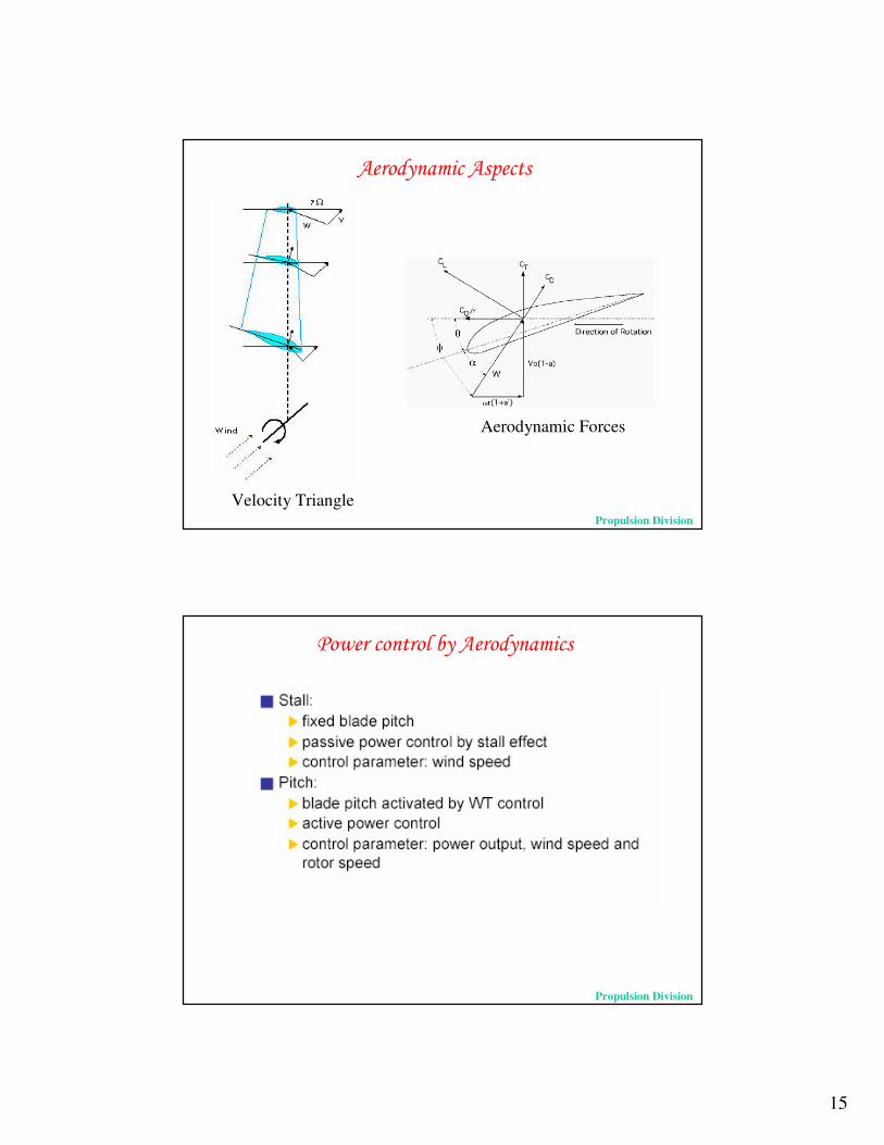
Velocity Triangle
#������"���#�*���
Aerodynamic Forces
Propulsion Division
+� �������������#������"����
Propulsion Division

16
+� �������������#������"����
The Stall Effect
Propulsion Division
+� �������������#������"����
Different Stall Effects
Gault D.E., “A correlation of low-speed, airfoil-section stalling characteristics with Reynolds number and airfoil Geometry”, NACA Technical Note 3963, 1957
Christian Bak, Helge Aagaard Madsen,Peter Fuglsang and Flemming Rasmussen, “Observations and Hypothesis ofDouble Stall”, Wind Energy, Vol – 2, pg 195 – 210, 1999
Propulsion Division

17
Laminar Separation Bubble
+� �������������#������"����Separation Phenomenon
Qualitative Representation of Separation Types
Diagrammatic Representation of the boundary layer flow near separation point Propulsion Division
+� �������������#������"����
Stall Control
Propulsion Division

18
+� �������������#������"����
Stall Control
Propulsion Division
+� �������������#������"����
Stall Control
Propulsion Division

19
+� �������������#������"����
Stall Control
Propulsion Division
+� �������������#������"����
Stall Control
Propulsion Division
20
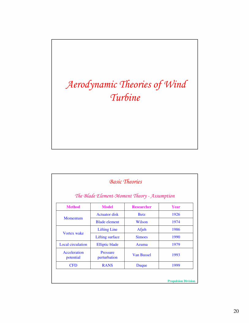
#������"��������������������
� �����
1999DuqueRANSCFD
1993Van BusselPressure perturbation
Acceleration potential
1979AzumaElliptic bladeLocal circulation
1990SimoesLifting surface
1986AfjehLifting LineVortex wake
1974WilsonBlade element
1926BetzActuator diskMomentum
YearResearcherModelMethod
������������"��,-�"����������, #�� "*���
��������������
Propulsion Division

21
����#� ���'����������
��������������
Propulsion Division
����#� ���'�����������, #�� "*����
� Homogenous, Incompressible, steady state fluid flow.
� No frictional drag.
� The pressure increment or thrust per unit area is constant over the disk.
� The rotational component of the velocity in the slipstream is zero.
� There is continuity of velocity through the disk.
� An infinite number of blades
��������������
Propulsion Division

22
������������"��,-�"���������
&
��������������
Propulsion Division
������������"��,-�"����������, #�� "*���
� Individual streamtubes can be analyzed independently of the rest of the flow.
� Spanwise flow is negligible.
� Axisymmetric flow
� Thrust force is equivalent to change in Axial Momentum
� Torque is equivalent to change in Angular Momentum
��������������
Propulsion Division

23
#������"���#����������
������ �����
& "��������������������#��������.�����������
•Aerofoil used for next 3 stations from hub : NASA LS(1) 0417 MOD
• Aerofoil used for first 5 stations from hub : NASA LS(1) 0421 MOD
• Aerofoil used for last 2 stations at Tip: NASA LS(1) 0413 MOD
Propulsion Division

24
#������������-��
Propulsion Division
#������������-��
Propulsion Division

25
#������������-��
Propulsion Division
#������������-��Hub-Tip Losses
Propulsion Division

26
#������������-��Common mode of operation
Propulsion Division
#������������-��
Hence g1 and g2 are re-defined as follows :
Taken from :Bossanyi E. A., “GH Bladed Theory Manual”, Version 3.6, GH Partners Ltd., UK, December, 2003
Propulsion Division

27
• Input parameters:- Blade radius- Operational parameters- Number of blades- Blade cone angle, (included)- Hub cut-out- Prandtl Tip loss switch, (included)- Wind shear exponent- Normalized tower height- Number of sections along the blade, (10)- Blade chord ratio and twist distribution- Airfoil characteristics, (Tunnel tested, Literature)- Shaft tilt angle, (included)- Blade pitch, (Fixed pitch)
#������������+�
Propulsion Division
#������������+�• Output parameters:
Non-dimensional Performance Parameters - Thrust coefficient- Torque coefficient- Power coefficient- Aerodynamic efficiency
Rotor Parameters- Aerodynamic Thrust- Aerodynamic Torque- Aerodynamic Moment- Aerodynamic Power
These output data are obtained for specified range of Tip speed ratio or free stream wind velocity.
• The blade span-wise aerodynamic information is not available from WTPE program. Propulsion Division

28
#������������,�����
• Commercial software for design and analysis of HAWTs with different configurations including present case.
• Pre-processing data- Blade geometry including pitch axis
- Airfoil characteristics with Re and tmax/c
- Rotor configuration
- Operational parameters
- Aerodynamic tolerance
- Prandtl hub and tip loss
- Wake treatment models
- Wind shear and tower shadow effects
- Power control strategy
Propulsion Division
#������������,�����
Propulsion Division

29
#������������,�����
0
20
40
60
80
100
120
140
160
180
200
220
240
260
0 1 2 3 4 5 6 7 8 9 10 11 12 13 14 15 16 17 18 19 20Wind speed, m/s
Pow
er, k
W
Field measurement Sangeeth Blade- July-2004 Predicted by " BLADED"
Validation of GH-Bladed for 300 kW Wind Turbine
Ref: Kishor Kumar and Krishna Murthy S.J., “ Aerodynamic Design and Analysis of a 500 kW Horizontal Axis Wind Turbine Rotor Blades”, PD-PR-0514, NAL Bangalore, October 2005 Propulsion Division
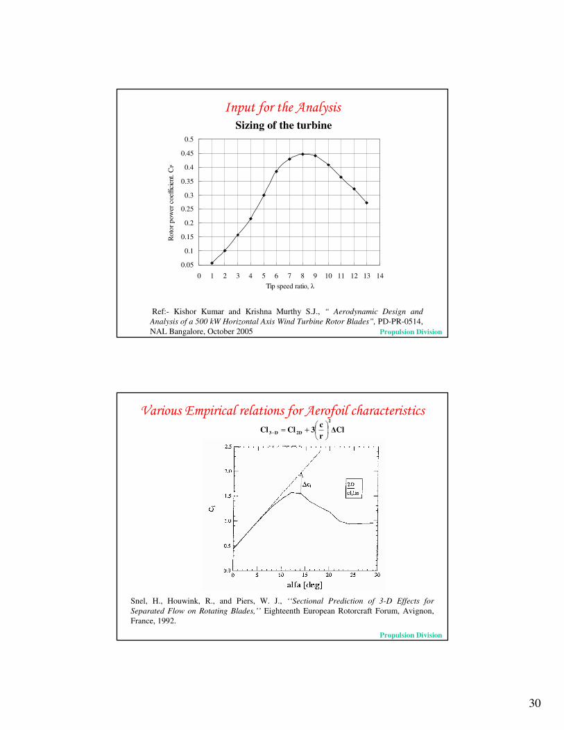
��* ��������#������Sizing of the turbine
Propulsion Division
30
0.05
0.1
0.15
0.2
0.25
0.3
0.35
0.4
0.45
0.5
0 1 2 3 4 5 6 7 8 9 10 11 12 13 14Tip speed ratio, �
Rot
or p
ower
coe
ffici
ent.
CP
��* ��������#������Sizing of the turbine
Ref:- Kishor Kumar and Krishna Murthy S.J., “ Aerodynamic Design and Analysis of a 500 kW Horizontal Axis Wind Turbine Rotor Blades”, PD-PR-0514, NAL Bangalore, October 2005 Propulsion Division
/��� ���"*������������������#��������������������
�Clrc3ClCl
2
2DD3 ��
���
�+=−
Snel, H., Houwink, R., and Piers, W. J., ‘‘Sectional Prediction of 3-D Effects for Separated Flow on Rotating Blades,’’ Eighteenth European Rotorcraft Forum, Avignon, France, 1992.
Propulsion Division
31
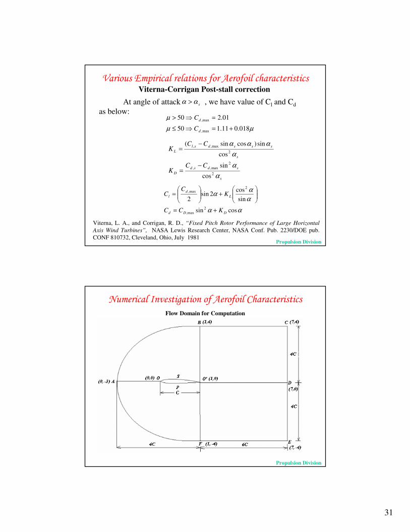
At angle of attack , we have value of Cl and Cdas below:
/��� ���"*������������������#��������������������
µµµ
018.011.150
01.250
max,
max,
+=�≤=�>
d
d
C
C
s
sdsdD
s
sssdslL
CCK
CCK
ααα
ααα
2
2max,,
2max,,
cos
sin
cos
sin)cossin(
−=
−=
ααααα
cossin
sincos
2sin2
2max,
2max,
DDd
Ld
l
KCC
KC
C
+=
���
����
�+��
�
����
�=
Viterna, L. A., and Corrigan, R. D., “Fixed Pitch Rotor Performance of Large Horizontal Axis Wind Turbines”, NASA Lewis Research Center, NASA Conf. Pub. 2230/DOE pub. CONF 810732, Cleveland, Ohio, July 1981
Viterna-Corrigan Post-stall correction
sαα >
Propulsion Division
& "��������������������#��������.�����������
Flow Domain for Computation
Propulsion Division

32
& "��������������������#��������.�����������Usage of IMPRANS code developed by
Computational & Theoretical Fluid Dynamics Division for obtaining 2-D aerofoil characteristics
SALIENT FEATURES OF IMPRANS
� IMPlicit finite volume nodal point scheme for RANS equations� Numerical Scheme evolved by combining basic ideas of
� Implicit finite difference technique of Beam and Warming� Nodal point schemes due to Ni and Hall� Cell-centered finite volume schemes due to Deiwert,
Hollanders and Lerat� Dual time stepping approach ( due to Jameson)
� Implicit Second order backward differencing in real time� Euler implicit time differencing in pseudo time
� Finite volume nodal point spatial discretization - Control volume formed by joining the centroids of the neighbouring cells
� Second and fourth order artificial dissipation terms� Algebraic eddy viscosity model due to Baldwin and Lomax� Computation carried out in the inertial frame of reference� Grid fixed to the moving body� Body motion and transition location prescribed CTFD Division
Sample Input parameters for the calculation :
(1) Profile Name : NASA LS(1) – 04XX (2) Co-ordinates : Design Co-ordinates(3) Reynolds Number : 4 X 10⁶
(4) Mach Number : 0.15(5) Angle of Attack : - 10o to 30o
(6) Artificial Viscosity Co-efficient : 0.01 to 0.03(7) Number of iterations : 3000(8) Grid : 247 X 65
& "��������������������#��������.�����������
CPU Usage (obtained after computation is carried out by code)
Approximately 35 min. for 3000 iterationsPropulsion Division

33
C type grid used for analysis
NASA LS(1) 0413 MOD NASA LS(1) 0417 MOD NASA LS(1) 0421 MOD
& "��������������������#��������.�����������
Propulsion Division
& "��������������������#��������.�����������Usage of CFD-ACE+ available at
Centre for Mathematical Modelling And Computer Simulationfor obtaining 2-D aerofoil characteristics
SALIENT FEATURES OF CFD-ACE+� Unstructured, poly-hedral flow solver.� Cell-centered control volume solution approach. � Solves the Favre-averaged Navier-Stokes equations using finite-volume approach.� FVM applied to structured, multi-domain, non-overlapping, non-orthogonal, body-
fitted grid.� Algorithm is pressure based.� Code able to solve laminar and turbulent, incompressible and compressible, 2-D and
3-D, steady as well as unsteady flow.� Several turbulent models available in the code such as Baldwin-Lomax, Launder and
Spalding k-�, RNG k-� and k-�.� CFD-ACE is able to handle domain interfaces where the number of cells in adjacent
domains are not equal, although each cell in the coarser-grid domain must exactly interface with an integer number of cells in the finer-grid domain.
Propulsion Division

34
& "��������������������#��������.�����������Characteristics of NASA LS(1) 0413 MOD
Propulsion Division
& "��������������������#��������.�����������Cp variation of NASA LS(1) 0413 MOD at 0 deg angle of attack
Propulsion Division

35
0
25
50
75
100
125
150
175
200
225
250
275
300
0 2 4 6 8 10 12 14 16 18 20 22 24 26 28 30
Hub height wind Speed , m/ s
GH-Bladed
3D IMPRANS
+(��$��.0$/�
& "��������������������������� ������
Propulsion & CTFD Division
��&'���0$��&����%#'�
Propulsion Division

36
Wind Energy Division
Fibre Reinforced Plastics Division

37
Wind Energy Division
Click here for the movie
Field studies at Sangeeth wind farm, Kethanur
50m instrumented mast and test wind turbine-Sangeeth Wind Farm, Kethanur, Coimbatore District.
To study:
�Wind pattern
�Turbine performance
�Rotor characteristics
Wind Energy DivisionNAL

38
.���� ����
1
� ������*�
.���� ����
� Comparative study of analysis of wind turbine by BEMT, WTPE and
GH-Bladed is carried out.
� BEMT with Prandtl Hub-Tip loss and transition factor gives good match with the analysis from GH-Bladed.
� Power prediction from BEMT and WTPE are on higher side at higher wind velocity. This is because no post-stall correlations have been included in them.
� A preliminary study of available CFD tools have been done while investigating the aerofoil characteristics. For thin aerofoil profile and in the attached flow regime, IMPRANS code gave good prediction for Cl.
� Parametric Study of the wind turbine under consideration is carried out using GH – Bladed software so as to analytically get an understanding of change in various parameters of the rotor on the turbines output and characteristics.
Propulsion Division

39
� ��������Experimental 2 meter diameter Stall Regulated Wind Turbine
Propulsion Division
� ��������Experimentation of 2 m diameter Stall Regulated Wind Turbine
Joint project between the Department of Aerospace Engineering, University of Glasgow and the Fluid Loading and Instrumentation Centre of the Department of Civil and Offshore Engineering at Heriot-Watt University Propulsion Division

40
� ��������An attempt to do 3D analysis of Wind turbine with CFD software
Usage of commercial CFD software package CFX for obtaining 3-D analysis of Wind Turbine
IMPORTING FLOW DOMAIN IN .igs FORMAT IN ANSYS WORKBENCH
Dept. of Mech. Engg. SVNIT, Surat
� ��������An attempt to do 3D analysis of Wind turbine with CFD softwares
Usage of commercial CFD software package CFX for obtaining 3-D analysis of Wind Turbine
MESHING IN CFX-MESH MODULE OF ANSYS WORKBENCH
Dept. of Mech. Engg. SVNIT, Surat

41
MESHING IN CFX-MESH MODULE OF ANSYS WORKBENCH
� ��������An attempt to do 3D analysis of Wind turbine with CFD softwares
Usage of commercial CFD software package CFX for obtaining 3-D analysis of Wind Turbine
Dept. of Mech. Engg. SVNIT, Surat
� ��������An attempt to do 3D analysis of Wind turbine with CFD softwares
Usage of commercial CFD software package CFX for obtaining 3-D analysis of Wind Turbine
DEFINING PHYSICS OF THE PROBLEM IN CFX-PRE
Dept. of Mech. Engg. SVNIT, Surat

42
��������� ��������� ��������� ��������� ��������� ��������� ��������� ���������