FINAL INVESTIGATION REPORT ON ACCIDENT TO … · 1 final investigation report on accident to...
75
1 FINAL INVESTIGATION REPORT ON ACCIDENT TO NATIONAL AEROSPACE LABORATORIES, BANGALORE SARAS PT2 AIRCRAFT VT –XRM AT SESHAGIRIHALLI NEAR BIDADI (KARNATAKA) ON 6 TH MARCH 2009 1. Aircraft Type & model : Saras Prototype PT 2 Nationality : Indian Registration : VT-XRM Engine : P&W,PT6A-67A 2. Owner & Operator : National Aerospace Laboratories P.B.No:1779, Kodihalli Bangalore-560017 3. a) Pilot-in command : Wg Cdr (22917-S),F(P) b) co-pilot : Wg Cdr (23165-H),F(P) c) Flight test engineer : Sqn Ldr (24746-M),AE(M) b) Extent of injuries : Fatal 4. a) Number of passengers : Nil b) Extent of injuries : N/A 5. Place of Accident : Seshagirihalli , near Bidadi about 37 Km Southwest of HAL airport, Bangalore Latitude: N 12º 50’ 56” Longitude: E 077º 23’ 46” 6. Date and time of Accident : 6 th March 2009, appr 1004 UTC (All Timings in this report are in UTC) S Y N O P S I S Saras Prototype PT2 aircraft VT -XRM manufactured and owned by National Aerospace Laboratories, Bangalore was scheduled for carrying out its test flight no 49. On 06.3.2009 which also include inflight engine shut down and relight procedure at 10000’AMSL . Chief test pilot was on commander seat , test pilot was on co -pilot seat and Flight test engineer was also on board. Aircraft took-off at 0925 UTC and thereafter changed over to radar. There was no events. Aircraft was then cleared to flight level 100, operate up -to 10miles. After completing general handling checks at 9000’AMSL without any events, Single engine simulated approach was carried out on r/w 09. At about 0941 UTC aircraft was cleared for overshoot, wind 090/06 kts. Aircraft made overshoot at 300’AGL. Aircraft was then changed over to radar again. At 0942 UTC Aircraft was cleared to climb FL100 and pr oceed sector Southwest 2 for carrying out engine relight test procedure. After climbing to about 9000’AMSL in sector Southwest aircraft reported 15 miles and FL 90 at about 0948 UTC
-
Upload
nguyenthuan -
Category
Documents
-
view
240 -
download
1
Transcript of FINAL INVESTIGATION REPORT ON ACCIDENT TO … · 1 final investigation report on accident to...

1
FINAL INVESTIGATION REPORT ON ACCIDENT TO NATIONALAEROSPACE LABORATORIES, BANGALORE SARAS PT2AIRCRAFT VT–XRM AT SESHAGIRIHALLI NEAR BIDADI(KARNATAKA) ON 6TH MARCH 2009
1. Aircraft Type & model : Saras Prototype PT 2Nationality : IndianRegistration : VT-XRMEngine : P&W,PT6A-67A
2. Owner & Operator : National Aerospace LaboratoriesP.B.No:1779, KodihalliBangalore-560017
3. a) Pilot-in command : Wg Cdr (22917-S),F(P)b) co-pilot : Wg Cdr (23165-H),F(P)c) Flight test engineer : Sqn Ldr (24746-M),AE(M)
b) Extent of injuries : Fatal
4. a) Number of passengers : Nilb) Extent of injuries : N/A
5. Place of Accident : Seshagirihalli , near Bidadi about37 Km Southwest of HAL
airport, BangaloreLatitude: N 12º 50’ 56”Longitude: E 077º 23’ 46”
6. Date and time of Accident : 6th March 2009, appr 1004 UTC
(All Timings in this report are in UTC)
S Y N O P S I S
Saras Prototype PT2 aircraft VT -XRM manufactured and owned by National AerospaceLaboratories, Bangalore was scheduled for carrying out its test flight no 49. On 06.3.2009which also include inflight engine shut down and relight procedure at 10000’AMSL . Chieftest pilot was on commander seat , test pilot was on co -pilot seat and Flight test engineer wasalso on board. Aircraft took-off at 0925 UTC and thereafter changed over to radar. There wasno events. Aircraft was then cleared to flight level 100, operate up -to 10miles. Aftercompleting general handling checks at 9000’AMSL without any events, Single enginesimulated approach was carried out on r/w 09. At about 0941 UTC aircraft was cleared forovershoot, wind 090/06 kts. Aircraft made overshoot at 300’AGL. Aircraft was then changedover to radar again. At 0942 UTC Aircraft was cleared to climb FL100 and pr oceed sectorSouthwest 2 for carrying out engine relight test procedure. After climbing to about9000’AMSL in sector Southwest aircraft reported 15 miles and FL 90 at about 0948 UTC
2
and reported turning around. But HAL radar as well BIAL radar was showing level 72 forwhich aircraft replied that it has descended and climbing back to 9000’AMSL. At about 0956UTC aircraft reported “OPS NORMAL” at 20Nm in sector Southwest 2. This was the lastcontact of aircraft with radar but was in contact with FTD telemetry desk of ASTE,Bangalore. After successful left engine shut down and its securing procedure, at about 1001UTC left engine relight procedure was initiated at about 9200’AMSL. During therelighting of left engine, FTD desk also lost contact with aircraft about 37 secs prior tocrash. Aircraft crashed at about 1004 UTC.
There was no response from pilots even after repeated calls made by the Radar controller aswell as FTD desk. Radar contact with the aircraft was also completely lost. All possibl ecommunication means including through en -route traffic to contact the aircraft went in vain.After extensive search efforts, at about 1100 UTC it was finally established that the aircraftcrashed at a village called Sehsagirihalli (close to wonderland amusement park) near Bidadi,37km by road (1km off Mysore road) southwest of HAL airport, Bangalore.
All the three persons on board were charred to death. There was post impact fire. Aircraft wascompletely destroyed due impact and fire.
1. Factual Information :
1.1 History of the flight
On 06.3.2009 Saras Prototype PT2 aircraft VT -XRM manufactured and owned byNational Aerospace Laboratories, Bangalore was scheduled for carrying out its test flight no49 . Test flight programme includes general a ir tests/handling checks to ascertain the aircraftflying characteristics after the 50 hrs Scheduled servicing, dummy approach in simulatedsingle engine configuration at 5000’AMSL, go around at 300’AGL in a simulated one engineinoperative condition, landing in a simulated one engine inoperative condition and to carryout in-flight engine shut down and relight procedure at 10000’AMSL within 130 -150 ktsspeed. Tests are to be carried out as per existing SOP and test procedures and limitations andpre flight test briefing meeting. Aircraft was cleared by approved inspectors of NAL aftercarrying out daily inspection on 6.3.2009 for test flight No:49 and was duly accepted by theChief test pilot. Preflight briefing was taken by the Wg Cdr (22917-S), F(P), chief test pilotwas on commander seat , Wg Cdr (23165-H), F(P) - test pilot was on co-pilot seat and SqnLdr (24746-M), AE(M) was on Flight test engineer on board. The test team also acceptedflight test schedule of flight No:49. Total duration of the tests was estimated to about 45minutes.
Engines were started at 0913 UTC at ASTE, dispersal area . All engine parameters werereported normal. After carrying out post start up and pre taxy checks, aircraft taxied out forRunway 09 at HAL airport. As pe r departure instructions after departure R/W 09 aircraft toclimb on R/W heading 5000’, turn right set course to southwest -2 and in coordination withapproach radar to operate upto 10 miles and level 100. Aircraft was cleared for take -off fromR/W 09 with surface wind 090º/06kts. Aircraft took-off at 0925 UTC and changed over toradar at 0926 UTC. There was no event. Aircraft was then cleared to level 100, operating upto10miles. After completing general handling checks at 9000’AMSL without any events,Aircraft was stabilized with simulated single engine approach to the landing r/w 09. Singleengine simulated approach was carried out. At about 0941 UTC aircraft was cleared forovershoot, wind 090/06 kts. Aircraft made overshoot at 300’AGL. Aircraft was t hen changedover to radar again. At 0942 UTC aircraft was cleared to climb level 100 and proceed sectorsouthwest 2. Aircraft right engine was throttled up to match left engine and aircraft climbed

3
out to 9000’AMSL in sector southwest. At about 0948 UTC aircraft reported 15 miles and FL90 and reported turning around. But HAL radar as well as BIAL radar showing level was 72for which aircraft replied that it has descended and climbing back to 9000’AMSL. At about0955 UTC aircraft reported “OPS NORMAL” at 20 Nm in sector southwest 2. This was thelast contact by aircraft with radar. After 0955 UTC Radar contact with the aircraft wascompletely lost.
As per ASTE Telemetry, after turned round to point towards HAL airfield aircraft wasobserved about 20 miles at 9000’AMSL with 140 kts speed. Telemetry link was good at thisposition Left engine was then shut down and secured following the test procedure at about10:00:40 UTC. Pilot was in touch with Flight test director on R/T at telemetry desk. Afterabout 47 secs, left engine relight procedure was initiated at around 9200’AMSL. Pilotalso reported to Telemetry the start of relight of the engine. Telemetry indications alsoshowed the rise in Ng and ITT. At about 100 secs prior to crash airc raft went into suddendive from 9200’ to 7300’ for about 13 secs. Meanwhile During the relighting of leftengine, FTD desk also lost RT contact with aircraft about 37 secs prior to crash andtelemetry link with the aircraft was also intermittent. At 37 secs prior to crash whenTelemetry called aircraft “ can you call up. What is going on”, aircraft replied“Standby” this was the last contact of Telemetry with aircraft. After that there was nocontact from the pilot.
Just before 7 secs of crash when the telemetry data signal was restored aircraft already lost tothe height of 4260’AMSL(1900’AGL) and in continuous loss of height and Ng was about31%. There was no response from pilots even after repeated calls from FTD desk. . Aircraftwas rapidly loosing the height without any control. Cockpit voice recording clearly showedthat on last moments just 10 secs prior to crash ,commander called out “ Aircraft hasdeparted” indicating aircraft completely gone out of control. During the last momentof crash telemetry recorded Ng : about 54%(63% as per FDR), Engine oil pressure 88,fuel flow 94%,ITT 647 deg C, indicating engine relight was successful. But by the timeaircraft was almost on ground. Aircraft crashed at about 1004 UTC.(10:03:44)
All possible communication means including through en -route traffic to contact the aircraftwent in vain. Search operation by ALH helicopter (A67) ,Chetak(T45) and T55 was effected.At about 1033 UTC police control room reported that an aircraft had crashed near Bid adi.After extensive search efforts, at about 1100 UTC, A67 found out the crash site havingbearing 251° and 17Nm from HAL airport. Later it was affirmed that the aircraft crashed at avillage called Sehsagirihalli (close to wonderland amusement park) ne ar Bidadi and 37km byroad(off Mysore road) Southwest of HAL airport, Bangalore. The crash site was a wide -openresidential plot area of uneven hard terrain surrounded by poles and wild plants. It was on aradial of 251° /17 NM from HAL, Bangalore airpo rt having coordinates LAT : N12° 50’56”, LONG: E077° 23’46”)
All the three persons on board were charred to death and were on their seats. There was postimpact fire. Aircraft fuselage was broken from rear of the main plane and found in an invertedposition. The vertical fin leading edge was facing the ground and the respective tail mountedengines by the side of it. The nose portion of the aircraft was facing East direction. Aircraftwas completely destroyed due impact and fire.

4
1.2 Injuries to Persons
Injuries Crew Passengers OthersFatal Three Nil NilSerious Nil Nil NilMinor/none Nil Nil
1.3 Damage to Aircraft
Aircraft was completely destroyed due impact and post impact fire.
1.4 Other Damage
Nil
1.5 Personnel information
The test flight No:49 of Saras PT2 aircraft VT -XRM was operated by flight test teamnominated by ASTE, IAF, Bangalore. The flight test team includes two Indian AirForce Test Pilots and a Test Engineer. The details of the crew members of the flighttest team are as follows:
i. Wg Cdr (22917-S), F(P) Chief test pilot was the commander of theaircraft,
ii. Wg Cdr (23165-H), F(P), test pilot was Co-Pilot andiii. Sqn Ldr (24746-N), AE(M) was Flight Test Engineer.
Both the cockpit crew have become test pilots after comp letion of the ExperimentalTest Pilot’s course in May 2006.
a) Wg Cdr (22917-S), F(P),aged 35, is a DGCA approved Chief test pilot forSaras PT2 with effect from 5 th Aug’ 2008. He is also flight test incharge andresponsible for deploying DGCA approved test pilots and flight test engineers to carryout flight tests of Saras PT2 aircraft. He had a total flying experience of 2414:00 hrswith about 310:00 hrs on turbo-props including Saras Aircraft.
b) Wg Cdr (23165-H), F(P),aged 36, is a DGCA approved prototype test pilot forSaras PT2 aircraft with effect from 14.11.2007. He had a total flying experience of2080:00 hrs with about 315:00 hrs on turbo props including Saras Aircraft.
c) Sqn Ldr (24746-M), AE(M) , aged 33, is a DGCA accepted flight test engi neerand approved by chief test pilot of Saras PT2 team with effect from 1.12.2006.
1.6 Aircraft Information
a) The SARAS PT-2 aircraft is an experimental aircraft under development by M/sNational Aerospace Laboratories, Bangalore and is intended for passe nger andcargo transportation on domestic routes. It is designed, manufactured andoperated by NAL, Bangalore as Saras Prototype -II aircraft. This aircraft has beenduly entered in the register of India with effect from 5.12.2006 and was given the
5
Registration marking as VT-XRM. The Certificate of Registration issued bearsCert. No. 3460, under category A. The aircraft serial number is SP002 and theyear of manufacture is 2006.
b) The aircraft is light transport aircraft configured as a low wing monoplane w ithT-tail powered by two Pratt & Whitney, Canada ,PT6A -67A Turboprop enginein the pusher configuration. Each engine is fitted with a 5 bladed MT propellermade of Aluminum alloy incorporating a variable pitch, constant speed unit anda propeller over speed governor. The engines are installed on the stub wings oneither side of the rear fuselage.
c) The flight compartment is equipped to allow operation of aircraft by a two -manflight crew. The standard design configuration is provided with seating for 14passengers, seated 2 abreast. Front and rear baggage compartments are providedfor the purpose of accommodating the baggage.
d) The fuselage is of semi monocoque construction and is made up of front, centerand rear sections. It has all -metal , fully cantilevered dihedral wing.
e) There is a swept back, fully cantilevered vertical stabilizer attached to the top ofrear fuselage. A horizontal stabilizer is mounted on top of the vertical stabilizer.Both the stabilizers are removable and are of twin spar constructi on. Elevatorsare hinge mounted to the rear spar of the horizontal stabilizer and similarlyrudder is mounted to the vertical stabilizer. Balance tab for all the controlsurfaces with gear ratios are provided.
f) Aircraft is fitted with wing integral tank hav ing fuel capacity of 840 litres oneach wing. Fuel used is any of the following: JP1, Jet A, Jet A-1, AVTUR. Oilused is of type II conforming to P&WC SB 14001 or synthetic Oil MIL -L-23699C
g) In a standard design configuration it features a pressurized cab in and is capableof cruising at altitudes upto 30,000 ft. It is designed for all weather operations.SARAS PT2 is designed to meet the airworthiness standards of FAR -25 andoperational requirements of FAR-121
h) The aircraft was still under the development s tage. Hence the weight schedulewas not yet finalized. However the restriction was fixed for the 49 th i.e theaccident test flight the details of which are given below:
i. Maximum take off weight of the aircraft: 6400Kg.ii. C.G at 30.02% MAC(U/C RETRACTED)
iii. Fuel status-752 Kgiv. Ballast – 99 Kgv. Persons on board – Three.
vi. Max Speed – 200 knots IAS
The aircraft was prepared as per Standard of Preparation SARAS PT -2, Vol33; Report SOP – 2 dated Nov-2006, Issue B with modifications as indicated indocument Ref. vol 33, MOD-SOP-2 Issue A June 2008. There was 793 kg of fuel onthe aircraft on clearing the aircraft for 49 th test flight on 6.3.2009. Aircraft was alsocarrying three serviceable parachute unit for emergency purpose.
Aircraft is also maintained by NA L, Bangalore and completed 48 test flights prior tothe accident test flight. Aircraft propeller had logged 50:20 hrs on completion of 48 th

6
test flight. On 6.3.2009 aircraft was inspected by the airframe, engine, avionics,instruments, electrical system i nspectors approved by DGCA as per dailyinspection/preflight/engine ground run schedule. Also telemetry serviceability wasreported signed by separate person as per DI. Aircraft was certified airworthy for testflight 49 in the form “daily inspection and clearance for Test flight-Saras aircraft” byconcerned DGCA approved inspectors. Aircraft was also accepted by the pilots in theform IAFF(T) 700D. However pilots also signed the “daily inspection andclearance for Test flight”. DI inspection record indica ting various approvedpersonnel/engineers checked the aircraft prior to departure of 49 th flight was notavailable.
The following aircraft documents were checked.
1. 50 Hrs. inspection Schedule2. SARAS PT2 Systems documents.3. Taxiing & Development test Flights4. 25 Hrs. Inspection Schedule5. Snags (Deficiency / Deviation) lists6. System integration documents.
No significant findings / observations are noticed except reported high control forces.
Further, the following documents were scrutinized:
1. SARAS PT-2 Compendium of mass properties - No major findings observed
2. Pilot Defect Register (PDR) – Flaps struck at 18°, 10°, 2°, 2° and 4° during flight nos.18,22,24,25 and 34 respectively. Subsequently, flap was set at 10°. Otherwise nomajor snags observed
3. Electrical, Battery capacitance records verified and found both Main & auxiliarybatteries were periodically Capacity tested and recharged and was valid on the day ofaccident.
From the aircraft flight test records and post flight pilot reports some of the obse rvations are:
Rudder Force feel inadequate, rudder response sluggish During Asymmetric Torque handling, Rudder Force reported heavy Poor Aircraft controllability during approach, flare out & touchdown. Exceedance
of ITT & Ng reported high at high Torque settings at high altitude
In general, there are Controllability issues and high control forces exist.
It is also observed from the post flight pilot reports(PFPR) that no PFPR was submittedby ASTE for the flight no 38 and 39. Also for flight 40 to 46 PFPR were not submittedby ASTE as the aircraft was used for flying demonstration in Aero India 2009 show atBangalore. But no DGCA permission was taken by NAL for the purpose.
7
1.7 Meteorological Information
As per the existing procedure the met report is obtained on telephone. Accident tookplace at about 1004 UTC under broad day light conditions. The MET report receivedon 06.03.2009 at 1000UTC is as follows :
METAR VOBG 061000Z 08008KT 8000 NSC 34/07 Q1012
Weather was fine and is not a contributory factor to the Accident.
1.8 Aids to Navigation
SARAS PT2 aircraft is fitted VHF -NAV, ADF, DME, ATC transponder, weatherradar, compasses, altimeters and their appropriate indicators to obtain navigationalinformation.
Navigation factor is not having any bearing in the accident.
1.9 Communications
SARAS PT2 had following communication systems installed:
2 VHF radio systems 1 HF system Passenger address / briefing system Audio management system (AMS) Cockpit voice recorder 2 Radio tuning units (RTU).
The real time performance of the aircraft is communicated to the ground station by asystem known as Telemetry. This is an effective tool for online monitoring ofprototype test flying wherein test crew could be warned by the Test Director in case ofany exceedances in flight parameters or a potential hazardous situation leading to anunsafe flight . Some of the Telemetry /data analysis sheet for the previous test flights(eg., flight test no.40) had been checked and did not revea l any telemetry linkproblems. However during the face to face to discussions , the reliability of thetelemetry system has been reported poor in general throughout the sortie and theauto tracking system was not available on the day of accident. All variousmonitoring groups at telemetry station have expressed the same. Moreover telemetryradio conversation between FTD desk and the aircraft is not a recorded channel.However CVR conversation reveals telemetry was intermittent. But FTD is in generalin contact with the aircraft till 37 secs prior to the aircraft crash. This also includesstarting of engine relighting procedure.
At about 0955 UTC aircraft reported “OPERATIONS NORMAL” at 20Nm in sectorsouthwest 2. This was the last contact by aircraf t with the radar. HAL radar did notcheck the position of the aircraft almost for 10 mins after the last reporting at 0956UTC. After that radar tried to call the aircraft only at 1006 UTC. Radar also did
8
not contact immediately the Telemetry. Its contact with telemetry was also about15 minutes after the last contact with aircraft .
However the two way communication between HAL Airport and the aircraft wassatisfactory and is not a contributory factor to the accident.
1.10 Aerodrome information
Aircraft had crashed near Bidadi on a radial of 251 o /17 NM from HAL, Bangaloreairport (coordinates N12o50’56” E077o23’46”’) and subsequently caught fire resultinginto the fatal injuries to the three flight crew and loss of the aircraft. The aircraftcrashed at a village called Sehsagirihalli (close to wonderland amusement park) nearBidadi and 37km by road(1 km off Mysore road) southwest of HAL airport,Bangalore. The crash site was a wide open residential plot area of uneven hard terrainsurrounded by poles and wild plants. It was on a radial of 251° /17 NM from HAL,Bangalore airport.
1.11 Flight Recorders
SARAS aircraft, VT–XRM is installed with M/s Penny & Giles, UK manufactured acombi version recorder for data and voice recording. It is a combined Solid StateFlight Data Recorder and Cockpit Voice Recorder. This is crash and fire protected andis installed in the rear i.e. dorsal fin area. Consequent to accident, the recorder wasdamaged in post crash fire, the unit was sent to manufacturer’s facil ity at UK forretrieval of the data. From the UK facility, the data has been obtained separately forthe Voice and Flight data. The details of the extract of the CVR and DFDR recordingare as follows:
Cockpit Voice Recorder:
The voice data has been played, in the Flight Recorder laboratory of DGCA HQ, usingdifferent support equipments. Transcript has been prepared after complete andcombined hearing of all the channels.
CVR data transcript for last 38 minutes along with elapsed time from the crash even tanalysed. In addition, 06 more minutes of data has also been added to the transcript togive proper continuity for the events.
In the CVR transcript there has been many occasions where the conversation betweencrew indicates concern. Such locations hav e been given in bold letters and have beenland marked under remarks column with alphabets A to Z. Detailed analysis wascarried out at these sites, to evaluate the circumstances in which the crew remained tomake such statements. The findings on these si tes have been given in the subsequentparagraphs of this report.
Flight Data Recorder:
FDR data has been obtained in raw format from M/s P&G, UK. The data has beenconverted in to engineering units by using NAL, FOQA, a software tool meantspecifically for SARAS aircraft. Though the data length is for last 24 hours, only thetest flight number 49 has been decoded and examined. Subsequently different sets ofgraph have been generated with judiciously chosen various combinations of aircraft

9
and flight parameters. These sets of graphs have been generated for different timelengths. These time lengths vary from 15 seconds to 30 minutes. Inferences have beenderived from these graphs and it has been given in the subsequent paragraphs.
Synchronization procedure of CVR and FDR Data and Telemetry data:
As this being a combi version recorder, it is believed that both the components of datawould have stopped at the same instant during the final and last event of the crashprocess. Hence the last coordinate of d ata appearance in both Voice and Flight Datahas been taken as the crash point and has been designated with time mark of 00:00(minute: sec). The data has been subsequently allowed to grow in the reverse directionwith negative timing marked in graphs as w ell as in CVR text. With this, at any timeof required reference, both CVR and FDR can be viewed together for any analysiswork. This is one of the adopted procedures for combi version recorders.
The subject flight being a test flight, it remained on co mplete telemetry monitoring.The telemetry data has also been compared with FDR data and also been used toprepare this data analysis report. Particularly there are some essential parameterslike engine oil pressure,ITT,fuel flow etc. are only available w ith telemetry data. Thefollowing analysis includes use of data from FDR and data of flight testInstrumentation with cockpit conversation.
FDR data presentation:
FDR data for the entire test flight no 49 has been converted into engineering units. Ofthe large volume of data, relevant parameters have been chosen and graphs have beenmade against time. Graphs in the form of six sets, with each set containing sixparameters. The time duration for these data graph have been kept for the last two andfive minutes. The time axis grows in negative direction with 00:00 designated as crashpoint. At any time of required reference CVR and FDR data can be read together asthey have been converted to a common time scale.
FDR data inferences:
GO-AROUND in simulated one engine inoperative was done at 100 feet AGL.against the test schedule clearance of 300’AGL. Subsequently, with full power on bothengines a normal climb was made up to 9000 feet height.
During left engine shutting down:
Before the left engine shutt ing down the flying remained steady with speed of 140 kts,altitude of 9400 feet and heading remaining at 60 – 70 deg. The engine oil pressureremained at 122 psi for both L&R engines. The PLA of left engine was brought tozero at the time of -04:53. With this the fuel flow reduced to 80 kg/h, Ng reduced to73%, torque reducing to 3% with no appreciable change in Np. At the time of -04:00,the prop lever was moved to feathered, as indicated by the Np reducing to 15% from100%. Torque has increased from 0% t o 30% and Ng now is steady at 73%. There hasbeen no change in right engine parameters.
At the time of -03:35, the left engine Ng reduced to 60% indicating possible conditionlever moving to ground IDLE. Fuel flow (FF) now reduced to 55 kg/h. all the att itude

10
parameters remains unchanged. At the time of -03:24, the FF indicates to zeroimplying that the condition lever has been selected to CUT OFF. This has resulted inITT, Engine OIL Pressure, EOP reducing to minimum level. Heading now is seensteady at 70 degree. To balance the asymmetry, the rudder remained at -12 degree,elevator and aileron remained respectively at 5 deg and 3 deg. Side slip was seen to 2deg with bank angle remaining 10 deg to right.
During the period while left engine remained shut down:
From time -03:20 to -01:56 the left engine (LE) remains shut down, Np remainednearly 5% with prop in feathered stage. ITT remained at 115deg, while the EOPremained 06 psi. The heading remained constant at 65 deg with a steady rudder of 12deg and pedal force of 20 Kg. The bank angle varied between -6 to 12 degrees.
Left Engine relight:
At the time of -01:44, Np is seen rising through 55% with EOP having remained lowat 5 psi. A small rise in Ng could be seen to the level of 7%, which is lower than theminimum 13% required for beginning of relight exercise. FF is seen increasing to 25 -30 kg/h indicating the condition lever having moved forward from CUT OFF.
Attitude parameters like side slip and bank angle position has started showingchanges. Side slip increases up to 28 deg and bank angle changing from 8 deg R to 70deg L. also the pitch attitude is seen reaching -42 deg.
The rise in prop rpm could be attributed to prop blade pitch having reached FINE fromfeathered statues. However, with EOP having remained at 5 psi, the blade normallynot expected to change the pitch from feathered status. At the time of -01:41, Np isseen to reaching 91% with no change in EOP, pitch angle, roll and side slip keptincreasing respectively to -42, 70 and 28 deg. Rudder deflection has changed nowfrom 12 deg R to 4 deg L with pedal force nearly 70 Kg. elevator remained at 8 degdown and aileron wheel deflection to 40 deg. The aircraft speed has reduced from 150to 130 kt with altitude steady at 9200 feet.
Right engine power reduction:
At the time of -01:40, PLA of R engine was brought down from 26 deg to 0 deg. Thishas resulted in reduction of torque to 2 % and EOP to 32 psi. This attempt couldpossibly be explained as an attempt to reduce the thrust asymmetr y and the large sideslip faced. During the time of -01:31, both L & R PLAs are seen increasing in steps. Inresponse to this, R torque is seen to increasing and during the same time the course hasreduced from 70 deg to 0 deg within a time period of 12 se conds.
Between the times of -01:36 to -01:24, the speed is seen to increase from 125 KTS to181 KTS with altitude reducing from 9200 feet to 7300 feet. Rate of descend for 12secs is very high can be attributed to diving of aircraft and speed of aircraft alsoincreasing. The seen ROD, rate of descend is about 10,000 feet per minute, which isvery high for this class of aircraft. During this phase, the NpL remained at 100 % andNgL is seen at 12%. Subsequently the aircraft was brought under control with allattitude parameters tending to change towards the normal levels.

11
During the time of -01:18 the speed has reduced to 160 Kts, altitude at 7200 feet, NpLremained 100%, Ng L at 15 % and the torque L remained 0%. At the time of -00:59NpL is seen reducing to 80% with Ng L increasing to 22%. Other battery relatedelectrical parameters indicate that the relight process has not been fully successful, orpossibly it has been aborted. At the time of -00:28, the aircraft has been observed to beon left turn. The side slip remained at 22 deg with pitch attitude about -15 deg. Thespeed remained at 130 kt and altitude reducing from 7000 feet to 5200 feet. The Rengine torque that has been reduced close to 0, is showing a sharp rise to 85%. BothPLAs were seen to be moving together. All the controls forces have been increasingexcessively.
Second relighting attempt:
During time of -00:30, a rise in PLA_ L could be seen with proportional rise in Ng.The raise in Ng, goes up to 60 % with Np having rem ained at the level of 80%. The FFincreased to 98 kg/h. Further the ITT – L increasing to 635 deg C and EOP_Lincreasing to 95 psi together indicates the possible success in relight operation of Leftengine. During the period of last 15 seconds there has been large input of pilotcontrols in all 3 axis resulting in large and proportional variations in aircraft attitude inall axis.
CVR data inferences
Over the 38 minutes of transcript prepared, about 26 different landmarks have beenidentified, as containing conversations requiring detailed analysis. Such landmarkshave been marked with letter A to Z. With reference to the transcript material thefollowing write-ups, details the possible interpretation of the remarks at theseidentified sites.
(A) Probably referring to the Elevator trim run out ( -15 deg, nose down limitreached, as expected at speed ~ 160 KTS).
(B) No comments
(C) No comments
(D) Descending for OEI simulated approach, Torque_L 21%, Torque_R 3%. Thecrew needs to have some little power ON to live engine.
(E) Still Descending for OEI simulated approach (telemetry t=1884s, ALT 3900ft).To maintain the speed of 125 KTS, at level flight, the crew discusses about theneed for more power.
(F) CVR Time of - 22:48 (telemetry t=1963.6s, 15:10:45)Rudder 2 deg, Boom_SS -10 deg, AIL_L -13, Ail_R 8 deg, bank 8 deg leftTorq_L increased from 44% to 64%Under these conditions, large Left aileron input required to maintain about 10deg bank to left.(running out of rudder and aileron limit)
(G) CVR Time -22:26, telemetry t= 1986s, 15:11:07

12
Probably referring to NG_R (E2Ng), which is now close to 102.5% , while theflight test limit is 103% (actual limit is 104% from OEM manual).
(H) CVR Time -21:37, telemetry t=, 2035s, 15:11:56
Here it is symmetric power, controls at normal levels. Discussion seems topertain to the requirement in general regarding desirability of procedure tobring all trims to neutral before landing.
(I) CVR Time -20:50, 46:33:45, telemetry t=2082s, 15:12:43
Erroneous speed indication on the masked side of speed sensors which is in thewake of Nose Landing gear door when sideslip is > 5 deg. Pilots are probablydiscussing here the sideslip effect on IAS on two different EFIS.
“Saturation of what?” - Is not understood -. Air show flights being spokenmay be referring to NAOA behavior, which used to go to 100% (spuriousindication). However, at this instant, in the current flight, NAOA is 30% -40%and no saturation is observed on this.
(J) CVR time -15.47, 46:38:48, telemetry t =2384.6 s, 15:17:46
Seems to be general talk, specific reasons/parameters could not be identified.
(K) CVR Time -15:03
Seems to have descended but not registered in their mind. Whilecommunicating to ATC, altitude reported is 9000’ in place of 7200 feet.Hence, this reference was to just from P1 to P2.
(L) CVR Time -13:12, 46:41:23Telemetry t= 2539.6 s, 15:20:21
Torq_L zero, Torq_R 89%, Rud -8 deg (right rudder), Rud tm full +13, sideslip 12 deg, wheel 15 deg. The crew may be mea ning the insufficient forcehere. At this instant the rudder force is 15 kg.
(M) CVR Time -12:56, 46:41:39Telemetry t= 2555 s , 15:20:37
Rudder is -12 deg (to the right), though Rudder Trim has continued to be full.This comment may be in reference to Rudder trim rather than rudder surface.Pedal force ~ 25 kg
(N) CVR time -12:36, Relative Time 46:41:59Telemetry t = 2560 s, IST 15:20:39
Sideslip 3-5 deg, speed is 130 Kts. As Torq_L is ~zero, this propeller would becreating negative thrust (disking) , so aircraft would appear to encounteringmore drag, even in clean configuration. Hence, the comment on inability tomaintain speed is understandable. Aircraft was descending
13
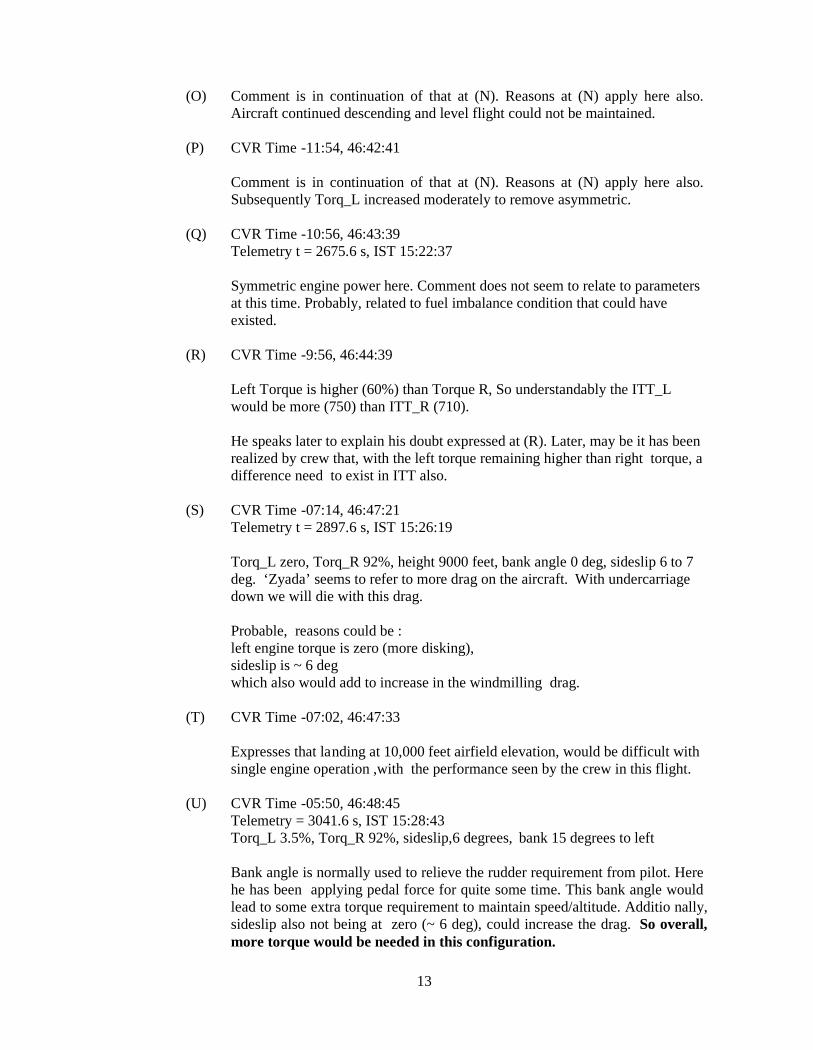
(O) Comment is in continuation of that at (N). Reasons at (N) apply here also.Aircraft continued descending and level flight could not be maintained.
(P) CVR Time -11:54, 46:42:41
Comment is in continuation of that at (N). Reasons at (N) apply here also.Subsequently Torq_L increased moderately to remove asymmetric.
(Q) CVR Time -10:56, 46:43:39Telemetry t = 2675.6 s, IST 15:22:37
Symmetric engine power here. Comment does not seem to relate to parametersat this time. Probably, related to fuel imbalance condition that could haveexisted.
(R) CVR Time -9:56, 46:44:39
Left Torque is higher (60%) than Torque R, So understandably the ITT_Lwould be more (750) than ITT_R (710).
He speaks later to explain his doubt expressed at (R). Later, may be it has beenrealized by crew that, with the left torque remaining higher than right torque, adifference need to exist in ITT also.
(S) CVR Time -07:14, 46:47:21Telemetry t = 2897.6 s, IST 15:26:19
Torq_L zero, Torq_R 92%, height 9000 feet, bank angle 0 deg, sideslip 6 to 7deg. ‘Zyada’ seems to refer to more drag on the aircraft. With undercarriagedown we will die with this drag.
Probable, reasons could be :left engine torque is zero (more disking),sideslip is ~ 6 degwhich also would add to increase in the windmilling drag.
(T) CVR Time -07:02, 46:47:33
Expresses that landing at 10,000 feet airfield elevation, would be difficult withsingle engine operation ,with the performance seen by the crew in this flight.
(U) CVR Time -05:50, 46:48:45Telemetry = 3041.6 s, IST 15:28:43Torq_L 3.5%, Torq_R 92%, sideslip,6 degrees, bank 15 degrees to left
Bank angle is normally used to relieve the rudder requirement from pilot. Herehe has been applying pedal force for quite some time. This bank angle wouldlead to some extra torque requirement to maintain speed/altitude. Additio nally,sideslip also not being at zero (~ 6 deg), could increase the drag. So overall,more torque would be needed in this configuration.

14
(V) CVR Time -05:33, 46:49:02
This is about high Ng at RH engine at high altitudes, which is a knownphenomenon. It was explained probably by the ground here, that this problemwould not occur at lower altitudes. When ground opined “low altitude it isbetter”, P1 expressed the dying situation at low altitude.
At -05:1, 7 FE expressed desire to go back ( and not carry out subsequenttests). P2 telling not to go back, we will shut down and later shown to PM, -project manager. Co-pilot also hilariously telling commander “road isthere for emergency” and advised FTE for the placing readiness ofparachute for emergency, without assessing the risk of the situation, whichwas also expressed by the commander.
(W) CVR Time -01:47, DFDR: 46:52:48
NP_L 38%, ht,9178 feet ,
FE is asking the pilots in suspicion about the actions taken till now. At thisinstant Rudder, elevator, sideslip are all steady at the values which weremaintained till now. There is no change in HDG, also. Immediately within asecond heading started changing rapidly and loosing the height
(X) CVR Time -01:18
Battery discharging voice warning is h eard for the first time after left engineshut down, indicating that the battery is in use now and probably starter -motorhas been engaged. This is the first instant when NG_L has crossed 13%, afterthe shut down. Speed now is 120 Kts. At this time telemet ry link also lost
Battery discharging sound was heard for 13 sec. Then it has stopped. Atthe instant of Battery discharge sound stopping, NG_L was constant at25%. For further 5 seconds, NG_L remained at 25% and subsequentlystarted reducing. Fuel flow remained on for 36 sec (could possibly lead towet start and high ITT).
During this time NP_L was 100% and reduced to 85%. This is an un -natural condition for a engine to start, in the presence of high NP_L. Thepresence of light-up can’t be determined as ITT information is notavailable for some small length of time.
One more and possible reason for unsuccessful re light could be improperfuel-air mixture.( seen from fuel flow rate)
(Y). CVR time -00:55,
Tor-R-0%, wheel- full, IAS-132 Kts, h-6620 feet, Bank-2 degrees,.Pitch- -12 degrees ,. Rudder-9 degrees right.
Concern is developing between the crew about, the intentional reductionof power by P1 on the live engine.
15
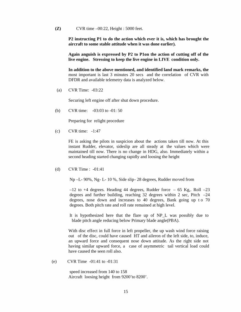
(Z) CVR time –00:22, Height : 5000 feet.
P2 instructing P1 to do the action which ever it is, which has brought theaircraft to some stable attitude when it was done earlier).
Again anguish is expressed by P2 to P1on the action of cutting off of thelive engine. Stressing to keep the live engine in LIVE condition only.
In addition to the above mentioned, and identified land mark remarks, themost important is last 3 minutes 20 secs and the correlation of CVR withDFDR and available telemetry data is analyzed below.
(a) CVR Time: -03:22
Securing left engine off after shut down procedure.
(b) CVR time: -03:03 to -01: 50
Preparing for relight procedure
(c) CVR time: -1:47
FE is asking the pilots in suspicion about the actions taken till now. At thisinstant Rudder, elevator, sideslip are all steady at the values which weremaintained till now. There is no change in HDG, also. Immediately within asecond heading started changing rapidly and loosing the height
(d) CVR Time : -01:41
Np –L- 90%, Ng- L- 10 %, Side slip- 28 degrees, Rudder moved from
–12 to +4 degrees. Heading 44 degrees, Rudder force – 65 Kg,. Roll –23degrees and further building, reaching 32 degrees within 2 sec, Pitch –24degrees, nose down and increases to 40 degrees, Bank going up t o 70degrees. Both pitch rate and roll rate remained at high level.
It is hypothesized here that the flare up of NP_L was possibly due toblade pitch angle reducing below Primary blade angle(PBA).
With disc effect in full force in left propeller, the up wash wind force raisingout of the disc, could have caused HT and aileron of the left side, to, induce,an upward force and consequent nose down attitude. As the right side nothaving similar upward force, a case of asymmetric tail vertical load couldhave caused the seen roll also.
(e) CVR Time -01:41 to -01:31
speed increased from 140 to 158Aircraft loosing height from 9200’to 8200’.

16
Ng_L: 10%, Np_L reaching 99%, Engine oil pressure down to 4.6, fuel flowincreased to 38 but still torque is zero on left side, ITT : 102 .
at the same time on right side: Ng down to 73 from 101, Np maintaining101, oil pressure 119, fuel flow gone down to 72 from 261, torque to zero .this indicates right side engine was brought down
(f) CVR time---01:27,
Altitude: 7311 ft , Bank angle recovers to 8 degrees, pitch recovers to –9 degrees, side slip recovers to + 2 degrees .
These conditions imply that the aircraft is momentarily returning to normalattitude. (pilots laughing)
The possible reasons behind this seen recovery could be:
1. Reduced disc effect due to side slip reduced airflow, over the disc.2. Pilot added control inputs to correct body attitude.
But altitude loss continued.
From time -1:41 to -1: 22 aircraft lost height from 9223’ to7266’ i.e. almost 2000’ in20secs.
At -1:22, CVR revealed the hurried voice of FE telling the pilots to start the enginequickly.
From -1:09 to 0:57 telemetry link was not there.
(g) CVR Time---01:02,
Speed losing to 116 KTS, Altitude to 7280 feet, pitch –9 degrees, bank 0 degree, Liveengine Torque was coming up to 16% which was reduced to zero earlier.
Large drop in speed seen, and hence is the comment. P2 is demanding from P1the same action (which ever recovered the aircraft from bad attitude felt few secondsbefore ).
(h) CVR Time - 00: 55,
PLA-right brought down from 16 to Zero again. Right Torque -0%,right fuelflow reduced to 70, Speed 132 KTS, Bank 2 degrees, pitch – 12 degrees, Rudder – 9degrees, ht-- 6620 feet , engine oil pressure -left increased to 56 and subsequentlystarted reducing to 38, ITT still 68 deg, Fuel flow remained 36, torq ue zero., Ng raisedto 22 and started dropping to 15,Np to 83.
This indicates the Left engine relighting not successful and height continuouslydropping. Right engine also brought to idle.
P2 Expressing anguish on reducing power of the live engi ne by P1 .

17
(i) CVR Time-- -00:44, altitude 6150’
Side slip is 20 degrees to right. Idle Kar do —could be referring to power, possiblyreferring to right engine. With disc effect prevailing on the left side, the power on theright engine, is the one, causing the noted side slip. (as possibly understood by thecrew ).
Immediate follow up words of—Ruk, jao.--, indicates, rapidly changing mind set ofPilots while coping up with rapidly changing attitude of the aircraft, as well as the f astfall in forward speed. Increase of right engine parameters noted.
On left side engine: oil pressure to 26, fuel flow remained 36, Ng 13, Np 85, ITT still68, almost no torque.
(j) CVR Time –00:33,
Speed reduced to 112 KTS, Height reduced to 5400 feet, E1 Ng-10 % , E2 N g-86 %,
The calculated rate of descent is as high as 12000 feet per min, with fast descendtaking place, the crew believes here that they have to have left engine live to cop upthe emergency.
P2 and P1 raising alarm voice of drastic reduction of speed. P2 asking P1 to relightimmediately.
(k) CVR Time—00:27,
Height 5000 feet,
excess rate of descend ,panics the crew with sayings seen here. The batterydischarging warning indicates the action of Second relight attempt on left engine.
(I ) CVR Time-- -00:26,
Height- 4800 feet . Side slip to 20 degrees, pitch at –15 degrees, Right engine torquereduced to zero and rapidly and immediately increased to 85 %.
Left engine relight process is on. Np L -77%, Ng –L- 16 %. Rudder pedal forceincreases as high as 90 kg. Aileron forces too ,seen to raise to 40 kg.
No telemetry link between -0:25 to-0:08
(m) from -0:22 to -0:15
P2 instructing P1 to do the action, which ever it is , which has brought theaircraft to some stable attitude when it was done earlier.
Again anguish is expressed by P2 to P1on the action of cutting off of the liveengine. Stressing to keep the live engine in LIVE conditi on only.

18
(n) CVR Time - -00: 14,
Ng L increasing to 23 %, Np L 80% -- , ITT increased to 96
indication of left engine responding to relight action . Ng R- 102 %.
During 1st un-successful attempt, NP_L reduced from 100% t o 83-85% (An increasein EngOilP_L was noticed from telemetry data which showed that EngOilP_L reachedthe required minimum of 60 psi.) But in this attempt, NG_L rise was not sustained, soEngOilP_L probably started reducing, thereby preventing further mod ulation of bladepitch angle. It could be conjectured that blade pitch is still below PBA.
During 2nd re-light attempt, EngOilP_L increased beyond 60psi as NG_L wassustained and so probably, now prop blade pitch angle might have come to PBA andmatching NP_L for ground idle setting. During this, as expected, NP_L reduced from82% to 61%.
(o) CVR time: last 10 secs
P1 calling aircraft departed repeatedly indicating aircraft fully gone outcontrol. The word used by the pilots “ F (unre adable).” repeatedly at lastmoment indicating, “No control on aircraft and their life is ending”
( p ) CVR Time-- - 5 Secs to 1 sec prior to crash
1 sec prior to crash:
Rapid loss of height from 4300’ to 3040’, speed started increas ing from 60 to 120 .Ng_L increased to 54,Np to 56, oil pressure to 79, ITT increased to 647, fuel flow to95,but torque started to come out of zero ,indicating Left engine successfully relighted.
Whereas on right side:
Ng R- 81%,Np: 86,Oil pressure 118, ITT 773, fuel flow 78(came down from336 which was increased in the 5 secs prior to crash), torque came down to11 from 81, PLA from 31 to almost zero. Indicating last moment try by the crew onright engine
At the last second of their life P2 calling “ F......…,F......” indicating he is seeing lastspell of the life. At the same time Battery discharge Warning coming in thebackground also stopped, indicating engine relighted successfully. But the aircraftalmost on ground, P1 cal ling “ Going to ground”
1.12 Wreckage and Impact information
Aircraft crashed at a village called Sehsagirihalli which is close to wonderlandamusement park near Bidadi ( about 1 Km off Mysore road) and about 37km by roadsouthwest from HAL airport , Bangalore. It was on a radial of 251° /17 NM fromHAL, Bangalore airport having coordinates LAT : N12° 50’56” , LONG: E077°
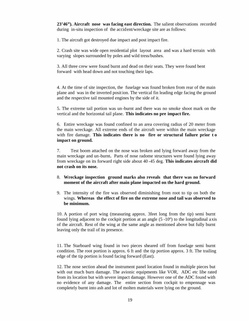
19
23’46”). Aircraft nose was facing east direction. The salient observations recordedduring in-situ inspection of the accident/wreckage site are as follows:
1. The aircraft got destroyed due impact and post impact fire.
2. Crash site was wide open residential plot layout area and was a hard terrain withvarying slopes surrounded by poles and wild tress/bushes.
3. All three crew were found burnt and dead on their seats. They were found bentforward with head down and not touching their laps.
4. At the time of site inspection, the fuselage was found broken from rear of the mainplane and was in the inverted posit ion. The vertical fin leading edge facing the groundand the respective tail mounted engines by the side of it.
5. The extreme tail portion was un -burnt and there was no smoke shoot mark on thevertical and the horizontal tail plane. This indicates no pre impact fire.
6. Entire wreckage was found confined to an area covering radius of 20 meter fromthe main wreckage. All extreme ends of the aircraft were within the main wreckagewith fire damage. This indicates there is no fire or structural failure prior t oimpact on ground.
7. Test boom attached on the nose was broken and lying forward away from themain wreckage and un-burnt. Parts of nose radome structures were found lying awayfrom wreckage on its forward right side about 40 -45 deg. This indicates aircraft didnot crash on its nose.
8. Wreckage inspection ground marks also reveals that there was no forwardmoment of the aircraft after main plane impacted on the hard ground.
9. The intensity of the fire was observed diminishing from root to tip on both thewings. Whereas the effect of fire on the extreme nose and tail was observed tobe minimum.
10. A portion of port wing (measuring approx. 3feet long from the tip) semi burntfound lying adjacent to the cockpit portion at an angle (5 -10º) to the longitudinal axisof the aircraft. Rest of the wing at the same angle as mentioned above but fully burntleaving only the trail of its presence.
11. The Starboard wing found in two pieces sheared off from fuselage semi burntcondition. The root portion is approx. 6 ft and the tip portion approx. 3 ft. The trailingedge of the tip portion is found facing forward (East).
12. The nose section ahead the instrument panel location found in multiple pieces butwith out much burn damage. The avionic equipments like VOR, ADC etc libe ratedfrom its location but with severe impact damage. However one of the ADC found withno evidence of any damage. The entire section from cockpit to empennage wascompletely burnt into ash and lot of molten materials were lying on the ground.

20
13. Control column found in place with operating cables attached to it. However theywere found burnt without deformation in shape. The entire control cable run withrespect to aileron, rudder, elevator are found attached either to its control surfacebrackets or to the operating belcranks / fittings. The cable run (burnt) found runningfrom cockpit to tail almost straight along the axis of longitudinal direction and nodiscontinuity was observed
14. Engine controls found attached to the control quadrant in cockpit and the operatingmechanism. However, few of the operating levers at operating end found sheared off.
15. Pilot / co-Pilot and flight test engineer’s seats were found fully burnt anddeformed. Seats structure could not be traced except one of the arm rest.
16. All the three undercarriage were in retracted position and found burnt but retainedits solidity. One of the nose tyres was found half burnt and another tyre was havingonly burnt steel braiding wires.
17. One of the crew parachutes was found deployed and found un -burnt lying awayfrom the wreckage. Rest two parachutes were found burnt one of which was 2 meteraway from the wreckage and the another one is within the wreckage in cockpit rearsection.
18. Five propeller blades were found liberated from their attachments and found lyingat different places away to the left of the main wreckage(viewing from rear)
19. Main door and Port Emergency door Handle was found in Open position and Stbd.emergency door handle was in closed position, affected by fire. Main door wasslightly damaged due impact. All the three doors were lying away from the mainwreckage and hence not affected with the fire except slight burn marks to portemergency door. Stbd emergency door was not having any impact/fire damage.
20. LH engine (on RH side of the fin in site) found in two pieces. PWR section andGas generator / RGB separated from each other. The RGB is found to have two of itsblade attached to it. Rest of the blades (Qty.3) found located north side of thewreckage. All the blades are found defo rmed.
21. RH engine (on LH side of the fin in site) found in three pieces. PWR section andGas generator section separated from each other. The blade attachment hub with threeblades attached to it found lying approx. 12 m aft of the fin on west side. Rest of theblades (Qty.2) found located north side of the wreckage. All the blades are founddeformed
22. The digital CVFDR was located inside the wreckage in the tail portion from itsmounted location covered with burnt / half melted frames. The CVFDR container w asfound burnt externally and no trace of its connectors. The ULB found installed withCVFDR also burnt externally.
23. Solid State Recorder(SSR) which forms part of the Flight Test Instrumentationsystem was located near cockpit was fully burnt as it was not fireproof.
24. The ELT could not be recovered however six ELT cells were recovered in burntcondition.

21
The wreckage was reconstructed and All parts were mostly identified . But the ELTcould not be traced. Most probably it could have burnt in fire as its housing was notfireproof. The ELT was not fitted on load bearing members/frames and is fittedseparately on platform.
1.13 Medical and Pathological information
Test flight No:49 of Saras PT -2 aircraft VT-XRM was commanded byWgCdr,22917S,F(P), who is also chief test pilot. Wg Cdr, 23165H,F(P),test pilot wasco-pilot. Sqn Ldr, 24746N,FTE AE(M), was flight test engineer on board. There wasno other persons on the test flight. All three were charred to death on their seats in thepost impact fire after the accident.
Immediately after the accident all three bodies of the deceased were shifted to theCHAF hospital, Bangalore. The bodies were duly identified by Wg Cdr A.C.Mathews(22893T) Admn of ASTE,IAF, Bangalore and were medically declared dead at 1730hrs IST on 6.3.2009. Later the bodies were subjected to Postmortem medicalexamination. The post mortem report of the all three deceased crew concluded thatthe crew were dead due to multiple soft tissue and bony injuries in an aircraft crash atground impact.
1.14 Fire
The evidences at accident site proved that there was post impact fire. The intensity ofthe fire was very high and complete aircraft structure was found burnt. The aircraftwas destroyed due to post impact fire. There was no evidenc e of pre-impact fire.
1.15 Survival Aspects
The accident proved non survival and all the three occupants of the aircraft weresuccumbed to their poly-traumatic injuries in the crash .
After the radar contact was lost around 1005 UTC, radar controller trie d to contacthim directly and also through PW461(Chennai - Coimbatore) and further on 122.7 and243 Mhz also. Meanwhile tower received a call from Saras telemetry to check ifSaras is in RT contact. Since aircraft was not in RT contact as well with radar, Towerwas advised to activate SAR through ASTE. ALH A -67 was requested for SAR and itdeparted at 1014 UTC.followed by T45(Chetak) from ASTE at 1020 UTC. Aftersome time T55(Chetak )also departed at 1058 UTC from ASTE. Based on thetelemetry last observation A67 after extensive search located the crash site to beB251/17NM from HAL. Earlier HAL tried through police control room also to findout the exact location of the crash site and police force informed that they had justinformation of an aircraft accident near “wonderland amusement park” in a village“Seshagirihalli” near Bidadi. Later police Sub -inspector –Bidadi informed thelandmark details of the site which were conveyed to the A67 and T45 to locate thecrash site of the Saras aircraft. At abou t 1100 UTC A67 confirmed the crash of theSaras aircraft in Seshagirihalli village.

22
1.16 Tests and Research
1.16.1 Failure analysis of main door and emergency doors
After the accident, National Aerospace Laboratories was asked to provide a repor t onthe possible failure of the main door and the emergency doors which were found nearthe main wreckage of the aircraft. Following this, a committee was constituted byHead, C-CADD comprising various experts members to look in to as to how thedoors came off the fuselage structure and whether or not there was any failure oflocking pins/mechanisms.
The committee examined the doors and the corresponding structures of the fuselageand other evidences. The findings of the committee are summarized as fol lows.
(a) The main door was in “CLOSE” position during the impact of the aircraft on to theground. The movement of the handle and the pins to “OPEN” position was causedduring the impact by the force created due to breaking of the linkages concurrentlywith the bending/buckling of the door.
(b) The emergency door (LH) was in “CLOSE” position during the impact of the aircrafton to the ground. The reason(s) for movement of the handle and the lockinglatches/pins to “OPEN” position appears to be the same as that m entioned in the caseof the main door.
(c) The emergency door (RH) was in “CLOSE” position during the impact of the aircrafton to the ground. During impact, the locking latches/pins have come out by damagingthe fuselage structure. However, in this case, the handle remained in the “CLOSE”position since there was no bending on the linkages or in the door frames as a whole.
(d) the integrity of the locking mechanisms of the main and the emergency doors wereintact at the time of impact of the aircraft on to the ground.
1.17 Organizational and Management information
The ill-fated aircraft was designed and developed and operated for experimental testflight by National Aerospace Laboratories (NAL), Bangalore. National AerospaceLaboratories (NAL), Bangalore is an approved Design Organisation by DGCA, Indiaunder CAR-21, subpart JA and its approval is valid till 31.12.2009 vide DGCAcertification 5-25/97-RD dated 16th march 2009. It was valid on the day of accident.The design organisation approval provides t he scope to NAL to design and developlight transport aircraft “SARAS” and also NAL to classify changes to type design andrepairs as major or minor as per the procedures agreed with DGCA. NAL also toevaluate and propose the conditions under which a “perm it to fly” operation can becarried out in accordance with procedures agreed with DGCA. DGCA also approvedlist of designers of NAL as authorized signatories ie., Showing Compliance Engineersand Compliance certification Engineers(SCEs and CVEs) for SARAS project, on13.8.2008, apart from the approval of head of design organisation and other managersas per design organisation manual(DOM). DOM was approved by DGCA only on 1 st
Dec 2008 under CAR 21, subpart JA, issue -II, revision 0.
There was an MoU between NAL and IAF on 14 th may 2003 for implementing Sarasproject. MoU provides the role and responsibilities of NAL and IAF and they alsoagreed to establish appropriate project management and monitoring structure. As apart of agreement NAL and IAF set up th e Management Committee(MC) which will

23
be the apex body, responsible for flight testing of SARAS prototype aircraft upto thecompletion of the certification . This MC will deliberate and decide on all major issuesrelating to flight test planning, sequencin g and supervision of the actual flight tests,flight safety aspects, expansion flight envelope and interaction with the certificationagencies.
A joint ASTE(IAF)/NAL Directive has been made effective with effect from 28 th May2004, which clearly lays down the role, duties and responsibilities of key personnelinvolved in the Saras flight test programme for efficient and safe conduct ofdevelopmental flight tests on Saras prototypes.
However from the records made available to the investigation group reveal ed someof the salient observations:
1) Management committee did not play its role as envisaged in the MoU. AfterAug 2006 there was no periodical review by MC. Only the joint meetingbetween NAL and ASTE,IAF was held on 28 th Aug 2008. After this meetingthere were 27 test flights (including ACCIDENT FLIGHT)done. There wasnothing reviewed. Similarly In 2009 also there was no review of the projectby MC or NAL.
2) Similarly there is no evidence made available to show that Local Modcommittee is established and functioning properly for its purpose said in thejoint directive .
3) Continuous evaluation of procedures/design modification for safe conduct oftest flight is not at satisfactory level.
4) Co-ordination with OEMs of engine and MT propellers is not the re aftervetting the relight procedure by ASTE for their comments and guidance.
5) There is no proper interaction between NAL and MT propeller regarding theformulation of the relight procedures.
6) There is no contingency plan in detail available in case of mi ssingaircraft/exigencies/loss of communication and accidents etc.
7) No chase aircraft and film shooting facilities were made available to monitorall critical \test flights especially the test flight involving relight procedure.
8) Failure of regular monitoring and improvement on telemetry monitoringsystems and their documentation procedures.
9) Failure of monitoring of CVR and FDR in co -ordination with solid staterecorder(SSR) and telemetry data for evaluation of better cockpit proceduresand design modification
10) Non-inclusion of critical engine parameters like ITT, engine oil pressure etc.,essential for monitoring test procedures, in the vacant slots of FDR
11) Aircraft was used for flying demonstration in Aero India 2009 show atBangalore. But no DGCA permissio n was taken by NAL for the purpose.
12) There is no effective and continuous monitoring of test programme by MCand no records of monitoring available.
NAL also subcontracted a private agency named Aircraft Design and EngineeringServices Pvt Ltd (ADES), Bangalore for supporting Saras project. Aircraft Designand Engineering services pvt Ltd (ADES), Bangalore was approved as a designorganisation under CAR21, subpart JB and it is valid till 31.12.2009. The scope of itincludes design and engineering support t o NAL in Civil Aircraft projects 14 seaterSaras aircraft to the parts and appliances complying FAR 25 standard. NAL enteredinto an agreement with this private contractor company -ADES on 1.5.2008. The

24
following peculiarity was observed while scrutinizing the agreement and itsattachments:
1) Even though agreement was made on 1.5.2008 it was made effective from 1 st April2008.
Contractor will engage experienced aircraft designers, engineers and other technicalstaff required for task as required during diffe rent phase of the project. The workschedule of the project also indicates almost complete work of the design anddevelopment of SARAS project is being done by the contractor.
2) This is not in line with DGCA approval given to the contractor that of only giv ingdesign and engineering support to the parts and appliances.
3) Since this is the national project, utmost vigil and care shall be taken by CSIR, Indiawhile implementing project and also the concept of employing the private contractorinvolving in each and every stage of the design and development of Saras projectrequires to be discontinued immediately and only the support for the parts andappliances shall be obtained from them.
4) As per agreement Even though NAL shall retain the absolute right on any pa tent thatmay be taken from the result of the work, Confidentiality clause of the agreement didnot point out the penalty/ punishment action on the contractor under law in case of thepilferage or theft of any technical information such as design, drawings , wind tunneltesting, flight tests results or any software etc.,
Apart from the above NAL also subcontracted several agencies for getting supportfacilities and parts for the Saras project.
1.18 Additional Information
1.18.1 Selection of test pilots:
It is learnt that ASTE,IAF is the only establishment in India and one of its kind in theworld to undertake test flying both for upgrades of existing aircraft and for prototypeaircraft. Presently the only prototype testing being undertaken is for LCA by NFTC,IJT by HAL Flight test centre and Saras by ASTE. All the test pilots and FTE areAlumni of ASTE test pilot school. The test pilots and test engineers are trained toundertake test flying on fighters and transport aircraft. The pilots and FTEs haveexperience in test flying of other turboprop previously like Dorniers, Avros and AN -32 of IAF. The aptitude for test flying is evaluated by IAF test pilot school. As therehave no remarks against the pilots of accident flight NAL accepted the pilotsnominated by the Commandant ASTE, IAF as per the “Memorandum ofUnderstanding for SARAS Programme, dated 14.05.2003 .The deceased Test pilotsand FTE were given training on various systems of SARAS aircraft by respectivedesigner and Test Director at NAL. On co mpletion of the training, a request was madeto DGCA by NAL for approval of test pilots and Chief of Trial Team. Similarlyacceptance of FTE was obtained from the DGCA. Previous experience of testpilots/FTE are examined as per advisory circular 01/2001 is sued by DGCA(AED).
Apart from the above, NAL has neither used its own expertise nor outsourced theexpertise from other aviation industries to test the Saras test pilots/flight test engineerfor their suitability in the civilian test flight wherein exp erimental aircraft under

25
development is used . Moreover, as per MOU of SARAS program it is understoodthat SARAS is the first civil turboprop prototype test flying undertaken by ASTE,IAFfor which assessment of crew for human factor is important . Human factor/CRM ofthe flight crew were not assessed by NAL for the civilian cockpit and flight operationenvironment as the test pilots are basically from the Air force environment. Similarlytest pilots/test engineer also did not undergo any human factors tr aining beforeoperating the test flights on VT -XRM. No documents were provided to theinvestigation team on the subject matter.
1.18.2 Preflight and post flight requirements :
NAL reported that the following arrangement are available for the purpose of Briefing/ debriefing:
For each test flight, the team consisting of Flight crew, Flight Test Engineer (FTE),Design group, Flight planning group along with Flight Test Director will discuss theprogramme and conditions. FTE will convert this programme and conditio ns to testcard and test schedule. The test card is approved by Test crew and FTE. During pre -flight briefing any change in test schedule or test points are discussed andincorporated. Also contingency action for specific emergency/precautionaryprocedures are discussed during pre-flight briefing, attended by Officer in Command -Proto type test squadron (OC/PTS), Flight Test Director (FTD), Test crew, FTE, Chiefof Design, APD/FTG, Telemetry monitoring team, Flight operations in -charge, aircraftmaintenance in-charge and crash/chase vehicle coordinator. Flight test schedule issigned by Test crew, FTE and Chief of Design. The program and condition for eachflight is transmitted to DGCA R&D prior to pre -flight briefing and conduct of testflight. Block of 10 or 20 test flights are normally approved by DGCA -ADE based ontest plan submitted by NAL. Individual test flight “Condition and Programme “ issubmitted just a day prior to actual test flight no 49.
After completion of flight, a hot -debrief is given by the flight crew at the telemetry ofASTE and the same is attended by those who were present in the flight briefing. Oncethe data has been analyzed by the NAL Flight Test team, a detailed data debrief isconducted at ASTE/NAL where all the observations ar e discussed and the results oftest points are accepted or repetition of some of the test points are discussed. Prior toconducting the next test flight aircraft readiness is authorized by individual monitoringand analysis team for the following discipli nes: Aerodynamics, Engine/power -plant,Systems, Electrical/Avionics, Telemetry and Maintenance / Operation and FTD.
As a defined procedure, pre -flight briefing is always carried out by the Flight TestEngineer who is part of the flight crew. For the ac cident flight ,the same was done on6th March 2009 afternoon. The briefing covered aircraft SOP for this flight, workdone on the aircraft prior to this flight, configuration limits, test points & testsequence according to the issued test programme and safety considerations. Detailsare as per flight test schedule dated 6.3. 2009. Flight crew, including the pilots and theflight test engineers, were present. From NAL side the following were present: flighttest director, APD (flight testing), PD (Saras aircraft project), members of real -timemonitoring team, inspectors from various trades, ground crew, design representativesfrom relevant disciplines. At the end of the briefing, the pilots were specifically toldby the Flight Test Director that in case of any problem during the relight attempt, theengine should be switched off, propeller feathered and single engine landing executed.

26
No effort should be made to try the relight a second time. These detailed discussionswere nowhere documented/minuted.
It has also been reported that the preflight briefing meeting were done before theaccident flight. Scrutiny of documents/records revealed that preflight and post flightdebriefing of the test flight /to the test pilots were not effectively documented at eachand every flight. Moreover the available documents did not include contingenciesplan/procedures for unexpected exigencies/missing/loss of communication/ accidentsetc.,
Similarly there is no documents made available to indicate the existence of ef fectiveprefight and post flight medical requirements and its compliance for the test crew.Also there is no proper system exist to monitor the fatigue level of the test pilots priorto the test flight.
It has been reported by NAL that at any stage of d iscussion including critical flighttest like “engine shut down and relight” no DGCA official took part. Only thedocuments are transmitted to DGCA for approval/acceptance/acknowledgement. Asthe Saras project is national project and involving country’s dignity It is felt necessarythat either local DGCA Officers or DGCA HQ officer should have participated foreffective guidance and timely implementation of each phase of the project. DGCAbeing the approving authority of the NAL, design organisation and the Sarasexperimental aircraft as well production aircraft and Since huge public money isinvolved in the project, DGCA’s serious involvement is a must for effective controlon the project.
1.18.3 Effective oversight functioning of DGCA,R&D(AED)
When the prototype is completed, NAL submits test plan for block of 10/20/25 flightsalong with aircraft definition document/SOP. After scrutiny by DGCA(R&D) HeadQuarters / Bangalore office will grant permission for conducting test flights. Oncompletion of approved block of test flights, a summary of the test report togetherwith test plan for next block of flights is submitted to DGCA and clearance obtainedfor continuing the test flights. Further the test program and conditions are prepared foreach individual flight in consultation with test crew and submitted to DGCA localoffice a day prior to execution of flight. During the scrutiny of various programs andrecords of Saras project it is revealed that there is no continuous monitoring andeffective control over the project by DGCA(R&D). Saras being the national projectby NAL, a Govt. of India organisation, and approved by DGCA under aircraft rules,much more participation and effective control by DGCA on the project is essentialand important.
Some of the serious lapses noted are:
1. NAL without DGCA’s permission took part in Aero India show - 2009 from11.2.2009 to 15.2.2009 covering test flight no: 40 to 46 using Saras PT2 VT -XRM at Bangalore and demonstrated the flight to public upto low alti tude of300’AGL over Yelahanka airfield.(actual test area: Bangalore LFA), for which notest report were submitted by the test pilots. Participation in the AERO India show

27
-2009 was planned in the month of Aug 2008 itself. NAL reported that theinformation of their participation was however, submitted on 9.2.2009 to DGCA.But there is no documentary evidence provided during the investigation for theapproval from DGCA. No action was taken by DGCA(R&D) also to restrict theirparticipation. Saras PT- 2 being the experimental prototype aircraft under test andC of A is not yet given to the aircraft, participation in the public demonstrativeflight show and that too at low level of 300’ AGL is dangerous to the life of thepublic and their properties. It is also not understood that how the ShowOwners/Conveners accepted the uncertified aircraft for flying demonstration in thepublic show.
2. While giving flight clearance including engine shut down and relight flight teststhere is no restriction made on minimum altitude by DGCA.
3. Uncertified propeller is tested on locally fabricated engine test rig, which does nothave DGCA approval. No inspection by the DGCA on these facilities for approvaleven though papers were submitted to them.
4. There is no periodic monitoring of CVR and FDR by NAL
5. No contingency plan for communication failure, accident, missing aircraft etc.
6. Non-participation and strong guidance in critical flight tests procedure like engineshut down and relight test programme.
1.18.4 Periodical monitoring of review of CVR and DFDR:
From the records made available to the investigation team it is clear that CVR andDFDR data was not monitored for each and every flight of Saras PT2 aircraft. Thereshall be a dedicated experts to do these con tinuous monitoring for improving thecockpit procedures and discipline apart from evaluating the design modificationrequirements using DFDR data in collaboration with telemetry data and SSR data.
According to FAR Part 121, paragraph 121.344, no person may operate a turbinepowered transport category airplane unless it is equipped with one or more approvedflight recorders that use a digital method of recording and storing data and a method ofreadily retrieving that data from the storage medium. The ope rational parametersbeing recorded on the SARAS aircraft by the digital flight recorder as per Vol 10, DR -36 noted above. All parameters mentioned are being recorded with the ranges,accuracy and resolutions as specified in Appendix M of FAR 121.344. This is also inaccordance with the latest NTSB recommendations .(also AS per note 3 of flightrecorder – CAR Sec 2 ser I, Part V )
However it is understood that DFDR does not have engine parameters like engineoil pressure, ITT and fuel flow etc to monitor the se in relight procedures and theengine performance. It is also revealed that the SSCVFDR installed in SARASaircraft has a capacity to record at the rate of 128 words / second. That means 128parameters of 12 bit resolution can be recorded in one secon d. At present 100 slots of12-bit are full and 28 slots of 12-bits are vacant. It means that SSCVFDR still has
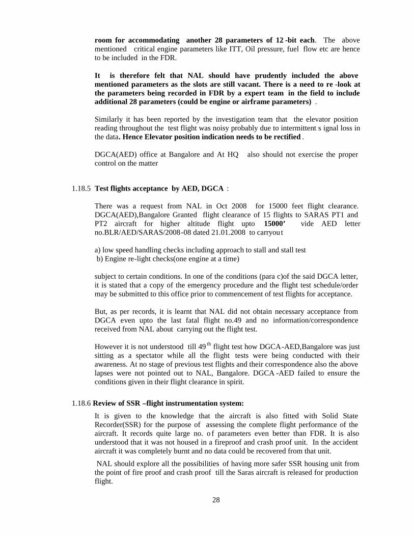
28
room for accommodating another 28 parameters of 12 -bit each. The abovementioned critical engine parameters like ITT, Oil pressure, fuel flow etc are henceto be included in the FDR.
It is therefore felt that NAL should have prudently included the abovementioned parameters as the slots are still vacant. There is a need to re -look atthe parameters being recorded in FDR by a expert team in the field to includeadditional 28 parameters (could be engine or airframe parameters) .
Similarly it has been reported by the investigation team that the elevator positionreading throughout the test flight was noisy probably due to intermittent s ignal loss inthe data. Hence Elevator position indication needs to be rectified .
DGCA(AED) office at Bangalore and At HQ also should not exercise the propercontrol on the matter
1.18.5 Test flights acceptance by AED, DGCA :
There was a request from NAL in Oct 2008 for 15000 feet flight clearance.DGCA(AED),Bangalore Granted flight clearance of 15 flights to SARAS PT1 andPT2 aircraft for higher altitude flight upto 15000’ vide AED letterno.BLR/AED/SARAS/2008-08 dated 21.01.2008 to carryou t
a) low speed handling checks including approach to stall and stall testb) Engine re-light checks(one engine at a time)
subject to certain conditions. In one of the conditions (para c)of the said DGCA letter,it is stated that a copy of the emergency procedure and the flight test schedule/ordermay be submitted to this office prior to commencement of test flights for acceptance.
But, as per records, it is learnt that NAL did not obtain necessary acceptance fromDGCA even upto the last fatal flight no.49 and no information/correspondencereceived from NAL about carrying out the flight test.
However it is not understood till 49 th flight test how DGCA-AED,Bangalore was justsitting as a spectator while all the flight tests were being conducted with theirawareness. At no stage of previous test flights and their correspondence also the abovelapses were not pointed out to NAL, Bangalore. DGCA -AED failed to ensure theconditions given in their flight clearance in spirit.
1.18.6 Review of SSR –flight instrumentation system:
It is given to the knowledge that the aircraft is also fitted with Solid StateRecorder(SSR) for the purpose of assessing the complete flight performance of theaircraft. It records quite large no. o f parameters even better than FDR. It is alsounderstood that it was not housed in a fireproof and crash proof unit. In the accidentaircraft it was completely burnt and no data could be recovered from that unit.
NAL should explore all the possibilities of having more safer SSR housing unit fromthe point of fire proof and crash proof till the Saras aircraft is released for productionflight.

29
1.18.7. Electrical system and role of Auxiliary battery
To understand role of auxiliary battery in relight operation electrical system of theaircraft is necessary to be understood
Electrical System Architecture
Electrical System Architecture for SARAS Aircraft is as follows. Two starter /Generators serve as main power supply sources. The same star ter/generators serve asstarter motors during starting phase. The capacity of each generator is 400 Amps at 28Volt; the over load rating of the starter / generator as generator is 600 Amps for 2minutes and 800 Amps for 5 seconds.
One Main Battery (Ni-Cd) of 44 Ah capacity is used as emergency power source. Thesame battery serves as internal starting source.
One Auxiliary battery (Ni-Cd) of 16 Ah capacity is used for the following purpose(during starting phase):
To improve voltage supplied to GCPU ( Generator Control & Protection Unit), CWP(Central Warning Panel), Fuel flow meters. Also the auxiliary battery serves asadditional emergency power source during double generator failure.
Reason for introduction of auxiliary battery .
During starting phase of Saras aircraft development main / emergency bus voltagedips below the operating voltage of Generator Control and protection unit (GCPU),Central Warning Panel (CWP) & fuel flow system due to large motor starting current.
It was found necessary to provide a separate Auxiliary battery and bus bar for thesecircuits to over come the low voltage problem while starting.
It is to be noted here that Auxiliary battery is not meant to supply starter motorcurrent during starting cycle (on ground and in air ).
After starting cycle is completed the auxillary bus bar will be powered by main powersource (generator supply) with auxiliary battery under float charge.
The electrical circuit is so arranged that both the emergency bus and auxiliary batterybus are powered by 44 Ah main battery in case of double generator failure(probability is extremely remote) In that case the auxiliary battery bus bar can beisolated and powered by auxiliary battery by selection.
Auxiliary Battery Selection Switch
The Auxiliary Battery is controlled by a three position switch, as follows: The threepositions are ‘ON’, ‘OFF’, and ‘CHARGE’.

30
1. Position ‘OFF’The Auxiliary BATTERY is separated from all bus bars. (This battery doesnot supply even to Auxiliary battery bus bar) . However the Auxiliary BatteryBus bar is connected to the emergency bus bar supplied by the main battery.
2. Position ‘ON’ (The Auxiliary bus bar is isolated from main and emergencybus bars)The Auxiliary battery is connected to Auxiliary battery bus ba r and supplies(discharge) current to all loads connected to Auxiliary battery bus bar only i.e.GCPU, CWP and fuel flow meters. Hence any voltage dip on other bus barswill not affect the Auxiliary battery bus bar (especially during starting cycle).
3. Position ‘CHARGE’The Auxiliary Battery is isolated from Auxiliary bus bar and connected tomain bus bar for getting charged by generator. Now the Auxiliary battery busbar is supplied by main power sources (Generator).
Indications and Warning:
a) Main Battery Discharge Warning .Main Battery Discharge warning will come ‘ON’ for the following conditionsand when the discharge current sensed by the current sensor in DC master boxis more than 6 Amps.
1. During internal starting (Main battery)2. During cross starting (Main BAT + GEN)3. During double generator failure.
During this condition battery is supplying power to the loads connected toemergency bus bar. Audio warning comes ‘ON’ along with indication, inCWP.
b) Battery Indications:
Main Battery:1. Battery disconnect (RED lamp in CWP).
This lamp comes ‘ON’ when battery is not connected to emergency busbar.
2. Battery discharge (RED lamp in CWP with Audio warning)3. Battery ‘HOT’ (RED lamp in CWP).
This lamp comes ‘ON’ if the battery temperatures rises above 71 20C.
Auxiliary Battery:1. Aux. Battery disconnect (RED lamp in over head panel):
This lamp comes ‘ON’ when battery is not connected to main bus bar.2. Aux. Battery ‘HOT’ (RED lamp in over head panel):
This lamp comes on when the battery temperature rises abo ve 7120C
1.18.8 Discussion on Synchronization of Propeller Control and Fuel Control
In Saras PT2 VT-XRM aircraft, concept is Three control levers for power, propellerblade pitch and condition are provided on pedestal in cockpit within the reach of both

31
pilots. The mechanical movement from cockpit is transmitted through flexible ballbearing controls to corresponding levers on engine.
Power lever controls the engine power and also selects reverse pitch by blade pitchvariation. Propeller lever cont rols pitch at max. RPM, min. RPM and feather. Positivestops are provided on quadrant so that inadvertent operation to feather regime isprevented.The required power is selected by means of power lever in direct proportion to torque.It has max. power, idle and max. reverse.
Condition lever has three positions: off, low idle (53% NG) and high idle (70% NG)with positive stops.
Propeller control lever movement provides smooth propeller operation (pitch change)within control range. The propell er lever has a governing range between max. RPMand minimum RPM positions and feather range.
The blade pitch is controlled automatically in flight to maintain the RPM constant topre-selected value. The chosen relationship of engine power to propeller pitc h dependson operating requirements. Based on propeller RPM selected, turbine governor sectionof propeller governor limits engine power according to ability of the propeller toabsorb the power at that speed. When lever is pushed fully forward, pitch chan gesfrom course pitch to fine pitch (high RPM).
Whereas in P.180 Avanti II aircraft. There exists two -lever concept.ie., power andcondition levers The engines and propellers are operated by two sets of controlsmounted in the control pedestal below the centre instrument panel.
The power levers (left side of pedestal) control engine power through the full rangefrom maximum takeoff power down to full reverse. They also select the propellerpitch (beta control) when they are moved back from the detent. A gate providesunrestricted power lever movement from idle to maximum forward but requires thepower lever handle to be pulled up before movement can be made from idle to reverse.Each power lever operates the NG speed governor in the fuel control unit inconjunction with the propeller cam linkages. Increasing NG results in an increasedengine power.
The condition levers (right side of pedestal) provide the propeller speedcommands as well as the fuel cut -off and propeller feathering functions. (iecombined propeller control and fuel condition lever.) In flight, the condition leversprovide the speed commands to the propeller governor for setting the desired propellerspeed. The condition levers are utilized to select high (about 70%) or low (about 54%)idle. Ground idle (low) is the normal condition for ground operations. Flight idle(high) is needed on ground for maintaining low ITTs during periods of high generatorloads at high ambient temperatures or when increased bleed air flow is necessary.Moving the condition lever aft from the G.I. position, over the gate, and aft to theFTR(Feather) and CUT OFF results in propeller feathering and fuel cut -off.
The above concept of two lever, single control box operation is easier compare tothe three lever operation. NAL should explore the above concepts to adopt infuture Saras project for achieving well coordinated cockpit control by the pilot.
32
1.18.9 Status of ATR on Inspection by DGCA authorized inspectors :
As per the instruction of DGCA, Delhi Air Indi a engineering team had visited NAL,Bangalore from 6 th Jan to 9th Jan 2009 to review and study the avionics and electricalsystems of SARAS aircraft VT-XSD for the purpose of type certification, design,implementation and system architecture. Certain o bservations were indicated forimprovement by NAL.
There were 31 major observations made for implementation. Some of them werepending for implementation. These were regarding provision of spare cables in eachloom, flushing of pitot probe and AOA with fuselage, position of pitot probe waterdrain hole, pitot probe heating, warning for emergency door opening. However thesewere not contributed to the accident.
1.18.10 Propeller certification
1. Selection of engine-propeller combination:
Since PT6A-67A engine that was flying in Beech star was selected for SARAS PT -2 ,the obvious choice would have been the same propeller driven by this engine on theBEECH aircraft. McCauley, USA supplied the propeller for the Starship power plant.McCauley have stopped the prod uction of this propeller and they have no interest instarting the production line again only for one customer. The other alternatives werealso explored and finally discussion held with MT propellers of Germany and apropeller development programme was f inalized. Broad details of the 1200 SHP,1700rpm propeller for PT2 are given for the purpose. MT propeller has been inbusiness of development of propellers for the past nearly 25 yrs for general aviationaircraft. They also have developed larger propeller s for various specific applicationsand have enough experience in design and development of propellers. They also have afacility in Poland(AVIA) to design and develop large metallic propeller(Since last 75years). The total system weight of Hartzell prope ller is 93 kg with Aluminum hub to bequalified with Aluminum material and 108 kg for MT propeller. After the comparisonof propulsive efficiency of the MT and Hartzell propeller, MT propeller was chosen asit has higher efficiency. Because of the competi tive cost, aggressive developmentschedules and the rich experience behind, MT propeller was selected for Saras PT2.The test propeller was delivered and 200hrs of endurance test have been completedsuccessfully at NAL facilities, as part of certification tests, along with PT6A-67Aengine. The engine-propeller combination has thus been proven for SARAS PT2aircraft.
2. On the day of accident, MT Propeller fitted on the accident Saras aircraft is notcertified propeller by any competent authority ie.,FAR /EASA or Indian DGCA as ondate of accident. It was manufactured in the year 2005,September, as per therequirement part 21 by MTP,Germany . Though it is uncertified NAL opted for it dueto the above selection process.
3. NAL reported that the MT prope ller fitted on the accident aircraft was made as pertheir specification. it is yet to be certified by competent authority due to othertechnical/test requirement like actual vibration test in flight. These propellers whenreceived from MT propeller, Germany by NAL in the year 2006 there is no declarationof airworthiness fitness made by NAL for its usage on Saras aircraft. Nor any

33
provisional clearance was obtained from DGCA for its fitness to fit on the aircraft tillthe propeller is certified.
4. The variable-pitch propeller system must be subjected to the applicable functionaltests of this section. The same propeller system used in the endurance test must beused in the functional tests and must be driven by a representative engine on a teststand or on an airplane. The propeller must complete these tests without evidence offailure or malfunction. This test may be combined with the endurance test foraccumulation of cycles.
5. To comply with the above requirement, the propeller was fitted on PT6 A-67Aengine and the tests (functional test and endurance test) were carried out. However Nowind tunnel tests have been called for in FAR 35. NAL at their facilities hassuccessfully carried out 200 hours tests (150 hours endurance tests+50 hours function altests) during the period between 18th January to 26th July 2006 for the purpose ofseeking type certification of the new MT propeller for the SARAS -PT2 aircraft. Thetests were carried out based on JAR -P-210 (B)(1)(ii) / CS-P 390(b)(2) / FAR35.39(c)(2), applying JAR-E 740(c)(1), CS-E 740 (c) (1) and FAR 33.87 valid forturbine engines with standard ratings (Maximum Take -off and Continues Power).Functional test was done according to JAR -P210(b)(2) or FAR 35.41 (2 hrs per stage).
Result of the above tests concluded that All the PT6A -67A engine parameters (bothinstallation and engine indicated parameters) were compared with the limits and foundto be satisfactory. Dynamic balancing was done for the MT propeller along with PT6A -67A engine was done and the vibration levels were brought down from 0.91 ips to 0.11ips by addition of balancing weight of specified locations. However the propellervibration check on the aircraft is kept pending and this also to simulate actualcondition of vibration.Moreover the engine test stand/rig used for this purpose is locally fabricated and does
not have any approval from DGCA.
6. After the endurance test, MT propeller issued “Statement of Compliance andInspection” Nr 241106 Issue November 24, 2006. Wherein NAL was given theapproval for 100 hr. flight and it has also been mentioned a TBO of 72 calendarmonths. Since the propeller is not yet formally certified, the reason for accepting thelong calendar months by NAL is not understood and no other aviation in dustries wasconsulted prior to its acceptance.
After the accident, MT propeller clarified that :
(a). The TBO of a propeller is always divided into hours and calendar month, becauseboth may have effect to airworthiness. Because it is not yet fully test ed ( vibrationflight test not completed ) only 100 hours initially allowed , full 72 month is used forTBO, because a reduced calendar time limit was not necessary. This is a normalprocedure they use with all propellers.
However it is to bear in mind that it is uncertified components going to be used inprototype aircraft it can not be straight away used for 72 months. NAL Should haveconsulted other aviation industries before following the TBO of 72 months.(Note:first flight test done on 18.4.2007) p ropeller was purchased in the year 2005,September.

34
(b). NAL and MTP have conducted a 150 hours type tests with this propeller at NALtest bench in Bangalore and this bench test included also a functional test as well as avibration test on ground (non-flying ) and a tear-down inspection after the run. Thiswas enough for MTP, to show, the propeller could be safely operated within the desiredenvelop of the aircraft/engine combination. A second vibration test was intended to bedone, once the aircraft was cleared for the entire flight envelope, which was neverconducted.
(c). Because it did not complete the inflight vibration test, the MTV -27-2-N-C-F-R(P)/LD265-417 was never fully certified by the EASA since MTP could not showcompliance of this part per CS-P.
(d). They have to certify the propeller according to CS -P first before they can getFAA Part 35 approval. In order to get the -2 model fully EASA certified, they have tocomplete the in-flight vibration test and if this does not show any negative r esults, theTBO will be established for 1500 hours.
It must be noted that there are other tests like Fatigue Characteristics,centrifugal loadtest , lightning strike tests etc., are yet to be completed for EASA certification purpose.
It is hence concluded that NAL used uncertified propeller either by country ofmanufacture or by the country of test flying. On receipt of the propeller and priorto use on the aircraft it was not declared “Airworthy“ by the NAL .
1.18.11 Discussion and clarification by MT Propellers :
After the accident the propeller OEM -MT propeller have been discussed along withinvestigation team and NAL to provide certain clarifications. As per OEM of thepropeller the following are their detailed clarifications/explanati ons:
1) It was informed by MT propeller that the present feathering angle setting (low: 11 deg,high 79 Deg )communicated by MT Propeller to NAL is based on theoreticalcalculations only. This would be fine -tuned during flight testing. Minimum engine oilpressure needed to start un-feathering the propeller is any thing above zero and minservo oil pressure needed to overcome the feathering spring piston is 80 psi approx.
2) Drop in Np during both relight attempts would occur only with propeller lever pul ledback from fully forward position.
3) Flight clearances were given to NAL for 100 flight hrs based on endurance tests. Thefactory setting was 11 deg for low pitch and 79 deg for feathering. There is no otheraircraft fitted with this engine propel ler combination of Saras PT2. Min eng oilpressure required to start un-feathering the propeller is above zero.
4). Propeller control lever should be in “Feather” position for engine relighting andonly to move forward after attaining the stabilized Ng at flight idle (ie 50 -55%)asper engine manufacturer
5). MT propeller does not have any data on windmilling drag characteristics of Propelleras no testing was done for that and hence not supplied to NAL
6). MT propeller was in constant touch with NAL till the clearance of 100 flight hours ofpropeller is completed by Fax and Mail, but not for relight procedures.

35
7) There was no SOP issued by MT Prop to NAL for re -light procedure8). As per them there can not be any other failure in the propeller/engine which could
have led to the situation experienced in the accident except not moving the propeller tofeather for relighting procedure.
9). The propeller was not tested for windmilling conditions during design as it is notcovered under requirement
10). For the query of When an engine is cut off in flight and propeller remains featheredand Ng is 7% and Np at 1%, the oil pressure at 6psi --what malfunction in the enginepropeller system can cause Np to raise continuously from 1% to 100% in about 14seconds. (the propeller lever is placed in “fine position” towards preparatory forengine re-light) , it is clarified that If a propeller is feathered, it usually should standstill at Vy. The blade angle to get this must be adjust ed during the flight tests, whichwas not completed, because our chief engineer or me was not present at the firstflights, because it was decided to come for the in -flight vibration tests, once the fullflight envelope was opened, which was not yet comple ted. Therefore, we could notadjust the feathering angle for a stopped propeller, in particular important for theengine.
11). If the pilot(s) feather the propeller for a single engine test flight, the propeller leversmust remain in feather position. Since the propeller lever was moved forward to maxrpm ( fine pitch ), the propeller behaved normal and because of the existing oilpressure from the engine and the rotating propeller ( Np) greater than zero %, thepropeller unwinded out of feathering, at the beginning slowly because of the low rpmand hence low servo pressure from the propeller governor, but increased the rpm fasterwith the windmilling reaction until it reached 100% Np ( or close to ).
12) For why Ng went never to zero % when the co ndition lever was pulled into fuel cut offmust be answered by PWC. According to one of their test pilots, which has a BeechKing Air rating, an air start is also possible with the PT6A - engines and some ram air,which means to us that at 130/20KIAS there was enough ram air blowing into the gasgenerator and turning it at 7% in this condition. Essential for them as the propellerpeople is, that the rpm lever should have been left in feathering position for the enginerestart and only moved forward, once the Ng is stabilized at flight idle (50 - 55 % orwhatever is specified for the engine in question). Since they do not know, what basicAFM was used for train the pilots ( they recommended the Beech 1900 -D because ituses -67 engine ) some mistakes should hav e been avoided. Again, this is what I donot know and therefore, it is hypothetical.
13). For the query, Can this situation given at above, occur on account of gradual increaseof oil pressure by the propeller governor gear pump to a value which overcom es theopposing spring force and thus results in propeller unfeathering process to commence.It is explained that This is absolutely correct. As explained above, there was engineoil pressure supplied to the propeller governor ( the governor need always pre-pressureat the pump inlet ) and while the propeller was turning with increased rpm, thegovernor pump increased pressure and flow and pumped the propeller out offeathering, first slow, but with decreased pitch faster and faster until the propellerblades reached hydraulic low pitch stop and consequently 100 % Np in windmillingconfiguration at 130 KIAS, creating a lot of drag, perhaps too much for controlling theaircraft. Help would have been to feather the propeller again in order to reduce theexcessive drag from the windmilling propeller. Whether the airplane could be stillcontrolled in such a configuration must be answered by the designers.

36
14) It was also confirmed that as the system behaves normal as seen from data (propcontrol full forward), there was no malfunction of the propeller system.
15) For the query, there have been two attempts to relight the engine in air. The firstattempt was unsuccessful and the second attempt, though successful, was too late --justa few seconds before the crash. However, it is noted that on both attempts when Ngstarted building up (and oil pressure increased), the Np has reduced substantiallyduring the same period. In the first attempt, Np reduced from 100% to 83%, and in thesecond re-light attempt, the Np reduced from 85% to 61 %. What would be thepossible explanation for this?
It is expressed that the increased Ng needed some engine oil for lubrication andtherefore, the pre-pressure dropped and consequently the servo pressure from thegovernor, which will move the blades towards high pitch (counterweights and springs)and a drop of Np will occur.
16) For the query , Is it possible under the earlier condition mentioned above , thepropeller will not respond to feather command, it is clarified th at No, not at this speedof 130KIAS. At higher speeds, it could be possible, if the counterweight mass is nothigh enough. But since the propeller initially feathered, it can be assumed, the systemfunctioned normal. Measuring the servo pressure would have been part of our testsrequirements, especially at high speeds up to Vd, but this was not possible because wehad to wait until the flight envelop was fully opened.
17) For the query, Before the engine re -stated, when the propeller lever is placed in fi neposition and Np starts raising due to unfeather action (even at low oil pressure) it isexpected that the propeller blade angle will not go below the PBA setting. If the windmilling Np raises to approximately 90% and with propeller at PBA, would the di skingdrag be so high as to make the aircraft uncontrollable at the speed of 130 knots.
MT propeller clarified that assuming that the system functions properly, there is noway to get the blade angles below the hydraulic low pitch stop and as mention edabove, there will be a lot of drag from the windmilling propeller at the given pitchsetting on one side and perhaps a lot of high thrust (depending on power setting of therunning propeller) on the other side. This asymmetric thrust must have been calc ulatedby the aircraft designers and defined. Again, this will be a certification criteria andcannot be commented from our side. However, that there is a problem also with the P -180 aircraft but no detailed facts are available.
18) It was further clarified that, when the governor starts pumping the propeller out offeathering, the process starts slowly and as the blade pitch decreased, the rpmincreases until at a certain pitch, the wind catches the blades and the rpm increase isquite rapid. This is similar on any installation, so nothing special. This is why it wasrecommended recommend to pilots that they should not move the rpm lever all theway to max. rpm at an air -restart, but only slightly over the feather gate in order toavoid over speeding at this very second, when the wind catches the blades.
19) It is also reported that Since Ng is already turning at 7% (producing the engine oilpressure for the governor), it is unclear , why Ng of about 12% cannot be reached bythe starter-generator for relighting the engine. If you have also recorded the position ofthe condition lever and if this was moved forward out of the fuel cut -off position, thereis no real reason for not getting the engine started at or around 10,000 feet. Accordingto MT propeller test pilot, Beech allows engine restart at altitudes up to 20,000 feet.

37
20) As a propeller manufacturer it was reiterated again, the normal procedure forthe engine re-start would be with the propeller in feathering.
21) It was firmly told that Since Np and Ng did not stop in feathered configuration withfuel cut-off, the engine produced still oil pressure, high enough to supply the primarygovernor with engine oil and hence the propeller behaved as designed and requiredand pumped the propeller out of feathering into low pitch (full fine), resulting in 100%Np, creating a lot of drag.
The only one action to prevent such a situation would have been to keep thepropeller in feathering position, which means the propeller control must stay infeathering position. This was not the case and the consequent result is known.
22) It was also explained that CTM and ATM do not play a factor here, because, therewas no attempt from the pilot(s) to feather the propeller again. As the engine is a twinshaft turbo prop, the power turbine run freely from the gas generator and how muchinfluence the reversed airflow from the power turbine (driven by the windmillingpropeller) on the gas generator has must be answered by PWC. The same is with theinfluence of the engine starting procedure with a windmilling propeller, because onlythe gas generator was started, not the power turbine, must be answered by Engine –OEM. If the beta linkage fails for any reason, the beta valve closes and the propeller isturning towards high pitch (20 feathering) because of the lost servo pressure and theleakage in the oil transfer system at the propeller shaft.
1.18.12 Mismatch of CAS on EFIS .
There has been couple of occasions during the sortie mismatch of CAS on two EFIS.This could be due to the presence of NLG blanking the feed to the pitot headSuitable modifications on Saras aircraft Pitot system or Nose Landing Gear D -Door mechanism (the D-Doors could be flushed when Nose Landing Gear isextended at certain angle of side slip) to be incorporated by NAL so that there isno mismatch of CAS between the two EFIS in flight.
1.18.13 Clarification by Engine manufacture on relight SOI:
During the deliberations with engine OEM(P&W), it has been replied by them that“Engine is capable of starting with propeller in any operating position and has nothingto do with the propeller” is not in good spirit as an established engine manufacturerhaving worked with probably all known propeller industries.
As per OEM engine, as far as pro peller concerned , the recommended pre airstart check procedure for Normal Air Starts is : Propeller Control Lever- anywherein operating range with Note That: propeller feathering is dependent oncircumstances and is at the pilot’s discretion. Fine pitch selection will provideincreased gas generator wind milling speed for emergency starts in the remote event ofstarter failure. Operating range of the propeller pitch is away from feathered position,during the whole flight profile. The note regarding eme rgency starts further makes thefeeling that the fine pitch is a better choice. NAL and ASTE crew have gone strictlyby their documents and answers to their TCM.
For the question of “Why only general engine relight SOP procedures were givenwhen it is known that at least some aircraft can have problems with relighting withpropeller other-than-feathered position?”, P&W replied that the present Specific
38
Operating Instructions (SOI) has a Note under relight procedure which talks aboutfeathering function which is under pilot's control. There are installations where startis achieved with propeller out of feather. However, such evaluation is typicallydone at the end of development testing by design agency to establish the best re -light procedure. It is opined that no relight should take place until aircraft hasflown full envelope and aircraft's aerodynamic characteristics fully understood.
It was ascertained by P&W that The present Installation Manual covers 14 enginemodels which were certified using si milar SOI. No issues were reported duringrelight certification testing .
However NAL reported that No clue was arrived till the accident day that a turbopropwith free turbine configuration, the propeller lever should be in feathered positionto avoid disk Drag and abnormal behavior of the propeller etc., recorded in theaccident flight. Since NAL was concentrating only on relighting of engine in the air,the propeller OEM was not consulted at any stage prior to finalisation of the relightprocedure.
As an approved Design organisation this should have been the hindmost sight ofwhole Saras project team and MC. However they failed in this aspect.
For the likely cause(s) of failure of first relight attempt it has been commentedby P&W that From the telemetry there is fuel flow indicated before the engine re -Iight is initiated. If this is true then it is possible that the igniters became 'wet'with fuel and did not provide the required ignition source during the first re -lightattempt. However, this is not considered as likely as the second re -light attemptwas successful with no exceedance or rapid rise of ITT during this relight. It is opinedby P&W that a more likely scenario is that the re -light procedure on the first attemptwas not completed .The star t sequence appears to be completed on the second attempt.This resulted in a normal air re -start with all parameters being as expected.
It is also now clarified by engine OEM - P&W for foot note of SOI “Relight normallyshould be obtained within 10 secs”. It means that it should be obtained within 10 secsof Ignition ON and fuel ON command. Please note that it is not related to the time foran engine to reach idle speed. 50% threshold is recommended min Ng to cut -offstarter motor during the start, after th at engine Ng will keep accelerating till normalidle is reached and start sequence is completed.
1.18.14 STATUS OF TELEMETRY SYSTEM USED FOR SARAS FLIGHT TRIALS
The telemetry ground station being used for the Saras Program is stationed at ASTEand comprises of RF system (tracking and proximity antenna, receivers anddemodulator) provided by ASTE and PCM decommutation system and PC basedmonitoring stations, video camera, LAN and H/F R/T sets provided by C -CADD. Theranges obtained with the telemetry system are generally in the vicinity of 60 km withthe main tracking antenna and 5 -10 km with the proximity antenna, which isconsidered quite poor compared to the ranges close to 250 km provided by thetelemetry system at HAL Flight Test Centre being used for LCA and IJT. Factorswhich affect the telemetry range are the receiver chain on ground, telemetrytransmitter being used and the antenna configuration on the a/c as well as on ground.
39
On the day of accident it was reported that the Autotracking func tion of the telemetrysystem was unserviceable and elevation control was not available. The tracking inazimuth was being done manually by monitoring the signal strength and aircraftposition. The monitoring group is stationed along with Flight Director in the 2nd floorwhile tracking group is stationed in 3 rd floor (Rx room). When aircraft taxies out theaircraft is tracked closely by the antenna by maximizing Rx signal strength. Thecontrol unit has also that AZ / EL display on the panel. Whenever the tra ckingengineer loses the position of aircraft in flight, he seeks the help of Flight Director toget the aircraft location.
The ground telemetry station has the following weak areas: -
(a) Tracking unit and antenna control unit (ACU) of the RF system do not haveany redundancy. The elevation control of ACU was unserviceable. Auto tracking waspossible only in azimuth.
(b) Though two telemetry receivers were available, the RF input to the receivers wasgiven independently from tracking antenna and proximity antenna, and automaticsource selection was not available.
(c) There was only one demodulator in the telemetry chain and its failure wouldresult in a complete link breakdown.
From the discussions held with the various members of the telemetry group it isinferred that the height and distance for carrying out various critical test points wasgoverned largely by the coverage area of the telemetry system. During the sortie therewere frequent link breaks, which increased towards the later part. This probab lyaffected the proper monitoring of the parameters by the telemetry group. Further, dueto the absence of any R/T calls from the crew towards the end, there was a total lack ofsituational awareness among the telemetry group. Availability of a hot mike sy stem inthe cockpit would have helped the test director to be in constant communication touchwith the test crew. This would especially be helpful in high workload conditionswherein a pilot may not have the time to press the PTT to transmit.
There is a telemetry link break every time during engine start up. This is probably dueto the fact that the telemetry transmitter operates in the voltage range of 25 -32 voltsand during startup the bus voltage dips below 25 V. As the voltage is restored thetransmission restarts. Hence, it is suspected that the two telemetry link breaks ofapprox 20 sec during relight attempts prior to the accident are due to this reason.
In view of the above, the following is to be considered for the telemetry system: -
(a) The ground telemetry tracking and RF system should be replaced / upgradedwith an advanced system with adequate redundancies.
(b) The telemetry transmitter in the a/c should be replaced with a better transmitter,which would be able to give better ranges.
(c) The antenna configuration on the a/c should be optimized in order to give bettercoverage in all attitudes and directions.
40
(d) A hot mike system should be introduced in the cockpit in order to give continueshands free transmission of all communication between the crew as well as withthe telemetry ground station.
(e) Recording facility should be provided in the telemetry station for the R/Tcommunication between the aircraft and telemetry station.
(f) Necessary modification may be carried out on the aircraft to isolate thetelemetry and FTI system from the main bus bar during an engine start up andput it on a standby battery in order to avoid loss of critical data during enginestart up.
1.18.15 Emergency Locator Transmitter
ISRO Satellite Centre, Peenya, Bangalore did not receive signal from the ELT fittedon the accident aircraft on 06.03.2009 after the accident. Also during the examinationof the wreckage at site the ELT unit was not traceable. Only six batteries of the ELTunit were recovered from the wreckage site i n burnt out condition. ELT could havebeen burnt in post impact fire as its housing is not fire proof. ELT antenna was alsofound disconnected.
1.18.16 Statements, collection of evidences and investigation:
DGCA, New Delhi vide order No. AV15013/1/2009 -AS dated 13-03-2009, apart fromappointing inspector of accidents who was also investigator -in-charge, the followinginvestigation groups were also formed to provide input to the inspector of accidents.
1. Operations group2. Engineering group3. Wreckage investigation group4. Recorder group5. Medical group
NAL provided all the technical assistance to the group members.
The inputs provided by the various investigation group have been taken intoconsideration and is carefully studied with various other evidences o f the inputs.Also Pratt & Whitney, Canada (Engine OEM), MT Propeller (Propeller OEM) andNAL (Aircraft Designer) had been discussed on face -to-face method and by e.mail/faxetc. All their valid views and comments/clarifications are also taken while final izingthe investigation report.
1.19 Useful or effective investigation techniques :Nil
41
2. A N A L Y S I S
2.1 Serviceability of the aircraft
The SARAS PT-2 aircraft VT-XRM is an experimental aircraft under development byM/s National Aerospace Laboratories, Bangalore. The Certificate of Registrationissued on 5.12.2006 bears Cert. No. 3460, under category A,. The aircraft serialnumber is SP002 and the year of manufacture is 2006. The aircraft is fitted withcertified two Pratt & Whitney, Canad a ,PT6A-67A Turboprop engine . However MTpropeller fitted is yet to be certified. The weight schedule was not yet finalized.However the restriction was fixed for the 49 th i.e the accident test flight as in testschedule. Aircraft is yet to be issued wit h C of A. On 6.3.2009 aircraft was inspectedby the airframe, engine, avionics, instruments, electrical system inspectors approvedby DGCA as per daily inspection/preflight/engine ground run schedule. Also telemetryserviceability was reported signed by se parate person as per DI. No snag wasreported. Aircraft was certified airworthy for test flight 49 in the form “dailyinspection and clearance for Test flight -Saras aircraft” by concerned DGCA approvedinspectors. Aircraft was also accepted by the pilots in the form IAFF(T) 700D.Aircraft production and maintenance documents did not reveal any significantfindings except reported high control forces, flap operation issues . From the aircraftflight test records and post flight pilot reports the followin g observations are noted:Rudder Force feel inadequate , rudder response sluggish, During Asymmetric Torquehandling, Rudder Force reported heavy, Poor Aircraft controllability during approach,flare out & touchdown and Exceedance of ITT & Ng reported h igh at high Torquesettings at high altitude. In general, there are Controllability issues and high controlforces exist. 50 hrs scheduled servicing was carried out after 48 th flight and theengine ground run up was given . All the onboard systems were found satisfactory.Auto-feather engine cut-off was also checked on both engines.
Since the aircraft is under developmental stage NAL informed the above design issuesof high control forces are being studied continuously for better design evaluation .There is no other known major maintenance defects or structural defects, which wereleft unattended.
2.2 Inflight procedures , Role of the crew and Cockpit emergency exit provision
NAL clarified that P1 is the Captain of the aircraft. As per ASTE standardoperating procedure, FTE reads out the command/ test point/ check list and P1 or P2as pre-decided by P1 will execute the action. But it was not documented properlyanywhere in the relight procedures. Saras PT2 quick reference handbook mentiononly challenge method, but Standard Aviation practice is “challenge and response”method. Further it does not speak clearly that at each and every stage of flight whochallenges and who responses. CVR also revealed that there is no proper crew co -ordination in the cockpit in handling the controls and achieving the action during theaccident flight because of lack of cockpit checklist procedures.
The values/ limits of engine oil pressure and ITT that are to be monitored duringengine relight exercise is not included in the detailed test points and NAL shouldinclude in the future test schedule.
42
Aircraft records revealed that aircraft was placed with 3 parachutes for emergencyevacuation purpose. During wreckage inspection this was also confirmed. Howev er,cockpit checklist procedure does not include checks for parachutes.
At about 5 mins prior to crash , when something abnormal behavior of theaircraft was felt by the pilots Co -pilot was hilariously telling commander “roadis there for emergency” and also advised FTE for placing readiness of parachutefor emergency. These parachutes were not used by the pilots/FTE in the accident. Itis not known that whether the pilots are trained to operate the parachutes in case ofexigencies. Records provided to the investigation is insufficient to show their trainingon parachutes exercise.
2.3 Procedural Lapse of project team and Management committee (MC) .
(a) The relight SOP was derived based on a SOI issued by the engine manufacturerP&WC, which did not take the airframe-engine integration aspects into consideration.These SOIs are issued to all P&WC operators (PT6A -67A) worldwide and does nottake into account the fact that SARAS was an experimental a/c. The copy of SOIManual (Part No. 3037028 Revised 11 July 2001) issued from P&WC is attached inattachment folder. The relight document was only vetted and approved by ASTE on6th Mar 09 even though the trial planner was remarked by CRPO,IAF on 22 nd Jan2009. This document was not sent to the engine and p ropeller OEMs i.e. M/sP&W,C and M/s MT Propellers respectively for getting their comments andguidance.
(b) Prior to the conduct of the Relight Tests, NAL had sought certain clarifications fromPW&C on 30th Dec 08, on the exact procedure to be follo wed for a relight. The replywas received after a reminder on 26 th Feb 09 and it stated that the procedure laiddown in the SOI should be followed. The SOI mentions that prop cont rol lever can bein any position in the entire operating range of the lever during a relight. There is alsoa footnote mentioning that “propeller feathering is dependent on circumstances andis at the pilot’s discretion. Fine pitch selection will provide increased GasGenerator (Ng) windmilling speeds for emergency starts in the remote event ofthe starter failure”.
As a well established Aviation engine industry , This lacks the clarity fromEngine OEM considering the aircraft being experimental aircraft and NAL wasin constant touch with them. P&W should have given clear cut in structionwhether to keep the propeller in “feather” or “Fine”.
As per OEM of propeller-MTP during the meeting with DGCA investigation team,the Prop Lever should ideally been kept in FEATHER position during relight.
In all this time there has been n o interaction between NAL and the propellermanufacturer (MT Prop Germany) regarding the formulation of the relight procedureas the NAL and ASTE attention was only on engine relighting ie., presumed propellerhaving no role to play.
It is hence clear that there is a Lapse of project team and ManagementCommittee (MC) in finalizing the correct procedure for engine relight procedure inflight.

43
2.4. The confusing instruction and guidance of Engine OEM -Pratt & Whitney,Canada :
Investigation team felt the incorrect position of the Prop lever “FINE” for relightingprocedure in a way might have contributed to some extent to the accident.Considering that this was an experimental prototype aircraft with a certified P&WCengine, and uncertified MT propeller, t he Engine OEM cannot absolve themselvesof the responsibility of giving critical information which could adversely affect thesafety of aircraft during the relight. Also, there was no caution provided by the OEMin the SOI in this regard. Considering the very definitive and clear instructions byP&WC to follow the procedure as laid down in the SOI, which specifies the positionof the Prop lever to any where in the operating range, the trial team and designerscould have been possibly misled by this inform ation and have not realized therepercussions resulting from the placement of the prop lever in the “Fine” positionAs a well established Aviation engine industry , This lacks the clarity fromEngine OEM considering the aircraft being experimental aircraft and NAL wasin constant touch with them. P&W should have given clear cut instructionwhether to keep the propeller in “feather” or “Fine”for engine relight in air.However the P&W still maintains the instructions given in SOI.
It is strongly felt that Indian-Aviation regulatory authority ie DGCA shouldtake up the issue to Pratt & Whitney, Canada through the regulatory body oftheir country.
2.5 Engine Relight procedures -Revision:
It has been observed from the records and statements th at pre-flight briefing meetingwas done in the afternoon of 6.3.2009 prior to the test flight 49 in which NAL andASTE took part of it . This meeting covered SOP for the flight, aircraft serviceability,configuration limits, test points, and test sequenc e etc as per the test program. Flightcrew were also present. It is also understood that at the end of the briefing the pilotswere specifically told by FTD that in case of any problem during the relight attempt,the engine should be switched off, prop eller feathered and single engine landingexecuted. No effort should be made to try the relight at second time. This was alsorepeated to them orally near the aircraft before the crew got into the aircraft.
However the above discussion was nowhere recor ded or documented in therelight test procedure.
Saras specific intentional engine shut down and relight procedure has been studiedand it revealed some of the following salient points:
1. There is no mentioning of role responsibility of the individual cr ew, of whowill check what and who will act and respond etc.,
2. Relight procedure check list or its note at the bottom does not mention Howmuch should be engine oil pressure to Check. Similarly no mentioning ofaction on “Engine Start Switch” only mention a bout Start Mode Switch.
3. Propeller control lever -- fine .( as per engine OEM, any where in theoperating range). But not cross checked with MT propeller.
4. Since this is the first relight test procedure nowhere cautioned aboutprohibition of 2nd relight attempt and that too at low level.
5. No altitude restriction was also highlighted for relighting.

44
It has been reported by NAL that adequate practice of re -light drill was done by thetest crew on ground. Dummy drills in the cockpit were also carried. But it is not clearthat whether these drills included the simulation of relighting in air conditions. Norecords were made available to the investigation group.
In view of the above complete system of test procedure including Engine shutdownand relight procedures is to be revised taking into consideration of all the factorsmentioned here or elsewhere in the report.
2.6 Role of Auxiliary Battery in relighting operation:
It has been doubted whether Auxiliary battery in “OFF” position played any role innon-restarting of the engine. From the detailed study of electrical system architectureof Saras PT2 aircraft the following three condition under that Functioning of theengine starting system involved are evaluated and are as follows:
It was reported by NAL that, in view of the above design condition architecture:
The cross start in air or on ground when the auxiliary battery switch is ONposition is always successful.
On ground, Auxiliary battery must be selected ‘ON’ as given in the existingprocedure (Vol. 28, TB-04, Quick Reference Handbook, page 4 –11, dated March2007).
The cross start in air when the auxiliary battery switch in OFF or in CHARGEposition will also be successful.
In view of the above it is inferred by NAL that
i) Auxiliary battery is not required for relight in air.
ii) Re-light in air will be successful without auxiliary battery.
iii) Three internal/cross starts/ air starts are possible with the main battery.
iv) A time gap of 3 minutes for ground start and 2 minutes for air start to be obse rvedbetween successive attempts to start (on account of limitations of startercontactor unit).
Further Electrical, Battery capacitance records verified and found both Main & auxiliarybatteries were periodically Capacity tested and recharged and are val id on the day ofaccident.
However, it is not understood the above explanation of NAL when Auxiliarybattery is not required for engine start in air, why and how it has been includedfor the ground start when main battery itself is sufficient for grou nd start. It ishence felt that NAL should come out with clear cut procedure for AUX. battery forengine start (internal) or increasing the capacity of Main battery is to be exploredand hence removal of Aux.battery from the electrical architecture.
2.7 Review Of Starting And Electrical System Of Saras Aircraft:
1. After the accident a lot of Discussions were held between NAL design team andDGCA investigation committee members regarding the function of aux. battery duringcross start on ground and in flight. The following points were discussed. The auxiliary
45
battery selection switch position and the bus arrangement were explained. With theauxiliary battery switch in any one of the following positions: ON / OFF / CHARGEposition. The plausible reasons for engine not starting during the first relight attemptcould be;
(a) Aux battery not on line.(b) Start mode switch selected to motor position.(c) Fuel mixture rich during relight.
2. Functioning of the electrical and starting system, under t he above-mentioned cases isexplained as under;
(i). Case (a) Aux. battery switch in ‘OFF’ positionThe aux battery is isolated from the rest of bus bars. Hence no current would be drawnfrom the Aux. battery. Auxiliary bus (which is supplying power to GC PU during startoperation) is connected to the emergency bus and also to the main bus which is beingsupplied by the live generator. During the cross start in air, a dip in the auxiliary busbar voltage is expected. In air start, the voltage dip is likely to be less than that duringcross start on ground. The air start could be successful because of wind milling effect.
(ii) Case (b) Aux battery switch the ‘ON’ position
The aux battery is connected to auxiliary busbar and it supplies current (discharge) t oall loads connected to that bus bar. In this case, the auxiliary bus is isolated from themain and the emergency bus bars. During the cross start in air / on ground the auxbattery voltage is close to 24 volts for all the loads connected to the aux bus b ar.However, dip in aux battery voltage due to motoring action would not arise. Hence,relight would be successful in air.
(iii) Case (c) Aux battery switch in ‘CHARGE’ position
The aux battery is connected to the main bus bar and charged by the genera tor. Auxbus bar is connected to the emergency bus and also to the main bus which is suppliedby the live generator. During cross start in air, a dip in voltage is expected in the aux.bus bar. The dip in voltage during air start would be less than that on ground start andrelighting could be successful (for reasons explained in case (a) above).
3. View of Design Team and Investigation group Members:
(i) The cross start in air or on ground when the aux battery switch is ‘ON’ position isalways successful. Hence recommended for all air starts . But it is not required tobe done so, as the main battery is sufficient to take the load as already othergenerator was working during cross start.
(ii) The cross start in air when the aux battery switch in OFF or in CHARGE positioncould be successful because of the wind milling effect. However, it is felt that thecross start with aux battery in OFF / CHARGE position needs to be tested on theground by simulating 13% Ng wind milling effect, to confirm (ii) above without theeffect of dynamics in the air .

46
4. While perusing the flight data it was quite apparent that they were two engine relightattempts carried out by the crew on 06 th Mar 09 during the course of the sortie. Thefirst attempt was initiated at ~ 7200 ft AMSL and the other at ~ 5100 ft AMSL. It isalso evident that the first relight attempt was unsuccessful however during the secondattempt while engine parameters were approaching close to idle conditions, the aircraftcrashed into the ground. Hence between the two relight attempts possibly some switchselections were made by the crew which resulted in the successful relight in the secondattempt. The committee also discussed all the possible reasons for the unsuccessfulrelight in air during the first attempt at an approx height of 7200 ft AMSL.
(i) It could be possible that the start mode selector switch was in the ‘Motor’ positioninstead of ‘Start’. This condition would result in dry motoring only (no ignition).This would also increase generator current by about 200 A. This is also corroboratedby the data wherein Ng increases to 25% and then drops down gradually. The startswitch could have been unintentionally deflected to ‘Motor’ position by any of theflight crew member during the ensuing div e and unsettling of crew in the cockpit (dueto excessive yaw rate, sharp pitch down and effect of negative ‘g’) caused due to spinup of propeller RPM to ~ 100%..Moreover there is no mentioning of “Engine Startswitch – to Start” in the CVR during this si tuation. It is quite possible engine wasnot started at all ie., ignition not started. This is clear from the no minus loadcurrent and drop in generator voltage.
(ii) The aux battery switch may have been selected to ON position during the secondrelight. The short break (about 22 sec) in telemetry data do not permit to check out thedischarge current of aux battery which returns to normal state during this break intelemetry link. However no mentioning of it in CVR . Hence this can be ruled out.
(iii) The cause of the unsuccessful relight could have been because of the rich mixture.The fact is that the fuel condition lever was not moved during the two relight attemptsand there has been a constant fuel flow of 30 kg / h. As the conditions with respect tofuel condition remained identical during the two relight attempts, hence, this factorcan be ruled out, as the cause for engine not starting in the first attempt
5. Inference: The successful second relight confirms that functioning of the sta rting andignition system in the aircraft was normal. There is no mention of the selection of auxbattery to ‘ON’ position during the air start in the relight document especially preparedby the NAL Engine team for the sortie, indicating no requirement of the same. Alsoother designers and ASTE Flight Crew were not very clear on this aspect whether auxbattery is required to be put ‘ON’ for cross start in air except designers from ElectricalGroup.
Hence, either wrong selection of mode switch or non pre ssing of Engine startswitch to start the engine during the first relight attempt is the most probablecause for engine not relight in the first attempt.
It is also inferred that NAL should increase the capacity of main Battery andremoving the auxiliary battery and review the electrical system of the aircraft
2.8 Probable Cause of the First Failed Relight :
After the aircraft had gone into a sudden dive and abnormal attitude, it lost heightfrom 9000 ft to 7000 ft and briefly stabilized. At th is point a relight was attempted.

47
However, the relight was not successful. It was seen from the FDR data that the Nghad risen upto 26% RPM and then wound down. The FDR data did not have the ITTor fuel flow. However, by interpolating the telemetry data du ring the link break, itappears that there was no rise in ITT or fuel flow. The reason for the engine notlighting up in the first attempt could be one of the following: -
(a) Wrong selection of the MODE SWITCH to MOTOR instead of START. From thetranscript, at time 00:31:47, it is seen that as there is a call for checking the Start modeswitch in Start position, the a/c suddenly yaws and dips viciously (from the pilot’sreaction at 00:31:57). If during this time the pilot’s hand is on the Mode Switch, thereis a possibility that accidentally the switch might have moved to the MOTOR position,thereby resulting in a false start. From the FDR data, it is seen during this periodthat the Ng has risen to about 25% rpm, stabilized for about 12 -14 sec and thenagain wound down, which may be indicative of a motoring action without lightup. Moreover there is no mentioning of “Engine Start switch – to Start” in theCVR during this situation. It is quite possible engine was not started at all ie.,ignition not started. This is clear from the no minus load current and drop ingenerator voltage. And also at last moment during second attempt crew wascalling for engine start. This indicates LH engine was yet to be started.
(b) Aux Battery not changed over to ON from CHAR GE position. This is a mandatoryrequirement during ground start. But not for on air start. However , in air the loads areexpected to be lower due to wind milling and hence the engine may or may not startwith Aux Bat in ‘Charge” position. This is a man datory requirement during groundstart. But not for on air start. The electrical system architecture however revealed thatAuxiliary battery is not required for relight in air. Re -light in air will be successfulwithout auxiliary battery. Three internal/c ross starts/ air starts are possible with themain battery with time difference of 2 minutes in air for second start and 3 minutes inground. So irrespective of Auxiliary battery position engine should start providedmain battery is healthy.
(c) The Fuel Condition lever was not selected ON when the Ng had crossed 13% rpm.
From the CVR transcript, it emerges that the crew was in preparation for the relightand about to set the Start Mode switch to START position when the a/c went out ofcontrol. Subsequently, after stabilizing at about 7000 ft altitude, they attempted to startthe engine by selecting Start mode Switch to the START . but no conformity of that.From the FDR data, it is seen during this period that the Ng has risen to about 25%rpm, stabilized for about 12-14 sec and then again wound down. The associatedparameters of fuel flow and ITT are not available in the FDR and due to a break intelemetry link during the start attempt; the same data is not available from telemetryalso during this period. By interpolating the data before and after the link loss, itappears that there has been no change in the ITT and Fuel Flow during this period,indicating a dry crank, which can happen if the Fuel Conditioning Lever is not movedforward. Also, there is no call given by the pilots also in the CVR transcript regardingoperation of the fuel lever. However, since the fuel -conditioning lever has not beeninstrumented, this cannot be corroborated.
(e) From the telemetry data, it is seen that there is an increas e in fuel flow from 6 kg to 35kg just before the unusual situation took place. On correlating this with the CVRtranscript, this point matches with the call of ‘BOOSTER PUMP ON’ given by thepilot.. Thereafter, the fuel flow has been steady at this value with minor variations till
48
the second relight attempt, after which it has risen due to successful relight just beforethe crash. However, the reason for this rise in fuel flow could not be established as thefuel flow will start only when Fuel Condition Le ver is moved forward, for whichthere was no call given by the pilot. It is possible that the FCL was already in slightlyforward position which allowed the fuel to flow. This fuel flow could have resulted ina wet start in the first attempt. However, the condition was the same even during thesecond relight attempt and should have resulted in a wet start again. This needs to bereviewed in detail by the designer.
2.9 Control forces and controllability issues:
Saras is being a prototype aircraft whe rein the control forces could be marginallyhigher than the prescribed values of FAR -25. Fine tuning of control forces in aprototype aircraft is a constant evolving phenomenon. In a prototype, optimization ofcontrol forces (& controllability aspects) i s a process of development through flighttesting and progressive design changes are made to meet the FAR requirements. Anumber of modifications to the control surfaces to meet these requirements are to becontinuously assessed and are planned to be fligh t tested in due course. Duringdevelopment of a prototype, such a process is acceptable, unless perceived as undulyhigher or abnormal by the Test Crew. In which case, correction should be made priorto further testing.
FAR 25.143,sub-section (d) stipulates the max control forces permitted forcontrollability and maneuverability. As per that permissible limit of the variouscontrol forces are given in a tabulated form for conventional wheel type controlsduring the testing.
Forces in pounds applied to the control wheelor the rudder pedals
pitch roll yaw
For short term application for pitch and rollcontrol-two hands available for control
75 50
For short term application for pitch and rollcontrol- one hand available for control
50 25
For short term application for yaw control
For long term application 10 5
150
20
As it has emerged from the CVR transcript of the 49 th flight, the pilots havecommented on the excessive control forces experienced during the asymmetric torqueconditions in OEI simulat ion as well as when the left engine was actually switched off.The forces on the rudder were very high and it would have been impossible to fly theaircraft when there is a sudden increase in the control forces both in yaw and rollchannel.
Aircraft post flight pilot report records also revealed most of the time ineffectivenessor sluggishness of control forces and high forces were experienced by pilots. Scrutinyof aircraft test records and various reports by Engineering team revealed that RudderForce feel inadequate in flight no.6. During Asymmetric Torque handling, Rudder
49
Force reported heavy in flight 36. Poor Aircraft controllability during approach, flareout & touchdown was also reported in flight no.47.
It is hence established that there are unr esolved Controllability issues and highcontrol forces are persisting beyond the permissible limit of controllability on theaccident flight.
Investigation also established that
1. The rudder pedal and aileron forces during asymmetric torque conditions have beenvery high and a fair amount of compensation was required to maintain the aircraft inlevel flight condition. This has been brought out by the crew time and again during theflight as has emerged from the CVR transcript of the 49 th flight, wherein the pilotshave commented on the lack of control margins during the asymmetric torqueconditions in OEI simulation as well as when the left engine was actually switched off.
2. Due to Rudder Stretch, the available full rudder deflection was expected to be ~22degrees instead of 30 degrees. This aspect needs to be looked into as this could haveaffected the safe recovery of aircraft. This could have been one of the critical factorswhich affected the recovery of the aircraft during the critical phase of flight prior tothe crash.
3. The control harmony requires aileron to be least control force for piloting. However itcan be seen that the aileron forces were also very high after Np >60%The controlforces experienced by the pilots during the critical pha se, when the Np_L shot up to100%, were extremely high and reached values as high as 75 -90 kgf in rudder pedaland 65-70Kgf in aileron. Under such high sustained forces, it would be almostimpossible for the pilot to control the a/c. These forces are also well beyond thepermissible limits as prescribed in the above said FAR 25.143,sub -section (d)
4. The control calibration by the pilots with telemetry prior to take off shows that asevere hysterisis existed in the rudder which could result in a reduction in the rudderrange of movement in one direction. This data needs further examination
It is hence clear that NAL as a designer failed to design suitable control surfacesto attain the prescribed limit of control forces as prescribed in the FAR25.143,sub-section (d) even after 48 th test flight and prior to formulating theengine relight procedures in air.
Design improvement on control surfaces is hence required to be done such thateven for flight testing purpose the magnitude of forces should be such that it ispossible by the flight crew to manually fly the aircraft without getting into fatiguelevel.
Similarly NAL should not look for the Maximum limit provided in the said FAR25. Rather it should consult other aircraft manufacturing industries to explorethe convenient limit of control forces for easy controllability and maneuverabilityby the pilots. This needs to be ensured by NAL on all prototypes.

50
2.10 Propeller Pitch Change Mechanism .
Initially, it appeared that there was a malfunction o f the pitch change mechanism ofthe propeller, due to which the pitch of the propeller had changed from FEATHER toFINE after the Propeller lever was moved forward to fully Fine position as apreparatory step towards relighting the engine. It was assumed t hat the pitch changemechanism operated at pressures above 60 psi, which would happen only after theengine had relighted and adequate oil pressure had built up in the engine oil system.However, after discussions with the propeller manufacturer M/s MT Pro pellers,Germany it emerged that the behaviour of the propeller was absolutely normal andas expected under the given conditions and selection of propeller control lever . Incase there was any residual oil pressure in the supply line and the propeller waswindmilling at that instant, then selection of the Prop lever out of FEATHER positionwould release this pressure to the inlet of the propeller governor, which would amplifythis pressure and supply it to the feathering spring. Once the oil pressure builds up toan extent where it can overcome the spring force, the propeller would unfeather andgradually move towards FINE position till it reached the low pitch stop. Atapproximately 35-40 deg of blade angle, the wind forces (due to the dynamics of airspeed) would start acting on the blades thereby resulting in a rapid movement towardsFULLY FINE position and rapid rise in the propeller rpm. As inferred from thetelemetry and FDR data, this is exactly what had happened and had resulted inexcessive drag due to the flat disk effect of the propeller wind milling at 100% rpm .
Prop OEM further reiterated that as a matter of normal practice, the relightshould be done with propeller in feathered condition and the pitch lever shouldbe moved to FINE only after successful relight and engine reaching the flight idleparameters
2.11 Propeller Windmilling drag :
No data has been provided by MT propeller as it is not available with them.
Evaluation of abnormal drag from the propeller in the windmilling conditi on neitherdone by NAL nor by MT propeller before cleared for 100 hrs flight operation. Therewas also no wind tunnel testing done for assessing the normal as well abnormalbehavior of propeller under various conditions including wind -milling situations andpropeller blade below PBA limit leading to Propeller windmilling drag or abnormalDisk drag.
This drag could be due to spinning propeller at pitch angle well below primary bladeangle(PBA ie 11 deg) and lead to the aircraft to behave the way it had in the accidentflight where the propeller RPM went to 100% with engine switched off condition.
It was clarified by NAL that till PBA, drag due to propeller is not excessive . Theysaid that it was experienced by them many times PBA was reached in flight ,particularly when engine was in flight idle and no adverse conditions were reportedby their crew. Therefore it could be possible that most probably the blade pitch hasgone below PBA. However there are no recorded documents made available to provethe above claim of NAL.
It was also clarified by NAL that as a part of engine -relight procedure given byP&WC (Specific Operating Instructions, Model PT6A -67A, Part No. 3037028 dated11.07.2001 and Technical Coordination Memo No. PWC065 dated 02.05.2008),propeller lever was moved to fine pitch setting. The propeller RPM has reached morethan 90% before an attempt was made at relight. This wind milling condition of the

51
propeller resulted in significantly higher drag, resulting in increased yaw and side slip.Sideslip always leads to pitch down moment, which can be substantiated by existingwind tunnel results on SARAS. In the usual range of sideslip encountered in flight, theresulting pitch down moment can be controlled with ease using normal elevator action .The rapid increase of sideslip to excessively high value (~30 deg) in 3 seconds couldhave led to severe initial nose down pitching.
The above aspects must be studied in detail with wind tunnel tests or shop tests or bothand other relevant procedures wh ichever is most appropriate, including trialassessment test prior to the next flight of Saras project.
2.12 CONDITION UNDER WHICH PROPELLER EXCEED 100% RPM
Distinction is made between Engine oil pressure and servo oil pressure. Engine oilpressure is measured at oil sump whereas servo pressure exists at Servo pump(positive pressure pump: in Saras installation it is a gear pump which will keepboosting pressure that is being fed to it.). Servo pump is directly connected topropeller shaft through gearing. Therefore, if propeller shaft is rotating, servo pumpgears will be rotating.
Propeller reaching High RPM from feathering:
Situation 1: Initial state taken is when aircraft was flying in controlled level flightcondition with LH engine shutdown, p ropeller in feathered condition (residual RPM ~2% implying approximately 35 RPM), Engine oil pressure ~6 psi. This implies that oilwill be flowing to propeller system and on the way, it will go through the servo pump.The servo pump pressure is rotating because propeller shaft is rotating but its pressureboost has no effect, since the oil flow path is open to sump. Hence, no pressure build -up takes place.
Situation 2: Now the situation is taken when aircraft was flying in controlled levelflight condition with LH engine shutdown, propeller in feathered condition (residualRPM ~ 2% implying approximately 35 RPM), Engine oil pressure ~6 psi and thepropeller lever is shifted to FINE condition (flight FINE pitch, this was in accordancewith procedure published by engine OEM). Non-zero engine oil pressure (~6 psi)means that there is small but positive pressure being applied to input side of servopressure pump. Propeller lever in FINE condition is a condition that enables thepropeller to come to/remain in F INE pitch condition. In this setting, servo pump isrotating slowly and increasing the pressure of oil going to propeller housing with eachrotation. This pressure rise per rotation is very low in the beginning. The oil with thisincreased pressure is now going to propeller housing and not being dumped to oilsump (which was happening in situation (1). Therefore, propeller feathering springwill feel increased oil pressure and start compressing. Consequently, propeller bladepitch will tend to reduce and it s RPM will tend to increase. (This is based oninformation provided by propeller manufacturer during accident investigation). If thisprocess continues, propeller RPM increase will take place monotonically. At certainstage of blade pitch angle, the ‘wind catches the blade’ (OEM’s phrase; within thistime engine should be started -up) and takes it quickly to higher RPM. Beyond thestage of ‘wind catching the blades’, propeller will be in truly wind milling conditionand start producing increasing drag (due t o low blade pitch angle).
52
If the engine does not start -up, propeller is likely to go on increasing RPM till someother mechanism controls it. Gradual RPM increase would be controlled by thepropeller governor at 100% RPM. But if RPM increases faster than response time ofpropeller governor, over-speed governor (OSG) would come into play forRPM>106%. In case of Saras, OSG did function as expected and contained propellerRPM to 109% and brought it to lower value also.
Evaluation of fail-safe engine relights procedure in air – Saras aircraft
After the unfortunate accident on ‘SARAS’ PT2 prototype aircraft, extensive studieswere done on what could be a fail safe engine relight procedure in air for ‘SARAS’aircraft which employs a free turbine engine. Deta iled discussions were also held withboth Pratt and Whitney, Canada (P&W), the engine manufacturer, as well as with MTPropeller, Germany, the propeller manufacturer. The following paragraph outlinessuch a procedure .
Single Shaft Turbo-Prop Vs Free Turbine Engine
There is a subtle difference between single shaft turboprops (used in aircraft like AvroHS-748, Dornier-228. etc.,) and free turbine engine configuration (SARAS). In thecase of former, the gas generator and propeller turbines are mechanically coupled to asingle shaft. Therefore, whether engine relight is starter assisted or wind millingstarted, it is a recommended practice to put the propeller in ‘un -feather’ position. Thishas two advantages as below
a)In case of starter assist, it prevent s a very high rotational drag on the starter. If on theother hand, the propellers are kept feathered, it may lead to starter/generator burn ofthe two engines.b)In case of wind milling start, it improves the wind milling efficiency (higher RPM)due to finer pitch of the propeller.
Also, since all rotating masses are on single shaft, inertia is high and when fine pitch isselected, the propeller does not go to high disking drag position immediately, allowingsufficient time for the pilot to relight. For this reason, there is a separate unfeatheringpump in single shaft engine configurations.
However, in the free turbine configuration (which is the case with ‘SARAS’), thepropeller turbine and gas generator turbine are only aerodynamically coupled and as aresult, the inertia of the propeller - turbine combination is relatively low. Therefore, ifthe fine pitch or ‘unfeather’ mode is selected, there is a tendency to go very easily tohigh disking drag situation. To avoid this and also due to the fact that t he propeller isnot directly driven by the starter, it is recommended that engine relight in flight bedone with propeller in ‘feathering’ mode only. Also, starter assist is mandatory foralmost the whole of flight envelope except in a very small region at the high speed endof the flight envelop where it is optional.
Propeller Feathering Operation
Following points may be noted before the operation is studied in detail:

53
The oil which operates the propeller system is the same that lubricates and cools themain engine
In the engine oil system, there is an engine driven oil gear pump The propeller shaft has a separate gear pump which takes in oil from the engine gear
pump Both the gear pumps are of positive displacement type As long as pressure at inlet to p ropeller gear pump is above zero and wind milling is
taking place, it is possible that oil pressure at the outlet from this pump builds up overa period of time even at very low RPM of the propeller, when selected to fine position.This result in a closed system scenario (because the oil dumping ceases), a conditionthat happens when we select `fine’ or “unfeather”, position, the resulting oil pressuregoes to a very high value sufficient to unfeather the propeller.
In a normal operation, the propeller ser vo pressure acts on one side of the servo pistonagainst the mechanical spring force. This adjusts the pitch of the propeller for variousengine demands, by keeping the propeller speed constant.
The feathering of propeller is done through operation of the feathering valve, which isa pilot action, when he moves the propeller lever to feathering position. The dumpvalve opens the hydraulic system to dump and pressure on the servo piston falls todump pressure value and consequently no oil pressure build up takes place in thepropeller system.
The spring force (when feathered position is selected by the pilot) drives the propellerto feathering mode and it remains there until the feathering valve is operated again.
The following points may be noted which can ensure fail safe engine relight operationin air, once the propeller is in ‘feathering’ mode.
a) The feathering valve is a purely mechanical valve with a plunger and a spring; it ispilot operated and even if its spring fails, it will remain in the dump position, which issafe.
b) As long as the gas generator keeps running (due to wind milling) even with Ng at lowRPM of 6 to 8 percent, there will be some positive pressure at inlet to the propellerpump; but when propeller is selected to feathering mode, oil pressure will reach thevalue of dump pressure and hence can never reach a value sufficient to un -feather thepropeller
c) The spring mechanism in the SARAS propeller servo system comprises of two co -axial springs. This feature has been incorporated to ensur e safe operation even if oneof the springs fails. Discussions with MT propeller have revealed that the reliabilitylevel of spring mechanism is very high; they have not noticed any such failure inservice.
To summaries, it is stated that engine inflight re-start is safest when it is starterassisted and the propeller is in ‘feathering’ mode. This must be a mandatoryprocedure for all engine re-starts in future.
2.13 Monitoring of Telemetry facilities and FTD role :
Telemetry is an effective tool f or online monitoring of prototype test flying whereintest crew could be warned by the Test Director in case of any exceedences in flightparameters or a potential hazardous situation leading to an unsafe flight condition. The

54
reliability of the telemetry system has been poor in general throughout the sortie andthe auto tracking system has been unserviceable. The same has been expressed by alldesigners of various monitoring groups at telemetry station.
The tracking antenna of ASTE works in azimuthal dire ction only and in elevation it isto be operated manually. Also the software used currently needs to be enhanced foradditional functionality. These points to be addressed prior to next Saras operation.Even if the telemetry station were to be working tota lly in auto tracking mode, whenthe aircraft makes rapid maneuvers, a mechanical tracking antenna system can neverreact so fast and link break is likely to occur. This will lead to short term fluctuationsin monitoring screen display during the test flig ht. This is a known phenomenon in thetelemetry system. As long as fluctuation frequency is not too high , the parameters canbe read and test can be continued. This hence emphasizes the importance of reliableand strong RF communication between aircraft a nd telemetry station, FTD desk. Butas of now RT communication is also limited and telemetry station do not haverecording of communication. The existing present system of communication betweenthe monitoring desks to FTD by PTT switch is not valid recordi ng system. Moreoverthere is no proper logbooks/records maintained for each desk of monitoring. Hencethere is no accountability of the desk person.
Suitable advance system should be developed to resolve the telemetry issue.
The regular link breaks at the crucial juncture when the relight was being attempted;probably lead to a lack of situational awareness at the telemetry station. Betterawareness at that point might have enabled the telemetry team to give the requiredinputs to recover from the situatio n safely. Regular changes in the telemetrymonitoring team may result in the team not being familiar with the intricacies andfiner nuances of the test plan. Continuity, close inter -action and well-versedcommunication between the trial team (test crew) an d the monitoring team is essentialfor the optimal conduct of prototype test flying. The aircraft OEM (NAL) needs to setup a system in place wherein the people in the monitoring team should be formallytrained to a certain basic level on aircraft systems as well as certain aspects ofprototype flight testing, prior to being cleared to sit in the monitoring team.
Informal training was reportedly conducted by a Sq.Ldr. of ASTE,IAF prior to 1 st
flight of PT1 for initial telemetry team members, including back up team. The presentteam has undergone on-the-job training along with the trained team members and thesame personnel have been accepted by FTD and flight crew. But no training recordswere made available. Telemetry system, its facilities and their perso nnel arerequired to be brought under DGCA approval system so that the efficiency of thesystem is under monitoring.
A formal training syllabus should be formulated for training of new incumbentunder supervision for a minimum set criteria before cleari ng them forindependent operations . Similarly some sort of refresher training is also required tobe imparted to these personnel.
Probably frequent breaks and disturbances in the telemetry data has resulted in all theground telemetry monitoring group as well as Test Director missing the rise in Np_Lprior to the relight attempt. The trigger for the sequence of all the events on the fatefulday has been “this unexpected increase in Np_L” which was not monitored by
55
concerned. Therefore, necessary up gradati on or revamping is required in thetelemetry system to make it more purposeful.
Since during relight operation, the most important parameters like ITT, Oil pressureand Ng were given full attention it was never expected that propeller will unfeathereven before engine has started and oil pressure build up.
May be due to telemetry link loss and fluctuations of parameters, the individualsmonitoring various system parameters could not appreciate the situation, including theFlight Test Director when there was unexplainable increase in Np -L reaching 100%when Ng was around10% and oil pressure was 6 -7 psi.
However from telemetry data it is understood apart from frequent telemetry linkfailure there were following abnormal situations under his close monitoring whentelemetry link was available immediately after starting of relight procedure , for whichFTD could have called off the flight test:
1. The Torque required on right engine to maintain the aircraft in stabilised level flightcondition with left engine switched off was about 90% and required about 12 – 13o ofrudder control input (up to 60% of total travel). This was higher than the predictedvalue of 50-60% Torque. There was high asymmetric Torque value or excessiverudder input could have been taken.
Aircraft crashed at 3330 secs telemetry time, Altitude: 3016’.
2. Telemetry time: 3234 secs to 3246: aircraft went into dive and loss the height from9200’ to 7300’,speed gone from 125 to 181 kts, ROD : 10,000FPM(emergency ROD3000FPM) – about 100 secs prior to crash.
3.TELE time:3273 to 3302 secs, Aux Battery current charging remained nearly Zero.,Ng-L reducing and engine parameter showed relight attempt failed. Altitude lossfrom 7050’ to 5300’ with speed 130 kts. Pedal force above 60 k g reached 90. Theaileron forces were 30-40 kg.--- about 60 secs prior to crash
4. Tele time 3321-3329: telemetry link restored after 17 secs from 3302. Aircraftspeed 120 kts, height 4600’ and continuously reducing.
FTD has the authority to advise the a ircrew to abandon any particular test, if heconsiders it necessary to do so in the interests of safety. As per Annexure -1 toappendix- C of joint Directive between NAL and ASTE,IAF , based on NO GOItems, he could have called off or aborted the flight f or the above said situationsinvolving telemetry link problems, abnormal aircraft behavior or doubted towardsthat, safe conduct of Test not feasible. But FTD failed to do so.
From CVR recordings it is also clear that at no time during the engine relig ht exercisedid the crew inform the Test Director regarding controllability problem. Allcommunication during that period was on intercom between the crew and nottransmitted to the Test Director. He was not consulted on the requirement to call offthe flight. Crew were also not responding to the doubts raised by FTD on threeoccasions even at one stage after the initiation of first relighting at about 37 secsprior to crash. FTD also failed to call for the aborting off flight after theabnormal telemetry link as well as abnormal flight situation including rapid lossof predetermined height and not getting response from the pilot at critical stages.
56
Similarly ASTE supervisor also failed in his responsibilities for flight safety in co -ordination with FTD as the situation warranted.
It is also informed that alongwith FTD Wg Cdr Jaiswal,Test pilot -Saras,Wg CdrG.D.singh, FTE_Saras were also monitoring the flight at Telemetry. They alsofailed to advise FTD for calling off the flight seeing the abnormal situation in themonitor.
The role and responsibility of telemetry monitoring team and Test Director andASTE supervisor in the Saras test programme needs to be reviewed .
2.14 CVR, DFDR and TELEMETRY Data analysis:
As the crew died in the accident an d no other eye witnesses were available to ascertainthe facts of the accident the only available effective tool for investigation isCVFDR(CVR& FDR) of the aircraft. Though the aircraft was gutted in fire the flightrecorder could be safely recovered an d the data were also retrieved. The othereffective means of data available for the accident is that Telemetry data recorded byASTE,IAF. Even though Telemetry link was intermittent especially at critical phasesof the flight, the available data was effe ctively corroborated with flight recorderdata/voice recordings and analysed to bring out certain salient facts of the accident.
The following are the salient annotations/ findings derived from the abovedata/cockpit voice /CVFDR analysis:
1. There were mainly the crew concern about control surfaces in -effectiveness andthe felt excessive drag and hence the requirement of more power.
2. Till 1:41min prior to crash, there have been no alarming situation in the cockpit.With preparation for restart of left engine done up, as per procedure, the finalcommand of the MODE SWITCH to START has been called at the Time of 5 secsbefore, But after that there is no call for “ENGINE START SWITCH to START.”At 1:22min prior to crash there was an excited voice of FTE “ Start..Start..StartEngine..” At this stage aircraft lost height from 9223’ to7266’ ie almost 2000’ in20secs. Subsequently there was a momentary control of the aircraft that wasindicated by the pilot laughing. But the height lost continued thereafter .
3. Alarm has been raised by P2 at 01: 41 min prior to crash, with the aircraft gettingin to unexpected attitude changes. There has been a large bank , side slip , pitch androll. The rates of these motions also remained at high level.
4. There has been no growth in Ng-L, indicating that the engine has not yet started. Inaddition, the battery discharge call appears only about 25 secs later. Batterydischarge call has been designed to rise along with starter motor engaging and largecurrent drawn.

57
5. There has been a steep raise in Np-L, producing excessive drag. The blades cannotbe expected to go to un-feathered state with oil pressure remaining only about 5psi. However the propeller RPM can increase only if blade pitch angle reduces andthe blades un-feathers.
6. The presence of high drag effect on the left side due to disc effect, probablycaused an upward force and consequent nose down attitude. As the right sidenot having similar upward force, a case of asymmetric tail vertical load couldhave caused the recorded excess roll also.
7. To counter the largely building up sideslip and course change, the crew took to theaction of throttle down the right live engine. This happened, after one or two secs ,after the first sign of emergency at the time of 1:41 prior to crash.
8. With reduction of thrust asymmetry, and with possibly corrective control in putsgiven by the crew, the aircraft was probably momentarily brought under control, atthe time of about 01 : 24min prior to crash
9. The status of battery current EOP-L, Ng-L, and LC-R, together indicates thatthe relight probably has not been succeeded, or could have been aborted.
10. With Np –L continuing in range of above 90%, during a large part of remainingflight time, there has been, a repetitive attempt / wrong handling by crew, withcontrol inputs and throttle of both the engine. There has been continuous drop ofaltitude and speed.
11. The possible second relight attempt seems to have taken place at the time of –26secs prior to crash. And the growth in Ng –L, the drop in Np-L, the growthin EOP-L and the drop in side slip, all together indicates the probable successin this attempt.
12. However the fast induced variation in power on live engine, and not havingenough height, to recover, the aircraft, has de parted from the controls andbalance.
13. There is no planned and proper crew co -ordination between the pilots and as wellFTE. Some times commander was on control and other times the copilot oncontrol. Especially after the initiation of relighting procedur e copilot wascautioning the commander for his wrong handling of live right engine at leasttwice at about 55 secs prior to crash when aircraft was loosing speed . Similarly atcritical stage of last moment at about 20 secs prior to crash again P2 wascautioning the P1 “ do not cut live engine” as the aircraft was loosing heightrapidly and viciously.
14. For each and every stage of test procedure, role and responsibility and theiraction for the situation is not proper and situational awareness andseriousness of the action were missing. Moreover cockpit sterility is notsatisfactory.
15. About 6 mins prior to crash commander was commenting “something getdrastically wrong-something is not OK”. Pilots had not given seriousness to higherdrag than expected at that situation. About 30 secs after this doubting

58
performance of the aircraft, when FTE suggested for going back to base, it isblindly rejected by the copilot. Commander also commented “we will switchoff and later show to the Ground”. Co -pilot also hilariously telling commander“road is there for emergency” and advised FTE for the placing readiness ofparachute for emergency, without assessing the risk of the situation.
16. Crew exceeded their limits and limitations of the test flight and its test poin tsin tackling the risk. Aircraft being under experimental stage they must nothave crossed the predetermined limits and limitations . As soon as the firstrelight attempt at appr. 7100’ failed and aircraft started loosing the heightviciously pilot should have shut down the involved engine and aborted theflight to come for single engine inoperative landing which they havesuccessfully simulated in the starting of the test flight. Aircraft wascontinuously loosing height. But crew went ahead with 2 nd relight attempt atabout 5000’ which was successful just 2 secs prior to crash by the time aircraftalmost near the ground. Relight procedure was not done at safe altitude asprefixed at 10000’AMSL
17. Crew were not responding to the doubts raised by FTD on three occasionseven at one stage after the initiation of first relighting at about 37 secs prior tocrash .. FTD also failed to call for the aborting off flight test due to theabnormal telemetry link as well abnormal flight situation including rapid lossof predetermined height and not getting response from the pilot at criticalstages.
18. Crew were not using the internationally accepted aviation language andterminology. Most of the time using Hindi and that too broken and unacceptedlevel creating lot of misunderstanding of the flight deck environment.
19. Crew never attained the flight level of 100 as cleared by radar. Maximumreached by the aircraft was 9528’AMSL at 3min 40 secs prior to crash.Similarly at time 09:48( about 15:25 mins prior to cr ash) UTC when radarasked for the level confirmation crew gave wrong level 90 even though theywere on level 70. ATC instruction at 0942 UTC for level clearance to 100 from5000’ was not adhered. They reached about 9236’ and then descend to 7200’at 0948 UTC.
20. DFDR recording also revealed that Radio Altimeter registered erroneousrecording most of the time especially below altitude 5200’ and also constantlyrecorded as 2600’ as Radio altitude for 3670’ to 3150’ during the accidentflight.
2.15 Non- functioning of ELT:
It has been observed during the investigation ELT signal was not recorded by ISROsatellite. Causes for the Emergency Locator Transmitter not Operating after theAccident of SARAS PT2 Aircraft VT -XRM on 06.03.2009 has been probed.
The Emergency Locator Transmitter (ELT) used in SARAS PT2 aircraft was procuredfrom M/s. AmeriKing Corporation, USA (Model No. AK -450). The set is designed totransmit at two radio frequencies, VHF (121.5 MHz) and UHF (243.0 MHz). The ELT
59
is activated on impact .As per the installation procedures suggested by OEM andguidelines in TSO C91a, all the components of ELT were installed in PT2 in the rearfuselage (forward of rear pressure bulkhead).
The unit has a built-in G switch and the same is automatically activated upon sensing achange of velocity of 3.5 +/ - 0.5 FPS (2 +/- O.3G), along its longitudinal axis. Theunit can be removed from the aircraft and used as a personal locating device when it isnecessary to leave the scene of the accident.
To ensure reliable operation, the equipment was inspected periodically and the internalbatteries in the main unit were replaced on 21.01.2009. Periodic maintenance wascarried out as per the guidelines of FAR 91.52 and 91.169. The co -axial connectionbetween main unit and antenna was checked during maintenance and found to begood. The switch on the main unit was selected at "ARM" position. This is the switchposition to be selected at all times in normal operation. In this position, ON andRESET functions of remote control unit located on MIP was checked and observed theON/OFF of LED. This is a part of daily inspection and was carried out on 6.3.2009 asper the laid down procedures before clearing the aircraft for flying. ELT was fullyfunctional at that point of t ime as confirmed by the approved inspector.
As stated above, the ELT unit has a built -in G switch and it is designed toautomatically activate upon sensing a change of velocity of 3.5 +/ - 0.5 FPS (2 +/-O.3G), along its longitudinal axis. During the inves tigation It was confirmed fromFDR investigation group that the maximum normal acceleration recorded was 2.12 Gin flight (88 seconds prior to crash) and - 6.07 G at impact. The longitudinal andlateral accelerations were - 3.04 G at impact. With these G l evels the ELT would havetransmitted signal at 121.5 MHz.
All ELTs installed on the aircraft are required to comply with current DGCA, CAR,SEC 2, SER I, PART II. Details of capability are mentioned in CAR SEC2 , SER ‘O’,Part II,III,IV,V with regard to type of operations. ICAO Annex 10, part 3, referred inCARs also clearly stipulate that after year 2005, all ELTs should be capable ofoperating on both frequency 121.5 MHz AND 406 MHz. However this fact has beenoverlooked by NAL and ELT fitted on accid ent Saras PT-2 aircraft was capable ofoperating only on frequency 121.5 MHz.
On enquiring at the ISRO Satellite Centre, Peenya, Bangalore it is learnt that, from01.01.2009 the distress frequency for reception by both SARSA -T and INSAT hasbeen shifted from 121.5 MHz to 406 MHz and thus no signal has been recorded byISRO on 06.03.2009.
Also during the examination of the wreckage at site the ELT unit was not traceable.It could have been burnt in post impact fire as its housing is not fire proof. Ho wever,only six batteries of the ELT unit were recovered from the wreckage site. Thedisconnection of antenna due to impact in the crash might also be a reason for the unitnot emitting the distress signal at 121.5 MHz, in addition to the fire that broke o utafter the crash.
It is also understood from NAL that ELT was not installed on load bearing primarystructure as per standard aeronautical practice but installed separately on a suspendedplatform attached with fuselage.

60
It is hence concluded that an inappropriate selection of ELT which is not capableof operating on 406 MHz compatible with satellite tracking system is the causefor ISRO satellite not picking up the ELT signal.
2.16 Operation of doors by crew in emergency
During the wreckage inspection and analysis it was observed that Main door and PortEmergency door Handle was found in Open position and stbd emergency door handlewas in closed position, affected by fire. Main door was slightly damaged due impact.All the three doors were lying away from the main wreckage and hence not affectedwith the fire except slight burn marks to port emergency door. Stbd emergency doorwas not having any impact/fire damage. This has created the doubts whether the crewoperated doors in emergency or came out due to structural failure on impact.
National Aerospace Laboratories was hence asked to provide a report on the possiblefailure of the main door and the emergency doors, which were found near the mainwreckage of the aircraft. Following this, a comm ittee was constituted by Head, C -CADD comprising various experts members to look into the subject as to how thedoors came off the fuselage structure and whether or not there was any failure oflocking pins/mechanisms.
The committee examined in details th e doors and the corresponding structures of thefuselage with available other evidences. The expert committee concluded that theintegrity of the locking mechanisms of the main and the emergency doors were intactat the time of impact of the aircraft on to the ground.
It is therefore inferred that handle positions and breakage/distortion of linkages anddoors are post impact. Moreover wreckage evidences showed that the charred bodiesof the flight test crew were on their respective seats. Cockpit voice re corder alsorevealed that there is no sufficient time for the crew to attempt opening the doors. Itis hence evident that flight crew did not open the doors in emergency and cameout due impact.
Since there was no much impact damage to the doors it is highly questionablewhy the doors including emergency doors came out of the fuselage without crewoperation. It could be possibly due to the weak locking mechanism of thesedoors. NAL should hence improve upon the locking mechanism of these doorsincluding emergency doors.
2.17. Structural integrity of Saras aircraft :
During the investigation and analysis of CVR recordings pilot called “aircraftdeparted” several times prior to the crash indicating the aircraft lost complete control.NAL was asked to assess whether any structural failure of the aircraft led to the causeof the above complete loss of aircraft control.
Based on the nature of impact damage in the accident, HAL structure specialist alongwith NAL designers studied detailed drawing s and stress analysis of the followingareas of Saras aircraft structure :
Engine mounts and engine pylon attachment to fuselageRear pressure bulkhead
61
All door attachments and lockingsFin attachment to fuselageGeneral cross section in fuselage area
It was found by the structural specialist that normal structural detail design practiceshave been followed and load diffusion paths are found to be in order. Stress analysisreports showed adequate safety margin. In view of the above findings, It is infer red bythem that the specific structural areas are safe from structural integrity point of viewfor design flight envelope.
It is hence inferred that there is no in -flight structural failure of the aircraft involvedin the accident.
2.18 The rationale behind selection of 10,000 feet for the relight exercise:
NAL has clarified that how the altitude selection was done for relighting procedure. Itwas clarified by them that Relight boundary given by P&WC was upto a maximum of25,000 ft. and max. speed of 200 kts. Also as the fuselage was not yet pressure testedfor PT2, DGCA has cleared operation only up to 15000ft. Since this was the first testfor relight in the air, we chose both altitude and speed near the mid band of the enginere-light envelope given by P&WC. This was to give best chance for a successfulrelight, due to higher pressure and temperature.
Trial planner documents of the in -flight shutdown and relight test programmerevealed that even though the engine OEM gave flight envelope for relight operationas maximum of 25000’ and speed(EAS) 200 kts, NAL restricted this to 15000’ and200kts due to the reason that Saras PT2 is yet to be commissioned with CPCS andECS system. DGCA, Bangalore also cleared provisionally to operate the a ircraft upto15000’ while according the approval for the block of next 25 flights. DGCA,Bangalore also did not fix the altitude restriction for engine shut down and relightprocedure.
DGCA had extended the flight envelope of Saras aircraft to 15,000 ft A MSL Theheight of commencement of relight test point ie 9400 ft AMSL (6400 ft AGL) asrecommended by designer’s (vide relight document) and executed by flight test crew(vide test programme of 49 th flight) did not provide the crew with sufficient height totake safe recovery actions, incase of some unforeseen circumstances. Pratt & Whitney,Canada as well as MT Propeller have also indicated that height selected for the trialsortie was inadequate in case of any emergency. This height is considered very low forconducting a critical exercise like engine relight for the first time.
The same documents also mentioned under the heading “Flight Safety Consideration”that minimum altitude in sector for engine shut down and relight trials is13000’indicated(10000’ AGL) as the max. limit is 15000’ indicated.
However after the deliberation on the Trial Planner CRPO,ASTE,IAF has maderemarks on 22 Jan 2009 that capability of engine on both positions for relight in air atdifferent altitudes above 10000’AGL(13000’AMSL ) may be progressed/established.Most of the test documents simply mention 10000’ only but never mentioned whetherAMSL or AGL. Flight test schedule on 6.3.2009 of 49 th test flight also mentionedunder “objective” only 10000’ altitude for the inflight eng ine shutdown and relightprocedure. It might be possible that Saras test team presumed wrongly this as10000’AMSL and fixed finally as such for the 49 th test flight on 6.3.2009.

62
CTP,IAF also commented that clear procedures for windmilling start in flight (notStarter assisted) and all limits for the same need to be laid down by NAL inconsultation with P & W. Nowhere MT propeller was considered for discussion on therelight procedure.
Normally all civilian transport aircraft operate safely upto 14000’ wit hout anypressurization requirement and no discomfort to its occupants. This was also not takeninto consideration while finalizing relight altitude requirements. ManagementCommittee(MC) of the Saras project also failed to act suitably on the issue.
Taking all the factors into account, the reason for selecting 9400 ft AMSL altitudefor the relight test profile was appeared to be inadequate for the flight crew totake suitable recovery actions.
From the above it is inferred that the selection of 10000’AMSL for engine shutdown and relight procedure is not prudent. It requires immediate attention and is tobe revised prior to the next flight.
2.19. Circumstances leading to the Accident:
At about 0956 UTC aircraft reported “OPS NORMAL” at 20Nm in sector Southwest2. This was the last contact of aircraft with radar but was in contact with FTDtelemetry desk of ASTE,IAF. After successful left engine shut down and its securingprocedure, at about 1001 UTC left engine relight procedure was initiate d at about9200’AMSL. During the relighting of left engine, FTD desk also lost contactwith aircraft for about 37 secs. prior to crash.
CVR revealed that after shutdown of LH engine securing of engine was calledfor. As per the procedure, propeller con trol lever was kept in “feather”, fuelcondition lever—OFF. After that, from 2:37 mins prior to crash aircraft wasprepared for engine restarting. As a pre -relight check procedure, pilots carriedout: auto feather: Off, propeller control lever: Fine, Po wer control lever : Idle,fuel condition lever: OFF, Fuel shut off valve: Open, Booster pump: ON, ECS;Already kept Off, fuel low pressure warning on CWP : Off . This was carried atabout 9200’AMSL at about 1:47 mins prior to crash. At that stage FTE asked thepilots in suspicion “what is happening” At this instant Rudder, elevator, sideslip areall steady at the values which were maintained till then. There was no change inHeading also. Followed this, as an engine relight procedure check, FE called for“Engine Start Mode switch to Start”. But for this there was no action from the pilotsas heard in the CVR. At 1:41 mins prior to crash ie., 5 secs after the above Startmode switch call by FE, P2 shouting in alarming tone, “………,” . This Alarm hasbeen raised by P2 with the aircraft getting into unexpected attitude changes. There hasbeen a large bank , side slip , pitch and roll. The rates of these motions also remainedat high level. At this stage aircraft lost height from 9223’ to7266’ ie almost 2000 ’ in20secs. Subsequently there was a momentary control of the aircraft , which wasindicated by the pilot laughing. But the height lost continued thereafter. But at notime the call was given for action “ENGINE START SWITCH to START.” At1:22mins prior to crash (ie 24 secs after mode switch selection call)there was anexcited voice of FTE “ Start.. Start. .Start Engine..” to start the engine. HoweverCVR as well flight recorder and telemetry data did not show engine started. There hasbeen no growth in Ng-L, indicating that the engine has not yet started. Telemetry data
63
did not show minus Load current(Lc) of left engine( negative implies current receivedfor starting the left engine) and drop in Generator voltage (from 28.4 to at least 22.4volt) at any duration of first relight attempt.
There has been a steep raise in Np -L, producing excessive drag. The blades cannot beexpected to go to un-feathered state with oil pressure remaining only about 5 psi.However the propeller RPM can increase only if blade pitch angle reduces and theblades un-feathers. The presence of high drag effect on the left side due topropeller disc effect, probably caused an upward force and consequent nosedown attitude. As the right side not having similar upward force, a c ase ofasymmetric tail vertical load could have caused the recorded excess roll also. Tocounter the largely building up sideslip and course change, the crew took to the actionof throttle down the right live engine. This happened, after one or two secs , after thefirst sign of emergency at the time of 1:41 prior to crash. With reduction of thrustasymmetry, and with possibly corrective control in puts given by the crew, the aircraftwas probably momentarily brought under control, at the time of about 01 : 24min priorto crash.
55 secs prior to crash engine oil pressure -left increased to 56 and subsequently startedreducing to 38, ITT still 68 deg, Fuel flow remained 36, torque zero, Ng raised to 22and started dropping to 15,Np to 83. This indicates the Left engine relighting notsuccessful and height continuously dropping. Right engine also brought to idle. P2Expressing anguish on reducing power of the live engine by P1 .The status ofbattery current EOP-L, Ng-L, and LC-R, together indicates that the relightprobably has not been succeeded. With Np –L continuing in range of above 90%,during a large part of remaining flight time, there has been, a repetitive attempt/ wronghandling by crew, with control inputs and throttle of both the engine. There ha s beencontinuous drop of altitude and speed. Aircraft lost to 5200’ and speed 110kts. 33 secsprior to crash , Speed reduced to 112 Kts, Height reduced to 5400 feet, E1 Ng -10 % ,E2 N g-86 %, the calculated rate of descent is as high as 12000 feet per min,. Withfast descend taking place, the crew believes here that they have to have left enginelive to cope up the emergency.P2 and P1 raising alarm voice of drastic reduction ofspeed. “ speed ………..speed…….speed……speed….” and P2 asking P1 “ Oye ..yaar.. do light up…, relight…” to relight immediately. This indicates that earlier firstrelight attempt was not done successfully. 27 secs prior to crash, aircraft losing toHeight 5000 feet, excess rate of descend ,panics the crew with sayings “ goingdown” in exhausted voice of P2 seen here.
15 to 22 secs prior to crash P2 instructing P1 to do the action which ever is , whichhas brought the aircraft to some stable attitude when it was done earlier. Againanguish is expressed by P2 to P1on the action of cutting off of the live engine andstressing to keep the live engine in LIVE condition only. The second relight attemptseems to have taken place at the time of just 8 secs prior to crash which was indicatedby Minus Lc and drop in Gene rator voltage . The growth in Ng –L, the drop in Np-L,the growth in EOP-L, increase of fuel flow and the drop in sideslip, all togetherindicates the probable success of relighting of engine at second attempt. However thefast induced variation in power o n live engine, and not having enough height, torecover, the aircraft has completely lost its controls and hence the pilots comments infully exhausted voice P1-“ aircraft has departed…aircraft going to ground”.
During last 10 secs of the crash P1 calling aircraft departed repeatedly indicatingaircraft fully gone out of control. At the last second of their life P2 calling in

64
exhausted voice“ F..…, F,., F.., F....”” indicating aircraft is crashing. At the sametime Battery discharge Warning coming i n the background also stopped, indicatingengine relighted successfully. But the aircraft almost on ground, P1 calling “ Going toground”. Last 5 secs prior to crash Rapid loss of height from 4300’ to 3040’, speedstarted increasing from 60 to 120 . Ng _L increased to 54,Np to 56, oil pressure to 79,ITT increased to 647, fuel flow to 95, but torque started to come out of zero ,indicating Left engine successfully relighted. Whereas on right side Ng R - 81%,Np:86,Oil pressure 118, ITT 773, fuel flow 78(c ame down from 336 which wasincreased in the 5 secs prior to crash), torque came down to 11 from 81, PLA from 31to almost zero. Indicating last moment try on right engine.
There is no planned and proper crew co -ordination between the pilots and as w ellFTE. Some times commander was on control and other times the copilot on control.Especially after the initiation of relighting procedure copilot was cautioning thecommander for his wrong handling of live right engine at least twice. Crew exceededtheir limits and limitations of the test flight and its test points in tackling the risk.Aircraft being under experimental stage they must not have crossed the predeterminedlimits and limitations for engine relight procedures .
From the preceding analysis, it is certain that engine was not relighted at firstattempt at an appropriate altitude of 10000’ AMSL instead done at 7100’ AMSLand correct procedure of completing electrical start cycle and engine start cyclewas not done by the pilots by selectin g mode switch to “Start” and pressing“Engine Start Switch- to start” at first attempt. Due to which aircraft behaved inabnormal way, speed was reaching very high and losing altitude rapidly out of relightenvelope. During the first relight attempt live e ngine was also handled injudiciouslyby the pilots. Aircraft viciously came down to about 5000’. As soon as the firstrelight attempt at appr. 7100’ AMSL failed and aircraft started loosing theheight viciously pilot should have shut down the involved engine and aborted theflight to make single engine inoperative landing, which they have successfullysimulated in the starting of the test flight. Aircraft was continuously loosing height.But crew went ahead with 2nd relight attempt just 8 secs prior to crash at about5000’ which was successful just 2 secs prior to crash. Speed was almost washedoff Just 2 secs Prior to the crash and then started rising. This was again doneoutside the relight envelope(speed and altitude). Even though the second relightattempt was successful aircraft almost reached near the ground and crashed.
Absence of any emergency call from the aircraft was possibly due to pilot remainingoccupied in controlling the aircraft till last moment of the critical situation.
3. C O N C L U S I O N S :
3.1 F I N D I N G S :
1. Aircraft was duly registered in India with effect from 5.12.2006 and issuedwith Certificate of registration under Category A,. Aircraft is yet to be issuedwith C of A as it is still under developmental stage. 49 th flight on 6th march2009 is the first test flight, which covered the test point of engine, relightprocedure.

65
2. There was no evidence of any defect or malfunction in the aircraft duemaintenance, which could have contributed to the accident. There were ingeneral controllability issues and high control forces exist in Saras PT2accident aircraft. There is no other known major maintenance defects orstructural defects.
3. Accident took place in a broad day light and Weather is not a contributoryfactor to the accident.
4. Crew were appropriately licensed and qualified to undertake the flight. Theywere also medically fit and taken adequate rest prior to operate the flight.
5. Test crew did not undergo approved human factors/CRM training and theNAL/ASTE also did not ensure CRM training of the pilots/test crew beforeusing them.
6. There was no pre impact fire. All extreme ends of the aircraft were withinthe main wreckage with fire damage. This indicates there is no fire orstructural failure prior to impact on ground. Aircraft did not crash onnose and there was no forward moment of the aircraft after main planeimpacted the hard ground.
7. The cable run (burnt) found running from cockpit to tail almost straight alongthe axis of longitudinal direction and no discontinuity was observed. All thethree undercarriages were in retracted position and found burnt but retained itssolidity.
8. Crew did not use the parachute on board as there was no time for that in theaccident situation. The crew did not operate Main doors and emergency doorsand it got opened in the crash.
9. Aircraft was used for flying demonstration in Aero India 2009 show from11.2.2009 to 15.2.2009 at Bangalore. But no DGCA permission was takenby NAL.
10. There is no effective and continuous monitoring of test programme byNAL-ASTE(IAF) Management Committee and no records of monitoringavailable.
11. NAL also subcontracted a private agency named Aircraft Design andEngineering service Ltd,Bangalore. The work sch edule of the project indicatesalmost complete work of the design and development of SARAS project isbeing done by the contractor, which includes flight testing analysis also. This isnot in line with DGCA approval given to the contractor that of onlygiving design and engineering support to the parts and appliances.
12. As per agreement between NAL and ADES -subcontractors, Even thoughNAL shall retain the absolute right on any patent that may be taken fromthe result of the work, Confidentiality clau se of the agreement did notpoint out the penalty/ punishment action on the contractor under law in

66
case of the pilferage or theft of any technical information such as design,drawings, wind tunnel testing, flight tests results or any software etc.,.
13. There is no effective pre-flight briefing to the crew and no records available toindicate the same on the day of accident. There is no contingency plan forunexpected emergencies like accident, missing aircraft, loss of communicationetc.,
14. There is no meaningful and effective supervision and control on the Sarasproject by DGCA-AED.
15. There is no periodic monitoring of CVR and DFDR by NAL. DFDR doesnot have critical engine parameters like engine oil pressure, ITT and fuelflow etc to monitor these in relight procedures and the engineperformance. The elevator position reading throughout the test flight wasnoisy probably due to intermittent signal loss in the data . Hence Elevatorposition indication is also to be rectified .
16. Several observations made in the inspection report of Air Indiaengineering team in 2009 are pending action by NAL
17. Aircraft was fitted with certified P&W engine . However the MT propellerfitted is under the process of certification and is yet to be certif ied. On receiptof the propeller and prior to use on the aircraft it was not declared FITby NAL .
18. Propeller manufacturer confirmed that Propeller control lever should beideally kept in “Feather” position for engine relighting and only to moveforward to “Fine” after successful relighting and engine attaining thestabilized Ng at flight idle (ie 50 -55%)as per engine manufacturer.Propeller manufacturer reiterated Again and again that the normalprocedure for the engine re -start would be with the propeller in“feathering” which was “Fine” in the accident flight for relight procedure.
19. There has been no interaction between NAL and the propeller manufacturer (MTProp Germany) regarding the formulation of the relight procedure as the NALand ASTE attention was only on engine relighting ie., presumed propellerhaving no role to play. NAL at any stage did not consult MT propeller forinstruction and guidance before finalizing the engine relight procedures
20. It was also confirmed that as the propeller system behaved normal as seenfrom data (prop control full forward), there was no malfunction of thepropeller system.
21. There was no malfunctioning of the engine system.
22. Facilities, functioning and training of monitoring personnel o f telemetrysystem requires immediate review as there is no proper documentation ofmonitoring, frequent link interruption etc.,

67
23. There is no proper recording system of RF between the FTD and the crew aswell telemetry monitoring personnel on ground. M oreover there is no properlogbooks/records maintained for each desk of monitoring. Hence there is noaccountability of the desk person.
24. CVR revealed that at no time during the engine relight exercise did the crewinform the Test Director regarding con trollability problems. Allcommunication during that period was on intercom between the crew and nottransmitted to the Test Director. He was not consulted on the requirement tocall off the flight.
25. Crew were not responding to the doubts raised b y FTD on three occasionseven at one stage after the initiation of first relighting at about 37 secsprior to crash. FTD also failed to call for the aborting off flight testing dueto the abnormal telemetry link as well abnormal flight situation includingrapid loss of predetermined height and not getting response from the pilotat critical stages.
26. Similarly ASTE supervisor also failed in his responsibilities for flightsafety in co-ordination with FTD as the situation warranted.
27. Some Test pilot-Saras,FTE_Saras were also monitoring the flight atTelemetry. They also failed to advise FTD for calling off the flight seeingthe abnormal situation during monitoring.
28. There is no “challenge and response” method formulated by NAL andadopted by the crew for carrying out checklist procedures.
29. The relight document was only vetted and approved by ASTE on 06 Mar 09and was not sent to the engine and propeller OEMs i.e. M/s P&W,C andM/s MT Propellers respectively for getting their comment s and guidance.
30. As a well established Aviation engine industry , There is a lack of clarityfrom Engine OEM considering the aircraft being experimental aircraftand NAL was in constant touch with them. P&W should have given clearcut instruction whether to keep the propeller in “feather” or “Fine” forrelight procedures.
31. There is a Lapse of project team and Management committee(MC) infinalizing the correct procedure for engine relight in flight.
32. Test documents available with NAL di d not mention about aborting of flight incase of failure of engine relight at first attempt.
33. “Saras specific intentional engine shut down and relight procedure” was notwell planned and prepared and did not include the following:
a) There is no mentioning of role and responsibility of the individual crew, ofwho will check what and who will act and respond ,etc.,

68
b) Relight procedure checklist or its note at the bottom does not mention howmuch should be engine oil pressure. Similarly no mentioning of action on“Engine Start Switch” only mention about Start Mode Switch.
c) Propeller control lever -- fine .( as per engine OEM, any where in theoperating range). But not cross checked with MT propeller.
d) Since this is the first relight test procedure nowhe re cautioned aboutprohibition of 2nd relight attempt and that too at low flight level.
e) No altitude restriction was also highlighted for relighting.
34. It has been reported by NAL that adequate practice of re -light drill was doneby the test crew on ground. Dummy drills in the cockpit were also carried. Butit is not clear that whether these drills included the simulation of relighting inair, using the internal start method. No sufficient records were made available.
35. NAL should increase the capacity of main Battery and to remove theauxiliary battery and review then the electrical system of the aircraft toavoid unwanted confusion in the operational procedures.
36. Control forces for rudder and aileron were very high. The rudder pedal andaileron forces during asymmetric torque conditions have been very high Thishas been brought out by the crew time and again during the flight as hasemerged from the CVR transcript of the 49 th flight, wherein the pilots havecommented on the lack of contr ol margins during the asymmetric torqueconditions in OEI simulation as well as when the left engine was actuallyswitched off. NAL should not only look at the Maximum limit of FAR 25.Rather it should consult other aircraft manufacturing industries toexplore the convenient limit of control forces. This needs to be looked inby NAL on all prototypes.
37. After moving propeller to “Fine” The propeller RPM has reached more than90% before an attempt was made at relight. This wind milling conditi on of thepropeller resulted in significantly higher drag, resulting in increased yaw andside slip. As inferred from the telemetry and FDR data, there was excessivedrag due to the flat disk effect of the propeller wind milling at 100% rpm .
NAL should study this abnormal behavior of propeller leading to thesituation of disk drag effect when it is windmilling.
38. Technical evaluation study by NAL concluded that engine inflight re -startis the safest when it is starter assisted and the propell er is in ‘feathering’mode. This must be a mandatory procedure for all engine re-starts infuture.
39. The procedure given by P&W lacked clarity and did not give any Advice /caution particularly with respect to free turbine configuration. This was notclearly spelt out by Engine OEM(P&W) in their SOI for engine shut down andrelight procedure. At any stage of finalization of engine relight procedure inflight, MT propeller had not been consulted by NAL for their instruction andguidance. Now MT propeller also reiterated that Propeller Should be in“FEATHER” position for relighting of engine in air. However this should have
69
been finalized by the designer ie., NAL before undertaking such criticalexercise.
40. During the first relight attempt, it co uld be possible that the start modeselector switch was in the ‘Motor’ position instead of ‘Start’. T hiscondition would result in dry motoring only (no ignition). This would alsoincrease generator current by about 200 A. This is also corroborated by thedata wherein Ng increases to nearly 25% and then drops down gradually. TheStart Mode Switch could have been unintentionally deflected to ‘Motor’position by any of the flight crew member during the ensuing dive andunsettling of crew in the cockpit (due t o excessive yaw rate, sharp pitch downand effect of negative ‘g’) caused due to spin up of propeller RPM to ~100%..Moreover there is no mentioning of “Engine Start switch – toStart” in the CVR during this situation. It is quite possible engine was notstarted at all ie., ignition not started. This is clear from the no minus loadcurrent and drop in generator voltage.
41 The successful second relight confirms that functioning of the starting andignition system in the aircraft were normal. There is no mention of theselection of aux battery to ‘ON’ position during the air start in the relightdocument especially prepared by the NAL Engine team for the sortie,indicating no requirement of the same. Also other designers and ASTE FlightCrew were not very clear on this aspect whether aux battery is required to beput ‘ON’ for cross start in air except designers from Electrical Group.
42 Hence, either wrong selection of mode switch or non -pressing of EngineStart switch or non selection of Both to start the engine during the firstrelight attempt is the most probable cause for engine not relighting in thefirst attempt.
43 Till 1:41min prior to crash, there have been no alarming situation in thecockpit. With preparation for re start of left engine done up, as per procedure,the final command of the MODE SWITCH to START has been called at theTime of 5 secs before, But after that there is no call for “ENGINE STARTSWITCH to START.” At 1:22 mins prior to crash there was an exci ted voiceof FTE “ Start..Start..Start Engine..” At this stage aircraft lost height from9223’ to7266’ ie almost 2000’ in 20secs. Subsequently there was amomentary control of the aircraft which was indicated by the pilotlaughing. But the aircraft lost height continued thereafter.
44 The presence of high drag effect on the left side due to disc effectprobably caused an upward force and consequent nose down attitude. Asthe right side not having similar upward force, a case of asymmetric tailvertical load could have caused the recorded excess roll also.
45. The status of battery current, EOP -L, Ng-L, and LC-L, together indicatesthat the relight probably has not been succeeded at first attempt.,
46. With Np –L continuing in range of above 90%, during a large part of
70
remaining flight time, there has been, a repetitive attempt/ wrong handling bycrew, with control inputs and throttle of both the engine. There has beencontinuous drop of altitude and speed.
47. The possible second relight attempt seems to have taken place at the timeof 26secs prior to crash. And the growth in Ng –L, the drop in Np-L, thegrowth in EOP-L and the drop in side slip, all together indicates theprobable success in this attempt. However the fast induced variatio n inpower on live engine, and not having enough height, to recover, theaircraft, has departed from the controls and balance.
48. There is no planned and proper crew co -ordination between the pilots and aswell FTE. Some times commander was on control and other times the copilot
on control. Especially after the initiation of relighting procedure copilot wascautioning the commander for his wrong handling of live right engine atleast twice at about 55 secs prior to crash when aircraft was l oosing speed .Similarly at critical stage of last moment at about 20 secs prior to crash againp2 was cautioning the P1 “ do not cut live engine” as the aircraft wasloosing height rapidly and viciously.
49. For each and every stage of test procedure, role and responsibility andtheir action for the situation is not proper and situational awareness andseriousness of the action were missing. Moreover cockpit sterility is notsatisfactory.
50. Crew were not using the internationally accepted aviation language andterminology. Most of the time using Hindi and that too broken andunaccepted level creating lot of misunderstanding of the flight deckenvironment.
51. At about 6 mins prior to crash commander was commenting “somethinggetting drastically wrong-something is not OK”. Pilots had not givenseriousness to higher drag than expected at that situation. About 30 secs afterthis doubting performance of the aircraft, when FTE suggested for goingback to base, it is blindly rejected by the copilot. Comm ander alsocommented “we will switch off and later show to the Ground”. Co -pilotalso hilariously telling commander “road is there for emergency” andadvised FTE for the placing readiness of parachute for emergency,without assessing the risk of the situat ion.
52. Crew exceeded their limits and limitations of the test flight and its testpoints in taking the risk. Aircraft being under experimental stage theymust not have crossed the predetermined limits and limitations. As soonas the first relight attempt at appr. 7100’ failed and aircraft startedloosing the height viciously pilot should have shut down the involvedengine and aborted the flight to come for single engine inoperative landingwhich they have successfully simulated in the starting of the t est flight.Aircraft was continuously loosing height. But crew went ahead with 2 nd
relight attempt at about 5000’ which was successful just 2 secs prior tocrash by the time aircraft almost near the ground. Relight procedure wasnot done at safe altitude as prefixed at 10000’AMSL

71
53. Crew never attained the flight level of 100 as cleared by radar. Maximumreached by the aircraft was 9528’AMSL at 3min 40 secs prior to crash.Similarly at time 09:48 UTC( about 15:25 mins prior to crash) when radarasked for the level confirmation crew gave wrong level 90 even thoughthey were at level 70. ATC instruction at 0942 UTC for level clearance to100 from 5000’ was not adhered. They reached about 9236’ and thendescend to 7200’ at 0948 UTC.
54. DFDR recording revealed that Radio Altimeter registered erroneousrecording most of the time especially below altitude 5200’ and alsoconstantly recorded 2600’ as Radio altitude for 3670’ to 3150’ pressurealtitude during the accident flight.
55. ELT was not installed on the load bearing primary structure as perstandard aeronautical practice but installed separately on a suspendedplatform attached with fuselage.
56. An inappropriate selection of ELT, which is not capable of operating on406 MHz compatible with satellite tracking system, is the cause for ISROsatellite not picking up the ELT signal after the accident.
57. Door handle positions and breakage/distortion of linkages and doors are postimpact. Moreover wreckage evidences sho wed that the charred bodies of theflight test crew were on their respective seats. Cockpit voice recorder alsorevealed that there is no sufficient time for the crew to attempt opening thedoors. It is hence evident that flight crew did not open the door s inemergency and came out due impact.
58. There is no inflight structural failure of the aircraft involved in the accident
59. Taking all the factors into account, selecting 9400 ft AMSL altitude forthe relight test profile is inadequate for the flight crew to take suitablerecovery actions. The selection of 10000’AMSL for engine shut down andrelight procedure is not prudent. It requires immediate attention and is to berevised prior to the next flight.
60. It is certain that engine was not relighted at first attempt at an appropriatealtitude of 10000’ AMSL instead done at 7100’ AMSL and correctprocedure of completing electrical start cycle and engine start cycle wasnot done by the pilots by selecting Start Mode Switch to “START” andpressing “Engine Start Switch - to start” at first attempt. Due to whichaircraft behaved in abnormal fashion, speed was reaching very high and losingaltitude rapidly out of relight envelope. During this first attempt live enginewas also wrongly handled by the pilots without following proper procedures.Aircraft viciously came down to about 5000’AMSL.
61. As soon as the first relight attempt at appr. 7100’ AMSL failed andaircraft started loosing the height viciously pilot should have shut downthe involved engine and aborted the flight to make single engine

72
inoperative landing, which they have successfully simulated in the startingof the test flight. Aircraft was continuously loosing height. But crew wentahead with 2nd relight attempt just 8 secs prior to crash at about 5000’AMSL which was successful just 2 secs prior to crash. Speed was almostwashed off Just 2 secs Prior to the crash and then started rising. This wasagain done outside the relight envelope (speed and altitude). Even thoughthe second relight attempt was successful aircraft reached almost near theground and crashed.
3.2. PROBABLE C A U S E (S):
Incorrect relight procedure devised by the designer and adopted by thecrew at insufficient height leading to rapid loss of altitude and abnormalbehavior of aircraft resulted into accident.
Contributory factors:
a) Lack of crew coordination and cockpit proceduresb) Handling of the controlsc) Non-aborting of flight by the crew in coordination with the flight test
Director after failure of first relight attempt.d) Devising engine relight procedures by NAL without consulting the
propeller manufacturer.
4.0 S A F E T Y R E C O M M E N D A T I O N S :
1. Saras Project shall be monitored by the high level group consisting ofeminent personnel from aircraft design, safety and operationaldiscipline on regular basis.
2. Any abnormality reported/observed by the crew has to be rectifiedimmediately prior to the subsequent flight.
3. Since Saras is the national project, utmost vigil and care shall be takenby CSIR, India while implementing project and the concept ofemploying the private contractor involving in each and every stage ofthe design and development of Saras project requires to bediscontinued immediately and only the support for the parts andappliances shall be obtained from them. The contracting systemfollowed by NAL is to be reviewed by competent authority.
4. DGCA should get the project overseen regularly by team of officersfrom Airworthiness, R & D and Air Safety. IAF representative may beassociated.
5. Appropriate action shall be taken on the findings pertaining to NAL,IAF (ASTE) and other agencies.
6. NAL should explore all the possibilities of having more safer SSRhousing unit from the point of fire proof and crash proof till the Sarasaircraft is released for production flight.
73
7. Synchronization of propeller control and fuel control in the cockpitshould be explored by NAL for better flight management.
8. ELTs capable of operating on 406 MHz frequency be installed formonitoring purpose on the Saras aircraft at suitable location.
9. Suitable modifications on Saras aircraft Pitot system or Nose LandingGear D-Door mechanism are to be incorporated by NAL so that the re isno mismatch of CAS between the two EFIS in flight.
10. Telemetry system, its facilities and their personnel are required to bebrought under DGCA approval system for proper monitoring.
11. Engine shutdown and relight procedures shall be revised taking intoconsideration of all the relevant factors.
Mumbai C. P. M. P. R a j u6.12.2009 Inspector of Accident

74
GLOSSARYt :Time : secs AMSL : above mean sea
level
CAS_L :Speed kcas AGL : above ground level
ALT_L :Altitude ft FL : flight level
Rad_Alt :Radio Altitude ft Kts : Knots
VG_L :Nz In term of g UTC : Universally coordinated time
HDG_L :Heading deg BIAL : Bangaluru International airport
Ltd
HDG_R :Heading deg FTD : Flight test director
VS :vertical speed ft/min NM : nautical mile
Stick :control column deg L : left
St_Ail :Wheel deg R : right
RudPed : mm FF : fuel flow
Elev :surface deg EOP : engine oil pressure
Ail_L :surface deg CAS : calibrated airspeed
Ail_R :surface deg OEI : one engine inoperative
Rud_Pos :surface deg s,secs : seconds
Rud_Tm :rudder trim deg PBA : primary blade angle
AIL_TM :Aileron trim deg ASTE : aircraft and system testing
P_Tm :pitch trim deg establishment
bank :bank angle deg C-CADD: centre for civil aircraft design
PR :Pitch rate deg/s and development
YR :Yaw rate deg/s DGCA : Director General of Civil
Aviation
RR :Roll rate deg/s AZ : azimuth
PA :pitch attitude deg EL : elevation
Boom_AOA :Angle of attack deg OPS : operations
Boom_SS :Side slip deg LAT : latitude
Boom_Speed: kcas LONG : Longitude
FQty_L :Fuel quantity kg PFPR : post flight pilot report
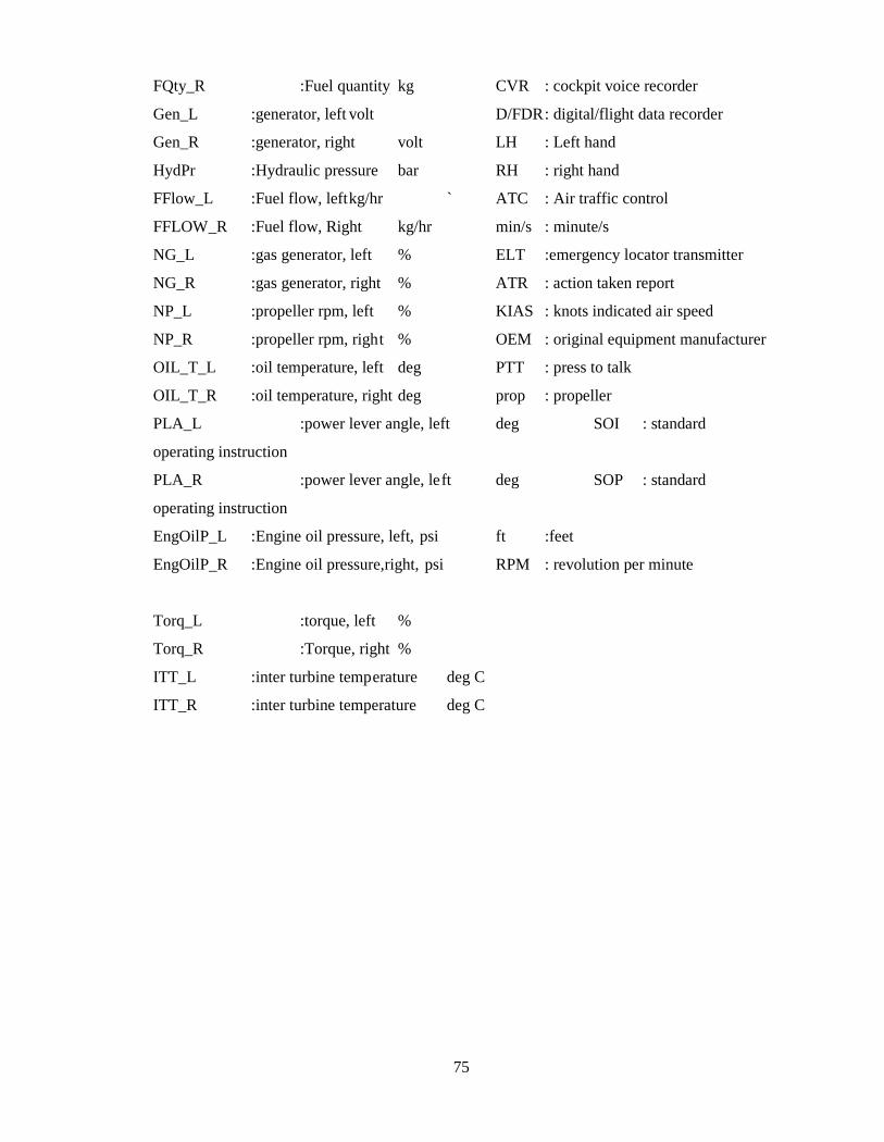
75
FQty_R :Fuel quantity kg CVR : cockpit voice recorder
Gen_L :generator, left volt D/FDR: digital/flight data recorder
Gen_R :generator, right volt LH : Left hand
HydPr :Hydraulic pressure bar RH : right hand
FFlow_L :Fuel flow, leftkg/hr ` ATC : Air traffic control
FFLOW_R :Fuel flow, Right kg/hr min/s : minute/s
NG_L :gas generator, left % ELT :emergency locator transmitter
NG_R :gas generator, right % ATR : action taken report
NP_L :propeller rpm, left % KIAS : knots indicated air speed
NP_R :propeller rpm, right % OEM : original equipment manufacturer
OIL_T_L :oil temperature, left deg PTT : press to talk
OIL_T_R :oil temperature, right deg prop : propeller
PLA_L :power lever angle, left deg SOI : standard
operating instruction
PLA_R :power lever angle, left deg SOP : standard
operating instruction
EngOilP_L :Engine oil pressure, left, psi ft :feet
EngOilP_R :Engine oil pressure,right, psi RPM : revolution per minute
Torq_L :torque, left %
Torq_R :Torque, right %
ITT_L :inter turbine temperature deg C
ITT_R :inter turbine temperature deg C