![V33Y-V33+ Service Manual[1]](https://static.fdocuments.in/doc/165x107/545a8755af795953128b5409/v33y-v33-service-manual1.jpg)
WIND-FLEX White Paper v33
13
WIND-FLEX White Paper v33.doc 20/05/2002 Copyright 2002 by WIND-FLEX consortium 1/13 http://www.vtt.fi/ele/research/els/projects/windflex.htm W I N D- F L EX WIND-FLEX A flexible radio interface architecture for short-range high-speed wireless networking All recent wireless technology developments, although pulled by different market requirements and applications (e.g., WLANs for portable connectivity in office IT enterprises, WPANs for cable replacement and personal sphere interconnectivity, etc.), have been characterized by a common quest for higher capacity density and link speed, on the one hand, as well as greater reliability and scalability in the presence of varying channel conditions and/or traffic loading and QoS system requirements, on the other. Guided by strong evidence on these common persistent trends, the WIND-FLEX European-wide consortium was launched in 2000, aiming at fulfilling the above requirements. Due to the combined adoption of a high frequency (17GHz) for the radio carrier, of flexible radio interface schemes, plus maximization of modem functions/controls allocation in the digital domain, the specified WIND-FLEX radio interface provides dynamically adaptive reliable and efficient communications at a very high link speed, namely, up to 4 bundle-able channels, each one providing a maximum speed of 215Mbit/s gross data rate in the air, which translates to slightly more than 100Mbit/s payload at IP layer, thus representing a very attractive and innovative solution for next- generation wireless LAN/PAN developments. The WIND-FLEX technology, thanks to the 17GHz frequency carrier choice which allows channels with wider bandwidth, smaller coverage ranges and good propagation characteristics, definitely outperforms both current state-of- the-art WPAN and WLAN technologies working in the 2.4 GHz (i.e., Bluetooth and 802.11b) and the 5 GHz range (i.e.802.11a), in terms of maximum bit rate (e.g., 802.11a can achieve in its higher profile a maximum air interface bit rate of 72 Mbit/s), in terms of capacity offering due to the easier channel reuse and the smaller cell sizes, plus in terms of spectral efficiency (about 20% better than 802.11a at PHY layer). Moreover, the proposed solution allows for joint and dynamic optimization of its RF, baseband and MAC/DLC parameters according to time-varying channel conditions, traffic loading and QoS requirements, in order to guarantee required performances at minimum power consumption, while also remaining backward compatible with other OFDM- based technologies (i.e. 802.11a), thus leveraging the huge OFDM know-how developed during last years in the whole wireless industry. This white paper is meant to: x provide an overview of the WIND-FLEX approach x explain its technological and market driven rationale x explain proposed solutions for RF/IF, baseband and MAC/DLC subsystems x benchmark WIND-FLEX versus other alternative technologies x provide an overview of possible business exploitation models
Transcript of WIND-FLEX White Paper v33

WIND-FLEX White Paper v33.doc 20/05/2002
Copyright 2002 by WIND-FLEX consortium
1/13 http://www.vtt.fi/ele/research/els/projects/windflex.htm
W
IN D -F L E X
� � � �� � �
� � �
� � � � � �
�
WWIINNDD--FFLLEEXX AA fflleexxiibbllee rraaddiioo iinntteerrffaaccee aarrcchhiitteeccttuurree ffoorr
sshhoorrtt--rraannggee hhiigghh--ssppeeeedd wwiirreelleessss nneettwwoorrkkiinngg
All recent wireless technology developments, although pulled by different market requirements and applications (e.g., WLANs for portable connectivity in office IT enterprises, WPANs for cable replacement and personal sphere interconnectivity, etc.), have been characterized by a common quest for higher capacity density and link speed, on the one hand, as well as greater reliability and scalability in the presence of varying channel conditions and/or traffic loading and QoS system requirements, on the other. Guided by strong evidence on these common persistent trends, the WIND-FLEX European-wide consortium was launched in 2000, aiming at fulfilling the above requirements. Due to the combined adoption of a high frequency (17GHz) for the radio carrier, of flexible radio interface schemes, plus maximization of modem functions/controls allocation in the digital domain, the specified WIND-FLEX radio interface provides dynamically adaptive reliable and efficient communications at a very high link speed, namely, up to 4 bundle-able channels, each one providing a maximum speed of 215Mbit/s gross data rate in the air, which translates to slightly more than 100Mbit/s payload at IP layer, thus representing a very attractive and innovative solution for next-generation wireless LAN/PAN developments. The WIND-FLEX technology, thanks to the 17GHz frequency carrier choice which allows channels with wider bandwidth, smaller coverage ranges and good propagation characteristics, definitely outperforms both current state-of-the-art WPAN and WLAN technologies working in the 2.4 GHz (i.e., Bluetooth and 802.11b) and the 5 GHz range (i.e.802.11a), in terms of maximum bit rate (e.g., 802.11a can achieve in its higher profile a maximum air interface bit rate of 72 Mbit/s), in terms of capacity offering due to the easier channel reuse and the smaller cell sizes, plus in terms of spectral efficiency (about 20% better than 802.11a at PHY layer). Moreover, the proposed solution allows for joint and dynamic optimization of its RF, baseband and MAC/DLC parameters according to time-varying channel conditions, traffic loading and QoS requirements, in order to guarantee required performances at minimum power consumption, while also remaining backward compatible with other OFDM-based technologies (i.e. 802.11a), thus leveraging the huge OFDM know-how developed during last years in the whole wireless industry. This white paper is meant to:
x� provide an overview of the WIND-FLEX approach x� explain its technological and market driven rationale x� explain proposed solutions for RF/IF, baseband and MAC/DLC subsystems x� benchmark WIND-FLEX versus other alternative technologies x� provide an overview of possible business exploitation models

WIND-FLEX White Paper v33.doc 20/05/2002
Copyright 2002 by WIND-FLEX consortium
2/13 http://www.vtt.fi/ele/research/els/projects/windflex.htm
W
IN D -F L E X
� � � �� � �
� � �
� � � � ! " # $
%
Application scenarios WIND-FLEX is proposed as an added-value solution for next generation wireless networking, in particular meeting the performance needs of the WPAN and WLAN application areas both in the home and enterprise scenarios. Indeed on one hand, as far as future home networking solutions are concerned, it must be observed that a mono-cluster approach, with a single wireless distribution point covering the entire home area, is unsuited to the requirements of concurrent multimedia-rich applications. The mono-cluster would be indeed characterized by poor effective throughput per user (shared media) and lack of flexibility with respect to differences among houses/apartments (room, size, wall) and single end-user scenarios. Therefore a multi-cluster approach has to be preferred, with each single cluster covering a limited area and being dedicated to specific functions/need (entertainment, productivity, automation/control), possibly minimizing the time/complexity/costs of installation and use. On the other hand, in the enterprise environment, besides the need for closing the gap between wired and wireless solutions as far as link speed is concerned, the strong demand for security, mobility and ease of resources access and information exchange (e.g. meetings) push toward a high-performing, intrinsically secure and flexible wireless solution. Therefore the general proposed architecture envisions the presence of multiple electronic devices in an indoor environment (i.e. office, house) which, when provided with a WIND-FLEX radio interface and co-located in the same short-range coverage area (consistent with the multi and application-specific cluster paradigm), can communicate at very high-speed offering, in addition, the attractive possibility of forming automatically a meshed network. Such a self-configuring networking characteristic, which considers also the run-time dynamic assignment of the roles of network elements among devices, represents an additional value when requiring interconnectivity in an infrastructure-less environment (e.g. WPAN at home) while still remaining compatible with infrastructure-based environments such as those typical of WLAN deployment in enterprises (Figure 1).
WIND-FLEX approach Among definitely established market trends in the field of communications, and of course valid for wireless connectivity as well, there is the continuous demand for higher effective data transfer rate and throughput per user. Besides that, from the user point of view there is a clear need for auto-configuring networking as the user does not have the competencies or does not want to be bored by setting up any kind of connectivity procedure. Solving of this user needs represents a market enabler for enterprise ad-hoc connectivity and for home networking. Pulled by these trends the WIND-FLEX approach has been on one hand to move towards a higher carrier range and on the other to maximize allocation of radio interface functions in the digital domain. The 17.1-17.3 GHz frequency range, recommended by ETSI [3], has been adopted in order to achieve the required capacity performance at a reasonable front-end cost, thanks to the foreseen evolution of SiGe processes (i.e. QuBic5G). This choice allows to get access to wider bandwidth, to provide high bit rate at same transmitter power on smaller ranges, and exploit propagation characteristics in smaller ranges and higher frequencies in order to achieve higher spatial capacity density and spectral efficiency. Moreover such frequency range provides higher level of capacity, due to the combined effect of smaller cell size and higher frequency re-use, while at the same time easing concerns about security because of the intrinsic limited propagation through walls. The maximization of radio interface functions in the digital domain allows for the possibility to automatically and dynamically control whole radio interface and react at all layers to guarantee proper communication conditions, despite varying propagation, traffic loading and networking topology conditions. To implement such features, modulation, coding and access schemes and protocols, have been designed in order to allow highly granular flexible variations of their parameters, instantiated by adaptive algorithms and re-configurable sub-systems.
Business rationale As a general remark it is worth to be observed here that in all wireless application areas there is a common strong need for high security, high speed, long-range, high spatial efficiency, low power and low costs. Given that it is very difficult to achieve all attributes with a single solution, the analysis of conceivable future technical propositions, the recent
&('*),+.-0/2123541768)
9;:=<;>*?;@BA;C D;C ABE2FHG5IBABJ2:BK;:LC M=JNMB@;J*IBO2:BC <
PBQ=R SLT0U0VLWPLXZY[VB\0]5^B_a`
68bLbLc7dBdeLf2g h=i
&('*),+.-0/712354176j)
G5I=ALJ7:kA=O5C ILlmJ2I=ALFHnj<HlmJoMB@LJ*ILO7:LC <
PLQkR SLT=UpV;Wqsr0rkVBU0UY[VB\0]5^=_0`
t.fHuvcwyxLiBc7zyxB{
Figure 1: WIND-FLEX application scenarios

WIND-FLEX White Paper v33.doc 20/05/2002
Copyright 2002 by WIND-FLEX consortium
3/13 http://www.vtt.fi/ele/research/els/projects/windflex.htm
W
IN D -F L E X
| } ~ �� � �
� � �
� � � �� � � � �
�
history of radio solutions [15] and the need for user/cluster/application-specific and dedicated systems could push to envisage a trend toward an improvement of all attributes at the expense of the distance, suggesting a future of wireless networking where WPAN and WLAN could collapse/overlap in the 10m range. The proposed technology, thanks to the 17GHz propagation characteristics which allows channels with wider bandwidth, smaller ranges and good propagation characteristics, definitely overcomes performances of current state-of-the-art WPAN and WLAN technologies working in the 2.4 GHz (i.e. Bluetooth and 802.11b) or the 5GHz range (i.e. 802.11a), both in terms of maximum bit rate (e.g. 802.11a can achieve in its higher profile a maximum air interface bit rate of 72Mbit/s) and capacity offering, due to easier channel reuse and smaller cell sizes. Furthermore it must be observed that the proposed solution leverages the OFDM know-how accumulated in the last years within the wireless industry, offering an attractive potential for a future backward-compatible, scalable and unique baseband chip solution for wireless networking. As far as design choices are concerned it must be noted that due to the greater bandwidth coherence offered by 17GHz propagation on a short distance (in the order of 4 MHz) an OFDM system with down to 32 sub-carriers could be designed obviously trading lower complexity in OFDM implementation versus overall maximum bit rate, spectral efficiency and sub-carrier allocation/control granularity. The WIND-FLEX choice of 128 carriers, as a matter of fact, is driven by the latter considerations. As explained, the WIND-FLEX technology has a high potential to be adopted for next generation enterprise wireless networking (for terminal and/or access point connectivity) driven by data speed and spatial efficiency (b/s/m2) and for ad hoc wireless networking in productivity (e.g. fast synchronization and/or data transfer among IT devices) and in entertainment clusters (e.g. audio/video fast streaming between sources and sinks devices,...) both in the home and enterprise scenarios. A shorter-term business opportunity for WIND-FLEX technology can be foreseen in synergy with existing WLAN technologies, by adopting WIND-FLEX as a wireless backbone for standard wireless LANs. Such combined WIND-FLEX/WLAN’s proposition will enable a true "entirely" wireless network coverage of indoor environments, thus providing a much easier, faster to deploy and flexible (distributing capacity according to needs) design and set-up solution, when compared to the current hybrid Ethernet/WLAN’s solution. Annexed to this document a description of this specific WIND-FLEX-based application is reported, along with details of technical proposed solution and relevant simplified WIND-FLEX specifications.
17GHz band regulatory status So far, no specific actions took place vs. regulatory organisations to discuss the use of 17 GHz band and/or closer ranges (say +/- 3 GHz) in which WIND-FLEX technology could be applied without any change in its design. At any rate, the choice to address the 17.1-17.3 GHz frequency band was in line with existing ETSI recommendation ([5]CEPT/T/R 22-06) assigning them for very high speed wireless LAN use on a non-protected and non-interference basis. Besides that, also CEPT/ERC/REC 70-03 [6] recommended, among others options, the use of 17.1-17.3 GHz for short-range wireless connectivity. A contiguous extension of the available 200 MHz in the 17GHz range was recognised by the ITU study group JRG 8A-9B [6], which proposed further 400MHz extensions from 17.3 to 17.7 GHz. For USA and Japan similar bandwidth are generically allocated for radio communications. Given the clear need for wireless systems to move to upper carrier frequency ranges in order to offer to high capacity and higher spatial efficiency and the fact that 17GHz allocation does not provide any harmful interference to other wireless systems, it is expected that FCC and global regulatory approval of this band won't be an issue, assuming industry support of such bands.
17GHz channel characteristics The 17GHz channel, though LOS (Line Of Sight) is the main propagation carrier, support also NLOS (Non Line Of Sight) links in a short range, as those that could be caused by small obstructions due to people movements or small objects present in the same short-range distance (i.e. room).
LOS NLOS
OLOS
Figure 2: Propagation scenarios

WIND-FLEX White Paper v33.doc 20/05/2002
Copyright 2002 by WIND-FLEX consortium
4/13 http://www.vtt.fi/ele/research/els/projects/windflex.htm
W
IN D -F L E X
� � � �� � �
� � �
� � � �� � � �
¡
Figure 3: RMS delay spread cumulative distribution function
OLOS (Obstructed Line of Sight) propagation is handled in short distances, though presence of big obstruction (i.e. walls) at a certain distance (say 5 meters) from emitting source causes a significant drop in receivable power beyond them. Such wall-confined nature of 17GHz propagation at given power transmission is anyway a desirable feature as it allows very dense frequency reuse (thus supporting increase of spatial efficiency over covered areas) and provides intrinsic security in both office/house neighbours. Figure 3 shows RMS delay spread cumulative distribution function at different frequencies 5 GHz, 10.5 GHz and 17 GHz in a typical short range networking scenario. Different materials as brick, metallic glass, soft internal walls or wooden surfaces have been considered in the evaluations. The path loss model has been calculated following the well-known lognormal shadowing effect around the mean value, for which an exponential variation of the received power with the distance has been considered [14]. The behaviour of wireless channels changes with the frequency, in particular the rms delay spread of the channel
impulse response, as the frequency increases, at the same distance, tends to be much lower. This channel characteristic allows to achieve, in the same short ranges, better OFDM design (WIND-FLEX has 20% better spectral efficiency than 802.11a at the PHY layer), as guard time can be made significantly smaller and also, being coherence bandwidth equal to 5 times mean rms delay, much wider subcarrier range, or on the other hand, easier OFDM equalisation.
WIND-FLEX ADAPTIVE MODEM ARCHITECTURE
System characteristics overview
A table of most important WIND-FLEX parameters is reported here below:
System parameters Values Coverage range (omnidirectional antenna, BER 10-6 , code 1/2)
LOS: ¢ 100 m (QPSK), ¢ 50 m (16QAM), ¢ 30 m (64QAM) NLOS: ¢ 10 m (QPSK), ¢ 6 m (16QAM), ¢ 4 m (64QAM)
Radio Interface optimization strategy Meet QoS requirements given channel conditions with the minimum transmitted/processing power
RF parameters Values Baseband parameters Values
Frequency 17.1-17.3 GHz Modulation scheme OFDM with variable number N (1-8) of subcarrier excision
Channel BW 50 MHz Modulation adaptivity Per frame, per user Number of channels 4 Subcarriers modulation schemes BPSK, QPSK, 16QAM, 64QAM Channels center frequencies 17.125, 17.175, 17.225, 17.275 Nominal OFDM carriers number 128 Upper guard frequency band 5,469 MHz (14 Suppressed Carriers) Unused carriers 28 (27+DC) Lower guard frequency band 5.078 MHz (13 Suppressed Carriers) Active OFDM carriers number 100 Subcarrier spacing 390.625 KHz Pilot carriers 0 Max peak EIRP 27 dBm Useful OFDM carriers numbers 100-N Max average EIRP 14 dBm OFDM useful symbol length 2.56 £ s Receiver sensitivity -85 dBm Guard interval 200 ns Dynamic range 60 dB Coding scheme Turbo code Noise figure 6 dB Turbo code scheme Parallel convolutional punctured Turbo codes polynomial (13, 15) octal Coding rates 1/2, 2/3, 3/4 Networking parameters Values Access scheme FDM/TDMA Duplexing scheme TDD Symbol slots/frame 178 Frame length 491.28 £ s Preamble structure 3 symbols Network entities Master, slaves, bridge, gateway Network entity allocation Dynamic
5 10 15 20 25 30 0 0.1 0.2 0.3 0.4 0.5 0.6 0.7 0.8 0.9
1
Rms Delay Spread (ns)
LOS Rms Delay Spread (ns) CDF
5 GHz 10 GHz 17 GHz
WIND-FLEX White Paper v33.doc 20/05/2002
Copyright 2002 by WIND-FLEX consortium
5/13 http://www.vtt.fi/ele/research/els/projects/windflex.htm
W
IN D -F L E X
¤ ¥ ¦ §¨ © ¨
ª « ¬
® ¯ °± ² ³ ´ µ
¶
·8¸L¹*ºB»L¼L½5¾ ¿L½5¸À»LÁ;Â7½2¸L¿H¾ »LÃH¸ÄÆÅLÇ=ÈyÉ7Ê;ËÌ Í;Î ÅHÊ
Ï5ÐÒÑjÓ8ÔÕ×Ö
Ø Í ÊBÙBÅLÇZÚ2ÛsÜÝ Ã;Þ
Ø Í ÊBÙBÅLÇ,Ü Í ÇLÅ
ßáàvâäãåjæ2âæ ¹2ç*½2¸
èsé Í7ê2ê Å Ìë É êkì5í Ç í É ê
Ø[è ë É ì ÅÊ Í ÇkÅ*îïsðÒð Ø î í ñ Åò ðÒó[ô
õ Í Ê Í;ö ÅLÇLÅHÊ2î Ø.÷ õ ÉHÈyÅHÊ
·8Á;¸Lø×ý5ºB¼LÃLù7½5¸ ú Öyåvßüû ÃLù
·.ÁH¸Lø5Ãýù2½*¼ ú Ö×åmßù*½ û ÃLùâsþ ¹5ºLºB½5ÿ½*»��7¾ û ¹��HÃ;¸ æ��,à
Ó��2à
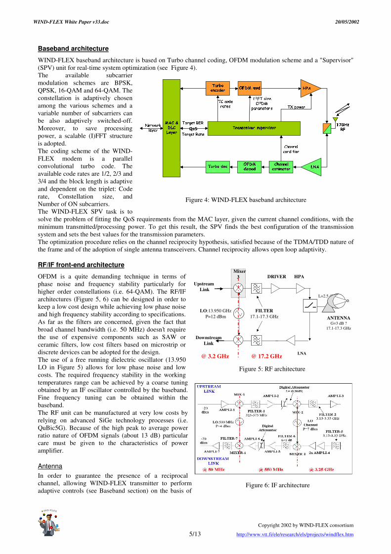
Baseband architecture
WIND-FLEX baseband architecture is based on Turbo channel coding, OFDM modulation scheme and a "Supervisor" (SPV) unit for real-time system optimization (see Figure 4). The available subcarrier modulation schemes are BPSK, QPSK, 16-QAM and 64-QAM. The constellation is adaptively chosen among the various schemes and a variable number of subcarriers can be also adaptively switched-off. Moreover, to save processing power, a scalable (I)FFT structure is adopted. The coding scheme of the WIND-FLEX modem is a parallel convolutional turbo code. The available code rates are 1/2, 2/3 and 3/4 and the block length is adaptive and dependent on the triplet: Code rate, Constellation size, and Number of ON subcarriers. The WIND-FLEX SPV task is to solve the problem of fitting the QoS requirements from the MAC layer, given the current channel conditions, with the minimum transmitted/processing power. To get this result, the SPV finds the best configuration of the transmission system and sets the best values for the transmission parameters. The optimization procedure relies on the channel reciprocity hypothesis, satisfied because of the TDMA/TDD nature of the frame and of the adoption of single antenna transceivers. Channel reciprocity allows open loop adaptivity.
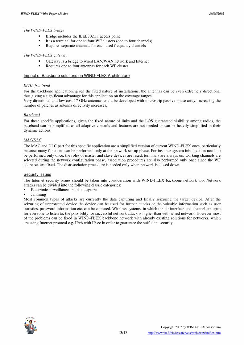
RF/IF front-end architecture
OFDM is a quite demanding technique in terms of phase noise and frequency stability particularly for higher order constellations (i.e. 64-QAM). The RF/IF architectures (Figure 5, 6) can be designed in order to keep a low cost design while achieving low phase noise and high frequency stability according to specifications. As far as the filters are concerned, given the fact that broad channel bandwidth (i.e. 50 MHz) doesn’t require the use of expensive components such as SAW or ceramic filters, low cost filters based on microstrip or discrete devices can be adopted for the design. The use of a free running dielectric oscillator (13.950 LO in Figure 5) allows for low phase noise and low costs. The required frequency stability in the working temperatures range can be achieved by a coarse tuning obtained by an IF oscillator controlled by the baseband. Fine frequency tuning can be obtained within the baseband. The RF unit can be manufactured at very low costs by relying on advanced SiGe technology processes (i.e. QuBic5G). Because of the high peak to average power ratio nature of OFDM signals (about 13 dB) particular care must be given to the characteristics of power amplifier.
Antenna In order to guarantee the presence of a reciprocal channel, allowing WIND-FLEX transmitter to perform adaptive controls (see Baseband section) on the basis of
Figure 6: IF architecture
Figure 4: WIND-FLEX baseband architecture
UpstreamLink
LO:13.950 GHzP=12 dBm
FILTER17.1-17.3 GHz
LNA
L=2.5 dB
DownstreamLink
DRIVER HPA
ANTENNAG=3 dB ?
17.1-17.3 GHz
@ 3.2 GHz @ 17.2 GHz
Mixer3
Figure 5: RF architecture

WIND-FLEX White Paper v33.doc 20/05/2002
Copyright 2002 by WIND-FLEX consortium
6/13 http://www.vtt.fi/ele/research/els/projects/windflex.htm
W
IN D -F L E X
� �
� � �
� �
� � � �
� � � � �
�
WF PHY layer
WF MAC layer
WF DLC layer
Shared Medium (17GHz radio spectrum)
TCP
IP
Multimedia and Internet applications
UDP
WIND-FLEX DEVICE A WIND-FLEX DEVICE B
WIND-FLEXINTERFACE
GENERIC UPPER
LAYERS
WF PHY layer
WF MAC layer
WF DLC layer
TCP
IP
Multimedia and Internet applications
UDP
WF PHY layer
WF MAC layer
WF DLC layer
WF PHY layer
WF MAC layer
WF DLC layer
Shared Medium (17GHz radio spectrum)
TCP
IP
Multimedia and Internet applications
UDPTCP
IP
Multimedia and Internet applications
UDP
WIND-FLEX DEVICE A WIND-FLEX DEVICE B
WIND-FLEXINTERFACE
GENERIC UPPER
LAYERS
WF PHY layer
WF MAC layer
WF DLC layer
WF PHY layer
WF MAC layer
WF DLC layer
TCP
IP
Multimedia and Internet applications
UDPTCP
IP
Multimedia and Internet applications
UDP
channel information estimated by the co-located receiver, the design required the presence of a single antenna, switched between transmitting and receiving phases. Given the mobile and ad-hoc network nature of WIND-FLEX an omni-directional antenna is compulsory. For this particular design, printed technology antennas provide a number of advantages as lightweight, low costs and relatively easy manufacturing. Among the different possibilities the line fed slot coupled microstrip patches is considered suitable as this technique makes relatively easier the impedance matching and facilitates fed network design for array configurations. Restrictive specifications for bandwidth in terms of return losses have to be given in order to provide the required bandwidths.
Technology for high volume production For the high volume production the use of a multi-layer PCB structure with some filters and the MMICs mounted in the top layer and other filters in the intermediate layers is envisaged. This structure would minimise the size of the PCB and avoid the radiation of the filters. Four MMICs are envisaged for the chip-set with the size and technology indicated in table 2.
Unit Ranges Estimated size Technology IF Transmitter 50 MHz-3,25 GHz 6 mm x 5 mm Si-Ge IF Receiver 3,25 GHz-50 MHz 6 mm x 5 mm Si-Ge Transmitter RF 3,25GHz-17 GHz 2 mm x 2 mm GaAs/ Si-Ge Receiver RF 17GHz-3,25 GHz 2 mm x 2 mm GaAs/ Si-Ge
Table 2: Chip-set for high volume production of WIND-FLEX modem A dielectric substrate of low losses should be used for the PCB. In order of reducing the size of the PCB, a substrate of high dielectric constant such as a ceramic of dielectric constant around 6 should be used. With this kind of substrate the size of the PCB for both units RF and IF would be of around 5cm x 5cm. Four layers are envisaged for the PCB with this substrate. The packages must be compatible with a high volume manufacturing process such as SMD. There are no problems for the IF chips for which plastic packages could be used but, however, these kind of packages are not available up to now for 17 GHz. Wire bonding must be avoided because it requires very sophisticated facilities for volume production. Flip-chip technology may be the most adequate. The entire radiofrequency unit must be enclosed by a metallic enclosure manufactured by an injection moulding process.
Network Architecture
The WIND-FLEX Network is composed by a set of clusters, being this set of devices such that every pair can establish a direct connection; a cluster is then a full-meshed sub-network. Every cluster consists of a Master device and of one or more (up to 63) Slave devices, which must perform an appropriate association procedure to the cluster. The Master carries out the synchronization and the coordination of the cluster and it is in charge of allocating the shared radio resources. There is no hardware or software difference among the Master and Slave devices, and each device can become a Master. The Master of a cluster is chosen among all the devices associated to the cluster: a Master election procedure ensures that the Master is the device having the "best" position within the cluster, meaning that its physical links
with all the other devices associated to the cluster are characterized by the best quality. A proper algorithm guarantees that the Master election is repeated whenever,
Figure 7: WIND-FLEX protocol stack

WIND-FLEX White Paper v33.doc 20/05/2002
Copyright 2002 by WIND-FLEX consortium
7/13 http://www.vtt.fi/ele/research/els/projects/windflex.htm
W
IN D -F L E X
� � � �
� � �
! "
# $ % &
' ( ) * +
,
System Windflex UWBModulation scheme OFDM TM-PPM
Frequency carrier 17GHz No carrier
Max capacity (PMD-SAP) Mb/s 102.00 110.00
Transmit Output Power (EIRP) mW 1.0E+01 3.2E-02
Transmit Output Power (MAX) mW 2.0E+02 1.6E-01
Bandwidth MHz 50.00 7500.00
Allocable band MHz 200.00 7500.00
Range m 5.00 10.00
Area/user (office scenario) m2 12.00 12.00
Power efficiency (Capacity/mW) Mb/s/mW 10.20 3478.51
Bandwidth efficiency (Capacity/Hz) b/s/Hz 2.040 0.015
Overlapping piconets # 4.00 4.00
Aggregate BW Eff (Capacity/Hz) b/s/Hz 2.040 0.059
Spatial efficiency (Capacity/m^2) Mb/s/m2 5.1975 1.4013
mainly due to device movement, the network topology significantly changes. In case a new Master is elected, the Master role is handed-over in a seamless fashion from the old Master to the new one [9, 10]. The system is able to reconfigure itself to react to changes in the network topology. The WIND-FLEX protocol stack is fully based on IP as depicted in Figure 7.
Medium Access Control (MAC) Layer
At MAC layer the bit transmission is organized in a Time Division Multiple Access (TDMA) way. The time axis is divided into frames that, in turn, are divided into 178 time slots, characterized by: x� a fixed time duration (about 2.8 Ps) which entails a frame duration equal to about 0.5 ms. x� a variable number of transported bits; being this number depending from the adopted radio transmission mode
(combination of modulation and channel coding schemes) and communicated from the PHY to the MAC layer via a proper interface.
In order to reduce battery consumption, data transmission speed is reduced whenever the traffic situation allows the delivery of the packets with an acceptable end-to-end delay and jitter delay using a lower transmission bit rate. On the contrary, when traffic is heavy and buffer length is large, the system attempt to use a bigger constellation scheme (up to 64-QAM), provided that channel status is so good that the required BER can be accomplished. Resource assignment is performed by the Master using a novel greedy-type scheduler algorithm, where the useful slots are assigned frame-by-frame to the different connections of all the devices in the cluster. Such assignment is based on the following two types of information for each active connection: 1. a “static” information that does not change while the connection is active. It depends only on the nature of the
connection and expresses the QoS parameters (delay, jitter, BER), characterizing the class of service of the connection.
2. a “dynamic” information that takes into account the status of the buffers of every transmitting device. It is updated every frame, according to the data received from the associated devices.
Data Link Control (DLC) layer
A specific requirement for the WIND-FLEX DLC is quick and dynamic adaptivity to changes in the physical link. The upper interface of DLC protocol serves the network layer, which in the case of WIND-FLEX, is the Internet Protocol, IPv4 or IPv6. DLC provides functions to transmit IP datagrams over the WIND-FLEX air interface to a peer Internet Protocol entity, mapping the IP datagram into different Class of Service, characterized by different QoS requirements. The data exchange between two DLC entities is always connection-oriented. At DLC layer runs also a suitable error control protocol, which works on a per-connection basis considering different QoS requirements of the different classes of service. The error control scheme adopted is Selective Repeat ARQ with partial bitmap, which offers good performance but also optimizes retransmission overhead. Acknowledgements are sent selectively to request the retransmission of corrupted or lost PDUs, either in a piggybacked fashion or by means of a control PDU. Sequence Numbers are used to guarantee flow control.
Alternative technologies WIND-FLEX system aims at solving the future capacity demand for high bit rate and high capacity per user in the short range and can therefore be proposed as the solution for next generation wireless personal area networking. Other
technologies targeting the same performances objectives are either making use of much wider bandwidth in the low frequency regions (i.e. Ultra Wide Band (UWB)) or at even higher frequencies (i.e. 60 GHz). As far as benchmarking with UWB is concerned, results of preliminary theoretical comparisons between the two technologies are reported in the table herewith. By that it can be inferred that the two technologies offer similar performances in terms of maximum capacity and spatial efficiency though, because of their intrinsic nature, providing very different figures in terms of power efficiency (much higher for UWB) and spectral efficiency (much higher for WIND-FLEX).
Given the comparable global systems performances, the WIND-FLEX technology offers the added values of keeping backward compatibility with all OFDM systems (where due to significant investments made so far there is considerable

WIND-FLEX White Paper v33.doc 20/05/2002
Copyright 2002 by WIND-FLEX consortium
8/13 http://www.vtt.fi/ele/research/els/projects/windflex.htm
W
IN D -F L E X
- . / 0
1 2 1
3 4 5
6 7 8 9
: ; < = >
?
know-how), of not requiring significant design challenges on the RF design (as in UWB), of not producing any harmful interferences on other existing technologies, due to the limited portion of unoccupied spectrum used. As far as the benchmarking with 60 GHz technologies are concerned, the main reason to explore this bandwidth for high bit rate (fixed) wireless access technologies was driven by the high attenuation produced by the oxygen absorption in that range, considered an enabler for easier and more dense frequency reuse. In an indoor environment those propagation characteristics are not exploited being propagation actually limited by obstruction (i.e. walls), moreover the 60GHz propagation require full LOS, not suitable for mobile/nomadic purposes. Another obvious consideration is the much higher RF/IF front-end cost that doesn’t make this technology suitable for low cost/consumer applications.
Status and next steps The WIND-FLEX technology, thanks to combination of high data rate, high spatial efficiency, flexible design and dynamic adaptivity and reconfigurability features at all layers represents one amongst the most attracting candidate option for next generation short-range wireless networking standardization. A WIND-FLEX proof-of-concept demonstrator is under development and, by Q103 will integrate significant part of WIND-FLEX specifications. A first prototype of the WIND-FLEX demonstrator will be available by end of Q202 and will be shown at Philips Corporate Research Exhibition (Eindhoven, The Netherlands, May02) and at IST Summit on Mobile Communications (Thessaloniki, Greece, Jun02). The WIND-FLEX consortium, due to its current technological competitive advantage, is open to look for most suitable business ownerships and industry support, in order to identify accordingly most profitable business exploitation path and get proper critical mass to address and solve regulatory and standardization issues.
Acknowledgements and contacts WIND-FLEX is a consortium constituted by industrial and academic companies partly funded by European Commission. This White paper integrates contributions from all members of WIND-FLEX team. WIND-FLEX project and technology primary contacts are:
x� Ilkka Saarinen, WIND-FLEX Project Manager, VTT Electronics, Finland, e-mail: [email protected] x� Giuseppe Coppola, WIND-FLEX Technical/Business Exploitation Manager, Philips Research, Italy, e-mail:
References [1] WIND-FLEX project public website: http://www.vtt.fi/ele/research/els/projects/windflex.htm [2] High Bit Rate Adaptive WIND-FLEX Modem Architecture for Wireless Ad-Hoc Networking in Indoor
Environments, I.Saarinen, G.Coppola et al., IST Mobile & Wireless Telecommunications Summit 2002, June 2002, Thessaloniki, Greece
[3] WIND-FLEX Internal document RFC-23, WIND-FLEX value proposition and relevant options for exploitation and standardization strategies, G.Coppola, L.Camiciotti.
[4] ETSI TR 101 031 v1.1.1 (1997-07) Radio Equipment and Systems (RES); High Performance Radio Local Area Networks (HIPERLAN); Requirements and Architectures for Wireless ATM Access and Interconnection.
[5] CEPT T/R 22-06 Harmonized Radio Frequency Bands for High Performance Radio Local Area Networks (HIPERLAN) in the 5 GHz and 17 GHz frequency range.
[6] ITU Study Groups, Documents 8A-9B/58-E, 28 September 1998 “ Spectrum aspects of fixed wireless Access [7] WIND-FLEX Deliverable D4.1 “ Design and performance of modulation and diversity algorithms” [8] WIND-FLEX Deliverable D4.2 “ Requirements and specification for the DSP core” [9] R.P. Torres, L. Valle, M. Domingo, S. Loredo, M.C. Diez, “ CINDOOR: An Engineering Tool for Planning and
Design of Wireless Systems in Enclosed Spaces” .. IEEE Antennas and propagation Magazine, Vol. 41, No. 4, August 1999.
[10] Manuel Lobeira, Ana García Armada, Rafael Torres, José Luis García,"Channel modelling and characterisation at 17 GHz for indoor broadband WLAN", IEEE JSAC- Channel and Propagation models for Wireless Design. To be published in the second quarter of 2002.
[11] M. Lobeira, I. Singla, J.L. García, “ Non Linearities, Phase Noise and Interference Influence on High Bit Rate 17 GHz Modem” , in Proceedings of IST Mobile Summit 2001, Barcelona, Paper MOBCS4VVMNA.
[12] R. Cusani, F. Delli Priscoli, G. Ferrari, G. Razzano, M. Torregiani, “ Dynamic, channel-status driver, re-configurable Medium Access Control for the WIND FLEX wireless Local Area Network” , in Proceedings of IST Mobile Summit 2001, Barcelona.
[13] R. Cusani, M. Torregiani, F. Delli Priscoli and G. Ferrari , "A novel MAC and Scheduling strategy to guarantee QoS for the new-generation WIND-FLEX wireless LAN", accepted for publication on IEEE Pers. Comm. Magazine, special issue on Mobile and Wireless Internet- Architectures and Protocols, 2002.
[14] Lee, W.C.Y., “ Mobile Cellular Telecommunications Systems” , McGraw Hill Publications, New York, 1989

WIND-FLEX White Paper v33.doc 20/05/2002
Copyright 2002 by WIND-FLEX consortium
9/13 http://www.vtt.fi/ele/research/els/projects/windflex.htm
W
IN D -F L E X
@ A B C
D E D
F G H
I J K L
M N O P Q
R
[15] J.Foerster, E.Green, S.Somayazulu, D.Leeper, “ Ultra-Wideband Technology for Short- or Medium Range Wireless Communications” , Intel Technology Journal Q2, 2001

WIND-FLEX White Paper v33.doc 20/05/2002
Copyright 2002 by WIND-FLEX consortium
10/13 http://www.vtt.fi/ele/research/els/projects/windflex.htm
W
IN D -F L E X
S T U V
W X W
Y Z [
\ ] ^ _
` a b c d
e
ANNEX: WIND-FLEX as a wireless backbone for WLANs/WPANs
Introduction
In recent years there has been a growing trend towards personal computers and workstations becoming “ portable” and “ mobile” . This ever-increasing group of mobile users has been demanding access to network services similar to their “ tethered” counterparts. Today many people carry numerous portable devices, such as laptops, mobile phones, PDAs and mp3 players, for use in their professional and private lives. For the most part, these devices are used separately that means their applications do not interact, but at the same time numerous factors associated with technology, business, regulation and social behavior naturally have led to a big expansion of wireless networking, which is advancing in terms of technology and usage/penetration, thanks to the Internet and the success of second-generation cellular systems. Table 1 summarizes the main features of the current wireless technologies and compared to WIND-FLEX ones.
802.11b 802.11a Bluetooth HIPERLAN/2 WIND-FLEX
Carrier 2.4 GHz 5 GHz 2.4 GHz 5 GHz 17 GHz
Bandwidth 22MHz (DSSS) 20 MHz 1 MHz per
channel 20 MHz 50 MHz
Max physical rate Up to 11 Mbps Up to 72 Mbps 1 Mb/s 72 Mb/s 215 Mbps
Medium Access Control
CSMA/CA RTS/CTS
CSMA/CA RTS/CTS
TDMA/FDMA TDD TDMA/TDD TDMA/TDD
Frequency Selection DSSS OFDM FHSS OFDM A-OFDM
Modulation QPSK BPSK/QPSK 16QAM/64QAM GFSK BPSK/QPSK/
16QAM
BPSK/4QAM 16QAM/64QA
M
Cell radius <30,50,70m <50m <10m <30m <100(LOS), <10m (NLOS)
Table 1. WLANs standards The goal of the WLAN standard is connectivity to the Ethernet plug in the wall at the workplace and Ethernet-like connectivity in ad hoc situations, such as conferences. Devices that attach to the Ethernet are usually high-capability devices, such as laptops and desktop computers. These devices are relatively expensive and wireless connectivity is justifiable for business entities as an infrastructure cost. The main WLAN technologies are currently the IEEE 802.11 standard, which is already available on the market in its b version, and HIPERLAN/2 standard.
IEEE802.11 and HIPERLAN type 2 Characteristics An 802.11 WLAN is based on a cellular architecture where the system is subdivided into cells, where each cell, called Basic Service Set (BSS), is controlled by a Base Station, called Access Point (AP). Most installations are formed by several cells, where the Access Points are connected through some kind of backbone (called Distributed System or DS), typically Ethernet or wireless itself. The basic MAC mechanism specified in IEEE802.11 is A Distributed Coordination Function (DCF) that allows for sharing of the wireless channel through the use of carrier sense multiple access with collision avoidance (CSMA/CA). A CSMA/CA protocol works as follows: a station desiring to transmit senses the medium, if the medium is busy then the station will defer its transmission to a later time, if the medium is sensed free then the station is allowed to transmit. The station transmits a short control packet called RTS (Request to Send), which will include the source, destination, and the duration of the following transaction, the destination station will respond (if the medium is free) with a response control Packet called CTS (Clear to Send), which will include the same duration information. All the stations receiving either the RTS and/or the CTS, will set their Virtual Carrier Sense indicator, for the given duration, and will use this information together with the Physical Carrier Sense when sensing the medium. This kind of protocols are very effective when the medium is not heavily loaded, since it allows stations to transmit with minimum delay, but there is always a chance of stations transmitting at the same time, caused by the fact that the station sensed the medium free and decided to transmit at once. So in general a MAC mechanism that uses TDMA, such as the WIND FLEX system, offers better performance. HIPERLAN/2 is a standard for high-speed radio communication system (air interface speed up to 72 Mbit/s) to provide short-range wireless access to various broadband core networks in the 5 GHz band. The standard defines core network independent Physical (PHY) and Data Link Control (DLC) layers as well as a set of core network specific Convergence Layers (CL) on top of the DLC layer. HIPERLAN/2 is a cellular system where each radio cell is controlled by an

WIND-FLEX White Paper v33.doc 20/05/2002
Copyright 2002 by WIND-FLEX consortium
11/13 http://www.vtt.fi/ele/research/els/projects/windflex.htm
W
IN D -F L E X
f g h i
j k j
l m n
o p q r
s t u v w
x
Access Point (AP) covering a certain geographical area. The system can be deployed both indoor and outdoor. The access scheme is TDMA
Wireless Personal Area Networks The goal of WPANs is replacing wires between objects that are close to each other. While the WLAN technologies are specifically designed for devices in and around the office or home, a WPAN device will travel from country to country, be used in cars, airplanes, and is designed for international use allowing PCs, PDAs, mobile phones, pagers, and other handheld devices to communicate and interoperate with one another. A WPAN technology is characterised by short-range, low power, low cost, small networks. Currently the main WPAN technology is Bluetooth. The Bluetooth’ s architecture is very similar to the WIND-FLEX’ s one: two or more units sharing the same channel form a piconet. There is one master unit and up to seven active slave units in a piconet. These devices can be in either of the states: active, park, hold and sniff. Multiple piconets with overlapping coverage areas form a scatternet. Recently a committee was created by the Institute of Electrical and Electronics Engineers (IEEE) to develop a new standard called 802.15 Wireless Personal Area Networks (WPAN); the goal of publishing the 802.15 standards will be to accommodate wider adoption and applicability, and to deal with issues like coexistence and interoperability within the networks. Established in January 1999, the WPAN working group, which is part of the Local and Metropolitan Area Network Standards Committee of IEEE, has formed four task groups, each focused on necessary standards, one of these has the scope of publishing a new standard for high data rate for WPAN, this data rate could reach 20 Mbit/sec. The Bluetooth Special Interest Group (SIG) specification serves as the foundation for developing the IEEE 802.15 WPAN standard, which would standardize the Medium Access Control (MAC) and Physical (PHY) layers of Bluetooth. The group has accepted significant parts of the Bluetooth specification without modification and has enriched it with various other features and considerations.
WIND-FLEX as a High-Speed Wireless LAN Backbone
The WIND-FLEX adaptive modem architecture can be used as a Wireless Local Area Network or Wireless Personal Area Network backbone. The WLAN backbone solution provides an efficient data transfer and Internet access from common mobile WLAN terminals. Currently IEEE802.11b and IEEE802.11a are the dominant standards for WLAN systems, thus the backbone should be able to support connections from IEEE802.11 standard based devices. The WIND-FLEX system provides either multichannel or single channel backbone network. The WIND-FLEX frequency band (17.1 GHz – 17.3 GHz) can be divided up to four channels in order to arrange separate network structures. The other possibility is to arrange a single channel, multihop backbone network. These solutions open the way for two different backbone scenarios for open space environments like airports and large factory halls.
F1 F2 F3 F4
17.3
GH
z
17.1
GH
z
Figure 8: WIND-FLEX frequency band and Channelisation.
System Overview and Scenarios Our solution for high speed wireless backbone is based on WIND-FLEX adaptive modem architecture, which is described at WIND-FLEX white paper. The backbone solution requires several WIND-FLEX system adjustments. The current WIND-FLEX target system and network structure is a single hop network with dynamic resource allocation for mobile terminals. In contrary the backbone network uses fixed terminals and it will simplify the system architecture slightly. With omni-directional antennas the WIND-FLEX coverage area is less than 20 meters, but the backbone network utilizes directional antennas and thus the WIND-FLEX backbone link span can be over 100 meters. This makes it possible to enlarge the coverage area
The Single Channel WIND-FLEX Backbone The following picture represents the single channel WIND-FLEX backbone solution for IEEE802.11 WLAN systems. The network includes WIND-FLEX terminals and Gateways. The WIND-FLEX terminals are wireless access points with IEEE802.11 interfaces and WIND-FLEX (WF) interfaces. The routing between WF and IEEE802.11 is handled at network layer, thus no additional routing mechanisms and adaptivity at lower levels of WIND-FLEX systems is needed.

WIND-FLEX White Paper v33.doc 20/05/2002
Copyright 2002 by WIND-FLEX consortium
12/13 http://www.vtt.fi/ele/research/els/projects/windflex.htm
W
IN D -F L E X
y z { |
} ~ }
� � �
� � � �
� � � � �
�
WF TEIEEE802.11 AP
IEEE802.11
WF GatewayIEEE802.11 APWF TE
IEEE802.11 AP
IEEE802.11
InternetRouter
HubWired Ethernet
100-base T
WF TEIEEE802.11 AP
IEEE802.11
WF link (F1)
WF link (F1)
WF link (F1)
Figure 9 WIND-FLEX Single Channel Backbone Network.
WF Terminals and IEEE802.11 Access Points �� WF Terminal acts as a normal IEEE802.11 access point. �� One WF high speed links to WF gateway and one directional antenna. �� One WF frequency channel per WF cluster.
WF Gateway �� Possibility to use as a IEEE802.11 Access Point �� Link connection to WF terminals (1 to N directional antennas) �� Connection to wired LAN/WAN and Internet.
The Multichannel WIND-FLEX Backbone The following picture describes the multichannel backbone network. Using the multichannel network the frequency can be fully utilized. Due to that, the solution is more efficient than single channel multihop system what comes to pure network throughput efficiency. However the costs for maintaining and constructing the network are higher than with the single channel backbone network. The network consists of WF gateway, WF terminals and WF bridges between WF clusters.
IEEE802.11
WF GatewayIEEE802.11 APWF TE
IEEE802.11 AP
IEEE802.11
InternetRouter
HubWired Ethernet
100-base T
WF BridgeIEEE802.11 AP
IEEE802.11WF cluster (F1)
WF cluster (F2)
Figure 10: WIND-FLEX Multichannel Backbone Network.
The WIND-FLEX terminal �� Terminal is a access point to IEEE802.11 cluster.
WIND-FLEX White Paper v33.doc 20/05/2002
Copyright 2002 by WIND-FLEX consortium
13/13 http://www.vtt.fi/ele/research/els/projects/windflex.htm
W
IN D -F L E X
� � � �
� � �
� � �
� � � �
� � � � �
�
The WIND-FLEX bridge �� Bridge includes the IEEE802.11 access point �� It is a terminal for one to four WF clusters (one to four channels). �� Requires separate antennas for each used frequency channels
The WIND-FLEX gateway �� Gateway is a bridge to wired LAN/WAN network and Internet �� Requires one to four antennas for each WF cluster
Impact of Backbone solutions on WIND-FLEX Architecture
RF/IF front-end For the backbone application, given the fixed nature of installations, the antennas can be even extremely directional thus giving a significant advantage for this application on the coverage ranges. Very directional and low cost 17 GHz antennas could be developed with microstrip passive phase array, increasing the number of patches as antenna directivity increases.
Baseband For these specific applications, given the fixed nature of links and the LOS guaranteed visibility among radios, the baseband can be simplified as all adaptive controls and features are not needed or can be heavily simplified in their dynamic actions.
MAC/DLC The MAC and DLC part for this specific application are a simplified version of current WIND-FLEX ones, particularly because many functions can be performed only at the network set-up phase. For instance system initialization needs to be performed only once, the roles of master and slave devices are fixed, terminals are always on, working channels are selected during the network configuration phase, association procedures are also performed only once since the WF addresses are fixed. The disassociation procedure is needed only when network is closed down.
Security issues The Internet security issues should be taken into consideration with WIND-FLEX backbone network too. Network attacks can be divided into the following classic categories: �� Electronic surveillance and data capture �� Jamming Most common types of attacks are currently the data capturing and finally seizuring the target device. After the seizuring of unprotected device the device can be used for further attacks or the valuable information such as user statistics, password information etc. can be captured. Wireless systems, in which the air interface and channel are open for everyone to listen to, the possibility for successful network attack is higher than with wired network. However most of the problems can be fixed in WIND-FLEX backbone network with already existing solutions for networks, which are using Internet protocol e.g. IPv6 with IPsec in order to guarantee the sufficient security.


