WinCC flexible 2008, User Logon to the Operator Panel via HMI-RFI · 2015-01-19 · WinCC flexible...
82
Service & Support Answers for industry. WinCC flexible 2008, User Logon to the Operator Panel via HMI-RFI Application Description Application y May 2009
Transcript of WinCC flexible 2008, User Logon to the Operator Panel via HMI-RFI · 2015-01-19 · WinCC flexible...

Service & Support
Answers for industry.
WinCC flexible 2008, User Logon to the Operator Panel via HMI-RFI Application Description
Application May 2009

Warranty, liability and support
User Logon to the Operator Panel via HMI-RFI ID Number: 35214239
V 1.0 Issue 08.05.2009 2/82
Cop
yrig
ht ©
Sie
men
s A
G C
opyr
ight
-200
9 A
ll rig
hts
rese
rved
35
2142
39_W
inC
Cfle
xibl
e_H
MI-R
FI_e
.doc
Note The application examples are not binding and do not claim to be
complete regarding the circuits shown, equipping and any eventuality. The application examples do not represent customer-specific solutions. They are only intended to provide support for typical applications. You are responsible for ensuring that the described products are correctly used. These application examples do not relieve you of the responsibility of safely and professionally using, installing, operating and servicing equipment. When using these application examples, you recognize that we cannot be made liable for any damage/claims beyond the liability clause described. We reserve the right to make changes to these application examples at any time without prior notice. If there are any deviations between the recommendations provided in these application examples and other Siemens publications – e.g. Catalogs – then the contents of the other documents have priority.
Warranty, liability and support
We do not accept any liability for the information contained in this document.
Any claims against us – based on whatever legal reason – resulting from the use of the examples, information, programs, engineering and performance data etc. described in this application example shall be excluded. Such an exclusion shall not apply in the case of mandatory liability, e.g. under the German Product Liability Act (“Produkthaftungsgesetz”), in case of intent, gross negligence, or injury of life, body or health, guarantee for the quality of a product, fraudulent concealment of a deficiency or breach of a condition which goes to the root of the contract (“wesentliche Vertragspflichten”). However, claims arising from a breach of a condition which goes to the root of the contract shall be limited to the foreseeable damage which is intrinsic to the contract, unless caused by intent or gross negligence or based on mandatory liability for injury of life, body or health. The above provisions do not imply a change in the burden of proof to your detriment.
Copyright © Copyright-2009 Siemens I IA/DT. It is not permissible to transfer or copy these application examples or excerpts of them without first having prior authorization from Siemens I IA/DT in writing. For questions about this document please use the following e-mail address:

Foreword
User Logon to the Operator Panel via HMI-RFI ID Number: 35214239
V 1.0 Issue 08.05.2009 3/82
Cop
yrig
ht ©
Sie
men
s A
G C
opyr
ight
-200
9 A
ll rig
hts
rese
rved
35
2142
39_W
inC
Cfle
xibl
e_H
MI-R
FI_e
.doc
Foreword
Objective of the application This application was created to
• show you how to log on to an operator panel via HMI-RFI (card reader).
• show you how to acquire materials management goods on an operator panel via HMI-RFI (card reader).
• show the different options for exchanging this data between an additional operator panel or another application (using the example of MS Excel) via Industrial Ethernet.
Main contents of this application The following main points are described in this application:
• Interaction between HMI-RFI and operator panel
• MS Excel program description
• Hardware requirements
Delimitation This application does not include a description of
• the SIMATIC WinCC flexible engineering tool.
• the MS Excel spreadsheet.
• the used operator panels.
Basic knowledge of these topics is required.
Furthermore, the application does not provide a detailed description of the special properties of the used HMI-RFI devices. This document describes only the settings required for this application.
For detailed information on the used HMI-RFI devices, please refer to the “SIMATIC HMI-RFI QuickGuide” that is supplied in electronic form with each card/chip card reader.
Foreword
User Logon to the Operator Panel via HMI-RFI ID Number: 35214239
V 1.0 Issue 08.05.2009 4/82
Cop
yrig
ht ©
Sie
men
s A
G C
opyr
ight
-200
9 A
ll rig
hts
rese
rved
35
2142
39_W
inC
Cfle
xibl
e_H
MI-R
FI_e
.doc
Document structure The documentation of this application is divided into the following main parts.
Part Description Application Description This part provides a general overview of the
contents. You are informed on the used components (standard hardware and software components and the specially created user software).
Principles of Operation and Program Structures
This part describes the detailed functional sequences of the involved hardware and software components, the solution structures and – where useful – the specific implementation of this application. It is required to read this part if you want to familiarize with the interaction of the solution components to use these components, e.g., as a basis for your own developments.
Structure, Configuration and Operation of the Application
This part takes you step by step through structure, important configuration steps, startup and operation of the application.
Appendix This part of the documentation provides additional information such as references, glossaries, etc.
Reference to Automation and Drives Service & Support This entry is from the Internet application portal of Automation and Drives Service & Support. The link below takes you directly to the download page of this document.
http://support.automation.siemens.com/WW/view/en/35214239

User Logon to the Operator Panel via HMI-RFI ID Number: 35214239
V 1.0 Issue 08.05.2009 5/82
Cop
yrig
ht ©
Sie
men
s A
G C
opyr
ight
-200
9 A
ll rig
hts
rese
rved
35
2142
39_W
inC
Cfle
xibl
e_H
MI-R
FI_e
.doc
Table of Contents
Table of Contents ......................................................................................................... 5
Application Description ............................................................................................... 7
1 Automation Problem ...................................................................................... 7 1.1 Overview........................................................................................................... 7 1.2 Requirements ................................................................................................... 9
2 Automation Solution .................................................................................... 10 2.1 Description of the automation solution............................................................ 10 2.2 Overview of the overall solution...................................................................... 11 2.3 Description of the core functionality................................................................ 12 2.4 Required hardware and software components ............................................... 13 2.5 Performance data ........................................................................................... 15 2.6 Alternative solutions........................................................................................ 17
Principles of Operation and Program Structures .................................................... 18
3 General functional Mechanisms.................................................................. 18 3.1 RFID card ....................................................................................................... 19 3.2 HMI-RFI module ............................................................................................. 19 3.3 HMI-RFI device driver..................................................................................... 20 3.4 HMI-RFI OPC Server...................................................................................... 21 3.5 Operator panel(s)............................................................................................ 21 3.6 MES ................................................................................................................ 25 3.6.1 SOAP.............................................................................................................. 25 3.6.2 OPC ................................................................................................................ 25
4 Functional Mechanisms of this Application............................................... 27 4.1 HMI-RFI OPC Server functionality .................................................................. 27 4.2 User logon functionality .................................................................................. 29
5 Modifications to the Sample Program ........................................................ 33 5.1 “Device_1” operator panel .............................................................................. 33 5.2 “Device_3” operator panel .............................................................................. 34
Structure, Configuration and Operation of the Application ................................... 35
6 Installation and Startup................................................................................ 35 6.1 Hardware and software installation................................................................. 35 6.2 Application software installation...................................................................... 36 6.3 Setting up SOAP (“Device_1” operator panel)................................................ 39 6.4 Setting up OPC XML (“Device_2” operator panel) ......................................... 41 6.5 Setting up OPC............................................................................................... 44 6.5.1 Setting up the OPC service on the server and client side .............................. 44 6.5.2 Setting up the OPC server (“Device_3” operator panel) ................................. 49

User Logon to the Operator Panel via HMI-RFI ID Number: 35214239
V 1.0 Issue 08.05.2009 6/82
Cop
yrig
ht ©
Sie
men
s A
G C
opyr
ight
-200
9 A
ll rig
hts
rese
rved
35
2142
39_W
inC
Cfle
xibl
e_H
MI-R
FI_e
.doc
6.5.3 Setting up the OPC client (MES) .................................................................... 59 6.6 Setting up SIMATIC HMI HTTP ...................................................................... 61
7 Description of the Application..................................................................... 62 7.1 Overview of operating screens/operating elements........................................ 62 7.2 Status displays of the HMI-RFI-USB module.................................................. 62 7.3 Overview and description of the operator panel user interface....................... 63 7.4 Overview and description of the HMI-RFI Manager........................................ 65 7.5 Overview and description of the Excel file ...................................................... 66 7.5.1 “Device 1 via SOAP” spreadsheet .................................................................. 66 7.5.2 “Device 2 or Device 3 via OPC” spreadsheet ................................................. 67 7.5.3 Editing the scripts ........................................................................................... 69 7.5.4 Scripts of the “Device 1 via SOAP” spreadsheet ............................................ 69 7.5.5 Scripts of the “Device 2 or Device 3 via OPC” spreadsheet ........................... 69
8 Typical Operating Scenarios ....................................................................... 71 8.1 User administration......................................................................................... 71 8.1.1 Creating user groups in WinCC flexible.......................................................... 71 8.1.2 Creating users in WinCC flexible .................................................................... 72 8.1.3 Managing users .............................................................................................. 72 8.1.4 Writing to the RFID card ................................................................................. 74 8.2 Typical logon to and logoff from the operator panel ....................................... 74 8.3 Materials management ................................................................................... 76 8.3.1 ID .................................................................................................................. 76 8.3.2 Data record ..................................................................................................... 76
Appendix and References.......................................................................................... 78
9 Glossary ........................................................................................................ 78
10 References .................................................................................................... 80 10.1 References ..................................................................................................... 80 10.2 Internet links ................................................................................................... 81
11 History ........................................................................................................... 82

Application DescriptionAutomation Problem
User Logon to the Operator Panel via HMI-RFI ID Number: 35214239
V 1.0 Issue 08.05.2009 7/82
Cop
yrig
ht ©
Sie
men
s A
G C
opyr
ight
-200
9 A
ll rig
hts
rese
rved
35
2142
39_W
inC
Cfle
xibl
e_H
MI-R
FI_e
.doc
Application Description
Contents You are informed on the used components (software components and the specially created user software).
The listed performance data illustrates the performance capability of this application.
1 Automation Problem
You are provided with information on… the specific automation problem discussed in this documentation.
1.1 Overview
Introduction The automation problem is divided into the following 3 sections:
• Personnel data recording
Your customer has different plant parts that can be operated and parameterized using several operator panels. Depending on whether an employee operates or maintains the plant or has to perform setting work, different user authorizations are required. Until now, the user has logged on to the operator panel by manually entering the user name and the associated password. This type of logon is to be replaced by an RFID card that is read out by means of a card reader.
• Material data acquisition
Your customer is searching for an automation solution to acquire and centrally store his materials management. An RFID card that is read out by means of a card reader is to be used for the acquisition.
• Data management
For central data management, the collected data records are to be communicated to a master plant control level (MES).

Application DescriptionAutomation Problem
User Logon to the Operator Panel via HMI-RFI ID Number: 35214239
V 1.0 Issue 08.05.2009 8/82
Cop
yrig
ht ©
Sie
men
s A
G C
opyr
ight
-200
9 A
ll rig
hts
rese
rved
35
2142
39_W
inC
Cfle
xibl
e_H
MI-R
FI_e
.doc
Overview of the automation problem The figure below provides an overview of the automation problem.
Figure 1-1
Note If merely a user logon via RFID is to be performed, it is sufficient to connect a card reader to the respective operator panel via the USB interface. For more detailed information, please refer to chapter 5, "Modifications to the Sample Program".
Application DescriptionAutomation Problem
User Logon to the Operator Panel via HMI-RFI ID Number: 35214239
V 1.0 Issue 08.05.2009 9/82
Cop
yrig
ht ©
Sie
men
s A
G C
opyr
ight
-200
9 A
ll rig
hts
rese
rved
35
2142
39_W
inC
Cfle
xibl
e_H
MI-R
FI_e
.doc
1.2 Requirements
Solution requirements • The data exchange between the operator panels is performed via
Industrial Ethernet.
• The data exchange between the operator panels and the plant control level is performed via Industrial Ethernet.
• The plant control level is mapped by an OPC client (using the example of MS Excel).
• It is to be possible to realize a user logon to the operator panel via RFID without bus interface (e.g., Industrial Ethernet, Profibus).
HMI requirement • User groups and users are to be used.
• A display of the currently logged in user is to exist.
• Via separate I/O fields, it is to be possible to read and write the data from the RFID card.
• Using a card reader, it is to be possible to log on to several operator panels.
• The data is to be exchanged between two operator panels via SIMATIC HMI HTTP.
• In addition, the data is to be exchanged with the plant control level via SOAP.
• Furthermore, the data is to be exchanged with the plant control level via OPC XML.
• In addition, the data is to be exchanged with the plant control level via OPC.
Requirements for RFID cards and card readers • The card readers have to be connected to the individual operator
panels via USB.
• It must be possible to read out the card readers and write to the card readers via the operator panel.
• The RFID cards have to be readable and rewritable.

Application DescriptionAutomation Solution
User Logon to the Operator Panel via HMI-RFI ID Number: 35214239
V 1.0 Issue 08.05.2009 10/82
Cop
yrig
ht ©
Sie
men
s A
G C
opyr
ight
-200
9 A
ll rig
hts
rese
rved
35
2142
39_W
inC
Cfle
xibl
e_H
MI-R
FI_e
.doc
2 Automation Solution
You are provided with information on… the specific solution selected for the automation problem.
2.1 Description of the automation solution
The operator logs on to the operator panel via a card reader with an RFID card (“RFID tag”).
The logon duration depends on the set logoff time in the WinCC flexible user settings. Optionally, the operator can log off prematurely by selecting the corresponding button on the operator panel.
The user data is evaluated by the operator panel and its user administration.
Irrespective of this evaluation, materials management goods can also be acquired via the RFID card.
Using the operator panel, you can read out the RFID card, make changes to this data and rewrite blank RFID cards.
The data is additionally communicated to other operator panels or to an MES (Manufacturing Execution System) for central storage.
Read and write access to the data of the RFID card is possible from both the operator panels and the plant control level.
The operator panel and the “card reader” are connected to one another via a USB interface. The data between the operator panels and the plant control level is exchanged via Industrial Ethernet.
Central data management at plant control level is performed in the form of an OPC client or alternatively via SOAP – in this application with Excel as an example.
Application DescriptionAutomation Solution
User Logon to the Operator Panel via HMI-RFI ID Number: 35214239
V 1.0 Issue 08.05.2009 11/82
Cop
yrig
ht ©
Sie
men
s A
G C
opyr
ight
-200
9 A
ll rig
hts
rese
rved
35
2142
39_W
inC
Cfle
xibl
e_H
MI-R
FI_e
.doc
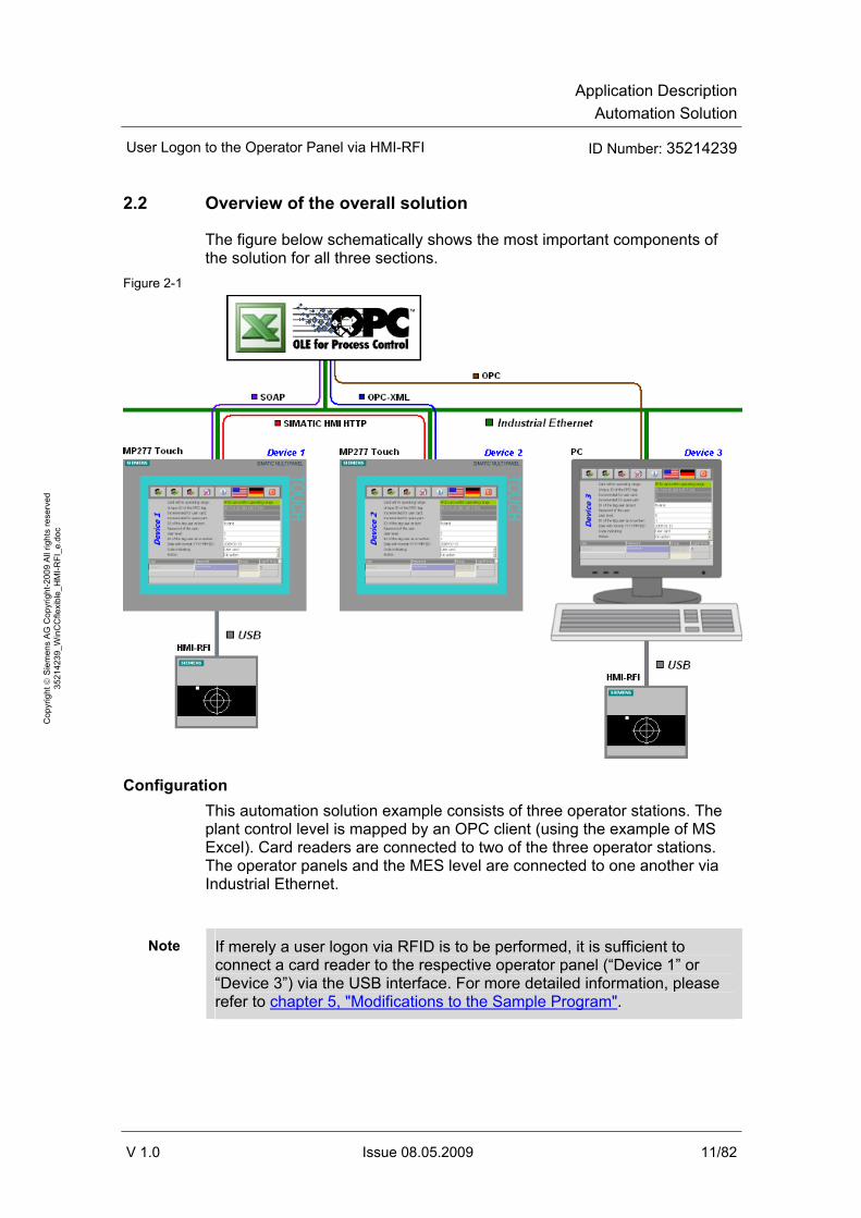
2.2 Overview of the overall solution
The figure below schematically shows the most important components of the solution for all three sections.
Figure 2-1
Configuration This automation solution example consists of three operator stations. The plant control level is mapped by an OPC client (using the example of MS Excel). Card readers are connected to two of the three operator stations. The operator panels and the MES level are connected to one another via Industrial Ethernet.
Note If merely a user logon via RFID is to be performed, it is sufficient to connect a card reader to the respective operator panel (“Device 1” or “Device 3”) via the USB interface. For more detailed information, please refer to chapter 5, "Modifications to the Sample Program".

Application DescriptionAutomation Solution
User Logon to the Operator Panel via HMI-RFI ID Number: 35214239
V 1.0 Issue 08.05.2009 12/82
Cop
yrig
ht ©
Sie
men
s A
G C
opyr
ight
-200
9 A
ll rig
hts
rese
rved
35
2142
39_W
inC
Cfle
xibl
e_H
MI-R
FI_e
.doc
2.3 Description of the core functionality
The creation of an example illustrating how to perform a user logon to an operator panel via the “HMI-RFI” RFID system is the core of this application. It is also shown how materials management data can be passed on to other operator panels or to the master plant control level.
When an RFID card is held to the card reader, the data on the card is evaluated and transferred to the operator panel.
The following actions are performed on the operator panel:
• Evaluation of the user data (if the data matches the user administration data, this results in a logon to the panel) or
• evaluation of the data for materials management.
Irrespective of the action, all data is always read out to provide it to other operator panels and/or the plant control level.
Advantages of this solution • Errors when entering user name and password are avoided.
• Easy and quick handling.
• Easy logon even under unfavorable conditions, for example, when wearing work gloves.
• High flexibility (e.g., changing user data).
• Clear tracking of the flow of goods.
• Quick synchronization of the stock (production, warehouse, inventory).

Application DescriptionAutomation Solution
User Logon to the Operator Panel via HMI-RFI ID Number: 35214239
V 1.0 Issue 08.05.2009 13/82
Cop
yrig
ht ©
Sie
men
s A
G C
opyr
ight
-200
9 A
ll rig
hts
rese
rved
35
2142
39_W
inC
Cfle
xibl
e_H
MI-R
FI_e
.doc
2.4 Required hardware and software components
Hardware components Table 2-1
Component No. MLFB/order number Note
Starter kit HMI-RFI-USB module
1 6AV6 675-8XQ00-0AX0 The starter kit contains: • HMI-RFI-USB module • USB cable, type B • Software on CD (API,
USB driver) • 5 x chip cards • Demo software (tool for
reading and writing via WinXP) HMI-RFI-USB module
1 6AV6 675-8XQ10-0AX0
MP 277 10" Touch 2 6AV6 643-0CD01-1AX1 Alternatively, any other MP 277 or MP 377 can also be used.
SD card, 256 MByte 2 6AV6 671-8XB10-0AX0 Alternatively, an MMC with MLFB 6AV6 671-1CB00-0AX2 can also be used.
PC with Windows XP 2 --- Windows XP is only mandatory when using SOAP.
Note If you only want to operate an operator panel with an RFID reader (no connection to MES/ERP level), you merely require the “RFID reader starter kit” with the desired hardware platform (MP277/MP 377 or a PC)
Application DescriptionAutomation Solution
User Logon to the Operator Panel via HMI-RFI ID Number: 35214239
V 1.0 Issue 08.05.2009 14/82
Cop
yrig
ht ©
Sie
men
s A
G C
opyr
ight
-200
9 A
ll rig
hts
rese
rved
35
2142
39_W
inC
Cfle
xibl
e_H
MI-R
FI_e
.doc
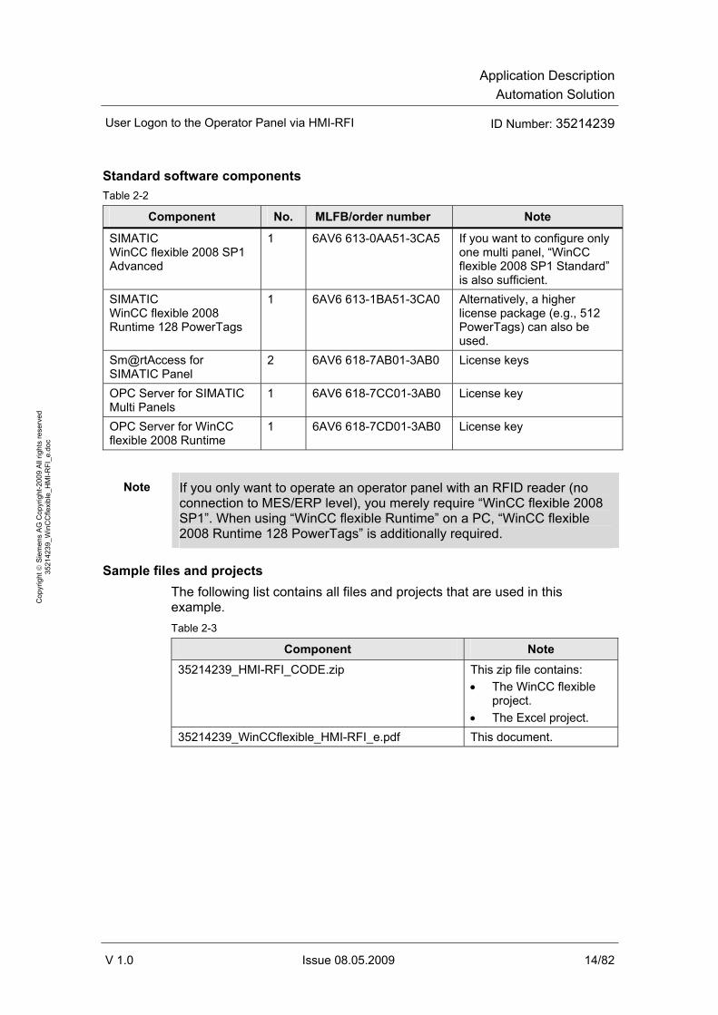
Standard software components Table 2-2
Component No. MLFB/order number Note
SIMATIC WinCC flexible 2008 SP1 Advanced
1 6AV6 613-0AA51-3CA5 If you want to configure only one multi panel, “WinCC flexible 2008 SP1 Standard” is also sufficient.
SIMATIC WinCC flexible 2008 Runtime 128 PowerTags
1 6AV6 613-1BA51-3CA0 Alternatively, a higher license package (e.g., 512 PowerTags) can also be used.
Sm@rtAccess for SIMATIC Panel
2 6AV6 618-7AB01-3AB0 License keys
OPC Server for SIMATIC Multi Panels
1 6AV6 618-7CC01-3AB0 License key
OPC Server for WinCC flexible 2008 Runtime
1 6AV6 618-7CD01-3AB0 License key
Note If you only want to operate an operator panel with an RFID reader (no connection to MES/ERP level), you merely require “WinCC flexible 2008 SP1”. When using “WinCC flexible Runtime” on a PC, “WinCC flexible 2008 Runtime 128 PowerTags” is additionally required.
Sample files and projects The following list contains all files and projects that are used in this example. Table 2-3
Component Note 35214239_HMI-RFI_CODE.zip This zip file contains:
• The WinCC flexible project.
• The Excel project. 35214239_WinCCflexible_HMI-RFI_e.pdf This document.
Application DescriptionAutomation Solution
User Logon to the Operator Panel via HMI-RFI ID Number: 35214239
V 1.0 Issue 08.05.2009 15/82
Cop
yrig
ht ©
Sie
men
s A
G C
opyr
ight
-200
9 A
ll rig
hts
rese
rved
35
2142
39_W
inC
Cfle
xibl
e_H
MI-R
FI_e
.doc
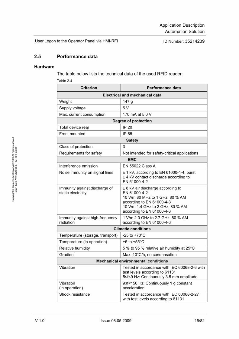
2.5 Performance data
Hardware The table below lists the technical data of the used RFID reader: Table 2-4
Criterion Performance data
Electrical and mechanical data Weight 147 g Supply voltage 5 V Max. current consumption 170 mA at 5.0 V
Degree of protection Total device rear IP 20 Front mounted IP 65
Safety Class of protection 3 Requirements for safety Not intended for safety-critical applications
EMC Interference emission EN 55022 Class A Noise immunity on signal lines ± 1 kV, according to EN 61000-4-4, burst
± 4 kV contact discharge according to EN 61000-4-2
Immunity against discharge of static electricity
± 8 kV air discharge according to EN 61000-4-2 10 V/m 80 MHz to 1 GHz, 80 % AM according to EN 61000-4-3 10 V/m 1.4 GHz to 2 GHz, 80 % AM according to EN 61000-4-3
Immunity against high-frequency radiation
1 V/m 2.0 GHz to 2.7 GHz, 80 % AM according to EN 61000-4-3
Climatic conditions Temperature (storage, transport) -25 to +70°C Temperature (in operation) +5 to +55°C Relative humidity 5 % to 95 % relative air humidity at 25°C Gradient Max. 10°C/h, no condensation
Mechanical environmental conditions Vibration Tested in accordance with IEC 60068-2-6 with
test levels according to 61131 5≤f<9 Hz: Continuously 3.5 mm amplitude
Vibration (in operation)
9≤f<150 Hz: Continuously 1 g constant acceleration
Shock resistance Tested in accordance with IEC 60068-2-27 with test levels according to 61131

Application DescriptionAutomation Solution
User Logon to the Operator Panel via HMI-RFI ID Number: 35214239
V 1.0 Issue 08.05.2009 16/82
Cop
yrig
ht ©
Sie
men
s A
G C
opyr
ight
-200
9 A
ll rig
hts
rese
rved
35
2142
39_W
inC
Cfle
xibl
e_H
MI-R
FI_e
.doc
Criterion Performance data
Shock resistance (in operation)
15 g, 11 ms, half sine wave
RFID Compatible, standard ISO/IEC 15693 Transmitting power Typ. 160 mW at 50 Ω
min. 3 cm Transmission range Typ. 6 cm, depending on mounting situation
Application software The application has the following performance data: Table 2-5
Criterion Performance data Number of devices in the project 3 (2 x MP 277 10" Touch, 1 x PC) Number of HMI screens per project 1 Use of special characters No Number of characters for password and user name
16
Number of connections 2, 1 of the 2 as a reserve (process interfacing)
Number of spreadsheets in Excel 2 (1 for SOAP, 1 for OPC)

Application DescriptionAutomation Solution
User Logon to the Operator Panel via HMI-RFI ID Number: 35214239
V 1.0 Issue 08.05.2009 17/82
Cop
yrig
ht ©
Sie
men
s A
G C
opyr
ight
-200
9 A
ll rig
hts
rese
rved
35
2142
39_W
inC
Cfle
xibl
e_H
MI-R
FI_e
.doc
2.6 Alternative solutions
As an alternative, an Euchner Key System can be used instead of the HMI-RFI card reader. The respective entry is available at the following link:
http://support.automation.siemens.com/WW/view/en/26481978
Comparison of the two solutions Table 2-6
HMI-RFI Euchner Key
Siemens product with support from one source
Third-party manufacturer (third-party product)
Direct connection to the operator panel via USB
Connection only possible via process bus (Profibus)
No load whatsoever of PLC and process bus
Load of controller and process bus by the application
Easy implementation by OPC driver in the operator panel
Implementation by GSD file and program blocks in the controller
Aside from the user logon to the operator panel, the acquisition of materials management goods is also provided
Only user logon to the operator panel possible
Synchronization of user data possible with WinCC flexible
Manual user data synchronization required
Can only be used with MP277, MP377 and PC
Can basically be used with every SIMATIC Panel or PC

Principles of Operation and Program StructuresGeneral functional Mechanisms
User Logon to the Operator Panel via HMI-RFI ID Number: 35214239
V 1.0 Issue 08.05.2009 18/82
Cop
yrig
ht ©
Sie
men
s A
G C
opyr
ight
-200
9 A
ll rig
hts
rese
rved
35
2142
39_W
inC
Cfle
xibl
e_H
MI-R
FI_e
.doc
Principles of Operation and Program Structures
Contents This part describes the detailed functional sequences of the involved hardware and software components, the solution structures and – where useful – the specific implementation of this application.
You only require this part if you are interested in the interaction of the individual solution components.
3 General functional Mechanisms
You are provided with information on… the specific general functional mechanisms that apply with regard to the data exchange between
• the RFID card,
• the HMI-RFI module,
• the HMI-RFI device driver,
• the HMI-RFI OPC Server,
• the operator panels
• and the MES (using the example of MS Excel).

Principles of Operation and Program StructuresGeneral functional Mechanisms
User Logon to the Operator Panel via HMI-RFI ID Number: 35214239
V 1.0 Issue 08.05.2009 19/82
Cop
yrig
ht ©
Sie
men
s A
G C
opyr
ight
-200
9 A
ll rig
hts
rese
rved
35
2142
39_W
inC
Cfle
xibl
e_H
MI-R
FI_e
.doc
3.1 RFID card
Reading out and writing to the RFID cards via the “HMI-RFI module” is possible via both the “SIMATIC HMI-RFI Manager” (an application for Windows XP) and the “HMI-RFI OPC Server”.
• The data on the RFID card represents a “data record”.
• The RFID card is also referred to as an “RFID tag”.
3.2 HMI-RFI module
The RFID card (RFID tag) is read out or written to via the HMI-RFI module, the card reader.
• The HMI-RFI module is connected to the operator panel via the USB interface.
• To be able to operate the HMI-RFI module on the operator panel, the “SIMATIC HMI-RFI OPC Server” has to be installed.
• The “SIMATIC HMI-RFI OPC Server” represents the interface between the SIMATIC HMI-RFI module and a user application such as WinCC flexible.

Principles of Operation and Program StructuresGeneral functional Mechanisms
User Logon to the Operator Panel via HMI-RFI ID Number: 35214239
V 1.0 Issue 08.05.2009 20/82
Cop
yrig
ht ©
Sie
men
s A
G C
opyr
ight
-200
9 A
ll rig
hts
rese
rved
35
2142
39_W
inC
Cfle
xibl
e_H
MI-R
FI_e
.doc
Figure 3-1
When using the MP277 and MP377 operator panels, ProSave, after installing “SIMATIC HMI-RFI”, includes the Windows CE driver for the HMI-RFI-USB module and the HMI-RFI OPC Server as an option.
3.3 HMI-RFI device driver
The device driver provides the interface between the user application such as the HMI-RFI Manager or the HMI-RFI OPC Server to the HMI-RFI module.
Note When using the MP277 and MP377 operator panels, ProSave, after installing the HMI-RFI software, includes the Windows CE driver for the HMI-RFI module and the HMI-RFI OPC Server.
The installation is only possible if SIMATIC ProSave is installed.
Principles of Operation and Program StructuresGeneral functional Mechanisms
User Logon to the Operator Panel via HMI-RFI ID Number: 35214239
V 1.0 Issue 08.05.2009 21/82
Cop
yrig
ht ©
Sie
men
s A
G C
opyr
ight
-200
9 A
ll rig
hts
rese
rved
35
2142
39_W
inC
Cfle
xibl
e_H
MI-R
FI_e
.doc
3.4 HMI-RFI OPC Server
The HMI-RFI OPC Server represents the interface between the HMI-RFI module and a user application such as WinCC flexible.
To be able to access the information of an RFID card, WinCC flexible Runtime must be connected to the HMI-RFI OPC Server providing the card contents.
Prerequisites • The SIMATIC HMI-RFI OPC Server is installed.
• The WinCC flexible project is opened.
Note When using the MP277 and MP377 operator panels, ProSave, after installing the HMI-RFI software, includes the Windows CE driver for the HMI-RFI module and the HMI-RFI OPC Server.
The installation is only possible if SIMATIC ProSave is installed.
3.5 Operator panel(s)
The user administration is created in the WinCC flexible configuration and transferred to the operator panels with the configuration.
The data records of several RFID tags can be managed with the “HMI-RFI Manager” and saved to subsequently import them to WinCC flexible in the form of a password list.
To allow communication with the HMI-RFI OPC Server, a connection is necessary. In addition to this connection, “classic” process interfacing is also required. To provide the data to other applications, further services are needed on the operator panel.
The following sections describe the respective connections and services for the individual devices.
Device_1 • Connection_1:
“OPC” is used as a communications driver. It establishes the connection to the “HMI-RFI OPC Server” and is used for the data exchange between the “HMI-RFI module” and the operator panel.
• Connection_2: “SIMATIC S7 300/400” is used as a communications driver. It is inactive (online: Off) and used for the later data exchange between the operator panel and the controller (field level). Adjust the parameters as required for the application of the operator panel and switch it active (online: On).

Principles of Operation and Program StructuresGeneral functional Mechanisms
User Logon to the Operator Panel via HMI-RFI ID Number: 35214239
V 1.0 Issue 08.05.2009 22/82
Cop
yrig
ht ©
Sie
men
s A
G C
opyr
ight
-200
9 A
ll rig
hts
rese
rved
35
2142
39_W
inC
Cfle
xibl
e_H
MI-R
FI_e
.doc
• Runtime services – “Sm@rtAccess: Web service (SOAP)”: This service (SOAP) is used for the data exchange between the operator panel and the higher-level MES (using the example of MS Excel).
• Runtime services – “Sm@rtAccess: SIMATIC HMI HTTP Server”: This service is used for the data exchange between the operator panel and an additional operator panel (Device_2).
Figure 3-2
Note The Microsoft SOAP Toolkit required on the PC for accessing a SOAP service is not supported by Microsoft Windows Vista. For further information, please refer to the following ID number: 34881863.
“Sm@rtAccess” is a WinCC flexible option package and has to be purchased separately.
Device_2 • Connection_1:
“SIMATIC HMI HTTP Protocol” is used as a communications driver. It establishes the connection to a further “Device_1” operator panel and is used for the data exchange between the two operator panels.

Principles of Operation and Program StructuresGeneral functional Mechanisms
User Logon to the Operator Panel via HMI-RFI ID Number: 35214239
V 1.0 Issue 08.05.2009 23/82
Cop
yrig
ht ©
Sie
men
s A
G C
opyr
ight
-200
9 A
ll rig
hts
rese
rved
35
2142
39_W
inC
Cfle
xibl
e_H
MI-R
FI_e
.doc
• Connection_2: “SIMATIC S7 300/400” is used as a communications driver. It is inactive (online: Off) and used for the later data exchange between the operator panel and the controller (field level). Adjust the parameters as required for the application of the operator panel and switch it active (online: On).
• Runtime services – “Function as OPC server”: This service (OPC XML) is used for the data exchange between the operator panel and the higher-level MES (using the example of MS Excel).
Figure 3-3
Note The “WinCC flexible /OPC Server” license is a WinCC flexible option package and has to be purchased separately.
Device_3 • Connection_1:
“OPC” is used as a communications driver. It establishes the connection to the “HMI-RFI OPC Server” and is used for the communication between the “HMI-RFI module” and the operator panel.
• Connection_2: “SIMATIC S7 300/400” is used as a communications driver. It is inactive (online: Off) and used for the later data exchange between the operator panel and the controller (field level). Adjust the parameters as required for the application of the operator panel and switch it active (online: On).

Principles of Operation and Program StructuresGeneral functional Mechanisms
User Logon to the Operator Panel via HMI-RFI ID Number: 35214239
V 1.0 Issue 08.05.2009 24/82
Cop
yrig
ht ©
Sie
men
s A
G C
opyr
ight
-200
9 A
ll rig
hts
rese
rved
35
2142
39_W
inC
Cfle
xibl
e_H
MI-R
FI_e
.doc
• Runtime services – “Function as OPC server”: This service (OPC) is used for the data exchange between the operator panel and the higher-level MES (using the example of MS Excel).
Figure 3-4
Note The “WinCC flexible /OPC Server” license is a WinCC flexible option package and has to be purchased separately.
Principles of Operation and Program StructuresGeneral functional Mechanisms
User Logon to the Operator Panel via HMI-RFI ID Number: 35214239
V 1.0 Issue 08.05.2009 25/82
Cop
yrig
ht ©
Sie
men
s A
G C
opyr
ight
-200
9 A
ll rig
hts
rese
rved
35
2142
39_W
inC
Cfle
xibl
e_H
MI-R
FI_e
.doc
3.6 MES
For central data management, the collected data records are communicated to a master plant control level (using the example of MS Excel).
WinCC flexible offers two different approaches:
• SOAP
• OPC
3.6.1 SOAP
SOAP is a protocol with the aid of which data can be exchanged between systems. WinCC flexible provides options to use the “SOAP” web service. Compared to OPC, the setup of this connection is considered to be less complex.
In the configuration of the “Device_1” operator panel, SOAP is enabled as a “Sm@rtAccess: Web service (SOAP)” service and used for the data exchange between the operator panel and the higher-level MES (using the example of MS Excel).
Note The Microsoft SOAP Toolkit required on the PC for accessing a SOAP service is not supported by Microsoft Windows Vista. For further information, please refer to the following ID number: 34881863.
“Sm@rtAccess” is a WinCC flexible option package and has to be purchased separately.
3.6.2 OPC
OPC is a standardized software interface family that allows data exchange between applications of different manufacturers in automation. The setup of this connection, particularly beyond computer boundaries (DCOM), is considered to be significantly more complicated, but also considerably more powerful than SOAP.
OPC XML In the configuration of the “Device_2” operator panel, OPC is enabled as a “Function as OPC server” service and used for the data exchange between the operator panel and the higher-level MES (using the example of MS Excel). Since the “Device_2” operator panel is based on Windows CE, OPC XML is used. Data exchange via XML allows communication via the Internet or Intranet.

Principles of Operation and Program StructuresGeneral functional Mechanisms
User Logon to the Operator Panel via HMI-RFI ID Number: 35214239
V 1.0 Issue 08.05.2009 26/82
Cop
yrig
ht ©
Sie
men
s A
G C
opyr
ight
-200
9 A
ll rig
hts
rese
rved
35
2142
39_W
inC
Cfle
xibl
e_H
MI-R
FI_e
.doc
Note If the communication partner does not have a direct OPC XML interface, OPC-XML-Gateway is required.
OPC-XML-Gateway is included in the scope of delivery of the WinCC flexible engineering system and Runtime and must be installed on the communication partner’s target platform.
OPC In the configuration of the “Device_3” operator panel, OPC is enabled as a “Function as OPC server” service and used for the data exchange between the operator panel and the higher-level MES (using the example of MS Excel).
OPC is based on the Windows technologies COM and DCOM. DCOM extended COM by the capability of accessing objects beyond computer boundaries.
Note Communication via DCOM is limited to local networks.

Principles of Operation and Program StructuresFunctional Mechanisms of this Application
User Logon to the Operator Panel via HMI-RFI ID Number: 35214239
V 1.0 Issue 08.05.2009 27/82
Cop
yrig
ht ©
Sie
men
s A
G C
opyr
ight
-200
9 A
ll rig
hts
rese
rved
35
2142
39_W
inC
Cfle
xibl
e_H
MI-R
FI_e
.doc
4 Functional Mechanisms of this Application
You are provided with valuable and necessary information on… the data exchange between the components involved.
4.1 HMI-RFI OPC Server functionality
To be able to access the information of an RFID card, WinCC flexible Runtime must be connected to the HMI-RFI OPC Server providing the card contents.
Prerequisites:
• The device driver for the HMI-RFI module is installed.
• The HMI-RFI OPC Server is installed.
• In WinCC flexible, “OPC” is selected as a communications driver.
• “OPC.SimaticHMI.RFI” has been selected as an OPC server. Figure 4-1

Principles of Operation and Program StructuresFunctional Mechanisms of this Application
User Logon to the Operator Panel via HMI-RFI ID Number: 35214239
V 1.0 Issue 08.05.2009 28/82
Cop
yrig
ht ©
Sie
men
s A
G C
opyr
ight
-200
9 A
ll rig
hts
rese
rved
35
2142
39_W
inC
Cfle
xibl
e_H
MI-R
FI_e
.doc
The following items are provided by the OPC server: Table 4-1
OPC item Data type Access Explanation
RFID_ACCESS/UID String R The unique ID of the RFID tag RFID_ACCESS/UserIdNumerical DWord RW ID of the tag user as a number RFID_ACCESS/UserIdTextual String RW ID of the tag user as text RFID_ACCESS/ExpiryDate String RW Date in JJJJ-MM-TT format RFID_ACCESS/UserPassword String RW User password RFID_ACCESS/IsProduct Byte RW ID whether user card = 0 or
spare part = 1 RFID_ACCESS/UserLevel Byte RW User level RFID_CTRL/UserFlag Byte R Incremented for user card RFID_CTRL/ProductFlag Byte R Incremented for spare part RFID_CTRL/TagAccess Byte R RFID card within operating
range = 1, otherwise 0 RFID_CTRL/InactiveOrReadOrWrite Byte RW The item can be changed by
the user to trigger an action. • Default = 0 (no action) • Read = 1 (RFID card is
read out again) • Write = 2 (OPC item
contents are written to the card)
[R = item only for reading / RW = item for reading and writing]
NOTICE As Acquisition mode, all OPC tags must be set to the “Cyclic continuous” setting. An acquisition cycle of 500 ms is recommended. A smaller value is not supported by the OPC server.

Principles of Operation and Program StructuresFunctional Mechanisms of this Application
User Logon to the Operator Panel via HMI-RFI ID Number: 35214239
V 1.0 Issue 08.05.2009 29/82
Cop
yrig
ht ©
Sie
men
s A
G C
opyr
ight
-200
9 A
ll rig
hts
rese
rved
35
2142
39_W
inC
Cfle
xibl
e_H
MI-R
FI_e
.doc
4.2 User logon functionality
Data exchange between the Device_1 and Device_2 operator panels To understand the functionality, it is important to know that all tags of the “Device_2” operator panel (except for the “CurrentPassword” tag) are read by the “Device_1” operator panel via the “SIMATIC HMI HTTP” channel.
The HMI-RFI module connected to the “Device_1” operator panel can thus also be used on the “Device_2” operator panel. Figure 4-2
The following sections provide a more detailed explanation of the tags involved in the user logon.
CurrentPassword The internal “CurrentPassword” tag without PLC connection was created in each of the three operator panels.
Each time a user change is made on the respective operator panel, the scheduler writes the current password to this string tag and the tag thus contains the password of the last valid logon to this operator panel.
The tag is not used in the example and can be used in your own use case.
RFID_CTRL/UserFlag • “Device_1” operator panel
The “RFID_CTRL/UserFlag” tag is incremented with each logon with a user card. An acquisition of materials management goods does not influence this tag. In “Screen_1”, the “RFID_CTRL/UserFlag” tag is displayed as “Read user cards since start”; at the same time, it serves as a trigger for the user logon to the operator panel.

Principles of Operation and Program StructuresFunctional Mechanisms of this Application
User Logon to the Operator Panel via HMI-RFI ID Number: 35214239
V 1.0 Issue 08.05.2009 30/82
Cop
yrig
ht ©
Sie
men
s A
G C
opyr
ight
-200
9 A
ll rig
hts
rese
rved
35
2142
39_W
inC
Cfle
xibl
e_H
MI-R
FI_e
.doc
The following tags are used as parameters for the user logon:
– Password: “RFID_ACCESS/UserPassword”
– User name: “RFID_ACCESS/UserIdTextual”
Note After the read action of the RFID card, the contents of the “UserPassword” tag are available only for a short time. The OPC server overwrites the tag with blank contents after approx. 2 seconds.
Figure 4-3
• “Device_2” operator panel
The “RFID_CTRL/UserFlag” tag is incremented with each logon with a user card on the HMI-RFI module of the “Device_1” operator panel. An acquisition of materials management goods does not influence this tag. In “Screen_1”, the “RFID_CTRL/UserFlag” tag is displayed as “Read user cards since start”; at the same time, it serves as a trigger for the user logon to the operator panel. The following tags are used as parameters for the user logon:
– Password: “UserPassword”
– User name: “RFID_ACCESS/UserIdTextual”

Principles of Operation and Program StructuresFunctional Mechanisms of this Application
User Logon to the Operator Panel via HMI-RFI ID Number: 35214239
V 1.0 Issue 08.05.2009 31/82
Cop
yrig
ht ©
Sie
men
s A
G C
opyr
ight
-200
9 A
ll rig
hts
rese
rved
35
2142
39_W
inC
Cfle
xibl
e_H
MI-R
FI_e
.doc
Figure 4-4
RFID_ACCESS/UserIdTextual In “Screen_1” of each of the three operator panels, the “RFID_ACCESS/UserIdTextual” tag is displayed as “User Name”; at the same time, it serves as a user name for the user logon to the operator panel.
RFID_ACCESS/UserPassword • “Device_1” operator panel
In “Screen_1”, the “RFID_ACCESS/UserPassword” tag is displayed as “Password of the user”; at the same time, it serves as a password for the user logon to the operator panel. Each time a change occurs, the “RFID_ACCESS/UserPassword” tag copies its value to the “UserPassword” tag. This is necessary since cyclic reading of the “RFID_ACCESS/UserPassword” tag by another operator panel (in this project, “Device_2” via the “SIMATIC HMI HTTP” channel) results in immediate deletion of the value. The “RFID_ACCESS/UserPassword” tag would then be unusable for the user logon; instead, the “UserPassword” tag is used for logging on to the “Device_2” operator panel via the HMI-RFI module of the “Device_1” operator panel.
• “Device_2” operator panel The “RFID_ACCESS/UserPassword” tag is not required in the “Device_2” operator panel; instead, the “UserPassword” tag is used for logging on to the “Device_2” operator panel via the HMI-RFI module of the “Device_1” operator panel.
Principles of Operation and Program StructuresFunctional Mechanisms of this Application
User Logon to the Operator Panel via HMI-RFI ID Number: 35214239
V 1.0 Issue 08.05.2009 32/82
Cop
yrig
ht ©
Sie
men
s A
G C
opyr
ight
-200
9 A
ll rig
hts
rese
rved
35
2142
39_W
inC
Cfle
xibl
e_H
MI-R
FI_e
.doc
• “Device_3” operator panel In “Screen_1”, the “RFID_ACCESS/UserPassword” tag is displayed as “Password of the user”; at the same time, it serves as a password for the user logon to the operator panel.
UserPassword • “Device_1” operator panel
Each time the value of the “RFID_ACCESS/UserPassword” tag changes, its value is written to the “UserPassword” tag, which is thus actually a copy of this tag. This is necessary since cyclic reading of the “RFID_ACCESS/UserPassword” tag by another operator panel (in this project, “Device_2” via the “SIMATIC HMI HTTP” channel) results in immediate deletion of the value. The “RFID_ACCESS/UserPassword” tag would then be unusable for the user logon; instead, the “UserPassword” tag is used for logging on to the “Device_2” operator panel via the HMI-RFI module of the “Device_1” operator panel.
• “Device_2” operator panel In “Screen_1”, the “UserPassword” tag is displayed as “Password of the user”; at the same time, it serves as a password for the user logon to the operator panel. Since the “UserPassword” tag in the “Device_1” operator panel always has the same value as the “RFID_ACCESS/UserPassword” tag, it is used for logging on to the “Device_2” operator panel via the HMI-RFI module of the “Device_1” operator panel.
• “Device_3” operator panel The “UserPassword” tag is not required in the “Device_3” operator panel since a separate HMI-RFI module is connected to it and since the contents of the “RFID_ACCESS/UserPassword” tag do not have to be provided to another operator panel.

Principles of Operation and Program StructuresModifications to the Sample Program
User Logon to the Operator Panel via HMI-RFI ID Number: 35214239
V 1.0 Issue 08.05.2009 33/82
Cop
yrig
ht ©
Sie
men
s A
G C
opyr
ight
-200
9 A
ll rig
hts
rese
rved
35
2142
39_W
inC
Cfle
xibl
e_H
MI-R
FI_e
.doc
5 Modifications to the Sample Program
You are provided with information on… what you have to do if you merely want to perform a user logon to an operator panel via an HMI-RFI module.
The application is designed in such a way that the configuration for the “Device_1” (MP 277 10" Touch) and “Device_3” (PC) operator panels can be used with few changes without additional data exchange with a higher-level control system (MES) or another operator panel.
5.1 “Device_1” operator panel
The configuration for the “Device_1” operator panel can also be used without any changes only with the connected HMI-RFI module and its driver and the OPC server. In this case, however, a prompt indicating a missing license (Sm@rt Access) is displayed on the operator panel.
To disable this behavior, you have to disable the “Runtime services” in “Device Settings > Device Settings” in the project of the “Device_1 (MP 277 10" Touch)” operator panel.
Uncheck “Sm@rtAccess: Web service (SOAP)” and “Sm@rtAccess: SIMATIC HMI HTTP Server”. Figure 5-1

Principles of Operation and Program StructuresModifications to the Sample Program
User Logon to the Operator Panel via HMI-RFI ID Number: 35214239
V 1.0 Issue 08.05.2009 34/82
Cop
yrig
ht ©
Sie
men
s A
G C
opyr
ight
-200
9 A
ll rig
hts
rese
rved
35
2142
39_W
inC
Cfle
xibl
e_H
MI-R
FI_e
.doc
5.2 “Device_3” operator panel
The configuration for the “Device_3” operator panel can also be used without any changes only with the connected HMI-RFI module and its driver and the OPC server. In this case, however, a prompt indicating a missing license (OPC server) is displayed on the operator panel.
To disable this behavior, you have to disable the “Runtime services” in “Device Settings > Device Settings” in the project of the “Device_3 (WinCC flexible Runtime)” operator panel.
Uncheck “Function as OPC server”. Figure 5-2

Structure, Configuration and Operation of the ApplicationInstallation and Startup
User Logon to the Operator Panel via HMI-RFI ID Number: 35214239
V 1.0 Issue 08.05.2009 35/82
Cop
yrig
ht ©
Sie
men
s A
G C
opyr
ight
-200
9 A
ll rig
hts
rese
rved
35
2142
39_W
inC
Cfle
xibl
e_H
MI-R
FI_e
.doc
Structure, Configuration and Operation of the Application
Contents This part takes you step by step through structure, important configuration steps, startup and operation of the application.
6 Installation and Startup
You are provided with information on… the specific hardware and software you have to install and the steps that are necessary to start up the example.
6.1 Hardware and software installation
This chapter describes which hardware and software components have to be installed. The descriptions and manuals as well as delivery information included in the delivery of the respective products should be observed in any case.
Hardware installation For the hardware components, please refer to chapter 2.4. For the hardware configuration, follow the instructions listed in the following table:
Table 6-1
No. Action Remark 1. Install your operator panel according to the
installation regulations. The following entry provides more information on this topic (e.g., MP277 manual). http://support.automation.siemens.com/WW/view/en/23337820
---
2. Install the HMI-RFI modules according to the installation regulations. Use the USB cable supplied with the HMI-RFI module for the connection to the relevant operator panel.
---
3. Connect all nodes via Industrial Ethernet. ---
Note The installation guidelines must always be observed.
Structure, Configuration and Operation of the ApplicationInstallation and Startup
User Logon to the Operator Panel via HMI-RFI ID Number: 35214239
V 1.0 Issue 08.05.2009 36/82
Cop
yrig
ht ©
Sie
men
s A
G C
opyr
ight
-200
9 A
ll rig
hts
rese
rved
35
2142
39_W
inC
Cfle
xibl
e_H
MI-R
FI_e
.doc
Standard software installation Table 6-2
No. Action Remark 1. It is required that the software specified in table 2-6
of chapter 2.3 be installed on your PG/PC. Please observe the system requirements in any case. More information on this topic is available on the Customer Support pages on the Internet.
Link to the Customer Support pages. http://support.automation.siemens.com
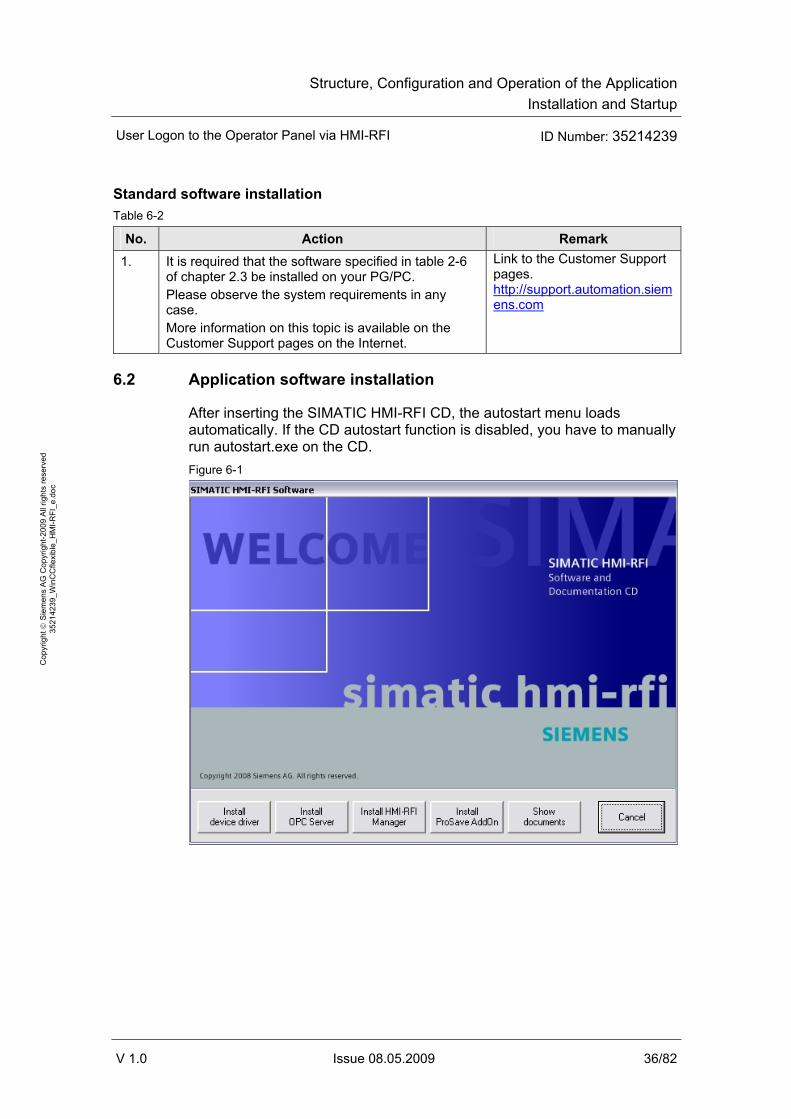
6.2 Application software installation
After inserting the SIMATIC HMI-RFI CD, the autostart menu loads automatically. If the CD autostart function is disabled, you have to manually run autostart.exe on the CD. Figure 6-1

Structure, Configuration and Operation of the ApplicationInstallation and Startup
User Logon to the Operator Panel via HMI-RFI ID Number: 35214239
V 1.0 Issue 08.05.2009 37/82
Cop
yrig
ht ©
Sie
men
s A
G C
opyr
ight
-200
9 A
ll rig
hts
rese
rved
35
2142
39_W
inC
Cfle
xibl
e_H
MI-R
FI_e
.doc
Table 6-3
No. Action Remark 1. Install the device driver for the HMI-RFI
module on both the “Device_3” operator panel and on your configuration computer. A script is started that copies the required files to the system folder and that registers and starts the “UIDDRV_Service”.
The HMI-RFI module should only be connected to the USB port after the driver installation, otherwise the driver for the device has to be subsequently updated.
2. Install the HMI-RFI OPC Server on both the “Device_3” operator panel and on your configuration computer. The OPC server can only be integrated into your WinCC flexible project after successful installation.
The installation is only possible if the HMI-RFI device driver has already been installed. The installation is performed to this directory: “%ProgramFiles%\Siemens\SIMATIC HMI-RFI OPC Server\”
3. Install the SIMATIC HMI-RFI Manager on your configuration computer.
The installation is only possible if the HMI-RFI device driver has already been installed. The installation is performed to this directory: “%ProgramFiles%\Siemens\SIMATIC HMI-RFI Manager\”
4. Install the HMI-RFI ProSave AddOn on your configuration computer.
The installation is only possible if SIMATIC ProSave is installed. The AddOn is copied to the ProSave AddOn directory and is subsequently available for the MP277 and MP377 devices.
5. By means of ProSave, transfer the HMI-RFI ProSave AddOn to the “Device_1” operator panel.
The ProSave AddOn provides support for the MP277 and MP377 device groups and contains the Windows CE driver for the HMI-RFI module and the HMI-RFI OPC Server.
6. Use ALM (Automation License Manager) to transfer the licenses to the respective operator panel: • “Device_1” operator panel:
– Sm@rtAccess for SIMATIC Panel • “Device_2” operator panel:
– Sm@rtAccess for SIMATIC Panel – OPC Server for SIMATIC Multi
Panels • “Device_3” operator panel:
– WinCC flexible 2008 Runtime 128 PowerTags
– OPC Server for WinCC flexible 2008 Runtime
The following entry provides more information on this topic: http://support.automation.siemens.com/WW/view/en/22195512
Structure, Configuration and Operation of the ApplicationInstallation and Startup
User Logon to the Operator Panel via HMI-RFI ID Number: 35214239
V 1.0 Issue 08.05.2009 38/82
Cop
yrig
ht ©
Sie
men
s A
G C
opyr
ight
-200
9 A
ll rig
hts
rese
rved
35
2142
39_W
inC
Cfle
xibl
e_H
MI-R
FI_e
.doc
No. Action Remark 7. Transfer the WinCC flexible configuration
to your operator panel. For information on how to transfer a configuration to an operator panel, please refer to the respective manual.
Link to the Customer Support pages. http://support.automation.siemens.com

Structure, Configuration and Operation of the ApplicationInstallation and Startup
User Logon to the Operator Panel via HMI-RFI ID Number: 35214239
V 1.0 Issue 08.05.2009 39/82
Cop
yrig
ht ©
Sie
men
s A
G C
opyr
ight
-200
9 A
ll rig
hts
rese
rved
35
2142
39_W
inC
Cfle
xibl
e_H
MI-R
FI_e
.doc
6.3 Setting up SOAP (“Device_1” operator panel)
The table below explains the procedure for setting up the SOAP service. Table 6-4
Step Procedure
1. Setting in the WinCC flexible configuration In the Project Manager, select “Device Settings > Device Settings > Runtime services” and check the “Sm@rtAccess: Web service (SOAP)” check box: This setting has already been made in the “Device_1” operator panel.
2. Settings on the operator panel
On the operator panel, open the “Control Panel”. • Setting the Ethernet connection:
Change the network settings in “Network and Dial-up Connections > LAN90001”. The subnet mask must be identical for all nodes and was defined as “255.255.255.0” for this application. Set the following IP addresses for the nodes: – For the “Device_1” operator panel: “192.168.0.21” (SOAP). – For the “Device_2” operator panel: “192.168.0.22” (OPC XML). – For the “Device_3” operator panel: “192.168.0.23” (OPC). – For the PC with MES (using the example of MS Excel):
“192.168.0.20”.
• Changing the device name: In “System > Device Name”, change the device name to “HMI_Panel”.
Complete all changes by selecting “OK”. Perform a reboot, for example, using the “OP > Device > Reboot” menu. Note: The device name in the “Profinet” menu does not correspond to the device name of the operator panel.

Structure, Configuration and Operation of the ApplicationInstallation and Startup
User Logon to the Operator Panel via HMI-RFI ID Number: 35214239
V 1.0 Issue 08.05.2009 40/82
Cop
yrig
ht ©
Sie
men
s A
G C
opyr
ight
-200
9 A
ll rig
hts
rese
rved
35
2142
39_W
inC
Cfle
xibl
e_H
MI-R
FI_e
.doc
Step Procedure
3. Settings on the PC with MES (using the example of MS Excel) Data access to Windows CE operator panels via the web service (SOAP) requires a connection via “name resolution”. If there is no DNS service in your network, you have to make the settings in the host or lmhosts file. • Open the lmhosts file (e.g., with Notepad or WordPad) in
“C:\WINNT\System32\drivers\etc”. • In the host or lmhosts file, enter the IP address and the name of the
operator panel: “192.168.0.21 HMI_Panel”.
Note: The lmhosts file frequently exists as lmhosts.sam; “.sam” stands for sample. To ensure that Windows considers the file, delete the “.sam” extension. Alternatively, you can also use the hosts file. The device name of the “Device_1” operator panel must be made known to the SOAP partner (using the example of MS Excel). In this application, this is done in cell “C4”.
Structure, Configuration and Operation of the ApplicationInstallation and Startup
User Logon to the Operator Panel via HMI-RFI ID Number: 35214239
V 1.0 Issue 08.05.2009 41/82
Cop
yrig
ht ©
Sie
men
s A
G C
opyr
ight
-200
9 A
ll rig
hts
rese
rved
35
2142
39_W
inC
Cfle
xibl
e_H
MI-R
FI_e
.doc
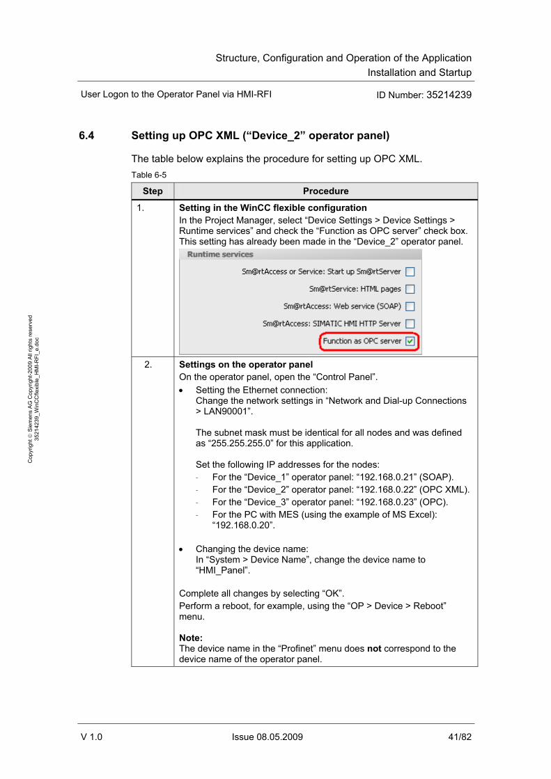
6.4 Setting up OPC XML (“Device_2” operator panel)
The table below explains the procedure for setting up OPC XML. Table 6-5
Step Procedure
1. Setting in the WinCC flexible configuration In the Project Manager, select “Device Settings > Device Settings > Runtime services” and check the “Function as OPC server” check box. This setting has already been made in the “Device_2” operator panel.
2. Settings on the operator panel
On the operator panel, open the “Control Panel”. • Setting the Ethernet connection:
Change the network settings in “Network and Dial-up Connections > LAN90001”. The subnet mask must be identical for all nodes and was defined as “255.255.255.0” for this application. Set the following IP addresses for the nodes: – For the “Device_1” operator panel: “192.168.0.21” (SOAP). – For the “Device_2” operator panel: “192.168.0.22” (OPC XML). – For the “Device_3” operator panel: “192.168.0.23” (OPC). – For the PC with MES (using the example of MS Excel):
“192.168.0.20”.
• Changing the device name: In “System > Device Name”, change the device name to “HMI_Panel”.
Complete all changes by selecting “OK”. Perform a reboot, for example, using the “OP > Device > Reboot” menu. Note: The device name in the “Profinet” menu does not correspond to the device name of the operator panel.

Structure, Configuration and Operation of the ApplicationInstallation and Startup
User Logon to the Operator Panel via HMI-RFI ID Number: 35214239
V 1.0 Issue 08.05.2009 42/82
Cop
yrig
ht ©
Sie
men
s A
G C
opyr
ight
-200
9 A
ll rig
hts
rese
rved
35
2142
39_W
inC
Cfle
xibl
e_H
MI-R
FI_e
.doc
Step Procedure
3. Settings on the PC with MES (using the example of MS Excel) Data access to Windows CE operator panels via OPC XML requires that OPC-XML-Gateway be used. The OPC client (MES) accesses the OPC XML server (“Device_2” operator panel) via OPC-XML-Gateway providing the communication between OPC and XML.
On the PC of the higher-level MES (using the example of MS Excel), open the gateway configuration by selecting “SIMATIC > OPC-XML-Gateway > OPC XML Manager”. Enter the values according to the “Device_2” operator panel: • [Prefix]
The prefix indicates to which OPC XML server the tag is assigned.

Structure, Configuration and Operation of the ApplicationInstallation and Startup
User Logon to the Operator Panel via HMI-RFI ID Number: 35214239
V 1.0 Issue 08.05.2009 43/82
Cop
yrig
ht ©
Sie
men
s A
G C
opyr
ight
-200
9 A
ll rig
hts
rese
rved
35
2142
39_W
inC
Cfle
xibl
e_H
MI-R
FI_e
.doc
Step Procedure Specify “Prefix”.
• [Host Name] Device name or IP address of the OPC XML server. Enter “192.168.0.22”.
Note: If the OPC XML Manager cannot be found on the PC, it has to be installed now. The setup for installing “OPC-XML-Gateway” is available on the WinCC flexible CD2 in “WinCCflexible\setup\OPCXMLWrapper\Disk1”. Double-click on the “Setup.exe” file.
Structure, Configuration and Operation of the ApplicationInstallation and Startup
User Logon to the Operator Panel via HMI-RFI ID Number: 35214239
V 1.0 Issue 08.05.2009 44/82
Cop
yrig
ht ©
Sie
men
s A
G C
opyr
ight
-200
9 A
ll rig
hts
rese
rved
35
2142
39_W
inC
Cfle
xibl
e_H
MI-R
FI_e
.doc
6.5 Setting up OPC
6.5.1 Setting up the OPC service on the server and client side
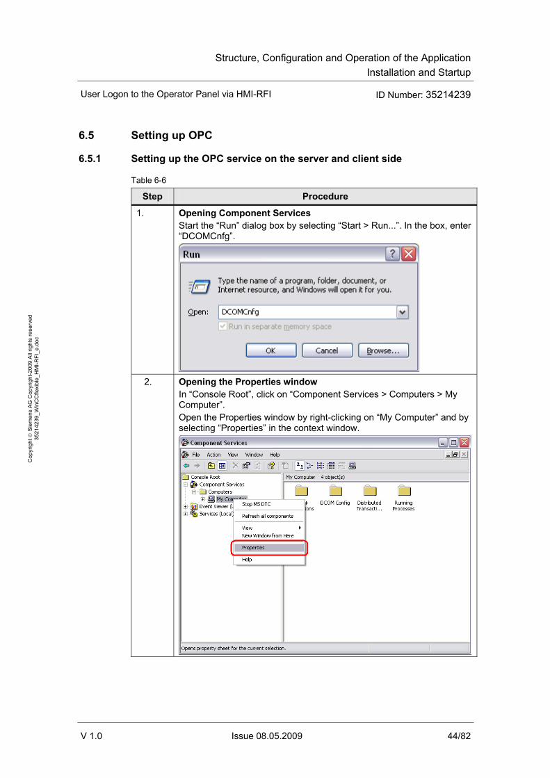
Table 6-6
Step Procedure
1. Opening Component Services Start the “Run” dialog box by selecting “Start > Run...”. In the box, enter “DCOMCnfg”.
2. Opening the Properties window
In “Console Root”, click on “Component Services > Computers > My Computer”. Open the Properties window by right-clicking on “My Computer” and by selecting “Properties” in the context window.

Structure, Configuration and Operation of the ApplicationInstallation and Startup
User Logon to the Operator Panel via HMI-RFI ID Number: 35214239
V 1.0 Issue 08.05.2009 45/82
Cop
yrig
ht ©
Sie
men
s A
G C
opyr
ight
-200
9 A
ll rig
hts
rese
rved
35
2142
39_W
inC
Cfle
xibl
e_H
MI-R
FI_e
.doc
Step Procedure
3. Defining Default Properties Select the “Default Properties” tab and check the “DCOM” check box. Set the Default Authentication Level to “Default” and the Default Impersonation Level to “Identify”.
Structure, Configuration and Operation of the ApplicationInstallation and Startup
User Logon to the Operator Panel via HMI-RFI ID Number: 35214239
V 1.0 Issue 08.05.2009 46/82
Cop
yrig
ht ©
Sie
men
s A
G C
opyr
ight
-200
9 A
ll rig
hts
rese
rved
35
2142
39_W
inC
Cfle
xibl
e_H
MI-R
FI_e
.doc
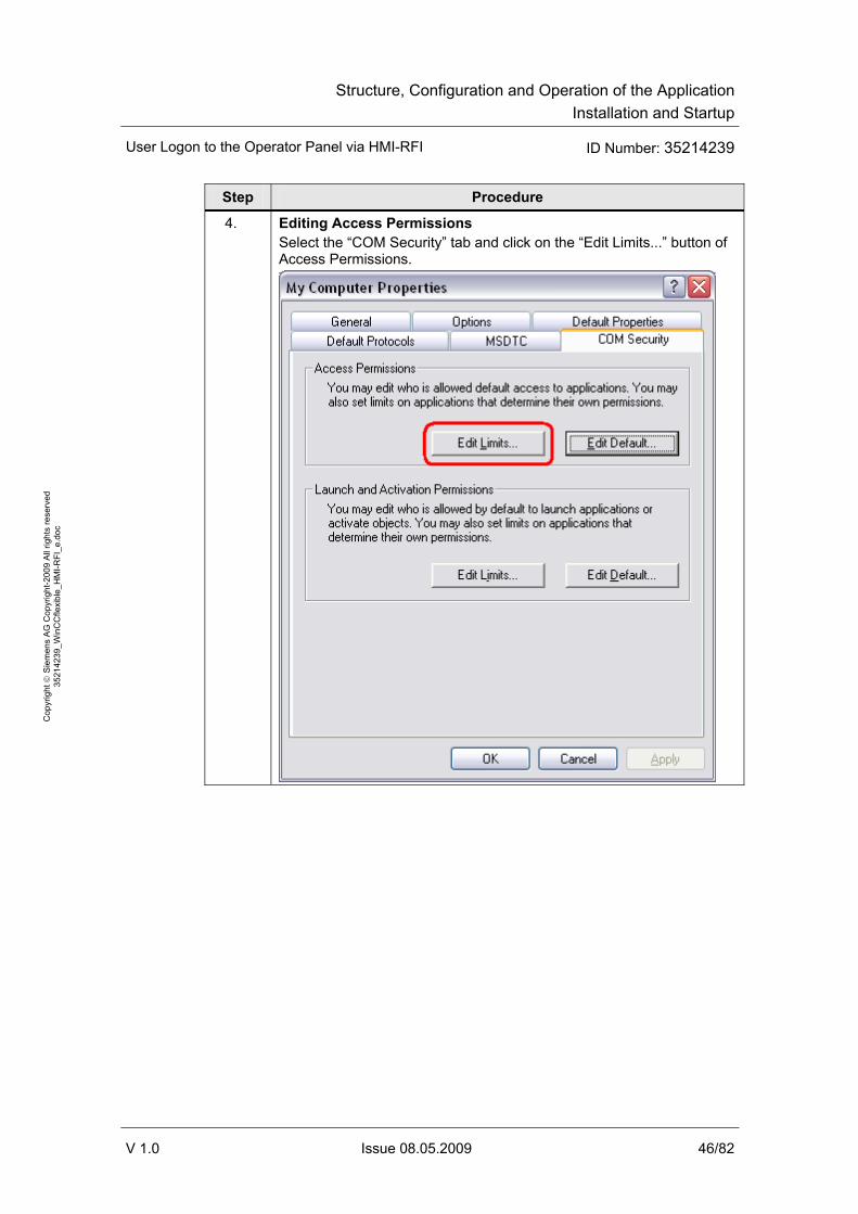
Step Procedure
4. Editing Access Permissions Select the “COM Security” tab and click on the “Edit Limits...” button of Access Permissions.

Structure, Configuration and Operation of the ApplicationInstallation and Startup
User Logon to the Operator Panel via HMI-RFI ID Number: 35214239
V 1.0 Issue 08.05.2009 47/82
Cop
yrig
ht ©
Sie
men
s A
G C
opyr
ight
-200
9 A
ll rig
hts
rese
rved
35
2142
39_W
inC
Cfle
xibl
e_H
MI-R
FI_e
.doc
Step Procedure
5. Defining Access Permissions Add the following group and user names and enable their “Remote Access”: • (ANONYMOUS-LOGON) • INTERACTIVE • (Everyone) • NETWORK • SYSTEM

Structure, Configuration and Operation of the ApplicationInstallation and Startup
User Logon to the Operator Panel via HMI-RFI ID Number: 35214239
V 1.0 Issue 08.05.2009 48/82
Cop
yrig
ht ©
Sie
men
s A
G C
opyr
ight
-200
9 A
ll rig
hts
rese
rved
35
2142
39_W
inC
Cfle
xibl
e_H
MI-R
FI_e
.doc
Step Procedure
6. Defining Launch and Activation Permissions Add the following users and user groups and enable all access permissions, including “Remote Launch” and “Remote Activation”. • (ComputerName\Administrators) • INTERACTIVE • (Everyone) • NETWORK • SYSTEM

Structure, Configuration and Operation of the ApplicationInstallation and Startup
User Logon to the Operator Panel via HMI-RFI ID Number: 35214239
V 1.0 Issue 08.05.2009 49/82
Cop
yrig
ht ©
Sie
men
s A
G C
opyr
ight
-200
9 A
ll rig
hts
rese
rved
35
2142
39_W
inC
Cfle
xibl
e_H
MI-R
FI_e
.doc
6.5.2 Setting up the OPC server (“Device_3” operator panel)
The following settings have to be made only on the computer on which WinCC flexible functions as an OPC server. Table 6-7
Step Procedure
1. Setting in the WinCC flexible configuration In the Project Manager, select “Device Settings > Device Settings > Runtime services” and check the “Function as OPC server” check box. This setting has already been made in the “Device_3” operator panel.
2. Network settings on the operator panel
Open the network properties by selecting “Start > Settings > Network Connections” and then Properties.
Structure, Configuration and Operation of the ApplicationInstallation and Startup
User Logon to the Operator Panel via HMI-RFI ID Number: 35214239
V 1.0 Issue 08.05.2009 50/82
Cop
yrig
ht ©
Sie
men
s A
G C
opyr
ight
-200
9 A
ll rig
hts
rese
rved
35
2142
39_W
inC
Cfle
xibl
e_H
MI-R
FI_e
.doc
Step Procedure
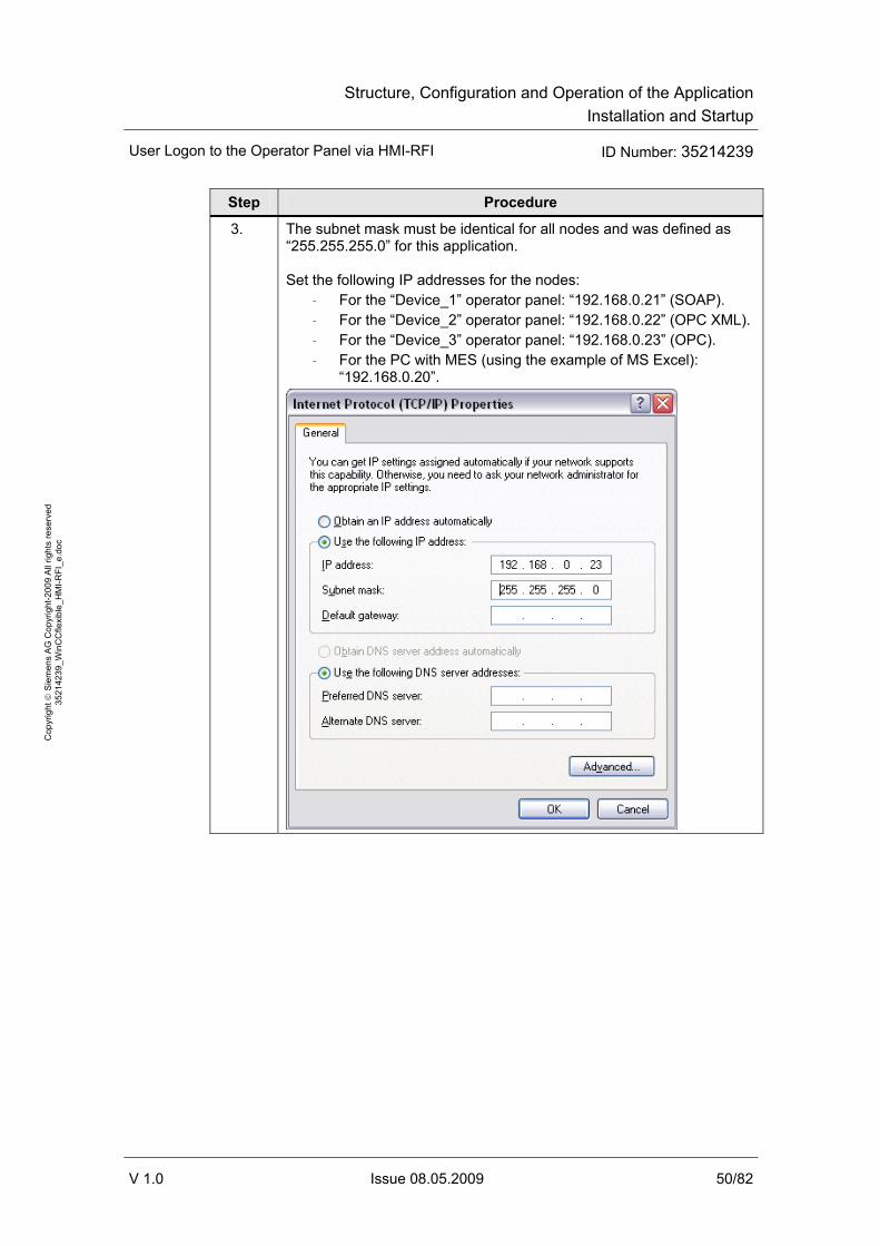
3. The subnet mask must be identical for all nodes and was defined as “255.255.255.0” for this application. Set the following IP addresses for the nodes:
– For the “Device_1” operator panel: “192.168.0.21” (SOAP). – For the “Device_2” operator panel: “192.168.0.22” (OPC XML). – For the “Device_3” operator panel: “192.168.0.23” (OPC). – For the PC with MES (using the example of MS Excel):
“192.168.0.20”.

Structure, Configuration and Operation of the ApplicationInstallation and Startup
User Logon to the Operator Panel via HMI-RFI ID Number: 35214239
V 1.0 Issue 08.05.2009 51/82
Cop
yrig
ht ©
Sie
men
s A
G C
opyr
ight
-200
9 A
ll rig
hts
rese
rved
35
2142
39_W
inC
Cfle
xibl
e_H
MI-R
FI_e
.doc
Step Procedure
4. Making the DCOM settings • Start the “Run” dialog box by selecting “Start > Run...”. In the box,
enter “DCOMCnfg”. • Maximize the “DCOM Config” folder in “Console Root > Component
Services > Computers > My Computer”. • Open the Properties window of “OPC.SimaticHMI.HmiRTm” by
opening the context window with the right mouse button and clicking on “Properties”.

Structure, Configuration and Operation of the ApplicationInstallation and Startup
User Logon to the Operator Panel via HMI-RFI ID Number: 35214239
V 1.0 Issue 08.05.2009 52/82
Cop
yrig
ht ©
Sie
men
s A
G C
opyr
ight
-200
9 A
ll rig
hts
rese
rved
35
2142
39_W
inC
Cfle
xibl
e_H
MI-R
FI_e
.doc
Step Procedure
5. Setting the authentication level In the “General” tab, select “None” in the Authentication Level combo box.

Structure, Configuration and Operation of the ApplicationInstallation and Startup
User Logon to the Operator Panel via HMI-RFI ID Number: 35214239
V 1.0 Issue 08.05.2009 53/82
Cop
yrig
ht ©
Sie
men
s A
G C
opyr
ight
-200
9 A
ll rig
hts
rese
rved
35
2142
39_W
inC
Cfle
xibl
e_H
MI-R
FI_e
.doc
Step Procedure
6. Defining the location • Go to the “Location” tab. • Select “Run application on this computer”.

Structure, Configuration and Operation of the ApplicationInstallation and Startup
User Logon to the Operator Panel via HMI-RFI ID Number: 35214239
V 1.0 Issue 08.05.2009 54/82
Cop
yrig
ht ©
Sie
men
s A
G C
opyr
ight
-200
9 A
ll rig
hts
rese
rved
35
2142
39_W
inC
Cfle
xibl
e_H
MI-R
FI_e
.doc
Step Procedure
7. Opening the Launch and Activation Permissions dialog box • Click on the “Security” tab. • In “Launch and Activation Permissions”, check the “Customize”
option box. • Subsequently, select the “Edit...” button.

Structure, Configuration and Operation of the ApplicationInstallation and Startup
User Logon to the Operator Panel via HMI-RFI ID Number: 35214239
V 1.0 Issue 08.05.2009 55/82
Cop
yrig
ht ©
Sie
men
s A
G C
opyr
ight
-200
9 A
ll rig
hts
rese
rved
35
2142
39_W
inC
Cfle
xibl
e_H
MI-R
FI_e
.doc
Step Procedure
8. Adding launch permissions Add the following group and user names and enable their Remote Access: • (ComputerName/Administrators) • Everyone • (INTERACTIVE) • NETWORK • (SYSTEM)

Structure, Configuration and Operation of the ApplicationInstallation and Startup
User Logon to the Operator Panel via HMI-RFI ID Number: 35214239
V 1.0 Issue 08.05.2009 56/82
Cop
yrig
ht ©
Sie
men
s A
G C
opyr
ight
-200
9 A
ll rig
hts
rese
rved
35
2142
39_W
inC
Cfle
xibl
e_H
MI-R
FI_e
.doc
Step Procedure
9. Adding access permissions Add the following group and user names and enable all access permissions: • Administrators • INTERACTIVE • Everyone • NETWORK • (SYSTEM)

Structure, Configuration and Operation of the ApplicationInstallation and Startup
User Logon to the Operator Panel via HMI-RFI ID Number: 35214239
V 1.0 Issue 08.05.2009 57/82
Cop
yrig
ht ©
Sie
men
s A
G C
opyr
ight
-200
9 A
ll rig
hts
rese
rved
35
2142
39_W
inC
Cfle
xibl
e_H
MI-R
FI_e
.doc
Step Procedure
10. Defining endpoints • Go to the “Endpoints” tab and click on “Add”. • In the displayed dialog box, select the “Use default points” option
and “Connection-oriented TCP/IP” as a protocol sequence.

Structure, Configuration and Operation of the ApplicationInstallation and Startup
User Logon to the Operator Panel via HMI-RFI ID Number: 35214239
V 1.0 Issue 08.05.2009 58/82
Cop
yrig
ht ©
Sie
men
s A
G C
opyr
ight
-200
9 A
ll rig
hts
rese
rved
35
2142
39_W
inC
Cfle
xibl
e_H
MI-R
FI_e
.doc
Step Procedure
11. Defining the identity • Go to the “Identity” tab. • Enable “The interactive user” if it has not been selected yet.
Firewall settings When using WinCC flexible as an OPC client or server, you have to enter the following applications: Table 6-8
No. Application OPC component Port
1. SOPC_HmiRTm.exe OPC server Dynamic 2. HmiRTm.exe OPC client Dynamic 3. OpcEnum.exe OPC server Dynamic

Structure, Configuration and Operation of the ApplicationInstallation and Startup
User Logon to the Operator Panel via HMI-RFI ID Number: 35214239
V 1.0 Issue 08.05.2009 59/82
Cop
yrig
ht ©
Sie
men
s A
G C
opyr
ight
-200
9 A
ll rig
hts
rese
rved
35
2142
39_W
inC
Cfle
xibl
e_H
MI-R
FI_e
.doc
6.5.3 Setting up the OPC client (MES)
The following settings only have to made on the MES computer (using the example of MS Excel). Table 6-9
Step Procedure
1. Network settings on the operator panel – Open the network properties by selecting “Start > Settings >
Network Connections” and then Properties.

Structure, Configuration and Operation of the ApplicationInstallation and Startup
User Logon to the Operator Panel via HMI-RFI ID Number: 35214239
V 1.0 Issue 08.05.2009 60/82
Cop
yrig
ht ©
Sie
men
s A
G C
opyr
ight
-200
9 A
ll rig
hts
rese
rved
35
2142
39_W
inC
Cfle
xibl
e_H
MI-R
FI_e
.doc
Step Procedure
2. The subnet mask must be identical for all nodes and was defined as “255.255.255.0” for this application. Set the following IP addresses for the nodes:
– For the “Device_1” operator panel: “192.168.0.21” (SOAP). – For the “Device_2” operator panel: “192.168.0.22” (OPC XML). – For the “Device_3” operator panel: “192.168.0.23” (OPC). – For the PC with MES (using the example of MS Excel):
“192.168.0.20”.
3. Settings on the PC with MES (using the example of MS Excel)
An IP address or “name resolution” is used for data access to Windows operator panels via OPC. The IP address of the “Device_3” operator panel must be made known to the OPC client (using the example of MS Excel). In this application, this is done in cell “B4”.
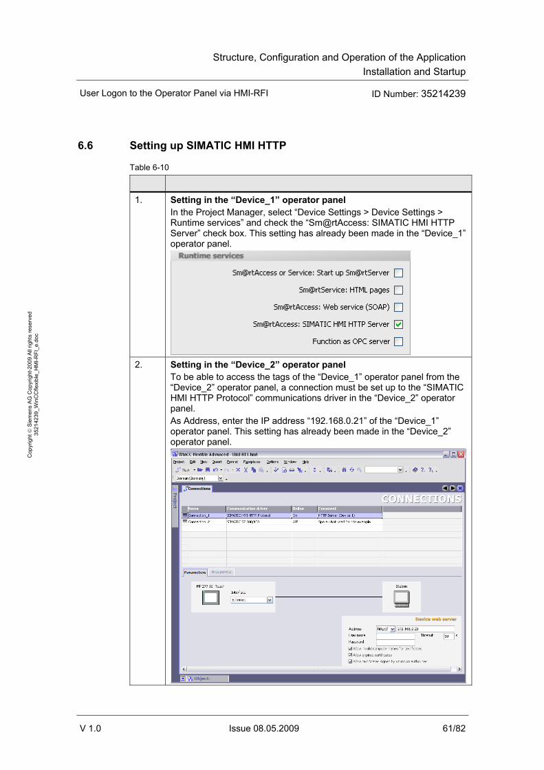
Structure, Configuration and Operation of the ApplicationInstallation and Startup
User Logon to the Operator Panel via HMI-RFI ID Number: 35214239
V 1.0 Issue 08.05.2009 61/82
Cop
yrig
ht ©
Sie
men
s A
G C
opyr
ight
-200
9 A
ll rig
hts
rese
rved
35
2142
39_W
inC
Cfle
xibl
e_H
MI-R
FI_e
.doc
6.6 Setting up SIMATIC HMI HTTP
Table 6-10
1. Setting in the “Device_1” operator panel In the Project Manager, select “Device Settings > Device Settings > Runtime services” and check the “Sm@rtAccess: SIMATIC HMI HTTP Server” check box. This setting has already been made in the “Device_1” operator panel.
2. Setting in the “Device_2” operator panel
To be able to access the tags of the “Device_1” operator panel from the “Device_2” operator panel, a connection must be set up to the “SIMATIC HMI HTTP Protocol” communications driver in the “Device_2” operator panel. As Address, enter the IP address “192.168.0.21” of the “Device_1” operator panel. This setting has already been made in the “Device_2” operator panel.
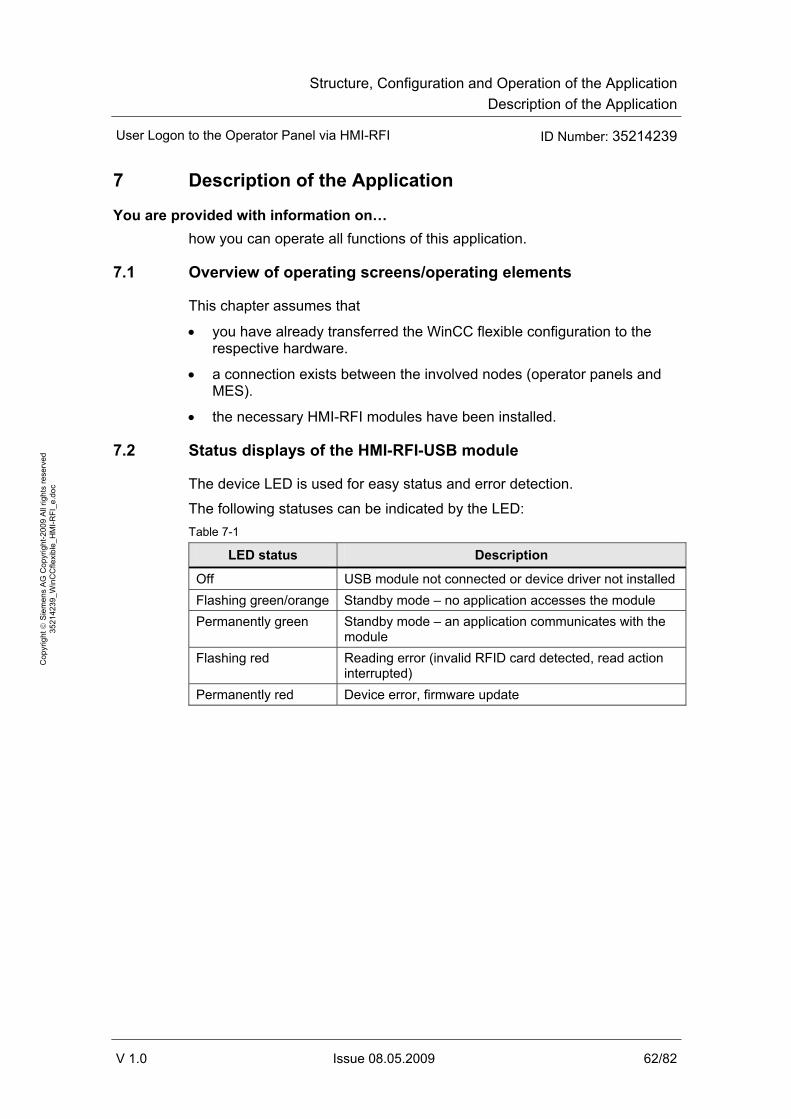
Structure, Configuration and Operation of the ApplicationDescription of the Application
User Logon to the Operator Panel via HMI-RFI ID Number: 35214239
V 1.0 Issue 08.05.2009 62/82
Cop
yrig
ht ©
Sie
men
s A
G C
opyr
ight
-200
9 A
ll rig
hts
rese
rved
35
2142
39_W
inC
Cfle
xibl
e_H
MI-R
FI_e
.doc
7 Description of the Application
You are provided with information on… how you can operate all functions of this application.
7.1 Overview of operating screens/operating elements
This chapter assumes that
• you have already transferred the WinCC flexible configuration to the respective hardware.
• a connection exists between the involved nodes (operator panels and MES).
• the necessary HMI-RFI modules have been installed.
7.2 Status displays of the HMI-RFI-USB module
The device LED is used for easy status and error detection.
The following statuses can be indicated by the LED: Table 7-1
LED status Description
Off USB module not connected or device driver not installed Flashing green/orange Standby mode – no application accesses the module Permanently green Standby mode – an application communicates with the
module Flashing red Reading error (invalid RFID card detected, read action
interrupted) Permanently red Device error, firmware update
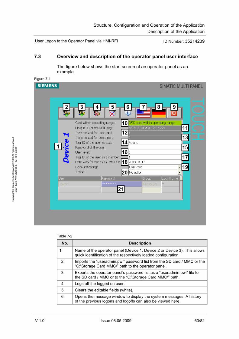
Structure, Configuration and Operation of the ApplicationDescription of the Application
User Logon to the Operator Panel via HMI-RFI ID Number: 35214239
V 1.0 Issue 08.05.2009 63/82
Cop
yrig
ht ©
Sie
men
s A
G C
opyr
ight
-200
9 A
ll rig
hts
rese
rved
35
2142
39_W
inC
Cfle
xibl
e_H
MI-R
FI_e
.doc
7.3 Overview and description of the operator panel user interface
The figure below shows the start screen of an operator panel as an example.
Figure 7-1
Table 7-2
No. Description
1. Name of the operator panel (Device 1, Device 2 or Device 3). This allows quick identification of the respectively loaded configuration.
2. Imports the “useradmin.pwl” password list from the SD card / MMC or the “C:\Storage Card MMC\” path to the operator panel.
3. Exports the operator panel’s password list as a “useradmin.pwl” file to the SD card / MMC or to the “C:\Storage Card MMC\” path.
4. Logs off the logged on user. 5. Clears the editable fields (white). 6. Opens the message window to display the system messages. A history
of the previous logons and logoffs can also be viewed here.

Structure, Configuration and Operation of the ApplicationDescription of the Application
User Logon to the Operator Panel via HMI-RFI ID Number: 35214239
V 1.0 Issue 08.05.2009 64/82
Cop
yrig
ht ©
Sie
men
s A
G C
opyr
ight
-200
9 A
ll rig
hts
rese
rved
35
2142
39_W
inC
Cfle
xibl
e_H
MI-R
FI_e
.doc
No. Description
7. Changes the current language setting to “English (USA)”. 8. Changes the current language setting to “German”. 9. Exits the user interface and takes you back to the Loader menu. 10. Indicates whether an RFID card is within the operating range of the card
reader. • Green = RFID card within the operating range • Orange = no RFID card within the operating range
11. Displays the unique ID of the last read RFID card. 12. Is incremented for each read user card. 13. Is incremented for each read materials management part. 14. Editable
• For user card: Displays the card user’s user name as text and is used for logging on to the operator panel.
• For spare part (materials management): Displays the spare part ID as text, for example an MLFB.
15. Editable Displays the card user’s password as text and is used for logging on to the operator panel. The display is automatically reset after approx. one second.
16. Editable Displays the card user’s group number.
17. Editable • For user card: Displays the card user’s identification number. • For spare part (materials management): Displays the spare part
identification number. 18. Editable
Displays the date stored on the RFID card in JJJJ-MM-TT format. 19. Editable
Displays the ID of the RFID card. Two different IDs exist: • User card • Spare part (materials management)
20. Editable The value can be changed by the user to trigger the following actions: • Reading out the RFID card, • writing to the RFID card
21. Editable Display of the currently logged on user. Alternatively, the user can also log on without RFID card.

Structure, Configuration and Operation of the ApplicationDescription of the Application
User Logon to the Operator Panel via HMI-RFI ID Number: 35214239
V 1.0 Issue 08.05.2009 65/82
Cop
yrig
ht ©
Sie
men
s A
G C
opyr
ight
-200
9 A
ll rig
hts
rese
rved
35
2142
39_W
inC
Cfle
xibl
e_H
MI-R
FI_e
.doc
Note The editable fields no.13 to no.19 can also be written to using the “HMI-RFI Manager”. By importing and exporting the data of the password list file from WinCC flexible (*.pwl files), the user administration can be kept consistent.
7.4 Overview and description of the HMI-RFI Manager
The following figure shows the HMI-RFI Manager user interface. Figure 7-2
Table 7-3
No. Description
1. Changeover between user card and spare part card (materials management).
2. Importing and exporting the password list file (*.pwl files) of an operator panel. This is required to keep the user administration consistent.
3. Editing the entries of the RFID card. 4. Clearing the RFID card and writing to the RFID card. 5. Current data record of the RFID card.
• Bold: Data record on the RFID card within the reception range. • Normal: Data record has been saved. • Italics: Data record has not yet been saved.
6. Status window
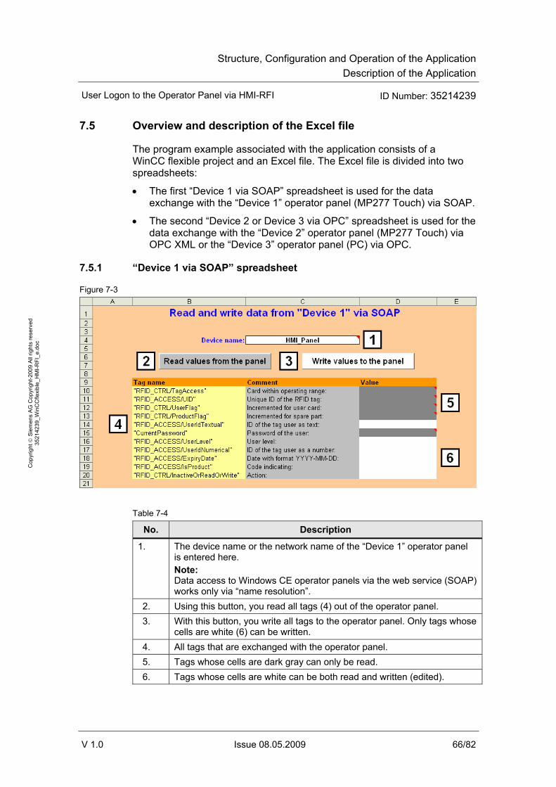
Structure, Configuration and Operation of the ApplicationDescription of the Application
User Logon to the Operator Panel via HMI-RFI ID Number: 35214239
V 1.0 Issue 08.05.2009 66/82
Cop
yrig
ht ©
Sie
men
s A
G C
opyr
ight
-200
9 A
ll rig
hts
rese
rved
35
2142
39_W
inC
Cfle
xibl
e_H
MI-R
FI_e
.doc
7.5 Overview and description of the Excel file
The program example associated with the application consists of a WinCC flexible project and an Excel file. The Excel file is divided into two spreadsheets:
• The first “Device 1 via SOAP” spreadsheet is used for the data exchange with the “Device 1” operator panel (MP277 Touch) via SOAP.
• The second “Device 2 or Device 3 via OPC” spreadsheet is used for the data exchange with the “Device 2” operator panel (MP277 Touch) via OPC XML or the “Device 3” operator panel (PC) via OPC.
7.5.1 “Device 1 via SOAP” spreadsheet
Figure 7-3
Table 7-4
No. Description
1. The device name or the network name of the “Device 1” operator panel is entered here. Note: Data access to Windows CE operator panels via the web service (SOAP) works only via “name resolution”.
2. Using this button, you read all tags (4) out of the operator panel. 3. With this button, you write all tags to the operator panel. Only tags whose
cells are white (6) can be written. 4. All tags that are exchanged with the operator panel. 5. Tags whose cells are dark gray can only be read. 6. Tags whose cells are white can be both read and written (edited).

Structure, Configuration and Operation of the ApplicationDescription of the Application
User Logon to the Operator Panel via HMI-RFI ID Number: 35214239
V 1.0 Issue 08.05.2009 67/82
Cop
yrig
ht ©
Sie
men
s A
G C
opyr
ight
-200
9 A
ll rig
hts
rese
rved
35
2142
39_W
inC
Cfle
xibl
e_H
MI-R
FI_e
.doc
7.5.2 “Device 2 or Device 3 via OPC” spreadsheet
Figure 7-4
Table 7-5
No. Description
1. Enter the IP address (or the name of the computer) on which the OPC server runs. If the OPC server (WinCC flexible RT) or OPC-XML-Gateway runs on the same computer as the OPC client (Excel), no input is necessary.
2. Select the OPC server name. By selecting “OPC.Siemens.XML” you connect the “Device 2” operator panel (MP277 Touch) as an OPC XML server, with “OPC.SimaticHMI.HmiRTm” you connect the “Device 3” operator panel (PC) as an OPC server.
3. Use this button to start the OPC client in Excel. This is the prerequisite for reading and writing tag values. After starting the OPC client, the tags are read cyclically. Note: The respective OPC XML server or OPC server must have previously been started.
4. With this button, you write all tags to the operator panel. Only tags whose cells are white (8) can be written.
5. Use this button to stop the OPC client in Excel. 6. All tags that are exchanged with the operator panel. 7. Tags whose cells are dark gray can only be read. 8. Tags whose cells are white can be both read and written (edited).

Structure, Configuration and Operation of the ApplicationDescription of the Application
User Logon to the Operator Panel via HMI-RFI ID Number: 35214239
V 1.0 Issue 08.05.2009 68/82
Cop
yrig
ht ©
Sie
men
s A
G C
opyr
ight
-200
9 A
ll rig
hts
rese
rved
35
2142
39_W
inC
Cfle
xibl
e_H
MI-R
FI_e
.doc
No. Description
9. Shows the current OPC status (no write access possible): • Server status: Indicates whether the OPC server is active (ON/OFF). • Client status: Indicates whether the OPC client (Excel) is active
(ON/OFF). Tag prefix: When using an OPC XML server, the complete tag prefix is entered here. The following syntax is applied: [Prefix]:Win CC Flexible RT<@> [Prefix] stands for the prefix that has been assigned to the IP address of the “Device 2” operator panel (MP277 Touch) in the “Prefix” column of the OPC XML Manager (OPC-XML-Gateway) and indicates to which OPC XML server the tags are assigned. Note: For OPC XML connections, the tag prefix is prefixed to the tag. The tag prefix consists of the prefix specified in the OPC XML Manager and the above-listed syntax.
• Items: Displays the number of updated tags (OPC items). • Update-Time: Time/date stamp of the last update. • OPC-Server-Vendor: Outputs information on the server vendor.

Structure, Configuration and Operation of the ApplicationDescription of the Application
User Logon to the Operator Panel via HMI-RFI ID Number: 35214239
V 1.0 Issue 08.05.2009 69/82
Cop
yrig
ht ©
Sie
men
s A
G C
opyr
ight
-200
9 A
ll rig
hts
rese
rved
35
2142
39_W
inC
Cfle
xibl
e_H
MI-R
FI_e
.doc
7.5.3 Editing the scripts
You can call the script editor in Excel either by selecting “Tools > Macro > Visual Basic Editor” or using the “Alt + F11” shortcut.
The used scripts are not protected so that they can be adapted to your own requirements if necessary.
7.5.4 Scripts of the “Device 1 via SOAP” spreadsheet
The “Device 1 via SOAP” spreadsheet contains two buttons; each button triggers a separate script.
“Read values” button The stored “SOAP_read_values_Click” script reads out the tag values of the “Device_1” operator panel.
• The device name of the “Device_1” operator panel is read out in cell “C4”.
• In the script, the user name “Administrator” and the password “100” are used as logon data. If you are using different logon data on your operator panel (can be set in “Control Panel > WinCC Internet Settings > Web Server > User Administration”), it has to be adapted accordingly in the script.
• The values are written to cells “D10” to “D20”.
“Write values” button The stored “SOAP_write_values_Click” script writes the tag values to the “Device_1” operator panel.
• The device name of the “Device_1” operator panel is read out in cell “C4”.
• In the script, the user name “Administrator” and the password “100” are used as logon data. If you are using different logon data on your operator panel (can be set in “Control Panel > WinCC Internet Settings > Web Server > User Administration”), it has to be adapted accordingly in the script.
• The values of cells “D14” and “D16” to “D20” are written to the “Device_1” operator panel.
7.5.5 Scripts of the “Device 2 or Device 3 via OPC” spreadsheet
The “Device 2 or Device 3 via OPC” spreadsheet contains three buttons; each button triggers a separate script. A further script is triggered via the list box.

Structure, Configuration and Operation of the ApplicationDescription of the Application
User Logon to the Operator Panel via HMI-RFI ID Number: 35214239
V 1.0 Issue 08.05.2009 70/82
Cop
yrig
ht ©
Sie
men
s A
G C
opyr
ight
-200
9 A
ll rig
hts
rese
rved
35
2142
39_W
inC
Cfle
xibl
e_H
MI-R
FI_e
.doc
“First: Start Client” button The stored “OPC_start_client_Click” script starts the OPC client.
• The device name or the IP address of the “Device_2” or “Device_3” operator panel is read out in cell “B4”.
• The OPC server to which the OPC client is to establish a connection is read out in the “D4” drop-down list.
• “MyGroup” is used as a group name. If you want to select another group name for the connection, this has to be adapted accordingly in the script.
• The values are cyclically written to cells “D10” to “D20”.
• The connection status is cyclically written to cells “C22”, “C23” and “C25” to “C27”.
NOTICE When communicating via OPC XML, this application assumes that OPC-XML-Gateway runs on the same computer as the OPC client. Cell “B4” listing the device name or the IP address of the “Device_2” operator panel is thus ignored.
“Write values” button The stored “OPC_write_values_Click” script writes the tag values to the “Device_2” or “Device_3” operator panel.
• The server status of the “Device_2” or “Device_3” operator panel is read out in cell “C22”.
• When the server status is “ON”, the values of cells “D14” and “D16” to “D20” are written to the “Device_2” or “Device_3” operator panel.
“Last: Stop Client” button The stored “OPC_stop_client_Click” script stops the OPC client.
• The server status of the “Device_2” or “Device_3” operator panel is read out in cell “C22”.
• When the server status is not “ON”, the OPC client is stopped and the values of cells “C22” and “C23” and “C27” are updated.
List box The stored “ComboBox1_Change” script selects the OPC server.
• Depending on the selected OPC server, the complete prefix is written to cell “C24”.
Note The prefix in cell “C24” is only prefixed to the OPC items (tags) of an OPC XML server (“Device_2” operator panel).
Cell “C24” is thus deleted when establishing a connection via OPC.
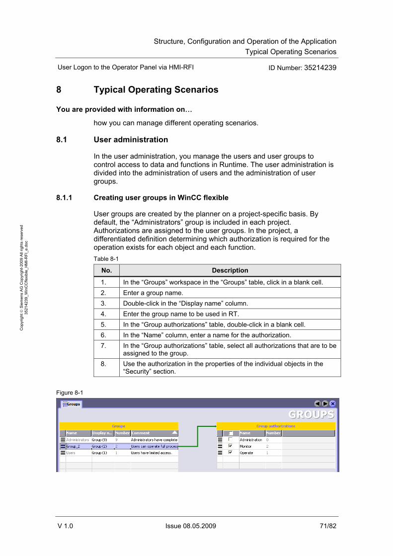
Structure, Configuration and Operation of the ApplicationTypical Operating Scenarios
User Logon to the Operator Panel via HMI-RFI ID Number: 35214239
V 1.0 Issue 08.05.2009 71/82
Cop
yrig
ht ©
Sie
men
s A
G C
opyr
ight
-200
9 A
ll rig
hts
rese
rved
35
2142
39_W
inC
Cfle
xibl
e_H
MI-R
FI_e
.doc
8 Typical Operating Scenarios
You are provided with information on…
how you can manage different operating scenarios.
8.1 User administration
In the user administration, you manage the users and user groups to control access to data and functions in Runtime. The user administration is divided into the administration of users and the administration of user groups.
8.1.1 Creating user groups in WinCC flexible
User groups are created by the planner on a project-specific basis. By default, the “Administrators” group is included in each project. Authorizations are assigned to the user groups. In the project, a differentiated definition determining which authorization is required for the operation exists for each object and each function. Table 8-1
No. Description
1. In the “Groups” workspace in the “Groups” table, click in a blank cell. 2. Enter a group name. 3. Double-click in the “Display name” column. 4. Enter the group name to be used in RT. 5. In the “Group authorizations” table, double-click in a blank cell. 6. In the “Name” column, enter a name for the authorization. 7. In the “Group authorizations” table, select all authorizations that are to be
assigned to the group. 8. Use the authorization in the properties of the individual objects in the
“Security” section.
Figure 8-1

Structure, Configuration and Operation of the ApplicationTypical Operating Scenarios
User Logon to the Operator Panel via HMI-RFI ID Number: 35214239
V 1.0 Issue 08.05.2009 72/82
Cop
yrig
ht ©
Sie
men
s A
G C
opyr
ight
-200
9 A
ll rig
hts
rese
rved
35
2142
39_W
inC
Cfle
xibl
e_H
MI-R
FI_e
.doc
8.1.2 Creating users in WinCC flexible
Users are assigned to exactly one user group. Table 8-2
No. Description
9. In the “Users” workspace in the “Users” table, click in a blank cell. 10. Enter a user name. 11. Double-click in the “Password” column. 12. Enter a password. 13. To confirm the password, enter it again in the field below. 14. Close the dialog box. 15. In the “User group(s)” table, enable the user group that is to be assigned
to the user. Figure 8-2
8.1.3 Managing users
Unlike user groups, users can also be created during runtime after completing the configuration.
The HMI-RFI Manager offers you the option of
• importing the exported password list of an operator panel via the file import.
• creating new users.
• writing user data to an RFID card.
• exporting the password list for an operator panel via the file export.
Importing the password list on the operator panel ensures consistent user administration for all operator panels and RFID cards.
Chapter 7.4 provides further information on the HMI-RFI Manager.

Structure, Configuration and Operation of the ApplicationTypical Operating Scenarios
User Logon to the Operator Panel via HMI-RFI ID Number: 35214239
V 1.0 Issue 08.05.2009 73/82
Cop
yrig
ht ©
Sie
men
s A
G C
opyr
ight
-200
9 A
ll rig
hts
rese
rved
35
2142
39_W
inC
Cfle
xibl
e_H
MI-R
FI_e
.doc
Table 8-3
No. Description Picture
1. Export the password list on the operator panel using the corresponding button. For a multi panel, the “useradmin.pwl” file is written to the SD card or the MMC; for the “Device_3” operator panel, the list is exported to the “C:\Storage Card MMC\” path.
2. Open the HMI-RFI Manager and import the “useradmin.pwl” file from the memory card or the storage path of the operator panel.
3. Create a new item or change or delete an existing item in the imported list items of the HMI-RFI Manager.
4. For the duration of the write operation, hold the RFID card to the HMI-RFI module and write the changed or new item to the RFID card.
5. Export the changed list items of the HMI-RFI Manager to the memory card or the storage path of the operator panel under the file name “useradmin.pwl”. If the file already exists, confirm the following dialog box with “Yes”.
6. Import the password list on the operator panel using the corresponding button. For a multi panel, the “useradmin.pwl” file is read from the SD card or the MMC; for the “Device_3” operator panel, the list is imported from the “C:\Storage Card MMC\” path.
Note When the operator panels are networked with the computer of the HMI-RFI Manager via Industrial Ethernet, it is not necessary to use memory cards.
Instead, set up a shared network path for the “useradmin.pwl” file to which both the HMI-RFI Manager and all operator panels have access.
The file name of the “ExportImportUserAdministration” function in the WinCC flexible configuration for the operator panels must be adapted according to the changed storage path. The functions are available on the buttons as shown in table 8-3.
The triggering event for the “ExportImportUserAdministration” function can also be triggered via an additional OPC tag from the MES.
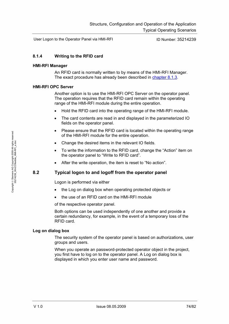
Structure, Configuration and Operation of the ApplicationTypical Operating Scenarios
User Logon to the Operator Panel via HMI-RFI ID Number: 35214239
V 1.0 Issue 08.05.2009 74/82
Cop
yrig
ht ©
Sie
men
s A
G C
opyr
ight
-200
9 A
ll rig
hts
rese
rved
35
2142
39_W
inC
Cfle
xibl
e_H
MI-R
FI_e
.doc
8.1.4 Writing to the RFID card
HMI-RFI Manager An RFID card is normally written to by means of the HMI-RFI Manager. The exact procedure has already been described in chapter 8.1.3.
HMI-RFI OPC Server Another option is to use the HMI-RFI OPC Server on the operator panel. The operation requires that the RFID card remain within the operating range of the HMI-RFI module during the entire operation.
• Hold the RFID card into the operating range of the HMI-RFI module.
• The card contents are read in and displayed in the parameterized IO fields on the operator panel.
• Please ensure that the RFID card is located within the operating range of the HMI-RFI module for the entire operation.
• Change the desired items in the relevant IO fields.
• To write the information to the RFID card, change the “Action” item on the operator panel to “Write to RFID card”.
• After the write operation, the item is reset to “No action”.
8.2 Typical logon to and logoff from the operator panel
Logon is performed via either
• the Log on dialog box when operating protected objects or
• the use of an RFID card on the HMI-RFI module
of the respective operator panel.
Both options can be used independently of one another and provide a certain redundancy, for example, in the event of a temporary loss of the RFID card.
Log on dialog box The security system of the operator panel is based on authorizations, user groups and users.
When you operate an password-protected operator object in the project, you first have to log on to the operator panel. A Log on dialog box is displayed in which you enter user name and password.

Structure, Configuration and Operation of the ApplicationTypical Operating Scenarios
User Logon to the Operator Panel via HMI-RFI ID Number: 35214239
V 1.0 Issue 08.05.2009 75/82
Cop
yrig
ht ©
Sie
men
s A
G C
opyr
ight
-200
9 A
ll rig
hts
rese
rved
35
2142
39_W
inC
Cfle
xibl
e_H
MI-R
FI_e
.doc
Figure 8-3
After logging on, you can operate operator objects for which you have the necessary authorizations.
Note The planner can also provide the Log on dialog box via a separate operator object.
To do this, create a new operator object in your project using the “ShowLogonDialog” function.
RFID card To log on to the operator panel via the RFID card, it is sufficient to hold the card to the HMI-RFI module.
For more information, please refer to chapter 4.2.
Logging off Logoff is performed either
• time-controlled, according to the “Logoff time” setting of the user or
• by using the respective button on the operator panel. Figure 8-4
Note After logging off, you can no longer operate password-protected objects, you might have to log on again.

Structure, Configuration and Operation of the ApplicationTypical Operating Scenarios
User Logon to the Operator Panel via HMI-RFI ID Number: 35214239
V 1.0 Issue 08.05.2009 76/82
Cop
yrig
ht ©
Sie
men
s A
G C
opyr
ight
-200
9 A
ll rig
hts
rese
rved
35
2142
39_W
inC
Cfle
xibl
e_H
MI-R
FI_e
.doc
8.3 Materials management
The handling of the RFID cards for materials management (spare part) differs from the user cards in the ID and the stored data record.
8.3.1 ID
You specify the ID in the HMI-RFI Manager by means of an option box in which you can select between “User” and “Spare Part”. Figure 8-5
When writing to the RFID card on the operator panel, select the “ID” item on the operator panel. You can select between the following two items:
• User card
• Spare part
8.3.2 Data record
While
• user name
• password and
• group
are stored for user cards, spare part cards contain
• order number (MLFB) and
• identification number.

Structure, Configuration and Operation of the ApplicationTypical Operating Scenarios
User Logon to the Operator Panel via HMI-RFI ID Number: 35214239
V 1.0 Issue 08.05.2009 77/82
Cop
yrig
ht ©
Sie
men
s A
G C
opyr
ight
-200
9 A
ll rig
hts
rese
rved
35
2142
39_W
inC
Cfle
xibl
e_H
MI-R
FI_e
.doc
User card Figure 8-6
Spare part card Figure 8-7
To transfer ID and data record to the RFID card, please follow the instructions in chapter 8.1.4.

Appendix and ReferencesGlossary
User Logon to the Operator Panel via HMI-RFI ID Number: 35214239
V 1.0 Issue 08.05.2009 78/82
Cop
yrig
ht ©
Sie
men
s A
G C
opyr
ight
-200
9 A
ll rig
hts
rese
rved
35
2142
39_W
inC
Cfle
xibl
e_H
MI-R
FI_e
.doc
Appendix and References
9 Glossary
The glossary explains terms that are important to understand this application.
ALM ALM (Automation License Manager) is a product of Siemens AG and used for handling license keys (technical representatives of licenses).
DNS DNS (Domain Name System) is one of the most important services on the Internet. However, DNS is not limited to the Internet. It is possible without difficulty and compatible with the definition to set up individual zones in the name server for the resolution of local names and to enter the respective addresses there. Its main task is to reply to name resolution requests.
ERP ERP (Enterprise Resource Planning) is a complex user software used to support the resource planning of an entire enterprise. ERP describes the corporate task to use the resources available in an enterprise (capital, resources or staff) as efficiently as possible for the business process.
HTTP HTTP (Hypertext Transfer Protocol) is a protocol for transferring data over a network. It is mainly used to download web pages from the World Wide Web (WWW) to a web browser.
MES MES (Manufacturing Execution System) is a process-oriented production management system. Compared to similarly effective systems for production planning, ERP (Enterprise Resource Planning), it is characterized by the direct connection to the automation system and allows production control in real-time. This includes classic data acquisition and preparation such as production data acquisition (PDA), machine data acquisition (MDA) and personnel data recording, but also all other processes that have a quick effect on the manufacturing/production process.

Appendix and ReferencesGlossary
User Logon to the Operator Panel via HMI-RFI ID Number: 35214239
V 1.0 Issue 08.05.2009 79/82
Cop
yrig
ht ©
Sie
men
s A
G C
opyr
ight
-200
9 A
ll rig
hts
rese
rved
35
2142
39_W
inC
Cfle
xibl
e_H
MI-R
FI_e
.doc
OPC OPC (OLE for Process Control) is the name for a standardized software interface family that allows data exchange between applications of different manufacturers in automation.
RFI(D) RFID (Radio Frequency Identification) means identification with the aid of electromagnetic waves. RFID allows automatic identification and localization of objects and persons and thus considerably facilitates the acquisition and storage of data.
SOAP SOAP (Simple Object Access Protocol) is a protocol with the aid of which data can be exchanged between systems. SOAP is based on two standards: XML for representing the data and Internet protocols of the Transport and Application Layer for transmitting the messages.
XML XML (Extensible Markup Language) is a markup language for representing hierarchically structured data as text data. Among other things, XML is used for the exchange of data between computer systems, especially via the Internet.

Appendix and ReferencesReferences
User Logon to the Operator Panel via HMI-RFI ID Number: 35214239
V 1.0 Issue 08.05.2009 80/82
Cop
yrig
ht ©
Sie
men
s A
G C
opyr
ight
-200
9 A
ll rig
hts
rese
rved
35
2142
39_W
inC
Cfle
xibl
e_H
MI-R
FI_e
.doc
10 References
10.1 References
This list is by no means complete and only provides a selection of appropriate sources. Table 10-1
Topic Title /1/ WinCC flexible
2008 Manual WinCC flexible 2008 Compact/ Standard/ Advanced Order no. 6AV6691-1AB01-3AA0 http://support.automation.siemens.com/WW/view/en/18796010
/2/ MP277 Operating Instructions MP277 Order no. 6AV6691-1DJ01-0AA0 http://support.automation.siemens.com/WW/view/en/23337820
/3/ MP377 Operating Instructions MP377 Order no. 6AV6691-1DR01-0AA0 http://support.automation.siemens.com/WW/view/en/26248558
/4/ HMI RFID Catalog ST80, chapter 6: Customized Products - General machine construction http://www.automation.siemens.com/salesmaterial-as/catalog/en/st80_e.pdf
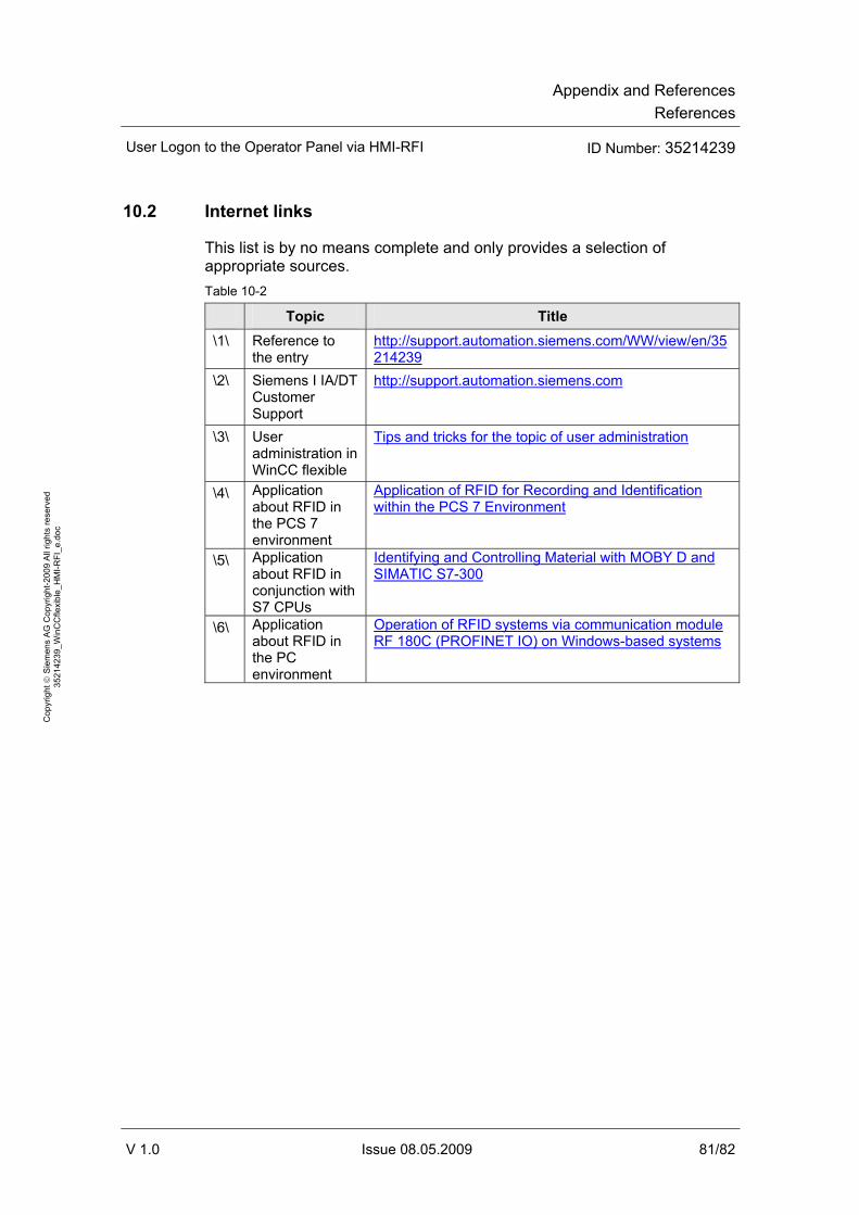
Appendix and ReferencesReferences
User Logon to the Operator Panel via HMI-RFI ID Number: 35214239
V 1.0 Issue 08.05.2009 81/82
Cop
yrig
ht ©
Sie
men
s A
G C
opyr
ight
-200
9 A
ll rig
hts
rese
rved
35
2142
39_W
inC
Cfle
xibl
e_H
MI-R
FI_e
.doc
10.2 Internet links
This list is by no means complete and only provides a selection of appropriate sources. Table 10-2
Topic Title \1\ Reference to
the entry http://support.automation.siemens.com/WW/view/en/35214239
\2\ Siemens I IA/DT Customer Support
http://support.automation.siemens.com
\3\ User administration in WinCC flexible
Tips and tricks for the topic of user administration
\4\ Application about RFID in the PCS 7 environment
Application of RFID for Recording and Identification within the PCS 7 Environment
\5\ Application about RFID in conjunction with S7 CPUs
Identifying and Controlling Material with MOBY D and SIMATIC S7-300
\6\ Application about RFID in the PC environment
Operation of RFID systems via communication module RF 180C (PROFINET IO) on Windows-based systems

Appendix and ReferencesHistory
User Logon to the Operator Panel via HMI-RFI ID Number: 35214239
V 1.0 Issue 08.05.2009 82/82
Cop
yrig
ht ©
Sie
men
s A
G C
opyr
ight
-200
9 A
ll rig
hts
rese
rved
35
2142
39_W
inC
Cfle
xibl
e_H
MI-R
FI_e
.doc
11 History Table 11-1 History
Version Date Modification
V1.0 05/08/09 First edition