Wilo-TOP-S/-SD/-RL/-I - productfinder …productfinder-wilo.cdn.mediamid.com/pfcdndoc/wilo_f...3~400...
28
2 132 725-Ed.02 / 2013-11-Wilo Wilo-TOP-S/-SD/-RL/-I Pioneering for You de Einbau- und Betriebsanleitung en Installation and operating instructions fr Notice de montage et de mise en service es Instrucciones de instalación y funcionamiento
-
Upload
truongliem -
Category
Documents
-
view
223 -
download
2
Transcript of Wilo-TOP-S/-SD/-RL/-I - productfinder …productfinder-wilo.cdn.mediamid.com/pfcdndoc/wilo_f...3~400...
2 132 725-Ed.02 / 2013-11-Wilo
Wilo-TOP-S/-SD/-RL/-I
Pioneering for You
de Einbau- und Betriebsanleitungen Installation and operating instructions
fr Notice de montage et de mise en servicees Instrucciones de instalación y funcionamiento

Fig. 1:
Fig. 2: Fig. 3:

Fig. 4: 1~
Fig. 4: 3~
max.
med.min.
1~230V

Fig. 5: Fig. 6:
Fig. 7a: Fig. 7b:
1 ~ 230 V/N/50 Hz
PE
PE
PE
TOP-S
SK 602SK 622
L2L1
L1
VU
L3 N
N
N 1 2WSK
WSK
W N 15 10 10 11
L N
15 10TOP-SD med.
min.
max.n
X4 X3 X2 X1
TOP-STOP-SDTOP-RLTOP-I
L1PE
1~230 V/N/50 Hz
N
Installation and operating instructions Wilo-TOP-S/-SD/-RL/-I 25
English
Installation and operating instructions1 GeneralAbout this documentThe language of the original operating instructions is German. All other lan-guages of these instructions are translations of the original operating instruc-tions.These installation and operating instructions are an integral part of the product. They must be kept readily available at the place where the product is installed. Strict adherence to these instructions is a precondition for the proper use and correct operation of the product. These installation and operating instructions correspond to the relevant version of the product and the underlying safety standards valid at the time of going to print.
2 SafetyThese operating instructions contain basic information which must be adhered to during installation, operation and maintenance. For this reason, these operating instructions must, without fail, be read by the service technician and the responsi-ble specialist/operator before installation and commissioning.It is not only the general safety instructions listed under the main point "safety” that must be adhered to but also the special safety instructions with danger symbols included under the following main points.
2.1 Indication of instructions in the operating instructions
Symbols:
General danger symbol
Danger due to electrical voltage
NOTE:
Signal words:
DANGER!Acutely dangerous situation.Non-observance results in death or the most serious of injuries.
WARNING!The user can suffer (serious) injuries. 'Warning' implies that (serious) injury to persons is probable if this information is disregarded.
CAUTION!There is a risk of damaging the product/unit. 'Caution' implies that damage to the product is likely if this information is disregarded.
NOTE: Useful information on handling the product. It draws attention to possi-ble problems.

English
26 WILO SE 11/2013
Information that appears directly on the product, such as:• Direction of rotation arrow, flow direction symbol• Identification for connections• Rating plate• Warning sticker
Must be strictly complied with and kept in legible condition.
2.2 Personnel qualificationsThe installation, operating and maintenance personnel must have the appropri-ate qualifications for this work. Area of responsibility, terms of reference and monitoring of the personnel are to be ensured by the operator. If the personnel are not in possession of the necessary knowledge, they are to be trained and instructed. This can be accomplished if necessary by the manufacturer of the product at the request of the operator.
2.3 Danger in the event of non-observance of the safety instructionsNon-observance of the safety instructions can result in risk of injury to persons and damage to the environment and the product/unit. Non-observance of the safety instructions results in the loss of any claims to damages.In detail, non-observance can, for example, result in the following risks:
• Danger to persons from electrical, mechanical and bacteriological influences• Damage to the environment due to leakage of hazardous materials• Property damage• Failure of important product/unit functions• Failure of required maintenance and repair procedures
2.4 Safety consciousness on the jobThe safety instructions included in these installation and operating instructions, the existing national regulations for accident prevention together with any internal working, operating and safety regulations of the operator are to be complied with.
2.5 Safety instructions for the operatorThis appliance is not intended for use by persons (including children) with reduced physical, sensory or mental capabilities, or lack of experience and knowledge, unless they have been given supervision or instruction concerning use of the appliance by a person responsible for their safety. Children should be supervised to ensure that they do not play with the appli-ance.
• If hot or cold components on the product/the unit lead to hazards, measures must be taken on site to guard them against touching.
• Guards protecting against touching moving components (such as the coupling) must not be removed whilst the product is in operation.
• Highly flammable materials are always to be kept at a safe distance from the product.

Installation and operating instructions Wilo-TOP-S/-SD/-RL/-I 27
English
• Leakages of hazardous fluids (e.g. explosive, toxic or hot) must be removed so that no danger to persons or the environment arises. National statutory provi-sions are to be complied with.
• Danger from electrical current must be eliminated. Local directives or general directives and local energy supply companies must be adhered to.
2.6 Safety instructions for installation and maintenance workThe operator must ensure that all installation and maintenance work is carried out by authorised and qualified personnel, who are sufficiently informed from their own detailed study of the installation and operating instructions.Work on the product/unit must only be carried out when at a standstill. It is mandatory that the procedure described in the installation and operating instructions for shutting down the product/unit are complied with.Immediately on conclusion of the work, all safety and protective devices must be put back in position and/or recommissioned.
2.7 Unauthorised modification and manufacture of spare partsUnauthorised modification and manufacture of spare parts will impair the safety of the product/personnel and will make void the manufacturer's declarations regarding safety.Modifications to the product are only permissible after consultation with the manufacturer. Original spare parts and accessories authorised by the manufac-turer ensure safety. The use of other parts will absolve us of liability for conse-quential events.
2.8 Improper useThe operating reliability of the supplied product is only guaranteed for conven-tional use in accordance with Section 4 and 5 of the installation and operating instructions. The limit values must on no account fall under or exceed those specified in the catalogue/data sheet.
3 Transport and interim storageOn arrival, immediately check the product and its packaging for damage caused during transit. If transport damage is found, the necessary procedures involving the forwarding agent must be taken within the specified period.
CAUTION! Risk of injuries to personnel and property damage!Incorrect transport and interim storage can cause damage to the product and injury to personnel.
• The pump and its packaging must be protected against moisture, frost and mechanical damage during transport and interim storage.
• Packaging that has become weakened due to moisture may allow the prod-uct to fall out, causing injury to personnel.
• The pump must only be carried by the motor/pump housing when trans-ported, never by the module/terminal box, cable or external condenser.

English
28 WILO SE 11/2013
4 Intended useCirculation pumps are used for pumping liquids in
• hot water heating systems• cooling and cold water circuits• closed-circuit industrial circulation systems.
WARNING! Health hazard!Because of the materials used in their construction, pumps of the TOP-S/-SD/-RL/-I series are unsuitable for use in applications involving potable water or foodstuffs.
5 Product information
5.1 Type key Example: TOP-S 25/5 EM
TOP Circulation pump, glandlessS -S/-RL = Standard type
-SD = Standard type , double pump-I = Industrial type
25 Screwed connection [mm]: 20 (Rp ¾), 25 (Rp 1), 30 (Rp 1¼)Flange connection: DN 32, 40, 50, 65, 80, 100Combination flange (PN 6/10): DN 32, 40, 50, 65
/5 Maximum delivery head in [m] for Q = 0 m3/hEM EM = Single-phase motor
DM = Three-phase motor
5.2 Technical data
Max. flow rate Depends on the pump type, see catalogueMax. delivery head Depends on the pump type, see catalogueSpeed Depends on the pump type, see catalogueMains voltage 1~230 V in accordance with DIN IEC 60038
3~400 V in accordance with DIN IEC 600383~230 V* in accordance with DIN IEC 60038 (optionally with switching plug)*Exception: TOP-S/-SD 80/15 and 80/20For other voltages see rating plate
Rated current See rating plateFrequency See rating plate (50 or 60 Hz)Insulation class See rating plateProtection class See rating platePower consumption P1 See rating plateNominal diameters See type keyConnection flanges See type key

Installation and operating instructions Wilo-TOP-S/-SD/-RL/-I 29
English
CAUTION! Risk of injuries to personnel and property damage!Non-approved fluids can damage the pump and also cause injury. Comply strictly with the relevant safety data sheets and manufacturer's data!
Pump weight Depends on the pump type, see cataloguePermissible Ambient temperature
-20 °C to +40 °C
Max. rel. humidity 95%Permissible fluidsTOP-S/-SD/-RL/-I
Heating water (as per VDI 2035)Water/glycol mixtures, max. mixing ratio of 1:1(If glycol is added, the delivery data of the pump must be corrected according to the higher viscosity, depending on the mixing ratio percentage.) Only use brand-name goods with corrosion protection inhibitors; comply with the manufacturer's specifications and safety data sheets. The pump manufacturer's approval must be obtained for use of other fluids.Special versions with fluids-resistant materials (e.g. versions for use with oil) available on request.
Permissible fluid temperature
Heating water:TOP-S/-SD/-RL:-20 °C to +130 °C (for a short time (2h): +140 °C)Exception: TOP-S 25/13; TOP-S/-SD 80/15 and 80/20:-20 °C to +110 °C
TOP-I:-20 °C to +110 °C
TOP-S/-SD/-RL:If used with Wilo-Protect module C: -20 °C to +110 °C
Max. permissible operating pressure
See rating plate
Emission sound-pressure level
< 50 dB(A)(depending on the pump type)
Emitted interference EN 61000-6-3Interference resistance EN 61000-6-2
5.2 Technical data

English
30 WILO SE 11/2013
Minimum inlet pressure (above atmospheric pressure) at the pump suction port in order to avoid cavitation noises (at fluids temperature TMed):
The values apply up to 300 m above sea level; allowance for higher altitudes:0.01 bar/100 m increase in height.
5.3 Scope of delivery• Pump, complete
• Two gaskets for threaded connection• Two-part thermal insulation shell (single pump only); not on TOP-RL
and TOP-I• 8 x M12 washers
(for M12 flange screws on combination flange version DN 32-DN 65)• 8 x M16 washers
(for M16 flange screws on combination flange version DN 32-DN 65)• Installation and operating instructions
5.4 AccessoriesAccessories must be ordered separately:
• Wilo-Protect Module C• Switching plug for 3~230 V
See catalogue for detailed list.
6 Description and function6.1 Description of the pump
The pump is fitted with a glandless motor (single-phase (1~) or three-phase (3~), for mains connection voltage and mains frequency see the rating plate, in which all the rotating parts are in contact with the fluid. The design relies on the fluid to provide lubrication for the plain bearings of the rotor shaft.The motor is multi-speed. Speed switching is executed in different ways depending on the terminal box. This is performed either by a speed selection switch, by plugging in the switching plug differently or by internally or exter-nally jumpering the contacts (See Commissioning/Switching Over the Speed). A suitable switching plug is available as an accessory for 3 ~230 V.
TOP-S/-SD/-RL TOP-I
TMed Rp 1, Rp 1¼, DN 32/40
DN 50, DN 65, DN 80, DN 100
Rp ¾, Rp 1
+50 °C 0.05 bar 0.3 bar 0.5 bar +80 °C - - 0.8 bar +95 °C 0.5 bar 1.0 bar -+110 °C 1.1 bar 1.6 bar 2.0 bar+130 °C 2.4 bar(*) 2.9 bar(*) -
(*) not applicable to TOP-S 25/13, TOP-S/-SD 80/15, TOP-S/-SD 80/20

Installation and operating instructions Wilo-TOP-S/-SD/-RL/-I 31
English
The assignment of terminal boxes to the individual pump types is described in the section "Terminal boxes" (chapter 6.2).
TOP-SD:For a double pump the two motor impeller units are fitted identically and accommodated in a common pump housing.
6.2 Terminal boxes
There are nine terminal boxes (fig. 4) covering all the pump types. Table 1 lists the assignment of terminal boxes to pump types:
Table 1: Assignment of terminal box types to pump types (see also fig. 4)
The fittings for the terminal boxes can be found in Table 2:
Table 2: Fitting of terminal boxes
1) The light indicator signals are carried by a common fibre optic cable to the cover, so that the signals are visible from outside.
2) When mains voltage is present, the lamp lights up green
• The direction of rotation indicator light lights up green when mains voltage is present and the direction of rotation is correct; if the direction of rotation is incorrect, the control lamp goes out (see the chapter "Commissioning").
• The fault signal light lights up red if the integral motor protection has tripped.
Mains connection
Max. power consumption P1(see rating plate data)
Terminal box typeTOP-RL, TOP-I TOP-S, TOP-SD
1~ 95 W ≤ P1max ≤ 265 W 1 1/2320 W ≤ P1max ≤ 400 W - 3/4/5650 W ≤ P1max ≤ 960 W - 5
3~ 95 W ≤ P1max ≤ 270 W 6 6305 W ≤ P1max ≤ 3125 W - 7
Terminal box type
Direction-of-rotation control lamp
Fault signal light
Variable speed control
(fig. 4, item 1) (fig. 4, item 2) (fig. 4, item 3)
1 - - Speed selection switch, 3-step2 - - Internal/external
Jumpering of contacts "x1-x2" or "x1-x3" or "x1-x4"
3 - - Speed selection switch, 3-step4 - - Internal/external
Jumpering of contacts "x1-x2" or "x1-x3" or "x1-x4"
5 - 2) X 1) Switching plug, 2-step6 X (internal) - Switching plug, 3-step7 X 1) X 1) Switching plug, 3-step
English
32 WILO SE 11/2013
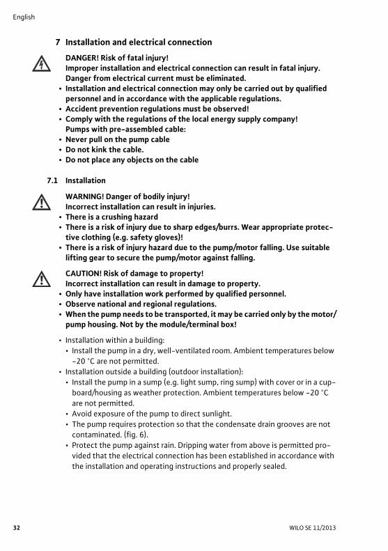
7 Installation and electrical connection
DANGER! Risk of fatal injury!Improper installation and electrical connection can result in fatal injury. Danger from electrical current must be eliminated.
• Installation and electrical connection may only be carried out by qualified personnel and in accordance with the applicable regulations.
• Accident prevention regulations must be observed!• Comply with the regulations of the local energy supply company!
Pumps with pre-assembled cable:• Never pull on the pump cable• Do not kink the cable.• Do not place any objects on the cable
7.1 Installation
WARNING! Danger of bodily injury!Incorrect installation can result in injuries.
• There is a crushing hazard • There is a risk of injury due to sharp edges/burrs. Wear appropriate protec-
tive clothing (e.g. safety gloves)!• There is a risk of injury hazard due to the pump/motor falling. Use suitable
lifting gear to secure the pump/motor against falling.
CAUTION! Risk of damage to property!Incorrect installation can result in damage to property.
• Only have installation work performed by qualified personnel.• Observe national and regional regulations.• When the pump needs to be transported, it may be carried only by the motor/
pump housing. Not by the module/terminal box!
• Installation within a building:• Install the pump in a dry, well-ventilated room. Ambient temperatures below
-20 °C are not permitted.• Installation outside a building (outdoor installation):
• Install the pump in a sump (e.g. light sump, ring sump) with cover or in a cup-board/housing as weather protection. Ambient temperatures below -20 °C are not permitted.
• Avoid exposure of the pump to direct sunlight.• The pump requires protection so that the condensate drain grooves are not
contaminated. (fig. 6).• Protect the pump against rain. Dripping water from above is permitted pro-
vided that the electrical connection has been established in accordance with the installation and operating instructions and properly sealed.

Installation and operating instructions Wilo-TOP-S/-SD/-RL/-I 33
English
CAUTION! Risk of damage to property!Ensure sufficient ventilation/heating if the ambient temperature exceeds/falls below the permitted limit values.
• Carry out all welding and soldering work prior to the installation of the pump.
CAUTION! Risk of damage to property!Contamination from the pipe system can destroy the pump during operation. Before installing the pump, flush the pipe system.
• Provide check valves upstream and downstream of the pump.• Attach piping to the floor, ceiling or wall using appropriate fittings so that the
pump does not bear the weight of the piping.• When installing in the feed of open systems, the safety supply must branch off
upstream of the pump (DIN EN 12828). • If necessary remove the two half shells of the thermal insulation before install-
ing the single pump.• Install the pump at an easily accessible location to allow it to be easily checked
or replaced at a later time.• Precautions during installation:
• Assemble such that the pump shafts are horizontal and not under strain (see the installation positions shown in fig. 2). The motor terminal box must not point downwards. If necessary, slacken the socket-head screws and rotate the motor housing (see chapter 9).
• The direction of flow of the fluid must correspond to the flow direction sym-bol on the pump housing or the pump flange.
7.1.1 Installation of a threaded pipe union pump• Install appropriate threaded pipe unions before installing the pump.• Use the supplied flat gaskets between the suction/pressure ports and threaded
pipe unions when installing the pump.• Screw union nuts onto the threads of the suction/pressure ports and tighten
them using a suitable open-end wrench or pipe wrench.
CAUTION! Risk of damage to property!When tightening the pipe unions, keep the pump in position by gripping the motor. Not the module/terminal box!
• Check the threaded pipe unions for leaks.• Single pump:
Fit the two half-shells of the thermal insulation before commissioning and push them together so that the guide pins engage in the opposite holes.
7.1.2 Installation of a flange-end pumpAssembly of pumps with a combination flange PN6/10 (Flange-end pumps DN 32 to DN 65 inclusive)

English
34 WILO SE 11/2013
WARNING! Risk of injury and damage to property! The flange connection can be damaged and develop leaks if the pump is not installed correctly. There is a risk of injury and damage to property due to hot fluid escaping.
• Never connect two combination flanges to each other!• Pumps with combination flanges are not suitable for operating pressures
PN16.• The use of securing elements (e.g. spring rings) can result in leaks at the
flange connection. They are therefore not permitted. The washers supplied (fig. 3, item 1) must be inserted between screw heads / nuts and the combi-nation flange.
• The permissible tightening torques listed in the table below must not be exceeded, even if screws of higher strength (≥4.6) are used, since otherwise splintering can occur at the edges of the long holes. This causes the screws to lose their preload and the flange connection can become leaky.
• Use screws of sufficient length. The screw thread must protrude at least one thread turn beyond the nut (fig. 3, item 2).
• Install appropriate flat gaskets between pump and counter flanges.• Tighten the flange bolts crosswise in two steps to the prescribed tightening
torque (see Table 7.1.2).• Step 1: 0.5 x permissible tightening torque• Step 2: 1.0 x permissible tightening torque
• Check the flange connections for leaks.• Single pump:
Fit the two half-shells of the thermal insulation before commissioning and push them together so that the guide pins engage in the opposite holes.
DN 32, 40, 50, 65 Rated pressure PN 6 Rated pressure PN 10/16
Screw diameter M12 M16Strength class ≥ 4.6 ≥ 4.6Permitted tightening torque 40 Nm 95 Nm Min. screw length for• DN 32/DN 40 55 mm 60 mm• DN 50/DN 65 60 mm 65 mm
DN 80, 100 Rated pressure PN 6 Rated pressure PN 10/16
Screw diameter M16 M16Strength class ≥ 4.6 ≥ 4.6Permitted tightening torque 95 Nm 95 Nm Min. screw length for• DN 80 65 mm 65 mm• DN 100 70 mm 70 mm

Installation and operating instructions Wilo-TOP-S/-SD/-RL/-I 35
English
7.1.3 Insulation of the pump in cooling/air-conditioning systems• The series TOP-S/-SD/-RL/-I are suitable for use in refrigeration and air-condi-
tioning systems with fluid temperatures down to -20 °C. • The thermal insulation shells included in the scope of delivery of single pumps
may however only be used in heating systems at fluid temperatures of +20 °C or higher, since these thermal insulation shells do not enclose the pump housing in a diffusion-proof manner.
• For applications in refrigeration and air-conditioning systems commercially-available diffusion-proof thermal insulation materials must be used.
CAUTION! Risk of damage to property!If the diffusion-proof insulation is applied by the customer, the pump hous-ing may be insulated only up to the motor separation joint, so that the con-densate drain openings remain open and allow the condensate accumulating in the motor to flow out without obstruction (fig. 6). Otherwise condensate can accumulate in the motor, eventually causing an electrical defect.
7.2 Electrical connection
DANGER! Risk of fatal injury!Improper electrical connections pose a risk of fatal injury due to electric shock.
• Only allow the electrical connection and all associated activities to be made by an electrician approved by the local power supply company and in accord-ance with the local regulations in force.
• Before working on the pump, all poles of the power supply must be discon-nected. Because voltages hazardous to persons persist for some time (in condensers), no work may be commenced on the module until 5 minutes have elapsed (applies only to 1~ systems). Check to ensure that all connec-tions (including potential-free contacts) are voltage-free.
• Do not operate the pump if the module/terminal box is damaged.• If the setting and operating elements on the module/terminal box are inad-
missibly removed, there is a danger of electric shock by touching the electri-cal components located inside.
CAUTION! Risk of damage to property!An incorrect electrical connection can cause damage to property.If the wrong voltage is applied, the motor can be damaged!
• The current type and voltage of the mains connection must correspond to the specifications on the rating plate.
• The electrical connection must be established via a fixed connection line equipped with a connector device or an all-pole switch with a contact opening width of at least 3 mm.
• Mains-side fuse protection: 10 A, slow.

English
36 WILO SE 11/2013
• Double pumps: provide a separate mains connection cable and a separate fuse on the mains side for both motors of the double pump.
• The pumps can also be used without restriction in existing installations with and without residual-current-operated protection switch switches. When dimen-sioning the residual-current-operated protection switch, consider the number of pumps connected and their motor currents.
• When pumps are used in systems with water temperatures above 90 °C, a suit-able heat-resistant supply cable must be used.
• All connection cables must be installed so that they do not touch the pipe and/or the pumps or motor housing.
• To ensure protection against dripping water and to provide the threaded cable connection with strain relief, (PG 13.5), a connection cable with an outside diameter of 10 - 12 mm should be used, and fitted as shown in fig. 5. In addition, the cable near the screwed connection should be bent into the form of a drip loop, from which any accumulated drips will fall. Unused threaded cable con-nections should be blanked off with the sealing plates provided, and screwed tight.
• Commission pumps only if they are fitted with the correct modular cover. Check that the cover seal is correctly seated.
• Earth the pump/installation in accordance with the regulations.
7.2.1 Collective fault signal (SSM)
DANGER! Risk of fatal injury!Improper electrical connections pose a risk of fatal injury due to electric shock.If the mains leads and SSM lead are brought together in a 5-core cable, the SSM-lead must not be monitored using a protective low voltage.
For pumps with terminal boxes of types 5 and 7 (fig. 4) a collective fault signal "SSM" for connection to the building automation system is available as a poten-tial-free NC relay (max. contact loading 250 VAC/1A). The contacts open if the integral motor protection trips to disconnect the motor. After a manual reset (fig. 4, item 4) at the pump, the contacts close again and the fault signal is acknowledged.
7.2.2 Motor protection
CAUTION! Risk of damage to property!If the thermal winding contact (WSK) of the pump is not connected to a motor protection system, the motor can be damaged due to thermal overload!

Installation and operating instructions Wilo-TOP-S/-SD/-RL/-I 37
English
• The setting of any thermal tripping that is fitted must correspond to the maxi-mum current (see rating plate) of the speed stage at which the pump is being operated.
Motor protection tripping devicesIf Wilo tripping units SK 602 (N)/ SK 622 (N) are present in existing systems, pumps with full motor protection (WSK) can be connected to them. Perform the mains connection and also the tripping unit connection (refer to the rating plate data) in accordance with the circuit diagram fig. 7a: 1~230 V: 320 W ≤ P1max ≤ 400 W, with thermal winding contact
Pump with terminal box type
Tripping SSM Fault acknowledgement
TOP-STOP-SDTOP-RLTOP-I
1~230 V
1(P1max ≤ 265 W)
Internal switching off of motor voltage
- Automatically, after the motor has cooled down
2(P1max ≤ 265 W)
Internal switching off of motor voltage
- Automatically, after the motor has cooled down
3(320 W ≤ P1max ≤ 400 W)
Thermal winding con-tact and external trip-ping unit (SK602 (N)/ SK622 (N) or other switch gear/control device)
- Manually at the tripping unit, after the motor on the SK602/SK622 has cooled down on the SK602N/SK622N: automatically
4(320 W ≤ P1max ≤ 400 W)
Thermal winding con-tact and external trip-ping unit (SK602 (N)/ SK622 (N) or other switchgear/control device)
- Manually at the tripping unit, after the motor on the SK602/SK622 has cooled down on the SK602N/SK622N: automatically
5(650 W ≤ P1max ≤ 960 W)
All-pole deactivation by the integral trip electronics
Tripping the SSM is performed in paral-lel with deactiva-tion of the integral trip electronics
Manually at the pump, after the motor has cooled down
Pump with terminal box type
Tripping SSM Fault acknowledgement
TOP-STOP-SDTOP-I
3~400 V
6(P1max ≤ 270 W)
Internal switching off of a motor phase
- • Switch off mains voltage
• Allow motor to cool down
• Switch on mains volt-age
7(305 W ≤ P1max ≤ 3125 W)
All-pole deactivation by the integral trip electronics
Tripping the SSM is performed in paral-lel with deactiva-tion of the integral trip electronics
Manually at the pump, after the motor has cooled down

English
38 WILO SE 11/2013
7.2.3 Frequency converter operationThree-phase motors of the series TOP-S/-SD/-I can be connected to a fre-quency converter. When operating with frequency converters, output filters should be used to reduce noise and to avoid damage due to voltage spikes.For noise reduction, it is recommended that sine filters (LC filters) are used rather than du/dt filters (RC filters).The following limit values should be complied with:
• Rate of voltage rise du/dt <500 V/μs• Voltage spikes û < 650 V
The following limit values at the connection terminals of the pump must not be exceeded:
• Umin = 150 V• fmin = 30 Hz
At low output frequencies from the frequency converter, the direction of rota-tion indicator light at the pump may go out.
8 Commissioning
WARNING! Risk of injury and damage to property!Commissioning the pump without the sealing screw including the flat gasket is not permissible, since escaping fluid can cause damage!
Prior to commissioning the pump, check that it was installed and connected correctly.
8.1 Filling and ventingPrime and vent the unit correctly. Venting the pump rotor compartment is car-ried out automatically after a short operating period. Dry running for short peri-ods will not harm the pump.
WARNING! Risk of injury and damage to property!It is not permitted to remove the motor head, differential pressure screw (fig. 3 item 3) or the flange connection / threaded pipe union for the purpose of venting the system!
• There is a risk of scalding!Escaping fluid can lead to injuries to persons and damage to the product. When the venting screw is opened, hot fluid may escape at high pressure in liquid of vapour form.
• Touching the pump can cause burns! Depending on the operating status of the pump or unit (fluid temperature), the entire pump can become very hot.
Pumps with venting screws (visible on motor head; fig. 1, item 1) can be vented as follows if required:
• Switch off the pump.• Close the check valve on the pressure side.• Protect electrical parts from any escaping water.• Carefully open the venting screw (fig. 1, item 1) using a suitable tool.

Installation and operating instructions Wilo-TOP-S/-SD/-RL/-I 39
English
CAUTION! Risk of damage to property!Depending on the operating pressure, the pump may jam when the venting screw is open. The necessary inlet pressure must be present at the suction side of the pump!
• Carefully push back the motor shaft with a screwdriver several times.• After 15 to 30 seconds, screw the venting screw back in.• Switch on the pump.• Open the check valve again.
NOTE! Incomplete venting will result in noises in the pump and unit. Repeat the procedure if necessary.
8.2 Rotation direction monitoring• Direction of rotation check for 3~:
Depending on the terminal box, the direction of rotation is indicated by a light on or in the terminal box (fig. 4, item 1). If the direction of rotation is correct, the light lights up green. If the direction of rotation is incorrect, the light remains dark. To check the direction of rotation, briefly switch the pump on. If the direc-tion of rotation is incorrect, proceed as follows:• Electrically isolate the pump.• Interchange 2 phases in the terminal box.• Restart the pump.The direction of rotation of the motor must correspond to the direction of rota-tion arrow on the rating plate.
8.2.1 Variable speed control
DANGER! Risk of fatal injury!When working on the open terminal box, there is a danger of electric shock from touching the live terminals.
• Disconnect the system from the power supply and secure it against being switched on again.
• It is not permissible to perform a stage change-over whilst in operation.• Only specialist personnel may perform a step change-over.
For 1~ pumps with terminal box type 1, 3 (fig. 4):Undo the terminal box cover screws, then remove the terminal box cover, switch the 3-step rotary switch within the box (fig. 4, item 3) to the symbol for the desired speed stage, then correctly refit the terminal box cover.When the terminal box cover is closed, the speed stage setting can be viewed through the viewing window.

English
40 WILO SE 11/2013
For 1~ pumps with terminal box type 2, 4 (fig. 4):• Speed change-over in the terminal box:
• Undo the terminal box cover screws, then remove the terminal box cover, select the desired speed stage for the terminal box type 2/4 by changing over the cable jumpers, then correctly refit the terminal box cover.
• External speed change-over outside the terminal box (pump with cable ver-sion):• For an external change-over of the speed stage, a cable can be connected as
shown in the circuit diagram fig. 7b. Undo the terminal box cover screws then remove the terminal box cover, remove the cable jumpers, feed in the cable through the PG cable gland and connect it, then correctly refit the terminal box cover. The cable end should be connected to an external 3-step switch.
NOTE! If the cable jumpers are not connected or incorrectly connected, the pump will not start. Make the connections for terminal box type 2 / 4 and circuit diagram fig. 7b.
For 1~ and 3~ pumps with terminal box type 5, 6, 7 (fig. 4):The switching plug in the terminal box can be set to one of a maximum of two or three steps (depending on the terminal box type).Undo the terminal box cover screws then remove the terminal box cover, pull off the switching plug (fig. 4, item 3) only with the pump switched off, then replace it so that the symbol for the desired speed stage in the terminal box is indicated by the respective marking of the switching plug.When the terminal box cover is closed, the speed stage setting can be viewed through the viewing window.
NOTE! If on a double pump both the individual pumps are in operation at the same time, the selected speeds must be identical for both pumps.
8.3 DecommissioningThe pump must be decommissioned before conducting maintenance, repair or dismantling work.
DANGER! Risk of fatal injury!Deadly electric shock may occur when working on electrical equipment.
• Have work on the electrical part of the pump carried out only by a qualified electrician as a basic principle.
• Before starting any maintenance and repair work, disconnect the pump from the power supply, and make sure it cannot be switched back on by unauthor-ised persons.
WARNING! Risk of burns!Depending on the operating status of the pump or unit (fluid temperature), the entire pump can become very hot. Touching the pump can cause burns.Allow the system and pump to cool down to room temperature.

Installation and operating instructions Wilo-TOP-S/-SD/-RL/-I 41
English
9 MaintenanceBefore carrying out maintenance, cleaning and repair work, read the chapters "Dismantling/installation of the motor" and "Decommissioning". The safety instructions in chapters 2.6, 7 and 8 must be complied with.After successful maintenance and repair work, install and connect the pump according to the "Installation and electrical connection" chapter. Switch on the system as described in the "Commissioning" chapter.
9.1 Dismantling/installation of the motor
WARNING! Danger of bodily injury!• Touching the pump can cause burns!
Depending on the operating status of the pump or unit (fluid temperature), the entire pump can become very hot.
• At high fluid temperatures and system pressures there is risk of scalding due to escaping hot fluid. Before dismantling the motor, close the existing check valves on both sides of the pump, allow the pump to cool to room temperature, and drain the isolated branch of the system. If no check valves are fitted, drain the entire system.
• Observe the manufacturer's information and safety data sheets on possible additives in the unit.
• Risk of injury due to the motor falling when the fastening screws have been undone. Comply with national regulations for accident prevention and also with the operator's internal works, company and safety regulations. If nec-essary, wear protective clothing and equipment!
• During installation/dismantling of the motor head, the rotor unit can fall out and injure personnel. Do not hold the motor head with the impeller facing downward.
The motor does not have to be completely removed from the pump housing if only the terminal box is to be repositioned. The motor can be rotated to the desired position whilst still attached to the pump housing (see fig. 2 for the per-missible installation positions).
CAUTION! Risk of damage to property!If for maintenance or repair work the motor head is detached from the pump housing, the O-ring located between the motor head and pump housing must be replaced with a new one. When installing the motor head, check that the O-ring is correctly seated.
• To release the motor, undo four socket-head screws.
CAUTION! Risk of damage to property!Do not damage the O-ring located between the motor head and the pump housing. The O-ring must lie in the angled end of he bearing plate that faces the impeller, and must not be twisted.
• After the installation tighten the four socket-head screws again crosswise.• For the commissioning of the pump, see chapter 8.

English
42 WILO SE 11/2013
10 Faults, causes and remediesHave faults remedied by qualified personnel only! Observe the safety instructions in chapter 9!
Fault Cause Remedy
The system is noisy. Air in the system. Vent the system.The flow rate at the pump is too high.
Reduce the pump power by switching to a lower speed.
The pump delivery head is too high.
Reduce the pump power by switching to a lower speed.
Pump is making noises.
Cavitation due to insuffi-cient supply pressure.
Check pressure stability / supply pressure and if necessary increase them within the permissible range.
Foreign bodies in the pump housing or impeller.
After dismantling the motor impel-ler unit, remove the foreign body.
Air within the pump. Vent the pump/system.The check valves in the system are not fully open.
Fully open the check valves.
The pump power is too low.
Foreign bodies in the pump housing or impeller.
After dismantling the motor impel-ler unit, remove the foreign body.
Incorrect flow direction. Interchange the pressure side and suction side of the pump. Refer to the direction symbol on the pump housing or pump flange.
The check valves in the system are not fully open.
Fully open the check valves.
Incorrect direction of rotation.
Correct the electrical connections in the terminal box:Refer to the direction of rotation arrow on the rating plate
(only for 3~) terminal box type 6/7:Indicator light off Interchange two phases at the
mains supply terminals.
Installation and operating instructions Wilo-TOP-S/-SD/-RL/-I 43
English
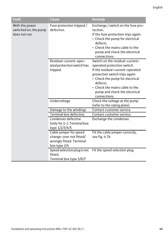
With the power switched on, the pump does not run.
Fuse protection tripped / defective.
Exchange / switch on the fuse pro-tection.If the fuse protection trips again:• Check the pump for electrical
defects.• Check the mains cable to the
pump and check the electrical connections.
Residual-current-oper-ated protection switch has tripped.
Switch on the residual-current-operated protection switch.If the residual-current-operated protection switch trips again:• Check the pump for electrical
defects.• Check the mains cable to the
pump and check the electrical connections.
Undervoltage Check the voltage at the pump (refer to the rating plate).
Damage to the windings Contact customer service.Terminal box defective. Contact customer service.Condenser defective (only for 1~). Terminal box type 1/2/3/4/5
Exchange the condenser.
Cable jumper for speed change-over not fitted/wrongly fitted. Terminal box type 2/4
Fit the cable jumper correctly, see fig. 4.7b
Speed selection plug is not fitted.Terminal box type 5/6/7
Fit the speed selection plug.
Fault Cause Remedy

English
44 WILO SE 11/2013
If the operating fault cannot be remedied, please consult an installer or the nearest Wilo customer service point or representative.
Fault With the power switched on, the pump does not run.
Cause Motor protection has switched the pump off, because:a) Switch off because of hydraulic over-loading of the pump.
b) Switch off because of obstruction within the pump.
c) Switch off because of excessive fluid temperature.
d) Switch off because of excessive ambient tem-perature.
Remedy a) Throttle the pump at the pressure side to a duty point on the pump curve.
b) If necessary remove the venting screw (visi-ble from outside) from the pump and check the free running of the pump rotor by turning the slotted shaft end, using a screwdriver; unblock if necessary.Alternatively:Dismantle the motor head and check; if nec-essary unblock by turn-ing the impeller. If the obstruction cannot be cleared, contact cus-tomer service.
c) Reduce the temperature of the fluid, see rating plate data.
d) Reduce the ambient tem-perature , e.g. by insulating the piping and fittings.
Display Displays of the lights in the terminal box type1 2 3 4 5 6 7- - - - red green red
Fault acknowl-edgement
Terminal box type 1/2Auto-reset; after the motor has cooled down, the pump restarts automatically.Terminal box type 5/7After the motor has cooled down, press the reset button for a manual reset of the fault. The pump will restart.Terminal box type 3/4It the thermal winding contact was connected to an external switchgear SK602/SK622, this must be reset. With the switchgear SK602N/SK622N, acknowledge-ment is made automatically after the motor has cooled down.Terminal box type 6:After the motor protection has tripped, switch off the mains voltage. Allow the pump to cool down approx. 8 to 10 min, then switch the power supply on again.

Installation and operating instructions Wilo-TOP-S/-SD/-RL/-I 45
English
11 Spare partsSpare parts may be ordered via local installers and/or Wilo customer service.To avoid queries and incorrect orders, all data of the rating plate should be sub-mitted for each order.
12 DisposalProper disposal and recycling of this product prevents damage to the environ-ment and risks to personal health.
1. Use public or private disposal organisations when disposing of the entire product or part of the product.
2. For more information on proper disposal, please contact your local council or waste disposal office or the supplier from whom you obtained the prod-uct.
NOTE! The pump must not be disposed of along with household waste.For further information on recycling, go to www.wilo-recycling.com
Subject to change without prior notice!

DE Herstellererklärung EN Manufacturer Declaration FR Déclaration Fabricant
Hiermit erklären wir, dass die Nassläufer-Umwälzpumpen der Baureihen: TOP-S Herewith, we declare that the glandless circulating pumps of the series: TOP-SD Par le présent, nous déclarons que les circulateurs des séries : TOP-RL
TOP-I (Die Seriennummer ist auf dem Typenschild des angegeben. / The serial number is marked on the product site. / Le numéro de série est inscrit sur la plaque signalétique du produit). in der gelieferten Ausführung in Übereinstimmung mit den Sicherheits- und Gesundheitsanforderungen der folgenden europäischen Bestimmungen konstruiert wurden: in their delivered stateare designed in accordance with the helth and safety requirements of the following european provisions: dans leur état de livraison, sont construits en conformité aux prescriptions de santé et de sécurité des dispositions europénnes suivantes: Maschinenrichtlinie 2006/42/EG Machinery directive 2006/42/EC Directives relatives aux machines 2006/42/CE und gemäß Anhang I, § 1.5.1 die Schutzziele der Niederspannungsrichtlinie 2006/95/EG eingehalten werden / and accordingto the annex I, §. 1.5.1, comply with the safety objectives of the Low Voltage Directive 2006/95/EC / et, suivant l�annexe I, § 1.5.1, respectent les objectifs de sécurité de la Directive Bbasse Tension 2006/95/CE. Elektromagnetische Verträglichkeit - Richtlinie 2004/108/EG Electromagnetic compatibility - directive 2004/108/EC Directive compatibilité électromagnétique 2004/108/CE sowie die angewendeten internationalen Normen, insbesondere: EN 809+A1 as well as following relevant international standards: ISO 12100 ainsi qu�aux normes internationales suivantes: IEC 60335-2-51 Dortmund, 15.03.2013
Holger Herchenhein
Group Quality Manager
WILO SE Nortkirchenstraße 100 44263 Dortmund Germany
Document: 2117858.1 (DC 2015112.2)

Wilo – International (Subsidiaries)
Argentina WILO SALMSON ���������� � � C1295ABI Ciudad Autónoma de Buenos Aires T+ 54 11 4361 5929 ���������� ��� �
Australia WILO Australia Pty Limited Murrarrie, Queensland, 4172 T +61 7 3907 6900 ���� ��������� ��� �
Austria WILO Pumpen �������������� 2351 Wiener Neudorf T +43 507 507-0 ��������� �
Azerbaijan WILO Caspian LLC 1014 Baku T +994 12 5962372 ������� �
Belarus WILO Bel OOO 220035 Minsk T +375 17 2535363 ������� ��
Belgium WILO SA/NV �!"#��������� T +32 2 4823333 ������� ��
Bulgaria $%&'�*�����&�� 1125 Sofia T +359 2 9701970 ������� ��
Brazil WILO Brasil Ltda Jundiaí – São Paulo – Brasil ;%<�=���>��# ?�#@�!F T + 55 11 2923 (WILO) 9456 �������@���� ��� ��
Canada $%&'�=���%�� � Calgary, Alberta T2A 5L4 T +1 403 2769456 ��� ��������@� ���
China $%&'�=���&�� 101300 Beijing T +86 10 58041888 ����K���� ��� ��
Croatia $�����Y��Z�� � � 10430 Samobor T +38 51 3430914 ���@��Y��Z���� ��
Czech Republic $%&'�=�[�� � � ?F�!��=������ T +420 234 098711 ������� ��
Denmark WILO Danmark A/S 2690 Karlslunde T +45 70 253312 ������� �Z
Estonia WILO Eesti OÜ 12618 Tallinn T +372 6 509780 ������� ��
Finland WILO Finland OY 02330 Espoo T +358 207401540 ������� �
France $%&'�� � � _"#`!�*����q���� T +33 1 30050930 ������� ��
Great Britain $%&'�v{ | }�&�� Burton Upon Trent DE14 2WJ T +44 1283 523000 �������� �� �Z
Greece $%&'��������� 14569 Anixi (Attika) T +302 10 6248300 ��� ������� ��
Hungary $%&'������������|�� ?!�F�����Z������ (Budapest) T +36 23 889500 ������� ��
India $%&'�%������������<����<�����&�� Pune 411019 T +91 20 27442100 ���Y������������� ���
Indonesia WILO Pumps Indonesia Jakarta Selatan 12140 T +62 21 7247676 ���������� ��� �
Ireland WILO Ireland &����Z T +353 61 227566 �������� �
Italy $%&'�%���� � � ?!!�"�<�������*�������� (Milano) T +39 25538351 ��� ������ �
Kazakhstan WILO Central Asia 050002 Almaty T +7 727 2785961 ������� Z�
Korea $%&'�<�����&�� � ��"@??!�������[�*��� T +82 51 950 8000 ������� �� Z�
Latvia $%&'�*�����%� 1019 Riga T +371 6714-5229 ������� �Y
Lebanon WILO LEBANON SARL ��������?!?�?!#!� Lebanon T +961 1 888910 ������� ��� ��
Lithuania $%&'�&���Y�{�* 03202 Vilnius T +370 5 2136495 ������ ���
Morocco WILO MAROC SARL 20600 CASABLANCA T + 212 (0) 5 22 66 09 24/28 ���������� �
The Netherlands $%&'����������� Y �FF�����$����� T +31 88 9456 000 ������� ��
Norway WILO Norge AS 0975 Oslo T +47 22 804570 ������� ��
Poland $%&'�<���Z��� �� � � !F@F!��&�������� T +48 22 7026161 ������� ��
Portugal Bombas Wilo-Salmson <�������&� 4050-040 Porto T +351 22 2080350 ��������� ��
Romania $%&'������� � � !__!�!�=�� �=�K����� �%���Y T +40 21 3170164 ������� ��
Russia WILO Rus ooo �?#F`?������� T +7 495 7810690 ������� ��
Saudi Arabia $%&'����@����� ���������F T +966 1 4624430 ������������ ���
Serbia and Montenegro $%&'�*������� � � 11000 Beograd T +381 11 2851278 ��������� ��
Slovakia $%&'�=��� � � [���� �;���Z "#�!��*����Y T +421 2 33014511 ������� �Z
Slovenia $%&'�������� � � 1000 Ljubljana T +386 1 5838130 ��� �������� �
South Africa ����������������� ���!�����Y�� T +27 11 6082780 ����� ��������� ������ �� �
Spain $%&'�%������ � ?""!������������������(Madrid) T +34 91 8797100 ��� �������� ��
Sweden $%&'��Y������* 35246 Växjö T +46 470 727600 ������� ��
Switzerland ��*�<�������� �#�!����������� T +41 61 83680-20 �������@������ ��
Taiwan $%&'�����=������&�� ����������� [���������City 24159 T +886 2 2999 8676 ������ ������ ��� ��
Turkey WILO Pompa Sistemleri �� �Y���� �� �� #�`F��������� T +90 216 2509400 ������� ��� ��
Ukraina $%&'�{Z���� � � !�!##�|�� T +38 044 2011870 ������� �
United Arab Emirates WILO Middle East FZE ��������������;��������� PO Box 262720 Dubai T +971 4 880 91 77 ������� �
USA WILO USA LLC Rosemont, IL 60018 T +1 866 945 6872 �������@�� ���
Vietnam $%&'�������=��&�� ���=������=��[������ T +84 8 38109975 �Z������� Y�
May 2013����������������[����������������������������������� ��� ���

WILO SENortkirchenstraße 100D-44263 DortmundGermanyT +49(0)231 4102-0F +49(0)231 [email protected] for You


![High Voltage - Comar Condensatori · Network voltages Voltage systems ( belongs to IEC 60038 @50 Hz, belongs to IEC 60038 @60 Hz) Insulation level [kV] (Power freq. voltage withstand](https://static.fdocuments.in/doc/165x107/5b07063f7f8b9a56408c7527/high-voltage-comar-condensatori-voltages-voltage-systems-belongs-to-iec-60038.jpg)