T gri d con - Welcome to EWA Website 60364-1 IEC 60364-4 IEC 60364-4 IEC 60364-4 IEC 60364-4 IEC...
36
T con Standa Techn nnect for rds for D Distri nical tion g r the Distribu ibution N Exp guid King uted Sola NetworO www.ewa.bh pert teline gdom ar PV Pl k of the Version 1.3 October 201 h o dev es an m of B ants to Kingdo 7 velop nd sta Bahra be conn om of Ba p gri anda ain nected w ahrain d ards with the e
Transcript of T gri d con - Welcome to EWA Website 60364-1 IEC 60364-4 IEC 60364-4 IEC 60364-4 IEC 60364-4 IEC...
Tcon
Standa
Technnnect
for
rds for DDistri
nicaltion gr the
Distribuibution N
ExpguidKing
uted SolaNetwork
O
www.ewa.bh
pert toeline
gdom
ar PV Plk of the
Version 1.3
October 201
h
o deves anm of B
lants to Kingdo
7
velopnd staBahra
be connom of Ba
p griandaain
nected wahrain
d ards
with thee
A
A
A
1 SCOPE .
2 REFERE
3 TERMS
4 TECHNINETWORKS
4.1 Gen
4.2 Con
4.3 Nor
4.4 Imm4.4.1 4.4.2
4.5 Req4.5.1 4.5.2 4.5.3
4.6 Req4.6.1 4.6.2 4.6.3 4.6.4
4.7 Req4.7.1 4.7.2 4.7.3 4.7.4 4.7.5 4.7.6
4.8 Met
5 COMPL
ANNEX A. C
ANNEX B. D
ANNEX C. L
A.1. PV m
A.2. Inver
A.3. EMC
A.4. Cable
.................
ENCE DOCU
AND DEFIN
ICAL REQUIS ...............
neral require
nnection sche
rmal operati
munity to disLow Voltage ROCOF withs
quirements fActive powerActive powerRemote limita
quirements fReactive powReactive powPower reductReactive curr
quirements fConnection cRemote discoAutomatic reInterface ProMonitoring, rPower quality
tering .........
LIANCE .......
CONNECTIO
DEFAULT SE
LIST OF APP
modules .......
rters ...........
(Electro Ma
es and conne
.................
MENTS ......
NITIONS .....
IREMENTS F.................
ements .......
eme ...........
ng ranges ...
sturbances ..Ride Through tand capabilit
for the frequr response to fr delivery at uation of active
for the voltagwer capability .wer control motion at increasrent injection
for the manaonditions ......onnection ......connection aftection ..........remote controy ....................
..................
.................
ON SCHEME
ETTINGS OF
PLICABLE ST
..................
..................
gnetic Comp
ectors .........
Tab
.................
.................
.................
FOR THE CO.................
...................
...................
...................
...................(LVRT) capabty ...................
uency stabilitfrequency varnder‐frequene power ........
ge stability o......................odes ..............sing voltage ...during a fault
agement of t............................................fter tripping ........................ol and informa......................
...................
.................
ES ...............
F INTERFACE
TANDARDS
...................
...................
patibility) ....
...................
ble of cont
..................
..................
..................
ONNECTION..................
...................
...................
...................
...................bility .....................................
ty of the powriations .........cies .....................................
of the powe..................................................................t .....................
the power sy........................................................................................ation exchang......................
...................
..................
..................
E PROTECTI
FOR EQUIP
...................
...................
...................
...................
tents
..................
..................
..................
N IN PARALL..................
...................
...................
...................
.............................................................
wer system ................................................................
r system .........................................................................................
ystem .............................................................................................ge .......................................
...................
..................
..................
ION ...........
PMENT .......
...................
...................
...................
...................
..................
..................
..................
LEL TO THE ..................
...................
...................
...................
...............................................................
.....................................................................................
...........................................................................................................
.......................................................................................................................................................
...................
..................
..................
..................
..................
...................
...................
...................
...................
.................
.................
.................
DISTRIBUT.................
...................
...................
...................
...............................................................
.....................................................................................
...........................................................................................................
.......................................................................................................................................................
...................
.................
.................
.................
.................
...................
...................
...................
...................
Page | 2
........ 4
........ 5
........ 5
TION ........ 7
......... 7
......... 7
....... 10
....... 10 ........ 10 ........ 11
....... 11 ........ 11 ........ 11 ........ 12
....... 12 ........ 12 ........ 13 ........ 15 ........ 15
....... 15 ........ 15 ........ 16 ........ 16 ........ 16 ........ 19 ........ 19
....... 20
...... 21
...... 22
...... 28
...... 29
....... 29
....... 30
....... 30
....... 32
2
A.5. Comb
A.6. LV sw
A.7. HV sw
A.8. Trans
A.9. Elect
A.10. PV m
A.11. Grid
biner boxes
witchgears a
witchgears a
sformers .....
rical installa
mounting sy
d connection
..................
nd controlge
and controlg
..................
ation ...........
ystem ..........
n .................
...................
ear ..............
gear .............
...................
...................
...................
...................
...................
...................
...................
...................
...................
...................
...................
...................
...................
...................
...................
...................
...................
...................
...................
...................
...................
...................
...................
...................
...................
...................
...................
...................
...................
...................
...................
...................
Page | 3
....... 32
....... 32
....... 33
....... 33
....... 34
....... 35
....... 35
3
1 SCOP
This documeintend to orequirementdocument d
Requirethe distr
Requiredisturba
Require
Requireto the d
Requiredistribut
The presentinternationathe connectInstallationssystem of thdocument tothe installatsolar PV genpart of the cto [1]. Moreover, it
define th
define thplant to
define ththe pres
define tenetwork
Unless othePV generatistandards. Finally, eventhe fundammanner, whcommonly uplants. Some
PE
ent providesperate in pats shall be fuefines:
ments for thribution netw
ments to suances,
ments for th
ments to preistribution n
ments to pretion network
t documental standards,tion of a ss” [1] is “apphe Kingdom oo refer to forion of an exnerating plancustomer’s n
t is not withi
he process to
he process tothe power s
he process tosent standard
echnical rulek is involved;
rwise explicing plants w
n if it is not mental imporich means thused for thee of the mos
s a common arallel with ulfilled irresp
he equipmenwork,
pport the fr
he start‐up, t
event the soetwork and
event the sok which has b
is not inco network cosolar PV geplicable to alof Bahrain” ar the design xisting customnt and shall network. For
n the scope
o be followe
o be followesystem;
o be followeds;
es for the isla
itly specifiedwhich don’t h
directly withrtance and nhe use of proe planning, dst relevant do
set of requithe LV & Mpective of the
nt to be used
equency and
he operation
olar PV geneto the other
olar PV generbeen disconn
ompatible wdes or specienerating plall electrical inas set out inof the electrmer. The prebe intendedr the “passiv
of the prese
ed for the sel
ed for the ass
ed for the ass
anding oper
d, the requirehave already
hin the scopnecessity fooducts and thdesign, instaocuments ar
irements forMV distributioe presence o
d for the inte
d voltage sta
n and the dis
erating plantsr customers c
rating plantsnected on pu
with additionific technicalant; especianstallations in [1] itself. Surical installatesent standad as an exteve” part of th
ent documen
lection and e
sessment of
sessment of
ation of isola
ements set fy been appr
e of the docr solar PV gheir assemballation, opere listed in AN
r solar PV (Pon networksof loads in th
erconnection
ability of the
sconnection
s from causiconnected to
s from operaurpose from
nal requireml requiremenally, the doin any premiuch documetion of a newards shall apnsion of [1]he customer
nt to:
evaluation of
the impact o
a connection
ated networ
forth by thesoved by EW
cument, the generating ply in accordaration and mNNEX C.
hotovoltaic) s of the Kinge customer’
n of a solar P
e power syst
of the solar
ng disturbano the same d
ating in parathe main po
ments set onts of EWA, aocument “Reises fed by thnt still reprew customer oply only if thonly for whr’s network,
f the point of
of the conne
n application
rks, where no
se standardsWA at the da
present docplants to beance with themaintenance
generating gdom of Ba’s network. E
PV generatin
tem when it
PV generatin
nces and damdistribution n
allel with a power system
out by otherand which megulations fhe Electricityesents the mor for the mohe installatiohat concernsreference sh
f connection
cting solar P
n and its com
o part of the
s shall apply ate of public
cument intee built in a e internatione of solar PV
Page | 4
plants whichahrain. TheseEspecially the
ng plant with
is subject to
ng plants;
mages eithenetwork;
ortion of the.
r national &may apply fofor Electricay distributionain technicaodification oon includes athe “active”hall be made
n;
PV generating
mpliance with
e distribution
only to solacation of the
nds to stressworkmanlikenal standardsV generating
4
h e e
h
o
r
e
& r al n al f a ” e
g
h
n
r e
s e s g

2 REFE
[1] ReguDire
[2] IEC prev
[3] IEC curr
[4] IEC currand
[5] Bah[6] IEC/
requ
3 TERM
Active Powethereof (e.gcase of ratedApparent Pokilovolt‐ampimaginary coapparent poMaximum A(for exampleoperating poCurrent ‐ UnDelay time relay beforeDistributionend consum
A LokV D
A MAC (
Generating distribution Interface Prand/or any safety and reIslanding ‐ Sphysically dmaintain a sLoss Of Maion purpose
ERENCE D
ulations for ectorate, Sec62116:2014
vention mea61000‐3‐2:2rent emission61000‐3‐12:rents produc≤ 75 A per prain Grid Cod/TR 61000‐3uirements fo
MS AND D
er ‐ Active P. kilowatts (d active powower ‐ Is thperes (kVA) oomponent (Rower of equipAvailable Acte, sun irradioint. nless stated o(of a protece the output n system / nemers; for the s
ow Voltage (DC. The LV ne
Medium Volta1.5 kV DC) u
plant ‐ Is network androtection (IPgenerating eliability of tSituation whdisconnectedsupply of elecins (LOM) – separated fr
DOCUMEN
electrical iond edition,4, Utility‐intsures 2014 Electrons (equipme:2011 Electroced by equipphase de, Electricit‐15: 2009, Aor dispersed g
DEFINITIO
ower is the kW) or meg
wer of equipmhe product oor megavolt‐Reactive Powpment. tive Power Oiance) and b
otherwise, cction relay) –of the proteetwork ‐ Is tscope of the
LV) networketwork nom
age (MV) netup to 35 kV. T
an indivisibd is composeP) ‐ The eleunit is discothe distributihere a portid from the ctrical energRepresents rom the main
NTS
nstallations, 2004 terconnected
magnetic cont input curromagnetic cment conne
y and WaterAssessment generation s
NS
real compongawatts (MWment. of voltage (in‐amperes (Mwer). In the t
Output – Is tby the maxim
urrent refers– Indicates tction relay isthe medium present doc
is a distribuinal voltage o
twork is a neThe MV netw
le set of ined of generatctrical proteonnected forion network.on of the drest of the gy to such isoan operatingn power syst
Ministry o
d photovolt
ompatibility rent ≤ 16 A pcompatibilityected to pub
r Authority, Kof low freqsystems in LV
nent of the aW)). In the te
n volts) and MVA) and conext this will
he Active Pomum steady
s to the rootthe minimums triggered.or low voltacument and
ution networof the Kingd
etwork with work nomina
nstallations wting units, ciection requir any event . istribution ndistribution
olated part og conditionstem with the
f Electricity
taic inverte
(EMC) – Paper phase) y (EMC) ‐ Palic low‐volta
Kingdom of Bquency electV network
apparent poext this will b
current (in nsists of a rebe generical
ower Output ‐state efficie
‐mean‐squam duration o
age electricitin accordanc
rk with nomiom of Bahra
nominal volal voltage of t
which can grcuits and aured to ensuthat could
network, conn network aof the distribus in which a e final scope
and Water
ers ‐ Test
rt 3‐2: Limit
rt 3‐12: Limge systems w
Bahrain, Novromagnetic
wer, expressbe generical
amperes). Ial componenly referred a
determinedency of the g
re value of pof a fault det
ty grid for suce with inter
nal voltage lin is 400/230
ltage includethe Kingdom
generate eleuxiliary servire that eithimpair the i
ntaining gennd one or ution networdistribution of de‐energi
r, Electricity
procedure
ts – Limits f
its ‐ Limits fwith input c
vember 2011immunity a
sed in wattslly referred a
t is usually nt (Active Poas S or Sn in
d by the primgenerating p
phase currentected by th
upplying elecrnational sta
lower than 10V.
ed in the ranm of Bahrain
ectrical eneces. her the geneintegrity or
nerating planmore generrk. network, orization.
Page | 5
Distribution
of islanding
for harmonic
for harmonicurrent >16 A
1 and emission
or multiplesas P or Pn in
expressed inower) and ancase of rated
mary resourceplant for this
t. he protection
ctricity to thendards:
1kV AC or 1.5
nge from 1kVis 11kV.
rgy into the
erating plandegrade the
nts, becomerating plants
r part of it, is
5
n
g
c
c A
n
s n
n n d
e s
n
e
5
V
e
t e
s s
s
Main electrenergy actuaNetwork ‐ Poperated byPV electricitand which mPoint of Codistribution Power FactoReactive poprovided bythe voltage oReactive Po(kVAr) or MeROCOF – RaSwitch – Meand, when stime, currenTHD – with content to tVoltage ‐ Un
ricity meter ally exchangPlant and apy the DSO. ty meter ‐ Ismeasures theonnection ornetwork andor ‐ Is the ratower capabiy a generatinof the generower ‐ Repreegavar (MVAte of changeechanical despecified, in nts under spereference tohe r.m.s. valnless stated o
‐ Is the deed by the cuparatus con
s the device e total energyr POC ‐ Is thd where the tio of Active ility – Definng plant/unitrating plant/usents the imAr). e of frequencevice capablegiven operaecified abnoro an alternatue of the funotherwise, v
evice installestomer withnected toge
installed at y produced fhe location main electriPower to Apnes the reset. The reactivunit. maginary com
cy usually exe of making,ating overloarmal circuit cting quantityndamental coltage refers
ed at the POh the distribuether in orde
the commofrom the solat which a city meter ispparent Powerves of indve power ca
mponent of t
pressed in H, carrying anad conditionconditions, sy, it represeomponent os to the root
OC and whicution networer to transm
on output poar PV genera solar PV ges installed. er. uctive/capacpability usua
the apparent
Hz/s. nd breaking cns. In additiouch as shortnts the ratioor the referen‐mean‐squa
ch measuresrk. it or distribu
oint of the sating units. enerating pl
citive reactivally varies w
t power, usu
currents in non, it is able ‐circuit condo of the r.m.nce fundamere value of p
s the amoun
ute electrica
olar PV gene
lant is conn
ve power with the activ
ually express
normal circu to carry, foditions. s. value of tental compophase‐to‐pha
Page | 6
nt of electric
l power, and
erating plan
ected to the
which can beve power and
sed in kilova
uit conditionor a specified
the harmoniconent. ase voltages.
6
c
d
t
e
e d
r
s d
c
4 TECHDISTR
4.1 Gene
A solar PV gthe responsthe capacitya safe and se If the resultsthe networkdown the ccharacteristreinforceme With refererequirementplant shall b1. Protecti2. Protecti
network3. Remote 4. Active p5. Remote 6. Remote 7. Local rea
4.2 Conn
A solar PV gshall meet th
the synconditiostatutor
the protthe netwsolar PV
o
o
o
HNICAL RRIBUTION
eral requi
generating plibility of EWy of the netwecure operat
s of such prok to possibly connection ics of the soents) to enab
nce to the ts may interbe organized on of the geon of the nk); disconnectioower responlimitation oreactive powactive powe
nection s
enerating plhe following
nchronizationons, i.e. in thry power qua
tection schemwork protecV generating faults and operation ofthe protectperformancethe protectidistribution within the d
REQUIREMN NETWO
irements
lants shall beWA to design work to host tion of the n
ocess put in operate outapplication olar PV geneble the conne
requiremenrfere with eain accordancnerating uninetwork (int
on; nse to frequef active powwer control mr control mo
cheme
ant shall be requiremen
n, operationhe absence ality of the n
mes and setction schemeplant ownermalfunctionf the distribuion schemees of the solon schemesnetwork in oistribution n
MENTS FORKS
e connected a suitable pthe connectetwork for a
evidence thtside of EWAor to prop
erating plantection.
ts defined iach other, tce with the fts; erface prote
ency variatioer; modes; odes.
in compliancnts:
n and discoof faults or etwork;
tings neededes and settinr with the fols within theution networs and settinar PV generaof the solarorder to openetworks.
OR THE C
to the netwprocess whicting solar PVall operating
at the conneA statutory ppose modifict) or alterna
n the presethe protectiofollowing pri
ection and p
ons;
ce with the c
onnection ofr malfunction
d for the solngs; they shllowing scope solar PV rk, ngs for inteating plant;r PV generaterate proper
CONNECT
work at an apch determineV generating conditions.
ecting solar erformance cations (for tive solution
ent documenon and contority ranking
protection a
connection r
f the plant ns, shall be
ar PV generahall therefore: generating
ernal electri
ting plant shly in case of
TION IN P
ppropriate pes the approplant at that
PV generatinstandards, Eexample in
ns (for exam
nt and the prol devices og (from highe
against fault
requirements
under nordone witho
ating plant se be agreed
plant shall
cal faults m
all be coordfaults within
PARALLEL
oint, called topriate POC t POC whilst
ng plant is likEWA has then terms of mple in terms
possibility thof a solar PVest to lowest
ts within the
s of EWA; a
rmal netwoout conseque
shall be coord between E
not impair
must not jeo
dinated with n the genera
Page | 7
L TO THE
the POC. It isand assesset maintaining
kely to causeright to turnPOC and/os of network
hat differenV generatingt):
e customer’s
nd especially
rk operatingences to the
rdinated withEWA and the
the norma
opardize the
those of theating plant o
7
E
s s g
e n r k
t g
s
y
g e
h e
al
e
e r
In order toequipment wplant with th
The maprotecticustomeorder, fdedicate
The intenetworksolar PVonly one
The unitgenerati
ANNEX A pgenerating pwith EWA. For each of contactors o
the func
the char Especially, th
the main
the swit
Electron
For solaon the M
o o
For solaon the Lthe inte
o o
any swicustome
the shorcircuit p
1 For the defirefer to [1] 2 With particu
o satisfy thewhich shall bhe distributio
in switch shon system aer’s networkfor example,ed to the sol
erface switck the part(s)V generating e interface sw
t switch shaing unit of th
resents typiplant to EW
the above mor mechanica
ctions the sw
racteristics o
he following
n switch sha
ch(es) of the
nic switches s
r PV generatMV side of ththree‐polar three‐polar (either upstr
r PV generatLV side of thrface switch automatic comnipolar A
itch shall haer’s network
rt‐time withsower at the
inition of the
ular reference
e above reqbe at least inon network:
hall be instaagainst interk from the d, to have twar PV genera
h shall be i of the custplant with awitch shall b
all be instalhe generatin
cal connectWA distributio
mentioned eqal circuit brea
witch shall ca
of the custom
criteria shal
ll be complia
e generating
shall not be u
ting plants che plant (Figuwithdrawabautomatic ciream or dow
ting plants che plant or foshall consistircuit breakeAC3 contacto
ave a break, taking into
stand currenPOC3.
requirements
e to section 5
quirements, nstalled for a
alled as closrnal faults1; distribution nwo separateating plant.
nstalled in ttomer’s netw rated activee used (see a
led as electg plant, for t
ion schemeson networks
quipment, thakers, …) sha
rry out,
mer’s networ
l be adopted
ant with the
unit(s) shall
used for pro
connected toure 8), the inle automaticircuit breakewnstream the
connected toor solar PV gt of: er or switch dor.
king and mconsideratio
nt of the swit
s of the prote
“EXCESS CURR
Error! Refea safe and re
se as possibthe main swnetwork; it ie circuits, on
the customework containe power greaalso § 4.7.4).
rically closethe protectio
s which cans. Different a
he choice of all be based
rk.
d:
requirement
be complian
tective funct
o the MV disnterface switc circuit breaer operated be circuit brea
o the MV disgenerating p
disconnector
aking capacon both the g
tching devic
ection system
RENT PROTEC
erence sourceliable interc
ble to the Pwitch is alsos possible tone dedicated
er’s networkning at leastater than 11
as possibleon and the d
n be adoptearrangement
the type of on:
ts of [1]2,
nt with the m
tions.
stribution netch shall consaker operateby an undervaker).
stribution neplants conne
r operated b
city coordinagenerating p
es shall be c
against fault
CTION”
ce not founonnection of
POC and shao used for to install up td to the cu
k to separatone solar PkW, unless e
e to the termisconnection
d for the cots may be u
switch to be
manufacturer
etwork and wsist of: d by an undevoltage relea
etwork and wected to the
y an undervo
ated with tplant and the
oordinated w
s within the c
nd. presentsf the solar P
all be commthe disconneto two mainstomer’s loa
te from thePV generatinexplicitly agr
minals of ean of that gen
onnection oused if previo
e installed (p
r’s requirem
with the inte
ervoltage relase along wit
with the inteLV distribut
oltage releas
the rated vae passive load
with the ma
customers’ ne
Page | 8
s the typicaV generating
manded by aection of then switches inads and one
e distributionng unit; for areed by EWA
ach solar PVerating unit.
of a solar PVously agreed
power relays
ents,
erface switch
lease, or th an isolato
erface switchion network
se, or
alues of theds.
ximum shor
etwork, please
8
al g
a e n e
n a A,
V .
V d
s,
h
r
h k,
e
t
e
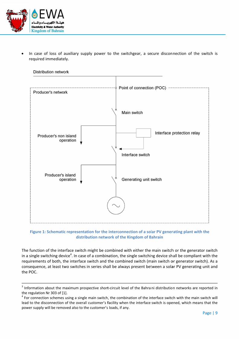
In case required
Figure 1
The functionin a single swrequirementconsequencthe POC.
3 Informationthe regulation4 For connectlead to the dpower supply
of loss of ad immediate
1: Schematic
n of the intewitching devts of both, the, at least tw
n about the mn Nr 303 of [1tion schemes isconnection y will be remo
auxiliary suply.
c representadistrib
rface switchvice4. In case he interface wo switches
maximum pros1]. using a singleof the overalloved also to th
pply power t
tion for the bution netwo
might be coof a combinswitch and tin series sha
spective short
e main switch,l customer’s fhe customer’s
to the switc
interconnecork of the K
ombined witnation, the sithe combineall be always
t‐circuit level
, the combinafacility when t loads, if any.
chgear, a se
ction of a solingdom of B
h either the ngle switchined switch (ms present bet
of the Bahrai
ation of the inthe interface
cure discon
lar PV generahrain
main switchng device shain switch otween a sola
ni distributio
nterface switcswitch is ope
nection of t
rating plant w
h or the geneall be complor generator ar PV genera
n networks a
ch with the mened, which m
Page | 9
the switch i
with the
erator switchiant with theswitch). As ating unit and
re reported in
ain switch wimeans that the
9
s
h e a d
n
ll e
4.3 Norm
Solar PV gecontinuouslyprotection s
when th
when th
4.4 Imm
4.4.1 Low
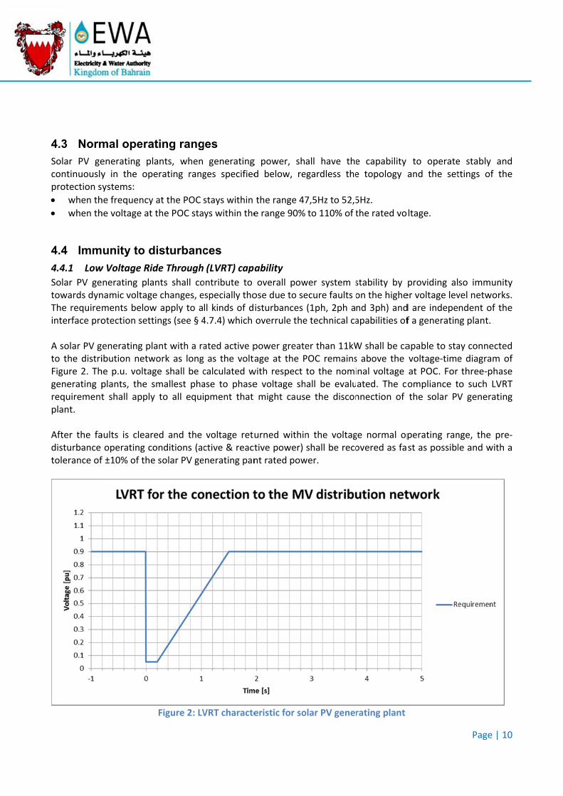
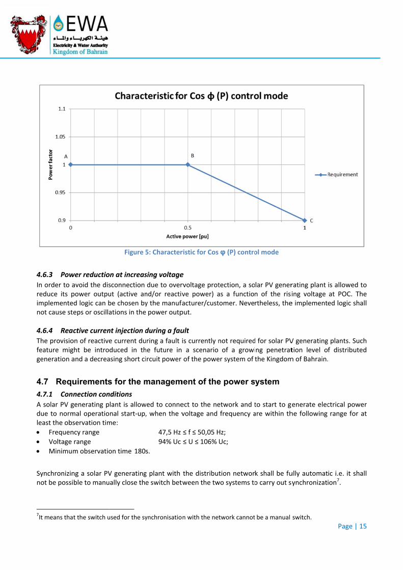
Solar PV getowards dynThe requireminterface pro A solar PV gto the distriFigure 2. Thgenerating prequirementplant. After the fadisturbance tolerance of
mal opera
enerating ply in the opystems:
he frequency
he voltage at
unity to d
w Voltage Ri
nerating planamic voltagments belowotection sett
enerating plibution netwhe p.u. voltagplants, the st shall apply
aults is clearoperating cf ±10% of the
ating rang
lants, when erating rang
y at the POC
the POC sta
disturbanc
ide Through
ants shall coe changes, ew apply to atings (see § 4
ant with a rawork as longge shall be csmallest phay to all equi
red and the onditions (ace solar PV ge
Figure 2: LV
ges
generatingges specified
stays within
ys within the
ces
(LVRT) capa
ontribute to especially tholl kinds of d4.7.4) which
ated active p as the voltacalculated wase to phasepment that
voltage retuctive & reactenerating pan
VRT characte
g power, shd below, re
the range 47
e range 90%
ability
overall powose due to seisturbances overrule the
power greateage at the Pwith respect e voltage shmight caus
urned withintive power)nt rated pow
eristic for so
all have theegardless the
7,5Hz to 52,5
to 110% of t
wer system secure faults o(1ph, 2ph ae technical ca
er than 11kWPOC remainsto the nomihall be evalue the discon
n the voltagshall be reco
wer.
olar PV gener
e capability e topology a
5Hz.
the rated vo
stability by on the highend 3ph) andapabilities of
W shall be cas above the inal voltage ated. The connection of
ge normal opovered as fa
rating plant
to operateand the set
oltage.
providing aler voltage levd are indepef a generatin
apable to stavoltage‐timeat POC. Forompliance tthe solar PV
perating ranst as possibl
Page | 10
e stably andttings of the
so immunityvel networksndent of theng plant.
ay connectede diagram othree‐phase
to such LVRTV generating
nge, the prele and with a
0
d e
y s. e
d of e T g
‐a
4.4.2 ROC
Solar PV genfrequency w
4.5 Requ
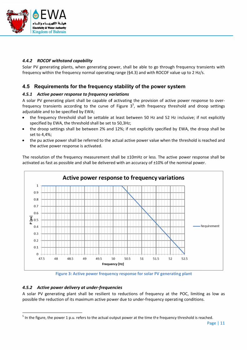
4.5.1 Acti
A solar PV gfrequency tadjustable a
the freqspecified
the drooset to 4,
the pu athe activ
The resolutiactivated as
4.5.2 Acti
A solar PV possible the
5 In the figure
COF withsta
nerating plawithin the fre
uirements
ive power re
generating pransients acnd to be spe
quency thresd by EWA, th
op settings s4%;
active powerve power res
on of the frefast as poss
Figure
ive power de
generating reduction o
e, the power 1
nd capabilit
nts, when gequency norm
s for the f
esponse to f
plant shall beccording to ecified by EW
shold shall bhe threshold
shall be betw
shall be refesponse is act
equency meible and sha
e 3: Active po
elivery at un
plant shall bof its maximu
1 p.u. refers to
ty
enerating pomal operatin
frequency
frequency va
e capable ofthe curve o
WA;
be settable ashall be set
ween 2% and
erred to the tivated.
asurement sll be delivere
ower freque
nder‐freque
be resilient um active pow
o the actual o
ower, shall bng range (§ 4.
y stability
ariations
f activating tof Figure 35
at least betwto 50,3Hz;
d 12%; if no
actual active
shall be ±10ed with an ac
ncy respons
encies
to reductionwer due to u
utput power a
be able to go3) and with
of the po
the provision, with frequ
ween 50 Hz
ot explicitly s
e power valu
mHz or less.ccuracy of ±1
se for solar P
ns of frequeunder‐freque
at the time th
o through frROCOF value
ower syste
n of active puency thresh
and 52 Hz i
specified by
ue when the
. The active 10% of the n
PV generatin
ency at the ency operati
e frequency t
requency trae up to 2 Hz/
em
power respohold and dr
nclusive; if
EWA, the dr
threshold is
power responominal pow
g plant
POC, limitinng condition
threshold is re
Page | 11
ansients with/s.
onse to overroop setting
not explicitly
roop shall be
reached and
onse shall beer.
ng as low asns.
eached.
1
h
r‐s
y
e
d
e
s
4.5.3 Rem
A solar PV gan interfacereduction of The reductioPn. In accordanrequirementexecution, wwhich allownetwork.
4.6 Requ
4.6.1 Rea
When voltagshall be ablecapability de
6 The active ppower, the releading to 0.9
mote limitati
generating ple (input port)f the active p
on of active p
nce with thts in terms owhich allow w to remotel
uirements
active power
ge and freque to provideefined in Figu
power 1 p.u. seactive power9 lagging.
ion of active
ant with a ra) which is abpower outpu
power shall b
e provisionof equipmento integrately limit the
s for the v
r capability
uency at PO reactive poure 46.
shall refer to tr capability of
e power
ated active pble to receivet.
be carried ou
s set forth t, communice such featuactive powe
voltage st
C are withinwer in any o
the rated actif a solar PV ge
power greate, from a rem
ut as fast as
in § 4.7.5,cation protoure into the er output of
tability of
n their normoperating po
ve power valuenerating plan
er than or eqmote contro
possible and
EWA shall col, informacontrol systthe solar P
the powe
al operatingoint within th
ue of the solant correspond
qual to 11kWl center, an
d with an acc
have the rtion to be exems of its dV generatin
er system
g ranges, a she boundarie
ar PV generatids to a power
W shall be eqinstruction
curacy greate
right to spexchanged andistribution g units conn
solar PV genes of the rea
ing plant: at 1factor varying
Page | 12
quipped withrequiring the
er than 5% o
ecify furthend/or time onetwork andnected to its
erating planactive powe
1 p.u. of activeg between 0,9
2
h e
of
r f d s
t r
e 9
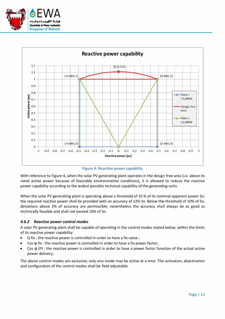
With referenrated activepower capab When the sothe requireddeviations atechnically f
4.6.2 Rea
A solar PV geof its reactiv
Q fix : th
Cos φ fix Cos φ (P
power d
The above cand configur
nce to Figuree power becbility accord
olar PV gened reactive poabove 2% offeasible and
active power
enerating plave power cap
he reactive p
x : the reacti
P) : the reactdelivery;
control moderation of the
e 4, when thecause of faving to the wi
rating plant ower shall bef accuracy ashall not exc
r control mo
ant shall be pability:
power is cont
ve power is
tive power is
es are excluse control mod
Figure 4: Re
e solar PV georable enviridest possibl
is operating e provided ware permissiceed 10% of
odes
capable of o
trolled in ord
controlled in
s controlled
sive; only ondes shall be f
eactive powe
enerating plaronmental ce technical c
above a threwith an accurble; neverthSn.
operating in t
der to have a
n order to ha
in order to h
e mode mayfield adjusta
er capability
ant operatesonditions), icapability of
eshold of 10acy of ±2% Sheless the a
the control m
a fix value ;
ave a fix pow
have a powe
y be active aable.
y
in the desigit is allowedthe generati
% of its nomSn. Below theccuracy sha
modes stated
wer factor;
er factor func
t a time. The
gn free area (d to reduce ing units.
minal apparee threshold oll always be
d below, wit
ction of the
e activation,
Page | 13
(i.e. above itsthe reactive
ent power Snof 10% of Sne as good a
hin the limits
actual active
deactivation
3
s e
n, n, s
s
e
n
4.6.2.1 Fix
When operapower or thplant. For a solar generating pthe provisio
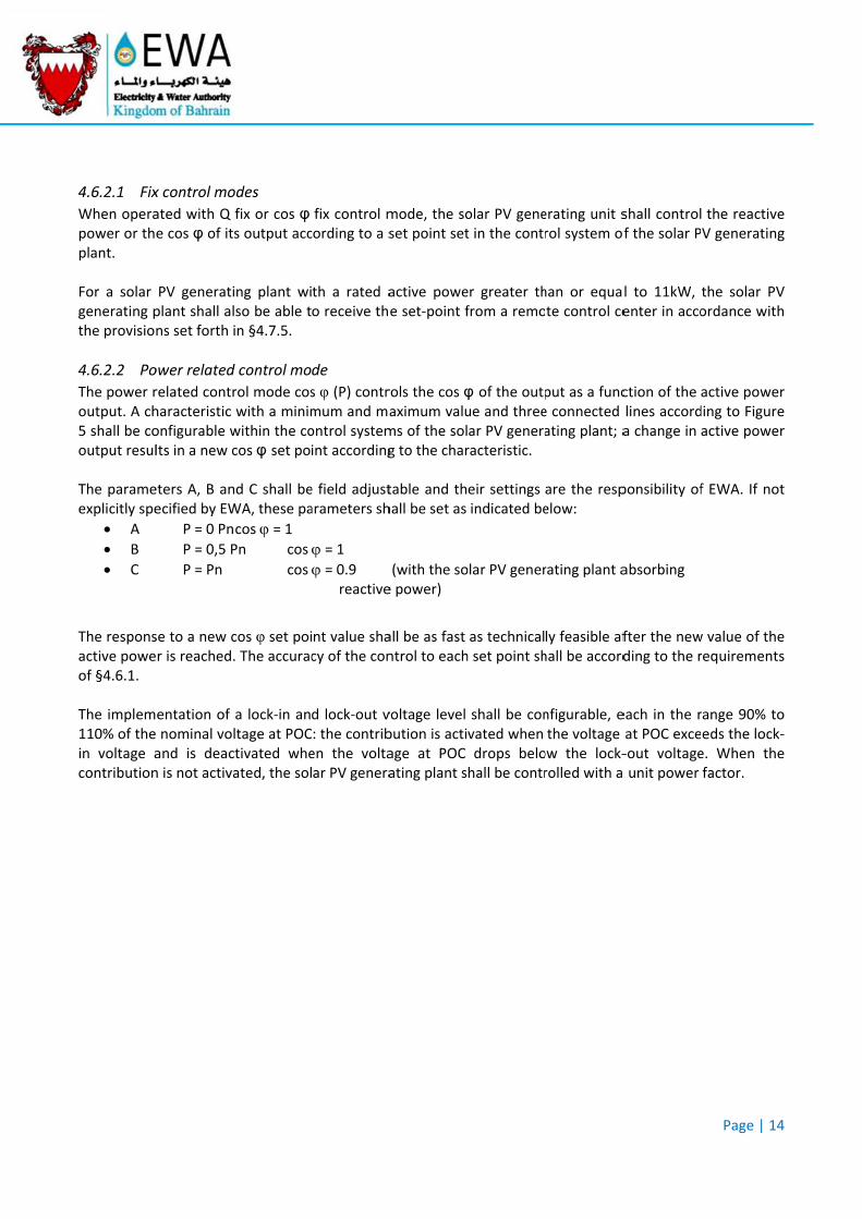
4.6.2.2 Po
The power routput. A ch5 shall be cooutput resul The parameexplicitly spe
A
B
C
The responsactive poweof § 4.6.1. The implem110% of thein voltage acontribution
x control mo
ated with Q e cos φ of it
PV generatiplant shall alns set forth i
ower related
related contrharacteristic onfigurable wlts in a new c
eters A, B anecified by EW
P = 0 Pn
P = 0,5 P
P = Pn
se to a new cer is reached.
entation of nominal voland is deacn is not activa
odes
fix or cos φ s output acc
ing plant wilso be able tin § 4.7.5.
d control mo
rol mode coswith a minimwithin the cocos φ set po
nd C shall beWA, these pa
cos = 1 Pn cos
cos
cos φ set poi. The accurac
a lock‐in anltage at POCctivated wheated, the sol
fix control mcording to a s
th a rated ao receive th
de
s φ (P) contrmum and maontrol systemint according
e field adjustarameters sh
= 1 = 0.9
reactive
nt value shacy of the con
d lock‐out v: the contriben the voltaar PV genera
mode, the soset point set
active powee set‐point f
rols the cos φaximum valums of the solg to the char
table and thhall be set as
(with the soe power)
all be as fast ntrol to each
voltage level bution is actiage at POC ating plant s
olar PV genet in the contr
er greater thfrom a remo
φ of the outpue and threear PV generaracteristic.
eir settings indicated be
olar PV gener
as technicalh set point sh
shall be convated when drops belohall be contr
erating unit srol system of
han or equate control ce
put as a funce connected ating plant; a
are the respelow:
rating plant a
ly feasible afhall be accord
nfigurable, ethe voltage
ow the lock‐rolled with a
shall controlf the solar P
l to 11kW, enter in acco
ction of the lines accorda change in
ponsibility of
absorbing
fter the newding to the r
each in the rat POC exce‐out voltage unit power
Page | 14
the reactiveV generating
the solar PVordance with
active poweding to Figureactive powe
f EWA. If no
w value of therequirements
range 90% toeds the locke. When thefactor.
4
e g
V h
r e r
t
e s
o k‐e
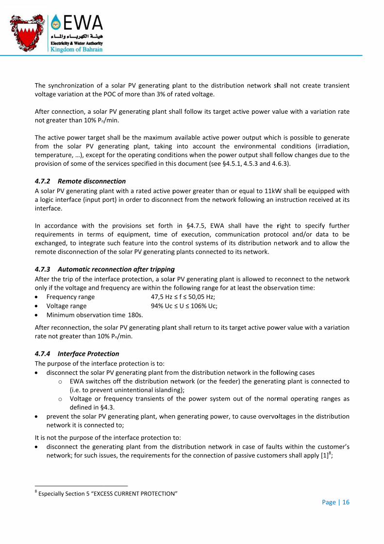
4.6.3 Pow
In order to areduce its pimplementenot cause st
4.6.4 Rea
The provisiofeature miggeneration a
4.7 Requ
4.7.1 Con
A solar PV gdue to normleast the obs
Frequen
Voltage
Minimum
Synchronizinnot be possi
7It means tha
wer reductio
avoid the dispower outpued logic can beps or oscilla
active curren
on of reactiveght be introand a decrea
uirements
nection con
generating pmal operatioservation tim
ncy range
range
m observatio
ng a solar PVible to manu
t the switch u
Figure 5
on at increas
sconnection ut (active anbe chosen byations in the
nt injection d
e current duduced in thasing short ci
s for the m
nditions
lant is allownal start‐up,me:
on time 180
V generatingally close th
used for the sy
5: Character
sing voltage
due to overnd/or reactivy the manufa power outp
during a fau
ring a fault ihe future in ircuit power
managem
wed to conne, when the v
47,5 Hz
94% Uc
s.
g plant with e switch betw
ynchronisatio
ristic for Cos
e
rvoltage protve power) aacturer/custput.
ult
is currently n a scenario of the powe
ment of the
ect to the nevoltage and
≤ f ≤ 50,05 H
≤ U ≤ 106%
the distribuween the tw
n with the ne
φ (P) contro
tection, a soas a functiontomer. Neve
not requiredof a growi
er system of
e power s
etwork and tfrequency a
Hz;
Uc;
tion networwo systems to
twork cannot
ol mode
lar PV genern of the risirtheless, the
d for solar PVng penetratthe Kingdom
ystem
to start to gare within th
k shall be fuo carry out s
be a manual
rating plant ing voltage e implement
V generatingtion level om of Bahrain.
generate eleche following
ully automatsynchronizat
switch.
Page | 15
is allowed toat POC. Theed logic shal
g plants. Suchf distributed.
ctrical powerange for a
ic i.e. it shalion7.
5
o e ll
h d
r t
ll
The synchrovoltage varia After connenot greater t The active pfrom the stemperatureprovision of
4.7.2 Rem
A solar PV ga logic interfinterface. In accordanrequirementexchanged, remote disco
4.7.3 Auto
After the trionly if the vo
Frequen
Voltage
Minimum
After reconnrate not grea
4.7.4 Inte
The purpose
disconneo
o
prevent network
It is not the
disconnenetwork
8 Especially Se
onization of ation at the
ction, a solathan 10% Pn/
power targetsolar PV gee, …), exceptsome of the
mote disconn
generating plface (input p
nce with thts in terms to integrateonnection of
omatic reco
p of the inteoltage and fr
ncy range
range
m observatio
nection, the ater than 10
erface Protec
e of the inter
ect the solarEWA switch(i.e. to preveVoltage or fdefined in § 4
the solar PVk it is connec
purpose of t
ect the genek; for such iss
ection 5 “EXC
a solar PV gPOC of more
ar PV genera/min.
t shall be theenerating plt for the opee services spe
nection
ant with a raport) in orde
e provisionof equipm
e such featurf the solar PV
onnection af
erface protecrequency are
on time 180
solar PV gen0% Pn/min.
ction
rface protect
r PV generaties off the dent unintentfrequency tr4.3.
V generatingcted to;
the interface
erating plantsues, the req
ESS CURRENT
generating pe than 3% of
ting plant sh
e maximum ant, taking rating conditecified in this
ated active pr to disconn
s set forth ent, time ore into the cV generating
fter tripping
ction, a solare within the f
47,5 Hz
94% Uc
s.
nerating plan
tion is to:
ing plant fromistribution nional islandiransients of
plant, when
e protection t
t from the dquirements f
T PROTECTION
plant to therated voltag
hall follow it
available acinto accoutions when ts document
power greatect from the
in § 4.7.5, of executioncontrol systeg plants conn
g
r PV generatfollowing ra
≤ f ≤ 50,05 H
≤ U ≤ 106%
nt shall retur
m the distribnetwork (or tng); the power
n generating
to:
distribution for the conne
N”
distributionge.
s target acti
ctive power ount the envthe power ou(see § 4.5.1,
er than or eqe network fo
EWA shall n, communicems of its dinected to its
ting plant is ange for at lea
Hz;
Uc;
n to its targe
bution netwothe feeder) t
system out
power, to c
network in ection of pas
n network sh
ve power va
output whichvironmental utput shall fo 4.5.3 and 4.
qual to 11kWollowing an in
have the rcation protostribution nnetwork.
allowed to reast the obse
et active pow
ork in the folthe generati
of the norm
ause overvo
case of faultssive custom
hall not crea
alue with a v
h is possibleconditions
ollow change6.3).
W shall be eqnstruction re
right to speocol and/or etwork and
econnect to rvation time
wer value wit
llowing casesing plant is c
mal operatin
oltages in the
ts within themers shall app
Page | 16
ate transien
variation rate
e to generate(irradiation
es due to the
quipped witheceived at it
ecify furthedata to beto allow the
the networke:
th a variation
s connected to
ng ranges as
e distribution
e customer’ply [1]8;
6
t
e
e n, e
h s
r e e
k
n
o
s
n
s
prevent short cirrecomm
In any case, as those userequirement The interfacgenerating pprotection in The interfacactive poweinterface sw For a solar Padditionally operate. Theup switch ispossible10. For a solar interface pro The loss of tsystem shall The protecti
Undervoo
o
Overvolto
Overvolto
9 It is anywayoverall custombeing remove10 The reasoninterface swit11 voltage pro
damages torcuits) on th
mendations a
the protected for the prts set out at
ce protectioplant with anto the solar
ce protectioner greater thwitch shall be
PV generatinact on anote backup sws triggered
PV generatiotection sha
the auxiliaryl trigger the i
ion functions
oltage [27] One thresho5%, and delaOne thresho5%, and dela
tage 10 min One threshoand delay tim
tage [59] One threshoof 1%, and d
y recommendemer’s facility ed to customens are that ittch failed to ootection funct
o the customhe distributiond requirem
tion schemesrotection of § 4.4 (immun
n shall be aa rated activr PV generat
n shall commhan 11kW, ue used for a s
ng plant withther switch (itch may conbecause the
ing plant will include an
y voltage of einterface sw
s required in
old [27<] in tay time in thold [27<<] in ay time in th
mean [59‐Avold in the ranme lower tha
old [59>] in tdelay time in
ed not to use in the case ther’s loads. t is required open, then remion using the
mer’s equipmon network ments of the m
s and settingthe customenity).
a dedicated ve power loing units.
mand the intunless explicsolar PV gene
h a rated act(backup switnsist of a dede interface s
th a rated auninterrupt
either the initch without
the Interfac
the range [20e range [0,1the range [0e range [0,1
v]11 nge [100%; 1an or equal t
the range [1 the range [0
the main swithe interface sw
that the planmedies the tec10 minutes r.
ment (generaor on the cumanufacture
gs for electrier’s equipme
device whicower than 1
terface swititly agreed erating plant
tive power gtch) with a pdicated switcswitch had
active powetible power s
terface prott delay.
ce Protection
0%; 100%] os;100s] adju0%; 100%] os;5s] adjusta
115%] of theto 3s;
100%; 120%]0,1s;100s] ad
tch as back‐upwitch fails to o
nt operator fchnical issues.m.s. voltage a
ating units oustomer’s iners of the eq
ical faults wient must not
ch acts on t1kW, it is p
ch; for a solby EWA, ont.
greater than proper delaych or an alrefailed to op
er greater thsupply.
tection or th
n are the foll
f the POC nostable in stef the POC noable in steps
e POC nomin
of the POC djustable in s
p switch sinceopen, with th
first acknowle and finally reas input
or loads) duenternal netwuipment sha
ithin the cust jeopardise
the interfacepermitted to
lar PV generly one interf
20kW, the iy in case theady existing pen, only ma
han 11kW, t
e solar PV g
owing:
ominal voltagps of 0,1s; ominal voltagof 0,05s.
al voltage ad
nominal volsteps of 0,1s
it could lead e consequenc
edges and chesumes operat
e to faults/inwork; for sucall apply.
stomer’s netthe perform
e switch. Foo integrate t
rating plant face protect
nterface proe interface sw switch9. Whanual reclos
the power s
enerating pl
ge adjustabl
ge adjustabl
djustable by
ltage adjustas;
to the disconce of the pow
hecks the reation.
Page | 17
ncidents (e.gh issues, the
twork as welmances of the
or a solar PVthe interface
with a ratedtion and one
otection shalwitch fails tohen the backsure shall be
upply of the
ant’s contro
e by steps o
e by steps o
steps of 1%
able by steps
nection of thewer supply also
sons why the
7
g. e
ll e
V e
d e
ll o k‐e
e
ol
of
of
%,
s
e o
e
o
Overfreqo
o
Underfeo
o
Loss Of Mfor tobsedetepresefficshalevalsyste
The LOM prsuitably. The protectiat least oneoverfrequen EWA is respcan ensure tchosen so t(which in tuall the solar ANNEX B prapplied in thcommunicat The interfacby EWA forcapacity of reliability.
12 In a scenarBahrain
One threshoof 1%, and d
quency [81>One threshorange [0,1s;One threshothe range [0
equency [81<One threshorange [0,1s;One threshothe range [0
Mains: the LOM proervation of vect unintentsent documecacy; for sucl be tested iuate the peems.
rotection fun
ion functionse solar PV gncy [81>] sha
ponsible to dthe correct tthat, in casern disconnecPV generatin
roposes defahe IP of a soted by EWA.
ce protectionr transfer trthe distribu
rio of growing
old [59>>] indelay time in
] old [81>] in t100s] adjustold [81>>] in0,1s;5s] adjus
<] old [81<] in t100s] adjustold [81<<] in0,1s;5s] adjus
otection funvoltage and ional islandient doesn’t inh a reason, tn accordancerformance
nctions shall
s for undervgenerating uall be fed by a
define the aptripping of te a fault witct the faultyng plants hav
ault settingsolar PV gene
n shall have aip, remote ttion networ
g penetration
the range [1 the range [0
he range [50able in stepsn the range [stable in step
he range [47able in stepsn the range [stable in step
nctions, a wifrequency, ong situationntend to spethe only reqce with [2] (oof islanding
have the po
oltage [27] aunit, whereaat least one
ppropriate sthe solar PV thin the disty feeder), theve been disc
s for the diferating plant
at least two tripping or arks to host d
level of distr
100%; 130%0,1s;5s] adju
0Hz; 53Hz] ads of 0,1s; [50Hz; 53Hz]ps of 0,05s;
7Hz; 50Hz] ads of 0,1s; [47Hz; 50Hz]ps of 0,05s;
ide variety oother active ns but only secify the metquirement onor other equg prevention
ossibility to
and overvoltas the proteline voltages
settings to bgenerating tribution neere could noconnected.
fferent protet only in cas
configurableany other fudistributed g
ributed gener
] of the POCstable in ste
djustable by
] adjustable
djustable by
] adjustable
of approacheand passivesome of thethod to be un LOM proteivalent stand measures
be excluded
tage [59] shaection functs.
e applied toplant under twork triggeot be any rec
ection functse no setting
e digital inpuunction thatgeneration w
ration in the d
C nominal vops of 0,05s.
steps of 0,1
by steps of
steps of 0,1
by steps of
es can be use methods aese methodssed to achievection is thatdards) whichused with u
or the LOM
all be fed by tions for un
o the interfacspecific coners the netwclosure of th
ions. Such sgs have been
uts which mat may be newhile keeping
distribution n
ltage adjusta
Hz, and dela
0,1Hz, and d
Hz, and dela
0,1Hz, and d
sed: besidesre available s rely on stave the goal bt the protecth provides putility‐interco
M settings to
all the line vnderfrequenc
ce protectionditions. Thework protecthe network s
settings shaln explicitly s
ay be used inecessary to g an accept
etworks of th
Page | 18
able by steps
ay time in the
delay time in
ay time in the
delay time in
s the passiveand used toandards. Thebut rather ittion functionrocedures toonnected PV
be modified
voltages withcy [81<] and
on and whiche settings aretion systemswitch before
l be actuallyspecified and
n the future1
increase theable level o
he Kingdom o
8
s
e
n
e
n
e o e s n o V
d
h d
h e s e
y d
2 e f
of
4.7.5 Mon
Adequate inenabling EWoverview ofoperating copossibility toprovisions o Such requirein the distribexample, to A solar PV gdirectional cactually neehave the rig
Data, wconditio
Operatioinstructirequirem
Commu
If technicallymetering inarchitecture
4.7.6 Pow
4.7.6.1 Vo
Under normcause the vnetwork, to
4.7.6.2 Ra
Connection rise to voltag
4.7.6.3 Ha
Voltage harmspecified be
nitoring, rem
nformation cWA to maintf the state onditions of o communicf the presen
ements are ubution netwothe optimiza
enerating plcommunicateded for theht to specify
which shall bons of the sol
onal instructions shall bements of § 4.
nications cha
y possible, Enfrastructuree and reduce
wer quality
oltage deviat
mal operatingvoltage at itsvary from th
apid voltage
and disconnge variations
armonics an
monics and ilow.
mote contro
oncerning thtain the staof its netwthe solar PVate with thet document.
usually needorks; they mation of the
ant with a raion interface operation oy additional r
e collected lar PV gener
tion sent bye compliant w5.3 and § 4.7
annels and p
WA may take, in order the costs of
tion
g conditions,s POC and ahe system ra
changes
nection of a s exceeding 3
d inter‐harm
inter‐harmo
ol and inform
he customersbility and seork, which V generating ese plants in .
ed in case oay also be incontrol perfo
ated capacitye which canof the networequirements
and sent toating plant;
y EWA whichwith the req7.2);
protocols to b
ke advantageto facilitatef implementa
, the connecat the POC oted voltage b
solar PV gen3% of the sys
monics
nics at the P
mation exch
s connected ecurity of itmay require plants connorder to dir
f growing pentroduced in ormances of
y greater than be used foork, in accors concerning
o EWA in rea
h shall be euirements in
be used for t
e of already e the integration.
ction and opof any otheby more tha
nerating plastem rated v
POC of a sola
hange
to the distrits networks.e, in some nected to its rect the ope
enetration lethe framewf the networ
an 11kW13 shor the exchardance with g especially:
al‐time or p
xecuted by ndicated in t
the above re
existing comation of the
peration of ar customer n ±6%.
nt from the voltage at th
ar PV genera
bution netw. EWA needcases, updadistributionrational inst
evel of the soork of other k.
hall therefornge of infora cost/bene
eriodically, r
the solar PVthe present s
equirements.
mmunicatione monitorin
a solar PV geconnected t
distributione POC.
ting plant sh
works is a preds to have aated informan networks atructions set
olar PV gener initiatives d
re be equipprmation withefit approac
related to th
V generatingstandards (e
.
n channels, sng activities
enerating plto the same
n networks s
hall not exce
Page | 19
erequisite foa continuouation on theas well as theforth by the
erating plantsedicated, fo
ped with a bih EWA. Onceh, EWA shal
he operating
g plant; suchespecially the
uch as smarinto its ICT
ant shall noe distribution
shall not give
eed the limits
9
r s e e e
s r
‐e ll
g
h e
t T
t n
e
s
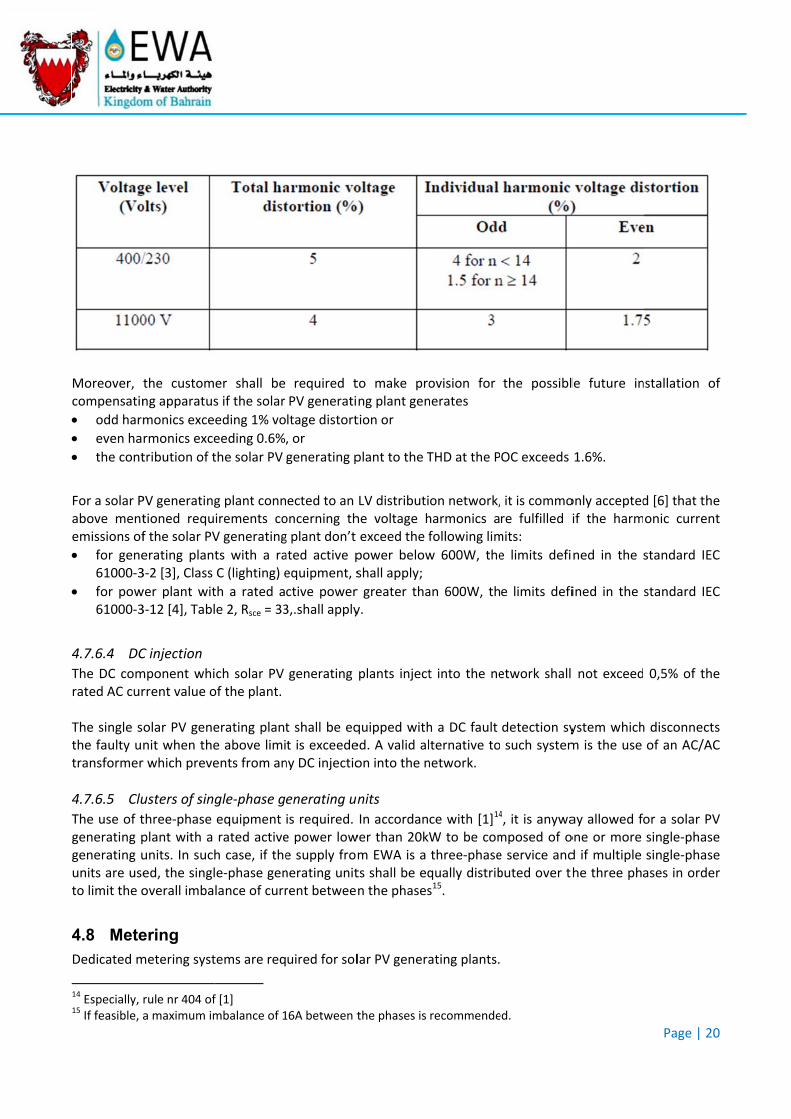
Moreover, compensatin
odd harm
even ha
the cont
For a solar Pabove mentemissions of
for gene61000‐3
for pow61000‐3
4.7.6.4 DC
The DC comrated AC cur The single sthe faulty utransformer
4.7.6.5 Clu
The use of tgenerating pgenerating uunits are useto limit the o
4.8 Mete
Dedicated m
14 Especially, 15 If feasible, a
the customng apparatus
monics exce
rmonics exce
tribution of t
PV generatingtioned requf the solar PV
erating plan3‐2 [3], Class
wer plant wit3‐12 [4], Tabl
C injection
mponent whirrent value o
olar PV genenit when ther which preve
usters of sin
three‐phase plant with a units. In suched, the singloverall imba
ering
metering syst
rule nr 404 ofa maximum im
er shall be s if the solar
eding 1% vo
eeding 0.6%,
the solar PV
g plant connirements coV generating
ts with a raC (lighting) e
th a rated ale 2, Rsce = 33
ich solar PV of the plant.
erating plante above limients from an
gle‐phase g
equipment rated activeh case, if thele‐phase genlance of curr
tems are req
f [1] mbalance of 1
required tPV generati
ltage distort
, or
generating p
ected to an oncerning thg plant don’t
ated active pequipment, s
ctive power 3,.shall apply
generating
t shall be eqt is exceedeny DC injectio
enerating un
is required. e power lowe supply fromnerating unitrent betwee
uired for sol
16A between t
to make prong plant gen
tion or
plant to the T
LV distributihe voltage hexceed the f
power belowshall apply;
r greater thay.
plants inject
quipped withed. A valid alon into the n
nits
In accordanwer than 20km EWA is a ts shall be eqn the phases
lar PV genera
the phases is
ovision for nerates
THD at the P
on network,harmonics afollowing lim
w 600W, the
an 600W, th
t into the ne
h a DC fault lternative tonetwork.
ce with [1]14
W to be comthree‐phasequally distribs15.
ating plants.
recommende
the possibl
OC exceeds
it is commore fulfilled imits:
e limits defi
e limits defi
etwork shall
detection sy such system
4, it is anywamposed of oe service andbuted over th
ed.
le future in
1.6%.
only acceptedif the harm
ned in the
ined in the
not exceed
ystem whichm is the use
ay allowed fone or more d if multiple he three pha
Page | 20
nstallation o
d [6] that theonic curren
standard IEC
standard IEC
0,5% of the
h disconnectsof an AC/AC
or a solar PVsingle‐phasesingle‐phaseases in orde
0
of
e t
C
C
e
s C
V e e r
As a generabe in accord In partial detwo meterin
A net‐m
A solar P The main elthe energy p In derogatiopremises; in
5 COMP
A customer present stan The customplant which The customethe complian If deemed nstudies withthe present time througmodificationthe present When studinecessary to
l rule. the mdance with se
erogation frong positions:
etering posit
PV productio
ectricity metproduced by
on from regu such case, t
PLIANCE
shall ensurendards throu
er shall notimay affect t
er shall provnce of the so
necessary, E the scope todocument. Sghout the lifn or replacemstandards.
es are requo carry out th
metering posiection 4 of [1
om regulatio
tion where t
on metering
ter measurethe solar PV
ulation Nr 41the PV electr
e that its soughout the ov
ify to EWA athe complian
vide EWA wiolar PV gene
EWA shall hao demonstraSuch activitifetime of thment of any
ired, EWA she studies.
itions and th1].
on Nr 401 of
the main elec
position whe
es the net enV generating
18 of [1], thericity meter s
lar PV geneverall lifetim
any incidentnce with the
th all the dorating plant
ave the righate the compes may be rehe solar PV equipment t
shall provide
he meters us
f [1], a custo
ctricity mete
ere the PV el
nergy at the plant conne
e PV electricshall have re
rating plant me of the faci
t, failure or requirement
ocuments, stto the requi
ht to requespliance of theequested nogenerating
that may hav
e the custom
sed for mete
omer with a
er is installed
lectricity me
POC whereacted to the P
city meter camote meter
complies wlity.
planned mots defined in
tudies and mrements def
t the custome solar PV geot only durinplant, and
ve an impact
mer with all
ering solar PV
solar PV gen
d,
ter is installe
as the PV elePOC.
an be installereading cap
with the requ
odification ofn the present
measurementined in the p
mer to carryenerating plag the connecmore specit on the com
the technic
V generating
nerating pla
ed.
ectricity met
ed within thpability.
uirements de
f its solar PVt standards.
ts useful to present stand
y out additioant with the ction procesifically after
mpliance of th
cal data of
Page | 21
g plants shal
nt shall have
ter measures
e customer’
efined in the
V generating
demonstratedards.
onal tests oprovisions oss, but at anyany failure
he plant with
the network
1
ll
e
s
s
e
g
e
r of y e, h
k
ANNEX A.. CONNEC
F
CTION SC
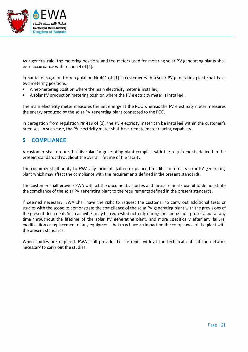
Figure 6: MV
CHEMES
connection scheme – Innterface swittch on LV sidde
Page | 22
2

Figure 7: MV connecttion schemee – Two mainn switches
Page | 233
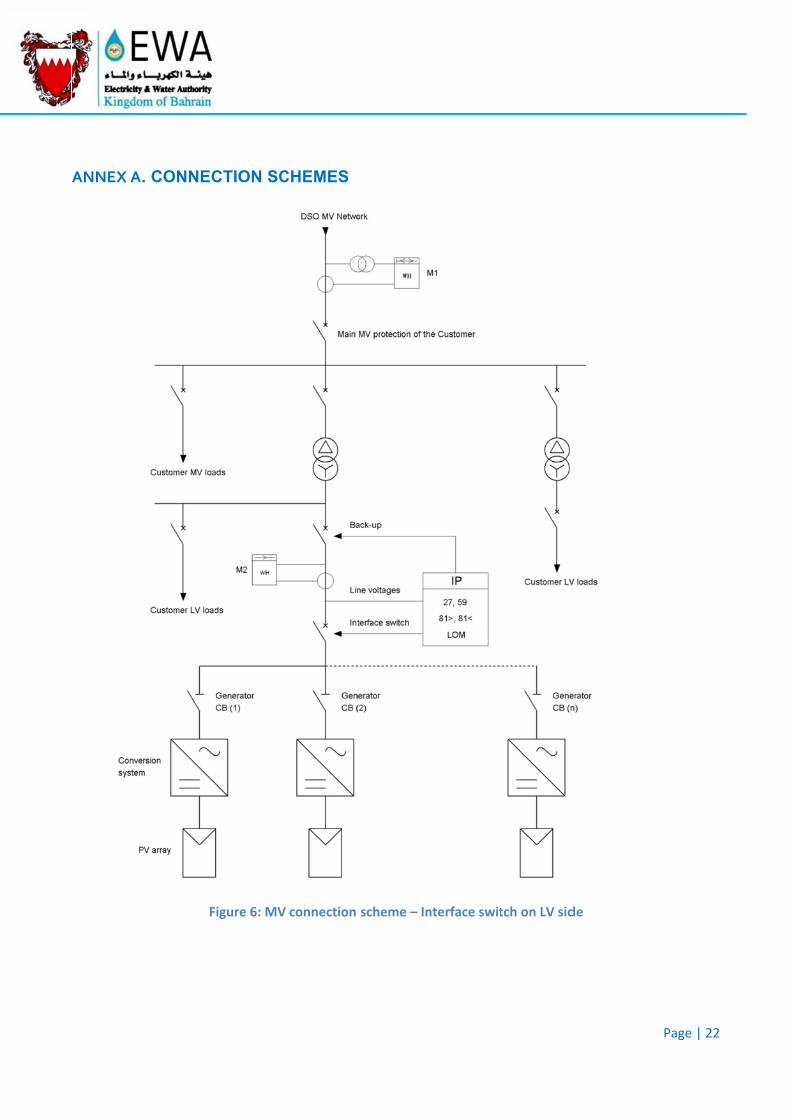
Fiigure 8: MV connection s
scheme – Intterface Switch on MV sidde
Page | 24
4
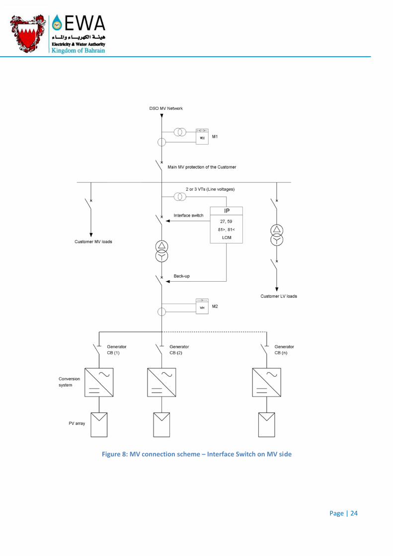
Figure 9: LLV Connectioon Scheme
Page | 255
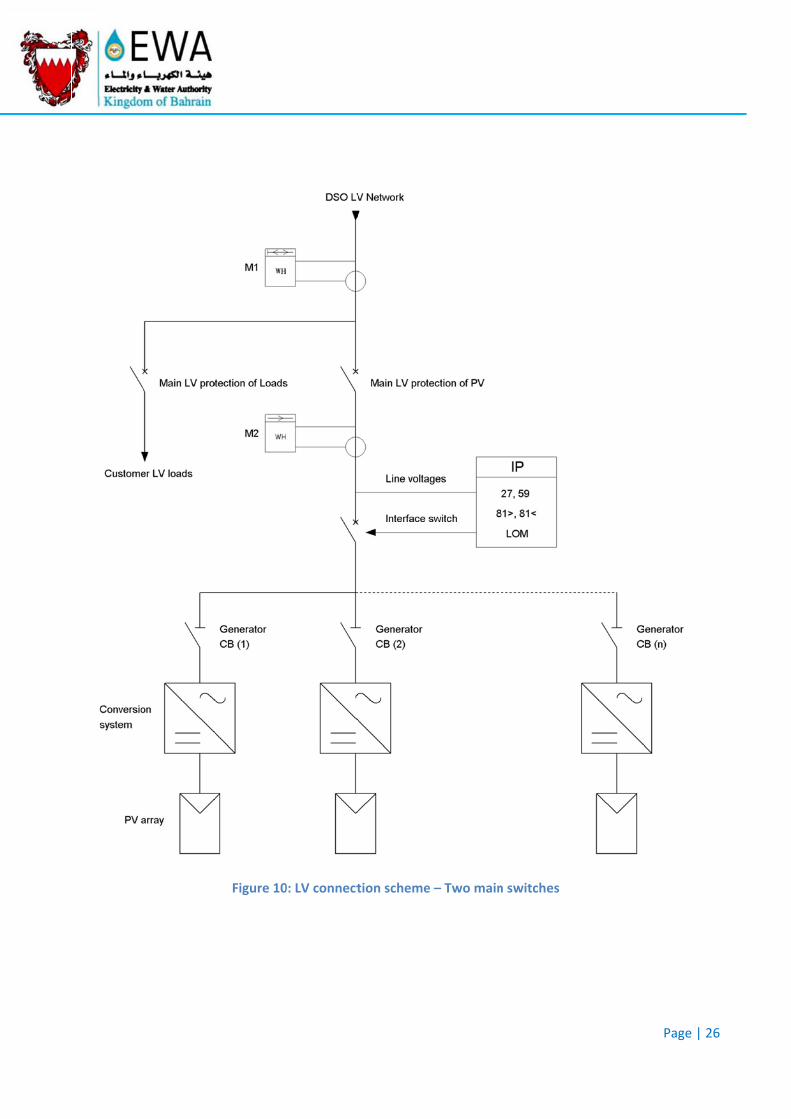
Figure 100: LV connecttion schemee – Two mainn switches
Page | 266
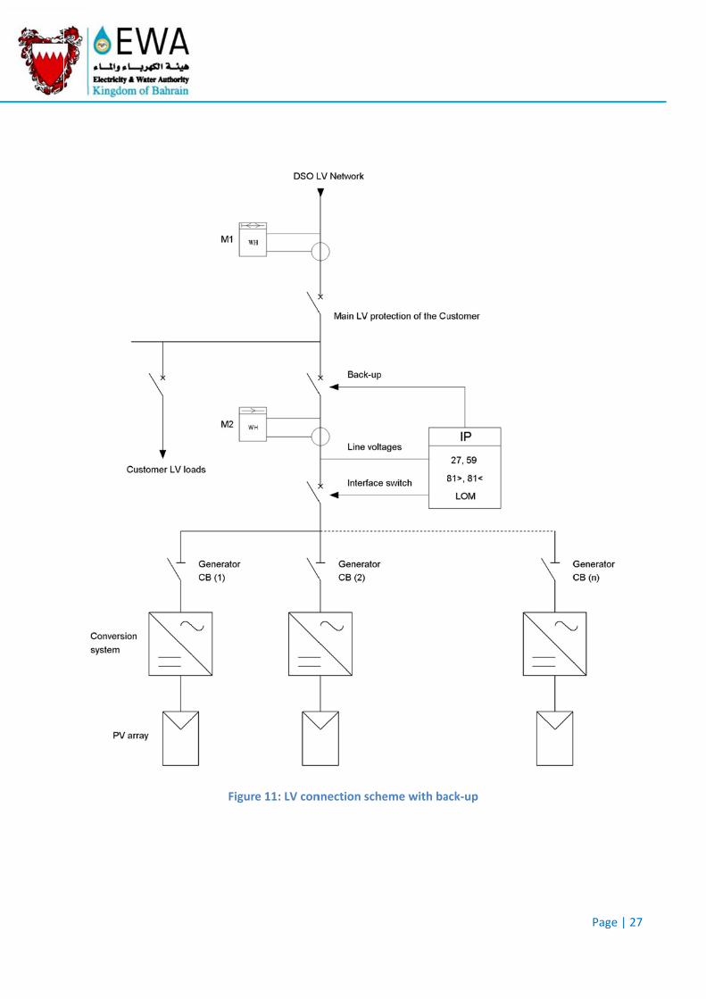
Figur
e 11: LV connnection scheeme with baack‐up
Page | 277
ANNEX B.
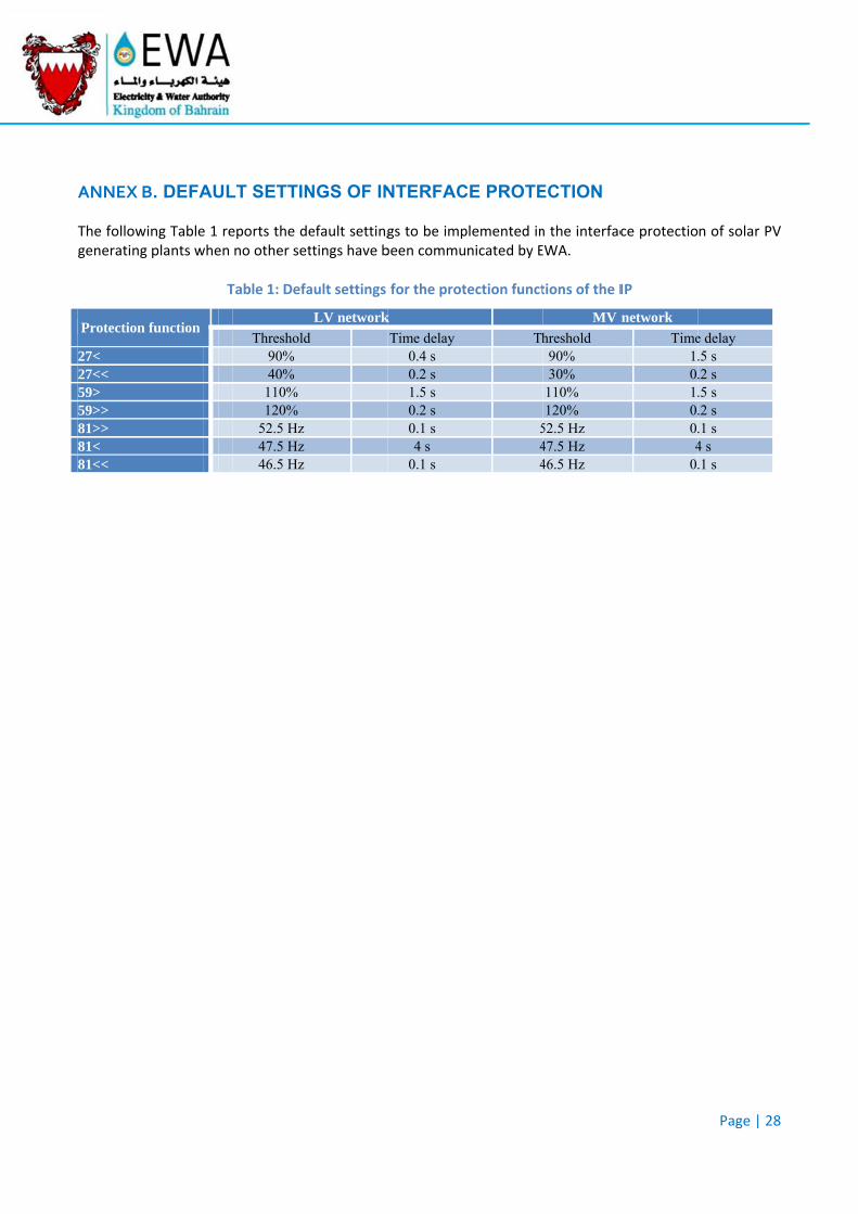
The followingenerating p
Protection fu
27< 27<< 59> 59>> 81>> 81< 81<<
. DEFAUL
ng Table 1 replants when
T
unction
LT SETTIN
eports the deno other set
Table 1: Defa
Threshold90% 40%
110% 120%
52.5 Hz 47.5 Hz 46.5 Hz
NGS OF IN
efault settingttings have b
ault settings
LV network
NTERFAC
gs to be impbeen commu
for the prot
k
Time delay 0.4 s 0.2 s 1.5 s 0.2 s 0.1 s 4 s
0.1 s
CE PROTE
plemented innicated by E
tection funct
Th
544
ECTION
n the interfacEWA.
tions of the I
MV
hreshold 90% 30%
110% 120%
52.5 Hz 47.5 Hz 46.5 Hz
ce protectio
IP
network
Time1.0.1.0.0.4
0.
Page | 28
n of solar PV
e delay .5 s .2 s .5 s .2 s .1 s 4 s .1 s
8
V
ANNEX C.
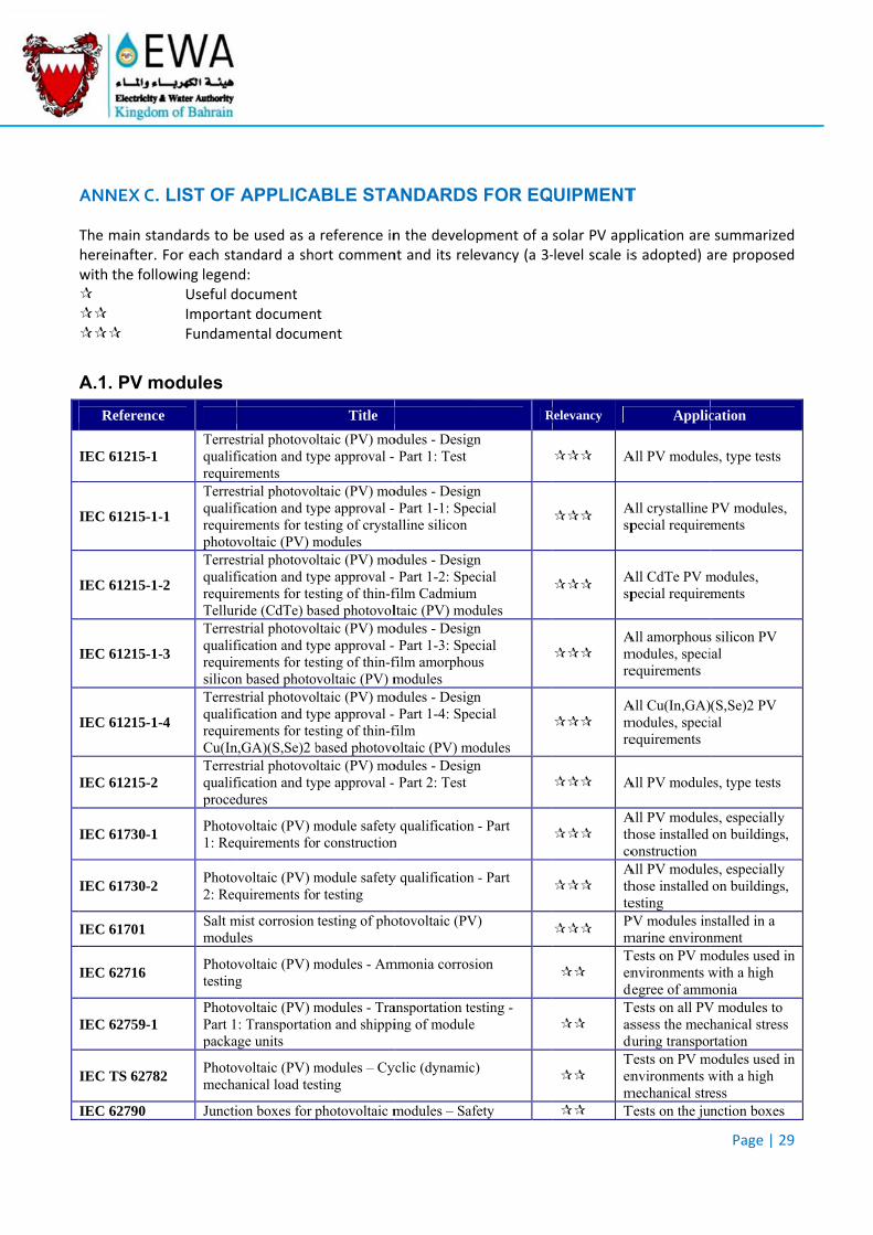
The main stahereinafter. with the foll
A.1. PV m
Referenc
IEC 61215-1
IEC 61215-1
IEC 61215-1
IEC 61215-1
IEC 61215-1
IEC 61215-2
IEC 61730-1
IEC 61730-2
IEC 61701
IEC 62716
IEC 62759-1
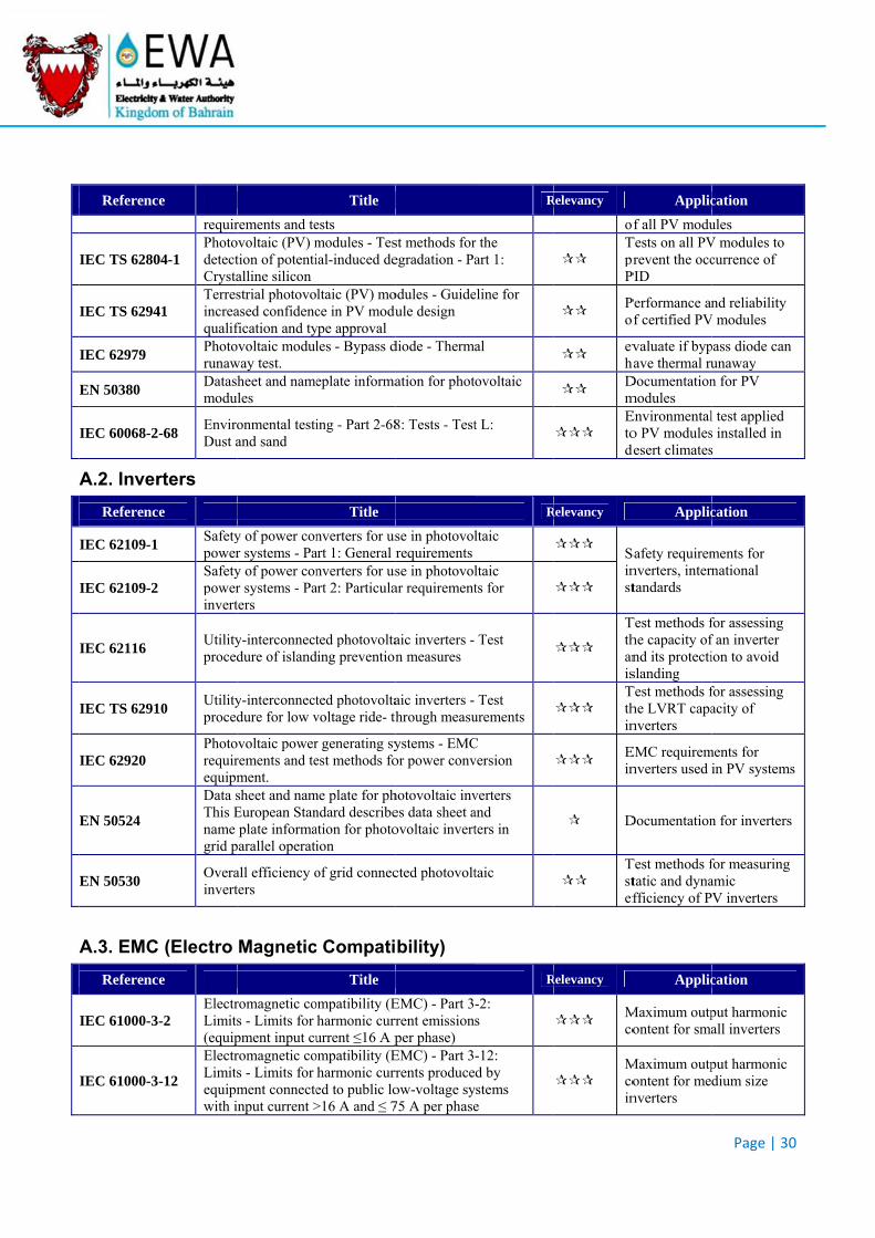
IEC TS 6278
IEC 62790
. LIST OF
andards to bFor each staowing legen
Useful dImportaFundam
modules
ce
Terresqualifrequir
-1
Terresqualifrequirphotov
-2
TerresqualifrequirTellur
-3
Terresqualifrequirsilicon
-4
TerresqualifrequirCu(In
Terresqualifproced
Photo1: Req
Photo2: Req
Salt mmodu
Phototesting
PhotoPart 1packa
82 Photomecha
Juncti
APPLICA
be used as aandard a shod: document nt documen
mental docum
strial photovofication and tyrements strial photovofication and tyrements for tesvoltaic (PV) mstrial photovofication and tyrements for tesride (CdTe) bastrial photovofication and tyrements for tesn based photostrial photovofication and tyrements for tesn,GA)(S,Se)2 bstrial photovofication and tydures
ovoltaic (PV) mquirements fo
ovoltaic (PV) mquirements fo
mist corrosion les
ovoltaic (PV) mg
ovoltaic (PV) m: Transportati
age units
ovoltaic (PV) manical load tes
ion boxes for p
ABLE STA
reference inort commen
t ment
Title
ltaic (PV) moype approval -
ltaic (PV) moype approval -sting of crystamodules ltaic (PV) mo
ype approval -sting of thin-fased photovolltaic (PV) mo
ype approval -sting of thin-fvoltaic (PV) mltaic (PV) mo
ype approval -sting of thin-fbased photovoltaic (PV) mo
ype approval -
module safetyr construction
module safetyr testing
testing of pho
modules - Am
modules - Traion and shippi
modules – Cysting
photovoltaic m
ANDARDS
n the develont and its rel
odules - Desig Part 1: Test
odules - Desig Part 1-1: Spealline silicon
odules - Desig Part 1-2: Spe
film Cadmiumltaic (PV) mododules - Desig Part 1-3: Spe
film amorphoumodules
odules - Desig Part 1-4: Spe
film oltaic (PV) mo
odules - Desig Part 2: Test
y qualificationn
y qualification
otovoltaic (PV
mmonia corros
ansportation teing of module
yclic (dynamic
modules – Saf
S FOR EQ
opment of a evancy (a 3‐
R
n
n ecial
n ecial m dules n
ecial us
n ecial
odules n
n - Part
n - Part
V)
sion
esting - e
c)
fety
QUIPMENT
solar PV app‐level scale is
Relevancy
A
Asp
Asp
Amre
Amre
A
Athco
Athte
Pm
Tende
Tasdu
Tenm
T
T
plication ares adopted) a
Applic
All PV module
All crystalline pecial require
All CdTe PV mpecial require
All amorphousmodules, speciequirements
All Cu(In,GA)modules, speciequirements
All PV module
All PV modulehose installed onstruction
All PV modulehose installed esting
PV modules inmarine environTests on PV mnvironments w
degree of ammTests on all PVssess the mech
during transporTests on PV mnvironments w
mechanical streTests on the ju
Page | 29
summarizedare proposed
cation
es, type tests
PV modules, ments
modules, ments
s silicon PV ial
(S,Se)2 PV ial
es, type tests
es, especially on buildings,
es, especially on buildings,
nstalled in a nment
modules used inwith a high
monia V modules to hanical stress rtation
modules used inwith a high ess nction boxes
9
d d
n
n
Referenc
IEC TS 6280
IEC TS 6294
IEC 62979
EN 50380
IEC 60068-2
A.2. Inver
Referenc
IEC 62109-1
IEC 62109-2
IEC 62116
IEC TS 6291
IEC 62920
EN 50524
EN 50530
A.3. EMC
Referenc
IEC 61000-3
IEC 61000-3
ce
requir
04-1 PhotodetectCrysta
41 TerresincreaqualifPhotorunawDatashmodu
-68 EnviroDust a
rters
ce
Safetypower
Safetypowerinvert
Utilityproced
10 Utilityproced
PhotorequirequipmData sThis Ename grid p
Overainvert
C (Electro
ce
-2 ElectrLimits(equip
-12
ElectrLimitsequipmwith i
rements and teovoltaic (PV) mtion of potentialline silicon strial photovoased confidencfication and tyovoltaic modulway test.
heet and nameles
onmental testiand sand
y of power conr systems - Pay of power conr systems - Paters
y-interconnectdure of island
y-interconnectdure for low v
ovoltaic powerrements and tement. sheet and namEuropean Stanplate informa
parallel operati
all efficiency oters
Magnetic
romagnetic cos - Limits for pment input curomagnetic cos - Limits for ment connectenput current >
Title
ests modules - Tesial-induced de
ltaic (PV) moce in PV modu
ype approval les - Bypass d
eplate informa
ing - Part 2-68
Title
nverters for usart 1: General rnverters for us
art 2: Particula
ted photovoltading prevention
ted photovoltavoltage ride- th
r generating syest methods fo
me plate for phndard describeation for photoion
of grid connec
c Compati
Title
ompatibility (Eharmonic currurrent ≤16 A p
ompatibility (Eharmonic curred to public lo>16 A and ≤ 7
st methods foregradation - Pa
odules - Guideule design
diode - Therm
ation for phot
8: Tests - Test
se in photovolrequirementsse in photovolar requirement
aic inverters -n measures
aic inverters -hrough measu
ystems - EMCor power conv
hotovoltaic inves data sheet aovoltaic invert
cted photovolt
bility)
EMC) - Part 3rrent emissionper phase) EMC) - Part 3rrents produceow-voltage sy75 A per phase
R
r the art 1:
eline for
al
tovoltaic
t L:
R
ltaic
ltaic ts for
Test
Test urements
C version
verters and ters in
taic
R
-2: s
-12: d by
ystems e
Relevancy
of
TprP
Pof
evha
Dm
Etode
Relevancy
Sinst
Tthanis
Tthin
Ein
D
Tstef
Relevancy
Mco
Mcoin
Applic
f all PV moduTests on all PV
revent the occPID
Performance anf certified PV
valuate if byphave thermal ruDocumentationmodules Environmentalo PV modules
desert climates
Applic
Safety requiremnverters, interntandards
Test methods fhe capacity ofnd its protectislanding
Test methods fhe LVRT capanverters
EMC requiremnverters used
Documentation
Test methods ftatic and dynafficiency of P
Applic
Maximum outpontent for sma
Maximum outpontent for menverters
Page | 30
cation
ules V modules to currence of
nd reliability V modules
pass diode canunaway n for PV
l test applied s installed in s
cation
ments for national
for assessing f an inverter ion to avoid
for assessing acity of
ments for in PV systems
n for inverters
for measuring amic V inverters
cation
put harmonic all inverters
put harmonic dium size
0
n
s
s
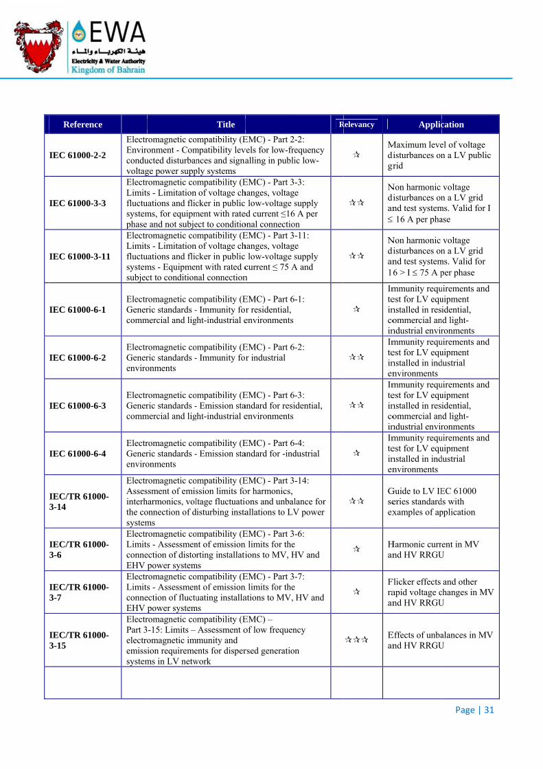
Referenc
IEC 61000-2
IEC 61000-3
IEC 61000-3
IEC 61000-6
IEC 61000-6
IEC 61000-6
IEC 61000-6
IEC/TR 61003-14
IEC/TR 61003-6
IEC/TR 61003-7
IEC/TR 61003-15
ce
-2
ElectrEnviroconduvoltag
-3
ElectrLimitsfluctusystemphase
-11
ElectrLimitsfluctusystemsubjec
-1 ElectrGenercomm
-2 ElectrGenerenviro
-3 ElectrGenercomm
-4 ElectrGenerenviro
00-
ElectrAssesinterhthe cosystem
00-ElectrLimitsconneEHV
00-ElectrLimitsconneEHV
00-
ElectrPart 3electroemisssystem
romagnetic coonment - Com
ucted disturbange power suppromagnetic cos - Limitation
uations and flicms, for equipm
and not subjeromagnetic cos - Limitation
uations and flicms - Equipmenct to condition
romagnetic coric standards -
mercial and lig
romagnetic coric standards -onments
romagnetic coric standards -
mercial and lig
romagnetic coric standards -onments
romagnetic cossment of emisharmonics, volonnection of dms romagnetic cos - Assessmen
ection of distopower system
romagnetic cos - Assessmen
ection of fluctupower system
romagnetic co-15: Limits – omagnetic imion requireme
ms in LV netw
Title
ompatibility (Empatibility levnces and signaply systems ompatibility (E
of voltage chcker in public ment with rateect to conditioompatibility (E
of voltage chcker in public nt with rated cnal connection
ompatibility (E- Immunity forght-industrial e
ompatibility (E- Immunity for
ompatibility (E- Emission staght-industrial e
ompatibility (E- Emission sta
ompatibility (Ession limits foltage fluctuatio
disturbing insta
ompatibility (Ent of emission rting installati
ms ompatibility (Ent of emission uating installa
ms ompatibility (E
Assessment ommunity and ents for disperwork
EMC) - Part 2vels for low-frealling in publi
EMC) - Part 3hanges, voltag low-voltage s
ed current ≤16onal connectioEMC) - Part 3hanges, voltag low-voltage scurrent ≤ 75 An
EMC) - Part 6r residential, environments
EMC) - Part 6r industrial
EMC) - Part 6andard for resienvironments
EMC) - Part 6andard for -ind
EMC) - Part 3or harmonics, ons and unbalallations to LV
EMC) - Part 3n limits for theions to MV, H
EMC) - Part 3n limits for theations to MV,
EMC) – of low frequen
rsed generatio
R
-2: equency ic low-
-3: e supply
6 A per on -11: e supply
A and
-1:
-2:
-3: idential,
-4: dustrial
-14:
lance for V power
-6: e HV and
-7: e HV and
ncy
n
Relevancy
Mdigr
Ndian
Ndian1
Imteincoin
Imteinen
Imteincoin
Imteinen
Gseex
Han
Fraan
Ean
Applic
Maximum levedisturbances ongrid
Non harmonic disturbances onnd test system 16 A per pha
Non harmonic disturbances onnd test system6 > I 75 A p
mmunity request for LV equnstalled in resommercial anndustrial envirmmunity request for LV equnstalled in indnvironments mmunity request for LV equnstalled in resommercial anndustrial envirmmunity request for LV equnstalled in indnvironments
Guide to LV IEeries standardxamples of ap
Harmonic currnd HV RRGU
Flicker effects apid voltage cnd HV RRGU
Effects of unband HV RRGU
Page | 31
cation
el of voltage n a LV public
voltage n a LV grid
ms. Valid for I ase
voltage n a LV grid
ms. Valid for per phase
uirements and uipment idential,
nd light-ronments
uirements and uipment dustrial
uirements and uipment idential,
nd light-ronments
uirements and uipment dustrial
EC 61000 ds with pplication
ent in MV U
and other changes in MVU
alances in MVU
1
V
V
Referenc
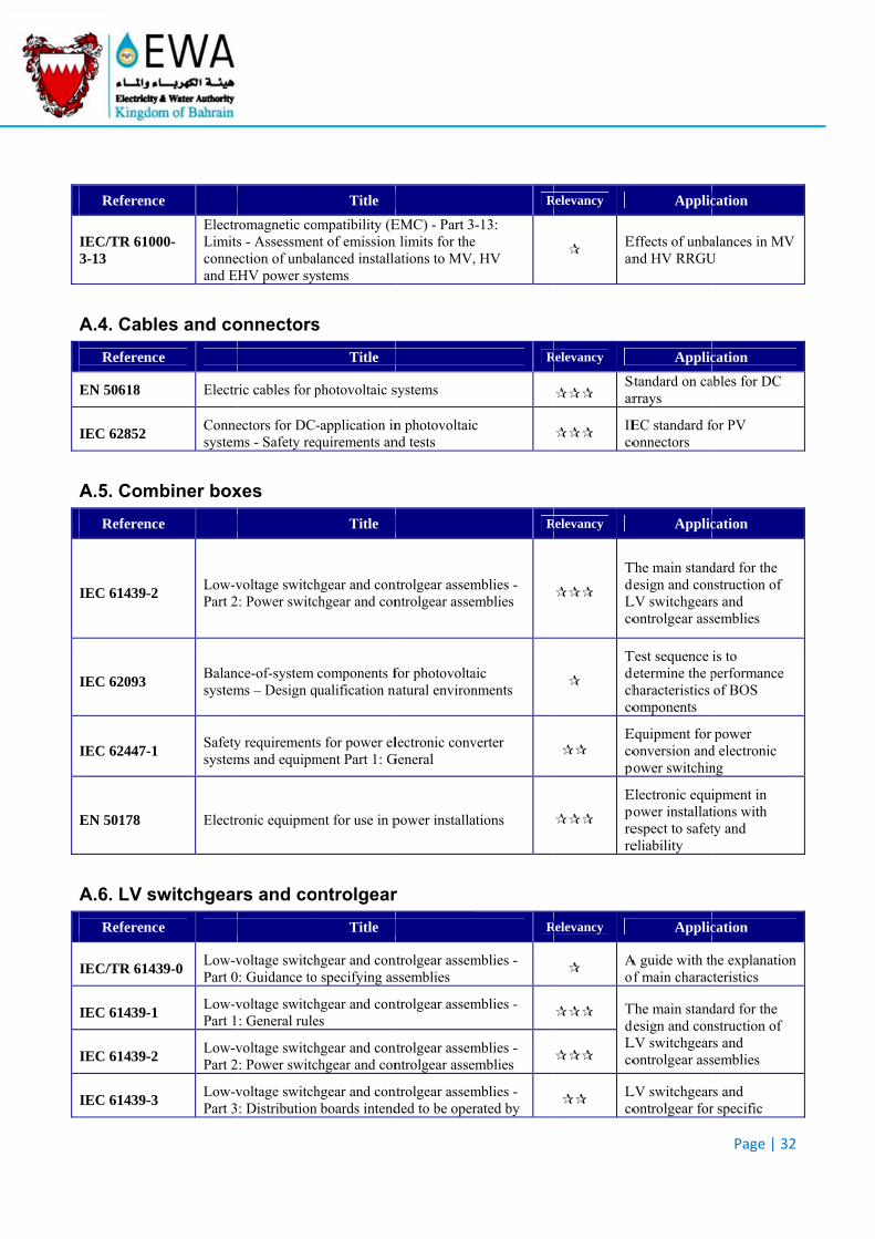
IEC/TR 61003-13
A.4. Cabl
Referenc
EN 50618
IEC 62852
A.5. Com
Referenc
IEC 61439-2
IEC 62093
IEC 62447-1
EN 50178
A.6. LV sw
Referenc
IEC/TR 6143
IEC 61439-1
IEC 61439-2
IEC 61439-3
ce
00-ElectrLimitsconneand E
es and co
ce
Electr
Connesystem
biner box
e
Low-vPart 2
Balansystem
Safetysystem
Electr
witchgear
e
39-0 Low-vPart 0
Low-vPart 1
Low-vPart 2
Low-vPart 3
romagnetic cos - Assessmen
ection of unbaHV power sy
onnectors
ric cables for p
ectors for DC-ms - Safety req
xes
voltage switch2: Power switc
nce-of-system ms – Design q
y requirementms and equipm
ronic equipme
rs and co
voltage switch0: Guidance to
voltage switch: General rule
voltage switch2: Power switc
voltage switch: Distribution
Title
ompatibility (Ent of emission lanced installastems
s
Title
photovoltaic s
-application inquirements an
Title
hgear and conchgear and con
components fqualification n
s for power elment Part 1: G
ent for use in p
ontrolgear
Title
hgear and cono specifying as
hgear and cones
hgear and conchgear and con
hgear and conn boards intend
EMC) - Part 3n limits for theations to MV,
systems
n photovoltaicnd tests
ntrolgear assemntrolgear asse
for photovoltanatural environ
lectronic convGeneral
power installa
r
ntrolgear assemssemblies
ntrolgear assem
ntrolgear assemntrolgear asse
ntrolgear assemded to be oper
R
-13: e , HV
R
c
R
mblies - mblies
aic nments
verter
ations
R
mblies -
mblies -
mblies - mblies
mblies - rated by
Relevancy
Ean
Relevancy
Sar
IEco
Relevancy
TdeLco
Tdechco
Ecopo
Eporere
Relevancy
Aof
TdeLco
Lco
Applic
Effects of unband HV RRGU
Applic
Standard on carrays
EC standard fonnectors
Applic
The main standdesign and conLV switchgearontrolgear ass
Test sequence determine the pharacteristics omponents
Equipment for onversion andower switchin
Electronic equiower installatespect to safeteliability
Applic
A guide with thf main charac
The main standdesign and conLV switchgearontrolgear ass
LV switchgearontrolgear for
Page | 32
cation
alances in MVU
cation
ables for DC
for PV
cation
dard for the nstruction of rs and semblies
is to performance of BOS
power d electronic ng
ipment in tions with ty and
cation
he explanationcteristics
dard for the nstruction of rs and semblies
rs and r specific
2
V
n
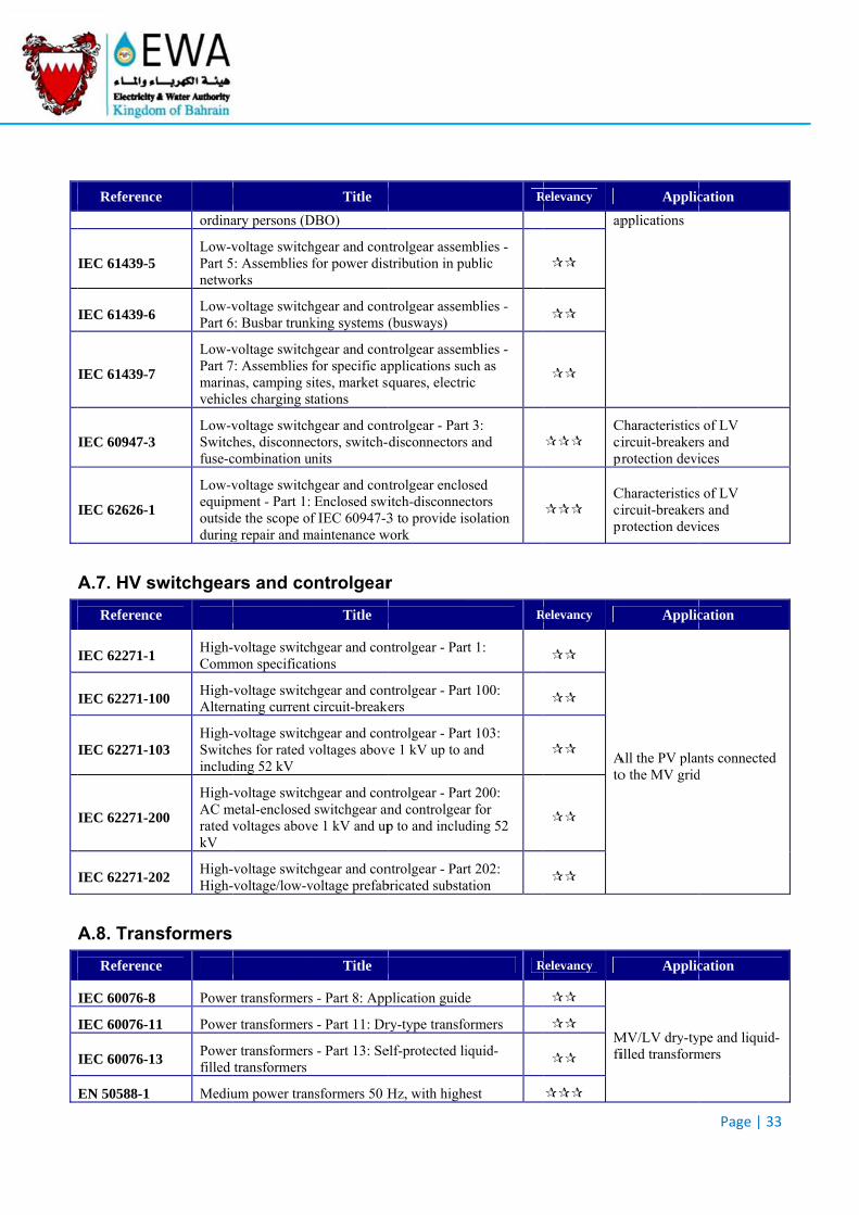
Referenc
IEC 61439-5
IEC 61439-6
IEC 61439-7
IEC 60947-3
IEC 62626-1
A.7. HV s
Referenc
IEC 62271-1
IEC 62271-1
IEC 62271-1
IEC 62271-2
IEC 62271-2
A.8. Tran
Referenc
IEC 60076-8
IEC 60076-1
IEC 60076-1
EN 50588-1
e
ordina
Low-vPart 5netwo
Low-vPart 6
Low-vPart 7marinvehicl
Low-vSwitchfuse-c
Low-vequipmoutsidduring
switchgea
e
High-Comm
00 High-Altern
03 High-Switchinclud
00
High-AC mrated vkV
02 High-High-
sformers
ce
Power
1 Power
3 Powerfilled
Mediu
ary persons (D
voltage switch: Assemblies
orks
voltage switch6: Busbar trunk
voltage switch7: Assemblies nas, camping sles charging st
voltage switchhes, disconne
combination u
voltage switchment - Part 1:
de the scope og repair and m
ars and co
voltage switchmon specificat
voltage switchnating current
voltage switchhes for rated v
ding 52 kV
voltage switchmetal-enclosed
voltages abov
voltage switchvoltage/low-v
r transformers
r transformers
r transformerstransformers
um power tran
Title
DBO)
hgear and confor power dis
hgear and conking systems (
hgear and confor specific ap
sites, market stations
hgear and conctors, switch-
units
hgear and conEnclosed swi
f IEC 60947-3maintenance w
ontrolgear
Title
hgear and contions
hgear and concircuit-breake
hgear and convoltages abov
hgear and conswitchgear an
ve 1 kV and up
hgear and convoltage prefab
Title
s - Part 8: App
s - Part 11: Dr
s - Part 13: Se
nsformers 50 H
ntrolgear assemstribution in pu
ntrolgear assem(busways)
ntrolgear assempplications suquares, electri
ntrolgear - Partdisconnectors
ntrolgear encloitch-disconnec3 to provide is
work
r
ntrolgear - Par
ntrolgear - Parers
ntrolgear - Parve 1 kV up to a
ntrolgear - Parnd controlgeap to and includ
ntrolgear - Parbricated substa
plication guide
ry-type transfo
elf-protected li
Hz, with high
R
mblies - ublic
mblies -
mblies - uch as ic
t 3: s and
osed ctors solation
R
rt 1:
rt 100:
rt 103: and
rt 200: ar for ding 52
rt 202: ation
R
e
ormers
iquid-
est
Relevancy
ap
Ccipr
Ccipr
Relevancy
Ato
Relevancy
Mfi
Applic
pplications
Characteristicsircuit-breakerrotection devi
Characteristicsircuit-breakerrotection devi
Applic
All the PV plano the MV grid
Applic
MV/LV dry-tyilled transform
Page | 33
cation
s of LV rs and ices
s of LV rs and ices
cation
nts connected d
cation
ype and liquid-mers
3
-
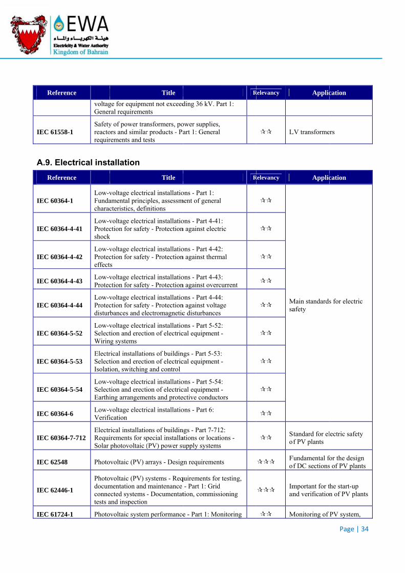
Referenc
IEC 61558-1
A.9. Elect
Referenc
IEC 60364-1
IEC 60364-4
IEC 60364-4
IEC 60364-4
IEC 60364-4
IEC 60364-5
IEC 60364-5
IEC 60364-5
IEC 60364-6
IEC 60364-7
IEC 62548
IEC 62446-1
IEC 61724-1
ce
voltagGener
Safetyreactorequir
trical inst
ce
Low-vFundacharac
-41 Low-vProtecshock
-42 Low-vProteceffect
-43 Low-vProtec
-44 Low-vProtecdisturb
-52 Low-vSelectWirin
-53 ElectrSelectIsolati
-54 Low-vSelectEarthi
Low-vVerifi
-712 ElectrRequiSolar
Photo
Photodocumconnetests a
Photo
ge for equipmeral requiremen
y of power traors and similarrements and te
tallation
voltage electriamental princicteristics, defi
voltage electriction for safet
k
voltage electriction for safets
voltage electriction for safet
voltage electriction for safetbances and el
voltage electrition and erecti
ng systems
rical installatiotion and erectiion, switching
voltage electrition and erectiing arrangeme
voltage electriication
rical installatioirements for spphotovoltaic (
ovoltaic (PV) a
ovoltaic (PV) smentation and ected systems and inspection
ovoltaic system
Title
ent not exceednts
ansformers, por products - Paests
Title
ical installatioiples, assessminitions
ical installatioy - Protection
ical installatioy - Protection
ical installatioy - Protection
ical installatioy - Protectionectromagnetic
ical installatioion of electric
ons of buildinion of electricg and control
ical installatioion of electricents and prote
ical installatio
ons of buildinpecial installa(PV) power su
arrays - Desig
systems - Reqmaintenance - Documentat
n
m performance
ding 36 kV. P
ower supplies,art 1: General
ons - Part 1: ment of general
ons - Part 4-41n against electr
ons - Part 4-42n against therm
ons - Part 4-43n against overc
ons - Part 4-44n against voltac disturbances
ons - Part 5-52cal equipment
ngs - Part 5-53cal equipment
ons - Part 5-54cal equipment ective conduct
ons - Part 6:
ngs - Part 7-71ations or locatiupply systems
gn requiremen
quirements for- Part 1: Grid
tion, commiss
e - Part 1: Mo
R
art 1:
, l
R
l
1: ric
2: mal
3: current
4: age s
2: -
3: -
4: -
tors
2: ions - s
ts
r testing, d sioning
onitoring
Relevancy
L
Relevancy
Msa
Sof
Fof
Iman
M
Applic
LV transforme
Applic
Main standardsafety
Standard for elf PV plants
Fundamental fof DC sections
mportant for tnd verification
Monitoring of
Page | 34
cation
ers
cation
s for electric
lectric safety
for the design s of PV plants
the start-up n of PV plants
PV system,
4
s
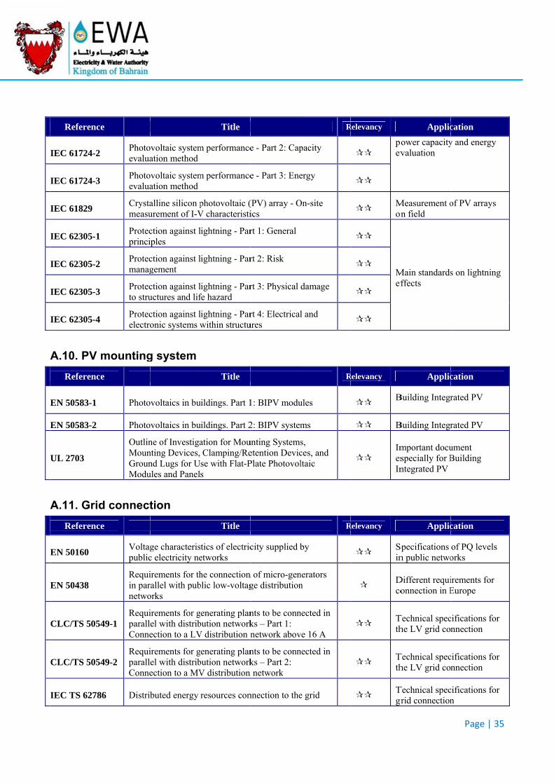
Referenc
IEC 61724-2
IEC 61724-3
IEC 61829
IEC 62305-1
IEC 62305-2
IEC 62305-3
IEC 62305-4
A.10. PV
Referenc
EN 50583-1
EN 50583-2
UL 2703
A.11. Grid
Referenc
EN 50160
EN 50438
CLC/TS 505
CLC/TS 505
IEC TS 6278
ce
Photoevalua
Photoevalua
Crystameasu
Protecprinci
Protecmanag
Protecto stru
Protecelectro
mounting
ce
Photo
Photo
OutlinMounGrounModu
d connect
e
Voltagpublic
Requiin parnetwo
49-1 RequiparallConne
49-2 RequiparallConne
86 Distrib
ovoltaic systemation method
ovoltaic systemation method
alline silicon purement of I-V
ction against liples
ction against lgement
ction against luctures and lif
ction against lonic systems w
g system
ovoltaics in bu
ovoltaics in bu
ne of Investiganting Devices, nd Lugs for Uules and Panel
tion
ge characterisc electricity ne
irements for thrallel with puborks
irements for gel with distribection to a LV
irements for gel with distribection to a MV
buted energy
Title
m performance
m performance
photovoltaic (V characteristi
lightning - Par
lightning - Par
lightning - Parfe hazard
lightning - Parwithin structu
Title
uildings. Part 1
uildings. Part 2
ation for MouClamping/Rese with Flat-Ps
Title
stics of electricetworks
he connectionblic low-voltag
generating planbution networkV distribution n
generating planbution networkV distribution
resources con
e - Part 2: Cap
e - Part 3: Ene
(PV) array - Oics
rt 1: General
rt 2: Risk
rt 3: Physical
rt 4: Electricalures
1: BIPV modu
2: BIPV system
unting Systemsetention DevicPlate Photovol
city supplied b
n of micro-genge distribution
nts to be connks – Part 1: network abov
nts to be connks – Part 2:
n network
nnection to the
R
pacity
ergy
On-site
damage
l and
R
ules
ms
s, ces, and ltaic
R
by
nerators n
nected in
ve 16 A
nected in
e grid
Relevancy
poev
Mon
Mef
Relevancy
B
B
ImesIn
Relevancy
Sin
Dco
Tth
Tth
Tgr
Applic
ower capacityvaluation
Measurement on field
Main standardsffects
Applic
Building Integr
Building Integr
mportant docuspecially for Bntegrated PV
Applic
Specifications n public netwo
Different requionnection in E
Technical speche LV grid co
Technical speche LV grid co
Technical specgrid connection
Page | 35
cation
y and energy
of PV arrays
s on lightning
cation
rated PV
rated PV
ument Building
cation
of PQ levels orks
irements for Europe
cifications for nnection
cifications for nnection
cifications for n
5
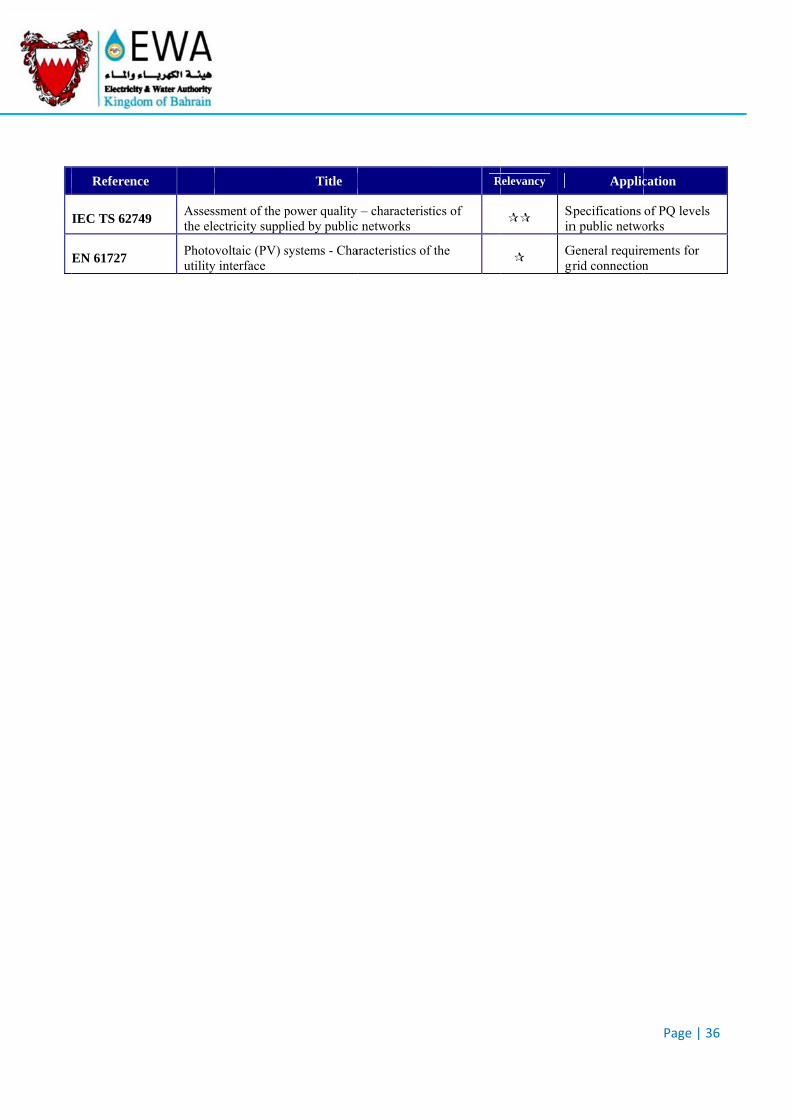
Referenc
IEC TS 6274
EN 61727
e
49 Assesthe ele
Photoutility
ssment of the pectricity suppl
voltaic (PV) sy interface
Title
power quality lied by public
systems - Cha
y – characteristc networks
aracteristics of
R
tics of
f the
Relevancy
Sin
Ggr
Applic
Specifications n public netwo
General requiregrid connection
Page | 36
cation
of PQ levels orks
ements for n
6