Wilo-Stratos PARA - Danfoss...
32
Wilo-Stratos PARA 2 068 561-Ed.02 / 2006-09-Kothes! VMILP102
-
Upload
truongthuan -
Category
Documents
-
view
257 -
download
0
Transcript of Wilo-Stratos PARA - Danfoss...

Wilo-Stratos PARA
2 06
8 56
1-Ed
.02
/ 200
6-09
-Kot
hes!
VMILP102
U253655
Typewritten Text
Installation and operating instructions
u253655
Typewritten Text

Fig. 1
Fig. 2
VMILP102
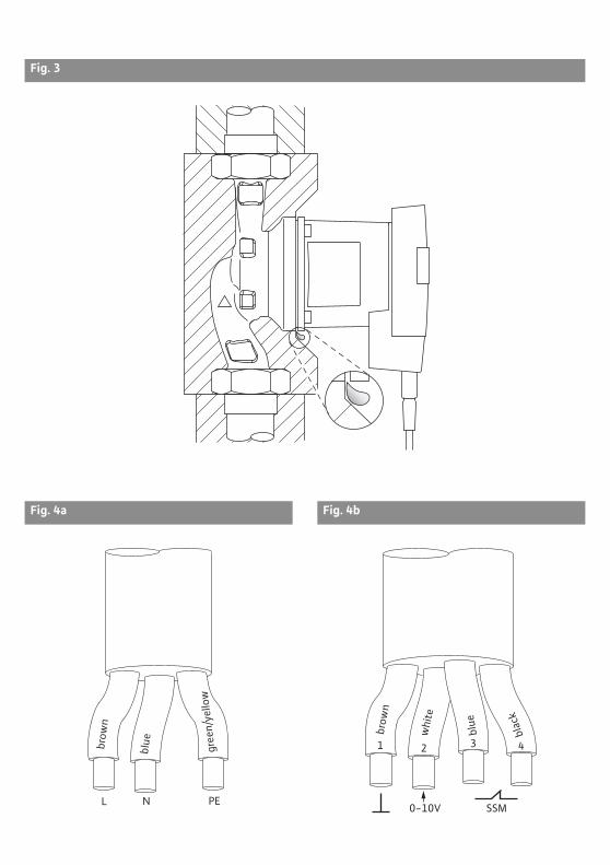
Fig. 3
Fig. 4a Fig. 4b
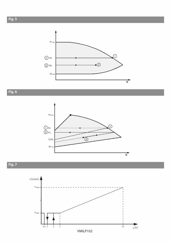
Fig. 5
Fig. 6
Fig. 7
n [1/min]
u [V]
nmax
nmin
0,5 1 2 3 10
VMILP102
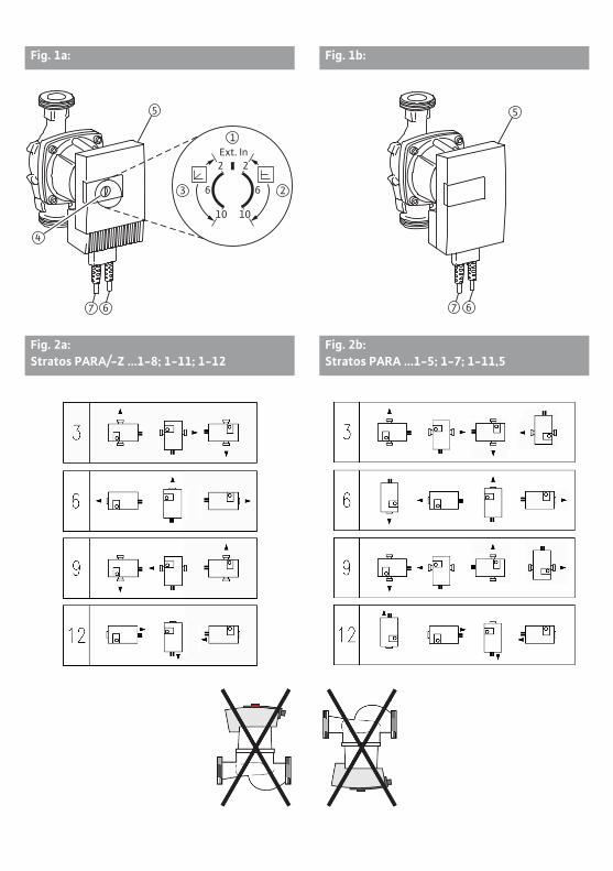
Fig. 1a: Fig. 1b:
Fig. 2a: Stratos PARA/-Z ...1-8; 1-11; 1-12
Fig. 2b: Stratos PARA ...1-5; 1-7; 1-11,5
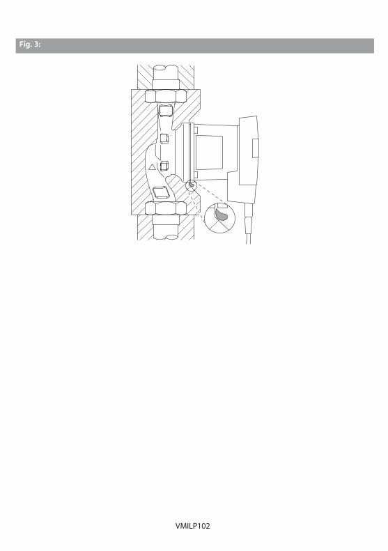
Fig. 3:
VMILP102

Installation and operating instructions Wilo-Stratos PARA/-Z 27
English
Installation and operating instructions1 GeneralAbout this documentThe language of the original operating instructions is German. All other languages of these instructions are translations of the original operating instructions.These installation and operating instructions are an integral part of the product. They must be kept readily available at the place where the product is installed. Strict adherence to these instructions is a precondition for the proper use and correct operation of the product.These installation and operating instructions correspond to the relevant version of the product and the underlying safety standards valid at the time of going to print.EC declaration of conformity:A copy of the EC declaration of conformity is a component of these operating instruc-tions.If a technical modification is made on the designs named there without our agreement, this declaration loses its validity.
2 SafetyThese operating instructions contain basic information which must be adhered to during installation, operation and maintenance. For this reason, these operating instructions must, without fail, be read by the service technician and the responsible specialist/oper-ator before installation and commissioning.It is not only the general safety instructions listed under the main point “safety” that must be adhered to but also the special safety instructions with danger symbols included under the following main points.
2.1 Indication of instructions in the operating instructions
Symbols:
General danger symbol
Danger due to electrical voltage
NOTE:
Signal words:
DANGER!Acutely dangerous situation.Non-observance results in death or the most serious of injuries.
WARNING!The user can suffer (serious) injuries. “Warning” implies that (serious) injury to persons is probable if this information is disregarded.
CAUTION!There is a danger of damaging the product/unit. “Caution” implies that damage to the product is likely if this information is disregarded.
NOTE: Useful information on handling the product. It draws attention to possible problems.Information that appears directly on the product, such as:
• Flow direction symbol,• Identification for connections,• Rating plate,• Warning sticker,
Must be strictly complied with and kept in legible condition.
English
28 WILO SE 09/2013
2.2 Personnel qualificationsThe installation, operating and maintenance personnel must have the appropriate quali-fications for this work. Area of responsibility, terms of reference and monitoring of the personnel are to be ensured by the operator. If the personnel are not in possession of the necessary knowledge, they are to be trained and instructed. This can be accomplished if necessary by the manufacturer of the product at the request of the operator.
2.3 Danger in the event of non-observance of the safety instructionsNon-observance of the safety instructions can result in risk of injury to persons and dam-age to the environment and the product/unit. Non-observance of the safety instructions results in the loss of any claims to damages.In detail, non-observance can, for example, result in the following risks:
• Danger to persons from electrical, mechanical and bacteriological influences• Pollution of the environment due to leakage of hazardous materials• Damage to property• Failure of important product/unit functions• Failure of required maintenance and repair procedures
2.4 Safety consciousness on the jobThe safety instructions included in these installation and operating instructions, the exist-ing national regulations for accident prevention together with any internal working, oper-ating and safety regulations of the operator are to be complied with.
2.5 Safety instructions for the operatorThis appliance is not intended for use by persons (including children) with reduced phys-ical, sensory or mental capabilities, or lack of experience and knowledge, unless they have been given supervision or instruction concerning use of the appliance by a person respon-sible for their safety or where they receive instructions from such a person as to how the device is to be operated. Children should be supervised to ensure that they do not play with the appliance.
• If hot or cold components on the product/the unit lead to hazards, local measures must be taken to guard them against touching.
• Guards protecting against touching moving components (such as the coupling) must not be removed whilst the product is in operation.
• Leakages (e.g. from the shaft seals) of hazardous fluids (which are explosive, toxic or hot) must be led away so that no danger to persons or to the environment arises. National stat-utory provisions are to be complied with.
• Highly flammable materials are always to be kept at a safe distance from the product.• Danger from electrical current must be eliminated. Local directives or general directives
(e.g. IEC, VDE etc.) and local energy supply companies must be adhered to.
2.6 Safety instructions for installation and maintenance workThe operator must ensure that all installation and maintenance work is carried out by authorised and qualified personnel, who are sufficiently informed from their own detailed study of the installation and operating instructions.Work to the product/unit must only be carried out when at a standstill. It is mandatory that the procedure described in the installation and operating instructions for shutting down the product/unit are complied with.Immediately on conclusion of the work, all safety and protective devices must be put back in position and/or recommissioned.
VMILP102

Installation and operating instructions Wilo-Stratos PARA/-Z 29
English
2.7 Unauthorised modification and manufacture of spare partsUnauthorised modification and manufacture of spare parts will impair the safety of the product/personnel and is not permitted. This also applies to all installed plug and cable connections on the product. Non-observance results in a loss of any claims to damages and it will void the manufacturer's declarations regarding safety.
2.8 Improper useThe operating safety of the supplied product is only guaranteed for conventional use in accordance with Chapter 4 of the operating instructions. The limit values must on no account fall under or exceed those specified in the catalogue/data sheet.
3 Transport and interim storageOn arrival, immediately check the product and its packaging for damage in transit. If dam-age is detected, the necessary steps involving the forwarding agent must be taken within the specified period.
CAUTION! Risk of injuries to personnel and property damage!Incorrect transport and interim storage can cause damage to the product and injury to personnel.
• The pump and its packaging must be protected against moisture, frost and mechanical damage during transport and interim storage.
• Packaging that has become weakened loses its strength and call allow the product to fall out, causing injury to personnel.
• When the pump needs to be transported, it may be carried only by the motor/pump housing. Never by the control module or cable.
4 Intended useThe high-efficiency pumps of the Wilo-Stratos PARA/-Z series are for the circulation of liquids (no oils or liquids containing oil, no media containing foodstuffs) in
• hot water heating systems• cooling and cold water circuits• closed-circuit industrial• solar installations• Geothermal systems
WARNING! Health hazard!Because of the materials used in their construction, pumps of the Wilo-Stratos PARA series must not be used in applications involving potable water or foodstuffs.
Pumps of the Wilo-Stratos PARA-Z series are additionally suitable for use in• potable water circulation systems
English
30 WILO SE 09/2013
5 Product information
5.1 Type key
Example: Stratos PARA (-Z )25/1-11 T1 3H
Stratos PARA = high-efficiency pump OEM(-Z) = single pump
-Z = single pump for potable water circulation systems25 25 = nominal diameter 25
Screwed connection: 15 (Rp ½), 20 (Rp ¾), 25 (Rp 1), 30 (Rp 1¼)
1-11 1 = lowest selectable delivery head in [m]11 = maximum delivery head in [m] at Q = 0 m3/h
T1 For type keys of possible pump combinations with regard to their scope of functions and equipment, please refer to chapter 6.1
3H = position of the control module at 6 o'clock (standard version)3H = position of the control module at 3 o'clock
5.2 Technical data
Max. volume flow depends on the pump type, see catalogueMax. delivery head depends on the pump type, see catalogueSpeed depends on the pump type, see catalogueMains voltage 1~230 V +10%/-15%Frequency 50/60 HzRated current See rating plateEnergy Efficiency Index (EEI) 1) See rating plateInsulation class See rating plateProtection class See rating platePower consumption P1 See rating plateNominal diameters see type keyPump weight depends on the pump type, see cataloguePermitted ambient temperature -20°C to +65°C (the minimum ambient temperature must not fall
below the freezing point of the fluid)Permissible fluid temperature For heating, air-conditioning, cooling, solar and geothermal
energy applications:depends on the pump type, see chapter 5.2.1For potable water circulation applications:up to 3.57 mmol/l (20°d): 0°C to +80°C
Temperature class See rating plateMax. rel. humidity 95%Maximum permissible operating pressure
See rating plate
Emission sound-pressure level < 38 dB(A) (depending on the pump type)EMC (electromagnetic compatibility)
General EMC: EN 61800-3
Emission of interference EN 61000-6-3Resistance to interference EN 61000-6-2Residual current I 3.5 mA (also see chapter 7.2)
1) Reference value for the most efficient circulation pumps: EEI 0.23
VMILP102

Installation and operating instructions Wilo-Stratos PARA/-Z 31
English
Minimum inlet pressure (above atmospheric pressure) at the pump suction port in order to avoid cavitation noises (at fluid temperature TMed):
1) Special version for 110 °C (see rating plate)
The values apply up to 300 m above sea level; addition for higher locations:0.01 bar/100 m increase in height.
5.2.1 Permissible fluid temperatures:
1) Special version for 110 °C (see rating plate)
CAUTION! Risk of material damage!If the pump is operated with black steel piping in a heating water system according to VdTÜV 1466, or in permanent operation with a feed temperature of > 80 °C, the pump can be damaged. A heating filter is to be provided.
5.2.2 Approved fluidsThe high-efficiency pumps of the Wilo-Stratos PARA/-Z series are approved for the cir-culation of heating water (in accordance with VDI 2035/VdTÜV 1466).
CAUTION! Risk of injury and damage to property!Non-approved fluids can damage the pump and also cause injury.
• The pump manufacturer's approval must be obtained for the use of other fluids, such as water/glycol mixtures.
• The relevant safety data sheets and specifications of the manufacturer (e.g. regarding mixing ratios) must be observed without fail!
• Approved additives are to be mixed to the fluid on the pressure side of the pump, even if this is contrary to the recommendations of the additive manufacturer!
Pump type TMed TMed TMed
-10°C...+50°C +95°C +110°CStratos PARA …/1-5Stratos PARA …/1-7Stratos PARA …/1-11.5
0.05 bar 0.45 bar 1.1 bar 1)
Stratos PARA …/1-11Stratos PARA …/1-8Stratos PARA /1-12
0.3 bar 1.0 bar 1.6 bar
Pump type Stratos PARA …/1-5Stratos PARA …/1-7Stratos PARA …/1-11.5
Stratos PARA …/1-11Stratos PARA …/1-8
Stratos PARA …/1-12
Max. ambient tem-perature Permissible temperature of the fluid
25°C -10 to 95°C (110°C) 1) -10 to 110°C -10 to 110°C40°C -10 to 95°C -10 to 90°C -10 to 90°C45°C -10 to 95°C -10 to 80°C -10 to 80°C50°C -10 to 90°C -10 to 70°C -10 to 65°C55°C -10 to 80°C -10 to 60°C -10 to 50°C60°C -10 to 70°C -10 to 50°C -10 to 35°C65°C -10 to 60°C -10 to 40°C -10 to 20°C

English
32 WILO SE 09/2013
NOTE: If glycol is added, the delivery data of the pump must be corrected according to the higher viscosity, depending on the mixing ratio percentage (max. mixing ratio for water/glycol mixture 1:1).
Changing, refilling and replenishing fluidsWhen changing, refilling or replenishing the fluid with additives, the entire pump is to be dismantled.
CAUTION! Risk of material damage!When changing, refilling or replenishing the fluid with additives, there is a risk of material damage caused by chemical reactions (e.g. the bearings can seize). The pump is to be flushed separately for a sufficient amount of time to ensure the old fluid has been completely removed from the interior of the pump.
5.3 Scope of deliveryPump assembly• Mains and optional control cable connected to the pump at the factory• Installation and operating instructions
5.4 AccessoriesAccessories must be ordered separately:
• Two-piece thermal insulation shell• Material: EPP, polypropylene foam• Thermal conductivity: 0.04 W/m as per DIN 52612• Flammability: B2 class as per DIN 4102, FMVSS 302
• “Cooling-Shell” cold water insulation for pump See catalogue for a detailed description.
6 Description and function
6.1 Description of the pumpThe high-efficiency Wilo-Stratos PARA/-Z pumps are glandless pumps with integrated differential pressure control and ECM technology (Electronic Commutated Motor). Depending on the equipment variant “T...” (see following table), the pump can either be supplied with the “Red button” operating element (Fig. 1a), or without an operating ele-ment in the case of external control (Fig. 1b).
VMILP102

Installation and operating instructions Wilo-Stratos PARA/-Z 33
English
Equipment variants:
Type no. Combination of equipment / functions
T1 “Red button” operating element∆p-c, differential pressure constant∆p-v, differential pressure variableControl input “Analogue In 0 ... 10 V” with cable break detection Collective fault signal SSM
T2 “Red button” operating element∆p-c, differential pressure constant∆p-v, differential pressure variableControl input “Analogue In 0 ... 10 V” without cable break detection Collective fault signal SSM
T3 “Red button” operating element∆p-c, differential pressure constant∆p-v, differential pressure variableIf the red button is set in the vertical “Ext. In” position, the pump runs at the minimum speed
T6 Control input “Analogue In 0 ... 10 V” with cable break detection Collective fault signal SSM
T8 Control input “Analogue In 0 ... 10 V” without cable break detection Collective fault signal SSM
T10 Control input PWM 1T11 Control input PWM 2T12 Control input PWM 1
Collective fault signal SSMT13 Control input PWM 2
Collective fault signal SSMT16 “Red button” operating element
∆p-c, differential pressure constant∆p-v, differential pressure variableControl input “Analogue In 0 ... 10 V” with cable break detection
T17 “Red button” operating element∆p-c, differential pressure constant∆p-v, differential pressure variableControl input “Analogue In 0 ... 10 V” without cable break detection
T18 Control input “Analogue In 0 ... 10 V” with cable break detectionT19 Control input “Analogue In 0 ... 10 V” without cable break detectionT20 “Red button” operating element
∆p-c, differential pressure constant∆p-v, differential pressure variableControl input PWM 1
T21 “Red button” operating element∆p-c, differential pressure constant∆p-v, differential pressure variableControl input PWM 2
English
34 WILO SE 09/2013
6.2 Function of the pumpThere is a control module (Fig. 1a/b, item 5) in a vertical design on the motor housing, which controls the differential pressure of the pump to a setpoint within the control range and allows an automatic power adjustment of the pump at variable load conditions of the system.Depending on the combination of equipment / functions (chapter 6.1 tab. Equipment var-iants) up to two kinds of automatic power adjustment are possible.The basic advantages of the electronic control are:
• Energy savings and hence reduction of the operating costs,• Reduction of flow noises,
The high-efficiency pumps of the Wilo-Stratos PARA-Z series are coordinated specifically for the operating conditions in potable water circulation systems through a selection of materials and their design.
6.2.1 Pumps with the “Red button” operating elementOn the front of the control module (Fig. 1a, item 5) is the “red button” as a central oper-ating element (Fig. 1a, item 4), which features three setting ranges.
The following settings can be made:
Constant differential pressure setting range (p-c): Fig. 1a, item 2: The control mode p-c is active
Variable differential pressure setting range (p-v):Fig. 1a, item 3: The control mode p-v is active
T22 “Red button” operating element∆p-c, differential pressure constant∆p-v, differential pressure variableControl input PWM 1Collective fault signal SSM
T24 “Red button” operating element∆p-c, differential pressure constant∆p-v, differential pressure variableControl input PWM 2Collective fault signal SSM
T27 “Red button” operating element∆p-c, differential pressure constant∆p-v, differential pressure variableIf the red button is set in the vertical “Ext. In” position, the pump is switched off
T28 “Red button” operating element∆p-c, differential pressure constant∆p-v, differential pressure variableIf the red button is set in the vertical “Ext. In” position, the pump runs at the maximum speed
Type no. Combination of equipment / functions
VMILP102

Installation and operating instructions Wilo-Stratos PARA/-Z 35
English
Setting range Ext. In:Fig. 1a, item 1: External speed or delivery head setpoint setting via analogue input 0...10V or pulse-width modulation (PWM) is activated.
NOTE: The minimum and maximum set values for the delivery head during control modes p-c and p-v are dependent on the pump type and can be read from the pump curve. If the delivery head setpoint that is set on the red button falls below the minimum set value, the pump will run in the corresponding control mode at the minimum set value Hmin.If the delivery head setpoint that is set on the red button exceeds the maximum set value, the pump will run at the maximum set value Hmax.
6.2.2 Pumps without the “Red button” operating elementThe pumps, whose power adjustment is effected via an analogue signal 0...10V or PWM, are optionally available with restricted functionality (without p-c and p-v control modes) and without the red button operating element (Fig. 1b).
6.2.3 Control modes
Constant differential pressure (p-c): Variable differential pressure (p-v):
The electronics keep the differential pressure created by the pump constant above the permitted flow range at the selected differential pressure setpoint HS up to the maximum pump curve.
The electronics change the differential pressure setpoint to be maintained by the pump in linear form between ½HS and HS. The differential pressure set-point H decreases or increases with the flow rate.
H max
H
H min
Hs
Q
H max
H
H min
Hs
Q
Hs1/2

English
36 WILO SE 09/2013
6.2.4 Control signals 0...10V, PWMThe functions associated with the analogue control signal 0-10V and the available PWM logic are described in the following section.
Control input “Analogue In 0...10V”
with cable break detection: without cable break detection:
0.5 V < U < 1 V: Pump stops
2 V < U < 3 V: Pump runs at minimum speed (operation)
1 V < U < 3 V: Pump runs at minimum speed (starting)
3 V < U <10 V: Speed varies between nmin and nmax (linear)
U < 0.5 V: Cable break detection, the pump runs at mini-mum speed (emer-gency operation)
U < 1 V: Pump stops
2 V < U < 3 V: Pump runs at minimum speed (starting)
1 V < U < 3 V: Pump runs at minimum speed (operation)
3 V < U <10 V: Speed varies between nmin and nmax (linear)
nmax
n/ 1/min
nmin
Off1 2 3 10 U/V0,5
nmax
n/ 1/min
nmin
Off1 2 3 10 U/V
VMILP102

Installation and operating instructions Wilo-Stratos PARA/-Z 37
English
Control input “PWM”
6.2.5 General functions of the pump• The pump is equipped with an electronic overload protection function which switches
off the pump in the event of an overload.• When the power supply is re-established (chapter 10.2), the pump continues to run with
the values set prior to disconnection from the power supply.• SSM (if present, see chapter 6.1 tab. Equipment variants):
Faults always result in the activation of the collective fault signal (“SSM” via a relay). The contact of the collective fault signal (potential-free normally closed contact) can be con-nected to the system for the purpose of registering any error messages that may occur. The internal contact is closed if the pump is without power, if there is no fault or if there is a malfunction of the control module. The performance of the SSM is described in chap-ters 7.2.1 and 10.
CAUTION! Risk of material damage!An incorrect connection of the SSM can cause damage to property.The cable can only be connected at the factory. Subsequent installation is not possible.
PWM signal logic 1 (heating): PWM signal logic 2 (solar):
PWM signal input [%]
< 5: Pump runs at maximum speed
5-85: The speed of the pump decreases linearly from nmax to nmin
85-93: Pump runs at minimum speed (operation)
85-88: Pump runs at minimum speed (starting)
93-100:Pump stops (standby state)
PWM signal input [%]
0-7: Pump stops (standby state)
7-15: Pump runs at minimum speed (operation)
12-15: Pump runs at minimum speed (starting)
15-95: The speed of the pump decreases linearly from nmax to nmin
> 95: Pump runs at maximum speed
max
n/¹/min
min
0 5 85 88 93 100 PWM %
max
min
0 7 12 15 95 100 PWM %
n/¹/min

English
38 WILO SE 09/2013
7 Installation and electrical connection
DANGER! Risk of fatal injury!Incorrect installation and improper electrical connections can be life-threatening. Danger from electrical current must be eliminated.
• The installation and electrical connection may only be carried out by qualified person-nel in accordance with the applicable regulations!
• Adhere to regulations for accident prevention!• Comply with the regulations of the local energy supply company!
WARNING! Risk of injury!The control module is not removable. If the control module has been separated from the pump as a result of force, there is a risk of personal injury:
• During generator operation of the pump (rotor driven by booster pump) a hazardous voltage is produced at the unguarded motor terminals.
• Caused by the remaining electrical connection on the control module.
CAUTION! Risk of material damage!Excessive force on the pump module is to be avoided.
• The mains and control cable of the Stratos PARA/-Z series can only be connected at the factory. Subsequent installation is not possible.
• Never pull on the pump cable!• Do not kink the cable!• Do not place any objects on the cable!
7.1 Installation
WARNING! Risk of injury!Incorrect installation can result in personal injury.
• There is a crushing hazard! • There is a risk of injury due to sharp edges/burrs. Wear appropriate protective clothing
(e.g. safety gloves)!• There is a risk of injury hazard due to the pump/motor falling!
Use suitable lifting gear to secure the pump/motor against falling!
CAUTION! Risk of material damage!Incorrect installation can result in property damage.
• Only use qualified personnel for installation work!• Observe national and regional regulations!• When the pump needs to be transported, it may be carried only by the motor/pump
housing. Never by the control module or cable!
• Installation within a building: Install the pump in a dry, well-ventilated room. Ambient temperatures below -20°C are not permitted.
• Installation outside a building (outdoor installation):• Install the pump in a sump (e.g. light sump, ring sump) with a cover or in a cabinet/hous-
ing as weather protection.• To ensure the waste heat is dissipated properly the motor and the electronics must be
ventilated at all times.• Avoid exposure of the pump to direct sunlight.• The Stratos PARA/-Z 1-8, 1-11, 1-12 pump requires protection to ensure the conden-
sate drain grooves remain free from contaminants (Fig. 3).
VMILP102

Installation and operating instructions Wilo-Stratos PARA/-Z 39
English
• Protect the pump against rain.• The minimum ambient temperature should not fall below the freezing point of the fluid
nor should it be lower than -20°C.• The fluid and ambient temperature should not exceed or fall below the permissible val-
ues (see chapter 5.2).• Carry out all welding and soldering work prior to the installation of the pump.
CAUTION! Risk of material damage!Contamination from the pipe system can destroy the pump during operation. Before installing the pump, flush the pipe system.
• It is recommended to install check valves in front of and behind the pump.• When installing in the feed of open systems, the safety supply must branch off upstream of
the pump (DIN EN 12828).• Perform assembly so that the pump shaft is horizontal and not under strain (see the
installation positions shown in Fig. 2a/2b).• Make sure that it the pump is installed in a permissible installation position and with the
correct flow direction (compare with Fig. 2a/2b). The flow direction symbol on the pump housing indicates the direction of flow.
7.1.1 Insulation of the pump in heating systemsThermal insulation shells (optional accessories) are only permissible in heating applica-tions with fluid temperatures starting from +20°C, since these thermal insulation shells are not diffusion-proof when enclosing the pump housing. Install a thermal insulation shell before commissioning the pump:• fit the two half-shells of the thermal insulation and push them together so that the
guide pins engage in the opposing holes.
WARNING! Risk of burns!Depending on the pump or system operating conditions (fluid temperature), the entire pump can become very hot. When retrofitting the insulation during normal operation there is a risk of burns.
7.1.2 Insulation of the pump in systems with condensate formationThe pumps of the Wilo-Stratos PARA series are suitable for use in air-conditioning, cooling, geothermal energy and other similar systems with fluid temperatures down to -10°C. Con-densate can form on parts that come into contact with the fluid, such as pipes and pump housings.
• A diffusion-proof insulation must be provided onsite for application in such systems (e.g. Wilo-Cooling-Shell).
CAUTION! Risk of material damage!If the diffusion-proof insulation is fitted onsite, the pump housing of the Stratos PARA 1-8, 1-11, 1-12 pumps should only be insulated up to the motor's separation joint. The condensate drain grooves must remain unobstructed to ensure that condensate that develops in the motor can drain without problems (Fig. 3). Condensate that accumu-lates in the motor can cause an electrical defect.
• Condensate cannot form on the inside of Stratos PARA 1-5, 1-7, 1-11.5 pumps due to the special design of the motor.
• To protect against corrosion, the pump housings of all Stratos PARA pumps are provided with a cataphoresis coating.

English
40 WILO SE 09/2013
7.2 Electrical connection
DANGER! Risk of fatal injury!Improper electrical connections can lead to fatal electrical shocks.
• Only allow the electrical connection to be made by an electrician approved by the local power supply company and in accordance with the local regulations in force.
• Before working on the pump, all poles of the power supply must be disconnected. Work on the pump may only be started after 5 minutes have elapsed due to the dan-gerous residual contact voltage.
• Check whether all connections (including potential-free contacts) are voltage-free. • If the control module/cable is damaged, do not operate the pump.• If setting and operating elements are improperly removed, there is a danger of electric
shock if interior electrical components are touched.• The pump should neither be connected to an IT network nor to an uninterruptible
power supply
CAUTION! Risk of material damage!An incorrect electrical connection can cause damage to property.
• If the wrong voltage is applied, the motor can be damaged!• Control via triacs/semiconductor relay is not permitted!• When conducting insulation tests with a high voltage generator, the pump must be
completely disconnected from the mains in the system's switchbox.
• The current type and voltage of the mains connection must correspond to the details on the rating plate.
• The mains cable and the control cable, if present, (Fig. 1a/b, item 6/7) used for the Stratos PARA/-Z pumps is permanently connected to the control module.
DANGER! Danger of electric shock!If the cable has been separated from the pump as a result of force, there is a risk of personal injury by electric shock. The connection cable is not removable!
CAUTION! Risk of material damage!Modifications to the connection cable can cause damage to property.The cable can only be connected at the factory. Subsequent installation is not possible.
• The electrical connection must be established via a fixed power cable (3 x 1.5 mm2 mini-mum cross-section), equipped with a plug and socket connector or an all-pole switch with a minimum contact opening width of 3 mm.
• The mains connection cable is to be routed into the system's switchbox with a strain relief. The strain relief and tightness against dripping water/condensation water must be ensured. The cable is to be provided with a drip loop if necessary.
• The following minimum requirements are to be met if shutdown takes place by means of an onsite network relay: Rated current ≥ 8 A, rated voltage 250 VAC, Contact materials: AgSnO2 or Ag/Ni 90/10
• Fuse protection: 10/16 A, slow-blow or automatic fuse with C characteristic.• A motor protection switch supplied by the customer is not required. Nevertheless, if such
a protection switch is available in the installation, it must be bypassed or set to the highest possible current.
VMILP102

Installation and operating instructions Wilo-Stratos PARA/-Z 41
English
• It is recommended to safeguard the pump with a residual-current-operated protection switch.Labelling: RCD type A or RCD type B When dimensioning the residual-current-operated protection switch, consider the number of pumps connected and their motor currents.
• Leakage current per pump Ieff ≤ 3.5 mA (in acc. with EN 60335)
7.2.1 Configuration of the connection cable
Mains cable (Fig. 1a/b, item 6)
Control cable (Fig. 1a/b, item 7)
NOTE: To ensure interference resistance the total length of the 0-10V control line should not exceed 15 m
NOTE: To ensure interference resistance the total length of the PWM control line should not exceed 3 m
The free end of the cable is to be inserted in the system's switchbox:• brown wire: L1 (phase)• blue wire: N (neutral conductor)• green/yellow wire: (protective earth)• L, N, : Mains supply voltage:
1~230 VAC, 50/60 Hz, DIN IEC 60038• Earth the pump/installation in accordance with the
regulations.
Control via analogue signal 0...10V (2-wire or 4-wire cable)
• Wire 1 (brown): GND (signal earth)• Wire 2 (white): 0...10V (signal)• Wire 3 (blue): SSM (if present)• Wire 4 (black): SSM (if present)
Control via PWM (2-wire or 4-wire cable)
• Wire 1 (brown): PWM signal earth (GND) orPWM signal
• Wire 2 (white): PWM signal orPWM signal earth (GND)
• Wire 3 (blue): SSM (if present)• Wire 4 (black): SSM (if present)
0-10V SSM
GND PWM or orPWM GND
SSMGND PWM or orPWM GND
English
42 WILO SE 09/2013
• 0-10V:• Electric strength 24V DC• Input resistance of the voltage input >100kOhm
• PWM:• Frequency signal: 100Hz-5000Hz (1000Hz nominal)• Amplitude signal: 5V-15V (min power 5mA)• Polarity signal: positive / negative
• SSM: An integrated collective fault signal is applied as a potential-free normally closed contact. Contact load:• Permitted minimum: 12 V DC, 10 mA• Permitted maximum: 250 V AC, 1 A
DANGER! Risk of fatal injury!Improper connection of the collective fault signal (SSM) contact poses a risk of fatal injury due to electric shock.When connecting the SSM to the mains potential, the phase to be connected and phase L1 on the mains connection cable of the pump must be identical.
• All connection cables must be installed so that they do not touch the pipe and/or the pumps or motor housing.
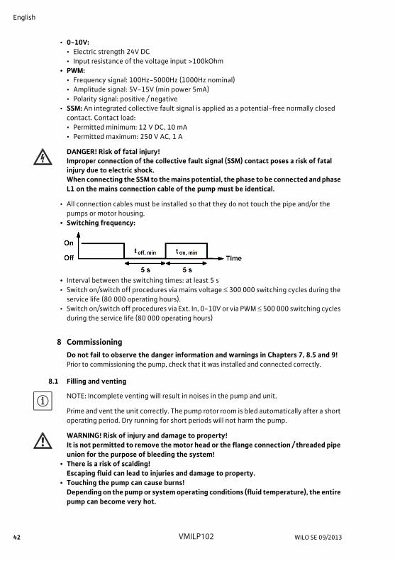
• Switching frequency:
• Interval between the switching times: at least 5 s• Switch on/switch off procedures via mains voltage 300 000 switching cycles during the
service life (80 000 operating hours).• Switch on/switch off procedures via Ext. In, 0-10V or via PWM 500 000 switching cycles
during the service life (80 000 operating hours)
8 CommissioningDo not fail to observe the danger information and warnings in Chapters 7, 8.5 and 9!Prior to commissioning the pump, check that it was installed and connected correctly.
8.1 Filling and venting
NOTE: Incomplete venting will result in noises in the pump and unit.
Prime and vent the unit correctly. The pump rotor room is bled automatically after a short operating period. Dry running for short periods will not harm the pump.
WARNING! Risk of injury and damage to property!It is not permitted to remove the motor head or the flange connection / threaded pipe union for the purpose of bleeding the system!
• There is a risk of scalding!Escaping fluid can lead to injuries and damage to property.
• Touching the pump can cause burns! Depending on the pump or system operating conditions (fluid temperature), the entire pump can become very hot.
VMILP102

Installation and operating instructions Wilo-Stratos PARA/-Z 43
English
8.2 OperationFaults of electronic devices due to electromagnetic fieldsElectromagnetic fields are created during the operation of pumps with frequency con-verter. Interference of electronic devices may be the result. The result may be a device malfunction, which can result in damage to the health or even death, e.g. of persons car-rying implanted active or passive medical devices. Therefore, during operation the pres-ence of any persons e.g. with cardiac pacemakers in the vicinity of the unit/pump should be prohibited. With magnetic or electronic data media, the loss of data is possible.
8.3 DecommissioningThe pump must be decommissioned before conducting maintenance, repair or disman-tling work on the system.
DANGER! Risk of fatal injury!There is risk of fatal injury from electrical shock when working on electrical equip-ment.
• Have work on the electrical part of the pump carried out only by a qualified electrician as a basic principle.
• Before starting any maintenance and repair work on the system, disconnect the pump from the power supply, and make sure it cannot be switched back on by unauthorised persons.
• Work on the control module may only be started after 5 minutes have elapsed, due to the dangerous residual contact voltage.
• Check whether all connections are voltage-free.• The pump may still be live even in voltage-free state. The drive rotor induces a dan-
gerous contact voltage at the motor contacts.Close the check valves in front of and behind the pump.
• If the control module/cable is damaged, do not operate the pump.
WARNING! Risk of burns!Touching the pump can cause burns! Depending on the pump or system operating conditions (fluid temperature), the entire pump can become very hot. Allow the installation and pump to cool to ambient temperature.
9 MaintenanceBefore carrying out maintenance / cleaning and repair work, observe chapters 8.2 “Operation”, 8.3 “Decommissioning” and 9.1 “Dismantling/installation”.The safety instructions in Chapter 2.6 and Chapter 7 must be complied with.After completing maintenance and repair work, install and connect the pump according to chapter 7 “Installation and electrical connection”. Switch on the pump according to chapter 8 “Commissioning”.
NOTE: When it is being disassembled, the entire pump should be dismantled from the sys-tem as a basic principle. An extraction of components (cable, control module, motor head, etc.) is not permitted.
English
44 WILO SE 09/2013
9.1 Dismantling/installation
WARNING! Risk of injury and damage to property!Incorrect dismantling/installation can lead to injuries and damage to property.
• Touching the pump can cause burns! Depending on the pump or system operating conditions (fluid temperature), the entire pump can become very hot.
• At high fluid temperatures and system pressures there is risk of scalding due to escap-ing hot fluid. Before dismantling the motor, close the existing check valves on both sides of the pump, allow the pump to cool down to ambient temperature, and drain the isolated branch of the system. If no check valves are fitted, drain the system.
• Observe the manufacturer's information and safety data sheets on possible additives in the unit.
• Risk of injury due to the pump falling when the threaded pipe union has been undone. Comply with national regulations for accident prevention and also with the operator's internal works, company and safety regulations. If necessary, wear protective clothing and equipment!
• It is not permitted to remove the control module and/or motor head!
WARNING! Danger due to strong magnetic field!Inside the machine there is always a strong magnetic field that can cause injury and damage to property in the event of incorrect dismantling.
• It is not permitted to remove the rotor from the motor housing!• There is a crushing hazard! If the rotor is pulled from the motor without permission, it
may be suddenly pulled back into its initial position by the strong magnetic field. • If the unit consisting of impeller, bearing plate and rotor is pulled out of the motor
without permission, persons with medical aids, such as cardiac pacemakers, insulin pumps, hearing aids, implants or similar are at risk. Death, severe injury and damage to property may be the result. For such persons, a professional medical assessment is always necessary.
• Electronic devices may be impaired functionally or damaged by the strong magnetic field of the rotor.
• If the rotor is outside the motor, magnetic objects may be attracted very suddenly. This can result in injury and damage to property.
In assembled condition, the rotor's magnetic field is guided in the motor's iron core. There is therefore no harmful magnetic field outside the machine.
DANGER! Risk of fatal electrical shock!Even without the module (without electrical connection), there may be dangerous contact voltage at the motor contacts. It is not permissible to dismantle the module!
• For the commissioning of the pump, see Chapter 8.
VMILP102
Installation and operating instructions Wilo-Stratos PARA/-Z 45
English
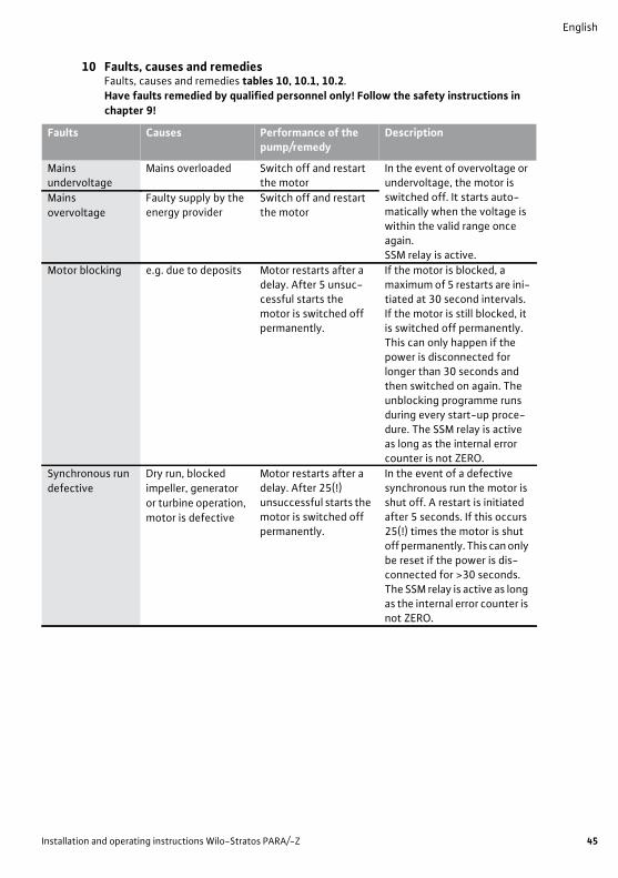
10 Faults, causes and remediesFaults, causes and remedies tables 10, 10.1, 10.2.Have faults remedied by qualified personnel only! Follow the safety instructions in chapter 9!
Faults Causes Performance of the pump/remedy
Description
Mains undervoltage
Mains overloaded Switch off and restart the motor
In the event of overvoltage or undervoltage, the motor is switched off. It starts auto-matically when the voltage is within the valid range once again. SSM relay is active.
Mains overvoltage
Faulty supply by the energy provider
Switch off and restart the motor
Motor blocking e.g. due to deposits Motor restarts after a delay. After 5 unsuc-cessful starts the motor is switched off permanently.
If the motor is blocked, a maximum of 5 restarts are ini-tiated at 30 second intervals. If the motor is still blocked, it is switched off permanently. This can only happen if the power is disconnected for longer than 30 seconds and then switched on again. The unblocking programme runs during every start-up proce-dure. The SSM relay is active as long as the internal error counter is not ZERO.
Synchronous run defective
Dry run, blocked impeller, generator or turbine operation, motor is defective
Motor restarts after a delay. After 25(!) unsuccessful starts the motor is switched off permanently.
In the event of a defective synchronous run the motor is shut off. A restart is initiated after 5 seconds. If this occurs 25(!) times the motor is shut off permanently. This can only be reset if the power is dis-connected for >30 seconds. The SSM relay is active as long as the internal error counter is not ZERO.

English
46 WILO SE 09/2013
Motor overload Deposits in the pump Motor restarts after a delay. After 5 unsuc-cessful starts the motor is switched off permanently.
If the power consumption of the motor exceeds the limit for longer than 60 seconds, an “Overload” error is reported. The motor is stopped and then restarted after a period of 30 seconds. If an overload does not occur within the next 2 minutes, the internal error counter is reset. Other-wise the motor is switched off permanently after 5 unsuc-cessful starts. This can only be reset if the power is discon-nected for >30 seconds. The SSM relay is active as long as the internal error counter is not ZERO.
Short-circuit Motor/module defective
Motor restarts after a delay. After 5 unsuc-cessful starts the motor is switched off permanently.
After a short-circuit the motor is shut off. It is reacti-vated after 30 seconds. The motor is shut off permanently if a short-circuit occurs 5 times. This can only be reset if the power is disconnected for >30 seconds. The SSM relay is active as long as the internal error counter is not ZERO.
Contact/winding error
Contact problems with the motor.Motor winding motor or plug is damaged.
Motor restarts after a delay. After 5 unsuc-cessful starts the motor is switched off permanently.
If contact between the motor and module fails, the motor is shut off. A restart is initiated after 30 seconds. After it has been switched off five times the motor is shut off perma-nently. This can only be reset if the power is disconnected for >30 seconds. The SSM relay is active as long as the internal error counter is not ZERO.
Faults Causes Performance of the pump/remedy
Description
VMILP102
Installation and operating instructions Wilo-Stratos PARA/-Z 47
English
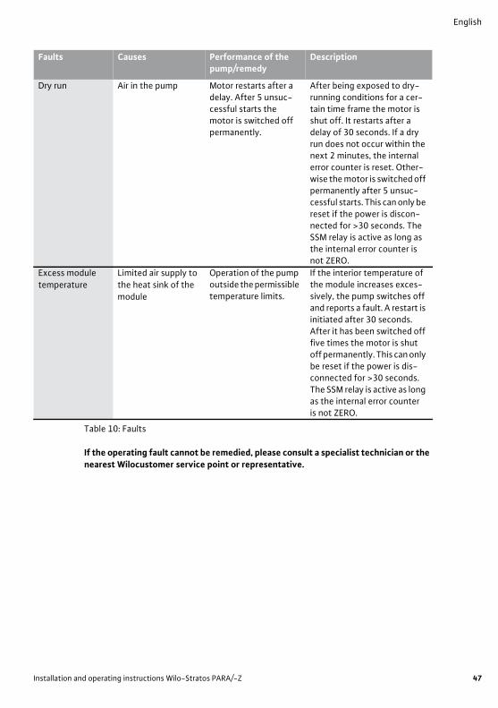
Table 10: Faults
If the operating fault cannot be remedied, please consult a specialist technician or the nearest Wilocustomer service point or representative.
Dry run Air in the pump Motor restarts after a delay. After 5 unsuc-cessful starts the motor is switched off permanently.
After being exposed to dry-running conditions for a cer-tain time frame the motor is shut off. It restarts after a delay of 30 seconds. If a dry run does not occur within the next 2 minutes, the internal error counter is reset. Other-wise the motor is switched off permanently after 5 unsuc-cessful starts. This can only be reset if the power is discon-nected for >30 seconds. The SSM relay is active as long as the internal error counter is not ZERO.
Excess module temperature
Limited air supply to the heat sink of the module
Operation of the pump outside the permissible temperature limits.
If the interior temperature of the module increases exces-sively, the pump switches off and reports a fault. A restart is initiated after 30 seconds. After it has been switched off five times the motor is shut off permanently. This can only be reset if the power is dis-connected for >30 seconds.The SSM relay is active as long as the internal error counteris not ZERO.
Faults Causes Performance of the pump/remedy
Description

English
48 WILO SE 09/2013
10.1 Fault signal Faults always result in the activation of the “collective fault signal” (SSM) via a relay.The response of the pump depends on the type of fault (see process diagram and table 10.1).
Process diagram of the temporal response of the pump in the event of a fault
Explanations regarding the fault process
(ts) Fault present: Start time of the fault process(tr) Response time:Time until the fault is detected(ta) Delay time:Time until the pump starts again; for restart times see table 10.2(n) Occurring fault:Number of repeated faults(Tar) Time for restart attempts:Time resulting from repetitions of the restart for as long as the fault is present. “Tar” can be 0 seconds if the fault only occurs once (n=1).(N) Allowed number of faults:If there is a restricted fault rate, the counter is only reset if a fault no longer occurs within 30 seconds (tn). Otherwise the mains voltage must be disconnected for >30 seconds in order to restart the pump.Auto reset:Yes: the number of allowed faults is unrestricted. The software ensures a restart of the
pump after the delay time.No: the number of allowed faults is restricted. The pump can only be restarted if the
mains voltage is disconnected for >30 seconds.(Tr) Total duration of SSM activity:Duration of the operating fault of the pump; the SSM contact is open› Waiting time to check whether a new fault follows.œ Pump runs again in the normal operating mode, (tx) Fault is remedied; SSM is closed
Pump status 0 = off / 1 = on
SSM status0 = not active (closed) / 1 = active (open)
ts
n=1 n=2 ... n < N
0
1
tntatr Tar = (n-1)x(tr+ta) (30s)
tx Time (t)
1
ts0
1
tntatr
Tr
Tar = (n-1)x(tr+ta) (30s)
tx Time (t)
2
VMILP102
Installation and operating instructions Wilo-Stratos PARA/-Z 49
English
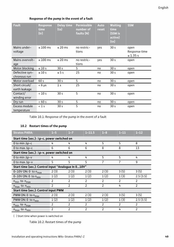
Response of the pump in the event of a fault
Table 10.1: Response of the pump in the event of a fault
10.2 Restart times of the pump
( ) Start time when power is switched on
Table 10.2: Restart times of the pump
Fault Response time (tr)
Delay time(ta)
Permissible number of faults (N)
Auto reset
Waiting time(SSM is active) (tn)
SSM
Mains under-voltage
≤ 100 ms ≤ 20 ms no restric-tions
yes 30 s openResponse time ≤ 1.35 s
Mains overvolt-age
≤ 100 ms ≤ 20 ms no restric-tions
yes 30 s open
Motor blocking ≤ 10 s 30 s 5 no 30 s openDefective syn-chronous run
≤ 10 s ≤ 5 s 25 no 30 s open
Motor overload 60 s 30 s 5 no 30 s openShort circuit/earth leakage
< 6 μs 1 s 25 no 30 s open
Contact/winding error
< 10 s 30 s 5 no 30 s open
Dry run < 60 s 30 s 5 no 30 s openExcess module temperature
< 1 s 30 s 5 no 30 s open
Stratos PARA: 1-5 1-7 1-11.5 1-8 1-11 1-12
Start time (sec.): p-c, power switched on0 to min p-c 4 4 4 5 5 80 to max p-c 6 6 6 8 8 13Start time (sec.): p-v, power switched on0 to min p-v 4 4 4 5 5 40 to max p-v 5 5 5 7 7 9Start time (sec.): Control input “Analogue In 0...10V”0-10V ON: 0 to nmax 2 (3) 2 (3) 2 (3) 2 (3) 3 (5) 3 (5)0-10V ON: 0 to nmin 1 (2) 1 (2) 1 (2) 1 (2) 1 (3) 2.5 (3.5)nmin to nmax 2 2 2 2 2 2nmax to nmin 2 2 2 2 4 2Start time (sec.): Control input PWMPWM ON: 0 to nmax 2 (3) 2 (3) 2 (3) 2 (3) 3 (5) 3 (5)PWM ON: 0 to nmin 1 (2) 1 (2) 1 (2) 1 (2) 1 (3) 2.5 (3.5)nmin to nmax 2 2 2 2 2 2nmax to nmin 2 2 2 2 4 2
English
50 WILO SE 09/2013
11 Spare partsNo spare parts are available for the Stratos PARA/-Z pumps.In the event of damage, the entire pump is to be replaced and the defective unit is to be returned to the manufacturer of the system in an assembled state.
12 DisposalProper disposal and recycling of this product prevents damage to the environment and risks to personal health.When dismantling and disposing of the pump, do not fail to observe the warnings in Chapter 9.1!1. Use public or private disposal organisations when disposing of all or parts of the prod-
uct.2. For more information on proper disposal, please contact your local council or waste
disposal office or the supplier from whom you obtained the product.
NOTE: The pump must not be disposed of along with household waste.For further information on recycling, go to www.wilo-recycling.com
Subject to change without prior notice
VMILP102

DE EG � Konformitätserklärung EN EC � Declaration of conformity FR Déclaration de conformité CE
(gemäß 2006/42/EG Anhang II,1A und2004/108/EG Anhang IV,2,according 2006/42/EC annex II,1A and2004/108/EC annex IV,2,
conforme 2006/42/CE appendice II,1A et 2004/108/CE appendice IV,2)
Hiermit erklären wir, dass die Nassläufer-Umwälzpumpen der Baureihe : Stratos PARA Herewith, we declare that the glandless circulating pumps of the series: Stratos PARA-Z Par le présent, nous déclarons que les circulateurs des séries : (Die Seriennummer ist auf dem Typenschild des Produktes nach Punkten b) & c) von §1.7.4.2 und §1.7.3 des Anhanges I der Maschinenrichtlinie 2006/42/EG angegeben. / The serial number is marked on the product site plate according to points b) & c) of §1.7.4.2 and §1.7.3 of the annex I of the machinery directive 2006/42/EC. / Le numéro de série est inscrit sur la plaque signalétique du produit en accord avec les points b) & c) du §1.7.4.2 et du §1.7.3 de l�annexe I de la Directive Machines 2006/42/CE.) in der gelieferten Ausführung folgenden einschlägigen Bestimmungen entsprechen:in their delivered state comply with the following relevant provisions:sont conformes aux dispositions suivantes dont ils relèvent:
EG-Maschinenrichtlinie 2006/42/EG EC-Machinery directive Directives CE relatives aux machines Die Schutzziele der Niederspannungsrichtlinie 2006/95/EG werden gemäß Anhang I, Nr. 1.5.1 der Maschinenrichtlinie 2006/42/EG eingehalten / The protection objectives of the low-voltage directive 2006/95/EC are realized according annex I, No. 1.5.1 of the EC-Machinery directive 2006/42/EC / Les objectifs de protection de sécurité de la directive basse-tension 2006/95/CE sont respectés conformément à l�annexe I, no 1.5.1 de la directive CE relatives aux machines 2006/42/CE. Elektromagnetische Verträglichkeit - Richtlinie 2004/108/EG Electromagnetic compatibility - directive Directive compatibilité électromagnétique
Energieverbrauchsrelevante Produkte - Richtlinie 2009/125/EG Energy-related products - directive
Directive des produits liés à l´énergie Entsprechend den Ökodesign-Anforderungen der Verordnung (EG) Nr. 641/2009 für Nassläufer-Umwälzpumpen, die durch die Verordnung (EU) Nr. 622/2012 geändert wird / This applies according to eco-design requirements of the regulation (EC) No 641/2009 for glandless circulators amended by the regulation (EU) No 622/2012 / Qui s�applique suivant les exigences d´éco-conception du règlement (CE) no 641/2009 pour les circulateurs, amendé par le règlement (UE) no 622/2012
und entsprechender nationaler Gesetzgebung,and with the relevant national legislation, et aux législations nationales les transposant,
angewendete harmonisierte Normen, insbesondere: EN 809+A1 as well as following harmonized standards: EN ISO 12100 ainsi qu�aux normes harmonisées suivantes: EN 60335-2-51 EN 61800-5-1 EN 61800-3: 2004 EN 16297-1 EN 16297-2 EN 16297-3 Bevollmächtigter für die Zusammenstellung der technischen Unterlagen ist:Authorized representative for the completion of the technical documentation: Personne autorisée à constituer le dossier technique est :
WILO SEDivision Circulators � PBU BIG Circulators Nortkirchenstraße 100 44263 Dortmund Germany
Dortmund, 02.01.2013
Holger Herchenhein
Group Quality Manager
WILO SENortkirchenstraße 100 44263 Dortmund Germany
Document: 2117852.1 CE-AS-Sh. Nr. 4146382

Danfoss Heat PumpsBox 950671 29 ARVIKAPhone +46 570 81300E-mail: [email protected]: www.thermia.comwww.heating.danfoss.com
Danfoss can accept no responsibility for possible errors in catalogues, brochures and other printed material. Danfoss reserves the right to alter its products without notice. This also applies to productsalready on order provided that such alterations can be made without subsequential changes being necessary in specifications already agreed. All trademarks in this material are property of the respectivecompanies. Danfoss Heating Solutions and the Danfoss Heating Solutions logotype are trademarks of Danfoss A/S. All rights reserved.
VMILP102 Produced by Danfoss Heating Solutions © 2013