WIGGINS PASS DELFT3D NUMERICAL MODELING:DELFT3D …
76
WIGGINS PASS DELFT3D NUMERICAL MODELING: DELFT3D NUMERICAL MODELING: CALIBRATION & CHANNEL ENHANCEMENT ALTERNATIVES ENHANCEMENT ALTERNATIVES Steve Keehn Lindino Benedet Lindino Benedet Rafael Bonanata 22 nd October, 2008
Transcript of WIGGINS PASS DELFT3D NUMERICAL MODELING:DELFT3D …
WIGGINS PASS DELFT3D NUMERICAL MODELING:DELFT3D NUMERICAL MODELING:
CALIBRATION & CHANNEL ENHANCEMENT ALTERNATIVESENHANCEMENT ALTERNATIVES
Steve KeehnLindino BenedetLindino BenedetRafael Bonanata
22nd October, 2008
TOPICSTOPICS
• Recap of last meetings• Recap of last meetings
• Field measurements and hydro calibration (recap)
• Morphology calibration (recap)
• Alternatives (optimized 1 yr, 2 yrs, 4 yrs, beach fill)
• Conclusions• Conclusions
• Future directions
INTRODUCTION• Numerical model known as Delft3D
• Waves, Currents, Sediment Transport, Morphology (erosion and sedimentation), D3D is actually 4 models in onemodels in one
• Morphology update in real time
• 1 yr morphology change simulations
• Testing different channel configurations to evaluate channel stability and adjacent shoreline effectseffects
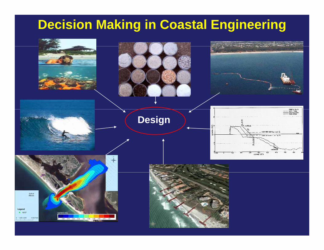
Decision Making in Coastal Engineering
Design
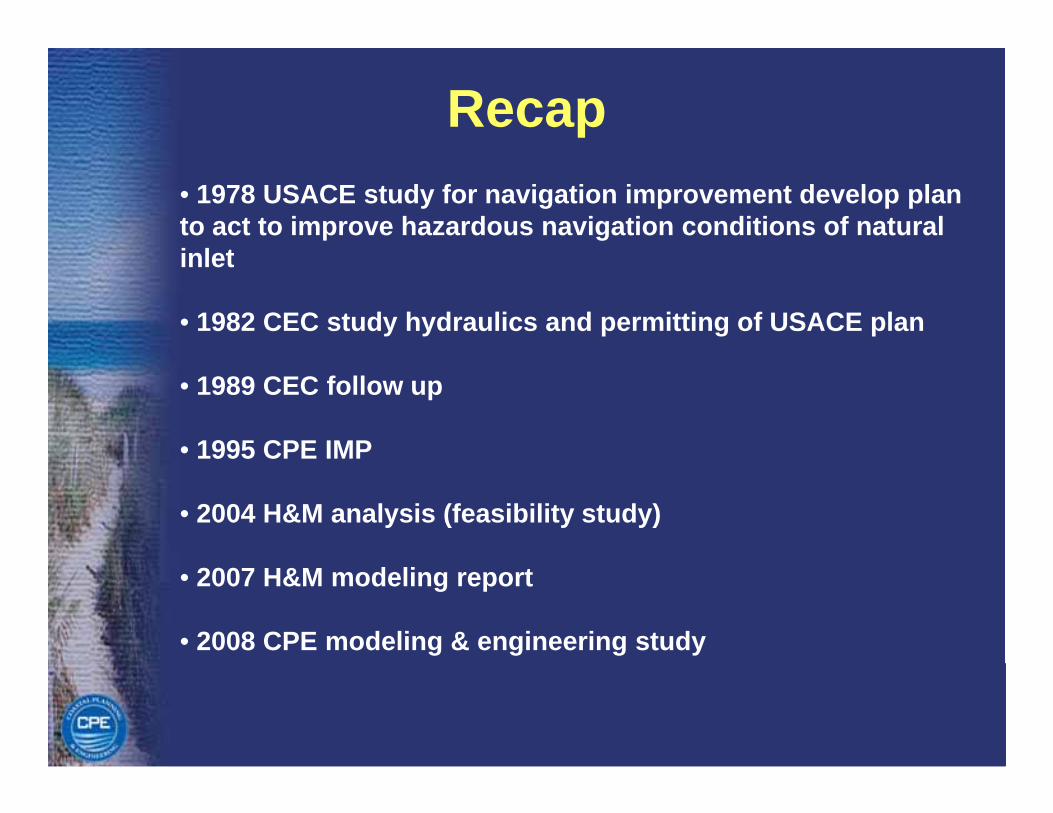
Recap• 1978 USACE study for navigation improvement develop plan to act to improve hazardous navigation conditions of natural i l tinlet
• 1982 CEC study hydraulics and permitting of USACE plan
• 1989 CEC follow up
• 1995 CPE IMP1995 CPE IMP
• 2004 H&M analysis (feasibility study)
• 2007 H&M modeling report
• 2008 CPE modeling & engineering study
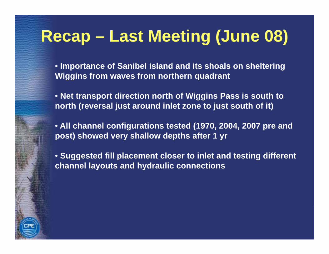
Recap – Last Meeting (June 08)• Importance of Sanibel island and its shoals on sheltering Wiggins from waves from northern quadrantgg q
• Net transport direction north of Wiggins Pass is south to north (reversal just around inlet zone to just south of it)
• All channel configurations tested (1970, 2004, 2007 pre and post) showed very shallow depths after 1 yr
• Suggested fill placement closer to inlet and testing different channel layouts and hydraulic connections
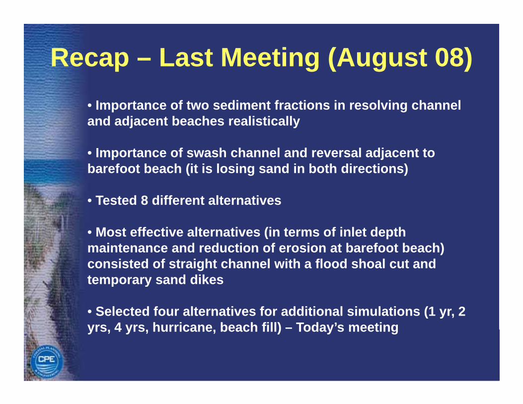
Recap – Last Meeting (August 08)• Importance of two sediment fractions in resolving channel and adjacent beaches realisticallyj y
• Importance of swash channel and reversal adjacent to barefoot beach (it is losing sand in both directions)
• Tested 8 different alternatives
M t ff ti lt ti (i t f i l t d th• Most effective alternatives (in terms of inlet depth maintenance and reduction of erosion at barefoot beach) consisted of straight channel with a flood shoal cut and temporary sand dikestemporary sand dikes
• Selected four alternatives for additional simulations (1 yr, 2 yrs 4 yrs hurricane beach fill) – Today’s meetingyrs, 4 yrs, hurricane, beach fill) Today s meeting
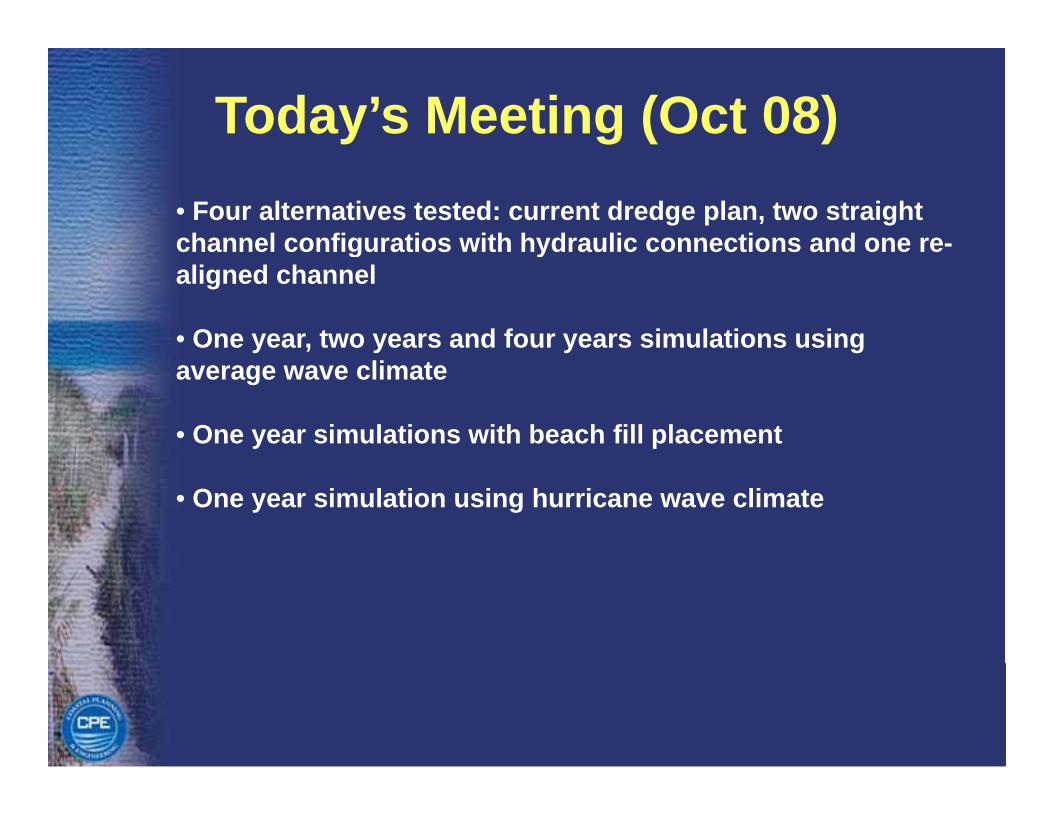
Today’s Meeting (Oct 08)• Four alternatives tested: current dredge plan, two straight channel configuratios with hydraulic connections and one re-g yaligned channel
• One year, two years and four years simulations using average wave climate
• One year simulations with beach fill placement
• One year simulation using hurricane wave climate

Wave Data
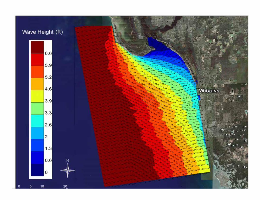
Wave Data
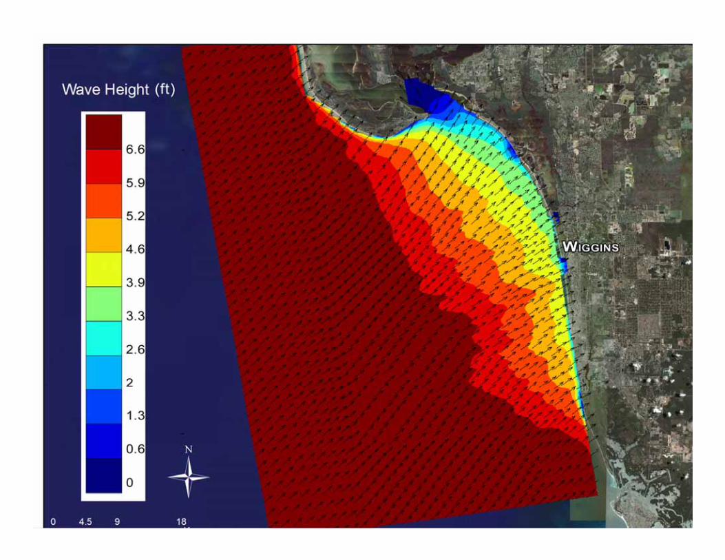
Wave Data
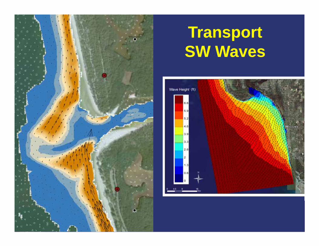
TransportSW WSW Waves
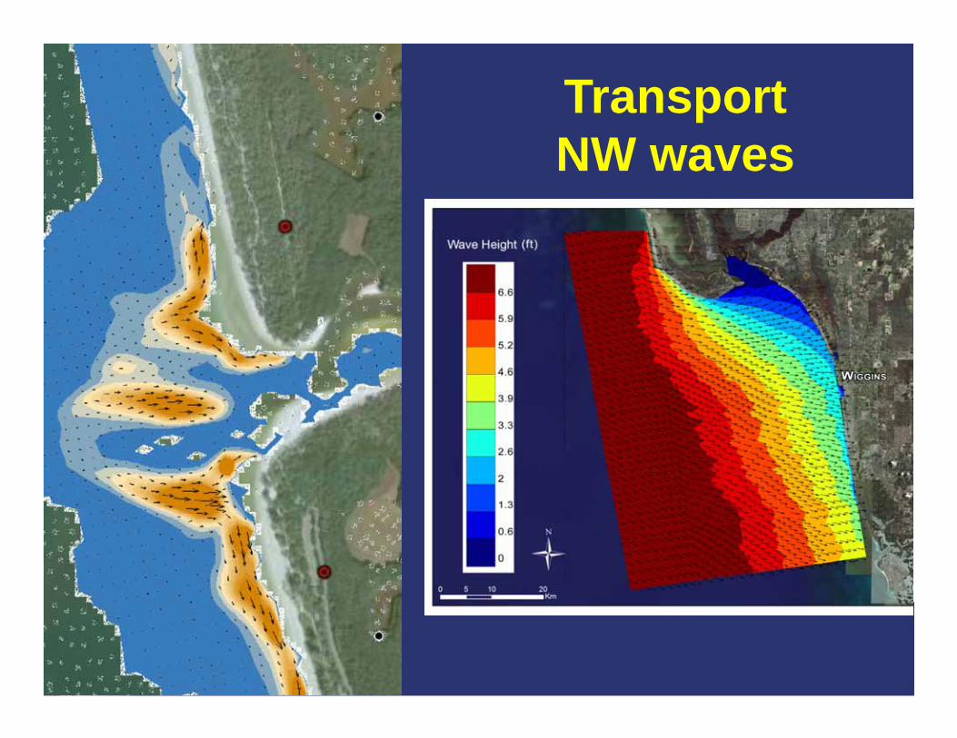
TransportNWNW waves
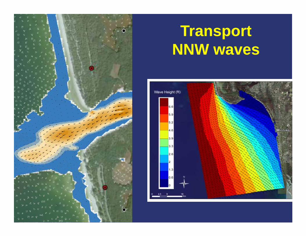
TransportNNWNNW waves

Net Transport – 1 yr
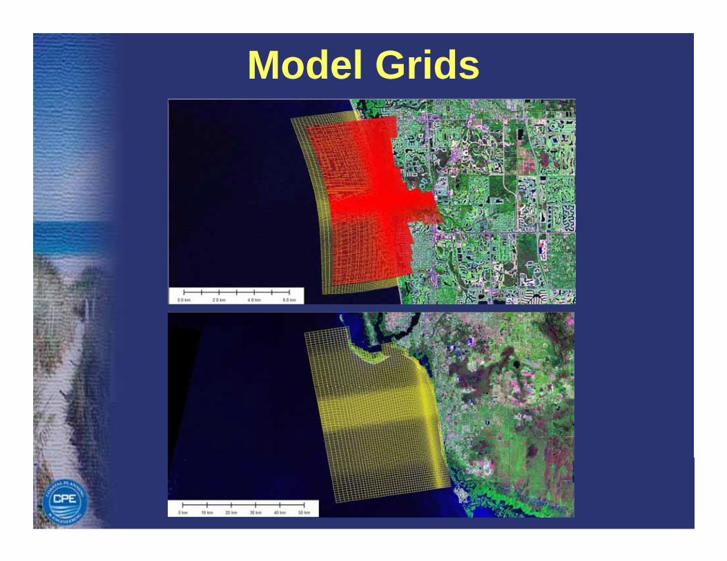
Model Grids
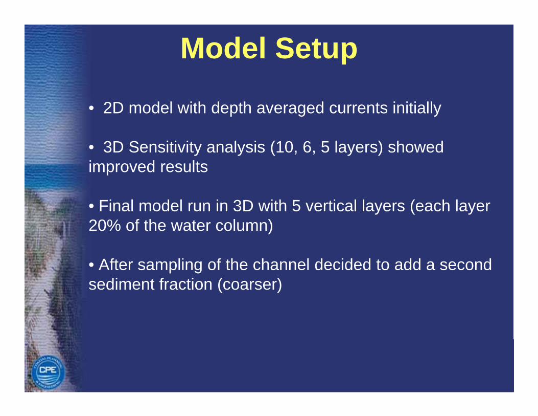
Model Setup
• 2D model with depth averaged currents initially
• 3D Sensitivity analysis (10, 6, 5 layers) showed improved results
• Final model run in 3D with 5 vertical layers (each layer 20% of the water column)
• After sampling of the channel decided to add a second sediment fraction (coarser)sediment fraction (coarser)
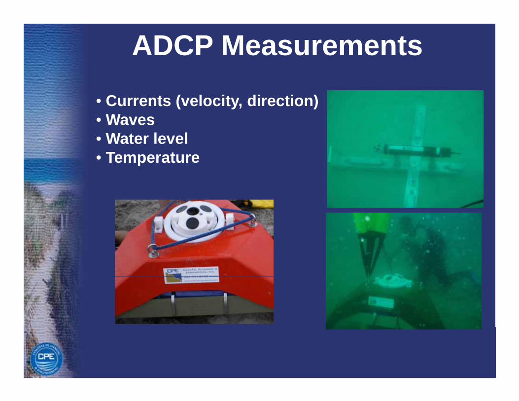
ADCP Measurements
• Currents (velocity, direction)• WavesWaves• Water level• Temperature

ADCP Measurements
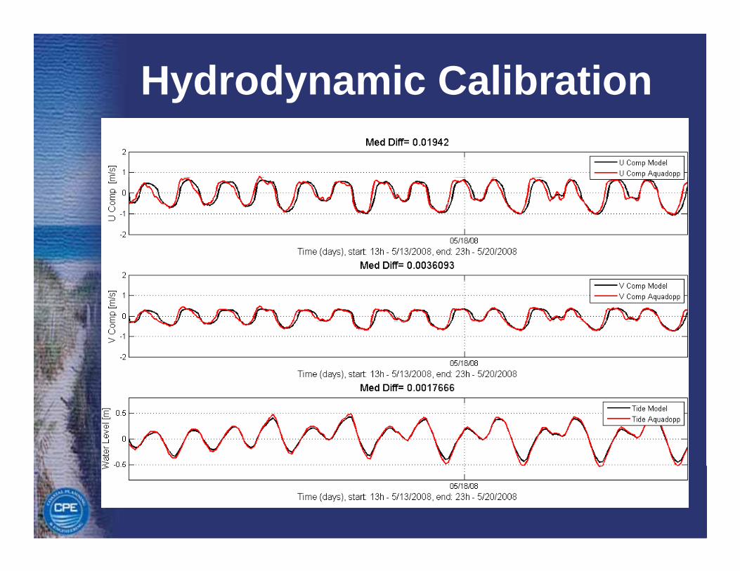
Hydrodynamic Calibration
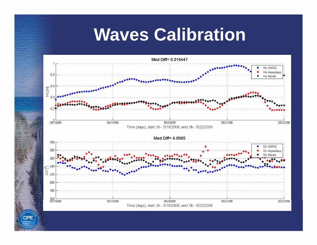
Waves Calibration
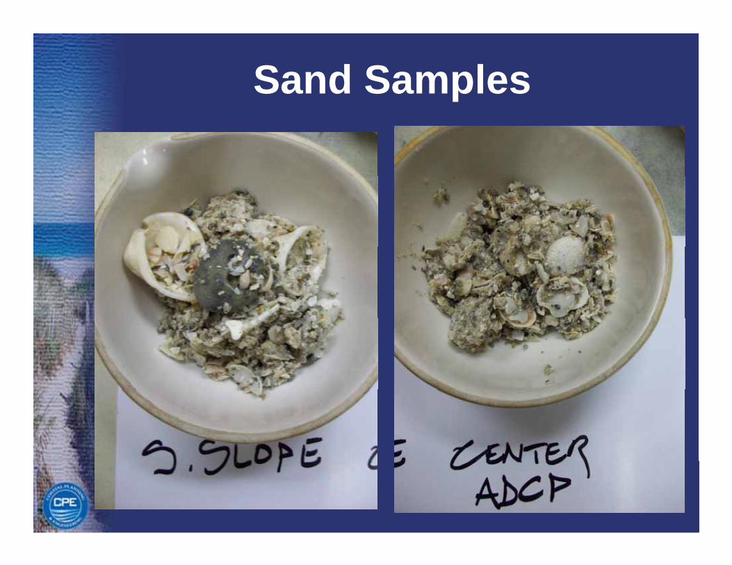
Sand Samples
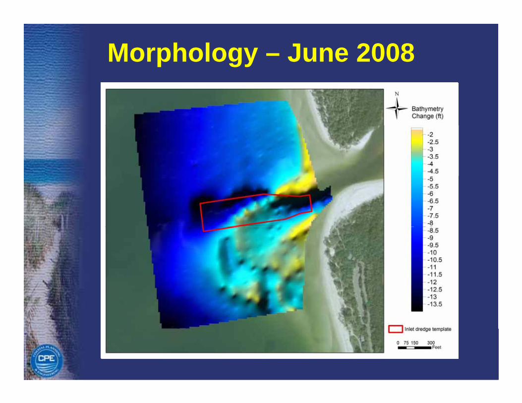
Morphology – June 2008
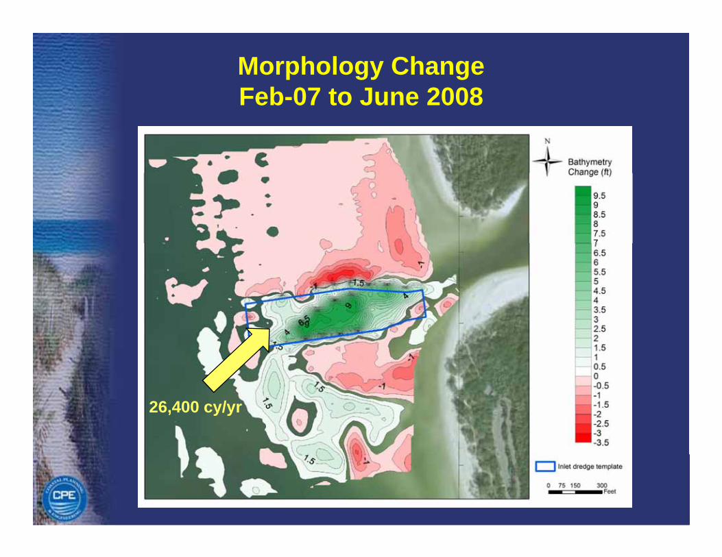
Morphology Change Feb-07 to June 2008Feb 07 to June 2008
26,400 cy/yr
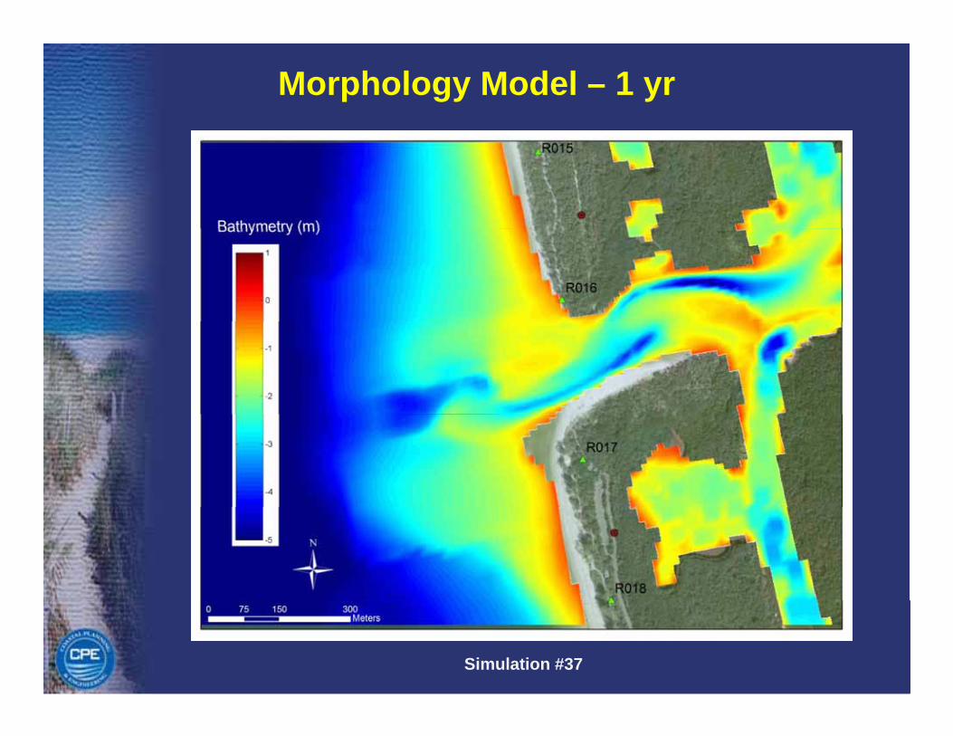
Morphology Model – 1 yr
Simulation #37
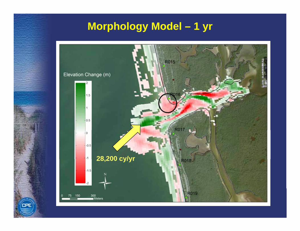
Morphology Model – 1 yr
28 200 cy/yr28,200 cy/yr
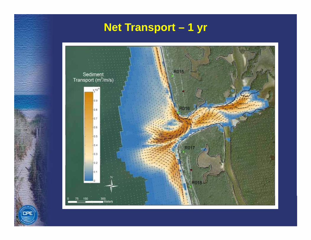
Net Transport – 1 yr

Alternatives
Alt 1. Permitted Channel
Alternatives
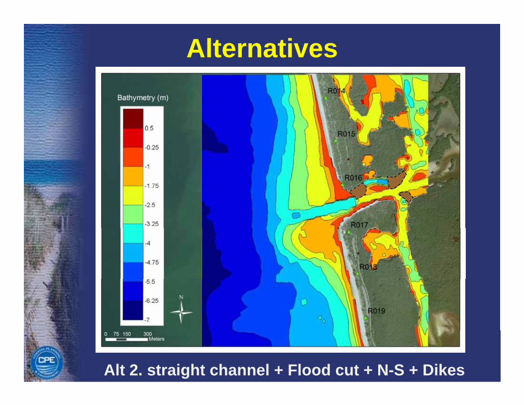
Alt 2. straight channel + Flood cut + N-S + Dikes
Alternatives
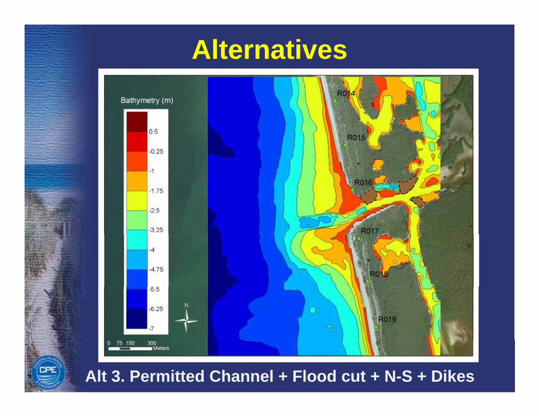
Alt 3. Permitted Channel + Flood cut + N-S + Dikes
Alternatives
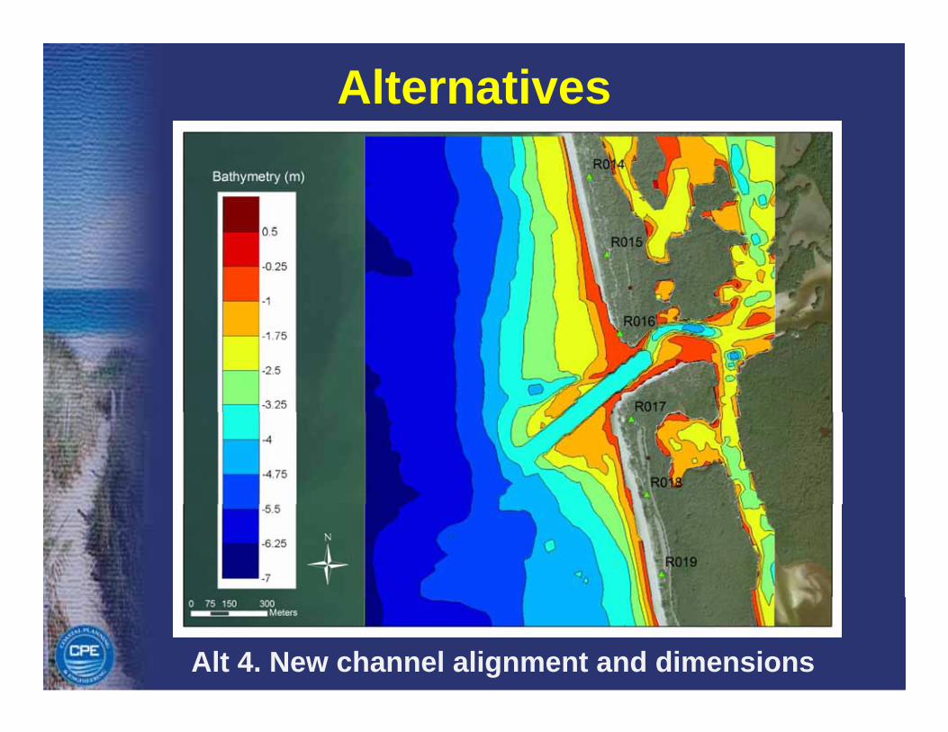
Alt 4. New channel alignment and dimensions
Alternatives
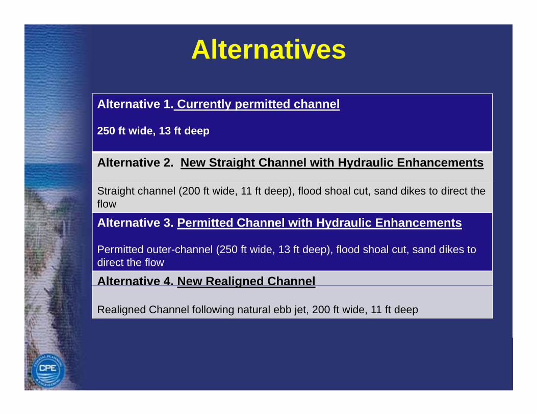
Alternative 1. Currently permitted channel
250 ft wide 13 ft deep250 ft wide, 13 ft deep
Alternative 2. New Straight Channel with Hydraulic Enhancements
Straight channel (200 ft wide, 11 ft deep), flood shoal cut, sand dikes to direct the flow
Alternative 3. Permitted Channel with Hydraulic Enhancements
Permitted outer-channel (250 ft wide, 13 ft deep), flood shoal cut, sand dikes to direct the flow
Alternative 4. New Realigned Channel g
Realigned Channel following natural ebb jet, 200 ft wide, 11 ft deep
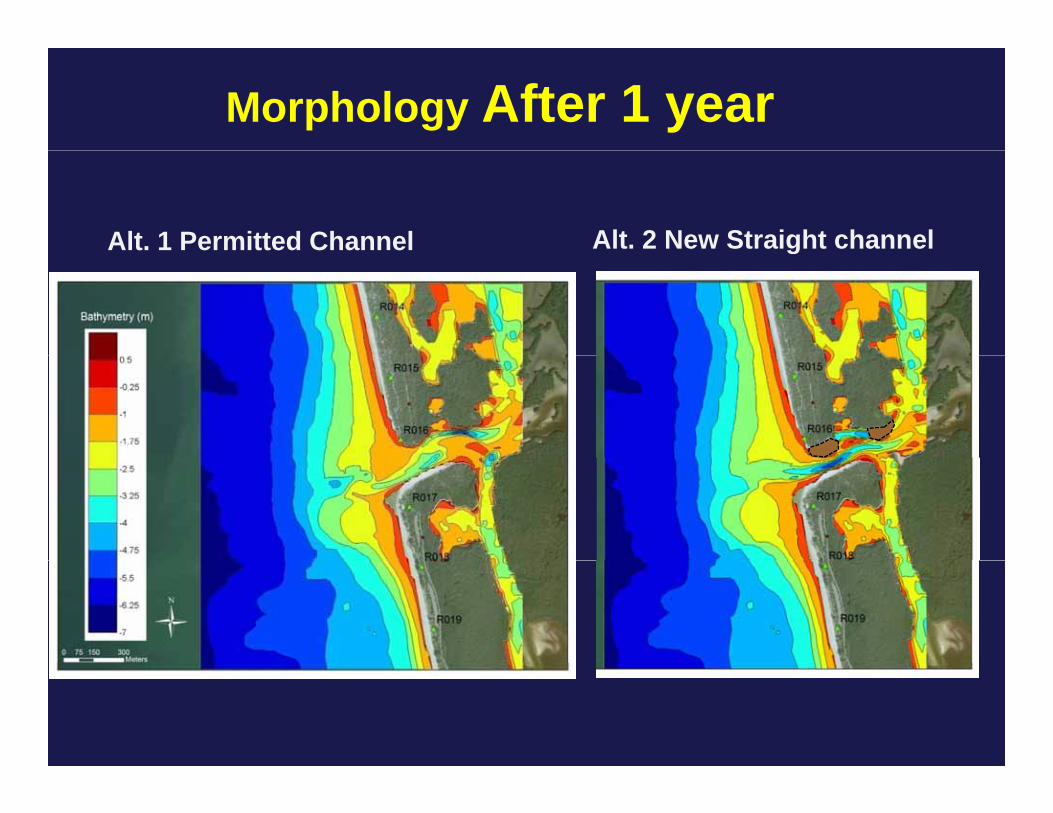
Morphology After 1 year
Alt. 1 Permitted Channel Alt. 2 New Straight channelg
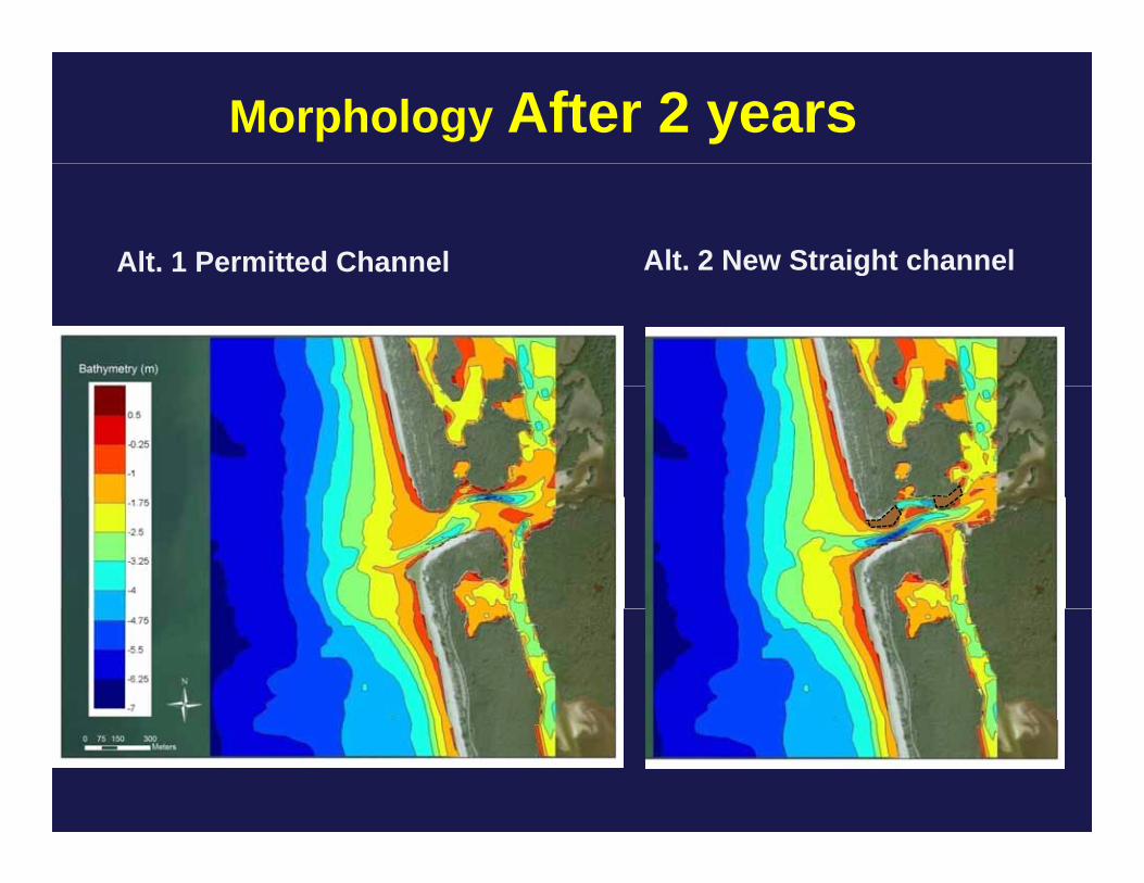
Morphology After 2 years
Alt. 1 Permitted Channel Alt. 2 New Straight channelg
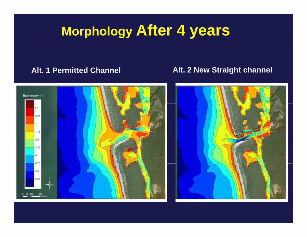
Morphology After 4 years
Alt. 1 Permitted Channel Alt. 2 New Straight channelg
ONE YEAR SIMULATIONSONE YEAR SIMULATIONS

Alt. 1
Permitted channel
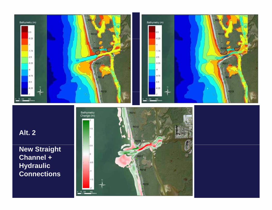
Alt. 2
New Straight Channel + Hydraulic CConnections
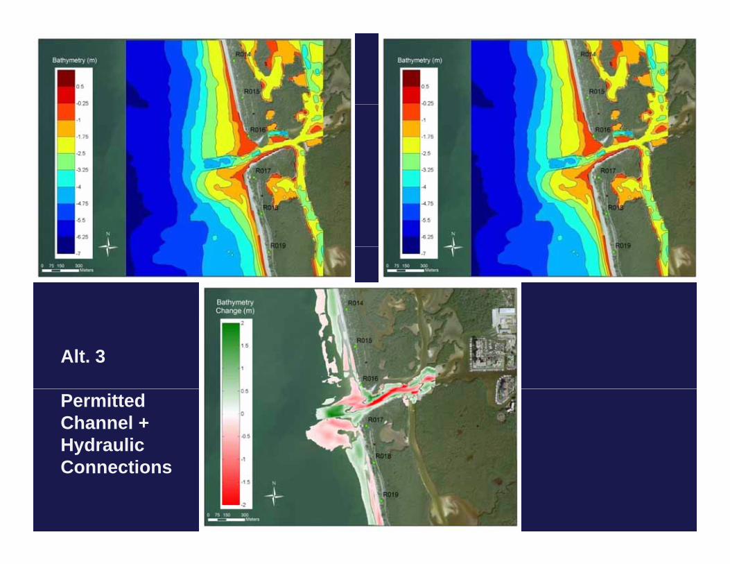
Alt. 3
Permitted Channel + Hydraulic CConnections
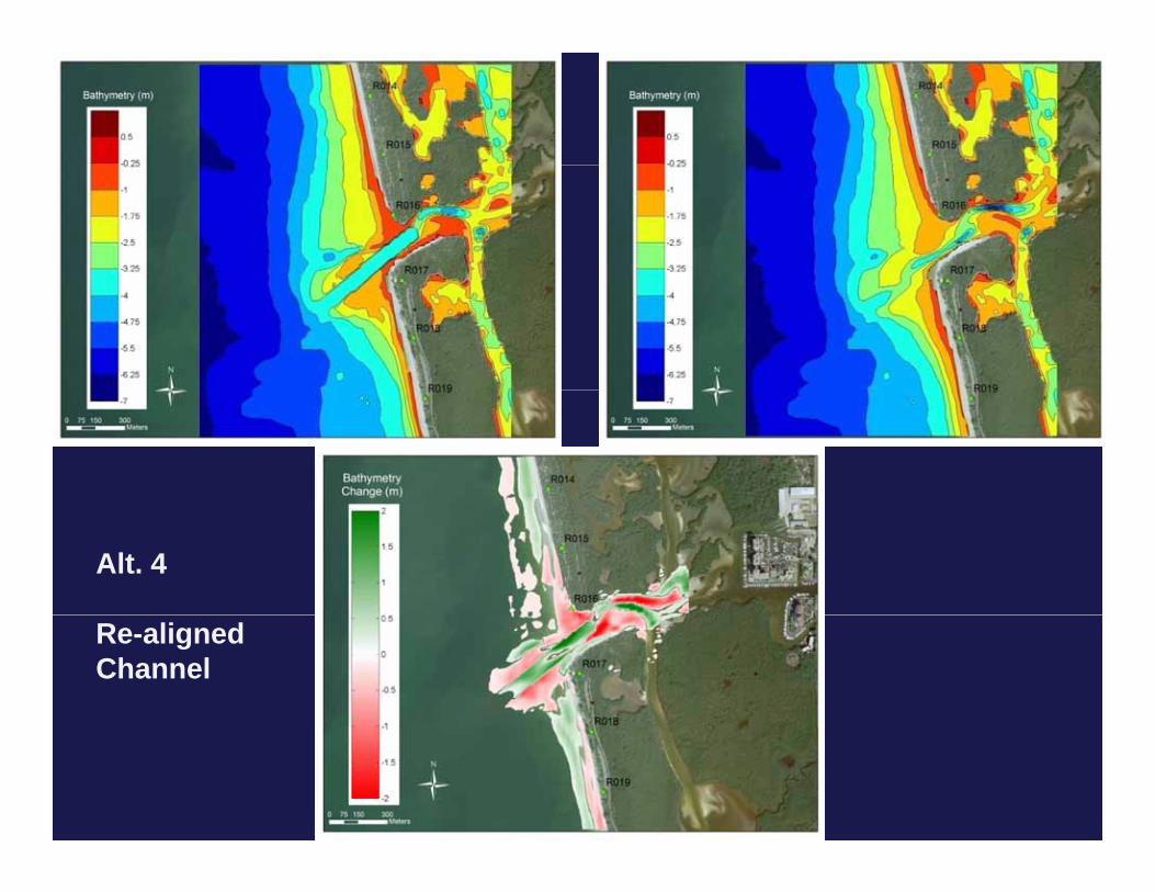
Alt. 4
Re-aligned Channel
Relative Changes
• The next two slides show the morphology predicted after one yr for the alternative being evaluated subtractedafter one yr for the alternative being evaluated subtracted by the morphology predicted after 1 yr for alternative 1
Th lid h th l ti h th h• The slides show the relative changes, or the changes caused by the alternative evaluated in relation to the current permit plan which is represented by alternative 1
• Shades of green indicate that the alternative tested caused deposition in the site in relation to alternative 1caused deposition in the site in relation to alternative 1 and vice-versa for shades of red

Alt 1 – Permitted ChannelAlt 2 – Straight Channel, Hydraulic Connections - Alt 1 Permitted Channel Hydraulic Connections
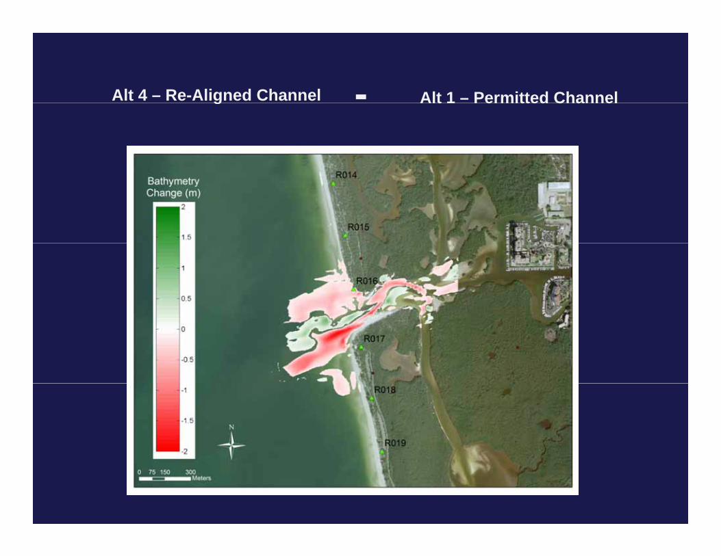
Alt 1 – Permitted ChannelAlt 4 – Re-Aligned Channel - Alt 1 Permitted Channel g
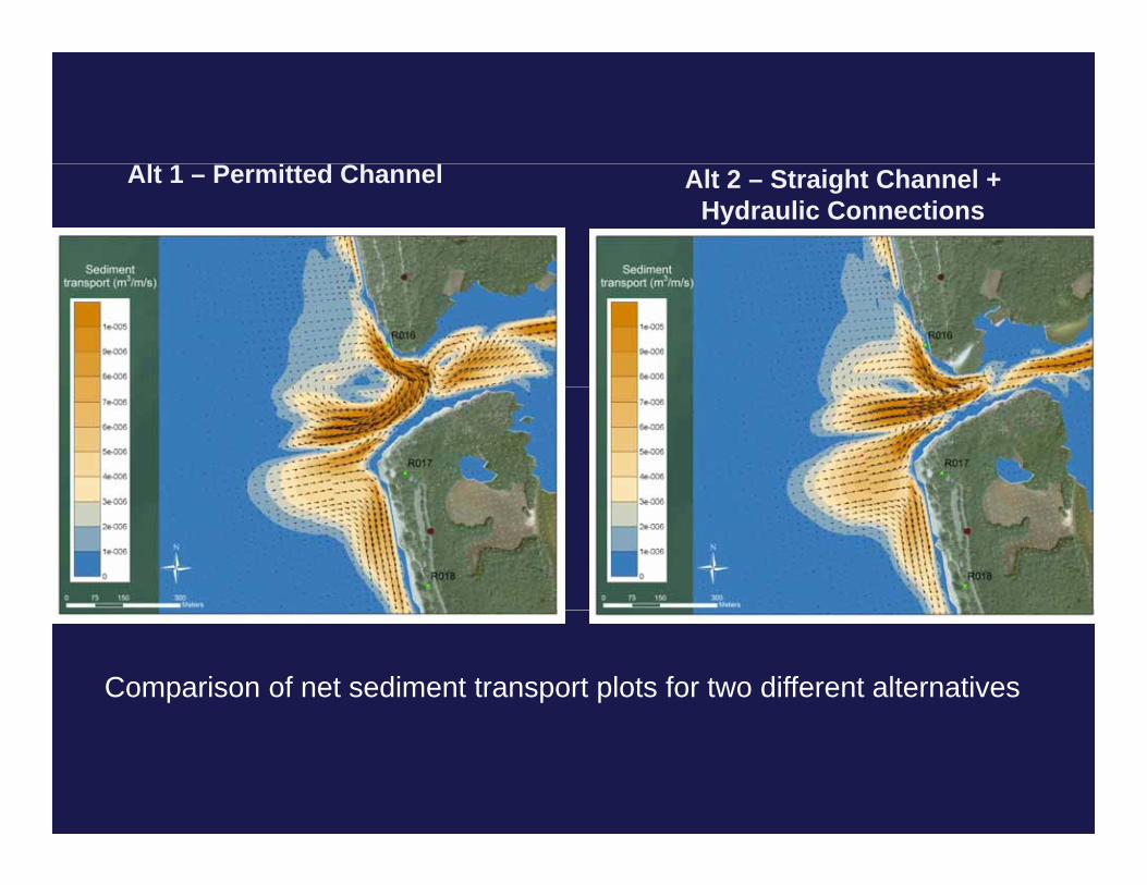
Alt 1 – Permitted Channel Alt 2 – Straight Channel + Hydraulic Connections
Comparison of net sediment transport plots for two different alternatives
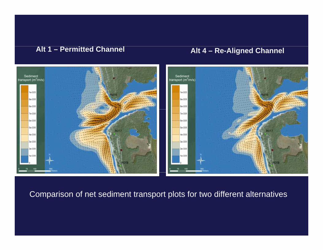
Alt 1 – Permitted Channel Alt 4 – Re-Aligned Channel
Comparison of net sediment transport plots for two different alternatives
TWO FOUR YEARS SIMULATIONSTWO- FOUR YEARS SIMULATIONS
Morphology PredictionsMorphology Predictions
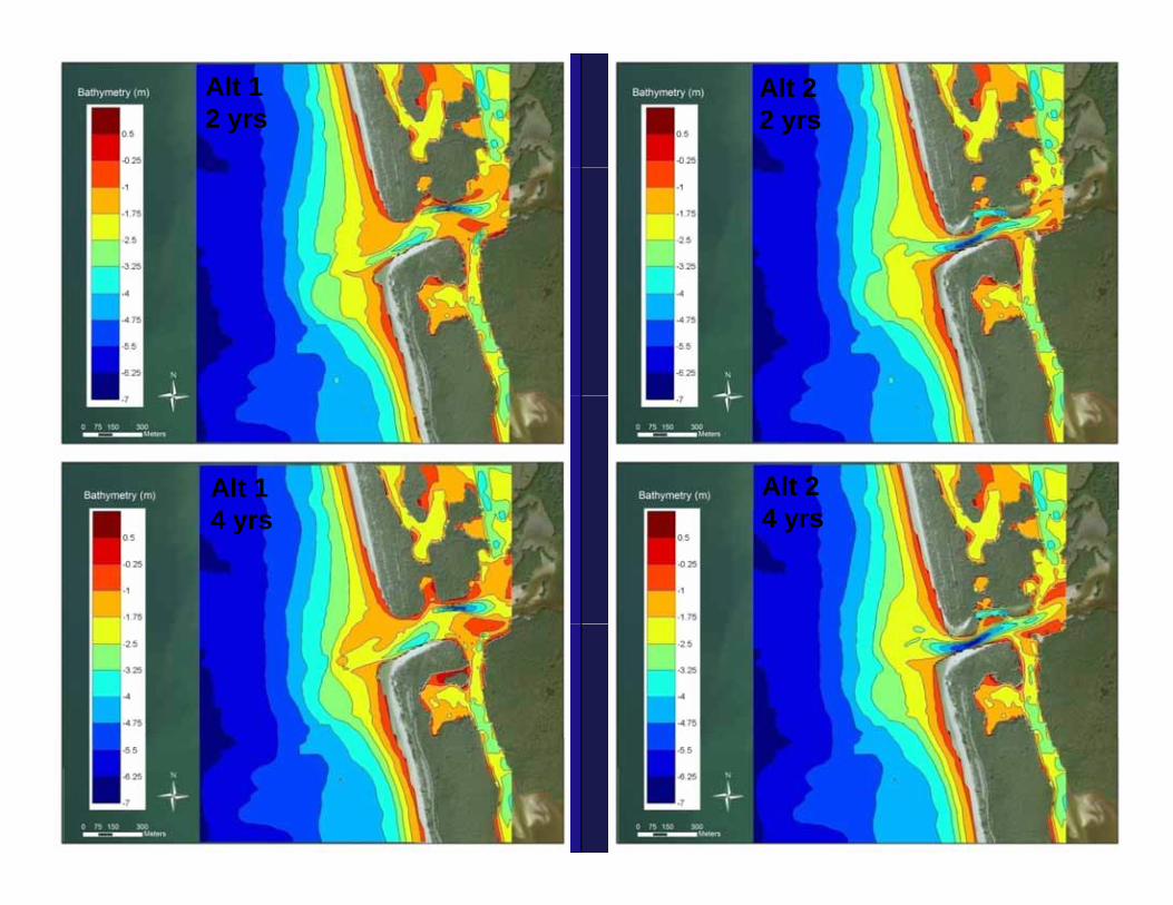
Alt 1 2 yrs
Alt 2 2 yrs
Alt 1 4
Alt 2 44 yrs 4 yrs
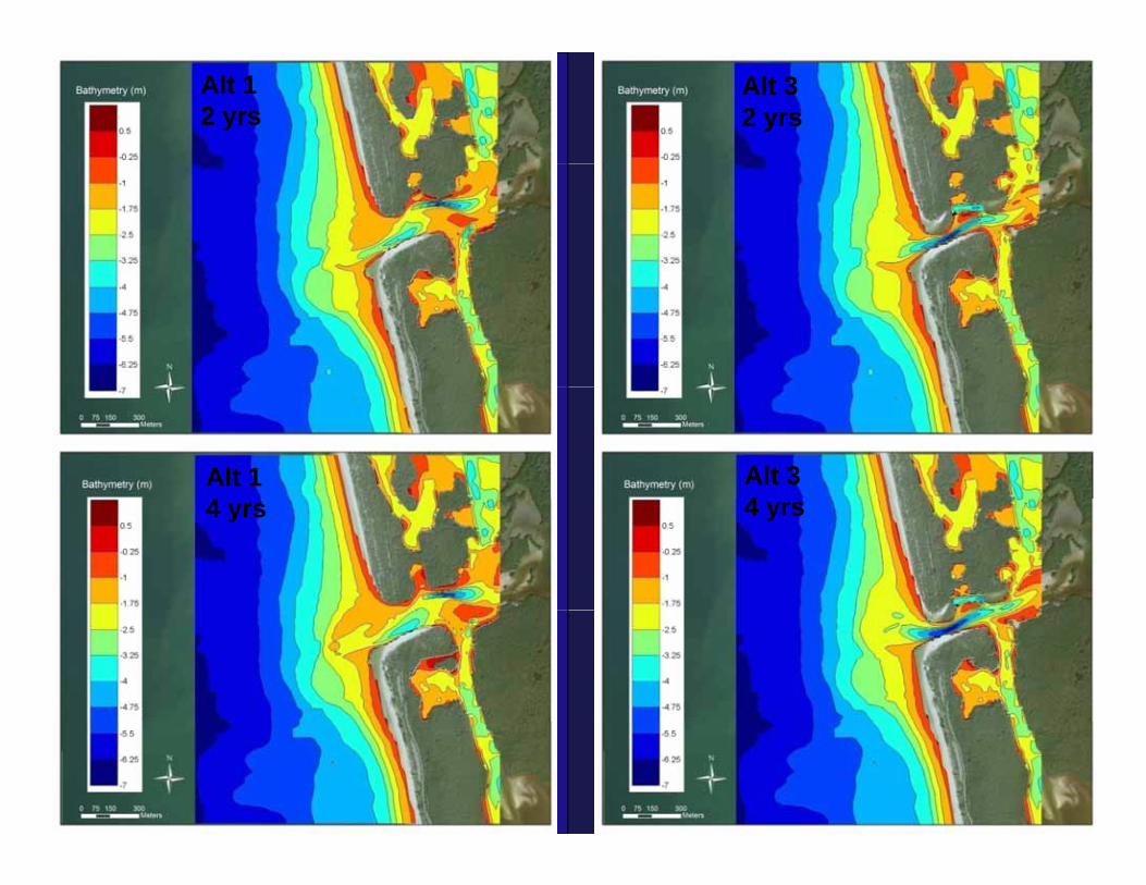
Alt 1 2 yrs
Alt 3 2 yrs
Alt 1 4
Alt 3 44 yrs 4 yrs
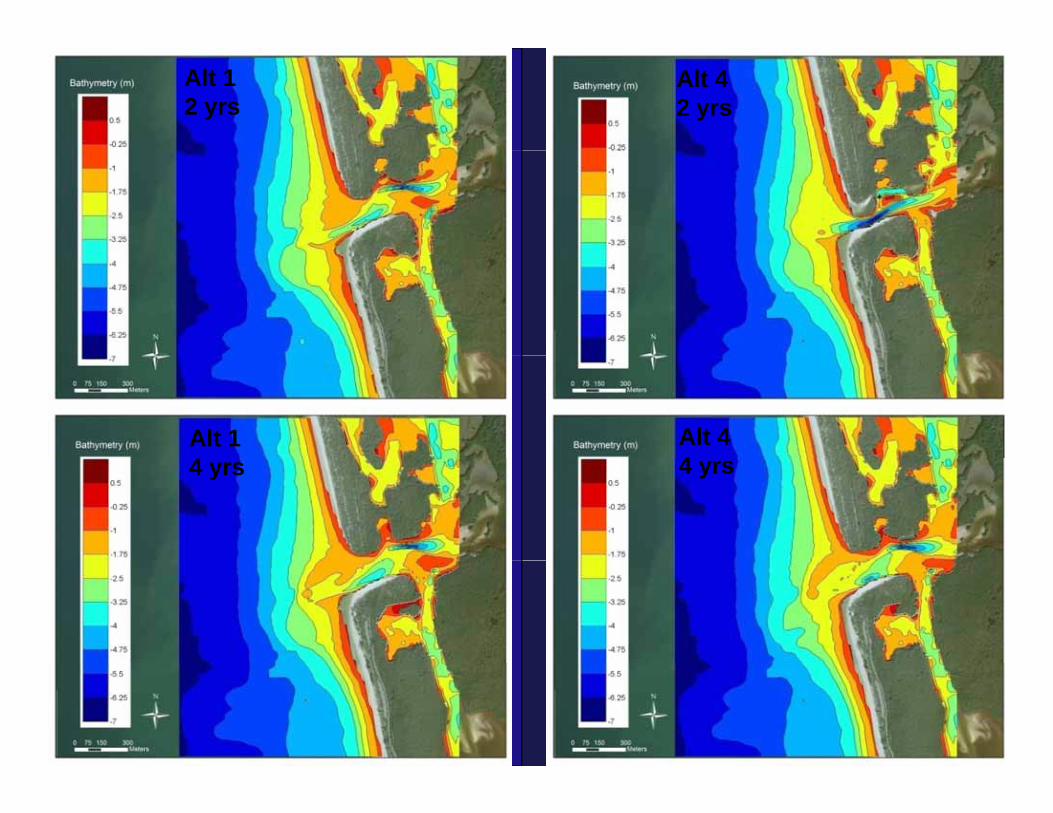
Alt 1 2 yrs
Alt 4 2 yrs
Alt 1 4
Alt 4 44 yrs 4 yrs
Erosion Sedimentation PlotsErosion-Sedimentation Plots
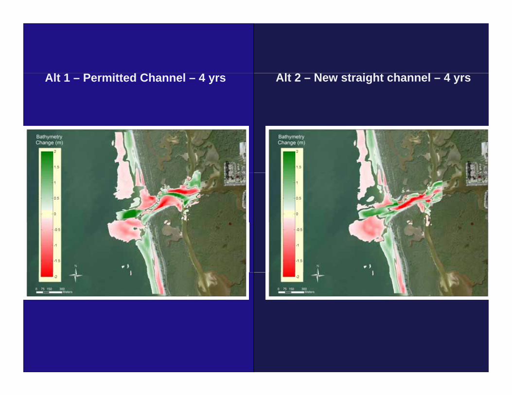
Alt 1 – Permitted Channel – 4 yrs Alt 2 – New straight channel – 4 yrs
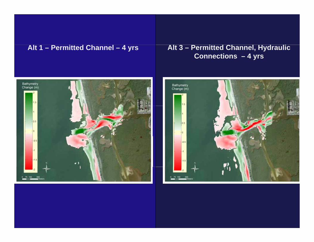
CAlt 1 – Permitted Channel – 4 yrs Alt 3 – Permitted Channel, Hydraulic Connections – 4 yrs
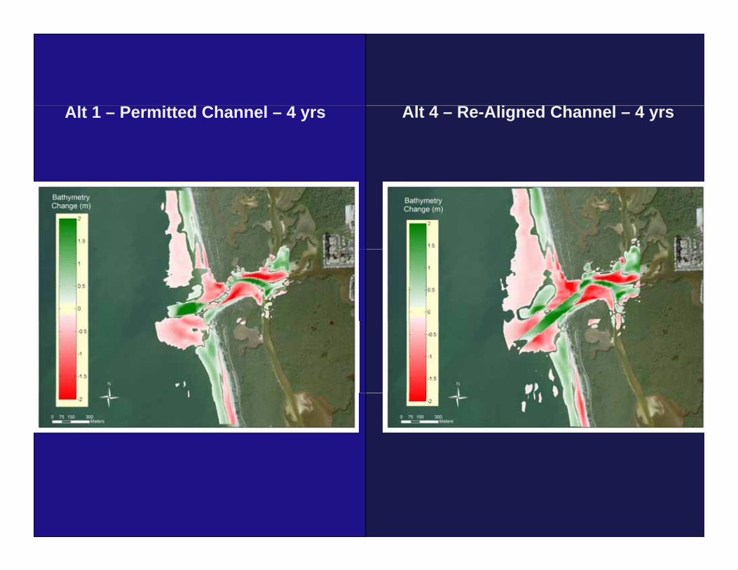
CAlt 1 – Permitted Channel – 4 yrs Alt 4 – Re-Aligned Channel – 4 yrs
Simulations of Alternative 1 withSimulations of Alternative 1 with the Beach Fill (1 yr)
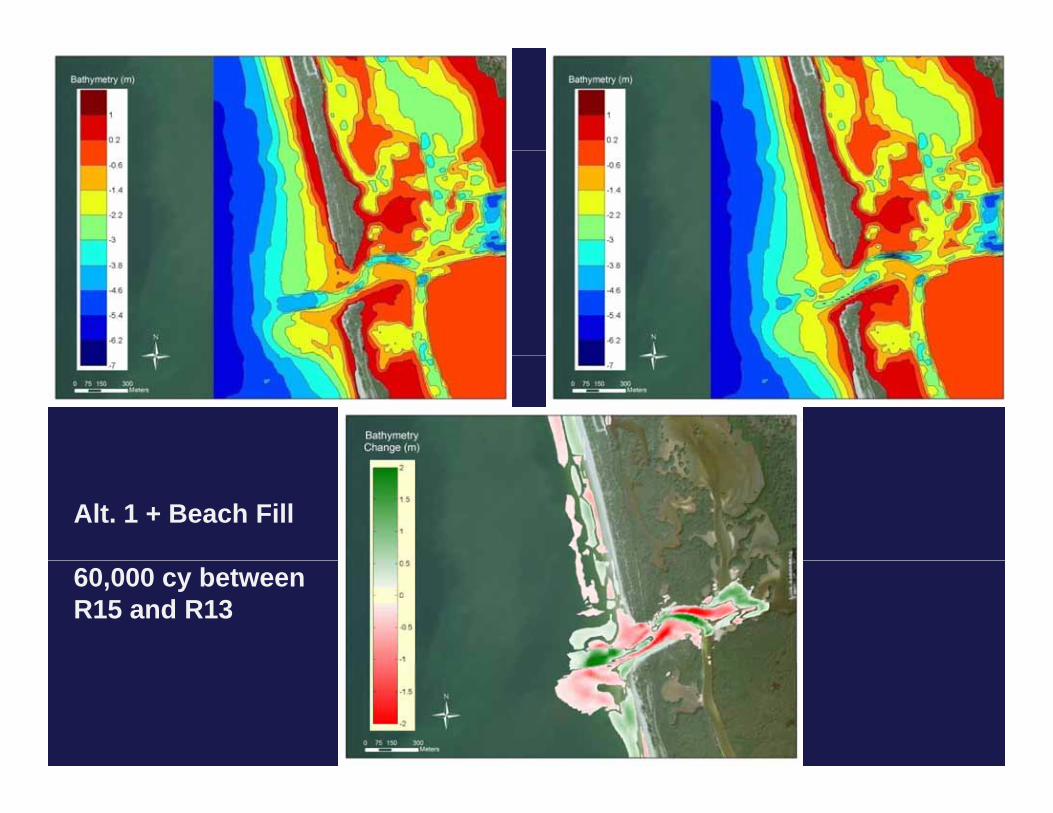
Alt. 1 + Beach Fill
60,000 cy between R15 and R13
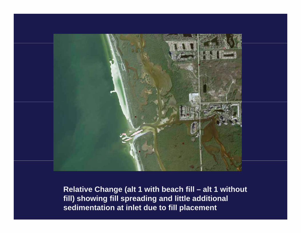
Relative Change (alt 1 with beach fill – alt 1 withoutRelative Change (alt 1 with beach fill – alt 1 without fill) showing fill spreading and little additional sedimentation at inlet due to fill placement
Hurricane (1 yr)Hurricane (1 yr)
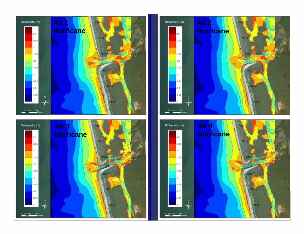
Alt 1 Hurricane
Alt 2 Hurricane
Alt 3 H i
Alt 4 H iHurricane Hurricane
Decision MatrixDecision Matrix
V l Ch ( / )
Alt 1 Alt 2 Alt 3 Alt 4 Alt 1 + B h Fill
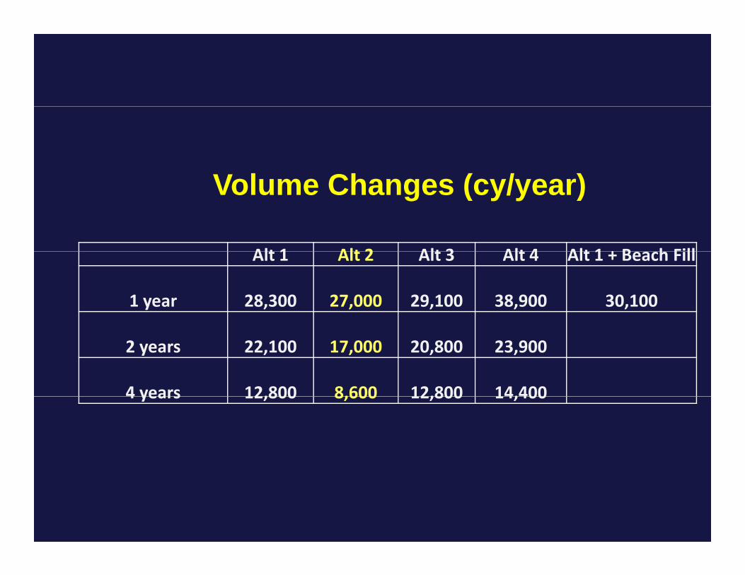
Volume Changes (cy/year)
Alt 1 Alt 2 Alt 3 Alt 4 Alt 1 + Beach Fill
1 year 28,300 27,000 29,100 38,900 30,100
2 years 22,100 17,000 20,800 23,900
4 years 12,800 8,600 12,800 14,4004 years 12,800 8,600 12,800 14,400
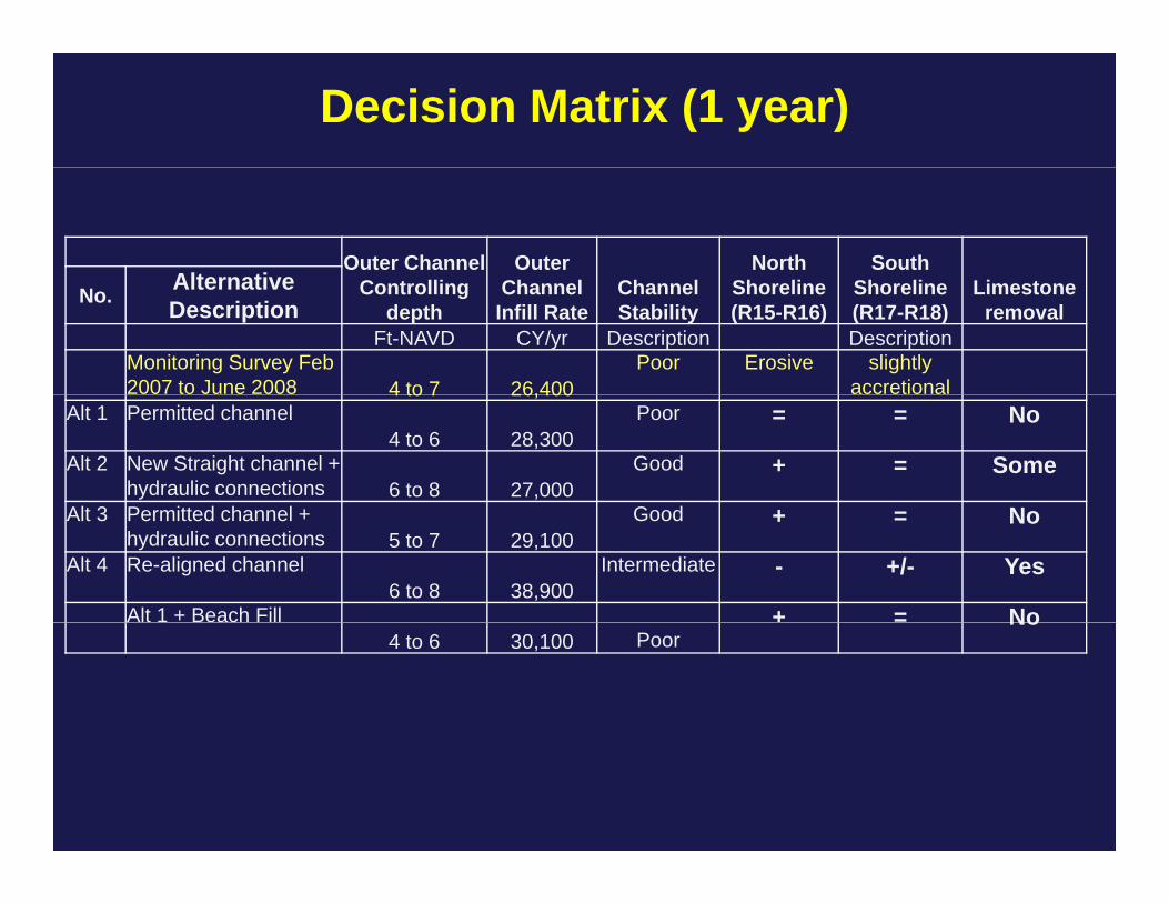
Decision Matrix (1 year)
Outer Channel C t lli
Outer Ch l Ch l
North Sh li
South Sh li Li tAlternative Controlling
depthChannel Infill Rate
Channel Stability
Shoreline (R15-R16)
Shoreline (R17-R18)
Limestone removal
No. Alternative Description
Ft-NAVD CY/yr Description Description Monitoring Survey Feb 2007 to June 2008 4 to 7 26,400
Poor Erosive slightly accretional4 to 7 26,400
Alt 1 Permitted channel4 to 6 28,300
Poor = = No
Alt 2 New Straight channel + hydraulic connections 6 to 8 27,000
Good + = Some
Alt 3 P itt d h l G d NAlt 3 Permitted channel + hydraulic connections 5 to 7 29,100
Good + = No
Alt 4 Re-aligned channel6 to 8 38,900
Intermediate - +/- Yes
Alt 1 + Beach Fill + = No4 to 6 30,100 Poor
No
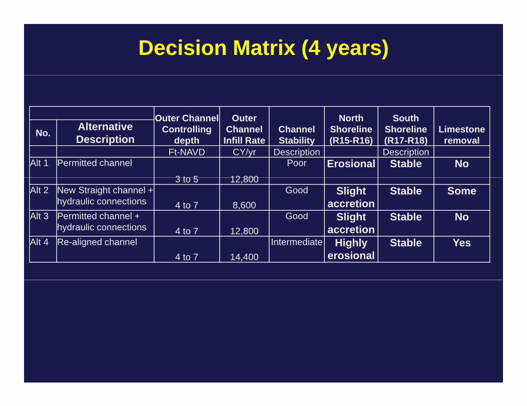
Decision Matrix (4 years)
Outer Channel C t lli
Outer Ch l Ch l
North Sh li
South Sh li Li tAlternative Controlling
depthChannel Infill Rate
Channel Stability
Shoreline (R15-R16)
Shoreline (R17-R18)
Limestone removal
No. Alternative Description
Ft-NAVD CY/yr Description Description Alt 1 Permitted channel
3 to 5 12 800
Poor Erosional Stable No3 to 5 12,800
Alt 2 New Straight channel + hydraulic connections 4 to 7 8,600
Good Slightaccretion
Stable Some
Alt 3 Permitted channel + hydraulic connections 4 t 7 12 800
Good Slight accretion
Stable Nohydraulic connections 4 to 7 12,800 accretion
Alt 4 Re-aligned channel4 to 7 14,400
Intermediate Highly erosional
Stable Yes
Conclusions• Off all alternatives tested (16 total) the two alternatives where there was a cut in the flood shoal and temporary sand dik i th ld h l th l th t t thdikes in the old channel were the only ones that meet the goals of the project
• Sedimentation rates in the model decrease with time as expected, after 2 yrs a quasi-equilibrium is reached and there is minimal additional sedimentation
• Beach fill placement between R13 and R15 had minimum effects on channel sedimentation and positive effects on barefoot beach and is therefore recommended
• During extreme hurricane years the channel gets filled in to a g y g4 yr ‘normal rate’ no mater what you do (emergency response)

ConclusionsConclusions• To promote stability of barefoot beach and provide improvements to navigation one has to re-align the channelimprovements to navigation one has to re-align the channel and block the 2 channel system (swash channel)
• This can be done by flood shoal dredging to straighten the• This can be done by flood shoal dredging to straighten the tidal jet and temporary sand dikes
• If flood shoal dredging is unacceptable then a similar effect• If flood shoal dredging is unacceptable then a similar effect could be achieved (blockage of swash channel) by use of structures
• If same plan is continued then some relief to barefoot beach can be provided by placing fill between R15 and R13 and
ll dj t t i h l d isome small adjustments in channel design
Future Tasks Recommended
• Refine the best alternative and simulate it for 1 yr, 2 yrs and 4 yrs, with beach fill placement. The final alternative will be a combination of alternatives 2 and 3
• Write final modeling report and provide recommendations for detailed design phase and new permit application
• Refine decision matrix of scenarios for comparison
Results of Preliminary E i t l I ti ti fEnvironmental Investigation of
Wiggins PassWiggins Pass
S kSnookSea grassMangrovesFlood Shoal SubstrateFlood Shoal Substrate
Wiggins Pass Environmental PermittingWiggins Pass Environmental Permitting
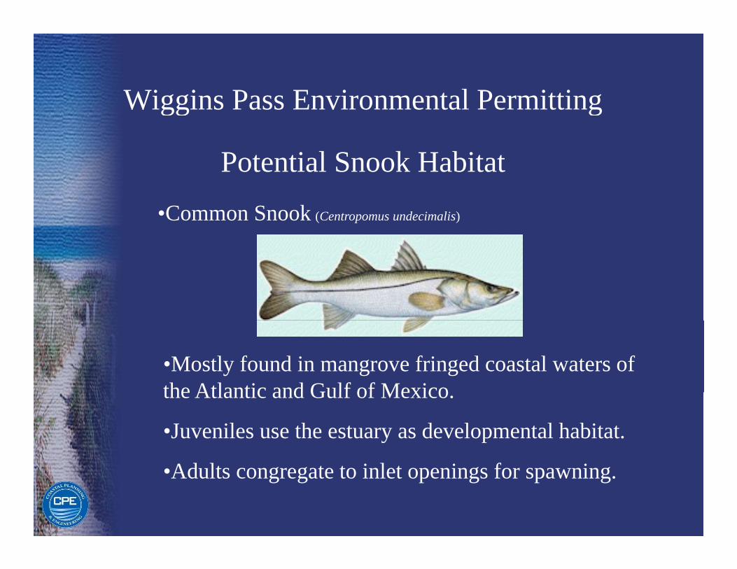
Potential Snook Habitat•Common Snook (Centropomus undecimalis)
•Mostly found in mangrove fringed coastal waters of the Atlantic and Gulf of Mexicothe Atlantic and Gulf of Mexico.
•Juveniles use the estuary as developmental habitat.
Ad l i l i f i•Adults congregate to inlet openings for spawning.

Wiggins Pass Environmental PermittingWiggins Pass Environmental Permitting
FWC Designation: Snookg•Listed as a ‘protected species of concern’ for the purposes of public awareness and commercial p p pfishing, however, that listing does not carry any specific conservation regulations in regard to dredging activitiesdredging activities.
•No critical habitat has been designated for snook, especially not Wiggins Passespecially not Wiggins Pass.
•In the Gulf Region, closed season for snook occur: During the months of Dec., Jan., Feb., May, June, g , , , y, ,July, and Aug.
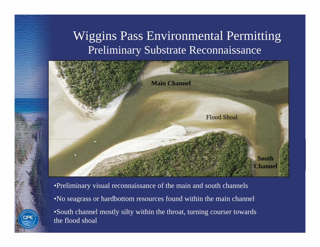
Wiggins Pass Environmental PermittingPreliminary Substrate Reconnaissance
Main Channel
Flood Shoal
South Channel
•Preliminary visual reconnaissance of the main and south channels
•No seagrass or hardbottom resources found within the main channelg
•South channel mostly silty within the throat, turning courser towards the flood shoal
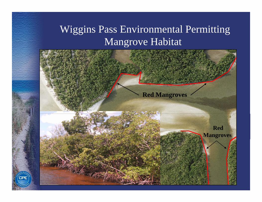
Wiggins Pass Environmental PermittingMangrove Habitat
Red Mangroves
Red Mangroves
Wiggins Pass Environmental PermittingWiggins Pass Environmental Permitting
State Regulations: Mangrovesg g•The Mangrove Trimming and Preservation Act (1996); enforced by the Florida Dept. of Environmental Protection( ); y p
•The term ‘trimming’ refers to the cutting of mangrove branches, twigs, limbs, and foliage; ‘altering’ means to remove, defoliate, or destroy mangroves.
•An individual permit must be applied for in order to conduct mangrove alteration or trimming.
•A professional mangrove trimmer must supervise all ti itiactivities.
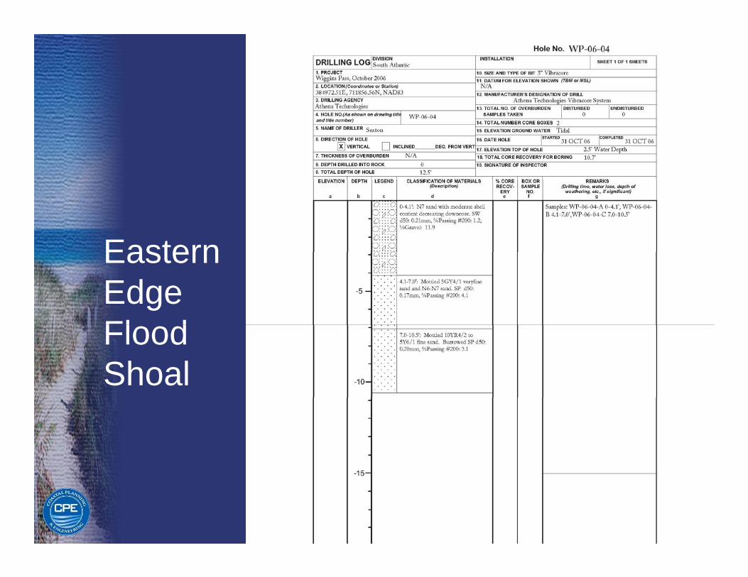
EasternEastern Edge Fl dFlood Shoal
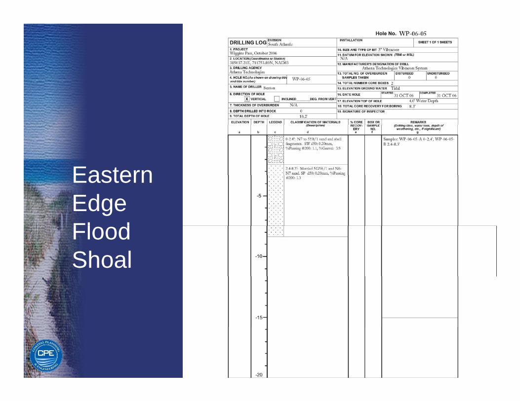
EasternEastern Edge Fl dFlood Shoal
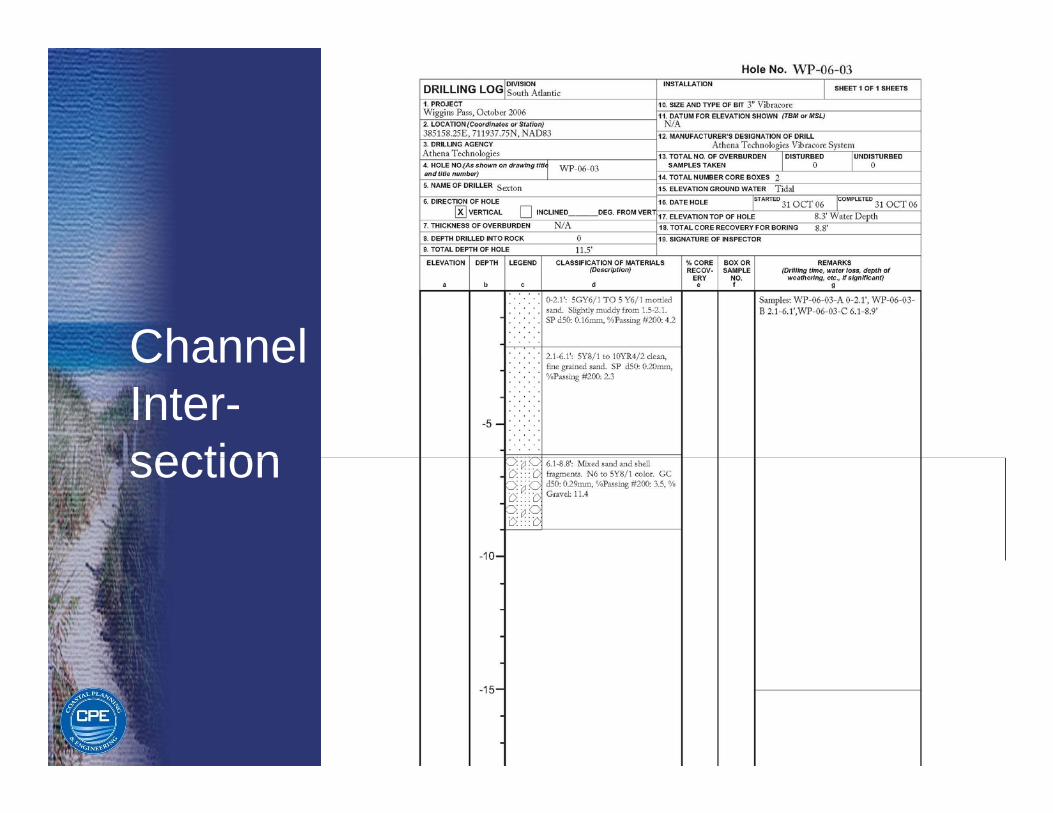
ChannelChannelInter-sectionsection
Thank YouThank YouThank YouThank You