
Why That Airfoila.moirier.free.fr/A%E9rodynamique/Profils/Th%E9orie/Why%20that%20... · the A-4...
3
Why That Airfoil? By BILL HUSA, Orion Technologies, 1827 N. 192nd St., Seattle, WA 98133 About eight years ago I had the good fortune to work with a gentleman who was the chief aerodynamicist for the A-4 Skyhawk program. He related the following story to me one day, when I was trying to make a bit more than I should have of selecting an air- foil for the project we were working on at the time. During the wing design phase of the Skyhawk development, a junior engineer working under the chief's supervision was assigned the task of designing the wing airfoil for the delta planform. After about four weeks of not hearing any progress on the shape development, the aerodynamicist went to visit the wind tunnel where the junior engineer was working, only to find him almost buried in reams of computer output and hand calcula- tions, as he was trying to tweak the last bit of infinitesimal performance out of the wind tunnel model. Somewhat upset by the engineer's lack of progress and understanding of the problem, the chief engineer replaced the highly optimized model in the tunnel with a piece of one inch plywood in the same planform shape as the configured wing. The leading edges were rounded but no other embellishments or refinements were incorporated. The plywood was then instrumented in the same way as the original model and run through the same test scenarios. The results were enlightening in that all values were, for all practical purposes, virtually identical to that of the highly optimized wing. This exer- cise was done in order to show the junior engineer (and later myself) that the choice of airfoil in many applica- tions is not all that critical and for the most part is not worth the expense of starting from scratch. Granted, the example uses a delta planform which is not very sensitive to airfoil shape, but over the years I've found that the same argument holds true for many applications in the gen- eral aviation arena, specifically for the smaller, light aircraft. Our company (Orion Technologies) designs aircraft for the private sector. As a result, we have file folders big enough to choke a mule, stuffed full of various airfoils and design reports, plus, of course, publications like the old and venera- ble "Theory of Wing Sections." Out of all that data how many have we used over the last eight years or so? Maybe four or five. Although much has been written in this magazine and others about airfoil selection, I'll try to approach the ques- tion from a different, more practical perspective. First of all, what does an airfoil do? When built into a wing planform it keeps your airplane air- borne, right? Will any practical airfoil do that? Yes. So what's needed in selecting one that works for you? To start with, you must have an idea of what you want your airplane to do, how it should perform, and how it should handle. You should also know how a particular airfoil affects the vari- ous aspects of your airplane's design. Table 1 compares a number of differ- ent section characteristics which are needed in order to make a logical selection. The numbers represent the airfoils' two dimensional values; pitch- ing moment coefficient; maximum lift, coefficient (unflapped); and lift-to- drag ratios for three different lift coefficient values. The first value, pitching moment coefficient about the aerodynamic center (where the value doesn't vary with the change in angle of attack), is a function of the pressure distribution (camber line) along the chord. In gen- eral, you can see that the higher the maximum lift coefficient of the sec- tion, the higher its pitching moment. During cruise, the horizontal tail must provide necessary lift in order to bal- ance the nose down tendency caused by this value, therefore, the higher the pitching moment, the higher the trim drag. Notice that some of the new airfoil shapes (NLF, LS, GAW) have pitching moments almost ten times that of some of the older sections. An additional effect of too much pitching moment is that if the airplane is not designed with a sufficiently large tail or a tail located adequately aft (sufficiently large tail volume coef- ficient), the allowable CG envelope may be limited. The forward limit of the CG envelope is determined by the elevator's power to flare the airplane in ground effect with the flaps down; if it already has to work just to balance the pitching moment and the CG is too far forward, there may not be suf- ficient elevator power left in order to flare the airplane during landing. This condition must be designed for at the start - there is a big difference between CG limits as the airplane is loaded and allowable CG limits due to stability and control characteristics. You'd be surprised how many people don't know the difference between the two, designers included. The next number, the section's maximum lift coefficient, represents the highest lift that section can deliver without using flaps. Generally, this is not as important as some make it to be since in most cases the airplane does have flaps in order to increase the lift coefficient for landing. High Lift airfoils are, however, advantageous on commuter type air- craft where higher wing loadings give better cruise performance. This is demonstrated in the last three columns of the table. Most small air- craft fly with relatively low wing loadings - cruise lift coefficient of around .15 to .25. At these points the lift-to-drag ratios are rather low - in the range of about twelve to twenty (pounds of lift to one pound of drag). Increasing the cruise lift coefficient (designing a smaller wing) to .4 or bet- ter, gives the airplane l/d ratio two to four times that as for the same air- plane with a larger wing and a lower planform loading. This was the primary reason for the development of the GAW, the NLF, and the LS series of airfoils - they enable larger airplanes to have smaller wings which operate more efficiently, yet still maneuver without the risk of stalling. For example, assuming a smaller wing was installed using an older airfoil, the benefits of high cl cruise would still be realized but if the cruise cl is .4 and the maximum cl of the wing is 1.0, then the aircraft would stall if a maneuver in excess of 2.5 G's was attempted. Using a section with a maximum cl of near 2.0 gives the aircraft a potential maneuver capability of almost 5 G's. Due to their high pitching moments, SPORT AVIATION 71
Transcript of Why That Airfoila.moirier.free.fr/A%E9rodynamique/Profils/Th%E9orie/Why%20that%20... · the A-4...
Why That Airfoil?By BILL HUSA, Orion Technologies, 1827 N. 192nd St., Seattle, WA 98133
About eight years ago I had thegood fortune to work with a gentlemanwho was the chief aerodynamicist forthe A-4 Skyhawk program. He relatedthe following story to me one day,when I was trying to make a bit morethan I should have of selecting an air-foil for the project we were working onat the time.
During the wing design phase ofthe Skyhawk development, a juniorengineer working under the chief'ssupervision was assigned the task ofdesigning the wing airfoil for the deltaplanform. After about four weeks ofnot hearing any progress on the shapedevelopment, the aerodynamicistwent to visit the wind tunnel wherethe junior engineer was working, onlyto find him almost buried in reams ofcomputer output and hand calcula-tions, as he was trying to tweak thelast bit of infinitesimal performanceout of the wind tunnel model.Somewhat upset by the engineer'slack of progress and understanding ofthe problem, the chief engineerreplaced the highly optimized modelin the tunnel with a piece of one inchplywood in the same planform shapeas the configured wing. The leadingedges were rounded but no otherembellishments or refinements wereincorporated. The plywood was theninstrumented in the same way as theoriginal model and run through thesame test scenarios.
The results were enlightening inthat all values were, for all practicalpurposes, virtually identical to that ofthe highly optimized wing. This exer-cise was done in order to show thejunior engineer (and later myself) thatthe choice of airfoil in many applica-tions is not all that critical and for themost part is not worth the expense ofstarting from scratch.
Granted, the example uses a deltaplanform which is not very sensitive toairfoil shape, but over the years I'vefound that the same argument holdstrue for many applications in the gen-eral aviation arena, specifically for thesmaller, light aircraft. Our company(Orion Technologies) designs aircraftfor the private sector. As a result, wehave file folders big enough to chokea mule, stuffed full of various airfoils
and design reports, plus, of course,publications like the old and venera-ble "Theory of Wing Sections." Out ofall that data how many have we usedover the last eight years or so? Maybefour or five.
Although much has been written inthis magazine and others about airfoilselection, I'll try to approach the ques-tion from a different, more practicalperspective. First of all, what does anairfoil do? When built into a wingplanform it keeps your airplane air-borne, right? Will any practical airfoildo that? Yes. So what's needed inselecting one that works for you?
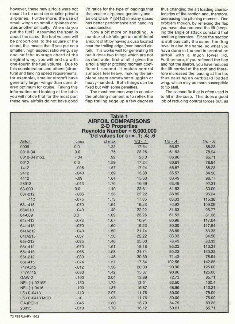
To start with, you must have anidea of what you want your airplane todo, how it should perform, and how itshould handle. You should also knowhow a particular airfoil affects the vari-ous aspects of your airplane's design.Table 1 compares a number of differ-ent section characteristics which areneeded in order to make a logicalselection. The numbers represent theairfoils' two dimensional values; pitch-ing moment coefficient; maximum lift,coefficient (unflapped); and lift-to-drag ratios for three different liftcoefficient values.
The first value, pitching momentcoefficient about the aerodynamiccenter (where the value doesn't varywith the change in angle of attack), isa function of the pressure distribution(camber line) along the chord. In gen-eral, you can see that the higher themaximum lift coefficient of the sec-tion, the higher its pitching moment.During cruise, the horizontal tail mustprovide necessary lift in order to bal-ance the nose down tendency causedby this value, therefore, the higher thepitching moment, the higher the trimdrag. Notice that some of the newairfoil shapes (NLF, LS, GAW) havepitching moments almost ten timesthat of some of the older sections.
An additional effect of too muchpitching moment is that if the airplaneis not designed with a sufficientlylarge tail or a tail located adequatelyaft (sufficiently large tail volume coef-ficient), the allowable CG envelopemay be limited. The forward limit ofthe CG envelope is determined by theelevator's power to flare the airplane
in ground effect with the flaps down; ifit already has to work just to balancethe pitching moment and the CG istoo far forward, there may not be suf-ficient elevator power left in order toflare the airplane during landing. Thiscondition must be designed for atthe start - there is a big differencebetween CG limits as the airplane isloaded and allowable CG limits due tostability and control characteristics.You'd be surprised how many peopledon't know the difference betweenthe two, designers included.
The next number, the section'smaximum lift coefficient, representsthe highest lift that section can deliverwithout using flaps. Generally, this isnot as important as some make it tobe since in most cases the airplanedoes have flaps in order to increasethe lift coefficient for landing.
High Lift airfoils are, however,advantageous on commuter type air-craft where higher wing loadings givebetter cruise performance. This isdemonstrated in the last threecolumns of the table. Most small air-craft fly with relatively low wingloadings - cruise lift coefficient ofaround .15 to .25. At these points thelift-to-drag ratios are rather low - inthe range of about twelve to twenty(pounds of lift to one pound of drag).Increasing the cruise lift coefficient(designing a smaller wing) to .4 or bet-ter, gives the airplane l/d ratio two tofour times that as for the same air-plane with a larger wing and a lowerplanform loading.
This was the primary reason for thedevelopment of the GAW, the NLF,and the LS series of airfoils - theyenable larger airplanes to have smallerwings which operate more efficiently,yet still maneuver without the risk ofstalling. For example, assuming asmaller wing was installed using anolder airfoil, the benefits of high clcruise would still be realized but if thecruise cl is .4 and the maximum cl ofthe wing is 1.0, then the aircraft wouldstall if a maneuver in excess of 2.5G's was attempted. Using a sectionwith a maximum cl of near 2.0 givesthe aircraft a potential maneuvercapability of almost 5 G's.
Due to their high pitching moments,SPORT AVIATION 71
however, these new airfoils were notmeant to be used on smaller privateairplanes. Furthermore, the use ofsmall wings on small airplanes cre-ates another difficulty: Where do youput the fuel? Assuming the span isabout the same, the fuel volume willbe proportional to the square of thechord, this means that if you put on asmaller, high aspect ratio wing, sayone-half the average chord of theoriginal wing, you will end up withone-fourth the fuel volume. Due tothis consideration and others (struc-tural and landing speed requirements,for example), smaller aircraft havegenerally larger wings than consid-ered optimum for cruise. Taking thisinformation and looking at the tableyou will notice that for the most partthese new airfoils do not have good
l/d ratios for the type of loadings thatthe smaller airplanes generally use -an old Clark Y (2412) in many caseshas better performance and handlingcharacteristics.
Now a bit more on handling. Anumber of airfoils get an additionalamount of lift by having a cusp locatednear the trailing edge (rear loaded air-foil). This works well for generating liftbut it does two things which are notas desirable; first of all it gives theairfoil a higher pitching moment coef-ficient; second, it makes controlsurfaces feel heavy, making the air-plane seem somewhat sluggish orheavy-handed. Both things can befixed but with some penalties.
The most common way to counterthe pitching moment is to reflex theflap trailing edge up a few degrees
thus changing the aft loading charac-teristics of the section and, therefore,decreasing the pitching moment. Oneproblem though, by reflexing the flapyou have also reduced the lift (keep-ing the angle of attack constant) thatsection generates. Since the sectionis still basically the same, the draglevel is also the same, so what youhave done in the end is created anairfoil with a much lower l/d.Furthermore, if you reflexed the flapand not the aileron, you have reducedthe lift carried at the root and there-fore increased the loading at the tip,thus causing an outboard loadedwing, which may be more susceptibleto tip stall.
The second fix that is often used isto fill in the cusp. This does a goodjob of reducing control forces but, as
Table 1AIRFOIL COMPARISONS
2-D PropertiesReynolds Number = 6,000,000
1/d values for ci = .1; .4; .6Airfoil00090010-34001 0-34 mod.00121412241244122301263-009631-212
-412632-41563A21064-009641-412642-415641A212642A215651-212651-412652-415661-212662-415747A315747A415GAW-2NFL(1)-0215FNFL(1)-0416LS(1)-0413LS(1)-0413MODGA (PQ-123015
cmac0.00.0-.040.0-.025-.040-.09-.0130.0-.035-.075-.070-.0400.0-.073-.070-.040-.037-.035-.070-.068-.030-.074-.012-.030-.100-.130-.100-.110-.10-.045-.010
cl max1.32.75.92
1.591.571.691.641.761.101.581.731.641.401.091.671.601.501.501.461.611.581.451.571.361.422.041.721.872.071.981.801.70
1/d - .117.5423.2625.0
17.2417.2415.3815.6316.3923.8122.2217.8519.2322.2223.2616.9419.2321.7422.2225.0018.1821.7430.3017.5420.0015.8713.8913.5115.8711.7611.7613.7016.12
1/d - .4 '66.6761.5386.9660.6166.6765.5763.4963.4961.5388.8983.3376.9281.6361.5386.9680.0088.8983.3378.4395.2395.2371.43
102.5690.9090.9072.7362.5068.9650.0050.0054.7960.61
1/d - .688.2378.9485.7178.9488.2384.5096.7792.3180.0095.24
115.38109.0996.7781.08
117.64117.6483.3384.5083.33
113.21133.3378.94
142.85125.00125.0085.71130.4
113.2175.0075.0083.3385.71
72 FEBRUARY 1992
before, it also reduces the lift gener-ated for a given angle of attack.
The bottom line is, if you have tomodify the section (or wing) geometryin order to make the airplane fly right,you've chosen the wrong airfoil. Onthe other hand, if you already have theairfoil set and tooled for, it is cheaperto make these quick fixes than to re-tool for a different section, but at thatpoint don't complain if the airplanedoesn't perform as well as you'dexpect.
Now a bit about laminar airfoils.Contrary to some opinions, laminarairfoils are good sections, applicableto many classes of airplanes. Theidea that a laminar section stops fly-ing when it gets wet or contaminatedwith bugs is absolutely false. All thecontamination does is trip the bound-ary layer from laminar to turbulent alittle earlier along the chord than nor-mal. This results in a bit more dragthan normal and a slight change in thecenter of pressure position but notmuch else.
In canard aircraft this change ofcenter of pressure position causedincreased stick forces, sometimes tothe point where the pilot had a hardtime pulling back hard enough to keepthe nose up. The airfoil did not stopflying; it's just that the control systemdid not have enough lever authority tocounteract this shift of pressure.
As far as performance is con-cerned, a dirty laminar section willgenerally have a lower drag countthan a turbulent airfoil with the sameamount of contamination. In the caseof published data, the numbers forcontaminated airfoils (standard rough-ness) are not realistic to the operationof most small aircraft unless you planon flying in a swarm of locusts. Theroughing medium used for the windtunnel analysis is equivalent to aboutforty grit sandpaper, far from whatmost private airplanes see in actualservice.
So after all this, what do I recom-mend? For most low to mediumperformance applications, say, lessthan 150 mph, you probably don'tneed anything fancier than the goodold standbys, the 2412, the 4412,even the 23012 if you can tolerate asomewhat sharper stall. All are verypredictable sections and due to theirlarge leading edge radii, work verywell with most flap configurations. Ifyou need more thickness for struc-tural or fuel benefits, you can use the15% versions, maybe even 18% atthe root. Twelve to fifteen percentthick sections will yield the highest l/d
values for wing loadings up to about30 psf; 18%, however, is still O.K. andgives you a lighter structure and morefuel capacity.
In some cases I still used the 23012section for aircraft with predicted per-formance in the 200 mph range,mainly because of the amount of gooddata available on that section in vari-ous flap configurations. The stalltends to be sharp but with sufficientwashout, say two to four degrees, thiscan be controlled.
Above 150 mph I start looking atthe laminar sections, my favorite:747A315. Although it doesn't have ahigh unflapped cl, it does have a verylow pitching moment, good stall char-acteristics, and some of the lowestdrag numbers in the table. It alsodoesn't seem to have the leadingedge separation tendencies of themore classical laminar sections likethe 63- to 66- series.
If you still want to use the classicallaminar foils however, I would recom-mend picking up a copy of HarryRiblett's publication "GA Airfoils". Init is a good write-up on the historyand characteristics of the sectionsand some excellent suggestions formodification which make the shapesmore suitable for general aviationapplications.
If you plan to go over about 350 to400 mph, more careful considerationhas to be given to the wing designand airfoil selection process. At thesespeeds compressibility becomes afactor, the best example of whichwere the effects encountered by theP-38 in WW-II when it developed its"tuck under" problem.
As the airplane picked up speed,the relative airflow over the wingstarted reaching the speed of soundat which point the center of pressurestarted shifting to the rear (at sub-sonic speeds the center of pressure isaround the quarter chord; supersoni-cally it is at about the 50% chord).This shift rearward created a highernose down pitching tendency while atthe same time increasing the controlforces required to deflect the sur-faces. The result was that if the pilotdidn't correct the motion quickenough, the effect built on itself wellpast the point of pilot controllability.Eventually this effect was fixed withdive brakes but not before a numberof pilots lost their lives.
Designing a wing for this flightenvelope requires the careful consid-eration of the airfoil, the wing shapeand the effect of the fuselage on thewing airflow, all beyond the scope of
this article. If you're developing anaircraft that will operate at thesespeeds you will have to consult withsomeone who is well versed in thisarena of design.
In conclusion, almost anything willfly, given sufficient power, stabilityand luck. The trick is to make it flywell. Airfoil selection is an importantpart of this process but there is noth-ing magic about it, nor does it need tobe expensive. Call around, somedesigners might even be able to giveyou ideas for candidate sections forfree. Good luck.
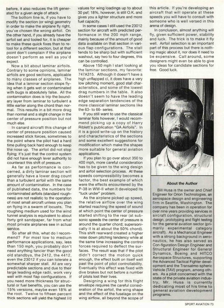
About the AuthorBill Husa is the owner and Chief
Engineer for Orion Technologies, anaerospace design and engineeringfirm in Seattle, Washington. Thecompany has been in operation forover nine years providing services inaircraft configuration, structuraldesign, prototyping and flight testingfor the general aviation sector (pri-marily experimental categoryaircraft). As a Mechanical Engineerwith a strong background in aero-nautics, he has also served asCon-figuration Design Engineer andStructural Engineer for GeneralDynamics, Boeing and HITCOAerospace Structures, supportingthe Advanced Tactical Fighter devel-opment and the Transatmo-sphericVehicle (TAV) program, among oth-ers. As a pilot concerned with thestate of the private aviation indus-try, Mr. Husa is currentlydedicating most of his time togeneral aviation developmentprograms.
SPORT AVIATION 73


![Creating%20a%20 lecture%20that%20students%20will%20actually%20learn%20from[1]](https://static.fdocuments.in/doc/165x107/5407fd788d7f7288088b50d6/creating20a20-lecture20that20students20will20actually20learn20from1.jpg)


![Foldable %20 compromises%20and%20events%20that%20led%20to%20the%20civil%20power%20point[1]](https://static.fdocuments.in/doc/165x107/55d55a6cbb61ebff4c8b45c7/foldable-20-compromises20and20events20that20led20to20the20civil20power20point1.jpg)