What's New in DataCAD? · DataCAD 21 supports the ability to import and export AutoCAD 2018/2019...
284
What's New in DataCAD?
Transcript of What's New in DataCAD? · DataCAD 21 supports the ability to import and export AutoCAD 2018/2019...

1
What's New in DataCAD?

2
What’s New in DataCAD®?
DataCAD 21 ..................................................................................................................................... 11
AutoCAD 2018/2019 support...........................................................................................................................11 Enhanced Softlock Integration .......................................................................................................................11
Online Store Integrated with License Portal ..............................................................................................12 Saved License ID and Password ..................................................................................................................12 Installation Name ..........................................................................................................................................13
DPI Awareness ..................................................................................................................................................13 Improved Symbol Layer Control ...................................................................................................................15 3D Inclined Polygons & Slabs: Pitch / Angle / Grade ................................................................................16 3D Inclined Polygons & Slabs: Properties Editor .......................................................................................17 Symbol Layer Manager ....................................................................................................................................18 Symbol Layer Manager: GoTo View Link Options ...................................................................................19 Symbol Browser: Recent / Favorite Folder Manager: .................................................................................20 Exclude Selection from Editing Routines: ...................................................................................................22 Pak-N-Go Enhancements ................................................................................................................................22 Symbol and Smart Entity Counts: .................................................................................................................23 Miscellaneous Enhancements ........................................................................................................................24
XREFs ..............................................................................................................................................................24 Smart Entities .................................................................................................................................................24 Associative Dimensions ................................................................................................................................24 Clip Cubes ......................................................................................................................................................24 AEC File Repair ..............................................................................................................................................25 Symbols ...........................................................................................................................................................25 Spell Checker ..................................................................................................................................................25 Enlarge Menu .................................................................................................................................................25 Materials .........................................................................................................................................................25 Layer Manager ...............................................................................................................................................25 Color Picker ....................................................................................................................................................26 Geometry, Divide ..........................................................................................................................................26 Entity Properties Editor ................................................................................................................................26 Multi-View Windows ....................................................................................................................................26 2D/3D Move, Copy, and Stretch ..................................................................................................................26 Mask Menu .....................................................................................................................................................27 Copy / Paste ....................................................................................................................................................27
New Configuration Settings ...........................................................................................................................28 XREFs: GTV-Link Remembers Smart Wall Hatch/Fill..............................................................................28 Symbols: New Scale/Rotation ......................................................................................................................28 Symbols: GTV Link ........................................................................................................................................28 Symbol Attributes: Allow Trailing Spaces .................................................................................................28 Display: Auto Adjust Marker Size Percentage ..........................................................................................28
New Extended Character Codes .....................................................................................................................29 DMF (DataCAD Material File): ....................................................................................................................29
Enhancements to DCAL (DataCAD Applications Language) ..................................................................30 DCAL for Delphi Enhancements .................................................................................................................30

3
Contour Search .............................................................................................................................................. 30 License-related Functions ............................................................................................................................. 30 DCAL for C++ Enhancements ...................................................................................................................... 31 Contour Search .............................................................................................................................................. 31 License-related Functions: ............................................................................................................................ 31 DCAL for DOS Enhancements .................................................................................................................... 32 KnockOut ........................................................................................................................................................ 32 License-related Functions ............................................................................................................................. 32
DataCAD 20 ..................................................................................................................................... 33
Symbol Layer Control ...................................................................................................................................... 33 Helplines (a.k.a. Construction Lines)............................................................................................................ 34 Layout BETA (DWG Paper Space Layouts) ................................................................................................. 35 Z-Datum Reference .......................................................................................................................................... 36 Drag-n-drop Layer Files .................................................................................................................................. 36 Productivity Enhancements ............................................................................................................................ 37
Polyline Length Readout .............................................................................................................................. 37 Identify, Set All, Create ................................................................................................................................. 37 Mirror, Bisect .................................................................................................................................................. 37 Change, Match, Layer ................................................................................................................................... 37 GetSnap Enhancements ................................................................................................................................ 37
Miscellaneous Enhancements ........................................................................................................................ 37 New Configuration Settings ........................................................................................................................... 38
Default Layer Control ................................................................................................................................... 39 Smart Text Margin Obeys TextScale ........................................................................................................... 39 AS 1100 Exports As mm ............................................................................................................................... 39 Nesting In XRefs ............................................................................................................................................ 39 Auto Adjust Marker Size Percentage .......................................................................................................... 40 Change Match All Includes Layer ............................................................................................................... 40 Entity Context Menu Obeys Layer Search ................................................................................................. 40 New Clipped Area Selection ........................................................................................................................ 40 Miscellaneous ................................................................................................................................................. 41
New Extended Character Codes ..................................................................................................................... 42 Helpline-related codes: ................................................................................................................................. 42 Dimension Rounding-related codes: .......................................................................................................... 42 Z-Datum-related codes: ................................................................................................................................ 42
Enhancements to DCAL (DataCAD Applications Language) .................................................................. 43 DCAL for C++ ................................................................................................................................................. 43 DCAL for DOS ............................................................................................................................................... 43
DataCAD 19 ..................................................................................................................................... 44
AEC File Repair................................................................................................................................................. 44 Drawing Database Tests ............................................................................................................................... 44 Additional File Repair Options.................................................................................................................... 46
Program Preferences ........................................................................................................................................ 47 Menus Tab ...................................................................................................................................................... 49 Toolbars Tab ................................................................................................................................................... 50 Interface Tab ................................................................................................................................................... 51

4
Drawing Tab ...................................................................................................................................................53 Miscellaneous Tab .........................................................................................................................................55 DXF/DWG Tab ...............................................................................................................................................57
New Toolbars ....................................................................................................................................................57 Object Snap Toolbar ......................................................................................................................................57 Icon-based SWOTHLUDFBK Toolbar ........................................................................................................57
Productivity Enhancements ............................................................................................................................58 New Ellipse Creation Methods ....................................................................................................................58 Plot Scale Dropdown / Print Icon ................................................................................................................58 Symbol Browser: Flatten to Zero .................................................................................................................58
Miscellaneous Enhancements ........................................................................................................................59 ClipCube Base/Height Display ....................................................................................................................59 Measures: To Clipboard ................................................................................................................................59 Offset: Coincident Entities ............................................................................................................................59
Update Installer Changes ................................................................................................................................59 Custom Support Path ....................................................................................................................................59 Wide Menu Labels .........................................................................................................................................59
New Configuration Settings ...........................................................................................................................59 Symbol Browser: Audit Symbol Files .........................................................................................................59 Symbol Editor: Inherit Parent Input Mode ................................................................................................60 No Macros From Locked Layer ...................................................................................................................60 XREFs: New Check For Nested ...................................................................................................................60 New Regen .....................................................................................................................................................60 Undo: Disable During Import ......................................................................................................................60 Symbol Browser: Windows Cursor .............................................................................................................60
New Extended Character Codes .....................................................................................................................61 Enhancements to DCAL (DataCAD Applications Language) ..................................................................62
DataCAD 18 ..................................................................................................................................... 63
SketchUp 2015 ...................................................................................................................................................63 Symbol Attribute Enhancements ...................................................................................................................63
Resolving Broken Links to Databases .........................................................................................................63 Edit Attribute Menu ......................................................................................................................................64 Edit Attributes Menu ....................................................................................................................................65
Hyperlink to File and GoTo View .................................................................................................................65 Line Type and/or Spacing by Layer...............................................................................................................66 Get Snap Enhancements ..................................................................................................................................67
New Get Snap Options .................................................................................................................................67 New 3D Edit Menus .........................................................................................................................................68 Productivity Enhancements ............................................................................................................................70
Save As Copy .................................................................................................................................................70 Coincident Entity Selection ..........................................................................................................................70 New & Only On .............................................................................................................................................70 Prevent Windows Screen Saver ...................................................................................................................70 Prevent Windows Sleep ................................................................................................................................70 Enable XClips and/or SClips ........................................................................................................................70 Orphaned Nested XREF Warning ...............................................................................................................71 Identify, Set All: Smart Arrows ....................................................................................................................71

5
XClip, New Cube Cursor .............................................................................................................................. 71 Process XREFs ................................................................................................................................................ 71 Identify: Associative Dimension.................................................................................................................. 71 Print Alias List ............................................................................................................................................... 72 Allow Scale Dependent Nested Symbols ................................................................................................... 72 No Scroll Forward / Backward Keys ........................................................................................................... 73 View Layer File .............................................................................................................................................. 73 Fix Text Toggle ............................................................................................................................................... 73 Use Significant Digits In Dialogs ................................................................................................................. 73 Persistent Layer Manager Hotkey ............................................................................................................... 73 GUI File Path .................................................................................................................................................. 73 Color Menu Goes Directly To Dialog ......................................................................................................... 73 Edit Symbol Fields Dialog ............................................................................................................................ 75 o2c None Materials ........................................................................................................................................ 75 o2c Fixed Materials ........................................................................................................................................ 75 Material XOR Background ........................................................................................................................... 76
Sun Shader Enhancements ............................................................................................................................. 76 Entity Filter ..................................................................................................................................................... 76 Smart Symbol Export .................................................................................................................................... 77 Miscellaneous Enhancements ...................................................................................................................... 77
New Configuration Settings ........................................................................................................................... 78 New extended character codes ....................................................................................................................... 81 Enhancements to DCAL (DataCAD Applications Language) .................................................................. 82
DataCAD 17 ..................................................................................................................................... 83
All-New SketchUp Translator ........................................................................................................................ 83 Inference Snapping .......................................................................................................................................... 86 Productivity enhancements ............................................................................................................................ 88
New commands and functions .................................................................................................................... 88 Mask by Hatch Pattern ................................................................................................................................. 88 Geometry commands .................................................................................................................................... 88 Symbol Tools .................................................................................................................................................. 89 Smart Entities ................................................................................................................................................. 89 Symbol attribute text ..................................................................................................................................... 90 Changing text ................................................................................................................................................. 90 Changing MText and PText line factor ....................................................................................................... 90 Managing drawing materials ....................................................................................................................... 90
Interface and program behavior changes ..................................................................................................... 91 Dimensions ..................................................................................................................................................... 91 XREFs .............................................................................................................................................................. 91 Layer Manager ............................................................................................................................................... 91 Offset ............................................................................................................................................................... 92 Text alignment point ..................................................................................................................................... 92 GoTo Views .................................................................................................................................................... 92
Sun Shader ......................................................................................................................................................... 92 New configuration settings ............................................................................................................................ 92
Symbol Browser ............................................................................................................................................. 92 Symbol Editor ................................................................................................................................................ 93

6
Nested symbols ..............................................................................................................................................93 XREFs ..............................................................................................................................................................93 Text Scale ........................................................................................................................................................93 GoTo Views ....................................................................................................................................................94 New extended character codes ....................................................................................................................94
DataCAD 16 ..................................................................................................................................... 95
AutoCAD 2013/2014/2015 support .................................................................................................................95 Productivity enhancements ............................................................................................................................96
Associative dimension prefix and suffix ....................................................................................................96 New selection method: Previous .................................................................................................................97 XREF enhancements ......................................................................................................................................97 Symbol enhancements ..................................................................................................................................98 Drag-N-Drop ..................................................................................................................................................99 Editing tools..................................................................................................................................................100 Text enhancements ......................................................................................................................................101 File management changes ..........................................................................................................................101 GoTo View enhancements ..........................................................................................................................102 Miscellaneous ...............................................................................................................................................102
3D modeling and viewing enhancements ..................................................................................................103 New configuration settings ...........................................................................................................................104
Show hatch ...................................................................................................................................................104 Line weight hot key .....................................................................................................................................104 Drawing timer ..............................................................................................................................................104 Printing ..........................................................................................................................................................104 Display speed ...............................................................................................................................................105 Fence selection ..............................................................................................................................................105 Busy cursor ...................................................................................................................................................106 o2c Object Viewer ........................................................................................................................................106
New extended character codes .....................................................................................................................107 Text underline and overline .......................................................................................................................107 DWG Export .................................................................................................................................................107 Polyline display............................................................................................................................................107
Sun Shader 2.0.4.1 ...........................................................................................................................................107 Entity Filters .................................................................................................................................................107 Render selected entities...............................................................................................................................108 New settings .................................................................................................................................................109 Miscellaneous ...............................................................................................................................................110 New configuration settings ........................................................................................................................110
DataCAD 15 ................................................................................................................................... 111
Sun Shader 2.0 .................................................................................................................................................111 Transparency ................................................................................................................................................111 GoTo Views ..................................................................................................................................................112 Layer Manager .............................................................................................................................................112 Edge Properties ............................................................................................................................................114 Smoothing .....................................................................................................................................................114 Other toolbars ...............................................................................................................................................114

7
Shadow Study Results ................................................................................................................................ 114 Pan/Zoom/Rotate Widget ........................................................................................................................... 115
New Commands and Functions ................................................................................................................... 117 AutoCAD compatibility ............................................................................................................................. 117 XREF changes ............................................................................................................................................... 117 Smart Arrow changes.................................................................................................................................. 119 2D drafting and drawing ............................................................................................................................ 119
New Configuration Settings ......................................................................................................................... 122 New extended character codes ..................................................................................................................... 123
DataCAD 14 .................................................................................................................................. 124
KnockOut ......................................................................................................................................................... 124 KnockOut enlargement ............................................................................................................................... 125 Related Settings ............................................................................................................................................ 126 AutoCAD compatibility ............................................................................................................................. 126 Extended character codes ........................................................................................................................... 127
Wall Type Manager ........................................................................................................................................ 127 Line Settings tab ........................................................................................................................................... 127 2D Cavity Settings tab ................................................................................................................................. 127 Cap Settings tab ........................................................................................................................................... 129 Cleanup Routines ........................................................................................................................................ 129
Lock Size on associative dimensions .......................................................................................................... 130 Lock Size on symbols .................................................................................................................................... 131 Lock Size on hatching .................................................................................................................................... 131 3D Object enhancements .............................................................................................................................. 132 Clipping Boundaries ...................................................................................................................................... 132 GoTo Views and XREFs ................................................................................................................................ 132
XREF Manager ............................................................................................................................................. 133 Miscellaneous enhancements ....................................................................................................................... 133
Pen Sort ......................................................................................................................................................... 133 WYSIWYG .................................................................................................................................................... 134 SketchUp Export .......................................................................................................................................... 134 Smart Arrow enhancements....................................................................................................................... 134 Layer Manager ............................................................................................................................................. 134 Layer Import ................................................................................................................................................ 134 Bitmaps ......................................................................................................................................................... 134 Mirror ............................................................................................................................................................ 135 1-Line Trim ................................................................................................................................................... 135 [Ctrl]+[Right-click] Context Menu ............................................................................................................. 135 Multi-View Windows ................................................................................................................................. 135 Move or Copy/To Layer.............................................................................................................................. 135 PText and MText .......................................................................................................................................... 135 Dynamic Pan ................................................................................................................................................ 135 New dcadwin.ini keys ................................................................................................................................ 136
DataCAD 13 .................................................................................................................................. 137
Persistent Layer Manager .............................................................................................................................. 137 New Arrow features ....................................................................................................................................... 138

8
Named Multi-View Windows ......................................................................................................................139 Recent and Favorite Symbol browser folders ...........................................................................................140 View-dependent symbol layers ...................................................................................................................141 View-dependency toggle ...............................................................................................................................142 Scale-dependent symbol layers....................................................................................................................143 Scale independent text ...................................................................................................................................144 Symbol Text Attribute enhancements ........................................................................................................145
Clipping ........................................................................................................................................................146 Fix Text ..........................................................................................................................................................146 Lock Size .......................................................................................................................................................146
Lock Text Angle ..............................................................................................................................................146 Lock Size on symbols .....................................................................................................................................146 Polygon Normal enhancements ...................................................................................................................147 New XREF Features ........................................................................................................................................147
Link to Drawing GoTo Views ....................................................................................................................147 Remove hidden lines in XREFs ..................................................................................................................147 Merge clipping boundaries ........................................................................................................................148
New GoTo View features ..............................................................................................................................148 Linking GoTo Views with Multi-Layout Details .....................................................................................148 Remove hidden lines in GoTo Views ........................................................................................................149
Polyline enhancements ..................................................................................................................................149 Sun Shadow Studies ......................................................................................................................................150
Navigation ....................................................................................................................................................150 Options dialog ..............................................................................................................................................150 Shadow Study section .................................................................................................................................150 Lighting section ............................................................................................................................................152 Ground Plane section ..................................................................................................................................152 Background section .....................................................................................................................................153 Performance section ....................................................................................................................................153
Shadow Study Results ...................................................................................................................................153 3D Object Viewer Enhancements ................................................................................................................153
Saved Views .................................................................................................................................................154 New Toolbars ...............................................................................................................................................155 Fixed Distance ..............................................................................................................................................155 Limit Rotation Angles .................................................................................................................................155 Copy, Copy (Raytrace) and Copy HTML .................................................................................................155
Miscellaneous Enhancements ......................................................................................................................156 Save As previous version ...........................................................................................................................156 Smart Entities ...............................................................................................................................................156 SketchUp 8 support .....................................................................................................................................156 Measures .......................................................................................................................................................157 Dimensions ...................................................................................................................................................157 DXF and DWG files .....................................................................................................................................157 Entity Properties Editor ..............................................................................................................................158 Enlarge ..........................................................................................................................................................159 Symbols .........................................................................................................................................................159 Object Snapping ...........................................................................................................................................159 Clipboard ......................................................................................................................................................159

9
Printing and Plotting ................................................................................................................................... 160 Settings .......................................................................................................................................................... 160 Texture Origin .............................................................................................................................................. 160 Other New Extended Character Codes .................................................................................................... 160 Move/To Layer and Copy/To Layer .......................................................................................................... 160 Curves ........................................................................................................................................................... 161
DataCAD 12 .................................................................................................................................. 162
Compatibility Enhancements ....................................................................................................................... 162 Forward/Backward Compatibility with Other DataCAD Versions ..................................................... 162 Compatibility with AutoCAD® Drawing Files (DXF/DWG) ................................................................. 162 More About Importing Files Into DataCAD ............................................................................................ 164
SketchUp File Import ..................................................................................................................................... 165 Excel Spreadsheet Import.............................................................................................................................. 166 SHX Fonts......................................................................................................................................................... 167 Productivity Enhancements .......................................................................................................................... 167
Smart Entities ............................................................................................................................................... 167 Key Terms and Concepts ............................................................................................................................ 168 Smart Entity Glossary ................................................................................................................................. 168 Using Smart Walls ....................................................................................................................................... 169 Using Smart Doors ...................................................................................................................................... 176 Using Smart Windows ................................................................................................................................ 179 Search and Replace ...................................................................................................................................... 183 Object Snapping ........................................................................................................................................... 184 3D Boolean Operations ............................................................................................................................... 184 Edit Planes .................................................................................................................................................... 185 Multi-line Text .............................................................................................................................................. 185 Font Dialog Enhancements ........................................................................................................................ 187 Entity Properties Editor .............................................................................................................................. 189 Rendering Settings for o2c.......................................................................................................................... 190 Symbol Enhancements ................................................................................................................................ 190 Textures, Backgrounds, Hatch Patterns ................................................................................................... 191 Dimension Enhancements .......................................................................................................................... 191 Clipping Changes ........................................................................................................................................ 192 Pen Styles/Pen Widths ................................................................................................................................ 193 New Toolbars ............................................................................................................................................... 193 Plotting Enhancements ............................................................................................................................... 194 Multiple Private Clipbooks with Preview ................................................................................................ 196 Reference File Manager Enhancements .................................................................................................... 196 Change Menu Enhancements .................................................................................................................... 197
DataCAD 11 .................................................................................................................................. 198
Productivity Features ..................................................................................................................................... 198 Symbol Browser ........................................................................................................................................... 198 Polygon Tools/TIN Modeler ...................................................................................................................... 218 3D Sectioning Tool....................................................................................................................................... 236 Toolbars ........................................................................................................................................................ 239 Keyboard Macros and Nested Aliases ...................................................................................................... 250
10
Mask on the Fly via EGAF ..........................................................................................................................250 Local Bitmap/Fill Order ..............................................................................................................................251 PDF Files with Layers .................................................................................................................................252 Multi-scale Plotting (MSP) Improvements ...............................................................................................252 Pen Table Enhancements ............................................................................................................................253 XREF Changes ..............................................................................................................................................253 o2c Rendering ...............................................................................................................................................253 Layer Sets ......................................................................................................................................................254 Additional Layer Changes..........................................................................................................................257 Checking Text for Spelling Errors .............................................................................................................257
Interface Enhancements ................................................................................................................................265 Program Interface ........................................................................................................................................265 12-Character Labels and Tooltips ..............................................................................................................265 Pull-down Menu Hints and Shortcuts ......................................................................................................268 Preview Window .........................................................................................................................................269
Compatibility Enhancements .......................................................................................................................269 Double-precision Database .........................................................................................................................269 DCAL Macros ...............................................................................................................................................270
Program Directory and File Maintenance Improvements .......................................................................270 Undocumented INI Settings .......................................................................................................................270 Double-Click DataCAD File Launch .........................................................................................................275 Network Awareness ....................................................................................................................................275 File Purge ......................................................................................................................................................275 Compressed Drawing Files ........................................................................................................................277 File Open DXF/DWG ...................................................................................................................................280 Insert Bitmap ................................................................................................................................................280 Save Image As... ...........................................................................................................................................280 STL (Stereolithography) ..............................................................................................................................280 3DS (3D Studio) ............................................................................................................................................280 DWF (Autodesk WHIP!) .............................................................................................................................280
Backup and Recover Process.........................................................................................................................281 File Open, Backup, and Recover Process ..................................................................................................281 Exit/Save and Crash/Recover Scenarios ...................................................................................................282 Drawing Session Backups...........................................................................................................................283
11
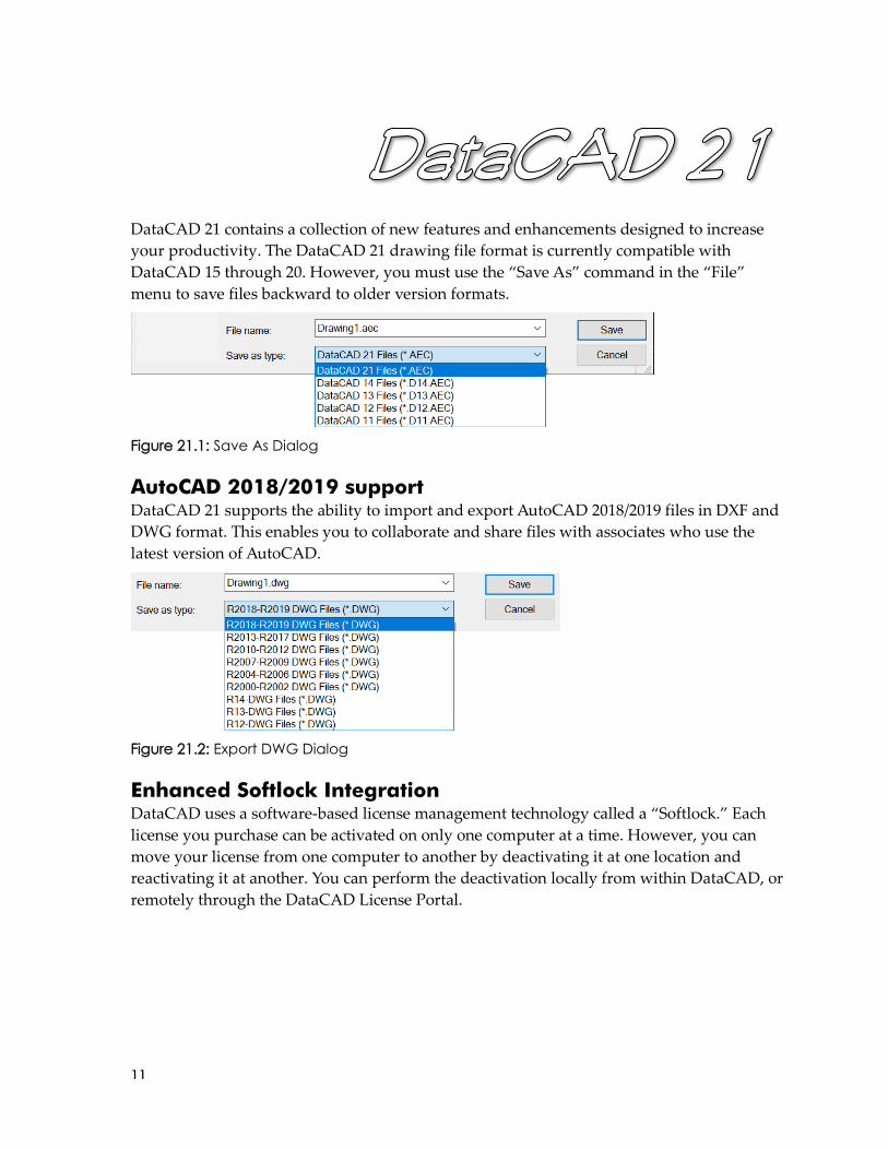
DataCAD 21 contains a collection of new features and enhancements designed to increase
your productivity. The DataCAD 21 drawing file format is currently compatible with
DataCAD 15 through 20. However, you must use the “Save As” command in the “File”
menu to save files backward to older version formats.
Figure 21.1: Save As Dialog
AutoCAD 2018/2019 support DataCAD 21 supports the ability to import and export AutoCAD 2018/2019 files in DXF and
DWG format. This enables you to collaborate and share files with associates who use the
latest version of AutoCAD.
Figure 21.2: Export DWG Dialog
Enhanced Softlock Integration DataCAD uses a software-based license management technology called a “Softlock.” Each
license you purchase can be activated on only one computer at a time. However, you can
move your license from one computer to another by deactivating it at one location and
reactivating it at another. You can perform the deactivation locally from within DataCAD, or
remotely through the DataCAD License Portal.

12
Online Store Integrated with License Portal
DataCAD's Softlock has been integrated with our Online
Store. So, in addition to managing your license activations
remotely, you can now renew your subscription or upgrade a
license directly from your customer license portal. Your new
License IDs and activation passwords are automatically-generated at the time you complete
your order.
Saved License ID and Password
DataCAD 21's Activation Dialog remembers your License ID and Password after a
successful activation. So, when you switch between your office and home computers, your
license credentials will be readily available.

13
Installation Name
An Installation Name field has been added to the Activation Dialog that allows you to
associate your license with the computer it is activated on. This will help you identify the
activation in your License Portal as this name appears next to the Installation ID.
DPI Awareness DataCAD's Program Interface and High-resolution Displays
A multitude of issues related to the display of DataCAD's drawing and program interface
on high-resolution devices, such as 4K monitors and tablets, have been addressed in this
update. In all, more than 100 dialogs, including the Layer Manager and the XREF Manager,
are affected by these changes.
Starting with Windows Vista, Microsoft introduced DPI Virtualization to automatically
upscale (i.e., bitmap stretch) applications like DataCAD so that their interfaces would
appear the same size on higher resolution displays. Until the recent introduction of hi-dpi
displays like 4K monitors and tablets, stretching DataCAD's interface (dialogs and the
drawing area) 125 - 150% wasn't detrimental. Even on a Surface Pro tablet running at 192
dpi, Windows did a fairly good job of upscaling DataCAD's menus and dialogs.
Figure 21.3: DataCAD's drawing window distorted by DPI Virtualization on a 4K display.

14
However, the quality of the drawing area could degrade beyond what was acceptable. A
display scaling of 200% or more would cause lines to look 'fat,' text to look 'fuzzy,' arcs to
look 'jagged,' and snapping points and markers to 'bloom.'
In Windows 8.1, Microsoft introduced a way to disable display scaling on a per application
basis. You could right-click on DCADWIN.exe (or the program shortcut), select Properties,
go to the Compatibility tab and check Disable Display Scaling On High DPI Settings. This
would prevent DataCAD from being scaled, and the draw form would be rendered at 1:1.
Disabling Display Scaling would restore the drawing area so that lines, text, and arcs were
sharp. However, DataCAD's menus and dialogs would also be rendered at 1:1, so the
interface would become too small to read. The size of toolbar icons and the menu font can
be adjusted in Program Preferences, so the main interface could be corrected, but many
other dialogs would appear too small.
The Windows 10 Creator's update introduced a major change to the way the operating
system and applications implement DPI Scaling. In some cases, this would cause DataCAD
to 'shrink' on high resolution displays. Even changing the display resolution would not
correct this since the native resolution is always used.
Figure 21.4: DataCAD's drawing window displayed 1:1 on a 4K display.

15
With this update to DataCAD, the drawing area will
always be drawn at the highest resolution possible,
or 1:1 with the display device. Toolbar icon sizes and
menu font sizes can still be adjusted the same way in
Program Preferences. For dialog boxes, a new Dialog
Box Size slider bar has been added to the Interface
tab. DataCAD will query the current display and automatically set a recommended
enlargement. You can change this setting by adjusting the slider bar position.
Since most of DataCAD's interface is affected by these changes, we expect there to be
anomalies we've overlooked. Please report any interface elements you find to be the wrong
size to [email protected].
Improved Symbol Layer Control In the first implementation of Symbol Layer Control, whenever a Symbol was added to a
drawing, its list of On/Off Layer Attributes were added to the symbol instance. This
happened regardless of whether Symbol Layer Control was set to None, Per Definition, or
Per Instance. In a drawing with hundreds of symbol instances, this created a lot of
unnecessary overhead. Handling this data could significantly slow down File, Exit and Save,
and saving a symbol from the Symbol Editor back to its parent drawing. Additionally, when
Per Instance layer control was enabled, GoTo View Link Attributes were being added to
symbol instances even when their GoTo View Link option was not enabled.
This is no longer the case. Layer On/Off Attributes are only added to a symbol instance
when Symbol Layer Control is set to Per Instance. These attributes will also be added to
existing symbol instances when you switch Symbol Layer Control from None or Per
Definition to Per Instance. If you switch from Per Instance to either None or Per Definition,
you will be asked "Would you like to retain Per Instance layer control attributes?" Answer
Yes if you intend to return to Per Instance layer control at some point. Otherwise, answering
No will delete the now unused Layer On/Off Attributes from each symbol instance in the
drawing.
Also, when Per Instance Layer Control is enabled, GoTo View Link Attributes will only be
added to those instances that have their GoTo View Link option enabled. This option is
available in the Insert Symbol menu, Symbol Tools context menu, and the newly-expanded
Symbol Layer Manager.
Additionally, when a drawing is first loaded into this version and Symbol Layer Control is
not set to Per Instance, DataCAD will delete the unused Layer On/Off attributes from each
symbol instance in the drawing. This will slow down the loading of the drawing. However,
it will only happen the first time the drawing is loaded and then saved.
Figure 21.5: Dialog Enlargement Slider

16
3D Inclined Polygons & Slabs: Pitch / Angle / Grade New options for Pitch, Angle, and Grade have been added to the 3D
Inclined Polygons and Slabs Create and Edit menus.
➔ To create an inclined polygon or slab using a pre-defined slope:
Go to 3D Entity, Polygons or Slabs, Inclines.
Select one of the inclined polygon or slab types to create:
• 4 Edge Parallel (i.e., gable roof plane or ramp)
• 4 Edge Trapezoid (i.e. hip roof plane or tapered ramp)
• 4 Edge General (i.e. gable to hip roof plane)
• 3 Edge Bottom (i.e. hip roof plane)
• 3 Edge Top (i.e. dormer roof plane)
Select one of the slope creation methods to use:
• Base/Pitch
(Create from z-base to a height, specified by Pitch: Rise / Run)
• Base/Angle
(Create from z-base to a height, specified by Angle)
• Base/Grade
(Create from z-base to a height, specified by Grade)
Note: For Pitch, any positive or negative Rise value is allowed. However, the Run value must be
positive. For Angle and Grade, any positive or negative value is allowed.
The maximum values allowed are:
- Rise: +/- 685 units
- Run: + 1000 units
- Angle: +/- 89 degrees
- Grade: +/- 5700 percent
The minimum value must be non-zero.
Follow the prompts to enter the first edge of the polygon or slab.
Follow the prompts to enter the second edge or point of the polygon or slab.
Select New Pitch, Angle, or Grade to enter a new value for the slope of the polygon or
slab.
Figure 21.6: 3D Inclined
Polygons Menu
17
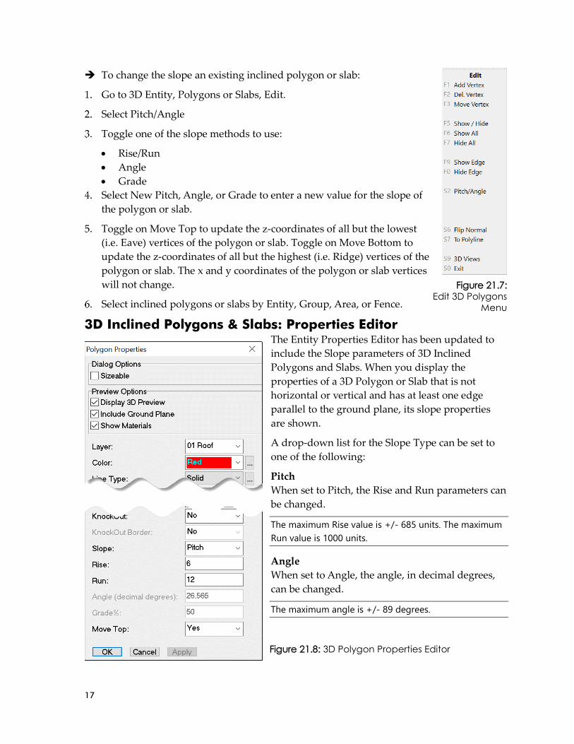
➔ To change the slope an existing inclined polygon or slab:
Go to 3D Entity, Polygons or Slabs, Edit.
Select Pitch/Angle
Toggle one of the slope methods to use:
• Rise/Run
• Angle
• Grade
Select New Pitch, Angle, or Grade to enter a new value for the slope of
the polygon or slab.
Toggle on Move Top to update the z-coordinates of all but the lowest
(i.e. Eave) vertices of the polygon or slab. Toggle on Move Bottom to
update the z-coordinates of all but the highest (i.e. Ridge) vertices of the
polygon or slab. The x and y coordinates of the polygon or slab vertices
will not change.
Select inclined polygons or slabs by Entity, Group, Area, or Fence.
3D Inclined Polygons & Slabs: Properties Editor The Entity Properties Editor has been updated to
include the Slope parameters of 3D Inclined
Polygons and Slabs. When you display the
properties of a 3D Polygon or Slab that is not
horizontal or vertical and has at least one edge
parallel to the ground plane, its slope properties
are shown.
A drop-down list for the Slope Type can be set to
one of the following:
Pitch
When set to Pitch, the Rise and Run parameters can
be changed.
The maximum Rise value is +/- 685 units. The maximum
Run value is 1000 units.
Angle
When set to Angle, the angle, in decimal degrees,
can be changed.
The maximum angle is +/- 89 degrees.
Figure 21.7: Edit 3D Polygons
Menu
Figure 21.8: 3D Polygon Properties Editor

18
Grade
When set to Grade, the grade, in percent, can be changed.
The maximum grade is +/- 5700%.
When you change the slope parameters, DataCAD will update the z-coordinates of all but
the lowest (i.e. Eave) vertices of the polygon or slab. Set Move Top to No to update the z-
coordinates of all but the highest (i.e. Ridge) vertices of the polygon or slab. The x and y
coordinates of the polygon or slab are always maintained.
Symbol Layer Manager When Symbol Layer Control is set to Per Instance, a new Symbol Layer Manager option is
available in the Symbol Tools context menu. Select this option to display the Symbol Layer
Manager for the currently-selected symbol.
Layers in the list can be toggled on/off by clicking
on them.
An Info Tip is displayed next to layers that have
View and/or Scale-independent attributes.
Note: The Symbol Layer Control 'Off' setting
supersedes the View/Scale-dependent Symbol Layer
'On' setting. So, if a symbol's layer is set to 'Off' by
Symbol Layer Control, the layer will not display,
regardless of its view/scale-dependent setting.
The View/Scale-dependent Symbol Layer 'Off' setting
supersedes the Symbol Layer Control 'On' setting. So, if
a symbol's layer is set to 'Off' by View/Scale-dependent
Control, the layer will not display, regardless if its layer
control setting.
In other words, if a symbol's layer is turned off by
either method, it will not display.
A new option, Open SLM (Symbol Layer
Manager), has been added to the Insert Symbol
menu when Symbol Layer Control is set to 'Per
Instance.' When toggled on, the Symbol Layer
Manager (SLM) will be opened when a symbol is
inserted.
Figure 21.9: Symbol Layer Manger

19
Symbol Layer Manager: GoTo View Link Options A number of options have been added to the
Symbol Layer Manager to give you greater
control of the way On/Off Layers and GoTo
View Links apply to symbol instances.
Changing the On/Off Layers in the Symbol Layer
Manager then selecting Apply or OK will set the
On/Off Layers for the selected symbol instance.
Apply To All Instances, can be checked prior to
clicking the Apply or OK buttons to apply the changes to all instances of the selected
symbol definition on the Active Layer.
If Apply To All Instances is checked, the option, On These Layers becomes available so you
can apply the changes to All Instances on the Active, On, or All layers.
A GoTo Views section provides options for managing the GoTo View Links in symbol
instances.
When GTV Link is checked, DataCAD will associate the symbol's On/Off Layers and
clipping boundary with a GoTo View whenever it is created or updated.
A drop-down list of the drawing's GoTo Views appears below the GTV Link checkbox.
Selecting one of the GoTo Views from this list will set the On/Off Layers in the Symbol
Layer Manager. Selecting Update will update the On/Off Layers that are associated with
the selected GoTo View. Selecting Update All GTVs will cause the symbol to display the
same On/Off Layers for every GoTo View.
For convenience, there is an option, As Selected, in the GoTo Views drop-down list.
Selecting this option will set the On/Off Layers in the Symbol Layer Manager to the way
they were when you first opened the Symbol Layer Manager.
Symbol Layer Control Notes:
Binding an XREF to a Symbol will copy the XREF's GoTo View links to the new Symbol Instance.
The following key has been added to the [Symbols] section of DCADWIN.ini:
GTV Link=TRUE
If that key is TRUE, the "GTV Link" toggle will always be ON when the Insert Symbol menu is shown.
Conversely if the key is FALSE, the toggle will always be OFF. If the key is present but left blank, the
state of the toggle will be remembered.
A GTV Link dropdown has been added to the Entity Properties Editor for symbols. This option is only
shown if the current Symbol Layer Control is set to "Per Instance".
When Per Instance layer control is enabled, a new GTV Link toggle is shown at F8 in the Insert Symbol
menu and the Symbol Tools context menu. The GTV Link toggle in the insert symbol menu controls
the state of a drawing variable that is used to set that property as symbols are inserted. The GTV Link
Figure 21.10: Symbol Layer Manager
20
property is per-instance and can be enabled/disabled on a per symbol entity basis. GTV Linking for
Symbols works essentially as it does for XREFs.
Changes have been made to allow you to add, delete, or rename layers in the Symbol Editor and have
all its instances automatically update their local layer lists to reflect those changes. This, essentially,
renders Symbol Tools, Layer Control..., Rebuild Layer List unnecessary when using Per Instance
symbol layer control.
Changes have been made so that Symbols using layer on/off settings that have been assigned with
Symbol Layer Control set to Per Instance will not lose those settings when switching between None,
Per Definition and back to Per Instance.
When exporting to DWG and Symbol Layer Control is NOT set to "None", DataCAD will use the
On/Off layer settings in the symbol definition. If you select "All Layers" for DWG export, all the layers
in the symbol will be exported, but the On/Off status will reflect the current state of the symbol
definition. If "On Layers" is selected, only those layers that are On will be exported.
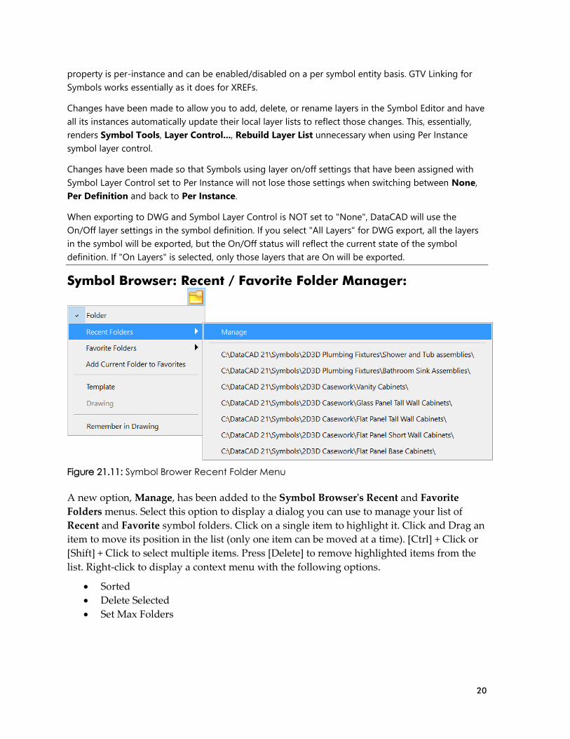
Symbol Browser: Recent / Favorite Folder Manager:
Figure 21.11: Symbol Brower Recent Folder Menu
A new option, Manage, has been added to the Symbol Browser's Recent and Favorite
Folders menus. Select this option to display a dialog you can use to manage your list of
Recent and Favorite symbol folders. Click on a single item to highlight it. Click and Drag an
item to move its position in the list (only one item can be moved at a time). [Ctrl] + Click or
[Shift] + Click to select multiple items. Press [Delete] to remove highlighted items from the
list. Right-click to display a context menu with the following options.
• Sorted
• Delete Selected
• Set Max Folders

21
Select Sorted to alpha-numerically sort the list. When Sorted is enabled, the ability to move
items in the list is disabled. Delete Selected is only available when items are selected. Select
Set Max Folders to set the maximum number of saved folder locations (1 - 100).
Figure 21.12: Symbol Browser Recent Folder Manager
Figure 21.13: Symbol Browser Favorite Folders Manager
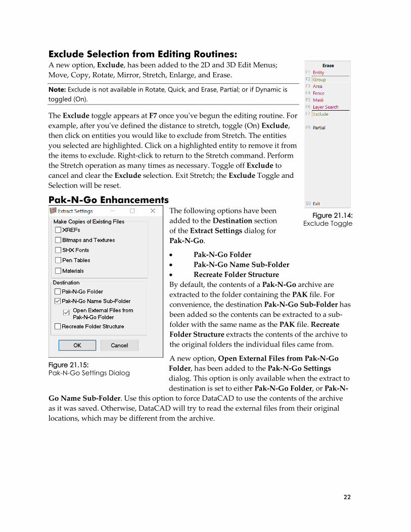
22
Exclude Selection from Editing Routines: A new option, Exclude, has been added to the 2D and 3D Edit Menus;
Move, Copy, Rotate, Mirror, Stretch, Enlarge, and Erase.
Note: Exclude is not available in Rotate, Quick, and Erase, Partial; or if Dynamic is
toggled (On).
The Exclude toggle appears at F7 once you've begun the editing routine. For
example, after you've defined the distance to stretch, toggle (On) Exclude,
then click on entities you would like to exclude from Stretch. The entities
you selected are highlighted. Click on a highlighted entity to remove it from
the items to exclude. Right-click to return to the Stretch command. Perform
the Stretch operation as many times as necessary. Toggle off Exclude to
cancel and clear the Exclude selection. Exit Stretch; the Exclude Toggle and
Selection will be reset.
Pak-N-Go Enhancements The following options have been
added to the Destination section
of the Extract Settings dialog for
Pak-N-Go.
• Pak-N-Go Folder
• Pak-N-Go Name Sub-Folder
• Recreate Folder Structure
By default, the contents of a Pak-N-Go archive are
extracted to the folder containing the PAK file. For
convenience, the destination Pak-N-Go Sub-Folder has
been added so the contents can be extracted to a sub-
folder with the same name as the PAK file. Recreate
Folder Structure extracts the contents of the archive to
the original folders the individual files came from.
A new option, Open External Files from Pak-N-Go
Folder, has been added to the Pak-N-Go Settings
dialog. This option is only available when the extract to
destination is set to either Pak-N-Go Folder, or Pak-N-
Go Name Sub-Folder. Use this option to force DataCAD to use the contents of the archive
as it was saved. Otherwise, DataCAD will try to read the external files from their original
locations, which may be different from the archive.
Figure 21.14: Exclude Toggle
Figure 21.15: Pak-N-Go Settings Dialog

23
Symbol and Smart Entity Counts: A new Count option is available for
Symbols and Smart Doors and Windows.
[Ctrl] + Right-click on any Symbol or
Smart Door / Window instance and
highlight Count in the Context Menu.
Select Active Layer, On Layer, or All
Layers to query the count for all
instances of that item. The results are
displayed on the Attention Toolbar.
For Symbols that have been loaded into
the drawing, the Count option is also
available in the Symbol Browser's
Context Menu when browsing a folder
or the current drawing.
Figure 21.17: Attention Toolbar Symbol Count Results
In the case of Smart Doors and Windows, instances of non-
fixed width types of varying widths are tallied separately.
So, the count will only include instances of the current type
with the current width.
A context menu has also been added to the item lists in the
Smart Door and Window Managers. Right-click on any
loaded Type to reveal the option, Count. Highlight Count
and select either Active Layer, On Layer, or All Layers to
display the number of occurrences of that Type. The
results are displayed on the Attention Toolbar.
Note: Varying widths of the same Type are counted together.
Figure 21.16: Symbol Count Context Menu
Figure 21.18: Symbol Browser Count Context Menu

24
Miscellaneous Enhancements XREFs
• Changed what is shown when selecting a renamed XREF for renaming in the
Reference File Manager.
• Added a new radio group, Ignore CC, to the Reference File Manager.
• For renamed XREFs, the original path to the XREF is now appended to the new
name, separated by characters, defined by line #6526 of DCADWIN.msg.
• Enhanced XREF GTV Linking to remember the state of the Reference File
Manager's Smart Wall Hatch/Fill toggles Show Hatch and Show Fill. This can
be turned off by modifying the following key in the [XREFS] section of
DCADWIN.ini:
GTV-Link Remembers Smart Wall Hatch/Fill=FALSE
Smart Entities
• Added a horizontal scroll-bar (only when necessary) to the Types list of the
Types Managers (Walls, Doors and Windows). Also, a hint is now displayed
when the mouse is over a Type in the list.
Associative Dimensions
• Changed Identify/Set All on an Associative Dimension to set the Show Dim
Text drawing variable.
Clip Cubes
• New options have been added to the Clip Cube menu for
incrementally adjusting either the x, y, or z coordinates of the
Drawing Clip Cube.
Ortho or Parallel Clip Cube:
Move X+
Move X-
Move Y+
Move Y-
Move Z+
Move Z-
Move Distance (X, Y, or Z Increment)
Note: These options only appear when Clip Cube is enabled. Use these
options while viewing a clipped view to move the clip box 'through' your
model.
• XREF Clips and Symbol Clips will now be clipped by the
Drawing Clip Cube. If an X-Clip or S-Clip overlaps a Drawing Clip Cube, it
will be merged with the Drawing Clip Cube. So, the portion of the X-Clip or S-
Clip that lies within the Drawing Clip Cube will be displayed.
Figure 21.19:
Clip Cube Menu
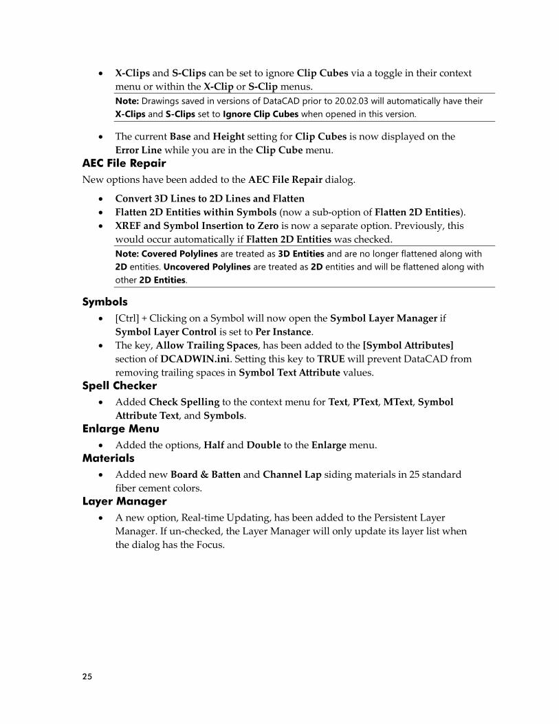
25
• X-Clips and S-Clips can be set to ignore Clip Cubes via a toggle in their context
menu or within the X-Clip or S-Clip menus.
Note: Drawings saved in versions of DataCAD prior to 20.02.03 will automatically have their
X-Clips and S-Clips set to Ignore Clip Cubes when opened in this version.
• The current Base and Height setting for Clip Cubes is now displayed on the
Error Line while you are in the Clip Cube menu.
AEC File Repair
New options have been added to the AEC File Repair dialog.
• Convert 3D Lines to 2D Lines and Flatten
• Flatten 2D Entities within Symbols (now a sub-option of Flatten 2D Entities).
• XREF and Symbol Insertion to Zero is now a separate option. Previously, this
would occur automatically if Flatten 2D Entities was checked.
Note: Covered Polylines are treated as 3D Entities and are no longer flattened along with
2D entities. Uncovered Polylines are treated as 2D entities and will be flattened along with
other 2D Entities.
Symbols
• [Ctrl] + Clicking on a Symbol will now open the Symbol Layer Manager if
Symbol Layer Control is set to Per Instance.
• The key, Allow Trailing Spaces, has been added to the [Symbol Attributes]
section of DCADWIN.ini. Setting this key to TRUE will prevent DataCAD from
removing trailing spaces in Symbol Text Attribute values.
Spell Checker
• Added Check Spelling to the context menu for Text, PText, MText, Symbol
Attribute Text, and Symbols.
Enlarge Menu
• Added the options, Half and Double to the Enlarge menu.
Materials
• Added new Board & Batten and Channel Lap siding materials in 25 standard
fiber cement colors.
Layer Manager
• A new option, Real-time Updating, has been added to the Persistent Layer
Manager. If un-checked, the Layer Manager will only update its layer list when
the dialog has the Focus.

26
Color Picker
• Added a new Color Picker/Mixer to replace the previous one.
• DataCAD's color drop-down combo-box will now give access to all 255 colors.
Geometry, Divide
• Associative Dimensions and Smart Walls can be selected using the Entity method
of Geometry, Divide. For Dimensions, the divisions are added along the
dimension line. For Smart Walls, they are added along the Control Line.
Entity Properties Editor
• The Entity Properties Editor has been updated to show all unavailable options in
a disabled state. So, only available options, based on the current settings, are
shown. For example, a Text entity has KnockOut Border and X/Y Enlargement
options. However, they will only be enabled if KnockOut is set to Yes. This way,
you do not need to select Apply after setting KnockOut to Yes in order to see
those additional options. Setting KnockOut to Yes enables those options
automatically.
Multi-View Windows
• As with GoTo Views, Multi-View Windows will now remember the current
Tangents setting.
2D/3D Move, Copy, and Stretch
• A ‘Distance X 2’ option has been added to the 2D and 3D Move, Copy, and
Stretch menus.
Note: The appearance and position of this option is affected by the state of the New 3D
Menu key in the [General] section of DCADWIN.ini.
Figure 21.20: New Color Picker Dialog

27
Mask Menu
• Added new options, Hatched, and Filled, to the Mask menu. These
options are mutually exclusive. When Hatched is toggled (On),
entities that are hatched will be selected. If Pattern is also toggled
(On), only entities hatched with the selected pattern will be selected.
When Filled is toggled (On), entities that are filled will be selected.
Copy / Paste
• Changes have been made to the way the z-coordinate is handled
when you select an Insertion Point during Copy/Paste. Previously,
the z-coordinate of the insertion point you defined was set at the
current Z-Base. Now, the z-coordinate will always be set at zero.
This is the same behavior as defining an insertion point for a
Symbol. When you Paste, the Z-Offset sub-menu is now available if
an insertion point has been defined.
Note: To Paste using the Insertion Point, By Center must be toggled (Off).
Figure 21.21: Mask Menu

28
New Configuration Settings DataCAD 21 contains new configuration settings designed to improve program speed and
functionality, while simultaneously improving productivity. After closing all drawings and
then exiting DataCAD, open the “dcadwin.ini” file, located in the DataCAD 21\ installation
folder on your C drive, to make changes.
Note: You should make a backup copy of dcadwin.ini prior to editing, in case you need to return the
program to its previous state.
XREFs: GTV-Link Remembers Smart Wall Hatch/Fill
[XREFs]
GTV-Link Remembers Smart Wall Hatch/Fill=TRUE
Symbols: New Scale/Rotation
[Symbols]
New Scale/Rotation=TRUE
Symbols: GTV Link
[Symbols]
GTV Link=TRUE
Symbol Attributes: Allow Trailing Spaces
[Symbol Attributes]
Allow Trailing Spaces=TRUE
Display: Auto Adjust Marker Size Percentage
[Display]
Auto Adjust Marker Size Percentage=100
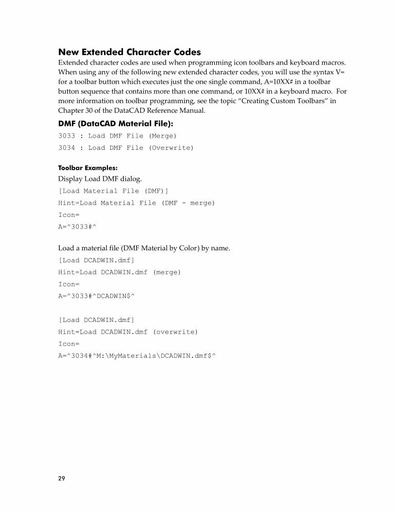
29
New Extended Character Codes Extended character codes are used when programming icon toolbars and keyboard macros.
When using any of the following new extended character codes, you will use the syntax V=
for a toolbar button which executes just the one single command, A=10XX# in a toolbar
button sequence that contains more than one command, or 10XX# in a keyboard macro. For
more information on toolbar programming, see the topic “Creating Custom Toolbars” in
Chapter 30 of the DataCAD Reference Manual.
DMF (DataCAD Material File):
3033 : Load DMF File (Merge)
3034 : Load DMF File (Overwrite)
Toolbar Examples:
Display Load DMF dialog.
[Load Material File (DMF)]
Hint=Load Material File (DMF - merge)
Icon=
A=^3033#^
Load a material file (DMF Material by Color) by name.
[Load DCADWIN.dmf]
Hint=Load DCADWIN.dmf (merge)
Icon=
A=^3033#^DCADWIN$^
[Load DCADWIN.dmf]
Hint=Load DCADWIN.dmf (overwrite)
Icon=
A=^3034#^M:\MyMaterials\DCADWIN.dmf$^

30
Enhancements to DCAL (DataCAD Applications Language)
DCAL for Delphi Enhancements
• Header files for Delphi DX have been added. They are in the DCAL for
Delphi\Header Files DX folder.
• A new sample macro, Edit_Group, has been added to demonstrate the use of the
mode_group command.
• Sample macros are now included for Delphi DX in the DCAL for
Delphi\Samples DX folder.
• All the sample macros have been compiled for DataCAD 21 and are available in
the DCAL for Delphi\Compiled Macros folder.
Added the following functions:
Contour Search
boundary_search(pt1 : point; var frst, last : lgl_addr) : aSInt;
License-related Functions
is_trial() : boolean;
get_license_type() : integer;
get_license_id() : string;
get_customer_id() : string;
get_customer_company() : string;
get_customer_FirstName() : string;
get_customer_LastName() : string;
get_customer_name() : string;
get_customer_address1() : string;
get_customer_address2() : string;
get_customer_city() : string;
get_customer_state_province() : string;
get_customer_zip() : string;
get_customer_country() : string;
get_customer_email() : string;
get_customer_phone() : string;
get_customer_fax() : string;
get_latest_version_number() : string;
get_installation_name() : string;
trial_days_left_since_license_creation() : integer;

31
DCAL for C++ Enhancements
Added the following functions:
Contour Search
boundary_search(point pt1, lgl_addr &frst, lgl_addr &last) : aSInt;
License-related Functions:
is_trial() : bool;
get_license_type() : aSInt;
get_license_id() : ShortString;
get_customer_id() : ShortString;
get_customer_company() : ShortString;
get_customer_FirstName() : ShortString;
get_customer_LastName() : ShortString;
get_customer_name() : ShortString;
get_customer_address1() : ShortString;
get_customer_address2() : ShortString;
get_customer_city() : ShortString;
get_customer_state_province() : ShortString;
get_customer_zip() : ShortString;
get_customer_country() : ShortString;
get_customer_email() : ShortString;
get_customer_phone() : ShortString;
get_customer_fax() : ShortString;

32
DCAL for DOS Enhancements
Added the following BUILTIN procedures:
KnockOut
PROCEDURE SetKnockOut(Ent : In Out entity; TurnOn : boolean);
BUILTIN 678;
License-related Functions
PROCEDURE IsTrial(Trial : IN OUT boolean); BUILTIN 679;
PROCEDURE GetLicenseType(LicenseType : IN OUT integer); BUILTIN 680;
PROCEDURE GetLicenseID (LiceseID : IN OUT string); BUILTIN 655;
Note: This procedure was first added to DCAL for DOS in DataCAD 18.
PROCEDURE GetCustomerID(CustomerID : IN OUT string); BUILTIN 681;
PROCEDURE GetLatestVersionNumber(LatestVersionNumber : IN OUT
string); BUILTIN 682;
PROCEDURE GetInstallationName(InstallationName : IN OUT string);
BUILTIN 683;
PROCEDURE TrialDaysLeft(DaysLeft : IN OUT integer); BUILTIN 684;
PROCEDURE GetCustomerCompany(CustomerCompany : IN OUT string);
BUILTIN 685;
PROCEDURE GetCustomerFirstName(CustomerFirstName : IN OUT string);
BUILTIN 686;
PROCEDURE GetCustomerLastName(CustomerLastName : IN OUT string);
BUILTIN 687;
PROCEDURE GetCustomerName(CustomerName : IN OUT string); BUILTIN
688;
PROCEDURE GetCustomerAddress1(CustomerAddress1 : IN OUT string);
BUILTIN 689;
PROCEDURE GetCustomerAddress2(CustomerAddress2 : IN OUT string);
BUILTIN 670;
PROCEDURE GetCustomerCity(CustomerCity : IN OUT string); BUILTIN
671;
PROCEDURE GetCustomerStateProv(CustomerStateProv : IN OUT string);
BUILTIN 672;
PROCEDURE GetCustomerZip(CustomerZip : IN OUT string); BUILTIN 673;
PROCEDURE GetCustomerCountry(CustomerCountry : IN OUT string);
BUILTIN 674;
PROCEDURE GetCustomerEmail(CustomerEmail : IN OUT string); BUILTIN
675;
PROCEDURE GetCustomerPhone(CustomerPhone : IN OUT string); BUILTIN
676;
PROCEDURE GetCustomerFax(CustomerFax : IN OUT string); BUILTIN 677;
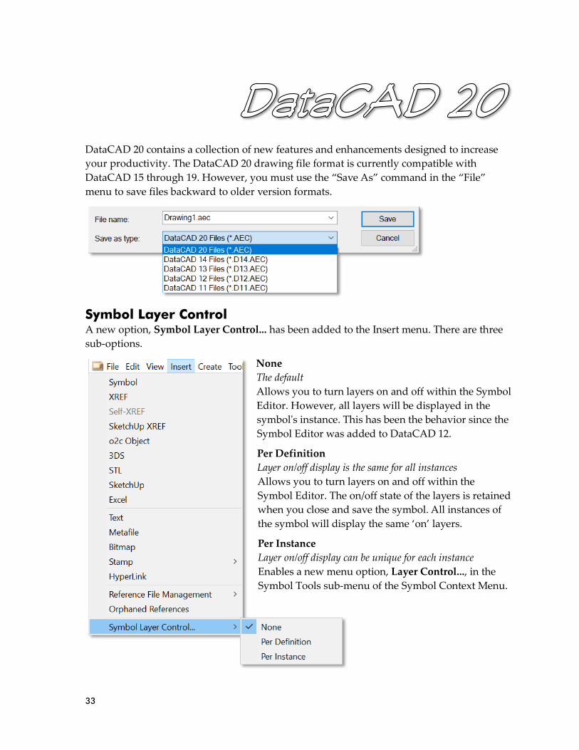
33
DataCAD 20 contains a collection of new features and enhancements designed to increase
your productivity. The DataCAD 20 drawing file format is currently compatible with
DataCAD 15 through 19. However, you must use the “Save As” command in the “File”
menu to save files backward to older version formats.
Symbol Layer Control A new option, Symbol Layer Control... has been added to the Insert menu. There are three
sub-options.
None
The default
Allows you to turn layers on and off within the Symbol
Editor. However, all layers will be displayed in the
symbol's instance. This has been the behavior since the
Symbol Editor was added to DataCAD 12.
Per Definition
Layer on/off display is the same for all instances
Allows you to turn layers on and off within the
Symbol Editor. The on/off state of the layers is retained
when you close and save the symbol. All instances of
the symbol will display the same ‘on’ layers.
Per Instance
Layer on/off display can be unique for each instance
Enables a new menu option, Layer Control..., in the
Symbol Tools sub-menu of the Symbol Context Menu.

34
Layer Control…
Highlighting this option reveals two sub-options.
Layer List
A listing of all layers, top-level and nested, contained in the symbol. A checkmark next to
the layer name indicates the layer should be displayed. Any layer that is unchecked, will not
be displayed.
Rebuild Layer List
Selecting this option rebuilds the complete list of layers based on the current symbol
definition and sets their displayed state to on. You should perform this operation after
adding or deleting layers from a symbol definition. There are two sub-options.
This Instance
Rebuilds layer list for the selected symbol.
All Instances
Rebuilds the layer list for all instances of the selected symbol.
Helplines (a.k.a. Construction Lines) A new option, [S4] Helplines, has been added to the Utility Menu. Helplines are infinite
lines you can add to your drawing for reference only. You can offset them, snap to them,
and trim to them, but they do not print.
➔ To add helplines to your drawing;
Select Helplines from the Utility menu.
Click the first point of the helpline.
Click the second point of the helpline.
DataCAD draws an infinite line between the two points.
The following options are available in the Helplines menu:
F1 Delete All
Select Delete All to remove all the helplines from your drawing.
F5 Color
Select Color to choose a color for helplines.
F6 Pen Style
Select Pen Style to choose a pen style for helplines.

35
F0 Show
Toggle Show off to disable the display of helplines.
S2 Draw First
Toggle Draw First on to have helplines draw before (i.e., underneath) other geometry.
S3 Draw Last
Toggle Draw Last on to have helplines draw after (i.e., on top of) other geometry.
Layout BETA (DWG Paper Space Layouts)
When you import a DWG file that includes Paper Space Layouts, DataCAD will display a
new option, Include Paper Space, on the DWG Import Entity Assignments dialog. Check
this option to include Paper Space Layouts and any Paper Space-specific entities from the
DWG file during import. If the DWG file does not include any Paper Space Layouts, the
Include Paper Space option will be greyed out.
Paper Space-specific entities belong to specific Paper Space Layouts and do not appear in the main DataCAD drawing.

36
A new option, Paper Space, has been added to the File drop-down menu. Selecting this
option will launch Layout to display imported Paper Space sheets. This option is greyed out
when no Paper Space Layouts have been imported.
A new option, Paper Space (PaprSpac for 8-character label), has been added to the Utility
menu. Selecting this option will launch Layout to display imported Paper Space sheets. This
option is only displayed when Paper Space Layouts have been imported.
Z-Datum Reference A new option, [S5] Z-Datum, has been added to the Utility, Settings menu. You can enable
this feature to set a Z offset to a relative zero height (a.k.a. Z-Datum Reference). For
example, if the first floor of your building is at a real-world height of 212', you would set the
Z-Datum value to 212'.
Subsequently, when you add a wall at Z-Base zero and Z-Height 8', DataCAD will
automatically calculate the offset to position the wall at a real-world Z-Base of 212' and a
real-world Z-Height of 220'. This makes it easier to model your project relative to the first
floor, rather than having to calculate the offset yourself.
Drag-n-drop Layer Files In addition to the default action, replace current layer, you can now hold down the [Ctrl]
key while dropping a layer to merge its contents with the current layer, or hold down the
[Ctrl] + [Alt] keys while dropping a layer to create a new layer.
Currently, Layout BETA does not provide any functionality other than displaying Paper Space Layouts that were imported from a DWG file. The primary utility of this feature is to reveal the Paper Space Layouts (like DataCAD’s Multi-Scale Plotting Sheets) that were previously inaccessible. To help us improve Layout while it is still in BETA, we ask you to report any inaccuracies in conversions or other problems to [email protected].
Note: When this feature is enabled, the Coordinates/Hints Toolbar, Identify, and 3D Coordinate Identification indicate both the relative and world Z values.

37
Productivity Enhancements Polyline Length Readout
The length, or perimeter and area of polylines is now displayed during editing.
Identify, Set All, Create
A new option, Create, has been added to the Identify, Set All menu. After you identify an
entity and select Set All, you can then select Create which will take you to the identified
entity's creation menu.
Mirror, Bisect
A new option, Bisect, has been added to the Mirror menu.
Change, Match, Layer
A new toggle option, Layer, has been added to the More... sub-menu of Change, Match.
After you select Change, Match, toggle on Layer to apply the layer property of one entity to
another.
GetSnap Enhancements
Two new options have been added to the GetSnap popup menu.
Angle + Distance
Gets the angle between two points, then adds (or subtracts with negative value) the distance
you specify.
➔ To get the angle between two points and specify a distance along that angle;
Click or snap to the first point.
GetSnap to the relative point.
Select Angle + Distance.
Enter the distance beyond (or short of with negative value) the relative point.
Midpoint
Gets the midpoint between two points.
➔ To get the midpoint between two points;
Click or snap to the first point.
GetSnap to the relative point.
Select Midpoint.
Miscellaneous Enhancements 1. The maximum number of Fence points has been increased (from 36) to 256 in Stretch
(2D and 3D).
The state of the Layer toggle when Change, Match, All is selected can be set by the key, Change Match All Includes Layer, in the [General] section of DCADWIN.INI. Set this key to TRUE if you want the entity's layer property to be included during Change, Match, All. The default value is FALSE.

38
2. In addition to MCR, DMX (DCAL for Delphi and C++) macros are now remembered
when they are the last macro used.
3. Modified 2 Line Trim to allow the selection of coincident lines for the selection of the
first line. That is, you select the 1st line and if it's the wrong one, right-click once and
select again and it will pick the next line. This may be repeated until the correct line
is selected.
4. Modified Explode in the Symbol Tools context menu to obey the Keep Groups toggle
in the Symbol Insert (Explode) menu.
5. Mirror by Entity has been enhanced to allow the selection of Helplines.
6. A new option, Separator, has been added to Scale Type, AS 1100 menu toggle. This
option allows you to choose either a space character, or a comma to delineate meters.
7. DataCAD will now save the Active layer upon a Symbol's creation.
8. Pak-N-Go now includes symbols marked for 'Auto Reload.'
9. It is now possible to Object Snap to the Absolute Zero indicator.
10. The display grids can now be set to a custom color.
11. A new toggle, Ignore CC (Clip Cubes), has been added to the symbol insert menu.
12. A new option, By Center, has been added to the Move, Drag menu.
13. For convenience, an 'Abs. Zero' option has been added to the Multi-scale Plotting,
Layout menu.
14. A New Layer option has been added to the Layer, Import menu.
15. Associative Dimension lines now support No. Divisions object snapping.
16. [Ctrl] + [Enter] may now be used with DataCAD's input line.
17. The Reload option is now available in the Symbol Browser's context menu, for
loaded symbols, when browsing by folder.
18. Pressing and holding [Ctrl] + [Shift] and selecting the New Layer option in the Layer
Manager will force the New Layer dialog to display at the center of the main display.
19. MText can now be selected in Tangents.
New Configuration Settings DataCAD 20 contains new configuration settings designed to improve program speed and
functionality, while simultaneously improving productivity. After closing all drawings and
then exiting DataCAD, open the “dcadwin.ini” file, located in the DataCAD 20\ installation
folder on your C drive, to make changes.
39
Default Layer Control
The following key is automatically added to the [Symbols] section of DCADWIN.ini to set
the default state of Layer Control in Symbols.
[Symbols]
Default Layer Control=0
0, the default ('None' in the menu option), allows you to turn layers on and off within the
Symbol Editor. However, all layers will be displayed in the symbol's instance. This has been
the behavior since the Symbol Editor was added to DataCAD 12.
1, ('Per Definition' in the menu option), allows you to turn layers on and off within the
Symbol Editor.
The on/off state of the layers is retained when you close and save the symbol. All instances
of the symbol will display the same layers.
2, ('Per Instance' in the menu option), enables a new menu option, 'Layers...', in the Symbol
Tools sub-menu of the Symbol Context menu. Highlighting this option reveals the list of all
layers, top-level and nested, contained in the symbol. A checkmark next to the layer name
indicates the layer should be displayed. Any layer that is unchecked, will not be displayed.
Smart Text Margin Obeys TextScale
The following key has been added to the [Smart Text] section of DCADWIN.ini to set the
behavior of Smart Text Margins.
[Smart Text]
Smart Text Margin Obeys TextScale=TRUE
Setting this key to FALSE will cause PText/MText margins to always act as though TextScale
is Off. The default value is TRUE.
AS 1100 Exports As mm
The following key has been added to the [DXF_DWG] section of DCADWIN.ini to set the
default scale type for export when AS 1100 is toggled on.
[DXF_DWG]
AS 1100 Exports As mm=TRUE
Setting this key to TRUE, will cause DataCAD to export the AS 1100 Scale Type as
millimeters.
Nesting In XRefs
Three new keys have been added to the [XRefs] section of DCADWIN.ini to control the
display of nested XREFs, and whether nesting is enabled for newly-inserted XREFs and Self-
XREFs.
Note: You should make a backup copy of dcadwin.ini prior to editing, in case you need to return the program to its previous state.

40
[XRefs]
Display Nesting=TRUE
The following keys control the default state of the Nesting toggle in the Insert XREF menu.
[XRefs]
Nesting In XRefs=FALSE
Nesting In Self-XRefs=FALSE
Auto Adjust Marker Size Percentage
The display size of DataCAD's markers used for the object snap indicator, insertion points,
and 3D markers can now be customized by changing the value of the following key in in the
[Display] section of DCADWIN.ini.
[Display]
Auto Adjust Marker Size Percentage=100
The initial value, in percent, is set automatically based on your display resolution.
Change Match All Includes Layer
The state of the Layer toggle when Change, Match, All is selected can be set by the following
key in the [General] section of DCADWIN.INI.
[General]
Change Match All Includes Layer=FALSE
Set this key to TRUE if you want the entity's layer property to be included during Change,
Match, All. The default value is FALSE.
Entity Context Menu Obeys Layer Search
The following key has been added to the [General] section of DCADWIN.ini to control
whether Layer Search applies to the Entity Context Menu.
[General]
Entity Context Menu Obeys Layer Search=FALSE
If FALSE, the default, [Ctrl] + Right-clicking on an entity ignores the Layer Search toggle. If
TRUE, the Layer Search toggle will apply to the Entity Context Menu.
New Clipped Area Selection
Corrections have been made to Area/Fence selection of clipped XRefs and Symbols. This
new methodology can be turned off with the following hey in the [XRefs] section of
DCADWIN.ini:
[XREFs]
New Clipped Area Selection=TRUE
The key, Allow Nesting has been deprecated. A new key, Display Nesting, has been added to store the Program Preference, Display Nested XREFs.

41
Miscellaneous
[General]
New Dimension Visible Attribute Positioning=FALSE
[General]
Show Visible Attributes When Dragging=FALSE

42
New Extended Character Codes Extended character codes are used when programming icon toolbars and keyboard macros.
When using any of the following new extended character codes, you will use the syntax V=
for a toolbar button which executes just the one single command, A=10XX# in a toolbar
button sequence that contains more than one command, or 10XX# in a keyboard macro. For
more information on toolbar programming, see the topic “Creating Custom Toolbars” in
Chapter 30 of the DataCAD Reference Manual.
A new toolbar code, 145, has been added for XClips. It is equivalent to the menu selection
sequence, Insert, Reference File Management, Clip Cubes.
Helpline-related codes:
1111 : Helplines Show On
1112 : Helplines Show Off
1113 : Helplines Draw First
1114 : Helplines Draw Last
Dimension Rounding-related codes:
1115 : Dimension Rounding On
1116 : Dimension Rounding Off
Z-Datum-related codes:
1117 : Z-Datum Reference On
1118 : Z-Datum Reference Off
1119 : Enter Z-Datum Reference point

43
Enhancements to DCAL (DataCAD Applications Language) DCAL for C++
A 'Hello World' example has been added to illustrate DataCAD's re-entrant state machine
logic.
The 'Arrow' example has been updated for Visual Studio 2013.
DCAL for DOS
PROCEDURE Get_Active_SSet : Integer; BUILTIN 672;
PROCEDURE PlinVoidAdd(Parent, Void : In Out entity; DoDraw :
boolean); BUILTIN 673;
PROCEDURE PlinCovered(Plin : In Out entity; covered : boolean);
BUILTIN 674;
PROCEDURE Ent_Mirr(ent : In Out entity; pt1, pt2 : point; FixText :
boolean); BUILTIN 675;
PROCEDURE Ent_Explode_With_Matrix(ent : In Out entity; mat :
modmat); BUILTIN 676;
PROCEDURE Explode_Symbol_Entity(Syment : In Out entity; Where :
integer); BUILTIN 677;

44
DataCAD 19 contains a collection of new features and enhancements designed to increase
your productivity. The DataCAD 19 drawing file format is currently compatible with
DataCAD 18, 17, 16, and 15. However, you must use the “Save As” command in the “File”
menu to save files backward to older version formats.
AEC File Repair A new 'Repair' option has been added to the 'idle' (no drawings open) File menu. When you
open a file using this option, you will be presented with a dialog that includes options for
testing the drawing database.
Drawing Database Tests
• Invalid Entities in Drawing
• Invalid Entities in Symbols
• Duplicate Polyline Vertices
• Extraordinary Values
Invalid Entities in Drawing / Symbols
Invalid Entities in Drawing, and Invalid Entities in Symbols, compares specific entity
variables to 'absolute zero' (defined as 1.0E-12). When these variables, such as the radius of a
circle, are so tiny (between 0 and 0.000000000001 32nds of an inch), they can prevent you
from editing them, or cause DataCAD to crash. These 'garbage' entities are identified and
can be deleted from the drawing database.
Figure 19.2: File, Repair Menu
Figure 19.1: File Repair Dialog
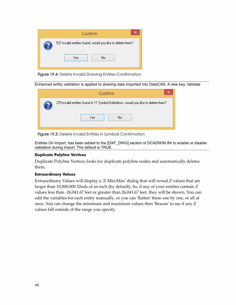
45
Enhanced entity validation is applied to drawing data imported into DataCAD. A new key, Validate
Entities On Import, has been added to the [DXF_DWG] section of DCADWIN.INI to enable or disable validation during import. The default is TRUE.
Duplicate Polyline Vertices
Duplicate Polyline Vertices looks for duplicate polyline nodes and automatically deletes
them.
Extraordinary Values
Extraordinary Values will display a 'Z-Min/Max' dialog that will reveal Z values that are
larger than 10,000,000 32nds of an inch (by default). So, if any of your entities contain Z
values less than -26,041.67 feet or greater than 26,041.67 feet, they will be shown. You can
edit the variables for each entity manually, or you can 'flatten' them one by one, or all at
once. You can change the minimum and maximum values then 'Rescan' to see if any Z
values fall outside of the range you specify.
Figure 19.4: Delete Invalid Drawing Entities Confirmation
Figure 19.3: Delete Invalid Entities in Symbols Confirmation

46
Additional File Repair Options
• Flatten 2D Entities
• Toggle off SWOTHLUDFBK
• Regen Screen on Load
• Load XREFs
Flatten 2D Entities
Flatten 2D Entities allows you to set all 2D entities' z-base and height values to zero;
including 2D entities found in symbols.
Toggle off SWOTHLUDFBK
Toggle off SWOTHLUDFBK is useful when a corrupt line type or hatch pattern is
preventing you from opening your drawing. Disabling the display of hatch patterns and
line types may allow you to open the drawing so you can reload the offending definition.
Figure 19.5: Extraordinary Z-Base/Height Values Dialog
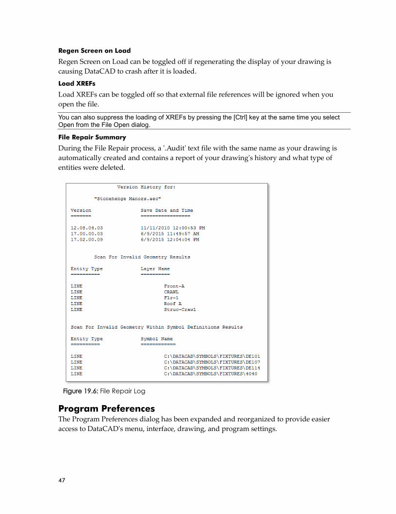
47
Regen Screen on Load
Regen Screen on Load can be toggled off if regenerating the display of your drawing is
causing DataCAD to crash after it is loaded.
Load XREFs
Load XREFs can be toggled off so that external file references will be ignored when you
open the file.
You can also suppress the loading of XREFs by pressing the [Ctrl] key at the same time you select Open from the File Open dialog.
File Repair Summary
During the File Repair process, a '.Audit' text file with the same name as your drawing is
automatically created and contains a report of your drawing's history and what type of
entities were deleted.
Program Preferences The Program Preferences dialog has been expanded and reorganized to provide easier
access to DataCAD's menu, interface, drawing, and program settings.
Figure 19.6: File Repair Log

48
The Interface tab has been renamed to Menus. The options provided on this tab affect the
display and behavior of DataCAD's menu buttons. A new Interface tab includes options for
customizing toolbars and dialog boxes. A new Drawing tab includes options for
customizing the drawing area and the behavior of the drawing cursor. Many of the options
that were previously on the Miscellaneous tab have been moved to the Menus, Interface, or
Drawing tab and several new options have been added.
An Apply button has also been added to the Program Preferences Dialog.
Figure 19.7: Program Preferences Menus Tab (formerly Interface)
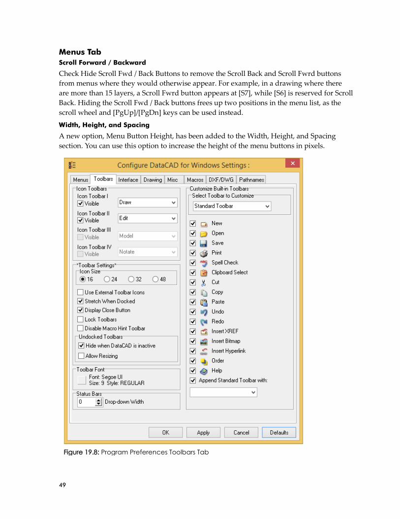
49
Menus Tab
Scroll Forward / Backward
Check Hide Scroll Fwd / Back Buttons to remove the Scroll Back and Scroll Fwrd buttons
from menus where they would otherwise appear. For example, in a drawing where there
are more than 15 layers, a Scroll Fwrd button appears at [S7], while [S6] is reserved for Scroll
Back. Hiding the Scroll Fwd / Back buttons frees up two positions in the menu list, as the
scroll wheel and [PgUp]/[PgDn] keys can be used instead.
Width, Height, and Spacing
A new option, Menu Button Height, has been added to the Width, Height, and Spacing
section. You can use this option to increase the height of the menu buttons in pixels.
Figure 19.8: Program Preferences Toolbars Tab

50
Toolbars Tab
A new Toolbars tab has been added to Program Preferences. Toolbar-related items which
were previously on the Interface tab have been moved to the Toolbars tab.
Customize Built-in Toolbars
A new section, Customize Built-in Toolbars has been added. You can use the 'Select Toolbar
to Customize' drop-down to choose the DataCAD toolbar you would like to modify. This
applies to the Standard, Status, Types, Object Snap, Rendering, and Viewer toolbars.
Icon Toolbars
The Icon Toolbars section has been expanded to accommodate two additional user-
definable toolbars. So, you can now have up to four user-definable toolbars displayed at
once.
Toolbar Settings
A new Toolbar Settings section exposes the following options.
Stretch When Docked
Enabled by default, this option determines whether a docked toolbar will 'stretch' to fill the
empty space that would otherwise occur between adjacent toolbars.
Display Close Button
Enabled by default, you can uncheck this option to hide the close button from docked
toolbars.
Lock Toolbars
You can enable this option to lock the current arrangement of your docked toolbars.
Disable Macro Hint Toolbar
If you only want pause hints to appear at the message line, then you can check this option to
prevent the hint toolbar from displaying.
There is a related enhancement to the behavior of the Macro Hint toolbar. The toolbar will no longer appear if the hint text is either, [''] (empty), or if it matches line 6288 of DCADWIN.MSG (NO COMMENT).
Undocked Toolbars: Allow Resizing
Check this option if you would like to resize undocked toolbars.
Toolbar font
The Toolbar Font section has been updated so you can now define the Font name, size, and
style for text that appears on toolbars. This includes status bar drop-down lists, the
SWOTHLUDFBK (Text), Coordinates / Hints, Message, and Attention toolbars. Formerly,
the menu button font was applied to these toolbars.

51
Interface Tab
The following items have been added to Interface Tab
File Dialog
You can use the options in this section to customize DataCAD's File Dialog preview settings.
Preview on Save and Close
Enable Preview on Save and Close to have DataCAD automatically create a bitmap preview
of your drawing in its current state when you close and save the file.
Preview on Forced Save
Enable Preview on Forced Save if you want DataCAD to update the bitmap preview of your
drawing in its current state each time you save your file.
Figure 19.9: Program Preferences Interface Tab

52
The time to create the drawing preview will increase as the drawing becomes more complex.
Show o2c Preview
Enable Show o2c Preview to see a 3D preview of files you select to open.
This option is available directly in the file dialog. However, if the 3D preview is problematic because of the complexity of the file(s), you can disable the option here instead.
Preview Image File Format
Use this option to select the file format for the bitmap preview image which can be either
BMP, JPG, TIF, TGA, PNG, or PCX.
Plot Preview
Max. Bitmap Size (MB)
This value sets the largest individual metafile size when generating the plot preview.
Disable Spacebar
You can check Disable Spacebar to prevent this key from registering while the Plot Preview
is being displayed.
Symbol Browser
Max. Favorites
Max. Favorites sets the maximum number of favorites to display at once.
Sort Favorites
Check Sort Favorites to sort the list of favorites alpha-numerically.
Max. Recent
Max. Recent sets the maximum number of recent folders to display at once.
Sort Recent
Check Sort Recent to sort the list of recent folders alpha-numerically.
Max. Auto-divisions X
Max. Auto-divisions X sets the maximum number of horizontal divisions that are
automatically created to display all the symbols in each folder.
Max. Auto-divisions Y
Max. Auto-divisions Y sets the maximum number of vertical divisions that are automatically
created to display all the symbols in each folder.
Resizable Folder Browser
Check Resizable Folder Browser to allow resizing the Folder Browser dialog.
Multi-view Windows
Increase or decrease the Scale Correction Percent value so Multi-View Window previews
more accurately reflect the saved view.
Layer Manager List Font
You can use this option to customize the font name and size used to display the list of layers.

53
Font style options such as bold and italic are not accessible since they are used by the Layer Manager to denote specific layer states.
Symbol Attributes
Check First Row is Header if the first row in your CSV files that are linked to a symbol
attribute database lookup contains headings, not data.
Drawing Tab
Display Options
Check Extents Box During Pan/Zoom to display an extents box while you are panning or
zooming instead of the line segments that make up the entities that are currently on screen.
Hot Keys
The 'Disable Hot Keys' section has been reworked for clarity. Disable Hot Keys has been
renamed to Hot Keys since only the [Insert] and [w] keys can be completely disabled. By
default, the Spacebar and numeric keys can be used to invoke distance input. Since the
Spacebar cannot be disabled, this option has been renamed to '[0...9] Number Keys for
Input'. When this option is unchecked, the number keys will not invoke distance input.
The [ - ], [ , ], or [ . ] keys for input options can be checked so that these keys will invoke
distance input instead of their default behaviors.
XREFs
Check Dynamic Snapping to search for object snapping points within XREFs.
Check Refresh on Regen to automatically refresh displayed XREFs when the display is
regenerated (i.e., when you press the [U] key).
When Update GoTo View Links is checked, XREFs that reside on locked layers may have
their GTV Link updated.
Check Automatically Convert to automatically convert DC5 files to AEC files when they are
referenced in the drawing being opened.

54
Mouse Panning and Zooming
Check Left&Right Mouse Buttons for Panning to enable panning while holding down the
left and right mouse buttons.
Figure 19.10: Program Preferences Drawing Tab

55
Miscellaneous Tab
Entities / Attributes to Print
The checkboxes in the Print / Plot Options section have been replaced with groups of three
radio buttons each. There are three possible states:
• Always, where all entities / attributes print, regardless of what is being displayed.
• Never, where none of the entities / attributes print, regardless of what is being
displayed.
• As Displayed, where what is printed corresponds to what is being displayed (i.e.,
THLUDFBK).
Figure 19.11: Program Preferences Miscellaneous Tab

56
Line Feed Distance = Text Height
The line feed distance for single line text and PText can now be based on the current text
height rather than the current font definition. This applies to single line text entered through
the Text menu, pasted from the clipboard, or inserted from a text file.
When Single Line Text or PText are checked, a line spacing factor of 1.5 applied to a text
height of 4 inches will always result in a line feed of 6 inches, regardless of the current font
selected.
Line Feed = Text Height can be applied on a per PText entity basis. This setting is exposed in the PText Properties dialog and [Ctrl] + Right-click context menu for PText.
Figure 19.12: Program Preferences DXF/DWG Tab

57
Hatching
Check Use Single Click to remove the Begin option and hatch entities as soon as you click on
them.
DXF/DWG Tab
Undo/Redo System: Suspend During Import
Suspending the undo/redo system during import can greatly reduce the time required to
convert DXF/DWG files. The default value is checked.
Stroke Font Adjustment: Use CHR2SHX.DAT to Adjust Text
The CHR2SHX.DAT file is now included with DataCAD 19. Previously, if this file were
present in the Fonts folder, it would automatically be used to adjust the size settings of
stroke fonts (i.e. SHX) during DXF/DWG import and export. Starting with DataCAD 19, this
file will only be used when Use CHR2SHX.DAT to Adjust Text is checked.
New Toolbars Object Snap Toolbar
A new Object Snap toolbar has been added to DataCAD to provide persistent access to the
current object snap settings. This toolbar may be turned on or off via the View, Toolbars
pull-down menu.
Icon-based SWOTHLUDFBK Toolbar
A new Icon-based SWOTHLUDFBK toolbar
has been added to DataCAD. The size of the
letter icons is determined by the Icon Size
setting located in the Icon Toolbars section
of the Interface tab in Program Preferences.
You can customize the icons displayed on this toolbar by changing the corresponding
bitmaps in the Toolbars folder.
Letter_S.png, Letter_W.png, Letter_O.png, Letter_T.png, Letter_H.png, Letter_L.png,
Letter_U.png, Letter_D.png, Letter_F.png, Letter_B.png, and Letter_K.png.
Use External Toolbar Icons must be enabled if you want DataCAD to give preference to bitmaps located in the Toolbars folder.
Figure 19.13: Object Snap Toolbar
Figure 19.14: Icon-based SWOTHLUD Toolbar

58
Productivity Enhancements
New Ellipse Creation Methods
Two creation methods, Radius and Diameter, have been added to
the Curves, Ellipse menu.
Radius
Radius allows you to define an ellipse by entering its center, and one
endpoint for the first, then second axis. The first two points entered
determine the angle of the ellipse.
Diameter
Diameter allow you to define an ellipse by entering both endpoints
of the first axis, and one endpoint of the second axis. The first two
points entered determine the angle of the ellipse.
Approximate
A new option, Approximate, has been added to the Ellipse menu.
When toggled on, DataCAD allows you to specify how many arcs
per quadrant will be used to approximate the edge of the ellipse.
This can be useful for specifying two or three radii for the
construction of an elliptical arch.
Plot Scale Dropdown / Print Icon
A new Plot Scale dropdown and Print menu icon can be displayed
on the Status Panel. These elements are off by default. To display
them, use the Customize Built-in Toolbars section on The Toolbars
tab of Program Preferences.
Symbol Browser: Flatten to Zero
A new 'Flatten to Zero'
option has been added to the
Symbol Browser's context
menu. You can use this option to set the z-base/height of 2D entities in a symbol to zero.
Figure 19.15: Ellipse Menu
Figure 19.16:
Status Panel
Figure 19.17: Symbol Browser Context Menu

59
Miscellaneous Enhancements
ClipCube Base/Height Display
The current ClipCube Base/Height is now displayed when the drawing's ClipCube is
enabled.
Measures: To Clipboard
A 'To Clipboard' option has been added to the Measures menu with the following options:
• Drawing Text: Copies the 'To Drawing' text to the clipboard.
• Value: Copies the measured value to the clipboard for use in the keyboard input
field.
Offset: Coincident Entities
The selection routine in the Offset command has been enhanced to cycle through coincident
entities. If you select the wrong entity, you can now right-click, then click the same spot to
choose the next available coincident entity.
Update Installer Changes Custom Support Path
The DataCAD updater will now determine if you have defined a custom path for your
Message and Label files. After the custom path has been verified, the updater will make the
necessary changes to the files in this location. If the custom path cannot be verified, the
default path 'DataCAD 19\Support Files\Messages and Labels\' will be used instead.
Wide Menu Labels
The DataCAD updater will now determine if you have customized the width of DataCAD's
'wide' menu button labels. If your existing DCADWIN.lbl and DCADWIN3.lbl files are
configured with 'wide' labels that are greater than the default 12 characters, new and
changed lines will be formatted accordingly.
New Configuration Settings DataCAD 19 contains new configuration settings designed to improve program speed and
functionality, while simultaneously improving productivity. After closing all drawings and
then exiting DataCAD, open the “dcadwin.ini” file, located in the DataCAD 19\ installation
folder on your C drive, to make changes.
Symbol Browser: Audit Symbol Files
External symbol files can now be audited by enabling the following key in the [DEBUG]
section of DCADWIN.INI.
[DEBUG]
Audit Symbol Files=TRUE
Note: You should make a backup copy of dcadwin.ini prior to editing, in case you need to return the program to its previous state.

60
The default value is FALSE. This key should only be set to TRUE temporarily when you
audit your symbol libraries, then set back to FALSE when you are finished. Leaving this key
set to TRUE will increase the time it takes to display symbols in the Symbol Browser.
Setting this key to TRUE will cause DataCAD to scan Symbols for invalid geometry while
browsing folders in the Symbol Browser. If an invalid entity is encountered, the entity is
deleted from the symbol definition, the .DSF file is updated, and a '.Audit' file is created
with the symbol's name in the same folder. The number of updated .DSF files is reported on
DataCAD's error line.
Symbol Editor: Inherit Parent Input Mode
A new key, Inherit Parent Input Mode, has been added to the [SymbolBrowser] section of
DCADWIN.INI. If set to TRUE, the default, the Symbol Editor will inherit the input mode
from the current drawing.
No Macros From Locked Layer
A new key, No Macros From Locked Layer, has been added to the [General] section of
DCADWIN.INI. The default is FALSE. If set to TRUE, keyboard macros and aliases will not
run when the active layer is locked.
Independent from this setting, DCAL macros cannot be run when the active layer is locked.
XREFs: New Check For Nested
A new key, New Check For Nested, has been added to the [XREFs] section of
DCADWIN.INI. If set to TRUE, the default, new trivial rejection logic is enabled to ignore
nested XREFs if nesting is turned off, either for the parent XREF or globally. This will reduce
the amount of time required to process XREFs for display, plotting, and object snapping.
New Regen
A new key, New Regen, has been added to the [General] section of DCADWIN.INI. If set to
TRUE, the default, DataCAD's Regen command will not include layers that are Off in its
extents recalculation.
Undo: Disable During Import
An option to disable the undo system during DXF/DWG file import has been added to the
DXF/DWG tab of Program Preferences. Disabling the undo system during import can
greatly reduce the time required to convert the file. The default value is TRUE.
[Undo]
Disable During Import=TRUE
This applies to the importation of DXF/DWG, SKP and STL files.
Symbol Browser: Windows Cursor
A new key, Windows Cursor, has been added to the [SymbolBrowser] section of
DCADWIN.INI. The default is FALSE. If set to TRUE, DataCAD will display the Windows
arrow cursor over the Symbol Browser instead of the cross-hair cursor.

61
New Extended Character Codes Extended character codes are used when programming icon toolbars and keyboard macros.
When using any of the following new extended character codes, you will use the syntax V=
for a toolbar button which executes just the one single command, A=10XX# in a toolbar
button sequence that contains more than one command, or 10XX# in a keyboard macro. For
more information on toolbar programming, see the topic “Creating Custom Toolbars” in
Chapter 30 of the DataCAD Reference Manual.
1105: Dimension Auto Style "No Points" On
1106: Dimension Auto Style "No Points" Off
1107: Dimension Auto Style "Points Only" On
1108: Dimension Auto Style "Points Only" Off
3022: Save File
3023: Save As
3024: File Purge
3025: Refresh Drawing
3026: Regen Display List
3027: Insert Symbol
3028: Save Symbol
3029: Pak-N-Go Create
3030: Pak-N-Go Extract
3031: Pak-N-Go Open
3032: Pak-N-Go Settings

62
Enhancements to DCAL (DataCAD Applications Language) The following routines have been added to DCAL.
PROCEDURE GetSetLayerFilter(Filter : IN OUT str8; ReadOnly :
boolean); BUILTIN 671;
PROCEDURE PrintStr255(str : str255; Column, Row, Color, Curs :
integer; Invert : boolean); BUILTIN 670;
FUNCTION DataCAD_Version : real; BUILTIN 669;
Added long layer name support to setlyrname() and lyr_find()
functions.

63
DataCAD 18 contains a collection of new features and enhancements designed to increase
your productivity. The DataCAD 18 drawing file format is currently compatible with
DataCAD 17, 16, and 15. However, you must use the “Save As” command in the “File”
menu to save files backward to older version formats.
SketchUp 2015 DataCAD 18 supports the ability to insert, export, and externally reference models from
SketchUp 2015. This enables you to collaborate and share files with associates who use the
latest version of SketchUp.
Symbol Attribute Enhancements Resolving Broken Links to Databases
Starting with this version of
DataCAD, a prompt will appear when
the database associated with a symbol
text attribute cannot be found.
Previously, DataCAD would always
ignore the error and allow you to
enter the value manually, rather than
select it from the database. You can
still choose to ignore the error, but
now you have the option to search for
the file yourself to repair the link.
Figure 18.2: Update Database Link Confirmation Dialog
If you can redefine the path to the file, you will then have the option to make the change
permanent. Otherwise, DataCAD will again look to the original path for the database the
next time you open the drawing.
Figure 18.1: Unable to Find Linked Database Warning
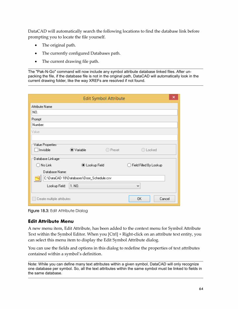
64
DataCAD will automatically search the following locations to find the database link before
prompting you to locate the file yourself.
• The original path.
• The currently configured Databases path.
• The current drawing file path.
Figure 18.3: Edit Attribute Dialog
Edit Attribute Menu
A new menu item, Edit Attribute, has been added to the context menu for Symbol Attribute
Text within the Symbol Editor. When you [Ctrl] + Right-click on an attribute text entity, you
can select this menu item to display the Edit Symbol Attribute dialog.
You can use the fields and options in this dialog to redefine the properties of text attributes
contained within a symbol’s definition.
The "Pak-N-Go" command will now include any symbol attribute database linked files. After un-packing the file, if the database file is not in the original path, DataCAD will automatically look in the current drawing folder, like the way XREFs are resolved if not found.
Note: While you can define many text attributes within a given symbol, DataCAD will only recognize one database per symbol. So, all the text attributes within the same symbol must be linked to fields in the same database.

65
Figure 18.4: Edit Attributes Dialog
Edit Attributes Menu
A new menu item, Edit Attributes, has been added to the context menu for symbols. When
you [Ctrl] + Right-click on a symbol that contains attribute text entities, you can select this
menu item to display the Edit/Customize Symbol Attribute dialog.
Hyperlink to File and GoTo View It’s now possible to hyperlink an entity in your current drawing to a specific GoTo View in a
different drawing. Once you’ve defined the drawing and corresponding GoTo View for the
entity’s hyperlink, selecting the hyperlink will open the drawing then automatically recall
the GoTo View. This is useful for linking a wall type tag in a plan drawing to its
corresponding detail in the details file.
To create a hyperlink to a drawing and a specific GoTo View:
Open the drawing which contains the entity, such as a wall type symbol, that will have
the hyperlink assignment.
[Ctrl] + Right-click the entity, select "File" from the
context menu, and then choose "Add."
In the "New File link" box, click the "File" button to
browse to and select the drawing file to link to. Click "OK"
when finished.
In the "New View" box, click the drop-down menu and
then choose from the list of available GoTo Views in the
linked file.
Note: For more information about using attributes, see “Using Text Attributes for Symbols” in Chapter 13 of the DataCAD Reference Manual.
Figure 18.5: File Hyperlink Dialog

66
Click "OK" on the "New View" box to accept the GoTo
View assignment or click "Cancel" to assign just the file, but
no specific GoTo View.
Now, whenever you access the hyperlink, DataCAD will
open the drawing then automatically recall the GoTo View. If
you chose "Cancel" on the "New View" box, DataCAD will
open the file to the last saved view in that file.
Figure 18.7: File Hyperlink Showing Linked Drawing and GoTo View
Line Type and/or Spacing by Layer New options, Line Type by Layer and Line Spacing by Layer have been
added to the Layer Manager dialog. When enabled, DataCAD will set
the current line type and/or spacing on a per layer basis. You can
specify the line type and/or spacing for a given layer within the Layer
Manager, however, DataCAD will always remember the last active line
type and spacing you used for a given layer.
New options, Line Type and Line Spacing have been added to the
Move, and Copy, To Layer menus. You can toggle these options on to
set the line type and/or spacing of the entities you are moving or
copying to a given layer.
When Line Type and/or Spacing by Layer are off, the default setting,
enabling these options will cause DataCAD to prompt you to select the
line type and/or spacing you wish to use.
When Line Type and/or Spacing by Layer are on, enabling these
options will cause DataCAD to automatically use the line type and/or
spacing currently associated with the layer.
Figure 18.6: New File / GoTo View Hyperlink Dialog
Figure 18.9: New Line Type and Spacing Options in Layer Manger
Figure 18.8: To Layer Menu
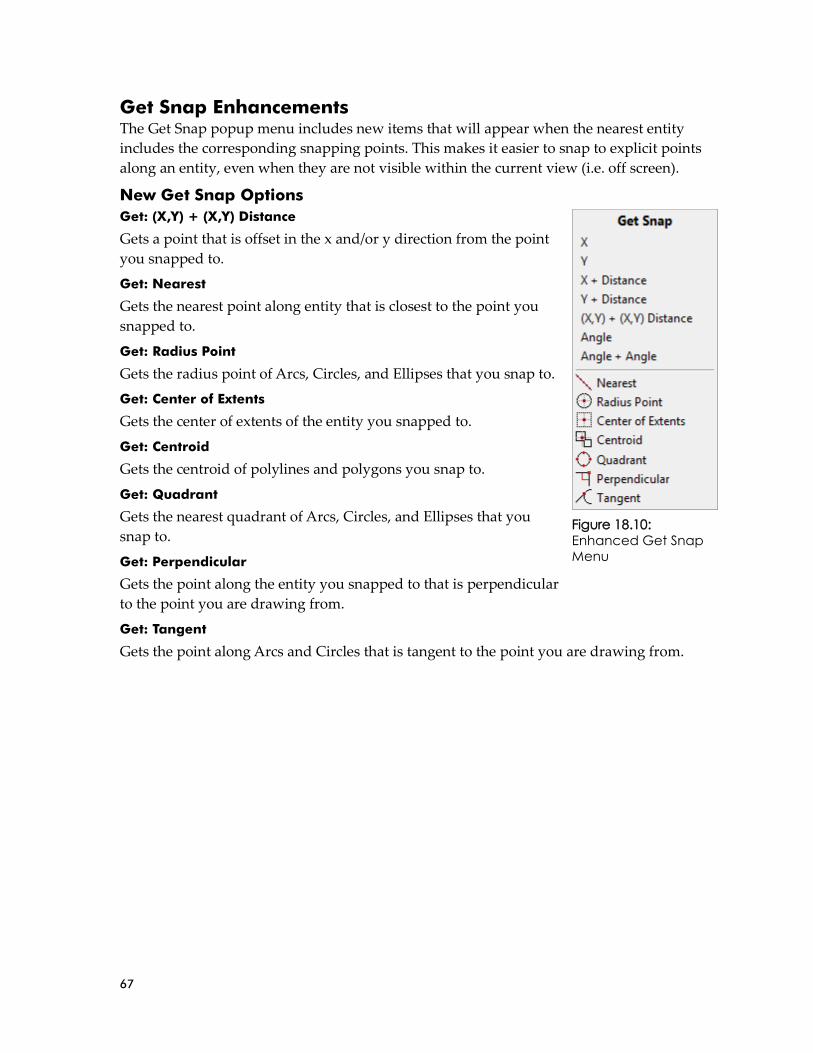
67
Get Snap Enhancements The Get Snap popup menu includes new items that will appear when the nearest entity
includes the corresponding snapping points. This makes it easier to snap to explicit points
along an entity, even when they are not visible within the current view (i.e. off screen).
New Get Snap Options
Get: (X,Y) + (X,Y) Distance
Gets a point that is offset in the x and/or y direction from the point
you snapped to.
Get: Nearest
Gets the nearest point along entity that is closest to the point you
snapped to.
Get: Radius Point
Gets the radius point of Arcs, Circles, and Ellipses that you snap to.
Get: Center of Extents
Gets the center of extents of the entity you snapped to.
Get: Centroid
Gets the centroid of polylines and polygons you snap to.
Get: Quadrant
Gets the nearest quadrant of Arcs, Circles, and Ellipses that you
snap to.
Get: Perpendicular
Gets the point along the entity you snapped to that is perpendicular
to the point you are drawing from.
Get: Tangent
Gets the point along Arcs and Circles that is tangent to the point you are drawing from.
Figure 18.10:
Enhanced Get Snap Menu

68
New 3D Edit Menus A new set of 3D Edit Menus are available
so you can have the position of the menu
buttons in the 3D Move, 3D Copy, 3D
Mirror, and 3D Stretch menus match (as
closely as possible) to the positions of the
menu buttons in the 2D Move, 2D Copy,
2D Mirror, and 2D Stretch menus.
To enable the new button arrangement in
the 3D Edit Menus, set the ‘New 3D
Menus’ key in the [General] section of
DCADWIN.INI to TRUE. The default is
FALSE, so you will not see these changes
without changing the value of this key.
Figure 18.11: 2D Move, New 3D Move, and 'old' 3D Move Menus
Figure 18.12: 2D Copy, New 3D Copy, and 'old' 3D Copy Menus

69
Figure 18.13: 2D Mirror, New 3D Mirror, and 'old' 3D Mirror Menus
Figure 18.14: 2D Stretch, New 3D Stretch, and 'old' 3D Stretch Menus

70
Productivity Enhancements Save As Copy
"Save As Copy" to the "File" pull-down menu. This command will save the changes of the
current drawing session to a new file with a new name. It differs from the "Save As"
command in that it will then return to working in the current drawing, as opposed to then
opening the new version of the file.
For example, you are working in Drawing1.aec. You choose File, Save As Copy, and then
save out Drawing1_OptionA.aec. When the process is complete, DataCAD returns you to
editing Drawing1.aec. If you had selected File, Save As to save out Drawing1_OptionA.aec,
DataCAD would have returned to editing Drawing1_OptionA.aec after completing the
command.
Coincident Entity Selection
The ability to select coincident entities when executing the Erase, Partial command has been
improved. In cases where there are two entities that occupy the same coordinates, choose
Erase, Partial and then left-click to select the entity. If it is the wrong entity, right-click once,
and then left-click again in the same place to select the other entity. You may now proceed
with defining the segment to remove.
New & Only On
Added a new button to the 3D Hide menu labeled "New+Only On." This button appears
after the command is complete. Clicking this button results in DataCAD setting the new
layer which contains the hidden line removal result as "Active Only," and switches to the
Plan view, enabling you to quickly access the hidden line removal result.
Prevent Windows Screen Saver
This key has been added to the [General] section of DCADWIN.INI so you can prevent the
Windows Screen Saver from running while DataCAD is running. The default value is
FALSE. Setting this key to TRUE will disable the Windows Screen Saver when DataCAD is
running.
Prevent Windows Sleep
This key has been added to the [General] section of DCADWIN.INI so you can prevent
Windows from going to sleep or hibernating while DataCAD is running. The default value
is FALSE. Setting this key to TRUE will disable Windows sleep and hibernate modes while
DataCAD is running.
Enable XClips and/or SClips
"Enable XClips" and "Enable SClips" toggles have been added to their respective entity
context menus for convenience.

71
Orphaned Nested XREF Warning
Figure 18.15: Orphaned Nested XREF Warning
DataCAD will now issue an explicit warning to indicate the occurrence of orphaned, nested
XREFs upon opening your drawing. Previously, the same warning applied to both
orphaned XREFs and orphaned nested XREFs.
Figure 18.16: Orphaned XREF Warning
Identify, Set All: Smart Arrows
Selecting a Smart Arrow using Identify, Set All now toggles Smart Arrow on in Text,
Arrows.
XClip, New Cube Cursor
The XClip, New Cube cursor now disables the crosshairs while you are creating the
bounding area box.
Process XREFs
This key has been added to the [DXF_DWG] section of DCADWIN.INI to enable (the
default) or disable the conversion of XREFs during DWG export. When the value is FALSE,
DataCAD will include XREF instances in the drawing being exported but will not convert
externally-referenced files.
This option may be useful when only the parent file has changed and externally-referenced
files do not need to be re-converted.
Identify: Associative Dimension
Selecting an Associative Dimension using Identify now displays its length on the
Coordinates/Hints toolbar.

72
Figure 18.17: Associative Dimension Length Display
Print Alias List
A new option, Print Alias List, has been added to the Select Alias dialog box. Selecting this
option will print the Alias List immediately.
Figure 18.18: New Print Alias List Menu
Allow Scale Dependent Nested Symbols
This key has been added to the [General] section of DCADWIN.INI to determine whether
the Lock Size setting of nested symbols should be recognized or ignored. The default value
is FALSE. If set to TRUE, DataCAD will recognize the Lock Size setting of nested symbols.
Note: This only applies to Associative Dimensions that have Lock Scale enabled.

73
No Scroll Forward / Backward Keys
A new key, "No Scroll Keys", has been added to
the [General] section of DCADWIN.INI. Setting
this key to TRUE, removes the Scroll Back and
Scroll Fwrd buttons from menus where they
would otherwise appear. For example, in a
drawing where there are more than 15 layers, a
Scroll Fwrd button appears at [S7], while [S6] is
reserved for Scroll Back. Setting No Scroll
Keys=TRUE frees up two positions in the menu
list, as the scroll wheel and [PgUp]/[PgDn] keys
can be used instead.
View Layer File
The View Layer File function has been enhanced
to allow 255 (increased from 80) character file /
path names.
Fix Text Toggle
The 'Fix Text' toggle has been added to the
Clipboard Paste menu when you are pasting text.
Use Significant Digits In Dialogs
This key has been added to the [General] section of DCADWIN.INI so you can enable
significant digits in DataCAD's distance edit fields shown in dialogs. The default value is
FALSE. Setting this key to TRUE will cause the Distance edit fields in dialogs to adhere to
the SigDigit setting in the ScaleType menu.
Persistent Layer Manager Hotkey
[Ctrl] + [L] is the default key combination for opening and closing the Layer Manager
(customizable in dcadwin.mnu). This only applies to the persistent Layer Manager.
GUI File Path
A unique path has been added to the "Pathnames" tab of Program Preferences to define the
location for "User Interface Files (.GUI)." This enables you to store the user interface files
"dcadwindialogs.gui," "dcadwintoolbars.gui," and "objectviewer.gui" in a path that is
different from other support files.
Color Menu Goes Directly To Dialog
This key has been added to the [General] section of DCADWIN.INI so you can now display
the Color Palette dialog in commands that would normally display the "Color" menu.
Figure 18.19: DataCAD's Layer On/Off Menu Shown With, and Without Scroll Fwrd/Back
Buttons

74
Figure 18.20: Color Menu Button
Figure 18.21: DataCAD's Color Palette Dialog
Note: While this feature is enabled, you can temporarily suppress the Color Palette dialog by pressing the [Ctrl] key while clicking the "Color" menu button. This causes DataCAD to display the "Color" menu, instead of the Color Palette dialog, for this one operation.
Note: To set a specific color in a keyboard macro, specify the color index number followed by the "$" character.

75
Edit Symbol Fields Dialog
Figure 18.22: Edit Symbol Fields Dialog
The "Edit Fields" dialog is now displayed after choosing "Save As" from the right-click menu
of a symbol displayed in the Symbol Browser, or from the [Ctrl] + Right-click, Symbol Tools
context menu of a symbol in the drawing area.
o2c None Materials
A set of keys have been added to the [o2cViewer] section of DCADWIN.INI so you can
customize the default "None" material settings. These settings determine the rendered
appearance of entities that do not already have a material assigned to them.
See “New Configuration Settings” for the list of keys.
o2c Fixed Materials
A set of keys have been added to the [o2cViewer] section of DCADWIN.INI so you can
'force' certain material settings to apply to all entities, regardless of their currently-defined
material definition. For example, if you want all surfaces in your model to appear glossy,
you might set MatFixed Specular to 70 instead of the default value of 10. Or, if you want
everything in your model to appear transparent, you might set MatFixed Opacity to 30
instead of the default value of 100.
See “New Configuration Settings” for the list of keys.
Note: These settings only apply at the time you launch your model in the Object Viewer and have no effect upon the material definitions that are stored in the drawing.

76
Material XOR Background
This key has been added to the [o2cViewer] section of DCADWIN.INI to prevent DataCAD
from 'flipping' an entity's default rendered color when it is the same as the background
color. Typically, this would apply to a white background. In this case, DataCAD will XOR
the white lines in your drawing to black so they will not 'disappear.' This causes white
entities to render black in the Object Viewer. Setting Material XOR Background to FALSE,
will cause white entities to render white, instead of black, when you have a white
background.
See “New Configuration Settings.”
Sun Shader Enhancements
Figure 18.23: Rendering Settings Sun Shader Tab
Entity Filter
The Sun Shader entity filter now applies to entities contained within Symbols, Smart
Entities, and XREFs. The key, ‘Apply Filters To Embedded Entities’ has been added to the
[Sun Shader] section of DCADWIN.INI to control this behavior. The default value is TRUE.

77
Smart Symbol Export
Added a new option to the Sun Shader tab of the View/Rendering/Settings dialog, labeled
"Smart Symbol Export." When "Auto Extract 2D" is checked, layers inside of symbols that
are assigned to display in 2D view projections (i.e. plan) are included in the Sun Shader.
When un-checked, the 2D layers are not included. When "Auto Extract 3D" is checked,
layers inside of symbols that are assigned to display in 3D view projections (i.e. isometric or
elevation) are included in the Sun Shader. When un-checked, the 3D layers are not included.
Miscellaneous Enhancements
• The width of the Saved Views drop-down is now defined by the length of the longest
name.
• When using File/Save Image, the path, image resolution, and image type are now stored
with the application, and remembered across sessions.
• Added the ability to reload the Sun Shader interface text without having to restart
DataCAD. This option is helpful when translating the program interface into other
languages.
Modify the following key in SunShaderNX.ini, located in the C:\DataCAD 18\Sun
Shader\NX\Support Files\ folder:
[TRANSLATION]
EXPOSE INTERNATIONALIZATION TOOLS=FALSE
If TRUE, a new "[Debug] - Internationalization Tools" pull-down menu is shown at the
top of the Sun Shader interface. Click it and then choose "Reload messages" to reload the
interface text.

78
New Configuration Settings DataCAD 18 contains new configuration settings designed to improve program speed and
functionality, while simultaneously improving productivity. After closing all drawings and
then exiting DataCAD, open the “dcadwin.ini” file, located in the DataCAD 18\ installation
folder on your C drive, to make changes.
[General]
New 3D Menus=FALSE
If TRUE, the position of the menu buttons in the 3D Move, 3D Copy, 3D Mirror, and 3D Stretch menus match as closely as possible to the positions of the menu buttons in the 2D Move, 2D Copy, 2D Mirror, and 2D Stretch menus.
Color Menu Goes Directly To Dialog=FALSE
If TRUE, clicking "Color" (for example in the Change menu) will automatically display the Color Palette dialog. Previously, it would display the "Color" menu.
Prevent Windows Sleep=FALSE
If TRUE, Windows sleep and hibernate modes will be disabled while DataCAD is running.
Prevent Windows Screen Saver=FALSE
If TRUE, the Windows Screen Saver will be disabled when DataCAD is running.
Use Significant Digits In Dialogs=FALSE
If TRUE, the Distance edit fields in dialogs will adhere to the SigDigit setting in the ScaleType menu.
Allow Scale Dependent Nested Symbols=FALSE
If TRUE, DataCAD will recognize the Lock Size setting of nested symbols.
SaveAs Uses Current Drawing Folder=FALSE
If TRUE, DataCAD will set the path to the current drawing folder, instead of the previous File, Open path, when you use the Save As... or Save As Copy... commands.
No Scroll Keys=FALSE
If TRUE, the Scroll Forward and Scroll Backward buttons will not appear in list menus with more than 15 items. Instead, up to 17 items will be shown.
[Paths]
PATH_GUI_FILES=Support Files\
Path to store GUI (User-interface) files.
[DXF_DWG]
Process XREFs=TRUE
If FALSE, DataCAD will include XREF instances in the drawing being exported but will not convert externally-referenced files.
Note: You should make a backup copy of dcadwin.ini prior to editing, in case you need to return the program to its previous state.

79
[o2cViewer]
Material XOR Background=TRUE
If FALSE, white entities will render white, instead of black, when you have a white background.
MatFixed ClrDiff_Red=
Fixed Diffuse Color for Red Component (0-255).
MatFixed ClrDiff_Green=
Fixed Diffuse Color for Green Component (0-255).
MatFixed ClrDiff_Blue=
Fixed Diffuse Color for Blue Component (0-255).
MatFixed ClrRefl_Red=
Fixed Reflection Color for Red Component (0-255).
MatFixed ClrRefl_Green=
Fixed Reflection Color for Green Component (0-255).
MatFixed ClrRefl_Blue=
Fixed Reflection Color for Blue Component (0-255).
MatFixed Reflection Ambient=
Fixed Ambient Reflection Percent (0-100).
MatFixed Reflection Diffuse=
Fixed Diffuse Reflection Percent (0-100).
MatFixed Reflection Specular=
Fixed Specular Reflection Percent (0-100).
MatFixed Highlight Size=
Fixed Highlight Size (1-200).
MatFixed Opacity=
Fixed Opacity Percent (0-100).
MatFixed Refraction=
Fixed Refraction Index (1-64 where 10 equals no refraction).
MatFixed Flags=
Fixed Material Flags
MatNone Color Diffuse=
‘None’ Material Diffuse Color (DataCAD Color Palette 1-255).
MatNone Color Reflect=
‘None’ Material Reflection Color (DataCAD Color Palette 1-255).
MatNone Reflection Ambient=50
‘None’ Material Ambient Reflection Percent (0-100).
MatNone Reflection Diffuse=40
‘None’ Material Diffuse Reflection Percent (0-100).
MatNone Reflection Specular=10
‘None’ Material Specular Reflection Percent (0-100).
MatNone Opacity=100

80
‘None’ Material Opacity Percent (0-100).
MatNone Refraction=10
‘None’ Material Refraction Index (1-64 where 10 equals no refraction).
MatNone Highlight Size=2
‘None’ Material Highlight Size (1-200).
MatNone Self-Illuminate=FALSE
If TRUE, ‘None’ Material is self-illuminated.
MatNone Render Backface=TRUE
If TRUE, ‘None’ Material will render both faces.
MatNone Has Texture=FALSE
If TRUE, ‘None’ Material will use assigned bitmap texture.
MatNone Texture Scale=1
‘None’ Material texture size defined in decimal meters.
MatNone Texture Name=
Name of ‘None’ Material bitmap.
MatNone Smooth Edges=TRUE
If TRUE, ‘None’ Material will smooth edges of adjacent polygons.
MatNone Texture Mask=FALSE
If TRUE, ‘None’ Texture will render black as transparent.
MatNone Texture Colorize=FALSE
If TRUE, ‘None’ Texture will colorize bitmap with diffuse color.
MatNone Texture Reflection=FALSE
If TRUE, ‘None’ Texture will reflect from surface of object.
[Sun Shader]
Apply Filters To Embedded Entities=TRUE
If TRUE, The Sun Shader entity filter will apply to entities contained within Symbols, Smart Entities, and XREFs. This is the default behavior.
[Symbol Attributes]
New Database Linking=TRUE
If TRUE, the default, the new symbol attribute database linking features are enabled.
Databases Have Header Row=FALSE
The default value is FALSE. If TRUE, DataCAD will assume the first row in CSV files linked to symbol attributes is a Header row.

81
New extended character codes Extended character codes are used when programming icon toolbars and keyboard macros.
When using any of the following new extended character codes, you will use the syntax V=
for a toolbar button which executes just the one single command, A=10XX# in a toolbar
button sequence that contains more than one command, or 10XX# in a keyboard macro. For
more information on toolbar programming, see the topic “Creating Custom Toolbars”
starting on page 591 of the Reference Manual.
1100: Reserved
New extended character codes have been added to set the state of the Highlight setting for
Classic Walls.
1101: Highlight On
1102: Highlight Off
New extended character codes have been added to set the state of Multiple in certain editing
commands.
1103: Copy Multiple On
1104: Copy Multiple Off
Note: The key, MultiRemembersStatus must be set to TRUE in the [General] section of
DCADWIN.INI.

82
Enhancements to DCAL (DataCAD Applications Language) The following routines have been added to DCAL.
PROCEDURE ExportAutoCADFile (acadfname: string; vernum, lyrmodenum:
aSInt); BUILTIN 652;
Where:
• “acadfname” is the fully qualified name of the DWG file to create.
• “vernum” is the DWG version to create (18=AC2004, 21=AC2007, etc.).
• “lyrmodenum” should be passed as either Lyr_On or Lyr_All.
FUNCTION LoadLinetype (name : string) : integer; BUILTIN 653;
PROCEDURE do_ChangePlotScale (NewScale : integer); BUILTIN 654;
PROCEDURE GetLicenseID (LiceseID : IN OUT string); BUILTIN 655;
PROCEDURE SortLayersByName; BUILTIN 656;
FUNCTION Contour_Search (cursor : IN point; Boundary : IN OUT
pntarr) : integer; BUILTIN 657;
FUNCTION Contour_Offset (cursor : IN point; Offset_Dis : IN real;
color : IN integer; pln : IN OUT entity) : boolean;
BUILTIN 658;
PROCEDURE SetPenStyle (PenStyleName : string); BUILTIN 659;
PROCEDURE SetPenSpacing (PenSpacing : IN real); BUILTIN 660;
PROCEDURE Ent_SetPenStyle (PenStyleName : string; Ent : IN OUT
entity); BUILTIN 661;
PROCEDURE Ent_SetPenSpacing (PenSpacing : IN real; Ent : IN OUT
entity); BUILTIN 662;
PROCEDURE Clear_Keys; BUILTIN 663;
Clears the function keys with a forced repaint.
PROCEDURE Set_Active_SSet (SSet : integer); BUILTIN 664;
PROCEDURE Unset_Active_SSet (SSet : integer); BUILTIN 665;
PROCEDURE Ent_SetLockSize (LockSize : boolean; Ent : IN OUT entity);
BUILTIN 666;
FUNCTION Ent_IsLockSize (Ent : IN OUT entity) : boolean; BUILTIN
667;
PROCEDURE GetDimTxtPnt (Ent : IN OUT entity; dmTxtPt : IN OUT
point); BUILTIN 668;

83
DataCAD 17 contains a collection of new features and enhancements designed to improve
compatibility with SketchUp and increase your productivity. The DataCAD 17 drawing file
format is currently compatible with DataCAD 16 and 15, however you must use the “Save
As” command in the “File” menu to save files backward to older version formats.
All-New SketchUp Translator DataCAD 17 supports the ability to insert models from SketchUp 2013 and 2014, export
DataCAD models to SketchUp 2013 and 2014, and to insert SketchUp 2013 and 2014 models
into DataCAD drawings as external references (XREFs). This enables you to collaborate and
share files with associates who use the latest versions of SketchUp.
➔ To insert a SketchUp 2013 or 2014 file into a DataCAD drawing file:
Run DataCAD and open the drawing file.
Choose “SketchUp” from the “Insert” pull-down menu.
When checked, the “Extract texture” option extracts textures assigned in SketchUp,
embeds them in the drawing, and assigned them to the objects.
When checked “Overwrite existing textures” will save the textures assigned in SketchUp
to DataCAD. Use the folder icon below this setting to define the folder in which to save
the textures.

84
When checked, “Extract front material(s) first” will extract and assign the material on
the “front” face of a polygon. When un-checked, the material assigned to the “back”
face is extracted and assigned.
Select the *.SKP file to insert, and then click “Open.”
Position your cursor in the drawing area, and then click or snap to insert the SketchUp
model.
DataCAD inserts the SketchUp model, in the form of a symbol, into the drawing file.
It is recommended that you insert unfamiliar SketchUp files into a new drawing file to
reduce the possibility of unwanted file corruption. SketchUp objects are available for
download from a variety of sources, and their contents are not guaranteed to be accurate.
After inserting a SketchUp file into a new drawing, and then reviewing it to ensure its
integrity, you can copy and paste it into the destination drawing file.
➔ To insert an XREF of a SketchUp file:
Choose “SketchUp XREF” from the “Insert” pull-down menu.
Select the *.SKP file to insert as an XREF, and then click “Open.”
If “Preview” is checked, DataCAD displays a preview of the object in Plan view. If “Isometric” is checked, that preview is shown in Isometric view. If “Object Viewer” is checked (Preview must be enabled first), DataCAD will launch the SketchUp object into the o2c Object Viewer to preview the object.
Note that the side menu changes to the “Ins Symbol” menu, which contains standard symbol insertion options. The SketchUp model will be inserted as a collection of polygons inside of a symbol. You can use the Symbol Editor to modify the contents of the symbol without exploding it, or you can explode the symbol to modify the individual entities within it.

85
Position your cursor in the drawing area, and then click or snap to insert an XREF of the
SketchUp file.
DataCAD inserts an XREF of the SketchUp file.
➔ To export a file to SketchUp 2013 or 2014 format:
Open the drawing in DataCAD.
Turn on the layers that you want to include in the SketchUp file. Turn off any layers that
you do not want to include.
Click the “File” pull-down menu, choose “Export,” and then pick “SketchUp.”
Note that this XREF behaves just like XREFs of DataCAD drawing files. If you move or rename the SketchUp file on your hard drive, it will become an orphaned reference. You must update the reference in the DataCAD drawing file, via the Insert/Orphaned References menu option, to maintain the XREF link. The SketchUp XREF will be listed in the Reference File Manager, along with any XREFs of DataCAD drawing files.

86
Use the “Save In” drop-down field to choose the folder on your hard drive in which to
save the SketchUp file.
Use the “Save As Type” drop-down menu to define the SketchUp release format in
which to save the file.
Type a name for the file and then click “Save.
DataCAD creates the SketchUp *.SKP file in the folder specified in the “Save In” field.
Inference Snapping There is a new option labeled "Inference Snapping," located in the "Dynamic Snapping"
section of the "Drawing" tab under Tools/Program Preferences. Either the dynamic
snapping "Hint" or "Indicator" must be enabled to use this feature.
When this option is checked, you can use the left mouse button to object snap to an entity
that is within the current object snap miss distance. If no entity is found within the miss
distance, DataCAD will register a left click as a standard left click.
Pressing the [Shift] key on the keyboard while simultaneously clicking the left mouse button
will temporarily disable inference snapping for that click only. DataCAD will interpret this
as a standard left-click.
If your model contains XREFs, use the “XREFs” field to decide whether to “Ignore” XREFs or “Bind to Symbols.”
You may find it helpful to adjust the Miss Distance in the Object Snap menu, which defines the search area for snapping. The Aperture can be enabled to provide a visual indicator of the Miss Distance.

87
The middle mouse button will summon the "Get Snap" popup menu. Previously, you
would execute Get Snap by pressing [Shift]+[Middle-click]. In addition, you can use the
middle mouse button to Object Snap while holding down the [Shift] key to disable Inference
Snapping.
[Shift]+[Right-click] will be registered as a double-click to summon the Properties Editor,
Reference File Manager and/or the Symbol Editor, depending upon your "Double-Click"
settings on the "Drawing" tab under Tools/Program Preferences.

88
Productivity enhancements New commands and functions
There is a new sub-menu labeled "Clean/Cap" in the
Architect/Edit Walls menu (with Auto3D on). It provides
the ability to change the status of Clean, Cap and Trim
In/Out for smart wall nodes using Entity, Group, Area,
Fence, Selection Set or Select All.
➔ To change the status of Clean or Cap, or to turn Trim In
or Trim Out on:
1. Click the “Clean/Cap” button to enter the sub-
menu.
2. Toggle "Cap" on to turn wall cap on or toggle it off
to turn wall cap off.
3. Toggle "Clean" on to enable automatic intersection
cleaning or toggle it off to disable automatic
intersection cleaning.
4. The "Trim Out" and "Trim In" sub-options are
mutually exclusive. They control whether wall
lines are trimmed at the intersections of their
interior or exterior lines.
5. Use Entity, Group, Area, Fence, Selection Set or Select All to select the entities to
change.
When you select walls to change by Entity, Group, Selection Set or Select All both nodes are
changed for each selected wall. If you select by Area or Fence, only the wall nodes that are
enclosed within the selection rectangle or polygon will be selected.
Mask by Hatch Pattern
There is a new option in the “Mask” sub-menu of each editing command that enables you to
select entities by their assigned Hatch Pattern. In the selection menu, choose "Mask" and
then toggle “Pattern” on. Select the pattern to mask, right-click, and then select the objects
to modify by Entity, Group, Area, Fence or press [Ctrl]+[a] for Select All.
Geometry commands
The Utility/Geometry menu has some new commands. In the “Tangents” sub-menu, you’ll
find that the “2 Points” method of aligning the snap grid now works while in parallel 3D
views, such as elevation or isometric. The “Offset” sub-menu includes "Dist / 2" and "Dist *
2" options (when “Dynamic” is toggled off). They will divide the current offset distance by
two, or multiply it by two, respectively. Also, there is a new "Offset Z" function which gives
you the ability to offset objects in the Z direction. Enter a positive value to move an object
up or enter a negative value to move it down.

89
Symbol Tools
The [Ctrl]+[Right-click] context menu for Symbols has a new command that will launch
Windows Explorer and then open the folder in which the selected symbol is stored. To
execute this command, [Ctrl]+[Right-click] on any symbol in the drawing area, choose
”Symbol Tools,” and then pick “Open this symbol's folder in Windows Explorer.” This
same command is also accessible when you right-click on a symbol in the Symbol Browser.
Smart Entities
If a Smart Door or Smart Window becomes detached from the Smart Wall into which it was
originally inserted, you can use the new button labeled "Reassociate" in the "Architect"
menu (when "Auto 3D" is enabled). Click "Reassociate," choose the Smart Wall, and then
pick the Smart Door or Smart Window to associate with it.
You now can define a specific color for the pocket portion of Smart Pocket Doors. In the
Door Type Manager, load a pocket door and then go to the "Swing" tab. Un-check "Match
Door Color," and then use the "Color" drop-down field to define the color of the door
pocket. Previously, the pocket matched the jamb color, as defined on the "Jambs" tab.

90
Symbol attribute text
Symbol Attribute Text entities now support the Underline
and Overline properties. The Underline and Overline are
variable length and match the length of the value text
entered. DataCAD can object snap to the underline and
overline as well.
These properties can be set in the Text/Font dialog prior to
creating the Symbol Attribute Text, or in the “Entity
Properties Editor,” after the text attribute has been
created. [Ctrl]+[Right-click] on the Symbol Attribute Text
entity, and then choose “Sym Atr Properties” to open this
dialog.
The Change/Text/Font command also supports changing
the status of Underline and Overline on text attributes. To
turn either property on, check the option in the
Change/Text/Font dialog and then choose the Symbol Text
Attribute to change. To turn either property off, un-check
the option in the Change/Text//Font dialog, and then
choose the Symbol Text Attribute to change.
Changing text
A new option labeled "Edit Contents" has been added to the [Ctrl]+[Right-click] context
menu for single-line text, MText, and PText. Picking this option executes the
Change/Text/Contents command for the selected text entity.
Changing MText and PText line factor
The Change/Text menu has a new command labeled “Factor.” This option enables you to
change the line spacing factor (the vertical space between individual lines of text) inside of
PText and MText entities. Single-line text is not supported.
Managing drawing materials
The “Edit Materials” dialog contains three new buttons labeled “Reload,” “Unload,” and
“Purge Unused.”
Clicking the “Reload” button reloads the currently selected material definition from the
hard drive. It is only available when the material definition has already been loaded.
Clicking the “Unload” button will remove the assignment of the selected material from any
entities, colors, or layers within the drawing while simultaneously removing the embedded
definition of the material from the drawing file. After opening the "Edit Materials" dialog
from the View/Rendering pull-down menu, highlight the name of the material whose
assignments you want to remove, and whose definition you want to purge from the file.
Click the "Unload" button. DataCAD removes all assignments of this material from entities,
colors or layers in your drawing, and then purge the definition from the drawing.
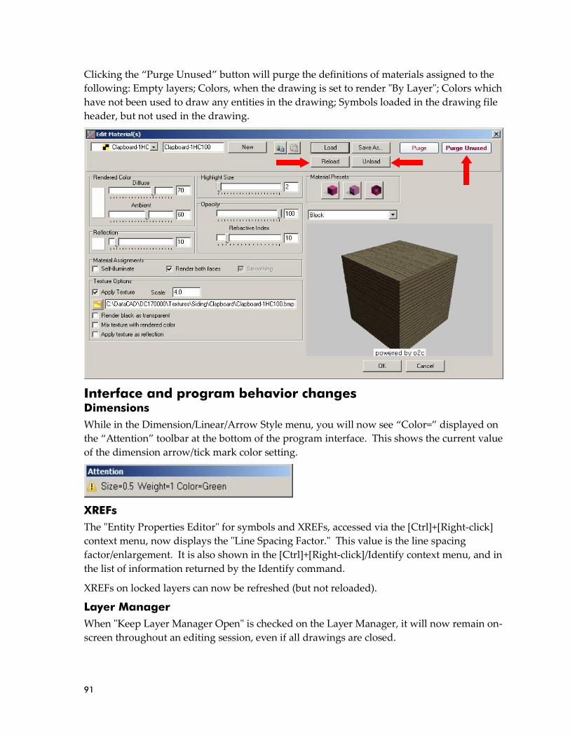
91
Clicking the “Purge Unused” button will purge the definitions of materials assigned to the
following: Empty layers; Colors, when the drawing is set to render "By Layer"; Colors which
have not been used to draw any entities in the drawing; Symbols loaded in the drawing file
header, but not used in the drawing.
Interface and program behavior changes Dimensions
While in the Dimension/Linear/Arrow Style menu, you will now see “Color=” displayed on
the “Attention” toolbar at the bottom of the program interface. This shows the current value
of the dimension arrow/tick mark color setting.
XREFs
The "Entity Properties Editor" for symbols and XREFs, accessed via the [Ctrl]+[Right-click]
context menu, now displays the "Line Spacing Factor." This value is the line spacing
factor/enlargement. It is also shown in the [Ctrl]+[Right-click]/Identify context menu, and in
the list of information returned by the Identify command.
XREFs on locked layers can now be refreshed (but not reloaded).
Layer Manager
When "Keep Layer Manager Open" is checked on the Layer Manager, it will now remain on-
screen throughout an editing session, even if all drawings are closed.

92
Offset
When using "Dynamic" in the Geometry/Offset menu to offset a line, DataCAD now
displays a rubber-band line to indicate the direction of the offset. This can be helpful, as it
shows the direction of the cursor when using Direction/Distance input mode and then
offsetting by a specific distance using keyboard coordinate input.
Text alignment point
When "Draw Text Insertion Point=TRUE" in the [Debug] section of dcadwin.ini, DataCAD
will display the text insertion point on the screen but will not print it.
GoTo Views
Previously, if a drawing contained more than 10 GoTo Views, and you accessed the second
page of the list, chose Move View, picked a view to move, and then picked the view to move
it in front of, DataCAD would revert to the first page of views when finished. Now,
DataCAD remains on the page you were on when you began the process of moving the
view.
Sun Shader The “View” pull-down menu and the View toolbar in the Sun Shader have a new command
labeled “Sun’s eye view.” Clicking this option will orient your model in the Sun Shader as if
you were viewing it from the Sun’s position.
New configuration settings DataCAD 17 contains new configuration settings designed to improve program speed and
functionality, while simultaneously improving productivity. After closing all drawings and
then exiting DataCAD, open the “dcadwin.ini” file, located in the DataCAD 17\ installation
folder on your C drive, to make changes.
Symbol Browser
There are two new keys in the configuration settings file that can automatically alphabetize
the "Recent Folders" and "Favorite Folders" lists in the Folder drop-down menu on the
Symbol Browser.
Add (if absent) or modify (if present) the following keys in the [SymbolBrowser] section
dcadwin.ini:
[SymbolBrowser]
Sort Recent=FALSE
Sort Favorites=FALSE
Set either key to TRUE to have the list sorted alphanumerically.
Note: You should make a backup copy of dcadwin.ini prior to editing, in case you need to return the program to its previous state.
93
Symbol Editor
There is also a new key in the configuration settings file related to editing symbols in the
Symbol Editor. Add (if absent) or modify (if present) the following keys in the [General]
section dcadwin.ini:
[General]
Close Symbol Editor Windows First=FALSE
When absent or set to TRUE, if a drawing file and a Symbol Editor window are open and the drawing is the active window, selecting File/Close All/Yes to All will result in DataCAD automatically switching to the Symbol Editor window to close it first. When set to FALSE, the windows will close in the current order, which may result in the "Save As" dialog being displayed for the Symbol Editor window, because the drawing from which the symbol originated has already been closed.
Nested symbols
Added support for the "Lock Size" property on nested-level symbols, independent of the
status of this setting on the top-level symbol in which the nested symbols are inserted. To
enable this feature, add (if absent) or modify (if present) the following key in the [General]
section of dcadwin.ini:
[General]
Allow Scale Dependent Nested Symbols=TRUE
When FALSE or absent, DataCAD continues to function as it did previously; Lock Size is not supported on nested level symbols.
XREFs
Added support for updating the GTV Link parameters for an XREF that is inserted upon a
locked layer. Add (if absent) or modify (if present) the following keys in the [XREFs] section
dcadwin.ini:
[XREFs]
Always Update GTV Links=FALSE
When absent or FALSE (default) nothing is changed; XREFs that reside on locked layers cannot have their GTV Link updated. When TRUE, XREFs that reside on locked layers may have their GTV Link updated.
Text Scale
The option to completely disable “Text Scale” in the Text and Dimension/Text Style menus
has been added. Add (if absent) or modify (if present) the following keys in the [General]
section dcadwin.ini:
[General]
No Text Scale=FALSE
When absent or FALSE (default), the Text Scale button is available in the Text and Dimension/Linear/Text Style menus. When TRUE, The Text Scale button is absent from both menus, and the function is disabled.

94
GoTo Views
New in DataCAD 16, GoTo Views store the status and angle of Tangents, from the
Utility/Geometry menu, and subsequently recall those values when the GoTo View is later
accessed. To disable this, add (if absent) or modify (if present) the following keys in the
[General] section dcadwin.ini:
[General]
GTV Remembers Tangents=TRUE
When absent or TRUE (default), GoTo Views store the status and angle of Tangents and the value of Tan Div from the Geometry/Tangents menu, and recall them as GoTo Views are restored (added in 16.00.00). Setting this key to FALSE will omit all Tangents related settings from the parameters stored and recalled by GoTo Views.
New extended character codes
Extended character codes are used when programming icon toolbars and keyboard macros.
When using any of the following new extended character codes, you will use the syntax V=
for a toolbar button which executes just the one single command, A=10XX# in a toolbar
button sequence that contains more than one command, or 10XX# in a keyboard macro. For
more information on toolbar programming, see the topic “Creating Custom Toolbars”
starting on page 591 of the Reference Manual.
1096 - PText/MText Boundary On
1097 - PText/MText Boundary Off
1098 - Purge Unused Symbols
1099 - Reload All Symbols

95
New features in DataCAD 16 combine 2D productivity enhancements, 3D modeling tools,
changes to the Sun Shader, and a collection of program optimizations which help to make
DataCAD 16 faster than previous versions. The DataCAD 16 drawing file format is
currently compatible with DataCAD 15, however you must use the “Save As” command in
the “File” menu to save files backward to older version formats.
AutoCAD 2013/2014/2015 support DataCAD 16 supports the ability to import and export AutoCAD 2013/2014/2015 files in
DXF and DWG format. This enables you to collaborate and share files with associates who
use the latest version of AutoCAD.
➔ To import an AutoCAD 2013/2014/2015 file:
Run DataCAD, and then choose “Open” from the “File” pull-down menu.
Click the “Files of Type” drop-down menu, and then select “DWG Files (*.DWG).”
Use the “Look In” field to browse to the folder which contains the DWG file you wish to
import.
Pick the DWG file, and then click “Open.”
Review the settings on the “DWG Import Entity Assignments” dialog, making
adjustments as necessary, and then click OK.
DataCAD imports the file and displays it in the drawing area. For more information on
importing DXF and DWG files, see page 30 in the Reference Manual.
➔ To export a file to AutoCAD 2013/2014/2015 format:
Open the drawing in DataCAD.
Click the “File” pull-down menu, choose “Export,” “DXF” or “DWG,” and then “All
Layers” or “On Layers.”
Use the “Look In” field to choose the folder on your hard drive in which to save the file.
Click the “Save As Type” drop-down menu and then select "R2013-R2014 DWG Files
(*.DWG)" or "R2013-R2014 DXF Files (*.DXF)."
Type a name for the file and then click “Save.
Note: If you are importing a DXF file, select “DXF Files (*.DXF)” instead.
Note: If you are unsure as to what version of AutoCAD your associate’s software supports, you should choose an older format in which to save the DXF or DWG file. Newer versions of AutoCAD can open files saved in older formats, but older versions cannot open files saved in newer formats.

96
DataCAD creates the DXF or DWG file in the specified folder. For more information on
exporting DXF and DWG files, see page 101 of the Reference Manual.
The DXF/DWG Translator has been optimized to reduce the size of exported DXF and DWG
files. When exporting to DXF or DWG files using the "On Layers" option, only those
symbols which are instanced on the exported layers are included in the file header.
Productivity enhancements Associative dimension prefix and suffix
Options to display "Prefix," “Dimension,” and "Suffix" have been added to the "Dim Style"
sub-menu of the Dimensions/Linear menu. Their status and custom data is included with
the collection of information saved in the dimension style file (*.dimstyle).
The prefix text will be added in front of the dimension text. If you want a
space between your prefix and the dimension text, you must make sure to
include it at the end of your prefix text. Similarly, suffix text will be added
after the dimension text. If you want a space shown in between, you must
add it at the beginning of your suffix text. When “Dimension” (on by
default) is toggled off, DataCAD will draw all the dimension components,
but the dimension text will be absent.
➔ To create a dimension with a Prefix or Suffix, or without dimension
text:
Toggle "Prefix" and/or "Suffix" on, and then type the custom data into
the entry field. Press [Enter] to accept the data. New dimensions will
be drawn with the specified Prefix and/or Suffix.
Toggle "Dimension" off to create dimensions that contain just the
custom data with no actual dimension.
Toggle any of the settings back to their original state to return to
drawing normal associative dimensions.
Options to change the "Prefix String" and "Suffix String" are available in
the Entity Properties Editor for associative dimensions, along with access
to the status of the "Dimension Text" setting. [Ctrl]+[right-click] on an
associative dimension and then choose “AssocDim Properties” to access
the Properties Editor.
The Geometry/Tangents function now supports the ability to select
Associative Dimensions. When you select an Associative Dimension, DataCAD rotates the
cursor to match the angle of the dimension line.

97
New selection method: Previous
Added a button labeled "Previous," which selects the previously
selected set of entities, to the "Mask" menu of each selection menu.
➔ For example, let’s say you wanted to move a set of entities, and
then rotate those same entities by 90°:
Choose “Move,” define a distance, and then select an Area of
entities to move. DataCAD moves the entities.
Next, select “Rotate,” define the center of rotation, and then set the
rotation angle.
Click “Mask,” and then click on “Previous.” DataCAD will rotate
the same entities that you had moved in the previous step.
XREF enhancements
Added the "Dynamic Snapping" setting (On or Off), found in the [Ctrl]+[Right-click]/XREF
Tools context menu for XREFs, to the Reference File Manager.
The "Nesting," "GTV Link," "Dyn. Snap," and "Smart Wall Hatch/Fill" sections of the
Reference File Manager are grayed out until you select an XREF to modify. This works like
the way the "Highlighting" section works.

98
You now can disable XClips and SClips for the entire drawing. [Ctrl]+[right-click] in a blank
section of the drawing area to access the Drawing Context Menu. Un-check "XClips On"
and/or "SClips On" will disable display of XClips or SClips. DataCAD will display XREFs
and Symbols as if no XClips or SClips are assigned. The individual clipping boundaries are
retained.
Symbol enhancements
When replacing or redefining a symbol, the name of the symbol is now displayed on the
"Message" toolbar at the bottom of the program interface.

99
DataCAD has a new "Auto Reload" option,
located in the [Ctrl]+[Right-click]/Symbol
Tools context menu for symbols. When this
option is checked, DataCAD will
automatically reload the symbol definition on
the hard drive for each instance of the selected
symbol every time you open the drawing.
This setting is assigned and remembered on a
per-symbol (but not per-instance) basis.
If a symbol marked for Auto Reload is not
found in the original location, DataCAD will
display a warning message when you open
the drawing which notes the name and path
of the missing symbol. DataCAD will then
display any instances of that symbol in the
drawing using the symbol definition from the
drawing file header.
A new "Save As" command has been added to the context menu that appears when you
right-click on a symbol in the Symbol Browser. This enables you to save a copy of the
symbol to a different folder, or with a different name.
There is also a new option labeled "Loaded Indicators" to the "Options" pull-down menu at
the top of the Symbol Browser. When enabled, a small check mark is displayed in the upper
right corner of cells on the Symbol Browser displaying symbols that have been loaded in the
header of the current drawing.
Drag-N-Drop
DataCAD supports the ability to drag and drop any of the following file types:
AEC/DC5
These files may be dropped onto the DataCAD start screen or an open drawing to open
them in new windows. Holding the [Ctrl] key when dropping the file will import it into the
active drawing. Holding the [Alt] key when dropping the file will insert it as an XREF in the
active drawing.
DXF/DWG
These files may be dropped onto the DataCAD start screen or an open drawing to open
them in new windows.
Holding the [Ctrl] key when dropping the file will import it into the active drawing.
Note: A separate warning message is displayed for each symbol that is not found in its original location on the hard drive

100
SKP
These files may be dropped onto an open drawing to insert them as a Symbol. Holding the
[Alt] key when dropping the file will insert it as an XREF in the active drawing.
TXT
These files may be dropped onto an open drawing to insert them as a PText. The drop point
is used the first point of the PText boundary. If you hold the [Ctrl] and [Alt] keys when
dropping the file, DataCAD will prompt you to select the first point of the PText boundary.
Bitmaps (BMP/JPG/JPEG/GIF/TIF/TGA/PNG/PCX/PCD)
These files may be dropped onto an open drawing. DataCAD will use the drop point as the
first point of the boundary rectangle. If you hold the [Ctrl] and [Alt] keys when dropping
the file, DataCAD will prompt you for the first point of the boundary.
XLS
These files may be dropped onto an open drawing to insert them as an XREF.
o2c, ACO, 3DS, STL, DSF/SM3
These files may be dropped onto an open drawing to insert them as a Symbol.
Metafiles (EMF/WMF)
These files may be dropped onto an open drawing to add vectors to the drawing file.
Editing tools
There is a new "Fit" sub-option to the "Copy" menu when "Array" is toggled on. Use this
command to copy selected entities in an array but have them fit within a specified area.
➔ To create an array that fits into a specified area:
Choose "Copy" and then select a start point and endpoint that define the overall distance
of the array.
Toggle "Array" on and then define the number of copies for the array.
Toggle "Fit" on, and then select the entity to copy. DataCAD creates an array and fits the
number of copies you defined within the two points that defined the distance.
We have added a "Dynamic" option to the 2D and 3D Stretch commands. 2D lines, 3D lines,
and (open) polylines are supported. After selecting "Dynamic," click near the endpoint of
the line or polyline you wish to stretch. You may then reposition it dynamically using the
rubber-band method.
When using the "Point" selection method in the "Stretch" command and then using the left
mouse button to click on a point, DataCAD will select all points that are within one pixel of
the cursor position. This has been enhanced such that if no point is found within one pixel,
DataCAD will now choose the closest available endpoint.
The "Stretch" command now supports the ability to select the quadrant points of ellipses.

101
Two new fields for "X Radius" and "Y Radius" have been added to the Entity Properties
Editor for ellipses. [Ctrl]+[Right-click] on an ellipse and then choose "Ellipse Properties" to
access these fields.
Text enhancements
Access to the "Underline" and "Overline" properties for single-line text entities has been
added to the Text/Font dialog. Checking either (or both) turns this property on for
subsequent text. In addition, access to the "Horizontal Alignment" and "Vertical Alignment"
settings is now available via drop-down menus in the Text/Font dialog.
Drop-down menus for "Horizontal Alignment" and "Vertical Alignment" have been added
to the Entity Properties Editor for text entities. In the Horizontal Alignment section, you
may select from the options "Left," "Center," and "Right." In the Vertical Alignment section,
you may select from the options "Bottom," "Middle," and "Top."
File management changes
When selecting "Save As" from the "File" menu, the "File Name" field is automatically
populated with the name of the current drawing file.
The status of the "Preview" check-box on the File/Open dialog has been separated from the
"Preview" check-box on other dialogs, such as Insert/SketchUp or Insert/o2c. Un-checking
"Preview" on the File/Open dialog turns off the creation of the drawing file preview images,
which are saved in the same folder as the drawing file and display a preview when you
select a file. You may now turn this off while leaving the preview of other files types on.
The "Batch Plot" dialog now shows the current path when "Plot to File" is checked.

102
GoTo View enhancements
There is a new button labeled "Extents" in the "Add View" and "Update View" sub-menus of
the "GoTo View" menu. Toggling this option on when adding a GoTo View or updating the
parameters of an existing GoTo View will result in DataCAD automatically recalculating the
extents of the view any time the view is recalled.
GoTo View parameters now include the status and angle of "Tangents" in the "Geometry"
menu, and the number of Tangent Divisions.
Miscellaneous
Menus which have [Scroll Fwd] and [Scroll Back] buttons, such as the Hatch/Patterns, Line
Type, or Layers/OnOff menus, now support the ability to use the scroll wheel on your
mouse to scroll forward and backward. Your cursor must be positioned over the menu for
DataCAD to execute this function.
We have added the ability to change the "At Head" or "At Tail" placement property for Smart
Arrows via the Entity Properties Editor. This enables you to swap the head and tail of a
Smart Arrow after it has been drawn.
The on/off state of the "Multiple" toggle in the "Move/Drag" or "Copy/Drag" menu has been
separated from the "Multiple" toggle in the "Save Symbol" menu.
When working in the Door Type Manager, making changes to a door type and then clicking
the "Apply" button now updates the display of all instances of the door immediately.
Previously, you would need to close the Door Type Manager to see the drawing update.
This change also affects the Window Type Manager and Wall Type Manager.
103
The Measure/InclAngle and Measure/ExclAngle now support Smart walls. Previously, only
2D lines were supported.
The "Intersection" command in the "Geometry" menu now supports Smart walls. Previously,
only 2D lines were supported.
Support for negative distances has been added to the Overshoot property, enabling lines to
fall short of their actual endpoints.
Pressing the [Enter] key on the keyboard after making a change in the Entity Properties
Editor now results in DataCAD applying the change immediately. Previously, you would
need to press the [Tab] key first to change the focus to a different field or click the [OK]
button.
We have updated the sample macros in the DCAL for Delphi\Samples folder (Complete or
Custom installation only) for compatibility with DataCAD 15. There is also a corresponding
“Compiled Macros” folder that contains a compiled DMX file for each sample macro.
3D modeling and viewing enhancements Inserting a symbol in a non-plan view with "Current View" toggled on now supports using
the “Nearest” Object Snapping option.
The ability to access the "Primary Divisions" and "Secondary Divisions" on a 3D Mesh entity
has been added to the Entity Properties Editor.
"Show Edge" and "Hide Edge" options are now available in the 3D Polygons/Edit menu,
enabling you to select individual polygon edges to show or hide.
There are new fields labeled "X Rotation," "Y Rotation," and "Z Rotation" in the Entity
Properties Editor for Polylines. Use these fields to check or adjust the X, Y, and Z rotation
angles of the selected polyline entity.
The "Viewer" toolbar buttons have changed. Rotate +/- Y has been removed. Rotate +/- Z
previously rotated relative to the screen, but now rotates using "world" Z. The default
rotation angle, previously 30°, has been changed to 5°. This is now consistent with the same
toolbars in the Object Viewer and the Sun Shader.
The appearance of the 3D cursor has been updated to display the X, Y, and Z axes in red,
blue, and green respectively. These colors remain independent of the current color.
The “Add Vertex” and “Move Vertex” commands in the Polyline/Edit, 3D Polygon/Edit and
3D Slab/Edit menus have been enhanced. DataCAD will highlight the selected polyline,
polygon or slab with a dashed gray line type. If multiple edges or nodes are found within
the miss distance, you may right-click and then select again to cycle through the coincident
entities.
Note: When these values are not zero, you must use the 'Get Construction Plane' menu before you can edit the Polyline. Otherwise, the error message "You must be in this Polyline's construction plane to perform this function" will be displayed when you try to use the Polyline editing tools.

104
If you convert a polygon to a polyline, edit it, and then explode it back to polygons, faces
that have four or more sides will no longer be triangulated.
New configuration settings DataCAD 16 contains new configuration settings designed to improve program speed and
functionality, while simultaneously improving productivity. After closing all drawings and
then exiting DataCAD, open the “dcadwin.ini” file, located in the DataCAD 16\ installation
folder on your C drive, to make changes.
Show hatch
The following key will disable the display of hatching during any dynamic drag operation:
[General]
Show Hatch During Drag=FALSE
When FALSE, the default, or absent, display of hatch is suppressed while performing a dynamic operation, such as Move/Drag, Copy/Drag or when inserting a symbol. When TRUE, all hatch is displayed during dynamic operations.
Line weight hot key
The following key disables the [w] key on the keyboard:
[General]
Disable Line Weight Hot Key=FALSE
When TRUE, the [w] key on the keyboard is disabled. When FALSE (default), pressing the [w] key increases the value of the current line weight by 1.
Drawing timer
The following key will keep the drawing timer running even if DataCAD is not the active
application.
[General]
No Timer Pause=FALSE
When TRUE, DataCAD will continue to increment its drawing timers even if it is not the active application. When FALSE (default), the drawing timers are paused if DataCAD is not the active application.
Printing
The following key will disable the Spacebar while the Plot Preview window is displayed:
[Plot Preview]
No Spacebar=TRUE
When FALSE or absent, pressing the Spacebar while the Plot Preview window is displayed will result in DataCAD selecting the current active button, which is the "Plot" button.
The following set of keys can be used to define whether display menu settings affect the
ability to print different drawing elements:
[Printer]
Print Text=DEFAULT
Note: You should make a backup copy of dcadwin.ini prior to editing, in case you need to return the program to its previous state.
105
Print Hatch=DEFAULT
Print Line Weight=DEFAULT
Print Line Types=DEFAULT
Print Associative Dimensions=DEFAULT
Print Fills= DEFAULT
Print Bitmaps=DEFAULT
Print KnockOuts=DEFAULT
Print Smart Wall Hatch=DEFAULT
Print Smart Wall Fill=DEFAULT
Set any of the above to TRUE to force them to print, even if the attribute setting in the Utility/Display menu is turned off. If set to DEFAULT or missing, the drawing's display toggles T, H, L, U, D, F, B, and K in SWOTHLUDFBK will be used to determine whether the element is included in the printed output.
Display speed
Speed of display has been improved by up to 100%. The improvement is most noticeable
when switching between GoTo Views or forcing a screen regeneration by pressing the [u]
key on the keyboard. If these changes cause unintended effects, they can be disabled using
the following key:
[General]
New Smart Object Generation=FALSE
When absent or TRUE (default), DataCAD uses the new faster method of screen regeneration. When FALSE, the older method is used.
We recommend using this key to disable the speed enhancement only after consulting with
a DataCAD support technician.
Fence selection
Fence selection now supports the same automatic crossing option used in Area selection.
Creating a Fence by clicking points in a counter-clockwise order results in DataCAD
automatically enabling "Crossing." Selecting the points in a clockwise order leaves
"Crossing" off. The order and position of the first three selected points determines whether
it is clockwise or counter-clockwise.
This feature requires the following key be enabled in dcadwin.ini
[General]
Automatic Crossing Selection=TRUE
When FALSE, the direction in which you choose Area or Fence points has no effect on whether Crossing is enabled; you must manually toggle Crossing on if you wish to use it.
The way symbols are selected when using "Fence" with "Crossing" enabled has been
adjusted. Previously, the symbol would only be selected if the insertion point was within
the Fence boundary, even with "Crossing" turned on. Now, the symbol will be selected if
the Fence boundary crosses any part of the symbol, like the way Area/Crossing selection
works.
There is a dcadwin.ini key that can restore the command to its previous state:
[General]
New Crossing Fence=FALSE
106
When absent or TRUE (default), DataCAD uses the new Fence/Crossing selection method on symbols. When FALSE, DataCAD uses the previous Fence/Crossing selection method on symbols.
Busy cursor
Use the following key to specify DataCAD's busy animated cursor. Windows cursors,
.CUR, and animated cursors, .ANI, are located in C:\Windows\Cursors\ by default.
[General]
Busy Cursor=GoldenMean
Type the name of the cursor you wish to use for DataCAD’s busy cursor after the equal sign.
o2c Object Viewer
You can add the following entries to the [o2cViewer] section of DCADWIN.INI to customize
the rotation of the model and/or the texture about the o2c world Z-axis.
Set Model_Z_Angle to 180 to orient the model consistent with o2c's coordinate system.
Set Texture_Z_Angle to 90 to orient bitmap textures on horizontal surfaces to match the
orientation of the source image that is read from the hard drive.
The default values; no rotation. Range: 0 - 360.
[o2cViewer]
Model_Z_Angle=0
Texture_Z_Angle=0
Recommended values for 'correct' orientation.
[o2cViewer]
Model_Z_Angle=180
Texture_Z_Angle=270
The ability to load the current DataCAD perspective view when launching the Object
Viewer has been added.
[o2cViewer]
LoadDataCADView=True
When TRUE, the o2c Object Viewer will open using DataCAD’s current perspective view. When FALSE, the o2c Object Viewer opens using its standard default view.
Note: The texture angle should be added to the model angle so they rotate 'together'.
Note: “Remember Last View” must be set to FALSE, otherwise the last o2c view will be restored instead.
107
New extended character codes Extended character codes are used when programming icon toolbars and keyboard macros.
When using any of the following new extended character codes, you will use the syntax V=
for a toolbar button which executes just the one single command, A=10XX# or A=30XX# in a
toolbar button sequence that contains more than one command, or 10XX# or 30XX# in a
keyboard macro.
Text underline and overline
The following extended character codes can be used to define the status of the Underline
and Overline properties in the Text/Font dialog:
1089: Underline On
1090: Underline Off
1091: Overline On
1092: Overline Off
DWG Export
The following extended character codes can be used to export a DWG which contains all
layers or on layers:
3017: DWG Export, All Layers
3018: DWG Export, On Layers
Polyline display
The following extended character codes can be used to set the state of the "Draw Marks"
toggle which displays (or suppresses display of) polyline vertices:
1094: 3D Settings/DrawMarks On
1095: 3D Settings/DrawMarks Off
Sun Shader 2.0.4.1 Entity Filters
The “Rendering Settings” dialog for the Sun Shader contains new “Entity Type” and “Entity
Size” filters, which can selectively omit information from the model to improve display
speed. You can filter certain types of entities, such as Revolved Surfaces or Cones, or you
can filter entities by size, whether absolute or relative to the rest of the model.

108
➔ To filter entities from the Sun Shader:
Click the “Rendering Settings” button on the “Rendering” toolbar, highlighted in the
image above, to launch the Rendering Settings dialog.
On the “Sun Shader” tab, check “Entity Type” if you wish to omit specific types of
entities from the model. Check the entity types in the list.
Check “Filter entities smaller than…” if you wish to omit entities that are smaller than a
certain size.
If you wish to filter by absolute size, click the “Absolute” radio button, and then enter a
size.
If you wish to filter by a size that is relative to the rest of the model, click the “Percent of
model extents” radio button, and then click the drop-down menu to select a percentage.
Click OK when you have finished configuring the options.
Launch the Sun Shader. DataCAD will omit entities which meet the defined criteria.
Render selected entities
The Sun Shader has two new methods of rendering selected information, instead of your
entire model: using the Clipboard, and rendering symbols.
➔ To render information from the Clipboard in the Sun Shader:
Press [Ctrl]+[e] on the keyboard or choose “Clipboard Select” from the “View” pull-
down menu.

109
Select the information you wish to launch into the Sun Shader, by Entity, Group, Area or
Fence.
Click the “Display Model in Sun Shader”
button on the “Rendering” toolbar to launch the
Sun Shader. DataCAD displays only the
selected information in the Sun Shader.
➔ To render a specific symbol in the Sun Shader:
Display the Symbol Browser by pressing [Ctrl]+[t] or by selecting “Symbol Browser” in
the “View” pull-down menu.
Right-click on the symbol you wish to display in the Sun Shader, and then choose “Sun
Shader” from the context menu. DataCAD opens the selected symbol in the Sun Shader.
New settings
The Sun Shader has some new settings designed to improve the shadow study results.
Custom time window
Now you can define a custom time window for shadow studies. Previously, only Sunrise to
Sunset was supported. This option is on the “Date and Time” tab under “Shadow Study
Settings.”
Frequency
The smallest time interval for "Frequency" on the "Date and Time" tab of Shadow Study
Settings is now 5 minutes. The 6-hour interval has been removed.

110
Customizable font size
The size of the text which displays the Shadow Study Results can now be customized.
Miscellaneous
Support for alpha channel in transparent bitmaps has been restored.
Pressing [Alt]+[x] locks rotation about the X-axis. Pressing [Alt]+[z] locks rotation about the
Z-axis.
New configuration settings
There are two new configuration settings related to the Sun Shader. After closing all
drawings and then exiting DataCAD, open the “dcadwin.ini” file, located in the DataCAD
16\ installation folder on your C drive, to make changes.
[Sun Shader]
Force Solid Background=TRUE
When FALSE (or absent) the Sun Shader background uses a gradient. When TRUE, the background uses a solid color.
[Sun Shader]
Force Ground Plane display for Shadow Study=FALSE
When TRUE (or absent) the Sun Shader includes a ground plane when Shadow Study mode is activated. When FALSE, no ground plane is used.
Note: Transparent bitmaps cannot be supported while shadows are being cast.
Note: You should make a backup copy of dcadwin.ini prior to editing, in case you need to return the program to its previous state.

111
Sun Shader 2.0 Sun Shader 2.0 features a new rendering engine that has been optimized for speed of
display, enabling you to review complex models with ease. It has support for smooth and
transparent materials and features new toolbars to improve navigation. Features such as
GoTo Views and a Layer Manager enable better control over your model using familiar
commands from DataCAD. Sun Shader 2.0 is accessed via the “Sun Shader” option in the
“View” pull-down menu, or the Sun Shader button on either the “Rendering” or “Viewer”
toolbar.
Transparency
Sun Shader 2.0 has support for transparent materials, such as glass. When you assign a
transparent material to an object, Sun Shader 2.0 will display it as transparent, enabling you
to see through it. Shadow Study mode also supports transparency, so you can see the effect
of sunlight through windows.

112
GoTo Views
The GoTo View toolbar in Sun Shader 2.0 enables you to save view parameters, including
rotation angle and zoom level. Click the “Add View” button to add the current view to the
list, click on “Update View” to update the selected view with the current view parameters,
or click on “Delete View” to delete the selected view from the list. Click the drop-down
view menu to select a saved view from the list and display it on the screen.
Layer Manager
Click the Layer Manager toolbar button to open the Sun Shader Layer Manager. It provides
access to the layers that were turned on in your model when you launched the Sun Shader
from DataCAD. Use it to turn layers in the model on and off without having to close the
Sun Shader and return to DataCAD, making it easier to explore construction options and see
their effect on the Sun path and shadows.
The Layer Manager contains familiar commands, such as All On, Set Active and Active
Only. In addition, options for Select All, Deselect All, and Invert Selection are available.

113

114
Edge Properties
There is an Edge Properties drop-down toolbar button which contains options for defining
the properties of edges in your model. It includes options to use the entity color or a specific
color, and the ability to define the width (in pixels) that each edge should be displayed.
Smoothing
Sun Shader 2.0 has support for smoothing in material properties. When enabled, curved
edges will not display facets, and will instead appear as smooth curves.
Other toolbars
Other toolbars, added for convenience, include the Zoom Toolbar, the Rotate Toolbar and
the Review Toolbar. From left to right, the Zoom Toolbar has buttons for zoom extents and
zoom window. The Rotation toolbar has buttons that rotate the model counter-clockwise
about the Z axis, clockwise about the Z axis, counter-clockwise about the X axis or clockwise
about the X axis. When Shadow Study mode is off, you may use the Review Toolbar to
check face winding, draw face normals, draw vertex normals, and to show the positive
(outside) face, the negative (inside) face, or both.
Shadow Study Results
Shadow study results, including location, date and time, and Sun position, are now
displayed as text in the upper left of the Sun Shader viewing window when Shadow Study
mode is enabled.

115
Pan/Zoom/Rotate Widget
The Pan/Zoom/Rotate widget is available in the "View" pull-down menu. When checked, it
is displayed in the lower right corner of the Sun Shader 2.0 interface.
Clicking the left and right arrows rotates the model about the Z axis, while clicking the up
and down arrows rotates the model about the X axis. Pressing and holding the [Shift] key
while clicking the arrows will pan in the selected direction. Clicking the center circle
restores the model to the initial view. Clicking the middle circle and then dragging the
cursor clockwise about the center point zooms in on the model, while dragging counter-
clockwise zooms out.

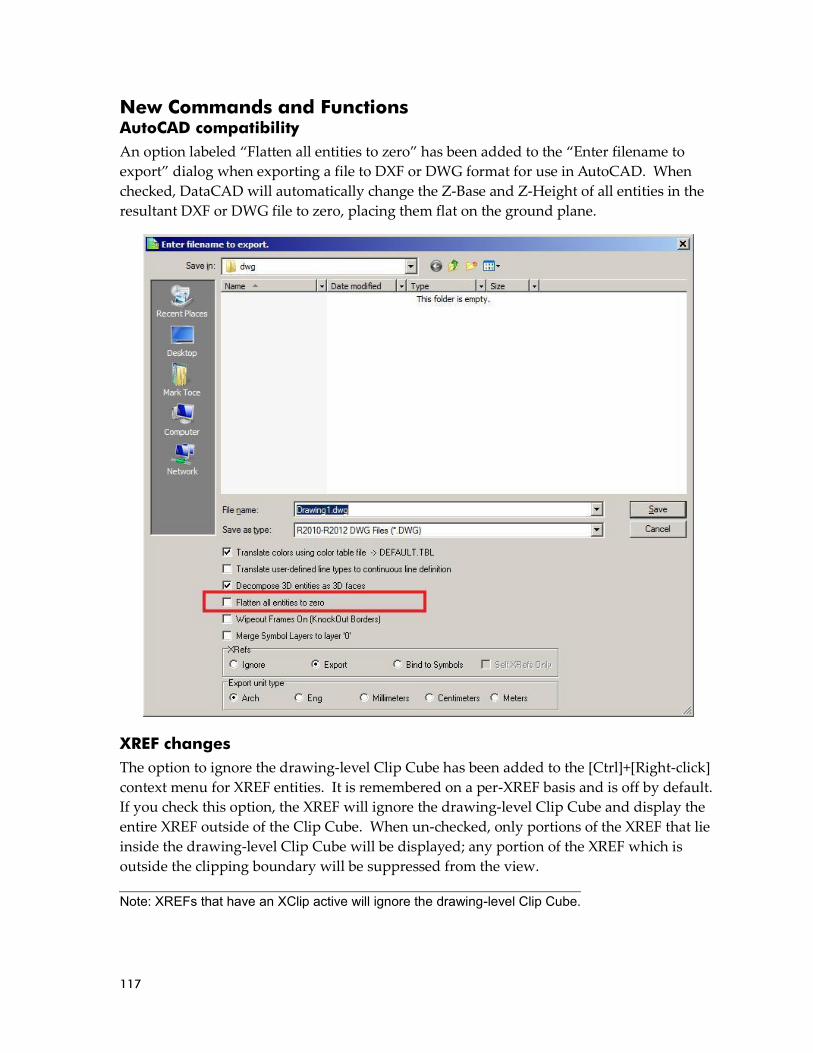
117
New Commands and Functions AutoCAD compatibility
An option labeled “Flatten all entities to zero” has been added to the “Enter filename to
export” dialog when exporting a file to DXF or DWG format for use in AutoCAD. When
checked, DataCAD will automatically change the Z-Base and Z-Height of all entities in the
resultant DXF or DWG file to zero, placing them flat on the ground plane.
XREF changes
The option to ignore the drawing-level Clip Cube has been added to the [Ctrl]+[Right-click]
context menu for XREF entities. It is remembered on a per-XREF basis and is off by default.
If you check this option, the XREF will ignore the drawing-level Clip Cube and display the
entire XREF outside of the Clip Cube. When un-checked, only portions of the XREF that lie
inside the drawing-level Clip Cube will be displayed; any portion of the XREF which is
outside the clipping boundary will be suppressed from the view.
Note: XREFs that have an XClip active will ignore the drawing-level Clip Cube.

118
The toggle "Remember Layer Settings for GoTo Views" has been removed from the
"Reference File Management..." menu in the "Insert" pull-down. It has been renamed "GTV
Link," and can be found in the Reference File Manager, the XREF Properties dialog, and the
[Ctrl]+[Right-click] context menu for XREFs. This setting is remembered on a per-XREF
basis.
The GTV Link feature now supports per-XREF highlighting in addition to the per-XREF-
layer highlighting that was previously supported. Using this feature, you can insert an
XREF and assign highlight color, line type and line spacing, and then save a GoTo View in
the host drawing. You can then assign different (or no) highlight color, line type and
spacing, save another GoTo View in the host drawing, and DataCAD will remember these
settings when switching between GoTo Views.
If the "GTV Link" in the Reference File Manager is set to "On," the status of the "Ignore Clip
Cube" setting is remembered with the host-level GoTo Views in the drawing.
Note: Even if this option is off, the GTV links are still remembered for the XREF. However, the XREF's layers will not be toggled on and off in response to changing GTVs unless this option is subsequently toggled on.

119
When an XREF is inserted with an enlargement factor, that same enlargement factor is now
applied to the overshoot value for any objects in the XREF that have overshoot assigned by
entity. Previously, no enlargement factor was assigned to overshoot.
Smart Arrow changes
The "Current Color" toggle in the Text/Arrow/Smart Arrows/Color menu will draw the
arrow heads using the current layer color. Using this setting saves you the step of defining a
color for arrow heads and is remembered on a per-drawing basis.
The "Current Wgt" option in the Text/Arrows/Smart Arrows/Weight menu will draw the
arrow heads using the current line weight. Using this setting saves you the step of defining
a line weight for arrow heads and is remembered on a per-drawing basis.
Smart Arrow styles "Closed" and "Dot" support the KnockOut setting. When enabled, they
will obscure any other information which occupies the same coordinates in the drawing
area.
“Smart Arrow" has been added to the list of entities supported by selection mask. When
selecting entities, choose “Mask,” pick “Entity” and then toggle “Smart Arrow” on. When
you return to the selection menu, DataCAD will only select Smart Arrows.
The "1st Ortho" toggle in the Smart Arrows menu has been enhanced. When on, only the
first segment of the Smart Arrow leader will be orthogonal, regardless of whether "Ortho
Mode" is on or off in the "Tools" pull-down menu. Previously, if Ortho Mode was checked
all segments of the leader would be drawn orthogonal; to draw only the first segment
orthogonal, you had to turn 1st Ortho on and turn Ortho Mode off.
2D drafting and drawing
The [Ctrl]+[Right-click] context menu has been enhanced to display new options when
executed while the cursor is positioned over a blank space in the drawing area.
• Selecting "Paste" will paste the contents of the Windows Clipboard.
• Selecting "Paste Special" will open the "Paste Special" dialog enabling you to select from
the available formats (if applicable) to paste the contents of the Clipboard.
• Selecting "Paste As Symbol" will enable you to paste the current contents of the
Clipboard as a symbol in the drawing, provided the Clipboard contains DataCAD
information.
• Choosing "Clipboard Select" invokes the Clipboard Selection mode so that you can
choose information to Copy to the Clipboard.
• Selecting "Save all drawing symbols to a folder" enables you to save all symbols
currently instanced in the drawing to a selected folder on your hard drive. Note:
DataCAD will not save nested-level symbols or symbols which are no longer instanced.

120
A temporary boundary box is displayed when creating or resizing MText and PText entities.
Even if the MText or PText entity has “Boundary” turned off, this temporary box is
displayed when you are placing or resizing the entity to show the limits of the object. This
boundary is temporary and disappears as soon as you complete the process of defining the
word wrap edge. It will not display or print. There is a corresponding dcadwin.ini key that
can disable this feature. See item 1 in the “New dcadwin.ini keys” section for details.
Smart walls that are drawn on different layers support the ability to have their intersections
cleaned using the "T Intersect," "L Intersect," and "X Intersect" commands in the Cleanup
menu. Layer Search must be toggled on for these to work. Previously, only Smart walls
that were drawn on the same layer could have their intersections cleaned.
Added "Relocate" to the [Ctrl]+[Right-click] context menu for associative dimensions.
Selecting this option puts DataCAD into dimension placement mode, so that you may
reposition the dimension line using the existing dimension points.
The "Bisect" function in the Geometry/Tangents menu supports the ability to select Smart
walls. Previously, only 2D lines were supported. After selecting “Bisect” from the
“Tangents” menu, choose two Smart walls. DataCAD will rotate your cursor to match the
angle of a line that would bisect the angle between the two walls.
The "Justify" command in the "Text" menu supports the ability to select 2D Lines, 3D Lines
and Smart walls as the line of justification, using the "Entity" option in that menu. After
selecting a justification line, and then exiting and returning to the menu, a "Prev. Line"
option is now available, enabling you to use the previously selected justification line.
The "1-Line Trim" command in the "Cleanup" menu supports the ability to select individual
wall lines of Smart walls when defining the “Trim To” line. Previously, this function was
limited to selecting the control line.
A "Prev. Line" option has been added to the Cleanup/1 Line Trim menu. It enables you to
choose a previously selected line as the trim-to line for the command. After choosing "Prev.
Line," you then pick the outside of the line, and then proceed with choosing lines to trim.
An "Entity" toggle has been added to the "Mirror" menu which enables you to select a 2D
Line, 3D Line or Smart wall to act as the line of reflection. The status of this setting is
remembered on a per-drawing basis.
DataCAD supports the ability to select Circles in the "Line To Poly" function of the
Polyline/Edit menu.

121
Area, Perimeter and Volume have been added to the list of information returned on the
Coordinates/Hints toolbar when you "Identify" a bitmap.
The new toggle named "WYSIWYG" has been added to the Plotter menu. This toggle is only
available when "Pen Sort" is off. When enabled, print order is the same as screen display
order, resulting in "What You See Is What You Get."
Added a "3-Sided Only" option to the 3D Explode/To Polygons command. When activated,
exploding an object will result in a collection of 3-sided polygons. This can be useful when
exporting a model to a rendering application.
The Layer Manager has new layer status indicators. If the layer name is drawn in black text,
the layer is turned on. If the layer name is underlined, it is the current active layer. If the
layer name is gray, the layer is turned off. If the layer name is red with a strikethrough, the
layer is on and locked. If the layer name is gray with strikethrough, the layer is off and
locked.
When you pick "Import" (and then either Replace or Merge) in the "Layers" menu to import
a layer, the "Load from which file" dialog appears. The default name in the "File name" field
is the same name as the layer which is currently active in the drawing and was previously
limited to eight characters. This limitation has been lifted, and the function now supports
long layer names.

122
New Configuration Settings DataCAD 15 contains new configuration settings designed to improve program speed and
functionality, while simultaneously improving productivity. After closing all drawings and
then exiting DataCAD, open the “dcadwin.ini” file, located in the DataCAD 15\ installation
folder on your C drive, to make changes.
1) Added a key to dcadwin.ini to facilitate turning off the temporary boundary box that
appears around MText and PText when placing or resizing the entity.
[General]
Show PText/MText Boundary On Entry/Resize=FALSE
When TRUE (or absent), a temporary boundary box is displayed around MText and PText entities when creating or resizing them. When FALSE, the temporary boundary box is not shown.
2) Added a key to dcadwin.ini which disables the Lock Size feature on text and
dimensions.
[General]
No LockSize=TRUE
When FALSE (or absent), Lock Size is available in the Text and Dimension/Text Style menus (with Text Scale enabled). When TRUE, the Lock Size button is no longer present in the Text or Dimension/Text Style menus. If a drawing contains text that has Lock Size turned on, DataCAD will continue to change the size of the text in the drawing area when you change the plot scale. Use the Change/More/Lock Size/Off menu command, or the "Lock Size" setting in the Entity Properties Editor, to turn Lock Size off if you wish to change this property for existing entities.
3) Add the following key to the [General] section of dcadwin.ini to disable all hard-
coded keyboard interrupts (single-letter key presses):
[General]
Shortcut Keys Invoke Alias=TRUE
When FALSE (or absent), single-letter keyboard interrupts continue to function as they always have. For example, pressing [a] sends DataCAD to the "Architect" menu. When TRUE, DataCAD directly accesses the Command Line Alias function and executes the selected command. This mode of command entry more closely mimics that of AutoCAD, and enables you to customize the keyboard commands. For example, you could set the [a] key to take you to the "Arrow" menu instead of the "Architect" menu. Multi-character aliases are also supported, for example "ZE" for "Zoom/Extents."
For more information on creating a command line alias, see "Using the Command Line
Alias" in Chapter 2 of the "DataCAD 14 Reference Manual."
4) Add the following key to the [General] section of dcadwin.ini to disable direct
distance input:
[General]
Spacebar For Distance Input=TRUE
Note: You should make a backup copy of dcadwin.ini prior to editing, in case you need to return the program to its previous state.

123
When FALSE (or absent), the [Spacebar] is not necessary to invoke coordinate input mode.
New extended character codes The following extended character codes have been added:
1066# : Pen Sort On
1067# : Pen Sort Off
1068# : WYSIWYG On
1069# : WYSIWYG Off
1079# : Hatch On
1080# : Hatch Off
1081# : Fill On
1082# : Fill Off
1083# : Bitmaps On
1084# : Bitmaps Off

124
KnockOut KnockOut can be enabled on various types of entities to mask out information behind the
object. When KnockOut is enabled, other drawing information around the entity is masked
by a solid fill which has the same color as the drawing area background, making it appear
transparent. This is particularly useful, for example, when adding text or dimensions which
you want to display over hatching.
The KnockOut feature is supported by Text, including MText and PText, Associative
Dimensions, 2D Arcs, 2D Circles, Ellipses, Polylines, Polygons and Slabs. Smart Arrows set
to the “Closed” and “Dot” arrow style are also supported. Additionally, a sub-option can
display or omit the KnockOut boundary, like the way in which hatching can be set to show
the outline or not. The status of the KnockOut toggle in the Text menu and in the
Dimension/Text Style menu is remembered in saved Text Styles and Dimension Styles
respectively.
➔ To draw text with KnockOut enabled:
1. Click the [F8] KnockOut on in the Text menu.
2. Toggle “Yes” on to include KnockOut on new text.
a. Toggle “Border” on if you wish to display the KnockOut border.
3. All new text will have KnockOut enabled.
➔ To enable KnockOut on an object already in the drawing:
1. [Ctrl]+[Right-click] on the entity and mouse over “KnockOut.”
125
2. Select “Yes.”
You may also change the status of KnockOut on entities using the standard selection menu.
Select “More” from the “Change” menu and then pick “KnockOut.” Toggle “Yes” on to
enable the option, or toggle “No” on to disable the option. When “Yes” is on, the “Border”
sub-option may also be selected. Right-click twice to return to the “Change” menu, and
then select the objects you wish to change.
The KnockOut feature will only mask entities that were drawn before it. These entities are
described as “behind” the KnockOut entity, both in terms of the draw order on the screen,
and the position of the entities relative to the KnockOut entity in the drawing file database.
If you add an entity with KnockOut enabled, and then draw on top of it, the new
information will display on top of the KnockOut. If both entities are on the same layer, and
you would like the KnockOut to mask information drawn after it, you can use the Move/To
Front command to move the KnockOut entity on top of the other information. You could
also use Move/In Front and select the entities you wish to move the KnockOut entity in front
of. Move/To Back and Move/In Back are also useful for defining the order in which the
entities display.
Enabling KnockOut on an entity via the Change menu, the [Ctrl]+[right-click] menu or the
Propertied Editor will also perform a “Move to Front” on the selected entity automatically.
This makes the KnockOut entity the last entity on the layer, thus displaying it on top of
other objects.
KnockOut enlargement
There are drawing-level settings for the default X and Y Enlargement factor for KnockOuts
on Text, PText, MText, Symbol Attribute Text and Associative Dimensions. The values for
Associative Dimensions are separate from the values for the other text-based entities. The
menu buttons to access these settings are in the various entity creation menus, after toggling
KnockOut on. Once an entity has been added to the drawing, the value of the X and Y
Enlargement for the KnockOut is remembered (and can be changed) on a per-entity basis.
➔ To set the default KnockOut enlargement value:
1. Click “KnockOut” in the “Text” menu or in the “Text Style” sub-menu of the
Dimension/Linear menu.
2. Toggle “Yes” on.
3. Click the “X Enlargement” button and set the enlargement size.
4. Click the “Y Enlargement” button and set the enlargement size.
➔ To change the values of these variables on entities already in the drawing:
1. Select “More” and then “KnockOut” from the “Change” menu.
2. Toggle on “Yes” to turn KnockOut on for selected entities, or “No” to turn it off.
After enabling KnockOut on an object, you may [Ctrl]+[Right-click] on it again, and set “Border” to “Yes” to display the KnockOut border

126
3. Right-click twice to return to the “Change” menu.
4. Select the entities to change.
Related Settings
The [k/K] button on the SWOTHLUDFBK toolbar controls whether KnockOuts are
displayed. When on, [K], KnockOuts are shown. When off, [k], no KnockOuts are
displayed in the drawing. You’ll find the same setting, labeled “KnockOut Display,” in the
“View” pull-down menu under the “KnockOuts…” sub-menu.
The “View” pull-down also has a “KnockOuts…” sub-menu with settings related to the
display of KnockOuts. The option “KnockOut Display” controls the display and printing of
all KnockOut entities. When toggled off, entities with a KnockOut property will display
and print as normal entities without the KnockOut. The “Show all KnockOut Borders”
setting forces DataCAD to display all KnockOut borders regardless of their individual
border settings. This is a display only setting and does not affect printing. When checked,
the “Compatibility Mode” option draws and displays KnockOuts in their database order
(the order in which they were created), using the same methodology as AutoCAD. You can
uncheck this option to always display and print all KnockOuts last, or on top of other
entities.
AutoCAD compatibility
AutoCAD has a similar feature named Wipeout. When you export a file that contains
KnockOuts, they are converted to AutoCAD Wipeout entities. The result is that the file
looks the same in AutoCAD. When you import a file that contains Wipeout entities,
DataCAD converts them to polygons with KnockOut enabled. The result is that the file
looks the same in DataCAD.
DataCAD can display KnockOut borders on a per-entity basis, but AutoCAD does not.
When you export a file to AutoCAD format, you must decide whether to display the
KnockOut borders for all KnockOut entities or for none. After you select File/Export/DWG
and pick either All Layers or On Layers, the “Enter filename to export” dialog appears. If
you wish to display KnockOut borders for all KnockOut entities, place a check next to
“Wipeout Frames On.” If you do not wish to display the KnockOut borders, leave this
option un-checked.
Similarly, when you import a file from AutoCAD, you must decide whether to display the
KnockOut borders. After you select the file to import, the Import Entity Assignments dialog
is displayed. If you wish to display the borders for all KnockOut entities, check the
“KnockOut Borders On” box. Leave this un-checked if you do not want all KnockOut
borders shown. Keep in mind that you can change them individually after you import the
file.
The “Show All KnockOut Borders” and “Compatibility Mode” options are only available when “KnockOut Display” is enabled.

127
Extended character codes
The following extended character codes can be used to change the status of the KnockOut
option and the KnockOut Border sub-option. This toggle is found in the Text, MText, PText,
Text Attributes and Dimension/Text Style menus, as well as in the 2D Curves menu and the
3D Polygons and Slabs menus:
1056: KnockOut On
1057: KnockOut Off
1058: KnockOut Border On
1059: KnockOut Border Off
The following extended character codes can be used to control the status of KnockOut
display in the View/KnockOuts menu:
1060: Display of KnockOuts On
1061: Display of KnockOuts Off
Wall Type Manager The Wall Type Manager has been updated to provide the ability to add hatching and/or
solid fill to the wall cavities. As part of this enhancement, we have changed the layout of the
Wall Type Manager. There are tabs named “Line Settings,” which contains settings related
to the wall lines in 2D and in 3D, “2D Cavity Settings,” which has settings related to
hatching and fill for 2D display of cavities, and “Cap Settings,” which is where you define
the way end caps, top and bottom caps, and opening caps render in the 3D Object Viewer.
Line Settings tab
The settings on this tab are the same as the previous version, except that the “Caps and
Openings” section has been removed. On the Line Settings tab, you will define the basic
properties of the lines that make up your wall type. Set the number of lines and select
which is used as the Control Line, choose the distance that each line is offset from the
previous line to define the width of the wall, and set the 2D line colors and 3D rendering
materials for the individual wall lines.
2D Cavity Settings tab
It is on this tab that you may apply hatching and/or solid fill to the wall cavities. In the case
of a 2-line wall, the hatching or fill covers the entire wall cavity. In the case of a 3-line wall,
you may choose to hatch or fill the inside cavity, the outside cavity, or both. 4-Line walls
support hatch and fill on the inside, center and outside cavities independently. These
properties are type-dependent, so any changes you make affect all instances of the wall type
throughout your drawing file.
➔ To apply hatching or solid fill to a wall type:
1. Open the Wall Type Manager, load a wall type and set it active.
2. Go to the “2D Cavity Settings” tab.

128
3. Click the “Cavity” drop-down to select which cavity to modify. For 2-line walls,
“Inside” is the only option; for 3-line walls, you may select the “Inside” or
“Outside” cavity; for 4-line walls, choose “Inside,” “Center” or “Outside.”
4. Check “Do Hatch” to apply hatching to the selected cavity.
a. Click the “Pattern” drop-down to select which hatch pattern will be
applied.
b. Enter a value in the “Scale” field to define the scale of the hatching.
c. When “Match Wall Angle” is unchecked, you define an absolute angle for
the pattern in the “Angle” field. When it is checked, the angle value is
relative to the angle of the wall. For example, if the angle is zero, the
pattern matches the wall angle. If the angle is 45°, the pattern is
displayed at a 45° angle relative to the angle of the wall segment.
d. When “Origin at Zero” is checked, the hatch pattern origin is situated at
absolute zero. When unchecked, the origin coincides with node 1 of the
wall segment.
e. You can match the color of the hatch to the wall line, or you can uncheck
that option and click the color rectangle to open the Color Palette and
select a different color.
5. Check “Do Fill” to apply a solid or pattern fill to the selected cavity.
a. Under “Settings,” you can either check the box to make the fill the same
color as the line that borders the cavity, or you can uncheck the box and
click the color rectangle to open the Color Palette and select a specific
color.
b. Click the “Pattern” drop-down if you wish to define a pattern fill.
c. Check the box next to “Pattern Color” to make the pattern the same color
as the line which borders the cavity or uncheck it to define a specific
color.
6. Click OK when you have finished adjusting the settings.
The “Architect” menu contains toggles labeled “Hatch” and “Fill” that enable or disable the
display of Smart wall hatching and Smart wall fill independent of other hatch and fill in the
drawing. These settings affect both display and printing. The “Hatch Patterns” and “Fills”
buttons in the “Display” menu and the corresponding [H] and [F] buttons on the
SWOTHLUDFBK toolbar will suppress all hatching and fill, including those that are within
Smart walls.
The following extended character codes are related to the display of Smart wall hatching
and solid fill:
Wall cavities support both hatching and solid fill at the same time. If the hatch and fill are different colors, you will see the hatch drawn on top of the solid fill.

129
1062: Turn display of Smart wall hatch on
1063: Turn display of Smart wall hatch off
1064: Turn display of Smart wall fill on
1065: Turn display of Smart wall fill off
Cap Settings tab
Use the settings on this tab to define the rendering characteristics of the Top/Bottom Covers,
the End Caps, and the Openings for Smart walls in the 3D Object Viewer. While the three
categories of caps are defined independently, they all have the same settings available.
Top/Bottom Caps refer to the horizontal plane on the top and bottom of each wall segment;
End Caps refer to the vertical plane at the end of each wall segment; Openings refer to the 4
edges of a window or door void, which are only displayed if the layer that contains the
window or door is turned off.
There are three mutually exclusive settings for the various caps, which you select by clicking
the appropriate radio button. When “Inherit From Inside Line” is selected, the material
assigned to the Inside line covers the cap from the inside line to the outside line. When
“Inherit From Outside Line” is selected, the opposite is true; the rendering material assigned
to the outside line covers the cap from the outside line to the inside line. Selecting
“Assigned” gives you the ability to define the material on each wall cavity independently.
Choose “Inside,” “Outside” or “Center” from the “Cavity” drop-down, and then use the
Material drop-down to set the material for that cavity. Refer to the preview window, which
updates to reflect your changes in real-time, to see what your wall will look like.
Cleanup Routines
When you draw Smart walls with hatching or solid fill, DataCAD will continue to clean the
intersections automatically. To display the hatching correctly, you will need to use the
Cleanup menu commands to manually clean the intersections. There are new steps
involved in the X-Intersect and L-Intersect routines, and a new result for T-Intersect cleanup
that creates a more accurate representation of the intersection.
➔ To perform an X–Intersect cleanup:
1. Decide which two walls you would like to clean.
2. Choose “X Intersect” from the “Cleanup” menu.
3. Place an Area box around the intersection of the two walls. DataCAD prompts
you to “Select Master wall.”
4. Click the Master wall. This wall will remain one continuous wall, while the other
wall will be broken and cleaned to the inside and outside face of the Master wall.

130
If you are performing an L-Intersect cleanup and the two wall segments are the same wall
type, the command works the same as always; the two walls are connected at the control
line, and the intersection of the interior wall lines is mitered. If the two wall segments are of
different wall types, and the angle between then is 90 degrees, you will need to define the
master wall; the master wall gets its end capped, and the other wall will butt up against it. If
the angle is not 90 degrees, the walls connect at the control line and have their interior lines
mitered.
The manual T-Intersect cleanup produces a similar result. While the automatic cleanup
continues to function as it always has, with the two walls meeting at the control line and the
interior wall lines being mitered, the manual cleanup routine butts the perpendicular wall
segment where it meets the primary wall.
Walls that are drawn on different layers now support the ability to have their intersections
cleaned using the "T Intersect," "L Intersect," and "X Intersect" commands in the Cleanup
menu. Layer Search must be toggled on for these to work.
Lock Size on associative dimensions The “Lock Size” property that maintains text size regardless of print scale can also be
applied to associative dimensions. DataCAD will automatically adjust the size and offset of
dimension text, the offset, overlap and overrun of dimension lines, and the size of the
arrows, tick marks or dots.
➔ To enable Lock Size on associative dimensions before you draw them:
1. Select “Text Style” from the Dimension/Linear menu.
2. Toggle “Text Scale” on.
3. Turn “Lock Size” on.
4. You may press the [PgUp] and [PgDn] keys on your keyboard to set the current
plot scale.
➔ To enable Lock Size on associative dimensions that you have already drawn:
1. [Ctrl]+[right-click] on the associative dimension.
2. Mouse over “Lock Size” in the context menu.
3. Select “Yes.”
You may alternatively use the Change/More/Lock Size menu option if you wish to select
multiple associative dimensions by Group or Area.
Note that the “Increment” setting, which controls the length of witness lines, is not affected by the Lock Size feature. The result is that your dimension line placement remains the same, and only the size of the text, offset, overlap, overrun and tick marks are changed when setting a new plot scale.
131
Lock Size on symbols You can apply the “Lock Size” property to symbols that you insert into your drawing. This
is particularly useful with notation symbols, which are typically printed at a fixed size
regardless of the scale of the detail. It works in combination with the Symbol Scale feature,
which is similar in concept to Text Scale for text and dimensions. When Symbol Scale is
enabled, DataCAD enlarges the symbol by a factor that is determined by the current plot
scale. The Lock Size property changes that factor each time you change the plot scale,
resulting in symbols that print at the same size no matter what the print scale is set to.
➔ To enable Lock Size on a symbol as you place it in your drawing:
1. Select the symbol that you wish to insert into the drawing by clicking on it in the
Symbol Browser. DataCAD displays the Ins Symbol menu.
2. Toggle “Symbol Scale” on.
3. Toggle “Lock Size” on.
4. You may press the [PgUp] and [PgDn] keys on your keyboard to set the current
plot scale.
➔ To enable Lock Size on a symbol you have already inserted into the drawing:
1. [Ctrl]+[right-click] on the symbol.
2. Mouse over “Lock Size.”
3. Select “Yes.”
You may alternatively use the Change/More/Lock Size menu option if you wish to select
multiple symbols by Group or Area.
If you are creating your own library of symbols and you intend to use Lock Size in
conjunction with Symbol Scale, you should not use Lock Size on any text that will be inside
the symbols. Since Lock Size is being applied to the symbols directly, it is not necessary to
apply it to text inside them.
Lock Size on hatching To keep hatch scale at a fixed size regardless of print scale, turn the “Lock Size” property on.
You might find this useful when drawing a ceiling grid using hatch. If you change the plot
scale, DataCAD will automatically enlarge (or reduce) the scale of the hatch so that size of
the pattern remains the same when you print your drawing.
➔ To enable Lock Size on hatching before you add it to the drawing:
1. Select “Hatch Type” from the “Hatching” menu.
2. Toggle “Lock Size” on.
When DataCAD changes the enlargement factor of the symbols in the drawing, the center of enlargement is defined by the symbol’s insertion point. Keep this in mind when creating the library of symbols that you intend to use with this feature.

132
➔ To enable Lock Size on hatching that is already in your drawing:
1. [Ctrl]+[right-click] on the hatching and choose “Polyline Properties.”
2. Click the drop-down menu labeled “Lock Size” and select “Yes.”
3. Click OK to dismiss the Properties editor.
3D Object enhancements The maximum number of vertices on a 3D Polygon or Slab has been increased from 36 to
256. The maximum number of primary and secondary divisions for 3D Curves, Cylinders,
Cones, Spheres, Tori, Contours, Mesh Surfaces and Revolved Surfaces has been increased
from 36 to 128. If you use the “Save As” command to save a DataCAD 14 file back to
DataCAD 13 or earlier format, Polygons and Slabs with more than 36 vertices are exploded
to a collection of three-sided polygons. Quadrics with greater than 36 primary or secondary
divisions are exported with 36 divisions.
Clipping Boundaries XREF Clipping boundaries (XClips) and Symbol Clipping boundaries (SClips) can be edited
without having to redraw the entire boundary. [Ctrl]+[right-click] on the XREF or Symbol
and choose “XClip” or “SClip” from the XREF Tools or Symbol Tools context menu. Click
the “Edit” menu button to edit the boundary. You will use the standard polyline editing
tools to edit the boundary.
GoTo Views and XREFs The feature which enables GoTo Views in your drawing to remember the on/off status of
layers in XREFs has been enhanced to provide greater control. If you define a highlight
color and/or line type for individual layers in the XREF, those settings are now maintained
when you use a GoTo View in the drawing to turn XREF layers on and off. In addition, the
GoTo View will save and restore XClip boundaries.
The toggle "Remember Layer Settings for GoTo Views" has been removed from the
"Reference File Management..." menu in the "Insert" pull-down. The new option "GTV Link"
has been added to the Insert XREF menu, the RFM, the XREF Properties dialog and the
[Ctrl]+Right-click context menu for XREFs. This setting is remembered on a per-XREF basis.
XREFs have the option of obeying or ignoring the drawing-level Clip Cube. You’ll find this
setting, labeled “Ignore Clip Cube,” in the [Ctrl]+[right-click] context menu for each XREF
instance in the drawing. It is remembered on a per-XREF basis and is on by default (to
continue working the way it always has) when you insert an XREF. If you un-check this
option, the XREF will obey the drawing-level Clip Cube; when the Clip Cube is enabled, any
portion of the XREF which is outside the boundary will be suppressed from the view.
Add-on macros which create or modify 3D objects are still limited to 36 divisions.
Even if this option is off, the GTV links are still remembered for the XREF. The XREF's layers will not be toggled on and off in response to changing GTVs unless this option is subsequently toggled on.

133
The “GTV Link” feature will remember the status of the “Ignore Clip Cube” setting for
XREFs. It will also support any per-XREF highlight settings, in addition to the per-XREF –
layer highlight settings that were previously supported.
XREF Manager
Smart Wall hatching and fill in XREFs now supports highlighting. As such, we have added
the ability to selectively show or suppress hatching and solid fill in Smart walls in XREFs.
This setting is remembered on a per-XREF basis. It is found in three places:
• In the Insert\XREF menu, the "Wall Hatch" and "Wall Fill" menu buttons control
whether hatching and solid fill inside of an XREF is shown.
• In the Reference File Manager, the "Show Hatch" and "Show Fill" check-boxes in the
"Smart Wall Hatch/Fill" section control whether hatching and solid fill inside of an XREF
is shown.
• In the [Ctrl]+[right-click] context menu, the XREF Tools\Smart Wall Hatch/Fill setting
defines whether hatching and solid fill inside of an XREF is shown.
In the Reference File Manager, the "Inherit current Smart Wall Hatch/Fill setting" controls
whether nested XREFs use the highlight settings of their host. This option is also in the
Insert\Reference File Management drop-down menu and is remembered in the top-level
drawing.
If you insert an XREF and assign an enlargement factor, that same enlargement factor is
applied to the overshoot value for any objects in the XREF that have overshoot assigned by
entity.
Miscellaneous enhancements Pen Sort
The Pen Sort toggle in the Print/Plot menu determines whether the draw order for
information on the printed page is defined by the Pen Table or by layer order. When this
option is on (default), DataCAD will continue to print objects based on their Pen
Assignment order, as in previous versions. Colors assigned to Pen 1 are printed first, and
then colors assigned to Pen 2 are printed next, continuing through the list of Pen
Assignments. If you toggle Pen Sort off, then objects are drawn based on layer order and
the order in which the objects were added to the drawing. For example, objects drawn on
Layer001 are drawn first, and then objects on Layer002 are drawn next. If two objects on the
same layer intersect, the one that was drawn first is on the bottom, and the one that was
drawn second is on top. You can use the Move command to move objects in front of or
behind each other.
The following extended character codes have been added for this feature:
1066 : Pen Sort On
1067 : Pen Sort Off

134
WYSIWYG
The new toggle named "WYSIWYG" has been added to the Plotter menu. This toggle is only
available when "Pen Sort" is Off. When enabled, print order is the same as screen display
order, resulting in "What You See Is What You Get."
The following extended character codes have been added for this feature:
1068 : WYSIWYG On
1069 : WYSIWYG Off
SketchUp Export
DataCAD can export files in both SketchUp 7 and SketchUp 8 format. This can be helpful if
you are working with someone that uses an earlier version of SketchUp. Select “SketchUp”
from the File/Export menu. Click the “Save As Type” drop-down on the “Enter filename to
export” dialog and select the format in which to save. Supply a name and click “Save” to
complete the process.
Smart Arrow enhancements
The "1st Ortho" toggle in the Smart Arrows menu has been enhanced. When on, only the
first segment of the Smart Arrow leader will be orthogonal, regardless of whether "Ortho
Mode" is on or off in the "Tools" pull-down menu. Previously, if Ortho Mode was checked
all segments of the leader would be drawn orthogonal; to draw only the first segment
orthogonal, you had to turn 1st Ortho on and turn Ortho Mode off. The “Current Color”
toggle will draw the Smart Arrow head using the current layer color. The “Current Weight”
toggle will draw the Smart Arrow head using the current line weight.
Layer Manager
The Layer Manager has new layer status indicators. If the layer name is drawn in black text,
the layer is turned on. If the layer name is underlined, it is the current active layer. If the
layer name is gray, the layer is turned off. If the layer name is red with a strikethrough, the
layer is on and locked. If the layer name is gray and strikethrough, the layer is off and
locked.
Layer Import
When you pick "Import" (and then either Replace or Merge) in the "Layers" menu to import
a layer, the "Load from which file" dialog appears. The default name in the "File name" field
is the same name as the layer which is currently active in the drawing and was previously
limited to eight characters. This limitation has been lifted, and the function now supports
long layer names.
Bitmaps
When you use the “Identify” command on a bitmap, the Area, Perimeter and Volume of the
boundary are included in the list of information returned on the Coordinates/Hints toolbar.

135
Mirror
An "Entity" toggle has been added to the "Mirror" menu which enables you to select a 2D
Line, 3D Line or Wall to act as the line of reflection. The status of this setting is remembered
on a per-drawing basis.
1-Line Trim
A "Prev. Line" option has been added to the Cleanup/1 Line Trim menu. It enables you to
define a previously selected line as the trim-to line for the command. After choosing "Prev.
Line," you then pick the outside of the line, and then proceed with choosing lines to trim.
[Ctrl]+[Right-click] Context Menu
The [Ctrl]+[Right-click] context menu has been enhanced to display new options when
executed while the cursor is positioned over a blank space in the drawing area.
• Selecting "Paste" will paste the contents of the Windows Clipboard.
• Selecting "Paste Special" will open the "Paste Special" dialog enabling you to select from
the available formats (if applicable) to paste the contents of the Clipboard.
• Selecting "Paste As Symbol" will enable you to paste the current contents of the
Clipboard as a symbol in the drawing, provided the Clipboard contains DataCAD
information.
• Choosing "Clipboard Select" invokes the Clipboard Selection mode so that you can
choose information to Copy to the Clipboard.
• Selecting "Save all drawing symbols to a folder" enables you to save all symbols
currently instanced in the drawing to a selected folder on your hard drive. Note:
DataCAD will not save nested-level symbols or symbols which are no longer instanced.
Multi-View Windows
There is a “Zoom %” option in the Multi-View Window pop-up menu. Right click in a
Multi-View Window and select it to set the zoom percentage for all Multi-View Windows.
The default is 100%. This feature may be helpful if you are unable to see the entire image in
the Multi-View Windows and need to reduce the image size.
Move or Copy/To Layer
The 2D and 3D Move/To Layer and Copy/To Layer commands have been updated to
include a “New Layer” button which creates a new layer on-the-fly. If the drawing contains
only one layer, the button label reads “To New Layer” or “ToNewLyr” and DataCAD
automatically creates the new layer then prompts you to name it.
PText and MText
The PText and MText entry dialogs have a “Zoom Level” slider bar that enables you to
increase the size of the text in the Window.
Dynamic Pan
You may click and hold both the left and right mouse buttons at the same time to enable
dynamic panning of the drawing area.

136
This feature may be disabled using the following setting in the dcadwin.ini configuration
settings file:
[General]
Left+Right Mouse Button Panning=FALSE
When TRUE, dynamic panning may be invoked by pressing and holding the left and right mouse buttons at the same time.
New dcadwin.ini keys
[General]
LayerColorRemembersStatus=TRUE
When FALSE, the Layer Color toggle in the Move/To Layer command will always default to off.

137
Persistent Layer Manager The Layer Manager can now remain open while you are working in DataCAD. When you
turn layers on and off, the result is shown immediately in the drawing.
The persistent Layer Manager is particularly beneficial if you are using a multi-screen
configuration or a wide-screen monitor. You can position the Layer Manager on the second
monitor or off to the side of the screen and continue working on your drawing while it is
open. As you highlight layers in the Layer Manager, you can see the current Z-Base and
Height of the layer, how many entities are present, and what material is assigned for
rendering. You can also adjust which layers are included in your GoTo Views via the
[Update] button in the GoTo Views section.
Changing the order of layers by clicking and dragging them to a new position in the list, or
by using the “Move Up” or “Move Down” buttons, the new order is saved immediately.
The “Save new layer order” button remains grayed out. If you click on the “On,” “Lock,”
“Color,” “Name” or Count” column headers to change the order, the “Save new layer
order” button becomes active. If you wish to save the new order, you must click this button.

138
To enable this feature, open the Layer Manager in a drawing and click the check box which
says, “Keep Layer Manager Open.” You will need to exit and reopen DataCAD for this
setting to take effect.
New Arrow features DataCAD supports the ability to draw curved leaders. Select “Arrows” from the “Text”
menu, toggle “Smart Arrows” on, and then pick the first point of the arrow. [F1]2PtArc and
[F2]3PtArc menu buttons appear. After selecting a second point, [F3] Tangent is available.
These buttons enable you to add curved segments to your leaders. You can toggle “At Tail”
on to draw arrows by selecting the tail end first, or toggle “At Head” on to draw them by
selecting the arrow head first. There is also a “1st Ortho” toggle, whose status is
remembered on a per-drawing basis. When enabled, the first segment of the leader line is
restricted to the ortho grid, even if Orthomode is turned off. The Snap Angle setting in the
Grids menu determines the number of divisions.
A new style of arrow head has also been added. Select “Symbol” from the “Style” sub-
menu to select a symbol to act as the arrow head. When creating the symbol, you must
draw it pointing to the right, and define the insertion point at the tip of the arrow head. The
figure you draw must fit inside a square, as the square extents of the symbol are used when
calculating the position of the arrow head relative to the leader. The leader will stop at the
square extents of the symbol, so make sure to include any portion of the leader that would
be inside the square extents of the symbol. If you plan to use the arrow with Text Scale on,
draw the symbol at the real-world printed size. If you typically have Text Scale off, draw
the symbol scaled to the size at which it will be printed (for example, a 1/8” high printed
arrow at 1/4"=1’ would be drawn in a 6” square).

139
Since arrows support Text Scale and the new Lock Size options in the Text menu, you can
create the custom arrow head at the
printed size. Toggle “Text Scale” on to
add the arrow head and have
DataCAD automatically scale it to the
current plot scale. Toggle “Lock Size”
on to keep the arrow head scaled
correctly even if you change your plot
scale.
In addition, arrow heads have been
enhanced so that when you stretch one
end, the arrow head rotates
automatically to match the orientation
of the leader line.
The Entity Properties Editor for Arrows has been enhanced to provide access to the Text
Size, Arrow Size, Arrow Aspect, Arrow Weight, Arrow Color, Lock Size and Arrow Style
settings.
New options for changing Arrows have been added to the Change menu. Select
Change/Text/Arrows to access these options: Text Size, Style, Aspect, Weight, Color and
Lock Size status. Match is also supported.
Arrows may now be displayed outside the boundary of an active Clip Cube, like Text.
[Ctrl]+[right-click] on an arrow and mouse over "Clipping" to change the "Obeys Clip
Cubes" or "Ignores Clip Cubes" status.
Named Multi-View Windows Multi-View Windows have support for custom names. These names are saved on a per-
drawing basis, so they may be different from one drawing to another. Names of Multi-View
Windows may be saved in your default drawing file.
When you change the Arrow Style from an open style (i.e. Open, Bridge or Tick) to a closed style (i.e. Closed or Dot), clicking "Apply" will activate a "Filled" field with the options "Yes" and "No." Setting the style to "Symbol" will prompt you to select a symbol. You may subsequently select a different symbol by clicking the [...] button to the right of the Arrow Style field.
Symbol
extents
Insertion
point
Leader in
symbol
Arrow head

140
To turn Multi-View Windows on, open your drawing and choose "Toolbars" from the
"View" pull-down menu. Place a check mark next to each window that you would like to
display. Alternatively, you may open the drawing and press [Ctrl]+[w] on the keyboard to
turn on all Multi-View Windows.
Right click in a Multi-View Window to display the context menu and choose from the list of
available functions.
• Selecting "View In" will read the current view of the drawing into the Multi-View
Window.
• If the drawing contains any GoTo Views, a "GoTo View" sub-menu with a list of
available GoTo Views will appear. Selecting one of the views will read it into the
Multi-View Window. The Multi-View Window will automatically take the name
of the selected GoTo View.
After you have assigned a view to the Multi-View Window, you may rename it. Right click
in the Multi-View Window and choose "Rename." Type a new name for the window and
click OK.
Recent and Favorite Symbol browser folders New options named "Recent Folders" and "Favorite Folders" have been added to the folder
icon pull-down menu of the Symbol Browser. As the names suggest, a list of recently
accessed symbol folders and favorite symbol folders will be displayed when you mouse
over these menu options. Click on "Add Current Folder to Favorites" in the Symbol
Browser’s “Options” menu to add the folder you are currently browsing to the favorites list.

141
The maximum number of recent and favorite folders to display is controlled by a
configuration setting in your Dcadwin.ini file:
[SymbolBrowser]
Max Recent=4
Max Favorites=4
View-dependent symbol layers DataCAD can assign view dependency to layers inside symbols. A symbol may contain
layers which display information only in the 2D (plan) view, layers which display
information only in 3D (elevation, isometric, perspective and axonometric) views, or layers
which display information in both.
➔ To assign view dependency to layers inside symbols:
1. Save a symbol which contains all the information which will display in both 2D
views and in 3D views.
2. Right click on the symbol in the Symbol Browser and choose "Edit Symbol" to
launch the Symbol Editor.
If there is an instance of the symbol in the drawing, you could also [Ctrl] + [Right-click] on it and choose “Edit Symbol” from the “Symbol Tools” menu, or you could double click on it.

142
3. Open the Symbol Layer Manager and highlight the layers which you want to
assign to 2D (plan) view projection only. Toggle the "Show in 2D" button on and
toggle the "Show in 3D" button off.
4. Now highlight the layers that you want to assign to 3D views (elevation,
isometric, perspective, axonometric). Toggle the "Show in 2D" button off and
toggle the "Show in 3D" button on.
5. If there are layers in the symbol that you want to display in both 2D and 3D
views, toggle both buttons on.
6. When you have finished assign view dependency to your layers, close the
Symbol Layer Manager by clicking “Close.”
7. Close the Symbol Editor by clicking the [x] in the upper left corner and choose
"Yes" to save the changes.
Just like in DataCAD 12, the changes you make to the symbol in the Symbol Editor apply
only to the definition of the symbol in the current drawing. The original symbol on the hard
drive, and the definition of the symbol in other drawings, is not affected.
To save the symbol out to the folder on the hard drive, click the folder icon at the top of the
Symbol Browser and choose "Drawing" to browse symbols in the drawing. Locate the
updated symbol, right click on it and choose "Save As." Supply a name for the symbol and
select the folder in which to save it. You may overwrite the original version of the symbol.
DataCAD X3 includes a collection of over 1,000 2D/3D symbols, located in the Symbols\sub-
folder of the program installation folder.
View-dependency toggle In conjunction with the support for view dependent layers within symbols, a drawing
setting has been created to define whether view dependency is used. Click the "View" pull-
down menu and choose "View Dependency" to turn this option on or off. When on
(checked), if layers within symbols have a 2D and/or 3D view dependency assigned,
DataCAD will display the proper layers based on the current view projection. When off
(un-checked), all layers inside symbols will be displayed regardless of the current view
projection.
Corresponding toolbar codes:
(V= in toolbar button, or 10XX# in keyboard macro)
1042 = View Dependency ON
1043 = View Dependency OFF

143
Scale-dependent symbol layers Like the view dependent layers inside symbols, DataCAD X3 supports scale dependent
layers as well. This enables you to assign minimum and maximum scales at which layers
inside the symbols will be shown. If a layer falls outside the range of view scales, then it is
restricted from view. This gives you the ability to assign different levels of detail to display
at different scales. Scale dependency is recognized by both view scale (on screen) and print
scale (on paper).
For example, you could place hatching on a layer that is inside your symbol. Using the
Symbol Editor, assign a minimum scale of 1/16"=1' and a maximum scale of 1"=1'. When
you view a drawing, which contains this symbol at a scale that falls in between the defined
range, the information on the hatching layer is shown, providing a greater level of detail.
When the current view scale for the drawing is outside the defined range, the information
on the hatching layer is not shown. This can help to reduce clutter when viewing your
drawing at small scales or prevent unnecessary information from showing at large scales.
The method for assigning scale dependency to layers inside symbols is like the method for
assigning 2D and 3D view dependency.
➔ To assign scale dependency to layers inside a symbol:
1. Save the symbol which contains the information, separating the various levels of
detail by layer.

144
2. Right click on the symbol in the Symbol Browser and choose "Edit Symbol" to
launch the Symbol Editor.
3. Open the Symbol Layer Manager and highlight one or more of the layers that
you wish to assign to a scale or range of scales.
4. Click the "Minimum Scale" drop down menu and select the minimum scale at
which this layer will be shown.
5. Click the "Maximum Scale" drop down and choose the maximum scale at which
the layer will be shown.
6. When you have finished assigning minimum and maximum scales to layers,
close the Layer Manager by clicking “Close.”
7. Close the Symbol Editor by clicking the [x] in the upper left corner and choose
"Yes" to save the changes.
Before you can use this symbol in other drawings, you must browse symbols in the
drawing, right click on the edited symbol and choose "Save As" to save the new definition
out to the hard drive.
Scale independent text A new "Lock Size" button has been added to the Text menu when “Text Scale” is active.
This setting will control the size of text such that it always prints at the absolute size you
define, regardless of the plot scale. Text which has this property assigned will change its
size automatically, each time you change the current plot scale. In the case of a Multi-
Layout Detail, the relative size of the text changes based on the scale of the detail, resulting
in printed text of the defined absolute size. For example, you could place a detail on a sheet
at 1/4" scale and have the text print 1/8” high. You could then place the same detail on a
different sheet at 3/8” scale, but the text will still print 1/8” high, without requiring you to
manually change the size of the text. DataCAD will do that automatically. Single line text,
ParaText, MText and Symbol Attribute text are all supported.
➔ Adding scale independent text to your drawing:
1) Toggle “Text Scale” on in the “Text” menu.
2) Toggle “Lock Size” on.
3) Click “Size” and define the size as the absolute height that you want the text to
appear on the printed page, for example 1/8” high.
4) Add your text to the drawing.
If there is an instance of the symbol in the drawing, you could also [Ctrl]+[Right-click] on it and choose “Edit Symbol” from the “Symbol Tools” menu, or you could double click on it.
If the same scale is selected for both minimum and maximum, the layer will only be displayed when the exact scale is selected.
145
When you add the text to the drawing, DataCAD calculates the size relative to the current
plot scale (because Text Scale is on) and draws the text. For example, if your text is 1/8”
high, and your current plot scale it 1/8” = 1’, DataCAD will draw 1’ high text.
What makes “Lock Size” different is that the 1/8” height of the text is locked to the text
entity. If you change the plot scale to 1/16” = 1’, for example, DataCAD will automatically
change the height of the text to 2’. You can [Ctrl]+[Right-click] on a text entity and mouse
over “Lock Size” to change this property after you have added text to the drawing. You can
also use the Change/Text/Lock Size menu option to adjust this property for multiple text
entities using the standard selection menu.
There are new extended character codes that can turn Lock Size on and off in the Text menu:
(V= in toolbar button, or 10XX# in keyboard macro)
1048 = Lock Size ON
1049 = Lock Size OFF
When you change the current plot scale, any text which has Lock Size enabled will change
its size. As a result, the position of the text will also change. This change in position is
relative to the anchor point defined in the Text/Alignment menu, so you need to pay
attention to this setting when creating your text.
A minor change to the Text menu has also been added to automatically adjust the current
text size setting when you turn Text Scale on and off. If you go to the Text menu and Text
Scale is off with Size set to 6”, and the current plot scale is 1/4"=1’, when you turn Text Scale
on, DataCAD will automatically change the Size to 1/8”. It is no longer necessary for you to
set the size. Conversely, if you go to the Text menu and Text Scale is on, Size is set to 1/8”,
and the Plot Scale is 1/4" = 1’, when you turn Text Scale off, DataCAD will automatically set
the text Size to 6”.
When you export your drawing to DXF or DWG format, DataCAD automatically converts
the scaled text to the real-world size so that it looks the same.
Symbol Text Attribute enhancements Symbol Text Attributes (SymAtr) support the same Clipping, Fix Text and Lock Size
properties that normal text supports. After adding the SymAtr entity to the drawing, use
the [Ctrl]+[right-click] context menu to adjust the settings for these attributes.
In the "Text" menu, toggle "Attribute" on. Place the text cursor in the drawing to open the
"Create Symbol Attribute" dialog. Enter the Attribute Name, Prompt and Value, and then
click OK. You may now [Ctrl]+[right-click] on the Symbol Attribute entity and choose from
the following new options:
Clipping > Obeys Clip Cube/Ignores Clip Cube
Fix Text > On/Off
Lock Size > Yes/No

146
Clipping
When "Obeys Clip Cube" is checked, portions of the Symbol Text Attribute which fall
outside the boundary of a Clip Cube will be restricted from view.
When "Ignores Clip Cube" is checked, the entire Symbol Attribute entity is always
displayed, even if it is partially or entirely outside the drawing’s Clip Cube boundary.
Fix Text
When "On" is checked, text is automatically rotated to be right and bottom readable.
When "Off" is checked, text is not rotated.
Lock Size
When "Yes" is checked, Symbol Attribute text size is an absolute value as defined for printed
output, regardless of print scale.
When "No" is checked, Symbol Attribute text size is a relative value, and can be printed at
different sizes by changing the plot scale.
Lock Text Angle Text inside symbols can be kept at a fixed angle. This
enables you to insert a symbol and define a rotation
angle but keep the text inside the symbol displayed at
the angle at which it was originally created. You’ll find
the “Lock Angle” option in the “Ins Symbol” menu.
“Lock Text Angle” is also listed as an option in the
[Ctrl]+[right-click] context menu. This setting works for
regular text and Symbol Attribute text. Lock Angle and
Fix Text are mutually exclusive. Lock Angle may not be
used with Dynamic Flip.
Lock Size on symbols The Lock Size feature which automatically changes the size of text when you change the
plot scale can also be applied to symbols. It applies an enlargement factor to the symbol
which changes when you change your plot scale. The symbol insertion point acts as the
center of enlargement, so keep this in mind when saving the symbol and defining the
insertion point. The object you are drawing should be created at real-world size, since the
Lock Size feature takes care of adjusting the size of the object for the print scale
For example, let’s say you want to create a door tag symbol which prints a 1/8” high letter
inside a 1/4” high circle. First, you will draw the circle with a 1/4" diameter. Then, add the
text at 1/8” high, with the Alignment set to Center/Middle. Finally, when saving the
geometry as a symbol, select the center point of the circle as the insertion point for the
symbol. When you insert this symbol into a drawing with Lock Size enabled, and you later
change the plot scale, the symbol will enlarge about its center point, as will the text inside it.
Symbols with Lock Angle on, rotated to different orientations

147
Polygon Normal enhancements There have been several enhancements that improve the handling or polygon normals.
In the 3D Polygon/Horizontal and Polygon/Rectangle menus, a “Normal Up” option has
been added. When this option is toggled on, the front face (normal) of the polygon is
oriented out of the screen, regardless of the order in which you select the points that define
the polygon. Previously, selecting points in a clockwise direction would orient the front
face into the screen away from the viewer, while selecting points in a counter-clockwise
fashion would orient the front face out of the screen toward the viewer.
In the 3D Polygon/Edit menu, a “Flip Normal” option has been added. After choosing this
command, you will select a polygon in the drawing. DataCAD will reverse the direction of
the polygon normal for the selected polygon. This operation supports the standard Entity,
Group, Area and Fence selection methods, including the ability to Mask.
New XREF Features XREFs have been enhanced so that you can control the state of layers using GoTo Views in
the host drawing, and to automatically remove hidden lines from the current projection.
Link to Drawing GoTo Views
GoTo Views that are native to the host drawing can control which layers are turned on and
off inside of XREFs. This setting operates on a per-drawing basis. Click the “Insert” pull-
down menu, mouse over “Reference File Management” and click “Remember Layer Settings
for GoTo Views” to enable this option.
When you save a GoTo View in the host drawing, DataCAD will also include the on/off
status of layers inside any XREFs which are present. When you recall the GoTo View,
DataCAD recalls not only the drawing layers, but the layers in the XREFs as well.
Remove hidden lines in XREFs
An option named “Hide” has been added to the [Ctrl] + [right-click]/XREF Tools context
menu. When you select this option, DataCAD will perform the Hidden Line Removal
operation on the selected XREF and store the result as a symbol. DataCAD automatically
replaces the XREF instance with the symbol instance. The hidden line image inside the
symbol is flat on the ground plane, but the symbol is then inserted in the current view
projection. The result is a hidden line image of the XREF in the current view.
If you make changes to the model, you can [Ctrl]+[right-click] on the symbol and choose
“Update Hide” to update the hidden line result with the changes you made. You can also
choose “Unhide” to revert to a wireframe representation of the model.
When creating a symbol which contains text, do not enable Lock Size on the text which will be included in the symbol. Since Lock Size is being applied to the symbol when you insert it, it is not necessary to apply it to the individual objects inside the symbol.
The status and position of an XClip is not remembered with the GoTo View parameters.

148
Merge clipping boundaries
XREF Clip Cubes (XClips) and Symbol Clip Cubes (SClips) may now be merged with the
parent XClips. You will find this option both in the “Reference File Manager,” and in the
“Reference File Management” sub-menu of the “Insert” pull-down menu.
When this option is unchecked, DataCAD X3 will treat XClips that are applied to nested-
level XREFs and SClips applied to symbols within the XREF as separate clipping
boundaries. This works the way it did in DataCAD 12. The information inside the XREF-
level XClip, the information inside the nested-level XClip, and the information inside SClips
will all be displayed.
When this option is checked, the nested level clipping boundaries are ignored. If you apply
an XClip boundary to the top-level XREF, only the information inside the boundary is
shown, even if the XREF contains a nested XREF or symbols with SClips.
New GoTo View features GoTo Views have an optional link to any Multi-Layout Details that were created from them
and can also have their hidden lines removed from the current view.
Linking GoTo Views with Multi-Layout Details
If you use GoTo Views to define your Multi-Layout Details, you can link your details to
your views. When you adjust which layers are included in a GoTo View, either by turning
existing layers on and off or by adding new layers or deleting existing ones, and then use
the “Update” option in the GoTo View menu to update the saved view parameters, the
linked Multi-Layout Detail updates automatically. You no longer have to use the “Layer
Toggle” command in the Multi-Layout/Details menu to adjust which layers are included in
the detail. Whether or not GoTo Views are linked to Multi-Layout Details is remembered on
a per-drawing basis.
➔ To link GoTo Views with Multi-Layout Details:
1) Choose “Multi-Layout” from the “Print/Plot” menu.
2) Pick “GoTo View” from the “Multi-Layout” menu.
3) Toggle [S8] Linked on.
When you place a Multi-Layout Detail that is linked to a GoTo View, the default detail name
has the same name as the GoTo View. Press [Enter] on the keyboard to accept this default
name or type a new name and press [Enter] to proceed. In addition, if you rename the
parent GoTo View, DataCAD will automatically rename the linked Detail. The names of
linked Details are displayed in green text on the menu buttons, instead of the standard black
text.
When “Linked” is on, each Multi-Layout Detail in the drawing is linked to the GoTo View that was used to create it. This is a global drawing setting and cannot be used selectively on just one or some details. Turning “Linked” off will enable you to update GoTo View parameters without affecting existing Multi-Layout Details.

149
Remove hidden lines in GoTo Views
Using the “Hide GTV” button in the 3D Hide menu, you can select any GoTo View in your
drawing and DataCAD will perform the hidden line removal process on it. A “Hide All”
option is also available to perform the operation on all GoTo Views in the drawing.
The result of the hidden line removal operation is saved as a symbol in the current drawing.
During this process, the Symbol Browser automatically changes its current view to browse
the symbols in the drawing. You may then place instances of the symbols in your drawing.
They work just like normal symbols and may be edited further in the Symbol Editor.
The Hide GTV procedure uses all the same settings that can be adjusted in the Hide menu.
You can use “HLR Partial” to speed up the process, “Pierce” to calculate intersections
between surfaces and edges, and “Clip Cube” to recognize the status and position of the
Clip Cube. This option is very helpful because the Clip Cube is one of the parameters that
are remembered with the GoTo View definition. In addition, the settings in the
Hide/Options menu are also recognized by this feature.
If you make changes to the model, you can update the hidden line symbol. The “Update
Hide” option is available in the [Ctrl]+[right-click]/Symbol Tools context menu, or by right-
clicking on the symbol in the Symbol Browser. Keep in mind that if you used the Symbol
Editor to make changes to the information inside the symbol, those changes will be
overwritten by the Update Hide process.
Polyline enhancements Polyline entities, created via the 2D Curves menu, may be rotated off the ground plane. You
can use the 3D Rotate command to rotate them about the X or Y axis, resulting in an inclined
polyline. You can also create them in any parallel view projection. Using polylines in this
manner enables you to create complex 3D shapes which contain curved edges and voids.
The Entity Properties Editor for polylines has a “Height” field which defines the unit height
of the polyline entity. This value represents the perpendicular distance from the bottom face
to the top face, in the polyline’s construction plane.
When you use the Identify command on a polyline, the “Z-Min” and “Z-Max” values
returned on the “Attention” toolbar define the lowest and highest points of the polyline.
The “Unit Height” value shown on the “Coordinates/Hints” toolbar is the difference
between the lowest and highest points.
A “Push Pull” option has been added to the Curves/Polyline/Edit menu. This command
enables you to dynamically stretch the top or bottom of a polyline.
The time it takes to perform the operation can be lengthy, so you should only use the Hide All method if there are only a few GoTo Views, or if you are prepared to wait. The [End] key on the keyboard will skip the current view, and the [Del] key will abort the command.

150
Sun Shadow Studies A new, OpenGL-based Sun Shadow rendering window provides you with sun angle and
shadow data based on date, time, and location. A three-dimensional representation of the
path of the sun across the sky from sunrise to sunset can also be displayed around your
model for illustrative purposes. You can save individual views out to various image formats
or combine them into a time-lapse animation. Click the “Display model in Sun Shader”
button on the “Rendering” toolbar or choose “Sun Shader” from the “View” pull-down
menu to open the Sun Shadow rendering window.
Navigation
Positioning your model in the Sun Shader window is like using the o2c-based 3D Object
Viewer. Click your left mouse button and drag the mouse to spin the model around. You
can use the scroll wheel on your mouse or click and hold the right mouse button to zoom in
and out. Pressing [Shift] + [Left button] will pan the model.
Options dialog
The options dialog accessed via the “Sun Shader Options” toolbar icon or the “File” pull-
down menu, contains the configuration settings for the Sun Shader.
Shadow Study section
The Shadow Study section of the Options dialog contains settings that define the location of
the model, and the relative position of the Sun.
Location tab
The Shadow Study Settings section contains tabs that enable you to select the location of
your site, the date and time or range of time, and adjust the properties of the shadows that
are cast.

151
On the "Location" tab, select a Country from the drop-down list and then select a City. If the
city you wish to use is not shown, click the globe icon to the right of the "Country" drop-
down to access the "Manage Locations" dialog. In "Manage Locations," click the [+] icon to
add a new location. Choose a country from the "Location" drop-down, or just type a name.
Choose the City from the drop-down to the right of the Country, or just type a name. You
may then proceed with defining the longitude and latitude of the location.
Longitude is an angular measurement ranging from 0° at the Prime Meridian to 180°
Eastward (+) and 180° Westward (-). Each degree of longitude is sub-divided into 60
minutes, each of which divided into 60 seconds. Latitude is an angular measurement
ranging from 0° at the Equator to 90° at the poles, with North being (+) and South being (-).
Each degree of latitude is sub-divided into 60 minutes, each of which divided into 60
seconds. Longitude and latitude of locations around the world are available on the Internet.
Decimal expressions of longitude and latitude are not currently supported, so if the
information you find is noted in decimal form, you will need to convert it to degrees,
minutes and seconds.
Date and Time tab
In the "Date" field, click the drop-down menu to select a specific date from the list. You can
click the Calendar icon to the right of this field to set the value to today's date, based on
your Windows system settings. Select the radio button marked "Specific Time" to set the
exact time of day for the shadow or click the clock icon to use the current time.
Alternatively, you can select the radio button marked "Frequency" to play an animation
which shows the path of the shadows from sunrise to sunset at the selected time frequency.
If Daylight Saving Time is in effect, click the check box and define the value in hours.
Shadows tab
You can define the "Minimum altitude to cast shadows" by entering a value into the field.
The default is 5. When the Sun position is lower than the defined altitude, shadows are not
cast on the model. When “Cast Shadows” is checked, you are working in Shadow Study
mode, and shadows will be displayed in the model.
Check the box next to "Display Sun trajectory" to include lines which show the position of
the Sun relative to the model. You may also define the radius of the symbolic Sun, and the
distance from the model to the symbolic Sun. If a specific time is selected on the "Date and
Time" tab, the line represents the Sun trajectory at the selected time. If a frequency is
selected, there are three lines which show Sunrise, Solar Noon, and Sunset.
The “Animation Speed” section determines the speed at which the Sun Shader cycles
through the animation of the Sun path, in milliseconds, when you press “Play.” Pressing
“Fast Forward” doubles the speed and pressing “Fast Fast Forward” triples it.
In the “North” section, you may decide whether to display a compass graphic on the
ground plane, and whether to use DataCAD’s “North” angle. If you do not use DataCAD’s
North angle, you may define a specific angle to use for North.

152
The "Rendering" section enables you to define a color for the "Shadow tint" by clicking the
color selection button. Alternatively, you can pick "Shadow contrast" and use the slider bar
to define the level of contrast to use when displaying the shadows.
Lighting section
The "Sunlight" must be enabled to display shadows in your model. This light is positioned
based on the real-world position of the sun relative to the location that you define on the
"Shadow Study" section of the Sun Shader Options dialog. It produces shadows that
correspond to the real shadows you would see on the site. Set the intensity using the slider
bar or the input field. The default value is 80.
The "Key Light" does not cast shadows but may be used to illuminate the dark side of the
model while using the Sunlight to show the path of shadows. Use the radio buttons around
the globe icon to define the position of the Key Light relative to the model. Set the intensity
using the slider bar or the input field. The default value is 80.
"Ambient Light" is used for general illumination of the model. The "Headlight" adds
another level of ambient lighting to the model. Set their intensity using the slider bar or the
input field. The default values are 20.
The "Custom Lights" section adds up to five positional light sources. These correspond to
the lights in DataCAD's "Shader" menu. Any changes you make to the settings in this
section will affect the same lights in the drawing, and vice versa. In terms of defining the
position of these lights, you are limited to setting the X, Y and Z coordinates while working
in the Sun Shader, so you may find it easier to set the positions using the options available
in DataCAD's Shader menu. Use the "Color" column to set the intensity (white is highest,
black is lowest).
Ground Plane section
In the "Ground Plane Settings" section, place a check in the box marked "Display ground
plane" to add a polygon which represents the ground plane in the model. If your model
does not include a ground plane or other ground surface, this option is necessary to have a
surface on which to display shadows. Without it, shadows will only display on other
portions of the model.
The "Scale" section includes a "Factor" setting which describes the size of the ground plane.
The value is a multiple of the extents of the model. The "Elevation" section indicates the
position of the ground plane in the model. When "At base of model" is checked, the ground
plane is situated at the lowest calculated point of the model extents. When un-checked, you
may enter a value into the "Height" field which represents a real-world Z-location of the
ground plane.
The "Material" section provides the ability to map a DataCAD rendering material to the
ground plane, giving you the option of showing grass, for example. To remove a previously
set material, highlight the value in the field and press [Del] on your keyboard to delete the
information.

153
Background section
You may select from three different background types, a gradient, a solid color, or an image.
In the "Background Settings" section, choose the radio button labeled “Gradient” to define a
gradient background. You will then define a “Top Color” and “Bottom Color” using the
color squares to the right. Alternatively, you may select "Background color" to set a solid
color for the background. Click the "Set background color" button to the right and then
select a color from the palette and click OK. Finally, you may choose the "Background
image" radio button to define an image for the background. Click the "Set background
image" button to the right to choose an image from your hard drive. To remove the selected
background image, highlight the value in the field below and press [Del] on your keyboard
to delete it.
Performance section
The "Rendering method during Pan/Zoom/Rotate" may be set to "Render as wireframe,"
"Render with entity colors" or "Render with materials." The value for this setting is
remembered on a per-drawing basis. Performance varies from one computer to another,
based on processor type and speed, available memory, and graphics card, so you may want
to try different settings to see which works best for you.
Shadow Study Results After you have configured the location and time for the Shadow Study Settings, you can
click the "Shadow Study Results" toolbar icon to review the data. It includes the Altitude
and Azimuth of the Sun, and the apparent or true time for Sunrise, Sunset and Solar Noon.
If you have selected the option to show a frequency of shadows, you may click the "Play"
toolbar icon to review an animation which shows the path of the Sun and the resultant
shadows on the model. You can alternatively click the slider bar to select various times of
day, or select a specific time from the drop-down menu, and the Sun Shader will display the
Sun position and resultant shadows in your model.
Other toolbar icons enable you to select from pre-defined view projections, including
perspective, isometric, plan, or various elevation views. When Shadow Study mode is
enabled, you can render the model with shaded faces or with shaded faces and edges.
When Shadow Study mode is disabled, wireframe and hidden line modes are also
supported.
Click the "Save Image" icon or select "Save Image" from the "File" menu to save out an image
from the Sun Shader window. You may specify a resolution that is higher than your screen
resolution, limited only by your graphics hardware.
3D Object Viewer Enhancements The 3D Object Viewer interface has had a number of toolbars added to improve ease of
navigation. In addition, the 3D Object Viewer supports saved views, like GoTo Views in
DataCAD.

154
Saved Views
Saving a view in the 3D Object Viewer is like saving a GoTo View in DataCAD. After you
save a view, you may recall it later. Parameters saved with views include View Name, Eye
Point (X, Y, Z), Focal Point (X, Y, Z), Cone Angle, Parallel or Perspective Projection, Zoom
Factor, View Rotation about X-Axis (screen), View Rotation about Z-Axis (world),
Background Mode (Color only, Single image, Tiled image), Background Color, Background
image, Background Picture Offset (X, Y), Lights (1, 2, 3, and User-defined: On/Off), Walk-
through Mode (On/Off), and Anti-aliasing (On/Off).
➔ To save a view in the 3D Object Viewer:
1) Make sure the “Views” toolbar is displayed. If it is not, select it from the
View/Toolbars pull-down menu.
2) Position your model in the viewer, adjusting any of the parameters named above
as desired.
3) Click the “Add View” button on the Views toolbar.
4) Supply a name for the view, up to 80 characters.
The view name is now available to recall from the drop-down list. All the parameters
named above are saved to the view definition.
Saved views may also be updated after they have been created.
➔ To update view parameters:
1) Select the saved view that you wish to update from the list.
2) Adjust the view parameters as desired.
3) Click the “Update View” button on the Views toolbar.
4) Click “OK” to confirm that you wish to update the view parameters.
DataCAD updates the view parameters.
If you no longer wish to store a saved view in the drawing, you may delete it from the list.
➔ To delete a saved view:
1) Select the view you wish to delete from the list.
2) Click the “Delete View” button on the Views toolbar.
3) Click “OK” to confirm that you wish to delete the view.
DataCAD deletes the saved view.
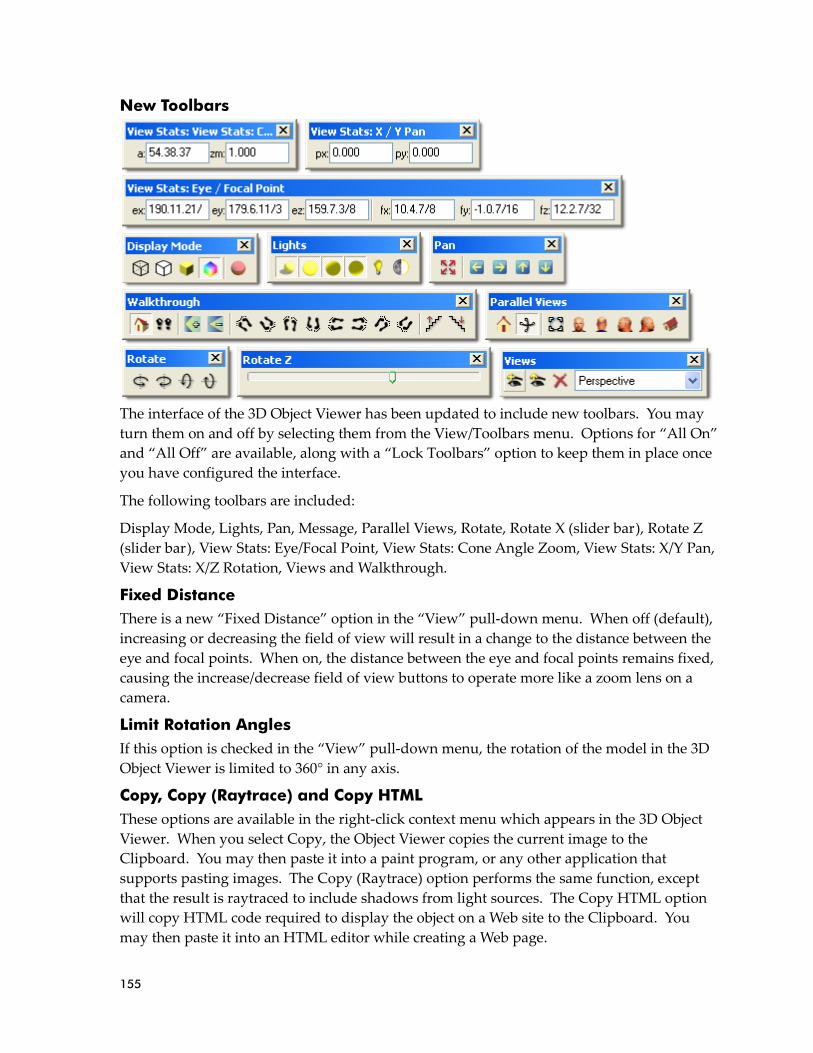
155
New Toolbars
The interface of the 3D Object Viewer has been updated to include new toolbars. You may
turn them on and off by selecting them from the View/Toolbars menu. Options for “All On”
and “All Off” are available, along with a “Lock Toolbars” option to keep them in place once
you have configured the interface.
The following toolbars are included:
Display Mode, Lights, Pan, Message, Parallel Views, Rotate, Rotate X (slider bar), Rotate Z
(slider bar), View Stats: Eye/Focal Point, View Stats: Cone Angle Zoom, View Stats: X/Y Pan,
View Stats: X/Z Rotation, Views and Walkthrough.
Fixed Distance
There is a new “Fixed Distance” option in the “View” pull-down menu. When off (default),
increasing or decreasing the field of view will result in a change to the distance between the
eye and focal points. When on, the distance between the eye and focal points remains fixed,
causing the increase/decrease field of view buttons to operate more like a zoom lens on a
camera.
Limit Rotation Angles
If this option is checked in the “View” pull-down menu, the rotation of the model in the 3D
Object Viewer is limited to 360° in any axis.
Copy, Copy (Raytrace) and Copy HTML
These options are available in the right-click context menu which appears in the 3D Object
Viewer. When you select Copy, the Object Viewer copies the current image to the
Clipboard. You may then paste it into a paint program, or any other application that
supports pasting images. The Copy (Raytrace) option performs the same function, except
that the result is raytraced to include shadows from light sources. The Copy HTML option
will copy HTML code required to display the object on a Web site to the Clipboard. You
may then paste it into an HTML editor while creating a Web page.

156
Miscellaneous Enhancements Save As previous version
Although DataCAD X3 files use the same *.AEC file extension as DataCAD 11 and
DataCAD 12, internally the file format is different. To work with users of previous versions,
you will need to use the “Save As” command in the “File” menu to save your file back to an
earlier format. If your associate is using DataCAD 12, set the “Save As Type” to “DataCAD
12 Files.” Similarly, if your associate is using DataCAD 11, set the Save As Type to
“DataCAD 11 Files.”
When saving back to DataCAD 11 or DataCAD 12 format, the file is automatically renamed.
As an example, a file named “Example.aec” in DataCAD X3 will become “Example.d11.aec”
when saved to DataCAD 11 format, or “Example.d12.aec” when saved to DataCAD 12
format.
What happens when you save your file back to an older format?
Since DataCAD X3 has new features that previous versions did not have, saving back to
DataCAD 11 or DataCAD 12 format will change some of the data in your file. Smart arrows
are exploded to groups of lines. Any text which has Lock Size enabled has its scaled size
converted to the real-world size, so that it does not look different on the screen. MText gets
exploded to multiple, single line text entities.
Smart Entities
The Change/Match/More menu can now match a Smart entity’s type. After you choose
Change/Match and click “More…,” select “Smart Type.” Right click to return to the Change
menu, and then select the object(s) to change. When prompted, select the Smart entity
whose type you wish to match.
A "Creation Method" field has been added to the Entity Properties Editor for Smart doors
and windows. It shows whether the Smart door or window was created "By Sides" or "By
Center." You may click this drop-down field to change the setting for the selected Smart
door or window. In effect, it changes the anchor point of the opening. If you change the
size of the opening in the type definition, DataCAD resizes the opening relative to the
anchor point.
You may turn off the display of node markers, which appear as an x at each end of a Smart
wall and as a diamond at each side of a Smart door or window, via the “Node Markers”
toggle button in the “Architect” menu. Although node markers never print, turning off
their display can reduce screen clutter when zoomed out.
SketchUp 8 support
DataCAD X3 supports the ability to insert and XREF SketchUp version 8 files. Files are still
exported to SketchUp version 6 format, to preserve compatibility with older versions.
Newer versions of SketchUp can open older format files, however older version may not
open newer files.
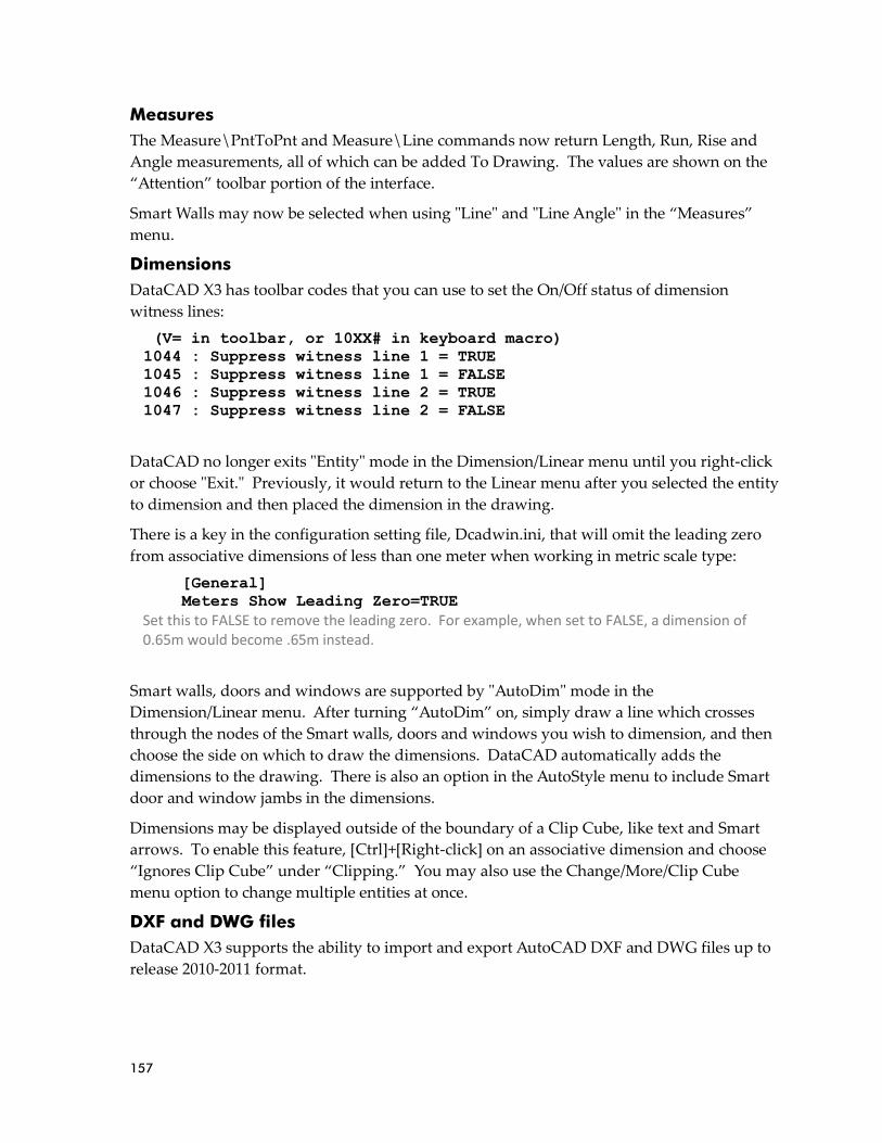
157
Measures
The Measure\PntToPnt and Measure\Line commands now return Length, Run, Rise and
Angle measurements, all of which can be added To Drawing. The values are shown on the
“Attention” toolbar portion of the interface.
Smart Walls may now be selected when using "Line" and "Line Angle" in the “Measures”
menu.
Dimensions
DataCAD X3 has toolbar codes that you can use to set the On/Off status of dimension
witness lines:
(V= in toolbar, or 10XX# in keyboard macro)
1044 : Suppress witness line 1 = TRUE
1045 : Suppress witness line 1 = FALSE
1046 : Suppress witness line 2 = TRUE
1047 : Suppress witness line 2 = FALSE
DataCAD no longer exits "Entity" mode in the Dimension/Linear menu until you right-click
or choose "Exit." Previously, it would return to the Linear menu after you selected the entity
to dimension and then placed the dimension in the drawing.
There is a key in the configuration setting file, Dcadwin.ini, that will omit the leading zero
from associative dimensions of less than one meter when working in metric scale type:
[General]
Meters Show Leading Zero=TRUE
Set this to FALSE to remove the leading zero. For example, when set to FALSE, a dimension of 0.65m would become .65m instead.
Smart walls, doors and windows are supported by "AutoDim" mode in the
Dimension/Linear menu. After turning “AutoDim” on, simply draw a line which crosses
through the nodes of the Smart walls, doors and windows you wish to dimension, and then
choose the side on which to draw the dimensions. DataCAD automatically adds the
dimensions to the drawing. There is also an option in the AutoStyle menu to include Smart
door and window jambs in the dimensions.
Dimensions may be displayed outside of the boundary of a Clip Cube, like text and Smart
arrows. To enable this feature, [Ctrl]+[Right-click] on an associative dimension and choose
“Ignores Clip Cube” under “Clipping.” You may also use the Change/More/Clip Cube
menu option to change multiple entities at once.
DXF and DWG files
DataCAD X3 supports the ability to import and export AutoCAD DXF and DWG files up to
release 2010-2011 format.

158
When importing a DXF or DWG, the way the "Move drawing to origin” setting on the
“DWG Import Entity Assignments” dialog works has been updated to provide more
accurate results. It calculates the center of the extents of the entities in the drawing and sets
that point at absolute zero. You should only use this setting if you know that all the data in
the DXF or DWG file you are importing is far away from absolute zero. This function
cannot selectively move some of the information closer to the origin, so if the data in the file
is spread over a large expanse of space in the original file, it will remain that way after
import. You will need to use the “Move” command to move the portion of the drawing that
is far away closer to the rest of the information.
Entity Properties Editor
New options to alter the "Scale" and "Rotation" of symbols, XREFs and quadrics have been
added to the Entity Properties Editor. When you [Ctrl] + [right-click] the entity and choose
“Properties,” you can see the current settings and adjust if needed.
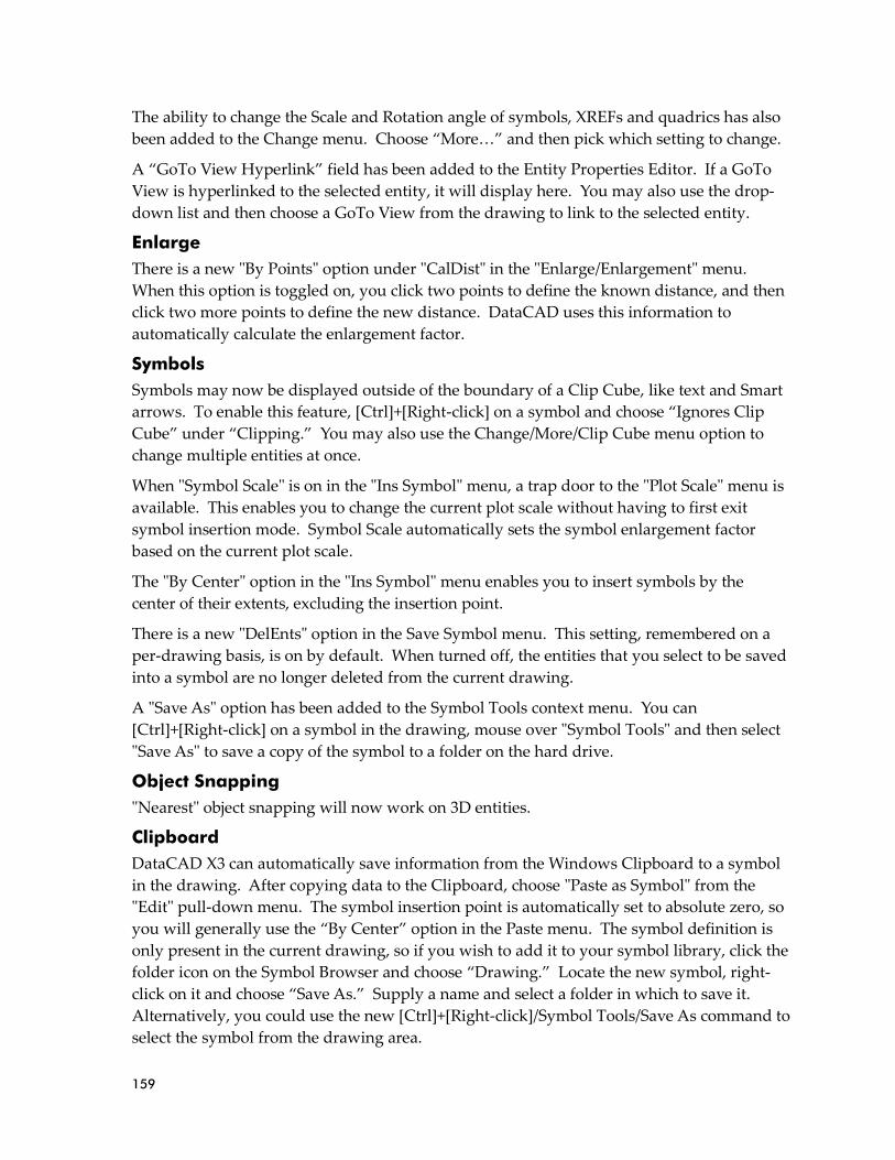
159
The ability to change the Scale and Rotation angle of symbols, XREFs and quadrics has also
been added to the Change menu. Choose “More…” and then pick which setting to change.
A “GoTo View Hyperlink” field has been added to the Entity Properties Editor. If a GoTo
View is hyperlinked to the selected entity, it will display here. You may also use the drop-
down list and then choose a GoTo View from the drawing to link to the selected entity.
Enlarge
There is a new "By Points" option under "CalDist" in the "Enlarge/Enlargement" menu.
When this option is toggled on, you click two points to define the known distance, and then
click two more points to define the new distance. DataCAD uses this information to
automatically calculate the enlargement factor.
Symbols
Symbols may now be displayed outside of the boundary of a Clip Cube, like text and Smart
arrows. To enable this feature, [Ctrl]+[Right-click] on a symbol and choose “Ignores Clip
Cube” under “Clipping.” You may also use the Change/More/Clip Cube menu option to
change multiple entities at once.
When "Symbol Scale" is on in the "Ins Symbol" menu, a trap door to the "Plot Scale" menu is
available. This enables you to change the current plot scale without having to first exit
symbol insertion mode. Symbol Scale automatically sets the symbol enlargement factor
based on the current plot scale.
The "By Center" option in the "Ins Symbol" menu enables you to insert symbols by the
center of their extents, excluding the insertion point.
There is a new "DelEnts" option in the Save Symbol menu. This setting, remembered on a
per-drawing basis, is on by default. When turned off, the entities that you select to be saved
into a symbol are no longer deleted from the current drawing.
A "Save As" option has been added to the Symbol Tools context menu. You can
[Ctrl]+[Right-click] on a symbol in the drawing, mouse over "Symbol Tools" and then select
"Save As" to save a copy of the symbol to a folder on the hard drive.
Object Snapping
"Nearest" object snapping will now work on 3D entities.
Clipboard
DataCAD X3 can automatically save information from the Windows Clipboard to a symbol
in the drawing. After copying data to the Clipboard, choose "Paste as Symbol" from the
"Edit" pull-down menu. The symbol insertion point is automatically set to absolute zero, so
you will generally use the “By Center” option in the Paste menu. The symbol definition is
only present in the current drawing, so if you wish to add it to your symbol library, click the
folder icon on the Symbol Browser and choose “Drawing.” Locate the new symbol, right-
click on it and choose “Save As.” Supply a name and select a folder in which to save it.
Alternatively, you could use the new [Ctrl]+[Right-click]/Symbol Tools/Save As command to
select the symbol from the drawing area.

160
The "Clipboard Select" command has a "By Center" option that is available when "Ins Point"
is toggled on. It will automatically calculate the center of the extents of the selected entities
when you copy the information to the Clipboard. If you later use the Edit/Paste As Symbol
function, the symbol insertion point will be set to the center of the extents of the entities,
rather than absolute zero.
Printing and Plotting
There is a new “Extents” button in the Multi-Layout/Layout menu when creating a multi-
scale plot sheet. While in layout mode, toggle this button off to see the actual drawing
information in the detail, rather than the extents box you typically see by default. This
option improves accuracy when placing your detail on a sheet.
A new Plot Scale stamp has been added to the Insert/Stamp menu. The token for this stamp
is @PLOTSCALE. The Plot Scale stamp will update automatically to show the current plot
scale, so if you change the scale after inserting the stamp, it will change to show the new
scale. When you place a Multi Scale Plot detail which contains the stamp, it will show the
selected plot scale for the detail. In addition, the Insert/Stamp function now supports the
ability to use Text Scale to define the size of text relative to the plot scale, and Lock Size to
lock the size of the text to the real-world printed size.
You may customize the stamp by editing the [Stamp] section of your Dcadwin.ini file:
[Stamp]
PLOTSCALE_1MenuText=Plot Scale 1
PLOTSCALE_1=Scale: @PLOTSCALE = 1'-0"
PLOTSCALE_2MenuText=Plot Scale 2
PLOTSCALE_2=This is the current plot scale: @PLOTSCALE
Settings
You may now Load, Edit and Save the "Decimals" file, Dcadwin.dec, via the
Utility/Settings/EditDefs menu.
Texture Origin
The View/Rendering/Texture Origin pull-down menu has options that enable you to
“Show” and “Clear” the texture origin of entities in your drawing.
There is also an extended character code for Set Texture Origin:
(V= in toolbar button, or 10XX# in keyboard macro)
1052 = Set Texture Origin
Other New Extended Character Codes (V= in toolbar button, or 10XX# in keyboard macro)
1050 = Orthmode On
1051 = Orthmode Off
Move/To Layer and Copy/To Layer
There is a “Layer Color” toggle in the Move/To Layer and Copy/To Layer menus. This
option appears after you select the destination layer. When enabled, the selected entities
will inherit the color currently assigned to the destination layer.

161
Curves
Beziers and B-spline curves, in the 2D “Curves” menu, may now have up to 20 control
points. The previous limit was 8. In addition, you may define different Z-Base and Z-
Height values for Beziers and B-spline curves.

162
DataCAD 12 has many new and improved features which are designed to help you increase
productivity. Some changes affect compatibility with previous versions of DataCAD and
with other programs.
Compatibility Enhancements Forward/Backward Compatibility with Other DataCAD Versions
DataCAD 12 is compatible with drawing files, symbols, templates, line types, hatch
patterns, fonts, and DCAL® macros from DataCAD versions 4 through 11. That means
migrating your designs to DataCAD 12 is effortless.
DataCAD 11 cannot open drawings from DataCAD 12, however, you can save your
DataCAD 12 (AEC) files to DataCAD 11 (AEC) file format using the File \ Save As
DataCAD 11 AEC menu option within DataCAD 12. This is especially helpful if your office
has copies of both DataCAD 11 and 12 running on various computers and you need to
exchange files with another user.
DataCAD versions 4 through 10 cannot open drawings from DataCAD 11 or 12. If some of
your associates are running these older versions, you will not be able to share your
DataCAD 12 files directly with them. You’ll have to use DXF/DWG as a common file
format.
Compatibility with AutoCAD® Drawing Files (DXF/DWG)
DataCAD 12’s drawing translator can import DXF and DWG files compatible with
AutoCAD R12‐R14, R2000‐R2002 (R15), R2004‐2006 (R16), and R2007‐R2009 (R17). You can
choose an automatic translation or an interactive one, where you can decide how each line type
and font should be translated and displayed in DataCAD.
Block Attributes appear as Symbol Attributes when you open a DWG file.
➔ To import a DWG or DXF file and open it in DataCAD:
1. Select Open from the File pull‐down menu. The Enter name of drawing file to
open dialog box appears.
2. Select DWG or DXF from the Files of type drop‐down box. Choose DWG to
display all DWG files or select DXF to display all DXF files.

163
3. Select a file to import from the list or type the name of the file to import in the
File name input box. By default, DataCAD looks for DXF and DWG files in your
DataCAD\Transfer folder. If your DXF or DWG files are in a different folder,
change to that folder using the “Look in:” drop-down and then click on the file
you want to import.
You can open multiple files at the same time. Just highlight the first file, then
press (Ctrl), and continue highlighting other files you want to open. DataCAD
adds all the files you selected to the Filename field and will open all of them
when you click on Open or press (Enter).
4. Click Open. The DWG Import Entity Assignments dialog box appears if the
Import section of the DXF/DWG tab of the Configure DataCAD for Windows
Settings dialog shows that “Interactively assign . . .” is toggled on. The options in
the DWG Import Entity Assignments dialog box allow you to choose how
DataCAD will translate line types and fonts.
5. Look at the options in the Line Type Assignments box; this lists each AutoCAD
line type used in the file and suggests a DataCAD equivalent. To change any of
these assignments, click on the line type to change. The line type you selected
appears immediately below the Assignment list box with the translation line type
in a drop‐down box. Choose a new line type from the drop‐down box; your selection
appears in the preview window. When you click on the line type in the list box
again, the name of the line type changes to reflect your choice.

164
6. Repeat step 5 for the Font Assignments. You can specify DataCAD‐supplied or
TrueType fonts.
7. Click on OK to close the dialog box and begin importing the file. Progress is
noted in the Message toolbar. Or click on Cancel to stop the import process and
close the dialog box.
More About Importing Files Into DataCAD
The settings and assignments that are displayed in the DWG Import Entity Assignments
dialog box are contained in a file called TRANSFER.INI in your DataCAD\Support Files
folder. If you change any of the settings in the DWG Import Entity Assignments dialog box,
you have the option to save those settings in a new .INI file to use when translating other
files. This new .INI file is saved in the \Support Files folder.
You can affect how importing files and the DWG Import Entity Assignments dialog box
work through settings on the DXF/DWG tab in the Tools/Program Preferences Configure
DataCAD for Windows Settings dialog box.
This could be useful if you normally exchange files with several different offices. If you
change the settings and save a separate .INI file for each office, then you can easily switch
between .INI files without having to go through entity assignments repeatedly.
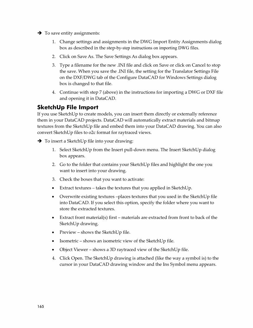
165
➔ To save entity assignments:
1. Change settings and assignments in the DWG Import Entity Assignments dialog
box as described in the step‐by‐step instructions on importing DWG files.
2. Click on Save As. The Save Settings As dialog box appears.
3. Type a filename for the new .INI file and click on Save or click on Cancel to stop
the save. When you save the .INI file, the setting for the Translator Settings File
on the DXF/DWG tab of the Configure DataCAD for Windows Settings dialog
box is changed to that file.
4. Continue with step 7 (above) in the instructions for importing a DWG or DXF file
and opening it in DataCAD.
SketchUp File Import If you use SketchUp to create models, you can insert them directly or externally reference
them in your DataCAD projects. DataCAD will automatically extract materials and bitmap
textures from the SketchUp file and embed them into your DataCAD drawing. You can also
convert SketchUp files to o2c format for raytraced views.
➔ To insert a SketchUp file into your drawing:
1. Select SketchUp from the Insert pull-down menu. The Insert SketchUp dialog
box appears.
2. Go to the folder that contains your SketchUp files and highlight the one you
want to insert into your drawing.
3. Check the boxes that you want to activate:
• Extract textures – takes the textures that you applied in SketchUp.
• Overwrite existing textures –places textures that you used in the SketchUp file
into DataCAD. If you select this option, specify the folder where you want to
store the extracted textures.
• Extract front material(s) first – materials are extracted from front to back of the
SketchUp drawing.
• Preview – shows the SketchUp file.
• Isometric – shows an isometric view of the SketchUp file.
• Object Viewer – shows a 3D raytraced view of the SketchUp file.
4. Click Open. The SketchUp drawing is attached (like the way a symbol is) to the
cursor in your DataCAD drawing window and the Ins Symbol menu appears.

166
5. Make decisions about the way you want the SketchUp drawing to appear by
using the options in the Ins Symbol menu. This menu allows you to set the X, Y,
or Z enlargement factors, dynamically rotate or explode the drawing, change the
line factor and Z offset, toggle Fix Text to control legibility, and alter the symbol
scale and maximum lines.
6. Position the cursor in your DataCAD drawing window where you want the
SketchUp drawing to appear. Then click the left mouse button. If you want to
place additional copies of the SketchUp drawing into your DataCAD drawing,
reposition the cursor and left-click where appropriate. When you are finished
placing the SketchUp drawing(s), right-click.
➔ To insert a SketchUp file as an XREF:
1. Select SketchUp XREF from the Insert pull-down menu. The Insert SketchUp
dialog box appears.
2. Go to the folder that contains your SketchUp files and highlight the one you
want to insert as an XREF into your drawing.
3. Click Open. The SketchUp drawing appears as an XREF box attached to your
cursor and the Insert XREF menu appears.
4. Make decisions about the way DataCAD should treat the SketchUp drawing
based on the options in the Insert XREF menu.
5. Position the cursor where you want the SketchUp drawing to appear as an XREF
and left-click.
The layers you create in SketchUp are retained in DataCAD when you insert the .skp file
into your drawing. If you insert your SketchUp file as an XREF, you can manage the on/off
layers via the Reference File Manager. If you use the Insert menu to add a SketchUp file to
your drawing as a symbol (versus an XREF), you can later use the Symbol Explode
command to create original layers. SketchUp groups and components convert to symbols in
DataCAD.
Excel Spreadsheet Import
➔ To import an Excel spreadsheet into your drawing:
1. Select Excel from the Insert pull-down menu.
2. Select the Excel spreadsheet that you want to import from the files on your
computer.
3. Select Open to import the spreadsheet into your drawing.
4. Choose the insertion point for the spreadsheet.

167
SHX Fonts DataCAD 12 provides direct support for SHX fonts and TrueType fonts (TTF). DataCAD
CHR fonts are no longer used. However, your existing DataCAD fonts are automatically
converted to SHX format.
Productivity Enhancements Smart Entities
Now you can quickly draw walls, windows, and doors in 2D, automatically clean up stray
lines, and seamlessly convert your design into a 3D model by using smart entities. A smart
entity is a drawing element (such as a wall, door, or window) that contains routines and
parameters to define its characteristics and to determine how it interacts with other smart
entities.
In older versions of DataCAD, when you drew two walls, they didn’t know anything about
each other until after you joined them and cleaned their intersection. In DataCAD 12, walls
of the same type automatically clean to each other, allowing you to skip the cleanup step
manually. Imagine how much time you can save when you take advantage of smart entities.
When you add doors and windows to a wall, DataCAD 12 automatically cuts the wall to
accommodate them. If you move, copy, or delete a door or window from a wall, DataCAD
12 automatically heals the wall.
These smart entities know what they should look like in both plan and perspective views. In
plan view, you will see the 2D doors just as you did in prior versions of DataCAD. But when
you switch to perspective view, you will see 3D doors, complete with jambs, casing, and
trim. When you look at your model in the object viewer, you will also see the rendered
materials you selected for the walls and other entities.
Of course, you can still use the traditional lines and arcs to create your designs. You can also
convert smart entities to simple entities (lines and arcs). Both standard and smart entities
happily coexist in DataCAD 12.
What are some of the advantages of using smart entities?
• You can make changes quickly.
• You can change the width of a wall and all its intersections will update automatically.
• You can change a door from double to bi-fold without removing and redrawing it.
• You can copy a window from one wall to another.
To convert CHR fonts to SHX format, simply add them to the DataCAD\Fonts folder, then run DataCAD. The program will scan this folder and convert any CHR fonts that do not already have an SHX equivalent.

168
Key Terms and Concepts
To use smart entities effectively, you should learn a few new terms. Some terms (for
example, Type) apply to walls, doors, and windows. Other terms (for example, Control Line)
apply only to walls.
Type refers to smart entity definitions (walls, doors, and windows) that you can use in your
drawing. The available types of smart entities are listed on the left in each Manager dialog
box. Many walls, doors, and windows are already defined, so you can quickly activate them
and put them to work in your drawing. However, you can also customize or create your
own smart wall, door, and window types very easily.
Some properties are intrinsically-linked with a particular type of smart entity and can only
be controlled by the definition you established for it in the corresponding Manager.
Intrinsically-linked properties are called Type-dependent. (For example, the width of a wall is
type-dependent.) If you change a type-dependent property, all instances of that particular
type will reflect the change.
You can change some properties on a case-by-case basis. These properties are Type-
independent. (For example, the swing angle of a door is type-independent since you can
change the angle for each smart door in your drawing, regardless of its type.) These
properties have a default value that defines how new instances of the entity will appear, but
the value may be changed independently on each instance once the entity has been added to
the drawing.
Smart Entity Glossary
The following is a list of technical terms and their definitions which relate specifically to
smart entities.
Smart Entity
A smart entity is a drawing object designed for a specific purpose and is governed by a
fixed set of parameters and variables. Since the object has internal awareness of how it
should behave, it is considered to be “smart”. Smart entities are controlled by the user
via dialogs that provide access to certain settings and their corresponding values.
Wall, door and window type definition files are stored in folders on your hard drive. You may create new wall, door and window type files, which contain the parameters that define how each instance of the wall, door or window will look in both 2D and 3D. The external files may be loaded into your drawings, then used and modified as desired.
If you make changes and want to use the modified type in other files, you may save out the definition, either overwriting the existing type file on the hard drive or saving to a new name. If you overwrite a type file on the hard drive, the changes will not be realized in other drawing files unless you reload the type file in those drawings.
To delete a type file from the hard drive, open Windows Explorer (or My Computer) and go to the DataCAD\Support Files folder, open the appropriate Wall Type, Door Type or Window Type sub-folder, then delete the type file.
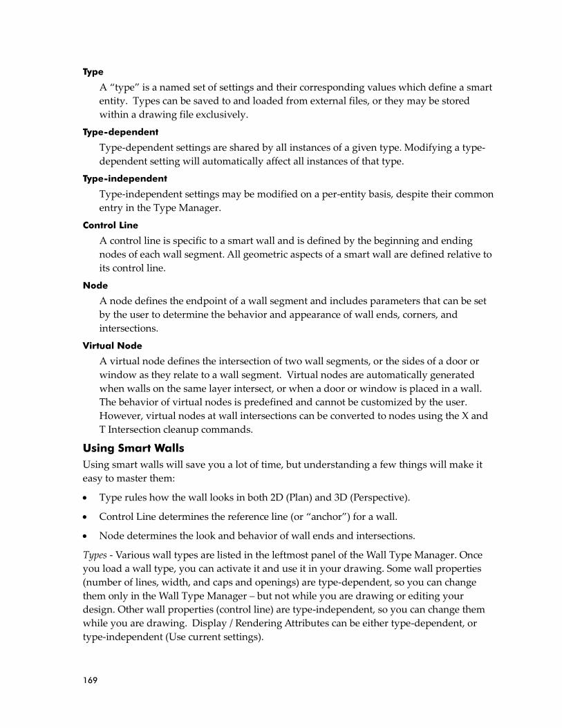
169
Type
A “type” is a named set of settings and their corresponding values which define a smart
entity. Types can be saved to and loaded from external files, or they may be stored
within a drawing file exclusively.
Type-dependent
Type-dependent settings are shared by all instances of a given type. Modifying a type-
dependent setting will automatically affect all instances of that type.
Type-independent
Type-independent settings may be modified on a per-entity basis, despite their common
entry in the Type Manager.
Control Line
A control line is specific to a smart wall and is defined by the beginning and ending
nodes of each wall segment. All geometric aspects of a smart wall are defined relative to
its control line.
Node
A node defines the endpoint of a wall segment and includes parameters that can be set
by the user to determine the behavior and appearance of wall ends, corners, and
intersections.
Virtual Node
A virtual node defines the intersection of two wall segments, or the sides of a door or
window as they relate to a wall segment. Virtual nodes are automatically generated
when walls on the same layer intersect, or when a door or window is placed in a wall.
The behavior of virtual nodes is predefined and cannot be customized by the user.
However, virtual nodes at wall intersections can be converted to nodes using the X and
T Intersection cleanup commands.
Using Smart Walls
Using smart walls will save you a lot of time, but understanding a few things will make it
easy to master them:
• Type rules how the wall looks in both 2D (Plan) and 3D (Perspective).
• Control Line determines the reference line (or “anchor”) for a wall.
• Node determines the look and behavior of wall ends and intersections.
Types - Various wall types are listed in the leftmost panel of the Wall Type Manager. Once
you load a wall type, you can activate it and use it in your drawing. Some wall properties
(number of lines, width, and caps and openings) are type-dependent, so you can change
them only in the Wall Type Manager – but not while you are drawing or editing your
design. Other wall properties (control line) are type-independent, so you can change them
while you are drawing. Display / Rendering Attributes can be either type-dependent, or
type-independent (Use current settings).
170
Control Line – You decide which line (outside, center, inside, line 2, or line 3 options are
available, depending on the wall type you loaded) you want to use when you are drawing
your structure. The control line is type-independent, so you can change it when necessary
while you are drawing.
Node – At intersections and wall ends, nodes influence how two wall surfaces interact as far
as cleaning, moving, and stretching are concerned. DataCAD automatically inserts nodes
(indicated by an X) when you start or end a wall or when you make a corner. Virtual nodes
(indicated by an open diamond) are automatically inserted when two walls cross (for
example, at an X intersection) or when you place a smart door or window on a wall. You can
use the Edit Walls option in the Architect menu (with Auto 3D enabled) to add nodes to
smart walls. You can also use the Weld Wall and Weld Line commands in the Cleanup menu
to remove nodes from smart walls.
Before you set up your drawing, there is one important fact to remember: smart walls must
all be on the same layer if you want them to clean to each other. That means exterior walls
will not clean to interior walls if they are on different layers. Doors and windows do not
have to be on the same layer as walls (for example, walls can be on Layer 1 and windows on
Layer 2).
➔ To create walls:
1. Make sure you are on the layer that contains your walls. This assures that the
walls will be able to clean properly.
2. Go to the Edit menu in the Menu Window and select Architect.
3. Toggle on Auto 3D in the Architect menu. The Walls menu appears. This allows
you to work with the smart entities. If Auto 3D is toggled off, you can draw walls
the old-fashioned way.

171
4. Select Manage to display the Wall Type Manager dialog box. Notice that the
default is a 2-line wall suitable for an interior wall. If this is what you want, just
select OK and begin drawing walls. Otherwise, make sure a checkmark appears
in the Display External Types box and continue to refine your choices.

172
5. Select the wall type you would like to use instead of the default by double-
clicking or by highlighting it and clicking on Load. Notice that when you make a
selection, the illustration in the preview window and the wall and line properties
change.
6. Refine the wall and line properties by using the options in the Wall Properties,
Caps and Openings, and Line Properties sections of the Wall Type Manager.
• Number of lines – select from the pull-down options (2, 3, or 4) to indicate how
many lines will appear in the 2D drawing.
• Control Line – select from the pull-down options (Outside, Center, Inside, Line 2,
or Line 3) to indicate which line is dominant when you are drawing.
• Caps inherit line properties from – select Inside Wall or Outside Wall. (This
option is available for 2-line walls only. On 3- and 4-line walls, material is
applied from the outside line to the next one in and from the inside line to the
next one in.)
• Openings inherit line properties from – select Inside Wall or Outside Wall. (This
option is available for 2-line walls only. On 3- and 4-line walls, material is
applied from the outside line to the next one in and from the inside line to the
next one in.)
• Line – select the line number you want to describe and then make offset and
display/rendering attributes choices to control how each line will appear in your
drawing. If you are not satisfied with your choices, click Revert. When you want
to test your choices for each line, decide which field you want to be active, then
click Apply and look at the results in the preview window.
• Offset from previous line – use this option to indicate the width of a 2-line wall
or to show the offset for 3- or 4-line walls. Changing the offset values, affects the
overall Width shown in the Wall Properties section. Do this for each line except
line 1.
• Use current settings – controls your ability to change display/rendering
attributes. If you want to make changes to the color, line type, pen style, and
material defaults supplied by DataCAD, click to remove the checkmark from this
box.
• Color – select the line’s color from the pull-down options. Do this for each line.
• Weight – control the line’s weight for the 2D drawing. Do this for each line.
• Line Type – select the line’s appearance (Solid, Dotted, Dashed, Dot-Dash, or -
dash-) for the 2D drawing. Change the value in the Spacing field to control the
line. Do this for each line.
When you use a 3- or 4-line smart wall, the material extends from the outside face to the next line on the interior of the wall and from the inside face to the second line from the outside wall.

173
• Pen Style – select the option you want from the pull-down menu and indicate a
Spacing value. Do this for each line. This scale-independent feature always
appears and prints in one size.
• Material – select an option from the pull-down menu to describe the material
associated with each line. If you are not satisfied with the available materials,
click Load to display the Load Material File dialog box, highlight the option you
want, click Open to add that material to the list of available materials, then select
it from the pull-down menu. Do this for each line.
7. Make sure you are satisfied with your choices for each line of the wall, click Save
or Save As, name the wall type in the dialog box that appears, and click Save.
Your new wall type appears in the Wall Type Manager list.
8. Highlight a wall from the list and select Set Active to indicate which type of wall
you want to draw. Then select OK and begin to draw the wall.
➔ To quickly access the Wall Type Manager:
1. Press A to display the Architect toolbar, toggle Auto 3D on in the Walls menu,
and select S from the Architect toolbar or Manage from the Walls menu to
open the Wall Type Manager. If Auto 3D is toggled off in the Walls menu and
you select S from the Architect toolbar, the old Wall Style Manager dialog box
appears.
2. Or select the first button in the Types toolbar.
➔ To create your own smart wall type:
3. Select New in the Wall Type Manager.
4. Enter a distinctive name in the New Wall Type dialog box and select OK.
5. Highlight the name in the Wall Type Manager’s list and define the wall and line
properties.
6. Select Set Active. Then select OK to exit the Wall Type Manager and begin using
it in your drawing.
What’s the difference between Save and Save As? When you select Save, the changes you made are stored on the hard disk in place of the original file. That means the original file no longer exists because you wrote over it with your changes. When you select Save As, you supply a new name for the changes you made to the original. That means the original file still exists and the new file you just named contains your customized version.
174
➔ To draw with smart walls:
1. Highlight the wall you want to use in the Wall Type Manager, select Set Active, and
select OK to exit to the drawing window.
2. Activate Walls in the Walls menu.
3. Decide which options you want to use in the Walls menu:
• Trim Out – trims wall segments by the outermost line. If you activate this option,
you cannot use Trim In. This option is available only when Clean is activated and
Cap is not.
• Trim In – trims wall segments by the innermost line. If you activate this option,
you cannot use Trim Out. This option is available only when Clean is activated
and Cap is not.
• Clean – automatically cleans wall intersections.
• Cap –
places a cap at the
beginning and ending of each wall segment.
4. Draw your walls.
➔ To quickly access activated smart wall types:
1. Make sure the Types toolbar is displayed. If it isn’t, select Toolbars from the View
pull-down menu, check the Types box, and click OK.
2. Select the wall type that you want to use from the Wall pull-down list on the Types
toolbar.
➔ To edit smart walls:
1. Activate Edit Walls in the Walls menu.
2. Decide which function(s) you want to use on a particular wall segment:
• Add Node – lets you add segments to an existing wall. Just click near the wall
where you want to add the node, then drag your mouse and click to establish the
position of the new node.
• Poly to Wall – converts existing polyline edges into wall segments.
• Swap In/Out – lets you swap the outside wall line with the inside and vice versa.
This is easiest to see when the outside and inside wall lines are different colors.
3. Activate the function(s) you want to use, then follow the prompts shown on the
Message toolbar.
Shortcut: Press the \ key to toggle Clean on while creating a smart wall.
Shortcut: Press Shift-\ to toggle Cap on while creating a smart wall.
If you activate both Cap and Clean, the beginning of the wall is capped, the linked segments are cleaned, and the ending segment is capped.

175
➔ To add an adjoining wall to your drawing:
1. Press [A] to display the Walls menu and make sure Auto 3D is on.
2. Toggle on Clean and either Trim Out or Trim In (depending on the way you want to
trim your walls).
3. Open the Wall Type Manager, highlight the wall you want to use, select Set Active,
and select OK.
4. Draw the additional walls, starting at one of the existing smart walls.
➔ To cut an opening in a smart wall:
1. Press [A] to display the Walls menu and make sure Auto 3D is on.
2. Select Cut Wall to display the Openings menu.
3. Select the Layer that contains the wall you want to cut.
4. Toggle Cap on if you want to cap each end of the cut.
5. Select the wall where you want the cut to begin; then select the wall where you want
it to end. If you toggled Cap on, each end is capped.
➔ To change a smart wall’s base elevation (Z-Base), height elevation (Z-Height), and
overall height:
1. Go to the Change menu by pressing [Alt] + [C].
2. Toggle on Z-Base, type a different value in the insert field, and press [Enter].
3. Toggle on Z-Height, type a different value in the insert field, and press [Enter].
➔ To switch between drawing smart walls and regular lines:
1. Draw the smart walls.
2. Press the [=] key on the keyboard and draw using regular lines.
3. Press the [=] key on the keyboard again and return to drawing smart walls.
If you change only the Z-Base of a smart wall, the bottom of the wall will move to the specified Z-Base. The top of the wall will be determined by the wall’s height property. For example, if the original Z-Base was 0 and the Z-Height was 8, the wall was 8 feet high. By changing the Z-Base alone to 4, the wall would still be 8 feet high, making the top reach a height of 12.
If you change only the Z-Height or a smart wall, the top of the wall will move to the specified Z-Height. The base of the wall will be determined by the wall’s height property. For example, if the original Z-Base was 0 and the Z-Height was 8, the wall was 8 feet high. By changing the Z-Height alone to 6, the wall would still be 8 feet high, making the base extend down to -2 feet.
If you change both the Z-Base and Z-Height in the same operation, both the top and bottom of the smart wall will change. For example, if the original Z-Base was 0 and the Z-Height was 8, the wall was 8 feet high. By changing the Z-Base to 6 and the Z-Height to 16, the wall would now be 10 feet high.

176
When you are entering smart walls, and have the Walls menu displayed, snapping works
like this:
• If Clean is activated, Pick or Snap projects the node point to the control line of the
intersecting wall and cleans the intersection.
• If Clean is off, Pick or Snap places the node point at the selected point and does not clean
the intersection.
Using Smart Doors
Of course, smart walls are fun to draw, but installing smart doors is even easier. You simply
activate doors that you want to use in your drawing and then place them into the smart
walls.
➔ To activate doors for insertion into smart walls:
1. Select the middle button on the Types toolbar to open the Door Type Manager dialog
box. Alternatively, you can Press [A] to display the Walls menu, make sure Auto 3D
is highlighted, select Doors to display the Doors menu, and select Manage.
2. Select the door type you would like to use instead of the default by double-clicking
or by highlighting it and clicking on Load. Notice that when you make a selection,
the illustration in the preview window and the door and line properties change.
3. Refine the door properties by using the options in the various tab sections of the
Door Type Manager.
• Unit – you can change the unit type (single, double, bi-fold, double bi-fold,
sliding, pocket, and overhead) in addition to head and sill heights.
Notice that the Door Type Manager has multiple tabs. This gives you more control over the components of the doors you include in your drawings. Each tab offers different display/rendering attributes that you may be able to change. Options that you cannot change are grayed out.
For most of the tab sections, you can change the display/rendering attributes to customize the doors for your drawing. Your alterations appear in the preview window when you change the focus to the next field.

177
• Trim Out and Trim In – you can control the exterior and interior trim by
specifying head and jamb width and thickness as well as head extension.
• Header – based on the options you checked, you can change the header’s
thickness, depth, and offset from the wall.
• Jamb – based on the options you checked, you can change the jamb’s thickness,
depth, and offset characteristics.
• Sill – if Include is checked, you can control the sill’s thickness and its inside,
outside, and side extensions.
• Stop – if Include is checked, you can control the stop’s thickness and width.
• Door – toggle Include on to display the door in both 2D and 3D views. A
parametric door will be drawn for both. If you check Use Symbol in the 2D
section, you can select a symbol that will be displayed in 2D views in place of the
Trim In, Trim Out, Header, Sill, Stop, and Knob. If Include Parametric Door is
not checked, it will also include the Door and Swing. If Include Parametric Door
is checked, you do not need to include the Door or Swing in your 2D symbol
because they will be drawn parametrically. Make sure the symbol you create has
the correct depth to match the wall’s width, is wide enough to match the
opening’s width, and has the insertion point at the lower left outside corner of
the wall opening. When Flush is checked, the door is flush with the wall opening;
if it is not checked, you can enter an Offset value. When Use Symbol 3D is
checked, you select a 3D symbol to use in place of the parametric door for 3D
views.
• Knob – if Include is checked, you can control the appearance and position of the
inside and outside door knobs. If you check Use Symbol and select a specific
knob, you cannot change its diameter and extension.
• Swing – use this tab to describe the way the door’s swing should appear in both
2D and 3D versions, including swing type, color, and angle. If you do not check
Match Door Color, you can specify any color for the 2D swing arc or line. The
Swing Angle for both 2D and 3D are applied to the door when the door is
inserted. Once the door is created, they become a property of the door entity, not
the door type. To change them after you created a door, you must change the
property of each door with the Entity Properties Editor.
4. Select Apply to finalize your choices; then select OK if you want to use this door in
your drawing without changing the basic description in the file.
If you want to use this door with all the attributes you changed in future drawings, select Save As. Give the door a distinctive file name and select Save in the Enter door type filename dialog box. Whenever you want to use it later, just select it from the list that appears in the Door Type Manager, activate it, and insert it in future drawings.
Caution: If you select Save, your changes will overwrite the original door file.

178
➔ To insert a smart door into your drawing from the Door Type Manager:
1. Highlight the door that you want to use from the ones you loaded into the Door
Type Manager.
2. Click on Set Active and then select OK to close the Door Type Manager. Notice that
the active door’s name is red and the inactive ones that you loaded are black.
3. Make decisions about how you want to place the smart door into your drawing:
• Toggle Sides on in the Doors menu if you want to place the smart door by sides.
You are prompted to Click hinge side of door.
• Toggle Sides off in the Doors menu if you want to place the smart door by its
center. You are prompted to Click center of door.
• Toggle Center Point on to add a snapping point to the center of the door.
• Toggle Cut Wall on to automatically remove the smart wall where you place the
smart door.
• Anchor the door by its sill or head. Toggle At Sill on to anchor the door by its sill.
Toggle At Sill off to anchor the door by its head.
• Decide which layer you want to search for walls. Toggle One Layer on if you
want to search only one layer. Toggle One Layer off if you want to search more
than one layer. If you toggle One Layer off, another option appears on the Doors
menu to allow you to toggle on Any Layer if you want to search all the “on”
layers for smart walls where you can place the door.
4. Select the point on the smart wall where you want to install the door. You are
prompted to Click strike side of door and indicate direction of door swing.
5. Click to indicate the way the door should open.
6. Continue placing copies of that door into your drawing where needed.
7. Place other smart doors that you loaded in the Door Type Manager by selecting them
from the pull-down menu in the Types toolbar.
➔ To replace one smart door with another:
1. Select Search/Repl. from the Doors menu. The Search and Replace dialog box
appears.
If you select Search and Replace from the Edit pull-down menu, select Door types from the Type pull-down menu in the Search and Replace dialog box.

179
2. Select the door type you want to eliminate from the ones available in the Find pull-
down menu. Only loaded smart doors are available.
3. Select the door type you want to take the place of those you indicated in step 2. Only
loaded smart doors are available.
4. Click OK. The Search/Repl. menu appears.
5. Toggle on the search parameter you want to use:
• Entity – lets you replace the doors you select on a case-by-case basis, leaving the
other ones as you originally indicated.
• Group – automatically replaces all the doors at once.
• Area – prompts you to place a rubber band around the rectangular area where
the doors need to be changed. Doors outside the area you indicated will not
change.
• Fence – prompts you to create a rubber band around the polygon-shaped area
where the doors need to be changed. Doors outside the fence you indicated will
not change.
• Mask – lets you search for specific entities based on their properties.
• Replace All – provides the ability to replace all entities on “On” layers.
➔ To change a smart door’s Z-Base, Z-Height, and door height:
1. Go to the Change menu by pressing (Alt-C).
2. Determine which option (At Sill or At Head) was used when the door was created:
• If At Head was toggled off, select Z-Base. This is the only way to affect the door’s
z-position. Selecting Z-Height will do nothing.
• If At Head was toggled on, select Z-Height. This is the only way to affect the
door’s position. Selecting Z-Base will do nothing.
Using Smart Windows
Installing smart windows is much like smart doors. You simply activate windows that you
want to use in your drawing and then place them into the smart walls.
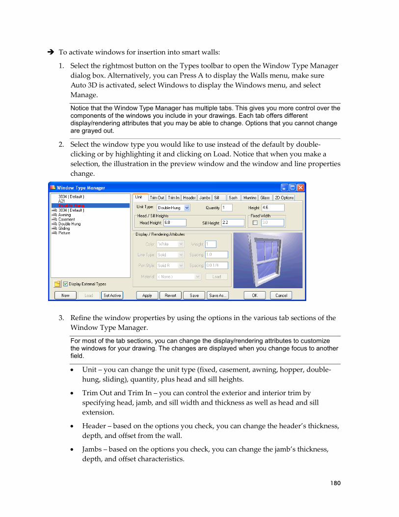
180
➔ To activate windows for insertion into smart walls:
1. Select the rightmost button on the Types toolbar to open the Window Type Manager
dialog box. Alternatively, you can Press A to display the Walls menu, make sure
Auto 3D is activated, select Windows to display the Windows menu, and select
Manage.
2. Select the window type you would like to use instead of the default by double-
clicking or by highlighting it and clicking on Load. Notice that when you make a
selection, the illustration in the preview window and the window and line properties
change.
3. Refine the window properties by using the options in the various tab sections of the
Window Type Manager.
• Unit – you can change the unit type (fixed, casement, awning, hopper, double-
hung, sliding), quantity, plus head and sill heights.
• Trim Out and Trim In – you can control the exterior and interior trim by
specifying head, jamb, and sill width and thickness as well as head and sill
extension.
• Header – based on the options you check, you can change the header’s thickness,
depth, and offset from the wall.
• Jambs – based on the options you check, you can change the jamb’s thickness,
depth, and offset characteristics.
Notice that the Window Type Manager has multiple tabs. This gives you more control over the components of the windows you include in your drawings. Each tab offers different display/rendering attributes that you may be able to change. Options that you cannot change are grayed out.
For most of the tab sections, you can change the display/rendering attributes to customize the windows for your drawing. The changes are displayed when you change focus to another field.

181
• Sill – if Include Sill is checked, you can control the sill’s thickness and its inside,
outside, and side extensions.
• Sash – if Include Sash is checked, you can control its thickness, width, and offset.
The Use 3D Symbol option lets you use a 3D symbol to represent your window
in 3D views instead of the parametric window. The % Open 3D setting defines
the percentage that the window is open in 3D views. This setting is applied to
each window when you place it in your drawing; however, it is a property of the
window entity, not its type. To change the percent opening after adding a
window to your drawing, use the window Entity Properties Editor. For casement
or hopper windows, you can check Opens Inward.
• Muntins – if Include Muntins is not checked, the window is plain. If Include
Muntins, Centered, and Use Slabs are checked, you can control their thickness,
offset, and width. On the window’s edges, you can use the full-width or half-
width muntins. Alternatively, the edge can contain no muntins if you select
None.
• Glass – if Include Glass is checked, you can control the thickness of the window,
its offset position, and the number of horizontal and vertical panes. Depending
on the Unit Type, options for Upper and Lower panes are available separately. If
you check Centered, the Offset option is unavailable.
• 2D Options – you can specify a symbol to use in place of the Sill, Sash, and Glass,
or any combination of the three in 2D views of your drawing. Remember that the
depth of the symbol must match the width of your wall; the width of the symbol
must match the width of your opening. The Unit Width will be defined by the
width of the symbol you select.
4. Select Apply to finalize your choices; then select OK if you want to use this window
in your drawing without changing the basic description in the file.
➔ To insert the window into your drawing.
1. Make sure the Walls menu is displayed (if it isn’t, press A) and select Windows.
2. Decide which smart window you want to use. Either go to the Window Type
Manager, highlight the loaded window you want, click Set Active, and select OK to
exit the dialog box. Or select the window you want from the pull-down options
available on the Types toolbar. The Windows menu appears.
3. Make decisions about how you want to place the smart window into your drawing:
If you want to use this window with all the attributes you changed in future drawings, select Save As. Give the window a distinctive file name and select Save in the Enter window type filename dialog box. Whenever you want to use it later, just select it from the list that appears in the Window Type Manager, activate it, and insert it in future drawings.
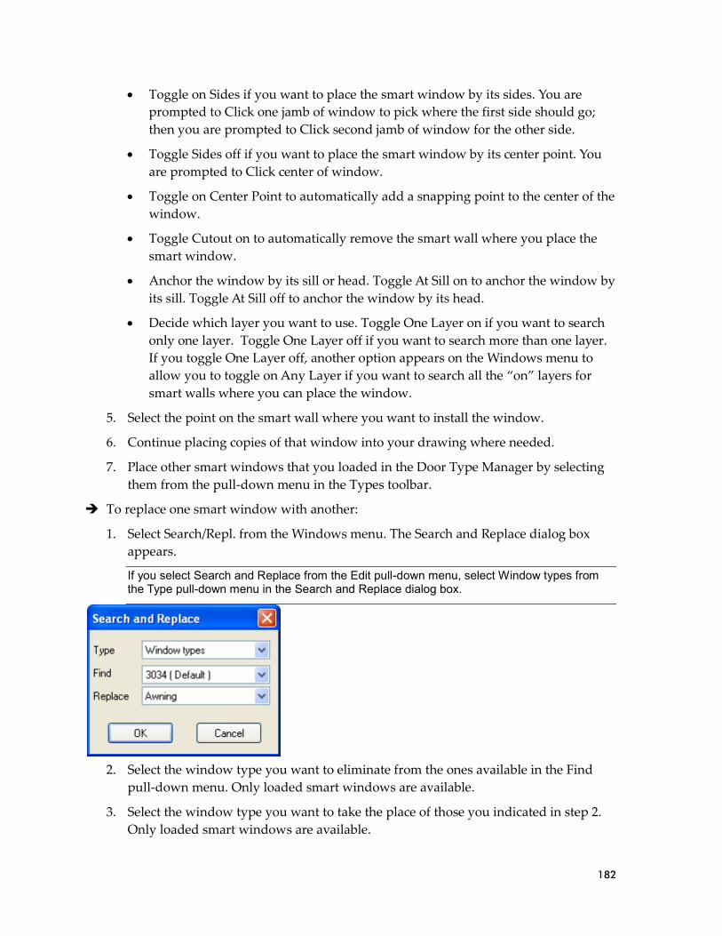
182
• Toggle on Sides if you want to place the smart window by its sides. You are
prompted to Click one jamb of window to pick where the first side should go;
then you are prompted to Click second jamb of window for the other side.
• Toggle Sides off if you want to place the smart window by its center point. You
are prompted to Click center of window.
• Toggle on Center Point to automatically add a snapping point to the center of the
window.
• Toggle Cutout on to automatically remove the smart wall where you place the
smart window.
• Anchor the window by its sill or head. Toggle At Sill on to anchor the window by
its sill. Toggle At Sill off to anchor the window by its head.
• Decide which layer you want to use. Toggle One Layer on if you want to search
only one layer. Toggle One Layer off if you want to search more than one layer.
If you toggle One Layer off, another option appears on the Windows menu to
allow you to toggle on Any Layer if you want to search all the “on” layers for
smart walls where you can place the window.
5. Select the point on the smart wall where you want to install the window.
6. Continue placing copies of that window into your drawing where needed.
7. Place other smart windows that you loaded in the Door Type Manager by selecting
them from the pull-down menu in the Types toolbar.
➔ To replace one smart window with another:
1. Select Search/Repl. from the Windows menu. The Search and Replace dialog box
appears.
2. Select the window type you want to eliminate from the ones available in the Find
pull-down menu. Only loaded smart windows are available.
3. Select the window type you want to take the place of those you indicated in step 2.
Only loaded smart windows are available.
If you select Search and Replace from the Edit pull-down menu, select Window types from the Type pull-down menu in the Search and Replace dialog box.
183
4. Click OK. The Search/Repl. menu appears.
5. Toggle on the search parameter you want to use:
• Entity – lets you replace the windows you select on a case-by-case basis, leaving
the other ones as you originally indicated.
• Group – automatically replaces all the windows at once.
• Area – prompts you to place a rubber band around the rectangular area where
the windows need to be changed. Windows outside the area you indicated will
not change.
• Fence – prompts you to create a rubber band around the polygon-shaped area
where the windows need to be changed. Windows outside the fence you
indicated will not change.
• Mask – lets you search for specific entities by their properties.
• Replace All – provides the ability to replace all entities on “On” layers.
➔ To change a smart window’s Z-Base, Z-Height, and window height:
1. Go to the Change menu by pressing [Alt] + [C].
2. Determine which option (At Sill or At Head) was used when the window was
created:
• If At Head was toggled off, select Z-Base. This is the only way to affect the
window’s z-position. Selecting Z-Height will do nothing.
• If At Head was toggled on, select Z-Height. This is the only way to affect the
window’s position. Selecting Z-Base will do nothing.
Search and Replace
You can quickly replace smart walls, smart doors, smart windows, and materials by using
this handy feature.
➔ To replace one activated smart entity or material with another:
1. Select Search and Replace from the Edit pull-down menu. The Search and Replace
dialog box appears.
2. Use the options in the pull-down field to indicate what you want to find in your
drawing and what you want to replace it with:
• Type - choose one option from Wall types, Door types, window Types, or
Materials.
• Find – select what you want to eliminate from a list of the smart entities or
materials activated in your drawing.
Hint: Switching to an elevation view and using 3D Move is another way to accomplish this.

184
• Replace – select what you want to replace it with from a list of the smart entities
or materials activated in your drawing.
3. Select OK. Select the entities to replace by using the standard selection menu or
choose Replace All to replace all instances of the smart entity in your drawing.
Object Snapping
The enhancements make object snapping faster and easier to use. This faster response time
is particularly helpful in larger drawings. You can now snap between and within symbols
and XREFs (including nested levels). Also, you can snap to polyline bulge centers and XClip
boundaries.
The dynamic snap indicator automatically displays available object snap locations in real-
time, based on your object snap settings.
The Object Snap menu (accessed by typing Shift-X or selecting Object Snap from the Utility
menu) has changed:
• No. Divisions – (replaces No. Points) allows you to search for a specified number of
divisions.
• Offset – lets you snap to a specific offset from the endpoint or midpoint. Use Offset Dist
to define the offset distance. For example, setting and Offset Dist of 0.4 will enable object
snapping to points four inches from endpoints and midpoints.
• More Options – leads to a submenu that contains some of the options that were moved
from previous versions of the Object Snap menu: Fast Symbol, Fast 3D, Quick, and Sel.
Set.
3D Boolean Operations
This addition allows you to combine, intersect, and subtract portions of 3D entities in your
drawing. You can access these operations via the 3D Edit or the Create pull-down menus.
You cannot access smart entities or materials that you did not use in your drawing. For example, you can replace smart window CXW 145 with CXW245 since both were already loaded within your drawing; however, you cannot replace it with C24 if you had not previously loaded it within the Window Type Manager.

185
➔ To use 3D Boolean operations:
1. Select Boolean 3D from the 3D Edit menu or select Boolean 3D from the Create pull-
down menu. The main Boolean 3D menu appears. You are prompted to Select first
object.
2. Select a 3D object in your drawing. The secondary Boolean 3D menu appears. You
are prompted to Select second object.
3. Select the operation (these are mutually exclusive options) you want to perform:
• Combine – merges (or adds together) two or more 3D objects.
• Intersect – shows the portion where two or more 3D objects overlap.
• Subtract – eliminates parts of 3D objects.
4. Select the second 3D entity to interact with the first one. Toggle Multiple on if you
want to select more than one entity. At this point, DataCAD will make the necessary
calculations and create a symbol which contains the 3D geometry defined by the
Boolean operation.
5. Change the enlargement, rotation, offset, or scale of the resultant object if necessary,
based on the options available in the Ins Symbol menu.
6. Position the symbol box where you want the results of the 3D Boolean operation to
appear in your drawing.
Edit Planes
You can recall construction planes on a per-entity basis.
➔ To change your current view projection to match the edit planes of a 3D entity in your
drawing:
1. Press and hold [Ctrl] while you hover your cursor over the entity.
2. Right-click to access the context menu
3. Choose Get Construction Plane.
Multi-line Text
Now you can format multi-line text. It features wrap-around text boundaries and the ability
to format the font, size, amendments (bold, italic, underline, overstrike, and color),
alignment, and line spacing factor. Multi-line text is based on RTF (Rich Text Formatting)
and is compatible with AutoCAD’s MText.
➔ To use multi-line text:
1. Highlight Text in the Create pull-down menu, drag your cursor to the right, and
select MText from the submenu. Alternatively, you press Alt-T to access the Text
menu and select MText. The Text menu appears, and you are prompted to Enter 1st
point of paragraph text.
2. Select features you want to modify in Text menu:

186
• Margins – sets the distance between the text and the boundary.
• Boundary – displays a boundary line around the text if you toggle this option on.
If you toggled Boundary on, a Box Property button becomes available, allowing
you to control the line type and weight, color, spacing overshoot, pen style, and
spacing of the boundary box. Also, the Print toggle lets you enable (on) or disable
(off) printing of the boundary box.
• Word Wrap – wraps text within the boundary when toggled on.
• Line Spacing – lets you select the amount of space between lines of text.
• Alignment – defines the text alignment properties (left, right, or center).
• Angle – defines the rotation angle of the text.
3. Point in your drawing where you want to place the text and click. This serves as an
anchor point. The Edit Multiline Text dialog box appears.
4. Type the text in the dialog box and format it before placing it in your drawing.
• Select the font you want for various parts of your text from the pull-down menu.
• Select the font size from the pull-down box or enter a new size.
• Highlight portions of your text and use the B (bold), I (italics), U (underscore), or
O (overstrike) buttons to add emphasis.
• Change the color of portions of your text by highlighting the word or phrase,
clicking on the button beside O, picking the color you prefer from the Color
Palette, and selecting OK.
• Select text position (Bottom, Center, or Top) from the pull-down menu.

187
5. Select OK to place the text into your drawing. You are prompted to Enter point to
calculate text wrapping width.
6. Move the cursor about to position the block of text. Click when you are satisfied with
the way it looks.
Font Dialog Enhancements
Several additions to the Font (formerly, Set Text Parameters) dialog box make it easier to
define the font and its characteristics. Characteristics that were once controlled via the Font
menu are now included in the Font dialog box, including height (size), aspect, slant, weight,
line factor (line spacing), text scale, and all caps. Perhaps the most useful new feature is the
ability to create, save, and load text styles.
➔ To control font characteristics:
1. Point to Text in the Create pull-down menu, slide your cursor to the right, and select
Text from the submenu. Alternatively, select from the Icon I Draw toolbar or
press Alt-T. The Text menu appears.
2. Select Font from the Text menu to open the Font dialog box.
3. Define the font’s characteristics by selecting from pull-down menus, entering
measurements in fields, and checking boxes. The results of your decisions appear in
the Preview window.

188
• Font Format(s) – check the types of fonts (TTF, SHX, or All) you want to have
available in the Font List.
• Font List – select the font you want to use.
• Height, Aspect, Slant, and Weight – enter values into the fields.
• Style – select regular, bold, italic, or bold italic from the pull-down menu.
• TrueType Fill/Outline – define the fill and outline colors. If you check Fill with
current color or Outline with current color, DataCAD uses the active layer’s color
for the text. If you want to select your own fill and outline colors, click on the
color swatch and pick from the Color Palette options.
• All Caps – turns all text you type to uppercase if checked.
• Text Scale – sets text size relative to current print/plot scale if checked.
• Text Styles – select from available styles.
• Sample text – type in the input field within the Preview window.
4. Select OK when you are satisfied with your font decisions. When you return to the
Drawing window, the cursor changes to a text tool so that you can begin typing
information.
➔ To create and use text styles:
1. Define font characteristics.
2. Select Text Styles options:
• Add – allows you to name your text style. Just type the style’s name in the input
field and select OK.
• Delete – lets you eliminate a text style. Display the style name, select the Delete
button, and select Yes in the Confirm dialog box.
• Update – lets you change a text style’s characteristics. Display the style name,
make changes to the font’s characteristics, and select the Update button.
• Copy – copies text style settings to the Windows clipboard. This lets you use the
text styles you created in another drawing file.
• Paste – pastes text style settings from the clipboard. This lets you retrieve text
styles you placed on the Windows clipboard via the Copy button from another
drawing file and insert them into the current one.
3. Display the text style you want to use in the pull-down Text Styles box.
The CHR fonts from previous DataCAD versions are no longer used. DataCAD 12 automatically converts all existing CHR fonts to SHX format.

189
4. Select OK to exit the Font dialog box, position the font cursor in your drawing, and
begin typing text.
Entity Properties Editor
You can access the properties of any entity in your drawing, change them, and apply the
results immediately. The preview window lets you see how your changes affect three-
dimensional entities.
➔ To control an entity’s properties:
1. Place your cursor on an entity in your drawing. Then hold down the Ctrl key and
simultaneously right-click (Ctrl-right click).
2. Select Properties from the pop-up menu. This displays the Properties dialog box and
the Preview window.
3. Define the entity’s properties:

190
• Preview options – use Display 3D Preview, Include Ground Plane, and Render
by Color boxes to determine the way the object appears in the Preview window.
• Layer – select the layer that contains the object.
• Color – select the color of the line that will appear in your drawing.
• Line Type and Spacing – set the way the line will be drawn.
• Pen Style, Spacing, Line Weight, and Overshoot – set Pen Style for display.
• Material – select from materials you defined previously.
4. Select Apply to view the results in your drawing as well as the Preview window. If
necessary, you can refine your decisions by making changes in the definition fields.
5. Select OK when you are satisfied with the results.
Rendering Settings for o2c
You can assign material definitions on a per entity basis. All these material definitions are
embedded in your drawing. This lets you apply the same material to multiple entities in
your drawing.
➔ To assign defined materials to other entities in your drawing:
1. Place your cursor on an entity in your drawing. Then hold down the Ctrl key and
simultaneously right-click ([Ctrl] + right-click).
2. Select Material by Entity from the pop-up menu. This displays the Material
Assignment (Entity) dialog box. It contains the embedded materials settings you
created for individual entities in your drawing in the Drawing Materials pull-down
menu.
3. Select the material definition you want to use and pick OK to exit to your drawing.
4. Display the model in the object viewer. DataCAD applies the material to the object
you selected in step 1.
Symbol Enhancements
You can edit unexploded symbols on the fly. You can save these changes to the current
drawing only and/or to your hard disk. Also, you can save the changes to a new symbol
definition.
➔ To edit an unexploded symbol in your drawing:
1. Place your cursor on the symbol and press Ctrl-right click to expose the pop-up
menu.
2. Select Symbol Tools, slide your cursor to the right to see the submenu, and pick Edit
Symbol. The symbol you selected appears along with the Edit menu.
3. Make changes to the symbol.

191
4. Select Save As from the File pull-down menu. Supply a new file name and select
Save to store the edited symbol to your hard drive. To overwrite the symbol
definition on the hard drive, you must first save the changes to the symbol in the
current drawing. Next, click the folder icon on the Symbol Browser and choose
“Drawing” to browse symbols in the current drawing. Locate the revised symbol,
right-click on it and choose “Save As,” then choose the existing file to overwrite.
Textures, Backgrounds, Hatch Patterns
Seamless textures and backgrounds are available to add realism to your renderings. Both
textures for various materials and backgrounds are found in the Textures folders.
Many new hatch patterns are in Support Files in the Hatch Patterns folder.
Dimension Enhancements
You can assign a unique scale type to any associative dimension. This allows you to
maintain multiple dimensioning formats within the same drawing.
➔ To assign a unique scale type to different parts in a drawing:
1. Select Dimensions from the Utility menu or press D to display the Dimensions
menu.
2. Select Linear.
3. Select Lock Scale.
4. Choose the measurement scale type (Drawing, Arch., Eng., Decimal, etc.) you want
to use to dimension something in your drawing. Right-click to return to the previous
menu.
5. Toggle on the placement option (Horizontal, Vertical, Aligned, or Rotated) you want
to use.
6. Object snap to the first point of the distance you want to dimension.
7. Object snap to the second point of the distance you want to dimension.
8. Pull the dimension line and click when you are satisfied with its position. If
DataCAD cannot automatically position the dimension measurement, you can place
it where it will fit on your drawing.
In the following example, Lock Scale allowed us to use different scale types to dimension selected edges of closed polylines.
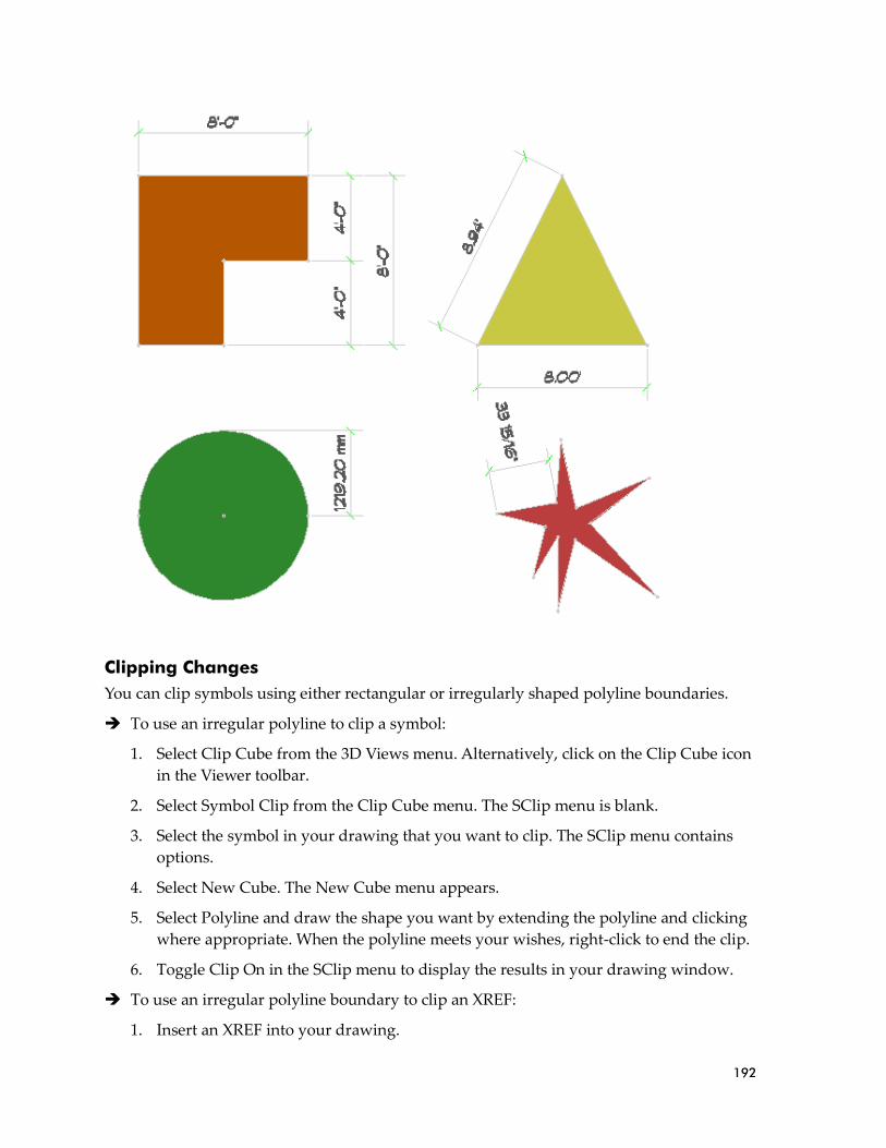
192
Clipping Changes
You can clip symbols using either rectangular or irregularly shaped polyline boundaries.
➔ To use an irregular polyline to clip a symbol:
1. Select Clip Cube from the 3D Views menu. Alternatively, click on the Clip Cube icon
in the Viewer toolbar.
2. Select Symbol Clip from the Clip Cube menu. The SClip menu is blank.
3. Select the symbol in your drawing that you want to clip. The SClip menu contains
options.
4. Select New Cube. The New Cube menu appears.
5. Select Polyline and draw the shape you want by extending the polyline and clicking
where appropriate. When the polyline meets your wishes, right-click to end the clip.
6. Toggle Clip On in the SClip menu to display the results in your drawing window.
➔ To use an irregular polyline boundary to clip an XREF:
1. Insert an XREF into your drawing.

193
2. Select Clip Cube from the 3D Views menu. Alternatively, click on the Clip Cube icon
in the Viewer toolbar.
3. Select XREF Clip from the Clip Cube menu. The XClip menu is blank.
4. Select the XREF in your drawing that you want to clip. The XClip menu contains
options.
5. Select New Cube. The New Cube menu appears.
6. Select Polyline and draw the shape you want by extending the polyline and clicking
where appropriate. When the polyline meets your wishes, right-click to end the clip.
7. Toggle Clip On in the XClip menu to display the results in your drawing window.
Pen Styles/Pen Widths
Based on the Windows line type format, you can apply scale-independent patterns to your
DataCAD line types. These patterns are compatible with the Windows Metafile format and
convert directly to Adobe PDF format. This allows you to apply non-standard patterns such
as a property line to curves.
New Toolbars
The Notate and Types toolbars are helpful additions that can speed up the drawing process.
➔ To control the scale of notations:
1. Display the Notate toolbar.
2. Open the Set symbol scale pull-down menu on the toolbar.
3. Select the scale option that you want to use.
➔ To add and control notations in your plots:
1. Select the option you want to use from the Notate toolbar.
2. Point where you want that notation to appear. Then click. For many options, the
Edit/Customize definition box appears.

194
3. Supply information in the Value fields. Select OK when you are finished. The
notation is added to your plot.
The Types toolbar lets you quickly manage and use the smart walls, doors, and windows.
Plotting Enhancements
You can save your current plotter and Quick Layout settings to a file that you can load into
other drawings. Also, you can assign unique pen tables to specific scales. This means that
large-scale drawings and details can have thicker pens and small-scale drawings can have
thinner ones. You can assign unique pen tables to specific multi-scale plotting details.
➔ To assign pen tables to specific scales:
1. Select Scale to Pen in the Print/Plot menu to display the Pen Table Assignments
dialog box.
2. Click in the appropriate Uses this Pen Table field.
3. Open the Load pen file dialog box by clicking on the three-dot button that appears at
the end of the field you selected.
4. Select the pen file you want to use for that scale and click Open.

195
➔ To assign unique pen tables to specific multi-scale plotting details:
1. Select Multi-layout from the Print/Plot menu.
2. Add one or more details to the sheet. When you hover over a detail with your cursor,
DataCAD highlights its extents, provides its scale, and displays its name as a tooltip.
3. Place your cursor on a detail and press
Ctrl-right click. This displays a pop-up
menu.
4. Select Pen Table. The Pen Table Assignments dialog box appears.
5. Supply the pen table you want to use for that detail and click OK.
Detail names may contain up to 80 characters.

196
Multiple Private Clipbooks with Preview
DataCAD stores up to 10 private Clipbooks that contain the most recent data you copied
from your drawing to the Windows Clipboard. Whenever you select Paste, you can re-select
any of your Clipbooks. A preview of each Clipbook’s contents is shown when you highlight
the item in the menu.
Reference File Manager Enhancements
You can assign XREF Highlight settings on a per-XREF and/or XREF Layer basis. The
Reference File Manager dialog box allows you to drag-and-drop between the Loaded,
Refresh, Reload, Bind, and Delete lists. You can also assign custom names to XREFs. The
Inherit Current Highlight Setting option for nested XREFs is remembered on a per-drawing
versus global basis.
➔ To assign highlight settings:
1. Select Reference File Management from the Insert pull-down menu, slide your
cursor to the right, and select Manager from the submenu. Alternatively, you can
press Ctrl-R to display the Reference File Manager dialog box.
2. Select a loaded reference file to display its layers and views.
3. Set highlighting options:

197
• X-Ref – sets highlights for the entire X-Ref when this box is checked. You can
select the line type and color from the pull-down menus. Supply a value in the
Spacing field.
• X-Ref layer – sets highlights for one layer at a time when this box is checked. You
must first highlight the name of the layer you want to use in the list of available
XREF layers.
Change Menu Enhancements
Two additional options are available in the Edit/Change/Text menu. You can now change
the text angle and alignment.
For the angle option, you simply supply the new value and press Enter.
For the alignment option, the Alignment submenu offers additional choices. Left, Center,
and Right are mutually exclusive; the same is true for Top, Middle, and Bottom. Reversed
lets you draw text reversed about its height. Mirrored lets you draw text mirrored about its
width.
If XREF highlighting is on and a layer within the XREF is also highlighted, the layer highlight settings supersede the overall XREF highlight settings.

198
DataCAD 11 has many new and improved features. Some of these features are designed to
help you increase productivity. For example, the new Symbol Browser allows you to rapidly
find, place, customize, and manage symbols that you use in your drawings. The
Triangulated Irregular Network (TIN) modeler and other improved polygon tools have
been added to DataCAD 11.
Many interface enhancements are included in DataCAD 11. All the interface elements in
DataCAD 11 are based on the visual style of your current desktop theme. DataCAD 11
provides Windows® 2000-style properties and allows you to apply Windows XP Themes. It
is easy to dock and undock the toolbars and menus; you can even have them “float” on your
desktop so that you can increase the drawing area.
Compatibility with other programs is improved. The new double-precision floating point
database (accurate to ~14 decimal places instead of the ~7 of earlier versions) makes
DataCAD 11 as accurate as AutoCAD®. Exchanging drawings with colleagues using other
CAD programs is easier as a result.
Program directory and file maintenance changes also affect your productivity. New import
and export enhancements improve your ability to work with drawings from other
programs. Backup and recovery routines have been improved, too.
Productivity Features Let’s look at the new and/or improved productivity features that you can put to work
immediately.
The new Symbol Browser makes it easy to use supplied and custom symbols and templates.
Inserting a symbol into your drawing involves little more than selecting it from the Symbol
Browser and dropping it where you want it.
The new polygon tools include the Triangulated Irregular Network (TIN) modeler, the ruled
surface modeler, 3D knife, and sectioning tool. The TIN modeler is especially helpful for
developing a site model based on a surveyor’s data. The ruled surface feature is especially
helpful when you are designing roof contours. The 3D knife provides a multitude of options
for slicing polygons. With the sectioning tool, you can generate a 2D section from your 3D
model.
Symbol Browser
DataCAD makes it easy to use symbols and templates in your drawings. With just a few
mouse clicks, you can open the appropriate folder, display the symbols in the browser, and
select the ones you want to use into your drawing. If you developed custom templates with
older versions of DataCAD, you can open them in the Symbol Browser, too. In effect, the
Symbol Browser treats file folders as templates that contain collections of symbols.
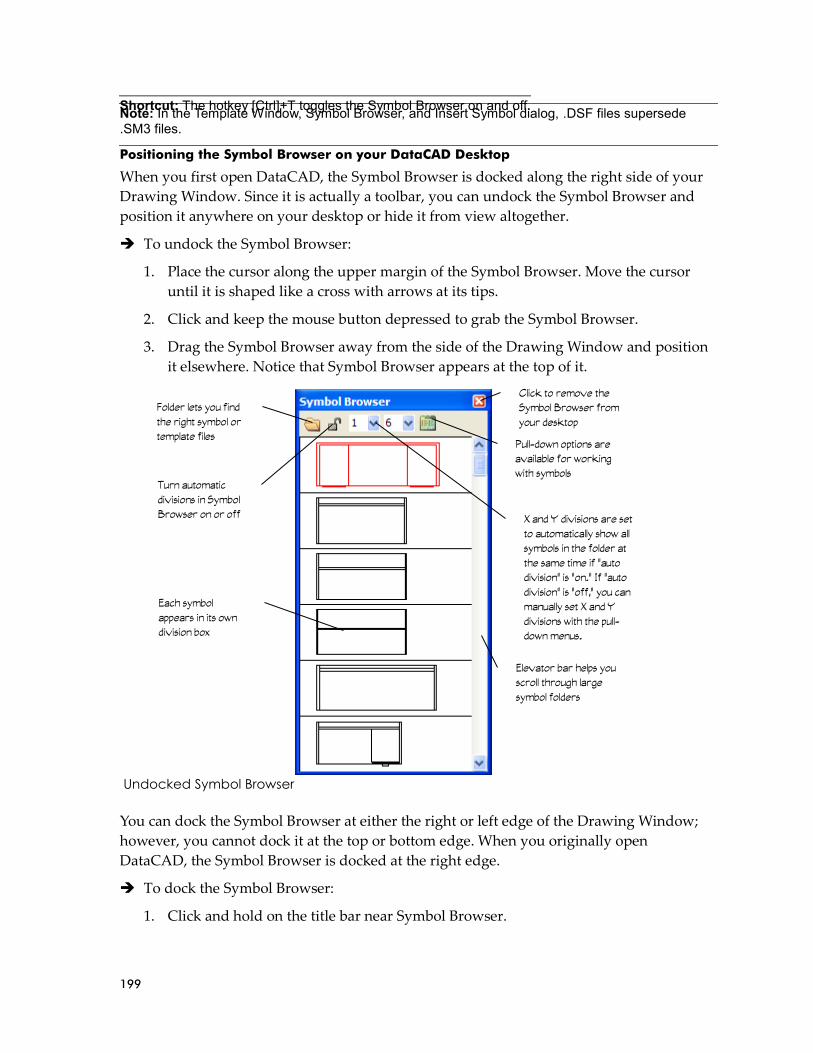
199
Positioning the Symbol Browser on your DataCAD Desktop
When you first open DataCAD, the Symbol Browser is docked along the right side of your
Drawing Window. Since it is actually a toolbar, you can undock the Symbol Browser and
position it anywhere on your desktop or hide it from view altogether.
➔ To undock the Symbol Browser:
1. Place the cursor along the upper margin of the Symbol Browser. Move the cursor
until it is shaped like a cross with arrows at its tips.
2. Click and keep the mouse button depressed to grab the Symbol Browser.
3. Drag the Symbol Browser away from the side of the Drawing Window and position
it elsewhere. Notice that Symbol Browser appears at the top of it.
Undocked Symbol Browser
You can dock the Symbol Browser at either the right or left edge of the Drawing Window;
however, you cannot dock it at the top or bottom edge. When you originally open
DataCAD, the Symbol Browser is docked at the right edge.
➔ To dock the Symbol Browser:
1. Click and hold on the title bar near Symbol Browser.
Shortcut: The hotkey [Ctrl]+T toggles the Symbol Browser on and off. Note: In the Template Window, Symbol Browser, and Insert Symbol dialog, .DSF files supersede .SM3 files.
Folder lets you find
the right symbol or
template files
X and Y divisions are set
to automatically show all
symbols in the folder at
the same time if “auto
division” is “on.” If “auto
division” is “off,” you can
manually set X and Y
divisions with the pull-
down menus.
Pull-down options are
available for working
with symbols
Each symbol
appears in its own
division box
Click to remove the
Symbol Browser from
your desktop
Elevator bar helps you
scroll through large
symbol folders
Turn automatic
divisions in Symbol
Browser on or off

200
2. Drag the Symbol Browser to the right or left margin of the Drawing Window until
the title bar disappears. To dock the Symbol Browser to the left of the Edit/Utility
menu bar, simply continue dragging it leftward until it pops into place.
Symbol Browser docked at the leftmost edge of the screen
DataCAD automatically calculates the divisions to display all the symbols in the folder you
selected. This occurs when the lock on the Symbol Browser menu bar is “on” (or depressed)
and the pull-down number menus are grayed (this means you cannot change them).
➔ To specify the number of X and Y divisions for the Symbol Browser:
1. Click on the auto divisions icon on the Symbol Browser menu bar. When the drop-
down arrows appear next to the X and Y division numbers, you can change these
values manually to suit your needs.
2. Select the number of X divisions you want the Symbol Browser to display.
3. Select the number of Y divisions you want the Symbol Browser to display.
Describes the
symbol as you
pass over it with
your cursor
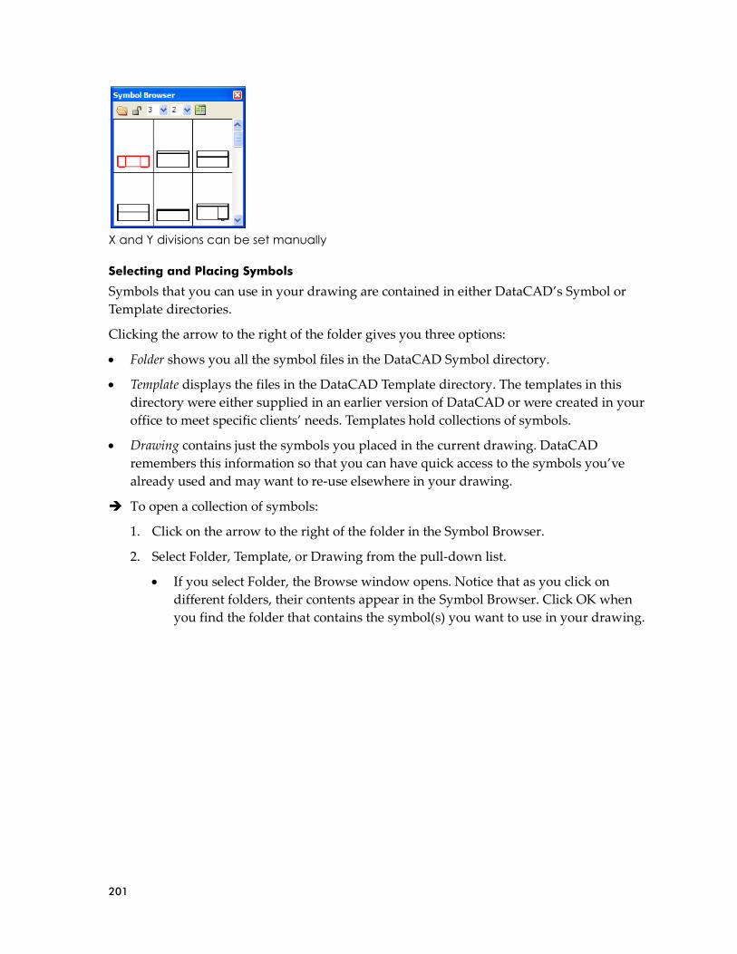
201
X and Y divisions can be set manually
Selecting and Placing Symbols
Symbols that you can use in your drawing are contained in either DataCAD’s Symbol or
Template directories.
Clicking the arrow to the right of the folder gives you three options:
• Folder shows you all the symbol files in the DataCAD Symbol directory.
• Template displays the files in the DataCAD Template directory. The templates in this
directory were either supplied in an earlier version of DataCAD or were created in your
office to meet specific clients’ needs. Templates hold collections of symbols.
• Drawing contains just the symbols you placed in the current drawing. DataCAD
remembers this information so that you can have quick access to the symbols you’ve
already used and may want to re-use elsewhere in your drawing.
➔ To open a collection of symbols:
1. Click on the arrow to the right of the folder in the Symbol Browser.
2. Select Folder, Template, or Drawing from the pull-down list.
• If you select Folder, the Browse window opens. Notice that as you click on
different folders, their contents appear in the Symbol Browser. Click OK when
you find the folder that contains the symbol(s) you want to use in your drawing.

202
Symbols contained in the folder in the Browse window simultaneously appear in the Symbol Browser
• If you pick Template, the Select Template File to Browse window opens. When
you click on a file in the list, its collection of symbols is displayed in the Symbol
Browser. Click Open when you find the template file that contains the symbol(s)
you want to use in your drawing.
Template file contents are displayed in the Symbol Browser
• If you choose Drawing, DataCAD displays the symbols you used already in the
current drawing.
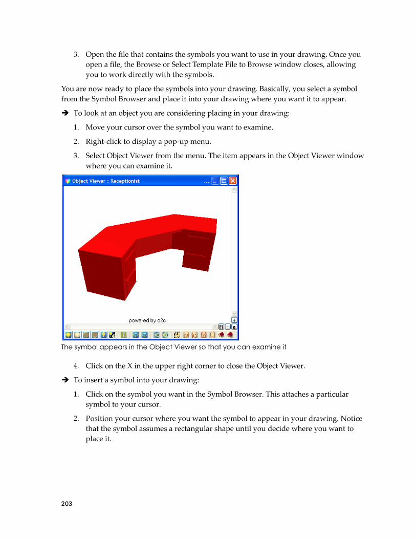
203
3. Open the file that contains the symbols you want to use in your drawing. Once you
open a file, the Browse or Select Template File to Browse window closes, allowing
you to work directly with the symbols.
You are now ready to place the symbols into your drawing. Basically, you select a symbol
from the Symbol Browser and place it into your drawing where you want it to appear.
➔ To look at an object you are considering placing in your drawing:
1. Move your cursor over the symbol you want to examine.
2. Right-click to display a pop-up menu.
3. Select Object Viewer from the menu. The item appears in the Object Viewer window
where you can examine it.
The symbol appears in the Object Viewer so that you can examine it
4. Click on the X in the upper right corner to close the Object Viewer.
➔ To insert a symbol into your drawing:
1. Click on the symbol you want in the Symbol Browser. This attaches a particular
symbol to your cursor.
2. Position your cursor where you want the symbol to appear in your drawing. Notice
that the symbol assumes a rectangular shape until you decide where you want to
place it.

204
The symbol assumes a rectangular shape as you drag it into your drawing
3. Click when the rectangular shape is positioned where you want to place the symbol
into your drawing. Notice that a rectangular shape is still attached to your cursor.
This allows you to “place” many copies of a symbol into your drawing. (For chairs,
replication may be a convenient feature, but most houses only require one kitchen.)
You can place many copies of the symbol into your drawing
4. Right-click when you are finished placing the symbol(s) into your drawing. The
cursor returns to its normal shape, allowing you to continue working in your
drawing or to select and place other symbols.
Controlling Symbols
You don’t have to live with the symbols as they are; you can change them in several ways by
using the Options pull-down menu. For example, you can enlarge, offset, or rotate them.

205
The Options menu lets you further control the symbols you add to your drawing. The left menu offers related options when you insert a symbol.
The Error Bar tells how the symbol will behave within the drawing. In the following
example, the desk symbol will be rotated, enlarged, and offset based on the options that you
set. These settings remain in effect for placing all future symbols until you change one of the
options.
The Error Bar summarizes settings you selected through the Options menu

206
➔ To rotate a symbol:
1. Select Rotate from the Symbol Browser’s Options pull-down menu. The Edit menu
appears and you are prompted to Position symbol on drawing.
2. Decide whether you want to rotate the symbol dynamically with your cursor or use
a fixed rotation angle. When Rotate is on, you can place the symbol dynamically;
when Rotate is off, you are prompted to specify the angle you want.
If you opted for a fixed angle instead of dynamic rotation, remember to set the angle back to
zero. If you don’t do this, all future symbols will be placed at the rotation angle you
specified. For example, if you set a 30-degree rotation angle while placing a desk symbol
and neglect to change it back to zero, the next symbol (perhaps a conference table) will also
appear at a 30-degree angle.
➔ To enlarge a symbol:
1. Select Enlarge from the Symbol Browser’s Options pull-down menu. The Enlarge
menu appears and you are prompted to Select symbol enlargement factor to change.
2. Choose X Englargmnt, Y Enlargmnt, Z Enlargmnt, Line Factor, or Set All from the
Enlarge menu; select an enlargement value from the list or type your own; and press
(Enter). Notice that the enlargement factor(s) you entered are displayed on the Error
Bar.
3. Right-click, or click on Exit, or press (Shift-F10) to leave the Enlarge menu.
4. Click on the symbol that you want to drag into your drawing.
5. Drag the symbol into your drawing with your mouse. You are prompted to Position
symbol on drawing.
6. Click the left button when the symbol is in the correct place. The enlarged symbol
appears in the drawing. Continue placing additional copies of the symbol by
repeating this step.
7. Right-click to stop placing additional copies of the symbol into your drawing.
➔ To offset the insertion height of symbols:
1. Select Z Offset from the Symbol Browser’s Options pull-down menu. The Z Offset
menu appears, and you are prompted to Enter Z-offset for symbols.
2. Supply the value and press (Enter). Notice that the Z-offset you entered is displayed
on the Message Bar.
3. Click on the symbol that you want to drag into your drawing.
4. Drag the symbol into your drawing with your mouse. You are prompted to Position
symbol on drawing.
Hint: If you want to reduce the size of a symbol, use a decimal value (such as .25). If you want to mirror the symbol, enter a negative value (such as –1).

207
5. Click the left button when the symbol is in the correct place. The symbol appears in
the drawing at the Z-offset you supplied in step 2. Continue placing additional
copies of the symbol by repeating this step.
6. Right-click to stop placing additional copies of the symbol into your drawing. You
can use the Object Viewer in the View pull-down menu to see the effect of the Z-offset
you applied.
Editing Symbols
If you want to edit or change the symbol, you must first convert it into separate lines and/or
arcs. In other words, you will “explode” the symbol back into its component drawing
elements. You can do this when you insert the symbol into your drawing or after the symbol
has been inserted. Once the symbol has been edited, you can reform the symbol lines and
arcs into a single symbol entity and save it back into the Symbol Browser and then update
the symbols already in your drawing.
➔ To explode a symbol:
1. Click on the Options icon in the Symbol Browser.
2. Select Explode. When this function is “on,” a checkmark appears to the left of the
word “Explode.”
When Explode is activated, you can convert a symbol into lines and/or arcs
3. Click on the symbol you want to use and drag it into your drawing.
4. Click the left mouse button to place it. The exploded symbol appears in your
drawing. You can repeat this step to continue placing copies of the exploded symbol.
5. Right-click to stop placing copies of this symbol.
6. Make changes to the exploded symbol.

208
In this exploded version of the desk symbol, the upper left drawer was erased
1. Select and place other symbols you want to drag into your drawing as exploded
lines and/or arcs.
2. Deactivate Explode in the Symbol Browser’s Options menu when you are
finished. Until the checkmark to the left of Explode disappears, all symbols that
you place will be converted to lines and/or arcs in your drawings.
When you activate Explode in the Symbol Browser’s Options menu, the left Layers menu
includes an Explode button. This is how you explode a symbol when you place it. If you
want to explode a symbol that you previously placed in your drawing, select Explode from
the 3D Edit menu.
Creating New Symbols
You can create and save your own symbols in a new or existing folder.
➔ To create and save a symbol:
1. Draw something that you want to use as a symbol.
2. Select Save Symbol from the Options pull-down menu in the Symbol Browser. The
contents of the active symbol folder appear in a window and you are asked to Enter
name of symbol file to be saved.
3. Type a name for the item you drew in step 1. Then press (Enter) or click on Save. The
Save Symbol menu appears.
4. Select the entities you drew in step 1. The items you selected are highlighted. You are
prompted to Select an insertion point for symbol.
5. Click once in the Drawing Window to create a “handle” that will help you place
your symbol. A symbol descriptor window appears.
The file name is limited to 255 characters.
You could save the item in another folder or create a new folder by using the icons at the top of this window.

209
Describe the item you are saving as a symbol
6. Fill in the fields with information about the item. Double-click in a field and supply
information in the Name or Value columns. When you double-click on the Type
column, you can select Text, Decimal, or Integer for the information that should
appear in the Value column.
7. Click on Ok when you have finished describing the item. The object you created
appears in the Symbol Browser. Once an item you created is designated as a symbol,
you can put clones of it anywhere in the drawing on your screen.
The new item appears in the Symbol Browser
Editing Symbols
What if you want to edit information about a symbol or get rid of it in your Symbol
Browser? That’s easy.
➔ To edit information about a symbol:
1. Move your cursor in the Symbol Browser to the symbol you want to edit.
2. Right-click to display the pop-up menu.
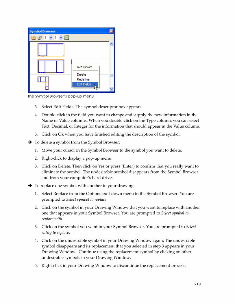
210
The Symbol Browser’s pop-up menu
3. Select Edit Fields. The symbol descriptor box appears.
4. Double-click in the field you want to change and supply the new information in the
Name or Value columns. When you double-click on the Type column, you can select
Text, Decimal, or Integer for the information that should appear in the Value column.
5. Click on Ok when you have finished editing the description of the symbol.
➔ To delete a symbol from the Symbol Browser:
1. Move your cursor in the Symbol Browser to the symbol you want to delete.
2. Right-click to display a pop-up menu.
3. Click on Delete. Then click on Yes or press (Enter) to confirm that you really want to
eliminate the symbol. The undesirable symbol disappears from the Symbol Browser
and from your computer’s hard drive.
➔ To replace one symbol with another in your drawing:
1. Select Replace from the Options pull-down menu in the Symbol Browser. You are
prompted to Select symbol to replace.
2. Click on the symbol in your Drawing Window that you want to replace with another
one that appears in your Symbol Browser. You are prompted to Select symbol to
replace with.
3. Click on the symbol you want in your Symbol Browser. You are prompted to Select
entity to replace.
4. Click on the undesirable symbol in your Drawing Window again. The undesirable
symbol disappears and its replacement that you selected in step 3 appears in your
Drawing Window. Continue using the replacement symbol by clicking on other
undesirable symbols in your Drawing Window.
5. Right-click in your Drawing Window to discontinue the replacement process.

211
If you select Reload All from the Options pull-down menu, DataCAD gets the most recent
definition of a symbol from the hard drive. Otherwise, it goes to the drawing itself for the
definition.
Once you place a symbol in your drawing, DataCAD will no longer read the definition from
your hard drive. That’s why Reload All is important.
Symbols you insert “travel” with your drawing. If you insert symbol A into drawing 1, then
redefine symbol A from drawing 2, symbol A will look different in drawings 1 and 2. You
can use Reload All to make symbol A look the same in drawings 1 and 2.
Generating Reports About Symbols
You can generate reports based on the symbols that appear in your drawing.
➔ To generate reports about symbols used in your drawing:
1. Select Reports from the Options pull-down menu. The Report Forms dialog box
appears.
The Report Forms dialog box
2. Click in the box to the left of the items you want to include in your report. If you
want reports on all the items, click on Select All. If you want to start over with a clean
slate, click on Select None. Symbols that are not currently used in your drawing but
still “live” in your drawing’s database are grayed out or unavailable for reports.
3. Use the drop-down box in the right corner to select the type of report you want to
generate. If you want to use forms that are in another folder, click on the browse icon
and make your selection.

212
4. Decide which layer(s) you want to include in your reports by clicking on the
appropriate option in the Layer Search box.
5. Choose an output option in the lower left portion of the Report Forms dialog box:
• If you select To File, you are asked to supply a file name. The file will be in .txt
format.
• If you select To Printer, the report goes to your default text printer.
• If you select To Drawing, you are prompted to Select point to position text. You can
change the appearance of the text by selecting Size, Angle, Weight, Slant, Aspect,
Factor, or Font from the left menu. Place the text insertion icon where you want
the report to appear in your Drawing Window.
Reports you generate can be placed in your drawing
6. Right-click to return to the Report Forms dialog box. You can generate other reports
and select the appropriate output option by following steps 2 through 5.
7. Click Close when you are finished generating reports.
Purging Unused Symbols
DataCAD remembers all the symbols you used even though you may have already erased
some of those symbols from the drawing on your screen. When you add a symbol to your
drawing, DataCAD stores that symbol with your drawing. This definition is not deleted
when you erase the symbol and continues to take up drawing file space. When you erase
symbols from your drawing, it’s important to purge the symbol if you don’t plan to use it
again.
Hint: To keep report column spacing consistent, use a fixed-width font (such as ARCWY2FW).
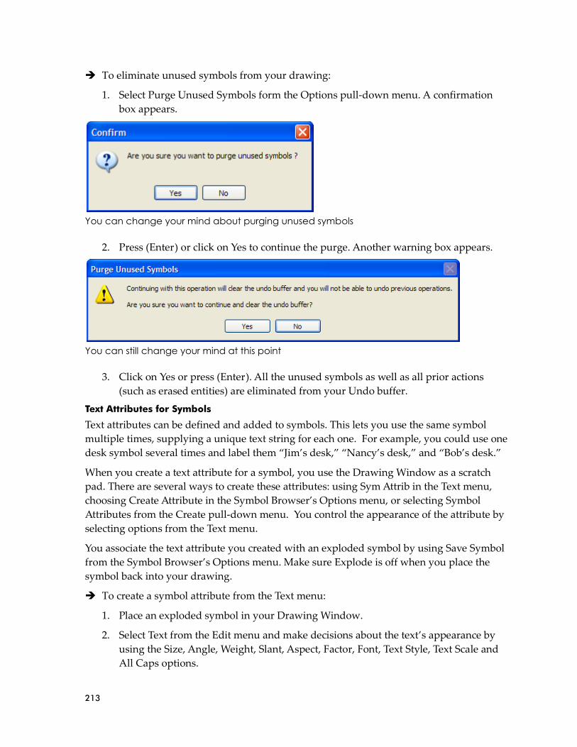
213
➔ To eliminate unused symbols from your drawing:
1. Select Purge Unused Symbols form the Options pull-down menu. A confirmation
box appears.
You can change your mind about purging unused symbols
2. Press (Enter) or click on Yes to continue the purge. Another warning box appears.
You can still change your mind at this point
3. Click on Yes or press (Enter). All the unused symbols as well as all prior actions
(such as erased entities) are eliminated from your Undo buffer.
Text Attributes for Symbols
Text attributes can be defined and added to symbols. This lets you use the same symbol
multiple times, supplying a unique text string for each one. For example, you could use one
desk symbol several times and label them “Jim’s desk,” “Nancy’s desk,” and “Bob’s desk.”
When you create a text attribute for a symbol, you use the Drawing Window as a scratch
pad. There are several ways to create these attributes: using Sym Attrib in the Text menu,
choosing Create Attribute in the Symbol Browser’s Options menu, or selecting Symbol
Attributes from the Create pull-down menu. You control the appearance of the attribute by
selecting options from the Text menu.
You associate the text attribute you created with an exploded symbol by using Save Symbol
from the Symbol Browser’s Options menu. Make sure Explode is off when you place the
symbol back into your drawing.
➔ To create a symbol attribute from the Text menu:
1. Place an exploded symbol in your Drawing Window.
2. Select Text from the Edit menu and make decisions about the text’s appearance by
using the Size, Angle, Weight, Slant, Aspect, Factor, Font, Text Style, Text Scale and
All Caps options.
214
3. Click on Alignment and use the toggles to control the way your text will be inserted;
then right-click to return to the main Sym Attrib menu.
Left Text inserted from left to right
Center Text inserted from the center
Right Text inserted from right to left
Top Cursor is at the top of the characters you input
Middle Cursor is at the midpoint of the characters you input
Bottom Cursor is at the bottom of the characters you input
Aligned Adjusts text to fit between two given points
Fit Adjusts text to fit a certain width and height
Reversed Draws each character backward from right to left
Mirrored Draws each character upside down from left to right
4. Click on Sym Attrib. The text cursor appears and you are prompted to Select point to
position text. Once you position your cursor, the Create Symbol Attribute dialog box
appears.
Attribute Name Name of the attribute
Prompt Reminder question
Value Information that should appear on the symbol. This can include constant text.
Value Properties
Invisible Information that appears in the Value field will be invisible if you check this box. If
there is no check in the box, the Value text will appear in your drawing. This can be
applied to either Locked or Preset
Variable Supply new information when prompted.
Preset Add new information. This allows you to use constant text either before or after the
new information.
Locked Supply information that cannot be changed
Create multiple
attributes If this is checked, you can supply more symbol attributes. Each symbol can have
many attributes.
Hint: Save time by selecting Font from the Text menu and use the Set Text Parameters dialog box to control many of your options and view a sample in the Font Preview window.
Note: The text cursor coincides with the current text alignment setting. A “+” marker is incorporated into the carat as a visual indicator of the current alignment setting. There are nine text alignment points.

215
A symbol can have multiple attributes if the Create multiple attribute box is checked
5. Click on Ok or press [Enter] to leave the Create Symbol Attribute dialog box. If you
enabled (the box is checked) Create multiple attributes, repeat steps 4 and 5. When
you are finished creating attributes for this symbol, make sure you disable Create
multiple attributes (the box is not checked).
The last (or only) symbol attribute should not have a check in the Create multiple attributes box
6. Turn off Explode in the Symbol Browser’s Options pull-down menu. Then save the
symbol and its attribute by following the directions under “Creating New Symbols.”
Make sure you use Area in the Save Symbol menu rather than Group. (Group
ignores the attribute.) DataCAD creates a .DSF file for the symbol. When you are
finished saving the symbol and its attribute, right-click to leave the Sym Attrib menu.
7. Place the symbol into your drawing as often as necessary.

216
8. Select Edit Symbol Attributes from the Symbol Browser’s Options pull-down menu.
Then click on the symbol. The Edit/Customize Symbol Attribute dialog box appears.
The Edit/Customize Symbol Attribute dialog box prompts you for the value that should
appear on the symbol in your drawing
9. Supply the information in the Value column and click on Ok. (In this example, “’s
Desk” and “PD-1-“ were constants; “Michelle” and “936” were added to these
constant values.) If you placed the same symbol into your drawing several times and
want to use different values, repeat steps 8 and 9 as often as necessary.
Several personalized desks were placed in the drawing
If you selected Locked in the Value Properties portion of the Create Symbol Attribute dialog
box, you cannot edit the value. If you selected Variable, you supply new information when
responding to the Prompt question.

217
What if some of the information in a symbol changes? For example, what if Harry leaves the
company and his desk is reassigned to Maryjane?
➔ To edit an existing symbol attribute:
1. Select Edit Symbol Attributes from the Symbol Browser’s Options menu.
2. Click on the symbol attribute you want to edit. (In this case, Harry.) The
Edit/Customize Symbol Attribute dialog box appears.
3. Change only the relevant information. (In this case, change Harry to Maryjane.) Then
click on OK.
Notice that the inventory control number stayed the same, but Maryjane replaced Harry as
the desk’s owner.
4. Edit other existing symbol attributes by repeating steps 2 and 3.
Symbol Attributes appear as Block Attributes when you open a DWG file.
Layers in Symbols
Symbols retain layer information. This lets you customize on/off layer settings for each
symbol. When a symbol is exploded, its constituent entities are returned to their proper
layers or new layers are created automatically if necessary.
Symbol Browser Settings
The Symbol Browser retains the following settings between DataCAD sessions.
• Last browse type (folder, template, or drawing)
• Last path browsed for symbols (independent from Template and Insert Symbol menus)
• Last path browsed for templates (independent from Template menu)
• Auto-divisions On/Off status
Shortcut: You can use [Ctrl]-Click on either the Folder or Template menu item in the browse pull-down menu to bypass the folder/file dialog. This lets you go directly to browsing the last symbol folder or template file.

218
Polygon Tools/TIN Modeler
The Ruled Surf function allows you to mesh polygons between Contours and Polylines. If
you are 3D modeling, investigate the new TIN (Triangular Irregular Network) modeler in
the 3D Polygon menu. The TIN modeler can connect a random series of survey points (3D
markers) with triangular polygons. Once the polygons are generated, you can calculate the
surface area of TIN models, use the flip valley option to “flip” the valley between coincident
polygon edges, or create roads, foundation cuts, etc. with the 3D Knife. The drop point
option lets you place 3D markers on the surface of inclined polygons. You can create
polyline contours from polygon site models.
The Triangulated Irregular Network (TIN) modeler uses a set of points, polylines, or
contours to help you accurately plan site changes that will be necessary to accommodate
your building. Often, the surveyor will provide the points or contours you need to generate
the TIN model. However, you can also generate your own points or contour lines using
Contours or Markers from the 3D Entity menu.
Once the TIN is generated from the points or contour lines, you can cut, fill, and sculpt the
surface of the building site. DataCAD calculates the surface area and volume for each
operation.
Generating a TIN Model from Contour Lines or Markers You Created
You can use the Contours or 3D Markers functions in the 3DEntity menu to represent the
surface of your building site. Then, you can generate a TIN model.
➔ To create your own contour lines:
1. Choose Contours from the 3D Entity menu. The Contours menu appears.
2. Activate one of the mutually exclusive toggles Natural (open-ended), Cyclic
(connects the first and last points with a smooth closed curve), or Tangent (requires
two more points at the start and end of the contour line), depending on the type of
contour you want to create. For a tangent contour line only, you must select a first
point before the curve; this point determines the curve’s tangent direction when you
enter the first control point.
3. Set the number of line segments (from 4 to 36) between control points by clicking on
Divisions, typing a number when prompted to Enter number of divisions per contour
segment, and pressing [Enter]. The farther apart your control points, the more
divisions you need to create a smooth curve.
4. Set the curve tangent factor by clicking on Stiffness, typing a number when
prompted to Enter new contour stiffness tangent factor, and pressing [Enter]. The
higher the number, the flatter the line as it passes through each control point.
5. Set elevation values by clicking on Set Z User 1 or Set Z User 2, typing a number
when prompted to Enter new Z-user1 (or Z-user2) height, and pressing [Enter].
6. Use Set Index to control the Z-coordinate index distance.

219
7. Select up to 36 control points for each contour line. To accurately position each
control point, use coordinate entry by pressing [Spacebar], supplying the X and Y
values, and pressing [Enter]. You can use Add Index or Sub Index for a steadily
rising or declining line. You can use Z-Base, Z-User 1, Z-User 2, and Z-Height to
change elevation values.
8. Right-click when you have entered the final control point. DataCAD generates the
contour line. For a tangent contour line only, you must also specify the ending
tangent point after the curve; this point determines the curve’s tangent direction
when it enters the last control point.
9. Generate more contour lines if necessary. You can use these lines to generate the TIN
model.
➔ To draw concentric contour lines that steadily rise at specified intervals:
1. Draw the first contour line at Z-Base.
2. Click on Set Index, specify a value, and press [Enter]. This controls the Z-coordinate
index height of the second and subsequent contour lines. For example, if you specify
the Set Index value as 2, the second contour line will be 2’ above the first, the third
will be 2’ above the second, and so on.
3. Click on Add Index and draw the second contour line. When DataCAD generates
this line, it will be higher than the first one, based on the index you set in step 2.
4. Generate more contour lines using Add Index if necessary, by repeating step 3.
➔ To generate a TIN model from contour lines:
1. Open the drawing that contains the lines you entered using Contours.
2. Rename the file to distinguish it from the contour lines. For example, if the lines
were in a file named My Contours, you may want to use My Contours TIN for the
TIN model. To do this select Save As from the File pull-down menu, supply the new
file name, and click on Save or press [Enter].
3. Select Polygons from the 3D Entity menu and click on TIN Surface. The TIN Surface
menu appears. Another way to arrive at the TIN Surface menu is to select 3D
Surfaces from the Create pull-down menu and then click on TIN Surface.

220
4. Select Area, click above the top left contour, draw the rubber band around the set of
contours, and click to end the box. DataCAD generates the TIN model.
TIN Model generated from contour lines
➔ To use Marker to generate a set of points for the TIN model:
1. Set the Z-Base for the points by choosing Settings from the 3D Edit menu.
Alternatively, you can choose 3D Settings from the Tools, Settings pull-down menu.
The 3D Settings menu appears.
2. Click on Z-Base, supply the new value, and press [Enter].
3. Choose 3D Markers from the 3D Entity menu. The 3D Markers menu appears.
4. Click on Z-Base. If you changed the Z-Base in steps 1 and 2, the new value will
appear in the Information bar. You are prompted to Select the snapping point or
marker.

221
5. Use the coordinate entry method to accurately place the points on your screen. A
small dot appears each time you supply the X and Y coordinate values and press
[Enter]. These dots are markers that you can use to generate a TIN model.
➔ To generate a TIN model from points you entered using Marker:
1. Open the drawing that contains the points you entered using 3D Markers.
2. Rename the file to distinguish it from the data points. For example, if the points were
in a file named My 3DMarkers, you may want to use My 3D TIN for the TIN model.
To do this select Save As from the File pull-down menu, supply the new file name,
and click on Save or press [Enter].
3. Select Area, click above the top left point, draw the rubber band around the set of
markers, and click to end the box. DataCAD generates the TIN model.
Generating a TIN Model from Surveyor’s Data
If the surveyor provides you with data in a point file, you can import that information into
DataCAD. Then, you can create the TIN model.
➔ To generate a TIN model from a file containing the surveyor’s points:
1. Select 3D Surfaces from the Create pull-down menu, then click on TIN Surface in the
submenu. Alternatively, select Polygon from the 3D Entity menu, then click on TIN
Surface. The TIN Surface menu appears.
2. Open the file that contains the surveyor’s set of points by selecting Import from the
TIN Surface menu.
3. Highlight the file that contains the data for the site and click on Open. The
surveyor’s points appear on your screen.
4. Select Area, click once above the top leftmost point, draw the rubber band around all
the points, and click again. DataCAD generates the TIN model.

222
The surveyor may have inadvertently duplicated points in the data file. This could result in
a TIN model that takes up more storage space than necessary on your computer. To control
the size of your file, you can eliminate duplicate points before you generate the TIN model.
➔ To delete duplicate points:
1. Use Import in the TIN Surface menu to bring the surveyor’s information into
DataCAD.
2. Click on Delete Dupes in the TIN Surface menu.
3. Select MissDist. You are prompted to supply the Maximum Distance between points to
combine.
4. Choose a distance from the ones offered in the menu or supply your own value.
Press [Enter]. The Miss Distance lets you determine what “duplicate” means in
terms of your file. For example, if you want to eliminate points that are within 1 foot
of each other, you would input 1 as the miss distance. The larger the value you
supply for the miss distance, the more points will be eliminated and the smaller your
file.
5. Click at the top leftmost corner of the points, drag the rubber band diagonally
downward until you surround the area, and click again. DataCAD eliminates the
duplicate points that fall within the miss distance you specified. If you specified a
large value for the miss distance, you should see a lot less points on your drawing
screen. If you specified a small miss distance value, the difference may not be as
obvious.
6. Right-click to return to the main TIN Surface menu. You are prompted to Select first
corner of area to Process Points for TIN.
7. Click above the top leftmost corner of the area, surround the points with the rubber
band, and click again. DataCAD produces the TIN model. Depending on the miss
distance you selected, the resulting TIN model will be much simpler, and your file
will be much smaller.
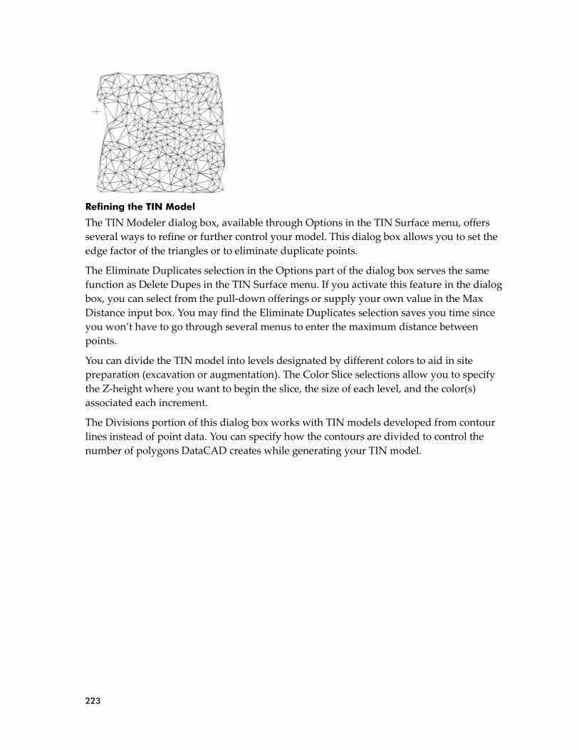
223
Refining the TIN Model
The TIN Modeler dialog box, available through Options in the TIN Surface menu, offers
several ways to refine or further control your model. This dialog box allows you to set the
edge factor of the triangles or to eliminate duplicate points.
The Eliminate Duplicates selection in the Options part of the dialog box serves the same
function as Delete Dupes in the TIN Surface menu. If you activate this feature in the dialog
box, you can select from the pull-down offerings or supply your own value in the Max
Distance input box. You may find the Eliminate Duplicates selection saves you time since
you won’t have to go through several menus to enter the maximum distance between
points.
You can divide the TIN model into levels designated by different colors to aid in site
preparation (excavation or augmentation). The Color Slice selections allow you to specify
the Z-height where you want to begin the slice, the size of each level, and the color(s)
associated each increment.
The Divisions portion of this dialog box works with TIN models developed from contour
lines instead of point data. You can specify how the contours are divided to control the
number of polygons DataCAD creates while generating your TIN model.

224
Using the Edge Factor
The edge factor affects the length of triangles at the TIN model’s boundary. The minimum
edge factor is 1; the default factor is 15; and the maximum is 50. If you input a low value, the
triangles at the perimeter of the TIN model will have short, jagged edges. In comparison, a
high edge factor value produces triangles with longer edges and a smoother perimeter.
➔ To generate a TIN model with smoother edges:
1. Open the file that contains the point data that you or the surveyor supplied.
2. Click on Options in the TIN Surface menu. The TIN Modeler dialog box appears.
3. Use the slide bar or type a value in the Edge Factor input field to indicate the degree
of smoothness. The higher the value, the longer triangles and the smoother the
perimeter of the model. The lower the value, the shorter the triangles and the more
jagged the perimeter of the TIN model.
4. Click on OK or press [Enter] to accept the value and return to the drawing window.
5. Activate Area in the TIN Surface menu and surround the points with a rubber band
box. DataCAD generates the TIN model.
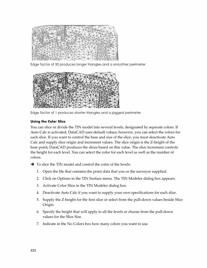
225
Edge factor of 50 produces longer triangles and a smoother perimeter
Edge factor of 1 produces shorter triangles and a jagged perimeter
Using the Color Slice
You can slice or divide the TIN model into several levels, designated by separate colors. If
Auto Calc is activated, DataCAD uses default values; however, you can select the colors for
each slice. If you want to control the base and size of the slice, you must deactivate Auto
Calc and supply slice origin and increment values. The slice origin is the Z-height of the
base point; DataCAD produces the slices based on this value. The slice increment controls
the height for each level. You can select the color for each level as well as the number of
colors.
➔ To slice the TIN model and control the color of the levels:
1. Open the file that contains the point data that you or the surveyor supplied.
2. Click on Options in the TIN Surface menu. The TIN Modeler dialog box appears.
3. Activate Color Slice in the TIN Modeler dialog box.
4. Deactivate Auto Calc if you want to supply your own specifications for each slice.
5. Supply the Z-height for the first slice or select from the pull-down values beside Slice
Origin.
6. Specify the height that will apply to all the levels or choose from the pull-down
values for the Slice Size.
7. Indicate in the No Colors box how many colors you want to use.

226
8. Click on one of the colored boxes to reveal the Color Palette, make your selections,
and click on OK or press [Enter]. You can use between 2 and 15 colors to indicate
different elevations. You can select shades of one color (for example, light green to
dark green) or you can use a different color for each slice. The TIN Modeler dialog
box reappears.
9. Click on OK to make your selections take effect.

227
Using the Division Settings
If you are using contours to generate a TIN model, you can control the number of polygons
that are created. You do this by specifying how the contours are divided through the dialog
box that appears when you select Options from the TIN Surface main menu. The Division
Settings portion of the dialog box offers four mutually exclusive alternatives:
• Nodes Only – This is the default. When this option is activated, the contours will not be
divided. Only nodes will be used to generate the TIN model.
• Contour Divisions – This option uses the division setting from each contour.
• Specify Divisions – This overrides the division setting for all contours. You indicate how
many divisions the TIN model should have. The minimum number of divisions is 2; the
maximum is 36.
• Division Distance – This allows you to specify divisions by distance.
➔ To generate a TIN model and control contour divisions:
1. Open the file that contains the contours that you input, or the surveyor supplied.
2. Click on Options in the TIN Surface menu. The TIN Modeler dialog box appears.
3. Activate one of the alternatives (Nodes Only, Contour Divisions, Specify Divisions,
or Division Distance) in the Division Settings portion of the dialog box. If you
activate either Specify Divisions or Division Distance, you must also select a value
from the pull-down list or supply your own.
4. Click on OK.
5. Click on Area in the TIN Surface menu and surround the contours with the rubber
band. DataCAD produces the TIN model.
Nodes Only option

228
Contour Divisions option
Specify Divisions, set at 15
Division Distance, set at 10 meters

229
Using the Flip Valley
You can flip the valley seam that the TIN modeler generated between two adjoining
triangular polygons. This gives you greater flexibility and control when you work with the
TIN surfaces.
➔ To flip the valley seam between two triangles:
1. Open a file that contains triangles generated with the TIN modeler.
2. Select Polygons from the 3D Entity menu. The Polygons menu appears.
3. Click on Flip Valley in the Polygons menu. You are prompted to Select triangle
junction to flip.
4. Zoom to enlarge the triangle junction you want to flip and place your cursor on the
line between the two triangles.
5. Click on the line that separates two adjoining triangles. DataCAD flips the valley.
Using the 3D Knife
You can use your TIN model to cut out, raise, or depress irregular areas and paths on the
building site. Since DataCAD also calculates the volume of the affected area, you can
estimate the amount of fill that must be removed (if you are digging for a foundation or a
roadway) or added (if you are building up part of the site). To differentiate the cut area, you
can specify a different color from the rest of the TIN model. Further, you can select distinct
colors for each level and/or side of the cut area.
➔ To cut polygons from the TIN model:
1. Open the TIN model of the building site.
2. Select Polygon from the 3DEntity menu. The Polygons menu appears.

230
3. Click on 3D Knife in the Polygon menu. The 3D Knife menu appears.
4. Click on Options in the 3D Knife menu. The 3D Knife Settings dialog box appears.
The choices you make in this dialog box affect the type of cut you create based on
your TIN model. The choices you make will be shown in the small preview window
in the dialog box. If you are unhappy with your choices, you can change them until
the representation in the preview window is correct.
5. Make selections from the Cut Type options. The options you activate in Cut Type
portion of this dialog box affect the number of settings you can control in other parts
of the 3D Knife Settings dialog box. If an option is gray in the dialog box, it is
unavailable.
Remove Eliminates the cut polygons from your drawing.
Cut Edge Cuts the edge of the boundary but does not remove the polygons. You can select the color
of the surface from the palette.
Indent Produces a depressed area or path with visible sides. You can select separate colors from
the palette for the surface and the side of the depression. You can control the depth of the
cut using the pull-down selections or input your own value.
Uplift Raises the cut polygons, producing visible sides. You can select separate colors from the
palette for the surface and the side of the raised polygons. You can control the height of
the cut using the pull-down selections or input you own value.
Level Depresses or raises the cut polygons to a fixed level that you designate. You can use this to
create terraces on a sloping site. This lets you control the maximum depth of the cut or the
maximum height of the fill in addition to the surface and side colors.
6. Set the measurement you want (meters, yards, or feet) in the Volume Units portion
of the dialog box.
7. Select one of the options in the Cut Selection portion of the dialog box. You can either
select an existing polygon/polyline or create your own line.
8. Indicate how to deal with bulges by changing the values in the Bulge Divisions and
Maximum Arc input boxes. These control the curved boundaries.

231
9. Click on one of the mutually exclusive options in the Path Setting portion of the
dialog box. If you select either Center Path or Side Path, you must also supply the
path width in the input field.
10. Activate Hide Triangulation Edges to hide the edges of cut polygons.
11. Click on OK when you are satisfied with your responses in the dialog box.
Drop Point
You can place a three-dimensional marker on a polygon at an inclined point.
➔ To place a 3D marker on a polygon:
1. Select Polygons from the 3D Entity menu.
2. Select Drop Point from the Polygons menu. The Drop Point menu appears.
3. Select Area. You are prompted to Select first corner of area to drop 3D markers on.
4. Click in your drawing window where you want the area to begin; then extend the
rubber band by dragging your mouse.
5. Click again when you have enclosed the entire area of polygons that should contain
3D markers. You are prompted to Place markers.
6. Position your cursor where you want the 3D marker to appear in one of the polygons
you selected. If you want to place markers in additional polygons in the area you
selected, just click to indicate where they should appear.
Make Contours
You can make a topological contour map based on a group of three-dimensional points or
polygons by specifying an interval for the contours or using a list of colors for each level.
Also, you can label the contours with their respective Z-heights.
➔ To generate contours based on 3D points or polygons:
1. Select Polygons from the 3D Entity menu.
2. Select Gen. Contour from the Polygons menu. The Gen. Contour menu appears.
3. Click on From Polys. If you are working from polygons or From Points if you are
basing the contours on points.
4. Make decisions about variables:
Base Set the Z-base.
Interval Set the Z-distance between contour lines.
Highlight Highlight contours at specific height intervals. If you select this option, Color Slice is
unavailable.
Highlt. Inc. Set the Z-distance between highlighted contours.
Highlt. Clr. Select the highlight color you want.
Color Slice Change the color of the TIN model at specific intervals.
Slice Int. Indicate size of the color slice.
Slice Colors Select colors.
Label Turn labels on.

232
Label Spec. Set text attributes (font, size, color, etc.) for labels and indicate the label’s
position (top end, bottom end, etc.).
5. Select Area. You are prompted to Select first corner of area to Interpolate Contours.
6. Click where you want the Area rubber band to begin, drag diagonally until the
points or polygons are enclosed, then click to end it.
Surface Area
You can calculate the surface area of the polygons you cut, duplicated, or indented.
➔ To calculate the surface area of the polygons:
1. Select Polygons from the 3D Entity menu.
2. Choose Surface Area from the Polygons menu.
3. Indicate the selection method (Entity, Group, Area, Fence, Mask) that you prefer and
follow the prompts in the Message toolbar. DataCAD calculates the surface area of
the polygon(s) you selected.
Ruled Surface
You can join two contour lines or two polylines with a ruled surface. Each contour line or
polyline can have its own Z-height and shape.
Drawing direction (clockwise or counterclockwise) can have a significant impact on
concentric closed polylines. If you want to stretch a ruled surface between two concentric
closed polylines, they must both be drawn in the same direction. For example, if you draw
the outer closed polyline clockwise, you must draw the inner closed polyline clockwise, too.
Likewise, if you draw the outer closed polyline counterclockwise, you must draw the inner
one clockwise, too. If you draw one closed polyline clockwise and the other counter
clockwise, you will not be able to stretch a ruled surface between the two. In fact, you will
end up with a jumbled mass of polygons.
➔ To create a ruled surface between two contour lines:
1. Make sure the two contour lines you want to connect with a ruled surface appear on
your drawing screen. Each contour line can have a different Z-height.
2. Click on Polygons in the 3DEntity menu. The Polygons menu appears.
3. Click on Ruled Surf.
4. Decide how you want the polygons to be drawn on the ruled surface. If you want the
rules to be evenly distributed along the length of the two contour lines, activate
Even. If you want the rules to be weighted based on the relationship between the two
contour lines, deactivate Even.

233
5. Click on Div. Dist to set the distance between contour divisions. You can control the
smoothness of the ruled surface by the distance between divisions. For example,
selecting a small distance between divisions (such as 3 inches) produces a smoother
ruled surface than a larger division distance (such 3 feet). The larger your division
distance, the more jagged the resulting edges of your ruled surface. Either select a
value from the menu or type your own in the input field. Then press [Enter].
6. Click on the first contour line. The solid contour line becomes a lighter colored,
dashed one. You are prompted to Select second contour line to process.
7. Click on the second contour line. DataCAD stretches the ruled surface between the
two contour lines. In this example, the distance between divisions was set at 3 inches
to produce a very smooth ruled surface.

234
8. Use the o2c viewer to get a better picture of the ruled surface.
Creating a ruled surface between two polylines is similar creating it between two contour
lines. Just begin with two polylines instead of two contour lines. You can place a ruled
surface over a closed polyline, too.
➔ To stretch a ruled surface between two closed concentric polylines:
1. Create two closed concentric polylines. Make sure you draw the second closed
polyline in the same direction as the first. For example, if you draw the first closed
polyline clockwise, you must draw the second closed polyline clockwise, too.
Otherwise, if you draw the first clockwise and the second counterclockwise, the
resulting ruled surface will be a jumbled mass of polygons.
2. Click on Polygons in the 3D Entity menu. The Polygons menu appears.
3. Click on Ruled Surf.
4. Decide how you want the polygons to be drawn on the ruled surface. If you want the
rules to be evenly distributed between the two concentric closed polylines, activate
Even. If you want the rules to be weighted based on the relationship between the two
closed polylines, deactivate Even.

235
5. Click on Div. Dist to set the distance between divisions. You can control the
smoothness of the ruled surface by the distance between divisions. For example,
selecting a small distance between divisions (such as 3 inches) produces a smoother
ruled surface than a larger division distance (such as 3 feet). The larger your division
distance, the more jagged the resulting edges of your ruled surface. Either select a
value from the menu or type your own in the input field. Then press [Enter].
6. Click on the first polyline. The solid polyline becomes a lighter colored, dashed one.
You are prompted to Select second polyline to process.
7. Click on the second polyline. DataCAD stretches the ruled surface between the two
concentric closed polylines. In this example, the distance between divisions was set
at 8 inches to produce a very smooth ruled surface.
8. Use the o2c viewer to examine the ruled surface.
Once you have created a ruled surface between two contour lines, two polylines, or two
concentric closed polylines, you can use 3D Knife functions to cut out, uplift, or indent
irregular shapes or areas. Just treat the ruled surface as if it were a TIN model.
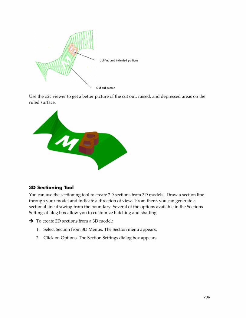
236
Use the o2c viewer to get a better picture of the cut out, raised, and depressed areas on the
ruled surface.
3D Sectioning Tool
You can use the sectioning tool to create 2D sections from 3D models. Draw a section line
through your model and indicate a direction of view. From there, you can generate a
sectional line drawing from the boundary. Several of the options available in the Sections
Settings dialog box allow you to customize hatching and shading.
➔ To create 2D sections from a 3D model:
1. Select Section from 3D Menus. The Section menu appears.
2. Click on Options. The Section Settings dialog box appears.
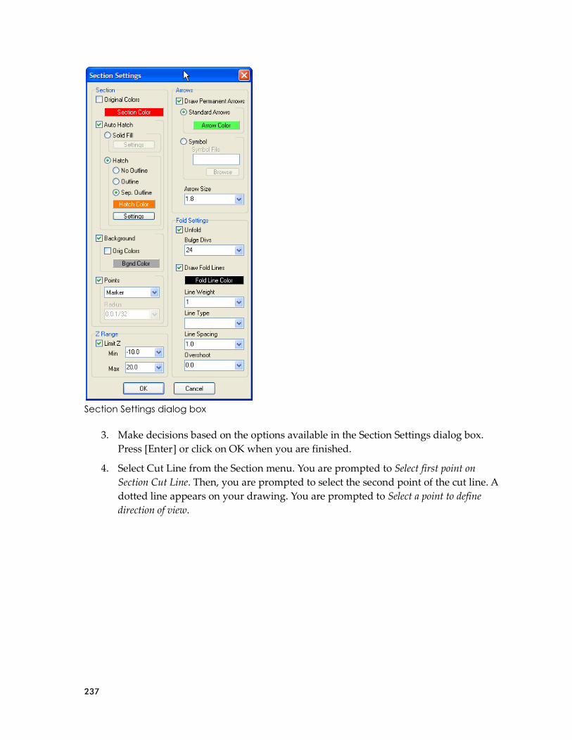
237
Section Settings dialog box
3. Make decisions based on the options available in the Section Settings dialog box.
Press [Enter] or click on OK when you are finished.
4. Select Cut Line from the Section menu. You are prompted to Select first point on
Section Cut Line. Then, you are prompted to select the second point of the cut line. A
dotted line appears on your drawing. You are prompted to Select a point to define
direction of view.

238
The cut line is a series of dashes; the arrow indicates the view direction
5. Click in your drawing to indicate the direction.
6. Select Begin from the Section menu. The section is attached to your cursor in the
shape of a box. You are prompted to Select location for Section.
7. Position the cursor where you want the section to appear in your drawing and click
the left mouse button. You can place the section on any existing layer, or you can
create a new one (just select New Layer from the Section menu).

239
If you change your drawing, you can select Update from the Section menu so that the
section will also be current.
Toolbars
Some new toolbars have been added to provide quick access to frequently used DataCAD
features. The former .KEY files were automatically converted to the new DTB, INI-based
DataCAD Toolbar format. The following examples show the differences between the
former KEY file and new DTB toolbar formats.
KEY File Format
4. !| | | | | |
5. *|01| | | | |
6. L| | |undo |119 | UNDO last action |
7. L| | |redo |120 | REDO previous action |
8. L| | |LAYERS_S|23 | Layers menu |
9. L| | |LINTYP_S|15 | LineType menu |
10. L| | |ARCTCT_S|11 | Architect menu
|
11. A| | |2DWALL_S|^·^È^;^S3^F1^¸^É | Toggle Walls on/off -
Architect menu |
12. A| | |2LWALL_S|^·^È^;^S3^F2^¸^É | Select 2 line walls -
Architect menu |
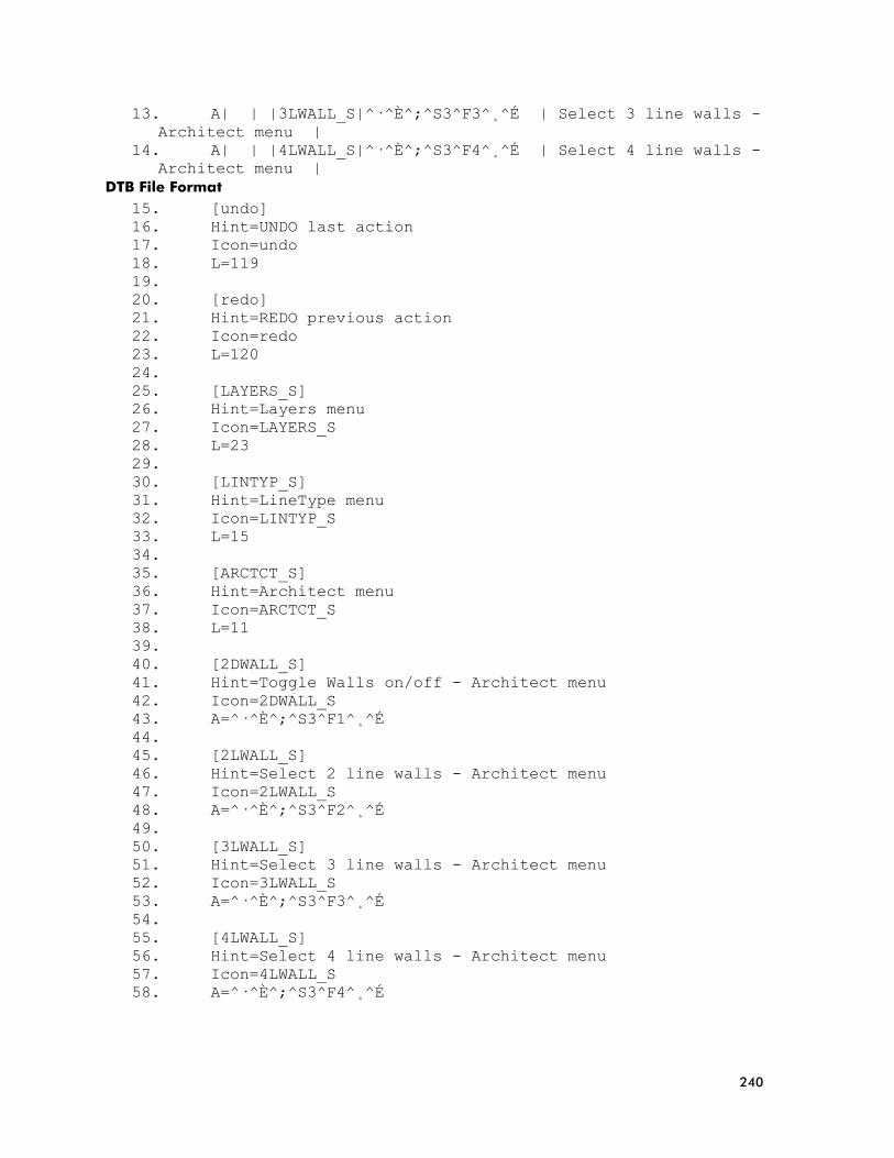
240
13. A| | |3LWALL_S|^·^È^;^S3^F3^¸^É | Select 3 line walls -
Architect menu |
14. A| | |4LWALL_S|^·^È^;^S3^F4^¸^É | Select 4 line walls -
Architect menu |
DTB File Format
15. [undo]
16. Hint=UNDO last action
17. Icon=undo
18. L=119
19.
20. [redo]
21. Hint=REDO previous action
22. Icon=redo
23. L=120
24.
25. [LAYERS_S]
26. Hint=Layers menu
27. Icon=LAYERS_S
28. L=23
29.
30. [LINTYP_S]
31. Hint=LineType menu
32. Icon=LINTYP_S
33. L=15
34.
35. [ARCTCT_S]
36. Hint=Architect menu
37. Icon=ARCTCT_S
38. L=11
39.
40. [2DWALL_S]
41. Hint=Toggle Walls on/off - Architect menu
42. Icon=2DWALL_S
43. A=^·^È^;^S3^F1^¸^É
44.
45. [2LWALL_S]
46. Hint=Select 2 line walls - Architect menu
47. Icon=2LWALL_S
48. A=^·^È^;^S3^F2^¸^É
49.
50. [3LWALL_S]
51. Hint=Select 3 line walls - Architect menu
52. Icon=3LWALL_S
53. A=^·^È^;^S3^F3^¸^É
54.
55. [4LWALL_S]
56. Hint=Select 4 line walls - Architect menu
57. Icon=4LWALL_S
58. A=^·^È^;^S3^F4^¸^É

241
Drop-Down Toolbar Items
You can add drop-down items to your own toolbars. To add a drop-down section to a
toolbar, use the following format in the INI file. For more information on this, see “Creating
Custom Toolbars” in the Appendix of the DataCAD User’s Manual.
59. [SECTION]
60. Icon= (insert the bitmap filename)
61. Hint= (insert the tool tip)
62. A= (insert the action form; e.g., Alt-???)
63.
64. DropDownCount=3 (change the number if more or less than 3
new icons)
65.
66. Icon00=
67. Hint00=
68. A00=
69.
70. Icon01=
71. Hint01=
72. A01=
73.
74. Icon02=
75. Hint02=
76. A02=
Selecting the parent icon will perform the action if one is defined or will drop down the
child icons if no action is defined. Hints for child icons will be used as menu labels.
Toolbar Icon Size
The default size of icons used in toolbars is 16x16 pixels. However, if you'd like to use
larger icons, you can add the following setting to the [KeyFile] section of the DCADWIN.INI
file:
77. [KeyFile]
78. IconSize=16
Valid values are 16, 24, and 32. This setting only changes the available area for icon bitmaps.
It does not make small icons larger or large icons smaller.
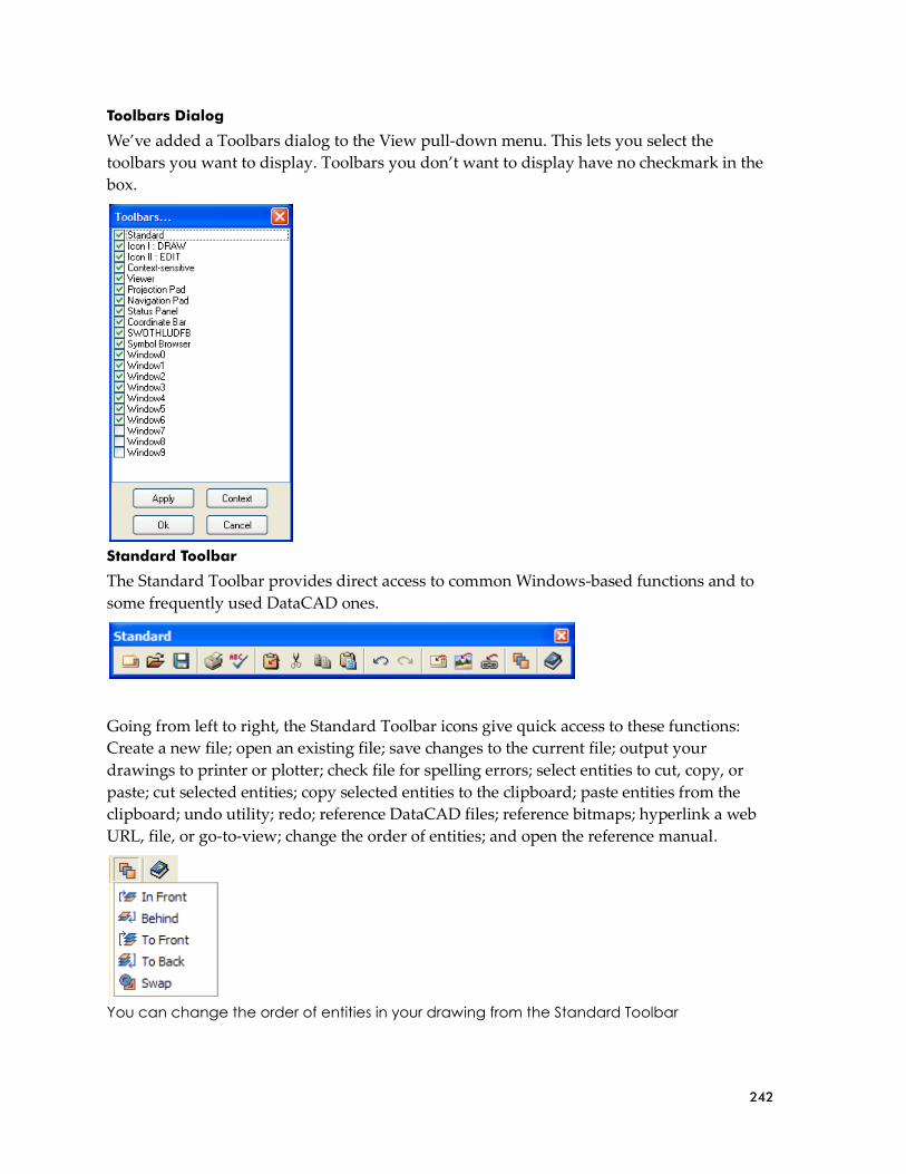
242
Toolbars Dialog
We’ve added a Toolbars dialog to the View pull-down menu. This lets you select the
toolbars you want to display. Toolbars you don’t want to display have no checkmark in the
box.
Standard Toolbar
The Standard Toolbar provides direct access to common Windows-based functions and to
some frequently used DataCAD ones.
Going from left to right, the Standard Toolbar icons give quick access to these functions:
Create a new file; open an existing file; save changes to the current file; output your
drawings to printer or plotter; check file for spelling errors; select entities to cut, copy, or
paste; cut selected entities; copy selected entities to the clipboard; paste entities from the
clipboard; undo utility; redo; reference DataCAD files; reference bitmaps; hyperlink a web
URL, file, or go-to-view; change the order of entities; and open the reference manual.
You can change the order of entities in your drawing from the Standard Toolbar

243
You can add the following entry to the [KeyFile] section of the DCADWIN.INI file to
automatically append the toolbar (.DTB) of your choice to the DataCAD Standard toolbar.
79. [KeyFile]
80. Standard=My_Toolbar.DTB
Projection (view) Toolbar
The Projection Pad Toolbar controls the type of view that appears in your Drawing
Window. You can display this toolbar lengthwise or in the traditional square format. The
icons in this toolbar (from left to right on the lengthwise version) display the following types
of views: parallel; front elevation; perspective; left elevation; plan; right elevation; isometric;
back elevation; and oblique (axonometric).
or
Two versions of the Projection Pad Toolbar
View-sensitive Viewer Toolbar
The Viewer Toolbar changes based on the type of view you select in the Projection Pad.
If you are displaying the plan or oblique (axonometric) view of your drawing, the Viewer
Toolbar contains the following icons (from left to right): refresh display; display model in
object viewer; display shaded view of model; remove hidden lines from 3D view; save
current view; update selected view based on current view; set a new clip cube; and enable
(on) or disable (off) clip cube.
Viewer Toolbar for plan or oblique (axonometric) view
If you display the parallel, elevation (front, back, right, left), or isometric view of the model,
the Viewer Toolbar adds several rotation icons to the basic eight: rotate +X; rotate –X; rotate
+Y; rotate –Y; rotate +Z; and rotate –Z.
Viewer Toolbar for parallel, elevation, or isometric view
If you display the perspective view of the model, the basic options remain, but the clip cube
and rotational options are replaced by others with different functions (from left to right
following the basic options): walk forward; walk backward; step left; step right; step up; step
down; look up; look down; turn left; and turn right.

244
Viewer Toolbar for perspective views of your model
Context-sensitive Toolbar
Context-sensitive Toolbars appear when you perform various functions. To determine what
function each icon performs, place your cursor on it for a few seconds to display a tool tip.
Cleanup options:
Architect options:
Door swing options:
Window options:
Polygon options:
Polyline options:
Modeling options:
Options shown as icons in context-sensitive toolbars perform the same functions as those in
the traditional left-hand menu
A user-definable, context-sensitive toolbar automatically changes to present related icons
based on the menu you choose. A configuration dialog allows you to easily set which user-
defined toolbar is related to a particular menu selection.
A new .CST file (Context-sensitive Toolbar) located in \Support Files\Toolbars contains a
list of menus that can be associated with toolbars. You do not need to edit this file
manually.
Default Toolbars
There are two default user-defined toolbars that can be active simultaneously. You can
configure these toolbars by selecting the Interface Settings tab in Program Preferences from
the Tools pull-down menu.
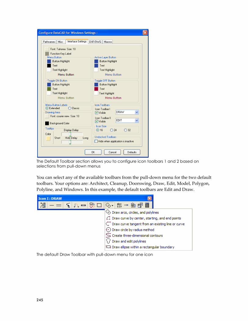
245
The Default Toolbar section allows you to configure icon toolbars 1 and 2 based on selections from pull-down menus
You can select any of the available toolbars from the pull-down menu for the two default
toolbars. Your options are: Architect, Cleanup, Doorswing, Draw, Edit, Model, Polygon,
Polyline, and Windows. In this example, the default toolbars are Edit and Draw.
The default Draw Toolbar with pull-down menu for one icon
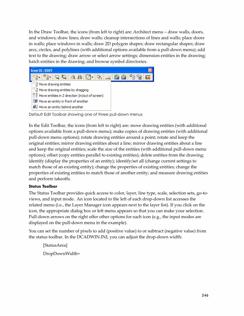
246
In the Draw Toolbar, the icons (from left to right) are: Architect menu – draw walls, doors,
and windows; draw lines; draw walls; cleanup intersections of lines and walls; place doors
in walls; place windows in walls; draw 2D polygon shapes; draw rectangular shapes; draw
arcs, circles, and polylines (with additional options available from a pull-down menu); add
text to the drawing; draw arrow or select arrow settings; dimension entities in the drawing;
hatch entities in the drawing; and browse symbol directories.
Default Edit Toolbar showing one of three pull-down menus
In the Edit Toolbar, the icons (from left to right) are: move drawing entities (with additional
options available from a pull-down menu); make copies of drawing entities (with additional
pull-down menu options); rotate drawing entities around a point; rotate and keep the
original entities; mirror drawing entities about a line; mirror drawing entities about a line
and keep the original entities; scale the size of the entities (with additional pull-down menu
options); offset (copy entities parallel to existing entities); delete entities from the drawing;
identify (display the properties of an entity); identify/set all (change current settings to
match those of an existing entity); change the properties of existing entities; change the
properties of existing entities to match those of another entity; and measure drawing entities
and perform takeoffs.
Status Toolbar
The Status Toolbar provides quick access to color, layer, line type, scale, selection sets, go-to-
views, and input mode. An icon located to the left of each drop-down list accesses the
related menu (i.e., the Layer Manager icon appears next to the layer list). If you click on the
icon, the appropriate dialog box or left menu appears so that you can make your selection.
Pull-down arrows on the right offer other options for each icon (e.g., the input modes are
displayed on the pull-down menu in the example).
You can set the number of pixels to add (positive value) to or subtract (negative value) from
the status toolbar. In the DCADWIN.INI, you can adjust the drop-down width:
[StatusArea]
DropDownWidth=

247
SWOTHLUDFB Toolbar
The [S]nap, [W]alls, [O]rtho, [T]ext, [H]atch, [L]ine weight, [U]ser-line, [D]imension, [F]ills,
and [B]itmap toggles are now located on their own toolbar.
Toggles that are off appear as lower-case letters
Coordinate, Error and Message Toolbars
The Error, Message, and Coordinate Bar Toolbars supply you with helpful warnings, input
requirements and input fields, and coordinate information. The information that appears in
each toolbar depends on the function you are currently performing and the location of your
cursor. If your cursor is on a symbol in the Symbol Browser, the Coordinate Bar displays
information about the location of the symbol file. The Coordinate Bar Toolbar can be resized
when you dock it.
The Pause Hint Toolbar appears to remind you of information you need to supply or
displays the appropriate left menu.

248
MultiView Windows (a.k.a. MVTOTB™ MultiView Tear-Off Toolbars)
The visual GoTo View Windows can be displayed in a toolbar that is turned on or off from
the View/MultiView pull-down menu. You can also use the [Ctrl]+[W] hotkey to turn this
toolbar on and off.
➔ To use MultiView Windows:
1. Create and name several GoTo Views.
2. Set the number of MultiView windows you want by selecting Toolbars from the
View pull-down menu and checking the appropriate number of Window boxes.
3. Select MultiView from the View pull-down menu.
4. Right-click within a window, select GoTo View, and choose a view that you created
in step 1. The view appears in the window.
5. Close the windows that do not display GoTo Views.
You can display up to 10 GoTo View windows plus undock and resize them to meet your
needs. Once displayed, right click on the GTV window for options. These windows may be
torn off, re-sized, and repositioned as desired as shown in this example. When docked, they
return to their original size.

249
Navigation Toolbar
The Navigation Pad Toolbar helps you quickly move about in your Drawing Window.
or
Two configurations of the Navigation Pad Toolbar
Traditionally, the second configuration is used so that the arrows are more ergonomically
correct. In the traditional configuration, beginning from the upper left and going clockwise,
the icons allow you to: zoom view in; pan view up; identify (display the properties of an
entity); pan view to right; zoom to area; pan view down; zoom view out; and pan view to
left. The center icon lets you zoom view to the drawing extents.
Action Codes for Toolbars
The following action codes have been added for use in Toolbars:
Action Code Number Action
81. L 82. 171 83. Partial Erase menu
84. L 85. 172 86. 2D Polygon by
Rectangle
87. L 88. 173 89. Arrows menu
90. L 91. 174 92. Drop Mesh menu
93. L 94. 175 95. Ruled Surface menu
96. L 97. 176 98. TIN Surface menu
99. L 100. 177 101. 3D Mirror menu
102. A 103. 1000# 104. 2D Polygon Vertex On
105. A 106. 1001# 107. 2D Polygon Vertex Off
108. A 109. 1002# 110. 2D Polygon Diameter
On

250
111. A 112. 1003# 113. 2D Polygon Diameter
Off
114. A 115. 1004# 116. 2D Polygon Inscribe
On
117. A 118. 1005# 119. 2D Polygon Inscribe
Off
120. A 121. 1006# 122. 2D Polygon Rectangle
On
123. A 124. 1007# 125. 2D Polygon Rectangle
Off
126. A 127. 1008# 128. Polyline Rectangle On
129. A 130. 1009# 131. Polyline Rectangle
Off
132. A 133. 1010# 134. Symbol Browser On
135. A 136. 1011# 137. Symbol Browser Off
Action Codes for toolbars
Keyboard Macros and Nested Aliases
Keyboard macro sequences used in [ALT] + [KEY] combinations, toolbars, or command line
aliases can include up to 1,024 commands. ^F1, or ^Enter this line of text$, and ^12.5$ each
equal one command, so there is essentially no limit to the number of keystrokes per macro
string.
You can use the PAUSE character ([ALT] + [0170] "ª") when defining a keyboard macro
string. Inserting this character after a carat "^ª" causes the macro sequence to halt until you
click or type. If the pause character is followed by text (i.e., "^ªThis is a comment"), the text
will be displayed in DataCAD as a prompt. You may not use the dollar sign [$] character in
comment strings.
You can call a command line alias from a keyboard, toolbar, or command line alias macro
sequence, allowing you to chain together existing aliases by name. To call a command line
alias by name, precede the command name with the special character [ALT] + [0169] "©".
For example, (B^;^F7^ªSelect entity to erase^©cp) calls the "cp" alias after going to the Erase
menu and waiting for one input.
Mask on the Fly via EGAF
Mask replaces the Selection Set option in the selection method portion of many DataCAD
menus. Entity, Group, Area, and Fence options are frequently abbreviated as EGAF.
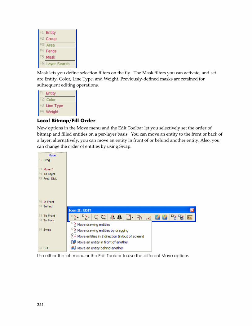
251
Mask lets you define selection filters on the fly. The Mask filters you can activate, and set
are Entity, Color, Line Type, and Weight. Previously-defined masks are retained for
subsequent editing operations.
Local Bitmap/Fill Order
New options in the Move menu and the Edit Toolbar let you selectively set the order of
bitmap and filled entities on a per-layer basis. You can move an entity to the front or back of
a layer; alternatively, you can move an entity in front of or behind another entity. Also, you
can change the order of entities by using Swap.
Use either the left menu or the Edit Toolbar to use the different Move options

252
PDF Files with Layers
You can include drawing layers when you create a PDF file directly from DataCAD. You
have three options when saving a plot preview as a PDF document: No Layers, Drawing
Layers, and MSP Details as Layers (this option is only available when there are MSP sheets
defined in the drawing; otherwise, the only valid options are No Layers and Drawing
Layers). You must have Adobe Reader version 6 to view layers. However, PDF files created
by DataCAD 11 can be read by Adobe Reader versions 4 and 5 as well.
➔ To create a PDF file of your drawing:
1. Select Print from the File pull-down menu. The Print/Plot menu appears.
2. Make sure Preview is enabled.
3. Select Print/Plot. The DataCAD Plot Previewer appears.
4. Click on Save As or select Save Image As from the File pull-down menu. The Save As
dialog box appears.
5. Select the PDF layer option you prefer.
Multi-scale Plotting (MSP) Improvements
You can add rotated clip cubes to multi-scale plotting sheets. In addition, you can add
perspective views to your multi-scale plotting sheets.
We've added new options for copying or moving the contents of one MSP sheet to another.
You can also move or copy details from one MSP sheet to another.
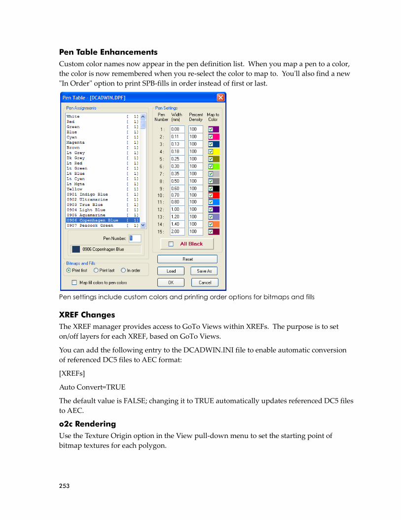
253
Pen Table Enhancements
Custom color names now appear in the pen definition list. When you map a pen to a color,
the color is now remembered when you re-select the color to map to. You'll also find a new
"In Order" option to print SPB-fills in order instead of first or last.
Pen settings include custom colors and printing order options for bitmaps and fills
XREF Changes
The XREF manager provides access to GoTo Views within XREFs. The purpose is to set
on/off layers for each XREF, based on GoTo Views.
You can add the following entry to the DCADWIN.INI file to enable automatic conversion
of referenced DC5 files to AEC format:
[XREFs]
Auto Convert=TRUE
The default value is FALSE; changing it to TRUE automatically updates referenced DC5 files
to AEC.
o2c Rendering
Use the Texture Origin option in the View pull-down menu to set the starting point of
bitmap textures for each polygon.

254
➔ To select a starting point:
1. Select Texture Origin from the View pull-down menu.
2. Select the polygon entity for which you want to define an origin.
3. Pick (or snap) to the origin point. A marker appears.
4. Apply a texture to this entity's color-to-material assignment using the Rendering
Settings dialog box. Click on OK when you are satisfied with the sample in the
Preview window.
The Rendering Settings dialog box
Layer Sets
In the Layers menu, Layer Sets replaces the former layer utility. Layer Sets controls setting
on a per drawing basis and retains them with the drawing file.
➔ To create a layer set:
1. Select Layers from the Utility menu. Then choose Layer Sets from the Layers menu.
The Layer Sets menu appears.
Hint: When you apply bitmap textures, keep these facts in mind:
The texture scale input uses the current scale type. This is the same as the scale used for [Spacebar] input.
To achieve the best rendered quality, your bitmap textures should have a square aspect ratio with a resolution of 2^n power. That means 128 pixels x 128 pixels, 256x256, 512x512, or 1024x1024, etc.
If you apply a bitmap texture that is not square, it will be "squashed" to fit in a square repeating pattern. If you apply a bitmap texture that does not have a resolution of 2^n power, it will be re-sampled during the conversion to o2c format. This may degrade the quality of the texture.

255
2. Click on Create and determine what you want in the current layer set.
All Layers Creates a layer set with all layers
On Layers Creates a layer set with only the layers that are on
Views Includes saved views in the layer set
Details Includes multi-scale plot details in the layer set
3. Click on Begin. A dialog box appears, prompting you to enter the name of the layer
set you want to create.
4. Click in the File name input box, supply a name, and click Open or press [Enter].
➔ To load a layer set:
1. Select Layers from the Utility menu. Then choose Layer Sets from the Layers menu.
The Layer Sets menu appears.
2. Select Load from the Layer Sets menu. A dialog box appears, prompting you to enter
the name of the layer set you want to load.

256
3. Select the layer set you want to load from the *.DLS files in the list and click on Open
or press [Enter].
➔ To delete a layer set:
1. Select Layers from the Utility menu. Then choose Layer Sets from the Layers menu.
The Layer Sets menu appears.
2. Select Delete Set from the Layer Sets menu. A dialog box appears, prompting you to
enter the name of the layer set you want to delete.

257
3. Select the layer set you want to delete from the *.DLS files in the list and click on
Open or press [Enter]. If you want to delete another layer set, repeat this step. If you
do not want to delete another layer set, click Cancel.
Additional Layer Changes
Layer names support extended characters.
You can assign materials on a per-layer basis.
The maximum number of layers per drawing or symbol is 32,768.
➔ To specify Z Base and Z Height settings for each layer:
1. Select Settings from the Utility menu. The Settings menu appears.
2. Toggle on Z By Layer.
Checking Text for Spelling Errors
Although not a new feature, spell-checking was not documented in recent versions of the
DataCAD User’s Manual.
When you type text in your Drawing Window, you don’t have to worry if you lost the
spelling bee when you were in school. DataCAD provides a spell-check function much like
the ones found in word processing programs.
➔ To check spelling and correct errors:
1. Type text in your Drawing Window.
Note: You can select either the Color or Layer radio button in the Rendering settings dialog box to define materials by color or by layer. This global setting is stored in DCADWIN.INI. Launching the Object Viewer or exporting to o2c format will use this setting.
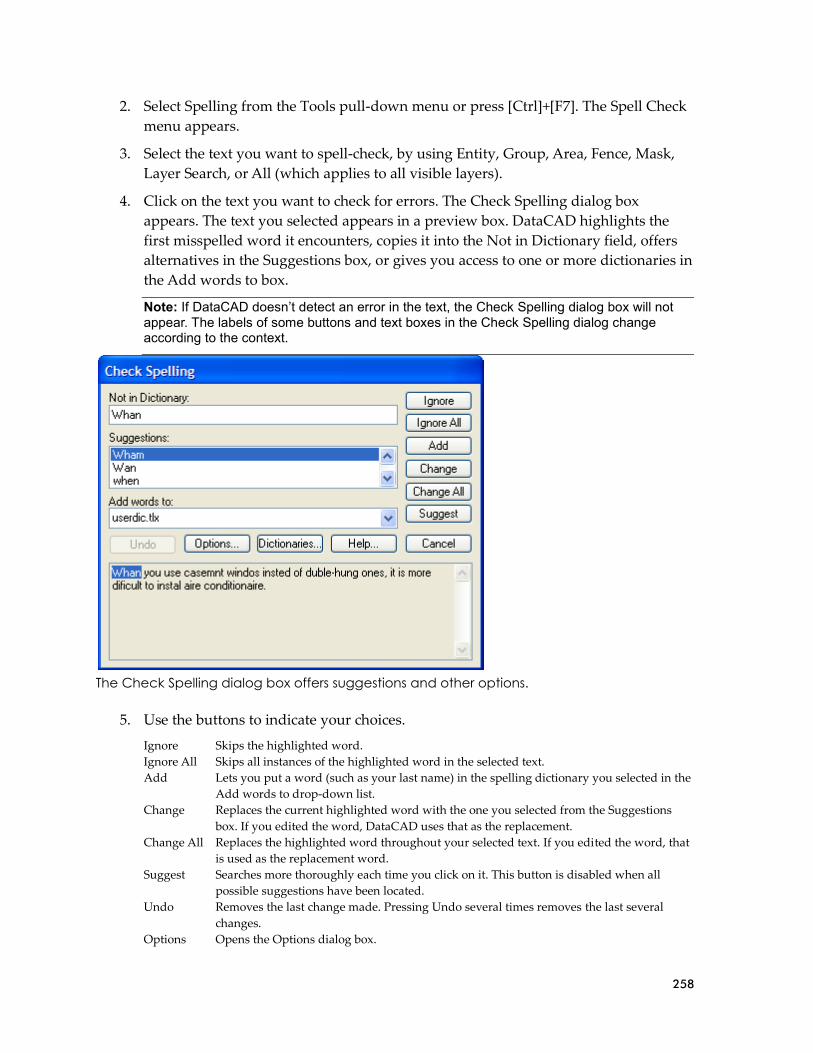
258
2. Select Spelling from the Tools pull-down menu or press [Ctrl]+[F7]. The Spell Check
menu appears.
3. Select the text you want to spell-check, by using Entity, Group, Area, Fence, Mask,
Layer Search, or All (which applies to all visible layers).
4. Click on the text you want to check for errors. The Check Spelling dialog box
appears. The text you selected appears in a preview box. DataCAD highlights the
first misspelled word it encounters, copies it into the Not in Dictionary field, offers
alternatives in the Suggestions box, or gives you access to one or more dictionaries in
the Add words to box.
The Check Spelling dialog box offers suggestions and other options.
5. Use the buttons to indicate your choices.
Ignore Skips the highlighted word.
Ignore All Skips all instances of the highlighted word in the selected text.
Add Lets you put a word (such as your last name) in the spelling dictionary you selected in the
Add words to drop-down list.
Change Replaces the current highlighted word with the one you selected from the Suggestions
box. If you edited the word, DataCAD uses that as the replacement.
Change All Replaces the highlighted word throughout your selected text. If you edited the word, that
is used as the replacement word.
Suggest Searches more thoroughly each time you click on it. This button is disabled when all
possible suggestions have been located.
Undo Removes the last change made. Pressing Undo several times removes the last several
changes.
Options Opens the Options dialog box.
Note: If DataCAD doesn’t detect an error in the text, the Check Spelling dialog box will not appear. The labels of some buttons and text boxes in the Check Spelling dialog change according to the context.

259
Dictionaries Opens the Dictionaries dialog box
Help
Cancel Stops the current spelling check
6. Continue making decisions about other misspelled words. Once DataCAD corrects
the highlighted word, it automatically goes to the next misspelled one. If there are no
more misspelled words, the Check Spelling dialog box closes automatically. If you
decide not to continue checking spelling, just click on Cancel.
You can change the way the spelling checker operates.
➔ To modify the spell-checking criteria:
1. Click on the Options buttons in the Check Spelling dialog box. The Options menu
appears.
The Check Spelling Options dialog box
2. Click in a box to select an option, indicated with a checkmark. You can click in a box
that contains a checkmark to remove it.
Ignore capitalized words: Ignores (skips over without checking) any words beginning with a capital
letter. This is useful if the text being checked contains many proper names.
Ignore all-caps words: Ignores (skips over without checking) any words containing all capital letters.
This is useful if the text being checked contains many acronyms.
Ignore words with numbers: Ignores (skips over without checking) any words containing embedded
digits. Examples of such words include “Win98” and “Q4.” This is useful if the text being
checked contains many code words or other symbols containing digits.

260
Ignore words with mixed case: Ignores (skips over without checking) any words containing an unusual
mixture of upper- and lower-case letters. Examples of such words include “MicroHouse”
and “CapsLock.” This is useful if the text being checked contains many variable names or
other symbols which use case changes to distinguish words.
Ignore domain names: Ignores (skips over without checking) any words that appear to be Internet
domain names (such as “wintertree-software.com”).
Report doubled words: Reports any word that appears twice in a row.
Case sensitive: Distinguishes between capitalized and non-capitalized words. For example, “canada” is
considered different from “Canada,” so “canada” would be reported as a misspelling.
When the option is disabled, “canada” and “Canada” are considered identical. Disabling
this option reduces the performance of the spelling checker.
Phonetic suggestions: Makes suggestions based on phonetic (sounds-like) similarity to the misspelled
word. This tends to improve suggestions for badly misspelled words. This option
increases the time required to locate suggestions.
Typographical suggestions: Makes suggestions based on typographical (looks-like) similarity to the
misspelled word. This is appropriate for people who are generally good spellers.
Suggest split words: Suggests two separate words as a replacement for a misspelling containing two
joined words. For example, “is the” would be suggested as a replacement for “isthe.”
Auto correct: Automatically changes words marked with "Auto Change" actions to their specified
replacements. When disabled, you are prompted before the words are changed.
3. Check the Main Dictionary language option. You can set the language of the main
dictionary used to check spelling. The list shows only languages for which
dictionaries are installed on your system. To check spelling in a different language,
select the language in the list.
Select the dictionary’s language
4. Select one of the options in the Suggestions area. These options determine the speed
and accuracy of the initial search for suggested replacements for misspelled words.
When a misspelled word is detected, a search is automatically made for suggestions.
This option controls the speed and accuracy of this automatic search. Pressing the
Suggest button in the Check Spelling dialog causes an increasingly more accurate
(but slower) search for suggestions.
5. Close the Options dialog when you are ready to resume checking spelling in your
file.
OK Closes the Options dialog and saves any changes made to the option settings.
Note: Either the Phonetic suggestions or Typographical suggestions option must be enabled or no suggestions will be offered.

261
Cancel Closes the Options dialog and discards any changes made to the option settings.
The Dictionaries dialog box lets you open and close user dictionaries and edit the contents
of an open user dictionary. The contents of dictionaries are saved in disk files. You can open
some or all user dictionary files at any time. Only open dictionaries are searched during a
spelling check.
➔ To add a word to the user’s dictionary:
1. Click on the Dictionaries button in the Check Spelling dialog box. The Dictionaries
dialog box appears.
The Dictionaries dialog box
2. Click on the arrow to display options in the Action area. Then choose the
appropriate option from the drop-down list.
The Action pull-down menu

262
Auto change (use case of checked word): Automatically replaces one word with another. For example, if
you often type “recieve” instead of “receive,” you might enter the word “recieve” with
“receive” as the other word and "Auto change (use case of checked word)" as the action.
The spelling checker automatically corrects “recieve” wherever it appears. If it is
capitalized (“Recieve”), the spelling checker automatically replaces it with “Receive.” The
replacement is made automatically only if the "Auto change" option is enabled (see the
Options Dialog for information on the Auto change option).
Auto change (use case of other word): Automatically replaces one word with another, always with the
same case pattern as the other word. This is useful for automatically expanding
abbreviations. For example, you could enter “TBD” with “to be determined” as the other
word and "Auto change (use case of other word)" as the action. The spelling checker
automatically replaces “TBD” with “to be determined” wherever it appears. The
replacement is made automatically only if "Auto change" is enabled (see the Options
Dialog for information on the Auto change option).
Conditionally change (use case of checked word): Lets you optionally replace one word with another.
For example, if you often type “receive” instead of “receive,” you might enter the word
“receive” with “receive” as the other word and "Auto change (use case of checked word)"
as the action. The spelling checker asks if you want to replace “receive” with “receive.” If
it is capitalized (“Receive”), the spelling checker asks if you want to replace it with
“Receive.”
Conditionally change (use case of other word): Lets you optionally replace one word with another,
always with the same case pattern as the other word. This is useful for optionally
expanding abbreviations. For example, you could enter the word “TBD” with “to be
determined” as the other word and "Conditionally change (use case of other word)" as the
action. The spelling checker asks if you want to replace “TBD” with “to be determined.”
Exclude (treat as misspelled): Tells the spelling checker that the word is misspelled, even if it is listed in
another dictionary. Words marked with “Exclude” will never be offered as suggestions for
misspelled words and they will be reported as misspellings when they are encountered by
the spelling checker. The spelling checker looks up words in user dictionaries in the order
in which they appear in the Files list. If you want to exclude a word, make sure it doesn't
appear in a previous user dictionary.
Ignore (skip): Tells the spelling checker that the word is spelled correctly and can be skipped over. This
is the most common action.
3. Click on the button in the Words portion of the Dictionaries dialog box that performs
the action you want. This portion lists words in the currently selected user
dictionary.
Add Word button: Adds the word you type in the Words input box to the currently selected dictionary.
The currently selected action and other word are associated with the word. You can use
the Add Word button to change the action or other word associated with a word. The Add
Word button is enabled only when a new word is typed in the edit area of the Words list.
The words you add may contain virtually any character, but only words which contain
embedded periods should have trailing periods (e.g., “U.S.A.” is OK, but USA. is not).
Delete Word button: When you highlight a word in the list, DataCAD places it in the Words input box.
When you click Delete Word, DataCAD removes the highlighted word from the currently
selected dictionary. The associated action and other word are also removed.
Import button: Adds the words contained within a text (*.txt) file to the currently selected dictionary.
When you select Import, a dialog box lets you select the text (*.txt) file you want. Each
word in the selected file is loaded into the dictionary in alphabetical order. Importing a
large list of words may take some time.
Export button: Saves the contents of the currently selected dictionary to a text (*.txt) file. When you click
Export, a dialog box lets you select the name of the text (*.txt) file to which words in the
dictionary will be exported. The words are written to the file one per line.

263
Other word box: Contains an alternate word associated with the currently selected word. The other
word is used in the "Auto change" and "Conditionally change" actions to supply a
replacement word. You can enter more than one word in the Other Word box, but the
total length should be limited to 63 characters.
4. Click on the appropriate button in the Files portion of the Dictionaries dialog box.
The pull-down list displays the open dictionary files. When you select a file from the
list, its contents are displayed in the Words list. Language: Displays the language
(e.g., English or French) of the words in the currently selected dictionary.
Add File button: Displays the Add Dictionary File dialog box. Supply the name of the file.
The Add Dictionary File dialog box
New File button: Creates a new user dictionary file. When you select this button, a dialog appears
which you can use to specify attributes of the new dictionary. See the New Dictionary
dialog box for details.
Remove File button: Closes the currently selected dictionary file. Closed dictionaries are not checked
during a spelling check. Although the file is closed, it is not deleted. Closed dictionary
files can be reopened later using the Add File button.
Close button: Closes the Dictionaries dialog.
You can use the New Dictionary dialog box to specify the attributes of a new user
dictionary.
➔ To select a new dictionary:
1. Click on New File in the Dictionaries dialog box. The New Dictionary dialog box
appears.

264
2. Click Browse to display the names of other user dictionary files in the Create
Dictionary File dialog box. You can use this dialog box to view the names of existing
dictionary files or to enter the name of the new dictionary file. Dictionary files end
with the *.tlx extension.
The Create Dictionary File dialog box
3. Type the name of the new user file and click Save to exit the Create Dictionary File
dialog box. The new dictionary appears in the File Name input field in the New
Dictionary dialog box. (Alternatively, you can click Cancel to abort the operation if
you don’t want to create a new dictionary.)
The New Dictionary dialog box
4. Select the language of the new dictionary you are creating by highlighting it in the
list. If the language you want to use is not listed, select "Any."
5. Click OK to close the New Dictionary dialog box and create the new dictionary.

265
Interface Enhancements Several enhancements give you more control over the way your drawings appear on the
screen. For example, you can position toolbars where you want them, select default toolbars,
and control the appearance of menu options and tooltips.
Interface enhancements let you control the appearance of your drawing, toolbars, and
menus
Program Interface
DataCAD 11 features an updated program interface that provides Windows 2000-style
properties and support for Windows XP Themes. You can position toolbars and menus
where you want by tearing them off and docking them to the top, bottom, left, or right side
of the application window. You can also place toolbars and menus outside of DataCAD to
"float" on your desktop, allowing you to resize the drawing area without adversely affecting
the user interface. In addition, all of the interface elements in DataCAD 11 will inherit the
visual style of your current desktop theme. For more information about Windows XP
Themes, go to http://www.themexp.org.
12-Character Labels and Tooltips
The “left-hand” menu option labels have been expanded from 8 to 12 characters. Menus
such as Architct and Dimenson now read Architect and Dimension respectively. The logic
used to calculate the default width and height of menu buttons has been adjusted to make
them more compact. A “Classic” option has been provided so you can restore the 8-
character labels if you wish. In addition, tooltips for each menu item have been added to
help you use each option.

266
➔ To change the menu labels:
1. Select Program Preferences from the Tools pull-down menu. The Configure
DataCAD for Windows Settings dialog box appears.
Make interface changes in this dialog box
2. Click on the Interface Settings tab.
3. Go to the Function Key Captions area and select either Long (12 characters) or
Classic (the traditional 8 characters of previous DataCAD versions).
4. Make other changes to the interface settings if desired. Click OK when you are
finished. The decisions you made take effect immediately.

267
Comparison of Extended 12-character (left) and Classic 8-character (right) menu labels
You can personalize other aspects of the DataCAD graphical interface to suit your needs
(especially helpful if you are colorblind) or your tastes (eclectic versus conservative).
➔ To change other interface settings:
1. Select Program Preferences from the Tools pull-down menu. The Configure
DataCAD for Windows Settings dialog box appears.
2. Click on the Interface Settings tab. The settings affect the left menu and message
lines; pull-down menus cannot be changed.
3. Decide what colors you want to change, click on the appropriate sample swatch, and
select the color you want from the Color Palette dialog box.
Function key label Located at the left edge in the left-hand menu
Buttons Each menu button has a highlight, text, and text highlight color that you can
change. Highlight Color appears when you run your cursor over a regular (not a
toggle) menu button; Text Color affects the text on the non-highlighted menu
button (the TestBtn shows a sample); Text Highlight Color appears on a highlighted
button as your cursor passes over it.
Normal Clicking on a normal button calls up a submenu or requests input
Active Layer Affects only the active layer, not the inactive ones
Toggle ON Affects just the active menu functions (the button is depressed)
Toggle OFF Affects just the inactive menu functions (the button is raised)
Background Drawing window color
Tooltips Background color of tooltip
4. Decide what fonts you want to change, click on the appropriate Font button, and
select font, style, and size from the Font dialog box:
Display Affects text that appears in the left-hand menu and in the message, error, and
coordinate toolbars

268
Drawing Window Affects text you add to the file displayed in your Drawing Window
5. Use the slider bars to set how long tooltips should appear.
Display Delay Affects how fast a tooltip appears from the moment your cursor hovers on a
function
Hide Delay Affects how quickly the tooltip disappears
6. Click on OK to make your changes take effect. If you click on Defaults, DataCAD
ignores your changes and asks you to confirm your decision before it restores the
original interface settings.
This warning appears if you click on Defaults to restore DataCAD’s original interface settings
Pull-down Menu Hints and Shortcuts
We've added hints to the MNU file. Hints appear at the message line when you highlight a
pull-down menu item.
Now, you can create keyboard shortcuts for any of the 250+ pull-down menu selections by
editing the DCADWIN.MNU file. The format of the menu file is Label|Shortcut|Hint. Any
shortcut you add to the MNU file will supersede any existing DataCAD shortcut if they are
the same. The following key sequences are supported.
138. (F1-F12)
139. Example: Open|F5|Open Existing File
140.
141. ([CTRL] + (0-9), (A-Z), (F1-F12))
142. Example: Open|CTRL+5|Open Existing File
143. Example: Open|CTRL+E|Open Existing File
144. Example: Open|CTRL+F5|Open Existing File
145.
146. ([CTRL] + [SHIFT] + (0-9), (A-Z), (F1-F12))
147. Example: Open|CTRL+SHIFT+5|Open Existing File
148. Example: Open|CTRL+SHIFT+E|Open Existing File
149. Example: Open|CTRL+SHIFT+F5|Open Existing File
150.
151. ([CTRL] + [ALT] + (0-9), (A-Z), (F1-F12))
152. Example: Open|CTRL+ALT+5|Open Existing File
153. Example: Open|CTRL+ALT+E|Open Existing File
154. Example: Open|CTRL+ALT+F5|Open Existing File
155.
156. ([SHIFT] + (0-9), (A-Z), (F1-F12))
157. Example: Open|SHIFT+5|Open Existing File
158. Example: Open|SHIFT+E|Open Existing File

269
159. Example: Open|SHIFT+F5|Open Existing File
160.
161. ([ALT] + (0-9), (A-Z), (F1-F12))
162. Example: Open|ALT+5|Open Existing File
163. Example: Open|ALT+E|Open Existing File
164. Example: Open|ALT+F5|Open Existing File
165.
166. ([ALT] + [SHIFT] + (0-9), (A-Z), (F1-F12))
167. Example: Open|ALT+SHIFT+5|Open Existing File
168. Example: Open|ALT+SHIFT+E|Open Existing File
169. Example: Open|ALT+SHIFT+F5|Open Existing File
170.
171. ([CTRL] + [ALT] + [SHIFT] + (0-9), (A-Z), (F1-F12))
172. Example: Open|CTRL+ALT+SHIFT+5|Open Existing File
173. Example: Open|CTRL+ALT+SHIFT+E|Open Existing File
174. Example: Open|CTRL+ALT+SHIFT+F5|Open Existing File
Preview Window
The preview window used in File I/O dialogs has been improved to display bitmap
previews more reliably and with better quality. If you don’t want to see a preview of an
existing drawing, simply click in the Show Preview box to remove the checkmark.
Compatibility Enhancements Double-precision Database
DataCAD 11 uses double-precision floating point math to calculate and store values in the
drawing database. Prior versions of DataCAD had an effective accuracy of ~7 decimal
places. DataCAD 11 has an effective accuracy of ~14 decimal places. That means DataCAD
11 is now as accurate as AutoCAD® and you can work on much larger projects without
running into rounding issues, especially when importing large drawings.

270
DCAL Macros
Existing DCAL macros should be compatible with DataCAD 11. Due to DCAL’s limitations,
existing macros still use single-precision math. The primary benefit is that macros do not
have to be re-compiled by the original author to work with this version of DataCAD.
Program Directory and File Maintenance Improvements Although not very glamorous, directory and file maintenance changes have a big impact on
DataCAD’s compatibility with other programs and with your productivity.
The program directory holds the .INI file, allowing you to run an older version of DataCAD
on the same computer. Expanded names will help you navigate quickly to the directory you
want to use.
Import and export enhancements affect many of the image file formats. The drawing file
size reduction will give you more room for new projects and will make file sharing easier.
The expanded file formats for backup and recovery will help retain your sanity and your
hair when you exit DataCAD incorrectly.
Undocumented INI Settings
175. [General]
176. USER_NAME=John Doe
177. USER_COMPANY=John Doe
Architects, Inc.
178. USER_SERIAL=DCXIW00000
Identifies the user,
company, and serial
number for the current
DataCAD version.
179. [General]
180. CAVWALL=FALSE If TRUE, inserting doors
and windows into cavity
(4-line) walls trims the
outer jamb lines to the
cavity lines.
181. [General]
182. CoplanarCheck=FALSE If TRUE, this forces the
vertices on 3D polygons
with more than three
sides to be coplanar,
based on the first three
non-collinear vertices.
183. [General]
184. ShowWinCursor=FALSE If TRUE, it would activate
the Windows system
cross-hair cursor along
with the DataCAD cursor.
This is useful for screen
capture programs that
record the movement of
the Windows system
cursor.
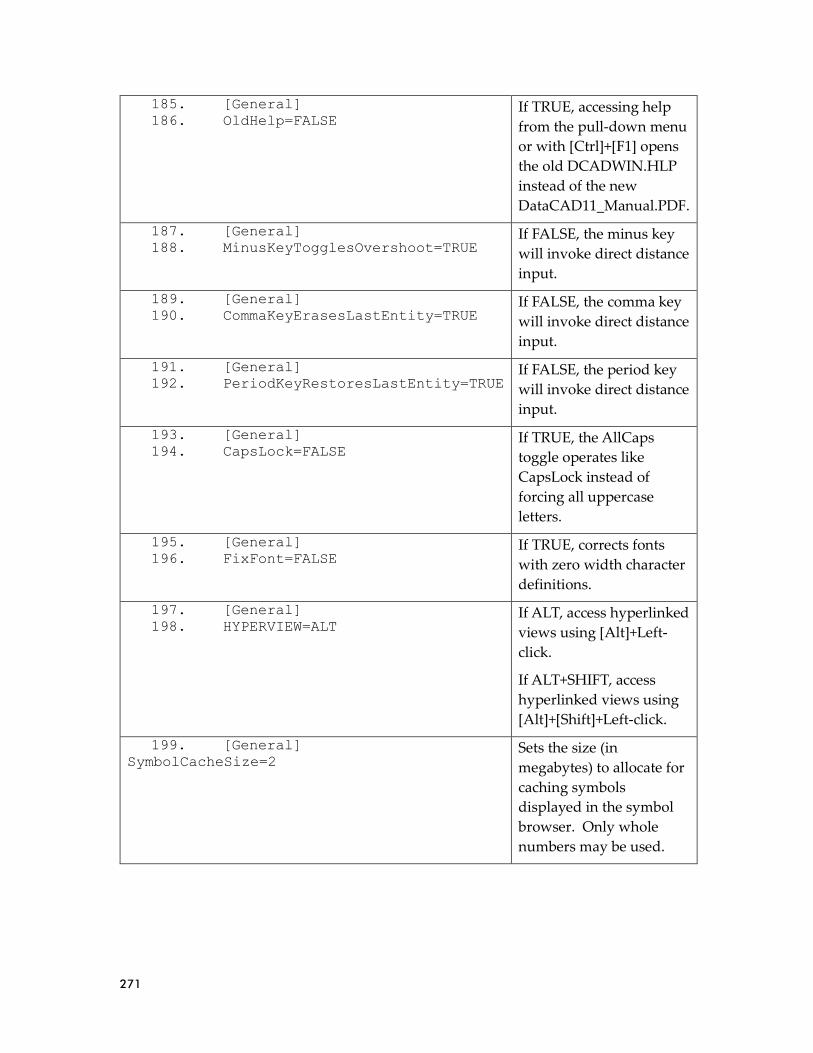
271
185. [General]
186. OldHelp=FALSE If TRUE, accessing help
from the pull-down menu
or with [Ctrl]+[F1] opens
the old DCADWIN.HLP
instead of the new
DataCAD11_Manual.PDF.
187. [General]
188. MinusKeyTogglesOvershoot=TRUE If FALSE, the minus key
will invoke direct distance
input.
189. [General]
190. CommaKeyErasesLastEntity=TRUE If FALSE, the comma key
will invoke direct distance
input.
191. [General]
192. PeriodKeyRestoresLastEntity=TRUE If FALSE, the period key
will invoke direct distance
input.
193. [General]
194. CapsLock=FALSE If TRUE, the AllCaps
toggle operates like
CapsLock instead of
forcing all uppercase
letters.
195. [General]
196. FixFont=FALSE If TRUE, corrects fonts
with zero width character
definitions.
197. [General]
198. HYPERVIEW=ALT If ALT, access hyperlinked
views using [Alt]+Left-
click.
If ALT+SHIFT, access
hyperlinked views using
[Alt]+[Shift]+Left-click.
199. [General]
SymbolCacheSize=2 Sets the size (in
megabytes) to allocate for
caching symbols
displayed in the symbol
browser. Only whole
numbers may be used.

272
200. [General]
201. PurgeDrawingsOnExit=1 Enables or disables the
automatic purging of
unused drawing data
upon exiting and saving a
drawing.
202. [General]
203. Aspect Ratio=1 The default value of 1
assumes a screen aspect
ratio of 4:3 (i.e., 640X480,
800X600, 1024X768, and
1600X12000). To adjust
your DataCAD Drawing
Window, measure the
width and height of a
square displayed on your
screen. Divide the width
(X) by the height (Y) and
enter this value for the
aspect ratio.
204. [General]
205. NoGridLnSelect=TRUE If FALSE, DataCAD will
not automatically disable
grid snapping during
selection and Window In.
206. [Paths]
INSTALL_DIR=c:\Program Files\DataCAD\
PATH_SWAP=Temporary Files\
PATH_SUPPORT=Support Files\
PATH_DEFAULTS=Support Files\
PATH_ICON=Support Files\Toolbars\
PATH_BMP=Support Files\Toolbars\
PATH_MSG=Support Files\
PATH_HELP=Help\
PATH_RECOVERY=Recover_Archive\
PATH_PENTABLE=Support Files\
PATH_O2C_TEX_IMPORT=Textures\o2c_Import\
Program paths that
are not accessible
via Program
Preferences.
207. [XREFs]
208. Auto Convert=TRUE If TRUE, DC5 XREFs are
automatically converted
to AEC files.
209. [PaletteFile]
210. DoCustomColors=TRUE If TRUE, DataCAD will
save the 16 custom colors
that can be defined using
the Windows Color Picker
via the Pen Table dialog.

273
211. [o2cViewer]
212. SmoothDistance=0 Distance between adjacent
polygons to be considered
for smoothing.
213. [o2cViewer]
214. SmoothAngle=30 Angle between adjacent
polygons to be considered
for smoothing.
215. [o2cViewer]
216. MergeTextures=FALSE If TRUE, DataCAD will
merge o2c bitmap
textures when two or
more materials use the
same texture.
217. [Printer]
218. FitToAdjustment=0 Percentage (positive or
negative whole number)
to add or subtract from
DataCAD’s automatic
FitTo calculation.
219. [Printer]
220. NewFitTo=TRUE If TRUE, DataCAD uses a
more accurate method to
determine the available
print area which may be
incompatible with some
drivers. If FALSE,
DataCAD uses the
original method to
determine the available
print area.
221. [Alias]
222. PopupWidth=300 Width of command line
alias popup window in
pixels.
223. [Alias]
224. PopupLines=4 Number of lines
displayed in command
line alias window.
225. [MenuBtn]
226. BTN_SPACING=2
227. BTN_WIDTH=0
Set the number of pixels
between menu buttons
vertically; alternatively,
set the number of pixels to
add or subtract from the
width of menu buttons.

274
228. [StatusArea]
229. DropDownWidth=0 Width in pixels to add or
subtract from Status
Panel.
230. [SymbolBrowser]
231. DockWidth= Width of Symbol Browser
in pixels when docked.
232. [SymbolBrowser]
233. ConvSM3ToDSF=FALSE Automatically convert
SM3 files to DSF files
while browsing.
234. [SymbolBrowser]
235. ConvSM3ToO2C=FALSE Automatically convert
SM3 files to O2C files
while browsing.
236. [SymbolBrowser]
237. ConvDSFToO2C=FALSE Automatically convert
DSF files to O2C files
while browsing.
238. [Mask]
239. UseGlobalMask=TRUE Use Mask instead of
Selection Sets when
editing (TRUE) or
Selection Sets instead of
Mask when editing
(FALSE).
240. [Undo]
241. Disabled=FALSE If TRUE, undo/redo
system is disabled.
242. [TemplateWindow]
243. WIDTH= Value in pixels to set the
width of the template
window.
244. [File Dialog]
245. Extension=PNG Bitmap format for
drawing preview. Valid
formats are PNG, BMP,
JPG, TIF, TGA, and PCX.
246. [Recent File List]
247. Max=4 The number of recently
opened files to display.
The maximum is 10.
248. [Recent Folder List]
249. Max=4 The number of recently
opened folders to display.
The maximum is 10.

275
250. [Clipboard]
251. CopyBitmap=TRUE If TRUE, entities copied to
the Windows clipboard
will maintain a
corresponding bitmap
representation for pasting
into bitmap applications.
252. [Debug]
253. ShowUndoHistory=FALSE If TRUE, menu option for
undo history is displayed.
254. [Debug]
255. LabelFileEditor=FALSE If TRUE, menu option for
label file editor is
displayed.
Double-Click DataCAD File Launch
Now, you can double-click on DataCAD drawing files in Windows Explorer to open them
while DataCAD is already running.
Network Awareness
DataCAD can query other instances of DataCAD running on a network to determine
whether or not a file is “in-use.” Every time you open a drawing, DataCAD records the
date, time, username, and workstation name in a corresponding user (.U$R) file. If you try
to open a drawing file that is “in-use,” DataCAD will only allow you to open a copy of the
file.
AEC File Extension
DataCAD 11 drawings have an AEC file extension. When you open a DC3 or DC5 file in
DataCAD 11 for the first time, it is automatically converted to an AEC file. This conversion
process takes a few moments longer than usual. In the process, the drawing file is cleaned
up and purged of unused entities and the database is converted from single-precision to
double-precision.
File Purge
DataCAD files are automatically purged of any unused data each time you exit and save
your drawing. In addition, a Purge dialog replaces the Layer Utility macro, allowing you to
create new drawings based on a sub-set of an existing drawing.
➔ To eliminate layers, multiviews, go-to-views, and/or sheets from your file:
1. Select Purge from the File pull-down menu. The Purge Drawing dialog box appears.

276
The Purge Drawing dialog box
2. Decide what you want to keep from this file by placing a checkmark in the
appropriate boxes. This lets you use the checked portions of the current drawing as
the basis for a different one.
3. Click Save As when you are finished making your selections. The Save file as . . .
dialog box appears.
Name the new file

277
4. Supply a name for the new file and click on Save or press [Enter]. The Purge
Drawing dialog box reappears. If you want to create more files, repeat steps 2
through 4 again.
5. Click on Close in the Purge Drawing dialog box when you are finished creating new
files based on the current drawing.
Compressed Drawing Files
DataCAD 11 drawings are stored in a compressed format. Though the drawing swap file is
nearly double in size (due to the double-precision database), AEC files are roughly 1/5 the
size of the DC5 files you created in previous versions.
Due to database changes, other DataCAD file extensions have changed. Most of DataCAD’s
file types are now registered with the operating system during installation. DataCAD
includes some unique file type icons to distinguish them from other programs’ files. The
following list describes the DataCAD 11 file extensions. Items marked with an asterisk are
new.
AEC* DataCAD Drawing File
ANG DataCAD Angle File
ARB* DataCAD Auto-recover Backup File
ARF* DataCAD Auto-recover File
CHR DataCAD Font File
CST* DataCAD Context Toolbar Configuration File
DBK* DataCAD Drawing Backup File
DCA DataCAD Command Alias File
DCX DataCAD Add-On Macro File
DEC DataCAD Decimal File
DIMSTYLE DataCAD Dimension Style File
DIS DataCAD Distance File
DLF* DataCAD Layer File
DMF DataCAD Material File
DOR DataCAD Door Style File
DPF DataCAD Pen Table File
DRF* DataCAD Drawing Recovery File
DSF* DataCAD Symbol File
DTB* DataCAD Toolbar File
278
EDB Estimator Link Database File
FRM DataCAD Symbol Report Form File
GUI* DataCAD Graphical User Interface File
LBL DataCAD Menu Label File
LIN DataCAD Line Type Definition File
LIT DataCAD Shader Light Source File
MCR DataCAD Keyboard Macro File
MNU DataCAD Pull-Down Menu File
MSG DataCAD Message File
O2C Object To See File
PAT DataCAD Hatch Pattern File
RGB DataCAD Color Palette File
SCH DataCAD Report Schedule File
SCL DataCAD Scale File
SHP DataCAD Font Definition File
STL DataCAD Text Style File
STR DataCAD Stair Style File
$WP DataCAD Drawing Swap File
SYM DataCAD Symbol File
TAG* DataCAD Drawing Tag File
TBL DataCAD DXF/DWG Color Map File
TPL DataCAD Template File
U$R* DataCAD User File
WIN DataCAD Window Style File

279
DataCAD User File
\datacad\drawings\my_drawing.U$R
The user file is a temporary file that stores the last date, time, username, and workstation
name of the operator who last opened the drawing successfully. DataCAD uses this data to
provide you with helpful information and appropriate options when you try to open a file
that is marked “in-use.” Under normal conditions, the user file is only present when a
drawing file is open. However, if you exit a drawing abnormally (e.g., in the case of a
program error), the user file remains and DataCAD queries it to determine an appropriate
course of action the next time you attempt to open the file.
DataCAD Drawing Backup File
\datacad\drawings\my_drawing_(backup).DBK
Backup drawings (with a DBK extension) are created each time a drawing is saved. The
DBK extension distinguishes DataCAD’s backup files from other programs’ generic BAK
extension.
DataCAD Drawing Session Backup (10 Maximum)
\datacad\drawings\my_drawing_(session-01).AEC
You can configure DataCAD to automatically save up to 10 incrementally-named backup
drawings. Drawing session backups are only created when you exit and save your drawing.
DataCAD Drawing Swap File
\datacad\temporary files\my_drawing.$WP
The drawing swap file is a temporary copy that is created when you open your drawing.
This is the file DataCAD modifies when you edit your drawing.
DataCAD Auto-recover File
\datacad\drawings\my_drawing.ARF
The auto-recover file is a copy of your drawing that DataCAD creates at regular time
intervals that you set. Auto-recover files are also created when you execute forced file saves.
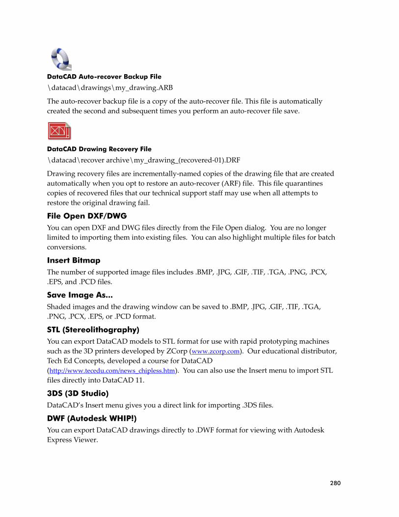
280
DataCAD Auto-recover Backup File
\datacad\drawings\my_drawing.ARB
The auto-recover backup file is a copy of the auto-recover file. This file is automatically
created the second and subsequent times you perform an auto-recover file save.
DataCAD Drawing Recovery File
\datacad\recover archive\my_drawing_(recovered-01).DRF
Drawing recovery files are incrementally-named copies of the drawing file that are created
automatically when you opt to restore an auto-recover (ARF) file. This file quarantines
copies of recovered files that our technical support staff may use when all attempts to
restore the original drawing fail.
File Open DXF/DWG
You can open DXF and DWG files directly from the File Open dialog. You are no longer
limited to importing them into existing files. You can also highlight multiple files for batch
conversions.
Insert Bitmap
The number of supported image files includes .BMP, .JPG, .GIF, .TIF, .TGA, .PNG, .PCX,
.EPS, and .PCD files.
Save Image As...
Shaded images and the drawing window can be saved to .BMP, .JPG, .GIF, .TIF, .TGA,
.PNG, .PCX, .EPS, or .PCD format.
STL (Stereolithography)
You can export DataCAD models to STL format for use with rapid prototyping machines
such as the 3D printers developed by ZCorp (www.zcorp.com). Our educational distributor,
Tech Ed Concepts, developed a course for DataCAD
(http://www.tecedu.com/news_chipless.htm). You can also use the Insert menu to import STL
files directly into DataCAD 11.
3DS (3D Studio)
DataCAD’s Insert menu gives you a direct link for importing .3DS files.
DWF (Autodesk WHIP!)
You can export DataCAD drawings directly to .DWF format for viewing with Autodesk
Express Viewer.

281
Backup and Recover Process We revamped DataCAD’s backup and recover process to be more reliable and less
confusing. Whenever you exit a drawing abnormally, DataCAD will automatically try to
recover the most recent version of your file without prompting you with unnecessary
warnings and options.
The following story about Joe User summarizes the file creation, backup, and recover
process.
File Open, Backup, and Recover Process
01. Joe User creates a new drawing. A corresponding swap file is created in the temp folder
along with a corresponding user file in the drawing folder.
\drawings\My_Drawing.U$R (User File) \temporary files\My_Drawing.$WP (Swap File)
02. Joe User continues to work in the new file for 15 minutes when DataCAD saves an auto-
recover file in the drawing folder.
\drawings\My_Drawing.U$R (User File) \drawings\My_Drawing.ARF (Auto-recover File)
\temporary files\My_Drawing.$WP (Swap File)
03. Joe User continues to work in the new file for another 15 minutes when DataCAD saves
an auto-recover file for the second time. The current auto-recover file is renamed to serve as
a backup and a new auto-recover file is created.
\drawings\My_Drawing.U$R (User File) \drawings\My_Drawing.ARF (Auto-recover File) \drawings\My_Drawing.ARB (Auto-recover File Backup)
\temporary files\My_Drawing.$WP (Swap File)
04. A few minutes later, Joe User presses [SHIFT] + [F] to save his drawing for the first time.
At this point, DataCAD creates a drawing file, copies the ARF to an ARB, saves a new ARF,
and resets the auto-recover timer to zero.
\drawings\My_Drawing.AEC (Drawing File) \drawings\My_Drawing.U$R (User File) \drawings\My_Drawing.ARF (Auto-recover File) \drawings\My_Drawing.ARB (Auto-recover File Backup)
\temporary files\My_Drawing.$WP (Swap File)
05. About ten minutes later, Joe User completes an extraordinary modeling feat and decides
to do a forced file save just to be safe. DataCAD copies the AEC file to a backup file for the
first time and updates the auto-recover files as previously described.
\drawings\My_Drawing.AEC (Drawing File) \drawings\My_Drawing.DBK (DataCAD Backup File) \drawings\My_Drawing.U$R (User File) \drawings\My_Drawing.ARF (Auto-recover File) \drawings\My_Drawing.ARB (Auto-recover File Backup)
\temporary files\My_Drawing.$WP (Swap File)
06. Another auto-recover save occurs and the auto-recover files are updated. However, the
drawing and its corresponding backup are not updated.
282
\drawings\My_Drawing.AEC (Drawing File) \drawings\My_Drawing.DBK (DataCAD Backup File) \drawings\My_Drawing.U$R (User File) \drawings\My_Drawing.ARF (Auto-recover File) \drawings\My_Drawing.ARB (Auto-recover File Backup)
\temporary files\My_Drawing.$WP (Swap File)
07. Then Joe user performs a forced file save. The drawing and its corresponding backup
are updated, the auto-recover files are updated, and the auto-recover timer is reset to zero.
\drawings\My_Drawing.AEC \drawings\My_Drawing.DBK \drawings\My_Drawing.U$R \drwaings\My_Drawing.ARF \drawings\My_Drawing.ARB
\temporary files\My_Drawing.$WP
Exit/Save and Crash/Recover Scenarios
Exit and Save
A. Joe user exits and saves the changes to his drawing. DataCAD updates the drawing and
its corresponding backup; then, it deletes the swap and auto-recover files.
\drawings\My_Drawing.AEC \drawings\My_Drawing.DBK
Crash and Recover (Same User)
B. The power goes out on Joe User. When his computer is back up and running, he tries to
re-open the file he was using previously. DataCAD checks the user file and determines Joe
was the previous user. Then DataCAD checks for the presence of an ARF, determines that
one is present, and notices it is newer than the AEC file.
DataCAD informs Joe he exited the drawing abnormally and gives him the option to
proceed and automatically recover the most recent version. Joe user accepts (his only
choice) and DataCAD copies the AEC file to a "Recover_Archive" folder.
The ARF file is copied to a new AEC file, the ARB file remains, the semaphore file is
updated, and the recovered drawing is opened.
\drawings\My_Drawing.AEC \drawings\My_Drawing.DBK \drawings\My_Drawing.U$R \drawings\My_Drawing.ARB
\temporary files\My_Drawing.$WP
\Recover_Archive\My_Drawing_(Recovered-01).DRF
Note: Each time My_Drawing is recovered, a new DRF file is created sequentially (i.e., My_Drawing_(Recovered-01).DRF, My_Drawing_(Recovered-02).DRF, My_Drawing_(Recovered-03).DRF).
Crash and Recover (Different User)
C. The power goes out on Joe User. He goes home for the day without trying to re-open the
file. In the meantime, Jill tries to open the file that Joe just crashed out of.

283
DataCAD checks the user file and determines Joe was the previous user. A message pops
up telling Jill that Joe was the last person to open the file and that DataCAD will perform a
check to see if Joe is still in the file.
Jill selects OK, then DataCAD tries to interrogate Joe's computer to see if he has the file
open. There is no response (Joe is not running DataCAD at the moment), so DataCAD then
checks for the presence of an ARF and determines one is present and that it is newer than
the AEC file.
DataCAD informs Jill that the file was exited abnormally and her only option is to proceed
and automatically recover the latest version. Jill accepts and DataCAD copies the AEC file to
a "Recover_Archive" folder.
The ARF file is copied to a new AEC file, the ARB file remains, the semaphore file is
updated, and the recovered drawing is opened.
\drawings\My_Drawing.AEC \drawings\My_Drawing.DBK \drawings\My_Drawing.U$R \drawings\My_Drawing.ARB
\temporary files\My_Drawing.$WP
\Recover_Archive\My_Drawing_(Recovered-01).DRF
Drawing Session Backups
The Drawing Session Backups feature allows you to incrementally save up to 10 drawing
sessions. When enabled (off by default), DataCAD creates sequential session backups only
when you exit and save your drawing. Forced drawing file saves you perform during the
session will not update drawing session backups. Drawing session backups use the
following naming convention.
\drawings\My_Drawing_Sessions\My_Drawing_(Session-01).AEC (Oldest) \drawings\My_Drawing_Sessions\My_Drawing_(Session-02).AEC \drawings\My_Drawing_Sessions\My_Drawing_(Session-03).AEC \drawings\My_Drawing_Sessions\My_Drawing_(Session-04).AEC \drawings\My_Drawing_Sessions\My_Drawing_(Session-05).AEC \drawings\My_Drawing_Sessions\My_Drawing_(Session-06).AEC \drawings\My_Drawing_Sessions\My_Drawing_(Session-07).AEC \drawings\My_Drawing_Sessions\My_Drawing_(Session-08).AEC \drawings\My_Drawing_Sessions\My_Drawing_(Session-09).AEC \drawings\My_Drawing_Sessions\My_Drawing_(Session-10).AEC (Newest)
An additional option (found in Program Preferences) allows you to specify a parent folder
for all session backups. The default path is \datacad\sessions\. The contents of the parent
folder might look like this:
\sessions\My_Drawing_Sessions\ My_Drawing_(Session-01).AEC My_Drawing_(Session-02).AEC My_Drawing_(Session-03).AEC
\sessions\My_Other_Drawing_Sessions\ My_Other_Drawing_(Session-01).AEC My_Other_Drawing_(Session-02).AEC My_Other_Drawing_(Session-03).AEC

284
\sessions\My_Favorite_Drawing_Sessions\ My_Favorite_Drawing_(Session-01).AEC My_Favorite_Drawing_(Session-02).AEC My_Favorite_Drawing_(Session-03).AEC