Appendix - DataCAD State 7168 Report to DATACAD LLC Key on keyboard is stuck down. ... Appendix /...
32
Appendix This appendix contains additional information for advanced users as well as tables defining such things as linetypes, hatch patterns, and keyboard shortcuts In this chapter: – Common error messages and solutions – DWG/DXF translator – Key file formats for icon toolbars – User-defined linetypes – Standard hatch patterns – Keyboard shortcuts – DataCAD fonts – Extended characters
Transcript of Appendix - DataCAD State 7168 Report to DATACAD LLC Key on keyboard is stuck down. ... Appendix /...
Appendix
This appendix contains additional information for advanced users as well as tables defining such things as linetypes, hatch patterns, and keyboard shortcuts
In this chapter:
± Common error messages and solutions
± DWG/DXF translator
± Key file formats for icon toolbars
± User-defined linetypes
± Standard hatch patterns
± Keyboard shortcuts
± DataCAD fonts
± Extended characters
Troubleshooting
602 / Appendix
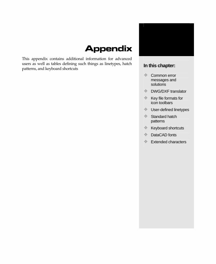
Troubleshooting This section contains some of the common error messages that can occur when you work with DataCAD. The probable cause of each message is given, followed by a description of possible solutions.
Attention! The drawing file ‘xxx’ is currently marked “In Use”. Continuing will result in data loss. Are you sure you want to continue?
Two conditions can cause this error:
1. The drawing file was not exited normally and is still marked “in use”.
2. The drawing file is in used by another DataCAD operator on the network. In this case, both operators can make changes to the file and save them, but be aware that Operator A’s changes will not appear in Operator B’s drawing and vice versa. Therefore, each time the file is saved by Operator A, any changes Operator B made to the file are overwritten, resulting in data loss.
Cannot Open Swap Files Not enough free disk space. Refer to Windows Help for information on how to free up disk space.
Computer out of memory. Press any key to continue. Not enough free space on disk. Refer to Windows Help for information on how to free up disk space.
Database does not contain any hideable entities. No concealable entities found during hidden line removal. Ensure that all layers upon which you want to perform a hidden line removal are on.
DataCAD fatal internal error: xxx An error occurred within DataCAD which adversely affects your drawing file. Follow procedures for recovering your work using Autosave.
dcadwin.lbl not found. Press any key to continue (occurs during initialization). 1) DCADWIN.LBL missing. Check for the DCADWIN.LBL file in the \SUP directory. 2) Path doesn't exist. Check the path given for support files.
Default Drawing File Incorrect Version. The default drawing file is not compatible with the latest version of DataCAD. Convert the default drawing file by loading the file into DataCAD and resaving the file.
Entity identified is an unknown data type. Internal error in recognizing selected entity. Contact DATACAD LLC Technical Support.
Error finding previous void in list. An internal error has occurred during use of the Void command. The error is recoverable and you may proceed with your work.
Troubleshooting
Appendix / 603
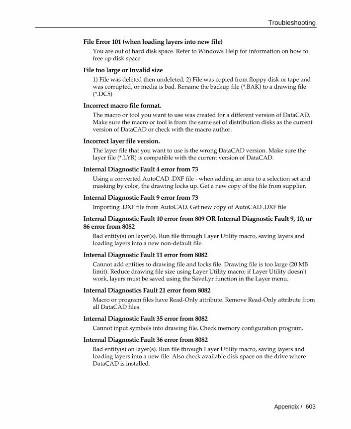
File Error 101 (when loading layers into new file) You are out of hard disk space. Refer to Windows Help for information on how to free up disk space.
File too large or Invalid size 1) File was deleted then undeleted; 2) File was copied from floppy disk or tape and was corrupted, or media is bad. Rename the backup file (*.BAK) to a drawing file (*.DC5)
Incorrect macro file format. The macro or tool you want to use was created for a different version of DataCAD. Make sure the macro or tool is from the same set of distribution disks as the current version of DataCAD or check with the macro author.
Incorrect layer file version. The layer file that you want to use is the wrong DataCAD version. Make sure the layer file (*.LYR) is compatible with the current version of DataCAD.
Internal Diagnostic Fault 4 error from 73 Using a converted AutoCAD .DXF file - when adding an area to a selection set and masking by color, the drawing locks up. Get a new copy of the file from supplier.
Internal Diagnostic Fault 9 error from 73 Importing .DXF file from AutoCAD. Get new copy of AutoCAD .DXF file
Internal Diagnostic Fault 10 error from 809 OR Internal Diagnostic Fault 9, 10, or 86 error from 8082
Bad entity(s) on layer(s). Run file through Layer Utility macro, saving layers and loading layers into a new non-default file.
Internal Diagnostic Fault 11 error from 8082 Cannot add entities to drawing file and locks file. Drawing file is too large (20 MB limit). Reduce drawing file size using Layer Utility macro; if Layer Utility doesn't work, layers must be saved using the SaveLyr function in the Layer menu.
Internal Diagnostics Fault 21 error from 8082 Macro or program files have Read-Only attribute. Remove Read-Only attribute from all DataCAD files.
Internal Diagnostic Fault 35 error from 8082 Cannot input symbols into drawing file. Check memory configuration program.
Internal Diagnostic Fault 36 error from 8082 Bad entity(s) on layer(s). Run file through Layer Utility macro, saving layers and loading layers into a new file. Also check available disk space on the drive where DataCAD is installed.
Troubleshooting
604 / Appendix
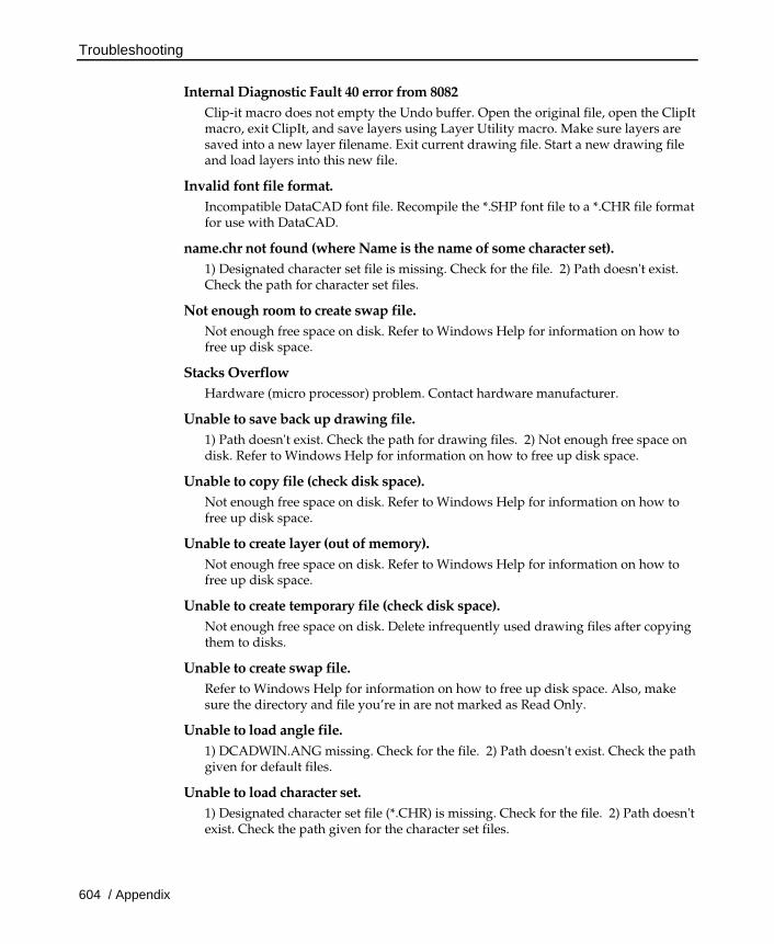
Internal Diagnostic Fault 40 error from 8082 Clip-it macro does not empty the Undo buffer. Open the original file, open the ClipIt macro, exit ClipIt, and save layers using Layer Utility macro. Make sure layers are saved into a new layer filename. Exit current drawing file. Start a new drawing file and load layers into this new file.
Invalid font file format. Incompatible DataCAD font file. Recompile the *.SHP font file to a *.CHR file format for use with DataCAD.
name.chr not found (where Name is the name of some character set). 1) Designated character set file is missing. Check for the file. 2) Path doesn't exist. Check the path for character set files.
Not enough room to create swap file. Not enough free space on disk. Refer to Windows Help for information on how to free up disk space.
Stacks Overflow Hardware (micro processor) problem. Contact hardware manufacturer.
Unable to save back up drawing file. 1) Path doesn't exist. Check the path for drawing files. 2) Not enough free space on disk. Refer to Windows Help for information on how to free up disk space.
Unable to copy file (check disk space). Not enough free space on disk. Refer to Windows Help for information on how to free up disk space.
Unable to create layer (out of memory). Not enough free space on disk. Refer to Windows Help for information on how to free up disk space.
Unable to create temporary file (check disk space). Not enough free space on disk. Delete infrequently used drawing files after copying them to disks.
Unable to create swap file. Refer to Windows Help for information on how to free up disk space. Also, make sure the directory and file you’re in are not marked as Read Only.
Unable to load angle file. 1) DCADWIN.ANG missing. Check for the file. 2) Path doesn't exist. Check the path given for default files.
Unable to load character set. 1) Designated character set file (*.CHR) is missing. Check for the file. 2) Path doesn't exist. Check the path given for the character set files.
Troubleshooting
Appendix / 605
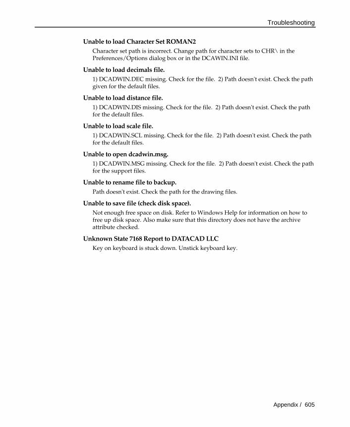
Unable to load Character Set ROMAN2 Character set path is incorrect. Change path for character sets to CHR\ in the Preferences/Options dialog box or in the DCAWIN.INI file.
Unable to load decimals file. 1) DCADWIN.DEC missing. Check for the file. 2) Path doesn't exist. Check the path given for the default files.
Unable to load distance file. 1) DCADWIN.DIS missing. Check for the file. 2) Path doesn't exist. Check the path for the default files.
Unable to load scale file. 1) DCADWIN.SCL missing. Check for the file. 2) Path doesn't exist. Check the path for the default files.
Unable to open dcadwin.msg. 1) DCADWIN.MSG missing. Check for the file. 2) Path doesn't exist. Check the path for the support files.
Unable to rename file to backup. Path doesn't exist. Check the path for the drawing files.
Unable to save file (check disk space). Not enough free space on disk. Refer to Windows Help for information on how to free up disk space. Also make sure that this directory does not have the archive attribute checked.
Unknown State 7168 Report to DATACAD LLC Key on keyboard is stuck down. Unstick keyboard key.
DWG/DXF Translator
606 / Appendix
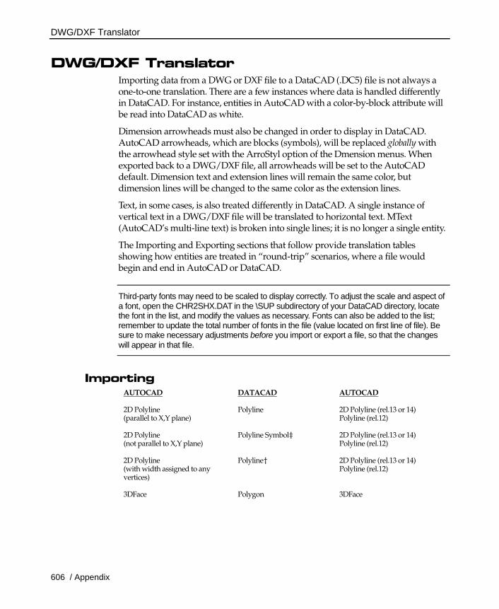
DWG/DXF Translator Importing data from a DWG or DXF file to a DataCAD (.DC5) file is not always a one-to-one translation. There are a few instances where data is handled differently in DataCAD. For instance, entities in AutoCAD with a color-by-block attribute will be read into DataCAD as white.
Dimension arrowheads must also be changed in order to display in DataCAD. AutoCAD arrowheads, which are blocks (symbols), will be replaced globally with the arrowhead style set with the ArroStyl option of the Dmension menus. When exported back to a DWG/DXF file, all arrowheads will be set to the AutoCAD default. Dimension text and extension lines will remain the same color, but dimension lines will be changed to the same color as the extension lines.
Text, in some cases, is also treated differently in DataCAD. A single instance of vertical text in a DWG/DXF file will be translated to horizontal text. MText (AutoCAD’s multi-line text) is broken into single lines; it is no longer a single entity.
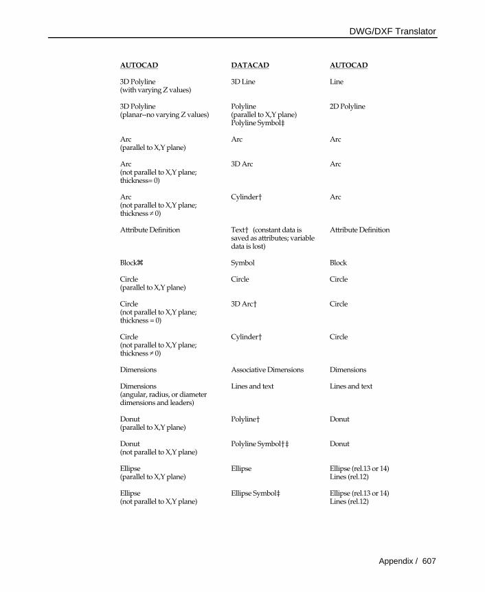
The Importing and Exporting sections that follow provide translation tables showing how entities are treated in “round-trip” scenarios, where a file would begin and end in AutoCAD or DataCAD.
Third-party fonts may need to be scaled to display correctly. To adjust the scale and aspect of a font, open the CHR2SHX.DAT in the \SUP subdirectory of your DataCAD directory, locate the font in the list, and modify the values as necessary. Fonts can also be added to the list; remember to update the total number of fonts in the file (value located on first line of file). Be sure to make necessary adjustments before you import or export a file, so that the changes will appear in that file.
Importing AUTOCAD
DATACAD AUTOCAD
2D Polyline (parallel to X,Y plane)
Polyline 2D Polyline (rel.13 or 14) Polyline (rel.12)
2D Polyline (not parallel to X,Y plane)
Polyline Symbol‡ 2D Polyline (rel.13 or 14) Polyline (rel.12)
2D Polyline (with width assigned to any vertices)
Polyline† 2D Polyline (rel.13 or 14) Polyline (rel.12)
3DFace
Polygon 3DFace
DWG/DXF Translator
Appendix / 607
AUTOCAD
DATACAD AUTOCAD
3D Polyline (with varying Z values)
3D Line Line
3D Polyline (planar--no varying Z values)
Polyline (parallel to X,Y plane) Polyline Symbol‡
2D Polyline
Arc (parallel to X,Y plane)
Arc Arc
Arc (not parallel to X,Y plane; thickness= 0)
3D Arc Arc
Arc (not parallel to X,Y plane; thickness ≠ 0)
Cylinder† Arc
Attribute Definition Text† (constant data is saved as attributes; variable data is lost)
Attribute Definition
Blockz Symbol Block
Circle (parallel to X,Y plane)
Circle Circle
Circle (not parallel to X,Y plane; thickness = 0)
3D Arc† Circle
Circle (not parallel to X,Y plane; thickness ≠ 0)
Cylinder† Circle
Dimensions
Associative Dimensions
Dimensions
Dimensions (angular, radius, or diameter dimensions and leaders)
Lines and text Lines and text
Donut (parallel to X,Y plane)
Polyline† Donut
Donut (not parallel to X,Y plane)
Polyline Symbol†‡ Donut
Ellipse (parallel to X,Y plane)
Ellipse Ellipse (rel.13 or 14) Lines (rel.12)
Ellipse (not parallel to X,Y plane)
Ellipse Symbol‡ Ellipse (rel.13 or 14) Lines (rel.12)

DWG/DXF Translator
608 / Appendix
AUTOCAD
DATACAD AUTOCAD
Hatch
Associative Hatch (if hatch boundary is LW polyline) Associative Hatch Symbol‡ (if hatch boundary is LW polyline but not parallel to X,Y plane) Lines (if hatch boundary includes any other boundary type besides LW polyline)
Lines
Leaders Lines and Text Lines and Text
Light-Weight Polyline (See 2D Polyline above)
Line (parallel to X,Y plane)
Line Line
Line (not parallel to X,Y plane; thickness = 0)
3D Line Line
Line (not parallel to X,Y plane; thickness ≠ 0)
Polygon† Line (if coordinates unchanged) Line, with changed thickness (if polygon stretched along the axis of thickness) Polygon (if coordinates changed in directions other than axis of thickness)
MText
Text Text
Mesh Polygons Polygons
Point (with no thickness)
Point£ Point
Point (with thickness)
3D Line†£ Point
Polyface Mesh Polygons Polygons
Spline
Point† Spline (rel.13 or 14)
Solid
Polygons, triangulated 3D Faces
Text, single line or multi-line
Text Text
† AutoCAD entity is imported into DataCAD as an entity with attributes. If the entity is edited in DataCAD, upon export it will return to its original (AutoCAD) entity type, incorporating the changes you made in DataCAD. Exceptions to this are exploding an entity, which permanently changes the entity type, or deleting an entity.
DWG/DXF Translator
Appendix / 609
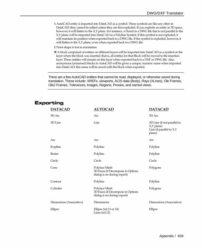
‡ AutoCAD entity is imported into DataCAD as a symbol. These symbols are like any other in DataCAD; they cannot be edited unless they are first exploded. If you explode an entity in 3D space, however, it will flatten to the X,Y plane. For instance, a Donut in a DWG file that is not parallel to the X,Y plane will be imported into DataCAD as a Polyline Symbol. If this symbol is not exploded, it will maintain its position when exported back to a DWG file. If the symbol is exploded, however, it will flatten to the X,Y plane, even when exported back to a DWG file.
£ Point shape is lost in translation.
z A block comprised of entities on different layers will be imported into DataCAD as a symbol on the layer where the block was inserted; that is, all entities for that Block will be moved to the insertion layer. These entities will remain on this layer when exported back to a DXF or DWG file. Also, anonymous (unnamed) blocks in AutoCAD will be given a unique, numeric name when imported into DataCAD; this name will be saved with the block when exported.
There are a few AutoCAD entities that cannot be read, displayed, or otherwise saved during translation. These include: XREFs, viewports, ACIS data (Body), Rays (XLines), Ole Frames, Ole2 Frames, Tolerances, Images, Regions, Proxies, and named views.
Exporting DATACAD AUTOCAD DATACAD
3D Arc
Arc 3D Arc
3D Line Line 3D Line (if not parallel to X,Y plane) Line (if parallel to X,Y plane)
Arc
Arc Arc
B-spline
Polyline Polyline
Bezier
Polyline Polyline
Circle
Circle Circle
Cone Polyface Mesh 3D Faces (if Decompose in Options dialog is on during export)
Polygons
Contour
Polyline Polyline
Cylinder Polyface Mesh 3D Faces (if Decompose in Options dialog is on during export)
Polygons
Dimensions (Associative) Dimensions Dimensions (Associative)
Ellipse
Ellipse (rel.13 or 14) Lines (rel.12)
Ellipse

DWG/DXF Translator
610 / Appendix
DATACAD AUTOCAD DATACAD
Hatch (Associative) Lines Lines
Line
Line Line
Mesh Surface Polyface Mesh 3D Faces (if Decompose in Options dialog is on during export)
Polygons
Point
Point Point
Polygon (with 3-4 vertices and no voids)
3D Face Polygon
Polygon (with 5 or more vertices and/or voids)
Triangulated into multiple 3D Faces Multiple 3-sided polygons
Polyline Lightweight Polyline (rel.14) Polyline (<rel.14)
Polyline
Sphere Polyface Mesh 3D Faces (if Decompose in Options dialog is on during export)
Polygons
Surface of Revolution Polyface Mesh 3D Faces (if Decompose in Options dialog is on during export)
Polygons
Symbol Block Symbol
Text Text Text
Torus Polyface Mesh 3D Faces (if Decompose in Options dialog is on during export)
Polygons
Truncated Cone Polyface Mesh 3D Faces (if Decompose in Options dialog is on during export)
Polygons
Creating Custom Toolbars
Appendix / 611
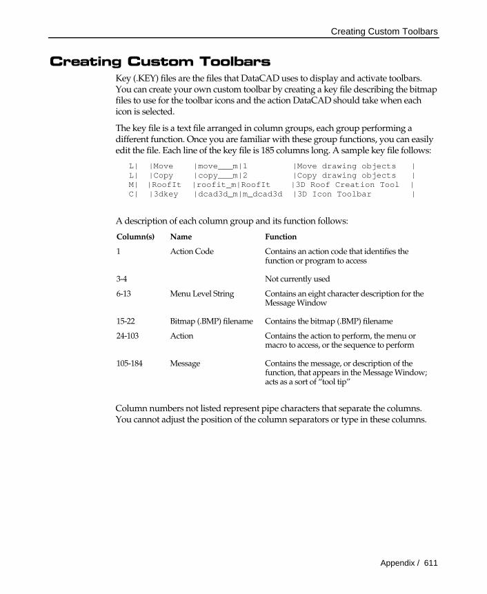
Creating Custom Toolbars Key (.KEY) files are the files that DataCAD uses to display and activate toolbars. You can create your own custom toolbar by creating a key file describing the bitmap files to use for the toolbar icons and the action DataCAD should take when each icon is selected.
The key file is a text file arranged in column groups, each group performing a different function. Once you are familiar with these group functions, you can easily edit the file. Each line of the key file is 185 columns long. A sample key file follows:
L| |Move |move___m|1 |Move drawing objects | L| |Copy |copy___m|2 |Copy drawing objects | M| |RoofIt |roofit_m|RoofIt |3D Roof Creation Tool | C| |3dkey |dcad3d_m|m_dcad3d |3D Icon Toolbar |
A description of each column group and its function follows:
Column(s) Name Function
1 Action Code Contains an action code that identifies the function or program to access
3-4 Not currently used
6-13 Menu Level String Contains an eight character description for the Message Window
15-22 Bitmap (.BMP) filename Contains the bitmap (.BMP) filename
24-103 Action Contains the action to perform, the menu or macro to access, or the sequence to perform
105-184 Message Contains the message, or description of the function, that appears in the Message Window; acts as a sort of “tool tip”
Column numbers not listed represent pipe characters that separate the columns. You cannot adjust the position of the column separators or type in these columns.
Creating Custom Toolbars
612 / Appendix
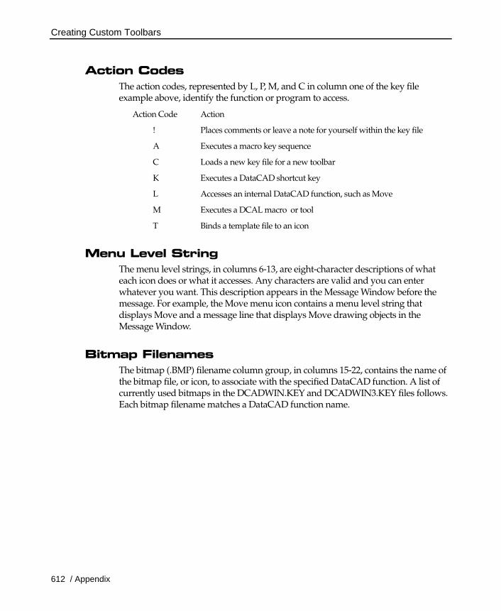
Action Codes The action codes, represented by L, P, M, and C in column one of the key file example above, identify the function or program to access.
Action Code Action
! Places comments or leave a note for yourself within the key file
A Executes a macro key sequence
C Loads a new key file for a new toolbar
K Executes a DataCAD shortcut key
L Accesses an internal DataCAD function, such as Move
M Executes a DCAL macro or tool
T Binds a template file to an icon
Menu Level String The menu level strings, in columns 6-13, are eight-character descriptions of what each icon does or what it accesses. Any characters are valid and you can enter whatever you want. This description appears in the Message Window before the message. For example, the Move menu icon contains a menu level string that displays Move and a message line that displays Move drawing objects in the Message Window.
Bitmap Filenames The bitmap (.BMP) filename column group, in columns 15-22, contains the name of the bitmap file, or icon, to associate with the specified DataCAD function. A list of currently used bitmaps in the DCADWIN.KEY and DCADWIN3.KEY files follows. Each bitmap filename matches a DataCAD function name.
Creating Custom Toolbars
Appendix / 613
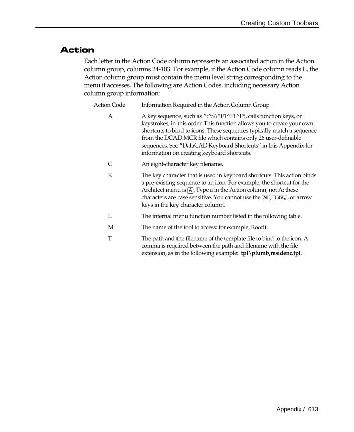
Action Each letter in the Action Code column represents an associated action in the Action column group, columns 24-103. For example, if the Action Code column reads L, the Action column group must contain the menu level string corresponding to the menu it accesses. The following are Action Codes, including necessary Action column group information:
Action Code Information Required in the Action Column Group
A A key sequence, such as ^:^S6^F1^F1^F5, calls function keys, or keystrokes, in this order. This function allows you to create your own shortcuts to bind to icons. These sequences typically match a sequence from the DCAD.MCR file which contains only 26 user-definable sequences. See “DataCAD Keyboard Shortcuts” in this Appendix for information on creating keyboard shortcuts.
C An eight-character key filename.
K The key character that is used in keyboard shortcuts. This action binds a pre-existing sequence to an icon. For example, the shortcut for the Architect menu is (A). Type a in the Action column, not A; these characters are case sensitive. You cannot use the (Alt), (Tab¿), or arrow keys in the key character column.
L The internal menu function number listed in the following table.
M The name of the tool to access: for example, RoofIt.
T The path and the filename of the template file to bind to the icon. A comma is required between the path and filename with the file extension, as in the following example: tpl\plumb,residenc.tpl.
Creating Custom Toolbars
614 / Appendix
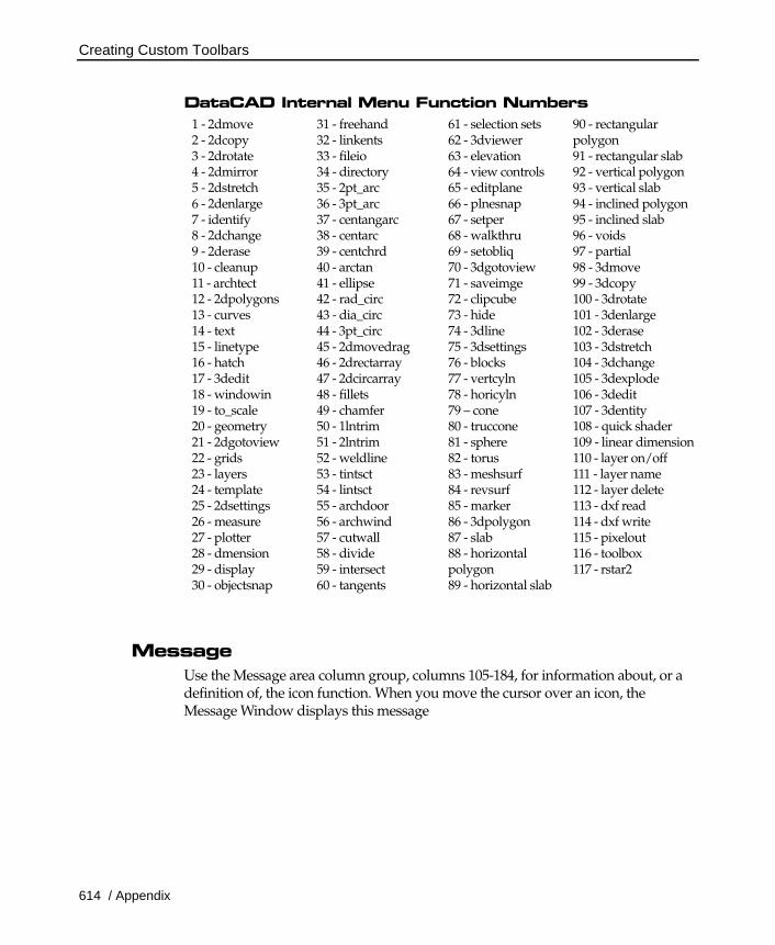
DataCAD Internal Menu Function Numbers 1 - 2dmove 2 - 2dcopy 3 - 2drotate 4 - 2dmirror 5 - 2dstretch 6 - 2denlarge 7 - identify 8 - 2dchange 9 - 2derase 10 - cleanup 11 - archtect 12 - 2dpolygons 13 - curves 14 - text 15 - linetype 16 - hatch 17 - 3dedit 18 - windowin 19 - to_scale 20 - geometry 21 - 2dgotoview 22 - grids 23 - layers 24 - template 25 - 2dsettings 26 - measure 27 - plotter 28 - dmension 29 - display 30 - objectsnap
31 - freehand 32 - linkents 33 - fileio 34 - directory 35 - 2pt_arc 36 - 3pt_arc 37 - centangarc 38 - centarc 39 - centchrd 40 - arctan 41 - ellipse 42 - rad_circ 43 - dia_circ 44 - 3pt_circ 45 - 2dmovedrag 46 - 2drectarray 47 - 2dcircarray 48 - fillets 49 - chamfer 50 - 1lntrim 51 - 2lntrim 52 - weldline 53 - tintsct 54 - lintsct 55 - archdoor 56 - archwind 57 - cutwall 58 - divide 59 - intersect 60 - tangents
61 - selection sets 62 - 3dviewer 63 - elevation 64 - view controls 65 - editplane 66 - plnesnap 67 - setper 68 - walkthru 69 - setobliq 70 - 3dgotoview 71 - saveimge 72 - clipcube 73 - hide 74 - 3dline 75 - 3dsettings 76 - blocks 77 - vertcyln 78 - horicyln 79 – cone 80 - truccone 81 - sphere 82 - torus 83 - meshsurf 84 - revsurf 85 - marker 86 - 3dpolygon 87 - slab 88 - horizontal polygon 89 - horizontal slab
90 - rectangular polygon 91 - rectangular slab 92 - vertical polygon 93 - vertical slab 94 - inclined polygon 95 - inclined slab 96 - voids 97 - partial 98 - 3dmove 99 - 3dcopy 100 - 3drotate 101 - 3denlarge 102 - 3derase 103 - 3dstretch 104 - 3dchange 105 - 3dexplode 106 - 3dedit 107 - 3dentity 108 - quick shader 109 - linear dimension 110 - layer on/off 111 - layer name 112 - layer delete 113 - dxf read 114 - dxf write 115 - pixelout 116 - toolbox 117 - rstar2
Message Use the Message area column group, columns 105-184, for information about, or a definition of, the icon function. When you move the cursor over an icon, the Message Window displays this message

Creating Custom Toolbars
Appendix / 615
Editing the Toolbar You can change any toolbar by editing its key file. You can also change the menu associated with any icon.
Make a backup copy of the key file before you edit it.
Editing a Key File Use (£), (¥), (¡), or (¢) to move within the key file. You cannot use (Tab¿) or place tabs anywhere in the key file.
Incorrectly editing key files can cause system lockups. Please follow these steps carefully and make sure that column separators, or pipe characters, remain in their original positions.
1. Exit DataCAD and open a DOS text editor, such as Notepad. (This will ensure that all characters are displayed properly.)
2. Access the key file directory, \DATACAD\SUP\MENUPOF\, and open the key file you'd like to edit, S_DCAD2D.KEY, for example.
3. Move the cursor to the line where you want to change the menu/icon association.
4. Change any column group:
Action Code Access a different program; for example, to access a tool instead of an internal DataCAD function, change an L to M.
Menu Level String Type the eight-character description that you want to appear in the Message Window, a menu name for example.
.BMP filename Leave the bitmap (.BMP) filename, which represents the icon, as it is. You are choosing a different menu to associate with the icon.
Action Fill in the information requirements of the Action Code: the new internal function number (listed in the DataCAD Internal Menu Function Numbers table), path and program name, macro name, key sequence, key filename, or key character.
Message Type the description of the function now associated with the icon.
5. Save the key file and exit the text editor.
All bitmaps must be 24 x 24 pixels. 16-color bitmaps are recommended.
Creating New Icons 1. Create a 16-color, square bitmap in bitmap (.BMP) format.
Creating Custom Toolbars
616 / Appendix
2. Save it with a filename of up to eight characters in the \DATACAD\SUP\MENUPOF\ directory.
Creating a New Key File
Incorrectly editing key files can cause system lockups. Make sure that column separators, or pipe characters, remain in their original positions.
1. Copy an existing key file from the \DATACAD\SUP\MENUPOF\ directory to a new filename. Store this file in the same directory as the other key files.
2. Edit this new file using existing icons and/or icons that you created. You can associate any bitmap (.BMP) file with any command or function, including functions that are already used in other key files.
Follow the steps in "Editing a Key File" earlier in this section. Remember you can change the bitmap (.BMP) filename in the bitmap (.BMP) filename column when creating a new key file. Changing the bitmap (.BMP) filename allows a different icon to appear in the toolbar.
All bitmaps must be 24 x 24 pixels; 16-color bitmaps are recommended.

User-Defined Linetypes
Appendix / 617
User-Defined Linetypes
Name
N/A CenterSolid
Sta
ndar
dU
ser-de
finab
lelin
es,5
0m
axim
um
1=1'-0" oncenter dots CenterDotted
1=1'-0" oncenter dashes CenterDashed
1=1'-0" oncenter dot todotDot-Dash Center
1=1'-0" oncenter E toEElecLine Center
1=1'-0" oncenterT toTTelLine Center
1=1'-0" oncenter box to boxBox Center
1=1'-0" oncenter doubledashesPropLine Center
0.3=6" width insulationInsul Center
0.0.3/4 =3/4" widthplywoodPlywood1 Left edgeat lineangle of 90°
0.0.1/2 =1/2" wide plywoodPlywood2 Left edgeat lineangle of 90°
1=4" wide linepatternHedge Center
1=1'-0" dash todashCentrLin Center
1=1'-0" oncenter breaksSection Center
0.8=4" to theweather(for line length divisable by set spacing)
ShingleR Left edgeat lineangle of 270°
0.4=4" to theweather(for line length divisable by set spacing)
0.8=4" to theweather(for line length divisable by set spacing)
0.4=4" to theweather(for line length divisable by set spacing)
LapSidR Left edgeat lineangle of 270°
0.4=4" to theweather(for line length divisable by set spacing)
ShipLap Left edgeat lineangle of 270°
0.8=4" nominal brick widthBrick Left edgeat lineangle of 90°
0.8=4" nominal brick width4Block Left edgeat lineangle of 90°
0.8=8" nominal block width8Block Left edgeat lineangle of 90°
0.8=12" nominal blockwidth12Block Left edgeat lineangle of 90°
0.2=2" thicknessRigidIns Left edgeat lineangle of 90°
0.5=3" highgrassGrass Lower edge at lineangleof 90°
1 = 6" betweenpatternbreaksGroundLn Lower edge at lineangleof 90°
ShingleL Right edgeat lineangle of 270°
LapSidL Right edgeat lineangle of 270°
Pattern Linespacingvalues Definedby:
User-Defined Linetypes
618 / Appendix
Linetype Definitions DataCAD allows you to use four standard linetypes and up to 175 user-defined linetypes. The definitions for linetypes provided with DataCAD are located at the end of this section. These definitions are in the DCADWIN.LIN file in directory \DATACAD\SUP\. Define new linetypes using any text editor. The lines consist of small segments linked together to form longer lines. Each segment is 100 "units" in length, and may be divided into as many as 20 definition components. One hundred units equals the line spacing length.
The first line of each definition must contain either an asterisk (*) or a greater than symbol (>), followed by a space and the title of the linetype. When an asterisk is used, DataCAD draws a short line, called a tail, to fill any remaining space not filled by the pattern. When a greater than symbol is used, DataCAD repeats the pattern as many times as possible to fill the specified space and then stretches the pattern slightly to fill any remaining space. The title must not exceed eight characters in length.
The second line specifies the factor by which one segment of the linetype must be multiplied to draw at the correct size. As 100 units equal the line spacing length to draw one segment or 100 units at a size of 8", a factor of 8/12 or .6667 is entered. Successive lines of the definition contain the origin, direction, and distance of each component in the line segment. Use one line for each component, with no more than 20 lines total, including the spacing value.
Each component is assigned a length based on the 100-unit dimension. Each component definition consists of two numbers. The first number specifies the line direction.
0 Right
90 Up
180 Left
270 Down
The second number specifies the line length. A line length of 50 equals one half the distance of the total line segment. A minus sign (-) before the first number moves the pen clockwise. Pen down commands (visible lines) have a space between the two numbers. Pen up commands (invisible lines) use a space and a minus sign between the two numbers.
User-Defined Linetypes
Appendix / 619
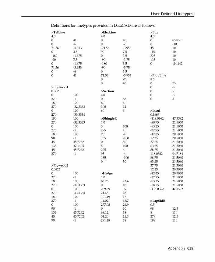
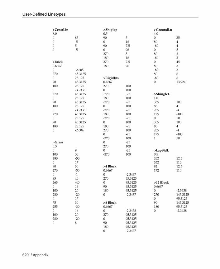
Definitions for linetypes provided in DataCAD are as follows:
>TelLine >ElecLine >Box 4.0 4.0 4.0 0 41 0 40 0 65.858 0 -6 0 -7 0 -10 71.56 -3.953 -71.56 -3.953 45 10 0 3.5 90 7.5 -45 10 -180 -1.675 0 3.5 225 10 -90 7.5 -90 -3.75 135 10 0 -1.675 -180 3.5 0 -24.142 71.56 -3.953 -90 -3.75 0 -6 0 3.5 0 41 71.56 -3.953 >PropLine 0 -7 8.0 0 40 0 75 >Plywood1 0 -5 0.0625 >Section 0 5 0 100 4.0 0 -5 270 -1 0 88 0 5 180 100 60 6 270 -32.3333 300 12 0 100 60 6 >Insul 270 -33.3334 0.1667 180 100 >ShingleR -118.0362 47.3592 270 -32.3333 1.0 -88.75 21.5060 0 100 5 100 -63.25 21.5060 270 -1 275 4 -37.75 21.5060 180 100 95 -4 -12.25 20.5060 90 -1 185 -100 12.25 20.5060 45 45.7262 0 50 37.75 21.5060 135 47.1405 5 100 63.25 21.5060 45 45.7262 275 4 88.75 21.5060 270 -1 95 -4 118.0362 94.7184 185 -100 88.75 21.5060 0 50 63.25 21.5060 >Plywood2 37.75 21.5060 0.0625 12.25 20.5060 0 100 >Hedge -12.25 20.5060 270 -1 1.0 -37.75 21.5060 180 100 63.26 22.4 -63.25 21.5060 270 -32.3333 0 10 -88.75 21.5060 0 100 289.59 39 -118.0362 47.3592 270 -33.3334 21.48 18 180 100 101.19 17 270 -1 14.02 13.7 >LapSidR 0 100 277.08 26.9 0.5 90 -1 0 10 98 12.5 135 45.7262 68.12 18 8 110 45 45.7262 51.20 21.3 278 12.5 90 -1 291.48 18 188 110
User-Defined Linetypes
620 / Appendix
>CentrLin >Shiplap >GroundLn 8.0 0.5 4.0 0 85 90 5 0 35 0 -5 0 16 80 4 0 5 90 7.5 -80 4 0 -5 0 96 0 5 270 5 80 2 180 16 -80 2 >Brick 270 7.5 0 45 0.6667 180 96 80 3 0 -2.605 -80 3 270 45.3125 80 6 0 28.125 >RigidIns -80 6 90 45.3125 0.1667 0 13.924 180 28.125 270 100 0 -33.333 0 100 270 45.3125 -270 -25 >ShingleL 0 28.125 180 100 1.0 90 45.3125 -270 -25 355 100 180 28.125 0 100 85 4 0 -33.333 -270 -25 265 -4 270 45.3125 180 100 175 -100 0 28.125 -270 -25 0 50 90 45.3125 0 100 355 100 180 28.125 180 -75 85 4 0 -2.604 270 100 265 -4 0 -25 175 -100 -270 100 1 50 >Grass 0 -25 0.5 270 100 0 9 0 -25 >LapSidL 100 50 -270 100 0.5 280 -50 262 12.5 0 17 352 110 90 30 >4 Block 82 12.5 270 -30 0.6667 172 110 0 -1 0 -2.3437 85 40 270 45.3125 265 -40 0 95.3125 >12 Block 0 16 90 45.3125 0.6667 100 20 180 95.3125 0 -2.3438 280 -20 0 -2.3437 270 145.3125 0 17 0 95.3125 75 30 >8 Block 90 145.3125 255 -30 0.6667 180 95.3125 0 16 0 -2.3438 0 -2.3438 100 20 270 95.3125 280 -20 0 95.3125 0 8 90 95.3125 180 95.3125 0 -2.3437

Hatch Patterns
Appendix / 621
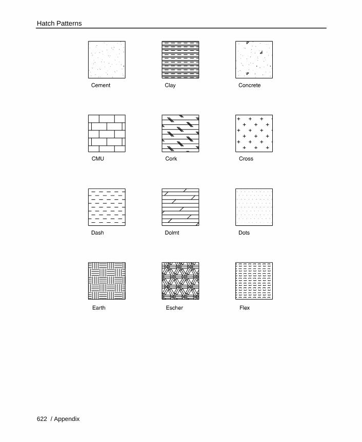
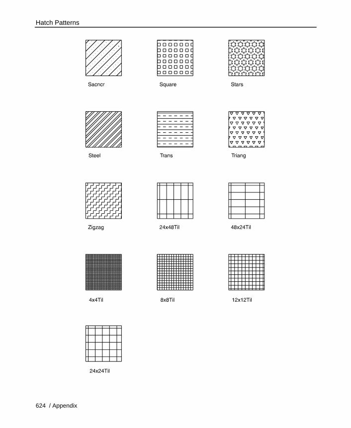
Hatch Patterns Hatch patterns included with DataCAD are pictured below.
Angle 31 32
Box Brass Brick
33 34 35
36 37 38
Hatch Patterns
622 / Appendix

Hatch Patterns
Appendix / 623
Hatch Patterns
624 / Appendix
DataCAD Keyboard Shortcuts
Appendix / 625
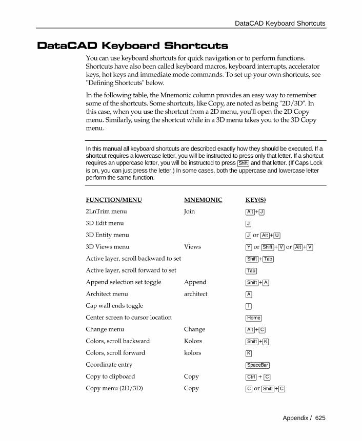
DataCAD Keyboard Shortcuts You can use keyboard shortcuts for quick navigation or to perform functions. Shortcuts have also been called keyboard macros, keyboard interrupts, accelerator keys, hot keys and immediate mode commands. To set up your own shortcuts, see "Defining Shortcuts" below.
In the following table, the Mnemonic column provides an easy way to remember some of the shortcuts. Some shortcuts, like Copy, are noted as being "2D/3D". In this case, when you use the shortcut from a 2D menu, you'll open the 2D Copy menu. Similarly, using the shortcut while in a 3D menu takes you to the 3D Copy menu.
In this manual all keyboard shortcuts are described exactly how they should be executed. If a shortcut requires a lowercase letter, you will be instructed to press only that letter. If a shortcut requires an uppercase letter, you will be instructed to press (Shift) and that letter. (If Caps Lock is on, you can just press the letter.) In some cases, both the uppercase and lowercase letter perform the same function.
FUNCTION/MENU MNEMONIC KEY(S)
2LnTrim menu Join (Alt)+(J)
3D Edit menu (J)
3D Entity menu (J) or (Alt)+(U)
3D Views menu Views (Y) or (Shift)+(V) or (Alt)+(V)
Active layer, scroll backward to set (Shift)+(Tab)
Active layer, scroll forward to set (Tab)
Append selection set toggle Append (Shift)+(A)
Architect menu architect (A)
Cap wall ends toggle (|)
Center screen to cursor location (Home)
Change menu Change (Alt)+(C)
Colors, scroll backward Kolors (Shift)+(K)
Colors, scroll forward kolors (K)
Coordinate entry (SpaceBar)
Copy to clipboard Copy (Ctrl) + (C)
Copy menu (2D/3D) Copy (C) or (Shift)+(C)
DataCAD Keyboard Shortcuts
626 / Appendix
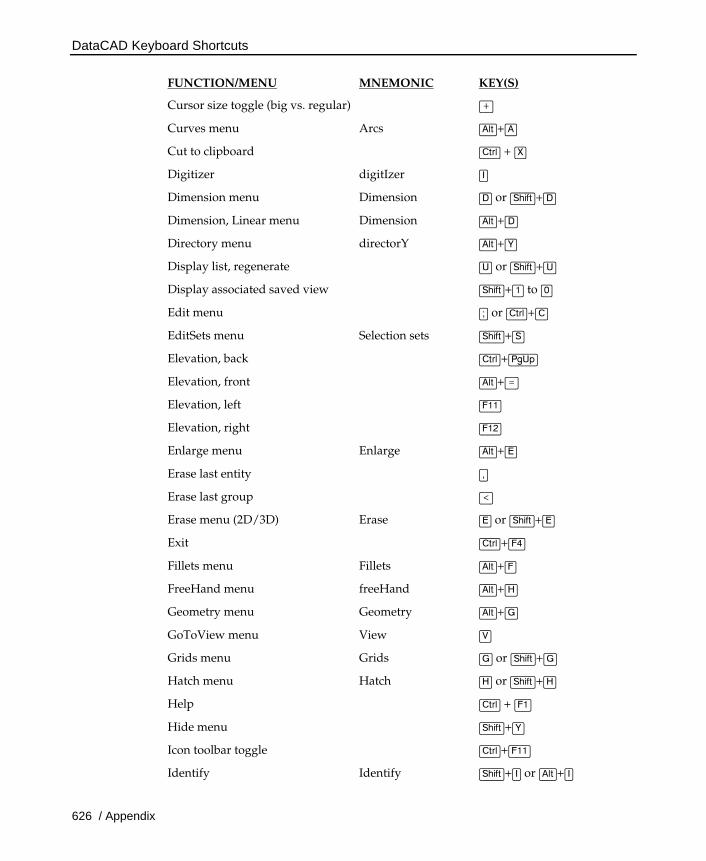
FUNCTION/MENU MNEMONIC KEY(S)
Cursor size toggle (big vs. regular) (+)
Curves menu Arcs (Alt)+(A)
Cut to clipboard (Ctrl) + (X)
Digitizer digitIzer (I)
Dimension menu Dimension (D) or (Shift)+(D)
Dimension, Linear menu Dimension (Alt)+(D)
Directory menu directorY (Alt)+(Y)
Display list, regenerate (U) or (Shift)+(U)
Display associated saved view (Shift)+(1) to (0)
Edit menu (;) or (Ctrl)+(C)
EditSets menu Selection sets (Shift)+(S)
Elevation, back (Ctrl)+(PgUp)
Elevation, front (Alt)+(=)
Elevation, left (F11)
Elevation, right (F12)
Enlarge menu Enlarge (Alt)+(E)
Erase last entity (,)
Erase last group (<)
Erase menu (2D/3D) Erase (E) or (Shift)+(E)
Exit (Ctrl)+(F4)
Fillets menu Fillets (Alt)+(F)
FreeHand menu freeHand (Alt)+(H)
Geometry menu Geometry (Alt)+(G)
GoToView menu View (V)
Grids menu Grids (G) or (Shift)+(G)
Hatch menu Hatch (H) or (Shift)+(H)
Help (Ctrl) + (F1)
Hide menu (Shift)+(Y)
Icon toolbar toggle (Ctrl)+(F11)
Identify Identify (Shift)+(I) or (Alt)+(I)
DataCAD Keyboard Shortcuts
Appendix / 627
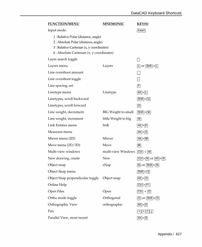
FUNCTION/MENU MNEMONIC KEY(S)
Input mode: (Insert)
1 : Relative Polar (distance, angle)
2 : Absolute Polar (distance, angle)
3 : Relative Cartesian (x, y coordinates)
4 : Absolute Cartesian (x, y coordinates)
Layer search toggle (')
Layers menu Layers (L) or (Shift)+(L)
Line overshoot amount (_)
Line overshoot toggle (-)
Line spacing, set (F)
Linetype menu Linetype (Alt)+(L)
Linetypes, scroll backward (Shift)+(Q)
Linetypes, scroll forward (Q)
Line weight, decrement BIG Weight to small (Shift)+(W)
Line weight, increment little Weight to big (W)
Link Entities menu linK (Alt)+(K)
Measures menu (Alt)+(X)
Mirror menu (2D) Mirror (Alt)+(M)
Move menu (2D/3D) Move (M)
Multi-view windows multi-view Windows (Ctrl) + (W)
New drawing, create New (Ctrl)+(N) or (Alt)+(N)
Object snap sNap (N) or (Shift)+(N)
Object Snap menu (Shift)+(X)
Object Snap perpendicular toggle Object snap (Alt)+(O)
Online Help (Ctrl)+(F1)
Open Files Open (Ctrl) + (O)
Ortho mode toggle Orthogonal (O) or (Shift)+(O)
Orthographic View orthographic (Alt)+(0)
Pan (¡) (¢) (£) (¥)
Parallel View, most recent (Alt)+(9)
DataCAD Keyboard Shortcuts
628 / Appendix
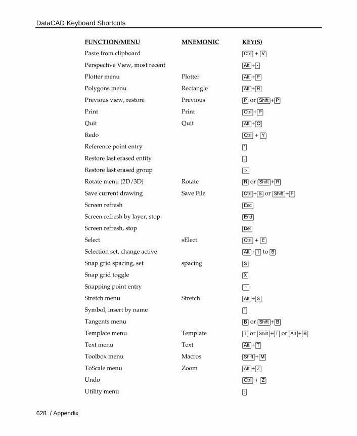
FUNCTION/MENU MNEMONIC KEY(S)
Paste from clipboard (Ctrl) + (V)
Perspective View, most recent (Alt)+(-)
Plotter menu Plotter (Alt)+(P)
Polygons menu Rectangle (Alt)+(R)
Previous view, restore Previous (P) or (Shift)+(P)
Print Print (Ctrl)+(P)
Quit Quit (Alt)+(Q)
Redo (Ctrl) + (Y)
Reference point entry (`)
Restore last erased entity (.)
Restore last erased group (>)
Rotate menu (2D/3D) Rotate (R) or (Shift)+(R)
Save current drawing Save File (Ctrl)+(S) or (Shift)+(F)
Screen refresh (Esc)
Screen refresh by layer, stop (End)
Screen refresh, stop (Del)
Select sElect (Ctrl) + (E)
Selection set, change active (Alt)+(1) to (8)
Snap grid spacing, set spacing (S)
Snap grid toggle (X)
Snapping point entry (~)
Stretch menu Stretch (Alt)+(S)
Symbol, insert by name (")
Tangents menu (B) or (Shift)+(B)
Template menu Template (T) or (Shift)+(T) or (Alt)+(B)
Text menu Text (Alt)+(T)
Toolbox menu Macros (Shift)+(M)
ToScale menu Zoom (Alt)+(Z)
Undo (Ctrl) + (Z)
Utility menu (:)
DataCAD Keyboard Shortcuts
Appendix / 629
FUNCTION/MENU MNEMONIC KEY(S)
Wall T intersection clean-up toggle (\)
Walls toggle and set new wall thickness (=)
Weld Line menu Weld (Alt)+(W)
Window In (/)
World coordinate identify (?)
Z-base or Z-height attribute entry Z-base/Z-height (Z) or (Shift)+(Z)
Zoom Extents (Ctrl)+(-)
Zoom In (PgDn)
Zoom Out (PgUp)
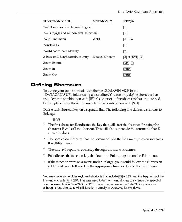
Defining Shortcuts To define your own shortcuts, edit the file DCADWIN.MCR in the \DATACAD\SUP\ folder using a text editor. You can only define shortcuts that use a letter in combination with (Alt). You cannot define shortcuts that are accessed by a single letter or those that use a letter in combination with (Shift).
Define each shortcut key on a separate line. The following line defines a shortcut to Enlarge:
E;^f6
? The first character E, indicates the key that will start the shortcut. Pressing the character E will call the shortcut. This will also supercede the command that E currently does.
? The semicolon indicates that the command is in the Edit menu; a colon indicates the Utility menu.
? The caret (^) separates each step through the menu structure.
? F6 indicates the function key that loads the Enlarge option on the Edit menu.
? If the function were on a menu under Enlarge, you would follow the F6 with an additional caret, followed by the appropriate function key on the next menu.
You may have some older keyboard shortcuts that include (Alt) + 183 near the beginning of the line and end with (Alt) + 184. This was used to turn off menu display to increase the speed of shortcut execution in DataCAD for DOS. It is no longer needed in DataCAD for Windows, although these shortcuts will still function normally in DataCAD for Windows.
DataCAD Fonts
630 / Appendix
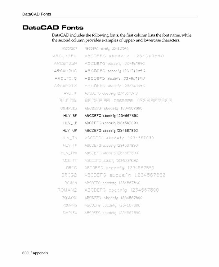
DataCAD Fonts DataCAD includes the following fonts; the first column lists the font name, while the second column provides examples of upper- and lowercase characters.
Extended Characters
Appendix / 631
Extended Characters Five DataCAD fonts feature extended characters, which allows you to include common drafting symbols, fractions, and exponents in your text:
ARCDR2GP ArcDraft General Purpose
ARCWY2GP ArcWyde General Purpose
ARCWY2HC ArcWyde Heavy Chisel
ARCWY2LC ArcWyde Light Chisel
HLV_TPX Helvetica Thin Proportional with extended characters
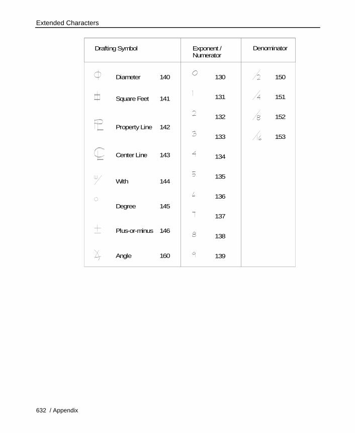
The following chart shows the drafting symbols, exponents and fractions you can include in your text. To create drafting symbols and exponents, press (Alt) and hold it down while you type the corresponding number using the numeric keypad.
To create fractions, use the Exponent/Numerator column of the chart to enter the numerator of your fraction; use the Denominator column to draw the denominator and the division sign. For example, to draw a fraction of 5/16 in your text, hold down (Alt) and type 135 using the numeric keypad. When you release (Alt), the 5 will appear. Depress (Alt) again and type 153 on the numeric keypad. The fraction is completed when you release (Alt).
If you'd like to change your font but you've used extended characters in your text, make sure the new font also includes the extended characters. If you choose a font which does not include the extended characters, the content of your text may be changed.
Extended Characters
632 / Appendix
PropertyLine
SquareFeet
Diameter
DraftingSymbol Exponent /Numerator
Denominator
Plus-or-minus
Angle
Center Line
With
Degree
142
141
140 130 150
131 151
132 152
133 153
134
135
136
137
138
139
146
160
143
144
145


![Command Quick Guide R12 - CAD.deww3.cad.de/foren/ubb/uploads/Felix-CAD/AutoCADCommandQuickG… · AutoCAD Productivity AutoCAD Command Quick Guide Appendix [ ] - 1 ... - Command applies](https://static.fdocuments.in/doc/165x107/5a7a06697f8b9a5e438b8ae4/command-quick-guide-r12-caddeww3caddeforenubbuploadsfelix-cadautocadcommandquickgautocad.jpg)