WFM8200 and WFM8300 Waveform Monitors System Integration ...
38
xx WFM8200 and WFM8300 Waveform Monitors System Integration ZZZ Technical Reference *P077039100* 077-0391-00
Transcript of WFM8200 and WFM8300 Waveform Monitors System Integration ...

xx
WFM8200 and WFM8300Waveform MonitorsSystem Integration
ZZZ
Technical Reference
*P077039100*
077-0391-00


WFM8200 and WFM8300Waveform MonitorsSystem Integration
ZZZ
Technical Reference
xx
WarningThe service instructions are for use by qualified personnel only.To avoid personal injury, do not perform any servicing unlessyou are qualified to do so. Refer to all safety summaries priorto performing service.
www.tektronix.com077-0391-00

Copyright © Tektronix. All rights reserved. Licensed software products are owned by Tektronix or its subsidiariesor suppliers, and are protected by national copyright laws and international treaty provisions.
Tektronix products are covered by U.S. and foreign patents, issued and pending. Information in this publicationsupersedes that in all previously published material. Specifications and price change privileges reserved.
TEKTRONIX and TEK are registered trademarks of Tektronix, Inc.
Contacting Tektronix
Tektronix, Inc.14200 SW Karl Braun DriveP.O. Box 500Beaverton, OR 97077USA
For product information, sales, service, and technical support:In North America, call 1-800-833-9200.Worldwide, visit www.tektronix.com to find contacts in your area.

Table of Contents
General Safety Summary . . . . . . . . . . . . . . . . . . . . . . . . . . . . . . . . . . . . . . . . . . . . . . . . . . . . . . . . . . . . . . . . . . . . . . . . . . . . . . . . . . . . . . . . . . iiService Safety Summary.. . . . . . . . . . . . . . . . . . . . . . . . . . . . . . . . . . . . . . . . . . . . . . . . . . . . . . . . . . . . . . . . . . . . . . . . . . . . . . . . . . . . . . . . . ivPreface .. . . . . . . . . . . . . . . . . . . . . . . . . . . . . . . . . . . . . . . . . . . . . . . . . . . . . . . . . . . . . . . . . . . . . . . . . . . . . . . . . . . . . . . . . . . . . . . . . . . . . . . . . . . . . . v
Where to Find More Information . . . . . . . . . . . . . . . . . . . . . . . . . . . . . . . . . . . . . . . . . . . . . . . . . . . . . . . . . . . . . . . . . . . . . . . . . . . . vPhysical, Environmental, and Power Specifications . . . . . . . . . . . . . . . . . . . . . . . . . . . . . . . . . . . . . . . . . . . . . . . . . . . . . . . . . . . . 1Rack and Custom Installation .. . . . . . . . . . . . . . . . . . . . . . . . . . . . . . . . . . . . . . . . . . . . . . . . . . . . . . . . . . . . . . . . . . . . . . . . . . . . . . . . . . . . 3Instrument Connectors . . . . . . . . . . . . . . . . . . . . . . . . . . . . . . . . . . . . . . . . . . . . . . . . . . . . . . . . . . . . . . . . . . . . . . . . . . . . . . . . . . . . . . . . . . . . . 9Video System Installation. . . . . . . . . . . . . . . . . . . . . . . . . . . . . . . . . . . . . . . . . . . . . . . . . . . . . . . . . . . . . . . . . . . . . . . . . . . . . . . . . . . . . . . . . 21Power-on and Power-off Procedure . . . . . . . . . . . . . . . . . . . . . . . . . . . . . . . . . . . . . . . . . . . . . . . . . . . . . . . . . . . . . . . . . . . . . . . . . . . . . 24Network Operation .. . . . . . . . . . . . . . . . . . . . . . . . . . . . . . . . . . . . . . . . . . . . . . . . . . . . . . . . . . . . . . . . . . . . . . . . . . . . . . . . . . . . . . . . . . . . . . . 25
WFM8200 and WFM8300 System Integrator i

General Safety Summary
General Safety SummaryReview the following safety precautions to avoid injury and prevent damage tothis product or any products connected to it.
To avoid potential hazards, use this product only as specified.
Only qualified personnel should perform service procedures.
To Avoid Fire or PersonalInjury
Use Proper Power Cord. Use only the power cord specified for this product andcertified for the country of use.
Connect and Disconnect Properly. Do not connect or disconnect probes or testleads while they are connected to a voltage source.
Ground the Product. This product is grounded through the grounding conductorof the power cord. To avoid electric shock, the grounding conductor must beconnected to earth ground. Before making connections to the input or outputterminals of the product, ensure that the product is properly grounded.
Observe All Terminal Ratings. To avoid fire or shock hazard, observe all ratingsand markings on the product. Consult the product manual for further ratingsinformation before making connections to the product.
Do not apply a potential to any terminal, including the common terminal, thatexceeds the maximum rating of that terminal.
Power Disconnect. The power cord disconnects the product from the power source.Do not block the power cord; it must remain accessible to the user at all times.
Do Not Operate Without Covers. Do not operate this product with covers or panelsremoved.
Do Not Operate With Suspected Failures. If you suspect that there is damage to thisproduct, have it inspected by qualified service personnel.
Avoid Exposed Circuitry. Do not touch exposed connections and componentswhen power is present.
Do Not Operate in Wet/Damp Conditions.
Do Not Operate in an Explosive Atmosphere.
Keep Product Surfaces Clean and Dry.
Provide Proper Ventilation. Refer to the manual’s installation instructions fordetails on installing the product so it has proper ventilation.
ii WFM8200 and WFM8300 System Integrator

General Safety Summary
Terms in this Manual These terms may appear in this manual:
WARNING. Warning statements identify conditions or practices that could resultin injury or loss of life.
CAUTION. Caution statements identify conditions or practices that could result indamage to this product or other property.
Symbols and Terms on theProduct
These terms may appear on the product:
DANGER indicates an injury hazard immediately accessible as you readthe marking.
WARNING indicates an injury hazard not immediately accessible as youread the marking.
CAUTION indicates a hazard to property including the product.
The following symbol(s) may appear on the product:
WFM8200 and WFM8300 System Integrator iii

Service Safety Summary
Service Safety SummaryOnly qualified personnel should perform service procedures. Read this ServiceSafety Summary and the General Safety Summary before performing any serviceprocedures.
Do Not Service Alone. Do not perform internal service or adjustments of thisproduct unless another person capable of rendering first aid and resuscitation ispresent.
Disconnect Power. To avoid electric shock, switch off the instrument power, thendisconnect the power cord from the mains power.
Use Care When Servicing With Power On. Dangerous voltages or currents mayexist in this product. Disconnect power, remove battery (if applicable), anddisconnect test leads before removing protective panels, soldering, or replacingcomponents.
To avoid electric shock, do not touch exposed connections.
iv WFM8200 and WFM8300 System Integrator

Preface
PrefaceThis document provides information for system integrators who are designingsystems for high-definition (HD), standard-definition (SD), and 3 Gb/s SDIdigital video content where the Tektronix WFM8200 and WFM8300 WaveformMonitors are to be deployed.
This manual is divided into the following sections:
Physical, Environmental, and Power specifications,
Rack and Custom Installation
Instrument Connectors
System Installation
Network Operation
Where to Find More InformationThe following tables list the documentation that is available for the product andshows where you can find it: in a printed manual, on the product documentationCD-ROM, or on the Tektronix Web site.
Table i: Product documentationItem Purpose LocationInstallation and Safety Instructions(this manual)
Provides safety and compliance information alongwith hardware installation instructions to present theassociated safety warnings. This manual is availablein English, Japanese, and Simplified Chinese.
Printed manual and alsoavailable in electronic formatat www.tektronix.com/manuals
User Manual Provides operation and application information.This manual is available in English, Japanese, andSimplified Chinese.
Product DocumentationCD and available atwww.tektronix.com/manuals
Online Help In-depth instrument operation and UI help. On the instrumentSpecifications and PerformanceVerification Technical Reference
Specifications and procedures for checking instrumentperformance.
Product DocumentationCD and available atwww.tektronix.com/manuals
WFM and WVR SeriesManagement InformationDatabase (MIB) ProgrammerManual
SNMP command reference for remotely controlling theinstrument.
Product DocumentationCD and available atwww.tektronix.com/manuals
Service Manual Provides information about adjustments, repair, andreplaceable parts.
Available atwww.tektronix.com/manuals
WFM8200 and WFM8300 System Integrator v

Preface
Table ii: Related referrence documentsItem Purpose LocationTop 10 Application-Based Presets Describes useful presets and how to set them up. Product Documentation CD and
available at www.tektronix.comPreventing Illegal Colors(application note)
Describes how the Diamond, Arrowhead, and Lightningdisplays can be used to help prevent the undesiredimpact of color gamut violations and to simplify theassessment of proper gamut compliance.
Product DocumentationCD and available atwww.tektronix.com/manuals
Understanding Colors and Gamut(poster)
Provides a large visual display of how the Diamond,Arrowhead, and Lightning displays can be used to helpprevent the undesired impact of color gamut violations.
Available atwww.tektronix.com/manuals
A Guide to Standard andHigh Definition Digital VideoMeasurements (primer)
This book explains the basics of making standard andhigh-definition, digital-video measurements.
Product DocumentationCD and available atwww.tektronix.com/manuals
Analog and Digital AudioMonitoring (application note)
Describes how to monitor analog and digital audiosignals. Also discussed are specific differences in themethods used to monitor analog audio versus digitalaudio, and how to plan the transition from monitoringanalog audio to monitoring digital audio.
Available atwww.tektronix.com/manuals
Audio Monitoring (application note) Describes balanced and unbalanced audio signals,and explains the physical and electrical characteristicsand the specific strength and weaknesses of thedifferent digital audio signal formats.
Available atwww.tektronix.com/manuals
Monitoring Surround Sound Audio(application note)
Describes the basics of 5.1-channel surround soundaudio and tells how to use the Surround Sound displayto visualize key audio-level and phase relationshipsin this audio format.
Available atwww.tektronix.com/manuals
NTSC Video Measurements(primer)
This book explains the basics of making NTSC videomeasurements.
Product DocumentationCD and available atwww.tektronix.com/manuals
PAL Systems TelevisionMeasurements (primer)
This bookexplains the basics of making PAL videomeasurements.
Product DocumentationCD and available atwww.tektronix.com/manuals
Table iii: Graphics and photos for system integratorsItem Purpose LocationFront and rear panel photos of theWFM8200 and WFM8300
These photos might be useful if you need to present informationto your customer
Product DocumentationCD
Front and rear panel line art This line art might be useful if you need to present informationto your customer
Product DocumentationCD and this manual
vi WFM8200 and WFM8300 System Integrator

Physical, Environmental, and Power SpecificationsThe physical, environemental, and power specifications apply to all intrumentmodels. Use this information to ensure proper ventilation and clearance wheninstalling an instrument into a rack.
Table 1: Physical specificationsCharacteristic Description
Height 5.25 in (133.4 mm)Width 8.5 in (215.9 mm )
Dimensions
Depth (front to back including handles and BNCs) 18.125 in (460.4 mm)Net 12 lbs (5.5 kg), maximumWeightShipping 21 lbs (9.6 kg ), approximatelyTop NoneBottom NoneLeft side 2 in (51 mm)Right side 2 in (51 mm)Front None
RequiredClearances
Rear 2 in (51 mm)
Table 2: Power specificationsCharacteristic Description
Input Voltage 100 to 240 VAC ± 10%Input Power Frequency 50 or 60 Hz
Power
Power Consumption, typical 50 to 110 VA at 110 or 240 VAC
NOTE. More information about the power connector is available in this document.(See page 10, Power Connector.) You can also read about the power-on andpower-off procedures. (See page 24.)
Table 3: Environmental specificationsCharacteristic Description
Operating 0 °C to +40 °CTemperatureNon-operating -20 °C to +60 °COperating 20% to 80% relative humidity (% RH) at up to +40 °C,
non-condensingHumidity
Non Operating 5% to 90% RH (relative humidity) at up to +60 °C,non-condensing
WFM8200 and WFM8300 System Integrator 1

Physical, Environmental, and Power Specifications
Table 3: Environmental specifications (cont.)
Characteristic DescriptionOperating 9,842 ft (3,000 m )AltitudeNon-operating 40,000 ft (12,192 m)
The variable fans provide forced air circulation. Do not blockventilation openings.
Bare instrument (no optional sleeves) To ensure proper air flow, there must be 2 inches of clearanceon both sides of the instrument, at least 2 inches of clearancefrom the rear of the instrument, and at least a 1/2 inch ofclearance from the top of the instrument.
Portable cabinet Use only the Tektronix portable cabinet, WFMF02, to ensureproper airflow with this instrument. When using the portablecabinet, the same minimum clearances as the Bare Instrumentapply.
Cooling
Rack cabinet Use only the Tektronix rackmount insert, WFM7F00, with theTektronix Dual Rack Adapter, WFM7F05 for this instrument. Toensure proper airflow when installing the Dual Rack Adapter ina closed rack with solid walls, there must be at least 2 inchesof clearance from both sides of the rack adapter frame to therack side walls, at least 3 inches of clearance from the rear ofthe rack adapter frame to the rack’s back wall, and at leasta 1/2 inch of clearance from the top of the rack adapter toanother rack adapter or installed instrument. The rack intakeair to the side vents must not exceed 40 °C.
Pollution Degree 2, Indoor use only
2 WFM8200 and WFM8300 System Integrator

Rack and Custom Installation
Rack and Custom InstallationThe instrument is shipped in a wrap-around chassis that covers the instrumentbottom and two sides. A cover is installed on the chassis, and the rear panelis made up of the module rear panels.
You can operate the instrument in the instrument chassis (be sure the top cover ison) or installed in an approved portable cabinet or rack adapter. (See page 5, RackAdapter Installation.) You can also install the instrument in a custom installation,such as a console.
CAUTION. To prevent damage to the instrument and the cabinet, do not installthe instrument in any cabinet except one that is approved by Tektronix, such asthe WFM7F05.
WFM7F05 Dimensions The following three figures show the dimensions of the WFM7F05 rack adapterhardware and the sleeves.
Figure 1: WFM7F05 rack adapter dimensions
WFM8200 and WFM8300 System Integrator 3

Rack and Custom Installation
Figure 2: WFM7F05 sleeve dimensions
4 WFM8200 and WFM8300 System Integrator
Rack and Custom Installation
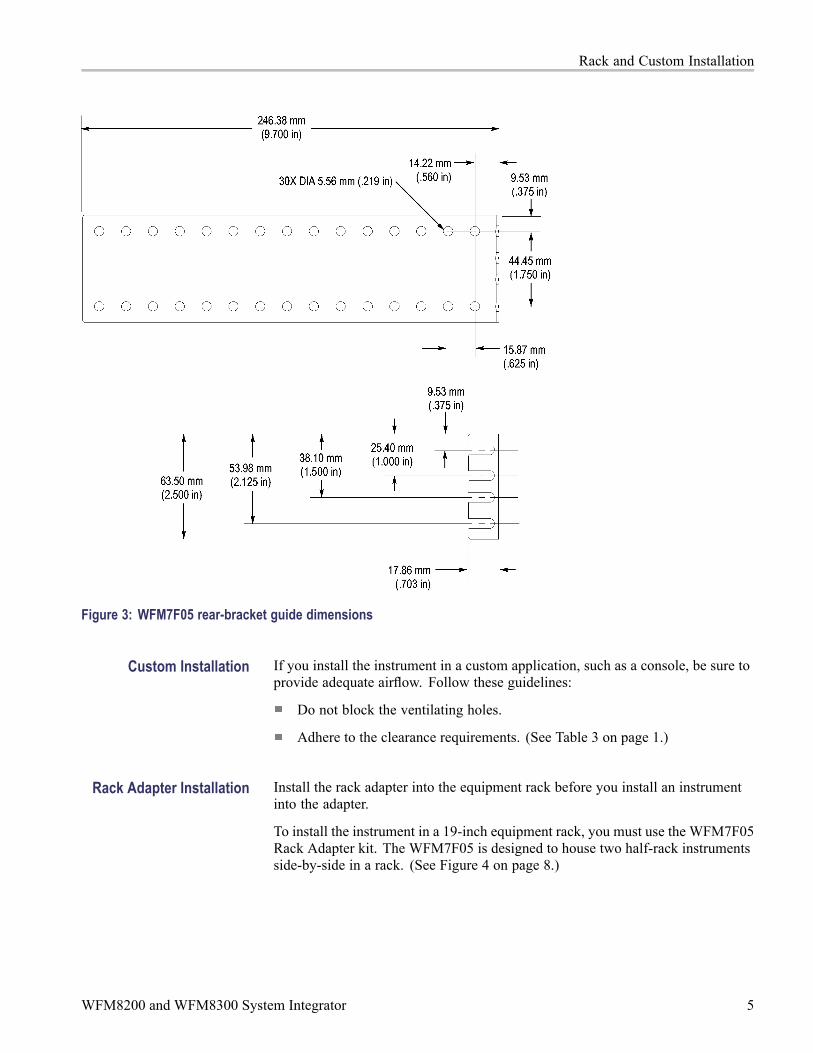
Figure 3: WFM7F05 rear-bracket guide dimensions
Custom Installation If you install the instrument in a custom application, such as a console, be sure toprovide adequate airflow. Follow these guidelines:
Do not block the ventilating holes.
Adhere to the clearance requirements. (See Table 3 on page 1.)
Rack Adapter Installation Install the rack adapter into the equipment rack before you install an instrumentinto the adapter.
To install the instrument in a 19-inch equipment rack, you must use the WFM7F05Rack Adapter kit. The WFM7F05 is designed to house two half-rack instrumentsside-by-side in a rack. (See Figure 4 on page 8.)
WFM8200 and WFM8300 System Integrator 5

Rack and Custom Installation
To accommodate different products, two types of sleeves are available. The twosleeve types are designed to properly fit only the products listed below.
CAUTION. Be sure to use the correct sleeve for your product. If you use the wrongsleeve, it could damage the instrument and cause overheating problems. Refer tothe cooling specifications in this manual. (See page 2.)
The ventilation holes and EMI shielding on the sleeves are specially designed tomeet the requirements of the instruments for which they were intended.
The type of sleeve(s) included with the rack adapter kit is configured when youorder the adapter. You can also install a sleeve in one side of the rack adapter anda blank panel (1700F06) or an accessory drawer (1700F07) in the other side of theadapter to improve airflow and appearance.
Table 4: Available rack adapter options and sleeves
ItemTektronix partnumber Supported products Description
WFM7F05 WFM7F05 WFM8000 series, WFM7000 series,WFM700 series, 1700 series, andWFM601 seriesWFM8000 series, WFM7000 series,WFM6000 series, WFM5000 series,WFM4000 series, WFM700 series,1700 series, WFM601 series,MTX100A and B, RTX A and B series
Rack adapter, dual side-by-side
WFMF05NN WFM7F05 optionNN
WFM8000 series, WFM7000 series,WFM6000 series, WFM700 series,MTX100A and B, RTX A and B series
Rack adapter and two WFM7F00 sleeves
WFMF05OO WFM7F05 optionOO
1700 series, WFM601 series,MTX100, 760A, 764
Rack adapter and two 1700F00A sleeves
WFMF05ON WFM7F05 optionON
WFM8000 series, WFM7000 series,WFM6000 series, WFM700 series,MTX100A and B, RTX A and Bseries, 1700 series, WFM601 series,MTX100, 760A, 764
Rack adapter and one 1700F00A sleeveand one WFM7F00 sleeve
WFM50F02 WFMF05 optionWFM50F02
WFM4000 series and WFM5000series
Rack adapter and two WFM50F03-001sleeves
WFM50F03 WFMF05 optionWFM50F03
WFM4000 series, WFM5000 series,WFM8000 series, WFM7000 series,WFM6000 series, WFM700 series,MTX100A and B, RTX A and B series
Rack adapter and one WFM7F00 sleeveand one WFM50F03-001 sleeve
WFM7F00 sleeve 390-1210-XX WFM8200, WFM8300, WFM6100,WFM7000, and WFM7100 WFM700A,WFM700HD, WFM700M, MTX100A,RTX100A, and RTX130A
WFM7F00 sleeve
6 WFM8200 and WFM8300 System Integrator

Rack and Custom Installation
Table 4: Available rack adapter options and sleeves (cont.)
ItemTektronix partnumber Supported products Description
1700F00A sleeve 390-1211-XX 1700 Series instruments, WFM601Series instruments, older half rackinstruments, 760A, and 764
1700F00A sleeve
WFM50F03-001sleeve
437-0523-XX WFM4000 series and WFM5000series
WFM50F03-001 sleeve
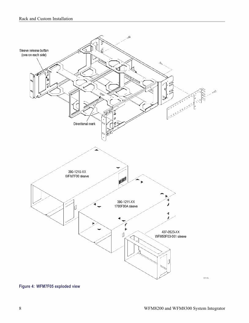
During installation, be aware of the following:
The rack adapter is marked with the word "TOP" to indicate which side of theadapter should face up. (See Figure 4 on page 8.)
You can adjust the position of the handle brackets to mount the adapter flushwith other equipment in the rack. (See rack adapter instructions.)
Press the sleeve release buttons to remove the instrument from the rackadapter. (See Figure 4.)
After you install the rack adapter, install the instrument(s) into the rack adapterfollowing the instructions that accompany the WFM7F05 Rack Adapter Kit.
WFM8200 and WFM8300 System Integrator 7
Rack and Custom Installation
Figure 4: WFM7F05 exploded view
8 WFM8200 and WFM8300 System Integrator

Instrument Connectors
Instrument ConnectorsThe instrument has connectors on the front and rear panels. The following pagesdescribe the connector types, pin numbering, and associated signal requirements.
The first illustration shows the rear panel of a fully optioned instrument. Yourinstrument may have a different configuration than that shown.
NOTE. More illustrations and photographs of these instruments are available inJPEG format on the Tektronix Web site (www.tektronix.com) and on the ProductDocumentation CD that was shipped with your instrument.
Figure 5: Rear panel with Option CPS, EYE or PHY, and AD or DDE installed
WFM8200 and WFM8300 System Integrator 9

Instrument Connectors
Power Connector
The instrument has the following power requirements:
A single-phase power source with one current-carrying conductor at or nearearth-ground (the neutral conductor).
The power source frequency must be 50 or 60 Hz, and a operating voltagerange must be from 100 to 240 VAC, continuous.
WARNING. To reduce risk of fire and shock, ensure the mains supply voltagefluctuations do not exceed 10% of the operating voltage range.
Systems with both current-carrying conductors live with respect to ground(such as phase-to-phase in multiphase systems) are not recommended aspower sources.
NOTE. Only the line conductor is fused for over-current protection. The fuse isinternal and not user replaceable. Do not attempt to replace the fuse. If yoususpect the fuse has blown, return the unit to an authorized service center forrepair.
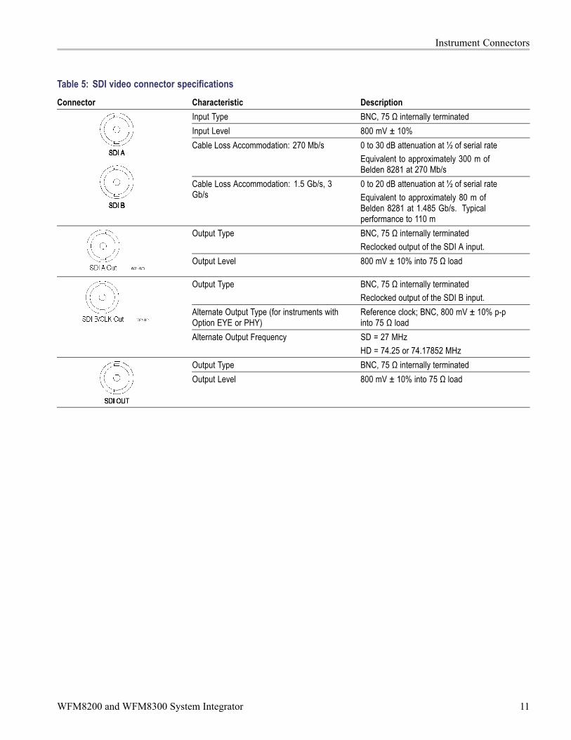
SDI Video Connectors SDI inputs are self-terminating inputs. Use the SDI A and SDI B inputs to connecta serial digital video signal to the instrument.
The SDI A Out signal is the reclocked output of the SDI A input and has thesame data rate as the input signal. The SDI B/CLK Out signal is the reclockedoutput from the SDI B input and has the same data rate as the input signal. If theinstrument has Option Eye or PHY, the SDI B/CLK Out signal can also be therecovered clock output. You can connect the Clock Out signal to a spectrumanalyzer to view jitter frequency components in the video signal.
The SDI OUT can be selected to output either the looped-through input signal,a test signal (Option 3G only), or the Pix Mon signal output, which containsconfigurable error brightups. This can be done from the Config > Outputs > SDIOutput menu.
The following table lists the characteristics of the SDI video connectors.
10 WFM8200 and WFM8300 System Integrator
Instrument Connectors
Table 5: SDI video connector specificationsConnector Characteristic Description
Input Type BNC, 75 Ω internally terminatedInput Level 800 mV ± 10%Cable Loss Accommodation: 270 Mb/s 0 to 30 dB attenuation at ½ of serial rate
Equivalent to approximately 300 m ofBelden 8281 at 270 Mb/s
Cable Loss Accommodation: 1.5 Gb/s, 3Gb/s
0 to 20 dB attenuation at ½ of serial rateEquivalent to approximately 80 m ofBelden 8281 at 1.485 Gb/s. Typicalperformance to 110 m
Output Type BNC, 75 Ω internally terminatedReclocked output of the SDI A input.
Output Level 800 mV ± 10% into 75 Ω load
Output Type BNC, 75 Ω internally terminatedReclocked output of the SDI B input.
Alternate Output Type (for instruments withOption EYE or PHY)
Reference clock; BNC, 800 mV ± 10% p-pinto 75 Ω load
Alternate Output Frequency SD = 27 MHzHD = 74.25 or 74.17852 MHz
Output Type BNC, 75 Ω internally terminatedOutput Level 800 mV ± 10% into 75 Ω load
WFM8200 and WFM8300 System Integrator 11

Instrument Connectors
Composite VideoConnectors
Use the CMPST A and CMPST B inputs to connect an NTSC or PAL compositevideo signal to the instrument. The following table lists the signal characteristicsof the composite video connectors.
Table 6: Composite video connector specificationsConnector Characteristic Description
Input Type; Quantity BNC, passive loop-through, 75 Ωcompensated; 2 inputs (Composite A andComposite B)
Maximum Operating Amplitude withClamping Off (DC Coupled)
-1.8 V to +2.2 V (all inputs), DC + peak AC
Maximum Absolute Input Voltage -6.0 V to +6.0 V, DC + peak AC
Video External ReferenceConnector
Use the REF LOOP connector to input a composite Black Burst signal or atri-level sync signal for use as a sync timing reference for the selected videoinput signal. The following table lists the signal characteristics of the externalreference connectors.
Table 7: External reference connector specificationsConnector Characteristic Description
Input Type BNC, passive loop-through, 75 Ωcompensated
Input Level -6 to +6 dBMaximum Input Voltage Level ± 5 V, DCMaximum Absolute Input Voltage ± 5 V, DC
12 WFM8200 and WFM8300 System Integrator

Instrument Connectors
AES Digital AudioConnectors
Use the AES audio connectors to input or output digital audio signals. The "A"connectors are input only. You can configure the "B" connectors to functionas additional inputs or as outputs of the selected audio inputs. Use the AudioInputs/Outputs menu to configure the channel mapping in the audio displays.
The following table lists the signal characteristics of the AES Audio connectors.
Table 8: AES digital audio connector specificationsConnector Characteristic Description
Input Type (A and B connectors) BNC, 75 Ω terminated, unbalanced(meets requirements of AES 3-ID andSMPTE 276M-1995)
Input Amplitude Range (A and B connectors) 0.1 Vp-p to 2 Vp-p
Output Type (B connectors only) BNC, 75 Ω terminated, unbalanced(meets requirements of AES 3-ID andSMPTE 276M-1995)
Output Amplitude Range (B connectors only) 0.9 V to 1.1 V Pk-Pk into 75 Ω
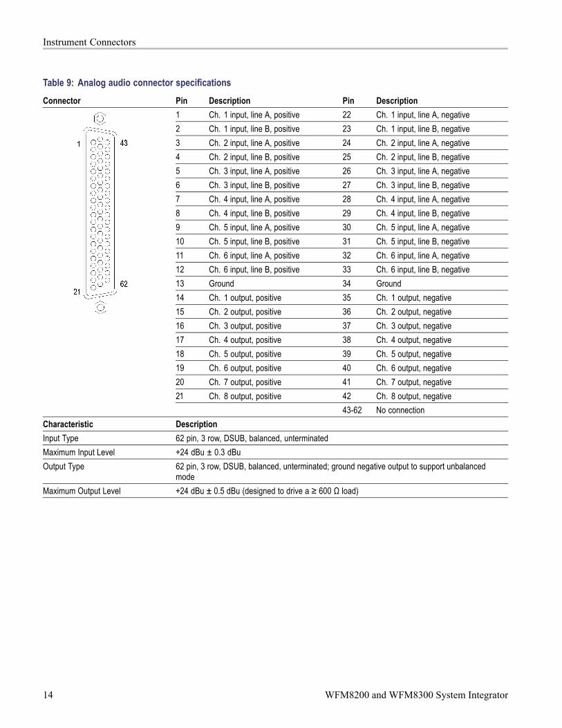
Analog Audio Connector The ANALOG AUDIO connector is used to receive and send analog signals. Theconnector is a 62-pin, female, D-subminiature connector. Pin assignments andpin names are listed in the following figure and table.
Use the ANALOG AUDIO connector to input or output analog audio signals. Usethe Audio Settings menu to configure the channel mapping in the audio displays.
For all audio options, use the supplied 62-pin DSUB connector to attachanalog-audio signals to the instrument. Solder wires to the connector as neededto accommodate the desired audio inputs and outputs. Audio signals can beconnected as either balanced or unbalanced. Be sure to use a suitable cable whenyou are wiring balanced audio. An example of a suitable cable is Belden 8451,which is a shielded twisted pair cable. Alternatively, you can purchase an audiobreakout cable (Tektronix part number 012-1688-00), which provides a two metercable with XLR connectors for all twelve inputs and eight outputs.
WFM8200 and WFM8300 System Integrator 13
Instrument Connectors
Table 9: Analog audio connector specificationsConnector Pin Description Pin Description
1 Ch. 1 input, line A, positive 22 Ch. 1 input, line A, negative2 Ch. 1 input, line B, positive 23 Ch. 1 input, line B, negative3 Ch. 2 input, line A, positive 24 Ch. 2 input, line A, negative4 Ch. 2 input, line B, positive 25 Ch. 2 input, line B, negative5 Ch. 3 input, line A, positive 26 Ch. 3 input, line A, negative6 Ch. 3 input, line B, positive 27 Ch. 3 input, line B, negative7 Ch. 4 input, line A, positive 28 Ch. 4 input, line A, negative8 Ch. 4 input, line B, positive 29 Ch. 4 input, line B, negative9 Ch. 5 input, line A, positive 30 Ch. 5 input, line A, negative10 Ch. 5 input, line B, positive 31 Ch. 5 input, line B, negative11 Ch. 6 input, line A, positive 32 Ch. 6 input, line A, negative12 Ch. 6 input, line B, positive 33 Ch. 6 input, line B, negative13 Ground 34 Ground14 Ch. 1 output, positive 35 Ch. 1 output, negative15 Ch. 2 output, positive 36 Ch. 2 output, negative16 Ch. 3 output, positive 37 Ch. 3 output, negative17 Ch. 4 output, positive 38 Ch. 4 output, negative18 Ch. 5 output, positive 39 Ch. 5 output, negative19 Ch. 6 output, positive 40 Ch. 6 output, negative20 Ch. 7 output, positive 41 Ch. 7 output, negative21 Ch. 8 output, positive 42 Ch. 8 output, negative
43-62 No connectionCharacteristic DescriptionInput Type 62 pin, 3 row, DSUB, balanced, unterminatedMaximum Input Level +24 dBu ± 0.3 dBuOutput Type 62 pin, 3 row, DSUB, balanced, unterminated; ground negative output to support unbalanced
modeMaximum Output Level +24 dBu ± 0.5 dBu (designed to drive a ≥ 600 Ω load)
14 WFM8200 and WFM8300 System Integrator

Instrument Connectors
Remote Connector The REMOTE connector is a 15-pin, female, D-type connector with socketcontacts. It uses ground closures for remote control and sending indications toexternal equipment when alarms have occurred. The input of LTC is through theREMOTE connector.
Use the Remote connector to input LTC time code signals, and to remotely selectone of the first four instrument presets in group "A" using ground closure. Thefollowing table lists the signal characteristics of the Remote connector.
Remote connector preset functions.
Table 10: Remote connector pin assignments and specificationsCharacteristic Pin out Preset functionsConnector Pin Assignments Hex Binary
Pins 15,14, 13,12, 11,10
Directmodeselection
Encodedmodeselection
F 111111 none No actionE XX1110 Preset 1 No actionD XX1101 Preset 2 No actionC XX1100 SDI BB XX1011 Preset 3 SDI AA XX1010 No action9 XX1001 No action8 XX1000 Preset 87 XX0111 Preset 4 Preset 76 XX0110 Preset 65 XX0101 Preset 54 XX0100 Preset 43 XX0011 Preset 32 XX0010 Preset 21 XX0001 Preset 10 XX0000 UnusedN/A 101111 Preset 5 N/A
1 GND (In)2 Reserved (I/O)3 Reserved (I/O)4 Reserved (In)5 Reserved (In)6 GND (In)7 Time Code Positive (LTC In)8 Time Code Negative (LTC In)9 Ground Closure (Alarm Out)10 Preset 1 (In)11 Preset 2 (In)12 Preset 3 (In)13 Preset 4 (In)14 Preset 5 (In)15 Preset 6 (In)
N/A 011111 Preset 6 N/ACharacteristic DescriptionLTC Input Connector 15-pin DSUB, balanced, unterminatedLTC Input Signal Longitudinal Time Code per IEC Publication 461LTC Signal Amplitude Range 0.2 Vp-p to 5.0 Vp-p balanced differential or single-endedGround Closure Input Signal TTL thresholds, 5 V max input, -0.5 min input; pull low to assertGround Closure Output Signal One open collector output
WFM8200 and WFM8300 System Integrator 15

Instrument Connectors
PIX MON Connector The PIX MON connector is a 15-pin, female, D-type connector with socketcontacts. This is the video picture output. The output is compatible with standardanalog PC monitors, either CRT or LCD-based.
Use the PIX MON connector to output the video picture, including configurablecursor, safe area graticules, and error brightups, to an external monitor. For HDand SD input signals, use the CONFIG > Outputs menu to configure the outputsignal to be RGB, YPbPr, or off.
The following table lists the signal characteristics of the PIX MON connector.
Table 11: Picture Monitor connector pin assignments and specificationsConnector Pin Description Pin Description
1 Red output 9 Not used2 Green output 10 Ground3 Blue output 11 Not used4 Not used 12 Not used5 Ground 13 Horizontal sync output6 Ground 14 Vertical sync output7 Ground 15 Not used8 Ground
Characteristic DescriptionOutput Connector VGA DSUBOutput Format Y, Pb, Pr with sync on Y; RGB with sync on allActive Video Accuracy 700 mVp-p ± 5% (Y-Pb-Pr mode)
16 WFM8200 and WFM8300 System Integrator

Instrument Connectors
EXT DISPLAY Connector The EXT DISPLAY connector is a female DVI-I connector with socket contacts.This is the external display monitor output. The display resolution is 1024 x768. The output supports DVI monitors directly and analog PC (RGB) monitorswith the use of a DVI-I to VGA adapter.
WFM8200 and WFM8300 System Integrator 17

Instrument Connectors
Table 12: EXT DISPLAY connector specificationsConnector Pin Description Pin Description
1 TMDS Data 2–Red – (Link 1)
13 TMDS Data 3+Blue + (Link 2)
2 TMDS Data 2+Red + (Link 1)
14 Ground
3 TMDS Data 2/4 shield 15 + 5 VPower for monitor when in standby
4 TMDS Data 4–Green – (Link 2)
16 Hot plug detect
5 TMDS Data 4+Green + (Link 2)
17 TMDS Data 0–Blue – (Link 1) and digital sync
6 DDC clock 18 TMDS Data 0+Blue + (Link 1) and digital sync
7 DDC data 19 TMDS data 0/5 shield8 Analog vertical sync 20 TMDS Data 5–
Red – (Link 2)9 TMDS Data 1–
Green – (Link 1)21 TMDS Data 5+
Red + (Link 2)10 TMDS Data 1+
Green + (Link 1)22 TDMS clock shield
11 TMDS Data 1/3 shield 23 TDMS clock +Digital clock + (Links 1 and 2)
12 TMDS Data 3–Blue – (Link 2)
24 TDMS clock –Digital clock – (Links 1 and 2)
C1 Analog red C4 Analog horizontal syncC2 Analog green C5 Analog ground
Return for R, G, B signalsC3 Analog blue
Characteristic DescriptionOutput Connector DVI-I (intigrated, digital and analog)
18 WFM8200 and WFM8300 System Integrator

Instrument Connectors
Ethernet Connector Use the Ethernet connector to connect the waveform monitor to your localnetwork. A network connection is required for remote control, software upgrades,and enabling some instrument options.
The Ethernet connector includes built-in green and yellow LEDs to indicate signalstatus as indicated below:
Lit green LED indicates connection is active
Lit yellow LED indicates a 100 MB transmission rate
Unlit yellow LED indicates a 10 MB transmission rate
The following table lists the signal characteristics of the Ethernet connector.
Table 13: Ethernet connector pin assignmentsConnector Pin/LED Name Description
1 TX_D1+ Transceive Data+2 TX_D1- Transceive Data-3 RX_D2+ Receive Data+4 Not used5 Not used6 RX_D2- Receive Data-7 Not used8 Not used
Characteristic DescriptionEthernet connector RJ-45 LAN supporting 10/100/1000 BaseT; supports manual and DHCP address modes
WFM8200 and WFM8300 System Integrator 19

Instrument Connectors
Headphone Jack Use the headphone jack, located on the front panel, to listen to the audio associatedwith the selected video input signal. The following table describes the signalcharacteristics of the headphone jack.
Table 14: Headphone jack specificationsConnector Characteristic Description
Output Type Standard 1/4-inch stereo phone jack,capable of driving a 6.25 dBu sine wave into32 Ω or 16 Ω
USB Connector Use the USB connector, located on the front panel, to save and restore instrumentpresets and captured data using a USB memory drive. The following tabledescribes the signal characteristics of the USB connector.
Table 15: USB connector specificationsConnector Characteristic Description
Type HostSpeed Complies with USB 1.1 and 2.0 Full Speed
Specification (12 Mb/s)
20 WFM8200 and WFM8300 System Integrator
Video System Installation
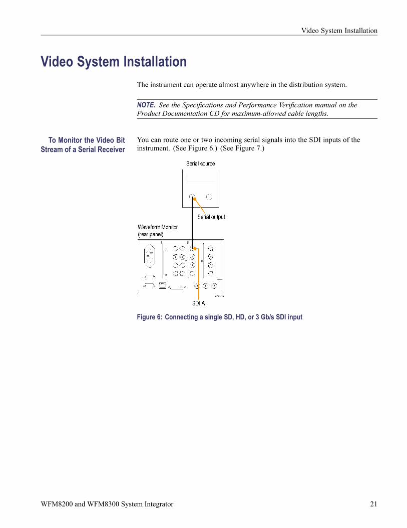
Video System InstallationThe instrument can operate almost anywhere in the distribution system.
NOTE. See the Specifications and Performance Verification manual on theProduct Documentation CD for maximum-allowed cable lengths.
To Monitor the Video BitStream of a Serial Receiver
You can route one or two incoming serial signals into the SDI inputs of theinstrument. (See Figure 6.) (See Figure 7.)
Figure 6: Connecting a single SD, HD, or 3 Gb/s SDI input
WFM8200 and WFM8300 System Integrator 21

Video System Installation
Figure 7: Connecting two SD, HD, or 3 Gb/s SDI inputs
NOTE. To monitor serial digital signals around a routing switcher, connect yourserial sources through a patch panel to a serial router. Connect the output of theserial router to an SDI input for comparison.
To Monitor CompositeSignals
Connect your sources to the CMPST A or CMPST B loop-through inputs onthe rear-panel. (See Figure 8.)
Figure 8: Composite signal connection
22 WFM8200 and WFM8300 System Integrator

Video System Installation
To Monitor Dual LinkSignals
You can connect two SDI signals or one SDI signal and one composite signalwhen you are using a Dual Link signal or monitoring two signals in simultaneousinput mode. (See Figure 9.)
Figure 9: Dual Link signal connection
Line Termination The instrument uses passive loop-through analog and reference inputs.Accordingly, the loop-through must be terminated externally. It is important thatthis external termination meet accuracy and return loss requirements.
If the instrument is installed to monitor an operating link, the destination receiverand the connecting cable serve as the termination. This monitoring connectionis best because it checks the performance of the entire path. The return loss ofthe instrument is sufficiently high that, in most cases, the destination receiver setsthe system return loss.
In cases where the instrument is placed at the end of a link, a BNC terminationmust be installed on one side of the loop-through analog or reference connector.The termination must be 75 Ω and DC coupled (good return loss extends to DC).Return loss should exceed 40 dB from DC to 6 MHz for composite.
Compatibility of BNCCenter Pins
Most BNC connectors for video equipment, whether 50 Ω or 75 Ω, use a 50Ω standard center pin. Some laboratory 75 Ω BNC connectors use a smallerdiameter center pin. The BNC connectors this instrument are designed to workwith the 50 Ω standard (large diameter) center pins.
CAUTION. To prevent intermittent signal connections, do not use connectors orterminators with the smaller diameter center pins.
WFM8200 and WFM8300 System Integrator 23
Power-on and Power-off Procedure
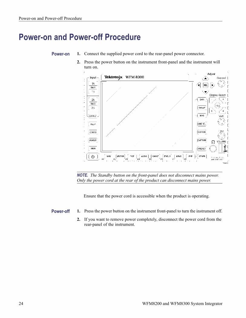
Power-on and Power-off ProcedurePower-on 1. Connect the supplied power cord to the rear-panel power connector.
2. Press the power button on the instrument front-panel and the instrument willturn on.
NOTE. The Standby button on the front-panel does not disconnect mains power.Only the power cord at the rear of the product can disconnect mains power.
Ensure that the power cord is accessible when the product is operating.
Power-off 1. Press the power button on the instrument front-panel to turn the instrument off.
2. If you want to remove power completely, disconnect the power cord from therear-panel of the instrument.
24 WFM8200 and WFM8300 System Integrator

Network Operation
Network OperationThis section provides the following information for operating the instrument ona local LAN network:
How to configure the instrument for operation on an IP network
How to configure the instrument to send and/or receive SNMP remotecommands
How to use a Web browser to start a remote application to enable controlof the instrument, or to download the Event and Diagnostic log files, or tocapture images of the instrument display
Ethernet Connection Connect the instrument to your network using an ethernet cable. You can connectit directly to the instrument or through a HUB, as shown below.
WFM8200 and WFM8300 System Integrator 25

Network Operation
IP Settings Configuration To allow network access to the instrument, you need to set the IP address.Network addresses can be assigned either automatically (DHCP) or manually. Ifyour network does not use DHCP, you will have to manually enter the address forthe instrument. To obtain a valid IP address, contact your LAN administrator.
Perform the following steps to configure the IP settings on the instrument:
1. Press the CONFIG button to display the Configuration menu.
2. Use the General knob to navigate to Network Settings.
3. Press the right arrow key to select IP Config Mode.
4. Press the SEL button to select between DHCP andManual.
5. If you selected DHCP, you are finished.
6. If you selected Manual mode, you need to set the Subnet Mask and GatewayAddress parameters. Contact your LAN administrator for these values. (Besure to use compatible addresses between the PC and the instrument.)
7. Press the down arrow key to select IP Address.
8. Press the right arrow key. A dialog box will appear that allows you to enterthe IP address.
9. Repeat steps 7 and 8 for the Subnet Mask and the Gateway Address.
10. If desired, select Instrument Name and then press the right arrow button toassign the instrument a network name.
11. Press the CONFIG button to close the configuration menu.
26 WFM8200 and WFM8300 System Integrator

Network Operation
SNMP Remote ControlConfiguration
SNMP remote control is primarily intended for instrument access using automatedsystems. If you intend to use SNMP commands to control the instrument, youmust first configure the SNMP settings on the waveform monitor.
NOTE. The SNMP commands are contained in a MIB (Management InformationBase). Refer to the WFM Series Waveform Monitors and WVR Series WaveformRasterizers Management Information Base Technical Reference (Tektronixpart number 077-1592-XX) for information about using the MIB to control thewaveform monitor.
The procedure to configure SNMP settings is similar to that previously describedfor configuring the IP settings. Touch SNMP Setup in the Communicationsubmenu of the Main menu to configure the following SNMP parameters:
Remote SNMP Mode. Use this setting to configure the remote access to theinstrument via SNMP. You can select enabled, disabled, or read only.
SNMP Traps. Use this setting to enable or disable the SNMP traps that aresent from the instrument when error conditions are detected.
Trap Destination Address. Use these settings to enter up to four differentIP addresses to which SNMP traps will be sent when error conditions aredetected.
NOTE. A value of all zeroes for the IP address will disable that trap output.
Private Community String. Use this menu setting to enter the PrivateCommunity string, which effectively is a password. Without this string,SNMP commands cannot change values in the waveform monitor.
NOTE. Use the Private Community String to control the ability of SNMPcommands to make changes to the waveform monitor. Use the Public CommunityString to control the ability of SNMP commands to read information from thewaveform monitor.
Public Community String. This menu entry allows you to set the PublicCommunity string. This string is effectively a password. Without this string,SNMP commands cannot read information from the instrument.
WFM8200 and WFM8300 System Integrator 27

Network Operation
Web Browser Operation You can connect to an instrument installed on an Ethernet IP network withoutinstalling any software and using only a Web browser. Using the Web browser,you can perform the following functions:
Start a remote application to enable control of the instrument
Download the Event and Diagnostic log files
Capture images of the instrument display
Perform the following steps to connect to the instrument using a Web browser:
1. Verify that the instrument has been configured for IP network operation andnote the IP address. (See page 26, IP Settings Configuration.)
2. Press the CONFIG button.
3. Use the General knob to navigate to Network Settings.
4. Press the right arrow key and then use the General knob to navigate toWebEnable.
5. Press the SEL button to select On.
6. On your PC, start your Web browser and enter the network address of theinstrument into the URL entry box like this:
http://123.123.123.123/
NOTE. Many Web browsers do not correctly interpret IP addresses with leadingzeros. If the IP address shown in the Configuration menu contains leading zeros,remove any leading zeros when you enter the address in the browser.
For example, the IP address 124.161.038.092 should be entered as follows:
124.161.38.92
7. The Web browser will display the remote interface for the instrument. Tomake a selection, click the desired link.
28 WFM8200 and WFM8300 System Integrator