10 step-service-product-marketing-plan-abadimperialuyrvalencia-110108131258-phpapp02

7/25/2019 Weldinglectures9!10!121030153810 Phpapp02
http://slidepdf.com/reader/full/weldinglectures910121030153810-phpapp02 1/25
10/5/2012
1
, (ME31007)
Jinu Paul
111
Dept. of
Mechanical
Engineering
1
Course details: Welding
Topic Hours
1. Introduction to welding science & technology 2-3
2 Welding Processes 4
3 Welding Energy sources & characteristics 1-2
4 Welding fluxes and coatings 15 Physics of Welding Arc 1
6 Heat flow in welding 2
7 Design of weld joints 1
2
8 Defects, Testing and inspection of weld joints 1-2
9 Metallurgical characteristics of welded joints, Weldabilityand welding of various metals and alloys 2
Total 19

7/25/2019 Weldinglectures9!10!121030153810 Phpapp02
http://slidepdf.com/reader/full/weldinglectures910121030153810-phpapp02 2/25
10/5/2012
2
Welding Lecture ‐ 904 Oct 2012, Thursday, 8.30‐9.30 am
Heat flow in welds
333
The welding thermal cycle• Thermal excursion Weld temp. ranges from the
ambient temp. of the work environment to above theliquidus temp. (possibly to boiling point and above forsome very g -energy- ens y processes
• The severity of this excursion in terms of the
– temp. reached
– time taken to reach them
– the time remain at them
4
microstructural for material changes andmacrostructural for distortion)
• To quantify the thermal cycle mathematically, weneed temp. distribution in time and space co-ordinates
7/25/2019 Weldinglectures9!10!121030153810 Phpapp02
http://slidepdf.com/reader/full/weldinglectures910121030153810-phpapp02 3/25
10/5/2012
3
Thermal cycle characterization via
thermocouples
Temp.
5
Time
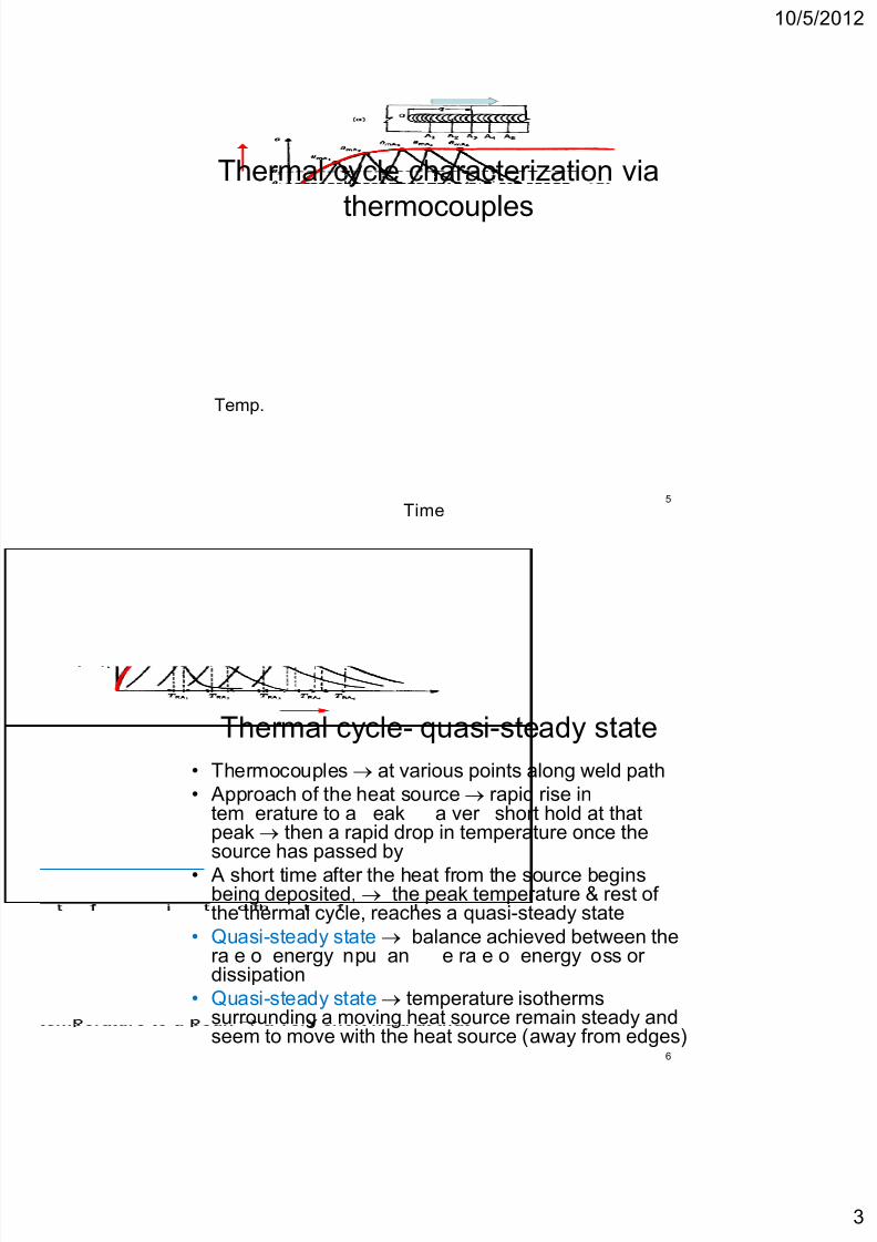
Thermal cycle- quasi-steady state
• Thermocouples at various points along weld path
• Approach of the heat source rapid rise intem erature to a eak a ver short hold at that peak then a rapid drop in temperature once thesource has passed by
• A short time after the heat from the source beginsbeing deposited, the peak temperature & rest ofthe thermal cycle, reaches a quasi-steady state
• Quasi-steady state balance achieved between the
6
ra e o energy npu an e ra e o energy oss ordissipation
• Quasi-steady state temperature isothermssurrounding a moving heat source remain steady andseem to move with the heat source (away from edges)

7/25/2019 Weldinglectures9!10!121030153810 Phpapp02
http://slidepdf.com/reader/full/weldinglectures910121030153810-phpapp02 4/25
10/5/2012
4
Thermal cycle- quasi-steady state
S Fusion
zone
HAZ
7
Temperature isotherms surrounding a moving heat source
remain steady and seem to move with the heat source
Time-Temperature curvesTp Time= ti
Temperature
8Time

7/25/2019 Weldinglectures9!10!121030153810 Phpapp02
http://slidepdf.com/reader/full/weldinglectures910121030153810-phpapp02 5/25
10/5/2012
5
Time-Temperature curves• The peak temp. decrease with increasing distance from
the source, and more or less abruptly
• The maximum temperatures reached (TmA TmB, Tmc)decrease with distance from the weld line and occur attimes (tmA, tmB, tmc) that increase. This allows the peaktemperature, Tp to be plotted as a function of time
• Peak temp. separates the heating portion of the weldingthermal cycle from the cooling portion,
• At a time when points closest to a weld start cooling, thepoints farther away are still undergoing heating. This
9
phenomenon explains – certain aspects of phase transformations that go on in the
heat-affected zone,
– differential rates of thermal expansion/contraction that lead tothermally induced stresses and, possibly, distortion
Spatial isotherms
Tp (Peak temperature)
oo ng zone
Cooling zone
10
Heating zone

7/25/2019 Weldinglectures9!10!121030153810 Phpapp02
http://slidepdf.com/reader/full/weldinglectures910121030153810-phpapp02 6/25
10/5/2012
6
The generalized heat flow equation
• Temp. distribution Controls microstructure,residual stresses and distortions, andchemical reactions (e.g., oxidation)
• The influencing parameters
– the solidification rate of the weld metal,
– the distribution of peak temperature in the HAZ
– the coolin rates in the fusion and HAZ
11
– the distribution of heat between the fusion zoneand the heat-affected zone
• Requires mathematical formulation toquantify the influence of these parameters
The generalized heat flow equation
Heat suppl ied + Heat generated = Heat
consumed for tem rise meltin + Heat
transferred via conduction + Heat loss via
convection & radiation
12

7/25/2019 Weldinglectures9!10!121030153810 Phpapp02
http://slidepdf.com/reader/full/weldinglectures910121030153810-phpapp02 7/25
10/5/2012
7
The generalized heat flow equation
x = coordinate in the direction of welding (mm)
= coordinate transverse to the weldin direction mm
z = coordinate normal to weldment surface (mm)
T = temperature of the weldment, (K)
k(T) = thermal conductivity of the material (J/mm s-1K-1) as afunction of temperature
(T) = density of the material (g/mm3) as a function of temp.
= -1 -1
13
,
temperatureVx, Vy, and Vz = components of velocity
Q = rate of any internal heat generation, (W/mm3)
The generalized heat flow equation
• This general equation needs to be solved for one, two, orthree dimensions depends on – Weld geometry,
– Whether the weld penetrates fully or partially
– Parallel sided or tapered, and
– Relative plate thickness• 1-D solution thin plate or sheet with a stationary source or
for welding under steady state (at constant speed and inuniform cross sections remote from edges) in very thinweldments
14
• - so u on n we men s or n c er we men swhere the weld is full penetration and parallel-sided (as inEBW) to assess both longitudinal and transverse heat flow
• 3-D solution thick weldment in which the weld is partialpenetration or non-parallel-sided (as is the case for mostsingle or multipass welds made with an arc source)

7/25/2019 Weldinglectures9!10!121030153810 Phpapp02
http://slidepdf.com/reader/full/weldinglectures910121030153810-phpapp02 8/25
10/5/2012
8
Weld geometry and dimensionality
of heat flow(a)2-D heat flow for
full-penetration
we s n t n p ates
or sheets;
(b)2-D heat flow for
full-penetration
welds with parallel
sides (as in EBW
and some LBW)
15
(c)3-D heat flow for
partial penetration
welds in thick plate
(d)3D, condition for
near-full penetration
welds
• Rosenthal’s first critical assumption Energy input
from the heat source was uniform and moved with a
Rosenthal’s Simplified Approach
constant velocity v along the x-axis of a fixed
rectangular coordinate system
• The net heat input to the weld under theseconditions is
given by
Hnet = EI/v (J/m)
16
where is the the transfer efficiency of the process E
and I are the welding voltage (in V) and current (in A),
respectively, and v is the velocity of welding or travel
speed (in m/s).

7/25/2019 Weldinglectures9!10!121030153810 Phpapp02
http://slidepdf.com/reader/full/weldinglectures910121030153810-phpapp02 9/25
10/5/2012
9
Rosenthal’s Simplified Approach
Assumption 2 Heat source is a point source,
weld at a single point – This assumption avoided complexities with density distribution of
the energy from different sources and restricted heat flowanalysis to the heat-affected zone, beyond the fusion zone orweld pool boundary.
Assumption 3 The thermal properties (thermal
17
, ,
density, Cp) of the material being welded are constants Assumption 4 Modify the coordinate system from a
fixed system to a moving system
Rosenthal’s Simplified Approach
• The moving coordinate system replace x with,
source from some fixed position along the x
axis, depending on the velocity of welding, v=x-vt
where t is the time
18

7/25/2019 Weldinglectures9!10!121030153810 Phpapp02
http://slidepdf.com/reader/full/weldinglectures910121030153810-phpapp02 10/25
10/5/2012
10
Rosenthal’s Simplified Approach
• This equation can be further simplified, in
, -
temperature distribution exists.
• Temperature distribution around a point heat
source moving at constant velocity will settle
down to a steady form, such that dT/dt = 0, for
=
19
.
Rosenthal’s solution
• Rosenthal solved the simplified form of the heat flow
equation above for both thin and thick plates in which
- - , .
• For thin plates,
20
=
k = thermal conductivity (in J/m s-1 K-1)
= thermal diffusivity = k/pC, (in m/s)
R = (2 + y2 + z2)1/2, the distance from the heat source to a particular
fixed point (in m)
K0 = a Bessel function of the first kind, zero order

7/25/2019 Weldinglectures9!10!121030153810 Phpapp02
http://slidepdf.com/reader/full/weldinglectures910121030153810-phpapp02 11/25
10/5/2012
11
Rosenthal’s solution
• For the thick plate,
where d = depth of the weld (which for symmetrical
21
welds is half of the weld width, since w = 2d)
Rosenthal’s solution
• Above equations can each be written in a simpler form,-
when the position from the weld centerline is defined by aradial distance, r, where r 2 = z2 + y2
• For the thin plate, the time-temperature distribution is
22

7/25/2019 Weldinglectures9!10!121030153810 Phpapp02
http://slidepdf.com/reader/full/weldinglectures910121030153810-phpapp02 12/25
10/5/2012
12
Dimensionless Weld Depth Vs
Dimensionless OperatingParameter
• ase on osen a s so u on o e s mp e ree-
dimensional heat flow equation, Christiansen et al.
(1965) derived theoretical relationships between a weld
bead’s cross-sectional geometry and the welding
process operating conditions using dimensionless
parameters.
23
• e eore ca re a ons p e ween e mens on ess
weld width, D, and dimensionless operating parameter,n, is shown, where
Dimensionless weld depth (D) Vs
process operating parameter nChristiansen (1965)
24
• Width of the weld bead can
be determined (w = 2d)
• Width of heat-affected zone
can be determined

7/25/2019 Weldinglectures9!10!121030153810 Phpapp02
http://slidepdf.com/reader/full/weldinglectures910121030153810-phpapp02 13/25
10/5/2012
13
Dimensionless Weld Depth Vs
Operating Parameter n
d = depth of penetration of the weld,
U = welding speed (m/s),
s = thermal diffusivity (k/C) of the base material (as a solid),
Q = rate of heat input to the workpiece (J/s),
Tm = melting point of the base material (the workpiece), and
To = temperature of the workpiece at the start of welding.
25
, ,
Cross-sectional area of the weld bead can be determined
Can be applied to the heat-affected zone by simply substituting
TH for Tm where TH is the temperature of some relevant phase
transformation that could take place
Assignment -2
1) Find w and d for symmetrical weld bead as shown in
figure.
n e w o p ase rans on emp =
Material steel with Tm= 1510 CE=20 V
I= 200 A
Welding speed (v or U) =5 mm/s w
26
0
Arc efficiency =0.9
K=40 W/mK
C = 0.0044 J/mm3. C
t=5 mm
d

7/25/2019 Weldinglectures9!10!121030153810 Phpapp02
http://slidepdf.com/reader/full/weldinglectures910121030153810-phpapp02 14/25
10/5/2012
14
Welding Lecture ‐ 1005 Oct 2012, Friday, 11.30‐12.30 am
Heat flow in welds
272727
Effect of welding parameters on heat
distribution
• The shape of the melt , size & heat distribution,
is a function of
1. Material (thermal conductivity, heat capacity,
density)
2. Welding speed, and
28
3. Welding power/energy density
4. Weldment plate thickness

7/25/2019 Weldinglectures9!10!121030153810 Phpapp02
http://slidepdf.com/reader/full/weldinglectures910121030153810-phpapp02 15/25
10/5/2012
15
Effect of thermal conductivity (and
material property) on heat distribution
•
– tends to cause deposited heat to spread
– Smaller welds for a given heat input and
melting temperature
• For a given heat input, the lower the
29
melting point, the larger the weld
Material Thermal
diffusivity
=k/ C
(mm2/s)
Aluminium 84
Carbon steel 12
Effect of
Austenitic
steel
4
30
thermal
conductivity
(and material
property) on
heat distribution

7/25/2019 Weldinglectures9!10!121030153810 Phpapp02
http://slidepdf.com/reader/full/weldinglectures910121030153810-phpapp02 16/25
10/5/2012
16
Effect of welding speed on
Shape of Fusion/HAZ
Velocit
y
0 Low Medium High Very high
Plan
view
Circle elliptical Elongated
ellipse
Tear
drop
Detached
tear drop
-
view
em -
spherical
ro a e
spheroidal
onga e
prolatespheroidal
teardrop
ear
drop
Effect of welding speed
32
7/25/2019 Weldinglectures9!10!121030153810 Phpapp02
http://slidepdf.com/reader/full/weldinglectures910121030153810-phpapp02 17/25
10/5/2012
17
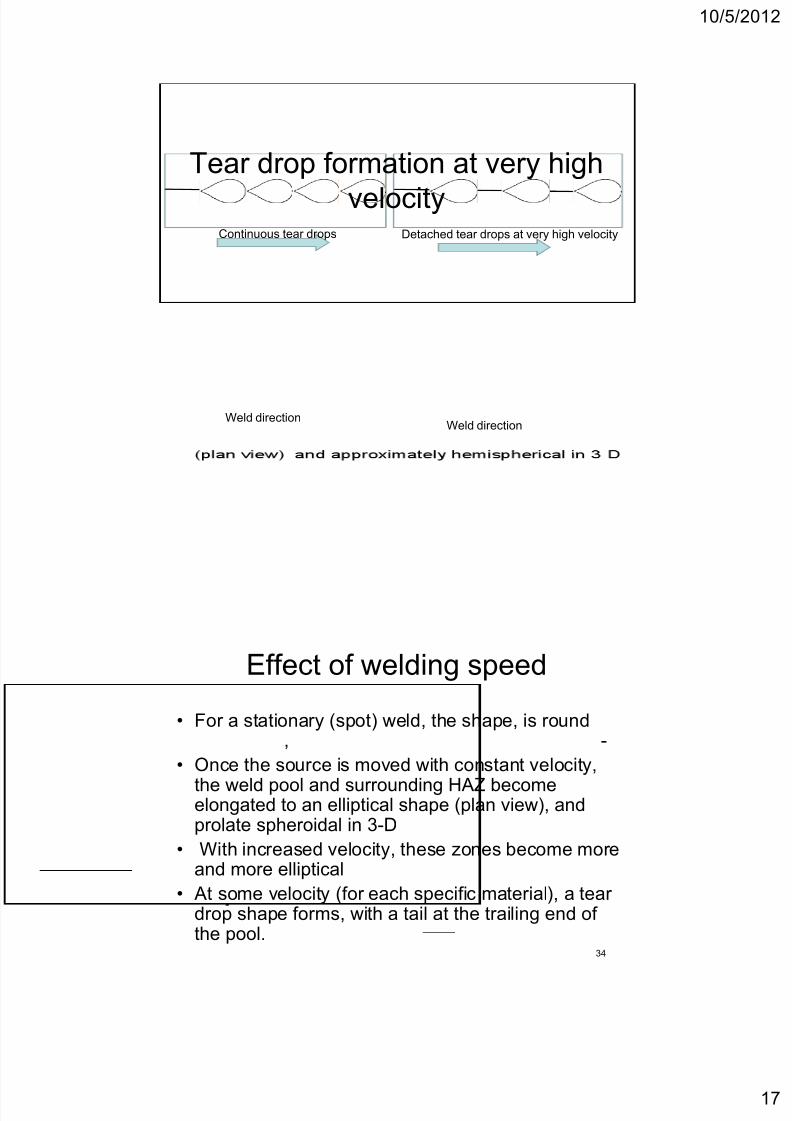
Tear drop formation at very high
velocityDetached tear drops at very high velocityContinuous tear drops
Weld directionWeld direction
Effect of welding speed
• For a stationary (spot) weld, the shape, is round, -
• Once the source is moved with constant velocity,
the weld pool and surrounding HAZ becomeelongated to an elliptical shape (plan view), andprolate spheroidal in 3-D
• With increased velocity, these zones become more
34
and more elliptical
• At some velocity (for each specific material), a teardrop shape forms, with a tail at the trailing end ofthe pool.

7/25/2019 Weldinglectures9!10!121030153810 Phpapp02
http://slidepdf.com/reader/full/weldinglectures910121030153810-phpapp02 18/25
10/5/2012
18
Effect of welding speed• Increasing velocity elongates the teardrop
more and more, narrows the fusion and heat-affected zone overall melted volume constant
• Very high welding speeds the tail of theteardrop weld pool detaches isolate regionsof molten metal lead to shrinkage-inducedcracks alon the centerline of the weld
35
Efect of the thickness of a
weldment
36
•Thick weldment Small weld pool and heat-affected zone

7/25/2019 Weldinglectures9!10!121030153810 Phpapp02
http://slidepdf.com/reader/full/weldinglectures910121030153810-phpapp02 19/25
10/5/2012
19
Effect of energy density
• Increased energy density increases theefficiency of melting, increases the amountof melting (especially in the depth direction) decreases the heat-affected zone.
• Shape of weld pool & HAZ will be distortedby any asymmetry around the joint.
• Asymmetry might be the result of the relative
37
. .,
elements as well as their relative thermalproperties (Tm, k & C)
Simplified Equations for Approximating
Welding Conditions
1) Peak Temperatures Predicting metallurgical
transformations meltin austenitization recr stallization of
cold-worked material, etc.) at a point in the solid material
near a weld requires some knowledge of the maximum
temperature reached at that specific location.
For a single-pass, full-penetration butt weld in a sheet or a
plate, the distribution of peak temperatures (Tp) in the base
material ad acent to the weld is iven b
38

7/25/2019 Weldinglectures9!10!121030153810 Phpapp02
http://slidepdf.com/reader/full/weldinglectures910121030153810-phpapp02 20/25
10/5/2012
20
Peak Temperature
To = initial temperature of the weldment (K)
e = base of natural logarithms = 2.718
= density of the base material (g/mm3)
C = specific heat of the base material (J/g K- I)
=
39
y = 0 at the fusion zone boundary and where Tp = TmTm = melting (or liquidus) temperature of the material
being welded (K)
Hnet = EI/v (J/m)
Width of the Heat-Affected Zone• Peak temperature equation can be used to
calculate the width of the HAZ.
• Define T Tre or Tau
• The width of the HAZ is determined by the value ofy that yields a Tp equal to the pertinent
transformation temperature (recrystallizationtemperature, austenitizing temperature, etc.).
• Equation cannot be used to estimate the width ofthe fusion zone, since it becomes unsolvable when
40
p = m
• (Remember the assumption in Rosenthal’s solutionof the generalized equation of heat flow, Heatwas deposited at a point, and there was no meltedregion, but just a HAZ)

7/25/2019 Weldinglectures9!10!121030153810 Phpapp02
http://slidepdf.com/reader/full/weldinglectures910121030153810-phpapp02 21/25
10/5/2012
21
Assignment 3- Part A
A single full penetration weld pass is made on steel using the
following parameters.
= = = =
a) Calculate the peak temperatures at distances of 1.5 and 3.0
mm from the weld fusion boundary
b) Calculate the width of HAZ if the recrystallization temperature
m , , ,
mm/s, T0= 25 C, Arc efficiency =0.9, C = 0.0044 J/mm3. C,
t=5 mm, Hnet= 720 J/mm
41
is 730 C
c) Find the influence on the width of HAZ if a preheated sample
is used (Assume preheat temp =200 C)
d) Find the influence on the width of HAZ if the net energy is
increased by 10%
Solidification rate
• The rate at which weld metal solidifies can
,
properties, and response to post weld heat
treatment.• The solidification time, St, in seconds, is
given by
42

7/25/2019 Weldinglectures9!10!121030153810 Phpapp02
http://slidepdf.com/reader/full/weldinglectures910121030153810-phpapp02 22/25
10/5/2012
22
Solidification rate• L is the latent heat of fusion (J/mm3),
• k is the thermal conductivity of the base material(J/m s-1 K-1),
• , C, Tm and To are as before
• St is the time (s) elapsed from the beginning tothe end of solidification.
• The solidification rate, which is derived from the
43
so ca on me, e ps e erm ne e na ure othe growth mode (with temperature gradient) andthe size of the grains
(will be discussed in detail on a separate lecture)
Cooling Rates
• The rate of cooling influences – the coarseness or fineness of the resulting structure
– ,constituents in the microstructure, of both the FZ and the HAZ fordiffusion controlled transformations
• Cooling rate determines which transformation (phase) willoccur and, thus, which phases or constituents will result.
• If cooling rates are too high in certain steels hard,untempered martensite embrittling the weld addssusce tibilit to embrittlement b h dro en.
44
• By calculating the cooling rate, it is possible to decidewhether undesirable microstructures are likely to result.
• Preheat To reduce the cooling rate. Cooling rate isprimarily calculated to determine the need for preheat.

7/25/2019 Weldinglectures9!10!121030153810 Phpapp02
http://slidepdf.com/reader/full/weldinglectures910121030153810-phpapp02 23/25
10/5/2012
23
Cooling Rates-Thick plates• For a single pass butt weld (equal thickness),
For thick plates,
45
R = cooling rate at the weld center line (K/s)
k = thermal conductivity of the material (J/mm s-1 K-1 )
T0 = initial plate temperature (K)
Tc = temperature at which the cooling rate is calculated (K)
Cooling Rates-Thin plates
For thin plates,
h = thickness of the base material (mm)
p = density of the base material (g/mm3)
46
C = specific heat of the base material (J/g K- )
pC = volumetric specific heat (J/mm3 K-1)
Increasing the initial temperature, T0 or applying preheat,
decreases the cooling rate

7/25/2019 Weldinglectures9!10!121030153810 Phpapp02
http://slidepdf.com/reader/full/weldinglectures910121030153810-phpapp02 24/25
10/5/2012
24
Relative plate thickness factor
≤ 0.75 Thin plate equation is valid
0.75 Thick plate equation is valid
47
Assignment 3- Part B
Find the best welding speed to be used for welding
6 mm steel plates with an ambient temperature of
30 C with the welding transformer set at 25 V and
current passing is 300 A. The arc efficiency is 0.9
and possible travel speeds ranges from 5-10 mm/s.
The limiting cooling rate for satisfactory
48
per ormance s s a a empera ure o .

7/25/2019 Weldinglectures9!10!121030153810 Phpapp02
http://slidepdf.com/reader/full/weldinglectures910121030153810-phpapp02 25/25
10/5/2012
Assignment 3- Part B-Solution
49
Assignment 3- Part B-Solution
50