
WELDING INDUSTRIES OF AUSTRALIA A DIVISION OF WELDING ...
13
WELDING INDUSTRIES OF AUSTRALIA A DIVISION OF WELDING INDUSTRIES LTD ACN 004 547 Ill Head Office and International Sales 5 Allan Street, Melrose Park South Australia, 5039 Telephone (08) 8276 6494 Facsimile (08) 8276 6327 OWNERS MANUAL VORTEX DX16 MODEL. VRBXl6-Q Q2198
Transcript of WELDING INDUSTRIES OF AUSTRALIA A DIVISION OF WELDING ...

WELDING INDUSTRIES OF AUSTRALIA A DIVISION OF WELDING INDUSTRIES LTD
ACN 004 547 Ill
Head Office and International Sales
5 Allan Street, Melrose Park
South Australia, 5039
Telephone (08) 8276 6494 Facsimile (08) 8276 6327
OWNERS MANUAL
VORTEX DX16
MODEL. VRBXl6-Q
Q2198

Page 2 VORTEX DX16 OWNERS MANUAL
The information contained in this manual is set out to enable you to properly maintain your new equipment and ensure that you obtain maximum operating efficiency.
Please ensure that this information is kept in a safe place for ready reference when required at any future time.
When requesting spare parts, please quote the model and serial number of the machine and part number of the item required. All relevant numbers are shown in lists contained in this manual. Failure to supply this information may result in unnecessary delays in supplying the correct parts.
SAFETY
Before this equipment is put into operation, the SAFE PRACTICES section at the back of the manual must be read completely. This will help to avoid possible injury due to misuse or improper welding applications.
CONTENTS
1 ....................... Introduction ........................................................ .3 2. ...................... Receiving,. ......................................................... .4 3.. .................... .Specifications .................................................... .4 4... ................... .Power Source Controls.. ................................... ..5 5 ....................... Connection to Electrical Mains Power Supply .... 6 6 ....................... GTAW Welding .................................................. 6 7. ...................... MMAW Welding ................................................. 7 8. ...................... General Maintenance.. ...................................... .8 g... .................... Fault Finding ..................................................... .8 10 .................... .Circuit Diagram ................................................. ..9 1 l ..................... Parts Diagram ..................................................... 10 12 ..................... Parts List ............................................................ 1 1 13.. ................... Safe Practices Information ................................. 'l 2
QUALITY WELDING PRODUCTS, SYSTEMS AND SERVlCE
Section Page

VORTEX DX16 OWNERS MANUAL Page 3
1. INTRODUCTION
The VORTEX DX16 is an inverter based DC Constant Current type welding power supply for Manual Metal Arc (MMAW) and Gas Tungsten Arc (GTAW or TIG) welding.
MANUAL METAL ARC WELDING Manual Metal Arc Welding is a process where an arc is struck between a flux-coated
consumable electrode and the work piece. The arc and the weld pool are both shielded by gases generated by the flux coating of the electrode.
WIA markets a wide range of mild steel and special purpose electrodes which cater for home workshop, rural, and industrial requirements. Some popular AUSTARC electrodes are listed below. The correctly selected AUSTARC electrode used in conjunction with your new VORTEX DX16 will influence the stability of the arc and the quality of the weld
Austarc 1 2P, Classification E41 12. A popular general purpose electrode used with ease in all positions, vertical up or down. The smooth forceful arc makes it an ideal electrode for all general mild steel applications.
Austarc 13S, Classification E41 13. A smooth running electrode with a soft arc, particularly suited to light sheetmetal and smooth mitre fillet welds.
Austarc 16TC, Ctassification E4816. A low hydrogen electrode with good arc stability and out-of-position welding characteristics. This electrode is ideal for medium carbon steels.
Unicord 31 2, Classification E31 2-1 6 A high tensile (770 Mpa), high chromium nickel electrode specially formulated for joining all alloy steels and irons, and for tool and die maintenance and steels of unknown analysis.
GAS TUNGSTEN ARC WELDING GTAW is a welding process where the arc is struck between a non-consumable
tungsten electrode and the work piece. A ceramic nozzle surrounds the tungsten electrode and directs a flow of inert gas, usually Argon, over the electrode and the weld zone. If filler metal is required, it is hand fed into the welding arc.
The DC (direct current) output of the VORTEX DX16 is suitable for welding most ferrous and non-ferrous metals, excluding aluminium and titanium for which AC is required.
QUALlPY WELDlNG PRODUCTS, SYST€MS AND SERVICE

c VORTEX DX16 OWNERS MANUAL
2. RECEIVING
Check the equipment received against the shipping invoice to make sure the shipment is complete and undamaged. If any damage has occurred in transit, please immediately notify your supplier.
The VORTEX DX1 6 package contains:
E Vortex DX16 Inverter Power Source El (This) Owners Manual
MMAW Welding Lead Kit - 5m .................................................... AA53-0/5 E Complete GTAW and MMAW Welding kit ..................................... SA47-Q
Optional additional items for VORTEX DX16:
Tig Torch Twistlock Connector BIN25T MMAW Lead Kit SA32-Q Argon Regulator and Flow gaugeHA801AR 15OAmp TIG Torch with gas valve BE" 7V-4M-R TI6 Torch Accessory Kit BEAK-2
15 Amp extension primary lead, l OM ..................................... AM259-8/10
20 Amp primary plug ............................................................ CbP43920TR
3. SPECIFICATIONS
Input Voltage ............................. 220/240 Volts AC Single Phase, 50160 Hz Rated Output ......................... 160 Amps @ 26.4 Volts DC, 40% Duty Cycle Maximum Primary Demand ........................................................... ,32 Amps Rated Input Current ..................................................................... 22.2 Amps
Open Circuit Voltage ................................................................. 54 Volts DC Electrical Efficiency .............................................................................. .85%
Mass ................................................................................................... 6.9Kg
Output Current Range ............................................................. 5 - 160 Amps
Dimensions ................................................ H:250mm W: 130mm D: 31 Omm
SPECIFICATIONS FOR USE WITH 15AMP SUPPLY Rated Output ......................... 160 Amps @ 26.4 Volts DC, 25% Duty Cycle Maximum Primary Demand ........................................................... .32 Amps Rated Input Current.. ..................................................................... . l 6 Amps
The VORTEX DX16 is supplied with 20Amp flex, fitted with a 15 Amp plug. If the machine is to be used at maximum rated output current and duty cycle, a 20
Amp plug should be fitted, and the machine connected to a 20 Amp mains supply circuit. IMPORTANT NOTICE
WARRANTY MAY BE VOIDED IF EQUIPMENT IS POWERED FROM AN ENGINE DRIVEN GENERATOR.
This equipment may be damaged if it is powered from a low capacity engine driven generator. Generators less than 23kva may have inadequate voltage control in this application.
QUALlTY WELDiNG PRODUCTS, SYSTEMS AND SERVlCE
VORTEX DX16 OWNERS MANUAL Page 5
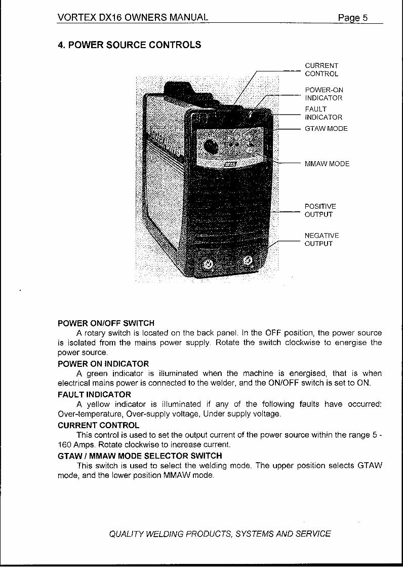
4. POWER SOURCE CONTROLS
CURRENT CONTROL
POWER-ON INDICATOR
FAULT INDICATOR
GTAW MODE
MMAW MODE
POSITIVE OUTPUT
NEGATIVE OUTPUT
POWER ONlOFF SWITCH A rotary switch is located on the back panel. In the OFF position, the power source
is isolated from the mains power supply. Rotate the switch clockwise to energise the power source. POWER ON INDICATOR
electrical mains power is connected to the welder, and the ONlOFF switch is set to ON. FAULT INDICATOR
Over-temperature, Over-supply voltage, Under supply voltage. CURRENT CONTROL
160 Amps. Rotate clockwise to increase current. GTAW I MMAW MODE SELECTOR SWITCH
mode, and the lower position MMAW mode.
A green indicator is illuminated when the machine is energised, that is when
A yellow indicator is illuminated if any of the following faults have occurred:
This control is used to set the output current of the power source within the range 5 -
This switch is used to select the welding mode. The upper position selects GTAW
QUALITY WELDlNG PRODUCTS, SYSTEMS AND SERVICE

Page 6 VORTEX DX16 QWNERS MANUAL
5. CONNECTION TO ELECTRICAL MAINS POWER SUPPLY
The VORTEX DX16 is supplied fitted with a 20 Amp mains power supply cable fitted with a 15 Amp plug. If used on a 15 Amp supply circuit, machine usage should be timited to 25% duty cycle at 160 Amps output. The supply circuit should be protected by a 30 Amp mains fuse or circuit breaker (see note below).
If the machine is to be used at maximum rated output current and duty cycle, a 20 Amp plug (part no. CLP43920TR) should be fitted to the primary lead, and the machine connected to a 20 Amp mains supply circuit. The supply circuit should be protected by a 40 Amp mains fuse or circuit breaker.
As noted previously, it is not recommended that the VORTEX DX13 be powered from small engine-driven generator sets due to the peaks of supply voltage which can occur with some equipment of this type. Excessive voltage peaks can damage the circuits of the welder.
6. GTAW (TIG) WELDING
FRONT PANEL SETTINGS. Set the front mode selector switch to the upper position for GTAW. The VORTEX DX16 supplies DC welding current in GTAW mode which is suitable
for welding most ferrous and non-ferrous metals, with the exception of Aluminium and Titanium for which AC is required. TORCH AND WORK LEADS.
The Tig torch must be connected to the (-) output terminal, and the Work lead connected to the positive (+) output terminal.
For all GTAW welding, WIA recommends use of WITSTAR thorium-free tungsten electrodes. These will provide the best arc initiation, arc stability and tip shape retention characteristics. WITSTAR electrodes can be recognised by a turquoise cotoured tip.
The electrode should be ground to a point, with the grinding marks pointing towards the tip. For welding currents less than 20 Amps, the included angle of the point should be 30 degrees, for currents greater than 20 Amps, the recommended angle is 60 degrees. When fixed in the torch, the electrode should protrude 6mm from the ceramic gas nozzle. If the electrode is contaminated during welding the arc will become unstable, and the electrode must be reground before further use. GAS CONNECTION.
Connect a supply of shielding gas to the Tig torch. Welding grade Argon gas is recommended for all GTAW welding with the VORTEX DX16 The gas flow rate should be set in the range 2 - 5 litres/min.
QUALITY WELDING PRODUCTS, SYSTEMS AND SERVICE

VORTEX DX16 OWNERS MANUAL Page 7
7. MMAW WELDING
Set the front panel mode selector switch to the lower position for MMAW. The VORTEX DX16 supplies DC welding current. Most MMAW electrodes are
operated electrode positive (+) when operated under DC current. Fit the electrode welding lead to the (+) output terminal.
Select an appropriate welding current to suit the electrode in use by setting the Current Control.
The VORTEX DX1 6 is not recommended for use with cellulosic type electrodes. STRIKING THE ARC.
To initiate an arc, drag the end of the electrode along the work piece as if striking a match. As the arc strikes, lift the electrode slightly away, aiming to establish an arc length of approximately 3mm. As the electrode is consumed, feed the electrode into the arc to maintain a constant arc length. As a general rule, the arc should be held as short as possible.
An arc which is too long causes unwieldy flow of metal with a rough weld appearance and reduced penetration. An arc too short leads to a narrow weld deposit and “stuttery” arc characteristics, and the electrode is liable to freeze onto the work piece.
As the solidified weld deposit forms, move the end of the electrode slowly along the weld path, aiming to maintain a stable pool of molten metal behind the arc. Moving more slowly will result in a wider weld deposit, and moving faster will narrow the weld deposit.
Always fill the crater which tends to form at the end of a weld deposit by pausing momentarily before withdrawing the electrode. Unfilled craters are a point of weakness and may lead to fatigue weld cracking.
. .
Maintain constant travel speed for even bead width
.. i....
L Maintain constant arc length
QUALITY WELDING PRODUCTS, SYSTEMS AND SERVICE

Page 8 VORTEX DX16 OWNERS MANUAL
8. GENERAL MAINTENANCE
Care should be taken to prevent excessive build-up of dust and dirt within the welding power source. It is recommended that at regular intervals, according to the prevailing conditions, the machine covers be removed and any accumulated dust be removed by the use of dry, low pressure compressed air.
Ensure that the internal Earth wire is reconnected to the cover before the cover is refitted.
Inspect the visible components for any signs of overheating or other damage. Report any observed problems to qualified service personnel.
9. FAULT FINDING.
NO WELDING CURRENT Check that mains supply is available at the Power Source, ie. that the fan is running
and the POWER ON indicator is lit. Check for continuity of the welding current circuit, ie. work lead, work clamp and
electrode holder. Check that the electrode and work leads are correctly connected for the welding process in use.
The welding power source incorporates in built protection devices which will trip if the unit is overloaded. In this event, the machine will not deliver welding current, and the FAULT indicator will be lit. Leave the machine energised with the fan running to achieve the maximum cooling rate.
If equipment failure is suspected, forward the unit to your nearest WIA Sales and Service branch, or a qualified service agent.
QUALITY W&LDING PRODUCTS, SYSTEMS AND SERVICE
VORTEX DX76 OWNERS MANUAL Paae 9
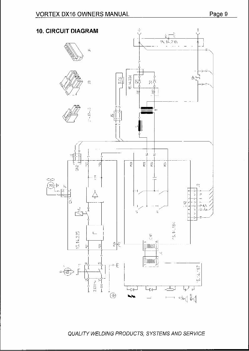
I O . CIRCUIT DIAGRAM
b- ud
I I
1 '" r
r
S CJ z U
J
' l 'I
QUALITY WlXDING PRODUCTS, SYSTEMS AND SERVICE
Page 10 VORTEX DX16 OWNERS MANUAL
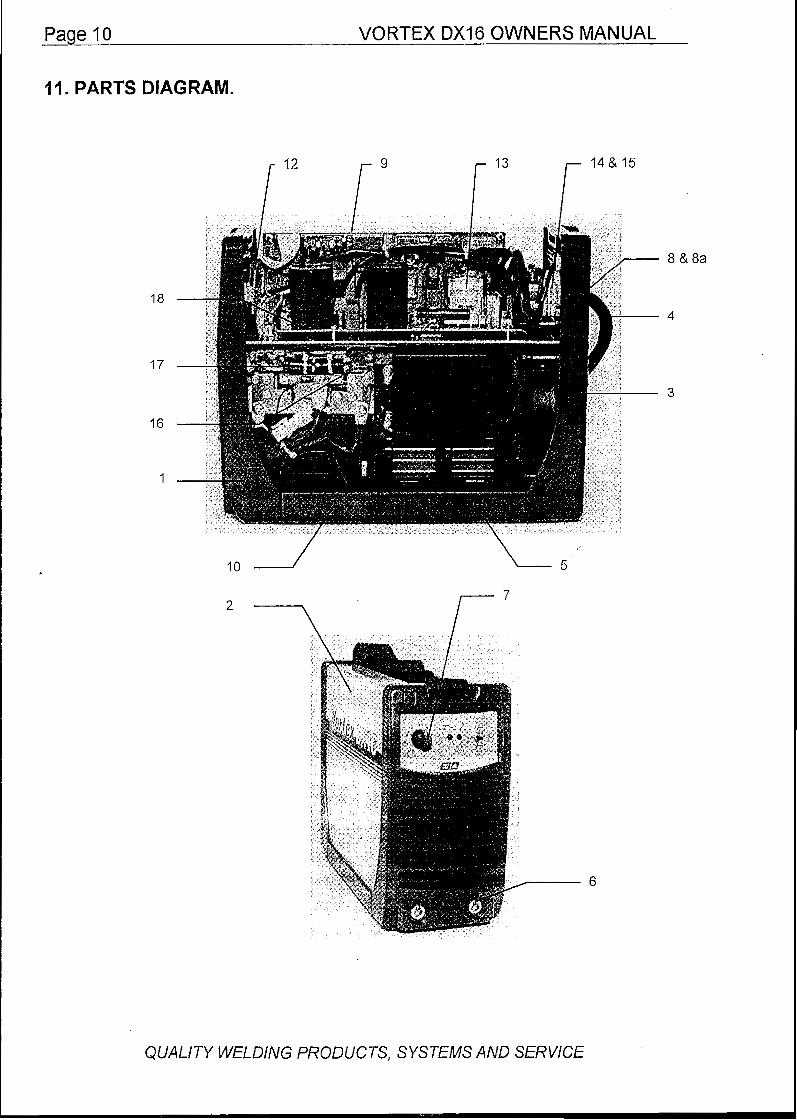
It l m PARTS DIAGRAM.
18
i " r" r l3 r 14&15
8 & 8 a
4
17
16
1
10 - - 5
6
3
QUALITY WELDING PRODUCTS, SYSTEMS AND SERVICE

VORTEX DXl6 OWNERS MANUAL Paae 1 l
12. PARTS LIST
Item.. ................ Part ............................... Description
1 ....................... VF?14.~0.018 ................ Front Cover Moulding 2 ....................... VR03.0 7.035 ................ Top/Side Metal Cover 3 ....................... VR14.7 0.019 ................ Back Cover Moulding 4 ....................... CPI 06-0/3 .................... Primary Cable and Plug 5 ....................... VR06.37.087 ................ Bottom Cover Moulding 6 ....................... VR10.1 3.010 ................ Output Terminal 7 ....................... VR09.11.207 ................ Current Control Knob 8 ....................... VR08.2 0.052 ................ Cable Clamp 8a ..................... VR08.20.053 ................ Cable Clamp Nut 9 ....................... VRI 5.1 8.01 1 ................ Logic and Power Circuit Board Kit IO.. ................... VR06.37.093 ................ Bottom Side Moulding 1 1 ..................... VR07.10.016 ................ Cooling Fan 12.. ................... VR15.14.187 ................ Controls Circuit Board 13 ..................... VR09.09.021 ................ Relay 14.. ................... VR09.1 1.005 ................ On/Off Switch 15. .................... VR09.11.009 ................ On/Off Switch Knob 16 ..................... VR14.05.076 ................ Output Diode 17 ..................... VR15.18.010 ................ Secondary Rectifier Kit 18. .................... VRI 5.14.225 ................ Input Circuit Board
VRII.26.001 ................ Varistor VR14.10.150 ................ Diode Bridge
QUALITY WELDlNG PRODUCTS, SYSTEMS AND SERVICE

VORTEX DX16 OWNERS MANUAL
42. SAFE PRACTICES WHEN USING WELDING EQUIPMENT.
These notes are provided in the interests of improving operator safety. They should be considered only as a basic guide to Safe Working Habits. A full list of Standards pertaining to industry is available from the Standards Association of Australia, also various State Electricity Authorities, Departments of Labour and Industry or Mines Department and other Local Health or Safety Inspection Authorities may have additional requirements. WTlA Technical Note TN7-98 also provides a comprehensive guide to safe practices in welding.
EYE PROTECTlON NEVER LOOK AT AN ARC WITHOUT PROTECTION. Wear a full face helmet, with an appropriate
shade filter lens protected by clear cover glass. This is a MUST for any arc process to protect the eyes from radiant energy and flying sparks etc.. Replace the cover glass when it is broken, pitted, or spattered.
The lens shade number should be chosen in accordance with the following list.
Recommended shade filter lens.
Amps TIG MMAW MlG Pulsed MlG 0-100 ............ 10 ................. 9 ................... 10 ................. 12-13 100-160 ......... 1 1 ................. 10 ................. 10 ................. 12-13 150-200 ......... 12 ................. 10-11 ............ 11-12 ............ 12-13 200-300 ......... 13 ................. l 1 ................. 12-13 ............ 12-13 300-400 ......... 14 ................. 12 ................. 13 ................. 14 400480 ............................ " 13 ................. 14 ................. 14 SQO + .................................................. " " 14 ................. 14
BURN PROTECTION. The welding arc is intense and visibly bright. Its radiation can damage eyes, penetrate lightweight
clothing, reflect from light-coloured surfaces, and burn the skin and eyes. Burns resulting from gas-shielded arcs resemble acute sunburn, but can be more severe and painful.
Wear protective clothing - leather or heat resistant gloves, hat, and safety-toe boots. Button shirt collar and pocket flaps, and wear cuffless trousers to avoid entry of sparks and slag.
Avoid oily or greasy clothing. A spark may ignite them. Hot metal such as electrode stubs and work pieces should never be handled without gloves.
Ear plugs should be worn when welding in overhead positions or in a confined space. A hard hat should be worn when others are working overhead.
Flammable hair preparations should not be used by persons intending to weld or cut.
TOXIC FUME PREVENTION. Adequate ventilation with air is essential. Severe discomfort, illness or death can result from fumes,
vapours, heat, or oxygen depletion that welding or cutting may produce. NEVER ventilate with oxygen.
Lead, cadmium, zinc, mercury, and beryllium bearing and similar materials when welded or cut may produce harmful concentrations of toxic fumes. Adequate local exhaust ventilation must be used, or each person in the area as well as the operator must wear an air-supplied respirator. For beryllium, both must be used.
Metals coated with or containing materials that emit fumes should not be heated unless coating is removed from the work surface, the area is well ventilated, or the operator wears an air-supplied respirator.
Work in a confined space only while it is being ventilated and, if necessary, while wearing air-supplied respirator.
Vapours from chlorinated solvents can be decomposed by the heat of the arc (or flame) to form PHOSGENE, a highly toxic gas, and lung and eye irritating products. The ultra-violet (radiant) energy of the arc can also decompose trichlorethylene and perchlorethylene vapours to form phosgene.
Do not weld or cut where solvent vapours can be drawn into the welding or cutting atmosphere or where the radiant energy can penetrate to atmospheres containing even minute amounts of trichlorethylene or percholorethylene.
QUALlTY WELDING PRODUCTS, SYSTEMS AND SERVICE

b
VORTEX DX16 OWNERS MANUAL Paae l 3
FIRE AND EXPLOSION PREVENTION. Be aware that flying sparks or falling slag can pass through cracks, along pipes, through windows or
doors, and through wall or floor openings, out of sight of the operator. Sparks and slag can travel up to 10 metres from the arc.
Keep equipment clean and operable, free of oil, grease, and (in electrical parts) of metallic particles
If combustibles are present in the work area, do NOT weld or cut. Move the work if practicable, to an area free of combustibles. Avoid paint spray rooms, dip tanks, storage areas, ventilators. If the work can not be moved, move combustibles at least IO metres away out of reach of sparks and heat; or protect against ignition with suitable and snug-fitting fire-resistant covers or shields.
Walls touching combustibles on opposite sides should not be welded on or cut. Walls, ceilings, and floor near work should be protected by heat-resistant covers or shields.
A person acting as Fire Watcher must be standing by with suitable fire extinguishing equipment during and for some time after welding or cutting if;
that can cause short circuits.
Combustibles (including building construction) are within 10 metres.
Combustibles are further than 10 metres but can be ignited by sparks.
Openings (concealed or visible) in floors or walls within IO metres may expose combustibles to
Combustibles adjacent to walls, ceilings, roofs, or metal partitions can be ignited by radiant or
After work is done, check that area is free of sparks, glowing embers, and flames.
Any tank or drum which has contained combustibles can produce flammable vapours when heated. Such a container must never be welded on or cut, unless it has first been cleaned as described in AS.1674- 1974, the S.A.A. Cutting and Welding Safety Code. This includes a thorough steam or caustic cleaning (or a solvent or water washing, depending on the combustible's solubility), followed by purging and inerting with nitrogen or carbon dioxide, and using protective equipment as recommended in AS.1674-1974. Water-filling just below working level may substitute for inerting.
Hollow castings or containers must be vented before welding or cutting. They can explode. Never weld or cut where the air may contain flammable dust, gas, or liquid vapours.
SHOCK PREVENTION. Exposed conductors or other bare metal in the welding circuit, or ungrounded electrically alive
equipment can fatally shock a person whose body becomes a conductor. Ensure that the machine is correctly connected and earthed. If unsure have machine installed by a qualified electrician. On mobile or portable equipment, regularly inspect condition of trailing power leads and connecting plugs. Repair or replace damaged leads.
Fully insulated electrode holders should be used. Do not use holders with protruding screws. Fully insulated lock-type connectors should be used to join welding cable lengths.
Terminals and other exposed parts of electrical units should have insulated knobs or covers secured before operation.
sparks.
conducted heat.
QUALITY WELDING PRODUCTS, SYSTEMS AND SERVlCE