WELCOME TO THE PRESENTATION ON STEAM TURBINE PROTECTIONS AND GOVERNING SYSTEMS AT ESCI, HYDERABAD BY...
67
WELCOME TO THE PRESENTATION ON STEAM TURBINE PROTECTIONS AND GOVERNING SYSTEMS AT ESCI, HYDERABAD BY BHEL – PS SR, CHENNAI 8-9 Dec, 2004
-
Upload
hollie-webster -
Category
Documents
-
view
248 -
download
5
Transcript of WELCOME TO THE PRESENTATION ON STEAM TURBINE PROTECTIONS AND GOVERNING SYSTEMS AT ESCI, HYDERABAD BY...

WELCOME TO THE PRESENTATION ON
STEAM TURBINE PROTECTIONS AND
GOVERNING SYSTEMS
AT
ESCI, HYDERABADBY
BHEL – PS SR, CHENNAI8-9 Dec, 2004
CONTROLS OF LARGE UTILITY TURBINES
Presentation By
Srinivasan Selvaraj
Main Control Systems Electro-Hydraulic Governing System (EH
TC) Turbine Stress Evaluator (TSE) LP Bypass Control System (LPBP) Gland Steam Control System (GSC) Protection System Turbovisory System (TSI) Automatic Turbine Tester (ATT)
Electro-Hydraulic Governing System (EHTC)
EHTC: Advantages Safe Operation of Turbine in
conjunction with Turbine Stress Evaluator (TSC)
Excellent Operation Reliability and Dependability
Low transient and steady state speed deviations

EHTC: Advantages
Dependable control during load rejection
Reliable Operation in case of Isolated Grid

Critical Measuring Devices Speed Probes (3 Nos.) and
associated circuit elements Load Transducers (3 Nos.) Electro-hydraulic Converter housed
in Governing Rack (1 No.) Position Feedback Transmitter of
EHC
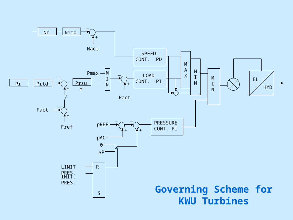
Control Loops
Speed Control Load Control Pressure Control

Speed Control: Main Functions PD Controller Start Up & Shut Down of Turbine Synchronizing with grid Providing Min. Load Operation of Turbine over entire
range of Load in case of Load Controller Failure
Load Control: Main Functions
PI Controller Provision of load reference
limiter Frequency influence option
Pressure Control:Main Functions
PI Controller Initial pressure control Limit pressure control
LOADCONT. PI
Governing Scheme for KWU Turbines
HYD
ELMIN
PRESSURECONT. PI
MAX
SPEEDCONT. PD
_
+
MINPrsu
m
++
+
_
+
PrtdPr
_
+NrtdNr
Nact
Pact
Pmax
Fact
Fref
_
+
_
+pREF
pACT
0
P
R
S
LIMIT PRES.
INIT. PRES.
MIN

MIN
HYD
HYD
HYD
EL
SPEEDERGEAR
STARTING DEVICE
MIN
FROM ELECCONTROLLER
TO CONTROLVALVES
Governing Scheme for KWU Turbines
Additional Functions
Tracking device option Load shedding relay Auto Synchronizer Isolated grid operation

Tracking Device Functions
The starting device keeps varying automatically with variation in the position of EHC. In case the EHC fails the starting device will restrict the raise in the load.
Load Shedding Relay Functions
During sudden load throw–off conditions, there will tendency for the speed to raise rapidly. To avoid such conditions the LSR gives a close command for closure of the control valves for a brief moment. The magnitude of load throw,time duration of closure of control valves are settable in the LSR.
Auto synchronizer Functions
The auto synchronizer accepts Gen and Grid Potential transformer signals. To match the frequency and voltage of the Generator, the auto. Sync. Unit gives Speed raise/lower command to EHTC and voltage raise/lower command to AVR.After parameter matching the auto sync. Unit generates a command for Synchronizing the unit
Auto synchronizer Functions
After parameter matching the auto sync. Unit generates a command for Synchronizing the unit
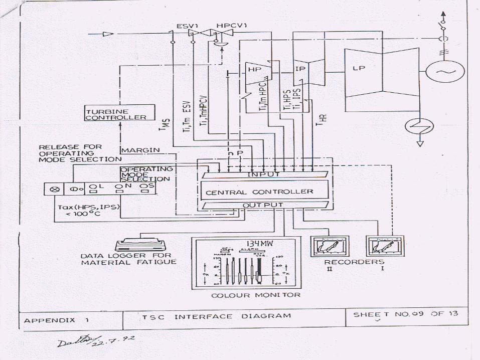
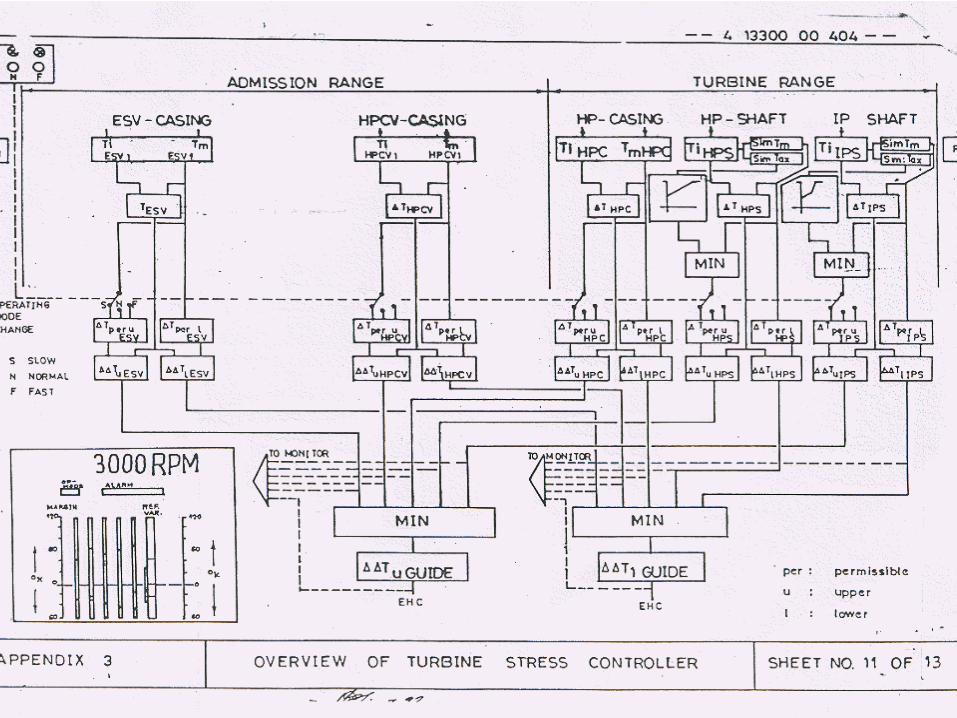
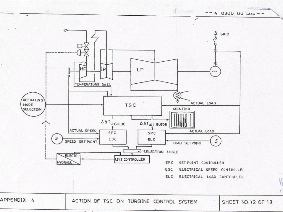
Turbine Stress Evaluator (TSE)
Turbine Stress Evaluator Compares thermal stress in the
monitored components with the permissible limits and generates margins.The temperature margin is fed to the set point controller – speed and load.
Derives start up criteria for ATRS
TSE: Components Monitored Emergency stop valve. HP control valve. HP casing. HP shaft. IP shaft.
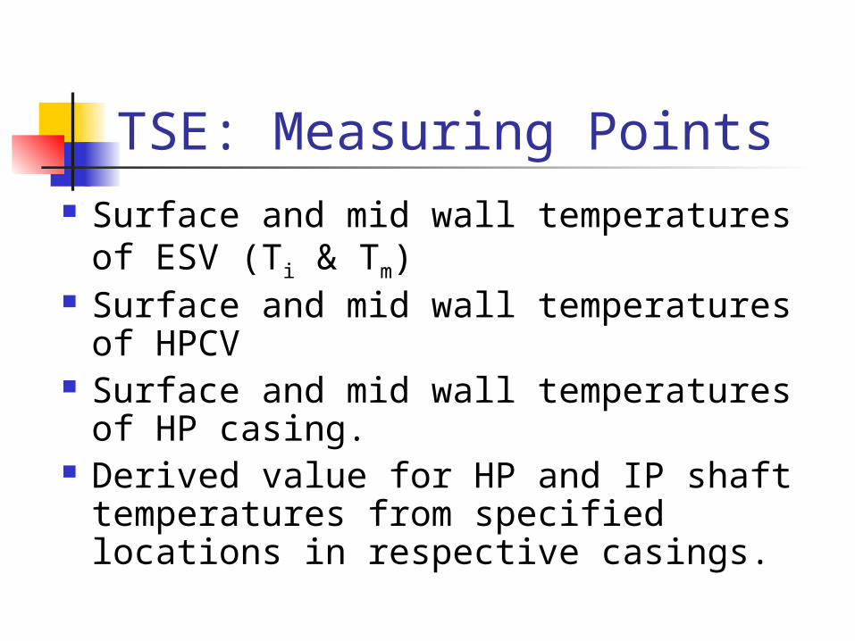
TSE: Measuring Points Surface and mid wall temperatures of
ESV (Ti & Tm) Surface and mid wall temperatures of
HPCV Surface and mid wall temperatures of
HP casing. Derived value for HP and IP shaft
temperatures from specified locations in respective casings.
TSE: Operating Modes Three modes viz., fast, normal,
slow available. The increased fatigue rate
associated with fast mode can be compensated by more slow mode operation.
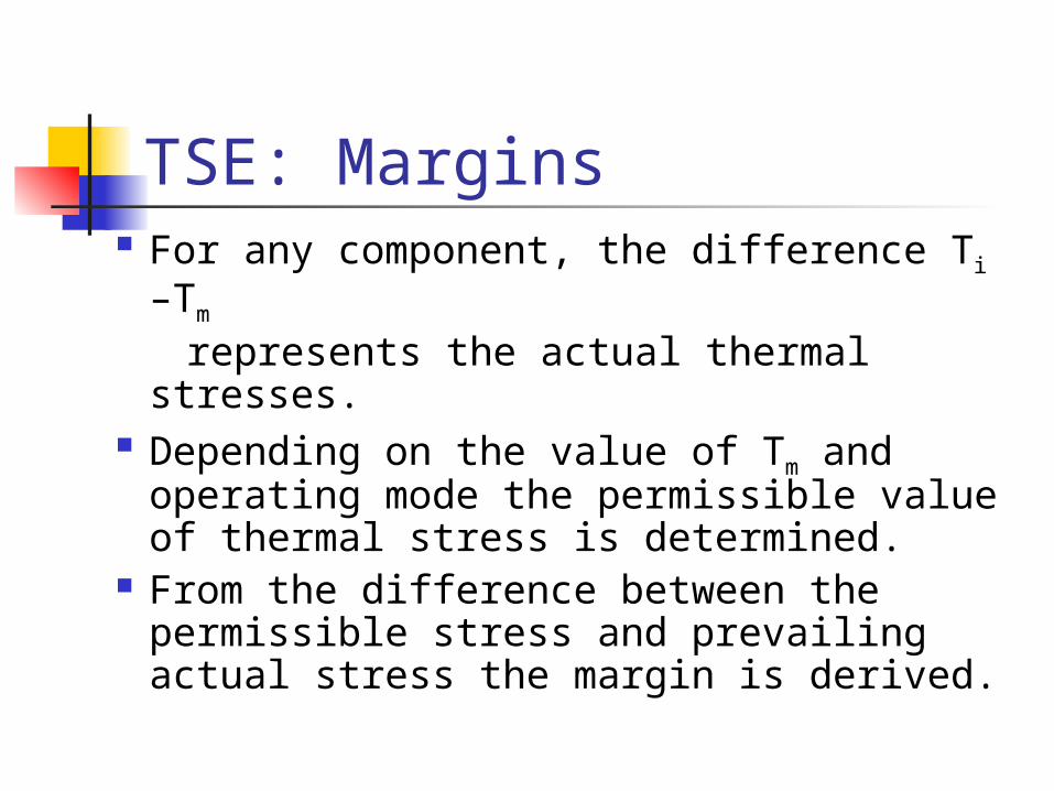
TSE: Margins For any component, the difference Ti –Tm
represents the actual thermal stresses. Depending on the value of Tm and
operating mode the permissible value of thermal stress is determined.
From the difference between the permissible stress and prevailing actual stress the margin is derived.

TSE: Margins The margins of different
components are provided in the Bar graph form in the TSE monitor.
The reference variable derived from the minimum margin acts directly on the turbine control system.

LP Bypass Control System (LPBP)

LPBP system: Main FeaturesEnables alternative path for dumping steam from RH outlet to condenser bypassing IP and LP turbine.Maintains RH pressure from a criteria representing the HP turbine flow.Works in conjunction with HP bypass systems and when necessitated by the system.
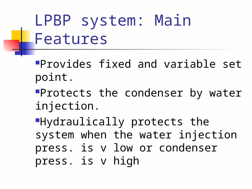
LPBP system: Main FeaturesProvides fixed and variable set point.Protects the condenser by water injection.Hydraulically protects the system when the water injection press. is v low or condenser press. is v high
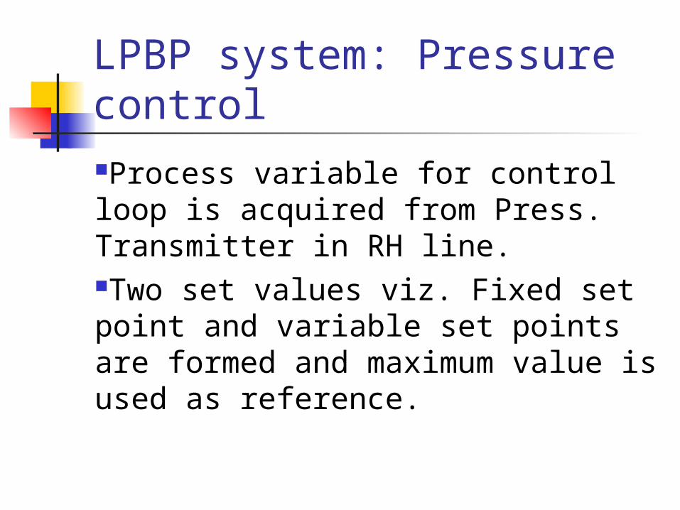
LPBP system: Pressure controlProcess variable for control loop is acquired from Press. Transmitter in RH line.Two set values viz. Fixed set point and variable set points are formed and maximum value is used as reference.
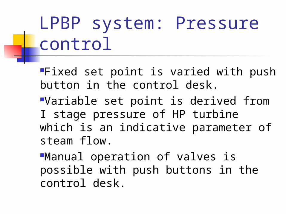
LPBP system: Pressure controlFixed set point is varied with push button in the control desk.Variable set point is derived from I stage pressure of HP turbine which is an indicative parameter of steam flow.Manual operation of valves is possible with push buttons in the control desk.
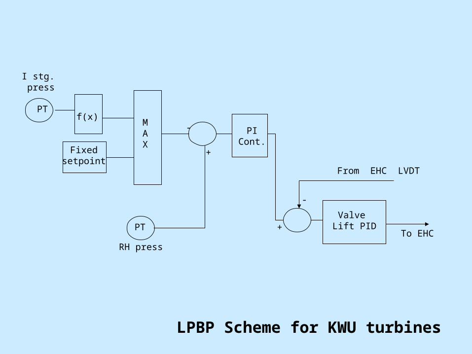
LPBP Scheme for KWU turbines
PTf(x)
Fixedsetpoint
MAX
PT
PICont.
Valve Lift PID
RH press
I stg. press
+
To EHC
From EHC LVDT
+
-
-
Gland Steam Control System (GSC)
Gland Steam Pressure Control Maintains the Gland steam header
pressure at required value. Provided with two control valves
viz. seal steam control valve and gland steam control valve.
Process variable is the header pressure from a transmitter.
Gland Steam Pressure Control The electro-hydraulic actuator
have inbuilt pump and it is powered by separate power supply.
In the event of pump failure,the valve remains stay put.
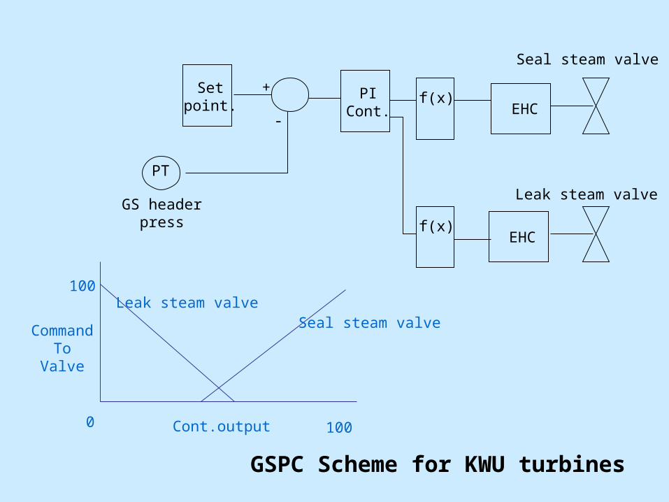
GSPC Scheme for KWU turbines
PT
PICont.
GS headerpress
+
-
Setpoint. f(x)
EHC
f(x)EHC
Seal steam valve
Leak steam valve
Cont.output 100
CommandTo
Valve
100
0
Seal steam valveLeak steam valve

Protection Systems
Protection Systems
Electrical Protection Systems
Hydraulic Protection Systems
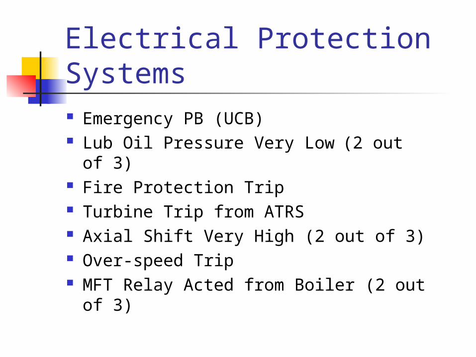
Electrical Protection Systems Emergency PB (UCB) Lub Oil Pressure Very Low (2 out of
3) Fire Protection Trip Turbine Trip from ATRS Axial Shift Very High (2 out of 3) Over-speed Trip MFT Relay Acted from Boiler (2 out of
3)
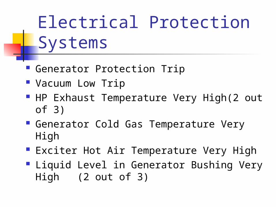
Electrical Protection Systems
Generator Protection Trip Vacuum Low Trip HP Exhaust Temperature Very High(2 out
of 3) Generator Cold Gas Temperature Very High Exciter Hot Air Temperature Very High Liquid Level in Generator Bushing Very
High (2 out of 3)
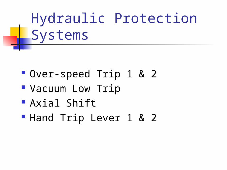
Hydraulic Protection Systems
Over-speed Trip 1 & 2 Vacuum Low Trip Axial Shift Hand Trip Lever 1 & 2

Features of Protection Systems Cyclic Test done periodically for each
Trip input Fault at input level will be annunciated Testing can be done online 2 out of 3 logic ensures reliability and
avoid spurious trippings 2 separate Processor Units realize the
Protection Logic with dedicated IOs.
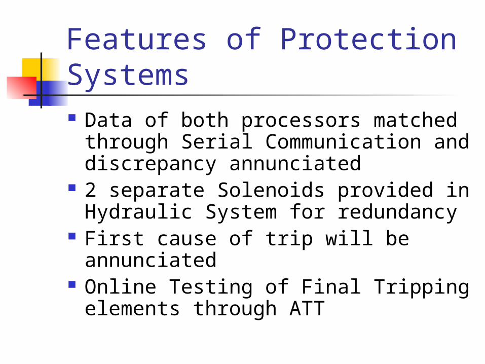
Features of Protection Systems Data of both processors matched
through Serial Communication and discrepancy annunciated
2 separate Solenoids provided in Hydraulic System for redundancy
First cause of trip will be annunciated
Online Testing of Final Tripping elements through ATT
Resetting of Protection
Turbine Trip Solenoid stays in energised condition until the following conditions are fulfilled. Command from individual Trip ceases Both ESVs Closed Trip Oil Pressure less than 2 kg/sq.cm
Turbovisory System (TSI)
Absolute bearing vibration Absolute shaft vibration Axial shift Relative expansion – HP Relative expansion – IP Relative expansion – LP Overall expansion
Turbovisory Instruments
Automatic Turbine Tester (ATT)

Individual testing of each turbine protective devices.
Pretest ensures substitute devices. Monitoring of program steps for
execution within a certain time. Interruption if trip is initiated. Automatic reset of program after a
fault.
ATT : Features
Sub group – Safety Devices. Sub group – HP/IP valves.
Automatic Turbine Tester

Remote trip device 1 & 2. Over speed trip device 1 & 2. Low vacuum trip device. Thrust bearing trip.
ATT: Safety devices
HP stop & control valve 1 HP stop & control valve 2 IP stop & control valve 1 IP stop & control valve 2
ATT: HP/IP Valves
Release condition for start All protective device in operating
condition.
1st step command Checking of Provision of control fluid
for enabling test
ATT: LOGICS for safety devices
Release condition for 2nd step Pressure before changeover valve >
5 kg/sq cm.
2nd step command Takes care of over speed trip-1
during test.
ATT: LOGICS for safety devices
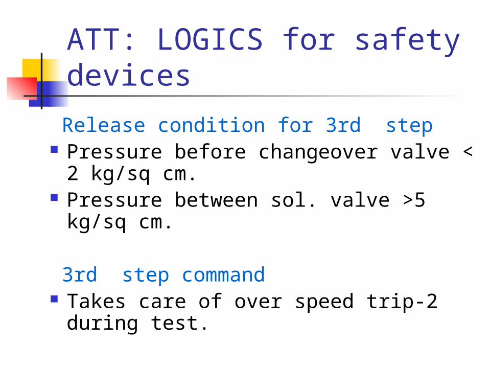
Release condition for 3rd step Pressure before changeover valve < 2
kg/sq cm. Pressure between sol. valve >5 kg/sq
cm.
3rd step command Takes care of over speed trip-2 during
test.
ATT: LOGICS for safety devices

Release condition for 4th step Pressure between sol. valve <2
kg/sq cm. 4th step command Provision of control fluid.
ATT: LOGICS for safety devices
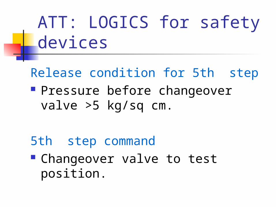
Release condition for 5th step Pressure before changeover valve
>5 kg/sq cm. 5th step command Changeover valve to test position.
ATT: LOGICS for safety devices

Release condition for 6th step Trip oil Pressure >5 kg/sq cm. Changeover valve test position. Aux startup fluid < 2 kg/sq cm. 6th step command Testing of remote trip device 1 & 2.
ATT: LOGICS for safety devices
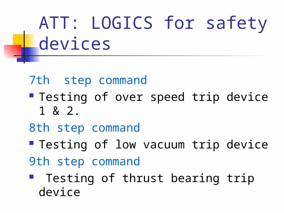
7th step command Testing of over speed trip device 1
& 2. 8th step command Testing of low vacuum trip device9th step command Testing of thrust bearing trip device
ATT: LOGICS for safety devices

Start conditions All stop valves 100 % position Load controller in action Load < 66.6 % Trip oil pressure > 2 kg
ATT: LOGICS for valves
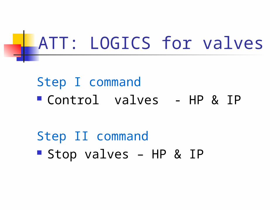
Step I command Control valves - HP & IP Step II command Stop valves – HP & IP
ATT: LOGICS for valves
Automatic Turbine Run-up System
(ATRS)
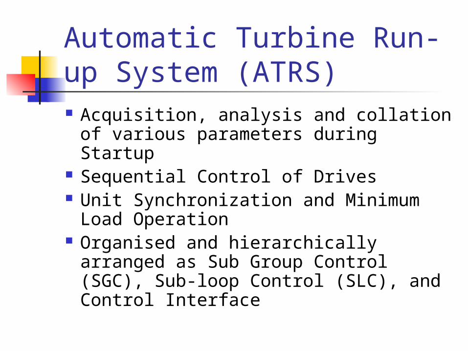
Automatic Turbine Run-up System (ATRS) Acquisition, analysis and collation of
various parameters during Startup Sequential Control of Drives Unit Synchronization and Minimum
Load Operation Organised and hierarchically arranged
as Sub Group Control (SGC), Sub-loop Control (SLC), and Control Interface
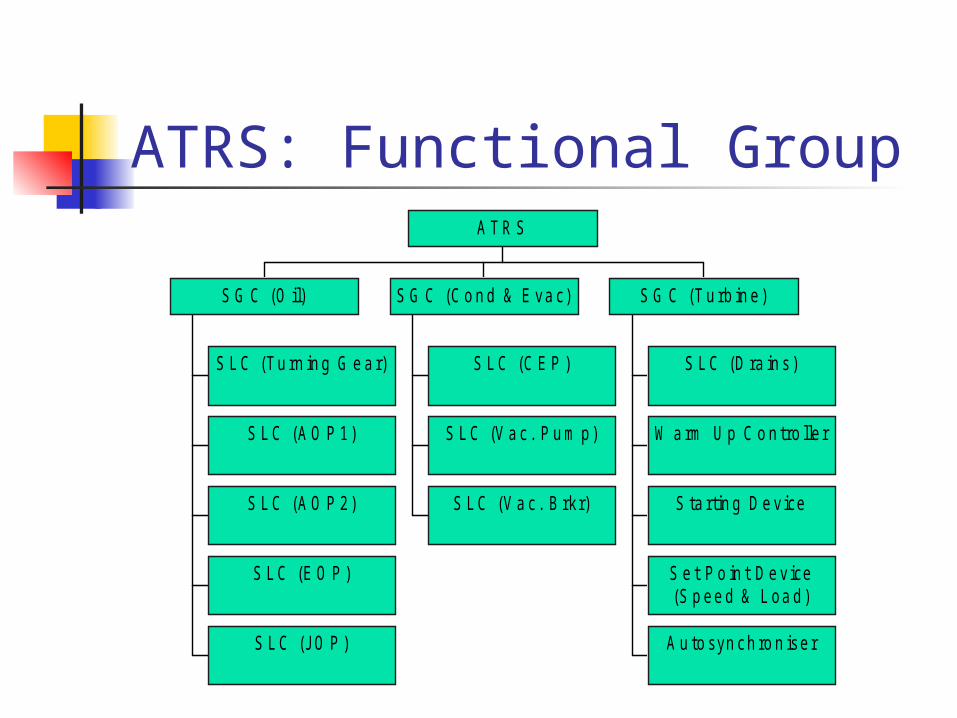
ATRS: Functional Group
S L C (Tu rn in g G e a r)
S L C (A O P 1)
S L C (A O P 2)
S L C (E O P )
S L C (JO P )
S G C (O il)
S L C (C E P )
S L C (V a c . P u m p)
S L C (V a c . B rk r)
S G C (C o n d & E va c)
S L C (D ra in s )
W a rm U p C o n tro lle r
S ta rtin g D e v ice
S e t P o in t D e v ice(S p ee d & L oa d)
A u to syn ch ro n iser
S G C (T u rb in e)
A T R S

THANK YOU !