Week13: Supercavitating...
25
1 Advanced Propulsion System GEM 423E Week13: Supercavitating Propellers Dr. Ali Can Takinacı Assosciate Professor in The Faculty of Naval Architecture and Ocean Engineering 34469 Maslak – Istanbul – Turkey
Transcript of Week13: Supercavitating...

1
Advanced Propulsion System
GEM 423E
Week13: Supercavitating Propellers
Dr. Ali Can Takinacı
Assosciate Professor
in
The Faculty of Naval Architecture and Ocean Engineering
34469
Maslak – Istanbul – Turkey

2
Contents
• Cavitation
• Some Historical Aspects
• Supercavitation
• Features of Supercavitating Flows
• Supercavitation Flow Problems
• Supercavitation Modelling
• Cavitator Hydrodynamics
• Design of Supercavitating Propeller
• The Story of Supercavitating Screw Propeller
What is CAVITATION?
The appearance of vapour
bubbles and pockets inside an
initially homogeneous liquid
medium, occurs in very different
situations.
3
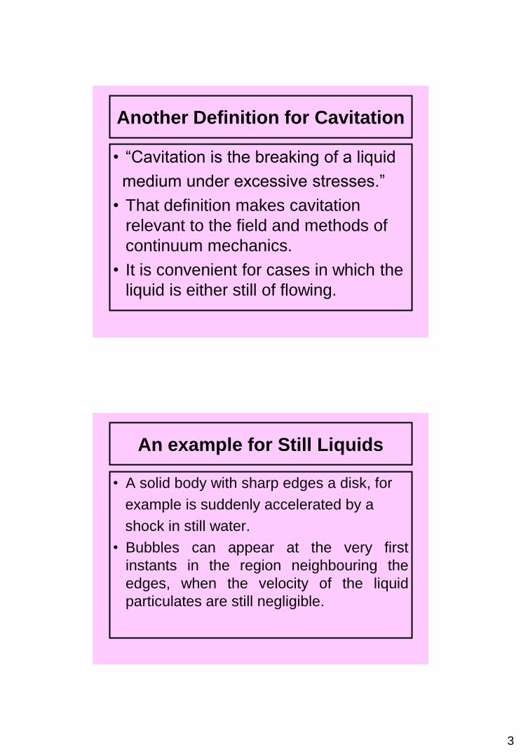
Another Definition for Cavitation
• “Cavitation is the breaking of a liquid
medium under excessive stresses.”
• That definition makes cavitation
relevant to the field and methods of
continuum mechanics.
• It is convenient for cases in which the
liquid is either still of flowing.
An example for Still Liquids
• A solid body with sharp edges a disk, for
example is suddenly accelerated by a
shock in still water.
• Bubbles can appear at the very first
instants in the region neighbouring the
edges, when the velocity of the liquid
particulates are still negligible.

4
An example of Flowing Liquids
- Flow in venturis or in narrow
passages valves for hydraulic
control.
- Flow near the upper-side of a
wing or a propeller blade.
The Vapour Pressure

5
Andrews-Isotherms
Specific Features of Cavitating
Flows
1. Pressure and Pressure
Gradients
2. Thermal Effects
3. Some Typical Orders of
Magnitude
4. The Liquid-Vapour Interfaces
6
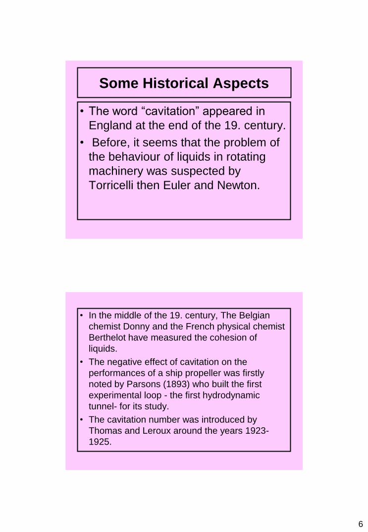
Some Historical Aspects
• The word “cavitation” appeared in
England at the end of the 19. century.
• Before, it seems that the problem of
the behaviour of liquids in rotating
machinery was suspected by
Torricelli then Euler and Newton.
• In the middle of the 19. century, The Belgian
chemist Donny and the French physical chemist
Berthelot have measured the cohesion of
liquids.
• The negative effect of cavitation on the
performances of a ship propeller was firstly
noted by Parsons (1893) who built the first
experimental loop - the first hydrodynamic
tunnel- for its study.
• The cavitation number was introduced by
Thomas and Leroux around the years 1923-
1925.

7
SupercavitationWhen a cavity length is much greater than the body dimensions, this flow regime is described as SUPERCAVITATION.
• Supercavities have many characteristics of classical free streamline flows. The cavity interior is essentially at constant pressure, and the cavity walls are essentially free-stream surfaces of constant velocity.
• Cavity pressures approach vapour pressure.
More On Supercavitation
- Supercavitation occurs at very low pressure where a very long vapour cavity exists and in many cases the cavity wall appears glassy and stable except near the end of the cavity
- Non-cavitating flows occur at sufficiently high-pressures where there is no evidence of bubbles.
- Between these flow regimes is limited cavitation and developed cavitation.
- Limited cavitation occurs at an intermediate value of the cavitation number where amount of a given type of cavitation is minimized. Limited cavitation can be vaporous or gaseous.

8
Features of Supercavitating
Flows
1. Supercavitation naturally occurs when the speed of a subsurface craft increases at fixed pressure P0.
At considerably low speeds (V>3 m/s), supercavities form when an object crosses the free water surface. In this case cavities are filled by athmospheric air and refer to artificial cavities formed at low speeds.
Features of Supercavitating Flows
2. According to the hydrodynamic scheme of
supercavitation flow, the object is placed
partially or fully inside a supercavity
formed by the nose part (cavitator)
3. In the case of a jet cavitator system the
cavity seperates from the craft hull and
body has no points of contact with cavity.

9
Features of Supercavitating Flow
Supercavitation Flow Problems
- In experimental investigation we realize a proccesses of physical modeling the supercavitation flows which includes three seperate but associate problems:
1. Modelling the supercavity shape and dimensions.
2. Modelling the main SC (Supercavity) process as gas supply, gas leakage, SC creation, SC control, SC disturbanse.
3. Modelling the supercavitating body motion.

10
Cavitation Flow Regimes
Supercavitation Modelling by the
σ Number
- The cavitation number σ is main scaling
criterion of the supercavitation flows.
- The value of σ<0.1 corresponds to the
supercavitation regime.
- Such values of the cavitation number are reached at velocities V∞>50 m/s.

11
Modelling of Supercavitating Flow
Modelling of Supercavitating Flow
• It is established experimentally; that
the water viscosity influence is partially
absent at such velocities in the case of the
disk cavitator and free cavity closure.
• Influence of gravity and surface tension
forces are also negligible when;
Fr>20-30, we>1000

12
Supercavitation Modelling by the
Fr Number
• It follows from the theory of similarity of
hydrodynamic flows that the shape and
dimensions of natural and artificial
( ventilated) cavities must be equal at the
same value of σ.
• However, this is not observed in reality.
Modelling of Supercavitaiton Flow
• The main cause is that the moderate
values of the Froude number Fr<20
correspond to the flows with artificial
cavitation when motion velocity V=10-50
m/s.
• It means that the gravity importance for
artificial cavity is essentially greater at
equality of the cavitation numbers.
13
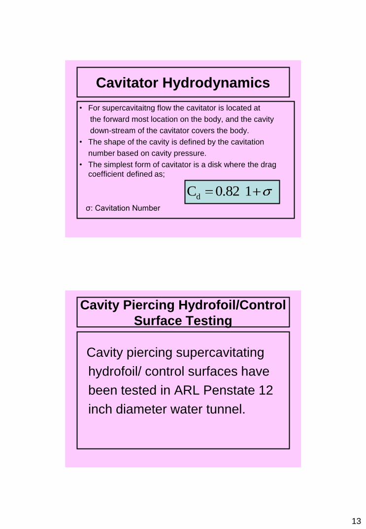
Cavitator Hydrodynamics
• For supercavitaitng flow the cavitator is located at
the forward most location on the body, and the cavity
down-stream of the cavitator covers the body.
• The shape of the cavity is defined by the cavitation
number based on cavity pressure.
• The simplest form of cavitator is a disk where the drag
coefficient defined as;
σ: Cavitation Number
dC 0.82 1
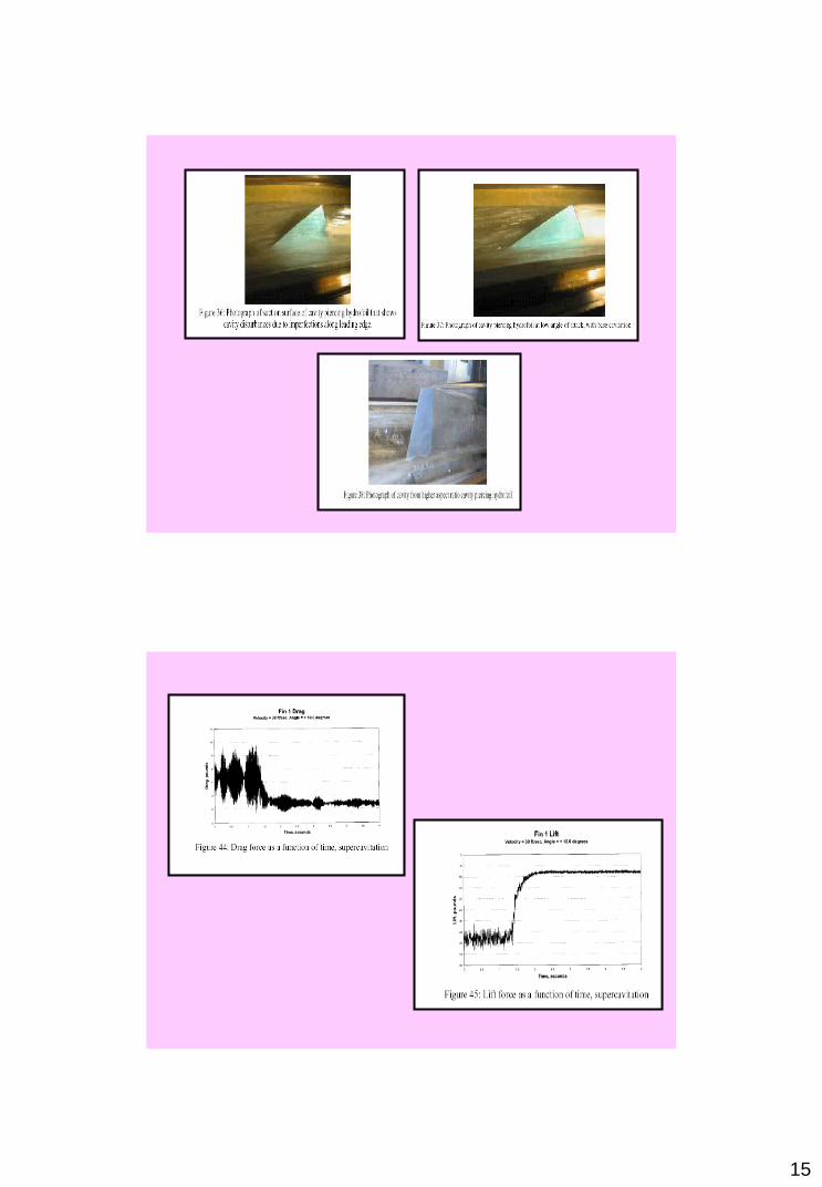
Cavity Piercing Hydrofoil/Control
Surface Testing
Cavity piercing supercavitating
hydrofoil/ control surfaces have
been tested in ARL Penstate 12
inch diameter water tunnel.

14
15

16
Design of Supercavitating Propeller
• An optimization method (CAVOPT-
3D), similar to that supercavitating
hydrofoil sections, has been
developed.
Design of Supercavitating Propeller
• The coefficients of the objective function are
determined in terms of second order Taylor
expansions from the result of MPUF-3A, a
vortex and source lattice method for
cavitating propellers in unsteady flow.
• This method determines both the optimum
cavitating propeller loading and the
corresponding blade geometry at the same
time.

17
• The required input design variables required by
CAVOPT-3D to set up the design model are given
as;
- advance coefficient (Js)
- cavitation number (σn)
- froude number (Fn)
- number of blades (z)
- hub radius (rH)
- required thrust coefficient (KT0)
-Inflow wake distribution
Application
• The 3-D method has been applied more
recently for the design of a supercavitating
propeller.
• The original thickness distribution, has been
used as input in CAVOPT-3D. We have
forced leading-edge cavity detachment in
MPUF-3A.
• The same design conditions as those of the
SRI propeller are used for CAVOPT-3D.

18
New Design
- The new design has a substantially larger efficiency
74.7 % ie. increase in efficiency of over 7 %.
- The new design has a wider blade area and a lower
pitch ( for the same thrust).
- The predicted cavities for the new design are thinner
at the leading edge as well as at the trailing edge,
thus resulting into a smaller cavity drag.
- The new design may lead to midchord cavitation and
this will increase its frictional drag, and degrade
some what the expected higher efficiency.
• The principle of functioning of the cavitation tunnel, which represents a vertically mounted hermetically sealed variable diameter tube, is extremely simple.
• This experimental installation enables to conduct the force measurement and visual observations of models of the cavitating or supercavitating propeller for given magnitudes of advance coefficient and axial cavitation number , which are taken equal to those of the full size propellers for a regime under consideration.

19
• In the case of supercavitation, which
depend to
- a lesser degree on the vertical
distribution
of the hydrostatic pressure
- Viscosity
- Turbulence
- Air content and other factors not
taken into account.
20
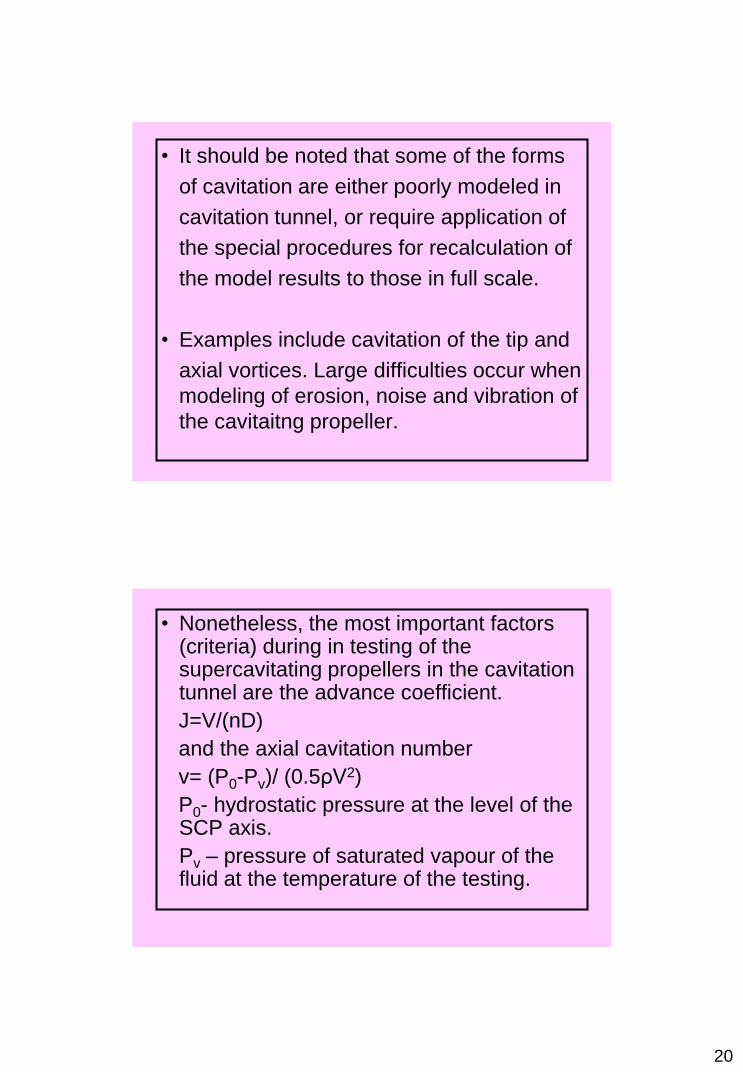
• It should be noted that some of the forms
of cavitation are either poorly modeled in
cavitation tunnel, or require application of
the special procedures for recalculation of
the model results to those in full scale.
• Examples include cavitation of the tip and
axial vortices. Large difficulties occur when
modeling of erosion, noise and vibration of
the cavitaitng propeller.
• Nonetheless, the most important factors (criteria) during in testing of the supercavitating propellers in the cavitation tunnel are the advance coefficient.
J=V/(nD)
and the axial cavitation number
v= (P0-Pv)/ (0.5ρV2)
P0- hydrostatic pressure at the level of the SCP axis.
Pv – pressure of saturated vapour of the fluid at the temperature of the testing.
21
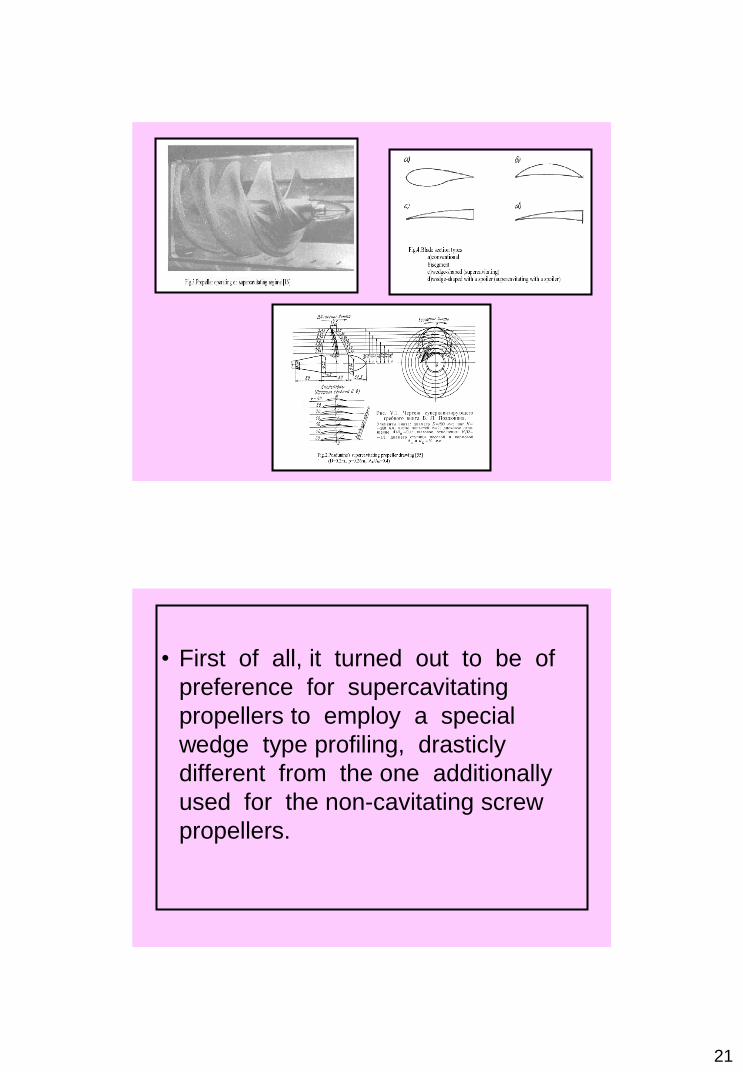
• First of all, it turned out to be of
preference for supercavitating
propellers to employ a special
wedge type profiling, drasticly
different from the one additionally
used for the non-cavitating screw
propellers.

22
• An important conclusion can be made on
the basis of the foregoing material.
• When designing a supercavitating
propeller for a hydrofoil ship the project
optimization at the regime of maximal
speed should be performed in such a way
that a sufficient thrust be provided at the
drag hump regime with account of the
power plant available on board.
• In short, the high efficiency at the maximal
speed regime is not the only requirement
when designing a supercavitating or a
highly cavitating propeller for a hydrofoil
ship.

23
• The analysis of hydrofoil revealed, in
particular, an important peculiarity of such
propellers, namely, for a given low
cavitation number and at a given
magnitude of the advance coefficient the
increase of pitch for the supercavitating
propeller as opposed to a non-cavitating
one, does not lead to a significant increase
of the thrust coefficient.
The Story of Supercavitating
Screw Propeller
• The story of the application of the
supercavitating screw propellers proper, which
started successfully in 1962 from the
hydrofoilship “Dension”, finishes over by the end
of the 80s, because the experience of operation
of this screw propellers on the world largest
serial hydrofoil ships of the “Sokol” type showed
insufficient reliability of the shaft sealing on the
naceless and ensuring necessity in frequent
repair.

24
• Project 23505 Sokol-Patrol Fast Borderguard Craft
– Displacement, t: standard 123 full 137
– Dimensions, m: overall length 36.5
– maximum beam 11.0
– midboard height 3.8
– design draught 1.6 – http://www.milparade.com/1999/36/05_03.shtml
• The problem of reliability
become so
acute that it was
decided to equip the
next projects of the
Russian open
ocean hydrofoil ships
not with
supercavitating propellers
but with
wateriest similarly to the
U.S. hydrofoil
ships “Tucumcari” and
“Pepas”.http://www.navsource.org/archives/1
2/1002.htm
Tucumcari

25
• However, these projects have not been
realized. Further on, unfortunately, the
interest toward the hydrofoil ships in the
world dropped quite abruptly in connection
with appearance of more prospective
types of high-speed ships, such as
catamarans, SES (Surface Effect Ships)
and SWATH (Small water-plane area twin
hull), for which implementation of the
supercavitating propellers proper is not
preferable.
Swath concept Typical application