Influence of Crosslinking on the Mechanical Properties of High TG ...

WEBINARJA SOLAR – PV TECH
BI-FACIAL PV MODULES TECHNOLOGY, APPLICATION AND FIELD DATA
JUNE 12TH 2018
Henning SchulzeJA Solar Vice-President Europe
Morgane FleuranceProduct Manager, Europe
0

JA SOLAR COMPANY
Founded / IPO May 2005 / February 2007 JASO (NASDAQ)
Headquarters Beijing, China
Annual Capacity (end 2017)
• 8.5 GW solar modules• 7 GW solar cells• 5 GW silicon wafer
Shipments
• 2014: 3.1 GW• 2015: 3.9 GW• 2016: 5.2 GW• 2017: 7.6 GW
Employees Around 15,000 at the end of March 2018
Business highlights
• Industry leader• Strong finance• Manufacturing excellence• Advanced innovation• Global market coverage and diversified
customer base
Products advantages• High conversion efficiency• High reliability• High yield efficiency 1
JA SOLAR COMPANY
JA SOLAR COMPANY
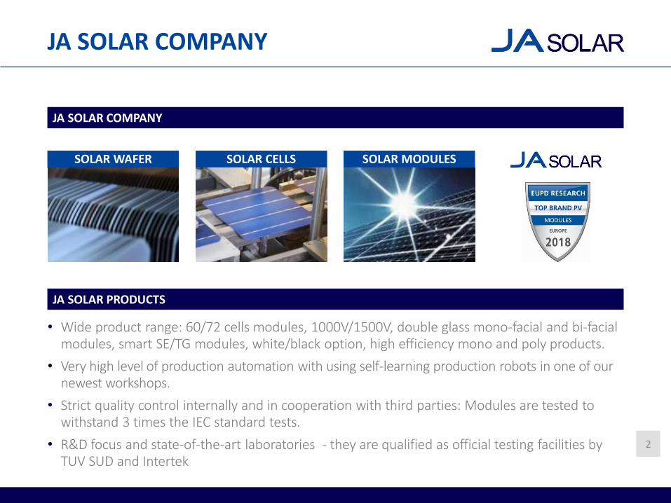
JA SOLAR PRODUCTS
• Wide product range: 60/72 cells modules, 1000V/1500V, double glass mono-facial and bi-facial modules, smart SE/TG modules, white/black option, high efficiency mono and poly products.
• Very high level of production automation with using self-learning production robots in one of our newest workshops.
• Strict quality control internally and in cooperation with third parties: Modules are tested to withstand 3 times the IEC standard tests.
• R&D focus and state-of-the-art laboratories - they are qualified as official testing facilities by TUV SUD and Intertek
SOLAR WAFER SOLAR CELLS SOLAR MODULES
2

BACKGROUND
WHAT WILL BE THE TECHNOLOGY TRENDS IN THE COMING YEARS?
P-type Polycrystalline or Monocrystalline
technology
P-type Monocrystalline PERC technology
N-type?P-type?
IBC? Bi-facial?Thin-film?
PASTTECHNOLOGIES
FUTURETECHNOLOGIES
OBJECTIVE:Decrease LCOE 3

OUTLINE
Technology• Baseline Mono PERC Technology• Bi-facial PV Cell Technology• Bi-facial PV Module Technology• Bi-facial PV Module Advantages
Bi-facial Modules Gain• Bi-facial Gain Definition• Factors Influencing the Gain:• Module Design• Mounting Methods• Climate Conditions• Albedo
Applications• Field Data• Yield Benefit under Various Environmental and Installation Conditions
4

TECHNOLOGY
PERC (Passivated Emitter Rear Contact): Leading Mono Technology
• Local Backside Surface Field on the solar cell rear side, acting as a mirror
• Higher efficiency, Voc and Isc : More energy per m²
• Main power class for 60-cell modules: 300Wp/305Wp
BASELINE MONOCRYSTALLINE PERC TECHNOLOGY
STANDARD SOLAR CELL PERC SOLAR CELL
Screen-printed Ag-paste
Screen-printed Al-paste
Back
Surface
Field
ARC
n*emitter Local BSF
Passivation layer
SiNx capping layer 5

TECHNOLOGY
ADVANTAGES:
• Superior low light performance compared to conventional modules.
• Lower temperature coefficient, better performance in higher temperatures.
BASELINE MONOCRYSTALLINE PERC TECHNOLOGY
FIELD DATA:
China Front Runner Project: 50MWp installed using standard poly and mono PERC modules:
6
3% additional energy yield compared to polycrystalline modules.
7% land savings compared to poly-crystalline modules.

TECHNOLOGY
• Bi-facial PERC cell: Grid printed at the backside of a monocrystalline PERC cell in order to collect light from the cell rear side.
• Bi-facial n-type and p-type cell technology co-exist on the market. Main difference: Efficiency of the front and rear side.
BI-FACIAL PV CELL TECHNOLOGY
MONO-FACIAL PERC SOLAR CELL BI-FACIAL PERC SOLAR CELL
7

TECHNOLOGY
• Double glass module design: Half-tempered glass as backside (rather than polymer backsheet)
• POE (polyolefin elastomer) as encapsulant
• Framed (in silver or black version) or frameless design
• Extended warranty, 30 years, 0.5% degradation
• Bi-faciality factor between 70-75%:
BF =Power Rear side
Power Front side𝑎𝑡 𝑆𝑇𝐶
BI-FACIAL PV MODULE TECHNOLOGY
Higher yield and electricity production coming from the module rear side generation.
Decrease LCOE.
BI-FACIAL FRONT SIDE BI-FACIAL REAR SIDE
Cell efficiency >21%
Rated Power: 300Wp
Cell Efficiency >15%
Rated Power: 210Wp
GLASS GLASSPOEPOE CELL
BI-FACIAL DOUBLE GLASS MODULE DESIGN
8

TECHNOLOGY
• Energy gain increase of 3-15% thanks to the module’s rear side power generation, actual yield increase depends on reflectivity of the ground, installation tilt, height etc.
• Excellent temperature coefficient.
• Superior low irradiance performance: Diffuse light absorbed through the rear side of the module.
• Highly reliability thanks to double glass design
BI-FACIAL PV MODULES ADVANTAGES
9

OUTLINE
Technology• Baseline Mono PERC Technology• Bi-facial PV Cell Technology• Bi-facial PV Module Technology• Bi-facial PV Module Advantages
Bi-facial Modules Gain• Bi-facial Gain Definition• Factors Influencing the Gain:• Module Design• Mounting Methods• Climate Conditions• Albedo
Applications• Field Data• Yield Benefit under Various Environmental and Installation Conditions
10

BI-FACIAL MODULES GAIN
• Gain definition:
BI-FACIAL MODULES GAIN DEFINITION
Comparing apples withapples for bi-facial modules sometimes does not make sense – ISC Konstanz Institute• Varying parameters:
–Baseline product technology: n-type/p-type, poly/mono PERC modules
–Module design/ Bifaciality factor
–Installation parameters: Installation tilt, with or without tracking, spacing, location of the module in the layout etc.
–Environmental conditions: Irradiance, latitude, longitude etc.
–Ground surface reflectivity (albedo)
𝐺𝑎𝑖𝑛 =
(in %)𝑥 100
(𝐸𝑏𝑖−𝑓𝑎𝑐𝑖𝑎𝑙 −𝐸𝑚𝑜𝑛𝑜𝑓𝑎𝑐𝑖𝑎𝑙)
𝐸𝑚𝑜𝑛𝑜𝑓𝑎𝑐𝑖𝑎𝑙 “”
11

BI-FACIAL MODULE GAIN
MODULE DESIGN
FACTORS INFLUENCING THE GAIN
Design 1Fully transparent rear glass, higher bi-faciality factor
(higher than 70%)
Design 2Partly transparent rear glass (called ceramic glass),
lower bi-faciality factor (around 70%)
12

BI-FACIAL MODULES GAIN
FACTORS INFLUENCING THE GAIN
MODULE DESIGN
• Bi-facial modules using partly transparent rear glass show higher energy yield in the field than bi-facial modules using fully transparent rear glass.
• The partly transparent rear glass helps to increase the module front side power.
13
300Wp – baseline 290Wp – BF = 72% 300Wp – BF = 64%
Energy gain design 1 module: 7.5 %.
Energy gain design 2 module: 11 %.

BI-FACIAL MODULES GAIN
FACTORS INFLUENCING THE GAIN
14
1.5m 2m 1.5m 2m
MOUNTING METHODS
• Higher-mounted bi-facial modules in general generate more energy than lower-mounted ones.
Raising installation height by 0.5m increase the gain by around 1%.

BI-FACIAL MODULES GAIN
FACTORS INFLUENCING THE GAIN
RECOMMENDED MOUNTING METHODS
• Installation with a tilt angle A of at least 30°.
• The length L of installation array less than 2.5 meters.
• No shading from the rear side.
• Installation height H of at least 0.5m.
15

BI-FACIAL MODULES GAIN
FACTORS INFLUENCING THE GAIN
Source: JA Solar R&D Center
SUNNY DAY CONDITIONS CLOUDY DAY CONDITIONS
CLIMATE CONDITIONS
16

BI-FACIAL MODULES GAIN
FACTORS INFLUENCING THE GAIN
SUNNY DAY CONDITIONS CLOUDY DAY CONDITIONS
• The yield gain is relatively higher in the early morning and late evening.
CLIMATE CONDITIONS
17

BI-FACIAL MODULES GAIN
FACTORS INFLUENCING THE GAIN
• The yield gain is relatively higher in the early morning and late evening
• On a cloudy/rainy day, the average energy gain is higher for bi-facial modules.
CLIMATE CONDITIONS
SUNNY DAY CONDITIONS CLOUDY DAY CONDITIONS
18

BI-FACIAL MODULES GAIN
FACTORS INFLUENCING THE GAIN
ALBEDO
• P-type modules installed in the optimum way of installation, comparison with mono PERC modules installed at a 30° tilt angle.
Surface Albedo Expected yield gain
Water 5-8% 4-6%
Green grassland 15-25% 7-9%
Concrete ground / white gravel 25-35% 8-10%
Dry sand 35-45% 10-15%
Old snow 40-70% 15-22%
Reflective roof coatings 80-90% 23-25%
Fresh snow 80-95% 25-30%
19
Earth surface
Total solar radiation
Light reflected
Light absorbed
ALBEDO A = Light reflected/Total solar radiation

BI-FACIAL MODULES GAIN
FACTORS INFLUENCING THE GAIN
ALBEDO
• Trend of the bi-facial gain plotted versus the albedo, taking into account more than 25 projects with mono-facial modules and bi-facial modules side by side.
• Large deviations on the bi-facial modules gain: the modelling is complex.
Source: ISC Konstanz Institute The Bifacial Book- Chapter 520

OUTLINE
Technology• Baseline Mono PERC Technology• Bi-facial PV Cell Technology• Bi-facial PV Module Technology• Bi-facial PV Module Advantages
Bi-facial Modules Gain• Bi-facial Gain Definition• Factors Influencing the Gain:• Module Design• Mounting Methods• Climate Conditions• Albedo
Applications• Field Data• Yield Benefit under Various Environmental and Installation Conditions
21

APPLICATIONS
FIELD DATA AND COMPARISON WITH SIMULATION
Project 1 Yangzhou R&D center
Location Yangzhou city, Jiangsu province, China
Altitude Around 0m
Total Installed capacity 6.4 kWp
Module power Bi-facial 290Wp, Mono-facial PERC 295Wp
Mounting structure 26°tilt angle
Inverter type String inverter
Type of surface Concrete ground
Grid connection time June 2017
22

APPLICATIONS
FIELD DATA AND COMPARISON WITH SIMULATION
PROJECT 1: YANGZHOU R&D CENTER
Electricity generation monitored from end June 2017 to end April 2018
JA Solar bi-facial modules generate 7.8% more than mono-facial PERC modules installed in the same configuration.
Source: JA Solar Yangzhou R&D center measurements23

APPLICATIONS
FIELD DATA AND COMPARISON WITH SIMULATION
Project 2 Huanghe power station project
Location Qinghai province, China
Altitude Around 3000m
Total Installed capacity 160MWp
JA Solar bi-facial modules installed capacity
5.5 MWp
Module power Bi-facial 345Wp, Mono-facial 335Wp
Mounting structure Horizontal single-axis tracker
Inverter type String inverter
Type of surface Sand of light colour
Grid Connection time July 2017
24

APPLICATIONS
FIELD DATA AND COMPARISON WITH SIMULATION
PROJECT 2
JA Solar bi-facial modules generate in average 10.5% more than conventional mono-facial modules installed in the same configuration.
Source: Verification report on the performance of mono-facial
and bi-facial modules from TUV Rheinland
Bi -facial moduleMono facial modules
Elec
tric
ity
gen
erat
ion
(kW
h/k
W.d
ay)
Bif
acia
l mo
du
les
gain
10.4%
10%
10.6%
11.4%
9.4%
10.5%
11.5%
HuangHe power station: monthly electricity production comparison between
mono-facial and bi-facial modules
25

APPLICATIONS
LATITUDE: 70°
LONGITUDE: 40°LONGITUDE: -10°
LATITUDE: 36°26
YIELD BENEFIT UNDER VARIOUS ENVIRONMENTAL AND INSTALLATION CONDITIONS

APPLICATIONS – MEDITERRANEAN
YIELD BENEFIT
Climate characteristics: High irradiance, high temperature, lots of direct sunlight
Common application: commercial/industrial or ground mount
Baseline Mono PERC 300Wp
28°tilt angle
Annual yield 1693 kWh/kWp/yr
Variation of the height
5 MWp ground mount installation
Bifacial 300Wp
Height: 0.5 m, tilt angle 28°, albedo: 40%
Annual yield 1810 kWh/kWp/yr
GAIN 7%
Bifacial 300Wp + change of height
Height: 1.5 m, tilt angle: 28°, albedo: 40%
Annual yield 1848 kWh/kWp/yr
GAIN 9%
Spain
27

APPLICATIONS – UK AND IRELAND
YIELD BENEFIT
Climate characteristics: Low irradiance
Common application: Commercial & industrial or ground mount
Variation of the tilt angle
200 kWp commercial installation on flat roof
Baseline Mono PERC 300Wp
15°tilt angle
Annual yield 998 kWh/kWp/yr
Bifacial 300Wp
Height: 0.3 m, tilt angle 15°, albedo: 25%
Annual yield 1019 kWh/kWp/yr
GAIN 2%
Bifacial 300Wp + change of tilt angle
Height: 0.3 m, tilt angle: 30°, albedo: 25%
Annual yield 1064 kWh/kWp/yr
GAIN 7%
United Kingdom
28

APPLICATIONS – SCANDINAVIA
YIELD BENEFIT
Climate characteristics: Long winters, in parts of the year little sunlight, but snow
Common application: Small ground mount or commercial & industrial
Variation of the albedo
2 MWp ground mount installation
Baseline Mono PERC 300Wp
30°tilt angle
Annual yield 2.92 kWh/kWp/day
Bifacial 300Wp in summer months
Height: 1.0 m, tilt angle 30°, albedo: 20%
Annual yield 2.94 kWh/kWp/day
GAIN 1%
Bifacial 300Wp in winter months
Height: 1.0 m, tilt angle: 30°, albedo: 80%
Annual yield 3.25 kWh/kWp/day
GAIN 11%
Sweden
29

APPLICATIONS – CENTRAL EUROPE
YIELD BENEFIT
Climate characteristics: Continental climate
Common application: Residential or commercial & industrial
100 kWp installation on flat roof with white gravels
Baseline Mono PERC 300Wp
10°tilt angle
Annual yield 953 kWh/kWp/yr
Bifacial 300Wp
Height: 0.1 m, tilt angle 20°, albedo: 35%
Annual yield 1029 kWh/kWp/yr
GAIN 8%
Germany
30
APPLICATIONS – EGYPT
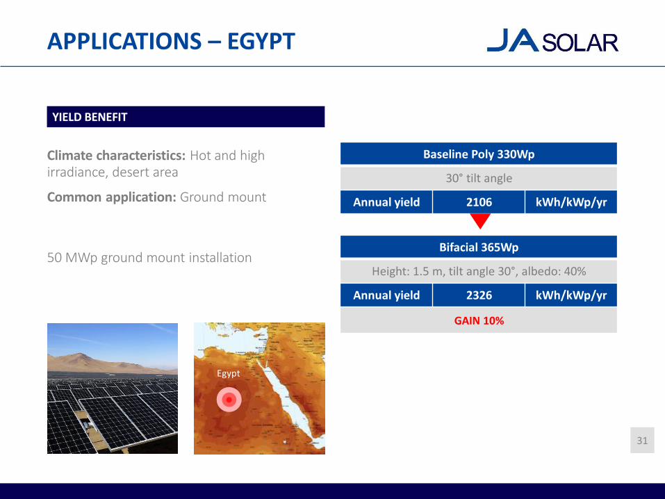
YIELD BENEFIT
Climate characteristics: Hot and high irradiance, desert area
Common application: Ground mount
50 MWp ground mount installation
Baseline Poly 330Wp
30°tilt angle
Annual yield 2106 kWh/kWp/yr
Bifacial 365Wp
Height: 1.5 m, tilt angle 30°, albedo: 40%
Annual yield 2326 kWh/kWp/yr
GAIN 10%
Egypt
31

APPLICATIONS – USA
YIELD BENEFIT
Climate characteristics: Hot and high irradiance, desert area
Common application: Ground mount or commercial installation
300 kWp commercial roof installation with highly reflective roof coating
Baseline Mono PERC 365Wp
15°tilt angle
Annual yield 1846 kWh/kWp/yr
Bifacial 365Wp
Height: 0.2 m, tilt angle 15°, albedo: 80%
Annual yield 1971 kWh/kWp/yr
GAIN 7%
USA
32

CONCLUSION
• The installation of bi-facial modules in a solar power plant systematically leads to a gain in the power generation compared to installing standard modules.
• The bi-facial module gain depends on many external factors i.e. mounting methods, climatic conditions, albedo etc. By optimizing the different parameters, the gain can be significantly improved.
• Field data shows that there is an actual extra yield, simulations have shown as well a gain in different environment and installation conditions.
• Bi-facial modules show clear benefits to decrease the Levelized Cost of Electricity: it is a promising technology.
33

THANK YOUContact: [email protected]

SOURCES
Page 5 Diagram Institute for Solar Energy Research Hamelin (ISFH)
Page 7 Diagram Institute for Solar Energy Research Hamelin (ISFH)
Page 9 Picture http://www.firstgreen.co/2013/06/bifacial-series-glass-to-glass-photovoltaic-module/
Page 19 Graph ISC Konstanz Institute The Bifacial Book- Chapter 5
Page 22 Map https://commons.wikimedia.org/wiki/File:SolarGIS-Solar-map-China-Mainlands-en.png
Page 24 Map https://commons.wikimedia.org/wiki/File:SolarGIS-Solar-map-China-Mainlands-en.png
Page 26 Map https://upload.wikimedia.org/wikipedia/commons/4/49/Pvgis_Europe-solar_opt_publication.png
Page 27 Picture https://www.solarpowerportal.co.uk/news/sainsburys_installs_its_100000th_solar_panel_2356
Page 28 Picture https://www.pv-tech.org/news/spain-installed-55mw-solar-pv-in-2016
Page 29 Picture http://www.saurenergy.com/solar-energy-news/yingli-power-largest-bifacial-pv-plant-europe
Page 30 Picture https://www.tdg.ch/suisse/politique/coup-dur-energie-solaire-suisse/story/13295422
Page 31 Picture https://www.financialexpress.com/industry/india-launches-state-of-the-art-solar-project-in-egypt-to-power- up-remote-village/765596/
Map https://commons.wikimedia.org/wiki/File:PVGIS_Africa_SolarPotential.bigopti.png
Page 32 Picture google earth
Map https://fr.wikipedia.org/wiki/Fichier:SolarGIS-Solar-map-USA-en.png
Page 34 Picture https://pangeabuilders.com/tag/fossil-fuels/