SINGLE OUTPUT HIGH VOLTAGE MODULES HIGH POWER 8C-30C …
4
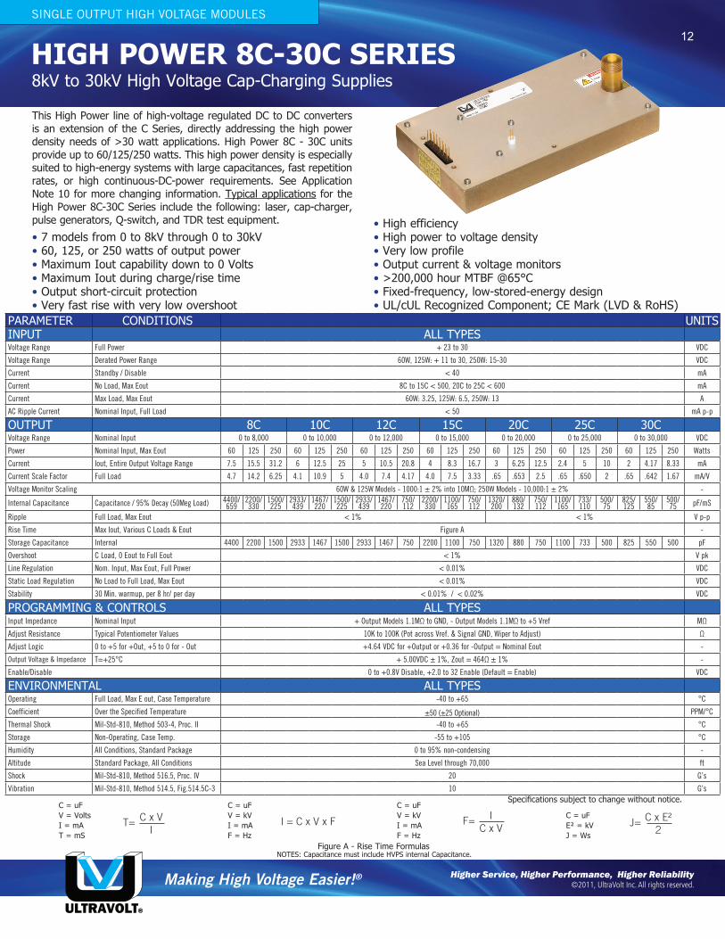
HIGH POWER 8C-30C SERIES This High Power line of high-voltage regulated DC to DC converters is an extension of the C Series, directly addressing the high power density needs of >30 watt applications. High Power 8C - 30C units provide up to 60/125/250 watts. This high power density is especially suited to high-energy systems with large capacitances, fast repetition rates, or high continuous-DC-power requirements. See Application Note 10 for more changing information. Typical applications for the High Power 8C-30C Series include the following: laser, cap-charger, pulse generators, Q-switch, and TDR test equipment. • 7 models from 0 to 8kV through 0 to 30kV • 60, 125, or 250 watts of output power • Maximum Iout capability down to 0 Volts • Maximum Iout during charge/rise time • Output short-circuit protection • Very fast rise with very low overshoot • High efficiency • High power to voltage density • Very low profile • Output current & voltage monitors • >200,000 hour MTBF @65°C • Fixed-frequency, low-stored-energy design • UL/cUL Recognized Component; CE Mark (LVD & RoHS) 8kV to 30kV High Voltage Cap-Charging Supplies SINGLE OUTPUT HIGH VOLTAGE MODULES PARAMETER CONDITIONS UNITS INPUT ALL TYPES Voltage Range Full Power + 23 to 30 VDC Voltage Range Derated Power Range 60W, 125W: + 11 to 30, 250W: 15-30 VDC Current Standby / Disable < 40 mA Current No Load, Max Eout 8C to 15C < 500, 20C to 25C < 600 mA Current Max Load, Max Eout 60W: 3.25, 125W: 6.5, 250W: 13 A AC Ripple Current Nominal Input, Full Load < 50 mA p-p OUTPUT 8C 10C 12C 15C 20C 25C 30C Voltage Range Nominal Input 0 to 8,000 0 to 10,000 0 to 12,000 0 to 15,000 0 to 20,000 0 to 25,000 0 to 30,000 VDC Power Nominal Input, Max Eout 60 125 250 60 125 250 60 125 250 60 125 250 60 125 250 60 125 250 60 125 250 Watts Current Iout, Entire Output Voltage Range 7.5 15.5 31.2 6 12.5 25 5 10.5 20.8 4 8.3 16.7 3 6.25 12.5 2.4 5 10 2 4.17 8.33 mA Current Scale Factor Full Load 4.7 14.2 6.25 4.1 10.9 5 4.0 7.4 4.17 4.0 7.5 3.33 .65 .653 2.5 .65 .650 2 .65 .642 1.67 mA/V Voltage Monitor Scaling 60W & 125W Models - 1000:1 ± 2% into 10MΩ; 250W Models - 10,000:1 ± 2% - Internal Capacitance Capacitance / 95% Decay (50Meg Load) 4400/ 659 2200/ 330 1500/ 225 2933/ 439 1467/ 220 1500/ 225 2933/ 439 1467/ 220 750/ 112 2200/ 330 1100/ 165 750/ 112 1320/ 200 880/ 132 750/ 112 1100/ 165 733/ 110 500/ 75 825/ 125 550/ 85 500/ 75 pF/mS Ripple Full Load, Max Eout < 1% < 1% V p-p Rise Time Max Iout, Various C Loads & Eout Figure A - Storage Capacitance Internal 4400 2200 1500 2933 1467 1500 2933 1467 750 2200 1100 750 1320 880 750 1100 733 500 825 550 500 pF Overshoot C Load, 0 Eout to Full Eout < 1% V pk Line Regulation Nom. Input, Max Eout, Full Power < 0.01% VDC Static Load Regulation No Load to Full Load, Max Eout < 0.01% VDC Stability 30 Min. warmup, per 8 hr/ per day < 0.01% / < 0.02% VDC PROGRAMMING & CONTROLS ALL TYPES Input Impedance Nominal Input + Output Models 1.1MΩ to GND, - Output Models 1.1MΩ to +5 Vref MΩ Adjust Resistance Typical Potentiometer Values 10K to 100K (Pot across Vref. & Signal GND, Wiper to Adjust) Ω Adjust Logic 0 to +5 for +Out, +5 to 0 for - Out +4.64 VDC for +Output or +0.36 for -Output = Nominal Eout - Output Voltage & Impedance T=+25°C + 5.00VDC ± 1%, Zout = 464Ω ± 1% - Enable/Disable 0 to +0.8V Disable, +2.0 to 32 Enable (Default = Enable) VDC ENVIRONMENTAL ALL TYPES Operating Full Load, Max E out, Case Temperature -40 to +65 °C Coefficient Over the Specified Temperature ±50 (±25 Optional) PPM/°C Thermal Shock Mil-Std-810, Method 503-4, Proc. II -40 to +65 °C Storage Non-Operating, Case Temp. -55 to +105 °C Humidity All Conditions, Standard Package 0 to 95% non-condensing - Altitude Standard Package, All Conditions Sea Level through 70,000 ft Shock Mil-Std-810, Method 516.5, Proc. IV 20 G’s Vibration Mil-Std-810, Method 514.5, Fig.514.5C-3 10 G’s Making High Voltage Easier! ® ULTRAVOLT® Higher Service, Higher Performance, Higher Reliability ©2011, UltraVolt Inc. All rights reserved. Specifications subject to change without notice. Figure A - Rise Time Formulas C = uF V = Volts I = mA T = mS C = uF V = kV I = mA F = Hz C = uF V = kV I = mA F = Hz C = uF E² = kV J = Ws NOTES: Capacitance must include HVPS internal Capacitance. T= C x V I I = C x V x F J= C x E² 2 F= I C x V 12
Transcript of SINGLE OUTPUT HIGH VOLTAGE MODULES HIGH POWER 8C-30C …
HIGH POWER 8C-30C SERIES
This High Power line of high-voltage regulated DC to DC converters is an extension of the C Series, directly addressing the high power density needs of >30 watt applications. High Power 8C - 30C units provide up to 60/125/250 watts. This high power density is especially suited to high-energy systems with large capacitances, fast repetition rates, or high continuous-DC-power requirements. See Application Note 10 for more changing information. Typical applications for the High Power 8C-30C Series include the following: laser, cap-charger, pulse generators, Q-switch, and TDR test equipment.
• 7 models from 0 to 8kV through 0 to 30kV• 60, 125, or 250 watts of output power• Maximum Iout capability down to 0 Volts• Maximum Iout during charge/rise time• Output short-circuit protection• Very fast rise with very low overshoot
• High efficiency• High power to voltage density• Very low profile• Output current & voltage monitors• >200,000 hour MTBF @65°C• Fixed-frequency, low-stored-energy design• UL/cUL Recognized Component; CE Mark (LVD & RoHS)
8kV to 30kV High Voltage Cap-Charging Supplies
SINGLE OUTPUT HIGH VOLTAGE MODULES
PARAMETER CONDITIONS UNITSINPUT ALL TYPESVoltage Range Full Power + 23 to 30 VDC
Voltage Range Derated Power Range 60W, 125W: + 11 to 30, 250W: 15-30 VDC
Current Standby / Disable < 40 mA
Current No Load, Max Eout 8C to 15C < 500, 20C to 25C < 600 mA
Current Max Load, Max Eout 60W: 3.25, 125W: 6.5, 250W: 13 A
AC Ripple Current Nominal Input, Full Load < 50 mA p-p
OUTPUT 8C 10C 12C 15C 20C 25C 30CVoltage Range Nominal Input 0 to 8,000 0 to 10,000 0 to 12,000 0 to 15,000 0 to 20,000 0 to 25,000 0 to 30,000 VDC
Power Nominal Input, Max Eout 60 125 250 60 125 250 60 125 250 60 125 250 60 125 250 60 125 250 60 125 250 Watts
Current Iout, Entire Output Voltage Range 7.5 15.5 31.2 6 12.5 25 5 10.5 20.8 4 8.3 16.7 3 6.25 12.5 2.4 5 10 2 4.17 8.33 mA
Current Scale Factor Full Load 4.7 14.2 6.25 4.1 10.9 5 4.0 7.4 4.17 4.0 7.5 3.33 .65 .653 2.5 .65 .650 2 .65 .642 1.67 mA/V
Voltage Monitor Scaling 60W & 125W Models - 1000:1 ± 2% into 10MΩ; 250W Models - 10,000:1 ± 2% -
Internal Capacitance Capacitance / 95% Decay (50Meg Load) 4400/659
2200/330
1500/225
2933/439
1467/220
1500/225
2933/439
1467/220
750/112
2200/330
1100/165
750/112
1320/200
880/132
750/112
1100/165
733/110
500/75
825/125
550/85
500/75 pF/mS
Ripple Full Load, Max Eout < 1% < 1% V p-p
Rise Time Max Iout, Various C Loads & Eout Figure A -
Storage Capacitance Internal 4400 2200 1500 2933 1467 1500 2933 1467 750 2200 1100 750 1320 880 750 1100 733 500 825 550 500 pF
Overshoot C Load, 0 Eout to Full Eout < 1% V pk
Line Regulation Nom. Input, Max Eout, Full Power < 0.01% VDC
Static Load Regulation No Load to Full Load, Max Eout < 0.01% VDC
Stability 30 Min. warmup, per 8 hr/ per day < 0.01% / < 0.02% VDC
PROGRAMMING & CONTROLS ALL TYPESInput Impedance Nominal Input + Output Models 1.1MΩ to GND, - Output Models 1.1MΩ to +5 Vref MΩ
Adjust Resistance Typical Potentiometer Values 10K to 100K (Pot across Vref. & Signal GND, Wiper to Adjust) Ω
Adjust Logic 0 to +5 for +Out, +5 to 0 for - Out +4.64 VDC for +Output or +0.36 for -Output = Nominal Eout -
Output Voltage & Impedance T=+25°C + 5.00VDC ± 1%, Zout = 464Ω ± 1% -
Enable/Disable 0 to +0.8V Disable, +2.0 to 32 Enable (Default = Enable) VDC
ENVIRONMENTAL ALL TYPESOperating Full Load, Max E out, Case Temperature -40 to +65 °C
Coefficient Over the Specified Temperature ±50 (±25 Optional) PPM/°C
Thermal Shock Mil-Std-810, Method 503-4, Proc. II -40 to +65 °C
Storage Non-Operating, Case Temp. -55 to +105 °C
Humidity All Conditions, Standard Package 0 to 95% non-condensing -
Altitude Standard Package, All Conditions Sea Level through 70,000 ft
Shock Mil-Std-810, Method 516.5, Proc. IV 20 G’s
Vibration Mil-Std-810, Method 514.5, Fig.514.5C-3 10 G’s
Making High Voltage Easier!®
ULTRAVOLT®
Higher Service, Higher Performance, Higher Reliability©2011, UltraVolt Inc. All rights reserved.
Specifications subject to change without notice.
Figure A - Rise Time Formulas
C = uFV = VoltsI = mAT = mS
C = uFV = kVI = mAF = Hz
C = uFV = kVI = mAF = Hz
C = uFE² = kVJ = Ws
NOTES: Capacitance must include HVPS internal Capacitance.
T= C x VI
I = C x V x F J= C x E²2
F= IC x V
12

Making High Voltage Easier!®
ULTRAVOLT®
1800 Ocean Avenue, Ronkonkoma, NY 11779 Phone: 1-631-471-4444 Fax: 1-631-471-4696 www.ultravolt.com
High Voltage Biasing Supply HIGH POWER 8C-30C SERIES8kV to 30kV High Voltage Cap-Charging Supplies
SINGLE OUTPUT HIGH VOLTAGE MODULES
8C TO 15C - 60/125W
20C TO 30C - 60/125W
13
Downloadable drawings (complete with mounting & pin information) and 3D models are available online.

Making High Voltage Easier!®
ULTRAVOLT®
1800 Ocean Avenue, Ronkonkoma, NY 11779 Phone: 1-631-471-4444 Fax: 1-631-471-4696 www.ultravolt.com
High Voltage Biasing Supply HIGH POWER 8C-30C SERIES8kV to 30kV High Voltage Cap-Charging Supplies
SINGLE OUTPUT HIGH VOLTAGE MODULES
14
CONSTRUCTION Epoxy-filled Aluminum Box Chem film per MIL-A-8625 Type II (Anodizing)
SIZE - 60 & 125W MODELS Volume 38.7 in³ (634cc) Weight 2.6 lbs. (1.18kg)
SIZE - 250W MODELS Volume 84.5 in³ (1386cc) Weight 5.6 lbs. (1.18kg)
TOLERANCE Overall ±0.025” (0.64) Pin to Pin ±0.015” (0.38) Hole to hole location ±0.025” (0.64)
PINSGold-plated 0.025 (0.64) sq.The center of the pins and mounting holes are located from the center of pin 1Pins 1 thru 14 spacing 0.100 (2.54) x 0.200 (5.08) on center,height from cover 0.280 (7.11) minPins 15 and 16 spacing 0.100 (2.54) on center, height from cover 0.450 (11.43) min
HV OUTPUT CONNECTIONUnit requires an LGH flying lead connector for proper operation:8C to 15C (60W & 125W Models) = CA-20KV-1000 20C to 30C (60W & 125W Models) = CA-40KV-10008C to 30C (250W Models) = CA-40KV-1000
8C TO 30C - 250W (PRELIMINARY)
Rev. AB 12/14
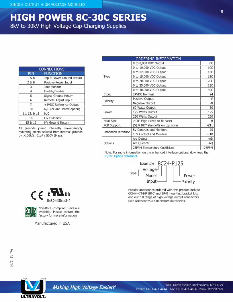
Example: 8C24-P125
Polarity
TypeVoltage
ModelInput
Power
ORDERING INFORMATION
Type
0 to 8,000 VDC Output 8C0 to 10,000 VDC Output 10C0 to 12,000 VDC Output 12C0 to 15,000 VDC Output 15C0 to 20,000 VDC Output 20C0 to 25,000 VDC Output 25C0 to 30,000 VDC Output 30C
Input 24VDC Nominal 24
PolarityPositive Output -PNegative Output -N
Power60 Watts Output 60125 Watts Output 125250 Watts Output 250
Heat Sink .400” High (sized to fit case) -HPCB Support (5) 0.187" standoffs on top cover -Z11
Enhanced Interface5V Controls and Monitors -I510V Control and Monitors -I10
OptionsArc Detect -ADArc Quench -AQ25PPM Temperature Coefficient -25PPM
CONNECTIONSPIN FUNCTION1 & 8 Input-Power Ground Return2 & 9 Positive Power Input
3 Iout Monitor4 Enable/Disable5 Signal Ground Return6 Remote Adjust Input7 +5VDC Reference Output10 N/C (or Arc Detect option)
11, 12, & 13 N/C14 Eout Monitor
15 & 16 HV Ground Return
All grounds joined internally. Power-supply mounting points isolated from internal grounds by >100kΩ, .01uF / 500V (Max).
IEC-60950-1
Non-RoHS compliant units are available. Please contact the factory for more information.
Making High Voltage Easier!®
ULTRAVOLT®
1800 Ocean Avenue, Ronkonkoma, NY 11779 Phone: 1-631-471-4444 Fax: 1-631-471-4696 www.ultravolt.com
High Voltage Biasing Supply HIGH POWER 8C-30C SERIES8kV to 30kV High Voltage Cap-Charging Supplies
SINGLE OUTPUT HIGH VOLTAGE MODULES
Popular accessories ordered with this product include CONN-KIT-HP, BR-7 and BR-8 mounting bracket kits and our full range of high voltage output connectors (see Accessories & Connectors datasheet).
15
Note: For more information on the enhanced interface options, download the I5/I10 Option datasheet.
Manufactured in USA