Web UI Reference Guide - eu.dlink.com 3600/Manual... · D-Link Corporation, ... nel cui caso è...
48
Web UI Reference Guide Product Model: DXS-3600 Series Layer 2/3 Managed 10GbE Switch Release: 1.10
Transcript of Web UI Reference Guide - eu.dlink.com 3600/Manual... · D-Link Corporation, ... nel cui caso è...
Web UI Reference GuideProduct Model: DXS-3600 SeriesLayer 2/3 Managed 10GbE SwitchRelease: 1.10
DXS-3600 Series 10GbE Layer 2/3 Switch Web UI Reference Guide
Information in this document is subject to change without notice. Reproduction of this document in any manner, without the written permission of the D-Link Corporation, is strictly forbidden.
Trademarks used in this text: D-Link and the D-Link logo are trademarks of the D-Link Corporation; Microsoft and Windows are registered trademarks of the Microsoft Corporation.
Other trademarks and trade names may be used in this document to refer to either as the entities claiming the marks and the names or their products. D-Link Corporation disclaims any proprietary interest in trademarks and trade names other than its own.
© 2012 D-Link Corporation. All rights reserved.
September, 2012. P/N 651XS3632010G
FCC Warning
This equipment has been tested and found to comply with the limits for a Class A digital device, pursuant to Part 15 of the FCC Rules. These limits are designed to provide reasonable protection against harmful interference when the equipment is operating in a commercial environment. This equipment generates, uses, and can radiate radio frequency energy and, if not installed and used in accordance with this manual, may cause harmful interference to radio communications. Operation of this equipment in a residential area is likely to cause harmful interference in which case the user will be required to correct the interference at his expense.
CE Mark Warning
This is a Class A product. In a domestic environment, this product may cause radio interference in which case the user may be required to take adequate measures.
Warnung!
Dies ist ein Produkt der Klasse A. Im Wohnbereich kann dieses Produkt Funkstoerungen verursachen. In diesem Fall kann vom Benutzer verlangt werden, angemessene Massnahmen zu ergreifen.
Precaución!
Este es un producto de Clase A. En un entorno doméstico, puede causar interferencias de radio, en cuyo case, puede requerirse al usuario para que adopte las medidas adecuadas.
Attention!
Ceci est un produit de classe A. Dans un environnement domestique, ce produit pourrait causer des interférences radio, auquel cas l`utilisateur devrait prendre les mesures adéquates.
Attenzione!
Il presente prodotto appartiene alla classe A. Se utilizzato in ambiente domestico il prodotto può causare interferenze radio, nel cui caso è possibile che l`utente debba assumere provvedimenti adeguati.
VCCI Warning
この装置は、クラス A 情報技術装置です。この装置を家庭環境で使用すると電波妨害を引き起こすことがあります。この場合には使用者が適切な対策を講ずるよう要求されることがあります。VCCI-A
i
DXS-3600 Series 10GbE Layer 2/3 Switch Web UI Reference Guide
Intended ReadersThe DXS-3600 Series Web UI Reference Guide contains detailed information about the Web User Interface of the switch in this series. This manual is intended for advanced level users that are familiar with network management concepts and terminology. For all practical reasons the DXS-3600 Series will simply be referred to as the switch throughout this manual.
Typographical Conventions
Notes, Notices, and Cautions
Safety InstructionsPlease pay careful attention to the following safety guidelines to ensure your own personal safety and to help protect your system from potential damage.
Convention Description
[ ] This convention is generally used in CLI commands. Square brackets indicate an optional entry. For example: [copy | paste] means that optionally you can type copy or you can type paste. Do not type the brackets.
Bold Font This font is generally used to put emphasis on a key subject in a sentence through-out this manual. This font is also used to represent the physical CLI command used when explaining a topic.
Boldface Typewriter Font This font is used to indicate CLI command examples used in this document.
Initial capital letter The use of initial capital letters indicates that a referral to a specific name was made. This will be seen a lot when referring to protocols, standards, keyboard keys, and when we refer to the ‘Switch’ as a generic name for all switches with in the series. For example: Click Enter.
Menu Name > Menu Option This convention indicates the referral to a menu structure found in the Web User Interface of this Switch. For example: Device > Port > Port Properties means the Port Properties menu option under the Port menu option that is located under the Device menu.
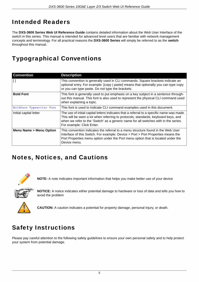
NOTE: A note indicates important information that helps you make better use of your device
NOTICE: A notice indicates either potential damage to hardware or loss of data and tells you how to avoid the problem
CAUTION: A caution indicates a potential for property damage, personal injury, or death.
ii

DXS-3600 Series 10GbE Layer 2/3 Switch Web UI Reference Guide
Safety CautionsTo greatly reduce the risk of physical injury, electrical shock, fire, and damage to equipment, observe the following precautions.
Observe and follow service markings.
• Do not attempt to service any product, except when it is explained in the system’s documentation.
• Opening or removing covers that are marked with this ( ) symbol may expose the user to electrical shock.• Only a trained service technician should service components inside these compartments.
If any of the following conditions occur, unplug the product from the electrical outlet immediately and replace the part or contact your trained service provider:
• Damage to the power cable, extension cable, or plug.• An object has fallen into the product.• The product has been exposed to water.• The product has been dropped or damaged.• The product does not operate correctly when the operating instructions are correctly followed.
General safety cautions:
• Keep the system away from radiators and heat sources. Also, do not block cooling vents.• Do not spill food or liquids on system components, and never operate the product in a wet environment. If the
system gets wet contact your trained service provider.• Do not push any objects into the openings of the system. Doing so can cause fire or electric shock by shorting out
interior components.• Only use this product with approved equipment.• Allow the product to cool before removing the cover or touching internal components.• Operate the product only from the type of external power source indicated on the electrical ratings label. If unsure of
the type of power source required, consult your service provider or local power company.• Be sure that attached devices are electrically rated to operate with the power available in your location.• Use only approved power cable(s). If you have not been provided with a power cable for your system or for any AC-
powered option intended for your system, purchase a power cable that is approved for use in your country. The power cable must be rated for the product and for the voltage and current marked on the product's electrical ratings label. The voltage and current rating of the cable should be greater than the ratings marked on the product.
• To help prevent electric shock, plug the system and peripheral power cables into properly grounded electrical outlets. These cables are equipped with three-prong plugs to help ensure proper grounding. Do not use adapter plugs or remove the grounding prong from a cable. If using an extension cable is necessary, use a 3-wire cable with properly grounded plugs.
• Observe the extension cable and power strip ratings. Make sure that the total ampere rating of all products plugged into the extension cable or power strip does not exceed 80 percent of the ampere ratings limit for the extension cable or power strip.
• To help protect the system from sudden, transient increases and decreases in electrical power, use a surge suppressor, line conditioner, or uninterruptible power supply (UPS).
• Position system cables and power cables carefully. Route cables so that they cannot be stepped on or tripped over. Be sure that nothing rests on any cables.
• Do not modify power cables or plugs. Consult a licensed electrician or your power company for site modifications. Always follow your local or national wiring rules.
When connecting or disconnecting power to and from hot-pluggable power supplies, observe the following guidelines:
• Install the power supply before connecting the power cable to the power supply.• Unplug the power cable before removing the power supply.• If the system has multiple sources of power, disconnect power from the system by unplugging all power cables from
the power supplies.• Move products with care and ensure that all casters and stabilizers are firmly connected to the system. Avoid
sudden stops and uneven surfaces.
To help avoid damage to the system, be sure that the voltage selection switch, on the power supply, is set to match the power available at the switch’s location:
iii
DXS-3600 Series 10GbE Layer 2/3 Switch Web UI Reference Guide
• 115V/60Hz is used mostly in North and South America as well as Far Eastern countries like as South Korea and Taiwan
• 100V/50Hz is used mostly in Eastern Japan and 100V/60Hz in Western Japan• 230V/50Hz is used mostly in Europe, the Middle East, Africa and the Far East
General Precautions for Rack-Mountable ProductsPlease pay careful attention to the following precautions concerning rack stability and safety. Systems are considered to be components in a rack. Thus, a component refers to any system, as well as to various peripherals or supporting hardware.
• Before working on the rack, make sure that the stabilizers are secured to the rack, extended to the floor, and that the full weight of the rack rests on the floor. Install front and side stabilizers on a single rack or front stabilizers for joined multiple racks before working on the rack.
• Always load the rack from the bottom up, and load the heaviest item in the rack first.• Make sure that the rack is level and stable before extending a component from the rack.• Use caution when pressing the component rail release latches and sliding a component into or out of a rack; the
slide rails can pinch your fingers.• After a component is inserted into the rack, carefully extend the rail into a locking position, and then slide the
component into the rack.• Do not overload the AC supply branch circuit that provides power to the rack. The total rack load should not exceed
80 percent of the branch circuit rating.• Ensure that proper airflow is provided to components in the rack.• Do not step on or stand on any component when servicing other components in a rack.
Protecting Against Electrostatic DischargeStatic electricity can harm delicate components inside the system. To prevent static damage, discharge static electricity from your body before touching any of the electronic components, such as the microprocessor. This can be done by periodically touching an unpainted metal surface on the chassis.
The following steps can also be taken prevent damage from electrostatic discharge (ESD):
• When unpacking a static-sensitive component from its shipping carton, do not remove the component from the antistatic packing material until ready to install the component in the system. Just before unwrapping the antistatic packaging, be sure to discharge static electricity from your body.
• When transporting a sensitive component, first place it in an antistatic container or packaging.• Handle all sensitive components in a static-safe area. If possible, use antistatic floor pads, workbench pads and an
antistatic grounding strap.
CAUTION: Installing systems in a rack without the front and side stabilizers installed could cause the rack to tip over, potentially resulting in serious injury. After installing system/components in a rack, never pull more than one component out of the rack on its slide assemblies at one time. The weight of more than one extended component could cause the rack to tip over and may result in serious injury.
CAUTION: Never defeat the ground conductor or operate the equipment in the absence of a suitably installed ground conductor. Contact the appropriate electrical inspection authority or an electrician if uncertain that suitable grounding is available.
CAUTION: The system chassis must be positively grounded to the rack cabinet frame. Do not attempt to connect power to the system until grounding cables are connected. Completed power and safety ground wiring must be inspected by a qualified electrical inspector. An energy hazard will exist if the safety ground cable is omitted or disconnected.
iv
DXS-3600 Series 10GbE Layer 2/3 Switch Web UI Reference Guide
Table of ContentsIntended Readers . . . . . . . . . . . . . . . . . . . . . . . . . . . . . . . . . . . . . . . . . . . . . . . . . . . . . . . . . . . . . . . . . . . . . . . . ii
Typographical Conventions. . . . . . . . . . . . . . . . . . . . . . . . . . . . . . . . . . . . . . . . . . . . . . . . . . . . . . . . . . . . . . . . . ii
Notes, Notices, and Cautions . . . . . . . . . . . . . . . . . . . . . . . . . . . . . . . . . . . . . . . . . . . . . . . . . . . . . . . . . . . . . . . ii
Safety Instructions. . . . . . . . . . . . . . . . . . . . . . . . . . . . . . . . . . . . . . . . . . . . . . . . . . . . . . . . . . . . . . . . . . . . . . . . ii
Safety Cautions . . . . . . . . . . . . . . . . . . . . . . . . . . . . . . . . . . . . . . . . . . . . . . . . . . . . . . . . . . . . . . . . . . . . . . . . iii
General Precautions for Rack-Mountable Products . . . . . . . . . . . . . . . . . . . . . . . . . . . . . . . . . . . . . . . . . . . . . . iv
Protecting Against Electrostatic Discharge . . . . . . . . . . . . . . . . . . . . . . . . . . . . . . . . . . . . . . . . . . . . . . . . . . . . . iv
Web-based Switch Configuration . . . . . . . . . . . . . . . . . . . . . . . . . . . . . . . . . . . . . . . . . . . . . . . . . . . . . . . . . . . . . 2
Management Options . . . . . . . . . . . . . . . . . . . . . . . . . . . . . . . . . . . . . . . . . . . . . . . . . . . . . . . . . . . . . . . . . . . . . 2
Connecting using the Web User Interface. . . . . . . . . . . . . . . . . . . . . . . . . . . . . . . . . . . . . . . . . . . . . . . . . . . . . . 2
Logging onto the Web Manager . . . . . . . . . . . . . . . . . . . . . . . . . . . . . . . . . . . . . . . . . . . . . . . . . . . . . . . . . . . . 2
Areas of the User Interface. . . . . . . . . . . . . . . . . . . . . . . . . . . . . . . . . . . . . . . . . . . . . . . . . . . . . . . . . . . . . . . . 3
Switch Status . . . . . . . . . . . . . . . . . . . . . . . . . . . . . . . . . . . . . . . . . . . . . . . . . . . . . . . . . . . . . . . . . . . . . . . . . . . . . 5
Device Information . . . . . . . . . . . . . . . . . . . . . . . . . . . . . . . . . . . . . . . . . . . . . . . . . . . . . . . . . . . . . . . . . . . . . . . 6
Temperature Status. . . . . . . . . . . . . . . . . . . . . . . . . . . . . . . . . . . . . . . . . . . . . . . . . . . . . . . . . . . . . . . . . . . . . . . 7
CPU Status . . . . . . . . . . . . . . . . . . . . . . . . . . . . . . . . . . . . . . . . . . . . . . . . . . . . . . . . . . . . . . . . . . . . . . . . . . . . . 8
System Log Entries . . . . . . . . . . . . . . . . . . . . . . . . . . . . . . . . . . . . . . . . . . . . . . . . . . . . . . . . . . . . . . . . . . . . . . . 9
Fan Status . . . . . . . . . . . . . . . . . . . . . . . . . . . . . . . . . . . . . . . . . . . . . . . . . . . . . . . . . . . . . . . . . . . . . . . . . . . . . 11
Flash, SD Card, and Memory Status. . . . . . . . . . . . . . . . . . . . . . . . . . . . . . . . . . . . . . . . . . . . . . . . . . . . . . . . . 12
Traffic Monitoring . . . . . . . . . . . . . . . . . . . . . . . . . . . . . . . . . . . . . . . . . . . . . . . . . . . . . . . . . . . . . . . . . . . . . . . . . 13
Traffic Monitoring by Direction. . . . . . . . . . . . . . . . . . . . . . . . . . . . . . . . . . . . . . . . . . . . . . . . . . . . . . . . . . . . . . 13
Traffic Monitoring by Type. . . . . . . . . . . . . . . . . . . . . . . . . . . . . . . . . . . . . . . . . . . . . . . . . . . . . . . . . . . . . . . . . 14
Traffic Monitoring by Size . . . . . . . . . . . . . . . . . . . . . . . . . . . . . . . . . . . . . . . . . . . . . . . . . . . . . . . . . . . . . . . . . 15
Traffic Monitoring by Error. . . . . . . . . . . . . . . . . . . . . . . . . . . . . . . . . . . . . . . . . . . . . . . . . . . . . . . . . . . . . . . . . 16
Management . . . . . . . . . . . . . . . . . . . . . . . . . . . . . . . . . . . . . . . . . . . . . . . . . . . . . . . . . . . . . . . . . . . . . . . . . . . . . 17
Download Firmware . . . . . . . . . . . . . . . . . . . . . . . . . . . . . . . . . . . . . . . . . . . . . . . . . . . . . . . . . . . . . . . . . . . . . 17
Download Configuration . . . . . . . . . . . . . . . . . . . . . . . . . . . . . . . . . . . . . . . . . . . . . . . . . . . . . . . . . . . . . . . . . . 18
Upload Firmware . . . . . . . . . . . . . . . . . . . . . . . . . . . . . . . . . . . . . . . . . . . . . . . . . . . . . . . . . . . . . . . . . . . . . . . . 18
Upload Configuration. . . . . . . . . . . . . . . . . . . . . . . . . . . . . . . . . . . . . . . . . . . . . . . . . . . . . . . . . . . . . . . . . . . . . 18
Appendix A - Password Recovery Procedure . . . . . . . . . . . . . . . . . . . . . . . . . . . . . . . . . . . . . . . . . . . . . . . . . . 20
Appendix B - System Log Entries. . . . . . . . . . . . . . . . . . . . . . . . . . . . . . . . . . . . . . . . . . . . . . . . . . . . . . . . . . . . 21
Appendix C - Trap Entries . . . . . . . . . . . . . . . . . . . . . . . . . . . . . . . . . . . . . . . . . . . . . . . . . . . . . . . . . . . . . . . . . . 41
DXS-3600 Series 10GbE Layer 2/3 Switch Web UI Reference Guide
Web-based Switch ConfigurationManagement OptionsConnecting using the Web User Interface
Management OptionsThis switch provides multiple access platforms that can be used to configure, manage and monitor networking features available on this switch. Currently there are three management platforms available and they are described below.
The Command Line Interface (CLI) through the Serial Port or remote TELNET
This switch can be managed, out-of-band, by using the console port on the front panel of the switch. Alternatively, the switch can also be managed, in-band, by using a TELNET connection to any of the LAN ports on this switch. The command line interface provides complete access to all switch management features.
SNMP-based Management
The switch can be managed with an SNMP-compatible console program. The switch supports SNMP version 1.0, version 2.0 and version 3.0. The SNMP agent decodes the incoming SNMP messages and responds to requests with MIB objects stored in the database. The SNMP agent updates the MIB objects to generate statistics and counters.
Web-based Management Interface
After successfully installing the switch, the user can configure the switch, monitor the LED panel, and display statistics graphically using a Web browser, such as Microsoft® Internet Explorer (version 6.0 and later), Mozilla Firefox (version 3.0 and later), Safari (version 4.0 and later), Google Chrome (version 5.0 and later), Opera (version 9.0 and later), and Netscape (version 7.0 and later).
Connecting using the Web User InterfaceAll software functions of the switch can be managed, configured, and monitored via the embedded Web-based (HTML) interface. This can be done from any remote station on the network through a standard web browser, such as Internet Explorer (version 6.0 and later), Mozilla Firefox (version 3.0 and later), Safari (version 4.0 and later), Google Chrome (version 5.0 and later), Opera (version 9.0 and later), or Netscape (version 7.0 and later). The browser acts as a universal access tool and can communicate directly with the switch using the HTTP protocol.
Only some of the software features that can be configured using the Command Line Interface can also be configured using the Web User Interface.
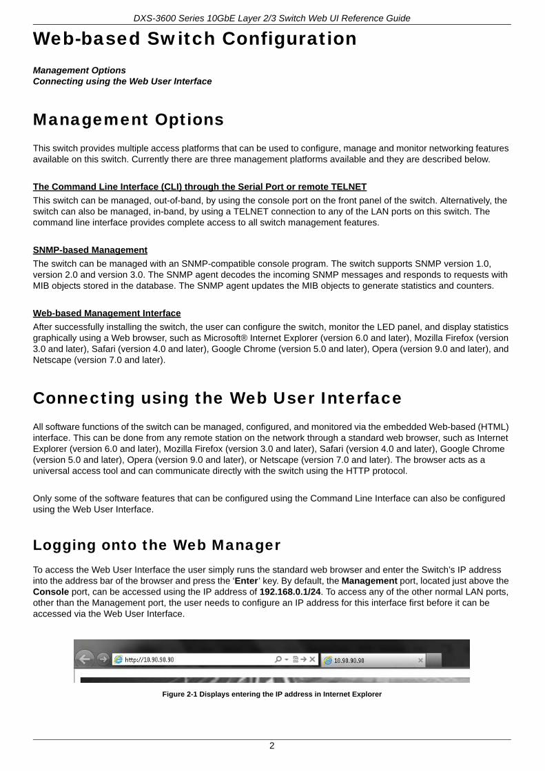
Logging onto the Web ManagerTo access the Web User Interface the user simply runs the standard web browser and enter the Switch’s IP address into the address bar of the browser and press the ‘Enter’ key. By default, the Management port, located just above the Console port, can be accessed using the IP address of 192.168.0.1/24. To access any of the other normal LAN ports, other than the Management port, the user needs to configure an IP address for this interface first before it can be accessed via the Web User Interface.
Figure 2-1 Displays entering the IP address in Internet Explorer
2
DXS-3600 Series 10GbE Layer 2/3 Switch Web UI Reference Guide
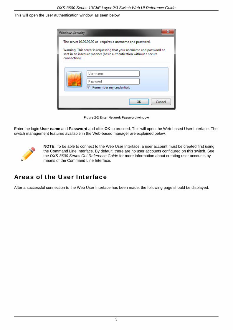
This will open the user authentication window, as seen below.
Figure 2-2 Enter Network Password window
Enter the login User name and Password and click OK to proceed. This will open the Web-based User Interface. The switch management features available in the Web-based manager are explained below.
Areas of the User InterfaceAfter a successful connection to the Web User Interface has been made, the following page should be displayed.
NOTE: To be able to connect to the Web User Interface, a user account must be created first using the Command Line Interface. By default, there are no user accounts configured on this switch. See the DXS-3600 Series CLI Reference Guide for more information about creating user accounts by means of the Command Line Interface.
3
DXS-3600 Series 10GbE Layer 2/3 Switch Web UI Reference Guide
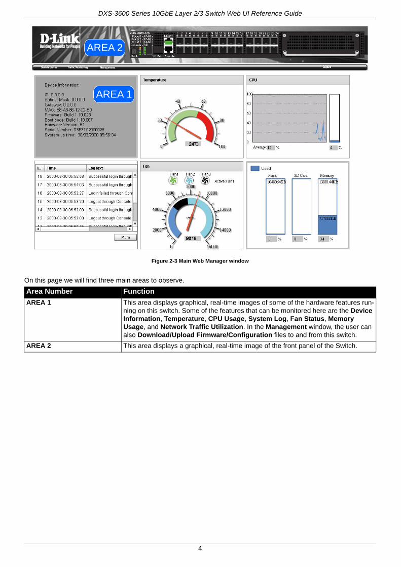
Figure 2-3 Main Web Manager window
On this page we will find three main areas to observe.
Area Number Function
AREA 1 This area displays graphical, real-time images of some of the hardware features run-ning on this switch. Some of the features that can be monitored here are the Device Information, Temperature, CPU Usage, System Log, Fan Status, Memory Usage, and Network Traffic Utilization. In the Management window, the user can also Download/Upload Firmware/Configuration files to and from this switch.
AREA 2 This area displays a graphical, real-time image of the front panel of the Switch.
AREA 1
AREA 2
4
DXS-3600 Series 10GbE Layer 2/3 Switch Web UI Reference Guide
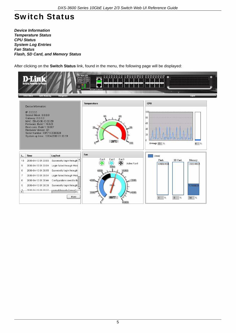
Switch StatusDevice InformationTemperature StatusCPU StatusSystem Log EntriesFan StatusFlash, SD Card, and Memory Status
After clicking on the Switch Status link, found in the menu, the following page will be displayed:
5

DXS-3600 Series 10GbE Layer 2/3 Switch Web UI Reference Guide
Device InformationIn the Device Information section, the user can view a list of basic information regarding the switch.
In the Device Information section, the following display parameters are available:
Parameter Description
IP Address Here the IP address of the switch’s main interface is displayed.
Subnet Mask Here the Subnet Mask of the switch’s main interface is displayed.
Gateway Here the Gateway IP address of the switch’s main interface is displayed.
MAC Address Here the MAC address of the switch is displayed.
Firmware Version Here the Firmware version of the switch is displayed.
Boot Code Version Here the Boot Code of the switch is displayed.
Hardware Version Here the Hardware version of the switch is displayed.
Serial Number Here the Serial number of the switch is displayed.
System Up Time Here the System’s up time is displayed.
6

DXS-3600 Series 10GbE Layer 2/3 Switch Web UI Reference Guide
Temperature StatusIn the Temperature section, the user can view a real-time display of the switch’s internal temperature. The temperature of the switch is mainly influenced by two factors: (1) the enviroment, and (2) the internal air-flow of the switch. In the Hardware Installation Guide, there are some guidelines that can assist the user with the installation of this switch in a temperature friendly environment. The fan modules, installed in this switch, have temperature sensors built-in, that automatically controls the air-flow inside the switch.
In the Temperature section, the following display parameters are available:
Parameter Description
Percentage Display In this graphic, the reading is divided into percentage sections. The green area is known as the ‘safe’ area. This area ranges from 0% to 60%. This is the optimum temperature range recommended for this switch.
Temperature Below the percentage gauge needle, the accurate temperature reading, for this switch, is displayed in degrees celsius.
Warning Section In this graphic, the reading is divided into percentage sections. The red area is known as the ‘warning’ area. This area ranges from 60% to 100%. It is recommended not to allow the switch to run this hot, to avoid component damage.
7

DXS-3600 Series 10GbE Layer 2/3 Switch Web UI Reference Guide
CPU StatusIn the CPU section, the user can view a real-time display of the switch’s CPU usage. There are a number of factors that can influance a depleted CPU usage. One of those factors are network broadcasts. In the CLI Reference Guide there is an abundance of features that can be enabled to prevent this problem from occuring.
In the CPU section, the following display parameters are available:
Parameter Description
Percentage Display In this graphic, the reading is divided into percentage sections. This area ranges from 0% to 100%.
Average Below the CPU percentage line chart, we find an accurate display of the average CPU usage percentage.
Percentage Bar In this graphic, an accurate reading of the real-time CPU usage percentage is displayed.
8
DXS-3600 Series 10GbE Layer 2/3 Switch Web UI Reference Guide
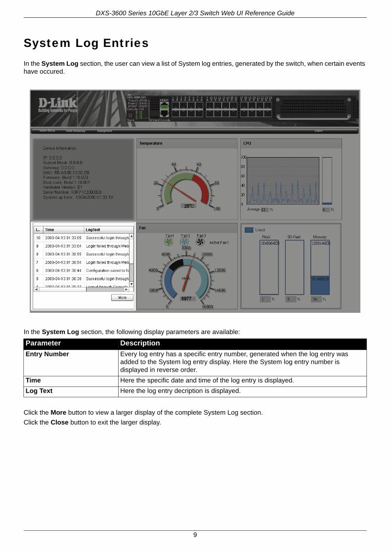
System Log EntriesIn the System Log section, the user can view a list of System log entries, generated by the switch, when certain events have occured.
In the System Log section, the following display parameters are available:
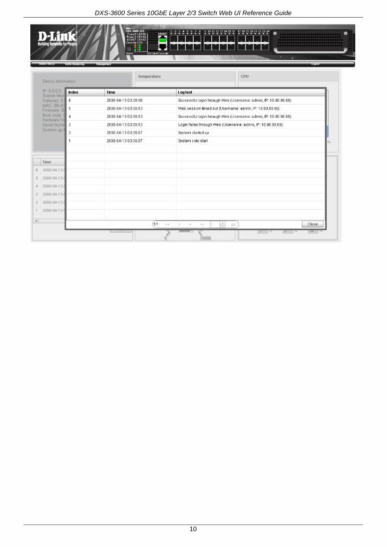
Click the More button to view a larger display of the complete System Log section.
Click the Close button to exit the larger display.
Parameter Description
Entry Number Every log entry has a specific entry number, generated when the log entry was added to the System log entry display. Here the System log entry number is displayed in reverse order.
Time Here the specific date and time of the log entry is displayed.
Log Text Here the log entry decription is displayed.
9
DXS-3600 Series 10GbE Layer 2/3 Switch Web UI Reference Guide
10
DXS-3600 Series 10GbE Layer 2/3 Switch Web UI Reference Guide
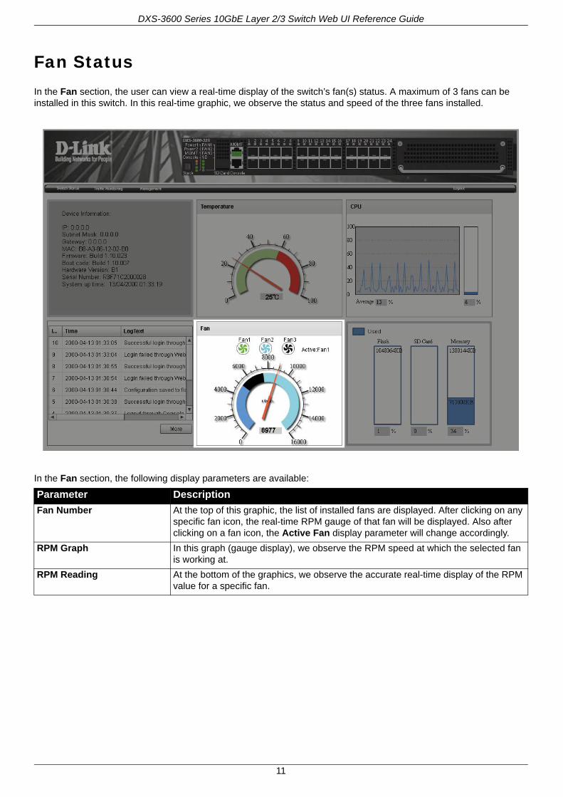
Fan StatusIn the Fan section, the user can view a real-time display of the switch’s fan(s) status. A maximum of 3 fans can be installed in this switch. In this real-time graphic, we observe the status and speed of the three fans installed.
In the Fan section, the following display parameters are available:
Parameter Description
Fan Number At the top of this graphic, the list of installed fans are displayed. After clicking on any specific fan icon, the real-time RPM gauge of that fan will be displayed. Also after clicking on a fan icon, the Active Fan display parameter will change accordingly.
RPM Graph In this graph (gauge display), we observe the RPM speed at which the selected fan is working at.
RPM Reading At the bottom of the graphics, we observe the accurate real-time display of the RPM value for a specific fan.
11
DXS-3600 Series 10GbE Layer 2/3 Switch Web UI Reference Guide
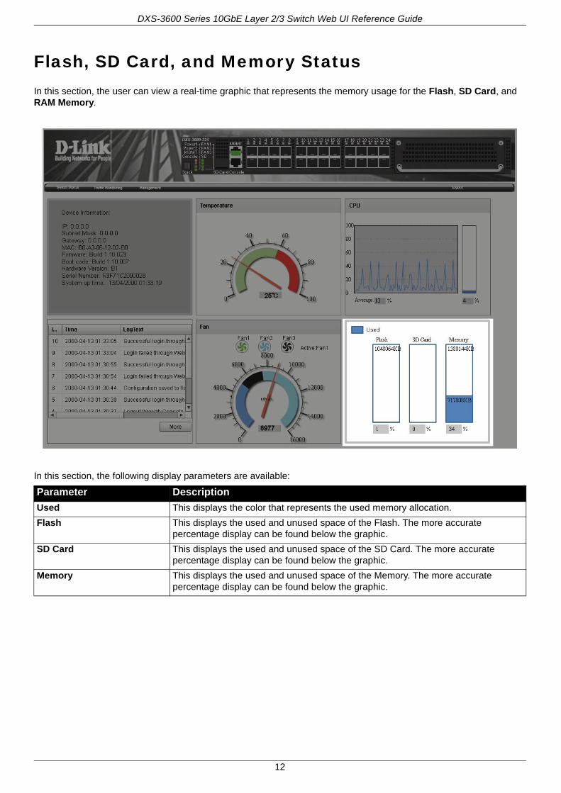
Flash, SD Card, and Memory StatusIn this section, the user can view a real-time graphic that represents the memory usage for the Flash, SD Card, and RAM Memory.
In this section, the following display parameters are available:
Parameter Description
Used This displays the color that represents the used memory allocation.
Flash This displays the used and unused space of the Flash. The more accurate percentage display can be found below the graphic.
SD Card This displays the used and unused space of the SD Card. The more accurate percentage display can be found below the graphic.
Memory This displays the used and unused space of the Memory. The more accurate percentage display can be found below the graphic.
12
DXS-3600 Series 10GbE Layer 2/3 Switch Web UI Reference Guide
Traffic MonitoringTraffic Monitoring by DirectionTraffic Monitoring by TypeTraffic Monitoring by SizeTraffic Monitoring by Error
After clicking on the Traffic Monitoring link, found in the menu, the following pages will be displayed.
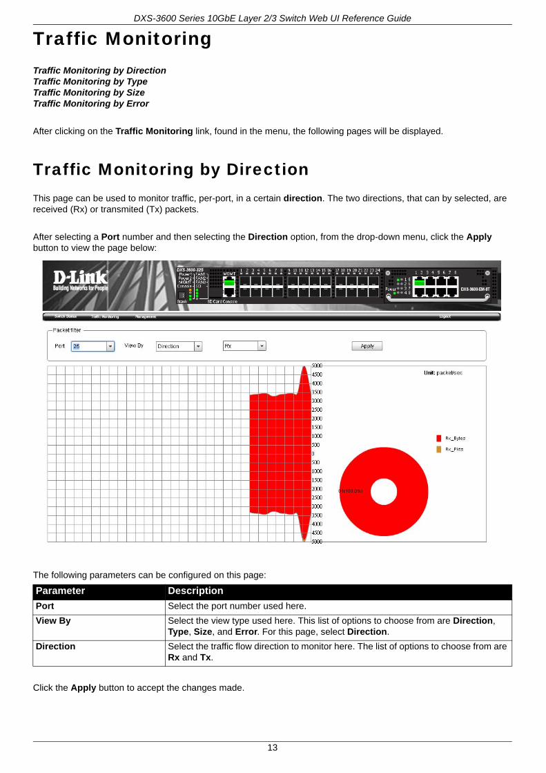
Traffic Monitoring by DirectionThis page can be used to monitor traffic, per-port, in a certain direction. The two directions, that can by selected, are received (Rx) or transmited (Tx) packets.
After selecting a Port number and then selecting the Direction option, from the drop-down menu, click the Apply button to view the page below:
The following parameters can be configured on this page:
Click the Apply button to accept the changes made.
Parameter Description
Port Select the port number used here.
View By Select the view type used here. This list of options to choose from are Direction, Type, Size, and Error. For this page, select Direction.
Direction Select the traffic flow direction to monitor here. The list of options to choose from are Rx and Tx.
13
DXS-3600 Series 10GbE Layer 2/3 Switch Web UI Reference Guide
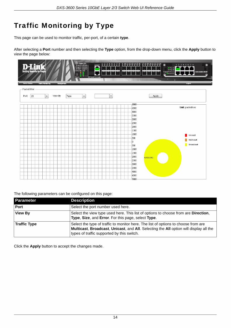
Traffic Monitoring by TypeThis page can be used to monitor traffic, per-port, of a certain type.
After selecting a Port number and then selecting the Type option, from the drop-down menu, click the Apply button to view the page below:
The following parameters can be configured on this page:
Click the Apply button to accept the changes made.
Parameter Description
Port Select the port number used here.
View By Select the view type used here. This list of options to choose from are Direction, Type, Size, and Error. For this page, select Type.
Traffic Type Select the type of traffic to monitor here. The list of options to choose from are Multicast, Broadcast, Unicast, and All. Selecting the All option will display all the types of traffic supported by this switch.
14

DXS-3600 Series 10GbE Layer 2/3 Switch Web UI Reference Guide
Traffic Monitoring by SizeThis page can be used to monitor traffic, per-port, of a certain packet size.
After selecting a Port number and then selecting the Size option, from the drop-down menu, click the Apply button to view the page below:
The following parameters can be configured on this page:
Click the Apply button to accept the changes made.
Parameter Description
Port Select the port number used here.
View By Select the view type used here. This list of options to choose from are Direction, Type, Size, and Error. For this page, select Size.
Size Select the packet size, to monitor, here. This list of options to choose from are 64, 65-127, 128-255, 256-511, 512-1023, 1024-1518, 1519-2047, 2048-4095, 4096-9216, and All. Selecting the All option, allows the user to monitor all the sizes of packets available on this switch.
15
DXS-3600 Series 10GbE Layer 2/3 Switch Web UI Reference Guide
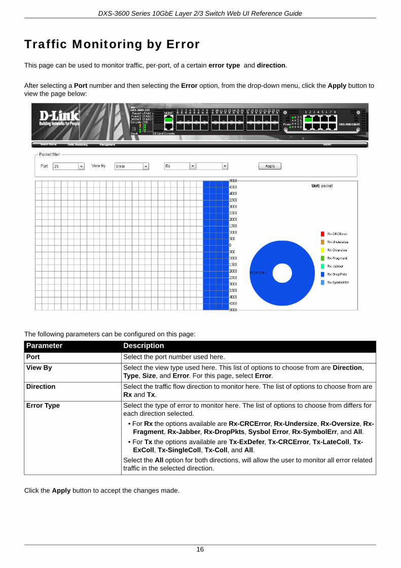
Traffic Monitoring by ErrorThis page can be used to monitor traffic, per-port, of a certain error type and direction.
After selecting a Port number and then selecting the Error option, from the drop-down menu, click the Apply button to view the page below:
The following parameters can be configured on this page:
Click the Apply button to accept the changes made.
Parameter Description
Port Select the port number used here.
View By Select the view type used here. This list of options to choose from are Direction, Type, Size, and Error. For this page, select Error.
Direction Select the traffic flow direction to monitor here. The list of options to choose from are Rx and Tx.
Error Type Select the type of error to monitor here. The list of options to choose from differs for each direction selected.
• For Rx the options available are Rx-CRCError, Rx-Undersize, Rx-Oversize, Rx-Fragment, Rx-Jabber, Rx-DropPkts, Sysbol Error, Rx-SymbolErr, and All.
• For Tx the options available are Tx-ExDefer, Tx-CRCError, Tx-LateColl, Tx-ExColl, Tx-SingleColl, Tx-Coll, and All.
Select the All option for both directions, will allow the user to monitor all error related traffic in the selected direction.
16
DXS-3600 Series 10GbE Layer 2/3 Switch Web UI Reference Guide
ManagementDownload FirmwareDownload ConfigurationUpload FirmwareUpload Configuration
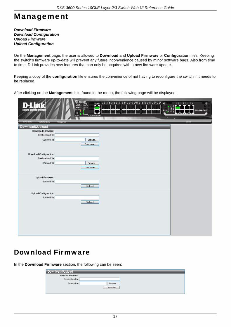
On the Management page, the user is allowed to Download and Upload Firmware or Configuration files. Keeping the switch’s firmware up-to-date will prevent any future inconvenience caused by minor software bugs. Also from time to time, D-Link provides new features that can only be acquired with a new firmware update.
Keeping a copy of the configuration file ensures the convenience of not having to reconfigure the switch if it needs to be replaced.
After clicking on the Management link, found in the menu, the following page will be displayed:
Download FirmwareIn the Download Firmware section, the following can be seen:
17
DXS-3600 Series 10GbE Layer 2/3 Switch Web UI Reference Guide
The following parameters can be configured in this section:
Click the Download button to initiate the download.
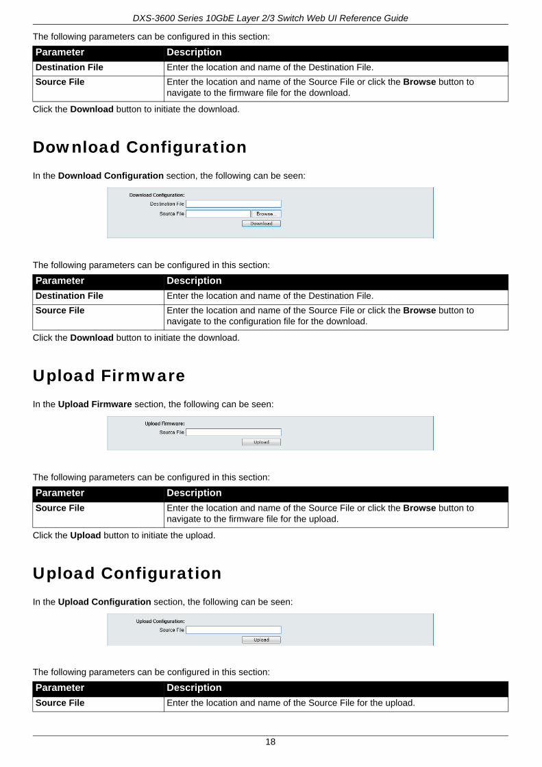
Download ConfigurationIn the Download Configuration section, the following can be seen:
The following parameters can be configured in this section:
Click the Download button to initiate the download.
Upload FirmwareIn the Upload Firmware section, the following can be seen:
The following parameters can be configured in this section:
Click the Upload button to initiate the upload.
Upload ConfigurationIn the Upload Configuration section, the following can be seen:
The following parameters can be configured in this section:
Parameter Description
Destination File Enter the location and name of the Destination File.
Source File Enter the location and name of the Source File or click the Browse button to navigate to the firmware file for the download.
Parameter Description
Destination File Enter the location and name of the Destination File.
Source File Enter the location and name of the Source File or click the Browse button to navigate to the configuration file for the download.
Parameter Description
Source File Enter the location and name of the Source File or click the Browse button to navigate to the firmware file for the upload.
Parameter Description
Source File Enter the location and name of the Source File for the upload.
18

DXS-3600 Series 10GbE Layer 2/3 Switch Web UI Reference Guide
Click the Upload button to initiate the upload.
19
DXS-3600 Series 10GbE Layer 2/3 Switch Web UI Reference Guide
20
Appendix A - Password Recovery ProcedureThis section describes the procedure for resetting passwords on the D-Link DXS-3600 Series switch.
Authenticating any user who tries to access networks is necessary and important. The basic authentication method used to accept qualified users is through a local login, utilizing a Username and Password. Sometimes, passwords get forgotten or destroyed, so network administrators need to reset these passwords. This section will explain how the Password Recovery feature can help network administrators reach this goal.
The following steps explain how to use the Password Recovery feature on this switch to easily recover passwords.
Complete these steps to reset the password:
1. For security reasons, the Password Recovery feature requires the user to physically access the device. Therefore this feature is only applicable when there is a direct connection to the console port of the device. It is necessary for the user needs to attach a terminal or PC with terminal emulation to the console port of the switch.
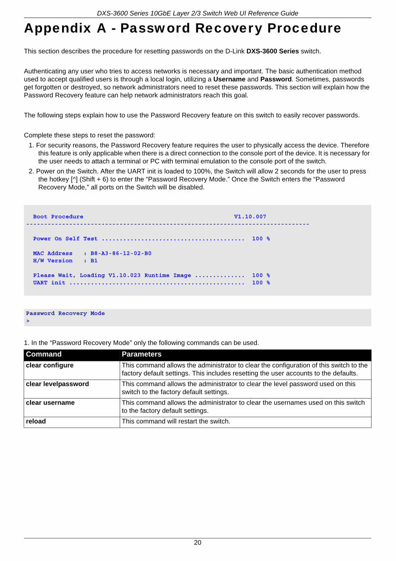
2. Power on the Switch. After the UART init is loaded to 100%, the Switch will allow 2 seconds for the user to press the hotkey [^] (Shift + 6) to enter the “Password Recovery Mode.” Once the Switch enters the “Password Recovery Mode,” all ports on the Switch will be disabled.
1. In the “Password Recovery Mode” only the following commands can be used.
Boot Procedure V1.10.007-------------------------------------------------------------------------------
Power On Self Test ........................................ 100 %
MAC Address : B8-A3-86-12-02-B0 H/W Version : B1
Please Wait, Loading V1.10.023 Runtime Image .............. 100 % UART init ................................................. 100 %
Password Recovery Mode>
Command Parameters
clear configure This command allows the administrator to clear the configuration of this switch to the factory default settings. This includes resetting the user accounts to the defaults.
clear levelpassword This command allows the administrator to clear the level password used on this switch to the factory default settings.
clear username This command allows the administrator to clear the usernames used on this switch to the factory default settings.
reload This command will restart the switch.
DXS-3600 Series 10GbE Layer 2/3 Switch Web UI Reference Guide
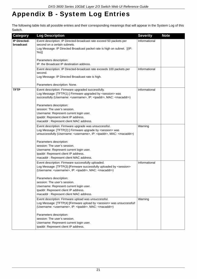
Appendix B - System Log EntriesThe following table lists all possible entries and their corresponding meanings that will appear in the System Log of this Switch.
Category Log Description Severity Note
IP Directed-broadcast
Event description: IP Directed-broadcast rate exceed 50 packets per second on a certain subnets.Log Message: IP Directed Broadcast packet rate is high on subnet. [(IP: %s)]
Parameters description:IP: the Broadcast IP destination address.
Informational
Event description: IP Directed-broadcast rate exceeds 100 packets per second.Log Message: IP Directed Broadcast rate is high.
Parameters description: None.
Informational
TFTP Event description: Firmware upgraded successfully.Log Message: [TFTP(1):] Firmware upgraded by <session> was successfully (Username: <username>, IP: <ipaddr>, MAC: <macaddr>)
Parameters description:session: The user’s session.Username: Represent current login user.Ipaddr: Represent client IP address.macaddr : Represent client MAC address.
Informational
Event description: Firmware upgrade was unsuccessful.Log Message: [TFTP(2):] Firmware upgrade by <session> was unsuccessfully (Username: <username>, IP: <ipaddr>, MAC: <macaddr>)
Parameters description:session: The user’s session.Username: Represent current login user.Ipaddr: Represent client IP address.macaddr : Represent client MAC address.
Warning
Event description: Firmware successfully uploaded.Log Message: [TFTP(3):]Firmware successfully uploaded by <session> (Username: <username>, IP: <ipaddr>, MAC: <macaddr>)
Parameters description:session: The user’s session.Username: Represent current login user.Ipaddr: Represent client IP address.macaddr : Represent client MAC address.
Informational
Event description: Firmware upload was unsuccessful.Log Message: [TFTP(4):]Firmware upload by <session> was unsuccessful! (Username: <username>, IP: <ipaddr>, MAC: <macaddr>)
Parameters description:session: The user’s session.Username: Represent current login user.Ipaddr: Represent client IP address.
Warning
21
DXS-3600 Series 10GbE Layer 2/3 Switch Web UI Reference Guide
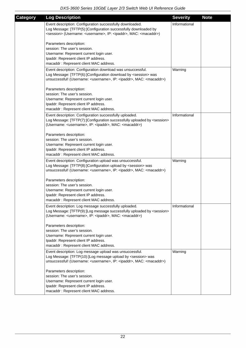
Event description: Configuration successfully downloaded.Log Message: [TFTP(5):]Configuration successfully downloaded by <session> (Username: <username>, IP: <ipaddr>, MAC: <macaddr>)
Parameters description:session: The user’s session.Username: Represent current login user.Ipaddr: Represent client IP address.macaddr : Represent client MAC address.
Informational
Event description: Configuration download was unsuccessful.Log Message: [TFTP(6):]Configuration download by <session> was unsuccessful! (Username: <username>, IP: <ipaddr>, MAC: <macaddr>)
Parameters description:session: The user’s session.Username: Represent current login user.Ipaddr: Represent client IP address.macaddr : Represent client MAC address.
Warning
Event description: Configuration successfully uploaded.Log Message: [TFTP(7):]Configuration successfully uploaded by <session> (Username: <username>, IP: <ipaddr>, MAC: <macaddr>)
Parameters description:session: The user’s session.Username: Represent current login user.Ipaddr: Represent client IP address.macaddr : Represent client MAC address.
Informational
Event description: Configuration upload was unsuccessful.Log Message: [TFTP(8):]Configuration upload by <session> was unsuccessful! (Username: <username>, IP: <ipaddr>, MAC: <macaddr>)
Parameters description:session: The user’s session.Username: Represent current login user.Ipaddr: Represent client IP address.macaddr : Represent client MAC address.
Warning
Event description: Log message successfully uploaded.Log Message: [TFTP(9):]Log message successfully uploaded by <session> (Username: <username>, IP: <ipaddr>, MAC: <macaddr>)
Parameters description:session: The user’s session.Username: Represent current login user.Ipaddr: Represent client IP address.macaddr : Represent client MAC address.
Informational
Event description: Log message upload was unsuccessful.Log Message: [TFTP(10):]Log message upload by <session> was unsuccessful! (Username: <username>, IP: <ipaddr>, MAC: <macaddr>)
Parameters description:session: The user’s session.Username: Represent current login user.Ipaddr: Represent client IP address.macaddr : Represent client MAC address.
Warning
Category Log Description Severity Note
22
DXS-3600 Series 10GbE Layer 2/3 Switch Web UI Reference Guide
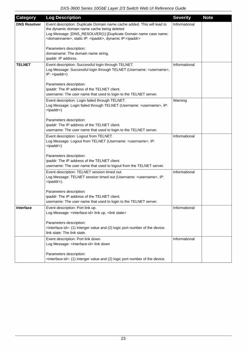
DNS Resolver Event description: Duplicate Domain name cache added. This will lead to the dynamic domain name cache being deletedLog Message: [DNS_RESOLVER(1):]Duplicate Domain name case name: <domainname>, static IP: <ipaddr>, dynamic IP:<ipaddr>
Parameters description:domainame: The domain name string.ipaddr: IP address.
Informational
TELNET Event description: Successful login through TELNET.Log Message: Successful login through TELNET (Username: <username>, IP: <ipaddr>)
Parameters description:ipaddr: The IP address of the TELNET client.username: The user name that used to login to the TELNET server.
Informational
Event description: Login failed through TELNET.Log Message: Login failed through TELNET (Username: <username>, IP: <ipaddr>)
Parameters description:ipaddr: The IP address of the TELNET client.username: The user name that used to login to the TELNET server.
Warning
Event description: Logout from TELNET.Log Message: Logout from TELNET (Username: <username>, IP: <ipaddr>)
Parameters description:ipaddr: The IP address of the TELNET client.username: The user name that used to logout from the TELNET server.
Informational
Event description: TELNET session timed out.Log Message: TELNET session timed out (Username: <username>, IP: <ipaddr>).
Parameters description:ipaddr: The IP address of the TELNET client.username: The user name that used to login to the TELNET server.
Informational
Interface Event description: Port link up.Log Message: <interface-id> link up, <link state>
Parameters description:<interface-id>: (1) Interger value and (2) logic port number of the device.link state: The link state.
Informational
Event description: Port link down.Log Message: <interface-id> link down
Parameters description:<interface-id>: (1) Interger value and (2) logic port number of the device.
Informational
Category Log Description Severity Note
23

DXS-3600 Series 10GbE Layer 2/3 Switch Web UI Reference Guide
802.1X Event description: 802.1X Authentication failure.Log Message: 802.1X Authentication failure [for <reason> ] from (Username: <username>, <interface-id>, MAC: <macaddr> )
Parameters description:reason: The reason for the failed authentication.username: The user that is being authenticated..interface-id: The interface name.macaddr: The MAC address of thr authenticated device.
Warning
Event description: 802.1X Authentication successful.Log Message: 802.1X Authentication successful from (Username: <username>, <interface-id>, MAC: <macaddr>)
Parameters description:username: The user that is being authenticated.interface-id: The interface name.macaddr: The MAC address of the authenticated device.
Informational
RADIUS Event description: The VID assigned from the RADIUS server after the RADIUS client was authenticated by the RADIUS server successfully. This VID will be assigned to the port and this port will be the VLAN untagged port member.Log Message: RADIUS server <ipaddr> assigned VID :<vlanID> to port <interface-id> (account :<username> )
Parameters description:ipaddr: The IP address of the RADIUS server.vlanID: The VID of the RADIUS assigned VLAN.interface-id: The interface name.Username: The user that is being authenticated.
Informational
Event description: The ingress bandwidth assigned from the RADIUS server after the RADIUS client was authenticated by the RADIUS server successfully. This ingress bandwidth will be assigned to the port.Log Message: RADIUS server <ipaddr> assigned ingress bandwith :<ingressBandwidth> to port <interface-id> (account : <username>)
Parameters description:ipaddr: The IP address of the RADIUS server.ingressBandwidth: The ingress bandwidth of the RADIUS assignment.interface-id: The interface name.Username: The user that is being authenticated.
Informational
Event description: The egress bandwidth assigned from the RADIUS server after the RADIUS client was successfully authenticated by the RADIUS server. This egress bandwidth will be assigned to the port.Log Message: RADIUS server <ipaddr> assigned egress bandwith :<egressBandwidth> to port <interface-id> (account: <username>)
Parameters description:ipaddr: The IP address of the RADIUS server.egressBandwidth: The egress bandwidth of the RADIUS assignment.interface-id: The interface name.Username: The user that is being authenticated.
Informational
Category Log Description Severity Note
24
DXS-3600 Series 10GbE Layer 2/3 Switch Web UI Reference Guide
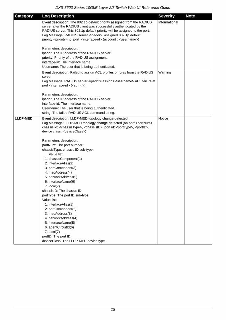
Event description: The 802.1p default priority assigned from the RADIUS server after the RADIUS client was successfully authenticated by the RADIUS server. This 802.1p default priority will be assigned to the port.Log Message: RADIUS server <ipaddr> assigned 802.1p default priority:<priority> to port <interface-id> (account : <username>)
Parameters description:ipaddr: The IP address of the RADIUS server.priority: Priority of the RADIUS assignment.interface-id: The interface name.Username: The user that is being authenticated.
Informational
Event description: Failed to assign ACL profiles or rules from the RADIUS server.Log Message: RADIUS server <ipaddr> assigns <username> ACL failure at port <interface-id> (<string>)
Parameters description:ipaddr: The IP address of the RADIUS server.interface-id: The interface name.Username: The user that is being authenticated.string: The failed RADIUS ACL command string.
Warning
LLDP-MED Event description: LLDP-MED topology change detected.Log Message: LLDP-MED topology change detected (on port <portNum>. chassis id: <chassisType>, <chassisID>, port id: <portType>, <portID>, device class: <deviceClass>)
Parameters description:portNum: The port number.chassisType: chassis ID sub-type. Value list:
1. chassisComponent(1)2. interfaceAlias(2)3. portComponent(3)4. macAddress(4)5. networkAddress(5)6. interfaceName(6)7. local(7)
chassisID: The chassis ID.portType: The port ID sub-type.Value list:
1. interfaceAlias(1)2. portComponent(2)3. macAddress(3)4. networkAddress(4)5. interfaceName(5)6. agentCircuitId(6)7. local(7)
portID: The port ID.deviceClass: The LLDP-MED device type.
Notice
Category Log Description Severity Note
25
DXS-3600 Series 10GbE Layer 2/3 Switch Web UI Reference Guide
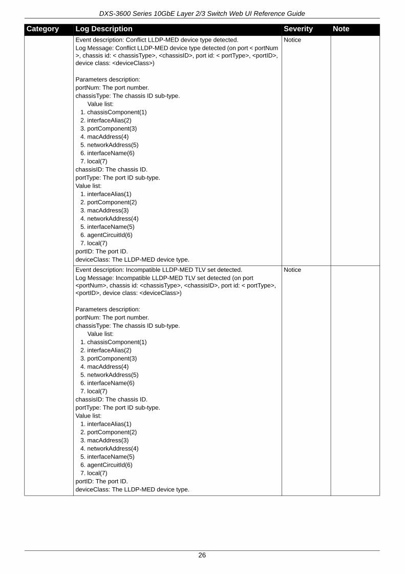
Event description: Conflict LLDP-MED device type detected.Log Message: Conflict LLDP-MED device type detected (on port < portNum >, chassis id: < chassisType>, <chassisID>, port id: < portType>, <portID>, device class: <deviceClass>)
Parameters description:portNum: The port number.chassisType: The chassis ID sub-type. Value list:
1. chassisComponent(1)2. interfaceAlias(2)3. portComponent(3)4. macAddress(4)5. networkAddress(5)6. interfaceName(6)7. local(7)
chassisID: The chassis ID.portType: The port ID sub-type.Value list:
1. interfaceAlias(1)2. portComponent(2)3. macAddress(3)4. networkAddress(4)5. interfaceName(5)6. agentCircuitId(6)7. local(7)
portID: The port ID.deviceClass: The LLDP-MED device type.
Notice
Event description: Incompatible LLDP-MED TLV set detected.Log Message: Incompatible LLDP-MED TLV set detected (on port <portNum>, chassis id: <chassisType>, <chassisID>, port id: < portType>, <portID>, device class: <deviceClass>)
Parameters description:portNum: The port number.chassisType: The chassis ID sub-type. Value list:
1. chassisComponent(1)2. interfaceAlias(2)3. portComponent(3)4. macAddress(4)5. networkAddress(5)6. interfaceName(6)7. local(7)
chassisID: The chassis ID.portType: The port ID sub-type.Value list:
1. interfaceAlias(1)2. portComponent(2)3. macAddress(3)4. networkAddress(4)5. interfaceName(5)6. agentCircuitId(6)7. local(7)
portID: The port ID.deviceClass: The LLDP-MED device type.
Notice
Category Log Description Severity Note
26
DXS-3600 Series 10GbE Layer 2/3 Switch Web UI Reference Guide
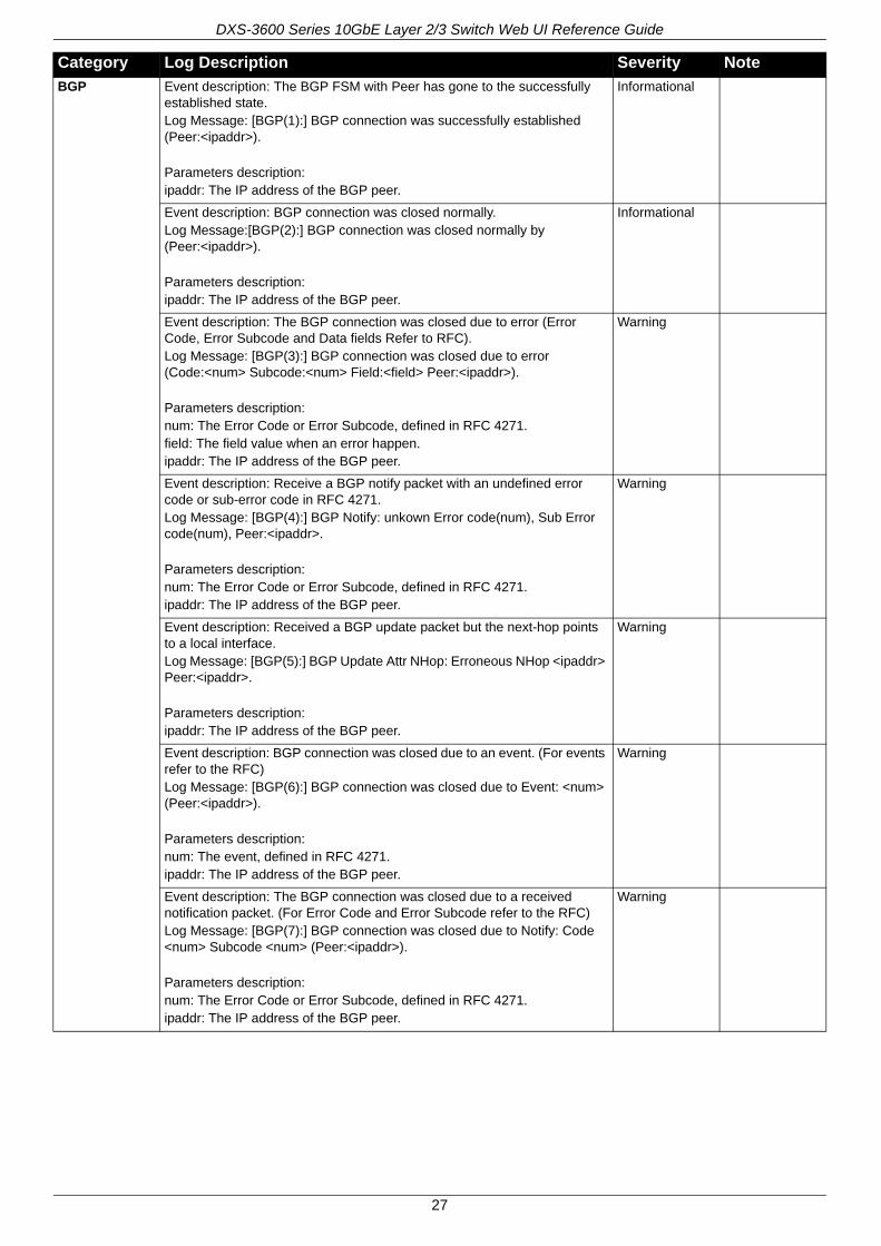
BGP Event description: The BGP FSM with Peer has gone to the successfully established state.Log Message: [BGP(1):] BGP connection was successfully established (Peer:<ipaddr>).
Parameters description:ipaddr: The IP address of the BGP peer.
Informational
Event description: BGP connection was closed normally.Log Message:[BGP(2):] BGP connection was closed normally by (Peer:<ipaddr>).
Parameters description:ipaddr: The IP address of the BGP peer.
Informational
Event description: The BGP connection was closed due to error (Error Code, Error Subcode and Data fields Refer to RFC). Log Message: [BGP(3):] BGP connection was closed due to error (Code:<num> Subcode:<num> Field:<field> Peer:<ipaddr>).
Parameters description:num: The Error Code or Error Subcode, defined in RFC 4271.field: The field value when an error happen.ipaddr: The IP address of the BGP peer.
Warning
Event description: Receive a BGP notify packet with an undefined error code or sub-error code in RFC 4271. Log Message: [BGP(4):] BGP Notify: unkown Error code(num), Sub Error code(num), Peer:<ipaddr>.
Parameters description:num: The Error Code or Error Subcode, defined in RFC 4271.ipaddr: The IP address of the BGP peer.
Warning
Event description: Received a BGP update packet but the next-hop points to a local interface. Log Message: [BGP(5):] BGP Update Attr NHop: Erroneous NHop <ipaddr> Peer:<ipaddr>.
Parameters description:ipaddr: The IP address of the BGP peer.
Warning
Event description: BGP connection was closed due to an event. (For events refer to the RFC)Log Message: [BGP(6):] BGP connection was closed due to Event: <num> (Peer:<ipaddr>).
Parameters description:num: The event, defined in RFC 4271.ipaddr: The IP address of the BGP peer.
Warning
Event description: The BGP connection was closed due to a received notification packet. (For Error Code and Error Subcode refer to the RFC)Log Message: [BGP(7):] BGP connection was closed due to Notify: Code <num> Subcode <num> (Peer:<ipaddr>).
Parameters description:num: The Error Code or Error Subcode, defined in RFC 4271.ipaddr: The IP address of the BGP peer.
Warning
Category Log Description Severity Note
27
DXS-3600 Series 10GbE Layer 2/3 Switch Web UI Reference Guide
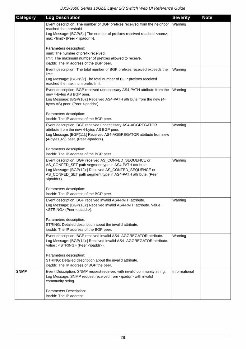
Event description: The number of BGP prefixes received from the neighbor reached the threshold.Log Message: [BGP(8):] The number of prefixes received reached <num>, max <limit> (Peer < ipaddr >).
Parameters description:num: The number of prefix received.limit: The maximum number of prefixes allowed to receive.ipaddr: The IP address of the BGP peer.
Warning
Event description: The total number of BGP prefixes received exceeds the limit.Log Message: [BGP(9):] The total number of BGP prefixes received reached the maximum prefix limit.
Warning
Event description: BGP received unnecessary AS4-PATH attribute from the new 4-bytes AS BGP peer.Log Message: [BGP(10):] Received AS4-PATH attribute from the new (4-bytes AS) peer. (Peer <ipaddr>).
Parameters description:ipaddr: The IP address of the BGP peer.
Warning
Event description: BGP received unnecessary AS4-AGGREGATOR attribute from the new 4-bytes AS BGP peer.Log Message: [BGP(11):] Received AS4-AGGREGATOR attribute from new (4-bytes AS) peer. (Peer <ipaddr>).
Parameters description:ipaddr: The IP address of the BGP peer.
Warning
Event description: BGP received AS_CONFED_SEQUENCE or AS_CONFED_SET path segment type in AS4-PATH attribute.Log Message: [BGP(12):] Received AS_CONFED_SEQUENCE or AS_CONFED_SET path segment type in AS4-PATH attribute. (Peer <ipaddr>).
Parameters description:ipaddr: The IP address of the BGP peer.
Warning
Event description: BGP received invalid AS4-PATH attribute.Log Message: [BGP(13):] Received invalid AS4-PATH attribute. Value : <STRING> (Peer <ipaddr>).
Parameters description:STRING: Detailed description about the invalid attribute.ipaddr: The IP address of the BGP peer.
Warning
Event description: BGP received invalid AS4- AGGREGATOR attribute.Log Message: [BGP(14):] Received invalid AS4- AGGREGATOR attribute. Value : <STRING> (Peer <ipaddr>).
Parameters description: STRING: Detailed description about the invalid attribute.ipaddr: The IP address of BGP the peer.
Warning
SNMP Event Description: SNMP request received with invalid community string.Log Message: SNMP request received from <ipaddr> with invalid community string.
Parameters Description:ipaddr: The IP address.
Informational
Category Log Description Severity Note
28
DXS-3600 Series 10GbE Layer 2/3 Switch Web UI Reference Guide
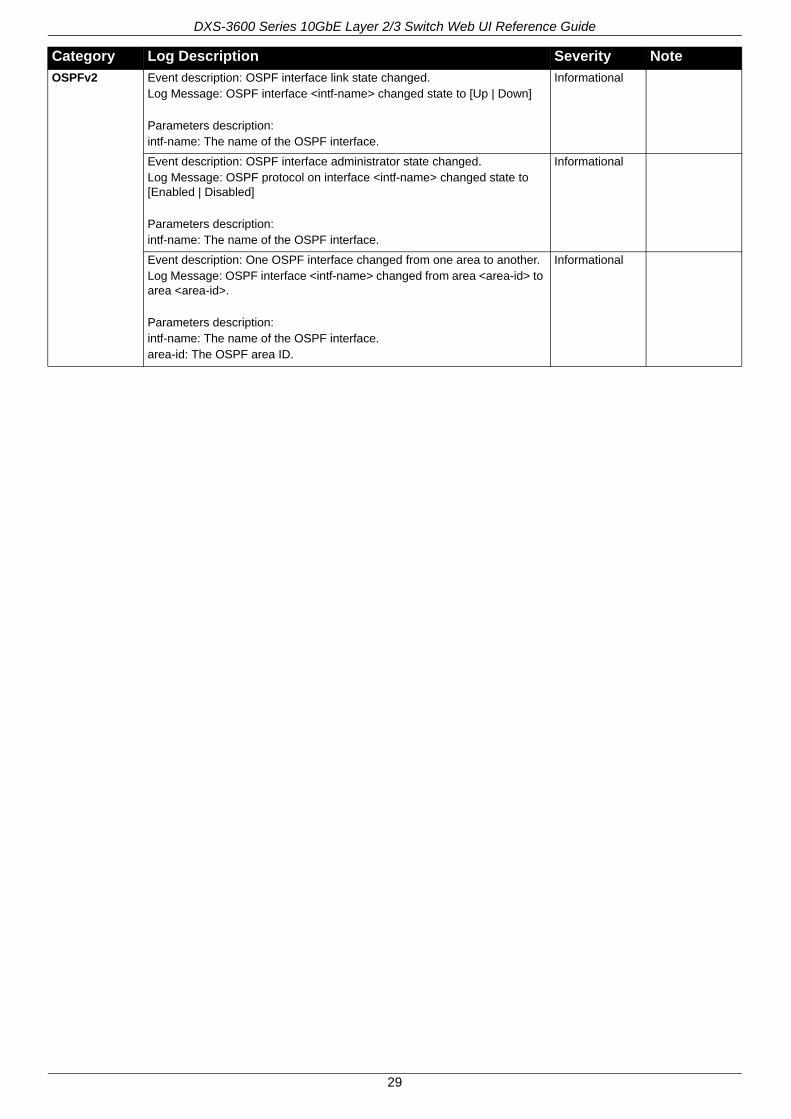
OSPFv2 Event description: OSPF interface link state changed.Log Message: OSPF interface <intf-name> changed state to [Up | Down]
Parameters description:intf-name: The name of the OSPF interface.
Informational
Event description: OSPF interface administrator state changed.Log Message: OSPF protocol on interface <intf-name> changed state to [Enabled | Disabled]
Parameters description:intf-name: The name of the OSPF interface.
Informational
Event description: One OSPF interface changed from one area to another.Log Message: OSPF interface <intf-name> changed from area <area-id> to area <area-id>.
Parameters description:intf-name: The name of the OSPF interface.area-id: The OSPF area ID.
Informational
Category Log Description Severity Note
29

DXS-3600 Series 10GbE Layer 2/3 Switch Web UI Reference Guide
Event description: One OSPF neighbor state changed from Loading to Full.Log Message: OSPF nbr <nbr-id> on interface <intf-name> changed state from Loading to Full.
Parameters description:intf-name: The name of the OSPF interface.nbr-id: The neighbor's router ID.
Notice
Event description: One OSPF neighbor state changed from Full to Down.Log Message: OSPF nbr <nbr-id> on interface <intf-name> changed state from Full to Down.
Parameters description:intf-name: The name of the OSPF interface.nbr-id: The neighbor's router ID.
Notice
Event description: One OSPF neighbor state’s dead timer expired.Log Message: OSPF nbr <nbr-id> on interface <intf-name> dead timer expired.
Parameters description:intf-name: The name of the OSPF interface.nbr-id: The neighbor's router ID.
Notice
Event description: One OSPF virtual neighbor state changed from Loading to Full.Log Message: OSPF nbr <nbr-id> on virtual link changed state from Loading to Full.
Parameters description:nbr-id: Neighbor's router ID.
Notice
Event description: One OSPF virtual neighbor state changed from Full to Down.Log Message: OSPF nbr <nbr-id> on virtual link changed state from Full to Down.
Parameters description:nbr-id: The neighbor's router ID.
Notice
Event description: The OSPF router ID was changed.Log Message: The OSPF router ID changed to <router-id>
Parameters description:router-id: The OSPF router ID.
Informational
Event description: Enable OSPF.Log Message: OSPF state changed to Enabled.
Informational
Event description: Disable OSPF.Log Message: OSPF state changed to Disabled.
Informational
VRRP Debug Event description: One virtual router’s state becomes Master.Log Message: VR <vr-id> at interface <intf-name> switched to Master
Parameters description:vr-id: The VRRP virtual router ID.intf-name: The virtual router’s interface name.
Informational
Event description: One virtual router’s state becomes Backup.Log Message: VR <vr-id> at interface <intf-name> switched to Backup
Parameters description:vr-id: The VRRP virtual router ID.intf-name: The virtual router’s interface name.
Informational
Category Log Description Severity Note
30

DXS-3600 Series 10GbE Layer 2/3 Switch Web UI Reference Guide
Event description: One virtual router’s state becomes Initiate.Log Message: VR <vr-id> at interface <intf-name> switched to Init
Parameters description:vr-id: The VRRP virtual router ID.intf-name: The virtual router’s interface name.
Informational
Event description: Authentication type mismatch on one received VRRP advertisement message.Log Message: Authentication type mismatch on VR <vr-id> at interface <intf-name>
Parameters description:vr-id: The VRRP virtual router ID.intf-name: The virtual router’s interface name.
Warning
Event description: Authentication check failed on one received VRRP advertisement message.Log Message: Authentication failed on VR <vr-id> at interface <intf-name>. Auth type <auth-type>
Parameters description:vr-id: The VRRP virtual router ID.intf-name: The virtual router’s interface name.Auth-type: The VRRP interface authentication type.
Warning
Event description: Checksum error of one received VRRP advertisement message.Log Message: Received an advertisement message with incorrect checksum on VR <vr-id> at interface <intf-name>
Parameters description:vr-id: The VRRP virtual router ID.intf-name: The virtual router’s interface name.
Warning
Event description: Virtual router ID mismatched on one received VRRP advertisement message.Log Message: Received advertisment message virtual router ID mismatched. VR <vr-id> at interface <intf-name>
Parameters description:vr-id: The VRRP virtual router ID.intf-name: The virtual router’s interface name.
Warning
Event description: Advertisement interval mismatched on one received VRRP advertisement message.Log Message: Received advertisement message interval mismatched. VR <vr-id> at interface <intf-name>
Parameters description:vr-id: The VRRP virtual router ID.intf-name: The virtual router’s interface name.
Warning
Event description: A virtual MAC address was added into the switch’s L2 table.Log Message: Added a virtual MAC <vrrp-mac-addr> into the switch’s L2 table.
Parameters description:vrrp-mac-addr: The VRRP virtual MAC address.
Notice
Event description: A virtual MAC address was deleted from the switch’s L2 table.Log Message: Deleted a virtual MAC <vrrp-mac-addr> from the switch’s L2 table.
Parameters description:vrrp-mac-addr: The VRRP virtual MAC address.
Notice
Category Log Description Severity Note
31
DXS-3600 Series 10GbE Layer 2/3 Switch Web UI Reference Guide
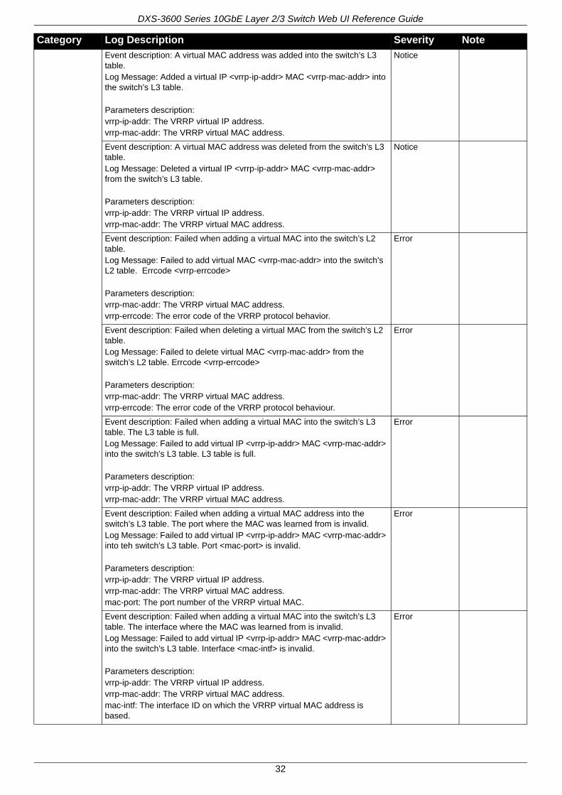
Event description: A virtual MAC address was added into the switch’s L3 table.Log Message: Added a virtual IP <vrrp-ip-addr> MAC <vrrp-mac-addr> into the switch’s L3 table.
Parameters description:vrrp-ip-addr: The VRRP virtual IP address.vrrp-mac-addr: The VRRP virtual MAC address.
Notice
Event description: A virtual MAC address was deleted from the switch’s L3 table.Log Message: Deleted a virtual IP <vrrp-ip-addr> MAC <vrrp-mac-addr> from the switch’s L3 table.
Parameters description:vrrp-ip-addr: The VRRP virtual IP address.vrrp-mac-addr: The VRRP virtual MAC address.
Notice
Event description: Failed when adding a virtual MAC into the switch’s L2 table.Log Message: Failed to add virtual MAC <vrrp-mac-addr> into the switch’s L2 table. Errcode <vrrp-errcode>
Parameters description:vrrp-mac-addr: The VRRP virtual MAC address.vrrp-errcode: The error code of the VRRP protocol behavior.
Error
Event description: Failed when deleting a virtual MAC from the switch’s L2 table.Log Message: Failed to delete virtual MAC <vrrp-mac-addr> from the switch’s L2 table. Errcode <vrrp-errcode>
Parameters description:vrrp-mac-addr: The VRRP virtual MAC address.vrrp-errcode: The error code of the VRRP protocol behaviour.
Error
Event description: Failed when adding a virtual MAC into the switch’s L3 table. The L3 table is full.Log Message: Failed to add virtual IP <vrrp-ip-addr> MAC <vrrp-mac-addr> into the switch’s L3 table. L3 table is full.
Parameters description:vrrp-ip-addr: The VRRP virtual IP address.vrrp-mac-addr: The VRRP virtual MAC address.
Error
Event description: Failed when adding a virtual MAC address into the switch’s L3 table. The port where the MAC was learned from is invalid.Log Message: Failed to add virtual IP <vrrp-ip-addr> MAC <vrrp-mac-addr> into teh switch’s L3 table. Port <mac-port> is invalid.
Parameters description:vrrp-ip-addr: The VRRP virtual IP address.vrrp-mac-addr: The VRRP virtual MAC address.mac-port: The port number of the VRRP virtual MAC.
Error
Event description: Failed when adding a virtual MAC into the switch’s L3 table. The interface where the MAC was learned from is invalid.Log Message: Failed to add virtual IP <vrrp-ip-addr> MAC <vrrp-mac-addr> into the switch’s L3 table. Interface <mac-intf> is invalid.
Parameters description:vrrp-ip-addr: The VRRP virtual IP address.vrrp-mac-addr: The VRRP virtual MAC address.mac-intf: The interface ID on which the VRRP virtual MAC address is based.
Error
Category Log Description Severity Note
32
DXS-3600 Series 10GbE Layer 2/3 Switch Web UI Reference Guide
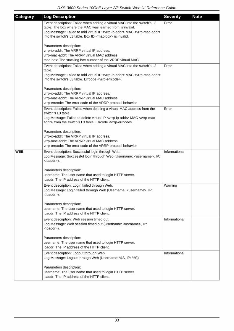
Event description: Failed when adding a virtual MAC into the switch’s L3 table. The box where the MAC was learned from is invalid.Log Message: Failed to add virtual IP <vrrp-ip-addr> MAC <vrrp-mac-addr> into the switch’s L3 table. Box ID <mac-box> is invalid.
Parameters description:vrrp-ip-addr: The VRRP virtual IP address.vrrp-mac-addr: The VRRP virtual MAC address.mac-box: The stacking box number of the VRRP virtual MAC.
Error
Event description: Failed when adding a virtual MAC into the switch’s L3 table.Log Message: Failed to add virtual IP <vrrp-ip-addr> MAC <vrrp-mac-addr> into the switch’s L3 table. Errcode <vrrp-errcode>.
Parameters description:vrrp-ip-addr: The VRRP virtual IP address.vrrp-mac-addr: The VRRP virtual MAC address.vrrp-errcode: The error code of the VRRP protocol behavior.
Error
Event description: Failed when deleting a virtual MAC address from the switch’s L3 table.Log Message: Failed to delete virtual IP <vrrp-ip-addr> MAC <vrrp-mac-addr> from the switch’s L3 table. Errcode <vrrp-errcode>.
Parameters description:vrrp-ip-addr: The VRRP virtual IP address.vrrp-mac-addr: The VRRP virtual MAC address.vrrp-errcode: The error code of the VRRP protocol behavior.
Error
WEB Event description: Successful login through Web.Log Message: Successful login through Web (Username: <username>, IP: <ipaddr>).
Parameters description:username: The user name that used to login HTTP server.ipaddr: The IP address of the HTTP client.
Informational
Event description: Login failed through Web.Log Message: Login failed through Web (Username: <username>, IP: <ipaddr>).
Parameters description: username: The user name that used to login HTTP server.ipaddr: The IP address of the HTTP client.
Warning
Event description: Web session timed out.Log Message: Web session timed out (Username: <usrname>, IP: <ipaddr>).
Parameters description: username: The user name that used to login HTTP server.ipaddr: The IP address of the HTTP client.
Informational
Event description: Logout through Web.Log Message: Logout through Web (Username: %S, IP: %S).
Parameters description: username: The user name that used to login HTTP server.ipaddr: The IP address of the HTTP client.
Informational
Category Log Description Severity Note
33
DXS-3600 Series 10GbE Layer 2/3 Switch Web UI Reference Guide
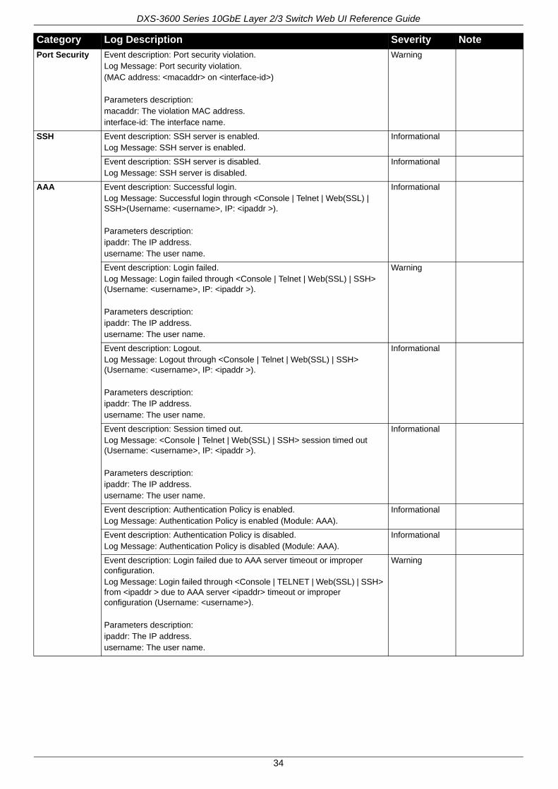
Port Security Event description: Port security violation.Log Message: Port security violation.(MAC address: <macaddr> on <interface-id>)
Parameters description:macaddr: The violation MAC address.interface-id: The interface name.
Warning
SSH Event description: SSH server is enabled.Log Message: SSH server is enabled.
Informational
Event description: SSH server is disabled.Log Message: SSH server is disabled.
Informational
AAA Event description: Successful login.Log Message: Successful login through <Console | Telnet | Web(SSL) | SSH>(Username: <username>, IP: <ipaddr >).
Parameters description:ipaddr: The IP address.username: The user name.
Informational
Event description: Login failed.Log Message: Login failed through <Console | Telnet | Web(SSL) | SSH> (Username: <username>, IP: <ipaddr >).
Parameters description:ipaddr: The IP address.username: The user name.
Warning
Event description: Logout.Log Message: Logout through <Console | Telnet | Web(SSL) | SSH> (Username: <username>, IP: <ipaddr >).
Parameters description:ipaddr: The IP address.username: The user name.
Informational
Event description: Session timed out.Log Message: <Console | Telnet | Web(SSL) | SSH> session timed out (Username: <username>, IP: <ipaddr >).
Parameters description:ipaddr: The IP address.username: The user name.
Informational
Event description: Authentication Policy is enabled.Log Message: Authentication Policy is enabled (Module: AAA).
Informational
Event description: Authentication Policy is disabled.Log Message: Authentication Policy is disabled (Module: AAA).
Informational
Event description: Login failed due to AAA server timeout or improper configuration.Log Message: Login failed through <Console | TELNET | Web(SSL) | SSH> from <ipaddr > due to AAA server <ipaddr> timeout or improper configuration (Username: <username>).
Parameters description:ipaddr: The IP address.username: The user name.
Warning
Category Log Description Severity Note
34
DXS-3600 Series 10GbE Layer 2/3 Switch Web UI Reference Guide
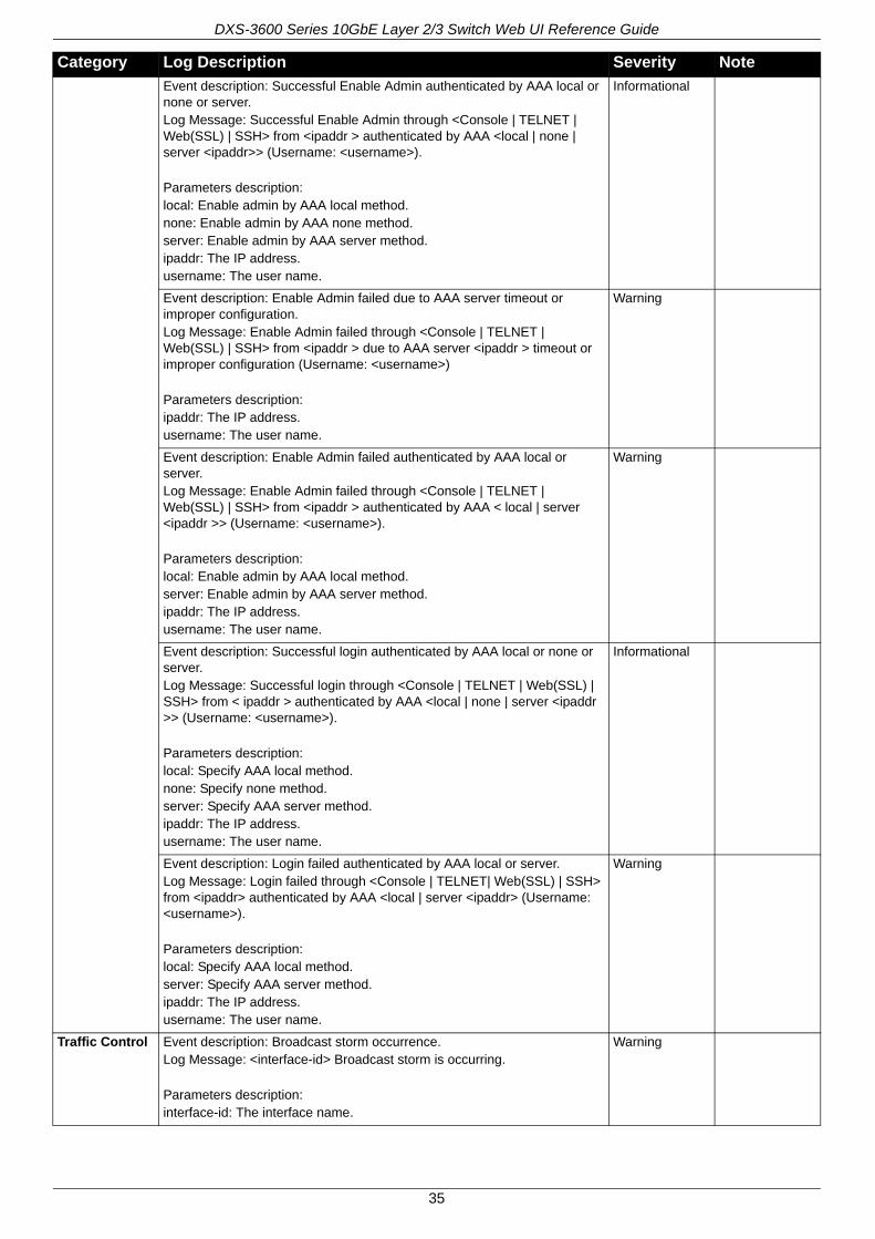
Event description: Successful Enable Admin authenticated by AAA local or none or server.Log Message: Successful Enable Admin through <Console | TELNET | Web(SSL) | SSH> from <ipaddr > authenticated by AAA <local | none | server <ipaddr>> (Username: <username>).
Parameters description:local: Enable admin by AAA local method.none: Enable admin by AAA none method.server: Enable admin by AAA server method.ipaddr: The IP address.username: The user name.
Informational
Event description: Enable Admin failed due to AAA server timeout or improper configuration.Log Message: Enable Admin failed through <Console | TELNET | Web(SSL) | SSH> from <ipaddr > due to AAA server <ipaddr > timeout or improper configuration (Username: <username>)
Parameters description:ipaddr: The IP address.username: The user name.
Warning
Event description: Enable Admin failed authenticated by AAA local or server.Log Message: Enable Admin failed through <Console | TELNET | Web(SSL) | SSH> from <ipaddr > authenticated by AAA < local | server <ipaddr >> (Username: <username>).
Parameters description:local: Enable admin by AAA local method.server: Enable admin by AAA server method.ipaddr: The IP address.username: The user name.
Warning
Event description: Successful login authenticated by AAA local or none or server.Log Message: Successful login through <Console | TELNET | Web(SSL) | SSH> from < ipaddr > authenticated by AAA <local | none | server <ipaddr >> (Username: <username>).
Parameters description:local: Specify AAA local method.none: Specify none method.server: Specify AAA server method.ipaddr: The IP address.username: The user name.
Informational
Event description: Login failed authenticated by AAA local or server.Log Message: Login failed through <Console | TELNET| Web(SSL) | SSH> from <ipaddr> authenticated by AAA <local | server <ipaddr> (Username: <username>).
Parameters description:local: Specify AAA local method.server: Specify AAA server method.ipaddr: The IP address.username: The user name.
Warning
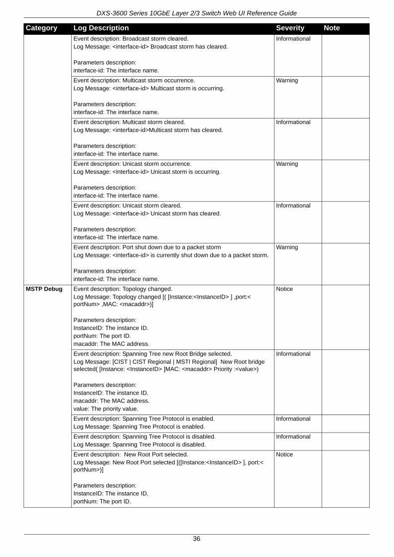
Traffic Control Event description: Broadcast storm occurrence.Log Message: <interface-id> Broadcast storm is occurring.
Parameters description:interface-id: The interface name.
Warning
Category Log Description Severity Note
35
DXS-3600 Series 10GbE Layer 2/3 Switch Web UI Reference Guide
Event description: Broadcast storm cleared.Log Message: <interface-id> Broadcast storm has cleared.
Parameters description:interface-id: The interface name.
Informational
Event description: Multicast storm occurrence.Log Message: <interface-id> Multicast storm is occurring.
Parameters description:interface-id: The interface name.
Warning
Event description: Multicast storm cleared.Log Message: <interface-id>Multicast storm has cleared.
Parameters description:interface-id: The interface name.
Informational
Event description: Unicast storm occurrence.Log Message: <interface-id> Unicast storm is occurring.
Parameters description:interface-id: The interface name.
Warning
Event description: Unicast storm cleared.Log Message: <interface-id> Unicast storm has cleared.
Parameters description:interface-id: The interface name.
Informational
Event description: Port shut down due to a packet stormLog Message: <interface-id> is currently shut down due to a packet storm.
Parameters description:interface-id: The interface name.
Warning
MSTP Debug Event description: Topology changed.Log Message: Topology changed [( [Instance:<InstanceID> ] ,port:< portNum> ,MAC: <macaddr>)]
Parameters description:InstanceID: The instance ID.portNum: The port ID.macaddr: The MAC address.
Notice
Event description: Spanning Tree new Root Bridge selected.Log Message: [CIST | CIST Regional | MSTI Regional] New Root bridge selected( [Instance: <InstanceID> ]MAC: <macaddr> Priority :<value>)
Parameters description:InstanceID: The instance ID.macaddr: The MAC address.value: The priority value.
Informational
Event description: Spanning Tree Protocol is enabled.Log Message: Spanning Tree Protocol is enabled.
Informational
Event description: Spanning Tree Protocol is disabled.Log Message: Spanning Tree Protocol is disabled.
Informational
Event description: New Root Port selected.Log Message: New Root Port selected [([Instance:<InstanceID> ], port:< portNum>)]
Parameters description:InstanceID: The instance ID.portNum: The port ID.
Notice
Category Log Description Severity Note
36
DXS-3600 Series 10GbE Layer 2/3 Switch Web UI Reference Guide
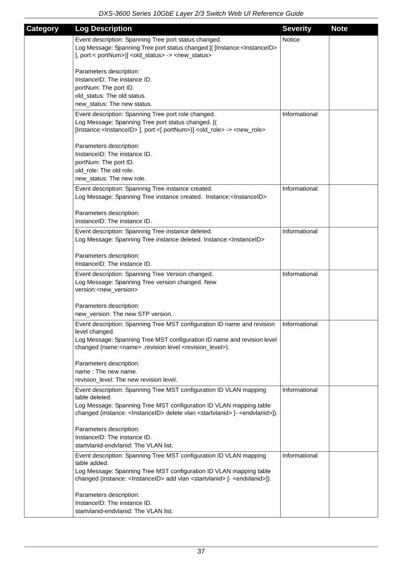
Event description: Spanning Tree port status changed.Log Message: Spanning Tree port status changed [( [Instance:<InstanceID> ], port:< portNum>)] <old_status> -> <new_status>
Parameters description:InstanceID: The instance ID.portNum: The port ID.old_status: The old status.new_status: The new status.
Notice
Event description: Spanning Tree port role changed.Log Message: Spanning Tree port status changed. [( [Instance:<InstanceID> ], port:<[ portNum>)] <old_role> -> <new_role>
Parameters description:InstanceID: The instance ID.portNum: The port ID.old_role: The old role.new_status: The new role.
Informational
Event description: Spannnig Tree instance created.Log Message: Spanning Tree instance created. Instance:<InstanceID>
Parameters description:InstanceID: The instance ID.
Informational
Event description: Spannnig Tree instance deleted.Log Message: Spanning Tree instance deleted. Instance:<InstanceID>
Parameters description:InstanceID: The instance ID.
Informational
Event description: Spanning Tree Version changed.Log Message: Spanning Tree version changed. New version:<new_version>
Parameters description:new_version: The new STP version.
Informational
Event description: Spanning Tree MST configuration ID name and revision level changed.Log Message: Spanning Tree MST configuration ID name and revision level changed (name:<name> ,revision level <revision_level>).
Parameters description:name : The new name.revision_level: The new revision level.
Informational
Event description: Spanning Tree MST configuration ID VLAN mapping table deleted.Log Message: Spanning Tree MST configuration ID VLAN mapping table changed (instance: <InstanceID> delete vlan <startvlanid> [- <endvlanid>]).
Parameters description:InstanceID: The instance ID.startvlanid-endvlanid: The VLAN list.
Informational
Event description: Spanning Tree MST configuration ID VLAN mapping table added.Log Message: Spanning Tree MST configuration ID VLAN mapping table changed (instance: <InstanceID> add vlan <startvlanid> [- <endvlanid>]).
Parameters description:InstanceID: The instance ID.startvlanid-endvlanid: The VLAN list.
Informational
Category Log Description Severity Note
37
DXS-3600 Series 10GbE Layer 2/3 Switch Web UI Reference Guide
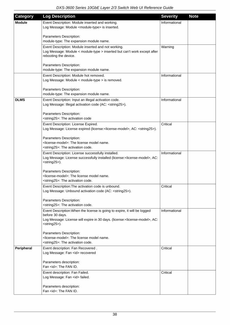
Module Event Description: Module inserted and working.Log Message: Module <module-type> is inserted.
Parameters Description:module-type: The expansion module name.
Informational
Event Description: Module inserted and not working.Log Message: Module < module-type > inserted but can’t work except after rebooting the device.
Parameters Description:module-type: The expansion module name.
Warning
Event Description: Module hot removed.Log Message: Module < module-type > is removed.
Parameters Description:module-type: The expansion module name.
Informational
DLMS Event Description: Input an illegal activation code.Log Message: Illegal activation code (AC: <string25>).
Parameters Description:<string25>: The activation code
Informational
Event Description: License Expired.Log Message: License expired (license:<license-model>, AC: <string25>).
Parameters Description:<license-model>: The license model name.<string25>: The activation code.
Critical
Event Description: License successfully installed.Log Message: License successfully installed (license:<license-model>, AC: <string25>).
Parameters Description:<license-model>: The license model name.<string25>: The activation code.
Informational
Event Description:The activation code is unbound.Log Message: Unbound activation code (AC: <string25>).
Parameters Description:<string25>: The activation code.
Critical
Event Description:When the license is going to expire, it will be logged before 30 days. Log Message: License will expire in 30 days. (license:<license-model>, AC: <string25>).
Parameters Description:<license-model>: The license model name.<string25>: The activation code.
Informational
Peripheral Event description: Fan Recovered .Log Message: Fan <id> recovered
Parameters description:Fan <id>: The FAN ID.
Critical
Event description: Fan Failed.Log Message: Fan <id> failed.
Parameters description:Fan <id>: The FAN ID.
Critical
Category Log Description Severity Note
38
DXS-3600 Series 10GbE Layer 2/3 Switch Web UI Reference Guide
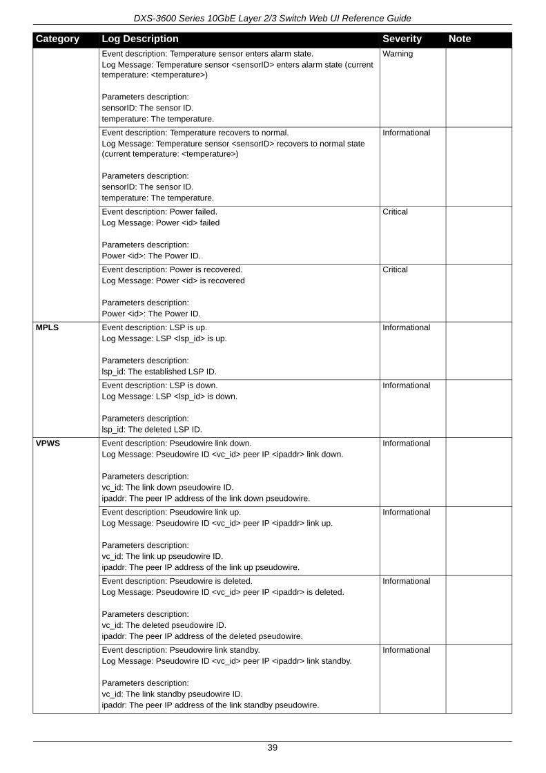
Event description: Temperature sensor enters alarm state. Log Message: Temperature sensor <sensorID> enters alarm state (current temperature: <temperature>)
Parameters description:sensorID: The sensor ID.temperature: The temperature.
Warning
Event description: Temperature recovers to normal. Log Message: Temperature sensor <sensorID> recovers to normal state (current temperature: <temperature>)
Parameters description:sensorID: The sensor ID.temperature: The temperature.
Informational
Event description: Power failed. Log Message: Power <id> failed
Parameters description:Power <id>: The Power ID.
Critical
Event description: Power is recovered. Log Message: Power <id> is recovered
Parameters description:Power <id>: The Power ID.
Critical
MPLS Event description: LSP is up.Log Message: LSP <lsp_id> is up.
Parameters description:lsp_id: The established LSP ID.
Informational
Event description: LSP is down.Log Message: LSP <lsp_id> is down.
Parameters description:lsp_id: The deleted LSP ID.
Informational
VPWS Event description: Pseudowire link down.Log Message: Pseudowire ID <vc_id> peer IP <ipaddr> link down.
Parameters description:vc_id: The link down pseudowire ID.ipaddr: The peer IP address of the link down pseudowire.
Informational
Event description: Pseudowire link up.Log Message: Pseudowire ID <vc_id> peer IP <ipaddr> link up.
Parameters description:vc_id: The link up pseudowire ID.ipaddr: The peer IP address of the link up pseudowire.
Informational
Event description: Pseudowire is deleted.Log Message: Pseudowire ID <vc_id> peer IP <ipaddr> is deleted.
Parameters description:vc_id: The deleted pseudowire ID.ipaddr: The peer IP address of the deleted pseudowire.
Informational
Event description: Pseudowire link standby.Log Message: Pseudowire ID <vc_id> peer IP <ipaddr> link standby.
Parameters description:vc_id: The link standby pseudowire ID.ipaddr: The peer IP address of the link standby pseudowire.
Informational
Category Log Description Severity Note
39

DXS-3600 Series 10GbE Layer 2/3 Switch Web UI Reference Guide
VPLS Event description: VPLS link up.Log Message: VPLS <vpls_name> link up.
Parameters description:vpls_name: The name of the link up VPLS.
Informational
Event description: VPLS link down.Log Message: VPLS <vpls_name> link down.
Parameters description:vpls_name: The name of the link down VPLS.
Informational
LACP Event description: Link Aggregation Group link up.Log Message: Link Aggregation Group <group_id> link up.
Parameters description:group_id: The group ID of the link down aggregation group.
Informational
Event description: Link Aggregation Group link down.Log Message: Link Aggregation Group <group_id> link down.
Parameters description:group_id: The group ID of the link down aggregation group.
Informational
Category Log Description Severity Note
40
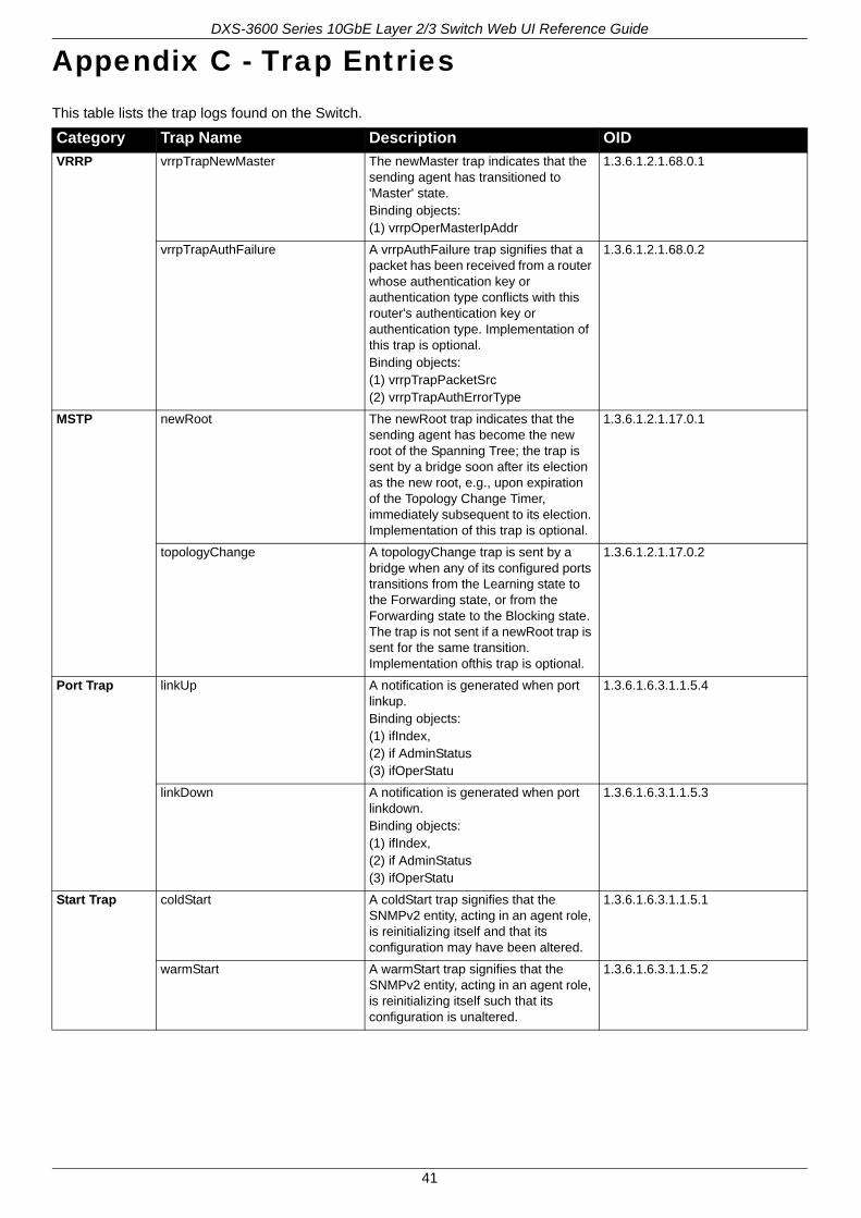
DXS-3600 Series 10GbE Layer 2/3 Switch Web UI Reference Guide
Appendix C - Trap EntriesThis table lists the trap logs found on the Switch.
Category Trap Name Description OID
VRRP vrrpTrapNewMaster The newMaster trap indicates that the sending agent has transitioned to 'Master' state.Binding objects:(1) vrrpOperMasterIpAddr
1.3.6.1.2.1.68.0.1
vrrpTrapAuthFailure A vrrpAuthFailure trap signifies that a packet has been received from a router whose authentication key or authentication type conflicts with this router's authentication key or authentication type. Implementation of this trap is optional.Binding objects:(1) vrrpTrapPacketSrc(2) vrrpTrapAuthErrorType
1.3.6.1.2.1.68.0.2
MSTP newRoot The newRoot trap indicates that the sending agent has become the new root of the Spanning Tree; the trap is sent by a bridge soon after its election as the new root, e.g., upon expiration of the Topology Change Timer, immediately subsequent to its election. Implementation of this trap is optional.
1.3.6.1.2.1.17.0.1
topologyChange A topologyChange trap is sent by a bridge when any of its configured ports transitions from the Learning state to the Forwarding state, or from the Forwarding state to the Blocking state. The trap is not sent if a newRoot trap is sent for the same transition. Implementation ofthis trap is optional.
1.3.6.1.2.1.17.0.2
Port Trap linkUp A notification is generated when port linkup.Binding objects:(1) ifIndex,(2) if AdminStatus(3) ifOperStatu
1.3.6.1.6.3.1.1.5.4
linkDown A notification is generated when port linkdown.Binding objects:(1) ifIndex,(2) if AdminStatus(3) ifOperStatu
1.3.6.1.6.3.1.1.5.3
Start Trap coldStart A coldStart trap signifies that the SNMPv2 entity, acting in an agent role, is reinitializing itself and that its configuration may have been altered.
1.3.6.1.6.3.1.1.5.1
warmStart A warmStart trap signifies that the SNMPv2 entity, acting in an agent role, is reinitializing itself such that its configuration is unaltered.
1.3.6.1.6.3.1.1.5.2
41
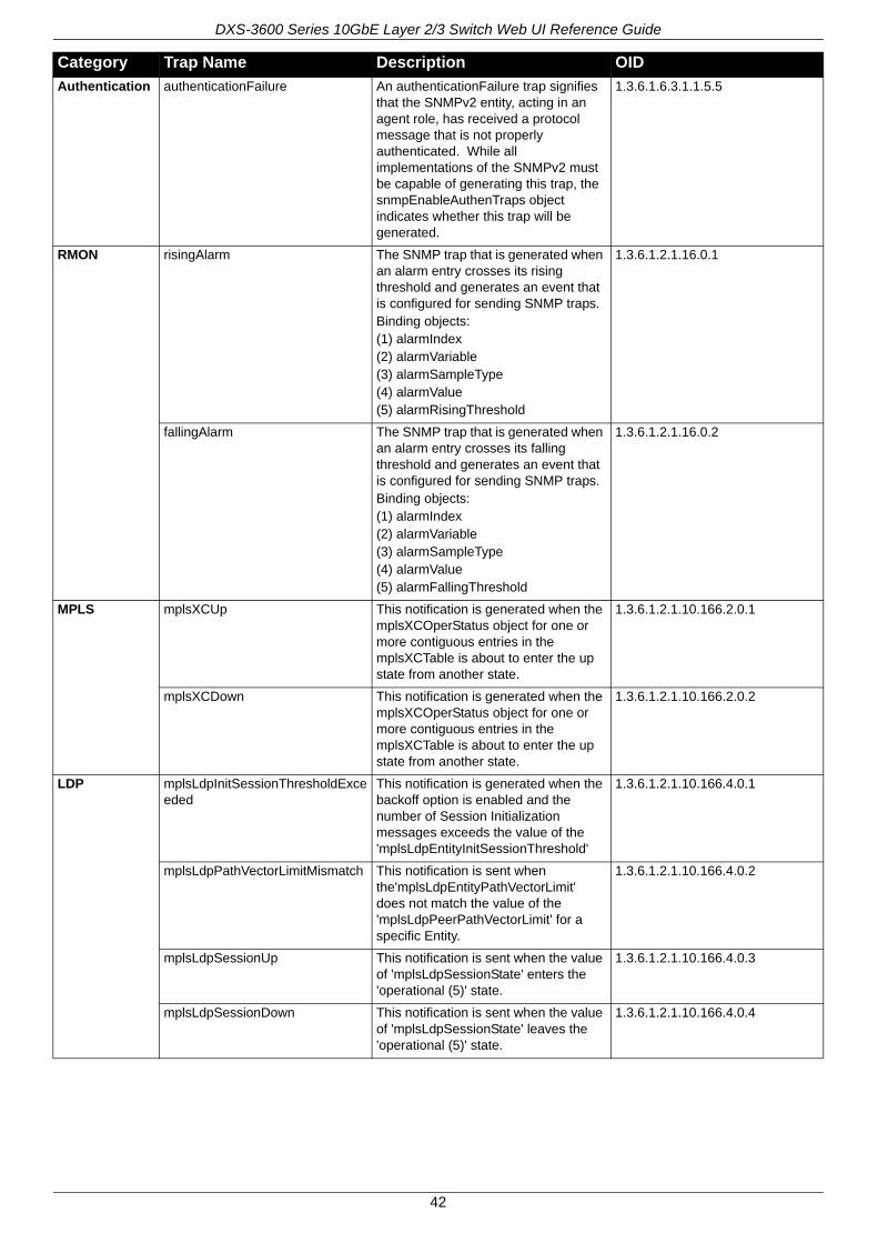
DXS-3600 Series 10GbE Layer 2/3 Switch Web UI Reference Guide
Authentication authenticationFailure An authenticationFailure trap signifies that the SNMPv2 entity, acting in an agent role, has received a protocol message that is not properly authenticated. While all implementations of the SNMPv2 must be capable of generating this trap, the snmpEnableAuthenTraps object indicates whether this trap will be generated.
1.3.6.1.6.3.1.1.5.5
RMON risingAlarm The SNMP trap that is generated when an alarm entry crosses its rising threshold and generates an event that is configured for sending SNMP traps.Binding objects:(1) alarmIndex(2) alarmVariable(3) alarmSampleType(4) alarmValue(5) alarmRisingThreshold
1.3.6.1.2.1.16.0.1
fallingAlarm The SNMP trap that is generated when an alarm entry crosses its falling threshold and generates an event that is configured for sending SNMP traps.Binding objects:(1) alarmIndex(2) alarmVariable(3) alarmSampleType(4) alarmValue(5) alarmFallingThreshold
1.3.6.1.2.1.16.0.2
MPLS mplsXCUp This notification is generated when the mplsXCOperStatus object for one or more contiguous entries in the mplsXCTable is about to enter the up state from another state.
1.3.6.1.2.1.10.166.2.0.1
mplsXCDown This notification is generated when the mplsXCOperStatus object for one or more contiguous entries in the mplsXCTable is about to enter the up state from another state.
1.3.6.1.2.1.10.166.2.0.2
LDP mplsLdpInitSessionThresholdExceeded
This notification is generated when the backoff option is enabled and the number of Session Initialization messages exceeds the value of the 'mplsLdpEntityInitSessionThreshold'
1.3.6.1.2.1.10.166.4.0.1
mplsLdpPathVectorLimitMismatch This notification is sent when the'mplsLdpEntityPathVectorLimit' does not match the value of the 'mplsLdpPeerPathVectorLimit' for a specific Entity.
1.3.6.1.2.1.10.166.4.0.2
mplsLdpSessionUp This notification is sent when the value of 'mplsLdpSessionState' enters the 'operational (5)' state.
1.3.6.1.2.1.10.166.4.0.3
mplsLdpSessionDown This notification is sent when the value of 'mplsLdpSessionState' leaves the 'operational (5)' state.
1.3.6.1.2.1.10.166.4.0.4
Category Trap Name Description OID
42

DXS-3600 Series 10GbE Layer 2/3 Switch Web UI Reference Guide
LACP linkUp A linkUp trap signifies that the SNMP entity, acting in an agent role, has detected that the ifOperStatus object for one of its communication links left the down state and transitioned into some other state (but not into the notPresent state). This other state is indicated by the included value of ifOperStatus.
Binding objects:(1) ifIndex(2) if AdminStatus(3) ifOperStatus
1.3.6.1.6.3.1.1.5.4
linkDown A linkDown trap signifies that the SNMP entity, acting in an agent role, has detected that the ifOperStatus object for one of its communication links is about to enter the down state from some other state (but not from the notPresent state). This other state is indicated by the included value of ifOperStatus.
Binding objects:(1) ifIndex(2) if AdminStatus(3) ifOperStatus
1.3.6.1.6.3.1.1.5.3
Category Trap Name Description OID
43