WBDB UFGS Diesel Generator Application
68
************************************************************************** USACE / NAVFAC / AFCEC / NASA UFGS-26 32 14.00 10 (February 2010) ----------------------------------- Preparing Activity: USACE Superseding UFGS-26 32 14.00 10 (October 2007) UNIFIED FACILITIES GUIDE SPECIFICATIONS References are in agreement with UMRL dated January 2014 ************************************************************************** SECTION TABLE OF CONTENTS DIVISION 26 - ELECTRICAL SECTION 26 32 14.00 10 DIESEL-GENERATOR SET, STATIONARY 15-300 KW, STANDBY APPLICATIONS 02/10 PART 1 GENERAL 1.1 REFERENCES 1.2 SYSTEM DESCRIPTION 1.2.1 Engine-Generator Parameter Schedule 1.2.2 Output Capacity 1.2.3 Power Rating 1.2.4 Engine Generator Set Enclosure 1.2.5 Vibration Isolation 1.2.5.1 Vibration Limitations 1.2.5.2 Torsional Analysis 1.2.5.3 Performance Data 1.2.6 Reliability and Durability 1.3 SUBMITTALS 1.4 QUALITY ASSURANCE 1.4.1 Conformance to Codes and Standards 1.4.2 Site Welding 1.4.3 Experience 1.4.4 Field Engineer 1.4.5 Seismic Requirements 1.4.6 Detailed Drawings 1.5 DELIVERY, STORAGE AND HANDLING 1.6 MAINTENANCE SERVICE 1.6.1 Operation Manual 1.6.2 Maintenance Manual 1.6.3 Extra Materials PART 2 PRODUCTS 2.1 NAMEPLATES 2.2 SAFETY DEVICES 2.3 MATERIALS AND EQUIPMENT 2.3.1 Circuit Breakers, Low Voltage 2.3.2 Filter Elements (Fuel-oil, Lubricating-oil, and Combustion-air) 2.3.3 Instrument Transformers 2.3.4 Pipe (Fuel/Lube-oil, Compressed-Air, Coolant and Exhaust) SECTION 26 32 14.00 10 Page 1
-
Upload
waseem-siddique -
Category
Documents
-
view
222 -
download
0
Transcript of WBDB UFGS Diesel Generator Application
7/23/2019 WBDB UFGS Diesel Generator Application
http://slidepdf.com/reader/full/wbdb-ufgs-diesel-generator-application 1/68
**************************************************************************USACE / NAVFAC / AFCEC / NASA UFGS-26 32 14.00 10 (February 2010) -----------------------------------Preparing Activity: USACE Superseding UFGS-26 32 14.00 10 (October 2007)
UNIFIED FACILITIES GUIDE SPECIFICATIONS
References are in agreement with UMRL dated January 2014**************************************************************************
SECTION TABLE OF CONTENTS
DIVISION 26 - ELECTRICAL
SECTION 26 32 14.00 10
DIESEL-GENERATOR SET, STATIONARY 15-300 KW, STANDBY APPLICATIONS
02/10
PART 1 GENERAL
1.1 REFERENCES 1.2 SYSTEM DESCRIPTION 1.2.1 Engine-Generator Parameter Schedule 1.2.2 Output Capacity 1.2.3 Power Rating 1.2.4 Engine Generator Set Enclosure 1.2.5 Vibration Isolation 1.2.5.1 Vibration Limitations 1.2.5.2 Torsional Analysis 1.2.5.3 Performance Data 1.2.6 Reliability and Durability 1.3 SUBMITTALS 1.4 QUALITY ASSURANCE 1.4.1 Conformance to Codes and Standards 1.4.2 Site Welding 1.4.3 Experience 1.4.4 Field Engineer 1.4.5 Seismic Requirements 1.4.6 Detailed Drawings 1.5 DELIVERY, STORAGE AND HANDLING 1.6 MAINTENANCE SERVICE 1.6.1 Operation Manual 1.6.2 Maintenance Manual 1.6.3 Extra Materials
PART 2 PRODUCTS
2.1 NAMEPLATES 2.2 SAFETY DEVICES 2.3 MATERIALS AND EQUIPMENT 2.3.1 Circuit Breakers, Low Voltage 2.3.2 Filter Elements (Fuel-oil, Lubricating-oil, and Combustion-air) 2.3.3 Instrument Transformers 2.3.4 Pipe (Fuel/Lube-oil, Compressed-Air, Coolant and Exhaust)
SECTION 26 32 14.00 10 Page 1

7/23/2019 WBDB UFGS Diesel Generator Application
http://slidepdf.com/reader/full/wbdb-ufgs-diesel-generator-application 2/68
2.3.5 Pipe Flanges and Fittings 2.3.5.1 Pipe Flanges and Flanged Fittings 2.3.5.2 Pipe Welding Fittings 2.3.5.3 Threaded Fittings 2.3.5.4 Valves 2.3.5.5 Gaskets 2.3.6 Pipe Hangers
2.3.7 Electrical Enclosures 2.3.7.1 General 2.3.7.2 Panelboards 2.3.8 Electric Motors 2.3.9 Motor Controllers 2.4 ENGINE 2.5 FUEL SYSTEM 2.5.1 Pumps 2.5.1.1 Main Pump 2.5.1.2 Auxiliary Fuel Pump 2.5.2 Filter 2.5.3 Relief/Bypass Valve 2.5.4 Integral Main Fuel Storage Tank 2.5.4.1 Capacity
2.5.4.2 Local Fuel Fill 2.5.4.3 Fuel Level Controls 2.5.4.4 Arrangement 2.5.5 Day Tank 2.5.5.1 Capacity, Standby 2.5.5.2 Drain Line 2.5.5.3 Local Fuel Fill 2.5.5.4 Fuel Level Controls 2.5.5.5 Arrangement 2.5.6 Fuel Supply System 2.6 LUBRICATION 2.6.1 Filter 2.6.2 Lube-Oil Sensors 2.7 COOLING SYSTEM 2.7.1 Coolant Pumps 2.7.2 Heat Exchanger 2.7.2.1 Fin-Tube-Type Heat Exchanger (Radiator) 2.7.2.2 Shell and U-Tube Type Heat Exchanger 2.7.3 Expansion Tank 2.7.4 Ductwork 2.7.5 Temperature Sensors 2.8 SOUND LIMITATIONS 2.9 AIR INTAKE EQUIPMENT 2.10 EXHAUST SYSTEM 2.10.1 Flexible Sections and Expansion Joints 2.10.2 Exhaust Muffler 2.10.3 Exhaust Piping 2.11 EMISSIONS 2.12 STARTING SYSTEM 2.12.1 Controls 2.12.2 Capacity 2.12.3 Functional Requirements 2.12.4 Battery 2.12.5 Battery Charger 2.12.6 Starting Aids 2.12.6.1 Glow Plugs 2.12.6.2 Jacket-Coolant Heaters 2.13 GOVERNOR
SECTION 26 32 14.00 10 Page 2
7/23/2019 WBDB UFGS Diesel Generator Application
http://slidepdf.com/reader/full/wbdb-ufgs-diesel-generator-application 3/68
2.14 GENERATOR 2.14.1 Current Balance 2.14.2 Voltage Balance 2.14.3 Waveform 2.15 EXCITER 2.16 VOLTAGE REGULATOR 2.17 GENERATOR PROTECTION
2.17.1 Panelboards 2.17.2 Devices 2.18 SAFETY SYSTEM 2.18.1 Audible Signal 2.18.2 Visual Alarm Signal 2.18.3 Alarms and Action Logic 2.18.3.1 Shutdown 2.18.3.2 Problem 2.18.4 Local Alarm Panel 2.18.5 Time-Delay on Alarms 2.18.6 Remote Alarm Panel 2.19 ENGINE GENERATOR SET CONTROLS AND INSTRUMENTATION 2.19.1 Controls 2.19.2 Engine Generator Set Metering and Status Indication
2.20 PANELS 2.20.1 Enclosures 2.20.2 Analog 2.20.3 Electronic 2.20.4 Parameter Display 2.20.5 Exerciser 2.21 SURGE PROTECTION 2.22 AUTOMATIC ENGINE-GENERATOR-SET SYSTEM OPERATION 2.22.1 Automatic Transfer Switch 2.22.2 Monitoring and Transfer 2.23 MANUAL ENGINE-GENERATOR SET SYSTEM OPERATION 2.24 BASE 2.25 THERMAL INSULATION 2.26 PAINTING AND FINISHING 2.27 FACTORY INSPECTION AND TESTS
PART 3 EXECUTION
3.1 EXAMINATION 3.2 GENERAL INSTALLATION 3.3 PIPING INSTALLATION 3.3.1 General 3.3.2 Supports 3.3.2.1 Ceiling and Roof 3.3.2.2 Wall 3.3.3 Flanged Joints 3.3.4 Cleaning 3.3.5 Pipe Sleeves 3.4 ELECTRICAL INSTALLATION 3.5 FIELD PAINTING 3.6 ONSITE INSPECTION AND TESTS 3.6.1 Submittal Requirements 3.6.2 Test Conditions 3.6.2.1 Data 3.6.2.2 Power Factor 3.6.2.3 Contractor Supplied Items 3.6.2.4 Instruments 3.6.2.5 Sequence
SECTION 26 32 14.00 10 Page 3

7/23/2019 WBDB UFGS Diesel Generator Application
http://slidepdf.com/reader/full/wbdb-ufgs-diesel-generator-application 4/68
3.6.3 Construction Tests 3.6.3.1 Piping Test 3.6.3.2 Electrical Equipment Tests 3.6.4 Inspections 3.6.5 Safety Run Tests 3.6.6 Performance Tests 3.6.6.1 Continuous Engine Load Run Test
3.6.6.2 Load Acceptance Test 3.6.7 Automatic Operation Tests for Stand-Alone Operation 3.7 ONSITE TRAINING 3.8 FINAL INSPECTION AND TESTING 3.9 MANUFACTURER'S FIELD SERVICE 3.10 INSTRUCTIONS 3.11 ACCEPTANCE
-- End of Section Table of Contents --
SECTION 26 32 14.00 10 Page 4

7/23/2019 WBDB UFGS Diesel Generator Application
http://slidepdf.com/reader/full/wbdb-ufgs-diesel-generator-application 5/68
**************************************************************************USACE / NAVFAC / AFCEC / NASA UFGS-26 32 14.00 10 (February 2010) -----------------------------------Preparing Activity: USACE Superseding UFGS-26 32 14.00 10 (October 2007)
UNIFIED FACILITIES GUIDE SPECIFICATIONS
References are in agreement with UMRL dated January 2014**************************************************************************
SECTION 26 32 14.00 10
DIESEL-GENERATOR SET, STATIONARY 15-300 KW, STANDBY APPLICATIONS02/10
**************************************************************************NOTE: This guide specification covers therequirements for stationary diesel driven generator
sets in the 15 to 300 kilowatt capacity for standbyapplications.
Adhere to UFC 1-300-02 Unified Facilities GuideSpecifications (UFGS) Format Standard when editingthis guide specification or preparing new projectspecification sections. Edit this guidespecification for project specific requirements byadding, deleting, or revising text. For bracketeditems, choose applicable items(s) or insertappropriate information.
Remove information and requirements not required inrespective project, whether or not brackets arepresent.
Comments, suggestions and recommended changes forthis guide specification are welcome and should besubmitted as a Criteria Change Request (CCR).
**************************************************************************
PART 1 GENERAL
**************************************************************************NOTE: This specification is for procurement ofengine-generator sets which are suitable for servinggeneral purpose and commercial-grade loads (loads which may be served by an electric utility). Theseare loads which can endure or recover quickly fromtransient voltage and frequency changes (as much as30 percent transient voltage drop, and plus or minus5 percent frequency deviation, with recovery time of2 seconds). For applications where strict controlof voltage, frequency, and transient response isrequired, provide uninterruptible power supplies orutilize Section 26 32 15.00 10 DIESEL-GENERATOR SETSTATIONARY 100-2500 KW, WITH AUXILIARIES. Thisspecification is for procurement of engine-generator
SECTION 26 32 14.00 10 Page 5

7/23/2019 WBDB UFGS Diesel Generator Application
http://slidepdf.com/reader/full/wbdb-ufgs-diesel-generator-application 6/68
sets for standby, stand-alone applications. Forprime or parallel applications, incorporate theappropriate paragraphs from Section 26 32 15.00 10.Select the features and fill in blanks with valuesappropriate for the design condition. Thisspecification does not apply to 400 Hz applications.
**************************************************************************
1.1 REFERENCES
**************************************************************************NOTE: This paragraph is used to list thepublications cited in the text of the guidespecification. The publications are referred to inthe text by basic designation only and listed inthis paragraph by organization, designation, date,and title.
Use the Reference Wizard's Check Reference feature when you add a RID outside of the Section'sReference Article to automatically place the
reference in the Reference Article. Also use theReference Wizard's Check Reference feature to updatethe issue dates.
References not used in the text will automaticallybe deleted from this section of the projectspecification when you choose to reconcilereferences in the publish print process.
**************************************************************************
The publications listed below form a part of this specification to theextent referenced. The publications are referred to within the text by thebasic designation only.
AMERICAN NATIONAL STANDARDS INSTITUTE (ANSI)
ANSI C39.1 (1981; R 1992) Requirements for Electrical Analog Indicating Instruments
ASME INTERNATIONAL (ASME)
ASME B16.11 (2011) Forged Fittings, Socket-Welding andThreaded
ASME B16.3 (2011) Malleable Iron Threaded Fittings,Classes 150 and 300
ASME B16.5 (2013) Pipe Flanges and Flanged Fittings:NPS 1/2 Through NPS 24 Metric/Inch Standard
ASME B31.1 (2012; INT 2-6, 8-10, 13, 15, 17-25, 27-31and 42-46) Power Piping
ASME BPVC SEC IX (2010) BPVC Section IX-Welding and BrazingQualifications
ASME BPVC SEC VIII D1 (2010) BPVC Section VIII-Rules forConstruction of Pressure Vessels Division 1
SECTION 26 32 14.00 10 Page 6
7/23/2019 WBDB UFGS Diesel Generator Application
http://slidepdf.com/reader/full/wbdb-ufgs-diesel-generator-application 7/68
ASSOCIATION OF EDISON ILLUMINATING COMPANIES (AEIC)
AEIC CS8 (2007) specification for ExtrudedDielectric Shielded Power Cables Rated 5Through 46 kV
ASTM INTERNATIONAL (ASTM)
ASTM A106/A106M (2013) Standard Specification for SeamlessCarbon Steel Pipe for High-TemperatureService
ASTM A135/A135M (2009) Standard Specification forElectric-Resistance-Welded Steel Pipe
ASTM A181/A181M (2013) Standard Specification for CarbonSteel Forgings, for General-Purpose Piping
ASTM A234/A234M (2013) Standard Specification for PipingFittings of Wrought Carbon Steel and Alloy
Steel for Moderate and High TemperatureService
ASTM A53/A53M (2012) Standard Specification for Pipe,Steel, Black and Hot-Dipped, Zinc-Coated,Welded and Seamless
ASTM B395/B395M (2013) Standard Specification for U-BendSeamless Copper and Copper Alloy HeatExchanger and Condenser Tubes
ASTM D975 (2013) Standard Specification for DieselFuel Oils
ELECTRICAL GENERATING SYSTEMS ASSOCIATION (EGSA)
EGSA 101P (1995) Performance Standard for EngineDriven Generator Sets
INSTITUTE OF ELECTRICAL AND ELECTRONICS ENGINEERS (IEEE)
IEEE 1 (2000; R 2005) General Principles forTemperature Limits in the Rating ofElectric Equipment and for the Evaluationof Electrical Insulation
IEEE 120 (1989; R 2007) Master Test Guide forElectrical Measurements in Power Circuits
IEEE 404 (2012) Standard for Extruded and LaminatedDielectric Shielded Cable Joints Rated2500 V to 500,000 V
IEEE 48 (2009) Standard for Test Procedures andRequirements for Alternating-Current CableTerminations Used on Shielded CablesHaving Laminated Insulation Rated 2.5 kVthrough 765 kV or Extruded Insulation
SECTION 26 32 14.00 10 Page 7

7/23/2019 WBDB UFGS Diesel Generator Application
http://slidepdf.com/reader/full/wbdb-ufgs-diesel-generator-application 8/68
Rated 2.5 kV through 500 kV
IEEE 519 (1992; R 1993; Errata 2004) RecommendedPractices and Requirements for HarmonicControl in Electrical Power Systems
IEEE 81 (2012) Guide for Measuring Earth
Resistivity, Ground Impedance, and EarthSurface Potentials of a Ground System
IEEE C2 (2012; Errata 2012; INT 1-4 2012; INT 5-62013) National Electrical Safety Code
IEEE Stds Dictionary (2009) IEEE Standards Dictionary: Glossaryof Terms & Definitions
MANUFACTURERS STANDARDIZATION SOCIETY OF THE VALVE AND FITTINGSINDUSTRY (MSS)
MSS SP-58 (2009) Pipe Hangers and Supports -Materials, Design and Manufacture,
Selection, Application, and Installation
MSS SP-69 (2003; Notice 2012) Pipe Hangers andSupports - Selection and Application (ANSI
Approved American National Standard)
MSS SP-80 (2013) Bronze Gate, Globe, Angle and CheckValves
NATIONAL ELECTRICAL MANUFACTURERS ASSOCIATION (NEMA)
NEMA ICS 2 (2000; R 2005; Errata 2008) Standard forControllers, Contactors, and OverloadRelays Rated 600 V
NEMA ICS 6 (1993; R 2011) Enclosures
NEMA MG 1 (2011; Errata 2012) Motors and Generators
NEMA PB 1 (2011) Panelboards
NEMA WC 74/ICEA S-93-639 (2012) 5-46 kV Shielded Power Cable forUse in the Transmission and Distributionof Electric Energy
NEMA/ANSI C12.11 (2007) Instrument Transformers for RevenueMetering, 10 kV BIL through 350 kV BIL(0.6 kV NSV through 69 kV NSV)
NATIONAL FIRE PROTECTION ASSOCIATION (NFPA)
NFPA 110 (2013) Standard for Emergency and StandbyPower Systems
NFPA 30 (2012; Errata 2011; Errata 2011) Flammableand Combustible Liquids Code
NFPA 37 (2010; TIA 10-1; TIA 13-2; TIA 13-3)
SECTION 26 32 14.00 10 Page 8
7/23/2019 WBDB UFGS Diesel Generator Application
http://slidepdf.com/reader/full/wbdb-ufgs-diesel-generator-application 9/68
Standard for the Installation and Use ofStationary Combustion Engines and GasTurbines
NFPA 70 (2014; AMD 1 2013; Errata 2013; AMD 22013) National Electrical Code
NFPA 99 (2012; TIA 11-1; TIA 11-2; Errata 12-1;TIA 12-3; TIA 13-4; TIA 13-5) Health CareFacilities Code
SOCIETY OF AUTOMOTIVE ENGINEERS INTERNATIONAL (SAE)
SAE ARP892 (1965; R 1994) DC Starter-Generator, Engine
SAE J537 (2011) Storage Batteries
U.S. DEPARTMENT OF DEFENSE (DOD)
UFC 3-310-04 (2012) Seismic Design for Buildings
UNDERWRITERS LABORATORIES (UL)
UL 1236 (2006; Reprint Jul 2011) Standard forBattery Chargers for ChargingEngine-Starter Batteries
UL 489 (2013) Molded-Case Circuit Breakers,Molded-Case Switches, and Circuit-BreakerEnclosures
UL 891 (2005; Reprint Oct 2012) Switchboards
1.2 SYSTEM DESCRIPTION
a. Provide and install each engine-generator set complete and totallyfunctional, with all necessary ancillary equipment to include airfiltration; starting system; generator controls, protection, andisolation; instrumentation; lubrication; fuel system; cooling system;and engine exhaust system. Each engine generator set shall satisfy therequirements specified in the Engine Generator Parameter Schedule.Submit certification that the engine-generator set and cooling systemfunction properly in the ambient temperatures specified.
b. Provide each engine-generator set consisting of one engine, onegenerator, and one exciter, mounted, assembled, and aligned on onebase; and all other necessary ancillary equipment which may be mountedseparately. Sets shall be assembled and attached to the base prior toshipping. Set components shall be environmentally suitable for thelocations shown and shall be the manufacturer's standard productoffered in catalogs for commercial or industrial use. Provide agenerator strip heater for moisture control when the generator is notoperating.
1.2.1 Engine-Generator Parameter Schedule
**************************************************************************NOTE: Where multiple engine-generator sets ofdifferent sizes or applications are to be provided,
SECTION 26 32 14.00 10 Page 9

7/23/2019 WBDB UFGS Diesel Generator Application
http://slidepdf.com/reader/full/wbdb-ufgs-diesel-generator-application 10/68
a Parameter Schedule should be shown on the contractdrawings (one for each engine-generator set to beinstalled). If only one engine-generator set isprovided (or multiples of the same type, size,etc.), the schedule may be in the body of thespecification. Note that the specifications referto the Engine Generator parameter Schedule and the
designer must provide one each by that name.
Power Ratings and Industry Terminology. Thefollowing definition is from the ElectricalGenerating Systems Association Standard 101P, EngineDriven Generating Sets. Stationarydiesel-engine-driven electric generator sets aredivided into the following four rating categories:EMERGENCY STANDBY, LIMITED RUNNING TIME, PRIMEPOWER, and INDUSTRIAL.
"EMERGENCY STANDBY RATING means the power that thegenerator set will deliver continuously under normalvarying load factors for the duration of a power
outage". It must be understood that this definitionuses the term "normal varying load conditions".Most manufacturers use this terminology to indicatethat their units typically are not rated forcontinuous operation at the nameplate rating, butrather that the units provided are rated forcontinuous operation at 70 to 80 percent of theirnameplate rating, with periodic loading up to 100percent of the nameplate rating for short (cyclical)periods during a power outage. Additionally, thedesigner must analyze the load characteristics andprofiles of the load to be served to determine thepeak demand, maximum step load increase anddecrease, motor starting requirements represented asstarting kVA, and the non-linear loads to beserved. This information should be included in theengine-generator set parameter schedule or on thedrawings for each different unit provided. For thisapplication service load is the peak estimatedloading to be placed on the engine generator set.Peak demand calculation provides a figure from whichto determine the service load. When specifying agenset be sure to specify what the peak load is andhow much is continuous.
Power Factor. Commercial genset power ratings areusually based on 0.8 power factor. Select 0.8unless the application requires one more stringent.
Motor Starting Load. Motor starting requirementsare important to properly size engine generator setsbecause the starting current for motors can be as much as six times the running current, and can causegenerator output voltage and frequency to drop, eventhough the genset has been sized to carry therunning load. The designer must analyze the motorloads to determine if the starting characteristicsof a motor or a group of motors to be started
SECTION 26 32 14.00 10 Page 10

7/23/2019 WBDB UFGS Diesel Generator Application
http://slidepdf.com/reader/full/wbdb-ufgs-diesel-generator-application 11/68
simultaneously will cause objectionable gensetperformance. Provide a starting kVA value for thelargest motor or combination of motors to be startedsimultaneously. An increase in the size rating ofthe genset may be necessary to compensate for theinrush current. This assists the genset supplier inproperly sizing the engine generator set.
Maximum Speed. The maximum allowable speed is 1800RPM. If there is no specific requirement or userrequirement for slower speed machines, select 1800RPM.
Heat Exchanger Type. Fin-tube exchangers(radiators) are the predominate method of cooling.Specify either a fin-tube or a shell-tube heaterexchanger for each engine-generator set. Heatexchangers located remote from the engine-generatorset (i.e., not mounted on the engine-generator setbase) shall be shown on the project plans, includingthe power source for associated fans and pumps.
Governor. The type of governor to be used on eachengine generator set should be identified asisochronous or droop on the engine-generator setparameter schedule. Isochronous governors holdfrequency at the setpoint frequency (withinbandwidth) for all steady state loads from 0 to 100percent load and are required for applications wheresevere demands are made on voltage and frequencyregulation. Droop governors allow frequency todroop to the specified percentage proportional tosteady state loads from 0 to 100 percent load andare generally acceptable for general purpose andcommercial applications.
Engine-generator sets in stand alone service(isolated bus) may utilize either droop orisochronous governors. The designer should analyzethe application and loads to determine if the moreexpensive isochronous unit is actually required.Droop units provide added stability (less enginecycling) in single unit applications where constantspeeds are not critical and are less expensive thanisochronous governors.
Frequency Bandwidth. Governor frequency bandwidthdefines the allowable steady state variation infrequency and is typically quite small forcommercially available governors (typically lessthan + 0.4 percent with + 0.25 percent readilyavailable). The predominant type of device loads which are susceptible to steady state frequencydeviations less that + 0.4 percent are those whichemploy switching power supplies (computers andvariable frequency drives). The designer shouldselect the least restrictive value for bandwidth forthe application.
SECTION 26 32 14.00 10 Page 11

7/23/2019 WBDB UFGS Diesel Generator Application
http://slidepdf.com/reader/full/wbdb-ufgs-diesel-generator-application 12/68
Voltage Regulators. Solid state regulators areeasily available which maintain the voltage level(regulation or voltage droop) to + 0.5 percent. Voltage regulator bandwidth is important relativeprimarily to transient response. EGSA Standard100R-1992 defines three performance classes forvoltage regulators: standard (2 percent bandwidth);
high (1 percent bandwidth); and precision (0.5percent bandwidth). Select the least restrictivebandwidth necessary to satisfy the applicationrequirement.
Generator frequency, and voltage should be shown onthe engine-generator set schedule. (For example:60 Hz, 208Y/120 volts, 3-phase, 4-wire).
Subtransient Reactance. The subtransient reactanceof a generator is the impedance characteristic whichdetermines current during the first cycle after asystem short circuit condition is presented to thegenerator. Therefore, it is used to determine the
necessary interrupting capacity of the gensetcircuit interrupting device. It also is utilized topredict generator response to non-linear loads.Typical values for generator subtransient reactanceare found in IEEE Std 141. Subtransient reactanceis specified in per unit of the generator ratedkVA. Also, see the following discussion onnon-linear loads.
Non-linear Loads: Non-linear loads are addressed inIEEE 519. They are loads that draw a non-sinusoidalcurrent wave form when supplied by a sinusoidalvoltage source. Typical non-linear loads includesolid state switching power supplies, computer powersupplies (including those found in desktop PC's,uninterruptible power supplies, variable frequencydrives, radar power supplies, and solid stateballasts in florescent light fixtures. They causedistortion of the source voltage and current waveforms that can have harmful effects on manytypes of electrical equipment and electronics,including generators. Non-linear loads are similarto short circuits in that they provide momentary,sub-cycle-duration, short-circuiting of two phases.Switching power supplies consist ofSCR/thyristors-controlled rectifier bridges whichact as three single-phase loads, each connectedacross two phases of the power system. When theSCR/thyristors are switched on and off a notch inthe voltage waveform will occur as a result of aninstantaneous phase-phase short-circuit during thecommutation of current. A low generatorsubtransient reactance minimizes the voltage waveform distortion in the presence of such loads.For this reason, when the non-linear loads comprise25 percent or more of the loads served, thegenerator subtransient reactance should be limitedto more than 0.12.
SECTION 26 32 14.00 10 Page 12

7/23/2019 WBDB UFGS Diesel Generator Application
http://slidepdf.com/reader/full/wbdb-ufgs-diesel-generator-application 13/68
Generators are particularly vulnerable to controlproblems and instability, excessive winding heating,neutral overheating, reduced efficiency, reducedtorque, shaft fatigue, accelerated aging, andinduced mechanical oscillations when non-linearloads are applied without careful consideration of
the generator's capability to supply them. Measures which can be used to mitigate the effects ofnon-linear loads on generators include: procurementof low impedance generators with special windings tocompensate for the additional heating; installationof harmonic filter traps; avoidance of self-excitedgenerators; use of 2/3 pitch factor (rather than 5/6pitch) generator windings; and generator derating with oversized neutrals.
For large non-linear loads, filter traps which aretuned to the dominant harmonic frequencies of thenon-linear loads should be procured/provided withthe load component. This approach is normally less
costly than procurement of specially designed orderated generators.
For combinations of linear and non-linear loads where the percentage of non-linear loads is smallrelative to the capacity rating of the generator (25percent or less), standard generator configurationsare normally acceptable.
Provide a list of the non-linear loads in theparameter schedule either on the drawings (anddenoted on the single-line diagram) or in tabularform in the specification section. The list shouldcontain a description of the load includingequipment type, whether the rectifier is 6-pulse or12-pulse, kVA rating, and frequency. Provide alinear load value (kVA @ PF) which represents the maximum linear load demand when non-linear loads will also be in use. The generator manufacturer will be required to meet the total harmonicdistortion limits established in IEEE 519. Deletethe non-linear load paragraph when non-linear loadsare not served from the engine-generator set.
Maximum Step Load Increase. Maximum step loadincrease is used to account for the addition ofblock loads. This affects engine-generator setfrequency and voltage output and usually initiategovernor and regulator response. The change inengine-generator set output and the response of thegovernor and regulator defines the transient loadingresponse. In the size range covered by thisspecification (and for standby applications)acquisition of full load in one step is typical for major genset manufacturers (voltage deviation of 30percent or less, frequency deviation of + 5 percent,recovery time 3 to 5 seconds, typical). If theapplication requires a more stringent response,
SECTION 26 32 14.00 10 Page 13
7/23/2019 WBDB UFGS Diesel Generator Application
http://slidepdf.com/reader/full/wbdb-ufgs-diesel-generator-application 14/68
specify the actual maximum step load and add theallowable deviations and recovery times to theEngine Generator Set Parameter Schedule. If it iscritical enough to add these requirements, also addthe Transient Response Test from Section26 32 15.00 10 DIESEL-GENERATOR SET STATIONARY100-2500 KW, WITH AUXILIARIES, to verify the results
in the field. It should be noted that this addssignificant cost to the cost of a genset.
Transient Recovery Criteria (short time duration).Genset response and recovery times vary according tothe size of the set, the block load, and thecontrols specified. Normal response to addition ofa block load will include dips in either outputvoltage or frequency or both and possible"overshoot" as the governor and voltage regulatorrespond to bring the voltage and frequency back within bandwidth. Normal response to lose of ablock load will include an upward spike in outputvoltage or frequency back within bandwidth. The
Maximum Voltage and Frequency deviation apply toundervoltage/underfrequency ("dips") from theaddition of block loads and any undershoot resultingfrom the recovery of an upward spike, as well asovervoltage/overfrequecy (upward spikes) from theloss of block loads and any overshoot resulting fromthe recovery of a dip.
Cost Impact. If stringent transient-responserequirements are specified the manufacturer mayselect engine and generator models which havenominal rating much larger than the service load; may use an unnecessarily expensive governor; and mayuse a higher inertia flywheel. The designer shouldinvestigate what may actually be provided so thatthe cost estimate will be reasonably accurate and toconfirm the selected transient requirements are notunnecessarily stringent. A maximum size for theengine-generator set may be needed to avoid theproblems associated with a small load on a largecapacity set.
The designer must determine the cost benefits ofproviding an uninterruptible power system fortransient ride-through versus purchasing a generator with stringent transient response requirements. Indetermining the allowable voltage and frequencyvariation and recovery times, analyze the effects onequipment performance and recovery. Consult theNEMA utilization equipment standards to determinethe maximum allowable voltage dips/overshoots(excursions).
Maximum Voltage Deviation. select 5 percent Maximum Voltage Deviation option only if communicationequipment or other sensitive electronic equipmentare a critical part of the load, and there is no UPSprovided. Fluorescent lights can tolerate a maximum
SECTION 26 32 14.00 10 Page 14

7/23/2019 WBDB UFGS Diesel Generator Application
http://slidepdf.com/reader/full/wbdb-ufgs-diesel-generator-application 15/68
of 10 percent voltage variation. NEMA induction motors and control relays can tolerate a maximum of10 percent variation, for 30 cycles and one cyclerespectively. Solenoids (brakes, valves, clutches)and ac & dc starter coils can tolerate a maximum of minus 30 percent variation, for 1/2 cycle, 2 cycles(dropout), and 5 - 10 cycles (dropout)
respectively. (The times listed in cycles are notgiven to define the recovery time back to bandwidth,but to assist the designer in defining the maximumallowable voltage deviation.) The designer shouldrealistically assess the need for limiting thetransient voltage dip to less than 30 percent.
Maximum Voltage Deviation [5] [10] [30] [_____] with Step Load Increase percent of rated
voltage.
Maximum Frequency Deviation. Computers can usuallytolerate only + 0.5 Hz variation, so an UPS isnormally required where computer service should not
be interrupted, or where system recovery times arecritical. Inverters can tolerate + 2 Hz variation.NEMA induction motors and control relays cantolerate a maximum of 5 percent frequencyvariation. (The times listed in cycles are notgiven to define the recovery time back to bandwidth,but to assist the designer in defining the maximumallowable frequency deviation.) The designer mustbe realistic in assessing the needs of the facilityto be served so that unnecessarily stringentrequirements are not specified.
Maximum Frequency Deviation [2.5] [5] [_____] with Step Load Increase frequency.
Recovery Time Back to Bandwidth. The designershould determine the required recovery time for theloads served. The recovery time to bandwidth is notcritical to operation of most equipment if thevoltage and frequency do not deviate from thecritical limits, or if momentary interruption isacceptable to the loads being served. The primaryimportance of this requirement is to ensure that theengine generator set recovers and stabilizes afterload changes. Most engine generator sets canrespond to 100 percent block loads ;and return tovoltage and frequency bandwidths within 15 - 20seconds, depending on the size of the machine (RPM,relative mass of the rotating elements, and ambientconditions).
Transient Recover Time [_____] seconds with Step Load Increase(Voltage).
Transient Recovery Time [_____] seconds with Step Load Increase(Frequency).
SECTION 26 32 14.00 10 Page 15

7/23/2019 WBDB UFGS Diesel Generator Application
http://slidepdf.com/reader/full/wbdb-ufgs-diesel-generator-application 16/68
Maximum Step Load Decrease (without shutdown). Anengine generator set should be capable of beingunloaded in a single step without tripping offline.In these situations the voltage and frequencytransients are of no concern because there is noload being served.
Nominal Step Load Decrease. Step load decrease isused to account for dropping of block loads. Thisaffects engine-generator set frequency and voltageoutput and usually initiates governor and regulatorresponse. The change in engine-generator set outputand the response of the governor and regulatordefines the transient loading response. Where theload served may be sensitive to voltage andfrequency variation due to significant loaddecrease, included the items below in the ParameterSchedule. The Nominal Step Load Decrease providedthe genset manufacturer with the informationnecessary to set the governor response for load
decreases such that an overspeed (over-frequency)condition does not occur. The cost ofengine-generator sets increase by large percentagesfor smaller frequency and voltage deviations frombandwidth and improved recovery times. Carefullyanalyze the user's need for restrictions onfrequency, voltage, and waveform characteristics.If required add the following to the EngineGenerator Set Parameter Schedule and also add theTransient Response Test from Section 26 32 15.00 10 DIESEL-GENERATOR SET STATIONARY 100-2500 KW, WITHAUXILIARIES to verify the results in the field.
Nominal Step Load [25] [50] [75]Decrease at [_____] PF percent of Service
Load
Transient Recovery Time [_____] seconds with Step Load Decrease(Voltage)
Transient Recovery Time [_____] seconds with Step Load Decrease(Frequency)
Maximum Voltage Deviation [5] [10] [30] with Step Load Decrease [_____] percent of rated voltage
Maximum Frequency Deviation [2.5] [5] [_____] with Step load Decrease percent of rated frequency
Maximum Time to Start and Assume Load. Choose 10seconds for emergency-standby applications (criticalfor life safety), NFPA 70 requires that standbyengine-generator sets used in emergency applicationsstart and assume load in 10 seconds. Most
SECTION 26 32 14.00 10 Page 16

7/23/2019 WBDB UFGS Diesel Generator Application
http://slidepdf.com/reader/full/wbdb-ufgs-diesel-generator-application 17/68
commercially available engine generator sets arecapable of starting and assuming load within 10seconds, however, a default value of 20 seconds isnon-restrictive and provides a reasonable maximumvalue for non-critical applications.
Temperature Management. The designer is responsible
for temperature control in the space occupied by theengine generator set. However, because the gensetsupplier normally provides the engine cooling system(and block heaters where required), the designer must provide ambient conditions under which theengine generator must operate, so that the suppliercan size the equipment. Typically, high temperatureprovides the most restrictive condition, thereforethe designer must design air-flow of adequatetemperature and sufficient quantity to maintain thetemperature of the generator and engine space withinacceptable limits. This requires the designer toconsult manufacturers literature and/orrepresentatives to determine the nominal heat
rejection to the surroundings at rated capacity(from all heat sources) to determine the requiredcooling or air flow through the engine generator setroom or enclosure. In turn the manufacturer mustsubmit the specific operating data in order for theContracting Officer and designers to verify that theproposed equipment meets the design parameters.
**************************************************************************
ENGINE GENERATOR PARAMETER SCHEDULE
Service Load [_____] [kVA] [kW]
Power Factor [0.8] [_____] lagging
Motor Starting kVA (maximum) [_____] kVA
Maximum Speed 1800 rpm
Engine-Generator Application stand-alone
Engine Cooling Type water/ethylene glycol
Heat Exchanger Type [fin-tube] [shell-tube]
[Governor Type] [Isochronous]
Frequency Bandwidth percent steady
state
+ [_____] [0.4] [0.25]
[Governor Type] [Droop]
Frequency Regulation (droop) (Noload to full load)
[[3] [_____] percent max.)]
SECTION 26 32 14.00 10 Page 17

7/23/2019 WBDB UFGS Diesel Generator Application
http://slidepdf.com/reader/full/wbdb-ufgs-diesel-generator-application 18/68
ENGINE GENERATOR PARAMETER SCHEDULE
Frequency Bandwidth percent(steady state)
+ [_____] [0.4] [0.25]
Voltage Regulation (No load tofull load)
+ 2 percent (max.)
Voltage Bandwidth (steady state) + [0.5] [1] [2] percent
Frequency [50] [60] Hz
Voltage [_____] volts
Phases [3 Phase, Wye] [3 Phase, Delta] [1Phase
Minimum Generator Reactance [_____] percent Subtransient
Nonlinear Loads [_____] kVA
Max Step Load Increase [_____] [100] percent of Service
Load at PFMax Step Load Decrease (w/oshutdown
[_____] [100] percent of ServiceLoad at PF
Max Time to Start and be Ready to Assume Load
[10] [_____] seconds
Max Summer Indoor Temp (Prior toGenset Operation)
[_____] degrees CF
Min Winter Indoor Temp (Prior toGenset Operation)
[_____] degrees CF
Min Winter Indoor Temp [_____] degrees CF
Max Allowable Heat Transferred ToEngine Generator Space at RatedOutput Capacity
[_____] kWMBTUH/hr
Max Summer Outdoor Temp (Ambient) [_____] degrees CF
Min Winter Outdoor Temp (Ambient) [_____] degrees CF
Installation Elevation [_____] above sea level
1.2.2 Output Capacity
**************************************************************************NOTE: The service load for each genset should beshown on the Engine-Generator Parameter Schedule.The designer has control over the service load. TheContractor through the supplier's manufacturer/assembler has control of the efficiencyand associated ancillary equipment loads.
SECTION 26 32 14.00 10 Page 18

7/23/2019 WBDB UFGS Diesel Generator Application
http://slidepdf.com/reader/full/wbdb-ufgs-diesel-generator-application 19/68
**************************************************************************
Provide each generator set with power equal to the sum of service load plusthe machine's efficiency loss and associated ancillary equipment loads.Rated output capacity shall also consider engine and/or generatoroversizing required to meet requirements in paragraph Engine-GeneratorParameter Schedule.
1.2.3 Power Rating
Standby ratings shall be in accordance with EGSA 101P.
1.2.4 Engine Generator Set Enclosure
**************************************************************************NOTE: If the engine-generator set is to beinstalled out-of-doors, include requirement for the weatherproof enclosure in the engine-generator setschedule. Define corrosion resistance and/or material required for the environment. Providestructural loading required for the geographic area
(wind loads, snow loads, etc.). A generator setenclosure may also be needed to mitigate excessivenoise caused by the engine generator set mechanicalcomponents. Delete the reference to mechanicalnoise limitations if an enclosure is not needed to mitigate sound emissions. If a sound enclosure isnot provided, the designer must provide a design toprevent excessive noise (meet OSHA requirements.Delete this paragraph if no engine-generator setenclosure is needed.
**************************************************************************
The engine generator set enclosure shall be corrosion resistant, fullyweather resistant, contain all set components, and provide ventilation topermit operation at rated load under secured conditions. Provide doors foraccess to all controls and equipment requiring periodic maintenance oradjustment. Provide removable panels for access to components requiringperiodic replacement. The enclosure shall be capable of being removedwithout disassembly of the engine-generator set or removal of componentsother than exhaust system. The enclosure shall reduce the noise of thegenerator set to within the limits specified in the paragraph SOUNDLIMITATIONS.
1.2.5 Vibration Isolation
**************************************************************************NOTE: See UFC 3-450-02, Power Plant Acoustics, andUFC 3-450-01, Noise and Vibration Control ForMechanical Equipment for vibration criteria. Choosebetween a vibration-isolation system and the manufacturer's standard mounting. Vibrationisolation systems should be applied where vibrationtransmitted through the generator set supportstructure produces (either directly or by resonantfrequencies of structural members) annoying ordamaging vibration in the surrounding environment.Select the manufacturer's standard or provide the maximum allowable vibration force necessary to limit
SECTION 26 32 14.00 10 Page 19
7/23/2019 WBDB UFGS Diesel Generator Application
http://slidepdf.com/reader/full/wbdb-ufgs-diesel-generator-application 20/68
the maximum vibration. Delete the vibrationisolation requirement for applications wherevibration does not affect the floor or foundation.
**************************************************************************
1.2.5.1 Vibration Limitations
The maximum engine-generator set vibration in the horizontal, vertical andaxial directions shall be limited to 0.15 mm 6 mils (peak-peak RMS), withan overall velocity limit of 24 mm/seconds 0.95 inches/seconds RMS, for allspeeds through 110 percent of rated speed. [Install a vibration-isolationsystem between the floor and the base to limit the maximum vibrationtransmitted to the floor at all frequencies to a maximum of [_____] (peakforce).] [The engine-generator set shall be provided withvibration-isolation in accordance with the manufacturer's standardrecommendation.] Where the vibration-isolation system does not secure thebase to the structure floor or unit foundation, provide seismic restraintsin accordance with the seismic parameters specified.
1.2.5.2 Torsional Analysis
Submit torsional analysis including prototype testing or calculations whichcertify and demonstrate that no damaging or dangerous torsional vibrationswill occur when the prime mover is connected to the generator, atsynchronous speeds, plus/minus 10 percent.
1.2.5.3 Performance Data
Submit vibration isolation system performance data for the range offrequencies generated by the engine-generator set during operation from noload to full load and the maximum vibration transmitted to the floor. Alsosubmit a description of seismic qualification of the engine-generatormounting, base, and vibration isolation.
1.2.6 Reliability and Durability
Submit documentation which cites engines and generators in similar serviceto demonstrate compliance with the requirements of this specification.Certification does not exclude annual technological improvements made by amanufacturer in the basic standard model set on which experience wasobtained, provided parts interchangeability has not been substantiallyaffected and the current standard model meets all the performancerequirements of this specification. For each different set, 2 like setsshall have performed satisfactorily in a stationary power application,independent and separate from the physical location of the manufacturer'sand assembler's facilities, for a minimum of 2 consecutive years withoutany failure to start, including periodic exercise. The certification shallstate that for the set proposed to meet this specification, there were nofailures resulting in downtime for repairs in excess of 72 hours or anyfailure due to overheating during 2 consecutive years of service. Likesets are of the same model, speed, bore, stroke, number and configurationof cylinders, and output power rating. Like generators are of the samemodel, speed, pitch, cooling, exciter, voltage regulator and output powerrating. A list shall be provided with the name of the installations,completion dates, and name and telephone number of a point of contact.
1.3 SUBMITTALS
**************************************************************************
SECTION 26 32 14.00 10 Page 20

7/23/2019 WBDB UFGS Diesel Generator Application
http://slidepdf.com/reader/full/wbdb-ufgs-diesel-generator-application 21/68
NOTE: Review submittal description (SD) definitionsin Section 01 33 00 SUBMITTAL PROCEDURES and editthe following list to reflect only the submittalsrequired for the project.
The Guide Specification technical editors havedesignated those items that require Government
approval, due to their complexity or criticality, with a "G." Generally, other submittal items can bereviewed by the Contractor's Quality ControlSystem. Only add a “G” to an item, if the submittalis sufficiently important or complex in context ofthe project.
For submittals requiring Government approval on Armyprojects, a code of up to three characters withinthe submittal tags may be used following the "G"designation to indicate the approving authority.Codes for Army projects using the ResidentManagement System (RMS) are: "AE" forArchitect-Engineer; "DO" for District Office
(Engineering Division or other organization in theDistrict Office); "AO" for Area Office; "RO" forResident Office; and "PO" for Project Office. Codesfollowing the "G" typically are not used for Navy,Air Force, and NASA projects.
Choose the first bracketed item for Navy, Air Forceand NASA projects, or choose the second bracketeditem for Army projects.
**************************************************************************
Government approval is required for submittals with a "G" designation;submittals not having a "G" designation are for [Contractor Quality Controlapproval.] [information only. When used, a designation following the "G"designation identifies the office that will review the submittal for theGovernment.] Submit the following in accordance with Section 01 33 00 SUBMITTAL PROCEDURES:
SD-02 Shop Drawings
Detailed Drawings[; G][; G, [_____]] Acceptance[; G][; G, [_____]]
SD-03 Product Data
Manufacturer's CatalogInstructions[; G][; G, [_____]]ExperienceField EngineerSite WeldingGeneral InstallationSite Visit
SD-05 Design Data
Sound Limitations[; G][; G, [_____]]GeneratorIntegral Main Fuel Storage Tank
SECTION 26 32 14.00 10 Page 21
7/23/2019 WBDB UFGS Diesel Generator Application
http://slidepdf.com/reader/full/wbdb-ufgs-diesel-generator-application 22/68
Day TankPower FactorHeat ExchangerTime-Delay on AlarmsCooling SystemVibration Isolation
SD-06 Test Reports
Performance TestsOnsite Inspection and Tests[; G][; G, [_____]]
SD-07 Certificates
Vibration IsolationPrototype TestsReliability and DurabilityEmissionsSound limitationsCurrent BalanceMaterials and Equipment
Factory Inspection and TestsInspectionsCooling System
SD-10 Operation and Maintenance Data
Operation ManualMaintenance ManualExtra Materials
1.4 QUALITY ASSURANCE
1.4.1 Conformance to Codes and Standards
Where equipment is specified to conform to requirements of any code orstandard such as UL, the design, fabrication and installation shall conformto the code.
1.4.2 Site Welding
Weld structural members in accordance with Section 05 05 23 WELDING,STRUCTURAL. For all other welding, qualify procedures and welders inaccordance with ASME BPVC SEC IX.
a. Welding procedures qualified by others, and welders and weldingoperators qualified by a previously qualified employer may be acceptedas permitted by ASME B31.1.
b. Welder qualification tests shall be performed for each welder whosequalifications are not in compliance with the referenced standards.Notify the Contracting Officer 24 hours in advance of qualificationtests. The qualification tests shall be performed at the work site ifpractical.
c. The welder or welding operator shall apply the assigned personal symbolnear each weld made as a permanent record
d. Submit a letter listing the welder qualifying procedures for each
SECTION 26 32 14.00 10 Page 22

7/23/2019 WBDB UFGS Diesel Generator Application
http://slidepdf.com/reader/full/wbdb-ufgs-diesel-generator-application 23/68
welder, complete with supporting data such as test procedures used,what was tested to, and a list of the names of all welders and theirqualifications symbols.
1.4.3 Experience
Each component manufacturer shall have a minimum of 3 years experience in
the manufacture, assembly and sale of components used with stationarydiesel engine-generator sets for commercial and industrial use. Theengine-generator set manufacture/assembler shall have a minimum of 3 yearsexperience in the manufacture, assembly and sale of stationary dieselengine-generator sets for commercial and industrial use. Submit astatement showing and verifying these requirements.
1.4.4 Field Engineer
The engine-generator set manufacturer or assembler shall furnish aqualified field engineer to supervise the complete installation of theengine-generator set, assist in the performance of the onsite tests, andinstruct personnel as to the operational and maintenance features of theequipment. The field engineer shall have attended the engine-generator
manufacturer's training courses on installation and operation andmaintenance for engine generator sets. Submit a letter listing thequalifications, schools, formal training, and experience of the fieldengineer.
1.4.5 Seismic Requirements
**************************************************************************NOTE: Provide seismic requirements, if a Governmentdesigner (either Corps office or A/E) is theEngineer of Record, and show on the drawings.Delete the bracketed phrase if no seismic detailsare provided. Pertinent portions of UFC 3-310-04and Sections 13 48 00, 13 48 00.00 10, and26 05 48.00 10, properly edited, must be included inthe contract documents.
**************************************************************************
Seismic requirements shall be in accordance with UFC 3-310-04 and Sections13 48 00 SEISMIC PROTECTION FOR MISCELLANEOUS EQUIPMENT, 13 48 00.00 10 SEISMIC PROTECTION FOR MECHANICAL EQUIPMENT and 26 05 48.00 10 SEISMICPROTECTION FOR ELECTRICAL EQUIPMENT [as shown on the drawings].
1.4.6 Detailed Drawings
Submit detailed drawings showing the following:
a. Base-mounted equipment, complete with base and attachments includinganchor bolt template and recommended clearances for maintenance andoperation.
b. Starting system.
c. Fuel system.
d. Cooling system.
e. Exhaust system.
SECTION 26 32 14.00 10 Page 23

7/23/2019 WBDB UFGS Diesel Generator Application
http://slidepdf.com/reader/full/wbdb-ufgs-diesel-generator-application 24/68
f. Electric wiring of relays, breakers, programmable controllers, andswitches including single line and wiring diagrams.
g. Lubrication system, including piping, pumps, strainers, filters, [heatexchangers for lube oil and turbocharger cooling,] [electric heater,]controls and wiring.
h. Location, type, and description of vibration isolation devices.
i. The safety system, including wiring schematics.
j. One-line schematic and wiring diagrams of the generator, exciter,regulator, governor, and all instrumentation.
k. Panel layouts.
l. Mounting and support for each panel and major piece of electricalequipment.
m. Engine-generator set rigging points and lifting instructions.
1.5 DELIVERY, STORAGE AND HANDLING
Properly protect materials and equipment in accordance with themanufacturers recommended storage procedures, before, during, and afterinstallation. Protect stored items from the weather and contamination.During installation, piping and similar openings shall be capped to keepout dirt and other foreign matter.
1.6 MAINTENANCE SERVICE
Submit the operation and maintenance manuals and have them approved priorto commencing onsite tests.
1.6.1 Operation Manual
Provide [three] [_____] copies of the [manufacturers standard operationmanual] [operation manual in 216 by 279 mm 8-1/2 by 11 inch three-ringbinders]. Sections shall be separated by heavy plastic dividers with tabswhich identify the material in the section. Drawings shall be folded bluelines, with the title block visible, and placed in 216 by 279 mm 8-1/2 by11 inch plastic pockets with reinforced holes. The manual shall include:
a. Step-by-step procedures for system startup, operation, and shutdown;
b. Drawings, diagrams, and single-line schematics to illustrate and definethe electrical, mechanical, and hydraulic systems with their controls,alarms, and safety systems;
c. Procedures for interface and interaction with related systems toinclude [automatic transfer switches] [fire alarm/suppression systems][load shedding systems] [uninterruptible power supplies] [_____].
1.6.2 Maintenance Manual
Provide [three] [_____] copies of the [manufacturers standard maintenancemanual] [maintenance manual containing the information described below in 216 x 279 mm 8-1/2 x 11 inch three-ring binders]. Each section shall be
SECTION 26 32 14.00 10 Page 24

7/23/2019 WBDB UFGS Diesel Generator Application
http://slidepdf.com/reader/full/wbdb-ufgs-diesel-generator-application 25/68
separated by a heavy plastic divider with tabs. Drawings shall be folded,with the title block visible, and placed in plastic pockets with reinforcedholes. The manual shall include:
a. [Procedures for each routine maintenance item.] [Procedures fortroubleshooting.] [Factory-service, take-down overhaul, and repairservice manuals, with parts lists.]
b. The manufacturer's recommended maintenance schedule.
c. A component list which includes the manufacturer's name, address, typeor style, model or serial number, rating, and catalog number for themajor components listed in paragraph GENERAL REQUIREMENTS.
d. A list of spare parts for each piece of equipment and a complete listof materials and supplies needed for operation.
1.6.3 Extra Materials
Provide two sets of special tools and two sets of filters required formaintenance. Special tools are those that only the manufacturer provides,
for special purposes, or to reach otherwise inaccessible parts. Onehandset shall be provided for each electronic governor when required toindicate and/or change governor response settings. Supply two completesets of filters in a suitable storage box in addition to filters replacedafter testing.
PART 2 PRODUCTS
2.1 NAMEPLATES
**************************************************************************NOTE: Delete any equipment not applicable to theproject.
**************************************************************************
Each major component of this specification shall have the manufacturer'sname, type or style, model or serial number, and rating number on a platesecured to the equipment. As a minimum, nameplates shall be provided for:Engines; Relays; Generators; Day tanks; Transformers (CT & PT); Regulators;Pumps and pump motors; Governors; Generator Breaker; Economizers; Heatexchangers (other than base-mounted).
Where the following equipment is provided as a standard component by thediesel-engine generator set manufacturer, the nameplate information may beprovided in the maintenance manual in lieu of nameplates.
Battery charger HeatersExhaust mufflers ExcitersSwitchgear SilencersBattery
2.2 SAFETY DEVICES
Exposed moving parts, parts that produce high operating temperatures, partswhich may be electrically energized, and parts that may be a hazard tooperating personnel during normal operation shall be insulated, fullyenclosed, guarded, or fitted with other types of safety devices. Thesafety devices shall be installed so that proper operation of the equipment
SECTION 26 32 14.00 10 Page 25

7/23/2019 WBDB UFGS Diesel Generator Application
http://slidepdf.com/reader/full/wbdb-ufgs-diesel-generator-application 26/68
is not impaired.
2.3 MATERIALS AND EQUIPMENT
Materials and equipment shall be as specified. Submit a letter certifyingthat where materials or equipment are specified to comply with requirementsof UL, or other standards, written proof of such compliance has been
obtained. The label or listing of the specified agency, or a writtencertificate from an approved, nationally recognized testing organizationequipped to perform such services, stating that the items have been testedand conform to the requirements and testing methods of the specified agencyare acceptable as proof.
2.3.1 Circuit Breakers, Low Voltage
UL 489 and UL 489.
2.3.2 Filter Elements (Fuel-oil, Lubricating-oil, and Combustion-air)
Manufacturer's standard.
2.3.3 Instrument Transformers
NEMA/ANSI C12.11.
2.3.4 Pipe (Fuel/Lube-oil, Compressed-Air, Coolant and Exhaust)
ASTM A53/A53M, ASTM A106/A106M or ASTM A135/A135M, steel pipe. Pipesmaller than 50 mm 2 inches shall be Schedule 80. Pipe 50 mm 2 inches andlarger shall be Schedule 40.
2.3.5 Pipe Flanges and Fittings
2.3.5.1 Pipe Flanges and Flanged Fittings
ASTM A181/A181M, Class 60, or ASME B16.5, Grade 1, Class 150.
2.3.5.2 Pipe Welding Fittings
ASTM A234/A234M, Grade WPB or WPC, Class 150, or ASME B16.11, 1360.7 kg 3000 lb.
2.3.5.3 Threaded Fittings
ASME B16.3, Class 150.
2.3.5.4 Valves
MSS SP-80, Class 150.
2.3.5.5 Gaskets
Manufacturers Standard.
2.3.6 Pipe Hangers
MSS SP-58 and MSS SP-69.
SECTION 26 32 14.00 10 Page 26
7/23/2019 WBDB UFGS Diesel Generator Application
http://slidepdf.com/reader/full/wbdb-ufgs-diesel-generator-application 27/68
2.3.7 Electrical Enclosures
2.3.7.1 General
NEMA ICS 6.
2.3.7.2 Panelboards
NEMA PB 1.
2.3.8 Electric Motors
Electric motors shall conform to the requirements of NEMA MG 1. Motorsshall have sealed ball bearings, a maximum speed of 1800 rpm and integralautomatic or manual reset thermal overload protectors. Motors used indoorsshall have drip proof frames; those used outside shall be totallyenclosed. AC motors larger than 373 W 1/2 Hp shall be of the squirrel cageinduction type for standard voltage of [[200][230][460][560] volts, 60Hz][[240][380] volts, 50 Hz] three phase power. AC motors 373 W 1/2 Hp orsmaller, shall be for standard voltage [[115][230] volts, 60 Hz,][[110][220][240] volts, 50 Hz,] single phase power.
2.3.9 Motor Controllers
Motor controllers and starters shall conform to the requirements of NFPA 70 and NEMA ICS 2.
2.4 ENGINE
**************************************************************************NOTE: Specify fuel type if different from No. 2diesel.
**************************************************************************
Each engine shall operate on No. 2-D diesel conforming to ASTM D975, shallbe designed for stationary applications and shall be complete withancillaries. The engine shall be a standard production model described inthe manufacturer's catalog data, which describes and depicts eachengine-generator set and all ancillary equipment in sufficient detail todemonstrate specification compliance. The engine shall be naturallyaspirated, scavenged, supercharged or turbocharged. The engine shall betwo- or four-stroke-cycle and compression-ignition type. The engine shallbe vertical inline, V-, or opposed-piston type, with a solid cast block orindividually cast cylinders. The engine shall have a minimum of twocylinders. Opposed-piston type engines shall have no less than fourcylinders. Each block shall have a coolant drain port. Each engine shallbe equipped with an overspeed sensor.
2.5 FUEL SYSTEM
The fuel system for each engine generator set shall conform to therequirements of NFPA 30 and NFPA 37 and contain the following elements.
2.5.1 Pumps
2.5.1.1 Main Pump
Each engine shall be provided with an engine driven pump. The pump shallsupply fuel at a minimum rate sufficient to provide the amount of fuel
SECTION 26 32 14.00 10 Page 27
7/23/2019 WBDB UFGS Diesel Generator Application
http://slidepdf.com/reader/full/wbdb-ufgs-diesel-generator-application 28/68
required to meet the performance indicated within the parameter schedule.The fuel flow rate shall be based on meeting the load requirements and allnecessary recirculation.
2.5.1.2 Auxiliary Fuel Pump
**************************************************************************
NOTE: The auxiliary fuel pump is required tosupport the main pump if the length of pipe from theday tank to the main pump is greater than the valuerecommended by the engine manufacturer. This value may be approximately 12m (40 feet); however, engine manufacturers should be consulted during design toverify the pumping requirements.
**************************************************************************
Auxiliary fuel pumps shall be provided to maintain the required engine fuelpressure, either required by the installation or indicated on thedrawings. The auxiliary pump shall be driven by a dc electric motorpowered by the starting/station batteries. The auxiliary pump shall beautomatically actuated by a pressure detecting device.
2.5.2 Filter
A minimum of one full flow fuel filter shall be provided for each engine.The filter shall be readily accessible and capable of being changed withoutdisconnecting the piping or disturbing other components. The filter shallhave inlet and outlet connections plainly marked.
2.5.3 Relief/Bypass Valve
A relief/bypass valve shall be provided to regulate pressure in the fuelsupply line, return excess fuel to a return line, and prevent the build-upof excessive pressure in the fuel system.
2.5.4 Integral Main Fuel Storage Tank
**************************************************************************NOTE: Delete this paragraph if an integral mainfuel storage tank is not desired.
An integral main fuel storage tank will be the onlyfuel source for the engine. These tanks may beuseful for applications that require a minimal fuelstorage capacity.
Due to the minimal storage capacity, integral mainfuel storage tanks are not practical for prime powerusage. They are also not practical for standby unitsthat require large fuel quantities. The designershould consider the availability and anticipatedfrequency of fuel truck deliveries when deciding whether or not to use an integral main fuel storagetank. These tanks should also not be used inlocations where a truck fueling hose can not reachthe diesel generator set.
See NFPA 99 and NFPA 110 for guidance on fuel tanksizes.
SECTION 26 32 14.00 10 Page 28

7/23/2019 WBDB UFGS Diesel Generator Application
http://slidepdf.com/reader/full/wbdb-ufgs-diesel-generator-application 29/68
See NFPA 37 restrictions on allowable tank sizes andenclosures. Integral tanks allow for 1 to 8 hoursof operation depending on diesel generator size andconfiguration. Consult generator set manufacturerfor the proper hours of operation for theapplication of integral tanks. Standby applications
for use with fire pumps will have tanks sized for 8hours duration. The tank can be sized by thedesigner or the Contractor. The size of the tankshould be based on a fuel flow rate that is equal tothe value of a typical engine manufacturer for theindicated engine generator size. A value of 200percent of the expected fuel consumption of theengine is not unusual for the flow rate of the mainfuel pump. Since the excess fuel will be returnedto the tank, the designer should consider the impactof heat buildup when sizing the tank. If a fuel oilcooler is not used, the day tank size may need to beincreased to properly dissipate the heat absorbed bythe fuel.
**************************************************************************
Each engine shall be provided with an integral main fuel tank. Each tankshall be factory installed and provided as an integral part of the dieselgenerator manufacturer's product. Each tank shall be provided withconnections for fuel supply line, fuel return line, local fuel fill port,gauge, vent line, and float switch assembly. A fuel return line coolershall be provided as recommended by the manufacturer and assembler. Thetemperature of the fuel returning to the tank shall be below the flashpoint of the fuel. Each engine-generator set provided with weatherproofenclosures shall have its tank mounted within the enclosure. The fuel fillline shall be accessible without opening the enclosure.
2.5.4.1 Capacity
Each tank shall have capacity [as indicated] [to supply fuel to the enginefor an uninterrupted [4-hour][_____] period] at 100 percent rated loadwithout being refilled.
2.5.4.2 Local Fuel Fill
Each local fuel fill port on the day tank shall be provided with a screw-oncap.
2.5.4.3 Fuel Level Controls
Each tank shall have a float-switch assembly to perform the followingfunctions:
a. Activate the "Low Fuel Level" alarm at 70 percent of the rated tankcapacity.
b. Activate the "Overfill Fuel Level" alarm at 95 percent of the ratedtank capacity.
2.5.4.4 Arrangement
Integral tanks may allow gravity flow into the engine. Gravity flow tanks
SECTION 26 32 14.00 10 Page 29
7/23/2019 WBDB UFGS Diesel Generator Application
http://slidepdf.com/reader/full/wbdb-ufgs-diesel-generator-application 30/68
and any tank that allows a fuel level above the fuel injectors shall beprovided with an internal or external factory installed valve located asnear as possible to the shell of the tank. The valve shall close when theengine is not operating. Integral day tanks shall be provided with anynecessary pumps to supply fuel to the engine as recommended by thegenerator set manufacturer. The fuel supply line from the tank to themanufacturer's standard engine connection shall be welded pipe.
2.5.5 Day Tank
**************************************************************************NOTE: Delete this paragraph if an integral mainfuel storage tank is used.
See NFPA 37 restrictions on allowable day tank sizesand enclosures. Select either self-supporting orintegral day tank. Select the first option belowfor applications where fuel is returned to the daytank. Select the second option below forapplications where fuel is returned to the maintank. Integral day tanks allow for 1 to 8 hours of
operation. Consult generator set manufacturer forthe proper hours of operation for the application ofintegral day tanks. Standby applications for use with fire pumps will have day tanks sized for 8hours duration. Select day tank capacity for eitherprime or standby application. The day tank can besized by the designer or the Contractor. The sizeof the day tank should be based on a fuel flow ratethat is equal to the value of a typical engine manufacturer for the indicated engine generatorsize. A value of 200 percent of the expected fuelconsumption of the engine is not unusual for theflow rate of the main fuel pump. The excess fuel may be returned to the day tank or main fuel tank.The designer should also consider the impact of heatbuild up when sizing the day tank. If a fuel oilcooler is not used or if fuel is returned to the daytank, the day tank size may need to be increased toproperly dissipate the heat absorbed by the fuel.
**************************************************************************
Provide each engine with [a separate self-supporting][integral] day tank.[Provide each day tank with connections for fuel supply line, fuel returnline, fuel overflow line, local fuel fill port, gauge, vent line, drainline, and float switch assembly for control. Provide a fuel return linecooler as recommended by the manufacturer and assembler. The temperatureof the fuel returning to the day tank shall be below the flash point of thefuel. Install a temperature sensing device in the fuel supply line.][Provide each day tank with connections for fuel supply line, fuel overflowline, local fuel fill port, gauge, vent line, drain line, and float switchassembly for control.] Each engine-generator set provided withweatherproof enclosures shall have its day tank mounted within theenclosure. The fuel fill line shall be accessible without opening theenclosure.
2.5.5.1 Capacity, Standby
Each day tank shall have capacity [as indicated] [to supply fuel to the
SECTION 26 32 14.00 10 Page 30

7/23/2019 WBDB UFGS Diesel Generator Application
http://slidepdf.com/reader/full/wbdb-ufgs-diesel-generator-application 31/68
engine for an uninterrupted [4-hour] [_____] period at 100 percent ratedload without being refilled, plus any fuel which may be returned to themain fuel storage tank. Submit calculations for the capacity of each daytank, including allowances for recirculated fuel, usable tank capacity, andduration of fuel supply. The calculation of the capacity of each day tankshall incorporate the requirement to stop the supply of fuel into the daytank at 90 percent of the ultimate volume of the tank.]
2.5.5.2 Drain Line
Each day tank drain line shall be accessible and equipped with a shutoffvalve. Self supporting day tanks shall be arranged to allow drainage into a 305 mm 12 inch tall bucket.
2.5.5.3 Local Fuel Fill
Provide each local fuel fill port on the day tank with a screw-on cap.
2.5.5.4 Fuel Level Controls
Each day tank shall have a float-switch-assembly to perform the following
functions:
a. [When the main storage tank is located higher than the day tank,open the solenoid valve located on the fuel supply line entering theday tank and start the supply of fuel into the day tank] [Start thesupply of fuel into the day tank] when the fuel level is at the "Low"level mark, 75 of the rated tank capacity.
b. [When the main storage tank is located higher than the day tank,stop the supply of fuel into the day tank and close the solenoid valvelocated on the fuel supply line entering the day tank] [Stop thesupply of fuel into the day tank] when the fuel level is at 90 percentof the rated tank capacity.
c. Activate the "Overfill Fuel Level" alarm at 95 percent of the ratedtank volume.
d. Activate the "Low Fuel Level" alarm at 70 percent of the rated tankCapacity.
e. Activate the automatic fuel supply shut-off valve located on thefill line of the day tank and shut down the fuel pump which suppliesfuel to the day tank at 95 percent of the rated tank volume. The flowof fuel shall be stopped before any fuel can be forced into the fueloverflow line.
2.5.5.5 Arrangement
**************************************************************************NOTE: Select between integral and self supportingday tanks. Also, select between applications wherethe main fuel storage tank is located above the daytank and applications where the main fuel storagetank is located below the day tank. The location ofall tanks, piping, and valves should also beindicated on the drawings.
**************************************************************************
SECTION 26 32 14.00 10 Page 31
7/23/2019 WBDB UFGS Diesel Generator Application
http://slidepdf.com/reader/full/wbdb-ufgs-diesel-generator-application 32/68
[Integral day tanks may allow gravity flow into the engine. Gravity flowtanks shall be provided with an internal or external valve located as nearas possible to the shell of the tank. The valve shall close when theengine is not operating. Integral day tanks shall be provided with anynecessary pumps to supply fuel to the engine as recommended by thegenerator set manufacturer. The overflow connection and the fuel supplyline for integral day tanks which do not rely upon gravity flow shall be
arranged so that the highest possible fuel level is below the fuelinjectors.] [Self-supporting day tank shall either be arranged so that thefuel level in the day tank remains above the suction port of the enginedriven fuel pump or be provided with a transfer pump to provide fuel to theengine driven pump. The overflow connection and fuel supply line shall bearranged so that the highest possible fuel level is below the fuelinjectors.] [When the main fuel storage tanks are located below the daytank, a check valve shall be provided in the fuel supply line entering theday tank.] [When the main fuel storage tanks are located above the daytank, a solenoid valve shall be installed in the fuel supply line enteringthe day tank. The solenoid valve shall be in addition to the automaticfuel shut off valve.]The fuel supply line from the day tank to themanufacturer's standard engine connection shall be welded pipe.
2.5.6 Fuel Supply System
**************************************************************************NOTE: Delete this paragraph if an integral mainfuel storage tank is used.
**************************************************************************
The fuel supply from the main storage of fuel to the day tank shall be asspecified in Section 33 56 10 FACTORY-FABRICATED FUEL STORAGE TANKS.
2.6 LUBRICATION
Each engine shall have a separate lube-oil system conforming to NFPA 30 andNFPA 37. Each system shall be pressurized by engine-driven oil pumps.Each system shall be furnished with a relief valve for oil pressureregulation (for closed systems) and a dip-stick for oil level indications.The crankcase shall be vented in accordance with the manufacturer'srecommendation except that it shall not be vented to the engine exhaustsystem. Crankcase breathers, if provided on engines installed in buildingsor enclosures, shall be piped to vent to the outside. The system shall bereadily accessible for service such as draining, refilling, etc. Eachsystem shall permit addition of oil and have oil-level indication with theset operating. The system shall utilize an oil cooler as recommended bythe engine manufacturer.
2.6.1 Filter
One full-flow filter shall be provided for each pump. The filter shall bereadily accessible and capable of being changed without disconnecting thepiping or disturbing other components. The filter shall have inlet andoutlet connections plainly marked.
2.6.2 Lube-Oil Sensors
Each engine shall be equipped with lube-oil pressure sensors. Pressuresensors shall be located downstream of the filters and provide signals forrequired indication and alarms.
SECTION 26 32 14.00 10 Page 32
7/23/2019 WBDB UFGS Diesel Generator Application
http://slidepdf.com/reader/full/wbdb-ufgs-diesel-generator-application 33/68
2.7 COOLING SYSTEM
**************************************************************************NOTE: Coordinate with paragraph SYSTEM DESCRIPTION.
**************************************************************************
Each engine cooling system shall operate automatically while the engine is
running. Each cooling system shall be sized for the maximum summer[outdoor] [indoor] design temperature and site elevation. Water-cooledsystem coolant shall use a combination of water and ethylene-glycolsufficient for freeze protection at the minimum winter outdoor temperaturespecified. The maximum temperature rise of the coolant across the engineshall be no more than that recommended and submitted.
a. The maximum and minimum allowable inlet temperatures of the [coolantfluid][cooling air].
b. The maximum allowable temperature rise in the [coolant fluid throughthe engine][cooling air across the engine].
c. The minimum allowable inlet fuel temperature.
2.7.1 Coolant Pumps
Coolant pumps shall be the centrifugal type. Each engine shall have anengine-driven primary pump. Secondary pumps shall be electric motor drivenand have automatic controllers.
2.7.2 Heat Exchanger
Each heat exchanger shall be of a size and capacity to limit the maximumallowable temperature rise in the coolant across the engine to thatrecommended and submitted in accordance with paragraph SUBMITTALS for themaximum summer outdoor design temperature and site elevation. Each heatexchanger shall be corrosion resistant, suitable for service in ambientconditions of application. Submit manufacturers data to quantify heatrejected to the space with the engine generator set at rated capacity.
2.7.2.1 Fin-Tube-Type Heat Exchanger (Radiator)
**************************************************************************NOTE: Keep this paragraph and delete the nextparagraph, if required by the project.
**************************************************************************
Heat exchanger may be factory coated with corrosive resistant filmproviding that corrosion measures are taken to restore the heat rejectioncapability of the radiator to the initial design requirement viaoversizing, or other compensating methods. Internal surfaces shall becompatible with liquid fluid coolant used. Materials and coolant aresubject to approval by the Contracting Officer. Heat exchangers shall bepressure type incorporating a pressure valve, vacuum valve and a cap. Capsshall be designed for pressure relief prior to removal. Each heatexchanger and the entire cooling system shall be capable of withstanding aminimum pressure of 48 kPa gauge 7 psi. Each heat exchanger shall beprotected with a strong grille or screen guard. Each heat exchanger shallhave at least two tapped holes. One tapped hole in the heat exchangershall be equipped with a drain cock, the rest shall be plugged.
SECTION 26 32 14.00 10 Page 33
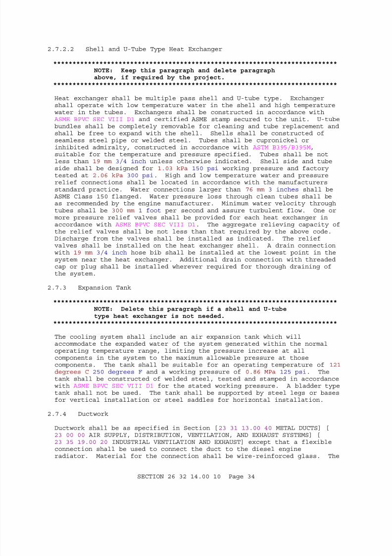
7/23/2019 WBDB UFGS Diesel Generator Application
http://slidepdf.com/reader/full/wbdb-ufgs-diesel-generator-application 34/68
2.7.2.2 Shell and U-Tube Type Heat Exchanger
**************************************************************************NOTE: Keep this paragraph and delete paragraphabove, if required by the project.
**************************************************************************
Heat exchanger shall be multiple pass shell and U-tube type. Exchangershall operate with low temperature water in the shell and high temperaturewater in the tubes. Exchangers shall be constructed in accordance with
ASME BPVC SEC VIII D1 and certified ASME stamp secured to the unit. U-tubebundles shall be completely removable for cleaning and tube replacement andshall be free to expand with the shell. Shells shall be constructed ofseamless steel pipe or welded steel. Tubes shall be cupronickel orinhibited admiralty, constructed in accordance with ASTM B395/B395M,suitable for the temperature and pressure specified. Tubes shall be notless than 19 mm 3/4 inch unless otherwise indicated. Shell side and tubeside shall be designed for 1.03 kPa 150 psi working pressure and factorytested at 2.06 kPa 300 psi. High and low temperature water and pressurerelief connections shall be located in accordance with the manufacturersstandard practice. Water connections larger than 76 mm 3 inches shall be
ASME Class 150 flanged. Water pressure loss through clean tubes shall beas recommended by the engine manufacturer. Minimum water velocity throughtubes shall be 300 mm 1 foot per second and assure turbulent flow. One ormore pressure relief valves shall be provided for each heat exchanger inaccordance with ASME BPVC SEC VIII D1. The aggregate relieving capacity ofthe relief valves shall be not less than that required by the above code.Discharge from the valves shall be installed as indicated. The reliefvalves shall be installed on the heat exchanger shell. A drain connectionwith 19 mm 3/4 inch hose bib shall be installed at the lowest point in thesystem near the heat exchanger. Additional drain connection with threadedcap or plug shall be installed wherever required for thorough draining ofthe system.
2.7.3 Expansion Tank
**************************************************************************NOTE: Delete this paragraph if a shell and U-tubetype heat exchanger is not needed.
**************************************************************************
The cooling system shall include an air expansion tank which willaccommodate the expanded water of the system generated within the normaloperating temperature range, limiting the pressure increase at allcomponents in the system to the maximum allowable pressure at thosecomponents. The tank shall be suitable for an operating temperature of 121degrees C 250 degrees F and a working pressure of 0.86 MPa 125 psi. Thetank shall be constructed of welded steel, tested and stamped in accordancewith ASME BPVC SEC VIII D1 for the stated working pressure. A bladder typetank shall not be used. The tank shall be supported by steel legs or basesfor vertical installation or steel saddles for horizontal installation.
2.7.4 Ductwork
Ductwork shall be as specified in Section [23 31 13.00 40 METAL DUCTS] [23 00 00 AIR SUPPLY, DISTRIBUTION, VENTILATION, AND EXHAUST SYSTEMS] [23 35 19.00 20 INDUSTRIAL VENTILATION AND EXHAUST] except that a flexibleconnection shall be used to connect the duct to the diesel engineradiator. Material for the connection shall be wire-reinforced glass. The
SECTION 26 32 14.00 10 Page 34

7/23/2019 WBDB UFGS Diesel Generator Application
http://slidepdf.com/reader/full/wbdb-ufgs-diesel-generator-application 35/68
connection shall be rendered practically airtight.
2.7.5 Temperature Sensors
Each engine shall be equipped with coolant temperature sensors.Temperature sensors shall provide signals for pre-high and high indicationand alarms.
2.8 SOUND LIMITATIONS
**************************************************************************NOTE: The designer must perform an analysis inaccordance with UFC 3-450-01 NOISE AND VIBRATIONCONTROL and UFC 3-450-02 POWER PLANT ACOUSTICS. Thedesigner must consider air intake, exhaust, anddiesel generator casing noise. The designer mustalso coordinate with the architect for proper material selections for the sound transmittancecharacteristics of the mechanical equipment room andadjacent areas. The designer should consider sound within the equipment room, adjacent areas and
building exterior. Acceptable sound levels willvary depending on the function of the space. As a minimum the design should comply with the followingOSHA safety requirements; however, more stringentsound restrictions may be required to met thefunctional requirements of the occupied spaces.
Frequency Band(Hz)
Maximum Acceptable Sound Level(Decibels)
Industrial Residential
20-75 87 81
75-150 77 71
150-300 70 64
300-600 64 58
600-1,200 61 55
1,200-2,400 60 54
2,400-4,800 60 54
4,800-10 kHz 62 56
Typically, the diesel generator manufacturer canprovide information concerning the noise generatedby the diesel generator in a free fieldenvironment. The manufacturer does not have controlover any other building parameters or additional mechanical equipment noise. Therefore the designershould indicate the required sound limits for eachof the indicated octave bands for the sound pressurelevel of the diesel generator set operating at 100
SECTION 26 32 14.00 10 Page 35
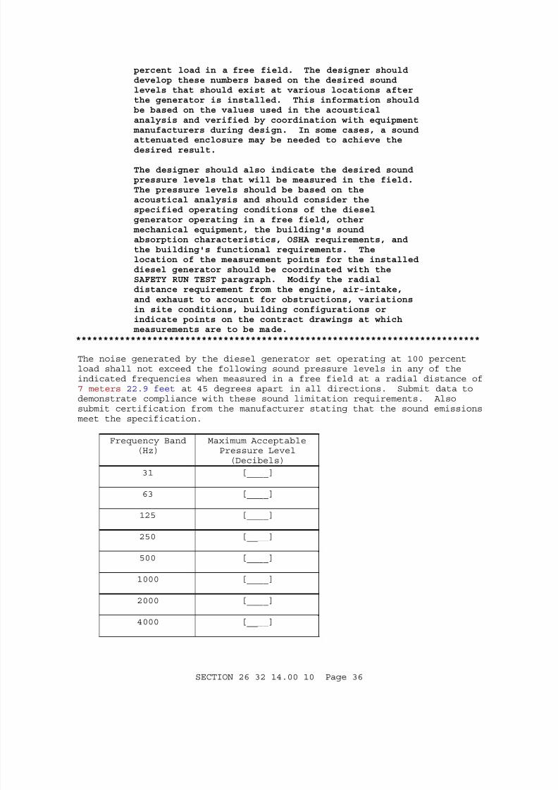
7/23/2019 WBDB UFGS Diesel Generator Application
http://slidepdf.com/reader/full/wbdb-ufgs-diesel-generator-application 36/68
percent load in a free field. The designer shoulddevelop these numbers based on the desired soundlevels that should exist at various locations afterthe generator is installed. This information shouldbe based on the values used in the acousticalanalysis and verified by coordination with equipment manufacturers during design. In some cases, a sound
attenuated enclosure may be needed to achieve thedesired result.
The designer should also indicate the desired soundpressure levels that will be measured in the field.The pressure levels should be based on theacoustical analysis and should consider thespecified operating conditions of the dieselgenerator operating in a free field, other mechanical equipment, the building's soundabsorption characteristics, OSHA requirements, andthe building's functional requirements. Thelocation of the measurement points for the installeddiesel generator should be coordinated with the
SAFETY RUN TEST paragraph. Modify the radialdistance requirement from the engine, air-intake,and exhaust to account for obstructions, variationsin site conditions, building configurations orindicate points on the contract drawings at which measurements are to be made.
**************************************************************************
The noise generated by the diesel generator set operating at 100 percentload shall not exceed the following sound pressure levels in any of theindicated frequencies when measured in a free field at a radial distance of 7 meters 22.9 feet at 45 degrees apart in all directions. Submit data todemonstrate compliance with these sound limitation requirements. Alsosubmit certification from the manufacturer stating that the sound emissionsmeet the specification.
Frequency Band(Hz)
Maximum AcceptablePressure Level(Decibels)
31 [____]
63 [____]
125 [____]
250 [____]
500 [____]
1000 [____]
2000 [____]
4000 [____]
SECTION 26 32 14.00 10 Page 36

7/23/2019 WBDB UFGS Diesel Generator Application
http://slidepdf.com/reader/full/wbdb-ufgs-diesel-generator-application 37/68
Frequency Band(Hz)
Maximum AcceptablePressure Level(Decibels)
8000 [____]
The noise generated by the installed diesel generator set operating at 100percent load shall not exceed the following sound pressure levels in any ofthe indicated frequencies when measured at a distance of [22.9] [_____] m [75] [_____] feet from the end of the exhaust and air intake pipingdirectly along the path of intake and discharge for horizontal piping; orat a radius of [22.9] [10.7] [_____] m [75] [35] [_____] feet from theengine at 45 degrees apart in all directions for vertical piping. Submitdata to demonstrate compliance with these sound limitation requirements.
Also submit certification from the manufacturer stating that the soundemissions meet the specification.
Frequency Band(Hz)
Maximum AcceptablePressure Level
(Decibels)31 [____]
63 [____]
125 [____]
250 [____]
500 [____]
1000 [____]
2000 [____]
4000 [____]
8000 [____]
2.9 AIR INTAKE EQUIPMENT
Filters and silencers shall be provided in locations that are convenientfor servicing. The silencer shall be of the high-frequency filter type,located in the air intake system as recommended by the enginemanufacturer. Silencer shall be capable of reducing the noise level at theair intake to a point below the maximum acceptable levels specified inparagraph SOUND LIMITATIONS. A combined filter-silencer unit meetingrequirements for the separate filter and silencer items may be provided.Expansion elements in air-intake lines shall be [copper][rubber].
2.10 EXHAUST SYSTEM
**************************************************************************NOTE: Include on the drawings a detail of theexhaust piping that penetrates building construction
SECTION 26 32 14.00 10 Page 37

7/23/2019 WBDB UFGS Diesel Generator Application
http://slidepdf.com/reader/full/wbdb-ufgs-diesel-generator-application 38/68
such as walls or roof.**************************************************************************
The system shall be separate and complete for each engine. Piping shall besupported so as to minimize vibration. Where a V-type engine is provided,a V-type connector with necessary flexible sections and hardware shallconnect the engine exhaust outlets.
2.10.1 Flexible Sections and Expansion Joints
A flexible section at each engine and an expansion joint at each mufflershall be provided. Flexible sections and expansion joints shall haveflanged connections. Flexible sections shall be made of convolutedseamless tube without joints or packing. Expansion joints shall be thebellows type. Expansion and flexible elements shall be stainless steelsuitable for diesel-engine exhaust gas at the maximum exhaust temperaturethat is specified by the engine manufacturer. Expansion and flexibleelements shall be capable of absorbing vibration from the engine andcompensation for thermal expansion and contraction.
2.10.2 Exhaust Muffler
**************************************************************************NOTE: Muffler locations and mountings shall beshown on the drawings.
**************************************************************************
A chamber type exhaust muffler shall be provided. The muffler shall beconstructed of welded steel and designed for [outside] [inside] [vertical][horizontal] mounting. Eyebolts, lugs, flanges, or other items shall beprovided as necessary for support in the location and position indicated.Pressure drop through the muffler shall not exceed the recommendations ofthe engine manufacturer. Outside mufflers shall be zinc coated or paintedwith high temperature 204 degrees C 400 degrees F resisting paint. Themuffler and exhaust piping together shall reduce the noise level to lessthan the maximum acceptable level listed for sound limitations in paragraphSOUND LIMITATIONS. The muffler shall have a drain valve, nipple, and capat the low-point of the muffler.
2.10.3 Exhaust Piping
**************************************************************************NOTE: Exhaust piping shall be sized at a gasvelocity of less than 25.4 m/second (5000 fpm).Piping should be shown on the drawings.
**************************************************************************
Horizontal sections of exhaust piping shall be sloped downward away fromthe engine to a condensate trap and drain valve. Changes in directionshall be long-radius. Exhaust piping, mufflers and silencers installedinside any building shall be insulated in accordance with paragraph THERMALINSULATION and covered to protect personnel. Vertical exhaust piping shallbe provided with a hinged, gravity operated, self-closing, rain cover.
2.11 EMISSIONS
**************************************************************************NOTE: The designer will coordinate emissionsrequirements with the installation (base/post)
SECTION 26 32 14.00 10 Page 38
7/23/2019 WBDB UFGS Diesel Generator Application
http://slidepdf.com/reader/full/wbdb-ufgs-diesel-generator-application 39/68
environmental office and provide a listing of therequirements. The identification of environmentalrequirements should be identified at the beginningof the project as a special study effort whichrequires funding separate from the normal design.
**************************************************************************
The finished installation shall comply with Federal, state, and localregulations and restrictions regarding the limits of emissions, as listedherein: [_____]
Submit a certification from the engine manufacturer stating that the engineexhaust emissions meet federal, state, and local regulations andrestrictions specified. At a minimum, this certification shall includeemission factors for criteria pollutants including nitrogen oxides, carbonmonoxide, particulate matter, sulfur dioxide, non-methane hydrocarbon, andfor hazardous air pollutants (HAPs).
2.12 STARTING SYSTEM
**************************************************************************
NOTE: Select the first option for emergencyapplications and delete subsequent paragraphs.Select second option for all other standbyapplications.
**************************************************************************
[The starting system for standby engine generator sets used in emergencyapplications shall be in accordance with NFPA 99 and NFPA 110 and asfollows.] [The starting system for engine generator sets used innon-emergency applications shall be as follows.]
2.12.1 Controls
An engine control switch shall be provided with functions including:run/start (manual), off/reset, and automatic mode. Start-stop logic shallbe provided for adjustable cycle cranking and cool down operation. Thelogic shall be arranged for [manual starting] [and] [fully automaticstarting in accordance with paragraph AUTOMATIC ENGINE-GENERATOR SET SYSTEMOPERATION]. Electrical starting systems shall be provided with anadjustable cranking limit device to limit cranking periods from 1 second upto the maximum duration.
2.12.2 Capacity
The starting system shall be of sufficient capacity, at the maximum[outdoor][indoor] summer temperature specified to crank the engine withoutdamage or overheating. The system shall be capable of providing a minimumof three cranking periods with 15-second intervals between cranks. Eachcranking period shall have a maximum duration of 15 seconds.
2.12.3 Functional Requirements
Starting system shall be manufacturers recommended dc system utilizing anegative circuit ground. Starting motors shall be in accordance withSAE ARP892.
SECTION 26 32 14.00 10 Page 39

7/23/2019 WBDB UFGS Diesel Generator Application
http://slidepdf.com/reader/full/wbdb-ufgs-diesel-generator-application 40/68
2.12.4 Battery
**************************************************************************NOTE: Select nickel-cadmium when the batterytemperature cannot be maintained above minus 6degrees C (22 degrees F).
**************************************************************************
A starting battery system shall be provided and shall include the battery,battery rack, intercell connectors, and spacers. The battery shall be inaccordance with SAE J537. Critical system components (rack, protection,etc.) shall be sized to withstand the seismic acceleration forcesspecified. The battery shall be [lead-acid][nickel-cadmium] type, withsufficient capacity, at the minimum [outdoor][indoor] winter temperaturespecified to provide the specified cranking periods. Valve-regulatedlead-acid batteries are not acceptable.
2.12.5 Battery Charger
A current-limiting battery charger, conforming to UL 1236, shall beprovided and shall automatically recharge the batteries. The charger shall
be capable of an equalize charging rate for recharging fully depletedbatteries within [24][_____] hours and a float charge rate for maintainingthe batteries in prime starting condition. An ammeter shall be provided toindicate charging rate. A timer shall be provided for the equalizecharging rate setting. A battery is considered to be fully depleted whenthe output voltage falls to a value which will not operate the enginegenerator set and its components.
2.12.6 Starting Aids
**************************************************************************NOTE: Jacket coolant heaters are normally providedfor most applications to aid starting. Some manufacturers may require glow plugs for combustionair temperatures significantly below 0 degrees C (32degrees F); however, use if these alone do notensure NFPA availability in the application sizerange. Consult manufacturers for availability inthe application size range.
**************************************************************************
The manufacturer shall provide one or more of the following methods toassist engine starting.
2.12.6.1 Glow Plugs
Glow plugs shall be designed to provide sufficient heat for combustion offuel within the cylinders to guarantee starting at an ambient temperature of -32 degrees C -25 degrees F.
2.12.6.2 Jacket-Coolant Heaters
A thermostatically controlled electric heater shall be mounted in theengine coolant jacketing to automatically maintain the coolant within plusor minus 3 degrees of the control temperature. The heater shall operateindependently of engine operation so that starting times are minimized.The control temperature shall be the temperature recommended by the enginemanufacturer to meet the starting time specified.
SECTION 26 32 14.00 10 Page 40
7/23/2019 WBDB UFGS Diesel Generator Application
http://slidepdf.com/reader/full/wbdb-ufgs-diesel-generator-application 41/68
2.13 GOVERNOR
**************************************************************************NOTE: Coordinate with paragraph Engine GeneratorParameter Schedule.
**************************************************************************
Each engine shall be provided with a governor which maintains the frequencywithin a bandwidth of the rated frequency, over a steady-state load rangeof zero to 100 percent of rated output capacity. The governor shall beconfigured for safe manual adjustment of the speed/frequency duringoperation of the engine generator set, without special tools, from 90 to110 percent of the rated speed/frequency, over a steady state load range ofzero to 100 percent of rated capacity. [Isochronous governors shallmaintain the midpoint of the frequency bandwidth at the same value forsteady-state loads over the range of zero to 100 percent of rated outputcapacity.] [Droop governors shall maintain the midpoint of the frequencybandwidth linearly for steady-state loads over the range of zero to 100percent of rated output capacity, with 3 percent droop.]
2.14 GENERATOR
**************************************************************************NOTE: Armature and field winding insulation classesare specified based on the allowable temperaturerise (the temperature in the windings above thetemperature of the air used to cool the windings).See NEMA MG 1 for a discussion of the classes withrespect to size range, elevation, method of measurement, and ambient temperature. Select theclass insulation for each application based onoperating conditions. Class F is consideredindustry standard. If a different class is requiredfor different machines, specify the one for eachapplication in the parameter schedule for therespective generator set.
**************************************************************************
Each generator shall be of the synchronous type, one or two bearing,conforming to NEMA MG 1, equipped with winding terminal housings inaccordance with NEMA MG 1, equipped with an amortisseur winding, anddirectly connected to the engine. Insulation shall be [Class H][Class F].Generator design shall protect against mechanical, electrical and thermaldamage due to vibration, 25 percent overspeeds, or voltages andtemperatures at a rated output capacity of 100 percent. Generatorancillary equipment shall meet the short circuit requirements of NEMA MG 1.Frames shall be the drip-proof type. Submit each generator KW rating andshort circuit capacity (both symmetric and asymmetric).
2.14.1 Current Balance
At 100 percent rated load, and load impedance equal for each of the threephases, the permissible current difference between any two phases shall notexceed 2 percent of the largest current on either of the two phases.Submit manufacturer's certification that the flywheel has been staticallyand dynamically balanced and is capable of being rotated at 125 percent ofrated speed without vibration or damage.
SECTION 26 32 14.00 10 Page 41
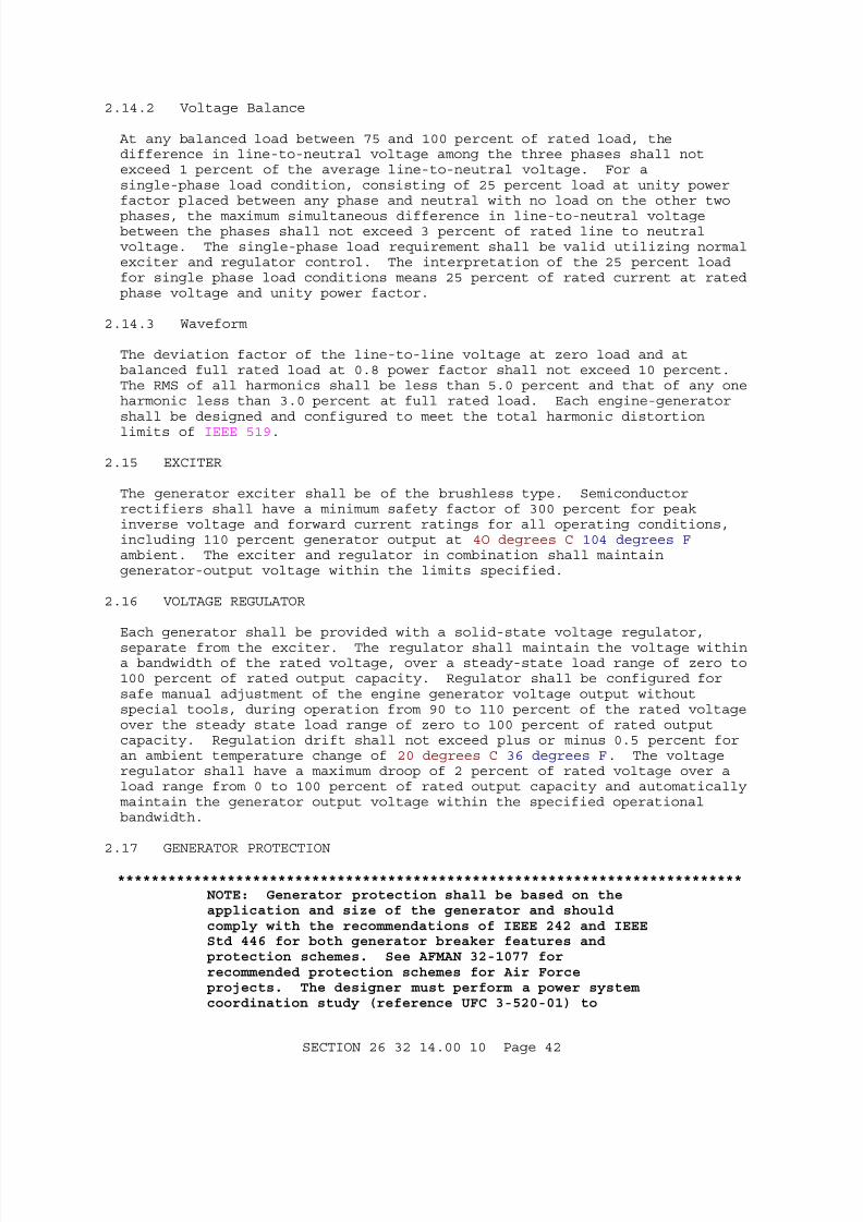
7/23/2019 WBDB UFGS Diesel Generator Application
http://slidepdf.com/reader/full/wbdb-ufgs-diesel-generator-application 42/68
2.14.2 Voltage Balance
At any balanced load between 75 and 100 percent of rated load, thedifference in line-to-neutral voltage among the three phases shall notexceed 1 percent of the average line-to-neutral voltage. For asingle-phase load condition, consisting of 25 percent load at unity powerfactor placed between any phase and neutral with no load on the other two
phases, the maximum simultaneous difference in line-to-neutral voltagebetween the phases shall not exceed 3 percent of rated line to neutralvoltage. The single-phase load requirement shall be valid utilizing normalexciter and regulator control. The interpretation of the 25 percent loadfor single phase load conditions means 25 percent of rated current at ratedphase voltage and unity power factor.
2.14.3 Waveform
The deviation factor of the line-to-line voltage at zero load and atbalanced full rated load at 0.8 power factor shall not exceed 10 percent.The RMS of all harmonics shall be less than 5.0 percent and that of any oneharmonic less than 3.0 percent at full rated load. Each engine-generatorshall be designed and configured to meet the total harmonic distortion
limits of IEEE 519.
2.15 EXCITER
The generator exciter shall be of the brushless type. Semiconductorrectifiers shall have a minimum safety factor of 300 percent for peakinverse voltage and forward current ratings for all operating conditions,including 110 percent generator output at 4O degrees C 104 degrees F ambient. The exciter and regulator in combination shall maintaingenerator-output voltage within the limits specified.
2.16 VOLTAGE REGULATOR
Each generator shall be provided with a solid-state voltage regulator,separate from the exciter. The regulator shall maintain the voltage withina bandwidth of the rated voltage, over a steady-state load range of zero to100 percent of rated output capacity. Regulator shall be configured forsafe manual adjustment of the engine generator voltage output withoutspecial tools, during operation from 90 to 110 percent of the rated voltageover the steady state load range of zero to 100 percent of rated outputcapacity. Regulation drift shall not exceed plus or minus 0.5 percent foran ambient temperature change of 20 degrees C 36 degrees F. The voltageregulator shall have a maximum droop of 2 percent of rated voltage over aload range from 0 to 100 percent of rated output capacity and automaticallymaintain the generator output voltage within the specified operationalbandwidth.
2.17 GENERATOR PROTECTION
**************************************************************************NOTE: Generator protection shall be based on theapplication and size of the generator and shouldcomply with the recommendations of IEEE 242 and IEEEStd 446 for both generator breaker features andprotection schemes. See AFMAN 32-1077 forrecommended protection schemes for Air Forceprojects. The designer must perform a power systemcoordination study (reference UFC 3-520-01) to
SECTION 26 32 14.00 10 Page 42

7/23/2019 WBDB UFGS Diesel Generator Application
http://slidepdf.com/reader/full/wbdb-ufgs-diesel-generator-application 43/68
specify the breaker ratings, breaker trip unitfeatures and settings, relay protection scheme, andrelay settings for coordination for each generatorset installed. The configuration should alwaysinclude a disconnecting means for taking clearanceon the generator for maintenance purposes. If thescope of protection is small the designer may elect
to delete the paragraphs in this section andreference Section 26 28 01.00 10 COORDINATED POWERSYSTEM PROTECTION. Show panelboard ratings on thecontract drawings for each generator set. Ratinginformation should include voltage, phase, buscontinuous capacity (amperes), bus withstandcapacity (amperes) (see NEMA PB 1 for necessaryrating information). Show breaker frame, trip, andinterrupting ratings on the contract drawings.
Surge capacitors and surge arresters should beprovided when the sets are to be connected toexposed overhead lines directly or throughtransformers, even though connection may be only for
transfer of load without service interruption.Surge arrester protection is not required where setsserve single buildings isolated from overhead linesby automatic or manual transfer switches whereprovision has been made to prevent simultaneousconnection to both sources. The designer willspecify the surge arrester rating.
Fuse and circuit breaker ratings should be shown onthe contract drawings. Show voltage, phase,continuous current (ampere), short circuit withstand, interrupting, neutral size, etc.
**************************************************************************
Short circuit and overload protection for the generator shall be provided.The generator circuit breaker (IEEE Device 52) ratings shall be consistentwith the generator rated voltage and frequency, with continuous, shortcircuit and interrupting current ratings to match the generator capacity.The manufacturer shall determine the short circuit current interruptingrating of the breaker. The breaker shall be engine generator base mountedby the engine-generator set manufacturer. Molded case breakers shall beprovided with shunt trip. Surge protection shall be provided for eachphase of the generator, to be mounted at the generator terminals.
2.17.1 Panelboards
Panelboards shall be metal-enclosed, general purpose, [3-phase, 4-wire],[1-phase, 3-wire], [600][_____] volt rated, with neutral bus and continuousground bus, conforming to NEMA PB 1 and UL 891. Neutral bus and ground buscapacity shall be [as shown][full capacity]. Enclosure designs,construction, materials and coatings shall be [as indicated][suitable forthe application and environment]. Bus continuous current rating shall be[at least equal to the generator rating and correspond to UL listed currentratings specified for panelboards and switchboards][as indicated]. Currentwithstand rating (short circuit rating) shall match the generatorcapacity. Buses shall be copper.
SECTION 26 32 14.00 10 Page 43

7/23/2019 WBDB UFGS Diesel Generator Application
http://slidepdf.com/reader/full/wbdb-ufgs-diesel-generator-application 44/68
2.17.2 Devices
Switches, circuit breakers, switchgear, fuses, relays, and other protectivedevices shall be as specified in Section 26 28 01.00 10 COORDINATED POWERSYSTEM PROTECTION.
2.18 SAFETY SYSTEM
Devices, wiring, remote panels, local panels, etc., shall be provided andinstalled as a complete system to automatically activate the appropriatesignals and initiate the appropriate actions. The safety system shall beprovided with a self-test method to verify its operability. Alarm signalsshall have manual acknowledgement and reset devices. The alarm signalsystems shall reactivate for new signals after acknowledgment is given toany signal. The systems shall be configured so that loss of any monitoringdevice shall be dealt with as an alarm on that system element.
2.18.1 Audible Signal
**************************************************************************NOTE: High dB levels are required for alarms
located near engine. Specify over 100 dB for engineroom application and show alarm location.
**************************************************************************
The audible alarm signal shall sound at a frequency of [70] [_____] Hz at avolume of [_____] [75] dB at 3.1 m 10 feet. The sound shall becontinuously activated upon alarm and silenced upon acknowledgment. Signaldevices shall be located as shown.
2.18.2 Visual Alarm Signal
The visual alarm signal shall be a panel light. The light shall benormally off, activated to be blinking upon alarm. The light shall changeto continuously light upon acknowledgement. If automatic shutdown occurs,the display shall maintain activated status to indicate the cause offailure and shall not be reset until cause of alarm has been cleared and/orrestored to normal condition. Shutdown alarms shall be red; all otheralarms shall be amber.
2.18.3 Alarms and Action Logic
2.18.3.1 Shutdown
Simultaneous activation of the audible signal, activation of the visualsignal, stopping the engine, and opening the generator main circuitbreakers shall be accomplished.
2.18.3.2 Problem
Activation of the visual signal shall be accomplished.
2.18.4 Local Alarm Panel
**************************************************************************NOTE: The designer must provide design features inaccordance with the requirements of NFPA 70, NFPA 99for medical facilities. The designer must providedesign features in accordance with the requirements
SECTION 26 32 14.00 10 Page 44
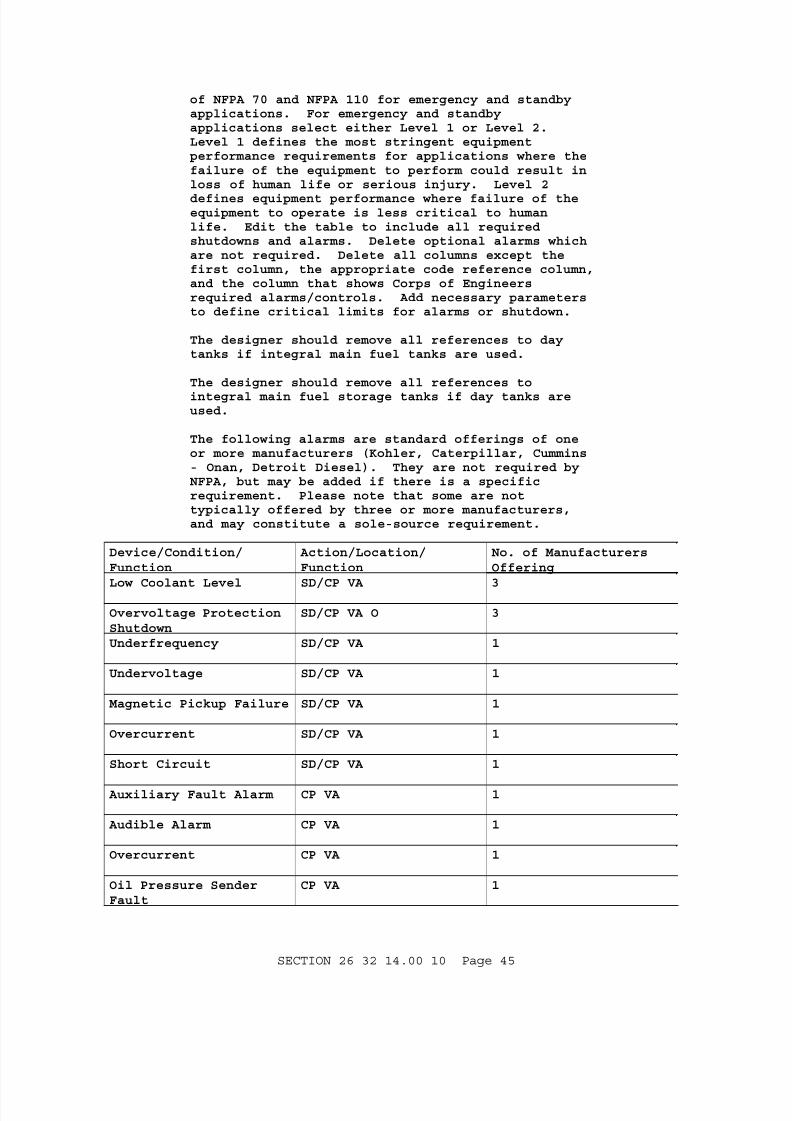
7/23/2019 WBDB UFGS Diesel Generator Application
http://slidepdf.com/reader/full/wbdb-ufgs-diesel-generator-application 45/68
of NFPA 70 and NFPA 110 for emergency and standbyapplications. For emergency and standbyapplications select either Level 1 or Level 2.Level 1 defines the most stringent equipmentperformance requirements for applications where thefailure of the equipment to perform could result inloss of human life or serious injury. Level 2
defines equipment performance where failure of theequipment to operate is less critical to humanlife. Edit the table to include all requiredshutdowns and alarms. Delete optional alarms whichare not required. Delete all columns except thefirst column, the appropriate code reference column,and the column that shows Corps of Engineersrequired alarms/controls. Add necessary parametersto define critical limits for alarms or shutdown.
The designer should remove all references to daytanks if integral main fuel tanks are used.
The designer should remove all references to
integral main fuel storage tanks if day tanks areused.
The following alarms are standard offerings of oneor more manufacturers (Kohler, Caterpillar, Cummins- Onan, Detroit Diesel). They are not required byNFPA, but may be added if there is a specificrequirement. Please note that some are nottypically offered by three or more manufacturers,and may constitute a sole-source requirement.
Device/Condition/Function
Action/Location/Function
No. of ManufacturersOffering
Low Coolant Level SD/CP VA 3
Overvoltage ProtectionShutdown
SD/CP VA O 3
Underfrequency SD/CP VA 1
Undervoltage SD/CP VA 1
Magnetic Pickup Failure SD/CP VA 1
Overcurrent SD/CP VA 1
Short Circuit SD/CP VA 1
Auxiliary Fault Alarm CP VA 1
Audible Alarm CP VA 1
Overcurrent CP VA 1
Oil Pressure SenderFault
CP VA 1
SECTION 26 32 14.00 10 Page 45

7/23/2019 WBDB UFGS Diesel Generator Application
http://slidepdf.com/reader/full/wbdb-ufgs-diesel-generator-application 46/68
Device/Condition/Function
Action/Location/Function
No. of ManufacturersOffering
Weak Battery CP VA 1
**************************************************************************
Provide a local alarm panel with the following shutdown and alarm functions[as indicated] [in accordance with [NFPA 99] [NFPA 110 level [1] [2]]] andincluding the listed Corps of Engineers requirements, mounted either on oradjacent to the engine generator set.
Device/Condition/Function
What/Where/Sizes
NFPA 99 NFPA 1 Level1
NFPA 110 Level 2
Corps ofEngineersRequired
Shutdowns W/Alarms
High enginetemperature
Automatic/jacket water/
cylinder
SD/CPVA
SD/CPVA
SD/CP VA SD VA
Low lube-oilpressure
Automatic/pressure/ level
SD/CPVA
SD/CPVA
SD/CP VA SD VA
Overspeedshutdown $ alarm
(110 percent (+2 percent) ofrated speed
SD/CPVA
SD/CPVA
SD/CP VA SD VA
Overcrankfailure to start
Automatic/Failure to start
SD/CPVA
SD/CPVA
SD/CP VA
Air shutdowndamper (200-600kW)
When used SD/CPVA
SD/CP VA
Day tankoverfill limitindication &transfer pumpshutdown (95percent volume)
Automatic/ DayTank/ Level
SD/OPA(Pump)
Red emergencystop switch
Manual switch SD/CPVA
SD/CP VA SD VA
Failure to crank Corps ofEngineersRequired
SECTION 26 32 14.00 10 Page 46

7/23/2019 WBDB UFGS Diesel Generator Application
http://slidepdf.com/reader/full/wbdb-ufgs-diesel-generator-application 47/68
Device/Condition/Function
What/Where/Sizes
NFPA 99 NFPA 1 Level1
NFPA 110 Level 2
Corps ofEngineersRequired
[Daytank][IntegralMain Fuel Tank]
low fuel limitDevice/Condition/indication (70percent volumeremaining)
Corps ofEngineersRequired
Alarms
Low lube-oilpressure
Pressure/ level CP VA CP VA CP VAO CP VA
Low fuel level Main tank, 3hours remaining
VA/AA CP VA CP VAO
High fuel level Integral MainFuel StorageTank 95 percentVolume
CP VA
Low coolant Jacket water CP/VA CP/VA CP/VA
Pre-hightemperature
Jacket water/cylinder
CP/VA CP/VA CP VAO CP/VA
Pre-low
lube-oilpressure
CP/VA CP/VA
High batteryvoltage
CP/VA CP VAO
Low batteryvoltage
CP/VA CP VAO
Battery charger AC failure
AC supply notavailable
CP/VA CP VAO
Control switchnot in AUTO
CP/VA CP VAO
Low startingair pressure
CP/VA CP VAO
Low startinghydraulicpressure
CP/VA CP VAO
SECTION 26 32 14.00 10 Page 47

7/23/2019 WBDB UFGS Diesel Generator Application
http://slidepdf.com/reader/full/wbdb-ufgs-diesel-generator-application 48/68
Device/Condition/Function
What/Where/Sizes
NFPA 99 NFPA 1 Level1
NFPA 110 Level 2
Corps ofEngineersRequired
Symbol Key
SD Shut Down
CP On Control Panel
VA Visual Alarm
AA Audible Alarm
O Optional
2.18.5 Time-Delay on Alarms
For startup of the engine-generator set, time-delay devices shall beinstalled bypassing the low lubricating oil pressure alarm during cranking,and the coolant-fluid outlet temperature alarm. The lube-oil time-delaydevice shall return its alarm to normal status after the engine starts.The coolant time-delay device shall return its alarm to normal status 5minutes after the engine starts.
Submit the magnitude of monitored values which define alarm or actionsetpoints, and the tolerance (plus and/or minus) at which the deviceactivates the alarm or action.
2.18.6 Remote Alarm Panel
**************************************************************************NOTE: The Remote Alarm Panel should be shown on thedrawings. Delete remote alarm panel where notrequired. Select the first option if theapplication is a prime power plant. For prime powerunits provide panel elevations depicting desiredconfigurations, together with a listing of alarmsand instruments. Select the second option forengine generator sets utilized in emergency orstandby applications. The designer must providedesign features in accordance with the requirementsof NFPA 70, and NFPA 99 for medical facilities. Thedesigner must provide design features in accordance with the requirements of NFPA 70 and NFPA 110 for
emergency and standby applications. A remote panelis required for NFPA 99 and for NFPA 110, Level 1applications. A remote panel is not required forNFPA 110, Level 2 applications. Edit the table toinclude all required alarms. Delete optional alarms which are not required. Delete all columns exceptthe first column and the appropriate code referencecolumn. Add necessary parameters where required todefine critical limits for alarms.
**************************************************************************
SECTION 26 32 14.00 10 Page 48

7/23/2019 WBDB UFGS Diesel Generator Application
http://slidepdf.com/reader/full/wbdb-ufgs-diesel-generator-application 49/68
[A remote alarm panel shall be provided as indicated.] [A remote alarmpanel shall be provided in accordance with [NFPA 99] [NFPA 110]and asfollows:
Device/Condition/Function
What/Where/Size NFPA 99 NFPA 110 Level 1
NFPA 110 Level 2
Remoteannunciator panel
Battery powered Alarms
Loads on genset VA
Battery chargermalfunction
VA
Low lube-oil Pressure/level VA/AA AA AAO
Low Temperature Jacket water VA/AA AA AAO
High Temperature Jacketwater/cylinder
VA/AA AA AAO
Low fuel level Main tank, 3 hrremaining
VA/AA AA AAO
Overcrank Failure to start VA/AA AA AAO
Overspeed VA/AA AA AAO
Pre-hightemperature
Jacketwater/cylinder
AA
Control switchnot in
AA
AUTO
Common alarmcontacts forlocal & remotecommon alarm
X X
Audible alarmsilencing switch
X O
Air shutdowndamper
When used AA AAO
Common faultalarm
AA
Symbology Key
X Required
SD Shut Down
CP On Control Panel
VA Visual Alarm
SECTION 26 32 14.00 10 Page 49

7/23/2019 WBDB UFGS Diesel Generator Application
http://slidepdf.com/reader/full/wbdb-ufgs-diesel-generator-application 50/68
Device/Condition/Function
What/Where/Size NFPA 99 NFPA 110 Level 1
NFPA 110 Level 2
AA Audible Alarm
O Optional
]2.19 ENGINE GENERATOR SET CONTROLS AND INSTRUMENTATION
Devices, wiring, remote panels, local panels, etc., shall be provided andinstalled as a complete system to automatically activate the appropriatesignals and initiate the appropriate actions.
2.19.1 Controls
**************************************************************************NOTE: Delete the remote control (control room)panel if the application is not a prime powerapplication. Provide plan and elevation drawings of
the remote control panels for prime powerapplications, depicting specific devices,instrument, and meters, including layouts.Generator circuit breaker controls with positionindication may be added if required (Not availablefor standard molded-case breakers. Use only forpower circuit breakers or switchgear).
Edit the table to include all required devices.Delete all columns except the first column and theappropriate reference columns (always delete "MFGOffering" column).
A remote stop switch is required by NFPA 37 for 100
hp and above engines, and by NFPA 110 for both Level1 and Level 2 applications. A remote fuel shutoffswitch, and a remote lube-oil shutoff switch arerequired by NFPA 37 for 100 hp and above engines.Delete the remote fuel shutoff switch, and a remotelube-oil shutoff switch where not required.
**************************************************************************
A local control panel shall be provided with controls [as indicated] [inaccordance with NFPA 110 level [1] [2]] [and as follows] mounted [either onor adjacent to the engine generator set] [as indicated]. A remote controlpanel shall be provided [with devices as indicated] [fully redundant to thelocal control panel].
Device/ Condition/Function
CorpsRequiremen
NFPA 110 Level 1
NFPA 110 Level 2
MFG Offering
Controls
Switch: run/start -off/set - auto
CP CP/STD
SECTION 26 32 14.00 10 Page 50
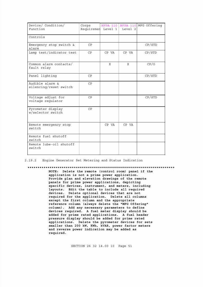
7/23/2019 WBDB UFGS Diesel Generator Application
http://slidepdf.com/reader/full/wbdb-ufgs-diesel-generator-application 51/68
Device/ Condition/Function
CorpsRequiremen
NFPA 110 Level 1
NFPA 110 Level 2
MFG Offering
Controls
Emergency stop switch &alarm
CP CP/STD
Lamp test/indicator test CP CP VA CP VA CP/STD
Common alarm contacts/fault relay
X X CP/O
Panel lighting CP CP/STD
Audible alarm &silencing/reset switch
CP
Voltage adjust for
voltage regulator
CP CP/STD
Pyrometer displayw/selector switch
CP
Remote emergency stopswitch
CP VA CP VA
Remote fuel shutoffswitch
Remote lube-oil shutoffswitch
2.19.2 Engine Generator Set Metering and Status Indication
**************************************************************************NOTE: Delete the remote (control room) panel if theapplication is not a prime power application.Provide plan and elevation drawings of the remotepanels for prime power applications, depictingspecific devices, instrument, and meters, includinglayouts. Edit the table to include all requireddevices. Delete optional devices that are notrequired for the application. Delete all columns
except the first column and the appropriatereference column (always delete the "MFG Offering"column). Add any necessary parameters to definedevices required. A fuel meter display should beadded for prime rated applications. A fuel headerpressure display should be added for prime ratedapplications. Delete the pyrometer devices for setssmaller than 200 kW, KWh, kVAR, power factor metersand reverse power indication may be added asrequired.
SECTION 26 32 14.00 10 Page 51
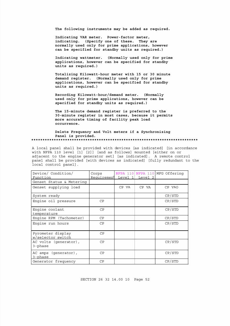
7/23/2019 WBDB UFGS Diesel Generator Application
http://slidepdf.com/reader/full/wbdb-ufgs-diesel-generator-application 52/68
The following instruments may be added as required.
Indicating VAR meter. Power-factor meter,indicating. (Specify one of these. They arenormally used only for prime applications, howevercan be specified for standby units as required.)
Indicating wattmeter. (Normally used only for primeapplications, however can be specified for standbyunits as required.)
Totalizing Kilowatt-hour meter with 15 or 30 minutedemand register. (Normally used only for primeapplications, however can be specified for standbyunits as required.)
Recording Kilowatt-hour/demand meter. (Normallyused only for prime applications, however can bespecified for standby units as required.)
The 15-minute demand register is preferred to the
30-minute register in most cases, because it permits more accurate timing of facility peak loadoccurrence.
Delete Frequency and Volt meters if a SynchronizingPanel is provided.
**************************************************************************
A local panel shall be provided with devices [as indicated] [in accordancewith NFPA 110 level [1] [2]] [and as follows] mounted [either on oradjacent to the engine generator set] [as indicated]. A remote controlpanel shall be provided [with devices as indicated] [fully redundant to thelocal control panel].
Device/ Condition/Function
CorpsRequiremen
NFPA 110Level 1
NFPA 110Level 2
MFG Offering
Genset Status & Metering
Genset supplying load CP VA CP VA CP VAO
System ready CP/STD
Engine oil pressure CP CP/STD
Engine coolanttemperature
CP CP/STD
Engine RPM (Tachometer) CP CP/STD
Engine run hours CP CP/STD
Pyrometer displayw/selector switch
CP
AC volts (generator),3-phase
CP CP/STD
AC amps (generator),3-phase
CP CP/STD
Generator frequency CP CP/STD
SECTION 26 32 14.00 10 Page 52

7/23/2019 WBDB UFGS Diesel Generator Application
http://slidepdf.com/reader/full/wbdb-ufgs-diesel-generator-application 53/68
Device/ Condition/Function
CorpsRequiremen
NFPA 110Level 1
NFPA 110Level 2
MFG Offering
Phase selector switches(amps & volts)
CP CP/STD
Watts/kW CP/VA-O
Voltage Regulator
Adjustment
CP
Symbology Key:
CP On Control Panel
VA Visual Alarm
AA Audible Alarm
O Optional
STD Manufacturers Standard Offering
2.20 PANELS
**************************************************************************NOTE: Panels, except the remote panel, can becombined into a single panel paragraph.
Provide a panel-mounting location and detail forpanels not mounted on the generator set base. Thedesigner may elect other locations such as adjacentto engine generator set; in the generator enclosure;or in or on the switchgear enclosure.
Provide panel nameplate and instrument nameplate
unique identifiers or user preferred identifiers.Provide sizes, materials, and attachment preferences.
Delete either the "standard panel" or "electronicpanel".
**************************************************************************
Each panel shall be of the type necessary to provide specified functions.Panels shall be mounted [on the engine generator set base byvibration/shock absorbing type mountings] [as shown]. Instruments shall bemounted flush or semiflush. Convenient access to the back of instrumentsshall be provided to facilitate maintenance. Instruments shall becalibrated using recognized industry calibration standards. Each panelshall be provided with a panel identification plate which clearly
identifies the panel function as indicated. Each instrument and device onthe panel shall be provided with a plate which clearly identifies thedevice and its function as indicated. Panels except the remote alarm panelcan be combined into a single panel.
2.20.1 Enclosures
**************************************************************************NOTE: Delete locking mechanism when not required.
**************************************************************************
SECTION 26 32 14.00 10 Page 53

7/23/2019 WBDB UFGS Diesel Generator Application
http://slidepdf.com/reader/full/wbdb-ufgs-diesel-generator-application 54/68
Enclosures shall be designed for the application and environment,conforming to NEMA ICS 6, and provided with locking mechanisms which arekeyed alike.
2.20.2 Analog
Analog electrical indicating instruments shall be in accordance with
ANSI C39.1 with semiflush mounting. Switchgear, and control-roompanel-mounted instruments shall have 250 degree scales with an accuracy ofnot less than 1 percent. Unit-mounted instruments shall be themanufacturer's standard with an accuracy of not less than 2 percent. Theinstrument's operating temperature range shall be minus 20 to plus 65degrees C minus 4 to plus 130 degrees F. Distorted generator outputvoltage waveform of a crest factor less than 5 shall not affect meteringaccuracy for phase voltages, hertz and amps.
2.20.3 Electronic
Electronic indicating instruments shall be true RMS indicating, 100 percentsolid state, microprocessor controlled to provide all specified functions.Control, logic, and function devices shall be compatible as a system,
sealed, dust and water tight, and shall utilize modular components withmetal housings and digital instrumentation. An interface module shall beprovided to decode serial link data from the electronic panel and translatealarm, fault and status conditions to set of relay contacts. Instrumentaccuracy shall be not less than 2 percent for unit mounted devices and 1percent for control room, panel mounted devices, throughout a temperaturerange of minus 20 to plus 65 degrees C minus 4 to plus 130 degrees F. Datadisplay shall utilize LED or back lit LCD. Additionally, the display shallprovide indication of cycle programming and diagnostic codes fortroubleshooting. Numeral height shall be [13 mm 1/2 inch][_____].
2.20.4 Parameter Display
Indication or readouts of the lubricating-oil pressure, ac voltmeter, acammeter, frequency meter, and coolant temperature.
2.20.5 Exerciser
**************************************************************************NOTE: Delete the exerciser when it is notrequired. Ensure that the exerciser is compatible with the automatic transfer scheme. It is highlydesirable to utilize system loads for generator setexercise loads and to exercise the complete standbysystem periodically. Coordinate requirements withthe user. The designer shall ensure that the designprovides warning signs in areas where the enginegenerator can start automatically.
**************************************************************************
The exerciser shall be in accordance with Section 26 36 00.00 10 AUTOMATICTRANSFER SWITCH AND BY-PASS/ISOLATION SWITCH.
2.21 SURGE PROTECTION
Electrical and electronic components shall be protected from, or designedto withstand the effects of surges from switching and lightning.
SECTION 26 32 14.00 10 Page 54

7/23/2019 WBDB UFGS Diesel Generator Application
http://slidepdf.com/reader/full/wbdb-ufgs-diesel-generator-application 55/68
2.22 AUTOMATIC ENGINE-GENERATOR-SET SYSTEM OPERATION
**************************************************************************NOTE: Adapt to fit application and provide desiredactuation sequence.
**************************************************************************
Fully automatic operation shall be provided for the following operations:engine-generator set starting and source transfer upon loss of [normal][preferred] source; retransfer upon restoration of the [normal] [preferred]source; sequential starting; and stopping of each engine-generator setafter cool down. Devices shall automatically reset after termination oftheir function.
2.22.1 Automatic Transfer Switch
Automatic transfer switches shall be in accordance with Section26 36 00.00 10 AUTOMATIC TRANSFER SWITCH AND BY-PASS/ISOLATION SWITCH.
2.22.2 Monitoring and Transfer
Devices shall be provided to monitor voltage and frequency for the [normal][preferred] power source and each engine generator set, and controltransfer from the [normal] [preferred] source and retransfer uponrestoration of the [normal] [preferred] source. Functions, actuation, andtime delays shall be as described in Section 26 36 00.00 10 AUTOMATICTRANSFER SWITCH AND BY-PASS/ISOLATION SWITCH.
2.23 MANUAL ENGINE-GENERATOR SET SYSTEM OPERATION
Complete facilities shall be provided for manual starting and testing ofeach set without load, loading and unloading of each set.
2.24 BASE
The base shall be constructed of steel. The base shall be designed torigidly support the engine-generator set, ensure permanent alignment of allrotating parts, be arranged to provide easy access to allow changing oflube-oil, and ensure that alignment will be maintained during shipping andnormal operation. The base shall permit skidding in any direction duringinstallation and shall be provided with suitable holes for foundationbolts. The base shall also withstand and mitigate the effects ofsynchronous vibration of the engine and generator, and shall be providedwith [suitable holes for anchor bolts] [[_____] diameter holes for anchorbolts] and jacking screws for leveling.
2.25 THERMAL INSULATION
Thermal insulation shall be as specified in Section 23 07 00 THERMALINSULATION FOR MECHANICAL SYSTEMS.
2.26 PAINTING AND FINISHING
The engine-generator set shall be cleaned, primed and painted in accordancewith the manufacturer's standard color and practice.
2.27 FACTORY INSPECTION AND TESTS
Perform factory inspection and tests on each engine-generator set proposed
SECTION 26 32 14.00 10 Page 55
7/23/2019 WBDB UFGS Diesel Generator Application
http://slidepdf.com/reader/full/wbdb-ufgs-diesel-generator-application 56/68
to meet this specification section. Inspections shall be completed andnecessary repairs made prior to testing. Inspectors shall look for leaks,looseness, defects in components, and proper assembly. Factory tests shallbe NEMA MG 1 routine tests and the manufacturers routine tests. Submit acertification that each engine generator set passed the factory tests andinspections and a list of the test and inspections.
PART 3 EXECUTION
**************************************************************************NOTE: Provide an equipment layout on the plans which provides the clear space for operation and maintenance in accordance with NFPA 70 and IEEE C2.Include requirements for a staging/laydown area fordisassembly or removal and replacement of majorparts of the generator set. Additionally, it isadvisable to provide access to remove the unitand/or major parts of equipment from the room andbuilding either through doors/passageways orequipment hatches.
**************************************************************************
3.1 EXAMINATION
After becoming familiar with all details of the work, perform a Site Visit to verify details of the work. Submit a site visit letter stating the datethe site was visited and listing discrepancies found and advise theContracting Officer in writing of any discrepancies before performing anywork.
3.2 GENERAL INSTALLATION
Submit a complete copy of the manufacturer's installation procedures. Adetailed description of the manufacturer's recommended break-in procedure.
Provide clear space for operation and maintenance in accordance with NFPA 70 and IEEE C2. Configure installation of pipe, duct, conduit, and ancillaryequipment to facilitate easy removal and replacement of major componentsand parts of the engine-generator set.
3.3 PIPING INSTALLATION
3.3.1 General
Piping shall be welded. Connections at valves shall be flanged.Connections at equipment shall be flanged except that connections to thediesel engine may be threaded if the diesel-engine manufacturer's standardconnection is threaded. Except as otherwise specified, flanged fittingsshall be utilized to allow for complete dismantling and removal of eachpiping system from the facility without disconnecting or removing anyportion of any other system's equipment or piping. Connections to allequipment shall be made with flexible connectors. Pipes extending throughthe roof shall be properly flashed. Piping shall be installed clear ofwindows, doors, and openings to permit thermal expansion and contractionwithout damage to joints or hangers, and with a 13 mm 1/2 inch drain valveat each low point.
SECTION 26 32 14.00 10 Page 56

7/23/2019 WBDB UFGS Diesel Generator Application
http://slidepdf.com/reader/full/wbdb-ufgs-diesel-generator-application 57/68
3.3.2 Supports
Hangers, inserts, and supports shall be of sufficient size to accommodateany insulation and shall conform to MSS SP-58 and MSS SP-69. Supportsshall be spaced not more than 2.1 m 7 feet on center for pipes 50 mm 2inches in diameter or less, not more than 3.6 m 12 feet on center for pipeslarger than 50 mm 2 inches but no larger than 100 mm 4 inches, and not more
than 5.2 m 17 feet on center for pipes larger than 100 mm 4 inches indiameter. Supports shall be provided at pipe bends or change of direction.
3.3.2.1 Ceiling and Roof
Exhaust piping shall be supported with appropriately sized type 41 singlepipe roll and threaded rods; all other piping shall be supported withappropriately sized type 1 clevis and threaded rods.
3.3.2.2 Wall
Wall supports for pipe shall be made by suspending the pipe fromappropriately sized type 33 brackets with the appropriate ceiling and roofpipe supports.
3.3.3 Flanged Joints
Flanges shall be Class 125 125 pound type, drilled, and of the proper sizeand configuration to match equipment and diesel-engine connections.Gaskets shall be factory cut in one piece 1.6 mm 1/16 inch thick.
3.3.4 Cleaning
After fabrication and before assembly, piping interiors shall be manuallywiped clean of all debris.
3.3.5 Pipe Sleeves
Pipes passing through construction such as ceilings, floors, or walls shallbe fitted with sleeves. Each sleeve shall extend through and be securelyfastened in its respective structure and shall be cut flush with eachsurface. The structure shall be built tightly to the sleeve. The insidediameter of each sleeve shall be 13 mm 1/2 inch, and where pipes passthrough combustible materials, 25 mm 1 inch larger than the outsidediameter of the passing pipe or pipe covering.
3.4 ELECTRICAL INSTALLATION
Electrical installation shall comply with NFPA 70, IEEE C2, and Section26 20 00 INTERIOR DISTRIBUTION SYSTEM. For vibration isolation, flexiblefittings shall be provided for all conduit, cable trays, and racewaysattached to engine-generator sets; metallic conductor cables installed onthe engine generator set and from the engine generator set to equipment notmounted on the engine generator set shall be flexible stranded conductor;and terminations of conductors on the engine generator set shall becrimp-type terminals or lugs. Submit manufacturer's standard certificationthat prototype tests were performed for the generator model proposed.
3.5 FIELD PAINTING
**************************************************************************NOTE: For Air Force work add that the exterior of
SECTION 26 32 14.00 10 Page 57

7/23/2019 WBDB UFGS Diesel Generator Application
http://slidepdf.com/reader/full/wbdb-ufgs-diesel-generator-application 58/68
all equipment shall be finished in the base standardcolor.
**************************************************************************
Field painting shall be as specified in Section 09 90 00 PAINTS ANDCOATINGS.
3.6 ONSITE INSPECTION AND TESTS
**************************************************************************NOTE: Delete tests not necessary.
**************************************************************************
3.6.1 Submittal Requirements
a. A letter giving notice of the proposed dates of all onsite inspectionsand tests at least [14] [_____] days prior to beginning tests.
b. A detailed description of the Contractor's proposed procedures foronsite tests including the test including the test plan and a listingof equipment necessary to perform the tests. Submission shall be at
least [_____] days prior to beginning tests.
c. [Six] [_____] copies of the onsite test data described below in 216 by279 mm 8-1/2 by 11 inch 3-ring binders with a separate section for eachtest. Sections shall be separated by dividers with tabs. Data plotsshall be full size 216 by 279 mm 8-1/2 by 11 inches minimum), showingall grid lines, with full resolution.
(1) A description of the procedures for onsite tests.
(2) A list of equipment used, with calibration certifications.
(3) A copy of measurements taken, with required plots and graphs.
(4) The date of testing.
(5) The parameters verified.
(6) The condition specified for the parameter.
(7) The test results, signed and dated.
(8) A description of all adjustments made.
3.6.2 Test Conditions
3.6.2.1 Data
Measurements shall be made and recorded of parameters necessary to verifythat each set meets specified parameters. If the results of any test stepare not satisfactory, adjustments or replacements shall be made and thestep repeated until satisfactory results are obtained. Unless otherwiseindicated, data shall be taken during engine-generator set operation andrecorded in 15 minute intervals and shall include: readings ofengine-generator set meters and gauges for electrical and power parameters;oil pressure; ambient temperature; and engine temperatures available frommeters and gauges supplied as permanent equipment on the engine-generatorset. In the following tests where measurements are to be recorded after
SECTION 26 32 14.00 10 Page 58

7/23/2019 WBDB UFGS Diesel Generator Application
http://slidepdf.com/reader/full/wbdb-ufgs-diesel-generator-application 59/68
stabilization of an engine-generator set parameter (voltage, frequency,current, temperature, etc.), stabilization is considered to have occurredwhen measurements are maintained within the specified bandwidths ortolerances, for a minimum of four consecutive readings. Electricalmeasurements shall be performed in accordance with IEEE 120. Definitionsand terms are in accordance with IEEE Stds Dictionary. Temperature limitsin the rating of electrical equipment and for the evaluation of electrical
insulation shall be in accordance with IEEE 1.
3.6.2.2 Power Factor
Engine-generator set operating tests shall be made utilizing a load with[the power factor specified in the engine generator set parameter schedule][a [_____] power factor]. Submit generator capability curve showinggenerator kVA output (kW vs. kvar) for both leading and lagging powerfactors ranging from 0 to 1.0.
3.6.2.3 Contractor Supplied Items
Provide all equipment and supplies required for inspections and testsincluding fuel, test instruments, and loadbanks at the specified power
factors.
3.6.2.4 Instruments
Readings of panel gauges, meters, displays, and instruments, provided underthis specification shall be verified during test runs by test instrumentsof precision and accuracy greater than the tested items. Test instrumentaccuracy shall be at least as follows: current, 1.5 percent; voltage, 1.5percent; real power, 1.5 percent; reactive power, 1.5 percent; powerfactor, 3 percent; frequency, 0.5 percent. Test instruments shall becalibrated by a recognized standards laboratory within [30] [90] days priorto testing.
3.6.2.5 Sequence
The sequence of testing shall be as specified in the approved testing planunless variance in authorized by the Contracting Officer. Field testingshall be performed in the presence of the Contracting Officer. Tests maybe scheduled and sequenced in order to optimize run-time periods; howeverthe following general order of testing shall be followed: ConstructionTests; Inspections; Safety run Tests; and Performance Tests and FinalInspection.
3.6.3 Construction Tests
**************************************************************************NOTE: Coordinate the construction test requirements with the other specification sections to eliminateredundant tests and provide additional reference tonecessary tests.
**************************************************************************
Individual component and equipment functional tests for fuel piping,coolant piping, and lubricating-oil piping, electrical circuit continuity,insulation resistance, circuit protective devices, and equipment notprovided by the engine-generator set manufacturer shall be performed priorto connection to the engine-generator set.
SECTION 26 32 14.00 10 Page 59

7/23/2019 WBDB UFGS Diesel Generator Application
http://slidepdf.com/reader/full/wbdb-ufgs-diesel-generator-application 60/68
3.6.3.1 Piping Test
a. Lube-oil and fuel-oil piping shall be flushed with the same type offluid intended to flow through the piping, until the outflowing fluidhas no obvious sediment or emulsion.
b. Fuel piping which is external to the engine-generator set shall be
tested in accordance with NFPA 30. All remaining piping which isexternal to the engine generator set shall be pressure tested with airpressure at 150 percent of the maximum anticipated working pressure,but in no case less than 1 MPa 150 psig, for a period of 2 hours toprove the piping has no leaks. If piping is to be insulated, the testshall be performed before the insulation is applied.
3.6.3.2 Electrical Equipment Tests
**************************************************************************NOTE: Delete ground resistance test where coveredby other project specifications, or where no groundsare installed.
**************************************************************************
a. Low-voltage cable insulation integrity tests shall be performed forcables connecting the generator breaker to the [automatic transferswitch] [panelboard] [main disconnect switch] [distribution bus][_____]. Low-voltage cable, complete with splices, shall be tested forinsulation resistance after the cables are installed, in their finalconfiguration, ready for connection to the equipment, and prior toenergization. The test voltage shall be 500 volts dc, applied for oneminute between each conductor and ground and between all possiblecombinations conductors in the same trench, duct, or cable, with allother conductors in the same trench, duct, or conduit. The minimumvalue of insulation shall be:
(1) R in megohms = (rated voltage in kV + 1) x 304,800/(length ofcable in meters).
(2) (R in megohms = (rated voltage in kV + 1) x 1000/(length of cablein feet)
(3) Each cable failing this test shall be repaired or replaced. Therepaired cable shall be retested until failures have beeneliminated.
b. Medium-voltage cable insulation integrity tests shall be performed forcables connecting the generator breaker to the [generator switchgear][main disconnect switch] [distribution bus]. After insulation andbefore the operating test or connection to an existing system, themedium-voltage cable system shall be given a high potential test.Direct-current voltage shall be applied on each phase conductor of thesystem by connecting conductors as one terminal and connecting groundsor metallic shieldings or sheaths of the cable as the other terminalfor each test. Prior to making the test, the cables shall be isolatedby opening applicable protective devices and disconnecting equipment.The test shall be conducted with all splices, connectors, andterminations in place. The method, voltage, length of time, and othercharacteristics of the test for initial installation shall be inaccordance with [NEMA WC 74/ICEA S-93-639] [_____] for the particulartype of cable installed, except that 28kV and 35kV insulation test
SECTION 26 32 14.00 10 Page 60

7/23/2019 WBDB UFGS Diesel Generator Application
http://slidepdf.com/reader/full/wbdb-ufgs-diesel-generator-application 61/68
voltages shall be in accordance with either AEIC CS8 or AEIC CS8 asapplicable, and shall not exceed the recommendations of IEEE 404 forcable joints and IEEE 48 for cable terminations unless the cable andaccessory manufacturers indicate higher voltages are acceptable fortesting. Should any cable fail due to a weakness of conductorinsulation or due to defects or injuries incidental to the installationor because of improper installation of cable, cable joints,
terminations, or other connections, make necessary repairs or replacecables as directed. Repaired or replaced cables shall be retested.
c. Ground-Resistance Tests. The resistance of [each grounding electrode][each grounding electrode system] [the ground mat] [the ground ring]shall be measured using the fall-of-potential method defined in IEEE 81.Ground resistance measurements shall be made before the electricaldistribution system is energized and shall be made in normally dryconditions not less than 48 hours after the last rainfall. Resistancemeasurements of separate grounding electrode systems shall be madebefore the systems are bonded together below grade. The combinedresistance of separate systems may be used to meet the requiredresistance, but the specified number of electrodes must still beprovided.
(1) Single rod electrode - [25] [_____] ohms.(2) Multiple rod electrodes - [_____] ohms.(3) Ground mat - [_____] ohms.
d. Circuit breakers and switchgear shall be examined and tested inaccordance with manufacturer's published instructions for functionaltesting.
3.6.4 Inspections
The following inspections shall be performed jointly by the ContractingOfficer and the Contractor, after complete installation of eachengine-generator set and its associated equipment, and prior to startup ofthe engine-generator set. Checks applicable to the installation shall beperformed. The results of those which are physical inspections (I) shallbe documented and submitted as a letter certifying that all facilities arecomplete and functional, that each system is fully functional, and thateach item of equipment is complete, free from damage, adjusted, and readyfor beneficial use. Present manufacturer's data for the inspectionsdesignated (D) at the time of inspection. Inspections shall verify thatequipment type, features, accessibility, installation and condition are inaccordance with the contract specification. Manufacturer's statementsshall certify provision of features which cannot be verified visually.
1. Drive belts. (I)2. Governor type and features. (I)3. Engine timing mark. (I)4. Starting motor. (I)5. Starting aids. (I)6. Coolant type and concentration. (D)7. Radiator drains. (I)8. Block coolant drains. (I)9. Coolant fill level. (I)10. Coolant line connections. (I)11. Coolant hoses. (I)12. Combustion air filter. (I)13. Intake air silencer. (I)
SECTION 26 32 14.00 10 Page 61

7/23/2019 WBDB UFGS Diesel Generator Application
http://slidepdf.com/reader/full/wbdb-ufgs-diesel-generator-application 62/68
14. Lube oil type. (D)15. Lube oil drain. (I)16. Lube-oil filter. (I)17. Lube-oil-fill level. (I)18. Lube-oil line connections. (I)19. Lube-oil lines. (I)20. Fuel type. (D)
21. Fuel-level. (I)22. Fuel-line connections. (I)23. Fuel lines. (I)24. Fuel filter. (I)25. Access for maintenance. (I)26. Voltage regulator. (I)27. Battery-charger connections. (I)28. Wiring & terminations. (I)29. Instrumentation. (I)30. Hazards to personnel. (I)31. Base. (I)32. Nameplates. (I)33. Paint. (I)34. Exhaust system. (I)
35. Access provided to controls. (I)36. Enclosure. (I)37. Engine & generator mounting bolts (proper application). (I)
3.6.5 Safety Run Tests
**************************************************************************NOTE: For the sound level tests, modify the radialdistance requirement from the engine intake andexhaust to account for obstructions, variations insite conditions, building configurations; orindicate points on the contract drawings at which measurements are to be made.
Delete item w if a day tank is not used.
Add the following test under item x below whenover/under frequency alarms are provided.Coordinate the requirement with paragraph AlarmPanels.
x. Manually adjust the governor to speed up theengine to a level beyond the over frequency alarmsetpoint and record the frequency when the audiblealarm sounds. Manually adjust the governor to slowdown the engine to a level below the under frequencyalarm setpoint and record the frequency when theaudible alarm sounds. Return the speed to the ratedvalue. Shut down the engine-generator set.
**************************************************************************
a. Perform and record engine manufacturer's recommended prestarting checksand inspections.
b. Start the engine, record the starting time, make and record enginemanufacturer's after-starting checks and inspections during areasonable warm-up period.
SECTION 26 32 14.00 10 Page 62
7/23/2019 WBDB UFGS Diesel Generator Application
http://slidepdf.com/reader/full/wbdb-ufgs-diesel-generator-application 63/68
c. Activate the manual emergency stop switch and verify that the enginestops.
d. Remove the high and pre-high lubricating oil temperature sensingelements from the engine and temporarily install temperature gauge intheir normal locations on the engine (required for safety, not forrecorded data). Where necessary, provide temporary wiring harness to
connect the sensing elements to their permanent electrical leads.
e. Start the engine, record the starting time, make and record enginemanufacturer's after-starting checks and inspections and operate theengine generator-set at no load until the output voltage and frequencystabilize. Monitor the temporarily installed temperature gauges. Iftemperature reading exceeds the value for an alarm condition, activatethe manual emergency stop switch.
f. Immerse the elements in a vessel containing controlled-temperature hotoil and record the temperature at which the pre-high alarm activatesand the temperature at which the engine shuts down. Remove thetemporary temperature gauges and reinstall the temperature sensors onthe engine.
g. Remove the high and pre-high coolant temperature sensing elements fromthe engine and temporarily seal their normal location on the engine andtemporarily install temperature gauges in their normal locations on theengine (required for safety, not for recorded data). Where necessaryprovide temporary wiring harness to connect the sensing elements totheir permanent electrical leads.
h. Start the engine, record the starting time, make and record enginemanufacturer's after-starting checks and inspections and operate theengine generator-set at no load until the output voltage and frequencystabilize.
i. Immerse the elements in a vessel containing controlled-temperature hotoil and record the temperature at which the pre-high alarm activatesand the temperature at which the engine shuts down. Remove thetemporary temperature gauges and reinstall the temperature sensors onthe engine.
j. Start the engine, record the starting time, make and record enginemanufacturer's after-starting checks and inspections during areasonable warm-up period.
k. Operate the engine generator-set for at least 30 minutes at 100 percentof service load.
l. Verify proper operation of the governor and voltage regulator.
m. Verify proper operation and setpoints of gauges and instruments.
n. Verify proper operation of ancillary equipment.
o. Manually adjust the governor to increase engine speed past theoverspeed limit. Record the RPM at which the engine shuts down.
p. Start the engine, record the starting time, make and record enginemanufacturer's after-starting checks and inspections and operate theengine generator-set for at least 15 minutes at 75 percent of rated
SECTION 26 32 14.00 10 Page 63
7/23/2019 WBDB UFGS Diesel Generator Application
http://slidepdf.com/reader/full/wbdb-ufgs-diesel-generator-application 64/68
load.
q. Manually fill the day tank to a level above the overfill limit. Recordthe level at which the overfill alarm sounds. Verify shutdown of thefuel transfer pump. Drain the day tank down below the overfill limit.
r. Shut down the engine. Remove the time-delay low lube oil pressure
alarm bypass and try to start the engine. Record the results.
s. Attach a manifold to the engine oil system (at the oil sensor pressureport) that contains a shutoff valve in series with a connection for theengine's oil pressure sensor followed by an oil pressure gauge endingwith a bleed valve. The engine's oil pressure sensor shall be movedfrom the engine to the manifold and its normal location on the enginetemporarily sealed. The manifold shutoff valve shall be open and bleedvalve closed.
t. Start the engine, record the starting time, make and record all enginemanufacturer's after-starting checks and inspections and operate theengine generator-set for at least 15 minutes at 75 percent of serviceload.
u. Close the manifold shutoff valve. Slowly allow the pressure in themanifold to bleed off through the bleed valve while watching thepressure gauge. Record the pressure at which the engine shuts down.Catch oil spillage from the bleed valve in a container. Add the oilfrom the container back to the engine, remove the manifold, andreinstall the engine's oil pressure sensor on the engine.
v. Start the engine, record the starting time, make and record all enginemanufacturer's after-starting checks and inspections and operate theengine generator-set for at least 15 minutes at 100 percent of serviceload. Record the maximum sound level in each frequency band at adistance of [_____] [22.9] m [_____] [75] feet from the end of theexhaust and air intake piping directly along the path of intake anddischarge horizontal piping; or at a radius of [22.9] [10.7] m [75][35] feet from the engine at 45 degrees apart in all directions forvertical piping. The measurements should comply with the paragraphSOUND LIMITATIONS. [If a sound limiting enclosure is provided, theenclosure, the muffler, and intake silencer shall be modified orreplaced as required to meet the sound requirements contained withinthis specification.] [If a sound limiting enclosure is not provided,the muffler and air intake silencer shall be modified or replaced asrequired to meet the sound limitations of this specification. If thesound limitations can not be obtained by modifying or replacing themuffler and air intact silencer, notify the Contracting Officer andprovide a recommendation for meeting the sound limitations.]
w. Manually drain off fuel slowly from the day tank to empty it to belowthe low fuel level limit and record the level at which the audiblealarm sounds. Add fuel back to the day tank to fill it above low levelalarm limits.
3.6.6 Performance Tests
Submit calculations of the engine and generator output power capability,including efficiency and parasitic load data.
SECTION 26 32 14.00 10 Page 64
7/23/2019 WBDB UFGS Diesel Generator Application
http://slidepdf.com/reader/full/wbdb-ufgs-diesel-generator-application 65/68
3.6.6.1 Continuous Engine Load Run Test
**************************************************************************NOTE: If contractually possible, specify an ambienttemperature for the load run test which is typicalfor the average maximum temperature. This is the most strenuous operating condition. Specify a month
which typically provides the most restrictiveoperating condition.
**************************************************************************
The engine-generator set and ancillary systems shall be tested at serviceload to: demonstrate reliability and durability (see paragraph RELIABILITY
AND DURABILITY for submittal requirements); verify that heat of extendedoperation does not adversely affect or cause failure in any part of thesystem; and check all parts of the system. If the engine load run test isinterrupted for any reason, the entire test shall be repeated. The engineload run test shall be accomplished principally during daylight hours, withan average ambient temperature of [_____] degrees C degrees F, during themonth of [_____]. After each change in load in the following test, measurethe vibration at the end bearings (front and back of engine, outboard end
of generator) in the horizontal, vertical, and axial directions. Verifythat the vibration is within the allowable range. Measurements are to berecorded after stabilization of an engine-generator set parameter (voltage,frequency, current, temperature, etc.). Stabilization is considered tohave occurred when measurements are maintained within the specifiedbandwidths or tolerances, for a minimum of four consecutive readings. Datataken at 15 minutes intervals shall include the following:
a. Electrical: Output amperes, voltage, real and reactive power, powerfactor, frequency.
b. Pressure: Lube-oil.
c. Temperature: Coolant, Lube-oil, Ambient.
(1) Perform and record engine manufacturer's recommended prestartingchecks and inspections. Include as a minimum checking of coolantfluid, fuel, and lube-oil levels.
(2) Start the engine; make and record engine manufacturer'safter-starting checks and inspections during a reasonable warm-upperiod.
(3) Operate the engine generator-set for at least 2 hours at 75percent of service load.
(4) Increase load to 100 percent of service load and operate theengine generator-set for at least 2 hours.
(5) Remove load from the engine-generator set.
3.6.6.2 Load Acceptance Test
Engine manufacturer's recommended prestarting checks and inspections shallbe performed and recorded. The engine shall be started, and enginemanufacturer's after-starting checks and inspections made and recordedduring a reasonable warm-up period. For the following steps, the outputline-line and line-neutral voltages and frequency shall be recorded after
SECTION 26 32 14.00 10 Page 65
7/23/2019 WBDB UFGS Diesel Generator Application
http://slidepdf.com/reader/full/wbdb-ufgs-diesel-generator-application 66/68
performing each step instruction (after stabilization of voltage andfrequency). Stabilization is considered to have occurred when measurementsare maintained within the specified bandwidths or tolerances, for a minimumof four consecutive readings.
a. Apply load in steps no larger than the Maximum Step Load Increase toload the engine-generator set to 100 of Service Load.
b. Verify that the engine-generator set responds to the load addition andthat the output voltage returns to and stabilizes within the ratedbandwidths.
3.6.7 Automatic Operation Tests for Stand-Alone Operation
**************************************************************************NOTE: Substitute manual operation and transfer forautomatic operation where automatic operation is notrequired by the project. Delete automatic loadingsystem where not required. The designer willprovide the sequence of operation (load sequencesfor load acquisition and load shedding) in the
design documents.**************************************************************************
The automatic loading system shall be tested to demonstrate [automaticstarting,] [and] [loading and unloading] of each engine-generator set. Theloads for this test shall utilize the actual loads to be served, and theloading sequence shall be the indicated sequence. Perform this test for aminimum of two successive, successful tests. Data taken shall include thefollowing:
a. Ambient temperature (at 15 minute intervals).
b. Generator output current (before and after load changes).
c. Generator output voltage (before and after load changes).
d. Generator output frequency (before and after load changes.)
(1) Initiate loss of the primary power source and verify automaticsequence of operation.
(2) Restore the primary power source and verify sequence of operation.
(3) Verify resetting of controls to normal.
3.7 ONSITE TRAINING
**************************************************************************NOTE: Delete onsite training if not required.
**************************************************************************
Conduct training course for operating staff as designated by theContracting Officer. The training period shall consist of a total [4][_____] hours of normal working time and shall start after the system isfunctionally completed but prior to final acceptance. The courseinstructions shall cover pertinent points involved in operating, starting,stopping, servicing the equipment, as well as all major elements of theoperation and maintenance manuals. Additionally, the course instructions
SECTION 26 32 14.00 10 Page 66
7/23/2019 WBDB UFGS Diesel Generator Application
http://slidepdf.com/reader/full/wbdb-ufgs-diesel-generator-application 67/68
shall demonstrate all routine maintenance operations such as oil change,oil filter change, and air filter change.
3.8 FINAL INSPECTION AND TESTING
a. Start the engine, record the starting time, make and record all enginemanufacturer's after-starting checks and inspections during a
reasonable warm-up period.
b. Increase the load in steps no greater than the maximum step loadincrease to 100 percent of service load, and operate theengine-generator set for at least 30 minutes. Measure the vibration atthe end bearings (front and back of engine, outboard end of generator)in the horizontal, vertical, and axial directions. Verify that thevibration is within the same range as previous measurements and iswithin the required range.
c. Remove load and shut down the engine-generator set after therecommended cool down period. Perform the pre-test inspections andtake necessary corrective actions.
d. Remove the lube oil filter and have the oil and filter examined by theengine manufacturer for excessive metal, abrasive foreign particles,etc. Any corrective action shall be verified for effectiveness byrunning the engine for 4 hours at service load, then re-examining theoil and filter.
e. Remove the fuel filter and examine the filter for trash, abrasiveforeign particles, etc.
f. Visually inspect and check engine and generator mounting bolts fortightness and visible damage.
g. Replace air, oil, and fuel filters with new filters.
3.9 MANUFACTURER'S FIELD SERVICE
The engine generator-set manufacturer shall furnish a qualifiedrepresentative to supervise the installation of the engine generator-set,assist in the performance of the onsite tests, and instruct personnel as tothe operational and maintenance features of the equipment.
3.10 INSTRUCTIONS
**************************************************************************NOTE: The designer should check with the customerto determine if framed instructions can be placed inthe project area (requires wall space), and wherethey are to be placed. Select the 216 x 279 mm (81/2 x 11 inches) notebook option where instructions will have to be placed in the genset enclosure or aswitchgear cubicle (or other suitable enclosure).
**************************************************************************
[Two sets of instructions shall be typed and framed under weatherprooflaminated plastic, and posted side-by-side where directed beforeacceptance. First set of instructions shall include a one-line diagram,wiring and control diagrams and a complete layout of the system. Secondset of instructions shall include the condensed operating instructions
SECTION 26 32 14.00 10 Page 67
7/23/2019 WBDB UFGS Diesel Generator Application
http://slidepdf.com/reader/full/wbdb-ufgs-diesel-generator-application 68/68
describing manufacturer's pre-start checklist and precautions; startprocedures for test-mode, manual-start mode, and automatic-start mode (asapplicable); running checks, procedures, and precautions; and shutdownprocedures, checks, and precautions. Instructions shall include proceduresfor interrelated equipment (such as heat recovery systems, co-generation,load-shedding, and automatic transfer switches).] [Two sets ofinstructions shall be typed in 216 x 279 mm 8 1/2 x 11 inches format,
laminated in weatherproof plastic, and placed in three-ring vinyl binders.The binders shall be placed as directed by the Contracting Officer. Theinstructions shall be in place prior to acceptance of the engine generatorset installation. First set of instructions shall include a one-linediagram, wiring and control diagrams and a complete layout of the system.Second set of instructions shall include the condensed operatinginstructions describing manufacturer's pre-start checklist and precautions;startup procedures for test-mode, manual-start mode, and automatic-startmode (as applicable); running checks, procedures, and precautions; andshutdown procedures, checks, and precautions. Instructions shall includeprocedures for interrelated equipment (such as heat recovery systems,co-generation, load-shedding, and automatic transfer switches).]
3.11 ACCEPTANCE
Final acceptance of the engine-generator set will not be given until theContractor has successfully completed all tests and after all defects ininstallation material or operation have been corrected.
Submit drawings which accurately depict the as-built configuration of theinstallation, upon acceptance of the diesel-generator set installation.Revise layout drawings to reflect the as-built conditions and submit themwith the as-built drawings.
-- End of Section --