Waves and antennas
24
Waves & antennas
-
Upload
brahmanandachari-killampalli -
Category
Education
-
view
72 -
download
16
Transcript of Waves and antennas

Waves & antennas

SIGNAL--FREQUENCY & WAVE LENGTH

ELECTROMAGNETIC WAVE
Electric field –voltage changes occurring in the RF antenna which is radiating the signal
Magnetic field– changes in the current flow

WHAT IS ANTENNA ?
Photons -- Electrons Electrons -- Photons
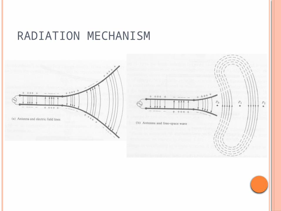
RADIATION MECHANISM

ELECTROMAGNETIC WAVE

SIMPLE DIPOLE ANTENNA

RESONANCE

POLARIZATION EM waves are composed
of two planes – vertical and horizantal (E and M fields)
If the s/g is Txed in one polarization , must be Rxed in same polarization
Otherwise attenuation
When the wave is in V-plane – V-polarization H-plane– H-polarization

TYPES OF POLARIZATION

ELECTROMAGNETIC SPECTRUM

WAVES USED IN TELECOMMUNICATION
Radio waves Radiated by the
Omnidirectional antennas
Transmits UHF frequencies
Micro waves Radiated by the
directional antennas Transmits 0.3GHz-
300GHz

ANTENNAS FOR RADIO WAVES
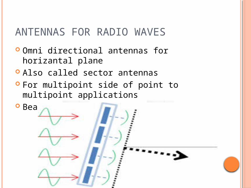
Omni directional antennas for horizantal plane
Also called sector antennas For multipoint side of point to multipoint
applications Beam width 45-180 degrees
ANTENNAS FOR RADIO WAVES

RADIATION PATTERN OF RF ANTENNA

ANTENNAS FOR MICRO WAVES

ANTENNAS FOR MICRO WAVES Low power mw sources –
FET, Tunnel , Impatt, Gunn diodes
High power mw sources – magnetron , klystron, TWT, gyrotron
Used for point to point communications
Shorter wavelengths and high frequencies
Antenna size is inversily proportional to the transmitted frequency
Allowing frequency reuse

PATCH ANTENNA USED IN MOBILES

CONSTRUCTION OF PATCH ANTENNA Simple patch antenna
uses one half wave length
two metallic plates separated by a dielectric layer.
Metalic plates made of copper
Antenna is fed by 50ohm transmission line
Generation of E and H fields dependent on length and width of the patch and wavelength

E AND H FIELDS OF A PATCH E-field
varies along the length of the patch
minimum at the centre and maximum at the edges
The H-field varies along the length is
in a direction perpendicular to the E-field.
maximum at the center and minimum at the edges.
The impedance is zero at the center of the patch
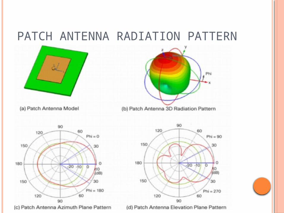
PATCH ANTENNA RADIATION PATTERN

PATCH ARRAY ANTENNA RADIATION PATTERN

RADIATION PATTERN FROM A CELL PHONE
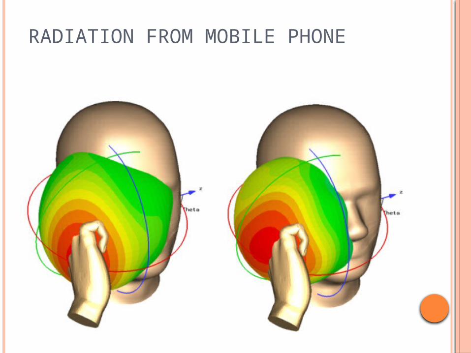
RADIATION FROM MOBILE PHONE