Wave Rotor Research Program at Michigan State University
15
American Institute of Aeronautics and Astronautics 1 Wave Rotor Research Program at Michigan State University P. Akbari * Mechanical Engineering Department, Purdue School of Engineering and Technology, Indianapolis, IN, 46202-5132 N. Müller † Mechanical Engineering Department, Michigan State University, E. Lansing, MI, 48824-1226 An attempt is carried out to introduce wave rotor research activities in the Turbomachinery Laboratory of Michigan State University (MSU). The activities vary for different propulsion and power generation purposes including utilization of wave rotors for microturbines, ultra-micro gas turbines, and water refrigeration systems. In collaboration with the research team at Warsaw University of Technology in Poland and Purdue School of Engineering and Technology in Indianapolis (IUPUI), several other analytical and numerical studies have been also investigated in this laboratory. This institute also houses the first wave rotor test rig at university levels in the nation. The goal of this paper is to summarize past and ongoing efforts in this institute. Special emphasis is given to propulsion applications and significant potential of wave rotor technology for performance improvement of gas turbine and jet engines. Observations and lessons learnt from experimental studies, numerical simulations, analytical approaches, and other design and analysis tools are discussed. I. Introduction here is a continual demand to increase the performance of thermodynamic cycles beyond the limits of conventional turbomachinery. Traditionally, these cycles often function based on steady-flow processes with relatively well understood fluid mechanics and predictable performance. Utilizing unsteady-flow machines has been considered as a possible solution for increasing significantly the efficiency of simple steady-flow or semi-steady devices. The basic concept underlying these unsteady devices, known as wave machines or wave engines, is employing compression and expansion waves to add or remove energy from a fluid flow. It has been proved that for modest pressure ratios, more efficient compression processes can be achieved using pressure waves rather than blades or pistons. 1-3 Among several wave machines, pulse detonation engines (PDE) and wave rotors have received significant attention. Many researchers and engineers consider the wave rotor concept as a breakthrough technology with the potential for quantum advances in various applications such as power generation, propulsion, refrigeration, and car engine supercharging. References 4-7 have comprehensively reviewed the above and some other possible applications. For each application, configurations of wave rotors (e.g., number of ports and their positions) vary but a common feature of all wave rotors is an array of channels arranged around the axis of a drum. Figure 1 schematically illustrates an axial-flow wave rotor with straight channels. The drum rotates between two stationary end plates, each of which has a few ports or manifolds, controlling the fluid flow through the channels. Through rotation, the channel ends are periodically exposed to the ports * Postdoctoral Research Associate, Mechanical Engineering Department, Purdue School of Engineering and Technology (IUPUI), Indianapolis, IN, 46202-5132, Member AIAA. † Assistant Professor, Mechanical Engineering Department, Michigan State University (MSU), E. Lansing, MI, 48824-1226, Member AIAA. T End plates Rotating drum Channels Ports Figure 1. Schematic configuration of a typical wave rotor. 41st AIAA/ASME/SAE/ASEE Joint Propulsion Conference and Exhibit AIAA 2005-3844 10-13 July 2005, Tucson, Arizona Copyright© 2005 by the American Institute of Aeronautics and Astronautics, Inc. All rights reserved
Transcript of Wave Rotor Research Program at Michigan State University

American Institute of Aeronautics and Astronautics
1
Wave Rotor Research Program at Michigan State University
P. Akbari* Mechanical Engineering Department, Purdue School of Engineering and Technology, Indianapolis, IN, 46202-5132
N. Müller† Mechanical Engineering Department, Michigan State University, E. Lansing, MI, 48824-1226
An attempt is carried out to introduce wave rotor research activities in the Turbomachinery Laboratory of Michigan State University (MSU). The activities vary for different propulsion and power generation purposes including utilization of wave rotors for microturbines, ultra-micro gas turbines, and water refrigeration systems. In collaboration with the research team at Warsaw University of Technology in Poland and Purdue School of Engineering and Technology in Indianapolis (IUPUI), several other analytical and numerical studies have been also investigated in this laboratory. This institute also houses the first wave rotor test rig at university levels in the nation. The goal of this paper is to summarize past and ongoing efforts in this institute. Special emphasis is given to propulsion applications and significant potential of wave rotor technology for performance improvement of gas turbine and jet engines. Observations and lessons learnt from experimental studies, numerical simulations, analytical approaches, and other design and analysis tools are discussed.
I. Introduction here is a continual demand to increase the performance of thermodynamic cycles beyond the limits of conventional turbomachinery. Traditionally, these cycles often function based on steady-flow processes with
relatively well understood fluid mechanics and predictable performance. Utilizing unsteady-flow machines has been considered as a possible solution for increasing significantly the efficiency of simple steady-flow or semi-steady devices. The basic concept underlying these unsteady devices, known as wave machines or wave engines, is employing compression and expansion waves to add or remove energy from a fluid flow. It has been proved that for modest pressure ratios, more efficient compression processes can be achieved using pressure waves rather than blades or pistons.1-3 Among several wave machines, pulse detonation engines (PDE) and wave rotors have received significant attention.
Many researchers and engineers consider the wave rotor concept as a breakthrough technology with the potential for quantum advances in various applications such as power generation, propulsion, refrigeration, and car engine supercharging. References 4-7 have comprehensively reviewed the above and some other possible applications. For each application, configurations of wave rotors (e.g., number of ports and their positions) vary but a common feature of all wave rotors is an array of channels arranged around the axis of a drum. Figure 1 schematically illustrates an axial-flow wave rotor with straight channels. The drum rotates between two stationary end plates, each of which has a few ports or manifolds, controlling the fluid flow through the channels. Through rotation, the channel ends are periodically exposed to the ports
* Postdoctoral Research Associate, Mechanical Engineering Department, Purdue School of Engineering and Technology (IUPUI), Indianapolis, IN, 46202-5132, Member AIAA. † Assistant Professor, Mechanical Engineering Department, Michigan State University (MSU), E. Lansing, MI, 48824-1226, Member AIAA.
T
End plates
Rotating drumChannels
Ports
Figure 1. Schematic configuration of a typical wave rotor.
41st AIAA/ASME/SAE/ASEE Joint Propulsion Conference and Exhibit AIAA 2005-384410-13 July 2005, Tucson, Arizona
Copyright© 2005 by the American Institute of Aeronautics and Astronautics, Inc. Al rights reserved Copyright© 2005 by the American Institute of Aeronautics and Astronautics, Inc. All rights reserved
American Institute of Aeronautics and Astronautics
2
located on the stationary end plates initiating compression and expansion waves within the wave rotor channels. Thus, pressure is exchanged dynamically between fluids by utilizing unsteady pressure waves. Suddenly opening of the moving channel ends to the stationary ports resembles rupturing a diaphragm in shock tube experiments which initiates gasdynamic waves. Unlike a steady-flow turbomachine that either compresses or expands the fluid, the wave rotor accomplishes both compression and expansion within a single component. To minimize leakage, the gap between the end plates and the rotor has to be minimized, but without contact under all operating and thermal expansion conditions. More details of wave rotor internal gasdynamic processes are described in the literature and they will not be repeated here.
While the wave rotor concept has been around more than a half century, it has recently received renewed interest due to technology advances and recent developments in related unsteady-flow studies. The pioneer work by Seippel 8 which implemented this concept into real engines, proving the feasibility of wave rotor machines, is often known as a milestone in wave rotor history. Since then, several companies and governmental agencies all over the world started designing and developing various wave rotor configurations.7 Among them, several successful designs performed efficiently over a wide range of operating conditions such as the CAL Wave Superheater,9 BBC Pressure Wave Supercharger,10 the Pearson Wave Engine,11 and the MSNW Rotor.12
The NASA wave rotor program started in 1989 6 opened a new chapter in wave rotor development taking advantage of new computational capabilities which allows accurate simulation of the flow field inside the wave rotor, and modern experimental measurements and diagnostic techniques. The relatively successful achievements made by the NASA wave rotor group motivated a number of other institutes and agencies to pay special attention to this novel technology which had been ignored by the turbomachinery community. For example, in the US, Rolls-Royce Alison (now AADC) and several academic universities including Indiana University-Purdue University in Indianapolis (IUPUI), Michigan State University (MSU), University of Florida, and University of Washington have conducted research and developments on wave rotors.7 This study summarizes wave rotor studies at MSU performed since initiation of the program in the year 2002.
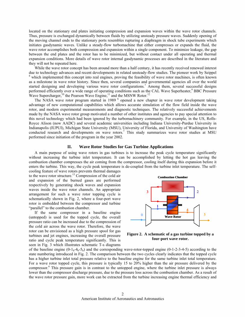
II. Wave Rotor Studies for Gas Turbine Applications A main purpose of using wave rotors in gas turbines is to increase the peak cycle temperature significantly
without increasing the turbine inlet temperature. It can be accomplished by letting the hot gas leaving the combustion chamber compresses the air coming from the compressor, cooling itself during this expansion before it enters the turbine. This way, the cycle peak temperature is de-coupled from the turbine inlet temperature. The self-cooling feature of wave rotors prevents thermal damages to the wave rotor structure.13 Compression of the cold air and expansion of the burned gases are performed respectively by generating shock waves and expansion waves inside the wave rotor channels. An appropriate arrangement for such a wave rotor topping cycle is schematically shown in Fig. 2, where a four-port wave rotor is embedded between the compressor and turbine “parallel” to the combustion chamber.
If the same compressor in a baseline engine (untopped) is used for the topped cycle, the overall pressure ratio can be increased due to the compression of the cold air across the wave rotor. Therefore, the wave rotor can be envisioned as a high pressure spool for gas turbines and jet engines, increasing the overall pressure ratio and cycle peak temperature significantly. This is seen in Fig. 3 which illustrates schematic T-s diagrams of the baseline engine (0-1b-4b-5b) and the corresponding wave-rotor-topped engine (0-1-2-3-4-5) according to the state numbering introduced in Fig. 2. The comparison between the two cycles clearly indicates that the topped cycle has a higher turbine inlet total pressure relative to the baseline engine for the same turbine inlet total temperature. For a wave rotor topped cycle, this pressure is typically 15 to 20% higher than the air pressure delivered by the compressor.6 This pressure gain is in contrast to the untopped engine, where the turbine inlet pressure is always lower than the compressor discharge pressure, due to the pressure loss across the combustion chamber. As a result of the wave rotor pressure gain, more work can be extracted from the turbine increasing engine thermal efficiency and
0
1
23
45Wave Rotor
Combustion Chamber
0
1
23
45Wave Rotor
Combustion Chamber
Figure 2. A schematic of a gas turbine topped by a four-port wave rotor.

American Institute of Aeronautics and Astronautics
3
specific work. Note that for the shown cycles the amount of heat addition is the same for both cycles because the wave rotor compression work is equal to the wave rotor expansion work.
Tturbine
Entropy
Tem
pera
ture
0-1b-4b-5bBaseline engine
0-1-2-3-4-5 Engine topped with a wave rotor
3
4
5
0
1b=1
2
4b
5b
Tturbine
Entropy
Tem
pera
ture
Entropy
Tem
pera
ture
0-1b-4b-5bBaseline engine
0-1-2-3-4-5 Engine topped with a wave rotor
3
4
5
0
1b=1
2
4b
5b
Figure 3. Schematic T-s diagrams for a gas turbine with and without a wave rotor.
A. Wave Rotor Designs Using Analytical Analyses Considerable contributions to design of wave rotors in the
past were made possible by employing analytical approaches and theoretical models.2, 14, 15 Even though developments of analytical methods required considerable time and effort and small design changes necessitated lengthy recalculations, computational methods were too primitive at the time and calculations by theoretical models were the only solutions. Albeit recent advances in computational methods have enabled fast, accurate, and efficient design methods, numerical codes developed for studying the unsteady-flow field of wave rotors 16-24 have not been widely disseminated. Utilizing analytical models still can provide some useful design parameters for a preliminary design.
Akbari and Müller at MSU have introduced 25, 26 a relatively simple one-dimensional gasdynamic model of the high-pressure phase (charging process) to calculate flow characteristics inside four-port wave rotors channels. In the high-pressure process, compression waves transfer the energy directly from a fluid at a higher pressure (driver fluid) to another fluid at a lower pressure (driven fluid). They implemented their model into several possible wave patterns that could exist in the charging process of a four-port wave rotor. For instance, two of such wave configurations known as wave diagrams are shown in Fig. 4. They represent developed (unwrapped) views of the charging processes of a wave rotor moving in the upward direction. Wave diagrams describe the rotor internal operation by tracing the trajectories of the waves and gas interfaces and showing the sequence of events occurring during one cycle within the channels. Vertical and horizontal directions represent time and axial direction along the rotor channels, respectively. The shock waves, interface lines, and expansion wave trajectories are depicted by dashed, dotted and solid lines, respectively. Lgas denotes the gas penetration length indicating how far the burned gas can
Lgas
W3
W2
1′
233
2′
3′
Lgas
33
2′
3′3′
Ls
22
1′
Figure 4. Two possible wave diagrams of high-pressure part: with two primary shock waves (top), with one primary shock wave plus a reflected shock wave (bottom).

American Institute of Aeronautics and Astronautics
4
penetrate the rotor channels. W2 and W3 represent inlet and outlet port widths, respectively. Implementing their suggested analytical model for a small gas turbine topped with a wave rotor, useful design
parameters such as port widths and rotor size were determined 26 by computing transit times of the waves traveling inside the channels. To validate and support the accuracy of the analytical results, comparisons with numerical results of a test case have been made.27 Table 1 compares the predicted values with those calculated by numerical simulations at University of Tokyo.28 Good agreement between the results is observed. The existing errors can be related to the assumptions made in the model, e.g., assuming pure air at the beginning of the high-pressure part of the cycle and using a constant specific heat at different states of air and gas. As the author expressed,27 in the first step, the accuracy of the presented model can be improved by solving the flow field in the low-pressure cycle to determine how much the temperature and pressure of the air filling the entire channel at the beginning of the high-pressure part model should be changed. Such an effort for a different wave pattern is made by Müller and Siol.29
Table 1. Comparison between the analytical model and the numerical data of the Tokyo wave rotor.
Geometry and port characteristics Model Tokyo wave rotor
Cell width 0.49 cm 0.4 cm Cell height 0.3 cm 0.3 cm Circumferential length from 0 to opening of air outlet port 0.76 cm 0.88 cm Width of high pressure air outlet port 1.65 cm 1.62 cm Width of high pressure gas inlet port 2.1 cm 1.87 Port width ratio 0.78 0.87
Angle from 0° until opening high pressure air outlet 18.7 ° 21.6 ° Opening angle of high pressure air outlet 40.6 ° 40.0 ° Opening angle of high pressure gas inlet 51.7 ° 46.0 °
B. Performance Predictions of Wave Rotor Topping Cycles Many investigations on performance prediction of wave rotor topping cycles for gas turbines have been
published,30-32 but it is not clearly specified where the most appropriate design space is in which the wave rotor application is most beneficial. Furthermore, to the knowledge of the author, there exits no comprehensive work investigating the potential benefits of various implementation cases of wave rotor topping cycles for small gas turbines. To answer these questions, a comprehensive performance prediction using basic thermodynamic equations has been performed.26, 33-36 The model can be employed to predict the performance improvement of various wave rotor topping cycles without the need for knowing the details of the complex fluid mechanics within the wave rotor.
Figure 5 schematically visualizes several possibilities to top a gas turbine with a wave rotor, according to the state numbering introduced in Fig. 2. Path 0-1b-4b-5b represents the baseline cycle and 0-1i-2i-3i-4i-5i (i=A, B, C, D, E) indicates possible wave rotor toppings. For instance, in Case A the pressure ratio of the compressor and turbine inlet temperature are kept the same as those of the baseline engine, as previously described in Fig. 3. Advantages and disadvantages of all cases have been already discussed in detail in the above references and they will not be repeated here.
4C
5C
3B
4B
5B
T
Entropy
Tem
pera
ture
turbine
3A
4A
5A
3E
4E
5E1D
2D
3D
0
1b= 1E = 1A
5b=5D
1B=1C
2B=2C
4b= 4D=3C
2A=2E
0-1b-4b-5b baseline engine0-1i-2i-3i-4i-5i topped engine
i=A, B, …, E
Figure 5. Schematic T-s diagrams for a baseline cycle and five different wave rotor topped cycles.

American Institute of Aeronautics and Astronautics
5
Figure 6 is only one example of such a performance prediction. This performance map illustrates the increase of cycle thermal efficiency (green) and specific work (blue), and the decrease of specific fuel consumption (red) for any combination of compressor pressure ratio pt1 /p0 (abscissa) and wave rotor pressure ratio PRW (parameter labeled in black defined as PRW = pt2 / pt1 where “t” denotes total stagnation pressure) for a 30 kW topped engine. The plot visualizes how the effect develops from the baseline engine with PRW =1 until PRW =2 which might be a practical limit for the investigated application. In this map, the multiplication of compressor pressure ratio and wave rotor pressure ratio PRW determines the overall cycle pressure ratio pt2/p0 (orange). The locus of optimum compressor pressure ratio points (for highest thermal efficiency, highest specific work, and lowest specific fuel consumption at each achievable wave rotor pressure ratio) are connected by black solid lines.
PRW=11.2
1.41.61.822.4
2.4
pt 2/p0=3.64.8 6 7.2
8.49.6
0
0.04
0.08
0.12
0.16
0.2
0.24
0.28
1 2 3 4 5 6 7 8 9 10 11 12 13 14 15Compressor Pressure Ratio
Ther
mal
Effi
cien
cy,
SFC
(kg/
kN.s
)
100
120
140
160
180
200
220
240
Spec
ific
Wor
k (k
J/kg
)
Tt4=1116.5 KηPC=0.83ηPT=0.82Π comb=0.98
Optima
Rcomp=3.6
No Gain Region
C-30 Engine
Figure 6. Performance map for wave-rotor-topping of gas turbines, Cases A, B, and D.
Such maps are not only very useful to explore the possible enhancement of already existing baseline engines, but
they also serve well for selecting a design point or region for designing a new wave-rotor-topped engine. In all plots, the performance points of the baseline engine (PRW =1) and the wave rotor enhanced engines of all cases with a wave rotor pressure ratio of PRW =1.8 can be found. For instance in Fig. 6, starting from the performance point of the baseline engine, the performance values for Case A are found by moving vertically upwards (e.g. along the dashed line for constant compressor pressure ratio pt1/p0) until the corresponding performance curve of the expected wave rotor pressure ratio is crossed. With a conceivable wave rotor pressure ratio of 1.8 and a compressor pressure ratio of 3.6, the plot predicts an attractive relative performance improvement in thermal efficiency and specific work of about 33.8% and a 25.2% reduction in specific fuel consumption for Case A. However, for higher compressor pressure ratios the benefit of using a wave rotor progressively diminishes for the fixed parameters shown in the upper right corner of the plot. In fact, for compressor pressure ratios greater than around 11, almost no benefit can be obtained for such engine. Akbari and Müller at MSU 27 have extensively discussed results of such a thermodynamic cycle analysis and other advantageous benefits of wave rotor topped cycles including performance superiority of topped engines over untopped engines under hot-weather conditions, and performance improvements of recuperated gas turbines topped with wave rotors.
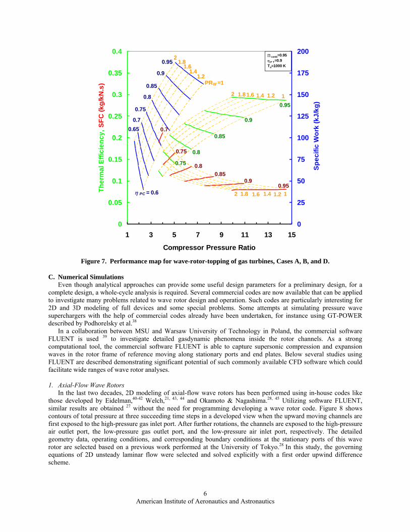
In a recent study at MSU,37 multi-parametric performance maps for different wave rotor implementations have been generated specifying optimum operating points for both untopped baseline and topped engines. The authors have predicted the performance calculations due to the variations of turbine inlet temperature, compressor pressure ratio, wave rotor compression ratio, compressor and turbine polytropic efficiencies and combustor loss in a systematic performance analysis. For instance, Fig. 7 shows only optimum points of the thermal efficiency, specific work, and specific fuel consumption by varying compressor polytropic efficiency (ηPC) for fixed turbine inlet temperature (Tt4), turbine polytropic efficiency (ηPT), and combustor pressure loss (Πcomb).
American Institute of Aeronautics and Astronautics
6
0.7
0.75
0.75 0.8
0.8
0.85
0.85
0.9
0.9
0.95
0.95
1
1
1.2
1.2
1.4
1.4
1.6
1.6
1.8
1.8
2
2η PC = 0.6
0.650.7
0.75
0.8
0.85
0.9
0.95
PRW =11.2
1.41.6
1.82
0
0.05
0.1
0.15
0.2
0.25
0.3
0.35
0.4
1 3 5 7 9 11 13 15
Compressor Pressure Ratio
Ther
mal
Effi
cien
cy, S
FC (k
g/kN
.s)
0
25
50
75
100
125
150
175
200
Spec
ific
Wor
k (k
J/kg
)
Π comb=0.95ηP T =0.9T4=1000 K
Figure 7. Performance map for wave-rotor-topping of gas turbines, Cases A, B, and D.
C. Numerical Simulations Even though analytical approaches can provide some useful design parameters for a preliminary design, for a
complete design, a whole-cycle analysis is required. Several commercial codes are now available that can be applied to investigate many problems related to wave rotor design and operation. Such codes are particularly interesting for 2D and 3D modeling of full devices and some special problems. Some attempts at simulating pressure wave superchargers with the help of commercial codes already have been undertaken, for instance using GT-POWER described by Podhorelsky et al.38
In a collaboration between MSU and Warsaw University of Technology in Poland, the commercial software FLUENT is used 39 to investigate detailed gasdynamic phenomena inside the rotor channels. As a strong computational tool, the commercial software FLUENT is able to capture supersonic compression and expansion waves in the rotor frame of reference moving along stationary ports and end plates. Below several studies using FLUENT are described demonstrating significant potential of such commonly available CFD software which could facilitate wide ranges of wave rotor analyses. 1. Axial-Flow Wave Rotors
In the last two decades, 2D modeling of axial-flow wave rotors has been performed using in-house codes like those developed by Eidelman,40-42 Welch,21, 43, 44 and Okamoto & Nagashima.28, 45 Utilizing software FLUENT, similar results are obtained 27 without the need for programming developing a wave rotor code. Figure 8 shows contours of total pressure at three succeeding time steps in a developed view when the upward moving channels are first exposed to the high-pressure gas inlet port. After further rotations, the channels are exposed to the high-pressure air outlet port, the low-pressure gas outlet port, and the low-pressure air inlet port, respectively. The detailed geometry data, operating conditions, and corresponding boundary conditions at the stationary ports of this wave rotor are selected based on a previous work performed at the University of Tokyo.28 In this study, the governing equations of 2D unsteady laminar flow were selected and solved explicitly with a first order upwind difference scheme.

American Institute of Aeronautics and Astronautics
7
(a) t = t1 (b) t = t2
(c) t = t3
Figure 8. Total pressure contours (in Pascal) at three sequential time steps t1 , t2 , t3.
As expected, the high-pressure flow starts compressing the low-pressure fluid in the channel by generating
compression waves. The pressure stratification along the channel length indicates the action of compression waves. These compression waves form a stronger single shock wave running through the channel. Once the compression waves reach the end wall, a reflected shock wave is generated as shown in red colors in the figures. The reflected shock wave compresses the air further. The double-compressed air leaves the channel by the opening of the high-pressure air outlet port. Afterwards, the flow is scavenged from the rotor channels by opening the gas outlet port. This process is supported by the generation of expansion fans traveling through the channels toward the air inlet port. Finally, the fresh air is ingested into the rotor channels by opening the air inlet port. It is interesting to note that a region of lowest pressure even less than the air inlet pressure (here shown numerically as negative pressure) is created just before opening the air inlet port. This can be interpreted as the reflection of the expansion wave off the left end plate shortly before the air inlet port opens. This low-pressure region significantly assists the ingestion process. Closing the air inlet port terminates the first operating cycle. The pressure contour at this moment is shown in the last figure (c). All of the above described phenomena can be seen in this figure.
One of the challenging steps in generating such flow fields is the creation of a stationary interface between the moving channels and the stationary ports. This is carried out by creating a relatively small gap (0.1 mm) between the wall ends of the channels and the end plates with the ports where an interface connects them. The entire channel grid lines slip along this interface during the wave rotor operation. An additional advantage of generating such a gap is the actual simulation of the leakage between the stationary end plates and the rotating channels. This can be seen in Fig. 9-a and Fig. 9-b where flow circulation at the high-pressure gas inlet port is shown. In the lower corner of the gas inlet port, the effect of gradual channel opening is magnified as shown in Fig. 9-a, also showing some leakage effects. Fig. 9-b represents a focused zone of the upper corner of the high-pressure gas inlet port, indicating less leakage because of flow blockage caused by intense flow recirculation in the beginning of the channels. This flow blockage suggests that a narrower gas inlet port may be substituted for the current wider port. The reader is referred to Ref. 27 for more details.
Hot Gas
Fresh Air
Compressed Air
Exhaust Gas
Rotation

American Institute of Aeronautics and Astronautics
8
(a) Lower corner of the gas inlet port (b) Upper corner of the gas inlet port
Figure 9. Axial component of relative velocity, lower and upper corners of gas inlet port.
Some 3D calculations have been performed 39 for an axial-flow wave rotor suitable for a microturbine. Its
preliminary design was obtained by an analytical procedure by Akbari and Müller.26 Results are shown in Fig. 10. These figures indicate very well the effects of compression and expansion waves in generating high-pressure and low-pressure regions.
Figure 10. Total pressure contours (in Pascal) for an axial reverse-flow wave rotor.
2. Radial-Flow Wave Rotors with Straight Channels For various wave rotor applications, axial-flow wave rotors have been the most common design developed so
far. The four-port version with straight channels has been used most widely. However, pure scavenging is a challenging task in axial-flow configurations.7 An innovative design taking advantage of centrifugal forces can improve the scavenging process. The radial-flow wave rotor concept 46 (wave disc) employing a flow in the radial and circumferential directions can substantially improve the scavenging process. To verify the novel concept of wave disc, FLUENT has been used again to generate 2D models.
As an example, contours of static pressure and temperature are shown in Fig. 11. The rotor size and operating conditions are reported in Ref. 39. The configuration studied here is known as the reverse-flow wave rotor (RF). In the RF configuration, the fresh air enters and exits at the same end of the rotor (air casing) while the burned gas enters and exits the rotor at the other end (gas casing). Fig. 11-b clearly indicates that the gas casing is located the outer radius while the air casing is placed at the inner radius. The temperature contours also clearly show the flow casing especially for the burned gas which is a typical feature of RF configurations. Relatively uniform regions shown before and after the four ports indicate that the combination of diameters, speed, and port arrangement is almost optimized, because nearly no changes are seen in these regions. Only the pressure contours show a certain radial stratification in these regions, indicating the action of centrifugal forces. They also show the effects of compression and expansion waves and how the low-pressure region is created by supporting the ingestion of fresh air.
Inlet Port
Moving Channels

American Institute of Aeronautics and Astronautics
9
Exhaust GasHot Gas
Fresh Air
Com
pres
sed
Air
Exhaust GasHot Gas
Fresh Air
Com
pres
sed
Air
(a) Contour plots of static pressure (Pascal) (b) Contour plots of static temperature (Kelvin)
Figure 11. Radial-flow wave rotor with straight channels, reverse-flow configuration. 3. Radial-Flow Wave Rotors with Curved Channels
In a radial wave rotor, the channels alternatively may be curved and varied in cross-sectional area. Compared with straight wall channels, curved channels provide a greater length for the same disc diameter, which can be important to obtain certain wave travel times for tuning. With curved channels also the angle against the radius can be changed freely. Furthermore, curved channels may be more effective for self-propelling and work extraction in the case of a wave turbine or work input for additional compression, analogous to the principle of turbomachines.
Figure 12 shows contours of static pressure and temperature in a radial wave rotor with curved channels, indicating that compression and expansion processes are generally working. Again, the static pressure contours (Fig. 12-a) show radial pressure stratifications in the regions where both ends of the channels are closed, as discussed in Fig. 11-a. The temperature contours (Fig. 12-b) now show a similar casing like in Fig. 11-b, but with deeper gas penetration and an unexpected carry on of expanding hot gas stretches after the exhaust gas port opens.
(a) Contour plots of static pressure (Pascal) (b) Contour plots of static temperature (Kelvin)
Figure 12. Radial-flow wave rotor with curved channels, reverse-flow configuration. The concept of radial-flow wave rotor can be used for various applications such as gas turbine topping,
refrigeration, and internal combustion wave rotors (a wave rotor in which combustion occurs inside the channels), as discussed in a previous study.46 For example, several wave discs can be stacked together to form an array of wave disks providing a unique opportunity to place such a unit in a gas turbine. Besides previously listed advantages of wave rotors, now, such a design eliminates the need for a diffuser which has been replaced by a more effective shock deceleration process 1-3 in the wave disc channels.

American Institute of Aeronautics and Astronautics
10
4. Ultra-Micro Wave Rotors Ultra-micro gas turbines (UµGT) manufactured using microfabrication technology have experienced difficulties
in obtaining high overall thermal efficiency and output power.47 Such performance reductions are mainly due to various losses and low component efficiencies resulting from miniaturization. For instance, compressor isentropic efficiency could drop to less than 50%, reducing optimum pressure ratios down to about 2.48 Therefore, innovations are desired to attractively enhance the performance of UµGT. As discussed in Fig. 6, the wave rotor has a significant potential for enhancing performance of gas turbines especially in the range of smaller sizes, where the pressure ratio is typically low. As a result, utilizing wave rotor technology to improve the performance of UµGT has been pursued by the wave rotor teams at University of Tokyo 28, 49 and MSU. 50, 51
Besides feasibility analyses and developing analytical models,50 in a collaboration with Warsaw University of Technology, the MSU team has also performed numerical simulations 51 to investigate the potential of integrating axial-flow and radial-flow wave rotors in UµGT. Figure 13 indicates flow pressure and temperature distributions inside a microscale wave rotor (1mm length and 0.42 mm radius) which operates on a RF configuration. The black arrows on the temperature contours indicate gas and air casings at the channels ends which are characteristics of RF configurations. The wave patterns are still consistent with the theory of wave rotor operation. Such simulations can be also used to investigate the effect of gap size between the rotating drum and the end plates on the wave rotor operation. At such a small scale, gap sizes are in the order of micrometers (e.g. 2-20 µm) 51 and experimental tests are extremely difficult with today’s microfabrication technology.
(a) Contour plots of static pressure (Pascal) (b) Contour plots of static temperature (Kelvin)
Figure 13. Flow simulation in an ultra-micro wave rotor, reverse-flow configuration.51
III. Condensing Wave Rotor Studies for Refrigeration Applications The application of wave rotor technology for refrigeration cycles using water (R718) as a refrigerant has been
introduced by Müller at MSU.3 R718 units which have been commercialized in Europe, such as those at the Volkswagen and DaimlerChrysler factories in Germany, have large sizes and high manufacturing costs. The large size is due to the use of two centrifugal compressors with comparably large diameter and voluminous (same diameter) internal direct heat exchangers. The high cost is mainly generated by the relative expensive specially built compressors with independent variable speed drives. Figure 14 schematically illustrates a water refrigeration cycle consisting of a two-stage compressor, direct condensation and evaporation units, expansion valve, pump, cooling tower, and a heat source. As described below, using the novel concept of condensing wave rotor in water refrigeration cycles can eliminate challenges which have hindered the wide application of R718 units.

American Institute of Aeronautics and Astronautics
11
Refrigerant cycle
compressor2b
1b
3b 4b5b
6b8b
7b
evaporatorco
nde
nse
r
Chilled w
ater cycleC
oolin
g w
ater
cyc
le
heat sou
rce
cool
ing
tow
er
throttling valve
pumppump
7b
wC1+wC2
wPL
throttling valve
Refrigerant cycle
compressor2b2b
1b
3b 4b5b
6b8b
7b
evaporatorco
nde
nse
r
Chilled w
ater cycleC
oolin
g w
ater
cyc
le
heat sou
rce
cool
ing
tow
er
throttling valve
pumppump
7b7b
wC1+wC2
wPL
throttling valve
Figure 14. Schematic of thermodynamic model of a R718 unit.
A schematic thermodynamic model of a R718 cycle using a 3-port condensing wave rotor is depicted in Fig 15.
In this modified cycle, condensation occurs inside the wave rotor channels by compressing the low-pressure vapor (state 2) using the high-pressure water (state 6). Hence, liquid water at an intermediate pressure is discharged from the rotor channels. Furthermore, one stage of the compressor is substituted by the pressure gain generated by shock waves inside the channels. The work necessary for the shock wave compression in the wave rotor channels (wPC) is provided by a larger pump (wPL+ wPC).
2 1
3 45
6 8
7CWR
heat sou
rce
Chilled w
ater cycle
Refrigerant cycle
compressor
evaporator
Coo
ling
wat
er c
ycle
cool
ing
tow
er
throttling valve
pumppump
wC1
wPL+wPC
2 1
3 445
6 8
7CWR
heat sou
rce
Chilled w
ater cycle
Refrigerant cycle
compressor
evaporator
Coo
ling
wat
er c
ycle
cool
ing
tow
er
throttling valve
pumppump
wC1
wPL+wPC
Figure 15. Schematic of the thermodynamic model of a R718 unit enhanced
by a 3-port condensing wave rotor (CWR). Fig. 16 shows a schematic of a 3-port condensing wave rotor. While the number of ports and their levels of
pressures (low, medium, high) are similar to those of a wave rotor equalizer,5 the phase change of the fluid inside the wave rotor is a major difference when compared with the operation of a pressure equalizer. Details of wave processes and phase changes inside the channels are discussed extensively in the previous publication.52-54
Low Pressure Vapor (2)
High Pressure Water (6)
Vapor collector
End plate
Condensing Wave Rotor (CWR)
Channel
Medium Pressure Water (3)End plate
Low Pressure Vapor (2)
High Pressure Water (6)
Vapor collector
End plate
Condensing Wave Rotor (CWR)
Channel
Medium Pressure Water (3)End plate
Figure 16. Schematic of a 3-port condensing wave rotor.

American Institute of Aeronautics and Astronautics
12
Using a 3-port condensing wave rotor in a water refrigeration cycle can also enhance the performance of R718 units by increasing the coefficient of performance (COP). This has been theoretically shown by Kharazi et al.52-56 using a thermodynamic cycle analysis which compares COP of a baseline cycle and a 3-port condensing wave rotor cycle. The authors have developed performance maps for specifying the maximum percentage increase in COP relative to baseline (COPgain) obtained by the optimum choice of PRW = p3 /p2 for a given evaporator temperature (T1) and a temperature lift (T3 - T1). Figure 17 shows one of these maps. The constant PRW lines indicate the optimum PRW that yields the highest possible COPgain indicated by constant maximum COPgain lines. Paramter K indicated on the top left side of the plot is the mass flow ratio (K = m6 /m2) which is an independent design parameter relating the mass flow of the cooling cycle (m6) to the mass flow of the core cycle (m2). The presented results show an additional improvement of the COP of up to 22% by using the 3-port condensing wave rotor.
8%
10%
12%
16%
18%20%
14%
22%1.4
1.6
1.9
2.4
2.452.45
PR =2.3
=2.3
5
10
15
20
25
30
35
40
45
0 5 10 15 20 25 30 35 40 45
T 3-T
1
Max. increase in COP relativeto baseline cycle =6%
w
T1[ºC]
[K]
K=125
8%
10%
12%
16%
18%20%
14%
22%1.4
1.6
1.9
2.4
2.452.45
PR =2.3
=2.3
5
10
15
20
25
30
35
40
45
5
10
15
20
25
30
35
40
45
0 5 10 15 20 25 30 35 40 450 5 10 15 20 25 30 35 40 45
T 3-T
1
Max. increase in COP relativeto baseline cycle =6%
w
T1[ºC]
[K]
K=125
Figure 17. Performance map: maximum performance increase and optimum wave rotor pressure ratios.
IV. MSU Wave Rotor Test Rig At MSU a wave rotor test rig 57 (Fig. 18) has been built for
verification of analyses and design concepts. The core of the test rig is a ceramic wave rotor of 60 mm length and 65mm outer diameter. It is a Comprex® prototype wave rotor that has been made available through Warsaw University of Technology. The end plates are easily exchangeable to adapt different port locations. A crucial feature of the test rig is the adjustable gap width that can be adjusted between zero and about 3.5 mm at both sides independently and during operation. Furthermore, the gap is controlled passively to maintain it as constant as possible, in the way that the wave rotor drum pushes and pulls the axially sliding end plates as it thermally expands and contracts (Fig 19). The gap is accessible to measurements optically through the transparent housing and mechanically by easily sliding the transparent housing off. Through throttle valves at all ports the pressure ratios can be adjusted. The rotor is driven by a variable speed motor, designed for up to 35,000 rpm. At the time of writing this paper, only cold tests (air) have been conducted while an upgrade is planned to enable tests with hot gases.
Figure 18. MSU wave rotor demonstrator.

American Institute of Aeronautics and Astronautics
13
Figure 19. Geometry details and the sealing technique of MSU test rig.
V. Conclusion The MSU wave rotor group has conducted studies to evaluate wave rotor technology benefits for several thermal
cycle applications. The activities have expanded from analytical, numerical, and experimental wave rotor assessments for refrigeration, propulsion, and power generation systems. Several novel concepts such as radial-flow wave rotors, 3-port condensing wave rotors, and wave discs for gas turbines have been introduced. Feasible implementations of these new design arrangements into steady-state cycles are described and preliminary designs are conducted using analytical and numerical tools.
Today, wave rotors are being investigated again extensively. While involved researchers may have state-of-the-art knowledge of this technology, it has not reached wider audiences. Rising fuel costs, new research data, and technology innovations have provided a fresh opportunity to consider the wave rotor concept to enable today’s gas turbine industry to gain significant performance improvements. New opportunities appear, especially for small-scale wave machines that may substantially surpass conventional concepts. Continued research on sealing and thermal expansion control are needed to solve still persistent challenges.
Acknowledgments This manuscript highlights the work of several colleagues who have contributed to the MSU wave rotor
program. The authors would like to express their gratitude to the efforts by F. Iancu, A. A. Kharazi, E. Dempsey, U. Siol, and A. Behinfar. The assistance of Prof. J. Piechna at Warsaw University of Technology in Poland who has initially developed the numerical simulations presented here is gratefully acknowledged. Useful comments and discussions with Prof. R. Nalim of Purdue School of Engineering and Technology in Indianapolis (IUPUI) are also appreciated. Finally, the supports by NASA and MSU have greatly enhanced the presented research.
.

American Institute of Aeronautics and Astronautics
14
References
1Weber, H. E., “Shock-Expansion Wave Engines: New Directions for Power Production,” ASME Paper 86-GT-62, 1986. 2Weber, H. E., Shock Wave Engine Design, John Wiley and Sons, New York, 1995. 3Akbari, P., Kharazi, A. A., Müller, N., “Utilizing Wave Rotor Technology to Enhance the Turbo Compression in Power and
Refrigeration Cycles,” ASME Paper IMECE2003-44222, 2003. 4Azoury P. H., Engineering Applications of Unsteady Fluid Flow, John Wiley and Sons, New York, 1992. 5Kentfield, J. A. C., Nonsteady, One-Dimensional, Internal, Compressible Flows, Oxford University Press, Oxford, 1993. 6Welch, G. E., “Overview of Wave-Rotor Technology for Gas Turbine Engine Topping Cycles,” Novel Aero Propulsion
Systems International Symposium, The Institution of Mechanical Engineers, 2000, pp. 2-17. 7Akbari, P., Nalim, M. R., and Müller, N., “A Review of Wave Rotor Technology and Recent Developments,” ASME Paper
IMECE2004-60082, 2004. 8Seippel, C., Swiss Patent 225426, 1940. 9Rose, P. H., “Potential Applications of Wave Machinery to Energy and Chemical Processes,” Proceedings of the 12th
International Symposium on Shock Tubes and Waves, 1979, pp. 3-30. 10Berchtold, M., “The Comprex®,” Proceeding ONR/NAVAIR Wave Rotor Research and Technology Workshop, Report
NPS-67-85-008, Naval Postgraduate School, Monterey, CA, 1985, pp. 50-74. 11Pearson, R. D., “A Gas Wave-Turbine Engine Which Developed 35 HP and Performed Over a 6:1 Speed Range,”
Proceeding ONR/NAVAIR Wave Rotor Research and Technology Workshop, Report NPS-67-85-008, Naval Postgraduate School, Monterey, CA, 1985, pp. 403-49.
12Thayer, W. J., “The MSNW Energy Exchanger Research Program,” Proceeding ONR/NAVAIR Wave Rotor Research and Technology Workshop, Report NPS-67-85-008, Naval Postgraduate School, Monterey, CA, 1985, pp. 85-116.
13Paxson, D. E., and Nalim, M. R., “Modified Through-Flow Wave-Rotor Cycle with Combustor Bypass Ducts,” Journal of Propulsion and Power, Vol. 15, No. 3, 1999, pp. 462-467. Also AIAA Paper 97-3140 and NASA TM-206971.
14Resler, E. L, Moscari, J. C., and, Nalim, M. R., “Analytic Design Methods for Wave Cycles,” Journal of Propulsion and Power, Vol. 10, No. 5, 1994, pp. 683-689. Also AIAA paper 93-2523.
15Nalim, M. R., and Resler, E. L., “Wave Cycle Design for Wave Rotor Gas Turbine Engines with Low NOX Emissions,” ASME Journal of Engineering for Gas Turbines and Power, Vol. 118, 1996, pp. 474-480. Also ASME Paper 95-GT-245.
16Eidelman, S., Mathur, A., Shreeve, R. P. and Erwin, J., “Application of Riemann Problem Solvers to Wave Machine Design,” AIAA Journal, Vol. 22, No. 7, 1984, pp. 1010-1012.
17Mathur, A., “Wave Rotor Research: A Computer Code for Preliminary Design of Wave Diagrams,” Report NPS67-85-006CR, Naval Postgraduate School, Monterey, CA, 1985.
18Johnston, D. T., “Further Development of a One-Dimensional Unsteady Euler Code for Wave Rotor Applications,” M.S. Thesis, Naval Postgraduate School, CA, 1987.
19Paxson, D. E., “A General Numerical Model for Wave-Rotor Analysis,” NASA TM-105740, 1992. 20Larosiliere, L. M., “Three-Dimensional Numerical Simulation of Gradual Opening in a Wave-Rotor Passage,” AIAA Paper
93-2526, 1993. Also NASA CR-191157. 21Welch, G. E., and Chima, R. V., “Two-Dimensional CFD Modeling of Wave Rotor Flow Dynamics,” AIAA-93-3318.
1993. Also NASA TM-106261. 22Fatsis, A., and Ribaud, Y., “Numerical Analysis of the Unsteady Flow Inside Wave Rotors Applied to Air Breathing
Engines,” 13th International Symposium on Airbreathing Engines, Paper ISABE-97-7214, 1997. 23Hoxie, S. S., Lear, W. E., and Micklow, G. J., “A CFD Study of Wave Rotor Losses Due to the Gradual Opening of Rotor
Passage Inlets,” AIAA Paper 98-3253, 1998. 24Okamoto, K., and Nagashima, T., “A Simple Numerical Approach of Micro Wave Rotor Gasdynamic Design,” 16th
International Symposium on Airbreathing Engines, Paper ISABE-2003-1213, 2003. 25Akbari, P., and Müller, N., “Gas Dynamic Design Analyses of Charging Zone for Reverse-Flow Pressure Wave
Superchargers,” ASME Paper ICES2003-690, 2003. 26Akbari, P., and Müller, N., “Preliminary Design Procedure for Gas Turbine Topping Reverse-Flow Wave Rotors,” ASME
Paper IGTC03-FR-301, 2003. 27Akbari, P., “Performance Prediction and Preliminary Design of Wave Rotors Enhancing Gas Turbine Cycles,” Ph.D.
Thesis, Michigan State University, MI, 2004. 28Okamoto, K., Nagashima, T., and Yamaguchi, K., “Introductory Investigation of Micro Wave Rotor,” ASME Paper
IGTC03-FR-302, 2003. 29Siol, U., Staudacher, S., and Müller, N., “Preliminary Wave Rotor Design by Means of Basic Thermodynamic and Fluid
Dynamic Laws,” ASME Paper PWR2005-50066, 2005. 30Wilson, J., and Paxson, D. E., “Jet Engine Performance Enhancement Through Use of a Wave-Rotor Topping Cycle,”
NASA TM-4486, 1993. 31Jones, S. M., and Welch, G. E., “Performance Benefits for Wave Rotor-Topped Gas Turbine Engines,” ASME Paper 96-
GT-075, 1996. 32Fatsis, A., and Ribaud, Y., “Thermodynamic Analysis of Gas Turbines Topped with Wave Rotors,” Aerospace Science and
Technology, Vol. 3, No. 5, 1999, pp. 293-299.

American Institute of Aeronautics and Astronautics
15
33Akbari, P., and Müller, N., “Performance Improvement of Small Gas Turbines Through Use of Wave Rotor Topping Cycles,” ASME Paper GT2003-38772, 2003.
34Akbari, P., and Müller, N., “Performance Investigation of Small Gas Turbine Engines Topped with Wave Rotors,” AIAA Paper 2003-4414, 2003.
35Akbari, P., Müller, N., and Nalim, M. R., “Performance Improvement of Recuperated and Unrecuperated Microturbines Using Wave Rotor Machines,” 2004 ASME-ICED Spring Technical Conference, Japan, 2004.
36Akbari, P., Müller, N., and Nalim, M. R., “Performance Enhancement of Microturbine Engines Topped with Wave Rotors,” ASME Journal of Engineering for Gas Turbines and Power, 2005 (to be published).
37Dempsey, E., Akbari, P., Müller, N., and, Nalim, M. R., “Optimum Applications of Four-Port Wave Rotors for Gas Turbines Enhancement” 17th International Symposium on Air Breathing Engines, ISABE Paper 2005-1214, 2005 (to be published).
38Podhorelsky L., Macek J., Polasek M., and Vitek O., “Simulation of a Comprex Pressure Exchanger in 1-D Code,” SAE Paper 2004-01-1000, 2004.
39Frąckowiak, M., Iancu, F., Potrzebowski, A., Akbari, P., Müller, N., and Piechna, J., “Numerical Simulation of Unsteady-Flow Processes in Wave Rotors,” ASME Paper IMECE2004- 60973, 2004.
40Eidelman, S., “The Problem of Gradual Opening in Wave Rotor Passages,” 19th Intersociety Energy Conversion Engineering, San Francisco, California, 1984, pp. 55-65.
41Eidelman, S., “The Problem of Gradual Opening in Wave Rotor Passages,” Journal of Propulsion and Power, Vol. 1, No. 1, 1985, pp. 22-28.
42Eidelman, S., “Gradual Opening of Rectangular and Skewed Wave Rotor Passages,” Proceeding ONR/NAVAIR Wave Rotor Research and Technology Workshop, Report NPS-67-85-008, Naval Postgraduate School, Monterey, CA, 1985, pp. 229-2249.
43Welch, G. E., “Two-Dimensional Numerical Study of Wave-Rotor Flow Dynamics,” AIAA Paper 93-2525, 1993. 44Welch, G. E., “Two-Dimensional Computational Model for Wave Rotor Flow Dynamics,” Journal Engineering for Gas
Turbines and Power, Vol. 119, No. 4, 1997, pp. 978-985. Also ASME Paper 96-GT-550 and NASA TM-107192. 45Okamoto, K., Nagashima, T., and Yamaguchi, K., “Rotor-Wall Clearance Effects upon Wave Rotor Passage
Flow,” 15th International Symposium on Airbreathing Engines, Paper ISABE-2001-1222, 2001. 46Piechna, J., Akbari, P., Iancu, F., and Müller, N., “Radial-Flow Wave Rotor Concepts, Unconventional Designs and
Applications,” ASME Paper IMECE2004-59022, 2004. 47Epstein, A. H., “Millimeter-Scale, Micro-Electro-Mechanical Systems Gas Turbine Engines,” ASME Journal of
Engineering for Gas Turbines and Power, Vol. 126, No. 2, 2005, pp. 205-226. See also ASME Paper 2003-GT-38866. 48Müller, N., and Fréchette, L. G., “Performance Analysis of Brayton and Rankine Cycle Microsystems for Portable Power
Generation,” ASME Paper IMECE2002-39628, 2002. 49Okamoto, K., Nagashima, T., and Yamaguchi, K., “Design and Performance of a Micro Wave Rotor,” 17th International
Symposium on Air Breathing Engines, ISABE Paper 2005-1270, 2005 (to be published). 50Iancu, F., Akbari, P., and Müller, N., “Feasibility Study of Integrating Four-Port Wave Rotors into Ultra-Micro Gas
Turbines,” AIAA Paper 2004-3581, 2004. 51Iancu, F., Piechna, J., and Müller, N., “Numerical Solutions for Ultra-Micro Wave Rotors,” AIAA Paper 2005–5034, 2005. 52Kharazi, A. A., Akbari, P., and Müller, N., “An Application of Wave Rotor Technology for Performance Enhancement of
R718 Refrigeration Cycles,” AIAA Paper 2004-5636, 2004. 53Kharazi, A. A., Akbari, P., and Müller, N., “Performance Benefits of R718 Turbo-Compression Cycles Using a 3-Port
Condensing Wave Rotors,” ASME Paper IMECE2004- 609926, 2004. 54Kharazi, A. A., Akbari, P., and Müller, N., “Preliminary Study of a Novel R718 Turbo-Compression Cycle Using a 3-Port
Condensing Wave Rotor,” ASME Paper GT2004-53622, 2004. 55Kharazi, A. A., Akbari, P., and Müller, N., “Preliminary Study of a Novel R718 Compression Refrigeration Cycle Using a
3-Port Condensing Wave Rotor,” ASME Journal of Engineering for Gas Turbines and Power, 2005 (to be published). 56Kharazi, A. A., Akbari, P., and Müller, N., “Implementation of Condensing Wave Rotors in R718 Cycles,” ASME Journal
of Energy (to be published). 57Siol, U., “Analytical Analyses of Wave Rotor Functionality and Constructing a Wave Rotor Test Rig,” Diploma Thesis,
University of Stuttgart Performed at Michigan State University, MI, 2004.


![RADIAL-FLOW WAVE ROTOR CONCEPTS, UNCONVENTIONAL …...rotor prototypes for propulsion applications [12, 13]. Mathematical Science Northwest (MSNW) also studied various aspects of wave](https://static.fdocuments.in/doc/165x107/5e7eeb9e4379aa3531764378/radial-flow-wave-rotor-concepts-unconventional-rotor-prototypes-for-propulsion.jpg)