
A Review of Wave Rotor Technology and Its Applications€¦ · A Review of Wave Rotor Technology...
19
Pezhman Akbari e-mail: [email protected] Razi Nalim e-mail: [email protected] Department of Mechanical Engineering, Purdue School of Engineering and Technology, Indianapolis, IN 46202-5132 Norbert Mueller Department of Mechanical Engineering, Michigan State University, 2455 Engineering Building, East Lansing, MI 48824-1226 e-mail: [email protected] A Review of Wave Rotor Technology and Its Applications The objective of this paper is to provide a succinct review of past and current research in developing wave rotor technology. This technology has shown unique capabilities to enhance the performance and operating characteristics of a variety of engines and ma- chinery utilizing thermodynamic cycles. Although there have been a variety of applica- tions in the past, this technology is not yet widely used and is barely known to engineers. Here, an attempt is made to summarize both the previously reported work in the literature and ongoing efforts around the world. The paper covers a wide range of wave rotor applications including the early attempts to use wave rotors, its successful commercial- ization as superchargers for car engines, research on gas turbine topping, and other developments. The review also pays close attention to more recent efforts: utilization of such devices in pressure-gain combustors, ultra-micro gas turbines, and water refrigera- tion systems, highlighting possible further efforts on this topic. Observations and lessons learnt from experimental studies, numerical simulations, analytical approaches, and other design and analysis tools are presented. DOI: 10.1115/1.2204628 Introduction Oscillatory and pulsatile fluid motion is ubiquitous in Nature, yet is relatively poorly studied by engineers despite the invention of cyclically operating engines and machines. The potential for utilizing unsteady flows has been recognized since the early twen- tieth century, but has been neglected as long as substantive im- provements could be made to conceptually simple semi-static de- vices, steady-flow devices, or crypto-steady devices having flow that is steady in a particular frame of reference, e.g., turboma- chines. Further, the inherent nonlinearity of large-amplitude wave phenomena in compressible fluids necessitates detailed flow cal- culations, which until recently were too laborious, expensive, or imprecise. By understanding and exploiting complex unsteady flows, significantly better engines and thermodynamic cycles can be enabled for various applications. Shock tubes, shock tunnels, pulse combustors, pulse detonation engines, and wave rotors are a few examples of unsteady-flow devices. The basic concept underlying these devices is the transfer of energy by pressure waves. By generating compression and ex- pansion waves in appropriate geometries, wave machines can transfer energy directly between different fluids without using me- chanical components such as pistons or vaned impellers. The ma- jor benefits of these unsteady-flow machines is their potential to generate large pressure changes in short time or distance 1,2, and to tolerate transient peak fluid pressures and temperatures that exceed continuous exposure limits. Furthermore, wave compres- sion is a relatively efficient process at moderate pressure ratios as shown in Fig. 1, where shock isentropic efficiency Shock red is compared with compressor isentropic efficiency Compressor green and subsonic diffuser isentropic efficiency Diffuser blue. Figure 1 shows variations of these parameters as functions of the pressure gain p 2 / p 1 obtained by a moving shock wave in a fric- tionless channel, by a compressor with different values of poly- tropic efficiencies, and by a diffuser with different values of total pressure drop expressed by p t2 / p t1 , respectively. The comparison reveals that for the same pressure gain p 2 / p 1 , the ideal shock compression efficiency may significantly exceed the efficiency obtained by a typical diffuser or compressor. Flow friction effects would lower the efficiency of wave devices 3 and reduces their efficiency advantage not shown in Fig. 1, but the relative advan- tage is expected to persist. As an example, Ref. 4 has investi- gated a feasibility study of replacing conventional diffusers used in centrifugal compressors with the wave augmented diffuser. Wave Rotor Machines The essential feature of a wave rotor is an array of channels arranged around the axis of a cylindrical drum. As schematically shown in Fig. 2, the drum rotates between two stationary end plates, each of which has a few ports or manifolds, controlling the fluid flow through the channels. Through rotation, the channel ends are periodically exposed to differing port pressures, initiating compression, and expansion waves within the wave rotor chan- nels. The number of ports and their positions vary for different applications. By carefully selecting their locations and widths to generate and utilize wave processes, a significant and efficient transfer of energy can be obtained between flows in the connected ducts. Thus, pressure is exchanged dynamically between fluids by utilizing unsteady pressure waves. Unlike a steady-flow turboma- chine that either compresses or expands the fluid, the wave rotor accomplishes both compression and expansion within a single component. To minimize leakage, the gap between the end plates and the rotor has to be very small, but without contact under all operating and thermal expansion conditions. An inverted design with stationary channels and rotating ports is also possible 5. Such a configuration may be preferred for laboratory investiga- tions for easy flow measurement in the channels where the impor- tant dynamic interactions take place. In practical design, this ar- rangement is mechanically inconvenient 6. Most designs use straight axial channels, but curved channels can be used to create a “wave turbine” that produces shaft power. With axial channels and matched port flow alignment, the power required to keep the rotor at a correctly designed speed is negli- gible 6,7, as it only needs to overcome rotor windage and fric- tion. In such a configuration, the rotor may be gear or belt driven or preferably direct driven by an electrical motor not shown. Alternatively, a self-driving configuration, known as the “free- running rotor,” can drive itself by using port flow incidence on channel walls to turn the rotor 8,9. There are several important advantages of wave rotor machines relative to competing turbomachines particularly for straight- channel rotors with no shaft power transfer. Wave rotor flows can respond on the time scale of pressure waves with no rotational inertia lag. Their rotational speed is low compared with turboma- Submitted to ASME for publication in the JOURNAL OF ENGINEERING FOR GAS TUR- BINES AND POWER. Manuscript received December 7, 2004; final manuscript received January 19, 2006. Review conducted by R. P. Shreeve. Journal of Engineering for Gas Turbines and Power OCTOBER 2006, Vol. 128 / 717 Copyright © 2006 by ASME
Transcript of A Review of Wave Rotor Technology and Its Applications€¦ · A Review of Wave Rotor Technology...

I
youtpvtcpciflb
edoptcjgaessc�Fpttprcow
B
J
J
Pezhman Akbarie-mail: [email protected]
Razi Nalime-mail: [email protected]
Department of Mechanical Engineering,Purdue School of Engineering and Technology,
Indianapolis, IN 46202-5132
Norbert MuellerDepartment of Mechanical Engineering,
Michigan State University,2455 Engineering Building,
East Lansing, MI 48824-1226e-mail: [email protected]
A Review of Wave RotorTechnology and Its ApplicationsThe objective of this paper is to provide a succinct review of past and current research indeveloping wave rotor technology. This technology has shown unique capabilities toenhance the performance and operating characteristics of a variety of engines and ma-chinery utilizing thermodynamic cycles. Although there have been a variety of applica-tions in the past, this technology is not yet widely used and is barely known to engineers.Here, an attempt is made to summarize both the previously reported work in the literatureand ongoing efforts around the world. The paper covers a wide range of wave rotorapplications including the early attempts to use wave rotors, its successful commercial-ization as superchargers for car engines, research on gas turbine topping, and otherdevelopments. The review also pays close attention to more recent efforts: utilization ofsuch devices in pressure-gain combustors, ultra-micro gas turbines, and water refrigera-tion systems, highlighting possible further efforts on this topic. Observations and lessonslearnt from experimental studies, numerical simulations, analytical approaches, andother design and analysis tools are presented. �DOI: 10.1115/1.2204628�
ntroductionOscillatory and pulsatile fluid motion is ubiquitous in Nature,
et is relatively poorly studied by engineers despite the inventionf cyclically operating engines and machines. The potential fortilizing unsteady flows has been recognized since the early twen-ieth century, but has been neglected as long as substantive im-rovements could be made to conceptually simple semi-static de-ices, steady-flow devices, or crypto-steady devices �having flowhat is steady in a particular frame of reference, e.g., turboma-hines�. Further, the inherent nonlinearity of large-amplitude wavehenomena in compressible fluids necessitates detailed flow cal-ulations, which until recently were too laborious, expensive, ormprecise. By understanding and exploiting complex unsteadyows, significantly better engines and thermodynamic cycles cane enabled for various applications.
Shock tubes, shock tunnels, pulse combustors, pulse detonationngines, and wave rotors are a few examples of unsteady-flowevices. The basic concept underlying these devices is the transferf energy by pressure waves. By generating compression and ex-ansion waves in appropriate geometries, wave machines canransfer energy directly between different fluids without using me-hanical components such as pistons or vaned impellers. The ma-or benefits of these unsteady-flow machines is their potential toenerate large pressure changes in short time or distance �1,2�,nd to tolerate transient peak fluid pressures and temperatures thatxceed continuous exposure limits. Furthermore, wave compres-ion is a relatively efficient process at moderate pressure ratios ashown in Fig. 1, where shock isentropic efficiency �Shock �red� isompared with compressor isentropic efficiency �Compressorgreen� and subsonic diffuser isentropic efficiency �Diffuser �blue�.igure 1 shows variations of these parameters as functions of theressure gain p2 / p1 obtained by a moving shock wave in a fric-ionless channel, by a compressor with different values of poly-ropic efficiencies, and by a diffuser with different values of totalressure drop expressed by pt2 / pt1, respectively. The comparisoneveals that for the same pressure gain p2 / p1, the ideal shockompression efficiency may significantly exceed the efficiencybtained by a typical diffuser or compressor. Flow friction effectsould lower the efficiency of wave devices �3� and reduces their
Submitted to ASME for publication in the JOURNAL OF ENGINEERING FOR GAS TUR-
INES AND POWER. Manuscript received December 7, 2004; final manuscript received
anuary 19, 2006. Review conducted by R. P. Shreeve.ournal of Engineering for Gas Turbines and PowerCopyright © 20
efficiency advantage �not shown in Fig. 1�, but the relative advan-tage is expected to persist. As an example, Ref. �4� has investi-gated a feasibility study of replacing conventional diffusers usedin centrifugal compressors with the wave augmented diffuser.
Wave Rotor MachinesThe essential feature of a wave rotor is an array of channels
arranged around the axis of a cylindrical drum. As schematicallyshown in Fig. 2, the drum rotates between two stationary endplates, each of which has a few ports or manifolds, controlling thefluid flow through the channels. Through rotation, the channelends are periodically exposed to differing port pressures, initiatingcompression, and expansion waves within the wave rotor chan-nels. The number of ports and their positions vary for differentapplications. By carefully selecting their locations and widths togenerate and utilize wave processes, a significant and efficienttransfer of energy can be obtained between flows in the connectedducts. Thus, pressure is exchanged dynamically between fluids byutilizing unsteady pressure waves. Unlike a steady-flow turboma-chine that either compresses or expands the fluid, the wave rotoraccomplishes both compression and expansion within a singlecomponent. To minimize leakage, the gap between the end platesand the rotor has to be very small, but without contact under alloperating and thermal expansion conditions. An inverted designwith stationary channels and rotating ports is also possible �5�.Such a configuration may be preferred for laboratory investiga-tions for easy flow measurement in the channels where the impor-tant dynamic interactions take place. In practical design, this ar-rangement is mechanically inconvenient �6�.
Most designs use straight axial channels, but curved channelscan be used to create a “wave turbine” that produces shaft power.With axial channels and matched port flow alignment, the powerrequired to keep the rotor at a correctly designed speed is negli-gible �6,7�, as it only needs to overcome rotor windage and fric-tion. In such a configuration, the rotor may be gear or belt drivenor preferably direct driven by an electrical motor �not shown�.Alternatively, a self-driving configuration, known as the “free-running rotor,” can drive itself by using port flow incidence onchannel walls to turn the rotor �8,9�.
There are several important advantages of wave rotor machinesrelative to competing turbomachines particularly for straight-channel rotors with no shaft power transfer. Wave rotor flows canrespond on the time scale of pressure waves with no rotational
inertia lag. Their rotational speed is low compared with turboma-OCTOBER 2006, Vol. 128 / 71706 by ASME

craffltItvtotceipbms
iNcstai
Fc
7
hines, unless designed for shaft power generation, which shouldesult in low material stresses. However, the tip shroud offsets thisdvantage somewhat, and the design must safeguard againstatigue-induced failures in surfaces subjected to cyclic pressureuctuations. Wave rotor geometry can be mechanically simpler
han those of turbomachines, allowing inexpensive manufacture.n addition the rotor channels are less prone to erosion damagehan the blades of turbomachines. This is mainly due to the lowerelocity of the working fluid in the channels, which is about one-hird of what is typical within turbomachines �6� and the absencef flow turning. Another important advantage of wave rotors isheir self-cooling capability. In heat engine applications, the rotorhannels pass both cool air �being compressed� and hot gas �beingxpanded� in the cycle at least once per rotor revolution, alternat-ng faster than thermal diffusion rates, allowing peak cycle tem-erature above materials limits. The rotor temperature equilibratesetween the temperature of the cooler air and the hotter gas, butay retain axial and radial temperature variation that limits
trength and distorts sealing surfaces.Despite generally attractive features, several challenges have
mpeded the extensive commercial appearance of wave rotors.umerous research efforts have been carried out during the past
entury to understand the complex unsteady flow and creativelyelect the best wave rotor configuration for a particular applica-ion. The obstacles have been mainly of a mechanical nature, suchs sealing and thermal expansion issues, as mentioned frequentlyn this review. Nevertheless, continued impetus for energy effi-
ig. 1 Shock wave, compressor, and diffuser isentropic effi-iencies as functions of pressure gain
Fig. 2 Schematic configuration of a typical wave rotor
18 / Vol. 128, OCTOBER 2006
ciency, diminishing advances of older technology, and market-place changes have stimulated new interest in wave rotor technol-ogy.
Four-Port Pressure-Exchange Wave Rotor Examples. A va-riety of wave rotor configurations have been developed for differ-ent applications. The number and azimuthal location of the waverotor ports along with heat addition schemes distinguish them fordifferent purposes. As will be shown in the next section, four-portconfigurations have been used mainly as superchargers for inter-nal combustion engines. Three-port wave rotors have been em-ployed in pressure dividers and pressure equalizers in which thepressures of different fluids are increased or reduced. Two-port,four-port, five-port, and nine-port wave rotors have been investi-gated for gas turbine engine topping applications, including somewith on-board combustion. As an application of current interest, afour-port pressure exchange wave rotor integrated into a gas tur-bine cycle is briefly discussed below to illustrate wave rotor op-eration and options.
Figure 3 shows a schematic of a gas turbine cycle using afour-port wave rotor. Following the flow path shown in Fig. 3, airfrom the compressor enters the wave rotor �state 1� and is furthercompressed inside the wave rotor channels. After the additionalcompression of the air in the wave rotor, it discharges into thecombustion chamber �state 2�. The hot gas leaving the combustionchamber �state 3� enters the wave rotor and compresses the airreceived from the compressor �state 1�. To provide the energytransfer to compress the air, the burned gas partially expands inthe wave rotor en route to the turbine �state 4�. In this configura-tion, combustion takes place at a higher pressure and temperaturethan in a conventional gas turbine engine with the same compres-sor exit state, while being limited to the same turbine inlet tem-perature. The turbine inlet total pressure is typically 15% to 20%higher than pressure of the air delivered by the compressor �10�.This pressure gain is in contrast to the untopped engine where theturbine inlet pressure is always lower than the compressor dis-charge pressure, due to the pressure loss across the combustionchamber. As a result of the wave rotor pressure gain, more workcan be extracted from the turbine, increasing overall engine ther-mal efficiency and specific work. For instance, a study by Rolls-Royce Allison has predicted �11,12� significant performance im-provements for both design point and off design operatingconditions of the Allison model 250 turboshaft engine topped by afour-port wave rotor, as shown in Fig. 4. It compares specific shafthorsepower and decreases in specific fuel consumption for thetopped and baseline engines as a percent improvement for the offdesign points.
Fig. 3 Schematic of a gas turbine topped by a through-flowfour-port wave rotor
In the above-described wave rotor, both gas and air inlet ports
Transactions of the ASME

alatfw�wvtpfirpfiTF
Fg
Ff
J
re located on one side of the rotor while and the outlet ports areocated on the other side of the rotor. This configuration is knowns the through-flow �TF� wave rotor in the literature. Alterna-ively, another type of wave rotor has been designed where theresh air enters and exits at the same end of the rotor �air casing�hile the burned gas enters and exits the rotor at the other end
gas casing�. This configuration is called the reverse-flow �RF�ave rotor, shown in Fig. 5. These two configurations may pro-ide identical topping and overall performance enhancement, buthey differ substantially in their internal processes. In the TF four-ort wave rotor, both hot gas and relatively cold air traverse theull length of the rotor, keeping the wall at a relatively uniformntermediate temperature. This self-cooling feature of TF waveotors has prompted interest in them for gas turbine engine top-ing applications where gas temperatures are high. The RF con-guration does not inherently result in such a self-cooled rotor.he cold air never reaches the other end of the rotor, as seen fromig. 5. As a result, the air side of the rotor is relatively cool while
ig. 4 Comparison of off-design performance to baseline en-ine performance, taken from Ref. †11‡
ig. 5 Schematic of a gas turbine topped by a reverse-flow
our-port wave rotorournal of Engineering for Gas Turbines and Power
the gas side of the rotor is relatively hot. Thus, the RF configura-tions have been mostly used in the relatively low-temperature ap-plication of engine supercharging although such a configurationfor gas turbines has been also investigated �11–14�. The GeneralElectric Company has obtained experimental data on a gas turbineengine enhanced by a RF wave rotor �15�.
Inner Workings of a Pressure-Exchanger. Two basic fluid-exchange processes usually happen at least once per revolution:the high-pressure �charging� process and the low-pressure �scav-enging� process. In the high-pressure process, compression wavestransfer the energy directly from a fluid at a higher pressure�driver fluid� to another fluid at a lower pressure �driven fluid�. Inthe low-pressure process, the driver fluid is scavenged from therotor channels, generating expansion waves that allow ingestionof a fresh low-pressure fluid into the rotor channels.
The wave process occurring inside the wave rotor channels iscustomarily illustrated by the wave diagram �space-time diagram�,where the circular motion of the rotor channels is represented onpaper in developed view by a straight translatory motion. It de-scribes the rotor internal operation by tracing the trajectories ofthe waves and gas interfaces. The wave diagram is very useful forvisualizing the wave process occurring inside the channels andalso for explaining wave rotor design parameters, i.e., port open-ing and closing times and their locations. The utility of the wavediagram is analogous to that of a velocity diagram for a conven-tional turbine or compressor.
Figure 6 taken from a NASA publication �16� presents wavediagrams for the TF �left� and the RF �right� four-port wave rotors,showing the sequence of events occurring during one cycle withinthe channels moving in the upward direction. The journey of achannel of the wave rotor is periodic. The top of each wave dia-gram is therefore considered to be looped around and joined to thebottom of the diagram. This presents a fundamental requirementin the simulation and design of wave rotors.
The events occurring in one cycle of a TF four-port wave rotorare now described. As shown in Fig. 6, the process begins in thebottom part of the left wave diagram, where the channel is closedat both ends and contains medium-pressure gas at state V. As thechannel gradually opens to the relatively low-pressure outlet port,an expansion fan originates from the leading edge of the outletport and propagates into the channel, discharging the gas to theturbine. The expansion fan reflects off the left wall and reducesthe pressure and temperature inside the channel further. The inletport at left opens shortly �time tc�, and this depression draws freshair provided by the compressor into the channel. When the re-flected expansion fan reaches the outlet port �ta�, it slows theoutflow and reflects back as compression waves, while the outletport then closes �tb� and halts the flow inside the channel. Thecompression waves form a single shock wave as they travel to-ward the inlet port. As the shock wave reaches the upper corner ofthe inlet port �td�, it closes gradually trapping both residual gas�D� and fresh air �C� at state Q.
The above sequence of events is called the low-pressure part ofthe cycle �scavenging process�. Its purpose is to discharge a rela-tively high-pressure gas into the turbine, partially purge the rotorchannels, and ingest fresh low-pressure air received from the com-pressor. In the high-pressure part of the cycle �charging process�that follows, the rotor channels are first exposed to high-pressureburned gas from the combustion chamber. This hot gas �driver�penetrates the channel triggering a shock wave from the lowercorner of the inlet port �te�. The shock wave runs through thechannel and causes an abrupt rise of pressure inside the channel.As the shock wave reaches the right end of the channel, the outletport opens �tg� and its lower edge originates a reflected shockwave that propagates back into the channel. The twice-compressed flow comprising both air and once-burned gas behindthe reflected shock wave leaves the wave rotor toward the com-
bustion chamber with total pressure sufficient to overcome com-OCTOBER 2006, Vol. 128 / 719

bgr�iAnecsda
rclppogcsas
H
mpwupt
7
ustor pressure loss. Detailed fluid flow investigations have sug-ested that approximately 30% to 50% of burned gas isecirculated to the combustion chamber in the TF configuration17�. A favorite case is considered when the closure of the gasnlet port is timed �tf� with the arrival of the reflected shock wave.t this moment, an expansion fan originates from the upper cor-er of the inlet port and brings the channel flow to rest. When thexpansion fan reaches the end of the channel, the outlet portloses �th� and the flow in the rotor channels stops with the sametate V as at the starting state of the cycle. It is now ready to beischarged into the turbine by the low-pressure process, explainedbove.
The RF configuration will not be presented in detail, but theight-hand wave diagram of Fig. 6 illustrates most features. Theycle begins with the channel containing both hot gas and a bufferayer separated by a contact surface. The low-pressure scavengingart of the cycle is similar to the TF configuration. The high-ressure part has the driver gas inlet on same side as the turbineutlet, allowing only fresh air to be sent to the burner. The bufferas oscillates back and forth in the channel, never leaving it ex-ept by gradual mixing at the contact surfaces. Buffer gas or re-idual gas can be avoided in pressure-exchangers that do not seek
net pressure gain between the low-pressure ports �such as aupercharger� or have a fifth lower pressure discharge port.
istorical ReviewThe following roughly chronological review attempts to sum-arize the developments in methods and designs of major partici-
ating institutions that began before 1985. Many applicationsere considered, and two or three emerged as commercial ornique solutions, even with simplified methods of predicting com-lex unsteady flow, perhaps because efficiency was not critical in
Fig. 6 Wave diagrams for through-flow „left… and rever
hose applications.
20 / Vol. 128, OCTOBER 2006
The Early Work (1906–1940). The earliest pressure exchangerproposed by Knauff in 1906 �18� did not employ the action ofpressure waves. It consisted of a cellular drum that rotates be-tween two end plates containing several ports through whichflows with different pressures enter and leave, exchanging theirpressure. Knauff initially described curved rotor blades and in-clined stator nozzles to provide output shaft power �pressure ex-change engine�. Reported by Pearson �19�, Knauff in his second1906 patent �20� and Burghard in 1913 �21� proposed a simplerdevice in which pressure exchange takes place in long narrowchannel configurations �pressure exchanger� known later as theLebre machine following Lebre’s patent in 1928 �22�. Around1928, Burghard proposed the utilization of pressure waves �23� inwhat was termed the “dynamic pressure exchanger” to distinguishit from the previous “static pressure exchangers.” Here, the term“dynamic” implies the utilization of pressure waves in both com-pression and expansion processes taking place inside the rotorchannels; hence our preferred term “wave rotor.” Limited under-standing of unsteady fluid mechanics delayed development of thewave rotor concept �24� until World War II.
The Brown Boveri Comprex® Pressure Wave Supercharger(1940–1989). Brown Boveri Company �BBC�, later Asea BrownBoveri �ABB�, in Switzerland has a long history in wave rotortechnology. As reported by Meyer �25�, BBC in the early 1940sdesigned a wave rotor as a topping stage for a 1640 kW �2200 hp�British Railways locomotive gas turbine �26–29�. An 80% powerboost and a 25% efficiency increase was expected, based on thepatents of Seippel �30–33�. The wave rotor had 30 channels rotat-ing at 6000 rpm, with two opening ports on each side throughwhich air and gas entered and left. It had originally shown apressure ratio up to 3:1 and total efficiency of 69% in tests during1941–1943, which correspond to 83% efficiency for each com-
flow „right… four-port wave rotors, taken from Ref. †16‡
se-pression and expansion process �25�. The first wave rotor worked
Transactions of the ASME

seFd
ndUAvarstgntdtCorcda1C��sh
aBn�tJu�b�
wotUdvs
Ft
J
atisfactorily, proving the concept of wave rotor machines. How-ver, its performance, when installed in the engine as shown inig. 7, was far from expectations, apparently due to mismatchedesign and crude integration �28�.
Seippel’s work, and growing practical knowledge led to theotion of using the wave rotor as a pressure wave supercharger foriesel engines, first by the ITE Circuit Breaker Company in the.S. �34–36�. In an effort jointly sponsored by the U.S. Bureau oferonautics and ITE, supervised by Kantrowitz of Cornell Uni-ersity and Berchtold of ITE, the first units were manufacturednd tested on vehicle diesel engines between 1947 and 1955. As aesult of this success, a cooperative program with BBC wastarted in 1955. As a manufacturer of superchargers, BBC pursuedhe development of pressure-wave superchargers for diesel en-ines �37�, collaborating with the Swiss Federal Institute of Tech-ology �ETH Zurich�. While the first prototype was installed in aruck engine in 1971 �38�, the supercharging of passenger cariesel engines was started in 1978 �39,40� with a first successfulest on an Opel 2.1 l diesel engine �40,41�. Given the trade nameomprex®, �Fig. 8�, its port arrangement indicates the use of twoperating cycles per revolution, shortening the rotor length andeducing thermal loads. The main advantage of the Comprex®ompared with a conventional turbocharger is its rapid response toriver demand. Light weight and compact size make this devicettractive for supercharging small engines �below about 75 kW or00 hp� �42,43�. By 1987, the first wide application of theomprex® in passenger cars appeared in the Mazda 626 Capella
8,44�, and ultimately in 150,000 Mazda diesel passenger cars45�. TheComprex® has been also tested successfully on vehiclesuch as Mercedes-Benz �9�, Peugeot and Ferrari �37�, and oneavy-duty engines.
The successful development of the Comprex® has been en-bled by efforts of other researchers including: Gyarmathy �7�,urri �46�, Wunsch �47�, Croes �48�, Summerauer �49�, Kollbrun-er �50�, Jenny �51�, Keller �52�, Rebling �53�, and Schneider54�, others at BBC �55–68� and elsewhere �69–79�. By the end ofhe 1980s, the Comprex® activity was transferred to Mazda inapan �24,80�, when researchers at ABB returned to the idea oftilizing wave rotor technology for gas turbine applications81,82�. Nalim has reviewed ABB’s recent efforts in developingoth pressure-exchange and combustion wave rotors in Ref.83,84�.
During 1990s, a few groups continued research on pressureave superchargers. Nour Eldin and associates at the Universityf Wuppertal in Germany developed a numerical method usinghe theory of characteristics �85–91�. Piechna et al. at the Warsawniversity of Technology developed one-dimensional and two-imensional numerical codes �92–98�. Oguri et al. at Sophia Uni-ersity in Japan performed measurements on a gasoline engine
ig. 7 Wave rotor as a topping stage for the locomotive gasurbine, taken from Ref. †25‡
upercharged by the pressure wave supercharger �99�. Guzzella et
ournal of Engineering for Gas Turbines and Power
al. �43,100–104� at ETH in Switzerland developed a control-oriented model that describes the engine supercharged by pressurewave devices, with special emphasis on the modeling of transientexhaust gas recirculation. The experimentally validated model hasintroduced an optimized strategy to operate a supercharged enginewith good drivability. Finally, an investigation of Comprex® su-percharging on diesel NOx emissions has proved fruitful in Turkey�105�.
To date, the Comprex® has been the most commercialized ofthe wave rotor devices. The Comprex® development by BBC/ABB also has established fabrication techniques for wave rotorsin commercial quantities and produced a mature and reliable ma-chine for internal combustion engine supercharging. For this ap-plication, BBC/ABB has solved difficult development challengesin sealing against leakages, noise, and thermal stress. For instance,leakage was kept to an acceptable level by enclosing the rotor in apressurized casing and using a rotor material with a low thermalexpansion coefficient over the operating temperature range �37�.Furthermore, off-design performance over the engine speed rangewas improved by using pockets in the end plates to control wavereflections �67�.
In recent years, Swissauto WENKO AG in Switzerland has de-veloped a more sophisticated version of the pressure wave super-charger �45�, known as the Hyprex®, for small gasoline engines.It benefits from the new ETH control features, enabling higherpressure ratios at low engine speeds, further reduced noise levels,and improvement of compression efficiency at medium or highengine speeds. The Hyprex® has been successfully demonstratedwith a two-cylinder gasoline engine in a modified RenaultTwingo, achieving very low specific fuel consumption and lowemissions.
Cornell Aeronautical Laboratory and Cornell University(1948–2001). Inspired by the cooperation with BBC in the late1940s, work on unsteady-flow concepts was initiated at CornellAeronautical Laboratory �CAL�. Among several novel conceptsincluding development of energy exchangers for gas turbine
Fig. 8 The Comprex®, taken from Ref. †42‡
cycles and various stationary power applications �106�, the CAL
OCTOBER 2006, Vol. 128 / 721

WThstuSt
pvwrwupupcmps
otttgf
FR
FR
7
ave Superheater was built in 1958 and utilized until 1969 �29�.he 2 m diameter Wave Superheater, photographed in Fig. 9, usedeated helium as the low molecular weight driver gas to provide ateady stream of high-enthalpy air for a hypersonic wind tunnelest facility. It compressed and heated air to more than 4000 K andp to 120 atm for run times as long as 15 s. The CAL Waveuperheater was a landmark demonstration of the high tempera-
ure capabilities of wave rotor devices �29,106�.Around 1985, Resler, a former member of the CAL Wave Su-
erheater team, recommenced wave rotor research at Cornell Uni-ersity. His efforts with his group led to the development of newave rotor concepts and analytic methods for three-port wave
otor diffusers �107�, double-wave rotor cycles �108�, five-portave rotors �108–113�, and supersonic combustor aircraft enginessing wave rotors �114�. Numerical modeling indicated significantotential for reducing NOx in gas turbine engine applications bysing a wave rotor for rapid expansion of fuel-rich combustionroducts. Figure 10 illustrates a double wave rotor in a gas turbineycle. The idea of using a compound unit consisting of two �orultiple� wave rotors, one supercharging the other, is also re-
orted in an early German patent by Müller in 1954 �115�, astated by Azoury �42�.
Power Jets Ltd (1949–1967). In parallel with, but independentf Seippel’s efforts in 1940s, Jendrassik, former chief engineer ofhe Gantz Diesel Engine Company of Budapest, was working onhe development of wave rotor machines for gas turbine applica-ions �28,116–118�. He quickly realizes its benefit for aircraft en-ines, proposing the wave rotor as a high pressure topping stageor early aircraft engines �119,120�. His ideas stimulated the Brit-
ig. 9 Photograph of the CAL Wave Supercharger, taken fromef. †6‡
ig. 10 Schematic of a double wave rotor cycle, taken from
ef. †108‡22 / Vol. 128, OCTOBER 2006
ish government-controlled Power Jets, Ltd. of jet-engine fame tobecome active in the wave rotor field in 1949. Initial interest in ICengine supercharging later extended to several other applicationsincluding air-cycle refrigerators, gas turbines, pressure equalizers,and dividers �6,24,28,118�. For instance, two prototype air-cyclerefrigerators using wave rotors were commissioned in gold minesin India and South Africa, with the advantage of low weight andbulk. After Jendrassik’s death in 1954, theoretical and experimen-tal work continued at Imperial College, University of London,directed by Spalding and Barnes, and at Ricardo �28,121�. Theexperimental divider test rig at Imperial College is shown in Fig.11. Power Jets, Ltd. efforts are detailed in company reports listedin Ref. �6�.
Spalding of Imperial College pioneered computational methodsfor wave rotors considering the effects of heat transfer and fric-tion. It utilized novel features to ensure solutions free from insta-bilities and physical improbabilities �28�. At the time, manualanalysis using characteristics was quite tedious, and could noteasily account for loss effects. Based on his numerical model, acomputer program was developed by Jonsson �122�, and it wassuccessfully applied to pressure exchangers �123–125�. Spalding’sstudents, Azoury �126� and Kentfield �127�, continued their effortson different theoretical aspects of pressure exchangers�6,24,28,42,118,125,128–131� despite the dissolution of PowerJets, Ltd. in 1967 �28�.
Ruston-Hornsby Turbine Company: The Pearson Rotor(Mid 1950s–1960). Also in the UK of the mid-1950s, the Ruston-Hornsby Turbine Company, manufacturer of diesel engines andindustrial gas turbines, supported the construction and testing of adifferent kind of wave rotor designed by Pearson �132,133�. Thisunique wave rotor, known as the wave turbine engine or simplythe wave engine, has helical channels that change the direction ofthe gas flows producing shaft work similar to a conventional tur-bine blade. Pearson designed and tested his wave rotor, shown inFig. 12, in less than a year. The rotor has a 23 cm �9 in.� diameterand a 7.6 cm �3 in.� length. The engine apparently worked suc-cessfully for several hundred hours in a wide range of operatingconditions �e.g., 3000–18,000 rpm� without variable porting, andproduced up to 26 kW �35 hp� at its design point with a cyclepeak temperature of 1070 K and a thermal efficiency of around10%. Better performance seemed possible with improvements toovercome leakage and incomplete scavenging. The design of theengine was based on complex wave diagrams using the method ofcharacteristics that accounted for internal wave reflections, and
Fig. 11 The experimental divider test rig at Imperial College,taken from Ref. †6‡
extra ports and injection nozzles to control and cancel unwanted
Transactions of the ASME
rdstopDa
aodspc
GpN�aGbwbcriirOsoeetpdpstprifwwre
1cdcpc
Fp
J
eflected waves. The engine had a length of only one-third of itsiameter despite having only one cycle per revolution �19�. Theealing and bearings were carefully adapted, considering rotorhermal expansion. Eventually, the engine was wrecked due tover-speeding from an improperly connected fuel line, and theroject was tragically canceled when success seemed so close.espite the technical success achieved, Pearson failed to attract
dditional funding for this radical idea.In the early history of wave rotor technology, the Pearson rotor
nd the Comprex® have performed efficiently over a wide rangef operating conditions �28,37,117�, demonstrating good off-esign performance, while the Wave Superheater was an equaluccess at its narrow purpose. Yet, the Pearson rotor is notable forroducing a significant power output in addition to being a suc-essful pressure exchanger.
General Electric Company (1956–1963). Contemporaneously,eneral Electric Company �GE� in the U.S. initiated a wave rotorrogram in 1956 �15�. The work was motivated by earlier work atASA Langley initiated by Kantrowitz and continued by Huber
134� during the development of a wave engine in the early 1950snd later in 1954–1956 developing pressure gain combustors �15�.E studied this new configuration of wave rotor in which com-ustion took place inside the rotor channels �internal combustionave rotors�. Such an arrangement eliminates the external com-ustion chamber used in the gas turbine cycle, promising signifi-antly lower weight, less ducting, and a compact size. In the pe-iod of 1956 to 1959, the methods used at NASA were analyzed,mproved and applied to the design and fabrication of the firstnternal combustion wave rotor. As reported by Weber �2�, the testig was first tested at the California Advanced Propulsion Systemsperation �CAPSO� of GE. After 20 s of operation, the rotor
eized between the end plates. The test demonstrated the difficultyf clearance control between the end plates and rotor during un-ven thermal expansion. While the running clearance between thend plates and rotor must be kept as small as possible, the rotorends to expand thermally due to hot gases in the rotor, while endlates may warp. This is an especially challenging problem in theesign of combustion wave rotors with localized heating and tem-erature gradients. Henceforth, GE resorted to inferior rubbingeals, and tested only pressure-exchange configurations from 1960o 1961 �15�. Despite flow leakage, respectable wave rotor overallressure ratios of 1.2 to 1.3 corresponded to overall temperatureatios of 1.9 to 2.6 were achieved, measured between low-pressurenlet and outlet ports. Meanwhile, a feasibility study was initiatedor substituting compressor stages of a T-58 GE-06 engine with aave rotor. It showed a considerable reduction in overall engineeight and cost, and a 15% reduction in specific fuel consumption
ate, motivating a conceptual design layout of such an advancedngine.
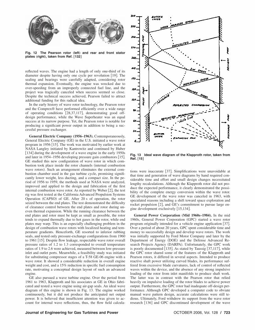
GE also pursued a wave turbine engine. Over the period from961 to 1963, Klapproth and his associates at GE in Ohio fabri-ated and tested a wave engine using air-gap seals. An ideal waveiagram of this engine is shown in Fig. 13. The engine workedontinuously, but it did not produce the anticipated net outputower. It is believed that insufficient attention was given to ac-
ig. 12 The Pearson rotor „left… and rear and front statorlates „right…, taken from Ref. †132‡
ount for internal wave reflections, thus, the flow field calcula-
ournal of Engineering for Gas Turbines and Power
tions were inaccurate �37�. Simplifications were unavoidable atthat time and generation of wave diagrams by hand required con-siderable time and effort and small design changes necessitatedlengthy recalculations. Although the Klapproth rotor did not pro-duce the expected performance, it clearly demonstrated the possi-bility of the complete energy conversion within the wave rotor.GE development of the wave rotor was canceled in 1963, withspeculated reasons including a shift toward space exploration androcket propulsion �2�, and GE’s commitment to pursue large en-gine development exclusively �15,134�.
General Power Corporation (Mid 1960s–1984). In the mid1960s, General Power Corporation �GPC� started a wave rotorprogram originally intended for a vehicle engine application �37�.Over a period of about 20 years, GPC spent considerable time andmoney to successfully design and develop wave rotors. The workwas initially supported by Ford Motor Company and later by theDepartment of Energy �DOE� and the Defense Advanced Re-search Projects Agency �DARPA�. Unfortunately, the GPC workis poorly documented �135�. As stated by Taussig �37,117�, whilethe GPC rotor shared some of the features of the Klapproth andPearson rotors, it differed in several aspects. Intended to producereactive shaft power utilizing curved blades, its performance suf-fered from excessive blade curvatures, lack of control of reflectedwaves within the device, and the absence of any strong impulsiveloading of the rotor from inlet manifolds to produce shaft work.The latter was in contrast with the Pearson rotor that reliedheavily on impulsive loading of the rotor blades to achieve poweroutput. Furthermore, the GPC rotor had inadequate off-design per-formance. Although GPC developed a computer code to obviatemanual wave pattern design, accurate calculations were still te-dious. Ultimately, Ford withdrew its support from the wave rotor
Fig. 13 Ideal wave diagram of the Klapproth rotor, taken fromRef. †15‡
research �136� and GPC discontinued development of the wave
OCTOBER 2006, Vol. 128 / 723

efsdesg
i�etCmcubwegfl
F†
7
ngine in the early 1980s. In 1994, the GPC engine was trans-erred to the University of Florida for further tests, accurate mea-urements, and improvements of the seals. Figure 14 shows theisassembled view of the engine. After testing under various op-rating conditions, major modifications in the starting system,eals and cooling, and rotor design were identified before the en-ine become a well-characterized experimental testbed �137�.
Rolls-Royce (1965–1972). In the mid-1960s, Rolls-Royce �RR�n the UK began numerical and experimental wave rotor research37�. BBC cooperated with RR in the development of pressure-xchange wave rotors as topping spools in gas turbine applica-ions �13�, with Berchtold of the ETH and Spalding of Imperialollege serving as consultants �24�. Considerable efforts wereade to design a wave rotor as a topping stage for a small heli-
opter engine �Allison Model 250� �138�. The BBC-RR enginetilized a reverse-flow wave rotor incorporated into a single tur-ine engine. Figure 15 is a rare illustration of the RR reverse-flowave rotor, taken from a 1965 poster. This was somewhat differ-
nt from the cycle suggested by Berchtold and Lutz �71� in BBCas-turbine-topping investigations, which employed a through-ow wave rotor integrated with both low-pressure and high-
ig. 14 Disassembled view of the GPC rotor, taken from Ref.137‡
Fig. 15 Reverse-flow wav
24 / Vol. 128, OCTOBER 2006
pressure turbines. BBC’s interests in wave rotors at that time weremostly related to development of small gas turbines for passengercars, beset by poor efficiencies at sizes of 100 kW and smaller�29�. While the enhanced engine operated nearly as predicated byprotracted manual design methods, performance suffered fromleakage �37�. Other difficulties related to the start-up, bearing du-rability, fuel system complications, and control are also reported�10�. The program was abruptly canceled in 1972 amid severecompany financial difficulties �13�. As stated by Kentfield �24�,contemporaneous rapid progress in turbomachinery technologymay have disfavored high-risk projects, both at RR and GE. It isemphasized that published literature is relatively meager on ef-forts at large corporations like GE, ABB, and RR, and underlyingbusiness strategy is rarely revealed. Internal company records, ifthey survive, may contain more technical details.
Mathematical Science Northwest Inc. (1978–1985). In thelate 1970s, Mathematical Science Northwest Inc. �MSNW, laterSpectra Technology Inc.� investigated various applications ofwave rotors �29�. Under the sponsorship of DOE and DARPA,they considered wave rotors for a broad range of stationary powersystems such as magnetohydrodynamic cycles �37�, combinedcycles integrated with gasification plants �139�, pressurized fluid-ized bed �PFB� power systems �140�, and also propulsion andtransportation applications �117�. Significant numerical and ex-perimental efforts included developing a laboratory wave rotor�141–144�, shown in Fig. 16. With diameter of 45 cm, it consistsof 100 channels each with a 40 cm length. It is a four-port waverotor with two additional small ports provided to cancel pressurewaves at critical rotor locations providing more uniform portflows and a higher transfer efficiency �144�. Besides successfultests using several configurations �clearance variations, port sizes,etc.� and various operating conditions, experiments were designedto verify the scaling laws for predicting the performance of largermachines �139�. The MSNW wave rotor was initially designedbased on the method of characteristics, but a one-dimensionalunsteady computer code �the FLOW code� was later used for opti-mization �117�. Modifications led to very good agreement be-tween the numerical and experimental results in a wide range ofoperating conditions. The FLOW code, which was developed spe-cifically for both pure pressure exchanger wave rotor and waveengine analyses, used the flux-corrected transport algorithm solv-ing Euler equations accounting for heat transfer, viscosity, gradualport opening, and flow leakage. The sensitivity of wave rotor per-formance to tip speed, port placement and size, inlet and outletflow conditions, channel geometry, number of channels, leakage,and heat transfer was analyzed for both on-design and off-design
e rotor of Rolls-Royce
Transactions of the ASME

cgwpfl
stbfpmT1
oppT�
J
onditions. It was concluded that heat transfer losses were negli-ible, and leakage was recognized as a key problem for efficientave rotor operation. Numerical work was reported for a nine-ort wave rotor concept to resolve the problem of nonuniform portows and poor scavenging.MSNW also produced preliminary wave rotor designs for a
mall turbofan engine generating 600 lb thrust at sea level condi-ion �117,145�, illustrated in Fig. 17. Performance calculations foroth on-design and off-design flight conditions using a cycle per-ormance code and the FLOW code simulation predicted significanterformance improvements of such an enhanced engine. No newaterial development for such combined engines was required.he wave rotor activity at MSNW was discontinued in the mid980s, for reasons not reported.
Naval Postgraduate School (1981–1986). In 1981, the Officef Naval Research �ONR� agreed to monitor a joint DARPA/ONRrogram to evaluate the wave rotor concept and its potential ap-lication in propulsion systems �134�. Following this decision, theurbopropulsion Laboratory �TPL� at Naval Postgraduate SchoolNPS�, directed by Shreeve, started an extensive numerical and
Fig. 16 Schematic of the MSNW wave ro
Fig. 17 Conceptual design of a turbofa
from Ref. †145‡ournal of Engineering for Gas Turbines and Power
analytical wave rotor program. To support the accuracy of thecomputational results, the wave rotor apparatus formerly used byKlapproth at GE was transferred to TPL and some preliminarytests were carried out. It is reported that the rotor produced someshaft work running at approximately 5000 to 6000 rpm �146�. Nofurther experimental details are reported.
For numerical simulations, two different approaches to the so-lution of the unsteady Euler equations were examined in the over-all program. First, Eidelman developed a two-dimensional codebased on the Godunov method to analyze the flow in wave rotorchannels �147–149�. Unlike contemporary one-dimensional ap-proaches �150�, the two-dimensional code showed the effect ofgradual opening of the channels. The main conclusion of thesestudies is that if the channels are straight, the flow remains nearlyone-dimensional, which in turn leads to minimal mixing lossescaused by rotational flow in the channels �151�. However, whenthe channel of the wave rotor is curved, even an instantaneousopening of the channel does not lead to the development of aone-dimensional flow pattern with small losses. For faster compu-tations, a one-dimensional, first-order time-accurate code was in-
experimental setup, taken from Ref. †29‡
ngine incorporating a wave rotor, taken
tor
n e
OCTOBER 2006, Vol. 128 / 725
ticuilpcpcmso
R
ptsemchmmctwpfma
1Rsdfdptatcp�de3eett
dc�tuolhup�tCd
7
roduced by Mathur based on the random choice method for solv-ng the Euler equations �152,153�. The unconditionally stableode, called WRCOMP �wave rotor component�, calculated thensteady-flow process inside the wave rotor, inlet and outlet open-ng times, and other useful design parameters required for a pre-iminary design. The outputs from WRCOMP were used in a secondrogram, called ENGINE, for turbofan jet engine performance cal-ulations �154–156�, and predicted significant performance im-rovement of a turbofan engine. Some improvements to WRCOMP
ode were begun �157,158�, but the wave rotor research was ter-inated around 1986. NPS also sponsored the most comprehen-
ive wave rotor conference in 1985 �159�, which reviewed muchf the history to that point.
ecent Research and DevelopmentSince the 1985 wave rotor workshop, there has been significant
rogress in wave rotor research, supported by improved methodshat include powerful computational capabilities allowing accurateimulation of the flow field inside the wave rotor, and modernxperimental measurement and diagnostic techniques. Improve-ents in aerodynamic design, sealing technologies, and thermal
ontrol methods have been sought for applications that demandighly efficient performance. Numerous studies of the perfor-ance benefits of wave rotor topped gas turbines underline theotivation to obtain a quantum improvement in performance over
onventional engines. Use of a wave rotor for confined combus-ion received renewed interest in Switzerland and the U.S., andas further stimulated by developments in related processes ofulsed detonation engines. The following recent and ongoing ef-orts indicate that a modern computational methods and experi-ental tools are allowing improved understanding, and more re-
lism in integration with conventional machines.
NASA Glenn Research Center (1988–Present). Since the late980s, a sustained research program at NASA Lewis �now Glenn�esearch Center �GRC�, collaborating with the U.S. Army Re-
earch Laboratory �ARL� and Rolls-Royce Allison has aimed toevelop and demonstrate the benefits of wave rotor technology foruture aircraft propulsion systems �10�. In 1993, using a thermo-ynamic approach to calculate the thermal efficiency and specificower, Wilson and Paxson �160� published a feasibility study foropping jet engines with wave rotors. Applied to the case of anircraft flying at Mach 0.8, they have shown that a wave-rotor-opped engine may gain 1–2% in efficiency and 10–16% in spe-ific power compared to a simple jet engine with the same overallressure ratio and turbine inlet temperature. In 1995, Welch et al.17� predicted a 19–21% increase in specific power and a 16–17%ecrease in specific fuel consumption compared with the baselinengines for small �300 to 500 kW� and intermediate �2000 to000 kW� wave-rotor-enhanced turboshaft engines. A wave-rotor-nhanced large turbofan engine, equal in thrust to the baselinengine, showed a 6–7% reduction in thrust specific fuel consump-ion. Welch has also studied the possibility of curving the channelso create a wave turbine �161,162�.
Early in the program, Paxson developed a quasi-one-imensional gasdynamic model and a computational code to cal-ulate design geometry and off-design wave rotor performance163,164�. The code uses an explicit, second order, Lax-Wendroffype TVD scheme based on the method of Roe to solve thensteady-flow field in an axial passage for time-varying inlet andutlet port conditions. It employs simplified models to account forosses due to gradual passage opening and closing, viscous andeat transfer effects, leakage, flow incidence mismatch, and non-niform port flow field mixing. In order to verify wave rotor flowredictions and to assess the effects of various loss mechanisms165�, a three-port wave-divider machine was constructed andested �166–168� in a new wave rotor laboratory facility at GRC.oncurrently, the nonideal behavior and losses due to multi-
imensional effects were studied by Welch �169–171� and Laro-26 / Vol. 128, OCTOBER 2006
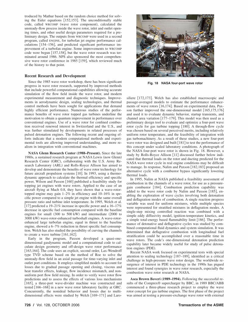
siliere �172,173�. Welch has also established macroscopic andpassage-averaged models to estimate the performance enhance-ments of wave rotors �16,174�. Based on experimental data, Pax-son further improved the one-dimensional model �165,175,176�and used it to evaluate dynamic behavior, startup transients, andchannel area variation �177–179�. This model was then used as apreliminary design tool to evaluate and optimize a four-port waverotor cycle for gas turbine topping �180�. A through-flow cyclewas chosen based on several perceived merits, including relativelyuniform rotor temperature, and the feasibility of integration withgas turbomachinery. As a result of these studies, a new four-portwave rotor was designed and built �181� to test the performance ofthis concept under scaled laboratory conditions. A photograph ofthe NASA four-port wave rotor is shown in Fig. 18. However, astudy by Rolls-Royce Allison �11� discussed further below indi-cated that thermal loads on the rotor and ducting predicted for theNASA wave rotor cycle in real engine conditions may be difficultto manage. In response, Nalim and Paxson �182,183� proposed analternative cycle with a combustor bypass significantly loweringthermal loads.
In 1995, Nalim at NASA published a feasibility assessment ofcombustion in the channels of a wave rotor, for use as a pressure-gain combustor �184�. Combustion prediction capability wasadded to the wave rotor code by Nalim and Paxson �185�, en-abling the exploration of wave cycles involving both detonationand deflagration modes of combustion. A single reaction progressvariable was used for uniform mixtures, while multiple specieswere represented for stratified mixtures in deflagration modes. Asingle-step mixing controlled reaction was combined with asimple eddy diffusivity model, ignition-temperature kinetics, anda simple total-energy based flammability limit �186�. The perfor-mance of detonative and deflagrative cycles was studied by com-bined computational fluid dynamics and system simulation. It wasdetermined that deflagrative combustion with longitudinal fuelstratification could be accomplished over a reasonable time inwave rotors. The code’s one-dimensional detonation predictioncapability later became widely useful for study of pulse detona-tion engines �PDE�.
Recent NASA work focused on experimental tests with specialattention to sealing technology �187–189�, identified as a criticalchallenge in high-pressure wave rotor design. The worldwide re-surgence of interest in PDE technology in the 1990s has piquedinterest and found synergies in wave rotor research, especially thecombustion wave rotor research at NASA.
Asea Brown Boveri (1989–1994). Following the successful re-sults of the Comprex® supercharger by BBC, in 1989 BBC/ABBcommenced a three-phase research project to employ the waverotor concept for gas turbine engines. The first phase of the project
Fig. 18 NASA four-port wave rotor
was aimed at testing a pressure-exchange wave rotor with external
Transactions of the ASME

ciwmiivrpmg
tntrcrlrtpntchrtvte
wtidlbttvmr�
�poepdoP
Fn
J
ombustion. The demonstrator engine produced 17% and 25%ncreases in efficiency and specific power, respectively, comparedith the baseline engine �81�. The obtained significant perfor-ance improvement encouraged ABB to investigate the possibil-
ty of manufacturing an integrated combustion wave rotor, startedn 1991. To explore fundamental parameters of such a constant-olume combustion device, a rotary-valved single-channel waveotor was built and tested �82�. Using preheated and precom-ressed air-propane as the working fluid, combustion measure-ents revealed low NOx values, down to 20 ppm, at the exhaust
as due to the short residence time �1–6 ms�.After successful operation of the fixed single channel device,
he design of an on combustion rotating wave rotor with 36 chan-els was started in 1992 �82,190�. Figure 19 shows a picture of theest rig and the cross section of the rotor channels including theotating shaft. The inner diameter of the rotor was 20 cm and eachhannel had 16.5 cm length and 15�15 mm cross section. Theotor was driven by an electric motor capable of up to 5000 revo-utions per minute. Both in the single-tube and 36-channel waveot engine, spark plug and hot gas-injection self-sustaining igni-ion methods were utilized. Self-sustaining ignition was accom-lished by employing jet injection of already-burned gas from aeighboring channel as suggested by Keller �191�. Such an igni-ion technique, which makes the combustion process essentiallyontinuous without need for pulsed methods with ignition delays,as a good potential to enhance ignition reliability and burningate, and can lead to a self-sustaining engine �192–194�. Duringhe tests, various fuels were tried and fuel mixture was stratifiedia four injection nozzles. Operating in two cycles per revolution,he engine had high-pressure and low-pressure outflows per cycle,nabling it to scavenge the exhaust gas in one cycle.
The prototype engine operated successfully until the projectas concluded in 1994, due to market concerns. During its opera-
ion, a number of problems were revealed and reported. Theyncluded �i� inhomogeneous mixture in the cell, resulting in a slowiffusion flame, �ii� maximum pressure reached was 9 bar, andeakage caused premature ignition and misfiring at higher cham-er pressures, �iii� thermal stresses on the ignition ring, �iv� can-ilever single bearing rotor support was inadequate, and �v� elec-romechanical device for controlling leakage gap turned out to beery complicated and sensitive. Major remedies recommended toake the system better include �a� lead away duct for leakage gas
emoval, �b� rotor cooling by air, �c� two-sided rotor support, andd� mechanical control for thermal expansion.
Rolls-Royce Allison (1990–Present). Allison Engine Companylater Rolls Royce Allison, and now Rolls Royce� was a closeartner in the NASA program. In 1996, Snyder and Fish �11,12�f Allison Engine Company evaluated the Allison 250 turboshaftngine as a potential platform for a wave rotor demonstration,redicting an 18–20% increase in specific power and a 15–22%ecrease in specific fuel consumption. They used a detailed mapf the wave rotor cycle performance accomplished by Wilson and
ig. 19 ABB test rig „left… and cross section of the rotor chan-els „right…, taken from Ref. †190‡
axson �10,160,180�. Allison has also studied transition duct de-
ournal of Engineering for Gas Turbines and Power
signs for integration with turbomachinery �195,196�. This waslater followed by investigations of pulse detonation wave rotors inthe newly formed Allison Advanced Development Company �nowRolls-Royce “LibertyWorks”�. A novel four-port device was pro-posed �197,198� for supersonic turbofan engines �199�, and wasinvestigated in collaboration with Nalim at Indiana UniversityPurdue University Indianapolis �IUPUI� as discussed later.
University of Florida (1992–1998). Motivated by NASA waverotor successes, Lear et al. at the University of Florida initiatedanalytical and numerical methods to investigate different configu-rations of wave rotors. His team developed an unsteady two-dimensional numerical code using a direct boundary value methodfor the Euler equations to analyze the flow in wave rotors andtheir adjoining ducts, treating the straight or curved channel wallsas constraints imposed via a body force term �200,201�. The codewas used to simulate the flow fields of the three-port NASA waverotor and the GPC wave engine �137�. They also introduced apreliminary design method for selecting the wave engine inflowand outflow blade angles, and an analytical thermodynamic model�202�, which predicted potential increase in specific power of 69%and a 6.8% increase in thermal efficiency over a conventional gasturbine. A parametric study of gradual opening effects on waverotor compression processes is also reported �203�.
ONERA in France (1995–1999). Fatsis and Ribaud at theFrench National Aerospace Research Establishment �ONERA�have investigated wave rotor enhancement of gas turbines in aux-iliary power units, turboshaft, turbojet, and turbofan engines�14,204�, accounting for compression and expansion efficiency, aswell as mixing and pressure losses in the ducting. Their resultsshow the largest gains for engines with a low compressor pressureratio and high turbine inlet temperature, such as turboshaft en-gines and auxiliary power units, consistent with NASA GRC stud-ies �205�. They have also developed a one-dimensional numericalcode based on an approximate Riemann solver taking into accountviscous, thermal, and leakage losses �14,206�, and applied it tothree-port, through-flow, and reverse-flow configurations.
Recent Academic WorkBesides ongoing research mainly at NASA, Allison Advanced
Development Company �AADC�, and ETH Zurich, a few univer-sities have been conducting wave rotor research. To the knowl-edge of the authors, the universities listed below are active in thisfield.
Purdue School of Engineering and Technology, IUPUI(1997–Present). Recent research at Indiana University PurdueUniversity Indianapolis �IUPUI� by Nalim and coworkers has fo-cused on the combustion wave rotor concept �83,84�, followinginitial work at NASA described before. Deflagrative combustionwith longitudinal fuel stratification has yielded a wave rotor ge-ometry competitive with pressure-exchanger designs using a sepa-rate combustor �186�. Nalim has highlighted the importance ofleakage flow temperature and thermal management of end-walltemperatures illustrating the impact of the hot ignition gas and thecold buffer zones on the end walls. This is consistent with themajor challenges revealed by the ABB experiment �82�. Radialstratification �207� using a pre-combustion partition has been pro-posed to introduce a relatively cooler buffer zone close to theleakage gaps, reducing hot gas or fuel leakage to the rotor cavity.Figure 20 is a contour plot of the temperature contour from asimulation of deflagrative combustion in a stoichiometric partitionregion propagating into a leaner mixture in the main chamber.Above and below the partitions, there is no fuel, and gas may leakout or in without danger of overheating or pre-ignition. Thesethermal management approaches are possible utilizing extensivecycle design studies and analysis, and seek to alleviate the chal-lenges previously recognized by ABB and NASA. This technique
also helps burn leaner mixtures, resulting in reduced NOx emis-OCTOBER 2006, Vol. 128 / 727

scflse
afctsodgsnbtwfofltlsw
wWcwgdocd
cgddbm
dmpaosrTut
rb
7
ions, similar to other pilot combustion or lean-burn techniques inonventional engines �208�. For this approach, radial leakageows �209� and different combustion models �210� have beentudied in detail. These ideas have not yet been testedxperimentally.
Detonative combustion cycles for propulsion engines have beenlso studied �211,212�. Interest in detonative combustion initiallyocused on pulsed detonation engines �PDEs� has evolved to theonsideration of the wave rotor as an effective implementation ofhe concept �213�, as the wave rotor provides automatic high-peed valving, nearly steady inflow and outflow, and the use ofne or few steady ignition devices for multiple tubes. However,etonative combustion is fundamentally restricted to highly ener-etic mixtures and sufficiently large passage widths, and generatestrong pressure waves. This results in the outflow being highlyonuniform in pressure, velocity, and possibly temperature. Toetter utilize the output of a wave rotor PDE, it has been proposedo add an ejector element to the wave rotor �214,215�. The rotaryave ejector admits bypass air after the detonation tubes to trans-
er energy and momentum. Numerical simulations using a quasi-ne-dimensional code, modified to account for radial-type bypassows, have shown that the specific impulse at static thrust condi-
ions can be doubled, after accounting for flow-turning and shockosses, comparing with an equivalently loss-free PDE cycle. Aample wave diagram and a schematic sketch are given in Fig. 21,here the cold ejector gas flow is clearly distinguishable.IUPUI has also investigated �198� the four-port detonation
ave rotor proposed by AADC �now Rolls-Royce “Liberty-orks”� �197�, in which a recirculation duct allows air that is
ompressed by the shock of a detonation wave to be reinjectedith fuel. Air-buffer regions both between the fuel/air-combustedas interface and at the exit end plate are inherent in the cycleesign, allowing self-cooling of the walls. The inflow and outflowf this engine concept is designed to be nearly uniform and ac-eptable to modern turbines, compared to conventional rotaryetonation cycles, as shown in Fig. 22.
A computational and experimental program is currently beingonducted at IUPUI in collaboration with Rolls-Royce to investi-ate the combustion process and performance of a wave rotor withetonative and near-detonative internal combustion. A preliminaryesign method based on a sequence of computational models haseen developed to design wave processes for testing in an experi-ental test rig �216�.
University of Tokyo (2000–Present). Nagashima et al. haveeveloped one-dimensional �217� and two-dimensional �218� nu-erical codes to simulate the flow fields inside through-flow four-
ort wave rotors, including the effects of passage-to-passage leak-ge. The codes have been validated with experimental databtained by a single-channel wave rotor experiment. The test rig,hown in Fig. 23, consists of a stationary single tube, and twootating plates connected to a shaft driven by an electric motor.his group has also explored the idea of using wave rotors forltra-micro gas turbines manufactured using microfabricationechnology �219,220�.
Michigan State University (2002–Present). The MSU waveotor group has initiated studies to evaluate wave rotor technology
Fig. 20 Temperature distribution of
enefits for several thermal cycle applications. Two unrecuperated
28 / Vol. 128, OCTOBER 2006
microturbines �30 and 60 kW� implementing various wave-rotor-topping cycles were predicted to have overall thermal efficiencyand specific work enhancement up to 34% for the smaller engineand 25% for the larger engine, using a four-port wave rotor with acompression ratio of 1.8 �221,222�. A similar approach has pre-dicted an improvement up to 15% of overall efficiency and spe-cific thrust in a turbojet engine using the wave-rotor-topping cycleof 30 kW microturbine �223�. Furthermore, multi-parametric per-formance maps for different wave rotor implementations havebeen generated specifying optimum operating points for both un-topped baseline and topped engines �224�. Using predicted perfor-mance results, an analytical preliminary design procedure was de-veloped for the critical high-pressure phase of four-port waverotors �225,226�. To validate and support the accuracy of the ana-lytical results, comparisons with numerical results of a test casewas performed �227�.
Recently, a unique application of wave rotors in refrigerationcycles using water �R718� as a refrigerant has also been studied�228–231�. The wave-rotor implementation can increase effi-ciency and reduce the size and cost of R718 units. A three-portwave rotor has been introduced as a condensing wave rotor thatemploys pressurized water to pressurize, desuperheat, and con-dense the refrigerant vapor—all in one dynamic process. In addi-tion to the possibility of an additional rise of the vapor pressure,
tition exit flow, taken from Ref. †208‡
Fig. 21 Rotary Wave Ejector Pulse Detonation Engine, taken
par
from Ref. †214‡
Transactions of the ASME

tdFtwsr
wasoibotSiinr
ine
J
he condensing wave rotor eliminates the need of a bulky con-enser because full condensation occurs inside the rotor channels.urthermore, adding a condensing wave rotor to a water refrigera-
ion cycle allows for a lower pressure ratio of the compressor,hich is crucial for R718 chiller technology. Figure 24 shows a
chematic of a R718 cycle using a three-port condensing waveotor.
Investigations of the feasibility and potential of integratingave rotors in microfabricated gas turbines are also being pursued
t MSU �3,232–235�. Ultra-micro gas turbines �U�GT� havehown difficulties in obtaining high overall thermal efficiency andutput power. Utilizing wave rotor technology was suggested tomprove the performance of U�GT. The wave rotor can enhanceoth the overall thermal efficiency and specific work output, basedn MSU studies that show an efficiency of the compression be-ween 70% and 80% can be achieved in an ultra-micro wave rotor.everal different conceptual designs for a four-port wave rotor
ntegrated into a baseline U�GT are reported �232�. Additionally,n a collaboration between MSU and Warsaw University of Tech-ology in Poland, the concept of radial-flow wave rotor configu-
Fig. 22 Wave Rotor Pulse Detonation Eng
ation for various gas turbines applications with an emphasize on
ournal of Engineering for Gas Turbines and Power
U�GT was introduced �234,235�. Figure 25 is an example of anultra-micro wave rotor playing simultaneously the role of com-pressor, turbine and electric generator.
MSU and Warsaw University of Technology have also em-ployed the commercial software FLUENT �236–239� to investigatedetailed gasdynamic phenomena inside axial and radial wave ro-tors. FLUENT is capable of accounting for the major losses oc-
, the “CVC” Engine, taken from Ref. †198‡
Fig. 23 University of Tokyo single-channel test rig, taken from
Ref. †218‡ and a personal visitOCTOBER 2006, Vol. 128 / 729

ctgmMsct
S
wiklipsdmt
f. †2
7
urred inside wave rotor channels including viscous and heatransfer losses, flow leakage between rotating channels, andradual opening/closing of channels to the ports, along with otherulti-dimensional features. To validate the computational results,SU has built a wave rotor rig �240�. Piechna at Warsaw Univer-
ity of Technology also proposed integration of a pressure ex-hanger with the internal combustion wave rotor, creating an au-onomous pressure wave compressor �241�.
ummaryThe goal of this review was to report the continued interest in
ave rotor technology and its wide variety of applications. Whilenvolved researchers may have state-of-the-art and historicalnowledge of this technology, it has not reached wider audiences,imiting the opportunity for meeting needs in new fields. The fall-ng cost of computer simulation bodes well for the study of com-lex non-steady flow that cannot be characterized in essence by aimple global performance equation. Naturally, recent efforts wereiscussed in more detail as fuel costs, new research data andethods, and technology innovations have provided fresh impetus
o consider the unique capabilities of wave rotor devices. Figure
Fig. 24 Schematic of the thermodynamic mcondensing wave rotor „CWR…, taken from Re
Fig. 25 Conceptual design of an ultra-micro
from Ref. †237‡30 / Vol. 128, OCTOBER 2006
26 summarizes the known history of the wave rotor research re-viewed here, arranged broadly by geography. It appears that inter-est in gas turbine topping cycles and IC engine superchargingcontinues, but new opportunities appear, especially for small-scalewave machines and combustion devices that may substantiallysurpass conventional concepts. Continued research on sealing andthermal expansion control are needed to solve these persistentchallenges, but it is important to understand and learn from theapproaches of earlier workers.
AcknowledgmentThe authors gratefully acknowledge several colleagues who
provided valuable historical information, comments, and sugges-tions through personal communications. Special recognition isgiven to L. Guzzella at ETH in Switzerland, H. A. Nour Eldin atthe University of Wuppertal in Germany, J. Piechna at WarsawUniversity of Technology in Poland, P. H. Snyder at Rolls-RoyceNorth American Technologies Inc., and R. Shreeve at the NavalPostgraduate School in the U.S.
el of a R718 unit enhanced by a three-port30‡
er generator using a radial wave rotor, taken
od
pow
Transactions of the ASME

R
J
eferences�1� Weber, H. E., 1986, “Shock-Expansion Wave Engines: New Directions for
Power Production,” ASME Paper 86-GT-62.�2� Weber, H. E., 1995, Shock Wave Engine Design, John Wiley and Sons, New
York.�3� Iancu, F., and Müller, N., 2005, “Efficiency of Shock Wave Compression in a
Microchannel,” Journal of Microfluid and Nanofluid, 2�1�, pp. 50–63.�4� Paxson, D. E.,1998, “Wave Augmented Diffusers for Centrifugal Compres-
sors,” AIAA Paper 98-3401, also NASA TM-208480.�5� Darrieus, G., 1950, “Pressure Exchange Apparatus,” U.S. Patent 2526618.�6� Kentfield, J. A. C., 1993, Nonsteady, One-Dimensional, Internal, Compressible
Flows, Oxford University Press, Oxford.�7� Gyarmathy, G., 1983, “How Does the Comprex Pressure-Wave Supercharger
Work?,” SAE Paper 830234.�8� Zehnder, G., Mayer, A., and Mathews, L., 1989, “The Free Running
Comprex®,” SAE Paper 890452.�9� Hiereth, H., 1989, “Car Tests With a Free-Running Pressure-Wave Charger—A
Study for an Advanced Supercharging System,” SAE Paper 890 453.�10� Welch, G. E., 2000, “Overview of Wave-Rotor Technology for Gas Turbine
Engine Topping Cycles,” Novel Aero Propulsion Systems International Sym-posium, The Institution of Mechanical Engineers, London, pp. 2–17.
�11� Snyder, P. H., 1996, “Wave Rotor Demonstrator Engine Assessment,” NASACR-198496.
�12� Snyder, P. H., and Fish, R. E., 1996, “Assessment of a Wave Rotor ToppedDemonstrator Gas Turbine Engine Concept,” ASME Paper 96-GT-41.
�13� Berchtold, M., 1985, “The Comprex as a Topping Spool in a Gas TurbineEngine for Cruise Missile Propulsion,” Proceedings ONR/NAVAIR Wave RotorResearch and Technology Workshop, Report NPS-67-85-008, pp. 284–290,Naval Postgraduate School, Monterey, CA.
�14� Fatsis, A., and Ribaud, Y., 1997, “Numerical Analysis of the Unsteady FlowInside Wave Rotors Applied to Air Breathing Engines,” 13th InternationalSymposium on Airbreathing Engines, Paper ISABE-97-7214.
�15� Mathur, A., 1985 “A Brief Review of the GE Wave Engine Program �1958-1963�,” Proceedings ONR/NAVAIR Wave Rotor Research and TechnologyWorkshop, Report NPS-67-85-008, pp. 171–193, Naval Postgraduate School,
Fig. 26 Historical perspective of wave rotor technology. Redrefrigeration cycle. Pink: pressure divider and equalizer. PurpBlack: general applications.
Monterey, CA.
ournal of Engineering for Gas Turbines and Power
�16� Welch, G. E., 1997, “Macroscopic Balance Model for Wave Rotors,” J. Propul.Power, 13�4�, pp. 508–516; also AIAA Paper 96-0243, and NASA TM-107114.
�17� Welch, G. E., Jones, S. M., and Paxson, D. E., 1997, “Wave Rotor-EnhancedGas Turbine Engines,” ASME J. Eng. Gas Turbines Power, 119�2�, pp. 469–477; also AIAA Paper 95-2799, and NASA TM 106998.
�18� Knauff, R., 1906, “Converting Pressures of Liberated Gas Energy into Me-chanical Work,” British Patent 2818.
�19� Pearson, R. D., 1982, “Pressure Exchangers and Pressure Exchange Engines,”in The Thermodynamics and Gas Dynamics of Internal Combustion EnginesVol. 1, R. Benson, ed., Oxford University Press, Chap. 16, pp. 903–940.
�20� Knauff, R., 1906, “Converting Internal Gas Energy into Mechanical Work,”British Patent 8273.
�21� Burghard, H., 1913, British Patent 19421.�22� Lebre, A. F., 1928, British Patent 290669.�23� Burghard, H., 1929, German Patent 485386.�24� Kentfield, J. A. C., 1998, “Wave Rotors and Highlights of Their Develop-
ment,” AIAA Paper 98-3248.�25� Meyer, A., 1947, “Recent Developments in Gas Turbines,” Journal of Me-
chanical Engineering, 69�4�, pp. 273–277.�26� Real, R., 1946, “The 3000 kW Gas Turbine Locomotive Unit,” Brown Boveri
Rev., 33�10�, pp. 270–271.�27� Meyer, A., 1947, “Swiss Develop New Gas Turbine Units,” Electr. World,
127, pp. 38–40.�28� Azoury, P. H., 1992, Engineering Applications of Unsteady Fluid Flow, John
Wiley and Sons, New York.�29� Rose, P. H., 1979, “Potential Applications of Wave Machinery to Energy and
Chemical Processes,” Proceedings of the 12th International Symposium onShock Tubes and Waves, Jerusalem, July 16–19, pp. 3–30.
�30� Seippel, C., 1940, Swiss Patent 225426.�31� Seippel, C., 1942, Swiss Patent 229280.�32� Seippel, C., 1946, “Pressure Exchanger,” U.S. Patent 2399394.�33� Seippel, C., 1949, “Gas Turbine Installation,” U.S. Patent 2461186.�34� Berchtold, M., and Gardiner, F. J., 1958, “The Comprex: A New Concept of
Diesel Supercharging,” ASME Paper 58-GTP-16.
s turbine application. Green: IC engine supercharging. Blue:wave superheater. Orange: internal combustion wave rotors.
: gale:
OCTOBER 2006, Vol. 128 / 731

7
�35� Berchtold, M., 1958, “The Comprex Diesel Supercharger,” SAE Paper No.63A.
�36� Berchtold, M., and Gull, H. P., 1959, “Road Performance of a Comprex Su-percharged Diesel Truck,” SAE Paper No. 118U.
�37� Taussig, R. T., and Hertzberg, A., 1984, “Wave Rotors for Turbomachinery,”Winter Annual Meeting of the ASME, Machinery for Direct Fluid-Fluid En-ergy Exchange, edited by J. F. Sladky, AD-07, pp. 1–7.
�38� Doerfler, P. K., 1975, “Comprex Supercharging of Vehicle Diesel Engines,”SAE Paper 750335.
�39� Schruf, G. M., and Kollbrunner, T. A., 1984, “Application and Matching of theComprex Pressure-Wave Supercharger to Automotive Diesel Engines,” SAEPaper 840133.
�40� Zehnder, G., and Mayer, A., 1984, “Comprex® Pressure-Wave Superchargingfor Automotive Diesels—State-of-the-Art,” SAE Paper 840132.
�41� Berchtold, M., 1985, “The Comprex®,” Proceedings ONR /NAVAIR Wave Ro-tor Research and Technology Workshop, Naval Postgraduate School,Monterey, CA, Report NPS-67-85-008, pp. 50–74.
�42� Azoury, P. H., 1965-1966, “An Introduction to the Dynamic Pressure Ex-changer,” Proc. Inst. Mech. Eng., 180�18�, Part 1, pp. 451–480.
�43� Guzzella, L., Wenger, U., and Martin, R., 2000, “IC-Engine Downsizing andPressure-Wave Supercharging for Fuel Economy,” SAE Paper 2000-01-1019.
�44� Mayer, A., Oda, J., Kato, K., Haase, W., and Fried, R., 1989, “ExtrudedCeramic—A New Technology for the Comprex® Rotor,” SAE Paper 890453.
�45� Guzzella, L., and Martin, R., 1998, “The Save Engine Concept,” MTZ Report10, pp. 9–12.
�46� Burri, H., 1958, “Nonsteady Aerodynamics of the Comprex Supercharger,”ASME Paper 58-GTP-15.
�47� Wunsch, A., 1971, “Fourier-Analysis Used in the Investigation of Noise Gen-erated by Pressure Wave Machines,” Brown Boveri Rev., 71�4-5�.
�48� Croes, N., 1977, “The Principle of the Pressure-Wave Machine as Used forCharging Diesel Engines,” Proceedings of the 11th International Symposiumon Shock Tubes and Waves, Seattle, July 11–14, pp. 36–55
�49� Summerauer, I., Spinnler, F., Mayer, A., and Hafner, A., 1978, “A Compara-tive Study of the Acceleration Performance of a Truck, Diesel Engine WithExhaust-Gas Turbocharger and With Pressure-Wave SuperchargerComprex®,” The Institution of Mechanical Engineers, London, Paper C70/78.
�50� Kollbrunner, T. A., 1980, “Comprex Supercharging for Passenger Diesel CarEngines,” SAE Paper 800884.
�51� Jenny, E., and Zumstein, B., 1982, “Pressure Wave Supercharger of PassengerCar Diesel Engines,” The Institution of Mechanical Engineers, London, PaperC44/82.
�52� Keller, J. J., 1984, “Some Fundamentals of the Supercharger Comprex,” Pre-sented at Winter Annual Meeting of the ASME, Machinery for Direct Fluid-Fluid Energy Exchange, edited by J. F. Sladky, Jr., AD-07, pp. 47–54.
�53� Rebling, P., and Jaussi, F., 1984, “Field Experience with a Fleet of Test CarsEquipped with Comprex Supercharged Engines,” Institution of MechanicalEngineers, London, Paper C442/84; also: SAE Paper 841308.
�54� Schneider, G., 1986, “Comprex® Pressure Wave Supercharger in an OpelSenator with 2.3 Liter Diesel Engine,” Brown Boveri Rev., 73�10�, pp. 563–565.
�55� Zehnder, G., 1971, “Calculating Gas Flow in Pressure-Wave Machines,”Brown Boveri Rev., 71�4-5�, pp. 172–176.
�56� Mayer, A., and Schruf, G., 1982, “Practical Experience with Pressure WaveSupercharger Comprex on Passenger Cars,” The Institution of Mechanical En-gineers, London, Paper C110/82.
�57� Zehnder, G., and Mayer, A., 1986, “Supercharging with Comprex to Improvethe Transient Behavior of Passenger Car Diesel Engines,” SAE Paper 860450.
�58� Spinnler, F., and Jaussi, F. A., 1986, “The Fully Self-Regulated Pressure WaveSupercharger Comprex for Passenger Car Diesel Engines,” The Institution ofMechanical Engineers, London, Paper C124/86.
�59� Jenny, E., Moser, P., and Hansel, J., 1986, “Progress with Variable Geometryand Comprex,” Institution of Mechanical Engineers Conference, London, Pa-per C109/86.
�60� Jenny, E., and Naguib, M., 1987, “Development of the Comprex Pressure-Wave Supercharger: In the Tradition of Thermal Turbomachinery,” BrownBoveri Rev., 74�8�, pp. 416–421.
�61� Mayer, A., 1987, “The Comprex Supercharger—A Simple Machine for aHighly Complex Thermodynamic Process,” Brown Boveri Rev., 74�8�, pp.422–430.
�62� Zehnder, G., and Müller, R., 1987, “Comprex Pressure-Wave Supercharger forCar Diesel Engines,” Brown Boveri Rev., 74�8�, pp. 431–437.
�63� Mayer, A., 1988, “Comprex-Supercharging Eliminates Trade-off of Perfor-mance, Fuel Economy and Emissions,” SAE Paper 881152.
�64� Mayer, A., and Pauli, E., 1988, “Emissions Concept for Vehicle Diesel En-gines Supercharged with Comprex,” SAE Paper 880008.
�65� Mayer, A., 1988, “The Free Running Comprex—A New Concept for PressureWave Supercharger,” SAE Document PC 55.
�66� Amstutz, A., Pauli, E., and Mayer, A., 1990, “System Optimization with Com-prex Supercharging and EGR Control of Diesel Engines,” SAE Paper 905097.
�67� Mayer, A., Nashar, I., Perewusnyk, J., 1990, “Comprex with Gas Pocket Con-trol,” The Institution of Mechanical Engineers, London, Paper C405/032.
�68� Mayer, A., Pauli, E., and Gygax, J., 1990, “Comprex �R� Supercharging andEmissions Reduction in Vehicles Diesel Engines,” SAE Paper 900881.
�69� Barry, F. W., 1950, “Introduction to the Comprex,” ASME J. Appl. Mech.,March, pp. 47–53.
�70� Lutz, T. W., and Scholz, R., 1968, “Supercharging Vehicle Engines by the
Comprex System,” The Institution of Mechanical Engineers, London, October.32 / Vol. 128, OCTOBER 2006
�71� Berchtold, M., and Lutz, T. W., 1974, “A New Small Power Output Gas Tur-bine Concept,” ASME Paper 74-GT-111.
�72� Berchtold, 1974, “The Comprex Pressure Exchanger: A New Device for Ther-modynamic Cycles,” JSAE Paper, Tokyo.
�73� Eisele, E., Hiereth, H., and Polz, H., 1975, “Experience with Comprex Pres-sure Wave Supercharger on the High-Speed Passenger Car Diesel Engine,”SAE Paper 750334.
�74� Groenewold, G. M., Welliver, D. R., and Kamo, R., 1977, “Performance andSociability of Comprex Supercharged Diesel Engine,” ASME Paper 77-DGP-4.
�75� Schwarzbauer, G. E., 1978, “Turbocharging of Tractor Engines with ExhaustGas Turbochargers and the BBC-Comprex,” The Institution of MechanicalEngineers, London, Paper C69/78.
�76� Walzer, P., and Rottenkolber, P., 1982, “Supercharging of Passenger Car DieselEngines,” The Institution of Mechanical Engineers, London, Paper C117/82.
�77� Wallace, F. J., and Aldis, C. A., 1982, “Comprex Supercharging Versus Tur-bocharging of a Large Truck Diesel Engine,” The Institution of MechanicalEngineers, London, Paper C39/82.
�78� Hong-De, J., 1983, “Two-Dimensional Unsteady Flow in Comprex Rotor,”Tokyo International Gas Turbine Congress, Paper 83-Tokyo-IGTC-59.
�79� Zhang, H. S., and So, R. M., 1990, “Calculation of the Material Interface in aPressure-Wave Supercharger,” Proc. Inst. Mech. Eng., Part A, 204�A3�, pp.151–161.
�80� Hitomi, M., Yuzuriha, Y., and Tanake, K., 1989, “The Characteristics of Pres-sure Wave Supercharged Small Diesel Engine,” SAE Paper 89054.
�81� Zauner, E., Chyou, Y. P., Walraven, F., and Althaus, R., 1993, “Gas TurbineTopping Stage Based on Energy Exchangers: Process and Performance,”ASME Paper 93-GT-58.
�82� Anonymous, 1997, “A Pressure-Wave Machine with Integrated Constant-Volume Combustion,” NEFF Funding of Swiss Energy Research 1977-1997,Project No. 426, pp. 142–153.
�83� Nalim, M. R., and Pekkan, K., 2003, “Internal Combustion Wave Rotors forGas Turbine Engine Enhancement,” ASME Paper IGTC-2003-FR-303.
�84� Nalim, M. R., and Pekkan, K., 2003, “A Review of Rotary Pressure-GainCombustion Systems for Gas Turbine Applications,” ASME Paper GT-2003-38349.
�85� Nour Eldin, H. A., Oberhem, H., and Schuster, U., 1987, “The Variable Grid-Method for Accurate Animation of Fast Gas Dynamics and Shock-Tube LikeProblems,” Proceedings of the IMACS/IFAC International Symposium onModeling and Simulation of Distributed Parameter Systems, Japan, pp. 433–440.
�86� Oberhem, H., and Nour Eldin, H. A., 1990, “Fast and Distributed Algorithmfor Simulation and Animation of Pressure Wave Machines,” Proceedings ofthe IMACS International Symposium on Mathematical and Intelligent Modelsin System Simulation, Belgium, pp. 807–815.
�87� Oberhem, H., and Nour Eldin, H. A., 1991, “A Variable Grid for AccurateAnimation of the Nonstationary Compressible Flow in the Pressure Wave Ma-chine,” 7th International Conference on Numerical Methods in Laminar andTurbulent Flow, U.S.
�88� Nour Eldin, H. A., and Oberhem, H., 1993, “Accurate Animation of theThermo-Fluidic Performance of the Pressure Wave Machine and its BalancedMaterial Operation,” 8th International Conference on Numerical Methods inLaminar and Turbulent Flow, UK.
�89� Markarious, S. H., Nour Eldin, H. A., and Pu, H., 1995, “Inverse ProblemApproach for Unsteady Compressible Fluid-Wave Propagation in the Com-prex,” 9th International Conference on Numerical Methods in Laminar andTurbulent Flow, U.S.
�90� Oberhem, H., and Nour Eldin, H. A., 1995, “Accurate Animation of theThermo-Fluidic Performance of the Pressure-Wave Machine and its BalancedMaterial Operation,” Int. J. Numer. Methods Heat Fluid Flow, 5�1�, pp. 63–74.
�91� Markarious, S. H., Hachicho, O. H., and Nour Eldin, H. A., 1997, “Wave-Control Modeling in the Pressure-Wave Supercharger Comprex,” 10th Inter-national Conference on Numerical Methods in Laminar and Turbulent Flow,UK.
�92� Piechna, J., 1998, “Comparison of Different Methods of Solution of EulerEquations in Application to Simulation of the Unsteady Processes in WaveSupercharger,” The Archive of Mechanical Engineering, 45�2�, pp. 87–106.
�93� Piechna, J., 1998, “Numerical Simulation of the Comprex Type of Super-charger: Comparison of Two Models of Boundary Conditions,” The Archive ofMechanical Engineering, 45�3�, pp. 233–250.
�94� Piechna, J., 1998, “Numerical Simulation of the Pressure Wave Supercharger -Effects of Pockets on the Comprex Supercharger Characteristics,” The Archiveof Mechanical Engineering, 45�4�, pp. 305–323.
�95� Piechna, J., and Lisewski, P., 1998, “Numerical Analysis of Unsteady Two-Dimensional Flow Effects in the Comprex Supercharger,” The Archive ofMechanical Engineering, 45�4�, pp. 341–351.
�96� Selerowicz, W., and Piechna, J., 1999, “Comprex Type Supercharger as aPressure-Wave Transformer Flow Characteristics,” The Archive of MechanicalEngineering, 46�1�, pp. 57–77.
�97� Elloye, K. J., and Piechna, J., 1999, “Influence of the Heat Transfer on theOperation of the Pressure Wave Supercharger,” The Archive of MechanicalEngineering, 46�4�, pp. 297–309.
�98� Piechna, J., 1999, “A Two-Dimensional Model of the Pressure Wave Super-charger,” The Archive of Mechanical Engineering, 46�4�, pp. 331–348.
�99� Oguri, Y., Suzuki, T., Yoshida, M., and Cho, M., 2001, “Research on Adapta-
Transactions of the ASME

�
�
�
�
�
�
�
�
�
�
�
�
�
�
�
��
�
�
�
�
�
�
�
�
�
�
�
�
�
�
�
�
J
tion of Pressure Wave Supercharger �PWS� to Gasoline Engine,” SAE Paper2001-01-0368.
100� Pfiffner, R., Weber, F., Amstutz, A., and Guzzella, L., 1997, “Modeling andModel based Control of Supercharged SI-Engines for Cars with MinimalFuel Consumption,” Proceedings of the American Control Conference, Vol.1, pp. 304–308.
101� Weber, F., and Guzzella, L., 2000, “Control Oriented Modeling of a PressureWave Supercharger,” SAE Paper 2000-01-0567.
102� Weber, F., Spring, P., Guzzella, L., and Onder, C., 2001, “Modeling of aPressure Wave Supercharged SI Engine Including Dynamic EGR Effects,”3rd International Conference on Control and Diagnostics in Automotive Ap-plications, Italy.
103� Weber, F., Guzzella, L., and Onder, C., 2002, “Modeling of a Pressure WaveSupercharger Including External Exhaust Gas Recirculation,” Proc. Inst.Mech. Eng., Part D �J. Automob. Eng.�, 216�3�, pp. 217–235
104� Spring, P., Guzzella, L., and Onder, C., 2003, “Optimal Control Strategy fora Pressure-Wave Supercharged SI Engine,” ASME Paper ICES2003-645,Austria.
105� Icingür, Y., Hasimoglu, C., and Salman, M. S., 2003, “Effect of ComprexSupercharging on Diesel Emissions,” Energy Convers. Manage., 44, pp.1745–1753.
106� Weatherston, R. C., and Hertzberg, A., 1967, “The Energy Exchanger, A NewConcept for High-Efficiency Gas Turbine Cycles,” ASME J. Eng. Power, 89,pp. 217–228.
107� Hendricks, J. R., 1991, “Wave Rotor Diffusers,” M.S. thesis, Cornell Univer-sity, Ithaca, New York.
108� Mathis, G. P., 1991, “Wave Enhanced Gas Turbine Engine Cycles,” M.S.thesis, Cornell University, Ithaca, New York.
109� Nalim, M. R., Moscari, J. C., and Resler, E. L., 1993, “Wave Cycle Designfor NOX Limited Wave Rotor Core Engines for High Speed Propulsion,”ASME Paper 93-GT-426.
110� Resler, E. L., Moscari, J. C., and Nalim, M. R., 1994, “Analytic DesignMethods for Wave Cycles,” J. Propul. Power, 10�5�, pp. 683–689; alsoAIAA Paper 93-2523.
111� Mocsari, J. C., 1994, “Design of Wave Rotor Topping Cycles for Propulsionand Shaftpower,” M.S. thesis, Cornell University, Ithaca, New York.
112� Nalim, M. R., 1994, “Wave Cycle Design for Wave Rotor Engines withLimited Nitrogen-Oxide Emissions,” Ph.D. thesis, Cornell University, Ithaca,New York.
113� Nalim, M. R., and Resler, E. L., 1996, “Wave Cycle Design for Wave RotorGas Turbine Engines with Low NOX Emissions,” ASME J. Eng. Gas Tur-bines Power, 118�3�, pp. 474–480; also ASME Paper 95-GT-245.
114� Resler, E. L., 2001, “Shock Wave Propulsion,” Int. J. Chem. Kinet., 33�12�,pp. 846–852.
115� Müller, M. A., 1954, German Patents 916607 and 924845.116� Foa, J. V., 1960, Elements of Flight Propulsion, John Wiley and Sons, New
York.117� Taussig, R. T., 1984, “Wave Rotor Turbofan Engines for Aircraft,” Winter
Annual Meeting of the ASME, Machinery for Direct Fluid-Fluid EnergyExchange, edited by J. F., Sladky, paper AD-07, pp. 9–45.
118� Kentfield, J. A. C., 1985, “The Pressure Exchanger, An Introduction Includ-ing a Review of the Work of Power Jets �R & D� Ltd.,” Proceedings ONR/NAVAIR Wave Rotor Research and Technology Workshop, Naval Postgradu-ate School, Monterey, CA, Report NPS-67-85-008, pp. 9–49.
119� Jendrassik, G., 1956, “Jet Reaction Propulsion Units Utilizing a PressureExchanger,” U.S. Patent 2757509.
120� Jendrassik, G., 1960, “Pressure Exchangers and Applications Thereof,” U.S.Patent 2946184.
121� Spalding, D. B., 1985, “Remarks on the Applicability of Computational FluidDynamics to Wave Rotor Technology,” Proceedings ONR/NAVAIR Wave Ro-tor Research and Technology Workshop, Naval Postgraduate School,Monterey, CA, Report NPS-67-85-008, pp. 403–449.
122� Jonsson, V. K., Matthews, L., and Spalding, D. B., 1973, “Numerical Solu-tion Procedure for Calculating the Unsteady, One-Dimensional Flow of Com-pressible Fluid,” ASME Paper 73-FE-30.
123� Matthews, L., 1969, “An Algorithm for Unsteady Compressible One-Dimensional Fluid Flow,” M.S. thesis, University of London.
124� Azim, A., 1974, “An Investigation Into the Performance and Design of Pres-sure Exchangers,” Ph.D. thesis, University of London.
125� Azoury, P. H., and Hai, S. M., 1975, “Computerized Analysis of DynamicPressure Exchanger Scavenge Processes,” Proc. Inst. Mech. Eng., 189, pp.149–158.
126� Azoury, P. H., 1960, “The Dynamic Pressure Exchanger-Gas Flow in aModel Cell,” Ph.D. thesis, University of London.
127� Kentfield, J. A. C., 1963, “An Examination of the Performance of PressureExchanger Equalizers and Dividers,” Ph.D. thesis, University of London.
128� Kentfield, J. A. C., 1968, “An Approximation Method for Predicting thePerformance of Pressure Exchangers,” ASME Paper 68-WA-FE-37.
129� Kentfield, J. A. C., 1969, “The Performance of Pressure-Exchanger Dividersand Equalizers,” ASME J. Basic Eng., 91�3�, pp. 361–370.
130� Kentfield, J. A. C., and Barnes, J. A., 1976, “The Pressure Divider: A Devicefor Reducing Gas-Pipe-Line Pumping-Energy Requirements,” Proceedings of11th Intersociety Energy Conversion Engineering Conference, pp. 636–643.
131� Kentfield, J. A. C., 1998, “Circumferential Cell-Dividers in Wave Rotors,”AIAA Paper 98-3397.
132� Pearson, R. D., 1983, “A Pressure Exchange Engine for Burning Pyroil as the
ournal of Engineering for Gas Turbines and Power
End User in a Cheap Power from Biomass System,” 15th International Con-gress of Combustion Engines, Paris.
�133� Pearson, R. D., 1985, “A Gas Wave-Turbine Engine Which Developed 35 HPand Performed Over a 6:1 Speed Range,” Proceedings ONR/NAVAIR WaveRotor Research and Technology Workshop, Naval Postgraduate School,Monterey, CA, Report NPS-67-85-008, pp. 403–449.
�134� Shreeve, R., Mathur, A., Eidelman, S., and Erwin, J., 1982, “Wave RotorTechnology Status and Research Progress Report,” Naval Post-GraduateSchool, Monterey, CA, Report NPS-67-82-014PR.
�135� Coleman, R. R., 1984, “Wave Engine Technology Development,” Final re-port prepared by General Power Corporation for AFWAL, Contract No.AFWAL-TR-83-2095.
�136� Coleman, R. R., 1994, “Cycle for a Three-Stage Ultrahigh Pressure RatioWave Turbine Engine,” AIAA Paper 94-2725.
�137� Lear, W. E., 1997, “Advanced Wave Rotor, Fluid-Fluid Exchanger,” Phase IIreport prepared by Unistry Associates for NASA, Contract No. NAS3-27647.
�138� Moritz, R., 1985, “Rolls-Royce Study of Wave Rotors �1965–1970�,” Pro-ceedings ONR/NAVAIR Wave Rotor Research and Technology Workshop, Na-val Postgraduate School, Monterey, CA, Report NPS-67-85-008, pp. 116–124.
�139� Zumdiek, J. F., Thayer, W. J., Cassady, P. E., Taussig, R. T., Christiansen, W.H., and Hertzberg, A., 1979, “The Energy Exchanger in Advanced PowerCycle Systems,” Proceedings of the 14th Intersociety Energy ConversionEngineering Conference, Boston.
�140� Thayer, W. J., and Taussig, R. T., 1982, “Erosion Resistance and Efficiencyof Energy Exchangers,” ASME Paper 82-GT-191.
�141� Zumdiek, J. F., Vaidyanathan, T. S., Klosterman, E. L., Taussig, R. T., Cas-sady, P. E., Thayer, W. J., and Christiansen, W. H., 1979, “The Fluid Dy-namic Aspects of an Efficient Point Design Energy Exchanger,” Proceedingsof the 12th International Symposium on Shock Tubes and Waves, Jerusalem.
�142� Thayer, W. J., Vaidyanathan, T. S., and Zumdiek, J. F., 1980, “Measurementsand Modeling of Energy Exchanger Flow,” Proceedings of the 14th Interso-ciety Energy Conversion Engineering Conference, Seattle.
�143� Thayer, W. J., and Zumdiek, J. F., 1981, “A Comparison of Measured andComputed Energy Exchanger Performance,” Proceedings of the 13th Inter-national Symposium on Shock Tubes and Waves, Niagara Falls.
�144� Thayer, W. J., 1985, “The MSNW Energy Exchanger Research Program,”Proceedings ONR/NAVAIR Wave Rotor Research and Technology Workshop,Naval Postgraduate School, Monterey, CA, Report NPS-67-85-008, pp. 85–116.
�145� Taussig, R. T., 1984, “Wave Rotor Turbofan Engines for Aircraft,” Mech.Eng. �Am. Soc. Mech. Eng.�, 106�11�, pp. 60–68.
�146� Mathur, A., 1985, “Design and Experimental Verification of Wave RotorCycles,” Proceedings ONR/NAVAIR Wave Rotor Research and TechnologyWorkshop, Naval Postgraduate School, Monterey, CA, Report NPS-67-85-008, pp. 215–228.
�147� Eidelman, S., Mathur, A., Shreeve, R. P., and Erwin, J., 1984, “Applicationof Riemann Problem Solvers to Wave Machine Design,” AIAA J., 22�7�, pp.1010–1012.
�148� Eidelman, S., 1985, “The Problem of Gradual Opening in Wave Rotor Pas-sages,” J. Propul. Power, 1�1�, pp. 23–28; also published at the 19th Inter-society Energy Conversion Engineering, San Francisco, California, 1984.
�149� Eidelman, S., 1985, “Gradual Opening of Rectangular and Skewed WaveRotor Passages,” Proceedings ONR/NAVAIR Wave Rotor Research and Tech-nology Workshop, Naval Postgraduate School, Monterey, CA, Report NPS-67-85-008, pp. 229–2249.
�150� Mathur, A., Shreeve, R. P., and Eidelman, S., 1984, “Numerical Techniquesfor Wave Rotor Cycle Analysis,” American Society of Mechanical Engineers,Fluids Engineering Division �Publication� Vol. 15, presented at the 1984Winter Annual Meeting of the American Society of Mechanical Engineers,U.S.
�151� Eidelman, S., 1986, “Gradual Opening of Skewed Passages in Wave Rotors,”J. Propul. Power, 2�4�, pp. 379–381.
�152� Mathur, A., 1985, “Wave Rotor Research: A Computer Code for PreliminaryDesign of Wave Diagrams,” Naval Postgraduate School, Monterey, CA, Re-port NPS67-85-006CR.
�153� Mathur, A., and Shreeve, R. P., 1987, “Calculation of Unsteady Flow Pro-cesses in Wave Rotors,” AIAA Paper 87-0011.
�154� Mathur, A., 1986, “Code Development for Turbofan Engine Cycle Perfor-mance With and Without a Wave Rotor Component,” Naval PostgraduateSchool, Monterey, CA, Report NPS67-86-006CR.
�155� Mathur, A., 1986, “Estimation of Turbofan Engine Cycle Performance Withand Without a Wave Rotor Component,” Naval Postgraduate School,Monterey, CA, Report NPS67-86-008CR.
�156� Roberts, J. W., 1990, “Further Calculations of the Performance of TurbofanEngines Incorporating a Wave Rotor,” M.S. thesis, Naval PostgraduateSchool, CA.
�157� Salacka, T. F., 1985, “Review, Implementation and Test of the QAZID Com-putational Method with a View to Wave Rotor Applications,” M.S. thesis,Naval Postgraduate School, CA.
�158� Johnston, D. T., 1987, “Further Development of a One-Dimensional Un-steady Euler Code for Wave Rotor Applications,” M.S. thesis, Naval Post-graduate School, CA.
�159� Shreeve, R. P., and Mathur, A., 1985, Proceedings ONR/NAVAIR Wave RotorResearch and Technology Workshop, Naval Postgraduate School, Monterey,CA, Report NPS-67-85-008.
�160� Wilson, J., and Paxson, D. E., 1993, “Jet Engine Performance Enhancement
OCTOBER 2006, Vol. 128 / 733

�
�
�
�
�
�
�
�
�
�
�
�
�
�
�
�
�
�
�
�
�
�
�
�
�
�
�
�
�
�
�
�
�
�
7
Through Use of a Wave-Rotor Topping Cycle,” NASA TM-4486.161� Welch, G. E., 1997, “Wave Engine Topping Cycle Assessment,” AIAA Paper
97-0707; also NASA TM-107371.162� Welch, G. E., and Paxson, D. E., 1998, “Wave Turbine Analysis Tool Devel-
opment,” AIAA Paper 98-3402; also NASA TM-208485.163� Paxson, D. E., 1992, “A General Numerical Model for Wave-Rotor Analy-
sis,” NASA TM-105740.164� Paxson, D. E., 1993, “An Improved Numerical Model for Wave Rotor Design
and Analysis,” AIAA Paper 93-0482; also NASA TM-105915.165� Paxson, D. E., 1995, “Comparison Between Numerically Modeled and Ex-
perimentally Measured Wave-Rotor Loss Mechanism,” J. Propul. Power,11�5�, pp. 908–914; also AIAA Paper 93-2522 and NASA TM-106279.
166� Wilson, J., and Fronek, D., 1993, “Initial Results from the NASA-LewisWave Rotor Experiment,” AIAA Paper 93-2521, also NASA TM-106148.
167� Wilson, J., 1997, “An Experiment on Losses in a Three Port Wave-Rotor,”NASA CR-198508.
168� Wilson, J., 1998, “An Experimental Determination of Loses in a Three-PortWave Rotor,” ASME J. Eng. Gas Turbines Power, 120�4�, pp. 833–842; alsoASME Paper 96-GT-117, and NASA CR-198456.
169� Welch, G. E., and Chima, R. V., 1993, “Two-Dimensional CFD Modeling ofWave Rotor Flow Dynamics,” AIAA Paper 93-3318; also NASA TM-106261.
170� Welch, G. E., 1993, “Two-Dimensional Numerical Study of Wave-RotorFlow Dynamics,” AIAA Paper 93-2525.
171� Welch, G. E., 1997, “Two-Dimensional Computational Model for Wave Ro-tor Flow Dynamics,” ASME J. Eng. Gas Turbines Power, 119�4�, pp. 978–985; also ASME Paper 96-GT-550, and NASA TM-107192.
172� Larosiliere, L. M., 1995, “Wave Rotor Charging Process: Effects of GradualOpening and Rotation,” J. Propul. Power, 11�1�, pp. 178–184; also AIAAPaper 93-2526, and NASA CR-191157.
173� Larosiliere, L. M., and Mawid, M., 1995, “Analysis of Unsteady Wave Pro-cesses in a Rotating Channel,” Int. J. Numer. Methods Fluids, 21�6�, pp.467–488; also AIAA Paper 93-2527, and NASA CR-191154.
174� Welch, G. E., and Larosiliere, L. M., 1997, “Passage-Averaged Description ofWave Rotor Flow,” AIAA Paper 97-3144; also NASA TM-107518.
175� Paxson, D. E., and Wilson, J., 1995, “Recent Improvements to and Validationof the One Dimensional NASA Wave Rotor Model,” NASA TM-106913.
176� Paxson, D. E., 1998, “An Incidence Loss Model for Wave Rotors with Axi-ally Aligned Passages,” AIAA Paper 98-3251; also NASA TM-207923.
177� Paxson, D. E., 1996, “Numerical Simulation of Dynamic Wave Rotor Perfor-mance,” J. Propul. Power, 12�5�, pp. 949–957; also AIAA Paper 95-2800,and NASA TM-106997.
178� Paxson, D. E., and Lindau, J. W., 1997, “Numerical Assessment of Four-PortThrough-Flow Wave Rotor Cycles with Passage Height Variation,” AIAAPaper 97-3142; also NASA TM-107490.
179� Paxson, D. E., 1997, “A Numerical Investigation of the Startup Transient in aWave Rotor,” ASME J. Eng. Gas Turbines Power, 119�3�, pp. 676–682; alsoASME Paper 96-GT-115, and NASA TM 107196.
180� Wilson, J., and Paxson, D. E., 1996, “Wave Rotor Optimization for GasTurbine Topping Cycles,” J. Propul. Power, 12�4�, pp. 778–785; also SAEPaper 951411, and NASA TM-106951.
181� Wilson, J., 1997, “Design of the NASA Lewis 4-Port Wave Rotor Experi-ment,” AIAA Paper 97-3139; also NASA CR-202351.
182� Paxson, D. E., and Nalim, M. R., 1999, “Modified Through-Flow Wave-Rotor Cycle with Combustor Bypass Ducts,” J. Propul. Power, 15�3�, pp.462–467; also AIAA Paper 97-3140, and NASA TM-206971.
183� Nalim, M. R., and Paxson, D. E., 1999, “Method and Apparatus for Cold-GasReinjection in Through-Flow and Reverse-Flow Wave Rotors,” U.S. Patent5894719.
184� Nalim, M. R., 1995, “Preliminary Assessment of Combustion Modes forInternal Combustion Wave Rotors,” AIAA Paper 95-2801;also NASA TM-107000;also published in the 1999 ASME ASME J. Eng. Gas TurbinesPower, 121�2�, pp. 265–271.
185� Nalim, M. R., and Paxson, D. E., 1997, “A Numerical Investigation of Pre-mixed Combustion in Wave Rotors,” ASME J. Eng. Gas Turbines Power,119�3�, pp. 668–675; also ASME Paper 96-GT-116, and NASA TM-107242.
186� Nalim, M. R., 2000, “Longitudinally Stratified Combustion in Wave Rotors,”J. Propul. Power, 16�6�, pp. 1060–1068; also AIAA Paper 97-3141, andNASA TM-107513.
187� Hendricks, R. C., Wilson, J., Wu, T., and Flower, R., 1997, “BidirectionalBrush Seals,” ASME Paper 97-GT-256; also NASA TM-107351.
188� Hendricks, R. C., Wilson, J., Wu, T., Flower, R., and Mullen, R. L., 1997,“Bidirectional Brush Seals – Post-Test Analysis,” NASA TM-107501.
189� Hendricks, R. C., Wilson, J., Wu, T., and Flower, R., 1998, “Two-Way BrushSeals Catch a Wave,” Journal of Mechanical Engineering, 120�11�, pp. 78–80.
190� Zauner, E., and Spinnier, F., 1994, “Operational behavior of a Pressure WaveMachine with Constant Volume Combustion,” ABB Technical Report.
191� Keller, J., 1993, “Method for Preparing the Working Gas in a Gas TurbineInstallation,” U.S. Patent 5,197,276.
192� Bilgin, M., Keller, J. J., and Breidenthal, R. E., 1998, “Ignition and FlamePropagation Process with Rotating Hot Jets in a Simulated Wave Engine TestCell,” AIAA Paper 98-3399.
193� Bilgin, M., 1998, “Stationary and Rotating Hot Jet Ignition Flame Propaga-tion In a Premixed Cell,” Ph.D. thesis, University of Washington, Seattle,Washington.
194� Akbari, P., Baronia, D., and Nalim, M. R., 2006, “Single-Tube Simulation of
34 / Vol. 128, OCTOBER 2006
a Semi-Intermittent Pressure-Gain Combustor,” ASME Paper GT2006-91061.
�195� Gegg, S., and Snyder, P. H., 1998, “Aerodynamic Design of a Wave Rotor toHigh Pressure Turbine Transition Duct,” AIAA Paper 98-3249.
�196� Weber, K., and Snyder, P. H., 1998, “Wave Rotor to Turbine Transition DuctFlow Analysis,” AIAA Paper 98-3250.
�197� Snyder, P. H., 2002, “Pulse Detonation Engine Wave Rotor,” U.S. Patent6449939.
�198� Snyder, P. H., Alparslan, B., and Nalim, M. R., 2002, “Gas Dynamic Analy-sis of the Constant Volume Combustor, A Novel Detonation Cycle,” AIAApaper 2002-4069.
�199� Smith, C. F., Snyder, P. H., Emmerson, C. W., and Nalim, M. R., 2002,“Impact of the Constant Volume Combustor on a Supersonic Turbofan En-gine,” AIAA Paper 2002-3916.
�200� Lear, W. E., and Candler, G., 1993, “Direct Boundary Value Solution ofWave Rotor Flow Fields,” AIAA Paper 93-0483.
�201� Lear, W. E., and Candler, G., 1993, “Analysis of the Accuracy of Wave RotorBoundary Conditions Using a Novel Computational Method,” AIAA Paper93-2524.
�202� Lear, W. E., and Kielb, R. P., 1996, “The Effect of Blade Angle DesignSelection on Wave-Turbine Engine Performance,” ASME Paper 96-GT-259.
�203� Hoxie, S. S., Lear, W. E., and Micklow, G. J., 1998, “A CFD Study of WaveRotor Losses Due to the Gradual Opening of Rotor Passage Inlets,” AIAAPaper 98-3253.
�204� Fatsis, A., and Ribaud, Y., 1999, “Thermodynamic Analysis of Gas TurbinesTopped with Wave Rotors,” Aerosp. Sci. Technol., 3�5�, pp. 293–299.
�205� Jones, S. M., and Welch, G. E., 1996, “Performance Benefits for Wave Rotor-Topped Gas Turbine Engines,” ASME Paper 96-GT-075.
�206� Fatsis, A., and Ribaud, Y., 1998, “Preliminary Analysis of the Flow Inside aThree-Port Wave Rotor by Means of a Numerical Model,” Aerosp. Sci. Tech-nol., 2�5�, pp. 289–300.
�207� Nalim, M. R., 2003, “Partitioned Multi-Channel Combustor,” U.S. Patent6526936.
�208� Pekkan, K., and Nalim, M. R., 2003, “Two-Dimensional Flow and NOXEmissions In Deflagrative Internal Combustion Wave Rotor Configurations,”ASME J. Eng. Gas Turbines Power, 125�3�, pp. 720–733; also ASME Paper2002-GT-30085.
�209� Pekkan, K., and Nalim, M. R., 2002, “Control of Fuel and Hot-Gas Leakagein a Stratified Internal Combustion Wave Rotor,” AIAA Paper 2002-4067.
�210� Pekkan, K., and Nalim, M. R., 2002, “On Alternative Models for InternalCombustor Wave Rotor Simulation,” Proceedings of 2002 Technical Meetingof the Central State Section of the Combustion Institute, Knoxville.
�211� Nalim, M. R., and Jules, K., 1998, “Pulse Combustion and Wave Rotors forHigh-Speed Propulsion Engines,” AIAA Paper 98-1614.
�212� Nalim, M. R., 2002, “Wave Rotor Detonation Engine,” U.S. Patent 6460342.�213� Kailasanath, K., 2003, “Recent Developments in the Research on Pulse Deto-
nation Engines,” AIAA J., 14�2�, pp. 145–159.�214� Izzy, Z., and Nalim, M. R., 2001, “Rotary Ejector Enhanced Pulsed Detona-
tion System,” AIAA Paper 2001-3613.�215� Izzy, Z., and Nalim, M. R., 2002, “Wave Fan and Rotary-Ejector Pulsed
Performance Prediction,” AIAA Paper 2002-4068.�216� Snyder, P., Alparslan, B., and Nalim, M. R., 2004, “Wave Rotor Combustor
Test Rig Preliminary Design,” ASME Paper IMECE2004-61795.�217� Okamoto, K., and Nagashima, T., 2003, “A Simple Numerical Approach of
Micro Wave Rotor Gasdynamic Design,” 16th International Symposium onAirbreathing Engines, Paper ISABE-2003-1213.
�218� Okamoto, K., Nagashima, T., and Yamaguchi, K., 2001, “Rotor-Wall Clear-ance Effects upon Wave Rotor Passage Flow,” 15th International Symposiumon Airbreathing Engines, Paper ISABE-2001-1222.
�219� Okamoto, K., Nagashima, T., and Yamaguchi, K., 2003, “Introductory Inves-tigation of Micro Wave Rotor,” ASME Paper IGTC03-FR-302, Japan.
�220� Okamoto, K., Nagashima, T., and Yamaguchi, K., 2005, “Design and Perfor-mance of a Micro Wave Rotor,” 17th International Symposium on Airbreath-ing Engines, Paper ISABE-2005-1270.
�221� Akbari, P., and Müller, N., 2003, “Performance Improvement of Small GasTurbines Through Use of Wave Rotor Topping Cycles,” 2003 InternationalASME/IGTI Turbo Exposition, ASME Paper GT2003-38772.
�222� Akbari, P., Nalim, M. R., and Müller, N., 2006, “Performance Enhancementof Microturbine Engines Topped with Wave Rotors,” ASME J. Eng. GasTurbines Power, 128�1�, pp. 190–202.
�223� Akbari, P., and Müller, N., 2003, “Performance Investigation of Small GasTurbine Engines Topped with Wave Rotors,” AIAA-Paper 2003-4414.
�224� Dempsey, E., Akbari, P., Müller, N., and Nalim, M. R., 2005, “OptimumApplications of Four-Port Wave Rotors for Gas Turbines Enhancement,” 17thInternational Symposium on Air Breathing Engines, ISABE Paper 2005–1214.
�225� Akbari, P., and Müller, N., 2003, “Preliminary Design Procedure for GasTurbine Topping Reverse-Flow Wave Rotors,” ASME Paper IGTC03-FR-301.
�226� Akbari, P., and Müller, N., 2003, “Gas Dynamic Design Analyses of Charg-ing Zone for Reverse-Flow Pressure Wave Superchargers,” ASME PaperICES2003-690.
�227� Akbari, P., 2004, “Performance Prediction and Preliminary Design of WaveRotors Enhancing Gas Turbine Cycles,” Ph.D. thesis, Michigan State Univer-sity, E. Lansing, MI.
�228� Akbari, P., Kharazi, A. A., and Müller, N., 2003, “Utilizing Wave Rotor
Transactions of the ASME

�
�
�
�
�
J
Technology to Enhance the Turbo Compression in Power and RefrigerationCycles,” ASME Paper IMECE2003-44222.
229� Kharazi, A. A., Akbari, P., and Müller, N., 2004, “An Application of WaveRotor Technology for Performance Enhancement of R718 RefrigerationCycles,” AIAA Paper 2004-5636.
230� Kharazi, A. A., Akbari, P., and Müller, N., 2004, “Performance Benefits ofR718 Turbo-Compression Cycles Using a 3-Port Condensing Wave Rotors,”ASME Paper IMECE2004-60992.
231� Kharazi, A. A., Akbari, P., and Müller, N., 2005, “Preliminary Study of aNovel R718 Compression Refrigeration Cycle Using a 3-Port CondensingWave Rotor,” ASME J. Eng. Gas Turbines Power, 127�3�, pp. 539–544; alsoASME Paper GT2004-53622.
232� Iancu, F., Akbari, P., and Müller, N., 2004, “Feasibility Study of IntegratingFour-Port Wave Rotors into Ultra-Micro Gas Turbines,” AIAA Paper 2004-3581.
233� Iancu, F., Piechna, J., Dempsey, E., and Müller, N., 2005, “Ultra-Micro WaveRotor Investigations,” 5th International Workshop on Micro Nanotechnologyfor Power Generation and Energy Conversion Application, PowerMEMS,Tokyo.
ournal of Engineering for Gas Turbines and Power
�234� Iancu, F., Piechna, J., Dempsey, E., and Müller, N., 2005, “The Ultra-MicroWave Rotor Research at Michigan State University,” 2nd International Sym-posium on Innovative Aerial/Space Flyer Systems, Tokyo.
�235� Iancu, F., Piechna, J., and Müller, N., 2005, “Numerical Solutions for Ultra-Micro Wave Rotors,” AIAA Paper 2005-5034.
�236� Piechna, J., Akbari, P., Iancu, F., and Müller, N., 2004, “Radial-Flow WaveRotor Concepts, Unconventional Designs and Applications,” ASME PaperIMECE2004-59022.
�237� Piechna, J., 2005, “The Micro Jet Wave Engine Idea,” 2nd InternationalSymposium on Innovative Aerial/Space Flyer Systems, Tokyo.
�238� Frackowiak, M., Iancu, F., Potrzebowski, A., Akbari, P., Müller, N., andPiechna, J., 2004, “Numerical Simulation of Unsteady-Flow Processes inWave Rotors,” ASME Paper IMECE2004-60973.
�239� Iancu, F., 2005, “Integration of a Wave Rotor to an Ultra-Micro Gas Turbine�U�GT�,” Ph.D. thesis, Michigan State University, E. Lansing, MI.
�240� Akbari, P., and Müller, N., 2005, “Wave Rotor Research Program at Michi-gan State University,” AIAA Paper 2005-3844.
�241� Piechna, J., 2003, “Autonomous Pressure Wave Compressor Device,” Inter-national Gas Turbine Congress, ASME Paper IGTC03-FR-305, Japan.
OCTOBER 2006, Vol. 128 / 735


![RADIAL-FLOW WAVE ROTOR CONCEPTS, UNCONVENTIONAL …...rotor prototypes for propulsion applications [12, 13]. Mathematical Science Northwest (MSNW) also studied various aspects of wave](https://static.fdocuments.in/doc/165x107/5e7eeb9e4379aa3531764378/radial-flow-wave-rotor-concepts-unconventional-rotor-prototypes-for-propulsion.jpg)

