WATERPROOF SYSTEM - HBS€¦ · WATERPROOF SYSTEM Window Wall is the ... Window wall is economical...
99
WATERPROOF SYSTEM Window Wall is the first waterproof Shopfront system in South Africa. It is quick and easy to install and a pneumatic punching tool makes fabrication quicker too.
Transcript of WATERPROOF SYSTEM - HBS€¦ · WATERPROOF SYSTEM Window Wall is the ... Window wall is economical...
WATERPROOFSYSTEM
Window Wall is the first waterproof
Shopfront system in South Africa. It is quick
and easy to install and a pneumatic
punching tool makes fabrication quicker too.

HBS has the largest and now the only SANAS accredited test rig
in South Africa
HBS Aluminium Systems Test Center is now an ISO 17025 accredited laboratory for
testing its products in line with SANS 613: 2011 (excl. par. 5.7). According to SANAS
the HBS test rig is the only test rig in South Africa that has this recognition.
The HBS test rig is the largest of its kind, accommodating test samples from
1200mm high to 6110mm high by 3000mm wide.
Some of the test rig capabilities include:
Testing pressures from A1 to A6
Water resistance from 200Pa to 700Pa
Deflection (positive and negative) from -3500Pa to 3500Pa
Structural proof loading from 1500Pa to 5250Pa
Our personnel have been declared competent and approved as Technical Signatories
by SANAS. This means a test certificate issued by HBS is legally acceptable and does
not need the signature of a professional engineer which saves HBS customers money.
Regular calibration of equipment is key to maintaining SANAS accreditation. HBS
equipment is calibrated with ILAC traceability thus ensuring accurate results every
time.
By achieving SANAS ISO17025 accreditation our laboratory now has national and
international recognition of competence and test reports. No other test rig in South
Africa can make this claim.
We offer branded aluminium system that architects and fabricators can trust because
they have been tested to destruction on the only SANAS accredited test rig in South
Africa.
- SANAS Accreditation -
Window Wall

Profiles & Hardware
Product Types
Features & Benefits
Load Charts
Full Size Details
Cutting Sizes,
Machining &
Installation
1. PROFILES
2. HARDWARE
3-4. PRODUCT TYPES
5-6. FEATURES & BENEFITS
7-8. PERFORMANCE CERTIFICATE
9-10. LOAD CHARTS
11. ARCHITECTURAL SPECIFICATION
12. GLAZING DETAILS
13-14. KEY DIMENSIONS
15-20. FULL SIZE DETAILS - MULLIONS
21-22. FACADES & CORNER DETAILS
23-28. FULL SIZE DETAILS - FRAME SIDES
29-30. FULL SIZE DETAIL - TRANSOMS
31-36. TOP & BOTTOM DETAIL - 60, 111 & 166MM
37-46. FULL SIZE DETAILS - SASH
47-48. FULL SIZE DETAILS - TOP & BOTTOM, (EQUAL LEG AND SMALL WINDOWS)
49-52. FULL SIZE DETAILS - SASH (EQUAL LEG)
53-54. FULL SIZE DETAILS - DOOR (HINGE STILE AND LOCK STILE)
55-56. FULL SIZE DETAILS - DOOR TOP
57-61. FULL SIZE DETAILS - DOOR SILL
62. CUTTING SIZES - DOOR REBATE
63-64. CUTTING SIZES - PANELS
65-66. CUTTING SIZES - SASH
67-70. CUTTING SIZES - DOORS
71-72. CUTTING SIZES - WINDOW FOR STEEL FRAME
73-78. WINDOW WALL PNEUMATIC PUNCHING MACHINE
79. PUNCHING - TRANSOM STATION 1 & 3
80. PUNCHING - SPLIT MULLION STATION 3 & 4
81. SPLIT MULLION SCREW JOINT
82. PUNCHING - EQUAL LEG FRAME
83-84. PUNCHING - TOP, BOTTOM AND MID RAIL STATION 1,2&3
85. PUNCHING - WINDOW WALL SASH STATION 5
86. MACHINING OF SASH FOR LOCK HANDLE
87-88. LOCK ROD LENGTH REDUCTION
89-90. 60MM COMPENSATOR MACHINING AND ASSEMBLY
91-92. 166MM COMPENSATOR MACHINING AND ASSEMBLY
93-94. PANEL INSTALLATION
95. WINDOW FOR STEEL FRAME
96. DISCLAIMER, CARE & MAINTENANCE
- Index -
JANUARY 2017
Window Wall
The latest version of this
document is available on the
HBS Aluminium Systems'
website. www.hbs.co.za

www.hbs.co.za
25
25
25
22
6
20
85
111
166
25
111
25
20
57.5
2
20
8
28
28,5
1
135
54
50
25
40
65
58
61
69
11
192137
55
179
10
124
40
30
5
56
25
166
55
40
30
5
25
EXTERNAL FACADES & SHOP FRONTS
SINGLE & DOUBLE GLAZING
indow
allW
Use with
HWW009
Connector
Use with
HWW009
Connector
HF030 Cleat
Cut-to-Size
HF219
6-7mm 8-11mm 24-27mm
Alignment
with HF030
Use with
HF219 Spigot
135
20
62
111
25
11-15mm
8-11mm
166
11197.5
35
80
81
62
35
40
90
65
CAPE TOWN 021 534-7420
DURBAN 031 564-7350
JOHANNESBURG 0861 246-444
0861 AIM HIGHER
PROFILE INERTIA
GLASS WEIGHT
WIND LOAD
85
85
34
25
13
54.8cm
17.3cm
51.0cm
16.7cm
40.7cm
16.6cm
142.8cm
25.9cm
2,95cm
8,90cm
0.54cm
2.81cm
1.1cm
8.4cm
6.4cm
17.5cm
16.8cm
27.1cm
34.0cm
305.0cm
42.6cm
309.0cm
37.2cm
175.0cm
20.8cm
21.1cm
21.1cm
63.8cm
32.7cm
103.0cm
33.7cm
104.0cm
20.5cm
78.3cm
7.4cm
22.6cm
11.6cm
82.88cm
13.6cm
275.0cm
Split Mullion Lock
AR300
6,0m
58
Use with
HF219 Spigot
Use with
HF219 Spigot
Use with
HF219 Spigot (modified)
Use with
HF219 Spigot
Use with
HF219 Spigot
Use with
HF219 Spigot
NKWW60L
AB224
7,25m
NKWW60R
AB248
7,25m
NKWW111L
AB225
7,25m
NKWW111
ABI211
7,25m
NKWW111LE
ABI226
7,25m
NKWW135
AB213
7,25m
NKWW166
AB212
7,25m
NKWW166E
AB207
7,25m
NKWW ST Rep A
AB246
7,25m
NKWW60SP
AB249
7,25m
NKWW111SP
ABI221
7,25m
NKWW166SP
AB208
7,25m
NKWW Sash
ABI227
7,25m
NKWW60 Head
AB245
7,25m
NKWW ST Rep B
AB247
7,25m
NKWW111 Head
ABI234
7,25m
NKWW166 Head
AB236
7,25m
NKWW60 Sill
AB250
7,25m
NKWW111 Sill
ABI235
7,25m
NKWW166 Sill
AB237
7,25m
NKWWEL
ABI233
7,25m
NKWWSB
ABI215
7,25m
NKWWBD10
AB220
7,25m
NKWWSLBD
AB243
7,25m
NKWWSLBD
AB244
7,25m
NKWWBD
ABI201
6,0m
NKWW Transom Spigot
AB219
6,0m
NKWWDoor Rebate
AB228
7,25m
NKWWR4 Filler
ABI200
6,5m
NKWW Panel Lock
AP016
6,0m
NKWW Door Spigot
AB206
6,0m
NKWWFRCI
AB210
7,25m
NKWWR6
AB242
7,25m
NKWWR4
ABI203
7,25m
NKWWR4DS
ABI202
7,25m
NKWWR4WP
AB204
7,25m

Picture
Description
Code
Project Out Sash Hardware
400mm Aluminium Locking Rod
(Shorter or Longer Version Available on order)
HWW013
900mm Aluminium Locking Rod
(Shorter or Longer Version Available on order)
HWW010
Left Sash Handle (Multi Point)
HWW011
Right Sash Handle (Multi Point)
HWW012
Self-Locating Corner Cleat
HWW009
Lock Plate HWW006
Wind Lock HWW002
Anti-drop Piece
HWW003
"A" Securistay Black
HJ020
Plastic Spacer
HG103
WW S/S Top Hung F/Stay 250mm
HJ100
WW S/S Top Hung F/Stay 250mm
HJ103
WW S/S Top/Side Hung F/Stay
400mm
HJ101
WW S/S Top Hung F/Stay 550mm
HJ102
Interlock Friction Stay 200
HJ026
Interlock Friction Stay 350
HJ027
Interlock Friction Stay 500
HJ028
Interlock Friction Stay Side Hung
230
HJ025
Interlock Friction Stay Side Hung
430
HJ029
Pneumatic Punch for Window Wall HWW027
Punch for HWW009 Cleat HWW026
Table for HWW027 HMZT022
Bubble Seal 6.7 Hard Back HK510
6,7x 900 Fin Pile
HMZ319
Picture
Description
Code
Door Hardware
Latchlock 25mm BS HZ013
Latchlock 35mm BS HZ014
Latchlock with Hook Deadbolt
35mm BS
HA218
Rollerlock 25mm BS HZ015
Rollerlock 35mm BS HZ016
Oval Profile Cylinder
HA155
Door Latch Handle Black HA214
Universal Shopfront Handle - Mill
(pair)
HD0003M
Aluminium Hinge - Natural
HC055N
Aluminium Hinge - Black
HC055B
Aluminium Double Hinge 200mm
Natural
HCD056N
Aluminium Double Hinge 200mm
Black
HCD056B
Vista Flush Bolt End Kit HFV140
Vista Double Action Flush Bolt HFV150
Door Closer HZ002
8mm Threaded rod & nuts 3mtr HU001
Glass Packer 2-6mm HZ031
NKWW Transom Spigot 30mm
HF219
NKWWDoor Spigot
HF206
Water Cap
HWW007
4mm Glazing Wedge
HK702
min = 3.4mm, max = 5.3mm
3mm Glazing Wedge
HK701
min = 2.2mm, max = 3.3mm
2mm Glazing Wedge
HK700
min = 1.0mm, max = 1.4mm
Butterfly
HK703
min = 2.1mm
Sash Gasket HK704
T Seal 6.7x8mm Hard Back HWW008
Fly screen Tubing Black, 6mm
HK159
- Hardware -
NOTE
14mm Stack Height
Not used with Wind Locks
NOTE
14mm Stack Height
Not used with Wind Locks
NOTE
not compatible
with Interlock
friction stay.
NOTE
16mm Stack Height
Window Wall
2

- Product types -
J
L G
W
C
Y
Z
DA
B
H
G
Double door entrance, with compensators
Bb
Cc
Dd
Ff
Gg
Sash height
Sash width
Sash height
Sash width
Q
S
M
P
N
Top hung max sash size
1700x1200mm
Side hung max size
1000x1700mm
Side hung min size
500x500mm
Top hung min sash size
500x500mm
R
Ss
O
Note
Sizes subject to friction stay size
and capacity.
Casement type window
in equal leg frame or steel frame
Without compensators
Aa Ee
Hh
K
H
I
3
Window Wall
Window Wall Window Wall
Window Wall
Side hung sash
Top hung sash

- Product types -
P
U
M
T
Screen with top hung sashes
Installation
from inside
Installation
from outside
C
A
H
G
F
E
C
A
E
V
B
B
Double volume with
compensators around
corner
D
V
O
4
Window Wall
Window Wall
Window Wall

- Features & benefits -
Waterproof
Window wall is certified to A3 SANS 613
Perfomance class which means that it is water
and weather proof for both coastal and inland
locations.
Structurally sound
Window wall meets requirements for L/175 for
structures in excess of 5000mm height with
1200mm mullion CTC at 1000Pa. Ideal for both
domestic and commercial applications.
Energy efficient
Window wall can accommodate single and double
glazing from 6mm to 27mm to allow energy
efficient installations.
U-value tested and certified down to 3.36 with
24mm (6-12-6) Low E glass with air fill.
Quick assembly
Window wall uses a split mullion design to allow
panel-by-panel assembly in the factory rather than
working on site.
Cost of assembly & product quality can be optimized
under controlled conditions.
Efficient installation
Panel-by-panel installation allows for the shortest
possible time on site. Floor levels can be closed off
quicker than with conventional stick systems.
Scaffolding will seldom be required thereby saving
money and time.
Sill
Panel 1 Panel 2 Panel 3
Head
Panel 1 Panel 2 Panel 3
Panel 4
Split
mullion
Head
In multi-storey buildings window wall can be installed from
inside or outside.
No fixing brackets are required since the structural head
compensator absorbs all structural loads and thermal
expansion along the top. No need for mullion fixing brackets
top and bottom.
- Long term settling of floor slabs and other building
dynamics up to 30mm can be absorbed.
up to
5400mm
Window wall is economical and fit for purpose
where high energy and/or structural
performance is required.
front but 40% less than a typical curtain wall.
Economical
Installation from inside or outside - no brackets
From
outside
From
inside
Head
6
27
...
58
111
166
Split
mullion
5
Window Wall
SANS613 Standard Achieved A3
Comment When manufactured to recommendations
stipulated by the system provider, the Nuklip
Window Wall is able to pass performance criteria
A3 as laid down in SANS613 General Specification
for aluminium and glass products.

Sash with multi-point lock system
A single handle locks at multiple points places to give
The benefits include -
- Improved locking and better weather performance.
- Better ergonomics with a single handle instead of 2.
- Improved security since the multi point lock system
can carry up to 150kg.
- 1700x1200mm with 24mm double glazing is the
maximum size for Window Wall sashes.
- Side hung sashes in principle up to 1000x1700mm.
Friction stay limitations restricts this size in reality.
Pneumatic punch tools
A dramatic productivity increase is the primary benefit of the punching tools.
- Machining operations are up to 10 times faster than with conventional
routing and milling.
- Accuracy & product finish is greatly improved.
- Wastage due to incorrect machining or marking is reduced dramatically.
- Assembly time is reduced as a result of correct and consistently prepared
profiles.
Right or left
hand
sash handle
Lock point Lock point
Entrances single and double doors.
Hinged doors are an integral part of the window wall
design.
The dedicated door rebate all round ensures a water
proof and weather resistant outside opening doors in
exposed conditions.
Doors can be made flush with floor or raised
depending on the degree of weather proofing
required.
- Features & benefits -
Easy upgrade for old steel windows
Window wall now includes an adaptor frame profile
which clips onto existing steel window frames. It fits
both the 10 and 13mm steel window or door frames.
The benefits include -
- Easy installation with clip-on profiles.
- Better appearance and increased property value.
- Improved weather and water performance
- Reduced energy consumption for cooling and heating.
- Ergonomic improvements with modern hardware.
- Larger sash openings to fit each building and owner.
- Single and double glazing
Typical steel
window
Replaced by
window wall
Detail X
X
6
Window Wall

7
Window Wall
- Performance certificate -

- Performance certificate -
8
Window Wall
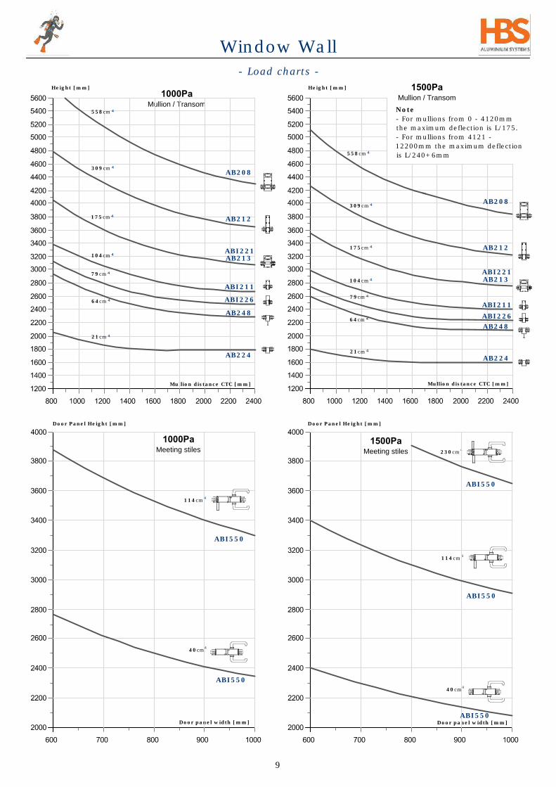
1000Pa
Mullion / Transom
- Load charts -
230cm
4
114cm
4
40cm
4
1500Pa
Mullion / Transom
1000Pa
Meeting stiles
1500Pa
Meeting stiles
104cm
309cm
558cm
Height [mm]
Mullion distance CTC [mm]
Door panel width [mm]
Door panel width [mm]
AB208
AB212
AB213
ABI211
ABI550
Note
- For mullions from 0 - 4120mm
the maximum deflection is L/175.
- For mullions from 4121 -
12200mm the maximum deflection
is L/240+6mm
ABI221
Height [mm]
175cm
ABI226
AB224
21cm
79cm
AB248
Door Panel Height [mm]Door Panel Height [mm]
114cm
4
ABI550
40cm
4
ABI550
64cm
Mullion distance CTC [mm]
AB208
AB212
AB213
ABI211
ABI221
ABI226
AB224
AB248
104cm
309cm
558cm
175cm
21cm
79cm
64cm
9
Window Wall
ABI550
ABI550

100mm
Transom length
100mm
- Load charts -
Note
- Maximum deflection of transoms
is limited by the smaller value of
Lt/1000 or 2mm.
- Glass packing blocks set at
100mm from transom end.
2000Pa
Mullion / Transom
Glass Weight
Transom
2000Pa
Meeting stiles
34cm
4
37cm
4
42cm
4
Door Panel Height [mm]
Mass [kg]
AB212
AB213
ABI211
Height [mm]
AB224
230cm
4
ABI550
114cm
4
ABI550
40cm
4
AB248
104cm
309cm
558cm
175cm
21cm
79cm
64cm
AB208
AB212
AB213
ABI211
ABI221
ABI226
AB224
AB248
Transom
deflection
Glass
Packing
block
Packing
block
10
Window Wall
Door panel width [mm]
Mullion distance CTC [mm]
Transom length [mm]

- Architectural specification -
GENERAL
Screens shall be the window wall system as supplied by HBS aluminium systems.
Manufacture shall be in accordance with the current manuals as provided by HBS
aluminium systems via www.hbs.co.za.
MATERIALS
Material shall be of 6063T6 aluminium alloy with a minimum structural wall
thickness of 1.8mm.
Outer frame to infill panels will be a nominal depth of 60, 111 or 166mm.
CONSTRUCTION
Outer frame to consist of a single part compensating head and jamb and
continuous sub-sill.
Infill panels are to be constructed from double cavity tubular profiles, forming a
wet cavity with drainage slots to allow for transom drainage to the exterior. All
glazing rebates to be 25mm. Joints of the infill panels shall be notched and
screwed to spigots with No 8 stainless steel screws. Where required, a 60mm,
111mm or 166mm split mullion assembly must be used to couple infill panels
together, still making allowance for all thermal and dynamic movement. Door
panels within the screens to have a 4-edge door rebate with gasket seal all round.
INSTALLATION
Panel-by-panel installation from inside or from outside the building.
HARDWARE
All sashes to have mechanical corner connectors, wind locks and multi-point
locking handles. Sashes not to exceed 1700mm wide by 1200mm high as per
specification. Friction stay to suit max weight and size of sash.
Door hardware shall be compatible with the system and will take cognisance of the
finish specification of the applicable area. See hardware schedule for door.
FINISH
Sections will be painted in accordance with SABS1578, parts1 & 2.
GLAZING
Glazing is to be carried out in accordance with SABS 0137, with particular attention
to size limitations, packing and setting blocks.
Thicknesses from 6-28mm.
STRUCTURAL PERFORMANCE
System shall meet or exceed the requirements of SANS613 and the design loading
determination by SABS 0160 for this application.
Deflection of structural members shall not exceed L/175 or L/240+6mm as
applicable.
THERMAL PERFORMANCE
System shall comply with SANS204 in applications where fenestration makes up
more than 15% of floor area.
For U-values below 3.38 use Argon or Krypton gas filled gl azing units.
11
Window Wall

- Glazing details -
Note
Details illustrated here apply on perfectly
supplied material.
In the real world tolerances of gaskets, profiles
and glass can differ from batch to batch.
Powder coated material may differ from
anodized in terms of room for gasket and glass.
To minimize on-site inconvenience we
recommend that the fabricator confirms the fit
of the chosen wedge gasket on the actual
material (profiles and glass) delivered.
12,8
31,3
15,2
ABI215
ABI201
6,76
10,76
8,76
6,38
12
6,38
26
107,76
7,76
12
6,38
27
6 to 6,76mm
6
2426
AB220
HK703
HK702
7.76 to 10,76mm
24 to 27mm
4mm Wedge
HK702
3mm Wedge
HK701
2mm Wedge
HK700
Butterfly
HK703
min = 2.1mm
max = 5,3mm
min = 3.4mm
= 1.9mm
max = 3,3mm
min = 2.2mm
= 1.1mm
max = 1,4mm
min = 1.0mm
= 0.4mm
17,76
15,2
10,76
8,76
10
7,76
AB243
10,76 to 14mm
AB244
10,76
12,76
14
12,76
7.76 to 10,76mm
12
HZ031
HK703
HK702
HZ031
HK703
HK702
HZ031
HK703
HK702
HZ031
HK703
HK702
HZ031
HK703
HK701
HZ031
HK703
HK701
HZ031
HK703
HK701
HZ031
HK703
HK701
HZ031
Window Wall

85
75
166
4
135
4
8
4
- Key dimensions -
AB208
AB213
I = 558cm
4
I = 175cm
4
I = 309cm
4
AB212
I = 104cm
4
8
117
40
I = 175cm
4
ABI202
ABI202
AB248AB228
AB249 AB228
ABI221
ABI201
ABI211
111
97
166
111
61
57
40
40
40
75
75
4
4
858
117
858
117
858
117
4
858
134,5
858
134,5
858
134,5
Mullions
Side
compensators
54,5
10
124
54,5
10
179
54,5
10
79
C
Y
Z
D
G
P
Detail G
SCALE 1:4
Detail D
SCALE 1:4
AB208
13
Window Wall

4
6
4
179
4
175
13
24
24
24
24
186
175
192
182
ABI550ABI550
ABI550ABI550 ABI550
ABI550
I = 230cm
4
I = 114cm
4
I = 40cm
4
Meeting stiles
AB182
45
936
10
35
45
80
80
10
35
45
80
81 137 192
Head compensator
ABI235
*
**
*
*
Sill compensator
45
8
40
14,5
5
40
14,5
5
45
8
35
9,5
79,4
124 179
20
20
20
9,5
19
54,5
10
8
10
10
10
157,5
122
112,5
103
14,5
14,5
14,5
Door sill
Detail P
Detail C
Detail Y
Detail Z
40
8
AB249AB245 ABI221
ABI234 AB236
AB249
ABI226 AB207
- Key dimensions -
AB207AB250
AB250ABI235
AB207
AB207
AB228
61
31,4
AB228AB228 AR255M
14
AB208
AB182
SCALE 1:4
SCALE 1:4
SCALE 1:4
SCALE 1:4
AB182
Window Wall

- Full size detail -
60mm mullion
Detail A
SCALE 1:1
24
90
4025 25
ABI201
ABI201
HK702
AB224
HK703
22cm
4
AB224
22cm
4
Note
- Seal all mullion/transom joints with
small joint sealant.
57,5
A
15
ABI215
6
HK702
HK702
HK703
Window Wall

40
24
ABI201
Detail A
- Full size detail -
60mm mullion
SCALE 1:1
40
AB248
63.8cm
4
ABI215 ABI215
63.8cm
4
2525
Note
- Seal all mullion/transom joints with
small joint sealant.
97,5
97,5
16
6
HK702
HK703
HK702
ABI201
AB248
HK703
HK702
Window Wall

111
40
Detail A
- Full size detail -
111mm mullion
SCALE 1:1
AB225
103cm
4
A
24
ABI201
Note
- Seal all mullion/transom joints with
small joint sealant.
17
HK702
ABI201 HK703
Window Wall

166
111
135
40
- Full size detail -
Mullion w. screw slots
AB212
ABI211
AB213
104cm
4
309cm
4
175cm
4
ABI201
Detail A
SCALE 1:1
Note
- Seal all mullion/transom joints with
small joint sealant.
18
HK702
ABI201
24
HK703
Window Wall

8
5
25
111
24
75
5
50x25x2mm
AR300
Detail A
- Full size detail -
Split mullion 60mm & 111mm
SCALE 1:1
ABI221
175cm
4
ABI201
25
61,5
24
75
ABI201
50x25x2mm
AR300
HWW008
5
5
HV032
(optional)
54cm
4
AB249
Note
- Seal all mullion/transom joints with
small joint sealant.
19
HK702
HK703ABI201
HK702
HK703ABI201
HWW008
Window Wall

8
5
5
5
25
166
24
75
Detail A
50x25x2mm
AR300
50x25x2mm
AR300
SCALE 1:1
558cm
4
- Full size detail -
Split mullion 166mm
ABI201
AB208
ABI201
AB208
Note
- Seal all mullion/transom joints with
small joint sealant.
A
20
HK702
HK703
Window Wall

Panel
Width
Min. Facade Radius for
Mullion sizes
60mm 111mm 166mm
(mm) (mm)
600 4301 5732 6878
700 5018 6688 8024
800 5734 7643 9171
900 6451 8599 10317
1000 7168 9554 11463
1100 7885 10509 12609
1200 8602 11465 13756
1300 9318 12420 14902
1400 10035 13376 16048
1500 10752 14331 17195
1600 11469 15286 18341
1700 12186 16242 19487
1800 12902 17197 20634
1900 13619 18152 21780
2000 14336 19108 22926
2100 15053 20063 24073
Detail V
SCALE 3:4
- Facade -
60mm Split mullion
111mm Split mullion
166mm Split mullion
Outside
Outside
Inside
Outside
Inside
Inside
Outside
Outside
Inside
Outside
5
13
5
20
5
22
3
3
3
HV032
(optional
Facade radius
Outside facade
Ou
tsid
e
In
sid
e
Ou
tsid
e
In
sid
e
Facade radius
Inside facade
Values listed here are for reference only.
Inside
Inside
21
Window Wall

Detail V
SCALE 3:4
- Corner detail -
Hulabond bend
to suit
ABI221
ABI221
50x25x2mm
AR300
50x25x2mm
AR300
ABI215
Foam
Foam
ABI235Angle hulabond
bend to suit
Note
- Corners with any angle from 90 to 270
degrees can be achieved with window
wall.
- Use splice plates to join mitered head
and sill profiles.
ABI235
Router 90deg V-shape of
inner skin to fold corner on
outer skin of panel
Hulabond corner routing
0,5
0,5
4
Hulabond
83,3
HV032
(optional)
HV032
(optional)
Hulabond bend
to suit
22
HWW008
HK703 HK702
V
Window Wall

25
24
54,5
152010
Note
- Use spacers between frame and wall.
- Distance between fixings as per
engineers instruction.
- Seal with closed cell foam or silicone
sealant.
Detail D
SCALE 3:4
Spacers
Polycord
Sealant
Plug and
Screw
124
127
10
- Full size detail -
Frame side 60 & 111mm
Installation from outside
9,5
ABI221
ABI201
Polycord
Sealant
25
Plug and
Screw
10
ABI201
AB249
Polycord
Sealant
Polycord
Sealant
Spacers
35
54,5
15,5 19,5
79,5
AB250
*
*
23
HK702
HK703
HK702
HK703
24
ABI235
*
Window Wall

25
24
54,5
152010
19,5
10
AB208
Detail D
SCALE 3:4
Plug and
Screw
181
179
D
- Full size detail -
Frame side 166mm
Installation from outside
9,5
ABI201
Polycord
Sealant
Spacers
Polycord
Sealant
Note.
- Use spacers between frame and wall.
- Distance between fixings as per
engineers instruction.
- Seal with closed cell foam or silicone
sealant.
*
*
24
HK702
HK703
AB237
Window Wall

Detail D
SCALE 3:4
24
Sealant
Spacers
Polycord
Polycord
Sealant
Plug and
Screw
ABI235
15
18,59,5
- Full size detail -
Frame side 60 & 111mm
Installation from inside
10
25
ABI221
ABI201
Note.
- Use spacers between frame and wall.
- Distance between fixings as per
engineers instruction.
- Seal with suitable sealant.
-Installation from inside requires panels
to be pre-glazed.
Polycord
Sealant
Polycord
Sealant
Spacers
AB250
ABI201
39,5
79,5
124
54,5
15,5
10
19,5
35
*
*
*
25
HK702
HK703
AB249
Plug and
Screw
HK702
HK703
Single
Sided Tape
4x12mm
Window Wall

Detail D
SCALE 3:4
Plug and
Screw
152010
9,5
Sealant
Polycord
Polycord
Sealant
Spacers
- Full size detail -
Frame side 166mm
Installation from inside
AB237
25
AB208
ABI201
Note.
- Use spacers between frame and wall.
- Distance between fixings as per
engineers instruction.
- Seal with suitable sealant.
-Installation from inside requires panels
to be pre-glazed.
179
*
*
Single
Sided Tape
4x12mm
26
HK702
HK703
24
D
Window Wall

25
Polycord
Polycord
Sealant
Spacers
Sealant
Plug and
Screw
ABI226
ABI201
Detail L
SCALE 1:1
- Frame side detail -
No compensator
AB207
166
111
40
L
*
Note
-Seal corner connector holes.
-Seal with suitable sealant.
27
HK702
HK703
24
*
Window Wall

40
65
25
Sealant
24
ABI201
ABI233
Plug
and
Screw
Fixing plate
(Not by HBS)
Sealant
57,5
Bb
Detail Bc
Spacers
Note
-Seal corner connector holes.
AB246
AB247
Steel frame
5
4,7
AE211
ABI201
HK159
Typical existing
steel window
1580
2080
1580
2080
Steel frame - Insert window
Wall built window.
Steel window replacement
Bc
- Frame side detail -
No compensator
Detail Bb
SCALE 1:1
HK704
28
HK702
HK703
HK702
HK703
Plaster
Window Wall
25
40
25
25
40
25
24
ABI201
ABI201
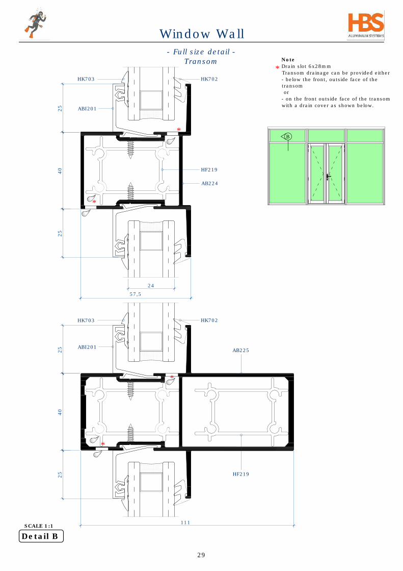
Detail B
- Full size detail -
Transom
SCALE 1:1
AB224
AB225
HF219
HF219
B
111
*
Note
Drain slot 6x28mm
Transom drainage can be provided either
- below the front, outside face of the
transom
or
- on the front outside face of the transom
with a drain cover as shown below.
*
*
*
*
57,5
29
HK702HK703
HK702HK703
Window Wall

25
40
25
25
25
40
166
24
Detail B
- Full size detail -
Transom
NKWW transom spigot
HF219
SCALE 1:1
ABI211
*
Note
Drain slot 6x28mm
- Use 4 x HF219 spigot when mounting
transoms on hollow mullion profiles
- Use the screws slots when mounting
transoms on split mullions profiles
When using HF219 spigot in ABI226
remove 1 leg by filing.
*
*
*
**
***
**
**
***
*
**
****
****
30
HK702HK703
ABI201
AB212
HK702HK703
ABI201
*
Window Wall

FFL - Inside
ABI201
Polycord
Sealant
SpacersPlug &
Screw
Plug and
Screw
Sealant
DPC
(not by HBS)
Screed
Water cap
FFL - Outside
- Full size detail -
Frame top & bottom
60mm profiles
Detail E
Detail C
SCALE 3:4
935
21
935
21
AB249
AB245
AB249
ABI233
AB250
HMZ319
AP016
34
44,5
34
Note
Apply damp course as required.
-Fixing detail shown is for information
only, select fixing method and profile
according to site conditions
Spacers
**
31
HK702HK703
Sealant
Polycord SpacersPlug &
Screw
AB245
ABI201
HK703
ABI233
HK702
ABI201
ABI201
ALD008
**
Window Wall

*
Note
Drain slot 6x28mm
-Seal all joints including mitre corners
on the sill for water proofing.
-AB249 is recommended frame to be
used for ABI203 & AB242
FFL - Inside
145
135
85
94,5
9,5
9,5
- Full size detail -
Frame top & bottom
60mm profiles
*
*
*
*
E
Detail E
7 7
Sealant
Plug &
Screw
935
21
AB245
HMZ319
AB250
AP016
Sealant
32
ABI201
HK702HK703
AB249
Polycord Spacers
ABI203
AP016
AB250
HK702HK703
AB242
Sealant
C
Detail C
SCALE 3:4
Window Wall

35
45
40
39
6
14.5
- Full size detail -
Frame top & bottom
111mm profiles
Sealant SpacersPlug & Screw
ABI234
Screed
Plug and
Screw
ABI221
HMZ319
E
FFL - Outside
25
Sealant
FFL - Inside
- Slab -
C
Detail E
Detail C
SCALE 3:4
45
9,5
137
4mm Wedge
T Seal 6.7x8mm
HWW008
ABI235
65
20
35
45
*
Note.
-One screw per panel to prevent lift.
-2 pieces of 100mm each under every
panel.
-Seal adequately around the fixing.
*
**
**
DPC
(not by HBS)
***
33
ABI201
HK702HK703
HMZ319
ABI226
Polycord
AP016
***
Window Wall

35
45
AB208
Detail E
AB236
SpacersPlug & Screw
- Full size detail -
Frame top & bottom
166mm profiles
Screed
DPC
Plug and
Screw
40
25
65
45
6
20
35
45
192
FFL - Outside
AB237
HMZ319
FFL - Inside
- Slab -
Detail C
SCALE 3:4
14.5
9,5
AP016
*
Note.
-One screw per panel to prevent lift.
-2 pieces of 100mm each under every
panel.
- Use spacers between frame and wall.
- Distance between fixings as per
engineers instruction.
- Seal with closed cell foam or silicone
sealant.
**
*
**
Sealant
DPC
(not by HBS)
34
ABI201
HK702HK703
Polycord
AB207
Sealant
Window Wall

- Sill detail -
111mm with R4 kick rail
*
Note.
-One screw per panel to prevent lift.
-2 pieces of 100mm each under every
panel.
-Seal with suitable sealant before
inserting R4/R6 kick rail.
-Seal adequately with suitable sealant
around the fixing.
**
***
40
39
6
14.5
Screed
Plug and
Screw
AP016
FFL - Outside
25
FFL - Inside
- Slab -
45
9,5
ABI235
*
**
85
30 6
22
ABI203
Water cap
24
ABI201
***
Detail Y
SCALE 3:4
DPC
(not by HBS)
****
*** *
124
35
HK702HK703
ABI226
Sealant
Window Wall

135
Detail Y
SCALE 3:4
Screed
Plug and
Screw
AP016
FFL - Inside
Sealant
40
FFL - Outside
AB237
- Slab -
14.5
9,5
135
45
24
179
Y
*
**
***
- Sill detail -
166mm with R6 kick rail
*
DPC
(not by HBS)
*** *
36
HK702HK703
ABI201
AB242
AB207
Window Wall

16
56
25
10,5
CTC
Ws
CTC
Hs
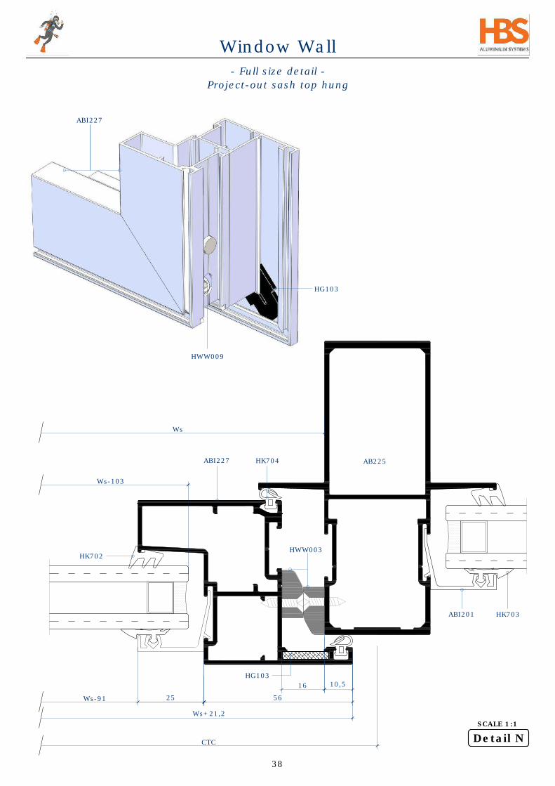
Detail M
- Full size detail -
Project-out sash top hung
SCALE 1:1
HJ100
HJ101
HJ102
HK704
CTC
Ws
AB225
Ws-103
Ws-91
Ws+21,2
HWW010/HWW013HWW006 HWW006
Note
Where necessary pack friction stay to
16mm stack height.
-Seal the transom-mullion joint
adequately. See also page 79.
ABI201
*
*
37
HK702
HK703
ABI227
Window Wall
M
N
Friction
stay
HWW011
HWW012
HWW002
(on sash center)
HWW003
Friction
stay
HWW003
16
5625
10,5
Detail N
SCALE 1:1
CTC
Ws
AB225
Ws-103
Ws-91
- Full size detail -
Project-out sash top hung
HWW003
Ws+21,2
ABI227
HWW009
HG103
HG103
38
HK702
ABI201 HK703
HK704ABI227
Window Wall

40
16
25
56
5
CTC
Hs
CTC
Ws
24
- Full size detail -
Project-out sash - top hung
ABI211
ABI227
HK704
HWW002
Note
Wind lock is not compatible with
interlock friction stay.
-Drain holes 6x28mm
HWW007
Detail O
SCALE 1:1
*
*
*
*
*
39
ABI201
HK702HK703
Window Wall
O
P
Friction
stay
HWW011
HWW012
HWW002
(on sash center)
HWW003 HWW003
Friction
stay

40
16
6
25
6
5
24,5
10,5
56
24
Detail P
ABI211
SCALE 1:1
- Full size detail -
Project-out sash
top hung
ABI227
HWW006
HWW011
or
HWW012
HWW013
or
HWW010
HK704
AMJ002
(cut to 40mm)
Note
-Drain slot 6x28mm
-400mm lock rod (HWW013) and
900mm lock rod (HWW010) are
available from HBS.
-Lock rods in lengths of 400 - 1200mm
can be supplied on order.
-It is possible to manually reduce the
effective length of the lock rods.
-The steps on PAGE 87 & 88 illustrate
how to split and rejoin a 900mm lock
rod to obtain the desired length.
*
*
*
*
*
40
ABI201
HK703
HK702
Window Wall
11,5

16
10,5
25
Detail Q
- Full size detail -
Project-out sash
Side hung (top)
SCALE 1:1
ABI227
HK704
CTC
Hs+
21,2
Hs-141
Hs-103
Hs
AB225
Note.
Where necessary pack friction stay to
16mm stack height.
16
14
Pack as required if
friction stay is not
16mm.
*
*
Sash
Frame
41
24
ABI201
HK702HK703
HJ100
HJ101
HJ102
Window Wall

CTC
Hs
CTC
Ws
24
10,5
16
Detail R
- Full size detail -
Project-out sash
Side hung (bottom)
SCALE 1:1
HK704
CTC
Hs+
21,2
Hs-141
Hs-103
Hs
AB225
Side hung max size
1000x1700mm
Side hung min size
450x450mm
HWW003
HWW003
*
Note
-Drain slot 6x28mm
*
*
*
*
42
ABI201
HK703
ABI227HK702
HJ100
HJ101
HJ102
Window Wall
Friction
stay
R
Q
Friction
stay
HWW002
(on sash center)
HWW011
HWW012
HWW006

16
10,5
24
CTC
Hs
CTC
Ws
HWW003
Detail S
- Full size detail -
Project-out sash side hung
Anti - drop piece position
SCALE 1:1
ABI227
HK704
CTC
Hs+
21,2
Hs-141
Hs-103
Hs
AB225
43
ABI201
HK702HK703
Window Wall
S

24
CTC
Hs
CTC
Ws
24
10,5
16
Detail Ss
SCALE 1:1
HK704
CTC
Hs+
21,2
Hs-141
Hs-103
Hs
AB225
Note
-Drain slots at 1/4 points of sash bottom
profile as indicated, 6 x 28mm.
- Anti-drop pieces must be mounted to
support the closed sash to avoid sagging.
- Drain holes to be positioned to avoid
interference from friction stay.
Side hung max size
1000x1700mm
Side hung min size
450x450mm
- Full size detail -
Project-out sash side hung
Transom and sash drainage
HWW003
HWW007
*
*
*
*
44
ABI201
HK703
ABI227HK702
Window Wall
Drainage of sash
& transom
Ss
Friction
stay
HWW002
(on sash center)
HWW006

56
16
25
10,5
56
16
25
10,5
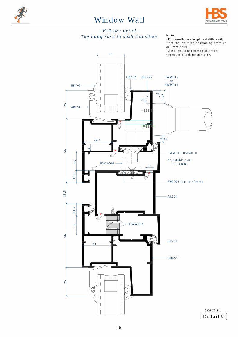
Detail T
SCALE 1:1
HK702
AB225
- Full size detail -
Top hung sash to sash transition
Note.
Where necessary pack friction stay to
16mm stack height.
U
T
18,5
40
45
HK703 ABI201
HK702 ABI227
HJ100
HJ101
HJ102
HJ100
HJ101
HJ102
Window Wall
16
25
16
23
6
25
10,5
6
10,5
56
56
18,5
5
24,5
24
5
6,5
- Full size detail -
Top hung sash to sash transition
Detail U
SCALE 1:1
HWW006
ABI227
HWW002
AB224
Adjustable cam
+/- 1mm
HK704
Note
-The handle can be placed differently
from the indicated position by 8mm up
or 6mm down.
-Wind lock is not compatible with
typical interlock friction stay.
AMJ002 (cut to 40mm)
HWW012
or
HWW011
HWW013/HWW010
*
*
*
*
46
ABI227HK702
ABI201
HK703
Window Wall
11,5

- Full size detail -
Equal leg fixed panel
40
25
ABI233
Detail Cc
Detail Aa
SCALE 1:1
*
Note
Drain slot 6x28mm
-Fixing detail shown is for information
only, select fixing method and profile
according to site conditions
-Seal corner connector holes.
Aa
Cc
**
47
Plug and
Screw
Spacers
Sealant Wood/Granite
Screed
Water cap
57,5
*
*
*
DPC
(not by HBS)
ALD008
**
ABI201
HK702
HK703
AP012
(Optional)
Window Wall
Plug and Screw

85
25
Note
-Drain slots 6x28mm.
- Frame top & bottom detail -
No compensators
SealantPolycord Plug and
Screw
Spacers
ABI226
40
25
Detail K
Detail J
SCALE 1:1
30 6
Water cap
ABI203
*
*
*
J
K
48
ABI201
HK702
HK703
6
HEX150
Window Wall
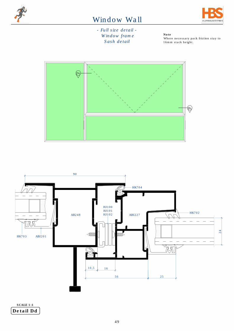
16
56 25
10,5
ABI201
Note
Where necessary pack friction stay to
16mm stack height.
Detail Dd
SCALE 1:1
- Full size detail -
Window frame
Sash detail
90
Dd
Hh
AB248
49
HK703
HK702
HK704
HJ100
HJ101
HJ102
24
ABI227
Window Wall

16
5625
10,5
ABI227
ABI201
HK704
HWW003
HG103
24
ABI233
ABI233
HWW009
57
69
Detail Hh
SCALE 1:1
- Full size detail -
Window frame corner
Sash detail
ABI233
29,5
Note
-Use the cancellation lever on tool for
easier punching where screw slot is not
required.
-Seal corner connector holes.
*
*
50
HK702
HK703
Window Wall

16
25
56
24
ABI227
HK704
HWW002
29,5
- Full size detail -
Window frame equal leg
Sash top
ABI233
Detail Ee
SCALE 1:1
65
45,5
Note
-Wind lock is not compatible with
interlock friction stay.
*
*
51
ABI201
HK702HK703
AP012
(Optional)
Window Wall

Plug and
Screw
Spacers
Sealant Wood/Granite
Screed
6
16
25
10,5
56
24
6
ABI227
HK704
Tiles
Gg
Ee
Detail Gg
SCALE 1:1
- Full size detail -
Window frame equal leg
Sash bottom
30
Note
-Drain slot 6x28mm
-400mm lock rod (HWW013) and 900mm
lock rod (HWW010) are available from
HBS.
-Lock rods in lengths of 400 - 1200mm
can be imported on order.
-It is possible to manually reduce the
effective length of the lock rods.
-The steps on PAGE 87 & 88 illustrate
how to split and rejoin a 900mm lock rod
to obtain the desired length.
*
*
*
*
*
*
ABI233
DPC
(not by HBS)
ALD008
52
ABI201
HK702
HK703
Window Wall

4840 85
27,5
25
Detail G
- Door rebate detail -
Hinge side
SCALE 1:1
I
ABI202
AB228
ABI226
G
AMD008
HK704
Note
-Seal before inserting door rebate.
-Fix with a flat bar here for
reinforcement of hinge screws.
*
*
**
**
40
44,5
Hinge
53
ABI201HK703
HK702 ABI200
Window Wall

84
35 BS
85
Detail I
ABI202
AB228
35mm BS
Latch lock
ABI226HK704
- Door rebate detail -
Lock handle side
40
Note
-Seal before inserting door rebate.
*
*
AB214
54
ABI201 HK703
HK702ABI200
Window Wall
SCALE 1:1

137
25
40
885
4
24
- Door rebate detail -
ABI203
AB228
5x20mm s/s self
tap screws
AB224
HK704
Detail H
SCALE 1:1
*
*
Note.
-Drain slots 6x28mm.
-Seal before inserting door rebate.
**
**
H
55
ABI201
HK702
HK703
Window Wall

137
40
885
4
24
- Door rebate detail -
ABI203
AB228
5x20mm s/s self
tap screws AB122
HK704
Detail H
SCALE 1:1
*
*
Note.
-Drain slots 6x28mm.
-Seal before inserting door rebate.
**
**
166
56
ABI201
HK702
HK703
Window Wall

Detail W
SCALE 1:1
W
25
85
30 6
22
10
8
Plug and
Screw
DPC
Screed
Slab
FFL - Inside
SSL
FFL - Outside
HK704
AB228
- Door sill detail -
No compensator
34
Water cap
ABI203
*
Note
-Drain slots 6x28mm.
-Seal all joints on the sill for water
proofing.
*
ABI201
HK702
HK703
Sealant
57
Window Wall

25
85
30 6
22
10
8
FFL - Inside
45
FFL - Outside
Detail W
SCALE 1:1
- Door sill detail -
with floor sill
9,5
AB250
Note
-Seal all joints including mitre joints on
the sill for water proofing.
-Seal adequately around the fixing.
*
*
27,5
58
ABI201
HK702
HK703
Water cap
AB228
ABI203
HK704 Sealant
Window Wall

25
85
30 6
22
10
Screed
Plug and Screw
8
FFL - Inside
Sealant
ABI235
- Slab -
14.5
9,5
Detail Z
SCALE 3:4
- Sill detail -
Flush w. floor door rebate
45
*
Note.
-Drain slots 6x28mm.
-One screw per panel to prevent lift.
-Seal before inserting door rebate.
-Seal adequately around fixing.
-Seal all joints including mitre corners
on the sill for water proofing.
**
*
** *
*
*
*
***
HK704
ABI203
AB228
Z
AR255
(non stock profile)
19
59
32
****
****
37
59
ABI201
HK702
HK703
Water cap
Window Wall
25
85
30 6
22
10
Screed
Plug and Screw
8
FFL - Inside
DPC
AB237
- Slab -
14.5
9,5
AB828
Sealant
Detail Z
SCALE 3:4
- Sill detail -
Flush w. floor door rebate
45
*
Note.
-Drain slots 6x28mm.
-One screw per panel to prevent lift.
-Seal before inserting door rebate.
-Seal all joints on the sill for water
proofing.
**
*
*
*
*
***
****
37
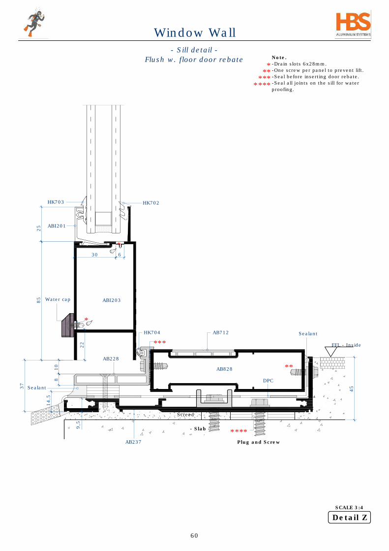
60
ABI201
HK702
HK703
Water cap
ABI203
AB228
HK704
** *
Sealant
****
AB712
Window Wall

25
85
30 6
22
10
Detail Z
SCALE 3:4
Screed
Plug and Screw
40
8
FFL - Inside
DPC
FFL - Outside
AB237
- Slab -
Z
AP016
14.5
9,5
- Sill detail -
Raised door rebate
45
*
Note.
-Drain slots 6x28mm.
-One screw per panel to prevent lift.
-Seal before inserting door rebate.
-Seal adequately around fixing.
**
***
**
*
*
****
****
61
ABI201
HK702
HK703
Water cap
ABI203
AB228
HK704
** *
AB207
Sealant
Window Wall

H1
Wd
40
55
40
20
H1
CTC
19
H1
40
20
Hd
H1
CTC
AB228
AB228
Mullion
Mullion
Transom
Transom
AB228
AB228
43
7
FFL - inside
FFL - inside
Flush with floor
(min step)
Raised step
NKWW door rebate
(CTC-75)
HF030
*
HF030
*
*
*
- Cutting sizes -
Door rebate
Note
-The door rebate AB228 is mitre cut and
and screw fixed or crimped as required.
*
62
AB228
AB207
Window Wall
Wd
NKWW door
rebate
(CTC-75)
NKW
W door rebate
(H
1-39)
Hd
NKW
W door rebate
(H
1-39)
HF030
HF030
Wd
Hd
NKW
W door rebate
(H
1-75)
NKWW door
rebate
(CTC-75)
NKW
W door rebate
(H
1-75)
HF030
HF030

Window Wall
- Cutting sizes -
Panels
ABI226
ABI203
AR300
ABI234
Cutting Sizes
Pic
Description
Codes
Qty
Cut
Length
NKWW111 Head ABI234 1 W
NKWW111 Sill ABI235 1 W
NKWW111 Sill ABI235 2 H-10
NKWW111LE ABI226 2
Wp-70
NKWW111SP ABI221 2 H-60
NKWW111SP ABI221 2
Wp-70
NKWWR4 ABI203 2
Wp-70
Panel Lock AP016 4 100
NKWWBD ABI201 4
Wp-70
NKWWBD ABI201 4 H-270
NKWWBD (sides)
ABI201 2 H-73
Glass
Width
2
Wp-82
Height
H-232
Accessories
Wedge
HK702 -
as req.
Butterfly
HK703 -
as req.
6,7x900 FinPile
HMZ319 2W
T Seal 6,7x8mm
HWW008 8H
Glass Packer 2-6mm HZ031 4 -
NKWWDoor Spigot
HF206 8 -
Water Cap
HWW007
as req.
Corner Cleat HSG12 2 45.5mm
H
W
CTC CTC
H
ABI201
H-10
ABI235
H-59,5
ABI221 (Panel H
eight)
H-73
ABI201
W
CTC CTC
ABI235 ABI221
Wp-70
ABI203, ABI226, ABI201
12,5
Wp-70
ABI203, ABI226, ABI201
75
57
57
12,5
ABI221
ABI221
86
H-231,5
80
45
35
139,5
Glass height
2
1
Note
Cutting sizes given apply to
both 111 & 166mm panels.
22
Wp Wp
Wp
W - 2a - (n-1)5
n
Wp =
where,
W = Total width incl compensators
n = Total number of panels (2 of in this example)
(n-1) = Total number of split mullions (1 of in this example)
a = Panel to compensator clearance (22mm)
W - 44 - (1)5
2
=
=
W - 49
2
9,5
14,5
Wp
22
a = a =
Wp-82
Glass width
Wp-82
Glass width
63
X
Y
Detail X
Scale 1:4
Detail Y
Scale 1:4

Cutting Sizes
Pic
Description
Codes
Qty
Cut
Length
NKWW111 Head ABI234 1 W
NKWW111 Sill ABI235 1 W
NKWW111 Sill ABI235 2 H-10
NKWW111LE ABI226 n
Wp-70
NKWW111SP ABI221 2n H-60
NKWW111SP ABI221 n
Wp-70
Mullion Lock AR300 2n-2 H-60
NKWWR4 ABI203 n
Wp-70
Panel Lock AP016 2n 100
NKWWBD ABI201 2n
Wp-70
NKWWBD ABI201 2n H-270
NKWWBD (sides)
ABI201 2 H-73
Glass
Width
n
Wp-82
Height
H-232
Accessories
Wedge
HK702 -
as req.
Butterfly
HK703 -
as req.
6,7x900 FinPile
HMZ319 2W
T Seal 6,7x8mm
HWW008
8H(n-1)
Glass Packer 2-6mm HZ031 2n -
NKWWDoor Spigot
HF206 - -
Water Cap
HWW007 2n
Corner Cleat HSG12 2 45.5mm
H
H-10
ABI235
H-59,5
ABI221 (Panel H
eight)
H-73
ABI201
86
H-231,5
80
45
35
139,5
Glass height
W
Wp
1 2
...
nn-1
5
5
a a
Wp
a
W = Total width
Wp = Panel width
n = Total number of panels
(n-1) = Total number of split mullions
a = 20mm panel to compensator clearance for n=1,3,4...
...nn-1
W
Wp
21
H
Wp WpWp
- Cutting sizes -
Multiple panels
W - 2a - (n-1)5
n
Wp =
20a =
20a =
Wp Wp
64
ABI234
ABI221
ABI226
ABI203
X
Y
Detail X
Scale 1:4
Detail Y
Scale 1:4
Window Wall

Friction stay
of choice
(pack to 16mm if required)
16
Ws
Hs
- Cutting sizes -
Top hung sash
16mm cavity
ABI211
Friction stay
of choice
(pack to 16mm if required)
ABI211
ABI227
ABI211
ABI227
HWW002
Friction
Stay
HWW003
HWW006
HWW010
Sash
handle
HWW006
HWW011/012
HWW010/013
HWW002
(on sash center)
HWW006
CSK S/Tap
HWW006
Detail X
Scale 1:4
Detail Y
Scale 1:4
X
Y
Note
Wind lock is incompatible with
interlock friction stay.
-Where necessary pack friction stay
to 16mm stack height.
AMD009
(cut to 15mm)
Flat bar
50.8x3.18mm
AMD009
(cut to 15mm)
Flat bar
50.8x3.18mm
AMD009
(cut to 15mm)
CSK S/Tap
CSK S/Tap
Hs
Ws
65
Sash
handle
HWW010
HWW013
HWW003
Pic
Description
Codes
Cut
Length
NKWW Sash ABI227
Hs+21,2
Ws+21,2
NKWWBD ABI201
Hs-141
Ws-91
Glass
Width Ws-103
Height
Hs-103
Accessories
Sash Gasket HK704 4W+4H
Wedge
HK702 2W+2H
Butterfly
HK703 2W+2H
Friction Stay
- 2
Self-Locating Corner Cleat
HWW009 4
Aluminium Locking RodHWW013/010
1
Sash Handle
HWW012 1
HWW011 -
Lock Plate HWW006 2
Wind Lock HWW002 1
Antidrop Piece
HWW003 4
Water Cap
HWW007
as req.
Window Wall

Ws
Ws-91
Ws-103
16
Ws+21,2
16
16
Hs+
21,2
Hs
Hs-141
Hs-103
16
ABI227
ABI227
ABI201
Glass width
ABI211
- Cutting sizes -
Side hung sash
16mm cavity
Detail X
Scale 1:4
Detail Y
Scale 1:4
Water
cap
ABI201
ABI227
ABI201
Glass height
Friction
stay
Sash
handle
HWW006
ABI211
ABI227
ABI227
HWW009
Corner assembly
HWW002
X
Y
Locking rod
Note
-Where necessary pack friction stay
to 16mm stack height.
-For extra alignment use HF020
cleat and HG103 spacer.
*
*
ABI227
ABI211
ABI227
ABI227
66
ABI211
Friction
stay
ABI211
Window Wall

Cutting Sizes
Pic
Description
Codes
Qty
Cut
Length
NKWWR4DS ABI202 2 Hd-27
NKWWR4 ABI203 2 Wd-194
NKWW Door Rebate AB228 2 Hd
NKWW Door Rebate AB228 2 Wd
56,8 x 31,4 x 3 Rect Tube
AR255M 1 Wd
NKWWBD ABI201 2 Wd-194
NKWWBD ABI201 2 Hd-250
Glass
Width
1
Wd-206
Height
Hd-212
Accessories
Door Latch Handle Black HA214 1 Pair
Latchlock 35mm BS HZ014 1
Oval Profile Cylinder
HA155 1 HA155
Wedge
HK702 2Hd+2Wd
Butterfly
HK703 2Hd+2Wd
Sash Gasket HK704 2Hd+2Wd
Double Hinge 200mm Natural
HCD056N 4
NKWWDoor Spigot
HF206 4
8mm Threaded rod & nuts 3m HU001 Wd-96
Water Cap
HWW007
as
req.
Door Rebate Corner Cleat HF030 4 28mm
Wd
Hd
Hd-27
Hd-212
4
Hd-250
Wd-194
Wd-206
8
4
Hd
Wd
8
- Cutting sizes -
Hinged door, single
AB208 AR300
ABI201
ABI202
AB228
ABI202
ABI202, AB550, ABI200
ABI201
Glass height
ABI203 & ABI201
Glass width
AB228
HA214
Detail Z
Scale 1:4
Detail Q
Scale 1:4
Z
Q
HCD056N
ABI211
8
8
75
8
Note
For flush floor door rebate see page 62.
-Depends on sill type
ABI203
AR300
AR300
AR300
9,5
19
55
19
8
14,5
14,5
20
AB228
ABI235
AR255M
37
85
18
85
27
85
73
85
*
*
67
ABI203
AB208
Window Wall

Cutting Sizes
Pic
Description
Codes
Qty
Cut
Length
NKWWR4DS ABI202 2 Hd-30
NKWWR4 ABI203 4
Wd/2-187
NKR4DMS ABI550 2 Hd-30
NKWW Door Rebate AB228 2 Hd
NKWW Door Rebate AB228 2 Wd
56,8 x 31,4 x 3 Rect Tube
AR255M 1 Wd
NKWWR4 Filler ABI200 2 Hd-30
NKWWBD ABI201 4
Wd/2-187
NKWWBD ABI201 4 Hd-250
Glass
Width
2
Wd/2-199
Height
Hd-212
Accessories
Door Latch Handle Black HA214
1 pair
-
Latchlock 35mm BS HZ014 1 -
Oval Profile Cylinder
HA155 1 -
Flush Bolt HEX106 1 -
Wedge
HK702 - 4Hd+2Wd
Butterfly
HK703 - 4Hd+2Wd
Sash Gasket HK704 - 2Hd+2Wd
Double Hinge 200mm Natural
HCD056N 8 -
NKWWDoor Spigot
HF206 8 -
8mm Threaded rod & nuts 3m HU001 - Wd-96
Water Cap
HWW007
as
req.
Door Rebate Corner Cleat HF030 4 28mm
Wd
Wd/2-187
Wd/2-199
8
4
Wd
Hd
ABI201
AB228
ABI202
ABI550
NKWWR4
Glass
HA214
Construction
- Door panels are assembled
using HF206 spigot and tie rod.
- Top & bottom rails are punched.
- Mid rails are punched and drilled
for additional screw fixing into the
spigot.
ABI203
HF206
Door panel construction
Exploded
Hinge
stile
Lock stile/
meeting stile
Detail Q
Scale 1:4
Z
Q
ABI202
HCD056B
HU001
- Cutting sizes -
Hinged door, double
17885 85
Hd
Hd-30
Hd-212
4
Hd-250
ABI202, AB550, ABI200
ABI201
Glass height
ABI203
Detail Z
Scale 1:4
8
ABI203
AR300
AR300
AR300
AR300
20
19
*
Note
For flush floor door rebate see page 62.
-Depends on sill type
*
68
AB228
ABI211
AB228
AB208 AB208
Window Wall

Cutting Sizes
Pic
Description
Codes
Qty
Cut
Length
NKWWR4DS ABI202 2 Hd-30
NKWWR4 ABI203 4
Wd/2-190
NKR4DMS ABI550 2 Hd-30
NKWW Door Rebate AB228 2 Hd
NKWW Door Rebate AB228 2 Wd
56,8 x 31,4 x 3 Rect Tube
AR255M 1 Wd
NKWWR4 Filler ABI200 2 Hd-30
GAS AB182 1 Hd-30
NKWWBD ABI201 4
Wd/2-190
NKWWBD ABI201 4 Hd-250
Glass
Width
2
Wd/2-202
Height
Hd-212
Accessories
Door Latch Handle Black HA214
1 pair
-
Latchlock 35mm BS HZ014 1 -
Oval Profile Cylinder
HA155 1 -
Flush Bolt HEX106 1 -
Wedge
HK702 - 4Hd+2Wd
Butterfly
HK703 - 4Hd+2Wd
Sash Gasket HK704 - 2Hd+2Wd
Double Hinge 200mm Natural
HCD056N 8 -
NKWWDoor Spigot
HF206 8 -
8mm Threaded rod & nuts 3m HU001 - Wd-96
Water Cap
HWW007
as
req.
Door Rebate Corner Cleat HF030 4 28mm
Wd
Wd/2-190
Wd/2-202
8
Wd
Hd
44,5
Hd-30
6,6
ABI202
ABI550
ABI203
Glass
AB182
Top end
Bottom end
AB182
Detail Q
Scale 1:4
Z
Q
- Cutting sizes -
Hinged door, double w. stiffener
184,5
85
Hd
Hd-30
Hd-212
4
Hd-250
ABI202, AB550, ABI200
ABI201
Glass height
ABI203
Detail Z
Scale 1:4
8
ABI203
AR300
ABI202
AR300
AR300
Note
- No machining required on AB182 when
it is facing outwards.
*
*
20
19 *
*
*
See note on
page 70
*
69
AB228
ABI211
AB228
AB228
AB208HA214 AB208
AB182
Window Wall

Wd
Wd/2-193
Wd/2-205
8
4
Wd
Hd
Cutting Sizes
Pic
Description
Codes
Qty
Cut
Length
NKWWR4DS ABI202 2 Hd-30
NKWWR4 ABI203 4
Wd/2-193
NKR4DMS ABI550 2 Hd-30
NKWW Door Rebate AB228 2 Hd
NKWW Door Rebate AB228 2 Wd
56,8 x 31,4 x 3 Rect Tube
AR255M 1 Wd
NKWWR4 Filler ABI200 2 Hd-30
GAS AB182 2 Hd-30
NKWWBD ABI201 4
Wd/2-193
NKWWBD ABI201 4 Hd-250
Glass
Width
2
Wd/2-205
Heght
Hd-212
Accessories
Door Latch Handle Black HA214
1 pair
-
Latchlock 35mm BS HZ014 1 -
Oval Profile Cylinder
HA155 1 -
Flush Bolt HEX106 1 -
Wedge
HK702 - 4Hd+2Wd
Butterfly
HK703 - 4Hd+2Wd
Sash Gasket HK704 - 2Hd+2Wd
Double Hinge 200mm Natural
HCD056N 8 -
NKWWDoor Spigot
HF206 8 -
8mm Threaded rod & nuts 3m HU001 - Wd-96
Water Cap
HWW007
Door Rebate Corner Cleat HF030 4 28mm
16
44,5
60
Hd-30
16
60
13.2
8
75
ABI202ABI550
ABI203
Glass
AB182
AB182
Top end
Bottom end
ABI202
Note
- Machining done on the
inside facing AB182.
- No machining required on
AB182 when it is facing
outwards.
Detail Q
Scale 1:4
Z
Q
- Cutting sizes -
Hinged door, double w. 2 x stiffener
19185 85
Hd
Hd-30
Hd-212
4
Hd-250
ABI202, AB550, ABI200
ABI201
Glass height
ABI203
Detail Z
Scale 1:4
8
ABI203
AR300AR300
AR300
20
19
*
Note
-Depends on sill type
*
*
70
AB228
ABI211
AB228
AB208HA214 AB208
AB182
AB182
105
40,8
40
Window Wall

- Cutting sizes -
Steel frame
Z
X
Y
Hs
Ws
W1
Pic
Description
Codes
Qty
Cut
Length
NKWW ST Rep A
AB246
Ws+9,5
Hs+9,5
NKWW ST Rep B
AB247
Ws-10
Hs-10
Transom AB224
W1-49,5
Mullion AB224 Hs-59
NKWW Sash ABI227
H1-28
W1-28
Glass 1, 2 & 3
Width
1
W2-61,5
Height
Hs-71
Width
1
W1-61,5
Height H2-61,5
Width
1
Ws-152,5
Height Hs-152,5
Accessories
Sash Gasket (frame)
HK704 4W+4H
Sash Gasket (Sash)
HK704 4W1+4H1
Rubber Gasket (Sash)
HK159 2W+2H
Friction Stay
- 2
Self-Locating Corner Cleat
HWW009 4
Aluminium Locking Rod HWW013/010
1
Sash Handle
HWW012 1
HWW011 -
Lock Plate HWW006 1
Wind Lock HWW002 2
Antidrop Piece
HWW003 4
Water Cap
HWW007
as
req.
Frame corner cleat 42mm HSG12 4
ABI201
18,8
5
AB247
AB246
Ws
W1-28
Ws+9,5
ABI227
W1
Ws-10
5
W2
1
2
3
H1
H2
Detail Z
Scale 1:2
26
Ws
Steel frames
Steel frame
AB246
AB247
Steel frame
AB224
71
ABI227 ABI227
Window Wall
HSG12

Hs
Hs+
9,5
ABI227
AB246
AB247
Steel frame
HK159
Hs-10
AB247
AB246
Hs-71
Glass height
AB246
- Full size detail -
Frame & sash for steel frame
Steel
frame
AB247
5
10
ABI201
AB224
HWW011/HWW012
HWW013/HWW010
*
*
*
*
AB246
AB247
Steel frame
Hs
H1-28
ABI227
H1-152,5
Glass height
HK704
5
5
AB247
Ws
Ws-10
AB246
Ws+9,5
Detail X
Scale 1:2
Detail Y
Scale 1:2
13,5
10
Available steel frames
Note
Steel frames can be irregular, to
accommodate tolerances HK704 may
be omitted and sealant used instead.
*
*
72
Steel frame
Window Wall

- Window wall pneumatic punching - Machine
overview
1
2
3
4
5
6
Note
Block sets for station 6 are not
used with window wall profiles.
4
YX
X
Y
Station 1 operations
Station 1 result
Station 1 profiles
1) Properly adjust the supporting stands for the profile to be
square and level into the station.
2) Ensure the is no swarf that prevents the profile to slide in.
2) Slide in the profile supported on stands from the one side.
4) The outside face of the profile should always be facing upwards.
6) Punch as required and follow procedure on pages below to
complete operation.
2
Station 2 operations
Station 2 result
Station 2 profiles
1) Station 2 is in preparation for station 3
2) Slide in the profile and punch as required.
3) Turn around profile and punch the other end.
Outside face
upward
Note
Spray station after every 10
operations.
Note
Spray station after every 10
operations.
ABI203
HWW027
ABI200
73
ABI200ABI203AB248
AB224
AB225 ABI211 ABI226 AB213
AB212 AB207
AB249
ABI221AB208
Window Wall

- Station operations -
Station 3 operations
Station 3 result
Station 3 profiles
Perform station 1 operations before station 3
Station 3 is a 2-stage operation :
1) Insert profile straight and level and punch. (support on stand)
2) Turn and re-insert profile to the stop and punch.
Station 4 operations
Station 4 result
Station 4 profiles
Perform station 4 operations before station 3. Only for spilt mullion
profiles used horizontally as transoms.
1) Insert split mullion profile to the stop and punch.
Station 5 operations
Station 5 result
Station 5 profiles
1)-Station 5 operations are for HWW009 corner connector.
2)-Use the cancellation lever for easier punching where slot is not
required.
ABI227 ABI233
Note
Spray station after every 10
operations.
ABI200 may have to be end
milled depending on finish.
Note
Spray station after every 10
operations.
Technical data
Perforation power :Up to 2500 Kg.
Air supply needed :7-8 Bars (for some perforations a lower pressure will suffice).
Dimensions :Width 650 mm, depth 300 mm, height 560 mm.
Weight :90 Kg.
Standard equip incl. :Foot valve with a sliding tap, pair of guards (front / back).
Block set for station 6 (6 items)
Block set for station 1 (2 items)
Note
Spray station after every 10
operations.
74
ABI200
ABI203
AB248AB224
AB225 ABI211 ABI226 AB213
AB212
AB207
AB249
ABI221
AB208
AB249ABI221AB208
Window Wall

- Station operations -
STATION 1
TOP VIEW
STATION 1 stages schematics
- Transom or top/bottom rail profiles are
punched.
- ID numbers indicating points on each end of
the profile illustrated below are turned upside
down deliberately to indicate the rotation of
the profile.
ALL 4 CORNERS ARE
PUNCHED CORRECTLY
75
Window Wall

Profile
Adjustable support
stand to ensure
profile is inserted
square and level
into station 1
Machine table
Outside face
upward
- Window wall -
Pneumatic punching manual
STATION 1 Elevation
Pneumatic punch
machine table
HMZT022
Station 1
stopper
Station 1
knife
Note
Always use as explained, do not
punch from only one end of
station 1.
76
Window Wall
Window wall punch tool check list
S
T
A
T
I
O
N
0
L R L R L R L R L R L R L R L R
1
2
3
4
5
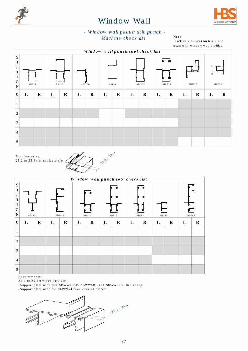
- Window wall pneumatic punch -
Machine check list
Window wall punch tool check list
S
T
A
T
I
O
N
0
L R L R L R L R L R L R L R
1
2
3
4
5
Requirements:
25,2 to 25,4mm evaluate slot
-Support plate used for: NKWW60SP, NKWW60R and NKWW60L - line at top
-Support plate used for NKWWR4 filler - line at bottom
Requirements:
25,2 to 25,4mm evaluate slot
Note
Block sets for station 6 are not
used with window wall profiles.
AB225 ABI200ABI203
AB248
AB224 ABI211ABI226
AB213 AB212AB207 AB249
ABI221 AB208
ABI227 ABI233
2
5
,
2
-
2
5
,
4
2
5
,
2
-
2
5
,
4
77
Window Wall

Technical data
Perforation power :Up to 2500 Kg.
Air supply needed :7-8 bars (for some perforations a
lower pressure will suffice).
Dimensions :Width 650 mm, depth 300 mm,
height 560 mm.
Weight :90 Kg.
standard equipment :Foot valve with a sliding tap, pair of
guards (front / back).includes
General information
The pneumatic punching unit uses die-sets to perforate the
various profiles.
Each die performs a different operation, and the dies are all
numbered.
Stoppers are installed when necessary for setting the desired
lengths.
The operating foot valve is pressed while the user holds the
profile tight in its position for punching.
punch tool table HMTZ022.
Using our steel table, the unit can be adjusted on a center
pivot so it swivels by 360 deg when being manually pushed.
Settings
No special settings are needed, the machine is already set to be
used immediately; while following the instructions in the drawings
of the specific model.
If a need to reset the machine arises, please contact your HBS
technical manager.
Installation & servicing
Installation
Attach the machine to a workbench.
-When using HBS's special steel bench, the machine does not need
to be connected to the bench by bolts. It is set on a pivot; and by
being manually pushed, it can swivel on the center pivot to allow
convenient operation.
-With other solid workbenches the machine must be connected to
the base plate by 4 bolts.
The machine air line should not obstruct movement of workers.
Also, make sure to allow ample space around the machine
according to the size of the profiles being punched.
The HWW027 is intended for inside use only. Keep dry at all times.
Servicing
No special service is needed for the machine. If die-sets are
worn-out, they should be replaced, contact HBS.
Operating instructions
Operational stages
Initial use
1) Check that all bolts and fittings are tight.
2) Connect the foot valve to the main air line and open the
sliding tap.
3) Press the foot valve slowly and check whether the
movement is smooth.
4) Insert the profile and make sure it hits the stopper correctly.
Regular operation
1) Adjust the stoppers if needed.
1) Open the sliding tap on foot pedal.
2) Operate the machine with the foot valve.
3) After each operation, make sure that burr does not block the
die sets.
4) Once every 10 perforations, oil the knives using the provided
spray can.
End of operation
1) Close the sliding tap.
2) Press the foot valve for several times to release all air
pressure from the system.
3) Clean the die sets using an air gun.
Maintenance & Safety
Maintenance
- Clean the machine at the end of the day and check that all bolts
and fittings are tight.
- When not using the machine for a long period oil-spray the
various knives.
Safety precautions & instructions
If parts of the machine, or the guards, have to be disassembled
for any reason, make sure that the air line is disconnected
beforehand.
Please be aware that:
-The manual contains most important information needed to
operate the machine safely.
-The user should allow only persons who comply with the
instructions of the manual to operate the machine.
-The machine has been constructed in line with the various CE
regulations and directives.
It should be used:
-Only for the intended application.
-Only in perfect safe working order.
- Only according to the regulations and instructions in the manual.
-For any amendments, a written consent of the manufacturer is
needed.
Note that improper usage poses risks of injuries to people, and
could damage sub-units and material.
HBS Aluminium Systems
Contact the technical manager at the HBS branch for assistance
and advice.
- Window wall -
Pneumatic punching manual
includes
78
Window Wall
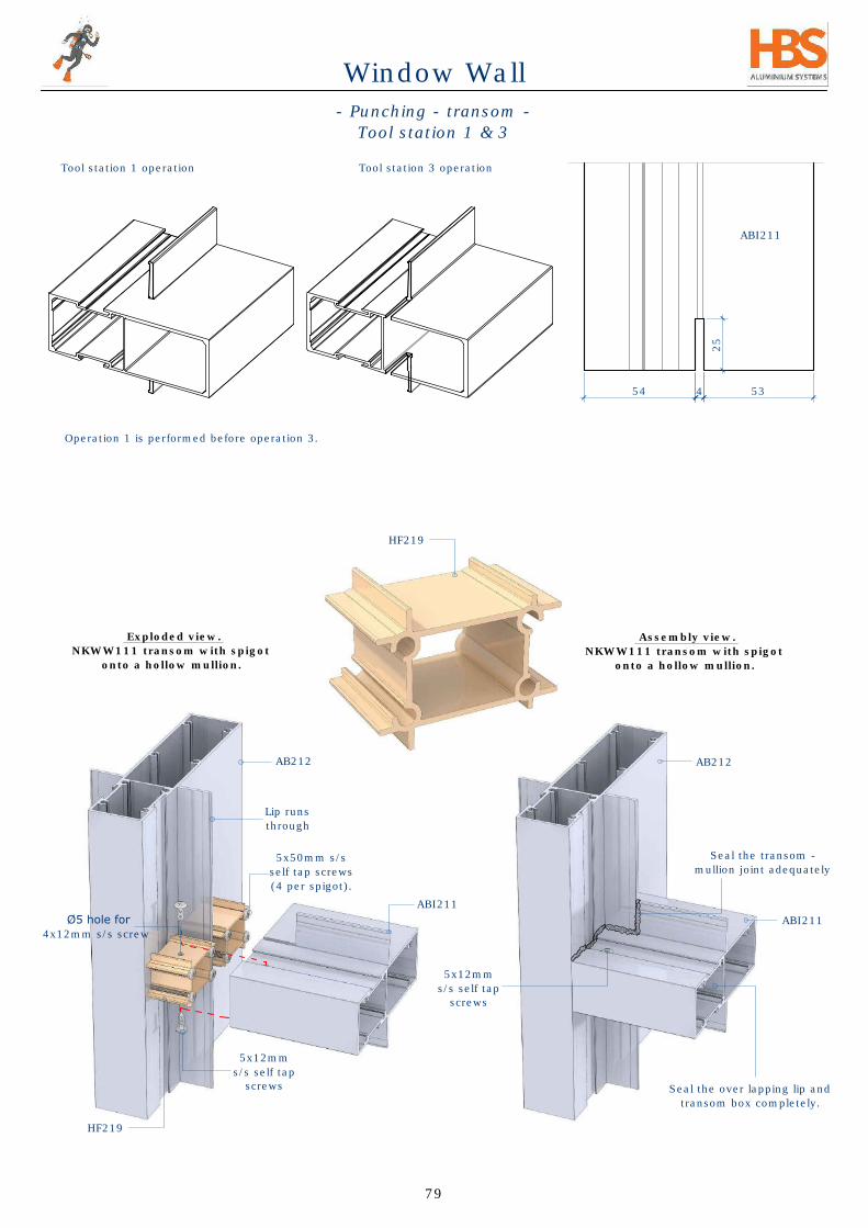
54 53
25
4
ABI211
ABI211
5x12mm
s/s self tap
screws
Exploded view.
NKWW111 transom with spigot
onto a hollow mullion.
Assembly view.
NKWW111 transom with spigot
onto a hollow mullion.
HF219
HF219
4x12mm s/s screw
5x50mm s/s
self tap screws
(4 per spigot).
AB212
Lip runs
through
- Punching - transom -
Tool station 1 & 3
Seal the transom -
mullion joint adequately
AB212
Tool station 1 operation Tool station 3 operation
Operation 1 is performed before operation 3.
Seal the over lapping lip and
transom box completely.
79
Window Wall
ABI211
5x12mm
s/s self tap
screws
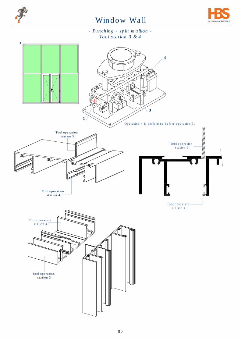
- Punching - split mullion -
Tool station 3 & 4
4
Tool operation
station 3
Tool operation
station 4
Tool operation
station 4
Tool operation
station 3
3
4
Tool operation
station 4
Tool operation
station 3
Operation 4 is performed before operation 3.
80
1
Window Wall

31
33 48
Detail 4. - Exploded
Lip runs
through
Transom
slotted.
ABI211
AB208
Detail 4. -Assembly
AB208
AB208
ABI211
AB208
ABI201
Glass
ABI211
Wedge
Butterfly
Wedge
ABI201
AB208
4,5x40mm s/s screw
Lip runs through
Lip is slotted
Seal all round the
slot and overlapping
lip and box.
4
- Machining -
Split mullion screw joint
15
Transom center
81
Window Wall

HWW009
HWW009
ABI233
ABI233
138
14
13
48
45
ABI233
ABI233
19
8
ABI233
ABI233
HWW009
- Punching -
Window wall equal leg
station 5
57,5
40
65
Note
-Use the cancellation lever for easier
punching where screw slot is not
required.
-Seal corner connector holes.
Detail C
Scale 1:2
C
*
Tool operation
station 5
*
*
*
*
*
82
Window Wall
HWW009
ABI233
ABI233

Detail 5. - Exploded
Detail 5. - Assembly
ABI203
HF206
8mm Threaded
rod & nuts 3mtr
HU001
5
ABI203
25
4
41
ABI203
NKWWDoor spigot
(cut to 52.5mm)
Tool operation
station 1
Tool operation
station 2
Tool operation
station 3
- Punching - top and bottom rail -
station 1, 2 & 3
83
ABI202
HF206
8mm
Threaded rod
& nuts 3mtr
HU001
Window Wall
ABI202

Detail 4. - Exploded
NKWWDoor spigot
cut to 52.5mm
5x12mm s/s
self tap screws
5x30mm
s/s self tap
screws
ALC108
(cut to 29mm)
AB208
ABI203
ABI200
4
1
4
ABI203
ABI203
NKWWDoor
spigot
cut to 52.5mm
AB208
Exploded view
NKWWR4 spigot fixing.
NKWWR4 after
punching process
- Punching - top/bottom/mid rail -
station 1, 2 & 3
2
5
4
ALC108
(cut to 29mm)
5x50mm
s/s self tap
screws
AB207
AB237
sealant
AP016
25
25
40,5
ABI200
ABI200
Tool operation
station 3
40,5
84
Window Wall

- Punching of window wall sash -
station 5
10
148
17
14
13
13
5
50
45
NKWW sash
punching
ABI227
ABI227
ABI227
ABI227
C-C
ABI227
HWW009
HWW009
HWW011
HWW012
ABI227
HWW009
ABI227
ABI227
HWW009
ABI227
ABI227
HF020
optional additional
alignment
HF020
HWW009
HG103
(alignment)
HG103
(alignment)
HG103
(alignment)
85
Window Wall
C

- Machining of window wall sash -
for multi point lock handle (manual)
Min 40
10
13
10
17
6
22
12
62
51
4
13
4
12
22
ABI227
ABI227
ABI227
ABI227
ABI227
HWW009
HWW009
Sash handle
(multi point)
Note
Vertical ABI227 is filed on one
end at the bottom to allow the
lock rod to slide into the
groove.
NKWW sash
Machining for lock rod and sash handle.
Machining for
lock rod.
Z
Detail Z
Scale 1:2
Right Left
ABI227
HWW013
HWW010
Right sash handle
(multi point)
HWW012
Left sash handle
(multi point)
HWW011
Machining for
sash handle.
86
Window Wall

- Lock rod length reduction -
900mm lock rod
HWW010
450 450
Cut away = 900 - desired length - 8mm
1/2 Desired length - 4mm
Lock pointLock point
900
Lock point
Lock rod pin
Desired length
8
1/2 Desired length - 4mm
Desired length
8
STEP 1
- Unscrew and remove lock pin from lock rod assembly
Lock point
RESULT:
Lock point
Lock rod pin
Lock rod
pin
screws
STEP 2
- Calculate cut-away = 900 - desired length - 8mm
CUT CUT
STEP 3
- Cut into 2 pieces
400mm lock rod (HWW013) and 900mm lock rod (HWW010) are available from HBS.
Lock rods in lengths of 400 - 1200mm can be imported on order.
In cases where these sizes are not suitable or time constraints do not allow importation it is possible
to manually reduce the effective length of the lock rods.
The steps below illustrate how to split and rejoin a 900mm lock rod to obtain the desired length.
Lock point
Lock point Lock point
87
Window Wall

- Lock rod length reduction -
1/2 Desired length - 4mm
Lock pointLock point
1/2 Desired length - 4mm
Desired length
8
Lock rod pin
5 58
STEP 4
that has been cut as shown here.
STEP 5
- Join the pieces with the lock rod pin.
- Insert screws and add lock-tite or similar
locking compound.
FINAL RESULT:
Lock rod pin
Lock point
Lock point
Lock point
Lock point
Lock point
Lock point
88
Window Wall

- Machining of 60mm compensators -
for outside panel installation
5
Cutting Sizes
Picture Profile Code
Cut
Length
NKWW60 Head AB245 W
NKWW60 Sill AB250 H-9
NKWW60 Sill AB250 W
NKWWBD ABI201 H-75
HSG12
corner cleat
HF030
AB250
HSG12
corner cleat
HF030
AB245
AB250
HSG12 corner
cleat
HF030
AB245
HSG12
corner cleat
HF030
NKW
W60 Sill
H-9
9
H
H-9
NKW
W60 sill side
AB250
AB250
ABI201
AB245
ABI201
AB250
AB237
ABI201
Note
-Seal all joints on the sill for water
proofing.
*
9,5
HF030
AB237
ABI201
HF030
89
Window Wall
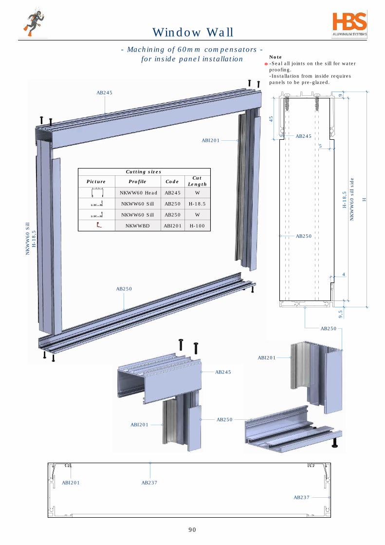
- Machining of 60mm compensators -
for inside panel installation
45
5
4
Cutting sizes
Picture Profile Code
Cut
Length
NKWW60 Head AB245 W
NKWW60 Sill AB250 H-18.5
NKWW60 Sill AB250 W
NKWWBD ABI201 H-100
AB237
AB245
AB245
AB250
NKW
W60 Sill
H-18,5
ABI201
AB245
AB250
ABI201
ABI201
AB250
ABI201
AB237
H
H-18,5
9,5
9
NKW
W60 sill side
AB250
Note
-Seal all joints on the sill for water
proofing.
-Installation from inside requires
panels to be pre-glazed.
*
90
Window Wall

- Machining of compensators -
for outside panel installation
ABI201
HSG12 corner
cleat
cut to 99.5mm
ABI201
HSG12 corner
cleat
cut to 99.5mm
HSG12 corner
cleat
cut to 99.5mm
Cutting Sizes
Picture Profile Code
Cut
Length
NKWW166 Head AB236 W
NKWW166 Sill AB237 H-10
NKWW166 Sill AB237 W
NKWWBD ABI201 H-75
ABI201
AB237
55
3
H
10
H-10
Sill
HSG12 corner
cleat
cut to 99.5mm
99,7
W
AB237
AB237
NKW
W166 Sill
H-10
Note
-Cutting sizes also apply to 111mm
profiles.
-Seal all joints on the sill for water
proofing.
AB236
NKW
W166 Sill
H-10
AB236
AB236
AB237
AB237
AB237
AB237
ABI201
Sill
HSG12 corner
cleat
cut to 99.5mm
HSG12 corner
cleat
cut to 99.5mm
91
Window Wall

Cutting Sizes
Picture Profile Code
Cut
Length
NKWW166 Head AB236 W
NKWW166 Sill AB237 H-19.5
NKWW166 Sill AB237 W
NKWWBD ABI201 H-105
ABI201
ABI201
Head compensator
W
ABI201
- Machining of compensators -
for inside panel installation
55
3
9,5
35
4
H
10
H-20
AB237
AB237
AB237
AB237
AB237
AB237
AB237
AB237
AB236
AB236
AB236
Note
Cutting sizes also apply to 111mm
profiles.
-Seal all joints on the sill for water
proofing.
NKW
W111 Sill
H-19,5
NKW
W111 Sill
H-19,5
AB237
ABI201
AB237
92
Window Wall

- Panel installation from outside -
Sill
Panel 1
Sill
STEP 1
-Insert first panel,
-Panel must click
into panel locks
on the sill.
Panel 1
Sill
STEP 2
- Insert the remaining panels - Slide
hard against each other to leave
space to insert the last panel.
STEP 3
Insert the last panel as
shown.
STEP 4
- Shift all panels sideways back to
their final positions centre to
centre.
- Mount anti-Lift screw into each
panel
- Clip in beads along the sides for
weather proofing.
- Seal along the inside of sides and
sill with either sealant or wedge
gasket as required.
Head compensator
AP016
Panel 2 Panel 3
Panel 1 Panel 2 Panel 3
Panel 1 Panel 2 Panel 3 Panel 4
Glazing
bead
CTC CTC CTC CTC
CTC CTC CTC CTC
CTC CTC CTC CTC
CTC CTC CTC CTC
AP016
Sill
Sill
Sill
Sill
Sill
Sill
Sill
AP016
Glazing
bead
Sill Sill
Glazing
bead
Sill
Glazing
bead
Head
HeadHead
93
Window Wall

- Panel installation from inside -
Sill
Panel 1
Sill
Panel 1
Sill
STEP 3
Insert the last
Panel as shown.
Head compensator
AP016
Panel 2 Panel 3
Panel 1 Panel 2 Panel 3
Panel 1 Panel 2 Panel 3 Panel 4
Glazing
bead
CTC CTC CTC CTC
CTC CTC CTC CTC
CTC CTC CTC CTC
CTC CTC CTC CTC
AP016
Sill
Sill
Sill
Sill
Sill
Sill
Head
Sill
AP016
Glazing
bead
Sill Sill
Glazing
bead
Sill
HeadHead
Glazing bead
STEP 4
- Shift all panels sideways back to
their final positions centre to centre.
- Mount anti-lift screw into each panel
- Clip in beads along the sides for
weather proofing.
- Seal along the inside of sides and sill
with either sealant or wedge gasket
as required.
STEP 1
-Insert first panel,
-Panel must click
into panel locks
on the sill.
STEP 2
- Insert the remaining panels - Slide
hard against each other to leave
space to insert the last panel.
94
Window Wall

- Steel frame installation -
Typical existing
steel window
1580
2080
1580
2080
Grind off steel hinges &
mullions to create a
clean opening
1580
2080
Insert window wall
unit and clip in fixing
profiles all round.
2100
1580
2700
W
Ws
Example of elevation with steel
window and steel entrance door:
Example of elevation with steel
window replaced by window wall:
2100
1580
2700
Detail X
Scale 1:4
X
Clip in fixing
profiles and
insert HK159
gasket all round.
95
Window Wall

Disclaimer
Due to HBS's policy of continual research and development to improve our products, to ensure they comply
with the latest building codes and requirements, details and specifications contained herein are subject to
change at HBS's discretion. The responsibility remains with the fabricator to ensure that he is working, and is
familiar, with the latest edition of this manual. It is assumed, that in accepting the information contained
herein, that the contractor or fabricator has acquainted himself with the necessary skills and machinery
required to effect this type of work. Also that he has the necessary drafting, factory and site resources and
expertise necessary to undertake the fabrication and installation of a product of this nature.
All I-values, strength and loading charts provided herein are for information only and it is expected that the
fabricator will ensure that his engineer has checked and confirmed that the details and strengths
recommendations comply with his particular contracts requirements.
Care and maintenance
Aluminium is an excellent material, nonetheless certain precautions should be taken to ensure
maximum longevity. HBS products should be periodically maintained and their use should be in
accordance with specified aims.
Profiles
Recommendations should be followed.
When the environment contains no aggressive elements, as is generally the case in rural or low density
urban areas, cleaning should generally be carried out annually, but with frequency variations
according to environmental conditions. Regularly maintained surfaces can be sponge-washed using
water and neutral detergent. This may be carried out at the same time as window cleaning.
Do not use abrasive products.
Glass
Cleaning should be carried out using water only or with neutral detergents. Avoid the use of tools
likely to scratch the glass. During maintenance, care should be taken to avoid damage leading to
tearing of weathering barriers. Some special glazing requires specific maintenance which should be
specified by the glass supplier.
Drainage
The various rebates, gutters, and rails should be kept clean and free from obstructions to ensure
proper movement of leaves and drainage of water ingress.
Drainage, guttering and pressure balancing openings should also be kept clean and free from
obstruction.
Hardware
Moving parts should be checked, adjusted, and lubricated at least once a year. Particular attention
should be paid to screw tightening. In the case of intensive use, maintenance should be suitably
scheduled to ensure joinery remains in good condition and meets safety standards.
All non-plastic mechanisms should be lubricated with oil or resin- and acid-free grease. Any damaged
parts should be replaced.
All lock mechanisms and moving parts should be lubricated. Do not lubricate hinges.
Powder Coating
Powder coating is preferred to anodising for the following reasons:
this does not happen with powder coating
forgiving and easier to clean.
- Disclaimer, care & maintenance -
96
Window Wall